Craftsman 113251890 User Manual ROUTER RECREATOR Manuals And Guides L0710170
CRAFTSMAN Router Manual L0710170 CRAFTSMAN Router Owner's Manual, CRAFTSMAN Router installation guides
User Manual: Craftsman 113251890 113251890 CRAFTSMAN CRAFTSMAN ROUTER-RECREATOR - Manuals and Guides View the owners manual for your CRAFTSMAN CRAFTSMAN ROUTER-RECREATOR #113251890. Home:Tool Parts:Craftsman Parts:Craftsman CRAFTSMAN ROUTER-RECREATOR Manual
Open the PDF directly: View PDF ![]() .
.
Page Count: 28
Serial
Number ............
Model and serial
number may be found
on a pfate attached
to the yoke assembly.
You should record both
model and serial number
in a safe place for
future use.
CAUTmON:
Read GENERAL
and ADDITIONAL
SAFETY ....
iNSTRUCTIONS
carefully
Sold_by SEARS, ROEBUCK
Part No. 76005
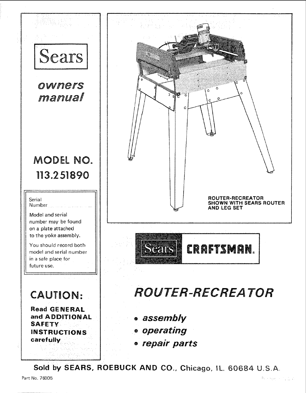
ROUTER-RECREATOR
SHOWN WITH SEARS ROUTER
AND LEG SET
ROUTER-RECREA TOR
®assembly
®operating
orepair parts
AND CO., Chicago, 1L. 60684 U.S.A.
This warranty gYes you specif c egal rights, and you may also have other rights which vary
from State to state; _
SEARSI ROEBUCK AND CO., DEPT. 69B/731A Sears ToWer. Chicago, IL 60684
Before =operating the Recreator read and understand your Router and Router Recreator
owner's manuals and affixed warnings.
The General Safety Instructions which follow apply to your Router and Router Recreator
co mbinaUon as a"power tool."
genera!l safety instructions for power tools
1. KNOW YOUR POWER TOOL
Read and understand the owner's manual and 12.
labels affixed to the tool Learn its application
and limitations as well as the specific potential
hazards peculiar to this tool.
2. GROUND ALL TOOLS UNLESS
DOUBLE INSULATED 13.
If tool is equipped with an approved
3-conductor cord and a 3--prong grounding
type pug to fit the proper grounding type
receptacle. The green conductor in the cord is
the grounding wire. Never: connect the green 14.
wire to a live terminal
3, KEEP GUARDS iN PLACE
and in working order.
4. REMOVE ADJUSTING KEYS
AND WRENCHES
Form habit of checking to seethat keys and 16.
adjusting wrenches are removed f,rom tool
before tui'ning it on. : i :- :
5; KEEP WORK AREA CLEAN :17.
Cluttef;ed areas and benches nv te accidents.
Ftoor must not be slippery dueto wax: or
sawdust. --18.
6, AVOID DANGEROUS ENVIRONMENT
Don't use power tools in damp or wet location.
Keep work area well lit. Provide adequate
surrounding work space.
7. KEEP CHILDREN AWAY 19.
AH visitors should be kept a safe distance from
work area,
8. MAKE WORKSHOP KID-PROOF
-- with padlocks, master switches, or by
removing starter keys.
9. DON'T FORCE TOOL
It wit! do the job better and safer at the rate for
which it was designed.
10. USE RIGHT TOOL
Don't force tool or attachment to d o a job it was
not designed for.
WEAR PROPER APPAREL
No loose clothing, g oves, neckties or jewelry to
get :caught in moving, parts. Rubber-soled damaged should
footwear is recOmn_ended fop best footing replaced.
USE SAFETY GOGGLES
Safety goggles must comply with ANSI
Z87.1-t968, Also use face or dust mask if
cutting operation is dusty. Everyday
eyeglasses only have =mpact resistant lenses,
they are not safety glasses.
SECURE WORK
Use clamps or a vise to hold work when
practical, it's safe r than using your hand, frees
both hands to operate toot.
DON'T OVERREACH
Keep proper footing and balance at all ttmes.
15. MAINTAIN TOOLS WITH CARE
Keep tools sharp and clean for best and safest
performance. Follow instructions for
lubrication and changing accessories.
DISCONNECT TOOLS
before servicing; when changing accessories
Such as blades, bits, cutters, _tc.
AVOID ACCIDENTAL STARTING
Make sure switch is in "OFF position before
plugging in.
USERECOMMENDEDACCESSORIES
Consult the owner's manual for recommended
accessories. Follow the instructions that
accompany the accessories. The use of
tmprope_" accessories may cause hazards.
NEVER STAND ON TOOL
Serious injury could occur if the toot is tipped
or if the cutting tool is accidentally contacted.
Do not store materials above or near the tool
such that it is necessary to stand on the tool to
reach them.
20. CHECK DAMAGED PARTS
Before further use of the tool, a guard or other
part that is damaged should be carefully
checked to ensure that it will operate properly
and perform its intended function,
Check for alignment of moving parts, binding
of moving parts, breakage of parts, mounting,
and any other conditions that may affect its
operation. A guard or other part that as
be properly repaired or
additional safety instructions for router-recreator
1. ALWAYS USE EYE PROTECTION.
The operation of any cutting tool can result in
foreign objects being thrown into the eyes,
which can result in severe eye damage. Always
wear safety goggles complying with ANSI
Z87.! before commencing cutting tool
operation. We recommend Wide Vision Safety
Mask for use over goggles.., available at Sears
retail or catalog stores.
2. DON'T FORCE TOOL
The Recreator was designed for smooth
operation, therefore, parts should never be
forced to operate.
3. KEEP HANDS CLEAR OF BITS
AND WORKING AREA.
4_ KEEP ROUTER RECREATOR AND
ROUTER CLEAN
After every use, clean saw dust off the
Recreator and Router,
NOTE: Motors used onwood-working tools are
particularly susceptible to the accumulation of
sawdust and wood chips and shouid be blown
out or "vacuumed" frequently to prevent
interference with normal motor ventilation.
Note and follow the instructions found on the
WARNING label which appears on the yoke
assembly.
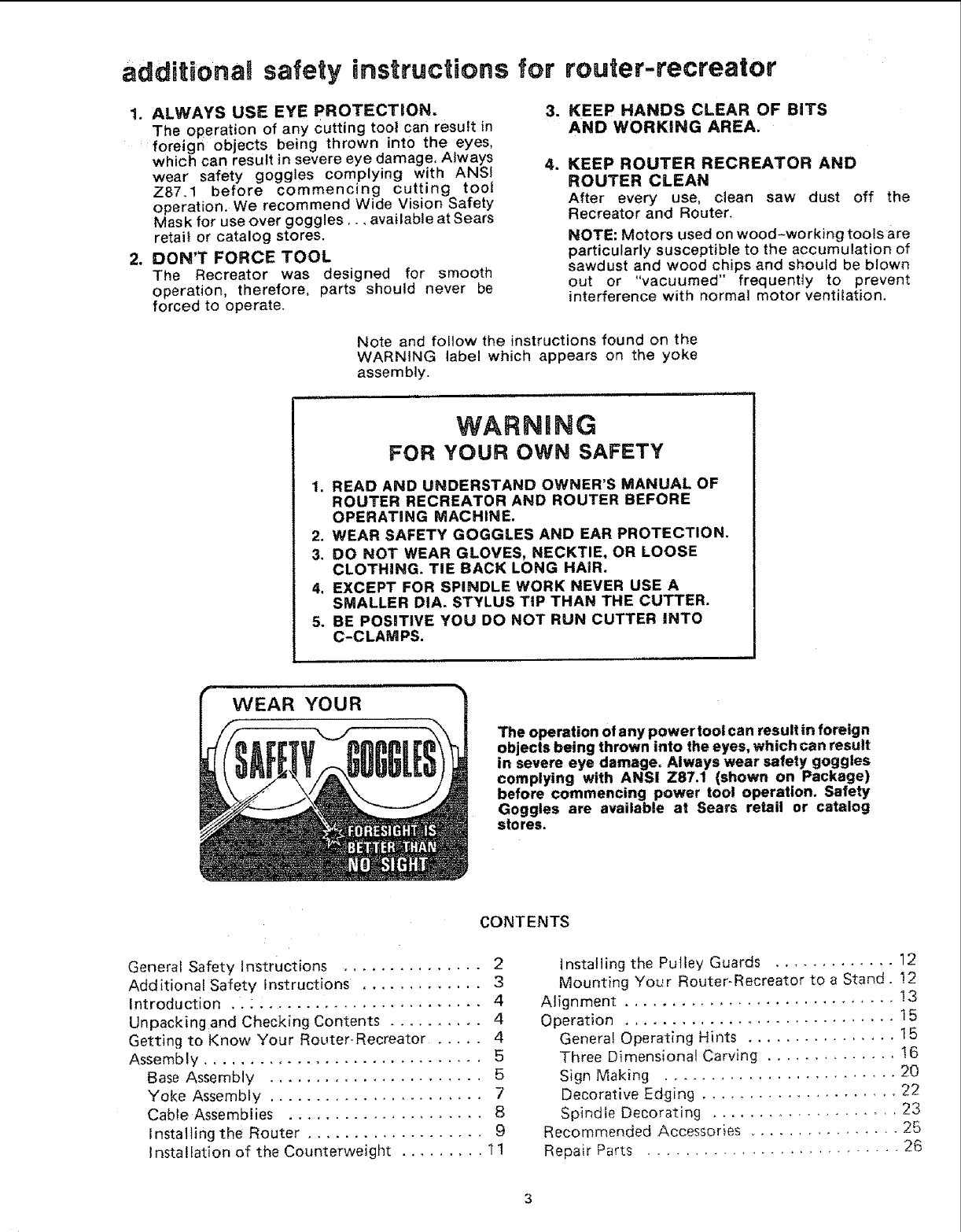
WARNING
FOR YOUR OWN SAFETY
1. READ AND UNDERSTAND OWNER'S MANUAL OF
ROUTER RECREATOR AND ROUTER BEFORE
OPERATING MACHINE.
2. WEAR SAFETY GOGGLES AND EAR PROTECTION.
3. DO NOT WEAR GLOVES, NECKTIE, OR LOOSE
CLOTHING. TIE BACK LONG HAIR.
4. EXCEPT FOR SPINDLE WORK NEVER USE A
SMALLER DIA. STYLUS TiP THAN THE CUTTER.
5. BE POSITIVE YOU DO NOT RUN CUTTER INTO
C-CLAMPS.
WEAR YOUR
The operation of any power tool can result in foreign
objects being thrown into the eyes, which can result
in severe eye damage. Always wear safety goggles
complying with ANSI Z87,1 (shown on Package)
before commencing power tool operation. Safety
Goggles are available at Sears retail or catalog
stores.
CONTENTS
General Safety Instructions ................ 2
Additional Safety Instructions ............. 3
Introduction .. : ........................ 4
Unpacking and Checking Contents .......... 4
Getting to Know Your Router-Recreator ..... 4
Assembly .............................. 5
Base Assembly ....................... 5
Yoke Assembly ....................... 7
Cable Assemblies ...................... 8
Instaliing the Router ................... 9
Installation of the Counterweight ......... 1!
Installing the Pulley Guards ............. 12
Mounting Your Router-Recreator to a Stand. !2
Alignment ............................. !3
Operation ............................. 15
Genera! Operating Hints ................ 15
Three Dimensional Carving .............. 16
2O
Sign Making .........................
Decorative Edging ..................... 22
Spindle Decorating ................... 23
Recommended Accessories ............... 25
26
Repair Parts ...........................
ntroduchon
Thank :you for- the purchase of your, Router and more enjoyable operatiOn later,
Recreator we think 0neof the most exciting and "tart b "'- :' -""; " "
-_ ,:_,_ ,_ __L__ ..,:_:n._i" ":"r_ _ y cnect_ ng anQ accoun[ ng mr all the loose
creaEivetuon_ w G,,)llle.alU gHyed =. --arts If an -art ";"";" "
: .... .... . : p . yp s are missing cnecK me car_on once
In order tofaclitate;handlingand.minimiZe any more, then contact your local Sears Retail or
damage that might occur during shipment your new Catalog outlet for replacement.
Recreator spackaged un-assembled We know Th
• . . T . .... :" "t J- b t e model number or your Recreator (113 251890)
youreanxloustoseewnatyournew_oolwtl oo u an-" th ...... ............ '-
.... n: wareful readn the u upar_numDeroTmemlssmgpar_wi Devery
a Tew minutes spe t no ,c y g het-fu n .............
fo low ng instructions, wi 1result in less frustration p s_€;ur_ng _ne replacemem part.
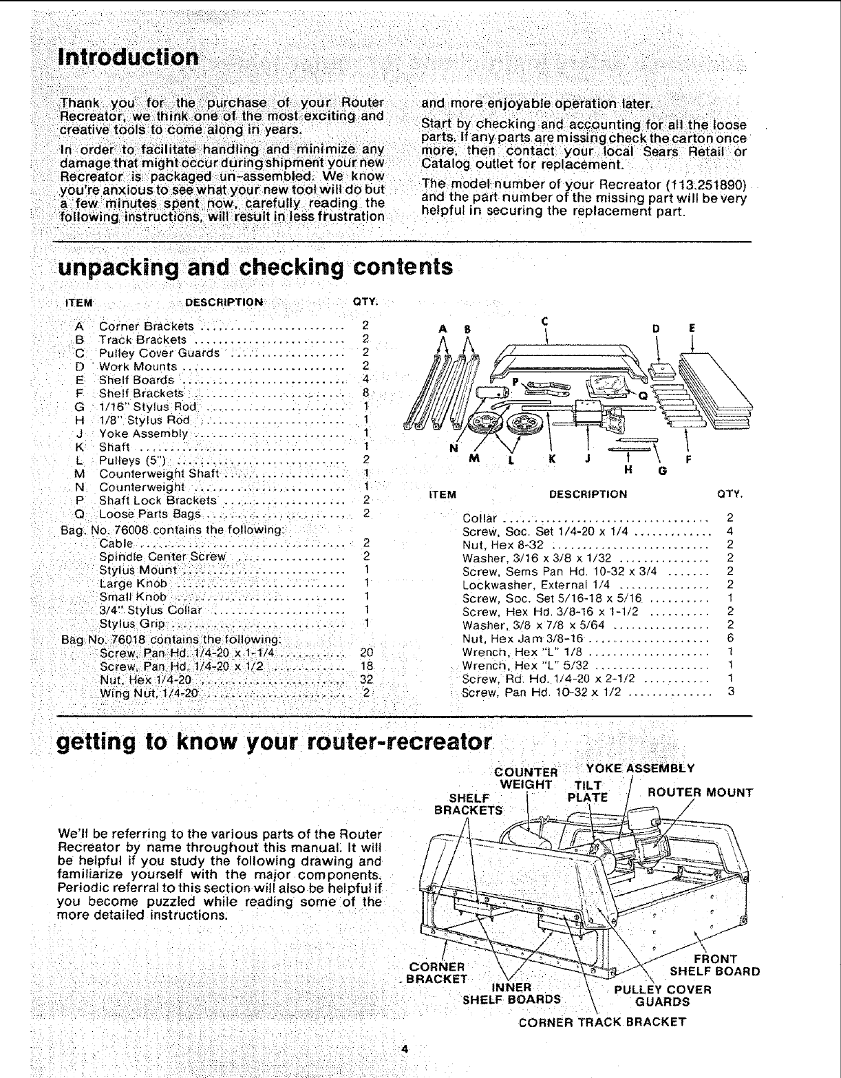
unpacking and checking contents
ITEM DESCRIPTION QTY.
A Corner Brackets ........................ 2 A 8C
_, D E
B Track Brackets ......................... 2 h A , _ |
C Pulley Cover Guards ................... 2 1_ t Y/7 _ _ *
E She f Boards .......................... 4 ii/i_iii._j _2 P.c -- _,_'_"_ % X
G 1/16 ' styIUSRR_d ............... ........ 11 Sii___
JYoke Assembly .. ........ : .............. _ i_ r=_ I i _ t
K Shaft .................. ; ............... 1 N' _V _K J _\ _
LPulleys (5") ............................ 21 L K H \G F
M Counterweight Shaft .. ........ ..........
N Counterweight ......................... 1
P Shaft Lock Brackets .................... 2
Q Loose Parts Bags ....................... 2
Bag. No, 76008 contains the following:
Cable ................................... 2
Spindle Center Screw .................... 2
Stylus Mount ........................... 1
Large Knob ........................... 1
Small Knob ...; ........................ 1
3/4" Stylus Collar ...................... 1
Stylus Grip .... ......................... I
Bag NO. 76018 contains the _otlowing:
Screw. Pan, Hd. t/4-20 x1-1/,_..... ..... : 20
Screw Pan Hd t/4-20 x 1/2 ........... 18
Nut, Hex 1/4-20 . . ......... ....... _ 32
Wing Nut. 1/4-20 ....................... 2
ITEM DESCRIPTION QTY.
Collar .................................. 2
Screw, Soc. Set 1/4-20 x 1/4 ............. 4
Nut. Hex 8-32 .......................... 2
Washer 3/16 x 3/8 x 1/32 ............... 2
Screw, Seres Pan Hd, 10-32 x 3/4 ...... 2
Lockwasher_ External 1/4 .............. 2
Screw, Soc. Set 5/16-18 x 5/16 .......... 1
Screw. Hex Hd 3/8-16 × 1-1/2 .......... 2
Washer. 3/8 x 7/8 x 5/64 ................ 2
Nut. Hex Jam 3/8-16 .................... 6
Wrench. Hex "L" t/8 .................... 1
Wrench, Hex "L" 5/32 .................. 1
Screw, Rd. Hd. 1/4-20 x 2-1/2 ........... 1
Screw, Pan lid 10-32 x 1/2 .............. 3
getting to know your router-recreator
COUNTER YOKE ASSEMBLY
WEIGHT TILT
PLATE ROUTER MOUNT
/
We'll be referring to the various parts of the Router
Recreator by name throughout this manual• It will
be helpful if you study the following drawing and
familiarize yourself with the major components,
Periodic referral to this section will also be helpful if
you become puzzled while reading some of the
more detailed instructions.
lFRONT
CORNER SHELF BOARD
.BRACKET INNER PULLEY COVER
" : -: SHELF BOARDS _GUARDS
i
CORNER TRACK BRACKET
"4
assembly
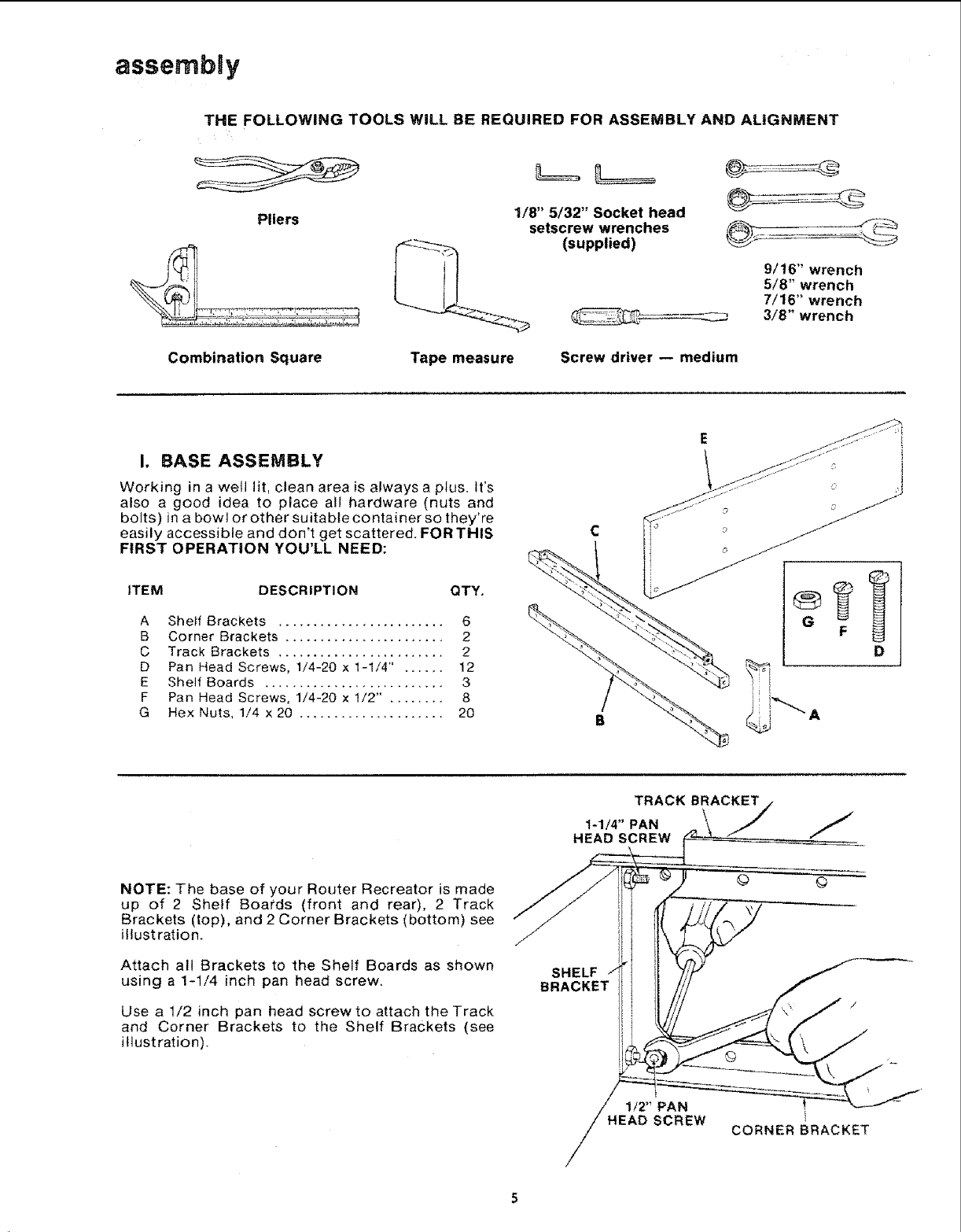
THE FOLLOWING TOOLS WiLL BE REQUIRED FOR ASSEMBLY AND ALIGNMENT
Pliers
Combination Square
1/8" 5/32" Socket head
setscrew wrenches
(supplied)
Tape measure Screw driver -- medium
9/16" wrench
5/8" wrench
7/16" wrench
3/8" wrench
I. BASE ASSEMBLY
Working in a welt lit, clean area is always a plus. It's
also a good idea to place all hardware (nuts and
bolts) in a bowl or other suitable container so they're
easily accessible and don't get scattered. FOR THIS
FIRST OPERATION YOU'LL NEED:
ITEM DESCRIPTION QTY.
A Shelf Brackets ........................ 6
B Corner Brackets ....................... 2
C Track Brackets ........................ 2
D Pan Head Screws, 1/4-20 x 1-1/4" ...... 12
E Shelf Boards .......................... 3
F Pan Head Screws, 1/4-20 x 1/2" ........ 8
G Hex Nuts, 1/4 x 20 ..................... 20
C
D
NOTE: The base of your Router Recreator is made
up of 2 Shelf Boards (front and rear), 2 Track
Brackets (top), and 2 Corner Brackets (bottom) see
illustration.
Attach all Brackets to the Shelf Boards as shown
using a 1-1/4 inch pan head screw.
Use a 1/2 inch pan head screw to attach the Track
and Corner Brackets to the Shelf Brackets (see
illustration).
TRACK BRACKET
1-1/4"PAN j
HEAD SCREW
© ©
SHELF
BRACKET
H1/2 'PAN 1
EAD SCREW CORNER BRACKET
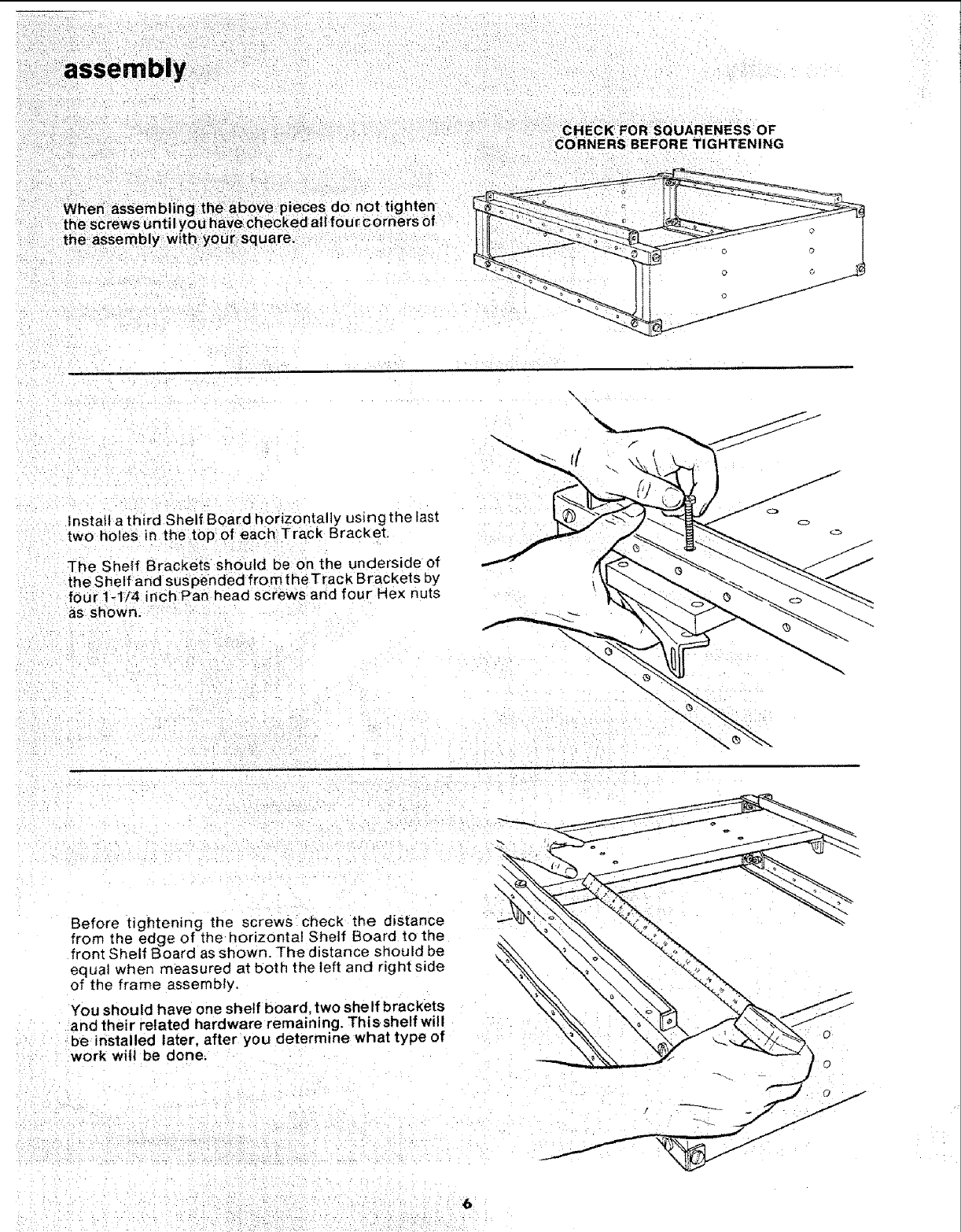
CHECK FOR SQUARENESS OF
:CORNERS BEFORE TIGHTENING
When assembling the above pieces do not tighten
the screws until you have checked all four cornerS of
the assembly with your square.
\
Instafl a third Shelf Board horizontally us_ngthe last
two holes in the:top of each Track Bracket,
The Shelf Brackets should be on the underside of
the Shelf and sus pended from the Track Brackets by
four 1-1/4 inch Pan head screws and four Hex nuts
as shown.
Before tightening the screws check the distance
from the edge of the horizontal She{f Board to the
front Shelf Board as shown. The distance shouEd be
equal when measured at both the left and rig ht side
of the frame assembly,
You should have one shelf board, two she If brac kets
and their related hardware remaining. Thisshelf will
be installed later, after you determine what type of
work will be done.
6 ¸
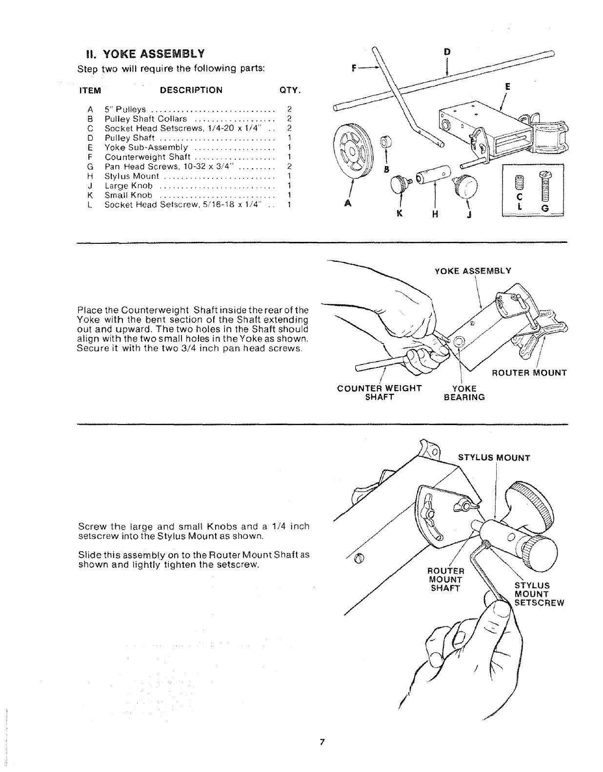
l!. YOKE ASSEMBLY
Step two will require the following parts:
ITEM DESCRJPT|ON QTY,
A 5" Pulleys ............................. 2
B Pulley Shaft Collars ................... 2
C Socket Head Setscrews, I/4-20 x t/4" .. 2
D Pulley Shaft ........................... 1
E Yoke Sub-Assembly ................... 1
F Counterweight Shaft ................... 1
G Pan Head Screws, 10-32 x 3/4" . ........ 2
H Stylus Mount .......................... 1
J Large Knob ........................... 1
K Small Knob ........................... !
L Socket Head Setscrew, 5/16-18 x t/4" .. 1
D
Place the Counterweight Shaft inside the rear of the
Yoke with the bent section of the Shaft extending
out and upward. The two holes in the Shaft should
align with the two small holes in the Yoke as shown.
Secure it with the two 3/4 inch pan head screws,
COUNTER WEIGHT
SHAFT
YOKE ASSEMBLY
YOKE
BEARING
/
ROUTER MOUNT
STYLUS MOUNT
Screw the large and small Knobs and a 1/4 inch
setscrew into the Stylus Mount as shown.
Slide this assembly on to the Router Mount Shaft as
shown and lightly tighten the setscrew.
STYLUS
MOUNT
SETSCREW
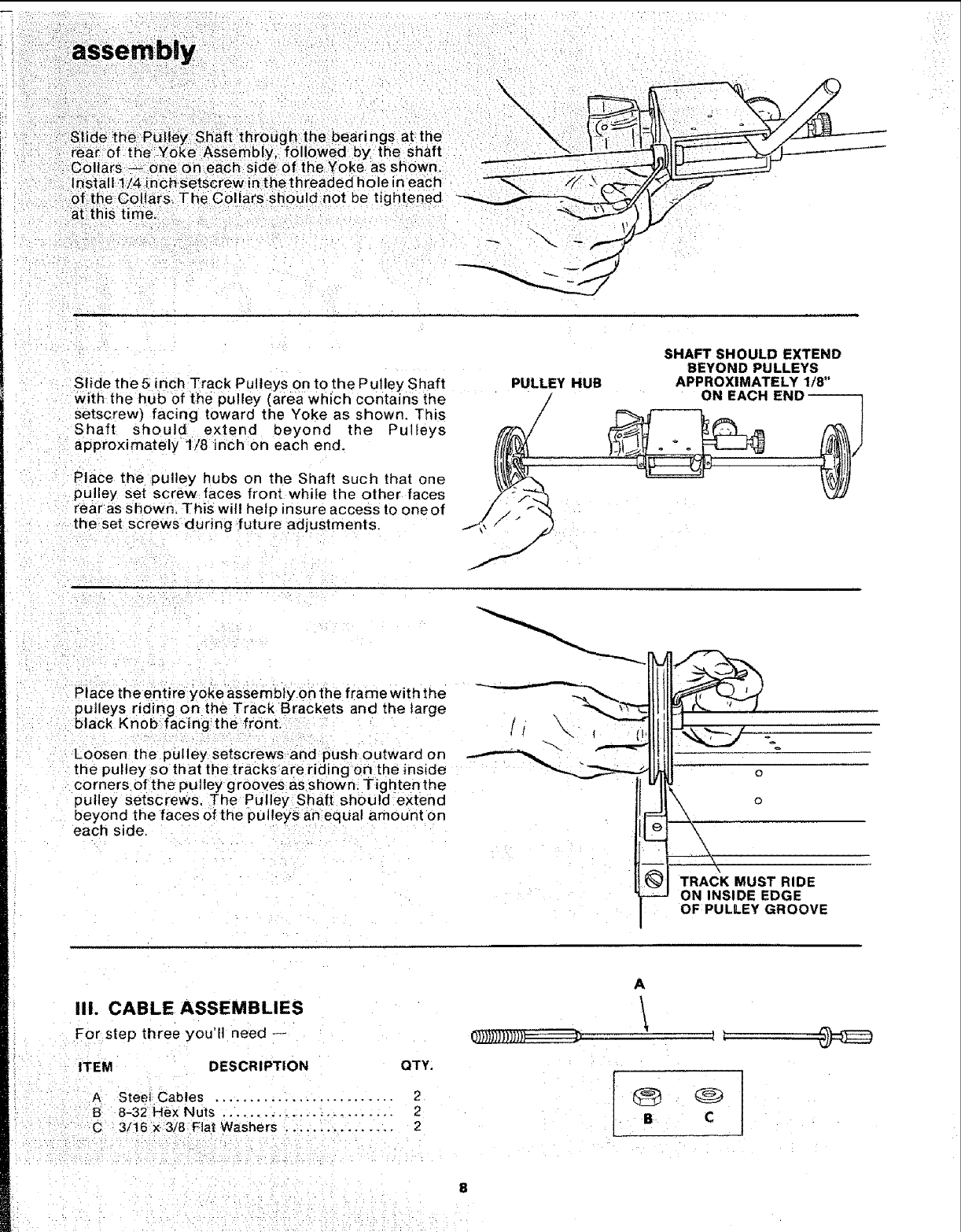
de the Pulley shaft through the bearings at the
.rear of the Y0ke Assembly followed by the shaft
Collars _ one or1 each side of the Yoke as shown,
install 1/4 inchsetsCrew in thethreaded h01e in each
of the Collars. The Collars should not be
at this time.
Slide the 5 inch Track Pulleys o n to the Pulley Shaft
with the hub of the pulley (area which contains the
setscrew) facing toward the Yoke as shown. This
Shaft shoulc_ extend beyond the Pulleys
approximately 1/8 inch on each end.
Place the pulley hubs on the Shaft such that one
pulley set screw faces front while the other faces
rear as Shown. This wil! help insure access to one of
the set screws during future adjustments.
PULLEY HUB
/
/
SHAFT SHOULD EXTEND
BEYOND PULLEYS
APPROXIMATELY 1/8"
ON EACH END
PlaCe the entire yoke assembly on the frame with the
pulleys riding on the Track Brackets and the large
black Knob facing the front.
Loosen the pulley setscrews and push outward on
the pulley so that the tracks are riding on the inside
corners of the pulley grooves as shown. Tighten the
pulley setscrews. The Pulley Shaft should extend
beyond the faces of the pulleysan equal amount on
each side,
TRACK MUST RIDE
ON INSIDE EDGE
OF PULLEY GROOVE
Iii. CABLE ASSEMBLIES
For step three you'll need --
ITEM DESCRIPTION QTY:
A Steel Cables .......................... 2
B 8-32 Hex Nuts ..................... 2
C 3/t6 X 3/8 Flat Washers ............... 2
0))))))l)))})})--
A
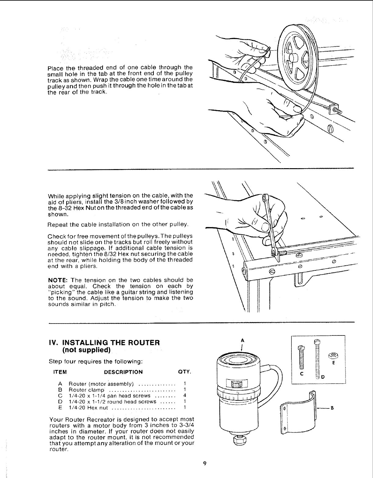
Place the threaded end of one cable through the
small hole in the tab at the front end of the pulley
track as shown. Wrap the cable one time around the
pulley and then push it through the hole in the tab at
the rear of the track.
While applying slight tension on the cable, with the
aid of pliers, install the 3/8 inch washer followed by
the 8-32 Hex Nut on the threaded end of the cable as
shown.
Repeat the cable installation on the other pulley.
Check for free movement of the pulleys. The pulleys
should not sJide on the tracks but roll freely without
any cable slippage. If additional cable tension is
needed, tighten the 8/32 Hex nut securing the cable
at the rear, while holding the body of the threaded
end with a pliers.
NOTE: The tension on the two cables should be
about equal. Check the tension on each by
"picking" the cable like a guitar string and listening
to the sound. Adjust the tension to make the two
sounds similar in pitch.
iV. INSTALLING THE ROUTER
(not supplied)
Step four requires the following:
ITEM DESCRIPTION QTY.
A Router (motor assembly) .............. 1
B Router clamp ,........................ 1
C 1/4-20 x 1-1/4 pan head screws ........ 4
D 1/4-20 x t-1/2 round head screws ...... 1
E 1/4-20 Hex nut . ....................... 1
Your Router Recreator is designed to accept most
routers with a motor body from 3 inches to 3-3/4
inches in diameter. If your router does not easily
adapt to the router mount, it is not recommended
that you attempt any alteration of the mount or your
router.
E
assembly
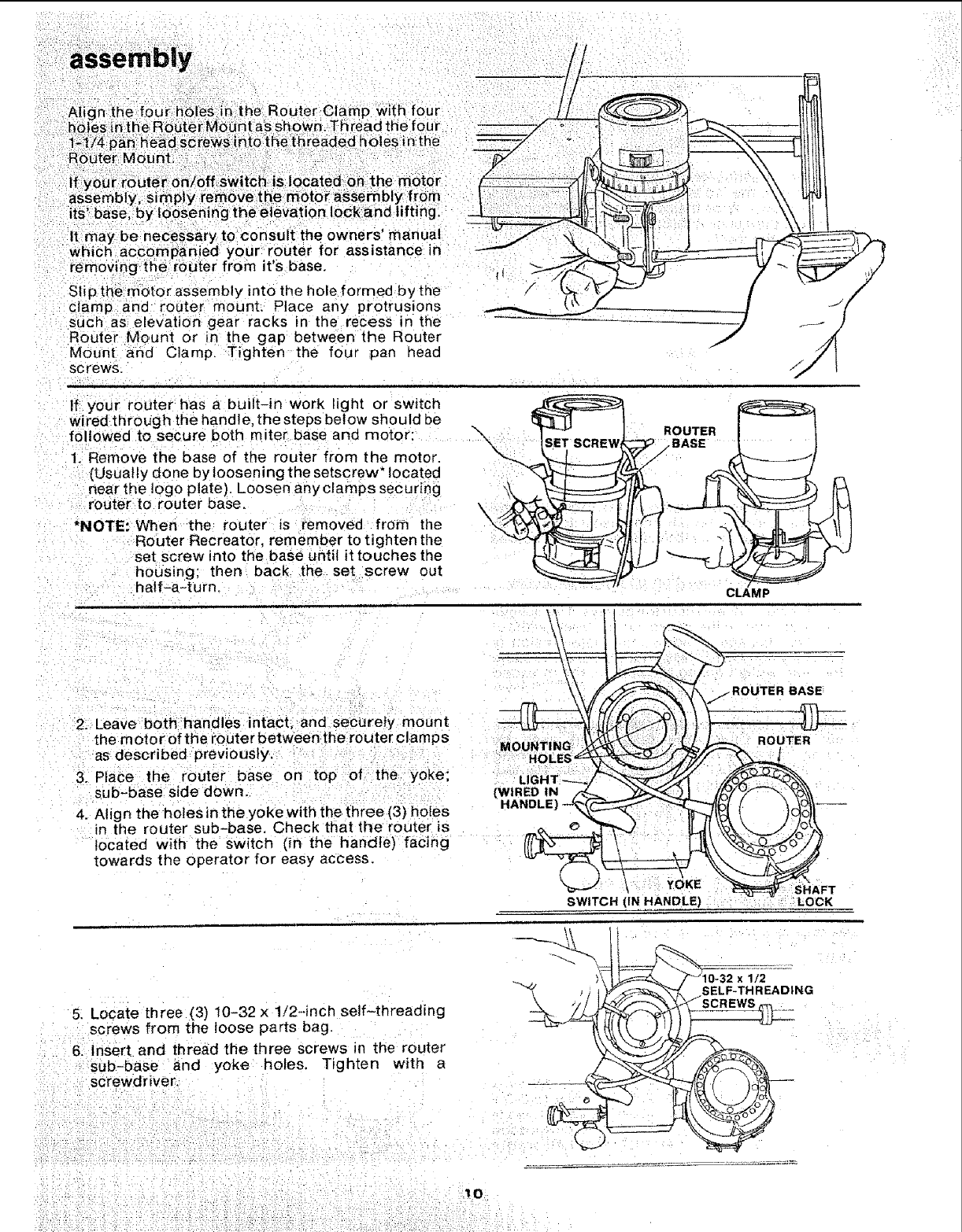
It may be necessary to consult the owners' manual
which accompanied your router for assistance in
removing the router from it's base.
Slip the motor assembly into the hole formed by the
clamp and router mount, Place any protrusions
SLiCh as elevation gear racks in the recess in the
Router Mount or in the gap between the Router
Mount and Clamp. Tighten the four pan head
sc rews.
If your router has a built-in work light or switch
wired throug h the handle, the steps below should be
followed to secure both miter base and motor:
!. Remove the base of the router from the motor.
[Usually done by loosening the setscrew* located
near the ]ogo plate). Loosen anyclamps securing
router to router base.
*NOTE:When the router is removed from the
Router Recreator, remember to tighten the
set screw into the base until it touches the
hoosing; then back the set screw out
half-a-turn.
\\ROUTER
_iBASE
CLAMP
2. Leave both hand es ntact, and securely mount
the motorofthe router between the router clamps
as described previously.
3. Place the router base on top ofthe yoke;
sub-base side down.
4. Align the holes in the yoke with the three (3) holes
in the router sub-base. Check that the router is
located with the switch (in the handle) facing
towards the operator for easy access.
MOUNTING
(WIRED
BASE
SWITCH (IN HANDLE) SHAFT
LOCK
5. Locate three (3) 10-32 x 1!2-inch self-threading
screws from the loose parts bag.
6. Insert and thread the three screws in the router
sub-base and yoke holes. Tighten with a
screwdriver.
10
i ....iii i: ! i
x1/2
SELF-THREADING
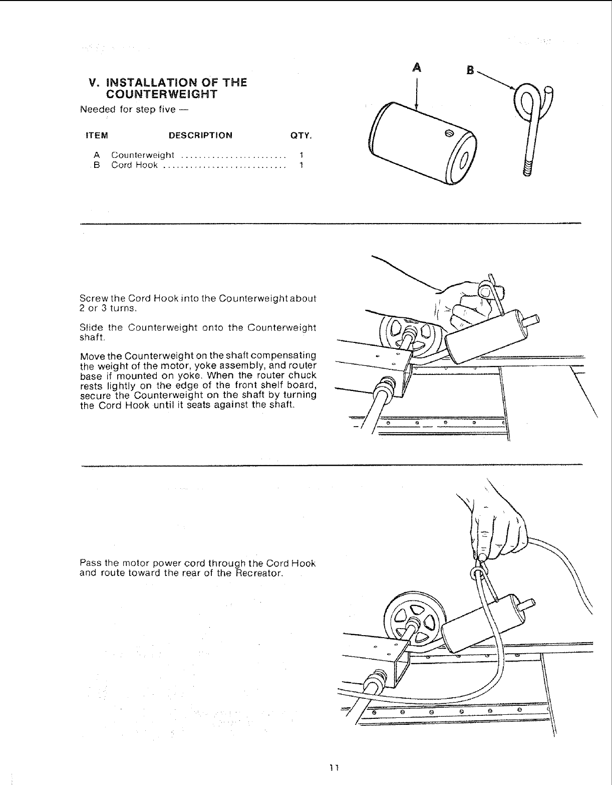
V. iNSTALLATiON OF THE
COUNTERWEIGHT
Needed for step five i
ITEM DESCRIPTION QTY,
A Counterweight ........................ 1
B Cord Hook ............................ 1
A
Screw the Cord Hook into the Counterweight about
2 or 3 turns,
Slide the Counterweight onto the Counterweight
shaft,
Move the Counterweight on the shaft compensating
the weight of the motor, yoke assembly, and router
base if mounted on yoke. When the router chuck
rests lightly on the edge of the front shelf board,
secure the Counterweight on the shaft by turning
the Cord Hook until it seats against the shaft.
Pass the motor power cord through the Cord Hook
and route toward the rear of the Recreator.
\
.'H
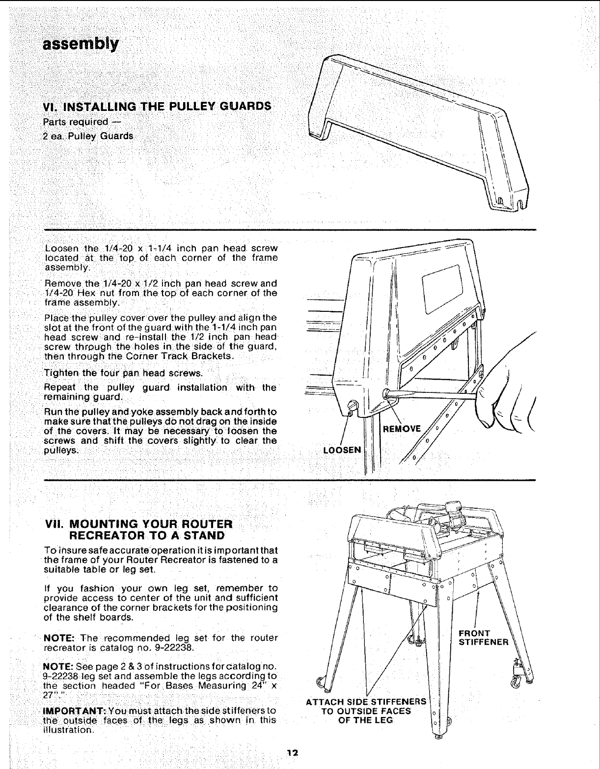
Vl. INSTALLING THE PULLEY GUARDS
Parts required --
2 ea Pulley Guards
Loosen the 1/4-20 x 1-1/4 inch pan head screw
located at the top of each corner of the frame
assembly.
Remove the 1/4-20 x 1/2 inch pan head screw and
1/4-20 Hex nut from the top of each corner of the
frame assembly.
Place the pulley cover over the pulley and align the
slot at the front of the guard with the 1-1/4 inch pan
head screw and re-install the 1/2 inch pan head
screw through the holes in the side of the guard.
then through the Corner Track Brackets.
Tighten=the four pan head screws.
Repeat the pulley guard installation with the
remaining guard.
Run the pulley and yoke assembly back and forth to
make sure that the pulleys do not drag on the inside
of the covers. It may be necessary to loosen the
screws and shift the covers slightly to clear the
pulleys. /
LOOSEN
VII. MOUNTING YOUR ROUTER
RECREATOR TO A STAND
To insure safe accurate operation it is important that
the frame of your Router Recreator is fastened to a
suitable table or leg set.
if you fashion your own leg set, remember to
provide access to center of the unit and sufficient
clearance of the corner brackets for the positioning
of the shelf boards.
NOTE: The recommended ieg set for the router
recreator is catalog no. 9-22238.
NOTE: See page 2 & 3of instructions for catalog no.
9-22238 leg set and assemble the legs according to
trle section headed "For Bases Measuring 24" x
27"."
IMPORTANT: You must attach the side stiffeners to
the outside faces of the legs as shown m this
illustration.
ATTACH SIDE STIFFENERS
TO OUTSIDE FACES
OF THE LEG
FRONT
STIFFENER
12
alignment
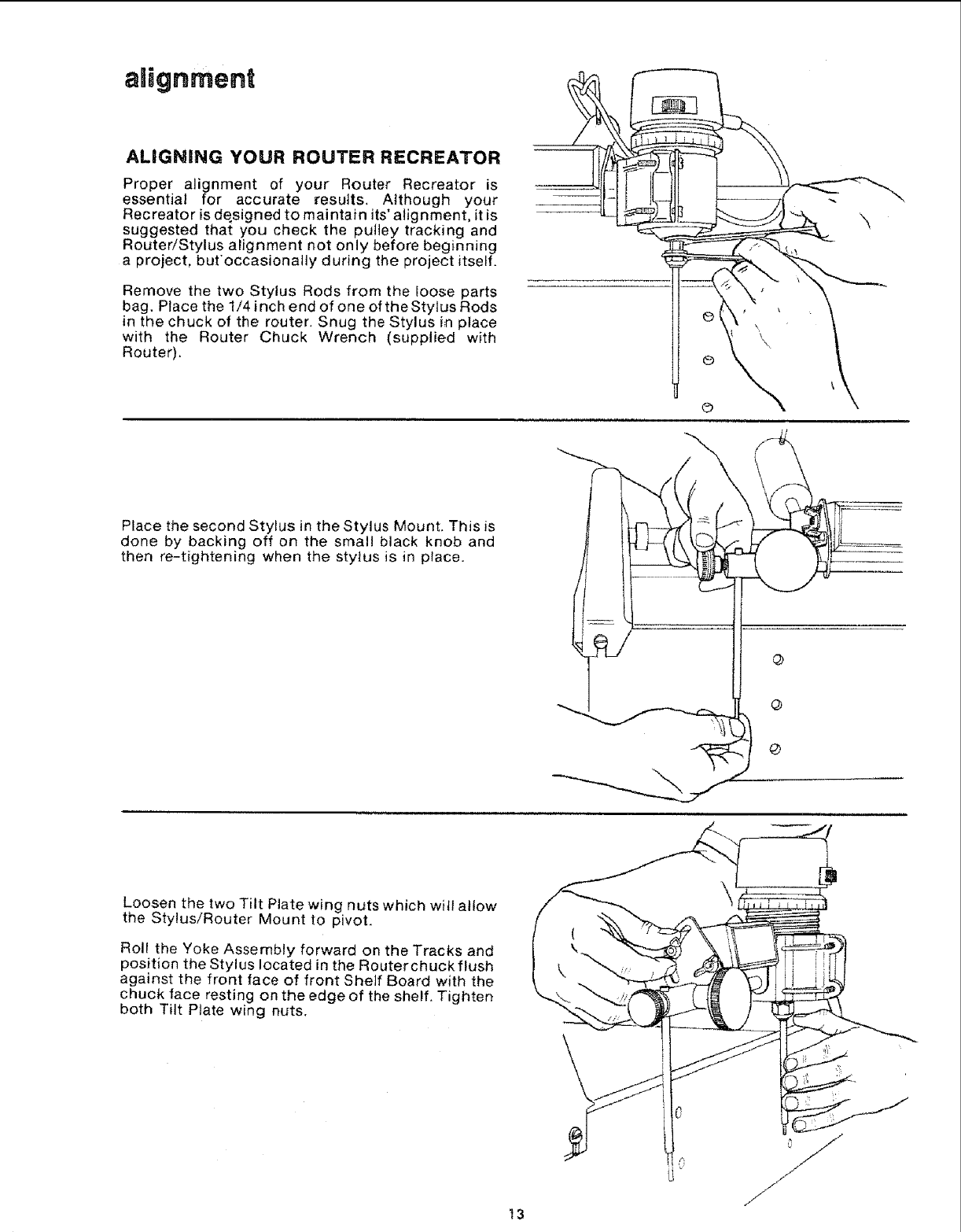
ALIGNING YOUR ROUTER RECREATOR
Proper alignment of your Router Recreator is
essential for accurate results. Although your
Recreator is designed to maintain its'alignment, it is
suggested that you check the pulley tracking and
Router/Stylus alignment not only before beginning
a project, but'occasionally during the project itself.
Remove the two Stylus Rods from the ioose parts
bag, Place the 1/4 inch end of one of the Stylus Rods
in the chuck of the router, Snug the Stylus in place
with the Router Chuck Wrench (supplied with
Router).
Place the second Stylus in the Stylus Mount. This is
done by backing off on the small black knob and
then re-tightening when the stytus is in place.
@
@
Loosen the two Tilt Plate wing nuts which will allow
the Stylus/Router Mount to pivot.
Roll the Yoke Assembly forward on the Tracks and
position the Stylus located in the Routerchuck flush
against the front face of front Shelf Board with the
chuck face resting on the edge of the shelf. Tighten
both Tilt Plate wing nuts.
t3
alignment
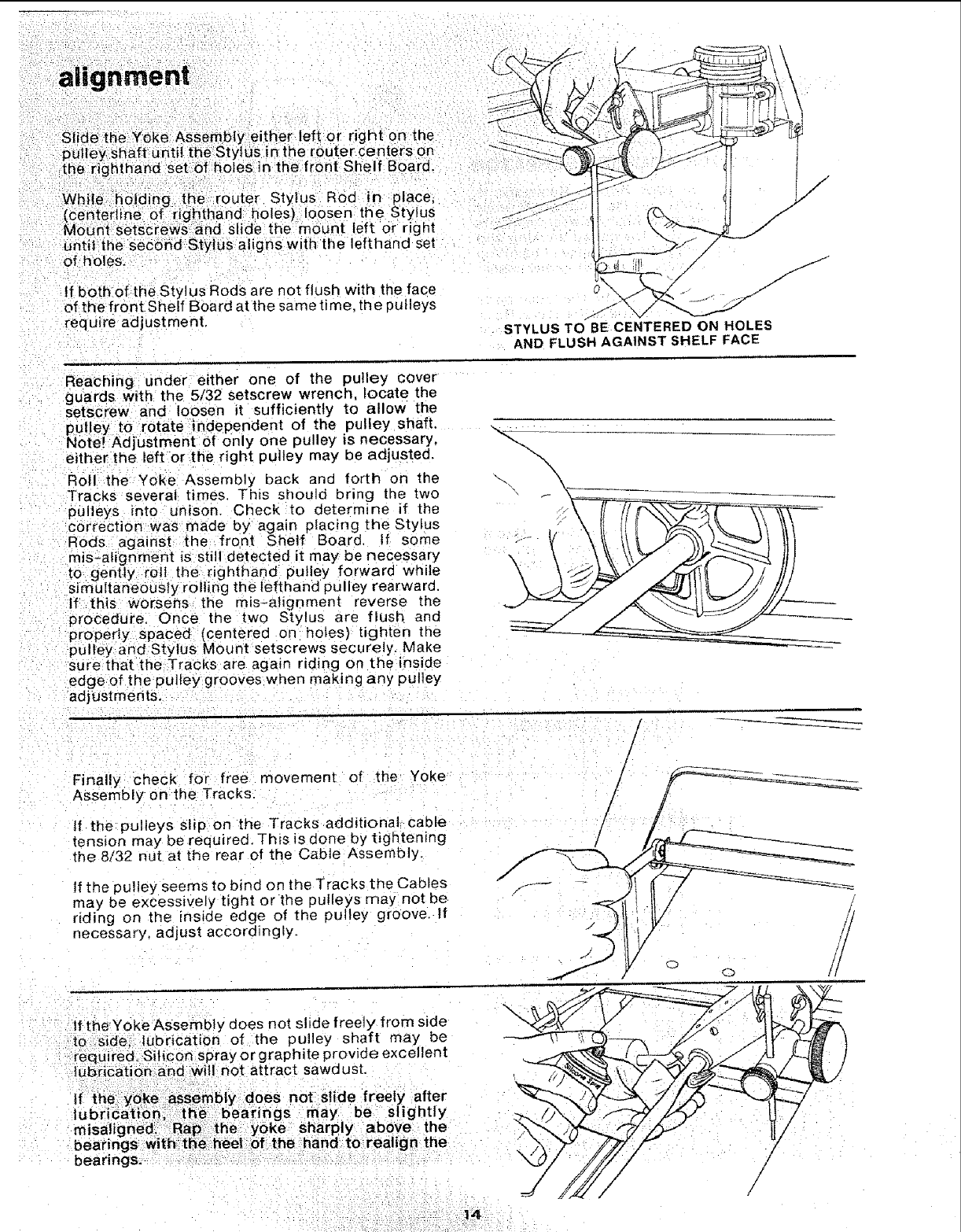
Slide the Yoke Assembly either left or right on the
p u[tey Shaft u ntit the Stylus in the route r centers on
the-righthand Set _afholes in the front Shelf Board.
While holding the router Stylus Rod in place,
(centeriine of righthand holes) loosen the Stylus
MoUnt sets_crews and slide the mount left or r ght
untd the secdnd Stylus aligns with the lefthand set
of h 01es.
If both of the Stylus Rods are not flush with the face
of the front Shelf Board atthe sametime, the pulleys
require adjustment.
/
/
/" j j/
J
0/
_J
STYLUS TO BE CENTERED ON HOLES
AND FLUSH AGAINST SHELF FACE
Reaching under either one of the pulley cover
guards with the 5/32 setscrew wrench locate the
setscrew and loosen it sufficiently to allow the
put ey to rotate independent of the pulley shaft,
Note! Adjustment of only one pulley is necessary,
either the left or the r ght pulley may be adjusted.
Rol! the =Yoke Assembly back and forth on the
Tracks several times. This should bring the two
pulleys into unison. Check to determine if the
correction was made by again placing the Stylus
Rods aganst the front Shelf Board. If some
mis-aiignment is sti detected it may be necessary
to gently roll the rig3thand pulley forward while
sirfiultaneOusfy rolling the lefthand pulley rearward.
If this worsens the rots-alignment reverse the
procedure. Once the two Stylus are flush and
properly spaced (centered on hotes) tighten the
_)utley and Stylus Mo[mt setscrews securely. Make
sure that the Tracks are again riding on the inside
edge of the puJley grooves when making any pulley
adjustments.
I
!
!
!
Finally check for free movement of the Yoke
Assembly on the Tracks.
If the pulleys slip on the Tracks additional cable
tenston may be required. This is done by tightening
the 8/32 nut at the rear of the Cable Assembly.
tf the pulley seems to bind on the Tracks the Cables
may be excessively tight or the pulleys may not be
riding on the inside edge of the pulley groove, if
necessary, adjust accordingly.
/
If the Yoke Assembly does not slide freely from side
to side.: lubrication of the pulley shaft may be
required. Silicon spray or graphite provi0e excellent
|egricat On and wil! not attract sawdust.
If the: yoke assembly does not slide freely after
lubrication; the. bearings may be slightly
misaligned. Rap :the yoke Sharply above the
bear rigs with _he beet of the hand torealign the
bearings. /
/
operation
GENERAL OPERATING HINTS
1. Most projects undertaken with the Router
Recreator will require some time to complete.
Make sure when you begin your work that you
are comfortable. Although your Recreator can
be operated from a standing position you'll find
a chair will be helpful,
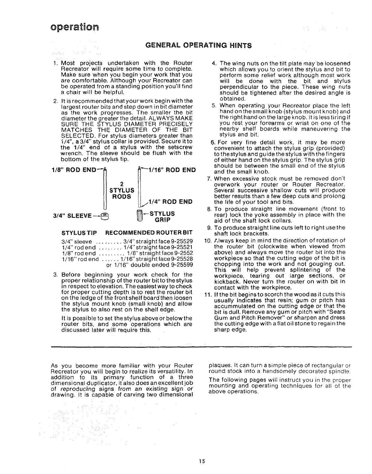
2. It is recommendedthatyourwork begin with the
largest router bits and step down in bit diameter
as the work progresses. The smaller the bit
diameter the greater the detail. ALWAYS MAKE
SURE THE STYLUS DIAMETER PRECISELY
MATCHES THE DIAMETER OF THE BIT
SELECTED. For stylus diameters greater than
i/4', a 3/4 stylus collar is provided. Secure itto
the 1/4" end of a stylus with the setscrew
wrench. The sleeve should be flush with the
bottom of the stylus tip.
1/8" ROD END-" _'"_1/16" ROD END
2
STYLUS
RODS IL...1/4' RODEND
3/4" SLEEVE --_ _- STYLUS
GRBP
STYLUS TgP RECOMMENDED ROUTER BIT
3/4" sleeve ......... 3/4" straight face 9-25529
1/4" rod end ........ 1/4" straight face 9-25521
1/8" rod end ......... 1/8" straight face 9-2552
1/16" rod end ...... 1/16" straight face 9-25528
or 1/16" double ended 9-25599
3. Before beginning your work check for the
proper relationship of the router bit to the stylus
in respect to elevation. The easiest way to check
for proper cutting depth is to rest the router bit
on the tedge of the front shelf board then loosen
the stylus mount knob (small knob)and allow
the stylus to also rest on the shelf edge.
It is possible to set the stylus above or below the
router bits, and some operations which are
discussed later will require this,
4. The wing nuts on the tilt plate may be loosened
which allows you to orient the stylus and bit to
perform some relief work although most work
will be done with the bit and stylus
perpendicular to the piece. These wing nuts
should be tightened after the desired angle is
obtained.
5, When operating your Recreator place the left
hand on thesmall knob (stylus mount knob) and
the right hand on the large knob. It is less tiring if
you rest your forearms or wrist on one of the
nearby shelf boards while maneuvering the
stylus and bit.
6. For very fine detail work, it may be more
convenient to attach the stylus grip (provided)
to the stylus and guide the stylus with the fingers
of either hand on the stylus grip. The stylus grip
should be between the small end of the stylus
and the small knob.
7. When excessive stock must be removed don't
overwork your router or Router Recreator_
Several successive shallow cuts witi produce
better results than a few deep cuts and prolong
the life of your tool and bits.
8. To produce straight tine movement (front to
rear) lock the yoke assembly in place with the
aid of the shaft lock collars.
9. TO produce straight line cuts left to right use the
shaft lock brackets.
t0. Always keep in mind the direction of rotation of
the router bit (clockwise when viewed from
above) and always move the router bit into the
workplace so that the cutting edge of the bit is
chopping into the work and not gouging out.
This will help prevent splintering of the
workplace, tearing out large sections, or
kickback. Never turn the router on with bit in
contact with the workpiece,
11. If the bit begins to scorch the wood as it cuts this
usually indicates that resin; gum or pitch has
accummulated on the cutting edge or that the
bit is dull, Remove any gum or pitch with "Sears
Gum and Pitch Remover" or sharpen and dress
the cutting edge with a ftat oil stoneto regain the
sharp edge.
As you become more familiar with your Router
Recreator you will begin to realize its versatility. In
addition to its primary function of a three
dimensional duplicator, it also does an excellent job
of reproducing signs from an existing sign or
drawing, it is capable of carving two dimensional
plaques. It can turn a simpte piece of rectangular or
round stock into a handsomely decorated spindle.
The following pages wilt instruct you in the proper
mounting and operating techniques for all of the
above operations.
15
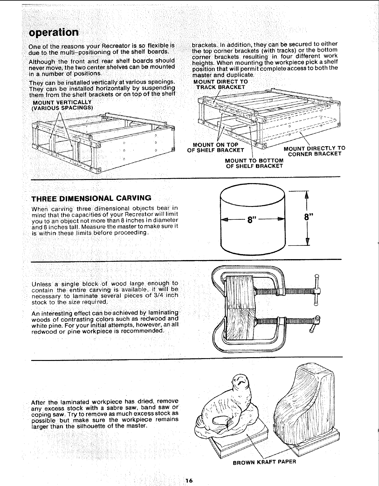
MOUNT VERTICALLY
{VARIOUS SPACINGS)
MOUNT ON TOP \
OF SHELF BRACKET MOUNT DIRECTLY TO
CORNER BRACKET
MOUNT TO BOTTOM
OF SHELFBRACKET
THREE DIMENSIONAL CARVING
When Ca_'ving three dimensional objects bear in
mind that the capacities of your Recreator will limit
you to an object not more than 8 inches in diameter
and 8 inches taif. Measure the master to make sure it
is within these limits before proceeding.
8_ _=,. 8_
,i
Unless a-single block of wood large enough to
contain the entire carving is: available, it;will be
necessary to laminate several: pieces of 3/4 inch
stock to the size required. ' . =
An interesting effect can be achieVed by laminating
woods of contrasting colors such as redwood and
white pine, For your initial attempts, however, an all
redwood or pine workpiece isrecommended.
, ,,,,i
After the laminated workpiece has dried, remove
any excess stock with a sabre saw. band saw or
coping saw. Try to remove as much excess stock as
possible but make sure the workpiece remains
larger than the silhouette of the master.
\
BROWN KRAFT PAPER
"16
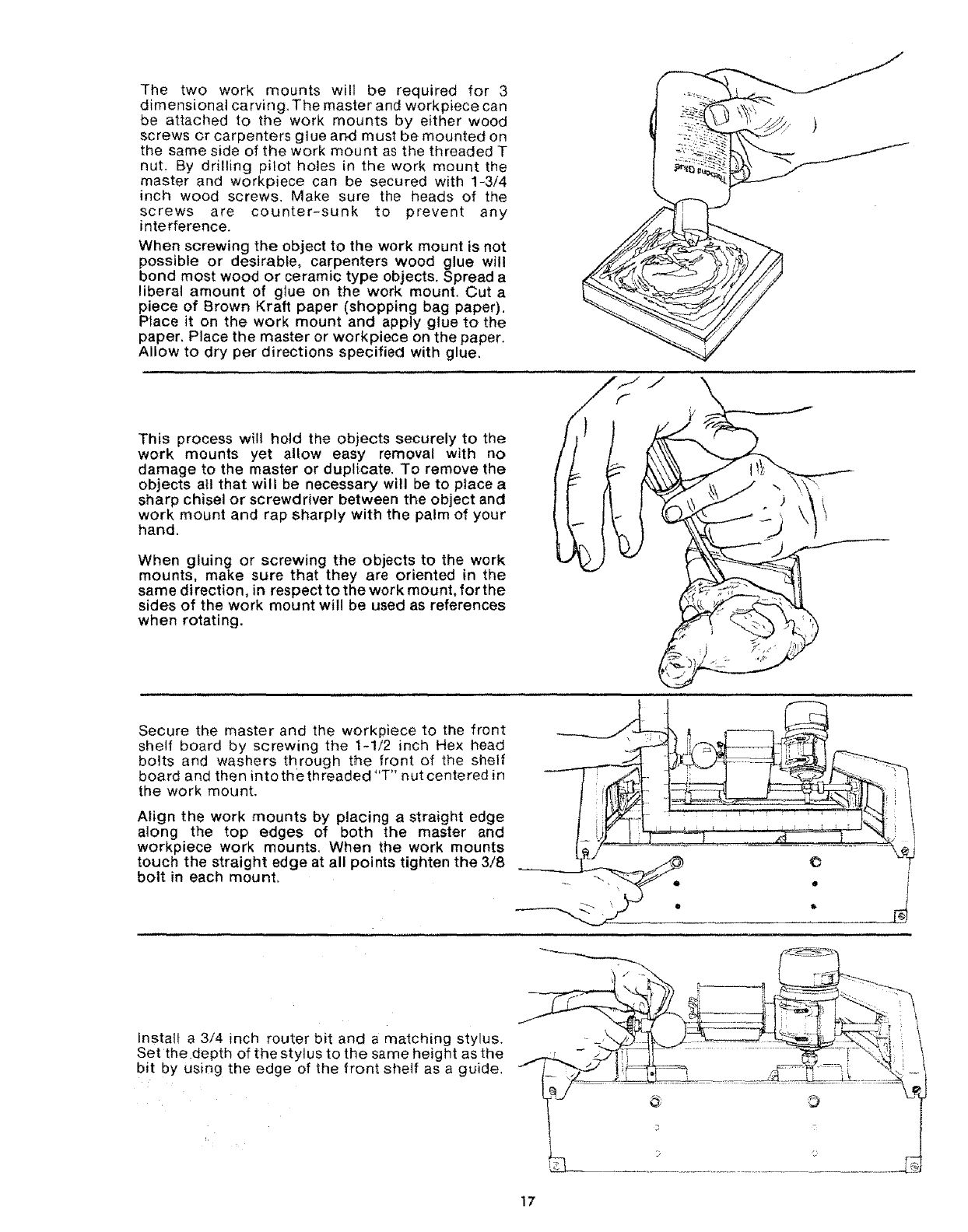
The two work mounts will be required for 3
dimensional carving. The master and workplace can
be attached to the work mounts by either wood
screws or carpenters glue and must be mounted on
the same side of the work mount as the threaded T
nut. By drilling pilot holes in the work mount the
master and workplace can be secured with 1-3/4
inch wood screws. Make sure the heads of the
screws are counter-sunk to prevent any
interference.
When screwing the object to the work mount is not
possible or desirable, carpenters wood glue wi!l
bond most wood or ceramic type objects. Spread a
liberal amount of glue on the work mount. Cut a
piece of Brown Kraft paper (shopping bag paper).
Place it on the work mount and apply glue to the
paper, Place the master or workpiece on the paper.
Allow to dry per directions specified with glue.
This process will hold the objects securely to the
work mounts yet allow easy removal with no
damage to the master or duplf.cate. To remove the
objects all that will be necessary will be to place a
sharp chisel or screwdriver between the object and
work mount and rap sharply with the palm of your
hand.
When gluing or screwing the objects to the work
mounts, make sure that they are oriented in the
same direction, in respect to the work mount, for the
sides of the work mount will be used as references
when rotating.
i....
J \
Secure the master and the workpiece to the front
shelf board by screwing the 1-1/2 inch Hex head
bolts and washers through t_e front of the shelf
board and then intothethreaded "T" nut centered in
the work mount,
Align the work mounts by placing a straight edge
along the top edges of both the master and
workpiece work mounts, When the work mounts
touch the straight edge at all points tighten the 3/8
bolt in each mount.
...........
Insta{t a 3/4 inch router bit and a matching stylus.
Set the depth of the stylus to the same height as the
bit by using the edge of the front shelf as a guide.
]7
operation
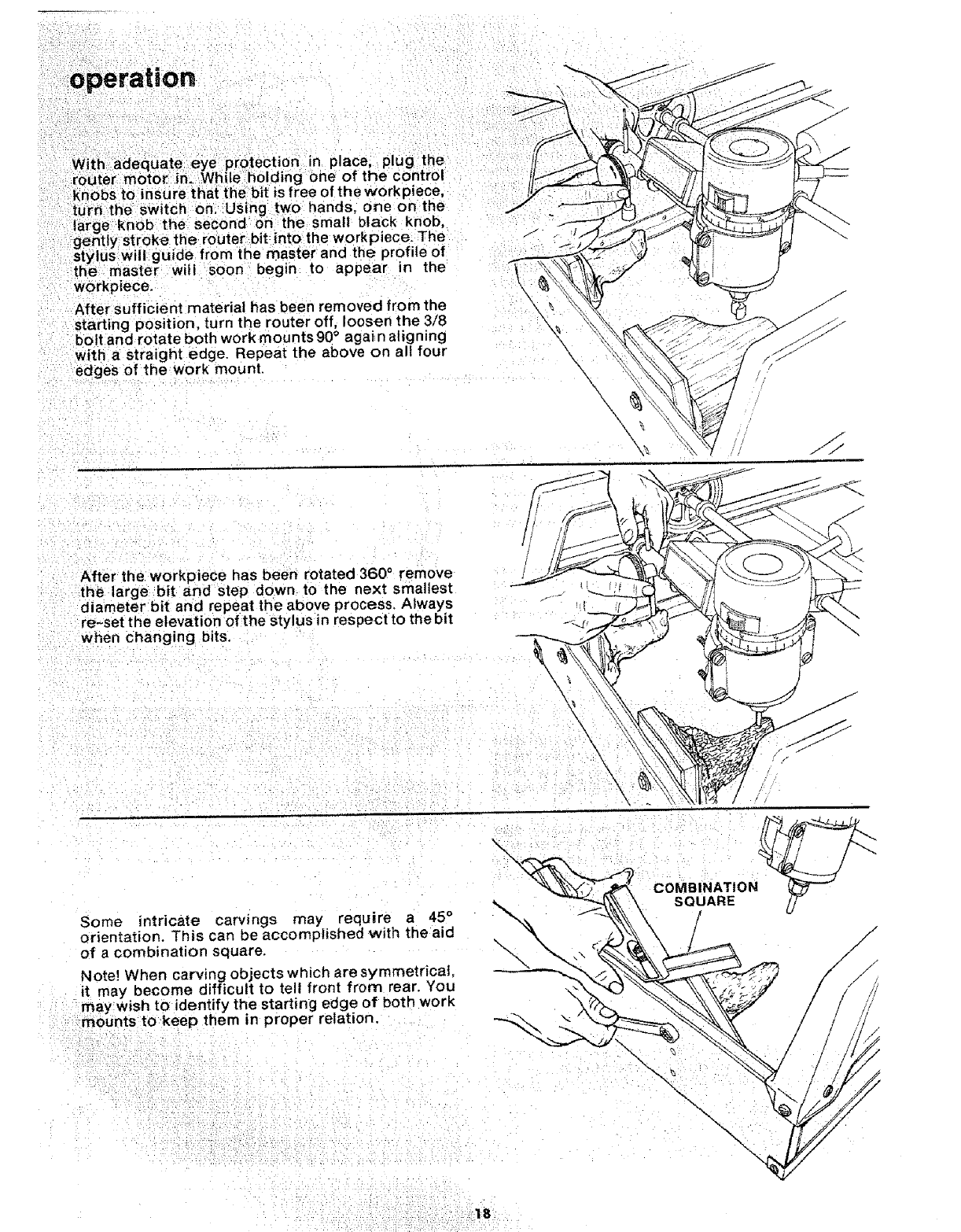
With adequate eye protection in place, plug the
router motor in. While holding one of the Control
knobs to insure that the bit is free of the workpiece,
turn the switch on. Using two hands, one on the
large knob the second on the small black knob,
gently stroke the router bit into the workpiece. The /"
stylus will guide from the master and the profile of
the master will soon begin to appear in the
workpiece.
After sufficient material has been removed from the
starting position, turn the router off, loosen the 3/8
bolt and rotate both work mounts 90° aga} n aligning
with a straight edge. Repeat the above on all four
edges of the work mount.
After the workpiece has been rotated 360 °remove
the large bit and step down to the next smallest .....
diameter bit and repeat the above process. Always
re-set the elevation of the stylus in respect to the bit _-_z,
when changing bits.
Some intricate carvings may require a 45°
orientation. This can be accomplished with the aid
of a combination square.
Note! When carving objects which are symmetrical,
it may become difficult to tell front from rear. You
may Wish to identify the starting edge of both work
mounts to keep them in proper relation.
\
\\
\
BINATION
SQUARE
/
-%
\\\
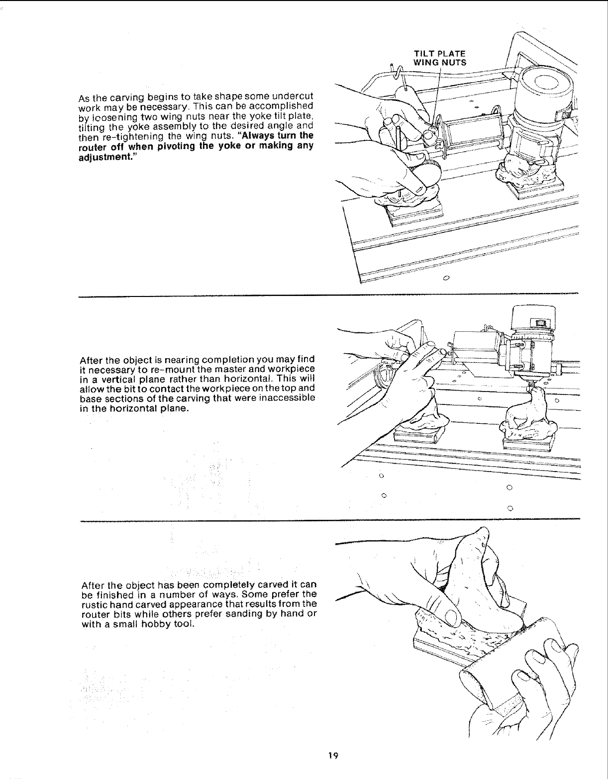
As the carving begins to take shape some undercut
work may be necessary. This can be accomplished
by loosening two wing nuts near the yoke tilt plate,
titting the yoke assembly to the desired angle and
then re-tightening the wing nuts. "Always turn the
router off when pivoting the yoke or making any
adjustment,"
TILT PLATE
WING NUTS
After the object is nearing completion you may find
it necessary to re-mount the master and workpiece
in a vertical plane rather than horizontal. This witl
allow the bit to contact the workpiece on the top and
base sections of the carving that were inaccessible
in the horizontal plane.
{3
0
©
©
After the object has been completely carved it can
be finished in a number of ways, Some prefer the
rustic hand carved appearance that results from the
router bits while others prefer sanding by hand or
with a small hobby too[.
\
!9
ii" n
operatlo
After the desired finish s achieved, additional detail
can' be addedw th hand sculpturing tools ora small
engraving tool.
Remove:the workpiece and master from the work
mount and if glued, any residue can be removed
from: the work mounts or workpieces with sand
paper,
/
/
SIGN MAKING
Signs can be duplicated from originals or
reproduced from a drawing. The Recreator will
carve signs upto 10 inches wide and 24 inches long
or even longer if there is sufficient room for the s_gn
to overhang the fro nt and rear shelf boards.
Place the two inner shelf boards between the front
and rear shelf boards with their surfaces flush tothe
top edge of the front and rear shelf board. Secure
the two inner shelf boards with the shelf brackets,
pan head screws and nuts.
Using a piece Of plywood, masonite or particle
board larger then the drawing, tape the drawing Of
the sign to this back-up board.
Select a workpiece cut to the desired final size of the
sign. Redwood is an excellent and relatively
inexpensive material to use for sign making.
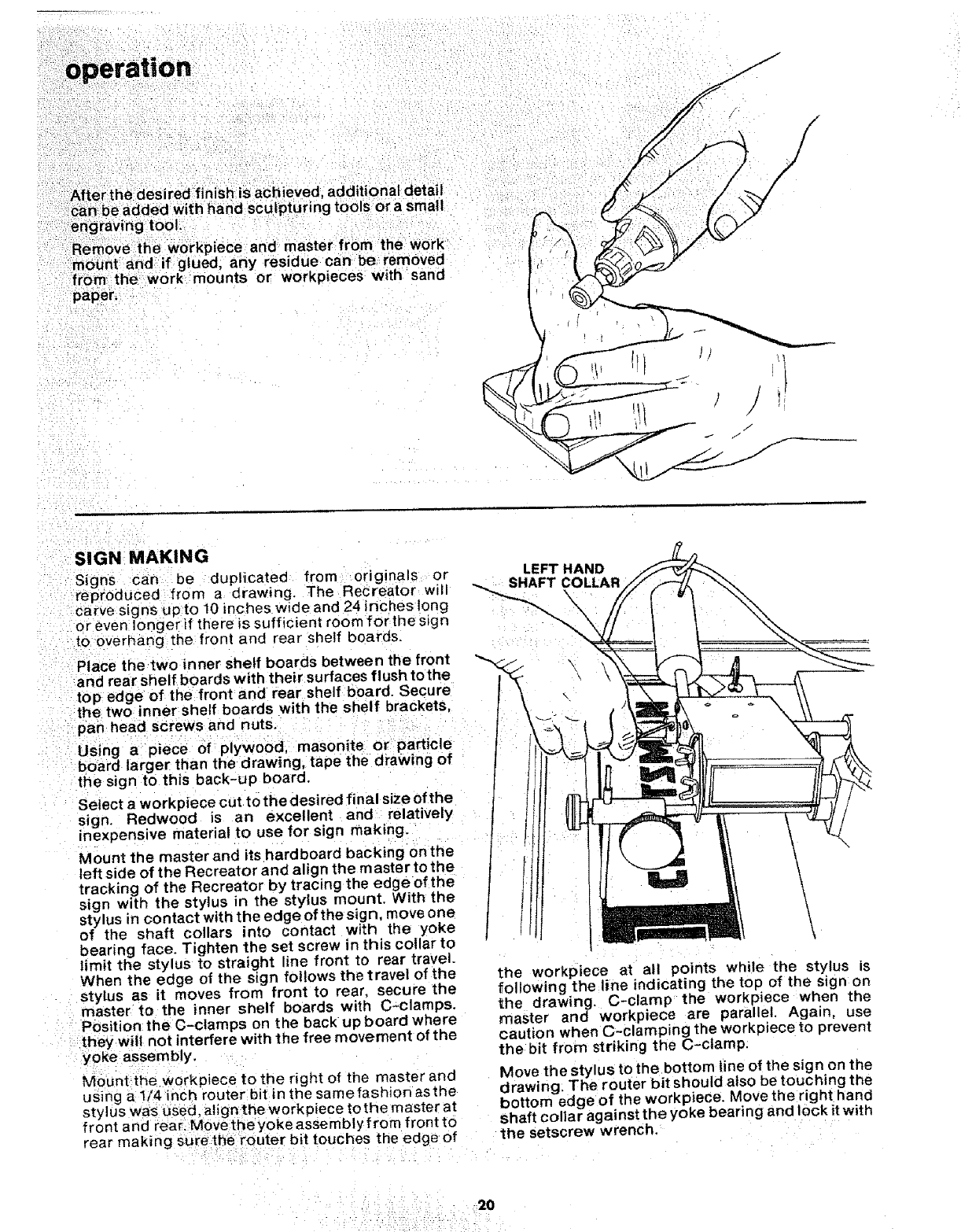
Mow nt the master and its hardboard backing on the
left side of the Recreator and align the m aster to the
tracking of the Recreator by tracing the edge of the
sign with the stylus in the stylus mount. With the
stylus in contact with the edge of the sign, move one
of the shaft collars into contact with the yoke
bearing face. Tighten the set screw in this cellar to
limit the stylus to straight line front to rear travel.
When the edge of the sign follows the travel of the
stylus as it moves from front to rear. secure the
master to the inner shelf boards with C-clamps.
Position the C-clamps on t he back up board where
they will not interfere with the free movement of the
yoke assembly.
Mount the workpiece to the right of the master and
using a t/4 inch router bit in the same fashion asthe
stylus was used, alignthe workpiece tothe master at
front and rearlMovetheyoke assembly from front to
rear making sure the router bit touches the edge of
LEFT HAND
SHAFT COLLAR
\
\\
the workpiece at all points while the stylus is
following the line indicating the top of the sign on
the drawing. C-clamp the workpiece when the
master and workpiece are parallel. Again, use
caution when C-clamping the work piece to prevent
the bit from striking the C-clamp.
Move the sty lus to the bottom line of the sign on the
drawing; The router bit should also be touching the
bottom edge of the workpiece. Move the right hand
shaft collar against the yoke bearing and lock it with
the setsc few wrench,
2O
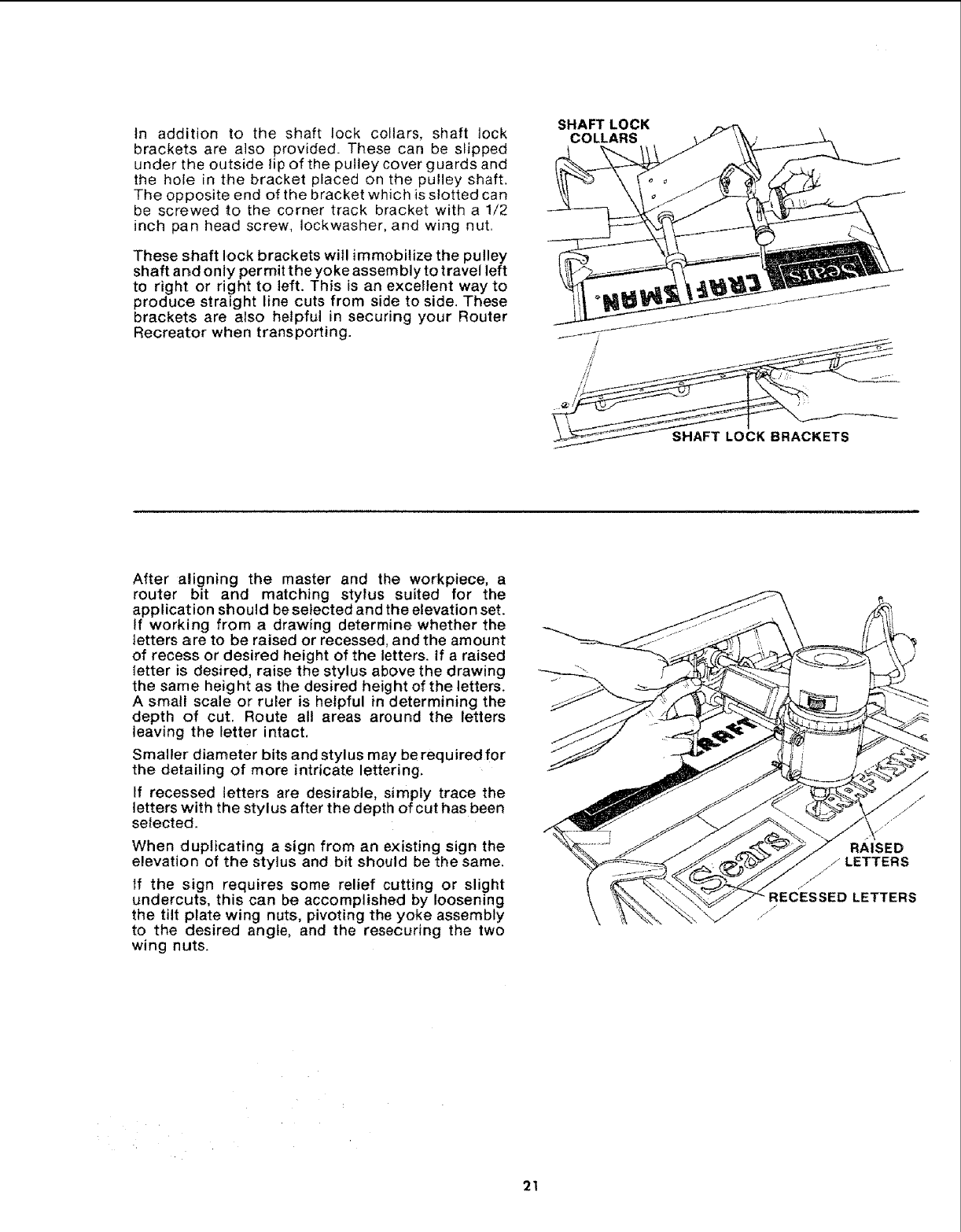
tn addition to the shaft lock collars, shaft lock
brackets are also provided. These can be slipped
under the outside tip of the pulley cover guards and
the hole in t:he bracket placed on the pulley shaft.
The opposite end of the bracket which is slotted can
be screwed to the corner track bracket with a 1/2
inch pan head screw, Iockwasher, and wing nut
These shaft lock brackets will immobilize the pulley
sh aft and only permit the yoke assem bly to travel left
to right or right to left. This is an excellent way to
produce straight line cuts from side to side. These
brackets are also helpful in securing your Router
Recreator when transporting.
SHAFT LOCK
COLLARS
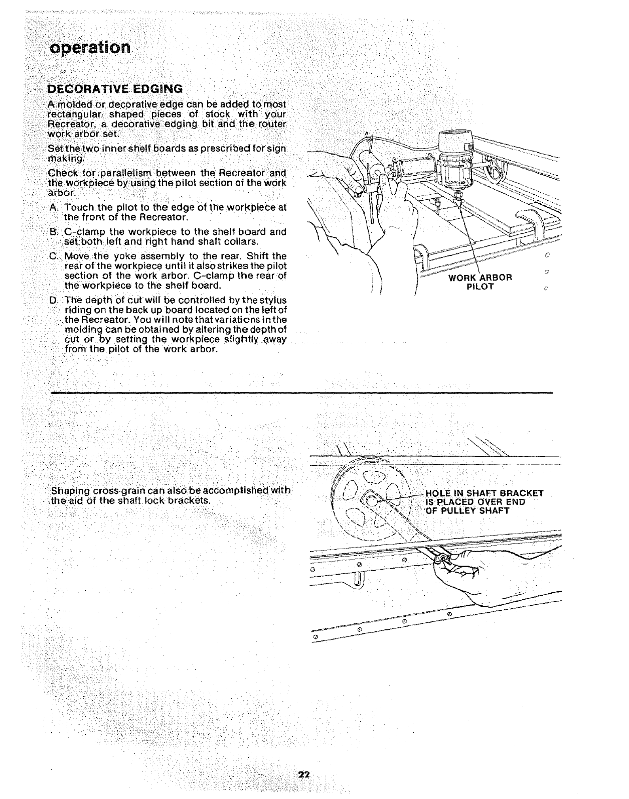
After aligning the master and the workpiece, a
router bit and matching stylus suited for the
application should be selected and the elevation set.
If working from a drawing determine whether the
_etters are to be raised or recessed, and the amount
of recess or desired height of the letters. If a raised
Ietter is desired, raise the stylus above the drawing
the same height as the desired height of the letters.
A small scale or ruler is helpful in determining the
depth of cut. Route all areas around the letters
leaving the letter intact,
Smaller diameter bits and stylus may be required for
the detailing of more intricate lettering,
If recessed letters are desirable, simply trace the
letters with the stylus after the depth of cut has been
selected.
When duplicating a sign from an existing sign the
elevation of the stylus and bit should be the same.
If the sign requires some relief cutting or slight
undercuts, this can be accomplished by loosening
the tilt plate wing nuts, pivoting the yoke assembly
to the desired angle, and the resecuring the two
wing nuts.
RAISED
JLETTERS
RECESSED LETTERS
F
/ /
21
i
operat on
iATIVE EDGING
Amolded or decorative-edge can be added to most
rectangular shaped pieces of stock with your
" Recreator, a decorative edging bit and the router
work arbor set; i :
Set the two inner shelf boards as prescribed for sign
making,
Check :for parallelism between the Recreator and
the workpiece by us ng the pilot section of the work
arbor.
A. Touch the pilot to the edge of the workpiece at
the front of the Recreator.
B.-C-clamp the work_)iece to the shelf board and
set both left and right hand shaft collars.
C. Move the yoke assembly to the rear. Shift the
rear of the workpiece until it also strikes the pilot
section of the work arbor. C-clamp the rear of
the workpiece to the shelf board.
D. The depth of cut will be controlled by thestylus
riding on the back up board located on the left of
the Recreator. You will note that variations in the
molding can be obtained by altering the depth of
cut or by setting the workpiece slightly away
from the pilot of the work arbor.
\WORK ARBOR
PILOT
Shaping cross grain can also be accomplished with
the aid of the shaft lock brackets. OLE IN SHAFT BRACKET
LACED OVER END
OF PULLEY SHAFT
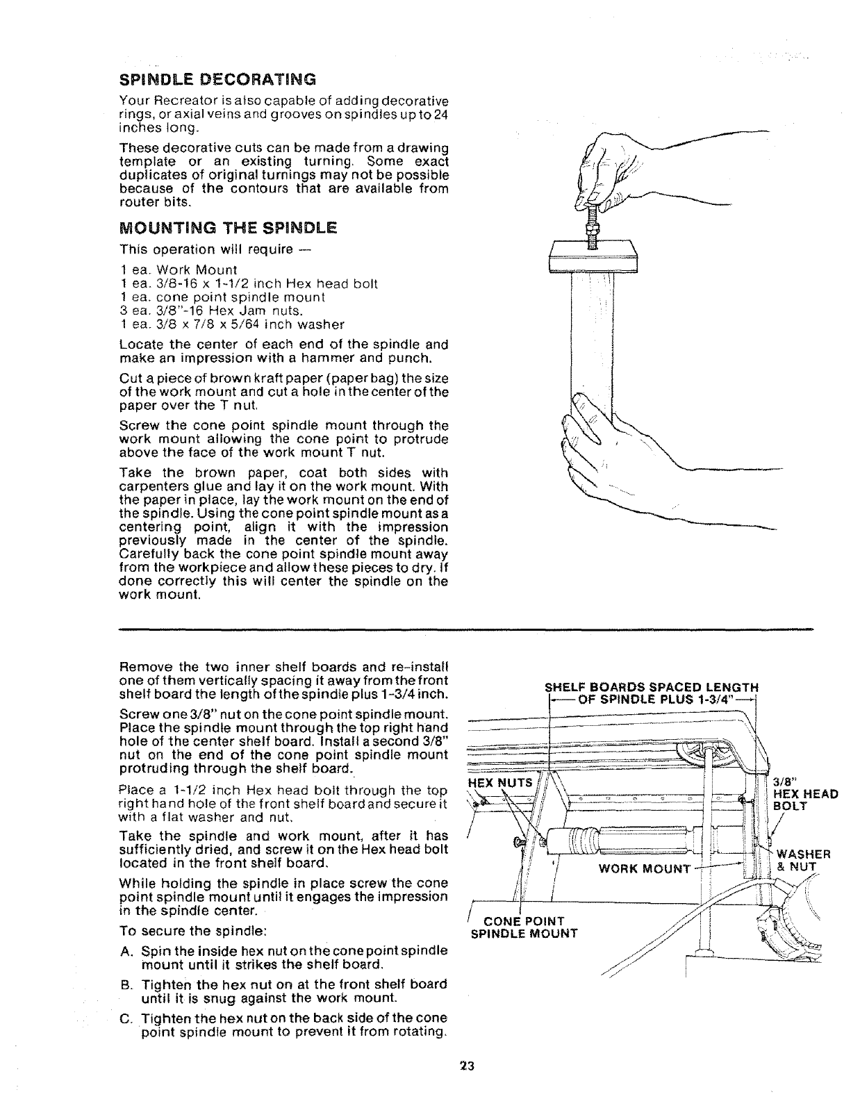
SPINDLE DECORATnNG
Your Recreator is also capable of adding decorative
rings, or axial veins and grooves on spindles up to 24
inches long_
These decorative cuts can be made from a drawing
template or an existing turning, Some exact
duplicates of original turnings may not be possible
because of the contours that are available from
router bits,
MOUNTING THE SPINDLE
This operation will require --
1 ca. Work Mount
1 ca. 3/8-!6 x 1-1/2 inch Hex head bolt
1 ca. cone point spindle mount
3 ca. 3/8"-16 Hex Jam nuts.
1 ca. 3/8 x 7/8 x 5/64 inch washer
Locate the center of each end of the spindle and
make an impression with a hammer and punch.
Cut a piece of brown kraft paper (paper bag) the size
of the work mount and cut a hole in the center of the
paper over the T nut,
Screw the cone point spindle mount through the
work mount allowing the cone point to protrude
above the face of the work mount T nut.
Take the brown paper, coat both sides with
carpenters glue and lay it on the work mount. With
the paper in place, lay the work mount on the end of
the spindle. Using the cone point spindle mount as a
centering point, align it with the impression
previously made in the center of the spindle.
Carefully back the cone point spindle mount away
from the workpiece and allow these pieces to dry. If
done correctly this will center the spindle on the
work mount.
• f
Remove the two inner shelf boards and re-install
one of them vertically spacing it away fromthe front
shelf board the length of the spindle plus 1-3/4 inch.
Screw one 3/8" nut on the cone point spindle mount.
Place the spindle mount through the top right hand
hole of the center shelf board. Install a second 3/8"
nut on the end of the cone point spindle mount
protruding through the shelf board.
Place a 1_1/2 inch Hex head bolt through the top
rig ht ha nd hole of the front shelf board and secure it
with a flat washer and nut,
Take the spindle and work mount, after it has
sufficiently dried, and screw it on the Hex head bolt
located in the front shelf board,
While holding the spindle in place screw the cone
point spindle mount until it engages the impression
in the spindle center.
To secure the spindle:
A. Spin the inside hex nut on the cone point spindle
mount until it strikes the shelf board.
B, Tighten the hex nut on at the front shelf board
until it is snug against the work mount.
C, Tighten the hex nut on the back side of the cone
point spindle mount to prevent it from rotating,
HEX NUTS
SHELF BOARDS SPACED LENGTH
=F SPINDLE PLUS
CONE POINT
SPINDLE MOUNT
WORK MOUNT
i
I
HEX HEAD
BOLT
"WASHER
&NUT
\
23
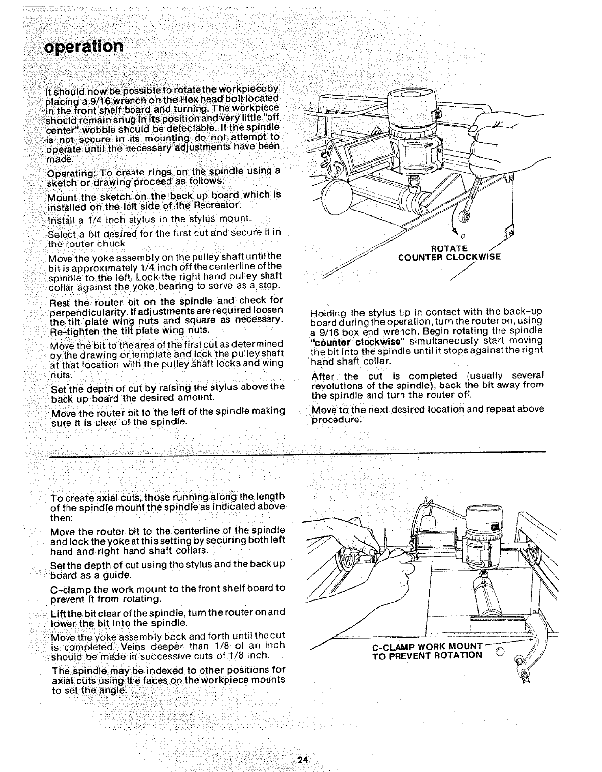
Jld now be pbsSible to rotate the workpiece by
L9/16 wrench on theHex head bolt located
center wobble should be etectable. If the spindle
:is not secure in its mounting do not attempt to
operate until the necessary adjustments have been
made.
Mount the sketch on the back up board which is
installed on the left side of the Recreator.
Install a 1/4 inch stylus in the stylus mount.
Select a bit desired for the first cut and secure it in
the router chuck.
Move the yoke assembly on the pulley shaft until the
bit is approximately 1/4 inch off the centertine of the
spindle to the left. Lock the right hand putley shaft
collar against the yoke bearing to serve as a stop,
Rest the router bit on the spindle and check for
perpendicularity. If adjustments are required loosen
the tilt plate wing nuts and square as necessary.
Re-tighten the tilt plate wing nuts.
Move the bit to the area of the first cut as determined
by the drawing or template and lock the pulley shaft
at that location with the pulley shaft locks and wing
n uts.
Set the depth of cut by raising the stylus above the
back up board the desired amount.
Move the router bit tothe left of the spindle making
sure it is clear of the spindle.
f
ROTATE t"
COUNTER CLOCKWISE
f
/
/
/
Holding the stylus tip in contact with the back-up
board during the operation,tu rn the router on. using
a 9/16 box end wrench, Begin rotating the spindle
"counter clockwise" s_multaneousty start moving
the bit into the s pindle until it stops against the right
hand shaft collar.
After the cut is completed (usually several
revolutions of the spindle), back the bit away from
the spindle and turn the router off.
Move to the next desired location and repeat above
procedure.
To create axia cuts, those running along the length
of the spindle mount the spind e as indk_ated above
then:
Move the router bit to the centerline of thespindte
and lock the yoke at this setting by securing both left
hand and right hand shaft collars.
Set the depth of cut usi ng the stylus and the back up
board as a guide.
C-clamp the work mount to the front shelf board to
prevent _t from rotating.
Liftthe bit clear of the spindle, turn tt_e router on and
lower the bit into the spindle.
Move the yoke assembly back and forth until thecut
is €ompleted, Veins deeper than 1/8 of an inch
should be made in successive cuts of 1/8 inch.
J
/ jjj i
L
C-CLAMP WORK MOUNT_
TO PREVENT ROTATION O

recommended accessories
ITEM CAT. NO.
Leg Set ................................ 9-22238
Recreator Bit Assortment ................ 9-2t 216
Casters ................................ 9-22208
Face Shield ............................ 9-18613
Portable Electric Tool Handbook .......... 9-2949
The above recommended accessories are current
and were available at the time this manual was
printed,
25
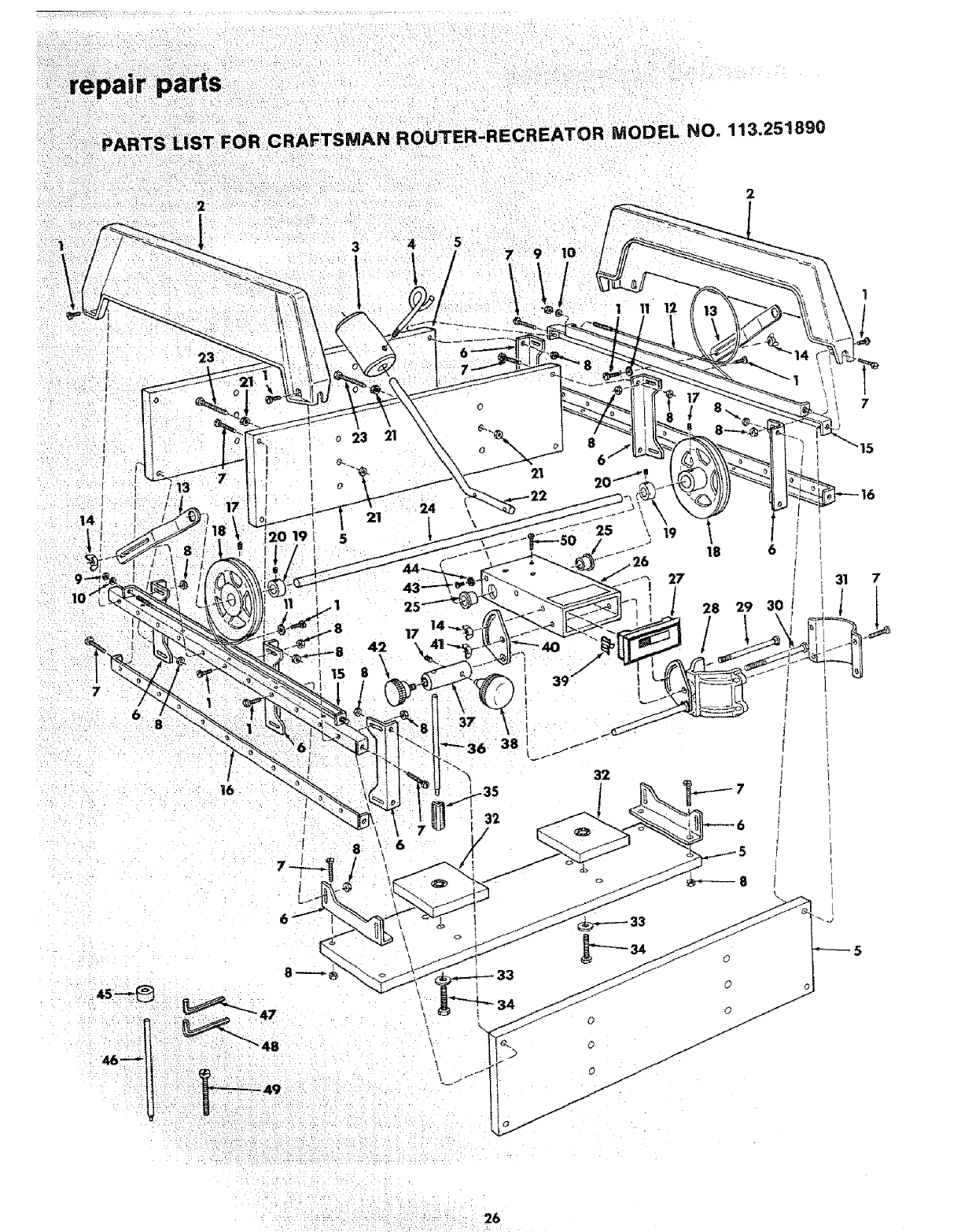
PARTS LIST FOR CRAFTSMAN ROUTER*RECREATOR MODEL NO. 113.251890
"2
2
I
19
o23
0
21
5
42
15 8
4
25
17
24
0
21
37
I32
8
6
25
39 /
32
1 11 12
_26
I
is 6
27
28 29 30
/
-7
31
4s--@ _47
°2! i:
\\
\
33
0
O
O
o0
/
0j//
J
J
J
J
J
J
7
15
26
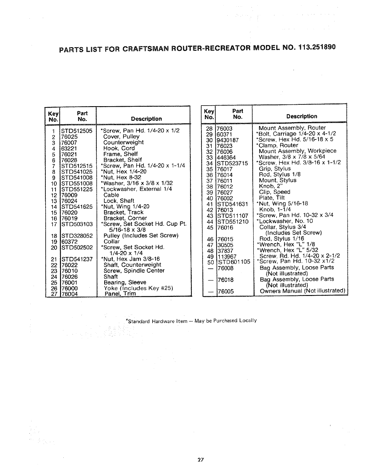
PARTS LIST FOR CRAFTSMAN ROUTER-RECREATOR MODEL NO. 113.251890
Key
NO.
1
2
3
4
5
6
7
8
9
10
11
12
!3
!4
!5
16
17
18
19
20
21
22
23
24
25
26
27
Part
No.
--i
ST D512505
176025
76007
63221
76021
76028
STD512515
STD541025
STD54!008
STD551008
STD551225
76009
76024
STD541625
76020
'76019
STD503103
STD328052
60372
STD502502
STD541237
76022
76010
76026
76001
76000
76004
Description
,p=,,,,=
*Screw, Pan Hd, I/4-20 × 1/2
Cover, Pulley
Counterweight
Hook, Cord
Frame, Shelf
Bracket, Shelf
*Screw, Pan Hd. 1/4-20 x 1-1/4
*Nut, Hex 1/4-20
*Nut, Hex 6-32
*Washer, 3/16 x 3/8 x 1/32
*Lockwasher, External 1/4
Cable
Lock, Shaft
*Nut, Wing 1/4-20
Bracket, Track
Bracket, Corner
*Screw, Set Socket Hd. Cup Pt.
5/16-18 x 3/8
Puiley (includes Set Screw)
Collar
*Screw, Set Socket Hd.
1/4-20 x t/4
*Nut, Hex Jam 3/8-16
Shaft, Counterweight
Screw, Spindle Center
Shaft
Bearing, Sleeve
Yoke ('Includes Key #25)
........Panel, Trim
Key
No.
_"28'
29
30
31
32
33
34
35
36
37
38
39
40
4!
42
43
44
45
46
47
48
49
5O
Part
No.
76003
60371
9430187
76023
76006
446364
ST D5237 ! 5
76017
76014
76011
760!2
76027
76002
STD541631
76013
STD511107
STD551210
760I 6
76015
30505
37837
113967
STD601105
76008
76018
76005
Description
Mount Asssembly, Router
*Bolt, Carriage 1/4-20 x 4-1/2
*Screw, Hex Hd. 5/t6-18 x 5
*Clamp, Router
Mount Assembly, Workpiece
Washer, 3/8 x 7/8 x 5/64
*Screw, Hex Hd. 3/8-t6 x !-1/2
Grip, Stylus
Rod, Stylus 1/8
Mount, Stylus
Knob, 2"
CIip, Speed
Plate, Tilt
*Nut, Wing 5/16-18
Knob, I-1/4
*Screw, Pan Hal. 10-32 x 3/4
*Lockwasher, No. 10
Collar, Stylus 3/4
(Includes Set Screw)
Rod, Stylus 1/16
*Wrench, Hex "L" 1/8
*Wrench, Hex "L" 5/32
Screw, Rd. Hal. t/4-20 x 2-1/2
*Screw, Pan Hd. 10-32 xl/2
Bag Assembly, Loose Parts
(Not illustrated)
Bag Assembly, Loose Parts
(Not illustrated)
Owners Manual (Not illustrated)
*Standard Hardware Item May be Purchased Locally
27
ears i
SERVaCE
MODEL NO.
113.251890
HOW TO ORDER
REPAnR PARTS
Part No. 76005
ROU'rER-RECREAIOR
Now that you have purchased your Router-Recreator,
should a need ever exist for repair parts or service, simply
contact any Sears Service Center and most Sears, Roebuck
and Co. stores. Be sure to provide all pertinent facts when
you call or visit.
The model number of your Router-Recreator will be found
on a plate attached to the yoke assembly.
WHEN ORDERING REPAIR PARTS, ALWAYS GIVE THE
FOLLOWING INFORMATION:
PART NUMBER
MODEL NUMBER
113.251890
PART DESCRIPTION
NAME OF 1TEM
ROUTER-RECREATOR
Ail parts listed may be ordered from any Sears Service
Center and most Sears stores. If the parts you need are not
stocked locally, your order will be electronically
transmitted to a Sears Repair Parts Distribution Center for
handling,
Sold by SEARS, ROEBUCK AND CO., Chicago, IL. 60684 U.S.A.
Form NO. SP4375-2 Printed in U.S.A. 3/83
