Craftsman 113298720 User Manual 10 INCH TABLE SAW Manuals And Guides L0804013
CRAFTSMAN Saw Table Manual L0804013 CRAFTSMAN Saw Table Owner's Manual, CRAFTSMAN Saw Table installation guides
User Manual: Craftsman 113298720 113298720 CRAFTSMAN 10-INCH TABLE SAW - Manuals and Guides View the owners manual for your CRAFTSMAN 10-INCH TABLE SAW #113298720. Home:Tool Parts:Craftsman Parts:Craftsman 10-INCH TABLE SAW Manual
Open the PDF directly: View PDF ![]() .
.
Page Count: 52
[Save ThisManual
For F_ure R_erence
owners
manual
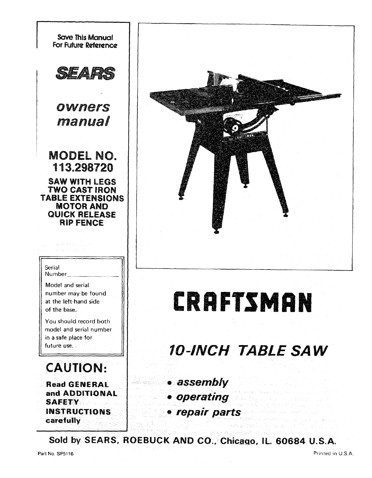
MODEL NO.
113.298720
SAW WiTH LEGS
TWO CAST iRON
TABLE EXTENSIONS
MOTOR AND
QUICK RELEASE
RiP FENCE
Serial
Number
Model and serial
number may be found
at the left-hand side
of the base.
You should record both
model and serial numoer
in a safe place for
future use.
CAUTION:
Read GENERAL
and ADDITIONAL
SAFETY
INSTRUCTIONS
carefully
Sold by SEARS,
Part No SP5!16
IO-INCH TABLE SAW
.assembly
.operating
erepair parts
ROEBUCK AND CO., Chicaqo, IL. 60684 U.S.A.
P_irqed in US.A.
FULL ONE YEAR 'WARRANTY ON CRAFTSMAN TABLE SAW
If within one year from the date of purchase, this Craftsman Table Saw fails due to a defect in
material or workmanship, Sears will repel r it, free of charge. This warranty applies only while
this product is in use in the United States.
WARRANTY SERVICE IS AVAILABLE BY SIMPLY CO NTACTI NG THE NEAREST SEARS
SERVICE CENTER/DEPARTMENT THROUGHOUT THE UNITED STATES.
This warranty gives you specific legal rights, and you may also have other rights which vary
from state to state.
SEARS, ROEBUCK AND CO,, Dept. 698/731A, Sears Tower. Chicago, IL 60684
SAFETY INSTRUCTIONS FOR TASLE SAW
Safety is a combination of common sense, slaying
alert and knowing how your table saw works. Read
this manual to understand this saw.
BEFORE USING THE SAW:
WARNING: TO AVOID MISTAKES THA'Ir L;OULD
CAUSE SERIOUS, PER MANENT INJURY, DO NOT
PLUG THE SAW IN UNTIL THE FOLLOWING STEPS
HAVE BEEN SATISFACTORILY COMPLETED:
ed for 120 volt 15 amp circuits. The green
conductor in the cord is the grounding wire. To
avoid electrocution, NEVER connect the green
wire to a live terminal.
5. To avoid injury from electrical shock, make sure
your fingers do not touch the plug's metal prongs
when plugging in or unplugging the saw.
6. To avoid back n.ury, get help or use recom-
mended casters when you need to move the saw.
Always get help if you need to lift the saw. Hold
the saw close to your body. Bend your knees so
you can lift with your legs, not your back.
NEVER STAND ON TOOL. Serious injury could
occur if the tool t_ps or you accidentally hit the
cutting tool. Do not store anything above or near
the tool where anyone might stand on the tool to
reach them.
1. Assembly and alignment (See pages9 - 21 ).
2. Learn the use and function of the ON-OFF switch,
guard, spreader, anti-kickback device, miter gauge, 7.
fence, table insert and blade elevation and bevel
controls. (See page 22)
3. Review and understanding of all safety instructions
and operating procedures in this manual. BEFORE EACH USE:
4. Review of the maintenance methods for this saw. 1. Inspect your saw.
(See page 41) a. To avoid injury from accidental starting, unplug
Read the following DANGER label found on the front of the saw, turn the switch off and remove the
the saw: switch key before raising or removing the
DANGER IFOR YOUR OWN SAFETY:
REA, DAND UNDERSTAND OWNERS MANUAL BEFORL;. OPERATING MACHINE
2 USE_;AWBLAOEGIJARDFOR ''THRUSAWING' 6 DO NOT PERFORM _) _ _E_
3_(E[PHANOS;OUY OF PATH OF SAWBLAOE ? NEVERREACHAROUNDOROVEflSAWBLAD_
4 IJSE A"pUSH _'r_CK' WIltON R_:OIJIR_O
W_RNI_G: 'J_.£ 12o VOLT I$ _.MP BRANCH CIrCUiT AND UE>E1_ AMP TIMI_ DEL_,V FUSE
WHEN INSTALLING OR MOVING THE SAW:
1. AVOID DANGEROUS ENVIRONMENT. Use the
saw in a dry place protectedfrom rain. Keep work
2. To avoidinjury from unexpected saw movement:
b. Support the saw so the table is level and the
saw does not rock.
C Bolt the saw to the floor if it tends to stip walk;
or slide during normal use. ,
d. When Using table extensions Over 24;'wide _n
any side of ;_hesaw, bo t the saw to the floor6r
prop Upthe outer end" of the extension from
the floor to keep the saw from tipping,
3 put the saw where neither operators or bystand-
ers must stand in line with the saw blade.
4. 'GROUND THE SAW- This saw has an approved
3-conductor cord and a3-prong grounding type
plug. The plug fits grounding type outlets design-
guard, changing the cutting tool. changing
the setup or adjusting anything.
b. Check for alignment of moving parts, binding
of moving parts, breakage of parts, mounting,
and any other conditions that may affect the
way it works. If any part is missing, bent, or
broken in anyway, or any electrical parts don't
work properly, turn the saw off and unplug the
saw.
c. Replace damaged, missing, or failed parts
before using the saw again.
d. Use the sawblade guard, spreader, and anti-
kickback pawls for any thru-sawing (wher)ever
the blade comes through the top of the work-
piece). Make sure the pawls work properly.
Make sure the spreader is in line with the
sawblade.
e. REMOVE ADJUSTING KEYS AND
WRENCHES. Form habit,of checking for and
removing keys and adjusting wrenches from
tool belt;re turning it on: ....
f. To avoid injury from jams, slips or thrown pieces
(kickback an(Jthrowback)_
1. USE ONLY RECOMMENDED ACCESSO:
R|ES. Follow the instructions that come with
the accessories. Consult the owners manual
!or recommended accessories. The use of
improper accessories may cause risk of injury
to persons.
2. Choose the right blade orcutting accessory
for the material and the type of cutting you
plan to do.
3. Never use grinding wheels, abrasive cut-off
wheels, friction wheels (metal slitting
blades) wire wheels or buffing wheel. They
can fly apart explosively.
4. Choose and inspect your cutting tool care-
fully.
a. To avoid cutting tool failure and thrown
shrapnel (broken pieces of blade), use
only 10" or smaller blades or other cutting
tools marked for speeds of 3450 rpm or
higher.
b. Always use unbroken, balanced blades
designed to fit this saw's 5/8" arbor.
c. When thru-sawing, (making cuts where
the blade comes through the workpiece
top) always use a 10 inch diameter blade.
This keeps the spreader in closest to the
blade.
d. Do not overtighten arbor nut. Use arbor
wrenches to "snug" it securely.
e. Use only sharp blades with properly set
teeth. Consult a professional blade sharp-
ener when in doubt.
f. Keep blades clean of gum and resin.
5. Adjust table inserts flush with the table top.
NEVER use the saw without the proper
insert.
6. Make sure all clamps and locks are tight
and no parts have any excessive play,
2. KEEP WORK AREA CLEAN
a. Cluttered areas and benches invite accidents,
Floor must not be slippery from wax or
sawdus_
b. To avoid burns or ott_er fire damage, never use
the saw near flammable liauids, vapors or
gases.
Plan ahead to protect your eyes, hands, face.'
ears.
a. To avoid injury, don't do layout, assembly, or
setup work on the table while the blade is
spin ning. It could cut or throw anything hitting
the blade.
AVOID ACCIDENTAL STARTING - Make sure
switch is "OFF" before plugging saw in.
Plan your work
1. USE THE RIGHT TOOL - Don't force tool or
attachment to do a job it was not designed for.
2. Dress for safety:
-Do not wear loose clothing, gloves, neckties
or jewelry (rings, wristwatches). They can get
caught and draw you into moving parts.
- Wear nonslip footwear.
- Tie back long hair.
- Roll long sleeves above the elbow
- Noise levels vary widely. To avoid possible
hearing damage, wear ear plugs or muffs
when using saw for long periods of time.
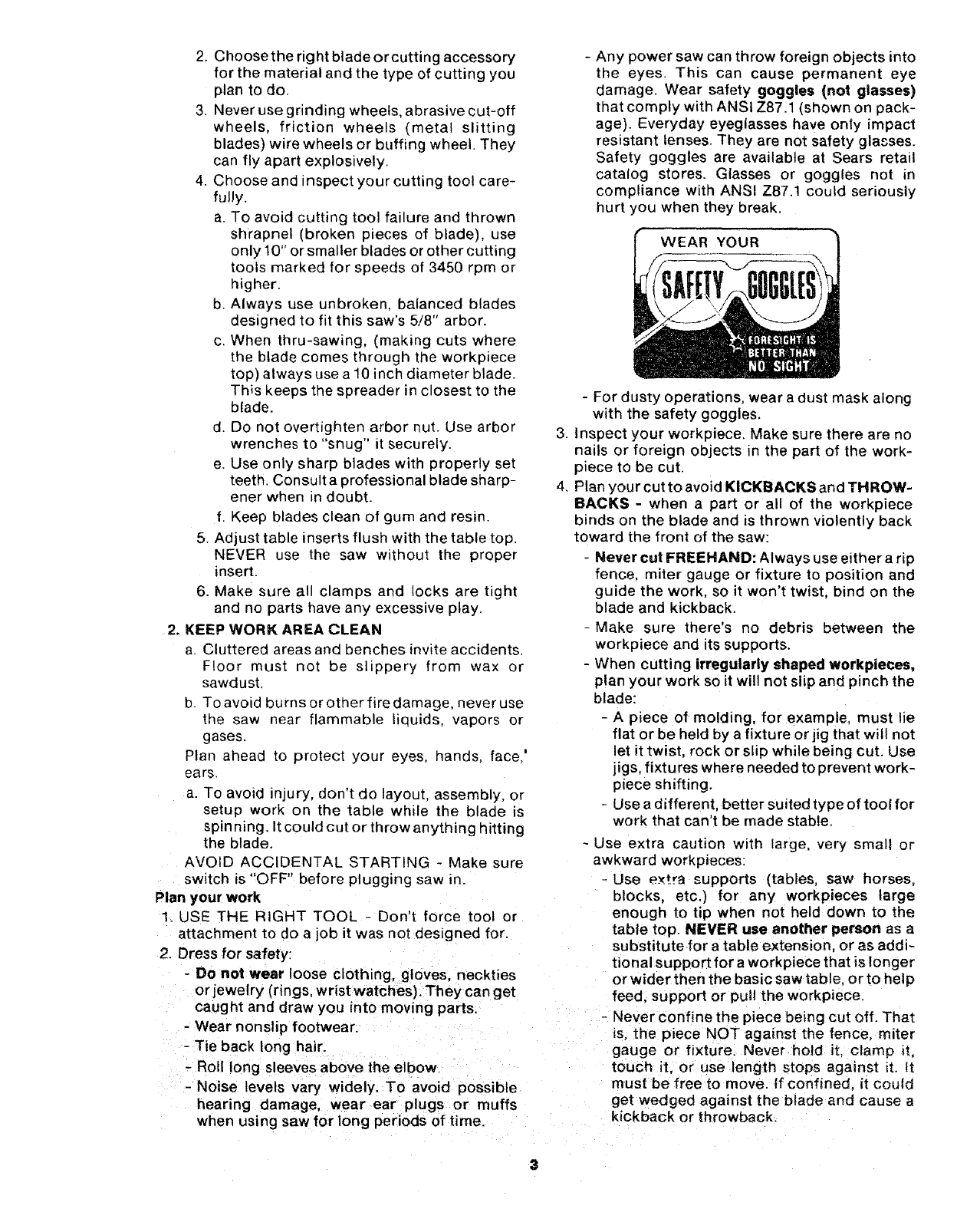
- Any power saw can throw foreign objects into
the eyes. This can cause permanent eye
damage, Wear safety goggles (not glasses)
that comply with ANSI Z87.1 (shown on pack-
age). Everyday eyeglasses have only impact
resistant lenses. They are not safety glasses.
Safety goggles are available at Sears retail
catalog stores. Glasses or goggles not in
compliance with ANSI Z87,1 could seriously
hurt you when they break.
WEAR YOUR
- For dusty operations, wear a dust mask along
with the safety goggles.
3. Inspect your workpiece. Make sure there are no
nails or foreign objects in the part of the work-
piece to be cut.
4. Plan your cut toavoid KICKBACKSand THROW-
BACKS - when a part or all of the workpiece
binds on the blade and is thrown violently back
toward the front of the saw:
-Never cut FREEHAND: Always use either a rip
fence, miter gauge or fixture to position and
guide the work. so it won't twist, bind on the
blade and kickback.
-Make sure there's no debris between the
workpiece and its supports.
- When cutting irregularly shaped workpieces,
plan your work so it will not slip and pinch the
blade:
- A piece of molding, for example, must lie
flat or be held by a fixture or jig that will not
let it twist, rock or slip while being cut, Use
jigs. fixtures where needed to prevent work-
piece shifting.
- Use a different, better suited type of tool for
work that can't be made stable.
- Use extra caution with large, very small or
awkward workpieces:
-Use extra supports (tables, saw horses,
blocks, etc.) for any workpieces large
enough to tip when not held down to the
table top. NEVER use another person as a
substitutefor a table extension, or as addi-
tional support for a workpiece that is longer
or wider then the basic saw table, orto help
feed. support or pull the workpiece.
-Never confine the piece being cut oft. That
is, the piece NOT against the fence, miter
gauge or fixture. Never hold it. clamp it,
touch it, or use length stops against it. tt
must be free to move. If confined, it could
get wedged against the blade and cause a
kickback or throwback.
- Never cut more than one workpiece at a
time.
-Never turn your table saw "ON" before
clearing everything except the workpiece
and related support devices off the table.
Plan the way you will push the workpiece through.
-NEVER putt the workpiece through. Start and
finish the cut from the front of the table saw.
-NEVER put your fingers or hands in the path of
the sawblade or other cutting tool.
-NEVER reach in back of the cutting tool with
either hand to hold down or support the work-
piece, remove wood scraps, or for any other
reason.
- Avoid hand positions where a sudden slip could
cause fingers or hand to move into a saw blade or
other cutting tool.
- DON'T OVERREACH. Always keep good footing
and balance.
- Push the workpiece against the rotation of the
blade. NEVER feed material into the cutting tool
from the rear of the saw.
- Always push the workpiece all the way past the
sawblade.
- As much as possible, keep you r face and body to
one side of the sawblade, out of line with a
possible kickback or throwback.
- NEVER turn the saw "ON" before clearing the
table of all tools, wood scraps, etc.. except the
werkpiece and related feed or support devices
for the cut planned.
WHENEVER SAW IS RUNNING
WARNING: DON'T LET FAMILIARITY (GAINED
FROM FREQUENT USE OF YOUR TABLE SAW)
CAUSE A CARELESS MISTAKE. ALWAYS
REMEMBER THAT A CARELESS FRACTION OF A
SECOND IS ENOUGH TO CAUSE A SEVERE
INJURY.
1. Before actually cutting with the saw watch it
while it runs for a short while. If it makes an
unfamiliar noise or vibrates a lot, stop immedi-
ately. Turn the saw off. Unplug the saw. Do not
restart until finding and fixing the problem.
,2. Make sure the top of the arbor or cutting tool
turns toward the front of the saw.
3. Set the cutting tool as low as possible for the cut
you're planning.
4. KEEPCHILDREN AWAY. All visitors should be
5. Let the blade reachfull speed before cutting.
c. Wait for all moving parts to stop.
d, Check blade, spreader and fence for proper
alignment before starting, again.
8. To avoid throwback of small, cut off pieces:
a. Use the guard assembly.
b. To remove pieces trapped inside the guard:
1. Turn saw off.
2. Remove switch key.
3. Unplug saw.
4. Wait for blade to stop before lifting the
guard.
additional instructions for
RiP TYPE CUTS
- NEVER use the miter gauge when ripping.
- Use a push stick whenever the fence is 2 to 6
inches from the blade. Use an auxiliary fence and
push block whenever the fence must be within 2
inches of the blade. (See "Basic Saw Operation
Using The Rip Fence" section.)
- Never rip anything shorter than 10" long.
-When using a push stick or push block, the
trailing end of the _)oard must be square. A push
stick or block against an uneven end could slip
off or push the work away from the fence.
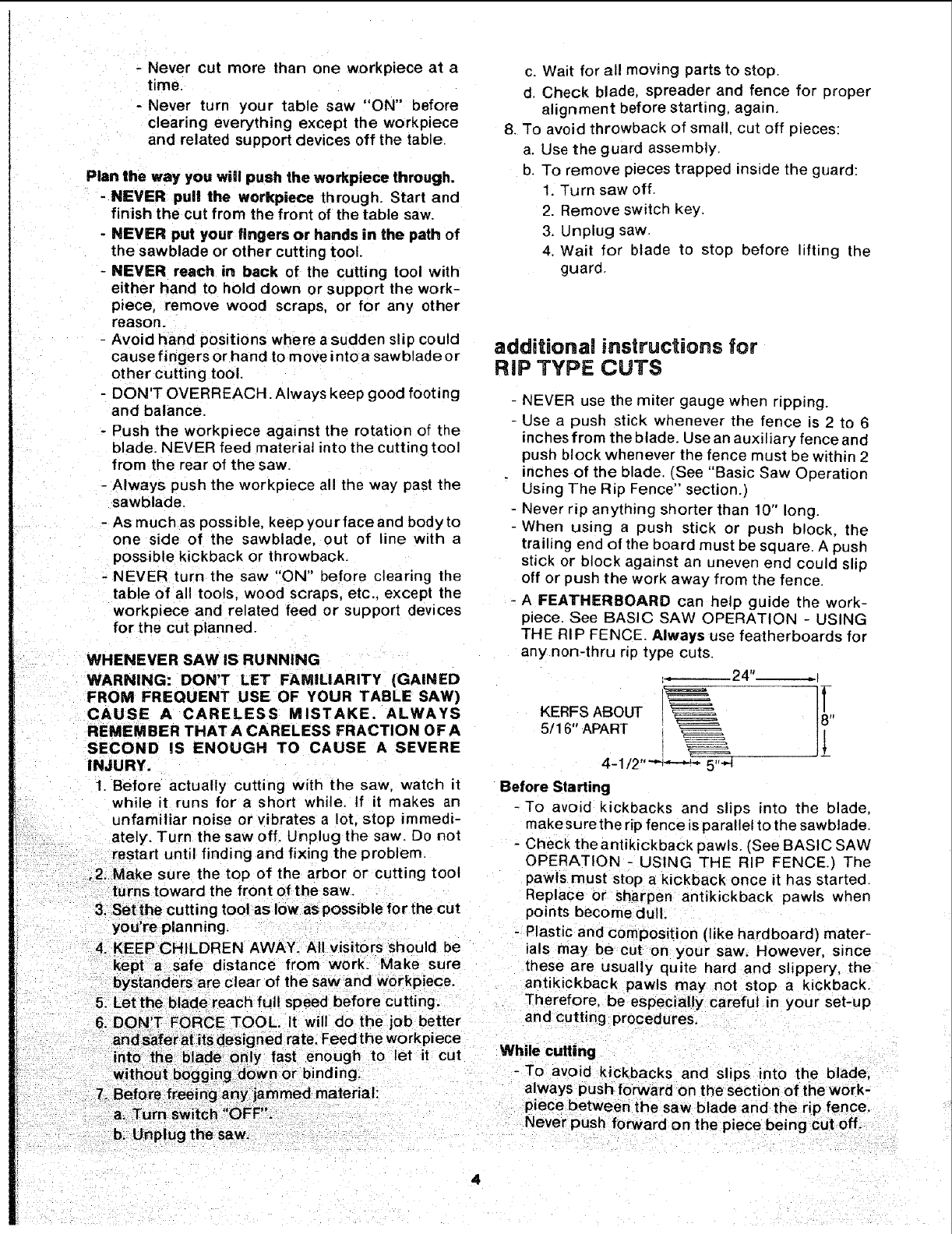
- A FEATHERBOARD can help guide the work-
piece. See BASIC SAW OPERATION - USING
THE RIP FENCE. Always use featherboards for
any non-thru rip type cuts.
,__24"___
KERFS ABOUT !_,
5/16" APART IJ_
4-1/2 '' _''_'.'-''_ 5
Before Starting
-To avoid kickbacks and slips into the blade,
make surethe rip fence is parallel to the sawblade.
- Check the antikickback pawls. (See BASIC SAW
OPERATION - USING THE RIP FENCE.) The
pawls must stop a kickback once it has started.
Replace or sharpen antikickback pawls when
points become dul t.
- Plastic and composition (like hardboard) mater-
ials may be cut on your saw. However, since
these are usually quite hard and slippery, the
antikickback pawls may not stop a kickback.
Therefore, be especially careful in your set-up
and cutting procedures.
6. DON TFORCE TOOL. It will do the job bette
and,safer at its designed rate. Feed the workpiece
into the blade only fast enough to let it cut While cutting
without bogging down or binding. -To avoid kickbacks and slips into the bade
always push forward on the section of the work-
addiUonai instructions for
CROSS CUT TYPE CUTS
Before starting
- NEVER use the rip fence when crosscutting.
-An auxiliary wood facing attached to the miter
gauge can help prevent workpiece twisting and
throwbacks. Attach it to the holes provided.
Make the facing long enough and big enough to
support your work, Make sure, however, it will
not interfere with the sawblade guard.
- Use jigs or fixtures to help hold any piece too
small to extend across the full length of the miter
gauge face during the cut. This lets you properly
hold the miter gauge and workpiece and hetps
keep your hands away from the blade.
While cutting
- To avoid blade contact, always hold the miter
gauge as shown in the BASIC SAW OPERA-
TIONS -USING THE MITER GAUGE.
BEFORE LEAVING THE SAW
1. Turn the saw off.
2. Wait for blade to stop spinning.
3. Make workshop child-proof. Lock the shop. Dis-
connect master switches. Remove the yellow
switch key. Store it away from children and
others not qualified to use the tool.
4. Unplug the saw.
GLOSSARY OF TERMS FOR WOODWORKING
Anti-Kickback Pawls (AKB)
Device which, when properly maintained, is design-
ed to stop the workpiece from being kicked back at
the operator during ripping operations.
Arbor
The shaft on which a cutting tool is mounted.
Crosscut
A cutting or shaping operation made across the
width of the workpiece.
Dado
A non-through cut which produces a square sided
notch or trough in the workpiece.
Featherboard
A device which can help guide workpqeces during np
type operations.
Freehand
Performing acut without using a fence, miter gauge,
fixture, hold down or other proper device to keep the
workpiece from twisting during the cut.
Gum
Asticky, sap based residue from wood products.
Heel
Misalignment of the blade.
Kerr
The amount of material removed by the blade in a
through cut or the slot produced by the blade in a
non-through or partial cut.
Kickback
An uncontrolled grabbing and throwing of the work-
piece back toward the front of the saw during a rip
type operation.
Leading End
The end of the workp_ece which during a r_p type
operation, is pushed into the cutting tool first.
Molding
Anon-through cut which produces a special shape
in the workpiece used for joining or decorat on.
Push Stick
A device used to feed the workpiece through the saw
during narrow ripping type operations and help
keep the operator's hands well away from the blade.
Push Block
A device used for ripping type operations too narrow
to allow use of a push stick.
Rabbet
A notch in the edge of a workpiece.
Resin
A sticky, sap base substance that has hardened.
Ripping
Acutting operation along the length of the work-
piece.
Revolutions Per Minute (RPM)
The number of turns completed by a spinning object
in one minute.
Sawblade Path
The area of the workpsece or table top directly in line
with the part of the workpiece which wil! be. or has
been, cut by the blade.
Set
The distance that the tip of the sawbJade tooth is
bent (or set) outward from the face of the blade.
Throw-Back
Throwing of pieces in a manner similar to a kickback.
Thru-Sawing
Any cutting operation where the blade extends
completely through the thickness of the workplece.
Trailing End
The workpiece end last cut bythe blade in a ripping
operation.
Workpiece
The item on which the cutting operation is being
done_ The surfaces of a workpiece are commonly
referred to as faces, ends, and edges.
MOTOR SPECIFICATIONS AN
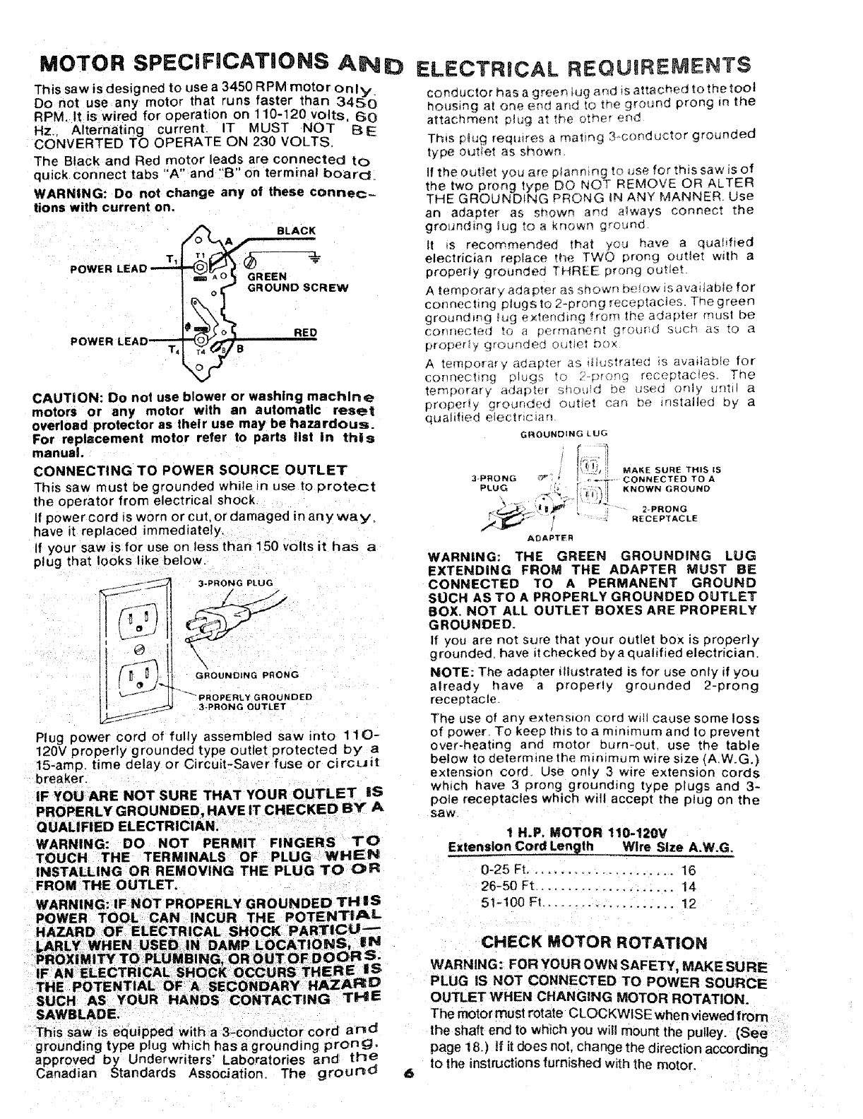
This saw is designed to use a 3450 RPM motor onmy.
Do not use any motor that runs faster than 345,0
RPM, It is wired for operation on 110-120 volts, 60
Hz.. Alternating current. IT MUST NOT BE
CONVERTED TO OPERATE ON 230 VOLTS.
The Black and Red motor leads are connected to
qu_ck connect tabs "A" and "g" on terminal board.
WARNING: Do not change any of these connec-
tions with current on.
POWER LEAD T_
POWER LEAD'---_ i
BLACK
REEN
"_ GROUND SCREW
IB RED
CAUTION: Do not use blower or washing machine
motors or any motor with an automatic reset
overload protector as their use may be hazardous.
For replacement motor refer to parts list in this
manual.
CONNECTING TO POWER SOURCE OUTLET
This saw must be grounded while in use to protect
the operator from electrical shock
If power cord is worn or cut, or damaged in any wa y,
have it replaced immediately.
If your saw is for use on less than 150 volts it has a
plug that looks like below.
3-PRONG PLUG
D
GROUNDING PRONG
GROUNDED
3-PRDNG OUTLET
Plug power cord of fully assembled saw into 11 0-
120V properly grounded type outlet protected by" a
15-amp. time delay or Circuit-Saver fuse or ci rcuit
breaker.
IF YOU ARE NOT SURE THAT YOUR OUTLET iS
PROPERLY GROUNDED, HAVE IT CHECKED BY A
QUALIFIED ELECTRICIAN.
WARNING: DO NOT PERMIT FINGERS TO
TOUCH THE TERMINALS OF PLUG WHEN
INSTALLING OR REMOVING THE PLUG TO CPR
FROM THE OUTLET.
WARNING: IF NOT PROPERLY GROUNDED THIS
POWER TOOL CAN INCUR THE POTENTIAL
HAZARD OF ELECTRICAL SHOCK PARTICU-
LARLY WHEN USED, IN DAMP LOCATIONS, iN
PROX|MITY TO rk_,,,,_U'S NG, OR OUT OF I)OOR S.
IF AN ELECTRICAL SHOCK OCCURS THERE IS
THE POTENTIAL OF ASECONDARY HAZARD
SUCH AS YOUR HANDS CC)NTACTING THE
SAWBLADE.
This saw is equipped with a3-conductor cord and
grounding type plug which has a grounding prong,
approved by Underwriters' Laboratories and the
Canadian Standards Association. The ground
ELECTRICAL REQUIREMENTS
conductor has a green _ug _ nd _sattached to the tOOt
housing a[ one _nd and _o the ground prong mtrle
attachrnent plu_ at tr_e otf_e _ end
Th_s p_ug rerau_res a rnat_ng 3-cunductor grounded
type outlet as sr_owf_
If the outlet you are planmng tc _Jsefor this saw is of
the two prong type DO NOT REMOVE OR ALTER
THE GROUNDING PRONG tN ANY MANNER. Use
an adapter as strewn and a_ways connect the
grounding _ug to a known ground
it _s recommended that y'ou have a qualified
electrician replace fh_ TWO prong outlet with a
properly grounded THREE ;_rong outlet.
A temperat, ado pter _s snown De_(_WtS avaliab;e for
connechnq ptugs to 2-prong receptacles. The green
ground ing Iug e×ter_din(_ f torn the aoa [)terrn us| be
corlr/f_,c|_(] t_ °) a _)ermanen! _!"©_rltJ S(;Ctq B5 [o a
proper_¥ _rt-_unded o(J'Je_ D()×
A temporary a(]aDter as _uusrrate(; m avadabte for
connecting plugs to 2-_)ronq receptacles The
ternp_}rarv adapt_:l ShOUld De use(] only _,n_tl a
properW _gro_Jnded out_et can be m_taHed oy a
qt_alified elec[nc_arl
GROUNDING LUG
MAK[ SURE THIS tS
3PRO_NG _ "._,_-. CONNECTED TD A
PLUG "* I' ;_")_i KNOWN GROUND
ADAPTER
WARNING: THE GREEN GROUNDING LUG
EXTENDING FROM THE ADAPTER MUST BE
CONNECTED TO A PERMANENT GROUND
SUCH AS TO A PROPERLY GROUNDED OUTLET
BOX, NOT ALL OUTLET BOXES ARE PROPERLY
GROUNDED.
If you are not sure that your outlet box is properly
g rounded, have it checked by a qualified electrician.
NOTE: The adapter dlustrated is for use only if you
already have a properly grounded 2-prong
receptacle
The use of any extension cord will cause some loss
of power_ To keep this to a minimum and to prevent
over-heating and motor burn-out use the table
below to determine the mm_mum w_re size (A.W.G.}
extension cord Use only 3 wire extension cords
which have 3 prong grounding type plugs and 3-
pole receptacles which will accept the plug on the
S_W.
1 H.P. MOTOR 110-120V
Extension Cord Length Wire Size A.W.G.
0-25 Ft...................... 16
26-50 Ft ..................... 14
51-100 FI .................... 12
CHECK MOTOR ROTATION
WARNING: FORYOUROWN SAFETY, MAKESURE
PLUG IS NOT CONNECTED TO POWER SOURCE
OUTLET WHEN CHANGING MOTOR ROTATION.
The motor must rotate CLOCKWISE when viewed from
the shaft end to which you wilt mount the pulley. (See
page 18.) tf it does not, change the direction according
to the instructions furnished with the motor.
CONTENTS
WARRANTY ............................................................... 2
SAFETY INSTRUCTIONS FOR TABLE SAWS ......... 2
Rip Type Cuts ........................................................ 4
Cross Cut Type Cuts ............................................. 5
GLOSSARY OF WOODWORKING TERMS .............. 5
MOTOR SPECIFICATIONS AND ELECTRICAL
REQUIREMENTS .................................................. 6
UNPACKING AND CHECKING CONTENTS ............ 7
Tools Needed ......................................................... 7
List of Loose Parts ................................................. 8
AS SEM SLY ................................................................ 9
Installing Handwheels ............................................ 9
Checking Table Insert ............................................ 9
Checking Blade Squareness to Table ................... 9
Assembling Steel Legs ........................................ 10
Mounting Saw ...................................................... 10
Attaching Table Extensions ................................. 11
Mounting Switch .................................................. 12
Installing Rip Fence Guide Bars .......................... 12
Aligning Rip Fence ............................................... 14
Adjusting Rip Scale Pointer ................................. 16
Installing Blade Guard ......................................... 16
Mounting the Motor .............................................. 18
installing Belt Guard ............................................. 20
Plugging in Motor ................................................. 21
GETTING TO KNOW YOUR SAW .......................... 22
On-Off Switch ....................................................... 22
Elevation Handwheel ........................................... 23
Tilt Handwheel ................................................... 23
Tilt Lock Handle ................................................... 23
Rip Fence ............................................................ 23
Miter Gauge ......................................................... 23
Blade Guard ......................................................... 23
Table Insert .......................................................... 23
Removing and Installing Sawblade ...................... 24
Exact-I-Cut ........................................................... 24
BASIC SAW OPERATION ....................................... 25
Work Helpers ....................................................... 25
Safety Instuctions for Basic Saw Operation ......... 26
Using the Miter Gauge ......................................... 29
Crosscutting ..................................................... 29
Repetitive Cutting ............................................ 30
Miter Cutting .................................................... 30
Bevel Crosscutting ........................................... 31
Compound Miter Cutting .................................. 31
Using the Rip Fence ............................................ 31
Ripping ............................................................ 32
Bevel Ripping .................................................. 32
Using Featherboards for Thru-Sawing ............ 32
Resawing ......................................................... 35
Cutting Panels ................................................. 35
Using Featherboards for Non-Thru Sawing ..... 35
Rabbeting ........................................................ 36
Ploughing and Molding .................................... 36
Dadoing ........................................................... 36
Melding Cutting ................................................ 37
ADJ USTM ENTS ....................................................... 37
Miter Gauge ......................................................... 37
Heeling Adjustment or Parallelism of Sawblade
to Miter Gauge Groove ................................... 38
Blade Tilt or Squareness of Blade to Table ......... 39
Tilt Mechanism ..................................................... 41
MAINTENANCE ....................................................... 41
LUBRICATION ......................................................... 42
RECOMM ENDED ACCESSORIES ........................ 42
TFIOUBLESHOQTING ............................................. 43
REPAIR PARTS ....................................................... 45
UNPACKING
NEEDED
_- ,_-,=-- _ Medium Screwdriver
(_ Hammer Small Screwdriver
__ .................... Wrenche
3/8 in. 7/16 in.
1/2 in. 9/16 in.
Combination Square 3/4 in.
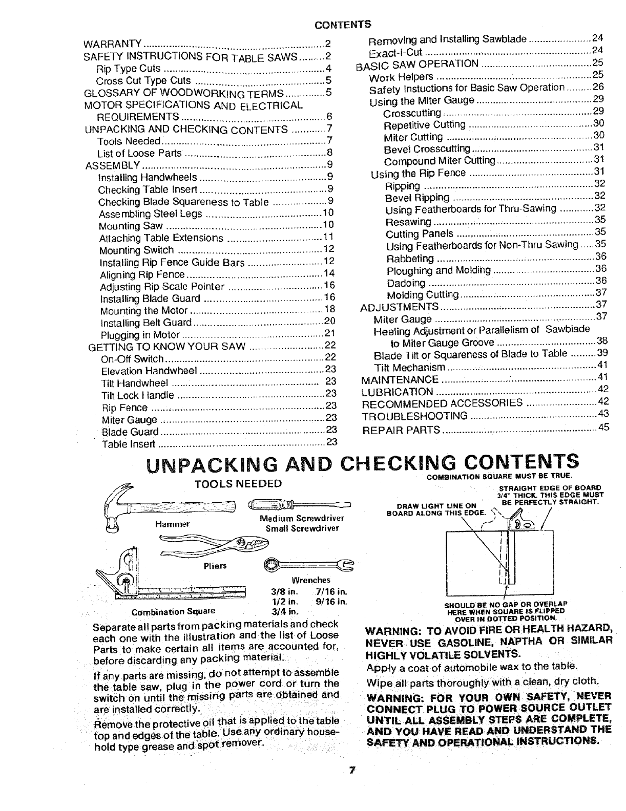
Separate all parts from packing materials and check
each one with the illustration and the list of Loose
Parts to make certain all items are accounted for,
before discarding any packing material.
If any parts are missing, do not attempt to assemble
the table saw, plug in the power cord or turn the
switch on until the missing parts are obtained and
are installed correctly.
Remove the protective oil that is applied to the table
top and edges of the table, Use any ordinary house-
hold type grease and spot remover.
AND CHECKING CONTENTS
COMBINATION SOUARE MUST BE TRUE.
DRAW LIGHT LINE ON
BOARD ALONG THIS EDGE. '_
I
L_
STRAIGHT EDGE OF BOARD
3/4" THICK. THIS EDGE MUST
BE PERFECTLY STRAIGHT.
SHOULD BE NO GAP OR OVERLAP
HERE WHEN SQUARE IS FLIPPED
O_R tNDOTTEDPosmoN.
WARNING: TO AVOID FIRE OR HEALTH HAZARD,
NEVER USE GASOLINE, NAPTHA OR SIMILAR
HIGHLY VOLATILE SOLVENTS.
Apply a coat of automobile wax to the table.
Wipe all parts thoroughly with a clean, dry cloth.
WARNING: FOR YOUR OWN SAFETY, NEVER
CONNECT PLUG TO POWER SOURCE OUTLET
UNTIL ALL ASSEMBLY STEPS ARE COMPLETE,
AND YOU HAVE READ AND UNDERSTAND THE
SAFETY AND OPERATIONAL INSTRUCTIONS,
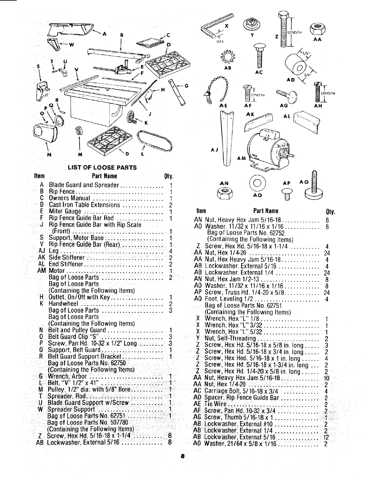
LIST OF LOOSE PARTS
item Part Name Qty.
A Blade Guard and Spreader ............... 1
B Rip Fence. ............................. 1
C Owners Manual . ....................... 1
D Cast Iron Table Extensions .............. 2
EMiter Gauge ........................... 1
F Rip Fence Guide Bar Rod ................ 1
J Rip Fence Guide Bar with Rip Scale
(Front) .............................. 1
S Support, Motor Base .................... 1
V Rip Fence Guide Bar (Rear) .............. 1
AJ Leg ............................... 4
AK Side Stiffener ........................... 2
AL End Stiffener ........................... 2
AM Motor ................................. 1
Bag of Loose Parts ..................... 2
Bag of Loose Parts
(Containing the Following Items)
H Outlet. 0n/0ff with Key .................. 1
K Handwheel ............................ 2
Bag of Loose Parts ..................... 3
Bag of Loose Parts
(Containing the Following Items)
NBelt and Pulley Guard ................... 1
0 Belt Guard Clip "S' . ......................
P Screw, Pan Hd. 10-32 x 1/2" Long ........ 3
Q Support, Belt Guard ..................... 1
R Belt Guard Support Bracket .............. 1
Bag of Loose Parts No. 62750
(Containing the Following Items)
G Wrench: Arbor ..; ............. 1
L Belt, V 1/2 x41 .................. ...
Z AA
AO "_
AG AH
M Pulley, 1/2" dia. with 5t8" Bore... ........
TSpreader, Rod.. ........................ 1
U Blade Guard Support wlScrew ........... 1
W Spreader Support .......: ........ _.... 1
Bag of Loose Parts No. 62751 ............ 1
Bag of Loose Parts No. 507780
(Containing the Following Items)
Z Screw, He;<Hd; 5/16-t8 x 1-1/4 ... : ...... 8
AB Lockwasher. External 5/16 .............. 8
AL
Item Part Name
AN Nut. Heavy Hex Jam 5/16-18 ............. 8
A0 Washer. 11/32 x 11t16 x 1/16 ............ 8
Bag of Loose Parts No 62752
(Containing the Following Items)
Z Screw. Hex Hd. 5/!6-18 x 1-1/4 .......... 4
AA Nut, Hex 1/4-20 ........................ 24
AA Nut, Hex Heavy Jam 5/!6-18 ............. 4
AB Lockwasher External 5/16 .............. 4
AB Lockwasher External 1/4 ............... 24
AN Nut. Hex Jam 1/2-13 .................... 8
A0 Washer, 11/32 x 11/16x t/16 ............ 8
AP Screw, Truss Hd 1/4-20 x 5/8 ............ 24
AQ Foot Leveling 1/2 ...................... 4
Bag of Loose Parts No. 62751
(Containing the Following Items)
XWrench, Hex"L" 1/8 ....................
XWrench. Hex "L" 3/32 ................... 1
XWrench. Hex"L" 5/32 ................... 1
Y Nut, Self-Threading ..................... 2
Z Screw. Hex Hd. 5/16-18 x 5/8 in. long ..... 3
Z Screw, Hex Hd. 5/16-18 x 3/4 in. long ...... 2
Z Screw, Hex Hed. 5/16-18 x t n. long ...... 4
g Screw. Hex Hd. 5/16-18 x 1-314 in. long .. 2
ZScrew, Hex Hd. 114-20 x 518 in. long ...... 2
AA Nut, Heavy Hex Jar_ 5/16-18 ............. 10
1 AA Nut, Hex 1/4-20 ................. 2
1 AC Carriage Bolt. 5/16-18 x 3/4 ............ 4
AI) Spacer, Rip Fence Guide Bar ............. 2
AE T_eWire ........ i ...................... 2
AF Screw; Pan Hd 10-32 x 3/4 ............ 2
AG Screw, Thurnb5/16-18x 1 ............... 1
AB Lockwasher External #10 ....... 2
A8 Lockwasher External 1/4 .............. 2
AB Lock_vasher,:External 5/16 .......... 12
A0 W'asher. 21/64 x 5/8 x 1/16 .............. 2
8
ASSEMBLY
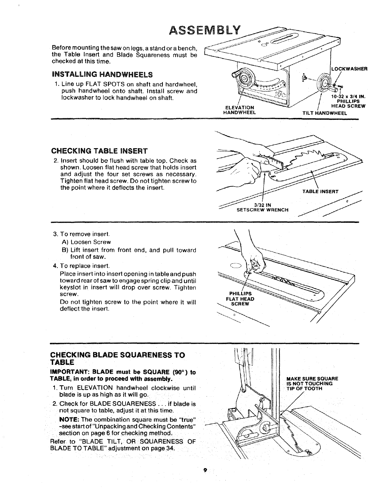
Before mounting the saw on legs, a stand or a bench,
the Table Insert and Blade Squareness must be
checked at this time.
iNSTALLING HANDWHEELS
1. Line up FLAT SPOTS on shaft and hardwheel,
push handwheel onto shaft. Install screw and
Iockwasher to lock handwheet on shaft.
.OCKWASHER
/
10-32 x314 IN.
PHILLIPS
ELEVATION HEAD SCREW
HANDWHEEL TILT HANDWHEEL
= =
CHECKING TABLE iNSERT
2. Insert should be flush with table top, Check as
shown. Loosen flat head screw that holds insert
and adjust the four set screws as necessary.
Tighten flat head screw. Do not tighten screw to
the point where it deflects the insert.
3/32 IN
SETSCREW WRENCH
3. To remove insert.
A) Loosen Screw
B) Lift insert from front end, and pull toward
front of saw.
4. To replace insert.
Place insert into insert opening in table and push
toward rear of saw to engage spring clip and until
keyslot m insert will drop over screw. Tighten
screw.
Do not tighten screw to the point where it will
deflect the insert.
FLAT HEAD _"__ //
CHECKING BLADE SQUARENESS TO
TABLE
iMPORTANT: BLADE must be SQUARE (90°) to
TABLE, in order to proceed with assembly.
1. Turn ELEVATION handwhee! clockwise until
blade is up as high as it will go.
2. Check for BLADE SQUARENESS... if blade is
not square to table, adjust it at this time.
NOTE: The combination square must be "true"
-see start of "Un packing and Checking Contents"
section on page 6 for checking method.
Refer to "BLADE TILT, OR SQUARENESS OF
BLADE TO TABLE" adjustment on page 34.
MAKE SURE SQUARE
iS NOT TOUCHING
TiP OF TOOTH
/
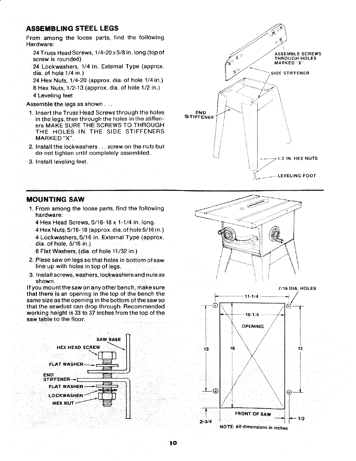
ASSEMBLING STEEL LEGS
From among the loose parts, find the following
Hardware:
24 Truss Head Screws, 1/4-20 x 5/8 in. long (top of
screw is rounded)
24 Lockwashers, 1/4 in, External Type (approx.
dia. of hote 1/4 in.)
24 Hex Nuts, 1/4-20 (approx. dia. of hole 1/4 in.)
8 Hex Nuts, 1/2-13 (approx. dia. of hole 1/2 in.)
4 Leveling feet
Assemble the legs as shown..
1. Insert the Truss Head Screws through the holes
in the legs, then through the holes in the stiffen-
ers MAKE SURE THE SCREWS TO THROUGH
THE HOLES IN THE SIDE STIFFENERS
MARKED "X'"
2. Install the Iockwashers.. _screw on the nuts but
do not tighten until completely assembled.
3. Install leveling feet. .-,+_71!2 IN. HEX NUTS
......... LEVELING FOOT
MOUNTING SAW
1. From among the loose parts, find the following
hardware:
4 Hex Head Screws, 5/16-18 x 1-1/4 in. long.
4 Hex Nuts, 5/16-18 (approx. dia. of hole 5/16 in.)
4 Lockwashers, 5/16 in. External Type (approx.
dia. of hole, 5/16 in.]
8 Flat Washers, (dia. of hole 11/32 in.)
2. Ptase saw on legs so that holes in bottom of saw
line up with holes in top of legs.
3. Install screws, washers, Iockwashersand nuts as
shown.
tf you mount the saw on any other bench, make sure
that there is an opening in the top of the bench the
same size as the opening n the bottom of the saw so
that the sawdust can drop through. Recommended
working height is 33 to 37 inches from the top of the
saw table to the floor.
SAW BASE ]_[
HEXHEAOSC.EW
FLAT WASHE R'----_ _ tl
END f _ ""
STIFFENER--_L
FLAT WASHER ]/
7/16 DIA. HOLES
/
_-- ................. 11-1/4 .....................
,o,I ............
'_{' OPENIN G
\, /
I
13
2-3/4
/
16 _\
/
\
;/ \
FRONT OF SAW
NOTE: All dimensions in inches
13
Q__3_
112
IO
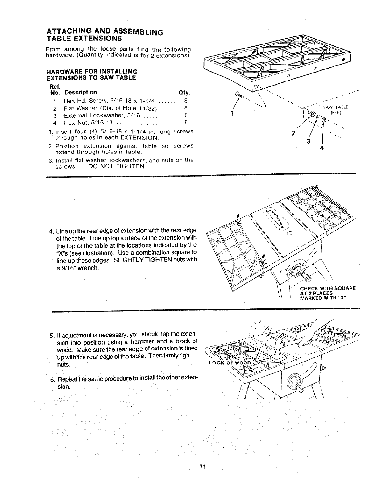
ATTACHING AND ASSEMBLING
TABLE EXTENSIONS
From among the loose parts find the following
hardware: (Quantity indicated is for 2 extensions)
HARDWARE FOR INSTALLING
EXTENSIONS TO SAW TABLE
Ref.
No. Description Qty,
1Hex Hdl Screw, 5/16-18 x 1-1/4 ...... 8
2 Flat Washer (Dia: of Hole 11/32) ..... 8
3 External Lockwasher, 5/16 ........... 8
4 He× Nut, 5/16-18 .................... 8
1. |nsert four (4) 5/16-18 x 1-1/4 in. tong screws
through holes in each EXTENSION.
2. Position extension against table so screws
extend through holes in table.
3_ Install flat washer, Iockwashers, and nuts on the
screws... DO NOT TIGHTEN.
4. Line up the rear edge of extension with the rear edge
of the table. Line u0 top sudace of the extension with
the top of the table at the locations indicated by the
"X"s (see illustration). Use a combination square to
line-up these edges. SLIGHTLY TIGHTEN nutswith
a 9/16" wrench.
_'_ JCHECK WITH SQUARE
AT 2 PLACES
MARKED WITH "X"
5. If adjustment is necessary, you should tap the exten-
sion into position using a hammer and a block of
wood. Make sure the rear edge of extension is lined
up withthe rear edge of the table. Thenfirmlytigh
nuts.
6. Repeatthe sameprocedureto installthe otherexten-
sion.
LOCK OF WOOD "
\
11
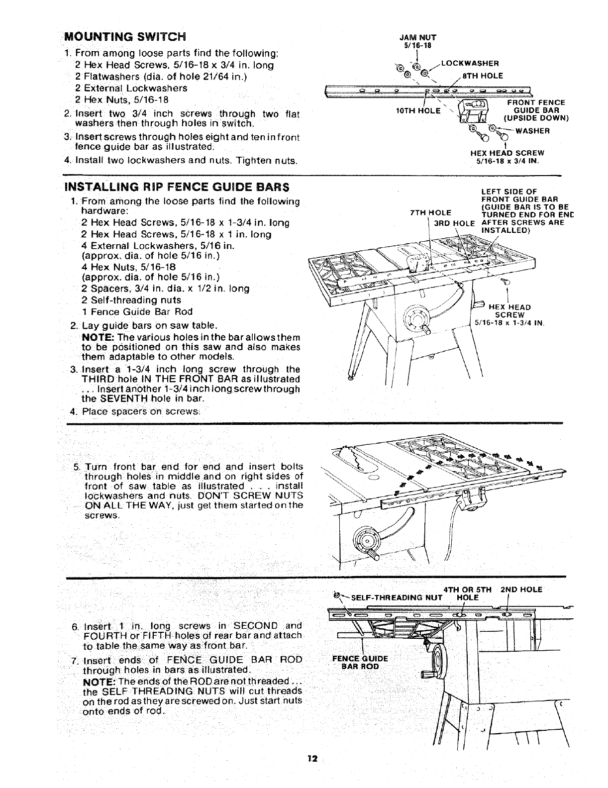
MOUNTING SWITCH
1. From among loose parts find the following:
2 Hex Head Screws, 5/16-18 x3/4 in. long
2 Flatwashers (dia. of hole 21/64 in.)
2 External Lockwashers
2 Hex Nuts, 5/16-18
2. Insert two 3/4 inch screws through two flat
washers then through holes in switch.
3. Insert screws through holes eight and ten in front
fence guide bar as illustrated
4. Install two Iockwashers and nuts Tighten nuts,
INSTALLING RiP FENCE GUIDE BARS
1. From among the loose parts find the following
hardware:
2 Hex Head Screws. 5/16-18 x 1-3/4 in. long
2 Hex Head Screws, 5/16-18 x 1 in. long
4 External Lockwashers, 5/16 in.
(approx. dia. of hole 5/16 in.)
4 Hex Nuts, 5/16-18
(approx. dia. of hole 5/16 in.)
2 Spacers. 3/4 in. dia. x 1/2 in. long
2 Self-threading nuts
1 Fence Guide Bar Rod
2. Lay guide bars on saw table.
NOTE: The various holes in the bar allows them
to be positioned on this saw and also makes
them adaptable to other models.
3. Insert a 1-3/4 inch long screw through the
THIRD hole IN THE FRONT BAR as illustrated
... Insert another 1-3/4 inch long screwthrough
the SEVENTH hole in bar.
4. Place spacers on screws,
JAM NUT
5116-18
7TH HOLE
t_---_ WASHER
I
HEX HEAD SCREW
5/16-18 x3/4 IN.
3RD HOLE
LEFT SIDE OF
FRONT GUIDE BAR
(GUIDE BAR IS TO BE
TURNED END FOR ENE
AFTER SCREWS ARE
INSTALLED)
HEX HEAD
SCREW
5/16-18 x 1-3/4 IN
5. Turn front bar end for end and insert bolts
through holes in middle and on right sides of
front of saw table as illustrated .. . install
Iockwashers and nuts. DON'T SCREW NUTS
ON ALL THE WAY, just get them started on the
screws.
4TH OR 5TH 2ND HOLE
_k"_ SELF-THREAD|NG NUT HOLE
6. Inse[t 1 in. long screws in SECOND and _ - /"
FOURTH or FI FTH holes of rear bar and attach
to table the same way as front bar.
7. Insert ends of FEKICE GUIDE BAR ROD F
through holes in bars as illustrated. BAR ROD
NOTE: The ends of the ROD are not threaded ...
the SELl: THREADING NUTS wil! cut threads
on the rod as they are screwed on. Just start nuts c
onto ends of rod.
]2
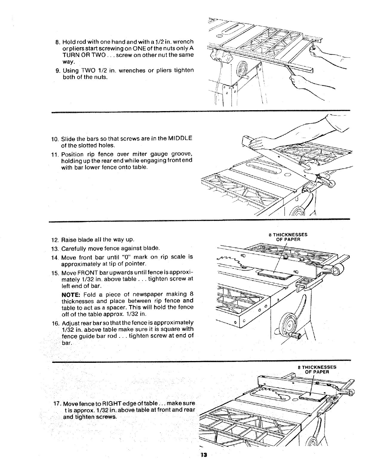
8. Hold rod with one hand and with a 1/2 in. wrench
or pliers start screwing on ONE of the nuts only A
TURN OR TWO... screw on other nut the same
way.
9. Using TWO 1/2 in. wrenches or pliers tighten
both of the nuts.
10. Slide the bars so that screws are in the MIDDLE
of the slotted holes.
11, Position rip fence over miter gauge groove,
holding up the rear end while engaging front end
with bar lower fence onto table.
12. Raise blade all the way up.
13. Carefully move fence against blade.
14. Move front bar until "0" mark on rip scale is
approximately at tip of pointer.
15. Move FRONT bar upwards until fence is approxi-
mately 1/32 in. above table.., tighten screw at
left end of bar.
NOTE: Fold a piece of newspaper making 8
thicknesses and place between rip fence and
table to act as a spacer. This wil! hold the fence
off of the table approx. 1/32 in.
16. Adjust rear bar so that the fence is approximately
1/32 in. above table make sure it is square with
fence guide bar rod.., tighten screw at end of
bar.
8THICKNESSES
OF PAPER
8 THICKNESSES
OF PAPER
17. Move fence to RIGHT edge of table.., make sure
tis approx. 1/32 in. above table at front and rear
and tighten screws.
13
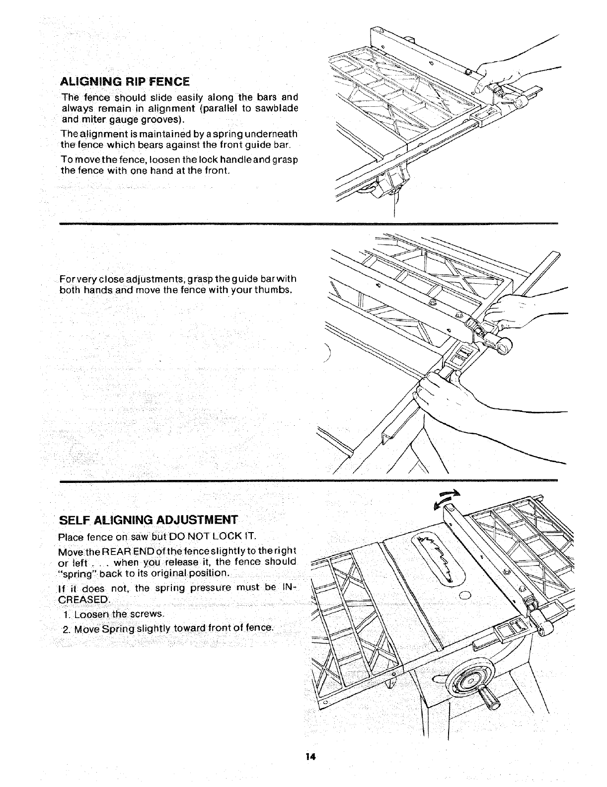
ALIGNING RiP FENCE
The fence should slide easily along the bars and
always remain in alignment (parallel to sawblade
and miter gauge grooves).
The alignment is maintained by a spring underneath
the fence which bears against the front guide bar.
TO movethe fence, loosen the lock handle and grasp
the fence with one hand at the front.
For very close adjustments, grasp theguide bar with
both hands and move the fence with your thumbs.
\
SELF ALIGNING ADJUSTMENT
Place fence on saw but DO NOT LOCK IT.
Move the R EAR END of the fence slightly to the right
or left. , . when you release it, the fence should
"spring" back to its original position.
If i| does not, the spring pressure must be IN-
1. Looser, the screws.
2 Move Spring slightly toward front of fence.
14
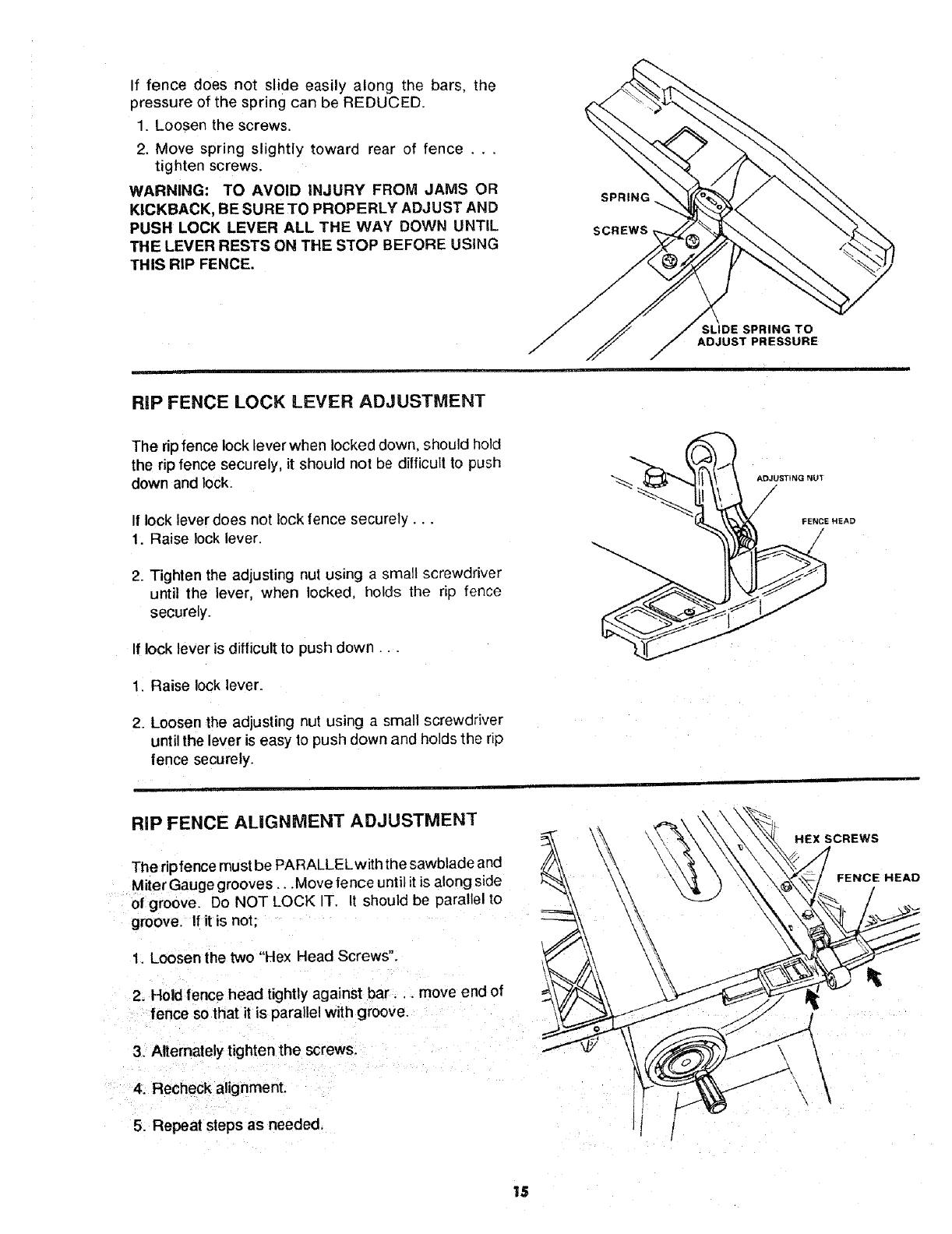
If fence does not slide easily along the bars, the
pressure of the spring can be REDUCED.
1. Loosen the screws.
2. Move spring slightly toward rear of fence . . .
tighten screws.
WARNING: TO AVOID INJURY FROM JAMS OR
KICKBACK, BE SURE TO PROPERLY ADJUST AND
PUSH LOCK LEVER ALL THE WAY DOWN UNTIL
THE LEVER RESTS ON THE STOP BEFORE USING
THIS RIP FENCE.
SPRING
SCREWS,
SLIDE SPRING TO
ADJUST PRESSURE
RIP FENCE LOCK LEVER ADJUSTMENT
The ripfence lock lever when locked down, should hold
the rip fence securely, it should not be difficultto push
down and lock.
If lock lever does not lock fence securely...
1. Raise lock lever.
2. Tighten the aOjusting nut using a small screwdriver
until the lever, when locked, holds the rip fence
securely.
If lock lever is difficult to push down...
1. Raise lock lever.
2. Loosen the adjusting nut using a small screwdriver
until the lever is easy to push down and holds the rip
fence securely.
AD3USTING NUT
FENCE HEAD
RiP FENCE ALIGNMENT ADJUSTMENT
The riptence must be PARALLEL with the sawblade and
Miter Gauge grooves_..Move fence until it is along side
of groove. Do NOT LOCK IT. It should be parallel to
groove. If it is not;
1. Loosen the two "Hex Head Screws".
2. Hold fence head tightly against bar.., move end of
fence so that it is parallel with groove.
3. Alternately tighten the screws.
4. Recheck alignment.
5. Repeat steps as needed.
HEX SCREWS
FENCE HEAD
\\
15
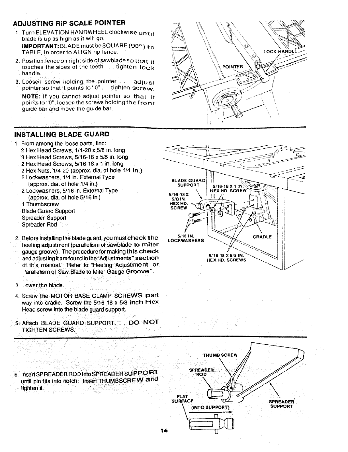
ADJUSTING RiP SCALE POINTER
1. Turn ELEVATION HANDWHEEL clockwise untH
blade is up as high as it will go,
IMPORTANT: BLADE must be SQUARE (90 ° ) to
TABLE. in order to ALIGN rip fence.
2. Position fenceon right side of sawblade so that it
touches the sides of the teeth.., tighten lock
handle.
3. Loosen screw holding the pointer . . . adjust
pointer so that it points to "0" .. tighten screw.
NOTE: If you cannot adjust pointer so that it
points to "0", loose n the screws holding the fro nt
guide bar and move the guide bar.
POINTER
_-K HANDLE
INSTALLING BLADE GUARD
1_ From among the loose parts, find:
2 Hex Head Screws, 1/4-20 x 5/8 in. long
3 Hex Head Screws, 5/16-18 x 5/8 in. long
2 Hex Head Screws, 5/16-18 x 1 in. long
2 Hex Nuts, 1/4-20 (approx. dia. of hole 1/4 in.)
2 Lockwashers, 1/4 in. External Type
(approx. dia. of hole 1/4 in.)
2 Lockwashers, 5/16 in. External Type
(approx. dia. of hole 5/16 in.)
1 Thumbscrew
Blade Guard Support
Spreader Support
Spreader Rod
2. Before installing the blade guard, you mustcheck the
heeling adjustment (parallelism of sawblade to miter
gauge groove). The procedure for making this check
and adjusting it are found inthe "Adjustments" sect ion
of this manual. Refer to "Heeling Adjustment or
Parallelism ol Saw Blade to Miter Gauge Groove".
BLADE GUARD _,_ ''-_
SUPPORT 5/16-18
\HEX HD.
5/16ol 8 X: \
HEX HD.
SCREW
5/16 IN.
LOCKWASHERS
5/16-18 X 5/8 IN
HEX HD. SCREWS
3. Lower the blade.
4. Screw the MOTOR BASE CLAMP SCREWS part
way into cradle. Screw the 5t16-18 x 5/8 inch Hex
Head screw into the blade guard support.
5. Attach BLADE GUARD SUPPORT... DO NOT
TIGHTEN SCREWS,
r
THUMB SCR EW//__
6 Insert SPREADER ROD intoSPREADER SUPPORT SPREADER
ti;thleP_nitlitsint° n°tch" Insert THUMBSCREW and sFRLFATcE
SPREADER
(INTO SUPPORT), SUPPORT
,,
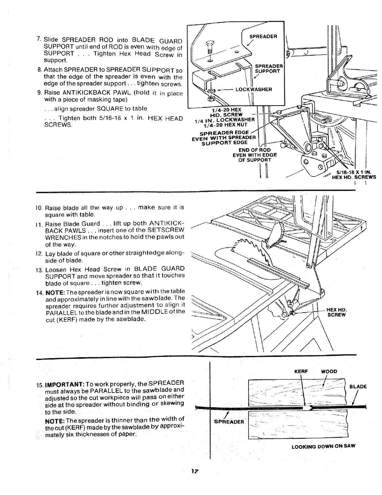
7. Slide SPREADER ROD into BLADE GUARD
SUPPORT until end of ROD is even With edge of
SUPPORT .. . Tighten Hex Head _crew in
support,
8. Attach SPREADER to SPREADER SUPPORT so
that the edge of the spreader is even with the
edge of the spreader support. •, tighten screws.
9. Raise ANTIKICKBACK PAWL (hoSd it in place
with a piece of masking tape)
•.. align spreader SQUARE to table
•..Tighten both 5/16-18 x ! in. HEX HEAD
SCREWS.
1/4-20 HEX
HD. SCREW
1/d IN. LOCKWASHER
-_/4~20 HEX NUT
sPREADER EDGE
EVEN WiTH SPREADER
SUPPORT EDGE
END OF ROD
EVEN WITH EDGE
OF SUPPORT
F
t
5/16-18 X 1 IN,
HEX HD. SCREWS
10. Raise blade all the way up... make sure it is
square with table.
I1. Raise Blade Guard ... lift up both ANTIKICK-
BACK PAWLS.,. insert one of the SETSCREW
WRENCHES in the notches to hold the pawls out
of the way.
12. Lay blade of square or other straightedge along-
side of blade.
13. Loosen Hex Head Screw in BLADE GUARD
SUPPORT and move spreader so that it touches
blade of square.,, tighten screw•
14. NOTE: The spreader is now square with the table
and approximately in line with the sawb_ade. The
spreader requires further adjustment to align it
PARALLEL to the blade and in the MIDDLE of the
cut (KERF) made by the sawblade. SCREW
15.IMPORTANT: To work property, the SPREADER
must always be PARALLEL to the sawblade and
adjusted so the cut workpiece will pass on either
side at the spreader without binding or skewing
to the side.
NOTE: The spreader is thinner than the width of
the cut (KERF) made by the 8awblade by approxi-
mately six thicknesses of paper.
KERF WOOD
iw
SPREADER
LOOKING DOWN ON SAW
BLADE
/
/
17
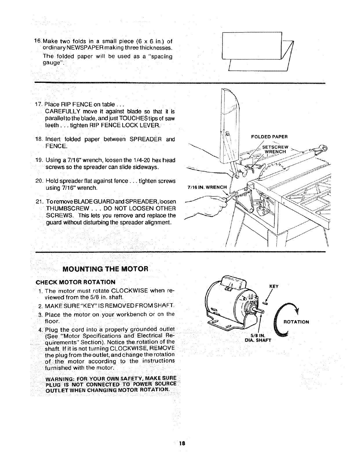
16.Make two folds n a small piece (6 x 6 in,) of
ordinary NEWSPAPER making three thicknesses.
The folded paper will be used as a "spacing
gauge". /I
17. Place RIP FENCE on table...
CAREFULLY move it against blade so that it is
paralletto the blade and just TOUCHES tips of saw
teeth.., tighten RIP FENCE LOCK LEVER.
18. Insert folded paper between SPREADER and
FENCE,
19. Using a 7/16" wrench, loosen the 1/4-20 hex head
screws so the spreader can slide sideways.
20. Hold spreader flat against fence.., tighten screws
using 7/16" wrench.
21. To remove BLADE GUARD and SPREADER, loosen
THUMBSCREW . DO NOT LOOSEN OTHER
SCREWS. This lets you remove and replace the
guard without disturbing the spreader alignment.
7/16 IN, WRENCH
\
FOLDEDPAPER
MOUNTING THE MOTOR
CHECK MOTOR ROTATION
1. The motor must rotate CLOCKWISE when re-
viewed from the 5/8 in. shaft,
2. MAKE SURE"KEY" IS REMOVED FROM SHAFT
3. Place the motor on your workbench or on the
floor.
4. Plug the cord into a properly grounded outlet
(See "Motor Specifications and Electrical Re-
quirements" Section). Notice the rotation of the
shaft. If it is not turning CLOCKWISE, REMOVE
the plug from the outlet, and change the rotation
of the motor according to the instructions
furnished with the motor,
KEY
/
J
5/8 IN. _ION
DIA, SHAFT
OUTLET WHEN CHANGING MOTOR ROTATION.
18
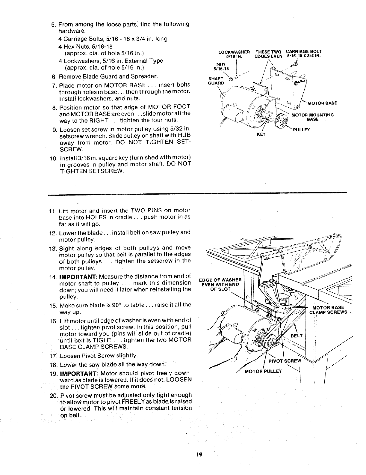
5. From among the loose parts, find the following
hardware:
4 Carriage Bolts, 5/16 - 18 x 3/4 in. long
4 Hex Nuts, 5/16-18
(approx. dia. of hole 5/t6 in.)
4 Lockwashers, 5/16 in. External Type
(approx. dia. of hole 5/16 in.)
6. Remove Blade Guard and Spreader.
7. Place motor on MOTOR BASE,.. insert bolts
through holes in base.., then through the motor.
Install Iockwashers, and nuts.
8. Position motor so that edge of MOTOR FOOT
and MOTOR BASE are even ... slide motor all the
way to the RIGHT... tighten the four nuts.
9. Loosen set screw in motor pulley using 5/32 in.
setscrew wrench, Slide pulley on shaft with HUB
away from motor. DO NOT TIGHTEN SET-
SCREW.
10. Install 3/16 in. square key (furnished with motor)
in grooves in pulley and motor shaft. DO NOT
TIGHTEN SETSCREW.
LOCKWASHER
5/16 IN.
NUT l
5/16-18
SHAFT _'_ ,,_"
GUARD
THESE TWO
EDGES EVEN
KEY
CARRIAGE BOLT
5./16-18 X 3/4 IN.
MOTOR MOUNTING
BASE
11. Lift motor and insert the TWO PINS on motor
base into HOLES in cradle,., push motor in as
far as it will go.
12. Lower the blade.., install belt on saw pulley and
motor pulley.
13, Sight along edges of both pulleys and move
motor pulley so that belt is parallel to the edges
of both pulleys.., tighten the setscrew in the
motor pulley.
14. IMPORTANT: Measure the distance from end of
motor shaft to pulley ...mark this dimension
down: you will need it later when reinstalling the
pulley.
15, Make sure blade is 90°to table., raise it al! the
way up.
16. Lift motor until edge of washer is even with end of
slot., tighten pivot screw. In this position, pull
motor toward you (pins will slide out of cradle)
until belt is TIGHT.. tighten the two MOTOR
BASE CLAMP SCREWS.
17. Loosen Pivot Screw slightly.
18, Lower the saw blade all the way down.
19. IMPORTANT: Motor should pivot freely down-
ward as blade is lowered. If it does not. LOOSEN
the PIVOT SCREW some more.
20. Pivot screw must be adjusted only tight enough
to allow motor to pivot FREELY as blade is raised
or lowered. This will maintain constant tension
on belt.
EDGE OF WASHER
EVEN WITH END
OF SLOT
PIVOTSCREW
MOTOR PULLEY ""
1
" MOTOR BASE
CLAMP SCREWS
19
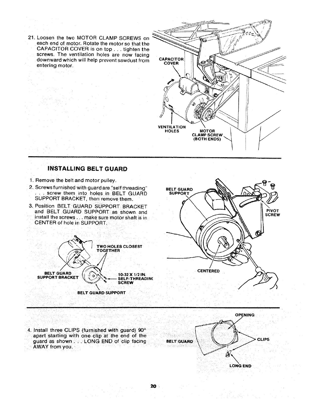
21. Loosen the two MOTOR CLAMP SCREWS on
each end of motor. Rotate the motor so that the
CAPACITOR COVER is on top.., tighten the
screws. The ventilation holes are now facing
downward which will help prevent sawdust from
entering motor.
CAPACITOR
COVER
\\
VENTILATION
HOLES \
MOTOR
CLAMP SCREW
(BOTH ENDS)
I
iNSTALLING BELT GUARD
1. Remove the belt and motor pulley.
2. Screws furnished with guard are "self threading"
•.screw them into holes in BELT GUARD
SUPPORT BRACKET, then remove them.
3. Position BELT GUARD SUPPORT BRACKET
and BELT GUARD SUPPORT as shown and
install the screws •,. make sure motor shaft is in
CENTER of hole in SUPPORT.
BELT GUARD
\
PIVOT
SCREW
_""J TWO HOLES CLOSEST
BELT GUARD (
SUPPORT BRACKET
SCREW
\
BELT GUARD SUPPORT
CENTERED
OPENING
/
4. Install three CLIPS (furnished with guard) 90°
apart starting with one clip at the end of the
guard as shown.. ,LONG END of clip facing BELTGUARD
AWAY from you.
LONG END
2O
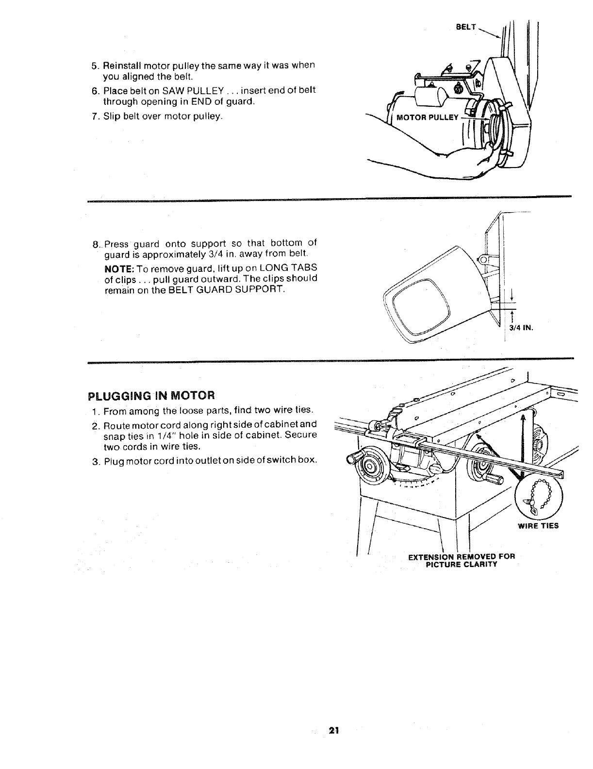
5. Reinstall motor pulley the same way it was when
you aligned the belt.
6. Place belt on SAW PULLEY... insert end of belt
through opening in END of guard,
7. Slip belt over motor pulley.
BELT
8. Press guard onto support so that bottom of
guard is approximately 3/4 in. away from belt,
NOTE: To remove guard, lift up on LONG TABS
of clips.., pull guard outward, The clips should
remain on the BELT GUARD SUPPORT.
1
3/4 IN.
PLUGGING IN MOTOR
1. From among the loose parts, find two wire ties.
2. Route motor cord along right side of cabinet and
snap ties in 1/4" hole in side of cabinet. Secure
two cords in wire ties,
3. Plug motor cord into outlet on side of switch box,
WIRE TIES
EXTENSION REMOVED FOR
PICTURE CLARITY
21
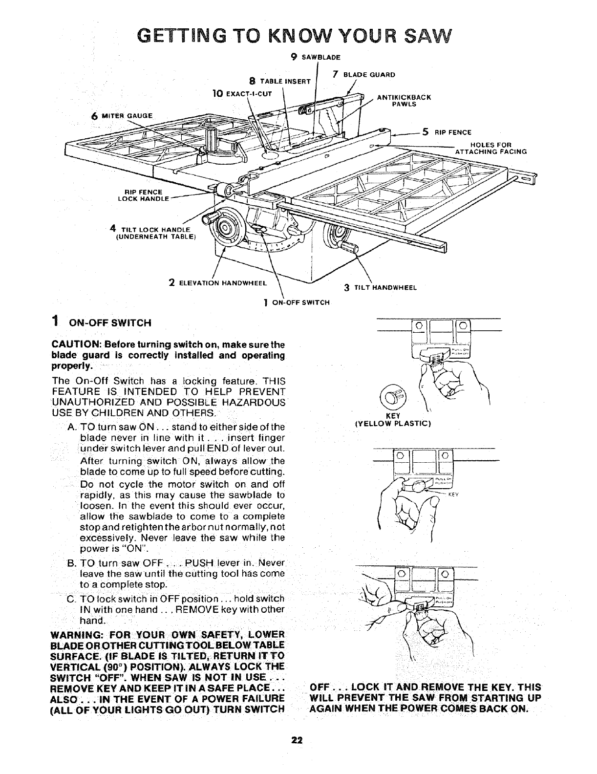
GETTING TO KNOW YOUR SAW
9 SAWBLADE
8TABLE INSERT
10 EXACT-I-CUT
6 MITER GAUGE
RIP FENC_
LOCK HANDLE _ _,_
4 TILT LOCK HANDLE -\_.C
(UNDERNEATH TABLE)
1
2ELEVATION HANDWHEEL
\
"_ ON-OFF SWITCH
7BLADE GUARD
ANTIKICKBACK
PAWLS
\
3TILT HANDWHEEL
ON-OFF SWITCH
CAUTION: Before turning switch on, make surethe
blade guard is correctly installed and operating
property.
The On-Off Switch has a locking feature. THIS
FEATURE IS INTENDED TO HELP PREVENT
UNAUTHORIZED AND POSSIBLE HAZARDOUS
USE BY CHILDREN AND OTHERS.
A. TO turn saw ON... stand to either side of the
blade never in line with it... insert finger
under switch lever and pull END of lever out.
After turning switch ON, always allow the
blade to come up to full speed before cutting.
Do not cycle the motor switch on and off
rapidly, as this may cause the sawblacle to
loosen. In the event this should ever occur,
allow the sawblade to come to a complete
stop and retighten the arbor nut normally, not
excessively. Never leave the saw while the
power is "ON'!.
B. TO turn saw OFF.. PUSH lever in. Never
leave the saw until the cutting tool has come
to a complete stop.
C. TO lock switch in OFF position.., hold switch
IN with one hand ... REMOVE key with other
hand.
RIP FENCE
HOLES FOR
ATTACHING FACING
KEY
(YELLOW PLASTIC)
=",, ;o,....
WARNING: FOR YOUR OWN SAFETY, LOWER
BLADE OR OTHER CUTTING TOOL BELOW TABLE
SURFACE. (IF BLADE IS TILTED, RETURN IT TO
VERTICAL (90 °) POSITION), ALWAYS LOCK THE
SWITCH "OFF". WHEN SAW iS NOT IN USE...
REMOVE KEY AND KEEP IT iN A SAFE PLACE... OFF... LOCK IT AND REMOVE THE KEY. THIS
ALSO... IN THE EVENT OF A POWER FAILURE WiLL PREVENT THE SAW FROM STARTING UP
(ALL OF YOUR LIGHTS GO OUT) TURN SWITCH AGAIN WHEN THE POWER COMES BACK ON.
22
2 ELEVATION HANDWHEEL...elevates or lowers
the blade, Turn clockwise to elevate.,, counter-
clockwise to lower.
3TILT HANDWHEEL... tilts the blade for bevel
cutting. Turn clockwise to tilt toward left . . .
counterclockwise to tilt toward right.
When the blade is tilted to the LEFT as far as it
will go, it should be at 45°to the table and the
bevel pointer should point 45°.
NOTE: There are LIMIT STOPS inside the saw
which prevent the blade from tilting beyond 45°
to the LEFT and 90° to the RIGHT. (See "Adjust-
ments" section "Blade Tilt, or Squareness of
Blade to Table").
4TILT LOCK HANDLE.. : locks the blade in the
desired tilt position. To loosen, turn counter-
clockwise. Push handle in and turn itto another
position if necessary in order to tighten or
loosen.
5RIP FENCE... is locked in place by pushing the
lock lever down until the lever rests on the stop.
To move the fence, lift the lock lever and grasp
the fence with one hand at the front.
Holes are provided in the rip fence for attaching
a wood facing when using the dado head, or
molding head.
Select a piece of smooth straight wood approx.
3/4 in. thick and the same size as the rip fence.
Attach it to the fence with three Round Head #10
Wood Screws 2 in. long. To remove the facing,
loosen the screws, slide the facing forward and
pull the screws through the round holes.
WOOD FACING
t
o q
\/ ///
\ROUND HEAD ./
#'tO WOOD SCREWS
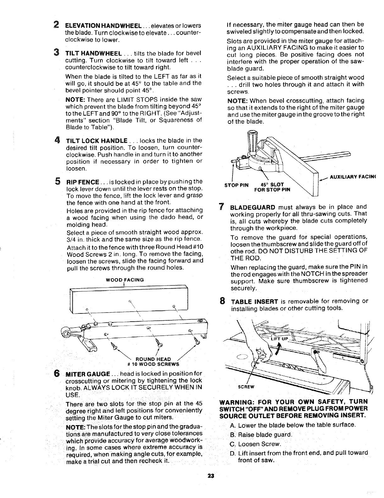
6MITER GAUGE... head is locked in position for
crosscutting or mitering by tightening the lock
knob ALWAYS LOCK IT SECURELY WHEN IN
USE.
There are two slots for the stop pin at the 45
degree right and left positions for conveniently
setting the Miter Gauge to cut miters.
NOTE: The slots for the stop pin and the gradua-
tions are manufactured to very closetolerances
which provide accuracyfor average woodwor k-
ing. In some cases where extreme accuracy is
required, when making angle cuts, for example,
make a trial cut and then recneck it.
If necessary, the miter gauge head can then be
swiveled slightly to compensate and then locked.
Slots are provided in the miter gauge for attach-
ing an AUXILIARY FACING to make it easier to
cut long pieces. Be positive facing does not
interfere with the proper operation of the saw-
blade guard.
Select a suitable piece of smooth straight wood
•.. drill two holes through it and attach it with
screws.
NOTE: When bevel crosscutting, attach facing
so that it extends to the right of the miter gauge
and use the miter gauge in the groove to the right
of the blade.
STOP PiN 45 _SLOT
FOR STOP PIN
IXtLIARY FACIN(
7BLADEGUARD must always be in place and
working properly for all thru-sawing cuts. That
is, all cuts whereby the blade cuts completely
through the workpiece.
To remove the guard for special operations,
loosen the thumbscrew and slide the guard off of
othe rod. DO NOT DISTURB THE SETTING OF
THE ROD.
When replacing the guard, make sure the PIN in
the rod engages with the NOTCH inthe spreader
support. Make sure thumbscrew is tightened
securely.
8 TABLE INSERT is removable for removing or
installing blades or other cutting tools.
\
SCREW
WARNING: FOR YOUR OWN SAFETY, TURN
SWITCH "OFF" AND REMOVE PLUG FROM POWER
SOURCE OUTLET BEFORE REMOVING INSERT.
A. Lower the blade below the table surface.
B. Raise blade guard.
C. Loosen Screw.
D. Lift insert from the front end, and pull toward
front of saw.
NEVEROPERATETHE SAWWITHOUT THE
PROPERINSERTIN PLACE.USEOFTHE SAW
BLADEINSERTWHENSAWING. . . USETHE
COMBINATrONDADOMOLDINGINSERTWHEN
DADOINGORMOLDING.
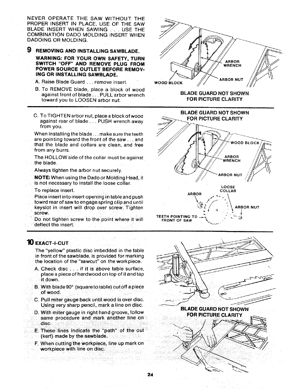
9REMOVING AND iNSTALLING SAWBLADE.
WARNING: FOR YOUR OWN SAFETY, TURN
SWITCH "OFF" AND REMOVE PLUG FROM
POWER SOURCE OUTLET BEFORE REMOV-
ING OR INSTALLING SAWBLADE.
A. Raise Blade Guard... remove insert.
B. To REMOVE blade, place a block of wood
against front of blade... PULL arbor wrench
toward you to LOOSEN arbor nut.
ARBOR
WRENCH
/
!
WOOD BLOCK ARBOR NUT
BLADE GUARD NOT SHOWN
FOR PICTURE CLARITY
C. To TIGHTEN arbor nut, place a block of wood
against rear of blade... PUSH wrench away
from you.
When installing the blade.., make sure the teeth
are pointing toward the front of the saw.. and
that the blade and collars are clean, and free
from any burrs.
The HOLLOW side of the collar must be against
the blade.
Always tighten the arbor nut securely.
NOTE: When using the Dado or Mold ing Head, it
is not necessary to install the loose collar.
To replace insert.
Place insert into insert opening in table and push
towrd rear of saw to engage spring clip and until
keyslot in insert will drop over screw. Tighten
screw.
Do not tighten screw to the point where it will
deflect the insert.
BLADE GUARD NOT SHOWN
PICTURE CLARITY
NUT
LOOSE
COLLAR
ARBOR
TEETH POINTING TO _ _T" -_;-
FRONT OF SAW _'_ .
10 EXACT-I-CUT
The "yellow" plastic disc imbedded in the table
in front of the sawblade, is provided for marking
the location of the "sawcut" on the workpiece.
A. Check disc.., if it is above table surface,
place a piece of hardwood on top of it and tap
it down.
B. With blade90 °(squaretotable} cutoff apiece
of wood.
C. Pull miter gauge back until wood is over disc.
Using very sharp pencil, mark a line on disc.
D. With miter gauge in right hand groove, follow
same procedure and mark another line on
disc.
..... ,i 71 t
E. These lines ndcate the path of the cu
(kerf) made by the sawblade.
F. When cutting the workpiece, line up mark on
workpiece with line on disc.
8LADEGUARDNOTS.OW.
24
BASIC SAW OPERATION
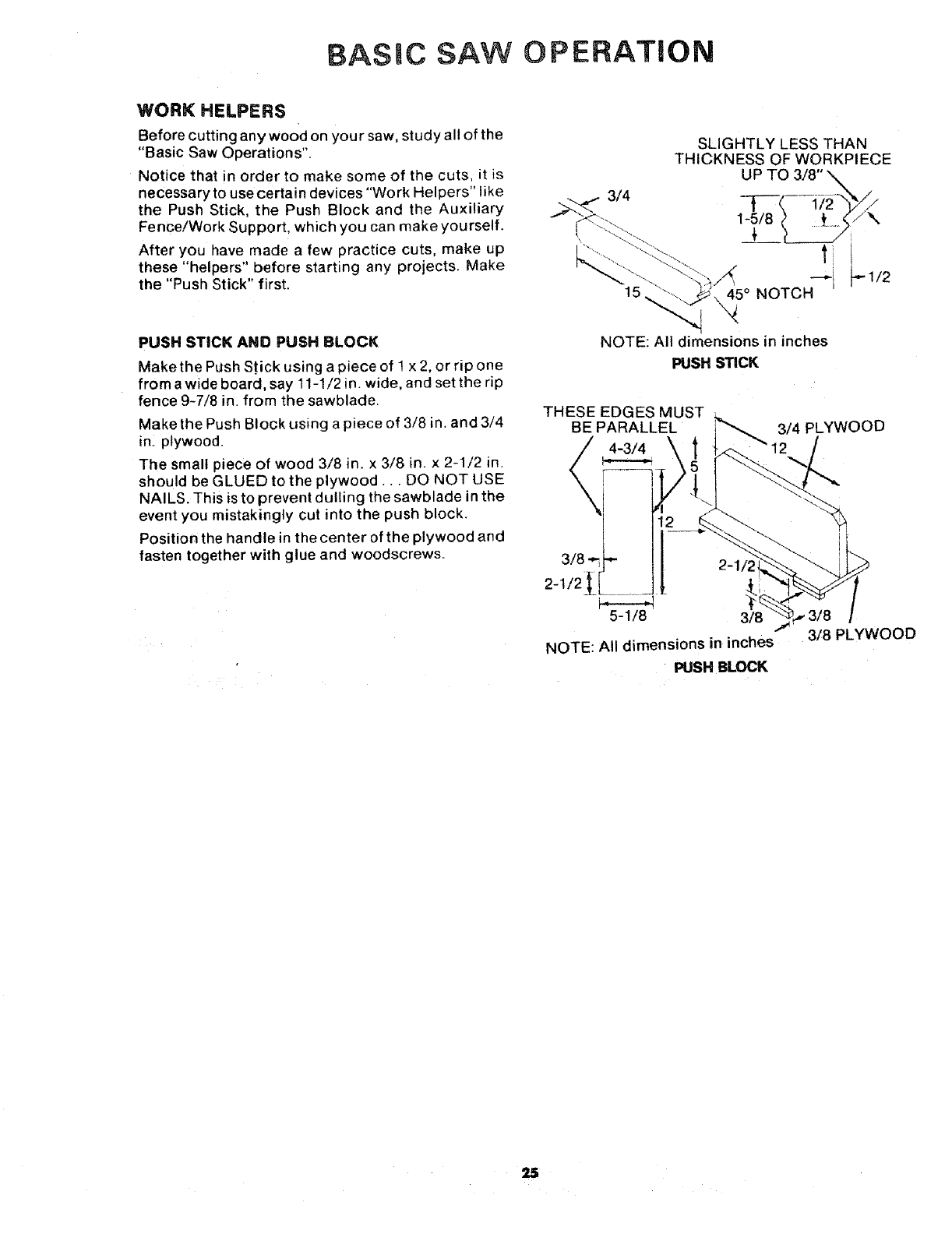
WORK HELPERS
Before cutting any wood on your saw, study all of the
"Basic Saw Operations".
Notice that in order to make some of the cuts, it is
necessary to use certain devices "Work Helpers" like
the Push Stick, the Push Block and the Auxiliary
Fence/Work Support, which you can make yourself.
After you have made a few practice cuts, make up
these "helpers" before starting any projects. Make
the "Push Stick" first.
SLIGHTLY LESS THAN
THICKNESS OF WORKPIECE
UP TO 3/8"
1-5/8
"-_i _" 1/2
45° NOTCH
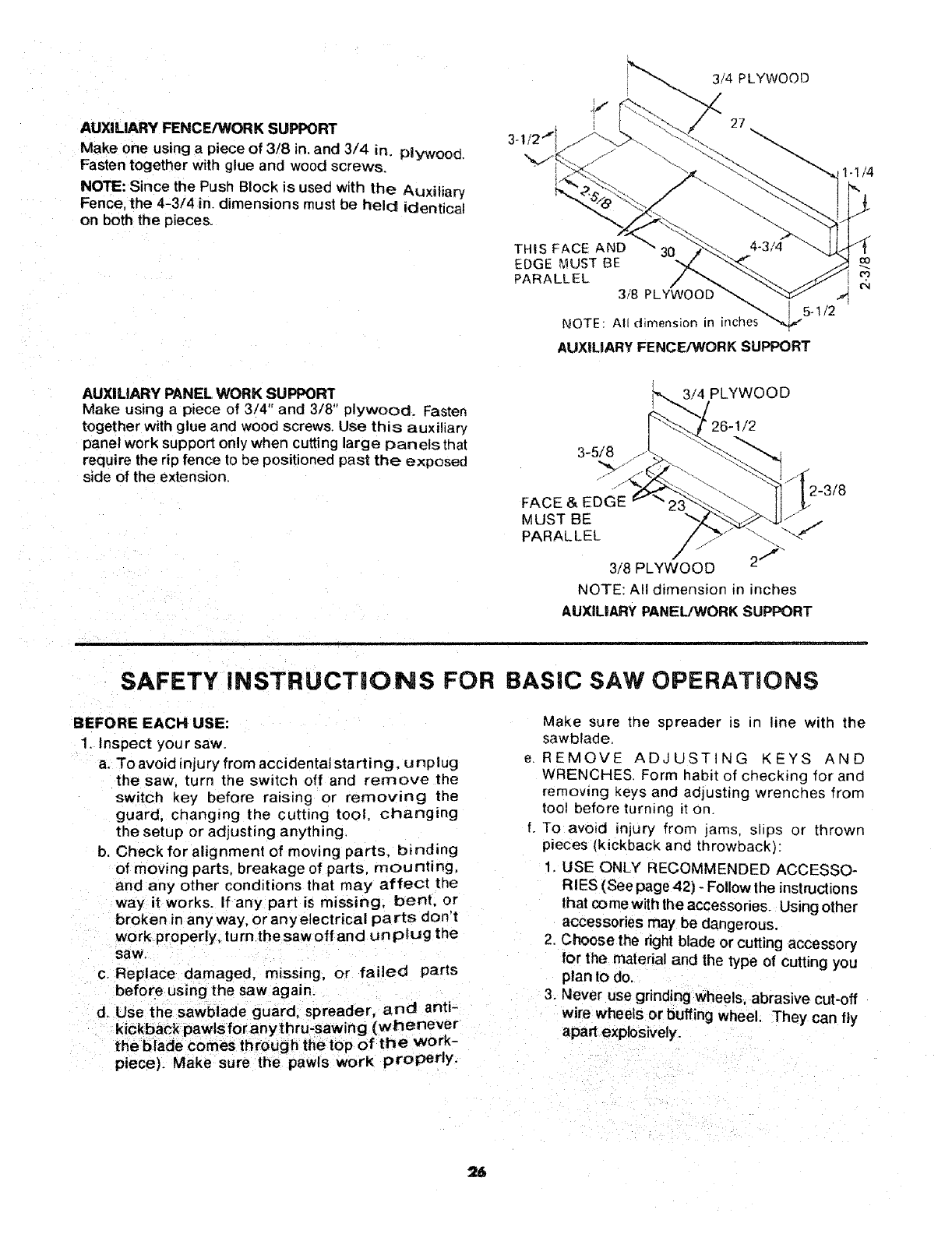
PUSH STICK AND PUSH BLOCK
Make the Push S'_ick using a piece of 1 x 2, or rip one
from a wide board, say 11-1/2 in. wide, and set the rip
fence 9-7/8 in. from the sawblade.
Make the Push Block using a piece of 3/8 in. and 3/4
in. plywood.
The small piece of wood 3/8 in. x 3/8 in. x 2-1/2 in.
should be GLUED to the plywood... DO NOT USE
NAILS. This isto prevent dulling the sawblade in the
event you mistakingly cut into the push block.
Position the handle in the center of the plywood and
fasten together with glue and woodscrews.
NOTE: All dimensions in inches
PUSH STICK
THESE EDGES MUST
BE PARALLEL
4-3/4 \
3/4 PLYWOOD
3/8
NOTE: All dimensions in inches
PUSH BLOCK
3/8
3/8 PLYWOOD
25
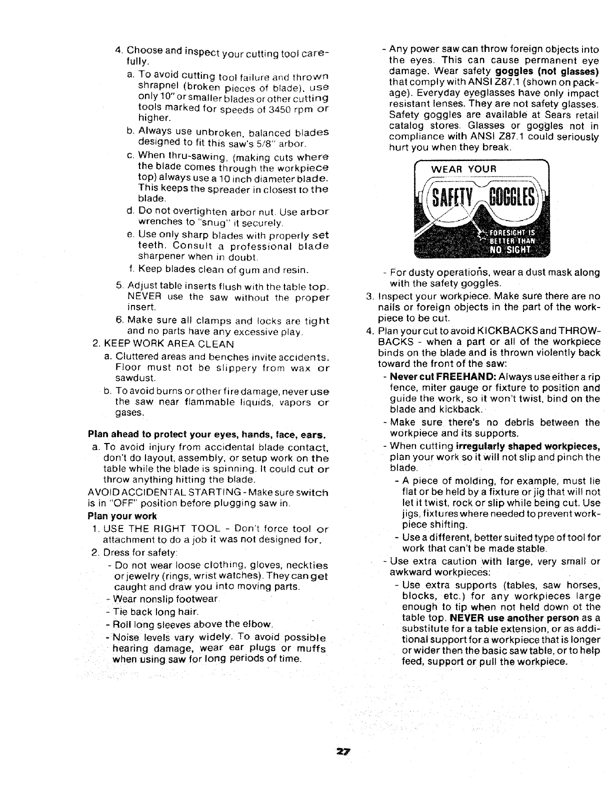
AUXILIARY FENCE/WORK SUPPORT
Make one using a piece of 3t8 in. and 3/4 in. Plywood.
Fasten together with glue and wood screws.
NOTE: Since the Push Block is used with the Auxiliary
Fence, the 4-3/4 in. dimensions must be held identical
on both the pieces.
THIS FACE AND
EDGE MUST BE
PARALLEL
3/8 PLYWOOD
NOTE All dimension in qches_"'_ 5"1/2
AUXILIARY FENCE!WORK SUPPORT
1-1/4
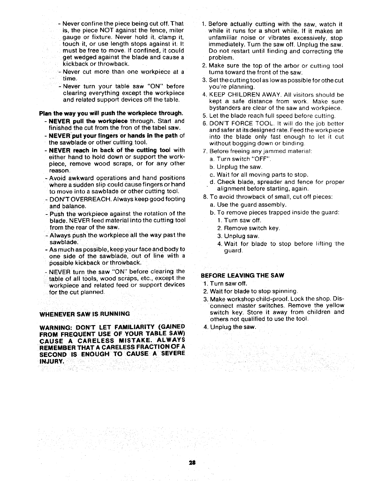
AUXILIARY PANEL WORK SUPPORT
Make using a piece of 3/4" and 3/8" plywood. Fasten
together with glue and wood screws. Use this auxiliary
panel work support only when cutting large panels that
require the rip fence to be positioned past the exposed
side of the extension,
3/4 PLYWOOD
3-5/8
FACE & EDGE
MUST BE "_ .I
PARALLEL _"
/2""
3/8 PLYWOOD
NOTE: All dimension in inches
AUXILIARY PANEL/WORK SUPPORT
SAFETY INSTRUCTIONS FOR
BEFORE EACH USE:
1. Inspect your saw.
a. To avoid injury from accidental starting, unplug
the saw, turP, the switch off and remove the
switch key before raising or removing the
guard, changing the cutting tool, changing
the setup or adjusting anything.
b. Check for alignment of moving parts, binding
of moving parts, breakage of parts mounting,
and any other conditions that may affect the
way it works. If any part is missing, bent, or
broken in any way, or any electrical parts don't
work properly, turn the saw off and unplug the
saw.
c. Replace damaged, missing, or failed parts
before using the saw again.
d. Use the sawblade guard, spreader, and anti-
piece). Make sure the pawls work properly.
BASIC SAW OPERATIONS
Make sure the spreader is in line with the
sawblade,
REMOVE ADJUSTING KEYS AND
WRENCHES. Form habit of checking for and
removing keys and adjusting wrenches from
tool before turning _ton.
To avoid injury from jams, slips or thrown
pieces (kickback and throwback):
1. USE ONLY RECOMMENDED ACCESSO-
RIES (See page 42) - Follow the instructions
that comewiththeaccessories. Usingother
accessories may be dangerous.
2. Choose the right blade or cutting accessory
for the matedal and the type of cutting you
plan to de.
3, Never use grinding wheels, abrasive cut-off
wire wheels or buffing wheel. They can fly
apart explosively.
4, Choose and inspect your cutting tool care-
fully.
a, To avoid cutting toot failure a_d thrown
shrapnel (broken pieces of blade), Ljse
only 10" or Smaller blades or other cutting
tools marked for speeds o_ 3450 rpm or
higher.
b. Always use unbroken, balanced blades
designed to fit this saw's 5/8" arbor.
c. When thru-sawing, (making cuts where
the blade comes through the workpiece
top) always use a 10 inch diameter blade.
This keeps the spreader in closest to the
blade.
d Do not overtighten arbor nut. Use arbor
wrenches to "snug" it securely,
e. Use only sharp b_ades with properly set
teeth. Consult a professional blade
sharpener when in doubt.
f, Keep blades clean of gum and resin.
5. Adjust table inserts flush with the table top.
NEVER use the saw without the proper
insert,
6, Make sure all clamps and locks are tight
and no parts have any excessive play.
2. KEEPWORK AREA CLEAN
a. Cluttered areas and benches invite accrdents.
Floor must not be slippery from wax or
sawdust.
b. To avoid burns or other fi re damage, never use
the saw near flammable liquids, vapors or
gases,
Plan ahead to protect your eyes, hands, lace, ears.
a. To avoid injury from accidental blade contact,
don't do layout, assembly, or setup work on the
table while the blade is spinning It could cut or
throw anything hitting me blade.
AVOID ACCIDENTAL STARTING - Make sure switch
is in "OFF" position before plugging saw Jn
Plan your work
1 USE THE RIGHT TOOL - Don't force toot or
attachment to do a job it was not designed for.
2. Dress for safety:
- Do not wear loose ctothing, gloves, neckties
or jewelry (rings, wrist watches). They can get
caught and draw you into moving parts.
- Wear nonslip footwear
- Tie back long hair.
- Roll long sleeves above the elbow.
- Noise levels vary widely. To avoid possible
heanng damage, wear ear plugs or muffs
when using saw for long periods of time.
- Any power saw can throw foreign objects into
the eyes, This can cause permanent eye
damage. Wear safety goggles (not glasses)
that comply with ANSI Z87.1 (shown on pack-
age). Everyday eyeglasses have only impact
resistant lenses. They are not safety glasses,
Safety goggles are available at Sears retail
catalog stores. Glasses or goggles not in
compliance with ANSI Z87.1 could seriously
hurt you when they break.
WEAR YOUR
- For dusty operatior_s, wear a dust mask along
with the safety goggles,
3. Inspect your workpiece. Make sure there are no
nails or foreign objects in the part of the work-
piece to be cut.
4. Plan your cut to avoid KICKBACKS and THROW-
BACKS - when a part or all of the workpiece
binds on the blade and is thrown violently back
toward the front of the saw:
-Never cut FREEHAN D: Always use either a rip
fence, miter gauge or fixture to position and
guide the work, so it won't twist, bind on the
blade and kickback.
-Make sure there's no debris between the
workp_ece and its supports.
- When cutting irregularly shaped workpieces,
plan your work so it will not slip and pinch the
blade.
- A piece of molding, for example, must lie
flat or be held by a fixture or jig that wiil not
let it twist, rock or slip while being cut. Use
jigs, fixtures where needed to prevent work-
piece shifting.
- Use a different, better suited type of tool for
work that can't be made stable.
- Use extra caution with large, very small or
awkward workpieces:
- Use extra supports (tables saw horses,
blocks, etc.) for any wor_pieces large
enough to tip when not held down ot the
table top. NEVER use another person as a
substitute for a table extension, or as addi-
tional support fora workpiece that is longer
or wider then the basic saw table or to help
feed. support or pul! the workpiece.
:=7
- Never c0nfinethe piece being cut off.That
is, the piece NOT against the fence, miter
gauge or fixture. Never hold it. clamp it.
touch it, or use length stops against it. It
must be free to move. If confined, it could
get wedged against the blade and cause a
kickback or throwback.
- Never cut more than one workpiece at a
time.
-Never turn your table saw "ON" before
clearing everything except the workpiece
and related support devices off the table.
Plan the way you will push the workpiece through.
-NEVER pull the workpiece through. Start and
finished the cut from the fron of the tabel saw.
-NEVER put your fingers or hands in the path of
the sawblade or other cutting tool.
-NEVER reach in back of the cutting tool with
either hand to hold down or support the work-
piece, remove wood scraps, or for any other
reason.
-Avoid awkward operations and hand positions
where a sudden slip couldcause fingers or hand
to move into a sawblade or other cutting tool.
- DON'T OVERREACH. Always keep good footing
and balance.
- Push the workpiece against the rotation of the
blade. NEVER feed material into the cutting tool
from the rear of the saw.
-Always push the workpiece all the way past the
sawblade.
- As much as possible, keep your face and body to
one side of the sawblade, out of line with a
possible kickback or throwback.
- NEVER turn the saw "ON" before clearing the
table of all tools, wood scraps, etc, except the
workpiece and related feed or support devices
for the cut planned.
WHENEVER SAW IS RUNNING
WARNING: DON'T LET FAMILiARiTY (GAINED
FROM FREQUENT USE OF YOUR TABLE SAW)
CAUSE A CARELESS MISTAKE. ALWAYS
REMEMBER THAT A CARELESS FRACTION OF A
SECOND IS ENOUGH TO CAUSE A SEVERE
INJURY.
1. Before actually cutting with the saw. watch it
while it runs for a short while. If it makes an
unfamiliar noise or vibrates excessively, stop
immediately, Turn the saw off_ Unplug the saw.
Do not restart until finding and correcting tl_e
problem.
2. Make sure the top of the arbor or cuthng tool
turns toward the front of the saw.
3. Set the cutting tool as low as possible for othe cut
you're _)tanning.
4. KEEP CHILDREN AWAY. All visitors should be
kept a safe distance from work. Make sure
bystanders are clear of the saw and workp_ece.
5, Let the blade reach full speed before cutting.
6. DON'T FORCE TOOL. It will do the job better
and safer at its designed rate. Feed the work p=ece
into the blade only fast enough to let it cut
without bogging down or binding.
7 Before freeing any jammed material:
a. Turn switch "OFF"
D Unplug the saw.
c. Wait for all moving parts to stop.
d. Check blade, spreader and fence for proper
alignment before starting, again.
8. T(_ avoid throwback of small, cut off pieces:
a. Use the guard assembly.
b. To remove pieces trapped inside the guard:
1. Turn saw off.
2. Remove switch key.
3. Unplug saw.
4. Wait for blade to stop before lifting-the
guard
BEFORE LEAVING THE SAW
1. Turn saw off
2. Wait for blade to stop spinning.
3. Make workshop child-proof. Lock the shop. Dis-
connect master switches. Remove the yellow
switch key. Store it away from children and
others not qualified to use the tool.
4. Unplug the saw.
USING THE MITER GAUGE
The MITER GAUGE is used when CROSSCUTTING,
MITER CUTTING, BEVEL CUTTING, COMPOUND
MITER CUTTING, DADOING and when RABBETTING
AND MOLDING across the end of a narrow workpiece.
WARNING: FOR YOUR OWN SAFETY, ALWAYS
OBSERVE THE FOLLOWING SAFETY PRECAU-
TIONS IN ADDITION TO THE SAFETY INSTRUC-
TIONS ON PAGES 2, 3, 4, 5, 6, 26, 27, AND 28.
ADDITIONAL SAFETY iNSTRUCTiONS
FOR CROSS CUT TYPE CUTS
Before starting
-NEVER use the rip fence when crosscutting.
- An auxiliary wood facing attached to the miter
gauge can help prevent workpiece twisting and
throwbacks. Attach it to the holes provided.
Make the facing long enough and big enough to
support your work. Make sure, however, it will
not in.terfere with the sawblade guard.
- Use jigs or fixtures to help hold any piece too
small to extend across the full length of the miter
gauge face during the cut. This lets you properly
hold the miter gauge and workpiece and helps
keep your hands away from the blade.
While cutting
-To avoid blade contact, always hold the miter
gauge as shown in the BASIC SAW OPERA-
TIONS- USING THE MITER GAUGE.
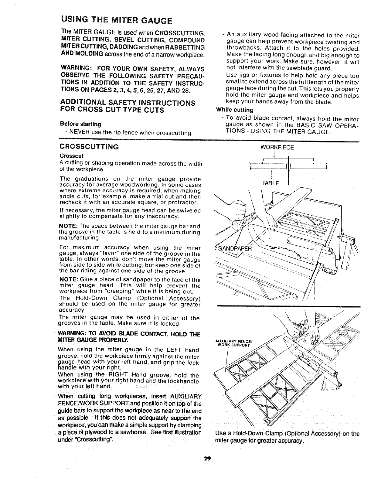
CROSSCUTTING
Crosscut
A cutting or shaping operation made across the width
of the workpiece.
The graduations on the miter gauge provide
accuracy for average woodworking. In some cases
where extreme accuracy is required, when making
angle cuts, for example, make a trial cut and then
recheck it with an accurate square, or protractor.
If necessary, the miter gauge head can be swiveled
slightly to compensate for any inaccuracy.
NOTE: The space between the miter gauge barand
the groove in the table is held to a minimum during
manufacturing
For maximum accuracy when using the miter
gauge, always "favor" one sade of the groove in the
table. In other words, don't move the miter gauge
from side to side while cutting, but keep one side of
the bar riding against one side of the groove.
NOTE: Glue a piece of sandpaoer to the face of the
miter gauge head. This will help prevent the
workpiece from "creeping" while it is being cut.
The Hold-Down Clamp (Optional Accessory)
sP]ould be used on the miter gauge for greater
accuracy.
The miter gauge may _e used in either of the
grooves m the table. Make sure it is locked.
WARNING: TO AVOID BLADE CONTACT, HOLD THE
MITER GAUGE PROPERLY.
When using the miter gauge in the LEFT hand
groove, hold the workpiece firmly against the miter
gauge head with your left hand. and grip the Fock
handle with your r_ght.
When using the RIGHT Hand groove, hold the
workpiece with your right hand and the !ockhandle
with your left hand
When cutting long workpieces, insert AUXILIARY
FENCE/WORK SUPPORT and position it on top of the
guide bars to support the workpiece as near to the end
as possible. If this does not adequately support the
workpiece, you can make a simple support by clamping
a piece of plywood to a sawhorse. See first illustration
under "Crosscutting.
\
\
PER
AUXILIARY FENCE!
WORK SUPPORT
ir
WORKPIECE
1
l I Jt l-2
TABLE
\\\
Use aHold-Down Clamp (Optional Accessory) on the
miter gauge for greater accuracy,
29
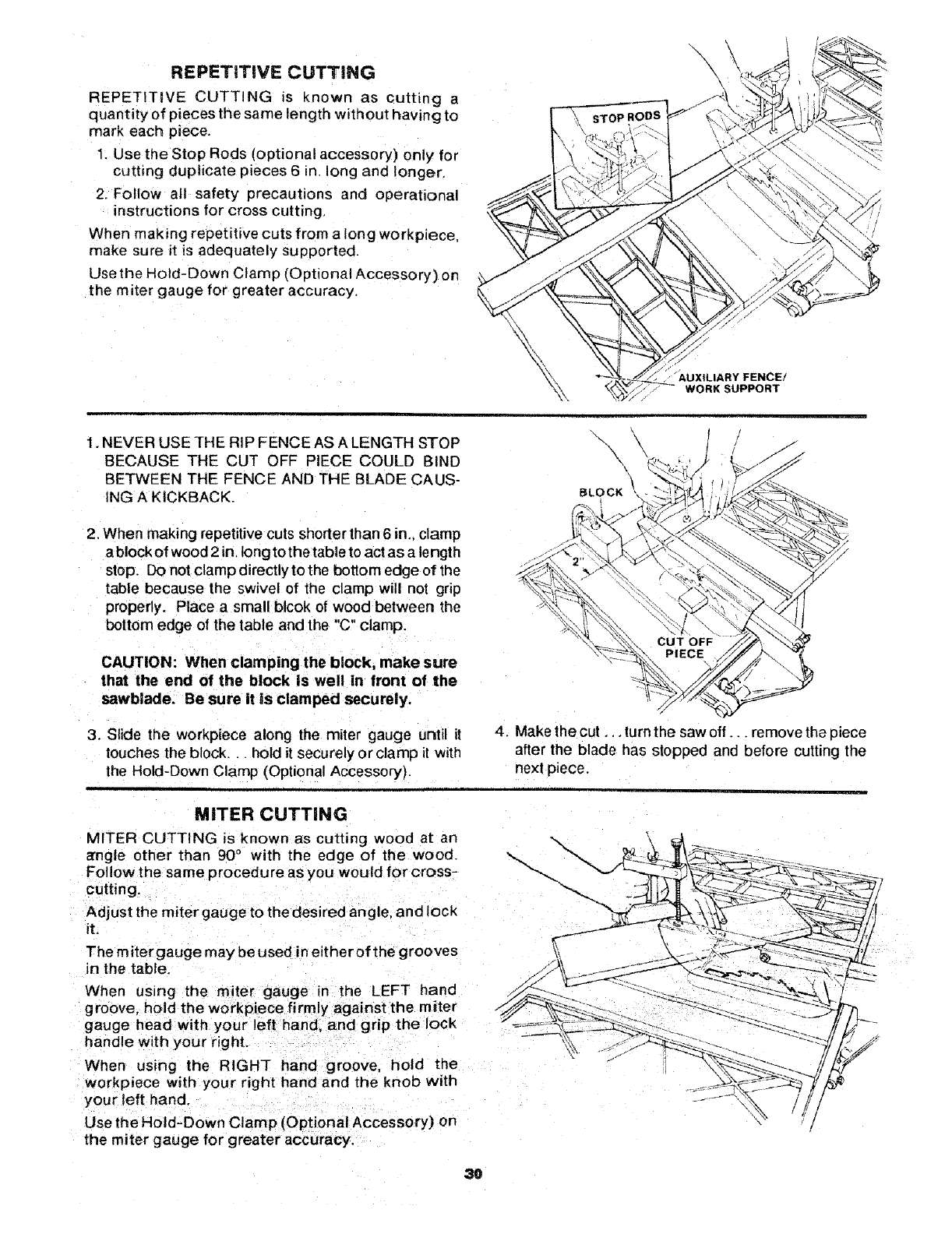
REPETITIVE CUTTING
REPETITIVE CUTTING is known as cutting a
quantity of pieces the same length without having to
mark each piece.
1. Use the Stop Rods (optional accessory) only for
cutting duplicate pieces 6 in. long and longer,
2. Follow all safety precautions and operational
instructions for cross cutting,
When making repetitive cuts from a long workpiece,
make sure it is adequately supported.
Use the Hold-Down Clam p (Optional Accessory) on
the miter gauge for greater accuracy,
_'_ AUXILIARY FENCE/
WORK SUPPORT
1. NEVER USE THE RIP FENCE AS A LENGTH STOP
BECAUSE THE CUT OFF PIECE COULD BIND
BETWEEN THE FENCE AND THE BLADE CAUS-
ING A KICKBACK.
2. When making repetitive cuts shorter than 6in,. clamp
a block of wood 2 in. tong to the table to act as a length
stop. Do not clamp directly to the bottom edge of the
table because the swivel of the clamp will not grip
properly. Place a small blcok of wood between the
bottom edge of the table and the "C" clamp.
CAUTION: When clamping the block, make sure
that the end of the block Is well in front of the
sawblade. Be sure it is clamped securely.
3. Slide the workpiece along the miter gauge until it
touches the block, hold it securely or clamp it with
the Hold-Down Clamp (Optional Accessory).
\\ \
BLOCK
4. Make the cut ... turn the saw off.., remove the piece
after the blade has stopped and before cutting the
next piece.
MITER CUTTING
MITER CUTTING is known as cutting wood at an
_rngle other than 90 ° with the edge of the wood.
Follow the same procedure as you would for cross-
cutting.
Adjust the miter gauge to the desired angle, and lock
it,
The miter gauge may be used in either of the grooves
in the table,
When us=rig the mi_er gauge in the LEFT hand
groove, hold the workpiece firmly against the miter
gauge head with your left hand. and grip the lock
handle with your right.
When using the RIGHT hand groove, hold the
workpiece with your right hand and the knob with
your left hand.
Use the Hold-Down Clamp (Optional Accessory) on
the miter gauge for greater accuracy.
30
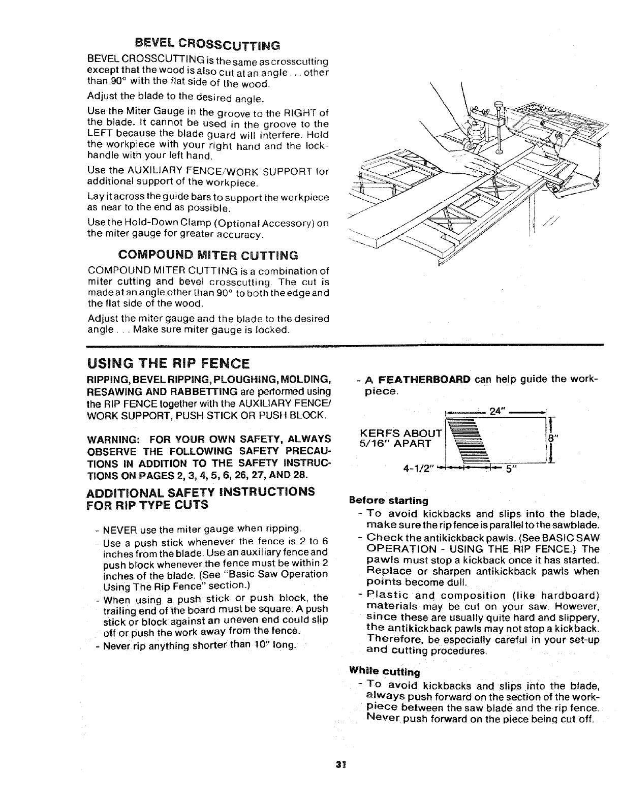
BEVEL CROSSCUTTING
BEVEL CROSSCUTTI NG is the same as crosscutting
except that the wood is also cut at an ang{e,, • other
than 90° with the flat side of the wood.
Adjust the blade to the desired angle.
Use the Miter Gauge in the groove to the RIGHT of
the blade. _t cannot be used in the groove to the
LEFT because the blade guard wilm interfere. Hold
the workpiece with your right hand and the lock-
handle with your left hand.
Use the AUXILIARY FENCE/WORK SUPPORT for
additional support of the workpiece_
Lay it across the guide bars to support the workpiece
as near to the end as possible.
Use the Hold-Down Clamp (Optional Accessory) on
the miter gauge for greater accuracy.
COMPOUND MITER CUTTmNG
COMPOUND MITER CUTTING is a combination of
miter cutting and bevel crosscutting. The cut is
made at an angle other than 90° to both the edge and
the flat side of the wood.
Adjust the miter gauge and the blade to the desired
angle... Make sure miter gauge is locked.
USING THE RiP FENCE
RIPPING, BEVEL RIPPING, PLOUGHING, MOLDING,
RESAWING AND RABBETTING are performed using
the RIP FENCE together with the AUXILIARY FENCE/
WORK SUPPORT, PUSH STICK OR PUSH BLOCK.
WARNING: FOR YOUR OWN SAFETY, ALWAYS
OBSERVE THE FOLLOWING SAFETY PRECAU-
TIONS iN ADDITION TO THE SAFETY INSTRUC-
TIONS ON PAGES 2, 3, 4, 5, 6, 26, 27, AND 28.
ADDiTiONAL SAFETY iNSTRUCTiONS
FOR RiP TYPE CUTS
- NEVER use the miter gauge when ripping.
- Use a push stick whenever the fence is 2 to 6
inches from the blade. Use an auxitiary fence and
push block whenever the fence must be within 2
inches of the blade. (See "Basic Saw Operation
Using The Rip Fence" section.)
-When using a push stick or push block the
trailing end of the board must be square. A push
stick or block against an uneven end could slip
off or push the work away from the fence.
- Never rip anything shorter than !0" long.
- A FEATHERBOARD can help guide the work-
piece.
I-- 24"
KERFS ABOUT ]_,
5/16" APART
4-1/2' 5"
Before starting
-To avoid kickbacks and slips into the blade,
make su re the rip fence is parallel to the sawblade.
- Check the antikickback pawls. (See BASIC SAW
OPERATION - USING THE RIP FENCE.) The
pawls must stop a kickback once it has started.
Replace or sharpen antikickback pawls when
points become dull.
-Plastic and composition (ike hardboard)
materials may be cut on your saw. However,
since these are usually quite hard and slippery,
the antikickback pawls may not stop a kickback.
Therefore, be especially careful in your set-up
and cutting procedures.
While cutting
-To avoid kickbacks and slips into the blade.
a!ways push forward on the section of the work-
piece between the saw blade and the rip fence.
Never push forward on the piece beinq cut off.
31
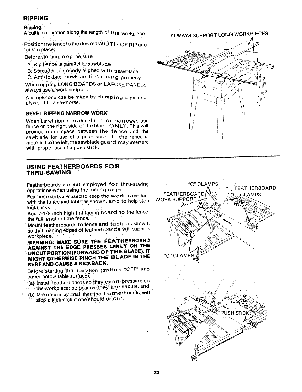
RIPPING
Ripping
Acutting operation along the length of the workpiece.
Position the fence to the desired WIDTH OF RIP and
lock in place.
Before starting to rip, be sure
A_ Rip Fence is parallel to sawblade.
B. Spreader is properly aligned with sawblade
C. Antikickback pawls are functioning properly
When ripping LONG BOARDS or LARGE PANEL_
always usea work support.
A simple one can be made by clamping a piece ol
plywood to a sawhorse.
BEVEL RIPPING NARROW WORK
When bevel ripping material 6 in. or narrower, use
fence on the right side of the blade ONLY. This will
provide more space between the fence and the
sawblade for use of a push stick. If the fence is
mounted to the left, the sawblade guard may _nterfere
with proper use of a push stick.
ALWAYS SUPPORT LONG WORKPIECES
//
USING FEATHERBOARDS FOR
THRU-SAWlNG
Featherboards are not employed for thru-sawing
operations when using the miter gauge.
Feat herboards are used to keep the work in contact
with the fence and table as shown, and to heip stop
kickbacks.
Add 7-1/2 inch high flat facing board to the fence,
the full length of the fence.
Mount featherboards to fence and table as shown,
so that leading edges of featherboards will support
workpiece.
WARNING: MAKE SURE THE FEATHERBOARD
AGAINST THE EDGE PRESSES ONLY ON THE
UNCUT PORTION (FORWARD OF THE BLADE). IT
MIGHT OTHERWISE PINCH THE BLADE IN THE
KERF AND CAUSE A KICKBACK.
Before starting the operation (switch "OFF" and
cutter below table surface):
(a) Install featherboards so they exert pressure on
the workpiece; be positive they are secure, and
(b} Make sure by trial that the featherboards will
stop a kickback if one should occur.
"C" CLAMPS
FEATHERBOARD
WORK SUPPORT..
"C'" CLAMPS
_FEATHERBOARD
32
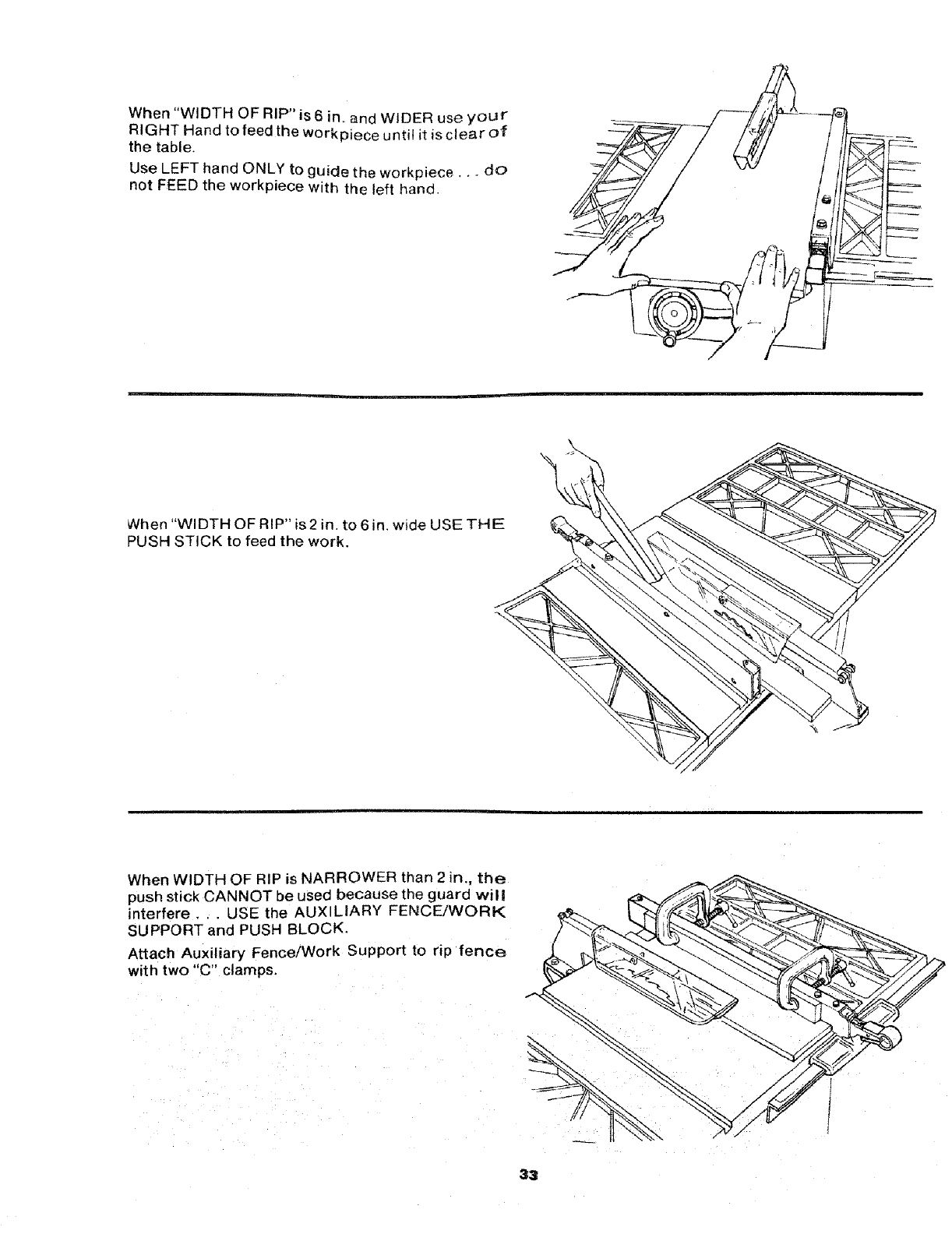
When "WIDTH OF RIP" is6 in, and WIDER use your
RIGHT Hand to feed the workpiece until it is clear of
the table,
Use LEFT hand ONLY to guide the workpiece.,, do
not FEED the workpiece with the left hand.
When "Wl DTH OF RIP" is 2 in. to 6 in, wide USE THE
PUSH STICK to feed the work.
When WIDTH OF RIP is NARROWER than 2 in., the
push stick CANNOT be used because the guard wil!
interfere, . . USE the AUX LIARY FENCE/WORK
SUPPORT and PUSH BLOCK,
Attach Auxiliary Fence/Work Support to rip fence
with two "C" clam ps.
33
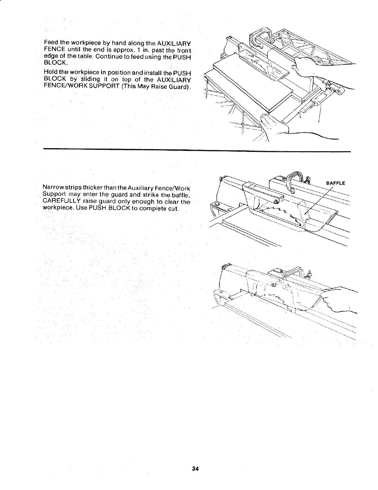
Feed the workpiece by hand along the AUXILIARY
FENCE until the end is approx. 1 in. past the front
edge of the table. Continue to feed using the PUSH
BLOCK,
Hold the workpiece in position and install the PUSH
BLOCK by sliding it on top of the AUXILIARY
FENCE/WORK SUPPORT (This May Raise Guard).
Narrow strips thicker than the Auxiliary Fence!Work
Support may enter the guard and strike the baffle.
CAREFULLY raise guard only enough to clear the
workpiece. Use PUSH BLOCK to complete cut.
BAFFLE
34
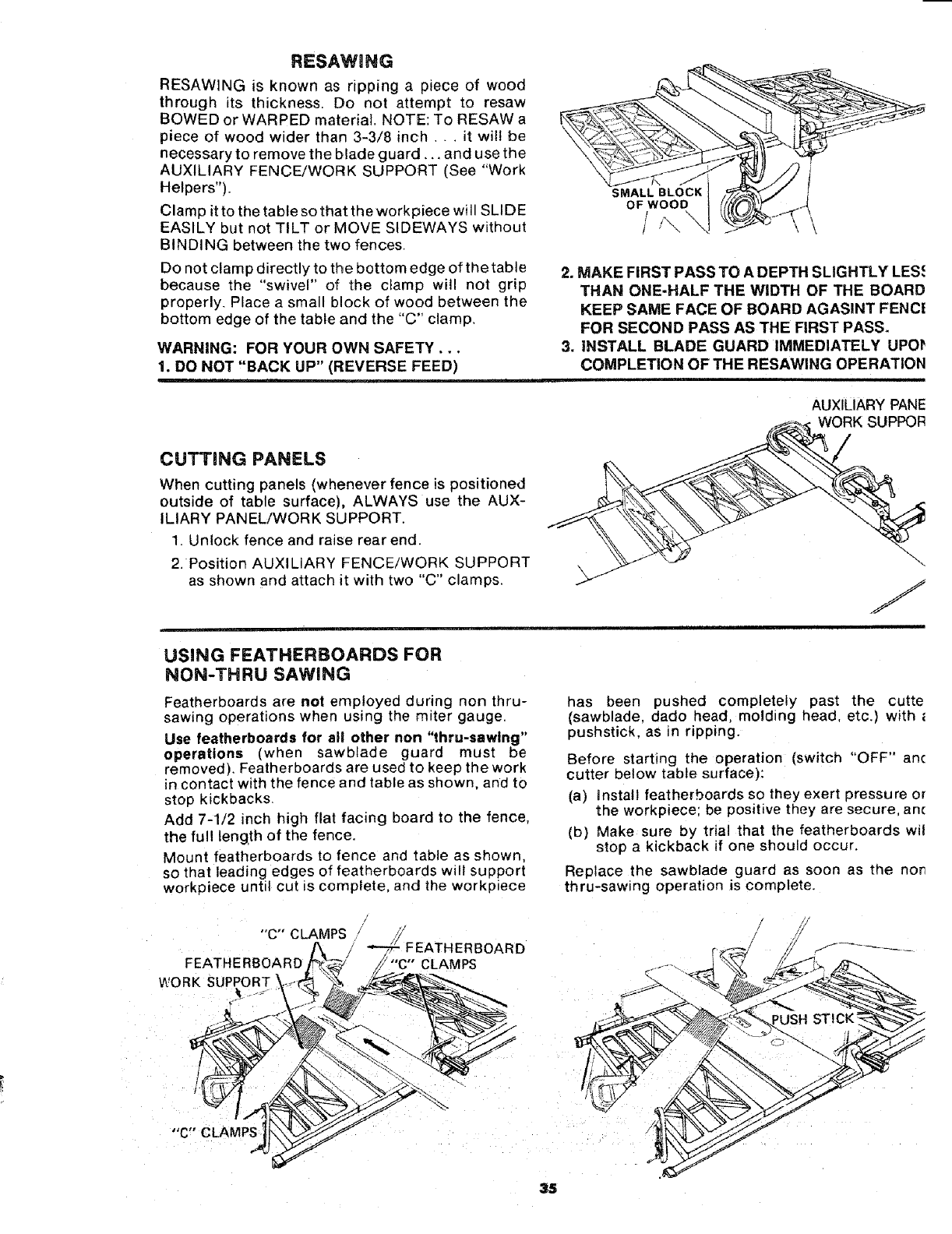
RE;SAWING
RESAWING is known as ripping apiece of wood
through its thickness. Do not attempt to resaw
BOWED or WARPED material. NOTE: To RESAW a
piece of wood wider than 3-3/8 inch . ..it will be
necessary to remove the blade guard,,, and use the
AUXILIARY FENCE/WORK SUPPORT (See "Work
Helpers").
Clamp itto the table so that the workpiece will SLIDE
EASILY but not TILT or MOVE SIDEWAYS without
BINDING between the two fences.
Do not clamp directly to the bottom edge of the table
because the "swivel" of the clamp will not grip
properly. Place a small block of wood between the
bottom edge of the table and the "C" clamp.
WARNING: FOR YOUR OWN SAFETY,..
1. DO NOT "BACK UP" (REVERSE FEED)
SMALL BLOCK
OF WOOD
/
/
2. MAKE FIRST PASS TO A DEPTH SLIGHTLY LES.€
THAN ONE-HALF THE WIDTH OF THE BOARD
KEEP SAME FACE OF BOARD AGASINT FENCi
FOR SECOND PASS AS THE FIRST PASS.
3. INSTALL BLADE GUARD IMMEDIATELY UPOI_
COMPLETION OF THE RESAWING OPERATION
CUTTING PANELS
When cutting panels (whenever fence is positioned
outside of table surface), ALWAYS use the AUX-
ILIARY PANEL/WORK SUPPORT.
1. Unlock fence and raise rear end.
2. Position AUXILIARY FENCE/WORK SUPPORT
as shown and attach it with two "C" clamps.
AUXILIARY PANE
USING FEATHERBOARDS FOR
NON-THRU SAWING
Featherboards are not employed during non thru-
sawing operations when using the miter gauge.
Use featherboards for all other non "thru-sawlng"
operations (when sawblade guard must be
removed). Featherboards are used to keep the work
in contact with the fence and table as shown, and to
stop kickbacks.
Add 7-1/2 inch high flat facing board to the fence,
the full length of the fence.
Mount featherboards to fence and table as shown,
so that leading edges of featherboards will support
workoiece until cut is complete, and the workpiece
has been pushed completely past the cutte
(sawblade, dado head, molding head, etc.) with
pushstick, as n ripping.
Before starting the operation (switch "OFF" ant
cutter below table surface):
(a) Instalt featherboards so they exert pressure or
the workpiece: be positive they are secure an€
(b) Make sure by trial that the featherboards wil
stop a kickback if one should occur.
Replace the sawblade guard as soon as the non
thru-sawing operation is complete.
"C" CLAMPS
BOARD
FEATHERBOARD "C'" CLAMPS
WORK SUPPORT
"'C" CLAMPS
35
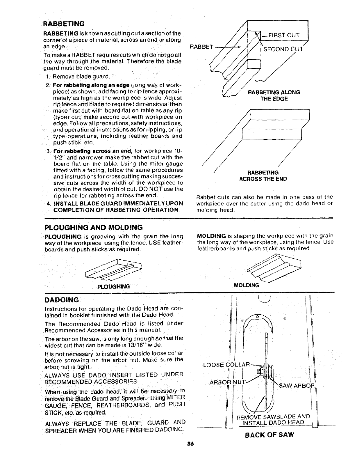
RABBETING
RABBETING is known as cutting out a section of the
corner of apiece of material, across an end or along
an edge
To make a RABBET requires cuts which do not go all
the way through the material. Therefore the blade
guard must be removed
1 Remove blade guard.
2. For rabbeting along an edge (long way of work-
piece) as shown, add facing to rip fence approxi-
mately as high as the workplece is wide. Adjust
rip fence and blade to required dimensions; then
make first cut with board flat on table as any rip
(type) cut: make second cut with workpiece on
edge. Follow al! precautions, safety instructions,
and operational instructions as for ripping, or rip
type operations, including feather boards and
push stick etc.
3. For rabbeting across an end, for workpiece 10-
1/2" and narrower make the rabbet cut with the
board flat on the table. Using the miter gauge
fitted with a facing, follow the same procedures
and instructions for cross cutting making succes-
sive cuts across the width of the workpiece to
obtain the desired width of cut. DO NOT use the
rip fence for rabbeting across the end.
4. iNSTALL BLADE G UARD IMMEDIATELY UPON
COMPLETION OF RABBETING OPERATION,
RA
_FIRST CUT J
J
SECOND CUT
/
/
/
/
/
/
/
/
RABBETING ALONG
THE EDGE
/
/
/
/
/
/
RABBETING
ACROSS THE END
Rabbet cuts can also be made in one pass of the
workpiece over the cutter using the dado head or
molding head.
i
PLOUGHING AND MOLDaNG
PLOUGHING is grooving with the grain the long
way of the workpiece using the fence. USE feather-
boards and push sticks as req ui red,
PLOUGHING
DADOING
Instructions for operating the Dado Head are con-
tained in booklet furnished with the Dado Head.
The Recommended Dado Head is isted under
Recommended Accessories in this manual.
The arbor on the saw, is only long enough so that the
widest cut that can be made is 13/16" wide.
It is not necessary to install the outside loose cotlar
before screwing o_ the arbor nut. Make sure the
arbor nut is tight.
ALWAYS USE DADO INSERT LISTED UNDER
RECOMMENDED ACCESSORIES.
MOLDING _sshaping the worKplece w_th the grain
the long way of the workpiece, using the fence. Use
featherboards and push sticks as rec uired
MOLDING
,, ,p ,
LOOSE COLLAR'-----_j
1
ARBOR NUT"
When using the dado head, it will be necessary to
removelhe Blade Guard and Spreader. Using MITER
GAUGE, FENCE, REATHERBOARDS and PUSH
STICK, etc. as required,
ALWAYS REPLACE THE BLADE, GUARD AND
SPREADER WHEN YOU ARE FINISHED DADOING.
_SAW ARBOR
REMOVE SAWBLADEAND
INSTALL DADO HEAD
BACK OF SAW
36
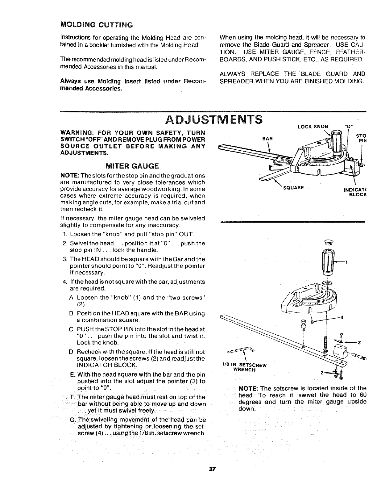
MOLDING CUTTING
Instructionsfor operating the Molding Head are con-
tained in a booklet furnished with the Molding Head.
The recommended molding head is listed under Recom-
mended Accessories in this manual.
Always use Molding Insert listed under Recom-
mended Accessories.
When using the molding head, it wil! be necessary to
remove the Blade Guard and Spreader. USE CAU-
TION. USE MITER GAUGE, FENCE, FEATHER-
BOARDS, AND PUSH STICK, ETC., AS REQUIRED.
ALWAYS REPLACE THE BLADE GUARD AND
SPREADER WHEN YOU ARE FINISHED MOLDING.
ADJUSTMENTS
WARNING: FOR YOUR OWN SAFETY, TURN
SWITCH "OFF" AND REMOVE PLUG FROM POWER
SOURCE OUTLET BEFORE MAKING ANY
ADJUSTMENTS.
BAR
i
LOCK KNOB
\
"0"
STO
PIN
MITER GAUGE
NOTE: The slots for the stop pin and the graduations
are manufactured to very close tolerances which
provide accuracy for average woodworking. In some
cases where extreme accuracy is required, when
making angle cuts, for example, make a trial cut and
then recheck it.
f necessary, the miter gauge head can be swiveled
slightly to compensate for any inaccuracy.
1. Loosen the "knob" and pull "stop ;)in" OUT.
2. Swivel the head., position it at "0"... push the
stop pin IN... lock the handle.
3. The HEAD should be square with the Bar and the
pointer should point to "0". Readjust the pointer
if necessary.
4. If the head is not square with the bar. adjustments
are required.
A Loosen the "knob" (1) and the "two screws"
(2).
B Position the HEAD square with the BAR using
a combination square.
C PUSH the STOP PIN into the slot in the head at
"0" .. push the pin into the slot and twist it.
Lock the knob.
D. Recheck with the square. If the head is still not
square, loosen thescrews (2) and readjust the
INDICATOR BLOCK.
E. With the head square with the bar and the pm
pushed into the slot adjust the pointer (3) to
point to "0".
F. The miter gauge head must rest on top of the
bar without being able to move up and down
•.. yet it must swivel freely
G. The swiveling movement of the head can be
adjusted by tightening or loosening the set-
screw (4)... using the 1/8 in. setscrew wrench.
SQUARE IND|CAT(
BLOCK
I
t
V
1/8 IN. SETSCREw
WRENCH 2_
NOTE: The setscrew is located inside of the
head. To reach it, swivel the head to 60
degrees and turn the miter gauge upside
down.
37
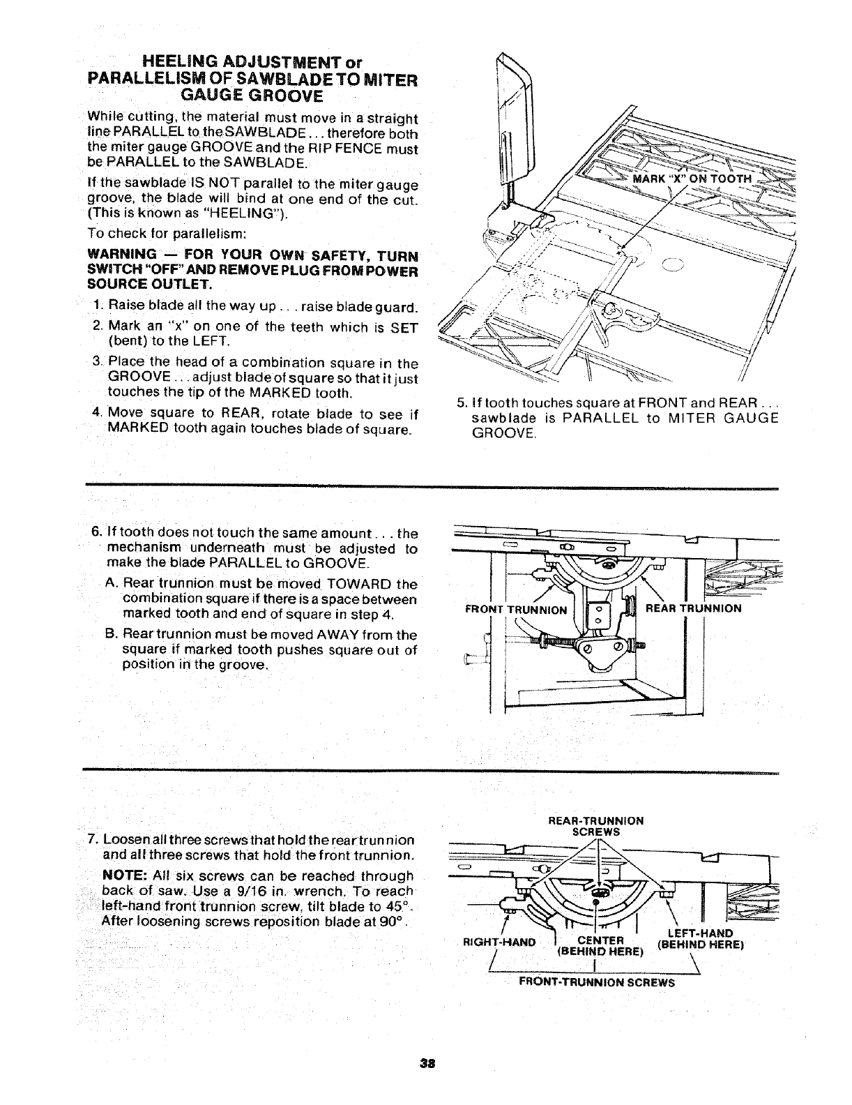
HEELING ADJUSTMENT or
PARALLELISM OF SAWBLADE TO MITER
GAUGE GROOVE
While cutting, the material must move in a straight
line PARALLEL to the SAWBLADE... therefore both
the miter gauge GROOVE and the RIP FENCE must
be PARALLEL to the SAWBLADE,
If the sawblade IS NOT parallel to the miter gauge
groove, the blade will bind at one end of the cut.
(This is known as "HEELING"),
To check for parallelism:
WARNING -- FOR YOUR OWN SAFETY, TURN
SWITCH "OFF" AND REM OVE PLUG FROM POWER
SOURCE OUTLET.
1. Raise blade all the way up., • raise blade guard.
2. Mark an "'x" on one of the teeth which is SET
(bent) to the LEFT
3. Place the head of acombination square in the
GROOVE ,,. adjust blade of square so that it just
touches the tip of the MARKED tooth_
4, Move square to REAR. rotate blade to see if
MARKED tooth again touches blade of square.
5, If tooth touches square at FRONT and REAR..
sawblade is PARALLEL to MITER GAUGE
GROOVE.
6. If tooth does not touch the same amount .. the
mechanism underneath must be adjusted to
make the blade PARALLEL to GROOVE.
A. Rear trunnion must be moved TOWARD the
combination square if there is a space between
marked tooth and end of square in step 4
13.Rear trunnion must be moved AWAY from the
square if marked tooth pushes square out of
position in the groove,
FRONT TRUNNION REAR TRUNNION
7, Loosen all three screwsthat hold the rear trun nion
and all three screws that hold the front trunnion,
NOTE: All six screws can be reached through
back of saw. Use a 9/16 in, wrench. To reach
left-hand front trunnion screw, tilt blade to 45 °.
After loosening screws reposition blade at 90 °.
REAR-TRUNNION
SCREWS
(BEHIND HERE) (BEHIND HERE)
i\
FRONT-TRUNNION SCREWS
38
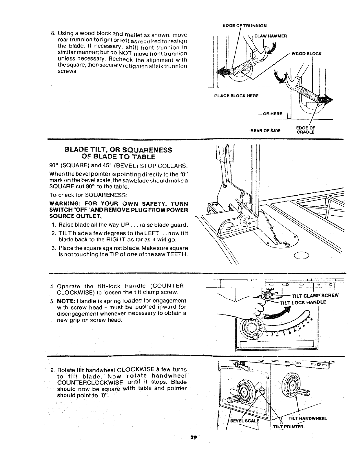
8. Using a wood block and mallet as showm move
rear trunnion to right or left as required to realign
the blade. If necessary, shift front trunnion in
similar manner; but do NOT move front trunnion
unless necessary. Recheck the alignment with
the square, then securely retighten a!l six trunnion
screws.
EDGE OF TRUNNION
CLAW HAMMER
WOOD BLOCK
PLACE BLOCK HERE_ OR HERE
),
EDGE OF
REAR OF SAW CRADLE
BLADE TILT, OR SQUARENESS
OF BLADE TO TABLE
90°(SQUARE) and 45°(BEVEL) STOP COLLARS.
When the bevel pointer is pointing directly to the "0"
mark on the bevel scale, the sawblade should makea
SQUARE cut 90° to the table.
To check for SQUARENESS:
WARNING: FOR YOUR OWN SAFETY, TURN
SWITCH "OFF' AND REMOVE PLUG FROM POWER
SOURCE OUTLET.
1. Raise blade all the way UP... raise blade guard.
2. TILT blade a few degrees to the LEFT... now dlt
blade back to the RIGHT as far as it will go.
3. Place the square against blade. Make sure square
is not touching the TIP of one of the saw TEETH.
4. Operate the tilt-lock handle (COUNTER-
CLOCKWISE) to loosen the tilt clamp screw.
5. NOTE: Handle is spring loaded for engagement
with screw head - must be pushed inward for
disengagement whenever necessary to obtain a
new grip on screw head.
"ILT LOCK HANDLE
6. Rotate tilt handwheel CLOCKWISE a few turns
to tilt blade, Now rotate handwheel
COUNTERCLOCKWISE until it stops. Blade
should now be square with table and pointer
should point to "0".
39
BEVEL SCALE TILT HANDWHEEL
TILLPOINTER
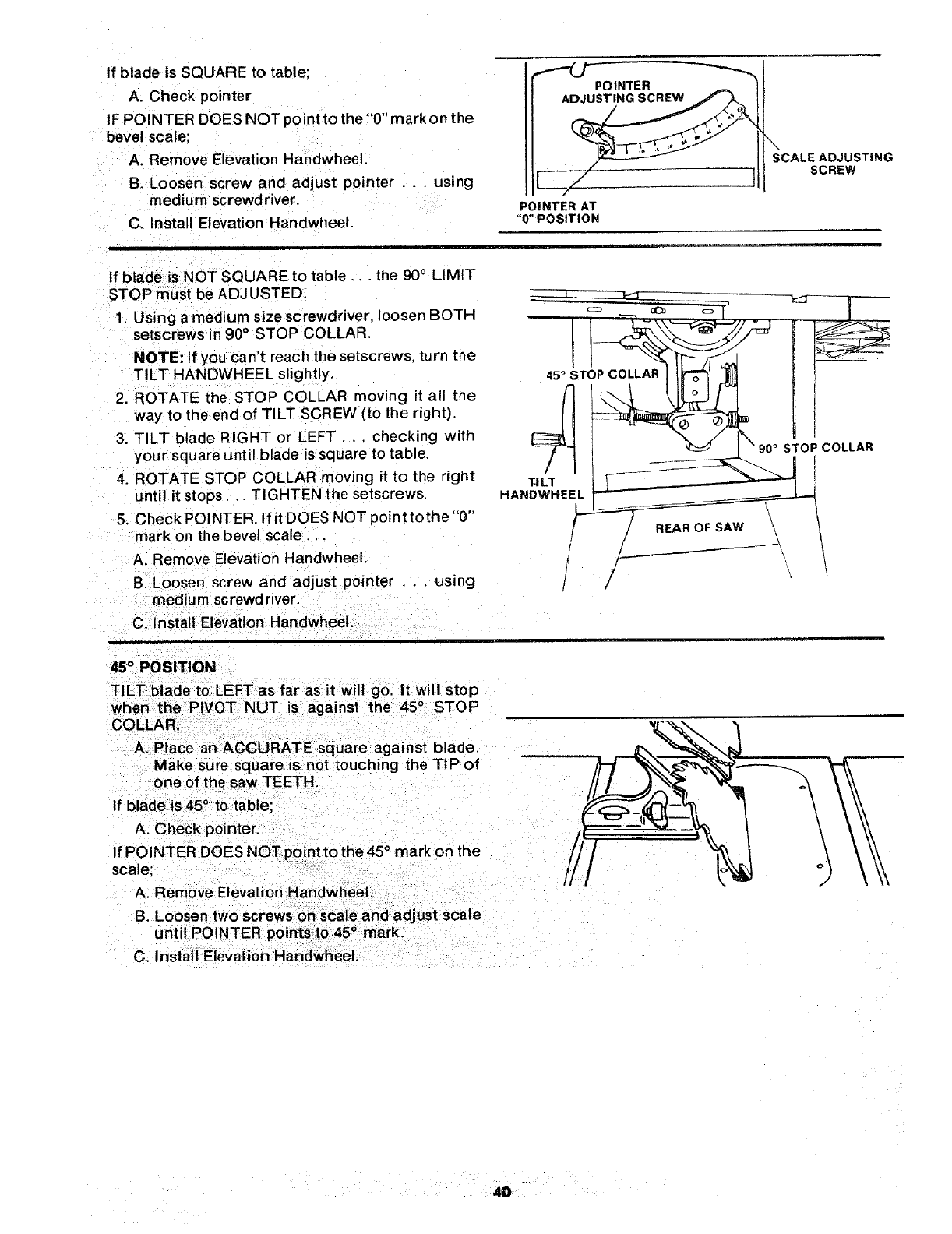
If blade is SQUARE to table;
A. Check pointer
IF POINTER DOES NOT pointto the"0" mark on the
bevel scale:
A. Remove Elevation Handwheel.
B. Loosen screw and adjust pointer . . . using
medium screwdriver.
C. Install Elevation Handwheel.
POINTER
POINTER AT
"O"POSITION
SCALE ADJUSTING
SCREW
If blade is NOT SQUARE tc table.., the 900 LIMIT
STOP must be ADJUSTED.
1. Using amedium sizescrewdriver, loosen BOTH
setscrews in 90° STOP COLLAR.
NOTE: If you can't reach the setscrews, turn the
TILT HANDWHEEL slightly.
2. ROTATE the STOP COLLAR moving it all the
way to the end of TILT SCREW (to the right).
3. TILT blade RIGHT or LEFT... checking with
your square until blade is square to table+
4. ROTATE STOP COLLAR moving it to the right
until it stops,, _TIGHTEN the setscrews.
5. Check POINTER. If it DOES NOT point tothe "0"
mark on the bevel scale.
A. Remove Elevation Handwheel.
B. Loosen screw and adjust pointer . . . using
medium screwdriver.
C. Install Elevation HandwheeL
45 °STOP COLLAR
4
TI LT
HANDWHEEL
STOP COLLAR
45° POSITION
TILT blade to LEFTas farasit will go, It will stop
when the PIVOT NUT is against the 45 ° STOP
COLLAR.
A. Place an ACCURATE square against blade.
Make sure square is not touching the TiP of
one of the saw TEETH.
If bladeis45 ° to table;
A. Check pointer.
If POINTER DOES NOT point tothe45 °mark on the
scale;
A. Remove Elevation HandwheeL
B. Loosen two screws on scale and adjust scale
unt IPC NTER points to 45° mark.
C. install Elevation Handwheel.
4O
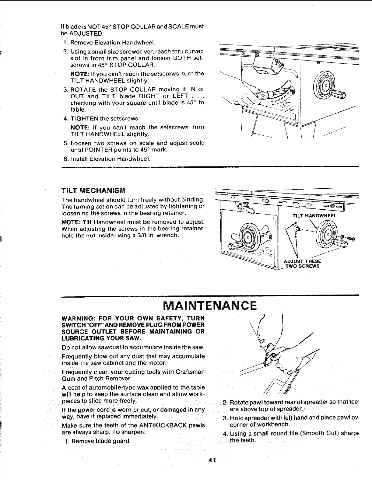
IfbladeisNOT45° STOPCOLLARandSCALEmust
beADJUSTED.
1.RemoveElevationHandwheel.
2. Usingasmallsizescrewdriver,reachthrucurved
slot in front trim paneland loosenBOTHset-
screwsin45°STOP COLLAR.
NOTE: If you can't reach the setscrews, turn the
TILT HANDWHEEL slightly.
3. ROTATE the STOP COLLAR moving it IN or
OUT and TILT blade RIGHT or LEFT .. .
checking with your square until blade is 45° to
table.
4. TIGHTEN the setscrews.
NOTE: If you can't reach the setscrews, turn
TILT HANDWHEEL slightly.
5. Loosen two screws on scale and adjust scale
until POINTER points to 45° mark.
6. Install Elevation Handwheel.
TiLT MECHANISM
The handwheel should turn freely without binding.
The turning action can be adjusted by tightening or
loosening the screws in the bearing retainer.
NOTE: Tilt Handwheel must be removed to adjust.
When adjusting the screws _nthe bearing retainer,
hold the nut inside using a 3/8 in. wrench.
TILT HANDWHEEL
J
J
/
ADJUST THESE
TWO SCREWS
MAINTENANCE
WARNING: FOR YOUR OWN SAFETY, TURN
SWITCH "OFF" AND REMOVE PLUG FROM POWER
SOURCE OUTLET BEFORE MAINTAINING OR
LUBRICATING YOUR SAW,
Do not allow sawdust to accumulate inside the saw.
Frequently blow out any dust that may accumulate
inside the saw cabinet and the motor.
Frequently clean your cutting tools with Craftsman
Gum and Pitch Remover.
Acoat of automobile-type wax applied to the table
will help to keep the surface clean and allow work-
pieces to slide more freely.
If the power cord is worn or cut, or damaged in any
way, have it replaced immediately.
Make sure the teeth of the ANTIKICKBACK pawls
are always sharp. To sharpen:
1 Remove blade guard.
2. Rotate paw l toward rear of spreader so that tee1
are above top of spreader.
3. Hold spreade rwith left hand and place pawl ov
corner of workbench.
4. Using asmatl round file (Smooth Cut) sharp_
the teeth.
4t
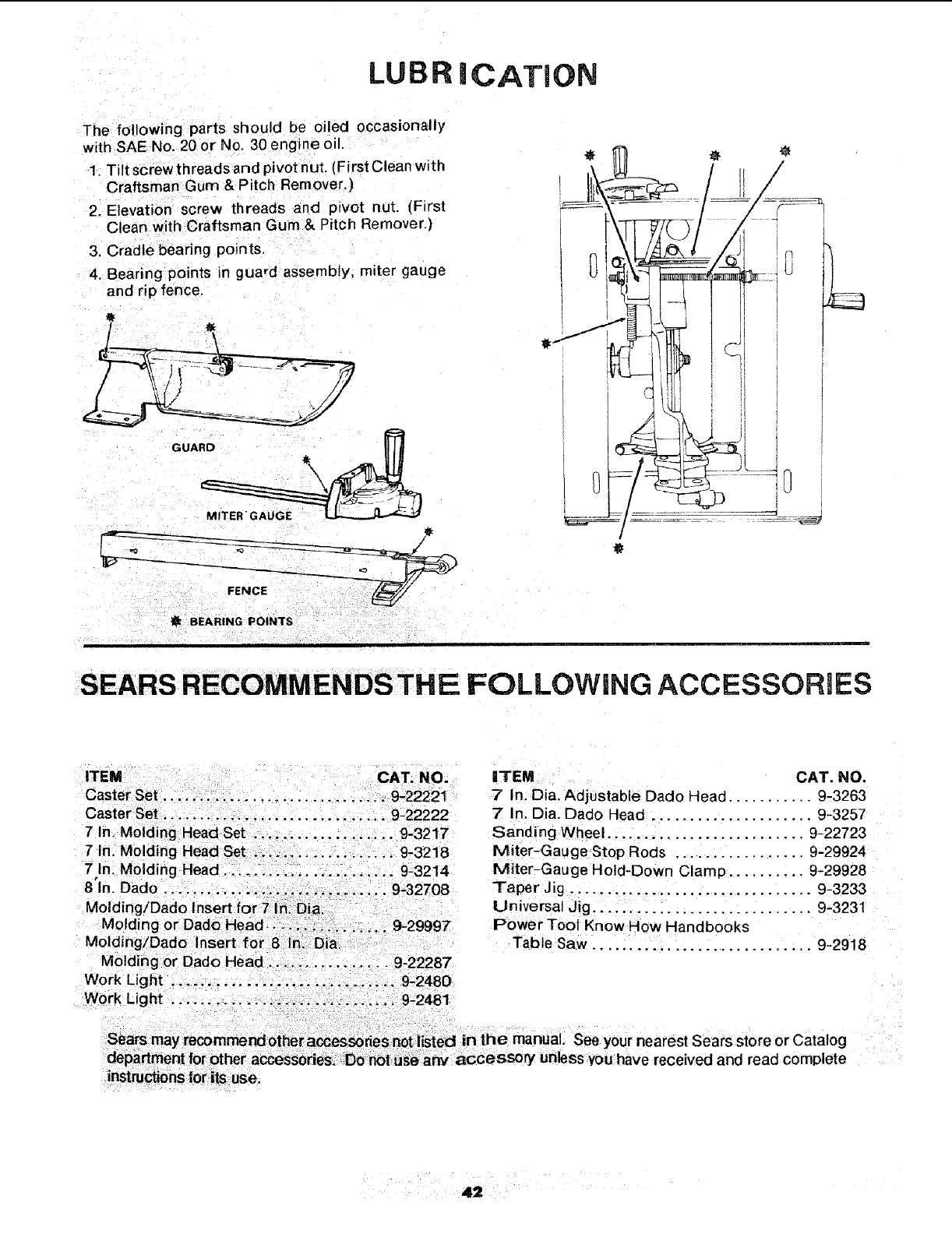
LUBRiCATiON
The following parts should be oiled occasionally
with SAE No. 20 or No. 30 engine oil.
1. Tilt screw th reads and pivot nut. (First Clean with
Craftsman Gum & Pitch Remover.)
2. Elevation screw threads and pivot nut. (First
Clean with Craftsman Gum & Pitch Remover.)
3. Cradle bearing points.
4. Bearing points n guard assembly, miter gauge
and rip fence.
0
t
tBEARING POINTS
SEARS RECOMMENDS THE FOLLOWING ACCESSORIES
CAT. NO.
7" In: Dia. Adjustable Dado Head ........... 9.3263
.._. :,_:,, ,:::;, 9_22222 7' In: Dia. Dado Head ....................... 9-3257
71nl U0iding Head set i i ,;: ii :, 9:3217 sanding Wheel.. i.. :_ ......... i ......... 9-22723
7 In: Molding i 9-32i8 Miter--Gauge stop Rods ................. 9-29924
7In! Molding Head _: ::: :i _ 9:3214 Miter'Gauge Hoid-Down Clamp ...... :.. 9-29928
8'In. Dado ;i ::. 9_32708 Taper,Jig .... ,.._.. ...................... 9'3233
Mold}ngiDad0 Universal Jig. :. i: _.:::., ................. 9=3231
Molding or Dado Power Tool KnoW How Handbooks
Mod ngiDado TabieSaW.. :.:i:!:_ ..... ..... 9-2918
Mbidi_g Or 0ad0 i::i i 9_22287
WorkUght _i:,i., :! 9_2480
nearest Sears store or Catalog
I read complete
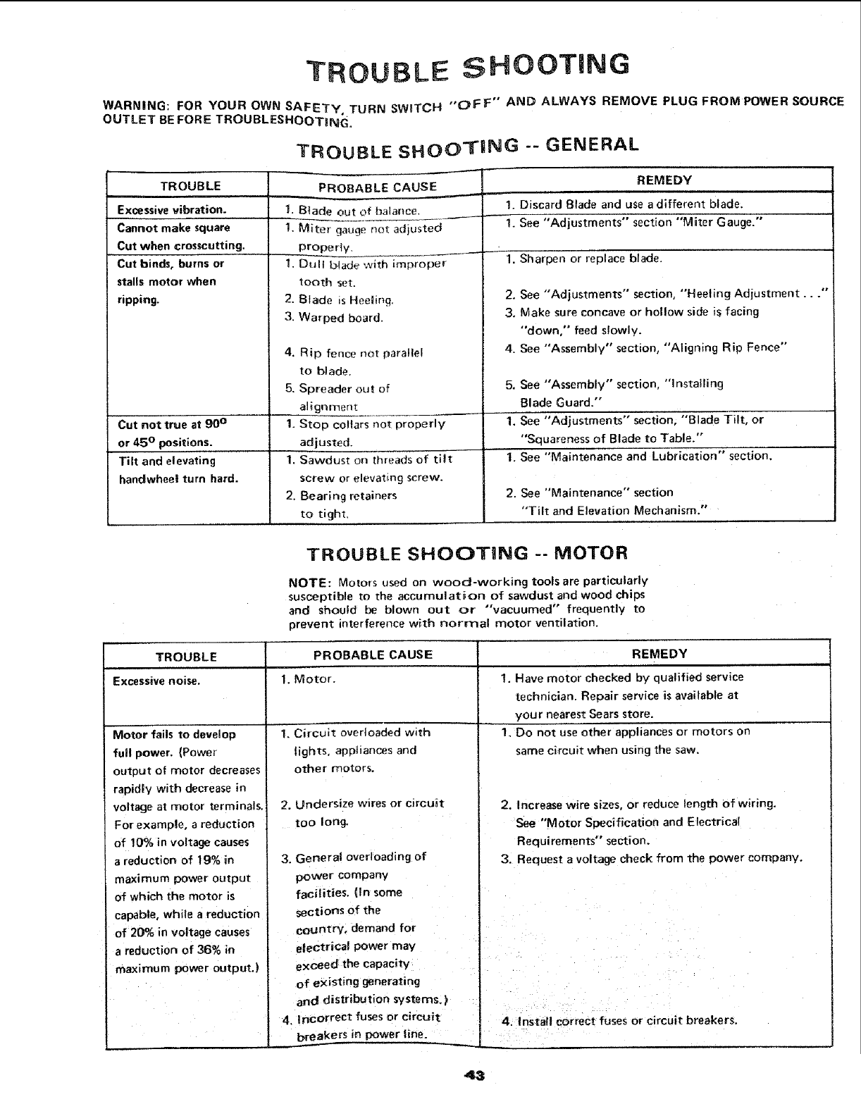
TROUBLE SHOOTING
WARNING: FOR YOUR OWN SAFETy, TURN SWITCH "OFF" AND ALWAYS REMOVE PLUG FROM POWER SOURCE
OUTLET BE FORE TROUBLESHOOTING.
TROUBLE SHOOTING "- GENERAL
TROUBLE
Excessive vibration.
Cannot make square
Cut when crosscutting,
Cut binds, burns or
stalls motor when
ripping.
PROBABLE CAUSE
1. Blade out of balanceL,____
1. Miter gauge not adjusted
properly,
1. Dull blade with improper
tooth set.
2. Blade is Heeling.
3. Warped board.
REMEDY
1, Discard Blade and use a different blade.
1. See "Adjustments" section "Miter Gauge."
4. Rip fence not parallel
to blade,
5. Spreader out of
alignment
1. Stop collars not properly
adjusted.
1. Sawdust on threads of ti_t
screw or elevating screw.
2. Bearing retainers
to tight,
1. Sharpen or replace blade.
2. See "Adjustments" section, "Heeling Adjustment...'"
3, Make sure concave or hollow side is facing
"down," feed slowly.
4. See "Assembly" section, "Aligning Rip Fence"
5. See "Assembly" section, "Installing
Blade Guard."
Cut not true at B0° 1. See "Adjustments" section, "'Blade Tilt, or
or 45 ° positions. "Squareness of Blade to Table."
Jn ""_' " n
Tilt and elevating 1. See Maintenance and Lubrication sect o .
handwhee| turn hard.
2. See "Maintenance" section
"Tilt and Elevation Mechanism."
TROUBLE SHOOTmNG -- MOTOR
NOTE: Motors used on wood-working tools are particularly
susceptible to the accumulation of sawdust and wood chips
and should be blown out or "vacuumed" frequently to
prevent interference with normal motor ventilation.
TROUBLE PROBABLE CAUSE
Excessive noise. 1. Motor.
Motor fails to develop
full power. (Power
output of motor decreases
rapidly with decrease in
voltage at motor terminals.
For example, areduction
of !0% in voltage causes
areduction of 19% in
maximum power output
of which the motor is
capable, while a reduction
of 20% in voltage causes
a reduction of 36% in
maximum power output.)
1. Circuit overloaded with
lights, appliances and
other motors.
2. Undersize wires or circuit
too long.
3. General overloading of
power company
facilities, (In some
sections of the
country, demand for
electrical power may
exceed the capacity
of existing generating
and distribution systems, }
4. Incorrect fuses or circuit
REMEDY
1. Have motor checked by qualified service
technician. Repair service is available at
your nearest Sears store.
1, Do not use other appliances or motors on
same circuit when using the saw.
2. Increase wire sizes, or reduce length of wiring.
See "Motor Specification and Electrical
Requirements" section.
3. Request a voltage check from the power company.
breakers in power line.
4. Install correct fuses or circuit breakers.
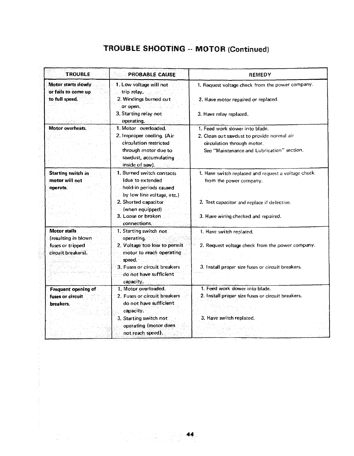
TROUBLE SHOOTING MOTOR (Continued)
IPROBABLE CAUSE
TROUBLE
to full speed,
Motor overheats,
REMEDY
Starting switch in
motor will not
operate.
1. Low voltage will not j
2. Windings burned out
'or open.
3. Starting relay not
operating.
1. Motor overloaded,
2. Improper cooling. (Air
circulation restricted
through motor due to
sawdust, accumulating
•inside of saw).
1. Burned switch contacts
(due to extended
hold-in periods caused
by low line voltage, etc.}
2. Shorted capacitor
(when equipped)
1. Request voltage check from the power company.
2. Have motor repaired or replaced.
3. Have relay replaced.
I. Feed work slower into blade.
2. Clean out sawdust to provide normal air
circulation through motor.
See "Maintenance and Lubrication" section.
1. Have switch replaced and request a voltage check
from the power company.
2. Test capacitor and replace if defective.
3. Loose or broken "3. Have wiring checked and repaired.
connections. I
I. Starting switch' not 1'. Have switch replaced.
t
{resulting in blown operating. o I orI1
fuses or tripped 2. Voltage to ow t pe m't I 2. Request voltage check from the power company.
circuit breakers), motor to reach operating I
,speed.
! 3. Fuses or circuit breakers 3. Install proper size fuses or circuit breakers.
do not have sufficient
tcapac=ty
I. Motor overloaded. I. Feed work slower into blade.
2. Fuses or circuit breakers i2. Install proper size fuses or circuit breakers.
breakers, do not have sufficient
Icapac=ty.
3. Starting switch not
operating (motor does
not reach speed).
3. Have switch replaced,
44
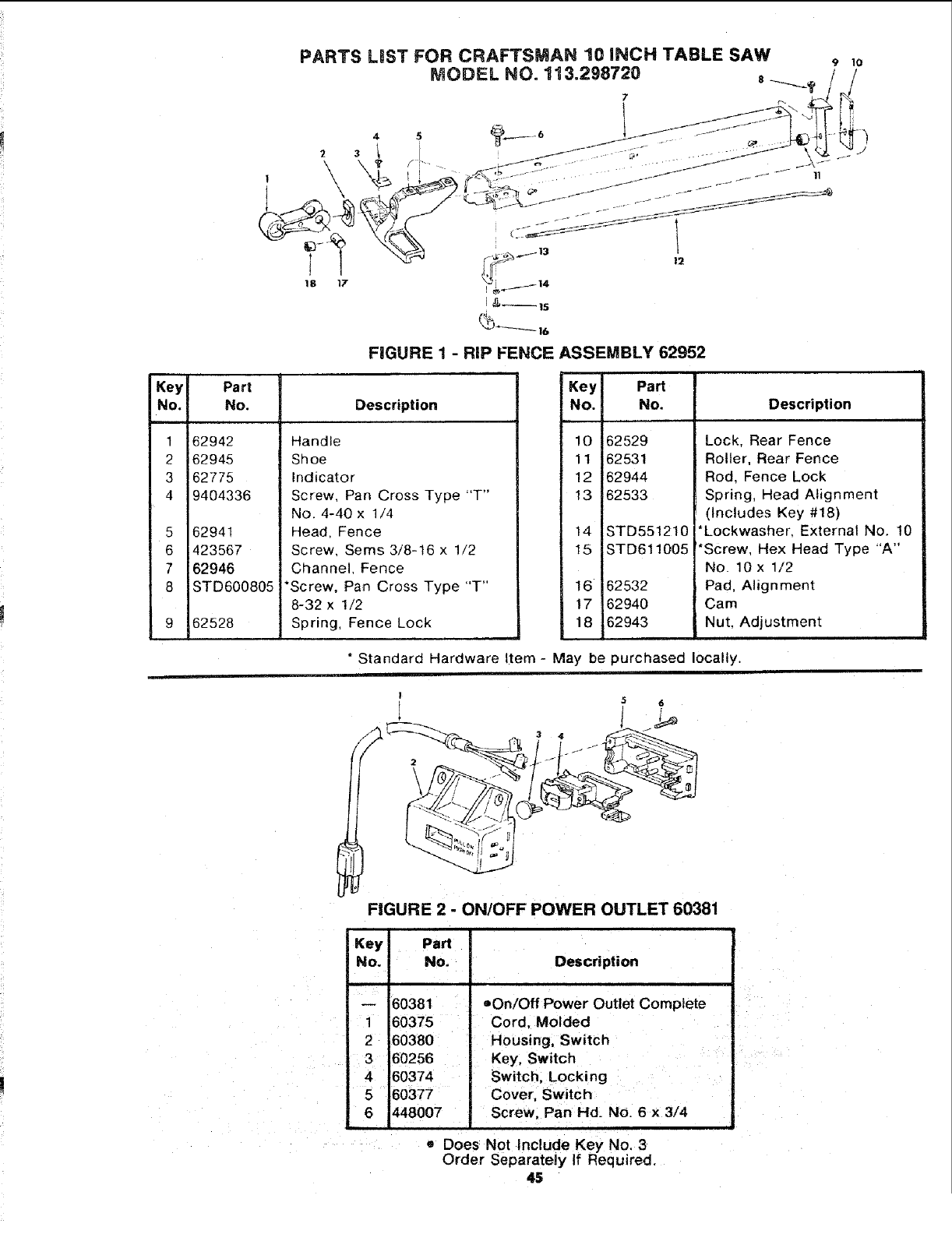
PARTS LiST FOR CRAFTSMAN 10 INCH TABLE SAW 9 10
MODELNO.113.298720 ,/_!
I#,_ /
;&_]s
FIGURE 1 - RIP FENCE ASSEMBLY 62952
Key
No.
1
2
3
4
5
6
7
8
Part
No.
62942
62945
62775
9404336
62941
423567
62946
STD600805
62528
Description
Handle
Shoe
Indicator
Screw, Pan Cross Type "T"
No. 4-40 x 1/4
Head. Fence
Screw, Sems 3/8-16 x 1/2
Channel, Fence
*Screw. Pan Cross Type "T"
8-32 x 1/2
Spring, Fence Lock
Key Part
No. No.
10 62529
11 62531
12 62944
13 62533
14 STD551210
15 STD611005
16 62532
17 62940
18 62943
Description
Lock, Rear Fence
Roller, Rear Fence
Rod. Fence Lock
Spring, Head Alignment
(Includes Key #18)
*Lockwasher, External No. 10
*Screw, Hex Head Type "A"
No. 10 x 1/2
Pad, Alignment
Cam
Nut, Adjustment
*Standard Hardware Item - May be purchased locally.
5
FIGURE 2 - ON/OFF POWER OUTLET 60381
Description
Ki
ey IPaN
No. No.
-- 60381
160375
2 60380
3 60256
4 60374
5 60377
6i448007
oOn/Off Power Outlet Complete
Cord, Molded
Housing. Switch
Key, Switch
Switch, Locking
Cover, Switch
Screw, Pan Hd. No. 6x 3/4
• Does Not Include Key No. 3
Order Separately if Required.
45
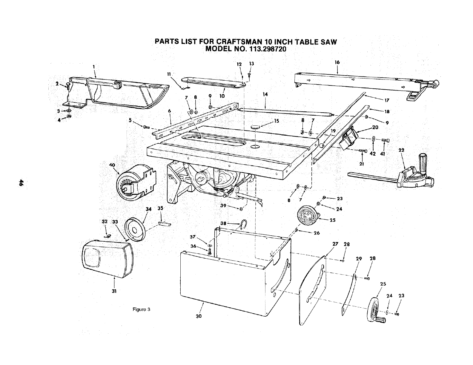
PARTS LIST FOR CRAFTSMAN 10 INCH TABLE SAW
MODEL NO. 113.298720
12 13 16
1
32 33
31
Figure 3
/
/
ij
3O
27 28
29 28
! !
_///_ /524 23
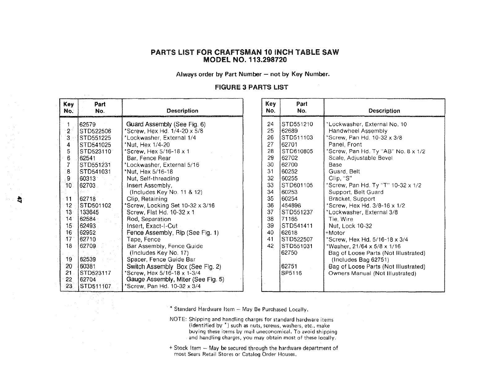
PARTS LiST FOR CRAFTSMAN 10 iNCH TABLE SAW
MODEL NO. 113.298720
Always order by Part Number - not by Key Number.
FIGURE 3 PARTS LIST
Key IPart
No. INo.
162579
2 ISTD522506
3 ISTD551225
4ISTD541025
5 ISTD523110
6 16254!
7 'STD551231
8 ISTD541031
9 J60313
10 !627O3
11 162718
12 ISTD501102
13 1133645
14 162584
15 162493
16 162952
17 162710
18 162709
19 162539
20 160381
21 ISTD523117
22 162704
23 ISTD511107
Description
Guard Assembly (See Fig. 6)
*Screw. Hex Hd. 1/4-20 x 5/8
*Lockwasher, External 1/4
*Nut. Hex 1/4-20
*Screw. Hex 5/16-18 x 1
Bar Fence Rear
*Lockwasher, External 5/16
*Nut, Hex 5/16-18
Nut, Self-threading
Insert Assembly,
(Includes Key No. 11 & 12)
Clip, Retaining
*Screw. Locking Set 10-32 x 3/16
Screw. Flat Hd. 10-32 x 1
Rod, Separation
Insert, Exact-l-Cut
Fence Assembly, Rip (See Fig. 1)
Tape, Fence
Bar Assembly, Fence Guide
ncludes Key No. 17)
Spacer. Fence Guide Bar
Switch Assembly Box (See Fig. 2)
*Screw, Hex 5/16-18 x 1-3/4
Gauge Assembly, Miter (See Fig. 5)
*Screw. Pan Hd. t0-32 x 3/4
Key Part
No. No, Description
24 STD551210
25 62689
26 STD511103
27 62701
28 STD610805
29 62702
30 62700
31 60252
32 60255
33 STD601105
34 60253
35 60254
36 454896
37 STD551237
38 71165
39 STD5414!1
40 62618
41 STD522507
42 STD551031
62750
62751
SP5116
*Lockwasher, External No. 10
Handwheet Assembly
*Screw, Pan Hd. 10-32 x 3/8
Panel, Front
*Screw, Pan Hd. Ty "AB" No. 8 x 1/2
Scale, Adjustable Bevel
Base
Guard, Belt
Clip, "S"
*Screw, Pan Hd. Ty "T" 10-32 x t/2
Support, Belt Guard
Bracket, Support
*Screw, Hex Hal. 3/8-!6 x 1/2
*Lockwasher, External 3/8
Tie, Wire
Nut, Lock 10-32
+Motor
*Screw, Hex Hd. 5/16-18 x 3/4
*Washer, 21/64 x 5/8 x 1/16
Bag of Loose Parts (Not Illustrated)
(Includes Bag 62751 )
Bag of Loose Parts (Not Illustrated)
Owners Manual (Not Illustrated)
* Standard Hardware Item -. May Be Purchased Locally.
NOTE: Shipping and handling charges for standard hardware items
(identified by *) such as nuts, screws, washers, etc., make
buying these items by mail uneconomical. To avoid shipping
and handling charges, you may obtain most of these locally.
+ Stock Item - May be secured through the hardware department of
most Sears Retail Stores or Catalog Order Houses.
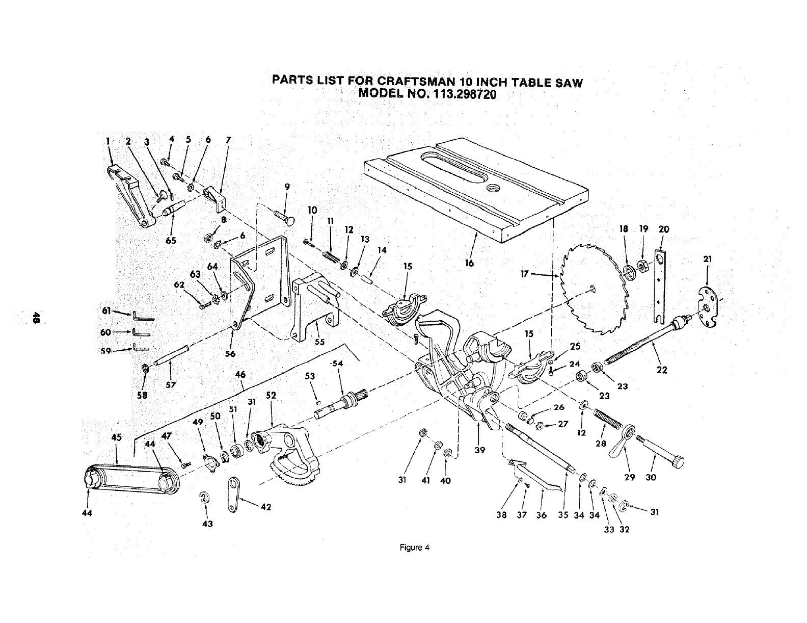
PARTS LIST FOR CRAFTSMAN 10 INCH TABLE SAW
MODEL NO. 113.298720
44
12 13
62
14
/
59 56
58
43
31 41 40
f
/
/
16
39
[
i
18 19 20
25
\
22
_. 23
23
29 30
38 37 36 35 34 34
33 32
21
Figure 4
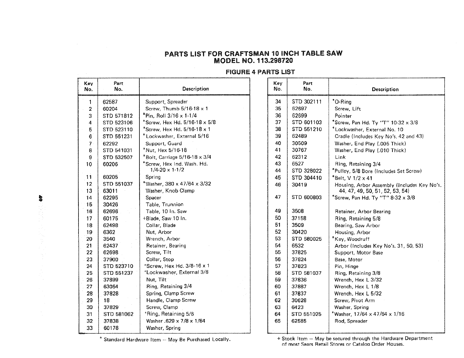
PARTS LIST FOR CRAFTSMAN 10 INCH TABLE SAW
MODEL NO. 113,298720
FIGURE 4 PARTS LIST
Key I
No. I
5 I
6 I
8 I
10 t
11 I
12 I
13 t
14 !
15 I
16 I
17 I
18 I
19 I
20 I
21 I
22 I
23 I
24 t
26 I
26 I
27 I
28 I
29 I
30 I
31 I
32 I
33 I
Part
No.
62587
60204
STD 571812
STD 523106
STD 523110
STD 551231
62292
STD 541031
STD 532507
60206
60205
STD 551037
63011
62295
30426
62696
60175
62498
6362
3540
62437
62698
37900
STD 523710
STD 551237
37899
63054
37828
18
37829
STD 581062
37838
60178
Description
Support, Spreader
Screw, Thumb 5/16-18 x 1
*Pin, Roll 3/16 x 1-1/4
*Screw, Hex Hd. 5/16-18 x 5/8
*Screw, Hex Hd. 5/16-18 x 1
* Lockwasher, External 5/16
Support, Guard
*Nut, Hex 5/!6-18
*Bolt, Carriage 5/16-18 x 3/4
*Screw, Hex Ind. Wash. Hd.
1/4-20 x 1-I/2
Spring
*Washer, 380 x 47/64 x 3/32
Washer, Knob Clamp
Spacer
Table, Trunnion
Table, 10 In. Saw
+Blade, Saw 10 In.
Collar; Blade
Nut, Arbor
Wrench, Arbor
Retainer, Bearing
Screw, Tilt
Collar, Stop
*Screw, Hex Hd. 3/8-16 x 1
*Lockwasher, External 3/8
Nut, Tilt
Ring, Retaining 3/4
Spring, Clamp Screw
Handle, Clamp Screw
Screw, Clamp
*Ring, Retaining 5/8
Washer .629 x 7/8 x 1/64
Washer, Spr!ng
Standard Hardware Item - May Be Purchased Locally.
Key
No.
34
35
36
37
38
39
40
41
42
43
44
45
46
47
49
5O
51
52
53
54
55
56
57
58
59
60
61
62
63
64
65
Part
No,
STD 302111
62697
62699
STD 601103
STD 551210
62489
30509
30767
62312
6527
STD 328022
STD 304410
30419
STD 600803
3508
37158
3509
30420
STD 580025
6532
37825
37824
37823
STD 581037
37836
37887
37837
30628
6423
STD 551025
62585
Description
*O-Ring
Screw, Lift
Pointer
*Screw, Pan Hd. Ty "T" 10-32 x 3/8
* Lockwasher, External No. !0
Cradle (Includes Key No's. 42 and 43)
Washer, End Play (.005 Thick)
Washer, End Play (.010 Thick)
Link
Ring, Retaining 3/4
*Pulley, 5/8 Bore (Includes Set Screw)
*Belt, V 1/2 x 41
Housing, Arbor Assembly (Includes Key No's.
44, 47, 49, 50, 51,52, 53, 54)
*Screw, Pan Hd. Ty "T" 8-32 x 3/8
Retainer, Arbor Bearing
Ring, Retaining 5/8
Bearing. Saw Arbor
Housing, Arbor
* Key, Woodruff
Arbor (Includes Key No's. 31,50, 53)
Support, Motor Base
Base, Motor
Pin, Hinge
Ring, Retaining 3/8
Wrench, Hex L 3/32
Wrench, Hex L 1/8
Wrench, Hex L 5/32
Screw, Pivot Arm
Washer, Spring
*Washer, 17/64 x 47/64 x 1/16
Rod, Spreader
+ Stock Item -- May be secured through the Hardware Department
nf mnst S_rs Rp,tail Storp.s or CataloQ Order Houses.
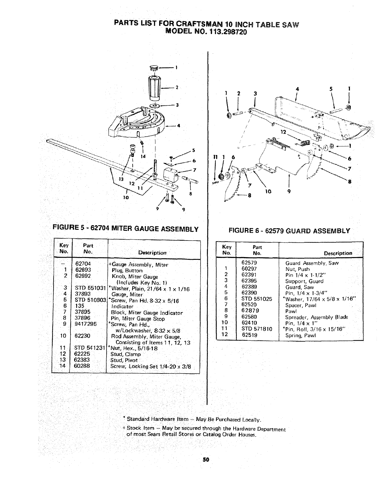
PARTS LIST FOR CRAFTSMAN 10 INCH TABLE SAW
MODEL NO. 113.298720
FIGURE 5 -62704 MITER GAUGE ASSEMBLY
Key Part
No. No. Description
-- 62704
1 162693
262692
I3
4
5
6
7
8i
9
10
11 STD541231
12 52225
13 62383
14 60288
STD 551031
37893
STD 510803
135
37895
37896
9417295
62230
+Gauge Assembly, Miter
Plug, Button
Knob, Miter Gauge
(Includes Key No. t)
*Washer, Plain, 21/64 ×1 x 1/16
Gauge, Miter
*Screw, Pan Hd. 8-32 x 5/15
Indicator
Block, Miter Gauge Indicator
Pin, Miter Gauge Stop
Screw, Pan lid.,
w/Lockwasher, 8-32 x 5/8
Rod Assembly, Miter Gauge,
Consisting of Items 11, 12, t3
*Nut, Hex., 5/16-18
Stud, Clamp
Stud, Pivot
Screw, LoCking Set 1/4-20 x 3/8
1
12
11 !6
_8 10 9
5 I
FIGURE 6 - 62579 GUARD ASSEMBLY
Key
No. Description
1
2
3
4
5
6
7
8
9
10
11
12
Part
No.
62579
60297
62391
62395
62389
6239O
STD 551025
62520
62879
62580
62410
STD 571810
62519
Guard Assembly, Saw
Nut, Push
Pin I/4 x 1-I/2'"
Support, Guard
Guard, Saw
Pin, 1/4 x 1-3/4"
*Washer, 17/64 x 5/8 x 1t16 °'
Spacer, Pawl
Pawl
Spreader, Assembly Blade
Pin, 1/4 x 1"
*Pin, Roll, 3/16 x 15/16"
Spring, Pawl
" Stendard Hardware Item - May Be Purchased Locally.
+ Stock Item - May be secured through the Hardware Department
of most Sears Retail Stores or Catalog Order Houses.
5O
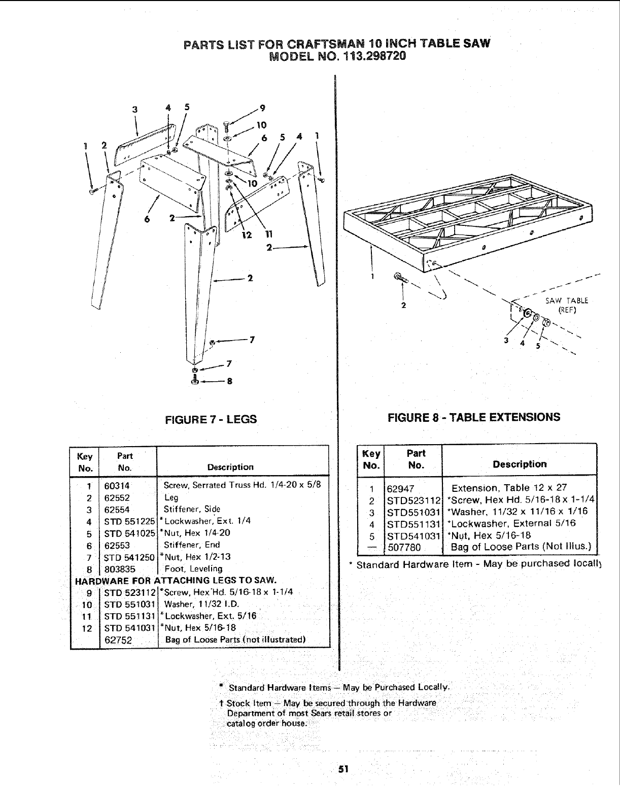
PARTS LiST FOR CRAFTSMAN 10 iNCH TABLE SAW
MODEL NO. 113.298720
5 4
I
/
FIGURE 7 - LEGS
Key Part
No. No.
1 60314
2 62552
3 62554
4 STD 551225'
5 STD 541025
6 62553
7 STD 541250
8 803835
Description
Screw, Serrated Truss Hd. 1/4-20 x 5/8
Leg
Stiffener, Side
*Lockwasher,' Ext. 1/4
*Nut, Hex 1/4-20
Stiffener, End
*Nut, Hex 1/2-13
Foot, Leveling
HARDWARE FOR ATTACHING LEGS TO SAW.
9STD 523112 *Screw, Hex'Hd. 5/16-18 x1-1/4
10 "STD 551031 Washer, 11/32 I.D.
11 STD 551131 *Lockwasher, Ext. 5/16
12 STD 541031 *Nut, Hex 5/16-18
62752 Bag of Loose Parts (not illustrated)
2
\
_3
f
FIGURE 8 -TABLE EXTENSIONS
Key! Part
No. No. Description
1 62947
2 STD523112i
3 STD551031
4 STD551131
5 STD541031
Extension, Table 12 x 27
*Screw, Hex Hd. 5/16-18x 1-1/4
*Washer, 11/32 x 11/16 x 1/16
*Lockwasher, External 5/16
*Nut, Hex 5/16-18
-- 507780 ,Bag of Loose Parts (Not Illus.)
" Standard Hardware Item - May be purchased Iocall_
Standard Hardware Items-- May be Purchased Locally.
t Stock Item - May be secured through the Hardware
Department of most Sears retail stores or
catalog order house.
51
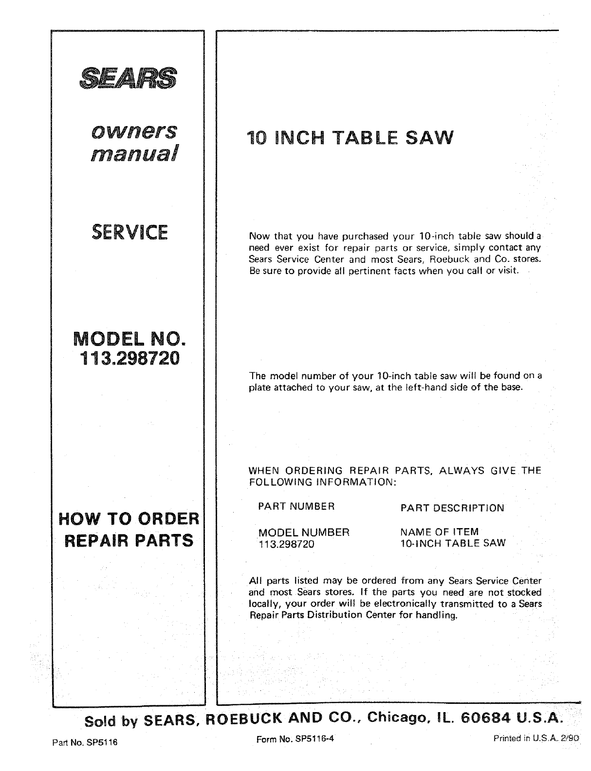
SERVICE
MODEL NO.
113.298720
HOW TO ORDER
REPAIR PARTS
10 iNCH TABLE SAW
Now that you have purchased your 10-inch table saw should a
need ever exist for repair parts or service, simply contact any
Sears Service Center and most Sears, Roebuck and Co. stores.
Be sure to provide all pertinent facts when you call or visit.
The model number of your 10-inch table saw will be found on a
plate attached to your saw, at the left-hand side of the base.
WHEN ORDERING REPAIR PARTS, ALWAYS GIVE THE
FOLLOWING INFORMATION:
PART NUMBER PART DESCRIPTION
MODEL NUMBER
113.298720
NAME OF ITEM
10-INCH TABLE SAW
All parts listed may be ordered from any Sears Service Center
and most Sears stores. If the parts you need are not stocked
locally, your order will be electronically transmitted to a Sears
Repair Parts Distribution Center for handling.
=
Sold by SEARS, ROEBUCK AND CO., Chicago, IL. 6;0684 U.S.A.
Part No. SP5116 Form No. SP51t 6-4 Printedin U.S.A_2/gO
