Craftsman 113299112 User Manual 10 BELT DRIVE SAW Manuals And Guides L0802709
CRAFTSMAN Saw Circular Manual L0802709 CRAFTSMAN Saw Circular Owner's Manual, CRAFTSMAN Saw Circular installation guides
User Manual: Craftsman 113299112 113299112 CRAFTSMAN 10 BELT DRIVE SAW - Manuals and Guides View the owners manual for your CRAFTSMAN 10 BELT DRIVE SAW #113299112. Home:Tool Parts:Craftsman Parts:Craftsman 10 BELT DRIVE SAW Manual
Open the PDF directly: View PDF ![]() .
.
Page Count: 76
FSave ThisManual
For FutureReference
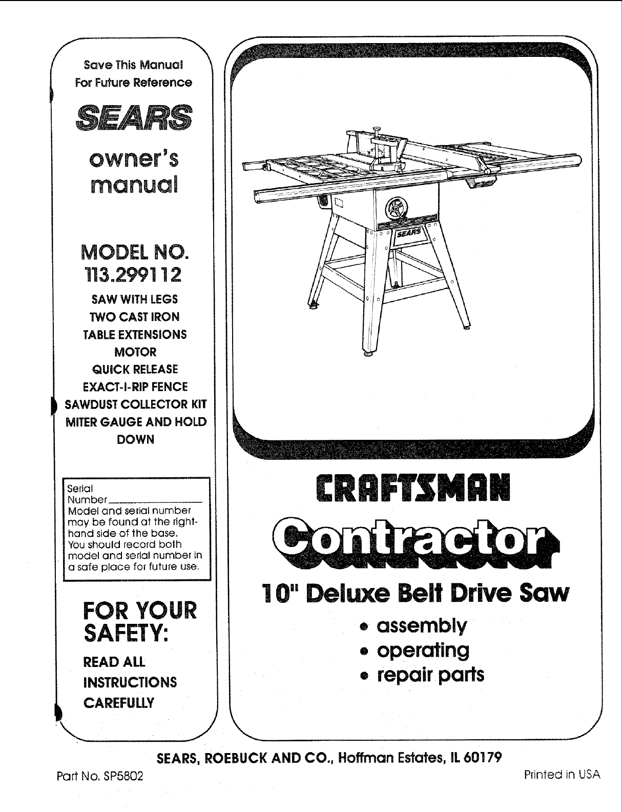
MODEL NO.
113.299112
SAW WITH LEGS
TWO CAST IRON
TABLEEXTENSIONS
MOTOR
QUICK RELEASE
EXACT-i-RIP FENCE
SAWDUST COLLECTOR KIT
MITER GAUGE AND HOLD
DOWN
Seria!
Number
Model and serial number
may be found at the right-
hand side of the base.
You should record both
model and serial number in
a safe place for future use.
YOUR
SAFETY:
READ ALL
INSTRUCTIONS
CAREFULLY
,,...
Part No. SP5802
[RRFTZMRN
I 0" Deluxe Belt Drive Saw
•assembly
•operating
•repair parts
SEARS, ROEBUCK AND CO., Hoffman Estates, IL 60179
J
Printed in USA
FULL ONE YEAR
STATES and Sears will repair it, free of charge.
This warranty applies only while this product is used in the United States.
If lJhisTable Saw is used for commercial or rental purposes, this warranty will apply for ninety
days from the date of purchase.
This warranty gives your specific legal rights, and you may also have other rights which vary
from state to state.
SEARS, ROEBUCK AND CO., D/817 WA Hoffman Estates, IL 60179
SAFETY iNSTRUCTiONS FOR TABLE SAW
Safety is a combination of common sense, staying alert
and knowing how your table saw works. Read this
manual to understand this saw.
SAFETY SIGNAL WORDS
DANGER: If the safety information is not followed,
someone WILL be seriously injured or killed
WARNING: If the safety information is not fol-
lowed, someone COULD be seriously injured or
killed.
CAUTION: If the safety information is not followed,
someone MAY be injured.
Read and follow all safety informationand instructions.
BEFORE USING THE SAW:
WARNING: To avoid mistakes that could cause
serious, permanent injury, do not plug the saw in
until the following steps have been satisfactorily
completed.
1. Assembly and alignment. (See pages 14-39)
2. Learn the use and function of the ON-OFF switch,
guard, spreader, anti-kickback device, miter gauge,
table insert and blade elevation and bevel controls.
(See pages 39-42)
3. Review and understanding of all safety instructions
C: Bolt the saw to the floor if it tends to slip, walk, or
slide during normal use.
D.When using table extensions over 24" wide on
any side of the saw, bolt the saw to the floor or
prop up the outer end of the extension from the
floor to keep the saw from tipping.
3. Put the saw where neither operators or bystanders
must stand in line with the saw blade.
4. GROUND THE SAW - This saw has an approved 3-
conductor cord and a 3-prong grounding type plug.
The plug fits grounding type outlets designed for 120
volt, 15 amp circuits. The green conductor in the
cord is the grounding wire. To avoid electrocution,
NEVER connect the green wire to a live terminal.
5. To avoid injury from electrical shock, make sure your
fingers do not touch the plug's metal prongs when
plugging in or unplugging the saw.
6. To avoid back injury, get help or use recommended
caster accessories when you need to move the saw.
Always get help if you need to lift the saw. Hold the
saw close to your body. Bend your knees so you can
lift withyour legs, not your back.
7. NEVER STAND ON TOOL. Serious injury could
occur if the tool tips or you accidentally hit the cutting
tool. Do not store anything above or near the tool
where anyone might stand on the tool to reach them.
BEFORE EACH USE:
1. Inspect your saw.
4. Review of the maintenance methods for this saw.
(See page 61)
Read the following WARNING label found on the
front of your saw.
WHEN INSTALUNG OR MOVING THE SAW':
1. AVOID DANGEROUS ENV RONMENT. Use the
saw na dry place protected from rain. Keep work
and operating procedures in this manual. A. To avoid injury from accidental starting, unplug
the saw, turn the switch off and remove the switch
key before raising or removing the Guard, chang-
ingthe cutting too!, changing the setup or adjust-
ing anything.
B. Check for alignment of moving parts, binding of
moving parts, breakage of parts, mounting, and
any other conditions that may affect the way it
works. If any part is missing, bent, or broken in
any way, or any electrical parts don't work proper-
ly.turn the saw off and unplug the saw.
C. Replace damaged, missing, or failed parts before
using the saw again.
D. Use the Sawblade Guard, Spreader, and Anti-
Kickback Pawls for any thru-sawing (whenever
the blade comes through the top of the work-
................. where there is piece} Make sure the Pawls work properly Make
A. _'u[ me saw on a nrm _evelsun_,uu ' . ... "
-len'" of room for handlin" and -roDerl,, su'_'_rt sure the Spreader is in hnewiththe sawblade.
ij [y t.j H u H y I-,v_, -
ing the workpiece. E. REMOVE ADJUSTING KEYS AND WRENCHES.
Form habit of checking for and removing keys and
B. Support the saw so the table is level and the saw
does not rock. 2 adjusting wrenchesfrom tool before tuming it on.
R [b avoidinjury from jams, slips or thrown pieces
(kickback and throwback):
1.)USE ONLY RECOMMENDED ACCESSORIES.
Follow the instructions that come with the acces-
sories. The use of improper accessories may
cause risk of injury to persons.
2,)Choose the right blade or cutting accessories for
the material and the type of cutting you plan to
do.
3.)Never use grinding wheels, abrasive cutoff
wheels, friction wheels (metal slitting blades) wire
wheels or buffing wheels. They can fly apart
explosively.
4.) Choose and inspect your cutting tool carefully.
To avoid cutting tool failure and thrown shrap-
nel (broken pieces of blade), use only 10" or
smaller blades or other cutting tools marked for
speed of 3450 rprn or higher.
Always use unbroken, balanced blades
designed to fit this saw's 5/8" arbor.
When thru-sawing, (making cuts where the
blade comes through the workpiece top)
always use a 10 inch diameter blade. This
keeps the spreader in closest to the blade.
Do not overtighten arbor nut. Use arbor
wrenches to "snug" it securely.
Use only sharp blades with properly set teeth.
Consult a professional blade sharpener when
in doubt.
Keep blades clean of gum and resin.
5.)Adjust table inserts flush with the table top.
NEVER use the saw without the proper insert.
6.) Make sure all clamps and locks are tight and no
parts have any excessive play.
2. Keep Work Area Clean
A. Cluttered areas and benches invite accidents.
Floor must not be slippery from wax or sawdust.
B. To avoid burns or other fire damage, never use
the saw near flammable liquids, vapors or gases.
C. To avoid injury, don't do layout, assembly, or
setup work on the table while the blade is spin-
ning. It could cut or throw anything hitting the
blade.
Plan ahead to protect your eyes, hands, face and
ears.
3, Plan your work.
A. USE THE RIGHT TOOL - Don't force tool or attach-
ment to do a job it was not designed for.
B. Dress for safety:
Do not wear loose clothing, gloves, neckties or
jewelry (rings, wrist watches). They can get
caugllt and draw you into moving parts.
Wear nonshp footwear.
Tie back long hair.
Roll long sleeves above the elbow.
Noise levels vary widely. To avoid possible qear-
_ngdamage, wear ear plugs or muffs when using
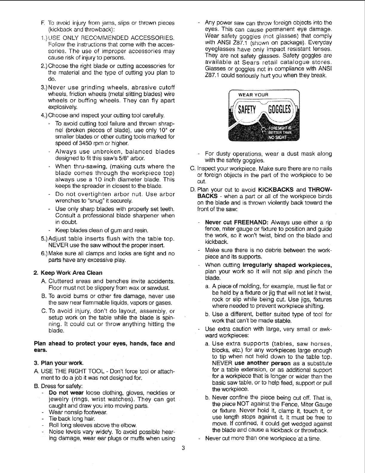
Any power saw can throw foreign objects into the
eyes. This can cause permanent eye damage.
Wear safety goggies (not gtasses) that comply
with ANSI Z87.1 (shown on package). Everyday
eyeglasses have only impaot resistant lenses.
They are not safety glasses. Safety goggles are
available at Sears retail catalogue stores.
Glasses or goggles not in compliance with ANSI
Z87.1 could seriously hurt you when they break.
WEAR YOUR
SAFE
For dusty operations, wear a dust mask along
with the safety goggles.
C. Inspect your workpiece. Make sure there are no nails
or foreign objects in the part of the workpiece to be
cut.
D. Plan your cut to avoid KICKBACKS and THROW-
BACKS - when a part or all of the workpiece binds
on the blade and is thrown violently back toward the
front of the saw:
Never out FREEHAND: Always use either a rip
fence, miter gauge or fixture to position and guide
the work, so it won't twist, bind on the blade and
kickback.
Make sure there is no debris between the work-
piece and its supports.
When cutting irregularly shaped workpieces,
plan your work so it wilt not slip and pinch the
blade.
a. A piece of molding, for example, must lie flat or
be held by a fixture or jig that wil! not let it twist,
rock or slip while being cut. Use jigs, fixtures
where needed to prevent workpiece shifting.
b. Use a different, better suited type of tool for
work that can't be made stable.
Use extra caution with large, very small or awk-
ward workpieces:
a. Use extra supports (tables, saw horses,
blocks, etc.) for any workpieces large enough
to tip when not held down to the table top.
NEVER use another person as a substitute
for a table extension, or as additiona! support
for a workpiece that is longer or wider than the
basic saw table, or to help feed, support or pull
the workpiece
b. Never confine the piece being cut off. That is,
the piece NOT against the Fence, Miter Gauge
or fixture. Never hold it, clamp it, touch it, or
use length stops against it. It must be free to
move. If confined, it could get wedged against
the blade and cause a kickback or throwback.
Never cut more than one workpiece at a time.
4. Plan the way you wlll push the workplece
through.
NEVER pull the workplece through. Start and
finish _e clot from the front of the table saw.
NEVER put your fingers or hands in the path
of the sawt_ade or other cutting too!.
NEVER reach in back of the cutting tool with
e_ther hand to hold down or support the work-
p_ece remove wood scraps, or for any other rea-
son.
Avoid hand pos_ons where a sudden s!ip could
cau_ fingers or hand to move _nto a sawblade or
oth,_" cutt=ng tO01
DON_ OVERREACH. AJways Keep good footing
an_ batance.
Push the workp_ece against the rotation of the
b_ade. NEVER feed materia! into the cutting tool
from tt_e rear of the saw.
Nways push the workp_ece all the way past the
As much as moss_bteoke_,_ your face and body to
one s_de of the _wbtade out of lille with a poss_-
t_e kickback or throwback
NEVER turn the saw "ON' before clearing the
tabte of atl tools, wood scraps etc exceot the
workp_ece and related fc_l or support devtce.s for
me cut ptanned
AVOID ACCIDENTAL, STARTING oMake sure
switch is "OFF" before plu.cLqing saw in.
WHENEVER SAW IS RUNNING
WARNING: Don't let familiarity (gained from
frequent use of your table saw) cause acare-
_ess mistake. Always remember that acareless
fraction of asecond is enough to cause a
severe injury.
t. Baler÷ aclualiy cutting w_th the saw, watc_ it while _t
runs for a short wh_ie If i! makes an unfarnihar no_se
or vibrates a tot, stoo immediately. Turn the ,_w eft,
Unplug the saw, Do not restart unt_t finding and fixing
the problemo
2. Make sure the top of the arbor or cu11_ng tool turns
toward the front of the saw.
3, Set the cutting tool as tow as possible for the cuz
you're planning.
4. KEEP CHILDREN AWAY. All ws_tors should be kept
a safe distance from work. MaKe sure bystanders
are c4ear of the saw and workp_ece
5. Let, #_e blade reach full sp_ before cutting,
& DON'T FORCE TOOL. !t wilt do the job be_er and
safer at _ts designed rate. Feed the workp_ece rote
the b{ade only fast enougr_ to let it cut without bog-
g_ng down or binding.
7. Before freeing any jammed material:
aTurn switch "OFF".
b Unplug the saw
c Wa_t for all moving parts to stop.
u, Check biade. Spreader a_d Fe_sce re: proper
a_gnrnent before slar_ir_g, _._f_an
8. To avoid throwback of cut off p;e,ces:
a. Use _ne G_4ard assemby.
h. To remove pt6wsesbeneath or trappecl ms,de the
Guard.
Turn saw "OFFL
2 Remove switch key.
3 Unplug saw,
4. Wa_t for blade to stop before !_fl_n9 the 9_sard.
Additional Instructions for
RiP TYPE CUTS
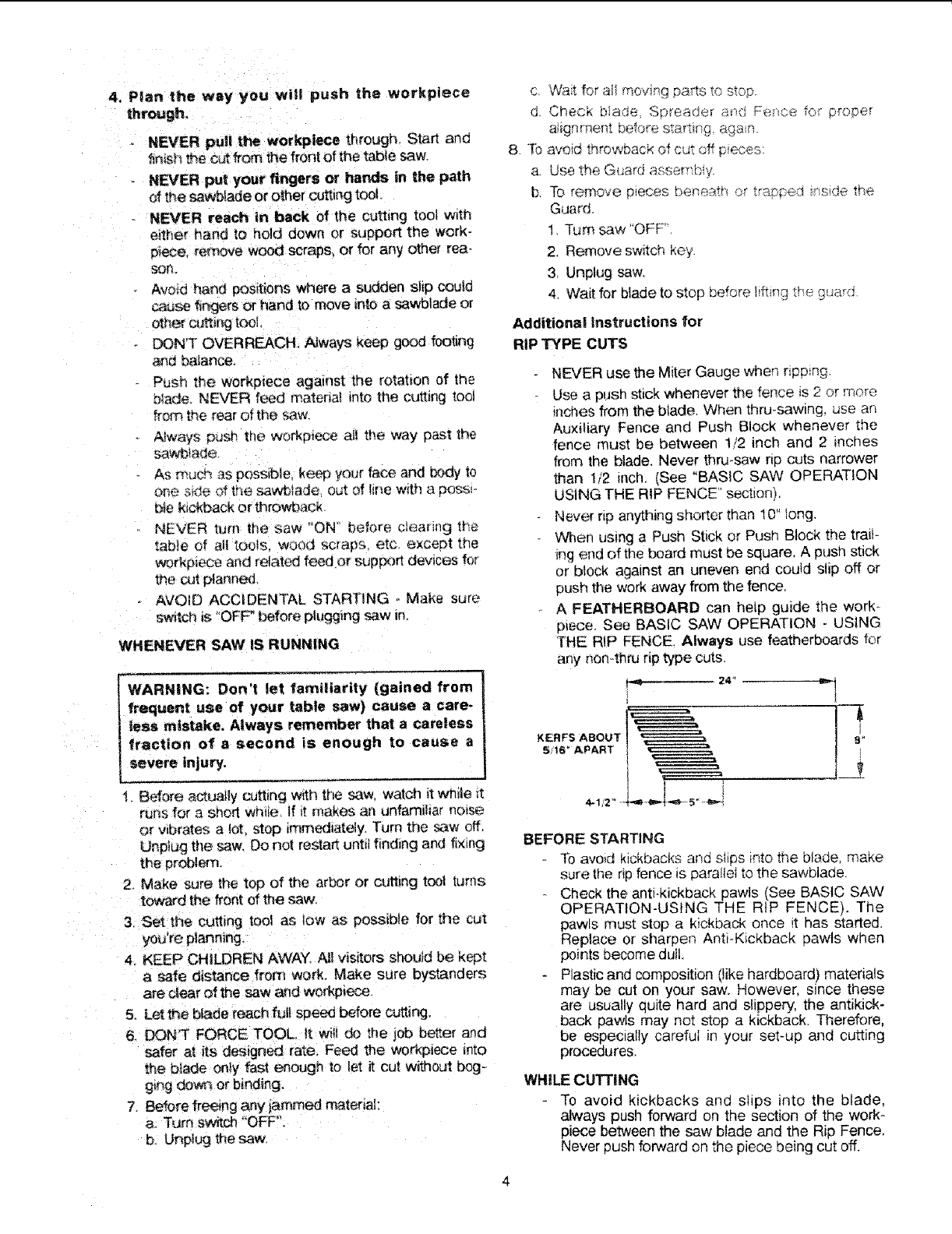
KERFS ABOUT
5/16" APART
9
NEVER use the Miter Gauge when npp_ng,
Use a push stick whenever the fence is 2 or more
inches from the blade When thru-sawing, use an
Auxiliary Fence and Push Block whenever the
fence must be between 1/2 inch and 2 inches
from the blade, Never thru-saw rip cuts narrower
_an 1/2 inch. (See "BASIC SAW OPERATION
USING THE RIP FENCE' section),
Never rip anything shorter than 10" tong,
When using a Push Stick or Push Block the trail-
_ng end of the board must be square, A push stick
or block against an uneven end could slip off or
push the work away from the fence,
A FEATHERBOARD can hetp guide the work-
p_ece See BASIC SAW OPERATION - USING
THE RiP FENCE. Always use featherboards for
any non4f_ru rip type cuts.
24 _
BEFORE STARTING
-[b avoid kickbacks and slips into the blade, make
sure the rip fence is parallel to the sawblade.
Check the anti-kickback pawls (See BASIC SAW
OPERATION-USING THE RiP FENCE). The
pawls must stop a kickback once it has started.
Replace or sharpen Anti*Kickback pawls when
points become dull.
Plastic and composition (like hardboard) materials
may be cut on your saw. However, since these
are usually quite hard and slippery, the antikick-
back pawls may not stop a kickback. Therefore,
be especially careful in your set-up and cutting
procedures.
WHILE CUTTING
To avoid kickbacks and slips into the blade,
always push forward on the section of the work-
piece between the saw blade and the Rip Fence.
Never push forward on the piece being cut off.

Addi_lona! Instructions for
CROSS CUT TYPE CUTS
Before starting
NEVER use the rip fence wt_en crosscutting.
An atJxiliary wood facing attached to the miter
gauge can heip prevent workpiece twisting and
throwbacks. Attach t to the i_oles provided. Make
the facing tong enough and big e,qo_gh to support
your work. Make sure however, it wii! not inter..
fore with the sawb_ade guard. (See "Using The
Miter Gauge" section),
Use jigs or fixtures to help hoid any piece too
smait to extend across the futl length dthe miter
gauge face duriT_g 1he cu_ Th}s _ets yo_.,,properly
ho_d the mi_er gauge and workp_ece ar_,d heips
keep your hands away from the b!ade
White cutting
fb avoid blade contact, aiways ho!d the miter
gauge as shown in the BASIC SAW OPERA-.
]'tONS USING file M_TER GAUGE.
BEFORE LEAVING THE SAW
1. Turn the saw off
2. Wait for b{ade to stop spirlnir_g
3. Make workshop child proof. Lock tt-;e shop.
Discon,qeot master switches Remove the yel_ow
switch key. Store it away from childre_ and others
not qua;fled to use the toei.
4, Unp}ug [iqe saw,
GLOSSARY OF TERMS FOR WOODWORKmNG
Anti-Kickback Paw_s (AKB)
Device which, when properly maintained, is desigried to
stop the workpiece from be}ng kicked back at the oper-
ator during ripping operations.
Arbor
The shaft on which a c_Jtti,qgtoo; is mounted
CrOSSCUt
A cutting or shaping operation made across tb,e width of
the workpiece,
Dado
A non-through cut which produces a square sided
notch or trough in the workpiece,
Featherboard
A device which can help guard workpieces during rip
type operations.
Freehand
Performing a cut without usir_ga fence, miter gauge, fix_
ture, hold down or other proper device to keep the
workpiece from twisting during the cut.
Gum
A sticky, sap based residue from wood products.
Heet
Misalignment of the b_ade.
Kerr
The amount of materia_ removed by the blade in a
tllrough cut or the slot produced by the bIade in a non
through or partial cut.
Kickback
An uncontrolled grabbing and throwing of the workpiece
back toward the front of the saw.
Leading End
The end of the workpiece which, dudng a rip type oper-
ation, is pushed into the cutting too! first.
Molding
A non-through cut which produces a special shape in
the workpiece used for jointing or decoration.
Ploughing
Ploughing is grooving with the grain the long way of the
workpiece, using the fence,
Push Stick
A dev,,ce used to feed the wo_kpiece throu#h the saw
during r_,arrow ripping type operations which helps keep
the operator's hands well away from the blade.
Push BRock
A devce used for rippir_g type operations toe _arrow to
a_iow use of a push stick,
Rabbet
A notch i_ the _lge of a workpiece.
Rea{n
A sticky, sap base substance that has hardened
Ripping
A cutting operation along the lengthof the workpiece.
Revolutions per Minute (RPM)
The number of turns completed by a spinning object in
one minute.
Sawblade Path
The area of the workpiece or tab}e top directiy in line
with tiqe part of tb.e workpiece which wi!! be, or has
been cut by the blade.
Set
The distance that the tip of the sawblade _ooth is be_t
(or set) outward from the face of the b_ade
Throw-Back
Throwing of pieces in a manner similar to a kickback.
Thru-Sawing
Any cutting operation where the blade e×!ends com-.
pietety through the thickness of the workpiece.
Trailing End
The workpiece end tast cut by the blade in a ripping
operation.
Workpiece
The item on which the cutting operation is being done.
The surfaces of a workpiece are commonly referred to
as faces, ends, and edges.
MOTOR SPECIFICATIONS AND ELECTRICAL REQUIREMENTS
MOTOR SPECIFICATIONS
This saw is designed to use a 3450 RPM motor only.
Do not use any motor that runs faster than 3450 RPM.
The A/C motor used in this saw is a capacitor start.
capacitor run, non-reversible type motor, it is wired at
the factory for operation on 120v AC, 60 Hz., alternating
current. It may be converted to operate on 240v AC
Listed below are the motor specifications.
IWARNING: Do use blower or washing
not
machine or any motor with an automatic reset
overload protector. They can start up by them-
selves and you could get injured.
Reference "Motor Connections" for connecting power
cord to motor.
CONNECTING TO POWER SOURCE
OUTLET
WARNING: To avoid electrical shock, do not
permit fingers to touch the terminals of the
plug, when installing or removing the plug to
or from the outlet.
WARNING: Failure to properly ground this
power tool can cause electrocution or serious
shock, particularly when used in damp loca-
tions, or near metal plumbing, if shocked, your
reaction coutd cause your hands to hit the cut-
ting tool
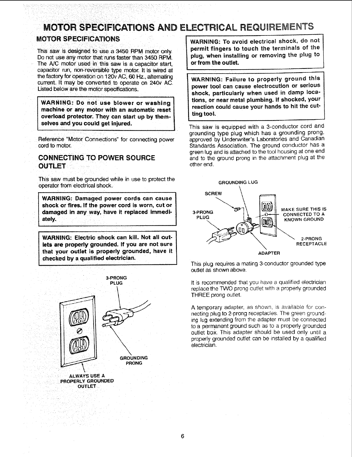
This saw is equipped with a 3-conductor cord and
grounding type Dlug which has agrounding prong,
approved by Underwriter's Laboratories and Canadian
Standards Association. The ground conductor has a
green lug and is attached to the tool housing at one end
and to the ground prong in the attachment plug at the
other end.
This saw must be grounded while in use to protect the
operator from electrical shock.
WARNING: Damaged power cords can cause
shock or fires. If the power cord is worn, cut or
damaged in any way, have it replaced immedi-
ately.
WARNING: Electric shock can kill Not all out-
lets are properly grounded. If you are not sure
that your outlet is properly grounded, have it
checked by a qualified electrician.
3-PRONG
PLUG
GROUNDING LUG
SCREW \
\.
ADAPTER
This plug requires a mating 3-conductor grounded type
outlet as shown above.
It is recommended that you nave a qualified electrician
replace the TWO prong outlet w_tna properly grounded
THREE prong outlet.
g)
\\x
GROUNDING
PRONG
A temporary adapter, as shown, is available for con-
necting plug to 2-prong receptacles. The green ground-
ing lug extending from the adapter must be connected
to a pen_anent ground such as to a properly grounded
outlet box. This adapter should be used only until a
properly grounded outlet can be installed by a qualified
electrician.
ALWAYS USE A
PROPERLY GROUNDED
OUTLET
WARNING: Avoid electric shock, tf the outlet
you are planning to use for this saw is of the
two prong type, DO NOT REMOVE OR ALTER
THE GROUNDING PRONG iN ANY MANNER.
Use an adapter, as shown, and always connect
the grounding lug to aknown ground, such as
to a properly grounded outlet box. Not all out-
let boxes are properly grounded, if you are not
sure the outlet box is properly grounded, have
it checked by a qualified electrician.
CHANGING MOTOR VOLTAGE
WARNING: Electric shock can kill. To avoid
shock, never connect plug to power source
outlet until all assembly steps are completed.
Unplug saw before making or changing any
connections.
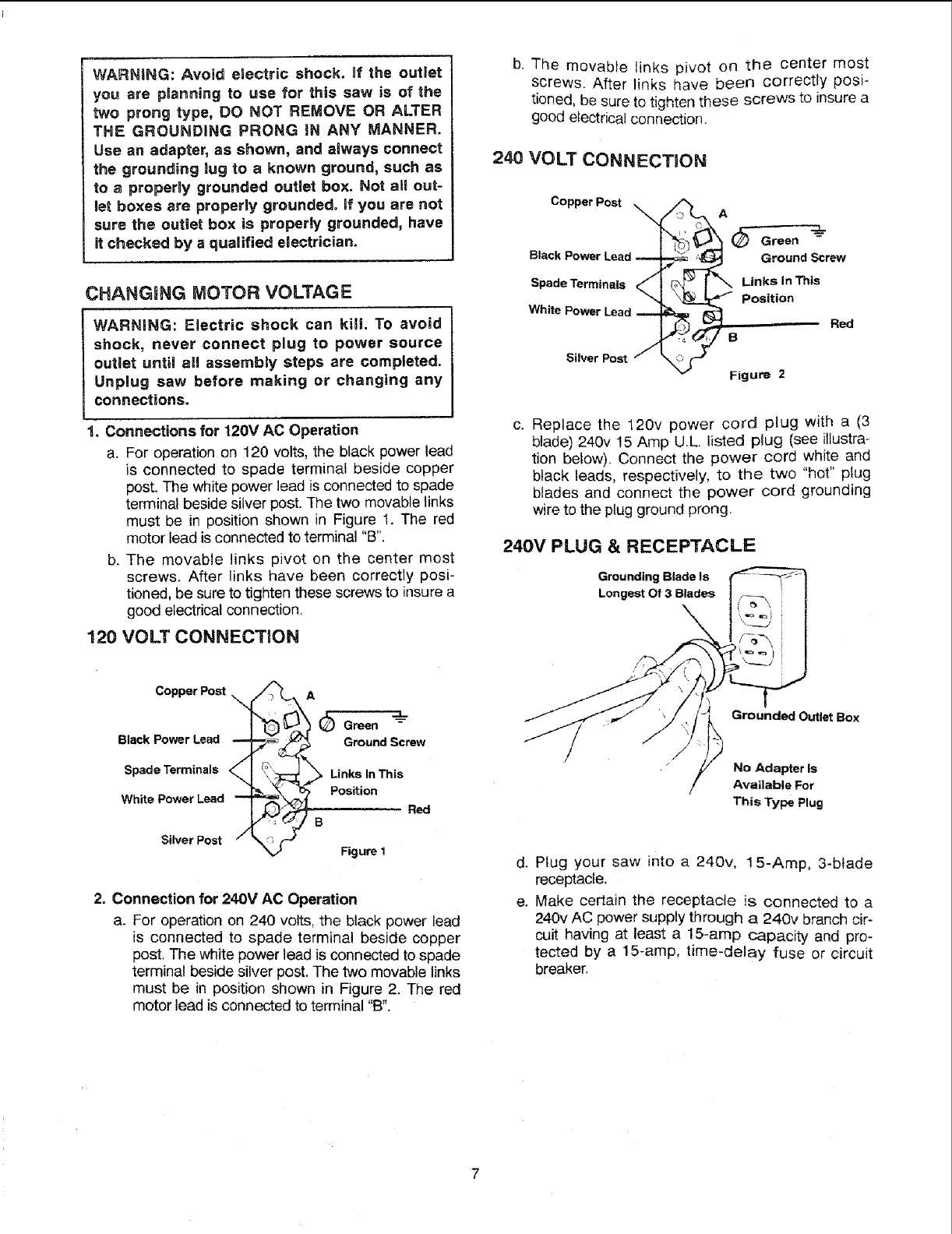
1. Connections for 120V AC Operation
a. For operation on 120 volts, the black power lead
is connected to spade terminal beside copper
post. The white power lead is connected to spade
terminal beside silver post. The two movable links
must be in position shown in Figure 1. The red
motor lead is connected to terminal "B".
b. The movable links pivot on the center most
screws, After links have been correctly posi-
tioned, be sure to tighten these screws to insure a
good electrical connection,
120 VOLT CONNECTION
b. The movable links pivot on the center most
screws. After links have been correctly posi-
tioned, be sure to tighten these screws to insure a
good electrical connectior_.
240 VOLT CONNECTION
Copper Post A
Black Power Ground Screw
Spade Terminals Links in This
Position
White Power Lead
Silver Post
Red
B
Figure 2
c. Replace the 120v power cord plug with a (3
blade) 240v 15 Amp U.L. listed plug (see illustra-
tion below). Connect the power cord white and
black leads, respectively, to the two "hot" plug
blades and connect the power cord grounding
wire to the plug ground prong.
240V PLUG & RECEPTACLE
Grounding Blade Is
Longest Of 3 Blades
Copper Post A
Green _-
Black Power Lead Ground Screw
Spade Terminals Links In This
Position
White Power Lead Red
B
Silver Post Figure I
2. Connection for 24.0V AC Operation
a. For operation on 240 volts, the black power lead
is connected to spade terminal beside copper
post. The white power lead is connected to spade
terminal beside silver post. The two movable links
must be in position shown in Figure 2. The red
motor lead is connected to terminal "B".
Grounded Outlet Box
No Adapter Is
Available For
This Type Plug
d. Plug your saw into a 240v, 15-Amp, 3-blade
receptacle.
e. Make certain the receptacle is connected to a
240v AC power supply through a 240v branch cir-
cuit having at least a 15-amp capacity and pro-
tected by a 15-amp, time-delay fuse or circuit
breaker.
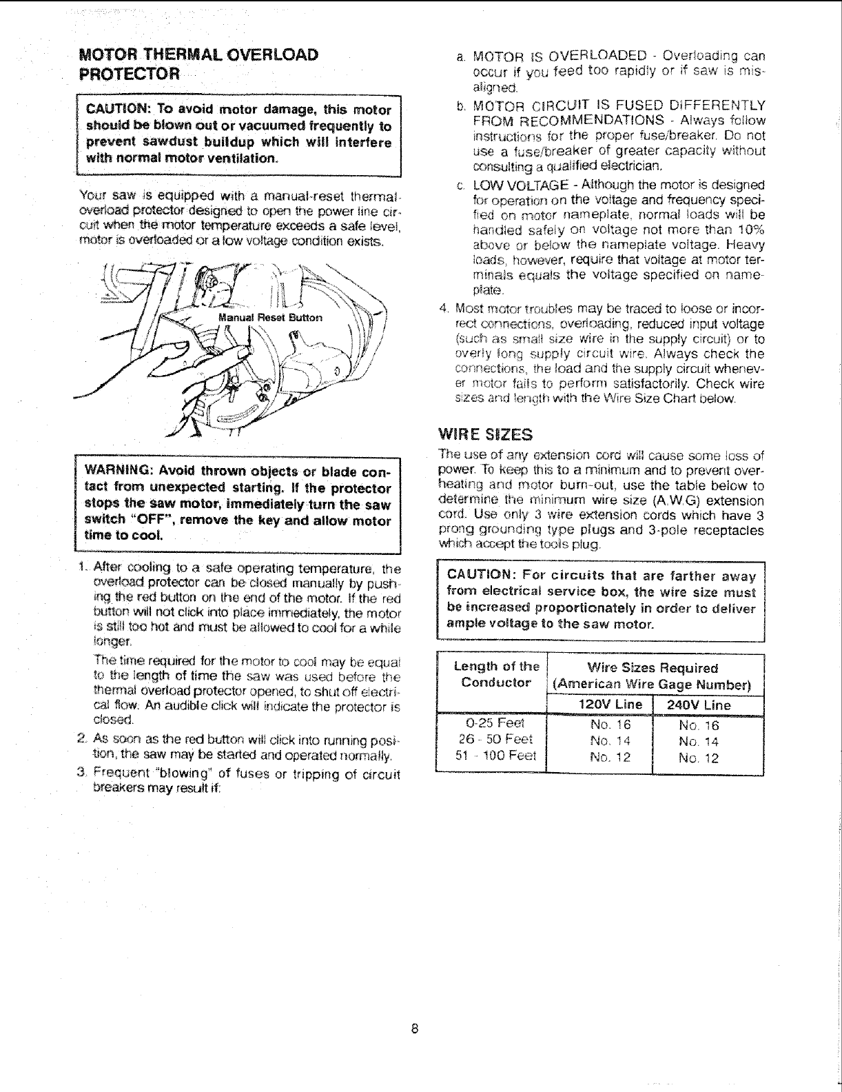
MOTOR THERMAL OVERLOAD
PROTECTOR
ICAUTION: TO avoid damage, this motor
nr_ot--or
shoued be blown out or vacuumed frequently to
prevent sawdust buildup which will interfere
Iwith n_ormal motor ventilation,
Your saw _s equipped w_th _ mar'_uaFreset thermal
over_a_ protector designed to open tr_e power line c_r.
cu_ w_en me motor temperature exce6_s asafe teveL
m_or $ overloaded el a low vo_ta_ cona_t_on exls'_.
t. After cooling [o a safe operahng temperature, the
eve#earl protector can be c_es_ manually by push.
{t_g the red button on the end of the motor, if the red
buttO_ W_t not click into place immed_ate{y, the moto_
_ss£!_too hot and must be allowed] to cool for a while
_onqer.
Th_._brae required for the motor to cooi may be equal
_o _t_e ;ength of time the _3w was useu before t_e
thermal overload protector opened, to shut off eiectri*
ca_ ,'lew. An audible click wilt _nd_catethe pretec[or is
CiOSed
2 As s_,_n as the re4dbutton w_!tdick _nto running posi-
t_ the saw may be started and operated norma!ty,
3 Frequent "b_owing" of fuses or tripping of c_rcu_t
breakers may result if.
a. MOTOR tS OVERLOADED - Overioading can
0ccu[ if yet,; feed too rapidly or if sew is mis_
a_igr_ecL
b MOTOR C_RCL_IT IS FUSED DIFFERENTLY
FROM RECOMMENDATIONS - A!ways fotlow
instructions for the proper fuseibreaker. Do not
use a fusefbreaker of greater capacity without
_msu_ting a qualified electrician.
c, LOW VOLTAGE -Aithough the motor is designed
fo_operation on the voitage and frequency speci-
fied on motor nameplate normal loads wilt be
har_died safely on voltage not more than 10%
above or below the namepiate voltage. Heavy
bads, i_owever, require that voltage a[ motor teF
m,inais equa!s the voltage specified on name
p_ate.
4. Most _otor troubles may be traced to loose or incor-
reel cormect_ons, overloading, reduced input voltage
(such as small size wire in the supply circuit) or to
overly _ong sup_'31y circuit wire, Always check the
cofinections the toad and the supply circuit whenev-
er motor fails to perform satisfactorily. Check wire
szes and ler_gthwith the Wire Size Chart below.
W_RE S_ZES
The use of any extension cord Will cause some !oss of
power, To keep this to a minimum and to prevent over-
heating ar_d motor burn-out_ use the table beiow to
determine ti_e minim{Kn wire size (AW, G) extension
co_J Use or_y 3w_re extension cords which have 3
prong gK._ur_dir]g type plugs and 3_pole receptacles
,,_ff,icha_ept the toots plug
CAUTION: For circuits that are farther away
from electrical service box, the wire size must
be _ncreased proportionately in order to de_iver
ample voltage tO the saw motor.
Length of the
Cor_ductor
0-25 Feet
26 50 Feet
5i -t00 Feet
Wire Sizes Required
(A_erican Wire Gage Number)
120V L_ne 240V Line
No. 16 No. 16
No_ 14 No. 14
No. 12 No. 12
contents
WARRANTY
SAFETY INSTRUCTIONS ............................... z
FOR TABLE SAWS ........................... 2-5
GLOSSARY OF TERMS FOR WOODWORKIN'GI: .,.5
MOTOR SPECIFICATIONS AND ELECTRICAL
REQUIREMENTS ...................................................... 6
Motor Specifications ................................................... 6
Changing Motor Voltage ............................................ 7
Wire Sizes .................................................................. 8
Motor Thermal Overload ............................................ 8
UNPACKING AND CHECKING CONTENTS ............... 9
Tools Needed ............................................................. 9
List of Loose Parts .............................................. t0-13
ASSEMBLY ................................................................... 14
Installing Handwheels ............................................... ! 4
Checking Table Insert ............................................. 14
Checking Blade Squareness to Table ......................15
Assembling Steel Legs ............................................ 15
Mounting Saw to Leg Set ......................................... 16
Installing Table Saw Dust Collector ....................... ! 7
Attaching and Assembling Table Extensions ...........t 9
Installing Table Extension Brackets ..........................20
Installing Front Rip Fence Guide Bar ...................... 21
Installing Rear Fence Guide Bars ........................... 23
Adjusting Rip Fence Guide Bars ............................ 24
Installing Separator Channel ....................................25
Rip Fence Alignment Adjustment ............................ 26
Rip Fence Lock Lever Adjustment .......................... 27
Installing Measuring Tapes and Indicator ................27
Assembling Micro Adjust and Racks ....................... 29
Mounting Switch ....................................................... 31
Installing Blade Guard .............................................. 32
Mounting the Motor .................................................. 35
Positioning Motor on Motor Mounting Base ............34
Installing Belt Guard ................................................. 36
Motor Connections ................................................... 37
Plugging in Motor ..................................................... 39
GE'I-FING TO KNOW YOUR SAW .............................. 39
On-Off Switch ........................................................... 39
Elevation Handwheel ............................................... 40
Tilt Handwheel .......................................................... 40
-I]lt Lock Handle ........................................................ 40
Rip Fence ................................................................. 40
Miter Gauge ............................................................. 40
i= =,== = ,1= = = , ==H,r
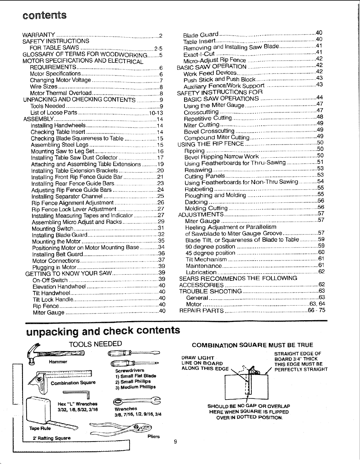
unpacking and check contents
E
_.r2' Rafting Square J
OLS NEEDED
mbination Square
Screwdrivers
1) Small Flat Blade
2) Small Philltps
3) Medium Phillips
Pliers
Blade Guard ............................................................. 40
Table Insert ............................................................... 40
Removing and Installing Saw Blade ........................41
Exact-l-Cut ................................................................ 41
Micro-Adjust Rip Fence ............................................ 42
BASIC SAW OPERATION .................................... 42
Work Feed Devices .................................................. 42
Push Stick and Push Block ...................................... 43
Auxiliary Fence/Work Support ................................ 43
SAFETY INSTRUCTIONS FOR
BASIC SAW OPERATIONS .................................... 44
Using the Miter Gauge ............................................. 47
Crosscutting ............................................................. 47
Repetitive Cutting ...................................................... 48
Miter Cutting .............................................................. 49
Bevel Crosscutting ................................................... 49
Compound Miter Cutting .......................................... 49
USING THE RIP FENCE ............................................. 50
Ripping ...................................................................... 50
Bevel Ripping Narrow Work .................................... 50
Using Featherboards for Thru-Sawing ....................51
Resawing .................................................................. 53
Cutting Panels .......................................................... 53
Using Featherboards for Non-Thru Sawing ............54
Rabbeting .................................................................. 55
Ploughing and Molding ............................................ 55
Dadoing .................................................................... 56
Molding Cutting ........................................................ 56
ADJUSTMENTS ............................................................ 57
Miter Gauge ............................................................. 57
Heeling Adjustment or Parallelism
of Sawblade to Miter Gauge Groove ....................... 57
Blade Tilt, or Squareness of Blade to Table ............59
90 degree position .................................................... 59
45 degree position ................................................... 60
Tilt Mechanism ......................................................... 61
Maintenance ............................................................. 61
Lubrication ................................................................. 62
SEARS RECOMMENDS THE FOLLOWING
ACCESSORIES ........................................................... 62
TROUBLE SHOOTING ................................................ 63
General ..................................................................... 63
Motor ................................................................... 63, 64
REPAi R PARTS ..................................................... 66 - 75
COMBINATION SQUARE MUST BE TRUE
DRAW LIGHT
LINE ON BOARD
ALONG THIS EDG_
STRAIGHT EDGE OF
BOARD 3f4" THICK
THIS EDGE MUST BE
PERFECTLY STRAIGHT
SHOULD BE NO GAP OR OVERLAP
HERE WHEN SQUARE IS FLIPPED
OVER IN DoI-rED POSITION,
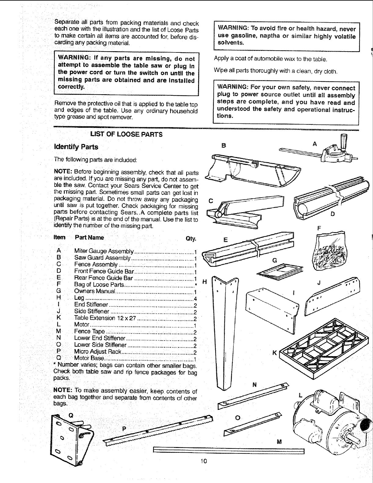
Separate all parts from packing materials ana check
each one with the illustration and the list of Loose Parts
to make certain all items are accounted for. before dis-
carding any packing material.
' WARNING: If any parts are missing, do not J
attempt to assemble the table saw or plug in f
the power cord or turn the switch on until the
missing parts are obtained and are instaUed
correctly.
Remove the protective oil that is applied to the table top
and edges of the table. Use any ordinary household
type grease and spot remover.
j WARNING: To avoid fire or health hazard, never J
i
use gasoline, naptha or simiJar highly volatile I
so,vents.
Apply a coat of automobile wax to the table.
Wipe all parts thoroughly with a clean, dry cloth,
WARNING: For your own safety, never connect
plug to power source outlet until all assembly
steps are complete, and you have read and
understood the safety and operational instruc-
tions.
LIST OF LOOSE PARTS
Identify Parts
The following parts are included'.
NOTE: Before beginning assembly, check that all parts
are included, If you are missing any part, do not assem-
ble the saw. Contact your Sears Service Center to get
the missing part, Sometimes small parts can get lost _n
packaging material. Do not throw away any packaging
until saw is put together. Check _ackaging for missing
parts before contacting Sears.,A corn plete parts list
(Repair Parts) Isat the end of the manual. Use the list to
identifythe number of the missing part.
Item Part Name
A Miter Gauge Assembly .................................... 1
B Saw Guard Assembly ........................................
C Fence Assembly ................................................ 1
D Front Fence Guide Bar ...................................... 1
E Rear Fence Guide Bar ...................................... 1
F Bag of Loose Parts ............................................. *
G Owners Manual .................................................. 1
H Leg ..................................................................... 4
I End Stiffener ...................................................... 2
J Side Stiffener ..................................................... 2
K Table Extension 12 x 27 .................................... 2
L Motor .................................................................. 1
M Fence Tape ........................................................ 2
N Lower End Stiffener ........................................... 2
O Lower Side Stiffener .......................................... 2
PMicroAdjust Rack .............................................. 2
Q Motor Base ........................................................ 1
•Number varies; bags can contain other smaller bags.
Check both table saw and rip fence packages for bag
packs,
F
NOTE: To make assembly easier, keep contents of
each bag together and separate from contents of other
bags.
Q
M
10
I t
___d
I°
--q
T
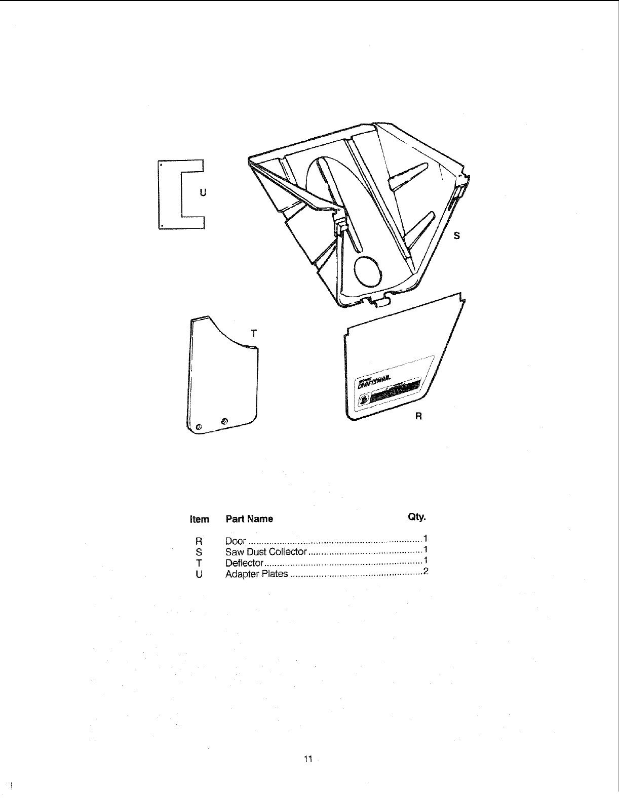
item Part Name Qty.
R
S
T
U
Door ................................................................... 1
Saw Dust Collector ........................................... 1
Deflector ............ 1
Adapter Plates .................................................. 2
11
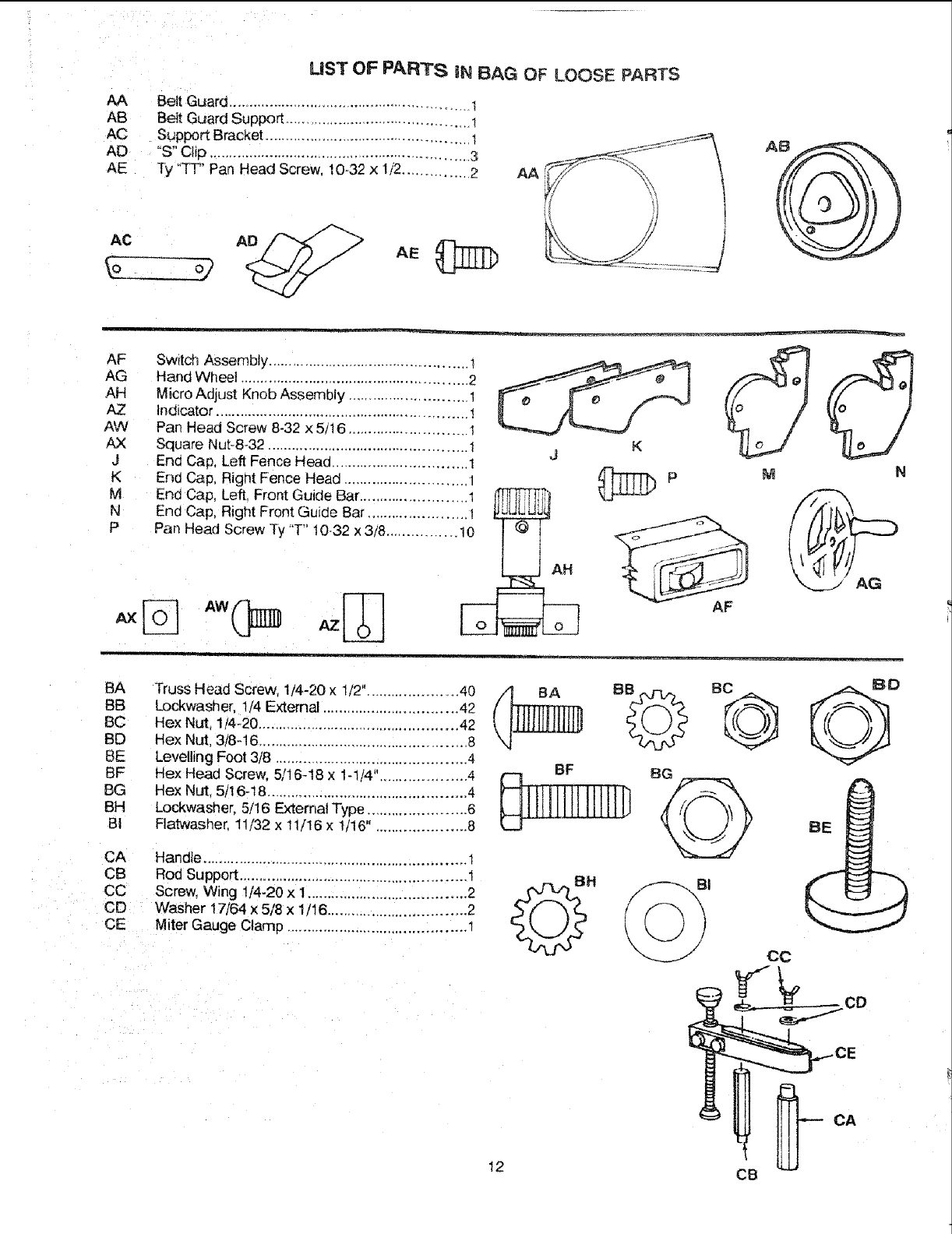
UST OF PARTS iN BAG OF LOOSE PARTS
AA Belt Guard ........................................................... t
AB Belt Guard Support ............................................. !
AC Support Bracket ................................................. 1
AD "S" Clip ................................................................ 3
AE Ty "TT' Pan Head Screw, 10-.32x 1/'2.................2 AA
AC AD
AF Switc_'lAssembly ................................................
AG Hand Wheel ....................................................... 2
AH Micro Adjust Knob Assembly ............................ I
AZ indicator ............................................................. 1
AW Pan Head Screw 8-32 x 5/16 ............................ 1
AX Square Nut-8-32 ................................................ 1
J End Cap, Left Fence Head ................................ 1
K End Cap, Right Fence Head ............................. 1
M End Cap, Left, Front Guide Bar ......................... 1 _
N End Cap, R ght Front Guide Bar ............ t
I!
K
J
M
AF
AG
BA Truss Head Screw, 1/4-20 x 1/2"...................... 40
BB Lockwasher, t/4 External .............................. 42
BC Hex Nut 1_4_20............................................ 42
BD Hex Nut, 3/8-16 .................................................. 8
BE Levelling Foot 3/8 .............................................. 4
BF Hex Head Screw. 5/16-18 x 1-1.'4".................... 4
BG Hex Nut. 5/16-18 ................................................ 4
BH Lockwasher, 5/16 External Type ....................... 6
BI Flatwasher. 11/32 x 11/16 x 1/16", .................... 8
CA Handle ................................................................ 1
CB Rod Support ....................................................... !
CC Screw, Wing 1/4-20 x 1...................................... 2
CD Washer 17/64 x 5/8 x 1/16 ................................. 2
CE Miter Gauge Clamp ........................................... 1
BE
CC
12 CB
CA
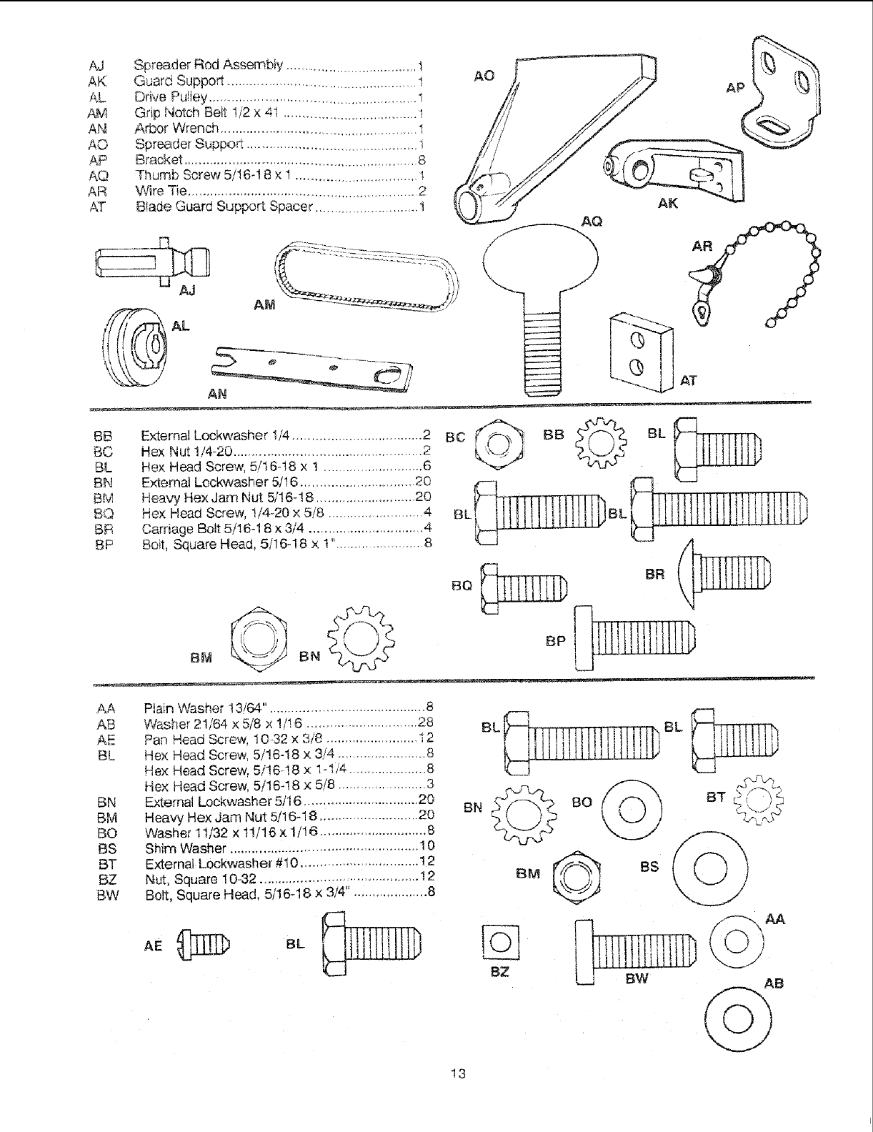
AJ SpreaderRodAssembly...................................1
AK GuardSupport..................................................l
AL DrivePuley.......................................................1
AM GripNotchBelt112x41.......................................1
AN ArborWrench.....................................................1
AO SpreaderSuppo_.............................................1
AP Bracket.............................................................8.
AQ ThumbScrew5/!648x 1................................I
AR WireTie..............................................................2
AT BIadeGuardSupportSpacer...........................!
AO
AK
AQ
AT
.o oc©
BC
BL
BN
BM
BQ BL
BR
BP
BQ _ BR __
External Lockwasher 1/4.................................... 2
Hex Nut 1/4-20 .................................................. 2
Hex Head Screw, 5/t6-18 x 1 ............................6
External Lockwasher 5/16 ............................... 20
Heavy Hex Jam Nut 5/!6-18 .......................... 20
Hex Head Screw, 1/4-20 x 5/8 ......................... 4
Carriage Bolt 5/!6-18 x 3/4 ............................... 4
Bolt, Square Head, 5/16-18 x I "........................ 8
AA Piain Washer 13164".......................................... 8
AB Washer 21/64 x 5/8 x !/16 ............................ 28
AE Pan Head Screw, 10-32 x 3/8 ......................... 12
BL Hex Head Screw, 5/16-18 x 3/4 ...................... 8
Hex Head Screw, 5/16-t8 x 1-I14 ..................... 8
Hex Head Screw, 5/16-!8 x 5/8 ...................... 3
BN External Lockwasher5/16 ............................... 20
BM Heavy. Hex Jam Nut 5/16-18 ......................... 20
BO VVasher11/32 x tlr16 x 1/16 ............................. 8
BS Shim Washer ................................................... 10
BT External Lockwasher #10 .............................. 12
BZ Nut, Square 10-32 ....................................... 12
BW Bolt, Square Head. 5116-18 x 3/4". ................... 8
BN
lilllt i p,BL
.© os )
8Z L_t BW AB
13
ASSEMBLY
Before mounting the saw on tegs or a stand or a bench,
the Table _nsert and Btade Squareness must be
Choked at this time.
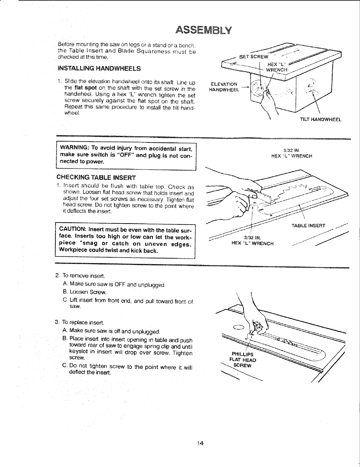
INSTALLING HANDWHEELS
1. Stide t,_e _evation bandy,heel onto its shaft. Line up
the flat spot on the shaft with the set screw in the
handv,dseol.Using a hex "L_Iwrench tighten the set
screw securely against the flat spot on the shaft,.
Repeat this same proco-xJureto instaJl the ti_t hand-
wheek
ELEVATION
HANDWHEEL
\TILT HANDWHEEL
IWARNtNG: To avoid injury from accidental start, 3732_N.
I make sure switch is "OFF" and plug is not con- HEX "'L"WRENCH
t netted to power.
CHECKING TABLE iNSERT
_nsert should be flush with tabie top Chec_ as
shown Loosen flat head screw that holds insert and
adjus! the four set screws as necessary [ighten flat
r'_ead screw Do not tighten screw to the point where
_tdeflects the inse£
CAUTION: insert must be even with the table sur-
face. inserts too high or low can let the work-
piece "snag or catch on uneven edges.
Workplece could twist and kick back.
2 To remove insert,
A. Make sure saw _s OFF an(] unplugged.
B Loosen Screw.
C, Luft =nsert from front end, and _ull toward front of
SaW.
3. To replace insert,
A Make sure saw is off and unplugged.
B. Place insert into insert opening m table and push
toward rear of saw to engage spring clip and until
keyslot =n insert will drop over screw. Tigl_ten
screw.
C, Do not tighten screw to the point where it will
deflect the insert.
/
PHILLIPS
FLAT HEAD
SCREW
14
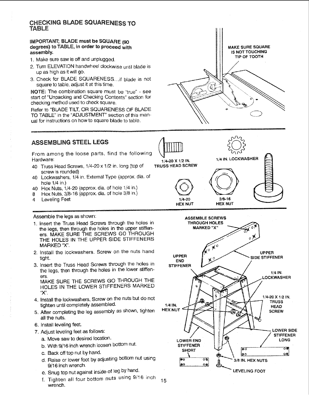
CHECKgNG BLADE SQUARENESS TO
TABLE
IMPORTANT; BLADE must be SQUARE (90
degrees) to TABLE, in order to proceed with
assemblly.
1. Make sure saw is off and unplugged,
2. Turn ELEVATION handwheel clockwise until blade is
up as high as it will go,
3, Check for BLADE SQUARENESS..,if blade is not
square to table, adjust it at this time,
NOTE: The combination square must be "true" - see
start of "Unpacking and Checking Contents" section for
checking method used to check square.
Refer to "BLADE TILT, OR SQUARENESS OF BLADE
TO TABLE" in the "ADJUSTMENT" section of this man-
ual for instructions on how to square blade to table.
MAKE SURE SQUARE
IS NOT TOUCHING
TIP OF TOOTH
ASSEMBLING STEEL LEGS
From among the loose parts, find the following
Hardware:
40 Truss Head Screws, 1/4-20 x !/2 in. long Itop of
screw is rounded)
40 Lockwashers, 1/4 in. External Type (approx. diG, of
hole 1/4 in.)
40 He× Nuts, 1/4-20 (approx. diG. of hole 1/4 in.)
8 Hex Nuts, 3/8-16 (approx. diG. of hole 3/8 in.)
4 Leveling Feet
....... i== I,i .
Assemble the legs as shown:
1. Insert the Truss Head Screws through the holes in
the legs, then through the holes in the upper stiffen-
ers. MAKE SURE THE SCREWS GO THROUGH
THE HOLES IN THE UPPER SIDE STIFFENERS
MARKED "X".
2. Install the Iockwashers. Screw on the nuts hand
tight.
3. Insert the Truss Head Screws through the holes in
the Legs,then through the holes in the lower stiffen-
ers.
MAKE SURE THE SCREWS GO THROUGH THE
HOLES IN THE LOWER STIFFENERS MARKED
4. Install the Iockwashers, Screw on the nuts but do not
tighten until completely assembled,
5. After completing the leg assembly as shown, tighten
all the nuts.
6. install leveling feet.
7. Adjust leveling feet as follows:
a. Move saw to desired location.
b. With 9/! 6 inch wrench loosen bottom nut,
c. Back offtop nut byhand.
d, Raise or lower foot by adjusting bottom nut using
9/16 inch wrench.
e. Snug top nut against ins;de of leg by hand.
f. Tighten all four bottom nuts using 9/16 inch
wrench,
1/4-20 X1/2 IN.
TRUSS HEAD SCREW
©
1/4-20
HEX NUT
1/4 IN. LOCKWASHER ___
HEX NUT
15
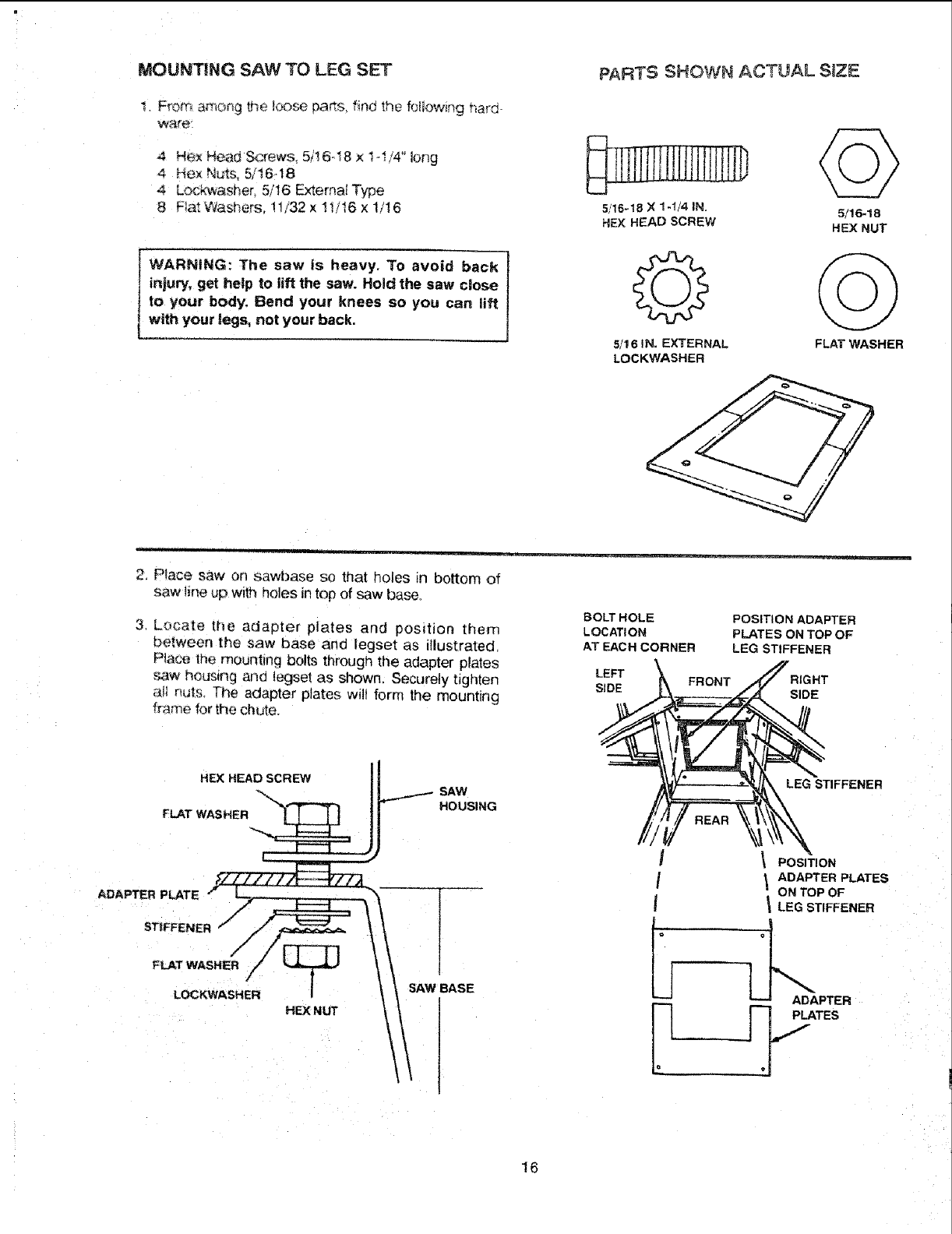
MOUNTING SAW TO LEG SET
I. From a_o_g the tcx_se pa_s, find the following hard
water
4 Hex Head Screws, 5/16..18 x t-I/4" long
4 Hex ,_quts,5/16.18
4 Lockwasher, 5/16 External Type
8 Flat Washers, !1/32 x t!/16 x 1/16
WARNING: The saw is heavy. To avoid back
injury, get help to lift the saw. Hold the saw close
to your body; Bend your knees so you can lift
with your legs, not your back.
PARTS SHOWN ACTUAL S_ZE
5/16-18 ;4 1-t/4 IN.
HEXHEAD SCREW
5/16 IN. EXTERNAL
LOCKWASHER
5/16-18
HEX NUT
FLATWASHER
2, Place saw or_ sawbase so that holes in bottom of
saw line up w_th holes in top of saw base.
3, Locate tt_e adapter plates and position them
between the _aw base and legset as illustrated.
Place, the mountin¢l bolts through the adapter plates
.saw houstng an(] legset as shown. Securely tigi_ten
a_ nuts. The adapter plates wi!t form the mounting
tr;_me for the chute.
BOLT HOLE
LOCATION
AT EACH OORNER
POSITION ADAPTER
PLATES ON TOP OF
LEG STIFFENER
LEFT FRONT RIGHT
SIDE SIDE
LEG STIFFENER
o
POSITION
ADAPTER PLATES
ON TOP OF
LEG STIFFENER
_ADAPTER
PLATES
16
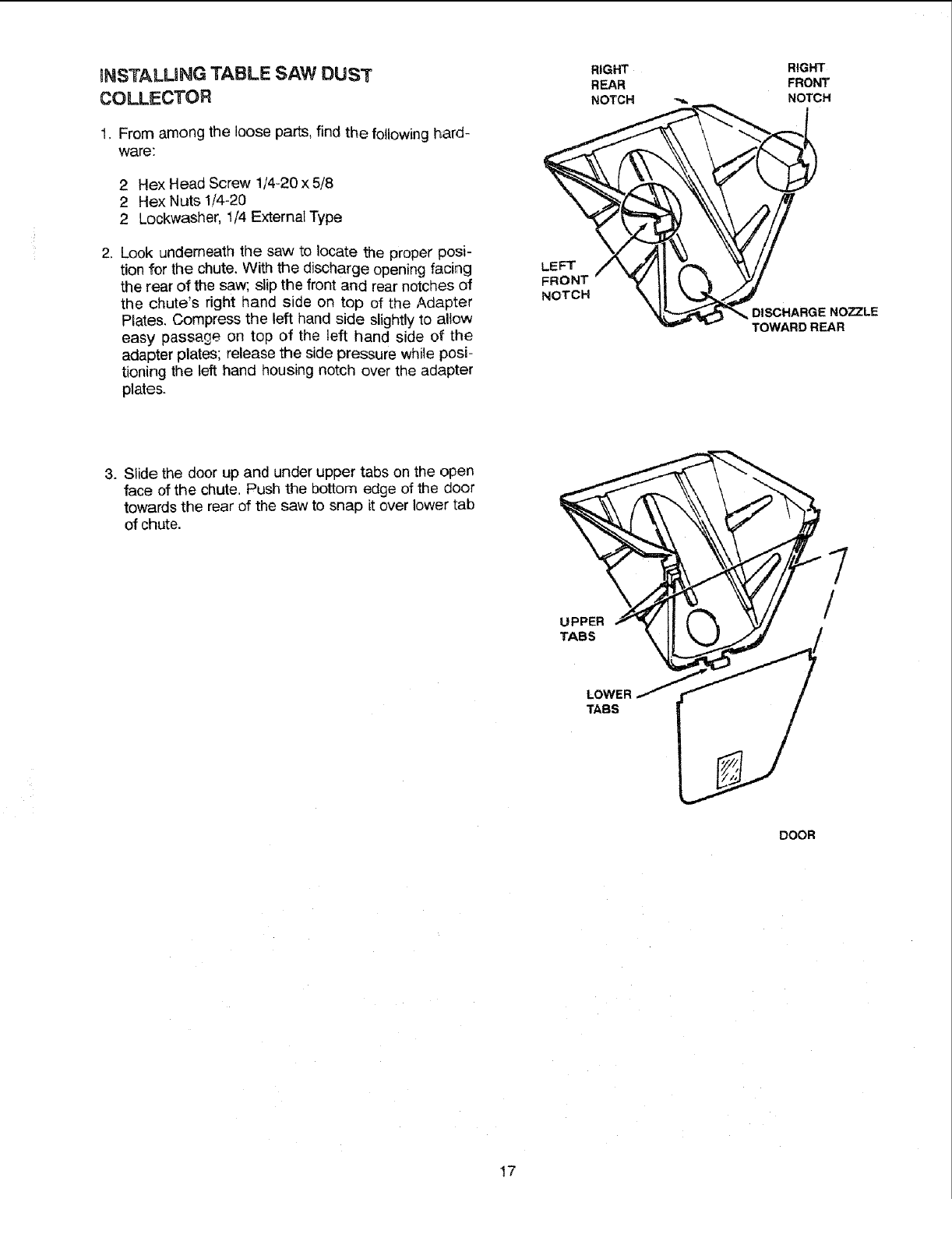
mNSTA.LLING TABLE SAW DUST
COLLECTOR
1. From among the loose parts, find the following hard-
ware:
2 Hex Head Screw 1/4-20 x 5/8
2 Hex Nuts 1/'4-20
2 Lockwasher, t/4 External Type
2, Look underneath the saw to locate the proper posi-
tion for the chute. With the discharge opening facing
the rear of the saw; slip the front and rear notches of
the chute's right hand side on top of the Adapter
Plates. Compress the left hand side slightly to allow
easy passage on top of the left hand side of the
adapter plates; release the side pressure while posi-
tioning the left hand housing notch over the adapter
plates.
LEFT
FRONT
NOTCH
RIGHT RIGHT
REAR FRONT
NOTCH _ NOTCH
DISCHARGE NOZZLE
TOWARD REAR
3. Slide the door up and under upper tabs on the open
face of the chute. Push the bottom edge of the door
towards the rear of the saw to snap it over lower tab
of chute.
UPPER
LOWER _
TABS
DOOR
17
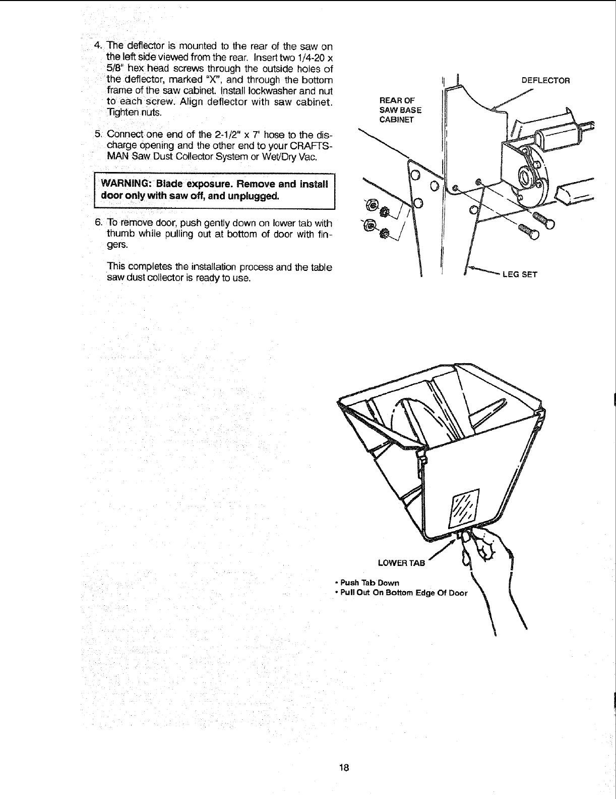
4. Thedeflectorismountedto therearof thesawon
theleftsideviewedfromtherear.Inserttwo1/4-20x
5/8"hexheadscrewsthroughtheoutsideholesof
thedeflector,marked"X".andthroughthebottom
frameofthesawcabinet.InstallIockwasherandnut
to eachscrew.Aligndeflectorwithsawcabinet.
"l]ghtennuts.
5. Connectoneendof the2-1/2"x 7' hosetothedis-
chargeopeningandtheotherendto yourCRAFTS-
MANSawDustCollectorSystemorWet/DryVac.
I WARNING: Blade exposure. Remove and install J
door only with saw off, and unplugged,
6. To remove door, push gently down on lower tab with
thumb while Dulling OUtat bottom of door with fin-
gers.
This completes the installation process and the table
saw dust collector is ready to use.
REAR OF
SAW BASE
CABINET
0
LEG SET
LOWER TAB
•Push Tab Down X
•Pull Out On Bottom Edge Of Door
18
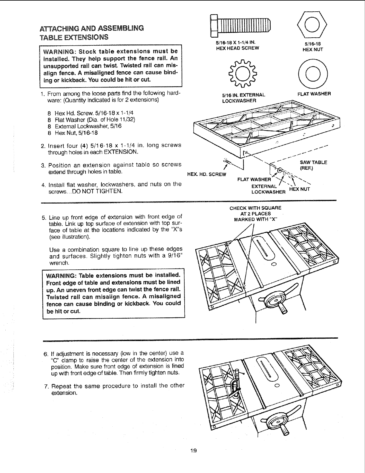
ATTACHmNG AND ASSEMBUNG
TABLE EXTENSmONS
WARNING: Stock table extensions must be
installed. They hetp support the fence rail. An
unsupported rail can twist. Twisted rail can mis-
aiign fence. Amisaligned fence can cause bind-
ing or kickback. You could be hit or cut.
1. From among the loose parts find the following hard-
ware: (Quantity indicated is for 2 extensions)
8Hex Hd. Screw. 5/16-18 x 1-!/4
8 Flat Washer (Dia. of Hole 11/32)
8 External Lockwasher, 5/16
8 Hex Nut, 5/16-18
2. Insert four (4) 5/16-18 x 1-1/4 in. long screws
through holes in each EXTENSION.
3. Position an extension against table so screws
extend through holes in table.
4. Install flat washer, Iockwashers, and nuts on the
screws... DO NOT TIGHTEN.
1111111111111i!111111)
5/16-18 X 1-1/4 IN.
HEX HEAD SCREW 5/16-18
HEX NUT
Q
5/16 IN. EXTERNAL FLAT WASHER
.Line up front edge of extension with front edge of
table. Link up top surface of extension with top sur-
face of table at the locations indicated by the "X"s
(see illustration).
Use a combination square to line up these edges
and surfaces. Slightly tighten nuts with a 9/16"
wrench.
WARNING: Table extensions must be installed.
Front edge of table and extensions must be lined
up. An uneven front edge can twist the fence rail.
Twisted rail can misaiign fence. A misaligned
fence can cause binding or kickback. You could
be hit or cut.
CHECK WITH SQUARE
AT 2 PLACES
MARKED WITH "X"
6: If adjustment is necessary (tow in the center) use a
"C" clamp to raise the center of the extension into
position. Make sure front edge of extension is lined
up with front edge of table. Then firmly tighten nuts.
7. Repeat the same procedure to insta!l the other
extension.
19
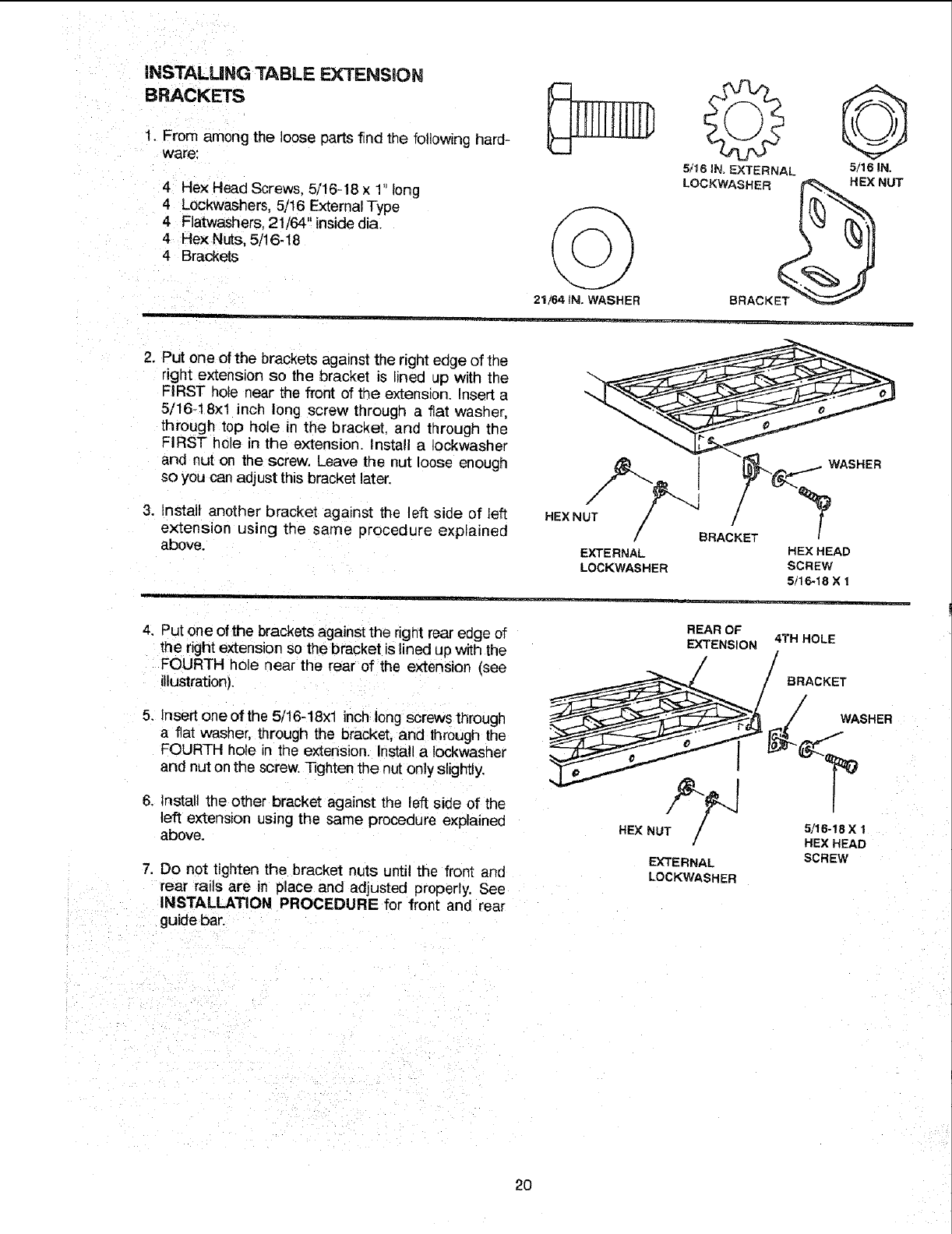
iNSTALLiNG TABLE EXTENSION
BRACKETS
1. From among the loose parts find the following hard-
ware:
4Hex Head Screws. 5/16-18x 1" long
4Lockwashers, 5/16 External Type
4 Flatwashers. 21/64" inside dia.
4 Hex Nuts, 5/16-18
4 Brackets
21/64 IN. WASHER
5/16 IN, EXTERNAL 5/16 IN.
2. Put one of the brackets against the rightedge of the
right extension so the bracket is lined up with the
FIRST hole near the front of the extensior Insert a
5/16-18xl inct_ long screw through a fiat washer,
through top hole in the bracket, and through the
FIRST hole in the extension. Install a Iockwasher
and nut on the screw. Leave the nut loose enough
so you can adjust this bracket later.
3. tnstalt another bracket against the left side of left
extension using the same procedure explained
above.
HEX NUT /
/BRACKET
EXTERNAL HEX HEAD
LOCKWASHER SCREW
5tl 6-18 X 1
4. Put one of the brackets against the right rear edge of
the right extension so the bracket is lined up with the
FOURTH hole near the rear of the extension (see
illustration).
REAR OF
EXTENSION 4TH HOLE
BRACKET
5. Insert one of the 5/16-18xl inch long screws through
a fiat washer, through the bracket, and through the
FOURTH hole in the extension. Install a Iockwasher
and nut on the screw. Tighten the nut only slightly.
6. Install the other bracket against the left side of the
left extension using the same procedure explained
above.
7. Do not tighten the bracket nuts until the front and
rear rails are in place and adjusted properly. See
INSTALLATION PROCEDURE for front and rear
guide bar.
HEX NUT_/_
EXTERNAL
LOCKWASHER
WASHER
5/16-18 X 1
HEX HEAD
SCREW
2O
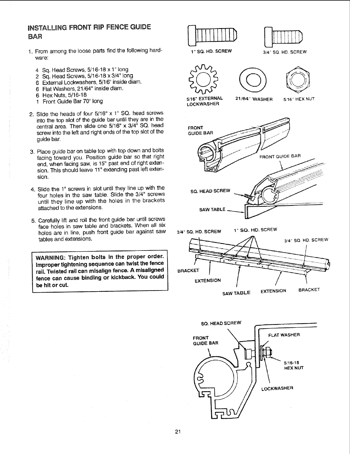
RNSTALLUNG FRONT RIP FENCE GUIDE
BAR
1. From among the loose parts find the following hard-
ware:
,
,
4 Sq. Head Screws, 5/16-18 x 1" long
2 Sq. Head Screws, 5/16-18 x 3/4" long
6 External Lockwashers, 5/16" inside diam.
6 Flat Washers, 21/64" inside diam.
6 Hex Nuts, 5/16-18
1 Front Guide Bar 70" long
Slide the heads of four 5/16" x 1" SQ. head screws
into the top slot of the guide bar until they are in the
central area. Then slide one 5/16" x 3/4" SQ, head
screw into the left and right ends of the top slot of the
guide bar,
Place guide bar on table top withtop down and bolts
facing toward you. Position guide bar so that right
end, when facing saw, is 15" past end of right exten-
sion. This should leave 11" extending past left exten-
sion.
4. Slide the 1" screws in slot until they line up with the
four holes in the saw table. Slide the 3/4" screws
until they line up with the holes in the brackets
attached to the extensions,
.Carefully lift and roll the front guide bar until screws
face holes in saw table and brackets. When all six
holes are in line, push front guide bar against saw
tables and extensions.
1 " SQ, HD. SCREW
5/16" EXTERNAL
LOCKWASHER 21164" WASHER
SQ. HEADSCREW
3/4" SO, HD. SCREW 1" SQ, HD. SCREW
WARNING: Tighten bolts in the proper order.
improper tightening sequence can twist the fence
rail Twisted rail can misalign fence, Amisaligned
fence can cause binding or kickback. You could
be hit or cut.
SAW TABLE EXTENSION 8RACKET
SO. HEAD SCREW
FRONT
GUIDE BAR
FLAT WASHER
511_1B
HEX NUT
LOCKWASHER
2!
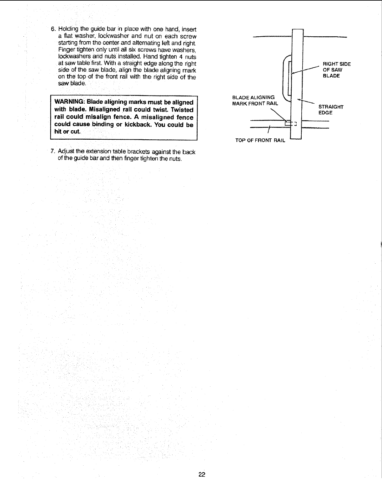
6. Holding the guide bar in place with one hand, insert
a flat washer, Iockwasher and nut on each screw
starting from the center and alternating left and right.
=inger tighten only until all six screws nave washers.
lockwashers and nuts installed. Hand tighten 4 nuts
at saw table first. With a straight edge along the right
side of the saw blade, align the blade aligning mark
on the top of the front rail with the right side of the
saw blade.
!
WARNING: Blade aligning marks must be aligned I
with blade. Misaligned rail could twist. Twisted
rail could misalign fence. A misaligned fence
could cause binding or kickback. You could be
hit or cuL
7. Adjust the extension table brackets against the back
of the guide bar and then finger tighten the nuts.
BLADE ALIGNING
MARK FRONT RAIL
TOP OF FRONT RAIL
RIGHT SIDE
OFSAW
BLADE
STRAIGHT
EDGE
.J
22
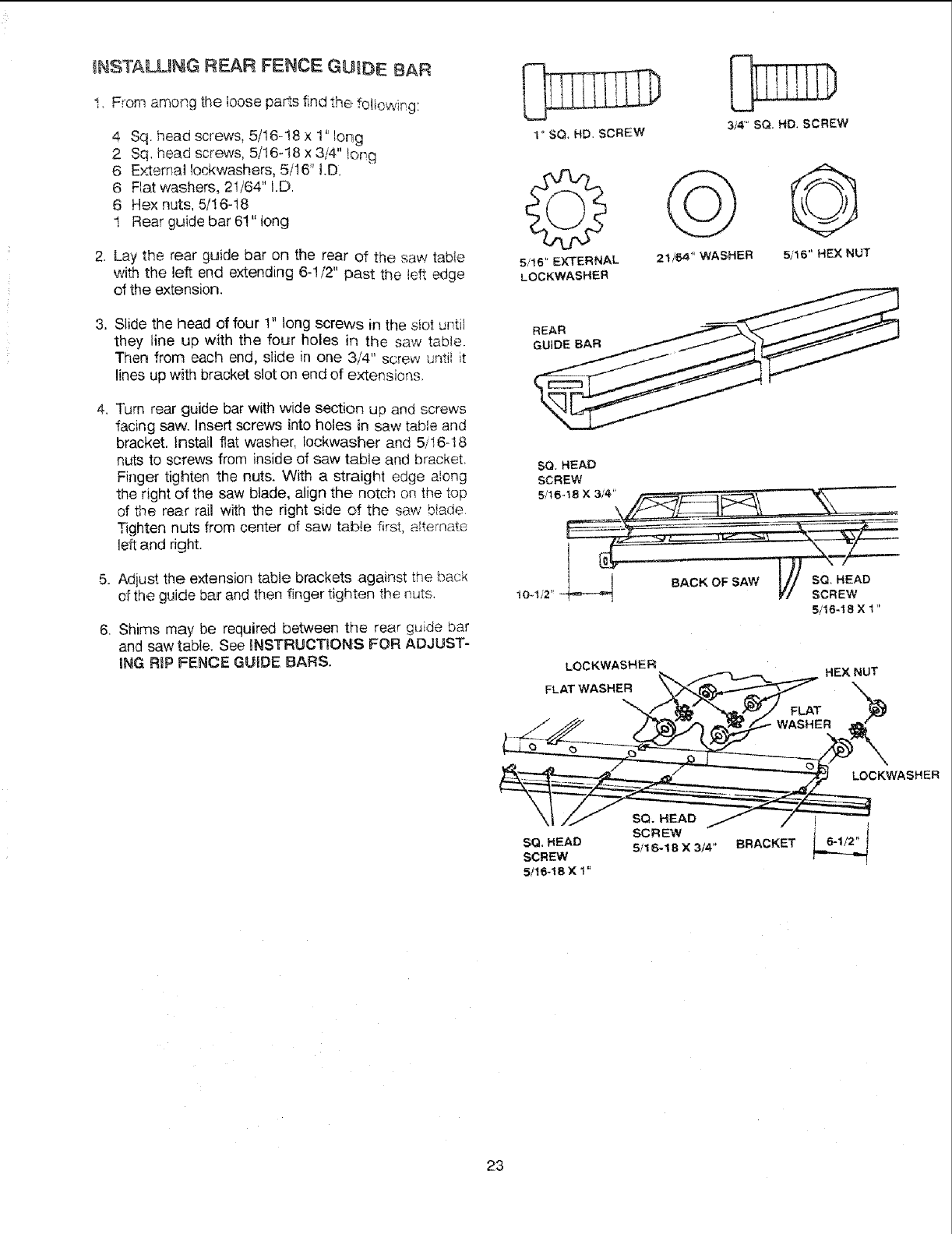
tNSTALU_G REAR FENCE GUIDE BAR
I. From among tt_e _ooseparts find the following:
4 Sq. head screws, 5/16--18 x 1" long
2 Sq. head screws, 5/16-18 x 3/4" torT,q
6 Externat lockwashers, 5/16" I.D.
6 Flat washers, 21/64" I.D.
6 Hex nuts, 5/!6-18
1 Rear guide bar 6!" tong
2. Lay the rear guide bar on the rear of the saw table
with the left end extending 6-1/2" past the le_ edge
of the extension.
3, Slide the head of four 1" long screws in the siot until
they line up with the four holes in the saw tabMe.
Then from each end, slide in one 3,/4" screw untii it
lines up with bracket slot on end of extensions,
4. Turn rear guide bar with ,,vide section up and screws
facing saw. Insert screws into holes in saw table and
bracket. Install flat washer, lockwasher and 5/16-t8
nuts to screws from inside of saw table and bracket.
Finger tighten the nuts. With a straight edge along
the right of the saw blade, align the notch on the top
of the rear rail with the right side of the saw btade.
Tighten nuts from center of saw tab!e first, alternate
left and right.
5. Adjust the extension table brackets against the back
of the guide bar and then finger tighten the nuts.
6. Shims may be required between the rear guide bar
and saw table. See INSTRUCTIONS FOR ADJUST-
ING RIP FENCE GUIDE BARS.
3i4" SQ, HD. SCREW
5/t6" EXTERNAL 2t/64 '! WASHER 5/16" HEX NUT
LOCKWASHER
SQ HEAO
SCREW
5/16-
5/16-18 X 1"
LOCKWASHEP;
FLAT WASHER _,,._ HEX _T
SCREW
SQ. HEAD 511 6-! B X 3/4" BRACKET
SCREW
5/16-18 X 1"
23
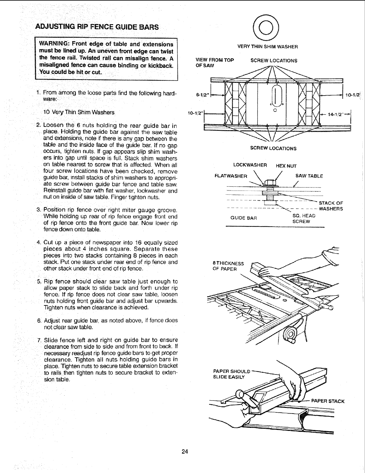
ADJUSTING RiP FENCE GUIDE BARS
1. From among the loose parts find the following hard-
ware:
10 Very Thin Shim Washers
2. Loosen the 6 nuts holding the rear guide bar in
place, Holding the guide bar against the saw table
and extensions, note if there is any gap between the
table and the inside face of the guide bar. If no gap
occurs, tighten nuts. If gap a_)pears slip shim wash-
ers into gap until space is full. Stack shim washers
on table nearest to screw that is affected, When all
four screw locations have been checked, remove
guide bar, Tnstallstacks of shim washers to appropri-
ate screw between guide bar fence and table saw,
Reinstall guide bar with fiat washer, Iockwasher and
nut on inside of saw table. Finger t_ghten nuts.
3. Position rip fence over right miter gauge groove,
While holding up rear of rip fence engage front end
of rip fence onto the front gutde bar. Now lower rip
fence down onto table.
4. Cut up a piece of newspalDer into 16 equally sizee
pieces about 4 inches square. Separate these
peces into two stacks containing 8 pieces in eacn
stack. Put one stack under rear end of ripfence and
other stack under front end of rip fence,
5, Rip fence should c_ear saw table lust enough to
allow paper stack to slide back and forth under r_p
fence. If rip fence does not clear saw table, loosen
n_s holding front guide bar aria adjust bar upwards,
Tighten nuts when clearance is achieved,
6. Adjust rear guide bar, as noted above, if fence does
not clear saw table.
7. Slide fence left and right on guide bar to ensure
clearance from side to side and from front to back. If
necessary readjust rip fence guide bars to get proper
clearance. Tighten all nuts holding guide bars _n
place, Tighten nuts to secure table extension bracket
to ra S then tighten nuts to secure bracket to exten-
s_iontable,
VERY THIN SHIM WASHER
VIEW' FROM TOP
OF SAW
,,_CREW LOCATIONS
O
SCREW LOCATIONS
LOCK_NASHER HEX NUT
FLATWASHER __/ SAW TABLE
SCL HEAD
GUIDE BAR SCREW
8 THICKNESS L< __
PAPER SHC
SLIDE EASILY
PAPER STACK
24
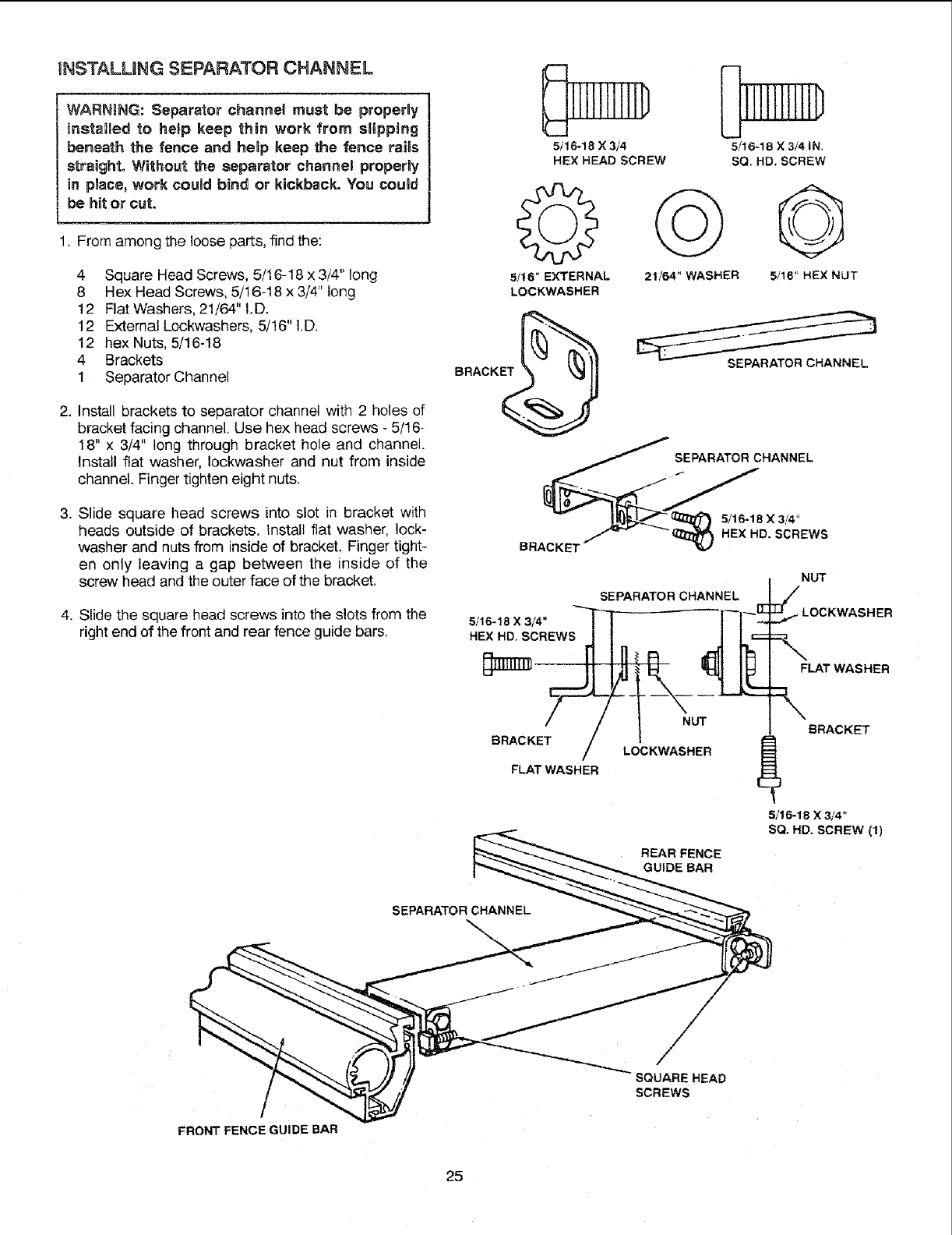
INSTALUNG SEPARATOR CHANNEL
WARNING: Separator channel must be properly
installed to help keep thin work from stipping
beneath the fence and heBp keep the fence raits
straight. Without the separator channel properly
in pnace,work could bind or kickback. You couM
be hit or cut.
1. From among the loose parts, find the:
4 Square Head Screws, 5/16-18 x 3/4" long
8 Hex Head Screws, 5/16-18 x 3/4" long
12 Flat Washers, 21/64" I.D.
12 External Lockwashers, 5/!6" I.D.
12 hex Nuts, 5/16-18
4 Brackets
1 Separator Channel
2. Install brackets to separator channel with 2 holes of
bracket facing channel. Use hex head screws - 5/16-
18" x 3/4" long through bracket hole and channel.
Install flat washer, Iockwasher and nut from inside
channel, Finger tighten eight nuts.
3. Slide square head screws into slot in bracket with
heads outside of brackets. Install flat washer, lock-
washer and nuts from inside of bracket. Finger tight-
en only leaving a gap between the inside of the
screw head and the outer face of the bracket.
4, Slide the square head screws into the slots from the
right end of the front and rear fence guide bars.
5/16-18 X3/4
HEX HEAD SCREW
[ 11IIIIIiD
5/16-18 X 3/4 IN.
SQ. HD. SCREW
G G
5/16" EXTERNAL 21/64" WASHER 5/16" HEX NUT
LOCKWASHER
BRACK_
SEPARATOR CHANNEL
SEPARATOR CHANNEL
BRACKET
5/16-18X3/4"
HEX HD. SCREWS
NUT
SEPARATOR CHANNEL
5/16-18 X 3/4" _ -'-------- I--I_ LOCKWASHER
HEX HD. SCREWS _ I _ k'
F_rn_ II Ig{R _1 IF
_S:I!_A_N-: T BRACKET
BRACKE
FLAT WASHER
5/16-18 X 3/4"
SQ. HD. SCREW (1)
REAR FENCE
GUIDE BAR
SEPARATOR CHANNEL
/
FRONT FENCE GUIDE BAR
SQUAREHEAD
SCREWS
25
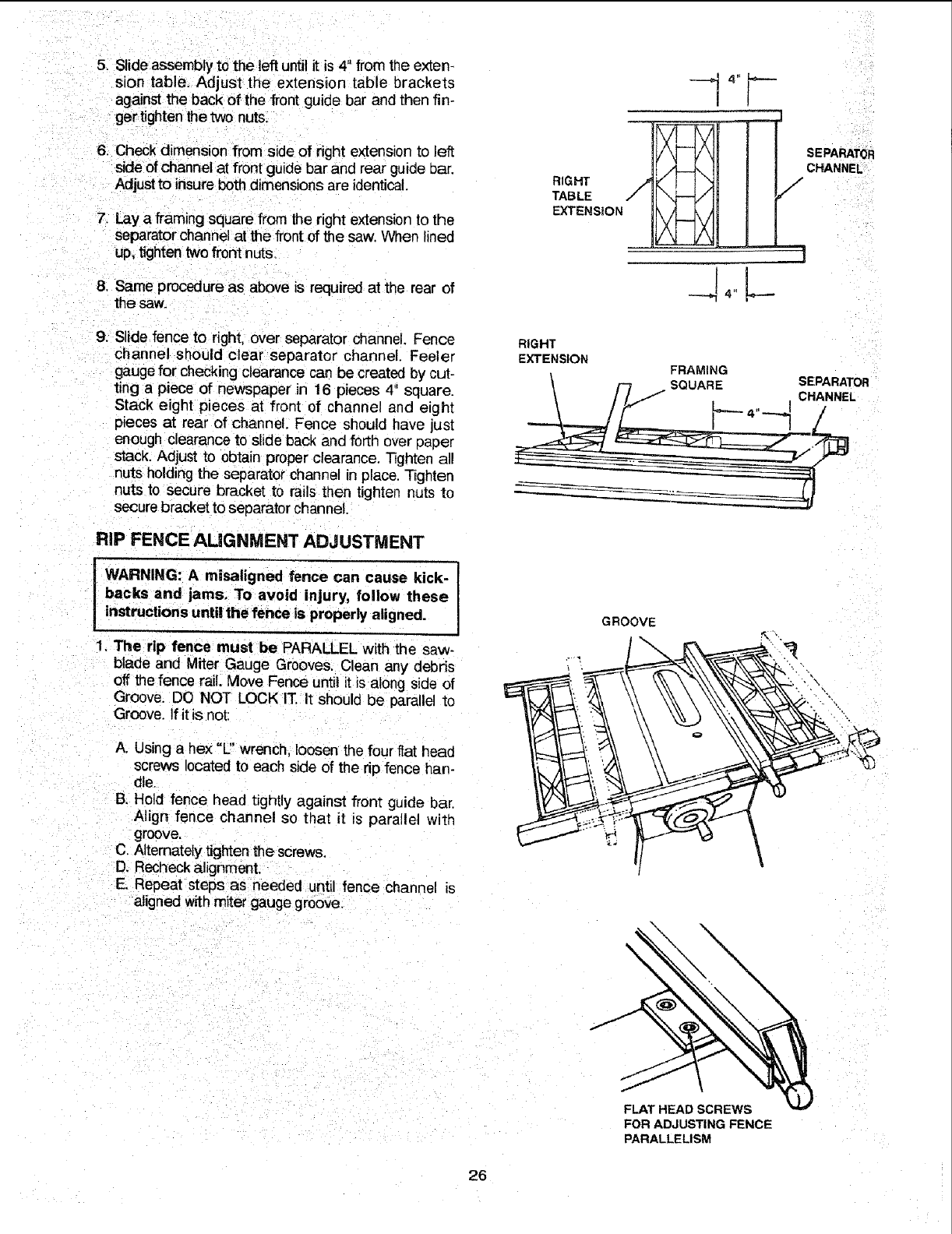
5. Slide assembly to the left until it is 4" from the exten-
sion table. Adjust the extension table brackets
against the back of the front guide bar and then fin-
ger tighten the two nuts.
6. Check dimension from side of right extension to le_t
side of channel at front guide bar and rear guide bar,
Adjust to insure both dimensions are identical.
7. Lay a framing square from the right extension to the
separator channel at the frontof the saw. When lined
up. tighten two front nuts.
8. Same procedure as above is required at the rear of
the saw.
9. Slide fence to right, over separator channel. Fence
channel should clear separator channel. Feeler
gauge for checking clearance can be created by cut-
ting a piece of newspaper in 16 pieces 4" square,
Stack eight pieces at front of channel and eight
pieces at rear of channel. Fence should have just
enough clearance to slide back and forth over paper
stack. Adjust to obtair proper clearance. Tighter all
nuts holding the separator channel in place. Tighten
nuts to secure bracket to rails then tighten nuts to
secure bracket to separator channel.
RiP FENCE AUGNMENT ADJUSTMENT
WARNING: A misaligned fence can cause kick-
backs and jams, To avoid injury, follow these
instructions until the fence is properly aligned.
1. The rip fence must be PARALLEL with the saw-
blade and Miter Gauge Grooves. Clean any debris
off the fence rail. Move Fence until it is along side of
Groove. DO NOT LOCK IT. It should be parallel to
Groove. If it is not:
A. Using a hex "L" wrench, loosen the four fiat head
screws located to each side of the rip fence han-
dle,
B. Hold fence head tightly against from guide bar
Align fence channel so that it is parallel With
groove.
C. Alternately tigtiten the screws.
D. Recheck alignment.
E. Repeat steps as needed until fence channel is
aligned with miter gauge groove.
RIGHT
EXTENSION
GROOVE
FRAMING
/
'3
ii
FLAT HEAD SCREWS
FOR ADJUSTING FENCE
PARALLELISM
26
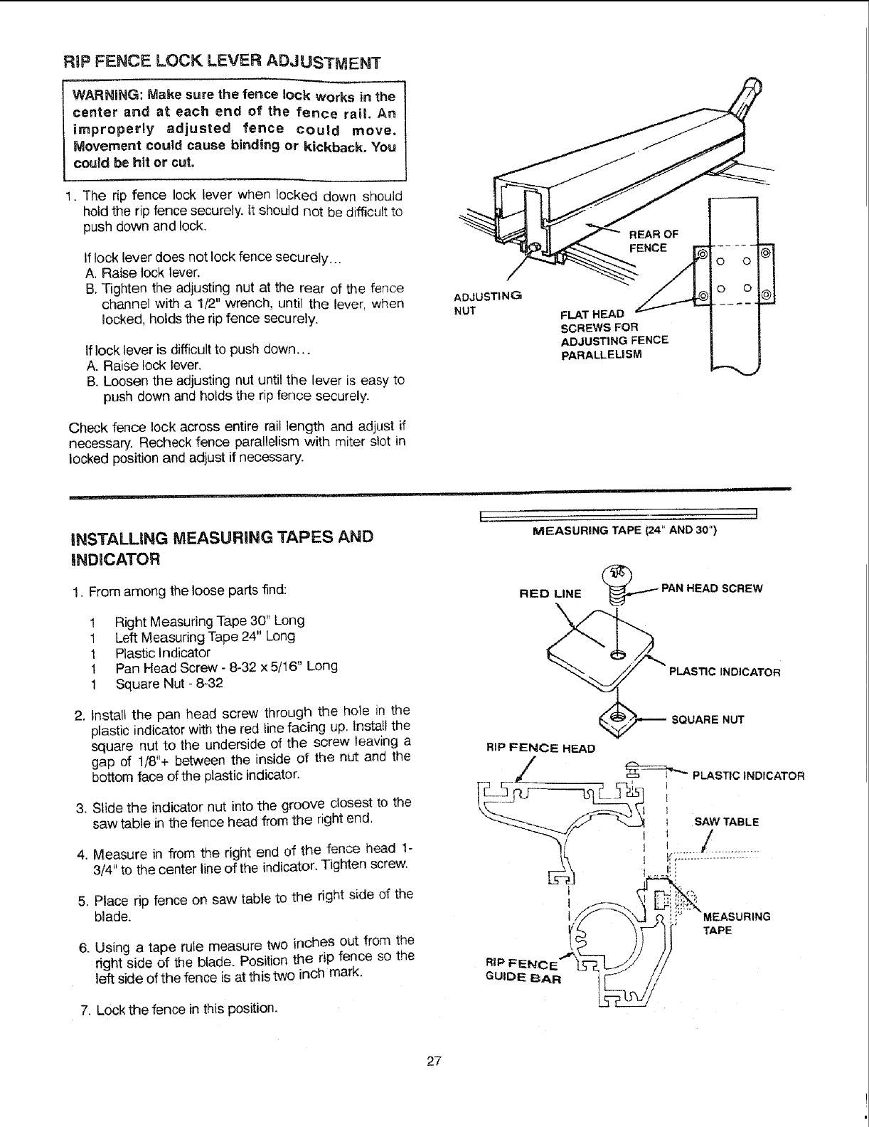
RiP FENCE LOCK LEVER ADJUSTMENT
WARNING: Make sure the fence lock works in the
center and at each end of the fence rail. An
improperly adjusted fence could move.
Movement could cause binding or kickback. You
could be hit or cut.
1. The rip fence lock lever when locked down should
hold the rip fence securely. It should not be difficult to
push down and lock.
If lock lever does not lock fence securely...
A, Raise lock lever.
B, Tighten the adjusting nut at the rear of the fence
channel with a 1/2" wrench, until the lever, when
locked, holds the rip fence securely.
If lock lever is difficult to push down.,.
A. Raise lock lever.
B. Loosen the adjusting nut until the lever is easy to
push down and holds the rip fence securely.
Check fence lock across entire rail length and adjust if
necessary. Recheck fence parallelism with miter slot in
locked position and adjust if necessary.
ADJUSTING
NUT
REAR OF
FLAT HEAD _
SCREWS FOR
ADJUSTING FENCE
PARALLELISM
o o
o o
%
iNSTALLiNG MEASURING TAPES AND
iNDiCATOR
1. From among the loose parts find:
1 Right Measuring Tape 30" Long
1 Left Measuring Tape 24" Long
1 Plastic Indicator
1 Pan Head Screw - 8-32 x 5/!6" Long
1 Square Nut - 8-32
2. tnstall the pan head screw through the hole in the
plastic indicator with the red linefacing up. Install the
square nut to the underside of the screw leaving a
gap of 1/8"+ between the inside of the nut and the
bottom face of the plastic indicator.
3. Slide the indicator nut into the groove closest to the
saw table in the fence head from the right end,
4. Measure in from the right end of the fence head 1-
3/4" to the center line of the indicator. Tighten screw.
5. Place rip fence on saw table to the right side of the
blade.
6. Using a tape rule measure two incheS out from the
right side of the blade. Position the rip fence so the
left side of the fence is at this two inch mark.
7. Lockthe fence in this position.
[ ]
MEASURING TAPE (24" AND 30")
RED LINE _PAN HEAD SCREW
\
PLASTIC INDICATOR
NUT
RIP FENCE HEAD
/_PLASTIC INDICATOR
__ _/r- _ I SAW TABLE
_._-..r/ l I /
t
q
TAPE
RIP FENC
GUIDE BAR i
I
27
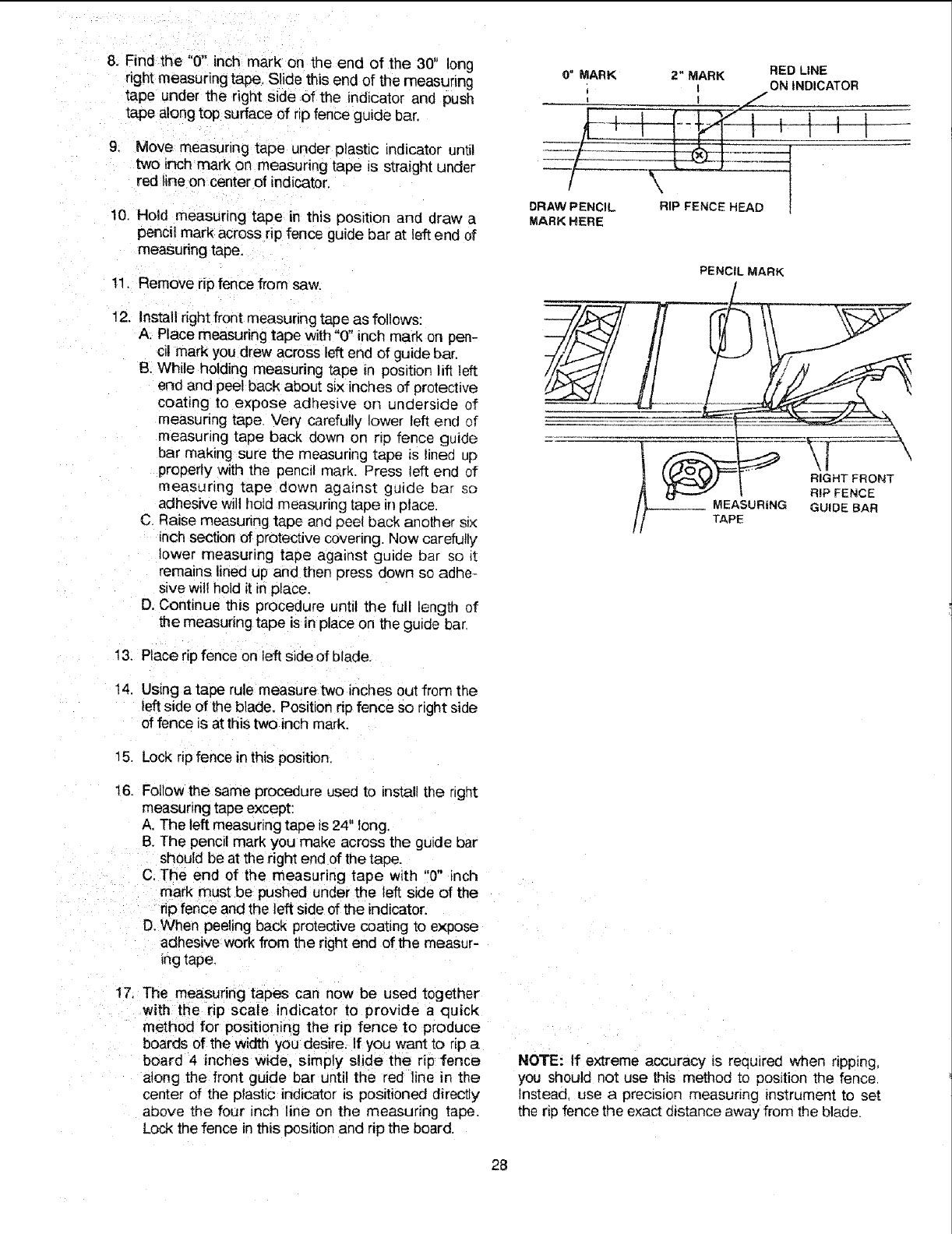
8. Find the "0" inch mark on the end of the 30" long
right measuring tape. Slide this end of the measuring
tape under the right side of the indicator and push
tape along top surface of rip fence guide bar.
9. Move measuring tape under plastic indicator until
two inch mark on measuring tape is straight under
red line on center of indicator.
10. Hold measuring tape in this position and draw a
pencii mark across rip fence guide bar at left end of
measuring tape,
11, Remove rip fence from saw,
12, Install right front measunng tape as follows:
A. Place measuring tape with "0" inch mark on pen-
cil mark you drew across left end of guide bar,
B. While holding measuring tape in position lift left
end and peel back about six inches of protective
coating to expose adhesive on underside of
measunng tape, Very carefully lower left end of
measuring tape back down on rip fence guide
bar making sure the measuring tape is lined up
properly with the pencil mark. Press left end of
measuring tape down against guide bar so
adhesive will hold measuring tape in place.
C, Raise measuring tape and peel back another st×
inch section of protective covering. Now carefully
lower measuring tape agmnst guide bar so it
remains lined up and then cress down so adhe-
sive will hold it in place,
D. Continue this procedure until the full length of
the measuring tape is in place on the guide bar.
13, Place rip fence on left side of blade.
O" MARK 2" MARK RED LINE
i ON INDICATOR
l_i J I -
DRaW/PENCIL P FENCE HEAD !
MARK HERE
PENCIL MARK
FRONT
RiP FENCE
--- TAP SURtNG GUIDE BAR
! 4. Usingatape rule measure two inches out from the
left side of the blade. Position rip fence so right side
of fence is at this two inch mark.
15. Lock np fence in this position
16. Followthe same procedure used to install the right
measuring tape except:
A, The left measuring tape is 24" long.
B, The pencil mark you make across the guide bar
should be at the right end of the tape.
C. The end of the measuring tape with "0" inch
mark must be pushed under the left side of the
rio fence and the left side of the indicator.
D.When peeling back protective coating to expose
adhesive work from the right end of the measur-
ing tape.
17, The measuring tapes can now be used together
with the rip scale indicator to provide a quick
method for positioning the rip fence to produce
boards of the width you desire, If you want to rip a
board 4 inches wide, simply slide the rip fence
along the front guide bar until the ,ed line in the
center of the plastic indicator is positioned directly
above the four inch line on the measuring tape.
Lock the fence in this position and rip the board.
NOTE: If extreme accuracy is required when ripping,
you should not use this method to position the fence
Instead. use a prec=sion measunng instrument to set
the rip fence the exact distance away from the blade.
28
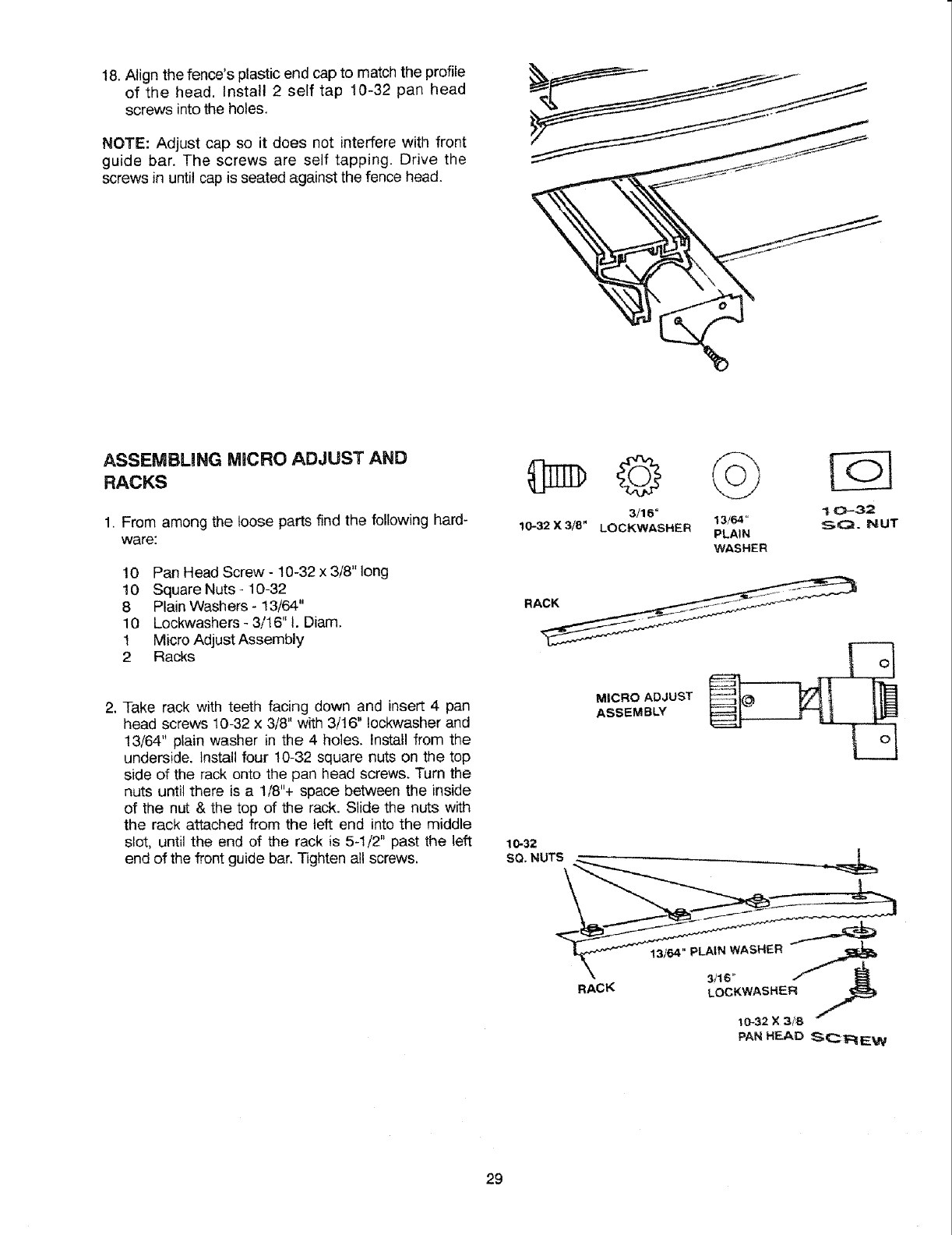
18,Alignthefence'splasticendcaptomatchtheprofile
of the head.Install2 self tap 10-32pan head
screwsintotheholes.
NOTE:Adjustcapso it doesnotinterferewithfront
guidebar,Thescrewsareselftapping.Drivethe
screwsinuntilcapisseatedagainstthefencehead.
ASSEMBUNG MICRO ADJUST AND
RACKS
1. From among the loose parts find the following hard-
ware:
10 Pan Head Screw - 10-32 x 3/8" long
10 Square Nuts -10-32
8 Plain Washers - 13/64"
10 Lockwashers - 3/16" 1. Diam.
1 Micro Adjust Assembly
2 Racks
10-32 X 3/8"
©
3/16"
LOCKWASHER 13/64"
PLAIN
WASHER
! 0-32
S<:_. NUT
2. Take rack with teeth facing down and insert 4 pan
head screws 10-32 x 3/8" with 3/16" Iockwasher and
13/64" plain washer in the 4 holes. Install from the
underside. Install four 10-32 square nuts on the top
side of the rack onto the pan head screws. Turn the
nuts until there is a 1/8"+ space between the inside
of the nut & the top of the rack. Slide the nuts with
the rack attached from the left end into the middle
slot, until the end of the rack is 5-1/2" past the left
end of the front guide bar, Tighten all screws. 10-32
SQ. NUTS \
MICRO ADJUST
ASSEMBLY
RACK
13/64" pLAIN WASHER
3/16 '=
LOCKWASHER
29
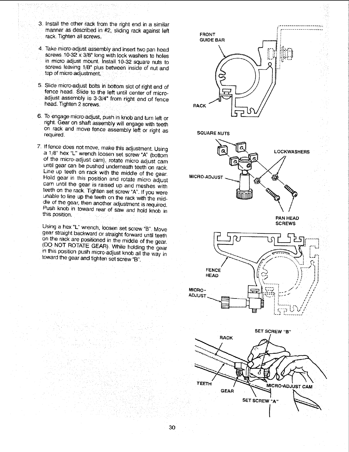
3 instanttheotherrackfromtherightendina similar
mannerasdescribedin#2.slidingrackagainstleft
rack.Tightenattscrews.
4 _akemicro-adjustassemblyandinserttwopanhead
screws10-32x 3/8"longwithlockwashersto holes
mm,,croadjustmount.Install10-32squarenutsto
screwsleaving1/8"plusbetweeninsideof nutand
topofmicroadjustmenL
5. Slidemicro-adjustboltsinbottomslotofrightendof
fencehead.Slideto theleftuntilcenterof micro-
adjustassemblyis 3-3/4"fromrightendof fence
head.Tighten2screws.
6. Toengagemicro-adjust,pushinknobandturnleftor
right.Gearonshaftassemblywillengagewithteeth
onrackandmovefenceassemblyleftorrightas
required.
7 fffencedoesnotmove,makethisadjustment.Using
a 1/8"hex"L" wrench loosen set screw "A" (bottom
of the m_cro-adjust cam), rotate micro aGjust cam
until gear can be pushed underneath teeth on rack.
Line up teeth on rack w_th the middle of the gear.
Ho_d gear in this position and rotate micro ad ust
cam until the gear is raised up and meshes with
t_th on me rack. Tighten set screw "A". If you were
unable to line up the teeth on the rack with the mi@
die of me gear, then another adjuslment _srequired.
Push knob tn toward rear of saw and hold knob in
this pos_t_on.
Using a hex "L" wrench, loosen set screw "B" Move
gear straight backward or straight forward until teeth
on _e rack are positioned in the middle of the gear.
(DO NOT ROTATE GEAR). While holding the gear
{nthis POSrltonpush micro_adjust knob all the way _n
toward the gear and tighten set screw "B".
FRONT
GUIDE BAR
\
RACK
SQUARE NUTS
CRO-ADJUST
FENCE
HEAD
MICRo-
ADJUST
2i
LOCKWASHERS
PAN HEAD
SCREWS
RACK
SET SCREW "B"
TEETH
GEAR MICRO-ADJUST CAM
SET SCREW "A"
I
30
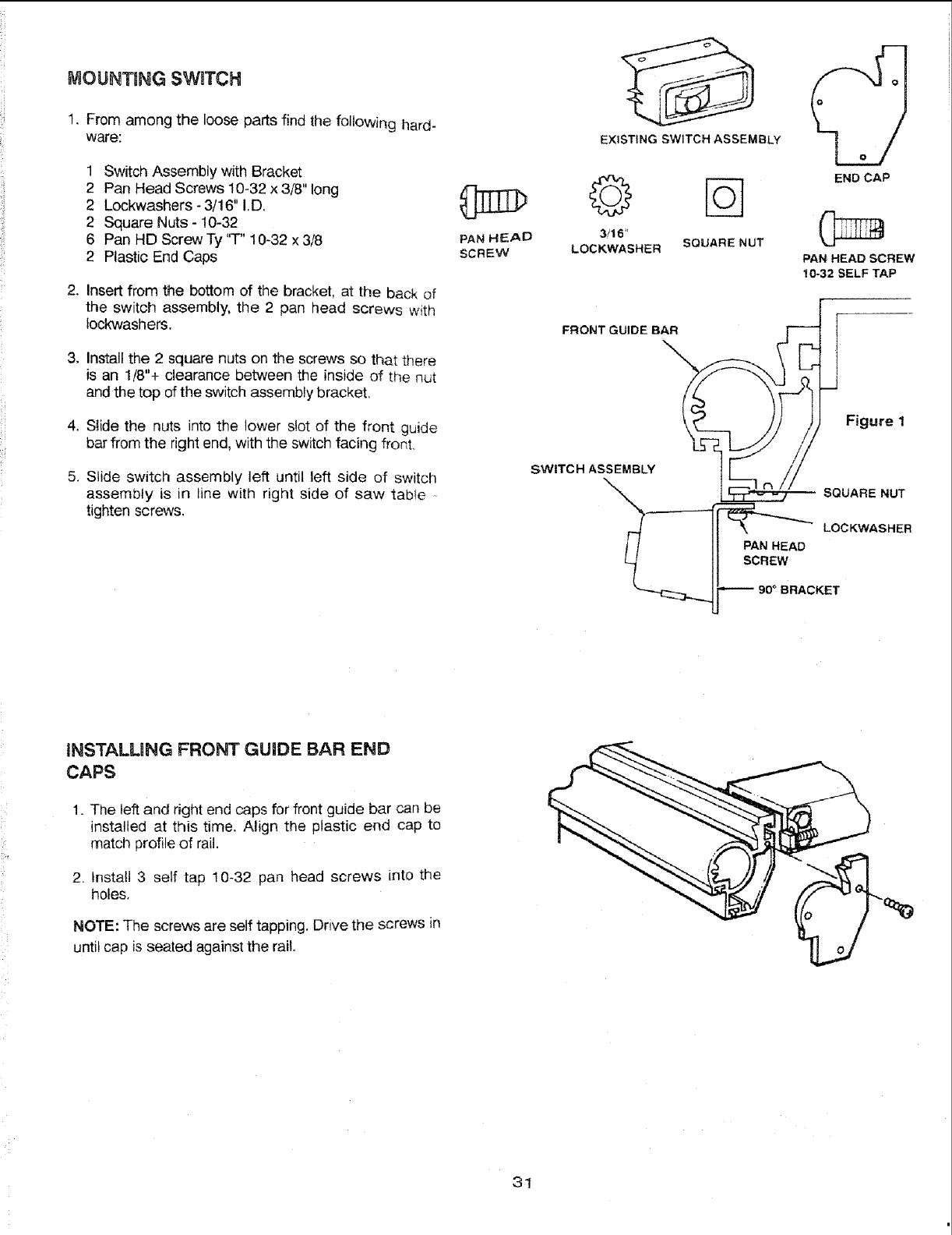
MOUNTING SWITCH
1. From among the loose parts find the following hard-
ware:
1 Switch Assembly with Bracket
2 Pan Head Screws 10-32 x 3/8" long
2 Lockwashers - 3/16" I.D,
2 Square Nuts - 10-32
6 Pan HD ScrewTy "T" 10-32 x3/8
2 Plastic End Caps
2. Insert from the bottom of the bracket, at the back of
the switch assembly, the 2 pan head screws with
tockwashers.
3. Install the 2 square nuts on the screws so that there
is an 1/8"+ clearance between the inside of the nut
and the top of the switch assembly bracket,
4. Slide the nuts into the lower slot of the front guide
bar from the right end, with the switch facing front,
5. Slide switch assembly left until left side of switch
assembly is in line with right side of saw table
tighten screws.
PAN HEAD
SCREW
EXISTING SWITCH ASSEMBLY
_END CAP
3/16"
LOCKWASHER SQUARENUT
PAN HEAD SCREW
10-32SELFTAP
[
FRONT GUIDE BAR
SWITCH ASSEMBI_ SQUARE NUT
II' N
__j_ 9o ° BRACKET
INSTALMNG FRONT GUIDE BAR END
CAPS
1. The left and right end caps for front guide bar can be
installed at this time. Align the plastic end cap to
match profile of rail.
2. Install 3 self tap 10-32 pan head screws into the
holes,
NOTE: The screws are self tapping, Drive the screws in
until cap is seated against the rail,
31
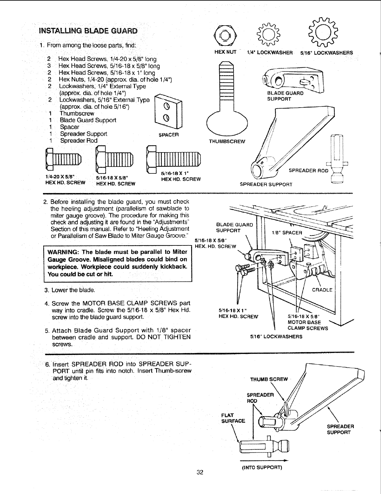
INSTALLING B_DE GUARD
1. From among the loose parts, find:
2 Rex Head SCrew& 1/4-20X5/8, long
3 Hex Head Screws, 5/i6-18 x 5/8, long
2 Hex Head Screws, 5/t6,18x 1" long
2Bex Nuts, 1/4_20 (approx. dia: of hole 1/4")
2 Lockwashers; !/4" External Type
(approx. dia: of hole t/4")
2 Lockwashers, 5/16" External Type
(approx, dia. of hole 5/18")
1 Thumbscrew
1 Blade Guard Support
1 Spacer
1 Spreader Support
1 Spreader Rod
1/4-20 X5/8"
HEX HD, SCREW
5t16-18 X 5/8"
HEX HD. SCREW
SPACER
lI!!ljtj!lll D
HEX HO. SCREW
©
HEX NUT
THUMBSCREW
©
1/4" LOCKWASHER 5/16" LOCKWASHERS
SUPPORT
SPREADER SUPPORT
2, Before installing the blade guard, you must check
the heeling adjustment (parallelism of sawblade to
miter gauge groove). The procedure for making this
check and adjusting it are found inthe "Adjustments"
Section of this manual. Refer to "Heeling Adjustment
or Parallelism of Saw Blade to Miter Gauge Groove."
WARNING: The blade must be parallel to Miter
Gauge Groove. Misaligned blades could bind on
workpiece. Workpiece could suddenly kickback.
You could be cut or hit.
BLADE GUARD
SUPPORT
5/16-18X 5/8' \
HEX. HD. SCREW
3, Lower the blade.
4. Screw the MOTOR BASE CLAMP SCREWS part
way into cradle. Screw the 5/! 6-18 x 5t8" Hex Hd.
screw into the blade guard support.
5. Attach Blade Guard Support with 1/8" spacer
between cradle and support. DO NOT TIGHTEN
screws.
6. Insert SPREADER ROD into SPREADER SUP-
PORT until pin fits into notch. Insert Thumb-screw
and tighten it.
5,'16-18 X 1 "
HEX HD. SCREW 5/16-18 X 5/8"
MOTORBASE
CLAMPSCREWS
5/16" LOCKWASHERS
THUMBSCREW
32
ROD
FLAT
SURFACE
\
U
(INT0 SUPPORT)
SPREADER
SUPPORT
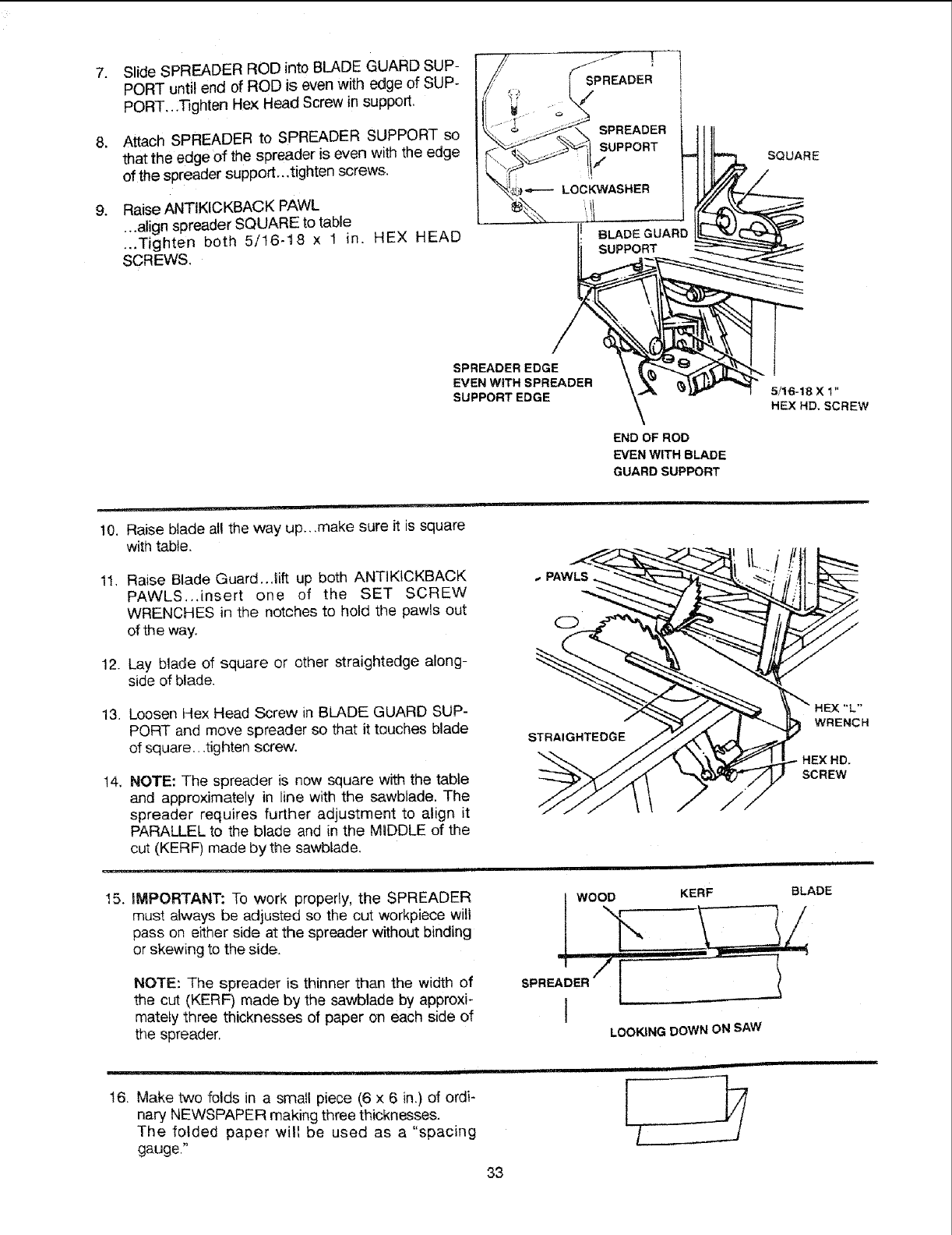
7.
.
Slide SPREADER ROD into BLADE GUARD SUP-
PORT until end of ROD is even with edge of SUP-
PORT,.,lqghten Hex Head Screw in support.
Attach SPREADER to SPREADER SUPPORT so
that the edge of the spreader is even with the edge
of the spreader support...tighten screws.
Raise ANTIKICKBACK PAWL
...align spreader SQUARE to table
..,Tighten both 5/t6-18 x 1 in. HEX HEAD
SCREWS.
SQUARE
SPREADEREDGE
EVEN WITH SPREADER
SUPPORT EDGE 5/16-18 X 1"
HEX HD. SCREW
END OF ROD
EVEN WITH BLADE
GUARD SUPPORT
__ ,irl,
10. Raise blade all the way up., ,make sure it is square
with table.
11. Raise Blade Guard..Jift up both ANTIKICKBACK
PAWLS..Jnsert one of the SET SCREW
WRENCHES in the notches to hold the pawls out
of the way.
12. Lay blade of square or other straightedge along-
side of blade.
13. Loosen Hex Head Screw in BLADE GUARD SUP-
PORT and move spreader so that it touches blade
of square...tighten screw.
14, NOTE: The spreader is now square with the table
and approximately in line with the sawblade. The
spreader requires further adjustment to align it
PARALLEL to the blade and in the MIDDLE of the
cut (KERF) made by the sawblade.
15. iMPORTANT: To work properly, the SPREADER
must always be adjusted so the cut workpiece will
pass on either side at the spreader without binding
or skewing to the side.
NOTE: The spreader is thinner than the width of
the cut (KERF) made by the sawblade by approxi-
mately three thicknesses of paper on each side of
the spreader.
WOOD
SPREADER I
I
KERF BLADE
LOOKING DOWN ON SAW
!6. Make two folds in a small piece (6 x 6 in.) of ordi-
nary NEWSPAPER making three thicknesses.
The folded paper will be used as a "spacing
gauge."
__ iiiii
i
33
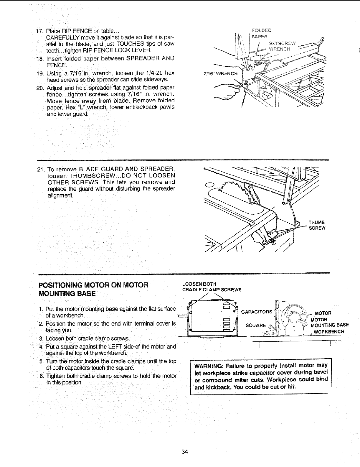
17.PlaceRIPFENCEontable.,,
CAREFULLYmoveitagainstbladesothat_tispar-
alle!to theblade,andjustTOUCHEStipsof saw
teeth...tightenRIPFENCELOCKLEVER.
18.InsertfoldedpaperbetweenSPREADERAND
FENCE.
19.Usinga 7/16in.wrench._oosenthe 1/4-20hex
headscrewssothespreadercanslidesideways.
20.Adjustandholdspreaderflatagainstfoldedpaper
fence...tightenscrewsusing7/16"in. wrench.
Movefenceawayfromblade.Removefolded
paper,He)("L" wrench, lower antikickback pawls
and lower guard.
7/16 WRENCH
\
FOLDED
21. To remove BLADE GUARD AND SPREADER,
loosen THUMBSCREW_.DO NOT LOOSEN
OTHER SCREWS. This lets you remove and
replace the guard without disturbing the s_)reader
alignment.
THUMB
SCREW
POSITIONING MOTOR ON MOTOR
MOUNTING BASE
1, Put the motor mounting base against the fiat surface
of a workbench.
2. Position the motor so the end with terminal cover is
facing you.
3. Loosen both cradle clamp screws,
4. Put a square against the LEFT side of the motor and
against the top of the workbench.
5. Turn the motor inside the cradle clamps until the top
of both capacitors touch the square.
6. Tighten both cradle clamp screws to hold the motor
in this position.
LOOSEN BOTH
CRADLE CLAMP SCREWS
CAPACWORS t l I/"L._,-_,,_,,_%_. MOTOR
_-];4-_, _ k---Z- WORKBENCH
1 !
WARNING: Failure to properly install motor may ]
let werkpiece strike capacitor cover during bevet |
or compound miter cuts. Workpiece could bind l
and kickback. You could be cut or hit.
34
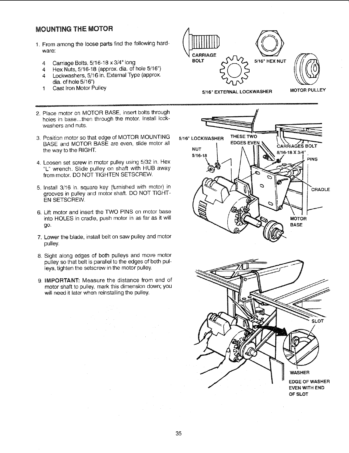
MOUNTING THE MOTOR
1. From among the loose parts find the following hard-
ware:
4 Carriage Bolts, 5/16-t8 x 3/4'! tong
4 Hex Nuts, 5/16-18 (approx. dia. of hole 5/16")
4 Lockwashers, 5/16 in, External Type (apprex,
dia. of hole 5/! 6")
1 Cast Iron Motor Pulley
2. Place motor on MOTOR BASE, insert bolts through
holes in base...then through the motor. Install lock-
washers and nuts,
3. Position motor so that edge of MOTOR MOUNTING
BASE and MOTOR BASE are even, slide motor all
the way to the RIGHT.
4. Loosen set screw in motor pulley using 5/32 in, Hex
"L" wrench. Slide pulley on shaft with HUB away
from motor. DO NOT TIGHTEN SETSCREW.
5. Install 3/16 in, square key (furnished with motor) in
grooves in pulley and motor shaft. DO NOT TIGHT-
EN SETSCREW,
6. Lift motor and insert the TWO PINS on motor base
into HOLES in cradle, push motor in as far as it will
go,
7. Lower the blade, install belt on saw pulley and motor
pulley.
8, Sight along edges of both pulleys and move motor
pulley so that belt is parallel to the edges of both pul-
leys, tighten the setscrew in the motor pulley.
9, iMPORTANT: Measure the distance from end of
motor shaft to pulley, mark this dimension down; you
wilt need it later when reinstalling the pulley.
CARRIAGE
BO_ G
5/16" HEX NUT
5/16" EXTERNAL LOCKWASHER MOTOR PULLEY
CRADLE
MOTOR
BASE
SLOT
WASHER
EDGE OF WASHER
EVEN WiTH END
OF SLOT
35
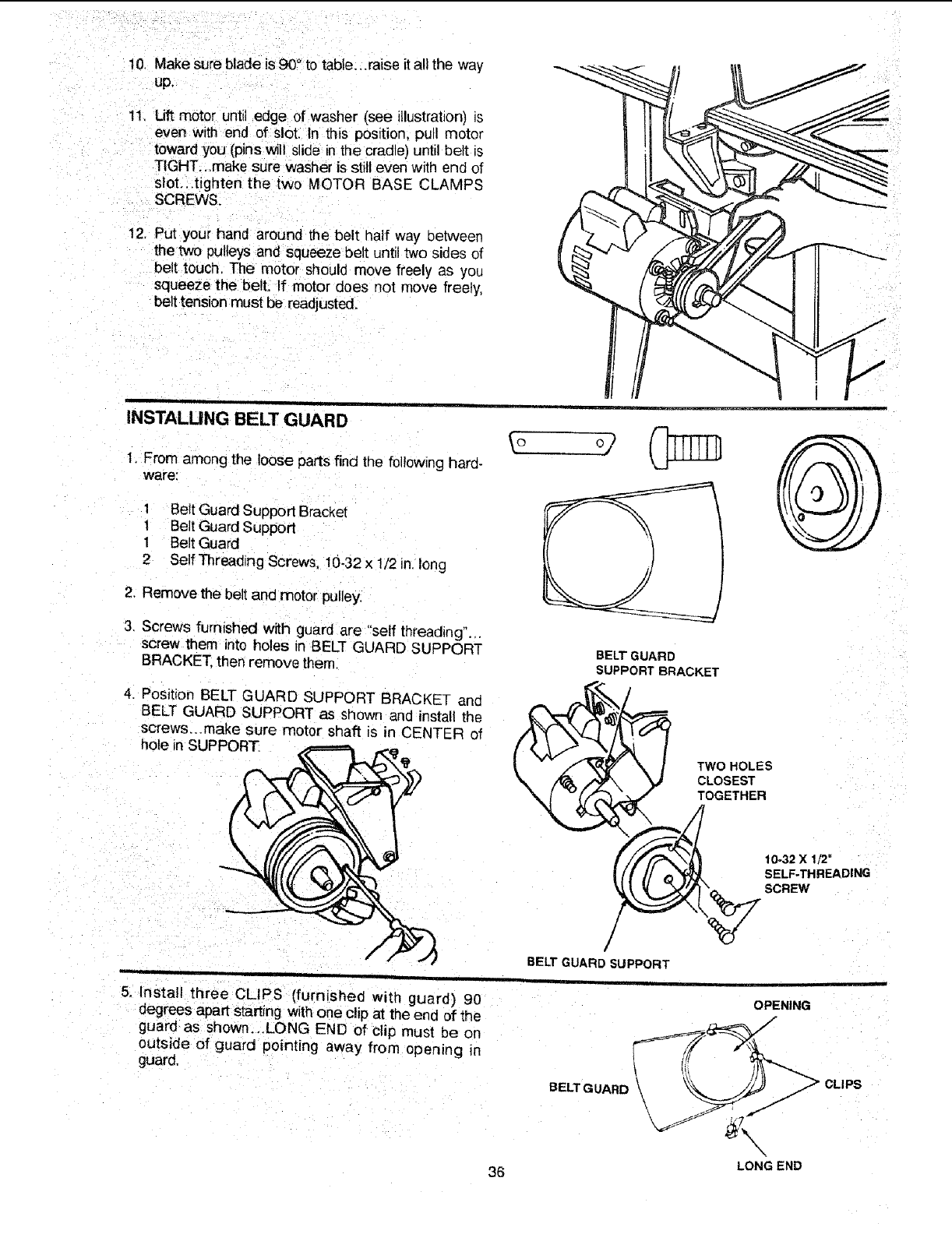
10.Makesurebladeis90°totable.,.raise it all the way
up.
11. Lift motor until edge of washer (see illustration) is
even with _nd of slot. in this position, pull motor
toward you(pins will slide in the cradle) until belt is
TIGHT...make sure washer is still even with end of
slot...tighten the two MOTOR BASE CLAMPS
SCREWS.
I2. Put your hand around the belt half way between
the two 0ulteys and squeeze belt until two sides of
belt touch, The motor should move freely as you
squeeze the belt. If motor does not move freely,
belt tension must be readjusted.
INSTALUNG BELT GUARD
1. From among the loose parts find the following hard-
ware:
1 Belt Guard Support Bracket
1 Belt Guard Support
1 Belt Guard
2 Self Threading Screws, 10.32 x 1/2 in. tong
2. Remove the belt and motor pulley.
3. Screws furnished with guard are "self threading".,.
screw them into holes in BELT GUARD SUPPORT
BRACKET. then remove them.
4. Position BELT GUARD SUPPORT BRACKET and
BELT GUARD SUPPORT as shown and install the
screws...make sure motor shaft is in CENTER of
hole in SUPPORT
BELT GUARD
SUPPORT BRACKET
TWO HOLES
CLOSEST
TOGETHER
10-32 X 1/2"
SELF-THREADING
SCREW
/
BELT GUARD SUPPORT
5. Install three CLIPS (furnished with guard) 90
degrees apart starting with one clip at the end of the
guard as shown...LONG END of clip must be on
outside of guard pointing away from opening n
guard.
BELT GUARD
OPENING
JCLIPS
\
LONG END
36
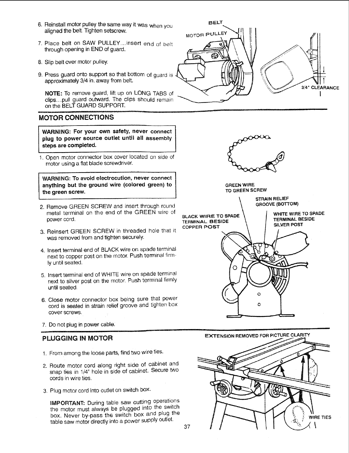
6. Reinstall motor pulley the same way it was when you BELT
aligned the belt. Tighten setscrew. MOTORpULLE_"_'_ !!
7, Place belt on SAW PULLEY,..insert end of belt ._'_ _'_ -_
U
through opening in END of guard.
8, Slip belt over motor pulley, _
<14
9. Press guard onto support so that bottom of guard is
approximately 3/4 in. away from belt.
NOTE: To remove guard, lift up on LONG TABS of
clips...pull guard outward. The clips should remain _
on the BELT GUARD SUPPORT.
MOTOR CONNECT|ONS
!t
3_"CLEARANCE
I
i WARNING: For your own safety, never connect I
|
plug to power source outlet until all assembly
steps are completed,
!. Open motor connector box cover located on side of
motor using a flat blade screwdriver.
WARNING: To avoid electrocution, never connect
anything but the ground wire (colored green) to
the green screw.
2, Remove GREEN SCREW and insert through round
metal terminal on the end of the GREEN wire of
power cord.
3. Reinsert GREEN SCREW in threaded hole that it
was removed from and tighten securely.
GREEN WIRE
TO GREEN SCREW
STRAIN RELIEF
GROOVE (BOI-rOM)
BLACK WIRE TO SPADE
TERMINAL BESIDE
COPPER POST
WHITE WiRE TO SPADE
TERMINAL BESIDE
SILVER POST
4, Insert terminal end of BLACK wire on spade terminal
next to copper post on the motor. Push terminal firm-
ly until seated.
5. Insert terminal end of WHITE wire on spade terminal
next to silver post on the motor. Push terminal firmly
until seated.
& Close motor connector box being sure that power
cord is seated in strain relief groove and tighten box
cover screws.
7. Do not plug in power cable,
_ i
PLUGGING IN MOTOR EXTENSION REMOVED FOR PICTURE CLARITY
!, From among the loose parts, find two wire ties.
2. Route motor cord along right side of cabinet and
snap ties in 1/4" hole in side of cabinet. Secure two
cords in wire ties.
3. Plug motor cord into outlet on switch box.
iMPORTANT: During table saw cutting operations
the motor must always be plugged into the switch
box. Never by-pass the switch box and plug the
table saw motor directly into a power supply outlet. 37
?WIRE TIES
\
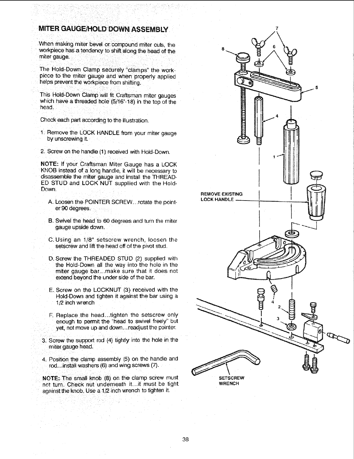
MITER GAUGF.JHOLD DOWN ASSEMBLY 7
When making miter bevel or compound miter cuts, the
workpiece has a tendency to shift along the head of the
miter gauge.
The Hold-Down Clamp securely "clamps" the work.
piece to the miter gauge and when properly applied
helps prevent the workpiece from shifting.
This Hold-Down Clamp will fit Craftsman miter gauges
which have a threaded hole (5/16"-18) in the top of the
head.
Check each part according to the illustration.
I Remove the LOCK HANDLE from your miter gauge
by unscrewing it.
2. Screw on the handle (1) received with Hold-Down.
NOTE: If your Craftsman Miter Gauge has a LOCK
KNOB instead of a long handle, it will be necessary to
disassemble the miter gauge and install the THREAD-
ED STUD and LOCK NUT suppliec with the Hold-
Down.
A. Loosen the POINTER SCREW...rotate the point-
er 90 degrees.
B, Swivel the head to 60 degrees and turn the miter
gauge upside down.
C. Using an 1/8" setscrew wrench, loosen the
setscrew and lift the head off of the pivot stud.
D. Screw the THREADED STUD (2) supplied with
the Hold-Down all the way into the hole in the
miter gauge bar.,.make sure that t does not
extend beyond the under side of the bar.
E. Screw on the LOCKNUT (3) received with the
Hold-Down and tighten it against the bar using a
1/2 inch wrench
F. Replace the head...tighten the setscrew only
enough to permit the "head to swivel freely" out
yet, not move up and down_.readjust the pointer.
3. Screw the support rod (4) tightly into the hole in the
miter gauge head,
4. Position the clamp assembly (5) on the handle and
rod.. Jnstal_washers (6) and wing screws (7).
NOTE: The small knob (8) on the clamp screw must
not turn. Check nut underneath it, ..it must be tight
against the knob, Use a 1/2 inch wrench to tighten it.
REMOVE EXISTING
LOCK HANDLE
SETSCREW
WRENCH
38
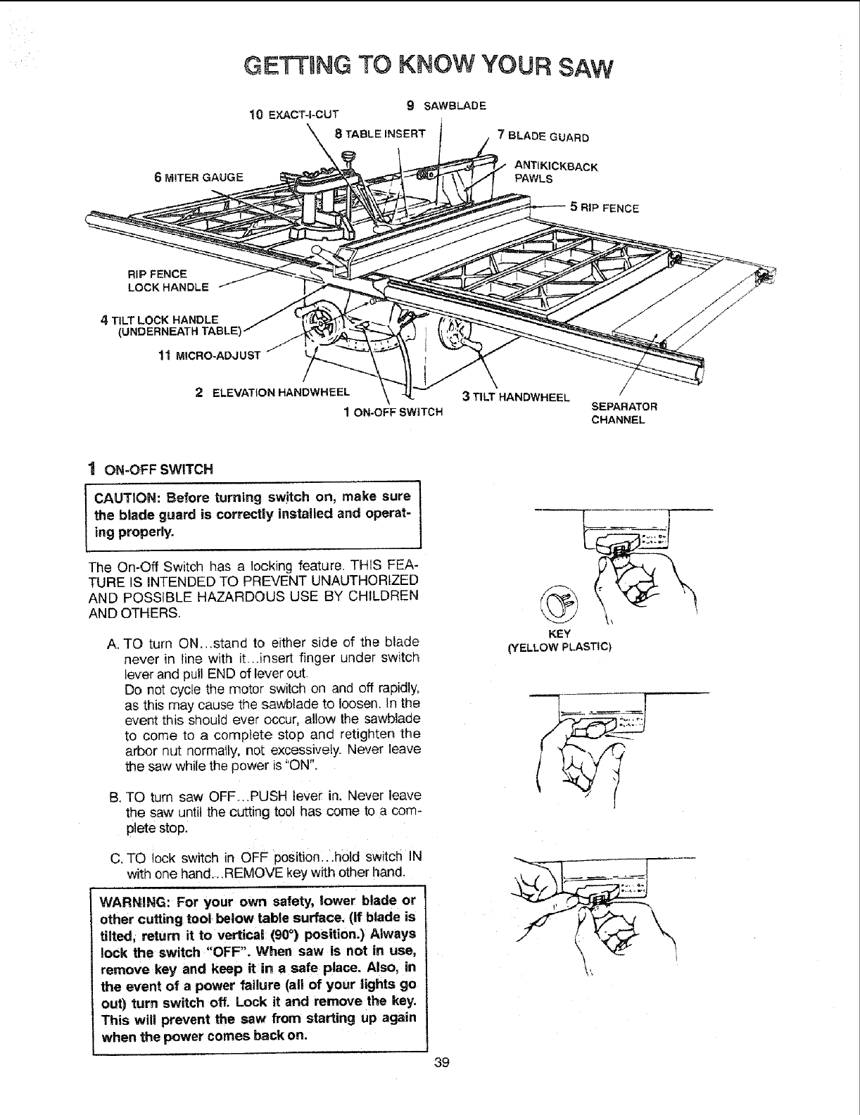
GETTING TO KNOW YOUR SAW
6 MITER GAUGE
9 SAWBLADE
10 EXACT-I-CUT
8 TABLE INSERT i
7 BLADE GUARD
ANTIKICKBACK
PAWLS
RIP FENCE
RIP FENCE
LOCK HANDLE
4 TILT LOCK HANDLE
(UNDERNEATH
11 MICRO-ADJUST
2ELEVATION HANDWHEEL
1ON-OFF SWITCH
3TILT HANDWHEEL /
SEPARATOR
CHANNEL
1 ON-OFF SWITCH
ICAUTION: Before turning sw!tch on, make sure
the blade guard is correctly installed and operat-
ing properly.
The On-Off Switch has a locking feature, THIS FEA-
TURE IS INTENDED TO PREVENT UNAUTHORIZED
AND POSSIBLE HAZARDOUS USE BY CHILDREN
AND OTHERS.
A. TO turn ON...stand to either side of the blade
never in line with it,..insert finger under switch
lever and pull END of lever out.
Do not cycle the motor switch on and off rapidly,
as this may cause the sawblade to loosen. In the
event this should ever occur, allow the sawblade
to come to a complete stop and retighten the
arbor nut normally, not excessively. Never leave
the saw while the power is "ON".
B. TO turn saw OFF,..PUSH lever in. Never leave
the saw dntil the cutting tool has come to a com-
plete stop.
C, TO lock switch in OFF position...hofd switch IN
with one hand...REMOVE key with other hand.
WARNING: For your own safety, lower blade or
other cutting tool below table surface. (if blade is
tilted, return it to vertical (90°) position.) Always
lock the switch "OFF". When saw is not in use,
remove key and keep it in a safe place. Also, in
the event of a power failure (all of your lights go
out) turn switch off. Lock it and remove the key.
This will prevent the saw from starting up again
when the power comes back on.
39
L
KEY
(YELLOW PLASTIC)
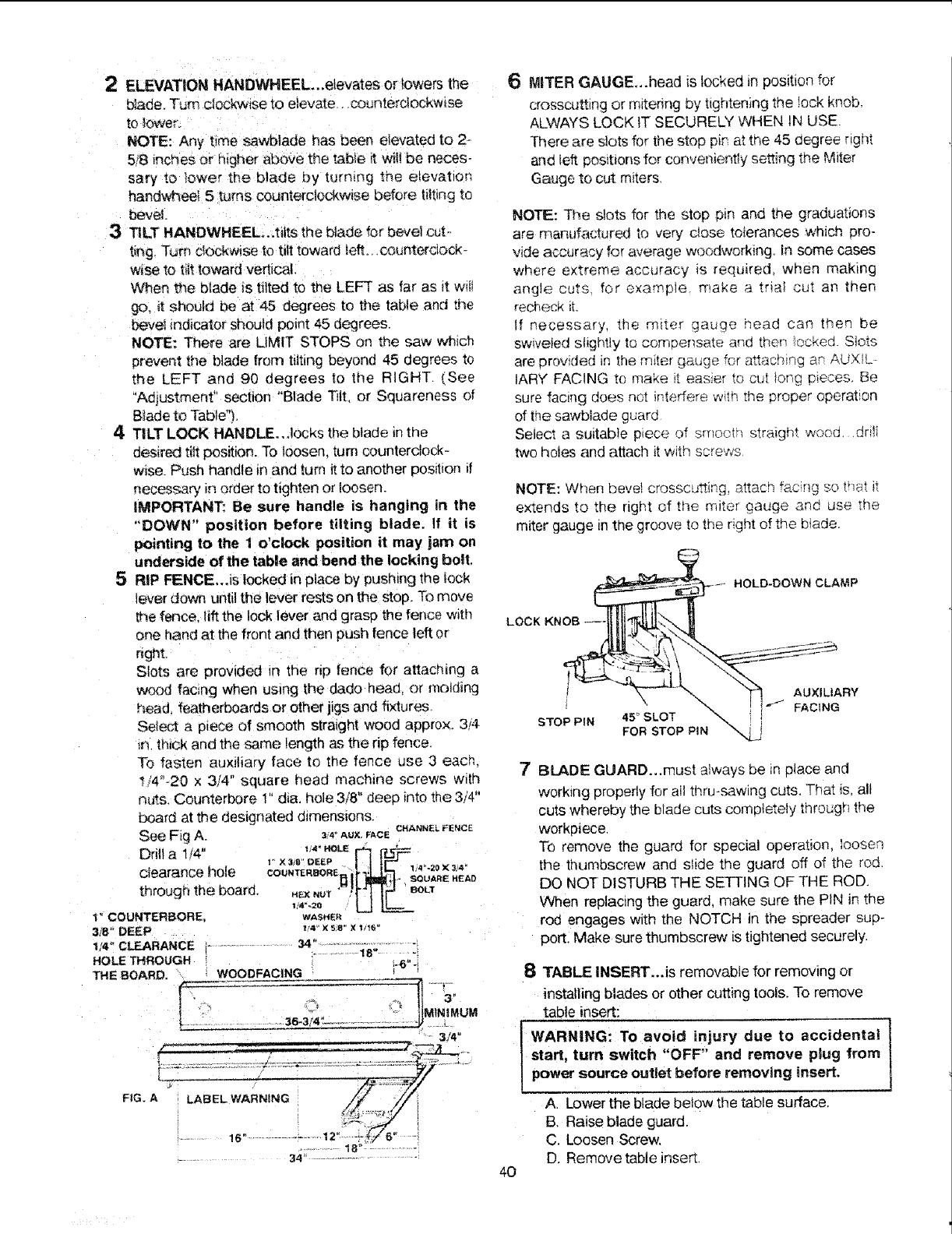
2ELEVATION HANDWHEEL...elevates or lowers the
blade_ Turn clockwise to elevate, counterclockwise
to lower.
NOTE: Any t_me sawblade has been etevated to 2-
5!8 inches or h_gher above the table _ w_Iibe neces-
sary to _ower the btade by turn_ng me elevation
handvtC_eel 5 turns counterclockwise before tilting to
bevel
3TILT HANDVtt'HEEL.,tilts the blade for bevel cut-.
t_ng Turn clOCkwise to tilt toward tuft_ .counterclock-
wise to titt toward vertical.
When the blade iS tilted to me LEFT as far as _t w_II
go. _t should be at 45 degrees to the table and T.ne
beve_ indicator should point 45 degrees,
NOTE: There are LIMIT STOPS on the saw whsch
prevent the blade from tilting beyond 45 degrees to
the LEFT and 90 degrees to the RIGHT, (See
"Adjustment" section "Blade Tilt, or Squareness of
B_ade to Table'1.
4 TILT LOCK HANDLE., ,locks the blade in the
desired tilt position. To loosen, turn counterclock-
wise. Push handle in and turn it to another position if
necessary in order to tighten or loosen.
IMPORTANT: Be sure handle is hanging in the
"DOWfN" position before tilting blade. If it is
pointing to the 1 o'clock position it may jam on
underside of the table and bend the locking bolt.
5 RtP FENCE,.,Is locked in place by pushing the lock
lever down until the lever rests on the stop. To move
the fence, lift the lock lever and grasp the fence with
one hand at the front and then push fence left or
r_ght.
Slots are provided in the nD fence for altachmg a
wood facing when uslng the da.do heac or molding
head, featherboards or other l_gs and fixtures
Select a piece of smooth stratght wood approx. 3/4.
n. thick and the same length as the rip fence,
To fasten auxiliary face to the fence use 3 eacn,
t/4"-20 x 3/4" square head machine screws with
nuts, Counterbore 1" dta. hole 3/8" deep into the 3/4"
board at the designated dimensions, CHANNEL FENCE
See Fig A. _4-AUX.FACE
t.,4_HOLE JI"_L' I_J-'-_z_
Drill a 1/4" I*X38" DEEP
clearance hote _ _11[WtJ;,t-, SOUARENEAP
through the board. HE×_UT";_t JJ_ BOLT
_,.'.=o ' L-I
1" COUNTERBORE, WASHER
318_'DEEP 1'4"x ss*x1;1_°
114= CLEARANCE ........... 34" .....................
....... 18"
HOLE THROUGH i.6-.:
THE BOARD, WOODFACtNG
.... 3/40
............. 18" -................
........ 34 ...................... '
6MITER GAUGE_.head is locked _nposition for
crosscut£ng or mitenng by t_ghteningthe !ock knob.
ALWAYS LOCK tT SECURELY WHEN IN USE.
There are slots for the stop p_nat the 45 degree right
and tuft pos_bonsfor conveniently setting the M_ter
Gauge to cut m_ters
NOTE: The slots for the stop p_n and the graduabons
are rnanufactured to very c_ose tolerances wn;cn pro-
vide accurNcy for average woodworking, in some cases
where extreme accuracy _s required when making
angle cuts for example make a tr_a_ cut an then
recheck _1.
If necessary, me m_ter gauge head can men be
swweied s!_ghtly to compensate ar;d men .ockea Slots
are provided in the m_ter qauqe for a_achin_ ar AUXIL-
IARY FAC!NG to make _, eas_er to cut _ong D_eces Be
sure facing does ncI ffqterfere wqn the orooer operation
of the sawb_ade guard
Select a suitable piece of srnocu straign_ wona. dnlt
two ho_es arid attach it w;th _crews
NOTE: When bevel crosscusing, attach fac.[_g s ___'_;T it
extends to the right of the m_ter gauge anc. use the
miter gauge m the groove to tne nght of the b!ade.
_.- HOLD-DOWN CLAMP
!__UXILIARY
;..o_,_. _ -- I t.,.J FACING
STOPP_N 45_SLOT -_.
FORSTOP PIN "-
8TABLE INSERT...Is removable for removing or
installing blades or other cutting tools. To remove
table insert:
WARNING: To avoid injury due to accidental
start, turn switch "OFF" and remove plug from
power source outlet before removing insert.
ALower the blade below the table surface.
B. Raise blade guard.
C, Loosen Screw,
D. Remove table inset,
7BLADE GUARD...must atways be in place and
working properly for aHthru-sawing cuts, That is, all
cuts whereby the blade cuts completely through the
workpiece,
To remove the guard for special operation, loosen
the thumbscrew and slide the guard off of the rod.
DO NOT DISTURB THE SETTING OF THE ROD.
When replacing the guard, make sure the PIN in the
rod engages with the NOTCH in the spreader sup-
portl Make sure thumbscrew is tightened securely.
40
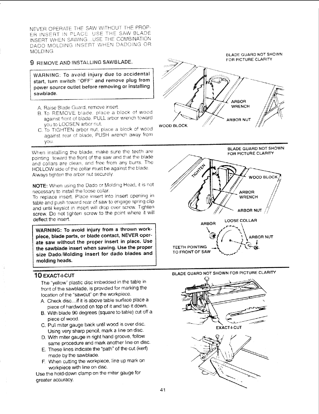
NEVER OP_]RA]E THE S,_¢d WiT_-iOUT ii-iE PROP-
ER INS_:!R,T iN PLAC! USE! TRE SAW BLAOE
NSERT WHEN SAWING. USE T?_._::CQMBiNATiOt,_
DA©O MOLDING iNS_!:RT WHEN DADOING OR
MOLD NG
9 RElieVE AND _NSTALUNG SAWBLADE.
BLADE GUARD NOT SHOWN
FOR PICTURE CLARITY
WARNING: To avoid iniury due to accidental
start, turn ._}witch 'OFF" and remove p_ug from
•power source outiet before removing or installing
sawblade.
A. Raise '
Bad<. Girard remove inserL
B. To REMOVE b._de, p!ace a block of wood
against f_ont of blade. PULL arbor wrench toward
you to LOOSEN arbor nut.
C. To TIGHTEN arbor nL,'t, p/ac;e a block of wood
against rear of ,),ado, PUSH wrench away frorn
you
When instailing the blade, make sure the teeth are
pointing toward the front of the saw and treat the b!ade
and cofiars Rre clea_, and flee from any burrs. Ti_e
HOLLOW side ,_4,_,,_.,.,.,_.co!lar iTiiJStbe against the blade
,_,_.,:,.r,.o. nu, securely
Always tighten ' ' = " _' r
WRENCH
ARBOR NUT
NOTE: '.,When using the Dado or Moiding Head, it is not
necessas_ to instai! _he _oose coi}ar.
]b replace insert. Place insert into insert opening in
table and push toward rear of savv to engage spring c!ip
and untit keyslot in insert will drop over screw, Tighten
screw. Do not t ghten screw to the point where it will
deflect the insert,
WARNING: To avoid injury from a thrown work-
piece, blade parts, or blade contact, NEVER oper*
ate saw wilhout the proper insert in ptace. Use
the sawblade insert when sawing. Use the proper
size Dado/Molding insert for dado blades and
molding heads.
ARBOR
TEETH POINTING
TO FRONT OF SAW
ARBOR
WRENCH
//
ARBOR NUTI,i_ I/
LOOSE COLLAR
ARBOR NUT
10 EXACT-I-CUT
The "yeliow" ptastic disc imbedded in the tabie in
front of the ._wblade, is provided for marking the
location of the 'sawcut" on the workpiece.
A. Check disc...if it is above table surface place a
piece of hardwood on top of it and tap it down.
B. With blade 90 degrees (square to table} cut off a
piece dwood.
C. Pull miter gauge back until wood is over disc,
Using very sharp pencil, mark a line on disc.
D. With miter gauge in right hand groove, follow
same procedure and mark another line on disc.
E. These lines indicate the "path" of the cut (kerr)
made by the sawbtade.
R Wen cutting the workpiece, _ine up mark on
workpiece with line on disc.
Use the hold-down clamp on the miter gauge for
greater accuracy.
4!
ii illrl,ll Ill'H II '11
BLADE GUARD NOT SHOWN FOR PICTURE CLARITY
O
EXACT-I-CUT
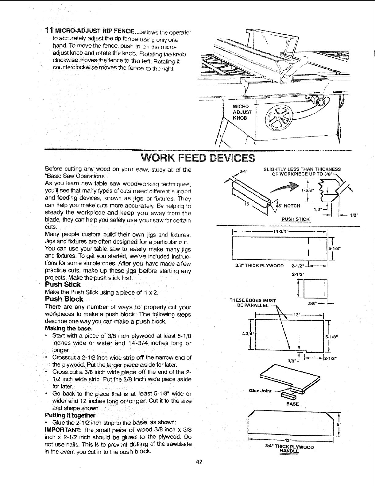
11 MICRO-ADJUST RiP FENCE, .,atlows the opera_or
to accurately aajust the rip fence using onw one
hand. To move the fence, push in _n the micro-
adjust knob and rotate the knob. Rotai_ng the knob
c!ockwise moves the fence to the left Rotating it
counterclockwise moves the fence to the rig_t.
WORK FEED DEVICES
Before cutting any wood on your saw. study all of the
"Basic Saw Operations".
As you learn new table saw WOOdworKing techniques.
you'll see that many types of cuts need different support
and feeding devices, known as jigs or fixtures They
can help you make cuts more accurately. By helping to
steady the workpiece and keep you away from the
blade, they can help you safely use your saw for certain
cuts.
Many people custom build their own jigs anc fixtures.
Jigs and fixtures are often designed for a particular cut
You can use your table saw to easily make many jigs
and fixtures. To get you started, we've included inszruc-
tions for some simple ones, After you have made a few
practice cuts. make up these jigs before starting any
projects. Make the push stick first.
Push Stick
Make the Push Stick using a piece of 1 x 2.
Push Block
There are any number of ways to properly cut your
workpieces to make a push block, The following s_eos
describe one way you can make a push block.
Making the base:
Start with a piece of 3/8 inch plywood at least 5-1/8
inches wide or wider and 14-3/4 inches long or
longer.
Crosscut a 2-1/2 inch wide strip off the narrow end of
the plywood. Put the larger piece aside for later.
Cross cut a3/8 inch wide piece off the end of the 2-
1/2 inch wide strip. Put the 3/8 inch wide piece aside
for late¢
Go back to the piece that is at least 5-1/8" wide or
wider and 12 inches long or longer. Cut it to the size
and shape shown,
Putting it together
Glue the 2-1/2 inch strip to the base, as shown:
IMPORTANT: The small piece of wood 3/8 inch x 3/8
inch × 2-1/2 inch should be glued to the plywood, Do
not use nails. This is to prevent dulling of the sawblade
in the event you cut in to the push block.
3/4" SLIGHTLY LESS THAN THICKNESS
PUSH STICK
14-3/4' - i
I !
3/8" THICK PLYWOOD 2-1/2"
2-1/2"
Fr--7
THESE EDGES MUST L_
BE PARALLEL -_
3J8"J- I----M21t2"
BASE
L-12.... - I
3/4" THICK PLYWOOD
HANDLE
42
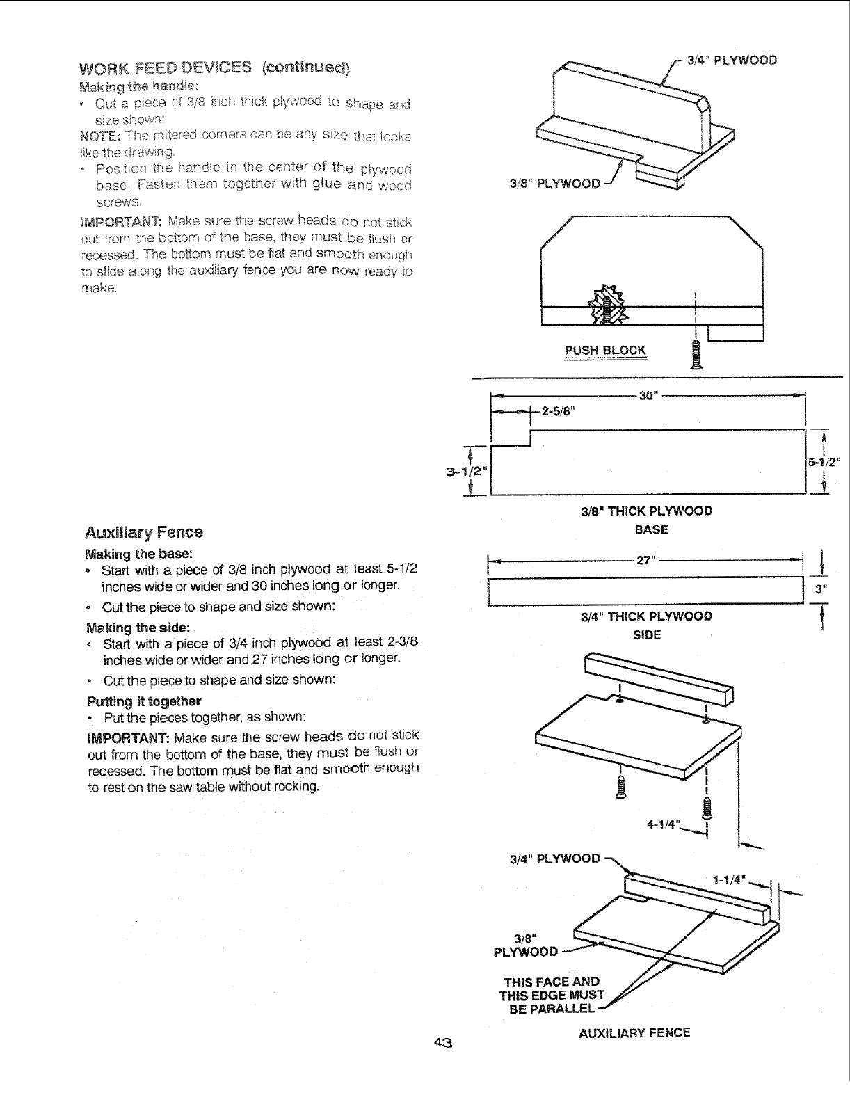
WORK FEEDDKV{CKS (cor_tinued)
Making the hand!e:
oply",tvooc_to shape and
,,I _ piece _''
C ....... o_'o8 ir_ch thick n, , _
" _ SIqOWR:
NOTE: The mitered corners ea_sbe any s_=zethat looks
3/4" PLYWOOD
o Position! the hande in the cef_ter of tf-_e #tywood
base. Fasten them together with glL_e and wood
screws.
_MPORTANT: Make sure, the screw heads do not stick
out from ti-_ebosom of the base, they must be flush or
recessed. The bottom must be fiat and smooth enough
to s_ide along the au×iiiarv fence you are now ready to
make
3/8" PLYWOOD
,Jo
PUSH BLOCK
i --
Auxiliary Fence
Making the base:
- Start with a piece of 3/8 inch plywood at Jeast 5-1/2
inches wide or wider and 30 inches long or longer.
o Cut the piece to shape and size shown:
Making the side:
o Start with a piece of 3/4 inch plywood at least 2-3/8
inches wide or wider and 27 inches long or longer.
,Cut the piece to shape and size shown:
Putting it together
- Put the pieces together, as shown:
IMPORTANT: Make sure the screw heads do not sticl<
out from the bottom of the base, they must be flush or
recessed. The bottom must be flat and smooth enough
to rest on the saw table without rocking.
3_ N
3/8" THICK PLYWOOD
BASE
27"
314" THICK PLYWOOD
SIDE
l_
4-1_"
3/4" PLYWOOD _ • ,,
3/8" / //
PL._40OD _ _
THISFACEAHD
THIS EDGE MUST ._
BE PARALLEL--I"
AUXiLiARY FENCE
43
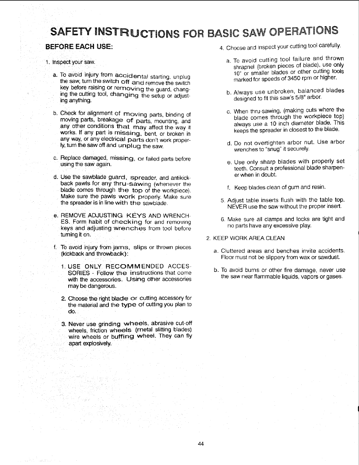
SAFETY INSTRUCTIONS FOR BASIC SAW OPERATIONS
BEFORE EACH USE: 4 Choose and inspect your cutting tool carefully.
1. Inspect your saw. a.
a. To avoid injury from aCCidenta_ starting, unptug
the saw, turn the switch off ana remove the sw_tcn
key before raising or remowng the guara chang-
ing the cutting tool, changing the setup or adjust-
ing anything.
b. Check for alignment of moving parts, binding of
moving parts, breakage of parts, mounting, and
any other conditions that may affect the way _t
works. If any part is missing, bent. or broken in
any way, or any electrical parts don't work proper-
ly,turn the saw off and unplug the saw.
c. Replace damaged, m_ssing, or failed parts before
using the saw again.
d. Use the sawblade guard, spreader, and antikick-
back pawls for any thru-sawing (whenever the
blade comes through the top of the workplace).
Make sure the pawls work properly Make sure
the spreader is in line with the sawbiade.
e. REMOVE ADJUSTING KEYS AND WRENCH-
ES. Form habit of checking for and remowng
keys and adjusting wrenches from tool before
turning it on.
f. To avoid injury from jams, slips or thrown pieces
(kickback and throwback):
USE ONLY RECOMMENDED ACCES.
SORIES - Follow the instructions that come
witl_ the accessories. Using other accessories
may be dangerous.
b.
C.
d.
To avoid cutting too! failure and thrown
shrapnel (broken pieces of blade), use only
10" or smatler blades or other cutting tools
marked for speeds of 3450 rpm or higher.
Always use unbroken, balanced blades
designed to fit this saw's 5/8" arbor.
When thru--sawing, (making cuts where the
blade comes through the workpiece top)
always use a 10 inch diameter blade. This
keeps the spreader in closest to the blade.
Do not overtighten arbor nut. Use arbor
wrenches to "snug" it securely.
e. Use only sharp blades with properly set
teeth. Consult a professional blade sharpen-
er when in doubt.
f. Keep blades clean of gum and resin.
5. Adjust table inserts flush with the table top.
NEVER use the saw without the proper insert.
6. Make sure all clamps and locks are tight and
no parts have any excessive play.
2 KEEP WORK AREA CLEAN
a. Cluttered areas and benches invite accidents.
Floor must not be slippery from wax or sawdust.
b. To avoid burns or other fire damage, never use
me saw near flammable liquids, vapors or gases.
2. Choose the right blade or cutting accessory for
the material and the type of cutting you plan to
do.
3. Never use grinding wheels, abrasive cut-off
wheels, friction wheels (metal slitting blades)
wire wheels or buffing wheel. They can fly
apart explosively.
44
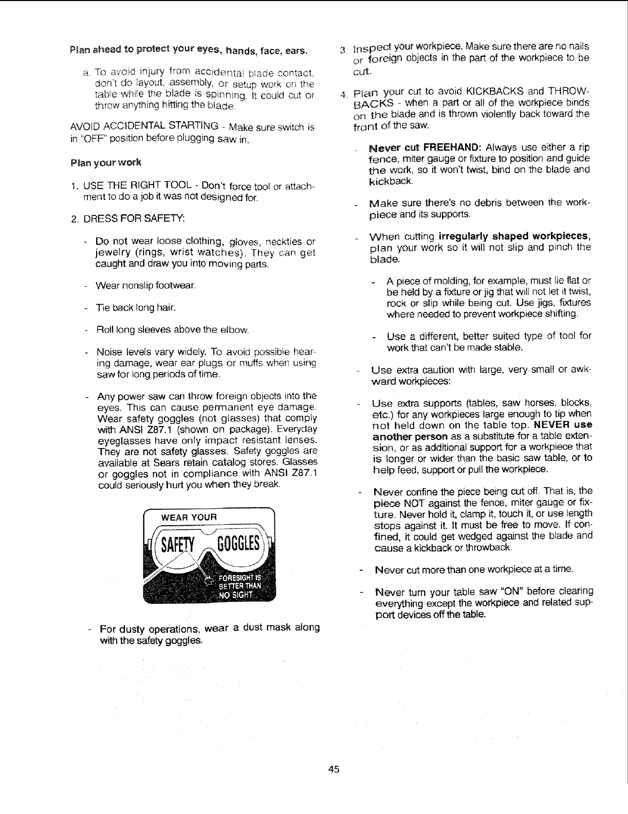
P_an ahead to protect your eyes, hands_ face, ears,
a To avoid injury from accidentai b!ade contact,
doHt do iayout, assembly, or setup work ors the
tab!e while the b_ade is spinning. It could cut or
throw anything hitting the b_ade.
AVOID ACCIDENTAL STARTING - Make sure switch is
in "OFF" position before plugging saw in.
Plan your work
I. USE THE RIGHT TOOL - Don't force tool or attach_
ment to do a job it was not designed for.
2. DRESS FOR SAFETY:
Do not wear loose clothing, gloves, neckties or
jewelry (rings, wrist watches). They can get
caught and draw you into moving parts.
Wear nonstip footwear.
Tie back long hair.
Roil long sleeves above the elbow.
Noise levels vary widely. To avoid possibte hear-
ing damage, wear ear plugs or muffs when using
saw for tong periods of time.
Any power saw can throw foreign objects into the
eyes. This can cause permanent eye damage.
Wear safety goggles (not glasses) that comply
with ANSI Z87.1 (shown on package). Everyday
eyeglasses have only impact resistant lenses.
They are not safety glasses. Safety goggles are
available at Sears retain catalog stores. Glasses
or goggles not in compliance with ANSI Z87.1
could seriously hurt you when they break.
WEAR YOUR
For dusty operations, wear a dust mask along
withthe safety goggles.
3. Inspect your workpiece. Make sure there are no nails
or foreign objects in the part of the workpiece to be
cdt-
4. Plan your cut to avoid KICKBACKS and THROW-
BACKS - when a part or all of the workpiece binds
on the btade and is thrown violently back toward the
front of the saw.
Never cut FREEHAND: Always use either a rip
fence, miter gauge or fixture to position and guide
the work, so it won't twist, bind on the blade and
kickback.
Make sure there's no debris between the work-
piece and its supports.
When cutting irregularly shaped workpieces,
plan your work so it will not slip and pinch the
blade.
A piece of molding, for example, must lie fiat or
be held by a fixture or jig that will not let it twist,
rock or slip while being cut. Use jigs, fixtures
where needed to prevent workpiece shifting.
Use a different, better suited type of tool for
work that can't be made stable.
Use extra caution with large, very small or awk-
ward workpieces:
Use extra supports (tables, saw horses, blocks,
etc.) for any workpieces large enough to tip when
not held down on the table top. NEVER use
another person as a substitute for a table exten-
sion, or as additional support for a workpiece that
is longer or wider than the basic saw table, or to
help feed, support or pull the workpiece.
Never confine the piece being cut off. That is, the
piece NOT against the fence, miter gauge or fix-
ture= Never hold it, clamp it, touch it, or use length
stops against it. It must be free to move. If con-
fined, it could get wedged against the blade and
cause a kickback or throwback.
Never cut more than one workpiece at a time.
Never turn your table saw "ON" before clearing
even/thing except the workpiece and related sup-
port devices off the table.
45
Plan the way you will push the workpiece through.
NEVER pull the workpiece through. Start and finish
the cut from the front of the table saw.
NEVER put your fingers or hands in the path of
the sawblade or other cutting tool.
- NEVER reach in back of the cutting tooJ with
either hand to hold down or support the workmece,
remove wood scraps, or for any other reason.
Avoid awkward operations and hand positions where
a sudden slip could cause fingers or hand to move
into a sawblade or other cutting tool.
DON'T OVERREACH Always keep gooo footing
and balance.
Push the workpiece against the rotation of the blade.
NEVER feed material _nto the cutting tool from the
rear of the saw.
Always push the workplece all the way past the saw-
blade,
As mucn as 3ossible, keep your face and Dotty to
one s_de of the sawbtade out of line with a possible
kickback or throwback.
NEVER turn the saw "ON" before clearing the table
of all tools, wood scraps, etc., except the worKplece
and related feed or support devices for the cut
planned.
WHENEVER SAW IS RUNNING
WARNING: Don't let familiarity (gained from fre-
quent use of your table saw) cause a careless
mistake. Always remember that acareless frac.
tion of a second is enough to cause asevere
injury.
t. Before actually cutting with the saw, watch it while it
runs for a short while. If it makes an unfamiliar noise
or vibrates excessively, stop immediately. Turn the
saw off. Unplug the saw. Do not restart until finding
and correcting the problem.
Make sure the,_[co _f the ardor or cutting tool turns
toward [ne front ot the sa'v',
Set ;no cutting [oo_ as tow as possible for the cut
you're oiann_ng
KEEP CHILDREN AWAY. All visitors should be kept
a safe d_stance from work Make sure bystanders
are c_ear of the saw and workpiece.
5, Let the b!ade reach full speed before cutting.
DON'T FORCE TOOL, It will do the job better and
safer at its designed rate. Feed the workpiece into
the blade only fast enough to !et it cut without bog-
ging (]own or binding,
7. Before freeing any jammed material:
a. Turn switch "OFF"
D. Unplug the saw,
c. Wait for all moving 3arts to stop,
d. Check blade, spreader and fence for proper align-
ment before starting, again.
8 To avoid throwback of cut off pieces:
a. Use the guard assembly.
b, To remove pieces beneath or trapped inside the
guard:
1 Turn saw off,
2. Remove switch key.
3. Unplug saw.
4. Wait for blade to stop before lifting tile guard.
BEFORE LEAVING THE SAW
1. Turn saw off,
2. Wait for blade to stop splnning.
3. Mlake workshop cmld-proof. Lock the shop.
Disconnect master switches. Remove the yellow
sw_tch key. Store it away from children and others
not qualified to use the too!,
4. Unplug the saw.
46
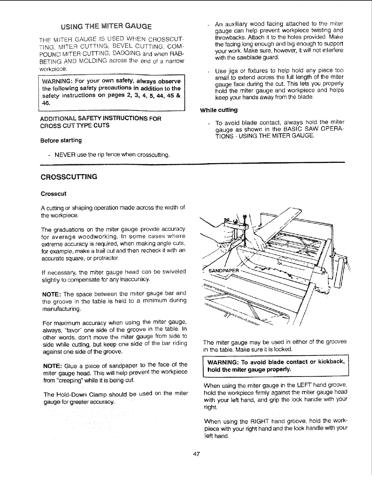
USING THE M_TER GAUGE
THE _IiTER GAUGE _8 USED WHEN CROSSOUT-
TING, MITER CUTT!NG, BEVEL CUTTING, COM-
POUND MITER CUTT!NG, DADOING and when RAB-
BETING AND MOLDING across the end of a narrow
workpiece.
WARNING: For your own safely, always observe
the fo_gowing safety precautions in addition to the
safety instructions on pages 2, 3, 4, 5, 44, 45 &
46.
ADDIT_!ONAL SAFETY iNSTRUCTIONS FOR
CROSS CUT TYPE CUTS
Before starting
An auxiliary wood facing attached to the miter
gauge can help prevent workpiece twisting and
throwbacks.Attach it to the holes provided. Make
the facing long enough and big enough to support
your work. Make sure, however, it wit! not into€ere
with the sawb}ade guard.
Use jigs or fixtures to help hold any piece too
small to extend across the full length of the miter
gauge face during the cut. This lets you properly
hold the miter gauge and workpiece and helps
keep your hands away from the blade.
While cuffing
To avoid blade contact, always hold the miter
gauge as shown in the BASIC SAW OPERA-
TIONS - USING THE MITER GAUGE.
NEVER use the rip fence when crosscutting.
CROSSCUTTING
Crosscut
A cutting or shaping operation made across the width of
the workpiece.
The graduations on the miter gauge provide accuracy
for average woodworking. In some cases where
extreme accuracy is required, when making angle cuts,
for example, make a trail cut and then recheck it with an
accurate square, or protractor.
If necessary, the miter gauge head can be swiveled
slightly to compensate for any inaccuracy.
NOTE: The space between the miter gauge bar and
the groove in the table is held to a minimum during
manufacturing.
For maximum accuracy when using the miter gauge,
always, '_favo¢'one side of the groove in the table. In
other words, don't move the miter gauge from side to
side while cutting, but keep one side of the bar riding
against one side of the groove.
NOTE: Glue a p_ece of sanopaper to the face of the
miter gauge head. This will help prevent the workpiece
from "creeping" while it is being cut.
The Hold-Down Clamp should be used on the miter
gauge for greater accuracy.
The miter gauge may be used in either of the grooves
in the table. Make sure it is locked.
iWARNING: To avoid blade contact or kickback, ]hold the miter gauge properly.
When using the miter gauge in the LEFT hand groove,
hold the workpiece firmly against the miter gauge head
with your left hand, and grip the lock handle with your
right.
When using the RIGHT hand groove, hold the WOrk-
piece with your right hand and the lock handle with your
left hand.
47
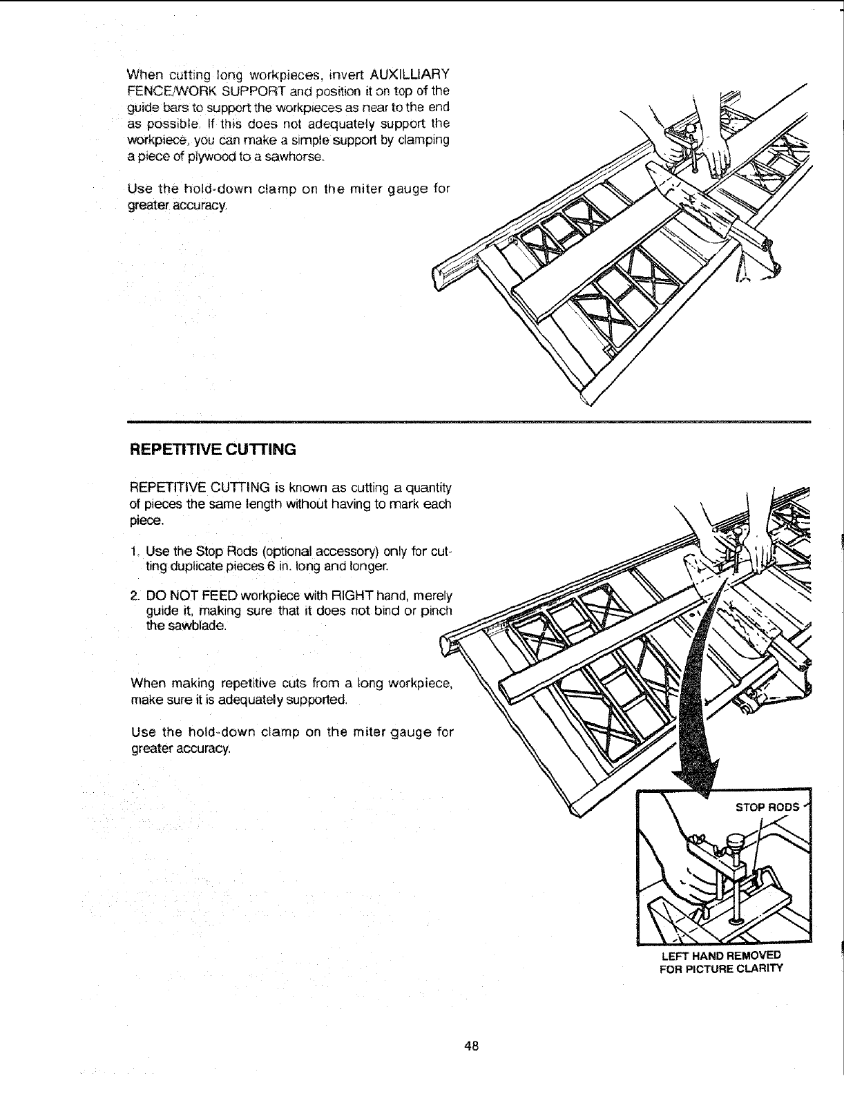
Whencuttinglongworkpieces,invertAUXILLIARY
FENCEZWQRKSUPPORTandpositionitontopofthe
guidebarstosupporttheworkp_ecesasneartotheend
aspossible,if t!_isdoesnotadequatelysupportthe
workpiece,youcanmakeasimplesupportbyclamping
apieceofplywoodtoasawhorse.
Usethe hold-downclampon the mitergaugefor
greateraccuracy:
\
REPETITIVE CUTTING
REPETITIVE CUFFING is known as cutting a quantity
of pieces the same length without having to mark each
piece,
1Use the Stop Rods (optional accessory) only for cut-
ting duplicate pieces 6 in. long and longer.
2. DO NOT FEED workpiece with RIGHT hand, merely
guide it. making sure that It does not binC or pinch
the sawblade.
When making repetitive cuts from a tong workpiece,
make sure it is adequately supported.
Use the hold-down clamp on the miter gauge for
greater accuracy,
LEFT HAND REMOVED
FOR PICTURE CLARITY
48
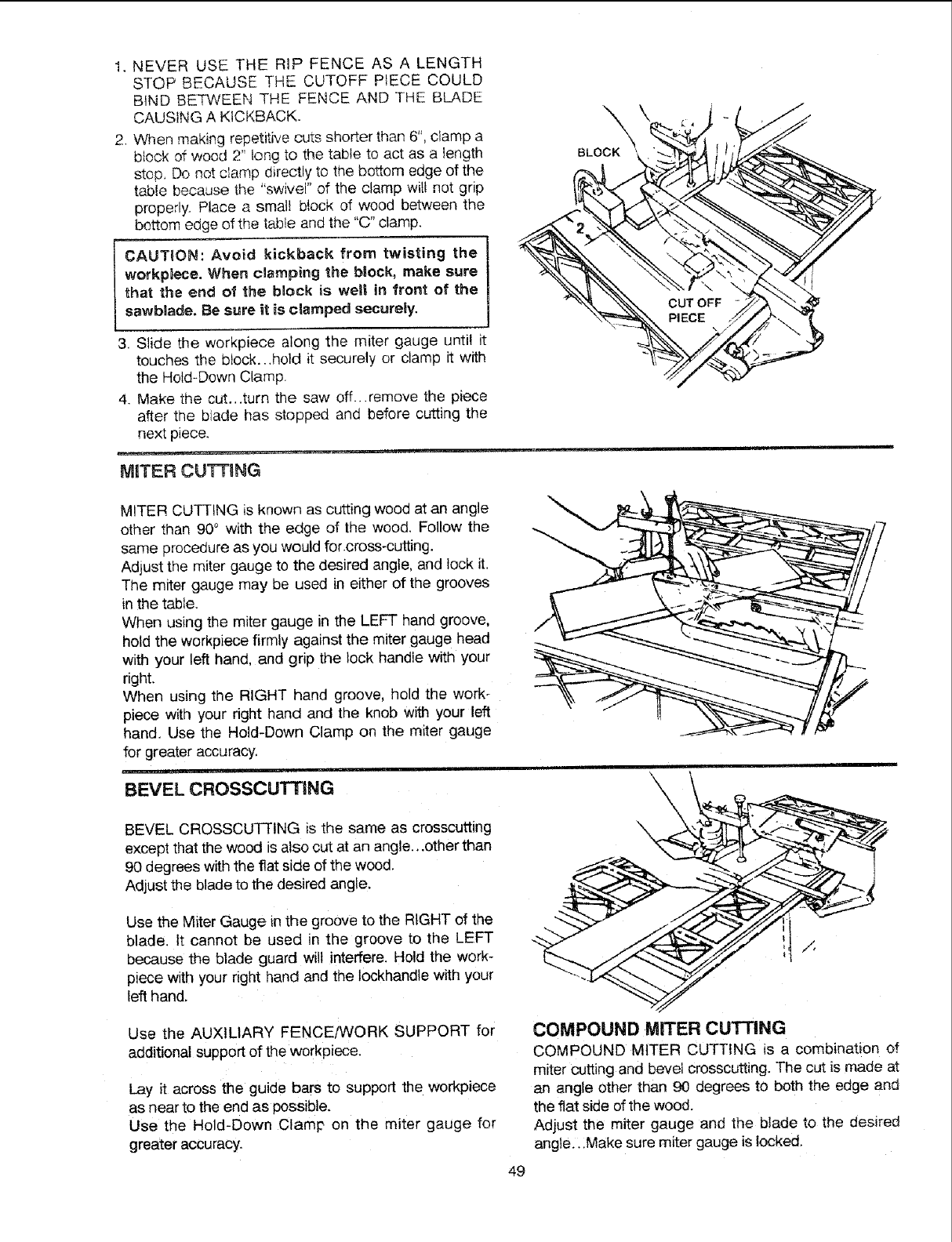
1.NEVERUSETHERIP FENCEASA LENGTH
STOPBECAUSETHECUTOFFPIECECOULD
BINDBETWEENTHEFENCEANDTHEBIJkDE
CAUSINGAKICKBACK.
2.Whenmakingrepetitivecutsshorterthan6",clampa
blockofwood2"longtothetabletoactasa length
stop,Donotclampdirectlytothebottomedgeofthe
tablebecausethe"swivel"oftheclampwit!notgrip
properly.Placea smal!blockof woodbetweenthe
bottomedgeofthetableandthe"C"clamp.
CAUTION: Avoid kickback from twisting the
workpiece. When clamping the block, make sure
that the end of the block is wetl in front of the
sawbRade.Be sure it is clamped securely,
3. Slide the workpiece along the miter gauge until it
touches the block...hold it securely or clamp it with
the Hold-Down Clamp.
4. Make tile cut...turn the saw off...remove the piece
after the biade has stopped and before cutting the
next piece.
MITER CUTTING
\
BLOCK
CUT OFF
PIECE
MITER CUTTING is known as cutting wood at an angle
other than 90° with the edge of the wood, Follow the
same procedure as you would for.cross-cutting.
Adjust the miter gauge to the desired angle, and lock it.
The miter gauge may be used in either of the grooves
in the table.
When using the miter gauge in the LEFT hand groove,
hold the workpiece firmly against the miter gauge head
with your left hand. and grip the lock handle with your
right.
When using the RIGHT hand groove, hold the work_
piece with your right hand and tie knob with your left
hand. Use the Hold-Down Clamp on the miter gauge
for greater accuracy,
..... =
BEVEL CROSSCUTTING
BEVEL CROSSCUTTING s the same as crosscutting
except that the wood is also cut at an angle...other than
90 degrees with the flat side of the wood.
Adjust the blade to the desired angle.
Use the Miter Gauge in the groove to the RIGHT of the
blade, it cannot be used in the groove to the LEFT
because the blade guard will interfere. Hold the work-
piece with your right hand and the Iockhandle with your
left hand.
Use the AUXILIARY FENCE,SNORK SUPPORT for
additional support of the workpiece.
Lay it across the guide bars to support the workplece
as near to the end as possible.
Use tie Hold-Down Clamp on the miter gauge for
greater accuracy.
COMPOUND MITER CUTTING
COMPOUND MITER CUTTING is a combination of
miter cutting and bevel crosscutting. The cut is made at
an angle other than 90 degrees to both the edge and
the flat side of the wood.
Adjust the miter gauge and the b_ade to the desired
angle...Make sure miter gauge is locked.
49
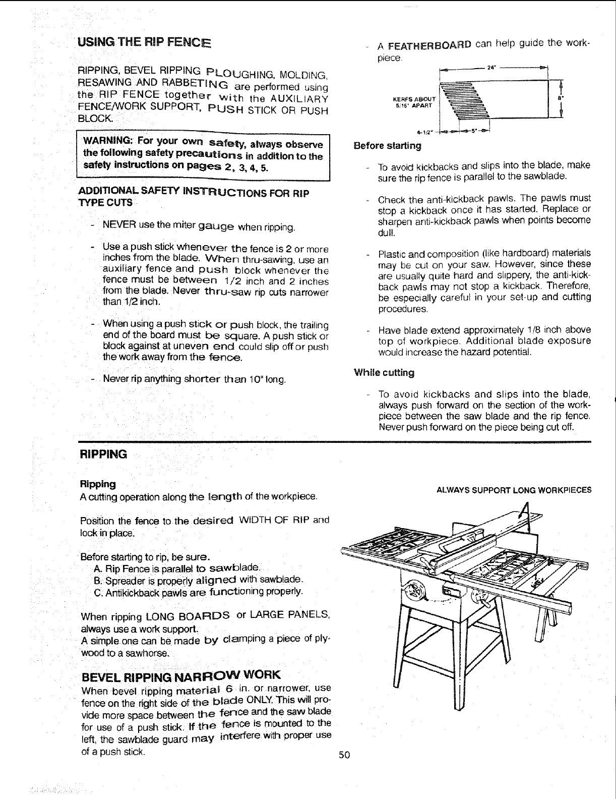
USING THE RiP FENCE
RIPPING. BEVEL RIPPING PLOUGHING. MOLDING
RESAWlNG AND RABBETING are performed using
the RIP FENCE together With the AUXILIARY
FENCE/MJORK SUPPORT, PUSH STICK OR PUSH
BLOCK.
AFEATHERBOARD can help guide the work-
p_ece
p._ 24- ,_
t
KERFS ABOU1 1---_
5/16" APART
WARNING: For your own safety, always observe I
the following safety precautions in addition to the I
safety instructions on pages 2, 3, 4, 5,
ADDITIONAL SAFETY INSTR UCTIONS FOR RiP
TYPE CUTS
NEVER use the miter gauge when ripping.
Use a push stick whenever the fence is 2 or more
inches from the blade. When thru-sawing, use an
auxiliary fence and 3L_sh block whenever the
fence must be between 1/2 inch and 2 inches
from the blade. Never thru-saw rip cuts narrower
than 1/2 inch.
- When using a push stick or push block, the trailing
end of the board must be square. A push stick or
block against at uneven end could shp off or push
the work away from the fence.
Never rip anything shorter than !0" long.
Before starting
To avoid kickbacks and slips into the blade, make
sure the rip fence is parallel to the sawblade.
Check the antFkickback pawls. The pawls must
stop a kickback once it has started. Replace or
sharpen antFkickback pawls when points become
dull.
Plastic and composition (like hardboard) materials
may be cut on your saw. However, since these
are usually quite hard and slippery, the anti-kick-
back pawls may not stop a kickback. Therefore,
be especially careful in your set-up and cutting
proceaures.
Have blade extend approximately !/8 inch above
top of workpiece. Additional blade exposure
would increase the hazard potential.
While cutting
To avo=d kickbacks and slips into the blade,
always push forward on the section of the work-
pece between the saw blade and the rip fence.
Never push forward on the piece being cut off.
RIPPING
Ripping
A cutting operation along the length of the workpiece.
Position the fence to the desired WIDTH OF RIP and
Iockin place.
Before starting to rip, be sure.
A. Rip Fence is parallel to sawblade.
B. Spreader is properly aligned with sawbtade.
C. Antikickback pawls are functmonlng properly.
When ripping LONG BOARDS or LARGE PANELS.
always use a work support.
A simple one can be made by" clamping a p_ece of ply-
wood to a sawhorse.
BEVEL RIPPING NARROW WORK
When bevel ripping rnateriat! 6 _n. or narrower, use
fence on the right side of the blade ONLY. This wil! pro-
vide more space between the fence and the saw blade
for use of a push stick, If the fence is mounted to the
left, the sawblade guard may interfere with eroper use
of a push stick.
ALWAYS SUPPORT LONG WORKPIECES
50
: _il ¸ ..
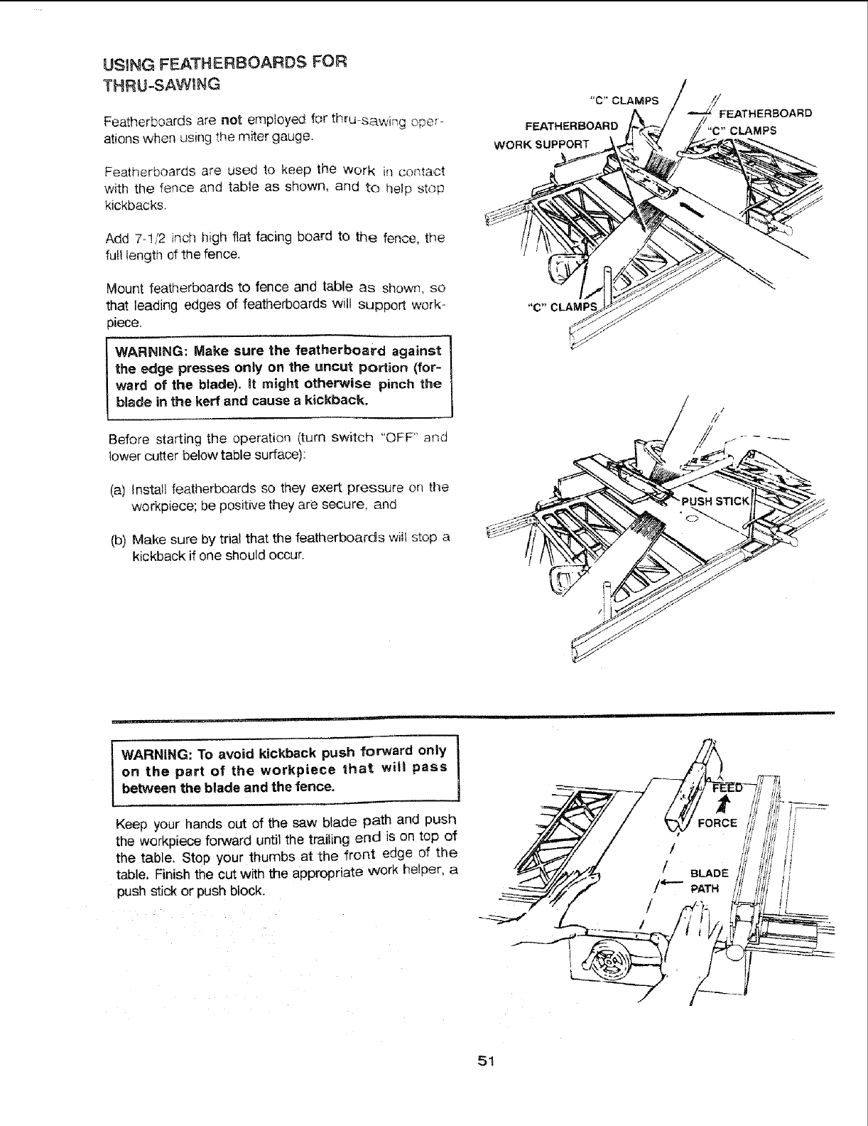
USING FEATHERBOARDS FOR
THRU-SAW_NG
Featherboards are not employed for thru sawing oper-
ations when using the miter gauge,
Featherboards are used to keep the Work in contact
with the fence and table as shown, and to help st(_;p
kickbacks.
Add 7-1/2 inch high flat facing board to the fence, the
full length of the fence.
Mount featherboards to fence and table as shown, so
that leading edges of featherboards will support work,-
piece.
lWARNING: Make sure the featherboatd against
the edge presses only on the uncut portion (for-
ward of the blade), it might otherwise pinch the
blade in the kerr and cause a kickback.
Before starting the operation (turn switch "OFF" and
lower cutter below table surface):
(a) Install featherboards so they exert pressure on the
workpiece; be positive they are secure, and
(b) Make sure by trial that the featherboards wit stop a
kickback if one should occur.
"C"CLAMPS
FEATHERBOARD
WORK SUPPORT
¢FEATHERBOARD
"C"CLAMPS
, ,,,,,,,.... ==1 ,=1
WARNING: To avoid kickback push forward only
on the part of the workpiece that will pass
between the blade and the fence.
Keep your hands out of the saw blade path and push
the worKpiece forward until the trailing end is on top of
the table, Stop your thumbs at the front edge of the
table, Finish the cut with the appropriate work helper, a
push stick or push block.
51
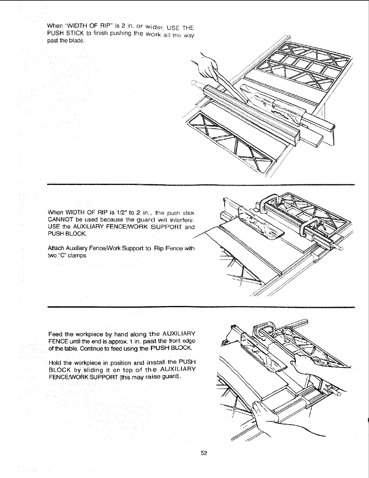
When "WIDTH OF RIP" is 2 tn. or wiaer LJSE THE
PUSH STICK to finish pushing the work a_ the way
past the blade.
When WIDTH OF RIP is 1/2" to 2 in., tlqe pusn st_ct<
CANNOT be used because the guard will interfere
USE the AUXILIARY FENCE/WORK SUPPORf and
PUSH BLOCK,
Attach Auxiliary Fence/Work Support to Rip Fence with
two "'C" clamps
Feed the workpiece by hand along the AUXILIARY
FENCE until the end is approx, 1 in, past the front edge
of the table. Continue to feed using the PUSH BLOCK.
Hold the workpiece in position and install the PUSH
BLOCK by sliding it on top of the AUXILIARY
FENCE_iORK SUPPORT (this may raise guard),
52
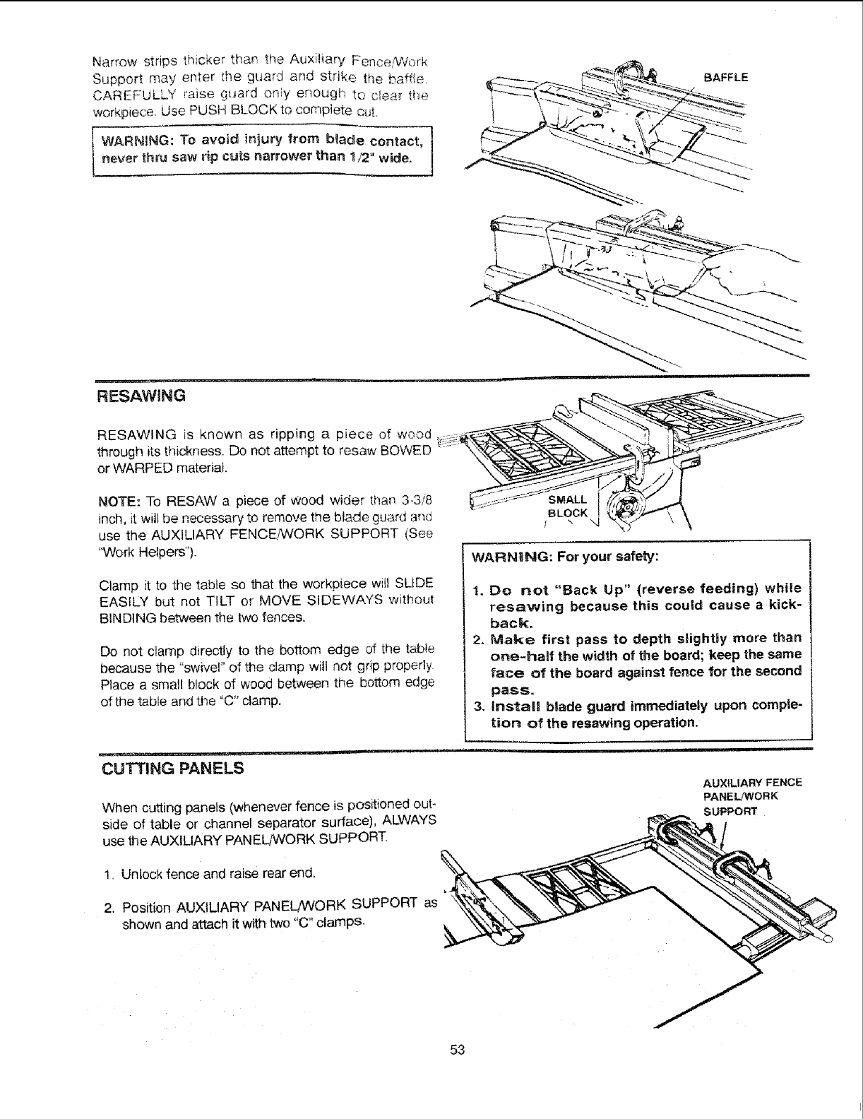
NarrowstripsthickerthantheAuxiliaryFence/Work
Supportmayenterthe guardandstrikethe baffle.
CAREFULLYt'aiseguardonly enoughto clea_the
workpieceUsePUSHBLOCKtocompletecut.
WARNING: To avoid #;iury from b_ade contact,
never thru saw rip cuts narrower than t/2" wide.
BAFFLE
RESAWJNG
RESAWING is known as ripping a piece of wood
through its thickness. Do not attempt to resaw BOWED
or WARPED material.
NOTE: To RESAW a piece of Wood wider than 3-3/8
inch, it witl be necessary to remove the blade guard and
use the AUXILIARY FENCENVORK SUPPORT (See
"Work Helpers").
<
_::_:_r";: _ .....SMALL'_'_"_ i
" BLOCKJ
Clamp it to the table so that the workpiece will SLIDE
EASILY but not TILT or MOVE SIDEWAYS without
BINDING between the two fences.
Do not clamp directly to the bottom edge of the table
because the "swivel" of the clamp will not grip properly.
Place a small block of wood between the bottom edge
of the table and the "C" clamp.
WARNING: For your safety:
1. Do not "Back Up" (reverse feeding) while
resawing because this could cause a kick-
back.
2. Make first pass to depth slightly more than
one=half the width of the board; keep the same
face of the board against fence for the second
paSS_
3, Install blade guard immediately upon comple-
tion of the resawing operation.
• __ = ,=rl =
CUTTING PANELS
When cutting panels (whenever fence is positioned out-
side of table or channel separator surface), ALWAYS
use the AUXILIARY PANEL!WORK SUPPORT.
AUXILIARY FENCE
PANEL_#ORK
SUPPORT
1. Unlock fence and raise rear end.
2. Position AUXILIARY PANEL/WORK SUPPORT as
shown and attach it with two "C" clamps.
53
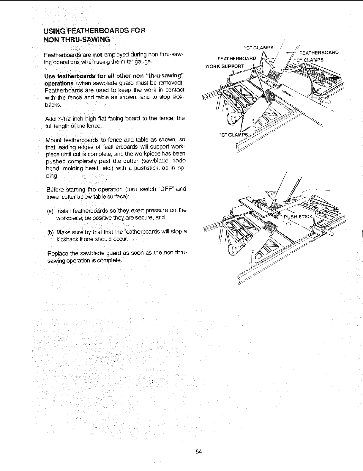
USING FEATHERBOARDS FOR
NON THRU-SAWING
Featherboaras are not employed during non tr_ru-saw-
ing operations when using the miter gauge.
Use featherboards for all other non "thru-sawing"
operations [when sawblade guard must be removedk
Featherboards are used to keep the work in contact
with the fence and table as shown, ana to stop kick-
backs.
Add 7-4/2 inch high flat facing board to the fence the
full length of the fence.
Mount featherboards to fence and table as shown, so
that leading edges of featherboards will support worK-
piece until cut is complete, and the workpiece has been
pushed completely past the cutter (sawblade. dado
head. molding head, etc.) with a pushstick, as _nrip-
ping.
Before starting the operation (turn switch "OFF" and
lower cutter below table surface):
(a) Install featherboards so they exer_ oressure on the
workpiece; be positive they are secure, and
(b) Make sure by trial that the featherboards will stop a
kickback ff one should occur.
Replace the sawblade guard as soon as the non thru-
sawing operation is complete.
"c" CLAMPS
FEATHERBOARD
WORK SUPPORT
54
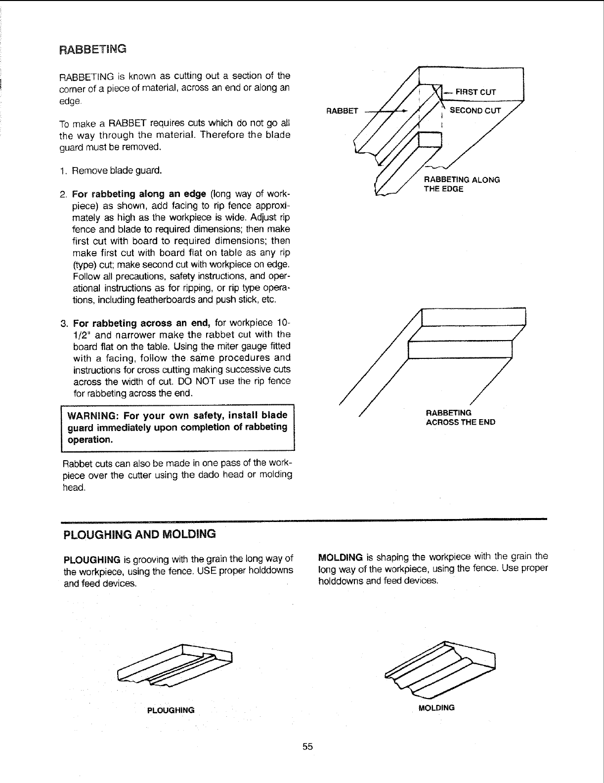
RABBETING
RABBETING is known as cutting out a section of the
corner of a piece of material, across an end or along an
edge.
To make a RABBET requires cuts which do not go all
the way through the material. Therefore the blade
guard must be removed.
1. Remove blade guard.
2. For rabbeting along an edge (long way of work-
piece) as shown, add facing to rip fence approxi-
mately as high as the workpiece is wide. Adjust rip
fence and blade to required dimensions; then make
first cut with board to required dimensions; then
make first cut with board flat on table as any rip
(type) cut; make second cut with workpieceon edge.
Follow all precautions, safety instructions, and oper-
ational instructions as for ripping, or rip type opera-
tions, including featherboards and push stick, etc.
3. For rabbeting across an end, for workpiece 10-
1/2" and narrower make the rabbet cut with the
board flat on the table. Using the miter gauge fitted
with a facing, follow the same procedures and
instructions for cross cutting making successive cuts
across the width of cut. DO NOT use the rip fence
for rabbeting across the end.
I WARNING: For your own safety, install blade I
I
guard immediately upon completion of rabbeting I
operation.
Rabbet cuts can also be made in one pass of the work-
piece over the cutter using the dado head or molding
head.
RABBET
FIRST CUT
RABBETING ALONG
THE EDGE
RABBETING
ACROSS THE END
PLOUGHING AND MOLDING
PLOUGHING is grooving with the grain the long way of
the workpiece, using the fence. USE proper holddowns
and feed devices.
MOLDING is shaping the workpiece with the grain the
long way of the workpiece, using the fence. Use proper
holddowns and feed devices.
PLOUGHING MOLDING
55
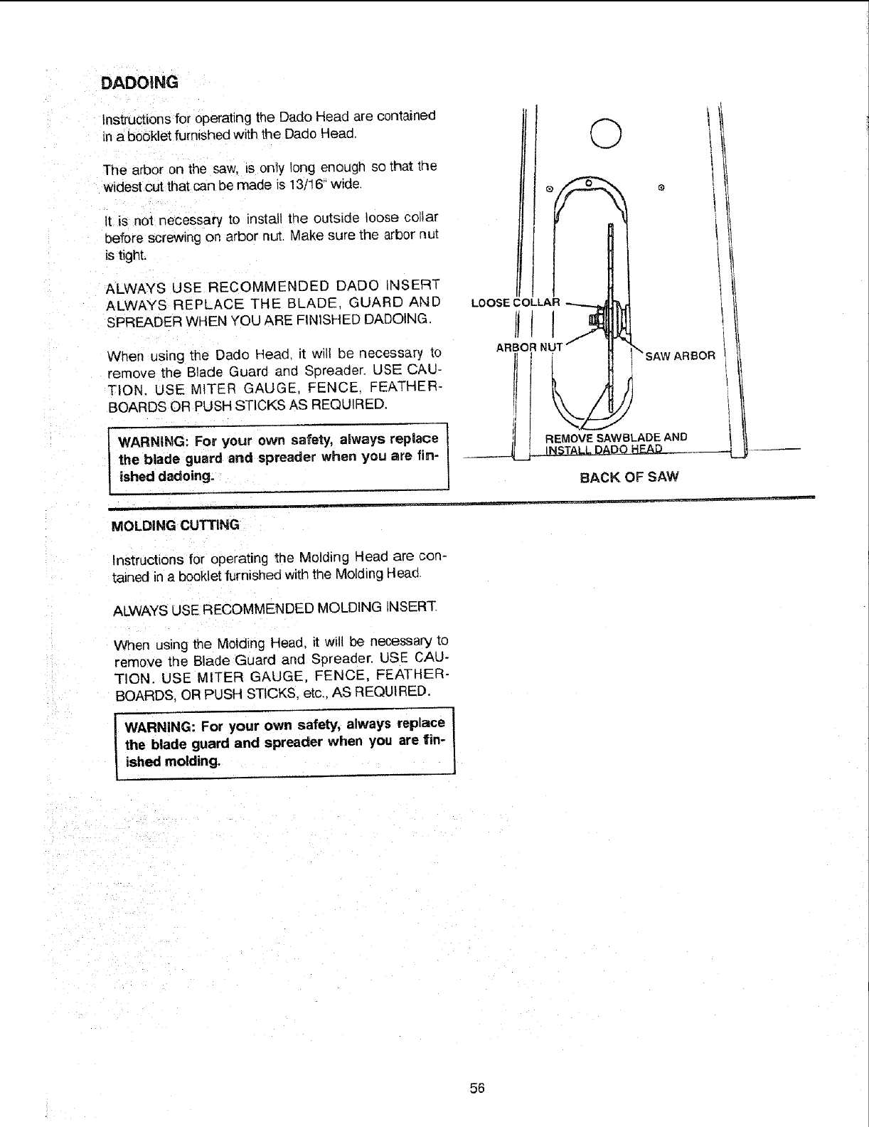
DADOING
Instructions for operating the Dado Head are contained
in a booklet furnished with the Dado Head.
The arbor on the saw, is only long enough so that the
widest cut that can be made is 13/16" wide.
It is not necessary to install the outside loose collar
before screwing on arbor nut. Make sure the arbor Rut
is tight,
ALWAYS USE RECOMMENDED DADO INSERT
ALWAYS REPLACE THE BLADE. GUARD AND
N
bPREADER WIlE YOU ARE FINISHED DADOING.
When using the Dado Head, it will be necessary to
remove the Blade Guard and Spreader. USE CAU-
TION. USE MITER GAUGE, FENCE. FEATHER-
BOARDS OR PUSH STICKS AS REQUIRED.
WARNING: For your own safety, always replace
the blade guard and spreader when you are fin-
ished dadoing.
MOLDING CUTTING
Instructions for operating the Molding Head are con-
tained in a booklet furnished with the Molding Head.
ALWAYS USE RECOMMENDED MOLDING [NSER-[
When using the Molding Head, it will be necessary to
remove the Blade Guard and Spreader. USE CAU-
TION. USE MITER GAUGE, FENCE, FEATHER-
BOARDS, OR PUSH STICKS. etc., AS REQUIRED.
i or,oo. !
the blade guard and spreader when you are fin-
ished molding.
©
LOOSE COLLAR
AR!O! N! SAW ARBOR
REMOVE SAWSLADE AND
INSTALL
SACK OF SAW
56
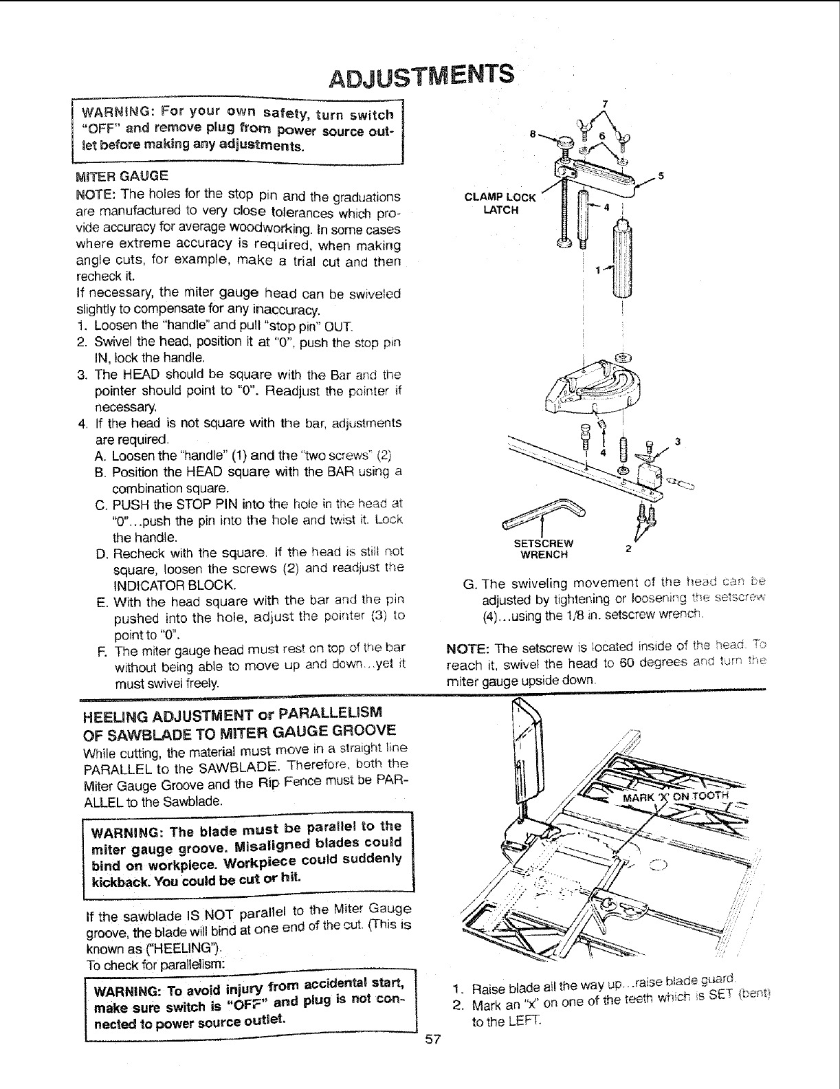
ADJUSTMENTS
WARNING: For your own safety, turn switch ]
"OFF" and remove pUugfrom Power source out-
_etbefore making any adjustments,
MITER GAUGE
NOTE: The holes for the stop pin and the graduations
are manufactured to very close tolerances which pro-
vide accuracy for average Woodworking. in some cases
where extreme accuracy is required, when making
angle cuts, for example, make a trial cut and then
recheck it.
If necessary, the miter gauge head can be swiveled
slightly to compensate for any inaccuracy.
1. Loosen the "handle" and pull "stop pin" OUT.
2. Swivel the head, position it at "0", push the stop pin
IN, lock the handle.
3. The HEAD should be square with the Bar and the
pointer should point to "0". Readjust the pointer if
necessary,
4. If the head is not square with the bar, adjustments
are required.
A. Loosen the "handle" (1) and the "two screws" (2)
B. Position the HEAD square with the BAR using a
combination square.
C. PUSH the STOP PIN into the hole in the head at
"0"...push the pin into the hole and twist it. Lock
the handle.
D. Recheck with the square. If the head is stilt not
square, loosen the screws (2) and readius[ the
INDICATOR BLOCK.
E. With the head square with the bar and the pin
pushed into the hole, adjust the pointer (3) to
point to "0".
E The miter gauge head must rest on top of the bar
without being able to move up and down_,.yet it
must swivel freely.
CLAMP LOCK "_
LATCH
7
5
"="4
1 iiiii!
WRENCH 2
G. The swiveling movement of the he_d can be
adjusted by tightening or loosening the _etscre_
(4)...using the 1/8 in. setscrew wrench.
NOTE: The setscrew is _ocated inside of the ,"'-a4,s..,.--,_-_
reach it, swivel the head to 60 degrees and turn th.'-_.
miter gauge upside down.
HEEUNG ADJUSTMENT or PARALLELISM
OF SAWBLADE TO MBTER GAUGE GROOVE
While cutting, the material must move in a straight line
PARALLEL to the SAWBLADE. Therefore, both the
Miter Gauge Groove and the Rip Fence must be PAR-
ALLEL to the Sawblade.
WARNING: The blade must be parallel to the
miter gauge groove. Misaligned blades could
bind on workpiece. Workpiece could suddenly
kickback. You could be cut or hit.
TOOTH
If the sawblade IS NOT parallel to the Miter Gauge
groove, the blade will bind at one end of the cut. (This is
known as ("HEELING'_.
To check for parallelism:
make sure switch is ,'OF_" and plug is not con-
nected to power source outtet. 57
t. Raise blade all the way up...raise b_ade.q_rd
2. Mark an "x" on one of the teeth w_ich is SET (be "_
to the LEFT.
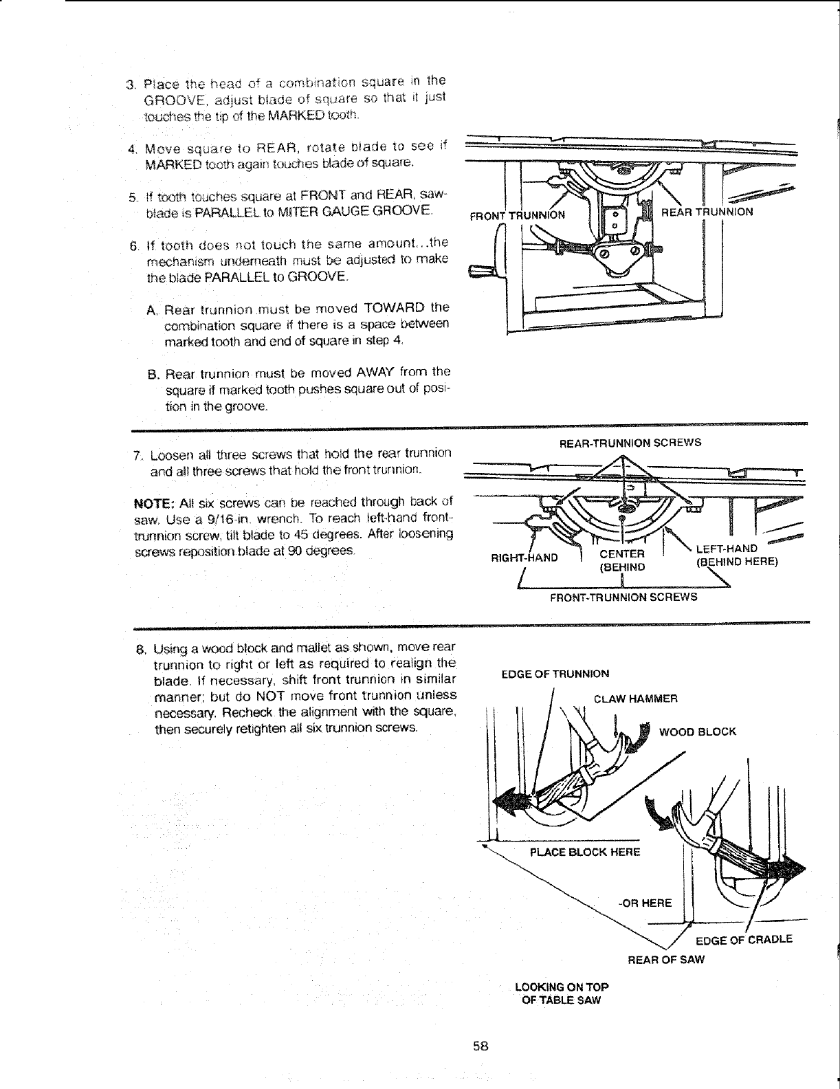
3 P_ace the head of a com_r_at_on square _n the
GROOVE ad_us_ blade of sqL_are so treat _I jus!
toucl_es t_e _D of lb,e MARKED top,n,
4 Move sq{_are to REAR rotate blade to see if - - -
MARKED tooth ag;_n toucr}es [:_ade of square.
5. tf tooth touches square at FRONT arid REAR saw-
btade is PARALLEL to MITER GAUGE GROOVE FRONTTRUNNION REARTRUNNION
6 if tooth does no; touch zr_e same amount, .the
mechanism underneath must be adjusted to make
the biade PARALLEL to GROOVE
A. Rear trunmon must be moved TOWARD the
combination square if there is a space oetween
marked tooth and end of square in step 4
B. Rear trunnion mus! be moved AWAY" from the
square ff marked tooth pushes souare out of pos_-
t_on in the groove,
7. LOOSenall three screws that hold the rear trunnton
and all three screws that hold the front trunn_orL
NOTE; All six screws can be reached through back of
saw. Use a 9/16-in wrench. To reach left-hand front_
trunnion screw, tilt blade to 45 d_grees After loosening
screws reposlbon blade at 90 degrees.
REAR-TRUNNION SCREWS
.J
/
RIGHT-HAND CENTER FT-HAND
/(BEHIND_ (B_,_ND HERE)
_RONT-TRUNNIONSCREWS
8, Using a wood block and mallet as shown, move rear
trunmon to right or left as required to realign the
blade, tf necessary, shift front trunnion _n sLmilar
manner: but do NOT move front trunnion unless
necessary Recheck the alignment with the square.
then securely rebghten all six trunnion screws,
EDGE OF TRUNNION
CLAW HAMMER
WOOD BLOCK
LOOKING ON TOP
OFTABLESAW
EDGE OF CRADLE
REAR OF SAW
58
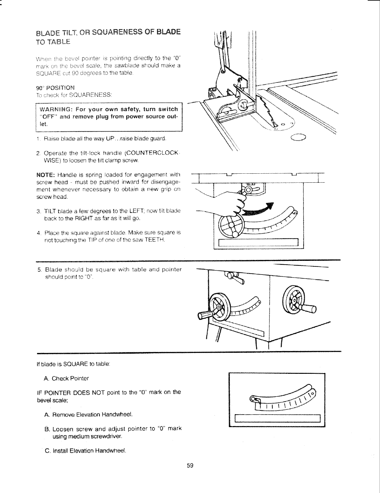
BLADE T_LT, OR SQUARENESS OF BLADE
TO TABLE
WT,:>t _Te bevel ponte is !,oi _t n9 directly to the '0'
rra:k (_ _e, ,_,_,,, scae. the sawMade st ou_d make a
•_ ,,0 t _,, e_., to the taHe
90' POSiTiON
;% c qec <for SQUARENESS:
[-6_G7 For your own safety, turn switch ]
i "OFF' a_d remove p_ug from power source out-
]
I leL
I Raise b_ade a_tthe way UP..:raise blade guard.
2 Operate the tiltqock handie (COUNTERCLOCK
WISE) to {oosen the tiit c_amp screw.
O
NOTE: Handle is spring loaded for engagement with
screw head - must be pushed irward for disengage
ment whenever necessary to obtain a few grip on
screw head.
3. TILT' blade a few degrees to the LEFT: .qow tiit b!ade
back to the R_GHT as far as it wifl go.
4 P_aoe the square against blade. Make sure sqdare s
not touchiT_g the TIP of one of the saw TEETH. [i..............................................J
5. Blade sbod_d be square with table and pointer
sho@d ' '
po,r,t _.,_'0'
i n l u
If biade is SQUARE to table:
A. Check Pointer
IF POINTER DOES NOT point to the "0" mark on the
bevel scale;
A. Remove Elevation HandWneet.
B. Loosen screw and adjust pointer to "0' mark
using medium screwdriver.
C, Install Elevation Hand_,_eeL
r , i •
59
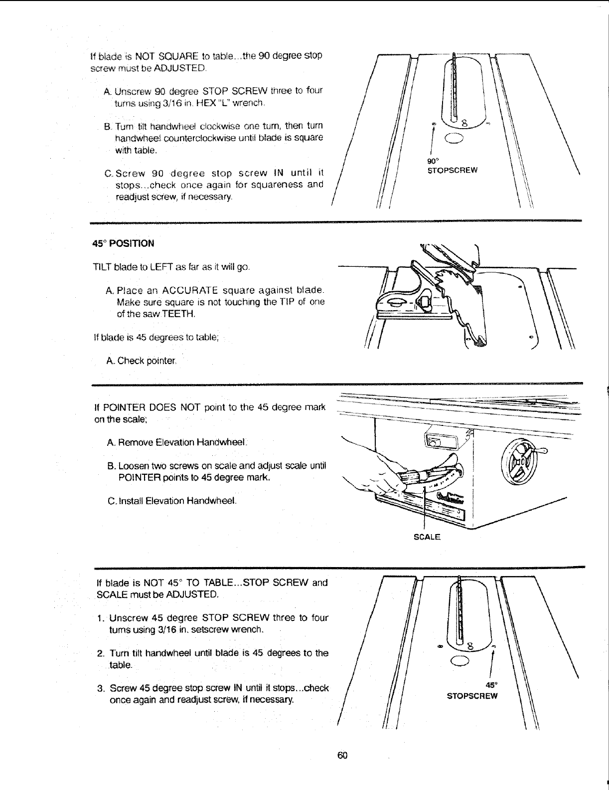
tf b_adeisNOTSQUAREtotabIe.,,the90degreestop
screwmustbeADJUSTED
A. Unscrew 90 degree STOP SCREW three to four
_ums usil_g 3/16 tn HEX L" wrench.
B -rum tilt handwheet ciockwise one turn taen turn
handwnee_ counterc½ockwise u_tit blade _s square
w_tt_table
C Screw 90 degree stop screw IN until it
stops...check once again for squareness and
react!ust screw, if necessary.
/
/
/
/
/
/
45 °POSITION
TILT blade to LEFT as far as _twilt go.
A. Place an ACCURATE square against blade.
Make sure square is not touching the TIP of one
of the saw TEETH,
If blade is 45 degrees to table;
A. Check pomter,
If POINTER DOES NOT point to the 45 degree mark
on thescale;
A, Remove Elevation Handwheel.
B. Loosen two screws on scale and adjust scale until
POINTER points to 45 degree mark
C. Install Elevation Handwheel.
SCALE
tf blade is NOT 45° TO TABLE_,STOP SCREW and
SCALE must be ADJUSTED.
1. Unscrew 45 degree STOP SCREW three to four
turns using 3/16 in. setscrew wrench.
2. Turn tilt handwheel until blade is 45 degrees to the
table.
3. Screw 45 degree stop screw tN until it stops...check
once again and readjust screw, if necessary.
/
/
/
45°
STOPSCREW
60
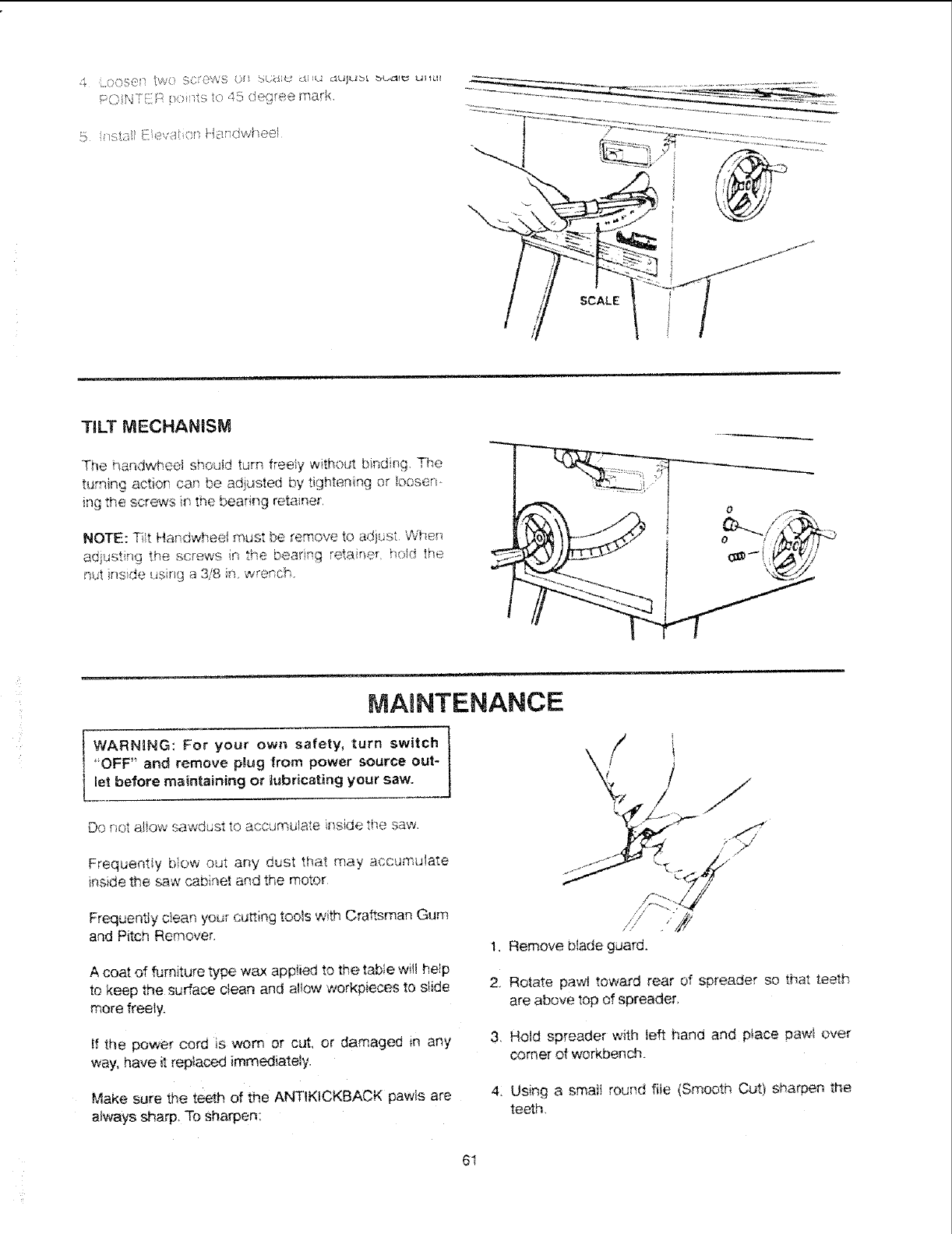
PC'N!i R _ei _sto 45 degree mark.
5 _/st,:-;, i£evs_t : He,_dwheel
\
SCALE
TiLT MECHANISM
The handwheel shou!d turn freely without binding. The
turning actior_ can be adiusted by tightening er Ioosen-
_ngthe scre_wTsin the bearir,,g retainer,
NOTE: T_t H_ndwheei must be remove to ad)ust When
ad}usting the screws r! the bearing retainer, ho_d _he
nut insde _sng a 318 im wrench.
Do not a!iow ,sawdust to accumulate inside the saw.
Frequentiy bow out any dust that may accumulate
inside the saw cabi:_e! and the motor
MAINTENANCE
"OFF" and remove plug from power source out-
let before maintaining or lubricating your saw. , /:
/
Frequently clean your curing tools with Craftsman Gum
and Pitch Remover.
A coat of furniture type wax app!ied to the table wilt hetp
to keep the sudace clean and a!!ow workpieces to siide
more freely.
/ /
t. Remove b!ade guard.
2, Rotate pawl toward rear of spreader so that teeth
are above top of spreader.
If the power cord is worn or cut, or damaged in any
way, have it replaced immediately.
Make sure the teeth of the ANTtKtCKBACK pawls are
atways sharp, To sharpen:
3, Hold spreader with left hand and p_ace pawt over
corner of workbench.
4: Using a smait round file (Smooth Cut) sharpen the
teeth,
61
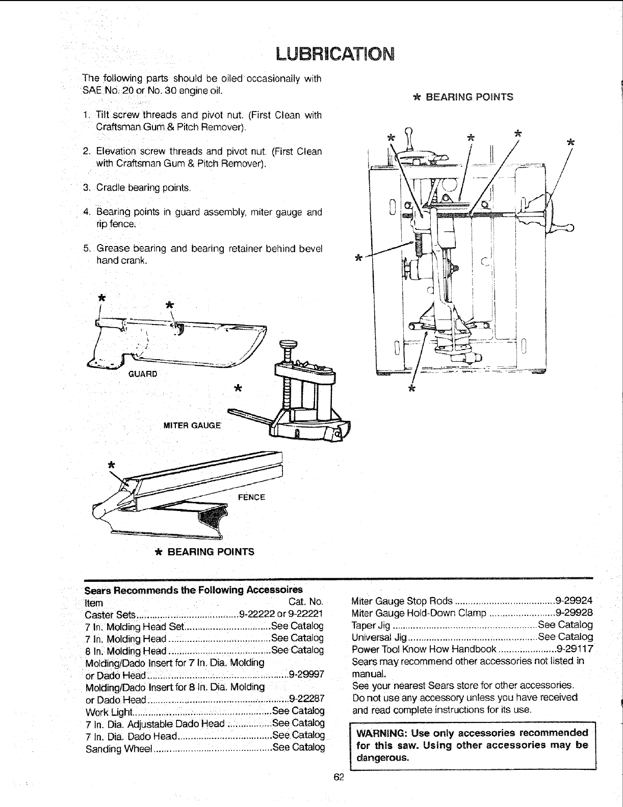
LUBRICATION
The following parts should De oiled occasionally with
SAE No, 20 or No. 30 engine oil.
Tilt screw threads and pivot nut, (First Clean with
Craftsman Gum & Pitch Remover).
Elevation screw tiqreads and pivot nut (First Clean
with Craftsman Gum & Pitch Remover),
'k BEARING POINTS
3, Cradle bearing points.
4. Bearing points in guard assembly, m_tergauge and
rip fence.
5. Grease bearing and bearing retainer behind bevel
hand crank.
/
•k BEARING POINTS
Sears Recommends the Following Accessoires
Item Cat. No,
Caster Sets....................................... 9-22222 or 9-22221
7 In. Molding Head Set ................................. See Catalog
7 In, Molding Head ...................................... See Catalog
8 In. Molding Head ...................................... See Catalog
MeldingiDado Insert for 7 In, Dia. Molding
or Dado Head ..................................................... 9-29997
MoldinglDado Insert for 8 In. Dia, Molding
or Dado Head ...................................................... 9-22287
Work Light..................................................... See Catalog
7 In. Dia. Adjustable Dado Head ................ See Catalog
7 In. Dia, Dado Head .................................... See Catalog
Sanding Wheel ............................................. See Catalog
62
Miter Gauge Stop Rods ...................................... 9-29924
Vliter Gauge Hold-Down Clamp ......................... 9-29928
Taper Jig ..................................................... See Catalog
Universal Jig ............................................... See Catalog
Power Tool Know How Handbook ......................9-29117
Sears may recommend other accessories not listed in
manual.
See your nearest Sears store for other accessories.
Do not use any accessory unless you have received
and read complete instrucbons for its use.
WARNING: Use only accessories recommended
for this saw. Using other accessories may be
dangerous.
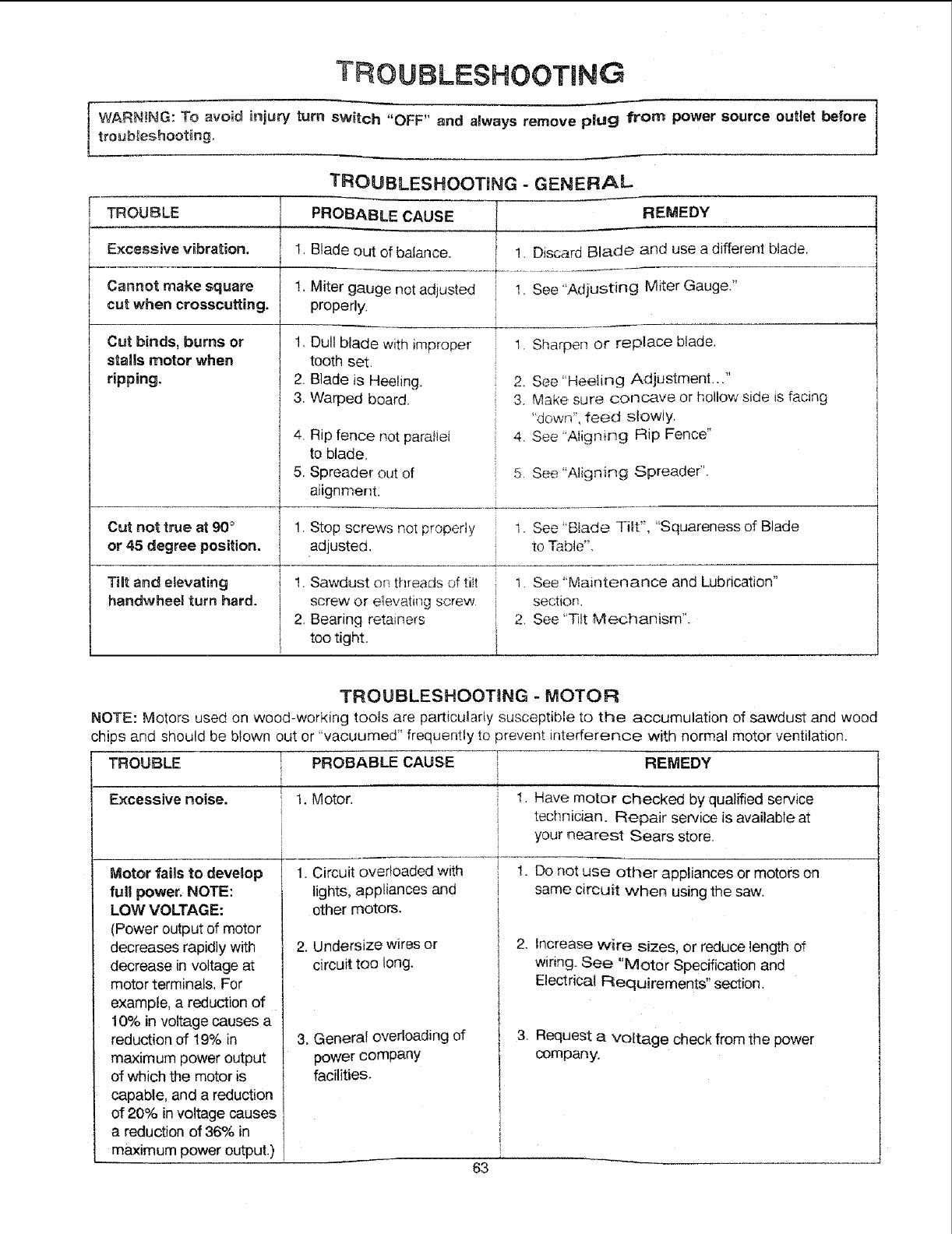
TROUBLESHOOTmNG
WARN!NG: To avoid injury turn switch "OFF" and always remove plug from power source outlet before I
troubleshooting, J
TROUBLE
Excessive vibration. !.
Cannot make square !.
cut when crosscutting.
Cut binds, burns or 1,
stalls motor when
ripping. 2.
3.
4_
5.
Cut not true at 90°
or 45 degree position.
TROUBLESHOOTING - GENERAL
PROBABLE CAUSE REMEDY
Blade out of balance, 1, Discard Blade and use a different blade,
.............................................. i................ :.................
Miter gauge not adjusted 1, See "Adiusting Miter Gauge,"
properly.
1. Sharpen or replace blade,Dull blade with improper
tooth set.
Blade is Heeling.
Warped board.
Rip fence not paratiei
to blade.
Spreader out of
alignment.
2. See "Heeling Adjustment..."
3. Make sure concave or hollow side is facing
"down', feed slowly.
4. See "AlignirTg Rip Fence"
5. See "Aligning Spreader".
1. Stop screws not property 1. See "Btade Tilt", "Squareness of Blade
adjusted, to Table",
Tilt and elevating
handwheel turn hard.
1. Sawdust or! threads of tiit
screw or elevatir, g screw
2. Bearing retainers
too tight.
1. See "Maintenance and Lubrication"
section.
2, See 'qqtt Mechanism".
TROUBLESHOOTING - MOTOR
NOTE: Motors used on wood-working tools are particular!y susceptible to the accumulation of sawdust and wood
chips and should be blown out or "vacuumed" frequently to prevent interference with normal motor ventilation.
TROUBLE I PROBABLE CAUSE TI
Excessive noise. 1. Motor.
Motor fails to develop
full power. NOTE:
LOW VOLTAGE:
(Power output of motor
decreases rapidly with
decrease in voltage at
motor terminals. For
example, a reduction of
10% in voltage causes a
reduction of 19% in
maximum power output
of which the motor is
capable, and a reduction
of 20% in voltage causes
a reduction of 36% in
maximum power output.)
1. Circuit overloaded with
lights, appliances and
other motors.
2. Undersize wires or
circuit too long.
3. General overloading of
REMEDY
t, Have motor checked by qualified service
technician. Repair service is available at
your nearest Sears store.
1. Do not use other appliances or motors on
same circuit when using the saw.
2. Increase w_re sizes, or reduce length of
wiring. See "Motor Specification and
Electrical Requirements" section.
power company
facilities,
3. Request a voltage check from the power
company.
63
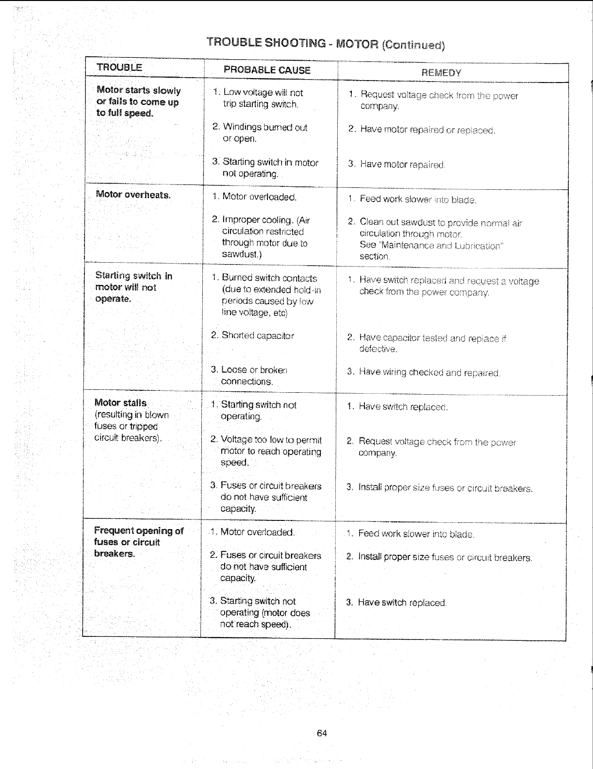
TROUBLE SHOOT_NG = P_OTOR {Continued)
TROUBLE
Motor starts slowly
or fails _o come up
to fun_speed.
Motor overheats,
PROBABLE CAUSE
1. Low voltage will not
trip starting sw_tcn.
2. Windings burned ouT.
or open.
3. Starting switch in motor
not operating.
1. Motor overloaded.
REMEDY
!. Reques_ volt%}echeck ?ro,m the power
compai _.
2 Have motet repasted or rep,sceC.
3 Have motor repaired
1 Feed work s_ower qto blade.
motor wil_act
operate,
2. Improper cooling. _A_r 2 Clean out sawdust Io 8rovide richhal aft
circulation restncted c_rcuta(_on throuqn motor.
through motor due to See Maintenance and Lubr ca._.ion"
sawdust.) section
I. Burned switch contacts _, Have switc_- re_qiaced _nd request avoltage
(due _3 extended he!d-in check from the t_ovve_oo_pan,€'.
penoc_s caused by lc',_i
hne voltage, etc
2. Shorted capacitor 2. Have capacitor tes[ed sar}c replace Jf
defoc_ave.
Motor stalls
(resulting in blown
fuses or tnppeu
circuit breakers,.
3_ Loose or broker]
corlr;ectlorts.
1. Starting switch not
operating.
2. Voltage too low to perm_[
motor to reach operat_,g
speed.
3. Have wFtrtg crlecKed aria repaired
! Have sw_tch rep]aceo.
2 Request voltage ;nee4 from the puwer
corr_par_y.
Frequent opening of
fuses or circuit
breakers.
3. Fuses or c{rcuit breakers
do not have sufficient
capacity.
I. Motor overloaded.
2. Fuses or circuit breakers
do not have sufficienl
capacity,
3. Instali oroper size fuses or circL_it bre,_kers.
-. Feed work slower into blade.
2, Install proper s_ze fuses or circuit breakers.
3, Starting switch not
operating (motor does
t not reach speea]_
i 3. Have switch replaced.
64

NOTES
65
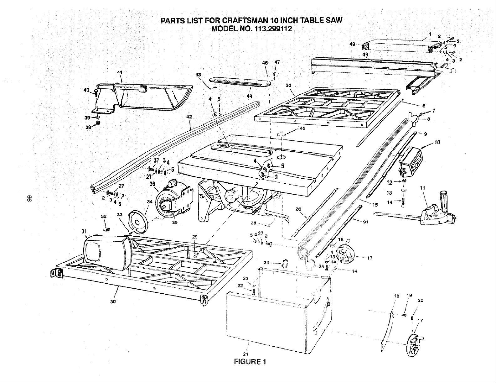
PARTS LIST FOR CRAFTSMAN 10 INCH TABLE SAW
MODEL NO. 113.299112
31 29
3O
26
\
FIGURE 1
t7

PARTS LIST FOR CRAFTSMAN 10 aNCH TABLE SAW
MODEL NO. 113o299112
Always order by Part Number -- Not by Key Number
O3
FIGURE 1 - PARTS LIST
Part
I 822142
o i STD523107
" , STD551031
,., , STD551231
:. : STD541231
t_ i 818314-1
' STD601103
!
8 I 823522
9 ] 818313
lO I---
11 i.....
I
I
_2 _822138-!
12 i STD551210
14 I STD51!103
15 I 822171
16 I STD551010
17 I 818526
18 I 818548
19 I STD610805
20 I STD503103
21 I 62700
22 I 60077
23 I STD551237
24 t 71165
Description
Channel, Separator
* Bolt, Square Head,
5/16-18 x 3/4"
*Washer, 21/64 x 5/8 x 1/16
* Lockwasher, External 5/16
* Nut, Hex 5/16-18
Tape, Fence, Right 30"
* Screw Pan HD Ty "F' 10-32 x
3/8
Cap, Front Guide Bar End,
Right
Rack, Fence. 30-1/4"
Switch Assembly, Box
(See Fig. 6)
Gauge Assembly, Miter
(See Fig. 4)
Nut, Square 10-32
* Lockwasher #t0
*Screw,Pan Head, 10-32 x 3/8"
Bar, Front Guide
Plain Washer 13/64"
Handwheel
Scale, Adjustable Bevel
* Screw, Pan Hd. Ty "AB"
No. 8 x 1/2
* Screw, Cup Pt. Set
5/16-18 x 5/16
Base
Screw, Hex Hd. 3/8-16 x 1/2
* Lockwasher, External 3/8
Tie, Wire
*Standard Hardware Item - May be purchased locally.
Key
No
25
26
27
28
29
30
31
32
33
34
35
36
37
38
39
4O
41
42
43
44
45
46
47
48
49
Part
NO,
823523
818314
818309
STD541411
STD523112
60252
60255
STD60 ! 105
60253
60254
819394
159653-38
STD541025
$1D551225
STD522506
823661
62718
62703
62493
STD501102
133645
818308
SP5802
Description
Cap, Front Guide Bar End; Left
Tape, Fence, Left 24"
Washer, Shim
* Nut, Lock 10-32
* Screw, Hex Hd. 5/16-18 x 1-1/4
Extension, Table (See Fig. 9)
Guard, Belt
Clip, "S"
* Screw, Pan Hd. Ty "T"
10-32 x 1/2
Support, Belt Guard
Bracket, Support
Motor
Bolt, Square Head, 5/16-18 x 1'
* Nut, Hex 1/4-20
* Lockwasher, Externa! 1/4
* Screw, Hex Hd. !/4-20 x 5/8
Guard Assembly (See Fig. 5)
Bar; Fence Rear Guide
Ctip, Retaining
Insert Assembly
(Includes Key No. 11 & 12)
Insert, Exact-!-Cut
* Screw, Locking Set
1032 x 3/16
Screw, Flat Hd. 10-32 x 1
Fence Assembly, Rip
(See Fig. 3)
Bracket
Owner's Manual (Not Illus.)
,Any attempt to repair this motor may create a hazard
unless repair is done by a qualified service technician.
Repair service is available at your nearest Sears Store.
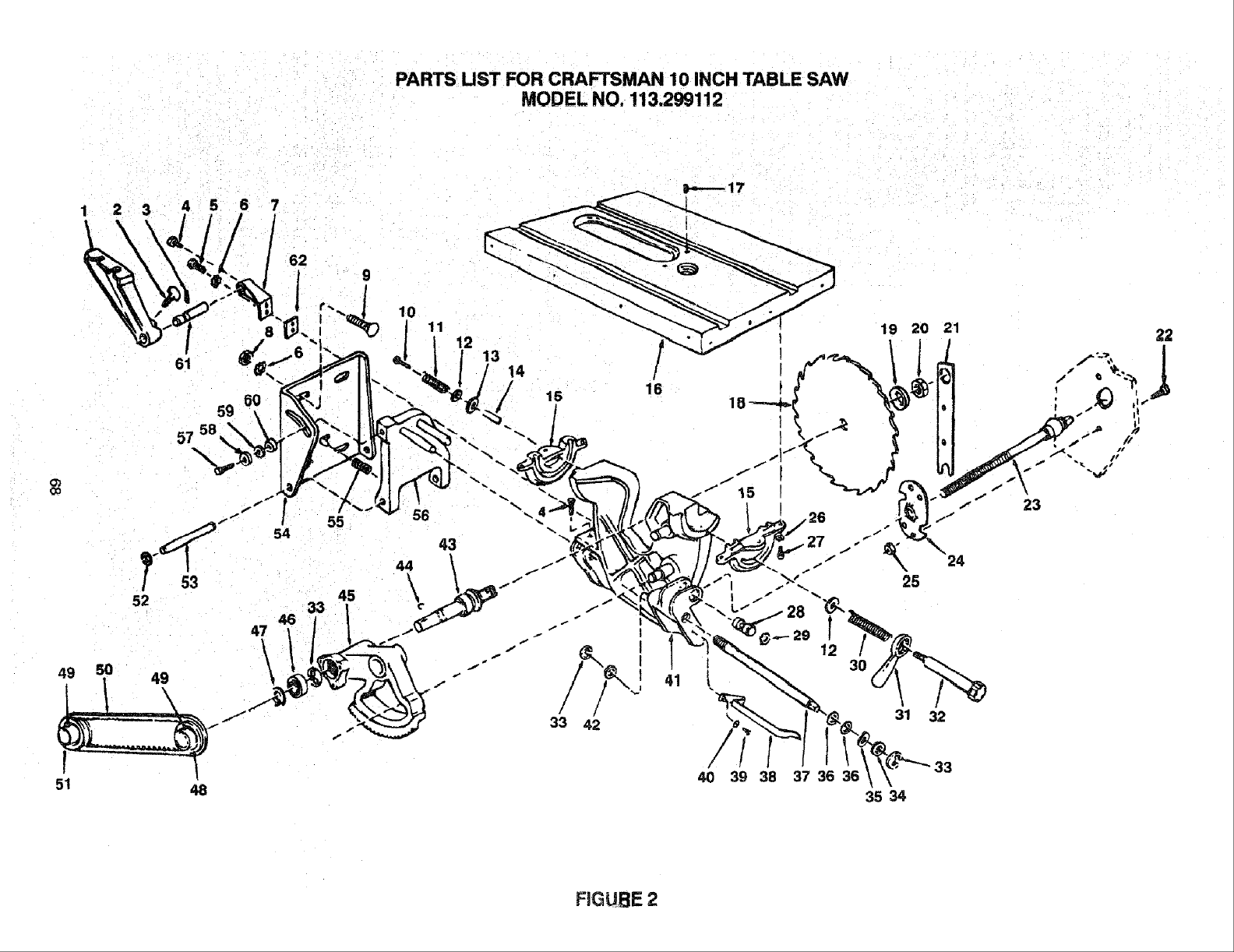
PARR lIST FOR CRAFTSMAN 10 INCH TABLE SAW
MODEL NO. 113.299112
1 2 3 4 5 6 7
I °
8
61
59
57
52
51
55
54
45
47
\
10 11
56
12
43
15 16
39 38 37 36 36
19 20 21
3O
31 32
33
\
35 34
23
FIGUflE 2
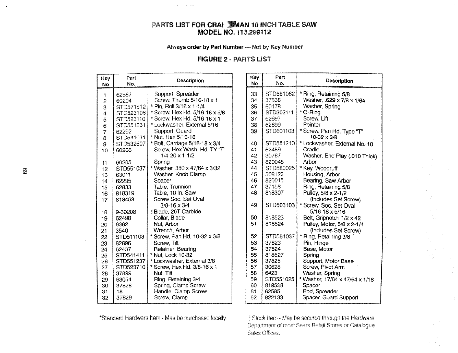
PARTS LiST FOR CRA| ._AN 10 INCH TABLE SAW
MODEL NO, 113.299112
Always order by Part Number -- Not by Key Number
FIGURE 2 -PARTS LiST
03
_O
Part
1 1625 7
2 I 60204
3 STD571812
4 STD523106
5 STD5231 t 0
6 STD551231
7 62292
8 STD541031
9 STD532507
10 I 60206
11 60205
12 I STD551037
13 I 63011
14 t 62295
15 162833
16 [ 818319
17 818463
18 9-30208
19 62498
20 6362
21 3540
22 I STD5!1103
23 I 62696
24 ! 62437
25 STD541411
26 STD551237
27 I STD523710
28 I 37899
29 t 63054
30 _37828
31 18
32 37829
m_
Description
Support, Spreader
Screw. Thumb 5/!6-18 x 1
* Pin, Roll 3/16 x 1-1/4
* Screw, Hex Hd. 5/16-18 x 5/8
*Screw, Hex Hd. 5/16-18 x 1
* Lockwasher, External 5/16
Support, Guard
* Nut. Hex 5/16-18
* Bolt, Carriage 5/16-18 x 3/4
Screw, Hex Wash. Hd. TY "T"
t/4-20 x 1-1/2
Spring
* Washer, 380 x 47/64 x 3/32
Washer, Knob Clamp
Spacer
Table, Trunnion
Table, 10 In. Saw
Screw Soc. Set Oval
3/8-16 x 3/4
1"Blade,20T Carbide
Collar, Blade
Nut, Arbor
Wrench, Arbor
* Screw, Pan Hd. 10-32 x 3/8
Screw, Tilt
Retainer, Bearing
* Nut, Lock 10-32
* Lockwasher, External 3/8
* Screw, Hex Hd. 3/8-16 x 1
Nut, Tilt
Ring, Retaining 3/4
Spring, Clamp Screw
Handle, Clamp Screw
Screw, Clamp
Key
No
33
34
35
36
37
38
39
40
41
42
43
44
45
46
47
48
49
5O
51
52
53
54
55
56
57
58
59
60
61
62
Part
No.
STD581062
37838
60178
STD302111
62697
62699
STD601103
STD551210
62489
30767
820048
STD580025
508123
820015
37158
818307
STD503103
818523
818524
STD581037
37823
37824
818527
37825
30628
6423
STD551025
818528
62585
822t33
Description
* Ring, Retaining 5/8
Washer, .629 x 7/8 x 1/64
Washer, Spring
* O-Ring
Screw, Lift
Pointer
* Screw, Pan Hd. Type "T"
10-32 x 3/8
* Lockwasher, External No. 10
Cradle
Washer, End Play (.010 Thick)
Arbor
* Key, Woodruff
Housing, Arbor
Bearing, Saw Arbor
Ring, Retaining 5/8
Pulley, 5/8 x 2-1/2
(includes Set Screw)
* Screw, Soc. Set Oval
5/16-18 x 5/16
Belt, Gripnotch 1/2 x 42
Pulley, Motor, 5/8 x 2-1/4
(Includes Set Screw)
* Ring, Retaining 3/8
Pin, Hinge
Base, Motor
Spring
Support, Motor Base
Screw, Pivot Arm
Washer, Spring
*Washer, t7/64 x 47/64 x t/16
Spacer
Rod, Spreader
Spacer, Guard Support
*Standard Hardware item, May be purchased locally. -', ¢,
t Stock Item.. May be secur_ through the Hard'are
Department of most Sears Retait Stores o_(.?.,arabesque
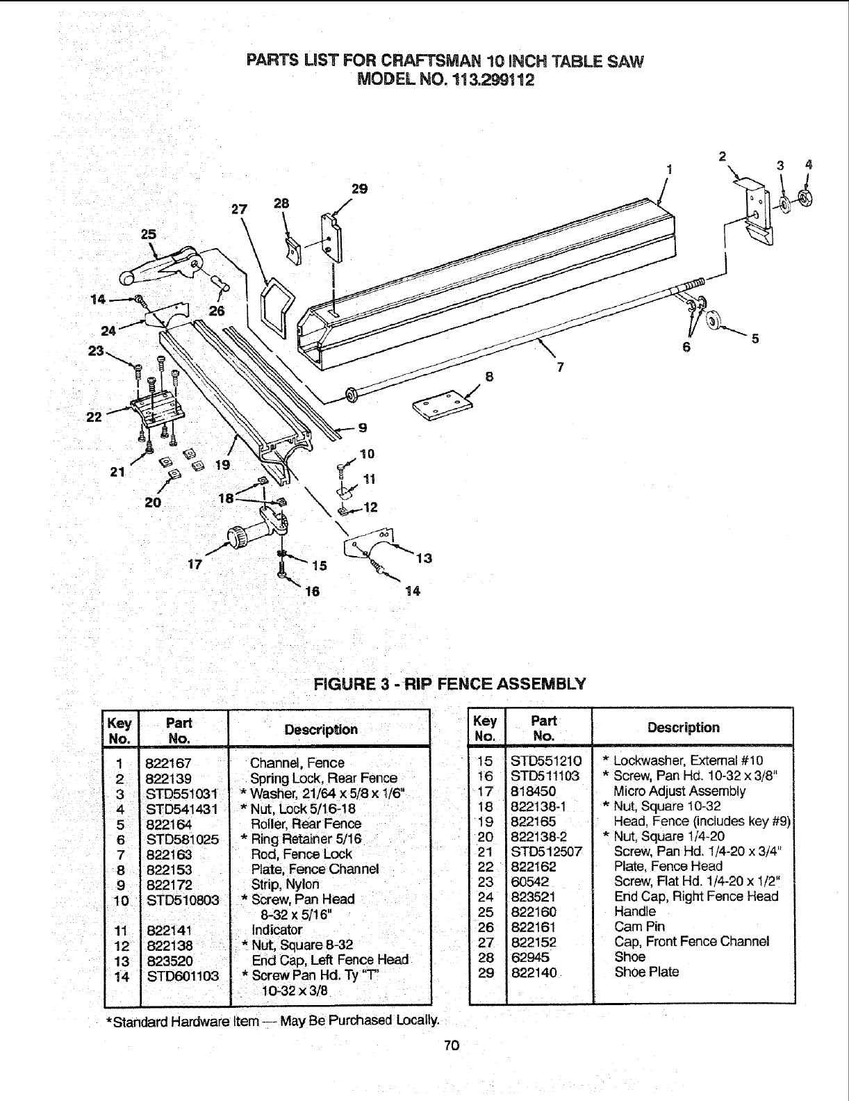
PARTS LIST FOR CRAFTSMAN 10 iNCH TABLE SAW
MODEL NO. 113.299112
21
25
\
2O
26
29
27 28 ,/
10
\
5
6
17 15
16
FIGURE 3 -RIP FENCE ASSEMBLY
Key]
No. i
2
3
4
Part
No.
822167
822139
STD551031
STD541431
Description
Channel, Fence
Spring Lock, Rear Fence
*Washer 21/64 x 5/8 ×1/6"
* Nut, Lock 5/16-! 8
Roller, Rear Fence
6 - STD581025 * Ring Retainer 5/16
7822163 Rod, Fence Lock
8 822!53 . Plate, Fence Channel
9 822172 Strip, Nylon
10 STD510803 *Screw, Pan Head
8-32 x 5/16"
11 822141 ' Indicator
12 822138 *Nut, Square 8-32
13 End Cap, Left Fence Head
14 STD601103 *Screw Pan Hal.Ty "T"
f 10-32 x 3/8
•Standard Hardware Item -- May Be Purchased Locally.
Key Part
No. No.
15 STD551210
I6 STD511103
t7 818450
18 822138-1
19 822165
20 822138-2
21 STD512507
22 822162
23 60542
24 823521
25 822160
26 822161
27 822152
28 62945
29 822140
Description
*Lockwasher, Extemat #10
*Screw, Pan Hd. 10-32 x 3/8"
Micro Adjust Assembly
*Nut, Square 10-32
Head, Fence (includes key #9)
* Nut, Square 1/4-20
Screw, Pan Hd, 1/4-20 x 3/4"
Plate, Fence Head
Screw, Flat Hd. 1/4-20 x 1/2"
End Cap, Right Fence Head
Handle
Cam Pin
Cap, Front Fence Channel
Shoe
Shoe Plate
7O
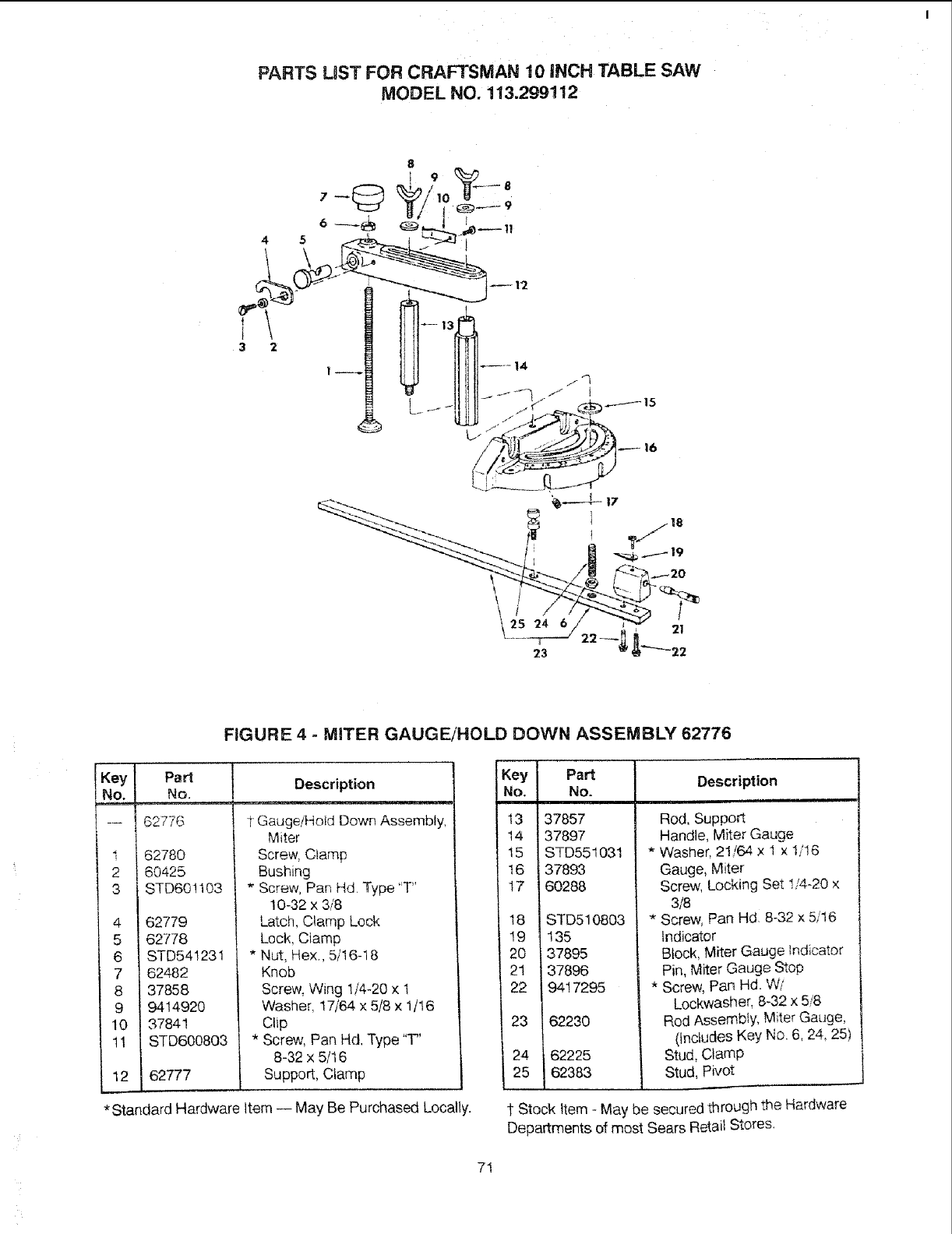
PARTS LaST FOR CRAFTSMAN 10 INCH TABLE SAW
MODEL NO. 113.299112
FIGURE 4 =MITER GAUGE/HOLD DOWN ASSEMBLY 62776
eYl
I
I
2
3
4
5
6
7
8
9
10
11
12
Pad
No.
62776
62780
60425
STD60!103
62779
62778
STD541231
62482
37858
9414920
37841
STD600803
62777
tDescription
t Gauge/Hold Down Assembly,
Miter
Screw, Clamp
Bushing
* Screw, Pan Hd. Type "T'
10-32 x 3/8
Latch, Clamp Lock
Lock, Clamp
* Nut, Hex., 5/16-18
Knob
Screw, Wing !/4-20 x t
Washer, 17/64 x 5/8 x 1/16
Clip
* Screw, Pan Hd. Type "T'
8-32 x 5/16
Support, Clamp
*Standard Hardware Item -- May Be Purchased Locally.
Key PaN
No. No.
13 37857
14 37897
15 STD551031
16 137893
17 60288
18
19
2O
21
22
23
24
25
STD510803
135
37895
37896
9417295
i62230
62225
62383
Description
Rod, Support
Handle, Miter Gauge
*Washer, 21/64 x I x 1/16
Gauge, Miter
Screw, Locking Set !/4-20 x
3/8
* Screw, Pan Hd 8-32 x 5/16
Indicator
Block, Miter Gauge Indicator
Pin, Miter Gauge Stop
* Screw, Pan Hd. Wi
Lockwasher, 8-32 x 5/8
Rod Assembly, Miter Gauge,
(Includes Key No. 6, 24_25)
Stud, Clamp
Stud, Pivot
1 Stock Item -May be secured through the Hardware
Departments of most Sears Retail Stores.
7!
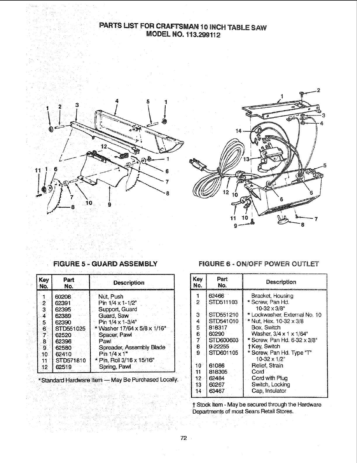
PARTS LIST FOR CRAFTSMAN 10 iNCH TABLE SAW
MODEL NO. 113.299112
10
\
FIGURE 5 -GUARD ASSEMBLY
Key Part
No. No.
1 60208
262391
362395
4 62389 "
5 62390
6STD551025
8 62396
t
r962580
10 62410
11 STD571810
12 62519
Description
= = ,_ ..... v
Nut, Push
Pin 1/4 × 1-1/2"
Support, Guard
Guard, Saw
Pin 1/4 x 1-3/4"
*Washer 17/64 x 5/8 × 1/16"
Spacer, Pawl
Pawl
Spreader, Assembly Blade
Pin 1/4 x 1"
*Pin, Roll 3/16 x 15/16"
Spring, Pawl
*Standard Hardware Item -- May Be Purchased Locally.
F_GURE 6 -ON/OFF POWER OUTLET
Key i
No. l
1
2
3
4
5
6
7
8
9
10
11
t2
13
t4
Part
No.
62466
STD511103
STD551210
STD541010
818317
60290
STD600603
9-22255
STD601105
61086
818305
62484
8O267
63467
Description
Bracket, Housing
*Screw. Pan Hd.
10-32 × 3/8"
* Lockwasher. Externa_No. 10
*Nut. Hex. 10-32 x3/8
Box, Switch
Washer. 3/4 x _x 1/64"
* Screw, Pan Hd. 6-32 x 3/8"
f Key, Switch
*Screw, Pan Hd. Type 'T'
10-32 x 1/2"
Relief, Strain
Cord
Cord with Plug
Switch. Locking
Cap, Insulator
1"Stock Item -May be secured through the Hardware
Departments of most Sears Retail Stores.
72
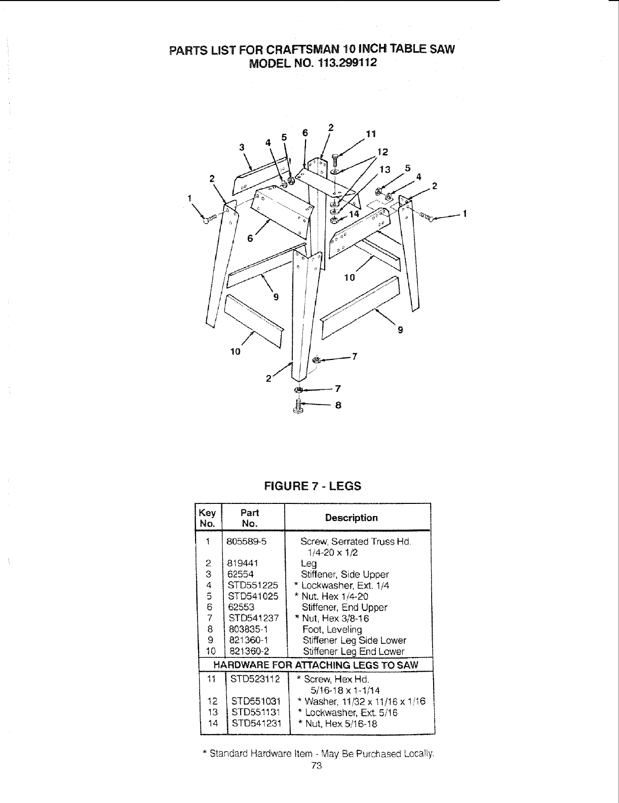
PARTS LIST FOR CRAFTSMAN 10 iNCH TABLE SAW
MODEL NO. 113,299112
2 4 2
1
/
10
8
FIGURE 7-LEGS
IKey IPart
No. !1 No, Description
! 1805589-5 Screw, Serrated Truss Hd.
1/4-20 x 1/2
2 I 8_9441 Leg
3 _ 62554 Stiffener, Side Upper
4 / STD551225 * Lockwasher, Ext. 1/4
5 / STD541025 *Nut, Hex 1/4-20
6 _ 62553 Stiffener, End Upper
7 | STD54!237 * Nut, Hex 3/8-16
8 | 803835-1 Foot, Leveling
9 | 821360-1 Stiffener Leg Side Lower
10 | 821360-2 Stiffener Leg End Lower
HARDWARE FOR ATTACHING LEGS TO SAW
1_ ! STD5231t 2 *Screw, Hex Hd.
5/16-!8 x 1-1/14
t,, | STD55!031
13 | STD55113i
_ STD541231
i
*Washer, 11/32 x 11/16 x "/'_-_,_o
*Lockwasher, Ext. 5/I 6
* Nut, Hex 5/16-18
*Standa.rdHardware item - May Be Purchased Loca!ty.
73
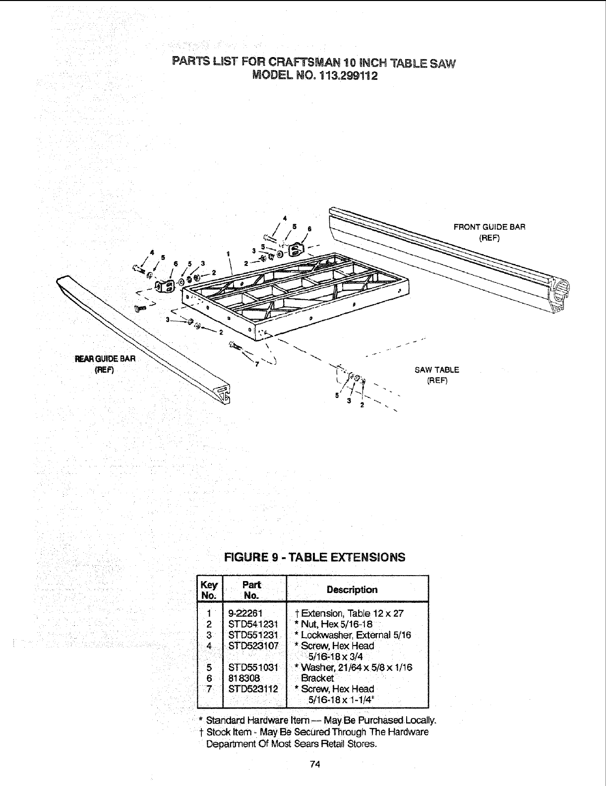
PARTS LIST FOR CRAFTSMAN 10 gNCH TABLE SAW
MODEL NO. 113o299112
SAW TABLE
CREF_
FRONT GUIDE BAR
(REF)
FIGURE 9 -TABLE EXTENSIONS
Key Part
No. No.
1 9-22261
2 STD541231
3
5 STD551031
6 818308
Description
1"Extension, Table 12 x27
*Nut, Hex 5/16-18
* L0ckwasher, External 5/16
* Washer, 21/64 x 5/8 x 1/16
Bracket
* Screw, Hex Head
5t16-18 x 1-1/4"
* Standard Hardware Item-- May Be Purchased Locally.
1Stock Item - May Be Secured Through The Hardware
Department Of Most Sears Retail Stores.
74
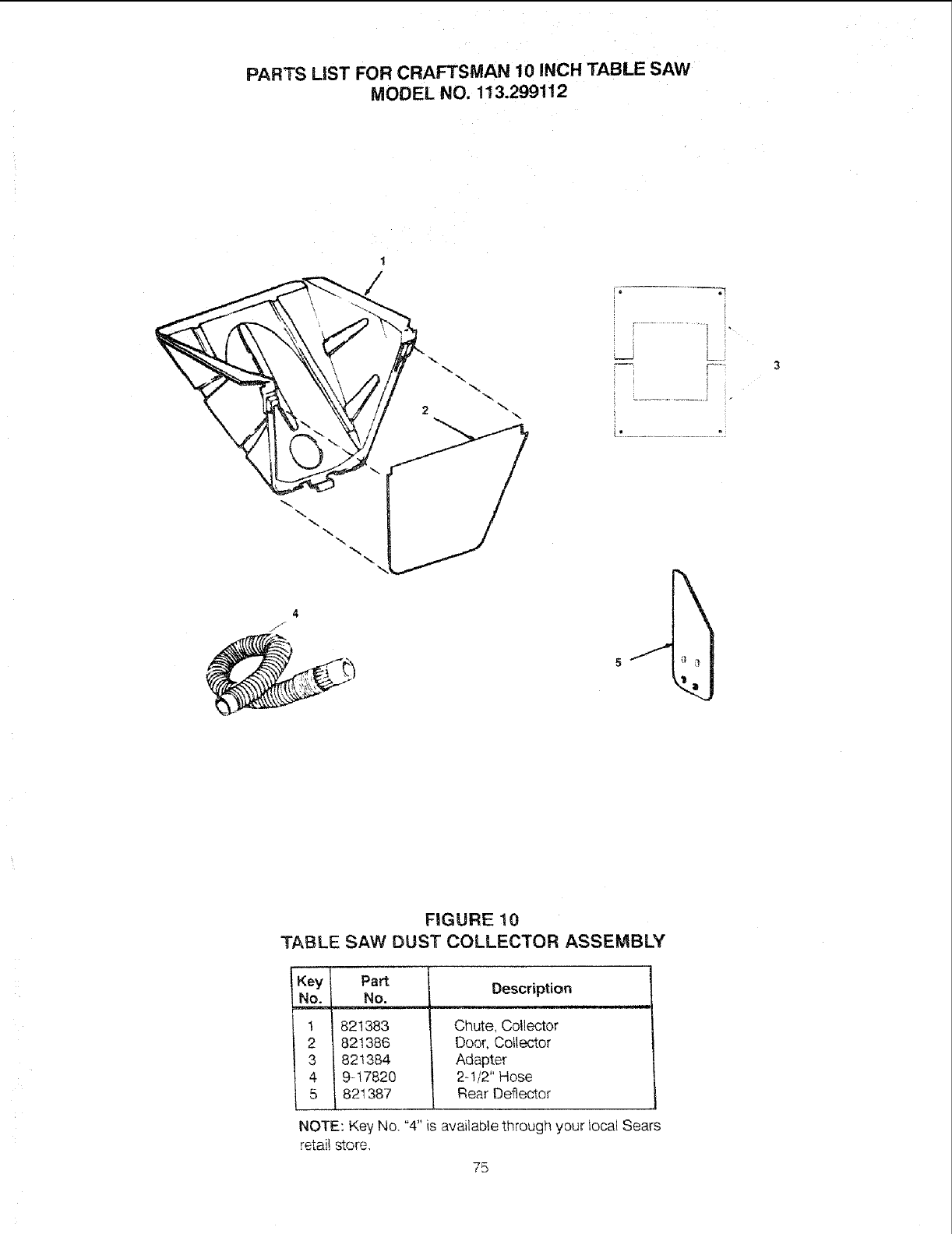
PARTS LiST FOR CRAFTSMAN 10 INCH TABLE SAW
MODEL NO. 113.299112
4
J
\
3
FIGURE 10
TABLE SAW DUST COLLECTOR ASSEMBLY
Part Description
No.
__ 821383
821386
821384
9--17820
821387
NOTE: Key No. "4" is available through your iocal Sears
retail store,
Chute, Collector
Door, Collector
Adapter
2-.1/2"Hose
Rear Deflector
75
f
HOW TO ORDER
REPAIR PARTS
The Model Number Of Your Table
Saw Is Found AtThe Right Hand
Side Of The Base.
When requesting service or
ordering parts, always provide
the following information.
•Product Type
oModel Number
oPart Number
•Part Description
For the repair or replacement parts you need
Call 7 am - 7 pro, 7 days a week
1-800-366-PART
(1-800-366-7278)
For in-home major brand repair service
Gall 24 hours a day, 7 days a week
t-800-4-REPAIR
(1-800-473-7247)
For the location of a
Sears Repair Service Center in your area
Call 24 hours a day, 7 days a week
1-800-488- t 222
For information on purchasing aSears
Maintenance Agreement or to inquire
about an existing Agreement
Gall 9 am - 5 pm, Monday-Saturday
1-8OO-827-6655
SEARS
America is Repair Specia fists
Part No. SP5802
SEARS,ROEBUCK AND CO., Hoffman Estates, IL 60179
Form No, SP5802-1 Printed in U.S.A, !/96
