Craftsman 113299315 User Manual 10 BELT DRIVE TABLE SAW Manuals And Guides L0907105
CRAFTSMAN Saw Table Manual L0907105 CRAFTSMAN Saw Table Owner's Manual, CRAFTSMAN Saw Table installation guides
User Manual: Craftsman 113299315 113299315 CRAFTSMAN 10 BELT DRIVE TABLE SAW - Manuals and Guides View the owners manual for your CRAFTSMAN 10 BELT DRIVE TABLE SAW #113299315. Home:Tool Parts:Craftsman Parts:Craftsman 10 BELT DRIVE TABLE SAW Manual
Open the PDF directly: View PDF ![]() .
.
Page Count: 60
Fr
Save This Manual
For Future Reference
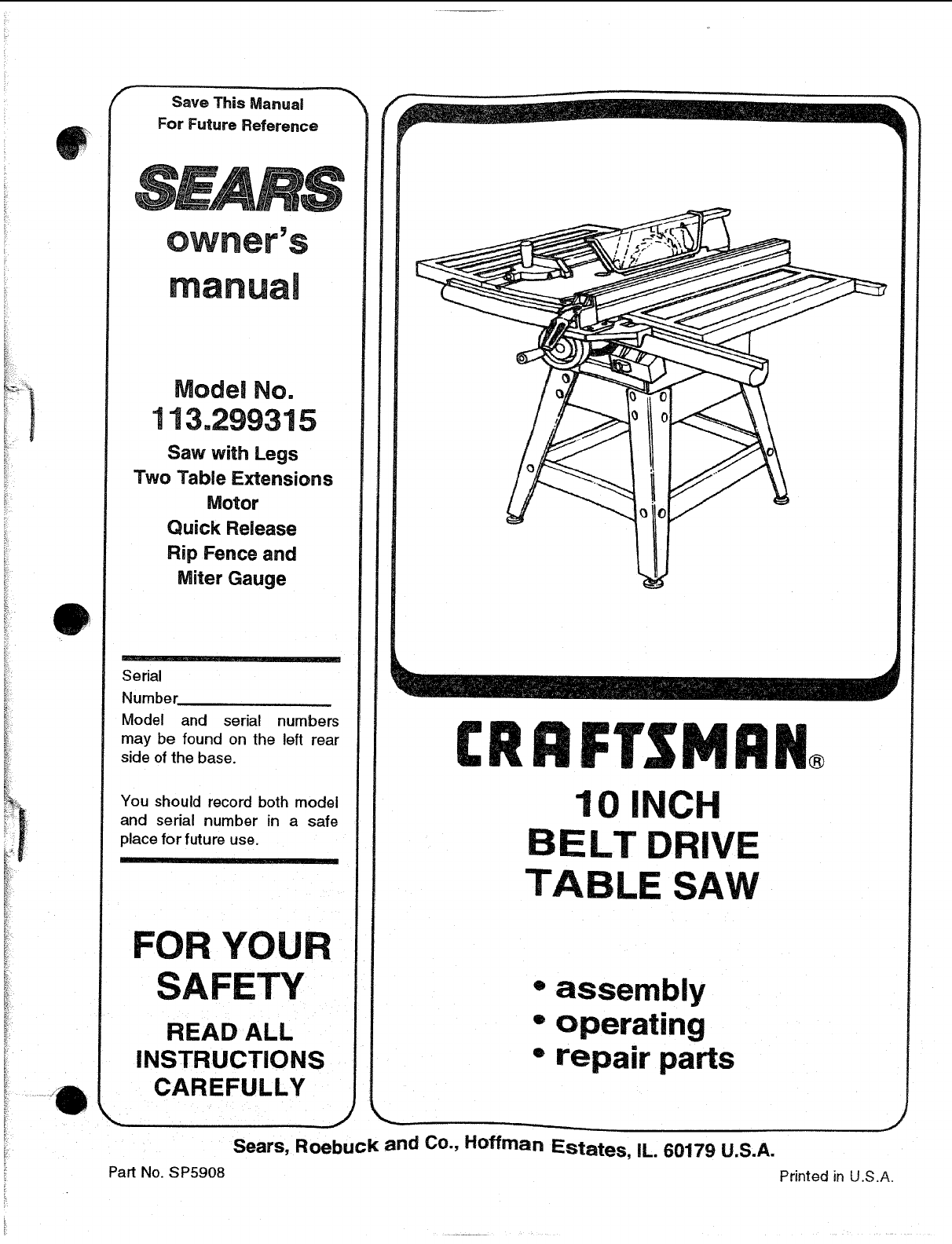
Model No.
113.299315
Saw with Legs
Two Table Extensions
Motor
Quick Release
Rip Fence and
Miter Gauge
Serial
Number
Model and serial numbers
may be found on the left rear
side of the base.
You should record both model
and serial number in a safe
place for future use.
m
FOR YOUR
SAFETY
READ ALL
INSTRUCTIONS
CAREFULLY
Part No. SP5908
10 INCH
BELT DRIVE
TABLE SAW
®
-assembly
°operating
°repair parts
Sears, Roebuck and Co., Hoffman Estates, IL. 60179 U.S.A.
J
Printed in U.S.A.
WARRANTY ON CRAFTSMAN STATIONARY TOOL
If this stationary tool fails due to adefect in material or workmanship within one year from the date
of purchase, CONTACT THE NEAREST SEARS SERVICE CENTER iN THE UNITED STATES and
Sears will repair it free of charge.
This warranty applies only while this product is in the UnReal States.
If this Table Saw is used for commercial or rental purposes, this warranty will apply for ninety days
from the date of purchase.
rhis warranty gives you specific legal rights, and you may also have other rights which vary from
state to state.
Sears, Roebuck and Co., !)/817 WA Hoffrnan Estates, IL. 60179
Safety Instructions For Table Saw ......
Safety is a combination of common sense, staying alert and knowing how your table saw works. Read this manual to
understand this table saw.
Safety Signal Words WARNING: means if the safety information is not followed
DANGER: means if the safety information is not followed someone could be seriously injured or killed.
someone will be seriously injured or killed. CAUTION: means if the safety information is not followed
someone may be injured.
iiu
Before Using The Saw
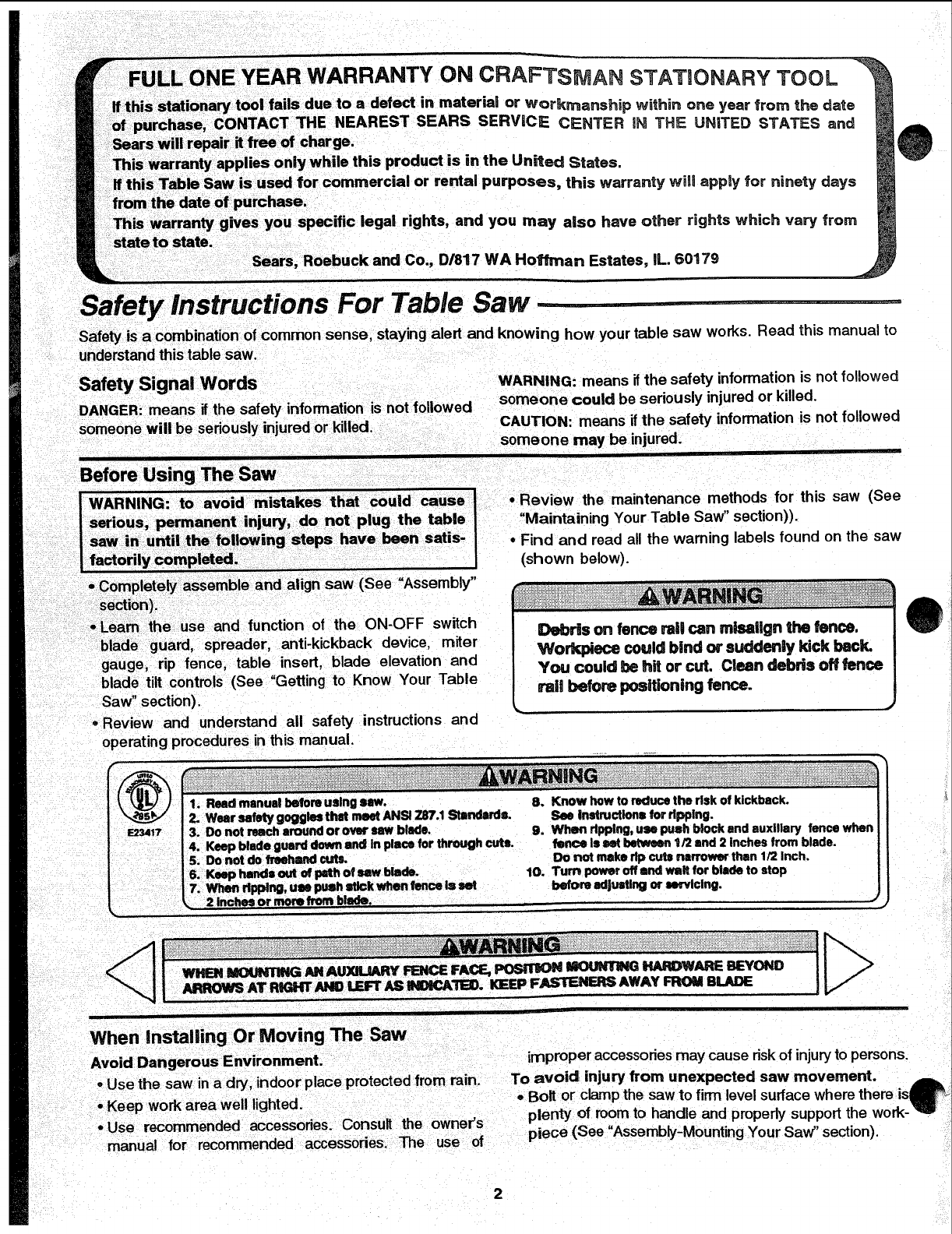
•Review the maintenance methods for this saw (See
"Maintaining Your Table Saw" section)).
°Find and read all the warning labels found on the saw
(shown below).
t ' "= I
Completely assemble and align saw (See Assembly
seCtion!).
i'Leam the use and function of the ON-OFF switch
blade guard, spreader, anti-kickback device, miter
gauge, rip fence, table insert, blade elevation and
blade tilt controls (See "Getting to Know Your Table
Saw" section).
-Review and understand all safety instructions and
operating procedures in this manual.
_1 1. Read manual before using saw. 8. Know how to reduce the risk of kickback.
I2. WearsafetygogglestilatmeetANSI7.87.1Stsndllrde. SeeInstructionsfordpplng.
E2_17 I 3. DO not reach around or oviw saw blade. 9. When ripping, use push block and auxiliary fence when
J4. Keap blade guard down end in place for through cuts. fence Is set belwean 1t2 lind 2inches from blado.
5. Do not do treehind cuts. Do not mike rip cuts narrower than 1/2 Inch.
I6. Keep hands out of path of saw blade. . 10. Turn power off and wait for blade to stop
17. _ripping, USe push stick when lence I= set before adJuMlng or all, Vicing.
_. , .2.inches or more from b!_. •
, ,,,
When Installing OrMoving The Saw
Avoid Dangerous Environment. improper accessoriesmay cause riskof injuryto persons.
-Usethe saw ina dry, indoor place protected from rain. To avoid injury from unexpected saw movement.
• Keep work area well lighted. - Bolt or clamp the saw to firm level surface where there is_
• Use recommended accessories. Consult the owner's plenty of room to handle and properly support the work-_
manual for recommended accessories. The use of piece (See "Assembly-Mounting Your Saw" section).
o
Before Each Use
Support the saw so the table is level and the saw does
not rock,
When using a table extension longer than 12" attached
to any side of the saw, bolt the saw to a stationary sur-
face or prop up the outer end of the extension from the
floor or bench top to keep the saw from tipping.
Put the saw where neither operator nor bystanders
must stand in line with the sawblade.
..... - .... w
= To avoid injury from electrical shock, make sure your
fingers do not touch the plug's metal prongs wlqen
plugging in or unplugging the saw.
Never Stand On Tool. Serious injury could occur if the
tool tips or you accidentally hit the cutting tool. Do not
store anything above or near the tool where anyone
might stand on the tool to reach them.
inspect your saw.
o To avoid injury from accidental starting, turn the switch
off, unplug the saw, and remove the switch key before
raising or removing the guard, changing the cutting
tool, changing the setup, or adjusting anything. Make
sure switch is in OFF position before plugging in.
Check for alignment of moving parts, binding of mov-
ing parts, breakage of parts, saw stability, and any
other conditions that may affect the way the saw
works.
If any part is missing, bent or broken in any way, or any
electrical part does not work properly, turn the saw off
and unplug the saw.
,I
To Avoid injury From Jams, Slips Or Thrown Pieces (Kickbacks Or Throwbacks)
oReplace damaged or missing parts before using the
saw again,
-Use the sawblade guard, spreader and anti-kickback
pawls for any thru-sawing (whenever the blade comes
through the top of the workpiece). Make sure the anti-
kickback pawls work properly. Make sure the spreader
is in line with sawblade (See "Assembly-Aligning Blade
Guard" section).
• Remove adjusting keys and wrenches. Form a habit of
checking for and removing keys and adjusting
wrenches from table top before turning saw on.
• Make sure all clamps and locks are tight and no parts
have excessive play.
Inspect Your Blade.
• Choose the right blade or cutting accessory for the
material and the type of cutting you plan to do.
•Use The Right Tool. Don't force tool or attachment to
do a job it was not designed for.
°Never use grinding wheels, abrasive cutoff wheels.
friction wheels (metal cutting blades) wire wheels or
buffing wheels. They can fly apart explosively.
•Cut only wood. wood like or plastic materials. Do not
cut metal.
•Choose and inspect your cutting tool carefully:
-To avoid cutting tool failure and thrown shrapnel
(broken pieces of blade), use only 10" or smaller
blades or other cutting tools marked for speeds of
5000 rpm or higher.
- Always use unbroken, balanced blades designed to
fit this saw's 5/8 inch arbor.
-When thru-sawing (making cuts where the blade
comes through the workpiece top), always use a 10
inch diameter blade. This keeps the spreader closest
to the blade.
- Do not over tighten arbor nut. Use arbor wrenches to
"snug" it securely.
- Use only sharp blades with properly set teeth. Con-
suit a professional blade sharpener when in doubt.
- Keep blades clean of gum and resin
- Never use the saw without the proper blade insert.
Inspect your work area.
• Keep work area clean.
•Cluttered areas and benches invite accidents. Floor
must not be slippery from wax or sawdust.
° To avoid burns or other fire damage, never use the
saw near flammable liquids, vapors or gases.
• To avoid injury, don't do layout assembly, or setup
work on the table while blade is spinning. It could cut
or throw anything hitting the blade.
Plan your work
•Use the right tool. Don't force tool or attachment to do
a job it was not designed for.
Inspect your workpiece.
•Make sure there are no nails or foreign objects in the
part of the workpiece to be cut.
• When cutting irregularly shaped workpieces, plan your
work so it will not slip and pinch the blade:
•A piece of molding for example, must lie flat or be held
by a fixture or jig that will not let it twist_ rock or slip
while being cut. Use jigs or fixtures where needed to
prevent workpiece from shifting.
• Use a different, better suited type of tool for work that
can't be made stable.
Plan your cut.
• To avoid kickbacks and throwbacks - when a part or all
of the workpiece binds on the blade and is thrown vio-
lently back toward the front of the saw:
- Never cut Freehand. Always use either a rip fence.
miter gauge or fixture to position and guide the work.
so it won't twist or bind on the blade and kick back.
- Make sure there's no debris between the workpiece
and its supports.
•Use extra caution with large, very small or awkward
workpieces.
3
Safety Instructions For Table
- Use extra supports (tables_ saw horses blocks, etc._
for any workpieces large enough to tip when not hold
down to the table top. Never use anolher person as a
substitute for atable extension, or as additional sup.
port for aworkpiece that Ls longer or wJder than the
basic saw table, or to help feed. support or pull the
werkpiece.
"Never confine the piece being cut off. that is the piece
not against the rip fence, miter gauge or fixture Never
Plan Ahead To Protect Your Eyes,---aanes, Face
Dress for safety
* Do no! wear loose c othing, gloves, neckties or jewelry
(rings wrist watches). -[hey can get caught and draw
you into moving parts.
- Wear nonslip footwear
- Tie back Ion.g hair.
o Roll tong sleeves above the elbow
-Noise levels vary widely. To avoid possible hearing
damage, wear ear plugs or muffs when using table
saw for hours at a time.
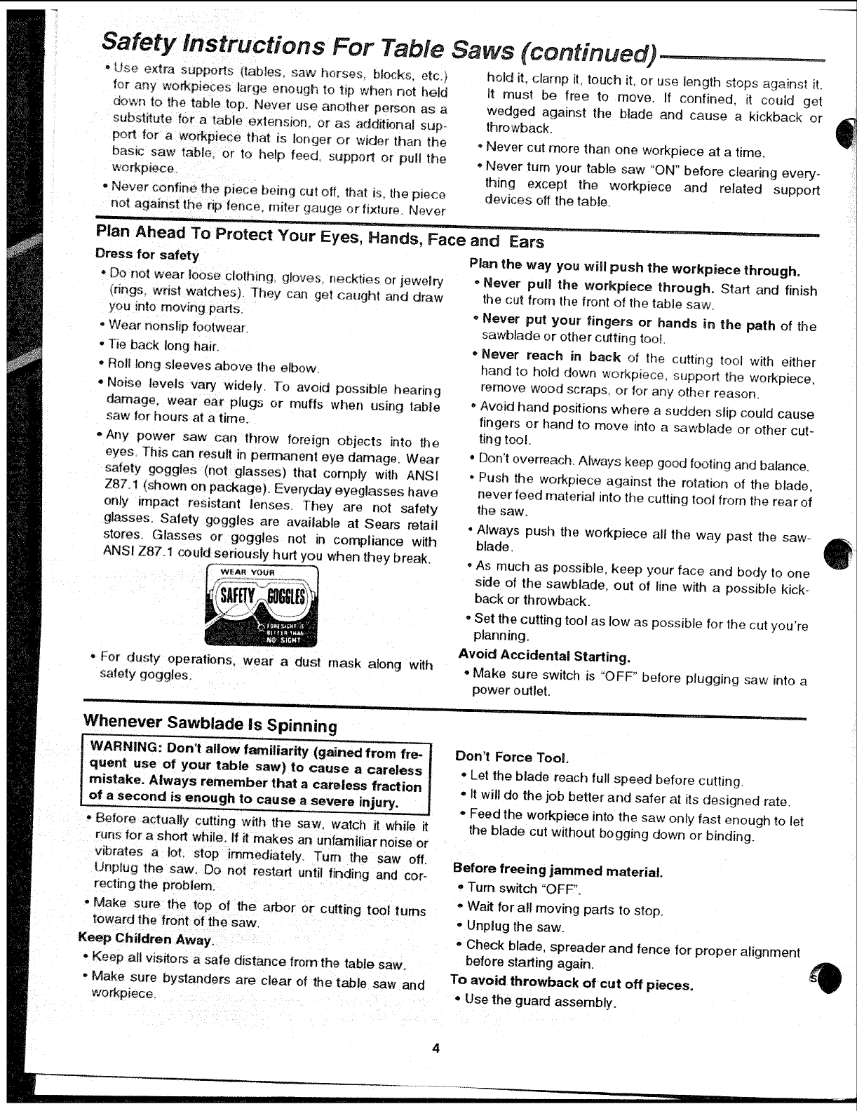
° Any power saw can throw foreign objects into the
eyes. ]"his can result in permanent eye damage. Wear
safety goggles (not glasses) that comply with ANSI
Z87 I (sl)own on package). Everyday eyeglasses have
only impact resistant lenses. They are not safety
glasses. Safety goggles are available at Sears retail
stores. Glasses or goggles not in compliance with
ANSI Z87.1 could seriously hurt you when they break.
WEAR YOUR
-For dusty operations, wear a dust mask along with
safety goggles
lu
Whenever Sawblade is Spinning
WARNING: Don't allow familiarity (gained from Ire- ]
cluent use of your table saw) to cause a careless/
mistake. Always remember that a careless fraction /
of a second is enough to cause a severe injury, /
° Before actually cutting with the saw, watch it while it
runs for a short while, if it makes an unfamiliar noise or
vibrates a IoL stop immediately. Turn the saw off,
Unplug the saw. Do nol restart until finding and cor-
recting the problem.
- Make sure the top of the arbor or cutting tool turns
toward the front of the saw.
Keep Children Away,
- Keep all visitors a safe distance from the table saw.
° Make sure bystanders are clear of the table saw and
workpJece.
Saws (continued) ...................
hold it. clamp it. touch it. or use length stops against it.
It must be free to move. If confined, it could get
wedged against the blade and cause a kickback or
throwback_
Never cut more than one workpiece at a time.
"Never turn your table saw "ON" before clearing every-
thing except the workpiece and related support
devices off the table,
and Ears
Plan the way you will push the workpiece through.
-Never pull the workpiece through. Start and finish
the cut from the front of the table saw.
-Never put your fingers or hands in the path of the
sawblade or other cutting tool
" Never reach in back of the cutting tool with either
hand to hold down workpiece, support the workpiece.
remove wood scraps, or for any other reason.
• Avoid hand positions where a sudden slip could cause
fingers or hand to move into a sawblade or other cut-
ting tool.
• Don't overreach. Always keep good footing and balance_
° Push the workpiece against the rotation el the blade.
never feed material into the cutting tool from the rear of
the saw.
• Always push the workpiece all the way past the saw-
blade.
• As much as possible, keep your face and body to one
side of the sawblade, out of line with a possible kick-
back or throwback.
• Set the cutting tool as low as possible for the cut you're
planning.
Avoid Accidental Starting.
° Make sure switch is "OFF" before plugging saw into a
power outlet.
Don't Force Tool.
- Let the blade reach full speed before cuthng.
° It will do the job better and safer at its designed rate.
= Feed the workpiece into the saw only fast enough to let
the blade cut without bogging down or binding.
Before freeing jammed material.
° Turn switch "OFF",
o Wait for all mowng parts to stop.
°Unplug the saw.
- Check blade, spreader and fence for proper alignment
before starting again,
To avoid throwback of cut off pieces.
• Use the guard assembly.
To remove Roose pieces beneath or trapped inside
the guard,
,, Turn saw "OFF".
,, Remove switch key.
,, Wait for blade to stop before _ifting the guard.
Before Leaving The Saw.
•Turn the saw off.
Wait for blade to stop spir_ning.
Unplug the saw.
o Make workshop child@roof, t.ock the shop. Disconnect
master switches_ Remove the yeliow switch key Store
it away from children and others not qualified to use
the tool.
...... i
Additional Safety _nstructions
Rip Type Cuts.
oNever use the miler gauge when ripping.
,, Use a push stick whenever the fence is 2 or more
inches from the blade.
o When thru-sawing, use an auxiliary fence and push
block whenever the fence must be between !/2 and 2
inches of the blade.
o Never thru-saw rip cuts narrower than 1/2 inch. (See
"Basic Saw Operations_Ripping and Beret Ripping"
sections.)
,, Never rip anything shorter than 10" long.
,, When using a push stick or push block, the trailing end
of the board must be square. A push stick or block
against an uneven end could slip off or push the work
away from the fence.
,, A Featherboard can help guide the workpiece. (see
"Basic Saw Operation-Using Featherboards for Thru.-
Sawing." section)
° Always use featherboards for any non thru rip type cuts.
(See "Basic Saw Operations - Using Featherboards for
Non-Thru Sawing" section,
Before Starting.
,, To avoid kickbacks and slips into the blade, make sure
the rip fence is parallel to the sawblade.
* Before thru-sawing, check the anti-kickback pawls,
The pawls must stop a kickback once it has started.
Replace or sharpen anti-kickback pawls when points
become dull. (See "Maintaining Your Table Saw - Anti-
Kickback Pawls" section o)
° Plastic and composition (like hardboard) materials may
be cut on your saw. However, since these are usually
quite hard and slippery, the anti-kickback pawls may
not stop a kickback. Therefore, be especially careful in
your setup and cutting procedures.
While Thru-sawing,
°To avoid kickbacks and slips into the blade, always
push forward on the section of the workpiece between
the sawblade and the rip fence. Never push forward on
the piece being cut off.
............... , , _ ......... Hi H H
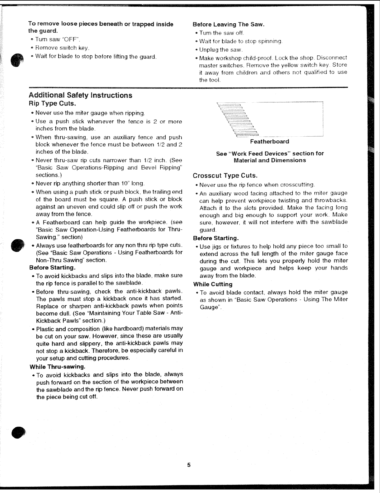
Featherboard
See "Work Feed Devices" section for
Material and Dimensions
Crosscut Type Cuts.
*Never use the rip fence when crosscutting.
*An auxiliary wood facing attached to the miter gauge
can help prevent workpiece twisting and throwbacks.
Attach it to the slots provided. Make the facing long
enough and big enough to support your work Make
sure, however, it will not interfere with the sawbiade
guard.
Before Starting.
.Use jigs or fixtures to help L_oidany piece too smali to
extend across the full length of the miter gauge face
during the cut. ]'his lets you properly hold the miter
gauge and workpiece and helps keep your hands
away from the blade:
While Cutting
, To avoid blade contact, always hold the miter gauge
as shown in "Basic Saw Operations -Using The Miter
Gauge'.
5
Glossary of Terms for Woodworking .............................
Anti-Kickback Pawls
Device which, when properly maintained, is designed to
stopthe workpiece from being thrown towards the front of
the saw at the operator during dpping operation.
Arbor
The shaft on which a cutting tool is mounted.
Bevel Cut
An angle cutting operation made through the face of the
workpiece.
Compound Cut
Asimultaneous bevel and miter crosscutting operation.
Crosscut
Acutting operation made across the width of the work-
piece.
Dado
A non thru cut which produces a square sided notch or
trough in the workpiece.
Featherboard
Adevice which can help guide workpieces during riptype
operation.
Freehand
Performing a cut without the use of fence (guide), miter
gauge, fixture, hold down or other proper device to pre-
vent the workpiece from twisting during the cutting opera-
tion. Twisting of the workpiece can cause it to be thrown.
Gum
Asticky, sap based residue from wood products.
Heel
Misalignment of the sawblade such that the blade is not
paraUelto the miter gauge groove.
Kerr
The amount of material removed by the blade in a
through cut or the slot produced by the blade in a non-
through or partial cut.
Kickback
An uncontrolled grabbing and throwing of the workpiece
back toward the front of the saw.
Leading End
The end of the workpiece which, during a rip type opera-
tion, is pushed intothe cutting tool first.
Miter Cut
An angle cutting operation made across the width of the
workpiece.
Molding
A non through cut which produces a special shape in the
workpiece used for joining or decoration.
PJoughing
Grooving with the grain the length of the workpiece, using
the fence. (P,type of non-through cut)
Push Stick
A device used to feed the workpiece through the saw
during narrow ripping type operations which helps keep
the operator's hands well away from the blade.
Push Block
Adevice used for ripping type operations too narrow to
allow use of a push stick.
Rabbet
A notch in the edge of a workpiece. (A type of non-
through cut)
Resin
A sticky, sap based substance that has hardened.
Revolutions Per Minute (RPM)
The number of turns completed by a spinning object in
one minute.
Rip Cut
A cutting operation along the length of the workpiece.
Sawblade Path
The area of the workpiece or tab le top directly in line with
either the travel of the blade or the part of the workpiece
which will be, or has been, cut by the blade.
Set
The distance that the tip of the sawblade tooth is bent (or
set) outward from the face of the blade.
Throw-Back
Throwing of pieces in a manner similar to a kickback.
Thru-Sawing
Any cutting operation where the blade extends com-
pletely through the thickness of the workpiece.
Trailing End
The workpiece end last cut by the blade in a ripping oper-
ation.
Workpiece
The item on which the cutting operation is being per-
formed. The surfaces of a workpiece are commonly
referred to as faces, ends, and edges.
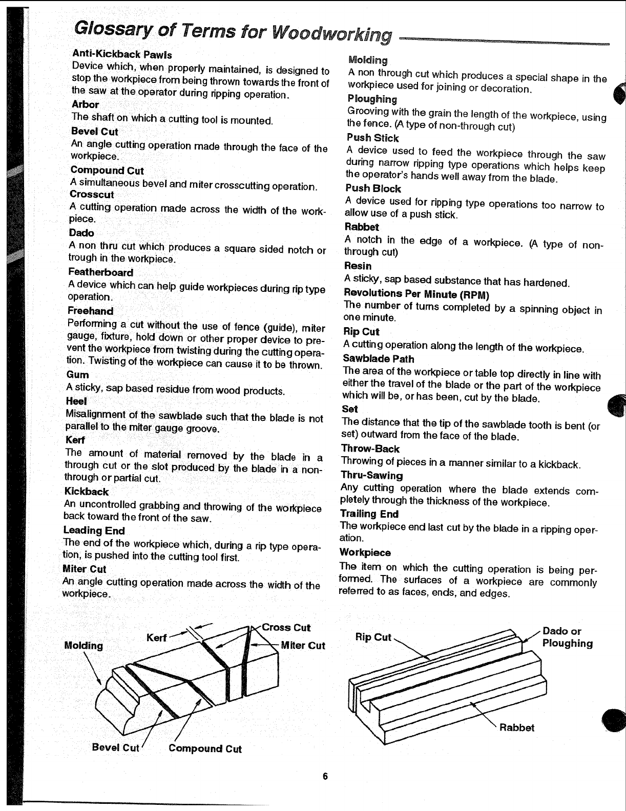
Molding
\
Cut
-Miter Cut Rip or
Ploughing
Bevel Cut /Compound Cut
Rabbet
i il;!ii
iiiii!!;!
Motor Specifications and Electrical Requirements
Power Suppny and Motor Specificatiens tions. It iswired at the factory for operation on 110-120v AC,
WARNING: To avoid electrical hazards, fire haz-
ards or damage to the tool, use proper circuit pro-
tection. Your tool is wired at the factory for
operation using the voltage shown. Connect tool
to a power line with the appropriate voltage and a
15-amp branch circuit. Use a 15-amp time delay
type fuse or circuit breaker. To avoid shock or fire,
if power cord is worn or cut, or damaged in any
way, have it replaced immediately.
The A-C motor used on thistool is a capacitorstart, capacI-
tor run non-reversibletype, having the foflowingspecifica-
60 Hz. service.
Rated H.P
Voltage
Amperes
Hertz (Cycles)
Phase
RPM
Rotation of Shaft
1-1/2
110-120
13
60
Single
3450
Clockwise
General Emectricai Connections
DANGER: To avoid electrocution:
1. Use only identical replacement parts when ser-
vicing. Servicing should be performed by a
qualified service technician.
2. De not use in rain or where floor is wet.
This tool is intended for indoor residential use
only.
WARNING: Do not permit fingers to touch the ter-
minals of plug when installing or removing the
plug to or from the outlet.
110-120 Volt, 60 Hz. Tool information
NOTE: The plug supplied on your tool may not fit into the
outlet you are planning to use. Your local electrical code
may require slightly different power cord plug connec-
If the grounding instructions are not completely under-
stood, or if you are in doubt as to whether the tool is prop-
erly grounded check with a qualified electrician or service
tions. If these differences exist refer to and make the
proper adjustments per your local code before your tool
is plugged in and turned on.
In the event of a malfunction or breakdown, grounding
provides apath of least resistance for electric current to
reduce the risk of electric shock. This tool is equipped
with an electric cord having an equipment-grounding con-
ductor and a grounding plug, as shown. The plug must
be plugged into amatching outlet that is properly
installed and grounded in accordance with all local codes
and ordinances.
Do not modify the plug provided. If it will notfit the outlet,
have the proper outlet installed by a qualified electrician.
Atemporary adapter may be used to connect this plug to
a2-prong outlet as shown if a properly grounded three
prong outlet is not available. This temporary adapter
should be used only until a properly grounded three
prong outlet can be installed by a qualified electrician.
The green colored rigid ear, lug or the like, extending
from the adapter must be connected to a permanent
ground such as a properly grounded outlet box.
Improper connection of the equipment-grounding con-
ductor can result in a risk of electric shock. The conduc-
tor with insulation having an outer surface that is green
with or without yellow stripes is the equipment-grounding
conductor. If repair or replacement of the electric cord or
plug is necessary, do not connect the equipment-ground-
ing conductor to alive terminal.
)ersonnei,
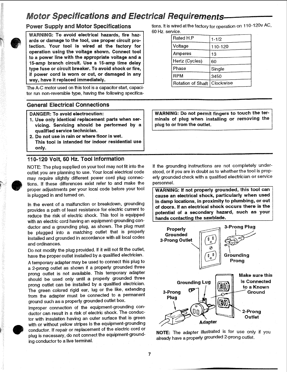
WARNING: ff not properly grounded, this tool can
cause an electrical shock, particularly when used
in damp locations, in proximity to plumbing, or out
of doors, if an electrical shock occurs there is the
potential of a secondary hazard, such as your
hands contacting the sawblade.
Properly _3-ProngPlu¢__
Grounded
3-Prong Outlet
Gr;Uonndgg
Grounding Lug /_--_-_
Adapter _" 2"oPur;:?
NOTE: The adapter illustrated is for use only if you
already have a properly grounded 2-prong outlet.
Make sure this
is Connected
to a Known
Ground
Motor Specifications and Electrical Requirements (continued)
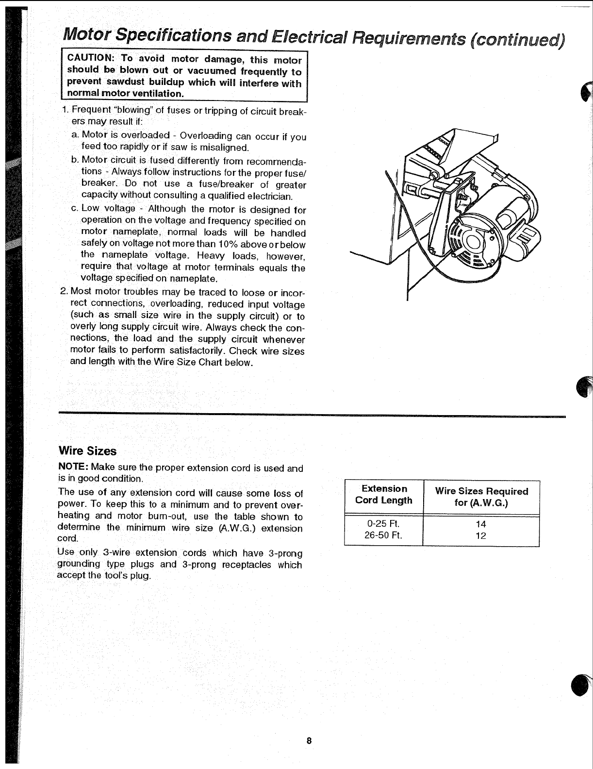
CAUTION: To avoid motor damage, this motor
should be blown out or vacuumed frequently to
prevent sawdust buildup which will interfere with
normal motor ventilation.
1. Frequent "blowing" of fuses or tripping of circuit break-
ers may result if:
a. Motor is overloaded - Overloading can occur if you
feed too rapidly or if saw is misaligned.
b, Motor circuit is fused differently from recommenda-
tions - Always follow instructions for the proper fuse/
breaker. Do not use a fuse/breaker of greater
capacity without consulting a qualified electrician.
c. Low voltage - Although the motor is designed for
operation on the voltage and frequency specified on
motor nameplate, normal loads will be handled
safely on voltage not more than 10% above o r below
the nameplate voltage. Heavy loads, however.
require that voltage at motor terminals equals the
voltage specified on nameplate.
2. Most motor troubles may be traced to loose or incor-
rect connections, overloading, reduced input voltage
(such as small size wire in the supply circuit) or to
overly long supply circuit wire. Always check the con-
nections, the load and the supply circuit whenever
motor fails to perform satisfactorily. Check wire sizes
and length with the Wire Size Chart below.
Wire Sizes
NOTE: Make sure the proper extension cord is used and
is in good condition.
The use of any extension cord will cause some loss of
power. To keep this to a minimum and to prevent over-
heating and motor burn-out, use the table shown to
determine the minimum wire size (A.W.G.) extension
cord.
Use only 3-wire extension cords which have 3-prong
grounding type plugs and 3-prong receptacles which
accept the tool's plug.
Extension Wire Sizes Required
Cord Length for (A.W.G.)
0-25 Ft. 14
26-50 Ft. 12
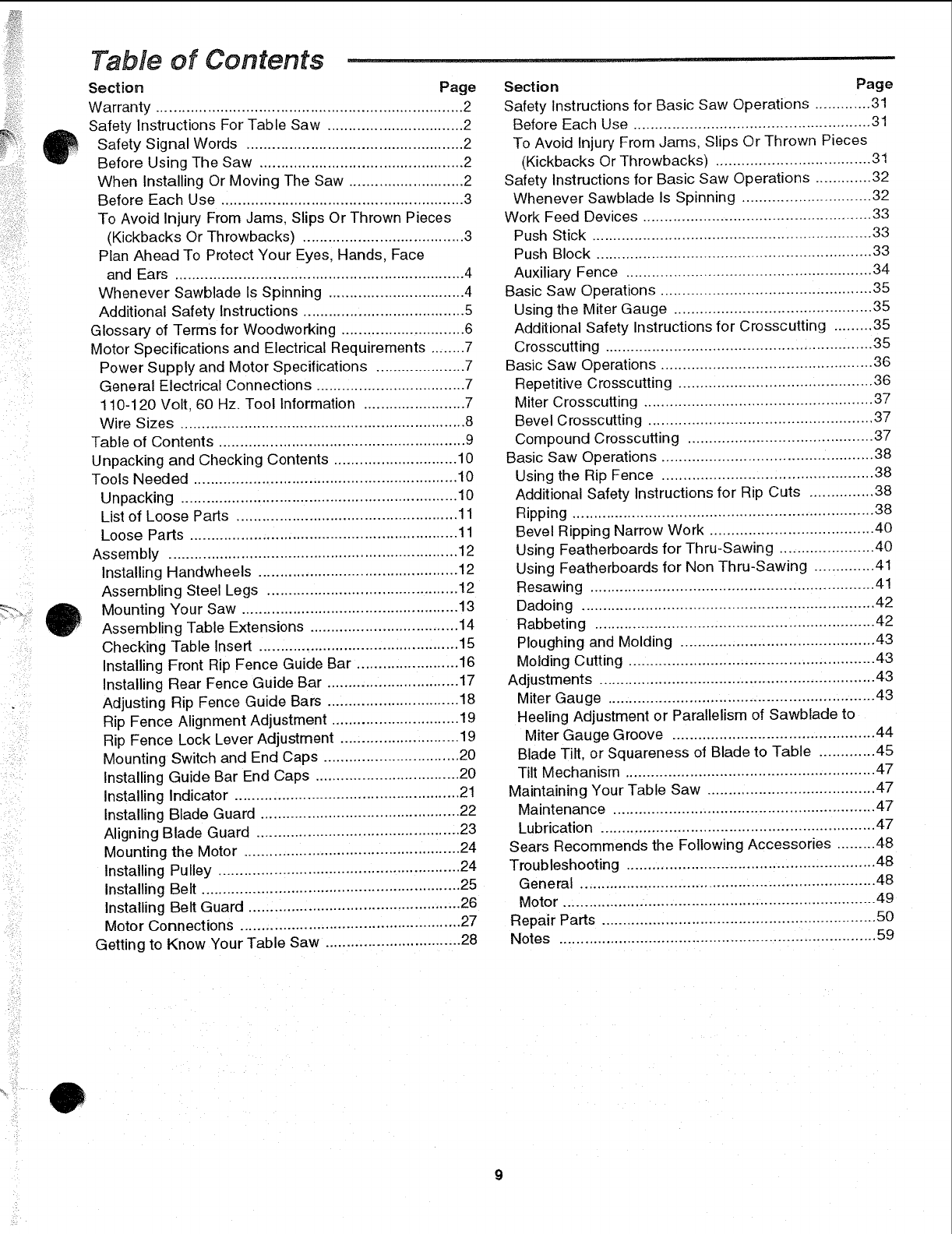
Table of Contents ............
Section Page
Warranty ........................................................................ 2
Safety Instructions For Table Saw ................................ 2
Safety Signal Words ................................................... 2
Before Using The Saw ................................................ 2
When Installing Or Moving The Saw ........................... 2
Before Each Use ......................................................... 3
To Avoid Injury From Jams. Slips Or Thrown Pieces
(Kickbacks Or Throwbacks) ...................................... 3
Plan Ahead To Protect Your Eyes, Hands, Face
and Ears ................................................................... 4
Whenever Sawblade Is Spinning ................................ 4
Additional Safety Instructions ...................................... 5
Glossary of Terms for Woodworking ............................. 6
Motor Specifications and Electrical Requirements ........7
Power Supply and Motor Specifications ..................... 7
General Electrical Connections ................................... 7
1t0-120 Volt, 60 Hz. Tool Information ........................ 7
Wire Sizes ................................................................... 8
Table of Contents .......................................................... 9
Unpacking and Checking Contents ............................ 10
Tools Needed .............................................................. 10
Unpacking ................................................................ 10
List of Loose Parts .................................................... 11
Loose Parts ............................................................... 11
Assembly .................................................................... 12
Installing Handwheels ............................................... 12
Assembling Steel Legs ............................................. 12
Mounting Your Saw ................................................... 13
Assembling Table Extensions ................................... 14
Checking Table Insert ............................................... 15
Installing Front Rip Fence Guide Bar ........................ 16
Installing Rear Fence Guide Bar ............................... 17
Adjusting Rip Fence Guide Bars ............................... 18
Rip Fence Alignment Adjustment .............................. 19
Rip Fence Lock Lever Adjustment ............................ 19
Mounting Switch and End Caps ................................ 20
Installing Guide Bar End Caps ................................. 20
Installing Indicator ..................................................... 21
Installing Blade Guard .............................................. 22
Aligning Blade Guard ................................................ 23
24
Mounting the Motor ...................................................
Installing Pulley ......................................................... 24
Installing Belt ............................................................. 25
Installing Belt Guard .................................................. 26
Motor Connections .................................................... 27
Getting to Know Your Table Saw ................................ 28
Section Page
Safety Instructionsfor Basic Saw Operations ............. 31
Before Each Use ....................................................... 31
To Avoid Injury From Jams, Slips Or Thrown Pieces
(Kickbacks Or Throwbacks) .................................... 31
Safety Instructions for Basic Saw Operations ............. 32
Whenever Sawblade Is Spinning ............................. 32
Work Feed Devices ..................................................... 33
Push Stick ................................................................. 33
Push Block ............................................................... 33
Auxiliary Fence ........................................................ 34
Basic Saw Operations ................................................. 35
Using the Miter Gauge .............................................. 35
Additional Safety Instructions for Crosscutting ......... 35
Crosscutting .............................................................. 35
Basic Saw Operations ................................................. 36
Repetitive Crosscutting ............................................. 36
Miter Crosscutting ..................................................... 37
Bevel Crosscutting .................................................... 37
Compound Crosscutting ........................................... 37
Basic Saw Operations ................................................. 38
Using the Rip Fence ................................................. 38
Additional Safety Instructions for Rip Cuts .............. 38
Ripping ...................................................................... 38
Bevel Ripping Narrow Work ...................................... 40
Using Featherboards for Thru-Sawing ...................... 40
Using Featherboards for Non Thru-Sawing .............. 41
Resawing .................................................................. 41
Dadoing .................................................................... 42
Rabbeting ................................................................. 42
Ploughing and Molding ............................................. 43
Molding Cutting ......................................................... 43
Adjustments ................................................................ 43
Miter Gauge .............................................................. 43
Heeling Adjustment or Parallelism of Sawblade to
Miter Gauge Groove ............................................... 44
Blade Tilt, or Squareness of Blade to Table ............. 45
Tilt Mechanism .......................................................... 47
Maintaining Your Table Saw ....................................... 47
Maintenance ............................................................. 47
Lubrication ................................................................ 47
Sears Recommends the Following Accessories ......... 48
Troubleshooting .......................................................... 48
General .................................................................... 48
Motor ......................................................................... 49
Repair Parts ................................................................ ,50
59
Notes ..........................................................................
cki"rigand Oh "
ecking Contents ......................
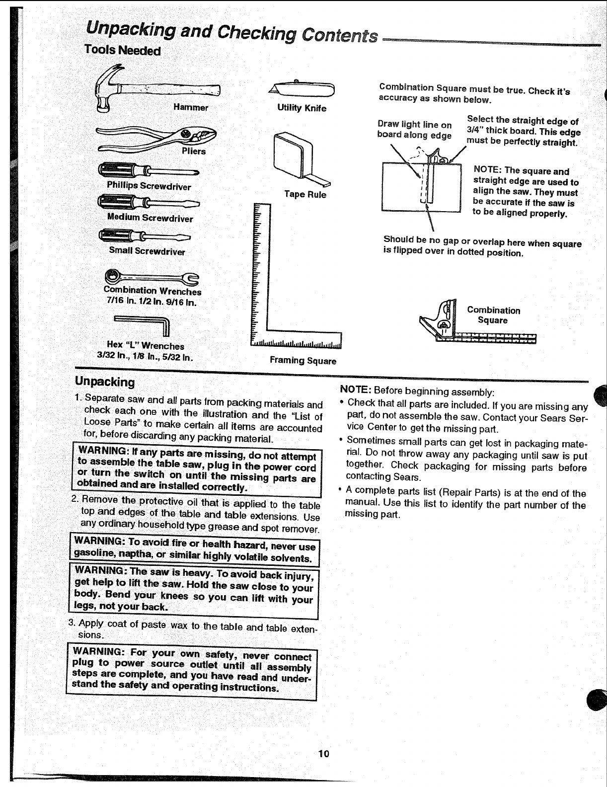
Tools Needed
Combination Square must be true. Check it'saccuracy as shown below.
Utility Knife
Select the straightedge of
Draw fight line on 314"thick board. This edge
board along edge must be perfectly straight.
PIiers
PhillipsScrewdriver
MediumScrewdriver
Small Screwdriver
CombinationWrenches
7/16 In. 1/2 In. 9/16 In.
Tape Rule
Hex "L" Wrenches
3/32 In., 1/8 in., 5/32 In.
r
J
U
NOTE: The square and
straight edge are used to
align the saw. They must
be accurate if the saw is
to be aligned properly.
Should be no gap or overlap here when square
is flipped over in dotted position.
"Jlll'tllJ,'lll,t*l|,*ll|,,llJ,=lll,llfJ,ljll
Framing Square
Combination
Square
_: i',_'. :"' ..........
Unpacking
1_Separate saw and all parts from packing materials and
check each one with the illustration and the "List of
Loose Pads" to make certain all items are accounted
for, before discarding any packing material,
j-WARNING: ff any parts are missing, do not attempt J
i to assemble the table saw, plug in the power cord
or turn the switch on until the missing parts are I
_btained and are installed correctly. J
NOTE: Before beginning assembly:
°Check that all parts are included. If you are missing any
part, do not assemble the saw. Contact your Sears Ser-
vice Center to get the missing part.
•Sometimes small parts can get lost in packaging mate-
rial. Do not throw away any packaging until saw is put
together. Check packaging for missing parts before
contacting Sears.
•A complete parts list (Repair Pads) is at the end of the
manual. Use this list to identify the part number of the
missing part,
4
3, Apply coat of paste wax to the table and table exten-
sions.
10
I
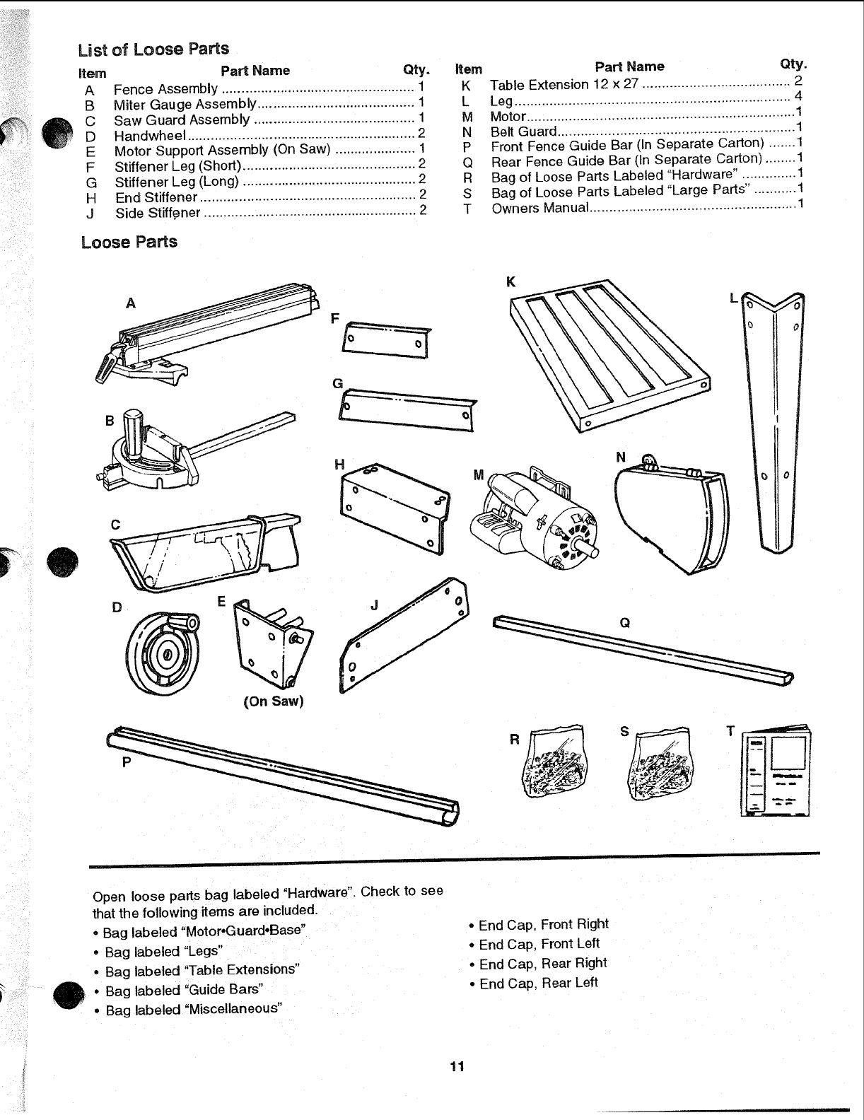
List of Loose Parts
item Part Name Qty.
A Fence Assembly .................................................. 1
B Miter Gauge Assembly ......................................... 1
C Saw Guard Assembly .......................................... 1
D Han dwheel ........................................................... 2
E Motor Support Assembly (On Saw) ..................... 1
F Stiffener Leg (Short) ............................................. 2
G Stiffener Leg (Long) ............................................. 2
H End Stiffener ....................................................... 2
J Side Stiffener ....................................................... 2
Loose Pa_s
item
K
L
M
N
P
Q
R
S
T
Part Name Qty.
Table Extension 12 x 27 ...................................... 2
Leg ....................................................................... 4
Motor ..................................................................... 1
Belt Guard ............................................................ 1
Front Fence Guide Bar (In Separate Carton) ....... 1
Rear Fence Guide Bar (In Separate Carton) .........
Bag of Loose Parts Labeled "Hardware". ............. 1
Bag of Loose Parts Labeled "Large Parts. .......... 1
Owners Manual ..................................................... 1
C
AKL
G
H
(On Saw)
P
Open loose parts bag labeled "Hardware". Check to see
that the following items are included.
* Bag labeled "Motor*Guard.Base"
oBag labeled "Legs"
*Bag labeled "Table Extensions"
- Bag labeled "Guide Bars"
- Bag labeled "Miscellaneous"
• End Cap, Front Right
• End Cap, Front Left
•End Cap, Rear Right
• End Cap, Rear Left
11
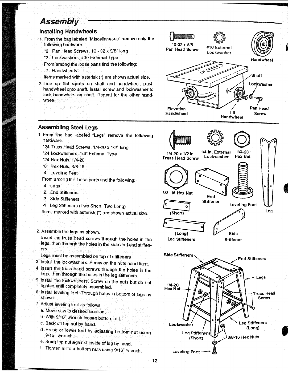
Assembly
installing Handwheeis
1. From the bag labeled "Miscellaneous" remove only the 10-32 x 5/8
following hardware: Pan Head Screw
*2 Pan Head Screws. 10 - 32 x 5/8" long
"2 Lockwashers. #10 External Type
From among the loose parts find the following:
2 Handwheels
Items marked with astedsk (*) are shown actual size.
2 Line up flat spots on shaft and handwheel, push
handwheel onto shaft. Install screw and Iockwasher to
lock handwheei on shaft. Repeat for the other hand-
wheel.
#10 External
Lockwasher
Elevation
Handwhee! Tilt
Handwheel
Pan Head
Screw
Handwheel
Assembling Steel Legs
1. From the bag labeled "Legs" remove the following
hardware:
*24 Truss Head Screws. 1/4-20 x 1/2" long
*24 Lockwashers. 1/4" Extemal Type
"24 Hex Nuts, 1/4-20
"8 Hex Nuts, 3/8-16
4 Leveling Feet
From among the loose parts find the following:
4 Legs
2 End Stiffeners
2 Side Stiffeners
4 Leg Stiffeners (Two Short. Two Long)
Items marked with asterisk (*) are shown actual size.
2. Assemble the legs as shown.
Insert the truss head screws through the holes in the
legs. then through the holes in the side arid end stiffen-
ers,
Legs must be assembled on top of stiffeners
3. Install the tockwashers. Screw on the nuts hand tight.
4. Insert the truss head screws through the holes in the
legs, then through the holes in the leg stiffeners.
5Install the lockwashers. Screw on the nuts but do not
tighten until completely assembled.
6_Install leveling feet. Through holes in bottom of legs as
showR ;
7. Adjust leveling feet as follows:
a. Move saw to desired location.
b. With 9/16" wrench loosen bottom nut.
c. Back off top nut by hand.
d. Raise or lower foot by adjusting bottom nut using
9/16" wrench_
e. Snug top nut against inside of leg by hand.
!. Tighten atltour bottom nuts using 9/16" wrench.
1/4 In. External
114-20 x112 In. Lockwasher
Truss Head Screw
Q
318-16 Hex Nut End
Stiffener
©
1/4-20
Hex Nut
0
Leveling Foot I
(Short) _Leg
(Long)
Leg Stiffeners Stiffener
i
Side Stiffeners _Stiffeners
ILegs
114-2o I!1 _ti ,_ i.,.,=..li \\ 'i
Lockwa_/ /'_- _ -_t! ". LegS_ffeners
,..:..r../il , oo0> |
Leg Stiffeners| I'F \ ............
-(Short) _/i318-16 Hex NlXls
Leveling Foot ---'-_
12
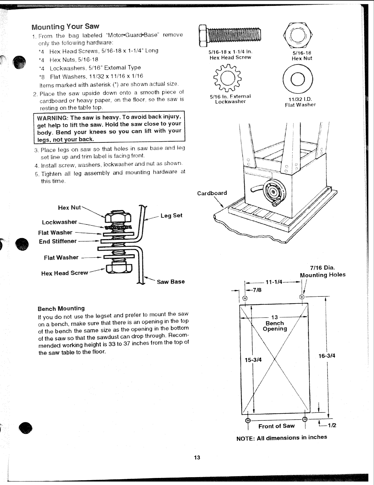
Mounting Your Saw
I. From the bag !abe_ed "Motor,_'3uard-Base" remove
only the lotlowing hardware:
_4 Hex He;_d Screws, 5/16-18 x 1-!/4" Lor_g
*4 He× Nuts, 5/!6-18
*4 Lockwashers. 5/16" External Type
_8 Flat Washers, 11/32 x 11/16 x 1/! 6
Items marked with asterisk (*) are si_own actual size.
2. Place the saw upside down onto a smooth piece ol
cardbo_rd or heavy paper, on the floor, so the saw is
resting on the table top.
5/i6-18 x !-,1/4 _n. 5/16-18
Hex Head Screw Hex Nut
5/16 in.External
Lockwasher 1!/32 I.D.
Ftat Washer
WARNING: The saw is heavy. To avoid back injury,
get help to lift the saw. Hoid the saw cQose to your
body. Bend your knees so you can lifl with your
I._egs, not your back.
3. Place _egs on saw so that ho_es in saw base and leg
set line up and trim Iabet is facing front.
4. Install screw, washers, lockwasher and nut as showr_.
5. Tighten aH _eg assembly and mounting hardware at
this time.
Rex
Lockvvasher
Fiat Washer
End Stiffener ._---.-
Flat Washer
Leg Set
Cardboard
Hex Head Screw
Saw Base
Bench Mounting
If you do not use the legset and prefer to mount the saw
on a bench, make sure that there is an opening in the top
of the bench the same size as the opening in the bottom
of the saw so that the sawdust can drop through. Recom-
mended working height is 33 to 37 inches from the top of
the saw table to the floor.
7/16 Din.
Mounting Holes
G) ®
I/
Bench
Opening
15-3/4
I
I
IFront of Saw
16-3!4
NOTE: All dimensions in inches
13
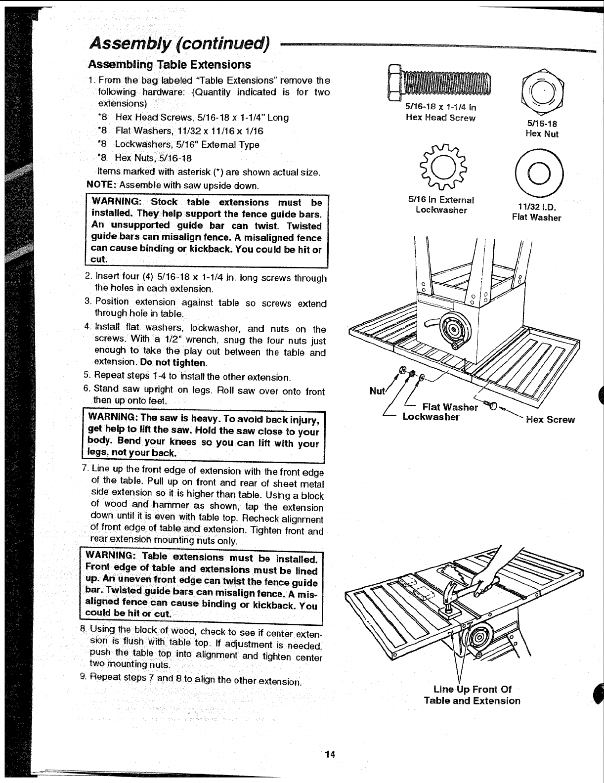
Assembly (continued)
Assernbiing Table Extensions
1. From the bag labeled "Table Extensions" remove the
following hardware: (Quantity indicated is for two
extensions/
"8 Hex Head Screws, 5/16-18 x 1-1/4" Long
*8 Flat Washers, 11/32x 11/16x 1/16
*8 Lockwashers, 5/16" ExternalType
"8 Hex Nuts, 5/16-18
items marked withasterisk (*) are shown actual size.
NOTE: Assemble with saw upside down.
WARNING: Stock table extensions must be
installed. They help support the fence guide bars,
An unsupported guide bar can twist. Twisted
guide bars can misalign fence. A rnisaligned fence
can cause binding or kickback. You could be hit or
cut.
5/16-18 x 1-114 in
Hex Head Screw 5116-18
Hex Nut
5/16 in ExternaJ
Lockwasher 11132i.D.
Fiat Washer
/
2. Insert four (4) 5/16-18 x 1-1/4 in. long screws through
the holes in each extension.
3. Position extension against table so screws extend
through hole in table.
4. Install flat washers, Iockwasher, and nuts on the
screws. With a1/2" wrench, snug the four nuts just
enough to take the play out between the table and
extension. Do not tighten.
5. Repeat steps 1-4 to installthe other extension.
6. Stand saw upright on legs. Roll saw over onto front
then up onto feet.
-WARNING: The saw is heavy. To avoid back injury,
get help to lift the saw. Hold the saw close to your
body. Bend your knees so you can lift with your
legs, not your back.
7. Line up the front edge of extension with the front edge
of the table. Pull up on front and rear of sheet metal
side extension so it is higher than table. Using a block
of wood and hammer as shown, tap the extension
down until it is even with table top. Recheck alignment
of front edge of table and extension. Tighten front and
rear extension mounting nutsonly,
WARNING: Table extensions must be installed.
Front edge of table and extensions must be lined
bar. Twisted guide bars can misalign fence. A mis-
aligned fence can cause binding or kickback. You
could be hit or cut.
8. Using the block of wood, check to see if center exten-
sion is flush with table top. If adjustment is needed,
push the table top into alignment and tighten center
two mounting nuts.
9. Repeat steps 7 and 8 to align the other extension.
<..
Flat Washer
Lockwasher Hex Screw
Line Up Front Of
Table and Extension
14
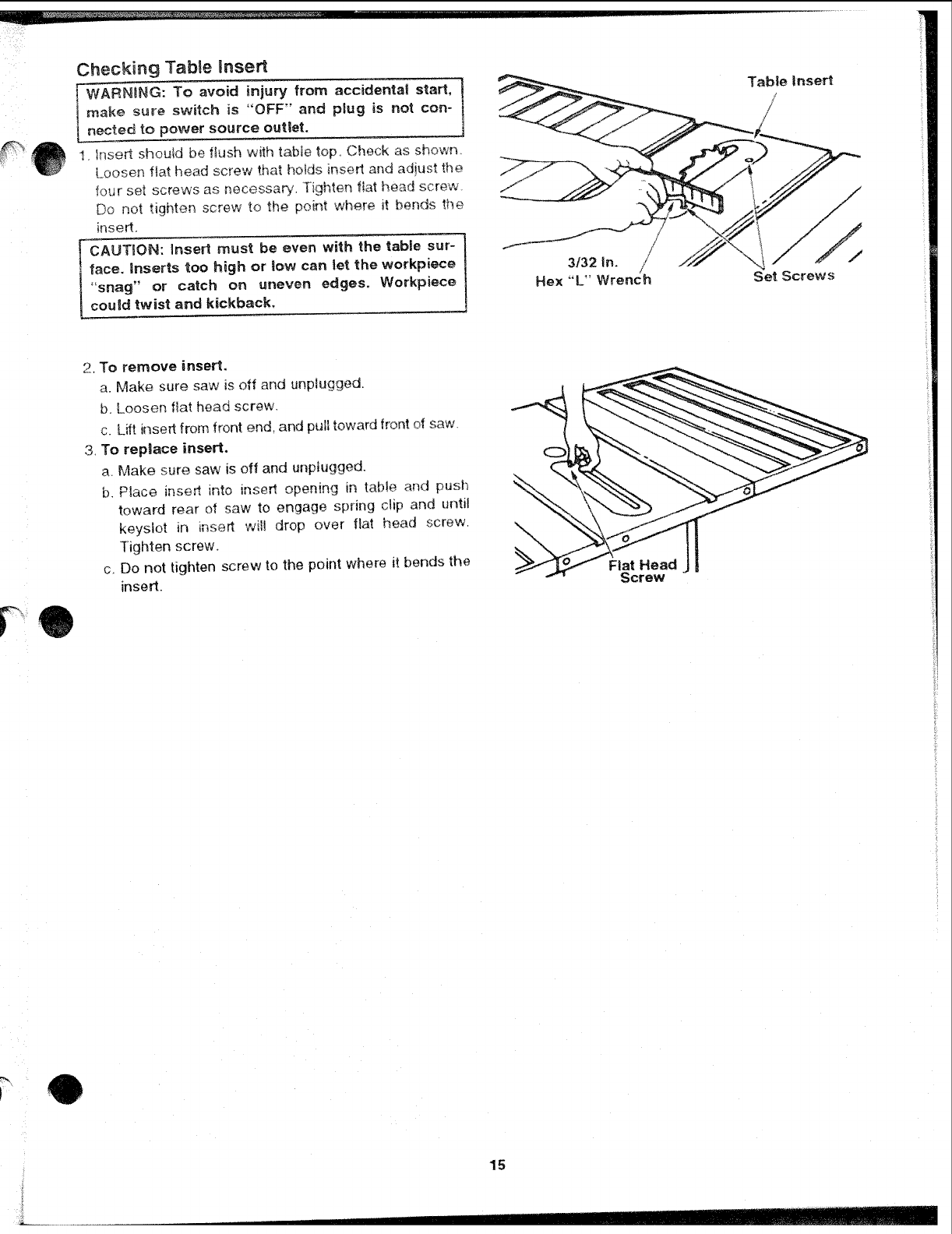
Checking TabBe Rnsert
l WARNBNG: To avoid injury from accidental start, t
make ,sure switch is "OFF" and plug is not con- }
nected to power source outlet.
1. Insert should be flush with tabie top, Check as shown.
Loosen flat head screw that holds insert and adjust the
four set screws as necessary, Tighten fiat head screw,
Do not tighten screw to the point where it bends the
insert,
CAUTION: insert must be even with the tabBe sur-
face. Unserts too high or tow can let the workpiece
"snag" or catch on uneven edges. Workpiece
could twist and kickback,
3/32 in.
Hex "L" Wrench
/
Set Screws
2, To remove insert,
a. Make sure saw is off and unplugged,
b, Loosen fiat head screw,
c. Lift insert from front end, and pull toward front of saw_
3, To repUaee insert.
a. Make sure saw is off and unpk_gged.
b. Place insert into insert opening in table and push
toward rear of saw to engage spring clip and until
keyslot in insert wil! drop over flat head screw,
Tighten screw,
c. Do not tighten screw to the point where it bends the
insert. Fiat Head
Screw
J15
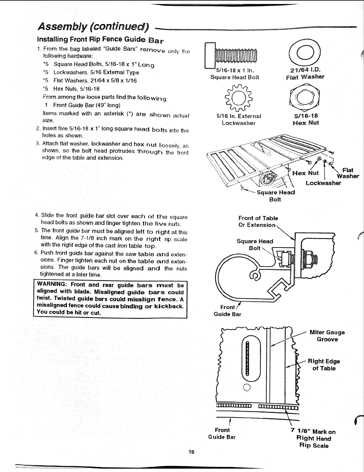
Assembly (continued)
lnstafling Front Rip Fence Guide Bar
1_ From the bag labeled "Guide Bars" remove on_y _h_
following hardware:
"5 Square Head Bolts. 5/16-18 × 1" Long
*5 Lockwashers, 5/16 Externat Type
"5 Fiat Washers. 21/64 × 5/8 x 1/16
°5 Hex Nuts, 5/16-18
From among the loose parts find the folio wir_g
1 Front Guide Bar (49" long)
items marked with an asterisk (*) are Shown aclua_
size.
2_ Inset1 five 5/16-18 x1" long square head bolts Into the
holes as shown
3. Attach flat washer, Iockwasher and hex nul loose_y, as;
shown so the bolt head protrudes through the front
edge of the table and extension.
21/64 i.D.
F_at Washer
5/!6-18
Hex Nut
.... Square Head
Boff
4 Slide the front guide bar slot over' each of the square
head bolts as shown and finger tighten the five nt_s
5. The front guide bar must be aligned left to right a_ this
time. Align the 7-1/8 inch mark on the r]gh! np scale
with the right edge of the cast iron table top.
Push front guide bar against the saw table and e×ten.,.
sions. Finger tighten each nut on the table and exten-
sions The guide bars will be aligned and the nuts
tightened at alater time.
_nt and rear guide bars must be
Ialigned with blade. Misaligned guide bars could
ItW_w;stedg=;ide bars could misa|ign fence. A
tmisaligned fence could cause binding or kickback.
oro,,. Guide Bar
Front of Table
Or Ext
Square Head
Bolt \
!6
'Miter Gauge
Groove
iRight Edge
of Table
Front 7118" Mark on
Guide Bar Right Hand
Rip Scale
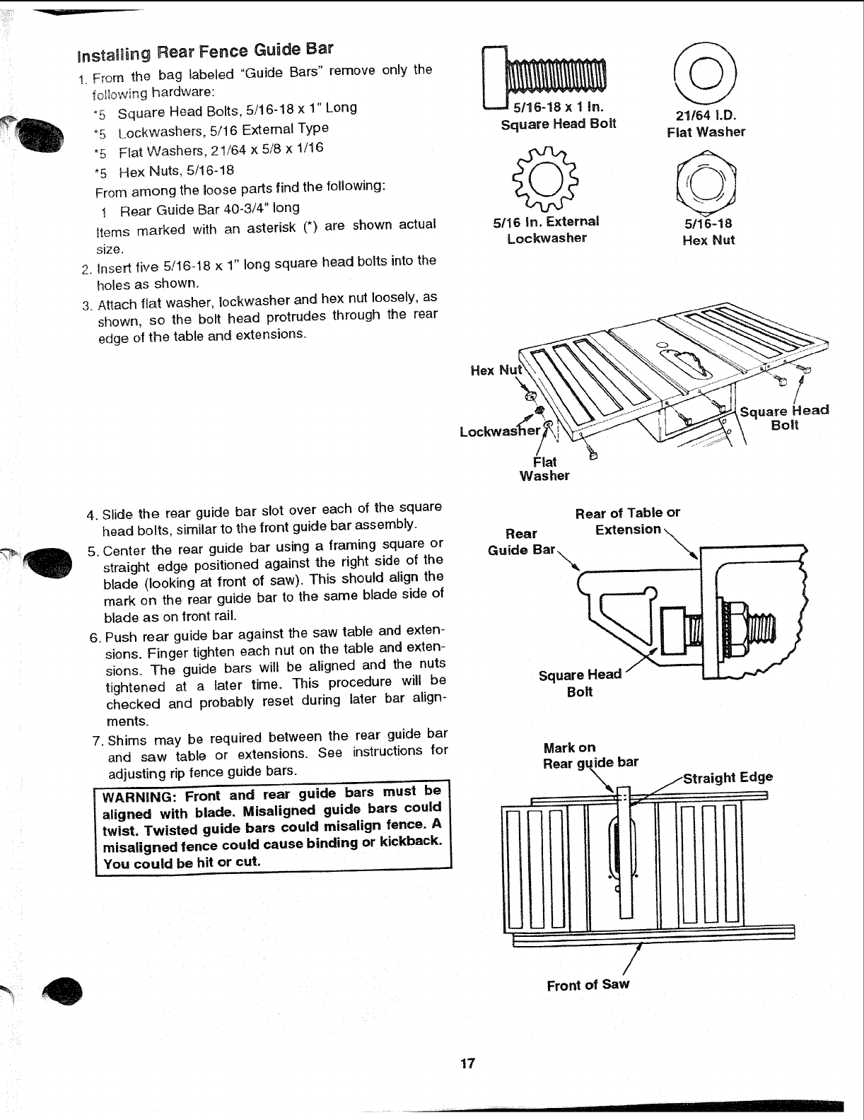
instaW_ing Rear Fence Guide Bar
1. F_om the bag labeled "Guide Bars" remove only the
following hardware:
_5 Square Head Bolts, 5/16-18 x 1" Long
*5 Lockwashers, 5/16 External Type
*5 Flat Washers, 21/64 x 5/8 x 1/16
*5 Hex Nuts, 5/16-18
From among the Joose parts find the following:
1 Rear Guide Bar 40-3/4" long
Items marked with an asterisk (*) are shown actual
size.
2. Insert five 5/16-18 x 1" long square head bolts into the
holes as shown.
3. Attach flat washer, Dckwasher and hex nut loosely, as
shown, so the bolt head protrudes through the rear
edge of the table and extensions.
G
5/16 in. External
Lockwasher
21164 I.D.
Flat Washer
5/16-18
Hex Nut
4. Slide the rear guide bar slot over each of the square
head bolts, similar to the front guide bar assembly.
5. Center the rear guide bar using a framing square or
straight edge positioned against the right side of the
blade (looking at front of saw). This should align the
mark on the rear guide bar to the same blade side of
blade as on front rail.
6. Push rear guide bar against the saw table and exten-
sions. Finger tighten each nut on the table and exten-
sions. The guide bars will be aligned and the nuts
tightened at a later time. This procedure will be
checked and probably reset during later bar align-
ments.
7. Shims may be required between the rear guide bar
and saw table or extensions. See instructions for
adjusting rip fence guide bars.
WARNING: Front and rear guide bars must be
aligned with blade. Misaligned guide bars could
twist. Twisted guide bars could misalign fence. A
misaligned fence could cause binding or kickback.
You could be hit or cut.
Hex
/
Flat
Washer
!
(
Square Head
Bolt
Rear of Table or
Rear Extension \
Guide Bar\ \._
\
Square Head
Boff
i
I
i
i
Mark on
Rear g_de bar
|, ,':
i
i
!
1
I
I
i
_Straight Edge
¢
/
/
Front of Saw
' I
17
Assembly (continued) --
Very Thin
Shim Washer Table or
Shim Extension
\\Rear Guide Bar
Adj usting Rip Fence Guide Bars
IiARNING: Front and rear guide
bars must be
ligned with blade. Misaligned guide bars could
tst. Twisted guide bars could misalign fence. A
_saltgned fence could cause binding or kickback.
ou could be hit or cut.
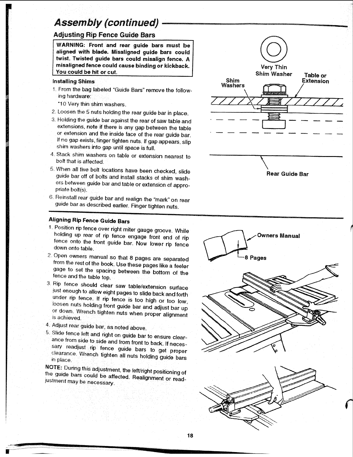
Insta!ling Shims
I From _he bag labeled "Guide Bars" remove the follow-
_ng hardware:
..... irrl
10 Very th_n sh washers.
2 Loosen the 5 nuts holding the rear guide bar in place.
3 Holding the guide bar against the rear of saw table and
extensions, note if there is any gap between the table
or e×_ens_on and the inside face of the rear guide bar,
_ no gap exists, finger tighten nuts. If gap appears, slip
_;t_m_washers into gap until space is full,
,_ S_ack shim washers on table or extension r_earest to
bo_ that is affected.
5. When all five bolt locations have been checked, slide
qu_de bar off of bolts and install stacks of shim wash-
ere between guide bar and table or extension of appro-
priate bolt(s).
6 Reinsta|l rear guide bar and realign the "mark" on rear
qu_de bar as described earlier, Finger tighten nuts.
./ JJIL i uJr " I [i
Manual
Aligning Rip Fence Guide Bars
Positwonnp fence over right miter gauge groove. While
holding up rear of rip fence engage front end of rip
ter_ce onto the front guide bar. Now lower rip fence
down onto table,
2. Open owners manual so that 8 pages are separated
from the rest of the book. Use these pages like a feeler
_age to set the spacing between the bottom of the
fence and the table top.
3Htp fence should clear saw table/extension surface
_ustenough to allow eight pages to slide back and forth
u_der np fence. If rip fence is too high ot too low.
toosen nuts holding front guide bar and adjust bar up
or down, Wrench tighten nuts when proper alignment
_sachieved.
4. A@usl rear guide bar. as noted above.
5. $_ fence left and right on guide bar to ensure clear-
ance from side to s_de and from front to back. If neces-
saw readjust rip fence guide bars to get proper
c_earance. Wrench tighten all nuts holding guide bars
NOTE: Duhng this adjustment, the left!right positioning of
the guide bars could be affected. Realignment or read-
_uslment may be necessary,
18
I III
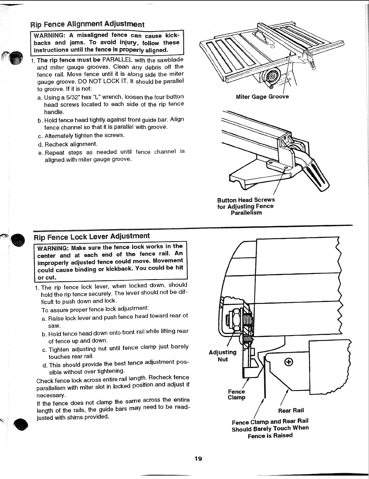
Rip Fence Alignment Adjustment
IWARNING: Amisaligned fence can cau_
backs and jams. To avoid injury, follow these I
instructions until the fence is properly aligned. J
1. The rip fence must be PARALLEL with the sawblade
and miter gauge grooves. Clean any debris off the
fence rail. Move fence until it is along side the miter
gauge groove. DO NOT LOCK IT. It should be parallel
to groove. If it is not:
a. Using a 5/32" hex "L" wrench, loosen the tour button
head screws located to each side of the rip fence
handle.
b. Hold fence head tightly against front guide bar. Align
fence channel so that it is parallel with groove.
c. Alternately tighten the screws.
d. Recheck alignment.
e. Repeat steps as needed until fence channel is
aligned with miter gauge groove.
Miter Gage Groove
Button Head Screws
for Adjusting Fence
Parallelism
Flip Fence Lock Lever Adjustment
WARNING: Make sure the fence lock works in the
center and at each end of the fence rail An
improperly adjusted fence could move. Movement
could cause binding or kickback. You could be hit
or cut.
1. The rip fence lock lever, when locked down. should
hold the rip fence securely. The lever should not be dif-
ficult to push down and lock
To assure proper fence lock adjustment:
a. Raise lock lever and push fence head toward rear of
saw.
b. Hold fence head clown onto front rail whimelifting rear
of fence up and down.
c. Tighten adjusting nut until fence clamp just barely
touches rear rail.
d. This should provide the best fence adjustment pos-
sible without over tightening.
Check fence rock across entire rail length. Recheck fence
parallelism with miter slot in locked position and adjust if
necessary.
If the fence does not clamp the same across the entire
length of the rails, the guide bars may need to be read-
justed with shims provided.
Adjusting
Nut
Fence
Clamp
Rear Rail
Fence Clamp and Rear Rail
Should Barely Touch When
Fence is Raised
19
Assembly (continued)
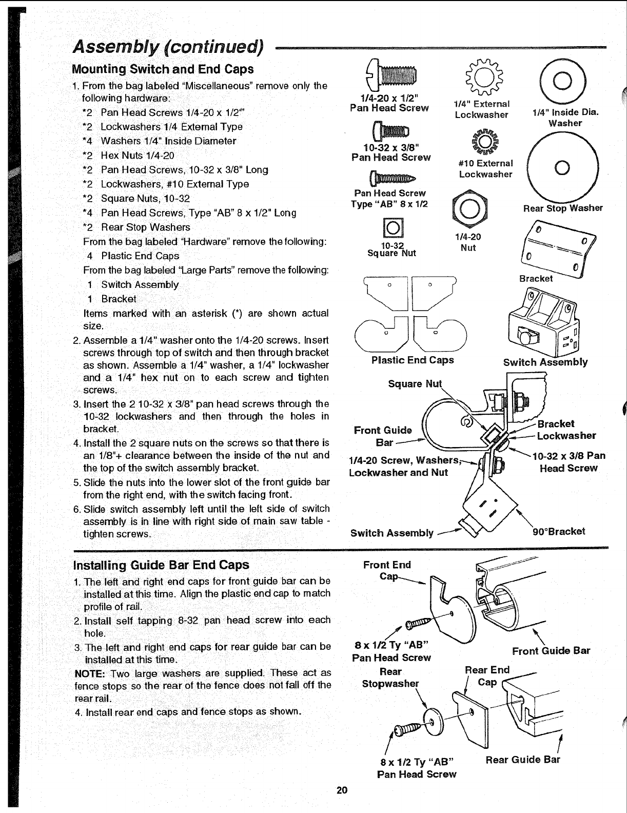
Mounting Switch and End Caps
1. Fmrn the bag labeled "Miscellaneous" remove only the
following hardware:
*2 Pan Head Screws 1/4-20 x 1/2"'
*2 Lockwashers 1/4 Extemal Type
*4 Washers 1/4" Inside Diameter
*2 Hex Nuts1/4-20
*2 Pan Head Screws, 10-32 x 3/8" Long
*2 Lockwashers, #10 External Type
*2 Square Nuts, 10-32
*4 Pan Head Screws, Type "AB" 8 x 1/2" Long
*2 Rear Stop Washers
From the bag labeled "Hardware" remove the following:
4 Plastic End Caps
From the bag labeled "LargeParts"remove the following:
1 Switch Assembly
1 Bracket
Items marked with an asterisk (*) are shown actual
size.
2. Assemble a 114" washer onto the 1/4-20 screws. Insert
screws through top of switch and then through bracket
as shown. Assemble a 1/4" washer, a 1/4" 10ckwasher
and a 1/4" hex nut on to each screw and tighten
screws.
114-20 x1/2"
Pan Head Screw 114"External
Lockwasher 1/4" Inside Dia.
(_ OWasher
10-32 x 3/8" _, _
Pan Head Screw #10 External
Lockwasher
Pan Head Screw
Type "AB" 8 x 112 Rear Stop Washer
[_ 114-20
10-32 Nut
Square Nut
_\__ j) Bracket
PmasticEnd Caps Switch As,' ;mbly
Square Nut
3. Insert the 2 10-32 x3/8" pan head screws through the
10-32 Iockwashers and then through the holes in
bracket.
4. Install the 2 square nuts on the screws so that there is
an 1/8"+ clearance between the inside of the nut and
the top of the switch assembly bracket.
5. Slide the nuts into the lower slot of the front guide bar
from the right end, with the switch facing front.
6, Slide switch assembly left until the left side of switch
assembly is in line with right side of main saw table -
tighten screws.
Front Guide
Bal
1/4-20 Screw, Washers,----_
Lockwasher and Nut
Switch Assembly
Bracket
x 3/8 Pan
Head Screw
90°Bracket
Installing Guide Bar End Caps
1. The left and right end caps for front guide bar can be
installed at thistime. Align the plastic end cap to match
profile of rail.
2. install self tapping 8-32 pan head screw into each
hole,
3. The left and right end caps for rear guide bar can be
installed at this time.
Front End _'j_._-_
8 x "AB" \
Front Guide Bar
Pan Head Screw
NOTE: Two large washers are supplied. These act as Rear Rear End
fence stops so the rear of the fence does not fall off the Stopwasher JCap
rear rail. ____
4. Install rear end caps and fence stops as shown.
/
8x1/2 Ty "AB" Rear Guide Bar
Pan Head Screw
2O
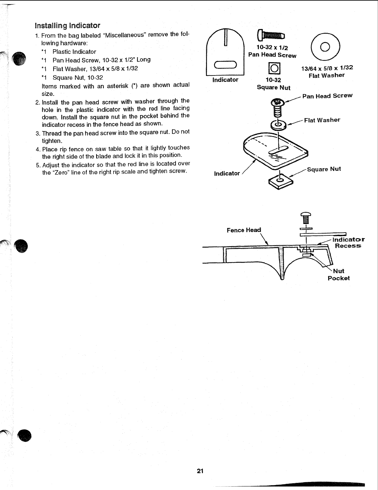
lnstamBingindicator
1. From the bag labeled "Miscellaneous" remove the fol-
lowing hardware:
"1 Plastic indicator
"1 Pan Head Screw, 10-32 x 1/2" Long
"1 Flat Washer, 13/64 x 5/8 × 1/32
"1 Square Nut. 10-32
Items marked with an asterisk (*) are shown actual
size.
2. Install the pan head screw with washer through the
hole in the plastic indicator with the red line facing
down. Install the square nut in the pocket behind the
indicator recess inthe fence head as shown,
3. Thread the pan head screw intothe square nut. Do not
tighten.
4. Place rip fence on saw table so that it lightly touches
the right side of the blade and lock it in this position.
5. Adjust the indicator so that the red line is located over
the "Zero" line of the right rip scale and tighten screw.
Ind icator
10-32 x 1/2
Pan Head Screw
[_ 13164 x 5/8 x 1132
Fiat Washer
10-32
Square Nut
.j_ Pan Head Screw
.I-- Fiat Washer
Indicator J '_._ /_Square Nut
Fence Head j==_=
L_ = _l
cat_¥
Recess
"Nut
Pocket
21
Assembly (continued)
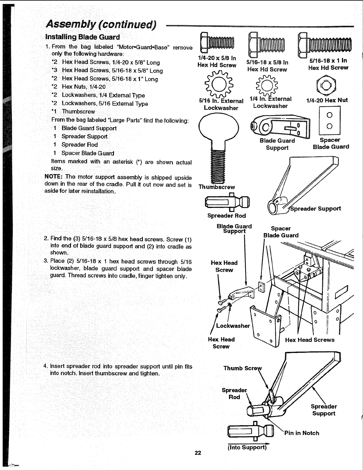
installing Blade Guard
1. From the bag labeled "MotoroGuard,,Base" remove
only the following hardware:
*2 Hex Head Screws. 1/4-20 x 5/8" Long
*3 Hex Head Screws, 5/16-18 x5/8" Long
*2 Hex Head Screws, 5/16-18 x 1" Long
*2 Hex Nuts, 1/4-20
*2 Lockwashers, 1/4 External Type
*2 Lockwashers, 5/16 External Type
"1 Thumbscrew
From the bag labeled "Large Pads" find the following:
1 Blade Guard Support
1 Spreader Support
1 Spreader Rod
1 Spacer Blade Guard
Items marked with an asterisk (*) are shown actual
size.
NOTE: The motor support assembly is shipped upside
down in the rear of the cradle. Pull it out now and set is
aside for later reinstallation.
1/4-20 x 5/8 In
Hex Hd Screw
Q
5/16 in. External
Lock"washer
5/16-18 x5/8 in
Hex Hd Screw
1/4 in. E_ernal
Lockwasher
Blade Guard
Suppod
5/16-18 x I in
Hex Hd Screw
@
1/4-20 Hex Nut
Spacer
Blade Guard
Thumbscrew
Spreader Rod
2. Find the (3) 5/16-18 x 5/8 hex head screws. Screw (1)
into end of blade guard support and (2) into cradle as
shown.
3. Place (2) 5/16-18 x 1 hex head screws through 5/16
Iockwasher, blade guard support and spacer blade
guard. Thread screws into cradle, finger tighten only.
Blade Guard
Support
Hex Head
Screw
Spacer
Blade Guard
/
Hex Head
Screw
!J
Hex Head Screws
4. Insert spreader rod into spreader support until pin fits
into notch. Insert thumbscrew and tighten.
Thumb Scre_
Spreader
Rod
Suppod
in Notch
(Into Support)"
22
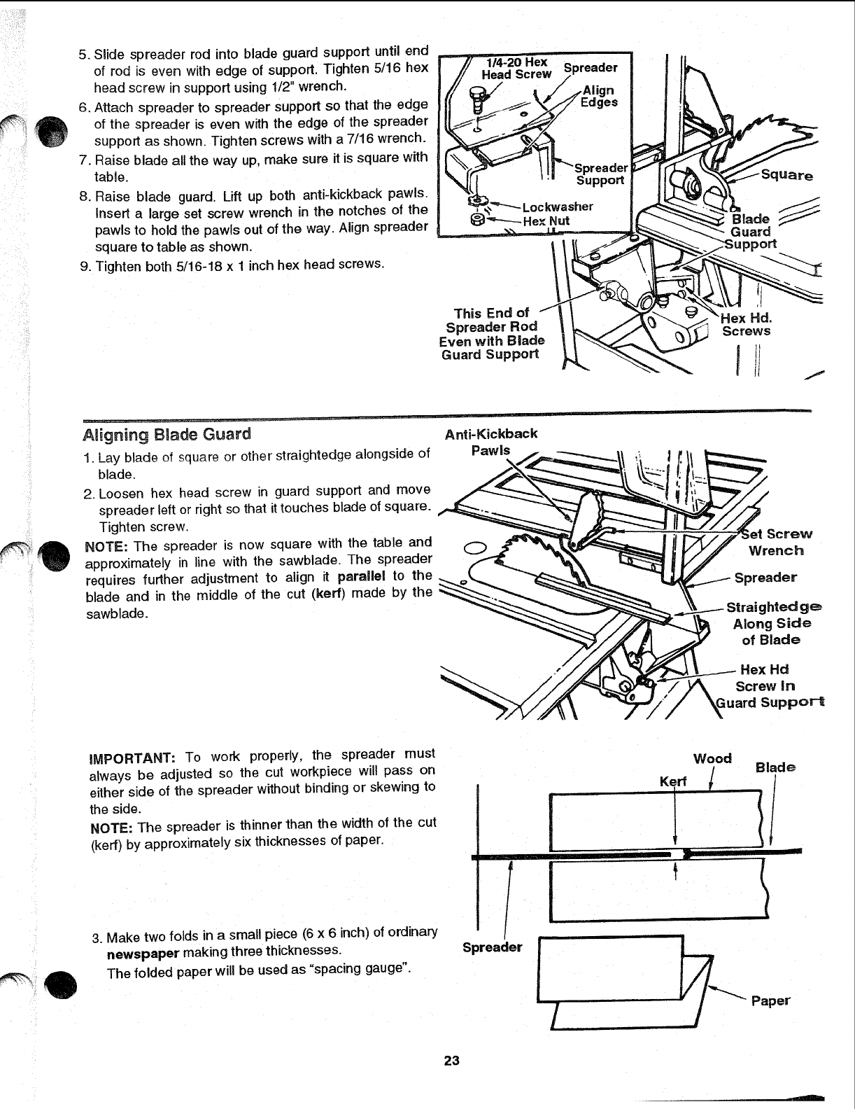
5. Slide spreader rod into blade guard support untit end
of rod is even with edge of support. Tighten 5/16 hex
head screw in support using 1/2" wrench.
6. Attach spreader to spreader support so that the edge
of the spreader is even with the edge of the spreader
support as shown. Tighten screws with a 7/16 wrench.
7. Raise blade all the way up, make sure it is square with
tabge.
8. Raise blade guard. Lift up both anti-kickback pawls.
Insert a large set screw wrench in the notches of the
pawls to hold the pawls out of the way. Align spreader
square to table as shown,
9. Tighten both 5/16-18 x 1 inch hex head screws.
This End of f
Spreader Rod
Even with Blade
Guard Support
/
ABigning BBade Guard
1. Lay blade of square or other straightedge alongside of
blade.
2. Loosen hex head screw in guard support and move
spreader left or right so that it touches blade of square.
Tighten screw.
NOTE: The spreader is now square with the table and
approximately in line with the sawblade. The spreader
requires further adjustment to align it parallel to the
blade and in the middle of the cut (kerf) made by the
sawblade.
Anti-Kickback
Pawls
Screw
Wrench
Spreader
Straighted g_
Along Side
of Blade
Hex Hd
Screw In
ppor-t
iMPORTANT: To work properly, the spreader must
always be adjusted so the cut workpiece will pass on
either side of the spreader without binding or skewing to
the side.
NOTE: The spreader is thinner than the width of the cut
(kerr) by approximately six thicknesses of paper.
3. Make two folds in a small piece (6 x 6 inch) of ordinary
newspaper making three thicknesses.
The folded paper will be used as "spacing gauge".
f
/
/
Spreader
23
Wood
Kerr /Blade
t "l!'
mr
,./
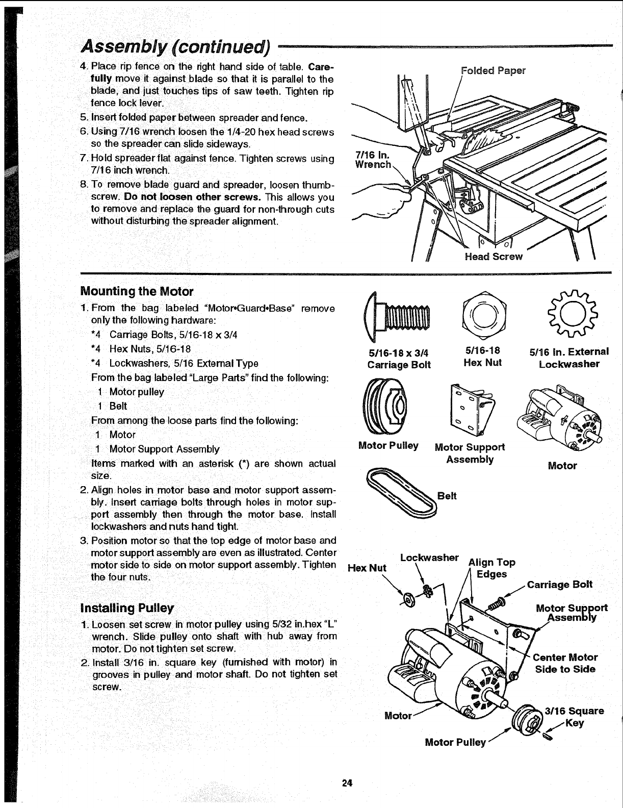
Assembly (continued)
4_Place rip fence on the right hand side of table. Care-
fully move it against blade so that it is parallel to the
blade, and just touches tips of saw teeth. Tighten rip
fence lock lever.
5. Insert folded paper between spreader and fence.
6. Using 7/16 wrench loosen the 1/4-20 hex head screws
so the spreader can slide sideways.
7. Hold spreader flat against fence, Tighten screws using
7/16 inch wrench.
8. To remove blade guard and spreader, loosen thumb-
screw. Do not loosen other screws. This allows you
to remove and replace the guard for non-through cuts
without disturbing the spreader alignment.
FoBded Paper
7116 In.
Wrench \
Head Screw
Mounting the Motor
1. From the bag labeled "Motor, Guard.Base" remove
only the following hardware:
*4 Carriage Bolts, 5/16-18 x3/4
*4 Hex Nuts, 5/16-18
*4 Lockwashers, 5/16 ExtemalType
From the bag labeled "Large Parts" find the following:
1 Motor pulley
1 Belt
From among the loose parts find the following:
1 Motor
1Motor Support Assembly
Items marked with an asterisk (*) are shown actual
size.
2. Align holes in motor base and motor support assem-
bly. Insert carriage bolts through holes in motor su p-
port assembly then through the motor base. Install
Iockwashers and nuts hand tight.
3. Position motor so that the top edge of motor base and
motor support assembly are even as illustrated Center
motor side to side on motor support assembly. Tighten
the four nuts.
5116-18 x 314
Carriage Bolt
5116-18
Hex Nut
Motor Pulley Motor Support
Assembly
Hex Nut Lockwasher Align Top
\Edges
O
5116 in. External
Lockwasher
Motor
Carriage Bolt
Installing Pulley
1. Loosen set screw inmotor pulley using 5/32 in.hex "L"
wrench. Slide pulley onto shaft with hub away from
motor. Do not tighten set screw.
2. Install 3/16 in. square key (furnished with motor) in
grooves in pulley and motor shaft. Do not tighten set
screw.
Motor
Motor Support
Assembly
Center Motor
Side to Side
3/16Square
Motor Pulley /
24
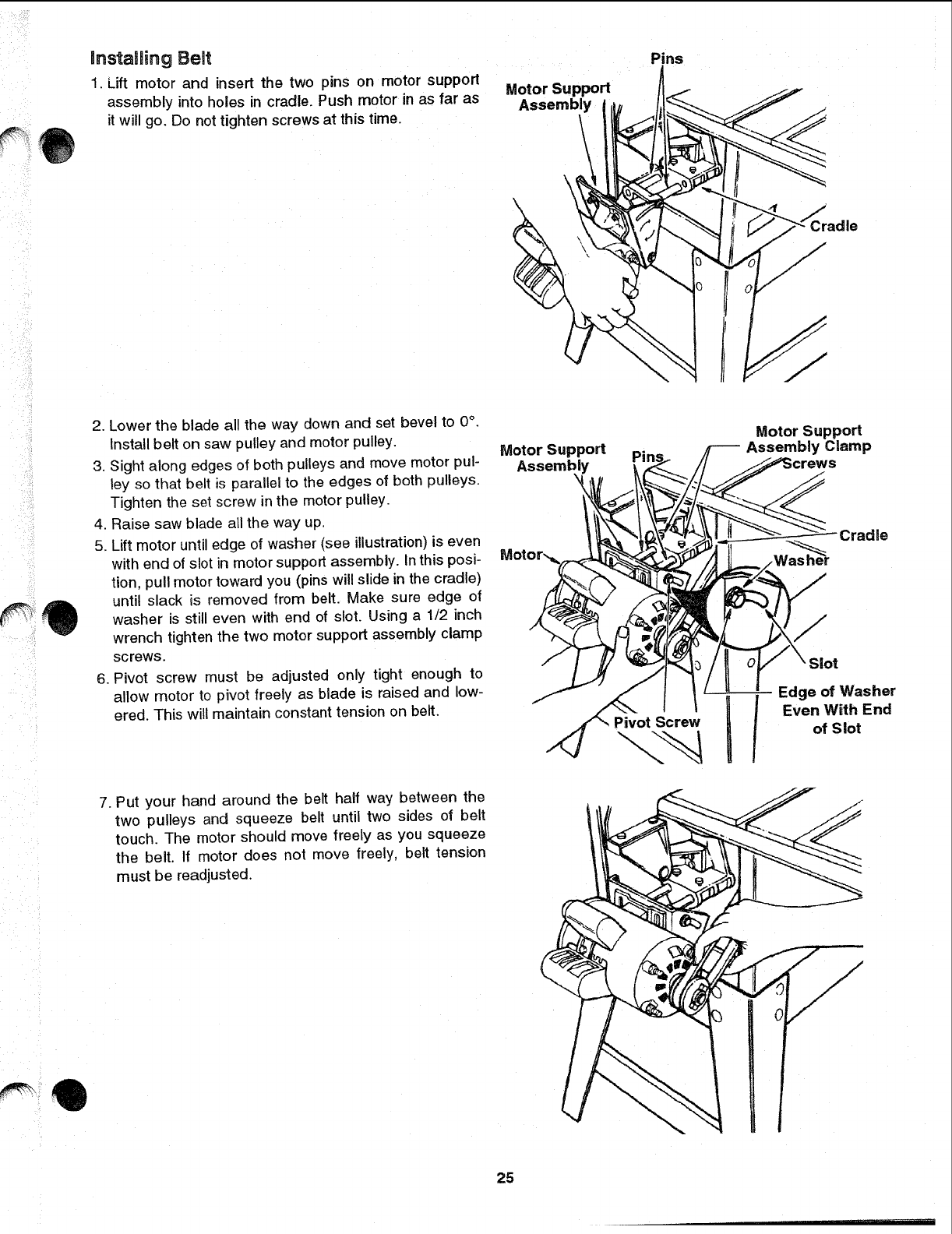
lnstaBling Belt
1. Lift motor and insert the two pins on motor support
assembly into holes in cradle. Push motor in as far as
it will go. Do not tighten screws at this time.
Motor Support
Assembly
\\
\
Pins
;radle
2. Lower the blade all the way down and set bevel to 0°.
Install belt on saw pulley and motor pulley.
3. Sight along edges of both pulleys and move motor pul-
ley so that belt is parallel to the edges of both pulleys.
Tighten the set screw in the motor pulley.
4. Raise saw blade all the way up
5. Lift motor until edge of washer (see illustration)is even
with end of slot in motor support assembly. In this posi-
tion, pull motor toward you (pins will slide in the cradle)
until slack is removed from belt, Make sure edge of
washer is still even with end of slot. Using a 1/2 inch
wrench tighten the two motor support assembly clamp
screws.
6, Pivot screw must be adjusted only tight enough to
allow motor to pivot freely as blade is raised and low-
ered. This will maintain constant tension on belt.
Motor Support
Assembly Clamp
!
crews
Cradle
.-- /Washe
/Slot
Edge of Washer
Even With End
of Slot
7. Put your hand around the belt half way between the
two pulleys and squeeze belt until two sides of belt
touch. The motor should move freely as you squeeze
the belt. If motor does not move freely, belt tension
must be readjusted.
25
Assembly (continued)
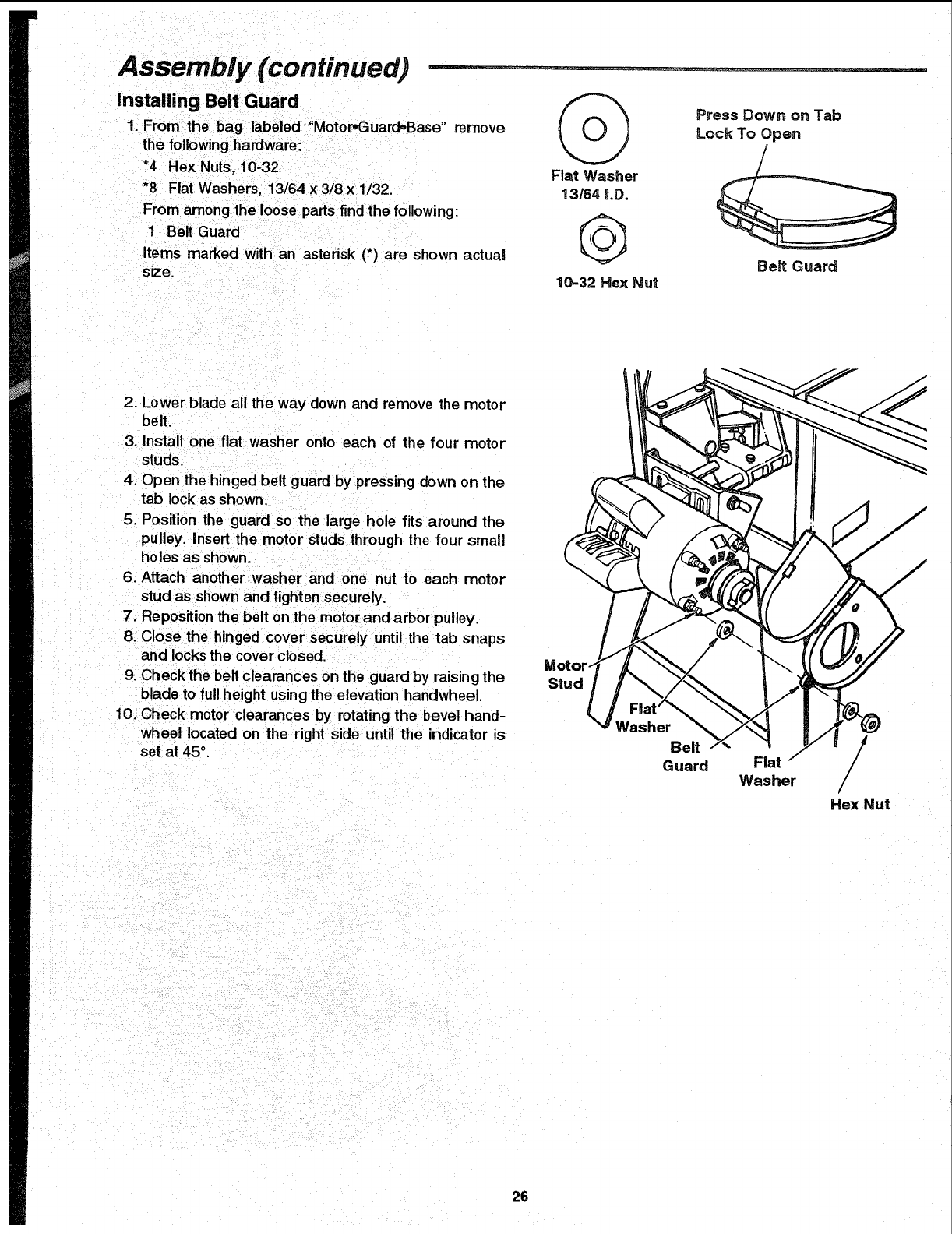
Installing Belt Guard
1. From the bag labeled "Motor_GuardoBase"remove
the following Itardware:
*4 He× Nuts, 10-32
*8 Fiat Washers, 13/64 x 3/8 x 1/32.
From among the loose parts find the following:
1Belt Guard
Items marked with an asterisk (*) are shown actual
size.
Flat Washer
13164 i.D.
@
10-32 Hex Nut
Press Down on Tab
Lock To Open
Belt Guard
2. Lower blade all the way down and remove the motor
belt.
3. Instal| one flat washer onto each of the four motor
studs.
4. Open the hinged belt guard by pressing down on the
tab lock as shown.
5. Position the guard so the large hole fits around the
pulley. Insert the motor studs through the four small
holes as shown.
6. Attach another washer and one nut to each motor
stud as shown and tighten securely.
7. Reposition the belt on the rnotorand arbor pulley.
8. Close the hinged cover securely until the tab snaps
and locks the cover closed.
9. Check the beff clearances on the guard by raising the
blade to full height using the elevation handwheel.
10. Check motor clearances by rotating the bevel hand-
wheel located on the right side until the indicator is
set at 45°.
Motor-
Stud
Washer
Belt
Guard Fiat /
Washer
Hex Nut
26
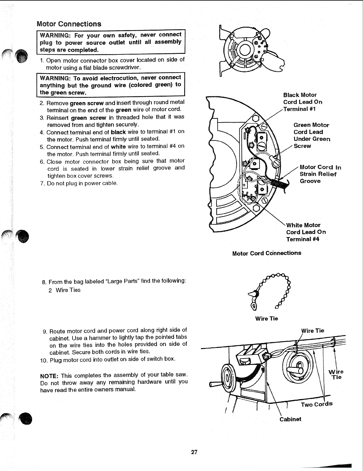
Motor Connections
WARNING: For your own safety, never connect I
plug to power source outlet until all assembly !
steps are completed.
1. Open motor connector box cover located on side of
motor using a flat blade screwdriver.
j WARNING: To avoid electrocution, never connect
anything but the ground wire (colored green) to
the green screw.
2. Remove green screw and insert through round metal
terminal on the end of the green wire of motor cord.
3, Reinsert green screw in threaded hole that it was
removed from and tighten securely.
4. Connect terminal end of black wire to terminal #1 on
the motor. Push terminal firmly until seated.
5. Connect terminal end of white wire to terminal #4 on
the motor. Push terminal firmly until seated,
6. Close motor connector box being sure that motor
cord is seated in lower strain relief groove and
tighten box cover screws.
7. Do not plug in power cable.
Black Motor
Cord Lead On
nal #1
Green Motor
Cord Lead
Under Green
"ew
Cord in
Strain Relief
Groove
\White M otor
Cord Lead On
Terminal #4
Motor Cord Connections
8. From the bag labeled "Large Parts" find the following:
2 Wire Ties
9. Route motor cord and power cord along right side of
cabinet. Use a hammer to lightly tap the pointed tabs
on the wire ties into the holes provided on side of
cabinet. Secure both cords in wire ties.
10. Plug motor cord into outlet on side of switch box.
NOTE: This completes the assembly of your table saw.
Do not throw away any remaining hardware until you
have read the entire owners manual.
Wire Tie
Wire Tie
Two Cords
\
Cabinet
Wire
Tie
27
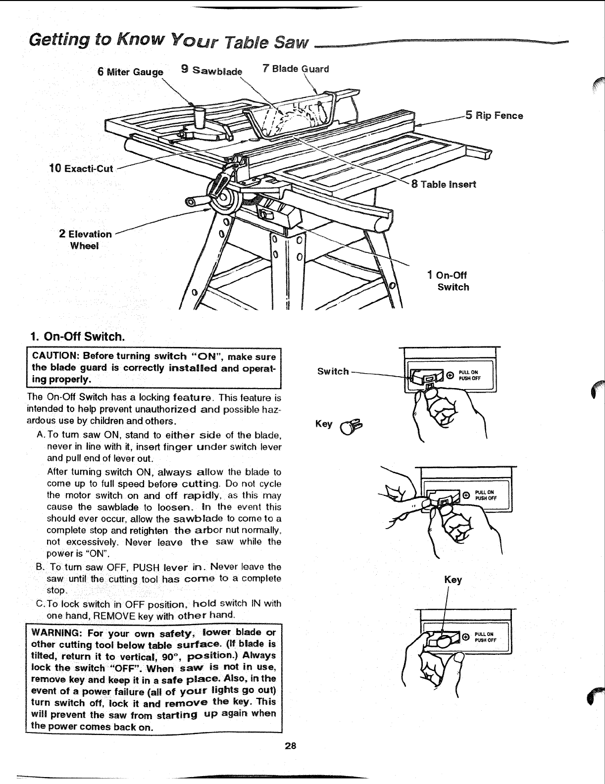
Getting to Know Your Table Saw
6 Miter Gauge 9 Sawblade 7 Blade Guard
\ \ \
Rip Fence
10
8Table insert
J
2 Elevation
Wheel
1 On-Off
Switch
1. On-Off Switch.
iCAUTION: turning switch "ON", make sure
Before
the blade guard is correctly instalUed and operat-
ing properly.
The On_Off Switch has a locking feature. This feature is
intended to help prevent unauthorized and possible haz-
ardous use by children and others.
A.To turn saw ON, stand to either sidle of the blade.
never in line with it, insert finger under switch lever
and pull end of lever out.
After turning switch ON. always allow the blade to
come up to full speed before cutting. Do not cycle
the motor switch on and off rapidly, as this may
cause the sawblade to loosen, in the event this
should ever occur, allow the sawb|ade to come to a
complete stop and retighten the arbor nut norrnalty.
not excessively. Never leave the saw while the
power is "ON".
B. To turn saw OFF, PUSH lever in. Never leave the
saw until the cutting tool has corne to a complete
stop.
C.To lock switch in OFF position, hold switch IN with
one hand, REMOVE key with other hand
WARNING: For your own safety, tower blade or
other cutting tool below table surface. (if b|ade is
tired, return it to vertical, 90 °, position.) Always
lock the switch "OFF". When saw' is not in use,
remove key and keep it in a safe p!_ace. Also, in the
event of apower failure (all of your lights go out)
turn switch off, lock it and remove the key. This
will prevent the saw from starting up again when
the power comes back on.
28
PULL O_
Key
(_ pULL 0N I1
PUSH OFF
_ili;ii
2. Elevation HartdwheeL,.elevates or _cwers t_e
bJade. Turn clockwise _o e_evate, counterclockwise to
lower
3. Ti_t HandwheeL,.tifts the blade fo, _ oeve! cutting
Turn c_ockwise to titt toward _eft. cou[_terc[ock Nlse to
tilt toward right.
When the b!ade is tilted to the left as far as it will go,
it 9_ot_ld be al 45 ° to the table anq the bevel pointer
should poi_lt 4.5°.
NOTE: There are limit stops inside the saw which
prever_t the D_ade from tilting beyond 45 ° to the left
and 90 ° to the right. (See "Adjustments and Align-
me,-,ts" section "Blade Tilt, or Squareness of BDade
to Tab!e'_ -
4. Titt Lock Handmeo.,Iocks the blade in the desired
fllt position. To loosen, turn counterclockwise. Push
handle in and turn it to another position if necessary
in order to tighten or loosen.
iMPORTANT: Be sure handle is hanging in the
"DOWN" position before tilting blade. If it is pointing
to the 1 o'clock position it may jam on underside of
the table and bend the locking bolt.
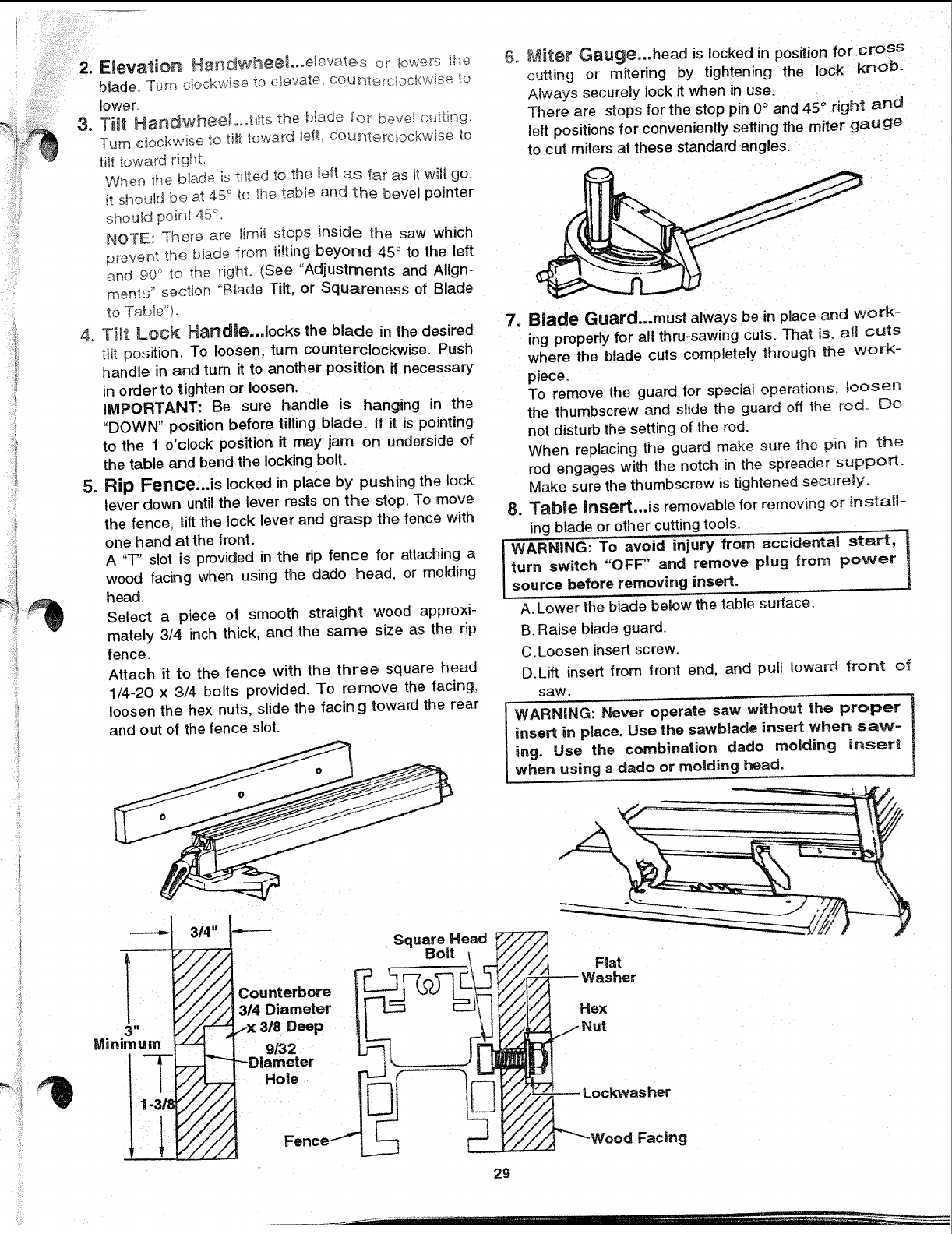
5, Rip Fence...is locked in place by pushing the lock
lever down until the lever rests on the stop To move
the fence, lift the lock lever and grasp the fence with
one hand at the front.
A "T" slot is provided in the rip fence for attaching a
wood facing when using the dado head, or molding
head.
Select a piece of smooth straight wood approxi-
mately 3/4 inch thick, and the same size as the rip
fence.
Attach it to the fence with the three square head
1/4-20 x 3/4 bolts provided. To remove the facing,
loosen the hex nuts, slide the facing toward the rear
and out of the fence slot.
3 I=
Minimum
314"
6, Miter Gauge...head is locked in position for cross
cutting or mitering by tightening the lock KnOb.
Always securely lock it when in use.
There are stops for the stop pin 0°and 45 °right and
left positions for conveniently setting the miter gauge
to cut miters at these standard angles.
7. Blade Guard...must always be in place and work-
ing properly for all thru-sawing cuts. That is. all cuts
where the blade cuts completely through the work-
piece.
To remove the guard for special operations, aoosen
the thumbscrew and slide the guard off the rod. Do
not disturb the setting ot the rod.
When replacing the guard make sure the pin in the
rod engages with the notch in the spreader support.
Make sure the thumbscrew is tightened securely.
8. Table Insert...is removable for removing or install-
ing blade or other cutting tools.
WARNING: To avoid injury from accidenta! start, t
turn switch OFF and remove plug from power
source before removing insert. ]
A. Lower the blade below the table surface.
B. Raise blade guard.
C.Loosen insert screw.
D,Lift insert from front end. and pull toward front o_
saw.
WARNING: Never operate saw without the proper
insert in place. Use the sawblade insert when saw-
_ng. Use the combination dado molding insert
when using adado or molding head.
2g
Getting to Know Your Table Saw (continued)'- -
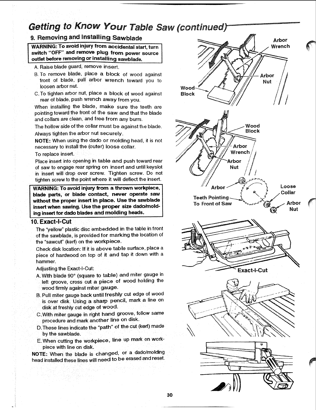
9. Removing and insta|ling Sawblade
WARNING: To avoid injury from accidental start, turn- 1
""' ' ve
switch OFF and remo plug from power source
outlet before removing or installing sawblade.
A. Raise blade guard, remove insert.
B. To remove blade, place a block of wood against
front of blade, pull arbor wrench toward you to
loosen arbor nut.
C.To tighten arbor nut place a block of wood against
rear of blade, push wrench away from you.
When installing the blade, make sure the teeth are
pointing toward the front of the saw and that the blade
and collars are clean, and free frorn any burrs.
The hollow side of the collar must be against the blade.
Always tighten the arbor nut securely.
NOTE: When using the dado or molding head, it is not
necessary to install the (outerl loose collar.
To replace insert.
Place insert into opening in table and push toward rear
of saw to engage rear spring on insert and until keyslot
in insert will drop over screw. Tighten screw. Do not
tighten screw to the point where it will deflect the insert.
iWARNING: To avoid injury from a thrown workpiece,
blade parts, or blade contact, never operate saw
without the proper insert in place. Use _he sawblade
insert when sawing. Use the proper size dado/mold-
.ing insert for dado blades and molding heads.
10. Exact-l-Cut
The "yellow" plastic disc embedded in the table in front
of the sawblade, is provided for marking the location of
the "sawcut" (kerr) on the workpiece.
Check disk location: If it is above table surface, place a
piece of hardwood on top of it and tap it down with a
hammer.
Block
Wood
Block
Teeth Pointin
To Front of Saw
Arbor
Wrench
Nut
/
Arbor
Nut
Adjusting the Exact-I-Cut:
A. With blade 90°(square to table) and miter gauge in
left groove, cross cut a piece of wood holding the
wood firmly against miter gauge.
B.Pull miter gauge back until freshly cut edge of wood
is over disk. Using a sharp pencil, mark a line on
disk at freshly cut edge of wood.
C.With miter gauge in right hand groove, follow same
procedure and mark another line on disk.
D.These lines indicate the "path" of the cut (ked) made
by the sawblade.
E.When cutting the workpiece, line up mark on work-
piece with line on disk.
NOTE: When the blade is changed, or a dado/molding
head installed these lines will need to be erased and reset.
Exact-l-Cut
3O
Safety instructions for Basic Saw Operations,
Before Each Use
Inspect your saw.
*To avoid injury from accidental starting, turn the switch
off, unplug the saw, and remove the switch key before
raising or removing the guard, changing the cutting
tool, changing the setup, or adjusting anything.
oCheck for alignment of moving parts, binding of mov-
ing parts, breakage of parts, saw stability, and any
other conditions that may affect the way the saw
works.
°If any part is missing, bent or broken in any way, or any
electrical part does not work properly, turn the saw off
and unplug the saw.
oReplace damaged or missing parts before using the
saw again.
,Use the sawblade guard, spreader and anti-kickback
pawls for any thru-sawing (whenever the blade comes
through the top of the workpiece). Make sure the anti-
kickback pawls work properly. Make sure the spreader
is _nline with sawblade:
,, Remove adjusting keys and wrenches. Form a habit of
checking for and removing keys and wrenches from
table top before turning saw on.
o Make sure all clamps and locks are tight and no parts
have excessive play.
i
To Avoid injury From Jams, Slips Or Thrown Pieces (Kickbacks Or Throwbacks)
inspect Your Blade.
°Choose the right blade or cutting accessory for the
material and the type of cutting you plan to do.
•Use The Right Tool. Don't force tool or attachment to
do a job it was not designed for.
•Never use grinding wheels, abrasive cutoff wheels,
friction wheels (metal cutting blades) wire wheels or
buffing wheels. They can fly apart explosively.
•Cut only wood. wood like or plastic materials. Do not
cut metal.
• Choose and inspect your cutting tool carefully:
-To avoid cutting tool failure and thrown shrapnel
(broken pieces of blade), use only 10" or smaller
blades or other cutting tools marked for speeds of
5000 rpm or higher.
- Always use unbroken, balanced blades designed to
fit this saw's 5/8 inch arbor.
-When thru-sawing (making cuts where the blade
comes through the workpiece top), always use a 10
inch diameter blade. This keeps the spreader in clos-
est to the blade.
- Do not over tighten arbor nut. Use arbor wrenches to
"snug" it securely.
- Use only sharp blades with properly set teeth. Con-
suit a professional blade sharpener when in doubt.
- Keep blades clean of gum and resin.
- Never use the saw without the proper blade insert.
Inspect your work area.
•Keep work area clean.
•Cluttered areas and benches invite accidents. Floor
must not be slippery from wax or sawdust.
°To avoid burns or other fire damage, never use the
saw near flammable liquids, vapors or gases.
•To avoid injury, don't do layout, assembly, or setup
work on the table while blade is spinning. It could cut
or throw anything hitting the blade.
Plan your work
°Plan ahead to protect your eyes, hands, face. ears.
,, Use the right tool. Don't force tool or attachment to do
ajob it was not designed for.
Dress for safety
,, Do not wear loose clothing, gloves, neckties or jewelry
(rings, wrist watches). They can get caught and draw
you into moving parts.
o Wear nonslip footwear.
° Tie back long hair.
,, Rotl long sleeves above the elbow.
oNoise levels vary widely. To avoid possible hearing
damage, wear ear plugs or muffs when using table
saw for hours at a time.
oAny power saw can throw foreign objects into the
eyes. This can result in permanent eye damage: Wear
safety goggles (not glasses) that comply with ANSI
Z87.1 (shown on package). Everyday eyeglasses have
only impact resistant lenses. They are not safety
glasses. Safety goggles are available at Sears retail
stores. Glasses or goggles not in compliance with
ANSI Z87.1 could seriously hurt you when they break.
WEAR YOUR
oFor dusty operations, wear a dust mask along with
safety goggles.
Inspect your workpiece.
°Make sure there are no nails or foreign objects in the
part of the workpiece to be cut.
° When cutting irregularly shaped workpieces, plan your
work so it will not slip and pinch the blade:
oA piece of molding for example, must lie flat or be held
by afixture of jig that will not let it twist, rock or slip
while being cut. Use jigs or fixtures where needed to
prevent workpiece shifting,
"Use a different, better suited type of tool for work that
can't be made stable.
31
Safety instructions for Basic Saw Operations
Plan your cut.
-To avoid kickbacks and throwbacks which occur when
a part or all of the workpiece binds on the blade and is
thrown violently back toward the front of the saw:
- Never cut Freehand. Always use either a rip fence,
miter gauge or fixture to position and guide the work,
so it won't twist or bind on the blade and kickback.
- Make sure there's no debris between the workpiece
and its supports.
•Use extra caution with large, very small or awkward
workpieces.
-Use extra supports (tables, saw horses, b locks, etc.)
for any workpieces large enough to tip when not held
down to the table top. Never use another person as a
substitute for a table extension, or as additional sup-
port for a workpiece that is longer or wider than the
basic saw table, or to help feed, support or pull the
workpiece.
•Never confine the piece being cut off, that is, the piece
not against the fence, miter gauge or fixture. Never
hold it. clamp it, touch it. or use length stops against it.
It must be free to move. If confined, it could get
wedged against the blade and cause a kickback or
throwback.
•Never cut more than one workpiece at a time,
•Never turn your table saw "ON" before clearing every-
thing except the workpiece and related support
devices off the table,
Whenever Sawblade is Spinning
iWARNING: Don't allow familiarity (gained from fre-
quent use of your table saw) cause acare|ess mis-
take. Always remember that acareless fraction of
a second is enough to cause a severe injury.
Plan the way you will push the workpiece through.
•Never puJl the workpiece through. Start and finish
the cut from the front of the table saw.
oNever put your fingers or hands in the path of the
sawbiade or other cutting tool.
oNever reach in back of the cutting tool with either
hand to hold down or support the workpiece, to
remove wood scraps, or for any other reason.
.Avoid hand positions where a sudden slip could cause
fingers or a hand to move into a sawblade or other cut-
ting tool.
.Don't overreach. Always keep good footing and balance.
o Push the workpiece against the rotation of the blade.
never feed material into the cutting tool from the rear of
the saw.
o Always push the workpiece all the way past the saw-
blade.
•As much as possible, keep your face and body to one
side of the sawblade, out of line with a possible kick-
back or throwback.
•Set the cutting tool as low as possible for the cut you're
planning.
Avoid Accidental Starting.
• Make sure switch is "OFF" before plugging saw into a
power outlet.
Before freeing jammed material.
oBefore actually cutting with the saw, watch it while it
runs for a short while. If it makes an unfamiliar noise or
vibrates a lot, stop immediately. Turn the saw off.
Unplug the saw. Do not restart until finding and cor-
° Turn switch "OFF".
•Wait for all moving parts to stop.
•Unplug tl_e saw.
-Check blade, spreader and fence for proper alignment
before starting again.
oTo avoid throwback of cut off pieces.
•Use the guard assembly.
recting the problem.
•Make sure the top of the arbor or cutting tool turns
toward the front of the saw.
Keep Children Away.
-Keep all visitors a safe distance from the table saw,
•Make sure bystanders are clear of the table saw and
workpiece.
Don't Force Tool ....
-Let the blade reach full speed before cutting-
.It will do the job better and safer at its designed rate.
•Feed the workpiece into the saw only fast enough to let
the blade cut without bogging down or binding,
To remove loose pieces beneath or trapped inside
the guard.
-Turn saw "OFF'
-Remove switch key.
oWait for blade to stop before lifting the guard.
Before Leaving The Saw.
-Turn the saw off.
oWait for blade to stop spinning.
-Unplug the saw.
° Make workshop child-proof. Lock the shop. Disconnect
master switches. Remove the yellow switch key. Store
it away from children and others not qualified to use
the tool,
32

Work Feed Devices ............. .......
Before cutting any wood on your saw, study a_ of the
"Basic Saw Operations".
As you learn new table saw woodworking techniques,
you'H see that many types of cuts need different support
and feeding devices, known as jigs or fixtures. They can
heRp you make cuts more accurately. By helping to
steady the workpiece and keep you away from the blade.
they can help you safely use your saw for certain cuts,
Many people custom build their own jigs and fixtures.
Jigs and fixtures are often designed for a particular cut.
You can use your table saw to easily make many jigs and
fixtures. To get you started, we've included instructions
for some simple ones. After you have made a few prac-
tice cuts, make up these jigs before starting any projects.
The use of these devices is explained in "Basic Saw
Operations" section,
Push Stick
Make the push stick from a piece of solid wood. Use a
piece of 1 x 2 (3/4" x 1-5/8" actual) by 15" long.
Slightly Less Than Thickness
.,__0 3/4" Of Workpiece To 3/8"
Up -x
o
Notch 112"---_t
Make the featherboard from a piece of 8" x 24" x 3/4"
thick solid wood.
Kerfs About
511 6" Apart
4-112" -=-
-= 24" =Iil
Push Block
NOTE: All dimensions in inches
There are any number of ways to properly cut your work-
pieces to make a push block. The following steps
describe one way you can make a push block.
Making the base:
•Start with apiece of 3/8 inch plywood at least 5-5/8
inches wide or wider and 12 inches tong or longer.
•Make two ripcuts. Perform the first ripcut along the side
of the 3/8" wide strip. Next, dpcut the 3/8" plywood to a
width of 5-1/8".
oCrosscut the 3/8" plywood to 12" long.
eCrosscut a 2-1/2" piece off the 3/8" wide by 3/8" thick
strip and save this short piece for later.
oThe next cuts wil! create the 3/8" by 9-1/2" notch in the
base, Mark the long edge of the board 2-1/2" from one
end. Make a crosscut into the edge on the mark, stop-
ping about 3/4" into the board. Set the saw and rip the
width to 4-3/4" along the same edge as the stopped
Material for Push Block
At Least 12"
3/8" Thick Plywood
Base
At Least 12"
314" Thick Plywood
Handle
Cutting Out the Base
_2-1/2" (save)
crosscut. Stop the ripcut where the two cuts intersect.
Turn off the saw and remove the base piece. The base
should now measure as shown.
Finished Base
L-. _-.L 4 th Cut 1 st Cut
2 nd Cut
2 nd Cut
12"
Creating the Notch
1 st Cut
I
I
-,=_--_ 2-1/2"
33
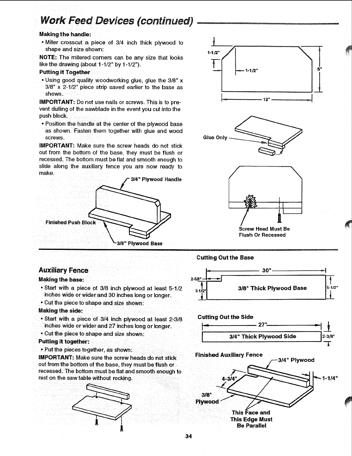
Work Feed Devices (continued) ............
Making the handle:
•Miter crosscut a piece of 3/4 inch thick plywood to
shape and size shown:
NOTE: The mitered corners can be any size that looks
likethe drawing (about 1-1/2" by 1-1/2").
Putting it Together
• Using good quality woodworking glue, glue the 3/8" x
3/8" x 2:1/2" piece strip saved earlier to the base as
shown.
IMPORTANT: Do not use nails or screws. This is to pre-
vent dulling of the sawblade in the event you cut into the
push block.
• Position the handle at the center of the plywood base
as shown. Fasten them together with glue and wood
screws.
IMPORTANT: Make sure the screw heads do not stick
out fmrn the bottom of the base, they must be flush or
recessed. The bottom must be flat and smooth enough to
slide along the auxiliary fence you are now ready to
make.
314"Plywood Handle
Finished Push Block
J
1-1/2"
1-
'_2" =--
Glue Only
J L__I
/i
Screw Head Must Be
Flush Or Recessed
5"
Cutting Out the Base
A
Auxiliary Fence |-- 30"
--i---,-J
Making the base: 2-5/8-
Ar
"Start with apiece of 3/8 inch plywood at least 5-1/2 3-1_'|
inches wide or wider and 30 inches long or longer.
•Cut the piece to shape and size shown:
Making the side: Cutting Out the Side
•Start with apiece of 3/4 inch plywood at least 2-3/8
inches wide or wider and 27 inches long or longer, i_ 27"
•Cut the piece to shape and size shown:
Putting it together:
-Put the pieces together, as shown:
IMPORTANT: Make sure the screw heads do not stick
out from the bottom of the base, they must be flush or
recessed. The bottom must be flat and smooth enough to
rest on the saw table without rocking.
1
34
3/8" Thick Plywood Base
3/4" Thick Plywood Side
Finished Auxiliary Fence
This Face and
This Edge Must
Be Parallel
4-314'
Plywood
2-3/8"
A
1-1/4"

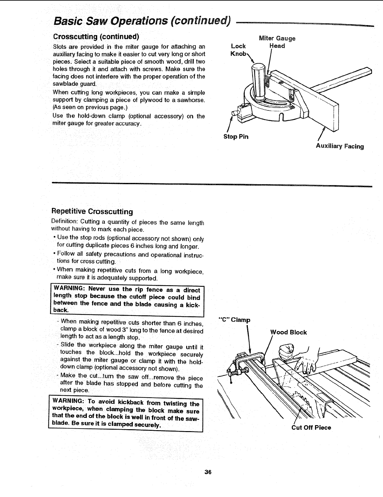
Basic Saw Operations (continued)
Crosscutting (continued)
Slots are provided in the miter gauge for attaching an
auxiliary facing to make it easier to cut very long or short
pieces. Select a suitable piece of smooth wood, drill two
holes through it and attach with screws. Make sure the
facing does not interfere with the proper operation of the
sawblade guard.
When cutting long workpieces, you can make a simple
support by clamping a piece of plywood to a sawhorse.
(Asseen on previous page.)
Use the hold-down clamp (optional accessory) on the
miter gauge forgreater accuracy,
Lock Miter Gauge
Head
Stop Pin
Auxiliary Facing
Repetitive Crosscutting
Definition Cutting a quantity of pieces the same length
without havingto mark each piece.
• Use the stop rods (optional accessory not shown) only
for cuttingduplicate pieces 6 inches long and longer.
•Follow all safety precautions and operational instruc-
tions f0 r cross cutting.
°When making repetitive cuts from a long workpiece,
make sure it is adequately supported.
WARNING: Never use the rip fence as a direct
length stop because the cutoff piece could bind
between the fence and the blade causing a kick-
back.
-When making repetitive cuts shorter than 6inches,
clamp a block of wood 3" tong to the fence at desired
length to act as a length stop.
-Slide the workpiece along the miter gauge until it
touches the block...hold the workpiece securely
against the miter gauge or clamp it with the hold-
down clamp (optional accessory not shown).
- Make the cut...turn the saw oft...remove the piece
after the blade has stopped and before cutting the
next piece.
WARNING: To avoid kickback from twisting the
workpiece, when clamping the block make sure
that the end of the block is well in front of the saw-
blade. Be sure it is clamped securely.
"'C" Clamp
\
\
Wood Block
/
Cut Off Piece
36
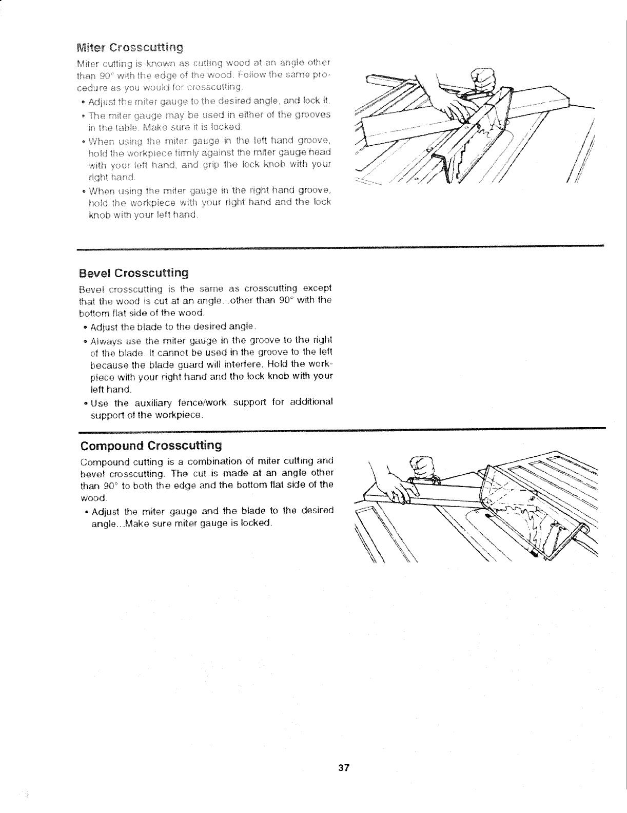
_7_iter Crosscu_ing
Mit4Dr cuttk_g is know_ as cutting woxJ at _ a_9te othe_
than 90 ° w_h the edge of _ise wood. f:oliow rise same pro..
cedu_e as you wo_Jd fo_ c_osscutti_}g
AdNst the m_ter gauge to the desired arsgle, and bck _t.
• Nse miter _tauge may be used in eitlqe[ of the .grooves
in tise taNe Make st_r_:_,it is locked.
o Whe_} us.qg the mite_ gauge in the _ett hand groove,
hold tb.e wo_kpiece fi_w_!yagainst the miter gauge head
...... .... ,, _" O
with yore iefi hand _q qdp the lock _,rk, b with your
jig?It ha_-_d
• When usir_g the miter gauge in the dght i_and groove_
hokJ the workpiece with your right hand and the _ock
knob with your left hand,
Bevel Crosscutting
Bevel crosscutting is the same as crosscutting except
that the wood is cut at an angle.. ,other than 9@' with the
bottom fiat side of the wood
Adjust the blade to the desired angle,
Always use the miter gauge in the groove to the fight
of the b!ade. _t cannot be used in the groove to the left
because the Made guard will interfere. Hold the work _
piece with your right hand and the lock knob with your
left hand.
-Use the auxitiap¢ fence/work support for additional
support of the workpiece,
_ _ .... : i , nlnl ,,,,r, . J
Compound Crosscutting
Compound cutting is a combination of miter cutting and
bevel crosscutting The cut is made at an angle other
than 90° to both the edge and the bottom flat side of the
wood,
• Adjust the miter gauge and the blade to the desired
angie...Make sure miter gauge is locked
i¸ in ill ,n I I I
37
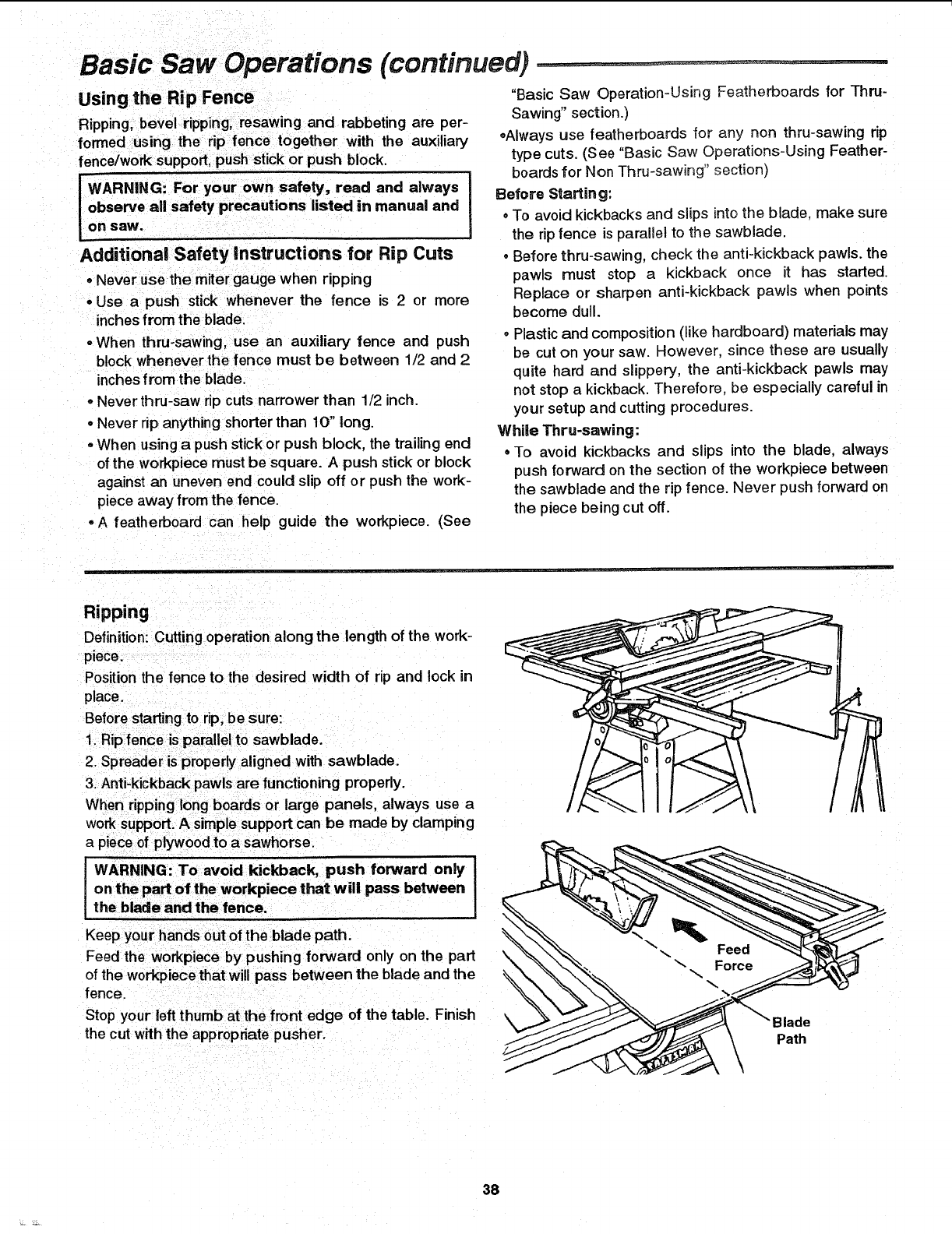
Basic Saw Operations (continued)
Using the Rip Fence
Ripping. bevel ripping, resawing and rabbeting are per-
formed using the rip fence together with the auxiliary
fence/work support, push stick or push block.
IWARNING: your own safety, always
For read and
observe all safety precautions listed in manual and
On SaW.
Additional Safety instructions for Rip Cuts
°Never use the miter gauge when ripping
• Use a push stick whenever the fence is 2 or more
inches from the blade.
•When thru-sawing, use an auxiliary fence and push
block whenever the fence must be between 1/2 and 2
inch es from the blade.
-Never thru-saw rip cuts narrower than 1/2 inch.
°Never rip anything shorter than 10" tong.
•When using a push stick or push block, the trailing end
of the workpiece must be square. A push stick or block
against an uneven end could slip off or push the work-
piece away from the fence.
-A featherboard can help guide the workpiece. (See
"Basic Saw Operation-Using Featherboards for Thru-
Sawing" section.)
.Always use featherboards for any non thru-sawing rip
type cuts. (See "Basic Saw Operations-Using Feather-
boards for Non Thru-sawing" section)
Before Starting:
oTo avoid kickbacks and slips into the blade, make sure
the rip fence is parallel to the sawblade.
.Before thru-sawing, check the anti-kickback pawls, the
pawls must stop a kickback once it has started.
Replace or sharpen anti-kickback pawls when points
become dull.
°Plastic and composition (like hardboard) materials may
be cut on your saw. However, since these are usually
quite hard and slippery, the anti-kickback pawls may
not stop a kickback. Therefore, be especially careful in
your setup and cutting procedures.
While Thru-sawing:
° To avoid kickbacks and slips into the blade, always
push forward on the section of the workpiece between
the sawblade and the rip fence. Never push forward on
the piece being cut off.
Ripping
Definition: Cutting operation along the length of the work-
piece.
Position the fence to the desired width of rip and lock in
place.
Before starting to rip, be sure:
1. Rip fence is parallel to sawblade.
2. Spreader is properlyaligned with sawblade.
3. Anti-kickback pawls are functioning properly.
When ripping long boards or large panels, always use a
worksupport.A simple support can be made by clamping
a pieceof plywoodto a sawhorse.
WARNING: To avoid kickback, push forward only I
on the part of the workpiece that will pass between I
the blade and the fence.
Keep your hands out of the blade path.
Feed the workpiece by pushing forward only on the part
of the workpiece that will pass between the blade and the
fence.
Stop your left thumb at the front edge of the table. Finish
the cut with the appropriate pusher. ]lade
Path
38
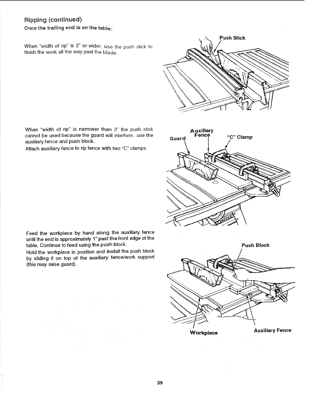
Ripping (continued)
Once the trai_ing end is on the table:
When "width of rip" is 2" or wider, use the push stick to
finish the work all the way past the blade.
Push Stick
When "width of rip" is narrower than 2" the push stick
cannot be used because the guard will interfere...use the
auxiliary fence and push block.
Attach auxiliary fence to rip fence with two "C" clamps.
Auxiliary
Fence
Feed the workpiece by hand along the auxiliary fence
until the end is approximately 1" past the front edge of the
table. Continue to feed using the push block.
Hold the workpiece in position and install the push block
by sliding it on top of the auxiliary fence/work support
(this may raise guard).
Workpiece
Push Block
Auxiliary Fence
39
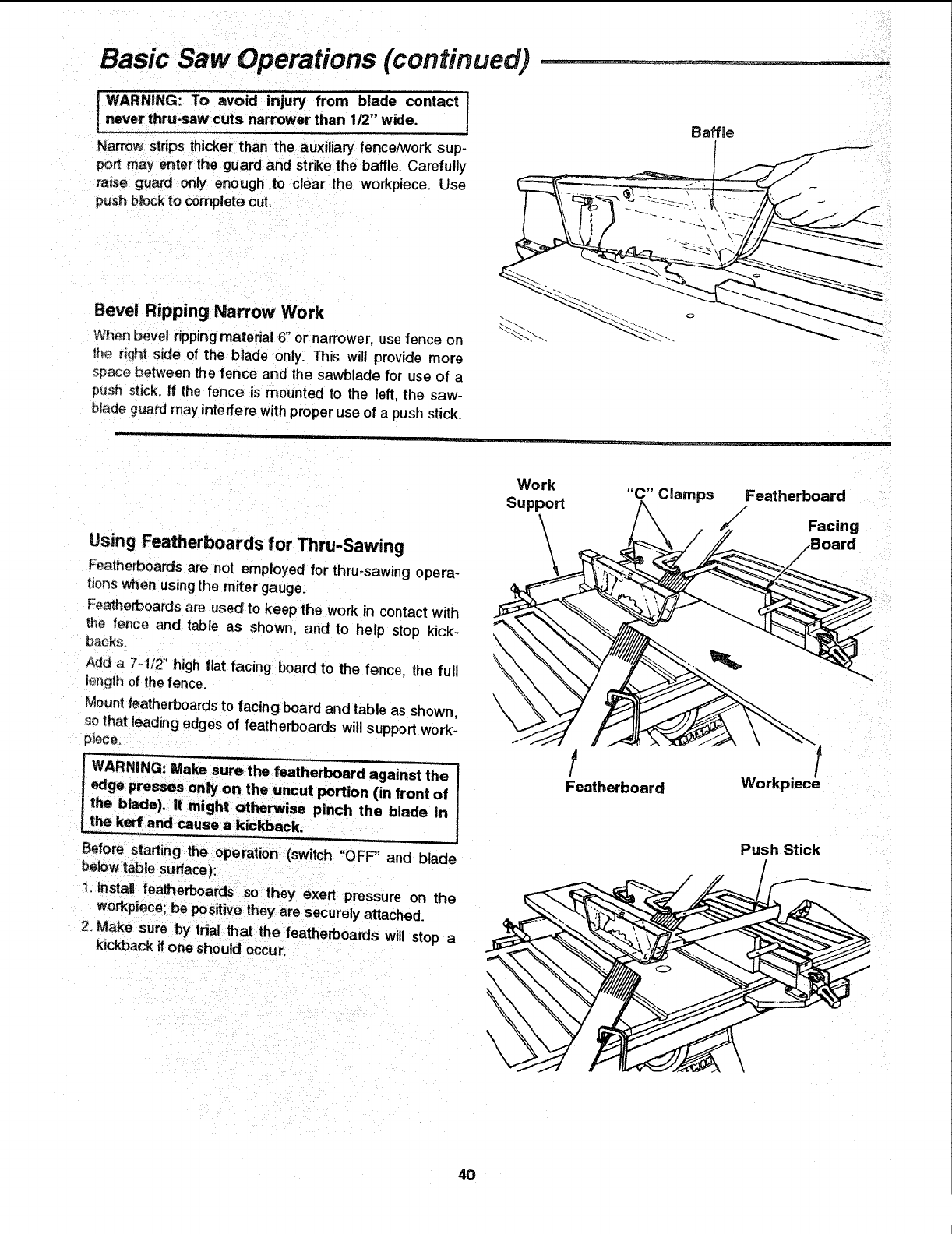
Basic Saw Operations (continued)
j WARN|NG: To avoid injury from blade contact 1
never thru-saw cuts narrower than 1/2" wide, I
Narrow strips thicker than the auxiliary fence/w0rk sup-
port may enter the guard and strike the baffle, Carefully
rinse guard only enough to clear the workpiece. Use
push b_ock to complete cut.
Bevel Ripping Narrow Work
When bevel ripping material 6" or narrower, use fence on
the rtght side of the btade only. This will provide more
space between the fence and the sawblade for use of a
p_sh stick. If the fence is mounted to the left. the saw-
btade guard may interfere with proper use of a push stick.
Baffle
Using Featherboards for Thru-Sawing
Featherboards are not employed for thru-sawing opera-
tions when using the miter gauge.
Featherboards are used to keep the work in contact with
the fence and table as shown, and to help stop kick-
backs.
Add a 7-1/2" high flat facing board to the fence, the full
tenth of the fence.
Mount teatherboards to facing board and table as shown,
so that leading edges of featherboards will support work-
piece,
tWARNING: Make sure the featherboard against the
edge presses only on the uncut portion (in front of
the blade), it might otherwise pinch the blade in
the k_f and cause a kickback
U-=- , _ •
Before starting the operation (switch "OFF" and blade
bek_w table surface):
1. install featherboards so they exert pressure on the
workpiece; be positive they are securely attached.
2. Make sure by trial that the featherboards will stop a
kickback ifone should occur,
\
\
\\
Work "C" Clamps Featherboard
Support
\Facing
\
!
Featherboard Workpiece
Push Stick
4O
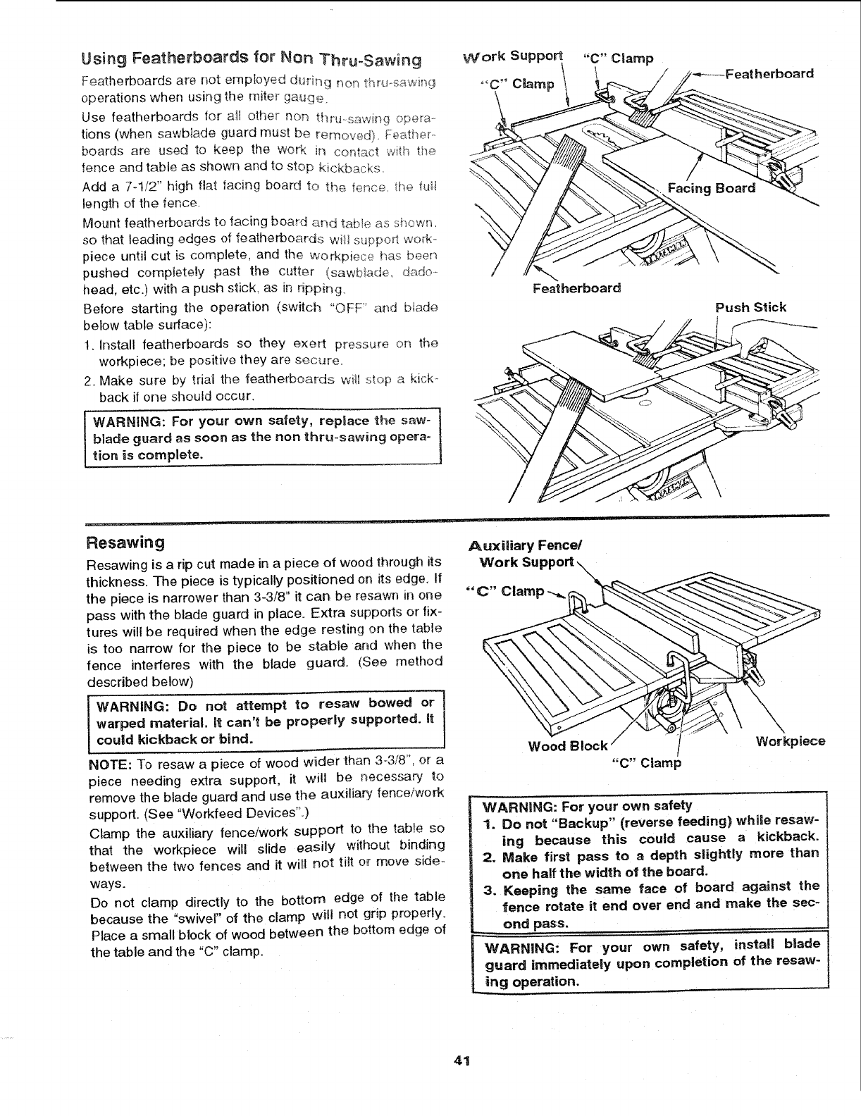
Using Featherboards for Non "Thru-Sawing
Featherboards are not emp!oyed duri_Tg nof_ thru-.sawing
operations when using the miter gauge.
Use featherboards for a_l other non !:hru--sawi_g opera ....
tions (when sawMade guard must be removed). Fe_,,ther.
boards are used to keep the woe< in contact wi_h fi_÷
fence and table as shown and to stop kickbacks.
Add a 7-1/2" high flat facing board to the fe_ce_ the full
length of the fence.
Mount featherboards to facing board and tame as shown.
so that leading edges of featherboards witl s,Jpporl work_
piece until cut is complete, and the Workpiece has been
pushed corlnpletely past the cutter (sawbtade, dado-
head, etc.) with a push stick, as in ripping.
Before starting the operation (switch "OFF" and btade
below table surface):
1. Install featherboards so they exert pressure on the
workpiece; be positive they are secure.
2. Make sure by trial the featherboards wi_l stop a kick-
back if one should occur.
WARNING: For your own safety, replace the saw- 1
blade guard as soon as the non thru-sawing opera-
lion is complete.
Featherboard
:herboard
Push Stick
Resawing
Resawing is a rip cut made in a piece of wood through its
thickness. The piece is typically positioned on its edge, I{
the piece is narrower than 3-3/8" it can be resawn in one
pass with the blade guard in place. Extra supports or fix-
tures will be required when the edge resting on the table
is too narrow for the piece to be stable and when the
fence interferes with the blade guard. (See method
described below)
WARNING: Do not attempt to resaw bowed or]
warped material. _t can't be properly supported, it /
could kickback or bind.
NOTE: To resaw a piece of wood wider than 3-3/8", or a
piece needing extra support, it will be necessary to
remove the blade guard and use the auxilia,_ fence/work
support. (See "Wed<feed Devices".)
Clamp the auxiliary fence/work support, to the table so
that the workpiece will slide easily without binding
between the two fences and it will not tilt or move side-
ways.
Do not clamp directly to the bottom edge of the table
because the "swivel" of the clamp will not grip properly.
Place a small block of wood between the bottom edge of
the table and the "C" clamp.
Auxiliary Fence/
Work Support _
""C" Clam
Wood Block /Workpiece
"C" Ciaml_
WARNING: For your own safety
1. Do not "Backup" (reverse feeding) whi_e resaw-
ing because this could cause akickback.
2. Make first pass to a depth slightly more than
one half the width ot the board.
3. Keeping the same face of board against the
fence rotate it end over end and make the sec-
ond pass,
WARNING: For your own safety, install blade
guard immediately upon completion of the resaw-
ing operation.
41
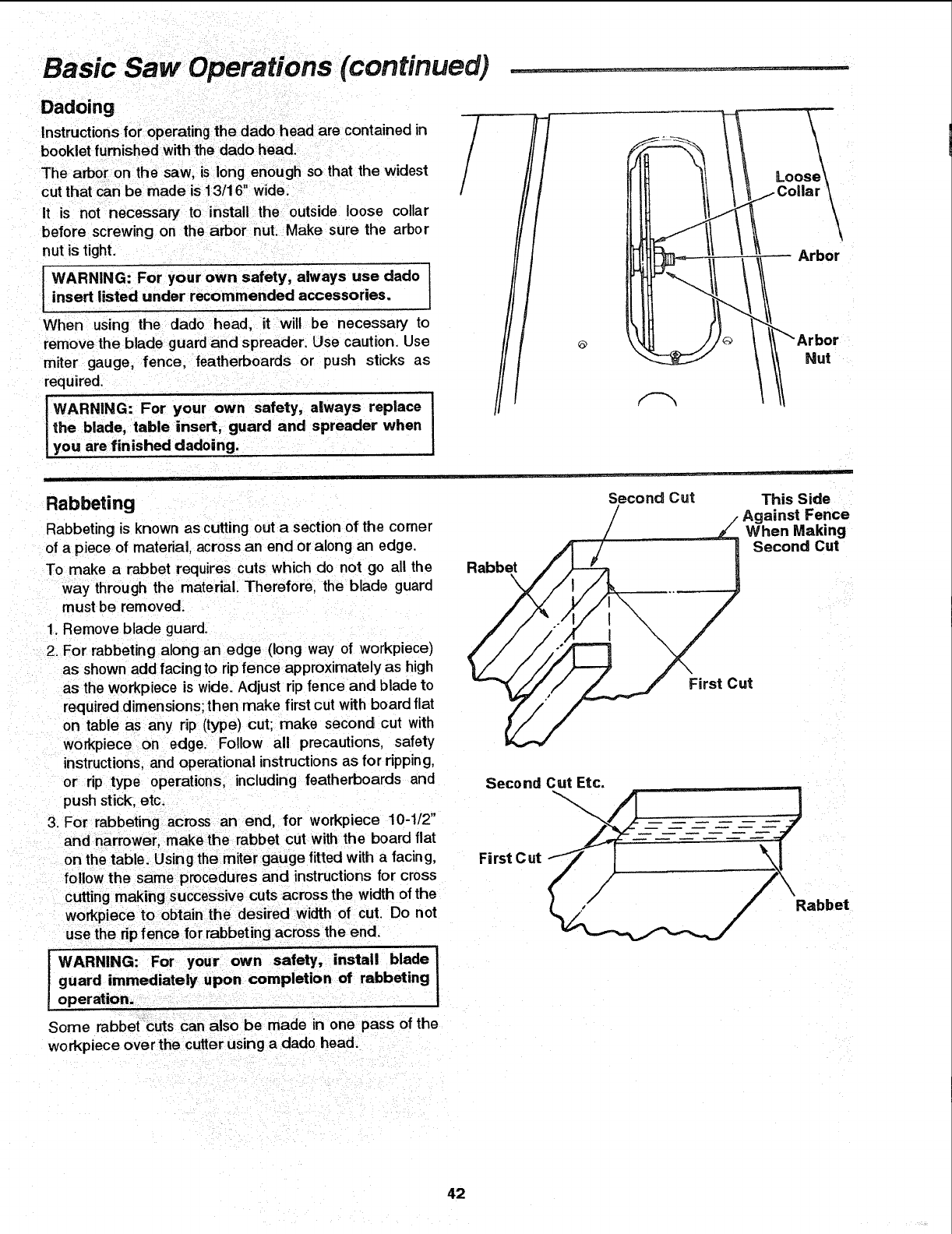
Basic Saw Operations (continued) ...................
Dadoing
Instructionsfor operating the dado head are contained in
booklet furnished with the dado head.
The arbor on the saw, is long enough so that the widest
cut that can be made is f3/16" wide.
it is not necessary to install the outside loose collar
before screwing on the arbor nut. Make sure the arbor
nut is tight.
IWARNING: For your own safety, always use dado
insert listed under recommended accessories.
When using the dado head, it will be necessary to
remove the blade guard and spreader. Use caution. Use
miter gauge, fence, featherboards or push sticks as
required.
WARNING: For your own safety, always replace
the blade, table insert, guard and spreader when
you are finished dadoing.
Loo_
Collar
"_bu_r
Rabbeting
Rabbeting is known as cutting out asection of the corner
of a piece of material, across an end or along an edge.
To make a rabbet requires cuts which do not go all the
way through the material. Therefore. the blade guard
must be removed.
Rabbet
\
Second Cut This Side
/Against Fence
When Making
Second Cut
1. Remove blade guard.
2. For rabbeting along an edge (long way of workpiece)
as shown add facing to rip fence approximately as high
as the workpiece is wide. Adjust rip fence and blade to
required dimensions; then make first cut with board flat
on table as any rip (type) cut; make second cut with
workpiece on edge. Follow all precautions, safety
instructions, and operational instructions as for ripping,
or rip type operations, including featherboards and
push stick, etc.
3. For rabbeting across an end, for workpiece 10-1/2"
and narrower, makethe rabbet cut with the board flat
on the table. Using the miter gauge fitted with a facin g,
follow the same procedures and instructions for cross
cutting makingsuccessive cuts across the width of the
workpiece to obtain the desired width of cut. Do not
use the rip fence for rabbeting across the end.
IWARNING: For your own safety, install blade i
guard immediately upon completion of rabbeting
operation.
Some rabbet cuts can also be made in one pass of the
workpiece over the cutter using adado head.
First Cut
Second Cut Etc.
First Cut
Rabbet
42
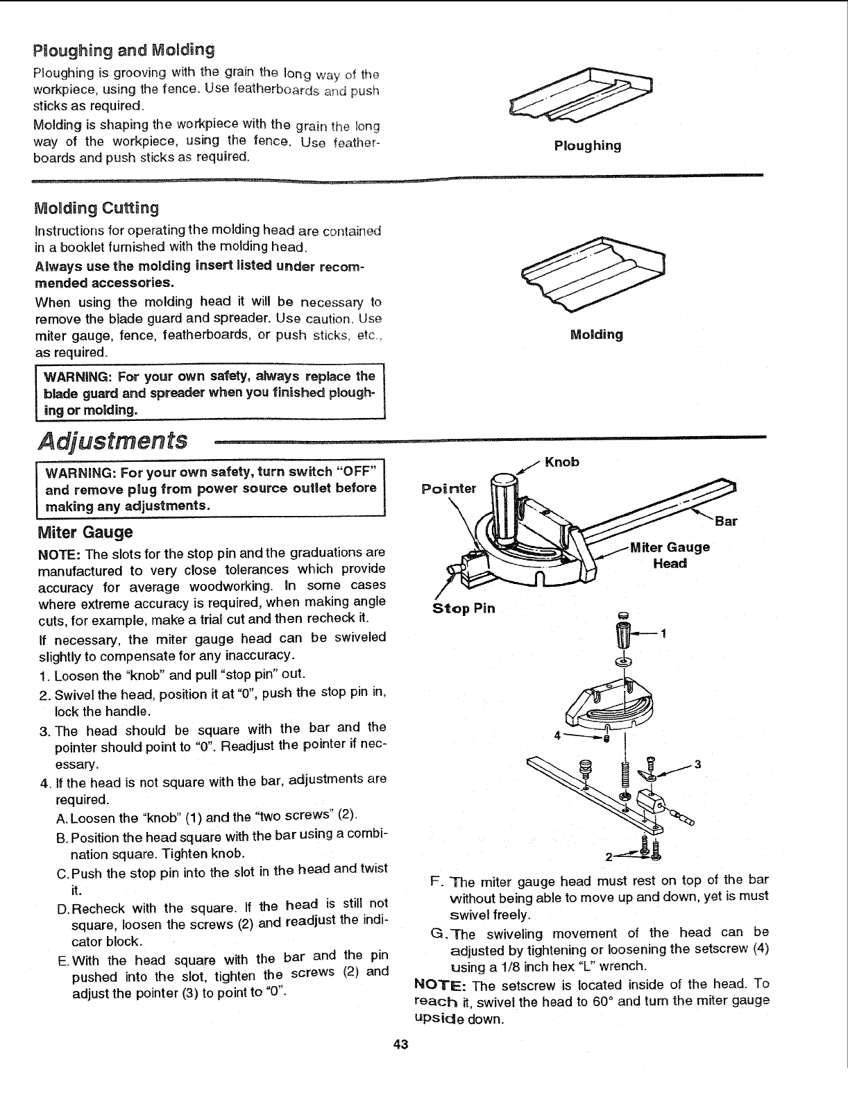
Ploughing and MoBding
Ploughing is grooving with the grain the long wa_/of the
workpiece, using the fence. Use featherboards and push
sticks as required.
Molding is shaping the wo_piece with the grain the _ong
way of the workpiece, using the fence. Use feather-
boards and push sticks as required. Ploughing
_- ............................. ,!, ir,,
Molding Cutting
Instructions for operating the molding head are contained
in a booklet furnished with the molding head.
Always use the molding insert listed under recom-
mended accessories,
When using the molding head it will be necessary to
remove the blade guard and spreader. Use caution_ Use
miter gauge, fence, featherboards, or push sticks, etc.
as required.
WARNING: For your own safety, ak_ays replace the !
blade guard and spreader when you finished plough-
ing or moUding.
Molding
Adjustments ..................
WARNaNG: For your own safety, turn sw_tch "OFF" I
and remove plug from power source outlet before l
making any adjustments.
Miter Gauge
NOTE: The slots for the stop pin and the graduations are
manufactured to very close tolerances which provide
accuracy for average woodworking. Un some cases
where extreme accuracy is required, when making angle
cuts, for exarnple, make atrial cut and then recheck it.
If necessary, the miter gauge head can be swiveled
slightly to compensate for any inaccuracy.
1. Loosen the "knob" and pull "stop pin" out.
2. Swivel the head. position it at "0", push the stop pin in,
lockthe handle.
3. The head should be square with the bar and the
pointer should point to "0". Readjust the pointer if nec-
essary.
4. If the head is not square with the bar, adjustments are
required.
A. Loosen the "knob" (1) and the "two screws" (2).
B. Position the head square withthe bar using acombi-
nation square. Tighten knob.
C. Push the stop pin into the slot in the head and twist
it.
D.Recheck with the square. If the head is still not
square, loosen the screws (2) and readjust the indi-
cator block.
E.With the head square with the bar and the pin
pushed into the slot, tighten the screws (2) and
adjust the pointer (3) to point to "0".
Pointer
\\
Knob
Gauge
Head
Bar
Stop Pin p-
F. The miter gauge head must rest on top of the bar
without being able to move up and down, yet is must
swivel freely.
G.-rhe swiveling movement of the head can be
adjusted by tightening or loosening the setscrew (4)
using a 1/8 inch hex "L" wrench.
NOTE: The setscrew is located inside of the head. To
reach it, swivel the head to 60 ° and turn the miter gauge
upside down.
43
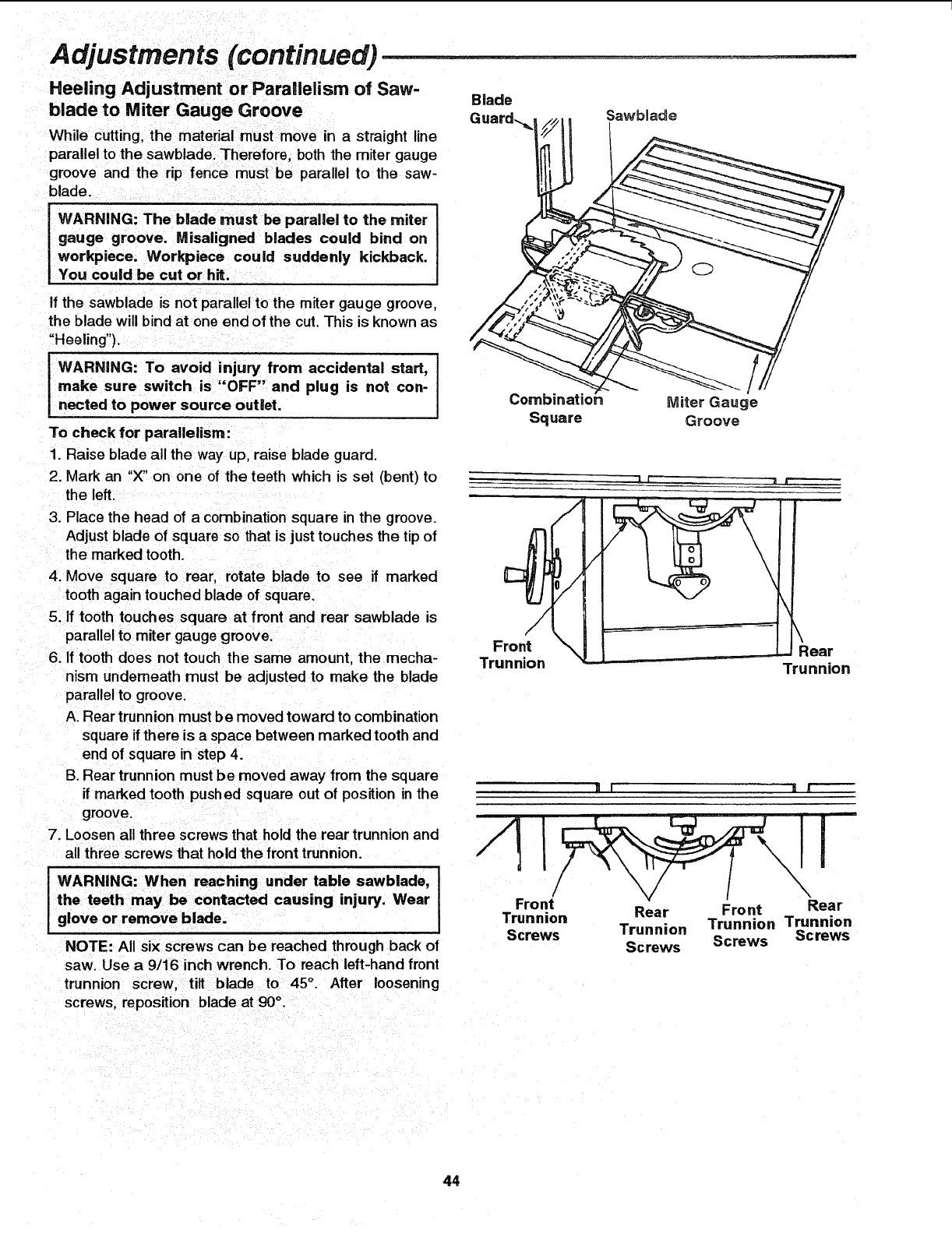
Adjustments (continued) ..............................................................
Heeling Adjustment or Parallelism of Saw-
blade to Miter Gauge Groove
While cutting, the material must move in a straight line
parallel to the sawblade. Therefore, both the miter gauge
groove and the rip fence must be parallel to the saw-
blade.
Blade
Guard-._ Sawblade
WARNING: The blade must be parallel to the miter
gauge groove. Misaligned blades could bind on
workpiece. Workpiece could suddenly kickback.
You could be cut or hit.
If the sawblade is not parallel to the miter gauge groove,
the blade will bind at one end of the cut. This is known as
"Heeling").
WARNING: To avoid injury from accidental start,
make sure switch is "OFF" and plug is not con-
nected to power source outlet.
To check for parallelism:
1. Raise blade all the way up, raise blade guard.
2. Mark an "X" on one of the teeth which is set (bent) to
the left.
3. Place the head of a combination square in the groove.
Adjust blade of square so that is justtouches the tip of
the marked tooth.
4. Move square to rear, rotate blade to see if marked
tooth again touched blade of square.
5. If tooth touches square at front and rear sawblade is
parallel to miter gauge groove.
6. If tooth does not touch the same amount, the mecha-
nism underneath must be adjusted to make the blade
parallel to groove.
A. Rear trunnion must be moved toward to combination
square if there is aspace between marked tooth and
end of square in step 4.
B. Rear trunnion must be moved away from the square
if marked tooth pushed square out of position in the
groove.
7. Loosen all three screws that hold the rear trunnion and
all three screws that hold the front trunnion.
iWARNING: When reaching under table sawblade,
the teeth may be contacted causing injury. Wear
glove or remove blade.
NOTE: All six screws can be reached through back of
saw. Use a 9/16 inch wrench. To reach left-hand front
trunnion screw, tilt blade to 45°. After loosening
screws, reposition blade at 90°.
Square Miter Gauge
Groove
I
Front
Trunnion
\
\
., Rear
Trunnion
Front Rear
Trunnion Rear Front
Screws Trunnion Trunnion Trunnion
Screws Screws Screws
44
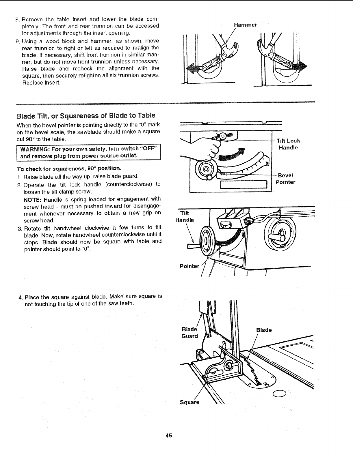
8. Remove the table insert and lower the blade com-
pletely. The front and rear trunnion can be accessed
for adjustments through the insert opening.
9. Using a wood block and hammer, as shown, move
rear trunnion to right or left as required to realign the
blade, If necessary, shift front trunnion in similar man-
ner, but do not move front trunnion unless necessary,
Raise blade and recheck the alignment with the
square, then securely retighten all six trunnion screws.
Replace insert.
Hammer
- - ..................................................... ,: := ......... i ....,
Blade Tilt, or Squareness of Bnade to Tabne
When the bevel pointer is pointing directly to the "0" mark
on the bevel scale, the sawblade should make a square
cut 90° to the table.
WARNING: For your own safety, turn switch "OFF"
and remove pmugfrom power source outlet.
To check for squareness, 90° position.
1. Raise blade all the way up, raise blade guard.
2. Operate the tilt lock handle (counterclockwise) to
loosen the tilt clamp screw.
NOTE: Handle is spring loaded for engagement with
screw head - must be pushed inward for disengage-
ment whenever necessary to obtain a new grip on
screw head.
3. Rotate tilt handwheel clockwise a few turns to tilt
blade. Now, rotate handwheel counterclockwise until it
stops. Blade should now be square with table and
pointer should point to "0".
Tilt Lock
Handle
Ievei
F ] Pointer
4. Place the square against blade. Make sure square is
not touching the tip of one of the saw teeth.
Blade
Guard /
Square
45
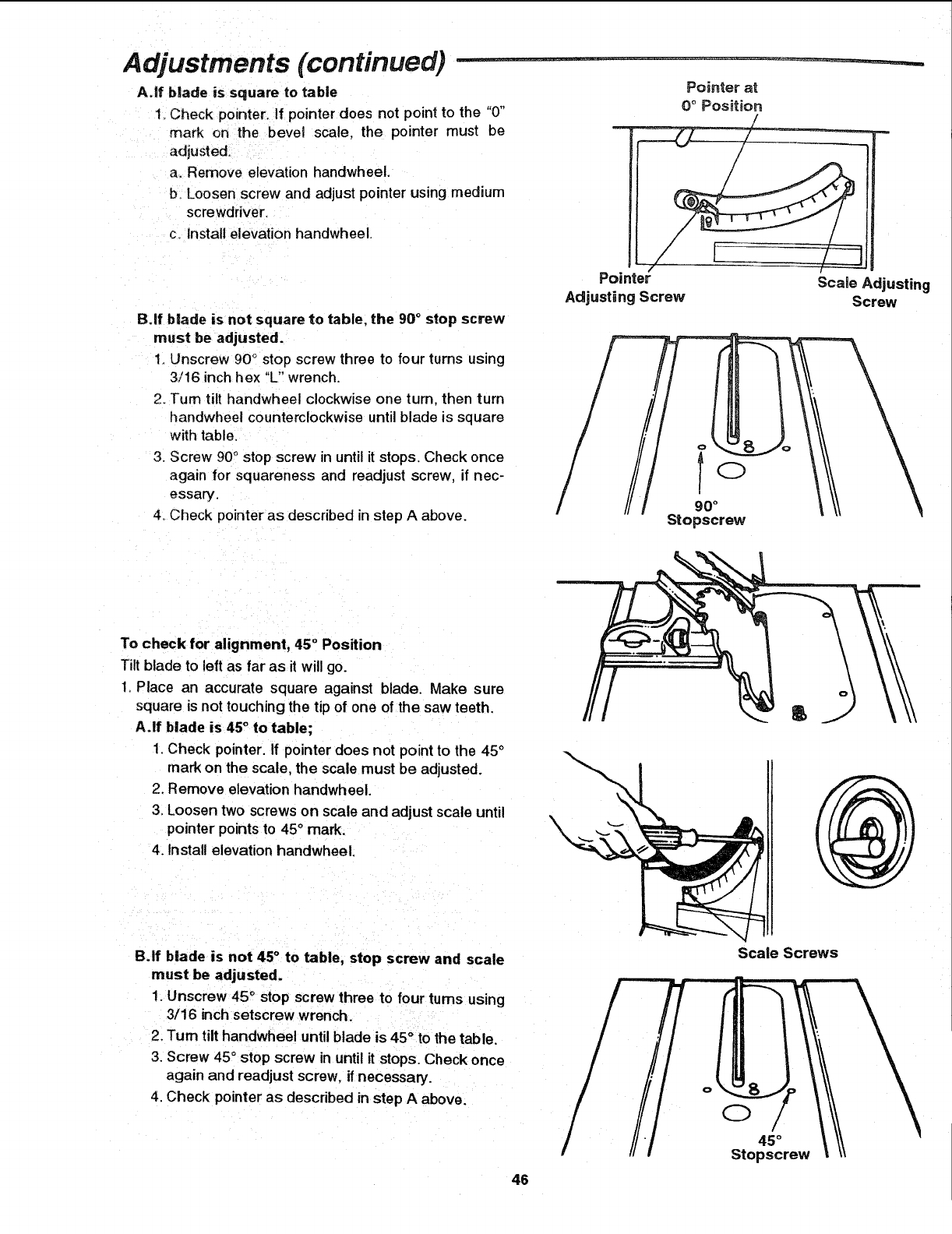
Adjustments (continued) - -
A,lf blade is square to table
1 Check pointer, if pointer does not point to the "0"
mark on the bevel scale, the pointer must be
adjusted.
a. Remove elevation handwheel.
b Loosen screw and adjust pointer using medium
screwdriver.
c. install elevation handwheel.
B.lf blade is not square to table, the 90 ° stop screw
must be adjusted.
1. Unscrew 90 ° stop screw three to four turns using
3/16 inch hex "L" wrench
2. Turn tilt handwheel clockwise one turn. then turn
handwheel counterclockwise until blade is square
with table.
3_ Screw 90° stop screw in until it stops. Check once
again for squareness and readjust screw, if nec-
essary.
4oCheck pointer as described in step A above.
Pointer at
0 ° Position
Pointer"
Adjusting Screw Scale Adjusting
Screw
Q
90 °
Stopscrew
To check for alignment, 45° Position
Tilt blade to left as far as it will go.
1. Place an accurate square against blade. Make sure
square is not touchingthe tip of one of the saw teeth.
A.If blade is 45° to table;
1. Check pointer. If pointer does not point to the 45°
mark on the scale, the scale must be adjusted.
2. Remove elevation handwheel.
3. Loosen two screws on scale and adjust scale until
pointer pointsto 45° mark.
4. Install elevation handwheel. \
B.If blade is not 45 ° to table, stop screw and scale
must be adjusted.
1. Unscrew 45 °stop screw three to four turns using
3/16 inch setscrew wrench.
2. Turn tilt handwheel until blade is 45 ° to the table.
3. Screw 45 ° stop screw in until it stops. Check once
again and readjust screw, if necessary.
4. Check pointer as described in step Aabove.
46
Scale Screws
45°
Stopscrew
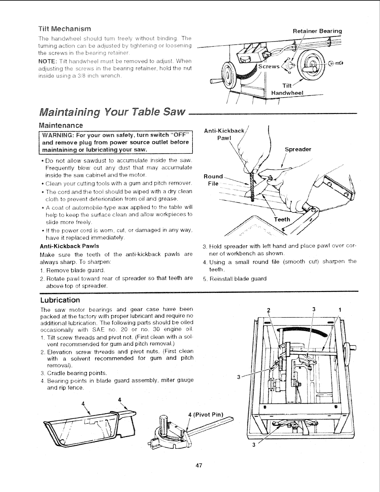
THt Mechanism
turning _ctior_ c_ be _,'.:iius_ed by _gMer_i__g or ioose<_ing
the screws in the bea,*i_!_ r_:_aim>_
NOTE: Ti!t har_dw_eei must be removed to adiust. W__,e_"_
adjusting the sc!ews i_ the bea_i,qg retainer, ho_d the nut
fftside using a 3'8 _ch wrench.
Maintaining Your TaMe Saw
Maintenance
WARNING: For your own safety, turn switch "OFF" ]
and remove plug from power source outget before J
maintaining or tJubr_cating your .saw.
• Do not altow sawdust to accumulate ip,side the saw,
Frequently Mow out any dust that may accumulate
ff'_side the saw cabinet a__d the motor.
o Clean your cutting tools with a gurn and pitch remover,
o The cord and the too_ should be wiped with a dry clean
cloth to prevent deterioration from oil and grease.
• A ceat of automobiie4ype wax appiied to the table wiJi
he_p to keep the surface clean and aIIow wo_kpieces to
s_ide more freely.
o tf the power cord is worn cut or damaged in any way
have it replaced irnmediately,
Anti-Kickback Paw_s
Make sure the teeth of the anti-kickback pawls are
always sharp. To sharpen:
1. Remove blade guard,
2. Rotate paw_ toward rear of spreader so that teeth are
above top of spreader.
Re_ainer _earring
_'_T _
i / _i e
._ ]i Tilt"
dwheel
Anti-Kickback//
Pawl /
X!
Teeth
Spreader
3. Hold spreader with left hand and place pawl over cop
ne_ of workbench as shown,
4, Using a smalt round file (smooth cut) sha_en the
teeth.
5, Reinstafl btade guard
Lubrication
The saw motor bearings and gear case have been
packed at the factory with proper lubricant and requffe no
additiona! tubricatior_. The following parts should be oiled
occasionai@ with SAE no. 20 or no. 30 engine oil.
1 Tiff screw threads and p_vot not. _First cJean with a sop
vent recommended fo_ gum and pitch removal }
2. E_evatien screw threads and pivot nuts, _Firsl c_ean
wffh a so_ven_ recommended for gum and pitch
removaI_
3 Cradle bearing points.
4 Bearing pomps _n blade guard assembly, m_ter gauge
and Np ter_ce,
dr-.,, 4 (Pivot Pin)
4
\
3"
47
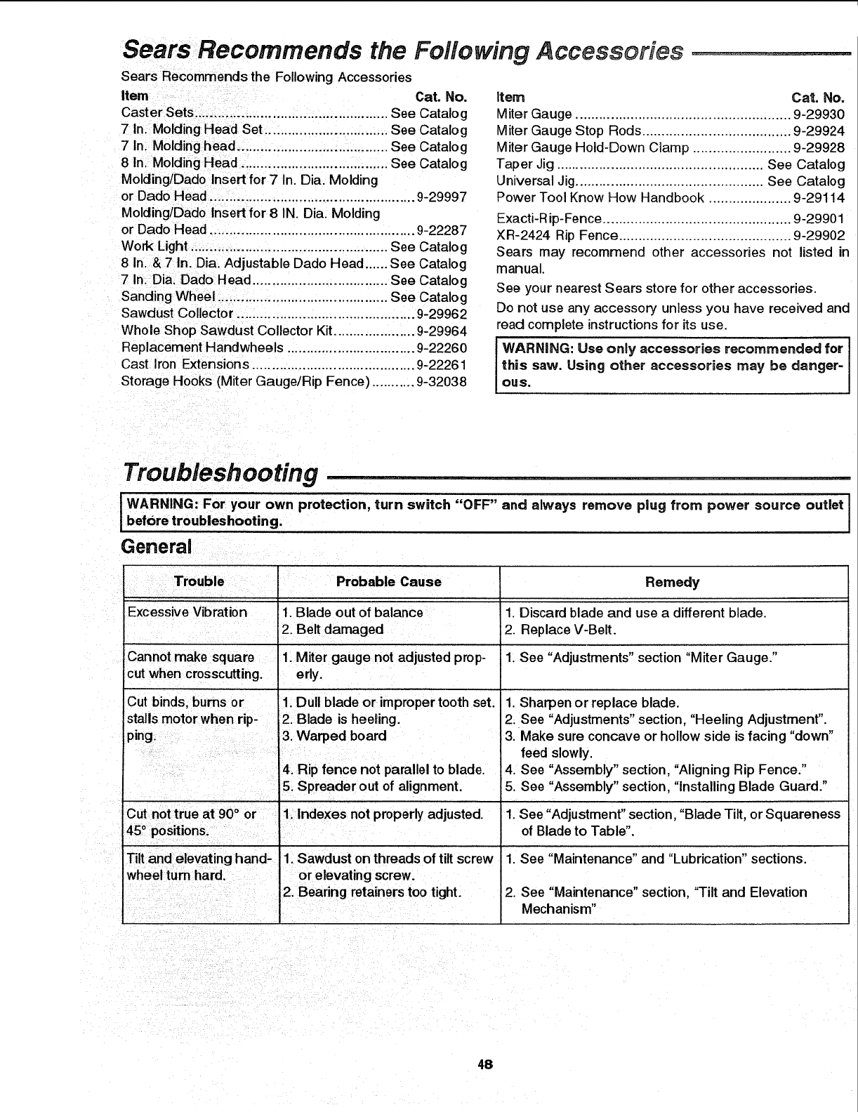
Sears Recommends the Following Accessories ............................
Sears Recommends the Following Accessories
Item Cat. No.
Caster Sets .................................................. See Catalog
7 in. Molding Head Set ................................ See Catalog
7 In. Molding head ....................................... See Catalog
8 In. Molding Head ...................................... See Catalog
Molding/Dado Insert for 7 In. Dia. Molding
or Dado Head ..................................................... 9-29997
Molding/Dado Insert for 8 IN. Dia. Molding
or Dado Head ..................................................... 9-22287
Work Light ................................................... See Catalog
8 in. & 7 In. Dia Adjustable Dado Head ...... See Catalog
7 In. Dia. Dado Head ................................... See Catalog
Sanding Wheel ............................................ See Catalog
Sawdust Collector .............................................. 9-29962
Whole Shop Sawdust Collector Kit ..................... 9-29964
Replacement Handwheels ................................. 9-22260
Cast Iron Extensions .......................................... 9-22261
Storage Hooks (Miter Gauge/Rip Fence) ........... 9-32038
Item Cat. No.
Miter Gauge ....................................................... 9-29930
Miter Gauge Stop Rods ...................................... 9-29924
Miter Gauge Hold-Down Clam p ......................... 9-29928
Taper Jig ..................................................... See Catalog
Universal Jig ................................................ See Catalog
Power Tool Know How Handbook ..................... 9-29114
Exacti-R ip-Fence ............................................... 9-29901
XR-2424 Rip Fence ............................................ 9-29902
Sears may recommend other accessories not listed in
manual.
See your nearest Sears store for other accessories.
Do not use any accessory unless you have received and
read complete instructions for its use.
IWARNING: Use only accessories recommended for I
this saw. Using other accessories may be danger-
ous,
Troubleshooting ..............................................
__ARN_NG: F__ y_ur _wn ___t_cti_n_ turn switch ``_FF__and a_way_ _em_ve p_ug fr_m powe_ s_u_ce _ut_et _beforetroubleshooting.
General
Probable Cause Remedy
Excessive Vibration 1. Blade out of balance 1. Discard blade and use a different blade.
2. Belt damaged 2. Replace V-Belt.
Cannot make square 1. Miter gauge not adjusted prop- 1. See "Adjustments" section "Miter Gauge."
cut when crosscutting, erly.
1. Dull blade or improper tooth set.
Cut binds, bums or
stalls motor when rip- 2. Blade is heeling.
ping. !3. Warped board
Tilt and elevating hand-
4. Rip fence not parallel to blade.
5. Spreader out of alignment.
1. Sawdust on threads of tilt screw
1. Sharpen or replace blade.
2. See "Adjustments" section, "Heeling Adjustment".
3. Make sure concave or hollow side is facing "down"
feed slowly.
4. See "Assembly" section, "Aligning Rip Fence."
5. See "Assembly" section, "Installing Blade Guard."
1. See "Adjustment" section, "Blade Tilt, or Squareness
of Blade to Table".
1. See "Maintenance" and "Lubrication" sections.
2. See "Maintenance" section, 'Tilt and Elevation
Mechanism"
48
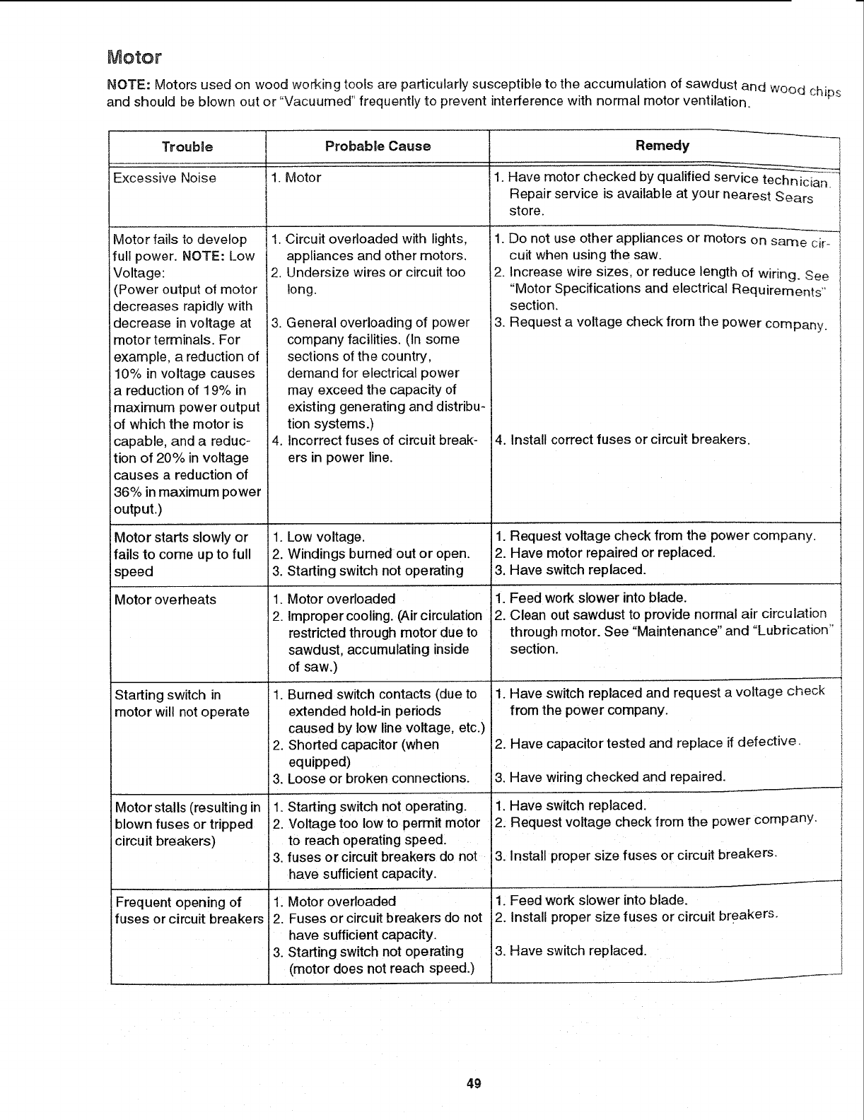
Motor
NOTE: Motors used on wood working tools are particularly susceptible to the accumulation of sawdust and WOod chips
and should be blown out or "Vacuumed" frequently to prevent interference with normal motor ventilation.
Trouble
Excessive Noise
Motor fails to develop
full power. NOTE: Low
Voltage:
(Power output of motor
decreases rapidly with
decrease in voltage at
motor terminals. For
example, a reduction of
10% in voltage causes
a reduction of 19% in
maximum power output
of which the motor is
capable, and a reduc-
tion of 20% in voltage
causes a reduction of
36% in maximum power
output.)
Motor starts slowly or
fails to come up to full
speed
Motor overheats
Starting switch in
motor will not operate
Motor stalls (resulting in
blown fuses or tripped
circuit breakers)
Frequent opening of
fuses or circuit breakers
Probable Cause
1. Motor
Circuit overloaded with lights,
appliances and other motors.
Undersize wires or circuit too
long.
3. General overloading of power
company facilities. (In some
sections of the country,
demand for electrical power
may exceed the capacity of
existing generating and distribu-
tion systems.)
4. Incorrect fuses of circuit break-
ers in power line.
1. Low voltage.
2. Windings burned out or open.
3. Starting switch not operating
.
2.
Motor overloaded
Improper cooling. (Air circulation
restricted through motor due to
sawdust, accumulating inside
of saw.)
1. Burned switch contacts (due to
extended hold-in periods
caused by low line voltage, etc.)
2. Shorted capacitor (when
equipped)
3. Loose or broken connections.
1. Starting switch not operating.
2. Voltage too low to permit motor
to reach operating speed.
3. fuses or circuit breakers do not
have sufficient capacity.
1. Motor overloaded
2. Fuses or circuit breakers do not
I have sufficient capacity.
3. Starting switch not operating
(motor does not reach speed.)
Remedy
.Have motor checked by qualified service technician.
Repair service is available at your nearest Sears
store.
1. Do not use other appliances or motors on same ciro
cult when using the saw.
2. Increase wire sizes, or reduce length of wiring. See
"Motor Specifications and electrical Requirements"
section.
3. Request a voltage check from the power company.
4. Install correct fuses or circuit breakers.
1. Request voltage check from the power company.
2. Have motor repaired or replaced.
3. Have switch replaced.
1. Feed work slower into blade.
2. Clean out sawdust to provide normal air circulation
through motor. See "Maintenance" and "Lubrication"
section.
1. Have switch replaced and request a voltage check
from the power company.
2. Have capacitor tested and replace if defective,
3. Have wiring checked and repaired.
1. Have switch replaced.
2. Request voltage check from the power company.
3. Install proper size fuses or circuit breakers.
1. Feed work slower into blade.
2. Install proper size fuses or circuit breakers.
3. Have switch replaced.
I
49
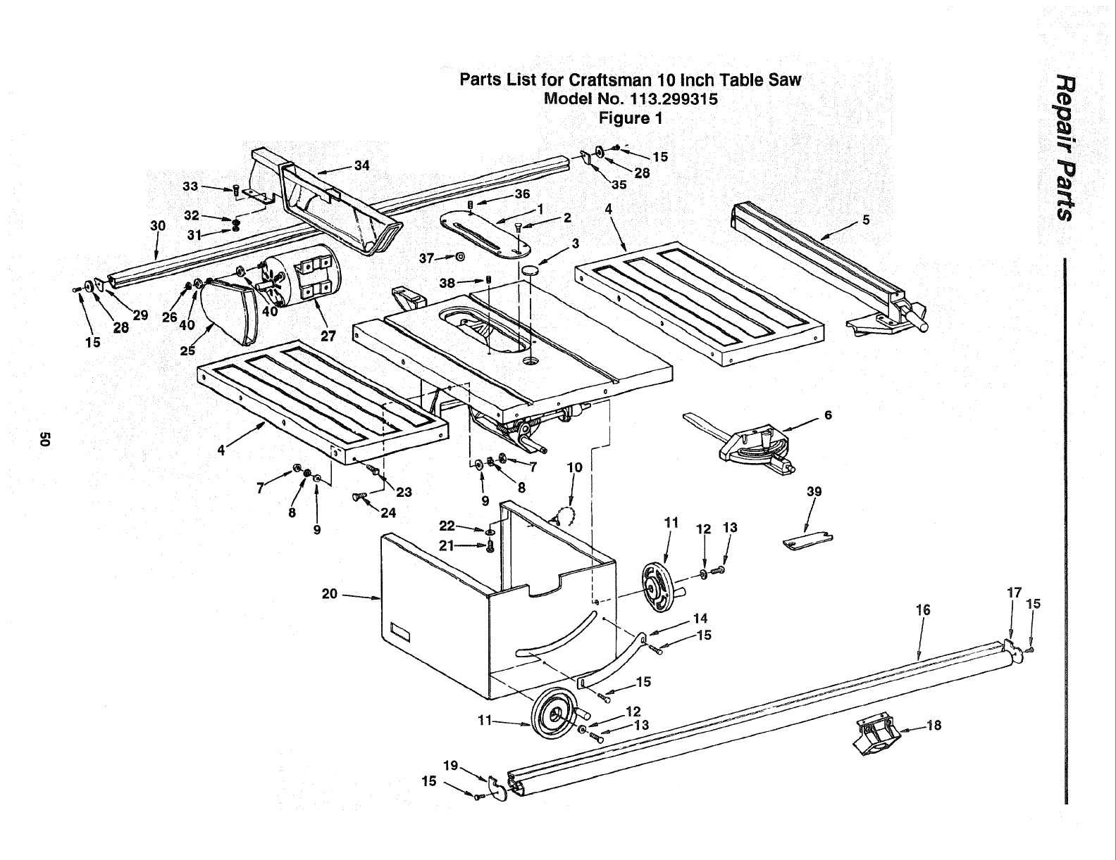
3O
28
15 2_
\
Parts List for Craftsman 10 Inch Table Saw
Model No. 113.299315
Figure 1
35
4
\\
ii
u1
o
8
9
2O
24
l \8
9
11
6
39
/
12 13
15

ol
,=,,&
Parts List for Craftsman 10 Inch Table Saw
Model No. 113.299315
Figure 1
Always Order by Part Number - not by Key Number
Key Part No. Description
No.
1 62703
2447441
362493
4824351
5
6
7STD541231
8STD551231
9 STD551031
10 71165
11 820452
12 STD551210
13 809372-7
14 818548
15 STD600805
16 824345-1
17 824339
18
19 824341
2O 810774-1
21 60077
Standard Hardware
_r
Insert (Includes Key #36)
Screw Flat Hd 10-32 x 1
Insert Exact-I-Cut
Extension Table 12 x 27
Fence Asm (See Fig 4)
Miter Gauge (See Fig 5)
Nut Hex 5/16-18
Lockwasher 5/16
Washer 21/64 x 5/8 x 1/16
Tie Wire
Handwheel
Lockwasher #10
Screw Pan Hd 10-32 x 5/8
Scale Adjustable Bevel
Screw Pan Hd Ty "AB" 8 x 1/2
Rail Front w/Scales
Cap Front Rail Right
Switch Box (See Fig 1)
Cap Front Rail Left
Base
Screw Hex Hd 3/8-16 x 1/2
tern - May be purchased locally
Key
No.
22
23
24
25
26
27
28
29
3O
31
32
33
34
35
36
37
38
39
40
Part No. Description
STD551237
159653-38
STD523712
824360
STD541110
824377
805548-11
*Lockwasher 3/8
Bolt Sq Hd 5/!6-!8 x 1
* Screw Hex Hd 5/16-18 x 1-1/4
Guard Belt
*Nut 10-32
,, Motor
Washer 3/16 xI x 1/16
824373
824340-1
STD541025 *
STD551225 *
STD522506 *
824372
104879
818309
818463
3540
STD551010 *
SP5908
Cap Rear Rail Left
Rail Rear
Nut Hex 1/4-20
Lockwasher 1/4
Screw Hex Hd 1/4-20 x 5/8
Guard Assembly (See Fig 6)
Cap Rear Rail Right
Screw Lock Set 10-32 x 3/16
Washer Shim
Screw Soc Set Oval 3/8-16 x 3/4
Wrench, Arbor
Washer 13/64 x 3/8 x 1/32
Owners Manual (Not Illustrated)
, Any attempt to repair this motor may create a hazard
unless repair is done by a qualified service technician.
Repair service is available at your nearest Service/Center
Department.
;&
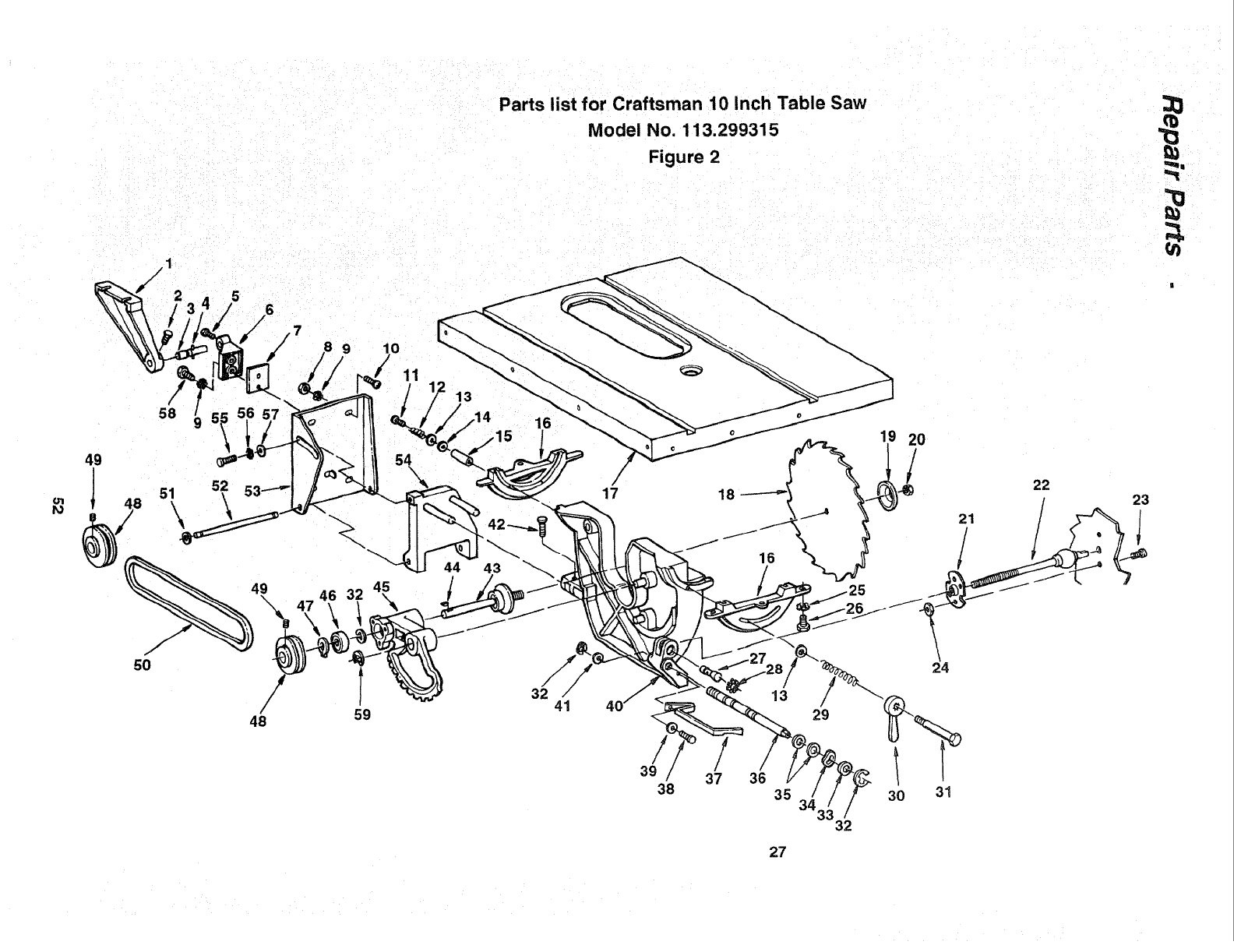
Parts list for Craftsman 10 Inch Table Saw
Model No. 113.299315
Figure 2
/1
49
5O
48
l32
59 41 13
29
24
21
/
22
n
==
23
39 /37 36 /
38 35 30 31
32
27
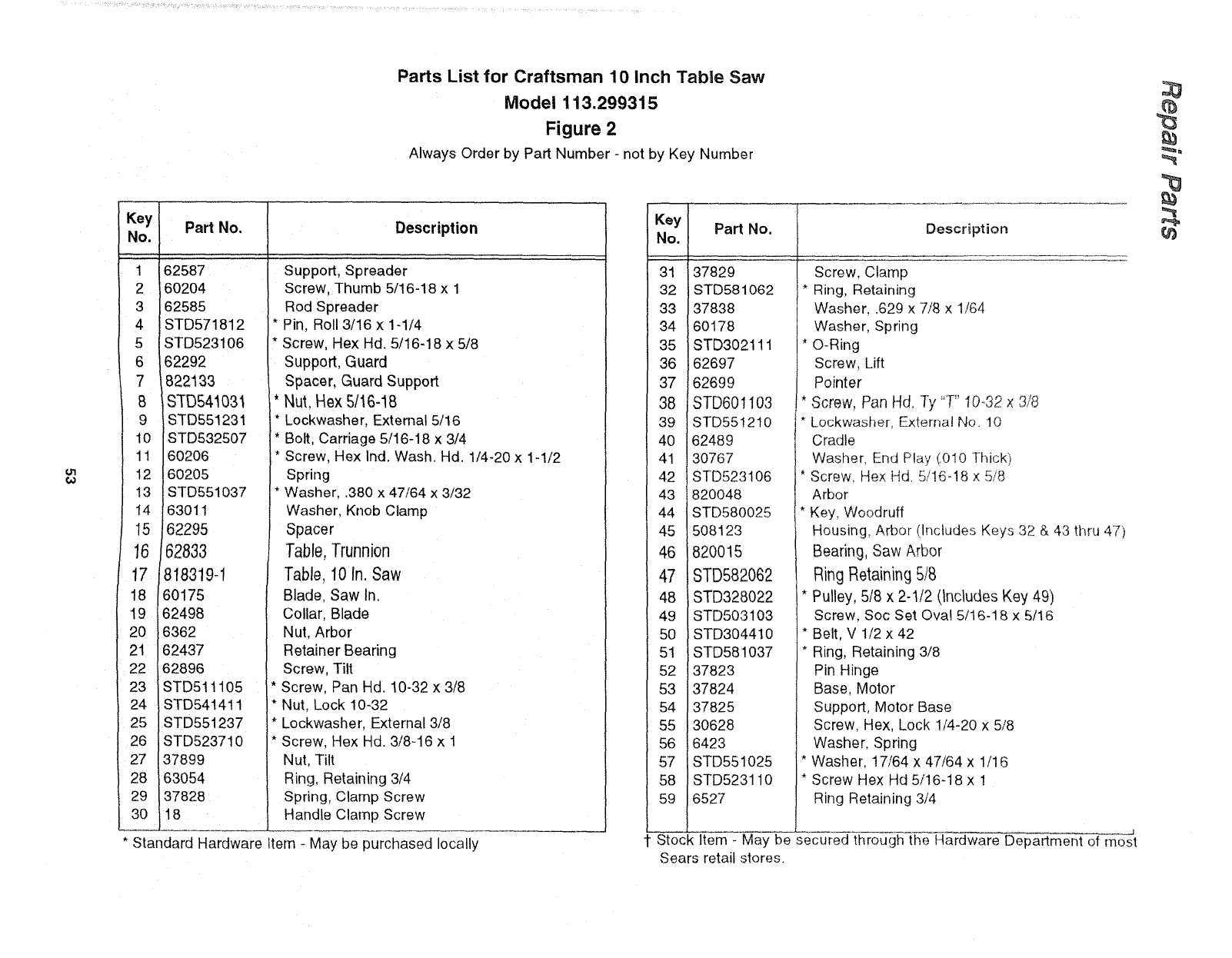
Parts List for Craftsman 10 Inch Table Saw
Model 113.299315
Figure 2
Always Order by Part Number - not by Key Number
Key
No.
1
2
3
4
5
6
7
B
9
lO
11
12
13
14
15
16
17
18
19
20
21
22
23
24
25
26
27
28
29
30
Part No. Description
62587
60204
62585
STD571812
STD523106
62292
822133
STD541031
STD551231
STD532507
60206
60205
STD551037
63011
62295
62833
818319-1
60175
62498
6362
62437
62896
STD511105
STD541411
STD551237
STD523710
37899
63054
37828
18
Support, Spreader
Screw, Thumb 5/16-18 x 1
Rod Spreader
* Pin. Roll 3/16 x 1-1/4
* Screw, Hex Hd. 5/16-18 x 5/8
Support. Guard
Spacer. Guard Support
Nut. Hex 5/!6-18
* Lockwasher, External 5/16
* Bolt, Carriage 5/16-18 x 3/4
* Screw, Hex Ind. Wash Hd. 1/4-20 x 1-1/2
Spring
* Washer..380 x 47/64 x 3/32
Washer Knob Clamp
Spacer
Table,Trunnion
Table. 10 in. Saw
Blade. Saw In
Collar, Blade
Nut. Arbor
Retainer Bearing
Screw, Tilt
Screw. Pan Hd 10-32 x 3/8
* Nut. Lock 10-32
* Lockwasher. External 3/8
* Screw. Hex Hd. 3/8-16 x 1
Nut, Tilt
Ring, Retaining 3/4
Spring, Clamp Screw
Handle Clamp Screw
* Standard Hardware Item - May be purchased locally
Key
No.
31
32
33
34
35
36
37
38
39
40
4!
42
43
44
45
46
47
48
49
5O
51
52
53
54
55
56
57
58
59
Part No.
37829
STD581O62
37838
6O178
STD302111
62697
62699
STD601 ! 03
STD551210
62489
30767
STD523106
820o48
STD580025
508123
820015
STD582062
iSTD328022
STD503103
iSTD304410
STD581037
37823
37824
37825
30628
6423
STD551025
STD523110
6527
Description
Screw, Clamp
* Ring, Retaining
Washer, .629 x 7/8 x 1/64
Washer, Spring
* O-Ring
Screw, Lift
Pointer
* Screw, Pan Hd, Ty "T" 10o32 x 3/8
Lockwasher, External No, 10
Cradle
Washer, End P!ay (O10 Thick)
* Screw, Hex Hd 5/16-18 x 5/8
Arbor
I* Key, Woodruff
Housing, Arbor (Includes Keys 32 & 43 thru 47)
Bearing, Saw Arbor
RingRetaining 5/8
* Pulley, 5/8 x 2-1/2 (includes Key 49)
Screw, Soc Set Ova! 5/!6-18 x 5/16
* Belt, V 1/2 x 42
* Ring, Retaining 3/8
Pin Hinge
Base, Motor
Support, Motor Base
Screw, Hex, Lock 1/4-20 x 5/8
Washer, Spring
* Washer, 17/64 x 47/64 x 1/16
* Screw Hex Hd 5/16-18 x !
Ring Retaining 3/4
1 Stock Item - May be secured through the Hardware Department of most
Sears retail stores.
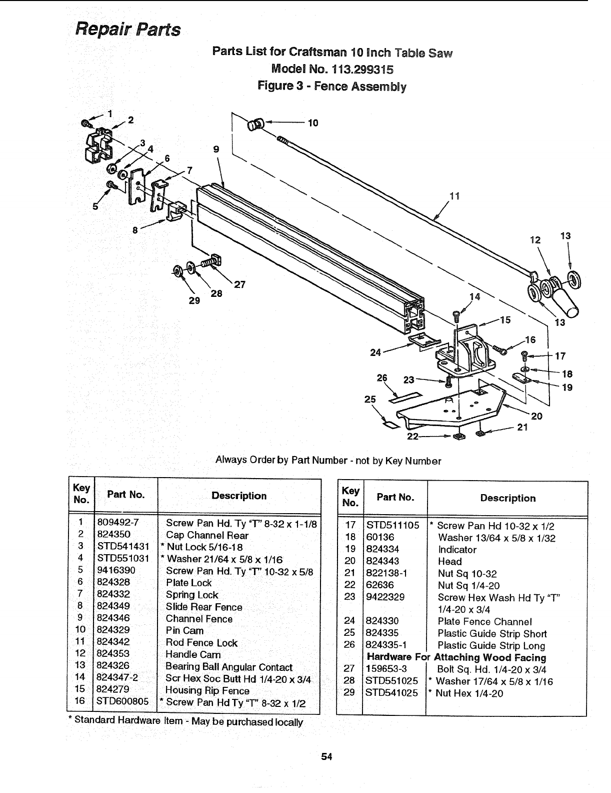
Repair Parts
28
29
Parts List for Craftsman 10 inch Table Saw
Model No. 113.299315
Figure 3 - Fence Assembly
10
11
24
26 23
\
25
o
12
20
21
17
19
Always Order by Part Number - not by Key Number
Key
No.
1
2
3
4
Pa_ No.
809492-7
824350
STD541431
STD551031
Description
Screw Pan Hd. Ty "T" 8-32 × 1-1/8
Cap Channel Rear
* Nut Lock 5/16-18
* Washer 21/64 x 5/8 x 1/16
5 9416390
6 824328
7 824332
10 824329
11 .824342
12 "824353
Screw Pan Hd. Ty "T" 10-32 x 5/8
Plate Lock
Spring Lock
Pin Cam
Rod Fence Lock
Handle Cam
I 13 824326 Bearing Bali Angular Contact
14 "824347-2 ' ScrHexSocButtHd 1/4-20x3/4
15
16 1/2
* Standard Hardware Item - May be purchased locally
Key
No. Part No.
17 STD511105
18 60136
19 824334
20 824343
21 822138-1
22 62636
23 9422329
24
25
26
27
28
29
1824330
824335
824335-1
Description
Screw Pan Hd 10-32 x 1/2
Washer 13/64 x 5/8 x 1/32
Indicator
Head
Nut Sq 10-32
Nut Sq 1/4-20
Screw Hex Wash Hd Ty "T"
1/4-20 x 3/4
Plate Fence Channel
Plastic Guide Strip Short
Plastic Guide Strip Long
Hardware For Attaching Wood Facing
159653-3 Bolt Sq. Hd. 1/4-20 x 3/4
STD551025 * Washer 17/64 x 5/8 x 1/16
STD541025 * Nut Hex 1/4-20
54
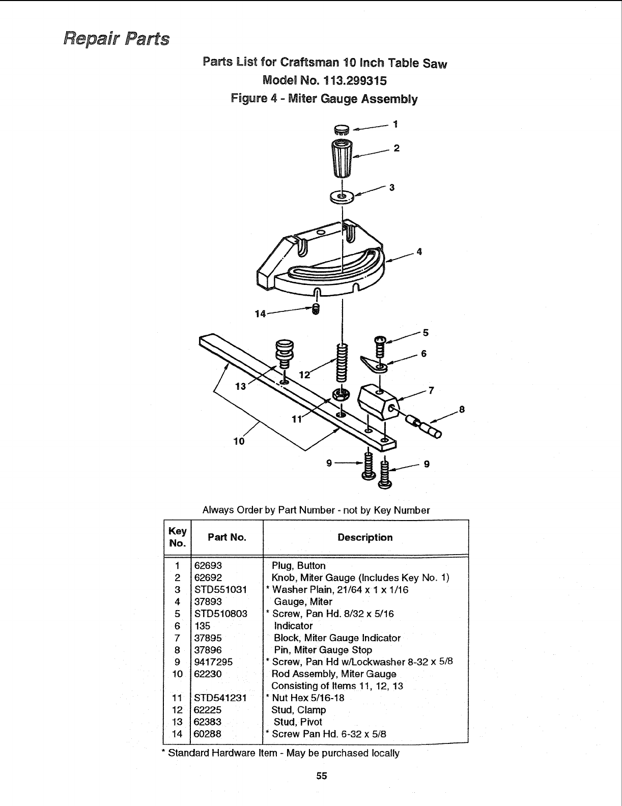
Repair Parts
Parts List for Craftsman 10 inch Table Saw
ModeJ No. 113.299315
Figure 4 - Miter Gauge Assembly
_ 4..__._I 1
.,,,._.j 2
Always Order by Part Number - not by Key Number
Key
No. Part No. Description
1 62693
2 62692
3 STD551031
4 37893
5 STD510803
6 135
7 37895
8 37896
9 9417295
10 62230
11 STD541231
12 62225
13 62383
14 60288
Plug, Button
Knob, Miter Gauge (Includes Key No. 1)
* Washer Plain, 21/64 x 1 x 1/16
Gauge, Miter
*Screw, Pan Hd. 8/32 x 5/16
Indicator
Block, Miter Gauge Indicator
Pin, Miter Gauge Stop
* Screw, Pan Hd w/Lockwasher 8-32 x 5/8
Rod Assembly, Miter Gauge
Consisting of Items 11, 12, 13
* Nut Hex 5/16-18
Stud, Clamp
Stud, Pivot
* Screw Pan Hd. 6-32 x 5/8
* Standard Hardware Item - May be purchased locally
55
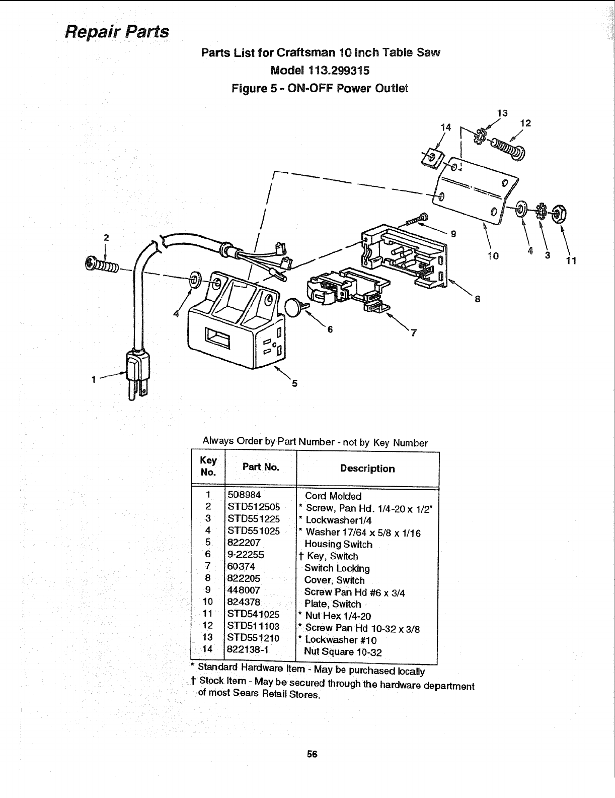
Repair Parts
Parts List for Craftsman 10 ranch Table Saw
Model 113.299315
Figure 5 -ON-OFF Power Outlet
14
/
/
5
x. 8
10 \11
Always Order by Part Number - not by Key Number
Key Part No.
No.
1508984
2 STD512505
3STD551225
4 STD551025
5822207
6 9-22255
7 60374
8 822205
9 4480O7
10 824378
11 STD541025
12 STD511103
13 STD551210
822138-1
Description
Cord Molded
* Screw, Pan Hd. 1/4-20 x 1/2"
* Lockwasherl/4
* Washer 17/64 x 5/8 x 1/16
Housing Switch
1"Key, Switch
Switch Locking
Cover, Switch
Screw Pan Hd #6 x 3/4
Plate, Switch
* Nut Hex 1/4-20
* Screw Pan Hd 10-32 x 3/8
* Lockwasher #10
Nut Square 10-32
* Standard Hardware Item - May be purchased locally
1 Stock Item - May be secured through the hardware department
of most Sears Retail Stores.
56
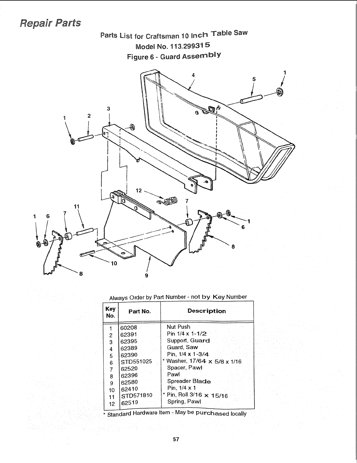
Repair Parts
1 2
\
11
Parts List for Craftsman 10 inch Table Saw
Model No. 113.29931 5
Figure 6 - Guard Asserr_blY
4
/
7
8
10
Always Order by Part Number- not by Key Number
Key
No.
1
2
3
4
5
6
7
8
9
10
11
12
Part No. Description
60208 Nut Push
62391 Pin 1/4 x1-1/2
62395 Support, Guard
62389 Guard, Saw
62390 Pin, 1/4 x 1-3/4
STD551025 * Washer, 17/64 x 5/8 x 1/16
62520 Spacer, Paw!
62396 Pawl
62580 Spreader Blade
62410 Pin, 1/4 x 1
STD571810 * Pin, Rol! 3/16 × 15/16
62519 Spring, Pawl
* Standard Hardware Item - May be purchased Iocatly
57
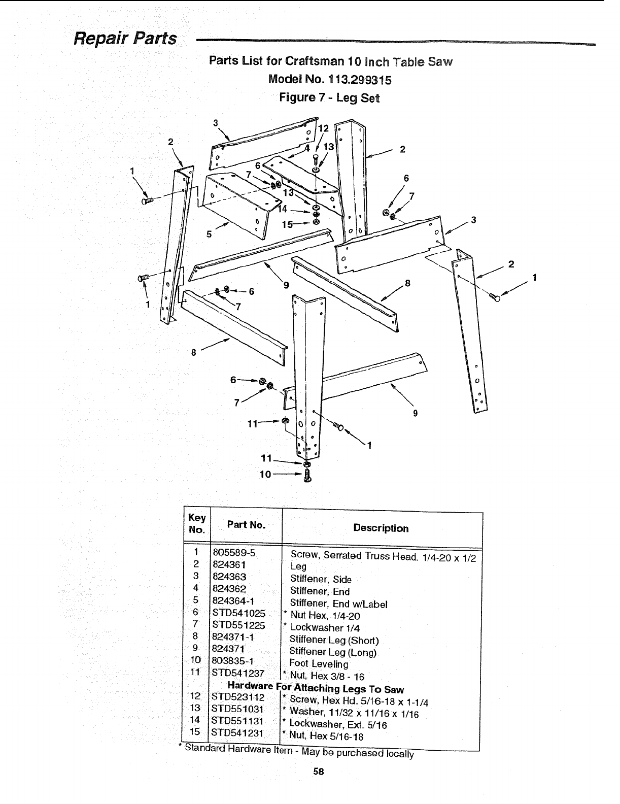
Repair Parts
2\
1
\
1
Parts List for Craftsman 10 inch Table Saw
Model No. 113.299315
Figure 7- Leg Set
Key
No.
1
2
3
6
7i
8
9
r 10
11
12
13
Part No.
805589-5
824361
824363
624362
1824364-1
STD541 O25
STD551225
824371-1
Description
Screw, Serrated Truss Head. 1/4-20 x 1/2
Leg
Stiffener, Side
Stiffener, End
Stiffener, End w/Label
* Nut Hex, 1/4-20
* Lockwasher 1/4
Stiffener Leg (Short)
824371 ] Stiffener Leg (Long)
803835-1 Foot Leveling
STD541237 *Nut, Hex 3/8 - 16 To Saw
STD523112 * Screw, Hex Hd. 5/16-18 x 1-1/4
STD551031 '* Washer, 11/32 x 11/16 x 1/16
14 I STD551131 * Lockwasher, Ext. 5/16
15 * Nut, Hex 5/16-18
• Standard Hardware Item - May be purchased locally
58

Notes
59
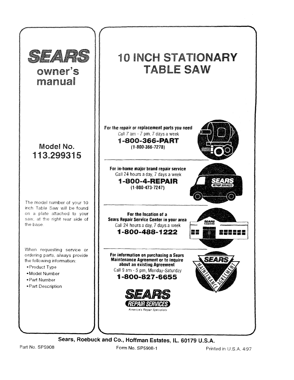
owner's
manuam
ModeJ No.
113.299315
Tt_e mode_ number of your 10
inch Table Saw will be found
or_ a p_ate attached to your
saw. at the right rear side of
the base,
When requesting service or
ordering parts_ always provide
the fo_owing information:
,, Product Type
- Model Number
°Part Number
*Part Description
Part No. SP5908
10 iNCH STATIONAJ
TABLE SAW
Y
For the repair or repRacementpads youneed
Carl 7am - 7pm, 7 days a week
t-800-366-PART
{1-808-356-7278)
For in-home major brandrepair service
Gall 24 hours a day;7 days a week
1-800-4-REPAIR
(1-800-473-7247)
For the location of a
Sears RepairService Centerin your area
Call 24 hours a day,7 days a week
1-800-488-1222
For information on purchasingaSears
Maintenance Agreementor to inquire
about an existingAgreement
Carl 9 am -5 pro, lVI0nday-Saturday
1-800-827-6655
_,"t:_,.rt;i,"i:/;jrt[_$t)
America's Repa;t" Specla&sts
...... j
i i i IH illl i i ii .... _1
Sears, Roebuck and Co., Hoffman Estates, iL. 60179 U.S.A.
Form No. SP5908-1 Printed in U.S.A. 4/97
