Craftsman 137211940 User Manual COMPOUND MITER SAW Manuals And Guides L0811588
CRAFTSMAN Miter Saw Manual L0811588 CRAFTSMAN Miter Saw Owner's Manual, CRAFTSMAN Miter Saw installation guides
User Manual: Craftsman 137211940 137211940 CRAFTSMAN COMPOUND MITER SAW - Manuals and Guides View the owners manual for your CRAFTSMAN COMPOUND MITER SAW #137211940. Home:Tool Parts:Craftsman Parts:Craftsman COMPOUND MITER SAW Manual
Open the PDF directly: View PDF ![]() .
.
Page Count: 44

Operator's Manual
CRRFrSr4RH°
7-1/4 in. SLiDiNG COMPOUND
MITER SAW WiTH LASER TRAC®
Model No. 137.211940
C US
CAUTION:
Before using this Miter Saw,
read this manual and follow
all its Safety Rules and
Operating Instructions
• Safety Instructions
• Installation
• Operation
• Maintenance
• Parts List
Customer Help Line
For Technical Support
1-800-843-1682
Sears Parts &
Repair Center
1-800-488-1222
Sears, Roebuck and Co., Hoffman Estates, IL 60179 USA
Visit our Craftsman website: www.sears.com/craftsman
Part No. 137211940001 Printed in China

SECTION PAGE
Warranty.........................................................................................2
ProductSpecifications....................................................................3
Symbols..........................................................................................4
PowerToolSafety..........................................................................5
CompoundMiterSawSafety..........................................................7
ElectricalRequirementsandSafety.................................................. 9
AccessoriesandAttachments........................................................11
ToolsNeededforAssembly............................................................12
CartonContents.............................................................................13
KnowYourSlidingCompoundMiterSaw......................................... 14
GlossaryofTerms..........................................................................15
AssemblyandAdjustments.............................................................17
Operation.......................................................................................26
Maintenance...................................................................................37
TroubleshootingGuide...................................................................39
PartsList........................................................................................41
CRAFTSMAN ONE YEAR FULL WARRANTY
If this Craftsman tool fails due to a defect in material or workmanship within
one year from the date of purchase, call 1-800-4-MY-HOME ® to arrange for
free repair (or replacement if repair proves impossible).
This warranty applies for only 90 days from the date of purchase if this product
is ever used for commercial or rental purposes.
This warranty does not include expendable parts, such as lamps, batteries,
bits or blades.
This warranty gives you specific legal rights, and you may also have other
rights which vary from state to state.
Sears, Roebuck and Co., Hoffman Estates, IL 60179
WARNING ]
Some dust created by using power tools contains chemicals known to the
state of California to cause cancer and birth defects or other reproductive
harm. Some examples of these chemicals are:
o Lead from lead-based paints
o Crystalline silica from bricks, cement and other masonry products
• Arsenic and chromium from chemically treated lumber
Your risk from these exposures varies, depending on how often you do
this type of work. To reduce your exposure to these chemicals, work in a
well ventilated area and work with approved safety equipment such as dust
masks that are specially designed to filter out microscopic particles.
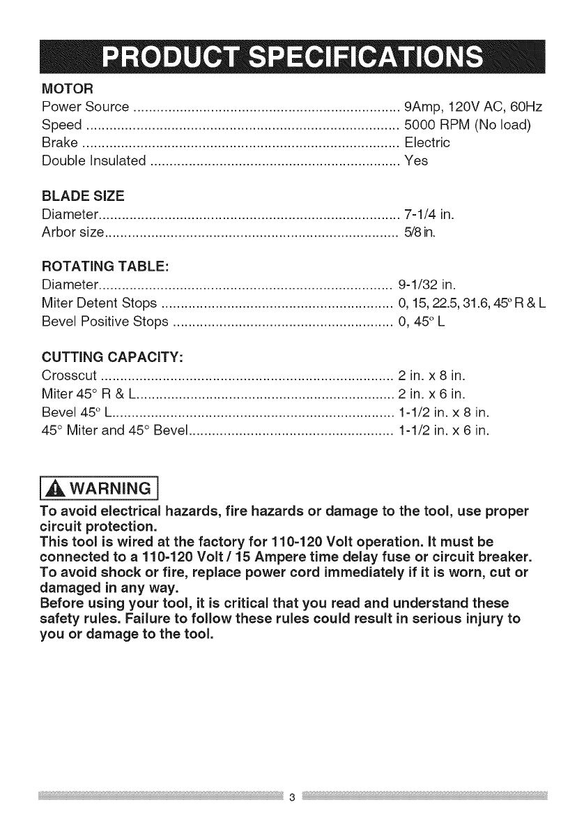
MOTOR
Power Source ..................................................................... 9Amp, 120V AC, 60Hz
Speed ................................................................................. 5000 RPM (No load)
Brake .................................................................................. Electric
Double Insulated ................................................................. Yes
BLADE SIZE
Diameter .............................................................................. 7-1/4 in.
Arbor size ............................................................................ 5/8 in.
ROTATING TABLE:
Diameter ............................................................................ 9-1/32 in.
Miter Detent Stops ............................................................ 0, 15, 22.5, 31.6, 45°R & L
Bevel Positive Stops ......................................................... 0, 45° L
CUTTING CAPACITY:
Crosscut ............................................................................ 2 in. x 8 in.
Miter 45 ° R & L................................................................... 2 in. x 6 in.
Bevel 45° L......................................................................... 1-1/2 in. x 8 in.
45° Miter and 45° Bevel ..................................................... 1-1/2 in. x 6 in.
i_J_WARNING]
To avoid electrical hazards, fire hazards or damage to the tool, use proper
circuit protection.
This tool is wired at the factory for 110=120 Volt operation, it must be
connected to a 110=120 Volt /15 Ampere time delay fuse or circuit breaker.
To avoid shock or fire, replace power cord immediately if it is worn, cut or
damaged in any way.
Before using your tool, it is critical that you read and understand these
safety rules. Failure to follow these rules could result in serious injury to
you or damage to the tool.
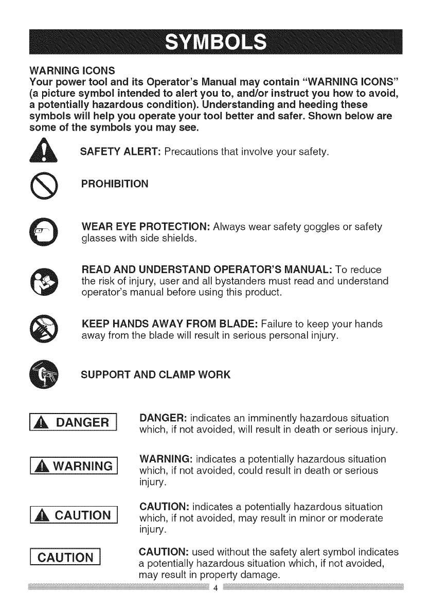
WARNINGiCONS
Your power tool and its Operator's Manual may contain "WARNING iCONS"
(a picture symbol intended to alert you to, and/or instruct you how to avoid,
a potentially hazardous condition). Understanding and heeding these
symbols will help you operate your tool better and safer. Shown below are
some of the symbols you may see.
SAFETY ALERT: Precautions that involve your safety.
®PROHiBiTiON
WEAR EYE PROTECTION: Always wear safety goggles or safety
glasses with side shields.
READ AND UNDERSTAND OPERATOR'S MANUAL: To reduce
the risk of injury, user and all bystanders must read and understand
operator's manual before using this product.
KEEP HANDS AWAY FROM BLADE: Failure to keep your hands
away from the blade will result in serious 3ersonal injury.
SUPPORT AND CLAMP WORK
[,_, DANGER] DANGER: indicates an imminently hazardous situation
which, if not avoided, will result in death or serious injury.
WARNING: indicates a potentially hazardous situation
which, if not avoided, could result in death or serious
injury.
CAUTION: indicates a potentially hazardous situation
which, if not avoided, may result in minor or moderate
injury.
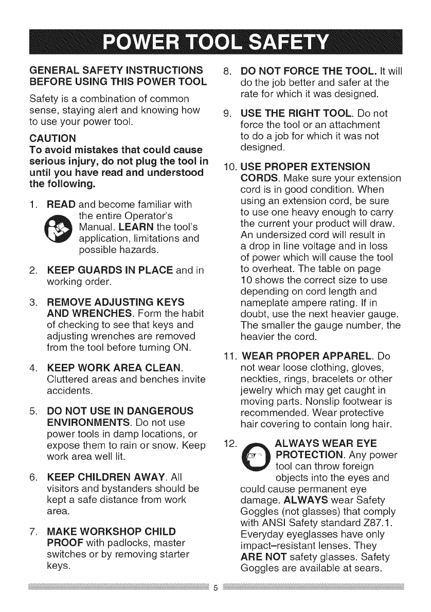
GENERALSAFETY iNSTRUCTiONS 8.
BEFORE USING THIS POWER TOOL
Safety is a combination of common
sense, staying alert and knowing how 9.
to use your power tool.
CAUTION
To avoid mistakes that could cause
serious injury, do not plug the tool in 10.
until you have read and understood
the following.
.
.
.
.
READ and become familiar with
the entire Operator's
Manual. LEARN the tool's
application, limitations and
possible hazards.
KEEP GUARDS iN PLACE and in
working order.
REMOVE ADJUSTING KEYS
AND WRENCHES. Form the habit
of checking to see that keys and
adjusting wrenches are removed
from the tool before turning ON.
KEEP WORK AREA CLEAN.
Cluttered areas and benches invite
accidents.
.DO NOT USE iN DANGEROUS
ENVIRONMENTS. Do not use
power tools in damp locations, or
expose them to rain or snow. Keep
work area well lit.
.KEEP CHILDREN AWAY. All
visitors and bystanders should be
kept a safe distance from work
area.
.MAKE WORKSHOP CHILD
PROOF with padlocks, master
switches or by removing starter
keys.
11.
12.
DO NOT FORCE THE TOOL. It will
do the job better and safer at the
rate for which it was designed.
USE THE RIGHT TOOL. Do not
force the tool or an attachment
to do a job for which it was not
designed.
USE PROPER EXTENSION
CORDS. Make sure your extension
cord is in good condition. When
using an extension cord, be sure
to use one heavy enough to carry
the current your product will draw.
An undersized cord will result in
a drop in line voltage and in loss
of power which will cause the tool
to overheat. The table on page
10 shows the correct size to use
depending on cord length and
nameplate ampere rating. If in
doubt, use the next heavier gauge.
The smaller the gauge number, the
heavier the cord.
WEAR PROPER APPAREL. Do
not wear loose clothing, gloves,
neckties, rings, bracelets or other
jewelry which may get caught in
moving parts. Nonslip footwear is
recommended. Wear protective
hair covering to contain long hair.
OALWAYS WEAR EYE
PROTECTION. Any power
tool can throw foreign
objects into the eyes and
could cause permanent eye
damage. ALWAYS wear Safety
Goggles (not glasses) that comply
with ANSI Safety standard Z87.1.
Everyday eyeglasses have only
impact-resistant lenses. They
ARE NOT safety glasses. Safety
Goggles are available at sears.
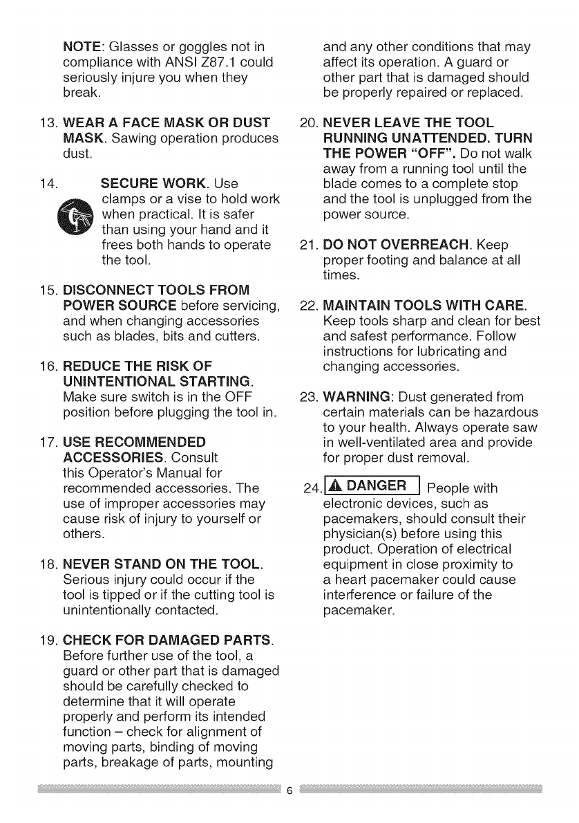
NOTE:Glassesorgogglesnotin
compliance with ANSI Z87.1 could
seriously injure you when they
break.
and any other conditions that may
affect its operation. A guard or
other part that is damaged should
be properly repaired or replaced.
13. WEAR A FACE MASK OR DUST
MASK. Sawing operation produces
dust.
14. SECURE WORK. Use
clamps or a vise to hold work
when practical. It is safer
than using your hand and it
frees both hands to operate
the tool.
15. DISCONNECT TOOLS FROM
POWER SOURCE before servicing,
and when changing accessories
such as blades, bits and cutters.
16. REDUCE THE RiSK OF
UNINTENTIONAL STARTING.
Make sure switch is in the OFF
position before plugging the tool in.
17. USE RECOMMENDED
ACCESSORIES. Consult
this Operator's Manual for
recommended accessories. The
use of improper accessories may
cause risk of injury to yourself or
others.
18. NEVER STAND ON THE TOOL.
Serious injury could occur if the
tool is tipped or if the cutting tool is
unintentionally contacted.
20. NEVER LEAVE THE TOOL
RUNNING UNATTENDED. TURN
THE POWER "OFF". Do not walk
away from a running tool until the
blade comes to a complete stop
and the tool is unplugged from the
power source.
21. DO NOT OVERREACH. Keep
proper footing and balance at all
times.
22. MAINTAIN TOOLS WiTH CARE.
Keep tools sharp and clean for best
and safest performance. Follow
instructions for lubricating and
changing accessories.
23. WARNING: Dust generated from
certain materials can be hazardous
to your health. Always operate saw
in well-ventilated area and provide
for proper dust removal.
24.IA, DANGER ] People with
electronic devices, such as
pacemakers, should consult their
physician(s) before using this
product. Operation of electrical
equipment in close proximity to
a heart pacemaker could cause
interference or failure of the
pacemaker.
19. CHECK FOR DAMAGED PARTS.
Before further use of the tool, a
guard or other part that is damaged
should be carefully checked to
determine that it will operate
properly and perform its intended
function - check for alignment of
moving parts, binding of moving
parts, breakage of parts, mounting

SPECiFiC SAFETY iNSTRUCTiONS
FOR THiS COMPOUND MITER SAW
.DO NOT operate the miter saw
until it is completely assembled
and installed according to these
instructions.
.iF YOU ARE NOT thoroughly
familiar with the operation of miter
saws, seek guidance from your
supervisor, instructor or other
qualified person.
.
10.
.
11.
12.
13.
ALWAYS hold the work firmly 14.
against the fence and table.
DO NOT perform any operation
free hand (use clamp wherever
possible). 15.
KEEP HANDS out of the path of
the saw blade. If the workpiece 16.
you are cutting would cause your
hands to be within 6-3/4 in. of the
saw blade, the workpiece should 17.
be clamped in place before making
the cut.
USE only blade collars specified for
your saw.
NEVER use blades larger in
diameter than 7-1/4 inches.
NEVER apply lubricants to the
blade when it is running.
ALWAYS check the blade for
cracks or damage before operation.
Replace a cracked or damaged
blade immediately.
NEVER use blades recommended
for operation at less than 5000
RPM.
ALWAYS keep the blade guards in
place and use at all times.
NEVER reach around the saw
blade.
MAKE SURE the blade is not
contacting the workpiece before the
switch is turned ON.
5. BE SURE the blade is sharp, runs 18.
freely and is free of vibration.
6. ALLOW the motor to come up to
full speed before starting a cut. 19.
7. KEEP THE MOTOR AiR SLOTS
CLEAN and free of chips or dust.
8. ALWAYS MAKE SURE all handles
are tight before cutting, even if the
table is positioned in one of the 20.
positive stops.
9. BE SURE both the blade and the
collar are clean and the arbor bolt
is tightened securely.
iMPORTANT: After completing the
cut, release the trigger and wait for
the blade to stop before returning
the saw to the raised position.
MAKE SURE the blade has come
to a complete stop before removing
or securing the workpiece,
changing the workpiece angle or
changing the angle of the blade.
NEVER cut metals or masonry
products with this tool. This miter
saw is designed for use on wood
and wood-like products.
21.NEVERcutsmallpieces.Ifthe
workpiecebeingcutwouldcause
yourhandorfingerstobewithin
6-3/4in.ofthesawbladethe
workpieceistoosmall.
22.PROVIDEadequatesupporttothe
sidesofthesawtableforlongwork
pieces.
23.NEVERusethemitersawinan
areawithflammableliquidsor
gases.
24.NEVERusesolventstoclean
plasticparts.Solventscould
possiblydissolveorotherwise
damagethematerial.
25.SHUTOFFthepowerbefore
servicingoradjustingthetool.
26.DISCONNECTthesawfrom
thepowersourceandcleanthe
machinewhenfinishedusing.
27.MAKESUREtheworkareais
cleanbeforeleavingthemachine.
28.SHOULDanypartofyourmitersaw
bemissing,damaged,orfailinany
way,oranyelectricalcomponent
failtoperformproperly,lockthe
switchandremovetheplugfrom
thepowersupplyoutlet.Replace
missing,damaged,orfailedparts
beforeresumingoperation.

POWERSUPPLYANDMOTOR
SPECiFiCATiONS
TheACmotorusedinthissawis
a universal,nonreversibletype.
See"MOTOR"inthe"PRODUCT
SPECIFICATIONS"sectiononpage3.
[,,d_WARNING]
To avoid electrical hazards, fire
hazards, or damage to the tool,
use proper circuit protection. Your
saw is wired at the factory for 120
V operation. Connect to a 120 V, 9A
circuit and use a 9 A time delay fuse
or circuit breaker. To avoid shock
or fire, if power cord is worn or
cut, or damaged in any way, have it
replaced immediately.
DOUBLE iNSULATED []
The power tool is double insulated to
provide a double thickness of insulation
between you and tool's electrical
system. All exposed metal parts are
isolated from the internal metal motor
components with protecting insulation.
Replacement parts - When servicing,
use only identical replacement parts.
Polarized plugs - This saw has a plug
that looks like the one shown below:
To reduce the risk of electrical shock,
this saw has a polarized plug (one
blade is wider than the other). This plug
will fit in a polarized outlet only one
way. If the plug does not fit fully in the
outlet, reverse the plug. If it still does
not fit, contact a qualified electrician to
install the proper outlet. Do not change
the plug in any way.
I,A WARNING J
Double insulation does not take the
place of normal safety precautions
when operating this tool.
To avoid electrocution:
1. Use only identical replacement parts
when servicing a tool with double
insulation. Servicing should be
performed by a qualified technician.
2. Do not use power tools in wet or
damp locations or expose them to
rain or snow.
MOTOR SAFETY PROTECTION
iMPORTANT
To avoid motor damage, the motor
should be blown out or vacuumed
frequently to keep sawdust from
interfering with the motor ventilation.
1. Connect this saw to a 120 V circuit.
This circuit must not be less than a
#18 wire with a 9 A time lag fuse.
NOTE: When using an extension
cord on a circuit with a #18 wire, the
extension cord must not exceed 25
feet in length.
2. If the motor will not start, release
the trigger switch immediately.
UNPLUG THE SAW. Check the saw
blade to make sure it turns freely. If
the blade is free, try to start the saw
again. If the motor still does not start,
refer to the TROUBLESHOOTING
GUIDE.
3. If the tool suddenly stalls while
cutting wood, release the trigger
switch, unplug the tool and free the
blade from the wood. The saw may
nowbestartedandthecutfinished.
4. FUSESmay"blow"orcircuit
breakersmaytripfrequentlyif:
a. MOTORisoverloaded-
overloadingcanoccurifyoufeed
toorapidlyormaketoomany
start/stopsinashorttime.
b. LINEVOLTAGEismore
than10%aboveorbelowthe
nameplatevoltagerating.For
heavyloads,thevoltageat motor
terminalsmustequalthevoltage
specifiedonthenameplate.
c. IMPROPERordullsawblades
areused.
5. Mostmotortroublesmaybetraced
to looseorincorrectconnections,
overload,lowvoltageorinadequate
powersupplywiring.Alwayscheck
theconnections,theloadand
supplycircuitif themotordoesn't
runwell.Checkminimumgaugefor
thelengthofcordyouareusingon
thechartbelow.
GUIDELINESFOREXTENSION
CORDS
Usea properextensioncord.Make
sureyourextensioncordisingood
condition.Whenusinganextension
cord,besureto useoneheavyenough
tocarrythecurrentyourproductwill
draw.Anundersizedcordwillcause
a dropinlinevoltage,resultingin
lossofpowerandoverheating.The
tablebelowshowsthecorrectsize
to usedependingoncordlengthand
nameplateampererating.If indoubt,
usethenextheaviergauge.The
smallerthegaugenumber,theheavier
thecord.
Besureyourextensioncordis
properlywiredandingoodcondition.
Alwaysreplacea damagedextension
cordorhaveit repairedbya qualified
personbeforeusingit.Protectyour
extensioncordsfromsharpobjects,
excessiveheatanddamporwetareas.
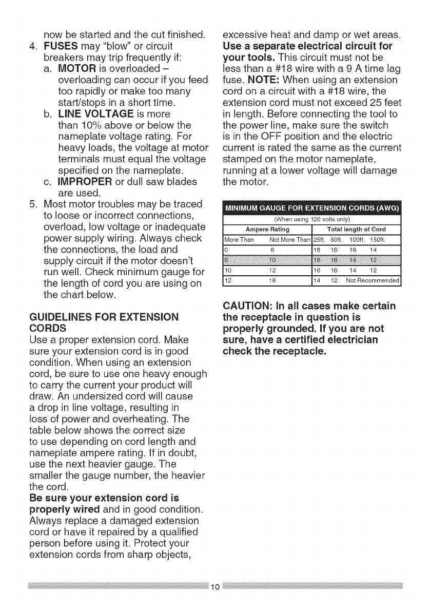
Use a separate electrical circuit for
your tools. This circuit must not be
less than a #18 wire with a 9 A time lag
fuse. NOTE: When using an extension
cord on a circuit with a #18 wire, the
extension cord must not exceed 25 feet
in length. Before connecting the tool to
the power line, make sure the switch
is in the OFF position and the electric
current is rated the same as the current
stamped on the motor nameplate,
running at a lower voltage will damage
the motor.
•O" O e'|
(When using 120 volts only)
Ampere Rating Total tength of Cord
More Than Not More Than 25ft. 50ft. 100ft. 150ft.
0 6 18 16 16 14
10 12 16 16 14 12
12 16 14 12 Not Recommended
CAUTION: in all cases make certain
the receptacle in question is
properly grounded, if you are not
sure, have a certified electrician
check the receptacle.
RECOMMENDED ACCESSORIES
i,_ WARNING]
oUse only accessories
recommended for this miter
saw. Follow instructions that
accompany accessories. Use of
improper accessories may cause
hazards.
oThe use of any cutting tool
except 7-1/4 in. saw blades which
meet the requirements under
recommended accessories
is prohibited. Do not use
accessories such as shaper
cutters or dado sets. Ferrous
metal cutting and the use of
abrasive wheels is prohibited.
oDo not attempt to modify this
tool or create accessories not
recommended for use with this
tool. Any such alteration or
modification is misuse and could
result in a hazardous condition
leading to possible serious
injury.
should be taken while mounting,
using, and storing carbide tipped
blades to prevent accidental
damage. Slight shocks, such as
striking the tip while handling,
can seriously damage the blade.
Foreign objects in the workpiece,
such as wire or nails, can also
cause tips to crack or break off.
Before using, always visually
examine the blade and tips for
bent blade, cracks, breakage,
missing or loose tips, or other
damage. Do not use if damage is
suspected. Failure to heed safety
instructions and warnings can
result in serious bodily injury.
ACCESSORIES
Visit your Sears Hardware Department
or see the Sears Power and Hand Tool
Catalog to purchase recommended
accessories for this power tool.
i,A WARNING]
o To avoid the risk of personal
injury, do not modify this power
tool or use accessories not
recommended by Sears.
oRead warnings and conditions
on your CARBIDE TIPPED SAW
BLADE. Do not operate the saw
without the proper saw blade
guard in place. Carbide is a very
hard but brittle material. Care
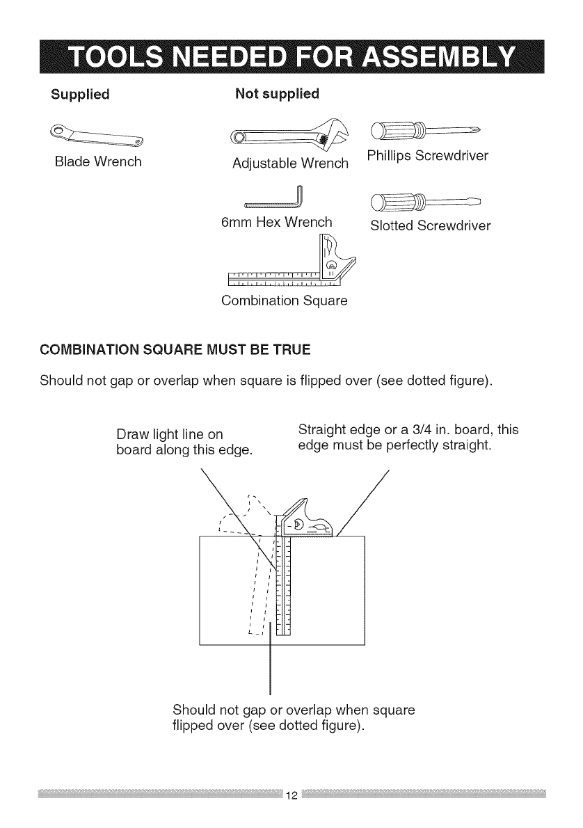
Supplied
Blade Wrench
Not supplied
Adjustable Wrench
6mm Hex Wrench
Combination Square
Phillips Screwdriver
Slotted Screwdriver
COMBINATION SQUARE MUST BE TRUE
Should not gap or overlap when square is flipped over (see dotted figure).
Draw light line on
board along this edge.
Straight edge or a 3/4 in. board, this
edge must be perfectly straight.
Should not gap or overlap when square
flipped over (see dotted figure).
12
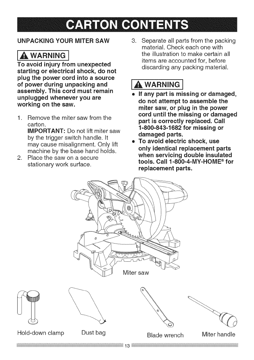
UNPACKING YOUR MITER SAW 3.
{_ WARNING]
To avoid injury from unexpected
starting or electrical shock, do not
plug the power cord into a source
of power during unpacking and
assembly. This cord must remain
unplugged whenever you are
working on the saw.
1. Remove the miter saw from the
carton.
IMPORTANT: Do not lift miter saw
by the trigger switch handle, it
may cause misalignment. Only lift
machine by the base hand holds.
2. Place the saw on a secure
stationary work surface.
Separate all parts from the packing
material. Check each one with
the illustration to make certain all
items are accounted for, before
discarding any packing material.
l,dk WARNING J
o If any part is missing or damaged,
do not attempt to assemble the
miter saw, or plug in the power
cord until the missing or damaged
part is correctly replaced. Call
1=800-843=1682 for missing or
damaged parts.
o To avoid electric shock, use
only identical replacement parts
when servicing double insulated
tools. Call 1-800=4-MY=HOME ® for
replacement parts.
Miter saw
Hold-down clamp Dust bag Blade wrench Miter handle
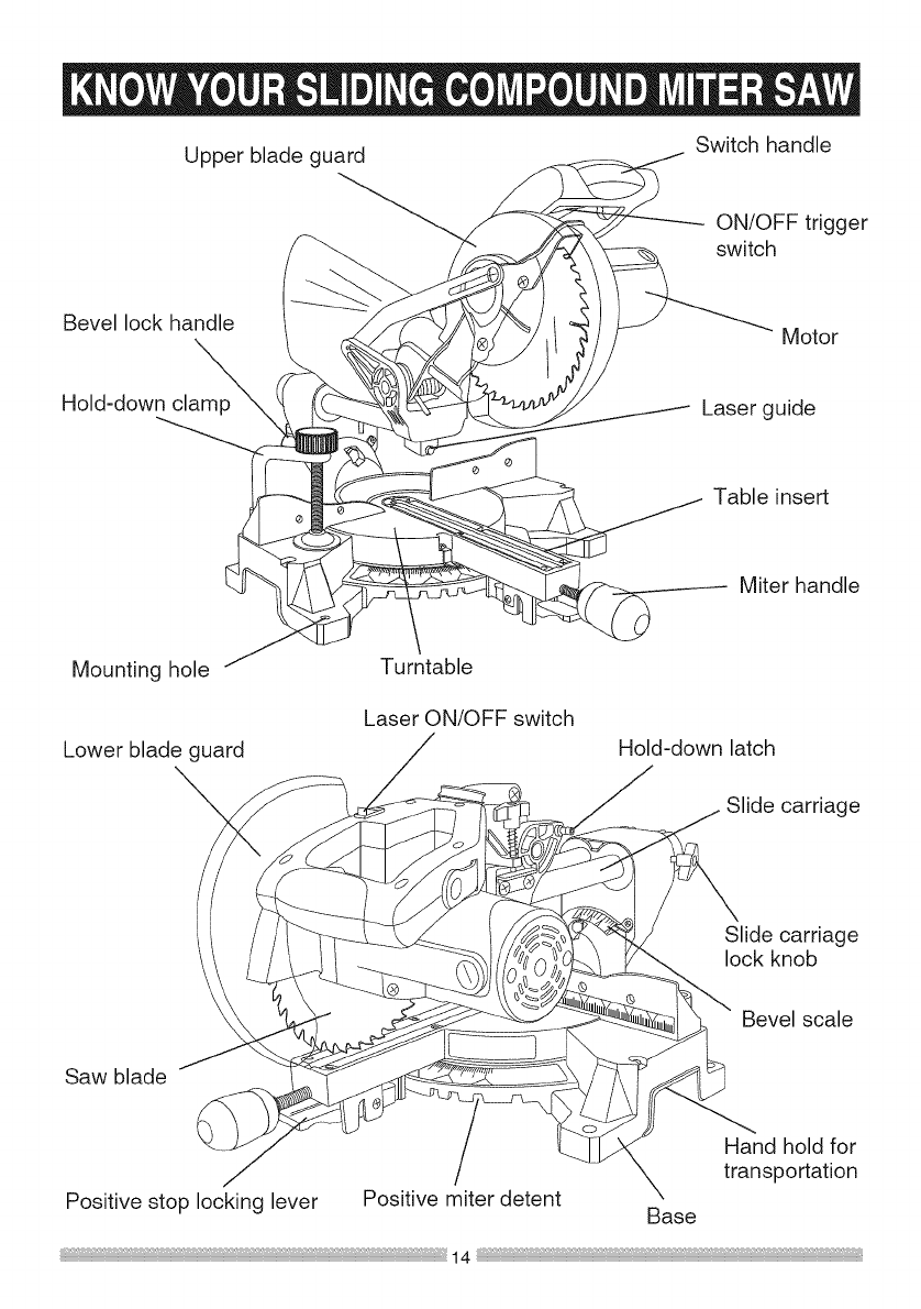
Upperbladeguard Switchhandle
ON/OFFtrigger
switch
Bevellockhandle Motor
Hold-downclamp Laserguide
Tableinsert
Miterhandle
Mountinghole
Lowerbladeguard
Turntable
LaserON/OFFswitch Hold-downlatch
Slidecarriage
Sawblade
Slidecarriage
lockknob
Bevelscale
Handholdfor
transportation
Positivestoplockinglever Positivemiterdetent Base
AMPERAGE(AMPS)- A measure
oftheflowofelectriccurrent.Higher
ratingsgenerallymeansthetoolis
suitedforheavieruse.
ARBORLOCK- Allowstheuserto
keepthebladefromrotatingwhile
tighteningorlooseningthearborbolt
duringbladereplacementorremoval.
eyes.Eyeprotectionshouldmeetthe
requirementsofANSIZ.87.1(USA)or
CSAZ94.3-M88(Canada).
FACESHIELD- Animpactresistant
shieldthathelpstoprotectyourface
fromchips,sparks,smalldebris.
Shouldonlybeusedinconjunctionwith
additionaleyeprotection.
BASE- Supportsthetable,holds
accessoriesandallowsforworkbench
orlegsetmounting.
FENCE- Helpsto keeptheworkpiece
frommovingwhensawing.Scaledto
assistwithaccuratecutting.
BEVELLOCKINGHANDLE- Locks
themitersawat adesiredbevelangle.
BEVELSCALE- Tomeasurethe
bevelangleofthesawblade0° to45°
left.
CARBIDETIPPED- Extremelyhard
steelpieceswithsharpcuttingedges
fastenedtocuttingtoolssuchassaw
blades.
COVERPLATESCREW- Loosenthis
screwandrotatetheplateforaccessto
thebladearborbolt.
GUARD- Protectivedevisethatforms
abarrierbetweena hazardousobject
suchasa blade,wheelorcutterand
theoperator.
HOLDDOWNLATCH- Locksthe
mitersawintheloweredpositionfor
compactstorageandtransportation.
INSTRUCTIONOROPERATOR'S
MANUAL- Bookletaccompanying
yourpowertoolthatdescribesthe
hazardsandsafeoperationprocedures,
outlinesbasictooloperation,careand
maintenance.
DOUBLE-INSULATED- Aformof
electricalprotectionfeaturingtwo
separateinsulationsystemsto help
protectagainstelectricalshock.
EXTENSIONCORD-An electric cord
used between power tools and outlets
to extend the range of the tools. The
more amerage your tool uses, the
longer the distance, the larger the size
of the wire needed in your extension
cord.
EYE PROTECTION - Goggles or
spectacles intended to protect your
MITER HANDLE - Used to rotate the
table, and to rotate the saw to a right or
left cutting position.
MITER SCALE - Measures the miter
angle 0° to 45 ° left and right.
MOUNTING HOLES - To mount the
miter saw to a stable surface.
ON/OFF TRIGGER SWITCH - To start
the tool, squeeze the trigger. Release
the trigger to turn off the miter saw.
POSITIVESTOPLOCKINGLEVER-
Locksthemitersawata presetpositive
stopforthedesiredmiterangle.
SWITCHHANDLE- Theswitch
handlecontainsthetriggerswitchand
thelaseron/offswitch.Thebladeis
loweredintotheworkpiecebypushing
downonthehandle.Thesawwill
returnto itsuprightpositionwhenthe
handleisreleased.
WARNINGLABELS- Readand
understandforyourownsafety.Make
surealllabelsarepresentonmachine
andlegible.
WRENCHSTORAGE - Convenient
storage to prevent misplacing the blade
wrench.
WOODWORKING TERMS
ARBOR - The shaft on which a blade
is mounted.
BEVEL CUT - An angle cut made
through the face of the workpiece.
COMPOUND CUT - An angled cut
to both the edge and face of a board,
most common use is with crown
molding.
CROSS CUT - A cut which runs across
the board perpendicular to the grain.
KICKBACK- Sudden and unintended
movement of the tool or workpiece. It is
typically caused by binding or pinching
of the workpiece
MITER CUT - A miter is a type of joint
where the two parts to be joined are cut
at an angle, and typically the finished
joint forms a 90-degree angle. Also
commonly spelled "mitre".
REVOLUTIONS PER MINUTE (RPM)
- The number of turns completed by a
spinning object in one minute.
SAW BLADE PATH - The area of the
workpiece or table top directly in line
with the travel of the blade or the part
of the workpiece which will be cut.
SET - The distance between two saw
blade tips, bent outward in opposite
directions to each other. The further
apart the tips are, the greater the set.
THIN=KERF BLADE - Thinner than
normal blades, remove less material,
smaller kerfs (between .065 and .070).
Blade thinness also may increase the
heat generated while cutting.
WORKPIECE - The wood being
cut. The surfaces of a workpiece are
commonly referred to as faces, ends
and edges.
FREEHAND - Performing a cut without
using a fence (guide), hold down or
other proper device to prevent the
workpiece from twisting during the
cutting operation.
HEEL - Misalignment of the blade.
KERF - The width of a saw cut,
determined by the thickness and set of
the blade.
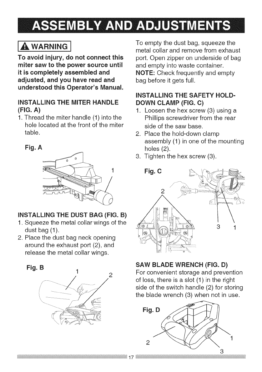
i,A WARNING ]
To avoid injury, do not connect this
miter saw to the power source until
it is completely assembled and
adjusted, and you have read and
understood this Operator's Manual.
iNSTALLING THE MITER HANDLE
(FIG. A)
1. Thread the miter handle (1) into the
hole located at the front of the miter
table.
Fig. A
iNSTALLING THE DUST BAG (FIG. B)
1. Squeeze the metal collar wings of the
dust bag (1).
2. Place the dust bag neck opening
around the exhaust port (2), and
release the metal collar wings.
To empty the dust bag, squeeze the
metal collar and remove from exhaust
port. Open zipper on underside of bag
and empty into waste container.
NOTE: Check frequently and empty
bag before it gets full.
iNSTALLING THE SAFETY HOLD-
DOWN CLAMP (FIG. C)
1. Loosen the hex screw (3) using a
Phillips screwdriver from the rear
side of the saw base.
2. Place the hold-down clamp
assembly (1) in one of the mounting
holes (2).
3. Tighten the hex screw (3).
Fig.C
2C:: _Z_\::
J K \_
3 1
SAW BLADE WRENCH (FIG. D)
2 For convenient storage and prevention
of loss, there is a slot (1) in the right
side of the switch handle (2) for storing
the blade wrench (3) when not in use.
/, Fig.2D_I
3
17
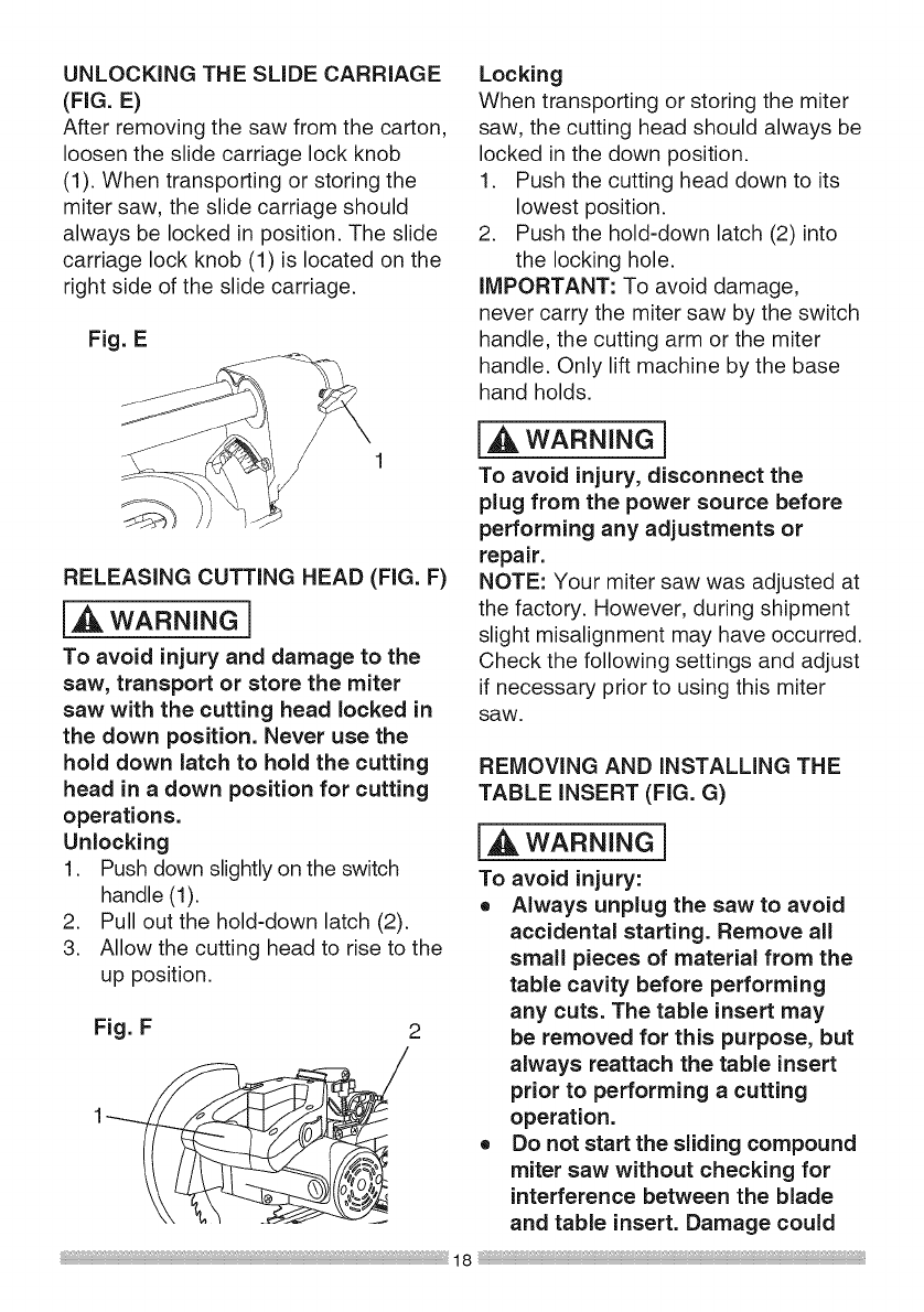
UNLOCKING THE SLIDE CARRIAGE
(FIG. E)
After removing the saw from the carton,
loosen the slide carriage lock knob
(1). When transporting or storing the
miter saw, the slide carriage should
always be locked in position. The slide
carriage lock knob (1) is located on the
right side of the slide carriage.
Fig. E
RELEASING CUTTING HEAD (FIG. F)
i_l_ WARNING]
To avoid injury and damage to the
saw, transport or store the miter
saw with the cutting head locked in
the down position. Never use the
hold down latch to hold the cutting
head in adown position for cutting
operations.
Unlocking
1. Push down slightly on the switch
handle (1).
2. Pull out the hold-down latch (2).
3. Allow the cutting head to rise to the
up position.
Fig. F 2
Locking
When transporting or storing the miter
saw, the cutting head should always be
locked in the down position.
1. Push the cutting head down to its
lowest position.
2. Push the hold-down latch (2) into
the locking hole.
IMPORTANT: To avoid damage,
never carry the miter saw by the switch
handle, the cutting arm or the miter
handle. Only lift machine by the base
hand holds.
I,A WARNING]
To avoid injury, disconnect the
plug from the power source before
performing any adjustments or
repair.
NOTE: Your miter saw was adjusted at
the factory. However, during shipment
slight misalignment may have occurred.
Check the following settings and adjust
if necessary prior to using this miter
SaW.
REMOVING AND iNSTALLING THE
TABLE iNSERT (FIG. G)
I_ WARNING]
To avoid injury:
o Always unplug the saw to avoid
accidental starting. Remove all
small pieces of material from the
table cavity before performing
any cuts. The table insert may
be removed for this purpose, but
always reattach the table insert
prior to performing a cutting
operation.
o Do not start the sliding compound
miter saw without checking for
interference between the blade
and table insert. Damage could

result to the blade, table insert or
turntable if blade strike occurs
during the cutting operation.
1. To remove, loosen and remove the
six screws (1) on the table inserts
(2) with a Phillips screwdriver and
remove the insert.
2. To install, reposition the table
inserts, install the six screws and
tighten.
3. Check for blade clearance by
moving the slide carriage through
the full motion of the blade in the
table slot.
Fig. G
2
MOUNTING THE MITER SAW
(FIG. H, i)
®
®
handle. Carrying the tool by the
power cord could cause damage
to the insulation or the wire
connections resulting in electric
shock or fire.
To avoid injury from flying debris,
do not allow visitors to stand
near the saw during any cutting
operation.
Support the saw on a level work
surface.
Always bolt or clamp the saw to
its support.
Mounting instructions
1. For stationary use, place the saw
in the desired location, directly on a
workbench where there is room for
handling and proper support of the
workpiece. The base of the saw has
four mounting holes. Bolt the base
of the miter saw (1) to the work
surface (5), using the fastening
method as shown in Fig H.
Fig. H
[,_ i 1. Miter saw base
WARNING 2. Hex head bolt
To avoid injury form unexpected 3. Rubber washer
saw movement: 4. Flat washer
o Disconnect the power cord from 5. Workbench
the outlet, and lock the cutting 6. Flat washer
7. Lockwasher
head in the lower position using 8. Hex nut
the stop latch. 9. Jam nut
o Lock the slide carriage in place
by tightening the slide carriage
lock knob.
o To avoid back injury, lift the saw
by using the designated carrying
handles located on the top of the
machine. When lifting, bend at 2.
your knees, not from your back.
o Never carry the miter saw by
3
4
1
--r- "
k I
NOTE: Mounting hardware is not
included with this tool. Bolts, nuts,
washers, & screws must be purchased
separately.
the power cord or by the switch
For portable use, place the
saw on a 3/4 in. thick piece of
plywood. Bolt the base of the
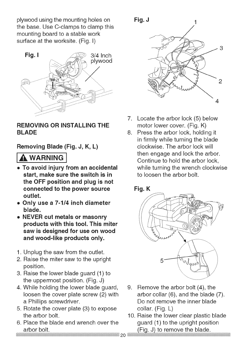
plywoodusingthemountingholeson
thebase.UseC-clampstoclampthis
mountingboardto astablework
surfaceattheworksite.(Fig.I)
Fig. I 3/4 Inch
plywood
Fig. J
REMOVING OR INSTALLING THE
BLADE
Removing Blade (Fig. J, K, L)
i,A WARNING]
o To avoid injury from an accidental
start, make sure the switch is in
the OFF position and plug is not
connected to the power source
outlet.
o Only use a 7-1/4 inch diameter
blade.
o NEVER cut metals or masonry
products with this tool. This miter
saw is designed for use on wood
and wood-like products only.
1. Unplug the saw from the outlet.
2. Raise the miter saw to the upright
position.
3. Raise the lower blade guard (1) to
the uppermost position. (Fig. J)
4. While holding the lower blade guard,
loosen the cover plate screw (2) with
a Phillips screwdriver.
5. Rotate the cover plate (3) to expose
the arbor bolt.
6. Place the blade end wrench over the
arbor bolt.
.
8.
Locate the arbor lock (5) below
motor lower cover. (Fig. K)
Press the arbor lock, holding it
in firmly while turning the blade
clockwise. The arbor lock will
then engage and lock the arbor.
Continue to hold the arbor lock,
while turning the wrench clockwise
to loosen the arbor bolt.
Fig. K
9. Remove the arbor bolt (4), the
arbor collar (6), and the blade (7).
Do not remove the inner blade
collar. (Fig. L)
10. Raise the lower clear plastic blade
guard (1) to the upright position
(Eig J) to[emovetheb!ade .
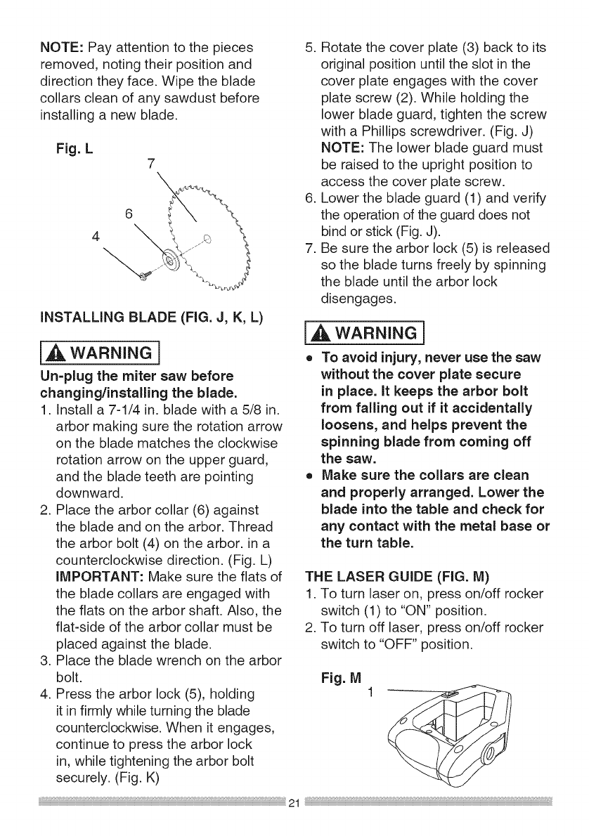
NOTE:Payattentiontothepieces
removed,notingtheirpositionand
directiontheyface.Wipetheblade
collarscleanofanysawdustbefore
installinga newblade.
Fig.L 7\
6
4
INSTALLING BLADE (FIG. J, K, L)
i_ WARNING]
Un-plug the miter saw before
changing/installing the blade.
1. Install a 7-1/4 in. blade with a 5/8 in.
arbor making sure the rotation arrow
on the blade matches the clockwise
rotation arrow on the upper guard,
and the blade teeth are pointing
downward.
2. Place the arbor collar (6) against
the blade and on the arbor. Thread
the arbor bolt (4) on the arbor, in a
counterclockwise direction. (Fig. L)
IMPORTANT: Make sure the flats of
the blade collars are engaged with
the flats on the arbor shaft. Also, the
flat-side of the arbor collar must be
placed against the blade.
3. Place the blade wrench on the arbor
bolt.
4. Press the arbor lock (5), holding
it in firmly while turning the blade
counterclockwise. When it engages,
continue to press the arbor lock
in, while tightening the arbor bolt
securely. (Fig. K)
5. Rotate the cover plate (3) back to its
original position until the slot in the
cover plate engages with the cover
plate screw (2). While holding the
lower blade guard, tighten the screw
with a Phillips screwdriver. (Fig. J)
NOTE: The lower blade guard must
be raised to the upright position to
access the cover plate screw.
6. Lower the blade guard (1) and verify
the operation of the guard does not
bind or stick (Fig. J).
7. Be sure the arbor lock (5) is released
so the blade turns freely by spinning
the blade until the arbor lock
disengages.
[,A WARNING]
oTo avoid injury, never use the saw
without the cover plate secure
in place. It keeps the arbor bolt
from falling out if it accidentally
loosens, and helps prevent the
spinning blade from coming off
the saw.
oMake sure the collars are clean
and properly arranged. Lower the
blade into the table and check for
any contact with the metal base or
the turn table.
THE LASER GUIDE (FIG. M)
1. To turn laser on, press on/off rocker
switch (1) to "ON" position.
2. To turn off laser, press on/off rocker
switch to "OFF" position.
Fig. M
THE LASER BEAM
i,_ WARNING ]
For your own safety, never connect
the plug to power source outlet
until all the adjustment steps
are complete and you have read
and understood the safety and
operational instructions.
Your tool is equipped with the Laser
Trac ®cutting guide using Class II laser
beam. The laser beam will enable you
to preview the saw blade path on the
stock to be cut before starting the miter
saw. This laser guide is powered by the
transformed alternating current supply
directly through the power lead. The
saw must be connected to the power
source and the laser on/off switch must
be turned on for the laser line to show.
j,AWARNING]
AVOID DIRECT EYE CONTACT
oLaser is radiated when laser
guide is turned on. Avoid direct
eye contact. Always un=plug the
miter saw from power source
before making any adjustments.
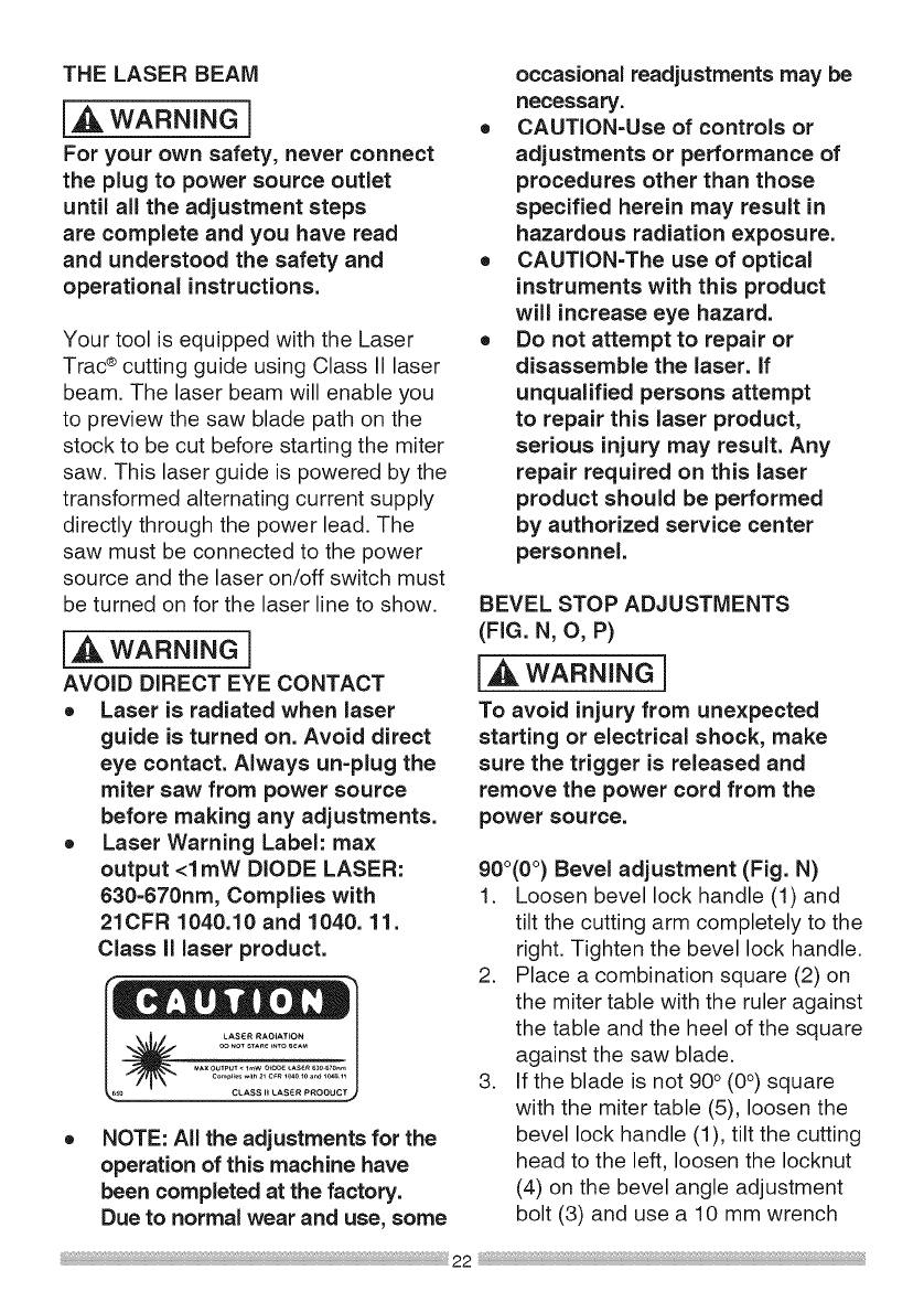
oLaser Warning Label: max
output <1 mW DIODE LASER:
630=670nm, Complies with
21CFR 1040.10 and 1040. 11.
Class II laser product.
LASER RAO_AT*ON
oo NOTSTAR__NTO_A_
MAXOUTPUT• _W 0_OO__AS_R630670._,
_CL_,SS!!LAS_ PROOUCTj
NOTE: All the adjustments for the
operation of this machine have
been completed at the factory.
Due to normal wear and use, some
occasional readjustments may be
necessary.
CAUTION=Use of controls or
adjustments or performance of
procedures other than those
specified herein may result in
hazardous radiation exposure.
CAUTION=The use of optical
instruments with this product
will increase eye hazard.
Do not attempt to repair or
disassemble the laser, if
unqualified persons attempt
to repair this laser product,
serious injury may result. Any
repair required on this laser
product should be performed
by authorized service center
personnel.
BEVEL STOP ADJUSTMENTS
(FIG. N, O, P)
i WA..I.G1
To avoid injury from unexpected
starting or electrical shock, make
sure the trigger is released and
remove the power cord from the
power source.
900(0°) Bevel adjustment (Fig. N)
1. Loosen bevel lock handle (1) and
tilt the cutting arm completely to the
right. Tighten the bevel lock handle.
2. Place a combination square (2) on
the miter table with the ruler against
the table and the heel of the square
against the saw blade.
3. If the blade is not 90° (0°) square
with the miter table (5), loosen the
bevel lock handle (1), tilt the cutting
head to the left, loosen the Iocknut
(4) on the bevel angle adjustment
bolt (3) and use a 10 mm wrench
22

to adjust the stop bolt (3) depth in
or out to increase or decrease the
bevel angle.
4. Tilt the cutting arm to back to the
right at 90° (0°) bevel and recheck
for alignment.
5. Repeat steps 1 through 4 if further
adjustment is needed.
6. Tighten bevel lock handle (1) and
Iocknut (4) when alignment is
achieved.
Fig. N
3\
4
45° Bevel Adjustment (Fig. P)
1. Loosen the bevel lock handle (8)
and tilt the cutting head completely
to the left.
2. Using a combination square, check
to see if the blade angle is 45° to
the table.
3. If the blade is not at 45 ° to the miter
table, tilt the cutting arm to the
right, loosen the Iocknut (9) on the
bevel angle adjustment bolt (10)
and use a 10 mm wrench to adjust
the stop bolt (10) depth in or out
to increase or decrease the bevel
angle.
4. Tilt the cutting arm to the left to 45 °
bevel and recheck for alignment.
5. Repeat steps 1 through 4 until the
blade is at 45° to the miter table.
6. Tighten bevel lock handle (8) and
Iocknut (9) when alignment is
achieved.
2 5
90° Bevel Pointer Adjustment (Fig. O)
1. When the blade is exactly 90°
(0°) to the table, loosen the bevel
indicator screw (6) using a # 2
Phillips screwdriver.
2. Adjust bevel indicator (7) to the
"0" mark on the bevel scale and
retighten the screw.
Fig. 0
\7
Fig. P
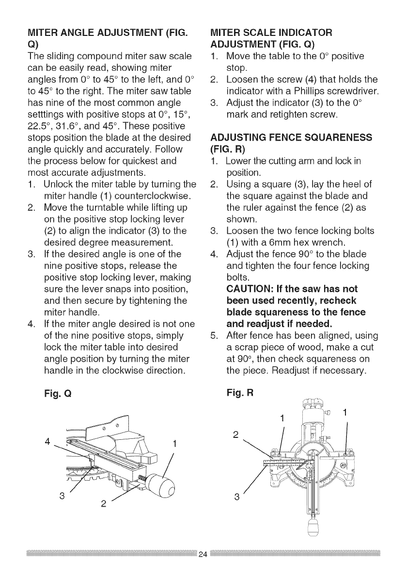
MITER ANGLE ADJUSTMENT (FIG.
Q)
The sliding compound miter saw scale
can be easily read, showing miter
angles from 0° to 45° to the left, and 0°
to 45 ° to the right. The miter saw table
has nine of the most common angle
setttings with positive stops at 0°, 15°,
22.5 °, 31.6 °, and 45°. These positive
stops position the blade at the desired
angle quickly and accurately. Follow
the process below for quickest and
most accurate adjustments.
1. Unlock the miter table by turning the
miter handle (1) counterclockwise.
2. Move the turntable while lifting up
on the positive stop locking lever
(2) to align the indicator (3) to the
desired degree measurement.
3. If the desired angle is one of the
nine positive stops, release the
positive stop locking lever, making
sure the lever snaps into position,
and then secure by tightening the
miter handle.
4. If the miter angle desired is not one
of the nine positive stops, simply
lock the miter table into desired
angle position by turning the miter
handle in the clockwise direction.
MITER SCALE iNDiCATOR
ADJUSTMENT (FIG. Q)
1. Move the table to the 0° positive
stop.
2. Loosen the screw (4) that holds the
indicator with a Phillips screwdriver.
3. Adjust the indicator (3) to the 0°
mark and retighten screw.
ADJUSTING FENCE SQUARENESS
(FIG. R)
1. Lower the cutting arm and lock in
position.
2. Using a square (3), lay the heel of
the square against the blade and
the ruler against the fence (2) as
shown.
3. Loosen the two fence locking bolts
(1) with a 6mm hex wrench.
4. Adjust the fence 90° to the blade
and tighten the four fence locking
bolts.
CAUTION: If the saw has not
been used recently, recheck
blade squareness to the fence
and readjust if needed.
5. After fence has been aligned, using
a scrap piece of wood, make a cut
at 90°, then check squareness on
the piece. Readjust if necessary.
Fig. QFig. R
1
2 _ ,,/_
,fy ¢'_
i
"1
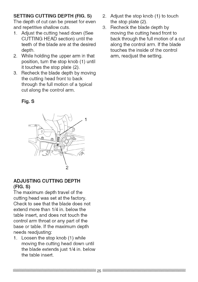
SETTING CUTTING DEPTH (FIG. S)
The depth of cut can be preset for even
and repetitive shallow cuts.
1. Adjust the cutting head down (See
CUTTING HEAD section) until the
teeth of the blade are at the desired
depth.
2. While holding the upper arm in that
position, turn the stop knob (1) until
it touches the stop plate (2).
3. Recheck the blade depth by moving
the cutting head front to back
through the full motion of a typical
cut along the control arm.
Fig. S
.
3.
Adjust the stop knob (1) to touch
the stop plate (2).
Recheck the blade depth by
moving the cutting head front to
back through the full motion of a cut
along the control arm. If the blade
touches the inside of the control
arm, readjust the setting.
2
ADJUSTING CUTTING DEPTH
(FIG. S)
The maximum depth travel of the
cutting head was set at the factory.
Check to see that the blade does not
extend more than 1/4 in. below the
table insert, and does not touch the
control arm throat or any part of the
base or table, if the maximum depth
needs readjusting:
1. Loosen the stop knob (1) while
moving the cutting head down until
the blade extends just 1/4 in. below
the table insert.
SAFETY iNSTRUCTiONS FOR BASIC
SAW OPERATION
BEFORE USING THE MITER SAW
i,A WARNING]
To avoid mistakes that could cause
serious, permanent injury, do not
plug the tool in until the following
steps are completed:
o Completely assemble and
adjust the saw, following the
instructions. (ASSEMBLY AND
ADJUSTMENTS)
o Learn the use and function of the
ON/OFF switch, upper and lower
blade guards, hold down latch, bevel
lock handle and cover plate screws.
o Review and understand all
safety instructions and operating
procedures in this Operator's
Manual. (SAFETY & OPERATIONS)
o Review the MAINTENANCE and
TROUBLESHOOTING GUIDE for
your miter saw.
o To avoid injury or possible death
from electrical shock:
Make sure your fingers do not
touch the plug's metal prongs
when plugging or unplugging
your miter saw. (ELECTRICAL
REQUIREMENTS AND SAFETY)
BEFORE EACH USE iNSPECT YOUR
SAW.
o Disconnect the miter saw.
To avoid injury from accidental
starting, unplug the saw before any
adjustments, including set-up and
blade changes.
o Compare the direction of rotation
arrow on the guard to the direction
arrow on the blade. The blade teeth
should always point downward at the
front of the saw.
o Tighten the arbor bolt.
o Tighten the cover plate screw.
o Check for damaged parts. Check
for:
o Alignment of moving parts
o Damaged electric cords
o Binding of moving parts
o Mounting holes
o Function of arm return spring
and lower guard: Push the
cutting arm all the way down,
then let it rise until it stops.
The lower guard should fully
close. Follow instructions in
TROUBLESHOOTING GUIDE
for adjustment if necessary.
o Other conditions that may affect
the way the miter saw works.
o Keep all guards in place, in working
order and proper adjustment. If any
part of this miter saw is missing,
bent, damaged or broken in any
way, or any electrical parts do not
work, turn the saw off and unplug it.
o Replace bent, damaged, missing or
defective parts before using the saw
again.
o Maintain tools with care. Keep the
miter saw clean for best and safest
performance. Follow instructions for
lubricating. Do not put lubricants on
the blade while it is spinning.
o Remove adjusting wrench from the
tool before turning it on.
o To avoid injury from jams, slips,
or thrown pieces, use only
recommended accessories.
RECOMMENDED ACCESSORIES
o Consult the ACCESSORIES and
ATTACHMENTS section of this
Operators Manual for recommended
accessories. Follow the instructions
that come with the accessory. The
use of improper accessories may
cause risk of injury to persons.
• Choose the correct 7-1/4 in.
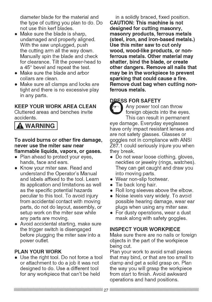
diameterbladeforthematerialand
thetypeofcuttingyouplantodo.Do
notusethinkerfblades.
o Makesurethebladeissharp,
undamagedandproperlyaligned.
Withthesawunplugged,push
thecuttingarmallthewaydown.
Manuallyspinthebladeandcheck
forclearance.Tiltthepower-headto
a45° bevelandrepeatthetest.
o Makesurethebladeandarbor
collarsareclean.
o Makesureallclampsandlocksare
tightandthereisnoexcessiveplay
inanyparts.
KEEPYOUR WORK AREA CLEAN
Cluttered areas and benches invite
accidents.
,_k WARNING I
To avoid burns or other fire damage,
never use the miter saw near
flammable liquids, vapors, or gases.
o Plan ahead to protect your eyes,
hands, face and ears.
o Know your miter saw. Read and
understand the Operator's Manual
and labels affixed to the tool. Learn
its application and limitations as well
as the specific potential hazards
peculiar to this tool. To avoid injury
from accidental contact with moving
parts, do not do layout, assembly, or
setup work on the miter saw while
any parts are moving.
o Avoid accidental starting, make sure
the trigger switch is disengaged
before plugging the miter saw into a
power outlet.
PLAN YOUR WORK
o Use the right tool. Do not force a tool
or attachment to do a job it was not
designed to do. Use a different tool
for any workpiece that can't be held
in a solidly braced, fixed position.
CAUTION: This machine is not
designed for cutting masonry,
masonry products, ferrous metals
(steel, iron, and iron-based metals.)
Use this miter saw to cut only
wood, wood-like products, or non-
ferrous metals. Other material may
shatter, bind the blade, or create
other dangers. Remove all nails that
may be in the workpiece to prevent
sparking that could cause a fire.
Remove dust bag when cutting non-
ferrous metals.
S FOR SAFETY
Any power tool can throw
foreign objects into the eyes.
This can result in permanent
eye damage. Everyday eyeglasses
have only impact resistant lenses and
are not safety glasses. Glasses or
goggles not in compliance with ANSI
Z87.1 could seriously injure you when
they break.
o Do not wear loose clothing, gloves,
neckties or jewelry (rings, watches).
They can get caught and draw you
into moving parts.
o Wear non-slip footwear.
o Tie back long hair.
o Roll long sleeves above the elbow.
o Noise levels vary widely. To avoid
possible hearing damage, wear ear
plugs when using any miter saw.
o For dusty operations, wear a dust
mask along with safety goggles.
INSPECT YOUR WORKPIECE
Make sure there are no nails or foreign
objects in the part of the workpiece
being cut.
Plan your work to avoid small pieces
that may bind, or that are too small to
clamp and get a solid grasp on. Plan
the way you will grasp the workpiece
from start to finish. Avoid awkward
operations and hand positions.
27

A sudden slip could cause your fingers
or hand to move into the blade.
DO NOT OVER-REACH
Keep good footing and balance. Keep
your face and body to one side, out of
the line of a possible kickback. NEVER
stand in the line of the blade.
Never cut freehand:
o Brace your workpiece firmly against
the fence and table stop so it will not
rock or twist during the cut.
o Make sure there is no debris
between the workpiece and the table
or fence.
o Make sure there are no gaps
between the workpiece, fence and
table that will let the workpiece shift
after it is cut.
o Keep the cut off piece free to move
sideways after it is cut off. Otherwise,
it could get wedged against the
blade and thrown violently.
• Only the workpiece should be on the
saws table.
o Secure work. Use clamps or a vise
to help hold the work when it is
practical.
USE EXTRA CAUTION WITH LARGE
OR ODD SHAPED WORKPIECES.
o Use extra supports (tables,
sawhorses, blocks, etc.) for
workpieces large enough to tip.
o Never use another person as a
substitute for a table extension, or as
an additional support for a workpiece
that is longer or wider than the basic
miter saw table, or to help feed,
support, or pull the workpiece.
o Do not use this saw to cut small
pieces. If the workpiece being cut
would cause your hand or fingers
to be within 6-3/4 inches of the saw
blade the workpiece is too small.
Keep hands and fingers out of the
"no hands zone" area marked on the
saws table.
o When cutting odd shaped
workpieces, plan your work so it
will not bind in the blade and cause
possible injury. Molding, for example,
must lie flat or be held by a fixture or
jig that will not let it move when cut.
o Properly support round material such
as dowel rods, or tubing, which have
a tendency to roll when cut, causing
the blade to "bite".
l_, WARNING i
To avoid injury, follow all applicable
safety instructions, when cutting
non-ferrous metals:
o Use only saw blades specifically
recommended for non-ferrous metal
cutting.
o Do not cut metal workpieces
that must be hand held. Clamp
workpieces securely.
o Cut non-ferrous metals only if you
are under the supervision of an
experienced person and the dust
bag has been removed from the
saw.
WHEN SAW IS RUNNING
I,_ WARNING]
Do not allow familiarity from
frequent use of your miter saw
to result in acareless mistake. A
careless fraction of a second is
enough to cause a severe injury.
Before cutting, if the saw makes an
unfamiliar noise or vibrates, stop
immediately. Turn the saw OFF.
Unplug the saw. Do not restart until
finding and correcting the problem.
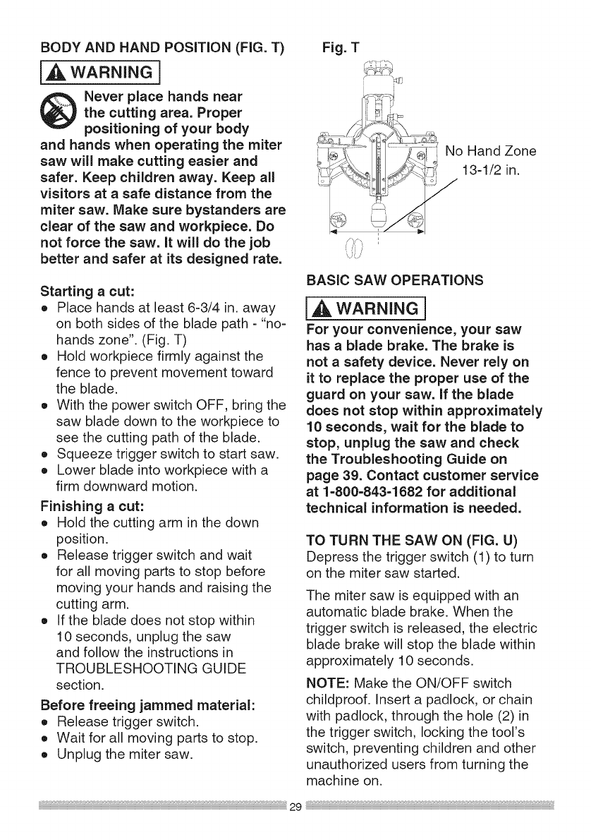
BODYAND HAND POSITION (FIG. T)
[_ WARNING]
Never place hands near
the cutting area. Proper
positioning of your body
and hands when operating the miter
saw will make cutting easier and
safer. Keep children away. Keep all
visitors at a safe distance from the
miter saw. Make sure bystanders are
clear of the saw and workpiece. Do
not force the saw. it will do the job
better and safer at its designed rate.
Starting acut:
o Place hands at least 6-3/4 in. away
on both sides of the blade path -"no-
hands zone". (Fig. T)
o Hold workpiece firmly against the
fence to prevent movement toward
the blade.
o With the power switch OFF, bring the
saw blade down to the workpiece to
see the cutting path of the blade.
o Squeeze trigger switch to start saw.
o Lower blade into workpiece with a
firm downward motion.
Finishing a cut:
eHold the cutting arm in the down
position.
o Release trigger switch and wait
for all moving parts to stop before
moving your hands and raising the
cutting arm.
o If the blade does not stop within
10 seconds, unplug the saw
and follow the instructions in
TROUBLESHOOTING GUIDE
section.
Before freeing jammed material:
o Release trigger switch.
o Wait for all moving parts to stop.
o Unplug the miter saw.
Fig. T
_-- No Hand Zone
_ 13-1/2 in.
BASIC SAW OPERATIONS
[_, WARNING]
For your convenience, your saw
has a blade brake. The brake is
not a safety device. Never rely on
it to replace the proper use of the
guard on your saw. If the blade
does not stop within approximately
10 seconds, wait for the blade to
stop, unplug the saw and check
the Troubleshooting Guide on
page 39. Contact customer service
at 1-800=843=1682 for additional
technical information is needed.
TO TURN THE SAW ON (FIG. U)
Depress the trigger switch (1) to turn
on the miter saw started.
The miter saw is equipped with an
automatic blade brake. When the
trigger switch is released, the electric
blade brake will stop the blade within
approximately 10 seconds.
NOTE: Make the ON/OFF switch
childproof. Insert a padlock, or chain
with padlock, through the hole (2) in
the trigger switch, locking the tool's
switch, preventing children and other
unauthorized users from turning the
machine on.
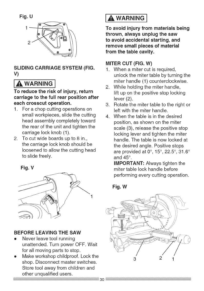
Fig. U
SLiDiNG CARRIAGE SYSTEM (FIG.
V)
[_1_WARNING]
To reduce the risk of injury, return
carriage to the full rear position after
each crosscut operation.
1. For a chop cutting operations on
small workpieces, slide the cutting
head assembly completely toward
the rear of the unit and tighten the
carriage lock knob (1).
2. To cut wide boards up to 8 in.,
the carriage lock knob should be
loosened to allow the cutting head
to slide freely.
Fig. V
I WARNINGi
To avoid injury from materials being
thrown, always unplug the saw
to avoid accidental starting, and
remove small pieces of material
from the table cavity.
MITER CUT (FIG. W)
1. When a miter cut is required,
unlock the miter table by turning the
miter handle (1) counterclockwise.
2. While holding the miter handle,
lift up on the positive stop locking
lever (2).
3. Rotate the miter table to the right or
left with the miter handle.
4. When the table is in the desired
position, as shown on the miter
scale (3), release the positive stop
locking lever and tighten the miter
handle. The table is now locked at
the desired angle. Positive stops
are provided at 0°, 15°, 22.5 °, 31.6 °
and 45° .
iMPORTANT: Always tighten the
miter table lock handle before
performing every cutting operation.
Fig. W
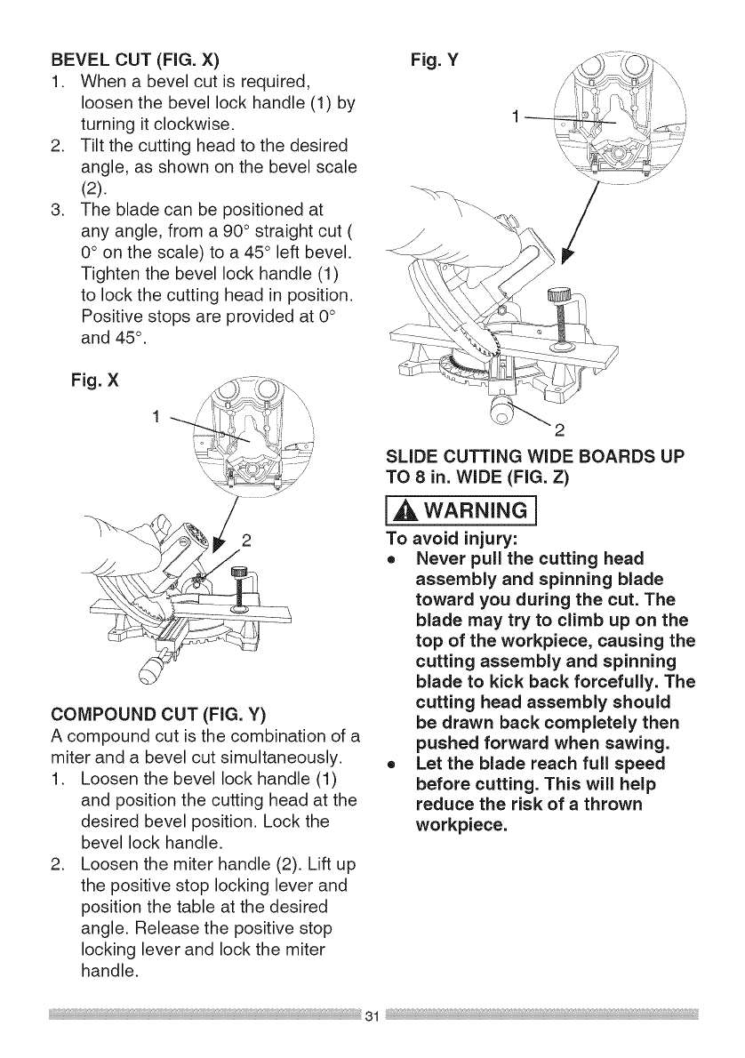
BEVEL CUT (FIG. X)
1. When a bevel cut is required,
loosen the bevel lock handle (1) by
turning it clockwise.
2. Tilt the cutting head to the desired
angle, as shown on the bevel scale
(2).
3. The blade can be positioned at
any angle, from a 90 ° straight cut (
0° on the scale) to a 45° left bevel.
Tighten the bevel lock handle (1)
to lock the cutting head in position.
Positive stops are provided at 0°
and 45°.
Fig. X
2
COMPOUND CUT (FIG. Y)
A compound cut is the combination of a
miter and a bevel cut simultaneously.
1. Loosen the bevel lock handle (1)
and position the cutting head at the
desired bevel position. Lock the
bevel lock handle.
2. Loosen the miter handle (2). Lift up
the positive stop locking lever and
position the table at the desired
angle. Release the positive stop
locking lever and lock the miter
handle.
Fig. Y
\
SLIDE CUTTING WIDE BOARDS UP
TO 8 in. WIDE (FIG. Z)
[,_ WARNING]
To avoid injury:
o Never pull the cutting head
assembly and spinning blade
toward you during the cut. The
blade may try to climb up on the
top of the workpiece, causing the
cutting assembly and spinning
blade to kick back forcefully. The
cutting head assembly should
be drawn back completely then
pushed forward when sawing.
o Let the blade reach full speed
before cutting. This will help
reduce the risk of a thrown
workpiece.
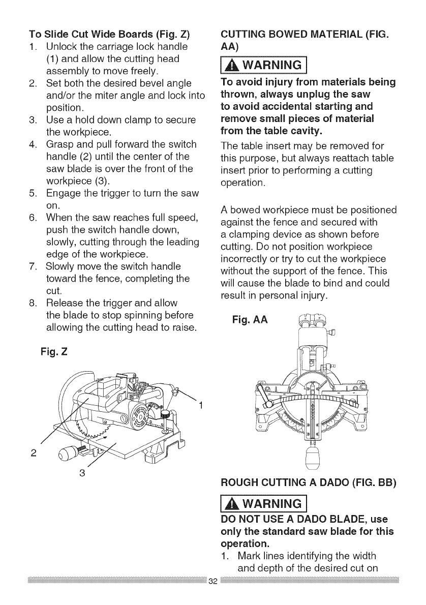
ToSlideCutWide Boards (Fig. Z)
1. Unlock the carriage lock handle
(1) and allow the cutting head
assembly to move freely.
2. Set both the desired bevel angle
and/or the miter angle and lock into
position.
3. Use a hold down clamp to secure
the workpiece.
4. Grasp and pull forward the switch
handle (2) until the center of the
saw blade is over the front of the
workpiece (3).
5. Engage the trigger to turn the saw
on.
6. When the saw reaches full speed,
push the switch handle down,
slowly, cutting through the leading
edge of the workpiece.
7. Slowly move the switch handle
toward the fence, completing the
cut.
8. Release the trigger and allow
the blade to stop spinning before
allowing the cutting head to raise.
Fig. Z
2
3
32
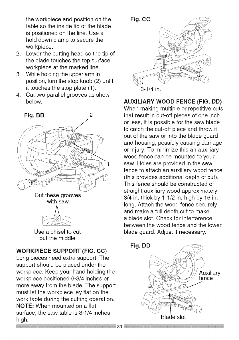
CUTTING BOWED MATERIAL (FIG.
AA)
i_ WARNING 1
To avoid injury from materials being
thrown, always unplug the saw
to avoid accidental starting and
remove small pieces of material
from the table cavity.
The table insert may be removed for
this purpose, but always reattach table
insert prior to performing a cutting
operation.
A bowed workpiece must be positioned
against the fence and secured with
a clamping device as shown before
cutting. Do not position workpiece
incorrectly or try to cut the workpiece
without the support of the fence. This
will cause the blade to bind and could
result in personal injury.
Fig. AA
ROUGH CUTTING ADADO (FIG. BB)
i,_ WARNING}
DO NOT USE A DADO BLADE, use
only the standard saw blade for this
operation.
1. Mark lines identifying the width
and depth of the desired cut on
theworkpieceandpositiononthe
tablesotheinsidetipoftheblade
ispositionedontheline.Usea
holddownclamptosecurethe
workpiece.
2. Lowerthecuttingheadsothetipof
thebladetouchesthetopsurface
workpieceatthemarkedline.
3. Whileholdingtheupperarmin
position,turnthestopknob(2)until
ittouchesthestopplate(1).
4. Cuttwoparallelgroovesasshown
below.
Fig.BB 2
Cut these grooves
with saw
Use a chisel to cut
out the middle
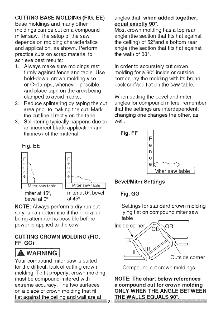
WORKPIECE SUPPORT (FIG. CO)
Long pieces need extra support. The
support should be placed under the
workpiece. Keep your hand holding the
workpiece positioned 6-3/4 inches or
more away from the blade. The support
must let the workpiece lay flat on the
work table during the cutting operation.
NOTE: When mounted on a flat
surface, the saw table is 3-1/4 inches
high.
Fig. CO
3-1/4 in.
AUXILIARY WOOD FENCE (FIG. DD)
When making multiple or repetitive cuts
that result in cut-off pieces of one inch
or less, it is possible for the saw blade
to catch the cut-off piece and throw it
out of the saw or into the blade guard
and housing, possibly causing damage
or injury. To minimize this an auxiliary
wood fence can be mounted to your
saw. Holes are provided in the saw
fence to attach an auxiliary wood fence
(this provides additional depth of cut).
This fence should be constructed of
straight auxiliary wood approximately
3/4 in. thick by 1-1/2 in. high by 16 in.
long. Attach the wood fence securely
and make a full depth cut to make
a blade slot. Check for interference
between the wood fence and the lower
blade guard. Adjust if necessary.
Fig. DD
/Auxiliary
fence
\
Blade slot
CUTTINGBASEMOLDING(FIG. EE)
Base moldings and many other
moldings can be cut on a compound
miter saw. The setup of the saw
depends on molding characteristics
and application, as shown. Perform
practice cuts on scrap material to
achieve best results:
1. Always make sure moldings rest
firmly against fence and table. Use
hold-down, crown molding vise
or C-clamps, whenever possible,
and place tape on the area being
clamped to avoid marks.
2. Reduce splintering by taping the cut
area prior to making the cut. Mark
the cut line directly on the tape.
3. Splintering typically happens due to
an incorrect blade application and
thinness of the material.
Fig. EE
Miter saw table
miter at 450,
bevel at 0° miter at 0°, bevel
at 450
NOTE: Always 3erform a dry run cut
so you can determine if the operation
being attempted is possible before
power is applied to the saw.
CUTTING CROWN MOLDING (FIG.
FF, GG)
[,d_ WARNING]
Your compound miter saw is suited
for the difficult task of cutting crown
molding. To fit properly, crown molding
must be compound-mitered with
extreme accuracy. The two surfaces
on a piece of crown molding that fit
angles that, when added to_
equal exactly 90 °.
Most crown molding has a top rear
angle (the section that fits flat against
the ceiling) of 52°and a bottom rear
angle (the section that fits flat against
the wall) of 38° .
In order to accurately cut crown
molding for a 90° inside or outside
corner, lay the molding with its broad
back surface flat on the saw table.
When setting the bevel and miter
angles for compound miters, remember
that the settings are interdependent;
changing one changes the other, as
well.
Fig. FF
e
Miter saw table
Bevel/Miter Settings
Fig. GG
Settings for standard crown molding
lying flat on compound miter saw
table ]
Inside corner OR
\
I[ Outside corner
Compound cut crown moldings
NOTE: The chart below references
a compound cut for crown molding
ONLY WHEN THE ANGLE BETWEEN

Bevel/MiterSettings
KEY BEVEL MITER
SETTING SETTING
TYPE OF CUT
IL 33.9 °
IR 33.9 °
OL 33.9 °
OR 33.9 °
31.6 o Right
31.6 ° Left
31.6 ° Left
31.6 o Right
inside corner-Left side
il. Position top of molding against fence.
i2. Miter table set at RIGHT 31.6 °.
3. LEFT side is finished piece.
inside corner-Right side
il. Position bottom of molding against fence.
i2. Miter table set at LEFT 31.6 °.
3. LEFT side is finished piece.
Outside corner-Left side
il. Position bottom of molding against fence.
i2. Miter table set at LEFT 31.6 °.
i3. RIGHT side is finished piece.
Outside corner-Right side
il. Position top of molding against fence.
2. Miter table set at RIGHT 31.6 ° .
3. RIGHT side is finished piece.

CROWNMOLDING CHART
Compound Miter saw
Miter and bevel Angle settings
Wall to Crown Molding Angle
52/38 ° C_wn Molding 45/45 ° C_wn Molding
Angle Miter Bevel Miter Bevel Angle
Between Setting Setting Se_ing Setting Between
Walls Wails
67 42.93 41.08 46.89 36.13 124
68 42.39 40.79 46.35 35.89 128
69 41.88 40.50 45.81 35.64 126
70 41.32 40.20 45.28 35.40 127
71 40.79 39.90 44.75 35.15 128
72 40.28 39.61 44.22 34.89 129
73 39.76 39.30 43.70 34.64 130
74 39.28 39.00 43.18 35.38 131
75 38.74 38.69 42.66 34.12 132
76 38.24 38.39 42.15 33.86 133
77 37.74 38.08 41.64 33.60 134
78 37.24 37.76 41.13 33.33 138
79 36.78 37.45 40.62 33.07 136
80 36.27 37.13 40.12 32.80 137
81 35.79 36.81 39.62 32.53 138
82 35.31 36.49 39.13 32.25 139
83 34.83 36.17 38.63 31.98 140
84 34.36 35.85 38.14 31.70 141
85 33.90 35.52 37.66 31.42 142
86 33.43 35.19 37.17 31.34 143
87 32.97 34.86 36.69 30.86 144
88 32.52 34.53 36.21 30.57 148
89 32.07 34.20 35.74 30.29 146
90 31.62 33.86 35.26 30.00 147
91 31.17 33.53 34.79 29.71 148
92 30.73 33.19 34.33 29.42 149
93 30.30 32.86 33.86 29.13 180
94 29.86 32.51 33.40 28.83 181
95 29.43 32.17 32.94 28.54 182
96 29.00 31.82 32.48 28.24 183
97 28.58 31.48 32.02 27.94 184
98 28.16 31.13 31.58 27.64 188
99 27.74 30.78 31.13 27.34 186
100 27.32 30.43 30.68 27.03 187
101 26.91 30.08 30.24 26.73 188
102 26.50 29.73 29.80 26.42 189
103 26.09 29.38 29.36 26.12 160
104 25.69 29.02 28.92 25.81 161
105 25.29 28.67 28.48 25.50 162
106 24.89 28.31 28.05 25.19 163
107 24.49 27.96 27.62 24.87 164
108 24.10 27.59 27.19 24.56 168
109 23.71 27.23 26.77 24.24 166
110 23.32 26.87 26.34 23.93 167
111 22.93 26.51 25.92 23.61 168
112 22.58 26.15 25.50 23.29 169
113 22.17 25.78 25.08 22.97 170
114 21.79 25.42 24.66 22.66 171
115 21.42 25.05 24.25 22.33 172
116 21.04 24.68 23.84 22.01 173
117 20.67 24.31 23.43 21.68 174
118 20.30 23.94 23.02 21.36 178
119 19.93 23.57 22.61 21.03 176
120 19.57 23.20 22.21 20.70 177
121 19.20 22.83 21.80 20.38 178
122 18.84 22.46 21.40 20.08 179
123 18.48 22.09 21.00 19.72
52/38 ° Crown Molding 45/45 ° Crown Molding
Miter Bevel Miter Bevel
Setting Setting Setting Setting
18.13 21.71 20.61 19.39
17.77 21.34 20.21 19.06
17.42 20.96 19.81 18.72
17.06 20.89 19.42 18.39
16.71 20.21 19.03 18.06
16.37 19.83 18.64 17.72
16.02 19.48 18.28 17.39
18.67 19.07 17.86 17.05
18.33 18.69 17.48 16.71
14.99 18.31 17.09 16.38
14.66 17.93 16.71 16.04
14.30 17.88 16.32 18.70
13.97 17.17 18.94 18.36
13.63 16.79 18.86 18.02
13.30 16.40 18.19 14.62
12.96 16.02 14.81 14.34
12.63 18.64 14.43 14.00
12.30 18.28 14.06 13.65
11.97 14.87 13.68 13.31
11.64 14.48 13.31 12.97
11.31 14.09 12.94 12.62
10.99 13.71 12.87 12.29
10.66 13.32 12.20 11.93
10.34 12.93 11.83 11.59
10.01 12.84 11.46 11.24
9.69 12.16 11.09 10.89
9.37 11.77 10.73 10.55
9.08 11.38 10.36 10.20
8.73 10.99 10.00 9.85
8.41 10.60 9.63 9.80
8.09 10.21 9.27 9.15
7.77 9.82 8.91 8.80
7.46 9.43 8.88 8.45
7.14 9.04 8.19 8.10
6.82 8.68 7.83 7.75
6.81 8.26 7.47 7.40
6.20 7.86 7.11 7.05
8.88 7.47 6.78 6.70
8.87 7.08 6.39 6.35
8.26 6.69 6.03 6.00
4.98 6.30 8.68 8.65
4.63 5.90 8.32 8.30
4.32 5.81 4.96 4.94
4.01 8.12 4.61 4.89
3.70 4.72 4.28 4.24
3.39 4.33 3.90 3.89
3.08 3.94 3.84 3.53
2.77 3.84 3.19 3.10
2.47 3.18 2.83 2.83
2.18 2.78 2.48 2.47
1.88 2.36 2.12 2.12
1.84 1.97 1.77 1.77
1.23 1.88 1.41 1.41
0.92 1.18 1.06 1.06
0.62 0.79 0.71 0.71
0.31 0.39 0.38 0.35
MAINTENANCE
I_ DANGER i
To avoid injury, never put lubricants
on the blade while it is spinning.
[,A WARNING]
o To avoid fire or toxic reaction,
never use gasoline, naphtha
acetone, lacquer thinner or
similar highly volatile solvents to
clean the miter saw.
oTo avoid injury from unexpected
starting or electrical shock,
unplug the power cord before
working on the saw.
o For your safety, this saw is
double=insulated. To avoid
electrical shock, fire or injury,
use only parts identical to
those identified in the parts
list. Reassemble exactly as
the original assembly to avoid
electrical shock.
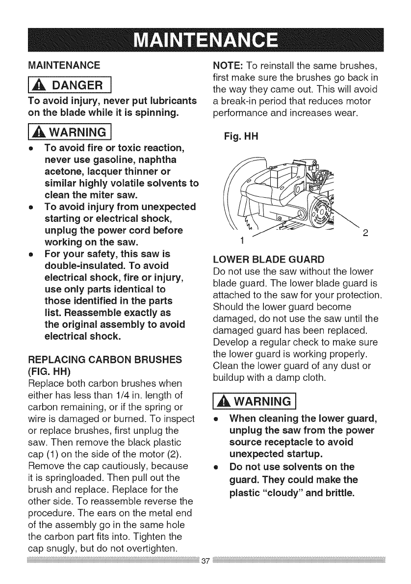
REPLACING CARBON BRUSHES
(FIG. HH)
Replace both carbon brushes when
either has less than 1/4 in. length of
carbon remaining, or if the spring or
wire is damaged or burned. To inspect
or replace brushes, first unplug the
saw. Then remove the black plastic
cap (1) on the side of the motor (2).
Remove the cap cautiously, because
it is springloaded. Then pull out the
brush and replace. Replace for the
other side. To reassemble reverse the
procedure. The ears on the metal end
of the assembly go in the same hole
the carbon part fits into. Tighten the
cap snugly, but do not overtighten.
NOTE: To reinstall the same brushes,
first make sure the brushes go back in
the way they came out. This will avoid
a break-in period that reduces motor
performance and increases wear.
Fig. HH
2
LOWER BLADE GUARD
Do not use the saw without the lower
blade guard. The lower blade guard is
attached to the saw for your protection.
Should the lower guard become
damaged, do not use the saw until the
damaged guard has been replaced.
Develop a regular check to make sure
the lower guard is working properly.
Clean the lower guard of any dust or
buildup with a damp cloth.
l,_ WARNING i
o When cleaning the lower guard,
unplug the saw from the power
source receptacle to avoid
unexpected startup.
o Do not use solvents on the
guard. They could make the
plastic "cloudy" and brittle.
37

SAWDUST
Periodically, sawdust will accumulate
under the work table and base. This
could cause difficulty in the movement
of the worktable when setting up
a miter cut. Frequently blow out or
vacuum up the sawdust.
i,A WARNING 1
Wear proper eye protection to keep
debris from entering eyes when
removing sawdust from unit.
LUBRICATION (FIG. II, JJ)
All the motor bearings in this tool are
lubricated with a sufficient amount of
high grade lubricant for the life of the
unit under normal operating conditions;
therefore, no further lubrication is
required.
Lubricate the Following as necessary:
Chop pivot: Apply light machine oil to
points indicated in illustration.
Fig. II
Chop pivot
Fig. JJ
Central pivot of
plastic guard
Central pivot of plastic guard: Use
light household oil (sewing machine
oil ) on metal-to-metal or metal-to-
plastic guard contact areas as required
for smooth, quiet operation. Avoid
excessive oil, to which sawdust will
cling.
Link: (actuates lower guard movement)
If down chop motion is hard to start, oil
link at two screws (1).

i,A WARNING ]
To avoid injury from accidental starting, always turn switch OFF and unplug
the tool before moving, replacing the blade or making adjustments.
TROUBLESHOOTING GUIDE = MOTOR
PROBLEM PROBLEM CAUSE
Brake does
notstop blade
within 10
seconds.
Motor does
not start
Brush spark
when switch
released.
1. Motor brushes not sealed
or lightly sticking.
2. Motor brake overheated
from use of defective or
wrong size blade or rapid
ON/OFF cycling.
3. Arbor bolt loose.
4. Brushes cracked,
damaged, etc.
5. Other.
1. Limit switch failure
2. Brush worn.
3. Fuse blown or circuit
breaker tripped on home
panel.
1. Brush worn.
2. Other.
SUGGESTED CORRECTIVE
ACTION
1. Inspect/clean/replace brushes.
See MAINTENANCE section.
2. Use a recommended blade. Let
cool down. See REMOVING
OR INSTALLING THE BLADE
section.
3. Retighten. See REMOVING
OR INSTALLING THE BLADE
section.
4. Replace brushes.
5. Contact Sears Service Center.
.
2.
3.
1.
2.
Replace limit switch.
Replace brushes. See
MAINTENANCE section.
Verify there is electrical power at
the outlet.
Replace Brushes. See
MAINTENANCE section.
Contact Sears Service Center.
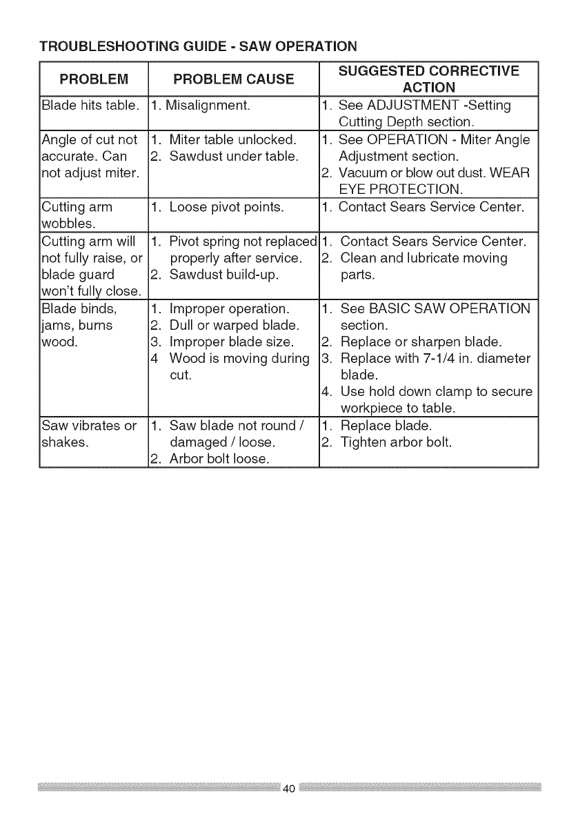
TROUBLESHOOTING GUIDE =SAW OPERATION
SUGGESTED CORRECTIVE
PROBLEM PROBLEM CAUSE ACTION
Blade hits table. 1. Misalignment. 1. See ADJUSTMENT -Setting
Cutting Depth section.
Angle of cut not 1. Miter table unlocked. 1. See OPERATION - Miter Angle
accurate. Can 2. Sawdust under table. Adjustment section.
not adjust miter. 2. Vacuum or blow out dust. WEAR
EYE PROTECTION.
Loose pivot points. 1. Contact Sears Service Center.
Pivot spring not replaced 1. Contact Sears Service Center.
properly after service. 2. Clean and lubricate moving
Sawdust build-up, parts.
Cutting arm 1.
wobbles.
Cutting arm will 1.
not fully raise, or
blade guard 2.
won't fully close.
Blade binds, 1.
ams, burns 2.
wood. 3.
4
Improper operation.
Dull or warped blade.
Improper blade size.
Wood is moving during
cut.
Saw vibrates or 1. Saw blade not round/ 1.
shakes, damaged /loose. 2.
2. Arbor bolt loose.
1. See BASIC SAW OPERATION
section.
2. Replace or sharpen blade.
3. Replace with 7-1/4 in. diameter
blade.
4. Use hold down clamp to secure
workpiece to table.
Replace blade.
Tighten arbor bolt.

74/4 in. COMPOUND MITER SAW MODEL NO. 137.211940
[_ WARNING]
When servicing use only CRAFTSMAN replacement parts. Use of any other
parts many create a HAZARD or cause product damage. Any attempt to
repair or replace electrical parts on this Miter Saw may create a HAZARD
unless repair is done by aqualified service technician. Repair service is
available at your nearest Sears Service Center.
PARTS LiST FOR SAW SCHEMATIC
Description Size Qty I.D. Description Size QtyI,D,
083S TRIGGER
083Z CORD CLAMP
091S COMPRESSION SPRING
0B5N COMPRESSION SPRING
0CES COMPRESSION SPRING
0CF5 SHAFT PIVOT
0CV5 DUST BAG ASSAY
0DHT SPRING GUARD
0DHY ARBOR COLLAR
0DVJ BLADE WRENCH
0HXV LINEAR MOTION BEARING
0J4E FLAT WASHER @6_13 1
0J4F FLAT WASHER @8_16 25
0J4J FLAT WASHER @1020 2
0J4L FLAT WASHER @122] 25
0J7K FLAT WASHER 3/8"27/32 5/64
0JBO WAVE WASHER
0JBB WAVE WASHER
0JE6 C RING
0JET E RING
0JMM O RING
0JNR O RING ROD
0JPE HEX HD BOLT M6*I 0 20
0JPF HEX HD BOLT M6*] 0 25
0JQ3 HEX HD BOLT M10_1 5 65
0JV6 HEX SOC HD CAP BOLT M10"1 5 25
0JX7 HEX SOO SET SCREW M6*I 0 B
0JZN ARBOR BOLT ME1 25 20
0K5D CR RE COUNT HD SCREW M6*I 0 20
0K7X CR RE TRUSS HD ROUND NECK SCREW M6*I 0 10
0KA9 CR RE PAN HE)TAPPING SCREW M3"24 ]0
0KB7 CR RE PAN HD TAPPING SCREW M418 ]6
0KBA CR RE PAN HD TAPPING SCREW M516 ]2
0KBC CR RE PAN HE)TAPPING SCREW M516 25
0KBM CR RE PAN HD TAPPING SCREW M4"]8 28
0KD5 CR RE PAN HE) SCREW M407 6
0KD6 CR RE PAN HD SCREW M4"07 8
0KD7 CR RE PAN HD SCREW M407 10
0KDH CR RE PAN HE) SCREW M508 8
0KDQ CR RE PAN HD SCREW M508 35
0KDT CR RE PAN HD SCREW M6*] 0 8
0KDW CR RE PAN HE) SCREW M6*] 0 20
0KKK CR RE PAN HD ROUND NECK SCREW M6*] 0 12
0KMS HEX NUT M6IOT 5
0KQW LOCK NUT M508 T 5
0KQY LOCK NUT MEI 25 T 8
0KQX NUT M6*I 0T 6
0KRO NUT M12 175T 12
0KR3 LOCK NUT M610T 6
0KTQ CABLE CLAMP
0KTS CABLE CLAMP
0KUW TERMINAL
0LU2 LIMIT SWITCH
0SIS COLLAR
23NX GUARD CORD
262V ANCHOR PLATE
26LU WARNING LABEL
27KY CLAMP BOLT
290M CAUTION LABEL
27PF COMPRESSION SPRING
2BB6 FENCE #AW
2BGV NEEDLE POINTER
2BGW SLIDE PLATE
2BLG SHAFT PIVOT
2BLL LOCATOR PIN
2CA8 CR RE TRUSS HD ROUND NECK SCREW M6"1 0 12
2CD2 COMPRESSION SPRING
2CGT SLOTrED SETSCREW M6*I 0 8
2CHF PLUNGER HOUSING ASSY
2DAT SCALE
2E63 ROCKER SWITCH
2KEQ WARNING LABEL
2K96 WARNING LABEL
2NO6 RIVET
2QBG CLAMP BOLT
2RSB ARM #AW
2RSC BASE #AW
2RSD TABLE #AW
2RSF ARM MITER #AW
2RSG PLUNGER HANDLE
2RSH LOCKING HANDLE ASSY
2RSJ PC GUARD
2RSL CUTTER SHAFT GUARD
2RSM TABLE INSERT {RIGHT)
2RSN TABLE INSERT {LEFT)
2RSP BRACING PLATE
2RSQ MOTOR HANDLE {TOP}
2RSR MOTOR HANDLE {DOWN)
2RSS CLEVIS PIN
2RST CENTER SHAFT
2RSU COVER
2RWY VISE ASS'Y
2RXl LEVER
2RX3 LASER PLUNGER HOUSING
2RX4 COVER
2RX5 TILT POINTER
2S1E BLADE
284L BEARING COVER
2S52 MOTOR ASS'Y
2S62 MITER BAR ASSY
2S65 POWER CABLE
2S67 LEAD WIRE ASS'Y
2SER HOLD DOWN CLAMP ASS'Y
2TBA CONTROLLER ASS 'Y
2T82 SHAFT SLEEVE
2T83 TORSION SPRING
2TgK OPERATORS MANUAL
2TgN LABEL
2TgP CAUTION LABEL
2T9© TRADE MARK LABEL
2TgR WARNING LABEL
2T9S TRADE MARK LABEL
2TgT TILTING SCALE
2T9U BRACKET TILT
2TgV CAUTION LABEL
2TGY CR RE PAN HD SCREW & WASHER M6*] 0 80
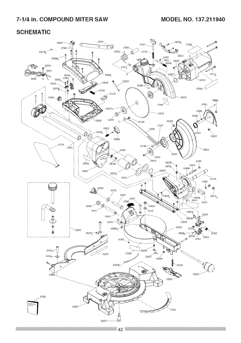
7=1/4 in. COMPOUND MITER SAW
SCHEMATIC
MODEL NO. 137.211940
OKBA
OKTS
i
i
i
2TgR
OKTQ\
_2CD2
0C_'5
OJBO
2RSH /
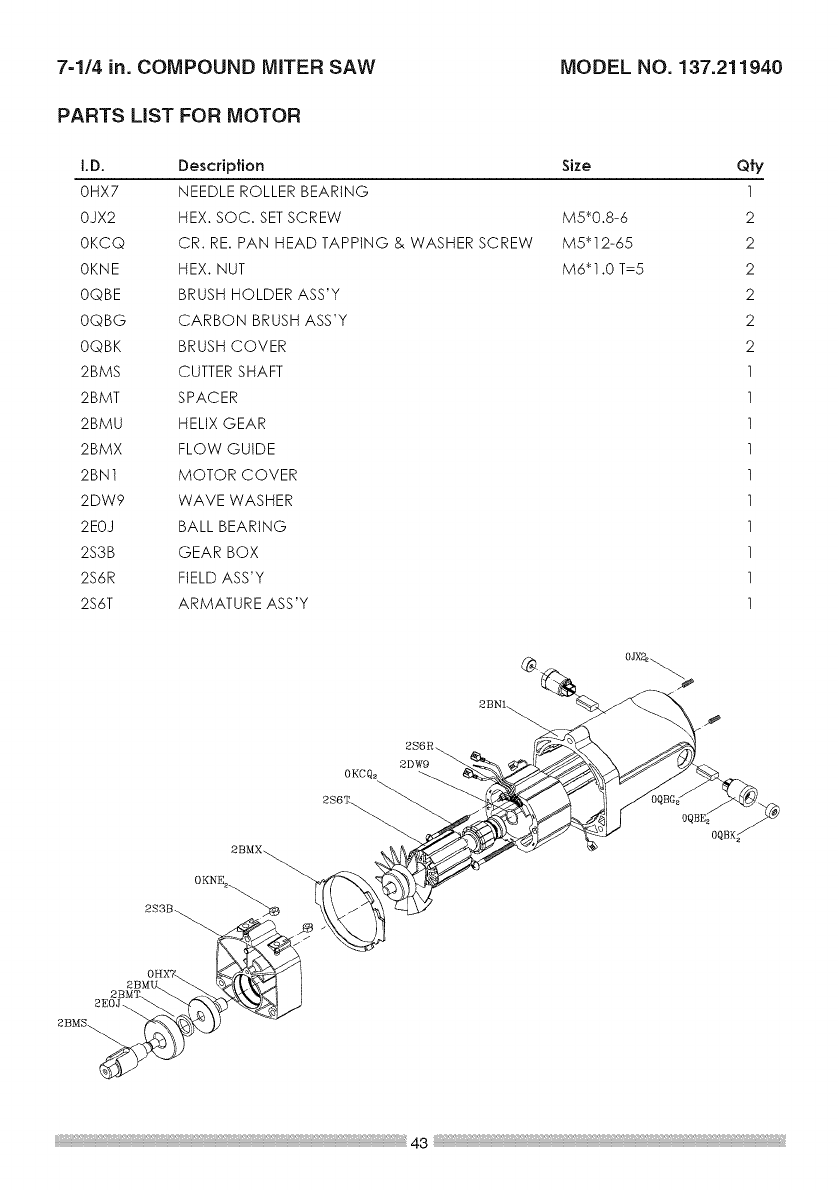
7=1/4 in. COMPOUND MITER SAW MODEL NO. 137.211940
PARTS LiST FOR MOTOR
I.D. Description
0HX7 NEEDLE ROLLER BEARING
0iX2 HEX. SOC. SETSCREW
0KC© CR. RE. PAN HEAD TAPPING & WASHER SCREW
0KNE HEX. NUT
0©BE BRUSH HOLDER ASS'Y
0©BG CARBON BRUSH ASS'Y
0©BK BRUSH COVER
2BMS CUTTER SHAFT
2BMT SPACER
2BMU HELIX GEAR
2BMX FLOW GUIDE
2BN1 MOTOR COVER
2DW9 WAVE WASHER
2EOJ BALL BEARING
2S3B GEAR BOX
2S6R FIELD ASS'Y
2S6T ARMATURE ASS'Y
Size
M5_0.8-6
M5 _ 12-65
M6"1.0 T=5
Q'l'y
1
2
2
2
2
2
2
1
1
1
1
1
1
1
1
1
1
OKNE2_
2S3B_ "_
2B OH
2S6R_
2DW9
@

Your Home
For expert troubleshooting and home solutions advice:
manage
www.managernyhorne.com
For repair - in your home - of all major brand appliances,
lawn and garden equipment, or heating and cooling systems,
no matter who made it, no matter who sold it!
For the replacement parts, accessories and
owner's manuals that you need to do-it-yourself.
For Sears professional installation of home appliances
and items like garage door openers and water heaters.
1-800-4-MY-HOME ® (1-800-4694663)
Call anytime, day or night (U.S.A. and Canada)
www.sears.comwww.sear_.c_
oct Home
Forrepairofcarry-initemslikevacuums,lawnequipment,
and electronics, call anytime for the location of your nearest
SearsPaas&RepairSe_iceCenter
1-800-488-1222 (U.S.A.) 1-800-469-4663 (Canada)
www.sears.com www.sears.ca 1i
11iii/To purchase a protection agreement on a product serviced by Sears:
1"800-827"8655 (U.S.A.) 1"800-361-6665 (Canada)
Parapedirse_viciode,epa_aci6n AuCanadapou,serviceenfran_ais:
a domicilio,y paraordenarpiezas: 1-800-LE-FOYER _'°
1-888-SU-HOGAR ® (1-800-533-6937)
(1-888-784-6427) _ www.sears.ca
TM SM
_) Registered Trademark /Trademark /Service Mark of Sears Brands, LLC
sM
® Marca Registrada /TM Marca de Fabdca /Marca de Servicio de Sears Brands, LLC
MC MD
Marque de commerce /Marque deposse de Sears Brands, LLC ©Sears Brands, LLC
