Craftsman 137212210 User Manual MITER SAW Manuals And Guides L0807737
CRAFTSMAN Miter Saw Manual L0807737 CRAFTSMAN Miter Saw Owner's Manual, CRAFTSMAN Miter Saw installation guides
User Manual: Craftsman 137212210 137212210 CRAFTSMAN MITER SAW - Manuals and Guides View the owners manual for your CRAFTSMAN MITER SAW #137212210. Home:Tool Parts:Craftsman Parts:Craftsman MITER SAW Manual
Open the PDF directly: View PDF ![]() .
.
Page Count: 224 [warning: Documents this large are best viewed by clicking the View PDF Link!]

Operator's Manual
CRAFTSMAN°
i PROFESSI ONAL i
12 in. DUAL BEVEL SLIDING COMPOUND
MITER SAW WITH LASER TRAC®
Model No. 137.212210
C US
CAUTION:
Before using this Miter Saw,
read this manual and follow
all its Safety Rules and
Operating Instructions
• Safety Instructions
• Installation
• Operation
• Maintenance
• Parts List
Customer Help Line
For Technical Support
1-800-843-1682
Sears Parts &
Repair Center
1-800-488-1222
Sears, Roebuck and Co., Hoffman Estates, IL 60179 USA
Visit our Craftsman website: www.sears.com/craftsman
Part No. 137212210001 Printed in Taiwan

SECTION PAGE
Warranty.............................................................................................2
ProductSpecifications........................................................................3
Symbols..............................................................................................4
PowerToolSafety..............................................................................5
CompoundMiterSawSafety..............................................................7
ElectricalRequirementsandSafety......................................................9
AccessoriesandAttachments............................................................11
ToolsNeededforAssembly................................................................12
CartonContents.................................................................................13
KnowYourCompoundMiterSaw........................................................14
GlossaryofTerms..............................................................................15
AssemblyandAdjustments................................................................17
Operation...........................................................................................30
Maintenance.......................................................................................44
TroubleshootingGuide.......................................................................46
PartsList.............................................................................................48
CRAFTSMAN ONE YEAR FULL WARRANTY
If this Craftsman tool fails due to a defect in material or workmanship within
one year from the date of purchase, call 1-800-4-MY-HOME® to arrange for
free repair (or replacement if repair proves impossible).
This warranty applies for only 90 days from the date of purchase if this product
is ever used for commercial or rental purposes.
This warranty does not include expendable parts, such as lamps, batteries,
bits or blades.
This warranty gives you specific legal rights, and you may also have other
rights which vary from state to state.
Sears, Roebuck and Co., Hoffman Estates, IL 60179
_, WARNING J
Some dust created by using power tools contains chemicals known to the
state of California to cause cancer and birth defects or other reproductive
harm. Some examples of these chemicals are:
•Lead from lead-based paints
•Crystalline silica from bricks, cement and other masonry products
•Arsenic and chromium from chemically treated lumber
Your risk from these exposures varies, depending on how often you do
this type of work. To reduce your exposure to these chemicals, work in a
well ventilated area and work with approved safety equipment such as dust
masks that are specially designed to filter out microscopic particles.
2
2008/04
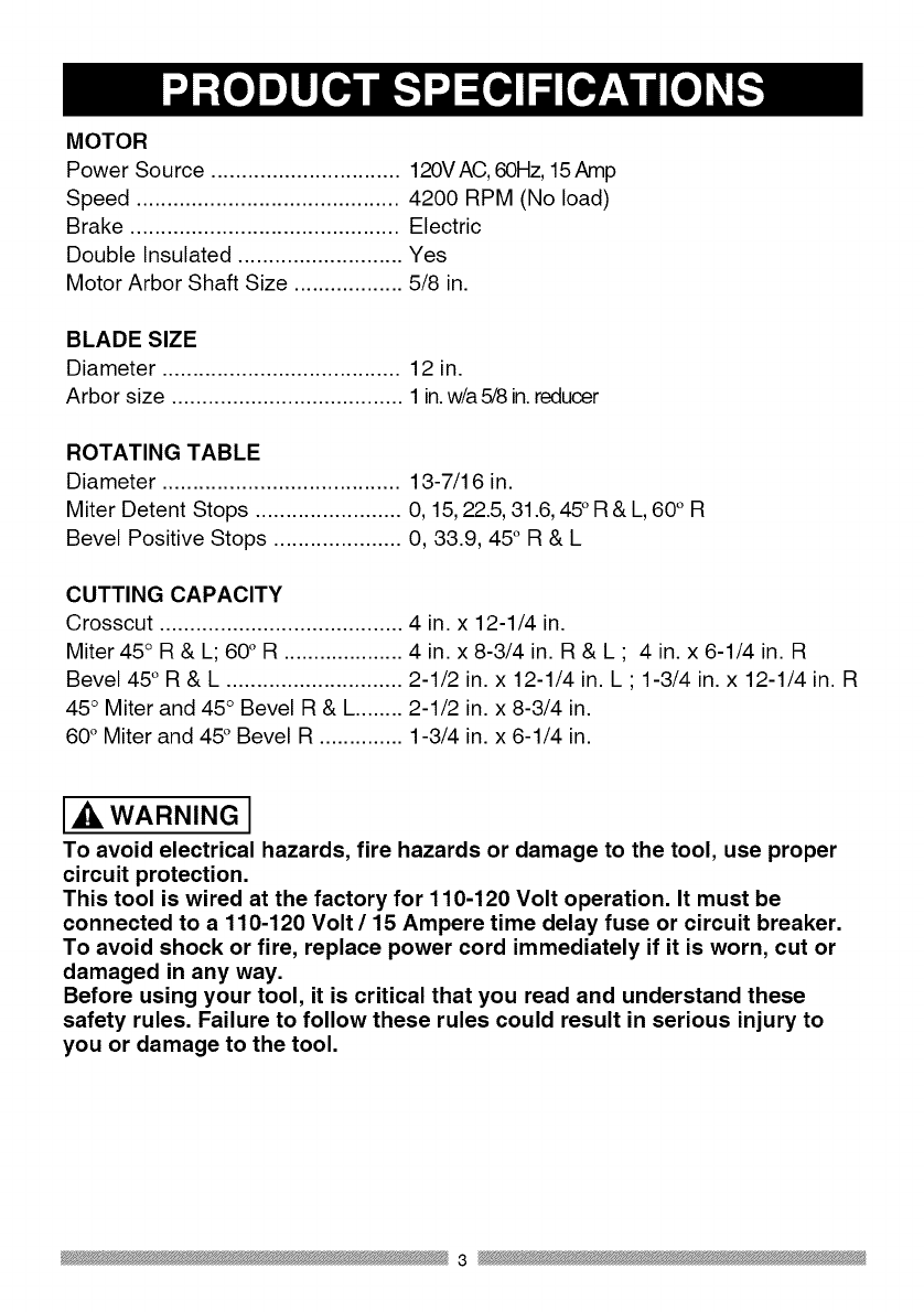
MOTOR
Power Source ............................... 120VAC, 60Hz, 15Amp
Speed ........................................... 4200 RPM (No load)
Brake ............................................ Electric
Double Insulated ........................... Yes
Motor Arbor Shaft Size .................. 5/8 in.
BLADE SIZE
Diameter ....................................... 12 in.
Arbor size ...................................... 1in.w/a 5/8 in.reducer
ROTATING TABLE
Diameter ....................................... 13-7/16 in.
Miter Detent Stops ........................ 0, 15, 22.5,31.6, 45° R & L, 60° R
Bevel Positive Stops ..................... 0, 33.9, 45° R & L
CUTTING CAPACITY
Crosscut ........................................ 4 in. x 12-1/4 in.
Miter 45° R & L; 60° R .................... 4 in. x 8-3/4 in. R & L ; 4 in. x 6-1/4 in. R
Bevel 45° R & L ............................. 2-1/2 in. x 12-1/4 in. L ; 1-3/4 in. x 12-1/4 in. R
45° Miter and 45° Bevel R & L........ 2-1/2 in. x 8-3/4 in.
60° Miter and 45° Bevel R .............. 1-3/4 in. x 6-1/4 in.
[_iL WARNING J
To avoid electrical hazards, fire hazards or damage to the tool, use proper
circuit protection.
This tool is wired at the factory for 110-120 Volt operation. It must be
connected to a 110-120 Volt /15 Ampere time delay fuse or circuit breaker.
To avoid shock or fire, replace power cord immediately if it is worn, cut or
damaged in any way.
Before using your tool, it is critical that you read and understand these
safety rules. Failure to follow these rules could result in serious injury to
you or damage to the tool.
3
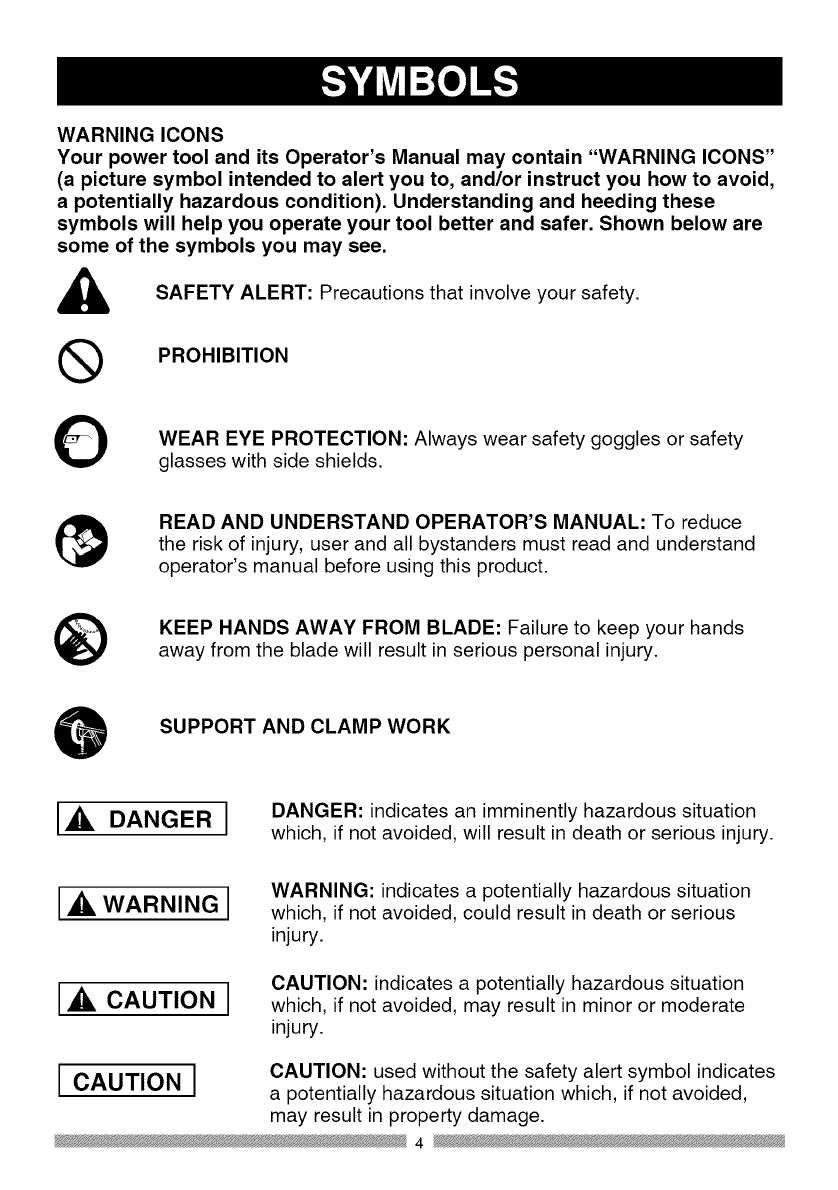
WARNING ICONS
Your power tool and its Operator's Manual may contain "WARNING ICONS"
(a picture symbol intended to alert you to, and/or instruct you how to avoid,
a potentially hazardous condition). Understanding and heeding these
symbols will help you operate your tool better and safer. Shown below are
some of the symbols you may see.
SAFETY ALERT: Precautions that involve your safety.
®PROHIBITION
OWEAR EYE PROTECTION: Always wear safety goggles or safety
glasses with side shields.
READ AND UNDERSTAND OPERATOR'S MANUAL: To reduce
the risk of injury, user and all bystanders must read and understand
operator's manual before using this product.
®KEEP HANDS AWAY FROM BLADE: Failure to keep your hands
away from the blade will result in serious personal injury.
SUPPORT AND CLAMP WORK
[_, DANGER] DANGER: indicates an imminently hazardous situation
which, if not avoided, will result in death or serious injury.
[A WARNING I
[A CAUTION I
WARNING: indicates a potentially hazardous situation
which, if not avoided, could result in death or serious
injury.
CAUTION: indicates a potentially hazardous situation
which, if not avoided, may result in minor or moderate
injury.
CAUTION: used without the safety alert symbol indicates
[ CAUTION ]a potentially hazardous situation which, if not avoided,
may result in property damage.
4

GENERAL SAFETY INSTRUCTIONS 8.
BEFORE USING THIS POWER TOOL
Safety is a combination of common
sense, staying alert and knowing how 9.
to use your power tool.
CAUTION
To avoid mistakes that could cause
serious injury, do not plug the tool in 10.
until you have read and understood
the following.
.
,
,
.
READ and become familiar with
the entire Operator's
Manual. LEARN the tool's
application, limitations and
possible hazards.
KEEP GUARDS IN PLACE and in
working order.
REMOVE ADJUSTING KEYS
AND WRENCHES. Form the habit
of checking to see that keys and
adjusting wrenches are removed
from the tool before turning ON.
KEEP WORK AREA CLEAN.
Cluttered areas and benches invite
accidents.
,DO NOT USE IN DANGEROUS
ENVIRONMENTS. Do not use
power tools in damp locations, or
expose them to rain or snow. Keep
work area well lit.
,KEEP CHILDREN AWAY. All
visitors and bystanders should be
kept a safe distance from work
area.
,MAKE WORKSHOP CHILD
PROOF with padlocks, master
switches or by removing starter
keys.
11.
12.
DO NOT FORCE THE TOOL. It will
do the job better and safer at the
rate for which it was designed.
USE THE RIGHT TOOL. Do not
force the tool or an attachment
to do a job for which it was not
designed.
USE PROPER EXTENSION
CORDS. Make sure your extension
cord is in good condition. When
using an extension cord, be sure
to use one heavy enough to carry
the current your product will draw.
An undersized cord will result in
a drop in line voltage and in loss
of power which will cause the tool
to overheat. The table on page
10 shows the correct size to use
depending on cord length and
nameplate ampere rating. If in
doubt, use the next heavier gauge.
The smaller the gauge number, the
heavier the cord.
WEAR PROPER APPAREL. Do
not wear loose clothing, gloves,
neckties, rings, bracelets or other
jewelry which may get caught in
moving parts. Nonslip footwear is
recommended. Wear protective
hair covering to contain long hair.
OALWAYS WEAR EYE
PROTECTION. Any power
tool can throw foreign
objects into the eyes and
could cause permanent eye
damage. ALWAYS wear Safety
Goggles (not glasses) that comply
with ANSI Safety standard Z87.1.
Everyday eyeglasses have only
impact-resistant lenses. They
ARE NOT safety glasses. Safety
Goggles are available at sears.
5

NOTE: Glasses or goggles not in
compliance with ANSI Z87.1 could
seriously injure you when they
break.
and any other conditions that may
affect its operation. A guard or
other part that is damaged should
be properly repaired or replaced.
13. WEAR A FACE MASK OR DUST
MASK. Sawing operation produces
dust.
14. SECURE WORK. Use
clamps or a vise to hold work
when practical. It is safer
than using your hand and it
frees both hands to operate
the tool.
15. DISCONNECT TOOLS FROM
POWER SOURCE before servicing,
and when changing accessories
such as blades, bits and cutters.
16. REDUCE THE RISK OF
UNINTENTIONAL STARTING.
Make sure switch is in the OFF
position before plugging the tool in.
17. USE RECOMMENDED
ACCESSORIES. Consult
this Operator's Manual for
recommended accessories. The
use of improper accessories may
cause risk of injury to yourself or
others.
18. NEVER STAND ON THE TOOL.
Serious injury could occur if the
tool is tipped or if the cutting tool is
unintentionally contacted.
20. NEVER LEAVE THE TOOL
RUNNING UNATTENDED. TURN
THE POWER "OFF". Do not walk
away from a running tool until the
blade comes to a complete stop
and the tool is unplugged from the
power source.
21. DO NOT OVERREACH. Keep
proper footing and balance at all
times.
22. MAINTAIN TOOLS WITH CARE.
Keep tools sharp and clean for best
and safest performance. Follow
instructions for lubricating and
changing accessories.
23. WARNING: Dust generated from
certain materials can be hazardous
to your health. Always operate saw
in well-ventilated area and provide
for proper dust removal.
24.[_k DANGER J People with
electronic devices, such as
pacemakers, should consult their
physician(s) before using this
product. Operation of electrical
equipment in close proximity to
a heart pacemaker could cause
interference or failure of the
pacemaker.
19. CHECK FOR DAMAGED PARTS.
Before further use of the tool, a
guard or other part that is damaged
should be carefully checked to
determine that it will operate
properly and perform its intended
function - check for alignment of
moving parts, binding of moving
parts, breakage of parts, mounting
6

SPECIFIC SAFETY INSTRUCTIONS
FOR THIS COMPOUND MITER SAW
.DO NOT operate the miter saw
until it is completely assembled
and installed according to these
instructions.
,IF YOU ARE NOT thoroughly
familiar with the operation of miter
saws, seek guidance from your
supervisor, instructor or other
qualified person.
,ALWAYS hold the work firmly
against the fence and table.
DO NOT perform any operation
free hand (use clamp wherever
possible).
.KEEP HANDS out of the path of the
saw blade. If the workpiece you are
cutting would cause your hands to
be within 8-3/4 in. of the saw blade,
the workpiece should be clamped in
place before making the cut.
5. BE SURE the blade is sharp, runs
freely and is free of vibration.
6. ALLOW the motor to come up to full
speed before starting a cut.
7. KEEP THE MOTOR AIR SLOTS
CLEAN and free of chips or dust.
,ALWAYS MAKE SURE all handles
are tight before cutting, even if the
table is positioned in one of the
positive stops.
9. BE SURE both the blade and the
collar are clean and the arbor bolt is
tightened securely.
10.USE only blade collars specified for
your saw.
11.NEVER use blades larger in
diameter than 12 inches.
12.NEVER apply lubricants to the
blade when it is running.
13.ALWAYS check the blade for
cracks or damage before operation.
Replace a cracked or damaged
blade immediately.
14.NEVER use blades recommended
for operation at less than 4200
RPM.
15.ALWAYS keep the blade guards in
place and use at all times.
16.NEVER reach around the saw
blade.
17.MAKE SURE the blade is not
contacting the workpiece before the
switch is turned ON.
18.IMPORTANT: After completing the
cut, release the trigger and wait for
the blade to stop before returning
the saw to the raised position.
19.MAKE SURE the blade has come
to a complete stop before removing
or securing the workpiece, changing
the workpiece angle or changing the
angle of the blade.
20.NEVER cut metals or masonry
products with this tool. This miter
saw is designed for use on wood
and wood-like products.
7

21. NEVER cut small pieces. If the
workpiece being cut would cause
your hand or fingers to be within
8-3/4 in. of the saw blade the
workpiece is too small.
22. PROVIDE adequate support to the
sides of the saw table for long work
pieces.
23. NEVER use the miter saw in an
area with flammable liquids or
gases.
24. NEVER use solvents to clean
plastic parts. Solvents could
possibly dissolve or otherwise
damage the material.
25. SHUT OFF the power before
servicing or adjusting the tool.
26. DISCONNECT the saw from
the power source and clean the
machine when finished using.
27. MAKE SURE the work area is
clean before leaving the machine.
28. SHOULD any part of your miter saw
be missing, damaged, or fail in any
way, or any electrical component
fail to perform properly, lock the
switch and remove the plug from
the power supply outlet. Replace
missing, damaged, or failed parts
before resuming operation.
8

POWER SUPPLY AND MOTOR
SPECIFICATIONS
The AC motor used in this saw is
a universal, nonreversible type.
See "MOTOR" in the "PRODUCT
SPECIFICATIONS" section on page 3.
WARNING I
To avoid electrical hazards, fire
hazards, or damage to the tool, use
proper circuit protection, Your saw
is wired at the factory for 120 V
operation, Connect to a 120 V, 15A
circuit and use a 15 A time delay
fuse or circuit breaker, To avoid
shock or fire, if power cord is worn
or cut, or damaged in any way, have
it replaced immediately,
way. If the plug does not fit fully in the
outlet, reverse the plug. If it still does
not fit, contact a qualified electrician to
install the proper outlet. Do not change
the plug in any way.
IAWARNINGI
Double insulation does not take the
place of normal safety precautions
when operating this tool.
To avoid electrocution:
1. Use only identical replacement parts
when servicing a tool with double
insulation. Servicing should be
performed by a qualified technician.
2. Do not use power tools in wet or
damp locations or expose them to
rain or snow.
DOUBLE INSULATED []
The power tool is double insulated to
provide a double thickness of insulation
between you and tool's electrical
system. All exposed metal parts are
isolated from the internal metal motor
components with protecting insulation.
Replacement parts - When servicing,
use only identical replacement parts.
Polarized plugs - This saw has a plug
that looks like the one shown below:
To reduce the risk of electrical shock,
this saw has a polarized plug (one
blade is wider than the other). This plug
will fit in a polarized outlet only one
MOTOR SAFETY PROTECTION
IMPORTANT
To avoid motor damage, the motor
should be blown out or vacuumed
frequently to keep sawdust from
interfering with the motor ventilation.
1. Connect this saw to a 120 V circuit.
This circuit must not be less than a
#12 wire with a 20 A time lag fuse or
a #14 wire with a 15 A time lag fuse.
NOTE: When using an extension
cord on a circuit with a #14 wire, the
extension cord must not exceed 25
feet in length.
2. If the motor will not start, release
the trigger switch immediately.
UNPLUG THE SAW. Check the saw
blade to make sure it turns freely. If
the blade is free, try to start the saw
again. If the motor still does not start,
refer to the TROUBLESHOOTING
GUIDE.
3. If the tool suddenly stalls while
cutting wood, release the trigger
switch, unplug the tool and free the
blade from the wood. The saw may
9

now be started and the cut finished.
4. FUSES may "blow" or circuit
breakers may trip frequently if:
a. MOTOR is overloaded -
overloading can occur if you feed
too rapidly or make too many
start/stops in a short time.
b. LINE VOLTAGE is more
than 10% above or below the
nameplate voltage rating. For
heavy loads, the voltage at motor
terminals must equal the voltage
specified on the nameplate.
c. IMPROPER or dull saw blades
are used.
5. Most motor troubles may be traced
to loose or incorrect connections,
overload, low voltage or inadequate
power supply wiring. Always check
the connections, the load and
supply circuit if the motor doesn't
run well. Check minimum gauge for
the length of cord you are using on
the chart below.
excessive heat and damp or wet areas.
Use a separate electrical circuit
for your tools. This circuit must not
be less than a #12 wire with a 20 A
time lag fuse or a #14 wire with a 15
A time lag fuse. NOTE: When using
an extension cord on a circuit with
a #14 wire, the extension cord must
not exceed 25 feet in length. Before
connecting the tool to the power line,
make sure the switch is in the OFF
position and the electric current is
rated the same as the current stamped
on the motor nameplate, running at a
lower voltage will damage the motor.
I,V_ll#lhVjIll Lvj|€f._11[_1 =11=[0]t,i _:Q i=1#{..I [el #El.ill ;I I]._fzViVL_l
(When using 120 volts only)
Ampere Rating Total length of Cord
More Than Not More Than 25ft. 50ft. 100ft. 150ft.
O 6 18 16 16 14
6 10 18 16 14 12
10 12 16 16 14 12
GUIDELINES FOR EXTENSION
CORDS
Use a proper extension cord. Make
sure your extension cord is in good
condition. When using an extension
cord, be sure to use one heavy enough
to carry the current your product will
draw. An undersized cord will cause
a drop in line voltage, resulting in
loss of power and overheating. The
table below shows the correct size
to use depending on cord length and
nameplate ampere rating. If in doubt,
use the next heavier gauge. The
smaller the gauge number, the heavier
the cord.
CAUTION: In all cases make certain
the receptacle in question is
properly grounded. If you are not
sure, have a certified electrician
check the receptacle.
Be sure your extension cord is
properly wired and in good condition.
Always replace a damaged extension
cord or have it repaired by a qualified
person before using it. Protect your
extension cords from sharp objects,
10

RECOMMENDED ACCESSORIES
[_k WARNING J
•Use only accessories
recommended for this miter
saw. Follow instructions that
accompany accessories. Use of
improper accessories may cause
hazards.
•The use of any cutting tool
except 12 in. saw blades which
meet the requirements under
recommended accessories
is prohibited. Do not use
accessories such as shaper
cutters or dado sets. Ferrous
metal cutting and the use of
abrasive wheels is prohibited.
•Do not attempt to modify this
tool or create accessories not
recommended for use with this
tool. Any such alteration or
modification is misuse and could
result in a hazardous condition
leading to possible serious
injury.
without the proper saw blade
guard in place. Carbide is a very
hard but brittle material. Care
should be taken while mounting,
using, and storing carbide tipped
blades to prevent accidental
damage. Slight shocks, such as
striking the tip while handling,
can seriously damage the blade.
Foreign objects in the workpiece,
such as wire or nails, can also
cause tips to crack or break off.
Before using, always visually
examine the blade and tips for
bent blade, cracks, breakage,
missing or loose tips, or other
damage. Do not use if damage is
suspected. Failure to heed safety
instructions and warnings can
result in serious bodily injury.
ACCESSORIES
Visit your Sears Hardware Department
or see the Sears Power and Hand Tool
Catalog to purchase recommended
accessories for this power tool.
[_, WARNING J
•To avoid the risk of personal
injury, do not modify this power
tool or use accessories not
recommended by Sears.
•Read warnings and conditions
on your CARBIDE TIPPED SAW
BLADE. Do not operate the saw
11

Supplied
Blade Wrench
Not supplied
Adjustable Wrench
6 mm Hex Wrench
l!'-'"-'_,_i'-:'_,_,_'-'' -'i'-_,_
Combination Square
Phillips Screwdriver
Slotted Screwdriver
COMBINATION SQUARE MUST BE TRUE
Should not gap or overlap when square is flipped over (see dotted figure).
Draw light line on
board along this edge.
Straight edge or a 3/4 in. board, this
edge must be perfectly straight.
Should not gap or overlap when square
flipped over (see dotted figure).
12

UNPACKING YOUR MITER SAW
WARNING I
To avoid injury from unexpected
starting or electrical shock, do not
plug the power cord into a source
of power during unpacking and
assembly. This cord must remain
unplugged whenever you are
working on the saw.
1. Remove the miter saw from the
carton.
IMPORTANT: Do not lift miter saw
by the trigger switch handle. It may
cause misalignment. Lift machine by
the built-in carry handle.
2. Place the saw on a secure stationary
work surface.
3. Separate all parts from the packing
material. Check each one with the
illustration to make certain all items
are accounted for, before discarding
any packing material.
IAWARNINGi
If any part is missing or damaged,
do not attempt to assemble the
miter saw, or plug in the power
cord until the missing or damaged
part is correctly replaced. To avoid
electric shock, use only identical
replacement parts when servicing
double insulated tools. Call
1-800-4-MY-HOME ®for replacement
parts.
Hold-down clamp
Dust bag Miter saw
%
Elbow
Power cord Hold-down clamp
Blade wrench Power cord storage clip lock knob
storage clips mounting
hardware
13

Motor \
Saw blade
Bevel scale
Hold-down clamp
Sliding fence
Carry handle Upper blade guard
Carry handle Laser ON/OFF switch
Handle locking lever
Switch handle
ON/OFF trigger switch
Lower blade guard
Base
Miter lock handle
Left extension table
Turntable
Bevel lock handle
Mounting hole Left support
Belt cover
Hold-down latch
Slide carriage
Slide carriage
lock knob
Laser guide
Right extension table
Stop plate
Quick-cam miter
table lock Table insert Right support
Positive miter detents
14

AMPERAGE (AMPS) - A measure
of the flow of electric current. Higher
ratings generally means the tool is
suited for heavier use.
ARBOR LOCK -Allows the user to
keep the blade from rotating while
tightening or loosening the arbor bolt
during blade replacement or removal.
eyes. Eye protection should meet the
requirements of ANSI Z.87.1 (USA) or
CSA Z94.3-M88 (Canada).
FACE SHIELD - An impact resistant
shield that helps to protect your face
from chips, sparks, small debris.
Should only be used in conjunction with
additional eye protection.
BASE - Supports the table, holds
accessories and allows for workbench
or leg set mounting.
FENCE - Helps to keep the workpiece
from moving when sawing. Scaled to
assist with accurate cutting.
BEVEL LOCKING HANDLE - Locks
the miter saw at a desired bevel angle.
BEVEL SCALE - To measure the
bevel angle of the saw blade 0° to 45°
left.
CARBIDE TIPPED -Extremely hard
steel pieces with sharp cutting edges
fastened to cutting tools such as saw
blades.
COVER PLATE SCREW - Loosen this
screw and rotate the plate for access to
the blade arbor bolt.
GUARD - Protective devise that forms
a barrier between a hazardous object
such as a blade, wheel or cutter and
the operator.
HOLD DOWN LATCH - Locks the
miter saw in the lowered position for
compact storage and transportation.
INSTRUCTION OR OPERATOR'S
MANUAL - Booklet accompanying
your power tool that describes the
hazards and safe operation procedures,
outlines basic tool operation, care and
maintenance.
DOUBLE-INSULATED - A form of
electrical protection featuring two
separate insulation systems to help
protect against electrical shock.
EXTENSION CORD -An electric cord
used between power tools and outlets
to extend the range of the tools. The
more amerage your tool uses, the
longer the distance, the larger the size
of the wire needed in your extension
cord.
EYE PROTECTION - Goggles or
spectacles intended to protect your
MITER HANDLE - Used to rotate the
table, and to rotate the saw to a right or
left cutting position.
MITER SCALE - Measures the miter
angle 0° to 45 ° left and right.
MOUNTING HOLES - To mount the
miter saw to a stable surface.
ON/OFF TRIGGER SWITCH - To start
the tool, squeeze the trigger. Release
the trigger to turn off the miter saw.
15
POSITIVE STOP LOCKING LEVER -
Locks the miter saw at a preset positive
stop for the desired miter angle.
SWITCH HANDLE - The switch
handle contains the trigger switch and
the laser on/off switch. The blade is
lowered into the workpiece by pushing
down on the handle. The saw will
return to its upright position when the
handle is released.
WARNING LABELS - Read and
understand for your own safety. Make
sure all labels are present on machine
and legible.
WRENCH STORAGE - Convenient
storage to prevent misplacing the blade
wrench.
WOODWORKING TERMS
ARBOR - The shaft on which a blade
is mounted.
BEVEL CUT - An angle cut made
through the face of the workpiece.
COMPOUND CUT - An angled cut
to both the edge and face of a board,
most common use is with crown
molding.
CROSS CUT - A cut which runs across
the board perpendicular to the grain.
KICKBACK - Sudden and unintended
movement of the tool or workpiece. It is
typically caused by binding or pinching
of the workpiece
MITER CUT - A miter is a type of joint
where the two parts to be joined are cut
at an angle, and typically the finished
joint forms a 90-degree angle. Also
commonly spelled "mitre".
REVOLUTIONS PER MINUTE (RPM)
- The number of turns completed by a
spinning object in one minute.
SAW BLADE PATH - The area of the
workpiece or table top directly in line
with the travel of the blade or the part
of the workpiece which will be cut.
SET - The distance between two saw
blade tips, bent outward in opposite
directions to each other. The further
apart the tips are, the greater the set.
THIN-KERF BLADE - Thinner than
normal blades, remove less material,
smaller kerfs (between .065 and .070).
Blade thinness also may increase the
heat generated while cutting.
WORKPIECE - The wood being
cut. The surfaces of a workpiece are
commonly referred to as faces, ends
and edges.
FREEHAND - Performing a cut without
using a fence (guide), hold down or
other proper device to prevent the
workpiece from twisting during the
cutting operation.
HEEL - Misalignment of the blade.
KERF - The width of a saw cut,
determined by the thickness and set of
the blade.
16

ESTIMATED ASSEMBLY TIME: 10~15
MINUTES
AL WARNING I
To avoid injury, do not connect this
miter saw to the power source until
it is completely assembled and
adjusted, and you have read and
understood this Operator's Manual,
UNLOCKING THE SLIDE CARRIAGE
(FIG. A)
After removing the saw from the carton,
loosen the slide carriage lock knob
(1). When transporting or storing the
miter saw, the slide carriage should
always be locked in position. The slide
carriage lock knob (1) is located on the
right side of the slide carriage.
Unlocking
1. Push down slightly on the switch
handle (1).
2. Pull out the hold-down latch (2).
3. Allow the cutting head to rise to the
up position.
Fig, B
/,
1
Fig, A
RELEASING CUTTING HEAD (FIG, B)
WARNING I
To avoid injury and damage to the
saw, transport or store the miter
saw with the cutting head locked in
the down position. Never use the
hold down latch to hold the cutting
head in a down position for cutting
operations.
Locking
When transporting or storing the miter
saw, the cutting head should always be
locked in the down position.
1. Push the cutting head down to its
lowest position.
2. Push the hold-down latch (2) into
the locking hole.
IMPORTANT: To avoid damage, never
carry the miter saw by the switch
handle, the cutting arm or the miter
handle. ALWAYS use the designated
carrying handles located on the top of
the machine and in the back of the unit.
17
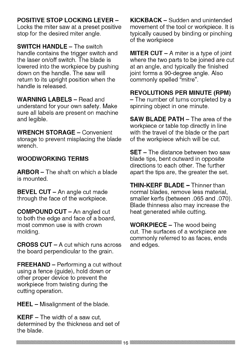
INSTALLING THE DUST
COLLECTION ELBOW (FIG. C)
1. Install the end of the elbow (1) onto
the exhaust port (2).
NOTE: The elbow can be used
to attach either the dust bag or a
vacuum hose to remove sawdust
from the work area.
Fig. C
INSTALLING THE DUST BAG (FIG. D)
1. Squeeze the metal collar wings (1)
of the dust bag (2).
2. Place the dust bag neck opening
around the dust collection elbow (3),
and release the metal collar.
Fig. D
2
To empty the dust bag, squeeze the
metal collar and remove from exhaust
port. Open zipper on underside of bag
and empty into waste container.
NOTE: Check frequently and empty
bag before it gets full.
THREE POSITION ROTATING
HANDLE (FIG. E)
The handle of the miter saw has been
designed to rotate and lock at three
different position stops; 450 left, 0°, and
450 right for operator convenience. To
rotate the handle:
1. Unlock the handle locking lever (1)
by pulling it toward the front of the
machine.
2. Pull the handle-locking latch (2)
to the front of the saw and hold in
position.
3. Rotate the handle to the desired
position stop and release the
handle-locking latch. NOTE: After
releasing the handle-locking latch,
rotate the handle left and right to
make sure the latch engages into
the positive locking position.
4. Lock the handle locking lever (1) by
pushing it IN toward the rear of the
handle.
Fig. E 2
\\
\\\
INSTALLING THE SAFETY HOLD-
DOWN CLAMP (FIG. F)
1. Place the hold-down clamp
assembly (1) in one of the mounting
hole (2), located behind the fence.
2. Thread the hold-down clamp knob
(3) into the hole (2) located at the
rear of the saw base.
3. Tighten the hold-down clamp knob
.
)
18

Fig. F
21
3
POWER CORD STORAGE CLIPS
(FIG. G)
For convenience and to prevent
damage to the power cord when
the miter saw is not in use or is in
transportation, the slide carriage has
two clips on the rear for cord storage.
To assembly these clips:
1. Attach each power cord storage
clips (2) to the rear of slide-bar seat
with one mounting screws (1).
Fig. G
2
1
SAW BLADE WRENCH (FIG. H)
For convenient storage and prevention
of loss, there is a clip (1) located at the
left rear foot of the base for storing the
blade wrench (2).
Fig. H
2
I,A WARNING I
To avoid injury, disconnect the
plug from the power source before
performing any adjustments or
repair.
NOTE: Your miter saw was adjusted at
the factory. However, during shipment
slight misalignment may have occurred.
Check the following settings and adjust
if necessary prior to using this miter
saw.
REMOVING AND INSTALLING THE
TABLE INSERT (FIG. I)
WARNINGI
To avoid injury:
• Always unplug the saw to avoid
accidental starting. Remove all
small pieces of material from the
table cavity before performing
any cuts. The table insert may
be removed for this purpose, but
always reattach the table insert
prior to performing a cutting
operation.
•Do not start the sliding compound
miter saw without checking for
interference between the blade
and table insert. Damage could
result to the blade, table insert or
turntable if blade strike occurs
during the cutting operation.
19

1. To remove, loosen and remove the
six screws (1) on the table inserts
(2) with a Phillips screwdriver and
remove the inserts.
2. To install, reposition the table
inserts, install the six screws and
tighten.
3. Check for blade clearance by
moving the slide carriage through
the full motion of the blade in the
table slot.
to the insulation or the wire
connections resulting in electric
shock or fire.
•To avoid injury from flying
debris, do not allow visitors to
stand near the saw during any
cutting operation.
•Support the saw on a level work
surface.
•Bolt or clamp the saw to its
support.
Fig. I Mounting instructions
1. For stationary use, place the saw
in the desired location, directly on
aworkbench where there is room
for handling and proper support
of the workpiece. The base of the
saw has four mounting holes. Bolt
the base of the miter saw (1) to
the work surface (5), using the
fastening method as shown in Fig J.
MOUNTING THE MITER SAW
(FIG. J, K)
[_ WARNING J
To avoid injury form unexpected
saw movement:
•Disconnect the power cord from
the outlet, and lock the cutting
head in the lower position using
the stop latch.
•Lock the slide carriage in place
by tightening the slide carriage
lock knob.
• To avoid back injury, lift the saw
by using the designated carrying
handles located on the top of the
machine. When lifting, bend at
your knees, not from your back.
•Never carry the miter saw by
the power cord or by the switch
handle. Carrying the tool by the
Fig. J
1. 3
2. 4
3.
4. 1
5. ---[--- _,
6. 5 _,:
7. _9
6 8
8.
9. 7
NOTE: Mounting hardware is not
included with this tool. Bolts, nuts,
washers & screws must be purchased
separately.
Miter saw base
Hex head bolt
Rubber washer
Flat washer
Workbench
Flat washer
Lockwasher
Hex nut
Jam nut
2. For portable use, place the saw on
o a 3/4 in. thick piece of plywood.
Bolt the base of the miter saw
securely to the
plywood using the mounting holes
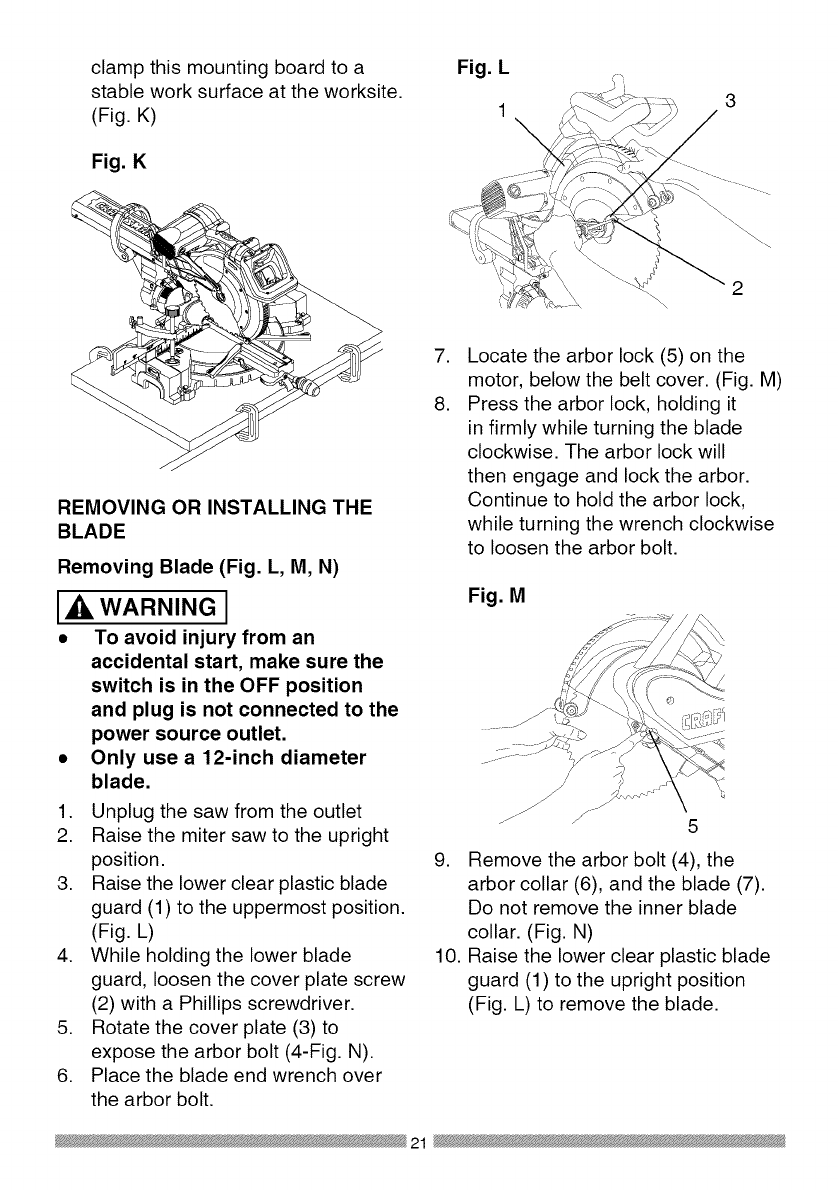
clampthismountingboardtoa
stableworksurfaceattheworksite.
(Fig.K)
Fig. K
Fig. L
13
2
REMOVING OR INSTALLING THE
BLADE
Removing Blade (Fig. L, M, N)
WARNING I
•To avoid injury from an
accidental start, make sure the
switch is in the OFF position
and plug is not connected to the
power source outlet.
Only use a 12-inch diameter
blade.
1.
2.
3.
.
,
6.
Unplug the saw from the outlet
Raise the miter saw to the upright
position.
Raise the lower clear plastic blade
guard (1) to the uppermost position.
(Fig. L)
While holding the lower blade
guard, loosen the cover plate screw
(2) with a Phillips screwdriver.
Rotate the cover plate (3) to
expose the arbor bolt (4-Fig. N).
Place the blade end wrench over
the arbor bolt.
,
8.
Locate the arbor lock (5) on the
motor, below the belt cover. (Fig. M)
Press the arbor lock, holding it
in firmly while turning the blade
clockwise. The arbor lock will
then engage and lock the arbor.
Continue to hold the arbor lock,
while turning the wrench clockwise
to loosen the arbor bolt.
Fig. M
9. Remove the arbor bolt (4), the
arbor collar (6), and the blade (7).
Do not remove the inner blade
collar. (Fig. N)
10. Raise the lower clear plastic blade
guard (1) to the upright position
(Fig. L) to remove the blade.
21

NOTE: Pay attention to the pieces
removed, noting their position and
direction they face. Wipe the blade
collars clean of any sawdust before
installing a new blade. Also, the 12 in.
blade has a 1 in. arbor hole with a 5/8
in. reducer (8) to mount onto the saw.
Fig. N
8\
6
4
INSTALLING BLADE (FIG. L, M, N)
WARNING J
Un-plug the miter saw before
changing/installing the blade.
1. Install a 12 in. blade with a 5/8 in.
arbor (or a 1 in. arbor with a 5/8 in.
reducer) making sure the rotation
arrow on the blade matches the
clockwise rotation arrow on the
upper guard, and the blade teeth
are pointing downward.
2. Place the arbor collar (6) against
the blade and on the arbor. Thread
the arbor bolt (4) on the arbor. (Fig.
N) in a counterclockwise direction.
IMPORTANT: Make sure the flats
of the blade collars are engaged
with the flats on the arbor shaft.
Also, the flat-side of the arbor collar
must be placed against the blade.
3. Place the blade wrench on the
arbor bolt.
4. Press the arbor lock (5), holding
it in firmly while turning the blade
counterclockwise. When it engages,
continue to press the arbor lock
in, while tightening the arbor bolt
securely. (Fig. M)
5. Rotate the cover plate (3) back to
its original position until the slot in
the cover plate engages with the
cover plate screw (2). While holding
the lower blade guard, tighten the
screw with a Phillips screwdriver.
(Fig. L) NOTE: The lower blade
guard must be raised to the upright
position to access the cover plate
screw.
6. Lower the clear retractable blade
guard (1) and verify the operation of
the guard does not bind or stick (Fig.
L).
7. Be sure the arbor lock is released
so the blade turns freely by
spinning the blade until the arbor
lock disengages.
WARNING J
• To avoid injury, never use the saw
without the cover plate secure
in place. It keeps the arbor bolt
from falling out if it accidentally
loosens, and helps prevent the
spinning blade from coming off
the saw.
•Make sure the collars are clean
and properly arranged. Lower
the blade into the table and
check for any contact with the
metal base or the turn table.
22

ALIGNING THE LASER BEAM (FIG.
O, P)
WARNING I
For your own safety, never connect
the plug to power source outlet
until all the adjustment steps
are complete and you have read
and understood the safety and
operational instructions.
The laser beam must always be
correctly aligned with the blade to
ensure straight, even cutting.
Your tool is equipped with the Laser
Trac ®cutting guide using Class II laser
beam. The laser beam will enable to
preview the saw blade path on the
stock to be cut before starting the miter
saw. This laser guide is powered by the
transformed alternating current supply
directly through the power lead. The
saw must be connected to the power
source and the laser on/off switch
must be turned on for the laser line
to show.
WARNING I
AVOID DIRECT EYE CONTACT
•Laser radiated when laser guide
is turned on. Avoid direct eye
contact. Always un-plug the miter
saw from power source before
making any adjustments.
•Laser Warning Label: Max output
<lmW DIODE LASER: 630-670nm,
Complies with 21CFR 1040.10 and
1040. 11.
•NOTE: All the adjustments for the
operation of this machine have
been completed at the factory.
Due to normal wear and use,
some occasional readjustments
may be necessary.
•CAUTION-Use of controls or
adjustments or performance of
procedures other than those
specified herein may result in
hazardous radiation exposure.
•CAUTION-The use of optical
instruments with this product will
increase eye hazard.
•Do not attempt to repair or
disassemble the laser. If
unqualified persons attempt
to repair this laser product,
serious injury may result. Any
repair required on this laser
product should be performed
by authorized service center
personnel.
A. Check Laser Beam Alignment.
1. Mark a 90° straight line across a
board to serve as a "pattern line" to
test laser alignment. Lay the board
on the miter table.
2. Plug saw into outlet and turn on the
laser beam and line it up with the
pattern line.
3. Lower saw blade to pattern line and
if blade is not flush with the pattern
line, adjust as follows in procedure
(B).
B. Adjusting the Angle of the Laser
Trac ®(Fig. P)
1. Turn the laser element (2) in the
desired direction to adjust the laser
angle. NOTE: Do not adjust the
laser more than 1/4 turn in either
direction as this may damage the
laser. There are two flat sides on
23
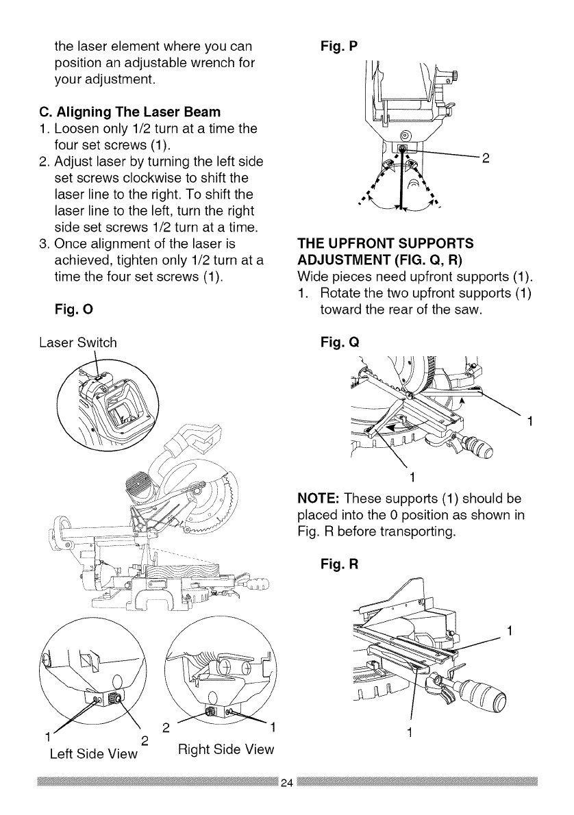
the laser element where you can
position an adjustable wrench for
your adjustment.
C. Aligning The Laser Beam
1. Loosen only 1/2 turn at a time the
four set screws (1).
2. Adjust laser by turning the left side
set screws clockwise to shift the
laser line to the right. To shift the
laser line to the left, turn the right
side set screws 1/2 turn at a time.
3. Once alignment of the laser is
achieved, tighten only 1/2 turn at a
time the four set screws (1).
Fig. 0
Fig. P
THE UPFRONT SUPPORTS
ADJUSTMENT (FIG. Q, R)
Wide pieces need upfront supports (1).
1. Rotate the two upfront supports (1)
toward the rear of the saw.
Laser Switch
i ...... l
Left Side View Right Side View
Fig. Q
\
1
NOTE: These supports (1) should be
placed into the 0 position as shown in
Fig. R before transporting.
Fig. R
1
24

BEVEL STOP ADJUSTMENTS
(FIG. S, T, U, V)
WARNING I
To avoid injury from unexpected
starting or electrical shock, make
sure the trigger is released and
remove the power cord from the
power source.
900(0°) Bevel adjustment (Fig. S, T)
1. Loosen bevel lock handle (2) and tilt
the cutting arm while pushing in the
bevel detent pin (3-Fig. T) in against
the 0° bevel stop. Tighten the bevel
lock handle.
2. Place a combination square on the
miter table with the rule against the
table and heel of the square against
the saw blade.
3. If the blade is not 0° to the miter
table, loosen the four adjustment
bolts (1) at the rear of the unit with
a 5 mm hex wrench. Unlock the
bevel lock handle (2) and adjust
the cutting arm zero degrees to the
table. Tighten the bevel lock handle
and the four adjustment bolts after
alignment is achieved.
Fig. S
2
Bevel Scale Indicators (Fig. T)
1. When the blade is exactly 90o(0°) to
the table, loosen the bevel indicator
screws (1) using a #2 Phillips
screwdriver.
2. Adjust bevel indicators (2) to the
"0" mark on the bevel scale and
retighten the screws.
Fig. T
2
45°Left Bevel Positive Stop
Adjustment (Fig. U)
1. Set the miter angle to zero degrees.
Fully extend the sliding fence
completely to the left then pull the
bevel detent pin (1) toward the
front of the machine. NOTE: When
retracting the bevel detent pin, it may
be required to shift the miter saw
upper arm assembly to the left/right.
2. Loosen the bevel lock handle (2)
and tilt the cutting arm completely to
the left.
3. Using a combination square, check
to see if the blade is 45° to the table.
4. To adjust, tilt the cutting arm to zero
degrees, loosen the Iocknut (3) and
turn the bolt (4) in or out accordingly.
5. Tilt the cutting arm back to the left
and recheck alignment.
6. Repeat steps until the blade is
45° to the table. Once alignment is
achieved, tighten the Iocknut (3) to
secure the positive stop bolt.
25

Fig. U
4
1
3
45°Right Bevel Positive Stop
Adjustment (Fig. V)
1. Set the miter angle to zero degrees.
Fully extend the sliding fence
completely to the right then pull
the bevel detent pin (1) toward the
front of the machine. NOTE: When
retracting the bevel detent pin, it may
be required to shift the miter saw
upper arm assembly to the left/right.
2. Loosen the bevel lock handle (2)
and tilt the cutting arm completely to
the right.
3. Using a combination square, check
to see if the blade is 45 ° to the table.
4. To adjust, tilt the cutting arm to zero
degrees, loosen the Iocknut (3) and
turn the bolt (4) in or out accordingly.
5. Tilt the cutting arm back to the right
and recheck alignment.
6. Repeat steps until the blade is
45 ° to the table. Once alignment is
achieved, tighten the Iocknut (3) to
secure the positive stop bolt.
Fig. V 4
1 3
2
33.9°Left & Right Bevel Adjustment
(Fig. W)
1. Set the miter angle to zero degree.
Fully extend both sliding fences.
2. Loosen the bevel lock handle and
tilt cutting arm to the 33.9 ° left bevel
positive stop by pushing in on the
bevel detent pin toward the rear of the
machine.
3. Using a combination square, check
to see if the blade is 33.9° to the
table.
4. To adjust, turn the screw in or out
with a wrench (from the locations
shown below) until the blade is 33.9 °
to the table.
5. Repeat steps for the right bevel
33.9 -0bevel adjustment.
Fig. W
For 33.9 ° left ._
bevel positive stop
adjustment, insert
wrench here
26

o right
sitive
ustment,
rench
here
NOTE: View from rear of machine
MITER ANGLE ADJUSTMENT (FIG.
X)
The sliding compound miter saw scale
can be easily read, showing miter
angles from 0° to 45° to the left, and 0°
to 45 ° to the right. The miter saw table
has nine of the most common angle
setttings with positive stops at 0°, 15°,
22.5 °, 31.6 °, and 45°. These positive
stops position the blade at the desired
angle quickly and accurately. Follow
the process below for quickest and
most accurate adjustments.
1. Lift up on the quick-cam miter table
lock (1) to unlock the table.
2. Move the turntable while lifting up on
the positive stop locking lever (4) to
align the indicator (2) to the desired
degree measurement.
3. Lock the table into position by
pressing down on the quick-cam
miter table lock (1).
Fig. X
2. Loosen the screw (3) that holds the
indicator with a screwdriver.
3. Adjust the indicator (2) to the 0°
mark and retighten screw.
ADJUSTING FENCE SQUARENESS
(FIG. Y)
1. Loosen the four fence locking bolts
(1).
2. Lower the cutting arm and lock in
position.
3. Using a square (3), lay the heel of
the square against the blade and the
ruler against the fence (2) as shown.
4. Adjust the fence 90° to the blade and
tighten the four fence locking bolts.
CAUTION: If the saw has not been
used recently, recheck blade
squareness to the fence and
readjust if needed.
5. After fence has been aligned, using
a scrap piece of wood, make a cut
at 90° then check squareness on the
piece. Readjust if necessary.
Fig. Y
2
3 2 4 1
Miter Scale Indicator (Fig. X)
1. Move the table to the 0° positive
POSITIVE STOP MITER ANGLE
ADJUSTMENT (FIG. Z)
1. Unlock the miter table by lifting up
on the quick-cam miter table lock
(1).
stop. 2. While raising the positive stop
locking lever (2) up, grasp the miter
27
handle and rotate the miter table left
or right to the desired angle.
3. Release the positive stop locking
lever and set the miter at the desired
angle making sure the lever snaps
into place. NOTE: The lever will
only lock into place at one of the ten
positive stops.
4. Once angle is achieved, press down
on the quick-cam miter table lock (1).
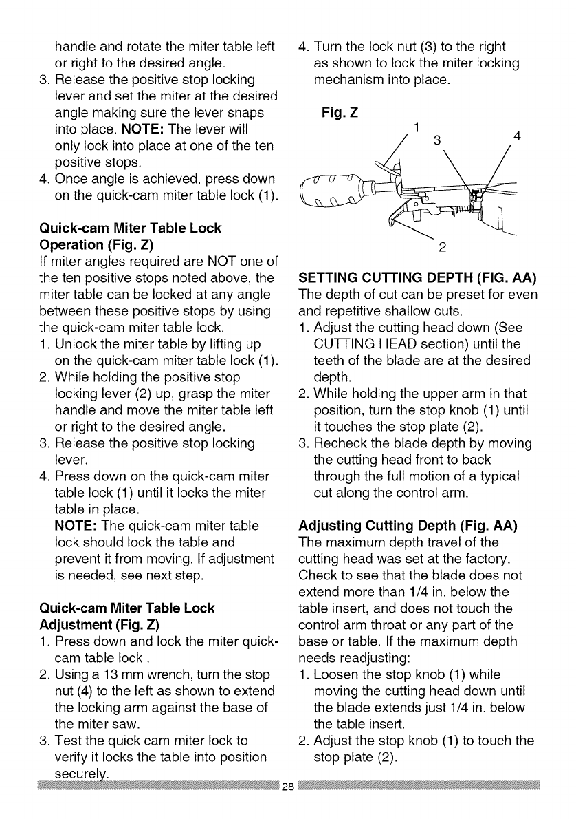
4. Turn the lock nut (3) to the right
as shown to lock the miter locking
mechanism into place.
Fig. Z 13 4
Quick-cam Miter Table Lock
Operation (Fig. Z)
If miter angles required are NOT one of
the ten positive stops noted above, the
miter table can be locked at any angle
between these positive stops by using
the quick-cam miter table lock.
1. Unlock the miter table by lifting up
on the quick-cam miter table lock (1).
2. While holding the positive stop
locking lever (2) up, grasp the miter
handle and move the miter table left
or right to the desired angle.
3. Release the positive stop locking
lever.
4. Press down on the quick-cam miter
table lock (1) until it locks the miter
table in place.
NOTE: The quick-cam miter table
lock should lock the table and
prevent it from moving. If adjustment
is needed, see next step.
Quick-cam Miter Table Lock
Adjustment (Fig. Z)
1. Press down and lock the miter quick-
cam table lock.
2. Using a 13 mm wrench, turn the stop
nut (4) to the left as shown to extend
the locking arm against the base of
the miter saw.
3. Test the quick cam miter lock to
verify it locks the table into position
SETTING CUTTING DEPTH (FIG. AA)
The depth of cut can be preset for even
and repetitive shallow cuts.
1. Adjust the cutting head down (See
CUTTING HEAD section) until the
teeth of the blade are at the desired
depth.
2. While holding the upper arm in that
position, turn the stop knob (1) until
it touches the stop plate (2).
3. Recheck the blade depth by moving
the cutting head front to back
through the full motion of a typical
cut along the control arm.
Adjusting Cutting Depth (Fig. AA)
The maximum depth travel of the
cutting head was set at the factory.
Check to see that the blade does not
extend more than 1/4 in. below the
table insert, and does not touch the
control arm throat or any part of the
base or table. If the maximum depth
needs readjusting:
1. Loosen the stop knob (1) while
moving the cutting head down until
the blade extends just 1/4 in. below
the table insert.
2. Adjust the stop knob (1) to touch the
stop plate (2).

3. Recheckthebladedepthbymoving
thecuttingheadfrontto back
throughthefullmotionofa cutalong
thecontrolarm.Ifthebladetouches
theinsideof thecontrolarm,readjust
thesetting.
Fig. AA
2
SLIDING THE REAR EXTENSION
SUPPORT BAR (FIG. BB)
WARNING I
To avoid possible personal injury
or damage to the miter saw due
to tipping, do not operate the saw
without the Rear Extension Support
Bar.
Loosen the two screws (1) and extend
the rear extension support bar (2) by
sliding it out to match position, tighten
the two screws.
Fig. BB
1
29

SAFETY INSTRUCTIONS FOR BASIC
SAW OPERATION
BEFORE USING THE MITER SAW
[_, WARNING J
To avoid mistakes that could cause
serious, permanent injury, do not
plug the tool in until the following
steps are completed:
•Completely assemble and
adjust the saw, following the
instructions. (ASSEMBLY AND
ADJUSTMENTS)
• Learn the use and function of the
ON/OFF switch, upper and lower
blade guards, hold down latch,
bevel lock handle and cover plate
screws.
• Review and understand
all safety instructions and
operating procedures in this
Operator's Manual. (SAFETY &
OPERATIONS)
• Review the MAINTENANCE and
TROUBLESHOOTING GUIDE for
your miter saw.
• To avoid injury or possible death
from electrical shock:
Make sure your fingers do not
touch the plug's metal prongs
when plugging or unplugging
your miter saw. (ELECTRICAL
REQUIREMENTS AND SAFETY)
BEFORE EACH USE INSPECT YOUR
SAW.
•Disconnect the miter saw.
To avoid injury from accidental
starting, unplug the saw before any
adjustments, including set-up and
blade changes.
•Compare the direction of rotation
arrow on the guard to the direction
arrow on the blade. The blade teeth
should always point downward at
the front of the saw.
•Tighten the arbor bolt.
•Tighten the cover plate screw.
•Check for damaged parts. Check
for:
• Alignment of moving parts
• Damaged electric cords
• Binding of moving parts
• Mounting holes
• Function of arm return spring
and lower guard: Push the
cutting arm all the way down,
then let it rise until it stops.
The lower guard should fully
close. Follow instructions in
TROUBLESHOOTING GUIDE
for adjustment if necessary.
• Other conditions that may affect
the way the miter saw works.
• Keep all guards in place, in working
order and proper adjustment. If any
part of this miter saw is missing,
bent, damaged or broken in any
way, or any electrical parts don't
work, turn the saw off and unplug
it.
• Replace bent, damaged, missing
or defective parts before using the
saw again.
• Maintain tools with care. Keep the
miter saw clean for best and safest
performance. Follow instructions
for lubricating. Do not put lubricants
on the blade while it is spinning.
• Remove adjusting wrench from the
tool before turning it on.
• To avoid injury from jams, slips,
or thrown pieces, use only
30

recommended accessories.
RECOMMENDED ACCESSORIES
• Consult the ACCESSORIES
and ATTACHMENTS section
of this Operator's Manual for
recommended accessories. Follow
the instructions that come with the
accessory. The use of improper
accessories may cause risk of
injury to persons.
• Choose the correct 12 in. diameter
blade for the material and the type
of cutting you plan to do. Do not
use thin kerf blades.
• Make sure the blade is sharp,
undamaged and properly aligned.
With the saw unplugged, push
the cutting arm all the way down.
Manually spin the blade and check
for clearance. Tilt the power-head
to a 45° bevel and repeat the test.
• Make sure the blade and arbor
collars are clean.
• Make sure all clamps and locks are
tight and there is no excessive play
in any parts.
KEEP YOUR WORK AREA CLEAN
Cluttered areas and benches invite
r RNING I
To avoid burns or other fire damage,
never use the miter saw near
flammable liquids, vapors, or gases.
• Plan ahead to protect your eyes,
hands, face and ears.
• Know your miter saw. Read and
understand the Operator's Manual
and labels affixed to the tool.
Learn its application and limitations
as well as the specific potential
hazards peculiar to this tool. To
avoid injury from accidental contact
assembly, or setup work on the
miter saw while any parts are
moving.
Avoid accidental starting,
make sure the trigger switch is
disengaged before plugging the
miter saw into a power outlet.
PLAN YOUR WORK
• Use the right tool. Do not force a
tool or attachment to do a job it was
not designed to do. Use a different
tool for any workpiece that can'
t be held in a solidly braced, fixed
position.
CAUTION: This machine is not
designed for cutting masonry,
masonry products, ferrous metals
(steel, iron, and iron-based metals.)
Use this miter saw to cut only
wood, wood-like products, or non-
ferrous metals. Other material may
shatter, bind the blade, or create
other dangers. Remove all nails that
may be in the workpiece to prevent
sparking that could cause a fire.
Remove dust bag when cutting non-
ferrous metals.
S FOR SAFETY
Any power tool can throw
foreign objects into the eyes.
This can result in permanent
eye damage. Everyday eyeglasses
have only impact resistant lenses and
are not safety glasses. Glasses or
goggles not in compliance with ANSI
Z87.1 could seriously injure you when
they break.
• Do not wear loose clothing, gloves,
neckties or jewelry (rings, watches).
They can get caught and draw you
into moving parts.
with movingparts, do not do layout, 31

•Wear non-slip footwear.
• Tie back long hair.
• Roll long sleeves above the elbow.
• Noise levels vary widely. To avoid
possible hearing damage, wear ear
plugs when using any miter saw.
• For dusty operations, wear a dust
mask along with safety goggles.
INSPECT YOUR WORKPIECE
Make sure there are no nails or foreign
objects in the part of the workpiece
being cut.
Plan your work to avoid small pieces
that may bind, or that are too small to
clamp and get a solid grasp on. Plan
the way you will grasp the workpiece
from start to finish. Avoid awkward
operations and hand positions.
A sudden slip could cause your fingers
or hand to move into the blade.
DO NOT OVER-REACH
Keep good footing and balance. Keep
your face and body to one side, out of
the line of a possible kickback. NEVER
stand in the line of the blade.
Never cut freehand:
• Brace your workpiece firmly against
the fence and table stop so it will
not rock or twist during the cut.
• Make sure there is no debris
between the workpiece and the
table or fence.
• Make sure there are no gaps
between the workpiece, fence and
table that will let the workpiece shift
after it is cut.
• Keep the cut off piece free to
move sideways after it is cut off.
Otherwise, it could get wedged
against the blade and thrown
violently.
• Only the workpiece should be on
the saws table.
• Secure work. Use clamps or a vise
to help hold the work when it's
practical.
USE EXTRA CAUTION WITH LARGE
OR ODD SHAPED WORKPIECES.
• Use extra supports (tables,
sawhorses, blocks, etc.) for
workpieces large enough to tip.
• Never use another person as a
substitute for a table extension,
or as an additional support for a
workpiece that is longer or wider
than the basic miter saw table, or
to help feed, support, or pull the
workpiece.
• Do not use this saw to cut small
pieces. If the workpiece being cut
would cause your hand or fingers
to be within 8-3/4 inches of the saw
blade the workpiece is too small.
Keep hands and fingers out of the
"no hands zone" area marked on
the saws table.
• When cutting odd shaped
workpieces, plan your work so
it will not bind in the blade and
cause possible injury. Molding, for
example, must lie flat or be held
by a fixture or jig that will not let it
move when cut.
• Properly support round material
such as dowel rods, or tubing,
which have a tendency to roll when
cut, causing the blade to "bite".
[,ik WARNING J
To avoid injury, follow all applicable
safety instructions, when cutting
non-ferrous metals:
• Use only saw blades specifically
recommended for non-ferrous
metal cutting.
32

Do not cut metal workpieces
that must be hand held. Clamp
workpieces securely.
Cut non-ferrous metals only if you
are under the supervision of an
experienced person and the dust
bag has been removed from the
saw.
WHEN SAW IS RUNNING
WARNING I
Do not allow familiarity from
frequent use of your miter saw
to result in a careless mistake. A
careless fraction of a second is
enough to cause a severe injury.
Before cutting, if the saw makes an
unfamiliar noise or vibrates, stop
immediately. Turn the saw OFF.
Unplug the saw. Do not restart until
finding and correcting the problem.
BODY AND HAND POSITION (FIG,
cc)
WARNING I
Never place hands near
the cutting area. Proper
positioning of your body
and hands when operating the miter
saw will make cutting easier and
safer. Keep children away. Keep all
visitors at a safe distance from the
miter saw. Make sure bystanders
are clear of the saw and workpiece.
Don't force the saw. It will do the job
better and safer at its designed rate.
•Hold workpiece firmly against the
fence to prevent movement toward
the blade.
• With the power switch OFF,
bring the saw blade down to the
workpiece to see the cutting path of
the blade.
• Squeeze trigger switch to start saw.
• Lower blade into workpiece with a
firm downward motion.
Finishing a cut:
• Hold the cutting arm in the down
position.
• Release trigger switch and wait
for all moving parts to stop before
moving your hands and raising the
cutting arm.
• If the blade does not stop within
10 seconds, unplug the saw
and follow the instructions in
TROUBLESHOOTING GUIDE
section.
Before freeing jammed material:
• Release trigger switch.
• Wait for all moving parts to stop.
• Unplug the miter saw.
Fig, CC
i
i
i
i
i
i
Starting a cut: i
• Place hands at least 8-3/4 in. away ®
from the path of the blade - out of 8-3/4 in.
the "no-hands zone". (Fig. CC)
o-Hand Zone
i
i
®
8-3/4 in.
33

TO TURN THE SAW ON (FIG. DD)
Depress the trigger switch (1) to turn
on the miter saw started.
NOTE: Make the ON/OFF switch
childproof. Insert a padlock, or chain
with padlock, through the hole (2) in
the trigger switch, locking the tool's
switch, preventing children and other
unauthorized users from turning the
machine on.
The miter saw is equipped with an
automatic blade brake. When the
trigger switch is released, the electric
blade brake will stop the blade within
approximately 10 seconds.
Fig. DD
2\
.
,
The right side sliding fence must
be removed when making any
right bevel angle cuts greater
than 350 in combination with
any right hand miter angle. This
fence must also be removed
whenever a 450bevel angle
is desired with a miter angle
greater than 22.50.
Unlock the fence cam locking lever
(1) by pushing it toward the rear of
the machine.
Extend the fence (2) by sliding it out
to match the degree of the bevel
cut. Lock the fence cam locking
lever by pushing it IN toward the
fence. NOTE: When transporting
the saw, always secure the sliding
fence in the collapsed position
(toward the saw blade).
Fig. EE
SLIDING FENCE (FIG. EE)
WARNING J
•The sliding fence must be
extended to the left or right when
making bevel cuts.The sliding
fence noted three bevel angles
where the user must adjust the
fences to match the degree of
the bevel cut. Failure to extend
the sliding fence will not allow
enough space for the blade to
pass through which could result
in serious injury. At extreme
miter or bevel angles the saw
blade may also contact the
fence.
34

REMOVING OR INSTALLING THE
RIGHT SLIDING FENCE
Removing (Fig. FF)
1. Unlock the fence cam-locking lever
by pushing it out toward the rear of
the machine.
2. Lift up on the sliding fence to
remove it from the saw.
Installing
1. Place the sliding fence onto the
miter saw fence aligning the nut (1)
with the slot (4).
2. To lock the sliding fence, push the
cam-locking lever in toward the
front of the machine.
Fig. FF
1 __............. JJ
..........÷I, ,d,I U,d, 4
SLIDING CARRIAGE SYSTEM (FIG.
GG)
Ak, WARNING I
To reduce the risk of injury, return
carriage to the full rear position after
each crosscut operation.
1. For a chop cutting operations on
small workpieces, slide the cutting
head assembly completely toward
the rear of the unit and tighten the
carriage lock knob (1).
2. To cut wide boards up to 12-1/4 in.,
the carriage lock knob should be
loosened to allow the cutting head
to slide freely.
Fig. GG
WARNINGI
To avoid injury from materials being
thrown, always unplug the saw
to avoid accidental starting, and
remove small pieces of material from
the table cavity. The table insert may
be removed for this purpose, but
always reattach the table insert prior
to performing a cutting operation.
MITER CUT (FIG. HH)
The sliding compound miter saw is
equipped with ten positive miter stops
(1) on the saw base. The locations are
at O, 15, 22.5, 31.6 and 45 degrees
left and right, and 60° right. These
locations represent the most common
angles for cutting operation. To make a
miter cut:
1. Unlock the miter table by lifting up
on the miter quick-cam table lock
(2).
2. While raising the positive stop
locking lever (3) up, grasp the miter
handle (4) and rotate the miter
table left or right to the desired
angle.
3. Release the positive stop locking
lever and set the miter at the
desired angle making sure the
lever snaps into place. NOTE: The
lever will only lock into place at one
of the ten positive stops.
35

4. Once the desired miter angle is
achieved, press down on the quick
cam miter table lock to secure the
table into position.
5. If the miter angle desired is NOT
one of the ten positive stops noted
above, simply lock the table at the
desired angle by pressing down on
the quick-cam miter table lock (2).
Fig. HH
2 1
BEVEL CUT (FIG. II)
WARNING J
• The sliding fence must be
extended to the left or right when
making bevel cuts.The sliding
fence noted three bevel angles
where the user must adjust the
fences to match the degree of
the bevel cut. Failure to extend
the sliding fence will not allow
enough space for the blade to
pass through which could result
in serious injury. At extreme
miter or bevel angles the saw
blade may also contact the
fence.
•The right side sliding fence must
be removed when making any
right bevel angle cuts greater
than 35° in combination with
any right hand miter angle. This
fence must also be removed
whenever a 45° bevel angle
is desired with a miter angle
greater than 22.5 °.
Tilt the cutting head to the desired
angle as shown on the bevel scale. The
blade can be positioned at any angle,
from a 90° straight cut (0° on the scale)
to a 45° left and right bevel. Tighten the
bevel lock handle (1) by pushing down
to lock the cutting head in position.
Bevel positive stops are provided at 0°,
33.9 ° and 45 °.
Fig. II
NOTE: The saw comes with a
33.9 ° bevel detent pin for setting up
crown molding cuts when the angle of
the walls equals 90° .
36

33.9 °BEVEL DETENT PIN FOR
CROWN MOLDINGS (FIG. JJ)
NOTE: A bevel detent pin is
incorporated into this machine for quick
bevel adjustments when the desired
bevel angle is 33.9 °.
1. Push the bevel detent stop pin (1)
in toward the front of the machine.
2. Loosen the bevel lock handle (2).
3. Rotate the cutting head until the
bevel detent pin stops the bevel
angle at 33.9 ° on the bevel scale.
4. Tighten the bevel lock handle
before you make your cut.
Fig. JJ
COMPOUND CUT (FIG. KK)
1. Extending the fence by sliding it out
to the required location or remove
the right sliding fence if necessary.
See "SLIDING FENCE or REMOVE
SLIDING FENCE".
2. Set the desired bevel angle using
the bevel lock handle (1).
3. Set the desired miter angle and
lock into position. See "MITER
CUT".
Fig. KK
CHOP CUTTING NARROW BOARDS-
90° CROSSCUT (FIG. LL)
1. For a chop cutting operations on
small workpieces, slide the cutting
head assembly completely toward
the rear of the unit and tighten the
carriage lock knob (1).
2. Position the cutting head to the
0° bevel position and lock the bevel
lock handle (2).
3. Position the table to the 0° miter
angle and lock the quick cam miter
table lock (3).
4. Position the workpiece on the table
and against the fence. Use a hold
down clamp (4) attached to the
base, whenever possible.
5. Pull the trigger (5), turning on the
saw. Lower the blade by pushing
the handle (6) down into the
workpiece with slow and even
pressure.
6. When the cut is complete, release
the switch and allow the blade to
stop before raising the cutting head
assembly.
37
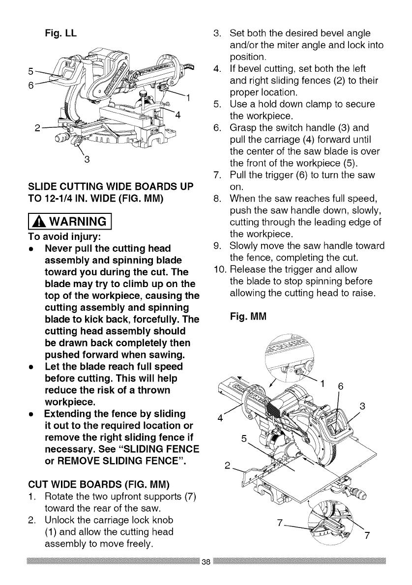
Fig. LL
3
SLIDE CUTTING WIDE BOARDS UP
TO 12-1/4 IN. WIDE (FIG. MM)
WARNING I
To avoid injury:
• Never pull the cutting head
assembly and spinning blade
toward you during the cut, The
blade may try to climb up on the
top of the workpiece, causing the
cutting assembly and spinning
blade to kick back, forcefully, The
cutting head assembly should
be drawn back completely then
pushed forward when sawing,
•Let the blade reach full speed
before cutting, This will help
reduce the risk of a thrown
workpiece,
•Extending the fence by sliding
it out to the required location or
remove the right sliding fence if
necessary, See "SLIDING FENCE
or REMOVE SLIDING FENCE",
3. Set both the desired bevel angle
and/or the miter angle and lock into
position.
4. If bevel cutting, set both the left
and right sliding fences (2) to their
proper location.
5. Use a hold down clamp to secure
the workpiece.
6. Grasp the switch handle (3) and
pull the carriage (4) forward until
the center of the saw blade is over
the front of the workpiece (5).
7. Pull the trigger (6) to turn the saw
on.
8. When the saw reaches full speed,
push the saw handle down, slowly,
cutting through the leading edge of
the workpiece.
9. Slowly move the saw handle toward
the fence, completing the cut.
10. Release the trigger and allow
the blade to stop spinning before
allowing the cutting head to raise.
Fig, MM
1 6
3
5
CUT WIDE BOARDS (FIG, MM)
1. Rotate the two upfront supports (7)
toward the rear of the saw.
2. Unlock the carriage lock knob
(1) and allow the cutting head
assembly to move freely.
38

CUTTING BOWED MATERIAL (FIG.
NN)
WARNING I
To avoid injury from materials being
thrown, always unplug the saw to
avoid accidental starting and remove
small pieces of material from the
table cavity. The table insert may be
removed for this purpose, but always
reattach table insert prior to performing
a cutting operation.
A bowed workpiece must be positioned
against the fence and secured with
a clamping device as shown before
cutting. Do not position workpiece
incorrectly or try to cut the workpiece
without the support of the fence. This
will cause the blade to bind and could
result in personal injury.
Fig. NN
ROUGH CUTTING A DADO (FIG. OO)
1. Mark lines identifying the width
and depth of the desired cut on
the workpiece and position on the
table so the inside tip of the blade
is positioned on the line. Use a
hold down clamp to secure the
workpiece.
2. Lower the cutting head so the tip of
the blade touches the top surface
workpiece at the marked line.
3. While holding the upper arm in
position, turn the stop knob (2) until
it touches the stop plate (1).
4. Cut two parallel grooves as shown
below.
Fig. OO
Cut these grooves
with saw
Use a chisel to cut
out the middle
TELESCOPING WORKPIECE
SUPPORT & REPETITIVE CUTTING
USING THE STOP PLATE (FIG. PP)
Long pieces need extension table
support.
1. Loosen the knob (1) then slide the
extension table to desired position
and tighten the knob.
2. The stop plate is designed for use
during repetitive cutting. Only use
one stop plate at a time. Rotate the
stop plate (3) to vertical position,
and retighten the locking bolt. If
stop plate will not rotate, loosen the
locking bolt (2) 1/4 turn.
39

Fig. PP
\
/
/
AUXILIARY WOOD FENCE (FIG. QQ)
When making multiple or repetitive cuts
that result in cut-off pieces of one inch
or less, it is possible for the saw blade
to catch the cut-off piece and throw it
out of the saw or into the blade guard
and housing, possibly causing damage
or injury. To minimize this an auxiliary
wood fence can be mounted to your
saw. Holes are provided in the saw
fence to attach an auxiliary wood fence
(this provides additional depth of cut).
This fence should be constructed of
straight auxiliary wood approximately
3/4 in. thick by 1-1/2 in. high by 22 in.
long. Attach the wood fence securely
and make a full depth cut to make
a blade slot. Check for interference
between the wood fence and the lower
blade guard. Adjust if necessary.
Fig. QQ
Blade slot
CHANGING THE BELT (FIG. RR, SS)
• Unplug your saw.
1. Loosen the bolts (1) and remove
the belt cover.
2. Turn the screw (2) anti-clockwise
with a hex wrench to move the
motor to forward.
3. Remove and replace the belt.
4. Turn the screw (2) clockwise with
a hex wrench to move the motor to
rearward. Do not over tighten.
5. Replace the belt cover and tighten
the bolts.
Fig. RR
Fig. SS
40

CUTTING BASE MOLDING (FIG. TT)
Base moldings and many other
moldings can be cut on a compound
miter saw. The setup of the saw
depends on molding characteristics
and application, as shown. Perform
practice cuts on scrap material to
achieve best results:
1. Always make sure moldings rest
firmly against fence and table. Use
hold-down, crown molding vise
or C-clamps, whenever possible,
and place tape on the area being
clamped to avoid marks.
2. Reduce splintering by taping the
cut area prior to making the cut.
Mark the cut line directly on the
tape.
3. Splintering typically happens due to
an incorrect blade application and
thinness of the material.
Fig. TT
Miter saw table
miter at 450,
bevel at 0°
_table
miter at 0°, bevel
at 450
angles that, when added together,
equal exactly 90 °.
Most crown molding has a top rear
angle (the section that fits flat against
the ceiling) of 52°and a bottom rear
angle (the section that fits flat against
the wall) of 38°.
In order to accurately cut crown
molding for a 90° inside or outside
corner, lay the molding with its broad
back surface flat on the saw table.
When setting the bevel and miter
angles for compound miters, remember
that the settings are interdependent;
changing one changes the other, as
well.
Fig. UU
ne
Miter saw table
Bevel/Miter Settings
Fig. VV
NOTE: Always perform a dry run cut
so you can determine if the operation
being attempted is possible before
power is applied to the saw.
CUTTING CROWN MOLDING (FIG.
UU, VV)
WARNING I
Your compound miter saw is suited
for the difficult task of cutting crown
molding. To fit properly, crown molding
must be compound-mitered with
extreme accuracy. The two surfaces
on a piece of crown molding that fit
flat against the ceiling and wall are at
Settings for standard crown molding
lying flat on compound miter saw
table ]
Inside corner OR
\
,-._1
Outside corner
Compound cut crown moldings
NOTE: The chart below references
a compound cut for crown molding
ONLY WHEN THE ANGLE BETWEEN
THE WALLS EQUALS 90 °.
41
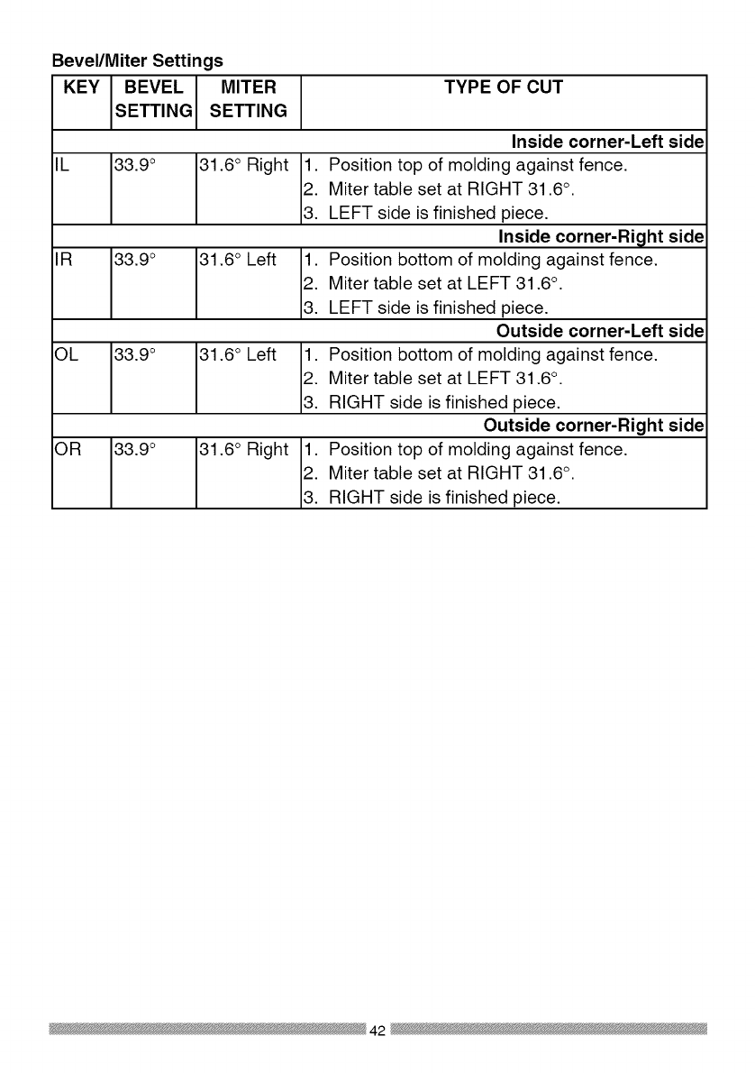
Bevel/Miter Settings
KEY BEVEL MITER
SETTING SETTING
TYPE OF CUT
IL 33.9 °
IR 33.9 °
OL 33.9 °
OR 33.9 °
31.6 o Right
31.6 ° Left
31.6 ° Left
31.6 o Right
Inside corner-Left side
1. Position top of molding against fence.
2. Miter table set at RIGHT 31.6 ° .
3. LEFT side is finished piece.
Inside corner-Right side
1. Position bottom of molding against fence.
2. Miter table set at LEFT 31.6 °.
3. LEFT side is finished piece.
Outside corner-Left side
1. Position bottom of molding against fence.
2. Miter table set at LEFT 31.6 °.
3. RIGHT side is finished piece.
Outside corner-Right side
1. Position top of molding against fence.
2. Miter table set at RIGHT 31.6 ° .
3. RIGHT side is finished piece.
42

CROWN MOLDING CHART
Compound Miter saw
Miter and bevel Angle settings
Wall to Crown Molding Angle
52/38 ° C_wn Molding 45/45 ° C_wn Molding
Angle Miter Bevel Miter Bevet Angle
Between Setting Setting Setting Setting Between
Walls Wails
67 42.93 41.08 46.89 36.13 124
68 42.39 40.79 46.35 35.89 128
69 41.85 40.80 45.81 35.64 126
70 41.32 40.20 48.28 38.40 127
71 40.79 39.90 44.78 35.18 128
72 40.28 39.61 44.22 34.89 129
73 39.76 39.30 43.70 34.64 130
74 39.28 39.00 43.18 35.38 131
75 38.74 38.69 42.66 34.12 132
76 38.24 38.39 42.15 33.86 133
77 37.74 38.08 41.64 33.60 134
78 37.24 37.76 41.13 33.33 138
79 36.75 37.45 40.62 33.07 136
80 36.27 37.13 40.12 32.80 137
81 35.79 36.81 39.62 32.53 138
82 35.31 36.49 39.13 32.28 139
83 34.83 36.17 38.63 31.98 140
84 34.36 35.88 38.14 31.70 141
88 33.90 38.82 37.66 31.42 142
86 33.43 35.19 37.17 31.34 143
87 32.97 34.86 36.69 30.86 144
88 32.82 34.83 36.21 30.87 148
89 32.07 34.20 38.74 30.29 146
90 31.62 33.86 38.26 30.00 147
91 31.17 33.83 34.79 29.71 148
92 30.73 33.19 34.33 29.42 149
93 30.30 32.86 33.86 29.13 150
94 29.86 32.51 33.40 28.83 151
95 29.43 32.17 32.94 28.84 182
96 29.00 31.82 32.48 28.24 183
97 28.88 31.48 32.02 27.94 154
98 28.16 31.13 31.58 27.64 188
99 27.74 30.78 31.13 27.34 156
100 27.32 30.43 30.68 27.03 157
101 26.91 30.08 30.24 26.73 158
102 26.50 29.73 29.80 26.42 189
103 26.09 29.38 29.36 26.12 160
104 25.69 29.02 28.92 25.81 161
105 25.29 28.67 28.48 25.80 162
106 24.89 28.31 28.05 25.19 163
107 24.49 27.96 27.62 24.87 164
108 24.10 27.89 27.19 24.86 168
109 23.71 27.23 26.77 24.24 166
110 23.32 26.87 26.34 23.93 167
111 22.93 26.51 25.92 23.61 168
112 22.88 26.18 28.50 23.29 169
113 22.17 25.78 25.08 22.97 170
114 21.79 25.42 24.66 22.66 171
118 21.42 28.05 24.25 22.33 172
116 21.04 24.68 23.84 22.01 173
117 20.67 24.31 23.43 21.68 174
118 20.30 23.94 23.02 21.36 175
119 19.93 23.57 22.61 21.03 176
120 19.87 23.20 22.21 20.70 177
121 19.20 22.83 21.80 20.38 178
122 18.84 22.46 21.40 20.05 179
123 18.48 22.09 21.00 19.72
82/38 °Crown Molding 45/45 ° Crown Molding
Miter Bevel Miter Bevel
Setting Setting Setting Setting
18.13 21.71 20.61 19.39
17.77 21.34 20.21 19.06
17.42 20.96 19.81 18.72
17.06 20.89 19.42 18.39
16.71 20.21 19.03 18.06
16.37 19.83 18.64 17.72
16.02 19.48 18.25 17.39
18.67 19.07 17.86 17.08
15.33 18.69 17.48 16.71
14.99 18.31 17.09 16.38
14.66 17.93 16.71 16.04
14.30 17.58 16.32 15.70
13.97 17.17 15.94 15.36
13.63 16.79 18.86 18.02
13.30 16.40 18.19 14.62
12.96 16.02 14.81 14.34
12.63 15.64 14.43 14.00
12.30 15.28 14.06 13.68
11.97 14.87 13.68 13.31
11.64 14.48 13.31 12.97
11.31 14.09 12.94 12.62
10.99 13.71 12.87 12.29
10.66 13.32 12.20 11.93
10.34 12.93 11.83 11.89
10.01 12.84 11.46 11.24
9.69 12.16 11.09 10.89
9.37 11.77 10.73 10.85
9.05 11.38 10.36 10.20
8.73 10.99 10.00 9.85
8.41 10.60 9.63 9.50
8.09 10.21 9.27 9.15
7.77 9.82 8.91 8.80
7.46 9.43 8.88 8.45
7.14 9.04 8.19 8.10
6.82 8.68 7.83 7.75
6.81 8.26 7.47 7.40
6.20 7.86 7.11 7.05
8.88 7.47 6.75 6.70
5.57 7.08 6.39 6.35
5.26 6.69 6.03 6.00
4.95 6.30 5.68 5.65
4.63 5.90 5.32 5.30
4.32 5.51 4.96 4.94
4.01 5.12 4.61 4.89
3.70 4.72 4.25 4.24
3.39 4.33 3.90 3.89
3.08 3.94 3.84 3.53
2.77 3.84 3.19 3.10
2.47 3.18 2.83 2.83
2.15 2.75 2.48 2.47
1.85 2.36 2.12 2.12
1.84 1.97 1.77 1.77
1.23 1.58 1.41 1.41
0.92 1.18 1.06 1.06
0.62 0.79 0.71 0.71
0.31 0.39 0.38 0.35
43
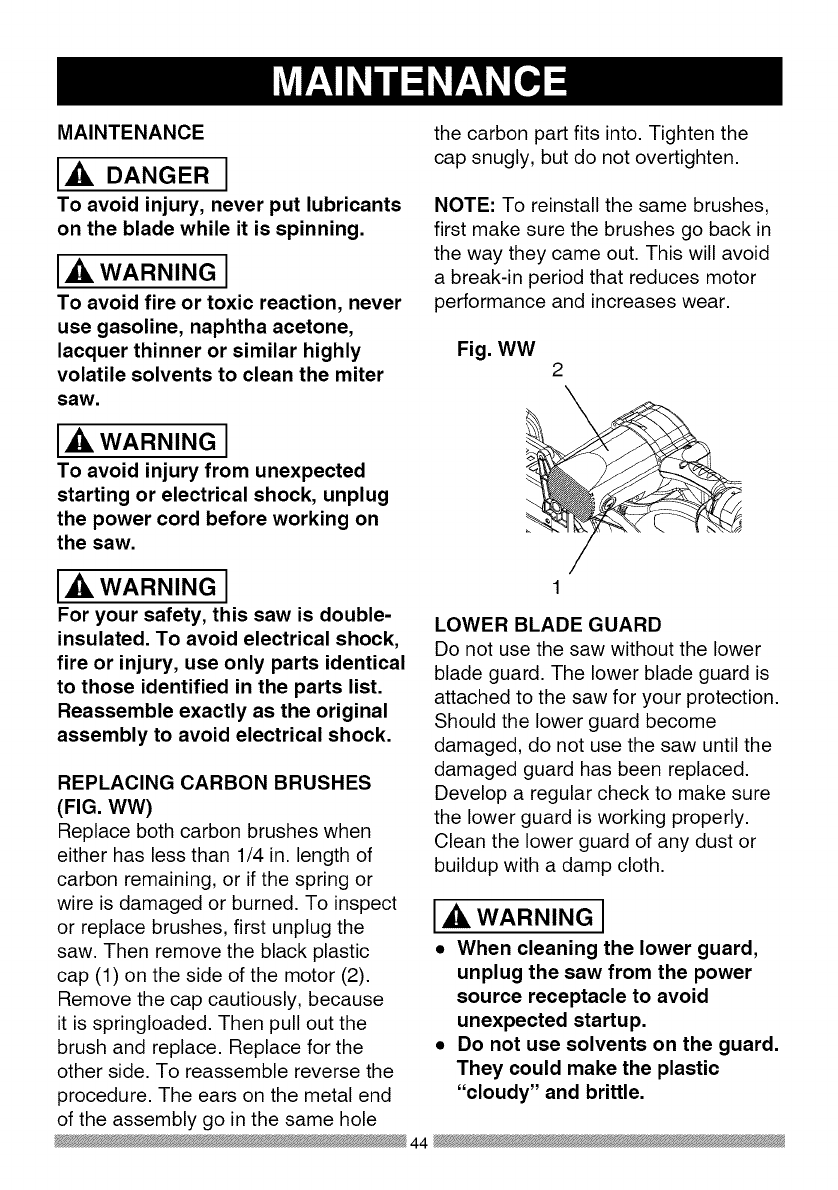
MAINTENANCE
DANGER I
To avoid injury, never put lubricants
on the blade while it is spinning.
_IL WARNING I
To avoid fire or toxic reaction, never
use gasoline, naphtha acetone,
lacquer thinner or similar highly
volatile solvents to clean the miter
saw.
_IL WARNING I
To avoid injury from unexpected
starting or electrical shock, unplug
the power cord before working on
the saw.
the carbon part fits into. Tighten the
cap snugly, but do not overtighten.
NOTE: To reinstall the same brushes,
first make sure the brushes go back in
the way they came out. This will avoid
a break-in period that reduces motor
performance and increases wear.
Fig. WW 2
_IL WARNING I
For your safety, this saw is double-
insulated. To avoid electrical shock,
fire or injury, use only parts identical
to those identified in the parts list.
Reassemble exactly as the original
assembly to avoid electrical shock.
REPLACING CARBON BRUSHES
(FIG. WW)
Replace both carbon brushes when
either has less than 1/4 in. length of
carbon remaining, or if the spring or
wire is damaged or burned. To inspect
or replace brushes, first unplug the
saw. Then remove the black plastic
cap (1) on the side of the motor (2).
Remove the cap cautiously, because
it is springloaded. Then pull out the
brush and replace. Replace for the
other side. To reassemble reverse the
procedure. The ears on the metal end
of the assembly go in the same hole
LOWER BLADE GUARD
Do not use the saw without the lower
blade guard. The lower blade guard is
attached to the saw for your protection.
Should the lower guard become
damaged, do not use the saw until the
damaged guard has been replaced.
Develop a regular check to make sure
the lower guard is working properly.
Clean the lower guard of any dust or
buildup with a damp cloth.
IXlWARNINGI
•When cleaning the lower guard,
unplug the saw from the power
source receptacle to avoid
unexpected startup.
•Do not use solvents on the guard.
They could make the plastic
"cloudy" and brittle.
44

SAWDUST
Periodically, sawdust will accumulate
under the work table and base. This
could cause difficulty in the movement
of the worktable when setting up
a miter cut. Frequently blow out or
vacuum up the sawdust.
WARNING J
If blowing sawdust, wear proper
eye protection to keep debris from
entering eyes.
LUBRICATION (FIG. XX)
All the motor bearings in this tool are
lubricated with a sufficient amount of
high grade lubricant for the life of the
unit under normal operating conditions;
therefore, no further lubrication is
required.
Lubricate the Following as necessary:
Chop pivot: Apply light machine oil to
points indicated in illustration.
Central pivot of plastic guard: Use
light household oil (sewing machine
oil ) on metal-to-metal or metal-to-
plastic guard contact areas as required
for smooth, quiet operation. Avoid
excessive oil, to which sawdust will
cling.
Fig. XX
Chop pivot Central pivot of
plastic guard
45

WARNING I
To avoid injury from accidental starting, always turn switch OFF and unplug
the tool before moving, replacing the blade or making adjustments,
TROUBLESHOOTING GUIDE -MOTOR
PROBLEM PROBLEM CAUSE
Brake does
not stop blade
within 10
seconds.
Motor does
not start
Brush spark
when switch
released.
,
2.
.
4.
.
1.
2.
3.
,
2.
Motor brushes not sealed 1.
or lightly sticking.
Motor brake overheated 2.
from use of defective or
wrong size blade or rapid
ON/OFF cycling. 3.
Arbor bolt loose.
Brushes cracked,
damaged, etc. 4.
Other. 5.
Limit switch failure 1.
Brush worn. 2.
Fuse blown or circuit
breaker tripped on home 3.
panel.
Brush worn. 1.
Other.
,
SUGGESTED CORRECTIVE
ACTION
Inspect/clean/replace brushes.
See MAINTENANCE section.
Use a recommended blade. Let
cool down. See REMOVING OR
INSTALLING THE BLADE section.
Retighten. See REMOVING
OR INSTALLING THE BLADE
section.
Replace brushes.
Contact Sears Service Center.
Replace limit switch.
Replace brushes. See
MAINTENANCE section.
Verify there is electrical power at
the outlet.
Replace Brushes. See
MAINTENANCE section.
Contact Sears Service Center.
46

TROUBLESHOOTING GUIDE -SAW OPERATION
SUGGESTED CORRECTIVE
PROBLEM PROBLEM CAUSE ACTION
1. Misalignment. See ADJUSTMENT -Setting
Cutting Depth section.
1. Miter table unlocked. See OPERATION - Miter Angle
2. Sawdust under table. Adjustment section.
Vacuum or blow out dust. WEAR
EYE PROTECTION.
1. Loose pivot points. Contact Sears Service Center.
Blade hits
table.
Angle of cut
not accurate.
Can not
adjust miter.
Cutting arm
wobbles.
Cutting arm
will not fully
raise, or
blade guard
won't fully
close.
Blade binds,
ams, burns
wood.
Saw vibrates
or shakes.
1. Pivot spring not replaced
properly after service.
2. Sawdust build-up.
1. Improper operation.
2. Dull or warped blade.
3. Improper blade size.
4 Wood is moving during
cut.
1. Saw blade not round /
damaged /loose.
2. Arbor bolt loose.
.
1.
2.
1.
1.
2.
Contact Sears Service Center.
Clean and lubricate moving
parts.
1. See BASIC SAW OPERATION
section.
2. Replace or sharpen blade.
3. Replace with 12 in. diameter
blade.
4. Use hold down clamp to secure
workpiece to table.
1. Replace blade.
2. Tighten arbor bolt.
47

12 in. COMPOUND MITER SAW MODEL NO. 137.212210
2680 LOCATOR PIN
2752 TRADE-MARK LABEL
2753 TILTING SCALE
07X8 ELBOW
083Z CORD CLAMP
084J STOP CLAMP
084K SET PLATE
084M STOP CLAMP
084Q COMPRESSION SPRING
OCH1 SHAFT-PIVOT
OCH2 SLEEVE
OCHF SPRING GUARD
OCKM TRIGGER
ODTZ ARBOR COLLAR
OFHW COLLAR
OJ4E FLAT WASHER cp6_13-1
OJ4F FLAT WASHER cp8_16-2.5
0J53 FLAT WASHER q_8.4_24-2
OJA8 EXTERNALTOOTH LOCK WASHER cp8
OJBO WAVE WASHER
OJB3 WAVE WASHER
OJET E-RING
OJUA HEX. SOC. HD. CAP BOLT M5_0.8-8
OJUL HEX. SOC. HD. CAP BOLT M6_1.0-20
OJUX HEX. SOC. HD. CAP BOLT M8_1.25-30
OJV2 HEX. SOC. HD. CAP BOLT M8_1.25-60
OJVQ HEX. SOC. HD. CAP BOLT M8_1.28-50
OJZF HEX. SOC. SETSCREW M6"1.0-10
OK2B HEX. SOC. HD. CAP SCREW M6_1.0-16
OK4D CR. RE. PAN HD. SCREW & WASHER M6_1.0-12
OK7X CR. RE. TRUSS HD. ROUND NECK SCREW M6_1.0-10
OKB6 CR. RE. PAN HD. TAPPING SCREW M4_18-35
OKB7 CR. RE. PAN HD. TAPPING SCREW M4_18-16
OKB8 CR. RE. PAN HD. TAPPING SCREW M4"18-20
OKC6 CR. RE. TRUSS HD. TAPPING SCREW M4"16-12
OKD4 CR. RE. PAN HD. SCREW M6_1.0-10
OKD8 CR. RE. PAN HD. SCREW M4_0.7-12
OKDH CR. RE. PAN HD. SCREW M5_0.8-8
OKDU CR. RE. PAN HD. SCREW M6_1.0-12
OKL1 CR. RE. PAN HD. ROUND NECK SCREW M6_1.0-12
OKQY LOCK NUT M8_1.25 T=8
OKTP CABLE CLAMP
OKUW TERMINAL
PARTS LIST FOR SAW SCHEMATIC A
I.D. Description Size Qty I.D. Qfy
1888 CR. RE. PAN HD. TAPPING SCREW M6_14-16
Description Size
3LMH LOCKING CABLETIE
3S2X LOCK HANDLE ASS'Y
145V HEX WASHER HD BOLT M8"1.25-16
246V TRIGGER SWITCH
25Y1 ARM #AW
25YJ CRANK HANDLE
25YL CRANK HANDLE
25YR PLATE
25YU DUST BAG
262N SEGMENT HANDLE
262U GEAR BOX COVER #AW
267Y PULLEY
26H6 V-RIBBED BElT(POIYOURETHANE)
26PW SPACER
26U8 LOCKING HANDLE ASS'Y
Z6UJ PC-GUARD ASS'Y
Z6UK GEAR SHAFT ASS'Y
26UL CUTTER SHAFT ASS'Y
Z77Y CR. RE. PAN HD. TAPPING SCREW M6 _14-25
27KD LEVER
27KE CUTTER SHAFT GUARD
27KY CLAMP BOLT
Z7LP LOCK KNOB
Z7PF COMPRESSION SPRING
Z7WC COMPRESSION SPRING
Z83G HEX. SOC. HD. CAP SCREW M5"0.8-20
2B62 HEX. HD. BOLT M6"1.0-16
2CGT SLOTTED SETSCREW M6_1.0-8
2E63 ROCKER SWITCH
2JSX SEGMENT HANDLE
ZK96 WARNING LABEL
ZLK2 LASER PLUNGER HOUSING
2MNJ CONTROLLER ASS'Y
2MYA LEAD WIRE ASS'Y
ZNNJ SEGMENT HANDLE
2NQC MOTOR ASS'Y
2P4U PLUNGER HOUSING ASSW
ZQC6 LABEL
ZQK4 BLADE
2QU3 OPERATOR'S MANUAL
2QYA PULLEY COVER
ZSJT POWER CABLE
Y_43B CR. RE. COUNT HD. SCREW M5_0.8-25
48
_ik WARNING I
When servicing use only CRAFTSMAN replacement parts. Use of any other
parts many create a HAZARD or cause product damage. Any attempt to
repair or replace electrical parts on this Miter Saw may create a HAZARD
unless repair is done by a qualified service technician. Repair service is
available at your nearest Sears Service Center.

262U
145V
2QU3 246_
2LK2
2CG'['4_i 2P4_
OI,MH
43B z
0
I1"1
I"
Z
0
".4
k)
o

12 in. COMPOUND MITER SAW MODEL NO. 137.212210
PARTS LIST FOR SAW SCHEMATIC B
I.D. Description Size
0831 SHAFT SLEEVE
2750 CAUTION LABEL
2841 CENTER SHAFT
OCEZ PLUNGER HANDLE
OD7Z KNOB-HANDLE
ODW5 POWER CORD CLAMP
OH9W CLEVIS PiN
OHAM DUST SHIELD
OHAN PLATE COVER
OHAP SLIDE-BAR GUIDE CLAMP
OHVD BALL BEARING
OHXX LINEAR MOTION BEARING
OJ4N FLAT WASHER @16_30-3
OJ6A FLAT WASHER q_8_16-2.5
0J78 FLAT WASHER 1/4_1/2-3/32
OJ7D FLAT WASHER 5/1639/16-1/16
OJ7K FLAT WASHER 3/8329/32-5/64
OJ8P FLAT WASHER 3/8_29/32-5/64
OJAF EXTERNAL TOOTH LOCK WASHER @5
OJB0 WAVE WASHER WW-8
OJMN O-RING
OJMP O-RING
OJMT O-RING ROD
OJPP HEX. HD. BOLT M8_1.25-30
OJUM HEX. SOC. HD. CAP BOLT M6_1.0-25
OJUW HEX. SOC. HD. CAP BOLT M8_1.25-25
OJX3 HEX. SOC. SETSCREW M5_0.8-8
OJXD HEX. SOC. SETSCREW M6_1.0-25
OJXG HEX. SOC. SETSCREW M8_1.25-16
OK2B HEX. SOC. HD. CAP SCREW M6_1.0-16
OK7F CR. RE. ROUND WASHER HD. SCREW M5_0.8-8
OK7X CR. RE. TRUSSHD. ROUND NECK SCREW M6_1.0-10
OKAE CR. RE. PAN HD. TAPPING SCREW M5_0.8-10
OKB3 CR. RE. PAN HD. TAPPING SCREW M4_18-8
OKD9 CR. RE. PAN HD. SCREW M4_0.7-16
OKDH CR. RE. PAN HD. SCREW M5_0.8-8
OKDM CR. RE. PAN HD. SCREW M5_0.8-20
OKDR CR. RE. PAN HD. SCREW M5_0.8-10
OKDV CR. RE. PAN HD. SCREW M6_1.0-16
OKMS HEX. NUT M6_1.0T=5
OKMY HEX. NUT M8_1.25 T=6.5
OKQY LOCK NUT M8_1.25 T=8
OKQZ NUT M10_1.5 T=IO
OKR1 LOCK NUT M16_2.0 T=16
Qty I.D.
OKR4
OKSP
25XZ
25YG
25YK
262Q
262R
262S
262V
26HX
26LU
26NH
26NP
26NQ
26NR
26NS
26P7
26PU
26U6
26UQ
27BC
27BU
27BV
27HE
27J9
27JA
27MN
27Y4
283H
290M
2A J3
2DUC
2ED6
2JT2
2NGV
2NGW
2NKR
2NLC
2NLK
2RAX
2RAY
2SY9
Y648
Description Size Qty
LOCK NUT M8_1.25 T=8 1
STRAIN RELIEF 1
ARM-MITER #AW 1
NEEDLE POINTER 1
SETPLATE 1
TILTPOINTER 1
TILTPOINTER #23 1
POWER CORD CLAMP 2
ANCHOR PLATE #06 1
GUIDE HOLDER 1
WARNING LABEL 1
SPECIAL NUT 1
SPECIAL BOLT 1
LOCATING BAR 1
SHAFT-PWOT 1
LOCKING ROD 1
SHAFT-PWOT 1
MITER BAR 1
LOCKING HANDLE ASS'Y 1
BRACKET-TILT 1
SAFETY CLAMP ASS'Y 1
TABLE INSERT 1
TABLE INSERT 1
TORSION SPRING 1
SETNUT 1
SCREW STOP 1
ANCHOR PLATE 1
HEX. SOC. SET SCREW M631.0-16 2
HEX. SOC. HD. CAP SCREW M530.8-12 4
CAUTION LABEL 1
CLAMP HANDLE #AW 1
CR. RE.TRUSS HD. SCREW M5_0.8-8 1
CAUTION LABEL 1
STEELBALL 2
SUPPORT(LEFT) #AW 1
SUPPORT(RIGHT) #AW 1
SPECIAL BOLT 2
SPRING 2
TABLE #AW 1
LOCK KNOB 1
PLATE 1
SLIDE-BAR ASS'Y 1
COMPRESSION SPRING 1
5O

26HX /
26PU
/27BC
2SY9
\\\
_?HE
", 083I__
, 27J9
OH9W
26P7
\OJBO
262V
25YK /
0Jppz /
./
0KMYa
OJXO /
26NS ENGV
25YG /
Z .N"
Ill •
0
w 0
C
Z
o
-I
r,n
r_
0
o
I'll
r-
Z
0
0)
o

12 in. COMPOUND MITER SAW
PARTS LIST FOR SAW SCHEMATIC C
I.D. Description Size
2258 SPECIAL BOLT I
2754 WARNING LABEL I
082J CUSHION 2
082L BOLT 2
0CDD FOOT 4
0CFX SLIDE PLATE 3
0DTH CENTER BOLT t
0DVJ BLADE WRENCH 1
0H9A REAR EXTENSION STAY I
0J69 FLAT WASHER cp6"13-I I
0J88 FLAT WASHER #I0"t/2-1/16 2
Qty I.D. Description
MODEL NO. 137.212210
0JB0 WAVE WASHER WW-8
0JUB HEX. SOC. HD. CAP BOLT M5_0.8-12
0JZF HEX. SOC. SETSCREW M6"1.0-10
0K28 HEX. SOC. HD. CAP SCREW M5"0.8-16
0K2P HEX. SOC. HD.CAP SCREW M8_1.25-40
0K55 CR. RE. COUNT HD. SCREW M5_0.8-8
0K74 CR. RE. TRUSSHD. SCREW M6"1.0-8
0KAE CR. RE. PAN HD. TAPPING SCREW M5_0.8-10
0KDG CR. RE. PANHD. SCREW
0KDH CR. RE. PANHD. SCREW
0KDM CR. RE. PANHD. SCREW
0KDU CR. RE. PANHD. SCREW
0KR2 LOCK NUT
0KR3 LOCK NUT
0LYT STEELBALL
20PL CLAMP HANDLE
224U ROLL PIN
23SR COMPRESSION SPRING
M5_0.8-6
M5_0.8-8
M5"0.8-20
M6_'1.0-12
M5_0.8 T=5
M6_1.0 T=6
2
2
t
4
4
4
4
2
2
1
2
2
2
2
2
2
2
2
25V3 KNOB
25XX BASE
25Y0 ASSIST-FENCE
25Y2 EXTENSION WING
25Y3 ASSIST-FENCE
25Y6 EXTENSION WING
25Y8 FENCE
25YA LOCKING HANDLE ASS'Y
25YV PLATE
25YW PLATE (RIGHT)
262T FENCE PLATE
Size Qty
4
#AW I
#AW
#AW
#AW
#AW
#AW t
1
#23 I
#23 I
#AW 2
2
M8"1.25-6 2
2
1
I
I
26NN UPPER TUBE
26PF HEX. SOC. SETSCREW
26PK BLADE HOLDER
26UG LOCKING HANDLEASS'Y
26US BRACKET-TILT
27H1 CLAMP-CORD
27KA ECCENTRIC SPANNER SEAT #06
27KP SLIDE-BAR BLADE GUARD #AW
27LI LOCKING HANDLE ASS'Y
2C7F UPPER TUBE
2D J6 BRACKET-TILT
2D J7 BRACKET-TILT
2ENA EXTENSION WING ASS'Y
2ENB EXTENSION WING ASS'Y
2KSQ WARNING LABEL
2NH7 PLUNGER HOUSINGASS'Y
2QM7 FLAT WASHER cp6_10-1
2
1
t
1
1
1
t
4
52
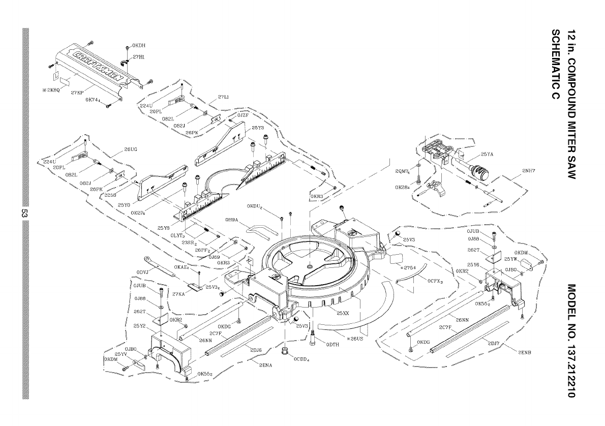
27KP
+_/+'+L+
io+_ I
J
J
\
J
\25XX J
// /+
\%
Z .N"
m •
_0
0"u
o0
C
Z
0
-I
r,n
r_
0
0
I'll
r-
Z
0
0)
o
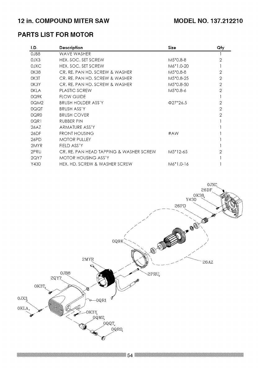
12 in. COMPOUND MITER SAW MODEL NO. 137.212210
PARTS LIST FOR MOTOR
I.D.
OJB8
OJX3
OJXC
0K38
OK3T
OK3Y
OKLA
OQ9K
OQM2
OQQT
OQR0
OQRI
26AZ
26DF
26PD
2MYR
2PRU
2QY7
Y430
Description Size Qfy
WAVE WASHER 1
HEX. SOC. SETSCREW M5"0.8-8 2
HEX. SOC. SETSCREW M6"1.0-20 1
CR. RE. PAN HD. SCREW & WASHER M5"0.8-8 2
CR. RE. PAN HD. SCREW & WASHER M5"0.8-25 2
CR. RE. PAN HD. SCREW & WASHER M5"0.8-50 2
PLASTIC SCREW M5"0.8-6 2
FLOW GUIDE 1
BRUSH HOLDER ASS'Y (b27"26.5 2
BRUSH ASS'Y 2
BRUSH COVER 2
RUBBER PIN 1
ARMATURE ASS'Y 1
FRONT HOUSING #AW 1
MOTOR PULLEY 1
FIELD ASS'Y 1
CR. RE. PAN HEAD TAPPING & WASHER SCREW M5"12-65 2
MOTOR HOUSING ASS'Y 1
HEX. HD. SCREW & WASHER SCREW M6"1.0-t6 1
0K3T\
OJX3
%
0KLA,
0JB8
2MYR
%
0JXC
26DF
0K38
Y430
26PD
54

55

Your Home
For expert troubleshooting and home solutions advice:
manage home
www.managemyhome.com
For repair - in your home - of all major brand appliances,
lawn and garden equipment, or heating and cooling systems,
no matter who made it, no matter who sold it!
For the replacement parts, accessories and
owner's manuals that you need to do-it-yourself.
For Sears professional installation of home appliances
and items like garage door openers and water heaters.
1-800-4-MY-HOME ®(1-800-469-4663)
Call anytime, day or night (U.S.A. and Canada)
www.sears.com www.sears.ca
Our Home
For repair of carry-in items like vacuums, lawn equipment,
and electronics, call anytime for the location of your nearest
Sears Parts & Repair Service Center
1-800-488-1222 (U.S.A.) 1-800-469-4663 (Canada)
www.sears.com www.sears.ca
To purchase a protection agreement on a product serviced by Sears:
1-800-827-6685 (U.S.A.) 1-800-361-6665 (Canada)
Para pedir servicio de reparaci6n Au Canada pour service en frangais:
a domicilio, y para ordenar piezas: 1-800-LE-FOYER M°
1-888-SU-HOGAR ® (1-800-533-6937)
Sea rs www.sears.ca
TM SM
® Registered Trademark /Trademark /Service Mark of Sears Brands, LLC
SM
® Marca Registrada /TM Marca de Fabrica /Marca de Servicio de Sears Brands, LLC
Mc MO
Marque de commerce /Marque deposce de Sears Brands, LLC © Sears Brands, LLC

Operator's Manual
CRAFTSMAN°
i PROFESSI ONAL i
12 in. DUAL BEVEL SLIDING COMPOUND
MITER SAW WITH LASER TRAC®
Model No. 137.212210
C US
CAUTION:
Before using this Miter Saw,
read this manual and follow
all its Safety Rules and
Operating Instructions
• Safety Instructions
• Installation
• Operation
• Maintenance
• Parts List
Customer Help Line
For Technical Support
1-800-843-1682
Sears Parts &
Repair Center
1-800-488-1222
Sears, Roebuck and Co., Hoffman Estates, IL 60179 USA
Visit our Craftsman website: www.sears.com/craftsman
Part No. 137212210001 Printed in Taiwan

SECTION PAGE
Warranty.............................................................................................2
ProductSpecifications........................................................................3
Symbols..............................................................................................4
PowerToolSafety..............................................................................5
CompoundMiterSawSafety..............................................................7
ElectricalRequirementsandSafety......................................................9
AccessoriesandAttachments............................................................11
ToolsNeededforAssembly................................................................12
CartonContents.................................................................................13
KnowYourCompoundMiterSaw........................................................14
GlossaryofTerms..............................................................................15
AssemblyandAdjustments................................................................17
Operation...........................................................................................30
Maintenance.......................................................................................44
TroubleshootingGuide.......................................................................46
PartsList.............................................................................................48
CRAFTSMAN ONE YEAR FULL WARRANTY
If this Craftsman tool fails due to a defect in material or workmanship within
one year from the date of purchase, call 1-800-4-MY-HOME® to arrange for
free repair (or replacement if repair proves impossible).
This warranty applies for only 90 days from the date of purchase if this product
is ever used for commercial or rental purposes.
This warranty does not include expendable parts, such as lamps, batteries,
bits or blades.
This warranty gives you specific legal rights, and you may also have other
rights which vary from state to state.
Sears, Roebuck and Co., Hoffman Estates, IL 60179
_, WARNING J
Some dust created by using power tools contains chemicals known to the
state of California to cause cancer and birth defects or other reproductive
harm. Some examples of these chemicals are:
•Lead from lead-based paints
•Crystalline silica from bricks, cement and other masonry products
•Arsenic and chromium from chemically treated lumber
Your risk from these exposures varies, depending on how often you do
this type of work. To reduce your exposure to these chemicals, work in a
well ventilated area and work with approved safety equipment such as dust
masks that are specially designed to filter out microscopic particles.
2
2008/04

MOTOR
Power Source ............................... 120VAC, 60Hz, 15Amp
Speed ........................................... 4200 RPM (No load)
Brake ............................................ Electric
Double Insulated ........................... Yes
Motor Arbor Shaft Size .................. 5/8 in.
BLADE SIZE
Diameter ....................................... 12 in.
Arbor size ...................................... 1in.w/a 5/8 in.reducer
ROTATING TABLE
Diameter ....................................... 13-7/16 in.
Miter Detent Stops ........................ 0, 15, 22.5,31.6, 45° R & L, 60° R
Bevel Positive Stops ..................... 0, 33.9, 45° R & L
CUTTING CAPACITY
Crosscut ........................................ 4 in. x 12-1/4 in.
Miter 45° R & L; 60° R .................... 4 in. x 8-3/4 in. R & L ; 4 in. x 6-1/4 in. R
Bevel 45° R & L ............................. 2-1/2 in. x 12-1/4 in. L ; 1-3/4 in. x 12-1/4 in. R
45° Miter and 45° Bevel R & L........ 2-1/2 in. x 8-3/4 in.
60° Miter and 45° Bevel R .............. 1-3/4 in. x 6-1/4 in.
[_iL WARNING J
To avoid electrical hazards, fire hazards or damage to the tool, use proper
circuit protection.
This tool is wired at the factory for 110-120 Volt operation. It must be
connected to a 110-120 Volt /15 Ampere time delay fuse or circuit breaker.
To avoid shock or fire, replace power cord immediately if it is worn, cut or
damaged in any way.
Before using your tool, it is critical that you read and understand these
safety rules. Failure to follow these rules could result in serious injury to
you or damage to the tool.
3

WARNING ICONS
Your power tool and its Operator's Manual may contain "WARNING ICONS"
(a picture symbol intended to alert you to, and/or instruct you how to avoid,
a potentially hazardous condition). Understanding and heeding these
symbols will help you operate your tool better and safer. Shown below are
some of the symbols you may see.
SAFETY ALERT: Precautions that involve your safety.
®PROHIBITION
OWEAR EYE PROTECTION: Always wear safety goggles or safety
glasses with side shields.
READ AND UNDERSTAND OPERATOR'S MANUAL: To reduce
the risk of injury, user and all bystanders must read and understand
operator's manual before using this product.
®KEEP HANDS AWAY FROM BLADE: Failure to keep your hands
away from the blade will result in serious personal injury.
SUPPORT AND CLAMP WORK
[_, DANGER] DANGER: indicates an imminently hazardous situation
which, if not avoided, will result in death or serious injury.
[A WARNING I
[A CAUTION I
WARNING: indicates a potentially hazardous situation
which, if not avoided, could result in death or serious
injury.
CAUTION: indicates a potentially hazardous situation
which, if not avoided, may result in minor or moderate
injury.
CAUTION: used without the safety alert symbol indicates
[ CAUTION ]a potentially hazardous situation which, if not avoided,
may result in property damage.
4
GENERAL SAFETY INSTRUCTIONS 8.
BEFORE USING THIS POWER TOOL
Safety is a combination of common
sense, staying alert and knowing how 9.
to use your power tool.
CAUTION
To avoid mistakes that could cause
serious injury, do not plug the tool in 10.
until you have read and understood
the following.
.
,
,
.
READ and become familiar with
the entire Operator's
Manual. LEARN the tool's
application, limitations and
possible hazards.
KEEP GUARDS IN PLACE and in
working order.
REMOVE ADJUSTING KEYS
AND WRENCHES. Form the habit
of checking to see that keys and
adjusting wrenches are removed
from the tool before turning ON.
KEEP WORK AREA CLEAN.
Cluttered areas and benches invite
accidents.
,DO NOT USE IN DANGEROUS
ENVIRONMENTS. Do not use
power tools in damp locations, or
expose them to rain or snow. Keep
work area well lit.
,KEEP CHILDREN AWAY. All
visitors and bystanders should be
kept a safe distance from work
area.
,MAKE WORKSHOP CHILD
PROOF with padlocks, master
switches or by removing starter
keys.
11.
12.
DO NOT FORCE THE TOOL. It will
do the job better and safer at the
rate for which it was designed.
USE THE RIGHT TOOL. Do not
force the tool or an attachment
to do a job for which it was not
designed.
USE PROPER EXTENSION
CORDS. Make sure your extension
cord is in good condition. When
using an extension cord, be sure
to use one heavy enough to carry
the current your product will draw.
An undersized cord will result in
a drop in line voltage and in loss
of power which will cause the tool
to overheat. The table on page
10 shows the correct size to use
depending on cord length and
nameplate ampere rating. If in
doubt, use the next heavier gauge.
The smaller the gauge number, the
heavier the cord.
WEAR PROPER APPAREL. Do
not wear loose clothing, gloves,
neckties, rings, bracelets or other
jewelry which may get caught in
moving parts. Nonslip footwear is
recommended. Wear protective
hair covering to contain long hair.
OALWAYS WEAR EYE
PROTECTION. Any power
tool can throw foreign
objects into the eyes and
could cause permanent eye
damage. ALWAYS wear Safety
Goggles (not glasses) that comply
with ANSI Safety standard Z87.1.
Everyday eyeglasses have only
impact-resistant lenses. They
ARE NOT safety glasses. Safety
Goggles are available at sears.
5

NOTE: Glasses or goggles not in
compliance with ANSI Z87.1 could
seriously injure you when they
break.
and any other conditions that may
affect its operation. A guard or
other part that is damaged should
be properly repaired or replaced.
13. WEAR A FACE MASK OR DUST
MASK. Sawing operation produces
dust.
14. SECURE WORK. Use
clamps or a vise to hold work
when practical. It is safer
than using your hand and it
frees both hands to operate
the tool.
15. DISCONNECT TOOLS FROM
POWER SOURCE before servicing,
and when changing accessories
such as blades, bits and cutters.
16. REDUCE THE RISK OF
UNINTENTIONAL STARTING.
Make sure switch is in the OFF
position before plugging the tool in.
17. USE RECOMMENDED
ACCESSORIES. Consult
this Operator's Manual for
recommended accessories. The
use of improper accessories may
cause risk of injury to yourself or
others.
18. NEVER STAND ON THE TOOL.
Serious injury could occur if the
tool is tipped or if the cutting tool is
unintentionally contacted.
20. NEVER LEAVE THE TOOL
RUNNING UNATTENDED. TURN
THE POWER "OFF". Do not walk
away from a running tool until the
blade comes to a complete stop
and the tool is unplugged from the
power source.
21. DO NOT OVERREACH. Keep
proper footing and balance at all
times.
22. MAINTAIN TOOLS WITH CARE.
Keep tools sharp and clean for best
and safest performance. Follow
instructions for lubricating and
changing accessories.
23. WARNING: Dust generated from
certain materials can be hazardous
to your health. Always operate saw
in well-ventilated area and provide
for proper dust removal.
24.[_k DANGER J People with
electronic devices, such as
pacemakers, should consult their
physician(s) before using this
product. Operation of electrical
equipment in close proximity to
a heart pacemaker could cause
interference or failure of the
pacemaker.
19. CHECK FOR DAMAGED PARTS.
Before further use of the tool, a
guard or other part that is damaged
should be carefully checked to
determine that it will operate
properly and perform its intended
function - check for alignment of
moving parts, binding of moving
parts, breakage of parts, mounting
6

SPECIFIC SAFETY INSTRUCTIONS
FOR THIS COMPOUND MITER SAW
.DO NOT operate the miter saw
until it is completely assembled
and installed according to these
instructions.
,IF YOU ARE NOT thoroughly
familiar with the operation of miter
saws, seek guidance from your
supervisor, instructor or other
qualified person.
,ALWAYS hold the work firmly
against the fence and table.
DO NOT perform any operation
free hand (use clamp wherever
possible).
.KEEP HANDS out of the path of the
saw blade. If the workpiece you are
cutting would cause your hands to
be within 8-3/4 in. of the saw blade,
the workpiece should be clamped in
place before making the cut.
5. BE SURE the blade is sharp, runs
freely and is free of vibration.
6. ALLOW the motor to come up to full
speed before starting a cut.
7. KEEP THE MOTOR AIR SLOTS
CLEAN and free of chips or dust.
,ALWAYS MAKE SURE all handles
are tight before cutting, even if the
table is positioned in one of the
positive stops.
9. BE SURE both the blade and the
collar are clean and the arbor bolt is
tightened securely.
10.USE only blade collars specified for
your saw.
11.NEVER use blades larger in
diameter than 12 inches.
12.NEVER apply lubricants to the
blade when it is running.
13.ALWAYS check the blade for
cracks or damage before operation.
Replace a cracked or damaged
blade immediately.
14.NEVER use blades recommended
for operation at less than 4200
RPM.
15.ALWAYS keep the blade guards in
place and use at all times.
16.NEVER reach around the saw
blade.
17.MAKE SURE the blade is not
contacting the workpiece before the
switch is turned ON.
18.IMPORTANT: After completing the
cut, release the trigger and wait for
the blade to stop before returning
the saw to the raised position.
19.MAKE SURE the blade has come
to a complete stop before removing
or securing the workpiece, changing
the workpiece angle or changing the
angle of the blade.
20.NEVER cut metals or masonry
products with this tool. This miter
saw is designed for use on wood
and wood-like products.
7

21. NEVER cut small pieces. If the
workpiece being cut would cause
your hand or fingers to be within
8-3/4 in. of the saw blade the
workpiece is too small.
22. PROVIDE adequate support to the
sides of the saw table for long work
pieces.
23. NEVER use the miter saw in an
area with flammable liquids or
gases.
24. NEVER use solvents to clean
plastic parts. Solvents could
possibly dissolve or otherwise
damage the material.
25. SHUT OFF the power before
servicing or adjusting the tool.
26. DISCONNECT the saw from
the power source and clean the
machine when finished using.
27. MAKE SURE the work area is
clean before leaving the machine.
28. SHOULD any part of your miter saw
be missing, damaged, or fail in any
way, or any electrical component
fail to perform properly, lock the
switch and remove the plug from
the power supply outlet. Replace
missing, damaged, or failed parts
before resuming operation.
8

POWER SUPPLY AND MOTOR
SPECIFICATIONS
The AC motor used in this saw is
a universal, nonreversible type.
See "MOTOR" in the "PRODUCT
SPECIFICATIONS" section on page 3.
WARNING I
To avoid electrical hazards, fire
hazards, or damage to the tool, use
proper circuit protection, Your saw
is wired at the factory for 120 V
operation, Connect to a 120 V, 15A
circuit and use a 15 A time delay
fuse or circuit breaker, To avoid
shock or fire, if power cord is worn
or cut, or damaged in any way, have
it replaced immediately,
way. If the plug does not fit fully in the
outlet, reverse the plug. If it still does
not fit, contact a qualified electrician to
install the proper outlet. Do not change
the plug in any way.
IAWARNINGI
Double insulation does not take the
place of normal safety precautions
when operating this tool.
To avoid electrocution:
1. Use only identical replacement parts
when servicing a tool with double
insulation. Servicing should be
performed by a qualified technician.
2. Do not use power tools in wet or
damp locations or expose them to
rain or snow.
DOUBLE INSULATED []
The power tool is double insulated to
provide a double thickness of insulation
between you and tool's electrical
system. All exposed metal parts are
isolated from the internal metal motor
components with protecting insulation.
Replacement parts - When servicing,
use only identical replacement parts.
Polarized plugs - This saw has a plug
that looks like the one shown below:
To reduce the risk of electrical shock,
this saw has a polarized plug (one
blade is wider than the other). This plug
will fit in a polarized outlet only one
MOTOR SAFETY PROTECTION
IMPORTANT
To avoid motor damage, the motor
should be blown out or vacuumed
frequently to keep sawdust from
interfering with the motor ventilation.
1. Connect this saw to a 120 V circuit.
This circuit must not be less than a
#12 wire with a 20 A time lag fuse or
a #14 wire with a 15 A time lag fuse.
NOTE: When using an extension
cord on a circuit with a #14 wire, the
extension cord must not exceed 25
feet in length.
2. If the motor will not start, release
the trigger switch immediately.
UNPLUG THE SAW. Check the saw
blade to make sure it turns freely. If
the blade is free, try to start the saw
again. If the motor still does not start,
refer to the TROUBLESHOOTING
GUIDE.
3. If the tool suddenly stalls while
cutting wood, release the trigger
switch, unplug the tool and free the
blade from the wood. The saw may
9

now be started and the cut finished.
4. FUSES may "blow" or circuit
breakers may trip frequently if:
a. MOTOR is overloaded -
overloading can occur if you feed
too rapidly or make too many
start/stops in a short time.
b. LINE VOLTAGE is more
than 10% above or below the
nameplate voltage rating. For
heavy loads, the voltage at motor
terminals must equal the voltage
specified on the nameplate.
c. IMPROPER or dull saw blades
are used.
5. Most motor troubles may be traced
to loose or incorrect connections,
overload, low voltage or inadequate
power supply wiring. Always check
the connections, the load and
supply circuit if the motor doesn't
run well. Check minimum gauge for
the length of cord you are using on
the chart below.
excessive heat and damp or wet areas.
Use a separate electrical circuit
for your tools. This circuit must not
be less than a #12 wire with a 20 A
time lag fuse or a #14 wire with a 15
A time lag fuse. NOTE: When using
an extension cord on a circuit with
a #14 wire, the extension cord must
not exceed 25 feet in length. Before
connecting the tool to the power line,
make sure the switch is in the OFF
position and the electric current is
rated the same as the current stamped
on the motor nameplate, running at a
lower voltage will damage the motor.
I,V_ll#lhVjIll Lvj|€f._11[_1 =11=[0]t,i _:Q i=1#{..I [el #El.ill ;I I]._fzViVL_l
(When using 120 volts only)
Ampere Rating Total length of Cord
More Than Not More Than 25ft. 50ft. 100ft. 150ft.
O 6 18 16 16 14
6 10 18 16 14 12
10 12 16 16 14 12
GUIDELINES FOR EXTENSION
CORDS
Use a proper extension cord. Make
sure your extension cord is in good
condition. When using an extension
cord, be sure to use one heavy enough
to carry the current your product will
draw. An undersized cord will cause
a drop in line voltage, resulting in
loss of power and overheating. The
table below shows the correct size
to use depending on cord length and
nameplate ampere rating. If in doubt,
use the next heavier gauge. The
smaller the gauge number, the heavier
the cord.
CAUTION: In all cases make certain
the receptacle in question is
properly grounded. If you are not
sure, have a certified electrician
check the receptacle.
Be sure your extension cord is
properly wired and in good condition.
Always replace a damaged extension
cord or have it repaired by a qualified
person before using it. Protect your
extension cords from sharp objects,
10

RECOMMENDED ACCESSORIES
[_k WARNING J
•Use only accessories
recommended for this miter
saw. Follow instructions that
accompany accessories. Use of
improper accessories may cause
hazards.
•The use of any cutting tool
except 12 in. saw blades which
meet the requirements under
recommended accessories
is prohibited. Do not use
accessories such as shaper
cutters or dado sets. Ferrous
metal cutting and the use of
abrasive wheels is prohibited.
•Do not attempt to modify this
tool or create accessories not
recommended for use with this
tool. Any such alteration or
modification is misuse and could
result in a hazardous condition
leading to possible serious
injury.
without the proper saw blade
guard in place. Carbide is a very
hard but brittle material. Care
should be taken while mounting,
using, and storing carbide tipped
blades to prevent accidental
damage. Slight shocks, such as
striking the tip while handling,
can seriously damage the blade.
Foreign objects in the workpiece,
such as wire or nails, can also
cause tips to crack or break off.
Before using, always visually
examine the blade and tips for
bent blade, cracks, breakage,
missing or loose tips, or other
damage. Do not use if damage is
suspected. Failure to heed safety
instructions and warnings can
result in serious bodily injury.
ACCESSORIES
Visit your Sears Hardware Department
or see the Sears Power and Hand Tool
Catalog to purchase recommended
accessories for this power tool.
[_, WARNING J
•To avoid the risk of personal
injury, do not modify this power
tool or use accessories not
recommended by Sears.
•Read warnings and conditions
on your CARBIDE TIPPED SAW
BLADE. Do not operate the saw
11

Supplied
Blade Wrench
Not supplied
Adjustable Wrench
6 mm Hex Wrench
l!'-'"-'_,_i'-:'_,_,_'-'' -'i'-_,_
Combination Square
Phillips Screwdriver
Slotted Screwdriver
COMBINATION SQUARE MUST BE TRUE
Should not gap or overlap when square is flipped over (see dotted figure).
Draw light line on
board along this edge.
Straight edge or a 3/4 in. board, this
edge must be perfectly straight.
Should not gap or overlap when square
flipped over (see dotted figure).
12

UNPACKING YOUR MITER SAW
WARNING I
To avoid injury from unexpected
starting or electrical shock, do not
plug the power cord into a source
of power during unpacking and
assembly. This cord must remain
unplugged whenever you are
working on the saw.
1. Remove the miter saw from the
carton.
IMPORTANT: Do not lift miter saw
by the trigger switch handle. It may
cause misalignment. Lift machine by
the built-in carry handle.
2. Place the saw on a secure stationary
work surface.
3. Separate all parts from the packing
material. Check each one with the
illustration to make certain all items
are accounted for, before discarding
any packing material.
IAWARNINGi
If any part is missing or damaged,
do not attempt to assemble the
miter saw, or plug in the power
cord until the missing or damaged
part is correctly replaced. To avoid
electric shock, use only identical
replacement parts when servicing
double insulated tools. Call
1-800-4-MY-HOME ®for replacement
parts.
Hold-down clamp
Dust bag Miter saw
%
Elbow
Power cord Hold-down clamp
Blade wrench Power cord storage clip lock knob
storage clips mounting
hardware
13

Motor \
Saw blade
Bevel scale
Hold-down clamp
Sliding fence
Carry handle Upper blade guard
Carry handle Laser ON/OFF switch
Handle locking lever
Switch handle
ON/OFF trigger switch
Lower blade guard
Base
Miter lock handle
Left extension table
Turntable
Bevel lock handle
Mounting hole Left support
Belt cover
Hold-down latch
Slide carriage
Slide carriage
lock knob
Laser guide
Right extension table
Stop plate
Quick-cam miter
table lock Table insert Right support
Positive miter detents
14

AMPERAGE (AMPS) - A measure
of the flow of electric current. Higher
ratings generally means the tool is
suited for heavier use.
ARBOR LOCK -Allows the user to
keep the blade from rotating while
tightening or loosening the arbor bolt
during blade replacement or removal.
eyes. Eye protection should meet the
requirements of ANSI Z.87.1 (USA) or
CSA Z94.3-M88 (Canada).
FACE SHIELD - An impact resistant
shield that helps to protect your face
from chips, sparks, small debris.
Should only be used in conjunction with
additional eye protection.
BASE - Supports the table, holds
accessories and allows for workbench
or leg set mounting.
FENCE - Helps to keep the workpiece
from moving when sawing. Scaled to
assist with accurate cutting.
BEVEL LOCKING HANDLE - Locks
the miter saw at a desired bevel angle.
BEVEL SCALE - To measure the
bevel angle of the saw blade 0° to 45°
left.
CARBIDE TIPPED -Extremely hard
steel pieces with sharp cutting edges
fastened to cutting tools such as saw
blades.
COVER PLATE SCREW - Loosen this
screw and rotate the plate for access to
the blade arbor bolt.
GUARD - Protective devise that forms
a barrier between a hazardous object
such as a blade, wheel or cutter and
the operator.
HOLD DOWN LATCH - Locks the
miter saw in the lowered position for
compact storage and transportation.
INSTRUCTION OR OPERATOR'S
MANUAL - Booklet accompanying
your power tool that describes the
hazards and safe operation procedures,
outlines basic tool operation, care and
maintenance.
DOUBLE-INSULATED - A form of
electrical protection featuring two
separate insulation systems to help
protect against electrical shock.
EXTENSION CORD -An electric cord
used between power tools and outlets
to extend the range of the tools. The
more amerage your tool uses, the
longer the distance, the larger the size
of the wire needed in your extension
cord.
EYE PROTECTION - Goggles or
spectacles intended to protect your
MITER HANDLE - Used to rotate the
table, and to rotate the saw to a right or
left cutting position.
MITER SCALE - Measures the miter
angle 0° to 45 ° left and right.
MOUNTING HOLES - To mount the
miter saw to a stable surface.
ON/OFF TRIGGER SWITCH - To start
the tool, squeeze the trigger. Release
the trigger to turn off the miter saw.
15

POSITIVE STOP LOCKING LEVER -
Locks the miter saw at a preset positive
stop for the desired miter angle.
SWITCH HANDLE - The switch
handle contains the trigger switch and
the laser on/off switch. The blade is
lowered into the workpiece by pushing
down on the handle. The saw will
return to its upright position when the
handle is released.
WARNING LABELS - Read and
understand for your own safety. Make
sure all labels are present on machine
and legible.
WRENCH STORAGE - Convenient
storage to prevent misplacing the blade
wrench.
WOODWORKING TERMS
ARBOR - The shaft on which a blade
is mounted.
BEVEL CUT - An angle cut made
through the face of the workpiece.
COMPOUND CUT - An angled cut
to both the edge and face of a board,
most common use is with crown
molding.
CROSS CUT - A cut which runs across
the board perpendicular to the grain.
KICKBACK - Sudden and unintended
movement of the tool or workpiece. It is
typically caused by binding or pinching
of the workpiece
MITER CUT - A miter is a type of joint
where the two parts to be joined are cut
at an angle, and typically the finished
joint forms a 90-degree angle. Also
commonly spelled "mitre".
REVOLUTIONS PER MINUTE (RPM)
- The number of turns completed by a
spinning object in one minute.
SAW BLADE PATH - The area of the
workpiece or table top directly in line
with the travel of the blade or the part
of the workpiece which will be cut.
SET - The distance between two saw
blade tips, bent outward in opposite
directions to each other. The further
apart the tips are, the greater the set.
THIN-KERF BLADE - Thinner than
normal blades, remove less material,
smaller kerfs (between .065 and .070).
Blade thinness also may increase the
heat generated while cutting.
WORKPIECE - The wood being
cut. The surfaces of a workpiece are
commonly referred to as faces, ends
and edges.
FREEHAND - Performing a cut without
using a fence (guide), hold down or
other proper device to prevent the
workpiece from twisting during the
cutting operation.
HEEL - Misalignment of the blade.
KERF - The width of a saw cut,
determined by the thickness and set of
the blade.
16

ESTIMATED ASSEMBLY TIME: 10~15
MINUTES
AL WARNING I
To avoid injury, do not connect this
miter saw to the power source until
it is completely assembled and
adjusted, and you have read and
understood this Operator's Manual,
UNLOCKING THE SLIDE CARRIAGE
(FIG. A)
After removing the saw from the carton,
loosen the slide carriage lock knob
(1). When transporting or storing the
miter saw, the slide carriage should
always be locked in position. The slide
carriage lock knob (1) is located on the
right side of the slide carriage.
Unlocking
1. Push down slightly on the switch
handle (1).
2. Pull out the hold-down latch (2).
3. Allow the cutting head to rise to the
up position.
Fig, B
/,
1
Fig, A
RELEASING CUTTING HEAD (FIG, B)
WARNING I
To avoid injury and damage to the
saw, transport or store the miter
saw with the cutting head locked in
the down position. Never use the
hold down latch to hold the cutting
head in a down position for cutting
operations.
Locking
When transporting or storing the miter
saw, the cutting head should always be
locked in the down position.
1. Push the cutting head down to its
lowest position.
2. Push the hold-down latch (2) into
the locking hole.
IMPORTANT: To avoid damage, never
carry the miter saw by the switch
handle, the cutting arm or the miter
handle. ALWAYS use the designated
carrying handles located on the top of
the machine and in the back of the unit.
17

INSTALLING THE DUST
COLLECTION ELBOW (FIG. C)
1. Install the end of the elbow (1) onto
the exhaust port (2).
NOTE: The elbow can be used
to attach either the dust bag or a
vacuum hose to remove sawdust
from the work area.
Fig. C
INSTALLING THE DUST BAG (FIG. D)
1. Squeeze the metal collar wings (1)
of the dust bag (2).
2. Place the dust bag neck opening
around the dust collection elbow (3),
and release the metal collar.
Fig. D
2
To empty the dust bag, squeeze the
metal collar and remove from exhaust
port. Open zipper on underside of bag
and empty into waste container.
NOTE: Check frequently and empty
bag before it gets full.
THREE POSITION ROTATING
HANDLE (FIG. E)
The handle of the miter saw has been
designed to rotate and lock at three
different position stops; 450 left, 0°, and
450 right for operator convenience. To
rotate the handle:
1. Unlock the handle locking lever (1)
by pulling it toward the front of the
machine.
2. Pull the handle-locking latch (2)
to the front of the saw and hold in
position.
3. Rotate the handle to the desired
position stop and release the
handle-locking latch. NOTE: After
releasing the handle-locking latch,
rotate the handle left and right to
make sure the latch engages into
the positive locking position.
4. Lock the handle locking lever (1) by
pushing it IN toward the rear of the
handle.
Fig. E 2
\\
\\\
INSTALLING THE SAFETY HOLD-
DOWN CLAMP (FIG. F)
1. Place the hold-down clamp
assembly (1) in one of the mounting
hole (2), located behind the fence.
2. Thread the hold-down clamp knob
(3) into the hole (2) located at the
rear of the saw base.
3. Tighten the hold-down clamp knob
.
)
18

Fig. F
21
3
POWER CORD STORAGE CLIPS
(FIG. G)
For convenience and to prevent
damage to the power cord when
the miter saw is not in use or is in
transportation, the slide carriage has
two clips on the rear for cord storage.
To assembly these clips:
1. Attach each power cord storage
clips (2) to the rear of slide-bar seat
with one mounting screws (1).
Fig. G
2
1
SAW BLADE WRENCH (FIG. H)
For convenient storage and prevention
of loss, there is a clip (1) located at the
left rear foot of the base for storing the
blade wrench (2).
Fig. H
2
I,A WARNING I
To avoid injury, disconnect the
plug from the power source before
performing any adjustments or
repair.
NOTE: Your miter saw was adjusted at
the factory. However, during shipment
slight misalignment may have occurred.
Check the following settings and adjust
if necessary prior to using this miter
saw.
REMOVING AND INSTALLING THE
TABLE INSERT (FIG. I)
WARNINGI
To avoid injury:
• Always unplug the saw to avoid
accidental starting. Remove all
small pieces of material from the
table cavity before performing
any cuts. The table insert may
be removed for this purpose, but
always reattach the table insert
prior to performing a cutting
operation.
•Do not start the sliding compound
miter saw without checking for
interference between the blade
and table insert. Damage could
result to the blade, table insert or
turntable if blade strike occurs
during the cutting operation.
19

1. To remove, loosen and remove the
six screws (1) on the table inserts
(2) with a Phillips screwdriver and
remove the inserts.
2. To install, reposition the table
inserts, install the six screws and
tighten.
3. Check for blade clearance by
moving the slide carriage through
the full motion of the blade in the
table slot.
to the insulation or the wire
connections resulting in electric
shock or fire.
•To avoid injury from flying
debris, do not allow visitors to
stand near the saw during any
cutting operation.
•Support the saw on a level work
surface.
•Bolt or clamp the saw to its
support.
Fig. I Mounting instructions
1. For stationary use, place the saw
in the desired location, directly on
aworkbench where there is room
for handling and proper support
of the workpiece. The base of the
saw has four mounting holes. Bolt
the base of the miter saw (1) to
the work surface (5), using the
fastening method as shown in Fig J.
MOUNTING THE MITER SAW
(FIG. J, K)
[_ WARNING J
To avoid injury form unexpected
saw movement:
•Disconnect the power cord from
the outlet, and lock the cutting
head in the lower position using
the stop latch.
•Lock the slide carriage in place
by tightening the slide carriage
lock knob.
• To avoid back injury, lift the saw
by using the designated carrying
handles located on the top of the
machine. When lifting, bend at
your knees, not from your back.
•Never carry the miter saw by
the power cord or by the switch
handle. Carrying the tool by the
Fig. J
1. 3
2. 4
3.
4. 1
5. ---[--- _,
6. 5 _,:
7. _9
6 8
8.
9. 7
NOTE: Mounting hardware is not
included with this tool. Bolts, nuts,
washers & screws must be purchased
separately.
Miter saw base
Hex head bolt
Rubber washer
Flat washer
Workbench
Flat washer
Lockwasher
Hex nut
Jam nut
2. For portable use, place the saw on
o a 3/4 in. thick piece of plywood.
Bolt the base of the miter saw
securely to the
plywood using the mounting holes

clampthismountingboardtoa
stableworksurfaceattheworksite.
(Fig.K)
Fig. K
Fig. L
13
2
REMOVING OR INSTALLING THE
BLADE
Removing Blade (Fig. L, M, N)
WARNING I
•To avoid injury from an
accidental start, make sure the
switch is in the OFF position
and plug is not connected to the
power source outlet.
Only use a 12-inch diameter
blade.
1.
2.
3.
.
,
6.
Unplug the saw from the outlet
Raise the miter saw to the upright
position.
Raise the lower clear plastic blade
guard (1) to the uppermost position.
(Fig. L)
While holding the lower blade
guard, loosen the cover plate screw
(2) with a Phillips screwdriver.
Rotate the cover plate (3) to
expose the arbor bolt (4-Fig. N).
Place the blade end wrench over
the arbor bolt.
,
8.
Locate the arbor lock (5) on the
motor, below the belt cover. (Fig. M)
Press the arbor lock, holding it
in firmly while turning the blade
clockwise. The arbor lock will
then engage and lock the arbor.
Continue to hold the arbor lock,
while turning the wrench clockwise
to loosen the arbor bolt.
Fig. M
9. Remove the arbor bolt (4), the
arbor collar (6), and the blade (7).
Do not remove the inner blade
collar. (Fig. N)
10. Raise the lower clear plastic blade
guard (1) to the upright position
(Fig. L) to remove the blade.
21

NOTE: Pay attention to the pieces
removed, noting their position and
direction they face. Wipe the blade
collars clean of any sawdust before
installing a new blade. Also, the 12 in.
blade has a 1 in. arbor hole with a 5/8
in. reducer (8) to mount onto the saw.
Fig. N
8\
6
4
INSTALLING BLADE (FIG. L, M, N)
WARNING J
Un-plug the miter saw before
changing/installing the blade.
1. Install a 12 in. blade with a 5/8 in.
arbor (or a 1 in. arbor with a 5/8 in.
reducer) making sure the rotation
arrow on the blade matches the
clockwise rotation arrow on the
upper guard, and the blade teeth
are pointing downward.
2. Place the arbor collar (6) against
the blade and on the arbor. Thread
the arbor bolt (4) on the arbor. (Fig.
N) in a counterclockwise direction.
IMPORTANT: Make sure the flats
of the blade collars are engaged
with the flats on the arbor shaft.
Also, the flat-side of the arbor collar
must be placed against the blade.
3. Place the blade wrench on the
arbor bolt.
4. Press the arbor lock (5), holding
it in firmly while turning the blade
counterclockwise. When it engages,
continue to press the arbor lock
in, while tightening the arbor bolt
securely. (Fig. M)
5. Rotate the cover plate (3) back to
its original position until the slot in
the cover plate engages with the
cover plate screw (2). While holding
the lower blade guard, tighten the
screw with a Phillips screwdriver.
(Fig. L) NOTE: The lower blade
guard must be raised to the upright
position to access the cover plate
screw.
6. Lower the clear retractable blade
guard (1) and verify the operation of
the guard does not bind or stick (Fig.
L).
7. Be sure the arbor lock is released
so the blade turns freely by
spinning the blade until the arbor
lock disengages.
WARNING J
• To avoid injury, never use the saw
without the cover plate secure
in place. It keeps the arbor bolt
from falling out if it accidentally
loosens, and helps prevent the
spinning blade from coming off
the saw.
•Make sure the collars are clean
and properly arranged. Lower
the blade into the table and
check for any contact with the
metal base or the turn table.
22
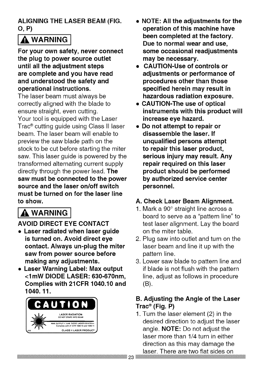
ALIGNING THE LASER BEAM (FIG.
O, P)
WARNING I
For your own safety, never connect
the plug to power source outlet
until all the adjustment steps
are complete and you have read
and understood the safety and
operational instructions.
The laser beam must always be
correctly aligned with the blade to
ensure straight, even cutting.
Your tool is equipped with the Laser
Trac ®cutting guide using Class II laser
beam. The laser beam will enable to
preview the saw blade path on the
stock to be cut before starting the miter
saw. This laser guide is powered by the
transformed alternating current supply
directly through the power lead. The
saw must be connected to the power
source and the laser on/off switch
must be turned on for the laser line
to show.
WARNING I
AVOID DIRECT EYE CONTACT
•Laser radiated when laser guide
is turned on. Avoid direct eye
contact. Always un-plug the miter
saw from power source before
making any adjustments.
•Laser Warning Label: Max output
<lmW DIODE LASER: 630-670nm,
Complies with 21CFR 1040.10 and
1040. 11.
•NOTE: All the adjustments for the
operation of this machine have
been completed at the factory.
Due to normal wear and use,
some occasional readjustments
may be necessary.
•CAUTION-Use of controls or
adjustments or performance of
procedures other than those
specified herein may result in
hazardous radiation exposure.
•CAUTION-The use of optical
instruments with this product will
increase eye hazard.
•Do not attempt to repair or
disassemble the laser. If
unqualified persons attempt
to repair this laser product,
serious injury may result. Any
repair required on this laser
product should be performed
by authorized service center
personnel.
A. Check Laser Beam Alignment.
1. Mark a 90° straight line across a
board to serve as a "pattern line" to
test laser alignment. Lay the board
on the miter table.
2. Plug saw into outlet and turn on the
laser beam and line it up with the
pattern line.
3. Lower saw blade to pattern line and
if blade is not flush with the pattern
line, adjust as follows in procedure
(B).
B. Adjusting the Angle of the Laser
Trac ®(Fig. P)
1. Turn the laser element (2) in the
desired direction to adjust the laser
angle. NOTE: Do not adjust the
laser more than 1/4 turn in either
direction as this may damage the
laser. There are two flat sides on
23

the laser element where you can
position an adjustable wrench for
your adjustment.
C. Aligning The Laser Beam
1. Loosen only 1/2 turn at a time the
four set screws (1).
2. Adjust laser by turning the left side
set screws clockwise to shift the
laser line to the right. To shift the
laser line to the left, turn the right
side set screws 1/2 turn at a time.
3. Once alignment of the laser is
achieved, tighten only 1/2 turn at a
time the four set screws (1).
Fig. 0
Fig. P
THE UPFRONT SUPPORTS
ADJUSTMENT (FIG. Q, R)
Wide pieces need upfront supports (1).
1. Rotate the two upfront supports (1)
toward the rear of the saw.
Laser Switch
i ...... l
Left Side View Right Side View
Fig. Q
\
1
NOTE: These supports (1) should be
placed into the 0 position as shown in
Fig. R before transporting.
Fig. R
1
24
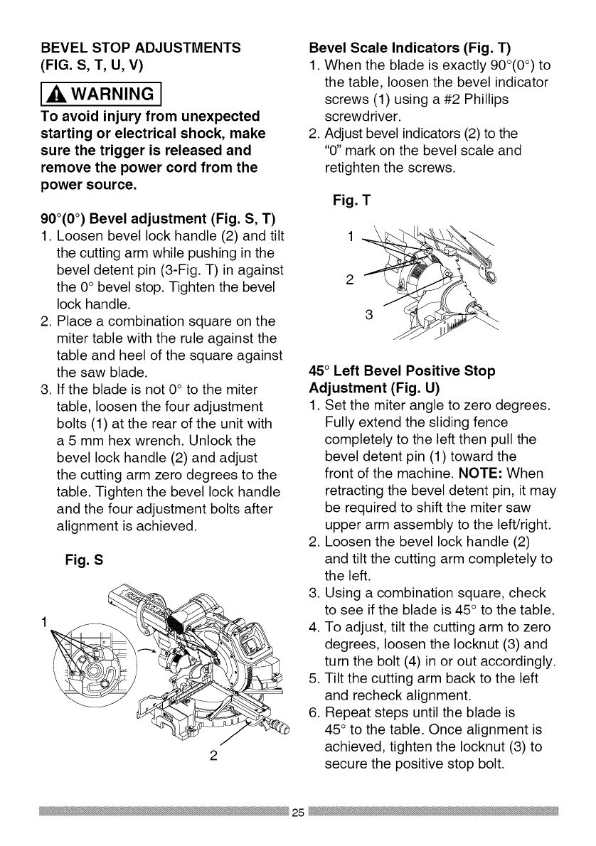
BEVEL STOP ADJUSTMENTS
(FIG. S, T, U, V)
WARNING I
To avoid injury from unexpected
starting or electrical shock, make
sure the trigger is released and
remove the power cord from the
power source.
900(0°) Bevel adjustment (Fig. S, T)
1. Loosen bevel lock handle (2) and tilt
the cutting arm while pushing in the
bevel detent pin (3-Fig. T) in against
the 0° bevel stop. Tighten the bevel
lock handle.
2. Place a combination square on the
miter table with the rule against the
table and heel of the square against
the saw blade.
3. If the blade is not 0° to the miter
table, loosen the four adjustment
bolts (1) at the rear of the unit with
a 5 mm hex wrench. Unlock the
bevel lock handle (2) and adjust
the cutting arm zero degrees to the
table. Tighten the bevel lock handle
and the four adjustment bolts after
alignment is achieved.
Fig. S
2
Bevel Scale Indicators (Fig. T)
1. When the blade is exactly 90o(0°) to
the table, loosen the bevel indicator
screws (1) using a #2 Phillips
screwdriver.
2. Adjust bevel indicators (2) to the
"0" mark on the bevel scale and
retighten the screws.
Fig. T
2
45°Left Bevel Positive Stop
Adjustment (Fig. U)
1. Set the miter angle to zero degrees.
Fully extend the sliding fence
completely to the left then pull the
bevel detent pin (1) toward the
front of the machine. NOTE: When
retracting the bevel detent pin, it may
be required to shift the miter saw
upper arm assembly to the left/right.
2. Loosen the bevel lock handle (2)
and tilt the cutting arm completely to
the left.
3. Using a combination square, check
to see if the blade is 45° to the table.
4. To adjust, tilt the cutting arm to zero
degrees, loosen the Iocknut (3) and
turn the bolt (4) in or out accordingly.
5. Tilt the cutting arm back to the left
and recheck alignment.
6. Repeat steps until the blade is
45° to the table. Once alignment is
achieved, tighten the Iocknut (3) to
secure the positive stop bolt.
25

Fig. U
4
1
3
45°Right Bevel Positive Stop
Adjustment (Fig. V)
1. Set the miter angle to zero degrees.
Fully extend the sliding fence
completely to the right then pull
the bevel detent pin (1) toward the
front of the machine. NOTE: When
retracting the bevel detent pin, it may
be required to shift the miter saw
upper arm assembly to the left/right.
2. Loosen the bevel lock handle (2)
and tilt the cutting arm completely to
the right.
3. Using a combination square, check
to see if the blade is 45 ° to the table.
4. To adjust, tilt the cutting arm to zero
degrees, loosen the Iocknut (3) and
turn the bolt (4) in or out accordingly.
5. Tilt the cutting arm back to the right
and recheck alignment.
6. Repeat steps until the blade is
45 ° to the table. Once alignment is
achieved, tighten the Iocknut (3) to
secure the positive stop bolt.
Fig. V 4
1 3
2
33.9°Left & Right Bevel Adjustment
(Fig. W)
1. Set the miter angle to zero degree.
Fully extend both sliding fences.
2. Loosen the bevel lock handle and
tilt cutting arm to the 33.9 ° left bevel
positive stop by pushing in on the
bevel detent pin toward the rear of the
machine.
3. Using a combination square, check
to see if the blade is 33.9° to the
table.
4. To adjust, turn the screw in or out
with a wrench (from the locations
shown below) until the blade is 33.9 °
to the table.
5. Repeat steps for the right bevel
33.9 -0bevel adjustment.
Fig. W
For 33.9 ° left ._
bevel positive stop
adjustment, insert
wrench here
26
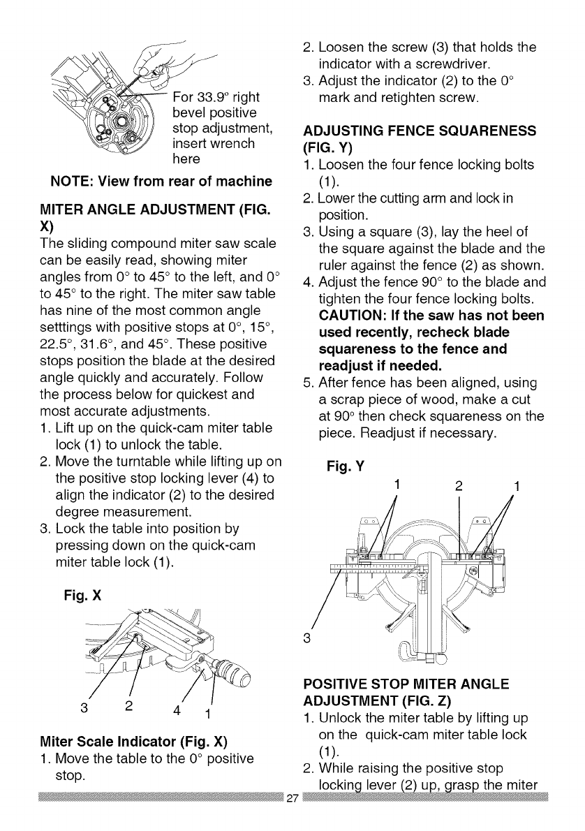
o right
sitive
ustment,
rench
here
NOTE: View from rear of machine
MITER ANGLE ADJUSTMENT (FIG.
X)
The sliding compound miter saw scale
can be easily read, showing miter
angles from 0° to 45° to the left, and 0°
to 45 ° to the right. The miter saw table
has nine of the most common angle
setttings with positive stops at 0°, 15°,
22.5 °, 31.6 °, and 45°. These positive
stops position the blade at the desired
angle quickly and accurately. Follow
the process below for quickest and
most accurate adjustments.
1. Lift up on the quick-cam miter table
lock (1) to unlock the table.
2. Move the turntable while lifting up on
the positive stop locking lever (4) to
align the indicator (2) to the desired
degree measurement.
3. Lock the table into position by
pressing down on the quick-cam
miter table lock (1).
Fig. X
2. Loosen the screw (3) that holds the
indicator with a screwdriver.
3. Adjust the indicator (2) to the 0°
mark and retighten screw.
ADJUSTING FENCE SQUARENESS
(FIG. Y)
1. Loosen the four fence locking bolts
(1).
2. Lower the cutting arm and lock in
position.
3. Using a square (3), lay the heel of
the square against the blade and the
ruler against the fence (2) as shown.
4. Adjust the fence 90° to the blade and
tighten the four fence locking bolts.
CAUTION: If the saw has not been
used recently, recheck blade
squareness to the fence and
readjust if needed.
5. After fence has been aligned, using
a scrap piece of wood, make a cut
at 90° then check squareness on the
piece. Readjust if necessary.
Fig. Y
2
3 2 4 1
Miter Scale Indicator (Fig. X)
1. Move the table to the 0° positive
POSITIVE STOP MITER ANGLE
ADJUSTMENT (FIG. Z)
1. Unlock the miter table by lifting up
on the quick-cam miter table lock
(1).
stop. 2. While raising the positive stop
locking lever (2) up, grasp the miter
27

handle and rotate the miter table left
or right to the desired angle.
3. Release the positive stop locking
lever and set the miter at the desired
angle making sure the lever snaps
into place. NOTE: The lever will
only lock into place at one of the ten
positive stops.
4. Once angle is achieved, press down
on the quick-cam miter table lock (1).
4. Turn the lock nut (3) to the right
as shown to lock the miter locking
mechanism into place.
Fig. Z 13 4
Quick-cam Miter Table Lock
Operation (Fig. Z)
If miter angles required are NOT one of
the ten positive stops noted above, the
miter table can be locked at any angle
between these positive stops by using
the quick-cam miter table lock.
1. Unlock the miter table by lifting up
on the quick-cam miter table lock (1).
2. While holding the positive stop
locking lever (2) up, grasp the miter
handle and move the miter table left
or right to the desired angle.
3. Release the positive stop locking
lever.
4. Press down on the quick-cam miter
table lock (1) until it locks the miter
table in place.
NOTE: The quick-cam miter table
lock should lock the table and
prevent it from moving. If adjustment
is needed, see next step.
Quick-cam Miter Table Lock
Adjustment (Fig. Z)
1. Press down and lock the miter quick-
cam table lock.
2. Using a 13 mm wrench, turn the stop
nut (4) to the left as shown to extend
the locking arm against the base of
the miter saw.
3. Test the quick cam miter lock to
verify it locks the table into position
SETTING CUTTING DEPTH (FIG. AA)
The depth of cut can be preset for even
and repetitive shallow cuts.
1. Adjust the cutting head down (See
CUTTING HEAD section) until the
teeth of the blade are at the desired
depth.
2. While holding the upper arm in that
position, turn the stop knob (1) until
it touches the stop plate (2).
3. Recheck the blade depth by moving
the cutting head front to back
through the full motion of a typical
cut along the control arm.
Adjusting Cutting Depth (Fig. AA)
The maximum depth travel of the
cutting head was set at the factory.
Check to see that the blade does not
extend more than 1/4 in. below the
table insert, and does not touch the
control arm throat or any part of the
base or table. If the maximum depth
needs readjusting:
1. Loosen the stop knob (1) while
moving the cutting head down until
the blade extends just 1/4 in. below
the table insert.
2. Adjust the stop knob (1) to touch the
stop plate (2).

3. Recheckthebladedepthbymoving
thecuttingheadfrontto back
throughthefullmotionofa cutalong
thecontrolarm.Ifthebladetouches
theinsideof thecontrolarm,readjust
thesetting.
Fig. AA
2
SLIDING THE REAR EXTENSION
SUPPORT BAR (FIG. BB)
WARNING I
To avoid possible personal injury
or damage to the miter saw due
to tipping, do not operate the saw
without the Rear Extension Support
Bar.
Loosen the two screws (1) and extend
the rear extension support bar (2) by
sliding it out to match position, tighten
the two screws.
Fig. BB
1
29

SAFETY INSTRUCTIONS FOR BASIC
SAW OPERATION
BEFORE USING THE MITER SAW
[_, WARNING J
To avoid mistakes that could cause
serious, permanent injury, do not
plug the tool in until the following
steps are completed:
•Completely assemble and
adjust the saw, following the
instructions. (ASSEMBLY AND
ADJUSTMENTS)
• Learn the use and function of the
ON/OFF switch, upper and lower
blade guards, hold down latch,
bevel lock handle and cover plate
screws.
• Review and understand
all safety instructions and
operating procedures in this
Operator's Manual. (SAFETY &
OPERATIONS)
• Review the MAINTENANCE and
TROUBLESHOOTING GUIDE for
your miter saw.
• To avoid injury or possible death
from electrical shock:
Make sure your fingers do not
touch the plug's metal prongs
when plugging or unplugging
your miter saw. (ELECTRICAL
REQUIREMENTS AND SAFETY)
BEFORE EACH USE INSPECT YOUR
SAW.
•Disconnect the miter saw.
To avoid injury from accidental
starting, unplug the saw before any
adjustments, including set-up and
blade changes.
•Compare the direction of rotation
arrow on the guard to the direction
arrow on the blade. The blade teeth
should always point downward at
the front of the saw.
•Tighten the arbor bolt.
•Tighten the cover plate screw.
•Check for damaged parts. Check
for:
• Alignment of moving parts
• Damaged electric cords
• Binding of moving parts
• Mounting holes
• Function of arm return spring
and lower guard: Push the
cutting arm all the way down,
then let it rise until it stops.
The lower guard should fully
close. Follow instructions in
TROUBLESHOOTING GUIDE
for adjustment if necessary.
• Other conditions that may affect
the way the miter saw works.
• Keep all guards in place, in working
order and proper adjustment. If any
part of this miter saw is missing,
bent, damaged or broken in any
way, or any electrical parts don't
work, turn the saw off and unplug
it.
• Replace bent, damaged, missing
or defective parts before using the
saw again.
• Maintain tools with care. Keep the
miter saw clean for best and safest
performance. Follow instructions
for lubricating. Do not put lubricants
on the blade while it is spinning.
• Remove adjusting wrench from the
tool before turning it on.
• To avoid injury from jams, slips,
or thrown pieces, use only
30

recommended accessories.
RECOMMENDED ACCESSORIES
• Consult the ACCESSORIES
and ATTACHMENTS section
of this Operator's Manual for
recommended accessories. Follow
the instructions that come with the
accessory. The use of improper
accessories may cause risk of
injury to persons.
• Choose the correct 12 in. diameter
blade for the material and the type
of cutting you plan to do. Do not
use thin kerf blades.
• Make sure the blade is sharp,
undamaged and properly aligned.
With the saw unplugged, push
the cutting arm all the way down.
Manually spin the blade and check
for clearance. Tilt the power-head
to a 45° bevel and repeat the test.
• Make sure the blade and arbor
collars are clean.
• Make sure all clamps and locks are
tight and there is no excessive play
in any parts.
KEEP YOUR WORK AREA CLEAN
Cluttered areas and benches invite
r RNING I
To avoid burns or other fire damage,
never use the miter saw near
flammable liquids, vapors, or gases.
• Plan ahead to protect your eyes,
hands, face and ears.
• Know your miter saw. Read and
understand the Operator's Manual
and labels affixed to the tool.
Learn its application and limitations
as well as the specific potential
hazards peculiar to this tool. To
avoid injury from accidental contact
assembly, or setup work on the
miter saw while any parts are
moving.
Avoid accidental starting,
make sure the trigger switch is
disengaged before plugging the
miter saw into a power outlet.
PLAN YOUR WORK
• Use the right tool. Do not force a
tool or attachment to do a job it was
not designed to do. Use a different
tool for any workpiece that can'
t be held in a solidly braced, fixed
position.
CAUTION: This machine is not
designed for cutting masonry,
masonry products, ferrous metals
(steel, iron, and iron-based metals.)
Use this miter saw to cut only
wood, wood-like products, or non-
ferrous metals. Other material may
shatter, bind the blade, or create
other dangers. Remove all nails that
may be in the workpiece to prevent
sparking that could cause a fire.
Remove dust bag when cutting non-
ferrous metals.
S FOR SAFETY
Any power tool can throw
foreign objects into the eyes.
This can result in permanent
eye damage. Everyday eyeglasses
have only impact resistant lenses and
are not safety glasses. Glasses or
goggles not in compliance with ANSI
Z87.1 could seriously injure you when
they break.
• Do not wear loose clothing, gloves,
neckties or jewelry (rings, watches).
They can get caught and draw you
into moving parts.
with movingparts, do not do layout, 31
•Wear non-slip footwear.
• Tie back long hair.
• Roll long sleeves above the elbow.
• Noise levels vary widely. To avoid
possible hearing damage, wear ear
plugs when using any miter saw.
• For dusty operations, wear a dust
mask along with safety goggles.
INSPECT YOUR WORKPIECE
Make sure there are no nails or foreign
objects in the part of the workpiece
being cut.
Plan your work to avoid small pieces
that may bind, or that are too small to
clamp and get a solid grasp on. Plan
the way you will grasp the workpiece
from start to finish. Avoid awkward
operations and hand positions.
A sudden slip could cause your fingers
or hand to move into the blade.
DO NOT OVER-REACH
Keep good footing and balance. Keep
your face and body to one side, out of
the line of a possible kickback. NEVER
stand in the line of the blade.
Never cut freehand:
• Brace your workpiece firmly against
the fence and table stop so it will
not rock or twist during the cut.
• Make sure there is no debris
between the workpiece and the
table or fence.
• Make sure there are no gaps
between the workpiece, fence and
table that will let the workpiece shift
after it is cut.
• Keep the cut off piece free to
move sideways after it is cut off.
Otherwise, it could get wedged
against the blade and thrown
violently.
• Only the workpiece should be on
the saws table.
• Secure work. Use clamps or a vise
to help hold the work when it's
practical.
USE EXTRA CAUTION WITH LARGE
OR ODD SHAPED WORKPIECES.
• Use extra supports (tables,
sawhorses, blocks, etc.) for
workpieces large enough to tip.
• Never use another person as a
substitute for a table extension,
or as an additional support for a
workpiece that is longer or wider
than the basic miter saw table, or
to help feed, support, or pull the
workpiece.
• Do not use this saw to cut small
pieces. If the workpiece being cut
would cause your hand or fingers
to be within 8-3/4 inches of the saw
blade the workpiece is too small.
Keep hands and fingers out of the
"no hands zone" area marked on
the saws table.
• When cutting odd shaped
workpieces, plan your work so
it will not bind in the blade and
cause possible injury. Molding, for
example, must lie flat or be held
by a fixture or jig that will not let it
move when cut.
• Properly support round material
such as dowel rods, or tubing,
which have a tendency to roll when
cut, causing the blade to "bite".
[,ik WARNING J
To avoid injury, follow all applicable
safety instructions, when cutting
non-ferrous metals:
• Use only saw blades specifically
recommended for non-ferrous
metal cutting.
32

Do not cut metal workpieces
that must be hand held. Clamp
workpieces securely.
Cut non-ferrous metals only if you
are under the supervision of an
experienced person and the dust
bag has been removed from the
saw.
WHEN SAW IS RUNNING
WARNING I
Do not allow familiarity from
frequent use of your miter saw
to result in a careless mistake. A
careless fraction of a second is
enough to cause a severe injury.
Before cutting, if the saw makes an
unfamiliar noise or vibrates, stop
immediately. Turn the saw OFF.
Unplug the saw. Do not restart until
finding and correcting the problem.
BODY AND HAND POSITION (FIG,
cc)
WARNING I
Never place hands near
the cutting area. Proper
positioning of your body
and hands when operating the miter
saw will make cutting easier and
safer. Keep children away. Keep all
visitors at a safe distance from the
miter saw. Make sure bystanders
are clear of the saw and workpiece.
Don't force the saw. It will do the job
better and safer at its designed rate.
•Hold workpiece firmly against the
fence to prevent movement toward
the blade.
• With the power switch OFF,
bring the saw blade down to the
workpiece to see the cutting path of
the blade.
• Squeeze trigger switch to start saw.
• Lower blade into workpiece with a
firm downward motion.
Finishing a cut:
• Hold the cutting arm in the down
position.
• Release trigger switch and wait
for all moving parts to stop before
moving your hands and raising the
cutting arm.
• If the blade does not stop within
10 seconds, unplug the saw
and follow the instructions in
TROUBLESHOOTING GUIDE
section.
Before freeing jammed material:
• Release trigger switch.
• Wait for all moving parts to stop.
• Unplug the miter saw.
Fig, CC
i
i
i
i
i
i
Starting a cut: i
• Place hands at least 8-3/4 in. away ®
from the path of the blade - out of 8-3/4 in.
the "no-hands zone". (Fig. CC)
o-Hand Zone
i
i
®
8-3/4 in.
33
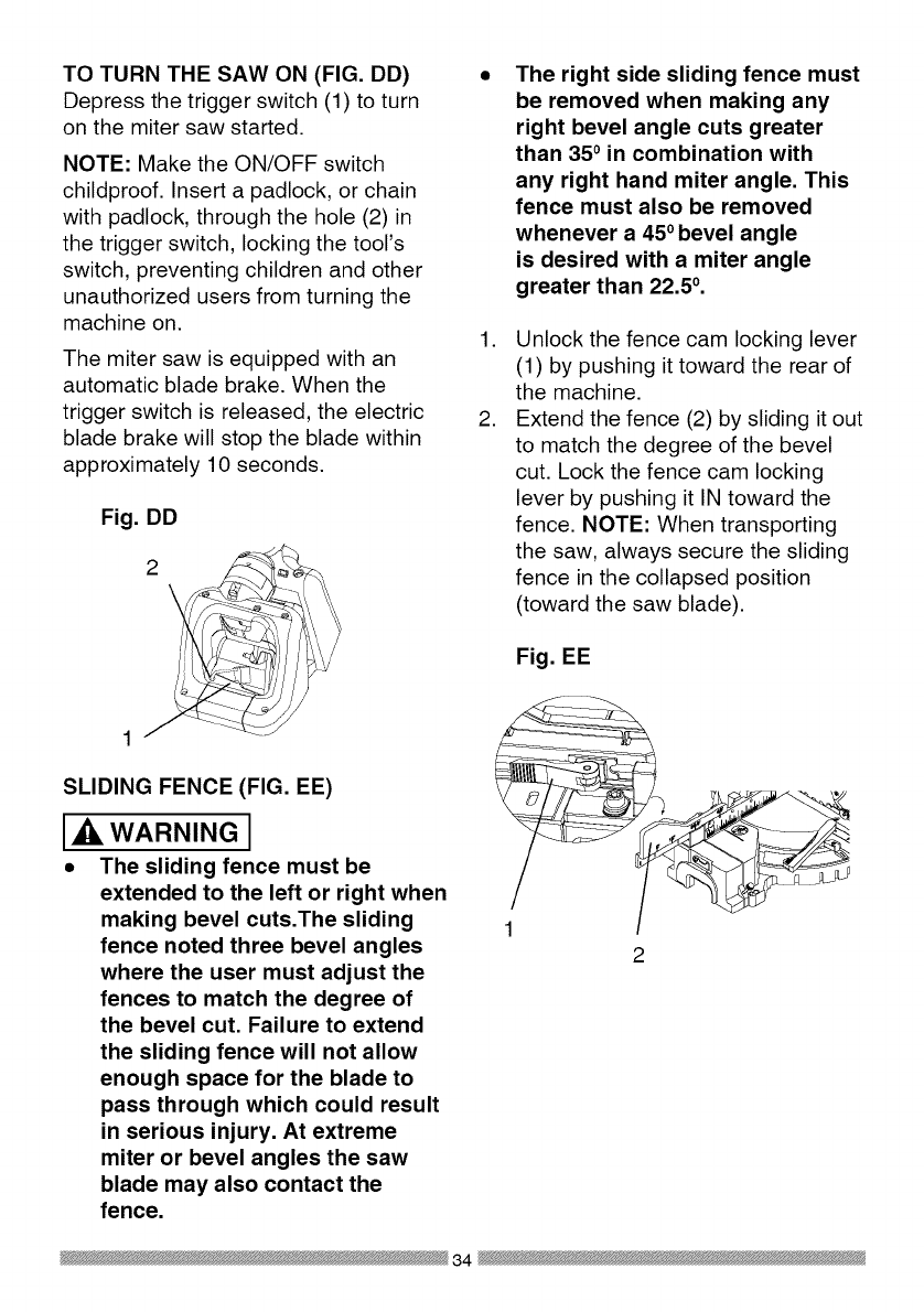
TO TURN THE SAW ON (FIG. DD)
Depress the trigger switch (1) to turn
on the miter saw started.
NOTE: Make the ON/OFF switch
childproof. Insert a padlock, or chain
with padlock, through the hole (2) in
the trigger switch, locking the tool's
switch, preventing children and other
unauthorized users from turning the
machine on.
The miter saw is equipped with an
automatic blade brake. When the
trigger switch is released, the electric
blade brake will stop the blade within
approximately 10 seconds.
Fig. DD
2\
.
,
The right side sliding fence must
be removed when making any
right bevel angle cuts greater
than 350 in combination with
any right hand miter angle. This
fence must also be removed
whenever a 450bevel angle
is desired with a miter angle
greater than 22.50.
Unlock the fence cam locking lever
(1) by pushing it toward the rear of
the machine.
Extend the fence (2) by sliding it out
to match the degree of the bevel
cut. Lock the fence cam locking
lever by pushing it IN toward the
fence. NOTE: When transporting
the saw, always secure the sliding
fence in the collapsed position
(toward the saw blade).
Fig. EE
SLIDING FENCE (FIG. EE)
WARNING J
•The sliding fence must be
extended to the left or right when
making bevel cuts.The sliding
fence noted three bevel angles
where the user must adjust the
fences to match the degree of
the bevel cut. Failure to extend
the sliding fence will not allow
enough space for the blade to
pass through which could result
in serious injury. At extreme
miter or bevel angles the saw
blade may also contact the
fence.
34

REMOVING OR INSTALLING THE
RIGHT SLIDING FENCE
Removing (Fig. FF)
1. Unlock the fence cam-locking lever
by pushing it out toward the rear of
the machine.
2. Lift up on the sliding fence to
remove it from the saw.
Installing
1. Place the sliding fence onto the
miter saw fence aligning the nut (1)
with the slot (4).
2. To lock the sliding fence, push the
cam-locking lever in toward the
front of the machine.
Fig. FF
1 __............. JJ
..........÷I, ,d,I U,d, 4
SLIDING CARRIAGE SYSTEM (FIG.
GG)
Ak, WARNING I
To reduce the risk of injury, return
carriage to the full rear position after
each crosscut operation.
1. For a chop cutting operations on
small workpieces, slide the cutting
head assembly completely toward
the rear of the unit and tighten the
carriage lock knob (1).
2. To cut wide boards up to 12-1/4 in.,
the carriage lock knob should be
loosened to allow the cutting head
to slide freely.
Fig. GG
WARNINGI
To avoid injury from materials being
thrown, always unplug the saw
to avoid accidental starting, and
remove small pieces of material from
the table cavity. The table insert may
be removed for this purpose, but
always reattach the table insert prior
to performing a cutting operation.
MITER CUT (FIG. HH)
The sliding compound miter saw is
equipped with ten positive miter stops
(1) on the saw base. The locations are
at O, 15, 22.5, 31.6 and 45 degrees
left and right, and 60° right. These
locations represent the most common
angles for cutting operation. To make a
miter cut:
1. Unlock the miter table by lifting up
on the miter quick-cam table lock
(2).
2. While raising the positive stop
locking lever (3) up, grasp the miter
handle (4) and rotate the miter
table left or right to the desired
angle.
3. Release the positive stop locking
lever and set the miter at the
desired angle making sure the
lever snaps into place. NOTE: The
lever will only lock into place at one
of the ten positive stops.
35
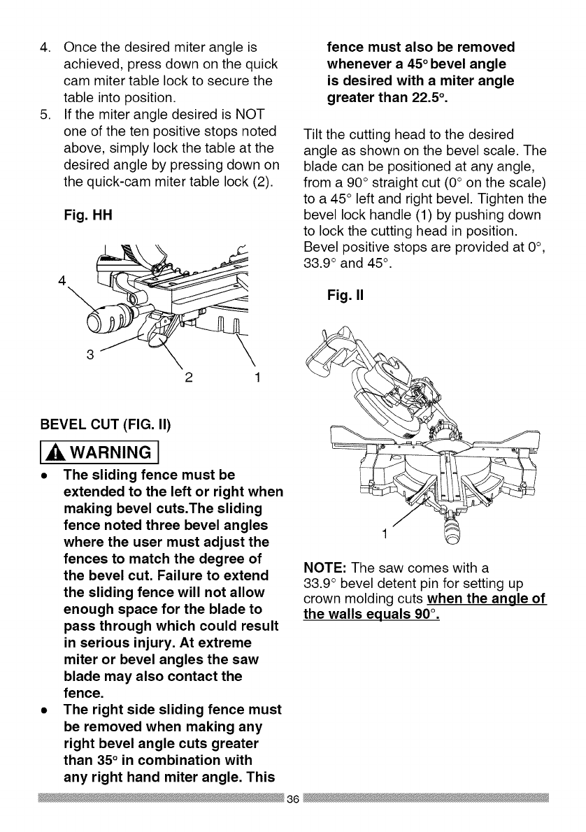
4. Once the desired miter angle is
achieved, press down on the quick
cam miter table lock to secure the
table into position.
5. If the miter angle desired is NOT
one of the ten positive stops noted
above, simply lock the table at the
desired angle by pressing down on
the quick-cam miter table lock (2).
Fig. HH
2 1
BEVEL CUT (FIG. II)
WARNING J
• The sliding fence must be
extended to the left or right when
making bevel cuts.The sliding
fence noted three bevel angles
where the user must adjust the
fences to match the degree of
the bevel cut. Failure to extend
the sliding fence will not allow
enough space for the blade to
pass through which could result
in serious injury. At extreme
miter or bevel angles the saw
blade may also contact the
fence.
•The right side sliding fence must
be removed when making any
right bevel angle cuts greater
than 35° in combination with
any right hand miter angle. This
fence must also be removed
whenever a 45° bevel angle
is desired with a miter angle
greater than 22.5 °.
Tilt the cutting head to the desired
angle as shown on the bevel scale. The
blade can be positioned at any angle,
from a 90° straight cut (0° on the scale)
to a 45° left and right bevel. Tighten the
bevel lock handle (1) by pushing down
to lock the cutting head in position.
Bevel positive stops are provided at 0°,
33.9 ° and 45 °.
Fig. II
NOTE: The saw comes with a
33.9 ° bevel detent pin for setting up
crown molding cuts when the angle of
the walls equals 90° .
36
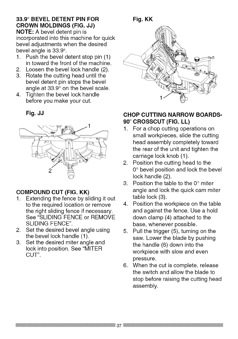
33.9 °BEVEL DETENT PIN FOR
CROWN MOLDINGS (FIG. JJ)
NOTE: A bevel detent pin is
incorporated into this machine for quick
bevel adjustments when the desired
bevel angle is 33.9 °.
1. Push the bevel detent stop pin (1)
in toward the front of the machine.
2. Loosen the bevel lock handle (2).
3. Rotate the cutting head until the
bevel detent pin stops the bevel
angle at 33.9 ° on the bevel scale.
4. Tighten the bevel lock handle
before you make your cut.
Fig. JJ
COMPOUND CUT (FIG. KK)
1. Extending the fence by sliding it out
to the required location or remove
the right sliding fence if necessary.
See "SLIDING FENCE or REMOVE
SLIDING FENCE".
2. Set the desired bevel angle using
the bevel lock handle (1).
3. Set the desired miter angle and
lock into position. See "MITER
CUT".
Fig. KK
CHOP CUTTING NARROW BOARDS-
90° CROSSCUT (FIG. LL)
1. For a chop cutting operations on
small workpieces, slide the cutting
head assembly completely toward
the rear of the unit and tighten the
carriage lock knob (1).
2. Position the cutting head to the
0° bevel position and lock the bevel
lock handle (2).
3. Position the table to the 0° miter
angle and lock the quick cam miter
table lock (3).
4. Position the workpiece on the table
and against the fence. Use a hold
down clamp (4) attached to the
base, whenever possible.
5. Pull the trigger (5), turning on the
saw. Lower the blade by pushing
the handle (6) down into the
workpiece with slow and even
pressure.
6. When the cut is complete, release
the switch and allow the blade to
stop before raising the cutting head
assembly.
37

Fig. LL
3
SLIDE CUTTING WIDE BOARDS UP
TO 12-1/4 IN. WIDE (FIG. MM)
WARNING I
To avoid injury:
• Never pull the cutting head
assembly and spinning blade
toward you during the cut, The
blade may try to climb up on the
top of the workpiece, causing the
cutting assembly and spinning
blade to kick back, forcefully, The
cutting head assembly should
be drawn back completely then
pushed forward when sawing,
•Let the blade reach full speed
before cutting, This will help
reduce the risk of a thrown
workpiece,
•Extending the fence by sliding
it out to the required location or
remove the right sliding fence if
necessary, See "SLIDING FENCE
or REMOVE SLIDING FENCE",
3. Set both the desired bevel angle
and/or the miter angle and lock into
position.
4. If bevel cutting, set both the left
and right sliding fences (2) to their
proper location.
5. Use a hold down clamp to secure
the workpiece.
6. Grasp the switch handle (3) and
pull the carriage (4) forward until
the center of the saw blade is over
the front of the workpiece (5).
7. Pull the trigger (6) to turn the saw
on.
8. When the saw reaches full speed,
push the saw handle down, slowly,
cutting through the leading edge of
the workpiece.
9. Slowly move the saw handle toward
the fence, completing the cut.
10. Release the trigger and allow
the blade to stop spinning before
allowing the cutting head to raise.
Fig, MM
1 6
3
5
CUT WIDE BOARDS (FIG, MM)
1. Rotate the two upfront supports (7)
toward the rear of the saw.
2. Unlock the carriage lock knob
(1) and allow the cutting head
assembly to move freely.
38

CUTTING BOWED MATERIAL (FIG.
NN)
WARNING I
To avoid injury from materials being
thrown, always unplug the saw to
avoid accidental starting and remove
small pieces of material from the
table cavity. The table insert may be
removed for this purpose, but always
reattach table insert prior to performing
a cutting operation.
A bowed workpiece must be positioned
against the fence and secured with
a clamping device as shown before
cutting. Do not position workpiece
incorrectly or try to cut the workpiece
without the support of the fence. This
will cause the blade to bind and could
result in personal injury.
Fig. NN
ROUGH CUTTING A DADO (FIG. OO)
1. Mark lines identifying the width
and depth of the desired cut on
the workpiece and position on the
table so the inside tip of the blade
is positioned on the line. Use a
hold down clamp to secure the
workpiece.
2. Lower the cutting head so the tip of
the blade touches the top surface
workpiece at the marked line.
3. While holding the upper arm in
position, turn the stop knob (2) until
it touches the stop plate (1).
4. Cut two parallel grooves as shown
below.
Fig. OO
Cut these grooves
with saw
Use a chisel to cut
out the middle
TELESCOPING WORKPIECE
SUPPORT & REPETITIVE CUTTING
USING THE STOP PLATE (FIG. PP)
Long pieces need extension table
support.
1. Loosen the knob (1) then slide the
extension table to desired position
and tighten the knob.
2. The stop plate is designed for use
during repetitive cutting. Only use
one stop plate at a time. Rotate the
stop plate (3) to vertical position,
and retighten the locking bolt. If
stop plate will not rotate, loosen the
locking bolt (2) 1/4 turn.
39

Fig. PP
\
/
/
AUXILIARY WOOD FENCE (FIG. QQ)
When making multiple or repetitive cuts
that result in cut-off pieces of one inch
or less, it is possible for the saw blade
to catch the cut-off piece and throw it
out of the saw or into the blade guard
and housing, possibly causing damage
or injury. To minimize this an auxiliary
wood fence can be mounted to your
saw. Holes are provided in the saw
fence to attach an auxiliary wood fence
(this provides additional depth of cut).
This fence should be constructed of
straight auxiliary wood approximately
3/4 in. thick by 1-1/2 in. high by 22 in.
long. Attach the wood fence securely
and make a full depth cut to make
a blade slot. Check for interference
between the wood fence and the lower
blade guard. Adjust if necessary.
Fig. QQ
Blade slot
CHANGING THE BELT (FIG. RR, SS)
• Unplug your saw.
1. Loosen the bolts (1) and remove
the belt cover.
2. Turn the screw (2) anti-clockwise
with a hex wrench to move the
motor to forward.
3. Remove and replace the belt.
4. Turn the screw (2) clockwise with
a hex wrench to move the motor to
rearward. Do not over tighten.
5. Replace the belt cover and tighten
the bolts.
Fig. RR
Fig. SS
40
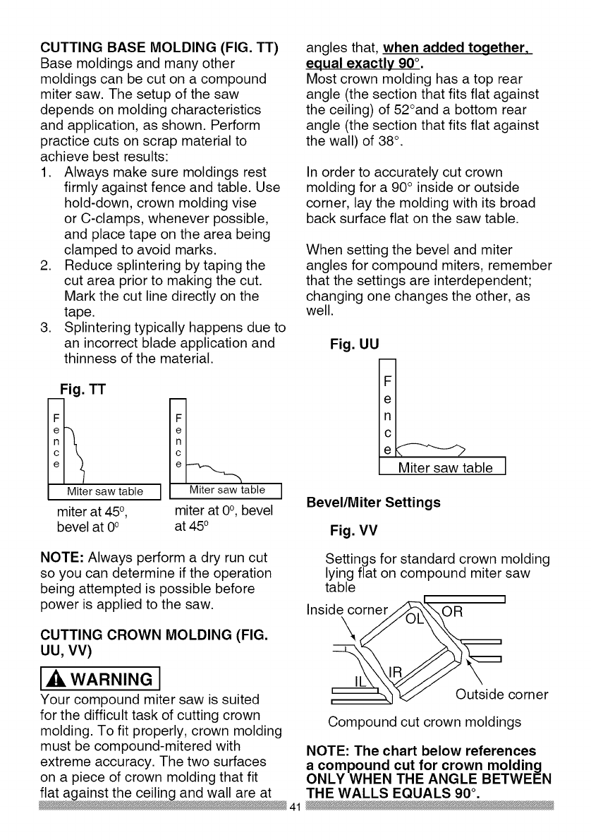
CUTTING BASE MOLDING (FIG. TT)
Base moldings and many other
moldings can be cut on a compound
miter saw. The setup of the saw
depends on molding characteristics
and application, as shown. Perform
practice cuts on scrap material to
achieve best results:
1. Always make sure moldings rest
firmly against fence and table. Use
hold-down, crown molding vise
or C-clamps, whenever possible,
and place tape on the area being
clamped to avoid marks.
2. Reduce splintering by taping the
cut area prior to making the cut.
Mark the cut line directly on the
tape.
3. Splintering typically happens due to
an incorrect blade application and
thinness of the material.
Fig. TT
Miter saw table
miter at 450,
bevel at 0°
_table
miter at 0°, bevel
at 450
angles that, when added together,
equal exactly 90 °.
Most crown molding has a top rear
angle (the section that fits flat against
the ceiling) of 52°and a bottom rear
angle (the section that fits flat against
the wall) of 38°.
In order to accurately cut crown
molding for a 90° inside or outside
corner, lay the molding with its broad
back surface flat on the saw table.
When setting the bevel and miter
angles for compound miters, remember
that the settings are interdependent;
changing one changes the other, as
well.
Fig. UU
ne
Miter saw table
Bevel/Miter Settings
Fig. VV
NOTE: Always perform a dry run cut
so you can determine if the operation
being attempted is possible before
power is applied to the saw.
CUTTING CROWN MOLDING (FIG.
UU, VV)
WARNING I
Your compound miter saw is suited
for the difficult task of cutting crown
molding. To fit properly, crown molding
must be compound-mitered with
extreme accuracy. The two surfaces
on a piece of crown molding that fit
flat against the ceiling and wall are at
Settings for standard crown molding
lying flat on compound miter saw
table ]
Inside corner OR
\
,-._1
Outside corner
Compound cut crown moldings
NOTE: The chart below references
a compound cut for crown molding
ONLY WHEN THE ANGLE BETWEEN
THE WALLS EQUALS 90 °.
41

Bevel/Miter Settings
KEY BEVEL MITER
SETTING SETTING
TYPE OF CUT
IL 33.9 °
IR 33.9 °
OL 33.9 °
OR 33.9 °
31.6 o Right
31.6 ° Left
31.6 ° Left
31.6 o Right
Inside corner-Left side
1. Position top of molding against fence.
2. Miter table set at RIGHT 31.6 ° .
3. LEFT side is finished piece.
Inside corner-Right side
1. Position bottom of molding against fence.
2. Miter table set at LEFT 31.6 °.
3. LEFT side is finished piece.
Outside corner-Left side
1. Position bottom of molding against fence.
2. Miter table set at LEFT 31.6 °.
3. RIGHT side is finished piece.
Outside corner-Right side
1. Position top of molding against fence.
2. Miter table set at RIGHT 31.6 ° .
3. RIGHT side is finished piece.
42

CROWN MOLDING CHART
Compound Miter saw
Miter and bevel Angle settings
Wall to Crown Molding Angle
52/38 ° C_wn Molding 45/45 ° C_wn Molding
Angle Miter Bevel Miter Bevet Angle
Between Setting Setting Setting Setting Between
Walls Wails
67 42.93 41.08 46.89 36.13 124
68 42.39 40.79 46.35 35.89 128
69 41.85 40.80 45.81 35.64 126
70 41.32 40.20 48.28 38.40 127
71 40.79 39.90 44.78 35.18 128
72 40.28 39.61 44.22 34.89 129
73 39.76 39.30 43.70 34.64 130
74 39.28 39.00 43.18 35.38 131
75 38.74 38.69 42.66 34.12 132
76 38.24 38.39 42.15 33.86 133
77 37.74 38.08 41.64 33.60 134
78 37.24 37.76 41.13 33.33 138
79 36.75 37.45 40.62 33.07 136
80 36.27 37.13 40.12 32.80 137
81 35.79 36.81 39.62 32.53 138
82 35.31 36.49 39.13 32.28 139
83 34.83 36.17 38.63 31.98 140
84 34.36 35.88 38.14 31.70 141
88 33.90 38.82 37.66 31.42 142
86 33.43 35.19 37.17 31.34 143
87 32.97 34.86 36.69 30.86 144
88 32.82 34.83 36.21 30.87 148
89 32.07 34.20 38.74 30.29 146
90 31.62 33.86 38.26 30.00 147
91 31.17 33.83 34.79 29.71 148
92 30.73 33.19 34.33 29.42 149
93 30.30 32.86 33.86 29.13 150
94 29.86 32.51 33.40 28.83 151
95 29.43 32.17 32.94 28.84 182
96 29.00 31.82 32.48 28.24 183
97 28.88 31.48 32.02 27.94 154
98 28.16 31.13 31.58 27.64 188
99 27.74 30.78 31.13 27.34 156
100 27.32 30.43 30.68 27.03 157
101 26.91 30.08 30.24 26.73 158
102 26.50 29.73 29.80 26.42 189
103 26.09 29.38 29.36 26.12 160
104 25.69 29.02 28.92 25.81 161
105 25.29 28.67 28.48 25.80 162
106 24.89 28.31 28.05 25.19 163
107 24.49 27.96 27.62 24.87 164
108 24.10 27.89 27.19 24.86 168
109 23.71 27.23 26.77 24.24 166
110 23.32 26.87 26.34 23.93 167
111 22.93 26.51 25.92 23.61 168
112 22.88 26.18 28.50 23.29 169
113 22.17 25.78 25.08 22.97 170
114 21.79 25.42 24.66 22.66 171
118 21.42 28.05 24.25 22.33 172
116 21.04 24.68 23.84 22.01 173
117 20.67 24.31 23.43 21.68 174
118 20.30 23.94 23.02 21.36 175
119 19.93 23.57 22.61 21.03 176
120 19.87 23.20 22.21 20.70 177
121 19.20 22.83 21.80 20.38 178
122 18.84 22.46 21.40 20.05 179
123 18.48 22.09 21.00 19.72
82/38 °Crown Molding 45/45 ° Crown Molding
Miter Bevel Miter Bevel
Setting Setting Setting Setting
18.13 21.71 20.61 19.39
17.77 21.34 20.21 19.06
17.42 20.96 19.81 18.72
17.06 20.89 19.42 18.39
16.71 20.21 19.03 18.06
16.37 19.83 18.64 17.72
16.02 19.48 18.25 17.39
18.67 19.07 17.86 17.08
15.33 18.69 17.48 16.71
14.99 18.31 17.09 16.38
14.66 17.93 16.71 16.04
14.30 17.58 16.32 15.70
13.97 17.17 15.94 15.36
13.63 16.79 18.86 18.02
13.30 16.40 18.19 14.62
12.96 16.02 14.81 14.34
12.63 15.64 14.43 14.00
12.30 15.28 14.06 13.68
11.97 14.87 13.68 13.31
11.64 14.48 13.31 12.97
11.31 14.09 12.94 12.62
10.99 13.71 12.87 12.29
10.66 13.32 12.20 11.93
10.34 12.93 11.83 11.89
10.01 12.84 11.46 11.24
9.69 12.16 11.09 10.89
9.37 11.77 10.73 10.85
9.05 11.38 10.36 10.20
8.73 10.99 10.00 9.85
8.41 10.60 9.63 9.50
8.09 10.21 9.27 9.15
7.77 9.82 8.91 8.80
7.46 9.43 8.88 8.45
7.14 9.04 8.19 8.10
6.82 8.68 7.83 7.75
6.81 8.26 7.47 7.40
6.20 7.86 7.11 7.05
8.88 7.47 6.75 6.70
5.57 7.08 6.39 6.35
5.26 6.69 6.03 6.00
4.95 6.30 5.68 5.65
4.63 5.90 5.32 5.30
4.32 5.51 4.96 4.94
4.01 5.12 4.61 4.89
3.70 4.72 4.25 4.24
3.39 4.33 3.90 3.89
3.08 3.94 3.84 3.53
2.77 3.84 3.19 3.10
2.47 3.18 2.83 2.83
2.15 2.75 2.48 2.47
1.85 2.36 2.12 2.12
1.84 1.97 1.77 1.77
1.23 1.58 1.41 1.41
0.92 1.18 1.06 1.06
0.62 0.79 0.71 0.71
0.31 0.39 0.38 0.35
43

MAINTENANCE
DANGER I
To avoid injury, never put lubricants
on the blade while it is spinning.
_IL WARNING I
To avoid fire or toxic reaction, never
use gasoline, naphtha acetone,
lacquer thinner or similar highly
volatile solvents to clean the miter
saw.
_IL WARNING I
To avoid injury from unexpected
starting or electrical shock, unplug
the power cord before working on
the saw.
the carbon part fits into. Tighten the
cap snugly, but do not overtighten.
NOTE: To reinstall the same brushes,
first make sure the brushes go back in
the way they came out. This will avoid
a break-in period that reduces motor
performance and increases wear.
Fig. WW 2
_IL WARNING I
For your safety, this saw is double-
insulated. To avoid electrical shock,
fire or injury, use only parts identical
to those identified in the parts list.
Reassemble exactly as the original
assembly to avoid electrical shock.
REPLACING CARBON BRUSHES
(FIG. WW)
Replace both carbon brushes when
either has less than 1/4 in. length of
carbon remaining, or if the spring or
wire is damaged or burned. To inspect
or replace brushes, first unplug the
saw. Then remove the black plastic
cap (1) on the side of the motor (2).
Remove the cap cautiously, because
it is springloaded. Then pull out the
brush and replace. Replace for the
other side. To reassemble reverse the
procedure. The ears on the metal end
of the assembly go in the same hole
LOWER BLADE GUARD
Do not use the saw without the lower
blade guard. The lower blade guard is
attached to the saw for your protection.
Should the lower guard become
damaged, do not use the saw until the
damaged guard has been replaced.
Develop a regular check to make sure
the lower guard is working properly.
Clean the lower guard of any dust or
buildup with a damp cloth.
IXlWARNINGI
•When cleaning the lower guard,
unplug the saw from the power
source receptacle to avoid
unexpected startup.
•Do not use solvents on the guard.
They could make the plastic
"cloudy" and brittle.
44

SAWDUST
Periodically, sawdust will accumulate
under the work table and base. This
could cause difficulty in the movement
of the worktable when setting up
a miter cut. Frequently blow out or
vacuum up the sawdust.
WARNING J
If blowing sawdust, wear proper
eye protection to keep debris from
entering eyes.
LUBRICATION (FIG. XX)
All the motor bearings in this tool are
lubricated with a sufficient amount of
high grade lubricant for the life of the
unit under normal operating conditions;
therefore, no further lubrication is
required.
Lubricate the Following as necessary:
Chop pivot: Apply light machine oil to
points indicated in illustration.
Central pivot of plastic guard: Use
light household oil (sewing machine
oil ) on metal-to-metal or metal-to-
plastic guard contact areas as required
for smooth, quiet operation. Avoid
excessive oil, to which sawdust will
cling.
Fig. XX
Chop pivot Central pivot of
plastic guard
45

WARNING I
To avoid injury from accidental starting, always turn switch OFF and unplug
the tool before moving, replacing the blade or making adjustments,
TROUBLESHOOTING GUIDE -MOTOR
PROBLEM PROBLEM CAUSE
Brake does
not stop blade
within 10
seconds.
Motor does
not start
Brush spark
when switch
released.
,
2.
.
4.
.
1.
2.
3.
,
2.
Motor brushes not sealed 1.
or lightly sticking.
Motor brake overheated 2.
from use of defective or
wrong size blade or rapid
ON/OFF cycling. 3.
Arbor bolt loose.
Brushes cracked,
damaged, etc. 4.
Other. 5.
Limit switch failure 1.
Brush worn. 2.
Fuse blown or circuit
breaker tripped on home 3.
panel.
Brush worn. 1.
Other.
,
SUGGESTED CORRECTIVE
ACTION
Inspect/clean/replace brushes.
See MAINTENANCE section.
Use a recommended blade. Let
cool down. See REMOVING OR
INSTALLING THE BLADE section.
Retighten. See REMOVING
OR INSTALLING THE BLADE
section.
Replace brushes.
Contact Sears Service Center.
Replace limit switch.
Replace brushes. See
MAINTENANCE section.
Verify there is electrical power at
the outlet.
Replace Brushes. See
MAINTENANCE section.
Contact Sears Service Center.
46

TROUBLESHOOTING GUIDE -SAW OPERATION
SUGGESTED CORRECTIVE
PROBLEM PROBLEM CAUSE ACTION
1. Misalignment. See ADJUSTMENT -Setting
Cutting Depth section.
1. Miter table unlocked. See OPERATION - Miter Angle
2. Sawdust under table. Adjustment section.
Vacuum or blow out dust. WEAR
EYE PROTECTION.
1. Loose pivot points. Contact Sears Service Center.
Blade hits
table.
Angle of cut
not accurate.
Can not
adjust miter.
Cutting arm
wobbles.
Cutting arm
will not fully
raise, or
blade guard
won't fully
close.
Blade binds,
ams, burns
wood.
Saw vibrates
or shakes.
1. Pivot spring not replaced
properly after service.
2. Sawdust build-up.
1. Improper operation.
2. Dull or warped blade.
3. Improper blade size.
4 Wood is moving during
cut.
1. Saw blade not round /
damaged /loose.
2. Arbor bolt loose.
.
1.
2.
1.
1.
2.
Contact Sears Service Center.
Clean and lubricate moving
parts.
1. See BASIC SAW OPERATION
section.
2. Replace or sharpen blade.
3. Replace with 12 in. diameter
blade.
4. Use hold down clamp to secure
workpiece to table.
1. Replace blade.
2. Tighten arbor bolt.
47

12 in. COMPOUND MITER SAW MODEL NO. 137.212210
2680 LOCATOR PIN
2752 TRADE-MARK LABEL
2753 TILTING SCALE
07X8 ELBOW
083Z CORD CLAMP
084J STOP CLAMP
084K SET PLATE
084M STOP CLAMP
084Q COMPRESSION SPRING
OCH1 SHAFT-PIVOT
OCH2 SLEEVE
OCHF SPRING GUARD
OCKM TRIGGER
ODTZ ARBOR COLLAR
OFHW COLLAR
OJ4E FLAT WASHER cp6_13-1
OJ4F FLAT WASHER cp8_16-2.5
0J53 FLAT WASHER q_8.4_24-2
OJA8 EXTERNALTOOTH LOCK WASHER cp8
OJBO WAVE WASHER
OJB3 WAVE WASHER
OJET E-RING
OJUA HEX. SOC. HD. CAP BOLT M5_0.8-8
OJUL HEX. SOC. HD. CAP BOLT M6_1.0-20
OJUX HEX. SOC. HD. CAP BOLT M8_1.25-30
OJV2 HEX. SOC. HD. CAP BOLT M8_1.25-60
OJVQ HEX. SOC. HD. CAP BOLT M8_1.28-50
OJZF HEX. SOC. SETSCREW M6"1.0-10
OK2B HEX. SOC. HD. CAP SCREW M6_1.0-16
OK4D CR. RE. PAN HD. SCREW & WASHER M6_1.0-12
OK7X CR. RE. TRUSS HD. ROUND NECK SCREW M6_1.0-10
OKB6 CR. RE. PAN HD. TAPPING SCREW M4_18-35
OKB7 CR. RE. PAN HD. TAPPING SCREW M4_18-16
OKB8 CR. RE. PAN HD. TAPPING SCREW M4"18-20
OKC6 CR. RE. TRUSS HD. TAPPING SCREW M4"16-12
OKD4 CR. RE. PAN HD. SCREW M6_1.0-10
OKD8 CR. RE. PAN HD. SCREW M4_0.7-12
OKDH CR. RE. PAN HD. SCREW M5_0.8-8
OKDU CR. RE. PAN HD. SCREW M6_1.0-12
OKL1 CR. RE. PAN HD. ROUND NECK SCREW M6_1.0-12
OKQY LOCK NUT M8_1.25 T=8
OKTP CABLE CLAMP
OKUW TERMINAL
PARTS LIST FOR SAW SCHEMATIC A
I.D. Description Size Qty I.D. Qfy
1888 CR. RE. PAN HD. TAPPING SCREW M6_14-16
Description Size
3LMH LOCKING CABLETIE
3S2X LOCK HANDLE ASS'Y
145V HEX WASHER HD BOLT M8"1.25-16
246V TRIGGER SWITCH
25Y1 ARM #AW
25YJ CRANK HANDLE
25YL CRANK HANDLE
25YR PLATE
25YU DUST BAG
262N SEGMENT HANDLE
262U GEAR BOX COVER #AW
267Y PULLEY
26H6 V-RIBBED BElT(POIYOURETHANE)
26PW SPACER
26U8 LOCKING HANDLE ASS'Y
Z6UJ PC-GUARD ASS'Y
Z6UK GEAR SHAFT ASS'Y
26UL CUTTER SHAFT ASS'Y
Z77Y CR. RE. PAN HD. TAPPING SCREW M6 _14-25
27KD LEVER
27KE CUTTER SHAFT GUARD
27KY CLAMP BOLT
Z7LP LOCK KNOB
Z7PF COMPRESSION SPRING
Z7WC COMPRESSION SPRING
Z83G HEX. SOC. HD. CAP SCREW M5"0.8-20
2B62 HEX. HD. BOLT M6"1.0-16
2CGT SLOTTED SETSCREW M6_1.0-8
2E63 ROCKER SWITCH
2JSX SEGMENT HANDLE
ZK96 WARNING LABEL
ZLK2 LASER PLUNGER HOUSING
2MNJ CONTROLLER ASS'Y
2MYA LEAD WIRE ASS'Y
ZNNJ SEGMENT HANDLE
2NQC MOTOR ASS'Y
2P4U PLUNGER HOUSING ASSW
ZQC6 LABEL
ZQK4 BLADE
2QU3 OPERATOR'S MANUAL
2QYA PULLEY COVER
ZSJT POWER CABLE
Y_43B CR. RE. COUNT HD. SCREW M5_0.8-25
48
_ik WARNING I
When servicing use only CRAFTSMAN replacement parts. Use of any other
parts many create a HAZARD or cause product damage. Any attempt to
repair or replace electrical parts on this Miter Saw may create a HAZARD
unless repair is done by a qualified service technician. Repair service is
available at your nearest Sears Service Center.
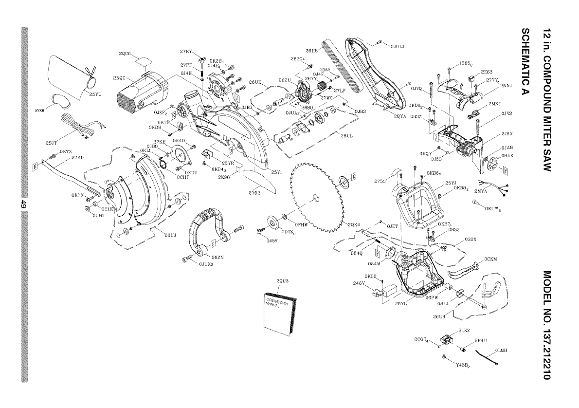
262U
145V
2QU3 246_
2LK2
2CG'['4_i 2P4_
OI,MH
43B z
0
I1"1
I"
Z
0
".4
k)
o

12 in. COMPOUND MITER SAW MODEL NO. 137.212210
PARTS LIST FOR SAW SCHEMATIC B
I.D. Description Size
0831 SHAFT SLEEVE
2750 CAUTION LABEL
2841 CENTER SHAFT
OCEZ PLUNGER HANDLE
OD7Z KNOB-HANDLE
ODW5 POWER CORD CLAMP
OH9W CLEVIS PiN
OHAM DUST SHIELD
OHAN PLATE COVER
OHAP SLIDE-BAR GUIDE CLAMP
OHVD BALL BEARING
OHXX LINEAR MOTION BEARING
OJ4N FLAT WASHER @16_30-3
OJ6A FLAT WASHER q_8_16-2.5
0J78 FLAT WASHER 1/4_1/2-3/32
OJ7D FLAT WASHER 5/1639/16-1/16
OJ7K FLAT WASHER 3/8329/32-5/64
OJ8P FLAT WASHER 3/8_29/32-5/64
OJAF EXTERNAL TOOTH LOCK WASHER @5
OJB0 WAVE WASHER WW-8
OJMN O-RING
OJMP O-RING
OJMT O-RING ROD
OJPP HEX. HD. BOLT M8_1.25-30
OJUM HEX. SOC. HD. CAP BOLT M6_1.0-25
OJUW HEX. SOC. HD. CAP BOLT M8_1.25-25
OJX3 HEX. SOC. SETSCREW M5_0.8-8
OJXD HEX. SOC. SETSCREW M6_1.0-25
OJXG HEX. SOC. SETSCREW M8_1.25-16
OK2B HEX. SOC. HD. CAP SCREW M6_1.0-16
OK7F CR. RE. ROUND WASHER HD. SCREW M5_0.8-8
OK7X CR. RE. TRUSSHD. ROUND NECK SCREW M6_1.0-10
OKAE CR. RE. PAN HD. TAPPING SCREW M5_0.8-10
OKB3 CR. RE. PAN HD. TAPPING SCREW M4_18-8
OKD9 CR. RE. PAN HD. SCREW M4_0.7-16
OKDH CR. RE. PAN HD. SCREW M5_0.8-8
OKDM CR. RE. PAN HD. SCREW M5_0.8-20
OKDR CR. RE. PAN HD. SCREW M5_0.8-10
OKDV CR. RE. PAN HD. SCREW M6_1.0-16
OKMS HEX. NUT M6_1.0T=5
OKMY HEX. NUT M8_1.25 T=6.5
OKQY LOCK NUT M8_1.25 T=8
OKQZ NUT M10_1.5 T=IO
OKR1 LOCK NUT M16_2.0 T=16
Qty I.D.
OKR4
OKSP
25XZ
25YG
25YK
262Q
262R
262S
262V
26HX
26LU
26NH
26NP
26NQ
26NR
26NS
26P7
26PU
26U6
26UQ
27BC
27BU
27BV
27HE
27J9
27JA
27MN
27Y4
283H
290M
2A J3
2DUC
2ED6
2JT2
2NGV
2NGW
2NKR
2NLC
2NLK
2RAX
2RAY
2SY9
Y648
Description Size Qty
LOCK NUT M8_1.25 T=8 1
STRAIN RELIEF 1
ARM-MITER #AW 1
NEEDLE POINTER 1
SETPLATE 1
TILTPOINTER 1
TILTPOINTER #23 1
POWER CORD CLAMP 2
ANCHOR PLATE #06 1
GUIDE HOLDER 1
WARNING LABEL 1
SPECIAL NUT 1
SPECIAL BOLT 1
LOCATING BAR 1
SHAFT-PWOT 1
LOCKING ROD 1
SHAFT-PWOT 1
MITER BAR 1
LOCKING HANDLE ASS'Y 1
BRACKET-TILT 1
SAFETY CLAMP ASS'Y 1
TABLE INSERT 1
TABLE INSERT 1
TORSION SPRING 1
SETNUT 1
SCREW STOP 1
ANCHOR PLATE 1
HEX. SOC. SET SCREW M631.0-16 2
HEX. SOC. HD. CAP SCREW M530.8-12 4
CAUTION LABEL 1
CLAMP HANDLE #AW 1
CR. RE.TRUSS HD. SCREW M5_0.8-8 1
CAUTION LABEL 1
STEELBALL 2
SUPPORT(LEFT) #AW 1
SUPPORT(RIGHT) #AW 1
SPECIAL BOLT 2
SPRING 2
TABLE #AW 1
LOCK KNOB 1
PLATE 1
SLIDE-BAR ASS'Y 1
COMPRESSION SPRING 1
5O

26HX /
26PU
/27BC
2SY9
\\\
_?HE
", 083I__
, 27J9
OH9W
26P7
\OJBO
262V
25YK /
0Jppz /
./
0KMYa
OJXO /
26NS ENGV
25YG /
Z .N"
Ill •
0
w 0
C
Z
o
-I
r,n
r_
0
o
I'll
r-
Z
0
0)
o

12 in. COMPOUND MITER SAW
PARTS LIST FOR SAW SCHEMATIC C
I.D. Description Size
2258 SPECIAL BOLT I
2754 WARNING LABEL I
082J CUSHION 2
082L BOLT 2
0CDD FOOT 4
0CFX SLIDE PLATE 3
0DTH CENTER BOLT t
0DVJ BLADE WRENCH 1
0H9A REAR EXTENSION STAY I
0J69 FLAT WASHER cp6"13-I I
0J88 FLAT WASHER #I0"t/2-1/16 2
Qty I.D. Description
MODEL NO. 137.212210
0JB0 WAVE WASHER WW-8
0JUB HEX. SOC. HD. CAP BOLT M5_0.8-12
0JZF HEX. SOC. SETSCREW M6"1.0-10
0K28 HEX. SOC. HD. CAP SCREW M5"0.8-16
0K2P HEX. SOC. HD.CAP SCREW M8_1.25-40
0K55 CR. RE. COUNT HD. SCREW M5_0.8-8
0K74 CR. RE. TRUSSHD. SCREW M6"1.0-8
0KAE CR. RE. PAN HD. TAPPING SCREW M5_0.8-10
0KDG CR. RE. PANHD. SCREW
0KDH CR. RE. PANHD. SCREW
0KDM CR. RE. PANHD. SCREW
0KDU CR. RE. PANHD. SCREW
0KR2 LOCK NUT
0KR3 LOCK NUT
0LYT STEELBALL
20PL CLAMP HANDLE
224U ROLL PIN
23SR COMPRESSION SPRING
M5_0.8-6
M5_0.8-8
M5"0.8-20
M6_'1.0-12
M5_0.8 T=5
M6_1.0 T=6
2
2
t
4
4
4
4
2
2
1
2
2
2
2
2
2
2
2
25V3 KNOB
25XX BASE
25Y0 ASSIST-FENCE
25Y2 EXTENSION WING
25Y3 ASSIST-FENCE
25Y6 EXTENSION WING
25Y8 FENCE
25YA LOCKING HANDLE ASS'Y
25YV PLATE
25YW PLATE (RIGHT)
262T FENCE PLATE
Size Qty
4
#AW I
#AW
#AW
#AW
#AW
#AW t
1
#23 I
#23 I
#AW 2
2
M8"1.25-6 2
2
1
I
I
26NN UPPER TUBE
26PF HEX. SOC. SETSCREW
26PK BLADE HOLDER
26UG LOCKING HANDLEASS'Y
26US BRACKET-TILT
27H1 CLAMP-CORD
27KA ECCENTRIC SPANNER SEAT #06
27KP SLIDE-BAR BLADE GUARD #AW
27LI LOCKING HANDLE ASS'Y
2C7F UPPER TUBE
2D J6 BRACKET-TILT
2D J7 BRACKET-TILT
2ENA EXTENSION WING ASS'Y
2ENB EXTENSION WING ASS'Y
2KSQ WARNING LABEL
2NH7 PLUNGER HOUSINGASS'Y
2QM7 FLAT WASHER cp6_10-1
2
1
t
1
1
1
t
4
52

27KP
+_/+'+L+
io+_ I
J
J
\
J
\25XX J
// /+
\%
Z .N"
m •
_0
0"u
o0
C
Z
0
-I
r,n
r_
0
0
I'll
r-
Z
0
0)
o

12 in. COMPOUND MITER SAW MODEL NO. 137.212210
PARTS LIST FOR MOTOR
I.D.
OJB8
OJX3
OJXC
0K38
OK3T
OK3Y
OKLA
OQ9K
OQM2
OQQT
OQR0
OQRI
26AZ
26DF
26PD
2MYR
2PRU
2QY7
Y430
Description Size Qfy
WAVE WASHER 1
HEX. SOC. SETSCREW M5"0.8-8 2
HEX. SOC. SETSCREW M6"1.0-20 1
CR. RE. PAN HD. SCREW & WASHER M5"0.8-8 2
CR. RE. PAN HD. SCREW & WASHER M5"0.8-25 2
CR. RE. PAN HD. SCREW & WASHER M5"0.8-50 2
PLASTIC SCREW M5"0.8-6 2
FLOW GUIDE 1
BRUSH HOLDER ASS'Y (b27"26.5 2
BRUSH ASS'Y 2
BRUSH COVER 2
RUBBER PIN 1
ARMATURE ASS'Y 1
FRONT HOUSING #AW 1
MOTOR PULLEY 1
FIELD ASS'Y 1
CR. RE. PAN HEAD TAPPING & WASHER SCREW M5"12-65 2
MOTOR HOUSING ASS'Y 1
HEX. HD. SCREW & WASHER SCREW M6"1.0-t6 1
0K3T\
OJX3
%
0KLA,
0JB8
2MYR
%
0JXC
26DF
0K38
Y430
26PD
54

55

Your Home
For expert troubleshooting and home solutions advice:
manage home
www.managemyhome.com
For repair - in your home - of all major brand appliances,
lawn and garden equipment, or heating and cooling systems,
no matter who made it, no matter who sold it!
For the replacement parts, accessories and
owner's manuals that you need to do-it-yourself.
For Sears professional installation of home appliances
and items like garage door openers and water heaters.
1-800-4-MY-HOME ®(1-800-469-4663)
Call anytime, day or night (U.S.A. and Canada)
www.sears.com www.sears.ca
Our Home
For repair of carry-in items like vacuums, lawn equipment,
and electronics, call anytime for the location of your nearest
Sears Parts & Repair Service Center
1-800-488-1222 (U.S.A.) 1-800-469-4663 (Canada)
www.sears.com www.sears.ca
To purchase a protection agreement on a product serviced by Sears:
1-800-827-6685 (U.S.A.) 1-800-361-6665 (Canada)
Para pedir servicio de reparaci6n Au Canada pour service en frangais:
a domicilio, y para ordenar piezas: 1-800-LE-FOYER M°
1-888-SU-HOGAR ® (1-800-533-6937)
Sea rs www.sears.ca
TM SM
® Registered Trademark /Trademark /Service Mark of Sears Brands, LLC
SM
® Marca Registrada /TM Marca de Fabrica /Marca de Servicio de Sears Brands, LLC
Mc MO
Marque de commerce /Marque deposce de Sears Brands, LLC © Sears Brands, LLC

Operator's Manual
CRAFTSMAN°
i PROFESSI ONAL i
12 in. DUAL BEVEL SLIDING COMPOUND
MITER SAW WITH LASER TRAC®
Model No. 137.212210
C US
CAUTION:
Before using this Miter Saw,
read this manual and follow
all its Safety Rules and
Operating Instructions
• Safety Instructions
• Installation
• Operation
• Maintenance
• Parts List
Customer Help Line
For Technical Support
1-800-843-1682
Sears Parts &
Repair Center
1-800-488-1222
Sears, Roebuck and Co., Hoffman Estates, IL 60179 USA
Visit our Craftsman website: www.sears.com/craftsman
Part No. 137212210001 Printed in Taiwan

SECTION PAGE
Warranty.............................................................................................2
ProductSpecifications........................................................................3
Symbols..............................................................................................4
PowerToolSafety..............................................................................5
CompoundMiterSawSafety..............................................................7
ElectricalRequirementsandSafety......................................................9
AccessoriesandAttachments............................................................11
ToolsNeededforAssembly................................................................12
CartonContents.................................................................................13
KnowYourCompoundMiterSaw........................................................14
GlossaryofTerms..............................................................................15
AssemblyandAdjustments................................................................17
Operation...........................................................................................30
Maintenance.......................................................................................44
TroubleshootingGuide.......................................................................46
PartsList.............................................................................................48
CRAFTSMAN ONE YEAR FULL WARRANTY
If this Craftsman tool fails due to a defect in material or workmanship within
one year from the date of purchase, call 1-800-4-MY-HOME® to arrange for
free repair (or replacement if repair proves impossible).
This warranty applies for only 90 days from the date of purchase if this product
is ever used for commercial or rental purposes.
This warranty does not include expendable parts, such as lamps, batteries,
bits or blades.
This warranty gives you specific legal rights, and you may also have other
rights which vary from state to state.
Sears, Roebuck and Co., Hoffman Estates, IL 60179
_, WARNING J
Some dust created by using power tools contains chemicals known to the
state of California to cause cancer and birth defects or other reproductive
harm. Some examples of these chemicals are:
•Lead from lead-based paints
•Crystalline silica from bricks, cement and other masonry products
•Arsenic and chromium from chemically treated lumber
Your risk from these exposures varies, depending on how often you do
this type of work. To reduce your exposure to these chemicals, work in a
well ventilated area and work with approved safety equipment such as dust
masks that are specially designed to filter out microscopic particles.
2
2008/04

MOTOR
Power Source ............................... 120VAC, 60Hz, 15Amp
Speed ........................................... 4200 RPM (No load)
Brake ............................................ Electric
Double Insulated ........................... Yes
Motor Arbor Shaft Size .................. 5/8 in.
BLADE SIZE
Diameter ....................................... 12 in.
Arbor size ...................................... 1in.w/a 5/8 in.reducer
ROTATING TABLE
Diameter ....................................... 13-7/16 in.
Miter Detent Stops ........................ 0, 15, 22.5,31.6, 45° R & L, 60° R
Bevel Positive Stops ..................... 0, 33.9, 45° R & L
CUTTING CAPACITY
Crosscut ........................................ 4 in. x 12-1/4 in.
Miter 45° R & L; 60° R .................... 4 in. x 8-3/4 in. R & L ; 4 in. x 6-1/4 in. R
Bevel 45° R & L ............................. 2-1/2 in. x 12-1/4 in. L ; 1-3/4 in. x 12-1/4 in. R
45° Miter and 45° Bevel R & L........ 2-1/2 in. x 8-3/4 in.
60° Miter and 45° Bevel R .............. 1-3/4 in. x 6-1/4 in.
[_iL WARNING J
To avoid electrical hazards, fire hazards or damage to the tool, use proper
circuit protection.
This tool is wired at the factory for 110-120 Volt operation. It must be
connected to a 110-120 Volt /15 Ampere time delay fuse or circuit breaker.
To avoid shock or fire, replace power cord immediately if it is worn, cut or
damaged in any way.
Before using your tool, it is critical that you read and understand these
safety rules. Failure to follow these rules could result in serious injury to
you or damage to the tool.
3

WARNING ICONS
Your power tool and its Operator's Manual may contain "WARNING ICONS"
(a picture symbol intended to alert you to, and/or instruct you how to avoid,
a potentially hazardous condition). Understanding and heeding these
symbols will help you operate your tool better and safer. Shown below are
some of the symbols you may see.
SAFETY ALERT: Precautions that involve your safety.
®PROHIBITION
OWEAR EYE PROTECTION: Always wear safety goggles or safety
glasses with side shields.
READ AND UNDERSTAND OPERATOR'S MANUAL: To reduce
the risk of injury, user and all bystanders must read and understand
operator's manual before using this product.
®KEEP HANDS AWAY FROM BLADE: Failure to keep your hands
away from the blade will result in serious personal injury.
SUPPORT AND CLAMP WORK
[_, DANGER] DANGER: indicates an imminently hazardous situation
which, if not avoided, will result in death or serious injury.
[A WARNING I
[A CAUTION I
WARNING: indicates a potentially hazardous situation
which, if not avoided, could result in death or serious
injury.
CAUTION: indicates a potentially hazardous situation
which, if not avoided, may result in minor or moderate
injury.
CAUTION: used without the safety alert symbol indicates
[ CAUTION ]a potentially hazardous situation which, if not avoided,
may result in property damage.
4

GENERAL SAFETY INSTRUCTIONS 8.
BEFORE USING THIS POWER TOOL
Safety is a combination of common
sense, staying alert and knowing how 9.
to use your power tool.
CAUTION
To avoid mistakes that could cause
serious injury, do not plug the tool in 10.
until you have read and understood
the following.
.
,
,
.
READ and become familiar with
the entire Operator's
Manual. LEARN the tool's
application, limitations and
possible hazards.
KEEP GUARDS IN PLACE and in
working order.
REMOVE ADJUSTING KEYS
AND WRENCHES. Form the habit
of checking to see that keys and
adjusting wrenches are removed
from the tool before turning ON.
KEEP WORK AREA CLEAN.
Cluttered areas and benches invite
accidents.
,DO NOT USE IN DANGEROUS
ENVIRONMENTS. Do not use
power tools in damp locations, or
expose them to rain or snow. Keep
work area well lit.
,KEEP CHILDREN AWAY. All
visitors and bystanders should be
kept a safe distance from work
area.
,MAKE WORKSHOP CHILD
PROOF with padlocks, master
switches or by removing starter
keys.
11.
12.
DO NOT FORCE THE TOOL. It will
do the job better and safer at the
rate for which it was designed.
USE THE RIGHT TOOL. Do not
force the tool or an attachment
to do a job for which it was not
designed.
USE PROPER EXTENSION
CORDS. Make sure your extension
cord is in good condition. When
using an extension cord, be sure
to use one heavy enough to carry
the current your product will draw.
An undersized cord will result in
a drop in line voltage and in loss
of power which will cause the tool
to overheat. The table on page
10 shows the correct size to use
depending on cord length and
nameplate ampere rating. If in
doubt, use the next heavier gauge.
The smaller the gauge number, the
heavier the cord.
WEAR PROPER APPAREL. Do
not wear loose clothing, gloves,
neckties, rings, bracelets or other
jewelry which may get caught in
moving parts. Nonslip footwear is
recommended. Wear protective
hair covering to contain long hair.
OALWAYS WEAR EYE
PROTECTION. Any power
tool can throw foreign
objects into the eyes and
could cause permanent eye
damage. ALWAYS wear Safety
Goggles (not glasses) that comply
with ANSI Safety standard Z87.1.
Everyday eyeglasses have only
impact-resistant lenses. They
ARE NOT safety glasses. Safety
Goggles are available at sears.
5

NOTE: Glasses or goggles not in
compliance with ANSI Z87.1 could
seriously injure you when they
break.
and any other conditions that may
affect its operation. A guard or
other part that is damaged should
be properly repaired or replaced.
13. WEAR A FACE MASK OR DUST
MASK. Sawing operation produces
dust.
14. SECURE WORK. Use
clamps or a vise to hold work
when practical. It is safer
than using your hand and it
frees both hands to operate
the tool.
15. DISCONNECT TOOLS FROM
POWER SOURCE before servicing,
and when changing accessories
such as blades, bits and cutters.
16. REDUCE THE RISK OF
UNINTENTIONAL STARTING.
Make sure switch is in the OFF
position before plugging the tool in.
17. USE RECOMMENDED
ACCESSORIES. Consult
this Operator's Manual for
recommended accessories. The
use of improper accessories may
cause risk of injury to yourself or
others.
18. NEVER STAND ON THE TOOL.
Serious injury could occur if the
tool is tipped or if the cutting tool is
unintentionally contacted.
20. NEVER LEAVE THE TOOL
RUNNING UNATTENDED. TURN
THE POWER "OFF". Do not walk
away from a running tool until the
blade comes to a complete stop
and the tool is unplugged from the
power source.
21. DO NOT OVERREACH. Keep
proper footing and balance at all
times.
22. MAINTAIN TOOLS WITH CARE.
Keep tools sharp and clean for best
and safest performance. Follow
instructions for lubricating and
changing accessories.
23. WARNING: Dust generated from
certain materials can be hazardous
to your health. Always operate saw
in well-ventilated area and provide
for proper dust removal.
24.[_k DANGER J People with
electronic devices, such as
pacemakers, should consult their
physician(s) before using this
product. Operation of electrical
equipment in close proximity to
a heart pacemaker could cause
interference or failure of the
pacemaker.
19. CHECK FOR DAMAGED PARTS.
Before further use of the tool, a
guard or other part that is damaged
should be carefully checked to
determine that it will operate
properly and perform its intended
function - check for alignment of
moving parts, binding of moving
parts, breakage of parts, mounting
6

SPECIFIC SAFETY INSTRUCTIONS
FOR THIS COMPOUND MITER SAW
.DO NOT operate the miter saw
until it is completely assembled
and installed according to these
instructions.
,IF YOU ARE NOT thoroughly
familiar with the operation of miter
saws, seek guidance from your
supervisor, instructor or other
qualified person.
,ALWAYS hold the work firmly
against the fence and table.
DO NOT perform any operation
free hand (use clamp wherever
possible).
.KEEP HANDS out of the path of the
saw blade. If the workpiece you are
cutting would cause your hands to
be within 8-3/4 in. of the saw blade,
the workpiece should be clamped in
place before making the cut.
5. BE SURE the blade is sharp, runs
freely and is free of vibration.
6. ALLOW the motor to come up to full
speed before starting a cut.
7. KEEP THE MOTOR AIR SLOTS
CLEAN and free of chips or dust.
,ALWAYS MAKE SURE all handles
are tight before cutting, even if the
table is positioned in one of the
positive stops.
9. BE SURE both the blade and the
collar are clean and the arbor bolt is
tightened securely.
10.USE only blade collars specified for
your saw.
11.NEVER use blades larger in
diameter than 12 inches.
12.NEVER apply lubricants to the
blade when it is running.
13.ALWAYS check the blade for
cracks or damage before operation.
Replace a cracked or damaged
blade immediately.
14.NEVER use blades recommended
for operation at less than 4200
RPM.
15.ALWAYS keep the blade guards in
place and use at all times.
16.NEVER reach around the saw
blade.
17.MAKE SURE the blade is not
contacting the workpiece before the
switch is turned ON.
18.IMPORTANT: After completing the
cut, release the trigger and wait for
the blade to stop before returning
the saw to the raised position.
19.MAKE SURE the blade has come
to a complete stop before removing
or securing the workpiece, changing
the workpiece angle or changing the
angle of the blade.
20.NEVER cut metals or masonry
products with this tool. This miter
saw is designed for use on wood
and wood-like products.
7
21. NEVER cut small pieces. If the
workpiece being cut would cause
your hand or fingers to be within
8-3/4 in. of the saw blade the
workpiece is too small.
22. PROVIDE adequate support to the
sides of the saw table for long work
pieces.
23. NEVER use the miter saw in an
area with flammable liquids or
gases.
24. NEVER use solvents to clean
plastic parts. Solvents could
possibly dissolve or otherwise
damage the material.
25. SHUT OFF the power before
servicing or adjusting the tool.
26. DISCONNECT the saw from
the power source and clean the
machine when finished using.
27. MAKE SURE the work area is
clean before leaving the machine.
28. SHOULD any part of your miter saw
be missing, damaged, or fail in any
way, or any electrical component
fail to perform properly, lock the
switch and remove the plug from
the power supply outlet. Replace
missing, damaged, or failed parts
before resuming operation.
8

POWER SUPPLY AND MOTOR
SPECIFICATIONS
The AC motor used in this saw is
a universal, nonreversible type.
See "MOTOR" in the "PRODUCT
SPECIFICATIONS" section on page 3.
WARNING I
To avoid electrical hazards, fire
hazards, or damage to the tool, use
proper circuit protection, Your saw
is wired at the factory for 120 V
operation, Connect to a 120 V, 15A
circuit and use a 15 A time delay
fuse or circuit breaker, To avoid
shock or fire, if power cord is worn
or cut, or damaged in any way, have
it replaced immediately,
way. If the plug does not fit fully in the
outlet, reverse the plug. If it still does
not fit, contact a qualified electrician to
install the proper outlet. Do not change
the plug in any way.
IAWARNINGI
Double insulation does not take the
place of normal safety precautions
when operating this tool.
To avoid electrocution:
1. Use only identical replacement parts
when servicing a tool with double
insulation. Servicing should be
performed by a qualified technician.
2. Do not use power tools in wet or
damp locations or expose them to
rain or snow.
DOUBLE INSULATED []
The power tool is double insulated to
provide a double thickness of insulation
between you and tool's electrical
system. All exposed metal parts are
isolated from the internal metal motor
components with protecting insulation.
Replacement parts - When servicing,
use only identical replacement parts.
Polarized plugs - This saw has a plug
that looks like the one shown below:
To reduce the risk of electrical shock,
this saw has a polarized plug (one
blade is wider than the other). This plug
will fit in a polarized outlet only one
MOTOR SAFETY PROTECTION
IMPORTANT
To avoid motor damage, the motor
should be blown out or vacuumed
frequently to keep sawdust from
interfering with the motor ventilation.
1. Connect this saw to a 120 V circuit.
This circuit must not be less than a
#12 wire with a 20 A time lag fuse or
a #14 wire with a 15 A time lag fuse.
NOTE: When using an extension
cord on a circuit with a #14 wire, the
extension cord must not exceed 25
feet in length.
2. If the motor will not start, release
the trigger switch immediately.
UNPLUG THE SAW. Check the saw
blade to make sure it turns freely. If
the blade is free, try to start the saw
again. If the motor still does not start,
refer to the TROUBLESHOOTING
GUIDE.
3. If the tool suddenly stalls while
cutting wood, release the trigger
switch, unplug the tool and free the
blade from the wood. The saw may
9
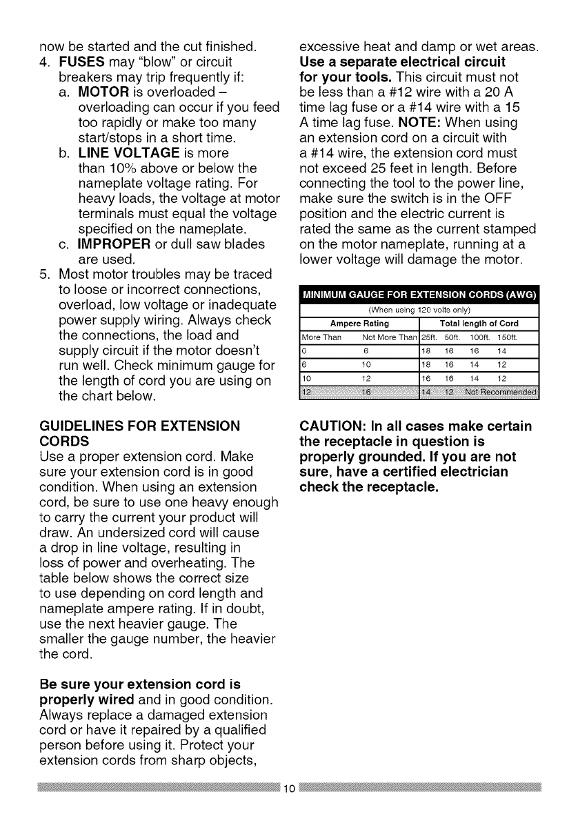
now be started and the cut finished.
4. FUSES may "blow" or circuit
breakers may trip frequently if:
a. MOTOR is overloaded -
overloading can occur if you feed
too rapidly or make too many
start/stops in a short time.
b. LINE VOLTAGE is more
than 10% above or below the
nameplate voltage rating. For
heavy loads, the voltage at motor
terminals must equal the voltage
specified on the nameplate.
c. IMPROPER or dull saw blades
are used.
5. Most motor troubles may be traced
to loose or incorrect connections,
overload, low voltage or inadequate
power supply wiring. Always check
the connections, the load and
supply circuit if the motor doesn't
run well. Check minimum gauge for
the length of cord you are using on
the chart below.
excessive heat and damp or wet areas.
Use a separate electrical circuit
for your tools. This circuit must not
be less than a #12 wire with a 20 A
time lag fuse or a #14 wire with a 15
A time lag fuse. NOTE: When using
an extension cord on a circuit with
a #14 wire, the extension cord must
not exceed 25 feet in length. Before
connecting the tool to the power line,
make sure the switch is in the OFF
position and the electric current is
rated the same as the current stamped
on the motor nameplate, running at a
lower voltage will damage the motor.
I,V_ll#lhVjIll Lvj|€f._11[_1 =11=[0]t,i _:Q i=1#{..I [el #El.ill ;I I]._fzViVL_l
(When using 120 volts only)
Ampere Rating Total length of Cord
More Than Not More Than 25ft. 50ft. 100ft. 150ft.
O 6 18 16 16 14
6 10 18 16 14 12
10 12 16 16 14 12
GUIDELINES FOR EXTENSION
CORDS
Use a proper extension cord. Make
sure your extension cord is in good
condition. When using an extension
cord, be sure to use one heavy enough
to carry the current your product will
draw. An undersized cord will cause
a drop in line voltage, resulting in
loss of power and overheating. The
table below shows the correct size
to use depending on cord length and
nameplate ampere rating. If in doubt,
use the next heavier gauge. The
smaller the gauge number, the heavier
the cord.
CAUTION: In all cases make certain
the receptacle in question is
properly grounded. If you are not
sure, have a certified electrician
check the receptacle.
Be sure your extension cord is
properly wired and in good condition.
Always replace a damaged extension
cord or have it repaired by a qualified
person before using it. Protect your
extension cords from sharp objects,
10

RECOMMENDED ACCESSORIES
[_k WARNING J
•Use only accessories
recommended for this miter
saw. Follow instructions that
accompany accessories. Use of
improper accessories may cause
hazards.
•The use of any cutting tool
except 12 in. saw blades which
meet the requirements under
recommended accessories
is prohibited. Do not use
accessories such as shaper
cutters or dado sets. Ferrous
metal cutting and the use of
abrasive wheels is prohibited.
•Do not attempt to modify this
tool or create accessories not
recommended for use with this
tool. Any such alteration or
modification is misuse and could
result in a hazardous condition
leading to possible serious
injury.
without the proper saw blade
guard in place. Carbide is a very
hard but brittle material. Care
should be taken while mounting,
using, and storing carbide tipped
blades to prevent accidental
damage. Slight shocks, such as
striking the tip while handling,
can seriously damage the blade.
Foreign objects in the workpiece,
such as wire or nails, can also
cause tips to crack or break off.
Before using, always visually
examine the blade and tips for
bent blade, cracks, breakage,
missing or loose tips, or other
damage. Do not use if damage is
suspected. Failure to heed safety
instructions and warnings can
result in serious bodily injury.
ACCESSORIES
Visit your Sears Hardware Department
or see the Sears Power and Hand Tool
Catalog to purchase recommended
accessories for this power tool.
[_, WARNING J
•To avoid the risk of personal
injury, do not modify this power
tool or use accessories not
recommended by Sears.
•Read warnings and conditions
on your CARBIDE TIPPED SAW
BLADE. Do not operate the saw
11

Supplied
Blade Wrench
Not supplied
Adjustable Wrench
6 mm Hex Wrench
l!'-'"-'_,_i'-:'_,_,_'-'' -'i'-_,_
Combination Square
Phillips Screwdriver
Slotted Screwdriver
COMBINATION SQUARE MUST BE TRUE
Should not gap or overlap when square is flipped over (see dotted figure).
Draw light line on
board along this edge.
Straight edge or a 3/4 in. board, this
edge must be perfectly straight.
Should not gap or overlap when square
flipped over (see dotted figure).
12

UNPACKING YOUR MITER SAW
WARNING I
To avoid injury from unexpected
starting or electrical shock, do not
plug the power cord into a source
of power during unpacking and
assembly. This cord must remain
unplugged whenever you are
working on the saw.
1. Remove the miter saw from the
carton.
IMPORTANT: Do not lift miter saw
by the trigger switch handle. It may
cause misalignment. Lift machine by
the built-in carry handle.
2. Place the saw on a secure stationary
work surface.
3. Separate all parts from the packing
material. Check each one with the
illustration to make certain all items
are accounted for, before discarding
any packing material.
IAWARNINGi
If any part is missing or damaged,
do not attempt to assemble the
miter saw, or plug in the power
cord until the missing or damaged
part is correctly replaced. To avoid
electric shock, use only identical
replacement parts when servicing
double insulated tools. Call
1-800-4-MY-HOME ®for replacement
parts.
Hold-down clamp
Dust bag Miter saw
%
Elbow
Power cord Hold-down clamp
Blade wrench Power cord storage clip lock knob
storage clips mounting
hardware
13

Motor \
Saw blade
Bevel scale
Hold-down clamp
Sliding fence
Carry handle Upper blade guard
Carry handle Laser ON/OFF switch
Handle locking lever
Switch handle
ON/OFF trigger switch
Lower blade guard
Base
Miter lock handle
Left extension table
Turntable
Bevel lock handle
Mounting hole Left support
Belt cover
Hold-down latch
Slide carriage
Slide carriage
lock knob
Laser guide
Right extension table
Stop plate
Quick-cam miter
table lock Table insert Right support
Positive miter detents
14
AMPERAGE (AMPS) - A measure
of the flow of electric current. Higher
ratings generally means the tool is
suited for heavier use.
ARBOR LOCK -Allows the user to
keep the blade from rotating while
tightening or loosening the arbor bolt
during blade replacement or removal.
eyes. Eye protection should meet the
requirements of ANSI Z.87.1 (USA) or
CSA Z94.3-M88 (Canada).
FACE SHIELD - An impact resistant
shield that helps to protect your face
from chips, sparks, small debris.
Should only be used in conjunction with
additional eye protection.
BASE - Supports the table, holds
accessories and allows for workbench
or leg set mounting.
FENCE - Helps to keep the workpiece
from moving when sawing. Scaled to
assist with accurate cutting.
BEVEL LOCKING HANDLE - Locks
the miter saw at a desired bevel angle.
BEVEL SCALE - To measure the
bevel angle of the saw blade 0° to 45°
left.
CARBIDE TIPPED -Extremely hard
steel pieces with sharp cutting edges
fastened to cutting tools such as saw
blades.
COVER PLATE SCREW - Loosen this
screw and rotate the plate for access to
the blade arbor bolt.
GUARD - Protective devise that forms
a barrier between a hazardous object
such as a blade, wheel or cutter and
the operator.
HOLD DOWN LATCH - Locks the
miter saw in the lowered position for
compact storage and transportation.
INSTRUCTION OR OPERATOR'S
MANUAL - Booklet accompanying
your power tool that describes the
hazards and safe operation procedures,
outlines basic tool operation, care and
maintenance.
DOUBLE-INSULATED - A form of
electrical protection featuring two
separate insulation systems to help
protect against electrical shock.
EXTENSION CORD -An electric cord
used between power tools and outlets
to extend the range of the tools. The
more amerage your tool uses, the
longer the distance, the larger the size
of the wire needed in your extension
cord.
EYE PROTECTION - Goggles or
spectacles intended to protect your
MITER HANDLE - Used to rotate the
table, and to rotate the saw to a right or
left cutting position.
MITER SCALE - Measures the miter
angle 0° to 45 ° left and right.
MOUNTING HOLES - To mount the
miter saw to a stable surface.
ON/OFF TRIGGER SWITCH - To start
the tool, squeeze the trigger. Release
the trigger to turn off the miter saw.
15

POSITIVE STOP LOCKING LEVER -
Locks the miter saw at a preset positive
stop for the desired miter angle.
SWITCH HANDLE - The switch
handle contains the trigger switch and
the laser on/off switch. The blade is
lowered into the workpiece by pushing
down on the handle. The saw will
return to its upright position when the
handle is released.
WARNING LABELS - Read and
understand for your own safety. Make
sure all labels are present on machine
and legible.
WRENCH STORAGE - Convenient
storage to prevent misplacing the blade
wrench.
WOODWORKING TERMS
ARBOR - The shaft on which a blade
is mounted.
BEVEL CUT - An angle cut made
through the face of the workpiece.
COMPOUND CUT - An angled cut
to both the edge and face of a board,
most common use is with crown
molding.
CROSS CUT - A cut which runs across
the board perpendicular to the grain.
KICKBACK - Sudden and unintended
movement of the tool or workpiece. It is
typically caused by binding or pinching
of the workpiece
MITER CUT - A miter is a type of joint
where the two parts to be joined are cut
at an angle, and typically the finished
joint forms a 90-degree angle. Also
commonly spelled "mitre".
REVOLUTIONS PER MINUTE (RPM)
- The number of turns completed by a
spinning object in one minute.
SAW BLADE PATH - The area of the
workpiece or table top directly in line
with the travel of the blade or the part
of the workpiece which will be cut.
SET - The distance between two saw
blade tips, bent outward in opposite
directions to each other. The further
apart the tips are, the greater the set.
THIN-KERF BLADE - Thinner than
normal blades, remove less material,
smaller kerfs (between .065 and .070).
Blade thinness also may increase the
heat generated while cutting.
WORKPIECE - The wood being
cut. The surfaces of a workpiece are
commonly referred to as faces, ends
and edges.
FREEHAND - Performing a cut without
using a fence (guide), hold down or
other proper device to prevent the
workpiece from twisting during the
cutting operation.
HEEL - Misalignment of the blade.
KERF - The width of a saw cut,
determined by the thickness and set of
the blade.
16

ESTIMATED ASSEMBLY TIME: 10~15
MINUTES
AL WARNING I
To avoid injury, do not connect this
miter saw to the power source until
it is completely assembled and
adjusted, and you have read and
understood this Operator's Manual,
UNLOCKING THE SLIDE CARRIAGE
(FIG. A)
After removing the saw from the carton,
loosen the slide carriage lock knob
(1). When transporting or storing the
miter saw, the slide carriage should
always be locked in position. The slide
carriage lock knob (1) is located on the
right side of the slide carriage.
Unlocking
1. Push down slightly on the switch
handle (1).
2. Pull out the hold-down latch (2).
3. Allow the cutting head to rise to the
up position.
Fig, B
/,
1
Fig, A
RELEASING CUTTING HEAD (FIG, B)
WARNING I
To avoid injury and damage to the
saw, transport or store the miter
saw with the cutting head locked in
the down position. Never use the
hold down latch to hold the cutting
head in a down position for cutting
operations.
Locking
When transporting or storing the miter
saw, the cutting head should always be
locked in the down position.
1. Push the cutting head down to its
lowest position.
2. Push the hold-down latch (2) into
the locking hole.
IMPORTANT: To avoid damage, never
carry the miter saw by the switch
handle, the cutting arm or the miter
handle. ALWAYS use the designated
carrying handles located on the top of
the machine and in the back of the unit.
17

INSTALLING THE DUST
COLLECTION ELBOW (FIG. C)
1. Install the end of the elbow (1) onto
the exhaust port (2).
NOTE: The elbow can be used
to attach either the dust bag or a
vacuum hose to remove sawdust
from the work area.
Fig. C
INSTALLING THE DUST BAG (FIG. D)
1. Squeeze the metal collar wings (1)
of the dust bag (2).
2. Place the dust bag neck opening
around the dust collection elbow (3),
and release the metal collar.
Fig. D
2
To empty the dust bag, squeeze the
metal collar and remove from exhaust
port. Open zipper on underside of bag
and empty into waste container.
NOTE: Check frequently and empty
bag before it gets full.
THREE POSITION ROTATING
HANDLE (FIG. E)
The handle of the miter saw has been
designed to rotate and lock at three
different position stops; 450 left, 0°, and
450 right for operator convenience. To
rotate the handle:
1. Unlock the handle locking lever (1)
by pulling it toward the front of the
machine.
2. Pull the handle-locking latch (2)
to the front of the saw and hold in
position.
3. Rotate the handle to the desired
position stop and release the
handle-locking latch. NOTE: After
releasing the handle-locking latch,
rotate the handle left and right to
make sure the latch engages into
the positive locking position.
4. Lock the handle locking lever (1) by
pushing it IN toward the rear of the
handle.
Fig. E 2
\\
\\\
INSTALLING THE SAFETY HOLD-
DOWN CLAMP (FIG. F)
1. Place the hold-down clamp
assembly (1) in one of the mounting
hole (2), located behind the fence.
2. Thread the hold-down clamp knob
(3) into the hole (2) located at the
rear of the saw base.
3. Tighten the hold-down clamp knob
.
)
18

Fig. F
21
3
POWER CORD STORAGE CLIPS
(FIG. G)
For convenience and to prevent
damage to the power cord when
the miter saw is not in use or is in
transportation, the slide carriage has
two clips on the rear for cord storage.
To assembly these clips:
1. Attach each power cord storage
clips (2) to the rear of slide-bar seat
with one mounting screws (1).
Fig. G
2
1
SAW BLADE WRENCH (FIG. H)
For convenient storage and prevention
of loss, there is a clip (1) located at the
left rear foot of the base for storing the
blade wrench (2).
Fig. H
2
I,A WARNING I
To avoid injury, disconnect the
plug from the power source before
performing any adjustments or
repair.
NOTE: Your miter saw was adjusted at
the factory. However, during shipment
slight misalignment may have occurred.
Check the following settings and adjust
if necessary prior to using this miter
saw.
REMOVING AND INSTALLING THE
TABLE INSERT (FIG. I)
WARNINGI
To avoid injury:
• Always unplug the saw to avoid
accidental starting. Remove all
small pieces of material from the
table cavity before performing
any cuts. The table insert may
be removed for this purpose, but
always reattach the table insert
prior to performing a cutting
operation.
•Do not start the sliding compound
miter saw without checking for
interference between the blade
and table insert. Damage could
result to the blade, table insert or
turntable if blade strike occurs
during the cutting operation.
19

1. To remove, loosen and remove the
six screws (1) on the table inserts
(2) with a Phillips screwdriver and
remove the inserts.
2. To install, reposition the table
inserts, install the six screws and
tighten.
3. Check for blade clearance by
moving the slide carriage through
the full motion of the blade in the
table slot.
to the insulation or the wire
connections resulting in electric
shock or fire.
•To avoid injury from flying
debris, do not allow visitors to
stand near the saw during any
cutting operation.
•Support the saw on a level work
surface.
•Bolt or clamp the saw to its
support.
Fig. I Mounting instructions
1. For stationary use, place the saw
in the desired location, directly on
aworkbench where there is room
for handling and proper support
of the workpiece. The base of the
saw has four mounting holes. Bolt
the base of the miter saw (1) to
the work surface (5), using the
fastening method as shown in Fig J.
MOUNTING THE MITER SAW
(FIG. J, K)
[_ WARNING J
To avoid injury form unexpected
saw movement:
•Disconnect the power cord from
the outlet, and lock the cutting
head in the lower position using
the stop latch.
•Lock the slide carriage in place
by tightening the slide carriage
lock knob.
• To avoid back injury, lift the saw
by using the designated carrying
handles located on the top of the
machine. When lifting, bend at
your knees, not from your back.
•Never carry the miter saw by
the power cord or by the switch
handle. Carrying the tool by the
Fig. J
1. 3
2. 4
3.
4. 1
5. ---[--- _,
6. 5 _,:
7. _9
6 8
8.
9. 7
NOTE: Mounting hardware is not
included with this tool. Bolts, nuts,
washers & screws must be purchased
separately.
Miter saw base
Hex head bolt
Rubber washer
Flat washer
Workbench
Flat washer
Lockwasher
Hex nut
Jam nut
2. For portable use, place the saw on
o a 3/4 in. thick piece of plywood.
Bolt the base of the miter saw
securely to the
plywood using the mounting holes

clampthismountingboardtoa
stableworksurfaceattheworksite.
(Fig.K)
Fig. K
Fig. L
13
2
REMOVING OR INSTALLING THE
BLADE
Removing Blade (Fig. L, M, N)
WARNING I
•To avoid injury from an
accidental start, make sure the
switch is in the OFF position
and plug is not connected to the
power source outlet.
Only use a 12-inch diameter
blade.
1.
2.
3.
.
,
6.
Unplug the saw from the outlet
Raise the miter saw to the upright
position.
Raise the lower clear plastic blade
guard (1) to the uppermost position.
(Fig. L)
While holding the lower blade
guard, loosen the cover plate screw
(2) with a Phillips screwdriver.
Rotate the cover plate (3) to
expose the arbor bolt (4-Fig. N).
Place the blade end wrench over
the arbor bolt.
,
8.
Locate the arbor lock (5) on the
motor, below the belt cover. (Fig. M)
Press the arbor lock, holding it
in firmly while turning the blade
clockwise. The arbor lock will
then engage and lock the arbor.
Continue to hold the arbor lock,
while turning the wrench clockwise
to loosen the arbor bolt.
Fig. M
9. Remove the arbor bolt (4), the
arbor collar (6), and the blade (7).
Do not remove the inner blade
collar. (Fig. N)
10. Raise the lower clear plastic blade
guard (1) to the upright position
(Fig. L) to remove the blade.
21
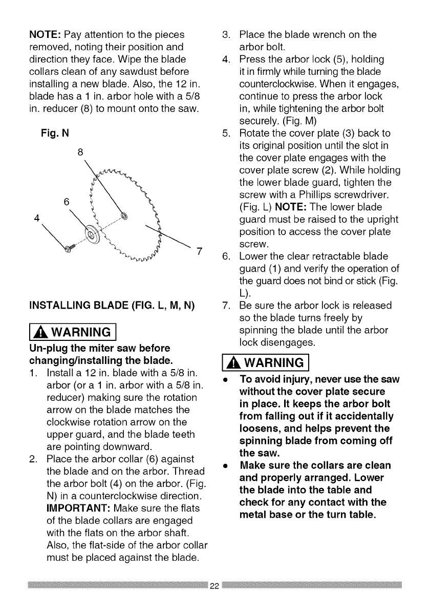
NOTE: Pay attention to the pieces
removed, noting their position and
direction they face. Wipe the blade
collars clean of any sawdust before
installing a new blade. Also, the 12 in.
blade has a 1 in. arbor hole with a 5/8
in. reducer (8) to mount onto the saw.
Fig. N
8\
6
4
INSTALLING BLADE (FIG. L, M, N)
WARNING J
Un-plug the miter saw before
changing/installing the blade.
1. Install a 12 in. blade with a 5/8 in.
arbor (or a 1 in. arbor with a 5/8 in.
reducer) making sure the rotation
arrow on the blade matches the
clockwise rotation arrow on the
upper guard, and the blade teeth
are pointing downward.
2. Place the arbor collar (6) against
the blade and on the arbor. Thread
the arbor bolt (4) on the arbor. (Fig.
N) in a counterclockwise direction.
IMPORTANT: Make sure the flats
of the blade collars are engaged
with the flats on the arbor shaft.
Also, the flat-side of the arbor collar
must be placed against the blade.
3. Place the blade wrench on the
arbor bolt.
4. Press the arbor lock (5), holding
it in firmly while turning the blade
counterclockwise. When it engages,
continue to press the arbor lock
in, while tightening the arbor bolt
securely. (Fig. M)
5. Rotate the cover plate (3) back to
its original position until the slot in
the cover plate engages with the
cover plate screw (2). While holding
the lower blade guard, tighten the
screw with a Phillips screwdriver.
(Fig. L) NOTE: The lower blade
guard must be raised to the upright
position to access the cover plate
screw.
6. Lower the clear retractable blade
guard (1) and verify the operation of
the guard does not bind or stick (Fig.
L).
7. Be sure the arbor lock is released
so the blade turns freely by
spinning the blade until the arbor
lock disengages.
WARNING J
• To avoid injury, never use the saw
without the cover plate secure
in place. It keeps the arbor bolt
from falling out if it accidentally
loosens, and helps prevent the
spinning blade from coming off
the saw.
•Make sure the collars are clean
and properly arranged. Lower
the blade into the table and
check for any contact with the
metal base or the turn table.
22

ALIGNING THE LASER BEAM (FIG.
O, P)
WARNING I
For your own safety, never connect
the plug to power source outlet
until all the adjustment steps
are complete and you have read
and understood the safety and
operational instructions.
The laser beam must always be
correctly aligned with the blade to
ensure straight, even cutting.
Your tool is equipped with the Laser
Trac ®cutting guide using Class II laser
beam. The laser beam will enable to
preview the saw blade path on the
stock to be cut before starting the miter
saw. This laser guide is powered by the
transformed alternating current supply
directly through the power lead. The
saw must be connected to the power
source and the laser on/off switch
must be turned on for the laser line
to show.
WARNING I
AVOID DIRECT EYE CONTACT
•Laser radiated when laser guide
is turned on. Avoid direct eye
contact. Always un-plug the miter
saw from power source before
making any adjustments.
•Laser Warning Label: Max output
<lmW DIODE LASER: 630-670nm,
Complies with 21CFR 1040.10 and
1040. 11.
•NOTE: All the adjustments for the
operation of this machine have
been completed at the factory.
Due to normal wear and use,
some occasional readjustments
may be necessary.
•CAUTION-Use of controls or
adjustments or performance of
procedures other than those
specified herein may result in
hazardous radiation exposure.
•CAUTION-The use of optical
instruments with this product will
increase eye hazard.
•Do not attempt to repair or
disassemble the laser. If
unqualified persons attempt
to repair this laser product,
serious injury may result. Any
repair required on this laser
product should be performed
by authorized service center
personnel.
A. Check Laser Beam Alignment.
1. Mark a 90° straight line across a
board to serve as a "pattern line" to
test laser alignment. Lay the board
on the miter table.
2. Plug saw into outlet and turn on the
laser beam and line it up with the
pattern line.
3. Lower saw blade to pattern line and
if blade is not flush with the pattern
line, adjust as follows in procedure
(B).
B. Adjusting the Angle of the Laser
Trac ®(Fig. P)
1. Turn the laser element (2) in the
desired direction to adjust the laser
angle. NOTE: Do not adjust the
laser more than 1/4 turn in either
direction as this may damage the
laser. There are two flat sides on
23

the laser element where you can
position an adjustable wrench for
your adjustment.
C. Aligning The Laser Beam
1. Loosen only 1/2 turn at a time the
four set screws (1).
2. Adjust laser by turning the left side
set screws clockwise to shift the
laser line to the right. To shift the
laser line to the left, turn the right
side set screws 1/2 turn at a time.
3. Once alignment of the laser is
achieved, tighten only 1/2 turn at a
time the four set screws (1).
Fig. 0
Fig. P
THE UPFRONT SUPPORTS
ADJUSTMENT (FIG. Q, R)
Wide pieces need upfront supports (1).
1. Rotate the two upfront supports (1)
toward the rear of the saw.
Laser Switch
i ...... l
Left Side View Right Side View
Fig. Q
\
1
NOTE: These supports (1) should be
placed into the 0 position as shown in
Fig. R before transporting.
Fig. R
1
24

BEVEL STOP ADJUSTMENTS
(FIG. S, T, U, V)
WARNING I
To avoid injury from unexpected
starting or electrical shock, make
sure the trigger is released and
remove the power cord from the
power source.
900(0°) Bevel adjustment (Fig. S, T)
1. Loosen bevel lock handle (2) and tilt
the cutting arm while pushing in the
bevel detent pin (3-Fig. T) in against
the 0° bevel stop. Tighten the bevel
lock handle.
2. Place a combination square on the
miter table with the rule against the
table and heel of the square against
the saw blade.
3. If the blade is not 0° to the miter
table, loosen the four adjustment
bolts (1) at the rear of the unit with
a 5 mm hex wrench. Unlock the
bevel lock handle (2) and adjust
the cutting arm zero degrees to the
table. Tighten the bevel lock handle
and the four adjustment bolts after
alignment is achieved.
Fig. S
2
Bevel Scale Indicators (Fig. T)
1. When the blade is exactly 90o(0°) to
the table, loosen the bevel indicator
screws (1) using a #2 Phillips
screwdriver.
2. Adjust bevel indicators (2) to the
"0" mark on the bevel scale and
retighten the screws.
Fig. T
2
45°Left Bevel Positive Stop
Adjustment (Fig. U)
1. Set the miter angle to zero degrees.
Fully extend the sliding fence
completely to the left then pull the
bevel detent pin (1) toward the
front of the machine. NOTE: When
retracting the bevel detent pin, it may
be required to shift the miter saw
upper arm assembly to the left/right.
2. Loosen the bevel lock handle (2)
and tilt the cutting arm completely to
the left.
3. Using a combination square, check
to see if the blade is 45° to the table.
4. To adjust, tilt the cutting arm to zero
degrees, loosen the Iocknut (3) and
turn the bolt (4) in or out accordingly.
5. Tilt the cutting arm back to the left
and recheck alignment.
6. Repeat steps until the blade is
45° to the table. Once alignment is
achieved, tighten the Iocknut (3) to
secure the positive stop bolt.
25

Fig. U
4
1
3
45°Right Bevel Positive Stop
Adjustment (Fig. V)
1. Set the miter angle to zero degrees.
Fully extend the sliding fence
completely to the right then pull
the bevel detent pin (1) toward the
front of the machine. NOTE: When
retracting the bevel detent pin, it may
be required to shift the miter saw
upper arm assembly to the left/right.
2. Loosen the bevel lock handle (2)
and tilt the cutting arm completely to
the right.
3. Using a combination square, check
to see if the blade is 45 ° to the table.
4. To adjust, tilt the cutting arm to zero
degrees, loosen the Iocknut (3) and
turn the bolt (4) in or out accordingly.
5. Tilt the cutting arm back to the right
and recheck alignment.
6. Repeat steps until the blade is
45 ° to the table. Once alignment is
achieved, tighten the Iocknut (3) to
secure the positive stop bolt.
Fig. V 4
1 3
2
33.9°Left & Right Bevel Adjustment
(Fig. W)
1. Set the miter angle to zero degree.
Fully extend both sliding fences.
2. Loosen the bevel lock handle and
tilt cutting arm to the 33.9 ° left bevel
positive stop by pushing in on the
bevel detent pin toward the rear of the
machine.
3. Using a combination square, check
to see if the blade is 33.9° to the
table.
4. To adjust, turn the screw in or out
with a wrench (from the locations
shown below) until the blade is 33.9 °
to the table.
5. Repeat steps for the right bevel
33.9 -0bevel adjustment.
Fig. W
For 33.9 ° left ._
bevel positive stop
adjustment, insert
wrench here
26

o right
sitive
ustment,
rench
here
NOTE: View from rear of machine
MITER ANGLE ADJUSTMENT (FIG.
X)
The sliding compound miter saw scale
can be easily read, showing miter
angles from 0° to 45° to the left, and 0°
to 45 ° to the right. The miter saw table
has nine of the most common angle
setttings with positive stops at 0°, 15°,
22.5 °, 31.6 °, and 45°. These positive
stops position the blade at the desired
angle quickly and accurately. Follow
the process below for quickest and
most accurate adjustments.
1. Lift up on the quick-cam miter table
lock (1) to unlock the table.
2. Move the turntable while lifting up on
the positive stop locking lever (4) to
align the indicator (2) to the desired
degree measurement.
3. Lock the table into position by
pressing down on the quick-cam
miter table lock (1).
Fig. X
2. Loosen the screw (3) that holds the
indicator with a screwdriver.
3. Adjust the indicator (2) to the 0°
mark and retighten screw.
ADJUSTING FENCE SQUARENESS
(FIG. Y)
1. Loosen the four fence locking bolts
(1).
2. Lower the cutting arm and lock in
position.
3. Using a square (3), lay the heel of
the square against the blade and the
ruler against the fence (2) as shown.
4. Adjust the fence 90° to the blade and
tighten the four fence locking bolts.
CAUTION: If the saw has not been
used recently, recheck blade
squareness to the fence and
readjust if needed.
5. After fence has been aligned, using
a scrap piece of wood, make a cut
at 90° then check squareness on the
piece. Readjust if necessary.
Fig. Y
2
3 2 4 1
Miter Scale Indicator (Fig. X)
1. Move the table to the 0° positive
POSITIVE STOP MITER ANGLE
ADJUSTMENT (FIG. Z)
1. Unlock the miter table by lifting up
on the quick-cam miter table lock
(1).
stop. 2. While raising the positive stop
locking lever (2) up, grasp the miter
27

handle and rotate the miter table left
or right to the desired angle.
3. Release the positive stop locking
lever and set the miter at the desired
angle making sure the lever snaps
into place. NOTE: The lever will
only lock into place at one of the ten
positive stops.
4. Once angle is achieved, press down
on the quick-cam miter table lock (1).
4. Turn the lock nut (3) to the right
as shown to lock the miter locking
mechanism into place.
Fig. Z 13 4
Quick-cam Miter Table Lock
Operation (Fig. Z)
If miter angles required are NOT one of
the ten positive stops noted above, the
miter table can be locked at any angle
between these positive stops by using
the quick-cam miter table lock.
1. Unlock the miter table by lifting up
on the quick-cam miter table lock (1).
2. While holding the positive stop
locking lever (2) up, grasp the miter
handle and move the miter table left
or right to the desired angle.
3. Release the positive stop locking
lever.
4. Press down on the quick-cam miter
table lock (1) until it locks the miter
table in place.
NOTE: The quick-cam miter table
lock should lock the table and
prevent it from moving. If adjustment
is needed, see next step.
Quick-cam Miter Table Lock
Adjustment (Fig. Z)
1. Press down and lock the miter quick-
cam table lock.
2. Using a 13 mm wrench, turn the stop
nut (4) to the left as shown to extend
the locking arm against the base of
the miter saw.
3. Test the quick cam miter lock to
verify it locks the table into position
SETTING CUTTING DEPTH (FIG. AA)
The depth of cut can be preset for even
and repetitive shallow cuts.
1. Adjust the cutting head down (See
CUTTING HEAD section) until the
teeth of the blade are at the desired
depth.
2. While holding the upper arm in that
position, turn the stop knob (1) until
it touches the stop plate (2).
3. Recheck the blade depth by moving
the cutting head front to back
through the full motion of a typical
cut along the control arm.
Adjusting Cutting Depth (Fig. AA)
The maximum depth travel of the
cutting head was set at the factory.
Check to see that the blade does not
extend more than 1/4 in. below the
table insert, and does not touch the
control arm throat or any part of the
base or table. If the maximum depth
needs readjusting:
1. Loosen the stop knob (1) while
moving the cutting head down until
the blade extends just 1/4 in. below
the table insert.
2. Adjust the stop knob (1) to touch the
stop plate (2).

3. Recheckthebladedepthbymoving
thecuttingheadfrontto back
throughthefullmotionofa cutalong
thecontrolarm.Ifthebladetouches
theinsideof thecontrolarm,readjust
thesetting.
Fig. AA
2
SLIDING THE REAR EXTENSION
SUPPORT BAR (FIG. BB)
WARNING I
To avoid possible personal injury
or damage to the miter saw due
to tipping, do not operate the saw
without the Rear Extension Support
Bar.
Loosen the two screws (1) and extend
the rear extension support bar (2) by
sliding it out to match position, tighten
the two screws.
Fig. BB
1
29
SAFETY INSTRUCTIONS FOR BASIC
SAW OPERATION
BEFORE USING THE MITER SAW
[_, WARNING J
To avoid mistakes that could cause
serious, permanent injury, do not
plug the tool in until the following
steps are completed:
•Completely assemble and
adjust the saw, following the
instructions. (ASSEMBLY AND
ADJUSTMENTS)
• Learn the use and function of the
ON/OFF switch, upper and lower
blade guards, hold down latch,
bevel lock handle and cover plate
screws.
• Review and understand
all safety instructions and
operating procedures in this
Operator's Manual. (SAFETY &
OPERATIONS)
• Review the MAINTENANCE and
TROUBLESHOOTING GUIDE for
your miter saw.
• To avoid injury or possible death
from electrical shock:
Make sure your fingers do not
touch the plug's metal prongs
when plugging or unplugging
your miter saw. (ELECTRICAL
REQUIREMENTS AND SAFETY)
BEFORE EACH USE INSPECT YOUR
SAW.
•Disconnect the miter saw.
To avoid injury from accidental
starting, unplug the saw before any
adjustments, including set-up and
blade changes.
•Compare the direction of rotation
arrow on the guard to the direction
arrow on the blade. The blade teeth
should always point downward at
the front of the saw.
•Tighten the arbor bolt.
•Tighten the cover plate screw.
•Check for damaged parts. Check
for:
• Alignment of moving parts
• Damaged electric cords
• Binding of moving parts
• Mounting holes
• Function of arm return spring
and lower guard: Push the
cutting arm all the way down,
then let it rise until it stops.
The lower guard should fully
close. Follow instructions in
TROUBLESHOOTING GUIDE
for adjustment if necessary.
• Other conditions that may affect
the way the miter saw works.
• Keep all guards in place, in working
order and proper adjustment. If any
part of this miter saw is missing,
bent, damaged or broken in any
way, or any electrical parts don't
work, turn the saw off and unplug
it.
• Replace bent, damaged, missing
or defective parts before using the
saw again.
• Maintain tools with care. Keep the
miter saw clean for best and safest
performance. Follow instructions
for lubricating. Do not put lubricants
on the blade while it is spinning.
• Remove adjusting wrench from the
tool before turning it on.
• To avoid injury from jams, slips,
or thrown pieces, use only
30
recommended accessories.
RECOMMENDED ACCESSORIES
• Consult the ACCESSORIES
and ATTACHMENTS section
of this Operator's Manual for
recommended accessories. Follow
the instructions that come with the
accessory. The use of improper
accessories may cause risk of
injury to persons.
• Choose the correct 12 in. diameter
blade for the material and the type
of cutting you plan to do. Do not
use thin kerf blades.
• Make sure the blade is sharp,
undamaged and properly aligned.
With the saw unplugged, push
the cutting arm all the way down.
Manually spin the blade and check
for clearance. Tilt the power-head
to a 45° bevel and repeat the test.
• Make sure the blade and arbor
collars are clean.
• Make sure all clamps and locks are
tight and there is no excessive play
in any parts.
KEEP YOUR WORK AREA CLEAN
Cluttered areas and benches invite
r RNING I
To avoid burns or other fire damage,
never use the miter saw near
flammable liquids, vapors, or gases.
• Plan ahead to protect your eyes,
hands, face and ears.
• Know your miter saw. Read and
understand the Operator's Manual
and labels affixed to the tool.
Learn its application and limitations
as well as the specific potential
hazards peculiar to this tool. To
avoid injury from accidental contact
assembly, or setup work on the
miter saw while any parts are
moving.
Avoid accidental starting,
make sure the trigger switch is
disengaged before plugging the
miter saw into a power outlet.
PLAN YOUR WORK
• Use the right tool. Do not force a
tool or attachment to do a job it was
not designed to do. Use a different
tool for any workpiece that can'
t be held in a solidly braced, fixed
position.
CAUTION: This machine is not
designed for cutting masonry,
masonry products, ferrous metals
(steel, iron, and iron-based metals.)
Use this miter saw to cut only
wood, wood-like products, or non-
ferrous metals. Other material may
shatter, bind the blade, or create
other dangers. Remove all nails that
may be in the workpiece to prevent
sparking that could cause a fire.
Remove dust bag when cutting non-
ferrous metals.
S FOR SAFETY
Any power tool can throw
foreign objects into the eyes.
This can result in permanent
eye damage. Everyday eyeglasses
have only impact resistant lenses and
are not safety glasses. Glasses or
goggles not in compliance with ANSI
Z87.1 could seriously injure you when
they break.
• Do not wear loose clothing, gloves,
neckties or jewelry (rings, watches).
They can get caught and draw you
into moving parts.
with movingparts, do not do layout, 31

•Wear non-slip footwear.
• Tie back long hair.
• Roll long sleeves above the elbow.
• Noise levels vary widely. To avoid
possible hearing damage, wear ear
plugs when using any miter saw.
• For dusty operations, wear a dust
mask along with safety goggles.
INSPECT YOUR WORKPIECE
Make sure there are no nails or foreign
objects in the part of the workpiece
being cut.
Plan your work to avoid small pieces
that may bind, or that are too small to
clamp and get a solid grasp on. Plan
the way you will grasp the workpiece
from start to finish. Avoid awkward
operations and hand positions.
A sudden slip could cause your fingers
or hand to move into the blade.
DO NOT OVER-REACH
Keep good footing and balance. Keep
your face and body to one side, out of
the line of a possible kickback. NEVER
stand in the line of the blade.
Never cut freehand:
• Brace your workpiece firmly against
the fence and table stop so it will
not rock or twist during the cut.
• Make sure there is no debris
between the workpiece and the
table or fence.
• Make sure there are no gaps
between the workpiece, fence and
table that will let the workpiece shift
after it is cut.
• Keep the cut off piece free to
move sideways after it is cut off.
Otherwise, it could get wedged
against the blade and thrown
violently.
• Only the workpiece should be on
the saws table.
• Secure work. Use clamps or a vise
to help hold the work when it's
practical.
USE EXTRA CAUTION WITH LARGE
OR ODD SHAPED WORKPIECES.
• Use extra supports (tables,
sawhorses, blocks, etc.) for
workpieces large enough to tip.
• Never use another person as a
substitute for a table extension,
or as an additional support for a
workpiece that is longer or wider
than the basic miter saw table, or
to help feed, support, or pull the
workpiece.
• Do not use this saw to cut small
pieces. If the workpiece being cut
would cause your hand or fingers
to be within 8-3/4 inches of the saw
blade the workpiece is too small.
Keep hands and fingers out of the
"no hands zone" area marked on
the saws table.
• When cutting odd shaped
workpieces, plan your work so
it will not bind in the blade and
cause possible injury. Molding, for
example, must lie flat or be held
by a fixture or jig that will not let it
move when cut.
• Properly support round material
such as dowel rods, or tubing,
which have a tendency to roll when
cut, causing the blade to "bite".
[,ik WARNING J
To avoid injury, follow all applicable
safety instructions, when cutting
non-ferrous metals:
• Use only saw blades specifically
recommended for non-ferrous
metal cutting.
32

Do not cut metal workpieces
that must be hand held. Clamp
workpieces securely.
Cut non-ferrous metals only if you
are under the supervision of an
experienced person and the dust
bag has been removed from the
saw.
WHEN SAW IS RUNNING
WARNING I
Do not allow familiarity from
frequent use of your miter saw
to result in a careless mistake. A
careless fraction of a second is
enough to cause a severe injury.
Before cutting, if the saw makes an
unfamiliar noise or vibrates, stop
immediately. Turn the saw OFF.
Unplug the saw. Do not restart until
finding and correcting the problem.
BODY AND HAND POSITION (FIG,
cc)
WARNING I
Never place hands near
the cutting area. Proper
positioning of your body
and hands when operating the miter
saw will make cutting easier and
safer. Keep children away. Keep all
visitors at a safe distance from the
miter saw. Make sure bystanders
are clear of the saw and workpiece.
Don't force the saw. It will do the job
better and safer at its designed rate.
•Hold workpiece firmly against the
fence to prevent movement toward
the blade.
• With the power switch OFF,
bring the saw blade down to the
workpiece to see the cutting path of
the blade.
• Squeeze trigger switch to start saw.
• Lower blade into workpiece with a
firm downward motion.
Finishing a cut:
• Hold the cutting arm in the down
position.
• Release trigger switch and wait
for all moving parts to stop before
moving your hands and raising the
cutting arm.
• If the blade does not stop within
10 seconds, unplug the saw
and follow the instructions in
TROUBLESHOOTING GUIDE
section.
Before freeing jammed material:
• Release trigger switch.
• Wait for all moving parts to stop.
• Unplug the miter saw.
Fig, CC
i
i
i
i
i
i
Starting a cut: i
• Place hands at least 8-3/4 in. away ®
from the path of the blade - out of 8-3/4 in.
the "no-hands zone". (Fig. CC)
o-Hand Zone
i
i
®
8-3/4 in.
33

TO TURN THE SAW ON (FIG. DD)
Depress the trigger switch (1) to turn
on the miter saw started.
NOTE: Make the ON/OFF switch
childproof. Insert a padlock, or chain
with padlock, through the hole (2) in
the trigger switch, locking the tool's
switch, preventing children and other
unauthorized users from turning the
machine on.
The miter saw is equipped with an
automatic blade brake. When the
trigger switch is released, the electric
blade brake will stop the blade within
approximately 10 seconds.
Fig. DD
2\
.
,
The right side sliding fence must
be removed when making any
right bevel angle cuts greater
than 350 in combination with
any right hand miter angle. This
fence must also be removed
whenever a 450bevel angle
is desired with a miter angle
greater than 22.50.
Unlock the fence cam locking lever
(1) by pushing it toward the rear of
the machine.
Extend the fence (2) by sliding it out
to match the degree of the bevel
cut. Lock the fence cam locking
lever by pushing it IN toward the
fence. NOTE: When transporting
the saw, always secure the sliding
fence in the collapsed position
(toward the saw blade).
Fig. EE
SLIDING FENCE (FIG. EE)
WARNING J
•The sliding fence must be
extended to the left or right when
making bevel cuts.The sliding
fence noted three bevel angles
where the user must adjust the
fences to match the degree of
the bevel cut. Failure to extend
the sliding fence will not allow
enough space for the blade to
pass through which could result
in serious injury. At extreme
miter or bevel angles the saw
blade may also contact the
fence.
34
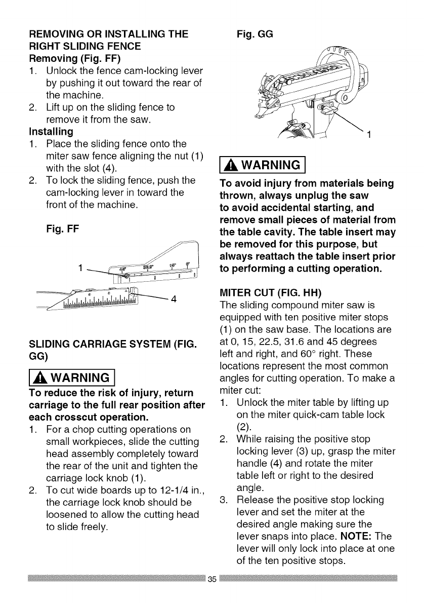
REMOVING OR INSTALLING THE
RIGHT SLIDING FENCE
Removing (Fig. FF)
1. Unlock the fence cam-locking lever
by pushing it out toward the rear of
the machine.
2. Lift up on the sliding fence to
remove it from the saw.
Installing
1. Place the sliding fence onto the
miter saw fence aligning the nut (1)
with the slot (4).
2. To lock the sliding fence, push the
cam-locking lever in toward the
front of the machine.
Fig. FF
1 __............. JJ
..........÷I, ,d,I U,d, 4
SLIDING CARRIAGE SYSTEM (FIG.
GG)
Ak, WARNING I
To reduce the risk of injury, return
carriage to the full rear position after
each crosscut operation.
1. For a chop cutting operations on
small workpieces, slide the cutting
head assembly completely toward
the rear of the unit and tighten the
carriage lock knob (1).
2. To cut wide boards up to 12-1/4 in.,
the carriage lock knob should be
loosened to allow the cutting head
to slide freely.
Fig. GG
WARNINGI
To avoid injury from materials being
thrown, always unplug the saw
to avoid accidental starting, and
remove small pieces of material from
the table cavity. The table insert may
be removed for this purpose, but
always reattach the table insert prior
to performing a cutting operation.
MITER CUT (FIG. HH)
The sliding compound miter saw is
equipped with ten positive miter stops
(1) on the saw base. The locations are
at O, 15, 22.5, 31.6 and 45 degrees
left and right, and 60° right. These
locations represent the most common
angles for cutting operation. To make a
miter cut:
1. Unlock the miter table by lifting up
on the miter quick-cam table lock
(2).
2. While raising the positive stop
locking lever (3) up, grasp the miter
handle (4) and rotate the miter
table left or right to the desired
angle.
3. Release the positive stop locking
lever and set the miter at the
desired angle making sure the
lever snaps into place. NOTE: The
lever will only lock into place at one
of the ten positive stops.
35

4. Once the desired miter angle is
achieved, press down on the quick
cam miter table lock to secure the
table into position.
5. If the miter angle desired is NOT
one of the ten positive stops noted
above, simply lock the table at the
desired angle by pressing down on
the quick-cam miter table lock (2).
Fig. HH
2 1
BEVEL CUT (FIG. II)
WARNING J
• The sliding fence must be
extended to the left or right when
making bevel cuts.The sliding
fence noted three bevel angles
where the user must adjust the
fences to match the degree of
the bevel cut. Failure to extend
the sliding fence will not allow
enough space for the blade to
pass through which could result
in serious injury. At extreme
miter or bevel angles the saw
blade may also contact the
fence.
•The right side sliding fence must
be removed when making any
right bevel angle cuts greater
than 35° in combination with
any right hand miter angle. This
fence must also be removed
whenever a 45° bevel angle
is desired with a miter angle
greater than 22.5 °.
Tilt the cutting head to the desired
angle as shown on the bevel scale. The
blade can be positioned at any angle,
from a 90° straight cut (0° on the scale)
to a 45° left and right bevel. Tighten the
bevel lock handle (1) by pushing down
to lock the cutting head in position.
Bevel positive stops are provided at 0°,
33.9 ° and 45 °.
Fig. II
NOTE: The saw comes with a
33.9 ° bevel detent pin for setting up
crown molding cuts when the angle of
the walls equals 90° .
36

33.9 °BEVEL DETENT PIN FOR
CROWN MOLDINGS (FIG. JJ)
NOTE: A bevel detent pin is
incorporated into this machine for quick
bevel adjustments when the desired
bevel angle is 33.9 °.
1. Push the bevel detent stop pin (1)
in toward the front of the machine.
2. Loosen the bevel lock handle (2).
3. Rotate the cutting head until the
bevel detent pin stops the bevel
angle at 33.9 ° on the bevel scale.
4. Tighten the bevel lock handle
before you make your cut.
Fig. JJ
COMPOUND CUT (FIG. KK)
1. Extending the fence by sliding it out
to the required location or remove
the right sliding fence if necessary.
See "SLIDING FENCE or REMOVE
SLIDING FENCE".
2. Set the desired bevel angle using
the bevel lock handle (1).
3. Set the desired miter angle and
lock into position. See "MITER
CUT".
Fig. KK
CHOP CUTTING NARROW BOARDS-
90° CROSSCUT (FIG. LL)
1. For a chop cutting operations on
small workpieces, slide the cutting
head assembly completely toward
the rear of the unit and tighten the
carriage lock knob (1).
2. Position the cutting head to the
0° bevel position and lock the bevel
lock handle (2).
3. Position the table to the 0° miter
angle and lock the quick cam miter
table lock (3).
4. Position the workpiece on the table
and against the fence. Use a hold
down clamp (4) attached to the
base, whenever possible.
5. Pull the trigger (5), turning on the
saw. Lower the blade by pushing
the handle (6) down into the
workpiece with slow and even
pressure.
6. When the cut is complete, release
the switch and allow the blade to
stop before raising the cutting head
assembly.
37

Fig. LL
3
SLIDE CUTTING WIDE BOARDS UP
TO 12-1/4 IN. WIDE (FIG. MM)
WARNING I
To avoid injury:
• Never pull the cutting head
assembly and spinning blade
toward you during the cut, The
blade may try to climb up on the
top of the workpiece, causing the
cutting assembly and spinning
blade to kick back, forcefully, The
cutting head assembly should
be drawn back completely then
pushed forward when sawing,
•Let the blade reach full speed
before cutting, This will help
reduce the risk of a thrown
workpiece,
•Extending the fence by sliding
it out to the required location or
remove the right sliding fence if
necessary, See "SLIDING FENCE
or REMOVE SLIDING FENCE",
3. Set both the desired bevel angle
and/or the miter angle and lock into
position.
4. If bevel cutting, set both the left
and right sliding fences (2) to their
proper location.
5. Use a hold down clamp to secure
the workpiece.
6. Grasp the switch handle (3) and
pull the carriage (4) forward until
the center of the saw blade is over
the front of the workpiece (5).
7. Pull the trigger (6) to turn the saw
on.
8. When the saw reaches full speed,
push the saw handle down, slowly,
cutting through the leading edge of
the workpiece.
9. Slowly move the saw handle toward
the fence, completing the cut.
10. Release the trigger and allow
the blade to stop spinning before
allowing the cutting head to raise.
Fig, MM
1 6
3
5
CUT WIDE BOARDS (FIG, MM)
1. Rotate the two upfront supports (7)
toward the rear of the saw.
2. Unlock the carriage lock knob
(1) and allow the cutting head
assembly to move freely.
38
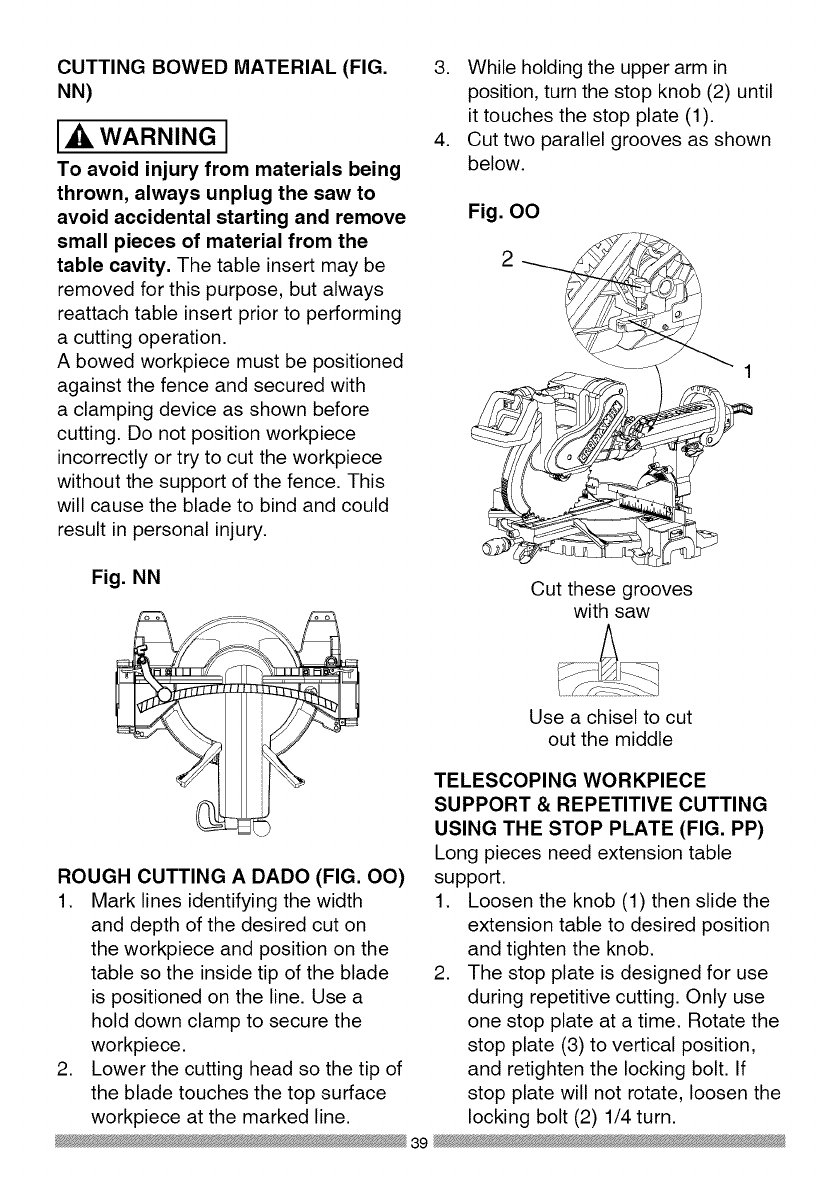
CUTTING BOWED MATERIAL (FIG.
NN)
WARNING I
To avoid injury from materials being
thrown, always unplug the saw to
avoid accidental starting and remove
small pieces of material from the
table cavity. The table insert may be
removed for this purpose, but always
reattach table insert prior to performing
a cutting operation.
A bowed workpiece must be positioned
against the fence and secured with
a clamping device as shown before
cutting. Do not position workpiece
incorrectly or try to cut the workpiece
without the support of the fence. This
will cause the blade to bind and could
result in personal injury.
Fig. NN
ROUGH CUTTING A DADO (FIG. OO)
1. Mark lines identifying the width
and depth of the desired cut on
the workpiece and position on the
table so the inside tip of the blade
is positioned on the line. Use a
hold down clamp to secure the
workpiece.
2. Lower the cutting head so the tip of
the blade touches the top surface
workpiece at the marked line.
3. While holding the upper arm in
position, turn the stop knob (2) until
it touches the stop plate (1).
4. Cut two parallel grooves as shown
below.
Fig. OO
Cut these grooves
with saw
Use a chisel to cut
out the middle
TELESCOPING WORKPIECE
SUPPORT & REPETITIVE CUTTING
USING THE STOP PLATE (FIG. PP)
Long pieces need extension table
support.
1. Loosen the knob (1) then slide the
extension table to desired position
and tighten the knob.
2. The stop plate is designed for use
during repetitive cutting. Only use
one stop plate at a time. Rotate the
stop plate (3) to vertical position,
and retighten the locking bolt. If
stop plate will not rotate, loosen the
locking bolt (2) 1/4 turn.
39

Fig. PP
\
/
/
AUXILIARY WOOD FENCE (FIG. QQ)
When making multiple or repetitive cuts
that result in cut-off pieces of one inch
or less, it is possible for the saw blade
to catch the cut-off piece and throw it
out of the saw or into the blade guard
and housing, possibly causing damage
or injury. To minimize this an auxiliary
wood fence can be mounted to your
saw. Holes are provided in the saw
fence to attach an auxiliary wood fence
(this provides additional depth of cut).
This fence should be constructed of
straight auxiliary wood approximately
3/4 in. thick by 1-1/2 in. high by 22 in.
long. Attach the wood fence securely
and make a full depth cut to make
a blade slot. Check for interference
between the wood fence and the lower
blade guard. Adjust if necessary.
Fig. QQ
Blade slot
CHANGING THE BELT (FIG. RR, SS)
• Unplug your saw.
1. Loosen the bolts (1) and remove
the belt cover.
2. Turn the screw (2) anti-clockwise
with a hex wrench to move the
motor to forward.
3. Remove and replace the belt.
4. Turn the screw (2) clockwise with
a hex wrench to move the motor to
rearward. Do not over tighten.
5. Replace the belt cover and tighten
the bolts.
Fig. RR
Fig. SS
40

CUTTING BASE MOLDING (FIG. TT)
Base moldings and many other
moldings can be cut on a compound
miter saw. The setup of the saw
depends on molding characteristics
and application, as shown. Perform
practice cuts on scrap material to
achieve best results:
1. Always make sure moldings rest
firmly against fence and table. Use
hold-down, crown molding vise
or C-clamps, whenever possible,
and place tape on the area being
clamped to avoid marks.
2. Reduce splintering by taping the
cut area prior to making the cut.
Mark the cut line directly on the
tape.
3. Splintering typically happens due to
an incorrect blade application and
thinness of the material.
Fig. TT
Miter saw table
miter at 450,
bevel at 0°
_table
miter at 0°, bevel
at 450
angles that, when added together,
equal exactly 90 °.
Most crown molding has a top rear
angle (the section that fits flat against
the ceiling) of 52°and a bottom rear
angle (the section that fits flat against
the wall) of 38°.
In order to accurately cut crown
molding for a 90° inside or outside
corner, lay the molding with its broad
back surface flat on the saw table.
When setting the bevel and miter
angles for compound miters, remember
that the settings are interdependent;
changing one changes the other, as
well.
Fig. UU
ne
Miter saw table
Bevel/Miter Settings
Fig. VV
NOTE: Always perform a dry run cut
so you can determine if the operation
being attempted is possible before
power is applied to the saw.
CUTTING CROWN MOLDING (FIG.
UU, VV)
WARNING I
Your compound miter saw is suited
for the difficult task of cutting crown
molding. To fit properly, crown molding
must be compound-mitered with
extreme accuracy. The two surfaces
on a piece of crown molding that fit
flat against the ceiling and wall are at
Settings for standard crown molding
lying flat on compound miter saw
table ]
Inside corner OR
\
,-._1
Outside corner
Compound cut crown moldings
NOTE: The chart below references
a compound cut for crown molding
ONLY WHEN THE ANGLE BETWEEN
THE WALLS EQUALS 90 °.
41

Bevel/Miter Settings
KEY BEVEL MITER
SETTING SETTING
TYPE OF CUT
IL 33.9 °
IR 33.9 °
OL 33.9 °
OR 33.9 °
31.6 o Right
31.6 ° Left
31.6 ° Left
31.6 o Right
Inside corner-Left side
1. Position top of molding against fence.
2. Miter table set at RIGHT 31.6 ° .
3. LEFT side is finished piece.
Inside corner-Right side
1. Position bottom of molding against fence.
2. Miter table set at LEFT 31.6 °.
3. LEFT side is finished piece.
Outside corner-Left side
1. Position bottom of molding against fence.
2. Miter table set at LEFT 31.6 °.
3. RIGHT side is finished piece.
Outside corner-Right side
1. Position top of molding against fence.
2. Miter table set at RIGHT 31.6 ° .
3. RIGHT side is finished piece.
42

CROWN MOLDING CHART
Compound Miter saw
Miter and bevel Angle settings
Wall to Crown Molding Angle
52/38 ° C_wn Molding 45/45 ° C_wn Molding
Angle Miter Bevel Miter Bevet Angle
Between Setting Setting Setting Setting Between
Walls Wails
67 42.93 41.08 46.89 36.13 124
68 42.39 40.79 46.35 35.89 128
69 41.85 40.80 45.81 35.64 126
70 41.32 40.20 48.28 38.40 127
71 40.79 39.90 44.78 35.18 128
72 40.28 39.61 44.22 34.89 129
73 39.76 39.30 43.70 34.64 130
74 39.28 39.00 43.18 35.38 131
75 38.74 38.69 42.66 34.12 132
76 38.24 38.39 42.15 33.86 133
77 37.74 38.08 41.64 33.60 134
78 37.24 37.76 41.13 33.33 138
79 36.75 37.45 40.62 33.07 136
80 36.27 37.13 40.12 32.80 137
81 35.79 36.81 39.62 32.53 138
82 35.31 36.49 39.13 32.28 139
83 34.83 36.17 38.63 31.98 140
84 34.36 35.88 38.14 31.70 141
88 33.90 38.82 37.66 31.42 142
86 33.43 35.19 37.17 31.34 143
87 32.97 34.86 36.69 30.86 144
88 32.82 34.83 36.21 30.87 148
89 32.07 34.20 38.74 30.29 146
90 31.62 33.86 38.26 30.00 147
91 31.17 33.83 34.79 29.71 148
92 30.73 33.19 34.33 29.42 149
93 30.30 32.86 33.86 29.13 150
94 29.86 32.51 33.40 28.83 151
95 29.43 32.17 32.94 28.84 182
96 29.00 31.82 32.48 28.24 183
97 28.88 31.48 32.02 27.94 154
98 28.16 31.13 31.58 27.64 188
99 27.74 30.78 31.13 27.34 156
100 27.32 30.43 30.68 27.03 157
101 26.91 30.08 30.24 26.73 158
102 26.50 29.73 29.80 26.42 189
103 26.09 29.38 29.36 26.12 160
104 25.69 29.02 28.92 25.81 161
105 25.29 28.67 28.48 25.80 162
106 24.89 28.31 28.05 25.19 163
107 24.49 27.96 27.62 24.87 164
108 24.10 27.89 27.19 24.86 168
109 23.71 27.23 26.77 24.24 166
110 23.32 26.87 26.34 23.93 167
111 22.93 26.51 25.92 23.61 168
112 22.88 26.18 28.50 23.29 169
113 22.17 25.78 25.08 22.97 170
114 21.79 25.42 24.66 22.66 171
118 21.42 28.05 24.25 22.33 172
116 21.04 24.68 23.84 22.01 173
117 20.67 24.31 23.43 21.68 174
118 20.30 23.94 23.02 21.36 175
119 19.93 23.57 22.61 21.03 176
120 19.87 23.20 22.21 20.70 177
121 19.20 22.83 21.80 20.38 178
122 18.84 22.46 21.40 20.05 179
123 18.48 22.09 21.00 19.72
82/38 °Crown Molding 45/45 ° Crown Molding
Miter Bevel Miter Bevel
Setting Setting Setting Setting
18.13 21.71 20.61 19.39
17.77 21.34 20.21 19.06
17.42 20.96 19.81 18.72
17.06 20.89 19.42 18.39
16.71 20.21 19.03 18.06
16.37 19.83 18.64 17.72
16.02 19.48 18.25 17.39
18.67 19.07 17.86 17.08
15.33 18.69 17.48 16.71
14.99 18.31 17.09 16.38
14.66 17.93 16.71 16.04
14.30 17.58 16.32 15.70
13.97 17.17 15.94 15.36
13.63 16.79 18.86 18.02
13.30 16.40 18.19 14.62
12.96 16.02 14.81 14.34
12.63 15.64 14.43 14.00
12.30 15.28 14.06 13.68
11.97 14.87 13.68 13.31
11.64 14.48 13.31 12.97
11.31 14.09 12.94 12.62
10.99 13.71 12.87 12.29
10.66 13.32 12.20 11.93
10.34 12.93 11.83 11.89
10.01 12.84 11.46 11.24
9.69 12.16 11.09 10.89
9.37 11.77 10.73 10.85
9.05 11.38 10.36 10.20
8.73 10.99 10.00 9.85
8.41 10.60 9.63 9.50
8.09 10.21 9.27 9.15
7.77 9.82 8.91 8.80
7.46 9.43 8.88 8.45
7.14 9.04 8.19 8.10
6.82 8.68 7.83 7.75
6.81 8.26 7.47 7.40
6.20 7.86 7.11 7.05
8.88 7.47 6.75 6.70
5.57 7.08 6.39 6.35
5.26 6.69 6.03 6.00
4.95 6.30 5.68 5.65
4.63 5.90 5.32 5.30
4.32 5.51 4.96 4.94
4.01 5.12 4.61 4.89
3.70 4.72 4.25 4.24
3.39 4.33 3.90 3.89
3.08 3.94 3.84 3.53
2.77 3.84 3.19 3.10
2.47 3.18 2.83 2.83
2.15 2.75 2.48 2.47
1.85 2.36 2.12 2.12
1.84 1.97 1.77 1.77
1.23 1.58 1.41 1.41
0.92 1.18 1.06 1.06
0.62 0.79 0.71 0.71
0.31 0.39 0.38 0.35
43

MAINTENANCE
DANGER I
To avoid injury, never put lubricants
on the blade while it is spinning.
_IL WARNING I
To avoid fire or toxic reaction, never
use gasoline, naphtha acetone,
lacquer thinner or similar highly
volatile solvents to clean the miter
saw.
_IL WARNING I
To avoid injury from unexpected
starting or electrical shock, unplug
the power cord before working on
the saw.
the carbon part fits into. Tighten the
cap snugly, but do not overtighten.
NOTE: To reinstall the same brushes,
first make sure the brushes go back in
the way they came out. This will avoid
a break-in period that reduces motor
performance and increases wear.
Fig. WW 2
_IL WARNING I
For your safety, this saw is double-
insulated. To avoid electrical shock,
fire or injury, use only parts identical
to those identified in the parts list.
Reassemble exactly as the original
assembly to avoid electrical shock.
REPLACING CARBON BRUSHES
(FIG. WW)
Replace both carbon brushes when
either has less than 1/4 in. length of
carbon remaining, or if the spring or
wire is damaged or burned. To inspect
or replace brushes, first unplug the
saw. Then remove the black plastic
cap (1) on the side of the motor (2).
Remove the cap cautiously, because
it is springloaded. Then pull out the
brush and replace. Replace for the
other side. To reassemble reverse the
procedure. The ears on the metal end
of the assembly go in the same hole
LOWER BLADE GUARD
Do not use the saw without the lower
blade guard. The lower blade guard is
attached to the saw for your protection.
Should the lower guard become
damaged, do not use the saw until the
damaged guard has been replaced.
Develop a regular check to make sure
the lower guard is working properly.
Clean the lower guard of any dust or
buildup with a damp cloth.
IXlWARNINGI
•When cleaning the lower guard,
unplug the saw from the power
source receptacle to avoid
unexpected startup.
•Do not use solvents on the guard.
They could make the plastic
"cloudy" and brittle.
44
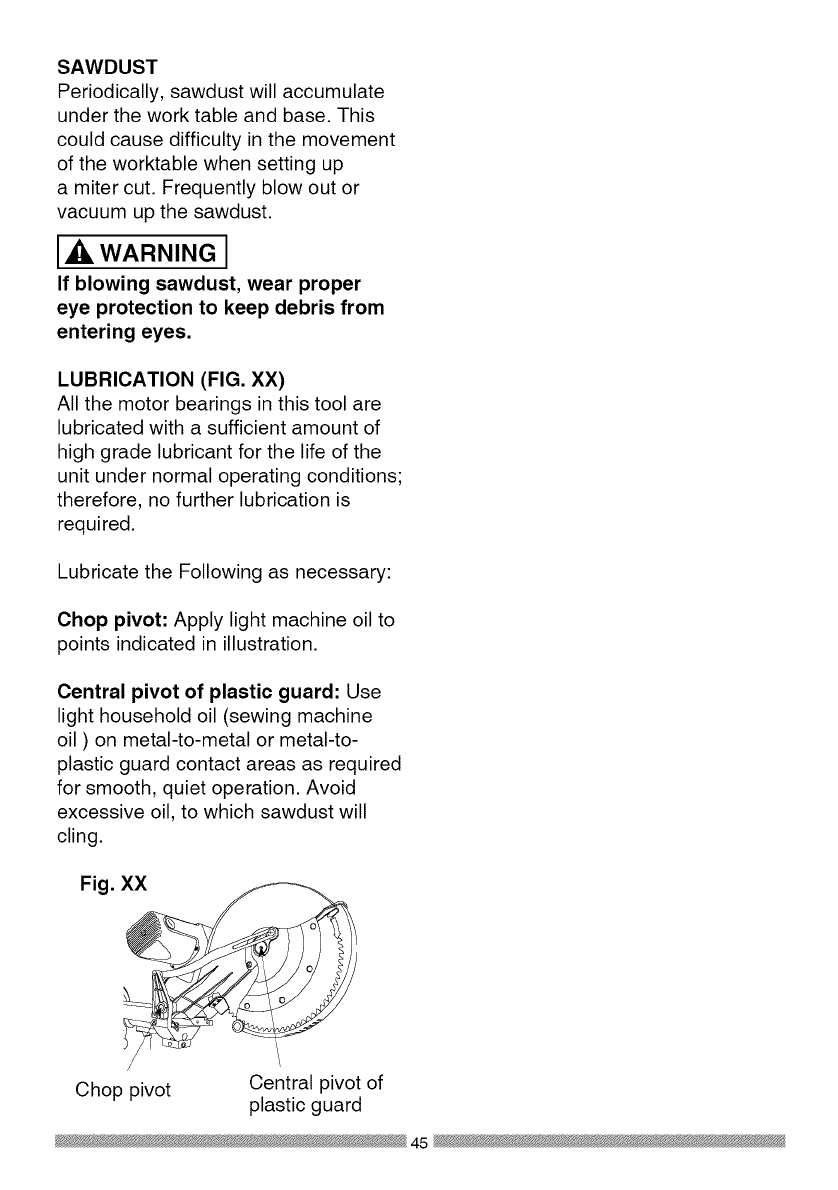
SAWDUST
Periodically, sawdust will accumulate
under the work table and base. This
could cause difficulty in the movement
of the worktable when setting up
a miter cut. Frequently blow out or
vacuum up the sawdust.
WARNING J
If blowing sawdust, wear proper
eye protection to keep debris from
entering eyes.
LUBRICATION (FIG. XX)
All the motor bearings in this tool are
lubricated with a sufficient amount of
high grade lubricant for the life of the
unit under normal operating conditions;
therefore, no further lubrication is
required.
Lubricate the Following as necessary:
Chop pivot: Apply light machine oil to
points indicated in illustration.
Central pivot of plastic guard: Use
light household oil (sewing machine
oil ) on metal-to-metal or metal-to-
plastic guard contact areas as required
for smooth, quiet operation. Avoid
excessive oil, to which sawdust will
cling.
Fig. XX
Chop pivot Central pivot of
plastic guard
45

WARNING I
To avoid injury from accidental starting, always turn switch OFF and unplug
the tool before moving, replacing the blade or making adjustments,
TROUBLESHOOTING GUIDE -MOTOR
PROBLEM PROBLEM CAUSE
Brake does
not stop blade
within 10
seconds.
Motor does
not start
Brush spark
when switch
released.
,
2.
.
4.
.
1.
2.
3.
,
2.
Motor brushes not sealed 1.
or lightly sticking.
Motor brake overheated 2.
from use of defective or
wrong size blade or rapid
ON/OFF cycling. 3.
Arbor bolt loose.
Brushes cracked,
damaged, etc. 4.
Other. 5.
Limit switch failure 1.
Brush worn. 2.
Fuse blown or circuit
breaker tripped on home 3.
panel.
Brush worn. 1.
Other.
,
SUGGESTED CORRECTIVE
ACTION
Inspect/clean/replace brushes.
See MAINTENANCE section.
Use a recommended blade. Let
cool down. See REMOVING OR
INSTALLING THE BLADE section.
Retighten. See REMOVING
OR INSTALLING THE BLADE
section.
Replace brushes.
Contact Sears Service Center.
Replace limit switch.
Replace brushes. See
MAINTENANCE section.
Verify there is electrical power at
the outlet.
Replace Brushes. See
MAINTENANCE section.
Contact Sears Service Center.
46

TROUBLESHOOTING GUIDE -SAW OPERATION
SUGGESTED CORRECTIVE
PROBLEM PROBLEM CAUSE ACTION
1. Misalignment. See ADJUSTMENT -Setting
Cutting Depth section.
1. Miter table unlocked. See OPERATION - Miter Angle
2. Sawdust under table. Adjustment section.
Vacuum or blow out dust. WEAR
EYE PROTECTION.
1. Loose pivot points. Contact Sears Service Center.
Blade hits
table.
Angle of cut
not accurate.
Can not
adjust miter.
Cutting arm
wobbles.
Cutting arm
will not fully
raise, or
blade guard
won't fully
close.
Blade binds,
ams, burns
wood.
Saw vibrates
or shakes.
1. Pivot spring not replaced
properly after service.
2. Sawdust build-up.
1. Improper operation.
2. Dull or warped blade.
3. Improper blade size.
4 Wood is moving during
cut.
1. Saw blade not round /
damaged /loose.
2. Arbor bolt loose.
.
1.
2.
1.
1.
2.
Contact Sears Service Center.
Clean and lubricate moving
parts.
1. See BASIC SAW OPERATION
section.
2. Replace or sharpen blade.
3. Replace with 12 in. diameter
blade.
4. Use hold down clamp to secure
workpiece to table.
1. Replace blade.
2. Tighten arbor bolt.
47

12 in. COMPOUND MITER SAW MODEL NO. 137.212210
2680 LOCATOR PIN
2752 TRADE-MARK LABEL
2753 TILTING SCALE
07X8 ELBOW
083Z CORD CLAMP
084J STOP CLAMP
084K SET PLATE
084M STOP CLAMP
084Q COMPRESSION SPRING
OCH1 SHAFT-PIVOT
OCH2 SLEEVE
OCHF SPRING GUARD
OCKM TRIGGER
ODTZ ARBOR COLLAR
OFHW COLLAR
OJ4E FLAT WASHER cp6_13-1
OJ4F FLAT WASHER cp8_16-2.5
0J53 FLAT WASHER q_8.4_24-2
OJA8 EXTERNALTOOTH LOCK WASHER cp8
OJBO WAVE WASHER
OJB3 WAVE WASHER
OJET E-RING
OJUA HEX. SOC. HD. CAP BOLT M5_0.8-8
OJUL HEX. SOC. HD. CAP BOLT M6_1.0-20
OJUX HEX. SOC. HD. CAP BOLT M8_1.25-30
OJV2 HEX. SOC. HD. CAP BOLT M8_1.25-60
OJVQ HEX. SOC. HD. CAP BOLT M8_1.28-50
OJZF HEX. SOC. SETSCREW M6"1.0-10
OK2B HEX. SOC. HD. CAP SCREW M6_1.0-16
OK4D CR. RE. PAN HD. SCREW & WASHER M6_1.0-12
OK7X CR. RE. TRUSS HD. ROUND NECK SCREW M6_1.0-10
OKB6 CR. RE. PAN HD. TAPPING SCREW M4_18-35
OKB7 CR. RE. PAN HD. TAPPING SCREW M4_18-16
OKB8 CR. RE. PAN HD. TAPPING SCREW M4"18-20
OKC6 CR. RE. TRUSS HD. TAPPING SCREW M4"16-12
OKD4 CR. RE. PAN HD. SCREW M6_1.0-10
OKD8 CR. RE. PAN HD. SCREW M4_0.7-12
OKDH CR. RE. PAN HD. SCREW M5_0.8-8
OKDU CR. RE. PAN HD. SCREW M6_1.0-12
OKL1 CR. RE. PAN HD. ROUND NECK SCREW M6_1.0-12
OKQY LOCK NUT M8_1.25 T=8
OKTP CABLE CLAMP
OKUW TERMINAL
PARTS LIST FOR SAW SCHEMATIC A
I.D. Description Size Qty I.D. Qfy
1888 CR. RE. PAN HD. TAPPING SCREW M6_14-16
Description Size
3LMH LOCKING CABLETIE
3S2X LOCK HANDLE ASS'Y
145V HEX WASHER HD BOLT M8"1.25-16
246V TRIGGER SWITCH
25Y1 ARM #AW
25YJ CRANK HANDLE
25YL CRANK HANDLE
25YR PLATE
25YU DUST BAG
262N SEGMENT HANDLE
262U GEAR BOX COVER #AW
267Y PULLEY
26H6 V-RIBBED BElT(POIYOURETHANE)
26PW SPACER
26U8 LOCKING HANDLE ASS'Y
Z6UJ PC-GUARD ASS'Y
Z6UK GEAR SHAFT ASS'Y
26UL CUTTER SHAFT ASS'Y
Z77Y CR. RE. PAN HD. TAPPING SCREW M6 _14-25
27KD LEVER
27KE CUTTER SHAFT GUARD
27KY CLAMP BOLT
Z7LP LOCK KNOB
Z7PF COMPRESSION SPRING
Z7WC COMPRESSION SPRING
Z83G HEX. SOC. HD. CAP SCREW M5"0.8-20
2B62 HEX. HD. BOLT M6"1.0-16
2CGT SLOTTED SETSCREW M6_1.0-8
2E63 ROCKER SWITCH
2JSX SEGMENT HANDLE
ZK96 WARNING LABEL
ZLK2 LASER PLUNGER HOUSING
2MNJ CONTROLLER ASS'Y
2MYA LEAD WIRE ASS'Y
ZNNJ SEGMENT HANDLE
2NQC MOTOR ASS'Y
2P4U PLUNGER HOUSING ASSW
ZQC6 LABEL
ZQK4 BLADE
2QU3 OPERATOR'S MANUAL
2QYA PULLEY COVER
ZSJT POWER CABLE
Y_43B CR. RE. COUNT HD. SCREW M5_0.8-25
48
_ik WARNING I
When servicing use only CRAFTSMAN replacement parts. Use of any other
parts many create a HAZARD or cause product damage. Any attempt to
repair or replace electrical parts on this Miter Saw may create a HAZARD
unless repair is done by a qualified service technician. Repair service is
available at your nearest Sears Service Center.

262U
145V
2QU3 246_
2LK2
2CG'['4_i 2P4_
OI,MH
43B z
0
I1"1
I"
Z
0
".4
k)
o

12 in. COMPOUND MITER SAW MODEL NO. 137.212210
PARTS LIST FOR SAW SCHEMATIC B
I.D. Description Size
0831 SHAFT SLEEVE
2750 CAUTION LABEL
2841 CENTER SHAFT
OCEZ PLUNGER HANDLE
OD7Z KNOB-HANDLE
ODW5 POWER CORD CLAMP
OH9W CLEVIS PiN
OHAM DUST SHIELD
OHAN PLATE COVER
OHAP SLIDE-BAR GUIDE CLAMP
OHVD BALL BEARING
OHXX LINEAR MOTION BEARING
OJ4N FLAT WASHER @16_30-3
OJ6A FLAT WASHER q_8_16-2.5
0J78 FLAT WASHER 1/4_1/2-3/32
OJ7D FLAT WASHER 5/1639/16-1/16
OJ7K FLAT WASHER 3/8329/32-5/64
OJ8P FLAT WASHER 3/8_29/32-5/64
OJAF EXTERNAL TOOTH LOCK WASHER @5
OJB0 WAVE WASHER WW-8
OJMN O-RING
OJMP O-RING
OJMT O-RING ROD
OJPP HEX. HD. BOLT M8_1.25-30
OJUM HEX. SOC. HD. CAP BOLT M6_1.0-25
OJUW HEX. SOC. HD. CAP BOLT M8_1.25-25
OJX3 HEX. SOC. SETSCREW M5_0.8-8
OJXD HEX. SOC. SETSCREW M6_1.0-25
OJXG HEX. SOC. SETSCREW M8_1.25-16
OK2B HEX. SOC. HD. CAP SCREW M6_1.0-16
OK7F CR. RE. ROUND WASHER HD. SCREW M5_0.8-8
OK7X CR. RE. TRUSSHD. ROUND NECK SCREW M6_1.0-10
OKAE CR. RE. PAN HD. TAPPING SCREW M5_0.8-10
OKB3 CR. RE. PAN HD. TAPPING SCREW M4_18-8
OKD9 CR. RE. PAN HD. SCREW M4_0.7-16
OKDH CR. RE. PAN HD. SCREW M5_0.8-8
OKDM CR. RE. PAN HD. SCREW M5_0.8-20
OKDR CR. RE. PAN HD. SCREW M5_0.8-10
OKDV CR. RE. PAN HD. SCREW M6_1.0-16
OKMS HEX. NUT M6_1.0T=5
OKMY HEX. NUT M8_1.25 T=6.5
OKQY LOCK NUT M8_1.25 T=8
OKQZ NUT M10_1.5 T=IO
OKR1 LOCK NUT M16_2.0 T=16
Qty I.D.
OKR4
OKSP
25XZ
25YG
25YK
262Q
262R
262S
262V
26HX
26LU
26NH
26NP
26NQ
26NR
26NS
26P7
26PU
26U6
26UQ
27BC
27BU
27BV
27HE
27J9
27JA
27MN
27Y4
283H
290M
2A J3
2DUC
2ED6
2JT2
2NGV
2NGW
2NKR
2NLC
2NLK
2RAX
2RAY
2SY9
Y648
Description Size Qty
LOCK NUT M8_1.25 T=8 1
STRAIN RELIEF 1
ARM-MITER #AW 1
NEEDLE POINTER 1
SETPLATE 1
TILTPOINTER 1
TILTPOINTER #23 1
POWER CORD CLAMP 2
ANCHOR PLATE #06 1
GUIDE HOLDER 1
WARNING LABEL 1
SPECIAL NUT 1
SPECIAL BOLT 1
LOCATING BAR 1
SHAFT-PWOT 1
LOCKING ROD 1
SHAFT-PWOT 1
MITER BAR 1
LOCKING HANDLE ASS'Y 1
BRACKET-TILT 1
SAFETY CLAMP ASS'Y 1
TABLE INSERT 1
TABLE INSERT 1
TORSION SPRING 1
SETNUT 1
SCREW STOP 1
ANCHOR PLATE 1
HEX. SOC. SET SCREW M631.0-16 2
HEX. SOC. HD. CAP SCREW M530.8-12 4
CAUTION LABEL 1
CLAMP HANDLE #AW 1
CR. RE.TRUSS HD. SCREW M5_0.8-8 1
CAUTION LABEL 1
STEELBALL 2
SUPPORT(LEFT) #AW 1
SUPPORT(RIGHT) #AW 1
SPECIAL BOLT 2
SPRING 2
TABLE #AW 1
LOCK KNOB 1
PLATE 1
SLIDE-BAR ASS'Y 1
COMPRESSION SPRING 1
5O
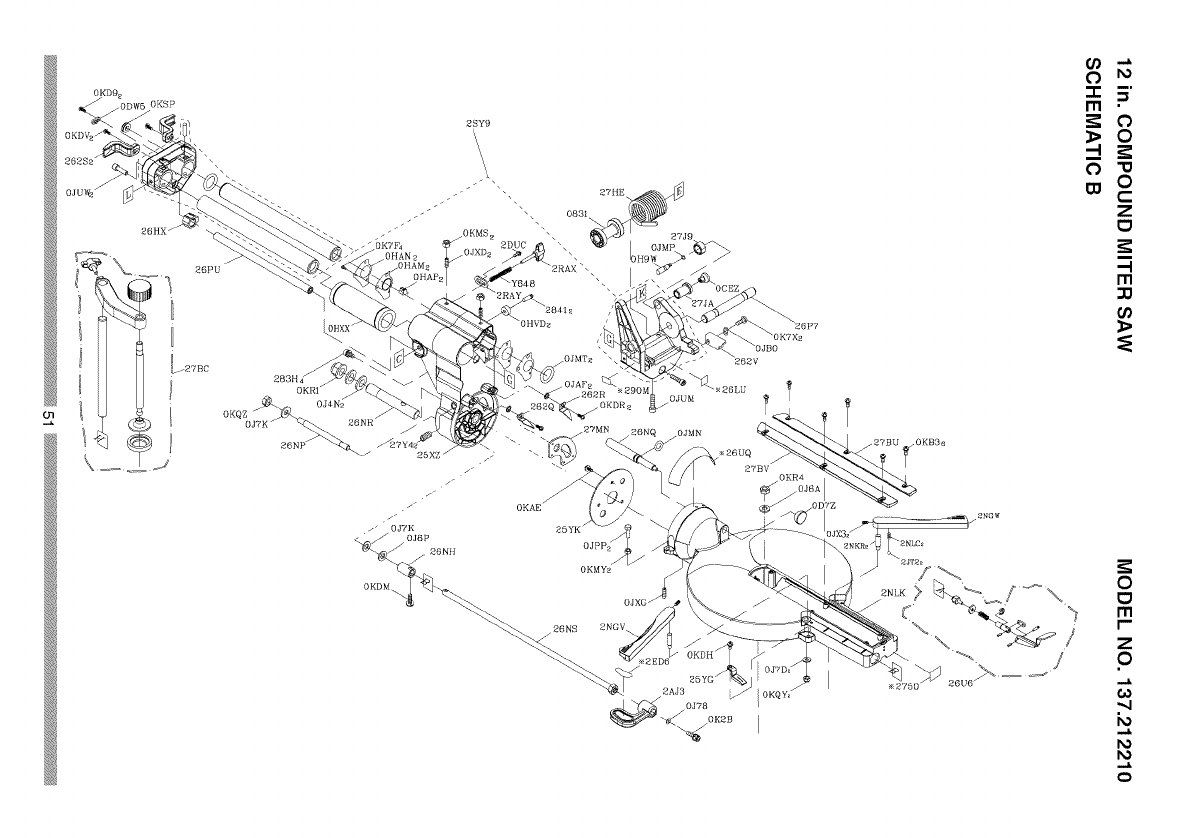
26HX /
26PU
/27BC
2SY9
\\\
_?HE
", 083I__
, 27J9
OH9W
26P7
\OJBO
262V
25YK /
0Jppz /
./
0KMYa
OJXO /
26NS ENGV
25YG /
Z .N"
Ill •
0
w 0
C
Z
o
-I
r,n
r_
0
o
I'll
r-
Z
0
0)
o

12 in. COMPOUND MITER SAW
PARTS LIST FOR SAW SCHEMATIC C
I.D. Description Size
2258 SPECIAL BOLT I
2754 WARNING LABEL I
082J CUSHION 2
082L BOLT 2
0CDD FOOT 4
0CFX SLIDE PLATE 3
0DTH CENTER BOLT t
0DVJ BLADE WRENCH 1
0H9A REAR EXTENSION STAY I
0J69 FLAT WASHER cp6"13-I I
0J88 FLAT WASHER #I0"t/2-1/16 2
Qty I.D. Description
MODEL NO. 137.212210
0JB0 WAVE WASHER WW-8
0JUB HEX. SOC. HD. CAP BOLT M5_0.8-12
0JZF HEX. SOC. SETSCREW M6"1.0-10
0K28 HEX. SOC. HD. CAP SCREW M5"0.8-16
0K2P HEX. SOC. HD.CAP SCREW M8_1.25-40
0K55 CR. RE. COUNT HD. SCREW M5_0.8-8
0K74 CR. RE. TRUSSHD. SCREW M6"1.0-8
0KAE CR. RE. PAN HD. TAPPING SCREW M5_0.8-10
0KDG CR. RE. PANHD. SCREW
0KDH CR. RE. PANHD. SCREW
0KDM CR. RE. PANHD. SCREW
0KDU CR. RE. PANHD. SCREW
0KR2 LOCK NUT
0KR3 LOCK NUT
0LYT STEELBALL
20PL CLAMP HANDLE
224U ROLL PIN
23SR COMPRESSION SPRING
M5_0.8-6
M5_0.8-8
M5"0.8-20
M6_'1.0-12
M5_0.8 T=5
M6_1.0 T=6
2
2
t
4
4
4
4
2
2
1
2
2
2
2
2
2
2
2
25V3 KNOB
25XX BASE
25Y0 ASSIST-FENCE
25Y2 EXTENSION WING
25Y3 ASSIST-FENCE
25Y6 EXTENSION WING
25Y8 FENCE
25YA LOCKING HANDLE ASS'Y
25YV PLATE
25YW PLATE (RIGHT)
262T FENCE PLATE
Size Qty
4
#AW I
#AW
#AW
#AW
#AW
#AW t
1
#23 I
#23 I
#AW 2
2
M8"1.25-6 2
2
1
I
I
26NN UPPER TUBE
26PF HEX. SOC. SETSCREW
26PK BLADE HOLDER
26UG LOCKING HANDLEASS'Y
26US BRACKET-TILT
27H1 CLAMP-CORD
27KA ECCENTRIC SPANNER SEAT #06
27KP SLIDE-BAR BLADE GUARD #AW
27LI LOCKING HANDLE ASS'Y
2C7F UPPER TUBE
2D J6 BRACKET-TILT
2D J7 BRACKET-TILT
2ENA EXTENSION WING ASS'Y
2ENB EXTENSION WING ASS'Y
2KSQ WARNING LABEL
2NH7 PLUNGER HOUSINGASS'Y
2QM7 FLAT WASHER cp6_10-1
2
1
t
1
1
1
t
4
52

27KP
+_/+'+L+
io+_ I
J
J
\
J
\25XX J
// /+
\%
Z .N"
m •
_0
0"u
o0
C
Z
0
-I
r,n
r_
0
0
I'll
r-
Z
0
0)
o

12 in. COMPOUND MITER SAW MODEL NO. 137.212210
PARTS LIST FOR MOTOR
I.D.
OJB8
OJX3
OJXC
0K38
OK3T
OK3Y
OKLA
OQ9K
OQM2
OQQT
OQR0
OQRI
26AZ
26DF
26PD
2MYR
2PRU
2QY7
Y430
Description Size Qfy
WAVE WASHER 1
HEX. SOC. SETSCREW M5"0.8-8 2
HEX. SOC. SETSCREW M6"1.0-20 1
CR. RE. PAN HD. SCREW & WASHER M5"0.8-8 2
CR. RE. PAN HD. SCREW & WASHER M5"0.8-25 2
CR. RE. PAN HD. SCREW & WASHER M5"0.8-50 2
PLASTIC SCREW M5"0.8-6 2
FLOW GUIDE 1
BRUSH HOLDER ASS'Y (b27"26.5 2
BRUSH ASS'Y 2
BRUSH COVER 2
RUBBER PIN 1
ARMATURE ASS'Y 1
FRONT HOUSING #AW 1
MOTOR PULLEY 1
FIELD ASS'Y 1
CR. RE. PAN HEAD TAPPING & WASHER SCREW M5"12-65 2
MOTOR HOUSING ASS'Y 1
HEX. HD. SCREW & WASHER SCREW M6"1.0-t6 1
0K3T\
OJX3
%
0KLA,
0JB8
2MYR
%
0JXC
26DF
0K38
Y430
26PD
54

55

Your Home
For expert troubleshooting and home solutions advice:
manage home
www.managemyhome.com
For repair - in your home - of all major brand appliances,
lawn and garden equipment, or heating and cooling systems,
no matter who made it, no matter who sold it!
For the replacement parts, accessories and
owner's manuals that you need to do-it-yourself.
For Sears professional installation of home appliances
and items like garage door openers and water heaters.
1-800-4-MY-HOME ®(1-800-469-4663)
Call anytime, day or night (U.S.A. and Canada)
www.sears.com www.sears.ca
Our Home
For repair of carry-in items like vacuums, lawn equipment,
and electronics, call anytime for the location of your nearest
Sears Parts & Repair Service Center
1-800-488-1222 (U.S.A.) 1-800-469-4663 (Canada)
www.sears.com www.sears.ca
To purchase a protection agreement on a product serviced by Sears:
1-800-827-6685 (U.S.A.) 1-800-361-6665 (Canada)
Para pedir servicio de reparaci6n Au Canada pour service en frangais:
a domicilio, y para ordenar piezas: 1-800-LE-FOYER M°
1-888-SU-HOGAR ® (1-800-533-6937)
Sea rs www.sears.ca
TM SM
® Registered Trademark /Trademark /Service Mark of Sears Brands, LLC
SM
® Marca Registrada /TM Marca de Fabrica /Marca de Servicio de Sears Brands, LLC
Mc MO
Marque de commerce /Marque deposce de Sears Brands, LLC © Sears Brands, LLC

Operator's Manual
CRAFTSMAN°
i PROFESSI ONAL i
12 in. DUAL BEVEL SLIDING COMPOUND
MITER SAW WITH LASER TRAC®
Model No. 137.212210
C US
CAUTION:
Before using this Miter Saw,
read this manual and follow
all its Safety Rules and
Operating Instructions
• Safety Instructions
• Installation
• Operation
• Maintenance
• Parts List
Customer Help Line
For Technical Support
1-800-843-1682
Sears Parts &
Repair Center
1-800-488-1222
Sears, Roebuck and Co., Hoffman Estates, IL 60179 USA
Visit our Craftsman website: www.sears.com/craftsman
Part No. 137212210001 Printed in Taiwan

SECTION PAGE
Warranty.............................................................................................2
ProductSpecifications........................................................................3
Symbols..............................................................................................4
PowerToolSafety..............................................................................5
CompoundMiterSawSafety..............................................................7
ElectricalRequirementsandSafety......................................................9
AccessoriesandAttachments............................................................11
ToolsNeededforAssembly................................................................12
CartonContents.................................................................................13
KnowYourCompoundMiterSaw........................................................14
GlossaryofTerms..............................................................................15
AssemblyandAdjustments................................................................17
Operation...........................................................................................30
Maintenance.......................................................................................44
TroubleshootingGuide.......................................................................46
PartsList.............................................................................................48
CRAFTSMAN ONE YEAR FULL WARRANTY
If this Craftsman tool fails due to a defect in material or workmanship within
one year from the date of purchase, call 1-800-4-MY-HOME® to arrange for
free repair (or replacement if repair proves impossible).
This warranty applies for only 90 days from the date of purchase if this product
is ever used for commercial or rental purposes.
This warranty does not include expendable parts, such as lamps, batteries,
bits or blades.
This warranty gives you specific legal rights, and you may also have other
rights which vary from state to state.
Sears, Roebuck and Co., Hoffman Estates, IL 60179
_, WARNING J
Some dust created by using power tools contains chemicals known to the
state of California to cause cancer and birth defects or other reproductive
harm. Some examples of these chemicals are:
•Lead from lead-based paints
•Crystalline silica from bricks, cement and other masonry products
•Arsenic and chromium from chemically treated lumber
Your risk from these exposures varies, depending on how often you do
this type of work. To reduce your exposure to these chemicals, work in a
well ventilated area and work with approved safety equipment such as dust
masks that are specially designed to filter out microscopic particles.
2
2008/04

MOTOR
Power Source ............................... 120VAC, 60Hz, 15Amp
Speed ........................................... 4200 RPM (No load)
Brake ............................................ Electric
Double Insulated ........................... Yes
Motor Arbor Shaft Size .................. 5/8 in.
BLADE SIZE
Diameter ....................................... 12 in.
Arbor size ...................................... 1in.w/a 5/8 in.reducer
ROTATING TABLE
Diameter ....................................... 13-7/16 in.
Miter Detent Stops ........................ 0, 15, 22.5,31.6, 45° R & L, 60° R
Bevel Positive Stops ..................... 0, 33.9, 45° R & L
CUTTING CAPACITY
Crosscut ........................................ 4 in. x 12-1/4 in.
Miter 45° R & L; 60° R .................... 4 in. x 8-3/4 in. R & L ; 4 in. x 6-1/4 in. R
Bevel 45° R & L ............................. 2-1/2 in. x 12-1/4 in. L ; 1-3/4 in. x 12-1/4 in. R
45° Miter and 45° Bevel R & L........ 2-1/2 in. x 8-3/4 in.
60° Miter and 45° Bevel R .............. 1-3/4 in. x 6-1/4 in.
[_iL WARNING J
To avoid electrical hazards, fire hazards or damage to the tool, use proper
circuit protection.
This tool is wired at the factory for 110-120 Volt operation. It must be
connected to a 110-120 Volt /15 Ampere time delay fuse or circuit breaker.
To avoid shock or fire, replace power cord immediately if it is worn, cut or
damaged in any way.
Before using your tool, it is critical that you read and understand these
safety rules. Failure to follow these rules could result in serious injury to
you or damage to the tool.
3

WARNING ICONS
Your power tool and its Operator's Manual may contain "WARNING ICONS"
(a picture symbol intended to alert you to, and/or instruct you how to avoid,
a potentially hazardous condition). Understanding and heeding these
symbols will help you operate your tool better and safer. Shown below are
some of the symbols you may see.
SAFETY ALERT: Precautions that involve your safety.
®PROHIBITION
OWEAR EYE PROTECTION: Always wear safety goggles or safety
glasses with side shields.
READ AND UNDERSTAND OPERATOR'S MANUAL: To reduce
the risk of injury, user and all bystanders must read and understand
operator's manual before using this product.
®KEEP HANDS AWAY FROM BLADE: Failure to keep your hands
away from the blade will result in serious personal injury.
SUPPORT AND CLAMP WORK
[_, DANGER] DANGER: indicates an imminently hazardous situation
which, if not avoided, will result in death or serious injury.
[A WARNING I
[A CAUTION I
WARNING: indicates a potentially hazardous situation
which, if not avoided, could result in death or serious
injury.
CAUTION: indicates a potentially hazardous situation
which, if not avoided, may result in minor or moderate
injury.
CAUTION: used without the safety alert symbol indicates
[ CAUTION ]a potentially hazardous situation which, if not avoided,
may result in property damage.
4

GENERAL SAFETY INSTRUCTIONS 8.
BEFORE USING THIS POWER TOOL
Safety is a combination of common
sense, staying alert and knowing how 9.
to use your power tool.
CAUTION
To avoid mistakes that could cause
serious injury, do not plug the tool in 10.
until you have read and understood
the following.
.
,
,
.
READ and become familiar with
the entire Operator's
Manual. LEARN the tool's
application, limitations and
possible hazards.
KEEP GUARDS IN PLACE and in
working order.
REMOVE ADJUSTING KEYS
AND WRENCHES. Form the habit
of checking to see that keys and
adjusting wrenches are removed
from the tool before turning ON.
KEEP WORK AREA CLEAN.
Cluttered areas and benches invite
accidents.
,DO NOT USE IN DANGEROUS
ENVIRONMENTS. Do not use
power tools in damp locations, or
expose them to rain or snow. Keep
work area well lit.
,KEEP CHILDREN AWAY. All
visitors and bystanders should be
kept a safe distance from work
area.
,MAKE WORKSHOP CHILD
PROOF with padlocks, master
switches or by removing starter
keys.
11.
12.
DO NOT FORCE THE TOOL. It will
do the job better and safer at the
rate for which it was designed.
USE THE RIGHT TOOL. Do not
force the tool or an attachment
to do a job for which it was not
designed.
USE PROPER EXTENSION
CORDS. Make sure your extension
cord is in good condition. When
using an extension cord, be sure
to use one heavy enough to carry
the current your product will draw.
An undersized cord will result in
a drop in line voltage and in loss
of power which will cause the tool
to overheat. The table on page
10 shows the correct size to use
depending on cord length and
nameplate ampere rating. If in
doubt, use the next heavier gauge.
The smaller the gauge number, the
heavier the cord.
WEAR PROPER APPAREL. Do
not wear loose clothing, gloves,
neckties, rings, bracelets or other
jewelry which may get caught in
moving parts. Nonslip footwear is
recommended. Wear protective
hair covering to contain long hair.
OALWAYS WEAR EYE
PROTECTION. Any power
tool can throw foreign
objects into the eyes and
could cause permanent eye
damage. ALWAYS wear Safety
Goggles (not glasses) that comply
with ANSI Safety standard Z87.1.
Everyday eyeglasses have only
impact-resistant lenses. They
ARE NOT safety glasses. Safety
Goggles are available at sears.
5

NOTE: Glasses or goggles not in
compliance with ANSI Z87.1 could
seriously injure you when they
break.
and any other conditions that may
affect its operation. A guard or
other part that is damaged should
be properly repaired or replaced.
13. WEAR A FACE MASK OR DUST
MASK. Sawing operation produces
dust.
14. SECURE WORK. Use
clamps or a vise to hold work
when practical. It is safer
than using your hand and it
frees both hands to operate
the tool.
15. DISCONNECT TOOLS FROM
POWER SOURCE before servicing,
and when changing accessories
such as blades, bits and cutters.
16. REDUCE THE RISK OF
UNINTENTIONAL STARTING.
Make sure switch is in the OFF
position before plugging the tool in.
17. USE RECOMMENDED
ACCESSORIES. Consult
this Operator's Manual for
recommended accessories. The
use of improper accessories may
cause risk of injury to yourself or
others.
18. NEVER STAND ON THE TOOL.
Serious injury could occur if the
tool is tipped or if the cutting tool is
unintentionally contacted.
20. NEVER LEAVE THE TOOL
RUNNING UNATTENDED. TURN
THE POWER "OFF". Do not walk
away from a running tool until the
blade comes to a complete stop
and the tool is unplugged from the
power source.
21. DO NOT OVERREACH. Keep
proper footing and balance at all
times.
22. MAINTAIN TOOLS WITH CARE.
Keep tools sharp and clean for best
and safest performance. Follow
instructions for lubricating and
changing accessories.
23. WARNING: Dust generated from
certain materials can be hazardous
to your health. Always operate saw
in well-ventilated area and provide
for proper dust removal.
24.[_k DANGER J People with
electronic devices, such as
pacemakers, should consult their
physician(s) before using this
product. Operation of electrical
equipment in close proximity to
a heart pacemaker could cause
interference or failure of the
pacemaker.
19. CHECK FOR DAMAGED PARTS.
Before further use of the tool, a
guard or other part that is damaged
should be carefully checked to
determine that it will operate
properly and perform its intended
function - check for alignment of
moving parts, binding of moving
parts, breakage of parts, mounting
6

SPECIFIC SAFETY INSTRUCTIONS
FOR THIS COMPOUND MITER SAW
.DO NOT operate the miter saw
until it is completely assembled
and installed according to these
instructions.
,IF YOU ARE NOT thoroughly
familiar with the operation of miter
saws, seek guidance from your
supervisor, instructor or other
qualified person.
,ALWAYS hold the work firmly
against the fence and table.
DO NOT perform any operation
free hand (use clamp wherever
possible).
.KEEP HANDS out of the path of the
saw blade. If the workpiece you are
cutting would cause your hands to
be within 8-3/4 in. of the saw blade,
the workpiece should be clamped in
place before making the cut.
5. BE SURE the blade is sharp, runs
freely and is free of vibration.
6. ALLOW the motor to come up to full
speed before starting a cut.
7. KEEP THE MOTOR AIR SLOTS
CLEAN and free of chips or dust.
,ALWAYS MAKE SURE all handles
are tight before cutting, even if the
table is positioned in one of the
positive stops.
9. BE SURE both the blade and the
collar are clean and the arbor bolt is
tightened securely.
10.USE only blade collars specified for
your saw.
11.NEVER use blades larger in
diameter than 12 inches.
12.NEVER apply lubricants to the
blade when it is running.
13.ALWAYS check the blade for
cracks or damage before operation.
Replace a cracked or damaged
blade immediately.
14.NEVER use blades recommended
for operation at less than 4200
RPM.
15.ALWAYS keep the blade guards in
place and use at all times.
16.NEVER reach around the saw
blade.
17.MAKE SURE the blade is not
contacting the workpiece before the
switch is turned ON.
18.IMPORTANT: After completing the
cut, release the trigger and wait for
the blade to stop before returning
the saw to the raised position.
19.MAKE SURE the blade has come
to a complete stop before removing
or securing the workpiece, changing
the workpiece angle or changing the
angle of the blade.
20.NEVER cut metals or masonry
products with this tool. This miter
saw is designed for use on wood
and wood-like products.
7

21. NEVER cut small pieces. If the
workpiece being cut would cause
your hand or fingers to be within
8-3/4 in. of the saw blade the
workpiece is too small.
22. PROVIDE adequate support to the
sides of the saw table for long work
pieces.
23. NEVER use the miter saw in an
area with flammable liquids or
gases.
24. NEVER use solvents to clean
plastic parts. Solvents could
possibly dissolve or otherwise
damage the material.
25. SHUT OFF the power before
servicing or adjusting the tool.
26. DISCONNECT the saw from
the power source and clean the
machine when finished using.
27. MAKE SURE the work area is
clean before leaving the machine.
28. SHOULD any part of your miter saw
be missing, damaged, or fail in any
way, or any electrical component
fail to perform properly, lock the
switch and remove the plug from
the power supply outlet. Replace
missing, damaged, or failed parts
before resuming operation.
8

POWER SUPPLY AND MOTOR
SPECIFICATIONS
The AC motor used in this saw is
a universal, nonreversible type.
See "MOTOR" in the "PRODUCT
SPECIFICATIONS" section on page 3.
WARNING I
To avoid electrical hazards, fire
hazards, or damage to the tool, use
proper circuit protection, Your saw
is wired at the factory for 120 V
operation, Connect to a 120 V, 15A
circuit and use a 15 A time delay
fuse or circuit breaker, To avoid
shock or fire, if power cord is worn
or cut, or damaged in any way, have
it replaced immediately,
way. If the plug does not fit fully in the
outlet, reverse the plug. If it still does
not fit, contact a qualified electrician to
install the proper outlet. Do not change
the plug in any way.
IAWARNINGI
Double insulation does not take the
place of normal safety precautions
when operating this tool.
To avoid electrocution:
1. Use only identical replacement parts
when servicing a tool with double
insulation. Servicing should be
performed by a qualified technician.
2. Do not use power tools in wet or
damp locations or expose them to
rain or snow.
DOUBLE INSULATED []
The power tool is double insulated to
provide a double thickness of insulation
between you and tool's electrical
system. All exposed metal parts are
isolated from the internal metal motor
components with protecting insulation.
Replacement parts - When servicing,
use only identical replacement parts.
Polarized plugs - This saw has a plug
that looks like the one shown below:
To reduce the risk of electrical shock,
this saw has a polarized plug (one
blade is wider than the other). This plug
will fit in a polarized outlet only one
MOTOR SAFETY PROTECTION
IMPORTANT
To avoid motor damage, the motor
should be blown out or vacuumed
frequently to keep sawdust from
interfering with the motor ventilation.
1. Connect this saw to a 120 V circuit.
This circuit must not be less than a
#12 wire with a 20 A time lag fuse or
a #14 wire with a 15 A time lag fuse.
NOTE: When using an extension
cord on a circuit with a #14 wire, the
extension cord must not exceed 25
feet in length.
2. If the motor will not start, release
the trigger switch immediately.
UNPLUG THE SAW. Check the saw
blade to make sure it turns freely. If
the blade is free, try to start the saw
again. If the motor still does not start,
refer to the TROUBLESHOOTING
GUIDE.
3. If the tool suddenly stalls while
cutting wood, release the trigger
switch, unplug the tool and free the
blade from the wood. The saw may
9

now be started and the cut finished.
4. FUSES may "blow" or circuit
breakers may trip frequently if:
a. MOTOR is overloaded -
overloading can occur if you feed
too rapidly or make too many
start/stops in a short time.
b. LINE VOLTAGE is more
than 10% above or below the
nameplate voltage rating. For
heavy loads, the voltage at motor
terminals must equal the voltage
specified on the nameplate.
c. IMPROPER or dull saw blades
are used.
5. Most motor troubles may be traced
to loose or incorrect connections,
overload, low voltage or inadequate
power supply wiring. Always check
the connections, the load and
supply circuit if the motor doesn't
run well. Check minimum gauge for
the length of cord you are using on
the chart below.
excessive heat and damp or wet areas.
Use a separate electrical circuit
for your tools. This circuit must not
be less than a #12 wire with a 20 A
time lag fuse or a #14 wire with a 15
A time lag fuse. NOTE: When using
an extension cord on a circuit with
a #14 wire, the extension cord must
not exceed 25 feet in length. Before
connecting the tool to the power line,
make sure the switch is in the OFF
position and the electric current is
rated the same as the current stamped
on the motor nameplate, running at a
lower voltage will damage the motor.
I,V_ll#lhVjIll Lvj|€f._11[_1 =11=[0]t,i _:Q i=1#{..I [el #El.ill ;I I]._fzViVL_l
(When using 120 volts only)
Ampere Rating Total length of Cord
More Than Not More Than 25ft. 50ft. 100ft. 150ft.
O 6 18 16 16 14
6 10 18 16 14 12
10 12 16 16 14 12
GUIDELINES FOR EXTENSION
CORDS
Use a proper extension cord. Make
sure your extension cord is in good
condition. When using an extension
cord, be sure to use one heavy enough
to carry the current your product will
draw. An undersized cord will cause
a drop in line voltage, resulting in
loss of power and overheating. The
table below shows the correct size
to use depending on cord length and
nameplate ampere rating. If in doubt,
use the next heavier gauge. The
smaller the gauge number, the heavier
the cord.
CAUTION: In all cases make certain
the receptacle in question is
properly grounded. If you are not
sure, have a certified electrician
check the receptacle.
Be sure your extension cord is
properly wired and in good condition.
Always replace a damaged extension
cord or have it repaired by a qualified
person before using it. Protect your
extension cords from sharp objects,
10
RECOMMENDED ACCESSORIES
[_k WARNING J
•Use only accessories
recommended for this miter
saw. Follow instructions that
accompany accessories. Use of
improper accessories may cause
hazards.
•The use of any cutting tool
except 12 in. saw blades which
meet the requirements under
recommended accessories
is prohibited. Do not use
accessories such as shaper
cutters or dado sets. Ferrous
metal cutting and the use of
abrasive wheels is prohibited.
•Do not attempt to modify this
tool or create accessories not
recommended for use with this
tool. Any such alteration or
modification is misuse and could
result in a hazardous condition
leading to possible serious
injury.
without the proper saw blade
guard in place. Carbide is a very
hard but brittle material. Care
should be taken while mounting,
using, and storing carbide tipped
blades to prevent accidental
damage. Slight shocks, such as
striking the tip while handling,
can seriously damage the blade.
Foreign objects in the workpiece,
such as wire or nails, can also
cause tips to crack or break off.
Before using, always visually
examine the blade and tips for
bent blade, cracks, breakage,
missing or loose tips, or other
damage. Do not use if damage is
suspected. Failure to heed safety
instructions and warnings can
result in serious bodily injury.
ACCESSORIES
Visit your Sears Hardware Department
or see the Sears Power and Hand Tool
Catalog to purchase recommended
accessories for this power tool.
[_, WARNING J
•To avoid the risk of personal
injury, do not modify this power
tool or use accessories not
recommended by Sears.
•Read warnings and conditions
on your CARBIDE TIPPED SAW
BLADE. Do not operate the saw
11
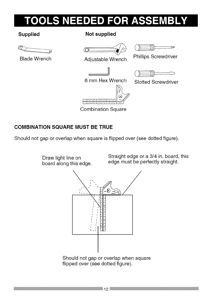
Supplied
Blade Wrench
Not supplied
Adjustable Wrench
6 mm Hex Wrench
l!'-'"-'_,_i'-:'_,_,_'-'' -'i'-_,_
Combination Square
Phillips Screwdriver
Slotted Screwdriver
COMBINATION SQUARE MUST BE TRUE
Should not gap or overlap when square is flipped over (see dotted figure).
Draw light line on
board along this edge.
Straight edge or a 3/4 in. board, this
edge must be perfectly straight.
Should not gap or overlap when square
flipped over (see dotted figure).
12
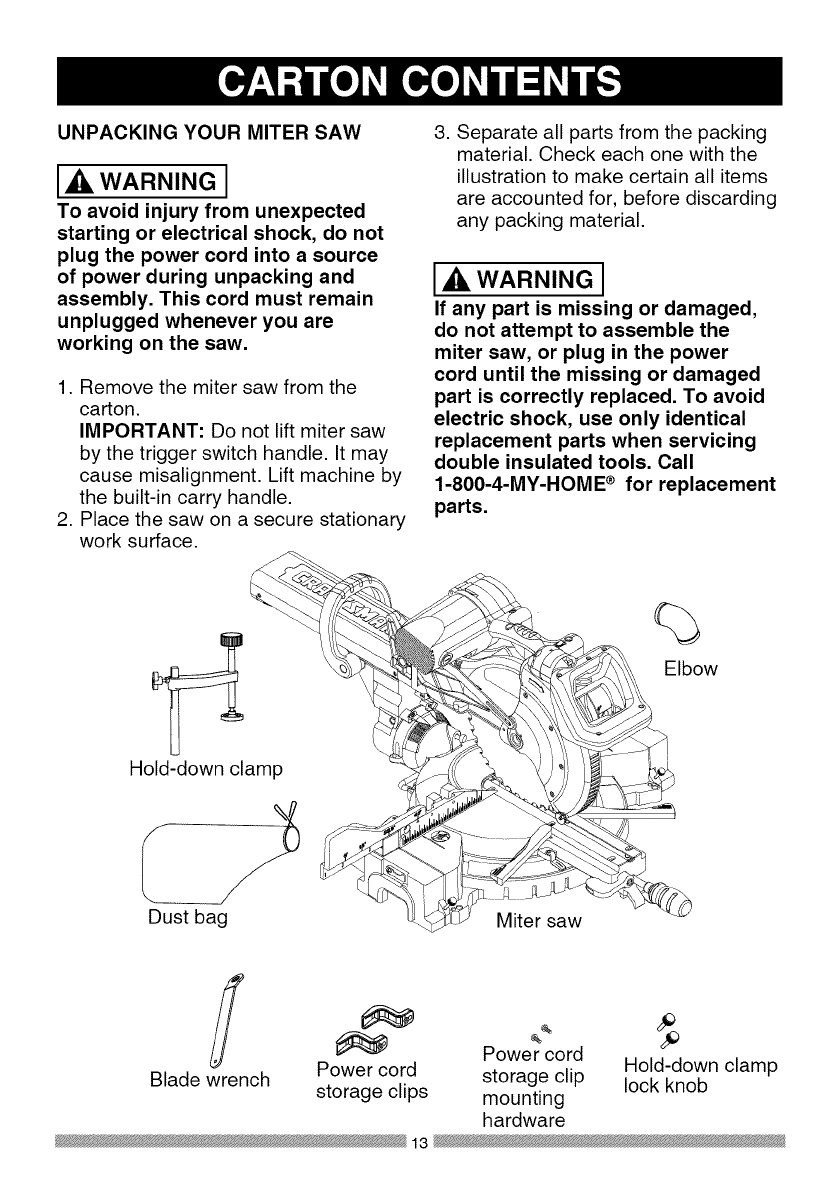
UNPACKING YOUR MITER SAW
WARNING I
To avoid injury from unexpected
starting or electrical shock, do not
plug the power cord into a source
of power during unpacking and
assembly. This cord must remain
unplugged whenever you are
working on the saw.
1. Remove the miter saw from the
carton.
IMPORTANT: Do not lift miter saw
by the trigger switch handle. It may
cause misalignment. Lift machine by
the built-in carry handle.
2. Place the saw on a secure stationary
work surface.
3. Separate all parts from the packing
material. Check each one with the
illustration to make certain all items
are accounted for, before discarding
any packing material.
IAWARNINGi
If any part is missing or damaged,
do not attempt to assemble the
miter saw, or plug in the power
cord until the missing or damaged
part is correctly replaced. To avoid
electric shock, use only identical
replacement parts when servicing
double insulated tools. Call
1-800-4-MY-HOME ®for replacement
parts.
Hold-down clamp
Dust bag Miter saw
%
Elbow
Power cord Hold-down clamp
Blade wrench Power cord storage clip lock knob
storage clips mounting
hardware
13
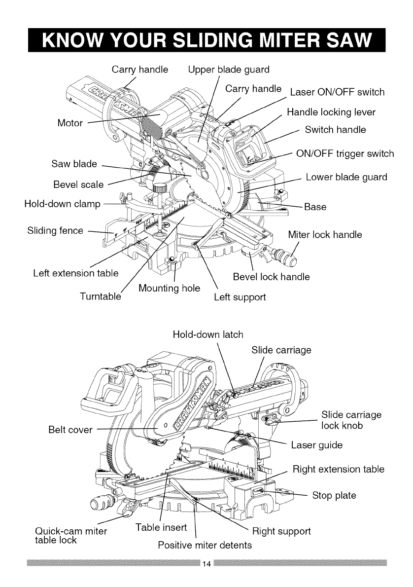
Motor \
Saw blade
Bevel scale
Hold-down clamp
Sliding fence
Carry handle Upper blade guard
Carry handle Laser ON/OFF switch
Handle locking lever
Switch handle
ON/OFF trigger switch
Lower blade guard
Base
Miter lock handle
Left extension table
Turntable
Bevel lock handle
Mounting hole Left support
Belt cover
Hold-down latch
Slide carriage
Slide carriage
lock knob
Laser guide
Right extension table
Stop plate
Quick-cam miter
table lock Table insert Right support
Positive miter detents
14

AMPERAGE (AMPS) - A measure
of the flow of electric current. Higher
ratings generally means the tool is
suited for heavier use.
ARBOR LOCK -Allows the user to
keep the blade from rotating while
tightening or loosening the arbor bolt
during blade replacement or removal.
eyes. Eye protection should meet the
requirements of ANSI Z.87.1 (USA) or
CSA Z94.3-M88 (Canada).
FACE SHIELD - An impact resistant
shield that helps to protect your face
from chips, sparks, small debris.
Should only be used in conjunction with
additional eye protection.
BASE - Supports the table, holds
accessories and allows for workbench
or leg set mounting.
FENCE - Helps to keep the workpiece
from moving when sawing. Scaled to
assist with accurate cutting.
BEVEL LOCKING HANDLE - Locks
the miter saw at a desired bevel angle.
BEVEL SCALE - To measure the
bevel angle of the saw blade 0° to 45°
left.
CARBIDE TIPPED -Extremely hard
steel pieces with sharp cutting edges
fastened to cutting tools such as saw
blades.
COVER PLATE SCREW - Loosen this
screw and rotate the plate for access to
the blade arbor bolt.
GUARD - Protective devise that forms
a barrier between a hazardous object
such as a blade, wheel or cutter and
the operator.
HOLD DOWN LATCH - Locks the
miter saw in the lowered position for
compact storage and transportation.
INSTRUCTION OR OPERATOR'S
MANUAL - Booklet accompanying
your power tool that describes the
hazards and safe operation procedures,
outlines basic tool operation, care and
maintenance.
DOUBLE-INSULATED - A form of
electrical protection featuring two
separate insulation systems to help
protect against electrical shock.
EXTENSION CORD -An electric cord
used between power tools and outlets
to extend the range of the tools. The
more amerage your tool uses, the
longer the distance, the larger the size
of the wire needed in your extension
cord.
EYE PROTECTION - Goggles or
spectacles intended to protect your
MITER HANDLE - Used to rotate the
table, and to rotate the saw to a right or
left cutting position.
MITER SCALE - Measures the miter
angle 0° to 45 ° left and right.
MOUNTING HOLES - To mount the
miter saw to a stable surface.
ON/OFF TRIGGER SWITCH - To start
the tool, squeeze the trigger. Release
the trigger to turn off the miter saw.
15

POSITIVE STOP LOCKING LEVER -
Locks the miter saw at a preset positive
stop for the desired miter angle.
SWITCH HANDLE - The switch
handle contains the trigger switch and
the laser on/off switch. The blade is
lowered into the workpiece by pushing
down on the handle. The saw will
return to its upright position when the
handle is released.
WARNING LABELS - Read and
understand for your own safety. Make
sure all labels are present on machine
and legible.
WRENCH STORAGE - Convenient
storage to prevent misplacing the blade
wrench.
WOODWORKING TERMS
ARBOR - The shaft on which a blade
is mounted.
BEVEL CUT - An angle cut made
through the face of the workpiece.
COMPOUND CUT - An angled cut
to both the edge and face of a board,
most common use is with crown
molding.
CROSS CUT - A cut which runs across
the board perpendicular to the grain.
KICKBACK - Sudden and unintended
movement of the tool or workpiece. It is
typically caused by binding or pinching
of the workpiece
MITER CUT - A miter is a type of joint
where the two parts to be joined are cut
at an angle, and typically the finished
joint forms a 90-degree angle. Also
commonly spelled "mitre".
REVOLUTIONS PER MINUTE (RPM)
- The number of turns completed by a
spinning object in one minute.
SAW BLADE PATH - The area of the
workpiece or table top directly in line
with the travel of the blade or the part
of the workpiece which will be cut.
SET - The distance between two saw
blade tips, bent outward in opposite
directions to each other. The further
apart the tips are, the greater the set.
THIN-KERF BLADE - Thinner than
normal blades, remove less material,
smaller kerfs (between .065 and .070).
Blade thinness also may increase the
heat generated while cutting.
WORKPIECE - The wood being
cut. The surfaces of a workpiece are
commonly referred to as faces, ends
and edges.
FREEHAND - Performing a cut without
using a fence (guide), hold down or
other proper device to prevent the
workpiece from twisting during the
cutting operation.
HEEL - Misalignment of the blade.
KERF - The width of a saw cut,
determined by the thickness and set of
the blade.
16
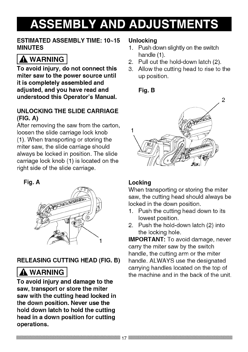
ESTIMATED ASSEMBLY TIME: 10~15
MINUTES
AL WARNING I
To avoid injury, do not connect this
miter saw to the power source until
it is completely assembled and
adjusted, and you have read and
understood this Operator's Manual,
UNLOCKING THE SLIDE CARRIAGE
(FIG. A)
After removing the saw from the carton,
loosen the slide carriage lock knob
(1). When transporting or storing the
miter saw, the slide carriage should
always be locked in position. The slide
carriage lock knob (1) is located on the
right side of the slide carriage.
Unlocking
1. Push down slightly on the switch
handle (1).
2. Pull out the hold-down latch (2).
3. Allow the cutting head to rise to the
up position.
Fig, B
/,
1
Fig, A
RELEASING CUTTING HEAD (FIG, B)
WARNING I
To avoid injury and damage to the
saw, transport or store the miter
saw with the cutting head locked in
the down position. Never use the
hold down latch to hold the cutting
head in a down position for cutting
operations.
Locking
When transporting or storing the miter
saw, the cutting head should always be
locked in the down position.
1. Push the cutting head down to its
lowest position.
2. Push the hold-down latch (2) into
the locking hole.
IMPORTANT: To avoid damage, never
carry the miter saw by the switch
handle, the cutting arm or the miter
handle. ALWAYS use the designated
carrying handles located on the top of
the machine and in the back of the unit.
17

INSTALLING THE DUST
COLLECTION ELBOW (FIG. C)
1. Install the end of the elbow (1) onto
the exhaust port (2).
NOTE: The elbow can be used
to attach either the dust bag or a
vacuum hose to remove sawdust
from the work area.
Fig. C
INSTALLING THE DUST BAG (FIG. D)
1. Squeeze the metal collar wings (1)
of the dust bag (2).
2. Place the dust bag neck opening
around the dust collection elbow (3),
and release the metal collar.
Fig. D
2
To empty the dust bag, squeeze the
metal collar and remove from exhaust
port. Open zipper on underside of bag
and empty into waste container.
NOTE: Check frequently and empty
bag before it gets full.
THREE POSITION ROTATING
HANDLE (FIG. E)
The handle of the miter saw has been
designed to rotate and lock at three
different position stops; 450 left, 0°, and
450 right for operator convenience. To
rotate the handle:
1. Unlock the handle locking lever (1)
by pulling it toward the front of the
machine.
2. Pull the handle-locking latch (2)
to the front of the saw and hold in
position.
3. Rotate the handle to the desired
position stop and release the
handle-locking latch. NOTE: After
releasing the handle-locking latch,
rotate the handle left and right to
make sure the latch engages into
the positive locking position.
4. Lock the handle locking lever (1) by
pushing it IN toward the rear of the
handle.
Fig. E 2
\\
\\\
INSTALLING THE SAFETY HOLD-
DOWN CLAMP (FIG. F)
1. Place the hold-down clamp
assembly (1) in one of the mounting
hole (2), located behind the fence.
2. Thread the hold-down clamp knob
(3) into the hole (2) located at the
rear of the saw base.
3. Tighten the hold-down clamp knob
.
)
18
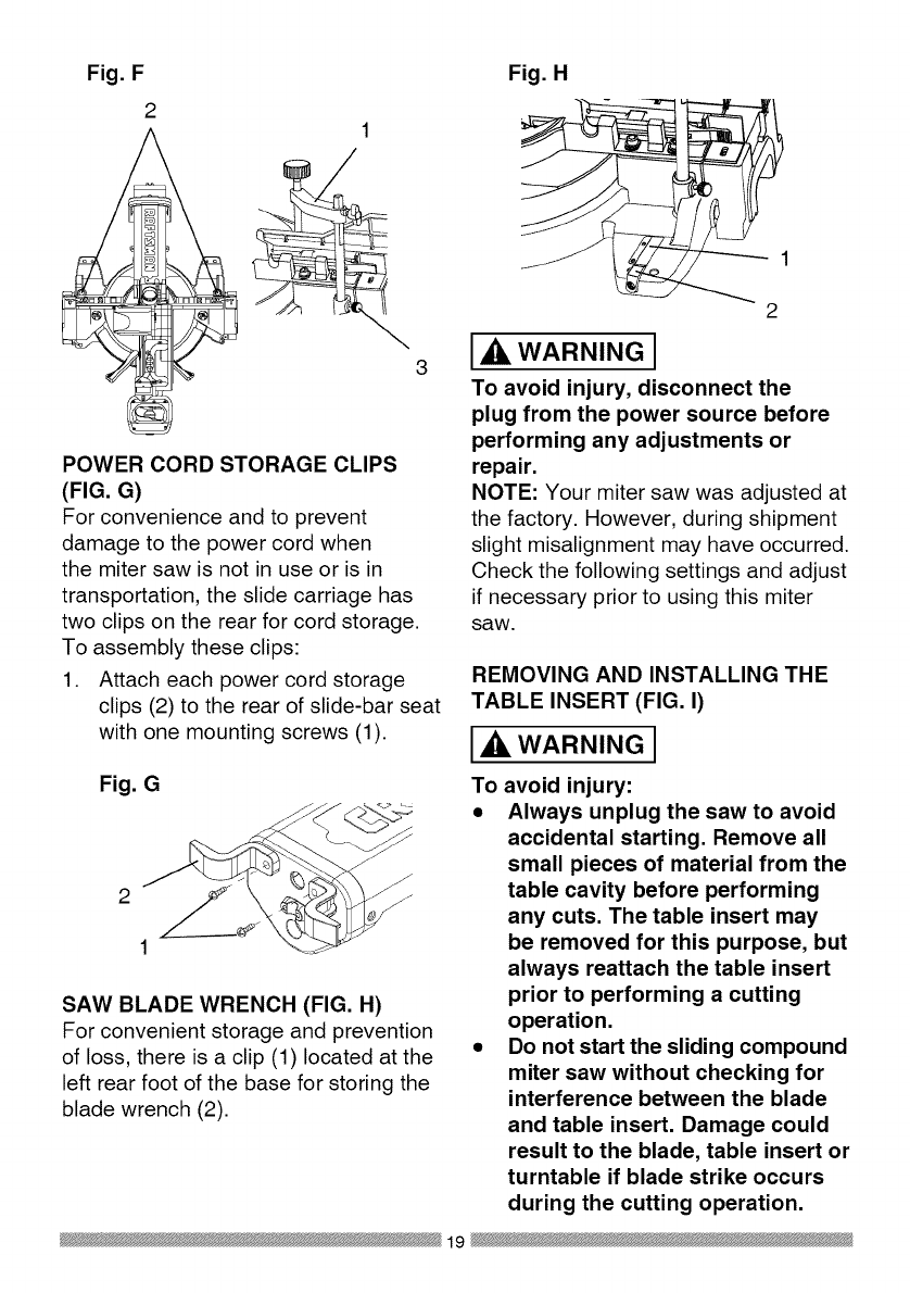
Fig. F
21
3
POWER CORD STORAGE CLIPS
(FIG. G)
For convenience and to prevent
damage to the power cord when
the miter saw is not in use or is in
transportation, the slide carriage has
two clips on the rear for cord storage.
To assembly these clips:
1. Attach each power cord storage
clips (2) to the rear of slide-bar seat
with one mounting screws (1).
Fig. G
2
1
SAW BLADE WRENCH (FIG. H)
For convenient storage and prevention
of loss, there is a clip (1) located at the
left rear foot of the base for storing the
blade wrench (2).
Fig. H
2
I,A WARNING I
To avoid injury, disconnect the
plug from the power source before
performing any adjustments or
repair.
NOTE: Your miter saw was adjusted at
the factory. However, during shipment
slight misalignment may have occurred.
Check the following settings and adjust
if necessary prior to using this miter
saw.
REMOVING AND INSTALLING THE
TABLE INSERT (FIG. I)
WARNINGI
To avoid injury:
• Always unplug the saw to avoid
accidental starting. Remove all
small pieces of material from the
table cavity before performing
any cuts. The table insert may
be removed for this purpose, but
always reattach the table insert
prior to performing a cutting
operation.
•Do not start the sliding compound
miter saw without checking for
interference between the blade
and table insert. Damage could
result to the blade, table insert or
turntable if blade strike occurs
during the cutting operation.
19
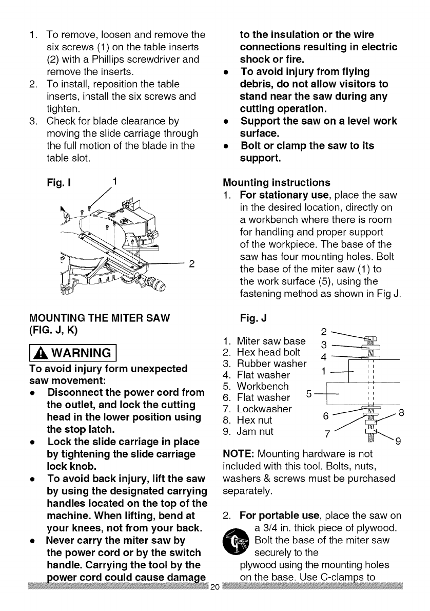
1. To remove, loosen and remove the
six screws (1) on the table inserts
(2) with a Phillips screwdriver and
remove the inserts.
2. To install, reposition the table
inserts, install the six screws and
tighten.
3. Check for blade clearance by
moving the slide carriage through
the full motion of the blade in the
table slot.
to the insulation or the wire
connections resulting in electric
shock or fire.
•To avoid injury from flying
debris, do not allow visitors to
stand near the saw during any
cutting operation.
•Support the saw on a level work
surface.
•Bolt or clamp the saw to its
support.
Fig. I Mounting instructions
1. For stationary use, place the saw
in the desired location, directly on
aworkbench where there is room
for handling and proper support
of the workpiece. The base of the
saw has four mounting holes. Bolt
the base of the miter saw (1) to
the work surface (5), using the
fastening method as shown in Fig J.
MOUNTING THE MITER SAW
(FIG. J, K)
[_ WARNING J
To avoid injury form unexpected
saw movement:
•Disconnect the power cord from
the outlet, and lock the cutting
head in the lower position using
the stop latch.
•Lock the slide carriage in place
by tightening the slide carriage
lock knob.
• To avoid back injury, lift the saw
by using the designated carrying
handles located on the top of the
machine. When lifting, bend at
your knees, not from your back.
•Never carry the miter saw by
the power cord or by the switch
handle. Carrying the tool by the
Fig. J
1. 3
2. 4
3.
4. 1
5. ---[--- _,
6. 5 _,:
7. _9
6 8
8.
9. 7
NOTE: Mounting hardware is not
included with this tool. Bolts, nuts,
washers & screws must be purchased
separately.
Miter saw base
Hex head bolt
Rubber washer
Flat washer
Workbench
Flat washer
Lockwasher
Hex nut
Jam nut
2. For portable use, place the saw on
o a 3/4 in. thick piece of plywood.
Bolt the base of the miter saw
securely to the
plywood using the mounting holes

clampthismountingboardtoa
stableworksurfaceattheworksite.
(Fig.K)
Fig. K
Fig. L
13
2
REMOVING OR INSTALLING THE
BLADE
Removing Blade (Fig. L, M, N)
WARNING I
•To avoid injury from an
accidental start, make sure the
switch is in the OFF position
and plug is not connected to the
power source outlet.
Only use a 12-inch diameter
blade.
1.
2.
3.
.
,
6.
Unplug the saw from the outlet
Raise the miter saw to the upright
position.
Raise the lower clear plastic blade
guard (1) to the uppermost position.
(Fig. L)
While holding the lower blade
guard, loosen the cover plate screw
(2) with a Phillips screwdriver.
Rotate the cover plate (3) to
expose the arbor bolt (4-Fig. N).
Place the blade end wrench over
the arbor bolt.
,
8.
Locate the arbor lock (5) on the
motor, below the belt cover. (Fig. M)
Press the arbor lock, holding it
in firmly while turning the blade
clockwise. The arbor lock will
then engage and lock the arbor.
Continue to hold the arbor lock,
while turning the wrench clockwise
to loosen the arbor bolt.
Fig. M
9. Remove the arbor bolt (4), the
arbor collar (6), and the blade (7).
Do not remove the inner blade
collar. (Fig. N)
10. Raise the lower clear plastic blade
guard (1) to the upright position
(Fig. L) to remove the blade.
21

NOTE: Pay attention to the pieces
removed, noting their position and
direction they face. Wipe the blade
collars clean of any sawdust before
installing a new blade. Also, the 12 in.
blade has a 1 in. arbor hole with a 5/8
in. reducer (8) to mount onto the saw.
Fig. N
8\
6
4
INSTALLING BLADE (FIG. L, M, N)
WARNING J
Un-plug the miter saw before
changing/installing the blade.
1. Install a 12 in. blade with a 5/8 in.
arbor (or a 1 in. arbor with a 5/8 in.
reducer) making sure the rotation
arrow on the blade matches the
clockwise rotation arrow on the
upper guard, and the blade teeth
are pointing downward.
2. Place the arbor collar (6) against
the blade and on the arbor. Thread
the arbor bolt (4) on the arbor. (Fig.
N) in a counterclockwise direction.
IMPORTANT: Make sure the flats
of the blade collars are engaged
with the flats on the arbor shaft.
Also, the flat-side of the arbor collar
must be placed against the blade.
3. Place the blade wrench on the
arbor bolt.
4. Press the arbor lock (5), holding
it in firmly while turning the blade
counterclockwise. When it engages,
continue to press the arbor lock
in, while tightening the arbor bolt
securely. (Fig. M)
5. Rotate the cover plate (3) back to
its original position until the slot in
the cover plate engages with the
cover plate screw (2). While holding
the lower blade guard, tighten the
screw with a Phillips screwdriver.
(Fig. L) NOTE: The lower blade
guard must be raised to the upright
position to access the cover plate
screw.
6. Lower the clear retractable blade
guard (1) and verify the operation of
the guard does not bind or stick (Fig.
L).
7. Be sure the arbor lock is released
so the blade turns freely by
spinning the blade until the arbor
lock disengages.
WARNING J
• To avoid injury, never use the saw
without the cover plate secure
in place. It keeps the arbor bolt
from falling out if it accidentally
loosens, and helps prevent the
spinning blade from coming off
the saw.
•Make sure the collars are clean
and properly arranged. Lower
the blade into the table and
check for any contact with the
metal base or the turn table.
22

ALIGNING THE LASER BEAM (FIG.
O, P)
WARNING I
For your own safety, never connect
the plug to power source outlet
until all the adjustment steps
are complete and you have read
and understood the safety and
operational instructions.
The laser beam must always be
correctly aligned with the blade to
ensure straight, even cutting.
Your tool is equipped with the Laser
Trac ®cutting guide using Class II laser
beam. The laser beam will enable to
preview the saw blade path on the
stock to be cut before starting the miter
saw. This laser guide is powered by the
transformed alternating current supply
directly through the power lead. The
saw must be connected to the power
source and the laser on/off switch
must be turned on for the laser line
to show.
WARNING I
AVOID DIRECT EYE CONTACT
•Laser radiated when laser guide
is turned on. Avoid direct eye
contact. Always un-plug the miter
saw from power source before
making any adjustments.
•Laser Warning Label: Max output
<lmW DIODE LASER: 630-670nm,
Complies with 21CFR 1040.10 and
1040. 11.
•NOTE: All the adjustments for the
operation of this machine have
been completed at the factory.
Due to normal wear and use,
some occasional readjustments
may be necessary.
•CAUTION-Use of controls or
adjustments or performance of
procedures other than those
specified herein may result in
hazardous radiation exposure.
•CAUTION-The use of optical
instruments with this product will
increase eye hazard.
•Do not attempt to repair or
disassemble the laser. If
unqualified persons attempt
to repair this laser product,
serious injury may result. Any
repair required on this laser
product should be performed
by authorized service center
personnel.
A. Check Laser Beam Alignment.
1. Mark a 90° straight line across a
board to serve as a "pattern line" to
test laser alignment. Lay the board
on the miter table.
2. Plug saw into outlet and turn on the
laser beam and line it up with the
pattern line.
3. Lower saw blade to pattern line and
if blade is not flush with the pattern
line, adjust as follows in procedure
(B).
B. Adjusting the Angle of the Laser
Trac ®(Fig. P)
1. Turn the laser element (2) in the
desired direction to adjust the laser
angle. NOTE: Do not adjust the
laser more than 1/4 turn in either
direction as this may damage the
laser. There are two flat sides on
23

the laser element where you can
position an adjustable wrench for
your adjustment.
C. Aligning The Laser Beam
1. Loosen only 1/2 turn at a time the
four set screws (1).
2. Adjust laser by turning the left side
set screws clockwise to shift the
laser line to the right. To shift the
laser line to the left, turn the right
side set screws 1/2 turn at a time.
3. Once alignment of the laser is
achieved, tighten only 1/2 turn at a
time the four set screws (1).
Fig. 0
Fig. P
THE UPFRONT SUPPORTS
ADJUSTMENT (FIG. Q, R)
Wide pieces need upfront supports (1).
1. Rotate the two upfront supports (1)
toward the rear of the saw.
Laser Switch
i ...... l
Left Side View Right Side View
Fig. Q
\
1
NOTE: These supports (1) should be
placed into the 0 position as shown in
Fig. R before transporting.
Fig. R
1
24

BEVEL STOP ADJUSTMENTS
(FIG. S, T, U, V)
WARNING I
To avoid injury from unexpected
starting or electrical shock, make
sure the trigger is released and
remove the power cord from the
power source.
900(0°) Bevel adjustment (Fig. S, T)
1. Loosen bevel lock handle (2) and tilt
the cutting arm while pushing in the
bevel detent pin (3-Fig. T) in against
the 0° bevel stop. Tighten the bevel
lock handle.
2. Place a combination square on the
miter table with the rule against the
table and heel of the square against
the saw blade.
3. If the blade is not 0° to the miter
table, loosen the four adjustment
bolts (1) at the rear of the unit with
a 5 mm hex wrench. Unlock the
bevel lock handle (2) and adjust
the cutting arm zero degrees to the
table. Tighten the bevel lock handle
and the four adjustment bolts after
alignment is achieved.
Fig. S
2
Bevel Scale Indicators (Fig. T)
1. When the blade is exactly 90o(0°) to
the table, loosen the bevel indicator
screws (1) using a #2 Phillips
screwdriver.
2. Adjust bevel indicators (2) to the
"0" mark on the bevel scale and
retighten the screws.
Fig. T
2
45°Left Bevel Positive Stop
Adjustment (Fig. U)
1. Set the miter angle to zero degrees.
Fully extend the sliding fence
completely to the left then pull the
bevel detent pin (1) toward the
front of the machine. NOTE: When
retracting the bevel detent pin, it may
be required to shift the miter saw
upper arm assembly to the left/right.
2. Loosen the bevel lock handle (2)
and tilt the cutting arm completely to
the left.
3. Using a combination square, check
to see if the blade is 45° to the table.
4. To adjust, tilt the cutting arm to zero
degrees, loosen the Iocknut (3) and
turn the bolt (4) in or out accordingly.
5. Tilt the cutting arm back to the left
and recheck alignment.
6. Repeat steps until the blade is
45° to the table. Once alignment is
achieved, tighten the Iocknut (3) to
secure the positive stop bolt.
25
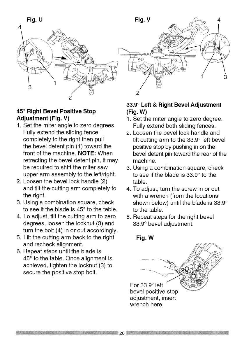
Fig. U
4
1
3
45°Right Bevel Positive Stop
Adjustment (Fig. V)
1. Set the miter angle to zero degrees.
Fully extend the sliding fence
completely to the right then pull
the bevel detent pin (1) toward the
front of the machine. NOTE: When
retracting the bevel detent pin, it may
be required to shift the miter saw
upper arm assembly to the left/right.
2. Loosen the bevel lock handle (2)
and tilt the cutting arm completely to
the right.
3. Using a combination square, check
to see if the blade is 45 ° to the table.
4. To adjust, tilt the cutting arm to zero
degrees, loosen the Iocknut (3) and
turn the bolt (4) in or out accordingly.
5. Tilt the cutting arm back to the right
and recheck alignment.
6. Repeat steps until the blade is
45 ° to the table. Once alignment is
achieved, tighten the Iocknut (3) to
secure the positive stop bolt.
Fig. V 4
1 3
2
33.9°Left & Right Bevel Adjustment
(Fig. W)
1. Set the miter angle to zero degree.
Fully extend both sliding fences.
2. Loosen the bevel lock handle and
tilt cutting arm to the 33.9 ° left bevel
positive stop by pushing in on the
bevel detent pin toward the rear of the
machine.
3. Using a combination square, check
to see if the blade is 33.9° to the
table.
4. To adjust, turn the screw in or out
with a wrench (from the locations
shown below) until the blade is 33.9 °
to the table.
5. Repeat steps for the right bevel
33.9 -0bevel adjustment.
Fig. W
For 33.9 ° left ._
bevel positive stop
adjustment, insert
wrench here
26

o right
sitive
ustment,
rench
here
NOTE: View from rear of machine
MITER ANGLE ADJUSTMENT (FIG.
X)
The sliding compound miter saw scale
can be easily read, showing miter
angles from 0° to 45° to the left, and 0°
to 45 ° to the right. The miter saw table
has nine of the most common angle
setttings with positive stops at 0°, 15°,
22.5 °, 31.6 °, and 45°. These positive
stops position the blade at the desired
angle quickly and accurately. Follow
the process below for quickest and
most accurate adjustments.
1. Lift up on the quick-cam miter table
lock (1) to unlock the table.
2. Move the turntable while lifting up on
the positive stop locking lever (4) to
align the indicator (2) to the desired
degree measurement.
3. Lock the table into position by
pressing down on the quick-cam
miter table lock (1).
Fig. X
2. Loosen the screw (3) that holds the
indicator with a screwdriver.
3. Adjust the indicator (2) to the 0°
mark and retighten screw.
ADJUSTING FENCE SQUARENESS
(FIG. Y)
1. Loosen the four fence locking bolts
(1).
2. Lower the cutting arm and lock in
position.
3. Using a square (3), lay the heel of
the square against the blade and the
ruler against the fence (2) as shown.
4. Adjust the fence 90° to the blade and
tighten the four fence locking bolts.
CAUTION: If the saw has not been
used recently, recheck blade
squareness to the fence and
readjust if needed.
5. After fence has been aligned, using
a scrap piece of wood, make a cut
at 90° then check squareness on the
piece. Readjust if necessary.
Fig. Y
2
3 2 4 1
Miter Scale Indicator (Fig. X)
1. Move the table to the 0° positive
POSITIVE STOP MITER ANGLE
ADJUSTMENT (FIG. Z)
1. Unlock the miter table by lifting up
on the quick-cam miter table lock
(1).
stop. 2. While raising the positive stop
locking lever (2) up, grasp the miter
27

handle and rotate the miter table left
or right to the desired angle.
3. Release the positive stop locking
lever and set the miter at the desired
angle making sure the lever snaps
into place. NOTE: The lever will
only lock into place at one of the ten
positive stops.
4. Once angle is achieved, press down
on the quick-cam miter table lock (1).
4. Turn the lock nut (3) to the right
as shown to lock the miter locking
mechanism into place.
Fig. Z 13 4
Quick-cam Miter Table Lock
Operation (Fig. Z)
If miter angles required are NOT one of
the ten positive stops noted above, the
miter table can be locked at any angle
between these positive stops by using
the quick-cam miter table lock.
1. Unlock the miter table by lifting up
on the quick-cam miter table lock (1).
2. While holding the positive stop
locking lever (2) up, grasp the miter
handle and move the miter table left
or right to the desired angle.
3. Release the positive stop locking
lever.
4. Press down on the quick-cam miter
table lock (1) until it locks the miter
table in place.
NOTE: The quick-cam miter table
lock should lock the table and
prevent it from moving. If adjustment
is needed, see next step.
Quick-cam Miter Table Lock
Adjustment (Fig. Z)
1. Press down and lock the miter quick-
cam table lock.
2. Using a 13 mm wrench, turn the stop
nut (4) to the left as shown to extend
the locking arm against the base of
the miter saw.
3. Test the quick cam miter lock to
verify it locks the table into position
SETTING CUTTING DEPTH (FIG. AA)
The depth of cut can be preset for even
and repetitive shallow cuts.
1. Adjust the cutting head down (See
CUTTING HEAD section) until the
teeth of the blade are at the desired
depth.
2. While holding the upper arm in that
position, turn the stop knob (1) until
it touches the stop plate (2).
3. Recheck the blade depth by moving
the cutting head front to back
through the full motion of a typical
cut along the control arm.
Adjusting Cutting Depth (Fig. AA)
The maximum depth travel of the
cutting head was set at the factory.
Check to see that the blade does not
extend more than 1/4 in. below the
table insert, and does not touch the
control arm throat or any part of the
base or table. If the maximum depth
needs readjusting:
1. Loosen the stop knob (1) while
moving the cutting head down until
the blade extends just 1/4 in. below
the table insert.
2. Adjust the stop knob (1) to touch the
stop plate (2).
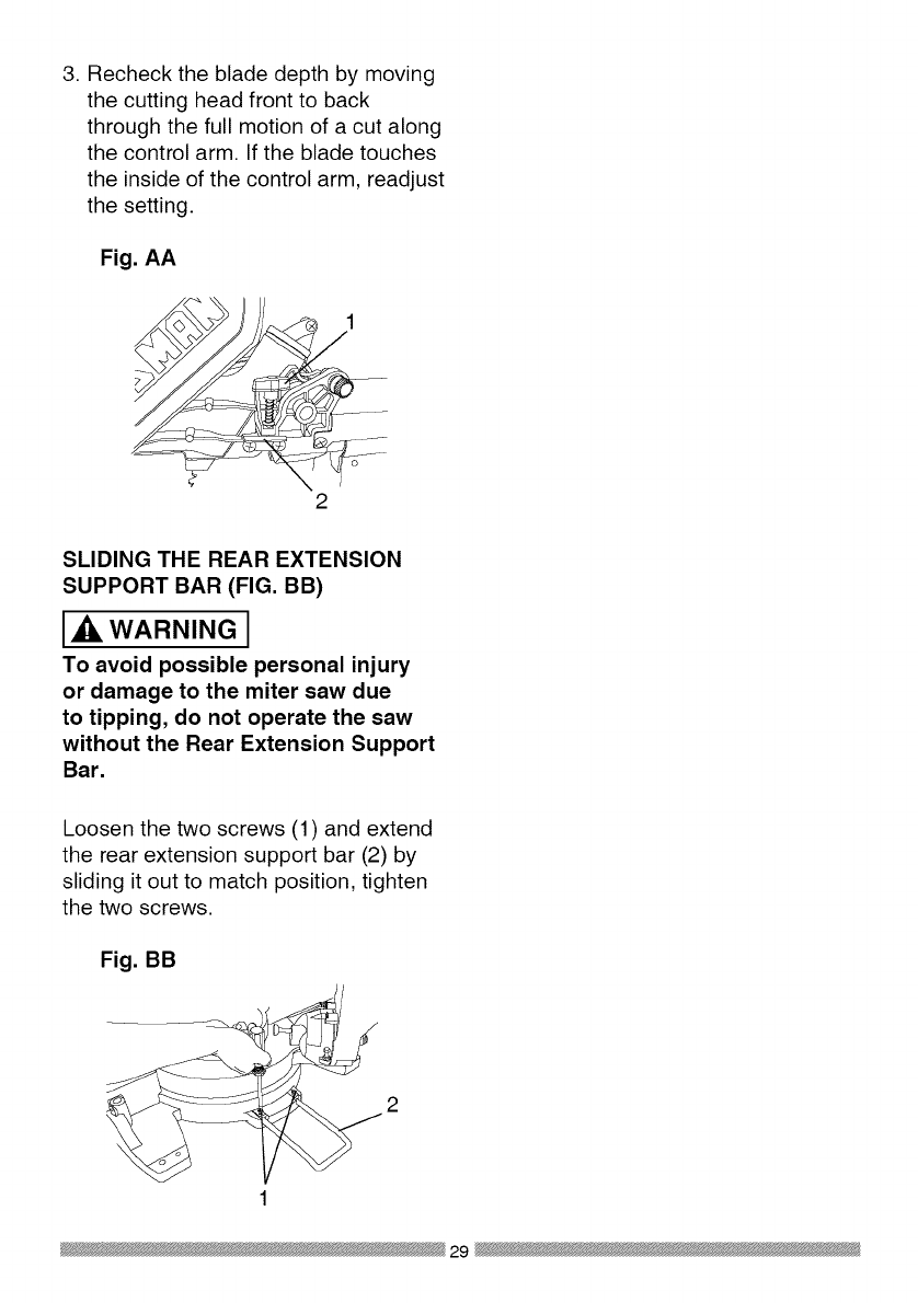
3. Recheckthebladedepthbymoving
thecuttingheadfrontto back
throughthefullmotionofa cutalong
thecontrolarm.Ifthebladetouches
theinsideof thecontrolarm,readjust
thesetting.
Fig. AA
2
SLIDING THE REAR EXTENSION
SUPPORT BAR (FIG. BB)
WARNING I
To avoid possible personal injury
or damage to the miter saw due
to tipping, do not operate the saw
without the Rear Extension Support
Bar.
Loosen the two screws (1) and extend
the rear extension support bar (2) by
sliding it out to match position, tighten
the two screws.
Fig. BB
1
29

SAFETY INSTRUCTIONS FOR BASIC
SAW OPERATION
BEFORE USING THE MITER SAW
[_, WARNING J
To avoid mistakes that could cause
serious, permanent injury, do not
plug the tool in until the following
steps are completed:
•Completely assemble and
adjust the saw, following the
instructions. (ASSEMBLY AND
ADJUSTMENTS)
• Learn the use and function of the
ON/OFF switch, upper and lower
blade guards, hold down latch,
bevel lock handle and cover plate
screws.
• Review and understand
all safety instructions and
operating procedures in this
Operator's Manual. (SAFETY &
OPERATIONS)
• Review the MAINTENANCE and
TROUBLESHOOTING GUIDE for
your miter saw.
• To avoid injury or possible death
from electrical shock:
Make sure your fingers do not
touch the plug's metal prongs
when plugging or unplugging
your miter saw. (ELECTRICAL
REQUIREMENTS AND SAFETY)
BEFORE EACH USE INSPECT YOUR
SAW.
•Disconnect the miter saw.
To avoid injury from accidental
starting, unplug the saw before any
adjustments, including set-up and
blade changes.
•Compare the direction of rotation
arrow on the guard to the direction
arrow on the blade. The blade teeth
should always point downward at
the front of the saw.
•Tighten the arbor bolt.
•Tighten the cover plate screw.
•Check for damaged parts. Check
for:
• Alignment of moving parts
• Damaged electric cords
• Binding of moving parts
• Mounting holes
• Function of arm return spring
and lower guard: Push the
cutting arm all the way down,
then let it rise until it stops.
The lower guard should fully
close. Follow instructions in
TROUBLESHOOTING GUIDE
for adjustment if necessary.
• Other conditions that may affect
the way the miter saw works.
• Keep all guards in place, in working
order and proper adjustment. If any
part of this miter saw is missing,
bent, damaged or broken in any
way, or any electrical parts don't
work, turn the saw off and unplug
it.
• Replace bent, damaged, missing
or defective parts before using the
saw again.
• Maintain tools with care. Keep the
miter saw clean for best and safest
performance. Follow instructions
for lubricating. Do not put lubricants
on the blade while it is spinning.
• Remove adjusting wrench from the
tool before turning it on.
• To avoid injury from jams, slips,
or thrown pieces, use only
30

recommended accessories.
RECOMMENDED ACCESSORIES
• Consult the ACCESSORIES
and ATTACHMENTS section
of this Operator's Manual for
recommended accessories. Follow
the instructions that come with the
accessory. The use of improper
accessories may cause risk of
injury to persons.
• Choose the correct 12 in. diameter
blade for the material and the type
of cutting you plan to do. Do not
use thin kerf blades.
• Make sure the blade is sharp,
undamaged and properly aligned.
With the saw unplugged, push
the cutting arm all the way down.
Manually spin the blade and check
for clearance. Tilt the power-head
to a 45° bevel and repeat the test.
• Make sure the blade and arbor
collars are clean.
• Make sure all clamps and locks are
tight and there is no excessive play
in any parts.
KEEP YOUR WORK AREA CLEAN
Cluttered areas and benches invite
r RNING I
To avoid burns or other fire damage,
never use the miter saw near
flammable liquids, vapors, or gases.
• Plan ahead to protect your eyes,
hands, face and ears.
• Know your miter saw. Read and
understand the Operator's Manual
and labels affixed to the tool.
Learn its application and limitations
as well as the specific potential
hazards peculiar to this tool. To
avoid injury from accidental contact
assembly, or setup work on the
miter saw while any parts are
moving.
Avoid accidental starting,
make sure the trigger switch is
disengaged before plugging the
miter saw into a power outlet.
PLAN YOUR WORK
• Use the right tool. Do not force a
tool or attachment to do a job it was
not designed to do. Use a different
tool for any workpiece that can'
t be held in a solidly braced, fixed
position.
CAUTION: This machine is not
designed for cutting masonry,
masonry products, ferrous metals
(steel, iron, and iron-based metals.)
Use this miter saw to cut only
wood, wood-like products, or non-
ferrous metals. Other material may
shatter, bind the blade, or create
other dangers. Remove all nails that
may be in the workpiece to prevent
sparking that could cause a fire.
Remove dust bag when cutting non-
ferrous metals.
S FOR SAFETY
Any power tool can throw
foreign objects into the eyes.
This can result in permanent
eye damage. Everyday eyeglasses
have only impact resistant lenses and
are not safety glasses. Glasses or
goggles not in compliance with ANSI
Z87.1 could seriously injure you when
they break.
• Do not wear loose clothing, gloves,
neckties or jewelry (rings, watches).
They can get caught and draw you
into moving parts.
with movingparts, do not do layout, 31

•Wear non-slip footwear.
• Tie back long hair.
• Roll long sleeves above the elbow.
• Noise levels vary widely. To avoid
possible hearing damage, wear ear
plugs when using any miter saw.
• For dusty operations, wear a dust
mask along with safety goggles.
INSPECT YOUR WORKPIECE
Make sure there are no nails or foreign
objects in the part of the workpiece
being cut.
Plan your work to avoid small pieces
that may bind, or that are too small to
clamp and get a solid grasp on. Plan
the way you will grasp the workpiece
from start to finish. Avoid awkward
operations and hand positions.
A sudden slip could cause your fingers
or hand to move into the blade.
DO NOT OVER-REACH
Keep good footing and balance. Keep
your face and body to one side, out of
the line of a possible kickback. NEVER
stand in the line of the blade.
Never cut freehand:
• Brace your workpiece firmly against
the fence and table stop so it will
not rock or twist during the cut.
• Make sure there is no debris
between the workpiece and the
table or fence.
• Make sure there are no gaps
between the workpiece, fence and
table that will let the workpiece shift
after it is cut.
• Keep the cut off piece free to
move sideways after it is cut off.
Otherwise, it could get wedged
against the blade and thrown
violently.
• Only the workpiece should be on
the saws table.
• Secure work. Use clamps or a vise
to help hold the work when it's
practical.
USE EXTRA CAUTION WITH LARGE
OR ODD SHAPED WORKPIECES.
• Use extra supports (tables,
sawhorses, blocks, etc.) for
workpieces large enough to tip.
• Never use another person as a
substitute for a table extension,
or as an additional support for a
workpiece that is longer or wider
than the basic miter saw table, or
to help feed, support, or pull the
workpiece.
• Do not use this saw to cut small
pieces. If the workpiece being cut
would cause your hand or fingers
to be within 8-3/4 inches of the saw
blade the workpiece is too small.
Keep hands and fingers out of the
"no hands zone" area marked on
the saws table.
• When cutting odd shaped
workpieces, plan your work so
it will not bind in the blade and
cause possible injury. Molding, for
example, must lie flat or be held
by a fixture or jig that will not let it
move when cut.
• Properly support round material
such as dowel rods, or tubing,
which have a tendency to roll when
cut, causing the blade to "bite".
[,ik WARNING J
To avoid injury, follow all applicable
safety instructions, when cutting
non-ferrous metals:
• Use only saw blades specifically
recommended for non-ferrous
metal cutting.
32
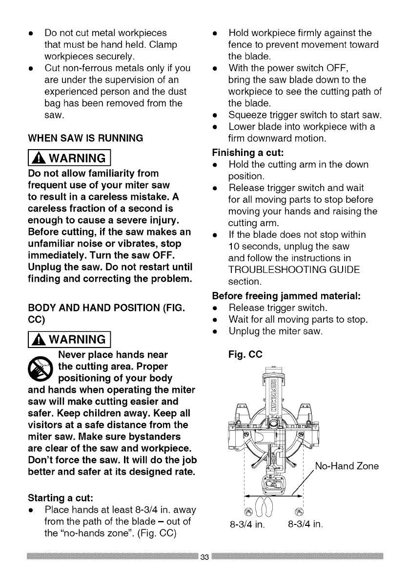
Do not cut metal workpieces
that must be hand held. Clamp
workpieces securely.
Cut non-ferrous metals only if you
are under the supervision of an
experienced person and the dust
bag has been removed from the
saw.
WHEN SAW IS RUNNING
WARNING I
Do not allow familiarity from
frequent use of your miter saw
to result in a careless mistake. A
careless fraction of a second is
enough to cause a severe injury.
Before cutting, if the saw makes an
unfamiliar noise or vibrates, stop
immediately. Turn the saw OFF.
Unplug the saw. Do not restart until
finding and correcting the problem.
BODY AND HAND POSITION (FIG,
cc)
WARNING I
Never place hands near
the cutting area. Proper
positioning of your body
and hands when operating the miter
saw will make cutting easier and
safer. Keep children away. Keep all
visitors at a safe distance from the
miter saw. Make sure bystanders
are clear of the saw and workpiece.
Don't force the saw. It will do the job
better and safer at its designed rate.
•Hold workpiece firmly against the
fence to prevent movement toward
the blade.
• With the power switch OFF,
bring the saw blade down to the
workpiece to see the cutting path of
the blade.
• Squeeze trigger switch to start saw.
• Lower blade into workpiece with a
firm downward motion.
Finishing a cut:
• Hold the cutting arm in the down
position.
• Release trigger switch and wait
for all moving parts to stop before
moving your hands and raising the
cutting arm.
• If the blade does not stop within
10 seconds, unplug the saw
and follow the instructions in
TROUBLESHOOTING GUIDE
section.
Before freeing jammed material:
• Release trigger switch.
• Wait for all moving parts to stop.
• Unplug the miter saw.
Fig, CC
i
i
i
i
i
i
Starting a cut: i
• Place hands at least 8-3/4 in. away ®
from the path of the blade - out of 8-3/4 in.
the "no-hands zone". (Fig. CC)
o-Hand Zone
i
i
®
8-3/4 in.
33

TO TURN THE SAW ON (FIG. DD)
Depress the trigger switch (1) to turn
on the miter saw started.
NOTE: Make the ON/OFF switch
childproof. Insert a padlock, or chain
with padlock, through the hole (2) in
the trigger switch, locking the tool's
switch, preventing children and other
unauthorized users from turning the
machine on.
The miter saw is equipped with an
automatic blade brake. When the
trigger switch is released, the electric
blade brake will stop the blade within
approximately 10 seconds.
Fig. DD
2\
.
,
The right side sliding fence must
be removed when making any
right bevel angle cuts greater
than 350 in combination with
any right hand miter angle. This
fence must also be removed
whenever a 450bevel angle
is desired with a miter angle
greater than 22.50.
Unlock the fence cam locking lever
(1) by pushing it toward the rear of
the machine.
Extend the fence (2) by sliding it out
to match the degree of the bevel
cut. Lock the fence cam locking
lever by pushing it IN toward the
fence. NOTE: When transporting
the saw, always secure the sliding
fence in the collapsed position
(toward the saw blade).
Fig. EE
SLIDING FENCE (FIG. EE)
WARNING J
•The sliding fence must be
extended to the left or right when
making bevel cuts.The sliding
fence noted three bevel angles
where the user must adjust the
fences to match the degree of
the bevel cut. Failure to extend
the sliding fence will not allow
enough space for the blade to
pass through which could result
in serious injury. At extreme
miter or bevel angles the saw
blade may also contact the
fence.
34

REMOVING OR INSTALLING THE
RIGHT SLIDING FENCE
Removing (Fig. FF)
1. Unlock the fence cam-locking lever
by pushing it out toward the rear of
the machine.
2. Lift up on the sliding fence to
remove it from the saw.
Installing
1. Place the sliding fence onto the
miter saw fence aligning the nut (1)
with the slot (4).
2. To lock the sliding fence, push the
cam-locking lever in toward the
front of the machine.
Fig. FF
1 __............. JJ
..........÷I, ,d,I U,d, 4
SLIDING CARRIAGE SYSTEM (FIG.
GG)
Ak, WARNING I
To reduce the risk of injury, return
carriage to the full rear position after
each crosscut operation.
1. For a chop cutting operations on
small workpieces, slide the cutting
head assembly completely toward
the rear of the unit and tighten the
carriage lock knob (1).
2. To cut wide boards up to 12-1/4 in.,
the carriage lock knob should be
loosened to allow the cutting head
to slide freely.
Fig. GG
WARNINGI
To avoid injury from materials being
thrown, always unplug the saw
to avoid accidental starting, and
remove small pieces of material from
the table cavity. The table insert may
be removed for this purpose, but
always reattach the table insert prior
to performing a cutting operation.
MITER CUT (FIG. HH)
The sliding compound miter saw is
equipped with ten positive miter stops
(1) on the saw base. The locations are
at O, 15, 22.5, 31.6 and 45 degrees
left and right, and 60° right. These
locations represent the most common
angles for cutting operation. To make a
miter cut:
1. Unlock the miter table by lifting up
on the miter quick-cam table lock
(2).
2. While raising the positive stop
locking lever (3) up, grasp the miter
handle (4) and rotate the miter
table left or right to the desired
angle.
3. Release the positive stop locking
lever and set the miter at the
desired angle making sure the
lever snaps into place. NOTE: The
lever will only lock into place at one
of the ten positive stops.
35

4. Once the desired miter angle is
achieved, press down on the quick
cam miter table lock to secure the
table into position.
5. If the miter angle desired is NOT
one of the ten positive stops noted
above, simply lock the table at the
desired angle by pressing down on
the quick-cam miter table lock (2).
Fig. HH
2 1
BEVEL CUT (FIG. II)
WARNING J
• The sliding fence must be
extended to the left or right when
making bevel cuts.The sliding
fence noted three bevel angles
where the user must adjust the
fences to match the degree of
the bevel cut. Failure to extend
the sliding fence will not allow
enough space for the blade to
pass through which could result
in serious injury. At extreme
miter or bevel angles the saw
blade may also contact the
fence.
•The right side sliding fence must
be removed when making any
right bevel angle cuts greater
than 35° in combination with
any right hand miter angle. This
fence must also be removed
whenever a 45° bevel angle
is desired with a miter angle
greater than 22.5 °.
Tilt the cutting head to the desired
angle as shown on the bevel scale. The
blade can be positioned at any angle,
from a 90° straight cut (0° on the scale)
to a 45° left and right bevel. Tighten the
bevel lock handle (1) by pushing down
to lock the cutting head in position.
Bevel positive stops are provided at 0°,
33.9 ° and 45 °.
Fig. II
NOTE: The saw comes with a
33.9 ° bevel detent pin for setting up
crown molding cuts when the angle of
the walls equals 90° .
36

33.9 °BEVEL DETENT PIN FOR
CROWN MOLDINGS (FIG. JJ)
NOTE: A bevel detent pin is
incorporated into this machine for quick
bevel adjustments when the desired
bevel angle is 33.9 °.
1. Push the bevel detent stop pin (1)
in toward the front of the machine.
2. Loosen the bevel lock handle (2).
3. Rotate the cutting head until the
bevel detent pin stops the bevel
angle at 33.9 ° on the bevel scale.
4. Tighten the bevel lock handle
before you make your cut.
Fig. JJ
COMPOUND CUT (FIG. KK)
1. Extending the fence by sliding it out
to the required location or remove
the right sliding fence if necessary.
See "SLIDING FENCE or REMOVE
SLIDING FENCE".
2. Set the desired bevel angle using
the bevel lock handle (1).
3. Set the desired miter angle and
lock into position. See "MITER
CUT".
Fig. KK
CHOP CUTTING NARROW BOARDS-
90° CROSSCUT (FIG. LL)
1. For a chop cutting operations on
small workpieces, slide the cutting
head assembly completely toward
the rear of the unit and tighten the
carriage lock knob (1).
2. Position the cutting head to the
0° bevel position and lock the bevel
lock handle (2).
3. Position the table to the 0° miter
angle and lock the quick cam miter
table lock (3).
4. Position the workpiece on the table
and against the fence. Use a hold
down clamp (4) attached to the
base, whenever possible.
5. Pull the trigger (5), turning on the
saw. Lower the blade by pushing
the handle (6) down into the
workpiece with slow and even
pressure.
6. When the cut is complete, release
the switch and allow the blade to
stop before raising the cutting head
assembly.
37

Fig. LL
3
SLIDE CUTTING WIDE BOARDS UP
TO 12-1/4 IN. WIDE (FIG. MM)
WARNING I
To avoid injury:
• Never pull the cutting head
assembly and spinning blade
toward you during the cut, The
blade may try to climb up on the
top of the workpiece, causing the
cutting assembly and spinning
blade to kick back, forcefully, The
cutting head assembly should
be drawn back completely then
pushed forward when sawing,
•Let the blade reach full speed
before cutting, This will help
reduce the risk of a thrown
workpiece,
•Extending the fence by sliding
it out to the required location or
remove the right sliding fence if
necessary, See "SLIDING FENCE
or REMOVE SLIDING FENCE",
3. Set both the desired bevel angle
and/or the miter angle and lock into
position.
4. If bevel cutting, set both the left
and right sliding fences (2) to their
proper location.
5. Use a hold down clamp to secure
the workpiece.
6. Grasp the switch handle (3) and
pull the carriage (4) forward until
the center of the saw blade is over
the front of the workpiece (5).
7. Pull the trigger (6) to turn the saw
on.
8. When the saw reaches full speed,
push the saw handle down, slowly,
cutting through the leading edge of
the workpiece.
9. Slowly move the saw handle toward
the fence, completing the cut.
10. Release the trigger and allow
the blade to stop spinning before
allowing the cutting head to raise.
Fig, MM
1 6
3
5
CUT WIDE BOARDS (FIG, MM)
1. Rotate the two upfront supports (7)
toward the rear of the saw.
2. Unlock the carriage lock knob
(1) and allow the cutting head
assembly to move freely.
38

CUTTING BOWED MATERIAL (FIG.
NN)
WARNING I
To avoid injury from materials being
thrown, always unplug the saw to
avoid accidental starting and remove
small pieces of material from the
table cavity. The table insert may be
removed for this purpose, but always
reattach table insert prior to performing
a cutting operation.
A bowed workpiece must be positioned
against the fence and secured with
a clamping device as shown before
cutting. Do not position workpiece
incorrectly or try to cut the workpiece
without the support of the fence. This
will cause the blade to bind and could
result in personal injury.
Fig. NN
ROUGH CUTTING A DADO (FIG. OO)
1. Mark lines identifying the width
and depth of the desired cut on
the workpiece and position on the
table so the inside tip of the blade
is positioned on the line. Use a
hold down clamp to secure the
workpiece.
2. Lower the cutting head so the tip of
the blade touches the top surface
workpiece at the marked line.
3. While holding the upper arm in
position, turn the stop knob (2) until
it touches the stop plate (1).
4. Cut two parallel grooves as shown
below.
Fig. OO
Cut these grooves
with saw
Use a chisel to cut
out the middle
TELESCOPING WORKPIECE
SUPPORT & REPETITIVE CUTTING
USING THE STOP PLATE (FIG. PP)
Long pieces need extension table
support.
1. Loosen the knob (1) then slide the
extension table to desired position
and tighten the knob.
2. The stop plate is designed for use
during repetitive cutting. Only use
one stop plate at a time. Rotate the
stop plate (3) to vertical position,
and retighten the locking bolt. If
stop plate will not rotate, loosen the
locking bolt (2) 1/4 turn.
39
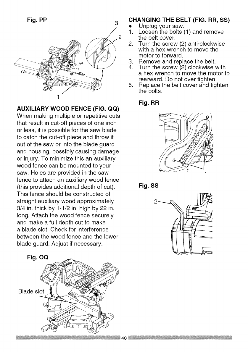
Fig. PP
\
/
/
AUXILIARY WOOD FENCE (FIG. QQ)
When making multiple or repetitive cuts
that result in cut-off pieces of one inch
or less, it is possible for the saw blade
to catch the cut-off piece and throw it
out of the saw or into the blade guard
and housing, possibly causing damage
or injury. To minimize this an auxiliary
wood fence can be mounted to your
saw. Holes are provided in the saw
fence to attach an auxiliary wood fence
(this provides additional depth of cut).
This fence should be constructed of
straight auxiliary wood approximately
3/4 in. thick by 1-1/2 in. high by 22 in.
long. Attach the wood fence securely
and make a full depth cut to make
a blade slot. Check for interference
between the wood fence and the lower
blade guard. Adjust if necessary.
Fig. QQ
Blade slot
CHANGING THE BELT (FIG. RR, SS)
• Unplug your saw.
1. Loosen the bolts (1) and remove
the belt cover.
2. Turn the screw (2) anti-clockwise
with a hex wrench to move the
motor to forward.
3. Remove and replace the belt.
4. Turn the screw (2) clockwise with
a hex wrench to move the motor to
rearward. Do not over tighten.
5. Replace the belt cover and tighten
the bolts.
Fig. RR
Fig. SS
40

CUTTING BASE MOLDING (FIG. TT)
Base moldings and many other
moldings can be cut on a compound
miter saw. The setup of the saw
depends on molding characteristics
and application, as shown. Perform
practice cuts on scrap material to
achieve best results:
1. Always make sure moldings rest
firmly against fence and table. Use
hold-down, crown molding vise
or C-clamps, whenever possible,
and place tape on the area being
clamped to avoid marks.
2. Reduce splintering by taping the
cut area prior to making the cut.
Mark the cut line directly on the
tape.
3. Splintering typically happens due to
an incorrect blade application and
thinness of the material.
Fig. TT
Miter saw table
miter at 450,
bevel at 0°
_table
miter at 0°, bevel
at 450
angles that, when added together,
equal exactly 90 °.
Most crown molding has a top rear
angle (the section that fits flat against
the ceiling) of 52°and a bottom rear
angle (the section that fits flat against
the wall) of 38°.
In order to accurately cut crown
molding for a 90° inside or outside
corner, lay the molding with its broad
back surface flat on the saw table.
When setting the bevel and miter
angles for compound miters, remember
that the settings are interdependent;
changing one changes the other, as
well.
Fig. UU
ne
Miter saw table
Bevel/Miter Settings
Fig. VV
NOTE: Always perform a dry run cut
so you can determine if the operation
being attempted is possible before
power is applied to the saw.
CUTTING CROWN MOLDING (FIG.
UU, VV)
WARNING I
Your compound miter saw is suited
for the difficult task of cutting crown
molding. To fit properly, crown molding
must be compound-mitered with
extreme accuracy. The two surfaces
on a piece of crown molding that fit
flat against the ceiling and wall are at
Settings for standard crown molding
lying flat on compound miter saw
table ]
Inside corner OR
\
,-._1
Outside corner
Compound cut crown moldings
NOTE: The chart below references
a compound cut for crown molding
ONLY WHEN THE ANGLE BETWEEN
THE WALLS EQUALS 90 °.
41

Bevel/Miter Settings
KEY BEVEL MITER
SETTING SETTING
TYPE OF CUT
IL 33.9 °
IR 33.9 °
OL 33.9 °
OR 33.9 °
31.6 o Right
31.6 ° Left
31.6 ° Left
31.6 o Right
Inside corner-Left side
1. Position top of molding against fence.
2. Miter table set at RIGHT 31.6 ° .
3. LEFT side is finished piece.
Inside corner-Right side
1. Position bottom of molding against fence.
2. Miter table set at LEFT 31.6 °.
3. LEFT side is finished piece.
Outside corner-Left side
1. Position bottom of molding against fence.
2. Miter table set at LEFT 31.6 °.
3. RIGHT side is finished piece.
Outside corner-Right side
1. Position top of molding against fence.
2. Miter table set at RIGHT 31.6 ° .
3. RIGHT side is finished piece.
42

CROWN MOLDING CHART
Compound Miter saw
Miter and bevel Angle settings
Wall to Crown Molding Angle
52/38 ° C_wn Molding 45/45 ° C_wn Molding
Angle Miter Bevel Miter Bevet Angle
Between Setting Setting Setting Setting Between
Walls Wails
67 42.93 41.08 46.89 36.13 124
68 42.39 40.79 46.35 35.89 128
69 41.85 40.80 45.81 35.64 126
70 41.32 40.20 48.28 38.40 127
71 40.79 39.90 44.78 35.18 128
72 40.28 39.61 44.22 34.89 129
73 39.76 39.30 43.70 34.64 130
74 39.28 39.00 43.18 35.38 131
75 38.74 38.69 42.66 34.12 132
76 38.24 38.39 42.15 33.86 133
77 37.74 38.08 41.64 33.60 134
78 37.24 37.76 41.13 33.33 138
79 36.75 37.45 40.62 33.07 136
80 36.27 37.13 40.12 32.80 137
81 35.79 36.81 39.62 32.53 138
82 35.31 36.49 39.13 32.28 139
83 34.83 36.17 38.63 31.98 140
84 34.36 35.88 38.14 31.70 141
88 33.90 38.82 37.66 31.42 142
86 33.43 35.19 37.17 31.34 143
87 32.97 34.86 36.69 30.86 144
88 32.82 34.83 36.21 30.87 148
89 32.07 34.20 38.74 30.29 146
90 31.62 33.86 38.26 30.00 147
91 31.17 33.83 34.79 29.71 148
92 30.73 33.19 34.33 29.42 149
93 30.30 32.86 33.86 29.13 150
94 29.86 32.51 33.40 28.83 151
95 29.43 32.17 32.94 28.84 182
96 29.00 31.82 32.48 28.24 183
97 28.88 31.48 32.02 27.94 154
98 28.16 31.13 31.58 27.64 188
99 27.74 30.78 31.13 27.34 156
100 27.32 30.43 30.68 27.03 157
101 26.91 30.08 30.24 26.73 158
102 26.50 29.73 29.80 26.42 189
103 26.09 29.38 29.36 26.12 160
104 25.69 29.02 28.92 25.81 161
105 25.29 28.67 28.48 25.80 162
106 24.89 28.31 28.05 25.19 163
107 24.49 27.96 27.62 24.87 164
108 24.10 27.89 27.19 24.86 168
109 23.71 27.23 26.77 24.24 166
110 23.32 26.87 26.34 23.93 167
111 22.93 26.51 25.92 23.61 168
112 22.88 26.18 28.50 23.29 169
113 22.17 25.78 25.08 22.97 170
114 21.79 25.42 24.66 22.66 171
118 21.42 28.05 24.25 22.33 172
116 21.04 24.68 23.84 22.01 173
117 20.67 24.31 23.43 21.68 174
118 20.30 23.94 23.02 21.36 175
119 19.93 23.57 22.61 21.03 176
120 19.87 23.20 22.21 20.70 177
121 19.20 22.83 21.80 20.38 178
122 18.84 22.46 21.40 20.05 179
123 18.48 22.09 21.00 19.72
82/38 °Crown Molding 45/45 ° Crown Molding
Miter Bevel Miter Bevel
Setting Setting Setting Setting
18.13 21.71 20.61 19.39
17.77 21.34 20.21 19.06
17.42 20.96 19.81 18.72
17.06 20.89 19.42 18.39
16.71 20.21 19.03 18.06
16.37 19.83 18.64 17.72
16.02 19.48 18.25 17.39
18.67 19.07 17.86 17.08
15.33 18.69 17.48 16.71
14.99 18.31 17.09 16.38
14.66 17.93 16.71 16.04
14.30 17.58 16.32 15.70
13.97 17.17 15.94 15.36
13.63 16.79 18.86 18.02
13.30 16.40 18.19 14.62
12.96 16.02 14.81 14.34
12.63 15.64 14.43 14.00
12.30 15.28 14.06 13.68
11.97 14.87 13.68 13.31
11.64 14.48 13.31 12.97
11.31 14.09 12.94 12.62
10.99 13.71 12.87 12.29
10.66 13.32 12.20 11.93
10.34 12.93 11.83 11.89
10.01 12.84 11.46 11.24
9.69 12.16 11.09 10.89
9.37 11.77 10.73 10.85
9.05 11.38 10.36 10.20
8.73 10.99 10.00 9.85
8.41 10.60 9.63 9.50
8.09 10.21 9.27 9.15
7.77 9.82 8.91 8.80
7.46 9.43 8.88 8.45
7.14 9.04 8.19 8.10
6.82 8.68 7.83 7.75
6.81 8.26 7.47 7.40
6.20 7.86 7.11 7.05
8.88 7.47 6.75 6.70
5.57 7.08 6.39 6.35
5.26 6.69 6.03 6.00
4.95 6.30 5.68 5.65
4.63 5.90 5.32 5.30
4.32 5.51 4.96 4.94
4.01 5.12 4.61 4.89
3.70 4.72 4.25 4.24
3.39 4.33 3.90 3.89
3.08 3.94 3.84 3.53
2.77 3.84 3.19 3.10
2.47 3.18 2.83 2.83
2.15 2.75 2.48 2.47
1.85 2.36 2.12 2.12
1.84 1.97 1.77 1.77
1.23 1.58 1.41 1.41
0.92 1.18 1.06 1.06
0.62 0.79 0.71 0.71
0.31 0.39 0.38 0.35
43

MAINTENANCE
DANGER I
To avoid injury, never put lubricants
on the blade while it is spinning.
_IL WARNING I
To avoid fire or toxic reaction, never
use gasoline, naphtha acetone,
lacquer thinner or similar highly
volatile solvents to clean the miter
saw.
_IL WARNING I
To avoid injury from unexpected
starting or electrical shock, unplug
the power cord before working on
the saw.
the carbon part fits into. Tighten the
cap snugly, but do not overtighten.
NOTE: To reinstall the same brushes,
first make sure the brushes go back in
the way they came out. This will avoid
a break-in period that reduces motor
performance and increases wear.
Fig. WW 2
_IL WARNING I
For your safety, this saw is double-
insulated. To avoid electrical shock,
fire or injury, use only parts identical
to those identified in the parts list.
Reassemble exactly as the original
assembly to avoid electrical shock.
REPLACING CARBON BRUSHES
(FIG. WW)
Replace both carbon brushes when
either has less than 1/4 in. length of
carbon remaining, or if the spring or
wire is damaged or burned. To inspect
or replace brushes, first unplug the
saw. Then remove the black plastic
cap (1) on the side of the motor (2).
Remove the cap cautiously, because
it is springloaded. Then pull out the
brush and replace. Replace for the
other side. To reassemble reverse the
procedure. The ears on the metal end
of the assembly go in the same hole
LOWER BLADE GUARD
Do not use the saw without the lower
blade guard. The lower blade guard is
attached to the saw for your protection.
Should the lower guard become
damaged, do not use the saw until the
damaged guard has been replaced.
Develop a regular check to make sure
the lower guard is working properly.
Clean the lower guard of any dust or
buildup with a damp cloth.
IXlWARNINGI
•When cleaning the lower guard,
unplug the saw from the power
source receptacle to avoid
unexpected startup.
•Do not use solvents on the guard.
They could make the plastic
"cloudy" and brittle.
44

SAWDUST
Periodically, sawdust will accumulate
under the work table and base. This
could cause difficulty in the movement
of the worktable when setting up
a miter cut. Frequently blow out or
vacuum up the sawdust.
WARNING J
If blowing sawdust, wear proper
eye protection to keep debris from
entering eyes.
LUBRICATION (FIG. XX)
All the motor bearings in this tool are
lubricated with a sufficient amount of
high grade lubricant for the life of the
unit under normal operating conditions;
therefore, no further lubrication is
required.
Lubricate the Following as necessary:
Chop pivot: Apply light machine oil to
points indicated in illustration.
Central pivot of plastic guard: Use
light household oil (sewing machine
oil ) on metal-to-metal or metal-to-
plastic guard contact areas as required
for smooth, quiet operation. Avoid
excessive oil, to which sawdust will
cling.
Fig. XX
Chop pivot Central pivot of
plastic guard
45

WARNING I
To avoid injury from accidental starting, always turn switch OFF and unplug
the tool before moving, replacing the blade or making adjustments,
TROUBLESHOOTING GUIDE -MOTOR
PROBLEM PROBLEM CAUSE
Brake does
not stop blade
within 10
seconds.
Motor does
not start
Brush spark
when switch
released.
,
2.
.
4.
.
1.
2.
3.
,
2.
Motor brushes not sealed 1.
or lightly sticking.
Motor brake overheated 2.
from use of defective or
wrong size blade or rapid
ON/OFF cycling. 3.
Arbor bolt loose.
Brushes cracked,
damaged, etc. 4.
Other. 5.
Limit switch failure 1.
Brush worn. 2.
Fuse blown or circuit
breaker tripped on home 3.
panel.
Brush worn. 1.
Other.
,
SUGGESTED CORRECTIVE
ACTION
Inspect/clean/replace brushes.
See MAINTENANCE section.
Use a recommended blade. Let
cool down. See REMOVING OR
INSTALLING THE BLADE section.
Retighten. See REMOVING
OR INSTALLING THE BLADE
section.
Replace brushes.
Contact Sears Service Center.
Replace limit switch.
Replace brushes. See
MAINTENANCE section.
Verify there is electrical power at
the outlet.
Replace Brushes. See
MAINTENANCE section.
Contact Sears Service Center.
46
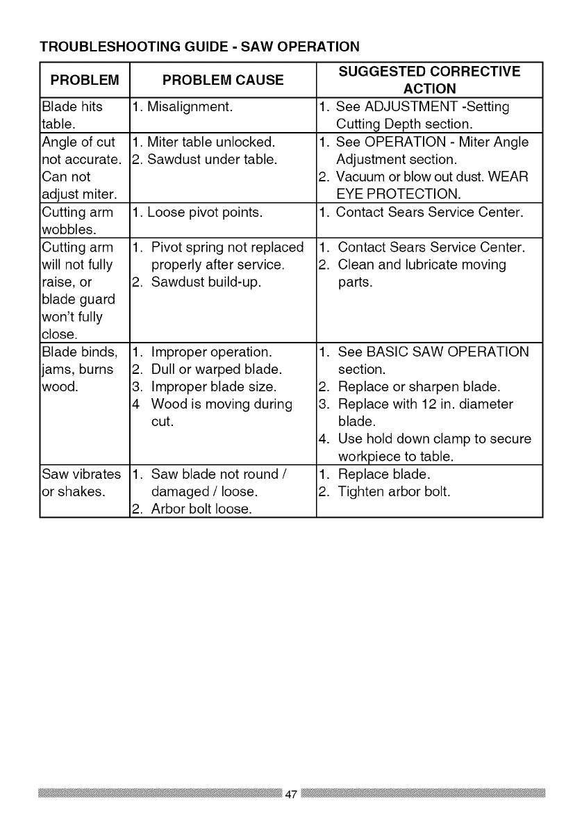
TROUBLESHOOTING GUIDE -SAW OPERATION
SUGGESTED CORRECTIVE
PROBLEM PROBLEM CAUSE ACTION
1. Misalignment. See ADJUSTMENT -Setting
Cutting Depth section.
1. Miter table unlocked. See OPERATION - Miter Angle
2. Sawdust under table. Adjustment section.
Vacuum or blow out dust. WEAR
EYE PROTECTION.
1. Loose pivot points. Contact Sears Service Center.
Blade hits
table.
Angle of cut
not accurate.
Can not
adjust miter.
Cutting arm
wobbles.
Cutting arm
will not fully
raise, or
blade guard
won't fully
close.
Blade binds,
ams, burns
wood.
Saw vibrates
or shakes.
1. Pivot spring not replaced
properly after service.
2. Sawdust build-up.
1. Improper operation.
2. Dull or warped blade.
3. Improper blade size.
4 Wood is moving during
cut.
1. Saw blade not round /
damaged /loose.
2. Arbor bolt loose.
.
1.
2.
1.
1.
2.
Contact Sears Service Center.
Clean and lubricate moving
parts.
1. See BASIC SAW OPERATION
section.
2. Replace or sharpen blade.
3. Replace with 12 in. diameter
blade.
4. Use hold down clamp to secure
workpiece to table.
1. Replace blade.
2. Tighten arbor bolt.
47
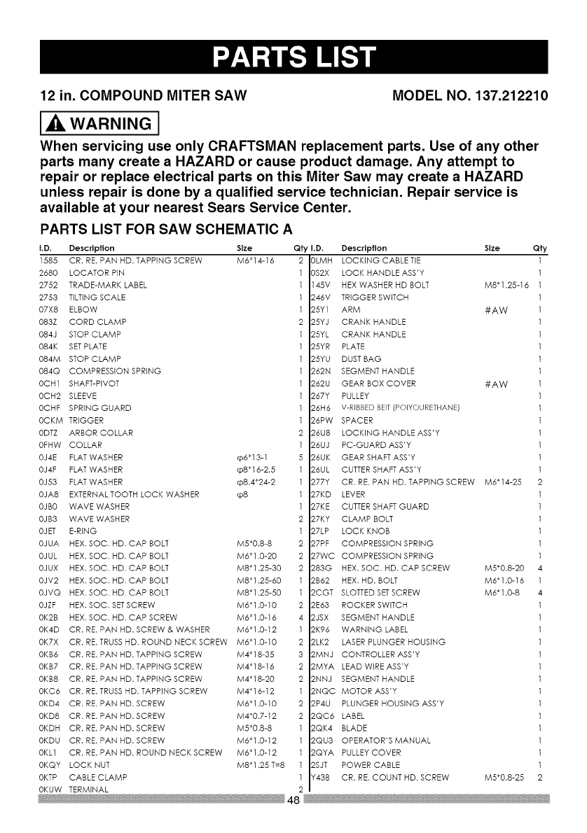
12 in. COMPOUND MITER SAW MODEL NO. 137.212210
2680 LOCATOR PIN
2752 TRADE-MARK LABEL
2753 TILTING SCALE
07X8 ELBOW
083Z CORD CLAMP
084J STOP CLAMP
084K SET PLATE
084M STOP CLAMP
084Q COMPRESSION SPRING
OCH1 SHAFT-PIVOT
OCH2 SLEEVE
OCHF SPRING GUARD
OCKM TRIGGER
ODTZ ARBOR COLLAR
OFHW COLLAR
OJ4E FLAT WASHER cp6_13-1
OJ4F FLAT WASHER cp8_16-2.5
0J53 FLAT WASHER q_8.4_24-2
OJA8 EXTERNALTOOTH LOCK WASHER cp8
OJBO WAVE WASHER
OJB3 WAVE WASHER
OJET E-RING
OJUA HEX. SOC. HD. CAP BOLT M5_0.8-8
OJUL HEX. SOC. HD. CAP BOLT M6_1.0-20
OJUX HEX. SOC. HD. CAP BOLT M8_1.25-30
OJV2 HEX. SOC. HD. CAP BOLT M8_1.25-60
OJVQ HEX. SOC. HD. CAP BOLT M8_1.28-50
OJZF HEX. SOC. SETSCREW M6"1.0-10
OK2B HEX. SOC. HD. CAP SCREW M6_1.0-16
OK4D CR. RE. PAN HD. SCREW & WASHER M6_1.0-12
OK7X CR. RE. TRUSS HD. ROUND NECK SCREW M6_1.0-10
OKB6 CR. RE. PAN HD. TAPPING SCREW M4_18-35
OKB7 CR. RE. PAN HD. TAPPING SCREW M4_18-16
OKB8 CR. RE. PAN HD. TAPPING SCREW M4"18-20
OKC6 CR. RE. TRUSS HD. TAPPING SCREW M4"16-12
OKD4 CR. RE. PAN HD. SCREW M6_1.0-10
OKD8 CR. RE. PAN HD. SCREW M4_0.7-12
OKDH CR. RE. PAN HD. SCREW M5_0.8-8
OKDU CR. RE. PAN HD. SCREW M6_1.0-12
OKL1 CR. RE. PAN HD. ROUND NECK SCREW M6_1.0-12
OKQY LOCK NUT M8_1.25 T=8
OKTP CABLE CLAMP
OKUW TERMINAL
PARTS LIST FOR SAW SCHEMATIC A
I.D. Description Size Qty I.D. Qfy
1888 CR. RE. PAN HD. TAPPING SCREW M6_14-16
Description Size
3LMH LOCKING CABLETIE
3S2X LOCK HANDLE ASS'Y
145V HEX WASHER HD BOLT M8"1.25-16
246V TRIGGER SWITCH
25Y1 ARM #AW
25YJ CRANK HANDLE
25YL CRANK HANDLE
25YR PLATE
25YU DUST BAG
262N SEGMENT HANDLE
262U GEAR BOX COVER #AW
267Y PULLEY
26H6 V-RIBBED BElT(POIYOURETHANE)
26PW SPACER
26U8 LOCKING HANDLE ASS'Y
Z6UJ PC-GUARD ASS'Y
Z6UK GEAR SHAFT ASS'Y
26UL CUTTER SHAFT ASS'Y
Z77Y CR. RE. PAN HD. TAPPING SCREW M6 _14-25
27KD LEVER
27KE CUTTER SHAFT GUARD
27KY CLAMP BOLT
Z7LP LOCK KNOB
Z7PF COMPRESSION SPRING
Z7WC COMPRESSION SPRING
Z83G HEX. SOC. HD. CAP SCREW M5"0.8-20
2B62 HEX. HD. BOLT M6"1.0-16
2CGT SLOTTED SETSCREW M6_1.0-8
2E63 ROCKER SWITCH
2JSX SEGMENT HANDLE
ZK96 WARNING LABEL
ZLK2 LASER PLUNGER HOUSING
2MNJ CONTROLLER ASS'Y
2MYA LEAD WIRE ASS'Y
ZNNJ SEGMENT HANDLE
2NQC MOTOR ASS'Y
2P4U PLUNGER HOUSING ASSW
ZQC6 LABEL
ZQK4 BLADE
2QU3 OPERATOR'S MANUAL
2QYA PULLEY COVER
ZSJT POWER CABLE
Y_43B CR. RE. COUNT HD. SCREW M5_0.8-25
48
_ik WARNING I
When servicing use only CRAFTSMAN replacement parts. Use of any other
parts many create a HAZARD or cause product damage. Any attempt to
repair or replace electrical parts on this Miter Saw may create a HAZARD
unless repair is done by a qualified service technician. Repair service is
available at your nearest Sears Service Center.

262U
145V
2QU3 246_
2LK2
2CG'['4_i 2P4_
OI,MH
43B z
0
I1"1
I"
Z
0
".4
k)
o

12 in. COMPOUND MITER SAW MODEL NO. 137.212210
PARTS LIST FOR SAW SCHEMATIC B
I.D. Description Size
0831 SHAFT SLEEVE
2750 CAUTION LABEL
2841 CENTER SHAFT
OCEZ PLUNGER HANDLE
OD7Z KNOB-HANDLE
ODW5 POWER CORD CLAMP
OH9W CLEVIS PiN
OHAM DUST SHIELD
OHAN PLATE COVER
OHAP SLIDE-BAR GUIDE CLAMP
OHVD BALL BEARING
OHXX LINEAR MOTION BEARING
OJ4N FLAT WASHER @16_30-3
OJ6A FLAT WASHER q_8_16-2.5
0J78 FLAT WASHER 1/4_1/2-3/32
OJ7D FLAT WASHER 5/1639/16-1/16
OJ7K FLAT WASHER 3/8329/32-5/64
OJ8P FLAT WASHER 3/8_29/32-5/64
OJAF EXTERNAL TOOTH LOCK WASHER @5
OJB0 WAVE WASHER WW-8
OJMN O-RING
OJMP O-RING
OJMT O-RING ROD
OJPP HEX. HD. BOLT M8_1.25-30
OJUM HEX. SOC. HD. CAP BOLT M6_1.0-25
OJUW HEX. SOC. HD. CAP BOLT M8_1.25-25
OJX3 HEX. SOC. SETSCREW M5_0.8-8
OJXD HEX. SOC. SETSCREW M6_1.0-25
OJXG HEX. SOC. SETSCREW M8_1.25-16
OK2B HEX. SOC. HD. CAP SCREW M6_1.0-16
OK7F CR. RE. ROUND WASHER HD. SCREW M5_0.8-8
OK7X CR. RE. TRUSSHD. ROUND NECK SCREW M6_1.0-10
OKAE CR. RE. PAN HD. TAPPING SCREW M5_0.8-10
OKB3 CR. RE. PAN HD. TAPPING SCREW M4_18-8
OKD9 CR. RE. PAN HD. SCREW M4_0.7-16
OKDH CR. RE. PAN HD. SCREW M5_0.8-8
OKDM CR. RE. PAN HD. SCREW M5_0.8-20
OKDR CR. RE. PAN HD. SCREW M5_0.8-10
OKDV CR. RE. PAN HD. SCREW M6_1.0-16
OKMS HEX. NUT M6_1.0T=5
OKMY HEX. NUT M8_1.25 T=6.5
OKQY LOCK NUT M8_1.25 T=8
OKQZ NUT M10_1.5 T=IO
OKR1 LOCK NUT M16_2.0 T=16
Qty I.D.
OKR4
OKSP
25XZ
25YG
25YK
262Q
262R
262S
262V
26HX
26LU
26NH
26NP
26NQ
26NR
26NS
26P7
26PU
26U6
26UQ
27BC
27BU
27BV
27HE
27J9
27JA
27MN
27Y4
283H
290M
2A J3
2DUC
2ED6
2JT2
2NGV
2NGW
2NKR
2NLC
2NLK
2RAX
2RAY
2SY9
Y648
Description Size Qty
LOCK NUT M8_1.25 T=8 1
STRAIN RELIEF 1
ARM-MITER #AW 1
NEEDLE POINTER 1
SETPLATE 1
TILTPOINTER 1
TILTPOINTER #23 1
POWER CORD CLAMP 2
ANCHOR PLATE #06 1
GUIDE HOLDER 1
WARNING LABEL 1
SPECIAL NUT 1
SPECIAL BOLT 1
LOCATING BAR 1
SHAFT-PWOT 1
LOCKING ROD 1
SHAFT-PWOT 1
MITER BAR 1
LOCKING HANDLE ASS'Y 1
BRACKET-TILT 1
SAFETY CLAMP ASS'Y 1
TABLE INSERT 1
TABLE INSERT 1
TORSION SPRING 1
SETNUT 1
SCREW STOP 1
ANCHOR PLATE 1
HEX. SOC. SET SCREW M631.0-16 2
HEX. SOC. HD. CAP SCREW M530.8-12 4
CAUTION LABEL 1
CLAMP HANDLE #AW 1
CR. RE.TRUSS HD. SCREW M5_0.8-8 1
CAUTION LABEL 1
STEELBALL 2
SUPPORT(LEFT) #AW 1
SUPPORT(RIGHT) #AW 1
SPECIAL BOLT 2
SPRING 2
TABLE #AW 1
LOCK KNOB 1
PLATE 1
SLIDE-BAR ASS'Y 1
COMPRESSION SPRING 1
5O

26HX /
26PU
/27BC
2SY9
\\\
_?HE
", 083I__
, 27J9
OH9W
26P7
\OJBO
262V
25YK /
0Jppz /
./
0KMYa
OJXO /
26NS ENGV
25YG /
Z .N"
Ill •
0
w 0
C
Z
o
-I
r,n
r_
0
o
I'll
r-
Z
0
0)
o

12 in. COMPOUND MITER SAW
PARTS LIST FOR SAW SCHEMATIC C
I.D. Description Size
2258 SPECIAL BOLT I
2754 WARNING LABEL I
082J CUSHION 2
082L BOLT 2
0CDD FOOT 4
0CFX SLIDE PLATE 3
0DTH CENTER BOLT t
0DVJ BLADE WRENCH 1
0H9A REAR EXTENSION STAY I
0J69 FLAT WASHER cp6"13-I I
0J88 FLAT WASHER #I0"t/2-1/16 2
Qty I.D. Description
MODEL NO. 137.212210
0JB0 WAVE WASHER WW-8
0JUB HEX. SOC. HD. CAP BOLT M5_0.8-12
0JZF HEX. SOC. SETSCREW M6"1.0-10
0K28 HEX. SOC. HD. CAP SCREW M5"0.8-16
0K2P HEX. SOC. HD.CAP SCREW M8_1.25-40
0K55 CR. RE. COUNT HD. SCREW M5_0.8-8
0K74 CR. RE. TRUSSHD. SCREW M6"1.0-8
0KAE CR. RE. PAN HD. TAPPING SCREW M5_0.8-10
0KDG CR. RE. PANHD. SCREW
0KDH CR. RE. PANHD. SCREW
0KDM CR. RE. PANHD. SCREW
0KDU CR. RE. PANHD. SCREW
0KR2 LOCK NUT
0KR3 LOCK NUT
0LYT STEELBALL
20PL CLAMP HANDLE
224U ROLL PIN
23SR COMPRESSION SPRING
M5_0.8-6
M5_0.8-8
M5"0.8-20
M6_'1.0-12
M5_0.8 T=5
M6_1.0 T=6
2
2
t
4
4
4
4
2
2
1
2
2
2
2
2
2
2
2
25V3 KNOB
25XX BASE
25Y0 ASSIST-FENCE
25Y2 EXTENSION WING
25Y3 ASSIST-FENCE
25Y6 EXTENSION WING
25Y8 FENCE
25YA LOCKING HANDLE ASS'Y
25YV PLATE
25YW PLATE (RIGHT)
262T FENCE PLATE
Size Qty
4
#AW I
#AW
#AW
#AW
#AW
#AW t
1
#23 I
#23 I
#AW 2
2
M8"1.25-6 2
2
1
I
I
26NN UPPER TUBE
26PF HEX. SOC. SETSCREW
26PK BLADE HOLDER
26UG LOCKING HANDLEASS'Y
26US BRACKET-TILT
27H1 CLAMP-CORD
27KA ECCENTRIC SPANNER SEAT #06
27KP SLIDE-BAR BLADE GUARD #AW
27LI LOCKING HANDLE ASS'Y
2C7F UPPER TUBE
2D J6 BRACKET-TILT
2D J7 BRACKET-TILT
2ENA EXTENSION WING ASS'Y
2ENB EXTENSION WING ASS'Y
2KSQ WARNING LABEL
2NH7 PLUNGER HOUSINGASS'Y
2QM7 FLAT WASHER cp6_10-1
2
1
t
1
1
1
t
4
52

27KP
+_/+'+L+
io+_ I
J
J
\
J
\25XX J
// /+
\%
Z .N"
m •
_0
0"u
o0
C
Z
0
-I
r,n
r_
0
0
I'll
r-
Z
0
0)
o

12 in. COMPOUND MITER SAW MODEL NO. 137.212210
PARTS LIST FOR MOTOR
I.D.
OJB8
OJX3
OJXC
0K38
OK3T
OK3Y
OKLA
OQ9K
OQM2
OQQT
OQR0
OQRI
26AZ
26DF
26PD
2MYR
2PRU
2QY7
Y430
Description Size Qfy
WAVE WASHER 1
HEX. SOC. SETSCREW M5"0.8-8 2
HEX. SOC. SETSCREW M6"1.0-20 1
CR. RE. PAN HD. SCREW & WASHER M5"0.8-8 2
CR. RE. PAN HD. SCREW & WASHER M5"0.8-25 2
CR. RE. PAN HD. SCREW & WASHER M5"0.8-50 2
PLASTIC SCREW M5"0.8-6 2
FLOW GUIDE 1
BRUSH HOLDER ASS'Y (b27"26.5 2
BRUSH ASS'Y 2
BRUSH COVER 2
RUBBER PIN 1
ARMATURE ASS'Y 1
FRONT HOUSING #AW 1
MOTOR PULLEY 1
FIELD ASS'Y 1
CR. RE. PAN HEAD TAPPING & WASHER SCREW M5"12-65 2
MOTOR HOUSING ASS'Y 1
HEX. HD. SCREW & WASHER SCREW M6"1.0-t6 1
0K3T\
OJX3
%
0KLA,
0JB8
2MYR
%
0JXC
26DF
0K38
Y430
26PD
54

55

Your Home
For expert troubleshooting and home solutions advice:
manage home
www.managemyhome.com
For repair - in your home - of all major brand appliances,
lawn and garden equipment, or heating and cooling systems,
no matter who made it, no matter who sold it!
For the replacement parts, accessories and
owner's manuals that you need to do-it-yourself.
For Sears professional installation of home appliances
and items like garage door openers and water heaters.
1-800-4-MY-HOME ®(1-800-469-4663)
Call anytime, day or night (U.S.A. and Canada)
www.sears.com www.sears.ca
Our Home
For repair of carry-in items like vacuums, lawn equipment,
and electronics, call anytime for the location of your nearest
Sears Parts & Repair Service Center
1-800-488-1222 (U.S.A.) 1-800-469-4663 (Canada)
www.sears.com www.sears.ca
To purchase a protection agreement on a product serviced by Sears:
1-800-827-6685 (U.S.A.) 1-800-361-6665 (Canada)
Para pedir servicio de reparaci6n Au Canada pour service en frangais:
a domicilio, y para ordenar piezas: 1-800-LE-FOYER M°
1-888-SU-HOGAR ® (1-800-533-6937)
Sea rs www.sears.ca
TM SM
® Registered Trademark /Trademark /Service Mark of Sears Brands, LLC
SM
® Marca Registrada /TM Marca de Fabrica /Marca de Servicio de Sears Brands, LLC
Mc MO
Marque de commerce /Marque deposce de Sears Brands, LLC © Sears Brands, LLC
