Craftsman 137212371 User Manual MITER SAW Manuals And Guides 1007215L
User Manual: Craftsman 137212371 137212371 CRAFTSMAN MITER SAW - Manuals and Guides View the owners manual for your CRAFTSMAN MITER SAW #137212371. Home:Tool Parts:Craftsman Parts:Craftsman MITER SAW Manual
Open the PDF directly: View PDF ![]() .
.
Page Count: 49
2WSA
Operator's Manual
10 in. SLiDiNG COMPOUND
MITER SAW WiTH LASER TRAC ®
Model No. 137.212371
CAUTION:
Before using this Miter Saw,
read this manual and follow
all its Safety Rules and
Operating Instructions
0 Safety Instructions
• Installation
0 Operation
0 Maintenance
0 Parts List
Customer Help Line
For Technical Support
t-800-843-t 682
Sears Parts &
Repair Center
t-800-488-t 222
Sears, Roebuck and Co., Hoffman Estates, IL 60179 USA
Visit our Craftsman website: www,sears.com/craftsman
Part No. __'_ Printed in China
P/N 2WSA
SECTION PAGE
Warranty .................................................................................................... 2
Product Specifications ............................................................................... 3
Symbols ...................................................................................................... 4
Power Tool Safety ..................................................................................... 5
Sliding Compound Miter Saw Safety ......................................................... 8
Electrical Requirements and Safety .......................................................... 10
Accessories and Attachments ................................................................... 12
Tools Needed for Assembly ...................................................................... 13
Carton Contents ........................................................................................ 14
Know Your Sliding Compound Miter Saw ................................................. 15
Glossary of Terms ..................................................................................... 16
Assembly .................................................................................................... 18
Adjustments ............................................................................................... 24
Operation ................................................................................................... 27
Maintenance .............................................................................................. 38
Troubleshooting Guide .......................... .................................................... 40
Parts List ....................................................... :........................................... 42
Repair Protection Agreement........ :............................................................... 47
CRAFTSMAN FULL WARRANTY
If this Craftman product fails due to a manufacturer's defect inmaterial or workmanship
with one year from the date of purchase, return it to any Sears store or other Craftman
outlet in the United States for free replacement.
This warranty does not include expendable parts such as saw blades which can wear
out from normal use within the warranty period.
This warranty applies for only 90 days from the date of purchase if this product is ever
used for commercial or rental purposes.
This warranty gives you specific legal rights, and you may also have other
rights which vary from state to state.
Sears, Roebuck and Co., Hoffman Estates, IL 60179
,_ WARNING
Some dust created by using power tools contains chemicals known to the state
of California to cause cancer and birth defects or other reproductive harm.
Some examples of these chemicals are:
® Lead from lead-based paints
® Crystalline silica from bricks, cement and other masonry
products
® Arsenic and chromium from chemically treated lumber
Your risk from these exposures varies, depending on how often you do
this type of work. To reduce your exposure to these chemicals, work in a
well ventilated area and work with approved safety equipment such as dust
masks that are specially designed to filter out microscopic particles.
2009/07
MOTOR
Power Source ................................................................. 120V AC, 60Hz, 15 Amp
Arbor Shaft Size ........................................................... 5/8 in.
Speed ............................................................................. 4800 RPM (No load)
Brake .............................................................................. Electric
Double Insulated ............................................................. Yes
MITER SAW
Rotating Table:
'MiterDetent Stops ......................... ................................. 0°, 15°, 22,5°, 31.6°, 45° R & L
BevelPositive Stops....................................................... 0°, 33.9°, 45° L
Cutting Capacity:
Crosscut ........................................................ :................. 3-9/16 in. x 12 in.
Miter 45° R & L ................................ ...i'.....' ............. _...,.... 3-9/16 in. x 8 in.
Bevel 45° L .., .................................. ..... ............. 1-5/8 in.x 12 _ir
45° Miter and 45° Bevel ....,_................................... ._L-5!83n. x_8 _n_:
BLADE
Diameter .......................................................................... 10 in.
Arbor ............................. :.......... .. ....................... ....... _.,i.' 5/8 in.
,_WARNING
To avoid electrical hazards, fire hazards or damage to the tool, use proper circuit
protection.
This tool is wired at the factory for 110-120 Volt operation. It must be connected to
a 110-120 Volt /15 Ampere time delay fuse or circuit breaker. To avoid shock or fire,
replace power cord immediately if it is worn, cut or damaged in any way.
Before using your tool, it is critical that you read and understand these safety rules.
Failure to follow these rules could result in serious injury to you or damage to the
tool.
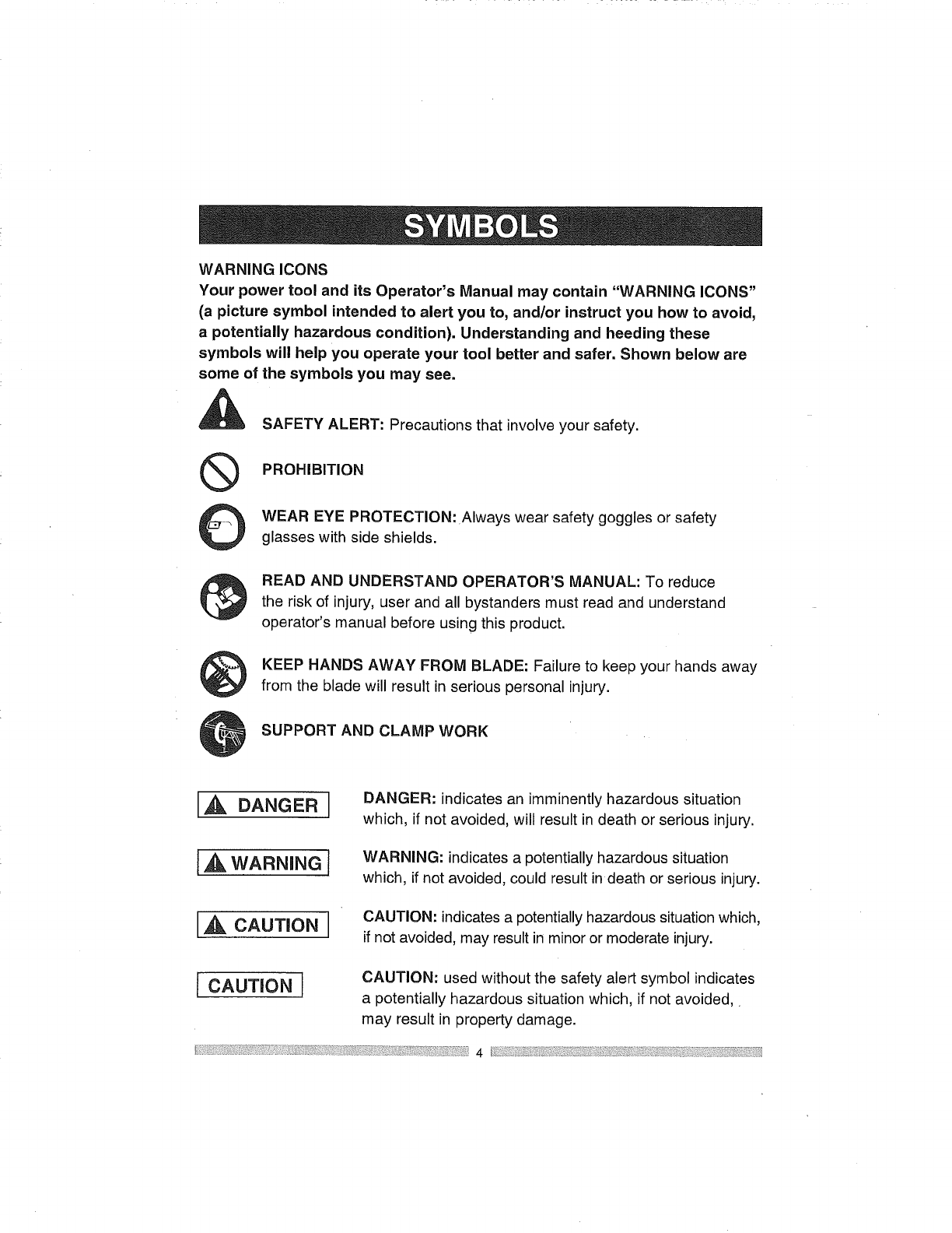
WARNING ICONS
Your power tool and its Operator's Manual may contain "WARNING ICONS"
(a picture symbol intended to alert you to, and/or instruct you how to avoid,
a potentially hazardous condition). Understanding and heeding these
symbols will help you operate your tool better and safer. Shown below are
some of the symbols you may see.
®
©
SAFETY ALERT: Precautions that involve your safety.
PROHIBITION
WEAR EYE PROTECTION: Always wear safety goggles or safety
glasses with side shields.
READ AND UNDERSTAND OPERATOR'S MANUAL: To reduce
the risk of injury, user and all bystanders must read and understand
operator's manual before using this product.
KEEP HANDS AWAY FROM BLADE: Failure to keep your hands away
from the blade will result in serious personal injury.
SUPPORT AND CLAMP WORK
[A DANGERJDANGER: indicates an imminently hazardous situation
which, if not avoided, will result in death or serious injury.
wAR.INGJWARNING: indicates a potentially hazardous situation
which, if not avoided, could result in death or serious injury.
LA CAUTIONJCAUTION: indicates a potentially hazardous situation which,
if not avoided, may result in minor or moderate injury.
[ CAUTION I CAUTION: used without the safety alert symbol indicates
a potentially hazardous situation which, if not avoided,.
may result in property damage.
!; 4
GENERAL SAFETY INSTRUCTIONS
BEFORE USING THIS POWER TOOL
,
Safety is a combination of common
sense, staying alert and knowing how 7.
to use your power tool.
[, WARNINGI
-- To avoid mistakes that could cause 8.
serious injury, do not plug the tool in
until you have read and understood
the following. 9.
1. READ and become familiar
with the entire Operator's
Manual. LEARN the tool's
application, limitations and
possible hazards.
2. KEEP GUARDS IN PLACE and in
working order.
3. REMOVE ADJUSTING KEYS
AND WRENCHES. Form the habit
of checking to see that keys and
adjusting wrenches are removed
from the tool before turning ON.
4. KEEP WORK AREA CLEAN.
Cluttered areas and benches invite
accidents.
DO NOT USE IN DANGEROUS
ENVIRONMENTS. Do not use
power tools in damp locations, or
expose them to rain or snow. Keep
work area well lit.
.
KEEP CHILDREN AWAY. All
visitors and bystanders should be
kept a safe distance from work area.
MAKE WORKSHOP CHILD PROOF
with padlocks, master switches or by
removing starter keys.
DO NOT FORCE THE TOOL. It will
do the job better and safer at the
rate for which it was designed.
USE THE RIGHT TOOL. Do not
force the tool or an attachment to do
a job for which it was not designed.
10.USE PROPER EXTENSION
CORDS. Make sure your extension
cord is in good condition. When
using an extension cord, be sure to
use one heavy enough to carry the
current your product will draw. An
undersized cord will result in a drop
in line voltage and in loss of power
which will cause thetool to overheat.
The table on page 11 shows the
correct size to use depending on
cord length and nameplate ampere
rating. If in doubt, use the next
heavier gauge. The smaller the
gauge number, the heavier the cord.
11.WEAR PROPER APPAREL. Do
not wear loose clothing, gloves,
neckties, rings, bracelets or other
jewelry which may get caught in
moving parts. Nonslip footwear is
recommended. Wear protective hair
covering to contain long hair.
12.ALWAYSWEAREYE
PROTECTION. Any power
tool can throw foreign
objects into the eyes and
could cause permanent
eye damage. ALWAYS wear Safety
Goggles (not glasses) that comply
with ANSI Safety standard Z87.1.
Everyday eyeglasses have only
impact-resistant lenses: They
ARE NOT safety glasses,Safety
Goggles are available at Sears.
NOTE: Glasses or goggles not in
compliance with ANSI Z87.1 could
seriously injure you when they break.
13.WEAR AFACE MASKOR DUST
MASK. Sawing operation produces
17.USE RECOMMENDED
ACCESSORIES. Consult
this Operator's Manual for
recommended accessories. The use
of improper accessories may cause
risk of injury to yourself or others.
18.NEVER STAND ON THE TOOl.
Serious injury could occur if the
tool is tipped or if the cutting tool is
unintentionally contacted:
19.CHECK FOR DAMAGED PARTS.
Before further use of the tool, a
guard or other part that is damaged:
should be carefully checked to
determine that it will operate
properly and perform its intended
dust.
14.SECURE WORK. Use clamps or
a vise to hold work when
practical. It is saferthan:
using your hand and
it frees both handst0
operate the too/
-:function -check for alignment-of--
moving parts, binding of moving
parts, breakage of parts, mounting
and any other conditions that may
affect its operation. A guard or other
part that is damaged should be
properly repaired or replaced.
15.DISCONNECT TOOLS FROM
POWER SOURCE before servicing,
and when changing accessories
such as blades, bits and cutters.
16.REDUCE THE RISK OF
UNINTENTIONAL STARTING.
Make sure switch is in the OFF
position before plugging the tool in.
20.NEVER LEAVE THE TOOL
RUNNING UNATTENDED. TURN
THE POWER "OFF". Do not walk
away from a running tool until the
blade comes to a complete stop
and the tool is unplugged from the
power source.
21 .DO NOT OVERREACH. Keep
proper footing and balance at all
times.
6
22.MAINTAIN TOOLS WITH CARE.
Keep tools sharp and clean for best
and safest performance. Follow
instructions for lubricating and
changing accessories.
23.WARNING: Dust generated from
certain materials can be hazardous
to your health. Always operate saw
in well-ventilated area and provide
for proper dust removal.
24.[,_ DANGER 1
People with electronic devices, such
as pacemakers, should consult
their physician(s) before using this
product. Operation of electrical
equipment in close proximity to
a heart pacemaker could cause
interference or failure of the
pacemaker.
_
SPECIFIC SAFETY INSTRUCTIONS
FOR THIS COMPOUND MITER SAW
.IMPORTANT: DO NOT USE
THIN KERF BLADES. They can
deflect and contact the blade guard
and cause possible injury to the
operator.
.DO NOT operate the miter saw
until it is completely assembled
and installed according to these
instructions.
.IF YOU ARE NOT thoroughly
familiar with the operation of miter
saws, seek guidance from your
supervisor, instructor or other
qualified person.
.ALWAYS hold the work firmly
against the fence and table.
DO NOT perform any operation
freehand (use clamp wherever
possible).
.
.
KEEP HANDS out of the path of the
saw blade. If the workpiece you are
cutting would cause your hands to
be within 7-1/2 in. of the saw blade,
the workpiece should be clamped in
place before making the cut.
MAKE SURE the blade is sharp,
runs freely and is free of vibration.
.
.
ALLOW the motor to come up to full
speed before starting a cut.
KEEP THE MOTOR AIR SLOTS
CLEAN and free of chips or dust.
.ALWAYS MAKE SURE all handles
are tight before cutting, even if the
table is positioned in one of the
positive stops.
10.MAKE SURE both the blade and
the collar are clean and the arbor
bolt is tightened securely.
11.USE only blade collars specified for
your saw.
12.NEVER use blades larger than 10
in. in diameter.
13.NEVER apply lubricants to the
blade when the saw is running.
14.ALWAYS check the blade for
cracks or damage before operation.
Replace a cracked or damaged
blade immediately.
15.NEVER use blades recommended
for operation at less than 4800 rpm.
16.ALWAYS keep the blade guards in
place and use at all times.
17.NEVER reach around the saw
blade.
18.MAKE SURE the blade is not in
contact with the workpiece before
the switch is turned ON.
19.IMPORTANT: After completing a
cut, release the trigger switch and
wait for the blade to stop before
returning the saw to the raised
position.
20.MAKESUREthebladehascome
toa completestopbeforeremoving
orsecuringtheworkpiece,changing
theworkpieceangleorchangingthe
angleoftheblade.
21.NEVER cut metals or masonry
products with this tool. This miter
saw is designed for use on wood
and wood-like products'i
22.NEVER cut small pieces. If the--:
workpiece being cut would cause
your hand or fingers to be within
7-1/2 in. of the saw blade, !he_
workpiece is too small.
23.PROVIDE adequate Support to
the sides of the saw table for long
workpieces.
24.NEVER use the miter saw in areas
with flammable liquids or gases.
25.NEVER use solvents to clean plastic
parts. Solvents could possibly
dissolve or otherwise damage the
material.
26.SHUT OFF the power before
servicing or adjusting the tool.
27.DISCONNECT the saw from
the power source and clean the
machine when finished using .....
28J_IAKE SURE the work area is clean
before leaving the machine.
29.SHOULD any part of you[ miter
saw become missing, damaged,
fail in any way or any electrical
_component fail to perform properly,
shut off the switch and remove the
plug from the power supply outlet.
Replace missing, damaged or failed _
parts before resuming operation.
POWER SUPPLY AND MOTOR
SPECIFICATIONS
The AC motor used in this saw is
a universal, nonreversible type.
See "MOTOR" in the "PRODUCT
SPECIFICATIONS" section on page 3.
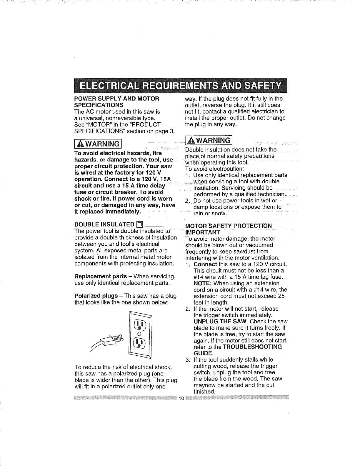
way. If the plug does not fit fully in the
outlet, reverse the plug. If it still does
not fit, contact a qualified electrician to
install the proper outlet. Do not change
the plug in any way.
,A WARNINGJ,A WARNING , ......
.... Double insulation does not take the
To avoid electrical hazards, fire place of normal safety precautions
hazards, or damage to the tool, use when operating this tool, - --
proper circuit protection. Your saw To avoid electrocution:
is wired at the factory for 120 V 1. Use only identical replacement parts
operation. Connect to a 120 V, 15A when servicing a tool with double _:
circuit and use a15 A time delay insulation. Servicing should be :. :
fuse or circuit breaker. To avoid performed by a qualified technician.
shock or fire, if power cord is worn 2. Do not use power tools in wet or
or cut, or damaged in any way, have damp locations or expose them to
it replaced immediately. - rain or snow.
DOUBLE INSULATED []
The power tool is double insulated to
provide a double thickness of insulation
between you and tool's electrical
system. All exposed metal parts are
isolated from the internal metal motor
components with protecting insulation.
Replacement parts - When servicing,
use only identical replacement parts.
Polarized plugs - This saw has a plug
that looks like the one shown below:
To reduce the risk of electrical shock,
this saw has a polarized plug (one
blade is wider than the other). This plug
will fit in a polarized outlet only one
MOTOR SAFETY PROTECTION
IMPORTANT
To avoid motor damage, the motor
should be blown out or vacuumed
frequently to keep sawdust from
interfering with the motor ventilation.
1. Connect this saw to a 120 V circuit.
This circuit must not be less than a
#14 wire with a 15 A time lag fuse.
NOTE: When using an extension
cord on a circuit with a #14 wire, the
extension cord must not exceed 25
feet in length.
2. If the motor will not start, release
the trigger switch immediately.
UNPLUG THE SAW. Check the saw
blade to make sure it turns freely. If
the blade is free, try to start the saw
again. If the motor still does not start,
refer to the TROUBLESHOOTING
GUIDE.
3. If the t0ol suddenly stalls while
cutting wood, release the trigger
switch, unplug the tool and free
the blade from the wood. The saw
maynow be started and the cut
finished.
10
4. FUSES may "blow" or circuit
breakers may trip frequently if:
a. MOTOR is overloaded -
overloading can occur if you feed
too rapidly or make too many
start/stops in a short time.
b. LINE VOLTAGE is more
than 10% above or below the
nameplate voltage rating. For
heaw loads, the voltage at motor
_ terminals must equal the voltage
specified on the nameplate.
C. IMPROPER or dull saw blades
are used.
5. Most motor troubles may be traced
to loose or incorrect connections,
overload, !oWvoltage or inadequate
power supplywiring. Always check
the connections, the load and
supply circuit if the motor doesn't
run well. Check minimum gauge for
the length of cord you are using on
the chart below.
GUIDELINES FOR EXTENSION
CORDS
Use a proper extension cord. Make
sure your extension cord is in good
condition. When using an extension
cord, be sure to use one heavy enough
to carry the current your product will
draw. An undersized cord will cause
a drop in line voltage, resulting in
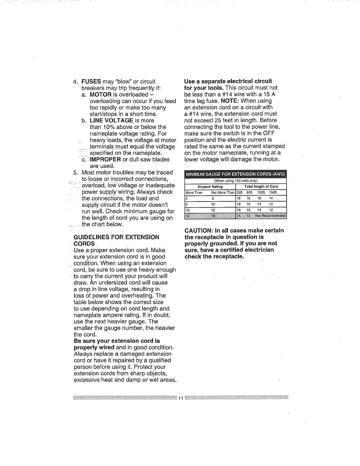
loss of power and overheating. The
table below shows the correct size
to use depending on cord length and
nameplate ampere rating. If in doubt,
use the next heavier gauge. The
smaller the gauge number, the heavier
the cord.
Be sure your extension cord is
properly wired and in good condition.
Always replace a damaged extension
cord or have it repaired by a qualified
person before using it. Protect your
extension cords from sharp objects,
excessive heat and damp or wet areas.
Use a separate electrical circuit
for your tools. This circuit must not
be less than a #14 wire with a 15 A
time lag fuse. NOTE: When using
an extension cord on a circuit with
a #14 wire, the extension cord must
not exceed 25 feet in length. Before
connecting the tool to the power line,
make sure the switch is in the OFF
position and the electric current is
rated the same as the current stamped
on the motor nameplate, running at a
lower voltage will damage the motor.
,=- e o"= ,
(When using 120 volts only)
Ampere Rating Total length of Cord
MoreThan Not More Than 25ft. 501t, 100ft. 150ft,
0 6 18 16 16 14
6 10 18 16 14 12
10 12 16 16 14 12
CAUTION: In all cases make certain
the receptacle in question is
properly grounded. If you are not
sure, have a certified electrician
check the receptacle.
11
RECOMMENDED ACCESSORIES
[,_WARNING J
® Use only accessories
recommended for this miter
saw. Follow instructions that
accompany accessories. Use of
improper accessories may cause
hazards,
® The use of any cutting tool
except 10 in. saw blades which
meet the requirements under
recommended accessories
is prohibited. Do not use
accessories such as shaper
cutters or dado sets. Ferrous
metal cutting and the use of
abrasive wheels is prohibited.
® Do not attempt to modify this
tool or create accessories not
recommended for use with this
tool. Any such alteration or
modification is misuse and could
result in a hazardous condition
leading to possible serious
injury.
should be taken while mounting,
using, and storing carbide tipped
blades to prevent accidental
damage. Slight shocks, such as
striking the tip while handling,
can seriously damage the blade.
Foreign objects in the workpiece,
such as wire or nails, can also
cause tips to crack or break off.
Before using, always visually
examine the blade and tips for
bent blade, cracks, breakage,
missing or loose tips, or other
damage. Do not use if damage is
suspected. Failure to heed safety
instructions and warnings can
result in serious bodily injury.
ACCESSORIES
Visit your Sears Hardware Department
or see the Sears Power and Hand Tool
Catalog to purchase recommended
accessories for this power tool.
IAWARNING]
®To avoid the risk of personal
injury, do not modify this power
tool or use accessories not
recommended by Sears.
®Read warnings and conditions
on your CARBIDE TIPPED SAW
BLADE. Do not operate the saw
without the proper saw blade
guard in place. Carbide is a very
hard but brittle material. Care
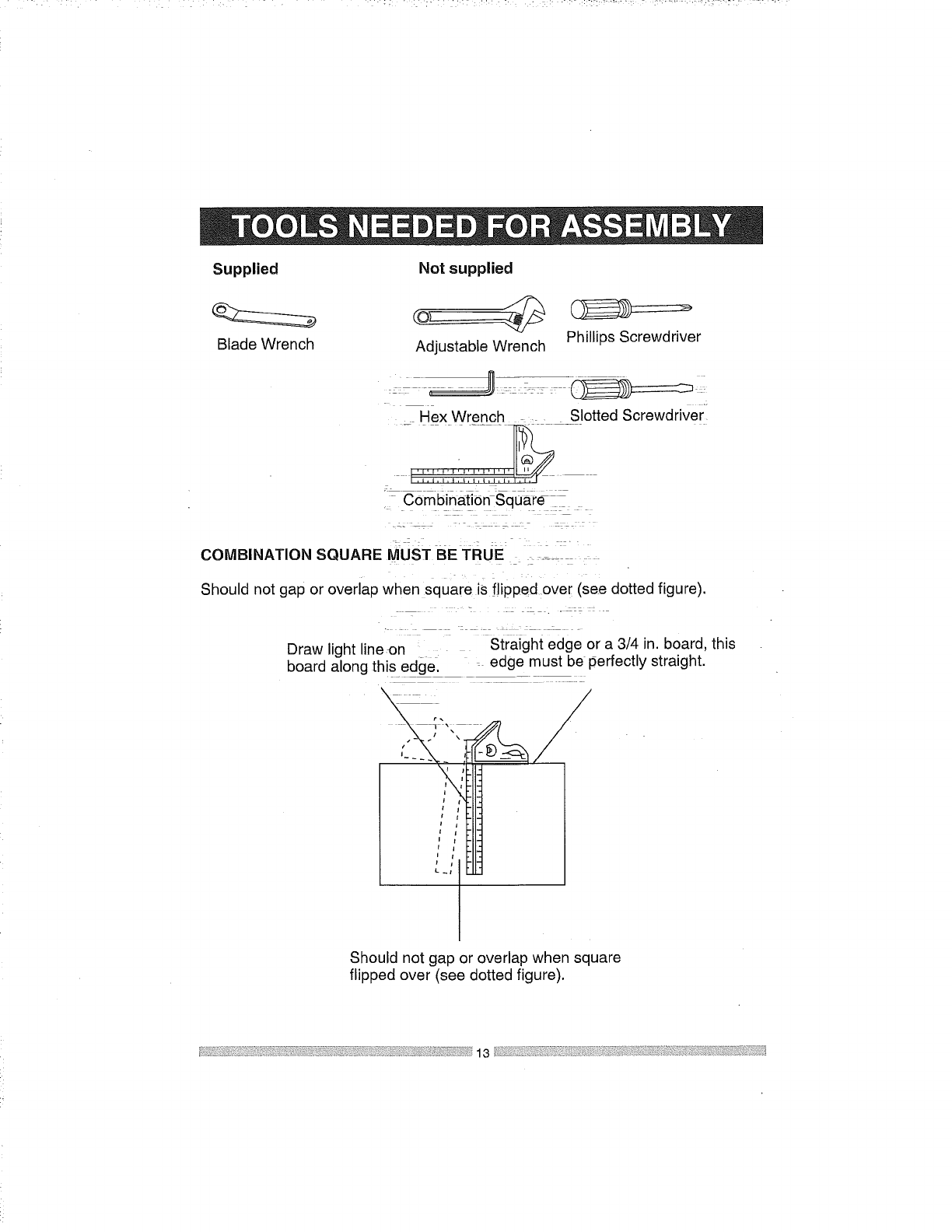
Supplied Notsupplied
Blade Wrench Adjustable Wrench Phillips Screwdriver
Hex Wrench ..... Slotted Screwdriver
, Combination-Square--
COMBINATION SQUARE MUST BE TRUE _ .....
: L
Should not gap or overlap when square is flipped over (see dotted figure).
:-_ . -
.z .... c .
Draw light lineon Straight edge or a 3/4 in. board, this
edge must be perfectly straight.
board along this edge.
r.
4 - \
I t
I;
Should not gap or overlap when square
flipped over (see dotted figure).
13
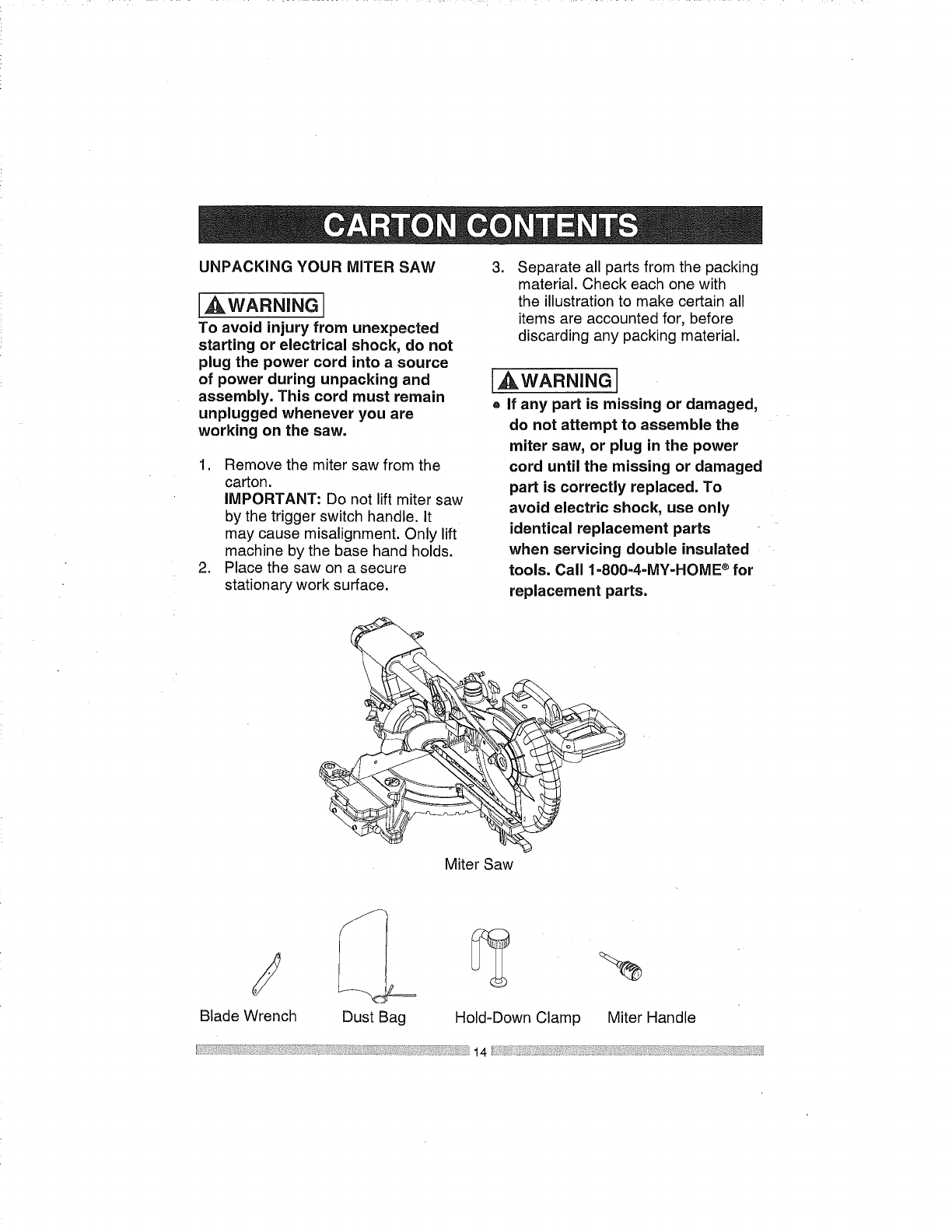
UNPACKING YOUR MITER SAW
[_WARNING
To avoid injury from unexpected
starting or electrical shock, do not
plug the power cord into a source
of power during unpacking and
assembly. This cord must remain
unplugged whenever you are
working on the saw.
1. Remove the miter saw from the
carton.
IMPORTANT: Do not lift miter saw
by the trigger switch handle. It
may cause misalignment. Only lift
machine by the base hand holds.
2. Place the saw on a secure
stationary work surface.
.Separate all parts from the packing
material. Check each one with
the illustration to make certain all
items are accounted for, before
discarding any packing material.
[AWARNING I
o If any part is missing or damaged,
do not attempt to assemble the
miter saw, or plug in the power
cord until the missing or damaged
part is correctly replaced. To
avoid electric shock, use only
identical replacement parts
when servicing double insulated
tools. Call 1=800-4=MY-HOME ®for
replacement parts.
Miter Saw
Blade Wrench Dust Bag Hold-Down Clamp Miter Handle
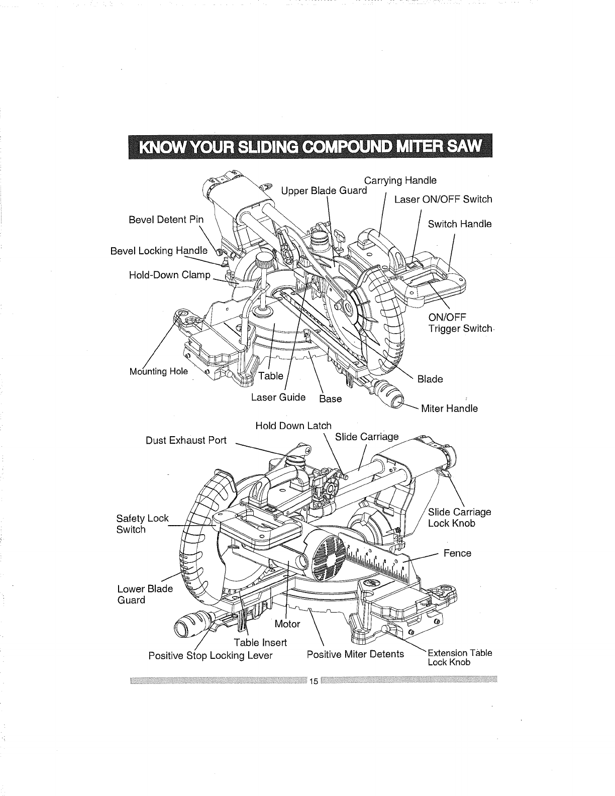
BevelDetentPin
CarryingHandle
UpperBladeGuard LaserON/OFFSwitch
SwitchHandle
BevelLockingHandle
Hold-DownClamp
ON/OFF
TriggerSwitch,
/
Mounting Hole Blade
Laser Guide Base Miter Handle
Hold Down Latch
Dust Exhaust Port \Slide Carriage
#,
Table Insert \
Safety Lock ,_
ii,i i
Guard
Positive Stop Locking Lever Positive Miter Detents
Slide Carriage
Lock Knob
Fence
Table
Lock Knob
15
AMPERAGE (AMPS) - A measure
of the flow of electric current. Higher
ratings generally means the tool is
suited for heavier use.
ARBOR LOCK - Allows the user to
keep the blade from rotating while
tightening or loosening the arbor bolt
during blade replacement or removal.
eyes. Eye protection should meet the
requirements of ANSI Z.87.1 (USA) or
CSA Z94.3-M88 (Canada).
FACE SHIELD - An impact resistant
shield that helps to protect your face
from chips, sparks, small debris.
Should only be used in conjunction with
additional eye protection.
BASE - Supports the table, holds
accessories and allows for workbench
or leg set mounting.
FENCE - Helps to keep the workpiece
from moving when sawing. Scaled to
assist with accurate cutting.
BEVEL LOCKING HANDLE - Locks
the miter saw at a desired bevel angle.
BEVEL SCALE - To measure the
bevel angle of the saw blade 0° to 45 °
left.
CARBIDE TIPPED - Extremely hard
steel pieces with sharp cutting edges
fastened to cutting tools such as saw
blades.
COVER PLATE SCREW - Loosen this
screw and rotate the plate for access to
the blade arbor bolt.
GUARD -Protective devise that forms
a barrier between a hazardous object
such as a blade, wheel or cutter and
the operator.
HOLD DOWN LATCH - Locks the
miter saw in the lowered position for
compact storage and transportation.
INSTRUCTION OR OPERATOR'S
MANUAL - Booklet accompanying
your power tool that describes the
hazards and safe operation procedures,
outlines basic tool operation, care and
maintenance.
DOUBLE-INSULATED - A form of
electrical protection featuring two
separate insulation systems to help
protect against electrical shock.
EXTENSION CORD - An electric cord
used between power tools and outlets
to extend the range of the tools. The
more amerage your tool uses, the
longer the distance, the larger the size
of the wire needed in your extension
cord.
EYE PROTECTION - Goggles or
spectacles intended to protect your
MITER HANDLE - Used to rotate the
table, and to rotate the saw to a right or
left cutting position.
MITER SCALE - Measures the miter
angle 0° to 45° left and right.
MOUNTING HOLES - To mount the
miter saw to a stable surface.
ON/OFF TRIGGER SWITCH - To start
the tool, squeeze the trigger. Release
the trigger to turn off the miter saw.
-i!f :!ii_i L ::: :k;! :ii ' ::!::'; :!?_::! :_"-"T :??':_ : ¸ ¸ " :L • • L
c
POSITIVE STOP LOCKING LEVER -
Locks the miter saw at a preset positive
stop for the desired miter angle.
SWITCH HANDLE -The switch
handle contains the trigger switch and
the laser on/off switch. The blade is
lowered into the workpiece by pushing
down on the handle. The saw will
return to its upright position when the
handle is released.
WARNING LABELS - Read and
understand for your own safety. Make
sure all labels are present on machine
and legible.
WRENCH STORAGE - Convenient
storage to prevent misplacing the blade
wrench.
WOODWORKING TERMS
ARBOR - The shaft on which a blade
is mounted.
BEVEL CUT - An angle cut made
through the face of the workpiece.
COMPOUND CUT - An angled cut
to both the edge and face of a board,
most common use is with crown
molding.
CROSS CUT - A cut which runs across
the board perpendicular to the grain.
KICKBACK- Sudden and unintended
movement of the tool or workpiece. It is
typically caused by binding or pinching
of the workpiece
MITER CUT - A miter is a type of joint
where the two parts to be joined are cut
at an angle, and typically the finished
joint forms a 90-degree angle. Also
commonly spelled "mitre".
REVOLUTIONS PER MINUTE (RPM)
-The number of turns completed by a
spinning object in one minute.
SAW BLADE PATH - The area of the
workpiece or table top directly in line
with the travel of the blade or the part
of the workpiece which will be cut.
SET - The distance between two saw
• t
blade tips, bent outward In opposite
directions to each other. The further
apart the tips are, the greater the set.
THIN-KERF BLADE - Thinner than
normal blades, remove less material,
smaller kerfs (between .065 in. and
.070 in.). Blade thinness also may
increase the heat generated while
cutting.
WORKPIECE - The wood being
cut. The surfaces of a workpiece are
commonly referred to as faces, ends
and edges.
FREEHAND - Performing a cut without
using a fence (guide), hold down or
other proper device to prevent the
workpiece from twisting during the
cutting operation.
HEEL - Misalignment of the blade.
KERF - The width of a saw cut,
determined by the thickness and set of
the blade.
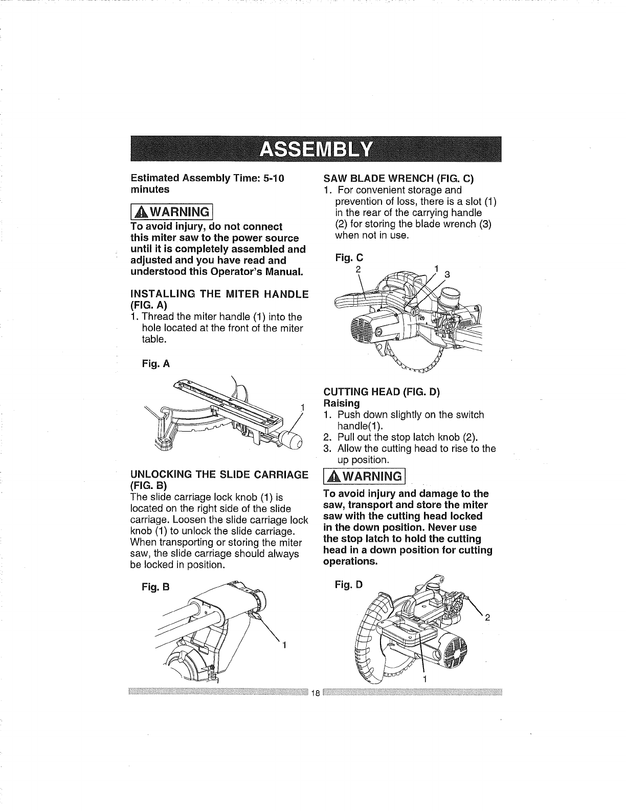
Estimated Assembly Time: 5-10
minutes
,_WARNING
To avoid injury, do not connect
this miter saw to the power source
until it is completely assembled and
adjusted and you have read and
understood this Operator's Manual.
INSTALLING THE MITER HANDLE
(FIG. A)
1. Thread the miter handle (1) into the
hole located at the front of the miter
table.
Fig. A
UNLOCKING THE SLIDE CARRIAGE
(FIG. B)
The slide carriage lock knob (1) is
located on the right side of the slide
carriage. Loosen the slide carriage lock
knob (1) to unlock the slide carriage.
When transporting or storing the miter
saw, the slide carriage should always
be locked in position.
SAW BLADE WRENCH (FIG. C)
1. For convenient storage and
prevention of loss, there is a slot (1)
in the rear of the carrying handle
(2) for storing the blade wrench (3)
when not in use.
Fig. C
2
CUTTING HEAD (FIG. D)
Raising
1. Push down slightly on the switch
handle(I).
2. Pull out the stop latch knob (2).
3. Allow the cutting head to rise to the
up position.
_WARNJNG
To avoid injury and damage to the
saw, transport and store the miter
saw with the cutting head locked
in the down position. Never use
the stop latch to hold the cutting
head in a down position for cutting
operations.
Fig. B Fig. D
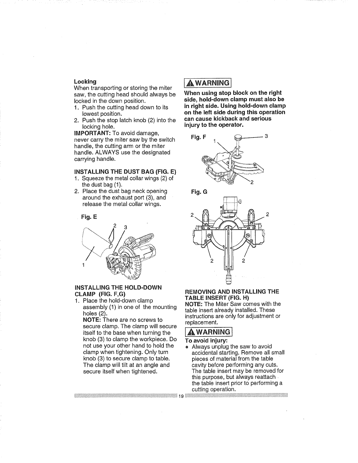
Locking
Whentransportingorstoringthemiter
saw,thecuttingheadshouldalwaysbe
lockedinthedownposition.
1. Pushthecuttingheaddowntoits
lowestposition.
2. Pushthestoplatchknob(2)intothe
lockinghole.
IMPORTANT:Toavoiddamage,
nevercarrythemitersawbytheswitch
handle,thecuttingarmorthemiter
handle.ALWAYSusethedesignated
carryinghandle.
INSTALLINGTHEDUSTBAG(FIG.E)
1. Squeezethemetalcollarwings(2)of
thedustbag(1).
2. Placethedustbagneckopening
aroundtheexhaustport(3),and
releasethemetalcollarwings.
Fig.E
2 3
[AWARNING1
When using stop block on the right
side, hold-down clamp must also be
in right side. Using hold-down clamp
on the left side during this operation
can cause kickback and serious
injury to the operator.
Fig. F_ 3
Fig. G
INSTALLING THE HOLD-DOWN
CLAMP (FIG. F,G)
1. Place the hold-down clamp
assembly (1) in one of the mounting
holes (2).
NOTE: There are no screws to
secure clamp. The clamp will secure
itself to the base when turning the
knob (3) to clamp the workpiece. Do
not use your other hand to hold the
clamp when tightening. Only turn
knob (3) to secure clamp to table.
The clamp will tilt at an angle and
secure itself when tightened.
REMOVING AND INSTALLING THE
TABLE INSERT (FIG. H)
NOTE: The Miter Saw comes with the
table insert already installed. These
instructions are only for adjustment or
replacement.
,_WARNING 1
To avoid injury:
o Always unplug the saw to avoid
accidental starting. Remove all small
pieces of material from the table
cavity before performing any cuts.
The table insert may be removed for
this purpose, but always reattach
the table insert prior to performing a
cutting operation.
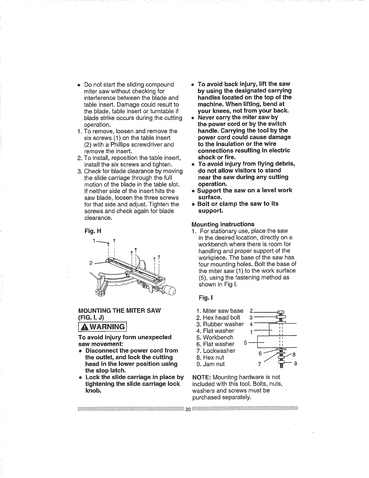
® Donotstarttheslidingcompound
mitersawwithoutcheckingfor
interferencebetweenthebladeand
tableinsert.Damagecouldresultto
theblade,tableinsertorturntableif
bladestrikeoccursduringthecutting
operation.
1.Toremove,loosenandremovethe
sixscrews(1)onthetableinsert
(2)withaPhillipsscrewdriverand
removetheinsert.
2.Toinstall,repositionthetableinsert,
installthesixscrewsandtighten.
3.Checkforbladeclearancebymoving
theslidecarriagethroughthefull
motionofthebladeinthetableslot.
Ifneithersideoftheinserthitsthe
sawblade,loosenthethreescrews
forthatsideandadjust.Tightenthe
screwsandcheckagainforblade
clearance.
Fig.H
2 ,,
®To avoid back injury, lift the saw
by using the designated carrying
handles located on the top of the
machine. When lifting, bend at
your knees, not from your back.
®Never carry the miter saw by
the power cord or by the switch
handle. Carrying the tool by the
power cord could cause damage
to the insulation or the wire
connections resulting in electric
shock or fire.
®To avoid injury from flying debris,
do not allow visitors to stand
near the saw during any cutting
operation.
®Support the saw on a level work
surface.
®Bolt or clamp the saw to its
support.
Mounting instructions
1. For stationary use, place the saw
in the desired location, directly on a
workbench where there is room for
handling and proper support of the
workpiece. The base of the saw has
four mounting holes. Bolt the base of
the miter saw (1) to the work surface
(5), using the fastening method as
shown in Fig I.
Fig. I
MOUNTING THE MITER SAW
(FIG. I, J)
I,_WARNING
To avoid injury form unexpected
saw movement:
® Disconnect the power cord from
the outlet, and lock the cutting
head in the lower position using
the stop latch.
® Lock the slide carriage in place by
tightening the slide carriage lock
knob.
1. Miter saw base 2_.__.____
2. Hex head bolt 3
3. Rubber washer 4
4. Flat washer 1 _,
5. Workbench / ,,
6. Flat washer 5 _ ',',
7. Lockwasher 6 _=_-_8
8. Hex nut
9. Jam nut 7 9
NOTE: Mounting hardware is not
included with this tool. Bolts, nuts,
washers and screws must be
purchased separately.
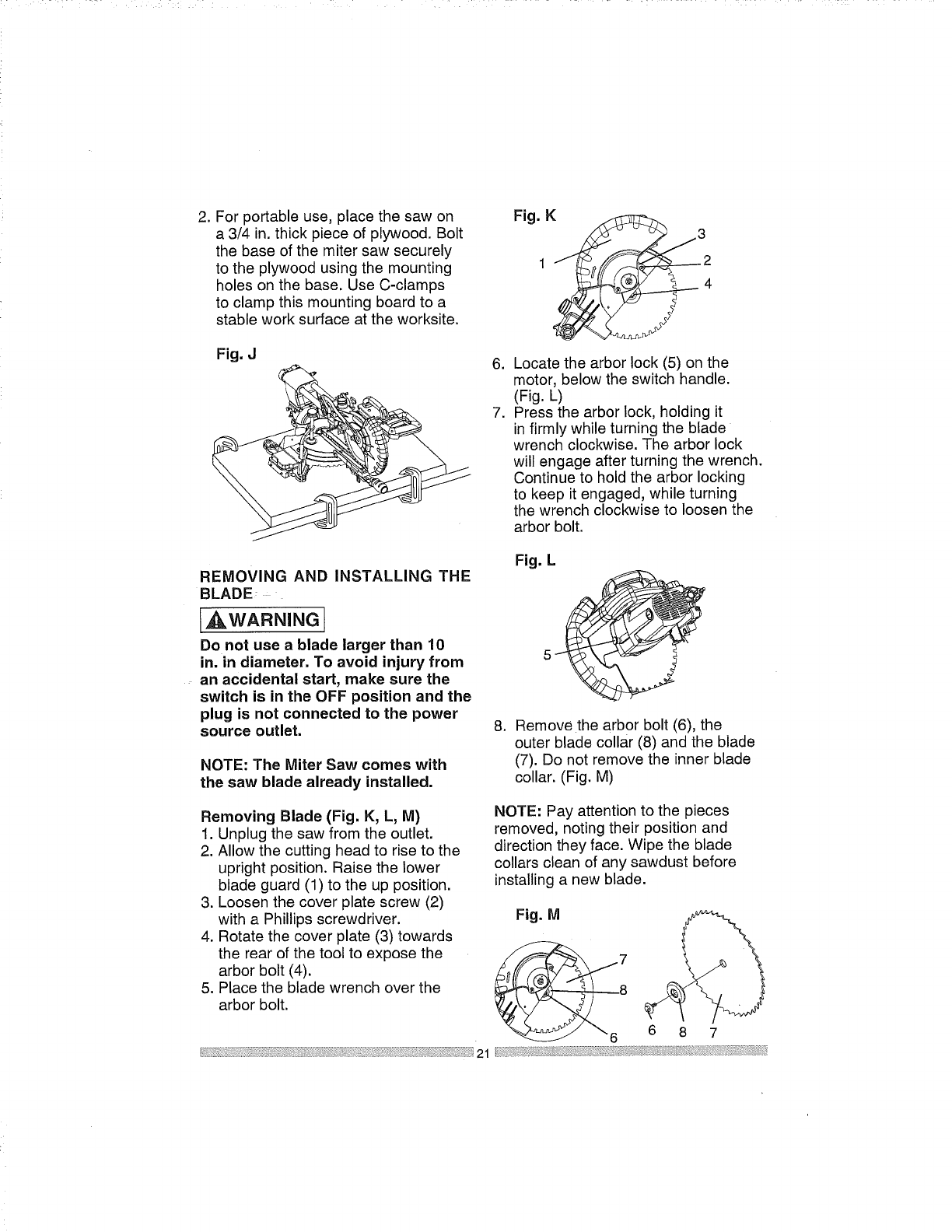
.For portable use, place the saw on
a 3/4 in. thick piece of plywood. Bolt
the base of the miter saw securely
to the plywood using the mounting
holes on the base. Use C-clamps
to clamp this mounting board to a
stable work surface at the worksite.
Fig. J .
.
Fig. K
2
4
Locate the arbor lock (5) on the
motor, below the switch handle.
(Fig. L)
Press the arbor lock, holding it
in firmly while turning the blade
wrench clockwise. The arbor lock
will engage after turning the wrench.
Continue to hold the arbor locking
to keep it engaged, while turning
the wrench clockwise to loosen the
arbor bolt.
REMOVING AND INSTALLING THE
BLADE
,_WARNING
Do not use a blade larger than 10
in. in diameter. To avoid injury from
an accidental start, make sure the
switch is in the OFF position and the
plug is not connected to the power
source outlet.
NOTE: The Miter Saw comes with
the saw blade already installed.
Fig. L
8. Remove the arbor bolt (6), the
outer blade collar (8) and the blade
(7). Do not remove the inner blade
collar. (Fig. M)
Removing Blade (Fig. K, L, M)
1. Unplug the saw from the outlet.
2. Allow the cutting head to rise to the
upright position. Raise the lower
blade guard (1) to the up position.
3. Loosen the cover plate screw (2)
with a Phillips screwdriver.
4. Rotate the cover plate (3) towards
the rear of the tool to expose the
arbor bolt (4).
5. Place the blade wrench over the
arbor bolt.
NOTE: Pay attention to the pieces
removed, noting their position and
direction they face. Wipe the blade
collars clean of any sawdust before
installing a new blade.
Fig. M
7
8
687
Installing Blade (Fig. K, L, M)
Unplug the miter saw before changing/
installing the blade.
1. Install a 10 in. blade with a 5/8 in.
arbor, making sure the rotation arrow
on the blade matches the clockwise
rotation arrow on the upper guard
and the blade teeth are pointing
downward.
2. Place the outer blade collar (8)
against the blade and on the arbor.
Thread the arbor bolt (6) onto the
arbor (Fig. M) in a counterclock_se_
direction.
IMPORTANT: Make sure the flats
of the blade collars are engaged with
the blade into the lower table
and check for any contact with
the base or the miter table by
spinning the blade manually.
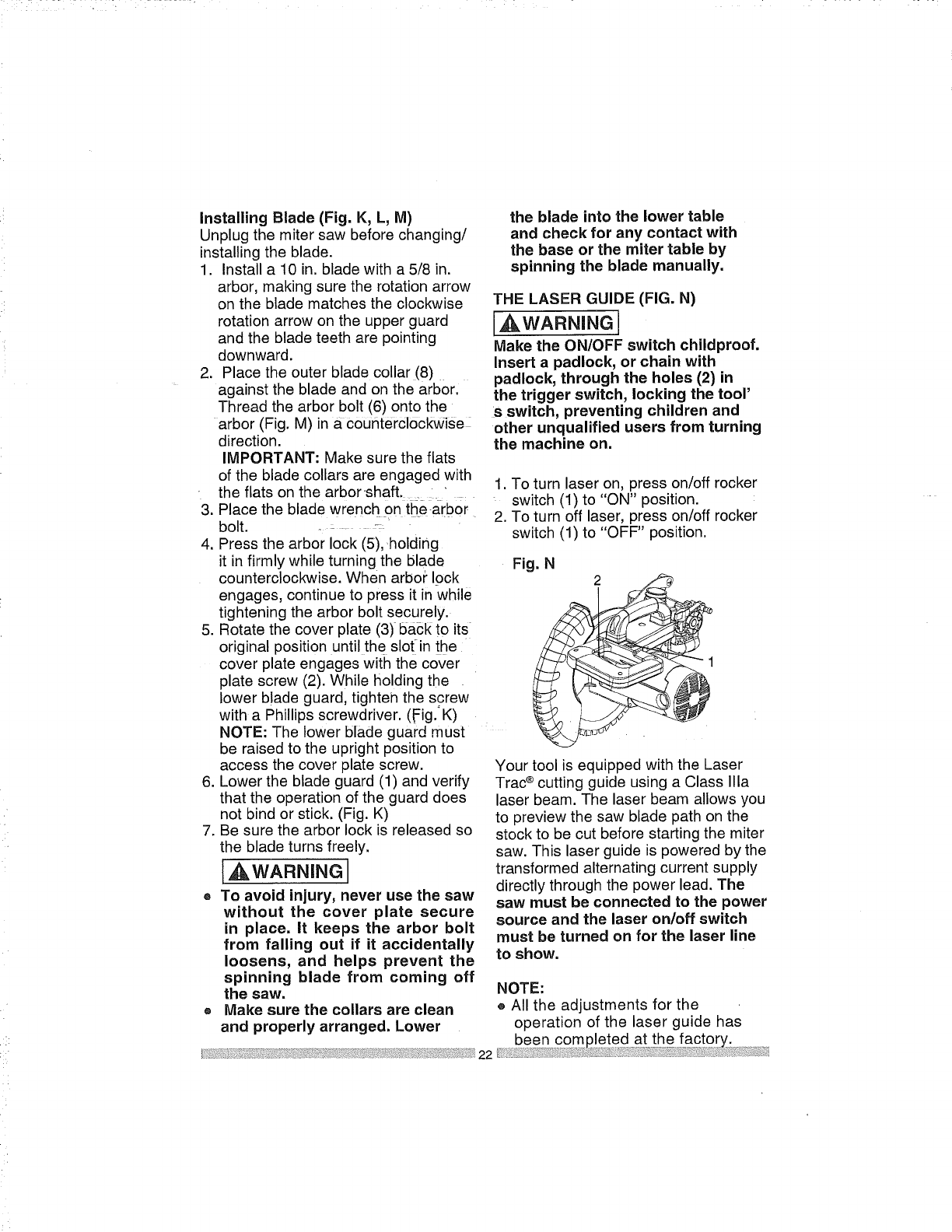
THE LASER GUIDE (FIG. N)
,_,WARNING
Make the ON/OFF switch childproof.
Insert a padlock, or chain with
padlock, through the holes (2) in
the trigger switch, locking the tool'
S switch, preventing children and
other unqualified users from turning
the machine on.
the flats on the arbor shaft. " 1. To turn laser on, press on/off rocker
...... switch (1) to "ON" position.
3. Place the blade wrench On the arbor
bolt ....
4. Press the arbor lock (5), holding
it in firmly while turning the blade
counterclockwise. When arbor lock
engages, continue to press it in while
tightening the arbor bolt securely.
5. Rotate the cover plate (3) back to its
original position until the slotin the
cover plate engages with the cover
plate screw (2). While holding the
lower blade guard, tighteh the screw
with a Phillips screwdriver. (Fig.'K)
NOTE: The lower blade guard must
be raised to the upright position to
access the cover plate screw.
6. Lower the blade guard (1) and verify
that the operation of the guard does
not bind or stick. (Fig. K)
7. Be sure the arbor lock is released so
the blade turns freely.
[ WARNINGI
®To avoid injury, never use the saw
without the cover plate secure
in place. It keeps the arbor bolt
from falling out if it accidentally
loosens, and helps prevent the
spinning blade from coming off
the saw.
®Make sure the collars are clean
and properly arranged. Lower
22
2. To turn off laser, press on/off rocker
switch (1) to "OFF" position.
Fig. N 2
Your tool is equipped with the Laser
Trac®cutting guide using a Class Ilia
laser beam. The laser beam allows you
to preview the saw blade path on the
stock to be cut before starting the miter
saw. This laser guide is powered by the
transformed alternating current supply
directly through the power lead. The
saw must be connected to the power
source and the laser on/off switch
must be turned on for the laser line
to show.
NOTE:
® All the adjustments for the
operation of the laser guide has
been completed at the factory. T'I
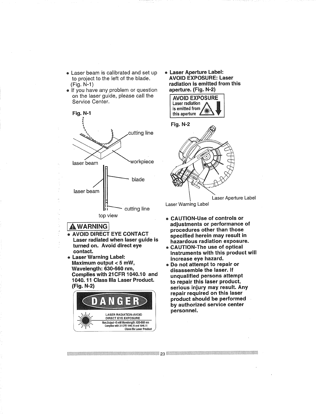
o Laser beam is calibrated and set up
to project to the left of the blade.
(Fig. N-l)
® If you have any problem or question
on the laser guide, please call the
Service Center.
Fig. N-1
cutting line
"b \workplece
laser eam
®Laser Aperture Label:
AVOID EXPOSURE: Laser
radiation is emitted from this
aperture. (Fig. N-2)
AVOID EXPOSURE
LaserradiationA []
isemittedfrom/___,
thisaperture_'
Fig. N-2
J
laser beam
blade
I I_ cutting line
top view
_WARNHNG
® AVOID DIRECT EYE CONTACT
Laser radiated when laser guide is
turned on. Avoid direct eye
contact.
®Laser Warning Label:
Maximum output <5roW,
Wavelength: 630-660 rim,
Complies with 21CFR 1040.10 and
1040. 11 Class Ilia Laser Product.
(Fig. N-2)
ClassIlia LaserProduct
Laser Aperture Label
Laser Warning Label
CAUTION-Use of controls or
adjustments or performance of
procedures other than those
specified herein may result in
hazardous radiation exposure.
CAUTION-The use of optical
instruments with this product will
increase eye hazard.
Do not attempt to repair or
disassemble the laser. If
unqualified persons attempt
to repair this laser product,
serious injury may result. Any
repair required on this laser
product should be performed
by authorized service center
personnel.
BEVEL STOP ADJUSTMENT
,_WARNING
To avoid injury from an accidental
start, make sure the switch is in
the OFF position and the plug is
not connected to the power source
outlet.
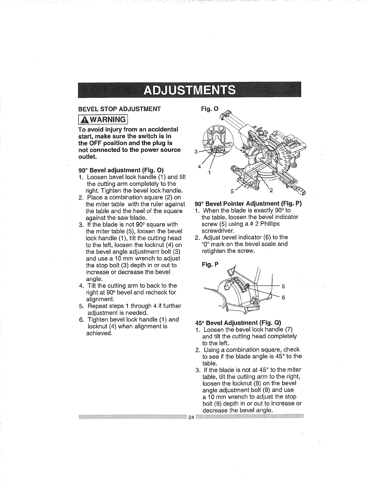
90° Bevel adjustment (Fig. O)
1. Loosen bevel lock handle (1) and tilt
the cutting arm completely to the
right. Tighten the bevel lock handle.
2. Place a combination square (2) on
the miter table with the ruler against
the table and the heel of the square
against the saw blade.
3. If the blade is not 900 square with
the miter table (5), loosen the bevel
lock handle (1), tilt the cutting head
to the left, loosen the Iocknut (4) on
the bevel angle adjustment bolt (3)
and use a 10 mm wrench to adjust
the stop bolt (3) depth in or out to
increase or decrease the bevel
angle.
4. Tilt the cutting arm to back to the
right at 90° bevel and recheck for
alignment.
5. Repeat steps 1 through 4 if further
adjustment is needed.
6. Tighten bevel lock handle (1) and
Iocknut (4) when alignment is
achieved.
Fig. 0
/
4
90° Bevel Pointer Adjustment (Fig. P)
1. When the blade is exactly 90° to
the table, loosen the bevel indicator
screw (5) using a # 2 Phillips
screwdriver.
2. Adjust bevel indicator (6) to the
"0" mark on the bevel scale and
retighten the screw.
Fig. P_//
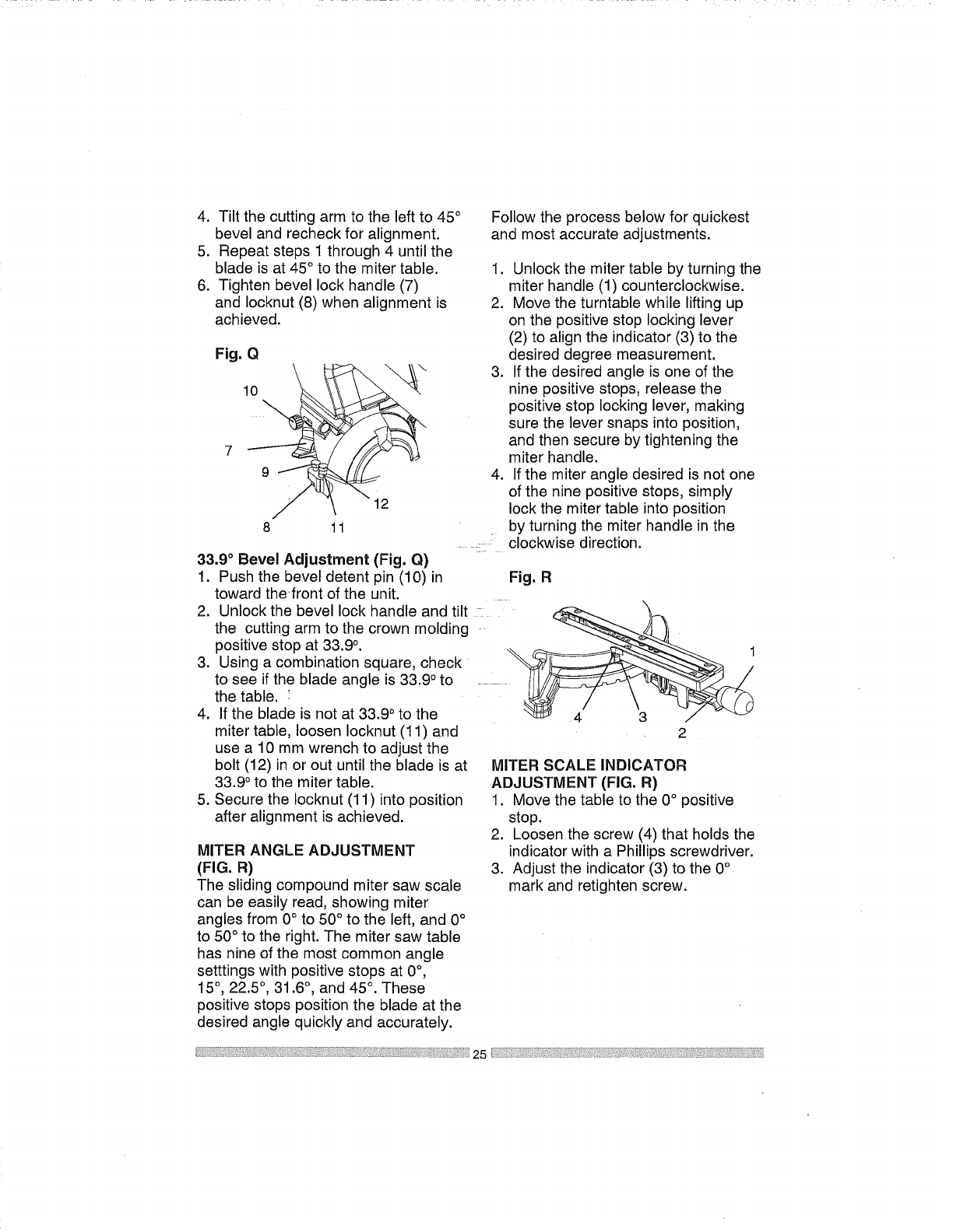
45° Bevel Adjustment (Fig. Q)
1. Loosen the bevel lock handle (7)
and tilt the cutting head completely
to the left.
2. Using a combination square, check
to see if the blade angle is 45°to the
table.
3. If the blade is not at 45 ° to the miter
table, tilt the cutting arm to the right,
loosen the Iocknut (8) on the bevel
angle adjustment bolt (9) and use
a 10 mm wrench to adjust the stop
bolt (9) depth in or out to increase or
decrease the bevel angle.
4. Tiltthecuttingarmtotheleftto45°
bevelandrecheckforalignment.
5. Repeatsteps1through4 untilthe
bladeisat45°to themitertable.
6. Tightenbevellockhandle(7)
andIocknut(8)whenalignmentis
achieved.
Fig.Q\
10
7
9
12
8 11
33.9 ° Bevel Adjustment (Fig. Q)
1. Push the bevel detent pin (10) in
toward thefront of the unit.
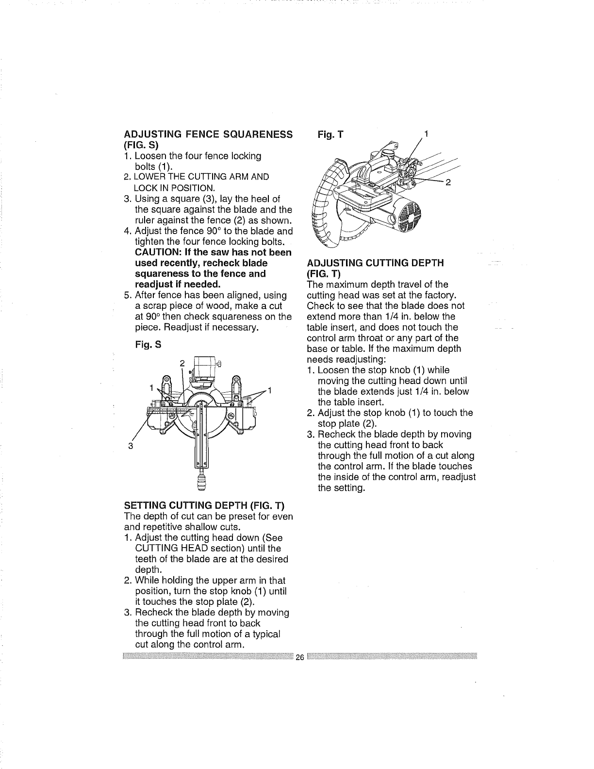
Follow the process below for quickest
and most accurate adjustments.
1. Unlock the miter table by turning the
miter handle (1) counterclockwise.
2. Move the turntable while lifting up
on the positive stop locking lever
(2) to align the indicator (3) to the
desired degree measurement.
3. If the desired angle is one of the
nine positive stops, release the
positive stop locking lever, making
sure the lever snaps into position,
and then secure by tightening the
miter handle.
4. If the miter angle desired is not one
of the nine positive stops, simply
lock the miter table into position
by turning the miter handle in the
clockwise direction.
Fig. R
2Unookthebeveookhandeandtt I
the cutting arm to the crown molding
positive stop at 33.9 °.
3. Using a combination square, check
to see if the blade angle is 33.9 ° to
the table. !
4. If the blade is not at 33.9 ° to the
5,
miter table, loosen Iocknut (11) and
use a 10 mm wrench to adjust the
bolt (12) in or out until the blade is at
33.90 to the miter table.
Secure the Iocknut (11) into position
after alignment is achieved.
MITER ANGLE ADJUSTMENT
(FIG. R)
The sliding compound miter saw scale
can be easily read, showing miter
angles from 0° to 50 ° to the left, and 0°
to 50 ° to the right. The miter saw table
has nine of the most common angle
setttings with positive stops at 0°,
15°, 22.5 °, 31.6 °, and 45°. These
positive stops position the blade at the
desired angle quickly and accurately.
2
MITER SCALE INDICATOR
ADJUSTMENT (FIG. R)
1. Move the table to the 0° positive
stop.
2. Loosen the screw (4) that holds the
indicator with a Phillips screwdriver.
3. Adjust the indicator (3) to the 0°
mark and retighten screw.
ADJUSTING FENCE SQUARENESS
(FIG. S)
1. Loosen the four fence locking
bolts (1).
2. LOWERTHE CUTTING ARM AND
LOCK IN POSITION.
3. Using a square (3), lay the heel of
the square against the blade and the
ruler against the fence (2) as shown.
4. Adjust the fence 90° to the blade and
tighten the four fence locking bolts.
CAUTION: If the saw has not been
used recently, recheck blade
squareness to the fence and
readjust if needed.
5. After fence has been aligned, using
a scrap piece of wood, make a cut
at 90° then check squareness on the
piece. Readjust if necessary.
Fig. S
2
1
3
Fig. T1
ADJUSTING CUTTING DEPTH
(FIG. T)
The maximum depth travel of the
cutting head was set at the factory.
Check to see that the blade does not
extend more than 1/4 in. below the
table insert, and does not touch the
control arm throat or any part of the
base or table. If the maximum depth
needs readjusting:
1. Loosen the stop knob (1) while
moving the cutting head down until
the blade extends just 1/4 in. below
the table insert.
2. Adjust the stop knob (1) to touch the
stop plate (2).
3. Recheck the blade depth by moving
the cutting head front to back
through the full motion of a cut along
the control arm. If the blade touches
the inside of the control arm, readjust
the setting.
SETTING CUTTING DEPTH (FIG. T)
The depth of cut can be preset for even
and repetitive shallow cuts.
1. Adjust the cutting head down (See
CUTTING HEAD section) until the
teeth of the blade are at the desired
depth.
2. While holding the upper arm in that
position, turn the stop knob (1) until
it touches the stop plate (2).
3. Recheck the blade depth by moving
the cutting head front to back
through the full motion of a typical
cut along the control arm.
[7 :.Y}!{:_;I _ iiii_ "ii 26 [}: :_I:IY ii;: ./_ZI_] :ii
SAFETY INSTRUCTIONS FOR BASIC
SAW OPERATIONS
BEFORE USING THE MITER SAW
[,_WARNING 1
To avoid mistakes that could cause
serious, permanent injury, do not
plug the tool in until the following
steps are completed:
® Completely assemble and adjust the
saw, following the instructions. (SEE
ASSEMBLY AND ADJUSTMENTS
SECTIONS)
• Learn the use and function of the
ON/OFF switch, upper and lower
blade guards, stop latch, bevel lock
handle and cover plate screws.
® Review and understand all
safety instructions and operating
procedures in this Operator'
s Manual. (SEE SAFETY AND
OPERATIONS SECTIONS)
® Review the MAINTENANCE AND
TROUBLESHOOTING GUIDE for
your miter saw.
® To avoid injury or possible death
from electrical shock, make sure
your fingers do not touch the
plug's metal prongs when
plugging in or unplugging your
miter saw. (SEE ELECTRICAL
REQUIREMENTS AND SAFETY
SECTIONS)
BEFORE EACH USE
Inspect your saw.
oDisconnect the miter saw.
To avoid injury from accidental
starting, unplug the saw before any
adjustments, including setup and
blade changes.
® Compare the direction of rotation
arrow on the guard to the direction
arrow on the blade. The blade teeth
should always point downward at
®Tighten the arbor bolt.
®Tighten the cover plate screw.
® Check for damaged parts, check
for:
e Alignment of moving parts
® Damaged blade teeth
® Damaged electric cords
® Binding of moving parts
® Mounting holes
® Function of arm return spring and
lower guard: Push the cutting
arm all the way down, and
then let it rise until it stops. The
lower guard should close fully.
Follow the instructions in the
TROUBLESHOOTING GUIDE
for adjustment, if necessary.
® Other conditions that may affect
the way the miter saw works.
® Keep all guards in place, in working
order and properly adjusted. If any
part of this miter saw is missing,
damaged or broken, or any electrical
parts do not work, turn off the saw
and unplug it.
® Replace bent, damaged, missing or
defective parts before using the saw
again.
® Maintain tools with care. Keep the
miter saw clean for best and safest
performance. Follow instructions for
lubricating. Do not apply lubricants
to the blade while it is spinning.
® Remove all adjusting wrenches from
the tool before turning it on.
e To avoid injury from jams, slips,
or thrown pieces, use only
recommended accessories.
the front of the saw.
RECOMMENDED ACCESSORIES
® Consult the ACCESSORIES
and ATTACHMENTS section
of this Operator's Manual for
recommended accessories. Follow
the instructions that come with the
accessory. The use of improper
•:., :, <:_-:::_--,, i_:_¸ : _:_Lt" • ,: _._ _ :
accessories may cause risk of
injury.
® Choose the correct 10 in. blade for
the material and the type of cutting
you plan to do. Do not use thin Kerf
blades.
® Make sure the blade is sharp,
undamaged and properly aligned.
With the saw unplugged, push
the cutting arm all the way down.
Manually spin the blade and check
for clearance. Tilt the miter head to
a 45° bevel and repeat the test.
o Make sure the blade and arbor
collars are clean.
® Make sure all clamps and locks are
tight and there is no excessive play
in any parts.
KEEP YOUR WOR K AREA CLEAN
Cluttered areas and benches invite
accidents.
I WARNINGJ
To avoid burns or other fire damage,
never use the miter saw near
flammable liquids, vapors or gases,
• Plan ahead to protect your eyes,
hands, face and ears.
o Know your miter saw.
Read and understand the Operator'
s Manual and labels affixed to
the tool. Learn its application and
limitations as well as the potential
hazards specific to this toot. To
avoid injury from accidental contact
with moving parts, do not lay out,
assemble or set up work on the
miter saw.
® Avoid accidental starting. Make sure
the switch is in the OFF position
before plugging the miter saw into a
power outlet.
PLAN YOUR WORK
Use the right tool. Do not force a tool
or attachment to do a job it was not
designed to do. Use a different tool for
any workpiece that cannot be held in a
solidly braced, fixed position.
[ &WARNINGJ
This machine is NOT designed for
cutting masonry, masonry products
or ferrous metals (steel, iron and
iron-based metals.) Use this miter
saw to cut only wood and wood
by-products. Other materials may
shatter, bind the blade or create
other dangers. Remove all nails that
may be in the workpiece to prevent
sparking that could cause afire.
DRESS FOR SAFETY
Ony power tool can throw
debris into the eyes. This can
result in permanent eye
damage.
Everyday eyeglasses have only impact
resistant lenses and are not safety
glasses. Glasses or goggles not in
compliance with ANSI Z87.1 could
seriously injure you when they break.
® Do _notwear loose clothing, gloves,
neckties or jewelry (rings, watches).
They can get caught and draw you
into moving parts.
® Wear non-s!ip footwear.
® Tie=backlong hair.
® Roll long sleeves above the elbow.
® Noise levels vary widely. To avoid
possible hearing damage, wear
hearing protection when using any
miter saw.
® For dusty operations, wear a dust
mask along with safety goggles.
INSPECT YOUR WORKPIECE
® Make sure there are no nails or
foreign objects in the part of the
workpiece being cut.
® Plan your work to avoid small pieces
that may bind or are too small to
clamp and hold securely.
® Plan the way you will grasp the
workpiece from start to finish. Avoid
awkward operations and hand
positions. A sudden slip could cause
your fingers or hand to move into
the blade.
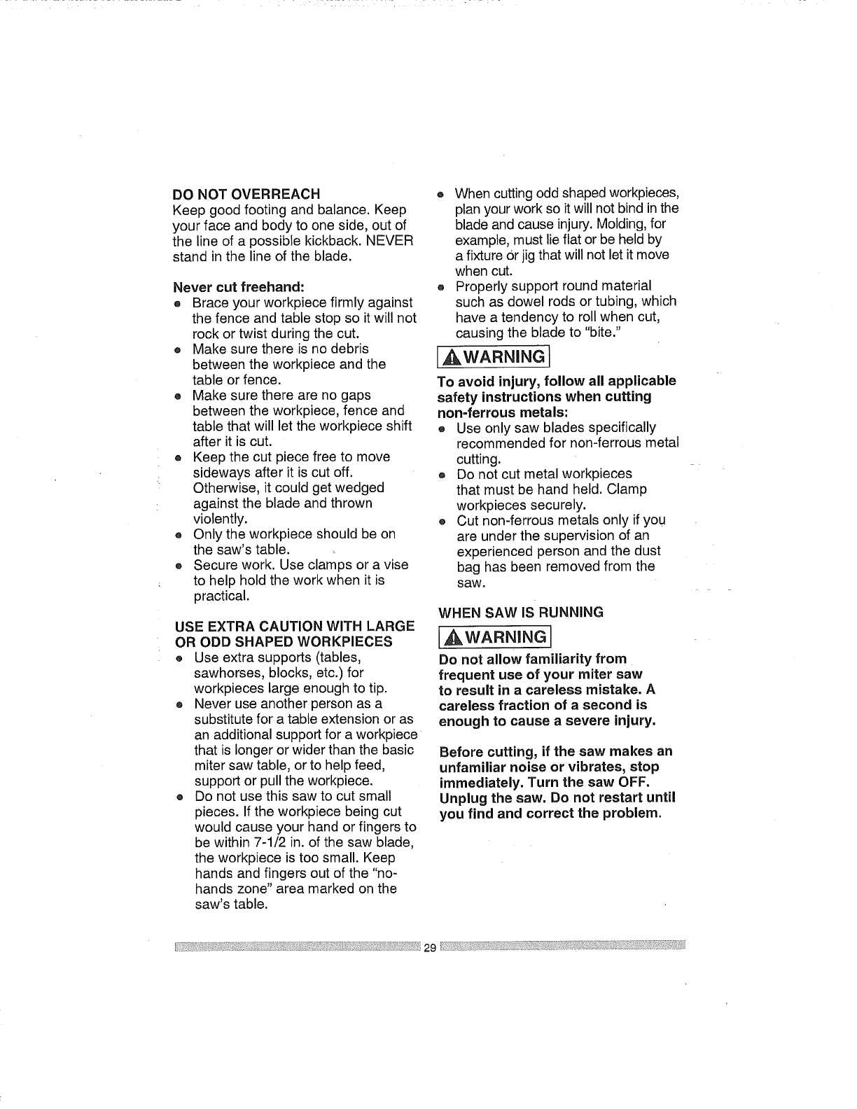
DONOTOVERREACH
Keepgoodfootingandbalance.Keep
yourfaceandbodytooneside,outof
thelineofa possiblekickback.NEVER
standinthelineoftheblade.
Nevercut freehand:
® Braceyourworkpiecefirmlyagainst
thefenceandtablestopsoitwillnot
rockortwistduringthecut.
® Makesurethereisnodebris
betweentheworkpieceandthe
tableorfence.
® Makesuretherearenogaps
betweentheworkpiece,fenceand
tablethatwilllettheworkpieceshift
afteritiscut.
o Keepthecutpiecefreetomove
sidewaysafterit iscutoff.
Otherwise,it couldgetwedged
againstthebladeandthrown
violently.
® Onlytheworkpieceshouldbeon
thesaw'stable.
® Securework.Useclampsora vise
tohelpholdtheworkwhenit is
practical.
USE EXTRA CAUTION WITH LARGE
OR ODD SHAPED WORKPIECES
® Use extra supports (tables,
sawhorses, blocks, etc.) for
workpieces large enough to tip.
® Never use another person as a
substitute for atable extension or as
an additional support for a workpiece
that is longer or wider than the basic
miter saw table, or to help feed,
support or pull the workpiece.
® Do not use this saw to cut small
pieces. If the workpiece being cut
would cause your hand or fingers to
be within 7-1/2 in. of the saw blade,
the workpiece is too small. Keep
hands and fingers out of the "no-
hands zone" area marked on the
saw's table.
® When cutting odd shaped workpieces,
plan your work so it will not bind in the
blade and cause injury. Molding, for
example, must lie flat or be held by
a fixture Orjig that will not let it move
when cut.
® Properly support round material
such as dowel rods or tubing, which
have a tendency to roll when cut,
causing the blade to "bite."
I,_WARNING
To avoid injury, follow all applicable
safety instructions when cutting
non=ferrous metals:
® Use only saw blades specifically
recommended for non-ferrous metal
cutting.
® Do not cut metal workpieces
that must be hand held. Clamp
workpieces securely.
®Cut non-ferrous metals only if you
are under the supervision of an
experienced person and the dust
bag has been removed from the
saw.
WHEN SAW IS RUNNING
[ WARNHNG l
Do not allow familiarity from
frequent use of your miter saw
to result in a careless mistake, A
careless fraction of a second is
enough to cause a severe injury.
Before cutting, if the saw makes an
unfamiliar noise or vibrates, stop
immediately. Turn the saw OFF.
Unplug the saw. Do not restart until
you find and correct the problem.
29
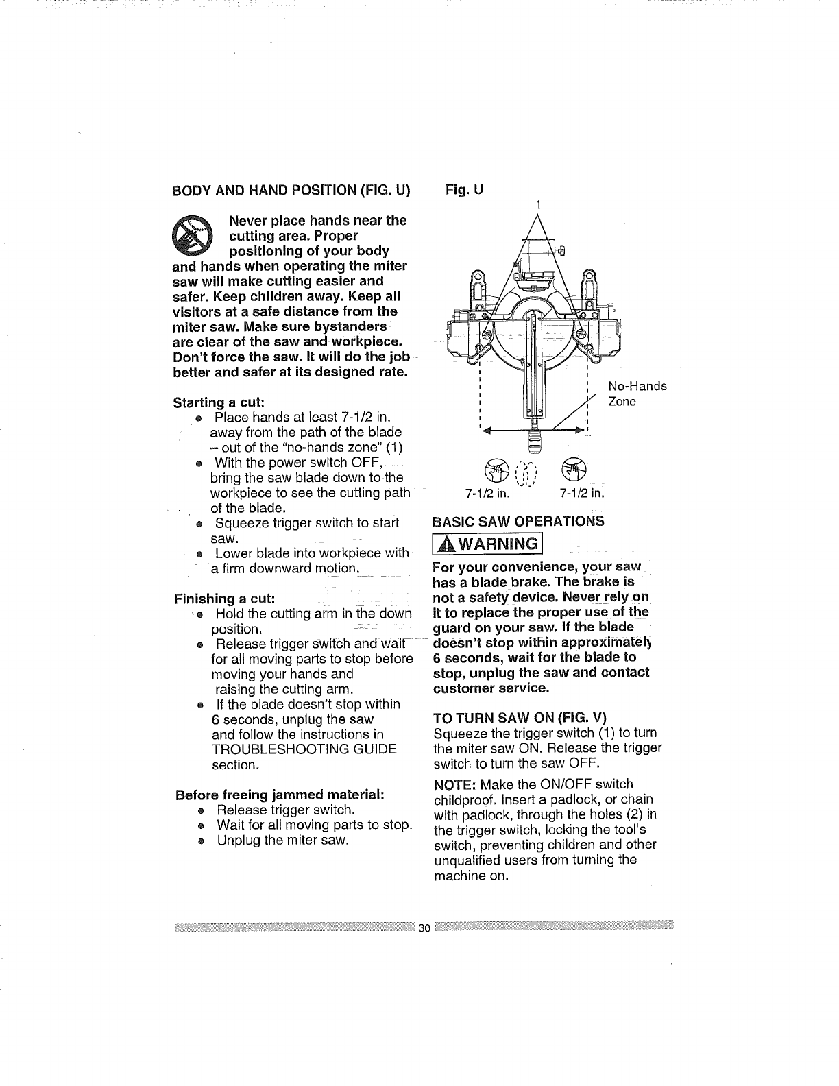
BODY AND HAND POSITION (FIG. U)
Never place hands near the
cutting area. Proper
positioning of your body
and hands when operating the miter
saw will make cutting easier and
safer. Keep children away. Keep all
visitors at a safe distance from the
miter saw. Make sure bystanders _
are clear of the saw and workpiece.
Don't force the saw. It will do the job
better and safer at its designed rate.
Starting a cut:
® Place hands at least 7-1/2 in.
away from the path of the blade
-out of the "no-hands zone" (1)
o With the power switch OFF,
bring the saw blade down to the
workpiece to see the cutting path
of the blade.
® Squeeze trigger switch to start
saw.
® Lower blade into workpiece with
a firm downward motion.
Finishing a cut: i
® Hold the cutting arm in the down
position. _.....
Fig. U1
No-Hands
Zone
7-1/2 in. 7-1/2 in.
BASIC SAW OPERATIONS
IAWARN=NGJ
For your convenience, your saw
has a blade brake. The brake is
not asafety device. Never rely on
it to replace the proper use of the
guard on your saw. If the blade
O
Q
Release trigger Switch and wai_ doesn't stop Within approximatel_
for all moving parts to stop before
moving your hands and
raising the cutting arm.
If the blade doesn't stop within
6 seconds, unplug the saw
and follow the instructions in
TROUBLESHOOTING GUIDE
section.
6seconds, wait for the blade to
stop, unplug the saw and contact
customer service.
TO TURN SAW ON (FIG. V)
Squeeze the trigger switch (1) to turn
the miter saw ON. Release the trigger
switch to turn the saw OFF.
Before freeing jammed material:
® Release trigger switch.
® Wait for all moving parts to stop.
® Unplug the miter saw.
NOTE: Make the ON/OFF switch
childpro0f. Insert a padlock, or chain
with padlock, through the holes (2) in
the trigger switch, locking the tool's
switch, preventing children and other
unqualified users from turning the
machine on.
Themitersawisequippedwithan
automaticbladebrake.Whenthe
triggerswitchisreleased,theelectric
bladebrakewillstopthebladewithin
approximately6seconds.
_WARNING
To avoid injury, after completing a
cut and releasing the trigger switch,
allow the blade brake to activate and
stop the blade before raising the
cutting head.
_WARNtNG
To avoid injury, check and tighten
the arbor bolt periodically.
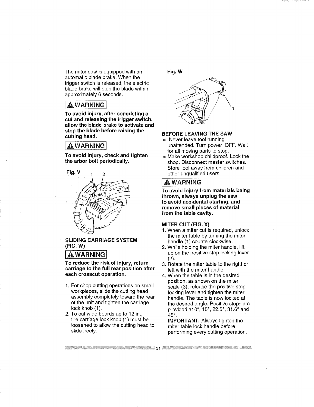
FJg. V1 2
SLIDING CARRIAGE SYSTEM
(FIG. W)
,_WARN_NG
To reduce the risk of injury, return
carriage to the full rear position after
each crosscut operation.
1. For chop cutting operations on small
workpieces, slide the cutting head
assembly completely toward the rear
of the unit and tighten the carriage
lock knob (1).
2. To cut wide boards up to 12 in.,
the carriage lock knob (1) must be
loosened to allow the cutting head to
slide freely.
Fig. W
BEFORE LEAVING THE SAW
® Never leave tool running
unattended. Turn power OFF. Wait
for all moving parts to stop.
®Make workshop childproof. Lock the
shop. Disconnect master switches.
Store tool away from children and
other unqualified users.
_WARNING
To avoid injury from materials being
thrown, always unplug the saw
to avoid accidental starting, and
remove small pieces of material
from the table cavity.
MITER CUT (FIG. X)
1. When a miter cut is required, unlock
the miter table by turning the miter
handle (i) counterclockwise.
2. While holding the miter handle, lift
up on the positive stop locking lever
(2).
3. Rotate the miter table to the right or
left with the miter handle.
4. When the table is in the desired
position, as shown on the miter
scale (3), release the positive stop
locking lever and tighten the miter
handle. The table is now locked at
the desired angle. Positive stops are
provided at 0°, 15°, 22.5 °, 31.6 ° and
45°.
IMPORTANT: Always tighten the
miter table lock handle before
performing every cutting operation.
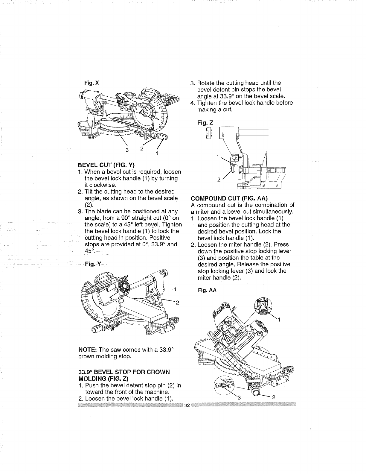
Fig. X
\3
BEVEL CUT (FIG. Y)
1. When a bevel cut is required, loosen
the bevel lock handle (1) by turning
it clockwise.
2. Tilt the cutting head to the desired
angle, as shown on the bevel scale
(2).
3. The blade can be positioned at any
angle, from a 90° straight cut (0° on
the scale) to a 45° left bevel. Tighten
the bevel lock handle (1) to lock the
Cutting head in position. Positive
=stops are provided at 0°, 33.9 ° and
45°..
zz
............... Fig,_y_ _
3. Rotate the cutting head until the
bevel detent pin stops the bevel
angle at 33.9 ° on the bevel scale.
4. Tighten the bevel lock handle before
making a cut.
Fig. Z
COMPOUND CUT (FIG. AA)
A compound cut is the combination of
a miter and a bevel cut simultaneously.
1. Loosen the bevel lock handle (1)
and position the cutting head at the
desired bevel position. Lock the
bevel lock handle (1).
2. Loosen the miter handle (2). Press
down the positive stop locking lever
(3) and position the table at the
desired angle. Release the positive
stop locking lever (3) and lock the
miter handle (2).
Fig. AA
NOTE: The saw comes with a 33.9 °
crown molding stop.
33.9 ° BEVEL STOP FOR CROWN
MOLDING (FIG. Z)
1. Push the bevel detent stop pin (2) in
toward the front of the machine.
2. Loosen the bevel lock handle (1). 2
_i:!_i_i_:i!ii_i,_: ii_i?_il 32 l:il _ii_ iii'!.i i: :_i
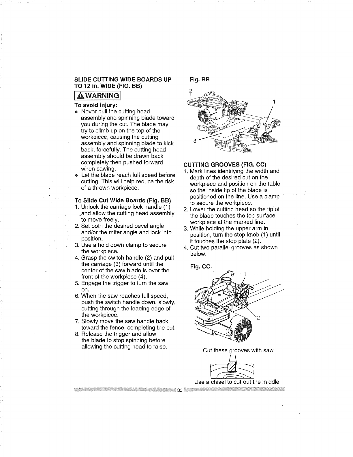
SLIDE CUTTING WIDE BOARDS UP
TO 12 in. WIDE (FIG. BB)
,_WARNING
To avoid injury:
oNever pull the cutting head
assembly and spinning blade toward
you during the cut. The blade may
try to climb up on the top of the
workpiece, causing the cutting
assembly and spinning blade to kick
back, forcefully. The cutting head
assembly should be drawn back
completely then pushed forward
when sawing.
® Let the blade reach full speed before
cutting. This will help reduce the risk
of a thrown workpiece.
To Slide Cut Wide Boards (Fig. BB)
1. Unlock the carriage lock handle (1)
_and allow the cutting head assembly
to move freely.
2. Set both the desired bevel angle
and/or the miter angle and lock into
position.
3. Use a hold down clamp to secure
the workpiece.
4. Grasp the switch handle (2) and pull
the carriage (3) forward until the
center of the saw blade is over the
front of the workpiece (4).
5. Engage the trigger to turn the saw
on.
6. When the saw reaches full speed,
push the switch handle down, slowly,
cutting through the leading edge of
the workpiece.
7. Slowly move the saw handle back
toward the fence, completing the cut.
8. Release the trigger and allow
the blade to stop spinning before
allowing the cutting head to raise.
Fig. BB
2
1
CUTTING GROOVES (FIG. CC)
1. Mark lines identifying the width and
depth of the desired cut on the
workpiece and position on the table
so the inside tip of the blade is
positioned on the line. Use a clamp
to secure the workpiece.
2. Lower the cutting head so the tip of
the blade touches the top surface
workpiece at the marked line.
3. While holding the upper arm in
position, turn the stop knob (1) until
it touches the stop plate (2).
4. Cut two parallel grooves as shown
below.
Fig. CO • 1
Out these grooves with saw
Use a chisel to cut out the middle
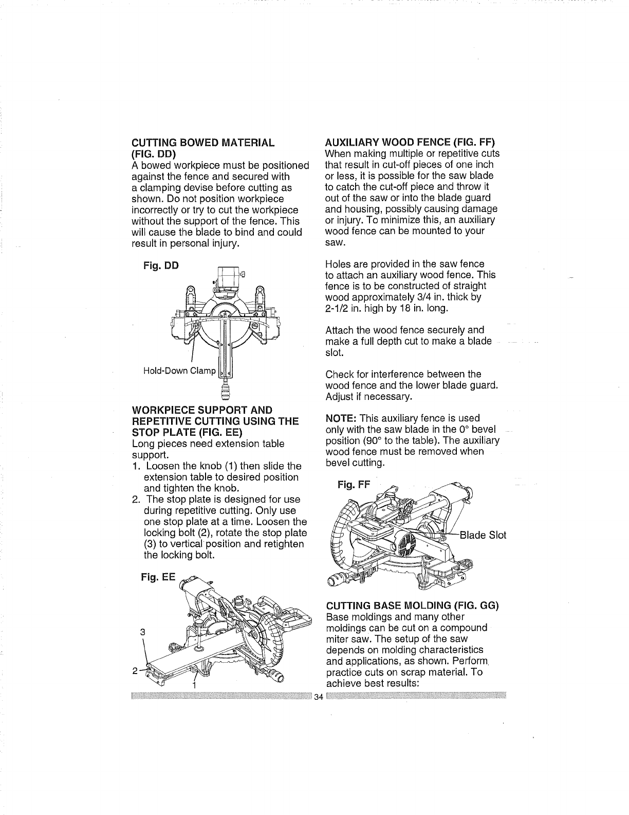
CUTTINGBOWED MATERIAL
(FIG. DD)
A bowed workpiece must be positioned
against the fence and secured with
a clamping devise before cutting as
shown. Do not position workpiece
incorrectly or try to cut the workpiece
without the support of the fence. This
will cause the blade to bind and could
result in personal injury.
Fig. DD
Hold-Down Clamp
WORKPIECE SUPPORT AND
REPETITIVE CUTTING USING THE
STOP PLATE (FIG. EE)
Long pieces need extension table
support.
1. Loosen the knob (1) then slide the
extension table to desired position
and tighten the knob.
2. The stop plate is designed for use
during repetitive cutting. Only use
one stop plate at a time. Loosen the
locking bolt (2), rotate the stop plate
(3) to verticalposition and retighten
the locking bolt.
Fig. EE
AUXILIARY WOOD FENCE (FIG. FF)
When making multiple or repetitive cuts
that result in cut-off pieces of one inch
or less, it is possible for the saw blade
to catch the cut-off piece and throw it
out of the saw or into the blade guard
and housing, possibly causing damage
or injury. To minimize this, an auxiliary
wood fence can be mounted to your
saw.
Holes are provided in the saw fence
to attach an auxiliary wood fence. This
fence is to be constructed of straight
wood approximately 3/4 in. thick by
2-1/2 in. high by 18 in. long.
Attach the wood fence securely and
make a full depth cut to make a blade
slot.
Check for interference between the
wood fence and the lower blade guard.
Adjust if necessary.
NOTE: This auxiliary fence is used
only with the saw blade in the 0° bevel
position (90° to the table). The auxiliary
wood fence must be removed when
bevel cutting.
Fig. FF __Bla
de Slot
CUTTING BASE MOLDING (FIG. GG)
Base moldings and many other
moldings can be cut on a compound
miter saw. The setup of the saw
depends on molding characteristics
and applications, as shown. Perform
practice cuts on scrap material. To
achieve best results:
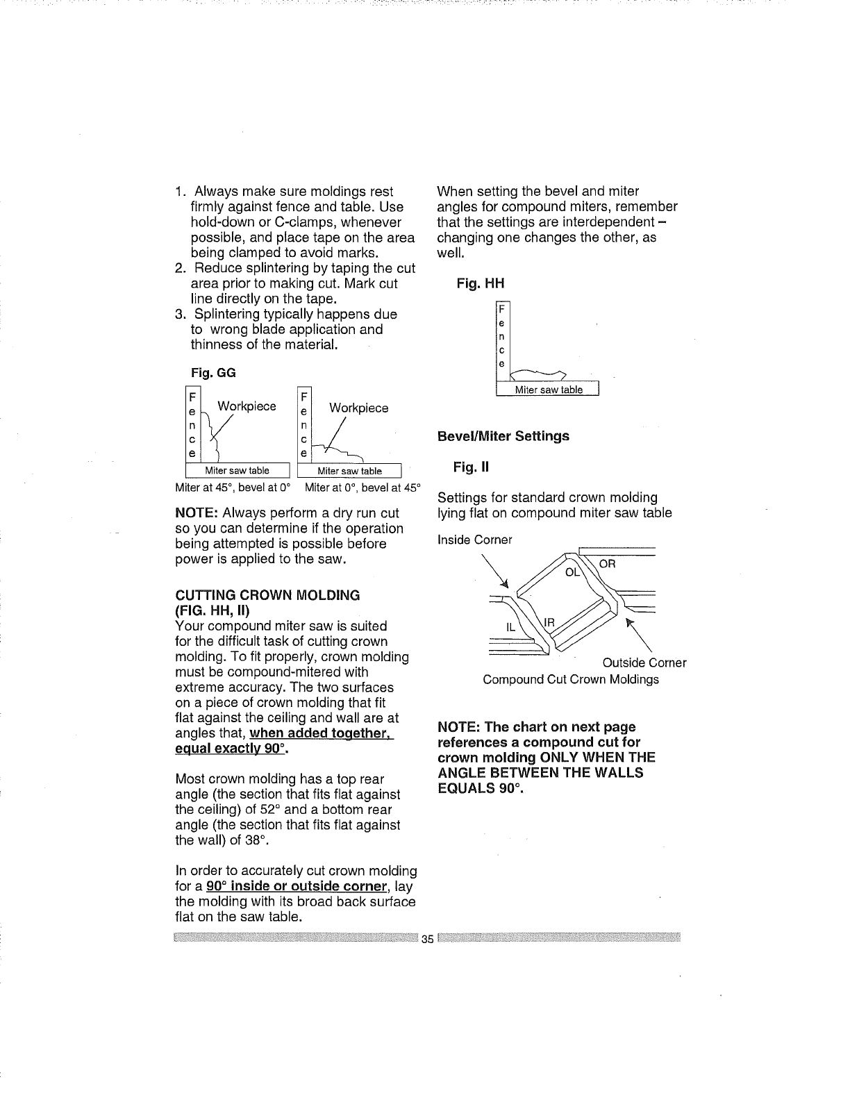
1. Alwaysmakesuremoldingsrest
firmlyagainstfenceandtable.Use
hold-downorC-clamps,whenever
possible,andplacetapeonthearea
beingclampedto avoidmarks.
2. Reducesplinteringbytapingthecut
areapriorto makingcut.Markcut
linedirectlyonthetape.
3. Splinteringtypicallyhappensdue
to wrongbladeapplicationand
thinnessofthematerial.
Fig. GG
Workpiece
Miter saw table
Miter at 45 °, bevel at 0°
iece
able j
Miter at 0°, bevel at 45 °
NOTE: Always perform a dry run cut
so you can determine if the operation
being attempted is possible before
power is applied to the saw.
CUTTING CROWN MOLDING
(FIG. HH, II)
Your compound miter saw is suited
for the difficult task of cutting crown
molding. To fit properly, crown molding
must be compound-mitered with
extreme accuracy. The two surfaces
on a piece of crown molding that fit
flat against the ceiling and wall are at
angles that, when added together,
equal exactly 90°.
Most crown molding has a top rear
angle (the section that fits flat against
the ceiling) of 52° and a bottom rear
angle (the section that fits flat against
the wall) of 38°.
When setting the bevel and miter
angles for compound miters, remember
that the settings are interdependent -
changing one changes the other, as
well.
Fig. HH
_able
Bevel/Miter Settings
Fig, II
Settings for standard crown molding
lying flat on compound miter saw table
Inside Corner
\OR
\
Outside Corner
Compound Cut Crown Moldings
NOTE: The chart on next page
references a compound cut for
crown molding ONLY WHEN THE
ANGLE BETWEEN THE WALLS
EQUALS 90°.
In order to accurately cut crown molding
for a 90° inside or outside corner, lay
the molding with its broad back surface
flat on the saw table.
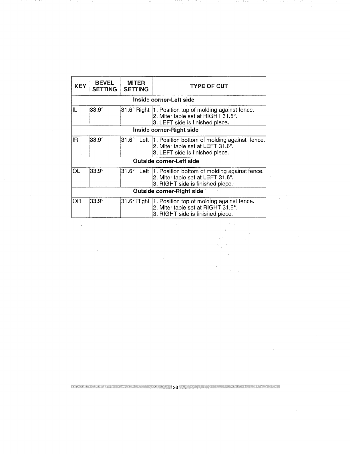
BEVEL MITER
KEY TYPE OF CUT
SETTING SETTING
Inside corner-Left side
IL 33.9 ° 31.6 ° Right 1. Position top of molding against fence.
2. Miter table set at RIGHT 31,6 °.
3. LEFT side is finished piece.
Inside corner-Right side
IR 33.9 ° 31.6 ° Left 1. Position bottom of molding against fence.
2. Miter table set at LEFT 31.6 °.
3. LEFT side is finished piece.
Outside corner-Left side
OL 33.9 ° 31.6 °Left 1. Position bottom of molding against fence.
2. Miter table set at LEFT 31.6 °.
3. RIGHT side is finished piece.
Outside corner-Right side
OR 33.9 °31.6 ° Right t. Position top of molding against fence.
2. Miter table set at RIGHT 3.t.6°.
3. RIGHT side is finished.piece.
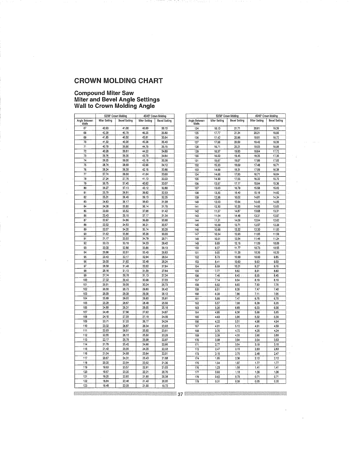
CROWN MOLDING CHART
Compound Miter Saw
Miter and Bevel Angle Settings
Wall to Crown Molding Angle
52/38= Crown Molding 45/45' Crown Molding 52/38= CroWn Molding 45/45=Crown Molding
Angle Between _ter Setting Beve! Setting Miter 5elting Bevel Se_ng Angle Between Miter Setting Bevel Setting Miter Setting Bevel Setting
Walls Walls
67 42.93 41.08 46,89 36.13 124 16,13 21,71 20.61 19.39
69 42,39 40,79 46,35 35,59 125 17.77 21,34 20,21 19.86
69 41.55 40.50 45.8! 35.64 126 17,42 20.96 19,51 18.72
70 41.32 40.20 45.2_ 35,40 127 17.06 20.59 19.42 18.39
7I 40,79 39.90 44,75 35,15 128 18.71 20.21 19.03 15.05
72 40.28 39.61 44.22 34.89 129 16.37 19,83 18.64 17.72
73 39,75 39,30 43.70 34.54 139 16.02 19,45 18.25 17.39
74 39,25 39.00 43,18 35.38 131 15,67 19,07 17,85 17.05
75 35,74 38.69 42.65 34,12 132 15.33 18.59 17.48 16.71
75 36.24 36.39 42.15 33.85 133 14.99 18.31 17.00 16.38
77 37.74 35.09 41,64 33,60 134 14.86 17.93 16.71 16.04
78 37,24 37.76 41.13 33,33 135 14.30 17.55 15,32 15,70
79 36.75 37.45 40.62 33.07 136 13,97 !7,17 15.94 15,36
80 35.27 37,13 49.12 32=60 137 13,53 16,79 15.59 15.02
81 35.79 36.61 39.62 3253 136 13.30 15.40 15.19 14,62
82 35.31 36.49 39.13 32.25 139 12.95 16.02 1&61 14,34
83 34,83 36,17 36.63 31.95 140 12.63 15.64 14,43 14,00
84 34.39 35,85 36.14 31.70 141 !2.30 15.25 14,06 13,65
85 33.90 35,52 37.65 31.42 142 11,97 14.87 13,65 13,31
86 33.43 35,19 37,17 31.34 143 11,94 14.46 13,31 12.97
67 32.97 34.56 36.89 30,89 144 11.31 14.09 12.64 12.62
88 32,52 34,53 36.21 30,57 145 ! 0,99 13,71 12.57 12.29
89 32.07 34,20 35.74 30,29 !45 10,66 13.32 12.20 11.93
90 31,62 33,86 35,26 30,90 147 10,34 12.93 11.93 11.59
91 31.17 35,53 34,79 29.71 145 10.01 12,54 !1.45 11.24
92 30.73 33.19 34.33 29.42 149 9.69 1216 !1.09 10.69
93 30.30 32,65 33.89 29,13 150 9.37 11,77 19.73 10,55
94 29.86 32.51 33.40 28.93 15I 9.95 11,35 t0.36 10.20
95 29.43 32.17 32,94 28,54 152 5.73 10.99 10,00 9.85
90 29,00 31,82 32.48 25,24 153 9.41 10.50 9,63 9,50
97 28.58 31,48 32.02 27,94 154 5,09 10,21 9,27 9.15
90 25,16 31,13 31,55 27,64 155 ' 7.77 9,82 8,91 8.80
99 27.74 30.75 3!,13 27,34 156 7,45 9.43 • 6,55 6.45
100 27,32 30,43 30.65 27,03 157 7,14 9.04 8,19 5,10
101 25.91 30,05 30.24 26,73 155 5.82 9.55 7.83 7,75
102 26,50 29,73 29.60 28,42 159 6,51 8.28 7,47 7,40
103 26,09 29.36 29,35 28.12 150 6.20 7.85 7,11 7,05
104 25.69 29.02 28.92 25.81 161 5.88 7,47 6,75 6.70
105 25,29 28,67 20.48 25,50 182 5.57 7.05 6.39 6,35
106 24.99 28,31 25.05 25.19 163 5.26 6.69 6.03 6.00
107 24,49 27,96 27.62 24.57 164 4.95 5.30 5.68 5.65
108 24,I0 27.59 27.19 24.55 165 4.63 5.90 5.32 5.30
109 23.71 27.23 26.77 24.24 165 4.32 5,51 4.96 4,94
110 23.32 26.87 20.34 23.93 157 4.01 5,12 4.81 4.59
111 22.93 26.51 25,92 23,51 168 320 4,72 4.25 4.24
112 22,55 26.15 25.50 23.29 169 3.39 4.33 3.90 3.59
113 22.17 25.78 35.06 2Z97 170 &06 3.94 3,54 3.53
114 21.79 25.42 24.66 22.65 171 2.77 3.54 3.19 3.10
115 21,42 25.05 24.25 22.33 172 2,47 3,15 2,83 2.83
116 21.04 24.65 23,64 22.01 173 2.I5 2.75 2.48 2.47
1t7 20.67 24.31 23.43 21,65 174 1.85 2.36 2.12 2.12
118 20,30 23.94 23.02 21.36 175 1.54 1,97 1,77 1,77
119 19.93 23.57 22.61 21.03 176 1.23 1,55 1,41 1,41
I20 18.57 23.20 22.21 20.70 177 9,92 1,18 1,86 1,06
121 19.20 22.53 21.80 20,35 178 0.62 0.79 0,71 0.71
122 16,84 22.46 21,_ 20,05 179 0.31 0.39 0.35 0,35
I23 1&45 22,09 21.00 19,72
MAINTENANCE
DANGER]
Never put lubricants on the blade
while it is spinning,
[,_WARNJNG ]
® To avoid fire or toxic reaction,
never use gasoline, naphtha
acetone, lacquer thinner or similar
highly volatile solvents to clean
the miter saw.
® To avoid injury from unexpected
starting or electrical shock,
unplug the power cord before
working on the saw.
®For your safety, this saw is double
insulated. To avoid electrical
shock, fire or injury, use only
parts identical to those identified
in the parts list. Reassemble
exactly as the original assembly
to avoid electrical shock.
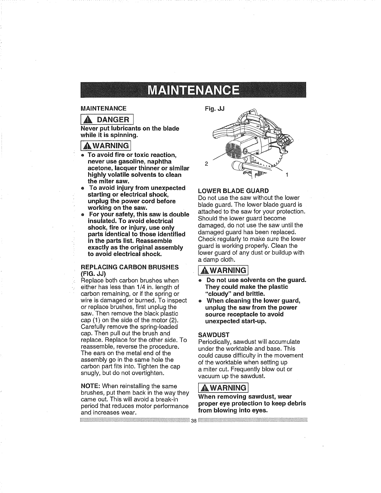
REPLACING CARBON BRUSHES
(FIG. JJ)
Replace both carbon brushes when
either has less than 1/4 in. length of
carbon remaining, or if the spring or
wire is damaged or burned. To inspect
or replace brushes, first unplug the
saw. Then remove the black plastic
cap (1) on the side of the motor (2).
Carefully remove the spring-loaded
cap. Then pull out the brush and
replace. Replace for the other side. To
reassemble, reverse the procedure.
The ears on the metal end of the
assembly go in the same hole the
carbon part fits into. Tighten the cap
snugly, but do not overtighten.
NOTE: When reinstalling the same
brushes, put them back in the way they
came out. This will avoid a break-in
period that reduces motor performance
and increases wear.
Fig. JJ
2
LOWER BLADE GUARD
Do not use the saw without the lower
blade guard. The lower blade guard is
attached to the saw for your protection.
Should the lower guard become
damaged, do not use the saw until the
damaged guard has been replaced.
Check regularly to make sure the lower
guard is working properly. Clean the
lower guard of any dust or buildup with
a damp cloth.
_WARNING I
®Do not use solvents on the guard.
They could make the plastic
"cloudy" and brittle.
®When cleaning the lower guard,
unplug the saw from the power
source receptacle to avoid
unexpected start-up.
SAWDUST
Periodically, sawdust will accumulate
under the worktable and base. This
could cause difficulty in the movement
of the worktable when setting up
a miter cut. Frequently blow out or
vacuum up the sawdust.
_WARNING]
When removing sawdust, wear
proper eye protection to keep debris
from blowing into eyes.
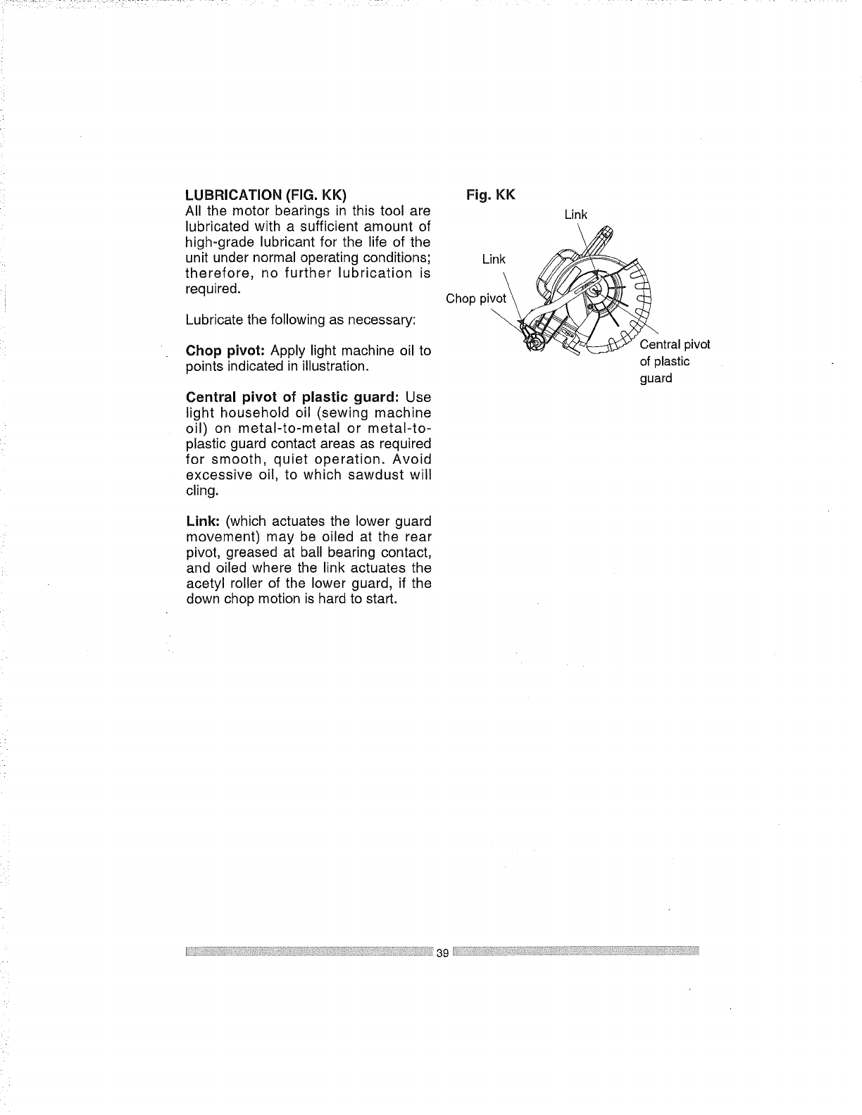
LUBRICATION(FIG.KK)
Allthe motorbearingsin thistoolare
lubricatedwitha sufficientamountof
high-gradelubricantfor thelifeof the
unitundernormaloperatingconditions;
therefore, no further lubrication is
required.
Lubricatethefollowingasnecessary:
Choppivot: Apply light machine oil to
points indicated in illustration.
Central pivot of plastic guard: Use
light household oil (sewing machine
oil) on metal-to-metal or metal-to-
plastic guard contact areas as required
for smooth, quiet operation. Avoid
excessive oil, to which sawdust will
cling.
Link: (which actuates the lower guard
movement) may be oiled at the rear
pivot, greased at ball bearing contact,
and oiled where the link actuates the
acetyl roller of the lower guard, if the
down chop motion is hard to start.
Fig, KK
Link
Link
Chop '
P_ Central pivot
of plastic
guard
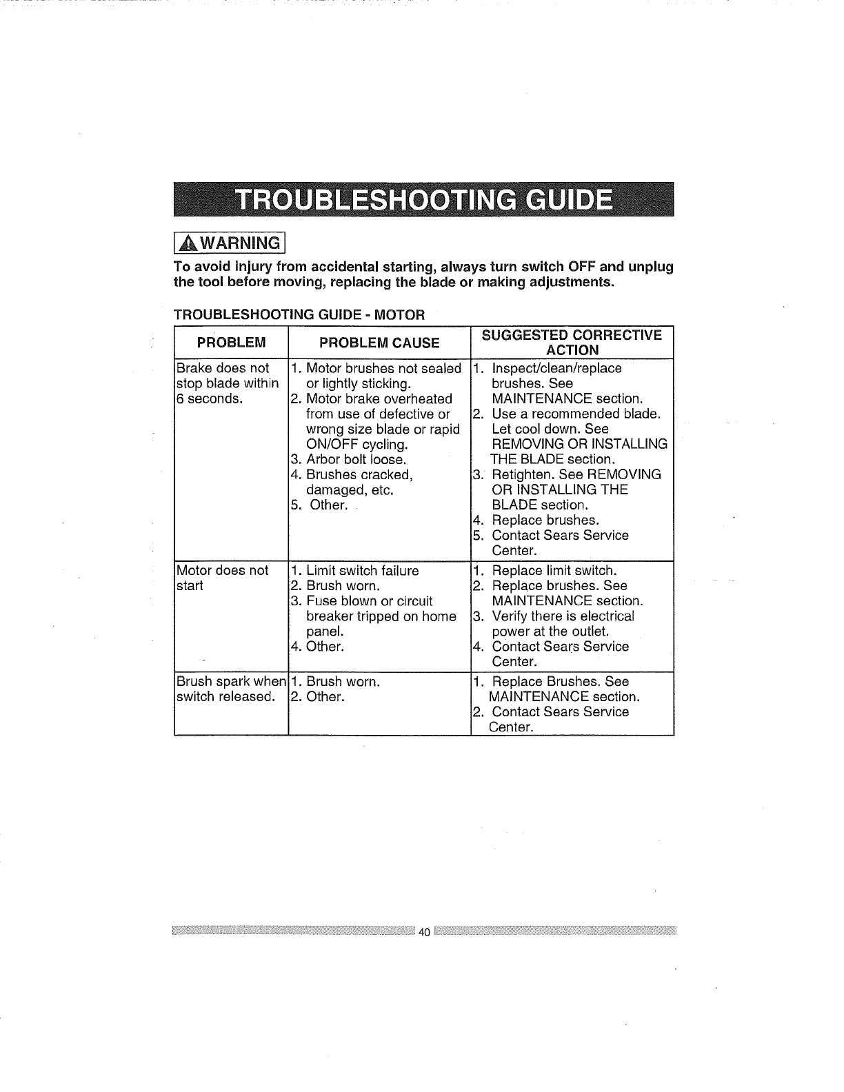
I,AWARNINGJ
To avoid injury from accidental starting, always turn switch OFF and unplug
the tool before moving, replacing the blade or making adjustments.
I'ROUBLESHOOTING GUIDE -MOTOR
PROBLEM CAUSE
PROBLEM
Brake does not
stop blade within
6 seconds.
.
2.
3.
4.
5,
Motor does not 1.
start 2.
13.
4.
Brush spark when il.
switch released. 12.
Motor brushes not sealed
or lightly sticking.
Motor brake overheated
from use of defective or
wrong size blade or rapid
ON/OFF cycling.
Arbor bolt loose.
Brushes cracked,
damaged, etc.
Other.
Limit switch failure
Brush worn.
Fuse blown or circuit
breaker tripped on home
panel.
Other.
Brush worn.
Other.
SUGGESTED CORRECTIVE
ACTION
1. Inspect/clean/replace
brushes. See
MAINTENANCE section.
2. Use a recommended blade.
Let cool down. See
REMOVING OR INSTALLING
THE BLADE section.
3. Retighten. See REMOVING
OR INSTALLING THE
BLADE section.
4. Replace brushes.
5. Contact Sears Service
Center.
1. Replace limit switch.
2. Replace brushes. See
MAINTENANCE section.
3. Verify there is electrical
power at the outlet.
4. Contact Sears Service
Center.
1. Replace Brushes. See
MAINTENANCE section.
2. Contact Sears Service
Center.
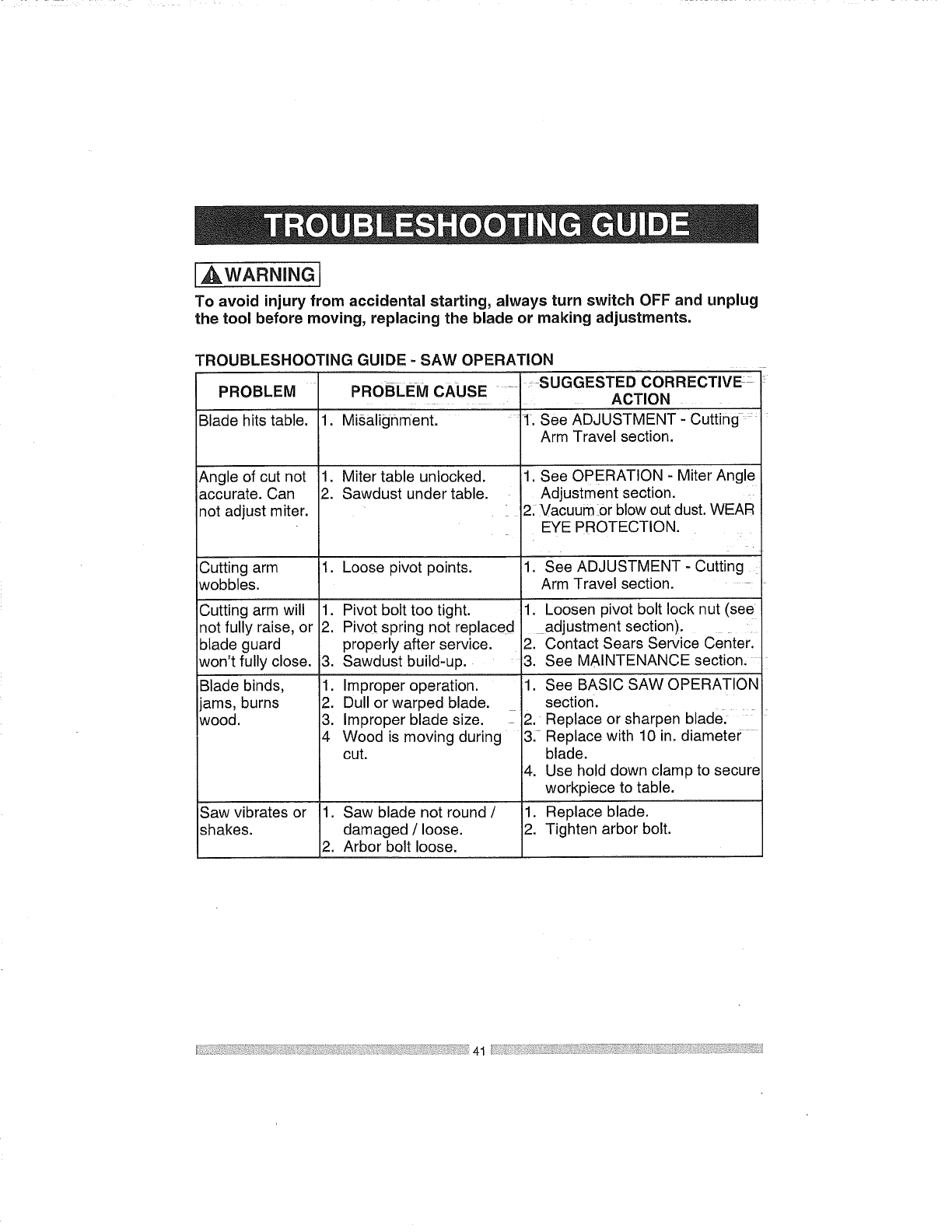
_.WARNING
To avoid injury from accidental starting, always turn switch OFF and unplug
the tool before moving, replacing the blade or making adjustments.
TROUBLESHOOTING GUIDE -SAW OPERATION
PROBLEM
Blade hits table.
Angle of cut not
accurate. Can
not adjust miter.
Cutting arm
wobbles.
Cutting arm will
not fully raise, or
blade guard
won't fully close.
jBlade binds,
jams, burns
wood.
Saw vibrates or
shakes.
PROBLEM CAUSE
1. Misalignment.
1. Miter table unlocked.
2. Sawdust under table.
1. Loose pivot points.
1. Pivot bolt too tight.
2. Pivot spring not replaced
properly after service.
3. Sawdust build-up.
1. Improper operation.
2. Dull or warped blade.
3. Improper blade size.
4 Wood is moving during
cut.
1. Saw blade not round /
damaged /loose.
2. Arbor bolt loose.
: SUGGESTED CORRECTIVE _
ACTION
1. See ADJUSTMENT -Cutting .....
Arm Travel section.
1. See OPERATION - Miter Angle
Adjustment section.
2: Vacuum :or blow out dust. WEAR
EYE PROTECTION.
1. See ADJUSTMENT - Cutting
Arm Travel section.
1. Loosen pivot bolt lock nut (see
adjustment section).
2. Contact Sears Service Center.
3. See MAINTENANCE section,
1. See BASIC SAW OPERATION
section.
2. Replace or sharpen blade.
3. Replace with 10 in. diameter
blade.
4. Use hold down clamp to secure
workpiece to table.
1. Replace blade.
2. Tighten arbor bolt.
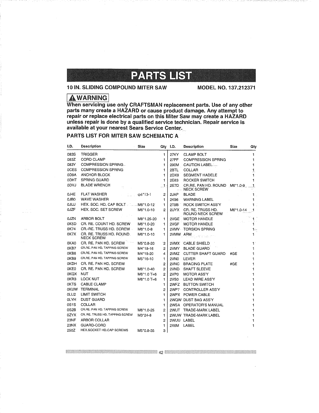
10 IN. SLIDING COMPOUND MITER SAW MODEL NO. 137.212371
I,AWARNING ]
When servicing use only CRAFTSMAN replacement parts. Use of any other
parts many create a HAZARD or cause product damage. Any attempt to
repair or replace electrical parts on this Miter Saw may create a HAZARD
unless repair is done by a qualified service technician. Repair service is
available at your nearest Sears Service Center.
PARTS LIST FOR MITER SAW SCHEMATIC A
I.D. Description Size Qty
083S TRIGGER 1
083Z CORD CLAMP 1
083Y COMPRESSION SPRING 1
0CES COMPRESSION SPRING 1
0D9A ANCHOR BLOCK 1
0DHT SPRING GUARD 1
0DVJ BLADE WRENCH 1
0J4E FLAT WASHER q)6"13-1 2
0JR0 WAVE WASHER 1
0JUJ HEX. SOC. HD. CAP BOLT M6"1.0-12: 1
0JZF HEX. SOC. SET SCREW M6"1.0-10 2
0JZN ARBOR BOLT M8"1.25-20
0K5D CR. RE. COUNT HD. SCREW M6"1.0-20
0K74 CR.-RE. TRUSS HD. SCREW M6"1.0-8
0K7X CR, RE. TRUSS HD. ROUND M6"1.0-10
NECK SCREW
0KA0 CR. RE. PAN HD. SCREW M5"0.8-20
0KB7 CR,RE.PANHD.TAPPINGSCREW M4* 18-16
0KB8 CR,RE. PAN HD. TAPPING SCREW M4"18-20
0KB9 CR.RE. PAN HD. TAPPING SCREW M5"16-10
0KDH CR. RE. PAN HD. SCREW
0KE0 CR. RE. PAN HD. SCREW M6"1,0-40
0KQX NUT M6"1.0 T=6
0KR3 LOCK NUT M6"1.0 T=6
0KTS CABLE CLAMP
0KUW TERMINAL
0LU2 LIMIT SWITCH
0LYH DUST GUARD
0S1S COLLAR
0S2B CR.RE. PAN HD. TAPPING SCREW M6"1.0-25
0ZYX CR. RE. TRUSS HD. TAPPING SCREW M3"24-8
23NF ARBOR COLLAR
23NX GUARD-CORD
250Z HEX.SOCKET HD.CAP SCREWS M5"0.8-35
I.D. Description Size Qty
27KY CLAMP BOLT 1
27PF COMPRESSION SPRING 1
290M CAUTION LABEL: 1
2BTL COLLAR t
2DX9 SEGMENT HADELE 1
2E63 ROCKER SWITCH 1
2ETD CR.RE. PAN HD. ROUND M6"1,0-9 1
NECK SCREW
2JAP BLADE i
2K96 WARNING LABEL 1
2T9B ROCK SWITCH ASS'Y 1
2UYX CR. RE. TRUSS HD. M6'1.0-14 1
1
1
1
1
2
2
4
]
2
2
2
1
1
2
]
1
]
2
]
2
]
3
ROUND NECK SCREW
2VGE MoToR HANDLE
2VGF MOTOR HANDLE
2VMV TORSION SPRING
2VMW ARM
2VMX cABLE SHIELD
2VMY BLADE GUARD
2VMZ CUTTER SHAFT GUARD
2VN0 LEVER
2VNC BRACING PLATE
2VND SHAFT SLEEVE
2VP0 MOTOR ASS'Y
2VS0 LEAD WIRE ASS'Y
2WFZ BUTTON SWITCH
2WP7 CONTROLLER ASS'Y
2WPX POWER CABLE
2WQW DUST BAG ASS'Y
2WSA OPERATOR'S MANUAL
2WUT TRADE-MARK LABEL
2WUW TRADE-MARK LABEL
2WUU LABEL
2X6M LABEL
1
1
1L=
1
1
#GE 1
1
#GE 1
1
1
1
1
1
1
1
1
1
1
1
1
42
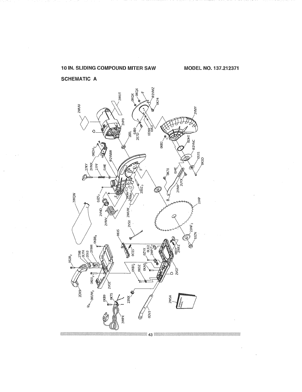
10 IN. SLIDING COMPOUND MITER SAW MODEL NO. 137,212371
SCHEMATIC A
"T"
/
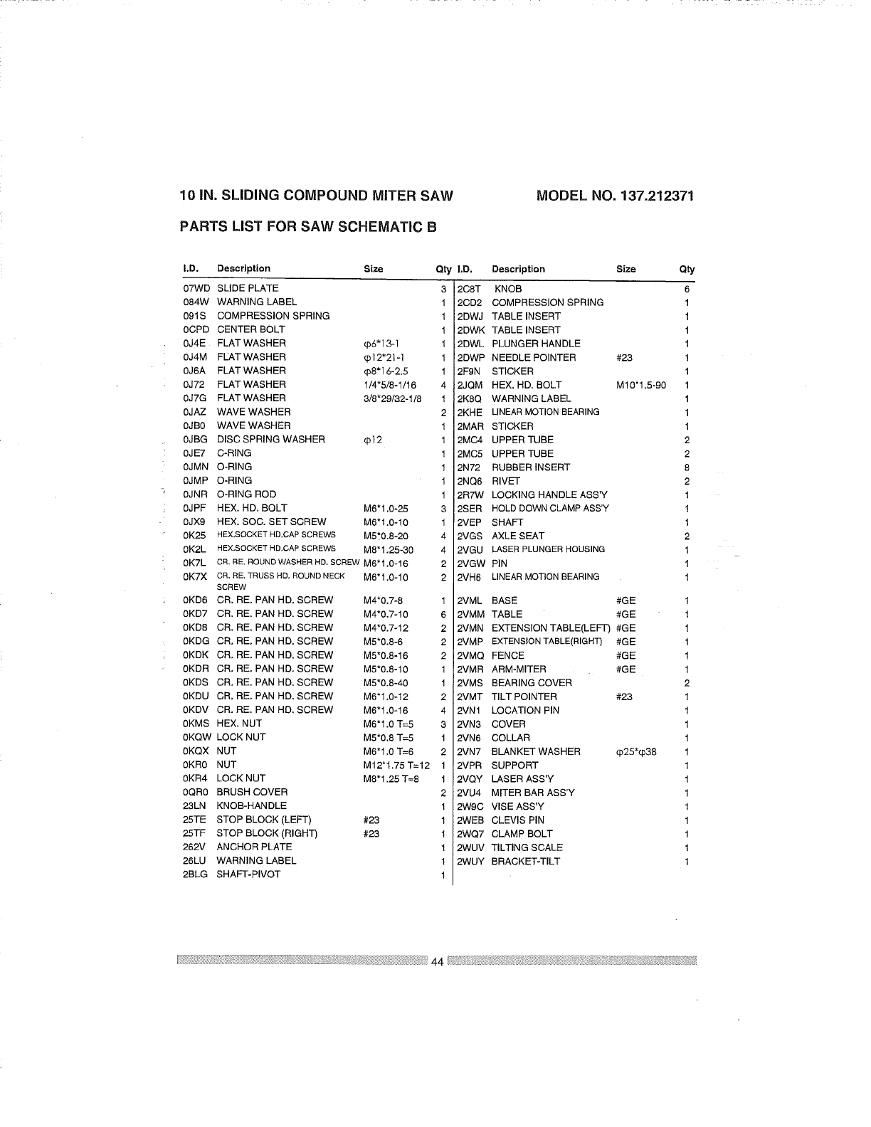
10 IN. SLIDING COMPOUND MITER SAW
PARTS LIST FOR SAW SCHEMATIC B
MODEL NO. 137.212371
I.D. Description Size
07WD SLIDE PLATE
084W WARNING LABEL
091S COMPRESSION SPRING
0CPD CENTER BOLT
0J4E FLATWASHER q)6"]3-'[
0J4M FLAT WASHER _'[2"21-1
0J6A FLATWASHER q)8"15-2.5
0J72 FLAT WASHER 1/4"5/8-1/16
0J7G FLAT WASHER 3/8"29/32-1/8
0JAZ WAVE WASHER
0JB0 WAVE WASHER
0JBG DISC SPRING WASHER ¢p12
0JE7 C-RING
0JMN O-RING
0JMP O-RING
0JNR O-RING ROD
0JPF HEX. HD, BOLT M6"1.0-25
0JX9 HEX. SOC. SET SCREW M6"1.0-10
0K25 HEX.SOCKET HD.CAP SCREWS M5'_0.8-20
0K2L HEX.SOCKETHD.CAPSCREWS M8* 1.25-30
0KTL CR, RE, ROUNDWASHERHD. SCREWM6"1,0-16
0K7X CR,RE.TRUSSHD,ROUNDNECK M6* 1,0-10
SCREW
0KD6 CR. RE. PAN HD. SCREW M4'0.7-8
0KD7 CR. RE. PAN HD, SCREW M4"0,7-10
0KD8 CR. RE, PAN HD. SCREW M4"0.7-12
0KDG CR. RE. PAN HD. SCREW M5"0.8-8
0KDK CR, RE. PAN HD. SCREW M5"0.8-16
0KDR CR. RE. PAN HD. SCREW M5"0.8-10
0KDS CR. RE. PAN HD, SCREW M5"0.8-40
0KDU CR. RE. PAN HD. SCREW M6"1.0-12
0KDV CR. RE, PAN HD, SCREW M6"1,0-16
0KMS HEX, NUT M6"1.0 T=5
0KQW LOCK NUT M5"0.8 -I--5
0KQX NUT M6"1,0 T=6
0KR0 NUT M12"1.75 "1"--12
0KR4 LOCK NUT M8"1.25 T=8
0QR0 BRUSH COVER
23LN KNOB-HANDLE
25TE STOP BLOCK (LEFT) #23
25TF STOP BLOCK (RIGHT) #23
262V ANCHOR PLATE
26LU WARNING LABEL
2BLG SHAFT-PIVOT
Q_ I.D.
3 2C8T
1 2CD2
1 2DWJ
1 2DWK
1 2DWL
1 2DWP
1 2FgN
4 2JQM
1 2K8Q
2 _-KHE
1 -_MAR
1 __MC4
1 2MC5
1 2N72
1 2NQ6
1 2R7W
3 2SER
1!2VEP
4 2VGS
4 2VGU
2 2VGW
2 2VH6
1 -WML
6 2VMM
2 2VMN
2 2VMP
2 2VMQ
1 2VMR
1 2VMS
2 2VMT
4 2VNI
3 2VN3
1 2VN6
2 2VN7
1 2VPR
1 2VQY
2 2VU4
1 2W9C
1 2WEB
1 2WQ7
1 2WUV
1 2WUY
1
Description Size Qty
KNOB 6
COMPRESSION SPRING 1
TABLE INSERT 1
TABLE INSERT 1
PLUNGER HANDLE 1
NEEDLE POINTER #23 1
STICKER 1
HEX. HD, BOLT M10"1.5-90 1
WARNING LABEL 1
LINEAR MOTION BEARING 1
STICKER 1
UPPER TUBE 2
UPPER TUBE 2
RUBBER INSERT 8
RIVET 2
LOCKING HANDLE ASS'Y 1
HOLD DOWN CLAMP ASS'Y 1
SHAFT 1
AXLE SEAT 2
LASER PLUNGER HOUSING 1
PIN 1
LINEAR MOTION BEARING 1
BASE #GE 1
TABLE #GE 1
EXTENSION TABLE(LEFT) #GE 1
EXTENSION TABLE(RIGHT) #GE 1
FENCE #GE 1
ARM-MITER #GE 1
BEARING COVER 2
TILT POINTER #23 1
LOCATION PIN 1
COVER 1
COLLAR 1
BLANKET WASHER q)25*cp38 1
SUPPORT 1
LASER ASS'Y 1
MITER BAR ASS'Y 1
VISE ASS'Y 1
CLEVIS PIN 1
CLAMP BOLT 1
TILTING SCALE 1
BRACKET-TILT 1
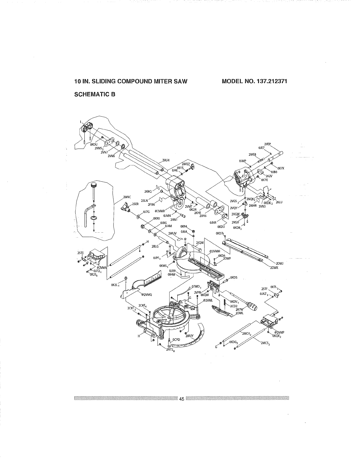
10 IN. SLIDING COMPOUND MITER SAW
SCHEMATIC B
MODEL NO. 137.212371
2VN6
OJM f
2VEP
OJE7
2WEB
2W9C
DJ7G
2VNI
OJBG
OJ4M
-2WUV
/H
2KHE
2VH6
_OK7X
2VN3
OKDU OKD82
OKD76
26LU
45
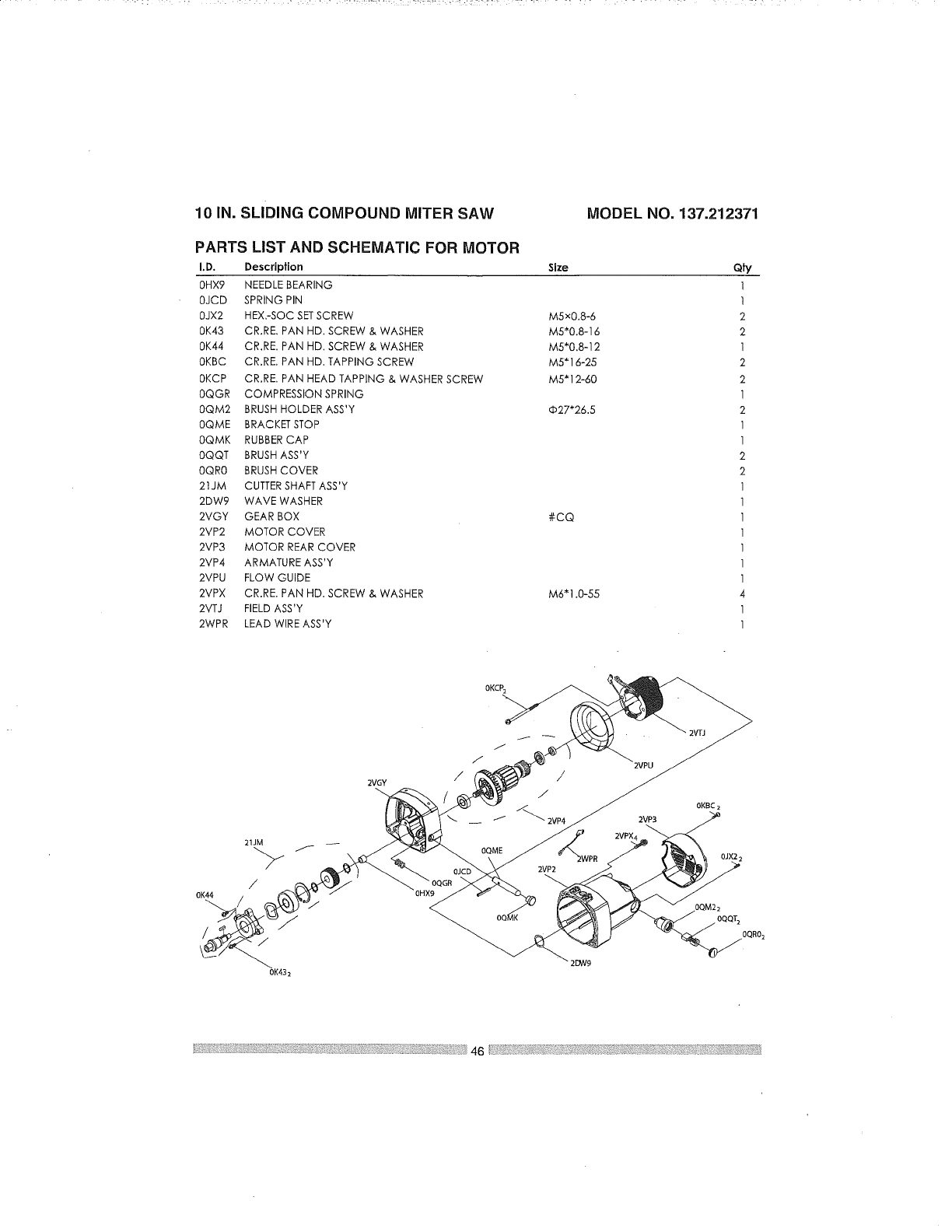
10 IN. SLIDING COMPOUND MITER SAW MODEL NO. 137.212371
PARTS LIST AND SCHEMATIC FOR MOTOR
I.D. Description
OHX9 NEEDLE BEARING
OJCD SPRING PIN
OJX2 HEX.-SOC SETSCREW
0K43 CR.RE. PAN HD. SCREW & WASHER
0K44 CR.RE. PAN HD. SCREW & WASHER
OKBC CR.RE. PAN HD. TAPPING SCREW
OKCP CR.RE. PAN HEAD TAPPING & WASHER SCREW
OQGR COMPRESSION SPRING
OQM2 BRUSH HOLDERASS'Y
OQME BRACKET STOP
OQMK RUBBER CAP
OQQT BRUSH ASS'Y
OQRO BRUSH COVER
21JM CUTTERSHAFT ASS'Y
2DW9 WAVE WASHER
2VGY GEAR BOX
2VP2 MOTOR COVER
2VP3 MOTOR REAR COVER
2VP4 ARMATURE ASS'Y
2VPU FLOW GUIDE
2VPX CR.RE. PAN HD. SCREW & WASHER
2VTJ FIELD ASS'Y
2WPR LEAD WIRE ASS'Y
Size
M5xO.8-6
M5"0.8-16
M5"0.8-12
M5"16-25
M5"12-60
_27"26.5
#CQ
M6"1.0-55
oF/
1
1
2
2
I
2
2
1
2
1
1
2
2
1
1
1
1
1
1
1
4
1
1
21JM
/
OK44
//
0K432
2VGY
OQME
2WPR
OJCD 2VP2
2DW9
2VPU
2VP3
2VPX4
2VTJ
0KBC 2
OQQT 2
OQRO 2
Congratulations on making a smart purchase. Your new Craftsman® product
is designed and manufactured for years of dependable operation. But like all
products, it may require repair from time to time. That's when having a Repair
Protection Agreement can save you money and aggravation.
Here's what the Repair Protection Agreement* includes:
[] Expert service by our 10,000 professional repair specialists
[] Unlimited service and no charge for parts and labor on all covered
repairs
[] Product replacement up to $1500 if your covered product can't be fixed
[] Discount of 10% from regular price of service and related installed
parts not covered by the agreement; also, 10% off regular price of
preventive maintenance check
[] Fast help by phone - we call it Rapid Resolution - phone support from a
Sears representative; Think of USas a '_alking owner's manual."
Once you p[Jrchase the Repair Protection Agreement, a simple phone call is all
that it takes foryou to schedule service. You can call anytime day or night, or
schedule a service appointment online.
The Repair Protection Agreement is a risk-free purchase. If you cancel for any
reason during theproduct warranty period, we will provide a full refund. Or, a
prorated refLind anytime after the product warranty period expires. Purchase
your Repair Protection Agreement today!
Some limitations and exclusions apply. For prices and additional
information in the U.S.A. call 1-800=827-6655.
*Coverage in Canada varies on some items. For full details call Sears
Canada at 1-800=361-6665.
Sears Installation Service
For Sears professional installation of home appliances, garage door openers,
water heaters, and other major home items, in the U.S.A. or Canada call
1=800-4=MY-HOME®.


ijiii!iiii
Your Home
For expert troubleshootingand home solutionsadvice:
manage
www.managemyhome.com
For repair- in your home - of all major brand appliances,
lawn and garden equipment, or heating and cooling systems,
no matter who made it, no matter who sold it!
For the replacement parts, accessories and
owner's manuals that you need to do-it-yourself.
For Sears professional installation of home appliances
and items like garage door openers and water heaters.
1-800-4-1ViY-HOME ®(1-800=469-4663)
Call anYtime, day or night (U.S.A. and Canada)
www.sears.com www.sears.ca
Our Home
For repair of carry-in items like vacuums, lawn equipment,
and electronics, call anytime for the location of your nearest
Sears Parts & Repair Service Center
1-800=488-1222 (u.s.A.) 1o800-469-4663 (Canada)
www.sears.com www.sears.ca
To purchase a protection agreement on a product serviced by Sears:
1=800-827-6655 (U.S.A.) 1-800-361=6665 (Canada)
Para pedir servicio de reparaci6n Au Canada pour service en fran_ais:
a domicilio, y para ordenar piezas: 1-800=LE-FOYER Mc
1-888=SU-HOGAR ® (1-800-533-6937)
Sea/rs
® Registered Trademark /"ru Trademark /sM Service Mark of Sears Brands, LLC
T_ s_
®Marca Registrada /Mama de F_bdca /Marca de Servicio de Sears Brands, LLC
Mc Marque de commerce /MO Marque d_pos_e de Sears Brands, LLC © Sears Brands, LLC
iiiili;
i,_J,!il
I;iii!ii_;i)ii;_
I}iii_i::i?
