Craftsman 137218780 User Manual TABLE SAW Manuals And Guides L0901159
CRAFTSMAN Saw Table Manual L0901159 CRAFTSMAN Saw Table Owner's Manual, CRAFTSMAN Saw Table installation guides
User Manual: Craftsman 137218780 137218780 CRAFTSMAN TABLE SAW - Manuals and Guides View the owners manual for your CRAFTSMAN TABLE SAW #137218780. Home:Tool Parts:Craftsman Parts:Craftsman TABLE SAW Manual
Open the PDF directly: View PDF ![]() .
.
Page Count: 10
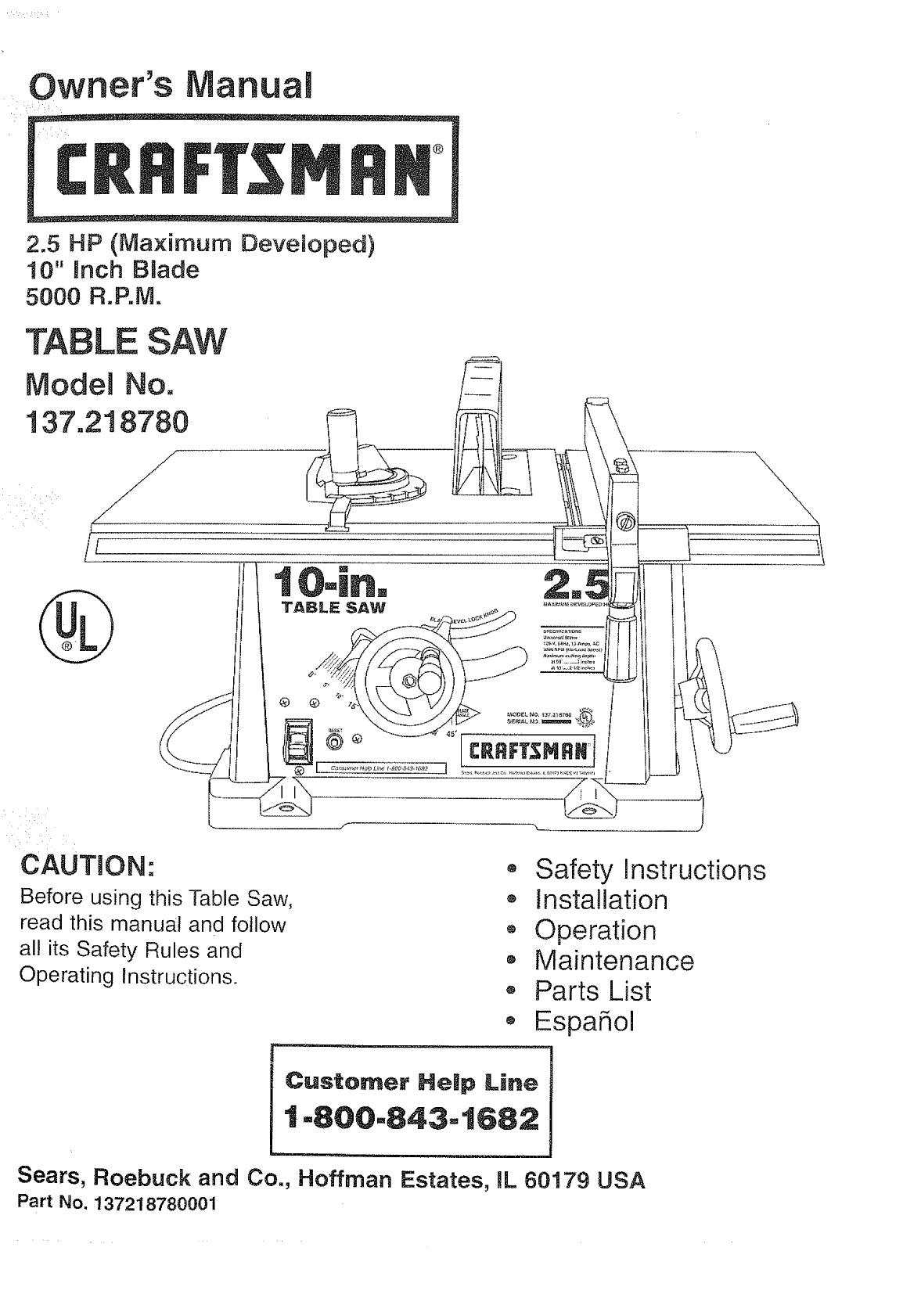
Owner's Manual
2.5 HP (Ma×imum Deveioped)
10" inch Blade
5000 R.P.M.
TABLE SAW
ModeJ No.
!37.218780
CAUTION..
Before using this Table Saw,
read this manual and follow
all its Safety Rules and
Operating Instructions.
o Safety Instructions
o Installation
,, Operation
• Maintenance
® Parts List
,, EspaSol
Customer Help Line
1-800-843-1682
Sears, Roebuck and Co., Hoffman Estates, mL60179 USA
Part No. 137218780001
SECTION PAGE
Warranty ................................................................ 2
Product Specifications ..................................................... 2
Safety instructions ........................................................ 3
Accessories and Attachments ................................................ 6
Tools needed for assembly ................................................. 6
Carton Contents .......................................................... 6
Know Your Table Saw ...................................................... 8
Assembly and Adjustments .................................. : .... .. ........ 9
Operation .............................................................. 14
Maintenance ............................................................ 18
Troubleshooting guide .................................................... 19
Parts .................................................................. 20
Making a push stick ...................................................... 29
EspaSol ................................................................ 33
,j
!i_i:i
i
i
i:! :i
: i
FULL ONE YEAR WARRANTY
If this product fails due to a defect in material or workmanship within one year from the date of purchase, Sears
will repair it free of charge.
Contact a Sears Service Center for repair.
if this product is used for commercial or rentat purposes, this warranty applies only for 90 days from the date of
purchase.
This warranty gives you specific legal rights, and you may also have other rights which vary from state to state.
Sears, Roebuck and Co., Dept. 817 WA, Hoffman Estates, IL 60179
::::!i/•
MOTOR
HP (Max. developed) ............ 2.5
Volts ........................ 120
Amperes ..................... 13
Hertz ....................... 60
RPM (no load) ................ 5000
Overload protection ............. YES
SAW
Table ....................... 17-1/2" x 26-!/2"
Blade ...................... 1i0 i!i
Maximum depth of cut at 90° ..... 3"
Maximum depth of cut at 45° ..... 2-1/2'!
Maximum width of dado ......... 1/2"
Weight ...................... 35.4 Ibs.
_,!:•:_::::i,:i::•i::!::_:::!:•:?_¸_i:;::::!:::/•:_:/?,i!::::::::_:::::/::•:,:_::?i::!:_:::'ii::;ii::i_:::::i!::f!:!:i:::ii::::_:_;:::i:i;::;i:::,!:!::,ii::i¸i::;il!i:il:i!i_:i¸!::ii::i_:i_::!:i:i!:ii__:!ii:::!:!i!_i::_ifi_•_!_i_i:iii:!i:_:¸i:i::_:_:ii::¸il:ii;:ii
To avoid electrical hazards, fire hazards, or damage to
the tool, use proper circuit protection.
Your table saw is wired at the factory for 120V operation. :i::i::
Connect to a t20V, 15 AMP branch circuit and use a t5 :::
AMP time delay fuse or circuit breaker. To avoid shock or
fire, replace power cord immediately if it is worn, cut or
damaged in any way.
:! [; :
,i
GENERAL SAFETY INSTRUCTIONS
BEFORE USING THE TABLE SAW
Safety is a combination of common sense, staying alert
and knowing how to use your table saw.
To avoid mistakes that could cause serious injury, do not
plug the table saw in until you have read and understood
the following:
t.
.
3.
.
READ and become familiar with this entire instruction
manual. LEARN the tool's applications, limitations, and
possible hazards.
KEEP GUARDS IN PLACE and in working order.
REMOVE ADJUSTING KEYS AND WRENCHES.
Form the habit of checking to see that keys and
adjusting wrenches are removed from the tool before
turning ON.
KEEP WORK AREA CLEAN. Cluttered areas and
benches invite accidents.
.
.
DON'T USE JN A DANGEROUS ENVIRONMENT.
Don't use power tools in damp or wet locations, or
expose them to rain. Keep work area well lighted.
KEEP CHILDREN AWAY. All visitors should be kept at
a safe distance from the work area.
,
,
MAKE WORKSHOP KID PROOF with padlocks, master
switches, or by removing starter keys.
DON'T FORCE THE TOOL. It will do the job better
and safer at the rate for which it was designed.
USE THE RIGHTTOOL. Don't force tool or the
attachment to do a job for which it was not designed.
USE PROPER EXTENSION CORD. Make sure your
extension cord is in good condition. When using an
extension cord, be sure to use one heavy enough to
carry the current your product wi!l draw. An undersized
cord will cause a drop in line voltage resulting in loss
of power and overheating. The table on page 5 shows
the correct size to use depending on cord length and
nameplate ampere rating. If in doubt, use the next
heavier gauge. The smaller the gauge number, the
heavier the cord.
1t. WEAR PROPER APPAREL. DO NOT wear loose
clothing, gloves, neckties, rings, bracelets, or other
jewelry which may get caught in moving parts.
Nonslip footwear is recommended. Wear protective
hair covering to contain long hair.
12.
13.
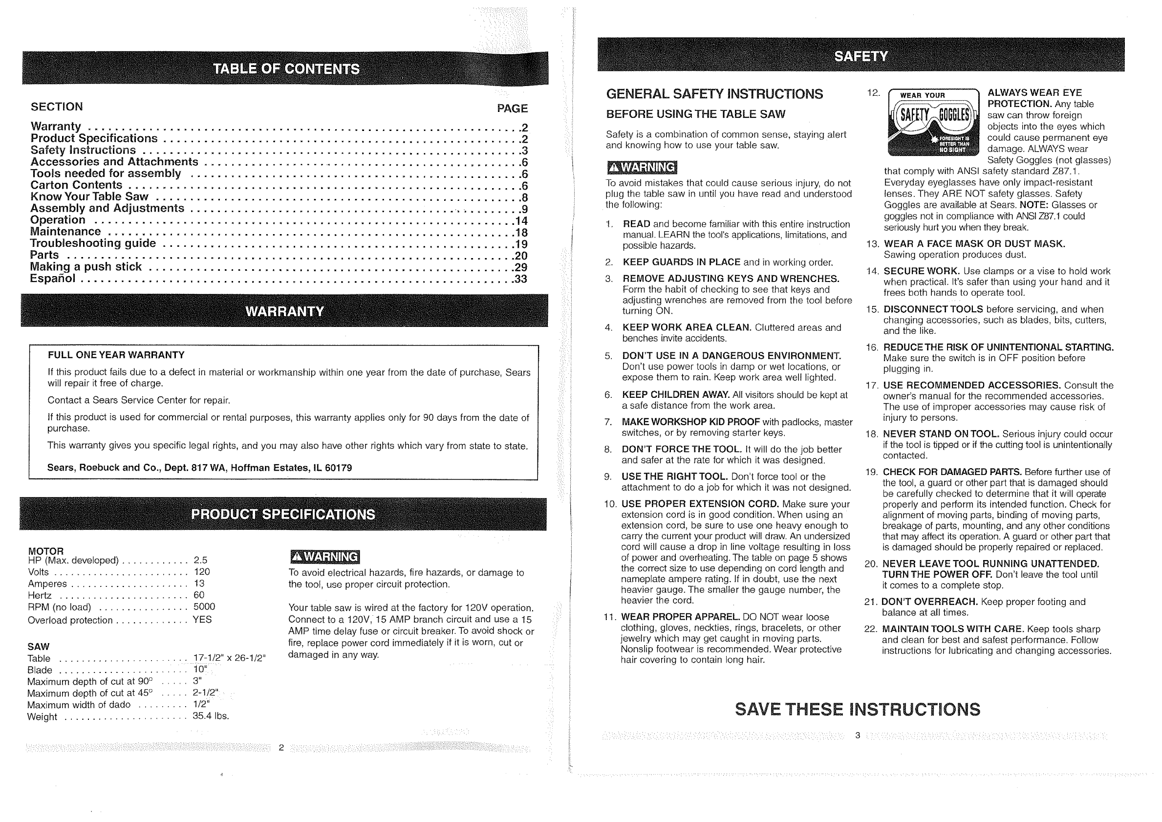
WEANYOUR ALWAYS WEAR EYE
PROTECTION. Any table
saw can throw foreign
objects into the eyes which
could cause permanent eye
damage. ALWAYS wear
Safety Goggles (not glasses)
that comply with ANSI safety standard Z87.1.
Everyday eyeglasses have only impact-resistant
lenses. They ARE NOT safety glasses. Safety
Goggles are available at Sears. NOTE: Glasses or
goggles not in compliance with ANSI Z87.! could
seriously hurt you when they break.
WEAR A FACE MASK OR DUST MASK.
Sawing operation produces dust.
t4. SECURE WORK. Use clamps or a vise to hold work
when practical. It's safer than using your hand and it
frees both hands to operate tool.
15. DISCONNECT TOOLS before servicing, and when
changing accessories, such as blades, bits, cutters,
and the like.
16.
17.
18.
19.
20.
21.
22.
REDUCE THE RISK OF UNINTENTIONAL STARTING.
Make sure the switch is in OFF position before
plugging in.
USE RECOMMENDED ACCESSORIES. Consult the
owner's manual for the recommended accessories.
The use of improper accessories may cause risk of
injury to persons.
NEVER STAND ON TOOL. Serious injury could occur
if the tool is tipped or if the cutting tool is unintentionally
contacted.
CHECK FOR DAMAGED PARTS. Before further use of
the tool, a guard or other part that is damaged should
be carefully checked to determine that it will operate
properly and perform its intended function. Check for
alignment of moving parts, binding of moving parts,
breakage of parts, mounting, and any other conditions
that may affect its operation. A guard or other part that
is damaged should be properly repaired or replaced.
NEVER LEAVE TOOL RUNNING UNATTENDED.
TURN THE POWER OFF. Don't leave the toot until
it comes to a complete stop.
DON'T OVERREACH. Keep proper footing and
balance at all times.
MAINTAIN TOOLS WITH CARE. Keep tools sharp
and clean for best and safest performance. Follow
instructions for lubricating and changing accessories.
SAVE THESE iNSTRUCTIONS
3 :: : i::; : : ::: :: : : : ::
23. DIRECTION OF FEED. Feed work into a blade or cutter
against the direction of rotation of the blade or cutter
only.
24. WARNING: Dust generated from certain materials can
be injurious to your health. Always operate saw in well
ventilated areas and provide for proper dust removal.
SPECIFMC SAFETY INSTRUCTmONS
FOR THE TABLE SAW
1. ALWAYS USE SAW BLADE GUARD spreader and
anti-kickback pawls for every operation fer which
they can be used, including through-sawing.
Through-sawing operations are those in which the
blade cuts completely through the workpiece
when ripping or cress-cutting,
2. ALWAYS HOLD THE WORK FIRMLY against the
miter gauge or rip fence.
.USE A PUSH STICK when required. Always use a
push stick for ripping narrow stock. Refer to ripping
applications in the instruction manual where the
push stick is covered in detail. See the push stick
pattern included in this Owner's Manual.
.NEVER PERFORM ANY OPERATION
"FREE HAND", which means using your hands
only to support or guide the werkpiece. Always
use either the fence or the miter gauge to position
and guide the work.
5. NEVER STAND or have any part of your body
in line with the path of the saw blade. Keep your
hands out of the line of the saw blade.
6. NEVER REACH behind or over the cutting tool
for any reason.
7. REMOVE the rip fence when cross-cutting.
8. DO NOT USE molding head set with this saw.
9. FEED WORK INTO THE BLADE against the
direction of rotation only.
10. NEVER use the fence as a cut-off gauge when
cross-cutting.
1i. NEVER ATTEMPTTO FREE A STALLED SAW
BLADE without first turning the saw OFR Turn
power switch OFF immediately to prevent motor
damage.
12.
13.
t4.
PROVIDE ADEQUATE SUPPORT to the rearand
sides of the saw table for wide or long Wbrkpiece_i
AVOID KICKBACKS (work thrown back towards
you) by keeping the blade sharp, keeping the rip
fence )arallel to the saw blade, and by keeping the
spreader, anti-kickback pawls, and guard in place
and functioning. Do not release work before it is
pushed all the way past the saw blade. Do not rip
work that is twisted, warped, or does not have a
straight edge to guide along the fence.
AVOID AWKWARD OPERATIONS and hand
positions where a sudden slip could cause your
hand to move into the cutting tool.
15. NEVER USE SOLVENTS to clean plastic parts.
Solvents could possibly dissolve or otherwise
damage the material. Only a soft damp cloth should
be used to clean plastic parts.
16. MOUNT your table saw before performing any
cutting operations. Refer to installation instructions.
17. NEVER CUT METALS or materials which may make
hazardous dust.
18. ALWAYS USE IN A WELL VENTILATED AREA.
Remove sawdust frequently. Clean out sawdust from
the interior of the saw to prevent a potential fire
hazard.
19. NEVER LEAVE THE TOOL running unattended.
Don't leave the too! until it comes to a complete stop.
20. For proper operation follow the instructions of this
owner's manual titled "SAW MOUNTED TO WORK
SURFACES." Failure to provide sawdust falFthrough
and removal hole will allow sawdust to build up in
the motor area, which may result in a fire hazard or
cause motor damage.
ELECTRICAL REQUIREMENTS
POWER SUPPLY AND MOTOR
SPECIFICATIONS
To avoid electrical hazards, fire hazards, or damage to
the tool, use proper circuit protection. Use a separate
electrical circuit for your tools.Your saw is wired at the
factory for t20V operation. Connect to a 120V, 15 Amp
circuit and use a I5 Amp time delay fuse or circuit
breaker. To avoid shock or fire, if power cord is worn or
cut, or damaged in any way, have it replaced
immediately.
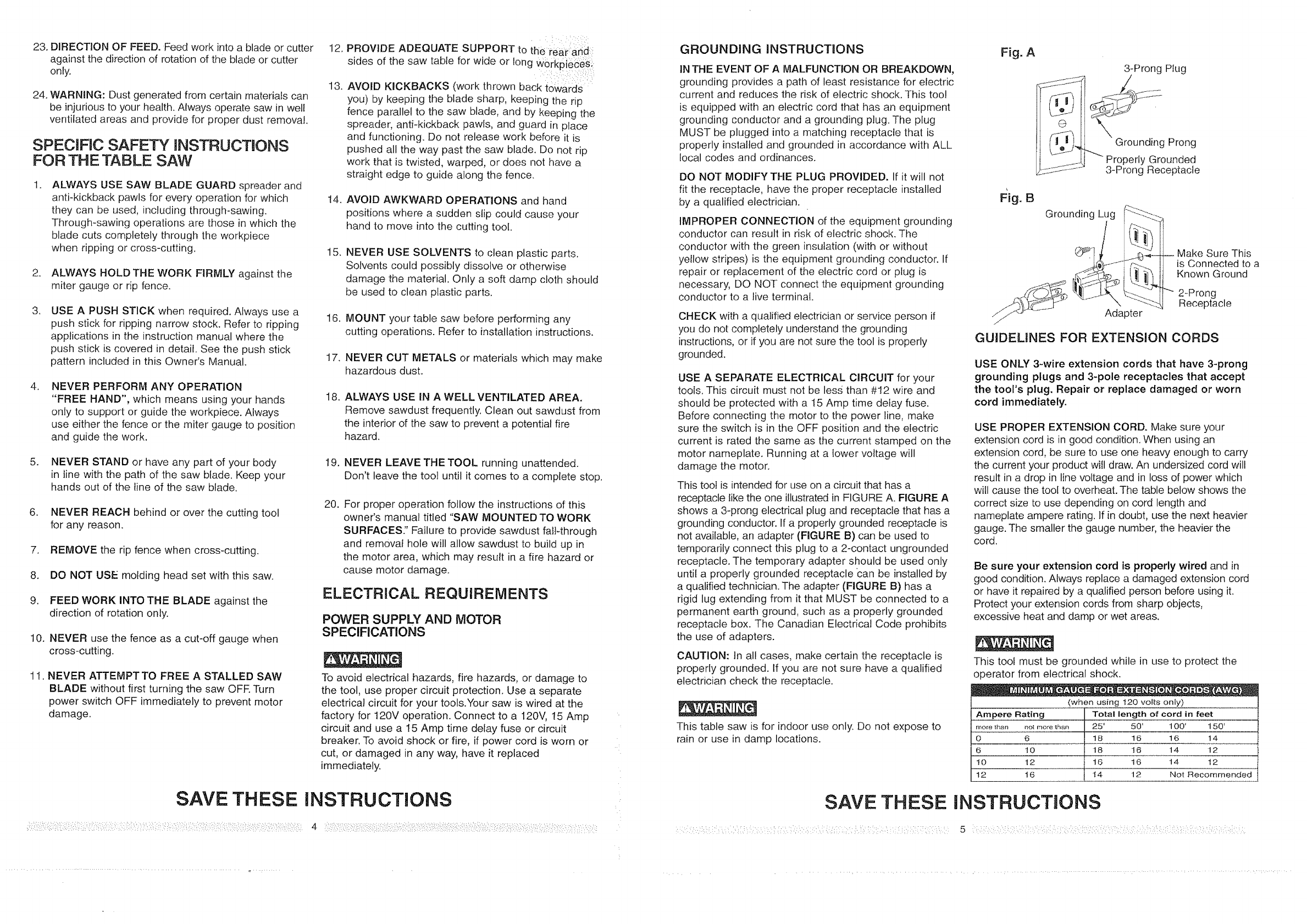
GROUNDING INSTRUCTIONS
IN THE EVENT OF A MALFUNCTmON OR BREAKDOWN,
grounding provides a path of least resistance for electric
current and reduces the risk of electric shock. This too!
is equipped with an electric cord that has an equipment
grounding conductor and a grounding plug. The plug
MUST be plugged into a matching receptacle that is
properly installed and grounded in accordance with ALL
local codes and ordinances.
DO NOT MODIFY THE PLUG PROVIDED. If it will not
fit the receptacle, have the proper receptacle installed
by a qualified electrician.
IMPROPER CONNECTION of the equipment grounding
conductor can result in risk ef electric shock. The
conductor with the green insulation (with or without
yellow stripes) is the equipment grounding conductor. If
repair or replacement of the electric cord or plug is
necessary, DO NOT connect the equipment grounding
conductor to a live terminal.
CHECK with a qualified electrician or service person if
you do not completely understand the grounding
instructions, or if you are not sure the tool is properly
grounded.
USE A SEPARATE ELECTRICAL CIRCUIT for your
tools. This circuit must not be less than #12 wire and
should be protected with a 15 Amp time delay fuse.
Before connecting the motor to the power line, make
sure the switch is in the OFF position and the electric
current is rated the same as the current stamped on the
motor nameplate. Running at a !ower voltage will
damage the motor.
This toot is intended for use on a circuit that has a
receptacle like the one illustrated in FIGURE A. FIGURE A
shows a 3-prong electrical plug and receptacle that has a
grounding conductor. If a properly grounded receptacle is
not available, an adapter (FIGURE B) can be used to
temporarily connect this plug to a 2-contact ungrounded
receptacle. The temporary adapter should be used only
until a properly grounded receptacle can be installed by
a qualified technician. The adapter (FIGURE B) has a
rigid lug extending from it that MUST be connected to a
permanent earth ground, such as a properly grounded
receptacle box. The Canadian Electrical Code prohibits
the use of adapters.
CAUTION: tn all cases, rnake certain the receptacle is
properly grounded, if you are not sure have a qualified
electrician check the receptacle.
This table saw is for indoor use only. Do not expose to
rain or use in damp locations.
SAVE THESE
Fig. A
® i
3-Prong PIug
---.... j Prong
Properly Grounded
3-Prong Receptacle
Fig. B
Greunding_qiLug _[_'_i_
_-- Adapter
_ Make Sure This
is Connected to a
Known Greund
"" 2-Prong
Receptacle
GUIDELINES FOR EXTENSION CORDS
USE ONLY 3-wire extension cords that have 3-prong
grounding plugs and 3-pole receptacles that accept
the tool's plug. Repair or replace damaged or worn
cord immediately.
USE PROPER EXTENSION CORD. Make sure your
extension cord is in good condition. When using an
extension cord, be sure te use one heaWenough to carry
the current your product will draw. An undersized cord will
result in a drop in line voltage and in loss of power which
will cause the tool to overheat. The table below shows the
correct size to use depending on cord length and
nameplate ampere rating. If in doubt, use the next heavier
gauge. The smaller the gauge number, the heavier the
cord.
Be sure your extension cord is properly wired and in
good condition. Always replace a damaged extension cord
or have it repaired by a qualified person before using it.
Protect your extension cords from sharp objects,
excessive heat and damp or wet areas.
This toot must be grounded while in use to protect the
operator from electrical shock.
(when using 120 volts only)
Ampere Rating Total length of cord in feet
more than not more than 25' 50' 100' 150'
0 6 18 16 16 14
6 10 18 t6 14 12
10 12 16 t6 14 12
12 16 t 4 12 Not Recommended
INSTRUCTIONS
5 : ::': : ::
RECOMMENDED ACCESSORIES
Visit your Sears Hardware Department or see the
Craftsman Power and Hand Tools Catalog to purchase
recommended accessories for this power tool.
To avoid the risk of personal injury:
- Do not use adjustable (wobble) type dadoes or
carbide tipped dado blades, maximum dado width
is I/2".
• Do not use a dado with a diameter larger than 6".
• Do not use molding head set with this saw.
o Do not modify this power tool or use accessories not
recommended by Sears.
TOOLS NEEDED
Medium screwdriver
#2 Phillips screwdriver
J I I I I _ L_L.J_LLL_
Straight edge
Adjustable wrench
Combination square
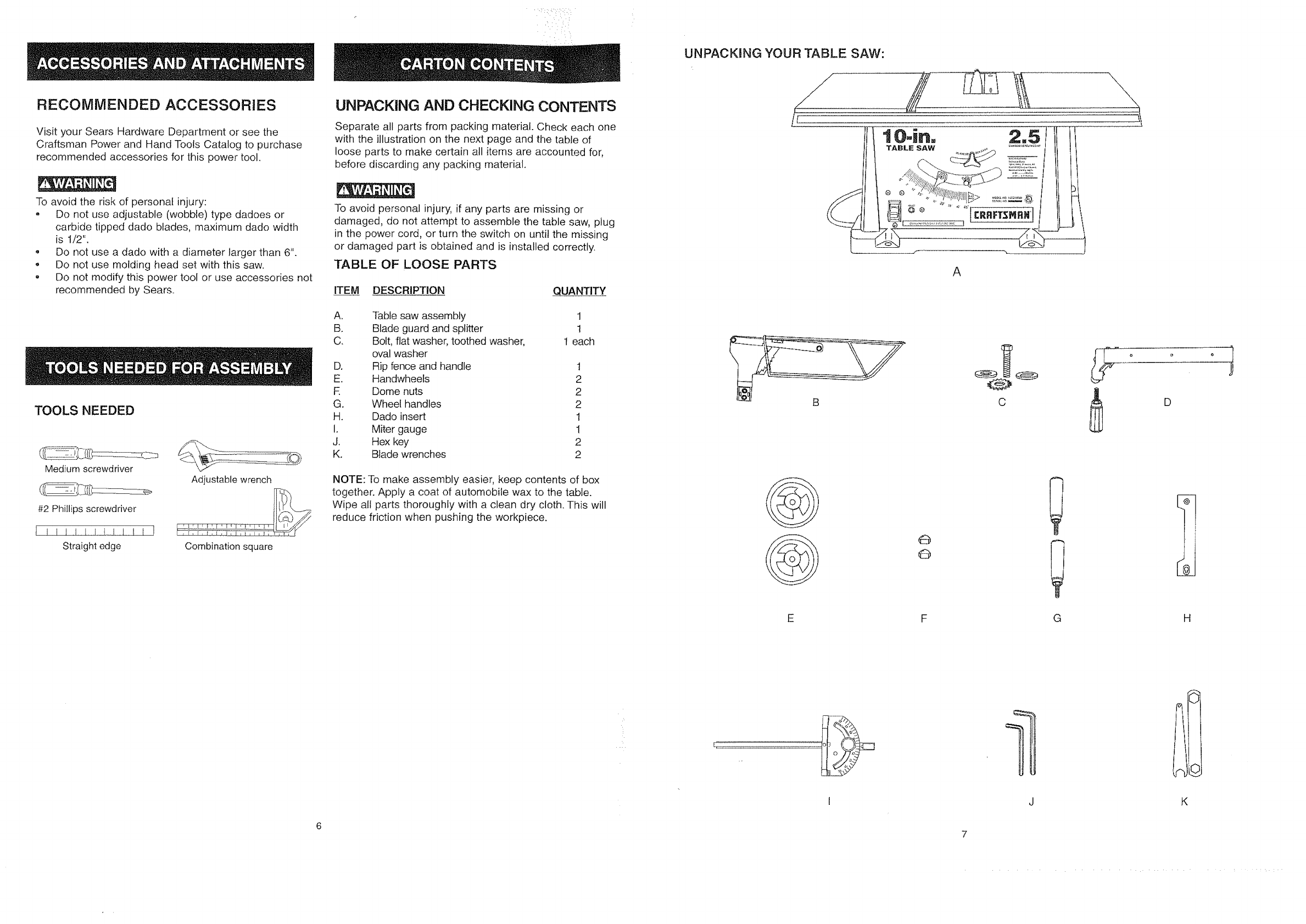
UNPACKING AND CHECKING CONTENTS
Separate all parts from packing material. Check each one
with the illustration on the next page and the table of
loose parts to make certain all items are accounted for,
before discarding any packing material.
To avoid personal injury, if any parts are missing or
damaged, do not attempt to assemble the table saw, plug
in the power cord, or turn the switch on until the missing
or damaged part is obtained and is installed correctly.
TABLE OF LOOSE PARTS
ITEM DESCRIPTION QUANTITY
A. Table saw assembly 1
B. Blade guard and splitter 1
C. Bolt, flat washer, toothed washer, t each
oval washer
D. Rip fence and handle t
E. Handwheels 2
R Dome nuts 2
G. Wheel handles 2
H. Dado insert 1
I. Miter gauge t
J. Hex key 2
K. Blade wrenches 2
NOTE: To make assembly easier, keep contents of box
together. Apply a coat of automobile wax to the table.
Wipe all parts thoroughly with a clean dry cloth. This will
reduce friction when pushing the workpiece.
UNPACKING YOUR TABLE SAW:
/
c D
@
@
E
@
@
G
1
H
K
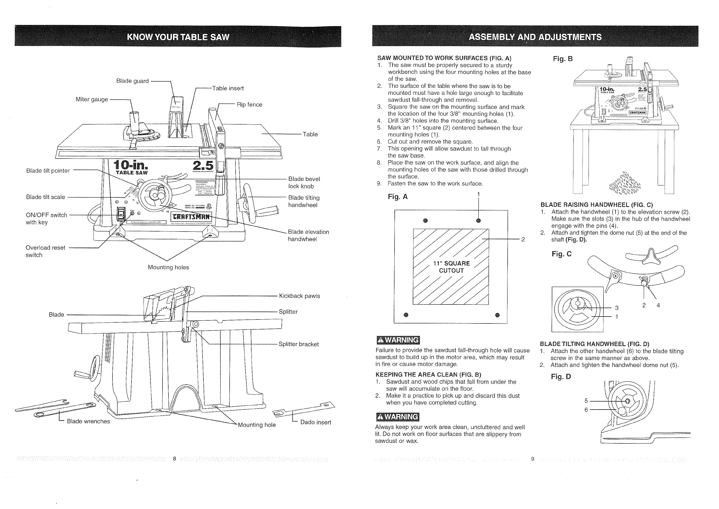
Miter gauge
Blade guard 31einsert
Rip fence
tO-i.o 2,5
Blade tilt pointer TABLE SAW ....................
Blade tilt scale
Overload reset
switch
Mounting holes
Table
Blade bevel
lock knob
Blade tilting
handwheel
•Blade elevation
handwheet
Blade
_nches
Kickback pawls
Splitter
Splitter bracket
_Mounting hole
: :::i: ::::::: : 8
SAW MOUNTED TO WORK SURFACES (FIG. A)
t. The saw must be properly secured to a sturdy
workbench using the four mounting holes at [he base
of the saw.
2. The surface of the table where the saw is to be
mounted must have a hole large enough to facilitate
sawdust fall-through and removal.
3. Square the saw on the mounting surface and mark
the location of the four 3/8" mounting holes (I).
4. Drill 3/8" holes into the mounting surface.
5. Mark an 11" square (2) centered between the four
mounting holes (1).
6. Cut out and remove the square•
7. This opening will allow sawdust to fall through
the saw base.
8. place the saw on the work surface, and align the
mounting holes of the saw with those drilled through
the surface.
9. Fasten the saw to the work surface.
Fig. A
@
1
1
@
Failure to provide the sawdust fall-through hole will cause
sawdust to build up in the motor area, which may result
in fire or cause motor damage.
KEEPING THE AREA CLEAN (FIG. B)
1. Sawdust and wood chips that fall from under the
saw will accumulate on the f!oor,
2. Make it a practice to pick up and discard this dust
when you have completed cutting,
Always keep your work area clean, uncluttered and well
lit, Do not work on floor surfaces that are slippery from
sawdust or wax.
Fig. B r_i:__ '
( i
BLADE RAISING HANDWHEEL (FIG. C)
1, Attach the handwheel (1) to the elevation screw (2),
Make sure the slots (3) in the hub of the handwheel
engage with the pins (4),
2. Attach and tighten the dome nut (5) at the end of the
shaft (Fig. D).
Fig. C
3 2 4
BLADE TILTING HANDWHEEL (FIG. D)
t. Attach the other handwheel (6) to the blade tilting
screw in the same manner as above.
2, Attach and tighten the handwheel dome nut (5),
Fig. O
• •• i i•• i ¸
4
RIP FENCE (FIG.E)
1. Thread the fence handle (t) into the cam hole (2)
until tight.
2, Lift upward on the rip fence handle so that the
holding clamp (3) is fully extended,
3. Place the rip fence on the saw table and engage
the holding clamp to the table rear. Lower the
front end onto the front rail (4).
4. Push down on the fence handle (t) to lock.
Fig. E
m
till[1
4 2
1
I I
CHANGING THE BLADE (FIG. F, G, H)
To avoid injury from an accidental start, make sure the
switch is in the OFF position and the plug is not
connected to the power source outlet.
.Remove the table insert (1) by unscrewing the two
screws (2, 3). Be careful not to lose the rubber
washer that is on the back screw (3) beneath the
table insert.
NOTE: The back screw is longer than the
front screw.
Fig, F
-- r--,-=
@..
IH
-t
i
:/:::i::::'::i¸_'i':::/:i¸!i::'(,i:::::::::/,_i:::?i¸:::?_:::::!:_::'::i:::i:,:¸:::::!::_::::,,i:_!:i::::i¸:::ii,:::!::::_i_,_/_i::: "i::_'_:i¸I¸:::::::?:!:::);!,
2. Raise the btade arbor (4) (FIG. G) to the maximum
height by turning the blade-raising handwheel
counterclockwise.
3. Remove the arbor nut (5) and flange (6), remove blade.
4. Install the new saw blade onto the arbor with the
blade teeth pointing toward the front of the saw.
5. Install the flange against the blade and thread the
arbor nut as far as possible by hand. Ensure that the
blade is flush against the inner side of the blade
flange.
Fig. G
5
6. To tighten the arbor nut (5) (FIG. H) use the open-end
wrench (7) and align the wrench jaws on the flats of
the blade arbor to keep the arbor from turning.
7. Place the box-end wrench (8) on the arbor nut,
and turn clockwise (to the rear of the saw table.)
8. Replace the blade insert in the table recess, insert
screws through the front and rear holes and tighten.
Fig, H
__ I8
5
To avoid injury from a thrown workpiece, blade
parts, or blade contact, never operate saw without
the proper insert in place. Use the saw blade
insert when sawing. Use the dado head insert
when using a dado.
10 : :::: :: ::::::: : ::::: : ::: : ::: :::::i
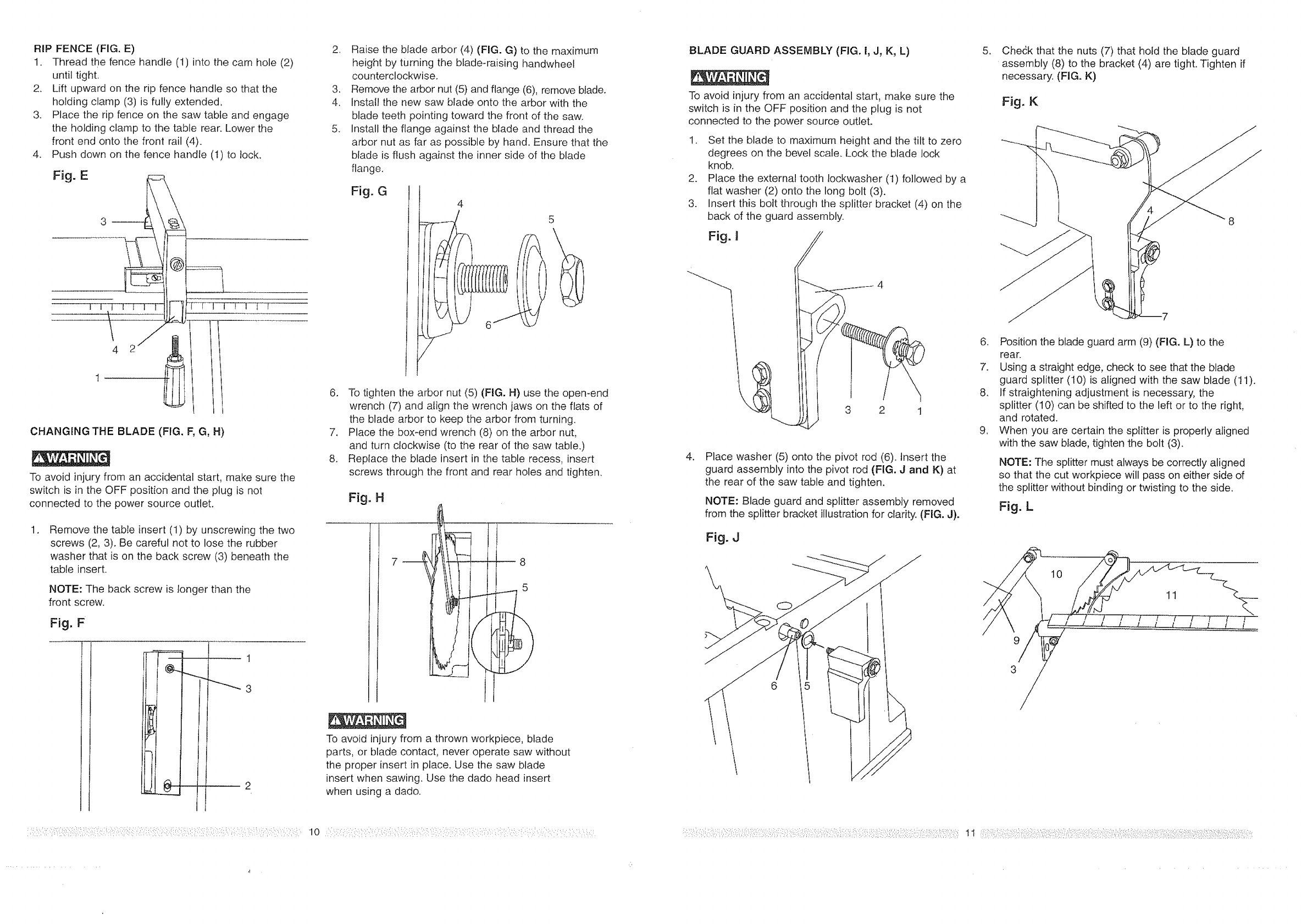
BLADE GUARD ASSEMBLY (FIG. I, J, K, L)
To avoid injury from an accidental start, make sure the
switch is in the OFF position and the plug is not
connected to the power source outlet.
1. Set the blade to maximum height and the tilt to zero
degrees on the bevel scale. Lock the blade lock
knob.
2. Place the external tooth lockwasher (t) followed by a
flat washer (2) onto the long bolt (3).
3. Insert this bolt through the splitter bracket (4) on the
back of the guard assembly.
Fig. I
\
4
3 2 1
,Place washer (5) onto the pivot rod (6). Insert the
guard assembly into the pivot rod {FIG. J and K) at
the rear of the saw table and tighten,
NOTE: Blade guard and splitter assembly removed
from the splitter bracket illustration for clarity. (FIG. J).
Fig.J
,Che6k that the nuts (7) that hold the blade guard
assembly (8) to the bracket (4) are tight. Tighten if
necessary. (FIG. K)
Fig, K
6. Position the blade guard arm (9) (FIG, L) to the
rear.
7. Using a straight edge, check to see that the blade
guard splitter (10) is aligned with the saw blade (t 1).
8, If straightening adjustment is necessary, the
splitter (10) can be shifted to the left or to the right,
and rotated.
9. When you are certain the splitter is properly aligned
with the saw blade, tighten the bolt (3).
NOTE: The splitter must always be correctly aligned
so that the cut workpiece will pass on either side of
the splitter without binding or twisting to the side.
Fig. L
10
11
9
6
i?;::i::!::{::,:!,i,¸:I::,::;!!:/:)I::_:I!:::::::!!::::i::,:_::':ii:_':!:_i:(::i!:::::::::?:i,>!:::i;::_:_:;:i:i/:?'::i;!_!::::i::_/:::::?,:::::!i::i:!:!:if!i,;:i?:{:::i:::i::i{_::::::_:i_;!;_::!i:,i:i::::_:;:::i:':?_::i::11 !::!:i¸i::_::::i,_i:::i,::i:)_::_?!::i_::i:::i!:::i:!:'::i/::?:_:!:!!:::_:/,:!i_:f:!::!::i¸!_:::!_:?/:,:;:::_;:i!i_:ii:!::!::ii::!::,!:;!_:;:_i:i;!i:,::iiiii!_:i:::!i:_':i:i:_:?i:i_ii:i!:i¸i:i!;:i::::i:_:i:¸:!.:i'i:i:::i::::!:!::!i!{iii:ii,::i!i_i:!_;;ili!ii:ii_:i:!:i,:::
4
ADJUSTMENT INSTRUCTIONS
MITER GAUGE ADJUSTMENT (FIG. M)
1. Make sure that the miter gauge will slide freely through
both table grooves.
2. Loosen the lock knob (1). Set the pointer (2) to the 90°
mark on the scale.
3. Make a 90° cut in a piece of scrap wood. Check cut
piece to see if it was cut at 90°. If it is not, continue to
adjust the miter gauge body (3) until the wood piece
is cut at 90°. Refer to OPERATION section for cutting
instructions.
Fig. M
II 90°
2
RIP FENCE ADJUSTMENT (FIG. N)
To avoid injury from an accidental start, make sure
the switch is in the OFF position and the plug is
not connected to the power source outlet.
t. The fence (1) is moved by lifting up on the handle (2)
and sliding the fence to the desired location. Pushing
down on the handle locks the fence in position.
2. Position the fence on the right side of the table, and
along one edge of the miter gauge grooves.
3. Lock the fence handle. The fence should be parallel
with the miter gauge groove.
4. If adjustment is needed to make the fence parallel to
the groove, do the following:
° Loosen the two screws (3) and lift up on the handle (2).
- Hold the fence bracket (4) firmly against the front
of the saw table. Move the far end of the fence
until it is parallel with the miter gauge groove.
* Tighten both screws and push the handle to lock.
5, If fence is loose when the handle is in the locked
(downward) position, do the following:
o Move the handle (2) upward and turn the adjusting
screw (5) clockwise until the rear clamp is snug.
Do not turn the adjusting screw more than 1/4
turn at a time.
- Over4ightening the adjusting screw will cause
the fence to come out of alignment.
Fig. N
L£i i
//
8 6 //
7 5
2_
\4
1 I
RIP FENCE INDICATOR ADJUSTMENT (FIG. N)
1. The rip fence indicator (6) points to the
measurement scale (8). The scale shows the
distance from the side of the fence to the nearest
side of the blade.
2. Measure the actual distance with a rule. If there is a
difference between the measurement and the
indicator, adjust the indicator (6).
3. Loosen the screw (7) and slide the indicator to the
correct measurement on the scale. Tighten screw
and remeasure with the rule.
To avoid injury from an accidental start, make sure the
switch is in the OFF position and the plug is not
connected to the power source outlet.
ADJUSTING THE 90° AND 45° POSITIVE STOPS
(FIG. O, P)
Your saw has )ositive stops that will quickIy position the
saw blade at 90° or 45° to the table, These stops were
set at the factory. Make adjustments only if necessary.
90° Stop
1. Disconnect the saw from the power source.
2. Turn the blade elevation handwheel and raise the
blade to the maximum elevation.
3. Loosen the blade bevel lock knob and move the
blade to the maximum vertical position. Tighten the
lock knob.
4. Place a combination square on the table and
against the blade (t) to determine if the blade
is 90° to the table. (FIG. O)
5. If the blade is not 90° to the table, loosen the two
set screws (4), located on the bottom of the table saw,
(FIG. P) with the hex key, and back off the collar (5).
6. Loosen the bevel lock knob. Turn the blade tilting
handwheel to move the blade until it is 90° to the
table.
7. Adjust the collar (5) so it contacts the bracket (3)
when the blade is 90° to the table. Tighten the
two set screws (4).
Fig. 0 90 ° 45 °
1 I
45° Stop
1. With the blade in the upright 90° position, loosen the
bevel lock knob. Turn the blade tilting handwheel and
move the blade to the 45° position as far as it will go.
2. Place the combination square on the table as shown
in (FIG. O) to check if the blade is 45° to the table,
3. If the blade is not 45 ° to the table, loosen the two set
screws (4) located under the table saw (FIG, P) with
a 3 mm hex key, and back off the collar (5).
4. Loosen the bevel lock knob; turn the tilting
handwheel to move the blade until it is 45° to the
table.
5. Adjust the collar (5) so it contacts the bracket (3)
when the blade is 45°, Tighten set screws (4).
BLADE TILT POINTER
1. When the blade is 3ositioned at 90°, adjust the
blade tilt pointer to read 0° on the scale.
2. Loosen the holding screw, position pointer over 0°
and tighten screw.
NOTE: Make a trial cut on scrap wood prior to making
critical cuts. Measure for exactness.
Fig. P
345
BLADE PARALLEL TO MITER GAUGE
GROOVE (FIG. Q, R)
This adjustment was made at the factory, but it should
be rechecked and adjusted if necessary.
To prevent personal injury:
-Always disconnect plug from the power source when
making any adjustments.
This adjustment must be correct or kickback could
result and accurate cuts cannot be made.
Initial adjustment (FIG. Q)
I. Remove the yellow switch key and unplug
the saw.
2. Move the blade guard out of the way.
3. Raise the blade to the highest position and set at
the 0° angle (90° straight up).
4. Select and mark, with a felt tip marker, a blade
tooth having a "right set".
5. Place the combination square base (1) into the
right side miter gauge groove (2). (FIG, Q)
6. Adjust the rule so it touches the front marked tooth
and lock the ruler so it holds its position in the
square assembly.
7. Rotate the blade bringing the marked tooth to the
rear and about 1/2 inch above the table,
8. Carefully slide the combination square to the rear
until the ruler touches the marked tooth.
9. If the ruler touches the marked tooth at the front and
rear positions, no adjustment is needed at this time.
If not, perform adjustment procedure described in
next section.
Fig, Q J
13
4
Additional blade adjustments (FIG. R)
1. If the front and rear measurements are not the
same, remove the combination square and loosen
the four adjusting screws (1) on the top of the table
about a half turn.
2. With a folded piece of cardboard covering the blade
to protect your hands, move the blade carefully to
the left or right as much as needed to align
the blade correctly.
3. Tighten the [our screws (t) and remeasure, as
described in steps 4 to 9 in the prior section.
4. If sufficient adjustment cannot be made by the four
adjusting screws (I), then also loosen the two
adjusting screws (2). Loosen these two screws only if
necessary.
5. Recheck blade clearance making sure that the
blade does not hit the table insert or other parts
when at the 90° and 45° settings.
6. Tighten all screws.
Fig. R
BASIC SAW OPERATIONS
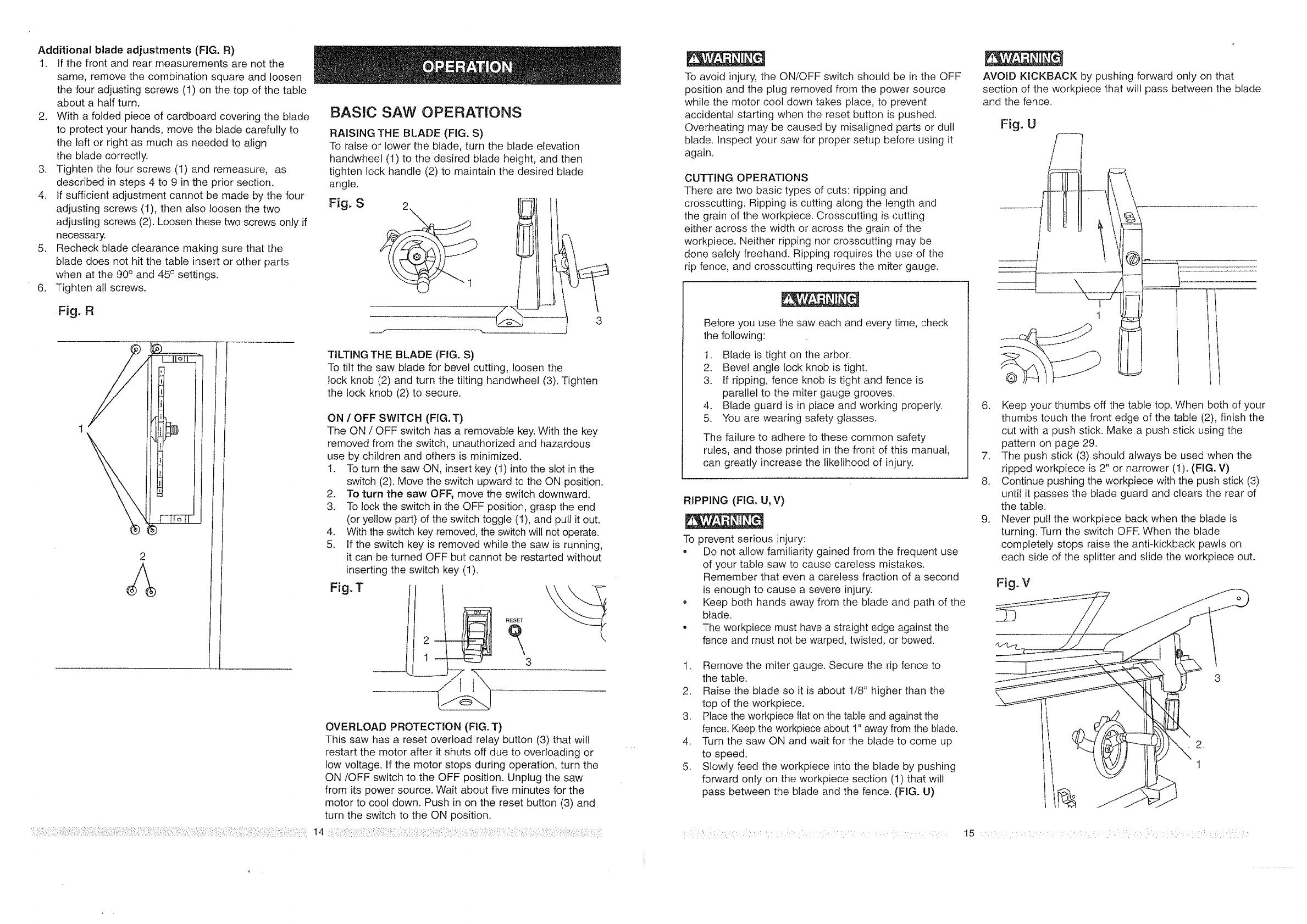
RAISING THE BLADE (FIG. S)
To raise or lower the blade, turn the blade elevation
handwheel (1) to the desired blade height, and then
tighten lock handle (2) to maintain the desired blade
angle.
Fig, S
\
J3
TILTING THE BLADE (FIG. S)
To tilt the saw blade for bevel cutting, loosen the
lock knob (2) and turn the tilting handwheel (3). Tighten
the lock knob (2) to secure.
ON /OFF SWITCH (FIG.T)
The ON /OFF switch has a removable key. With the key
removed from the switch, unauthorized and hazardous
use by children and others is minimized.
t. To turn the saw ON, insert key (1) into the slot in the
switch (2). Move the switch upward to the ON position.
2. To turn the saw OFF, move the switch downward.
3. To lock the switch in the OFF position, grasp the end
(or yellow part) of the switch toggle (t), and pul! it out.
4. With the switch key removed, the switch will not operate.
5. if the switch key is removed while the saw is running,
it can be turned OFF but cannot be restarted without
inserting the switch key (1).
Fig, !!"
RESET
3
OVERLOAD PROTECTION (FIG. T)
This saw has a reset overload relay button (3) that will
restart the motor after it shuts off due to overloading or
low voltage. If the motor stops during operation, turn the
ON/OFF switch to the OFF position. Unplug the saw
from its power source. Wait about five minutes for the
motor to cool down. Push in on the reset button (3) and
turn the switch to the ON position.
To avoid injury, the ON/OFF switch should be in the OFF
position and the plug removed from the power source
while the motor cool down takes place, to prevent
accidental starting when the reset button is pushed.
Overheating may be caused by misaligned parts or dull
blade. Inspect your saw for proper setup before using it
again.
CUTTING OPERATIONS
There are two basic types of cuts: ripping and
crosscutting, Ripping is cutting along the length and
the grain of the workpiece. Crosscutting is cutting
either across the width or across the grain of the
workpiece. Neither ripping nor crosscutting may be
done safely freehand. Ripping requires the use of the
rip fence, and crosscutting requires the miter gauge,
Before you use the saw each and every time, check
the following:
t. Blade is tight on the arbor.
2. Bevel angle lock knob is tight.
3. If ripping, fence knob is tight and fence is
parallel to the miter gauge grooves,
4. Blade guard is in place and working properly.
5. You are wearing safety glasses.
The failure to adhere to these common safety
rules, and those printed in the front of this manual,
can greatly increase the likelihood of injury.
RIPPING (FIG. U, V)
To prevent serious injury:
, Do not allow familiarity gained from the frequent use
of your table saw to cause careless mistakes.
Remember that even a careless fraction of a second
is enough to cause a severe injury.
, Keep both hands away from the blade and path of the
blade.
• The workpiece must have a straight edge against the
fence and must not be warped, twisted, or bowed.
1. Remove the miter gauge. Secure the rip fence to
the table.
2. Raise the blade so it is about 1/8" higher than the
top of the workpiece.
3. Place the workpiece flat on the table and against the
fence. Keep the workpiece about t" away from the blade.
4. Turn the saw ON and wait for the blade to come up
to speed.
5. Slowly feed the workpiece into the blade by pushing
forward only on the workpiece section (1) that will
pass between the blade and the fence. {FIG. U)
AVOID KICKBACK by pushing forward only on that
section of the workpiece that will pass between the blade
and the fence.
Fig. Uf
\/
I
I
-- -'------]
6. Keep your thumbs off the table top. When both of your
thumbs touch the front edge of the table (2), finish the
cut with a push stick. Make a push stick using the
pattern on page 29.
7. The push stick (3) should always be used when the
ripped workpiece is 2" or narrower (1). (FIG. V)
8. Continue pushing the workpiece with the push stick (3)
until it passes the blade guard and clears the rear of
the table.
9. Never puI! the workpiece back when the blade is
turning. Turn the switch OFF. When the blade
completely stops raise the anti-kickback pawls on
each side of the splitter and slide the workpiece out.
Fig. V
3
1
4
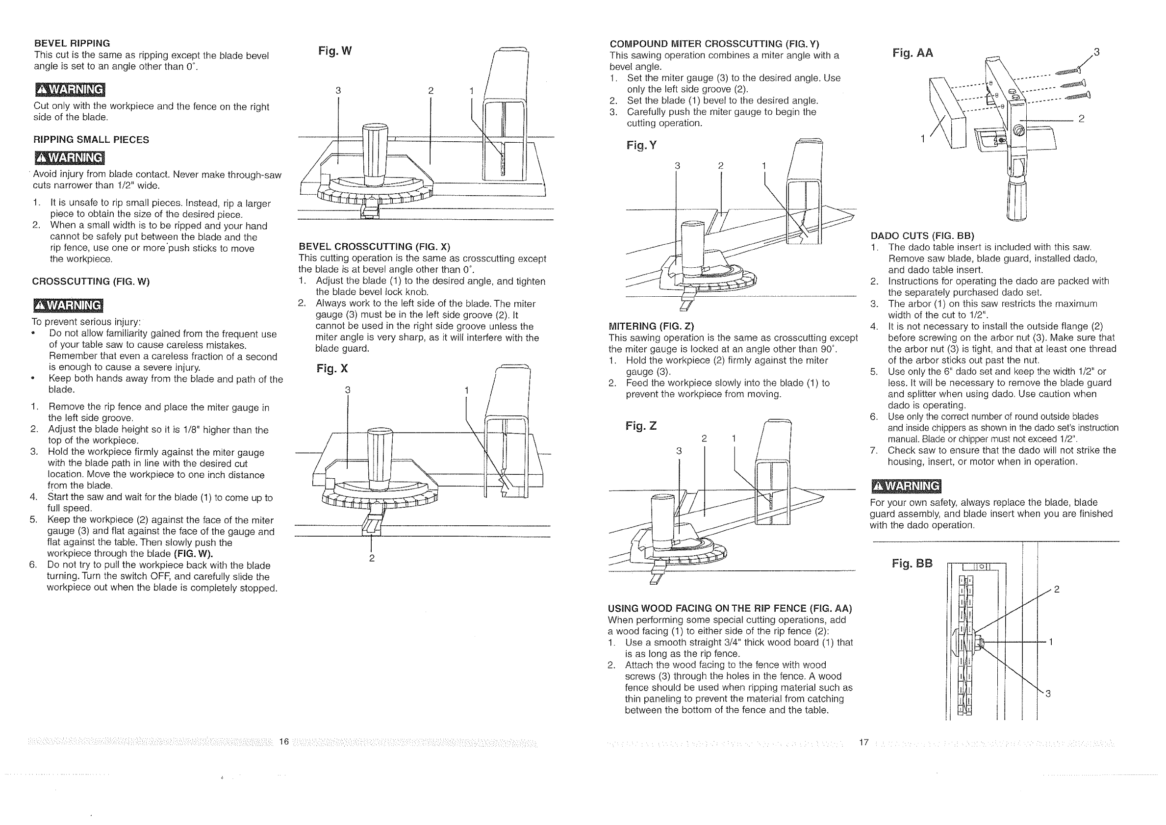
BEVEL RIPPING
This cut is the same as ripping except the blade bevel
angle is set to an angle other than 0°.
Cut only with the workpiece and the fence on the right
side of the blade.
RIPPING SMALL PIECES
Avoid injury from blade contact. Never make through_saw
cuts narrower than I/2" wide.
1.
2,
It is unsafe to rip small pieces. Instead, rip a larger
piece to obtain the size of the desired piece,
When a small width is to be ripped and your hand
cannot be safely put between the blade and the
rip fence, use one or more'push sticks to move
the workpiece.
CROSSCUTTING (FIG. W)
To prevent serious injury:
, Do not allow familiarity gained from the frequent use
of your table saw to cause careless mistakes.
Remember that even a careless fraction of a second
is enough to cause a severe injury.
• Keep both hands away from the blade and path of the
blade.
1. Remove the rip fence and place the miter gauge in
the left side groove.
2. Adjust the blade height so it is 1/8" higher than the
top of the workpiece.
3. Hold the workpiece firmly against the miter gauge
with the blade path in line with the desired cut
location. Move the workpiece to one inch distance
from the blade.
4, Start the saw and wait for the blade (1) to come up to
full speed.
5. Keep the workpiece (2) against the face of the miter
gauge (3) and flat against the face of the gauge and
flat against the table. Then slowly push the
workpiece through the blade (FIG. W).
6. Do not try to pull the workpiece back with the blade
turning. Turn the switch OFF, and carefully slide the
workpiece out when the blade is completely stopped.
Fig. W
3 2
BEVEL CROSSCUTTING (FroG.X)
This cutting operation is the same as crosscutting except
the blade is at bevel angle other than 0°.
1. Adjust the blade (1) to the desired angle, and tighten
the blade bevel lock knob.
2, Always work to the left side of the blade. The miter
gauge (3) must be in the left side groove {2). It
cannot be used in the right side groove unless the
miter angle is very sharp, as it wilt interfere with the
blade guard.
Fig. X
2
1
%\x
COMPOUND MITER CROSSCUTTING (FIG. Y)
This sawing operation combines a miter angle with a
bevel angle.
1. Set the miter gauge (3) to the desired angle. Use
only the left side groove (2).
2. Set the blade (1) bevel to the desired angle.
3. Carefully push the miler gauge to begin the
cutting operation.
Fig. Y
3 2 1
MITERING (FIG. Z)
This sawing operation is the same as crosscutting except
the miter gauge is locked at an angle other than 90°.
1. Hold the workpiece (2) firmly against the miter
gauge (3).
2. Feed the workpiece slowly into the blade (1) to
prevent the workpiece from moving.
Fig.Z
USING WOOD FACING ON THE RmPFENCE (FIG. AA)
When performing some special cutting operations, add
a wood facing (1) to either side of the rip fence (2):
1. Use a smooth straight 3/4" thick wood board (1) that
is as long as the rip fence.
2. Attach the wood facing to the fence with wood
screws (3) through the holes in the fence. A wood
fence should be used when ripping material such as
thin paneling to prevent the material from catching
between the bottom of the fence and the table.
':::I::L ¸ • •••••:• •:•• •
,,, S 3
DADO CUTS (FIG. BB)
1. The dado table insert is included with this saw.
Remove saw blade, blade guard, installed dado,
and dado table insert.
2. Instructions for operating the dado are packed with
the separately purchased dado set.
3. The arbor (1) on this saw restricts the maximum
width of the cut to 1/2".
4. It is not necessary to install the outside flange (2)
before screwing on the arbor nut (3). Make sure that
the arbor nut (3) is tight, and that at least one thread
of the arbor sticks out past the nut.
5. Use only the 6" dado set and keep the width 1/2" or
less. It wil! be necessary to remove the blade guard
and splitter when using dado. Use caution when
dado is operating.
6. Use only the correct number of round outside blades
and inside chippers as shown in the dado set's instruction
manual. Blade or chipper must not exceed 1/2".
7. Check saw to ensure that the dado will not strike the
housing, insert, or motor when in operation.
For your own safety, always replace the blade, blade
guard assembly, and blade insert when you are finished
with the dado operation.
Fig. BB
[q
'H
Pi
zFd I
ij
,.4
J
J
\
j2
1
"3
17 • /L¸ • •L• • : ::! • • i ¸ "• : :• : •:•: .:i:::• :-L::L•
MAINTAINING YOUR TABLE SAW
GENERAL MAINTENANCE
For your own safety, turn the switch OFF and remove the
switch key. Remove the plug from the power source
outlet before maintaining or lubricating your saw.
1. Clean out all sawdust that has accumulated inside
the saw cabinet and the motor.
2. Polish the saw table with an automotive wax to keep
it clean and to make it easier to slide the workpiece.
3. Clean cutting blades with pitch and gum remover.
4. A worn, cut, or damaged power cord should be
replaced immediately.
All electrical or mechanical repairs should be attempted
only by a trained repair technician. Contact the nearest
Sears Service Center for service. Use only identical
replacement parts. Any other parts may create a hazard.
5. Use liquid dish washing detergent and water to
clean all plastic parts.
NOTE: Certain cleaning chemicals can damage
plastic parts.
,Avoid use of the following cleaning chemicals or
solvents: gasoline, carbon tetrachtoride, chlorinated
solvents, ammonia and household detergents
containing ammonia.
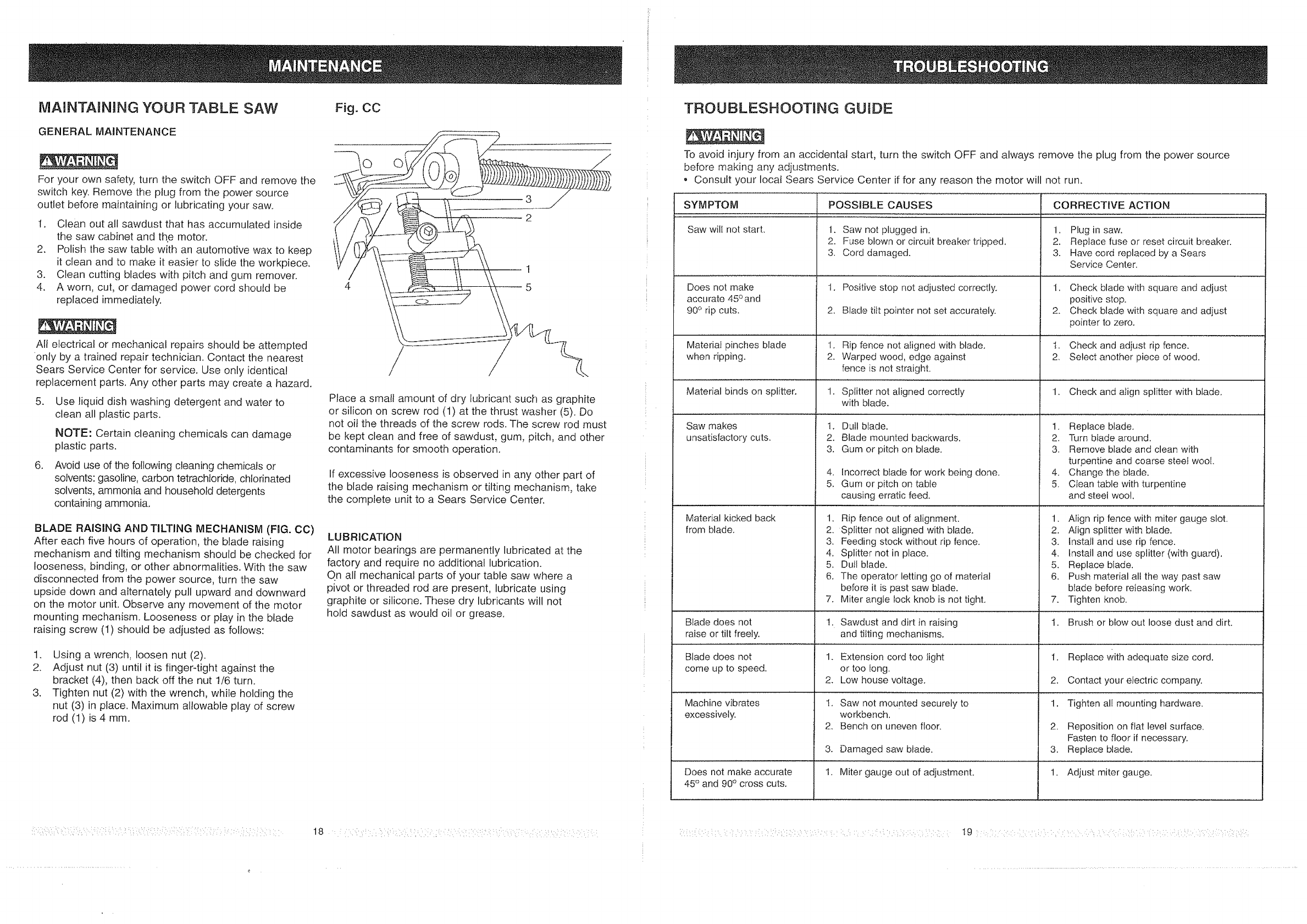
BLADE RAISING AND TILTING MECHANISM (FIG. CC)
After each five hours of operation, the blade raising
mechanism and tilting mechanism should be checked for
looseness, binding, or other abnormalities. With the saw
disconnected from the power source, turn the saw
upside down and alternately pull upward and downward
on the motor unit. Observe any movement of the motor
mounting mechanism. Looseness or play in the blade
raising screw (1) should be adiusted as follows:
1. Using a wrench, loosen nut (2).
2. Adjust nut (3) until it is finger4ight against the
bracket (4), then back off the nut 1/6 turn.
3. Tighten nut (2) with the wrench, while holding the
nut (3) in place. Maximum allowable play of screw
rod (1) is 4 ram.
Fig. CC
4
Place a small amount of dry lubricant such as graphite
or silicon on screw rod (1) at the thrust washer (5). Do
not oil the threads of the screw rods. The screw rod must
be kept clean and free of sawdust, gum, pitch, and other
contaminants for smooth operation.
If excessive looseness is observed in any other part of
the blade raising mechanism or tilting mechanism, take
the complete unit to a Sears Service Center.
LUBRICATION
All motor bearings are permanently lubricated at the
factory and require no additional lubrication.
On all mechanical parts of your table saw where a
pivot or threaded rod are present, lubricate using
graphite or silicone. These dry lubricants will not
hold sawdust as would oil or grease.
TROUBLESHOOTMNG GUIDE
To avoid injury from an accidental start, turn the switch OFF and always remove the plug from the power source
before making any adjustments.
• Consult your local Sears Service Center if for any reason the motor will not run.
SYM PTOM
Saw will not start.
Does not make
accurate 45 ° and
90° rip cuts.
Material pinches blade 1.
when ripping. 2.
Material binds on splitter.
Saw makes 1.
unsatisfactory cuts. 2.
3,
4.
5,
Material kicked back 1.
from blade. 2.
3.
4.
5.
6.
7.
Blade does not !.
raise or tilt freely.
Blade does not 1.
come up to speed. 2.
Machine vibrates 1.
excessively. 2.
3.
1,Does not make accurate
45° and 90° cross cuts,
POSSIBLE CAUSES
1. Saw not plugged in.
2. Fuse blown or circuit breaker tripped.
3. Cord damaged.
1. Positive stop not adjusted correctly.
2. Blade tilt pointer not set accurately.
Rip fence not aligned with blade.
Warped wood, edge against
fence is not straight.
1. Splitter not aligned correctly
with blade.
Dull blade.
Blade mounted backwards.
Gum or pitch on blade.
Incorrect blade for work being done.
Gum or pitch on table
causing erratic feed.
Rip fence out of alignment.
Splitter not aligned with blade,
Feeding stock without rip fence.
Splitter not in place.
Dull blade.
The operator letting go of material
before it is past saw blade.
Miter angle lock knob is not tight,
CORRECTIVE ACTION
1. Plug in saw.
2. Replace fuse or reset circuit breaker.
3. Havecord replaced by a Sears
Service Center.
1. Check blade with square and adjust
positive stop.
2. Check blade with square and adjust
pointer to zero.
1. Check and adjust rip fence.
2. Select another piece of wood.
1. Check and align splitter with blade,
1. Replace blade.
2. Turn btade around.
3. Remove blade and clean with
turpentine and coarse steel wool.
4. Change the blade.
5. Cfean table with turpentine
and steel wool.
1. Atign rip fence with miter gauge slot.
2. Align splitter with blade.
3. Install and use rip fence.
4. Install and use splitter (with guard).
5. Replace blade.
6. Push material all the way past saw
blade before releasing work.
7. Tighten knob.
Sawdust and dirt in raising 1. Brush or blow out loose dust and dirt.
and tilting mechanisms.
Extension cord too iight 1. Replace Withadequate size cord.
or too long.
Low house voltage. 2. Contact your electric company.
Saw not mounted securely to
workbench.
Bench on uneven floor,
Damaged saw blade.
Miter gauge out of adjustment.
1.
2.
3.
I 1-
Tighten all mounting hardware.
Reposition on fiat level surface.
Fasten to floor if necessary.
Replace blade.
Adjust miter gauge.
