Craftsman 137228010 User Manual TABLE SAW Manuals And Guides L0803292
CRAFTSMAN Saw Table Manual L0803292 CRAFTSMAN Saw Table Owner's Manual, CRAFTSMAN Saw Table installation guides
User Manual: Craftsman 137228010 137228010 CRAFTSMAN TABLE SAW - Manuals and Guides View the owners manual for your CRAFTSMAN TABLE SAW #137228010. Home:Tool Parts:Craftsman Parts:Craftsman TABLE SAW Manual
Open the PDF directly: View PDF ![]() .
.
Page Count: 17
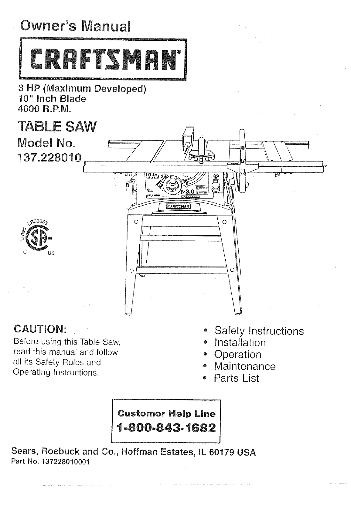
Owner's anual
3 HP (Maximum Developed)
10" inch B_ade
4000 R.P.M.
"TABLE SAW
Model No.
137.228010
C US
CAUTION:
Before using this Table Saw,
read this manual and follow
all its Safety Rules and
Operating Instructions.
• Safety Instructions
• Installation
,, Operation
o Maintenance
o Parts List
Customer Help Line
1-800=843=t682
Sears, Roebuck and Co., Hoffman Estates, IL 60179 USA
Part No. 137228010001
SECTION PAGE
Warranty ................................................................ 2
Product Specifications ..................................................... 2
Safety Instructions ........................................................ 3
Accessories and Attachments ............................................... 6
Tools needed for assembly ................................................. 6
Carton Contents .......................................................... 6
Know Your Table Saw ...................................................... 8
Assembly and Adjustments ................................................. 9
Operation .............................................................. 16
Maintenance ............................................................ 20
Troubleshooting guide .................................................... 21
Parts .................................................................. 22
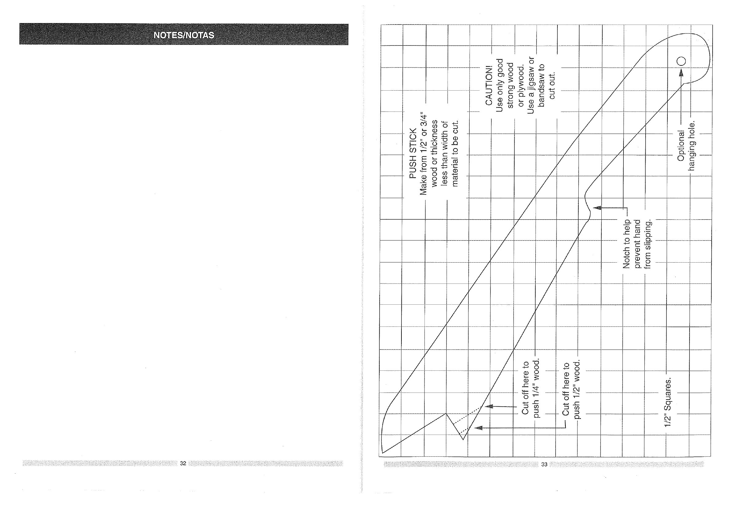
Making apush stick ....................................................... 33
FULL ONE YEAR WARRANTY
If this product fails due to a defect in material or workmanship within one year from the date of purchase, Sears
will repair it free of cha_rge.
Contact a Sears Service Center for repair.
If this product is used for commercial or rental purposes, this warranty applies only for 90 days from the date of
purchase.
This warranty gives you specific legal rights, and you may also have other rights which vary from state to state.
Sears, Roebuck and Co., Dept. 817 WA, Hoffman Estates, IL 60179
MOTOR
Maximum developed HP ........ 3.0
Type ....................... Universal
Volts ....................... 120
Amperes .................... 15
Hertz ....................... 60
RPM (no load) ................ 4000
Overload protection ............ Yes
To avoid electrica! hazards, fire hazards, or damage to
the tool, use proper circuit protection.
Your table saw is wired at the factory for 120V operation.
Connect to a 120V, 15 AMP branch circuit and use a 15
AMP time delay fuse or circuit breaker. To avoid shock or
• fire, replace power cord immediately if it is worn, cut or
damaged in any way.
SAW
Table ....................... 25-3/16" x 21-1/4"
Extension rails ................ 2 (Right & Left)
Extension rip capacity .......... 24-1/2" (Right)
Blade ....................... 10"
Rip scale ................... Yes
Rip fence .................... Yes
Miter gauge .................. Yes
Leg set ..................... Yes
Maximum cutting depth at 90° .... 3"
Maximum cutting depth at 45° .... 2"
Maximum width of dado ........ 13/16"
Weight ...................... 75 Lb.
GENERAL SAFETY INSTRUCTIONS
BEFORE USING THE TABLE SAW
Safety is a combination of common sense, staying alert
and knowing how to use your table saw.
To avoid mistakes that could cause serious injury, do not
plug the table saw in until you have read and understood
the following:
.
.
3.
,
READ and become familiar with this entire instruction
manual. LEARN the tool's applications, limitations, and
possible hazards.
KEEP GUARDS IN PLACE and in working order.
REMOVE ADJUSTING KEYS AND WRENCHES.
Form the habit of checking to see that keys and
adjusting wrenches are removed from the tool before
turning ON.
KEEP WORK AREA CLEAN. Cluttered areas and
benches invite accidents.
.
,
7.
8.
9.
10.
DON'T USE IN A DANGEROUS ENVIRONMENT.
Don't use power tools in damp or wet locations, or
expose them to rain. Keep work area well lighted.
KEEP CHILDREN AWAY. All visitors should be kept at
a safe distance from the work area.
MAKE WORKSHOP KID PROOF with padlocks, master
switches, or by removing starter keys.
DON'T FORCE THE TOOL, It will do the job better
and safer at the rate for which it was designed.
USE THE RIGHT TOOL. Don't force tool or the
attachment to do a job for which it was not designed.
USE PROPER EXTENSION CORD. Make sure your
extension cord is in good condition. When using an
extension cord, be sure to use one heavy enough to
carry the current your product will draw. An undersized
cord will cause a drop in line voltage resulting in loss
of power and overheating. The table on page 5 shows
the correct size to use depending on cord length and
nameplate ampere rating. If in doubt, use the next
heavier gauge. The smaller the gauge number, the
heavier the cord.
11. WEAR PROPER APPAREL. DO NOT wear loose
clothing, gloves , neckties, rings, bracelets, or other
jewelry which may get caught in moving parts.
Nonslip footwear is recommended. Wear protective
hair covering to contain long hair.
SAVE THESE
12.
13.
14.
15.
WEARYOUR ALWAYS WEAR EYE
PROTECTION. Any table
saw can throw foreign
objects into the eyes which
could cause permanent eye
damage. ALWAYS wear
Safety Goggles (not glasses)
that comply with ANSI safety standard Z87.1.
Everyday eyeglasses have only impact-resistant
lenses. They ARE NOT safety glasses. Safety
Goggles are available at Sears. NOTE: Glasses or
goggles not in compliance with ANSI Z87.1 could
seriously hurt you when they break.
WEAR A FACE MASK OR DUST MASK.
Sawing operation produces dust.
SECURE WORK. Use clamps or a vise to hold work
when practical. It's safer than using your hand and it
frees both hands to operate tool.
DISCONNECT TOOLS before servicing, and when
changing accessories, such as blades, bits, cutters,
and the like.
16. REDUCE THE RISK OF UNINTENTIONAL STARTING.
Make sure the switch is in OFF position before
plugging in.
17. USE RECOMMENDED ACCESSORIES. Consult the
owner's manual for the recommended accessories.
The use of improper accessories may cause risk of
injury to persons.
18. NEVER STAND ON TOOL. Serious injury could occur
if the tool is tipped or if the cutting tool is unintentionally
contacted.
19. CHECK FOR DAMAGED PARTS. Before further use of
the tool, a guard or other part that is damaged should
be carefully checked to determine that it will operate
properly and perform its intended function. Check for
alignment of moving parts, binding of moving parts,
breakage of parts, mounting, and any other conditions
that may affect its operation. A guard or other part that
is damaged should be properly repaired or replaced.
20. NEVER LEAVE TOOL RUNNING UNATTENDED.
TURN THE POWER OFF. Don't leave the tool until
it comes to a complete stop.
21. DON'T OVERREACH. Keep proper footing and
balance at all times.
22. MAINTAIN TOOLS WITH CARE. Keep tools sharp
and clean for best and safest performance. Follow
instructions for lubricating and changing accessories.
23. DIRECTION OF FEED. Feed work into a blade or
cutter against the direction of rotation of the blade or
cutter only.
INSTRUCTIONS
24. WARNING: Dust generated from certain materials can 14. AVOID AWKWARD OPERATIONS and hand
be injurious to your health. Always operate saw in well positions where a sudden slip could cause your hand
ventilated areas and provide for proper dust removal, to move into the cutting tool.
SPECiFiC SAFETY iNSTRUCTiONS
FOR THE TABLE SAW
.
,
3.
,
5,
15.
ALWAYS USE SAW BLADE GUARD spreader and
anti-kickback pawls for every operation for which 16.
they can be used, including through-sawing.
Through-sawing operations are those in which the 17.
blade cuts completely through the workpiece
when ripping or cross-cutting. 18.
ALWAYS HOLD THE WORK FIRMLY against the
miter gauge or rip fence.
USE A PUSH STICK when required. Always use a
push stick for ripping narrow stock. Refer to ripping
applications in the instruction manual where the 19.
push stick is covered in detail. See the push stick
pattern included in this Owner's Manual. 20.
NEVER PERFORM ANY OPERATION
"FREE HAND", which means using your hands
only to support or guide the workpiece. Always
use either the fence or the miter gauge to position
and guide the work.
NEVER STAND or have any part of your body
in line with the path of the saw blade. Keep your
hands out of the line of the saw blade.
6. NEVER REACH behind or over the cutting tool
for any reason.
7. REMOVE the rip fence when cross-cutting.
21.
22.
NEVER USE SOLVENTS to clean plastic parts.
Solvents could possibly dissolve or otherwise
damage the material. Only a soft damp cloth should
be used to clean plastic parts.
MOUNT your table saw before performing any
cutting operations. Refer to installation instructions.
NEVER CUT METALS or materials which may make
hazardous dust.
ALWAYS USE IN A WELL VENTILATED AREA.
Remove sawdust frequently. Clean out sawdust
from the interior of the saw to prevent a potential
fire hazard. Attach a vacuum to the dust chute for
additional sawdust removal.
NEVER LEAVE THE TOOL running unattended.
Don't leave the tool until it comes to a complete stop.
For proper operation follow the instructions of this
owner's manual titled "SAW MOUNTED TO WORK
SURFACES." Failure to provide sawdust fall-through
and removal hole will allow sawdust to build up in the
motor area, which may result in a fire hazard or
cause motor damage.
ALWAYS USE THE TABLE EXTENSION for extra
support when cutting a long workpiece.Never use
another person or any unstable surface to hold long
workpiece.
ALWAYS LOCK THE TABLE EXTENSION securely
in place before cutting workpiece.
8. DO NOT USE molding head set with this saw.
9. FEED WORK INTO THE BLADE against the
direction of rotation only.
10. NEVER use the fence as a cut-off gauge when
cross-cutting.
ELECTRICAL REQUIREMENTS
POWER SUPPLY AND MOTOR
SPECIFICATIONS
11. NEVER ATTEMPTTO FREE A STALLED SAW
BLADE without first turning the saw OFR Turn
power switch OFF immediately to prevent motor
damage.
12. PROVIDE ADEQUATE SUPPORT to the rear and
sides of the saw table for wide or long workpieces.
13. AVOID KICKBACKS (work thrown back towards
you) by keeping the blade sharp, keeping the rip
fence parallel to the saw blade, and by keeping the
spreader, anti-kickback pawls, and guard in place
and functioning. Do not release work before it is
pushed all the way past the saw blade. Do not rip
work that is twisted, warped, or does not have a
straight edge to guide along the fence.
SAVE THESE INSTRUCTmONS
To avoid electrical hazards, fire hazards, or damage to
the tool, use proper circuit protection. Use a separate
electrical circuit for your toots.Your saw is wired at the
factory for 120V operation. Connect to a 120V, 15 Amp
circuit and use a 15 Amp time delay fuse or circuit
breaker. To avoid shock or fire, if power cord is worn or
cut, or damaged in any way, have it replaced
immediately.
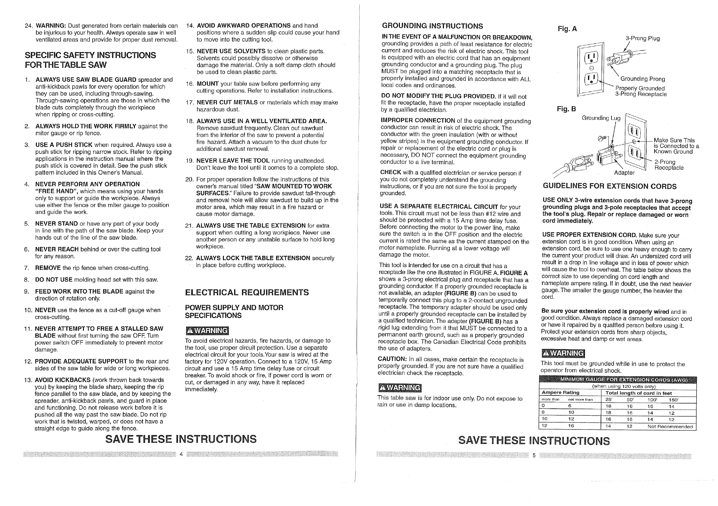
GROUNDING INSTRUCTIONS
INTHE EVENT OF A MALFUNCTION OR BREAKDOWN,
grounding provides a path of least resistance for electric
current and reduces the risk of electric shock. This tool
is equipped with an electric cord that has an equipment
grounding conductor and a grounding plug. The plug
MUST be plugged into a matching receptacle that is
properly installed and grounded in accordance with ALL
local codes and ordinances.
DO NOT MODIFYTHE PLUG PROVIDED. If it will not
fit the receptacle, have the proper receptacle installed
by a qualified electrician.
IMPROPER CONNECTION of the equipment grounding
conductor can result in risk of electric shock. The
conductor with the green insulation (with or without
yellow stripes) is the equipment grounding conductor. If
repair or replacement of the electric cord or plug is
necessary, DO NOT connect the equipment grounding
conductor to a live terminal.
CHECK with a qualified electrician or service person if
you do not completely understand the grounding
instructions, or if you are not sure the tool is properly
grounded.
USE ASEPARATE ELECTRICAL CIRCUIT for your
tools. This circuit must not be less than #12 wire and
should be protected with a 15 Amp time delay fuse.
Before connecting the motor to the power line, make
sure the switch is in the OFF position and the electric
current is rated the same as the current stamped on the
motor nameplate. Running at a lower voltage will
damage the motor.
This tool is intended for use on a circuit that has a
receptacle like the one illustrated in FIGURE A. FIGURE A
shows a 3-prong electrical plug and receptacle that has a
grounding conductor. If a properly grounded receptacle is
not available, an adapter (FIGURE B) can be used to
temporarily connect this plug to a 2-contact ungrounded
receptacle. The temporary adapter should be used only
until a properly grounded receptacle can be installed by
a qualified technician. The adapter (FIGURE B) has a
rigid lug extending from it that MUST be connected to a
permanent earth ground, such as a properly grounded
receptacle box. The Canadian Electrical Code prohibits
the use of adapters.
CAUTION: In all cases, make certain the receptacle is
properly grounded. If you are not sure have a qualified
electrician check the receptacle.
This table saw is for indoor use only. Do not expose to
rain or use in damp locations.
Fig. A
3-Prong Plug
Q
[fo! )._ Grounding Prong
'_/- "'" Properly Grounded
J_-JJ-/ 3-Prong Receptacle
Fig. B
Grounding Lug
GUIDELINES FOR EXTENSION CORDS
Make Sure This
is Connected to a
Known Ground
2-Prong
Receptacle
USE ONLY 3-wire extension cords that have 3-prong
grounding plugs and 3-pole receptacles that accept
the tool's plug. Repair or replace damaged or worn
cord immediately.
USE PROPER EXTENSION CORD. Make sure your
extension cord is in good condition. When using an
extension cord, be sure to use one heavy enough to carry
the current your product will draw. An undersized cord will
result in a drop in line voltage and in loss of power which
will cause the tool to overheat. The table below shows the
correct size to use depending on cord length and
nameplate ampere rating. If in doubt, use the next heavier
gauge. The smaller the gauge number, the heavier the
cord.
Be sure your extension cord is properly wired and in
good condition. Always replace a damaged extension cord
or have it repaired by a qualified person before using it.
Protect your extension cords from sharp objects,
excessive heat and damp or wet areas.
This tool must be grounded while in use to protect the
operator from electrical shock.
(when using 120 volts only)
Ampere Rating
more than not more than
0 6
6 10
10 12
12 16
Totallength ofcord in feet
25' 50' 100' 150'
18 16 16 !4
18 16 14 12
16 16 14 12
14 12 Not Recommended
SAVE THESE NSTRUCT ONS
RECOMMENDED ACCESSORMES
Visit your Sears Hardware Department or see the
Craftsman Power and Hand Tools Catalog to purchase
recommended accessories for this power tool.
To avoid the risk of personal injury:
o Do not use adjustable (wobble) type dadoes or
carbide tipped dado blades, maximum dado width
is 13/16".
Do not use a dado with a diameter larger than 6".
o Do not use molding head set with this saw.
Do not modify this power tool or use accessories not
recommended by Sears.
TOOLS NEEDED
#2 Phillips screwdriver
f-Illlll
Straight edge
Adjustable wrench
Combination square
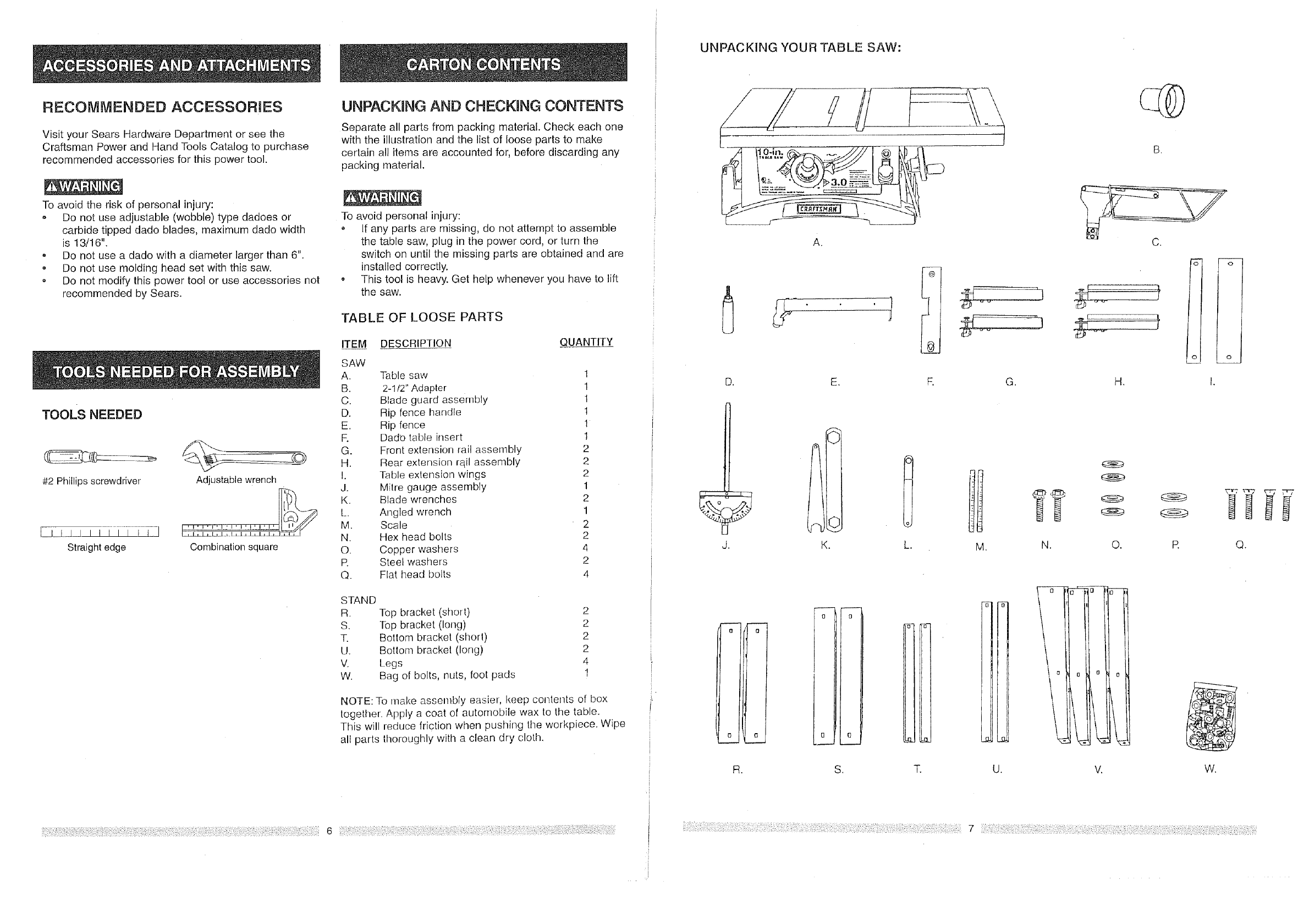
UNPACKING AND CHECKMNG CONTENTS
Separate all parts from packing material. Check each one
with the illustration and the list of loose parts to make
certain all items are accounted for, before discarding any
packing material.
To avoid personal injury:
If any parts are missing, do not attempt to assemble
the table saw, plug in the power cord, or turn the
switch on until the missing parts are obtained and are
installed correctly.
This tool is heavy. Get help whenever you have to lift
the saw.
TABLE OF LOOSE PARTS
ITEM DESCRIPTION QUANTITY
SAW
A. Table saw 1
B. 2-1/2" Adapter 1
C. Blade guard assembly 1
D. Rip fence handle I
E. Rip fence 1
R Dado table insert 1
G. Front extension rail assembly 2
H. Rear extension rqil assembly 2
I. Table extension wings 2
J. Milre gauge assembly 1
K. Blade wrenches 2
L. Angled wrench 1
M. Scale 2
N. Hex head bolts 2
O. Copper washers 4
R Steel washers 2
Q. Flat head bolts 4
STAND
R. Top bracket (short)
S. Top bracket (long)
T. Bottom bracket (short)
U. Bottom bracket (long)
V. Legs
W. Bag of bolts, nuts, foot pads
2
2
2
2
4
1
NOTE: To make assembly easier, keep contents of box
together. Apply a coat of automobile wax to the table.
This will reduce friction when pushing the workpiece. Wipe
all parts thoroughly with a clean dry cloth.
I
UNPACKING YOUR TABLE SAW:
A.
t1
D. E.
J. K.
e_
S.
"S" -S-
m.
O
O, R Q.
0
t3 L
(3
R. S. T. U. V.
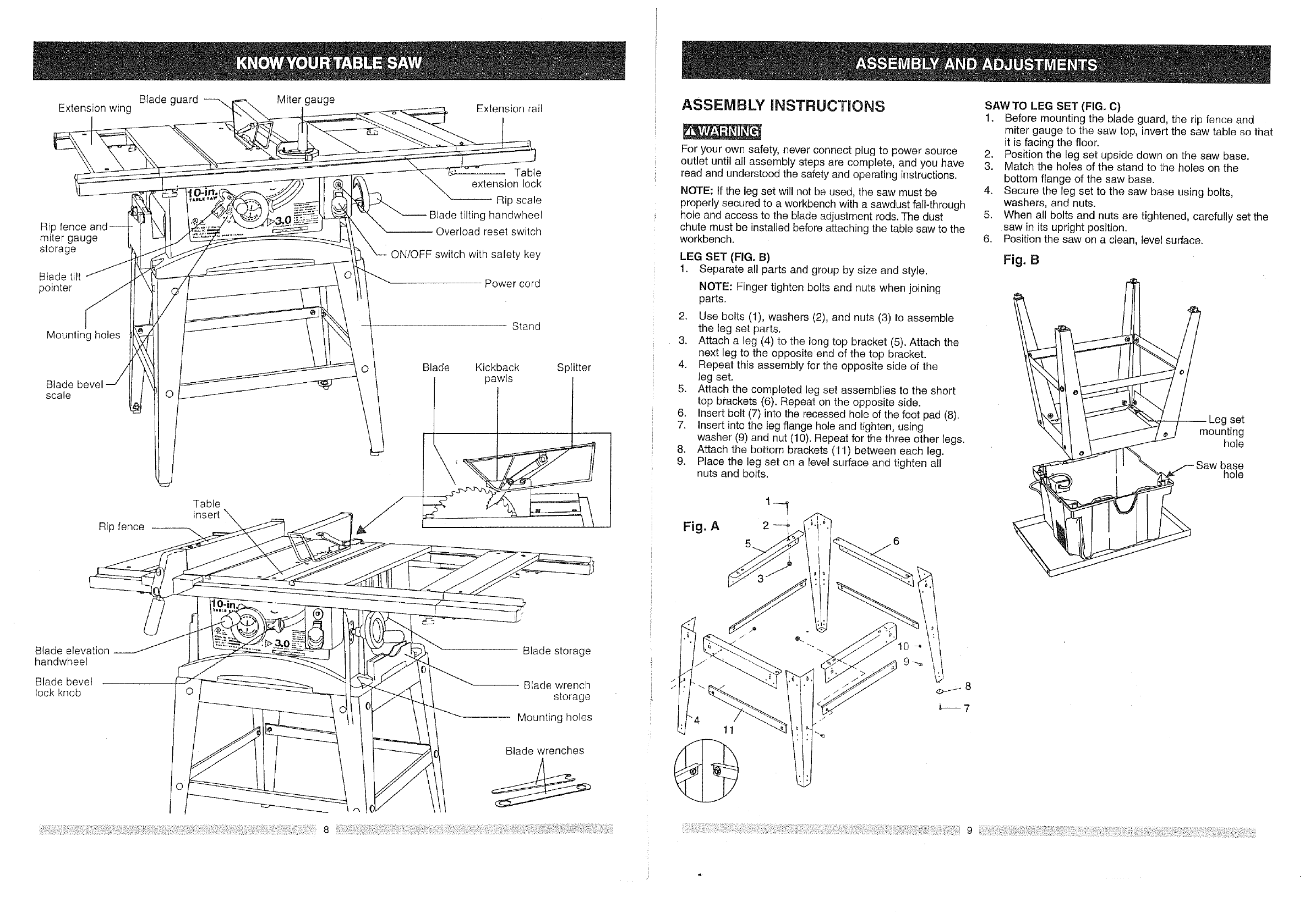
Extensionwing
Ripfence
mitergauge
storage
Bladetilt
pointer
Mounlingholes
Blade
scale
Ripfence--
Bladeguard
Table
insert
Milergauge Extensionrail
!Table
extensionlock
Ripscale
Bladetiltinghandwheel
Overloadresetswitch
ON/OFFswitchwithsafetykey
Powercord
Stand
Blade Kickback
pawls Splitter
ASSEMBLY JNSTRUCTUONS
,
7.
i
i 8.
9.
For your own safety, never connect plug to power source
outlet until all assembly steps are complete, and you have
read and understood the safety and operating instructions.
NOTE: If the leg set will not be used, the saw must be
properly secured to a workbench with a sawdust fall-through
hole and access to the blade adjustment rods. The dust
chute must be installed before attaching the table saw to the
workbench.
LEG SET (FIG. B)
1. Separate al! parts and group by size and style.
NOTE: Finger tighten bolts and nuts when joining
parts.
2. Use bolts (1), washers (2), and nuts (3) to assemble
the leg set parts.
3. Attach a leg (4) to the long top bracket (5). Attach the
next leg to the opposite end of the top bracket.
4. Repeat this assembly for the opposite side of the
leg set.
5. Attach the completed leg set assemblies to the short
top brackets (6). Repeat on the opposite side.
Insert bolt (7) into the recessed hole of the foot pad (8).
Insert into the leg flange hole and tighten, using
washer (9) and nut (10). Repeat for the three other legs.
Attach the bottom brackets (11) between each leg.
Place the leg set on a level surface and tighten all
nuts and bolts.
Fig. A 2
SAW TO LEG SET (FIG. C)
1. Before mounting the blade guard, the rip fence and
miter gauge to the saw top, invert the saw table so that
it is facing the floor.
2. Position the leg set upside down on the saw base.
3. Match the holes of the stand to the holes on the
bottom flange of the saw base.
4. Secure the leg set to the saw base using bolts,
washers, and nuts.
5. When all bolts and nuts are tightened, carefully set the
saw in its upright position.
6. Position the saw on a clean, level surface.
Fig. 8
set
mounting
hole
base
hole
Blade elevation
handwhee!
Blade bevel
lock knob
Blade storage
-- BEade wrench
storage
Mounting holes
Blade wrenches
?
11
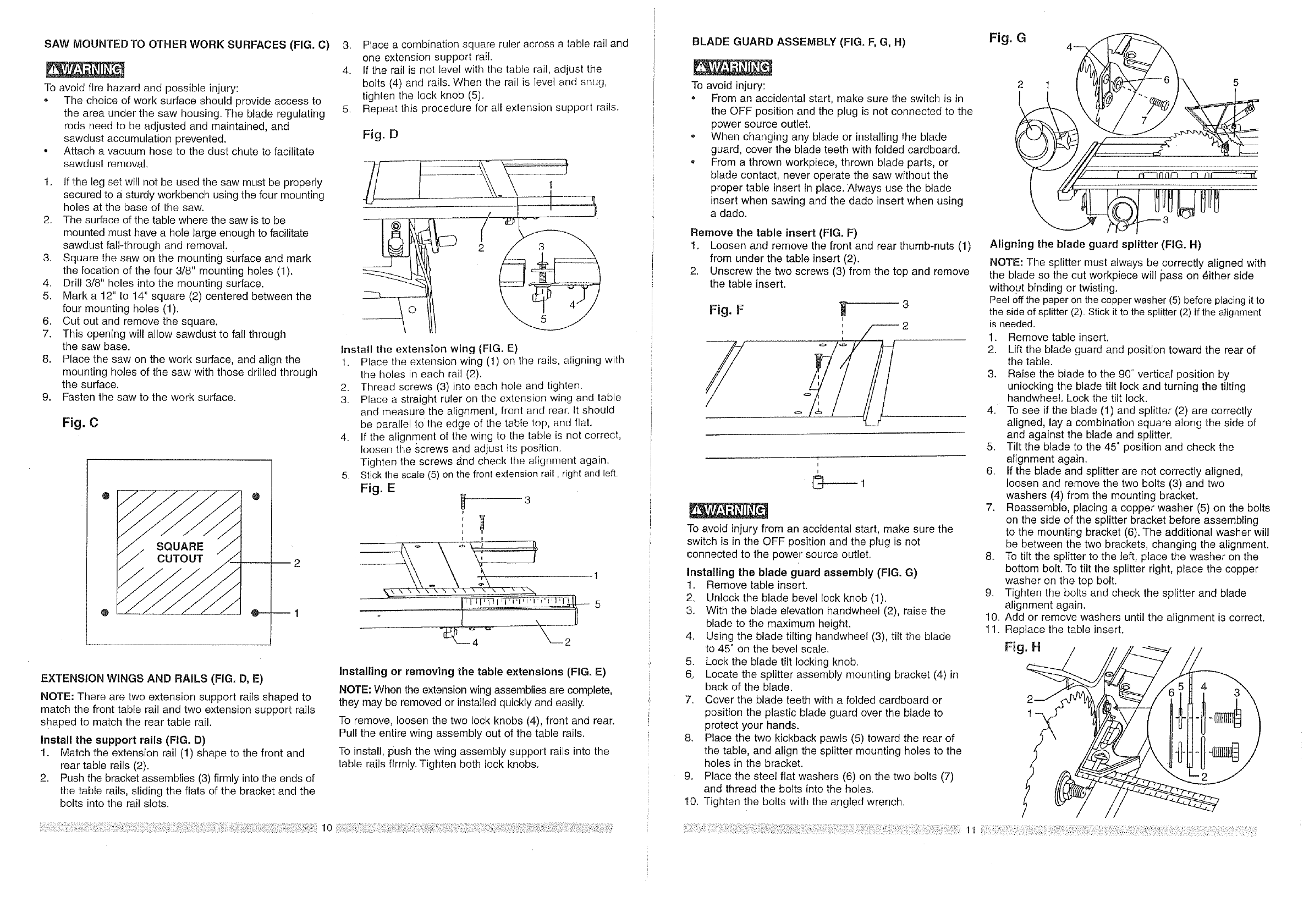
SAWMOUNTED TO OTHER WORK SURFACES (FIG. C)
To avoid fire hazard and possible injury:
- The choice of work surface should provide access to
the area under the saw housing. The blade regulating
rods need to be adjusted and maintained, and
sawdust accumulation prevented.
o Attach a vacuum hose to the dust chute to facilitate
sawdust removal.
1. If the leg set will not be used the saw must be properly
secured to a sturdy workbench using the four mounting
holes at the base of the saw.
2. The surface of the table where the saw is to be
mounted must have a hole large enough to facilitate
sawdust fall-through and removal.
3. Square the saw on the mounting surface and mark
the location of the four 3/8" mounting holes (1).
4. Drill 3/8" holes into the mounting surface.
5. Mark a 12" to 14" square (2) centered between the
four mounting holes (1).
6. Cut out and remove the square.
7. This opening will allow sawdust to fal! through
the saw base.
8. Place the saw on the work surface, and align the
mounting holes of the saw with those drilled through
the surface.
g. Fasten the saw to the work surface.
FJg. C
@
2
@----1
3. Place a combination square ruler across a table rail and
one extension support rail.
4. If lhe rail is not level with the table rail, adjust the
bolts (4) and rails. When the rail is level and snug,
tighten the lock knob (5).
5. Repeat this procedure for all extension support rails.
Fig. D
Install the extension wing (FIG. E)
1. Place tile extension wing (1) on the rails, aligning with
the holes in each rail (2).
2. Thread screws (3) into each hole and tighten.
3. Place a straight ruler on the extension wing and table
and measure the alignment, front and rear. It should
be parallel tothe edge of the table top, and flat.
4. If the alignment of the wing to the table is not correct,
loosen the screws and adjust its position.
Tighten the screws And check the alignment again.
5. Stick the scale (5) on the front extension rail, right and left.
Fig. E H 3
I
I
I
i I
EXTENSION WINGS AND RAILS (FIG. D, E)
NOTE: There are two extension support rails shaped to
match the front table rail and two extension support rails
shaped to match the rear table rail.
Install the support rails (FIG. D)
1. Match the extension rail (1) shape to the front and
rear table rails (2).
2. Push the bracket assemblies (3) firmly into the ends of
the table rails, sliding the flats of the bracket and the
bolts into the rail slots.
Installing or removing the table extensions (FIG. E)
NOTE: When the extension wing assemblies are complete,
they may be removed or installed quickly and easily.
To remove, loosen the two lock knobs (4), front and rear.
Pull the entire wing assembly out of the table rails.
To install, push the wing assembly support rails into the
table rails firmly. Tighten both lock knobs.
i
I
4
BLADE GUARD ASSEMBLY (FIG. F, G, H)
To avoid injury:
o From an accidental start, make sure the switch is in
the OFF position and the plug is not connected to the
power source outlet.
o When changing any blade or installing the blade
guard, cover the blade teeth with folded cardboard.
, From a thrown workpiece, thrown blade parts, or
blade contact, never operate the saw without the
proper table insert in place. Always use the blade
insert when sawing and the dado insert when using
a dado.
Remove the table insert (FIG. F)
1. Loosen and remove the front and rear thumb-nuts (1)
from under the table insert (2).
2. Unscrew the two screws (3) from the top and remove
the table insert.
o
I
I
To avoid injury from an accidental start, make sure the
switch is in the OFF position and the plug is not
connected to the power source outlet.
Installing the blade guard assembly (FIG. G)
1. Remove table insert.
2. Unlock the blade bevel lock knob (1).
3. With the blade elevation handwheel (2), raise the
blade to the maximum height.
4. Using the blade tilting handwheel (3), tilt the blade
to 45 ° on the bevel scale.
5. Lock the blade tilt locking knob.
6. Locate the splitter assembly mounting bracket (4) in
back of the blade.
7. Cover the blade teeth with a folded cardboard or
position the plastic blade guard over the blade to
protect your hands.
8. Place the two kickback pawls (5) toward the rear of
the table, and align the splitter mounting holes to the
holes in the bracket.
9. Place the steel flat washers (6) on the two bolts (7)
and thread the bolts into the holes.
I0. Tighten the bolts with the angled wrench.
Fig. G 4
5
Aligning the blade guard splitter (FIG. H)
NOTE: The splitter must always be correctly aligned with
the blade so the cut workpiece will pass on _ither side
without binding or twisting.
Peel offthe paper on the copper washer (5) before placing it to
the side of splitter (2). Stick it to the splitter (2) if the align[nent
is needed.
1. Remove table insert.
2. Lift the blade guard and position toward the rear of
the table.
3. Raise the blade to the 90 ° vertical position by
unlocking the blade tilt lock and turning the tilting
handwheel. Lock the tilt lock.
4. To see if the blade (1) and splitter (2) are correCtly
aligned, lay a combination square along the side of
and against the blade and splitter.
5. Tilt the blade to the 45 ° position and check the
alignment again.
6. If the blade and splitter are not correctly aligned,
loosen and remove the two bolts (3) and two
washers (4) from the mounting bracket.
7. Reassemble, placing a copper washer (5) on the bolts
on the side of the splitter bracket before assembling
to the mounting bracket (6). The additional washer will
be between the two brackets, changing the alignment.
8. To tilt the splitter to the left, place the washer on the
bottom bolt. To tilt the splitter right, place the copper
washer on the top bolt.
9. Tighten the bolts and check the splitter and blade
alignment again.
10. Add or remove washers until the alignment is correct.
11. Replace the table insert.
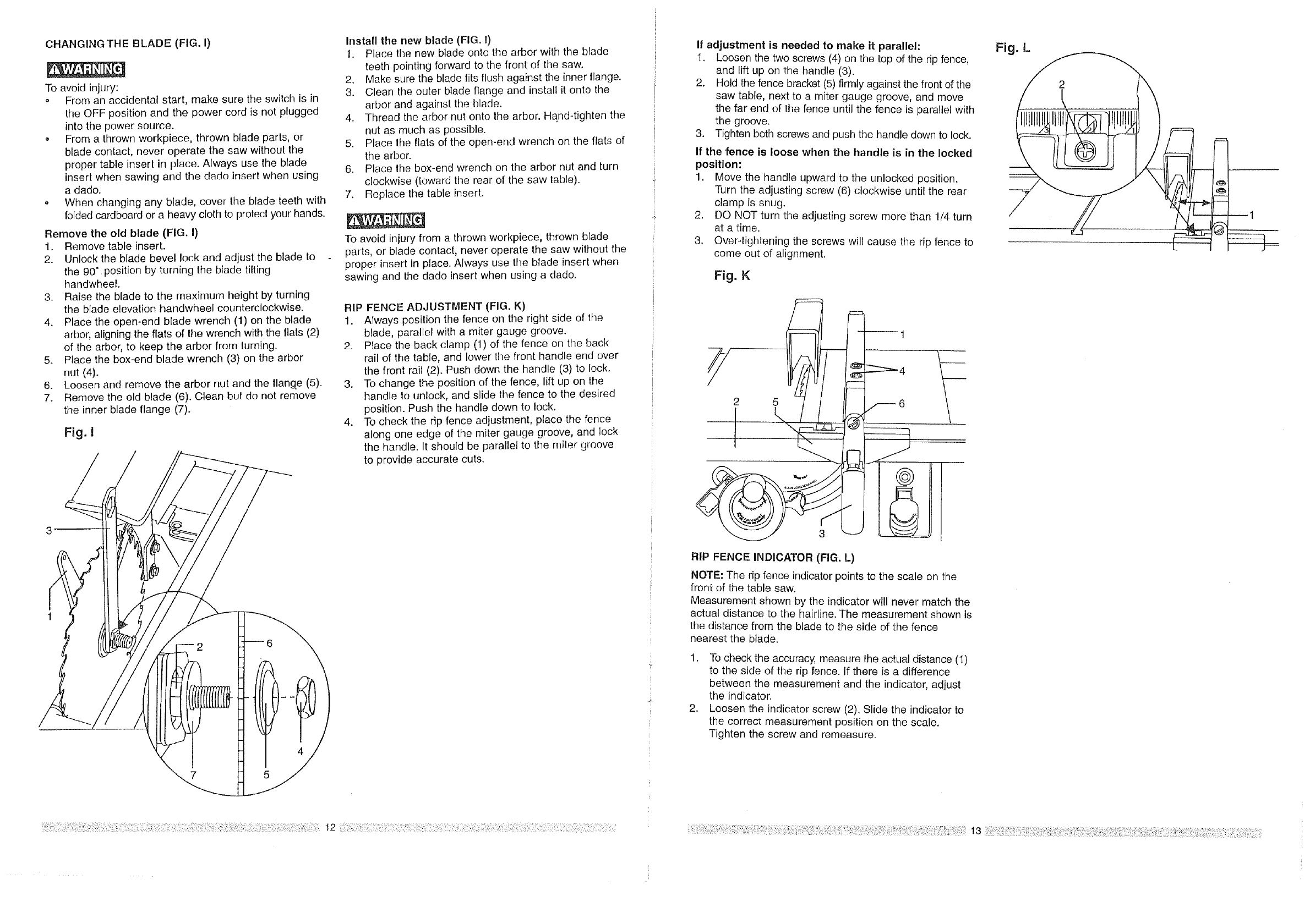
CHANGINGTHEBLADE(FIG.I)
Toavoidinjury:
,, From an accidental start, make sure the switch is in
the OFF position and the power cord is not plugged
into the power source.
,, From a thrown workpiece, thrown blade paris, or
blade contact, never operate the saw without the
proper table insert in place. Always use the blade
insert when sawing and the dado insert when using
a dado.
• When changing any blade, cover lhe blade teeth with
folded cardboard or a heavy cloth to protecl your hands.
Remove the old blade (FIG. I)
1. Remove table insert.
2. Unlock the blade bevel lock and adjust the blade to
the g0 °position by turning the blade tilting
handwheel.
3. Raise the blade to the maximum height by turning
the blade elevation handwheel counterclockwise.
4. Place the open-end blade wrench (1) on the blade
arbor, aligning the flats of the wrench with the flats (2)
of the arbor, to keep the arbor from turning.
5. Place the box-end blade wrench (3) on the arbor
nut (4).
6. Loosen and remove the arbor nut and the flange (5).
7. Remove the old blade (6). Clean but do not remove
the inner blade flange (7).
Fig. I
Install the new blade (FIG. I)
1. Place the new blade onto the arbor with the blade
teeth pointing forward to the front of the saw.
2. Make sure the blade fits flush against the inner flange.
3. Clean the outer blade flange and install it onto the
arbor and against the blade.
4. Thread the arbor nut onto the arbor. Hand-tighten the
nut as much as possible.
5. Place the flats of the open-end wrench on the flats of
the arbor.
6. Place the box-end wrench on the arbor nut and turn
clockwise (toward the rear of the saw table).
7. Replace the table insert.
To avoid injury from a thrown workpiece, thrown blade
parts, or blade contact, never operate the saw without the
proper insert in place. Always use the blade insert when
sawing and the dado insert when using a dado.
RIP FENCE ADJUSTMENT (FIG. K)
1. Always position the fence on the right side of the
blade, parallel with a miter gauge groove.
2. Place the back clamp (1) of the fence on the back
rail of the table, and lower the front handle end over
the front rail (2). Push down the handle (3) to lock.
3. To change the position of the fence, lift up on the
handle to unlock, and slide the fence to the desired
position. Push the handle down to lock.
4. To check the rip fence adjustment, place the fence
along one edge of the miter gauge groove, and lock
the handle. It should be parallel to the miter groove
to provide accurate cuts.
If adjustment is needed to make it parallel:
1. Loosen the two screws (4) on the top of the rip fence,
and lift up on the handle (3).
2. Hold the fence bracket (5) firmly against the front of the
saw table, next to a miter gauge groove, and move
the far end of the fence until the fence is parallel with
the groove.
3. Tighten both screws and push the handle down to lock.
If the fence is loose when the handle is in the locked
position:
1. Move the handle upward to the unlocked position.
Turn the adjusting screw (6) clockwise until the rear
clamp is snug.
2. DO NOT turn the adjusting screw more than 1/4 turn
at a time.
3. Over-tightening the screws will cause the rip fence to
come out of alignment.
Fig. K
2 5 /6
RIP FENCE INDICATOR (FIG, L)
NOTE: The rip fence indicator points to the scale on the
front of the table saw.
Measurement shown by the indicator will never match the
actual distance to the hairline. The measurement shown is
the distance from the blade to the side of the fence
nearest the blade.
1. To check the accuracy, measure the actual distance (1)
to the side of the rip fence. If there is a difference
between the measurement and the indicator, adjust
the indicator.
2. Loosen the indicator screw (2). Slide the indicator to
the correct measurement position on the scale.
Tighten the screw and remeasure.
Fig. L
2
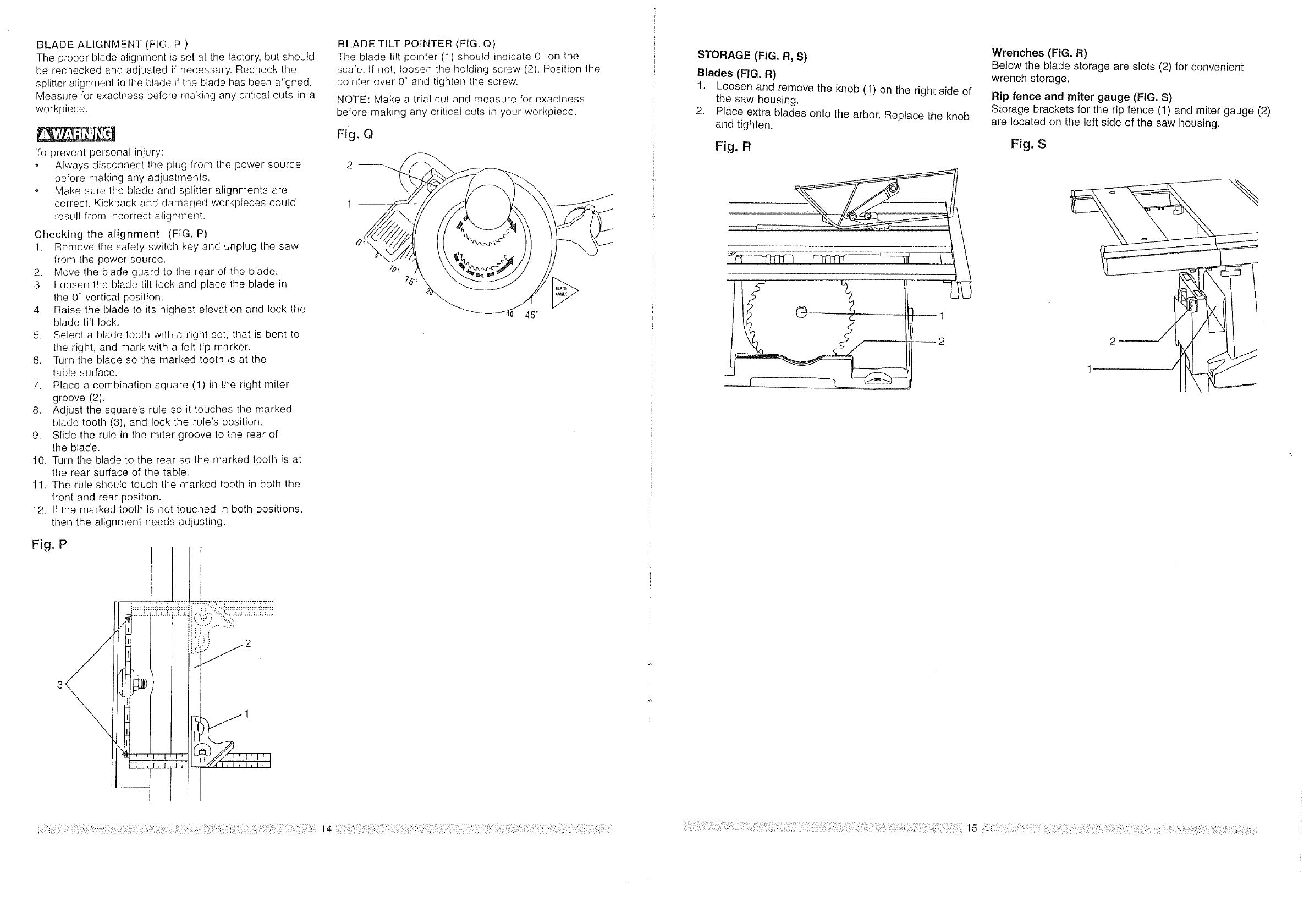
BLADE ALIGNMENT (FIG. P )
The proper blade alignment is set at the factory, but should
be rechecked and adjusled if necessary. Recheck the
splitter alignment to the blade if the blade has been aligned.
Measure for exactness before making any critical cuts in a
workpiece.
To prevent personal iniury:
,, Always disconnect tile plug Irom the power source
before making any adjustments.
, Make sure the blade and spliHer alignments are
correct. Kickback and damaged workpieces could
result from incorrect alignment.
Checking the alignment (FIG. P)
1. Remove the safety swilch key and unplug the saw
fl-om the power source.
2. Move the blade guard to the rear of the blade.
3. Loosen the blade tilt lock and place the blade in
the 0° vertical position.
4. Raise the blade to its highest elevation and lock the
blade lill lock.
5. Select a blade tooth with a right set, that is bent to
the right, and mark with a felt tip marker.
6. Turn the blade so the marked tooth is at the
table surface.
7. Place a cornbination square (1) in the right miter
groove (2).
8. Adjust the square's rule so it touches the marked
blade tooth (3), and lock the rule's position.
9. Slide the rule in the miter groove to the rear of
the blade.
10. Turn the blade to the rear so the marked tooth is at
the rear surface of the table.
11. The rule should touch the marked tooth in both the
front and rear position.
12. If the marked tooth is not touched in both positions,
then the alignment needs adjusting.
Fig. P !
i! f,
BLADE TILT POINTER (FIG. Q)
The blade tilt pointer (1) should indicate 0° on the
scale. If not, loosen the holding screw (2), Position the
pointer over 0 ° and tighten the screw.
NOTE: Make a trial cut and rneasure for exactness
before making any critical culs in your workpiece,
Fig. Q
45°
i
i
STORAGE (FIG. R, S)
Blades (FIG. R)
1. Loosen and remove the knob (1) on the right side of
the saw housing.
2. Place extra blades onto the arbor. Replace the knob
and tighten.
Fig. R
=__.L
Wrenches (FIG. R)
Below the blade storage are slots (2) for convenient
wrench storage.
Rip fence and miter gauge (FIG. S)
Storage brackets for the rip fence (1) and miter gauge (2)
are located on the left side of the saw housing.
Fig. S
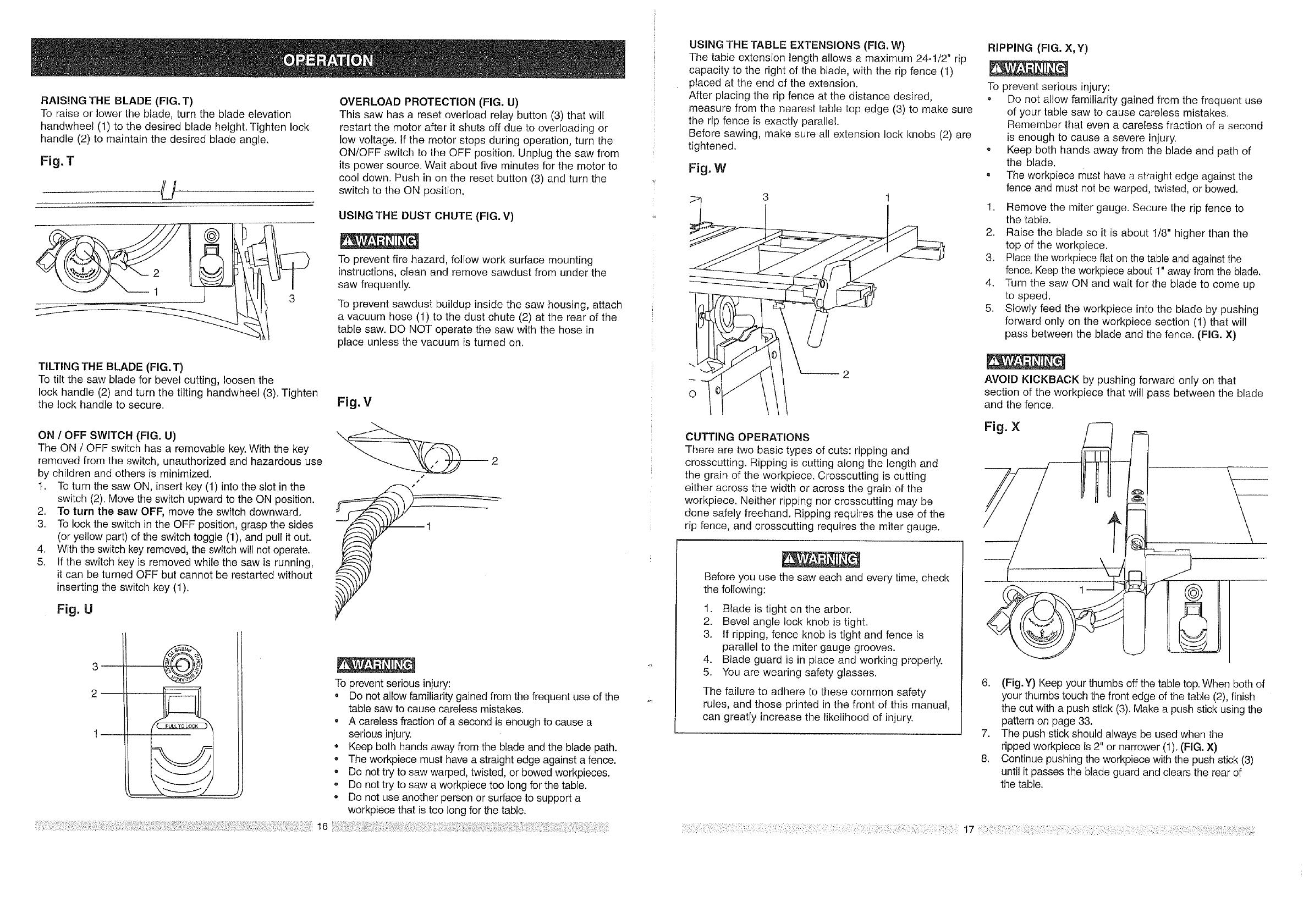
RAISING THE BLADE (FIG.T)
To raise or lower the blade, turn the blade elevation
handwheel (1) to the desired blade height. Tighten lock
handle (2) to maintain the desired blade angle.
Fig. T
U
TILTING THE BLADE (FIG. T)
To tilt the saw blade for bevel cutting, loosen the
lock handle (2) and turn the tilting handwheel (3). Tighten
the lock handle to secure.
ON /OFF SWITCH (FIG. U)
The ON /OFF switch has a removable key. With the key
removed from the switch, unauthorized and hazardous use
by children and others is minimized.
1. To turn the saw ON, insert key (1) into the slot in the
switch (2). Move the switch upward to the ON position.
2. To turn the saw OFF, move the switch downward.
3. To lock the switch in the OFF position, grasp the sides
(or yellow part) of the switch toggle (1), and pull it out.
4. With the switch key removed, the switch will not operate.
5. If the switch key is removed while the saw is running,
it can be turned OFF but cannot be restarted without
inserting the switch key (1).
Fig. U
OVERLOAD PROTECTION (FIG. U)
This saw has a reset overload relay button (3) that will
restart the motor after it shuts off due to overloading or
low voltage. If the motor stops during operation, turn the
ON/OFF switch to the OFF position. Unplug the saw from
its power source. Wait about five minutes for the motor to
cool down. Push in on the reset button (3) and turn the
switch to the ON position.
USING THE DUST CHUTE (FIG. V)
To prevent fire hazard, follow work surface mounting
instructions, clean and remove sawdust from under the
saw frequently.
To prevent sawdust buildup inside the saw housing, attach
a vacuum hose (1) to the dust chute (2) at the rear of the
table saw. DO NOT operate the saw with the hose in
place unless the vacuum is turned on.
3
2@
16
To prevent serious injury:
o Do not allow familiarity gained from the frequent use of the
table saw to cause careless mistakes.
• A careless fraction of a second is enough to cause a
serious injury.
•Keep both hands away from the blade and the blade path.
The workpiece must have a straight edge against a fence.
• Do not try to saw warped, twisted, or bowed workpieces.
o Do not try to saw a workpiece too long for the table.
. Do not use another person or surface to support a
workpiece that is too long for the table.
USING THE TABLE EXTENSIONS (FIG. W)
The table extension length allows a maximum 24-1/2" rip
capacity to the right of the blade, with the rip fence (1)
placed at the end of the extension.
After placing the rip fence at the distance desired,
measure from the nearest table top edge (3) to make sure
the rip fence is exactly parallel.
Before sawing, make sure all extension lock knobs (2) are
tightened.
Fig. W
0
CUTTING OPERATIONS
There are two basic types of cuts: ripping and
crosscutting. Ripping is cutting along the length and
the grain of the workpiece. Crosscutting is cutting
either across the width or across the grain of the
workpiece. Neither ripping nor crosscutting may be
done safely freehand. Ripping requires the use of the
rip fence, and crosscutting requires the miter gauge.
Before you use the saw each and every time, check
the following:
1. Blade is tight on the arbor.
2. Bevel angle lock knob is tight.
3. If ripping, fence knob is tight and fence is
parallel to the miter gauge grooves.
4. Blade guard is in place and working properly.
5. You are wearing safety glasses.
The failure to adhere to these common safety
rules, and those printed in the front of this manual,
can greatly increase the likelihood of injury.
RIPPING (FIG. X,Y)
To prevent serious injury:
° Do not allow familiarity gained from the frequent use
of your table saw to cause careless mistakes.
Remember that even a careless fraction of a second
is enough to cause a severe injury.
o Keep both hands away from the blade and path of
the blade.
, The workpiece must have a straight edge against the
fence and must not be warped, twisted, or bowed.
1. Remove the miter gauge. Secure the rip fence to
the table.
2. Raise the blade so it is about 1/8" higher than the
top of the workpiece.
3. Place the workpiece flat on the table and against the
fence. Keep the werkpiece about 1" away from the blade.
4. Turn the saw ON and wait for the blade to come up
to speed.
5. Slowly feed the workpiece into the blade by pushing
forward only on the workpiece section (1) that will
pass between the blade and the fence. (FIG. X)
AVOID KICKBACK by pushing forward only on that
section of the workpiece that will pass between the blade
and the fence.
t
6. (Fig.Y) Keep your thumbs off the table top. When both of
your thumbs touch the front edge of the table (2), finish
the cut with a push stick (3). Make a push stick using the
pattern on page 33.
7. The push stick should always be used when the
ripped workpiece is 2" or narrower (1). (FIG. X)
8. Continue pushing the workpiece with the push stick (3)
until it passes the blade guard and clears the rear of
the table.
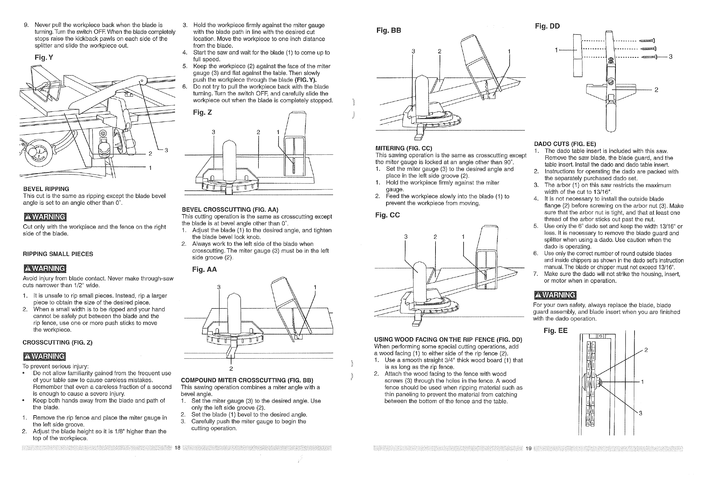
.Never pull the workpiece back when the blade is
turning. Turn the switch OFF. When the blade completely
stops raise the kickback pawls on each side of the
splitter and slide the workpiece out.
Fig. Y
2
1
BEVEL RIPPING
This cut is the same as ripping except the blade bevel
angle is set to an angle other than 0".
Cut only with the workpiece and the fence on the right
side of the blade.
RIPPING SMALL PIECES
Avoid injury from blade contact. Never make through-saw
cuts narrower than 1/2" wide.
.
2.
It is unsafe to rip small pieces. Instead, rip a larger
piece to obtain the size of the desired piece.
When a small width is to be ripped and your hand
cannot be safely put between the blade and the
rip fence, use one or more push sticks to move
the workpiece.
CROSSCUTTING (FIG. Z)
To prevent serious injury:
• Do not allow familiarity gained from the frequent use
of your table saw to cause careless mistakes.
Remember that even a careless fraction of a second
is enough to cause a severe injury.
o Keep both hands away from the blade and path of
the blade.
1. Remove the rip fence and place the miter gauge in
the left side groove.
2. Adjust the blade height so it is 1/8" higher than the
top of the workpiece.
3. Hold the workpiece firmly against the miter gauge
with the blade path in line with the desired cut
location. Move the workpiece to one inch distance
from the blade.
4. Start the saw and wait for the blade (1) to come up to
full speed.
5. Keep the workpiece (2) against the face of the miter
gauge (3) and flat against the table. Then slowly
push the workpiece through the blade (FIG.Y).
6. Do not try to pull the workpiece back with the blade
turning. Turn the switch OFF, and carefully slide the
workpiece out when the blade is completely stopped.
Fig. Z
3 2
i
BEVEL CROSSCUTTING (FIG. AA)
This cutting operation is the same as crosscutting except
the blade is at bevel angle other than 0°.
1. Adjust the blade (1) to the desired angle, and tighten
the blade bevel lock knob.
2. Always work to the left side of the blade when
crosscutting. The miter gauge (3) must be in the left
side groove (2).
Fig. AA
COMPOUND MITER CROSSCUTTING (FIG. BB)
This sawing operation combines a miter angle with a
bevel angle.
1. Set the miter gauge (3) to the desired angle. Use
only the left side groove (2).
2. Set the blade (1) bevel to the desired angle.
3. Carefully push the miter gauge to begin the
cutting operation.
18
Fig. BB
MITERING (FIG. CC)
This sawing operation is the same as crosscutting except
the miter gauge is locked at an angle other than 90°.
1. Set the miter gauge (3) to the desired angle and
place in the left side groove (2).
1. Hold the workpiece firmly against the miter
gauge.
2. Feed the workpiece slowly into the blade (1) to
prevent the workpiece from moving.
Fig. CC
3 2 1
k
USING WOOD FACING ON THE RIP FENCE (FIG. DD)
When performing some special cutting operations, add
a wood facing (1) to either side of the rip fence (2).
1. Use a smooth straight 3/4" thick wood board (1) that
is as long as the rip fence.
2. Attach the wood facing to the fence with wood
screws (3) through the holes in the fence. A wood
fence should be used when ripping material such as
thin paneling to prevent the material from catching
between the bottom of the fence and the table.
Fig. DD
DADO CUTS (FIG. EE)
1. The dado table insert is included with this saw.
Remove the saw blade, the blade guard, and the
table insert. Install the dado and dado table insert.
2. Instructions for operating the dado are packed with
the separately purchased dado set.
3. The arbor (1) on this saw restricts the maximum
width of the cut to 13/16".
4. It is not necessary to install the outside blade
flange (2) before screwing on the arbor nut (3). Make
sure that the arbor nut is tight, and that at least one
thread of the arbor sticks out past the nut.
5. Use only the 6" dado set and keep the width 13/16" or
less. It is necessary to remove the blade guard and
splitter when using a dado. Use caution when the
dado is operating.
6. Use only the correct number of round outside blades
and inside chippers as shown in the dado set's instruction
manual. The blade or chipper must not exceed 13/16".
7. Make sure the dado will not strike the housing, insert,
or motor when in operation.
For your own safety, always replace the blade, blade
guard assembly, and blade insert when you are finished
with the dado operation.
Fig. EE L__LL_LL
"4
J
J
\\
j2
"3
MAiNTAiNiNG YOUR TABLE SAW
GENERAL MAINTENANCE
For your own safety, turn the switch OFF and remove the
switch key. Remove the plug from the power source outlet
before maintaining or lubricating your saw.
1. Clean out all sawdust that has accumulated inside
the saw cabinet and the motor.
2. Polish the saw table with an automotive wax to keep
it clean and to make it easier to slide the workpiece.
3. Clean cutting blades with pitch and gum remover.
4. A worn, cut, or damaged power cord should be
replaced immediately.
All electrical or mechanical repairs should be attempted
only by a trained repair technician. Contact the nearest
Sears Service Center for service. Use only identical
replacement parts. Any other parts may create a hazard.
5. Use liquid dish washing detergent and water to
clean all plastic parts.
NOTE: Certain cleaning chemicals can damage
plastic parts.
6. Avoid use of the following cleaning chemicals or
solvents: gasoline, carbon tetrachloride, chlorinated
solvents, ammonia and household detergents
containing ammonia.
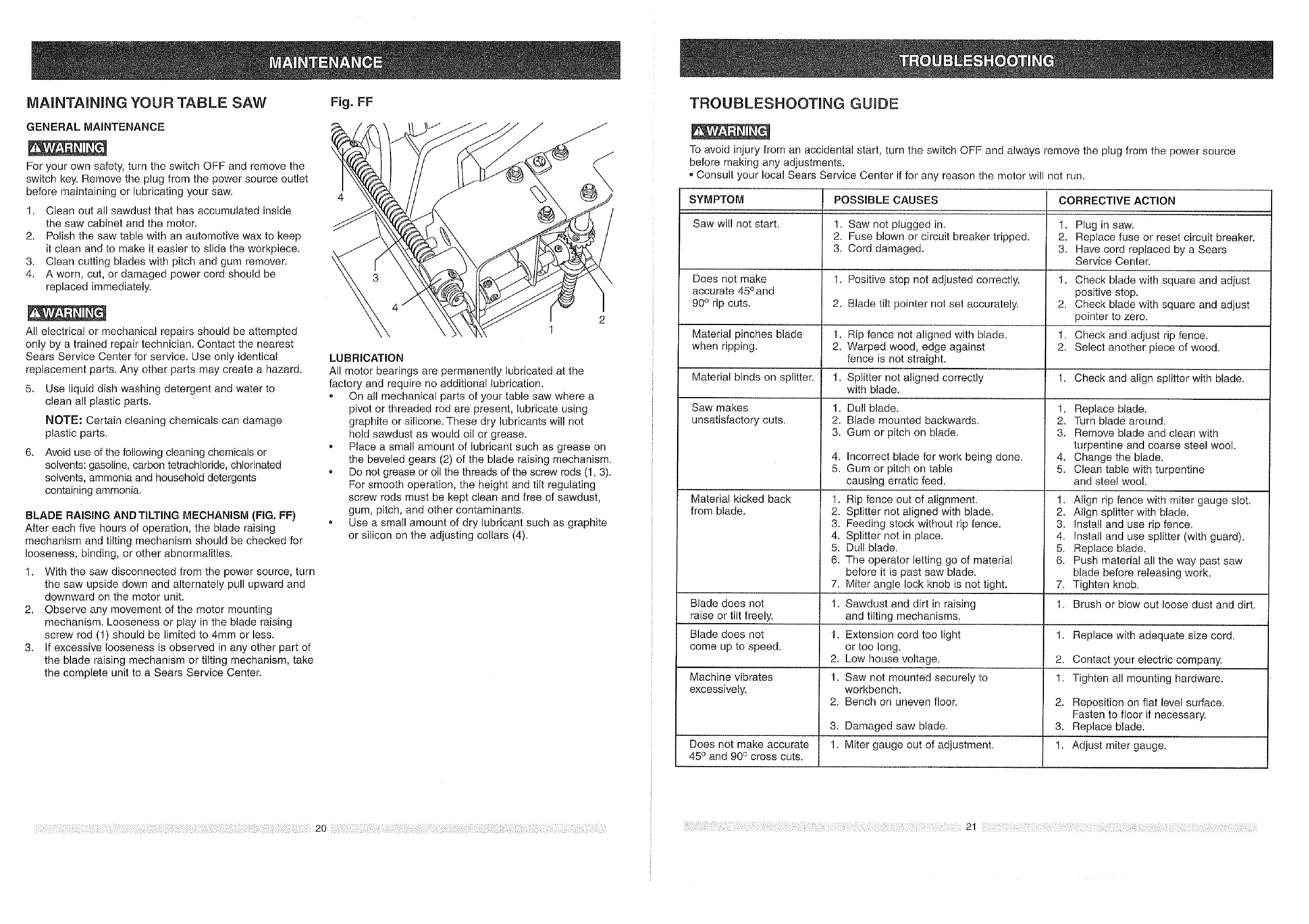
BLADE RAISING AND TILTING MECHANISM (FIG. FF)
After each five hours of operation, the blade raising
mechanism and tilting mechanism should be checked for
looseness, binding, or other abnormalities.
1. With the saw disconnected from the power source, turn
the saw upside down and alternately pull upward and
downward on the motor unit.
2. Observe any movement of the motor mounting
mechanism. Looseness or play in the blade raising
screw rod (1) should be limited to 4ram or less.
3. If excessive looseness is observed in any other part of
the blade raising mechanism or tilting mechanism, take
the complete unit to a Sears Service Center.
Fig. FF
2
t
LUBRICATION
All motor bearings are permanently lubricated at the
factory and require no additional lubrication.
On all mechanical parts of your table saw where a
pivot or threaded rod are present, lubricate using
graphite or silicone. These dry lubricants will not
hold sawdust as would oil or grease.
° Place a small amount of lubricant such as grease on
the beveled gears (2) of the blade raising mechanism.
• De not grease or oi! the threads of the screw rods (1, 3).
For smooth operation, the height and tilt regulating
screw rods must be kept clean and free of sawdust,
gum, pitch, and other contaminants.
o Use a small amount of dry lubricant such as graphite
or silicon on the adjusting cellars (4).
20
TROUBLESHOOTmNG GUIDE
To avoid injury from an accidental start, turn the switch OFF and always remove the plug from the power source
before making any adjustments.
o Consult your local Sears Service Center if for any reason the rnotor will not run.
SYMPTOM POSSIBLE CAUSES CORRECTIVE ACTION
Saw wil! not start. 1. Saw not plugged in. 1. Plug in saw.
2. Fuse blown or circuit breaker tripped. 2. Replace fuse or reset circuit breaker.
3. Cord damaged. 3. Have cord replaced by a Sears
Service Center.
Does not make 1. Positive stop not adjusted correctly. 1. Check blade with square and adjust
accurate 45° and positive stop.
90° rip cuts. 2. Blade tilt pointer not set accura[ely. 2. Check blade with square and adjust
pointer to zero.
Material pinches blade 1. Rip fence not aligned with blade. 1. Check and adjust rip fence.
when ripping. 2. Warped wood, edge against 2. Select another piece of wood.
fence is not straight.
Material binds on splitter. 1. Splitter not aligned correctly 1. Check and align splitter with blade.
with blade.
Saw makes
unsatisfactory cuts.
Material kicked back
from blade.
.
2.
3.
Dull blade.
Blade mounted backwards.
Gum or pitch on blade.
4. Incorrect blade for work being done.
5. Gum or pitch on table
causing erratic feed.
1. Rip fence out of alignment.
2. Splitter not aligned with blade.
3. Feeding stock without rip fence.
4. Splitter not in place.
5. Dull blade.
6. The operator letting go of material
before it is past saw blade.
Miter angle lock knob is not tight.
.
2.
3.
.
5.
Replace blade.
Turn blade around.
Remove blade and clean with
turpentine and coarse steel wool.
Change the blade.
Clean table with turpentine
and steel wool.
1. Align rip fence with miter gauge slot.
2. Align splitter with blade.
3. Install and use rip fence.
4. Install and use splitter (with guard).
5. Replace blade.
6. Push material all the way past saw
blade before releasing work.
Tighten knob.
7. 7,
Blade does not 1. Sawdust and dirt in raising 1. Brush or blow out loose dust and dirt.
raise or tilt freely, and tilting mechanisms.
Blade does not Extension cord too light
come up to speed, or too long.
Low house voltage.
Machine vibrates
excessively.
Does not make accurate
45° and 90° cross cuts.
Saw not mounted securely to
workbench.
Bench on uneven floor.
,
2.
1.
2.
3.
1.
Damaged saw blade.
Miter gauge out of adjustment.
1. Replace with adequate size cord.
2. Contact your electric company.
1. Tighten all mounting hardware.
2. Reposition on flat level surface.
Fasten to floor if necessary.
3. Replace blade.
1. Adjust miter gauge.
21
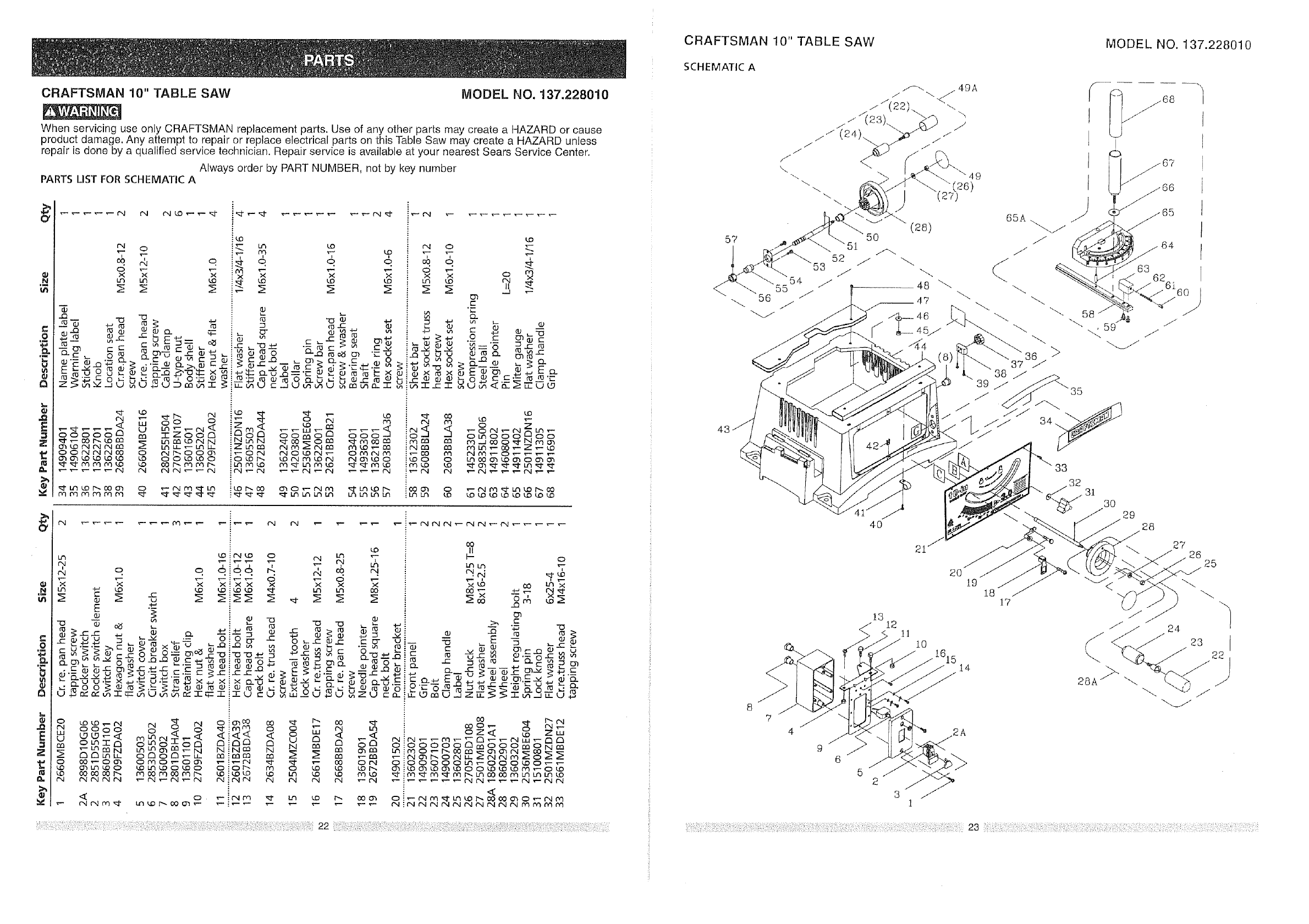
CRAFTSMAN 10" TABLE SAW MODEL NO. 137.228010
CRAFTSMAN 10" TABLE SAW MODEL NO. 137.228010
When servicing use only CRAFTSMAN replacement parts. Use of any other parts may create a HAZARD or cause
product damage. Any attempt to repair or replace electrical parts on this Table Saw may create a HAZARD unless
repair is done by a qualified service technician. Repair service is available at your nearest Sears Service Center.
Always order by PART NUMBER, not by key number
PARTS LIST FOR SCHEMATIC A
O'
Ill
O
'5
O
e,
E
z
8,.
_-_ _ __
n
+-_ r_
r_ cc
_J3
:_-- Lt3 LO
I'N O :"-.
'T, "T :, '7 _,
c _ E _----,, ,_
rg -- ¢" ,_
_'5__ _>,_ c..E
_,',._ _ , 0"_0_
_U_UD_umi
! ro _ • +.,
:-C_- _-'+a "-- _ "> _ _ i_
r- .._ _25
!>,P __ • m c _ _ %'r4d.r_
!"_q::: O.._.Q--_-'C _ _,, _ r_ r_ ,,_ _ _0
zooG _o oomo _
_0_ _N_
LO
r-4 o ._.
T T T
0 n3
X 0
r-
-r.
"_"d .- '- _"-
_='8 _ _
0 m _J3 0"1o3
00_OlC _'E
Ut9
O_OO OO
_ _ _0_
i_o_ _° __
O
o
o
E
Z
I&.
M
SCHEMATIC A
9
6
20 19
13
l]
I0
1615 14
52
31
64
63
35
33
32 31
30
18
17 (
29
28
27 26 25
24
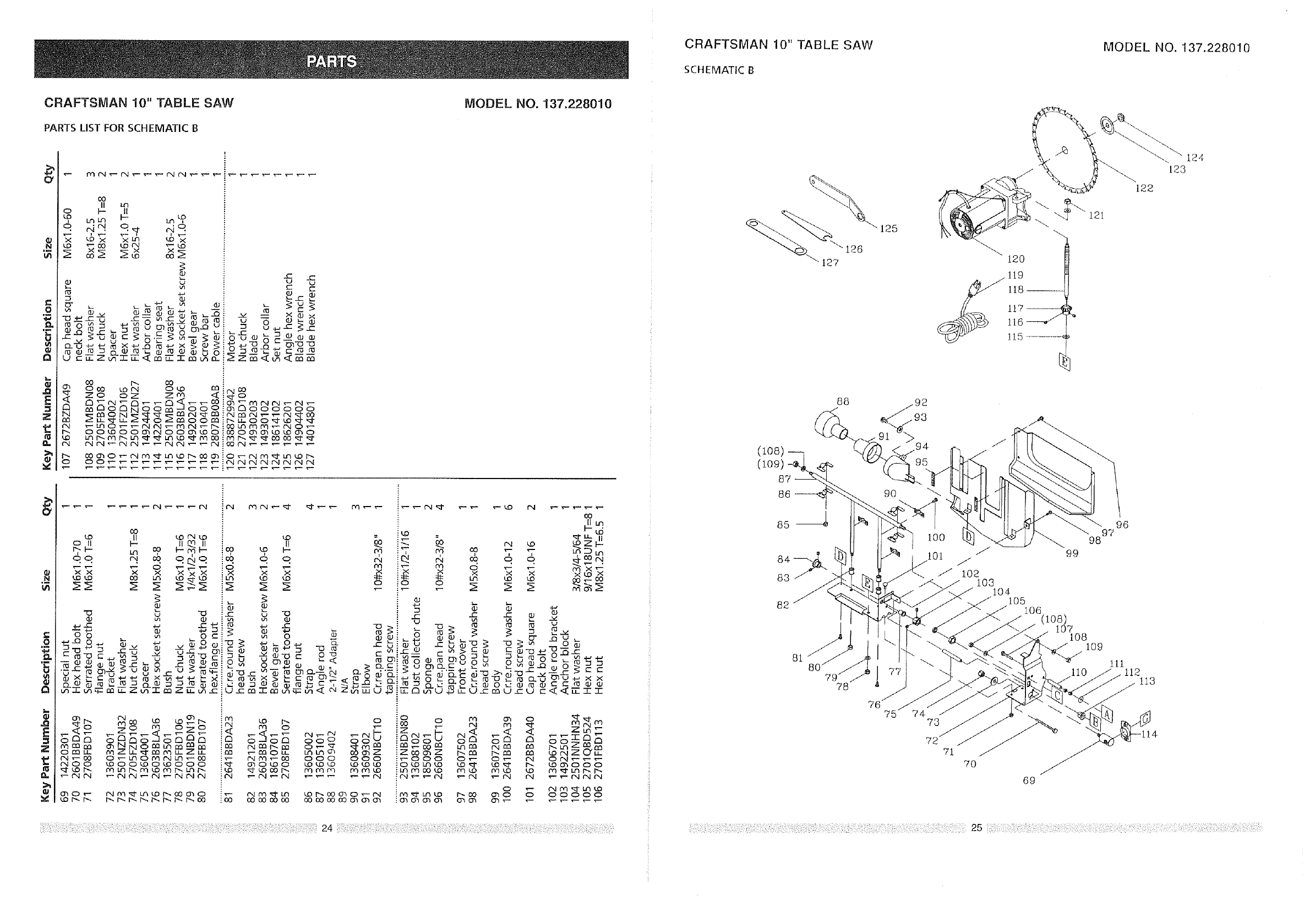
CRAFTSMAN 10" TABLE SAW
PARTS LIST FOR SCHEMATIC B
MODEL NO. 137.228010
O
,_N
'5
Q
,_a
E
z
t_
vi
CO
II L,h
oI-- II
L.nLq I-- <O
6N_ q_ m ,
• N ° .
'_ ,.b"_ '-xm' ,.b'_
co og_
L/1
"0 +-J ¢-'-_u ..C-- tat" ¢0
+-, _ X+-, Q rO+a X
uu
C
_O_NOO OOO!_OOOOO_
00_!_00_
___0_
g
Ill
e,
o
'5
Q
E
Z
Ill
CRAFTSMAN 10" TABLE SAW
SCHEMATIC B
MODEL NO. 137.228010
127
125
120
119
118 ..........
117 _--_
llg_
!1.5 .........
121
122
124
123
88
0o8)
87
86
/
78
75 74 73
72
81
71
70
69
96
97
98
99
108 109
111 112 113
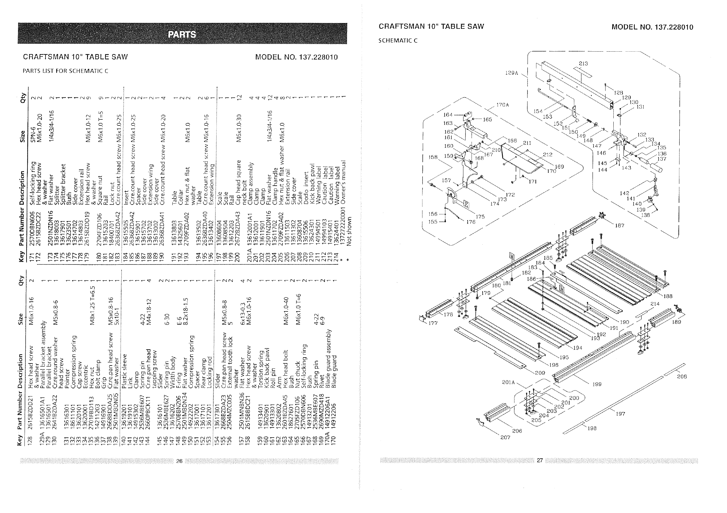
CRAFTSMAN 10" TABLE SAW
PARTS LIST FOR SCHEMATIC C
MODEL NO. 137.228010
,N
c
0
,t-
u
t_
J_
E
z
D.
LO LN L_ Lfh
¢'4 ¢N
6 6
LO LO
_3 q3
C {3) _ r0 fO CTJ ¢5
u_r'{_ O._ _ r_ O_ O_o'_ O
rnN NOSLf3hOO N N m4 r_ N _Lq N O3 t_ I_ O N OOLON
nm Zoo r-..m ,_f-,q_ u- cm 0 co ibq _3 uq uq m m a3 mUqLL
i_ O '..O £O t..O LO _ _ rooLo ¢OiLD kO L0 tD LO Lorqo
bTLO Lq r'q #q ¢q rq ,"Q LD ¢'q 5 LD _ t_ ¢q _r t'-.}cO ¢'Q ¢q rQ co
0 LO
6 o 6
LD LD LO
kO
rq F
6 __ o
>4 X X
u3 _ uv
.c
>. g -4
_0_
_- o_ Q _ _'_ o j3. C- o O.-C _;
x_-- c_ _+_ _ x _-=-o_z_-_ •
U Lu i uq uq c£:
0:000
O
,N
0
'5
Q
Z
t_
t_
n
CRAFTSMAN 10" TABLE SAW
SCHEMATIC C
175
]55 _ 176 //
//
12gA ,J
I
J
172
173
174
MODEL NO. 137.228010
213
\128129
1"
132 133 34
.135
_136
137
/
184
182
186-
"188
214
177 189
194
_196
"-209 <<_208
/_" 199
201 )_
202 / /_
203/ 197
!98
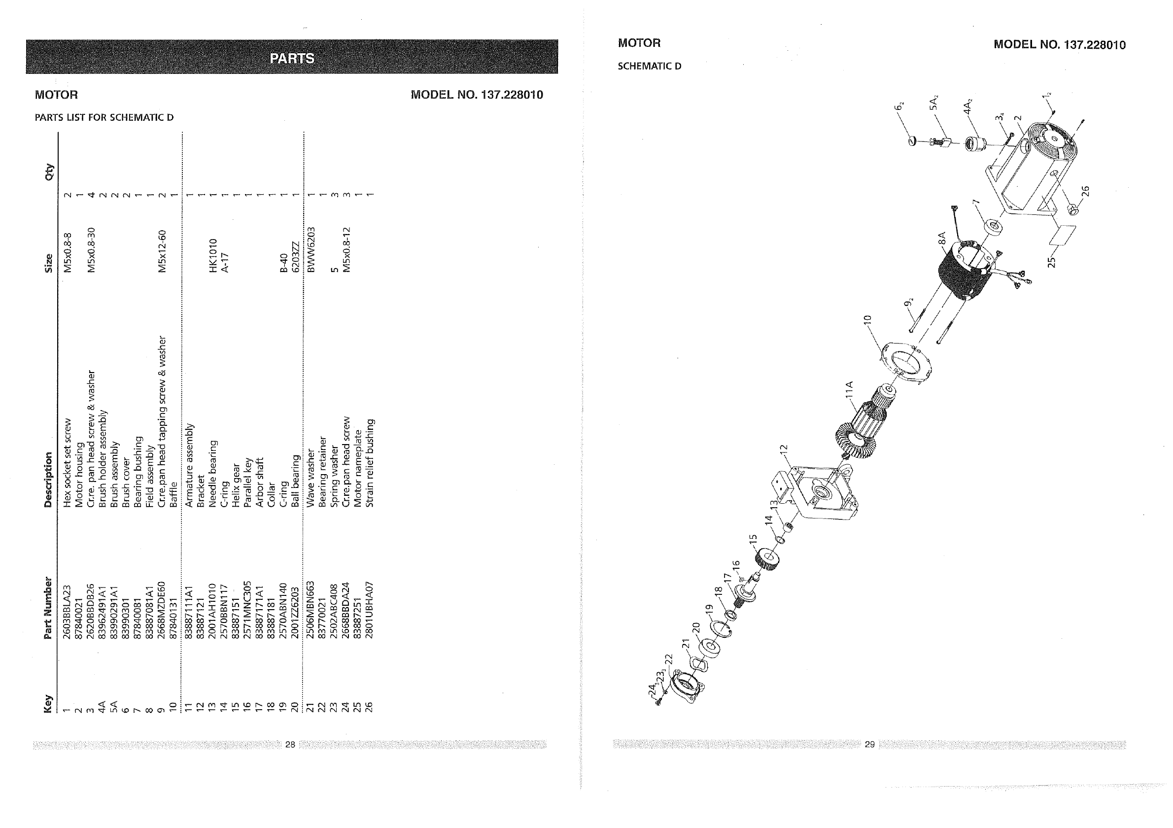
MOTOR
SCHEMATIC D
MODEL NO. 137.228010
MOTOR
PARTS LIST FOR SCHEMATIC D
MODEL NO. 137.228010
.£
o_
.Q
E
z
o_
m
143 Lth la3
U
Ltl
o_
-r-
t--
if}
¢0
O-
o_--_ _
.__._ _o
_222o_
¢Y1 rN
o 'T
0
L_
_- • _ m r- t-. O
_i >'_- r- d ._._
'_ _ ,_ 0 _
0
<< o
,..,.. _ <_iz ° _
130(30 OCO CO000 I_ ¢N O0 O0 '_
130000 I_ O0 I_ CO 60 I"-- 0 iO I'_ 0 LO ,CO 0
/
o \
\
\
< < /k7 7 < = hx <? ?9<v_<
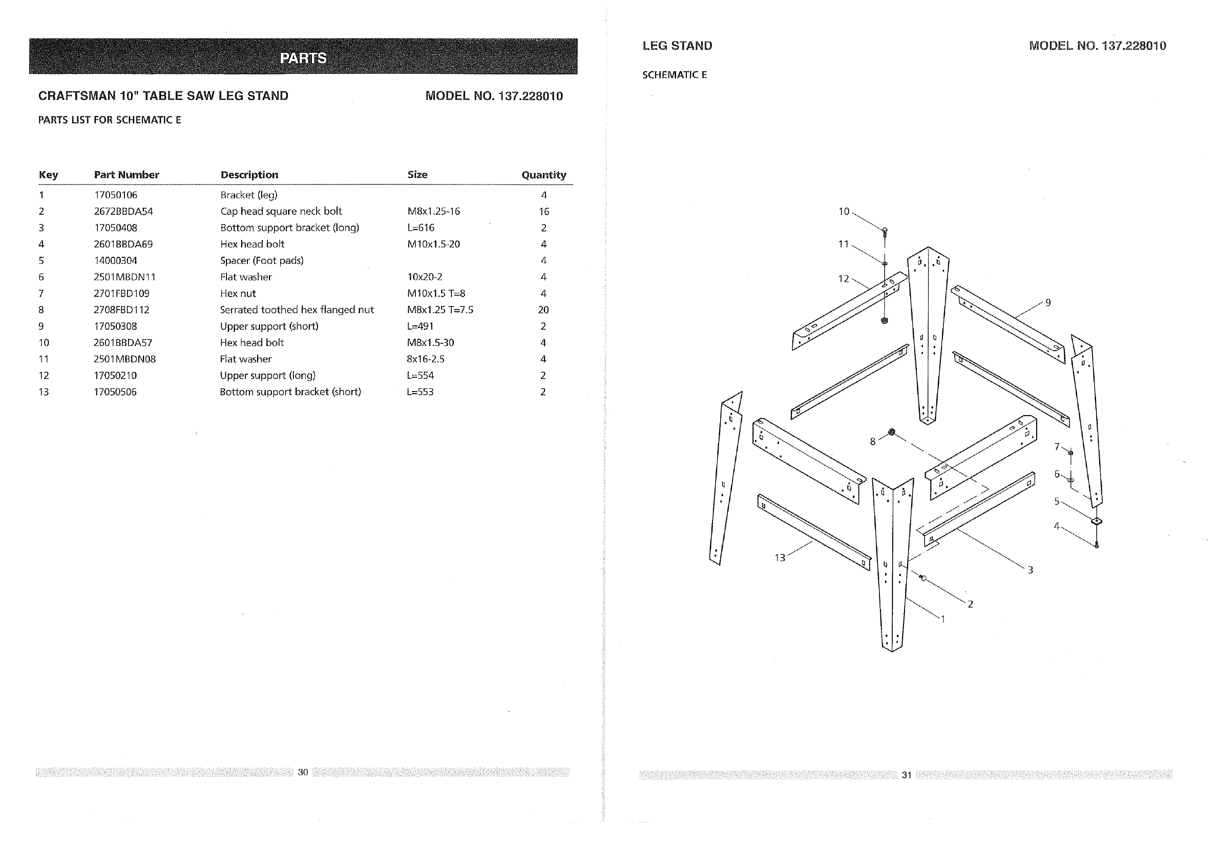
LEG STAND MODEL NO. 137.228010
CRAFTSMAN 10" TABLE SAW LEG STAND
PARTS LIST FOR SCHEMATIC E
MODEL NO. 137.228010
SCHEMATIC E
Key Part Number Description Size Quantity
1 17050106 Bracket (leg) 4
2 2672BBDA54 Cap head square neck bolt M8x1.25-16 16
3 17050408 Bottom support bracket (long) L=616 2
4 2601BBDA69 Hex head bolt M10x1.5-20 4
5 14000304 Spacer (Foot pads) 4
6 2501MBDN 11 Flat washer 10x20-2 4
7 2701FBD109 Hex nut M10x1.5 T=8 4
8 2708FBD 112 Serrated toothed hex flanged nut M8x1.25 T=7.5 20
9 17050308 Upper support (short) L=491 2
10 2601BBDA57 Hex head bolt M8x1.5-30 4
11 2501MBDN08 Flat washer 8x16-2.5 4
12 170502t0 Upper support (long) L=554 2
13 17050506 Bottom support bracket (short) L=553 2
i'ii
_fili
_iii!i
2
!_iii! /
ii_!!J
;{ f
C
/
-/
J
J
0
o
N
/
/
"_ 0
Z O O _
ooo__
_._,_ o
b_,. _
O_o___ D
/
/
/
/
/
!
/
/
/
o-_
"_ O
O --
(1)
O T-
o-d
_'+_ O
(D O
O _"
09
_J
/
/
/
/
/
1
o _..
j:: _ o9
o> :
o 6
f
©
/
I d
O
d
O-
cO
