Craftsman 137229150 User Manual 15 DRILL PRESS Manuals And Guides L0402119
CRAFTSMAN Drill Press Manual L0402119 CRAFTSMAN Drill Press Owner's Manual, CRAFTSMAN Drill Press installation guides
User Manual: Craftsman 137229150 137229150 CRAFTSMAN 15 DRILL PRESS - Manuals and Guides View the owners manual for your CRAFTSMAN 15 DRILL PRESS #137229150. Home:Tool Parts:Craftsman Parts:Craftsman 15 DRILL PRESS Manual
Open the PDF directly: View PDF ![]() .
.
Page Count: 48
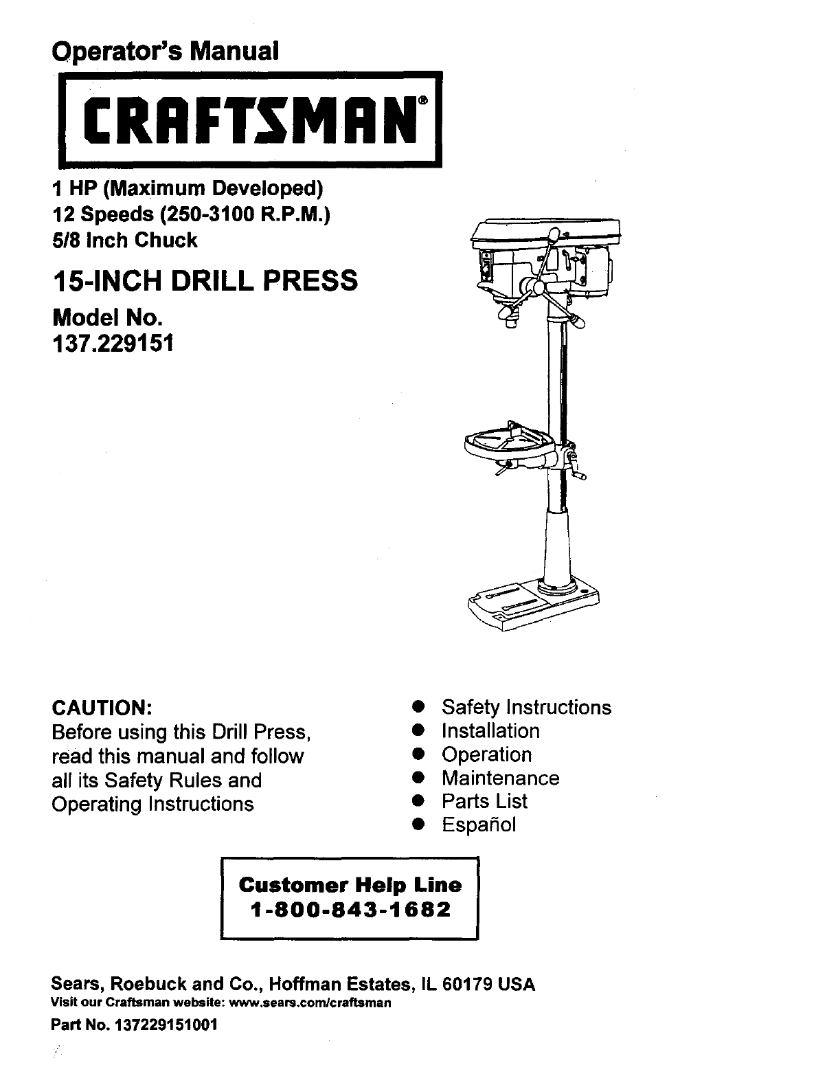
Operator's Manual
1 HP (Maximum Developed)
12 Speeds (250-3100 R.P.M.)
5/8 Inch Chuck
15-INCH DRILL PRESS
Model No,
137.229151
CAUTION:
Before using this Drill Press,
read this manual and follow
all its Safety Rules and
Operating Instructions
• Safety Instructions
• Installation
• Operation
• Maintenance
• Parts List
• EspaSol
Customer Help Line
1-800-843-1682
Sears, Roebuck and Co., Hoffman Estates, IL 60179 USA
Visit our Craftsman website: www.sears.comlcraftsman
Part No. 137229151001
SECTION PAGE
Warranty ................................................................................................................ 2
Product Specificattone ............................................................................................. 2
Safety Instructions .................................................................................................. 3
Accessories and Attachments .................................................................................. 6
Carton Contents ...................................................................................................... 6
Know Your Drill Press ............................... _.............................................................. 8
Glossary of Terms ....................................................................... ;........................... 9
Assembly and Adjustment ..................................................... _...................... ,............ 10
Operation ............................................................................................................... 15
Maintenance ........................................................................................................... 20
Troubleshooting Guide ............................................................................................ 21
Parts ...................................................................................................................... 22
Espafiol ............................................................ ;..................................................... 25
FULL ONE YEAR WARRANTY
If this Driss Press fails due to a defect in material or workmanship within one year of date of purchase,
Sears will at its option repair or replace it free of charge.
Return this Drill Press to aSears Service Center for repair, or to place of purchase for replacement.
This warranty gives you specific legal rights, and you may also have other rights which may vary from
state to state.
Sears, Roebuck and Co., Dept. 817 WA, Hoffrnan Estates, IL 60179
_q
Some dust created by power sanding, sawing, grinding, drilling and other construction activities contains
chemicals known to the state of California to cause cancer, birth defects or other reproductive harm. Some
examples of these chemicals are:
• Lead from lead-based paints
•Crystalline silica from bricks, cement and other masonry products
•Arsenic and chromium from chemicallytreatsd lumber
Your risk from these exposures varies, depending on how often you do this type of work. To reduce )/our
exposure to these chemicals work in a well-ventnated area and work with approved safety equipmentsuch as
dust masks that are spec a y des gned to filter out microscopic particles.
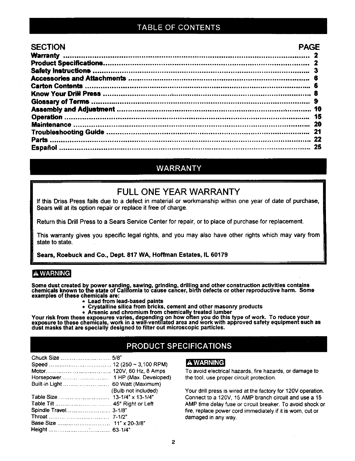
Chuck Size ............................ 5/8"
Speed ................................... 12 (250 ~ 3,100 RPM)
Motor .................................... 120V, 60 Hz, 8 Amps
Horsepower ........................... 1 HP (Max. Developed)
Built-in Light ......................... 60 Watt (Maximum)
(Bulb not included)
Table Size ............................ 13-1/4" x 13-1/4"
Table Tilt ............................... 45 ° Right or Left
Spindle Travel ........................ 3-1/8"
Throat ................................. 7-1/2"
Base Size ............................. 11" x 20-3/8"
Height ...................... :........... 63-1/4"
To avoid electrical hazards, fire hazards, or damage to
the tool, use proper circuit protection.
Your drill press is wired at the factory for 120V operation.
Connect to a 120V, 15 AMP branch circuit and use a15
AMP time delay fuse or circuit breaker. To avoid shock or
fire, replace power cord immediately if it is worn, cut or
damaged in any way.
2
GENERAL SAFETY INSTRUCTIONS 14.
BEFORE USING THE DRILL PRESS
Safety is a combination of common sense, staying alert
and knowing how to use your ddll press. 15.
REMOVE ADJUSTING KEYS AND WRENCHES.
Form the habit of checking to see that keys and
adjusting wrenches are removed from the tool before
turning =ON".
NEVER LEAVETOOL RUNNING UNATFENDED.
TURN THE POWER "OFF". Don't leave the tool until
it comes to a complete stop.
To avoid mistakes that could cause sedous injury, do not 16. NEVER STAND ON TOOL Sedous injurycould occur
plug the drill press in until you have read and understood if the tool is Upped or ifthe cuffingtool is unintentionally
the following: contacted.
1. READ and become familiar with this entire instruction
manual.LEARN the tool's applications,limitstJons,and
possiblehazards.
2. KEEP GUARDS IN PLACE and in working order.
3. DON'T USE IN A DANGEROUS ENVIRONMENT.
Don't use power tools in damp or wet locations, or
expose them to rain. Keep work area well lighted.
4. DO NOT use power tools in the presence of flammable
liquidsor gases.
5. KEEP WORK AREA CLEAN. Cluttered areas and
benches inviteaccidents.
6. KEEP CHILDREN AWAY.AUvisitorsshould be kept at
a safe distance from the work area.
7. DON'T FORCE THE TOOL. It Willdo the job better
and safer at the rate for which it was designed.
8. USETHE RIGHTTOOL. Don't force tool or the
attachment to do ajob for which it was not designed.
.WEAR PROPER APPAREL DO NOT wear loose
clothing, gloves, neckties, rings, bracelets, or other
_lowelrywhich may get caught in moving parts.
onslip footwear is recommended. Wear protective
hair covering to contain long hair.
10. WEAR A FACE MASK OR DUST MASK.
Drillingoperation produces dust.
11. DISCONNECTTOOLS before servicing, and when
changing accessories, such as blades, bits, ct_ttem,
and the like.
12. REDUCETHE RISK OF UNINTENTIONAL STARTING.
Make sure the switch is in "OFF" position before
plugging in.
13. USE RECOMMENDED ACCESSORIES. Consult the
owner's manual for the recommended accessories.
The use of improper accessories may cause risk of
injury to persons.
17. DON'T OVERREACH. Keep proper footing and
balance at all times.
18. MAINTAIN TOOLS WITH CARE. Keep tools sharp
and clean for best and safest performance. Follow
instructionsfor lubricating and changing accessories,
19. CHECK FOR DAMAGED PARrs. Beforefurther use of
the tool,a guard or other pert that is damaged should
be carefully checked to determine that it will operate
property and perform its intended function.Check for
alignment of movingparts, binding of moving parts,
breakage of parts, mounting,and any other conditions
that may affect its operation.A guard or other part that
is damaged should be properly repaired or replaced.
20. MAKE WORKSHOP laD PROOF withpadlocks,master
switches, or by removing starter keys.
21.
22.
DO NOT operate the tool if you are underthe influence
of any drugs, alcohol or medication that could affect
your abilityto use the tool properly.
Dust generated from certain materials can be
hazardous to your health. Always operate the drill
press in a well-ventilated area and provide for proper
dust removal. Use dust coflection systems whenever
possible.
23. ALWAYS WEAR EYE
PROTECTION. Any ddll press
can throw foreign objects into
the eyes which could cause
permanent eye damage.
ALWAYSwear Safety Goggles
(not glasses) that comply with
ANSI safety standard Z87.1. Everyday eyeglasses
have only impact-resistant lenses. They ARE NOT
safety glasses. Safety Goggles are available at Seam.
NOTE: Glasses or goggles not in compliance with
ANSI Z87.1 could seriouslyhurt you when they break.
SAVE THESE INSTRUCTIONS
3
SPECIFIC SAFETY INSTRUCTIONS
FOR THE DRILL PRESS
14.SECURE WORK. Usa clamps or vise to holdthe
work when practical. It's safer than using your hand
and it frees both hands to operate tool,
For your ownsafety, do nottry to use yourdrill press or
plug it in untilit is completelyassembled and installed
accordingto the instructions,and untilyou have read
and understoodthis instrucbonmanual:
15.WHEN usinga drill pressvise, always fasten to the
table.
16.MAKE SURE allclamps and locksare firmly
tightened before drilling.
1. YOUR DRILL PRESS MUST BE BOLTED securely
to a workbench. In addition, if there is any tendency
for your drillpressto move duringcertain operations,
boltthe workbenchto the floor.
2. THIS DRILL PRESS is intended for usa indry
conditions,indooruse only.
3. WEAR EYE PROTECTION. USE face or dustmask
alongwithsafety goggles if drillingoperation is dusty.
USE ear protectors,especially duringextended
periodsof operation.
4. DO NOT wear gloves, neckties, or looseclothing
5. DO NOT try to drillmaterial too smallto be securely
held.
6. ALWAYS keep hands out of the path of a drill bit.
Avoidawkward hand positionswhere a sudden slip
couldcause your hand to move into the drill bit.
7. DO NOT installor use any drill bit that exceeds 175
mm (7") in lengthor extends 150 mm (6") below
thechuckjaws. They can suddenly bend outwardor
break.
8. DO NOT USE wire wheels, router bits, shaper cutters,
circle(fly) cutters,or rotary planerson thisdrill press.
17.SECURELY LOCK THE HEAD and table supper to
the column, and the table to the table supportbefore
operatingthe drillpress.
18.NEVER turn your drill presson before clearing the
table of allobjects (tools,scrapsof wood, etc.)
19.BEFORE STARTING the operation,jog the motor
switchto make sure the drill bitdoes notwobbleor
vibrate.
20.LET THE SPINDLE REACH FULL SPEED before
startingto drill.If your drillpress makes an unfamiliar
noise or if it vibrates excessively,stop immediately,
turn the drillpress off and unplug. Do not restartuntil
the problem is corrected.
21.DO NOT perform layoutassembly or set up work on
the tablewhile the drill press is in operation.
22.USE RECOMMENDED SPEED for drill accessory
and workpiecematerial. SEE INSTRUCTIONS that
come withthe accessory
23.WHEN DRILLING large diameter holes,clamp the
workpiece firmlyto the table. Otherwise, the bitmay
grap and spin the workpieceat high speed. DO NOT
USE fly cuttersor multiple-parf hole cutters,as they
can come apart or become unbalancedin use.
9. WHEN cuttinga large piece of material make sure it
is fully supportedat the table height. 24.MAKE SURE the spindle has come to a complete
stop before touching the workpiece.
10.DO NOT perform any operation freehand. ALWAYS
holdthe workpiece firmly against the table so it will
notreck or twist. Use clamps or a vise for unstable
workpiece.
11.MAKE SURE there are no nailsor foreign objects in
the partof the workpieceto be drilled.
12.CLAMP WORKPIECE OR BRACE against the left
side of the columnto prevent rotation.If it is too short
or the table is tilted, clamp solidlyto the table and use
the fence provided.
25.TO AVOID INJURY from accidental starting,always
turn the switch"OFF" and unplugthe drill press
before installingor removing any accessoryor
attachmentor making any adjustment
26.KEEP GUARDS IN PLACE and inworkingorder.
27.USE ONLY SELF-EJECTING TYPE CHUCK KEY as
providedwiththe drill press
13.IF THE WORKPIECE overhangs the table such that
it will fall or tip if not held, clamp it to the table or
provide auxiliary support.
SAVE THESEINSTRUCTIONS
GROUNDING INSTRUCTIONS
IN THE EVENT OF A MALFUNCTION OR
BREAKDOWN, groundingprovidesa path of least
resistancefor electric currentand reduces the riskof
shock. This tool is equipped withan electric cordthat
has an equipmentgroundingconductorand grounding
plug.The plugMUST be pluggedintoa matching
receptacle that is properlyinstalledand grounded in
accordancewithALL local codesand ordinances.
DO NOT MODIFY THE PLUG PROVIDED. If it will notfit
the receptacle,have the proper receptacle installedby a
qualifiedelectdcian.
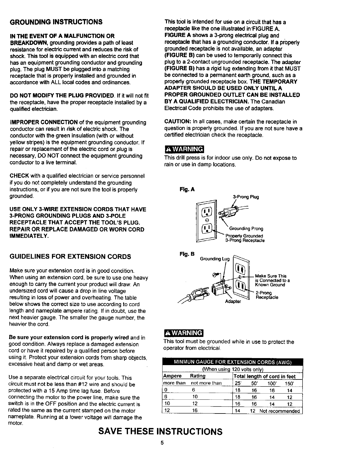
This tool is intendedfor use on a circuitthat has a
receptacle like the one illustratedin'FIGURE A.
FIGURE A shows a 3-prongelectricalplug and
receptacle that has a groundingconductor.If a pmparly
groundedreceptacle is notavailable, an adaPter
(FIGURE B) can be usedto temporarilyconnectthis
plugto a 2-contact ungroundedreceptacle.The adapter
(FIGURE B) has a rigid lug extendingfrom it that MUST
be connectedto a permanent earth ground,such as a
properlygrounded receptacle box. THE TEMPORARY
ADAPTER SHOULD BE USED ONLY UNTIL A
PROPER GROUNDED OUTLET CAN BE INSTALLED
BY AQUALIFIED ELECTRICIAN. The Canadian
ElectricalCode prohibitsthe use of adapters.
IMPROPER CONNECTION of the equipment grounding
conductorcan result inrisk of electricshock. The
conductorwiththe green insulation(withor without
yellow stripes)is the equipment groundingconductor.If
repair or replacementof the electriccordor plug is
necessary, DO NOT connectthe equipment grounding
conductorto a liveterminal.
CHECK with a qualified electrician orservice personnel
if you do notcompletelyunderstandthe grounding
instructions,or if you are notsure the tool is properly
grounded.
USE ONLY 3-WIRE EXTENSION CORDS THAT HAVE
3oPRONG GROUNDING PLUGS AND 3-POLE
RECEPTACLE THAT ACCEPT THE TOOL'S PLUG.
REPAIR OR REPLACE DAMAGED OR WORN CORD
IMMEDIATELY.
CAUTION: In all cases, make certain the receptacle in
questionis properlygrounded. If you are notsure have a
certifiedelectriciancheck the receptacle.
This drill press is for indoor use only. Do not expose to
rain or use in damp locations.
Flg. A
3-Prong Plug
_" p.rGprroP_o°nl_;_o_nrin;e
GUIDELINES FOR EXTENSION CORDS Fig. B GroundingLug
Make sure yourextension cord is ingood condition.
When usingan extensioncord, be sure to use one heavy
enoughto carrythe current your productwill draw. An
undersizedcord will cause a dropin line voltage
resultingin lossof power and overheating. The table
belowshowsthe correct size to use accordingto cord
length and nameplate ampere rating. If in doubt, use the
next heavier gauge. The smallerthe gauge number, the
heavier the cord.
Adapter
is Connected to a
Known Ground
Be sure your extension cord is properly wired and in
goodcondition.Always replace a damaged extension
cordor have it repaired by a qualifiedperson before
usingit. Protectyour extensioncords from sharp objects,
excessive heat and damp or wet areas rdI_ hV_lll_[e_-*ll[el na al] :s :1,:(ii :1_K'I[el _[l(e] _| i},.llr:t tjLt/t.
Use a separate electrical circuit for your tools. This
circuit must not be less than #12 wire and should be
protected with a15 Amp time lag fuse. Before
connecting the motor to the power line, make sure the
switch is in the OFF position and the electric current is
rated the same as the current stamped on the motor
nameplate. Running at a lower voltage will damage the
motor.
This tool must be grounded while in use to protect the
operator from electrical.
(When usinc
6,mpere Rating
more than not more than
0 6
610
10 12
12 16
SAVE THESE INSTRUCTIONS
120 volts only)
Total length of cord in feet
25' 50' 100' 150'
18 16 16 14
18 16 14 12
16 16 14 12
14 12 Not recommended
RECOMMENDED ACCESSORIES UNPACKING AND CHECKING CONTENTS
r_r/_J=-KqKE=]
Use onlyaccessorierrecommended for this drillpress.
Followinstructionsthat accompany accessories.Use of
improperaccessoriesmay cause hazards.
Visityour Sears Hardware Department or see the
Craftsman Power and Hand Tools Catalog for the
following accessories:
• Drill bits
•Hold-Down and Guide
•DrillpressVises
•Clamping kit
If any part is missingor damaged, do not plugthe drill
pressin untilthe missingor damaged part is replaced,
and assemblyis complete.
Carefully unpack the drill press and all its parts, and
compare againstthe list below.
To protectthe drillpress from moisture,a protective
coatinghas been applied to the machinedsurfaces.
Remove thiscoating with a soft clothmoistenedwith
kerosene or WD-40.
.r_rArl,_1d _11_[e
Use only accessoriesdesigned for this drill pressto avoid
injuryfrom thrownbrokenparts or workpieces.
Sears may recommend other accessories not listed in
this manual. See your nearest Sears store or Power and
Hand Tool Catalog for other accessories.
Do not use may accessoryunless you have completely
readthe instruction or operator'smanual for that
accessory.
To avoidfire or toxic reaction, never use gasoline,
naphtha, acetone, lacquerthinner or similarhighly
volatilesolventsto clean the drill press.
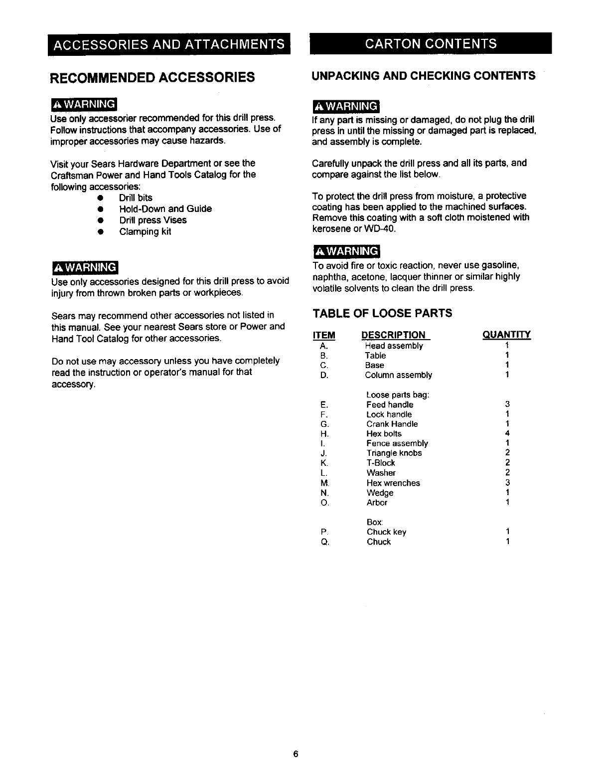
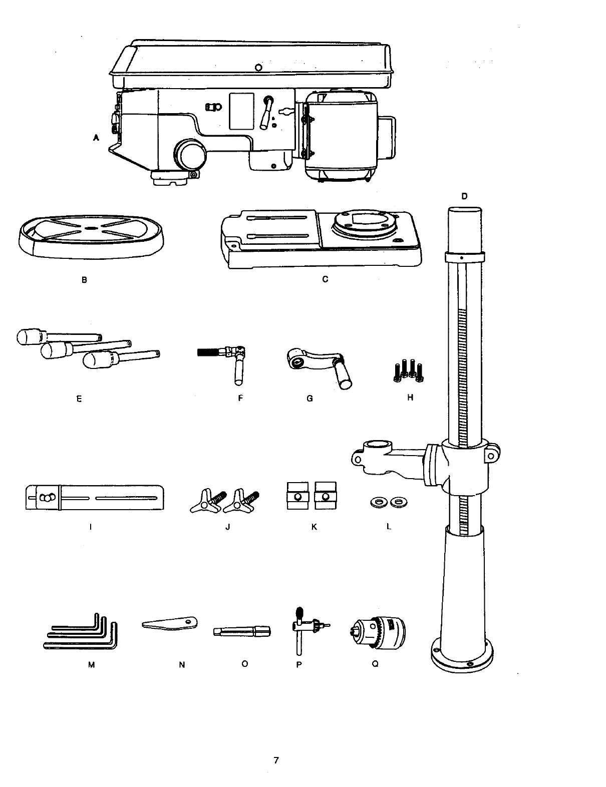
TABLE OF LOOSE PARTS
ITEM DESCRIPTION QUANTITY
A. Head assembly t
B. Table 1
C. Base 1
D. Column assembly 1
Loose parts bag:
E. Feed handle
F. Lock handle
G. Crank Handle
H. Hex botts
I. Fence assembly
J. Triangle knobs
K. T-Block
L, Washer
M. Hex wrenches
N. Wedge
O. Arbor
Boxz
P. Chuckkey
Q. Chuck
3
1
1
4
1
2
2
2
3
1
1
8
I
0
7
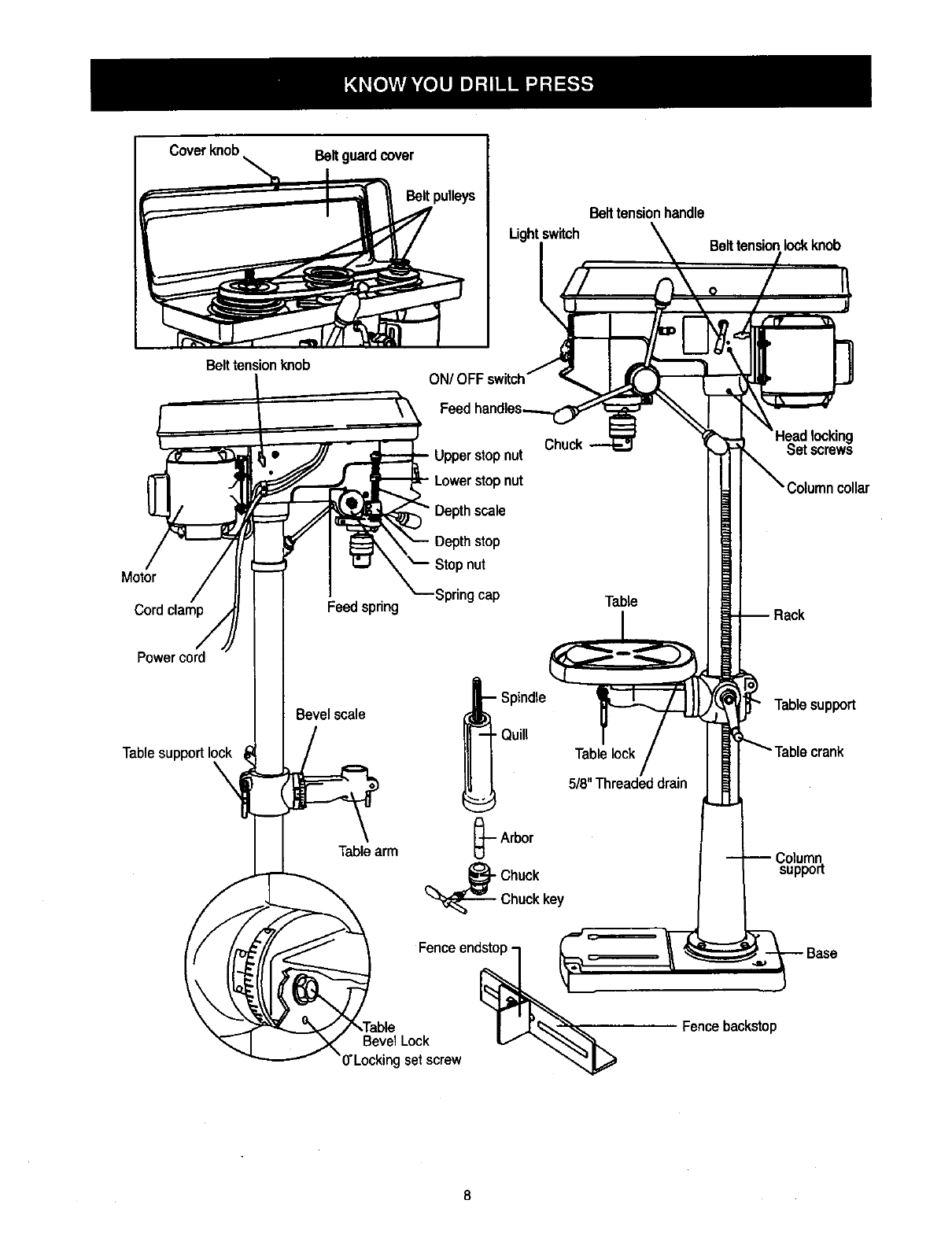
Coverknob\Beltguardcover
Belt pulleys
Lightswitch
Belt tensionhandle
Belttensionlock knob
Belttensionknob
Motor
Cordclamp
Power cord
Table support I(
Feedspring
Bevel scale
• Upperstopnut
-Lowerstopnut
Depthscale
Depthstop
Stopnut
Springcap
-- Spindle
•Quill
Table
Tablelock
5/8"Threadeddrain
Set screws
Tablesupport
Tablearm -.-Arbor
(_Chuck
Chuckkey
Column
support
Fenceend_\
Bevel Lock V_"_,,_
)'Locking setscrew
Fencebackstop
BASE - Supportsdrill press. For additionalstability,
holesare providedin base to bolt drillpressto floor.
(See "Specific Safety Instruction for Drill Presses.")
BACKUP MATERIAL - Apiece of scrapwood placed
betweenthe workpieceand table. The backup beard
preventswood in the workpiecefrom splintedngwhen
the drillpasses throughthe backsideof the workpiece. It
alsoprevents drillingintothe table top.
BELT GUARD ASSEMBLY - Covers the pulleysand
beltduringoperationof the drillpress.
BELT TENSION - Refer to the "Assembly" Section,
"Installingand Tensioning Belt.".
BELT TENSION HANDLE - Turn the handle clockwise
to apply tensionto belt, turnthe handle counterclockwise
to release belttension.
BELT TENSION LOCK KNOBS - Tighteningthe knobs
locksthe motor bracket supportand the belttension
handle, maintainingcorrect beltdistance and tension.
BEVEL SCALE - Shows degree of table tilt for bevel
operaions. The scale is mounted on the side of the arm.
CHUCK - Holdsdrill bit or other recommended
accessoryto performdesired operations.
CHUCK KEY - A self-ejectingchuckkey whichwill pop
outof the chuckwhen you let go of it.This actionis
designedto help preventthrowingof the chuck keyfrom
the chuckwhen the peer is turned ON. Do not use any
other key as a substitute; ordera new one if hamaged or
lost.
COLUMN - Connects the head, table, and base on a
one piecetube for easy alignment and movement.
COLUMN COLLAR - Holds the rack to the column.
Rack remains movable in the collarto permit table
support movements.
COLUMN SUPPORT - Supports the column, guides the
rack and providesmountingholes for columnto base.
DEPTH SCALE STOP NUTS - Lock the spindle to the
selected depth.
DEPTH SCALE - Indicates depth of hole being drilled.
DRILL BIT -The cutting tool used in the drill press to
make holes in aworkpiece.
DRILL ON/OFF SWITCH - Has lockingfeature. This
feature is intended to help prevent unauthorizedand
possible hazardous use by children and others. Insert
the key into the switch to turn the drill press on.
DRILLING SPEED - Changed by placingthe belt in any
of the steps (grooves) inthe pulleys.See the Spindle
Speed Chart insidebeltguard.
FEED HANDLE - Moves the chuckup or down.IF
necessary, one ortwo of the handles may be removed
whenever the workpiece is of suchunusualshape that it
interfereswith the handles.
FENCE - Attaches to the table to alignthe workpieceor
for fast repetitivedrilling.Removable. Removefence
when it interfereswith other drillpress accessories.
HEAD LOCKS - Locks the head to the column.
ALWAYS lockthe head in placewhile operatingthe drill
press.
RACK - Combines withgear mechanism to provide
easy elevationof the table by the hand operated table
crank.
REVOLUTION PER MINUTE (R.P.M.)- The numberof
turns completedby a spinningobject in one minute.
SPINDLE SPEED - The RPM. of the spindle.
SPRING CAP - Adjusts quill spring tension.
TABLE SUPPORTS LOCK - Tighteninglocksthe table
supportto column. Always have it lockedin placewhile
operatingthe dirll press.
TABLE - Provides a working surface to supportthe
workpiece.
TABLE ARM - Extends beyond the table supportfor
mounting and aligning the table.
TABEL BEVEL LOCK - Locks the table in any position
from 0° - 45°
TABLE CRANK - Elevates and lowers the table. Turn
clockwise to elevate the table. Support lock must be
released before operating the crank.
TABLE LOCK - Locksthe table after it is rotated to
variouspositions.
TABLE SUPPORT - Rides on the column to supportthe
table arm and table.
THREADED DRAIN (518")- Attach a5/8" (pipe
threaded) metal pipe to the threaded opening for
drainingexcees oil into container.For a non-draining
surfaceattach a threaded metal plug.Pipe and plugnot .
included.
WORKPIECE - Material being drilled.
ASSEMBLY INSTRUCTIONS
Foryourownsafety, neverconnectplugto power
sourceoutletuntilall assemblyand adjustmentsteps
are completed, andyou have readand understood
the safetyandoperatinginstructions.
TOOLS NEEDED
_w_encb
III tlilt IIIt_
Frw_ing
8"S 10"AdJustab__
Comb_e_m_tre
The DdlTPress is very heavy and MUST be liftedwiththe
helpof 2 PEOPLE OR MORE, to safetyassembly it.
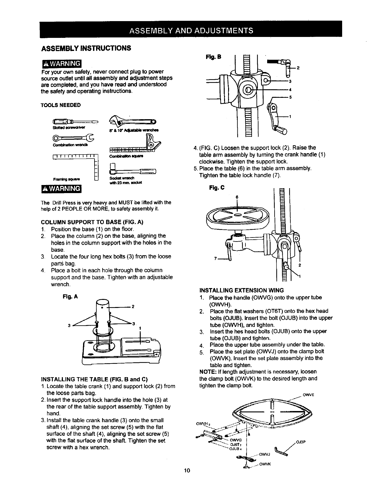
COLUMN SUPPORT TO BASE (FIG. A)
1. Position the base (1) on the floor.
2. Place the column (2) on the base, aligning the
holes in the column support with the holes in the
base.
3. Locate the four long hex bolts (3) from the loose
parts bag.
4. Place a bolt in each hole through the column
support and the base. Tighten with an adjustable
wrench.
i
INSTALLING THE TABLE (FIG. B and C)
1. Locate the table crank (1) and support lock (2) from
the loose parts bag.
2. Insert the support lock handle into the hole (3) at
the rear of the table support assembly. Tighten by
hand.
3. InstaJIthe table crank handle (3) onto the small
shaft (4), aligning the set screw (5) with the flat
surface of the shaft (4), aligning the set screw (5)
with the fiat surface of the shaft. Tighten the set
screw with a hex wrench.
10
Rg. B
4. (FIG. C) Loosen the support lock (2). Raise the
table arm assembly by turning the crank handle (1)
clockwise. Tighten the support lock.
5. Place the table (6) in the table arm assembly.
Tighten the table lock handle (7).
Rg. C
INSTALLING EXTENSION WING
1. Place the handle (OWVG) onto the upper tube
(OWVH).
2. Place the flat washers (OT6T) onto the hex head
bolts (OJUB). Insert the bolt (OJUB) into the upper
tube (OWVH), and tighten.
3. Insertthe hes head bolts (OJUB) onto the upper
tube (OJUB) and tighten.
4. Place the upper tube assembly under the table.
5. Place the set plate (OWVJ) onto the clamp bolt
(OWVK). Insert the set plate assembly into the
table and tighten.
NOTE: If length adjustment is necessary, loosen
the clamp bolt (OWVK) to the desired length and
tighten the clamp bolt.
OWVE
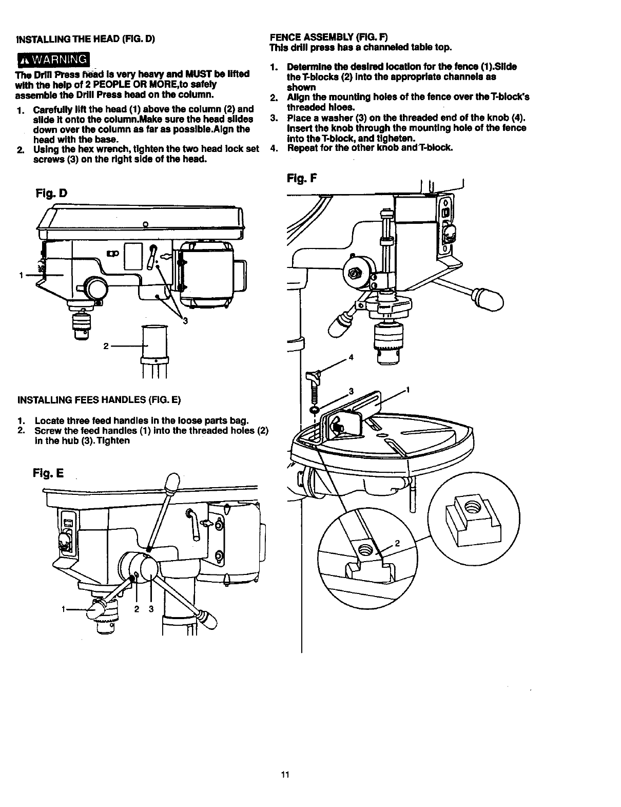
INSTALLING THE HF.AD (FIG. D)
mvl/_d_ql K_
The Drill Press h_d Is very heavy and MUST be lifted
with the help of 2 PEOPLE OR MORE,to safely
assemble the Drill Press head on the column.
1. Carefully lift the head (1) above the column (2) and
slide it onto the column.Make sure the head slldea
down over the column as far as poealble.Algn the
head with the base.
2. Using the hex wrench, tighten the two head lock eat
screws (3) on the right side of the head.
Fig. D
"ry
J
_3
INSTALLING FEES HANDLES (FIG. E)
1. Locate three feed handles in the loose parts bag.
2, Screw the feed handles (1) into the threaded holes (2)
in the hub (3), Tighten
FENCE ASSEMBLY (FIG. F)
This drill press has a channeled table top.
1. Determine the desired location for the fence (1).Sllde
theT-blocks (2) Into the appropriate channels as
shown
2. Align the mounting holes of the fence over theT-block's
threaded hloes.
3. Place a washer (3) on the threaded end of the knob (4).
Insert the knob through the mounting hole of the fence
into the T-block,and Ugbetan.
4. Repeatfor the other knob andT-block.
Fig. F
11
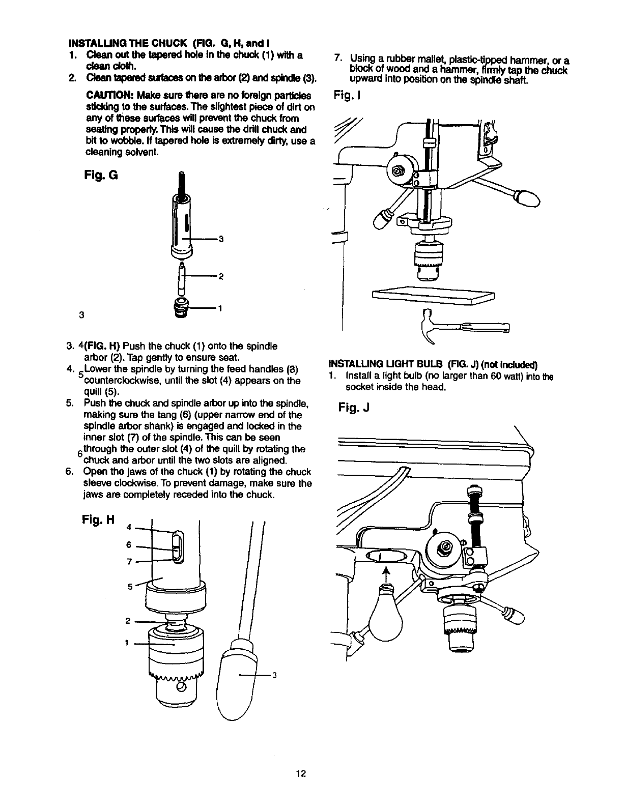
INSTALUNG THE CHUCK (FIG. G, H, and I
1. Clean out the tapered hole In the chuck (1) wltha
CkHlndoth.
2. Clean tapered surfacasonthe arbor(2) and spindle(3).
CAUTION: Make sure there am no foreign particles
stk:kingto the surfaces.The slightestpiece of dirt on
any of these surfaces will prevent the chuck from
seating properly.This will cause the ddll chuck and
bit to wobble. If tapered hole is extremely dirty, use a
cleaning solvent.
Fig. G
7. Using a robber mallet, plastic-tipped hammer, or a
mOCKOTwood and a hammer, firmlytap the chuck
upward into posi_n on the spindle shaft.
Fig. I
3. 4(FIG. H) Push the chuck(1) onto the spindle
arbor (2). Tap gently to ensure seat.
4. 5Lower the spindle by turning the feed handles (8)
countemlockwise, untilthe slot (4) appears on the
quill (5).
5. Push the chuck and spindlearborup into the spindle,
making sure the tang (6) (upper narrow end of the
spindle arbor shank) is engaged and locked in the
inner slot (7) of the spindle.This can be seen
throughthe outer slot (4) of the quill by rotatingthe
chuck and arbor untilthe two slotsare aligned.
6. Open the jaws of the chuck (1) by rotating the chuck
sleeve clockwise.To prevent damage, make sure the
jaws are completely receded into the chuck.
Fig. H 4 _. "----,_ I
INSTALLING UGHT BULB (RG. J) (not Included)
1. Installalight bulb(no larger than 60 watt)intothe
socket inside the head.
Fig. J
12
DRILL PRESS ADJUSTMENTS
CAUTION: All the adjustments for the opera,on of the
ddl press have been completed at the lectory.Due to
normalwear and use, some occasional madjustmente
may be necessary.
!_W_,I -'l_l_[el
Topreventpersonalinjury,a dys ciscor. thepaugfnxn
the powersourcewhen ma;dnganyadjustments
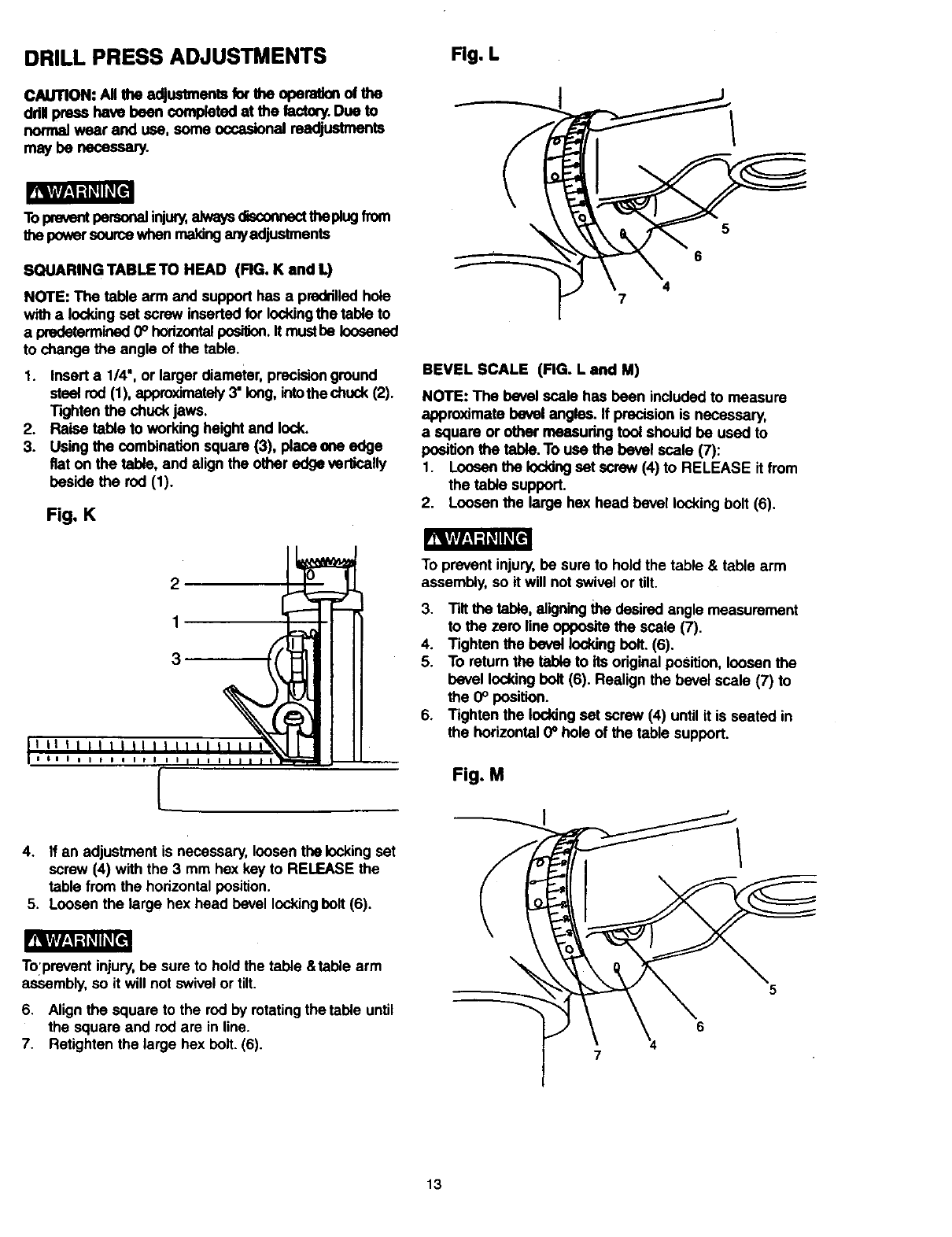
SQUARING TABLE TO HEAD (RG. K and L)
NOTE: The table arm and support has a preddlledhole
withalockingset screw insertedfor lockingthe table to
a predetermined0° horizontal_. It must be loosened
to change the angle of the table.
1. Insert a 1/4", or larger diameter,precisionground
stsetrod (1), approximately3" long,intothechuck(2).
Tighten the chuckjaws.
2. Raise table to working heightand lock.
3. Usingthe combinationsquare (3), placeena edge
fiat on the tebie, and alignthe other edge verlfoally
beside the rod (1).
Fig. K
Fig. L
5
6
4
7
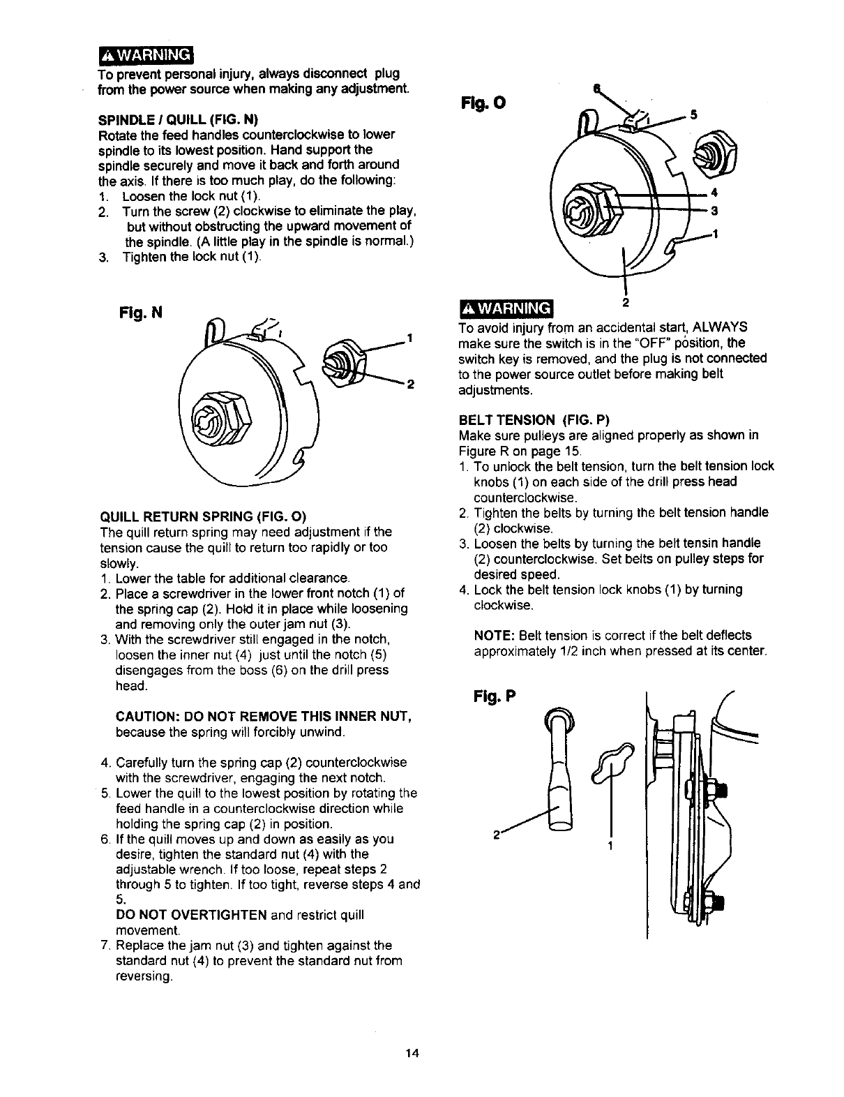
BEVEL SCALE (FIG. L and M)
NOTE: The bevel scale has been included to measure
approximate bevel angles. If precision is necessary,
a square or other measuring tool should he used to
positionthe table.To use the bevel scale (7):
1. Loosenthe Ioddngset screw (4) to RELEASE it from
the table support.
2. Loosen the large hex head bevel locking bolt (6).
2
1
3
IIIIIIIIII I I[
4. If an adjustment is necessary, loosen the lockingset
screw (4) with the 3 mm hex key to RELEASE the
table from the horizontal position.
5. Loosen the large hex head bevel lockingbolt (6).
Tolprevent injury,be sure to hold the table &table arm
assembly, so it will not swivelor tilt.
6. Align the square to the red by rotating the table until
the square and rod are in line.
7. Retighten the large bex belt. (6).
To prevent injury,be sure to holdthe table & table arm
assembly, so it will not swivel or tilt.
3. Tilt the table, aligningthe desired angle measurement
to the zero line opposite the scale (7).
4. Tighten the bevel lockingbolt. (6).
5. To returnthe table to its original position, loosen the
bevel lockingbolt (6). Realign the bevel scale (7) to
the 0° position.
6. Tighten the locking set screw (4) untilit is seated in
the horizontal 0_hole of the table support.
Fig. M
5
6
7
13
_[wr_,1 =t_'llKl[e_
To prevent personal injury,always disconnect plug
from the power source when making any adjustment.
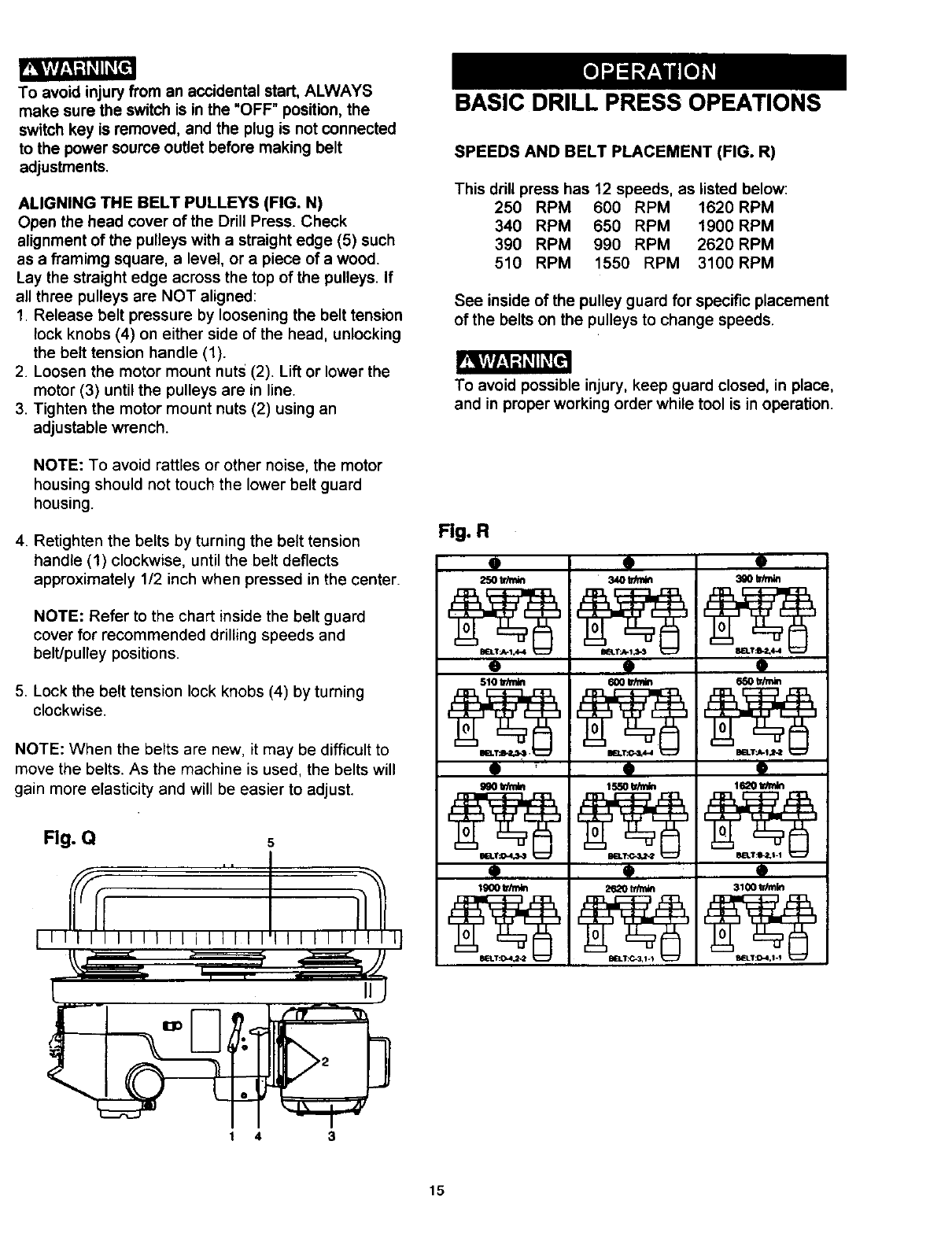
SPINDLE IQUILL (FIG. N)
Rotate the feed handles counterclockwiseto lower
spindleto its lowestposition. Hand supportthe
spindlesecurely and move it back and forth around
the axis. If there is too much play, do the following:
1. Loosenthe lock nut(1).
2. Turn the screw (2) clockwiseto eliminate the play,
butwithoutobstructingthe upward movement of
the spindle. (A little play in the spindle is normal.)
3. Tighten the lock nut(1).
Fig. O
Fig. N
QUILL RETURN SPRING (FIG. O)
The quill returnspring may need adjustment ifthe
tensioncause the quillto returntoo rapidly or too
slowly.
1. Lowerthe table for additionalclearance.
2. Place a screwdriver in the lower front notch (1) of
the springcap (2). Hold it in place while loosening
and removingonly the outer jam nut (3).
3. With the screwdriverstillengaged inthe notch,
loosenthe inner nut(4) just untilthe notch(5)
disengages from the boss (6) on the drill press
head.
CAUTION: DO NOT REMOVE THIS INNER NUT,
because the springwill forcibly unwind.
4. Carefully turn the spring cap (2) counterclockwise
with the screwdriver, engaging the next notch.
5. Lower the quill to the lowest position by rotating the
feed handle in a counterclockwise direction while
holding the spring cap (2) in position.
6. If the quill moves up and down as easily as you
desire, tighten the standard nut (4) with the
adjustable wrench. If too loose, repeat steps 2
through 5 to tighten. If too tight, reverse steps 4 and
5.
DO NOT OVERTIGHTEN and restrict quill
movement.
7. Replace the jam nut (3) and tighten against the
standard nut (4) to prevent the standard nut from
reversing.
2
To avoid injury from an accidental start, ALWAYS
make sure the switch is in the "OFF" position, the
switch key is removed, and the plug is not connected
to the power source outlet before making belt
adjustments.
BELT TENSION (FIG. P)
Make sure pulleysare aligned properly as shown in
Figure R on page 15.
1. To unlockthe belt tension, turn the belt tensionlock
knobs (1) on each side of the drill presshead
counterclockwise.
2. Tighten the belts by turningthe belt tension handle
(2) clockwise.
3. Loosenthe beltsby turning the belt tensin handle
(2) counterclockwise.Set belts on pulleysteps for
desired speed.
4. Lockthe belt tensionlockknobs (1) by turning
clockwise.
NOTE: Belt tension is correct if the belt deflects
approximately 1/2 inch when pressed at its center.
Fig. P
14
_vlvh_ =1_[I
To avoid injury from an accidental start, ALWAYS
make sure the switch is in the "OFF" position, the
switch key is removed, and the plug is not connected
to the power source outlet before making belt
adjustments.
ALIGNING THE BELT PULLEYS (FIG. N)
Open the head cover of the Drill Press. Check
alignment of the pulleys with a straight edge (5) such
as a framimg square, a level, or a piece of a wood.
Lay the straight edge across the top of the pulleys. If
all three pulleys are NOT aligned:
1. Release belt pressure by loosening the belt tension
lock knobs (4) on either side of the head, unlocking
the belt tension handle (1).
2. Loosen the motor mount nuts (2). Lift or lower the
motor (3) until the pulleys are in line.
3. Tighten the motor mount nuts (2) using an
adjustable wrench.
NOTE: To avoid rattles or other noise, the motor
housing should not touch the lower belt guard
housing.
4. Retighten the belts by turning the belt tension
handle (1) clockwise, until the belt deflects
approximately 1/2 inch when pressed in the center.
NOTE: Refer to the chart inside the belt guard
cover for recommended drilling speeds and
belt/pulley positions.
5. Lock the belt tension lock knobs (4) by turning
clockwise.
NOTE: When the belts are new, it may be difficult to
move the belts. As the machine is used, the belts will
gain more elasticity and will be easier to adjust.
Fig. Q
BASIC DRILL PRESS OPEATIONS
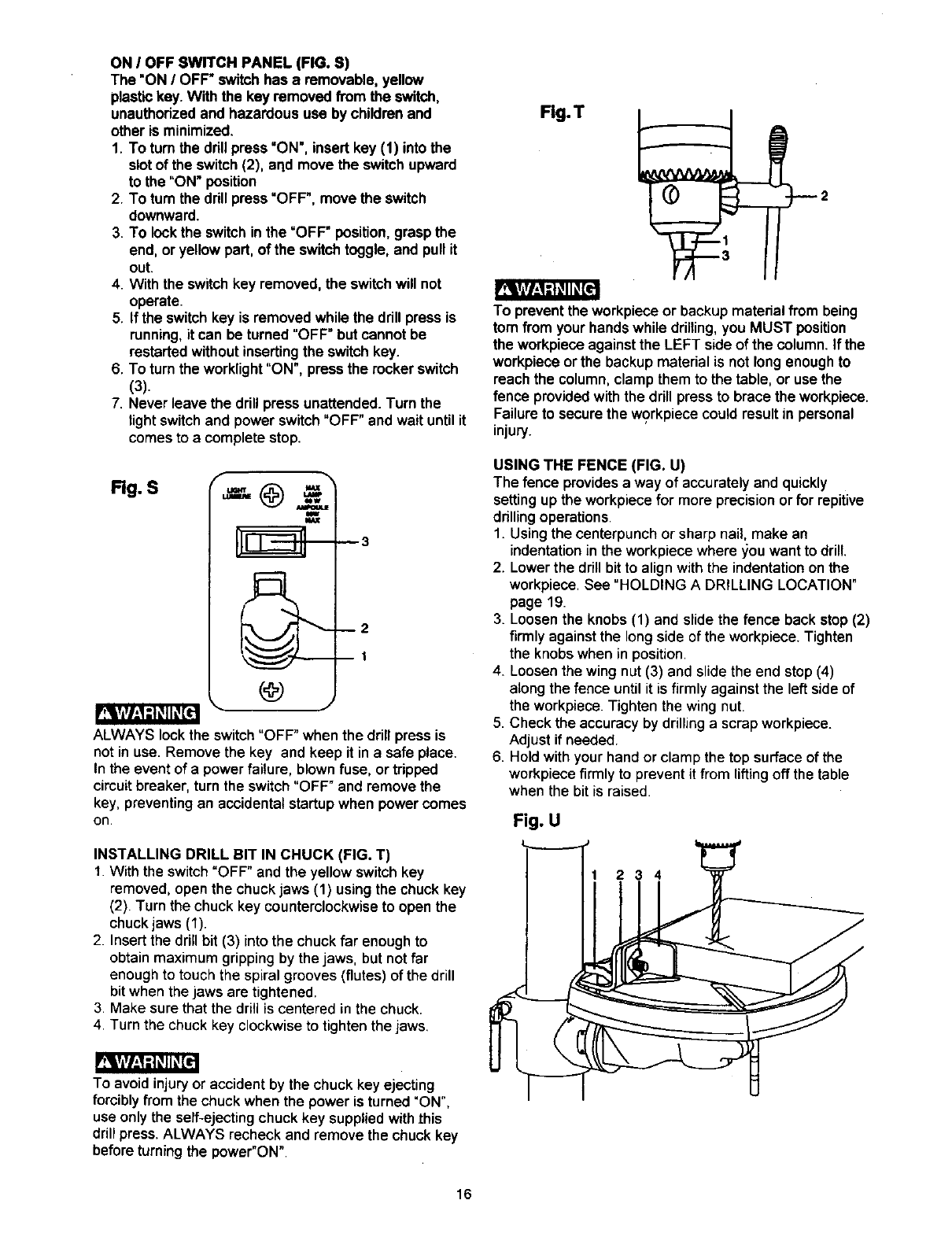
SPEEDS AND BELT PLACEMENT (FIG. R)
This drill press has 12 speeds, as listed below:
250 RPM 600 RPM 1620RPM
340 RPM 650 RPM 1900RPM
390 RPM 990 RPM 2620 RPM
510 RPM 1550 RPM 3100RPM
See inside of the pulley guard for specific placement
of the belts on the pulleys to change speeds.
To avoid possible injury, keep guard closed, in place,
and in proper working order while tool is in operation.
Fig. R
9
250 trim_
o
510 tdmin
i
9
9
9
9
9
9
Q
9
9
3100 tr_lin
14 3
15
ON IOFF SWITCH PANEL (FIG. S)
The "ON IOFF" switchhas a removable, yellow
plastickey. With the key removed from the switch,
unauthorizedand hazardous use by childrenand
other is minimized.
1. To turnthe drillpress "ON', insert key (1) into the
slotof the switch(2), aqd move the switchupward
to the "ON" position
2. To turn the drill press"OFF', move the switch
downward.
3. To lockthe switchinthe =OFF" position, grasp the
end, or yellow part, of the switchtoggle, and pullit
out.
4. With the switchkey removed, the switchwill not
operate.
5. If the switchkey is removed while the drillpress is
running,it can be turned "OFF" butcannot be
restartedwithoutinsertingthe switchkey.
6. To turnthe worklight"ON", pressthe rocker switch
(3).
7. Never leave the drill pressunattended. Turn the
lightswitchand power switch"OFF" and wait untilit
comesto a complete stop.
Rg. S f
m
_3
--2
BI
ALWAYS lock the switch"OFF" when the drill press is
not in use. Remove the key and keep it in a safe place.
In the event of a power failure, blown fuse, or tripped
circuit breaker, turn the switch "OFF" and remove the
key, preventing an accidental startup when power comes
on.
INSTALLING DRILL BIT IN CHUCK (FIG. T)
1. With the switch "OFF" and the yellow switchkey
removed, open the chuckjaws (1) usingthe chuckkey
(2). Turn the chuck key counterclockwiseto open the
chuckjaws (1).
2. Insertthe drillbit (3) into the chuck far enoughto
obtainmaximum grippingby the jaws, butnot far
enough to touch the spiralgrooves(flutes) of the drill
bitwhenthe jaws are tightened.
3. Make surethat the drillis centered inthe chuck.
4. Turn the chuckkey clockwiseto tightenthe jaws.
To avoid injury or accident by the chuckkey ejecting
forcibly from the chuck when the power is turned "ON",
use only the self-ejecting chuck key supplied with this
drill press. ALWAYS recheck and remove the chuck key
before turning the power"ON".
Fig.T
To preventthe workpieceor backup materialfrom being
tom from your hands while drilling, you MUST position
the workpiece against the LEFT side of the column. If the
workpiece or the backup material is not long enough to
reach the column, clamp them to the table, or use the
fence provided with the drill press to brace the workpiece.
Failure to secure the workpiece could result in personal
injury.
USING THE FENCE (FIG. U)
The fence provides a way of accuratelyand quickly
settingup the workpiecefor more precisionorfor repitive
drillingoperations.
1. Usingthe centerpunchor sharp nail, make an
indentationin the workpiecewhere _ou want to drill.
2. Lowerthe drillbit to alignwith the indentationon the
workpiece. See "HOLDING A DRILLING LOCATION"
page 19.
3. Loosenthe knobs (1) and slide the fence back stop (2)
firmly against the longside of the workpiece.Tighten
the knobswhen inposition.
4_ Loosenthe wing nut (3) and slide the end stop(4)
alongthe fence untilit is firmly against the left sideof
the workpiece.Tighten the wing nut.
5. Check the accuracyby drillinga scrapworkpiece.
Adjust if needed.
6. Holdwithyour hand or clamp the top surface of the
workpiecefirmly to prevent it from liftingoff the table
when the bit is raised.
Fig. U
234
16
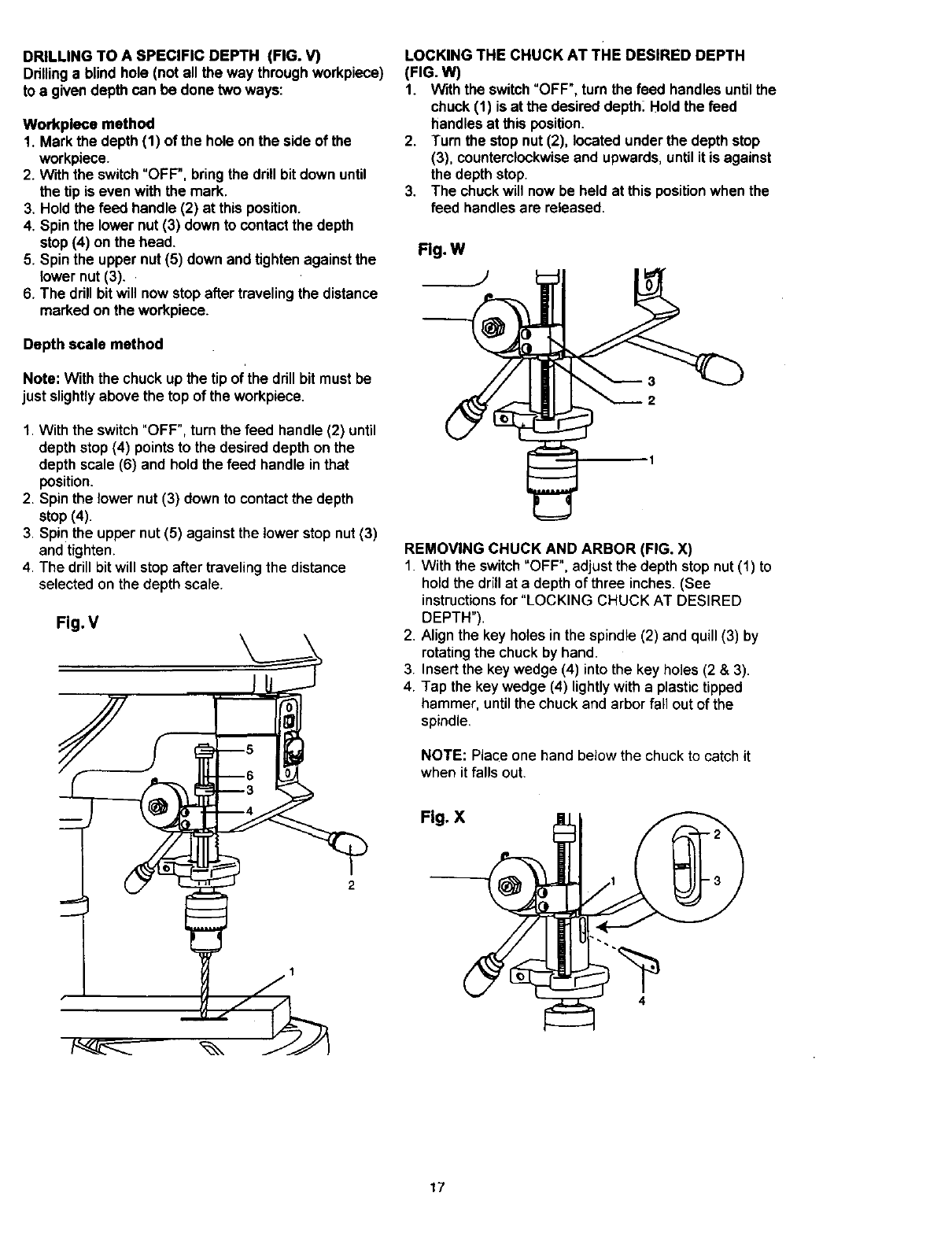
DRILLING TO A SPECIFIC DEPTH (FIG. V)
Drillinga blindhole (not all the way throughworkpiece)
to a given depth can be done two ways:
Workpleca method
1. Mark the depth (1) of the hole on the side of the
workpiece.
2. W'_ththe switch"OFF", bringthe drill bitdown until
the tip is even with the mark.
3. Hold the feed handle (2) at thisposition.
4. Spin the lower nut (3) down to contactthe depth
stop(4) on the head.
5. Spin the upper nut(5) down and tightenagainst the
lower nut (3)..
6. The drillbitwill nowstopafter travelingthe distance
marked on the workpiece.
Depth scale method
Note: With the chuckup the tipof'the drillbit must be
just slightlyabove the top of the workpiece.
1. With the switch"OFF", turn the feed handle (2) until
depth stop (4) points to the desired depth on the
depth scale (6) and hold the feed handle in that
position.
2. Spin the lower nut (3) down to contact the depth
stop (4).
3. Spin the upper nut (5) against the lower stop nut (3)
and tighten.
4. The drill bit will stop after traveling the distance
selected on the depth scale.
Fig. V
LOCKING THE CHUCK AT THE DESIRED DEPTH
(FIG. W)
1. With the switch"OFF",turn the feed handlesuntilthe
chuck (1) is at the desireddepth_Hold the feed
handlesat this position.
2. Turn the stopnut (2), located underthe depth stop
(3), counterclockwiseand upwards,untilit is against
the depth stop.
3. The chuckwill now be held at this positionwhen the
feed handlesare released.
Flg.W
REMOVING CHUCK AND ARBOR (FIG. X)
1. With the switch"OFF", adjust the depth stopnut(1) to
holdthe drillat a depth of three inches. (See
instructionsfor "LOCKING CHUCK AT DESIRED
DEPTH").
2. Align the key holes inthe spindle (2) and quill(3) by
rotatingthe chuckby hand.
3. Insertthe key wedge (4) into the key holes (2 & 3).
4. Tap the key wedge (4) lightlywith aplastictipped
hammer, until the chuckand arborfall out of the
spindle.
NOTE: Place one hand below the chuck to catch it
when it falls out.
Fig. X
S4
17
BASIC OPERATION INSTRUCTIONS
To get the best results and minimize the likelihoodof
personalinjury,follow these instructionsfor operating
your drillpress.
For your ownsafety, always observe the SAFETY
INSTRUCTIONS listedhere and on pages 3, 4 and 5
of the instructionmanual.
YOUR PROTECTION
To avoid being pulled intothe power tool,do notwear
looseclothing,gloves,neckties, orjewelry. Always tie
back longhair.
1. If any part of your drill press is missing, malfunctioning,
damaged or broken, stopoperation immediatelyuntil
that partis properlyrepaired or replaced.
2. Never placeyour fingers in a positionwhere they
couldcontactthe drill bitor other cuttingtool. The
workpiecemay unexpectedly shift,or your hand could
slip.
3. To avoid injuryfrom partsthrownby the spring,follow
instructionsexactly when adjustingthe springtension
of the quill.
4. To preven the workpiecefrom being torn from your
hands,thrown,spun by the tool,or shattered, always
properlysupportyour workpiece as follow:
a. Always positionBACKUP MATERIAL (used
beneath workpiece) so that it contactsthe left
sideof the column, or use the fence providedand
a clamp to brace a small workpiece.
b. Whenever possible,positionthe WORKPIECE to
contactthe left side of the column. If it is too short
or the table is tilted, use the fence providedor
clampsolidlyto the table, usingthe table slots.
c. When usinga drill pressvise, always fasten it to
the table.
d. Never do any work freehand (hand-holdingthe
workpiecerather than supportingit on the table),
exceptwhen polishing.
e. Securelylockthe head and supportto the column,
the table arm to the support,and the table to the
tablearm, before operatingthe drill press.
f. Never move the head or the table while the tool is
running.
g. Beforestartingan operation,jog the motor switch
to make sure the drillor other cuttingtool does not
wobble orcause vibration.
h. If a workpieceoverhangsthe table so itwill fall or
tip if not held,clamp it to the table or provide
auxiliarysupport.
i. Use fixturesfor unusualoperationsto adequately
hold,guide, and positionworkpiece.
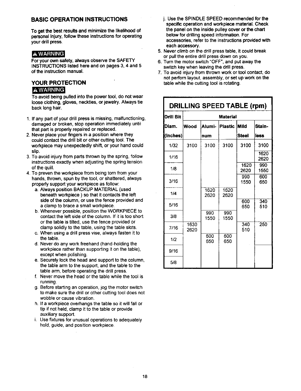
j. Use the SPINDLE SPEED recommended for the
specificoperation and workpiecematerial. Check
the panel on the insidepulleycover or the chart
belowfor drillingspeed information.For
accessories,refer to the instructionsprovidedwith
each accessory.
5. Never climbon the drill presstable, it couldbreak
or pullthe entire drill pressdown on you.
6. Turn the motor switch"OFF", and putaway the
switchkey when leaving the drillpress.
7. To avoid injuryfrom thrownwork or tool contact,do
notperfornlayout, assembly, or set up work on the
table while the cuttingtool is rotating.
DRILLING SPEED TABLE (rpm)
Drill Bit Material
Diam. Wood 6.1umi- Plastic Mild Stain-
(Inches) mum Steel less
1/32 3100 3100 3100 3100 3100
1620
1/16 2620
1620 990
1/8 2620 1550
990 600
3/16 1550 650
1620 1620
1/4 2620 2620
600 340
5/16 650 510
990 990
3/8 1550 1550
1630 340 250
7/16 2620 510
600 600
1/2 650 650
9/16
5/8
18
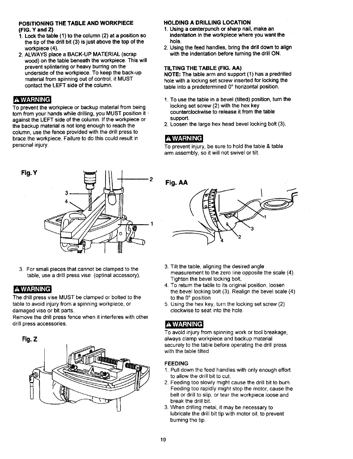
POSITIONING THE TABLE AND WORKPIECE
(FIG. Y and Z)
1. Lockthe table (1) to the column(2) at a positionso
the tipof the drillbit (3) is just abovethe topof the
workpiece(4).
2. ALWAYS place a BACK-UP MATERIAL (scrap
wood)on the table beneath the workpiece.This will
preventsplinteringor heavy burringon the
undersideof the workpiece. To keep the back-up
material from spinning out of control, it MUST
contact the LEFT side of the column.
To prevent the workpiece or backup material from being
torn from your hands while drilling, you MUST position it
against the LEFT side of the column. If the workpiece or
the backup matedal is not long enough to reach the
column, use the fence provided with the drill press to
brace the workpiece. Failure to do this could result in
personal injury.
HOLDING A DRILLING LOCATION
1. Usinga centerpunchor sharp nail,make an
indentationinthe workpiecewhereyouwant the
hole.
2. Usingthe feed handles,bdng the drilldownto align
withthe indentationbefore turningthe drillON.
TILTING THE TABLE (FIG. AA)
NOTE: The table arm and support (1) has a preddlled
hole with a locking set screw inserted for locking the
table into a predetermined 0 ° horizontal position.
1. To use the table in a bevel (tilted) position, turn the
locking set screw (2) with the hex key
counterclockwise to release it from the table
support.
2. Loosen the large hex head bevel locking bolt (3).
_t
To prevent injury,be sure to hold the table& table
arm assembly, so it will not swivel or tilt.
Fig. Y 2Fig. AA
\
3. For small pieces that cannot be clamped to the
table, use a drill press vise (optinal accessory).
The drill press vise MUST be clamped or bolted to the
table to avoid injury from aspinning workpiece, or
damaged vise or bit parts.
Remove the drill press fence when it interferes with other
drill press accessories.
Fig. Z
3. Tilt the table, aligning the desired angle
measurement to the zero line opposite the scale (4).
Tighten the bevel locking bolt.
4 To return the table to its original position, loosen
the bevel locking bolt (3). Realign the bevel scale (4)
to the 0° position
5 Using the hex key, turn the locking set screw (2)
clockwise to seat into the hole.
To avoid injury from spinning work or tool breakage,
always clamp workpiece and backup material
securely to the table before operating the drill press
with the table tilted
FEEDING
1. Pull down the feed handles with only enough effort
to allow the drill bit to cut.
2 Feeding too slowly might cause the drill bit to burn.
Feeding too rapidly might stop the motor, cause the
belt or drill to slip, or tear the workpiece loose and
break the drill bit
3. When drilling metal, it may be necessary to
lubricate the drill bit tip with motor oil, to prevent
burning the tip.
19

MAINTAINING YOUR DRILL PRESS
For your ownsafety, turn the switch=OFF" and remove
the plugfrom the power source outlet before maintaining
or lubricatingyour drillpress.
Frequentlyblow out, usingan air compressoror dust
vacuum, any dustthat accumulates insidethe motor.
Acoat of automotivepaste wax applied to the table and
columnwill help to keep the surfaceclean.
To avoidshock or fire hazard, if the power cord is worn or
cut in any way, have it replaced immediately.
LUBRICATION
All of the drill pressball bearingsare packedwith grease
at the factory. They require no further lubrication.
Periodicallylubricatethe gear and rack, table elevation
mechanism of the spindlethe rack (teeth) of the quill.
20
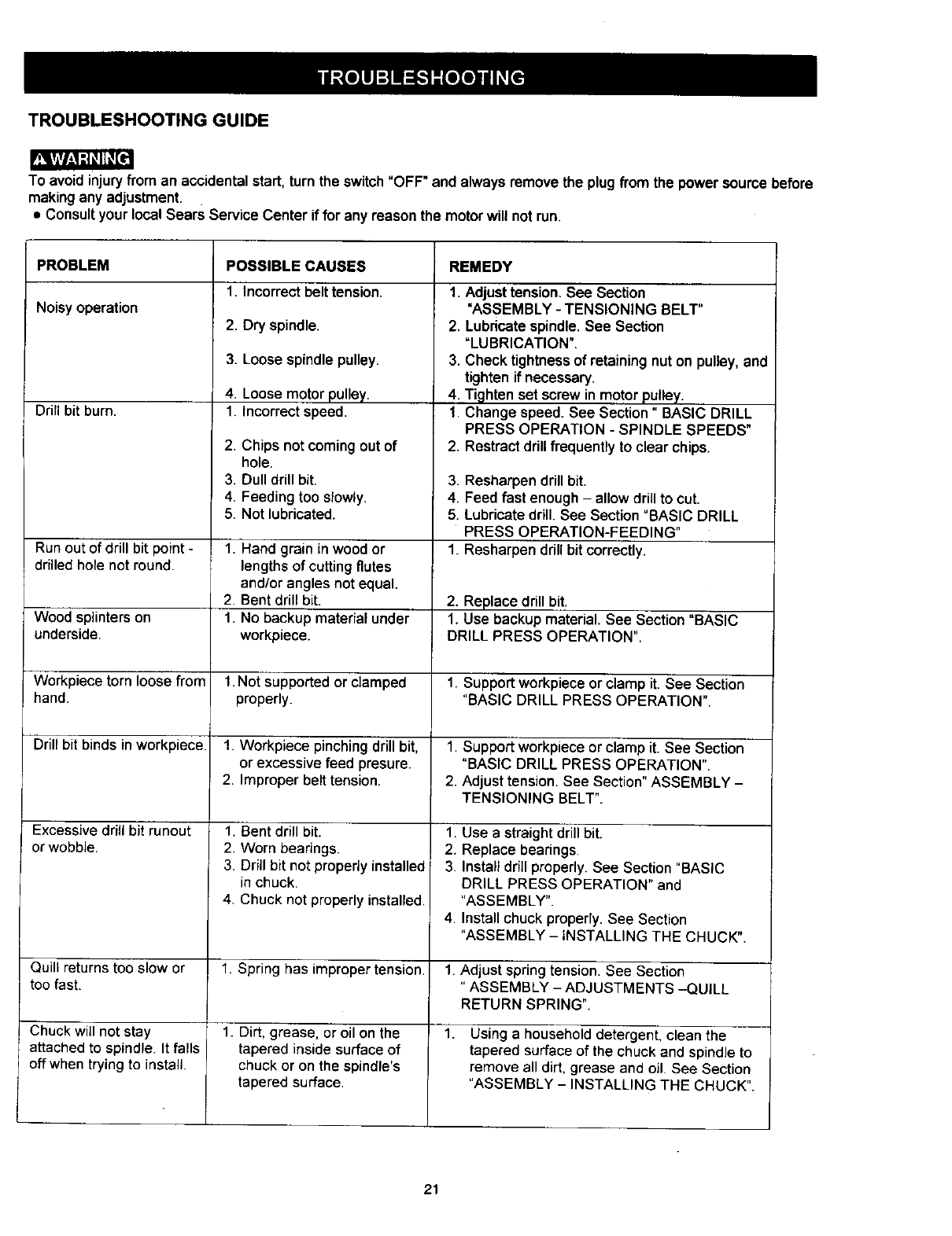
TROUBLESHOOTING GUIDE
To avoid injuryfrom an accidentalstart,turn the switch"OFF" and always removethe plugfrom the power source before
makingany adjustment.
•Consultyour local Sears Service Center iffor any reason the motor will notrun.
PROBLEM
Noisyoperation
Drill bit burn.
Run outof drill bit point -
drilled hole not round.
Wood splinters on
underside.
Workpiece torn loose from
hand.
Drill bit binds inworkpiece.
Excessive drill bit runout
orwobble.
Quill returns too slow or
too fast.
Chuck will not stay
attached to spindle. It falls
off when trying to install.
POSSIBLE CAUSES
1. Incorrectbelttension.
2. Dry spindle.
3. Loose spindlepulley.
4. Loose motor pulley.
1. Incorrect speed.
2. Chips notcomingout of
hole.
3. Dull drill bit.
4. Feeding too slowly.
5. Not lubricated.
1. Hand grain in wood or
lengths of cutting flutes
and/or angles not equal.
2. Bent drill bit.
1. No backup material under
workpiece.
1. Not supported or clamped
properly.
1. Workpiece pinching drill bit,
or excessive feed presure.
2. Improper belt tension.
1. Bent drill bit.
2. Worn bearings.
3. Drill bit not propedy installed
in chuck.
4. Chuck not properly installed.
1. Spring has improper tension.
1. Dirt, grease, or oil on the
tapered inside surface of
chuck or on the spindle's
tapered surface.
REMEDY
1. Adjust tension. See Section
"ASSEMBLY - TENSIONING BELT"
2. Lubricate spindle.See Section
"LUBRICATION".
3. Check tightness of retaining nut on pulley, and
tighten if necessary.
4. Tighten set screw in motor pulley.
1. Change speed. See Section" BASIC DRILL
PRESS OPERATION - SPINDLE SPEEDS"
2. Restract drill frequently to clear chips.
3. Resharpen drill bit.
4. Feed fast enough - allow drill to cut.
5. Lubricate drill. See Section "BASIC DRILL
PRESS OPERATION-FEEDING"
1. Resharpen drill bit correctly.
2. Replace drill bit.
1. Use backup material. See Section "BASIC
DRILL PRESS OPERATION".
1. Support workpiece or clamp it. See Section
"BASIC DRILL PRESS OPERATION".
1. Support workpiece or clamp it. See Section
"BASIC DRILL PRESS OPERATION".
2. Adjust tension. See Section" ASSEMBLY -
TENSIONING BELT".
1. Use a straight drill bit.
2. Replace bearings.
3. Install drill properly. See Section "BASIC
DRILL PRESS OPERATION" and
"ASSEMBLY".
4. Install chuck properly. See Section
"ASSEMBLY - iNSTALLING THE CHUCK".
1. Adjust spring tension. See Section
"ASSEMBLY - ADJUSTMENTS -QUILL
RETURN SPRING".
1. Using a household detergent, clean the
tapered surface of the chuck and spindle to
remove all dirt, grease and oil. See Section
"ASSEMBLY - INSTALLING THE CHUCK".
21
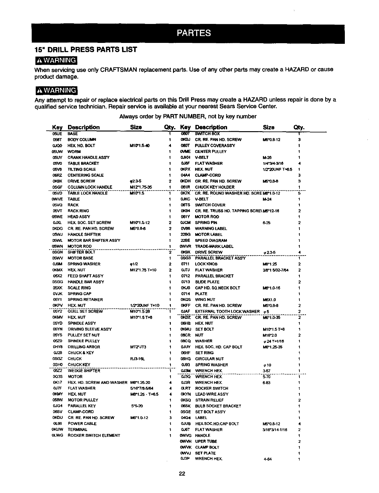
15" DRILL PRESS PARTS LIST
When servicing use only CRAFTSMAN replacement parts•Use of any other parts may create a HAZARD or cause
product damage,
Any attempt to repairot replace electricalparts on this Ddll Press may create a HAZARD unless repair is done by a
qualifiedservice technician.Repair service is availableat your nearest Sears Service Center•
Alwaysorder by PART NUMBER, not by key number
Size Qty. Key Description
M10"1.5_I0
0e07
0e0T
0VME
OJKH
0JBF
0t_oX
04A4
_.5-5 0KDH
Key Descdpfon
0SUE BASE
0583" BODY COLUMN
0JQO HEX. HD, BOLT
05UW WORM
05UY CRANK HANDLE ASS'Y
05VO TABLE BRACKET
05V8 TILTING SCALE
06RZ CENTERING SCALE
0KgX ORIVE SCREW
(_GF COLUMN LOCK HANDLE
Size Qty.
SWITCH BOX 1
CR. RE. PAN HD. SCREW M5"0.8-12 3
PULLEY COVERASS'Y I
CENTER PULLEY 1
V-BELT I_28 I
FLATWASHER 114"3/4_/16 4
HEX. NUT 1FJ'20UNFT==6.5 1
CLAMP-CORD 3
CR. RE. PAN HD. SCREW M6"0.8-8 3
1Mt 2"1.75-35 061R CHUCK KEy HOLDER
05VD TABLE LOCK HANDLE MtO*I_S OK7K CR_ BE_ ROUND WASHES HO_ SCBE MI8"1_0.12 5
0WVE TABLE
(]SVQ RACK
0b_rF RACK RING
(]SWE HEAD ASS'Y
0JXL HF.._SOC. SET SCREEN M10"I .5-12
0KDG CB RE. PAN HD. SCREW M5"0.8-6
05hVJ HANDLE SHIFTER
05WL MOTOR BAR SHIFTER ASS'Y
05WN MOTOR ROD
OSGN BH3FTERBOLT
05WV MOTOR BASE
OJgM SPBING WASHER _112
HEX. NUT M12*1_75T=|0
05X2 FEED SHAFT ASS_F
OSGG HANDLE BAR ABS'Y
05XK SCALERING
OVJK BPR_NGCAP
05YI SPRING RETA_NEB
OKPV HF.X.NUT II2*20UNF T=IS
05Y2 OUILL SET SCREW M10"1_5-28
SKMV HEX_NUT M16*1_ST=8
05YD SP_NBLEABS'Y
05YN DRMNG SLEEVE ASS'Y
05YS PULLEYBET NUT
05Z0 SP_NBLE PULLEY
OHY8 DRILUNG ARBOR MT2*JT3
0J28 CHUCKS KEY
OSGZ CHUCK RJ3-16L
OSHO CHUCK KEY
05Z2 WEDGE BHIFTER
OQ3S MOTOR
0K17 HEX_HD_SCRE_NAND WASHER M8"I__S-20
OJ7F FLAT WASHER 5J16"715-5i64
OfO_Y HEY..NUT M6.1_5 • T=6_5
058W MOTOR PULLEy
OJG4 PARALLEL KEy 5*5-20
06SV CLAMPJCORD
OKDU CR RB_PAN HD_SCREW M6"I_0-12
0L66 POWER CASLE
OKUW TERMINAL
OLWG ROCKER BWiTCH ELEMENT
0JKC V-BELT kk24 1
06TB SWITCH COVER 1
01<94 CR. RE. TRUSS HO. TAPPING SCRE_ M5"12-16 2
061Y MOTOR ROO 1
0JCM SPRING PIN 6-25 2
0V86 WARNING LABEL 1
22BG MOTOR LABEL 1
228E SPEED DIAGRAM 1
GWVR TRADEJA_RK LABEL 1
0_gX DRIVE SCREW _Z3-5 4
0SG3 PARALLEL _=P,ACKET ASS"{ 1
O711 LOCK KNOB M8"1.25 2
0JTJ FLATWASHER 3/8"1_32-7,_4 2
0712 PARALLEL BRACKET 1
0713 SLIDE PLATE 2
0KJO CAP HD, $QNECK BOLT M6"t,0-16 1
0714 PLATE 1
0KQ5 WING NUT M6Xl.0 1
01_F CR. RE. PAN HD. SCREW M5"0._8 2
01AF EXTERNALTOOTHLOCKWASHER _5 2
OKDZ CR_ RE_ PAN HD_ SCREW M6"1 _0-35 2
06HB HEX. NUT 1
0t_MU SET BOLT M10"1.5 T-_B 1
06CR NUT M16"2.0 2
_6CQ WASHER rp24 T=1/16 1
0JUY HEX. SOC, HD, CAP BOLT M_'1.25_5 1
06HF SET RING 1
IToHG CIRCULAR NUT 1
0J93 SPRtNG WASHER _10 1
OJ3M WRENCH HEY-. 3_57 1
0J3Q WRENCH HEX. 5-70 1
0J3R WRENCH HEX. 6-83 1
0LRT ROCKER SWITCH 1
0KYN LEADWIRE ASS'Y 1
0KSQ STRAIN REUEF 2
06SK BULB SOCKET BRACKET 1
G_GE SET BOLTASS_ 1
04Q4 LABEL 1
0JUS HEX.SOC,HD.CAP BOLT M5"0,8-12 4
0J6T FLATWASHER 3/16"3/14-1/16 2
0WVG HANDLE 1
0WVH UPER TUBE 2
0WVK CLAMP BOLT 1
0WVJ SET PLATE 1
0J3P WRENCH HEX. 4-64 1
22
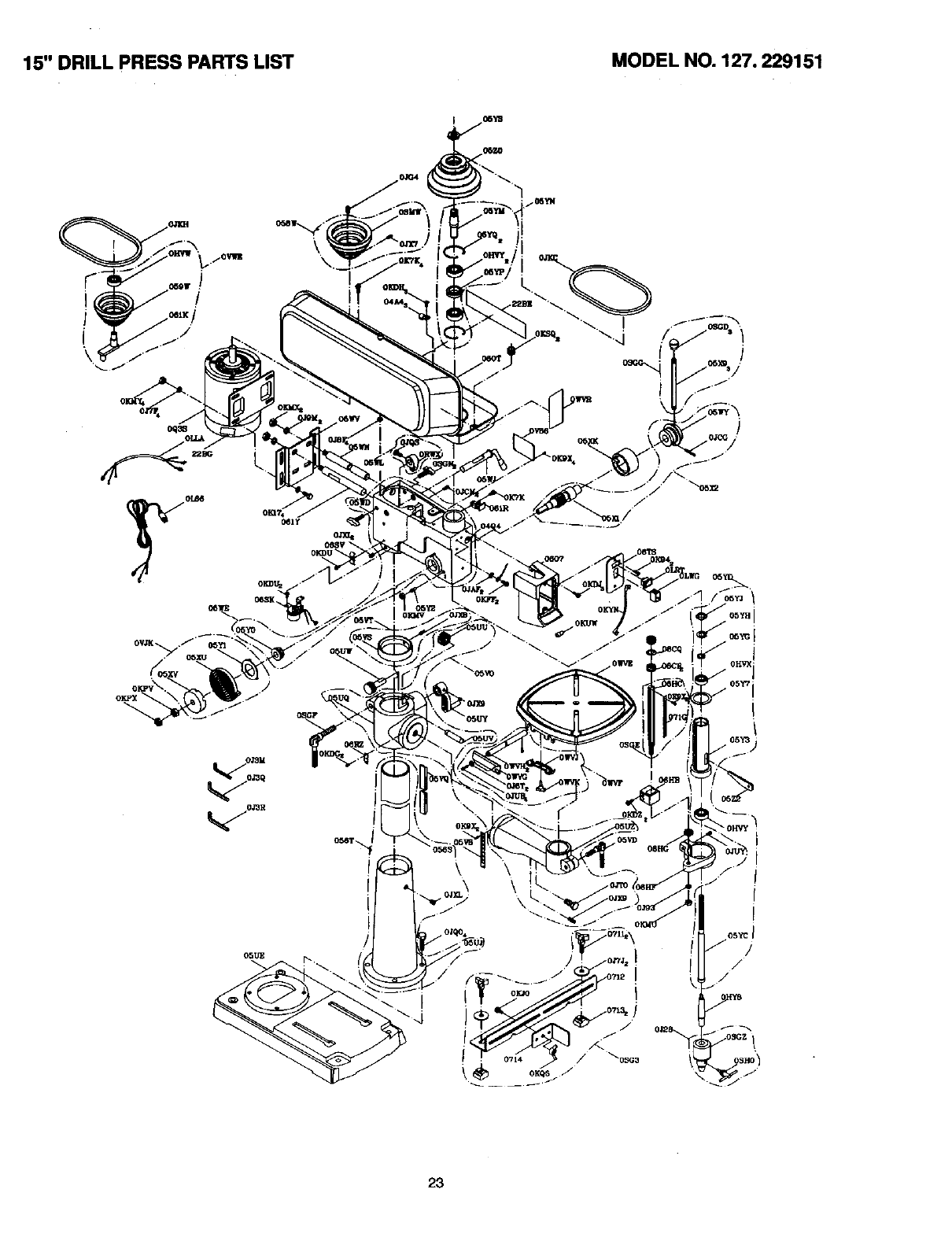
15" DRILL PRESS PARTS LIST MODEL NO. 127. 229151
/
23

24
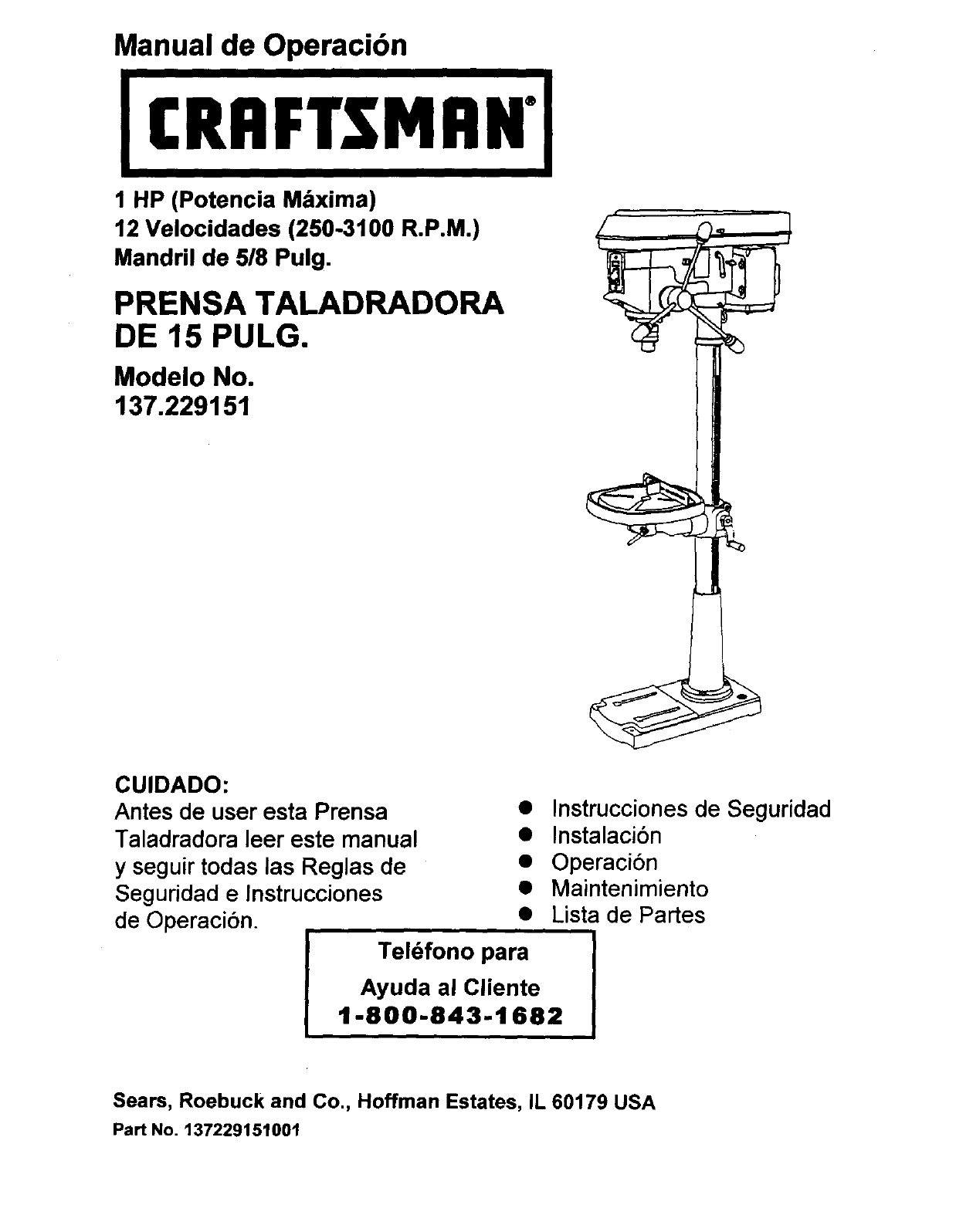
Manual de Operaci6n
CRIIFTSMllN"
1 HP (Potencia M&xima)
12 Velocidades (250-3100 R.P.M.)
Mandril de 518Pulg.
PRENSA TALADRADORA
DE 15 PULG.
Modelo No.
137.229151
CUIDADO:
Antes de user esta Prensa •
Taladradora leer este manual •
y seguir todas las Reglas de •
Seguridad e Instrucciones •
de Operaci6n. •
Tel6fono para
Instrucciones de Seguridad
Instalaci6n
Operaci6n
Maintenimiento
Lista de Partes
Ayuda al Cliente
1-800-843-1682
Sears, Roebuck and Co., Hoffman Estates, IL 60179 USA
Part No. 137229151001
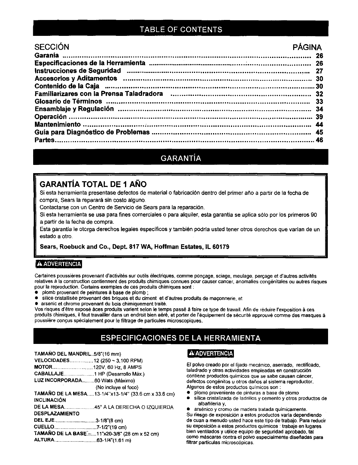
SECCI6N PAGINA
Garania ................................................................................................................. 26
Especiflcaciones de la Herramienta ................................................... ............................. 26
Instrucciones de Segutidad ....................................................................................... 27
Accosorios yAditamentos ....................................................................................... 30
Contenido de la Caja ................................................................................................ 30
Farniliarizares con la Prensa Taladradora ................................................................ 32
Glosario de T6rminos ............................................................................................. 33
Ensamblaje yRegulaci6n ........................................................................................ 34
Operaci6n ................................................................................................................ 39
Mantenimiento ............................ _........................................................................... 44
Guia para Diagn6stico de Problemas ......................................................................... 45
Partes ...................................................................................................................... 46
GARANTJA TOTAL DE 1 ANO
Siesta herramienta presentase defectos de material o fabricacibn dentro del primer argoa partir de la fecha de
compra, Sears la reparar_ sin costo alguno
Contactarse con un Centro de Servicio de Sears pare la reparacibn.
Siesta herramienta se usa para fines comerciales o para alquiler, esta garantia se aplica s61o per los primeros 90
a partir de la fecha de compra.
Esta garantia le otorga derechos legaLes espec{ficos y tambi_n podrla usted tener otros derechos que varian de un
estado a otto
Sears, Roebuck and Co., Dept. 8t7 WA, Hoffman Estates, IL 60179
r.,_
Certaines poussieresprovenant d'activit6ssur outils_lectdques, comme ponc..age,sciage, meulage, pelage et d'autres activit_s
relatives ala construction contiennent des produits chimiques connues pour causer cancer, anomalies congenitales ou autres dsques
pour la reproduction. Certains exemples de cosproduits chimiques sont :
•plomb provenant de peintures _ base de plomb ;
• silice cristallisee provenant des bdques et du ciment et d'autresproduits de ma<;onnerie, et
• arsenic et chrome provenant du bois chimiquement traite.
Vos dsques d'6tre expos6 _ces produits vadent selon le temps pass6 &faire ce type de travail. Afin de reduire rexposition & cos
produits chimiques, il faut travailler dans un endroit bien a6r6, et porter de I'_quipement de securit6 approuve comme des masques
poussi6re congus sp6cialement pour ]e filtrage de particules microscopiques.
TAMAI;IO DEL MANDRIL..5/8°(16 ram)
VELOCIDADES ............... 12 (250 ~3,100 RPM)
MOTOR ......................... 120V, 60 Hz, 8 AMPS
CABALLAJE ...................... 1 HP (Desarrollo Max.)
LUZ INCORPORADA .........60 Wats (Mdximo)
(No incluye el foco)
TAMAI;IO DE LA MESA.....13-1/4"x13-1/4" (33.6 cm x 33.6 cm)
INCLINACION
DE LA MESA...................... 45 ° A LA DERECHA O IZQUIERDA
DESPLAZAMIENTO
DEL EJE.............................. 3-1/8"(8 cm)
CUELLO ............................... 7-1/2"(19 cm)
TAMA_IO DE LA BASE-=....11")(20-3/8" (28 cm x 52 cm)
ALTURA ............................... 63-1/4"(1.61 m)
El polvocreado per el lijado mecanico, aserrado, rectificado,
taladrado y otras actividades empleadas en construcci6n
contiene productos quimicos que se sabe causan cancer,
defectos congenitos u otros daSos al sistema reproductor.
Algunos de estos productos quimicos son :
•plomo proveniente de pinturas abase de plomo
•silicecristalizada de ladnllos y cemento y otros productos de
alba_ileria y,
• arsenico y cromo de madera tratada quimicamente.
Su riesgo de exposicibn a estos productos varia dependiendo
de cuan a menudo usted hace este tipo de trabajo. Para reducir
su exposicibn a estos productos quimicos :trabaje en lugares
bien ventilados y utilice equipo de seguridad aprobado, tal
como mdscaras contra el polvo especialmente disefladas para
filtrar particulas microscopicas.
INSTRUCCIONES GENERALES DE 14.
SEGURIDAD
ANTES DE USAR LA PRENSATALADRADORA
Laseguridadesunacombinaci6ndesenlidocomdn,mantenerse 15.
alertaysabercomousarla PrermaTaladradera.
'RETiPJ_I_VI_I_eg
Paraevitarermresquepuedancausarlesionesserias,no
conectareltaladrobasrahaderle|doyentendidoIosiguiente:
1LEERy famiUarizarsocontodeestemanualde
instrucoionesENTENDERlasapiicaciones,limitacinoesy
riesgasposibles
2 MANTENERLOSPROTECTORESENPOSlCI(_Nyen
buenascondicionesde operadbn
3. NOOPERAREN AMBIENTIESPELIGROSOS.Nousarla
herramientaenlugaresht_medos,mojadeso e._puestosa la
Iluvia.Mantenerel dreade trabajobieniluminada.
4. NO USARherramientaseldctricasen la presenciade
Ifquidosogasesinflamables.
5. MANTIENEREL AREA DETRABAJOUMPIA. Lasdreasy
mesasdetrabajocongestJonadasinv_tana queocurran
accidentes.
6. MANTENERA LOS NIl;lOSALEJADOS.Todoslos
visitantesdebenmantenersea unadistanciaseguradel
_reade trabajo
7. NOFORZARLA HERRAMIENTA.La herramientahardun
mejortmbajoy rodssegurous_ndolaS61Oen laformapara
laquefuedisefiada.
8. USARLAHERRAMIENTAADECUADA.Noforzarla
herramientaal haceruntrabajoparael coalnohaside
diseSada.
9 USARROPAADECUADANO usarropasuelta,guantes,
corbatas,anillos,brazaletesnijeyasquepuedanquedar
atrapadosanlaspiezasmoviblesde la herramientaSe
recomiendausarcalzadoantJmsbalanteUsarprendasde
cabezaparacubriro contenerel cabetlolargo.
10. USARUNAM/t,SCARAPARALA CARAO PARAPOLVO.
Los trabajoscon tatadroproducenpolvo.
11 DESCONECTARLAS HERRAMIENTASantesde cambiarle
accesoriostalescomo:hojas,brocas,cortadoresy similares
12. REDUCIREL RIESGODE ARRANQUESACCIDENTALES.
Cerciorarsequeei interruptordeenergiaest_enla posicibn
=OFF"(Apagado)antesde enchufarlaherramientaa la
corfienteeldctrica.
13. USAR ACCESORIOS RECOMENDADOS. Consultarcon
el manualdel opemdorpara determinar cuales son los
acoesoriosrecomendados.El usode accesorios
inapropiadospuede ser peligrosoy genemr riesgode
lesionespersonales,
RETIRAR LAS HERRAMIENTAS DE
REGULACI_N. Formarseel tk_oitodeverificarquelas
herramientasy lasIlavesde regulaci6nhayansideretJradas
deltaladroantesdeactivarlo.
NUNCADEJARDESATENDIDAUNAHERRAMIENTA
ELI_CTRICACUANDOESTI_FUNClONANDO.
DESCONECTARLA FUENTEDEENERG|A.Noalejarse
dellugarhastaquela herramientasehayadetenidopor
compieto.
16. NUNCAPARARSESOBRELA HERRAMIENTA.Pusden
ocurdrlesionesseriassi laherramientasevolteao sise
entraen contactoconeltaladro.
17. NO ESTIRARSEM/t,SALLADELALCANCEDEUNO.
MantenerlosdospiesbienapoFadosyel equilibroen
todomomento.
18. DARMANTENIMIENTOCUIDADOSOA LAS
HERRAMIENTAS.Pareunaoperaci6nmejor,mdsseguray
rdpida,mantanerlesherramientasaflladasy limpias.Seguir
las instruccionesparala lubricack_ycambiodeaccesorios.
t9. INSPECClONARPAPADETECTARPIEZASDANADAS.
Antesdeusarla herramienta,siempreinspeccionada
cuidadosamenteparecemioraressilosprotectoresu otras
piezasest_ndahadasydeterminarsiva aoperar
adecuadamenteenel usoqueselevaa dar.Inspecolonar
si haypiezasmoviblesdesalineadaso atracadas;partes
rotaso realmontadas,ycoalquierotracondici6nquepueda
afectarlaoperaci6nde laherramienta.Si unprotectoro
cualquierotrapiezaestuvieseda_adadeberepamrse
adesuadamenteo reemp_azarse.
20. ASEGURARSEQUELOSNINOSNOTENGANACCESO
ALTALLERDETRABAJO.Usarcandados,intenuptores
maestrosy quitarlosIlavesde activaci_n.
21 NOoperarla herramientabajolainfluenciadedrogas,
alcoholo medicamentosquepudiesenafectarlahabilidad
paraoperarla herramientaadecuadamente
22. Elpolvogeneradoporciertosmaterialespuedesernocivo
parala salud.Siempreoperarla PrensaTaladmdoraen un
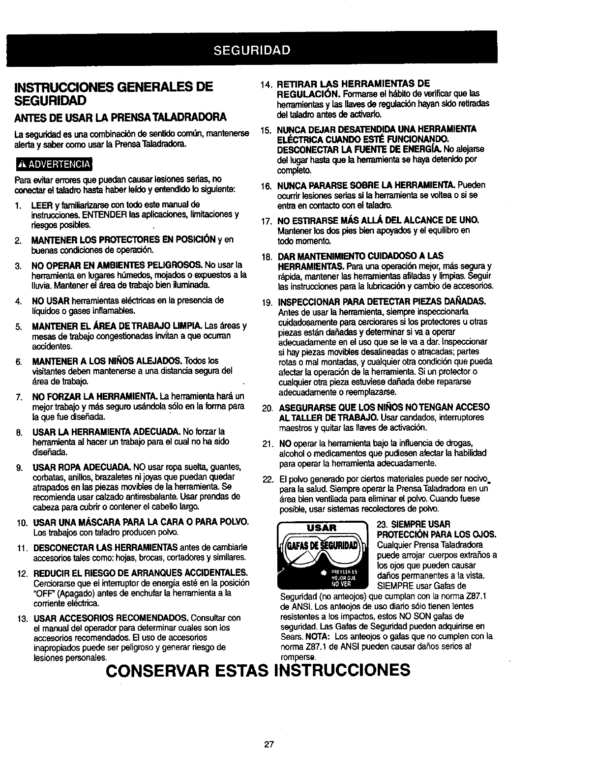
areabienventiladaparaeliminarel polvo.Cuandofuese
posible,usarsisternasrecolectoresdepotvo.
23 SIEMPREUSAR
PROTECCIONPAPALOSOJOS
CualquierPrensaTaladradora
puedearrojarcuerposextrahosa
los ojosquepuedencausar
dafiospermanentesa lavista
SIEMPREusarGalasde
Seguridad (no anteojos) que cumplancon la norrna Z87.1
de ANSI. Los anteojosde uso diafiosSIotienen ]entes
resistentes a losimpactos, estos NO SON galas de
seguridad. I.as Gatas de Seguridad pueden adquirirse en
Sears. NOTA: Los anteojos o galas que no cumplen con la
norma Z87.1 de ANSI pueden causar daSosserlos al
romperse.
CONSERVAR ESTAS INSTRUCCIONES
27
REGLAS DE SEGURIDADESPEC|FICAS
PARALA PRENSATALADRADOFIA
RBIJI_=I_I=K_
Porsupropiaseguddad,nobatarde usarla PrensaTaladradorani
enchufarlahastaqueest6cornpletamenteensambladae instalada
deacuerdoconlasistmcciones,y hastahaberlefdoy entendido
estemanualdeinstnJcciones:
2,
3.
4.
5.
6.
LA PRENSATALADRADORA DEBE ESTAR
EMPERNADA en formaseguraal banco de trabajo.
Adicionalmente,si hubiesela tendenciaa que el
bancode trabajoTaladradorase muevadurante
ciertasoperaciones,empernarla prensaal piso.
ESTAPRENSATALADRADORAs61oesparaucameen
condidonessecasyen intedores.
DSARPROTECCK_NOCULAR.USARmdscaraprotectora
paralacarao parapolvosjuntocongalasde segundadsi
laoperacibngenerapoivo.USARprotectoresde ofdo,
especialmentedurantepedodoslargosdeoperackSn.
NO usarguantes,corbataniropasuelta.
NO intentartaladrarobjetosqueseandemasiadopequerios
comeparafijarlosconsujetadores.
SIEMPREmantenerlasmanosfueradetcaminode las
brocas.Evitarcolocarlasmanosen posicionesen las
cualesunresbal6ns0bitopuedahacerquelasmanos
entrenencontactocon labroca.
7.
8.
NOinstalarniusarbrocascuyolargoexceda175mm(7")o
queseproyecten150mm(6")pordebajode lasquijadas
delmandril.Puedendoblarses6bitarnentehaciaafuera
o romperse.
NOUSARruedasde alambre,brocasparaburiladoras,
cuchillasformadoras,cortadoresde cfmulosnicepillos
giratoriosen estaPrensaTaladradora.
9. CUANDOse estetaladrandounapiezagrandede material,
cerciorarsequeest_cornpletarnentesujetaa la altura
de la mesa.
10. NOraalizaroperacibnalgunaa manolibre.SIEMPRE
sujetarla piezaquesa est_trabajandoen forrnafirme
contrala mesaparaquenosemuevao tuerza.Usar
sargentaso prensassisetaladranpiezasinestables.
11. CERCIORARSEqueno hayanclavosniobjetosextrarios
en laparte de lapiezaquesevaa taladrar.
14.
15.
t6.
17.
18.
19.
20.
21.
22.
23.
24.
25.
26.
12. FIJARLAPIEZADETRABAJOCONSUJETADORES
contrael ladoizquierdode la columnaparaevitarque gire.
Si fuesemuycortao sila mesadela herramientaestuviese 27.
indinada,sujetadafirmementea la mesay usar la
guiaprovista.
13. SI LA PIEZA DETRABAJO se proyecta fuera de la mesa
de forma tal que se caiga o inclinesi no estuviese sujeta,
sujetadaa la mesa o proveer un soporteauxiliar.
FIJARLA PIEZADE"rRABAJO,Cuandofuese_,
usarsargentaso unaprensaparasujetarla plezadetrabaJo.
Esn_a seguroqueusarla _ y dejalibreambasmanoe
paraoperarla herramlerCa.
AL USAR unaprensaparataJadro,siempresujetadaa
la mesa.
CERCIORARSEQUEtodosloselement.smec._nicosde
sujeci6nest6najustadosfirmementeantesde comenzar
a taladrar.
ASEGURAREL CABEZALCONELSEGUROy sujetarel
soportede la mesaa la columna,y la rnesaal soporteantes
deoperarla PrensaTaladradora.
NUNCAhacerfuncionarla PrensaTaladradoraantes
dehaberdespejadotodoobjetode la mesa(henamientas,
_hos de madera,etc.).
ANTESDE COMENZARlaoperadbn,hacerfuncionarel
taladrobrevementea bajavelocidadparacarciorarsequeno
sebamboleeo vibre.
PERMmRQUE EL EJEALCANCESUVELOCIDAD
MAXIMAantesde comenzaraataladrar.Siel taladrohaca
alg_nruidoquenoseafamiliaro vibraexcesivamente,
detenereltrabajoinmediatamente,apagarel taladroy
desenchufadode la corriente.Novotverloaponeren
operaci6nhastahabercorregidoel problema.
NO raalizarlaboresdetrazado,ensamblajenipraparaci6n
sobrelamesacuandola herramientaest_enoperacibn.
USARLA VELOCIDADRECOMENDADAparael accesorio
ytipode materialde lapiezaqueseest6trabajando.VER
I_ASINSTRUCCIONESquevienencon el accecorio.
ALTALADRARorificiosdedidmetmgrande,fijarla pieza
de trabajocon sujetadoresenformafirmea la mesa.De
Iocontrariola brocapuedeagarrarla piezaqueseestd
trabajandoy hacerlagirara granvelocidad.NOUSAR
cuchillasdefresadoranielementosquetaladrenoriflcios
rndltiplesporquepuedendesarmarsao desbalancearse
con el uso.
CERCIORARSEqueeleje sehayadetenidocompletamente
antesde entrarencontactocon tapiezadetrabajo.
PARAEVITARLESIONESdebidasa arranques
accidentales,siemprecolocarel interruptorenla posicibnde
"OFF"(Apagado)ydesanchufarel taladroantesdeinstalaro
ratiraraccesorioso de realizarcualquierajusteo regulacibn.
MANTENER LOS PROTECTORES EN POSICI(_N y en
buenas condicionesde operaci6n.
SOLOUSARUNALLAVEDELMANDRILTIPOAUTO
EXPULSANTEcomola provistaconla Pransa
Taladradora.
CONSERVAR ESTAS INSTRUCCIONES
28
INSTRUCCIONESPARA LA CONEXI6N ATIERRA
EN EL EVF.N10DE UNAFALLAO MALFUNClONAMIENTO,
la conex_na_rra Ixovee unavl'ade manorrosistenoiaparala
cordenteekY_foa,redudendoas(el riesgode choqueel_'trico.
Estaherramientaestdequipadaconuncord6nel6ctricoqua
tieneunconductorparaconexk_na IJerraytambi#nconun
enchufeconespigaparael mismofin.ElenchufeDEBE
conectarseen untomacorrientequelehagajuegoy queest6
debidamenteinstaladoyconectadoa tierrade acuerdocon
TODOSloscddigosyordenanzaslocales.
NOMODIRCAREL ENCHUFIEPROVISTO.Si noentraenel
tomacordente,hacerquaunelectricistacalificadoinstaleun
tomacordenteadecuado.
LACONEXJ6NINADECUADADELCONDUCTORparalJerra
deunequipopuedegenemrdesgode choqueeldctdco.El
conductorconformaislanteverde(cono sinrayasamarillas)es
elconductorparaconexibnatierra.Si elcordbnel_"tricoo el
enchuferequierenreparacioneso reemplazo,NO conectarel
conductorparatierradelequipoa unterminalvivo.
AVERIGUARcon unelectricistao personaldeserviciosise
tienecualquiardudeen cuantoa la con_6n correctaa tierra
delequipo,o silasinstrucoionosparala conexi6natierrano
_st_nclaras.
SOLOUSARCORDONESDE EXTENSIONQUETENGAN
ENCHUFEDETRESESPIGASY UNTOMACORRIENTEQUE
_,CEPTEEL ENCHUFEDE LA HERRAMIENTA.REPARARO
REEMPLAZARINMEDIATAMENTELOSCORDONES
DAI_ADOSO GASTADOS.
RECOMENDACIONES PARA LOS CORDONES
DE EXTENSION
Cerciorarsequeel cordbndeextensibnest_enbuenas
condiciones.AI usaruncord6nde extensi6n,cerciorarseque
seaIo suficientemente_]mesoparaconducirlacorrienteque la
herramientademandera.Uncordensubdimensionadecausar-_
unacaideen elvoltajede la lineacausandounap_rdidade
cotenciay recalentamiento.Latabtaqueaparecoenesta
paginamuestralos calibrescorrectosde los cordonesseg_n
su extensi6ny elamperajerequeddopot laherramientaque
apareceen la placa.Encasode dude,usarel siguientecalibre
n_s grueso.Cuantomenoret nL_merodelcalibre,mayorel
di_,metrodelalambre.
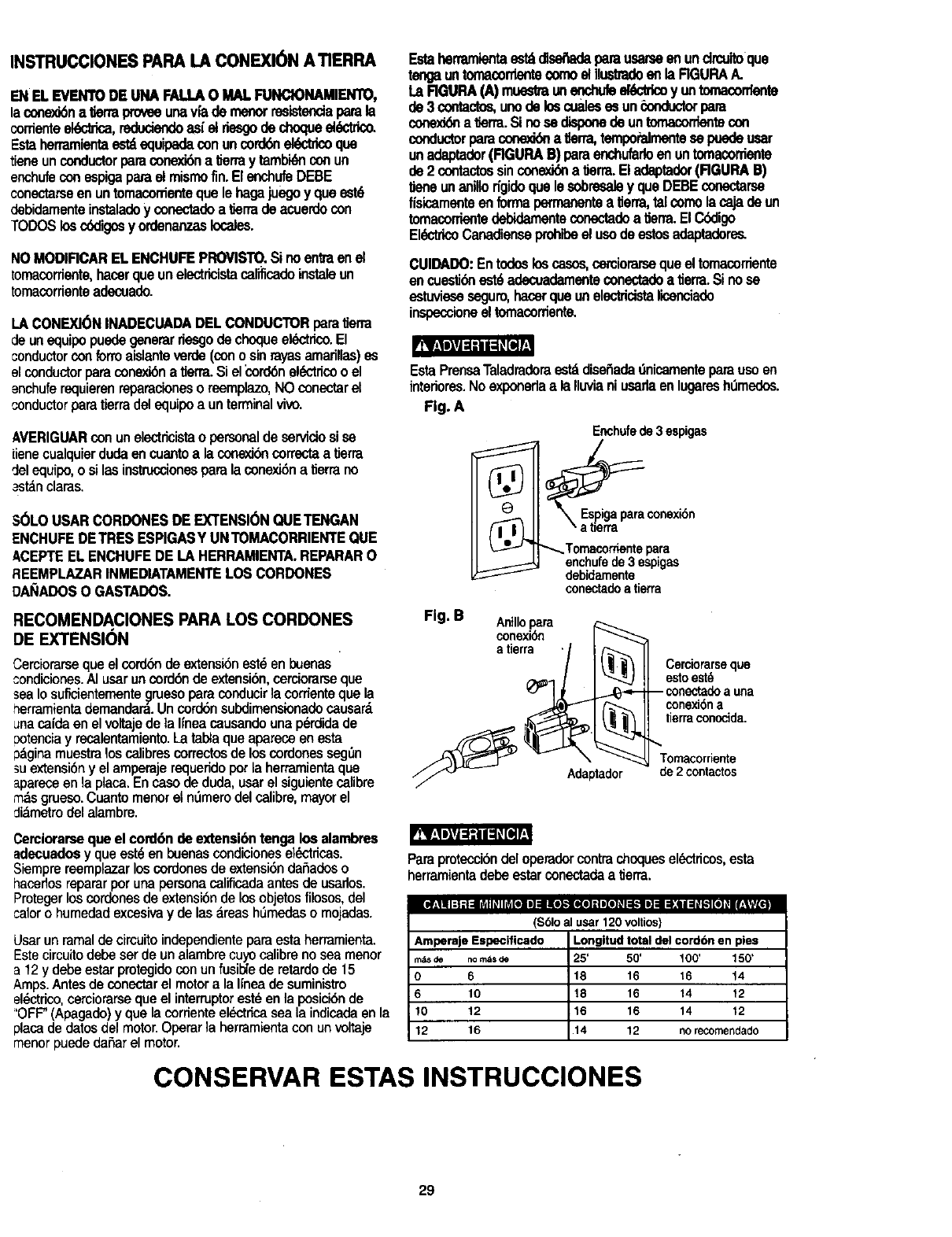
Estaherramlentaostd_ parausarseenundrcuitoque
teogauntomacorrlentecomoelilustradoeftla RGURAA.
La RGURA(A) muestmunenchufeel_K_o y untornacontente
pe 3contactos,unode loscualesesun_onductorpare
cor_J6na _erra.Si nosedisponede untomacordentecon
conductorparaconooddna _erra,tempoPalmentesepuedeusar
unadaptader(RGURAB) paraenchufarfoenuntomacorriente
de 2 contactossinconex_ alJerra.Eladaptader(RGURA13)
liene unanillodgidoquelesobresaley queDEBEconectarse
fisicameflteen formapermanen_a IJerra,talcomolacajade un
tomaconientedebidamenteconectadoa_erra.El C6digo
EldctricoCanadienseprohibeel usode estosadaptadere_
CUIDADO:Entodo6loscasos,carciorarsequeel tomacorriente
en cuesti_ est6adecuadamenteconectadoa tierra.Si nose
estuvioseseguro,hacerquaunelecldcistalicenciado
inspeccioneel tomacordente.
EstaPrensaTaladraderaestddiseSadadnicamenteparausoen
intedores.NoexponedaalaIluvianiusarlaenlugaresh_medes.
Fig. A
Enchufede3 espigas
®
,_ eJ'_ _Temacorriente para
enchufede3 espigas
debidamente
conectadoatierra
Fig. B cAoninllOxiPara
Adaptador
Cerciorarseque
estoest_
-- conectadoa una
conexi6na
tierraconocida.
Tomacorriente
de 2contactos
Cerciorarsequael cord6nde extensi6ntenga losalambres
adecuadosyqueest_en buenascondicioneseldctdcas.
Siemprereemplazarloscordonesde extensi6ndaSadoso
hacerlosrepararperunapersonacalificadaantesde usarlos.
Protegerloscordenesdeextensi6ndelosobjetosfilosos,del
calorohumedadexcesivay de lasareash_medaso mojadas.
Usar un ramal de circuito independiente para esta herramienta.
Este circuito debe ser de un alambre cuyo calibre no sea menor
a 12 y debe estar protegido con un fusi_e de retardo de 15
Amps. Antes de conectar el motor a la Iinea de suministro
el@ctrico,carciorarse que el interruptor est@en la posici6n de
='OFF"(Apagado) y que la corriente el_}ctdcasea la indicada en la
placa de datos del motor. Operar la herramienta con un voltaje
manor puede daSar el motor.
Paraproteccidedeloperadercontrachoquesel_ctdcos,esta
herramientadebeestarconectadaa tierra.
ii#;! i i:t 11=l_ydl_ll_[el i] =lllo],,-,ll(o]=1i[t]# i_.-tle]=1_:11=1_k"t[_]_ll_|_f[_l
($61o al usar 120 volUos)
Amperaje Especificado
m_s de no rods
0 6
6 10
10 12
12 16
Longltud total del cordbn en pies
25' 50' 100' 150'
18 16 16 14
18 16 14 12
16 16 14 12
14 12 norecomendado
CONSERVAR ESTAS INSTRUCCIONES
29
ACCESORIOS DISPONIBLES
$61ousaraccesoriosrecomendadosparaestaPrensa
Taladradera.Seguirlosinstrucoionesqueacompa_ana los
accesorios.[] usodeaccesoriosinadecuadospuede
generarriesgos.
Visitarel Departamantode Ferretedade la liendaSears
mdscercanaover el Catdlogode HerramientasEI6cbicas/
Neun_ticasy Manualesde Searsparalossiguiantos
_cesorios:
BrocasparaTaladro
• Sujetadory Gu(a
PrensasparaPransaTaladradera
•Juegode Mortajay EspigaparaPrensa
Taladradora
•Juegode Sujetadores
•Cincely BrocastipoMortajay Espiga
•TamboresLijadores
RusdasPulidorasde hasta4" (10cm)de
DidmetroM_ximo
•SierraparaOrificiosde hasta2-1/2' (6.35cm)
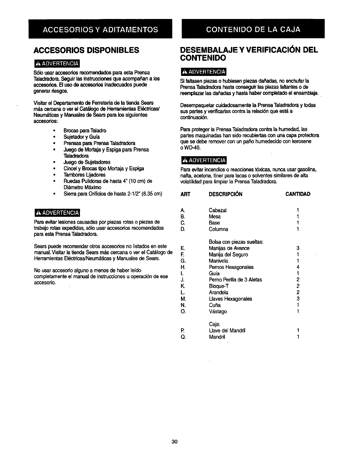
DESEMBALAJE Y VERIFICACI( N DEL
CONTENIDO
Si faltasanpiezaso hubiesenpiezasder3ades,noenohufarla
PrensaTaladradorahastaconseguirlaspiezasfaltantesode
reemplazarlasda_adasy basrahabercompletadeelensam_aje.
Desempaquetarcuidadosamentela PrensaTaladradoraytodas
suspartesyverificadascontrala relaci6nqueestda
con_nuaci6n.
Paraprotegerla PrensaTaladraderacontrala humedad,las
partesmaquinadashansiderecubiertasconunacapaprotectora
quesa deberemovercon unpasohumedecidocon kerosene
oWD-40.
rRBligPJ_l_J_l_
Paraevitarincendioso reacoionest6xicas,nuncausargasolina,
naffa,acetona,tinerparalacaso solventessimilaresdealta
volatilidadparalimpiarla PrensaTaladradora.
ART DESCRIPCI(_N CANTIDAD
ParaovitarIosionoscausadasporpiezasrotasopiezasde
trabajomtasexpedidas,s61ousaraccesoriosrecomendados
paraestaPrensaTaladradora.
Searspuederecomenderotrosaccesoriosnolistadosen este
manual.VisitarlatiendaSearsn_s cercanaoverel Catdlogode
HerramientasEldctdcas/Neumdticasy Manualesde Sears.
Nousaraccesorioalgunoa manosde haberleido
completamenteelmanualde instrucoionesuoperaci6nde ese
acoesorio.
A. Cabezai
B. Mesa
C. Base
D. Columna
E.
E
G.
H.
I.
J.
K.
L
M.
N,
O.
P.
Q.
Balsacon piezassueltas:
Manijasde Avance
Manijadel Seguro
Manivela
PernosHexagonales
Guia
PernoPerillade3 Aletas
Bloque-T
Arandela
LlavesHexaganales
Cuba
V_,stago
Caja;
Uave del Manddl
Mandril
1
I
1
1
3
1
1
4
1
2
2
2
3
1
I
3O
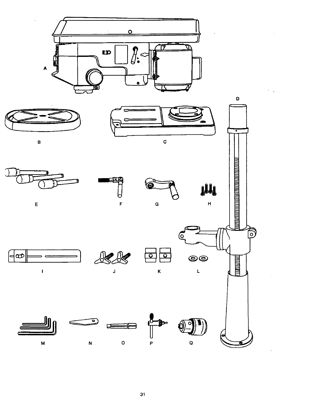
o
A
H_ _ .1
I
M
C
F G H
JK L
0
31
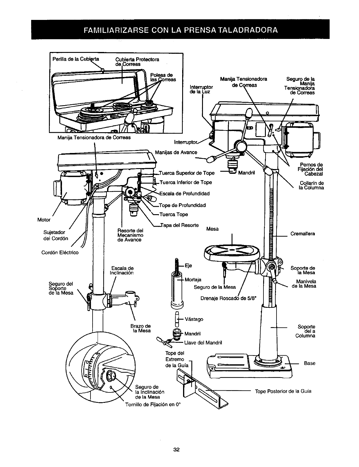
Perilla de la Cubi_ Cubierta Protectora
Poleas de
Interruptor
de la Luz
Manija Tensionadora Seguro dela
Manija
Tans_nadoia
de Co_eas
ManijaTensionadora de Correas
Motor
Sujetador
de1Cordbn
Cordbn El_,_,ctdco
Seguro del
Soporte
de ia Mesa
Resole del
Mecanismo
de Avance
Escala de
Inclinaci6n
Manijas de Avance
Profundidad
_pe
tpa del Resorte Mesa
Eje
Mortaja
Seguro de la Mesa
Drenaj,
A
Brazo de _'-- Vdstago
la Mesa __ Mandril
Llave del Mandril
Tope del
Extremo
de la_
Segurode J '_
la Inclinacibn I/J,_'"_
e,aMosa v
Tomillo de Fijacibnen 0_
Pemos de
Fijacibndel
Cabezal
Collarfnde
la Columna
Cremallera
Soporte de
la Mesa
Manivela
de la Mesa
Soporte
del a
Columna
Base
Tope Posterior de ia Guia
32
BASE- ,_porla la PreneaTeladradora.Paramayore6tabilidad
provisladeodfick_paraempemarla PrensaTalaclradom81
piso.(Ver"lnstruccionesdeSeguridadEspecificasparaPransas
Teladraden ').
MATERIALDEAPOYO- Unapiezade rnaderadedesachoque
sa colocaentrelapiezaquesa tmbajay la mesa.La mademde
apoyoevitaqueseas_llela maderaquesetaladracuandola
brocala al_a_eza.Tambidnevitataladrarla superl_iedela
mesa.
CUBIERTAPROTECTORADECORREAS- Cubrelaspoleasy
correasdurantelaopemci6ndela PrensaTeladradora.
TENSI6N DELASCORREAS- Refedrsea lassecdones:
=Ensamblaje"e =lnstalaci_yTans_ de Correas".
MANUATENSIONADORADECORREAS- Girarlamanijaen
el sanlidedelrelojperutensioharla correaycontmel sentidodel
relojparaaliviarla tensk_.
SEGURODE LAMANUATENSIONADORADE CORREAS-
Ajustandolas manijassa fijael soportedelmotory la manija
tensionadoramanteniendoladistanciaytensi6ncorrectade la
coffee.
ESCALADE INCLINACI_NDE LAMESA-Muestralos grades
de inclinaci6nde la mesaparelostrabajosde pianoindinado.La
escalaestdmontadaa uncostadodelbrazo.
MANDRIL- Sujetala brocateladradorao cualquierOtTO
accesoriorecomendadeparerealizerlos trabajosdesaados.
LLAVEDELMANDRIL-Usa gavequesa autoeyectadel
mandrilcuandoselesuelta.Estaacci6nest_disafiadapara
evitarquela Ilavesalgadisparadadelmandrilcuandoseactive
la herramienta.NousarIlavessubstitutas.Sisedeteriorao
pierde,ordenarunaIlavenueva.
COLUMNA - Es untubo queconecta el cabezal, la mesa y la
base Loamfacilitarsu alineamientoy movimianto.
COLLARiNDE LA COLUMNA- Sujetala cremelleraala
columna.Lacremallerasemantienem6vilenel collan'npara
perm_rlosmovimientosdelsoportede la mesa.
SOPORTEDELA COLUMNA- Soportala columna,guiala
cremellemy proveeoriflciosparemontarlacolumnaa
la base.
TUERCASDETOPEDE LAESCALADE PROFUNDIDAD-
Fijael ejea lapmfundidadseleccionada.
ESCALADE PROFUNDIDAD-Indica la profundideddelorificio
queseestataladrando.
BROCA - La herramientaque sa usa en la PrensaTaladradora
parehacer los oriflciosen la pieza de trabajo.
INTERRUPTORDELTALADRO- Tieneundispositivode
seguro.Estedispositivoestddisefiadeparaevitarel usono
autorizadoy pesiblementepeligrosoper nifiosyotraspersonas.
Insertarla Ilaveen el interruptory girarlaparaponerel teladroen
opemci<_n.
VELOClDADDETALADRADO- Se cambiacolosandolacorrea
ancualquierade laspoleas.VerlaTablede Velocidadesen la
perteintemade la cobiertapmtectorade lascorreas.
MANUASDE AVANCE- Muevenel mandrilhaciaarribay
abajo.Sifuesenecesario,sa puedenquitarunao dosmanijas
cuandola piezadebabajoseade unaformataninusualque
interfieraconlasmanijas.
GU_A- Se montaenla mesay sieveparealinearlap_ezade
trabajoo parehacerperforacionesrepetitivasenformardpide.Es
desmontable.Sacarlacuandointerfiemconlosaccesoriosdela
PrensaTaladradora.
SEGUROSDELCABEZAL- Fijaelcabezalan la columna.
SIEMPREfijarelcabezalan posici6ncon losseguroscuandose
operela PrensaTeladradora.
CREMALLERA- Funcionaancombinacibnconel mecanismo
deengranajes.Sirveparefacilitarla elevacibndela mesa
operandea manelamanivelade la mesa.
REVOLUCIONESPORMINBTO(R.P.M.)- El nOmemde
vueltascompletasque unobjetogiratorioda enunminuto.
VELOCIDADDELEJE -LasR.RM.deleje.
TAPADELRESORTE- Regulala tensi6ndelresortede la
mortaja.
SEGURODELSOPORTEDE LA MESA- AIajustarlosagums
seajustael soportedela mesaala columna.Siempmtenerlo
puestocuandosa operela PrensaTaledmdom.
MESA- Proveeunasuperficiede trabajoparaapoyarla pieza
detrabajo.
BRAZODE LAMESA- Se proyectamdsanddelsoportede la
mesaparemontar[amesay alinearia.
PERILLADESEGURODE LA INCLINACI(_NDE LAMESA-
Fijalamesaancualquierdngulode inclinaci6nde 0°a 45°.
MANIVELADELA MESA- SirVeparasubiry bajarla mesa.
Girarlaenel santidodelrelojpareelevarlamesa.Debesottarse
el segurodelsoporteantasdeoperalamanivela.
SEGURODE LAMESA- Fijala mesaen pesici6ndespuesde
colocarlaen cualquierpesici6n.
SOPORTEDELA MESA- Sedesplazaen la columnapare
sopodarel brazede lamesaylamesa.
DRENAJEROSCADODE (5/8")- Instalaruntubometal
(roscado)enel orificioroscadoparadrenarel excesodeaceitea
uncontenedor.ParaIograrunasuperficiesindrenaje,instalarun
taponroscadode metal.Noseincluyenel tuboniel tapbn.
PIEZADE TRABAJO - El materialquesetaladra.
33
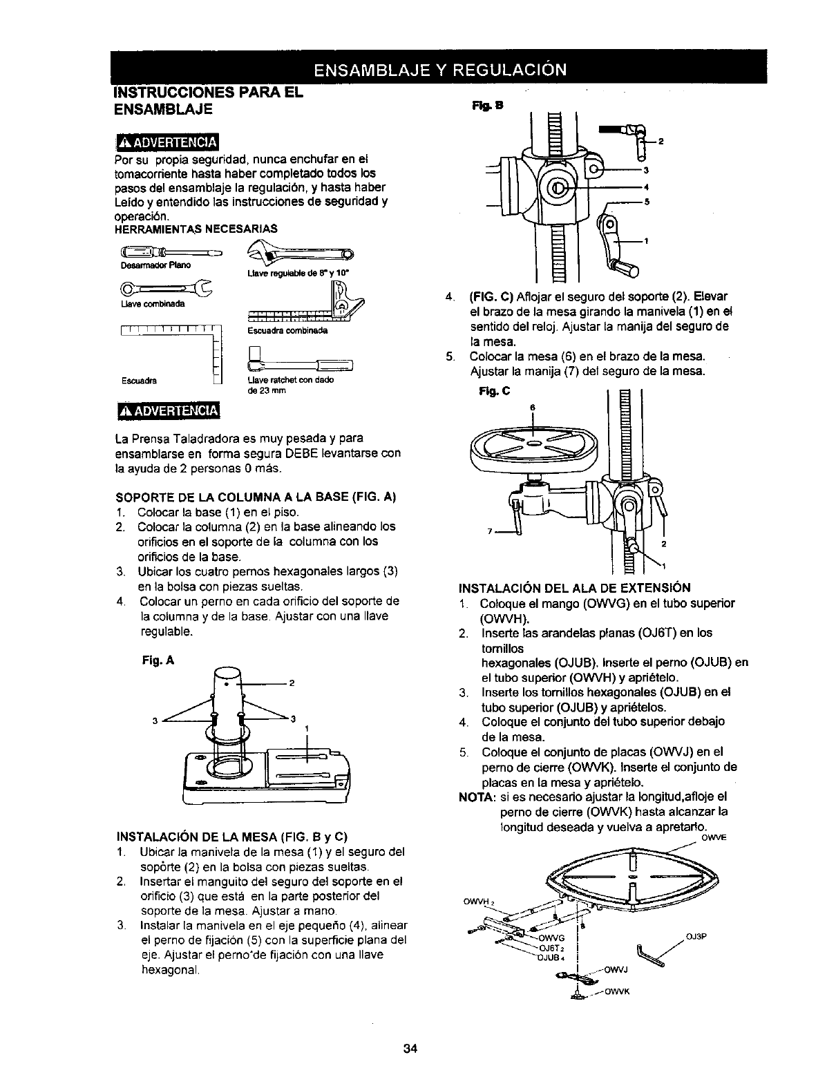
INSTRUCCIONES PARA EL
ENSAMBLAJE FlU.U
rfq_igJ_l_iK_d_
Per su propia seguddad, nunca enchufar en el
tomacorriente haste haber completado todos los
pesos del ensamblaje la regulacibe, y haste haber
Leido y entendido ]as instrucciones de seguddad y
operaci6n.
HERRAMIENTASNECESARIAS
DesarmadorPiano
Uave combinada
Llaveregufabdede 8"y 10"
[I I IIIIIII _ I1 IEscuadracomNnada
Escuadra Llave ratchet con dad<)
_23mm
La Prensa Taladradora es muy pesada y pare
ensamblarse en forma segura DEBE levantarse con
la ayuda de 2 personas 0 mas.
SOPORTE DE LA COLUMNA A LA BASE (FIG. A)
1. Colocar la base (1) en el piso.
2. Colocar ]a columna (2) en la base alineando los
orificiosen el soporte de la columna con los
orificiosde la base.
3. Ubicar los cuatro pemos hexagonales largos (3)
en la boise con piezas sueltas.
4. Colocar un perno en cada orificio del soporte de
la columna y de la base Ajustar con una Ilave
regulable.
Fig. A
INSTALACI(_N DE LA MESA (FIG. B y C)
1. Ubicar la manivela de la mesa (1) y el seguro del
sop6rte (2) en la boise con piezas sueltas.
2. Inserter el manguito del seguro del soporte en el
orificio (3) que estb en la parte posterior del
seporte de ]a mesa Ajustar amane.
3. Instalar la manivela en el eje pequet_o(4), alinear
el perno de fijacion (5) con la superScie plane del
eje. Ajustar el perno'de fijaci6n con una Ilave
hexagonal
4. (FIG. C) Aflojar el seguro det soporte (2). Elevar
el brazo de la mesa girando la manivela (1) en el
sentido del reloj. Ajustar ta manija del seguro de
la mesa.
5. Colocar la mesa (6) en el brazo de la mesa.
Ajustar la manija (7) del seguro de la mesa.
Fig. C
6
INSTALACI(_N DEL ALA DE EXTENSION
1. Coloque el mango (OWVG) en el tubo superior
(OWVH).
2. Inserte las arandelas pfanas (OJ6T) en los
tomillos
hexagonales (OJUB). Inserte el pemo (OJUB) en
el tubo superior (OWVH) y apri_telo.
3. Inserte los tomillos hexagonales (OJUB) en el
tubo superior (OJUB) y apd6telos.
4. Coloque el conjunto del tubo superior debajo
de la mesa.
5. Coloque el conjunto de places (OWVJ) en el
pemo de cierre (OWVK). Inserte el conjunto de
places en la mesa y apd6telo.
NOTA: si es necesado ajustar la Iongitud,afloje el
perno de cierre (OWVK) hasta alcanzar la
Iongitud deseada y vuelva a apretado.OWVE
OWVH 2
34
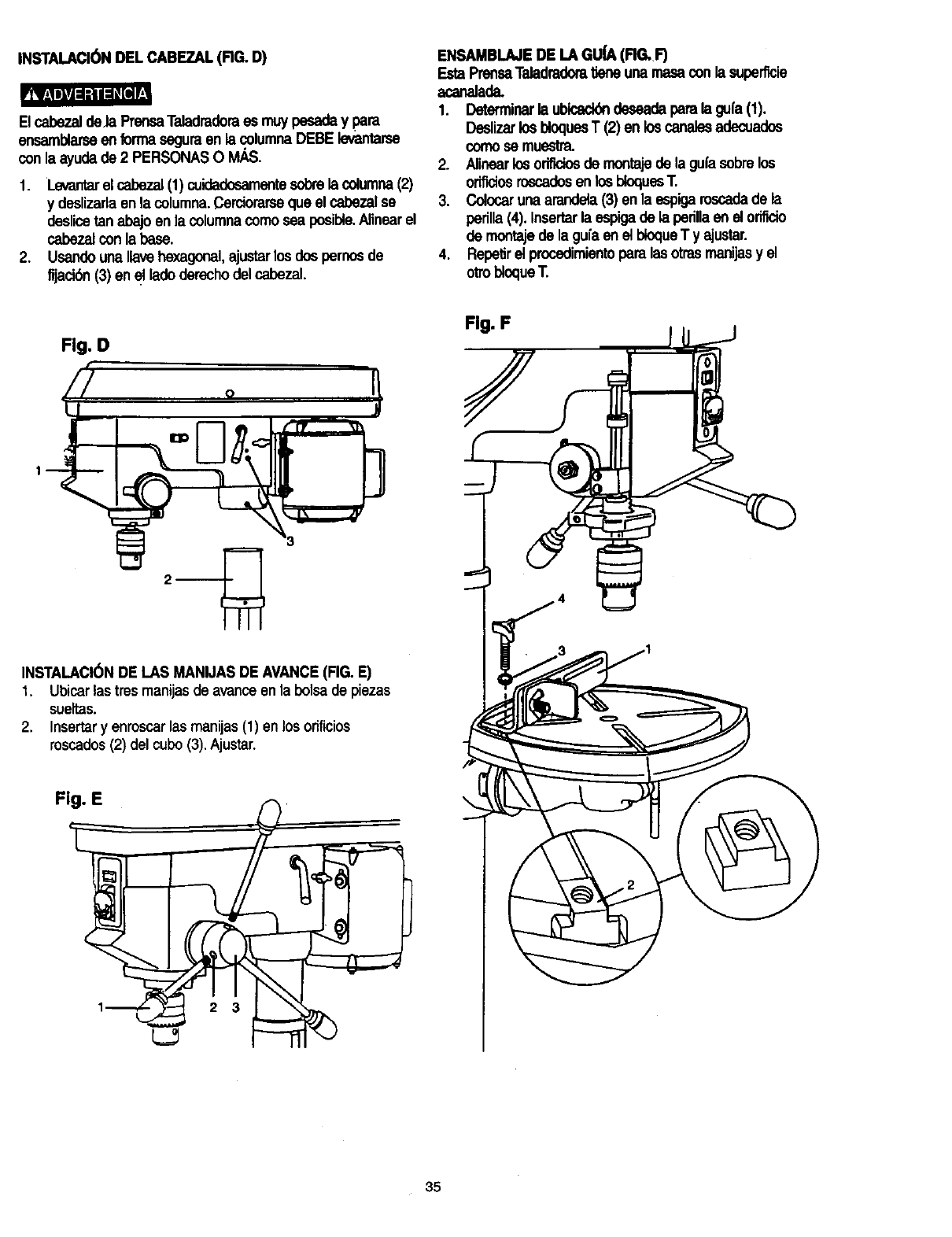
INSTALACI6N DEL CABEZAL(FIG. D)
ElcabezaldeJa PrensaTaladradoraes muypesaday para
ensamblarseen forrnaseguraen la columnaDEBElevantarse
conla ayudade 2 PERSONASOIV_S.
1. Levantarel cabezal(1) cuidadosamentesobrela columna(2)
y deslizarlaen la columna.Cerciorarseque el cabezalse
deslicetan abajoen la columnacomosea posible.Alinearel
cabezalconla base.
2. Usandouna,ave hexagonal,ajustarlosdospernosde
fijacibn(3) en el ladoderecho del cabezal.
ENSAMBLAJEDE LA GU_ (RG. F)
EstaPrensaTaladradom_eneuna masaconla superficie
acanalada.
1. Determinarla ubicack_deseadaparala gufa(1).
DeslizarlosbloquesT (2) en loscanalesadecuados
comosemuestra.
2. Alinearlosorificiosde montajede la gufasobrelos
orificiosroscadosen losbioquesT.
3. Colocarunaarandela(3) en la espigaroscadade la
perilla(4). Insertar la espigade la pedllaen el orifido
de montajede la guia en e]bloqueT y ajustar.
4. RepelJrel procedimientoparalas otrasmanijasy el
otrobloqueT.
Fig. D
Fig. F
INSTALACI(_NDE LAS MANIJAS DE AVANCE(FIG. E)
1. Ubicarlastres manijasde avariceen la bolsade piezas
sueltas.
2. Insertary enroscar las manijas (1) en los orificies
roscados(2) del cubo (3). Ajustar.
F
35
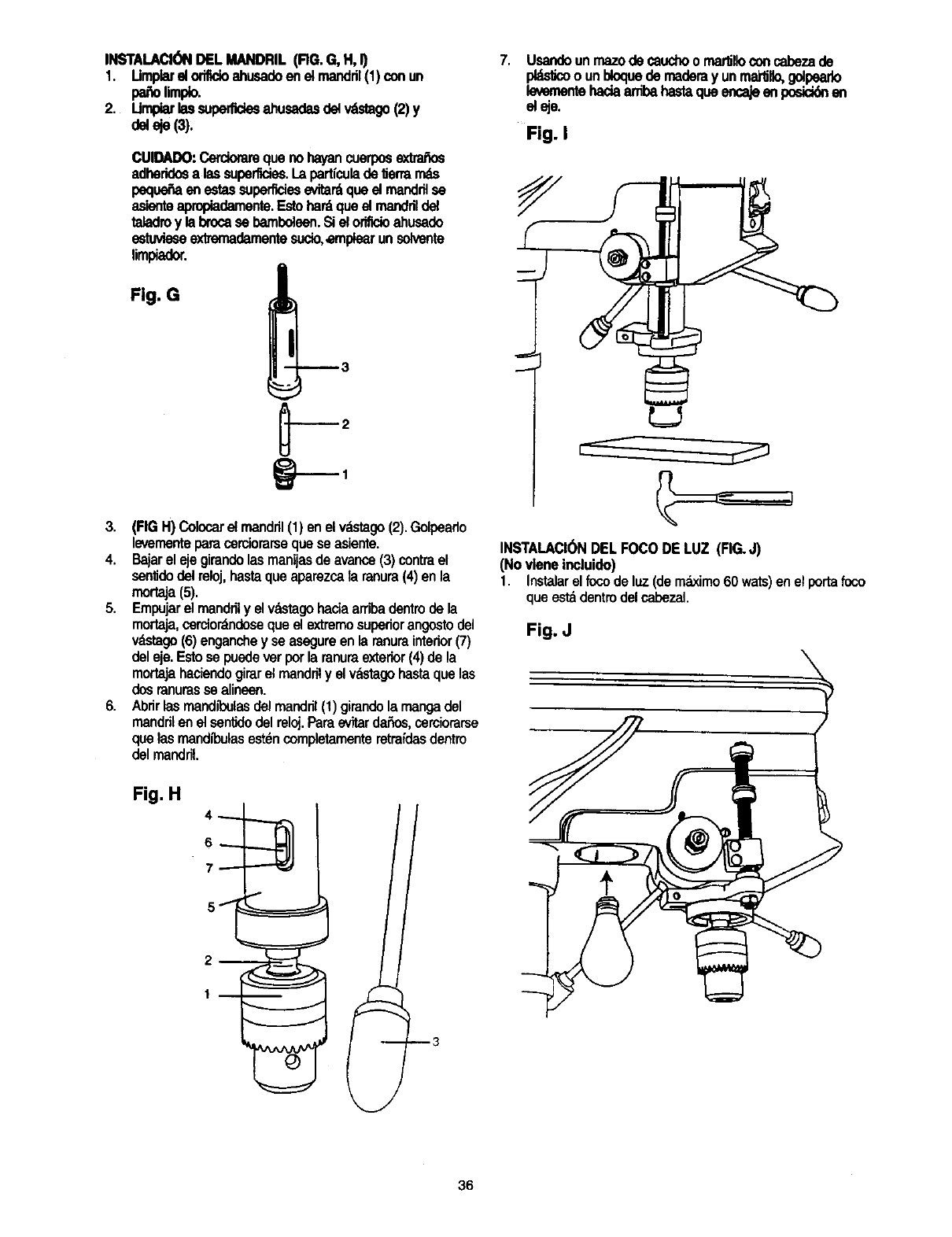
INSTALACI(_)NDELMANDRIL(RG.G,H,I)
1. Umplarel orifldoahusadoen etmandril(1)conun
pasolimp_o.
2. Umpiarlassuperfldesahusadasdelwf_tago(2)y
deleje (3):
7. Usandoun rnazode cauchoo rnartnoconcabezade
pl_dcoounbloquedemaderayunrna_llo,golpearlo
levementehadaardbahastaqueencajeen posicklnen
eleje.
Fig. I
CUIDADO:Cercioramquenoha/ancuerposextr'a_os
adheridosalas superficies.I.apartfculade lJermms
peque_aenestassuperficiesevitar_queel mandrilse _-_
_mienteapropiadamente.Estohardqueel manddldel
taladroy la brocasebamboleen.Si elorifidoahusado
estuvieseextrernadamentesucio,ernplearunsolvente
limpiador.
3. (FIGH) Colocarel mandril(1) enel v_tago (2).Golpearlo
levementeparacerciorarsequeseasiente.
4. Ba'larel ejegirandolasmanijasde avance(3)contrael
senfidodelreloj,hastaqueaparezcala ranura(4)en la
mortaja(5).
5. Empujarel mandnly elvastagohaciaarribadentrode la
mortaja,cercior_doseque el extremosuperiorangostodel
vdstago(6)enganchey seasegureenla ranurainterior(7)
deleje.Estosepuedeverporla ranumexterior(4)de la
mortajahaciendogirarel mandrily elvdstagohastaquelas
dosranurassealineen.
6. Abrirlasmandll_ulasdelmandr;I(1)girandolamangadel
mandrilenel sentidodelreloj.Pareevitarda_s, cerciorarse
quelasmandibulasest_ncompletamenteretmfdasdentro
delmandril.
L=J
INSTALACI(_NDEL FOCODE LUZ (RG.J)
(Novieneincluido)
1. Instalarel focode luz(demdximo60wars)en el portafoco
queestadentrodelcabezaL
Fig. J
Fig. H
36
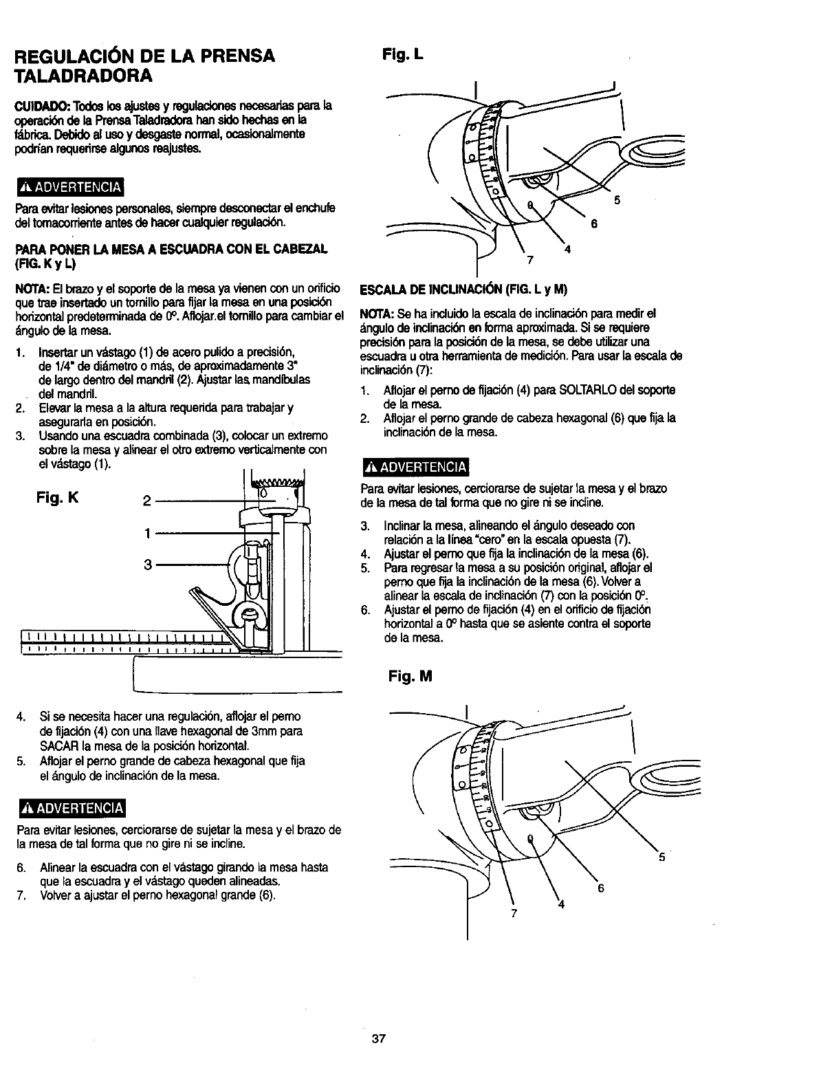
REGULACI6N DE LA PRENSA
TALADRADORA
CUIDADO:Todoslosajustesy regulacionesnecesariasparala
operesibnde la PrensaTeladradorahansidohechesen la
f_brica,DelYdoal usay desgestenormal,ocask_almente
podrfanrequedrseelgunosreajustes.
Paraevitarlesionespersonales,siempredesconectarelenchufe
deltomacorrienteantesdehasarcualquierregulacibn.
PAPAPONERLAMESAA ESCUADRACONEL CABEZAL
(RG. Ky L)
NORA:El brazo y el soportede la mesa ya vienen con un orificio
que trae insertadoun tomillopara fijar la mesa en una posici6n
horizontalpredeterminadade 0°. Aflojar.eltornillopara cambiar el
_ngulo de la mesa.
1. Insartarunv_stago(1)de aceropulidoa precisi6n,
de 1/4"de didmetroo mds,deaproximademente3"
delargodentrodelmandril(2).Ajustarlasmandibulas
•delmandril.
2. Elevarla mesaa laalturarequeridaparatmbajary
asagurarlaen posici6n.
3. Usandounaescuadracombinada(3),colocarunextremo
sobrela mesay alinearel otroextzernovertJcatmentecon
el v_stago(1). I I_..._._.J
Fig. K 2 _:_
It_5--- -- __
I I _ I _ tIIIIII/
4. Si sa necesitahaceruna regulaci6n,aflojarelpemo
de fljaci6n(4)conunaIlavehexagonalde3mmpara
SACARla mesadela posici6nhorizontal.
5. Aflojarel pernograndede cabezahexagonalquefija
elangulode inclinaci6ndela mesa.
Paraevitarlesiones,cerciorarsedesujetarta mesayel brazede
la mesade tal formaque nogireni se incline.
6. Alinaarlaescuadracon el v_stagogimndela mesahasta
quela escuadrayel vdstagoquedenalineadas.
7. Volveraajustarelpernohexagonalgrande(6).
Fig. L
5
6
4
7
ESCALADEINCLINACI6N(FIG,L y M)
NOTA: Se ha induido la escala de inclinaci6n para medir el
&ngulo de indinaci6nen formaaproximada.Si sa requiem
precisi6npara la posici6nde la mesa, se debe utilizaruna
escuadra uotra herramientade medici6n.Para usarla escala de
inclinaci6n(7):
1. Aflojarelpernodefljaci6n(4) paraSOLTARLOdelsoporte
de la mesa.
2. Aflojarelpernograndede cabezahexagonal(6)quefija la
inclinaci6nde la mesa.
Paraevitarlesionas,cemiorarsadesujetarla mesay elbraze
dela mesade talformaquenogireniseincline.
3. Inclinarla mesa,anneandoel_,ngulodesaadocon
ralaci6nalalinea"sam"en la escalaopuesta(7).
4. Ajustarelpernoquefija lainclinaci6nde la mesa(6).
5. Pararegresarla mesaa su posial6nodginel,aflojarel
pemoqueflja la inclinaci6nde la mesa(6).Volvera
alinearla escalade indinaei6n(7)con laposici6n0°,
6. Ajustarel pemode fijacibn(4)en el orificiode fijaci6n
horizontala 0° hastaquesa asientecontrael sogorte
de lamesa.
Fig. M
5
6
37
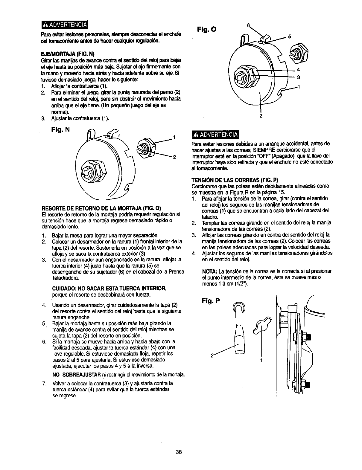
rRB[i_PJ_l_e[
Parae_r lesionespecsona_ siempredesco_ el enchub
delton_,co,-den_antesdehanercualquierreguladdn.
F OnT A (RG.N)
Girarlasmanijasde avancecontrael sanlJdodelrelojparebajar
el ejehastesuposiciderndsbaja.Sujetarel ejefirmementecon
la manoymovedohaciaatrdsy haciaadelantesobresusje.Si
tuviesedemasiadojuego,hacerIosiguiente:
1. Aflojarb contratuerca(1).
2. Paraeliminarel juego,girarla puntaranuradadetperno(2)
en elsentidodelreloj,perusinobstruirel rnovimientohada
arribaqueel eje tiene.(Unpeque6ojuegodeleje as
normal).
3. Ajustarla contmtuerca(1).
Fig. N
RESORTEDE RETORNODE LAMORTAJA(FIG.O)
Elresortede retomode la mortajapodr_arequerirregulacibnsi
sutensi6nhaosquelamortajaregrasedemasiadordpidoo
demasiadelento.
1. Bajarla mesapareIograrunamayorseparaci6n.
2. Colocarundesarmadoren la ranura(1)frontalinferiorde la
tape(2)del rasorte.Sostenedeen posici6nala vezquese
aflojay sesacalacontmtuercaexterior(3).
3. Conel desarmadoraunenganchadoen la ranura,aflojarla
tuercainterior(4)justohastaquela ranura(5)sa
desenganchede susujetador(6)enel cabezalde la Preosa
Taladradora.
CUIDADO: NO SACAR ESTA TUERCA INTERIOR,
porqueel rasorlese desbobinardcon fuerza.
4. Usandoundesarmador,girarcuidadosamentelatape(2)
delresortecontrael sentidodelrelojhastaquela siguiente
ranuraenganche.
5. Bajarlamortajehastasuposici6nrodsbajagirandola
manijade avancecontraelsentidodelrelojmientrasse
sujetala tapa(2) delresorteen posici6n.
6. Si la mortajasemuevehaciaarribay haciaabajoconla
facilidaddeseade,ajustarla tuercaestdndar(4)conuna
Ilaveregulable.Siestuviasedemasiadofloja,repetirlos
pasos2 al 5 paraajustarla.Si estuviasedemasiado
ajustade,ejecutarlospasos4 y5 ala inversa.
7.
NO SOBREAJUSTARnirestringirelmovimientodelamortaja.
Volvera colocarlacontratuerca(3)yajustarlacontrala
tuercaestandar(4)paraevitarquelatuercaestdndar
se regrase,
Fig. O
Pareevitarlesionesdsbidesa unarranqueaccidental,antesde
hacerajustesalas coneas,SIEMPREcerciorarsequeel
intermptore_6 en la posici6n=OFF"(Apagado),quela Ilavedel
interruptorhayasidoretiraday queelenchufenoest6conectado
al tomacorTiente.
TENSI(_NDE I.AS CORREAS(FIG.P)
Cerciorarsequelaspoleasest6ndebidamentealineadascoma
semuestraen la RguraR en lapdgina15.
1. Pareaflojarlatensi6nde lacorrea,girar(contrael sen_do
delreloj)lossegurosde lasmanijastensionadorasde
correas(1)queseencuentranacedeladedelcabezaldel
taladro.
2. Templar[ascorreasgirandoenel sentidodelrelojla manija
tensionadoradelascorreas(2).
3. Aflojarlascorreasgirandoencontradelsen_dodelrelojla
manijatensionadorade lascorreas(2).Colocarlascorreas
en las Ix)leasadecuadasparaIograrla velocideddaseada.
4. Ajustarlossegurosdetasmanijastensionadorasgirdndolos
en el sentidodelreloj.
NORA:Latensi6nde lacorreaeslacorrectasi alprasionar
el puntointermediodela correa,_stase muevemdso
menos1.3cm(1/2").
Fig. P
38
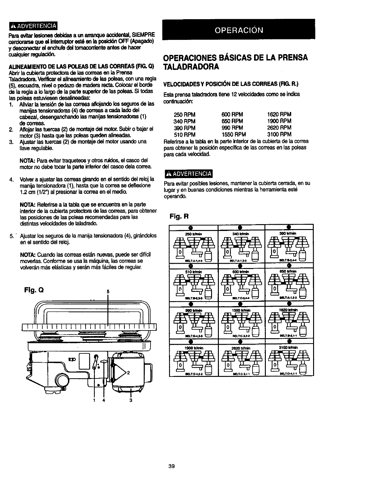
Paraevitartesionesdebidasa unananqueacddental,SIEMPRE
cerdomrsequeel Intenupexestden la posid6nOFF(Apagado)
y desconecWel enchuledeltomaconienteantesde hacer
cualquierregulacidn.
AUNEAMIENTODE LASPOLEASDE[.ASCORREAS(FIG.Q)
Abrirla cubiertaprotectomde lascorreasen laPrensa
Taladradora.Verificarel alineamientode laspoleas,conunaregla
(5),escuadra,nive;o pednTodemaderarecta.Colocarel borde
de lareglaa Iolargode la partesupedordelaspoleas.Sitodas
laspoleasestuviesendesalineadas:
1. Aliviarlatensi6nde lascorreasaltojandolossegurosde las
manijastensionadoras(4) decorreasa cadaladodel
cabezal,desenganchandolasmanijastensionadoras(1)
de correas.
2. Aflojarlastuercas(2)de mofltajedelmotor.Subiro bajarel
motor(3)hastaquelaspoleasquedenalineadas.
3. Ajustarlastuercas(2) demontajedelmotorusandouna
gaveregulable.
NOTA:Paraevitartraqueteosyotrosruidos,el cascodel
motornodebetocarla parteinfenordelcascodelacorrea.
4. Volvera ajustarlascorreasgirandoen elsentidodelrelojla
manijatensionadora(1), hastaquelacorreasedefle_ione
1.2 cm(1/2")al presionarlacorreaen el msdio.
NOTA:Refedrsea latablaquese encuentraen la parte
interiorde la cubiertaprotectomde lascorreas,paraobtener
lasposidonesdelaspoleasrecomendadasparalas
distintasvelocidadesdetaladrado.
5. " Ajustarlossegurosde la manijatensionadora(4),girdndolos
en elsentidodelreloj.
NOTA:Cuandolas correasestdnnuevas,puedeserdificil
moverlas.Conformeseusala mdquina,lascorreasse
volverdnmaseldsticasy serdnmdsfdcilesde regular.
Fig. Q s
OPERACIONES BASICAS DE LA PRENSA
TALADRADORA
VELOClDADESY POSlCI(_NDE I.ASCORREAS(RG.R.)
Estaprensataladmdomtiene12velocidadescomoseindica
continuaciOn:
250RPM 600RPM 1620RPM
340 RPM 650RPM 1900RPM
390RPM 990RPM 2620RPM
510RPM 1550RPM 3100RPM
Referirsea latabtaen laparteinteriorde la cubiertade lacorrea
paraobtenerla posicibnespecfficade lascorreasenlaspoleas
paracadavelocidad.
Paraevitarpo_ibleslesiones,mantenerlacubiertacerrada,ensu
lugary enbuenascondicionesmientrasla herramientaestd
operando.
Fig. R
99
250 tdmin 340 tdndn
Ip •
9 =' •
gQO_ 1_ _mln
o9
9
9
9
9
3100 tdmln
1 4 3
39
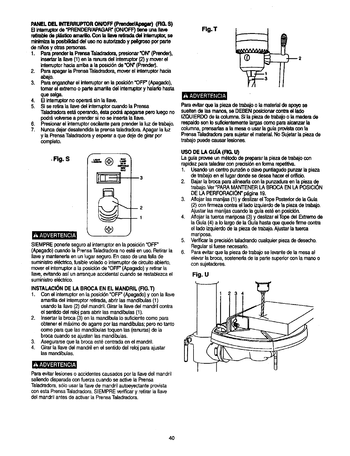
PANELDELINTERRUPTORON/OFF(PrenderlApegar)(RG. S)
[] intermptorde"PRENDER/APAGAR'(ON/OFF)tleneunanave
retlrablede pl_=_:o=na,'t_ Conla llavere_adadelIntermptor,se
rn]nimizalapos_lidaddelusonoautodzadoy pellgrosopotparte
de nii_osy otraspersonas.
1. Paraprenderla PrensaTeladradora,presionar"ON"(Prender),
insertarla Ilave(1) enla ranuradelinterruptor(2) ymoverel
interrupterhaciaarribaa la posici6nde"ON"(Prender).
2. Paraapagarla PrensaTeladradora,moverel interruptorhacia
abajo.
3. Paraengancharelinterruptoren la posic_n'OFF"(Apagado),
tomarel extremoo parteamarilladelinterruptory halarlohasta
queselga.
4. El interruptornooperardsinla Uave.
5, Si serelirala Ilavedelinterruptorcuandola Prensa
Taladradoraestdoperando,dstapodrdapagarseperoluegono
pod_ volversea prendersinoseinsertala Ilave.
6. Presionarel interruptoroscilanteparaprenderlaluzdetrabajo.
7. Nuncadejardesatendidala prensataladradora.Apagarla luz
y la PrensaTaladradorayesperuraquedejede girarper
completo.
.Rg. S f
m3
m2
DI
SIEMPREponerlesaguroal interrupterenla posici6n"OFF"
(Apagado)cuandela PrensaTaladraderanoest_en uso.Retirarla
llavey mantenerlaen untugarseguro.En casode unafallade
suministroel6ctrico,fusiblevoladeo intenuptorde circuitoabierto,
moverel interruptera laposici6nde"OFF"(Apagado)y retirar]a
Ilave,evftandeas{ unarranqueaccidentalcuandose restaUezcael
suministroel_ctdcc.
INSTALACI(_NDE LABROCAEN EL MANDRIL(FIG.T)
1. Conel interruptoren laposici6n"OFF"(Apagado)yconla Ilave
amarinadelinterruptorretirada,abdrlasmandll_ulas(1)
usandola Ilave(2)delmandrfl.Girarla Ilavedelmandrilcontra
el sentidodelrelojparaabrirlasmandll_ulas(1).
2. Insartarlabroca(3) enla rnandtl_ulaIosuflcientacomopara
obtenerel mdximode agarreporlasmandl_ulas;peronotanto
comeparaque lasmandibulastoquenlas (ranuras)de la
brocacuandoseajustenlasmandibulas.
3. Asegurarseque la brocaest_centradaenel mandril.
4. Girarla Ilavedelmandrilen el sentidodelrelojparaajustar
lasmandibulas.
Fig. T
12
Paraevitarquela piezadetrabajoo larsaterialde apoyose
sueltende lasmanos,sa DEBENposicionarcontraellado
IZQUIERDOdela columna.Si lapiezade trabajoo lamaderade
respaldosonIosuficientementelargascomoparaalcanzarla
columna,prensarlasa la mesao usarlaguiaprovistaconla
PrensaTaladradoraparasujetarel materiel.NoSujetarla piezade
trabajopuedecausarlesiones.
USODE LAGU[A(RG. U)
Laguiaproveeunm6todode prepararlapiezadetrabajocon
rapidezparataladmrconprecisi6nenforrnarelxYl_dva.
1. Usandouncentropunz6no clavopuntiagudopunzarlapieza
de trabajoen el lugardondese deseahacerel orificio.
2. Bajarla brcoaparaalinearlacon la punzaduraen lapiezade
trabajo.Ver"PARAMANTENERLABROCAEN LAPOSICI(_N
DE LAPERFORACI_N"pdgina19.
3. Aflojarlasmanijas(1)ydesnzarelTopePcoteriorde laGuia
(2)confirmezacontrael ladoizquierdodela piezade trabajo.
Ajustarlasmanijascuandola guiaest6enposicidn.
4. Aflojarlatuercamariposa(3)y deslizarelTopedelExtremede
laGuia(4)a Iolargode la Gufahastaquequedefirmecontra
elladoizquierdodela piezadetrabajo.Ajustarlatuerca
mariposa.
5. Verificarla precisibntaladrandocualquierpiezade desecho.
Regularsifuesanecesado.
6. Paraevitarquela piezade trabajoselevantedela mesael
elevarlabroca,sostenedadela partesuperiorcon la manoo
con sujetadores.
Fig. U
234
Para evitar lesioneso acoidentes causados por la Ilavedel mandril
saliendo disparada con fuerza cuando se active la Prensa
Taladradora, s61ousar la Ilavede mandril autoeyectante provista
con esta Prensa Taladradora. SIEMPRE verificar y retirar la Ilave
del mandril antes de activar la Prensa Taladradora.
4O
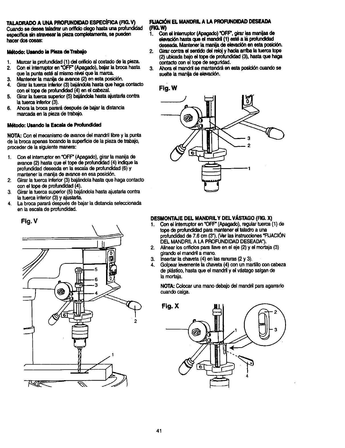
TALADRADOA UNA PROFUNDIDADESPECIFICA(RG.V)
Cuar_ se deseatalad_ unoritUodegohastaunaprofundk_
espemca¢na_=ar _pk3zacompk_amem,sep.eden
hacerdoscocas:
Uitodo: Uundo la Pie_ €leTrldx_
1, Marcarlaprofundidad(1)delorifidoelco6"tadode la pieza,
2. Conel intenuptoren"OFF"(Apegado),bajarlabrocahasta
quela puntaest6el mismonivelquela marca.
3. Mantenerla rnanijade avarice(2)enestaposlo_.
4. Girarlatuercainfeder(3)bajatndelahastaquehagacontacto
coneltopede profundidad(4) enel cabezaL
5. Girarlatuercasuperior(5)bajdndolahastaajustadacontra
la tuercainferkx(3).
6. Ahorala brocapararddespudsdebajarladistancia
marcadaenla piezade tmbajo.
I_todo: Usanclob Es_b de Profundld_l
NOTA:Conel mecanismode avancedelmandrillibrey la punta
de la brocaapenastocandola superficiede lapiezade trabajo,
procoderde la siguientemanera:
1. Conel interruptoren"OFF"(Apagado),girarla manijade
avance(2) basraqueel topedeprofundidad(4)indiquela
profundidaddeseadaen laescalade pmfundidad(6)y
mantenerla manijade avanceen esaposick_n.
2. Girarlatuercainferior(3)bajdndolahastaquehagacontaclo
con eltopedeprofundidad(4).
3. Girarlatuercasuperior(5)_la hastaajustadacontra
latuercainferior(3)y ajustarla.
4. La brocaperarddespu6sde bajarla distanciaselecoionada
en la escaladeprofundidad.
Fig. V
RJACI(_I ELMANDRILA LA PRO_DAD DESEADA
(FIG.W)
1. Cone|intenuptor(Apagade)"OFF",g_ar_manijasde
devad_ basraqueel manddl(1)est6a li prdundidad
deseade.Mantenerla manfjadedevack_en estapodck_.
2. Girarcontrael serfddodelrelojy hadaarribala tuercatope
(2)ubicadabajoeltopedeprofundidad(3),hastaquehaga
contactoconel topede seguridad.
3. Ahorael manddlsemantendr,_en estaposick_cuandese
sueltela manijadeelevackSn.
Fig. W
2
DESMONTAJEDEL MANDRILYDELV/_STAGO(FIG.X)
1. Conel intenuptoren"OFF"(Apegado),regulartuerca(1)de
topedeprofundidadperamantenerel teladroa una
profundidadde 7.6cm(3').(Verlasinstrucciones"FIJACK_
DELMANDRILA LAPROFUNDIDADDESEADA'),
2. Alinearlosorificiosparanaveen eleje (2)y elmortaja(3)
girandoel mandrila memo.
_. Insertarla chaveta(4)enlasranuras(2y 3).
• Golpearlevementela chaveta(4)conunma_lloconcabeza
de pldsfico,hastaqueel mandrily elv"astagosalgande
la rnortaja.
NOTA:Colocarunarnanodebajodelmandrilparaagarrado
coandocaJga.
Fig. X
2
1
4
41
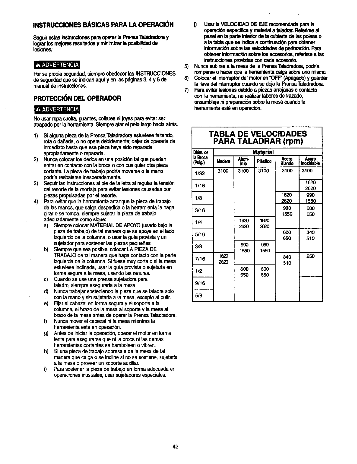
INSTRUCCIONES BASICAS PARA LA OPERACI6N
SegJirestasbs'm,,cdonesparaoperarla Prensa.Teladradoray
_rnejomsresultadosy minlmizarla podbi_adde
Porsuproplasaguridad,siempreobedecerlas INSTRUCCIONES
de seguridadqueseindicanaqufyen lespdginas3, 4y 5 del
manualde instrucdones.
PROTECCI6N DEL OPERADOR
R_r=1_=[=_l=Kffe]T.
Nousarropasuelta,guante_cdlaresnijoyasparaevitarser
atrapadoporla herramienta.Slampreafarel pstolargohaciaatrds.
1)
2)
3)
4)
$i algunapiezade la PrensaTeladradoraestuviesefaltando,
rotao da_ada,o nooperadebidamente;dejarde operarlade
inmediatobasraque esapiezahayasidereparada
apropiadamenteo reparada.
Noncacolocarlosdedosen unaposici6ntelque pusdan
entrarencontactoconla brooao concualquierotrapieza
cortante.Lapiezadetrabajopodriamoverseo la mano
podn'aresbalarseinesperadamente.
Seguirlasinstruccionesal piedela letraal regularla tensibn
delresortede lamortajaparaevitarlesionescausadaspor
piezaspropulsadasporel resorte.
Parae_tarquela herramientaarranquela piezadetrabajo
de lasmanos,que salgadespedideo la herramientala haga
giraro se rompa,siempresujetarla piezadetrabajo
adecuadamentecomosigue:
a) SiemprecolocarMATERIALDE APOYO(usadobajola
piezade tmbajo)detal maneraqueseapse enel lade
izquierdode lacolumna,o usarla gufaprovistayun
sujetadorparasostenerlaspiezaspequeSas.
b) Siemprequeseaposible,colocarLAPIEZADE
TRABAJOdetal maneraquehagacontactocon la parte
izquierdade lacolumna.Sifuesemuycortao sila mesa
estuvieseinclinada,usarla guiaprovistaosujetarlaen
formaseguraa la mesa,usandolasranuras.
c) Cuandosa useunaprensasujetadorapara
taladro,siempreasaguradaa la mesa.
d) Nuncatrabajarsosteniendola plazaquesa taladras61o
conla manoy sinsujetarlaa la mesa,excoptoal pulir.
e) Fijarel cabezatenformaseguray elsoporteala
columna,el brazode la mesaal soportey lamesaal
brazode la mesaantesde operarla PrensaTaladradora.
f) Nuncamoverel cabezalnila mesamientrasla
herramientaest_en operacion.
g) Antesde iniciarlaoperaci6n,operarel motoren forma
lentaparaasegurarseque nilabrocaniles dem_.s
herramientascortantesse bamboleeno vibran.
h) Si unapiezadetrabajosobresalede lamesadetal
maneraquecaigaoseinclinesi nose sostiene,sujetarla
a la mesaoproveerunsoporteauxiliar.
i) Farasostenerlapiezadetrabajoen formaadecuadeen
operacionesinusuales,usarsujetadoresespeciales.
5)
6)
7)
j) Usarla VELOClDADDE EJErecomendadeparala
opemddnespedflcay materiala teladrar.Refedrseel
panelen I==parteInteriordetambierlade laspoleeso
ala tablaqueseindlcaa conUnuack_nparaobtener
informac_ sobrelas veloddedesde perlomci_.Para
obtener informaci_ sobre Im accesodm, relerirsea las
in_nes provistasconcade accesodo.
Nuncasubirsea lamesade la PrensaTeladradora,podrfa
romperseo hacerquela herramientacaigasobreunomismo.
Colocarel intenuptordelmotoren "OFF"(Apagado)y guardar
la IlavedelinternJptorcuandosedejela PrensaTeladradora.
Paraevitarlesionesdebldea piezasarrojadaso contacto
conla herramienta,norealizarlaboresdetrazado,
ensamblajeni prepamd6nsobrelamesacuandola
herramientaest6enoperaci6n.
TABLA DE VELOCIDADES
PARA TALADRAR (rpm)
_tm.de Material
;laBroca Alum- Pl_stico Acero Acero
i(Pulg.) Madera ink) BlandoInoxfdable
1/32 3100 3100 3100 3100 _3100
1/16
1620
118 262O
3/16 990
1550
1/4 16_0 16_0
262O 262O
5/16 600
65O
3/8 990 990
1550 1550
1620 340
7/16 2_0 510
1/2 600 6OO
650 650
1620
2_0
9_
1550
6_
6_
34O
510
25O
9/16
5/8
42
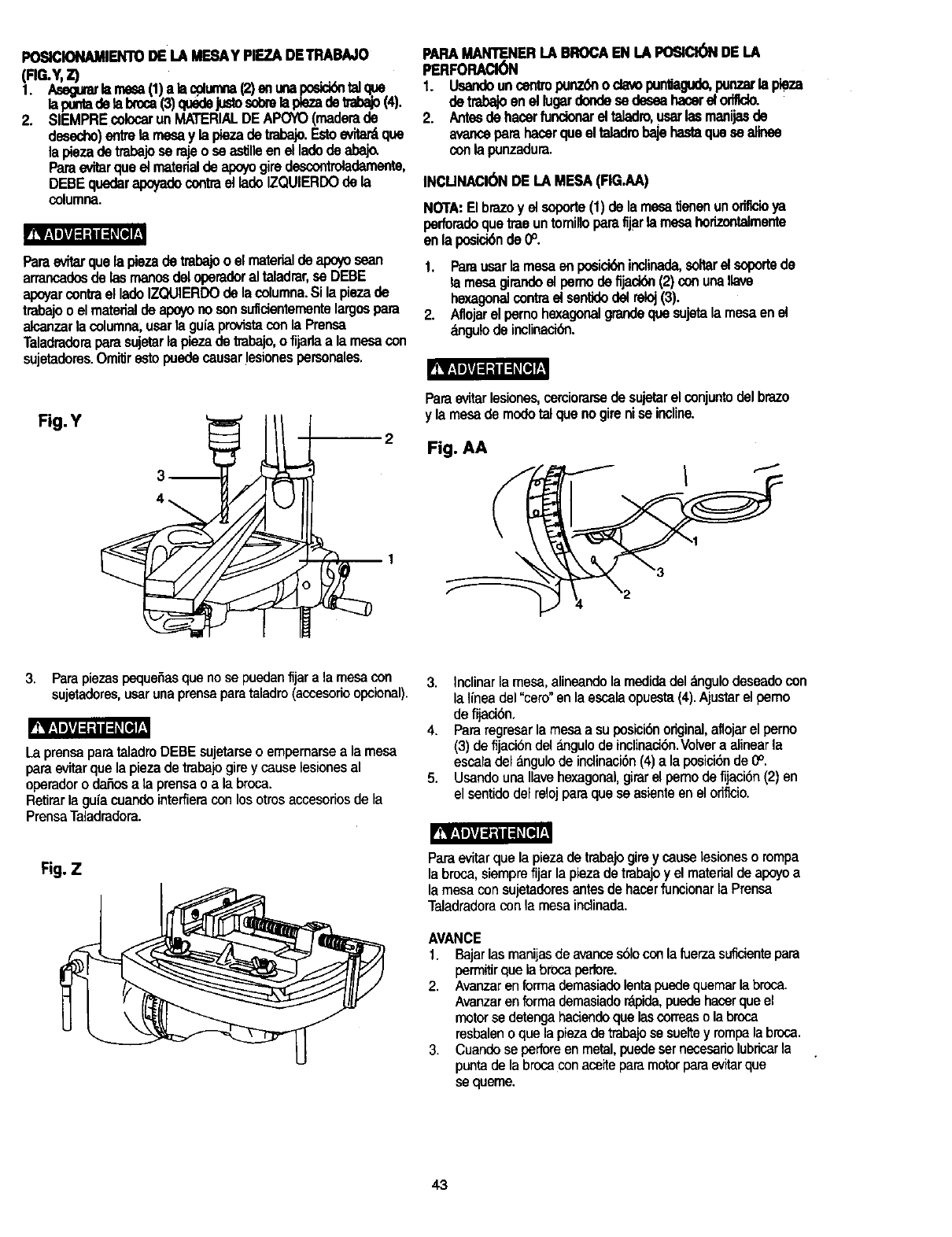
POSICIONAMIENTODE LA MESAYPIEZADETRABAJO
(Rr-Y, Z)
1. Asagularkm',==a(1)a lacplurnna(2)an unaposidd_talqoe
lapuntadela brcoa(3)quedejustosobrelaplezadetrabajo(4).
2. SIEMPREcolocarunMATERIALDE APOYO(maderade
desecho)eff_rela mesay lapiezadetrabajo.Estoevitardque
la piezadetrabajoserajeo seestflleen el ladodeabaj_
Paraevitarqueetmaterialde apoyogiredescontroladamente,
DEBEqu6daral_tado contraetladoIZQUIERDOde la
columna.
Paraevftarquefa piezade trabajoo efmatertaldealx_ sean
arrancadosde lasmanosdeloperadoraltaladrar,se DEBE
apoyarcontrael ladoIZQUIERDOde la columna.Si la piezade
trabajoo elmatedalde apoyonosonsuficienternentelargospara
alcanzarla columna,usarta gu(aprovistaconla Pransa
Taladradoraparasujetarla piezadetrabajo,ofijarlaa la mesacon
sujetadores.Omitirestopuedecausarlesionespersonales.
PARAMANTENERI.A BROCAEN LAPOSICl6NDE LA
PERFORACl6N
1. Usandoancentropunz6no davopunliagudo,punzarla pieza
detrabajoenel lugardondesedeseahacerel od_do.
2. Antesde hacerfuncionarel taladro,usarlasmanijasde
avanceparahacerqueel taladrobajehastaquesa alinee
conlapunzadura.
INCUNACl0NDE LA MESA(RG.AA)
NOTA: El brazo y el soporte(1) de la mesa tJanenun oriflcioya
perfomdoque tree un tomillopare fijar la mesa hofizontalmente
en la posici6nde 0°.
1. Parausarlamesaanposici6nindinad_coltarel soportede
la mesagirandoel pemodefljaci_ (2)conuna,ave
hexsgon_contmel santklodelreloj(3).
2. Aflojarel pemohexagonalgrandequesujetala mesaanel
_ngulode inclinaci6n.
Pt__
Fig. Y
3 2 Fig. AA
c
Paraevitarlesiones,cemiorarsedesujetarel conjuntodelbrazo
ylamesademodotalquenogireniseincline.
3. Para piezas pequefias que no se puedan fijar a la mesa con
sujetadores, usar una prensa para taladro (accesorio opcional).
LaprensaparataladroDEBEsujetarseo empemarsea la mesa
paraevitarquelapiezade tmbaiogirey causelesionesal
operadorodafiosa la prensao ala broca.
Retirarla guiacuandointeffieraconlosotrosaccesofiosde la
PrensaTaladmdora.
3. Inclinarlamesa,alineandola medidadel_,ngulodeseadocon
laIfneadel"cero"enla escalaopuesta(4).Ajustarel pemo
de fijaciSn.
4. Pararegresarlamesaasu posicibnoriginal,aflojarel perno
(3) defijacibndel_mgulode inclinaci6n.Vo_vera alinearla
escaladelangulodeindinacibn(4)a laposicibnde0°.
5. UsandounaIlavehexagonal,girarel pemodefijacibn(2)en
el sentidodelrelojparaqueseasienteenel odflcio.
Fig. Z Paraevitarquela piezade trabajogireycauselesionesotampa
la bresa,siemprefijarla piezadetrabajoy el materialde apoyoa
la mesacon sujetadoresantesde hacerfuncionarla Prensa
Taladradoracon la mesaindinada.
AVANCE
1. Bajarlasmanijesdeavarices61ocon lafuerzasuficientepara
permitirquelabrocaperlore.
2. Avanzarenformademasiadolentapuedequemarla broca.
Avanzarenformademesiado_koida,puedehacerqueel
motorsa detengahaciendoquelascorreaso labroca
resbaleno quelapiezadetrabajosa sueltey rompalabresa.
3. Cuandoseperforeenmetal,puedesetnesesariolubricarla
puntade labrcoaconaceiteparamotorparaevitarque
sequeme.
43
MANTENIMIENTO DE LA PRENSA
TALADRADORA
Por supropiaseguddadcolocarel interruptoren la posicibn
"OFF" (Apagado)y desconectarel enchufedeltomacorriente
antesde dademantenimientoo lubdcarla PrensaTaiadmdora.
Eliminarconfrecuenciael polvoquesa acumuladentrodelmotor
sopl_ndoleairecon uncompresoro aspir_dolo.
La aplicaci6nde unacapade ceraautomotrizen pastaa la mesa
y a lacoLumnaayudar_ta mantenerlas superficieslimpias.
Paraevitarlosdesgosde choqueel6ctdcoo incendio,si el
cordbn eli.._,'tdcoestuviesegastadoo cortado,reparadoo
cambiarlode inmediato.
LUBRICACI( N
Todosloscojinetesde bolasde la PrensaTaladradoravienen
rellenosde grasadesdela f_brica. Norequierenlubrisaci6n
adicional.
Lubdcarperibdicamentelosengranajesy la cremallera,el
mecanismode elevacibnde la mesa,el eje deltaladroy las
mandfbulasde su mortaja.
44
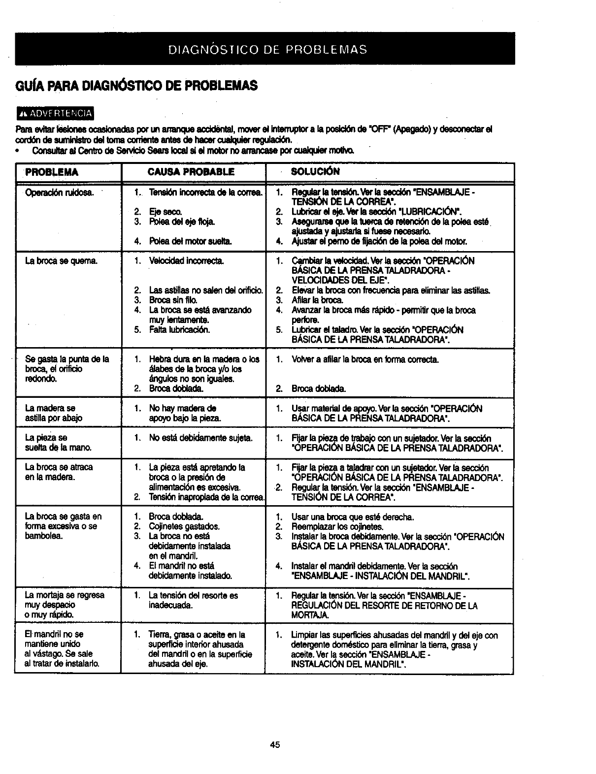
GUfA PARADIAGN( )STICODE PROBLEMAS
PareeviWIRionesocaslonadupotunmnmqueacdd_tal, moverel Intem¢_ ala posld_ de 'OFF"(_) y _ _
cord_ de sumlnls_delton_corrientemde hacercualqu_ regulaci6n,
• Consultaral CentredeSen_doSeamlocal_el molornoammcMe potcualqulermo_w
PROBLEMA SOLUCI6N
Operac_ nddo_
La brocaseq.ern_
Se _mlala_r_ _ la
Regular.laten_ Vetlasecd6n"ENSAMBI._E-
TENSIONDE LACORREA'.
Lubdcarel eje.Vetla secci6n"LUBRICAClON'.
Asegummequelatuercade retenck_de lapo_a est6
ajusu_eyNumdeeHuesenece_a_
Aiuetereli_no de,jeck_ de la i_ea delmotor.
i
Cambiarla velocidad.Vetlasecck_n"OPERACIC_N
BJ_SICADELAPRENSATALADRADORA-
VELOCIDADESDELEJE'.
Elevarla brocaoonfrecuendaparaeliminarlasaslglas.
Afllarlabroca.
Avanzarla brocam_ r'apido- pem_itirquelabroca
perfom
LubdcareltaladroVerlasecctdn'OPERACION
BASICADELAPRENSATALADRADORA'.
Volvera afilarla brocaenformacorrecta.
1,
2.
3.
4.
1.
2.
3.
4.
5.
1.
2.
1.
1.
1.
2.
1.
2.
3.
4.
1.
Brocadoblada.
CAUSA PROBABLE
Tensk_incon'ectade lacorrea. 1.
Ejeee_. 2.
P_a_ _,oi_ 3.
Poleadelmotorsuelta. 4.
Velocidadincorrect_ 1.
Lasas_dllasnosalendelorifido. 2.
Brocasinfilo. 3.
La brocasees_ avanzando 4.
muylefltamente.
Faitalubricack_. 5
Hebradumenla mademo Io_ 1.
dlabesde la brocay/olos
_gulosnosoniguales.
Brocadob_ 2.
Nohaymaderade I.
apoyobajo__za.
Noestddebidamentesujeta. 1.
Lapiezaest_apretandola 1.
brocao la presi6nde
alimentaci_ese_cesiva. 2.
Tensi_ inapropiadadela conea
Brocadoblada. 1.
Cojinetesgastados. 2.
Labrocanoestd 3.
debidamenteinstalada
enetmanddl.
Elmanddlnoestd 4.
debidamenteinstalado.
Latensi6ndetresortees 1.
inadecuada.
Tierra,grasao aceiteen la 1.
superfideinteriorahusada
delmandrilo en la super6de
ahusadadeleje.
La maderase Usarmaterialdeapoyo.Verlaseccidn"OPERACION
asl_llaporabajo BASICADELAPRENSATALADRADORA'
La piezase Rjarlapieza,de .'qzzbajoconunsujetador.Verla secck_
sueltade la mano. OPERACIONBASICADELAPRENSATALADRADORA'.
La brocaseatraca Rjarla_ a ta;_,L_lmrconunsu'.lel_or.Verla seccibn
en la madem. "OPERAClONBASICADE LA PRENSATALADRADORA'.
Regula[,la tensi6n.Verlasecck_'ENSAMBLAJE-
TENSIONDELA CORREA'.
Labrocasegastaen
foffnaexcesivao se
bambolea.
Usarunabrocaqueest6derecha.
Reemp_zzarlosmjinetes,
Instalarlabrocadebidamente.Vetla secc_n"OPERACI(_N
BASICADE LAPRENSATALADRADORA'.
Instalarel rnanddldebidamente.Verlasecck_n
'ENSAMBLAJE- INSTALACI(_NDELMANDRIL'.
La mortajase regresa Regularlatensk_.Verlasec_ "ENSAMBLAJE-
muydespado REGULACIONDELRESORTEDERETORNODE LA
o muyr_..pido. MORTAJA.
Elmanddlnose 1. Limpiarlassuperficiesahusadasdelmanddly d_ ejecon
man6eneunido detergentedorn6stJcopareeliminarlatierra,grasay
al vSsta9o.Sesale aceite.Vetla secck_n"ENSAMBLAJE-
al tratarde instalado. INSTALACIC_)NDELMANDRIL'.
45
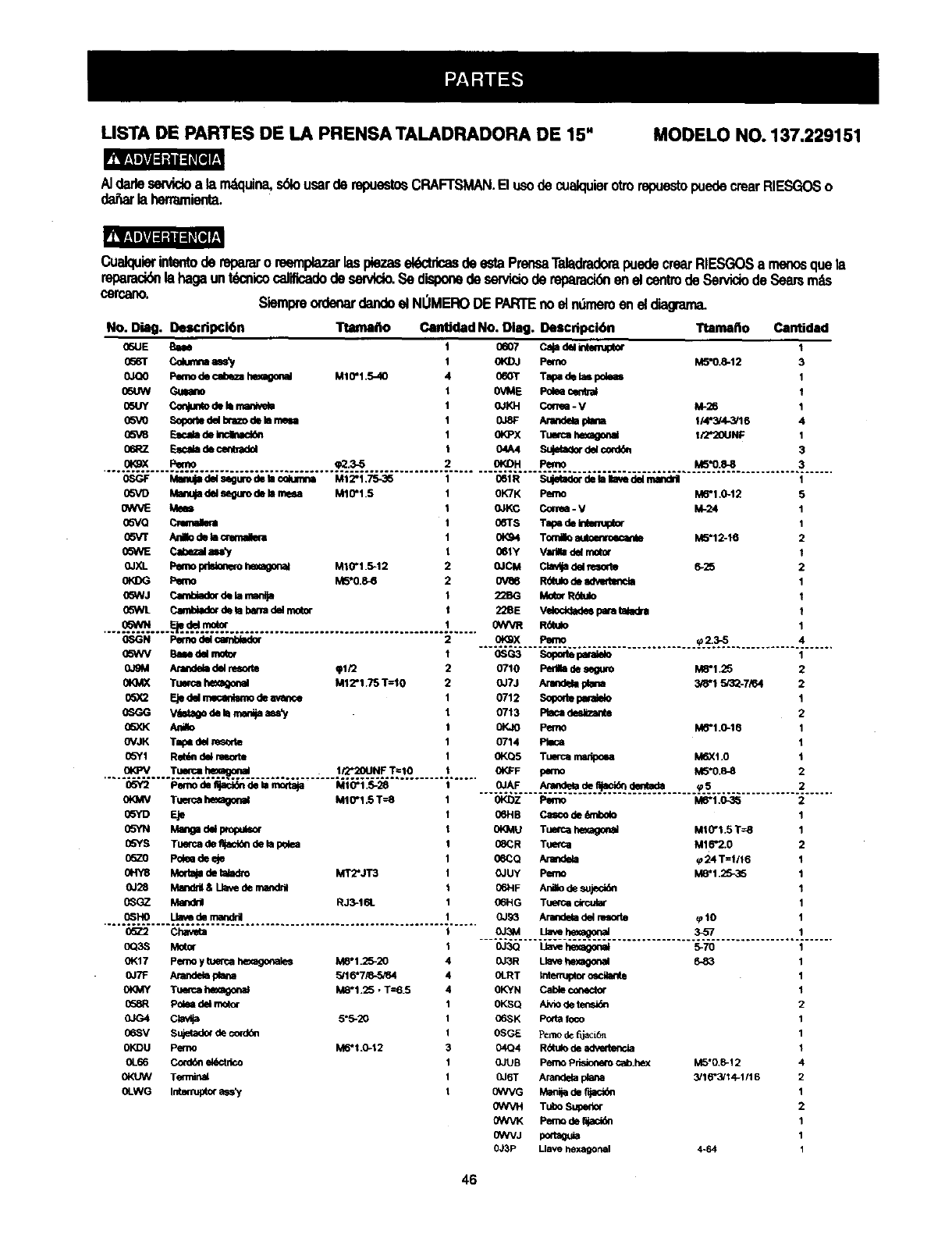
LISTA DE PARTES DE LA PRENSA TALADRADORA DE 15" MODELO NO. 137.229151
AIdarlesewicioa la m_quina,s_o usarde repuestosCRAFTSMAN.B usode cuak:luierotrorepuestopuedecrearRIESGOSo
da_arlaherramienta.
Cualquierinte_ode repararo reemplazarlaspiezasel6ctdcasdeestaPrensaTaladradorapuedecrearRIESGOSa rne/x_quela
repamck_la hagaunt_cnicocalificadode sen/Ido.Sedisponedeserviciode repamcidnen el _ _ _ _ _ m_
cercano. Siempreordenardandoel NOMERODE PARTEnoel nOmeroen el d_
No. Diag. Descripci6n Ttamaflo Canbdad No. Diag. Descdpci6n
06UE E_m
0_r Cokm_==.s_/
0JO0 Pemode¢al0ezahexagonal
05UW GLeam
05UY Cequmode_man_ve_
05VO SopohedelbrazodeIsm
05V8 _deIncinad_
06RZ FJN_adeceqbadel
M1_1.5-40
Ttamaho Cantidad
oeo7 caja d_ _tmup_ 1
0KDJ Pef_o M5"0.8-12 3
060T TalPa de bm pdems 1
0VME Polee central t
OJKH Corree -V M-26 1
0JSF Arar_ F_ana 114"N4-3/16 4
0_3=X Tuwca hexagonal I/2*20UNF 1
04A4 Sujeta_r del cord_ 3
ORgX Pemo _2.3-5 OI_H Pemo M5"0.8-8 3
0SGF IV_ del s6guro de la c(_mna MI 2"1.75-35 061R Sujetader de faIlave del ma_d_ 1
05VD Ma_ del seguro de kl meu M10"1.5 0K7K Peso M6"1.0-12 5
_NVE Meal 0JKC Collru - V M-24 1
05VQ Cmmalma 06Ts Tal_ de Intm_otor 1
05VT AnBodehlm 0KS4 Tomao NM5"12-16 2
05WE Cabl_al al_y 06ty Vldla d_ motor 1
0JXL I_mo pdstonemhexagonal MI0"t.5-12 0JCM Clavqa d_ resor_ 625 2
0_I)G Pemo M5"0.8_ 0V86 R6ttdodem 1
05WJ CamUador d_ _-m 22BG Motor RUado I
05WL Canl_ader de ta bana del r_tor 228E Vek)ddade_ para ta_dra t
...._....._..._....m_..................................................... _ R_o 1
0SGN Pemo del carffolador
05WV Based_ mo_ 0SG3 Sopode perm_
0J_M Arandeb del reso_te _t/2 0710 Pedla de seguro M8"1.25
0K]_K TLWCa heo_onal M12"1.75 1"=10 0JTJ Arandela plana 348"15r32-7_4
05_2 Eje del mecanlsmo de avar_e 0712 S_ paral_o
0SGG V_ de I_ marf_aass_ 0713 F_a_l desl_ante
05XK AJr_o _Pefno M6"1.0-16
OVJK Tap_ del resorle 0714 PIIca
05Y1 Ret_n del nmorte OKQ5 Tuerca manlx_a M6X1.0
O_X Pemo
............................................ ._..z._............... 4......
1
2
.... ...o_........T.....=._ ............. ;.__.I_N._..T==!0.............
(:6Y2 Pemodeqact_nde _amodaja M10"1.5-28
0t_qV Tuemahexagor,al M10"1.5T--8
0SYD Eje
0SYN Ma_gad_ Wop_,_o(
05YS Tu_fcade fljacldndela p_ea
O57-O I='o_edeeje
0HY8 Morta_det_adro MT2"JT3
O.128 Manddl& Lla_ de rnandfig
0_GZ _RJ3-t61.
0_HO Llavede mandril
0KFF pemo M5"0.8-8
._.OJ.AF...._._._._ ......._.S.........................
0K_Z Pemo M6"1.0-3_
06HB Casco de _ni0olo
0KMU Tue_c_ h_agor_l M10"1.5 T=8
08CR Tue_ca M16"2.0
06CQ Arandela (724 T=1/16
OJUY Pemo M8"1.25-35
06HF Ani_o de sujec_n
06HG Tt_e_ circular
0J93 Arandela de_msode _10
o_z c_m ___.%_......._ ................. .._...........................
0Q3S Motor
01<17 Pe_noy tuef_a he_agonales M8"1.25-20
OJ7F Arandegaplana 5/16"7/8-,5_4
0tOAY Tu_ca h_ M8"I .25 • T=6.5
058R Polea del motor
0JG4 _5"5-20
06SV Sujetadorde cordon
0KDU Pemo M6*t _-12
0L66 Con/_n ekk:tdco
0KUW Terminal
0LWG Inte_ asset
0J3Q _hexagonal 5-70
0J3R Llave hexagonal
04J_T tnte_uptor oscilante
0KYN Cable conect_
0KSQ Aivio de _
06SK Poda foco
0SGE P_mode fi_aci6n
04Q4 R_ulo de advede_<',ia
OJUB Pemo P_ cab.he0( M5"0.8-12
0J6T Arandela plana 3/16"3/14-1/16
0WVG Mani_ de ft_
(_VVH Tubo Superior
OWVK Perno de r_ac_n
0WVJ po_taguia
0J3P Llave hexagonal 4-64
46
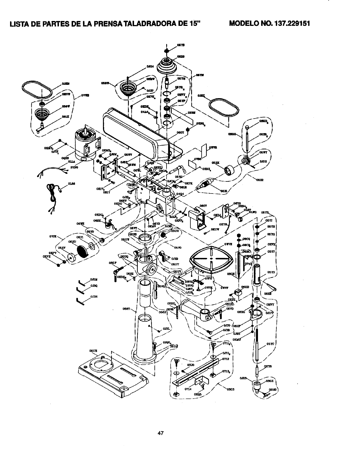
LISTA DE PA_ES DE _PRENSATA_DRADORA DE 15" MODELO NO. 137.229151
i\
I
\
L
/i
_R r
47

Your Home
For repair-in your home-of all major brand appliances,
lawn and garden equipment, or heating and cooling systems,
no matter who made it, no matter who sold it!
For the replacement parts, accessories and
Operator's Manuals that you need to do-it-yourself.
For Sears professional installation of home appliances
and items like garage door openers and water heaters.
1-800-4-MY-HOME ®(1-800-469-4663)
Call anytime, day or night (U.S.A. and Canada)
www,sears.com www.sears.ca
Our Home
For repair of carry-in items like vacuums, lawn equipment,
and electronics, call or go on-line for the location of your nearest
Sears Parts & Repair Center.
1-800-488-1222
Call anytime,dayor night(U.S.A. only)
www.sears.com
To purchase a protection agreement (U.S.A)
or maintenance agreement (Canada) on a product serviced by Sears:
1-800-827-6665 (u.s.A.) 1-800-361-6665 (Canada)
Para pedir servicio de reparacibn
a domicilio, y para ordenar piezas:
1-888-SU-HOGAR s"
(1-888-784-6427)
Au Canada pour service en franctais:
1-800"LE-FOYER "c
(1-800-533-6937)
www.sears.ca
6EAR6
®Registered Trademark ITM Trademark /SMService Mark of Sears, Roebuck and CO
®Marca Registrada /TMMarca de Fdbrica /sMMarca de Servicio de Sears, Roebuck and Co
uc Marque de commerce /MOMarque d_pos_e de Sears, Roebuck and Co ©Sears, Roebuc_ and Co
