Craftsman 137242750 User Manual SAW Manuals And Guides L0903560
CRAFTSMAN Miter Saw Manual L0903560 CRAFTSMAN Miter Saw Owner's Manual, CRAFTSMAN Miter Saw installation guides
User Manual: Craftsman 137242750 137242750 CRAFTSMAN SAW - Manuals and Guides View the owners manual for your CRAFTSMAN SAW #137242750. Home:Tool Parts:Craftsman Parts:Craftsman SAW Manual
Open the PDF directly: View PDF ![]() .
.
Page Count: 16
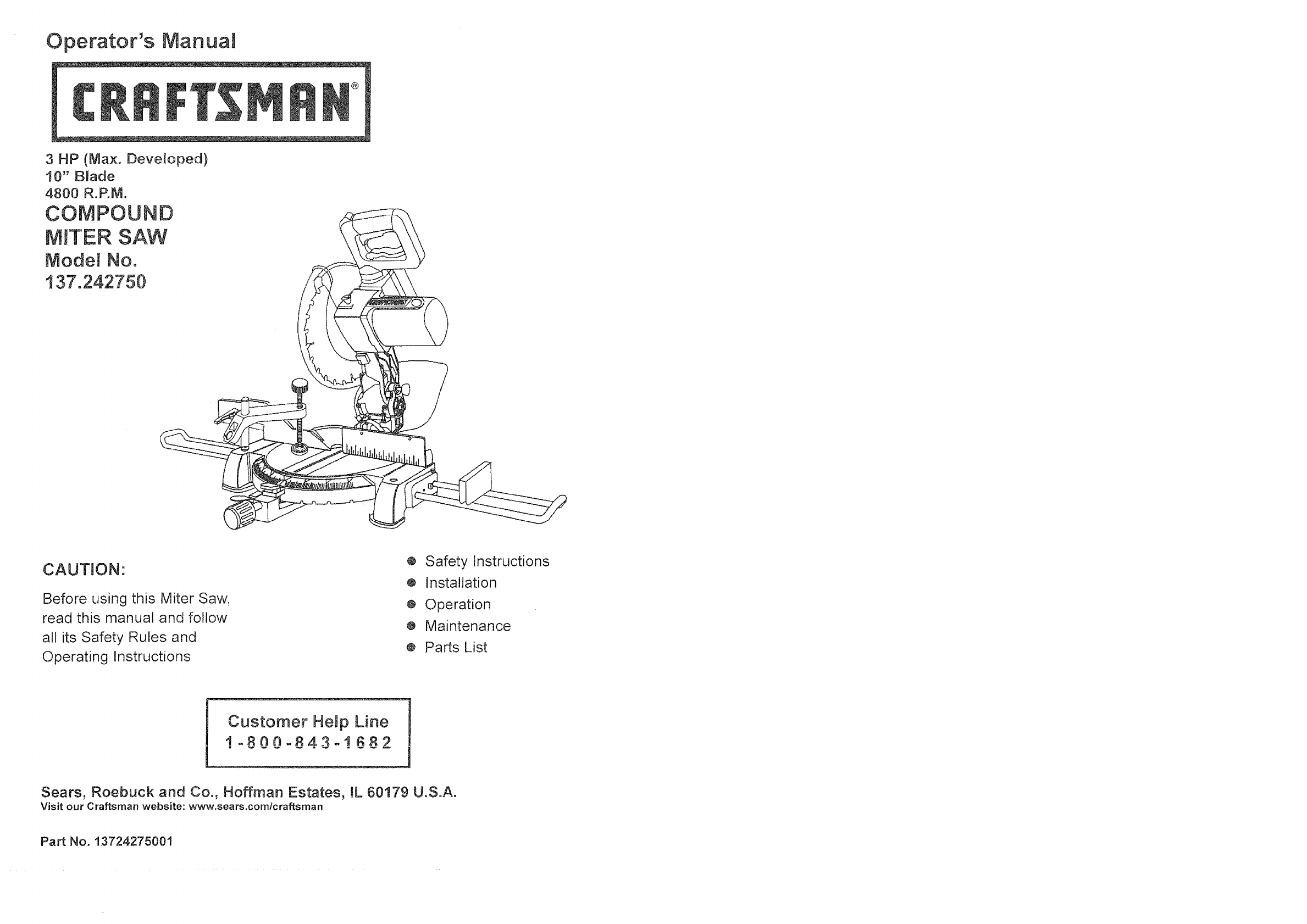
Operator's Manual
3HP (Max. Developed)
10" Blade
4800 R.P.M.
COMPOUND
M_TER SAW
ModeJ No.
137.242750
CAUTION:
Before using this Miter Saw,
read this manual and follow
all its Safety Rules and
Operating Instructions
® Safety Instructions
o Installation
® Operation
e Maintenance
® Parts List
Customer HeJp Line
!-800_843°!682
Sears, Roebuck and Co., Hoffman Estates, BL60179 U.S.A.
Visit our Craftsman website: www.sears.comfcraftsrnan
Pa_ No. 13724275001

SECTION PAGE
Warranty ........................................ 2
Product Specifications ....................... 2
Power Tool Safety ............................ 3
Compound Miter Saw Safety ............... 4
Electrical Requirements and Safety ...... 5
Accessories and Attachments .............. 6
Tools Needed For Assembly ................ 6
Carton Contents ......... :.................... 7
SECTION PAGE
Know Your Compound Miter Saw ........ 8
Glossary of Terms ............................ 9
Assembly and Adjustments ................. 10
Operation ....................................... 16
Maintenance ................................... 23
Troubleshooting Guide ....................... 24
Parts List......................................... 25
FULL TWO YEARS WARRANTY
If this tool fails due to a defect in material or workmanship within two years of date of purchase, Sears will
at its option repair or replace it free of charge.
Return this tool to a Sears Service Center for repair, or to place of purchase for replacement.
This warranty gives you specific legal rights, and you may also have other rights which may vary from
state to state.
Sears, Roebuck and Co., Dept. 817 WA, Hoffman Estates, lL 60179
Some dust created by power sanding, sawing, grinding, drilling and other construction activities contains
chemicals known to the state of California to cause cancer, birth defects or other reproductive harm. Some
examples of these chemicals are:
Lead from lead-based paints
• Crystalline silica from bricks, cement and other masonry products
Arsenic and chromium from chemically treated lumber
Your risk from these exposures varies, depending on how often you do this type of work. To reduce your
exposure to these chemicals, work in a well ventilated area and work with approved safety equipment such as dust
masks that are specially designed to filter out microscopic particles.
MOTOR
Power Source .....................
Horsepower ........................
Speed .................................
Brake ..................................
Double Insulated ....................
MITER SAW
Cutting Capacity:
Crosscut ............................
Miter 450 R. & L...................
Bevel 45° L.........................
45° Miter and 450 Bevel .........
120 V AC, 60HZ, 15 Amp
3HP (Max. Developed)
4800 RPM (No load)
Electric
Yes
2-5/8" x 5-1t2"
2-5/8" x 3-1/2"
1_1/2" x 5-112"
1-1/2" x 3-1t2"
Rotating Table:
Diameter .............................. 12-5/8"
Miter Detent Stops .................. 0, 15, 22-1t2, 31.6,
45° R.& L.
Bevel Positive Stops ............... 0, 45°
Base Dimensions ................... 19-7t8" x 16-3/8"
Dust Collection ...................... Yes
Extension Wings .................... Yes
Net Weight ........................... 28.6 Lbs
To avoid electrical hazards, fire hazards or damage to the tool, use proper circuit protection.
This tool is wired at the factory for tt0-120 Volt operation. It must be connected to a tt0-t20 Volt /1,'3Ampere time
deJay fuse or circuit breaker. To avoid shock or fire, replace power cord immediately if it is worn, cut or damaged
in any way.
Before using your tool, it is critical that you read and understand these safety rules. Failure to follow these rules
could result in serious injury to you or damage to the tool.2 !i
GENERAL SAFETY INSTRUCTIONS
BEFORE UStNG THE MITER SAW
Safety is a combination of common sense, staying alert
and knowing how to use your miter saw.
To avoid mistakes that could cause serious injury, do
not plug the tool in until you have read and understood
the following.
1. READ and become familiar with the entire
Operator's Manual. LEARN the toors application,
limitations and possible hazards.
2. KEEP GUARDS IN PLACE and in working order.
.REMOVE ADJUSTING KEYS AND WRENCHES.
Form the habit Of checking to see that keys and
adjusting wrenches are removed from the tool
before turning ON.
4. KEEP WORK AREA CLEAN. Cluttered areas and
benches invite accidents,
5. DON'T USE IN DANGEROUS ENVIRONMENT,
Don't use power tools in damp locations, or expose
them to rain or snow. Keep work area welt lighted.
6. KEEP CHILDREN AWAY. All visitors and b.ystanders
should be kept a safe distance.from work area.
7. MAKE WORKSHOP CHILD PROOF with padlocks,
master switches, or by removing starter keys.
8. DON'T FORCE THE TOOL. It will do the job better
and safer at the rate for which it was designed.
9. USE THE RIGHT TOOL. Do not force toot or
attachment to do a job for which it was not designed.
10.USE PROPER EXTENSION CORD. Make sure your
extension cord is in good condition. When using an
extension cord, be sure to use one heavy enough to
carry the current your product will draw. An
undersized cord wilt result in a drop in line voltage
and in loss of power which will cause .the tool to
overheat. The table on page 5 shows the correct
size to use depending on cord length and nameplate
ampere rating. If in doubt, use the next heavier
gauge. The smaller the gauge number, the heavier
the cord.
! 1.WEAR PROPER APPAREL. Do not wear loose
clothing, gloves, neckties, rings, bracelets, or other
jewelry which may get caught in moving parts.
Nonslip footwear is recommended. Wear protective
hair covering to contain long hair.
12.ALWAYS WEAR EYE PROTECTION. Any power
tool can throw foreign objects into the eyes and
could cause permanent eye damage.
_"*"Y°u"..... ALWAYS wear Safety Goggles (not
glasses) that comply with ANSI Safety
standard Z87.1 Everyday eyeglasses
have only impact-resistance lenses.
They ARE NOT safety glasses. Safety Goggles are
available at Sears. NOTE: Glasses or goggJes not in
compliance with ANSI Z87.1 could cause serious
injury when they break.
13.WEAR A FACE MASK OR DUST MASK. Sawing
operation produces dust.
14.SECURE WORK. Use clamps or a vise to hold work
When practical, it's safer than using your hand and it
frees both hands to operate toot.
15.DISCONNECT TOOLS before servicing, and when
changing accessories such as blades, bits and
cutters.
!&REDUCE THE RISK OF UNINTENTIONAL
STARTING. Make sure switch is in OFF position
before plugging in,
17.USE RECOMMENDED ACCESSORIES. Consult
this Operator's Manual for recommended
accessories, The use of improper accessories may
cause risk of injury to yourself or others.
IS.NEVER STAND ON TOOL. Serious injury could
occur if the tool is tipped or if the cutting tool is
unintentionally contacted.
19.CHECK FOR DAIVlAGED PARTS, Before further
use of the tool, a guard or other part that is
damaged should be carefully checked to determine
that it wilt operate properly and perform its intended
function - check for alignment of moving parts,
binding of moving parts, breakage of parts, mounting,
and any other conditions that may affect its
operation. A guard or other part that is damaged
should be properly repaired or replaced.
20.NEVER LEAVE TOOL RUNNING UNATTENDED.
TURN POWER "OFF". Don't leave tool until it
comes to a complete stop
2!,DON'T OVERREACH. Keep proper footing and
balance at all times.
22.1VlAINTA1NTOOLS WITH CARE. Keep tools sharp
and clean for best and safest performance, Follow
instructions for lubricating and changing
accessories.
3
• • • • _:• • _ • _ • _ •••.-_•. • • • • • • •::/:: .::: _:_,•::v ¸
POWER TOOL SAFETY - cont'd
Dust generated from certain materials can be
hazardous to your health. Always operate saw in
welt-ventilated area and provide for proper dust
removal.
SPECIFIC SAFETY INSTRUCTIONS FOR
THiS MITER SAW
1. USE ONLY CROSS-CUTTING SAW BLADES.
When using carbide tipped blades, make sure they
have a negative hook angle. Do not use blades with
deep gullets as they can deflect and contact guard.
2. DO NOT operate the miter saw until it is completely
assembled and installed according to these
instructions.
3. IF YOU ARE NOT thoroughly familiar with the
operation of miter saws, seek guidance from a
supervisor, instructor, or other qualified person.
4.
.
.
ALWAYS hold the work firmly against the fence and
table. DO NOT perform any operation free hand.
KEEP HANDS out of the path of the saw blade. If
the workpiece you are cutting would cause your
hands to be within 621/2 '' inches of the saw blade,
the workpiece should be clamped in place before
making the cut.
BE SURE the blade is sharp, runs freely, and is free
of vibration.
7. ALLOW the motor to come up to fun speed before
starting cut.
8. KEEP THE MOTOR AIR SLOTS CLEAN and free
of chips or dust.
9, ALWAYS MAKE SURE all handles are tight before
cutting, even if the table is positioned in one of the
positive stops.
10.BE SURE blade and collar are clean and that the
arbor screw is tightened securely.
!1.USE only blade collars specified for your saw.
12. NEVER use blades larger or smaller in diameter
than 10 inches.
13.
I4.
NEVER apply lubricants to the blade when it is
running.
ALWAYS check the blade for cracks or damage
before operation. Replace a cracked or damaged
blade immediately_
!5. NEVER use blades recommended for operation at
less than 4800 RPM
!6. USE the blade guards at all times.
17,ALWAYS keep the blade guards in place.
18.NEVER reach around the saw blade.
19.MAKE SURE the blade is not contacting the
workpiece before the switch is turned ON.
20,NEVER unplug the saw with the switch in the ON
position.
21.IMPORTANT: After completing the cut, release the
power switch and wait for the blade to stop before
returning the saw to the raised position.
22.1VlAKE SURE the blade has come to a complete
stop before removing or securing the workpiece,
changing the workpiece angle, or changing the
angle of the blade.
23.NEVER cut ferrous metals or masonry with this tool.
24,NEVER cut smatl pieces.
25.PROVIDE adequate support to the sides of the saw
table for Iong work pieces.
26.NEVER use the miter saw in an area with flammable
liquids or gases.
27.NEVER use solvents to clean plastic parts. Solvents
could possibly dissolve or otherwise damage the
material.
28,SHUT OFF the power before servicing or adjusting
the too!.
29.DISCONNECT the saw from the power source and
clean the machine before leaving it,
30.MAKE SURE the work area is clean before leaving
the machine.
31. SHOULD any part of your miter saw be missing,
damaged, or fail in any way, or any electrical
component fail to perform properly, shut OFF the
switch and remove the plug from the power supply
outlet. Reptace missing, damaged, or faiIed parts
before resuming operation.
ELECTRICAL REQUIREMENTS
POWER SUPPLY AND MOTOR
SPECIFICATIONS
The AC motor used in this saw is a
nonreversible type. See MOTOR in the
SPECIFICATIONS section on page 2.
universal,
PRODUCT
To avoid electrical hazards, fire hazards, or damage to
the tool, use proper circuit protection. Your saw is wired
at the factory for 120V operation. Connect to a I20V, !5
Amp circuit and use a 15 amp. time delay fuse or circuit
breaker. To avoid shock or fire, if power cord is worn or
cut, or damaged in any way, have it replaced
immediately.
DOUBLE INSULATED []
The power tool is double insulated to provide a double
thickness of insulation between you and the tool's
electrical system, All exposed metal parts are isolated
from the internal metal motor components with protecting
insulation.
Replacement parts - When servicing use only identical
replacement parts.
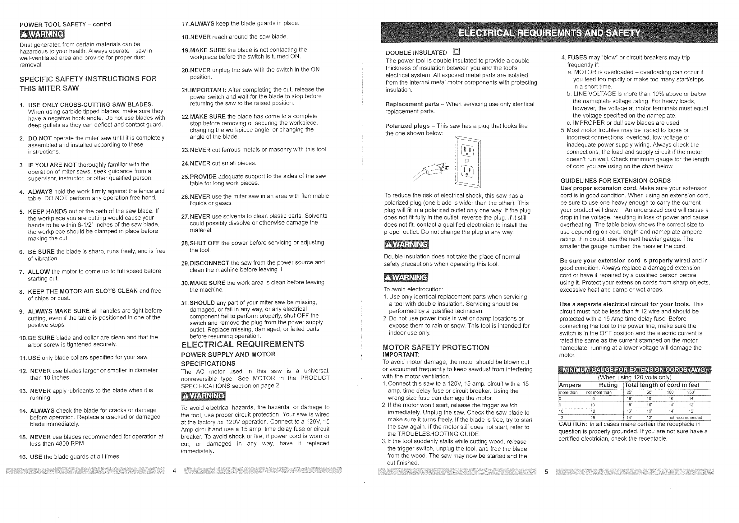
Polarized plugs - This saw has a plug that looks iike
the one shown below:
il 'L2_2_i!r
I,q-h /
To reduce the risk of electrical shock, this saw has a
polarized plug (one blade is wider than the other). This
plug will fit in a polarized outlet only one way. If the plug
does not fit fully in the outlet, reverse the plug. If it still
does not fit, contact a qualified electrician to install the
proper outlet. Do not change the plug in any way.
Double insulation does not take the place of normal
safety precautions when operating this tool.
To avoid electrocution:
1. Use only identical replacement parts when servicing
a tool with double insulation. Servicing should be
performed by a qualified technician.
2. Do not use power tools in wet or damp locations or
expose them to rain or snow. This tool is intended for
indoor use only_
MOTOR SAFETY PROTECTION
IMPORTANT."
To avoid motor damage, the motor shoutd be blown out
or vacuumed frequently to keep sawdust from interfering
with the motor ventilation.
1. Connect this saw to a 120V, 15 amp. circuit with a 15
amp. time delay fuse or circuit breaker. Using the
wrong size fuse can damage the motor.
2. If the motor won't start, release the trigger switch
immediately. Unplug the saw. Check the saw blade to
make sure it turns freely. If the blade is free, try. to start
the saw again. If the motor still does not start, refer to
the TROUBLESHOOTING GUIDE.
3. If the tool suddenly stalls while cutting wood, release
the trigger switch, unplug the tool, and free the blade
from the wood. The saw may now be started and the
cut finished.
4. FUSES may "blow" or circuit breakers may trip
frequently if:
a. MOTOR is overloaded - overloading can occur if
you feed too rapidly or make too many start/stops
in a short time.
b. LINE VOLTAGE is more than 10% above or below
the nameplate voltage rating. For heavy !oads,
however, the voltage at motor terminals must equal
the voltage specified on the nameplate.
c. IMPROPER or dull saw blades are used.
5. Most motor troubles may be traced to loose or
incorrect connections, overload, tow voltage or
inadequate power supply wiring. Always check the
connections, the load and supply circuit if the motor
doesn't run well. Check minimum gauge for the length
of cord you are"using on the chart below.
GUIDELINES FOR EXTENSION CORDS
Use proper extension cord. Make sure your extensiorh
cord is in good condition. When using an extension cord,
be sure to use one heavy enough to carry the current
your product will draw. An undersized cord will cause a
drop in line voltage, resulting in loss of power and cause
overheating. The table below shows the correct size to
use depending on cord length and nameplate ampere
rating. If in doubL use the next heavier gauge. The
smaller the gauge number, the heavier the cord.
Be sure your extension cord is properly wired and in
good condition. Atways replace a damaged extension
cord or have it repaired by a qualified person before
using it. Protect your extension cords from sharp objects,
excessive heat and damp or wet areas.
Use a separate electrical circuit for your tools, This
circuit must not be less than # 12 wire and should be
protected with a 15 Amp time delay fuse. Before
connecting the tool to the power line, make sure the
switch is in the OFF position and the electric current is
rated the same as the current stamped on the motor
nameplate, running at a lower voltage will damage the
motor.
i
(When using 120 volts onty)
Ampere Rating Total length of cord in feet
more than not more than / 25' 50' 100' 150'
0 6 ] 18' 16' 16' t4' "_
6 10 _: t6' 14' 12'
10 12 J 16' - 16' 14' 12'
t
t2 16 I !4' 12' not recommended
CAUTION: in all cases make certain the receptacle in
question is properly grounded. If you are not sure have a
certified electrician, check the receptacle.
RECOMMENDED ACCESSORIES
¢ Use only accessories recommended for this miter
saw. Follow instructions that accompany accessories.
Use of improper accessories may cause hazards,
€ The use of any cutting tool except I0 inch saw
blades which meet the requirements under
recommended accessories is prohibited. Do not use
accessories such as shaper cutters or dado sets.
Ferrous metal cutting and the use of abrasive wheels
is prohibited.
¢ Do not attempt to modify this tool or create
accessories not recommended for use with this toot.
Any such alteration or modification is misuse and
could result in a hazardous condition leading to
possible serious injury.
ACCESSORWES
Visit your Sears Hardware Department or see the Sears
Power and Hand Tool Catalog to purchase
recommended accessories for this power tool.
To avoid the risk of personal injury, do not modify this
power toot or use accessories not recommended by
Sears.
Read warnings and conditions on your CARBIDE
TIPPED SAW BLADE. Do not operate the saw without
the proper saw blade guard in place. Carbide is a very
hard but brittle material. Care should be taken while
mounting, using, and storing carbide tipped blades to
prevent accidental damage. Slight shocks, such as
striking the tip while handling, can seriously damage the
blade. Foreign objects in the workpiece, such as wire or
nails, can also cause tips to crack or break off. Before
using, always visually examine the blade and tips for
bent blade, cracks, breakage, missing or loose tips, or
other damage. Do not use if damage is suspected.
Failure to heed safety instructions and warnings can
result in serious bodily iniury.
Blade wrench (supplied)
Phillips screwdriver
Slotted screwdriver
Adjustable wrench
Hex Key 2.5 ram. _"_
Combination square
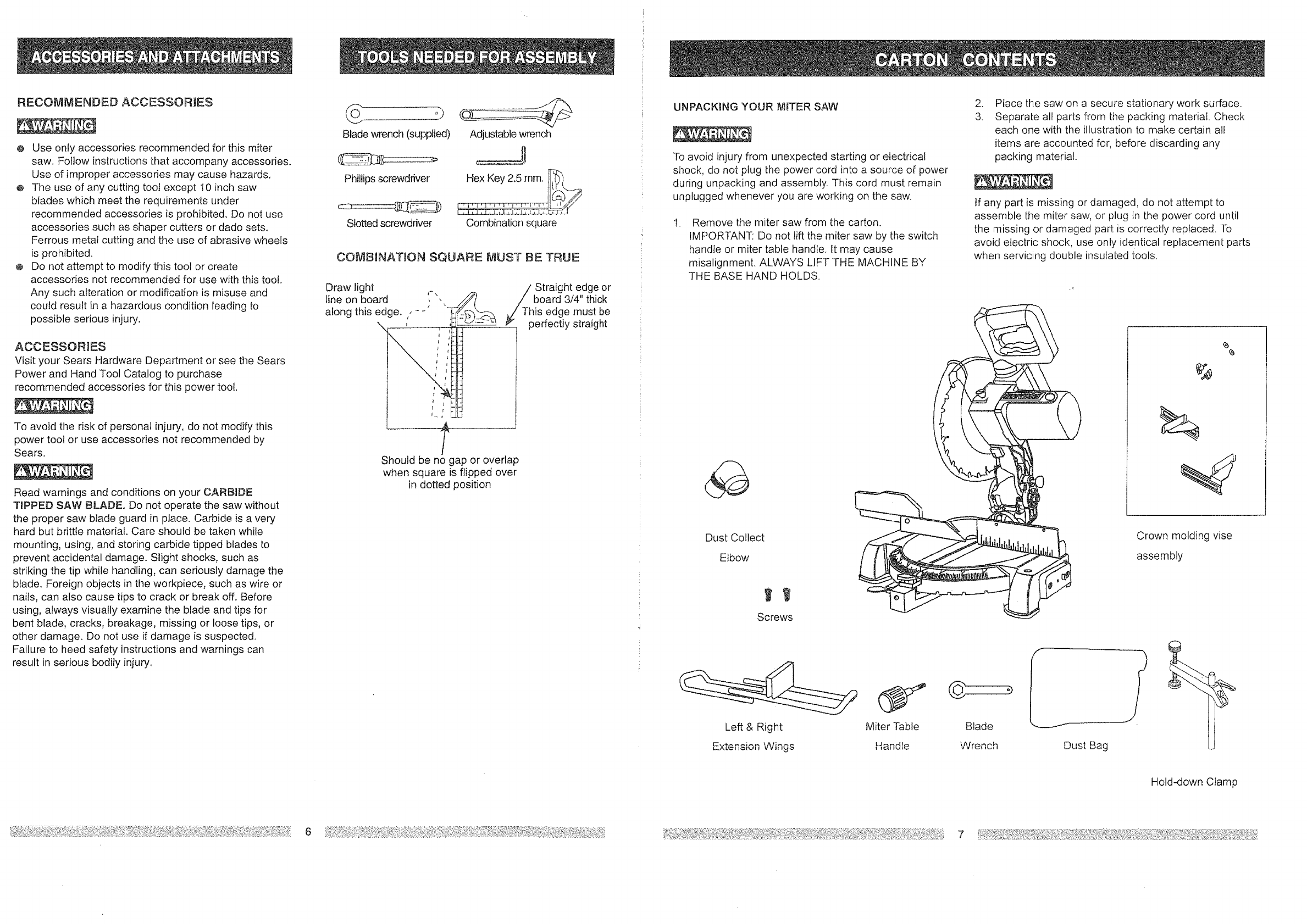
COMBnNATJON SQUARE MUST BE TRUE
Draw light ,-,
line on board , ,, /_
along this edge. /- _'
t
Should be no gap or overlap
when square is flipped over
in dotted position
hStraight edge or
board 3/4" thick
is edge must be
perfectly straight
UNPACKING YOUR MITER SAW
To avoid injury from unexpected starting or electrical
shock, do not plug the power cord into a source of power
during unpacking and assembly. This cord must remain
unplugged whenever you are working on the saw.
t, Remove the miter saw from the carton.
IMPORTANT: Do not lift the miter saw by the switch
handle or miter table handle. It may cause
misalignment. ALWAYS LIFT THE MACHINE BY
THE BASE HAND HOLDS.
Dust Collect
Elbow
Screws
Left & Right Miter Table
Extension Wings Handle
.
3. Place the saw on a secure stationary work surface.
Separate all parts from the packing material. Check
each one with the illustration to make certain all
items are accounted for, before discarding any
packing material.
tf any part is missing or damaged, do not attempt to
assemble the miter saw, or plug in the power cord until
the missing or damaged part is correctly replaced. To
avoid electric shock, use only identical replacement parts
when servicing double insulated tools.
Crown molding vise
assembly
G
Blade
Wrench Dust Bag
Hold-down Ctamp
67
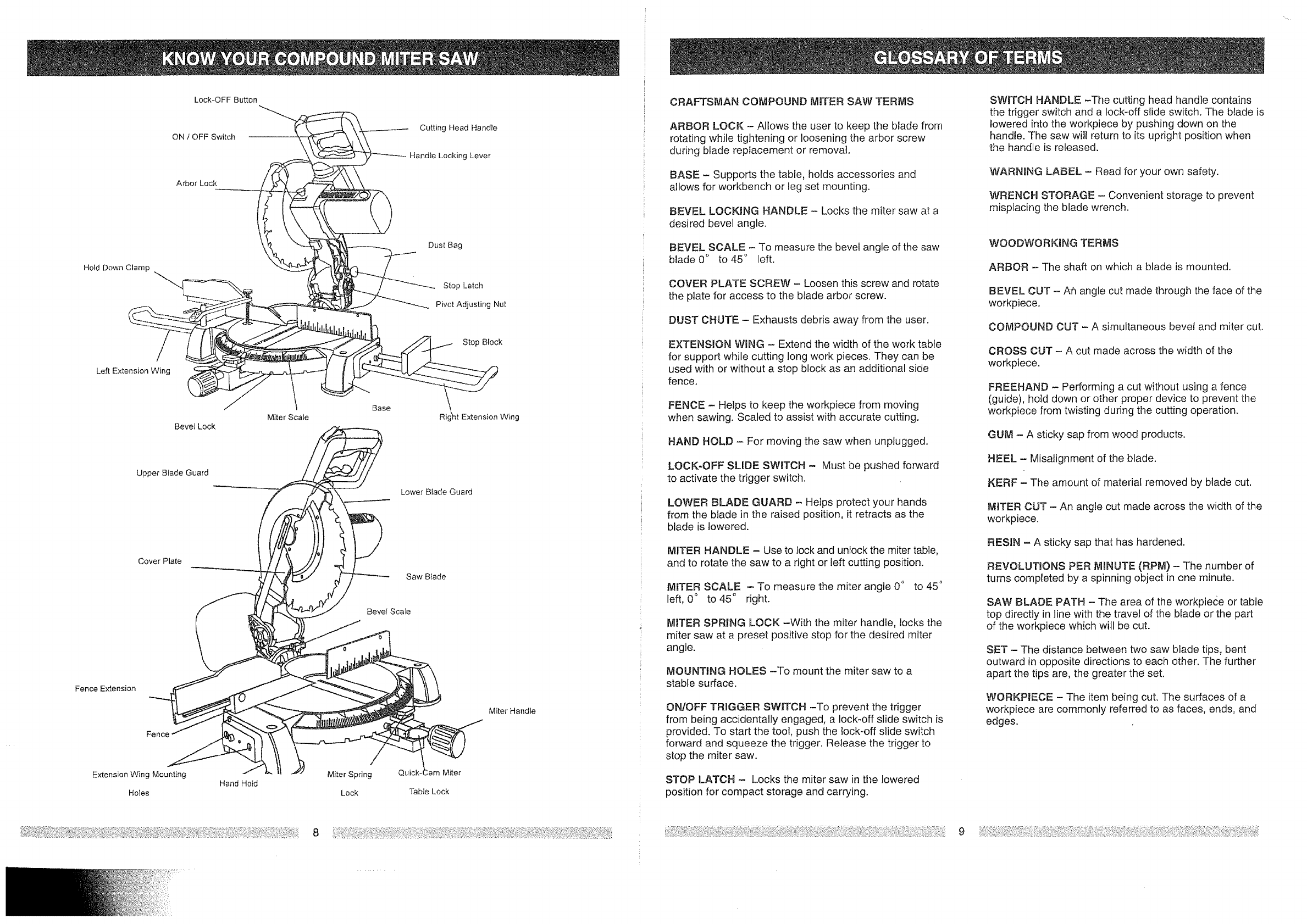
Lock-OFF Button
ON /OFF Switch
Arbor Lock
Hold Down Clamp
Left Extension Wing
Bevel Lock
Miter Sca_e
Upper BEadeGuard
Cover Plate
Fence Extension
Fence
Base
Cutting Head Handle
Handle Locking Lever
Dust Bag
Stop Latch
Pivot Adjusting Nut
Stop Block
\
Right Extension Wing
Lower Blade Guard
Saw Blade
BeveFScale
Extension Wing Mounting _"_" Miter Spring Quick-
Hand Hold
Holes Lock Table Lock
Miter Handle
CRAFTSMAN COMPOUND MINTERSAW TERMS
ARBOR LOCK - Allows the user to keep the blade from
rotating while tightening or loosening the arbor screw
during blade replacement or removal.
BASE - Supports the table, holds accessories and
allows for workbench or leg set mounting.
BEVEL LOCKING HANDLE -Locks the miter saw at a
desired bevel angle.
BEVEL SCALE -To measure the bevel angle of the saw
blade 0° to 45 ° left.
COVER PLATE SCREW - Loosen this screw and rotate
the plate for access to the blade arbor screw.
DUST CHUTE - Exhausts debris away from the user.
EXTENSION WiNG - Extend the width of the work table
for support while cutting long work pieces. They can be
used with or without a stop block as an additional side
fence.
FENCE - Helps to keep the workpiece from moving
when sawing. Scaled to assist with accurate cutting.
HAND HOLD - For moving the saw when unplugged.
LOCK-OFF SLIDE SWITCH - Must be pushed forward
to activate the trigger switch.
LOWER BLADE GUARD - Helps protect your hands
from the blade in the raised position, it retracts as the
blade is lowered.
MITER HANDLE - Use to lock and unlock the miter table,
and to rotate the saw to a right or left cutting position.
MITER SCALE - To measure the miter angle 0 ° to 45°
left, 0 ° to 45 ° right.
MITER SPRING LOCK -With the miter handle, locks the
miter saw at a preset positive stop for the desired miter
angle.
MOUNTING HOLES -To mount the miter saw to a
stable surface.
ON/OFF TRIGGER SWJlTCH -To prevent the trigger
from being accidentally engaged, a lock-off slide switch is
provided. To start the tool, push the lock-off slide switch
forward and squeeze the trigger. Release the trigger to
stop the miter saw.
STOP LATCH - Locks the miter saw in the lowered
position for compact storage and carrying.
SWmTCH HANDLE -The cutting head handle contains
the trigger switch and a lock-off slide switch. The blade is
lowered into the workpiece by pushing down on the
handle. The saw wildreturn to its upright position when
the handle is released.
WARNING LABEL -Read for your own safety.
WRENCH STORAGE - Convenient storage to prevent
misplacing the blade wrench.
WOODWORKING TERMS
ARBOR - The shaft on which a blade is mounted.
BEVEL CUT - Arhangle cut made through the face of the
workpiece.
COMPOUND CUT - A simultaneous bevel and miter cut.
CROSS CUT - A cut made across the width of the
workpiece.
FREEHAND - Performing a cut without using a fence
(guide), held down or other proper device to prevent the
workpiece from twisting during the cutting operation.
GUM - A sticky sap from wood products.
HEEL - Misatignment of the blade.
KERF - The amount of material removed by blade cut.
MITER CUT - An angle cut made across the width of the
workpiece.
RESIN - A sticky sap that has hardened.
REVOLUTIONS PER MINUTE (RPM) - The number of
turns completed by a spinning object in one minute.
SAW BLADE PATH - The area of the workpiece or table
top directly in line with the travel of the blade or the part
of the workpiece which will be cut.
SET - The distance between two saw blade tips, bent
outward in opposite directions to each other. The further
apart the tips are, the greater the set.
WORKP1ECE - The item being cut. The surfaces of a
workpiece are commonly referred to as faces, ends, and
edges.
89
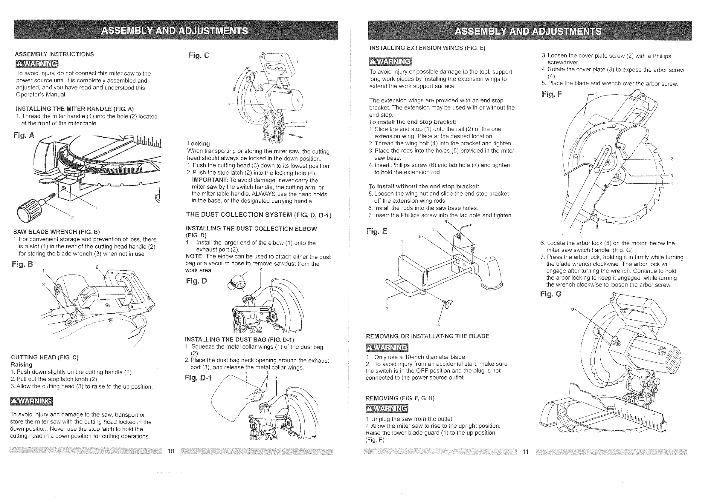
ASSEMBLYiNSTRUCTIONS
To avoid injury, do not connect this miter saw to the
power source until it is completely assembled and
adjusted, and you have read and understood this
Operator's Manual.
iNSTALLING THE MITER HANDLE (FIG. A)
!. Thread tile miter handle (1) into the hole (2) located
at the front of the miter table.
SAW BLADE WRENCH (FIG, B)
1. For convenient storage and prevention of loss, there
is a slot (!) in the rear of the cutting head handIe (2)
for storing the blade wrench (3) when not in use.
Fig, B 2
1 x
3\
/
CUTTING HEAD (FIG. C)
Raising
1. Push down slightly on the cutting handle (1).
2. Pull out the stop latch knob (2).
3. Allow the cutting head (3) to raise to the up position.
To avoid injury and damage to the saw, transport or
store the miter saw with the cutting head locked in the
down position. Never use the stop latch to hold the
cutting head in a down position for cutting operations.
Fig. C
Locking i_
When transporting or storing the miter saw, the cutting
head should always be locked in the down position,
1. Push the cutting head (3) down to its lowest position.
2. Push the stop latch (2) into the locking hole (4).
IMPORTANT: To avoid damage, never carry the
miter saw by the switch handle, the cutting arm, or
the miter table handle. ALWAYS use the hand holds
in the base, or the designated carrying handle.
THE DUST COLLECTION SYSTEM _(FIG, D, D-l)
iNSTALLING THE DUST COLLECTION ELBOW
{FIG. D)
1. Install the larger end of the elbow (1) onto the
exhaust port (2).
NOTE: The elbow can be used to attach either the dust
bag or a vacuum hose to remove sawdust from the
work area. 2
FJg. D
INSTALLING THE DUST BAG (FIG, D-I)
!. Squeeze the metal collar wings (1) of the dust bag
(2).
2. Place the dust bag neck opening around the exhaust
port (3), and release the metal collar wings.
1 2
Fig. Dot/
iNSTALLING EXTENSION W_NGS {FIG. E)
To avoid injury or possible damage to the tool, support
long work pieces by installing the extension wings to
extend the work support surface,
The extension wings are provided with an end stop
bracket. The extension may be used with or without the
end stop.
To install the end stop bracket:
1. Slide the end stop (I) onto the rail (2) of the one
extension wing. Place at the desired location.
2. Thread the wing bolt (4) into the bracket and tighten.
3. Place the rods into the ho_es (5) provided in the miter
saw base.
4. Insert Phillips screw (6) into tab hote (7) and tighten
to hold the extension rod.
To install without the end stop bracket:
5. Loosen the wing nut and slide the end stop bracket
off the extension wing rods.
6. Install the rods into the saw base holes.
7. Insert the Phillips screw into the tab hole and tighten.
REI_aOVING OR INSTALLAT_NG THE BLADE
1. Only use a 10-inch diameter blade.
2. To avoid injury from an accidental start, make sure
the switch is in the OFF position and the plug is not
connected to the power source outlet.
REMOVING (F_G. F, G, H)
1. Unplug the saw from the outlet.
2. Allow the miter saw to rise to the upright position.
Raise the tower blade guard (1) to the up position.
(Fig. F)
3. Loosen the cover plate screw (2) with a Phillips
screwd river.
4. Rotate the cover plate (3) to expose the arbor screw
(4).
5. Place the blade end wrench over the arbor screw.
Fig: F
6. Locate the arbor lock (5) on the motor, below the
miter saw switch handle. (Fig. G)
7. Press the arbor lock, holding it in firmly while turning
the blade wrench clockwise. The arbor lock will
engage after turning the wrench. Continue to hold
the arbor locking to keep it engaged1 while turning
the wrench clockwise to loosen the arbor screw,
Figo G
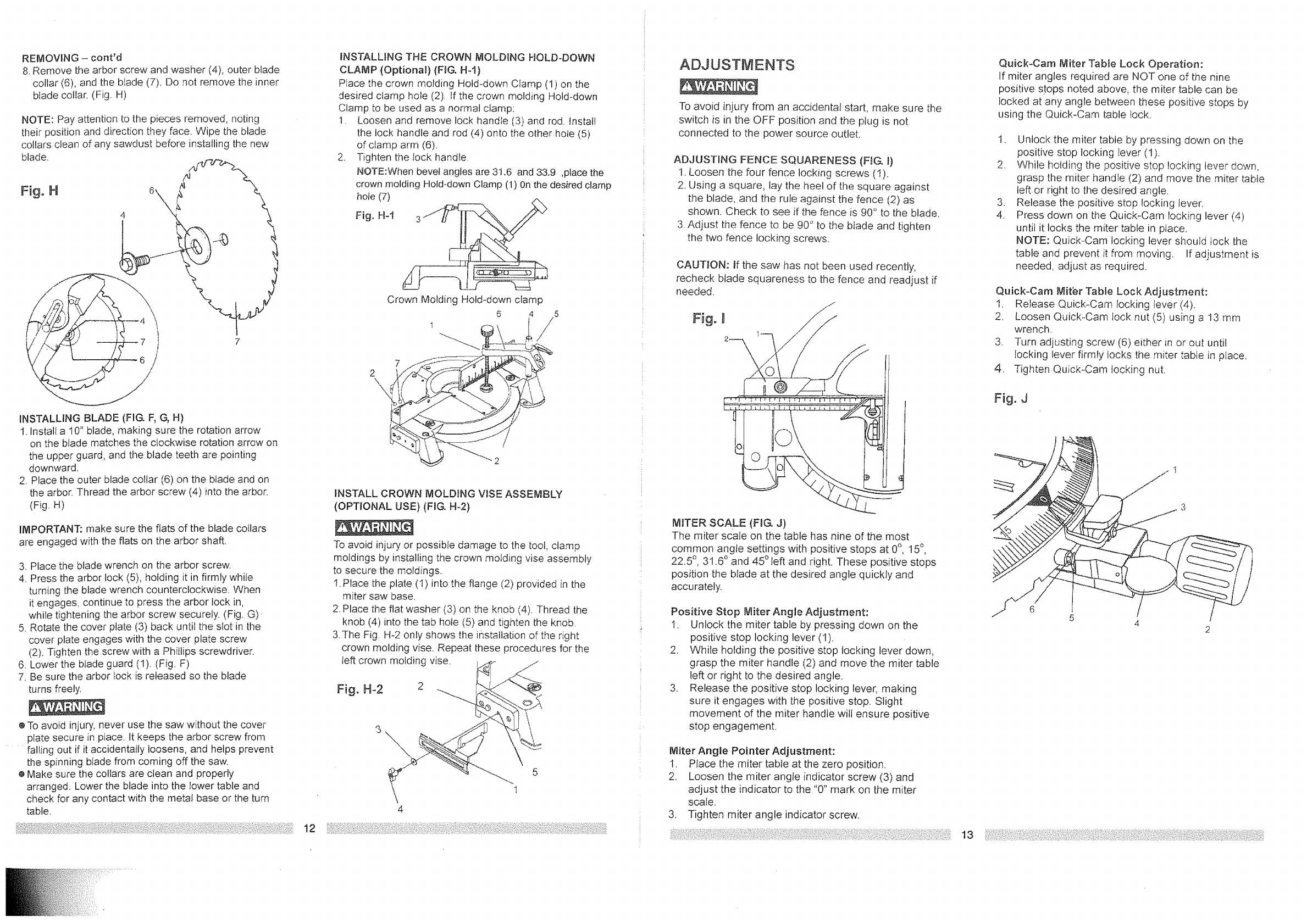
REMOVING - cont'd
8. Remove the arbor screw and washer (4), outer blade
collar (6), and the biade (7), Do not remove the inner
blade collar. (Fig. H)
NOTE: Pay attention to the pieces removed, noting
their position and direction they face. Wipe the blade
collars clean of any sawdust before installing the new
blade.
Fig. H
7
INSTALLING BLADE (FIG. F, G, H)
1. Instalf a 10" blade, making sure the rotation arrow
on the blade matches the clockwise rotation arrow on
the upper guard, and the blade teeth are pointing
downward.
2. Place the outer blade collar (6) on the blade and on
the arbor. Thread the arbor screw (4) into the arbor.
(Fig. H)
IMPORTANT: make sure the fiats of the blade collars
are engaged with the flats on the arbor shaft,
3. Place the blade wrench on the arbor screw.
4. Press the arbor lock (5), holding it in firmly while
turning the blade wrench counterclockwise. When
it engages, continue to press the arbor lock in,
while tightening the arbor screw securely. (Fig. G)-
5. Rotate the cover plate (3) back until the slot in the
cover plate engages with the cover plate screw
(2), Tighten the screw with a Phillips screwdriver.
6. Lower the blade guard (1). (Fig. F)
7, Be sure the arbor iock is released so the blade
turns freely.
e To avoid injury, never use the saw without the cover
plate secure in ptace. It keeps the arbor screw from
falling out if it accidentally loosens, and helps prevent
the spinning blade from coming off the saw.
e Make sure the collars are clean and properly
arranged. Lower the blade into the lower table and
check for any contact with the metal base or the turn
table,
INSTALLING THE CROWN MOLDING HOLD-DOWN
CLAMP (Optional) (FIG, H-t}
Place the crown molding Hold-down Ciamp (1) on the
desired clamp hole (2), If the crown molding Hold-down
Clamp to be used as a normal clamp:
1. Loosen and remove lock handle (3) and rod. fnstal!
the lock handle and rod (4) onto the other hole (5)
of clamp arm (6).
2. Tighten the Iock handle.
NOTE:When bevel angles are 31.6 and 33.9 ,place the
crown molding Hold-down Clamp (1) On the desired clamp
hole (7)
Fig. H-1
Crown Molding Hold-down clamp
6/5
1/
7
2
INSTALL CROWN MOLDING VISE ASSEMBLY
(OPTIONAL USE) (FIG. H-2)
To avoid injury or possible damage to the tool, clamp
moldings by installing the crown molding vise assembly
to secure the moldings.
1.Place the plate (1)into the flange (2) provided in the
miter saw base.
2. Place the flat washer (3) on the knob (4). Thread the
knob (4) into the tab hole (5) and tighten the knob
3.The Fig. H-2 only shows the installation of the right
crown molding vise. Repeat these procedures for the
left crown molding vise. /
Fig. H-2 2
1
4
!2 _'_J:_:!_!::i_
ADJUSTMENTS
To avoid injury from an accidenta_ start, make sure the
switch is in the OFF position and the plug is not
connected to the power source outlet.
ADJUSTING FENCE SQUARENESS (FIG. 1)
1. Loosen the four fence locking screws (1).
2. Using a square, lay the heel of Ihe square against
the blade, and the rule against the fence (2) as
shown. Check to see if the fence is 90° to the blade.
3. Adjust the fence to be 90 ° to the blade and tighten
the two fence locking screws.
CAUTION: if the saw has not been used recently,
recheck blade squareness to the fence and readiust if
needed.
MITER SCALE (FIG. J)
The miter scate on the table has nine of the most
common angle settings with positive stops at 0°, 15°,
22.5 °, 31.6 ° and 45°teft and right. These positive stops
position the blade at the desired angle quickly and
accurately.
Positive Stop Miter Angle Adjustment:
1. Unlock the miter table by pressing down on the
positive stop locking lever (!).
2. While holding the positive stop locking lever down,
grasp the miter handle (2) and move the miter table
left or right to the desired angle.
3. Release the positive stop locking lever, making
sure it engages with the positive stop, Slight
movement of the miter handle will ensure positive
stop engagement.
Miter Angle Pointer Adjustment:
1. Place the miter table at the zero position.
2. Loosen the miter angle indicator screw (3) and
adjust the indicator to the "0" mark on the miter
scale.
3, Tighten miter angle indicator screw.
Quick-Cam Miter Table Lock Operation:
If miter angles required are NOT one of the nine
positive stops noted above, the miter table can be
locked at any angle between these positive stops by
using the Quick-Cam table lock.
1. Unlock the miter table by pressing down on the
positive stop locking Iever (1).
2 While holding the positive stop locking lever down,
grasp the miter handle (2) and move the miter table
left or right to the desired angle.
3. Release the positive stop locking lever.
4. Press down on the Quick-Cam locking lever (4)
until it locks the miter table in place.
NOTE: Quick-Cam locking lever should lock the
table and prevent it from moving. If adjustment is
needed, adjust as required.
Quick-Cam Miter Table Lock Adjustment:
1. Release Quick-Cam locking fever (4).
2. Loosen Quick-Cam lock nut (5) using a 13 mm
wrench.
3. Turn adjusting screw (6) either in or out until
locking lever firmly locks the miter table in place.
4. Tighten Quick-Cam locking nut.
Fig. J
13
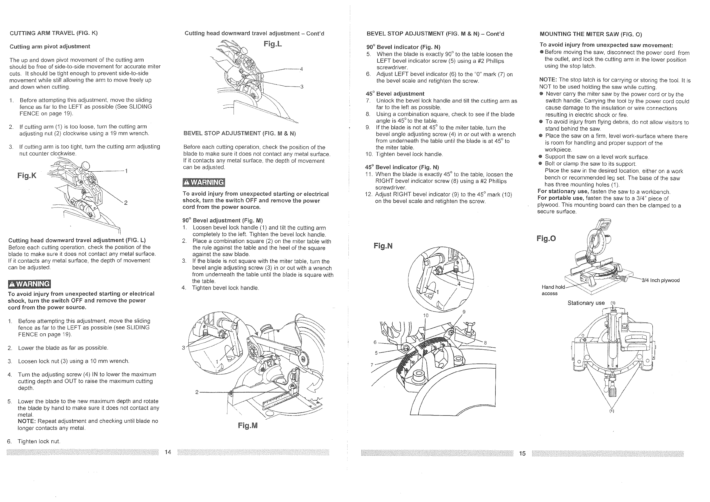
CUTTING ARM TRAVEL (FIG. K)
Cutting arm pivot adjustment
The up and down pivot movement of the cutting arm
should be free of side4o_side movement for accurate miter
cuts. It should be tight enough to prevent side-to-side
movement while still allowing the arm to move freely Lip
and down when cutting.
1. Before attempting this adjustment, move the sliding
fence as far to the LEFT as possible (See SLIDING
FENCE on page 19).
2. If cutting arm (I) is too loose, turn the cutting arm
adjusting nut (2) clockwise using a 19 mm wrench.
3. If cutting arm is too tight, turn the cutting arm adjusting
nut counter clockwise.
Fig.K
Cutting head downward travel adjustment (FIG. L)
Before each cutting operation, check the position of the
blade to make sure it does not contact any metal surface.
If it contacts any metal surface, the depth of movement
can be adjusted.
To avoid injury from unexpected starting or electricaa
shock, turn the switch OFF and remove the power
cord from the power source.
1. Before attempting this adjustment, move the sliding
fence as far to the LEFT as possible (see SLIDING
FENCE on page 19).
2. Lower the blade as far as possible.
3. Loosen lock nut (3) using a 10 mm wrench.
.
5.
Turn the adjusting screw (4) IN to lower the maximum
cutting depth and OUT to raise the maximum cutting
depth.
Lower the blade to the new maximum depth and rotate
the blade by hand to make sure it does not contact any
metal.
NOTE: Repeat adiustment and checking until blade no
longer contacts any metal.
6. Tighten lock nut.
Cutting head downward travel adjustment - Cont'd
Fig°L
BEVEL STOP ADJUSTMENT (FIG. PJl& N)
Before each cutting operation, check the position of the
blade to make sure it does not contact any metal surface.
If it contacts any metat surface, the depth of movement
can be adjusted.
To avoid injury from unexpected starting or electrical
shock, turn the switch OFF and remove the power
cord from the power source.
90 ° Bevel adjustment (Fig. NI)
1. Loosen bevel lock handFe (1) and tilt the cutting arm
completely to the left. Tighten the bevel lock handle.
2. Place a combination square (2) on the miter table with
the rule against the table and the heel of the square
against the saw blade.
3. If the blade is not square with the miter tabte, turn the
bevel angle adjusting screw (3) in or out with a wrench
from underneath the table until the blade is square with
the table.
4. Tighten bevel lock handle.
Fig°M
BEVEL STOP ADJUSTMENT (HG. tVi & N) - Cont'd
90° Bevel indicator (Fig. N)
5. When the blade is exactly 90 ° to the table loosen the
LEFT bevel indicator screw (5) using a #2 Phillips
screwdriver.
6. Adjust LEFT bevel indicator (6) to the "0" mark (7) on
the bevel scale and retighten the screw.
45 ° BeveU adjustment
7. Unlock the bevel lock handle and tilt the cutting arm as
far to the left as possible.
8. Using a combination square, check to see if the blade
angle is 45°to the table.
9. If the blade is not at 450 to the miter table, turn the
bevel angle adjusting screw (4) in or out with a wrench
from underneath the table until the blade is at 45 ° to
the miter table.
10. Tighten bevel lock handle.
45 ° Bevel indicator (Fig. N)
11. When the blade is exactly 45 ° to the table, loosen the
RIGHT bevel indicator screw (8) using a #2 Phillips
screwdriver.
I2. Adjust RIGHT bevel indicator (9) to the 450 mark (10)
on the bevel scale and retighten the screw.
Fig.N I
10
5
7
MOUNTING THE MITER SAW (FfG. O)
To avoid injury from unexpected saw movement:
e Before moving the saw, disconnect the power cord from
the outlet, and lock the cutting arm in the lower position
using the stop latch_
NOTE: The stop latch is for carrying or storing the tool. It is
NOT to be used holding the saw while cutting.
e Never carry the miter saw by the power cord or by the
switch handle. Carrying the tool by the power cord could
cause damage to the insulation or wire connections
resulting in electric shock or fire.
e To avoid injury from flying debris, do not allow visitors to
stand behind the saw.
e Place the saw on a firm, level work-surface where there
is room for handling and proper support of the
workpiece.
e Support the saw on a level work surface
e Bolt or clamp the saw to its support.
Place the saw in the desired location, either on a work
bench or recommended leg set. The base of the saw
has three mounting holes (t).
For stationary use, fasten the saw to a workbench.
For portable use, fasten the saw to a 3/4" piece of
plywood. This mounting board can then be clamped to a
secure surface.
Fig,O
access
Stationary use
Inch plywood
/
{11
SAFETY mNSTRUCTIONS FOR BASIC
SAW OPERAT!ON
BEFORE USING THE MITER SAW
To avoid mistakes that could cause serious,
permanent injury, do not plug the tool in until the
following steps are completed:
Completely assemble and adjust saw, following
the instructions. (ASSEMBLY AND
ADJUSTMENTS)
e Learn the use and function of the ON/OFF switch,
lock-off switch, upper and lower blade guards,
stop latch, bevel lock handle, and cover plate
screws.
e Review and understand all safety instructions
and operating procedures in this Operator's
Manual. {SAFETY & OPERATIONS)
eReview the MAINTENANCE and
TROUBLESHOOTING GUIDE for your miter
saw.
o To avoid injury or possible death from electrical
shock:
Make sure your fingers do not touch the plug's
metal prongs when plugging or unplugging your
miter saw. (ELECTRICAL REQUIREMENTS
AND SAFETY)
BEFORE EACH USE
Inspect your saw.
®Disconnect the miter saw. To avoid injury from
accidental starting, unplug the saw before any
adjustments, including set-up and blade
changes.
®Compare the direction of rotation arrow on
the guard to the direction arrow on the blade.
The blade teeth should always point downward
at the front of the saw.
e Tighten the arbor screw.
e Tighten the cover plate screw,
Check for damaged pa_ls. Check for:
Alignment of moving parts
e Damaged electric cords
e Binding of moving parts
® Mounting holes
o Function of arm return spring and lower
guard:
Push the cutting arm all the way down,
then let it rise until it stops. The lower guard
should fully close. Follow instructions in
TROUBLESHOOTING GUIDE for
adjustment.
e Other conditions that may affect the way
the miter saw works.
16
@Keep all guards in place, in working order and
proper adjustment.
NOTE: If any part of this miter saw is missing,
bent, damaged or broken in any way, or any
electrical parts don't work, turn the saw off and
unplug it. Replace damaged, missing, or
defective parts before using the saw again.
Maintain tools with care. Keep the miter saw
clean for best and safest performance. Follow
instructions for lubricating. Don't put lubricants
on the blade while it's spinning.
e Remove adjusting wrench from the toot before
turning it on.
To avoid injury from jams, slips, or thrown
pieces:
USE ONLY RECOMMENDED ACCESSORIES
@Consult the ACCESSORIES and
ATTACHMENTS section of this Operator's
Manual for recommended accessories. Follow
the instructions that come with the accessory.
The use of improper accessories may cause
serious injury.
¢ Choose the correct 10 inch diameter blade for
the material and the type of cutting you plan to
do.
@Make sure the blade is sharp, undamaged and
properly aligned. With the saw unplugged, push
the cutting arm all the way down. Hand spin the
blade and check for clearance. Tilt the
power-head to a 45 ° bevel and repeat the check.
o Make sure the blade and arbor collars are clean.
e Make sure all clamps and locks are tight and
there is no excessive play in any parts.
KEEP YOUR WORK AREA CLEAN
Cluttered areas and benches invite accidents.
To avoid burns or other fire damage, never use the
miter saw near flammable liquids, vapors, or gases.
o Plan ahead to protect your eyes, hands, face
and ears.
Know your miter saw.
Read and understand the Operator's Manual and
labels affixed to the tool. Learn its application and
limitations as well as the specific potential hazards
peculiar to this tool. To avoid injury from accidental
contact with moving parts, don't do layout, assembly,
or setup work on the miter saw while any parts are
moving.
@ Avoid accidental starting
Make sure the switch is OFF before plugging the
miter saw into a power outlet.
PLAN YOUR WORK
Use the right toot. Don't force a tool or
attachment to do a job it was not designed to do.
Use a different tool for any workpiece that can't
be held in a solidiy braced, fixed position.
CAUTION: This machine is not designed for cutting
ferrous metals (steel, iron, and iron-based metals.)
Use this miter saw to cut only wood, wood-like
products, or soft metals like aluminum. Other material
may shatter, bind the blade, or create other dangers.
Remove all nails that may be in the workpiece to
prevent sparking that could cause a fire.
DRESS FOR SAFETY
Any power tool can throw foreign objects into the
eyes. This can result in permanent eye damage.
Everyday eyeglasses have only impact resistant
lenses and are not safety glasses. Glasses or
goggles not in compliance with ANSI Z87.1 could
cause serious injury when they break.
Do not wear loose clothing, gloves, neckties or
jewelry (rings, watches). They can get caught
and draw you into moving parts.
o Wear non-slip footwear.
o Tie back tong hair.
e Roll long sleeves above the elbow.
o Noise levels vary widely. To avoid possible
hearing damage, wear ear plugs when using any
miter saw.
® For dusty operations, wear a dust mask along
with safety goggles.
INSPECT YOUR WORKPIECE
Make sure there are no nails or foreign objects in the
part of the workpiece being cut.
Plan your work to avoid small pieces that may
bind, or that are too small to clamp and get a
solid grasp on.
Plan the way you will grasp the workpiece from start
to finish. Avoid awkward operations and hand
positions. A sudden slip could cause your fingers or
hand to move into the blade.
DON'T OVER-REACH
Keep good footing and balance. Keep your face and
body to one side, out of the line of a possible
kickback. NEVER stand in the line of the blade.
Never cut freehand:
Brace your workpiece firmly against the fence
and table stop so it will not rock or twist during
the cut.
e Make sure there is no debris between the
workpiece and the table or fence.
_:.iiiil i:!:i,_'! 17
e Make sure there are no gaps between the
workpiece, fence and table that will let the
workpiece shirt after it is cut.
e Keep the cut off piece free to move sideways
after it is cut off. Otherwise, it could get wedged
against the blade and thrown violently.
e Only the workpiece should be on the saw table.
e Secure work. Use clamps or a vise to help hold
the work when it's practical.
USE EXTRA CAUTION WITH LARGE OR ODD
SHAPED WORKPJECES.
¢ Use extra supports (tables, sawhorses, blocks,
etc.) for workpieces large enough to tip.
@Never use another person as a substitute for a
table extension, or as an additional support for a
workpiece that is longer or wider than the basic
miter saw table, or to help feed, support, or pull
the workpiece,
¢ Do not use this saw to cut small pieces. If the
workpiece being cut would cause your hand or
fingers to be within 6-1/2 inches of the saw blade
the workpiece is too small. Keep hands and
fingers out of the "no hands zone" area marked
on the saw table.
• When cutting odd shaped workpieces, plan your
work so it will not bind in the blade and cause
possible injury. Molding, for example, must lie flat
or be held by a fixture or jig that will not tet it
move when cut.
¢ Properly support round material such as dowel
rods, or tubing, which have a tendency to roll
when cut, causing the biade to "bite".
WHEN SAW IS RUNNING
Don't allow familiarity from frequent use of your miter
saw to result in a careless mistake. A careless
fraction of a second is enough to cause a severe
injury.
Before cutting, if the saw makes an unfamiliar noise
or vibrates, stop immediately. Turn the saw OFR
Unplug the saw. Do not restart until finding and
correcting the problem.
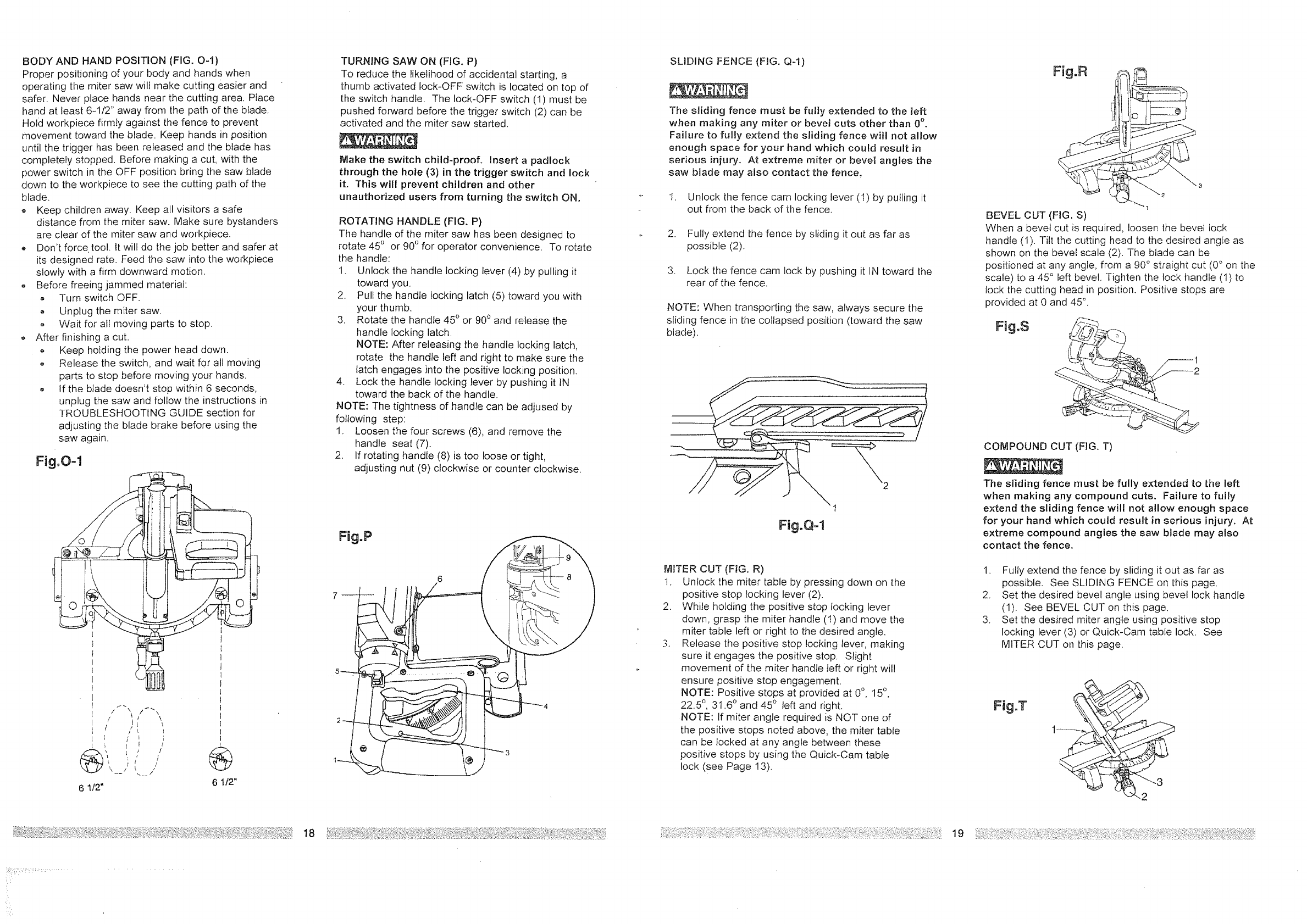
BODYANDHANDPOSITION(FIG.O-1)
Properpositioningofyourbodyandhandswhen
operatingthemitersawwillmakecuttingeasierand
safer.Neverplacehandsnearthecuttingarea,Place
handatleast6_t/2"awayfromthepathoftheblade.
Hoidworkpiecefirmtyagainstthefencetoprevent
movementtowardtheblade.Keephandsinposition
untilthetriggerhasbeenreleasedandthebladehas
completelystopped.Beforemakingacut,withthe
powerswitchintheOFFpositionbringthesawblade
downto theworkpiecetoseethecuttingpathof the
blade.
,, Keepchildrenaway.Keepallvisitorsasafe
distancefromthemitersaw.Makesurebystanders
areclearofthemitersawandworkpiece.
Don'tforce,tool.Itwilldothejobbetterandsaferat
itsdesignedrate.Feedthesawintotheworkpiece
slowlywithafirmdownwardmotion.
,, Beforefreeingjammedmaterial:
o TurnswitchOFF.
,, Unplugthemitersaw.
,, Wait for all moving parts to stop.
After finishing a cut.
Keep hotding the power head down.
,_ Release the switch, and wait for all moving
parts to stop before moving your hands.
If the blade doesn't stop within 6 seconds,
unplug the saw and follow the instructions in
TROUBLESHQOTfNG GUIDE section for
adjusting the blade brake before using the
saw again.
Fig.O-1
.4"
, t_ t \_,
[(' /
/! ,
6 1/2" 6 1/2"
TURNING SAW ON (FIG. P)
To reduce the likelihood of accidental starting, a
thumb activated lock-OFF switch is located on top of
the switch handle. The lock-OFF switch (1) must be
pushed forward before the trigger switch (2) can be
activated and the miter saw started.
Make the switch child-proof. Insert apadlock
through the hoie (3) in the trigger switch and lock
it. This will prevent children and other
unauthorized users from turning tile switch ON.
ROTATING HANDLE (FIG. P)
The handle of the miter saw has been designed to
rotate 45 ° or 90 ° for operator convenience. To rotate
the handle:
1. Unlock the handle locking lever (4) by pulling it
toward you.
2. Pull the handle locking latch (5) toward you with
your thumb.
3. Rotate the handle 45 ° or 90° and release the
handle locking latch.
NOTE: After releasing the handle locking latch,
rotate the handle left and right to make sure the
latch engages into the positive locking position.
4. Lock the handle locking lever by pushing it IN
toward the back of the handle.
NOTE: The tightness of handle can be adjused by
following step:
1. Loosen the four screws (6), and remove the
handle seat (7).
2, If rotating handle (8) is too loose or tight,
adjusting nut (9) clockwise or counter clockwise,
SLIDING FENCE (FIG, Q-l)
The sliding fence must be fu|ly extended to the left
when making any miter or beret cuts other than 0°.
Failure to fully extend the sliding fence will not allow
enough space for your hand which could result in
serious injury. At extreme miter or bevel angles the
saw b_ade may also contact the fence.
1. Unlock the fence cam locking lever (1) by pulling it
out from the back of the fence.
2. Fully extend the fence by sliding it out as far as
possible (2).
3. Lock the fence cam lock by pushing it IN toward the
rear of the fence.
NOTE: When transporting the saw, always secure the
sliding fence in the colIapsed position (toward the saw
blade).
Fig.Q-1
MITER CUT (FIG. R)
1. Unlock the miter table by pressing down on the
positive stop locking lever (2).
2. While holding the positive stop locking lever
down, grasp the miter handle (1) and move the
miter table left or right to the desired angle.
3. Release the positive stop locking lever, making
sure it engages the positive stop. Slight
movement of the miter handle teft or right wil!
ensure positive stop engagement.
NOTE: Positive stops at provided at 0°, 15°,
22.5 °, 31.6 ° and 45 °Ieft and right.
NOTE: If miter angle required is NOT one of
the positive stops noted above, the miter table
can be locked at any angle between these
positive stops by using the Quick-Cam table
lock (see Page 13).
BEVEL CUT (FIG. S)
When a bevel cut is required, loosen the bevel lock
handle (1). Tilt the cutting head to the desired angfe as
shown on the bevel scale (2). The blade can be
positioned at any angle, from a 90 ° straight cut (0 ° on the
.scale) to a 45 ° left bevel, Tighten the lock handle (1) to
lock the cutting head in position. Positive stops are
provided at 0 and 45 °,
Fig.S
1
COMPOUND CUT (FIG, T)
The sliding fence must be fully extended to the left
when making any compound cuts, Failure to fully
extend the sliding fence will not allow enough space
for your hand which could result in serious injury, At
extreme compound angles the saw blade may also
contact the fence.
1. Fully extend the fence by sliding it out as far as
possible. See SLIDING FENCE on this page.
2. Set the desired bevel angle using bevel lock handle
(1). See BEVEL CUT on this page.
3. Set the desired miter angle using positive stop
locking lever (3) or Quick-Cam table lock. See
MITER CUT on this page.
Fig.T
18 lg /4:
?: ,, ,:::: .....
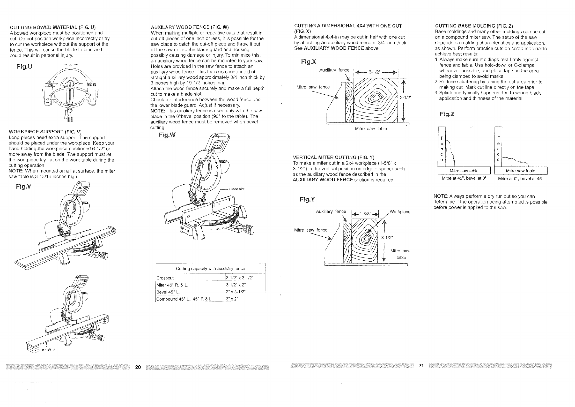
CUTTING BOWED MATERIAL (FIG. U)
A bowed workpiece must be positioned and
cut. Do not position workpiece incorrectly or try
to cut the workpiece without the support of the
fence. This will cause the blade to bind and
could result in personal injury,
Fig.U
WORK:PiECE SUPPORT (FIG, V)
Long pieces need extra support. The support
should be placed under the workpiece. Keep your
hand holding the workpiece positioned 6-1/2" or
more away from the blade, The support must let
the workpiece tay flat on the work table during the
cutting operation.
NOTE: When mounted on a flat surface, the miter
saw table is 3-13/16 inches high.
Fig.V
'l
3 13/16"
AUXtLARY WOOD FENCE (FIG. W)
When making multipte or repetitive cuts that result in
cut-off pieces of one inch or less, it is possible for the
saw blade to catch the cutooff piece and throw it out
of the saw or into the blade guard and housing,
possibly causing damage or injury. To minimize this,
an auxiliary wood fence can be mounted to your saw.
Holes are provided in the saw fence to attach an
auxiliary wood fence. This fence is constructed of
straight auxiliary wood approximately 3/4 inch thick by
3 inches high by 19q12 inches long.
Attach the wood fence securely and make a full depth
cut to make a blade slot,
Check for interference between the wood fence and
the lower blade guard. Adjust if necessary.
NOTE: This auxiliary fence is used only with the saw
blade in the 0°bevel position (90° to the table). The
auxiliary wood fence must be removed when bevel
cutting.
Fig.W
Blade slot
Cutting capacity with auxiliary fence
Crosscut _-1/2': X3-1/2"
Miter45° R. & L, 13-1/2"XZ'
Bevel 45° L. 12':x 3-1/2"
Compound 45° L,, 45" R & L. 12"x 2"
CUTTING A DHVtENSIONAL 4X4 WITH ONE CUT
(FIG. X)
A dimensional 4x4-in may be cut in half with one cut
by attaching an auxiliary wood fence of 3/4 inch thick.
See AUXILIARY WOOD FENCE above.
Fig.X
Auxiliary fence _ 3 1/2"
1- - -÷I
Mitre saw table
VERTICAL MITER CUTTING (FIG, Y)
To make a miter cut in a 2x4 workpiece (1-5/8" x
3-112") in the vertical position on edge a spacer such
as the auxiliary wood fence described in the
AUXILIARY WOOD FENCE section is required.
Fig.Y
AuxiIiary fence Workpiece
3-1/2"
Mitre saw
table
f
CUTTING BASE iVlOLD_NG (FIG, Z)
Base moldings and many other moldings can be cut
on a compound miter saw. The setup of the saw
depends on molding characteristics and application,
as shown. Perform practice cuts on scrap materiafto
achieve best results:
1. Always make sure moldings rest firmly against
fence and table. Use hold-down or C-clamps,
whenever possible, and place tape on the area
being clamped to avoid marks,
2. Reduce splintering by taping the cut area prior to
making cut. Mark cut line directly on the tape,
3. Splintering typically happens due to wrong blade
application and thinness of the material.
Fig oZ
m i ,_
F
e
n
c
e
Mitre saw table
Mitre at 45°, bevel at 0°
Mitre saw table
Mitre at 0°, bevel at 45°
NOTE: Always perform a dry run cut so you can
determine if the operation being attempted is possible
before power is applied to the saw.
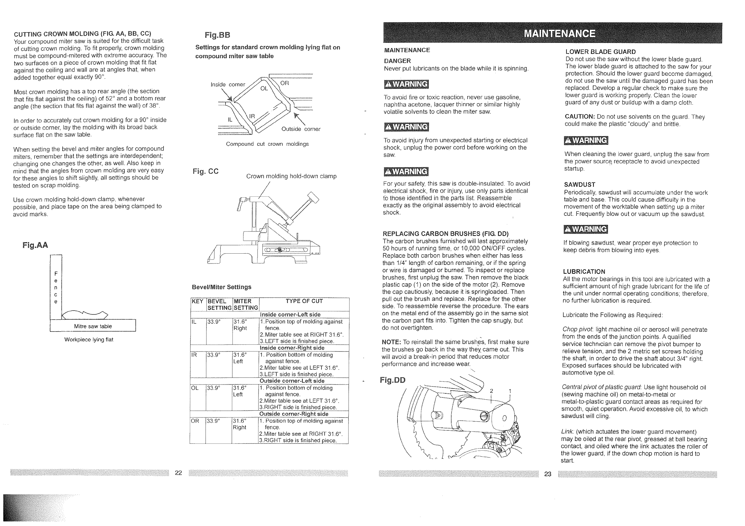
CUTTINGCROWNMOLDING (FIG. AA, BB, CC)
Your compound miter saw is suited for the difficult task
of cutting crown molding. To fit properly, crown molding
must be compound-mitered with extreme accuracy. The
two surfaces on a piece of crown molding that fit flat
against the ceiling and wall are at angles that, when
added together equal exactly 90 ° .
Most crown molding has a top rear angle (the section
that fits flat against the ceiling) of 52° and a bottom rear
angle (the section that fits flat against the wall) of 38°.
In order to accurately cut crown molding for a 90° inside
or outside corner, lay the molding with its broad back
surface flat on the saw table.
When setting the bevel and miter angles for compound
miters, remember that the settings are interdependent;
changing one changes the other, as well. Also keep in
mind that the angles from crown molding are very easy
for these angles to shift slightly, all settings should be
tested on scrap molding.
Use crown molding hold-down clamp, whenever
possibIe, and place tape on the area being clamped to
avoid marks.
FJg.AA
Fi
e !
n !
c I
e i
Mitre saw table
Workpiece lying ftat
Fig.gB
Settings for standard crown rooming lying fiat on
compound miter saw table
Inside corner OR
IL \
Outside corner
Compound cut crown moldings
Fig. CO Crown molding hold-down clamp
BevellMiter Settings
J-K"E'-Y-_BEVELIMITER i TYPE OF CUT
|SETTING SETTINGI
......ii.iii insidecorne Lertsiae
IL 33.9° 31.6° _tion top of molding against
Right {fence.
J I I I2.Miter table see at RIGHT 31.6°.
L- J_ I 13.LEFT side is finished piece.
•IR 33.9° 31.60 tl. Position bottom of molding
I i {Left against fence.
2.Miter table see at LEFT 31.6°.
•[/ 3.LEFT side is finished piece.
Outside corner-Left side
OL 33.9° 131.6° 1i. Position bottom of molding
Left against fence, o
2.Miter table see at LEFT 31.6.
i 3.R GHT s de s finished piece.
Outside corner:Right side
OR 33.9°31.6 °..... 1. Position top of molding against
Right fence.
2.Miter table see at RIGHT 31.6°.
&RIGHT side isfin____is.hed piece.
22
MAINTENANCE
DANGER
Never put lubricants on the blade while it is spinning.
To avoid fire or toxic reaction, never use gasoline,
naphtha acetone, lacquer thinner or similar highly
volatile solvents to clean the miter saw.
To avoid injury from unexpected starting or electrical
shock, unplug the 3ower cord before working on the
saw.
For your safety, this saw is double-insulated To avoid
electrical shock, fire or injury, use only parts identical
to those identified in the parts list. Reassemble
exactly as the original assembly to avoid electrical
shock.
REPLACING CARBON BRUSHES (FIG. DD)
The carbon brushes furnished will last approximately
50 hours of running time, or 10,000 ON/OFF cycles.
Replace both carbon brushes when either has less
than 114" length of carbon remaining, or if the spring
or wire is damaged or burned. To inspect or replace
brushes, first unplug the saw. Then remove the black
plastic cap (1) on the side of the motor (2). Remove
the cap cautiously, because it isspringloaded. Then
pul! out the .brush and replace. Replace for the other
side. To reassemble reverse the procedure. The ears
on the metal end of the assembly go in the same slot
the carbon part fits into. Tigtlten the cap snugly, but
do not overtighten.
NOTE: To reinstall the same brushes, first make sure
the brushes go back in the way they. came out. This
will avoid a break-in period that reduces motor
performance and increase wear.
Fig.DD
LOWER BLADE GUARD
Do not use the saw without the lower blade guard.
The lower blade guard is attached to the saw for your
protection. Should the lower guard become damaged,
do not use the saw until the damaged guard has been
replaced. Develop a regular check to make sure the
lower guard is working properly. C_ean the lower
guard of any dust or buildup with a damp cloth.
CAUTION: Do not use solvents on the guard. They
could make the plastic "cloudy" and brittle.
When cleaning the lower guard, unplug the saw from
the power source, receptacle to avoid unexpected
startup.
SAWDUST
Periodically, sawdust will accumulate under the work
tabie and base. This could cause difficulty in the
movement of the worktable when setting up a miter
cut. Frequently blow out or vacuum up the sawdust.
If blowing sawdust, wear proper eye protection to
keep debris from blowing into eyes.
LUBRICATION
All the motor bearings in this tool are lubricated with a
sufficient amount of high grade Jubricant for the life of
the unit under normal operating conditions; therefore,
no further lubrication is required.
Lubricate the Following as Required:
Chop pivot: light machine oil or aerosol will penetrate
from the ends of the junction points. A qualified
service technician can remove the pivot bumper to
relieve tension, and the 2 metric set screws holding
the shaft, in order to drive the shaft about 3/4" right.
Exposed surfaces should be lubricated with
automotive type oil.
Central pivot of plastic guard: Use light household oil
(sewing machine oil) on metat4o-metal or
metal-to-plastic guard contact areas as required for
smooth, quiet operation. Avoid excessive oil, to which
sawdust will cling.
Link: (which actuates the lower guard movement)
may be oiled at the rear pivot, greased at ball bearing
contact, and oiled where the link actuates the roller of
the lower guard, if the down chop motion is hard to
start.
23
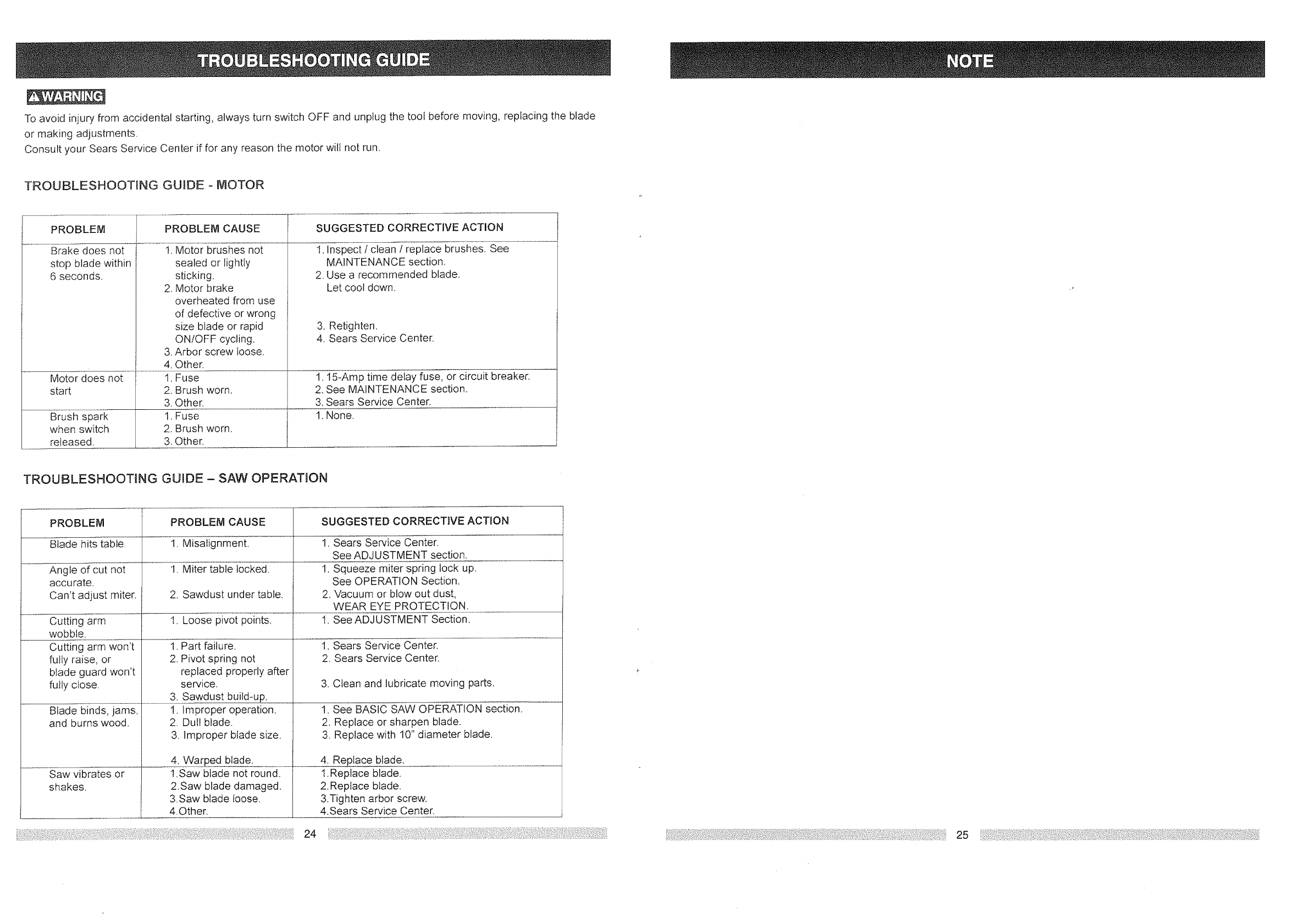
To avoid injury from accidental starting, always turn switch OFF and unplug the tool before moving, replacing the blade
or making adjustments,
Consult your Sears Service Center if for any reason the motor will not run,
TROUBLESHOOTING GUIDE - MOTOR
PROBLEM
Brake does not
stop blade within
6 seconds.
Motor does not
start
Brush spark
when switch
released.
PROBLEM CAUSE SUGGESTED CORRECTIVE ACTION I
1. Motor brushes not
sealed or lightly
sticking.
2, Motor brake
overheated from use
of defective or wrong
size blade or rapid
ONIOFF cycling,
3. Arbor screw loose.
4. Other.
1. Fuse
2. Brush worn.
3. Other.
1. Fuse
2. Brush worn.
3. Other.
J
1. Inspect /clean /replace brushes. See
MAINTENANCE section.
2. Use a recommended blade.
Let cool down.
3. Retighten.
4. Sears Service Center.
1.15-Amp time delay fuse, or circuit breaker.
2. See MAINTENANCE section.
3. Sears Service Center,
1. None.
TROUBLESHOOTING GUIDE -SAW OPERATION
PROBLEM
Blade hits table,
Angle of cut not
accurate.
Can't adjust miter.
Cutting arm
wobble.
Cutting arm won't
futly raise, or
btade guard won't
futiy close.
Blade binds, jams,
and burns wood.
Saw vibrates or
shakes.
i.
J
J
PROBLEM CAUSE
1_Misalignment.
1. Miter table locked.
2. Sawdust under table.
l. Loose pivot points.
1. Part failure,
2. Pivot spring not
replaced properly after
service.
3. Sawdust build-up.
1. Improper operation.
2. Dul! blade.
3. Improper blade size.
4. Warped blade.
1.Saw blade not round.
2.Saw blade damaged.
3.Saw blade toose.
4.Other.
SUGGESTED CORRECTIVE ACTION
1. Sears Service Center.
See ADJUSTMENT section.
1. Squeeze miter spring lock up.
See OPERATION Section,
2, Vacuum or blow out dust,
WEAR EYE PROTECTION.
t. See ADJUSTMENT Section,
1, Sears Service Center.
2. Sears Service Center.
3. Clean and lubricate moving parts.
1. See BASIC SAW OPERATION section.
2. Replace or sharpen blade.
3. Replace with 10" diameter blade.
4. Replace blade.
1.Replace blade.
2.Replace blade.
3.Tighten arbor screw.
4.Sears Service Center.
24
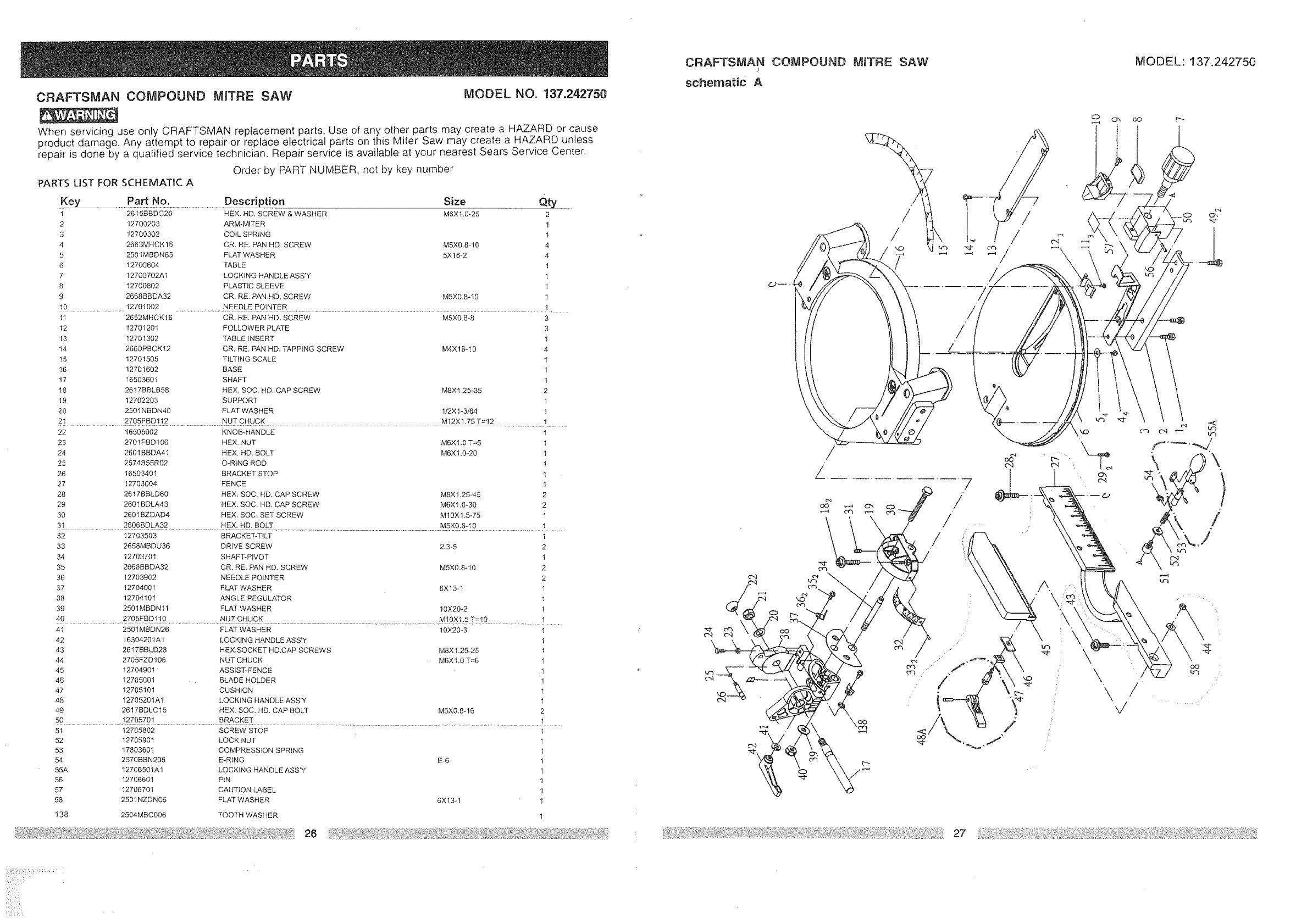
CRAFTSMAN COMPOUND MITRE SAW MODEL NO. !37.242750
When servicing use only CRAFTSMAN replacement parts. Use of any other parts may create a HAZARD or cause
product damage. Any attempt to repair or replace electrical parts on this Miter Saw may create a HAZARD unless
repair is done by a qua{ified service technician. Repair service is available at your nearest Sears Service Center.
Order by PART NUMBER, not by key number
PARTS LIST FOR SCHEMATIC A
Key Part No. Description Size Qty
1 2615BBDC20 HEX. kiD. SCREW & WASHER M6X1.0-25 2
2 12700203 ARM-MITER 1
3 12700302 COIL SPRING 1
4 2663MHCK16 CA, RE. PAN HD. SCREW MSX0.Sq0 ,t
5 2501MBDN85 FLAT WASHER 5X16-2 4
6"12700604 TABLE 1
7 12700702A1 LOCKING HANDLE ASS'Y l
8 12700802 PLASTIC SLEEVE t
9 2668BBDA32 CA. RE. PAN HD, SCREW MSX0.8-10 1
10 ..................... 12701002 ............................NEED[:E F_0tNTER.................................................................................................................................................................................!.
11 2652MHCK16 CR. RE. PAN HD. SCREW M5X0.8-8
12 12701201 FOLLOWER PLATE
13 12701302 TABLE INSERT
t4 2660PBCKI2 CA, RE, PAN HD. TAPPING SCREW M4X18-t0
15 12701505 TILTING SCALE
t6 12701602 BASE
t7 16503601 SHAFT
t8 2617BBLB58 HEX. SOC. HD, CAP SCREW M8X1,25-35
19 12702203 SUPPORT
20 2501NBDN40 FLAT WASHER 1/2X1-3/64
3
3
1
4
1
1
1
2
I
1
2! ....................... 2705FBD1.!. 2...............................t_U_T CHUCK .................................................................................................................................................................................M..t2fX!_75T_12 ...............................t ........
22 16505002 KNOB_HANDLE
23 2701EBD106 HEX, NUT M6X1,0 T=5
24 2801BBDA41 HEX, HD, BOLT MTXt,0-20
25 2574B55R02 O-RtNG ROD
26 16503401 BRACKET STOP
27 12703004 FENCE
28 2617BBLD60 HEX. SOC. HD. CAP SCREW M8X1,25-45
29 2601BDLA43 HEX, SOC. HD, CAP SCREW M6X1.0-30
30 2601BZDAD4 HEX. SOC. SET SCREW M10X1.5-75
1
1
1
1
1
1
2
2
1
3! ......................................261_6BDLA32.................................................H.EX:.HD._BgLT .............................................................................................................................................................M[XO:Stt_0...........................................................! ...........
32 12703503 BRACKET-TILT
33 2658MBDU36 DRIVE SCREW 2.3-5
34 12703701 SHAFT-PIVOT
35 2668BBDA32 CA, RE, PAN HD, SCREW M5X0.6-10
36 12703902 NEEDLE POINTER
37 12704001 FLAT WASHER 6X13-t
38 1270410t ANGLE PEGULATOR
39 2501 MBDN 1t FLAT WASHER IOX20-2
1
2
1
2
2
1
1
I
4o..................... 2_05FBD.!!fl.......................................N.UZCHUCK................................................................................................................................................................M!9,X1:5 _fflQ .................................1 .....
4t 2501MBDN26 FLAT WASHER 10X20-3 1
42 16304201A1 LOCKING HANDLE ASS'Y 1
43 2617BBLD28 HEX.SOCKET HD,CAP SCREWS M8X1.25-25 I
44 2705FZD106 NUT CHUCK M6X1.0 T=6 1
45 12704901 ASSIST-FENCE t
46 12705001 BLADE HOLDER 1
47 12705101 CUSHION 1
48 t 2705201A1 LOCKING HANDLE ASS'Y 1
49 2617BDLC15 HEX, SOC, HD, CAP BOLT M5X0.8-16 2
50 12705701 BRACKET 1
51 12705802 SCREW STOP
52 12705901 LOCK NUT
53 17803601 COMPRESSION SPRING
54 257(}BBN206 E-R_NG
55A 12706501At LOCKING HANDLE ASS'Y
56 12706601 PIN
57 12706701 CAUTION LABEL
58 2501 NZDN06 FLAT WASHER
138 2504MBC006 TOOTH WASHER
E6
6X13-1
1
1
1
1
1
1
!
I
t
CRAFTSMAN COMPOUND MITRE SAW
k
schematic A
MODEL: 137,242750
/
Gi:
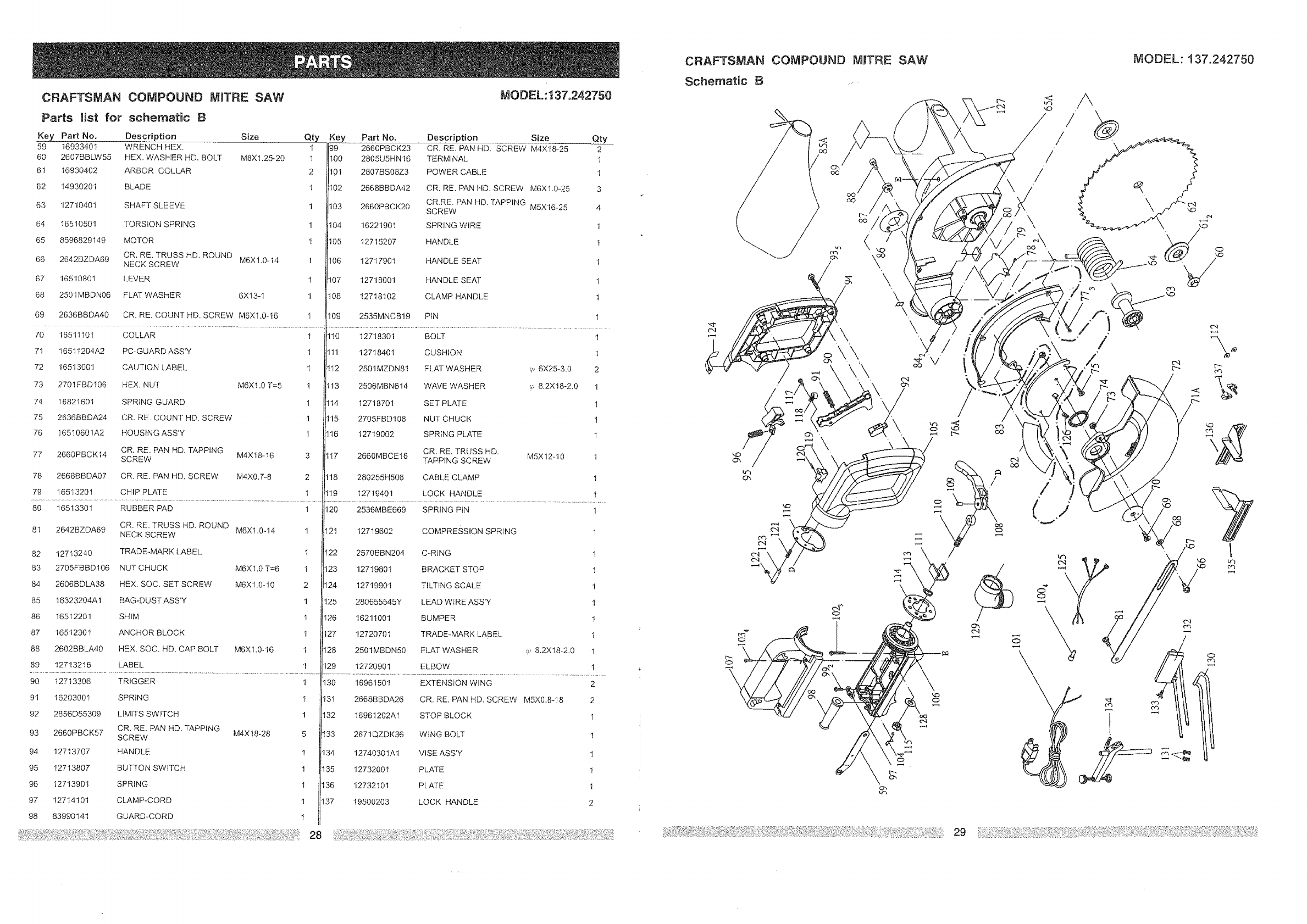
CRAFTSMAN COMPOUND MITRE SAW
Parts Hst for schematic B
Key Part No, Description Size Qty
59 16933401 WRENCH HEX, t
60 2607BBLW55 HEX. WASHER HD, BOLT MSX1,25-20 1
61 16930402 ARBOR COLLAR 2
62 14930201 BLADE 1
63 12710401 SHAFT SLEEVE 1
64 16510501 TORSION SPRING 1
65 8596829149 MOTOR 1
66 2642BZDA69 CR, RE, TRUSS HD, ROUND
NECK SCREW M6X1.0-14 t
67 16510801 LEVER I
68 2501MBDN06 FLAT WASHER 6X13-1 1
69 2636BBDA40 CR, RE. COUNT HD, SCREW M6X1.0-16 1
MODEL:137.242750
Key Part No. Description Size Qty
99 2660PBCK23 CR. RE. PAN HD, SCREW M4X18-25 2
l_0 2805U5HN16 TERMINAL t
101 2807BS08Z3 POWER CABLE 1
102 2668BBDA42 CR. RE. PAN HD. SCREW M6Xl.0-25 3
CR.RE. PAN HD, TAPPING
103 2660PBCK20 SCREW M5X16-25 4
104 16221901 SPRING WiRE 1
105 12715207 HANDLE I
106 12717901 HANDLE SEAT 1
107 12718001 HANDLE SEAT I
108 12718102 CLAMP HANDLE t
109 2535MNCB19 PIN 1
................................................................................................................................................ Jl......................................................................................................................................................................................
70 16511101 COLLAR 1 110 12718301 BOLT 1
71 16511204A2 PC-GUARD ASS'Y 1 1!1 12718401 CUSHION 1
72 16513001 CAUTION LABEL I 112 2501MZDN81 FLAT WASHER q_ 6X25-3,0 2
73 2701FBDI06 HEX. NUT M6Xt.0 T=5 1 t13 2506MBN614 WAVE WASHER _;, 8.2X18-2,0 1
74 16821601 SPRfNG GUARD 1 I14 12718701 SET PLATE I
75 2636BBDA24 CR. RE. COUNT HD. SCREW 1 115 2705FBD108 NUT CHUCK I
76 16510601A2 HOUSING ASS'Y t I16 12719002 SPRING PLATE 1
CR. RE, PAN HD. TAPPING CR, RE. TRUSS HD.
77 2660PBCKt4 SCREW M4X18-16 3 2660MBCEt6 TAPPING SCREW M5X12-10 1
78 2668BBDA07 CR. RE. PAN HD. SCREW M4X0.7-8 2 280255H506 CABLE CLAMP I
79 16513201 CHIP PLATE t 119 12719401 LOCK HANDLE I
80 16513301 RUBBER PAD 1 120 2536MBE669 SPRING PIN 1
81 2642BZDA69 CR. RE, TRUSS HD, ROUND
NECK SCREW M6X1.0-14 1 12t 12719602 COMPRESSION SPRING 1
82 12713240 TRADE-MARK LABEL 1 122 2570BBN204 C-RING I
83 2705FBBD106 NUT CHUCK M6Xt.0 T=6 1 !23 12719801 BRACKET STOP 1
84 2606BDLA38 HEX. SOC, SET SCREW M6XI.0-10 2 I24 127"t9901 TILTING SCALE I
85 16323204A1 BAG-DUST ASS'Y 1 125 280655545Y LEAD WIRE ASS'Y 1
86 16512201 SHIM 1 I26 16211001 BUMPER 1
87 16512301 ANCHOR BLOCK t 127 12720701 TRADE-MARK LABEL 1
88 2602BBLA40 HEX. SOC. HD. CAP BOLT M6X1.0-16 1 128 2501MBDN50 FLAT WASHER cl_8,2Xt8-2.0 1
89 12713216 LABEL 1 129 12720901 ELBOW 1
................................................................................................................................................................................................................... !l ...........................................................................................................................................................................................
90 12713306 TRIGGER 1 130 16961501 EXTENSION WING 2
91 16203001 SPRING t 131 2668BBDA26 CR. RE. PAN HD. SCREW M5X0.8-18 2
92 2856D55309 LiMiTS SWITCH 1 132 16961202A1 STOP BLOCK 1
93 2660PBCK57 CR. RE. PAN HD, TAPPING
SCREW M4X18-28 5 133 2671QZDK36 WING BOLT t
94 12713707 HANDLE 1 134 12740301A1 VISE ASS'Y 1
95 12713807 BUTTON SWITCH 1 t35 12732001 PLATE 1
96 12713901 SPRING 1 136 12732101 PLATE t
97 12714101 CLAMP-CORD t 137 19500203 LOCK HANDLE 2
98 83990141 GUARD-CORD 1
28
CRAFTSP_AN COMPOUND MRTRE SAW
Schematic B
MODEL: 137.242750
/
o
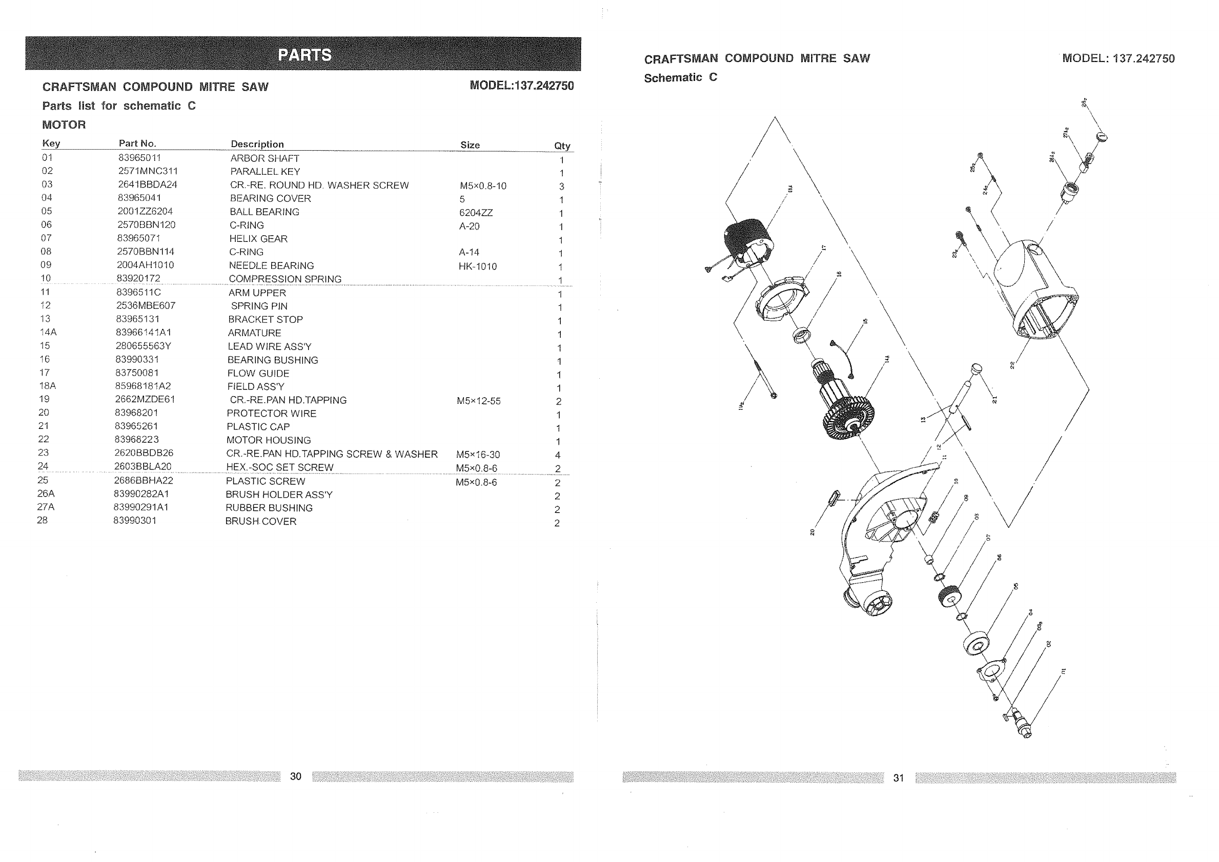
CRAFTSMAN COMPOUND NtnTRE SAW MODEL: 137.242750
Parts list for schematic C
_OTOR
Key Part No. Description Size Qty
0t 83965011 ARBOR SHAFT 1
02 2571MNC311 PARALLEL KEY 1
03 2641BBDA24 CR.-RE. ROUND HD. WASHER SCREW M5x0.8q 0 3
04 83965041 BEARING COVER 5 1
05 200 lZZ6204 BALL BEARING 6204ZZ 1
06 2570BBN120 C-RING A-20 1
07 83965071 HELIX GEAR 1
08 2570BBN114 C-RING A-14 1
09 2004AH 1010 NEEDLE BEARING HK- 1010 1
! 0 839201 T2............................................................. C OM pRESS IONI.SpR!NG .......................................................................................................................................1
11 8396511C ARM UPPER 1
I2 2536MBE607 SPRING PIN 1
13 83965131 BRACKET STOP 1
I4A 8396614 tA1 ARMATURE !
15 280655563Y LEAD WtRE ASS'Y 1
t6 83990331 BEARING BUSHING t
17 83750081 FLOW GUIDE 1
18A 8596818tA2 FIELD ASS'Y 1
19 2662MZDE61 CR,-RE.PAN HD.TAPPING M5x I2-55 2
20 83968201 PROTECTOR WIRE 1
21 83965261 PLASTIC CAP 1
22 83968223 MOTOR HOUSING 1
23 2620BBDB26 CR.-RE.PAN HD.TAPPING SCREW & WASHER M5xt6-30 4
2.........................................4 2603 B BLA 20 H Ex: :S ° c s E.T..SC.RE'_ .....................................................................................................M5 x0:8-:6 ..................................................................
25 2686BBHA22 PLASTIC SCREW M5x0.8-6 2
26A 83990282A! BRUSH HOLDER ASS'Y 2
27A 83990291A1 RUBBER BUSHING 2
28 83990301 BRUSH. COVER 2
CRAFTSMAN
Schematic C
COMPOUND MITRE SAW
\\
/
//
b
/
//
/
\\
/
\\
\
/
/
/
/
ii
MODEL: 137.242750
/
