Craftsman 137242760 User Manual 10 COMPOUND MITER SAW Manuals And Guides L0306228
CRAFTSMAN Miter Saw Manual L0306228 CRAFTSMAN Miter Saw Owner's Manual, CRAFTSMAN Miter Saw installation guides
User Manual: Craftsman 137242760 137242760 CRAFTSMAN 10 COMPOUND MITER SAW - Manuals and Guides View the owners manual for your CRAFTSMAN 10 COMPOUND MITER SAW #137242760. Home:Tool Parts:Craftsman Parts:Craftsman 10 COMPOUND MITER SAW Manual
Open the PDF directly: View PDF ![]() .
.
Page Count: 36
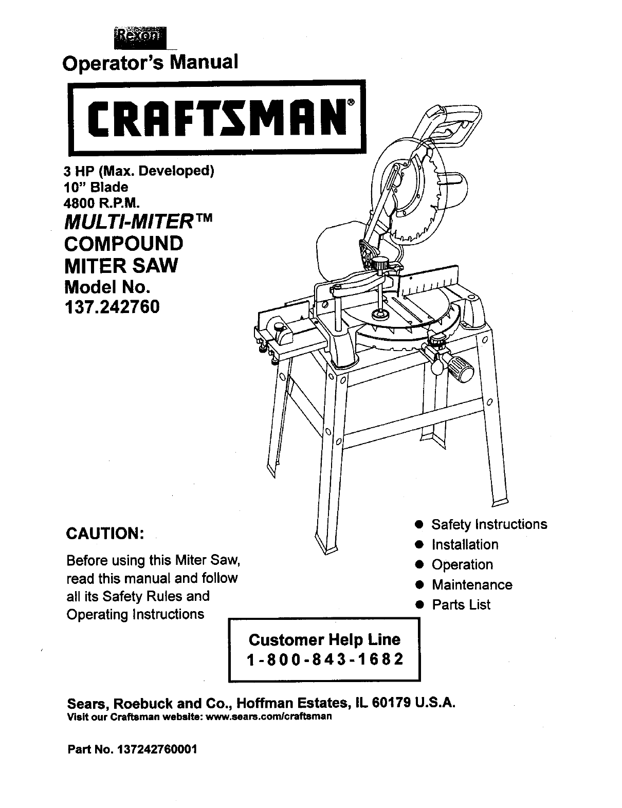
Operator's Manual
CRRFTSMRN°
3 HP (Max. Developed)
10" Blade
4800 R.P.M.
MULTI-MITER TM
COMPOUND
MITER SAW
Model No.
137.242760
CAUTION:
Before using this Miter Saw,
read this manual and follow
all its Safety Rules and
Operating Instructions
Customer Help Line
1-800-843-1682
•Safety Instructions
• Installation
• Operation
•Maintenance
•Parts List
Sears, Roebuck and Co., Hoffman Estates, IL 60179 U.S.A.
Visit our Craftsman webslte: www.sears.comlcraftsman
PaN No. 137242760001

SECTION PAGE
Warranty ........................................ 2
Product Specifications ....................... 2
Power Tool Safety ............................ 3
Compound Miter Saw Safety............... 4
Electrical Requirements and Safety...... 4-5
Accassodes and Attachments .............. 6
Tools Needed For Assembly................ 6
Carton Contents .............................. 7
SECTION PAGE
Know Your Miter Saw........ 8
Glossary of Terms ............................ 9
Assembly and Adjustments................. 10
Operation....................................... 17
Maintenance ................................... 24
Troubleshooting Guide....................... 25
Parts List......................................... 26
FULL ONE YEAR WARRANTY
If this tool fails due to a defect in material or workmanship within one year of date of purchase, Sears will
at its option repair or replace it free of charge.
Return this tool to a Sears Service Center for repair, or to place of purchase for replacement.
This warranty gives you specific legal rights, and you may also have other rights which may vary from
state to state.
Seam, Roebuck and Co., Dept. 817 WA, Hoffman Estates, IL 60179
UA WARNING ]
Some dust created by power sanding, sawing, grinding, dHIlinQ and other construction activities contains
chemicals known (to the State of Ca.fornie) to cause cancer, bnrthdefects or other reproductive harm. Some
examples of these chemicals are:
• Lead from lead-based paints
• Crystalline silica from bricks, cement and other masonry products
•Arsenic and chromium from chemically treated lumber
Your Hak from these exposures varies depending on how often you do this type of work. To reduce your
exposure to these chemicals work in a well ventilated area and work with approved safety aquipmantsuch as dust
masks that are specially des gned to fi tar out microscop c part c es.
MOTOR
Pov_r Source.....................
Horsepower........................
Speed.................................
Brake.................................
DoubleInsulated....................
MITER SAW
Cutting Capacity:
Crosscut............................
Miter45°R.&L.....................
Bevel45=L........................
45° Miterand45° Bevel.........
120VAC, 60HZ, 15 Amp
3HP (Max. Developed)
4800 RPM (No load)
Electric
Yes
2-5/8"x 5-1/2"
2-5/8"x 3-1/2"
1-1/2"x 5-1/2"
1-1/2"x 3-1/2"
Rotating Table:
Diameter .............................. 12-5/8"
Miter Detent Stops.................. 0, 15, 22-1/2, 31.6,
450 R. & L.
Bevel Positive Stops............... 0, 450
Base Dimensions................... 19-7/8" x 16-3/8"
Dust Collection...................... Yes
Extension Table ..................... Yes
Net Weight ........................... 51.25 Lbs
IA WARNONGI
To avoid electrical hazards, fire hazards or damage to the tool, use proper circuit protection.
This tool Is wired st the factory for 110-120 Volt operation. It must be connected to a 110-120 Volt 115 Ampere time
delay fuse or circuit breaker. To avoid shock or firs, replace power cord Immediately if it is worn, cut or damaged
in any way.
Before using your tool, it is cdtlcal that you read and understand these safety rules. Failure to follow these rules
could result in serious injury to you or damage to the tool.
2
GENERAL SAFETY INSTRUCTIONS
BEFOREUSINGTHISPOWERTOOL
Safety is a combination of common sense, staying alert
and knowing how to use your power tool.
AWARNING I
To avoid mistakes that could cause serious injury, do not
plug the tool in untilyou have read and understood the
following.
1. READ and become familiar with the entire Operators
Manual. LEARN the tool's application, limitations and
possible hazards.
2. KEEP GUARDS IN PLACE and in working order.
3. REMOVE ADJUSTING KEYS AND WRENCHES.
Form the habit of checking to see that keys and
adjusting wrenches are removed from the tool before
turning ON.
4. KEEP WORK AREA CLEAN. Cluttered areas and
benches invite accidents.
5. DON'T USE IN DANGEROUS ENVIRONMENTS.
Don't use power tools in damp locations, or expose
them to rain or snow. Keep work area well lighted.
6. KEEP CHILDREN AWAY.All visitorsand bystanders
should be kept a safe distance from work area,
7. MAKE WORKSHOP CHILD PROOF with padlocks,
master switches, or by removing starter keys.
8. DON'T FORCE THE TOOL. It will do the job better
and safer at the rate for which it was designed.
9. USE THE RIGHT TOOL. Do not force the tool or an
attachment to do a job for which it was not designed.
10.USE PROPER EXTENSION CORDS. Make sure
your extension cord is in good condition. When using
an extension cord, be sure to use one heavy enough
to carry the current your product will draw. An
undersized cord will result in a drop in line voltage
and in loss of power which will cause the tool to
overheat. The table on page 5 shows the correct size
to use depending on cord lengthand nameplate
ampere rating. If in doubt, use the next heavier gauge.
The smaller the gauge number, the heavier the cord.
11.WEAR PROPER APPAREL. Do not wear loose
clothing, gloves, neckties, rings, bracelets, or other
jewelry which may get caught in moving parts.
Nonslip footwear is recommended. Wear protective
hair covering to contain long hair.
12.ALWAYS WEAR EYE PROTECTION. Any power tool
can throw foreign objects into the eyes and
,,,*,,_could cause permanent eye damage.
ALWAYS wear Safety Goggles (not
glasses) that comply with ANSI Safety
standard Z87.1 Everyday eyeglasses
have only impact -resistance lenses.
TheyARE NOT safety glasses. Safety Goggles are
available at Sears. NOTE: Glasses or goggles not in
compliance with ANSI Z87.1 could seriously injure
you when they break.
13.WEAR A FACE MASK OR DUST MASK. Sawing
operation produces dust.
14.SECURE WORK. Use clamps or a vise to holdwork
when practical. It's safer than using your hand and it
frees both hands to operate the tool.
15.DISCONNECT TOOLS FROM POWER SOURCE
before servicing, and when changing accessories
such as blades, bits and cutters.
16.REDUCE THE RISK OF UNINTENTIONAL
STARTING. Make sure switch is in the OFF position
before pluggingthe tool in.
17.USE RECOMMENDED ACCESSORIES. Consult this
Operators Manual for recommended accessories.
The use of improper accessories may cause risk of
injuryto yourself or others.
18.NEVER STAND ON THE TOOL. Serious injury could
occur if the tool is tipped or if the cuttingtool is
unintentionallycontacted.
19.CHECK FOR DAMAGED PARTS. Before further use
of the tool, a guard or other part that is damaged
should be carefully checked to determine that it will
operate properlyand perform its intended function-
check for alignment of movingparts, binding of
moving parts, breakage of parts, mounting,and any
other conditions that may affect its operation. A guard
or other part that is damaged should be propedy
repaired or replaced.
20.NEVER LEAVETHE TOOL RUNNING UNAI-rENDED.
TURN THE POWER "OFF". Don't walk away from a
running tool untilthe blade comes to a complete stop
& unplugthe unit.
2t .DON'T OVERREACH. Keep proper footing and
balance at all times.
22.MAINTAIN TOOLS WITH CARE. Keep tools sharp
and clean for best and safest performance. Follow
instructionsfor lubricating and changing accessodes.
23. WARNING: Dust generated from certain materials
can be hazardous to your health. Always operate
saw in well-ventilated area and provide for proper
dust removal.
3
SPECIFIC SAFETY INSTRUCTIONS FOR
THIS COMPOUND MITER SAW
1. USE ONLY CROSS-CUTTING SAW BLADES. When
using carbide tipped blades, make sure they have a
negative hook angle.
IMPORTANT: DO NOT USE THIN KERF BLADES-
they can deflect and contact guard and can cause
possible injury to the operator.
2. DO NOT operate the miter saw untilit is completely
assembled and installed according to these
instructions.
3. IF YOU ARE NOT thoroughlyfamiliar with the
operation of miter sews, seek guidance from your
supervisor, instructor,or other qualified person.
4. ALWAYS hold the work firmly against the fence and
table. DO NOT perform any operation free hand (use
clamp wherever possible).
5. KEEP HANDS out of the path of the saw blade. If the
workpiece you are cuttingwould cause your hands to
be within6-1/2" inches of the saw blade, the
workpiece should be clamped in place before making
the cut.
6. BE SURE the blade is sharp, runs freely, and is free of
vibration.
7. ALLOW the motor to come up to full speed before
starting a cut.
8. KEEP THE MOTOR AIR SLOTS CLEAN and free of
chips or dust.
9. ALWAYS MAKE SURE all handles are tight before
cutting, even if the table is positioned in one of the
positivestops,
tO.BE SURE both the blade and the coUarare clean and
the arbor bolt is tightened securely.
11.USE only blade collars specifiedfor your saw.
12. NEVER use blades'larger or smaller in diameter than
10oinches.
13. NEVER apply lubricants to the blade when it is
running.
t4. ALWAYS check the blade for cracks or damage
before operation. Replace a cracked or damaged
blade immediately.
15. NEVER use blades recommended for operationat
less than 4800 RPM
16.ALWAYS keep the blade guards in place and use at
all times.
17.NEVER reach around the sew blade.
18.MAKE SURE the blade is not contactingthe
workpiece before the switchis turned ON.
19.IMPORTANT: After completing the cut, release the
power switchand wait for the blade to stopbefore
returningthe saw to the raised position.
20.MAKE SURE the blade has come to a complete stop
before removing or securing the workpiece, changing
the workpiece angle, or changingthe angle ofthe
blade.
21.NEVER cut ferrous metals or masonry with thistool.
22.NEVER cut small pieces..If the workpiece being cut
would cause your hand or fingers to be within7-1/4
inches of the saw blade the workpiece is too small.
23.PROVIDE adequate support to the sides of the saw
table for longwork pieces.
24.NEVER use the mitersaw in an area with flammable
liquidsor gases.
25.NEVER use solvents to clean plastic parts. Solvents
could possiblydissolve or otherwise damage the
matedaL
26,SHUT OFF the power before servicing or adjustingthe
tool.
27,DISCONNECT the saw from the power source and
clean the machine when finished using.
28.MAKE SURE the work area is clean before leaving
the machine.
29.SHOULD any part of your miter saw be missing,
damaged, or fail in any way, or any electrical
component fail to perform propedy, shut off the switch
and remove the plugfrom the power supplyoutlet.
Replace missing, damaged, or failed parts before
resuming operation.
POWER SUPPLY AND MOTOR SPECIFICATIONS
The AC motor used in this sew is a universal,
nonreversible type. See "MOTOR" in the "PRODUCT
SPECIFICATIONS" section on page 2.
To avoid electdcal hazards, fire hazards, or damage to
the tool, use proper circuitprotection.Your saw is wired at
the factory for 120V operation. Connect to a 120V, 15
Amp circuit and use a 15 amp. time delay fuse or circuit
breaker. To avoid shock or fire, if power cord is worn or
cut, or damaged in any way, have it replaced
immediately.
4
ELECTRICAL REQUIREMENTS - cont'd
DOUBLE INSULATED []
The power tool is double insulated to provide a double
thickness of insulation between you and tool's electricel
system. All exposed metal parts are isolated from the
internal metat motor components with protecting insulation.
Replacement parts - When servicing use only identical
replacement parts.
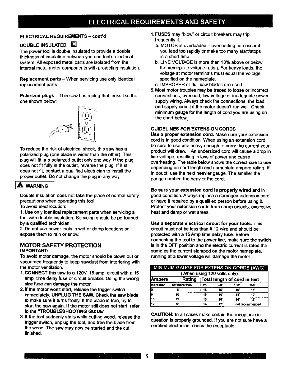
Polarized plugs - This saw has a plug that looks like the
one shown below:
-i;222
To reduca the risk of electrical shock, this saw has a
polarized plug (one blade is wider than the other). This
plug will fit in apolarized outlet only one way. If the plug
does not fit fully in the outlet, reverse the plug. If it still
does not fit, contact a qualified electrician to install the
proper outlet. Do not change the plug in any way.
[AWARN,NG]
Double insulationdoes nottake the place of normal safety
precautions when operating this tool.
To avoid electrocution:
1. Use only identical replacement parts when servicing a
tool with double insulation.Servicing should be performed
by a qualified technician.
2. Do not use power tools inwet or damp locations or
expose them to rain or snow.
MOTOR SAFETY PROTECTION
IMPORTANT:
To avoid motor damage, the motor should be blownout or
vacuumed frequently to keep sawdust from interfering with
the motor ventilation.
1.CONNECT this saw to a 120V, 15 amp. circuitwith a 15
amp. time delay fuse or circuit breaker. Using the wrong
size fuse can damage the motor.
2. If the motor won't start, release the trigger switch
immediately. UNPLUG THE SAW. Check the saw blade
to make sure it turns freely. If the blade is free, try to
start the sew again. If the motor still does not start, refer
to the "TROUBLESHOOTING GUIDE"
3. If the tool suddenly stalls while cutting wood, release the
trigger switch, unplugthe tool, and free the blade from
the wood. The saw may now be started and the cut
finished.
4. FUSES may "blow" or circuit breakers may tdp
frequently if:
a. MOTOR is overloaded - overloading can occur if
you feed too rapidly or make too many start/stops
in a short time.
b. LINE VOLTAGE is more than 10% above or below
the nameplate voltage rating. For heavy loads, the
voltage at motor terminals must equal the voltage
specified on the nameplate.
c. IMPROPER or dull saw blades are used.
5. Most motor troubles may be traced to loose or incorrect
connections, overload, lowvoltage or inadequate power
supplywiring.Always check the connections, the load
and supplycircuit if the motor doesn't run well. Check
minimum gauge for the lengthof cord you are usingon
the chart below.
/
GUIDELINES FOR EXTENSION CORDS
Use a proper extension cord. Make sure your extension
cord is in good condition.When using an extension cord,
be sure to use one heavy enough to carry the current your
product will draw. An undersized cord will cause a drop in
line voltage, resulting in lossof power and cause
overheating. The table below shows the correct size to use
depending on cord length and nameplate ampere rating. If
in doubt, use the next heavier gauge. The smaller the
gauge number, the heavier the cord.
Be sure your extension cord is properly wired and in
good condition.Always replace a damaged extension cord
or have it repaired by a qualified person before usingit.
Protect your extension cords from sharp objects, excessive
heat and damp or wet areas.
Use a separate electrical circuit for your tools. This
circuit must not be less than # 12 wire and should be
protected with a 15 Amp time delay fuse. Before
connecting the tool to the power line, make sure the switch
is in the OFF positionand the electric current is rated the
same as the current stamped on the motor nameplate,
running at a lower voltage will damage the motor.
lltd I_IliVdlllvJ1¢f_,_1[€t =1:re] _.i =);,4111:1_k.'f[e] _I[o(I] :| J_l f:VlvL_!
(When using 120 voltsonly)
_mpere Rating Total length of cord in feet
_ore fJlen not more I_n 25' 50' t00' 150'
6 18' 16' 16' 14'
10 18' 16' 14' 12'
I0 12 16' 16' 14' 12'
12 16 14' 12' not recommended
CAUTION: In all cases make certain the receptacle in
question is properly grounded. If you are not sure have a
certified electrician, check the receptacle.
5
RECOMMENDED ACCESSORIES
IA, WARNING]
•Use only accessories recommended for this miter saw.
Follow instructions that accompany accessories. Use
of improper accessories may cause hazards.
• The use of any cutting tool except 10 inch saw blades
which meet the requirements under recommended
accessories is prohibited. Do not use accessobes such
as shaper cutters or dado sets. Ferrous metal cutting
and the use of abrasive wheels is prohibited.
• Do not attempt to modify this tool or create
accessories not recommended for use with this tool.
Any such alteration or modification is misuse and could
result in a hazardous condition leading to possible
serious injury.
ACCESSORIES
Visit your Sears Hardware Department or see the Sears
Power and Hand Tool Catalog to purchase recommendec
accessories for this power tool.
[A WARNINGI
To avoid the risk of personal injury, do not modify this
power tool or use accessories not recommended by Sear
I,A WARNING]
Read warnings and conditionson your CARBIDE TIPPEr
SAW BLADE. Do not operate the saw without the proper
saw blade guard in place. Carbide is a very hard but brittle
material. Care should be taken while mounting, using, and
storing carbide tipped blades to prevent accidental
damage. Slight shocks, such as striking the tip while
handling, can seriously damage the blade. Foreign objects
in the workpiece, such as wire or nails, can also cause tips
to crack or break off. Before using, always visually
examine the blade and tips for bent teeth, cracks,
breakage, missing or loose tips, or other damage. Do not
use if damage is suspected. Failure to heed safety
instructionsand warnings can result in serious bodily
injury.
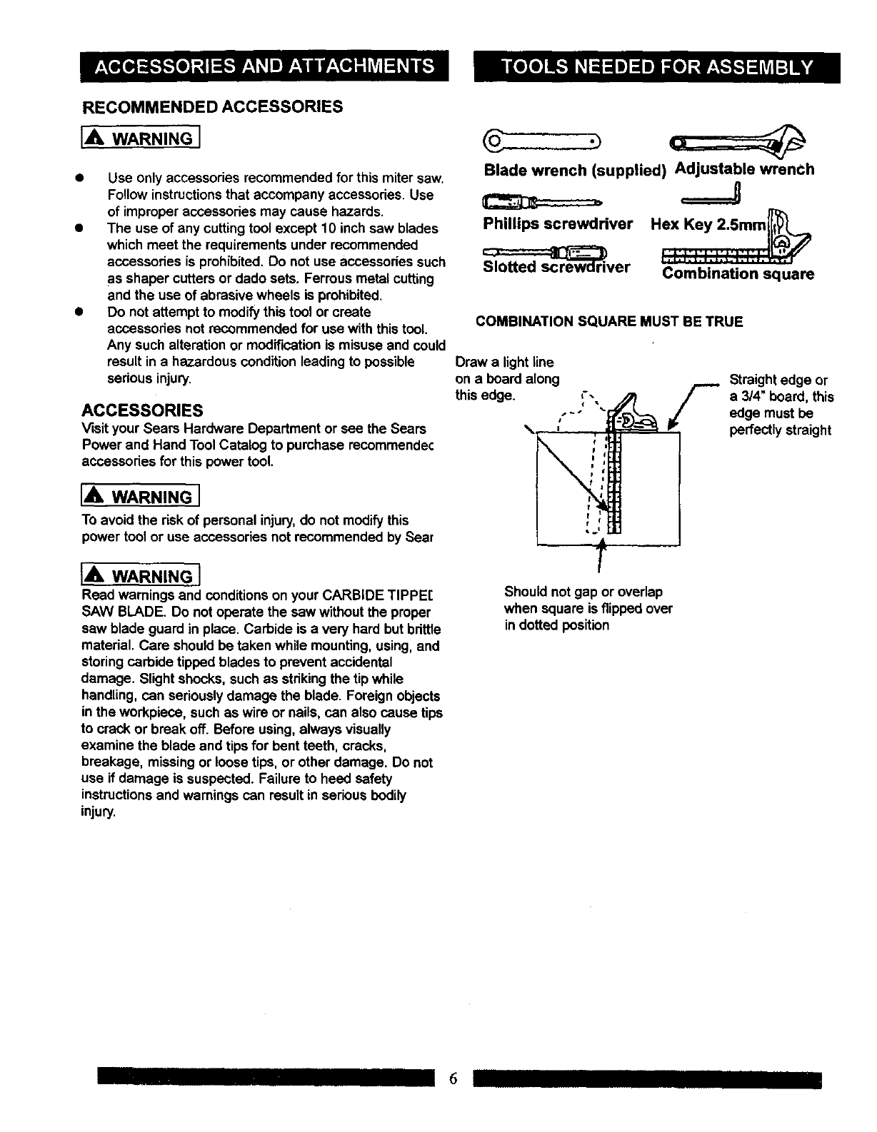
Blade wrench (supplied) Adjustable wrenCh
Phillips screwdriver
_ver
===J
Combination square
COMBINATION SQUARE MUST BE TRUE
Draw a light line
on a board along
this edge. ,--
s_J
Straight edge or
a 3/4" board, this
edge must be
perfectly straight
Should not gap or overlap
when square is flipped over
in dotted position
I 6
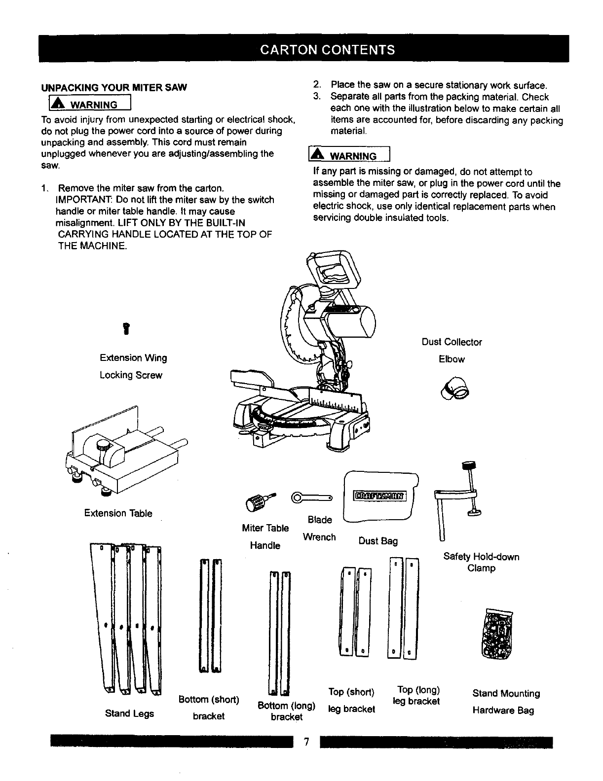
UNPACKING YOUR MITER SAW
IA WARNINGI
To avoid injury from unexpected starting or electrical shock,
do not plugthe power cord into a source of power during
unpacking and assembly. This cord must remain
unplugged whenever you are adjusting/assemblingthe
saw.
1, Remove the miter saw from the carton.
IMPORTANT: Do not liftthe miter saw by the switch
handle or miter table handle. It may cause
misalignment. LIFT ONLY BY THE BUILT-IN
CARRYING HANDLE LOCATED AT THE TOP OF
THE MACHINE.
.
3. Place the saw on a secure stationary work surface.
Separate all parts from the packing material. Check
each one with the illustration below to make certain all
items are accountedfor, before discarding any packing
material.
I,_b. WARNING I
If any part is missingor damaged, do not attempt to
assemble the miter saw, or plug in the power cord untilthe
missingor damaged part is correctly replaced. To avoid
electric shock, use only identical replacement parts when
servicing double insulated tools.
V
Extension Wing
Locking Screw
Dust Collector
Elbow
Extension Table
I
Stand Legs
Bottom (short)
bracket
Blade
Miter Table
Handle Wrench Dust Bag
,I
Safety Hold-down
Clamp
Bottom (long)
bracket
Top (short)
leg bracket
Top (long)
leg bracket Stand Mounting
Hardware Bag
7
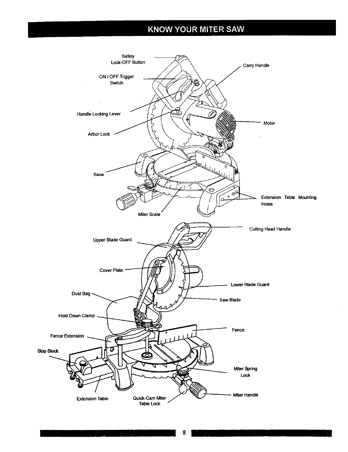
Safety
Lock-OFFButton
ON IOFF Trigger
Switch
' Handle
Handle Locking Lever
Arbor Lock
Motor
Base
Upper Blade Guard
Miter Scale
ExtensionTable Mounting
Holes
Cutting Head Handle
Lower Blade Guard
Saw Blade
Fence Extension
Fence
StopBlock
MiferSpdng
Lock
Extension Table Quick-Cam Miter
Table Lock
M_rHa_le
CRAFTSMAN COMPOUND MITER SAW TERMS
ARBOR LOCK -Allows the user to keep the blade from
rotating while tightening or loosening the arbor locking
bolt during blade replacement or removal.
BASE - Supports the table, holds accessories and
allows for workbench or leg set mounting.
BEVEL LOCKING HANDLE - Locks the miter saw at a
desired bevel angle.
BEVEL SCALE - To measure the bevel angle of the saw
blade 0°to 45 ° left.
COVER PLATE SCREW -Loosen this screw and rotate
the plate for access to the blade arbor locking bolt.
DUST CHUTE - Exhausts debds away from the user.
EXTENSION TABLE - Extends the width of the work
table for support while cutting long work pieces. They
can be used with or without a stop block as an additional
side fence.
FENCE - Helps to keep the workpiece from moving
when sawing. Scaled to assist with accurate cutting.
HAND HOLD - For movingthe saw when unplugged.
SAFETY LOCK-OFF SLIDE SWITCH - Yellow buttonon
handle must be pushed forward to activate the trigger
switch.
LOWER BLADE GUARD - Helps protect your hands
from the blade in the raised position, it retracts as the
blade is lowered.
MITER HANDLE - Used to lock and unlock the miter
table, and to rotate the saw to a right or left cutting
position.
MITER SCALE - To measure the miter angle 0° to 45°
left, 0°to 45° dght.
MITER SPRING LOCK - Used in combination with the
miter handle, it locks the miter saw at a preset positive
stop for the desired miter angle.
MOUNTING HOLES - To mount the miter saw to a
stable surface.
ON/OFF TRIGGER SWITCH - To prevent the tdgger
from being accidentally engaged, a lock-off slide switch
is provided. To start the tool, push the lock-off slide
switch forward and squeeze the trigger. Release the
tdgger to stop the miter saw.
STOP LATCH - Locks the miter saw in the lowered
positionfor compact storage and transportation.
SWITCH HANDLE - The cutting head handle contains
the trigger switch and a safety lock-off slide switch. The
blade is lowered into the workpiece by pushing down on
the handle. The saw will return to its upright position
when the handle is released.
WARNING LABELS -Read and understand for your
own safety. Always make certain these are in place &
legible.
WRENCH STORAGE - Convenient storage to prevent
misplacing the blade wrench.
WOODWORKING TERMS
ARBOR - The shaft on which a blade is mounted,
BEVEL CUT - An angle cut made through the face of
the workpiece.
COMPOUND CUT -A simultaneous bevel and miter cut.
CROSS CUT - A cut made across the width or grain of
the workpiece.
FREEHAND - Performing a cut without using a fence
(guide), hold down or other proper device to prevent the
workpiece from twistingduringthe cuttingoperation.
GUM -A sticky sap from wood products.
HEEL- Misalignment of the blade.
KERF - The amount of material removed by blade cut.
MITER CUT - An angle cut made across the width or
grain of the workpiece.
RESIN -A stickysap that has hardened.
REVOLUTIONS PER MINUTE (RPM) - The number of
turns completed by a spinningobject in one minute.
SAW BLADE PATH - The area of the workpiece or table
top directly in line with the travel of the blade Or the part
of the workpiece which will be cut.
SET - The distance between two saw blade tips, bent
outward in opposite directions to each other. The further
apart the tips are, the greater the set.
WORKPIECE - The item being cut. The surfaces of a
workpiece are commonly referred to as faces, ends, and
edges.
9
ASSEMBLY INSTRUCTIONS
IA WARNINGI
To avoid injury,do not connect this miter saw to the power
source untilit is completely assembled and adjusted, and
you have read and understood this Operators Manual.
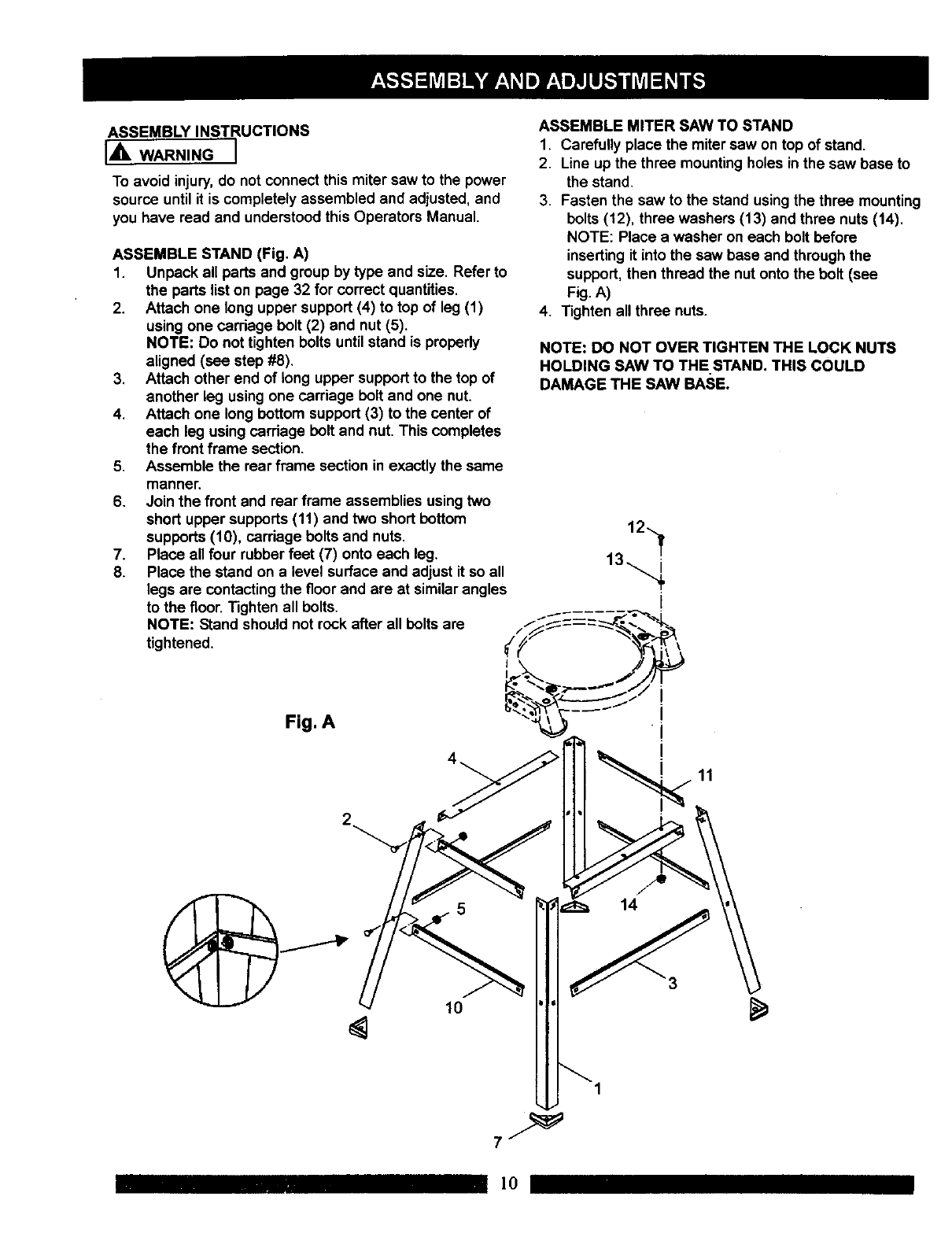
ASSEMBLE STAND (Fig. A)
1. Unpack all parts and group by type and size. Refer to
the parts list on page 32 for correct quantities.
2. Attach one long upper support(4) to top of leg (1)
usingone carriage bolt (2) and nut (5).
NOTE: Do not tighten bolts until stand is propedy
aligned (see step #8).
3. Attach other end of long upper support to the top of
another leg usingone carriage bolt and one nut.
4. Attach one long bottom support (3) to the center of
each leg using carriage bolt and nut. This completes
the front frame section.
5. Assemble the rear frame section in exactly the same
manner.
6. Join the front and rear frame assemblies usingtwo
short upper supports (11) and two short bottom
supports (10), carriage bolts and nuts.
7. Place all four rubber feet (7) onto each leg.
8. Place the stand on a level surface and adjust it so all
legs are contactingthe floor and are at similarangles
to the floor. Tighten all bolts.
NOTE: Stand should not rock after all bolts are
tightened.
ASSEMBLE MITER SAW TO STAND
1. Carefully place the miter saw on top of stand.
2. Line up the three mountingholes in the saw base to
the stand.
3. Fasten the saw to the stand using the three mounting
bolts (12), three washers (13) and three nuts (14).
NOTE: Place a washer on each bolt before
insertingit into the saw base and throughthe
support, then thread the nut onto the bolt (see
Fig. A)
4. Tighten all three nuts.
NOTE: DO NOT OVER TIGHTEN THE LOCK NUTS
HOLDING SAW TO THE STAND. THIS COULD
DAMAGE THE SAW BASE.
12
Fig. A
11
5
10
14
1
]0
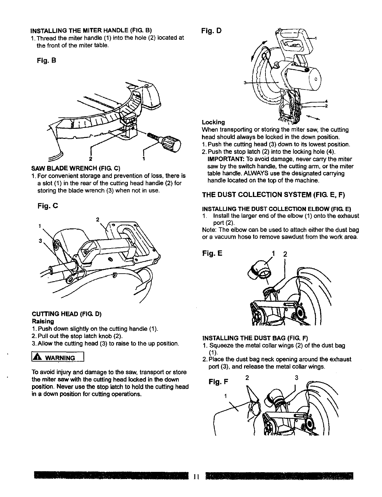
INSTALLING THE MITER HANDLE (FIG. B)
1,Thread the miter handle (1) into the hole (2) located at
the front of the mitertable.
Fig. B
2 1
SAW BLADE WRENCH (FIG. C)
1. For convenient storage and prevention of loss, there is
a slot (1) in the rear of the cutting head handle (2) for
storing the blade wrench (3) when not in use.
Fig. C
2
1
3
Fig. D
Locking
When transporting or storing the miter saw, the cutting
head should always be locked inthe down position.
1. Push the cutting head (3) down to its lowest position,
2, Push the stop latch (2) into the locking hole (4).
IMPORTANT: To avoid damage, never carry the miter
saw by the switch handle, the cuttingarm, or the miter
table handle, ALWAYS use the designated carrying
handle located on the top of the machine.
THE DUST COLLECTION SYSTEM (FIG. E, F)
INSTALLING THE DUST COLLECTION ELBOW (FIG. E)
1. Install the larger end of the elbow (1) onto the exhaust
port (2).
Note: The elbow can be used to attach either the dust bag
or a vacuum hose to remove sawdust from the work area.
Fig. E 1 2
CUTTING HEAD (FIG. D)
Raising
1. Push down slightly on the cutting handle (1).
2. Pull out the stop latch knob (2).
3.Allow the cutting head (3) to raise to the up position.
IA WA ,NGI
To avoid injuryand damage to the saw, transport or store
the miter saw with the cutting head locked in the down
position. Never use the stop latch to hold the cutting head
in a down position for cutting operations.
INSTALLING THE DUST BAG (FIG. F)
1. Squeeze the metal collar wings (2) of the dust bag
(1).
2, Place the dust bag neck opening around the exhaust
port (3), and release the metal collar wings,
Fig. F 2 3
IIIIIlllllll !_
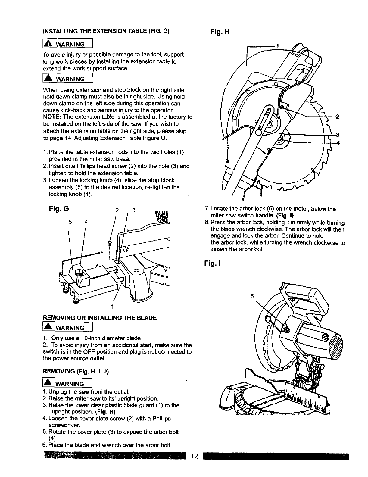
INSTALLING THE EXTENSION TABLE (FIG. G) Fig. H
[,_ WARNING 1
To avoid injury or possible damage to the tool, support
long work pieces by installingthe extension table to
extend the work support surface.
IA WARNINGI
When using extension and stop block on the right side,
hold down clamp must also be in right side. Using hold
down clamp on the left side during this operation can
cause kick-back and serious injury to the operator.
NOTE: The extension table is assembled at the factory to
be installed on the left side of the saw. If you wish to
attach the extension table on the rightside, please skip
to page 14, Adjusting ExtensionTable Figure O.
1. Place the table extension rods into the two holes (1)
provided in the miter saw base.
2. Insert one Phillips head screw (2) into the hole (3) and
tighten to hold the extension table.
3. Loosen the locking knob (4), slide the stop block
assembly (5) to the desired location, re-tighten the
locking knob (4).
Fig. G23
5 4
7. Locate the arbor lock (5) on the motor, below the
miter saw switch handle. (Fig. I)
8. Press the arbor lock, holding it infirmly while turning
the blade wrench clockwise.The arbor lockwill then
engage and lock the arbor. Continueto hold
the arbor lock, while turning the wrench clockwise to
loosen the arbor bolt.
Fig. I
REMOVING OR INSTALLING THE BLADE
['_ WARNING I
1. Only use a 10-inch diameter blade.
2. To avoid injury from an accidental start, make sure the
switch is in the OFF positionand plug is not connected to
the power source outlet.
REMOVING (Fig. H, I, J)
IA WARNINGI
1. Unplug the saw from the outlet.
2. Raise the miter saw to its'upright position,
3. Raise the lower clear plastic blade guard (1) to the
updght position. (Fig. H)
4, Loosen the cover plate screw (2) with a Phillips
screwdriver.
5. Rotate the cover plate (3) to expose the arbor bolt
(4).
6. Place the blade end wrench over the arbor bolt.
_I1, . rJ" I!'! 12
5
IIII
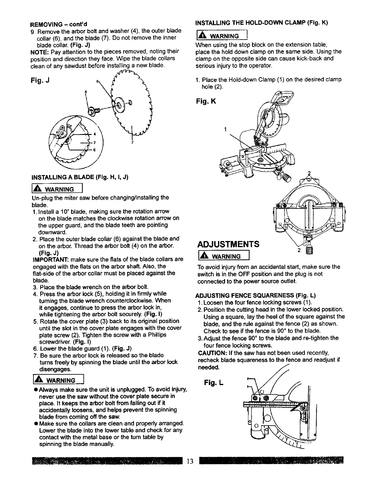
REMOVING - cont'd
9. Remove the arbor bolt and washer (4), the outer blade
collar (6), and the blade (7). Do not remove the inner
blade collar. (Fig. J)
NOTE: Pay attention to the pieces removed, notingtheir
positionand directionthey face. Wipe the blade collars
clean of any sawdust before installinga new blade.
Fig J _____
INSTALLING A BLADE (Fig. H, I, J)
IA WARNINGI
Un-plug the miter saw before changing/installingthe
blade.
1. Install a 10" blade, making sure the rotation arrow
on the blade matches the clockwiserotation arrow on
the upper guard, and the blade teeth are pointing
downward.
2. Place the outer blade collar (6) against the blade and
on the arbor. Thread the arbor bolt (4) on the arbor.
(Fig. J)
IMPORTANT: make sure the fiats of the blade collarsare
engaged with the flats on the arbor shaft. Also, the
fiat-side of the arbor collar must be placed against the
blade.
3. Place the blade wrench on the arbor bolt.
4. Press the arbor lock (5), holding it in firmly while
turningthe blade wrench counterclockwise.When
it engages, continue to press the arbor lockin,
while tightening the arbor bolt securely. (Fig. I)
5. Rotate the cover plate (3) back to its original position
untilthe slot in the cover plate engages with the cover
plate screw (2). Tighten the screw with a Phillips
screwddver. (Fig. I)
6. Lower the blade guard (1). (Fig. J)
7. Be sure the arbor lock is released so the blade
turns freely by spinning the blade untilthe arbor lock
disengages.
IA WARN,NGI
•Always make sure the unit is unplugged. To avoid injury,
never _Jsethe saw without the cover plate secure in
place. It keeps the arbor boltfrom falling out if it
accidentally loosens, and helps prevent the spinning
blade from coming off the saw.
•Make sure the collars are clean and properlyarranged.
Lower the blade into the lower table and check for any
contact with the metal base or the turn table by
spinningthe blade manually.
INSTALLING THE HOLD-DOWN CLAMP (Fig. K)
I_1, WARNING I
When usingthe stop block on the extension tabte,
place the holddown clamp on the same side. Using the
clamp on the opposite side can cause kick-back and
serious injuryto the operator.
1. Place the Hold-down Clamp (1) on the desired clamp
hote (2).
Fig. K
ADJUSTMENTS
I_lk WARNING I
To avoid injuryfrom an accidental start, make sure the
switch is in the OFF positionand the plug is not
connected to the power source outlet.
ADJUSTING FENCE SQUARENESS (Fig. L)
1. Loosen the four fence locking screws (1).
2. Position the cuttinghead inthe lower locked position.
Using a square, lay the heel of the square against the
blade, and the rule against the fence (2) as shown.
Check to see if the fence is 90°to the blade.
3. Adjust the fence 90° to the blade and re-tighten the
four fence locking screws.
CAUTION: If the saw has not been used recently,
recheck blade squareness to the fence and readjust if
needed.
Fig. L I-
'11 n13 r
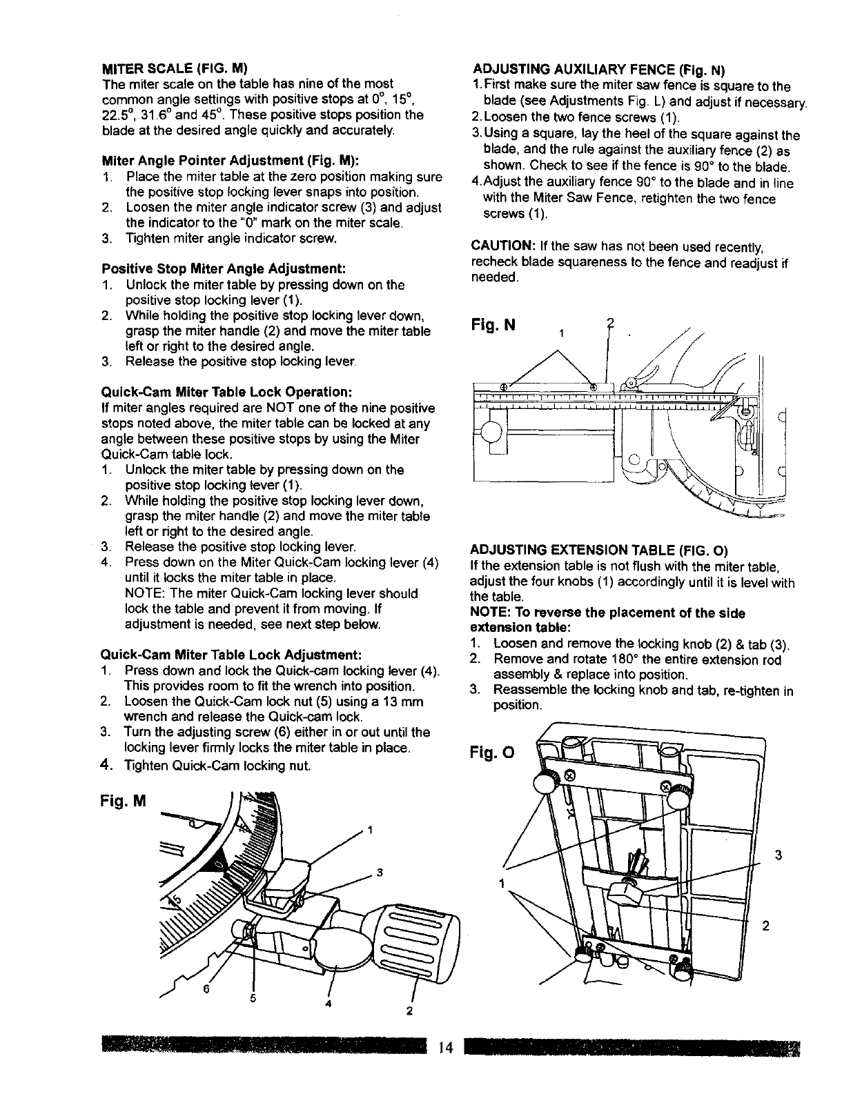
MITER SCALE (FIG. M)
The miter scale on the table has nine of the most
common angle settings with positive stops at 0°, 15°,
22.5°, 31.6° and 45°. These positive stops positionthe
blade at the desired angle quicklyand accurately.
Miter Angle Pointer Adjustment (Fig. M):
1. Place the miter table at the zero position making sure
the positive stop locking lever snaps into position.
2. Loosen the miter angle indicatorscrew (3) and adjust
the indicatorto the "0" mark on the miter scale.
3. Tighten miter angle indicator screw.
Positive Stop Miter Angle Adjustment:
1. Unlock the miter table by pressing down on the
positivestop locking lever (1).
2. While holding the positivestop lockinglever down,
grasp the miter handle (2) and move the miter table
left or dght to the desired angle.
3. Release the positivestop locking lever.
Quick-Cam Miter Table Lock Operation:
If miterangles required are NOT one of the nine positive
stops noted above, the miter table can be locked at any
angle between these positive stops by usingthe Miter
Quick-Cam table lock.
1. Unlock the miter table by pressing down on the
positivestop locking lever (1).
2. While holdingthe positive stop locking lever down,
grasp the miter handle (2) and move the mitertable
left or right to the desired angle.
3. Release the positive stop lockinglever.
4. Press down on the Miter Quick-Cam lockinglever (4)
until it locks the miter table in place.
NOTE: The miter Quick-Cam locking lever should
lock the table and prevent it from moving. If
adjustment is needed, see next step below.
Quick-Cam Miter Table Lock Adjustment:
1. Press down and lock the Quick-cam locking lever (4).
This provides room to fit the wrench into position.
2. Loosen the Quick-Cam lock nut (5) usinga 13 mm
wrench and release the Quick-cam lock.
3. Turn the adjusting screw (6) either in or out untilthe
locking lever firmly locks the miter table in place.
4. Tighten Quick-Cam lockingnut.
Fig. M
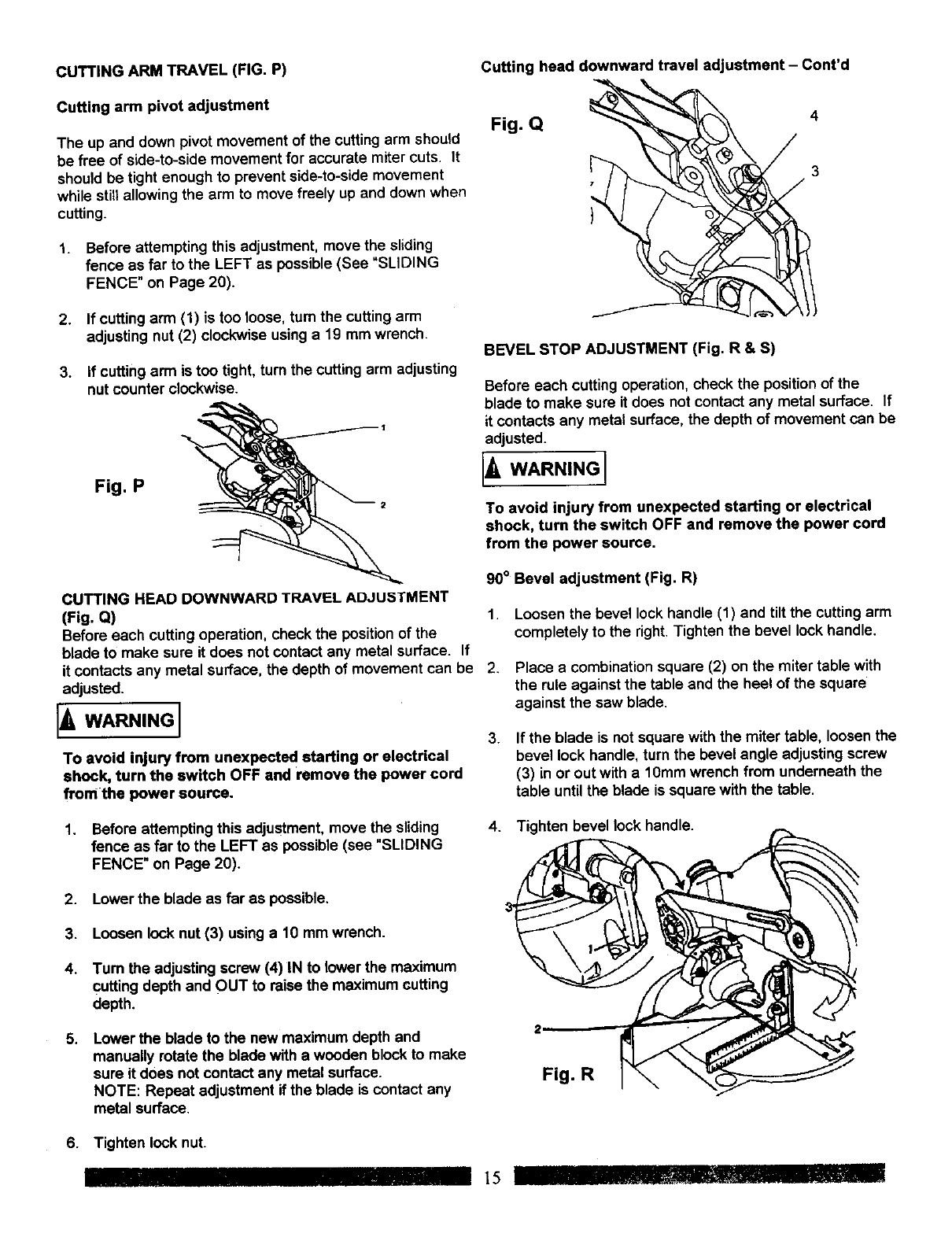
ADJUSTING AUXILIARY FENCE (Fig. N)
1.First make sure the miter saw fence is square to the
blade (see Adjustments Fig. L} and adjust if necessary.
2. Loosen the two fence screws (1).
3. Using a square, lay the heel of the square against the
blade, and the rule against the auxiliary fence (2) as
shown. Check to see if the fence is 90° to the blade.
4.Adjust the auxiliary fence 90° to the blade and inline
with the Miter Saw Fence, retighten the two fence
screws (1).
CAUTION: If the saw has not been used recently,
recheck blade squareness to the fence and readjust if
needed.
Fig. N 1
ADJUSTING EXTENSION TABLE (FIG. O)
If the extensiontable is not flush with the miter table,
adjust the four knobs (1) accordingly untilit is level with
the table.
NOTE: To reverse the placement of the side
extension table:
1. Loosen and remove the locking knob (2) & tab (3).
2. Remove and rotate 180° the entire extension rod
assembly & replace into position.
3. Reassemble the locking knob and tab, re-tighten in
position.
Fig. O
6
54
_!l!11II!ll.......
2
14 IIII
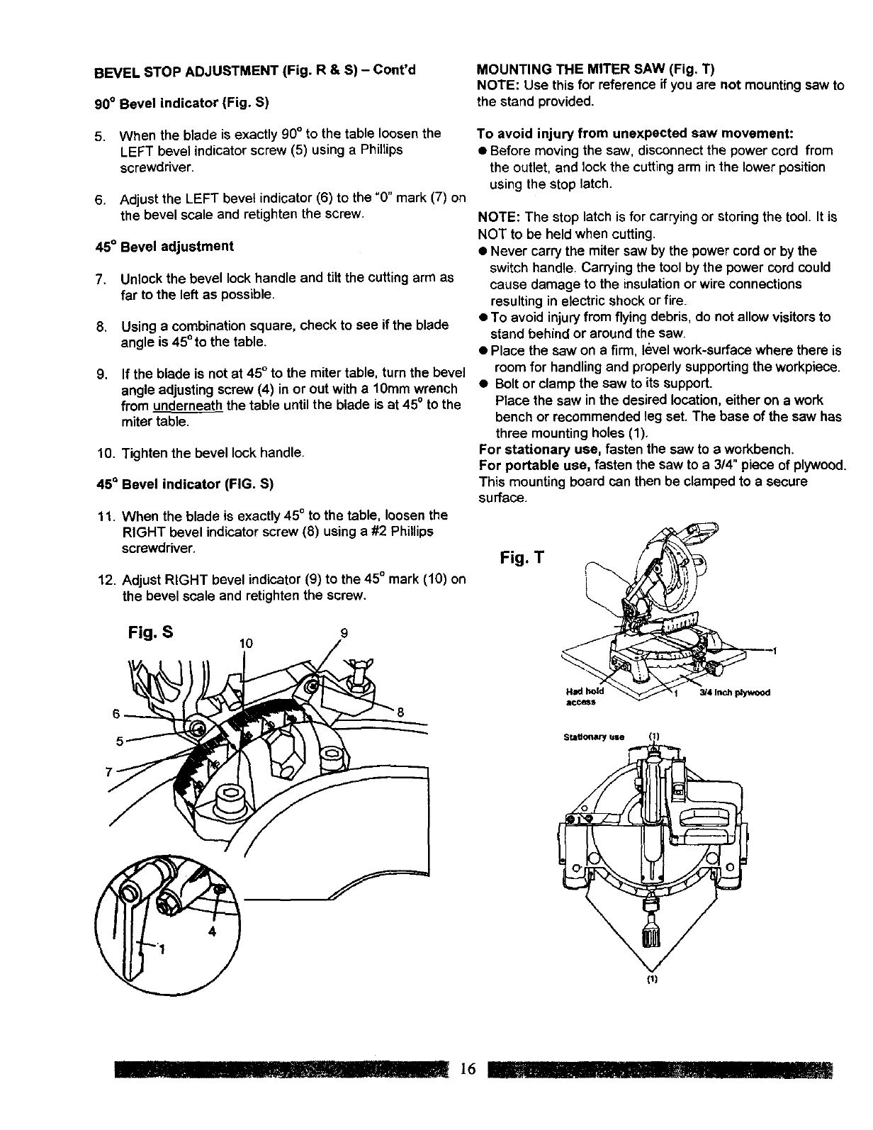
CUTTING ARM TRAVEL (FIG. P)
Cutting arm pivot adjustment
The up and down pivot movement of the cutting arm should
be free of side-to-side movement for accurate miter cuts. It
should be tight enough to prevent side-to-side movement
while still allowing the arm to move freely up and down when
cutting.
1. Before attempting this adjustment, move the sliding
fence as far to the LEFT as possible(See "SLIDING
FENCE" on Page 20).
2. If cutting arm (1) is too loose, turn the cutting arm
adjusting nut (2) clockwise using a 19 mm wrench.
3. If cutting arm is too tight, turn the cutting arm adjusting
nut counter clockwise.
Fig. P
CUTTING HEAD DOWNWARD TRAVEL ADJUSTMENT
(Fig. Q)
Before each cutting operation, check the position of the
blade to make sure it does not contact any metal surface. If
it contacts any metal surface, the depth of movement can be
adjusted.
IAw...,.GI
To avoid injury from unexpected starting or electrical
shock, turn the switch OFF and remove the power cord
from the power source.
1. Before attempting this adjustment, move the sliding
fence as far to the LEFT as possible (see "SLIDING
FENCE" on Page 20).
Cutting head downward travel adjustment - Cont'd
Fig. Q 4
BEVEL STOP ADJUSTMENT (Fig. R & S)
Before each cuttingoperation, check the positionof the
blade to make sure it does not contact any metal surface. If
it contacts any metal surface, the depth of movement can be
adjusted.
[A
To avoid injury from unexpected starting or electrical
shock, turn the switch OFF and remove the power cord
from the power source.
90° Bevel adjustment (Fig. R)
1. Loosen the bevel lock handle (1) and tilt the cutting arm
completely to the dght. Tighten the bevel lock handle.
2. Place a combination square (2) on the miter table with
the rule against the table and the heel of the square
against the saw blade.
3. If the blade is not square with the miter table, loosen the
bevel lock handle, turn the bevel angle adjusting screw
(3) in or out with a 10mm wrench from underneath the
table untilthe blade is square with the table.
4. Tighten bevel lock handle.
2. Lower the blade as far as possible.
3. Loosen lock nut (3) using a 10 mm wrench.
4.
.
Tum the adjusting screw (4) IN to lower the maximum
cuffingdepth and OUT to raise the maximum cutting
depth.
Lower the blade to the new maximum depth and
manually rotate the blade with a wooden block to make
sure it does not contact any metal surface.
NOTE: Repeat adjustment if the blade is contact any
metal surface.
Fig. R
6. Tighten lock nut.
15 II t
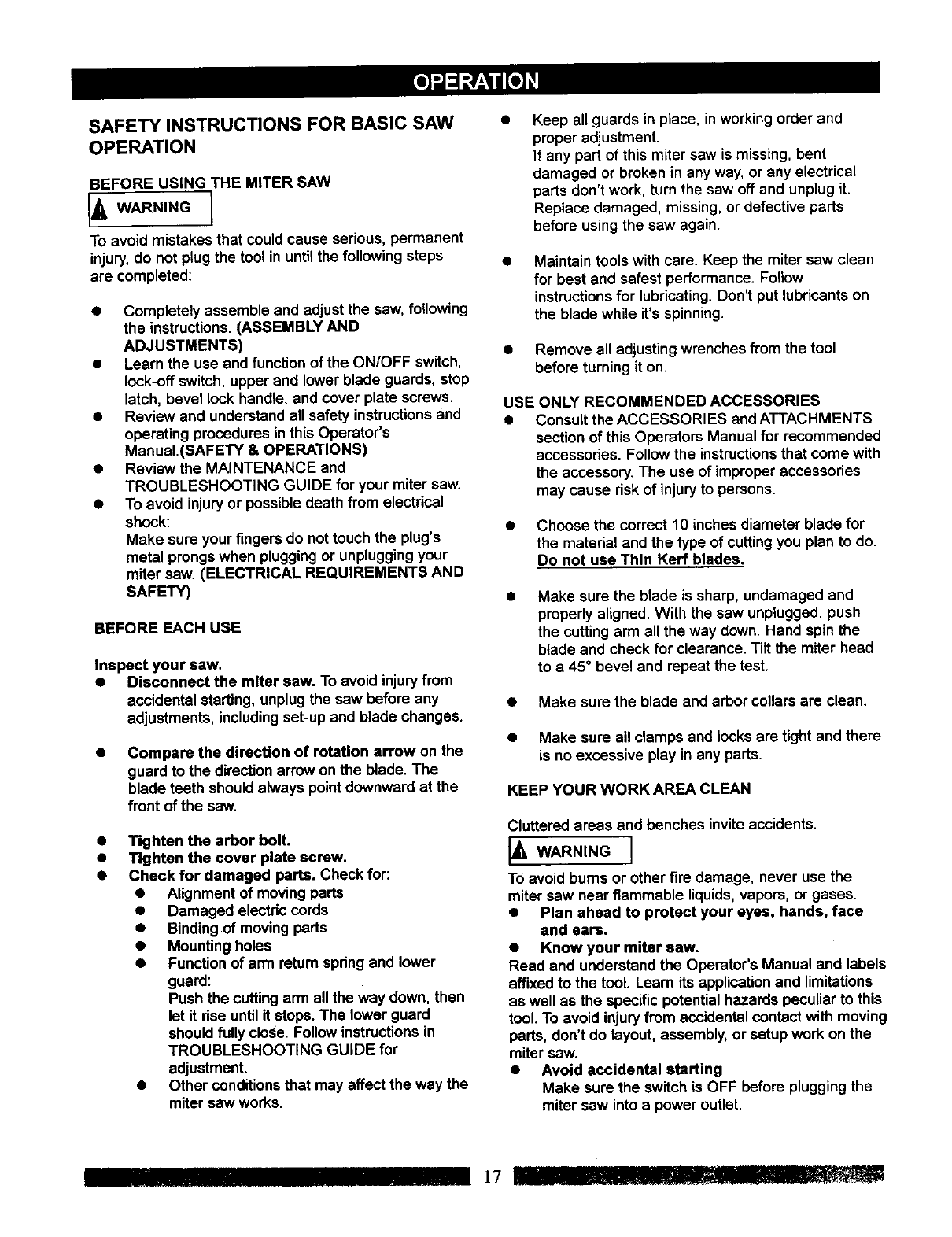
BEVEL STOP ADJUSTMENT (Fig. R & S) - Cont'd
90° Bevel indicator (Fig. S)
5. When the blade is exactly 90° to the table loosen the
LEFT bevel indicatorscrew (5) using a Phillips
screwdriver.
6. Adjust the LEFT bevet indicator (6) to the "0" mark (7) on
the bevel scale and retighten the screw.
45° Bevel adjustment
7. Unlock the bevel lock handle and tilt the cutting arm as
far to the left as possible.
8. Using a combination square, check to see if the blade
angle is 45°to the table.
9, If the blade is not at 45° to the miter table, turn the bevel
angle adjusting screw (4) in or out with a 10mm wrench
from underneath the table untilthe blade is at 45° to the
miter table.
10. Tighten the bevel lock handle.
45°Bevel indicator (FIG. S)
11. When the blade is exactly 45° to the table, loosenthe
RIGHT bevel indicator screw (8) using a #2 Phillips
screwdriver.
12. Adjust RIGHT bevel indicator (9) to the 45° mark (10) on
the bevel scale and retighten the screw,
Fig. S 9
lO
MOUNTING THE MITER SAW (Fig. T)
NOTE: Use this for reference if you are not mounting saw to
the stand provided.
To avoid injury from unexpected saw movement:
• Before moving the saw, disconnectthe power cord from
the outlet, and lock the cuttingarm in the lower position
using the stop latch.
NOTE: The stop latch is for carrying or storing the tool. It is
NOT to be held when cutting.
• Never carrythe miter saw by the power cord or by the
switch handle. Carrying the toolby the power cord could
cause damage to the insulationor wire connections
resulting in electric shock or fire.
•To avoid injuryfrom flyingdebris, do not allow visitorsto
stand behind or around the saw.
•Place the saw on a firm, level work-surface where there is
room for handling and properlysupportingthe workpiece.
•Bolt or clamp the saw to its support.
Place the saw in the desired location, either on a work
bench or recommended leg set. The base of the saw has
three mountingholes (1).
For stationary use, fasten the saw to aworkbench.
For portable use, fasten the saw to a 3/4" piece of plywood.
This mounting board can then be clamped to a secure
surface.
Fig. T
stationary tJse,_ (1)
\
(_)
I_! __ _..,, 16 ..........'l IIIIII_I_1II"'llllll 11W
SAFETY INSTRUCTIONS FOR BASIC SAW
OPERATION
BEFORE USING THE MITER SAW
WARN'NG1
To avoid mistakes that could cause sedous, permanent
injury, do not plug the tool in until the following steps
are completed:
•Completely assemble and adjust the saw, following
the instructions. (ASSEMBLY AND
ADJUSTMENTS)
• Learn the use and functionof the ON/OFF switch,
lock-off switch, upper and lower blade guards, stop
latch, bevel lock handle, and cover plate screws.
•Review and understandall safety instructionsand
operating procedures inthis Operator's
Manuai.(SAFETY & OPERATIONS)
•Review the MAINTENANCE and
TROUBLESHOOTING GUIDE for your miter saw.
•To avoid injuryor possible death from electrical
shock:
Make sure your fingers do not touch the plug's
metal prongs when pluggingor unpluggingyour
miter saw. (ELECTRICAL REQUIREMENTS AND
SAFETY)
BEFORE EACH USE
Inspect your saw,
•Disconnect the miter saw. To avoid injuryfrom
accidental starting, unplugthe saw before any
adjustments, includingset-up and blade changes.
Compare the direction of rotation arrow on the
guard to the directionarrow on the blade. The
blade teeth should always pointdownward st the
front of the saw.
Tighten the arbor bolt.
Tighten the cover plate screw.
Check for damaged parts. Check for:
•Alignment of movingparts
•Damaged electdc cords
•Bindingof moving parts
•Mounting holes
•Function of arm return spdng and lower
guard:
Push the cutting arm allthe way down. then
let it dse until it stops. The lower guard
should fully close. Follow instructions in
TROUBLESHOOTING GUIDE for
adjustment.
•Other conditions that may affect the way the
miter saw works.
Keep all guards in place, in working order and
proper adjustment.
If any part of this miter saw is missing, bent
damaged or broken in any way, or any electrical
parts don't work, turn the saw off and unplug it.
Replace damaged, missing, or defective parts
before using the sew again.
Maintain tools with care. Keep the miter saw clean
for best and safest performance. Follow
instructions for lubricating. Don't put lubricants on
the blade while it's spinning.
•Remove all adjustingwrenches from the tool
before turning it on.
USE ONLY RECOMMENDED ACCESSORIES
•Consult the ACCESSORIES and ATTACHMENTS
section of this Operators Manual for recommended
accessories. Follow the instructionsthat come with
the accessory. The use of improper accessories
may cause risk of injuryto persons.
• Choose the correct 10 inches diameter blade for
the material and the type of cuttingyou plan to do.
Do not use Thin Kerf blades,
Make sure the blade is sharp, undamaged and
properly aligned. With the saw unplugged, push
the cutting arm all the way down. Hand spin the
blade and check for clearance. Tilt the miter head
to a 45° bevel and repeat the test.
•Make sure the blade and arbor collars are clean.
•Make sure all clamps and locks are tight and there
is no excessive play in any parts.
KEEP YOUR WORK AREA CLEAN
Cluttered areas and benches invite accidents.
[_IL WARNING I
To avoid burns or other fire damage, never use the
miter saw near flammable liquids,vapors, or gases.
•Plan ahead to protect your eyes, hands, face
and ears.
•Know your miter saw.
Read and understand the Operator's Manual and labels
affixed to the tool. Leam its application and limitations
as well as the specific potential hazards peculiar to this
tool. To avoid injuryfrom accidental contact with moving
parts, don't do layout, assembly, or setup work on the
miter saw.
•Avoid accidental starting
Make sure the switch is OFF before pluggingthe
miter saw into a power outlet.
PLANYOURWORK
Use the right tool. Don't force a tool or attachment
to do a job it was not designed to do. Use a
different tool for any workpiece that can't be held in
asolidly braced, fixed position.
CAUTION: This machine is not designed for cutting
ferrous metals (steel, iron, and iron-based metals.) Use
this miter saw to cut only wood, wood-like products, or
soft metals like aluminum. Other material may shatter,
bind the blade, or create other dangers. Remove all
nails that may be in the workpiece to prevent sparking
that could cause a fire.
DRESS FOR SAFETY
Any power tool can throw foreign objects into the eyes.
This can result in permanent eye damage. Everyday
eyeglasses have only impact resistant lenses and are
not safety glasses. Glasses or goggles not in
compliance with ANSI Z87.1 could seriously injure you
when they break.
• Do not wear loose clothing, gloves, neckties or
jewelry (rings, watches). They can get caught and
draw you into moving parts.
• Wear non-slip footwear.
• Tie back long hair.
• Roll long sleeves above the elbow.
• Noise levels vary widely. To avoid possible hearing
damage, wear ear plugs when using any miter
saw.
•For dustyoperations, wear a dust mask along with
safety goggles.
INSPECT YOUR WORKPIECE
Make sure there are no nails or foreign objects in the
part of the workpiece being cut.
Plan your work to avoid small pieces that may bind,
or that are too small to clamp and get a solid grasp
on.
Plan the way you willgrasp the workpieca from start to
finish. Avoid awkward operations and hand positions.
A sudden slip could cause your fingers or hand to move
into the blade,
DON'T OVER-REACH
Keep good footing and balance. Keep your face and
body to one side, out of the line of a possible kickback.
NEVER stand in the line of the blade.
Never cut freehand:
•Brace your workpiece firmly against the fence and
table stop so it will not rock or twist during the cut.
•Make sure there is no debris between the
workpiece and the table or fence.
•Make sure there are no gaps between the
workpiece, fence and table that will let the
workpiece shiftduring the cut.
•Keep the cut off piece free to move sideways after
it is cut off. Otherwise, it could get wedged against
the blade and thrown, possiblycausing injury.
•Only the workpiece should be on the saw table.
•Secure work. Use clamps or a vise to help hold
the work when it's practical
USE EXTRA CAUTION WITH LARGE OR ODD
SHAPED WORKPIECES.
• Use extra supports (tables, sawhorses, blocks, etc.)
for workpieces large enough to tip.
•Never use another person as a substitutefor a
table extension, or as an additional supportfor a
workpiece that is longer or wider than the basic
miter saw table, or to help feed, support,or pullthe
workpiece.
•Do not use this sew to cut small pieces. If the
workpiece being cut would cause your hand or
fingers to be within 7-1/4 inches of the saw blade
the workpiece is too small. Keep hands and fingers
out of the "no hands zone" area marked on the
saws table.
•When cutting odd shaped workpieces, plan your
work so it will not bindin the blade and cause
possible injury.Molding, for example, must lie fiat
or be held by a fixture or jig that will not let it move
when cut.
Properly support round material such as dowel
rods, or tubing, which have a tendency to rollwhen
cut, causing the blade to "bite".
To avoid injury,follow all applicable safety instructions,
when cutting non-ferrous metals:
•Use only saw blades specificallyrecommended for
non-ferrous metal cutting.
• Do not cut metal workpieces that must be hand
held. Clamp workpieces securely.
•Cut non-ferrous metals only if you are under the
supervision of an experienced person.
WHEN SAW IS RUNNING
IAW,.N,NO1
Don't allow familiarityfrom frequent use of your miter
saw to result in a careless mistake.A careless fraction
of a second is enough to cause a severe injury.
Before cutting, if the sew makes an unfamiliarnoise or
vibrates, stop immediately. Tum the saw OFF Unplug
the sew. Do not restart untilfindingand correcting the
problem.
18
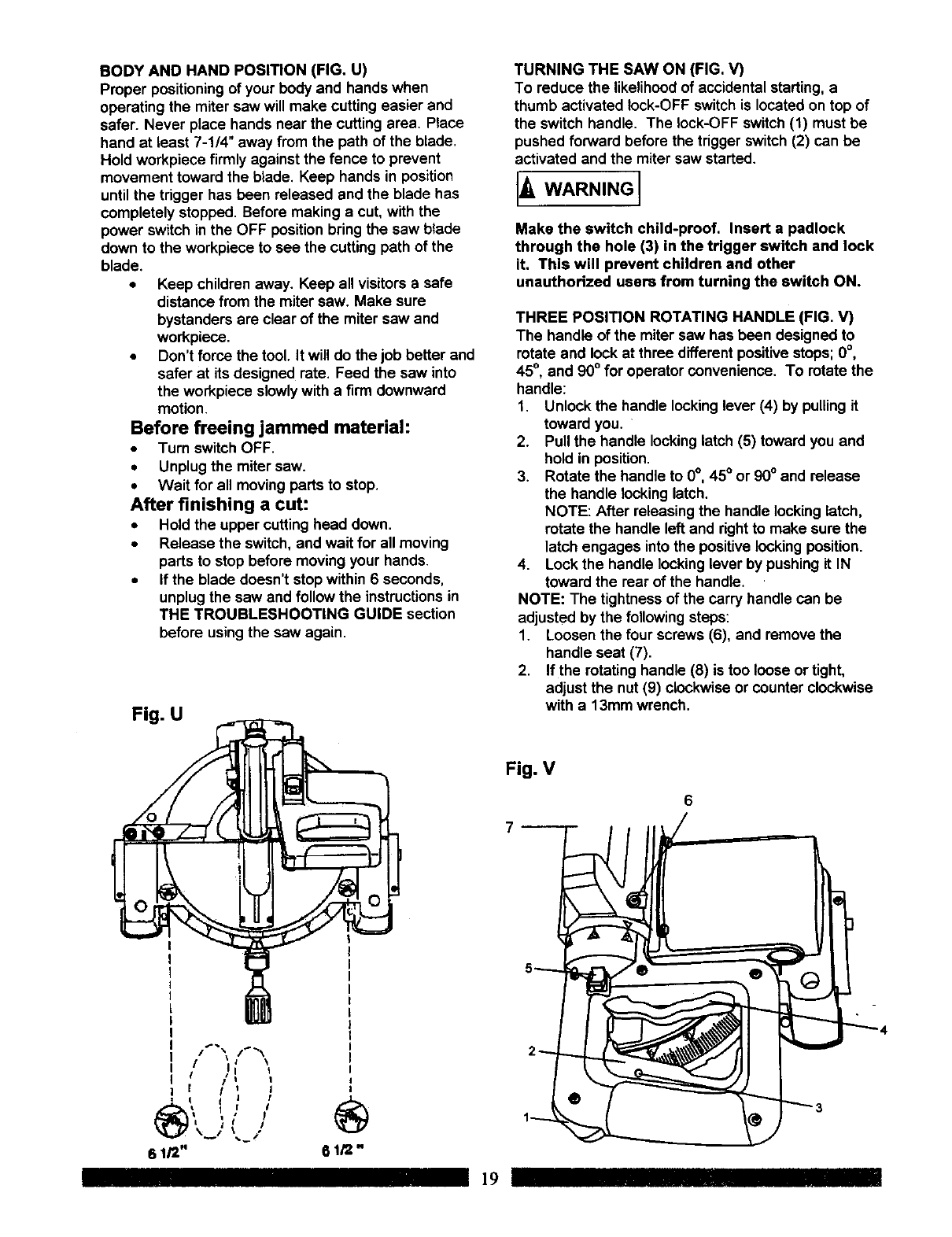
BODY AND HAND POSITION (FIG. U)
Proper positioningof your body and hands when
operating the miter saw will make cutting easier and
safer. Never place hands near the cutting area. Place
hand at least 7-1/4" away from the path of the blade.
Hold workplece firmly against the fence to prevent
movement toward the blade. Keep hands in position
untilthe trigger has been released and the blade has
completely stopped. Before making a cut, with the
power switch in the OFF positionbring the saw blade
down to the workplece to see the cutting path of the
blade.
• Keep children away. Keep all visitors a safe
distance from the miter saw. Make sure
bystanders are clear of the miter saw and
workplece.
•Don't force the tool. It will do the job better and
safer at its designed rate. Feed the saw into
the workpiece slowlywith a firm downward
motion.
Before freeing jammed material:
•Turn switch OFF.
•Unplugthe miter saw.
• Wait for all moving parts to stop.
After finishing a cut:
• Hold the upper cutting head down.
•Release the switch, and wait for all moving
parts to stop before moving your hands.
•if the blade doesn't stop within 6 seconds,
unplugthe saw and follow the instructionsin
THE TROUBLESHOOTING GUIDE section
before usingthe saw again.
Fig. U
Fig. V
TURNING THE SAW ON (FIG. V)
To reduce the likelihoodof accidental starting, a
thumb activated lock-OFF switchis located on top of
the switch handle. The lock-OFF switch (1) must be
pushed forward before the trigger switch(2) can be
activated and the miter saw started.
IAw'R"'NGI
Make the switch child-proof. Insert a padlock
through the hole (3) in the trigger switch and lock
it. This will prevent children and other
unauthorized users from turning the switch ON.
THREE POSITION ROTATING HANDLE (FIG. V)
The handle of the miter saw has been designed to
rotate and lockat three different positivestops; 0°,
45°, and 90° for operator convenience. To rotate the
handle:
1. Unlock the handle lookinglever (4) by pulling it
toward you.
2. Pull the handle lockinglatch (5) toward you and
hold in position.
3. Rotate the handle to 0°, 45° or 90° and release
the handle locking latch.
NOTE: After releasing the handle locking latch,
rotate the handle left and rightto make sure the
latch engages intothe positivelocking position.
4. Lock the handle locking lever by pushing it IN
toward the rear of the handle.
NOTE: The tightness of the carry handle can be
adjusted by the followingsteps:
1. Loosen the four screws (6), and remove the
handle seat (7).
2. If the rotating handle (8) is too loose or tight,
adjust the nut (9) clockwise or counter clockwise
with a 13mm wrench.
6
6t/2" 61/2"
19
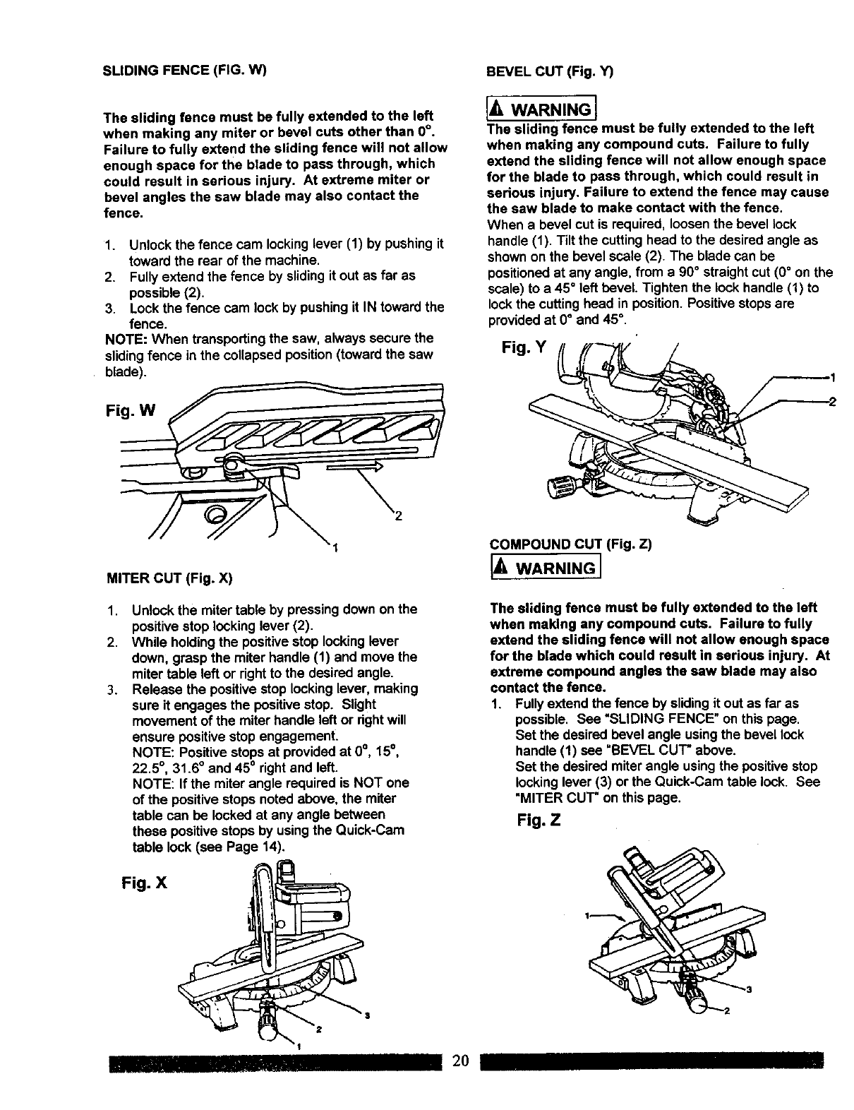
SLIDING FENCE (FIG. W) BEVEL CUT (Fig. Y)
The sliding fence must be fully extended to the left
when making any miter or bevel cuts other than 0°.
Failure to fully extend the sliding fence will not allow
enough space for the blade to pass through, which
could result in serious injury. At extreme miter or
bevel angles the saw blade may also contact the
fence.
1. Unlock the fence cam locking lever (1) by pushing it
toward the rear of the machine.
2. Fullyextend the fence by slidingit out as far as
possible (2).
3. Lock the fence cam rockby pushing it IN toward the
fence.
NOTE: When transportingthe saw, always secure the
slidingfence in the collapsed position(towardthe saw
blade).
Fig, W
I_ WARNING]
The sliding fence must be fully extended to the left
when making any compound cuts. Failure to fully
extend the sliding fence will not allow enough space
for the blade to pass through, which could result in
serious injury. Failure to extend the fence may cause
the saw blade to make contact with the fence.
When a bevel cut is required, loosen the bevel lock
handle (1). Tilt the cuttinghead to the desired angle as
shown on the bevel scale (2). The blade can be
positioned at any angle, from a 90°straight cut (0°on the
scale) to a 45° left bevel. Tighten the lock handle (I) to
lock the cutting head in position. Positive stopsare
provided at 0° and 45 °,
Fig. Y
==_2
MITER CUT (Fig. X)
1.
2.
3.
Unlock the miter table by pressing down on the
positive stop locking lever (2).
While holdingthe positive stop locking lever
down; grasp the miter handle (1) and move the
miter table left or dght to the desired angle.
Release the positive stop locking lever, making
sure it engages the positivestop. Slight
movement of the miter handle left or rightwill
ensure positive stop engagement.
NOTE: Positive stops at provided at 0°, 15°,
22,5 °, 31.6° and 45° right and left.
NOTE: If the miter angle required is NOT one
of the positive stops noted above, the miter
table can be locked at any angle between
these positive stops by usingthe Quick-Cam
table lock (see Page 14).
COMPOUND CUT (Fig. Z)
IWARNINGI
The sliding fence must be fully extended to the left
when making any compound cuts. Failure to fully
extend the sliding fence will not allow enough space
for the blade which could result in serious injury. At
extreme compound angles the saw blade may also
contact the fence.
1. Fullyextend the fence by sliding it out as far as
possible, See "SLIDING FENCE" on this page.
Set the desired bevel angle usingthe bevel lock
handle (1) see "BEVEL CUT" above.
Set the desired miter angle using the positive stop
locking lever (3) or the Quick-Cam table lock. See
"MITER CUT" on this page.
Fig. Z
2O
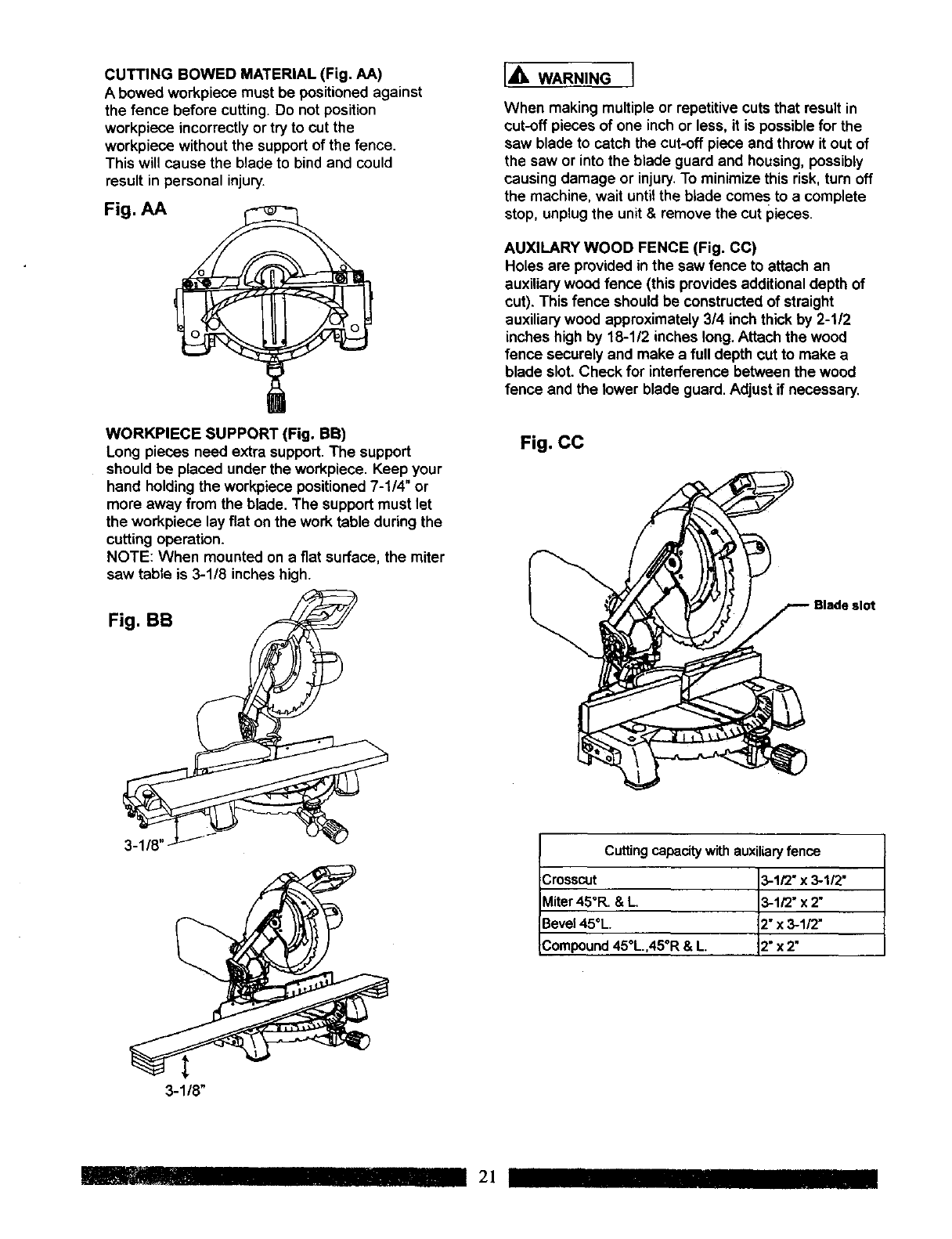
CUTTING BOWED MATERIAL (Fig. AA)
A bowed workpiece must be positionedagainst
the fence before cutting. Do not position
workpiece incorrectlyor try to cut the
workpiece withoutthe support of the fence,
This will cause the blade to bind and could
result in personal injury.
Fig. AA
IA WAR.I.GI
When making multiple or repetitivecuts that result in
cot-off pieces of one inch or less, it is possible for the
saw blade to catch the cut-off piece and throw it out of
the saw or into the blade guard and housing, possibly
causing damage or injury.To minimizethis risk, turn off
the machine, wait untilthe blade comes to a complete
stop, unplugthe unit & remove the cut pieces.
AUXlLARY WOOD FENCE (Fig. CC)
Holes are provided in the saw fence to attach an
auxiliary wood fence (this provides additionaldepth of
cut). This fence should be constructed of straight
auxiliary wood approximately3/4 inch thick by 2-1/2
inches high by 18-1/2 inches long.Attach the wood
fence securely and make a full depth cut to make a
blade slot. Check for interference between the wood
fence and the lower blade guard. Adjust if necessary.
WORKPIECE SUPPORT (Fig. BB)
Long pieces need extra support.The support
should be placed under the workpiece. Keep your
hand holdingthe workpiece positioned 7-1/4" or
more away from the blade. The support must let
the workpiece lay flat on the work table during the
cutting operation.
NOTE: When mounted on a fiat surface, the miter
saw table is 3-1/8 inches high.
Fig. CC
Fig. BB
Cutting capacity with auxiliaryfence
Crosscut _-1/2"x 3-1/2"
Miter 45°R. & L, _-1/2"x 2"
Bevel 45°L 2"x 3-112"
Compound 45°L.,45°R & L 2"x 2"
3-1/8"
. 21 IIII
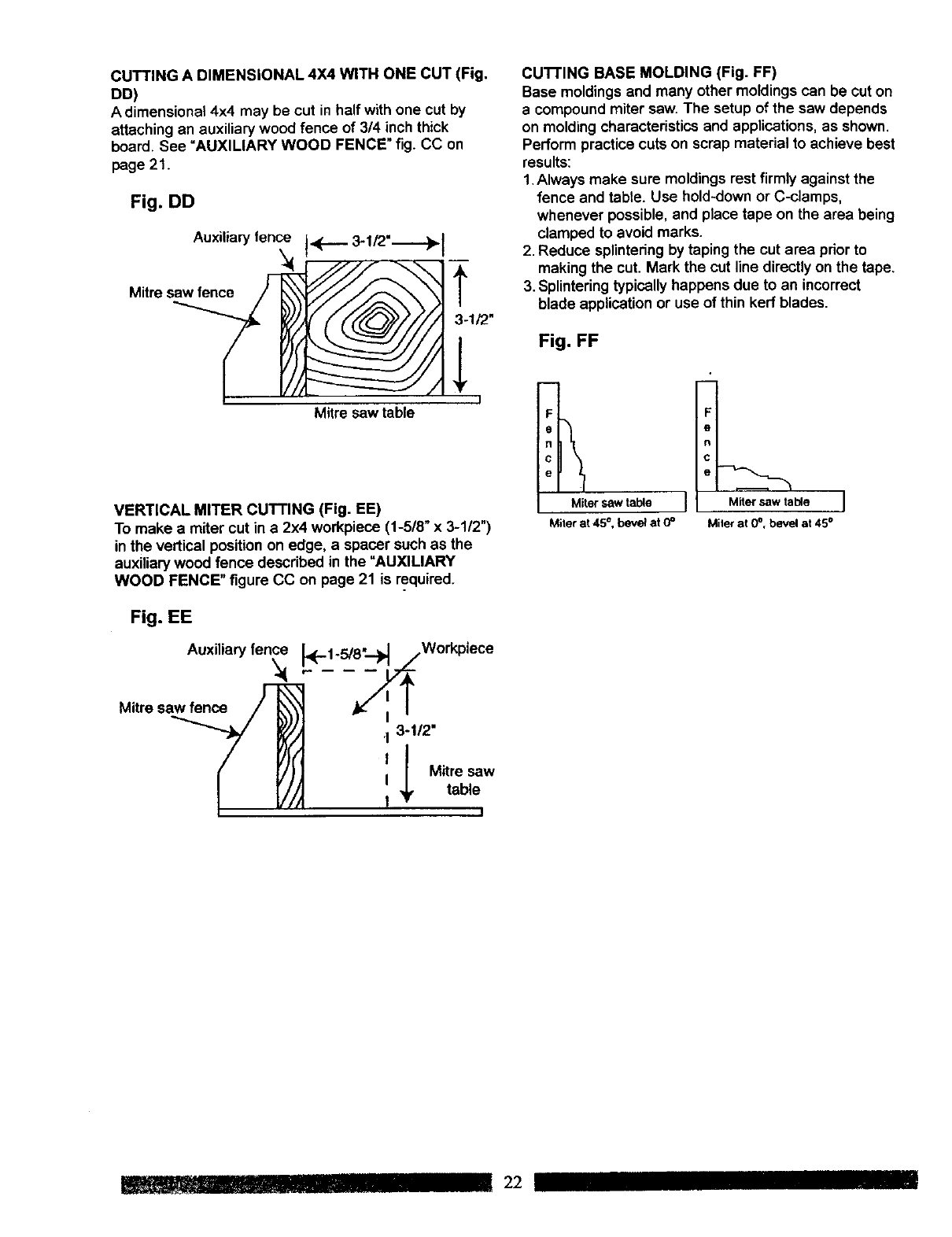
CUTTING A DIMENSIONAL 4X4 WITH ONE CUT (Fig.
DD)
A dimensional 4x4 may be cut in half with one cut by
attaching an auxiliary wood fence of 3/4 inch thick
board. See =AUXILIARY WOOD FENCE" fig. CC on
page 21.
Fig. DD
Auxiliaryfence 14_..... 3.1/,2"._._..._1
Mitre s_t _ _ "_--1F2"
Mitre saw table
VERTICAL MITER CUTTING (Fig. EE)
To make a miter cut in a2x4 workpiece (1-5/8" x 3-1/2")
inthe vertical positionon edge, a spacer such as the
auxiliary wood fence described in the "AUXILIARY
WOOD FENCE" figure CC on page 21 is required.
Fig. EE
Mitre sa_
'13-1!2"
I Mitre saw
table
I
cu'n'ING BASE MOLDING (Fig. FF)
Base moldingsand many other moldings can be cut on
a compound miter saw. The setup of the saw depends
on moldingcharacteristics and applications, as shown.
Perform practice cuts on scrap material to achieve best
results:
1.Always make sure moldings rest firmly against the
fence and table. Use hold-down or C-clamps,
whenever possible,and place tape on the area being
clamped to avoid marks.
2. Reduce splinteringby taping the cut area prior to
making the cut. Mark the cut line directly on the tape.
3. Splinteringtypicallyhappens due to an incorrect
blade application or use of thin kerf blades.
Fig. FF
I
Miter saw table J
Miler at 45°, bevel at O°
Miter saw table
Miler at 0o,bevel at 45°
22
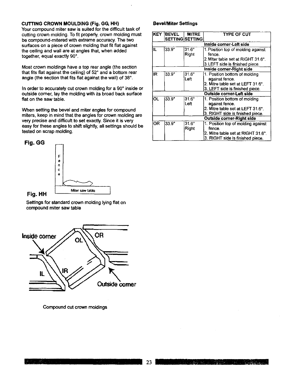
CUTTING CROWN MOULDING (Fig. GG, HH)
Your compound miter saw is suited for the difficult task of
cutting crown molding. To fit properly,crown molding must
be compound-mitered with extreme accuracy. The two
surfaces on a piece of crown moldingthat fit fiat against
the ceiling and wall are at angles that, when added
together, equal exactly 90".
Most crown moldings have a top rear angle (the section
that fits flat against the ceiling) of 52° and a bottom rear
angle (the section that fits fiat against the wall) of 38°.
In order to accurately cut crown moldingfor a 90°inside or
outside corner, lay the moldingwith its broad back surface
fiat on the saw table.
When setting the bevel and miter angles for compound
miters, keep in mind that the angles for crown moldingare
very precise and difficultto set exactly.Since it is very
easy for these angles to shift slightly,all settings should be
tested on scrap molding.
Fig. GG __
Bevel/Miter Settings
KEY REVEL MITRE TYPE OF CUT
SETT NG SETT NG Inside comer-Left side
IL 33.9* 31Right6° 1. fence.P°siti°ntop of molding against°
2. Miter table set at RIGHT 31,6.
3. LEFT side is finished piece.
Inside comer-Right side
IR 33.9 =31Left6° 1. againstPositiOnfence.bOttomof molding
2. Mitre table set at LEFT 31.6 °.
3. LEFT side s finished piece.
Outside corner-Left side
OL 33.9 =31Left"6° 1. againstPositionfence,bottom of molding
2. Mitre table set at LEFT 31.6*.
3. RIGHT side is finished piece.
Outside comer-Right side
OR 33.9 ° 31.6 °1. Position top of molding against
Right fence.
2. Mitre table set at RIGHT 31.6".
3. RIGHT s de s finished piece.
F
e
n
c
e
Fig. HH Miter saw table
Settings for standard crown molding lyingfiat on
compound miter saw table
i1=111
Compound cut crown moldings
IIIIIIIII23 I!1
MAINTENANCE
DANGER
Never put lubricantson the blade while it is spinning.
IAWARNINGI
To avoid fire or toxic reaction, never use gasoline,
naphtha acetone, lacquer thinner or similar highly
volatile solvents to clean the miter saw.
IAWAR.,.GI
To avoid injuryfrom unexpected starting or electrical
shock, unplug the power cord before working on the
saw,
IAW NINGI
For your safety, this saw is double-insulated. To avoid
electrical shock, fire or injury,use only parts identicalto
those identified inthe parts list. Reassemble exactly as
the original assembly to avoid electrical shock.
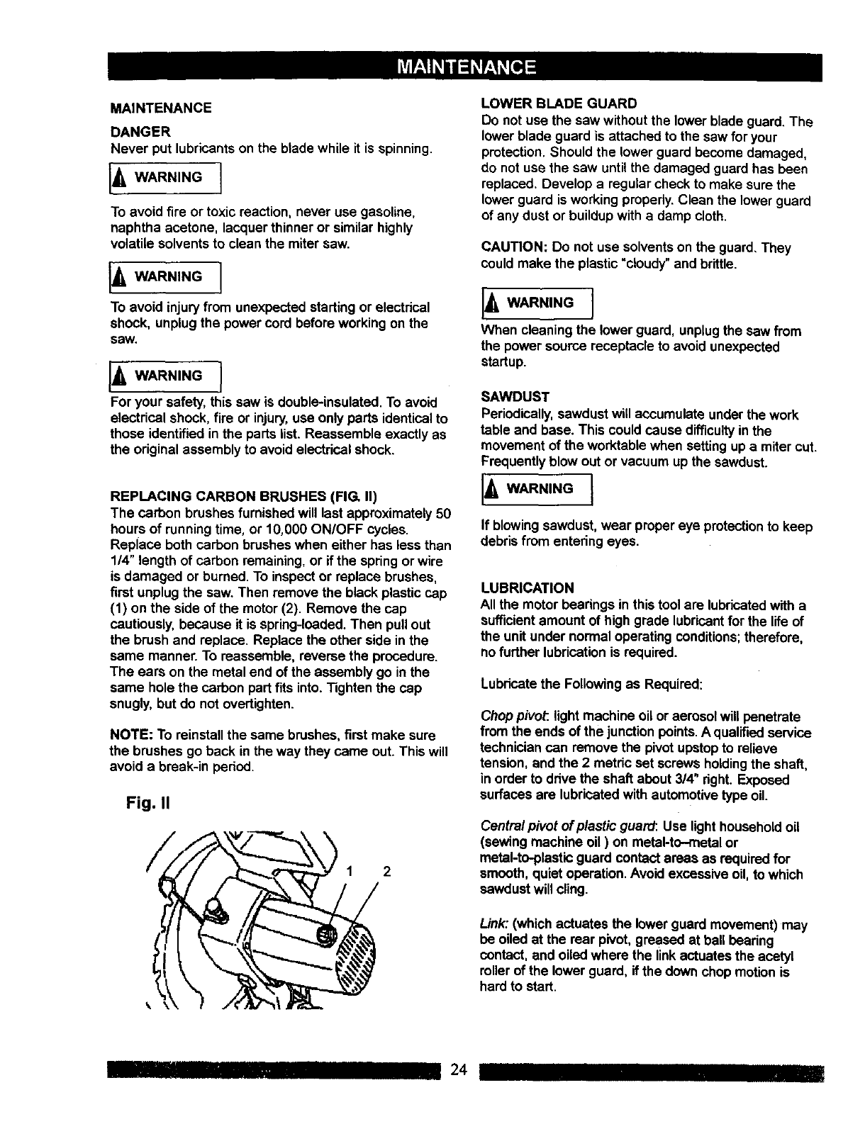
REPLACING CARBON BRUSHES (FIG. II)
The carbon brushes furnishedwill last approximately 50
hours of runningtime, or 10,000 ON/OFF cycles.
Replace both carbon brushes when either has less than
1/4" length of carbon remaining, or if the spring or wire
is damaged or burned. To inspect or replace brushes,
first unplugthe saw. Then remove the black plasticcap
(1) on the side of the motor(2). Remove the cap
cautiously, because it is spring-loaded.Then pullout
the brush and replace. Replace the other side in the
same manner. To reassemble, reverse the procedure.
The ears on the metal end of the assembly go in the
same hole the carbon part fits into. Tighten the cap
snugly, but do not overtighten.
NOTE: To reinstall the same brushes, first make sure
the brushes go back inthe way they came out. This will
avoid a break-in period.
Fig. II
2
LOWER BLADE GUARD
Do not use the saw without the lower blade guard,The
lower blade guard is attached to the saw for your
protection. Should the lower guard become damaged,
do not use the saw untilthe damaged guard has been
replaced, Develop a regular check to make sure the
lower guard is working properly.Clean the lower guard
of any dust or buildup with a damp cloth.
CAUTION: Do not use solvents on the guard. They
could make the plastic "cloudy"and brittle.
J,WARN,NGJ
When cleaning the lower guard, unplugthe saw from
the power source receptacle to avoid unexpected
startup.
SAWDUST
Periodically,sawdust will accumulate under the work
table and base. This could cause difficultyin the
movement of the worktable when setting up a miter cut.
Frequently blow out or vacuum up the sawdust.
14WARN,NGI
If blowingsawdust, wear proper eye protectionto keep
debrisfrom entering eyes.
LUBRICATION
All the motor bearings in this tool are lubricatedwith a
sufficient amount of high grade lubricantfor the life of
the unit under normal operating conditions; therefore,
no further lubricationis required.
Lubricate the Followingas Required:
Chop pivoP.,light machine oil or aerosol will penetrate
from the ends of the junctionpoints.Aqualifiedservice
technician can remove the pivot upstopto relieve
tension, and the 2 metric set screws holdingthe shaft,
in order to drive the shaft about 3/4" right. Exposed
surfaces are lubricatedwith automotive type oil.
Central pivot of plastic guard: Use lighthousehold oil
(sewing machine oil ) on metal-to-metal or
metal-to-plastic guard contact areas as requiredfor
smooth, quiet operation. Avoid excessive oil, to which
sawdust will cling.
Link: (which actuates the lower guard movement) may
be oiled at the rear pivot, greased at ball bearing
contact, and oiledwhere the link actuates the acetyl
roller of the lower guard, if the down chop motion is
hard to start.
......... III 24
i_WARNING I
To avoid injury from accidental starting, always turn the switch OFF and unplugthe tool before moving, replacing the blade
or making adjustments.
Consult your Sears Sewice Center if for any reason the motor will not run.
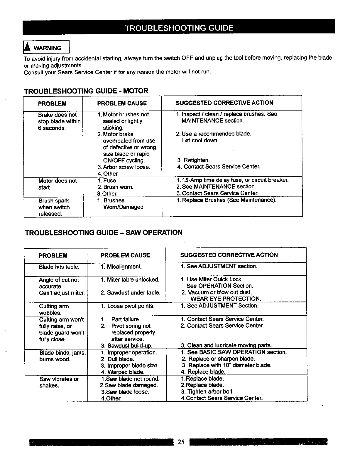
TROUBLESHOOTING GUIDE - MOTOR
PROBLEM CAUSE SUGGESTED CORRECTIVE ACTION
I. Inspect /clean /replace brushes, See
MAINTENANCE section.
PROBLEM
Brake does not
stop blade within
6 seconds.
Motor does not
start
Brushspark
when switch
released.
1. Motor brushes not
sealed or lightly
sticking.
2. Motor brake
overheated from use
of defective or wrong
size blade or rapid
ON/OFF cycling.
3. Arbor screw loose.
4. Other.
1. Fuse
2. Brushworn.
3. Other.
1. Brushes
Worn/Damaged
2. Use a recommended blade.
Let cool down.
3. Retighten.
4. Contact Sears Service Center.
1.15-Amp time delay fuse, or circuitbreaker.
2. See MAINTENANCE section.
3, Contact Sears Service Center.
1. Replace Brushes (See Maintenance).
TROUBLESHOOTING GUIDE - SAW OPERATION
PROBLEM
Blade hitstable.
Angle of cut not
accurate.
Can't adjust miter.
Cutting arm
wobbles.
Cutting arm won't
fully raise, or
blade guard won't
fully close.
Blade binds, jams,
bums wood.
Sew vibrates or
shakes.
PROBLEM CAUSE
1. Miselignment.
1. Miter table unlocked.
2. Sawdust under table.
1. Loose pivot points.
1. Part failure.
2. Pivotspring not
replaced propedy
after service.
3. Sawdust build-up.
1. Improper operation.
2. Dull blade.
3. Improper blade size.
4. Warped blade.
1.Saw blade not round.
2.Saw blade damaged.
3.Saw blade loose.
4.Other.
SUGGESTED CORRECTIVE ACTION
1. See ADJUSTMENT section.
1. Use Miter Quick Look.
See OPERATION Section.
2. Vacuum or blow out dust,
WEAR EYE PROTECTION.
1. See ADJUSTMENT Section.
1. Contact Sears Service Center.
2. Contact Sears Service Center.
3. Clean and lubricate moving parts.
1. See BASIC SAW OPERATION section.
2. Replace or sharpen blade.
3. Replace with 10" diameter blade.
4, Replace blade.
1.Replace blade,
2.Replace blade.
3. Tighten arbor bolt,
4,Contact Sears Service Center.
25
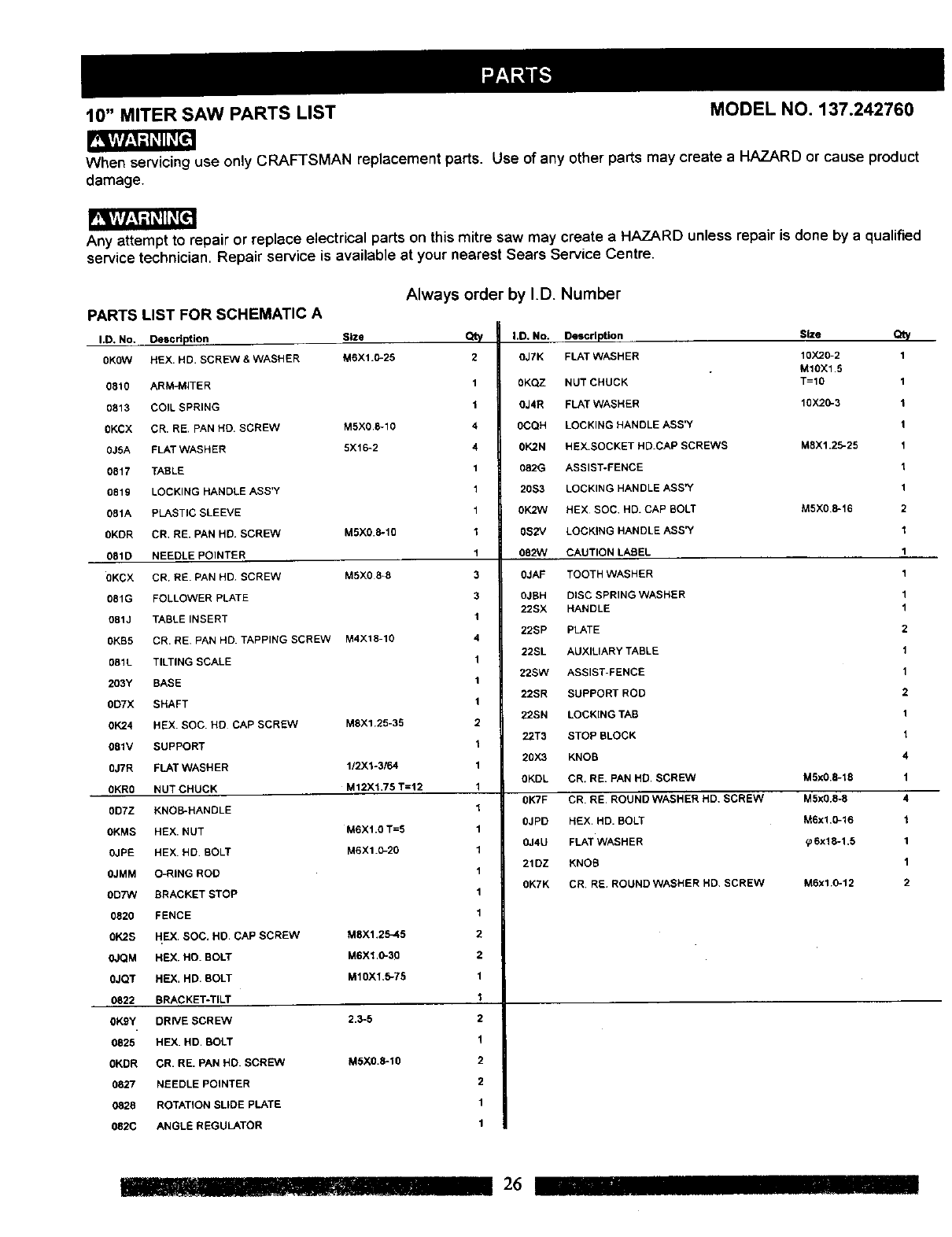
10" MITERSAW PARTS LIST MODEL NO. 137.242760
When servicing use only CRAFTSMAN replacement parts. Use of any other parts may create a HAZARD or cause product
damage.
Any attempt to repair or replace electrical parts on this mitre saw may create a HAZARD unless repair
service technician. Repair service is available at your nearest Sears Service Centre.
Always order by I.D. Number
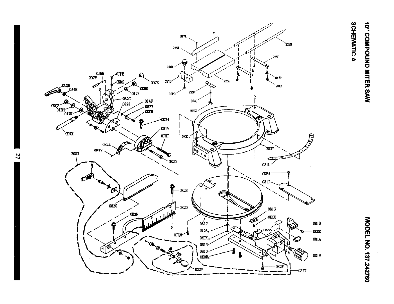
PARTS LIST FOR SCHEMATIC A
I.D. No. Description Size Qt,/
0KOW HEX. HD. SCREVV & WASHER M6X1.0-25 2
0810 ARM-MITER 1
0813 COIL SPRING 1
0KCX CR. RE, PAN HD. SCREW MSX0 B*10 4
0J5A FLAT WASHER 5X16-2 4
0817 TABLE 1
0819 LOCKING HANDLE ASS'Y 1
081A PLASTIC SLEEVE 1
0KDR CR, RE. PAN HD. SCREVV M5XO.5-10 1
081D N_nl FPOINTER 1
0KCX CR, RE. PAN HD SCREW MSX0 8-8 3
081G FOLLOWER PLATE 3
081J TABLE INSERT 1
0KB5 CR. RE. PAN HD. TAPPING SCREW M4X18-10 4
081L TILTING SCALE 1
203Y BASE 1
0DTX SHAFT 1
01(24 HEX. SOC. HD CAP SCREW MSX1.25-35 2
081V SUPPORT 1
0JTR FLAT WASHER 112X1o3164 1
0KR0 NUT CHUCK M12Xl.75 T=12 1
0D7Z KNOB*HANDLE 1
OKMS HEX. NUT M6X1.0 T=5 1
0JPE HEX. HD BOLT M6X1.0-20 1
0JMM O-RING ROD 1
OD7W BRACKET STOP 1
0820 FENCE 1
BK2S HEX. SOC. HD. CAP SCREW M8X1.25-45 2
is done by a qualified
0JQM HEX. HO. BOLT M6X1 .B*30 2
0JQT HEX. HD. BOLT M10X1,B*75 1
0822 BRACKET-TILT 1
0KBY DRWE SCREW 2,3-5 2
0825 HEX, HD. BOLT 1
0KDR CR. RE. PAN HD. SCREW M5X0.B*10 2
0827 NEEDLE POINTER 2
0828 ROTATION SLIDE PLATE 1
082C ANGLE REGULATOR 1
I.D, NO. Description Size Qty
OJ7K FLAT WASHER 10X20-2 1
M10X1,5
0KQZ NUT CHUCK T=10 1
OJ4R FLAT WASHER 10X20-3 1
0CQH LOCKING HANDLE ASS_( 1
0K2N HEX.SOCKET HD.CAP SCREWS M8X1,25-25 1
082G ASSIST-FENCE 1
20S3 LOCKING HANDLE ASS"( 1
0K2W HEX SOC HD. CAP BOLT M5X0.B*16 2
0S2V LOCKING HANDLE ASS"( 1
082W CAUTION LABEL 1
0JAF TOOTH WASHER 1
0JBH DISC SPRING WASHER 1
22SX HANDLE 1
22SP PLATE 2
22SL AUXILIARY TABLE 1
22SW ASSIST-FENCE 1
22SR SUPPORT ROD 2
22SN LOCKING TAB 1
22T3 STOP BLOCK 1
20X3 KNOB 4
0KDL CR. RE. PAN HD, SCREW M5xB,B*18 1
0KTF CR. RE. ROUND WASHER HD. SCREW M5x0.B*8 4
0JPD HEX. HD. BOLT M6x1.0-16 1
0J4U FLAT WASHER _6x1B*l.5 1
21DZ KNOB 1
0K7K CR. RE ROUND WASHER HD. SCREW M6xl,0-12 2
_"11" .......... 26 _]1 II1'1
bo
/
/ / .//
_/.. i _ o_ o•
i .-.... oj,,.--i o_sA r
i<i\ ., ...... _. o= _--os,A o
•IIo_ow_ "_
\_,............./) .0s2v ..........,__,.,Jj--os2_"
o
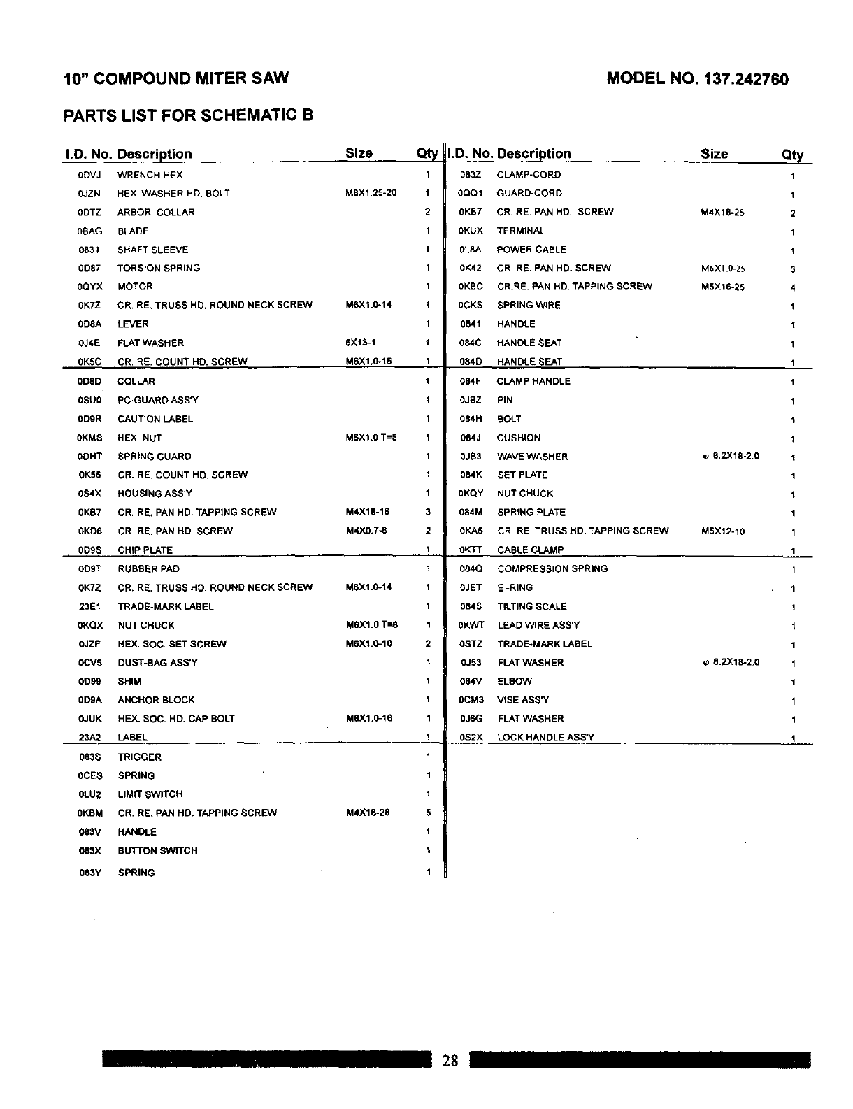
10" COMPOUND MITER SAW
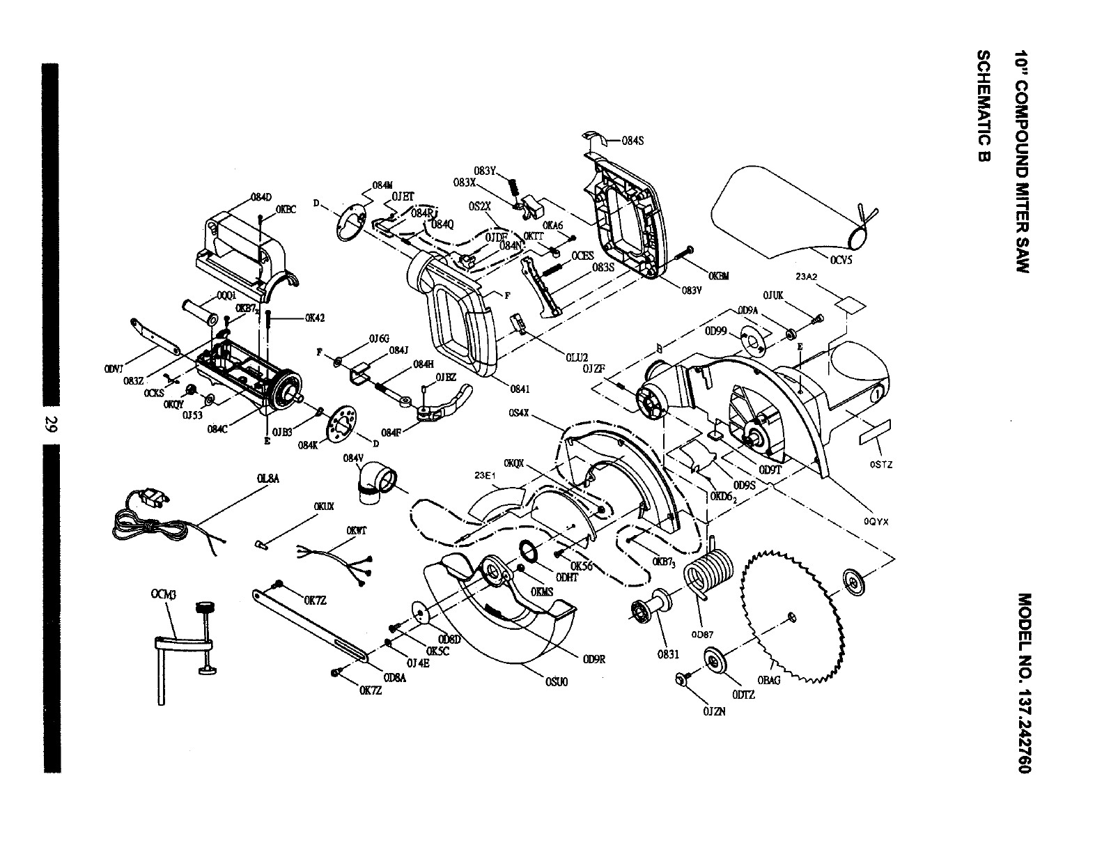
PARTS LIST FOR SCHEMATIC B
I.D. No. Description Size Qty I.D. No. Description
0DVJ WRENCH HEX
0JZN HEX WASHER HD. BOLT
0DTZ ARBOR COLLAR
0BAG BLADE
0831 SHAFT SLEEVE
0087 TORSION SPRING
0QYX MOTOR
OK7Z CR. RE, TRUSS HD. ROUND NECK SCREW
0D8A LEVER
0J4E FLAT WASHER
0K5C CR. RE. COUNT HD. SCREW
0DED COLLAR
8SU0 PC'GUARD ASS'Y
0DER CAUTION LABEL
0KMS HEX. NUT
0DHT SPRING GUARD
0K56 CR. RE. COUNT HD. SCREW
0S4X HOUSING ASS'Y
OKE7 CR. RE. PAN HD. TAPPING SCREW
0KD6 CR. RE. PAN HD. SCREW
0DBS CHIP PLATE
ODT RUBBER PAD
0KTZ CR. RE. TRUSS HD. ROUND NECK SCREW
23E1 TRADE-MARK LABEL
OKQX NUT CHUCK
0JZF HEX, SOC. SET SCREW
0CV5 DUST-BAG ASS'Y
0D99 SHIM
ODA ANCHOR BLOCK
0JUK HEX. SOC. HD. CAP BOLT
23A2 LABEL
083S TRIGGER
0CES SPRING
0LU2 LIMIT SWITCH
OKBM CR. RE, PAN HD, TAPPING SCREW
083V HANDLE
083X BUTTON swn'cH
0B3Y SPRING
M8X1.25-20
MBX1.0014
6X13-1
M6X1.0016
M6X1.0 T=8
M4X10016
M4X0.7-8
M6X1.0°14
M6X1.0 T=6
M6Xl.0-10
M6X1.0016
M4X10028
1083Z
1 0QQ1
2 OKB7
1 OKUX
1 0L8A
1 0K42
1 0KBC
1 0CKS
10841
1084C
1 084D
1 084F
1OJBZ
1 084H
I 084J
1 0JB3
1084K
1 0KQY
3 084M
2 OKA6
1 OKTT
I 084Q
1 0JET
1 084S
1 OKWT
20STZ
10J53
1 084V
1 OCM3
1 0J6G
1 OS2X
I
1
1
5
I
I
1
MODEL NO. 137.242760
CLAMP-CORD
GUARD'CORD
CR. RE. PAN HD. SCREW
TERMINAL
POWER CABLE
CR. RE. PAN HD. SCREW
CRRE. PAN HD. TAPPING SCREW
SPRING WIRE
HANDLE
HANDLE SEAT
HANDLE SEAT
CLAMP HANDLE
PIN
BOLT
CUSHION
WAVE WASHER
SET PLATE
NUT CHUCK
SPRING PLATE
CR. RE. TRUSS HD. TAPPING SCREW
CABLE CLAMP
COMPRESSION SPRING
E -RING
TILTING SCALE
LEAD WIRE ASS'Y
TRADE-MARK LABEL
FLAT WASHER
ELBOW
VISE ASS'Y
FLAT WASHER
LOCK HANDLE ASS'Y
Size Qty
1
1
M4X18-25 2
1
1
M6XI.O-25 3
MSX10025 4
1
I
1
1
1
1
1
1
8,2X18-2.0 1
1
1
1
MSX12-10 1
1
1
1
1
1
1
8.2X18-2.0 1
1
1
1
1
28
_o
0J53
083V 0JUK
OSTZ
_. OQYX
>
i8
0
o
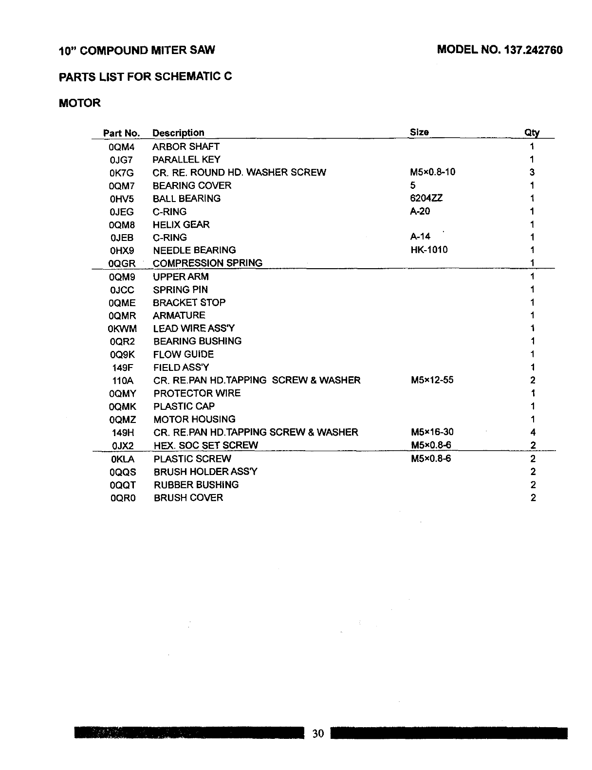
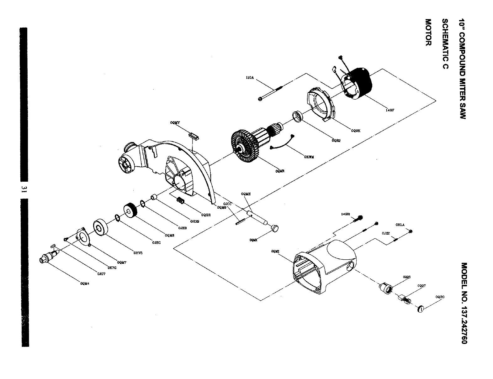
10" COMPOUND MITER SAW
PARTS LIST FOR SCHEMATIC C
MOTOR
MODEL NO. 137.242760
Part No.
0QM4
0JG7
0K7G
0QM7 BEARING COVER
0HV5 BALL BEARING
0JEG C-RING
0QM8 HELIX GEAR
0JEB C-RING
0HX9 NEEDLE BEARING
Descri_ion
ARBOR SHAFT
PARALLELKEY
CR. RE. ROUND HD. WASHER SCREW
Size
M5x0.8-10
5
6204ZZ
A-20
A-14
HK-1010
M5x12-55
M5x16-30
M5xO.8-6
M5xO.8-6
0QGR
0QM9
0JCC
0QME
0QMR
0KVVM
0QR2
0Q9K
149F
110A
0QMY
0QMK
0QMZ
149H
0JX2
0KLA
0QQS
0QQT
0QR0
COMPRESSION SPRING
UPPER ARM
SPRING PIN
BRACKET STOP
ARMATURE
LEAD WIRE ASS'Y
BEARING BUSHING
FLOW GUIDE
FIELD ASS'Y
CR. RE.PAN HD.TAPPING SCREW & WASHER
PROTECTOR WIRE
PLASTIC CAP
MOTOR HOUSING
CR. RE,PAN HD.TAPPING SCREW & WASHER
HE)(, SOC SET SCREW
PLASTIC SCREW
BRUSH HOLDER ASS'Y
RUBBER BUSHING
BRUSH COVER
QV
1
1
3
1
1
1
1
1
1
1
1
1
1
1
1
1
1
1
2
1
1
1
4
2
2
2
2
2
..... 30
L_
IIOA
OQME
OQM7
OKTC
OJG?
OQM80JEB
OJ_ _
149H
OQRO
o•
..4
m
0
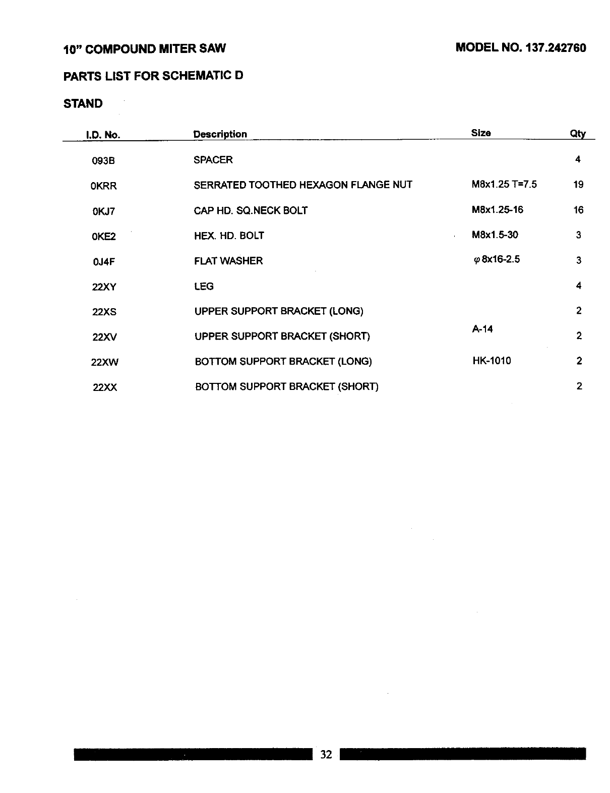
10" COMPOUND MITER SAW
PARTS LIST FOR SCHEMATIC D
STAND
MODEL NO. 137.242760
I.D. NO.
093B
0KRR
0KJ7
0KE2
0J4F
22XY
22XS
22XV
22XVV
22XX
Description
SPACER
SERRATED TOOTHED HEXAGON FLANGE NUT
CAP HD. SQ.NECK BOLT
HEX, HD. BOLT
FLAT WASHER
LEG
UPPER SUPPORT BRACKET (LONG)
UPPER SUPPORT BRACKET (SHORT)
BOTTOM SUPPORT BRACKET (LONG)
BO]-]'OM SUPPORT BRACKET (SHORT)
Size Qty
4
M8x1.25 "I"--7.5 19
M8x1.25-16 16
M8xl.5-30 3
_8x16-2,5 3
4
2
A-14 2
HK-1010 2
2
32
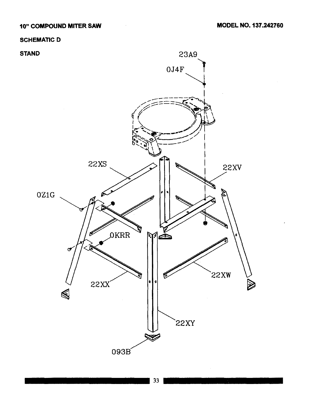
10" COMPOUNDMITER SAW MODEL NO. 137.242760
SCHEMATICD
STAND 23A9
0J4F "4
22XS
0ZIG
22XX
22XV
22XY
33

I_[o]ld:l
34

II 35 III

Your Home
For repair-in your home-of all major brand appliances,
lawn and garden equipment, or heating and cooling systems,
no matter who made it, no matter who sold it!
For the replacement parts, accessories and
Operator's Manuals that you need to do-it-yourself.
For Sears professional installation of home appliances
and items like garage door openers and water heaters.
1-800-4-MY-HOME ®(1400-469-4663)
Call anytime, day or night (U.S.A. and Canada)
www.sears.com www.sears.ca
Our Home
For repair of carry-in items like vacuums, lawn equipment,
and electronics, call or go on-line for the location of your nearest
Sears Parts & Repair Center.
1-800-488-1222
Call anytime, day or night (U.S.A. only)
www.sears.com
To purchasea protectionagreement (U.S.A)
or maintenance agreement (Canada) on a productservicedby Sears:
1-800-827-6655 (U.S.A.) 1-800-361-6665 (Canada)
Para pedir serviciode reparacibn
a domicilio,y para ordenar piezas:
1-888-SU-HOGAR s"
(1-888-784-6427)
Au Canada pour service en francr,,ais:
I"800"LE'FOYER "c
(1-800-533-6937)
www.sears.ca
8E/AR8
TM ma SM rk
®Registered Trademark ITrade rk /Service Ms of Seal-s. Roebuck and Co.
®Mama Regisb-ada ITMMarca de Fibrioe Im Marca de Servlcio de Sears. Roebuck snd Co.
Mc Marque de Commence I_o Marque dlpos6e de Sears. Roebuck and CO_ OSears, Roebuck and CO.
