Craftsman 137415020 User Manual TABLE SAW Manuals And Guides 1402280L
User Manual: Craftsman 137415020 137415020 CRAFTSMAN TABLE SAW - Manuals and Guides View the owners manual for your CRAFTSMAN TABLE SAW #137415020. Home:Tool Parts:Craftsman Parts:Craftsman TABLE SAW Manual
Open the PDF directly: View PDF ![]() .
.
Page Count: 56

Operator's Manual
CRRFr MRli
10 iN. JOBSITE TABLE SAW
Model No. 137.415020
C US
CAUTION:
Before using this Table Saw,
read this manual and follow
all its Safety Rules and
Operating Instructions
® Safety Instructions
® Installation
® Operation
® Maintenance
• Parts List
Customer Help Line
For Technical Support
1-800-843-1682
Sears Parts &
Repair Center
1-888-331-4569
Sears Brands Management Corporation Hoffman Estates, IL 60179 USA
See the full line of Craftsman ®products at craftsman.corn
Click on the Craftsman Club® link and join today!
Part No. 137415020001 Printed in Taiwan

SECTION PAGE
Warranty ............................................................................................................. 2
Product Specifications ........................................................................................ 3
Symbols ............................................................................................................... 4
Power Tool Safety ............................................................................................... 5
Table Saw Safety ................................................................................................ 8
Electrical Requirements and Safety .................................................................... 11
Accessories and Attachments ............................................................................. 13
Tools Needed for Assembly ................................................................................ 13
Carton Contents .................................................................................................. 14
Know Your Table Saw ......................................................................................... 16
Glossary of Terms ............................................................................................... 17
Assembly and Adjustments .................................................................................. 19
Operation ............................................................................................................ 34
Maintenance ....................................................................................................... 43
Troubleshooting Guide ........................................................................................ 45
Parts List ............................................................................................................. 48
Repair Protection Agreements ............................................................................ 55
CRAFTSMAN ONE YEAR LIMITED WARRANTY
FOR ONE YEAR from the date of purchase, this product is warranted against defects in
material or workmanship. With proof of purchase, a defective product will receive free repair
or replacement at option of seller. For warranty coverage details or to obtain free repair or
replacement, visit the web page: www.craftsman.com/warranty
This warranty does not cover the blade, which is an expendable part that can wear out from
normal use within the warranty period. This ONE YEAR warranty is void if this product is ever
used while providing commercial services or if rented to another person. For 90 DAY commercial
and rental use terms, see the Craftsman warranty web page. This warranty gives you specific
legal rights, and you may also have other rights which vary from state to state.
Sears Brands Management Corporation, Hoffman Estates, IL 60179
CALIFORNIA PROPOSITION 65
lA WARNINal
Some dust created by power sanding, sawing, grinding, drilling and other construction
activities contains chemicals known to the state of California to cause cancer, birth
defects or other reproductive harm. Some examples of these chemicals are:
® Lead from lead-based paints,
® Crystalline silica from bricks and cement and other masonry products, and
o Arsenic and chromium from chemically-treated lumber.
Your risk from these exposures varies, depending on how often you do this type of
work. To reduce your exposure to these chemicals: work in a well ventilated area, and
work with approved safety equipment, such as those dust masks that are specially
designed to filter out microscopic particles. Avoid prolonged contact with dust from
power sanding, sawing, grinding, drilling, and other construction activities. Wear
protective c_othing and wash exposed areas with soap and water. Allowing dust to
get into your mouth, eyes, or lay on the skin may promote absorption of harmful
chemicals. 2 ............................................................................................................................................................................................................................................................................................................................................................................
2014/01

MOTOR
Type ............................................................................. Universal
Amperes ....................................................................... 15 Amp
Voltage ........................................................................ 120 V AC
Hz................................................................................ 60 Hz
RPM (no load) ............................................................ 4000 RPM (No load)
Overload Protection .................................................... Yes
BLADE SiZE
Diameter ...................................................................... 10 in.
Arbor Size .................................................................... 5/8 in.
SAW
Rip Fence ...................................................................... Yes
Miter Gauge .................................................................. Yes
Rip Capacity ................................................................ 11 in. Left
24-1/2 in. Right
Maximum Cut Depth @ 90° ......................................... 3-1/8 in.
Maximum Cut Depth @ 45 ° ......................................... 2-1/2 in.
Maximum Diameter Dado ............................................ 8 in. (Stackable only)
Maximum Dado Cut Width ........................................... 13/16 in.
WARNINGl
To avoid electrical hazards, fire hazards or damage to the tool, use proper
circuit protection.
This tool is wired at the factory for 110-120 Volt operation, it must be
connected to a 110-120 Volt /15 Ampere time delay fuse or circuit breaker.
To avoid shock or fire, replace power cord immediately if it is worn, cut or
damaged in any way.
Before using your tool, it is critical that you read and understand these
safety rules. Failure to follow these rules could result in serious injury to
you or damage to the tool.
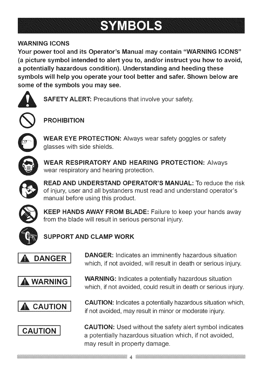
WARNING iCONS
Your power tool and its Operator's Manual may contain "WARNING iCONS"
(a picture symbol intended to alert you to, and/or instruct you how to avoid,
a potentially hazardous condition). Understanding and heeding these
symbols will help you operate your tool better and safer. Shown below are
some of the symbols you may see.
SAFETY ALERT: Precautions that involve your safety.
Q PROHIBITION
0WEAR EYE PROTECTION: Always wear safety goggles or safety
glasses with side shields.
WEAR RESPIRATORY AND HEARING PROTECTION: Always
wear respiratory and hearing protection.
READ AND UNDERSTAND OPERATOR'S MANUAL: To reduce the risk
of injury, user and all bystanders must read and understand operator's
manual before using this product.
KEEP HANDS AWAY FROM BLADE: Failure to keep your hands away
from the blade will result in serious personal injury.
SUPPORT AND CLAMP WORK
DANGER I DANGER: Indicates an imminently hazardous situation
which, if not avoided, will result in death or serious injury.
IA wARNINGl WARNING: Indicates a potentially hazardous situation
which, if not avoided, could result in death or serious injury.
1,_, CAUTION iCAUTION: Indicates a potentially hazardous situation which,
if not avoided, may result in minor or moderate injury.
{CAUTION ] CAUTION: Used without the safety alert symbol indicates
a potentially hazardous situation which, if not avoided,
may result in property damage.
GENERAL SAFETY iNSTRUCTiONS
BEFORE USING THiS POWER TOOL
Safety is a combination of common
sense, staying alert and knowing how
to use your power tool.
I,AWARNINe1
o To avoid mistakes that could
cause serious injury, do not plug
the tool in until you have read and
understood the following.
o Read all instructions before
operating product. Failure to
follow all instructions listed below
may result in electric shock, fire
and/or serious injury.
,READ and become familiar
with the entire Operator's
Manual. LEARN the tool's
application, limitations and possible
hazards.
2. KEEP GUARDS iN PLACE and in
working order.
3. REMOVE ADJUSTING KEYS
AND WRENCHES. Form the habit
of checking to see that keys and
adjusting wrenches are removed
from the tool before turning ON.
4. KEEP WORK AREA CLEAN.
Cluttered areas and benches invite
accidents.
5. DO NOT USE iN DANGEROUS
ENVIRONMENTS. Do not use
power tools in damp locations, or
expose them to rain or snow. Keep
work area well lit.
6. KEEP CHILDREN AWAY. All visitors
and bystanders should be kept a
safe distance from work area.
,
,
,
MAKE WORKSHOP CHILD PROOF
with padlocks, master switches or by
removing starter keys.
DO NOT FORCE THE TOOL. It will
do the job better and safer at the
rate for which it was designed.
USE THE RIGHT TOOL. Do not
force the tool or an attachment to do
a job for which it was not designed.
10.USE PROPER EXTENSION
CORDS. Make sure your extension
cord is in good condition. When
using an extension cord, be sure
to use one heavy enough to carry
the current your product will draw.
An undersized cord will result in
a drop in line voltage and in loss
of power which will cause the tool
to overheat. The table on page
12 shows the correct size to use
depending on cord length and
nameplate ampere rating. If in
doubt, use the next heavier gauge.
The smaller the gauge number, the
heavier the cord.

11.WEAR PROPER APPAREL. Do
not wear loose clothing, gloves,
neckties, rings, bracelets or other
jewelry which may get caught in
moving parts. Nonslip footwear is
recommended. Wear protective hair
covering to contain long hair.
12. ,d_l_ _ ALWAYS WEAR EYE
UPROTECTION. Any
power tool could throw
foreign objects into the eyes and
cause permanent eye damage.
ALWAYS wear Safety Goggles (not
glasses) that comply with ANSI
Safety standard Z87.1. Everyday
eyeglasses have only impact-
resistant lenses. They ARE NOT
safety glasses. Safety Goggles are
available at Sears. NOTE: Glasses
or goggles not in compliance with
ANSI Z87.1 could cause serious
injury when they break.
13. WEAR AFACE MASK
OR DUST MASK. Sawing
operation produces dust.
14.@ SECURE THE
WORKPIECE. Use
clamps or a vise to hold
workpiece when practical. It is safer
than using your hand and also it
frees both hands to operate the tool.
15.DISCONNECT TOOLS FROM
POWER SOURCE before servicing,
and when changing accessories
such as blades, bits and cutters.
16.REDUCE THE RISK OF
UNINTENTIONAL STARTING.
Make sure switch is in the OFF
position before plugging the tool in.
17.USE RECOMMENDED
ACCESSORIES. Consult
this Operator's Manual for
recommended accessories. The use
of improper accessories may cause
risk of injury to yourself or others.
18.NEVER STAND ON THE TOOL,
Serious injury could occur if the
tool is tipped or if the cutting tool is
unintentionally contacted.
19.CHECK FOR DAMAGED PARTS.
Before further use of the tool, a
guard or other part that is damaged
should be carefully checked to
determine that it will operate
properly and perform its intended
function - check for alignment of
moving parts, binding of moving
parts, breakage of parts, mounting
and any other conditions that may
affect its operation. A guard or other
part that is damaged should be
properly repaired or replaced.
20.NEVER LEAVE THE TOOL
RUNNING UNATTENDED. TURN
THE POWER "OFF". Do not walk
away from a running tool until the
blade complete stop and the tool is
unplugged from the power source.
21.DONOTOVERREACH.Keep
properfootingandbalanceatall
times.
22.MAINTAIN TOOLS WITH CARE.
Keep tools sharp and clean for best
and safest performance. Follow
instructions for lubricating and
changing accessories.
23. DO NOT use power tool in
presence of flammable liquids or
gases.
24. DO NOT operate the tool if you are
under the influence of any drugs,
alcohol or medicationn that could
affect your ability to use the tool
properly.
25.
26.
27.
I,_k WARNING I Dust generated
from certain
materials can be hazardous to your
health. Always operate saw in well-
ventilated area and provide for
proper dust removal.
I,_ DANGER I Pe°plewith
electronic
devices, such as pacemakers,
should consult their physician(s)
before using this product. Operation
of electrical equipment in close
proximity to a heart pacemaker
could cause interference or failure
of the pacemaker.
WEAR HEARING
PROTECTION to reduce
the risk of induced
hearing loss.
1.ALWAYSUSESAW BLADE 6.
GUARD, riving knife and anti-
kickback pawls for every through-
sawing operation. Through-sawing 7.
operations are those in which the
blade cuts completely through
the workpiece when ripping or 8.
crosscutting. Always be sure blade
guard is tightened securely.
2. ALWAYS HOLD WORKPIECE
FIRMLY against the miter gauge or
rip fence.
,
NEVER REACH behind or over the
cutting tool for any reason.
REMOVE the rip fence when
crosscutting.
DO NOT USE a molding head with
this saw.
DIRECTION OF FEED. Feed
workpiece into a blade or cutter
against the direction of rotation of
the blade or cutter only.
3. ALWAYS USE a push stick or push
block, especially when ripping
narrow stock. Refer to ripping
instructions in this Operator's Manual
where the push stick is covered in
detail. A pattern for making your own
push stick is included on page 46.
4. NEVER PERFORM ANY
OPERATION FREEHAND, which
means can using hands to support
the workpiece, but always use either
the fence OR the miter gauge to
position and guide the workpiece.
i,_ WARNING 1
FREEHAND CUTTING IS THE
MAJOR CAUSE OF KICKBACK
AND FINGER/HAND AMPUTATIONS.
NEVER USE THE MITER GAUGE
AND FENCE SIMULTANEOUSLY.
5. NEVER STAND or have any part of
your body in line with the path of the
saw blade. Keep your hands out of
the saw blade path.
10.NEVER use the rip fence as a
cut-off gauge when crosscutting.
11.NEVER ATTEMPT TO FREE A
STALLED SAW BLADE without first
turning the saw OFR Turn power
switch OFF immediately to prevent
motor damage.
12.PROVIDE ADEQUATE SUPPORT
to the rear and the sides of the saw
table for long or wide workpieces.
1&AVOID KICKBACKS (work thrown
back towards you) by keeping the
blade sharp, the rip fence parallel
to the saw blade and by keeping
the riving knife, anti-kickback pawls
and guards in place, aligned and
functioning. Do not release work
before passing it completely beyond
the saw blade. Do not rip work that
is twisted, warped or does not have
a straight edge to guide it along the
fence. Do not attempt to reverse out
of a cut with the blade running.
14.AVOIDAWKWARDOPERATIONS
and hand positions where a sudden
slip could cause your hand to move
into the saw blade,
15.NEVER USE SOLVENTS to
clean plastic parts. Solvents could
possibly dissolve or otherwise
damage the material. Only a soft
damp cloth should be used to clean
plastic parts.
16.MOUNT your table saw on a bench
or stand before performing any
cutting operations. Secure tool
properly to prevent unexpected
movement. Refer to ASSEMBLY on
page 19.
17.1,_ WARNING 1
Never cut metals or masonry
products with this tool. This table
saw is designed for use on wood
and wood-like products only.
18.ALWAYS USE iN A WELL-
VENTILATED AREA. Remove
sawdust frequently. Clean out
sawdust from the interior of the saw
to prevent a potential fire hazard.
Attach a vacuum to the dust port for
additional sawdust removal.
19.NEVER LEAVE THE SAW
RUNNING UNATTENDED. Do not
leave the saw until the blade comes
to a complete stop.
20.For proper operation follow the
instructions in this Instruction
Manual entitled ASSEMBLY AND
ADJUSTMENTS (Page 19). Failure
to provide sawdust fall-through and
removal hole will allow sawdust to
build up in the motor area resulting
in a fire hazard and potential motor
damage.
21.USE ONLY saw blades
recommended with the warning that
the riving knife shall not be thicker
than the width of the groove cut by
the saw blade and not thinner than
the body of the saw blade.
22.USE PUSH-STICK OR PUSH
BLOCK to feed the workpiece past
the saw blade. The push-stick or
push block should always be stored
with the machine when not in use.
SAW BLADE GUARD ASSEMBLY, ANTI-
KICKBACK ASSEMBLY AND RIVING
KNIFE
Your table saw is equipped with a blade
guard assembly, anti-kickback assembly
and riving knife that covers the blade and
reduces the possibility of accidental blade
contact. The riving knife is a flat plate that
fits into the cut made by the saw blade and
effectively fights kickback by lessening the
tendency of the blade to bind in the cut.
The blade guard assembly and anti-
kickback assembly can only be used when
making through cuts that sever the wood.
When making rabbets and other cuts that
make non through cuts, the blade guard
assembly and anti-kickback assembly must
be removed and riving knife lowered to the
non through cut position marked on the
riving knife. Two anti-kickback pawls are
located on the sides of the riving knife
that allow the wood to pass through the
blade in the cutting direction but reduce
the possibility of the material being thrown
backwards toward the operator. Use all
components of the guarding system (blade
guard assembly, riving knife and anti-
kickback assembly) for every operation
for which they can be used including all
through cutting. If you elect not to use
any of these components for a particular
application exercise additional caution
regarding control of the workpiece, the use
of push sticks, the position of your hands
relative to the blade, the use of safety
glasses, the means to avoid kickback
and all other warnings contained in this
manual and on the saw itself. Replace the
guarding systems as soon as you return
to thru-cutting operations. Keep the guard
assembly in working order.
KICKBACKS
KICKBACKS: Kickbacks can cause serious
injury. A kickback occurs when a part of the
workpiece binds between the saw blade
and the rip fence, or other fixed object, and
rises from the table and is thrown toward
the operator. Kickbacks can be avoided by
attention to the following conditions.
How to Avoid Kickbacks and Protect
Yourself from Possible Injury:
a. Be certain that the rip fence is parallel to
the saw blade.
b. Do not rip by applying the feed force to
the section of the workpiece that will
become the cut-off (free) piece. Feed
force when ripping should always be
applied between the saw blade and the
fence; use a push stick for narrow work,
6 in. (152 mm) wide or tess.
c. Keep saw blade guard assembly, riving
knife and anti-kickback assembly in place
and operating properly. If anti-kickback
assembly is not operational, return your
unit to the nearest authorized service
center for repair. The riving knife must be
in alignment with the saw blade and the
anti-kickback assembly must stop a
kickback once it has started. Check their
action before ripping by pushing the wood
under the anti-kickback assembly. The
teeth must prevent the wood from being
pulled toward the front of the saw.
d. Plastic and composite (like hardboard)
materials may be cut on your saw.
However, since these are usually quite
hard and slippery, the anti-kickback pawls
may not stop a kickback. Therefore, be
especially attentive to following proper
set up and cutting procedures for ripping.
e. Use saw blade guard assembly, anti-
kickback assembly and riving knife for
every operation for which it can be used,
including all through-sawing.
f. Push the workpiece past the saw blade
prior to release.
g. Never rip a workpiece that is twisted or
warped, or does not have a straight edge
to guide along the fence.
h. Never saw a large workpiece that cannot
be controlled.
i. Never use the fence as a guide or length
stop when crosscutting.
j. Never saw a workpiece with loose knots,
flaws, nails or other foreign objects.
k. Never rip a workpiece shorter than 10 in.
(254 mm).
1. NEVER use a dull blade - replace or
have resharpened.
m.NEVER use a rip fence and miter
gauge together.
n. Keep hands out of saw blade.
POWER SUPPLY AND MOTOR
SPECiFiCATiONS
i_ WARNING i
To avoid electrical hazards, fire
hazards, or damage to the tool, use
proper circuit protection. Use a
seperate electrical circuit for your
tool. Your table saw is wired at the
factory for 120V operation. Connect
to a120V, 15Amp circuit and use
a15 Amp time delay fuse or circuit
breaker. To avoid shock or fire, if
power cord is worn, cut, or damaged
in any way, have it replaced
immediately.
GROUNDING iNSTRUCTiONS
{_ WARNING l
This tool must be grounded while
in use to protect the operator from
electrical shock.
IN THE EVENT OF A MALFUNCTION
OR BREAKDOWN, grounding provides
a path of least resistance for electric
currents and reduces the risk of electric
shock. This tool is equipped with an
electrical cord that has an equipment-
grounding conductor and a grounding
plug. The plug must be plugged into
a matching receptacle that is properly
installed and grounded in accordance
with all local codes and ordinances.
DO NOT MODIFY THE PLUG
PROVIDED. If it will not fit the
receptacle, have the proper receptacle
installed by a qualified electrician.
IMPROPER CONNECTION of the
equipment grounding conductor can
result in risk of electric shock. The
conductor with the green insulation
(with or without yellow stripes) is the
equipment grounding conductor. If
repair or replacement of the electrical
cord or plug is necessary, do not
connect the equipment grounding
conductor to a live terminal.
CHECK with a qualified electrician or
service person if you do not completely
understand the grounding instructions,
or if you are not certain the tool is
properly grounded.
USE only 3-wire extension cords
that have three-pronged grounding
plugs with three=pole receptacles
that accept the tooVs plug. Repair
or replace damaged or worn cords
immediately.
Use a separate electrical circuit for
your tool. This circuit must not be less
than #14 wire and should be protected
with a 15 Amp time delay fuse. Before
connecting the motor to the power
line, make sure the switch is in the
off position and the electric current is
rated the same as the current stamped
on the motor nameplate. Running at a
lower voltage will damage the motor.
USE THE PROPER EXTENSION
CORD. Make sure your extension cord
is in good condition. Use an extension
cord heavy enough to carry the current
your product will draw. An undersized
cord will cause a drop in line voltage
resulting in loss of power, overheating
and burning out of the motor. The
table below shows the correct size
to use depending on cord length and
nameplate ampere rating. If in doubt,
use the next heavier gauge. The
smaller the gauge number, the heavier
the cord.
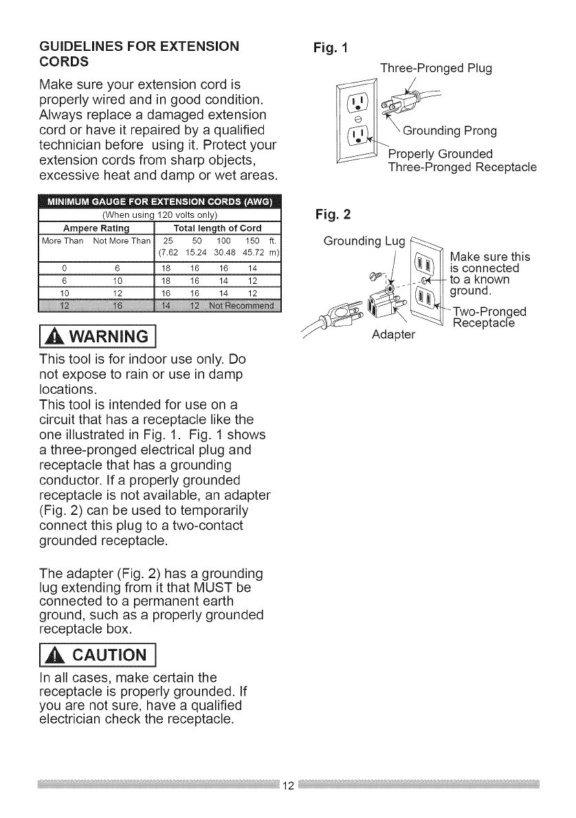
GUiDELiNES FOR EXTENSION
CORDS
Make sure your extension cord is
properly wired and in good condition.
Always replace a damaged extension
cord or have it repaired by a qualified
technician before using it. Protect your
extension cords from sharp objects,
excessive heat and damp or wet areas.
••=• e-= •
(When using 120 volts only)
Ampere Rating Total length of Cord
More Than Not More Than 25 50 100 150 ft.
(7.82 15.24 30.48 45.72 m)
0 6 18 16 16 14
6 10 18 16 14 12
10 12 16 18 14 12
hal:::::::
WARNINGl
This tool is for indoor use only. Do
not expose to rain or use in damp
locations,
This tool is intended for use on a
circuit that has a receptacle like the
one illustrated in Fig. 1. Fig. 1 shows
a three-pronged electrical plug and
receptacle that has a grounding
conductor. If a properly grounded
receptacle is not available, an adapter
(Fig. 2) can be used to temporarily
connect this plug to a two-contact
grounded receptacle.
The adapter (Fig. 2) has a grounding
lug extending from it that MUST be
connected to a permanent earth
ground, such as a properly grounded
receptacle box.
i,_ CAUTION i
In all cases, make certain the
receptacle is properly grounded. If
you are not sure, have a qualified
electrician check the receptacle.
Fig. 1
Three-Pronged Plug
g Prong
Properly Grounded
Three-Pronged Receptacle
Fig. 2
Grounding Lug
/_ ] Make sure this
/___)I is connected
¢_I:_ _.4_--_-to a known
,d_. __]1 ground.
Two-Pronged
j_-_ " ""_ Receptacle
_J Adapter
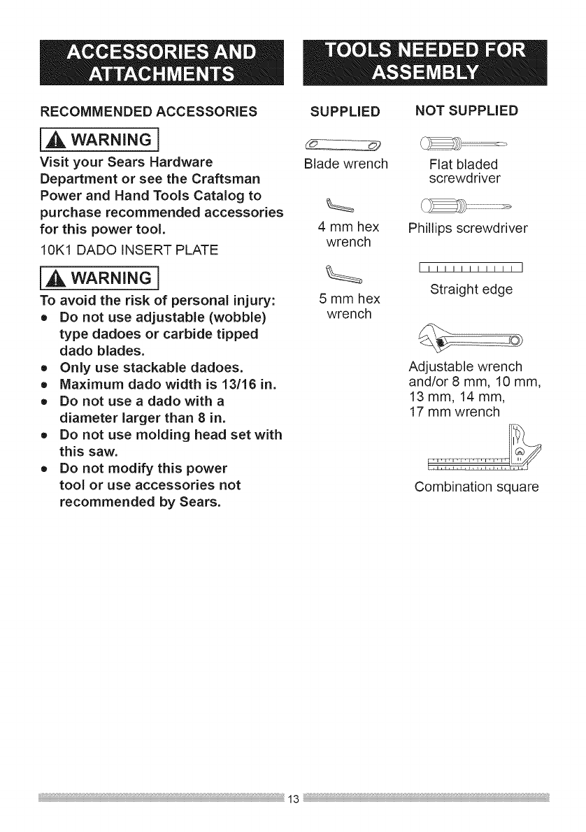
RECOMMENDEDACCESSORIES
iA WAR.I.Gi
Visit your Sears Hardware
Department or see the Craftsman
Power and Hand Tools Catalog to
purchase recommended accessories
for this power tool.
10K1 DADO iNSERT PLATE
iA WAR.I.G1
To avoid the risk of personal injury:
o Do not use adjustable (wobble)
type dadoes or carbide tipped
dado blades.
o Only use stackable dadoes.
oMaximum dado width is 13/16 in.
= Do not use a dado with a
diameter larger than 8 in,
= Do not use molding head set with
this saw.
o Do not modify this power
tool or use accessories not
recommended by Sears.
SUPPLIED NOT SUPPLIED
Blade wrench
4 mm hex
wrench
5 mm hex
wrench
Flat bladed
screwdriver
Phillips screwdriver
[! !! !! !! !! !! ]
Straight edge
Adjustable wrench
and/or 8 mm, 10 mm,
13 mm, 14 mm,
17 mm wrench
Combination square

Separateallpartsfrompackingmaterials.Checkeachpartwiththeillustration
onthenextpageandthe"TableofLooseParts"to makecertainall itemsare
accountedfor,beforediscardinganypackingmaterial.
NOTE:Tomakeassemblyeasier,keepcontentsofboxtogether.
[A WAR.I.Gi
if any part is missing or damaged, do not attempt to assemble the table saw,
plug in the power cord, or turn the switch ON until the missing or damaged
part is obtained and is installed correctly. Call 1=800=843=1682 for missing or
damaged parts.
TABLE OF LOOSE PARTS
TABLE SAW
ITEM DESCRIPTION QUANTITY
A Table saw assembly 1
B Handwheel handle 1
C Riving knife hardware bag 1
D Rip fence 1
E Miter gauge 1
F Blade guard assembly 1
G Push stick 1
H 4 mm & 5 mm hex wrench /Blade wrench 1 each
I Anti-kickback pawls assembly 1
J Blade 1
K Blade guard/pawls assembly storage hardware bag 1
L Table mounting hardware bag 1
STAND
M Wheel hardware assembly 2 set
N Stand assembly 1
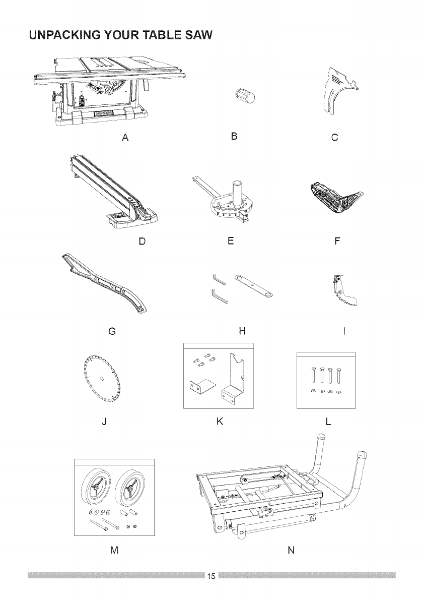
UNPACKING YOUR TABLE SAW
A
D
G
B
H
C
LK
M
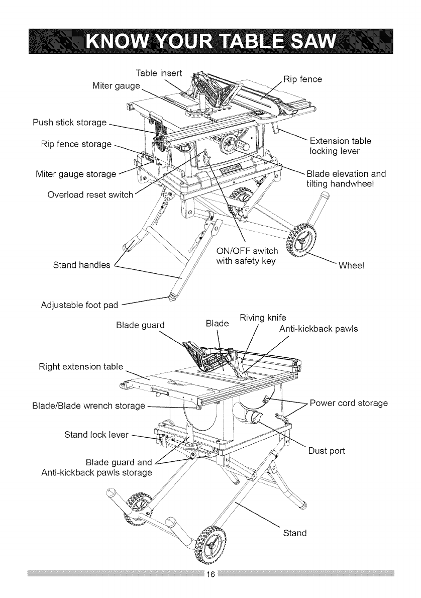
Table insert
Miter c _ Rip fence
Push stick storage
Rip fence storage
Miter gauge storage
Overload reset switch
Extension table
locking lever
Blade elevation and
tilting handwheel
ON/OFF switch
Stand handles with safety key Wheel
Adjustable foot pad
Blade guard Blade Riving knife
Anti-kickback pawls
Right extension table
Blade/Blade wrench storage Power cord storage
Stand lock lever
Blade guard and
Anti-kickback pawls storage
Dust port
Stand
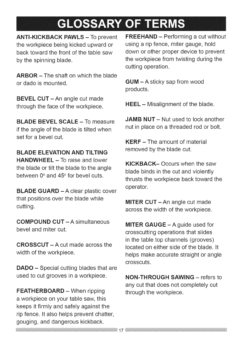
ANTI-KICKBACK PAWLS - To prevent
the workpiece being kicked upward or
back toward the front of the table saw
by the spinning blade.
ARBOR - The shaft on which the blade
or dado is mounted.
BEVEL CUT -An angle cut made
through the face of the workpiece.
FREEHAND - Performing a cut without
using a rip fence, miter gauge, hold
down or other proper device to prevent
the workpiece from twisting during the
cutting operation.
GUM - A sticky sap from wood
products.
HEEL - Misalignment of the blade.
BLADE BEVEL SCALE - To measure
if the angle of the blade is tilted when
set for a bevel cut.
BLADE ELEVATION AND TiLTiNG
HANDWHEEL -To raise and lower
the blade or tilt the blade to the angle
between 0° and 45° for bevel cuts.
BLADE GUARD -A clear plastic cover
that positions over the blade while
cutting.
JAMB NUT - Nut used to lock another
nut in place on a threaded rod or bolt.
KERF - The amount of material
removed by the blade cut.
KICKBACK- Occurs when the saw
blade binds in the cut and violently
thrusts the workpiece back toward the
operator.
MITER CUT-An angle cut made
across the width of the workpiece.
COMPOUND CUT - A simultaneous
bevel and miter cut.
CROSSCUT - A cut made across the
width of the workpiece.
DADO - Special cutting blades that are
used to cut grooves in a workpiece.
FEATHERBOARD - When ripping
a workpiece on your table saw, this
keeps it firmly and safely against the
rip fence. It also helps prevent chatter,
gouging, and dangerous kickback.
MITER GAUGE -A guide used for
crosscutting operations that slides
in the table top channels (grooves)
located on either side of the blade. It
helps make accurate straight or angle
crosscuts.
NON-THROUGH SAWING - refers to
any cut that does not completely cut
through the workpiece.
OVERLOADRESETSWITCH-
Protectsthemotorif itoverloadsduring
operation,providesawaytorestartthe
saw.
PUSHSTICK-Usedto push
workpieceswhenperformingripping
operations.
PUSHBLOCK-Usedforripping
operationwhentheworkpieceistoo
narrowto useapushstick.Alwaysusea
pushblockforripwidthslessthan2 in.
RESAWING- Flippingmaterialto
makeacutthesawisnotcapableof
makinginonepass.
i,A WARNING i
Do not resaw material with this saw.
REVOLUTIONS PER MINUTE (RPM)
- The number of turns completed by a
spinning object in one minute.
RIP FENCE -A guide used for rip
cutting which allows the workpiece to
cut straight.
RIPPING - Cutting with the grain of
the wood or along the length of the
workpiece.
RIVING KNIFE -A metal piece of the
guard assembly located behind and in-
line with the blade. Slightly thinner than
the saw blade, it helps keep the kerr
open and prevents kickback.
SAW BLADE PATH - The area of the
workpiece or table top directly in line
with the travel of the blade or the part
of the workpiece that will be cut.
SET - The distance between two saw
blade tips, bent outward in opposite
directions to each other. The further
apart the tips are, the greater the set.
TABLE INSERT - Insert that is
removed from the table to install /
remove blades. It is also removed for
dado cutting. When dado cutting, a
dado insert plate must be used.
THROUGH SAWING - Making a cut
completely through the length or width
of a workpiece.
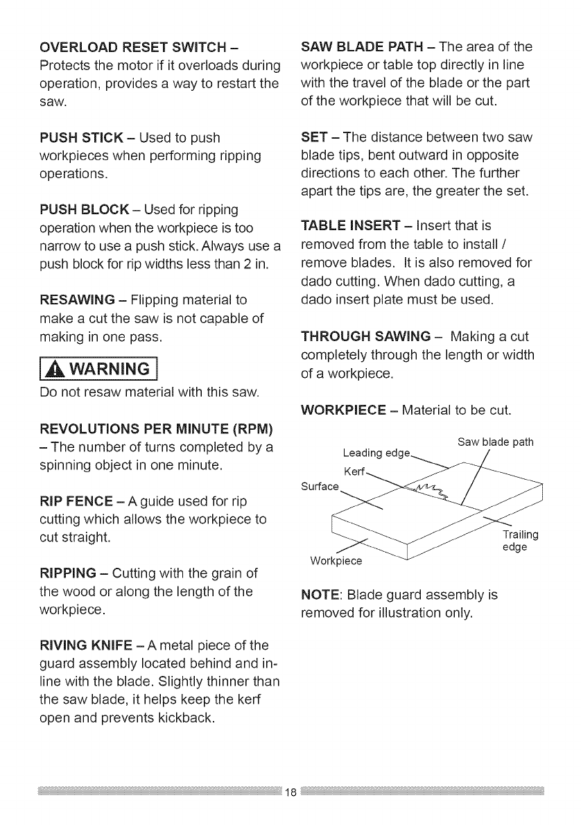
WORKPIECE - Material to be cut.
Leadin( Saw blade path
Surface
Workpiece
NOTE: Blade guard assembly is
removed for illustration only.
Trailing
edge
I,A WARNING 1
For your safety, never connect plug
to power source receptacle until all
assembly and adjustment steps are
complete, and you have read and
understood the safety instructions.
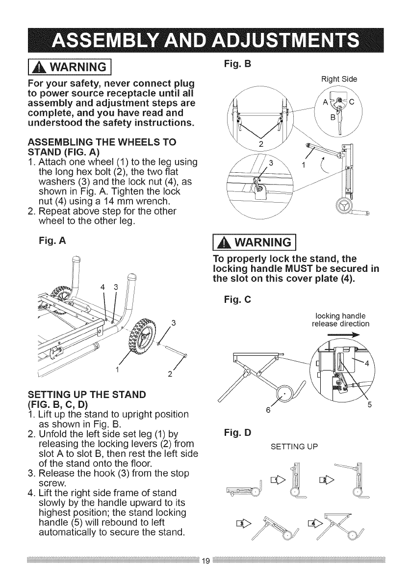
ASSEMBLING THE WHEELS TO
STAND (FIG. A)
1. Attach one wheel (1) to the leg using
the long hex bolt (2), the two flat
washers (3) and the lock nut (4), as
shown in Fig. A. Tighten the lock
nut (4) using a 14 mm wrench.
2. Repeat above step for the other
wheel to the other leg.
Fig. A
4 3
3
2
Right Side
1
[A wARNING]
To properly lock the stand, the
locking handle MUST be secured in
the slot on this cover plate (4).
Fig. C
SETTING UP THE STAND
(FIG. B, C, D)
1. Lift up the stand to upright position
as shown in Fig. B.
2. Unfold the left side set leg (1) by Fig. D
releasing the locking levers (2) from
slot A to slot B, then rest the left side
of the stand onto the floor.
3. Release the hook (3) from the stop
screw.
4. Lift the right side frame of stand
slowly by the handle upward to its
highest position; the stand locking
handle (5) will rebound to left
automatically to secure the stand,
locking handle
release direction
SETTING UP
d>
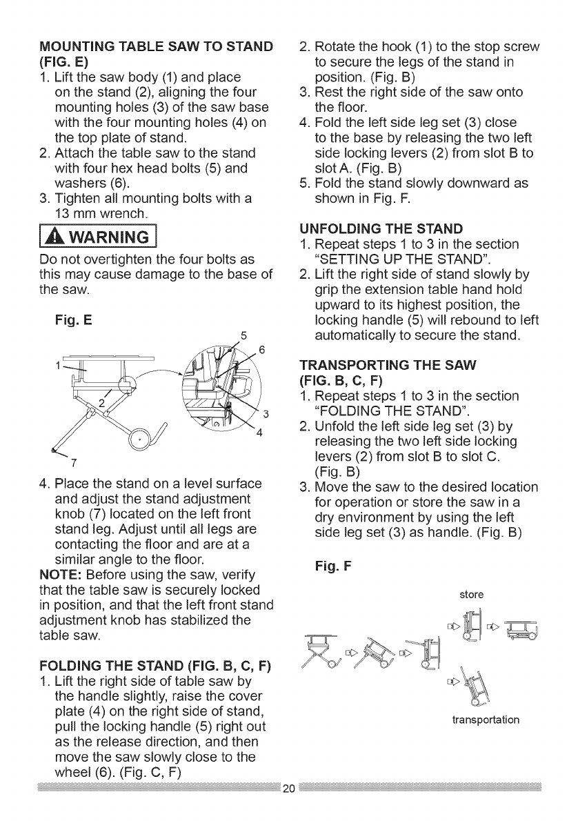
MOUNTING TABLE SAW TO STAND
(FIG. E)
1. Lift the saw body (1) and place
on the stand (2), aligning the four
mounting holes (3) of the saw base
with the four mounting holes (4) on
the top plate of stand.
2. Attach the table saw to the stand
with four hex head bolts (5) and
washers (6).
3. Tighten all mounting bolts with a
13 mm wrench.
[A wARNING]
Do not overtighten the four bolts as
this may cause damage to the base of
the saw.
Fig. E
5
,.6
3
4
4. Place the stand on a level surface
and adjust the stand adjustment
knob (7) located on the left front
stand leg. Adjust until all legs are
contacting the floor and are at a
similar angle to the floor.
NOTE: Before using the saw, verify
that the table saw is securely locked
in position, and that the left front stand
adjustment knob has stabilized the
table saw.
2. Rotate the hook (1) to the stop screw
to secure the legs of the stand in
position. (Fig. B)
3. Rest the right side of the saw onto
the floor.
4. Fold the left side leg set (3) close
to the base by releasing the two left
side locking levers (2) from slot B to
slot A. (Fig. B)
5. Fold the stand slowly downward as
shown in Fig. F.
UNFOLDING THE STAND
1. Repeat steps 1 to 3 in the section
"SETTING UP THE STAND".
2. Lift the right side of stand slowly by
grip the extension table hand hold
upward to its highest position, the
locking handle (5) will rebound to left
automatically to secure the stand.
TRANSPORTING THE SAW
(FIG. B, C, F)
1. Repeat steps 1 to 3 in the section
"FOLDING THE STAND".
2. Unfold the left side leg set (3) by
releasing the two left side locking
levers (2) from slot B to slot C.
(Fig. B)
3. Move the saw to the desired location
for operation or store the saw in a
dry environment by using the left
side leg set (3) as handle. (Fig. B)
Fig. F
store
FOLDING THE STAND (FIG. B, C, F)
1. Lift the right side of table saw by
the handle slightly, raise the cover
plate (4) on the right side of stand,
pull the locking handle (5) right out transportation
as the release direction, and then
move the saw slowly close to the
wheel (6). (Fig. C, F)
;_ 20
STORAGE
(FIG. G, H, I, J, K, L, M, N)
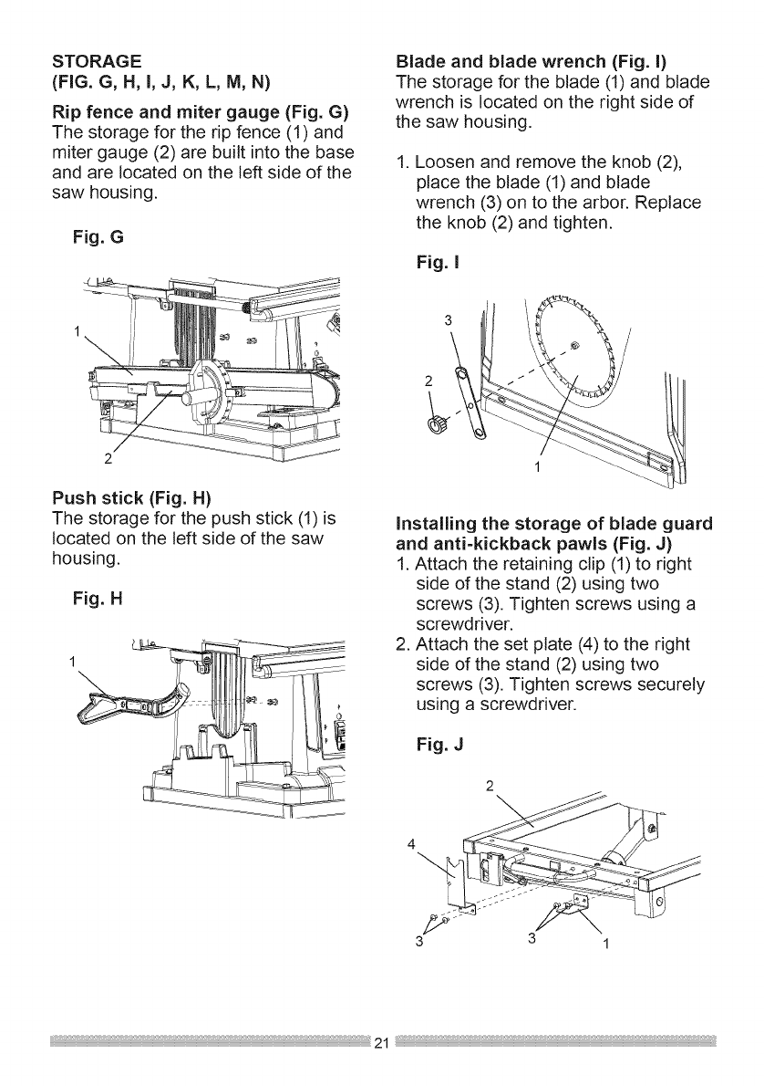
Rip fence and miter gauge (Fig. G)
The storage for the rip fence (1) and
miter gauge (2) are built into the base
and are located on the left side of the
saw housing.
Fig. G
Blade and blade wrench (Fig. I)
The storage for the blade (1) and blade
wrench is located on the right side of
the saw housing.
1. Loosen and remove the knob (2),
place the blade (1) and blade
wrench (3) on to the arbor. Replace
the knob (2) and tighten.
Fig. I
Push stick (Fig. H)
The storage for the push stick (1) is
located on the left side of the saw
housing.
Fig. H
o
2
Installing the storage of blade guard
and anti-kickback pawls (Fig. J)
1. Attach the retaining clip (1) to right
side of the stand (2) using two
screws (3). Tighten screws using a
screwdriver.
2. Attach the set plate (4) to the right
side of the stand (2) using two
screws (3). Tighten screws securely
using a screwdriver.
Fig. J
4
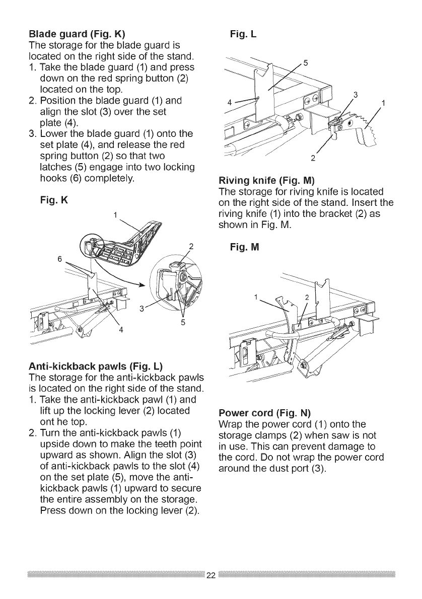
Blade guard (Fig. K)
The storage for the blade guard is
located on the right side of the stand.
1. Take the blade guard (1) and press
down on the red spring button (2)
located on the top.
2. Position the blade guard (1) and
align the slot (3) over the set
plate (4).
3. Lower the blade guard (1) onto the
set plate (4), and release the red
spring button (2) so that two
latches (5) engage into two locking
hooks (6) completely.
Fig. K
1
Anti-kickback pawls (Fig. L)
The storage for the anti-kickback pawls
is located on the right side of the stand.
1. Take the anti-kickback pawl (1) and
lift up the locking lever (2) located
ont he top.
2. Turn the anti-kickback pawls (1)
upside down to make the teeth point
upward as shown. Align the slot (3)
of anti-kickback pawls to the slot (4)
on the set plate (5), move the anti-
kickback pawls (1) upward to secure
the entire assembly on the storage.
Press down on the locking lever (2).
Fig. L
2
Riving knife (Fig. M)
The storage for riving knife is located
on the right side of the stand, insert the
riving knife (1) into the bracket (2) as
shown in Fig. M.
Fig. M
Power cord (Fig. N)
Wrap the power cord (1) onto the
storage clamps (2) when saw is not
in use. This can prevent damage to
the cord. Do not wrap the power cord
around the dust port (3).
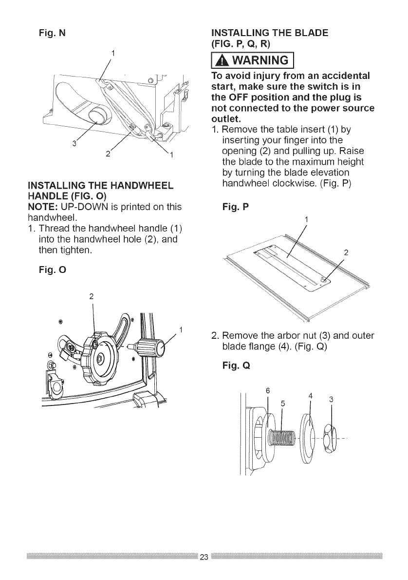
Fig.N
1
iNSTALLiNG THE HANDWHEEL
HANDLE (FIG. O)
NOTE: UP-DOWN is printed on this
handwheel.
1. Thread the handwheel handle (1)
into the handwheel hole (2), and
then tighten.
Fig. 0
/
I
iNSTALLiNG THE BLADE
(FIG. P, Q, R)
WAR.I.G}
To avoid injury from an accidental
start, make sure the switch is in
the OFF position and the plug is
not connected to the power source
outlet.
1. Remove the table insert (1) by
inserting your finger into the
opening (2) and pulling up. Raise
the blade to the maximum height
by turning the blade elevation
handwheel clockwise. (Fig. P)
Fig. P
1
2. Remove the arbor nut (3) and outer
blade flange (4). (Fig. Q)
Fig. Q
6
--_ --
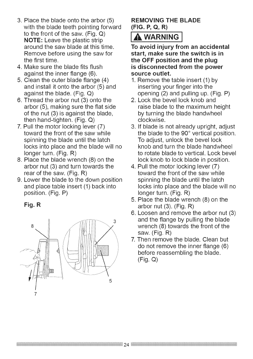
3. Place the blade onto the arbor (5)
with the blade teeth pointing forward
to the front of the saw. (Fig. Q)
NOTE: Leave the plastic strip
around the saw blade at this time.
Remove before using the saw for
the first time.
4. Make sure the blade fits flush
against the inner flange (6).
5. Clean the outer blade flange (4)
and install it onto the arbor (5) and
against the blade. (Fig. Q)
6. Thread the arbor nut (3) onto the
arbor (5), making sure the flat side
of the nut (3) is against the blade,
then hand-tighten. (Fig. Q)
7. Pull the motor locking lever (7)
toward the front of the saw while
spinning the blade until the latch
locks into place and the blade will no
longer turn. (Fig. R)
8. Place the blade wrench (8) on the
arbor nut (3) and turn towards the
rear of the saw. (Fig. R)
9. Lower the blade to the down position
and place table insert (1) back into
position. (Fig. P)
Fig. R
3
\
REMOVING THE BLADE
(FIG. P, Q, R)
WARNINGi
To avoid injury from an accidental
start, make sure the switch is in
the OFF position and the plug
is disconnected from the power
source outlet.
1. Remove the table insert (1) by
inserting your finger into the
opening (2) and pulling up. (Fig. P)
2. Lock the bevel lock knob and
raise blade to the maximum height
by turning the blade handwheel
clockwise.
3. If blade is not already upright, adjust
the blade to the 90 ° vertical position.
To adjust, unlock the bevel lock
knob and turn the blade handwheel
to rotate blade to vertical. Lock bevel
lock knob to lock blade in position.
4. Pull the motor locking lever (7)
toward the front of the saw while
spinning the blade until the latch
locks into place and the blade will no
longer turn. (Fig. R)
5. Place the blade wrench (8) on the
arbor nut (3). (Fig. R)
6. Loosen and remove the arbor nut (3)
and the flange by pulling the blade
wrench (8) towards the front of the
saw. (Fig. R)
7. Then remove the blade. Clean but
do not remove the inner flange (6)
before reassembling the blade.
(Fig. Q)
RiViNGKNIFEASSEMBLY
{AWARNING]
o To avoid injury from an
accidental start, make sure the
switch is in the OFF position and
the plug is disconnected from the
power source outlet.
=Never operate this saw without
the riving knife in the correct
position.
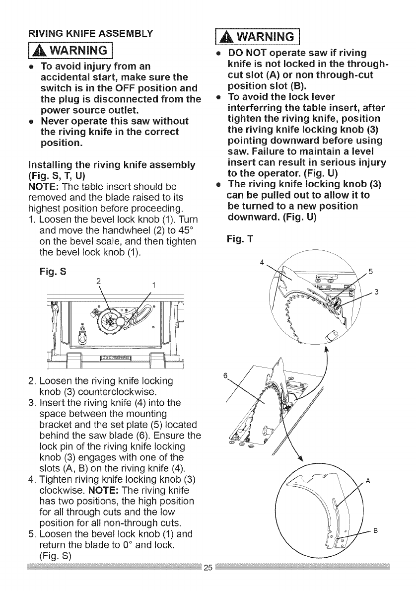
installing the riving knife assembly
(Fig. S, T, U)
NOTE: The table insert should be
removed and the blade raised to its
highest position before proceeding.
1. Loosen the bevel lock knob (1). Turn
and move the handwheei (2) to 45 °
on the bevel scale, and then tighten
the bevel lock knob (1).
Fig. S
2 1
Z
,_ WARNING i
oDO NOT operate saw if riving
knife is not locked in the through=
cut slot (A) or non through=cut
position slot (B).
=To avoid the lock lever
interferring the table insert, after
tighten the riving knife, position
the riving knife locking knob (3)
pointing downward before using
saw. Failure to maintain a level
insert can result in serious injury
to the operator. (Fig. U)
o The riving knife locking knob (3)
can be pulled out to allow it to
be turned to a new position
downward. (Fig. U)
Fig. T
4_ _\
......... =-
6
2. Loosen the riving knife locking
knob (3) counterclockwise.
3. insert the riving knife (4) into the
space between the mounting
bracket and the set plate (5) located
behind the saw blade (6). Ensure the
lock pin of the riving knife locking
knob (3) engages with one of the
slots (A, B) on the riving knife (4).
4. Tighten riving knife locking knob (3)
clockwise. NOTE: The riving knife
has two positions, the high position
for all through cuts and the low
position for all non-through cuts.
5. Loosen the bevel lock knob (1) and S
return the blade to 0° and lock,
(Fig, S) 25 :_
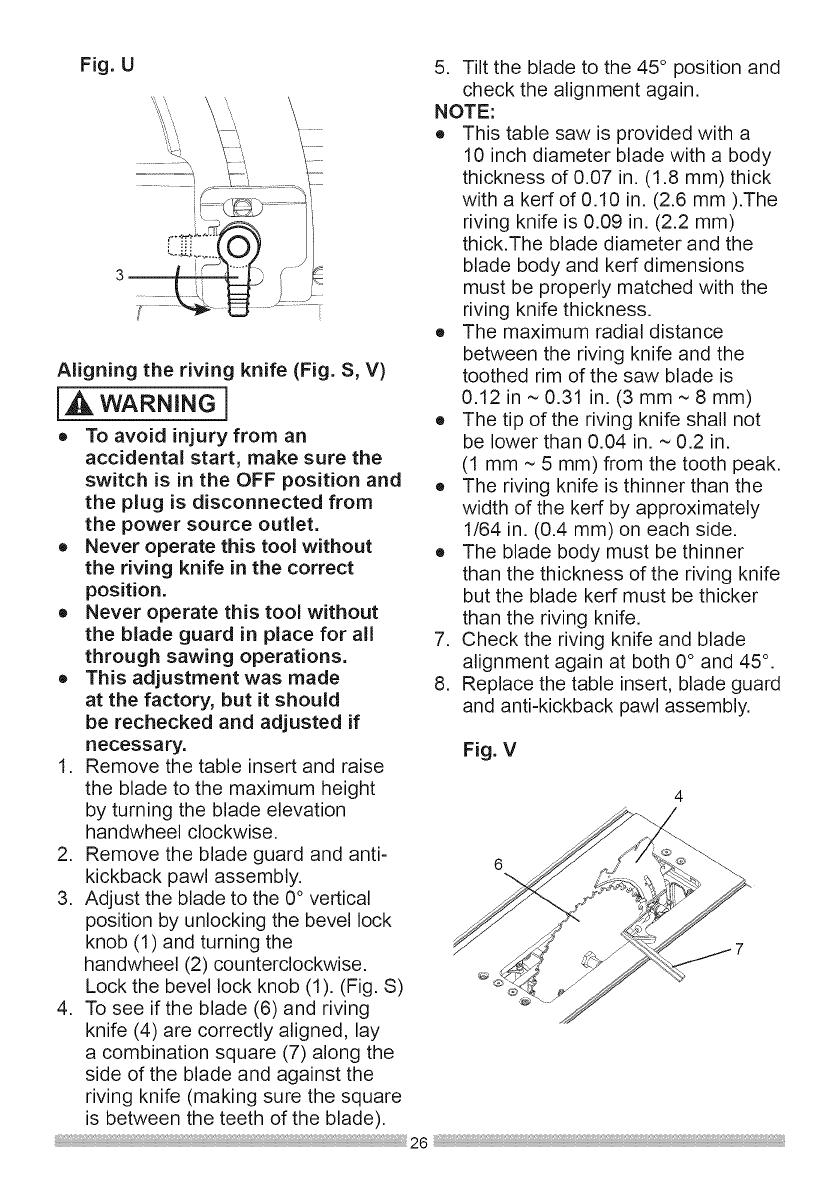
Fig. U
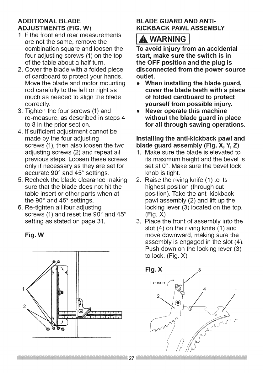
Aligning the riving knife (Fig. S, V)
WARNINGI
o To avoid injury from an
accidental start, make sure the
switch is in the OFF position and
the plug is disconnected from
the power source outlet.
o Never operate this tool without
the riving knife in the correct
position.
o Never operate this tool without
the blade guard in place for all
through sawing operations.
o This adjustment was made
at the factory, but it should
be rechecked and adjusted if
necessary.
1. Remove the table insert and raise
the blade to the maximum height
by turning the blade elevation
handwheel clockwise.
2. Remove the blade guard and anti-
kickback pawI assembly.
3. Adjust the blade to the 0° vertical
position by unlocking the bevel lock
knob (1) and turning the
handwheel (2) counterclockwise.
Lock the bevel lock knob (1). (Fig. S)
4. To see if the blade (6) and riving
knife (4) are correctly aligned, lay
a combination square (7) along the
side of the blade and against the
riving knife (making sure the square
is between the teeth of the blade).
5. Tilt the blade to the 45 ° position and
check the alignment again.
NOTE:
o This table saw is provided with a
10 inch diameter blade with a body
thickness of 0.07 in. (1.8 mm) thick
with a kerf of 0.10 in. (2.6 mm ).The
riving knife is 0.09 in. (2.2 mm)
thick.The blade diameter and the
blade body and kerf dimensions
must be properly matched with the
riving knife thickness.
o The maximum radial distance
between the riving knife and the
toothed rim of the saw blade is
0.12 in ~ 0.31 in. (3 mm ~ 8 mm)
o The tip of the riving knife shall not
be lower than 0.04 in. ~ 0.2 in.
(1 mm ~ 5 mm) from the tooth peak.
o The riving knife is thinner than the
width of the kerf by approximately
1/64 in. (0.4 mm) on each side.
o The blade body must be thinner
than the thickness of the riving knife
but the blade kerf must be thicker
than the riving knife.
7. Check the riving knife and blade
alignment again at both 0° and 45 °.
8. Replace the table insert, blade guard
and anti-kickback pawl assembly.
Fig. V
ADDiTiONALBLADE
ADJUSTMENTS (FIG. W)
1. If the front and rear measurements
are not the same, remove the
combination square and loosen the
four adjusting screws (1) on the top
of the table about a half turn.
2. Cover the blade with a folded piece
of cardboard to protect your hands.
Move the blade and motor mounting
rod carefully to the left or right as
much as needed to align the blade
correctly.
3. Tighten the four screws (1) and
re-measure, as described in steps 4
to 8 in the prior section.
4. If sufficient adjustment cannot be
made by the four adjusting
screws (1), then also loosen the two
adjusting screws (2) and repeat all
previous steps. Loosen these screws
only if necessary as they are set for
accurate 90° and 45 ° settings.
5. Recheck the blade clearance making
sure that the blade does not hit the
table insert or other parts when at
the 90 ° and 45° settings.
6. Re-tighten all four adjusting
screws (1) and reset the 90 ° and 45 °
setting as stated on page 31.
Fig. W
BLADE GUARD AND ANTI-
KICKBACK PAWL ASSEMBLY
[A,WAR.I.G]
To avoid injury from an accidental
start, make sure the switch is in
the OFF position and the plug is
disconnected from the power source
outlet.
• When installing the blade guard,
cover the blade teeth with a piece
of folded cardboard to protect
yourself from possible injury.
•Never operate this machine
without the blade guard in place
for all through sawing operations.
installing the anti-kickback pawl and
blade guard assembly (Fig. X, Y, Z)
1. Make sure the blade is elevated to
its maximum height and the bevel is
set at 0°. Make sure the bevel lock
knob is tight.
2. Raise the riving knife (1) to its
highest position (through cut
position). Take the anti-kickback
pawl assembly (2) and lift up the
locking lever (3) located on the top.
(Fig. X)
3. Place the front of assembly into the
slot (4) on the riving knife (1) and
move downward, making sure the
assembly is engaged in the slot (4).
Push down on the locking lever (3)
to lock. (Fig. X)
Fig. X
Loosen _
2
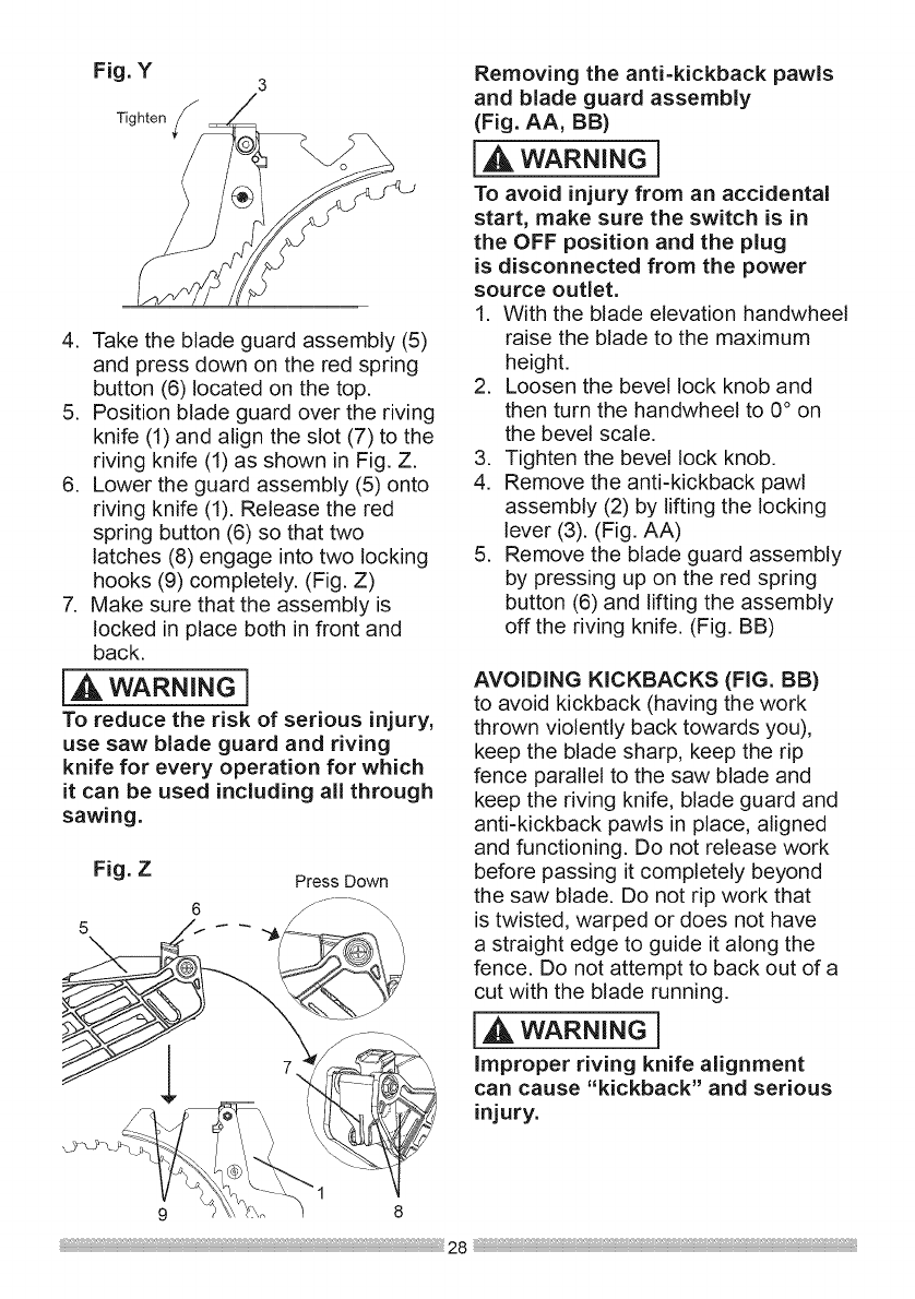
Fig. Y3
Tighten
4. Take the blade guard assembly (5)
and press down on the red spring
button (6) located on the top.
5. Position blade guard over the riving
knife (1) and align the slot (7) to the
riving knife (1) as shown in Fig. Z.
6. Lower the guard assembly (5) onto
riving knife (!). Release the red
spring button (6) so that two
latches (8) engage into two locking
hooks (9) completely, (Fig. Z)
7. Make sure that the assembly is
locked in place both in front and
back,
iA wAR.I.G]
To reduce the risk of serious injury,
use saw blade guard and riving
knife for every operation for which
it can be used including all through
sawing.
Fig. Z
5
Press Down
Removing the anti-kickback pawls
and blade guard assembly
(Fig. AA, BB)
l wAR.I.GI
To avoid injury from an accidental
start, make sure the switch is in
the OFF position and the plug
is disconnected from the power
source outlet.
1. With the blade elevation handwheel
raise the blade to the maximum
height.
2. Loosen the bevel lock knob and
then turn the handwheel to 0° on
the bevel scale.
3. Tighten the bevel lock knob.
4. Remove the anti-kickback pawl
assembly (2) by lifting the locking
lever (3). (Fig. AA)
5. Remove the blade guard assembly
by pressing up on the red spring
button (6) and lifting the assembly
off the riving knife. (Fig. BB)
AVOIDING KICKBACKS (FIG. BB)
to avoid kickback (having the work
thrown violently back towards you),
keep the blade sharp, keep the rip
fence parallel to the saw blade and
keep the riving knife, blade guard and
anti-kickback pawls in place, aligned
and functioning. Do not release work
before passing it completely beyond
the saw blade. Do not rip work that
is twisted, warped or does not have
a straight edge to guide it along the
fence. Do not attempt to back out of a
cut with the blade running.
IA wAR.I.G1
Improper riving knife alignment
can cause "kickback" and serious
injury.
9 8
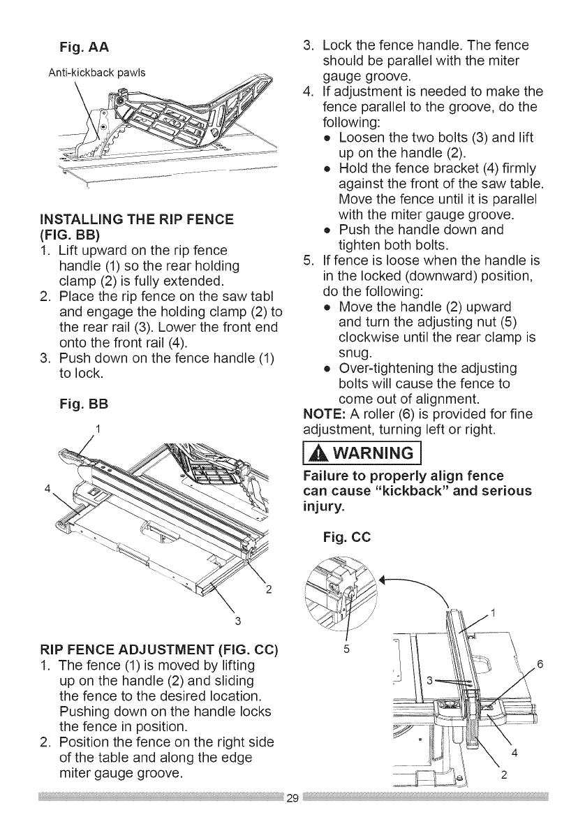
Fig. AA
Anti-kickback pawls
iNSTALLiNG THE RiP FENCE
(FIG. BB)
1. Lift upward on the rip fence
handle (1) so the rear holding
clamp (2) is fully extended.
2. Place the rip fence on the saw tabl
and engage the holding clamp (2) to
the rear rail (3). Lower the front end
onto the front rail (4).
3. Push down on the fence handle (1)
to lock.
Fig. BB
3. Lock the fence handle. The fence
should be parallel with the miter
gauge groove.
4. If adjustment is needed to make the
fence parallel to the groove, do the
following:
o Loosen the two bolts (3) and lift
up on the handle (2).
o Hold the fence bracket (4) firmly
against the front of the saw table.
Move the fence until it is parallel
with the miter gauge groove.
o Push the handle down and
tighten both bolts.
5. If fence is loose when the handle is
in the locked (downward) position,
do the following:
o Move the handle (2) upward
and turn the adjusting nut (5)
clockwise until the rear clamp is
snug.
o Over-tightening the adjusting
bolts will cause the fence to
come out of alignment.
NOTE: A roller (6) is provided for fine
adjustment, turning left or right.
WAR.I.G1
Failure to properly align fence
can cause "kickback" and serious
injury.
Fig. CO
RiP FENCE ADJUSTMENT (FIG. CC)
1. The fence (1) is moved by lifting
up on the handle (2) and sliding
the fence to the desired location.
Pushing down on the handle locks
the fence in position.
2. Position the fence on the right side
of the table and along the edge
miter gauge groove.
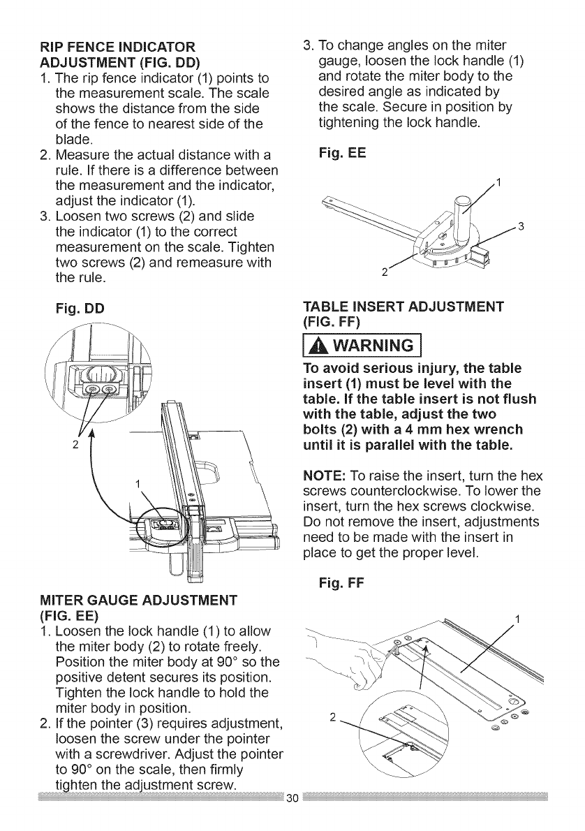
RIPFENCE INDICATOR
ADJUSTMENT (FIG. DD)
1. The rip fence indicator (1) points to
the measurement scale. The scale
shows the distance from the side
of the fence to nearest side of the
blade.
2. Measure the actual distance with a
rule. If there is a difference between
the measurement and the indicator,
adjust the indicator (1).
3. Loosen two screws (2) and slide
the indicator (1) to the correct
measurement on the scale. Tighten
two screws (2) and remeasure with
the rule.
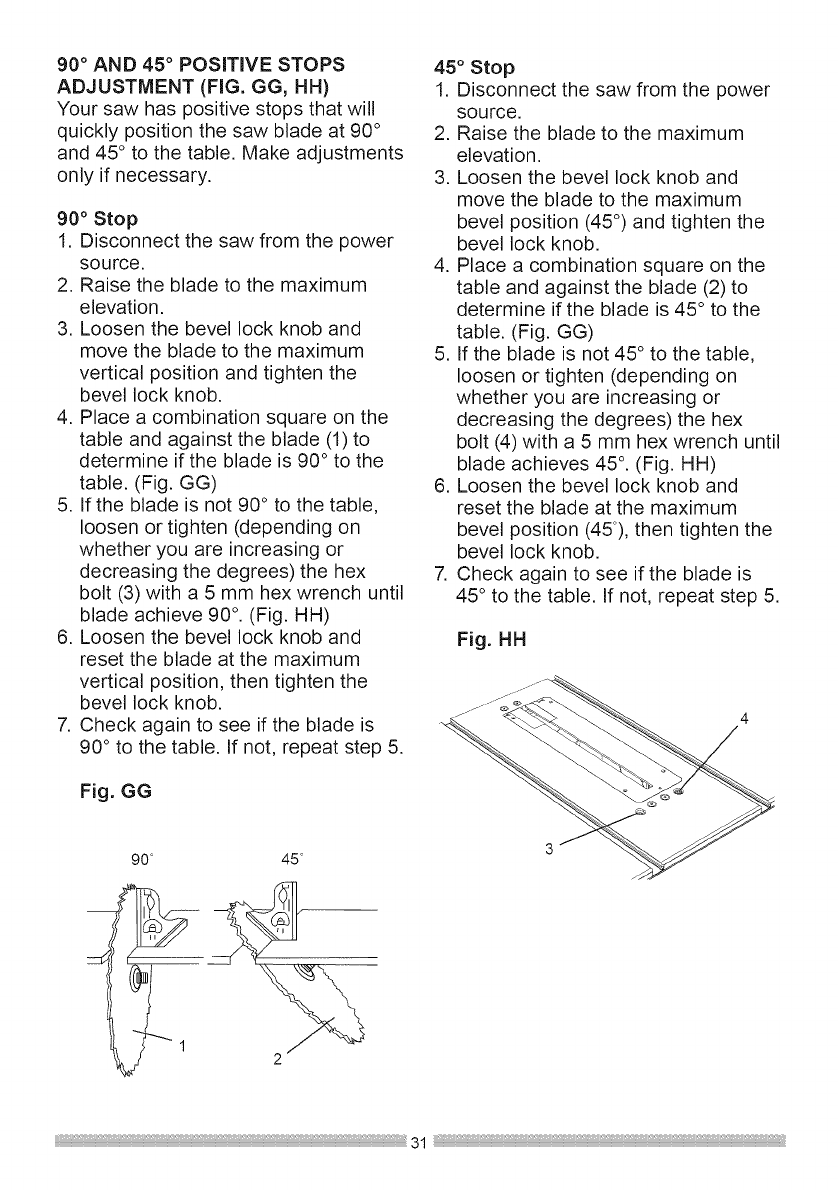
3. To change angles on the miter
gauge, loosen the lock handle (1)
and rotate the miter body to the
desired angle as indicated by
the scale. Secure in position by
tightening the lock handle.
Fig. EE
,_ 3
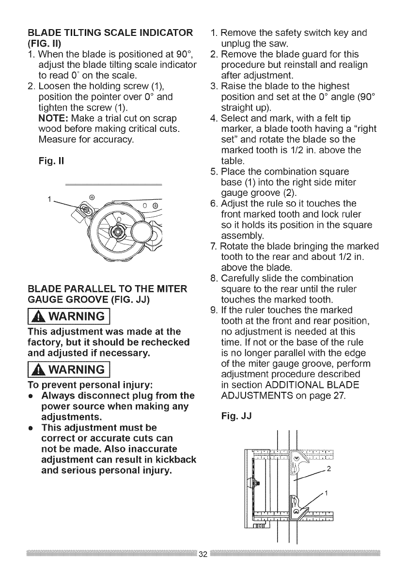
Fig. DD TABLE INSERT ADJUSTMENT
(FIG. FF)
[ WARNING]
To avoid serious injury, the table
insert (1) must be level with the
table. If the table insert is not flush
with the table, adjust the two
bolts (2) with a 4 mm hex wrench
until it is parallel with the table.
NOTE: To raise the insert, turn the hex
screws counterclockwise. To lower the
insert, turn the hex screws clockwise.
Do not remove the insert, adjustments
need to be made with the insert in
place to get the proper level.
Fig. FF
MITER GAUGE ADJUSTMENT
(FIG. EE) 1
1. Loosen the lock handle (1) to allow __
the miter body (2) to rotate freely. _ .........
Position the miter body at 90° so the _.
positive detent secures its position.
Tighten the lock handle to hold the
miter body in position.
2. If the pointer (3) requires adjustment, ®
loosen the screw under the pointer
with a screwdriver. Adjust the pointer
to 90° on the scale, then firmly
30
90 ° AND 45 °POSiTiVE STOPS
ADJUSTMENT (FIG. GG, HH)
Your saw has positive stops that will
quickly position the saw blade at 90 °
and 45° to the table, Make adjustments
only if necessary,
90 °Stop
1. Disconnect the saw from the power
source.
2. Raise the blade to the maximum
elevation.
3. Loosen the bevel lock knob and
move the blade to the maximum
vertical position and tighten the
bevel lock knob.
4. Place a combination square on the
table and against the blade (1) to
determine if the blade is 90° to the
table. (Fig. GG)
5. If the blade is not 90° to the table,
loosen or tighten (depending on
whether you are increasing or
decreasing the degrees) the hex
bolt (3) with a 5 mm hex wrench until
blade achieve 90 °. (Fig. HH)
6. Loosen the bevel lock knob and
reset the blade at the maximum
vertical position, then tighten the
bevel lock knob.
7. Check again to see if the blade is
90° to the table. If not, repeat step 5.
Fig. GG
90 45
45° Stop
1. Disconnect the saw from the power
source.
2. Raise the blade to the maximum
elevation.
3. Loosen the bevel lock knob and
move the blade to the maximum
bevel position (45°) and tighten the
bevel lock knob.
4. Place a combination square on the
table and against the blade (2) to
determine if the blade is 45 ° to the
table. (Fig. GG)
5. If the blade is not 45° to the table,
loosen or tighten (depending on
whether you are increasing or
decreasing the degrees) the hex
bolt (4) with a 5 mm hex wrench until
blade achieves 45 °. (Fig. HH)
6. Loosen the bevel lock knob and
reset the blade at the maximum
bevel position (45°), then tighten the
bevel lock knob.
7. Check again to see if the blade is
45° to the table. If not, repeat step 5.
Fig. HH
BLADETiLTiNGSCALE iNDiCATOR
(FIG. ll)
1. When the blade is positioned at 90°,
adjust the blade tilting scale indicator
to read 0° on the scale.
2. Loosen the holding screw (1),
position the pointer over 0° and
tighten the screw (1).
NOTE: Make a trial cut on scrap
wood before making critical cuts.
Measure for accuracy.
Fig. II
®
BLADE PARALLEL TO THE MITER
GAUGE GROOVE (FIG. JJ)
[A WARNING]
This adjustment was made at the
factory, but it should be rechecked
and adjusted if necessary,
IA WARNING1
To prevent personal injury:
• Always disconnect plug from the
power source when making any
adjustments.
• This adjustment must be
correct or accurate cuts can
not be made. Also inaccurate
adjustment can result in kickback
and serious personal injury.
1. Remove the safety switch key and
unplug the saw.
2. Remove the blade guard for this
procedure but reinstall and realign
after adjustment.
3. Raise the blade to the highest
position and set at the 0° angle (90 °
straight up).
4. Select and mark, with a felt tip
marker, a blade tooth having a "right
set" and rotate the blade so the
marked tooth is 1/2 in. above the
table.
5. Place the combination square
base (1) into the right side miter
gauge groove (2).
6. Adjust the rule so it touches the
front marked tooth and lock ruler
so it holds its position in the square
assembly.
7. Rotate the blade bringing the marked
tooth to the rear and about 1/2 in.
above the blade.
8. Carefully slide the combination
square to the rear until the ruler
touches the marked tooth.
9. If the ruler touches the marked
tooth at the front and rear position,
no adjustment is needed at this
time. If not or the base of the rule
is no longer parallel with the edge
of the miter gauge groove, perform
adjustment procedure described
in section ADDITIONAL BLADE
ADJUSTMENTS on page 27.
Fig. JJ
i,!iiiiii iil;iiiiii
j2
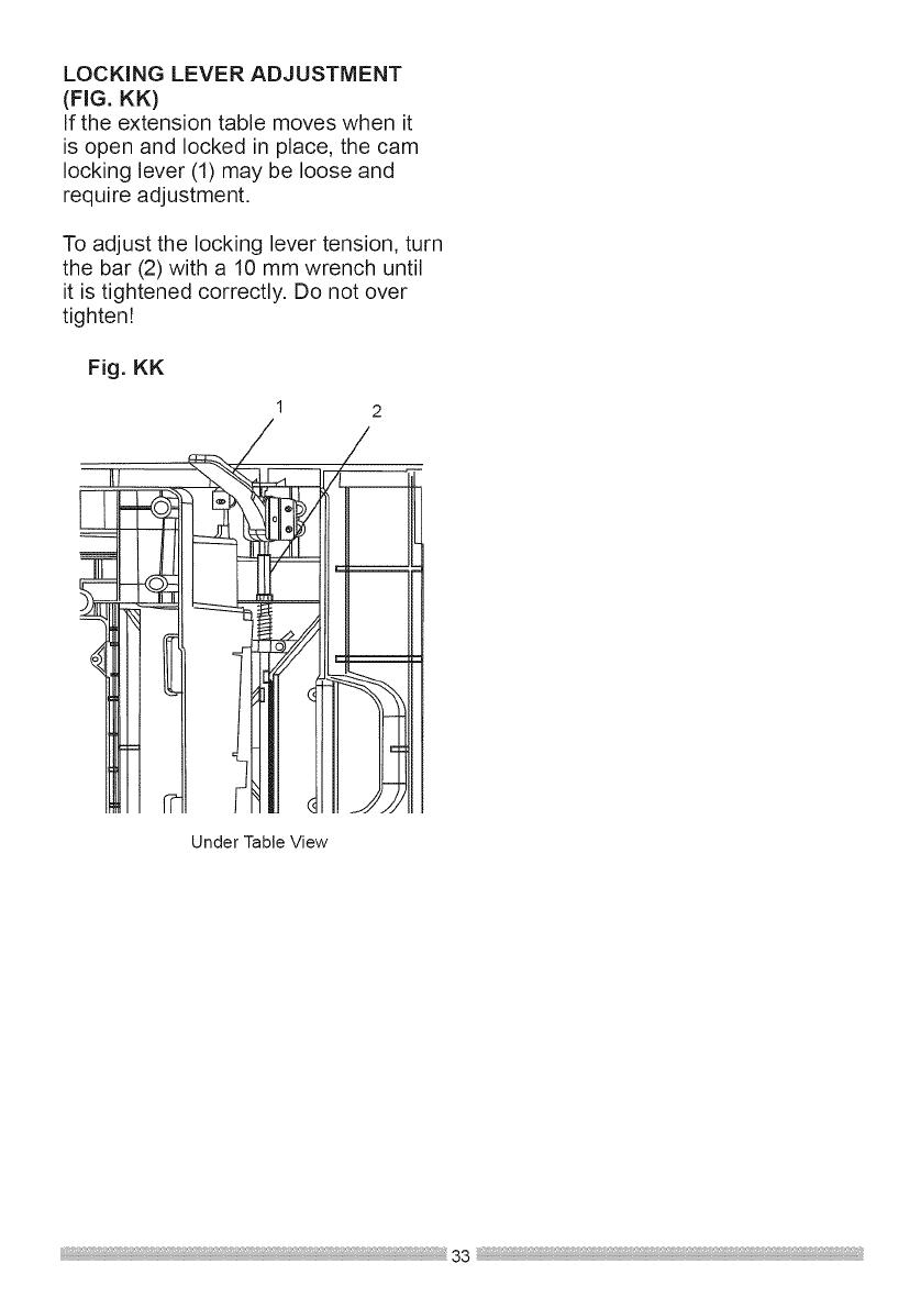
LOCKING LEVER ADJUSTMENT
(FIG. KK)
If the extension table moves when it
is open and locked in place, the cam
locking lever (1) may be loose and
require adjustment.
To adjust the locking lever tension, turn
the bar (2) with a 10 mm wrench until
it is tightened correctly. Do not over
tighten!
Fig. KK
1
/
/
Under Table View
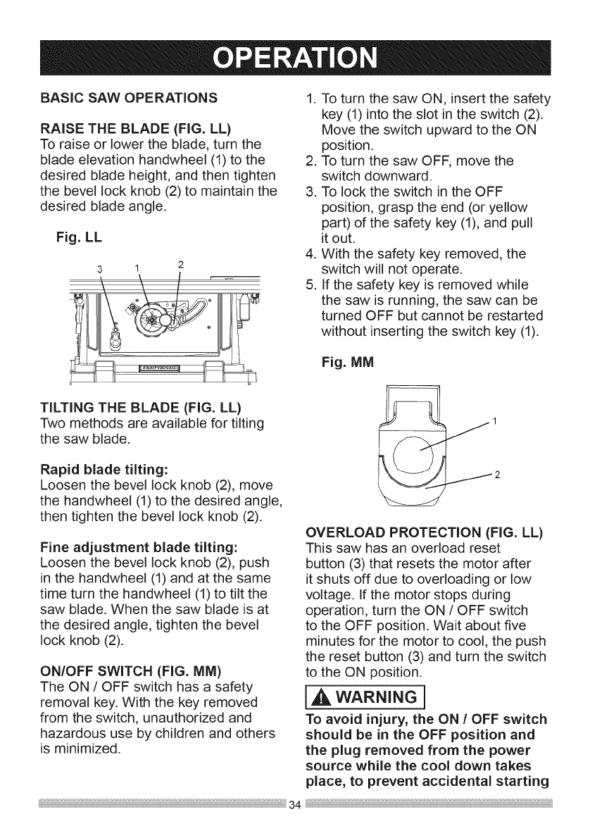
BASIC SAW OPERATIONS
RAISE THE BLADE (FIG. LL)
To raise or lower the blade, turn the
blade elevation handwheel (1) to the
desired blade height, and then tighten
the bevel lock knob (2) to maintain the
desired blade angle.
Fig. LL
3I2
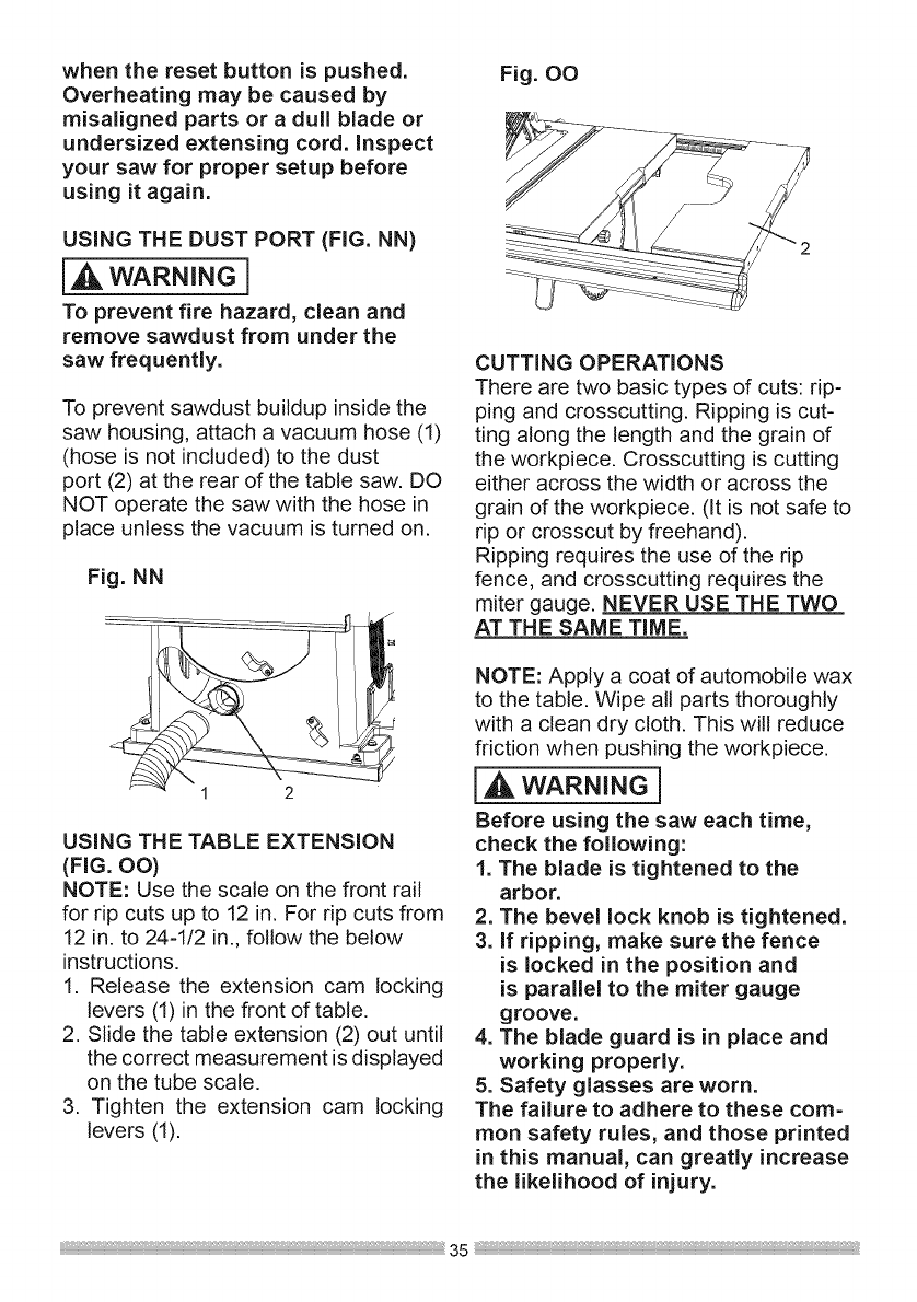
1. To turn the saw ON, insert the safety
key (1) into the slot in the switch (2).
Move the switch upward to the ON
position.
2. To turn the saw OFF, move the
switch downward.
3. To lock the switch in the OFF
position, grasp the end (or yellow
part) of the safety key (1), and pull
it out.
4. With the safety key removed, the
switch will not operate.
5. If the safety key is removed while
the saw is running, the saw can be
turned OFF but cannot be restarted
without inserting the switch key (1).
Fig. MM
TILTING THE BLADE (FIG. LL)
Two methods are available for tilting
the saw blade.
Rapid blade tilting:
Loosen the bevel lock knob (2), move
the handwheel (1) to the desired angle,
then tighten the bevel lock knob (2).
Fine adjustment blade tilting:
Loosen the bevel lock knob (2), push
in the handwheel (1) and at the same
time turn the handwheel (1) to tilt the
saw blade. When the saw blade is at
the desired angle, tighten the bevel
lock knob (2).
ON/OFF SWITCH (FIG. MM)
The ON /OFF switch has a safety
removal key. With the key removed
from the switch, unauthorized and
hazardous use by children and others
is minimized.
OVERLOAD PROTECTION (FIG. LL)
This saw has an overload reset
button (3) that resets the motor after
it shuts off due to overloading or low
voltage. If the motor stops during
operation, turn the ON /OFF switch
to the OFF position. Wait about five
minutes for the motor to cool, the push
the reset button (3) and turn the switch
to the ON position.
IA WARNINGl
To avoid injury, the ON /OFF switch
should be in the OFF position and
the plug removed from the power
source while the cool down takes
place, to prevent accidental starting
when the reset button is pushed.
Overheating may be caused by
misaligned parts or adull blade or
undersized extensing cord. inspect
your saw for proper setup before
using it again.
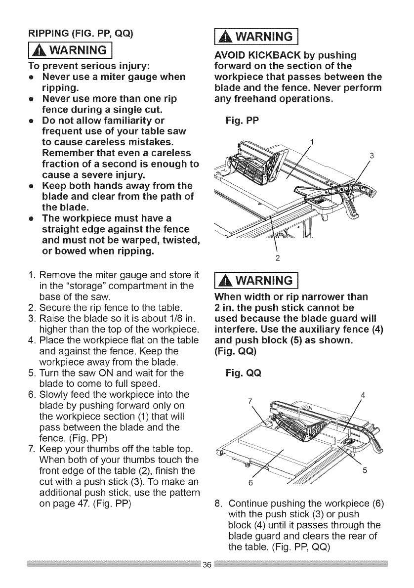
USING THE DUST PORT (FIG. NN)
[A wARNING]
To prevent fire hazard, clean and
remove sawdust from under the
saw frequently.
To prevent sawdust buildup inside the
saw housing, attach a vacuum hose (1)
(hose is not included) to the dust
port (2) at the rear of the table saw. DO
NOT operate the saw with the hose in
place unless the vacuum is turned on.
Fig. NN
1 2
USING THE TABLE EXTENSION
(FIG. OO)
NOTE: Use the scale on the front rail
for rip cuts up to 12 in. For rip cuts from
12 in, to 24-1/2 in,, follow the below
instructions,
1, Release the extension cam locking
levers (1) in the front of table,
2, Slide the table extension (2) out until
the correct measurement is displayed
on the tube scale,
3, Tighten the extension cam locking
levers (1),
Fig. O0
CUTTING OPERATIONS
There are two basic types of cuts: rip-
ping and crosscutting. Ripping is cut-
ting along the length and the grain of
the workpiece. Crosscutting is cutting
either across the width or across the
grain of the workpiece. (It is not safe to
rip or crosscut by freehand).
Ripping requires the use of the rip
fence, and crosscutting requires the
miter gauge. NEVER USE THE TWO
AT THE SAME TIME.
NOTE: Apply a coat of automobile wax
to the table. Wipe all parts thoroughly
with a clean dry cloth, This will reduce
friction when pushing the workpiece,
wAR.I.G]
Before using the saw each time,
check the following:
1. The blade is tightened to the
arbor.
2. The bevel lock knob is tightened.
3. If ripping, make sure the fence
is locked in the position and
is parallel to the miter gauge
groove.
4. The blade guard is in place and
working properly.
5. Safety glasses are worn.
The failure to adhere to these com-
mon safety rules, and those printed
in this manual, can greatly increase
the likelihood of injury.
35 :,
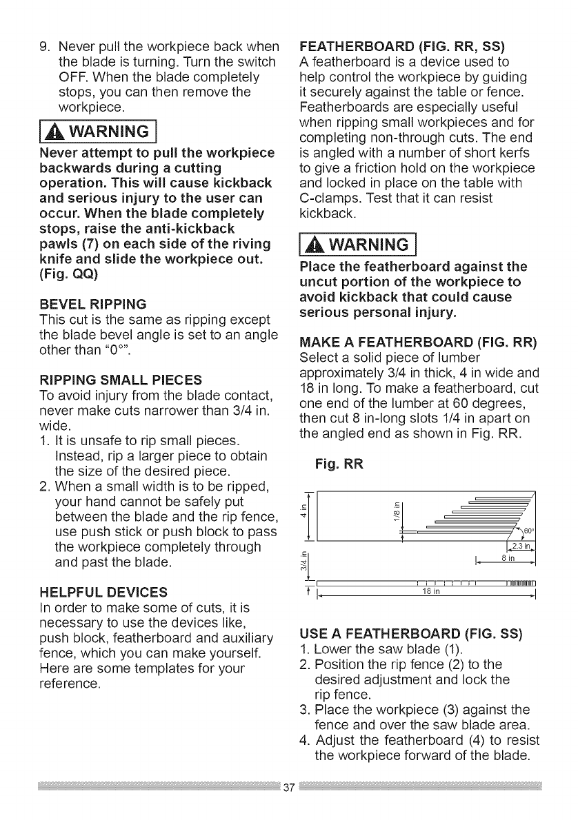
RiPPiNG (FIG. PP, QQ)
IA WARNING]
To prevent serious injury:
•Never use a miter gauge when
ripping.
•Never use more than one rip
fence during asingle cut.
•Do not allow familiarity or
frequent use of your table saw
to cause careless mistakes.
Remember that even a careless
fraction of a second is enough to
cause a severe injury.
• Keep both hands away from the
blade and clear from the path of
the blade.
• The workpiece must have a
straight edge against the fence
and must not be warped, twisted,
or bowed when ripping.
,_ WARNING I
AVOID KICKBACK by pushing
forward on the section of the
workpiece that passes between the
blade and the fence. Never perform
any freehand operations.
Fig. PP
1
3
1. Remove the miter gauge and store it
in the "storage" compartment in the
base of the saw.
2. Secure the rip fence to the table.
3. Raise the blade so it is about 1/8 in.
higher than the top of the workpiece.
4. Place the workpiece flat on the table
and against the fence. Keep the
workpiece away from the blade.
5. Turn the saw ON and wait for the
blade to come to full speed.
6. Slowly feed the workpiece into the
blade by pushing forward only on
the workpiece section (1) that will
pass between the blade and the
fence. (Fig. PP)
7. Keep your thumbs off the table top.
When both of your thumbs touch the
front edge of the table (2), finish the
cut with a push stick (3). To make an
additional push stick, use the pattern
on page 47. (Fig. PP)
[,AWARNING]
When width or rip narrower than
2 in. the push stick cannot be
used because the blade guard will
interfere. Use the auxiliary fence (4)
and push block (5) as shown.
(Fig. QQ)
Fig. QQ
.Continue pushing the workpiece (6)
with the push stick (3) or push
block (4) until it passes through the
blade guard and clears the rear of
the table. (Fig. PP, QQ)
9. Neverpulltheworkpiecebackwhen
thebladeisturning.Turntheswitch
OFF.Whenthebladecompletely
stops,youcanthenremovethe
workpiece.
I,A WARNING 1
Never attempt to pull the workpiece
backwards during a cutting
operation. This will cause kickback
and serious injury to the user can
occur. When the blade completely
stops, raise the anti-kickback
pawls (7) on each side of the riving
knife and slide the workpiece out.
(Fig. QQ)
BEVEL RIPPING
This cut is the same as ripping except
the blade bevel angle is set to an angle
other than "0 °''.
RIPPING SMALL PIECES
To avoid injury from the blade contact,
never make cuts narrower than 3/4 in.
wide.
1. It is unsafe to rip small pieces.
Instead, rip a larger piece to obtain
the size of the desired piece.
2. When a small width is to be ripped,
your hand cannot be safely put
between the blade and the rip fence,
use push stick or push block to pass
the workpiece completely through
and past the blade.
HELPFUL DEVICES
In order to make some of cuts, it is
necessary to use the devices like,
push block, featherboard and auxiliary
fence, which you can make yourself.
Here are some templates for your
reference.
FEATHERBOARD (FIG. RR, SS)
A featherboard is a device used to
help control the workpiece by guiding
it securely against the table or fence.
Featherboards are especially useful
when ripping small workpieces and for
completing non-through cuts. The end
is angled with a number of short kerfs
to give a friction hold on the workpiece
and locked in place on the table with
C-clamps. Test that it can resist
kickback.
wAR.I.G]
Place the featherboard against the
uncut portion of the workpiece to
avoid kickback that could cause
serious personal injury.
MAKE A FEATHERBOARD (FIG. RR)
Select a solid piece of lumber
approximately 3/4 in thick, 4 in wide and
18 in long. To make a featherboard, cut
one end of the lumber at 60 degrees,
then cut 8 in-long slots 1/4 in apart on
the angled end as shown in Fig. RR.
Fig. RR
nI
,//,
I 8in !
_-i, 18in 4
USE A FEATHERBOARD (FIG. SS)
1. Lower the saw blade (1).
2. Position the rip fence (2) to the
desired adjustment and lock the
rip fence.
3. Place the workpiece (3) against the
fence and over the saw blade area.
4. Adjust the featherboard (4) to resist
the workpiece forward of the blade.
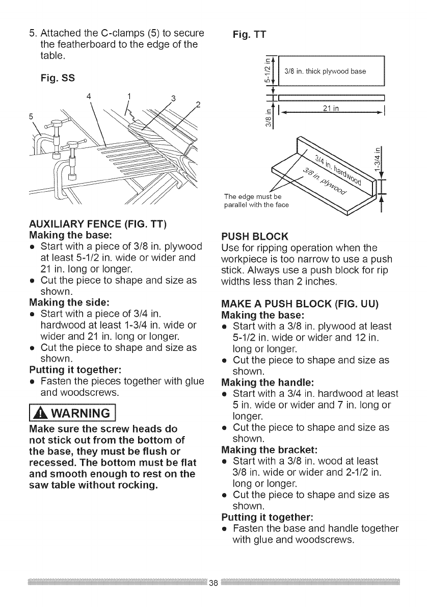
5.AttachedtheC-clamps(5)tosecure
thefeatherboardtotheedgeofthe
table,
Fig. SS
4
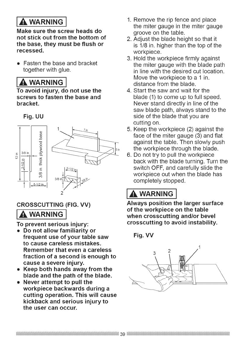
Fig. TT
c
3/8 in. thick plywood base
::I[
_ll_ 21in
]
AUXILIARY FENCE (FIG. TT)
Making the base:
o Start with a piece of 3/8 in. plywood
at least 5-1/2 in. wide or wider and
21 in. long or longer.
o Cut the piece to shape and size as
shown.
Making the side:
o Start with a piece of 3/4 in.
hardwood at least 1-3/4 in. wide or
wider and 21 in. long or longer.
o Cut the piece to shape and size as
shown.
Putting it together:
o Fasten the pieces together with glue
and woodscrews.
WARNING1
Make sure the screw heads do
not stick out from the bottom of
the base, they must be flush or
recessed. The bottom must be flat
and smooth enough to rest on the
saw table without rocking.
The edge must be
parallel with the face
PUSH BLOCK
Use for ripping operation when the
workpiece is too narrow to use a push
stick. Always use a push block for rip
widths less than 2 inches.
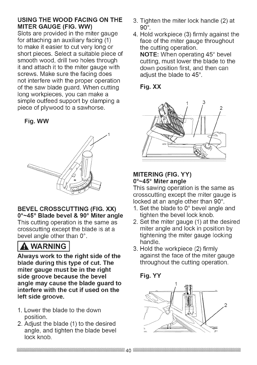
MAKE APUSH BLOCK (FIG. UU)
Making the base:
o Start with a 3/8 in. plywood at least
5-1/2 in. wide or wider and 12 in.
long or longer.
o Cut the piece to shape and size as
shown.
Making the handle:
o Start with a 3/4 in. hardwood at least
5 in. wide or wider and 7 in. long or
longer.
o Cut the piece to shape and size as
shown.
Making the bracket:
o Start with a 3/8 in. wood at least
3/8 in. wide or wider and 2-1/2 in.
long or longer.
o Cut the piece to shape and size as
shown.
Putting it together:
o Fasten the base and handle together
with glue and woodscrews.
WARNING i
Make sure the screw heads do
not stick out from the bottom of
the base, they must be flush or
recessed.
o Fasten the base and bracket
together with glue.
{_ WARNING 1
To avoid injury, do not use the
screws to fasten the base and
bracket.
Fig. UU
I I 3/8i_ _
2
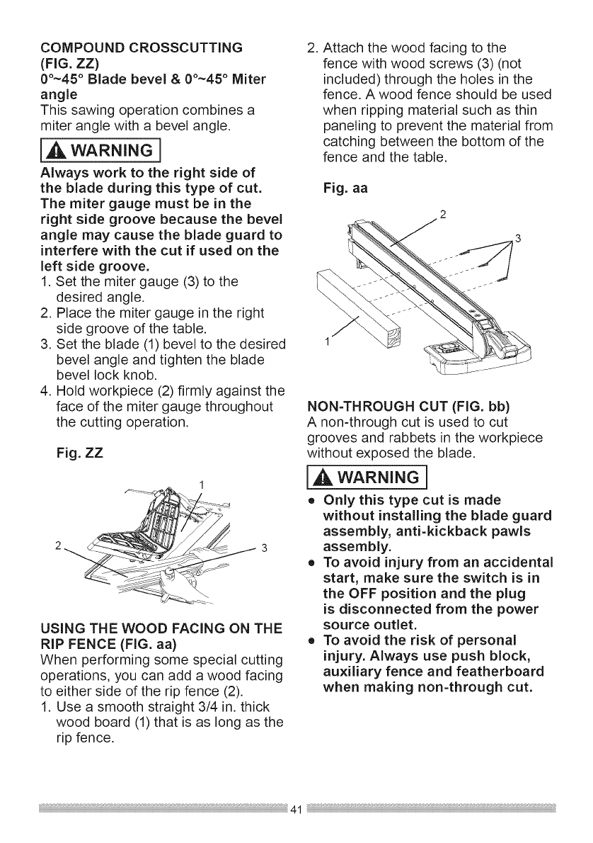
CROSSCUTTING (FIG. VV)
IA WARNINGl
To prevent serious injury:
o Do not allow familiarity or
frequent use of your table saw
to cause careless mistakes.
Remember that even a careless
fraction of a second is enough to
cause a severe injury.
o Keep both hands away from the
blade and the path of the blade.
o Never attempt to pull the
workpiece backwards during a
cutting operation. This will cause
kickback and serious injury to
the user can occur.
1. Remove the rip fence and place
the miter gauge in the miter gauge
groove on the table.
2. Adjust the blade height so that it
is 1/8 in. higher than the top of the
workpiece.
3. Hold the workpiece firmly against
the miter gauge with the blade path
in line with the desired cut location.
Move the workpiece to a 1 in.
distance from the blade.
4. Start the saw and wait for the
blade (1) to come up to full speed.
Never stand directly in line of the
saw blade path, always stand to the
side of the blade that you are
cutting on.
5. Keep the workpiece (2) against the
face of the miter gauge (3) and flat
against the table. Then slowly push
the workpiece through the blade.
6. Do not try to pull the workpiece
back with the blade turning. Turn the
switch OFF, and carefully slide the
workpiece out when the blade has
completely stopped.
I,A WARNING 1
Always position the larger surface
of the workpiece on the table
when crosscutting and/or bevel
crosscutting to avoid instability.
Fig. VV
--\ \
USING THE WOOD FACING ON THE
MITER GAUGE (FIG. WW)
Slots are provided in the miter gauge
for attaching an auxiliary facing (1)
to make it easier to cut very long or
short pieces. Select a suitable piece of
smooth wood, drill two holes through
it and attach it to the miter gauge with
screws. Make sure the facing does
not interfere with the proper operation
of the saw blade guard. When cutting
long workpieces, you can make a
simple outfeed support by clamping a
piece of plywood to a sawhorse.
Fig. WW
,
4.
Tighten the miter lock handle (2) at
90 °"
Hold workpiece (3) firmly against the
face of the miter gauge throughout
the cutting operation.
NOTE: When operating 45 ° bevel
cutting, must lower the blade to the
down position first, and then can
adjust the blade to 45 °.
Fig. XX
1 3
2
BEVEL CROSSCUTTING (FIG. XX)
00~45 ° Blade bevel & 90° Miter angle
This cutting operation is the same as
crosscutting except the blade is at a
bevel angle other than 0°.
WARNINOi
Always work to the right side of the
blade during this type of cut. The
miter gauge must be in the right
side groove because the bevel
angle may cause the blade guard to
interfere with the cut if used on the
left side groove.
1. Lower the blade to the down
position.
2. Adjust the blade (1) to the desired
angle, and tighten the blade bevel
lock knob.
MITERING (FIG. YY)
00~45° Miter angle
This sawing operation is the same as
crosscutting except the miter gauge is
locked at an angle other than 90°.
1. Set the blade to 0° bevel angle and
tighten the bevel lock knob.
2. Set the miter gauge (1) at the desired
miter angle and lock in position by
tightening the miter gauge locking
handle.
3. Hold the workpiece (2) firmly
against the face of the miter gauge
throughout the cutting operation.
Fig. YY
1
COMPOUND CROSSCUTTING
(FIG. 77)
00~45 ° Blade bevel & 00~45 ° Miter
angle
This sawing operation combines a
miter angle with a bevel angle.
l_ WARNING 1
Always work to the right side of
the blade during this type of cut.
The miter gauge must be in the
right side groove because the bevel
angle may cause the blade guard to
interfere with the cut if used on the
left side groove.
1. Set the miter gauge (3) to the
desired angle,
2. Place the miter gauge in the right
side groove of the table.
3. Set the blade (1) bevel to the desired
bevel angle and tighten the blade
bevel lock knob.
4. Hold workpiece (2) firmly against the
face of the miter gauge throughout
the cutting operation,
Fig. ZZ
1
USING THE WOOD FACING ON THE
RiP FENCE (FIG. aa)
When performing some special cutting
operations, you can add a wood facing
to either side of the rip fence (2).
1. Use a smooth straight 3/4 in. thick
wood board (1) that is as long as the
rip fence.
.Attach the wood facing to the
fence with wood screws (3) (not
included) through the holes in the
fence. A wood fence should be used
when ripping material such as thin
paneling to prevent the material from
catching between the bottom of the
fence and the table.
Fig. aa
2
1
NON-THROUGH CUT (FIG. bb)
A non-through cut is used to cut
grooves and rabbets in the workpiece
without exposed the blade,
IA,WARNING1
o Only this type cut is made
without installing the blade guard
assembly, anti=kickback pawls
assembly.
o To avoid injury from an accidental
start, make sure the switch is in
the OFF position and the plug
is disconnected from the power
source outlet.
o To avoid the risk of personal
injury. Always use push block,
auxiliary fence and featherboard
when making non-through cut.
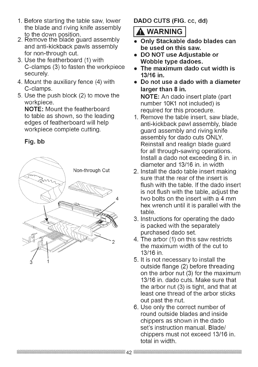
1.Beforestartingthetablesaw,lower
thebladeandrivingknifeassembly
to thedownposition.
2. Removethebladeguardassembly
andanti-kickbackpawlsassembly
fornon-throughcut.
3. Usethefeatherboard(1)with
C-clamps(3)tofastentheworkpiece
securely.
4. Mounttheauxiliaryfence(4)with
C-clamps.
5. Usethepushblock(2)tomovethe
workpiece.
NOTE:Mountthefeatherboard
to tableasshown,sotheleading
edgesoffeatherboardwillhelp
workpiececompletecutting.
Fig.bb
\Non-through Cut
3 1
DADO CUTS (FIG. cc, dd)
i WARNING1
o Only Stackable dado blades can
be used on this saw.
o DO NOT use Adjustable or
Wobble type dadoes.
o The maximum dado cut width is
13116 in.
o Do not use a dado with a diameter
larger than 8 in.
NOTE: An dado insert plate (part
number 10K1 not included) is
required for this procedure.
1. Remove the table insert, saw blade,
anti-kickback pawl assembly, blade
guard assembly and riving knife
assembly for dado cuts ONLY.
Reinstall and realign blade guard
for all through-sawing operations.
Install a dado not exceeding 8 in. in
diameter and 13/16 in. in width
2. Install the dado table insert making
sure that the rear of the insert is
flush with the table. If the dado insert
is not flush with the table, adjust the
two bolts on the insert with a 4 mm
hex wrench until it is parallel with the
table.
3. Instructions for operating the dado
is packed with the separately
purchased dado set.
4. The arbor (1) on this saw restricts
the maximum width of the cut to
13/16 in.
5. It is not necessary to install the
outside flange (2) before threading
on the arbor nut (3) for the maximum
13/16 in. dado cuts. Make sure that
the arbor nut (3) is tight, and that at
least one thread of the arbor sticks
out past the nut.
6. Use only the correct number of
round outside blades and inside
chippers as shown in the dado
set's instruction manual. Blade/
chippers must not exceed 13/16 in.
total in width.
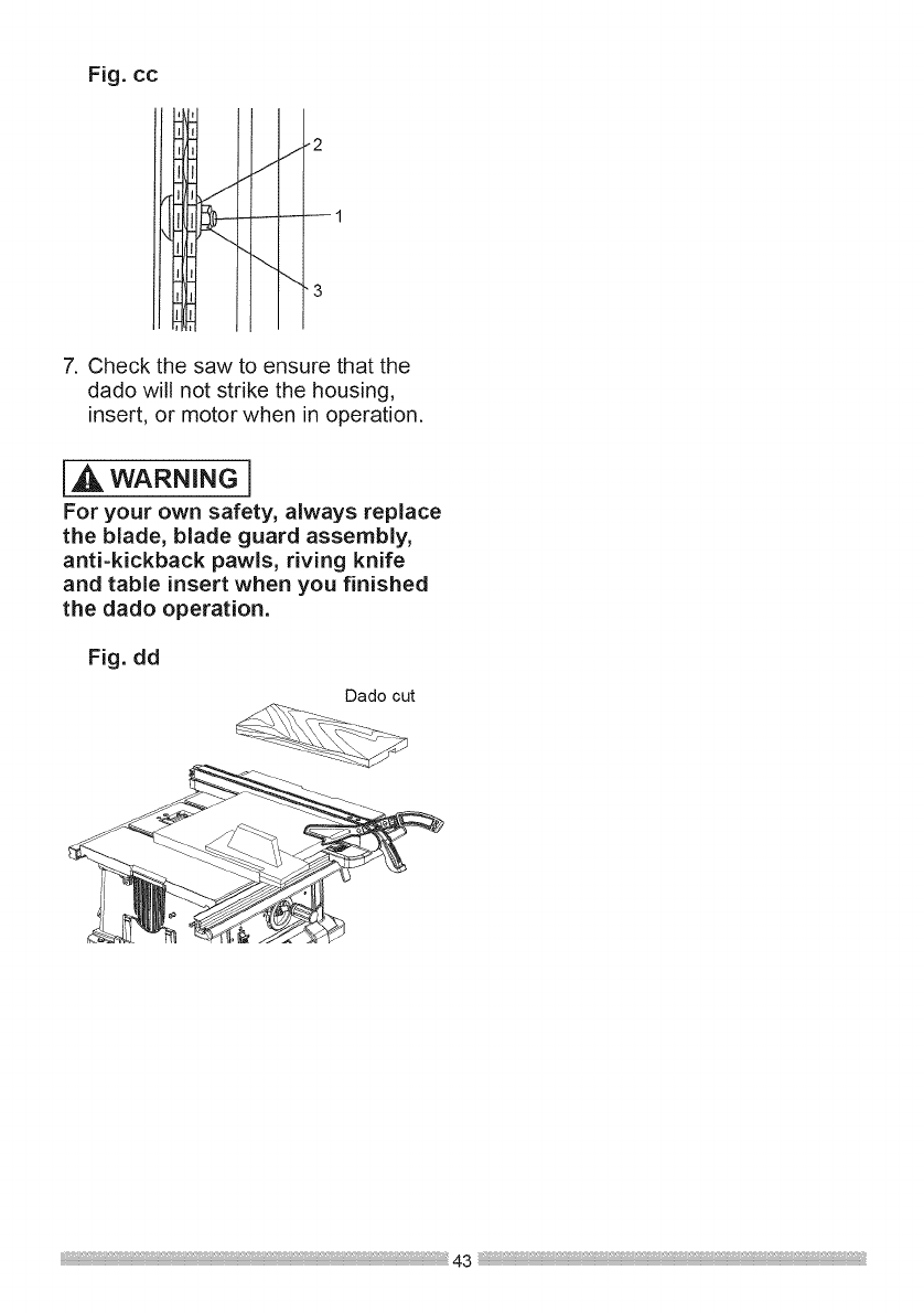
Fig.cc
J i
I I
!1 J"
!1
3
7. Check the saw to ensure that the
dado will not strike the housing,
insert, or motor when in operation.
IA wAR.I.G1
For your own safety, always replace
the blade, blade guard assembly,
anti-kickback pawls, riving knife
and table insert when you finished
the dado operation.
Fig. dd
Dado out
43
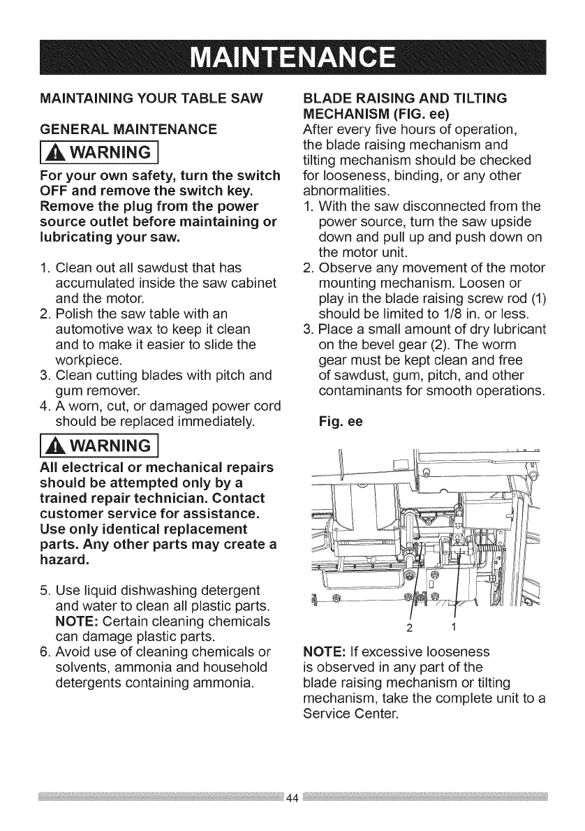
MAiNTAiNiNG YOUR TABLE SAW
GENERAL MAINTENANCE
A wARNINGi
For your own safety, turn the switch
OFF and remove the switch key.
Remove the plug from the power
source outlet before maintaining or
lubricating your saw.
1. Clean out all sawdust that has
accumulated inside the saw cabinet
and the motor.
2. Polish the saw table with an
automotive wax to keep it clean
and to make it easier to slide the
workpiece.
3. Clean cutting blades with pitch and
gum remover.
4. A worn, cut, or damaged power cord
should be replaced immediately.
iA wAR.I.G]
All electrical or mechanical repairs
should be attempted only by a
trained repair technician. Contact
customer service for assistance.
Use only identical replacement
parts. Any other parts may create a
hazard.
BLADE RAISING AND TILTING
MECHANISM (FIG. ee)
After every five hours of operation,
the blade raising mechanism and
tilting mechanism should be checked
for looseness, binding, or any other
abnormalities.
1. With the saw disconnected from the
power source, turn the saw upside
down and pull up and push down on
the motor unit.
2. Observe any movement of the motor
mounting mechanism. Loosen or
play in the blade raising screw rod (1)
should be limited to 1/8 in. or less.
3. Place a small amount of dry lubricant
on the bevel gear (2). The worm
gear must be kept clean and free
of sawdust, gum, pitch, and other
contaminants for smooth operations.
Fig. ee
5. Use liquid dishwashing detergent
and water to clean all plastic parts.
NOTE: Certain cleaning chemicals
can damage plastic parts.
6. Avoid use of cleaning chemicals or
solvents, ammonia and household
detergents containing ammonia.
2 1
NOTE: If excessive looseness
is observed in any part of the
blade raising mechanism or tilting
mechanism, take the complete unit to a
Service Center.
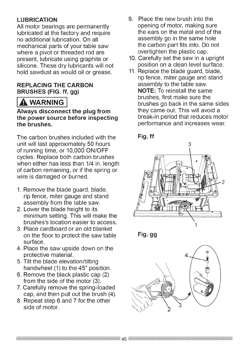
LUBRICATION
Al!motorbearingsarepermanently
lubricatedatthefactoryandrequire
noadditionallubrication.Onall
mechanicalpartsofyourtablesaw
wherea pivotorthreadedrodare
present,lubricateusinggraphiteor
silicone.Thesedrylubricantswillnot
holdsawdustaswouldoilorgrease.
REPLACINGTHECARBON
wAR.I.G]
Always disconnect the plug from
the power source before inspecting
the brushes.
The carbon brushes included with the
unit wil! last approximately 50 hours
of running time, or 10,000 ON/OFF
cycles. Replace both carbon brushes
when either has less than 1/4 in. length
of carbon remaining, or if the spring or
wire is damaged or burned.
1. Remove the blade guard, blade,
rip fence, miter gauge and stand
assembly from the table saw.
2. Lower the blade height to its
minimum setting. This will make the
brushes's location easier to access.
3. Place cardboard or an old blanket
on the floor to protect the saw table
surface.
4. Place the saw upside down on the
protective material.
5. Tilt the blade elevation/tilting
handwheel (1) to the 45 ° position.
6. Remove the black plastic cap (2)
from the side of the motor (3).
7. Carefully remove the spring-loaded
cap, and then pull out the brush (4).
8. Repeat step 6 and 7 for the other
side of motor.
9. Place the new brush into the
opening of motor, making sure
the ears on the metal end of the
assembly go in the same hole
the carbon part fits into. Do not
overtighten the plastic cap.
10. Carefully set the saw in a upright
position on a clean level surface.
11. Replace the blade guard, blade,
rip fence, miter gauge and stand
assembly to the table saw.
NOTE: To reinstall the same
brushes, first make sure the
brushes go back in the same sides
they came out. This will avoid a
break-in period that reduces motor
performance and increases wear.
Fig. ff
3
1
Fig. gg
•/_SZ-7 /
45 _
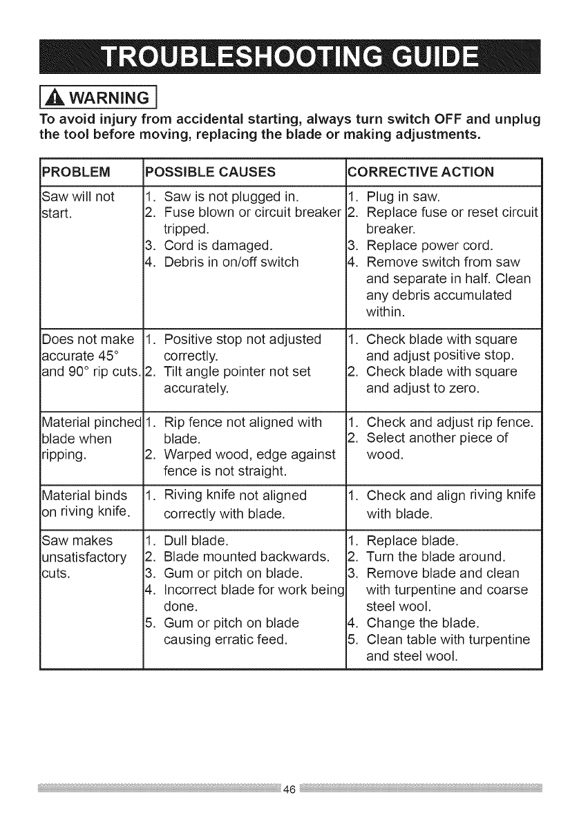
WARNINGl
To avoid injury from accidental starting, always turn switch OFF and unplug
the tool before moving, replacing the blade or making adjustments,
PROBLEM
Saw will not
start.
Does not make
accurate 45°
and 90 ° rip cuts.
Material pinched
blade when
ripping.
POSSIBLE CAUSES CORRECTIVE ACTION
1. Saw is not plugged in.
2. Fuse blown or circuit breaker
tripped.
3. Cord is damaged.
4. Debris in on/off switch
1. Positive stop not adjusted
correctly.
2. Tilt angle pointer not set
accurately.
1. Rip fence not aligned with
blade.
2. Warped wood, edge against
fence is not straight.
1. Plug in saw.
2. Replace fuse or reset circuit
breaker.
3. Replace power cord.
4. Remove switch from saw
and separate in half. Clean
any debris accumulated
within.
1. Check blade with square
and adjust positive stop.
2. Check blade with square
and adjust to zero.
1. Check and adjust rip fence.
2. Select another piece of
wood.
Material binds 1. Riving knife not aligned 1. Check and align riving knife
on riving knife, correctly with blade, with blade.
1. Dull blade.
2. Blade mounted backwards.
3. Gum or pitch on blade.
4. Incorrect blade for work being
done.
5. Gum or pitch on blade
causing erratic feed.
Saw makes
unsatisfactory
cuts.
1. Replace blade.
2. Turn the blade around.
3. Remove blade and clean
with turpentine and coarse
steel wool.
4. Change the blade.
5. Clean table with turpentine
and steel wool.
46
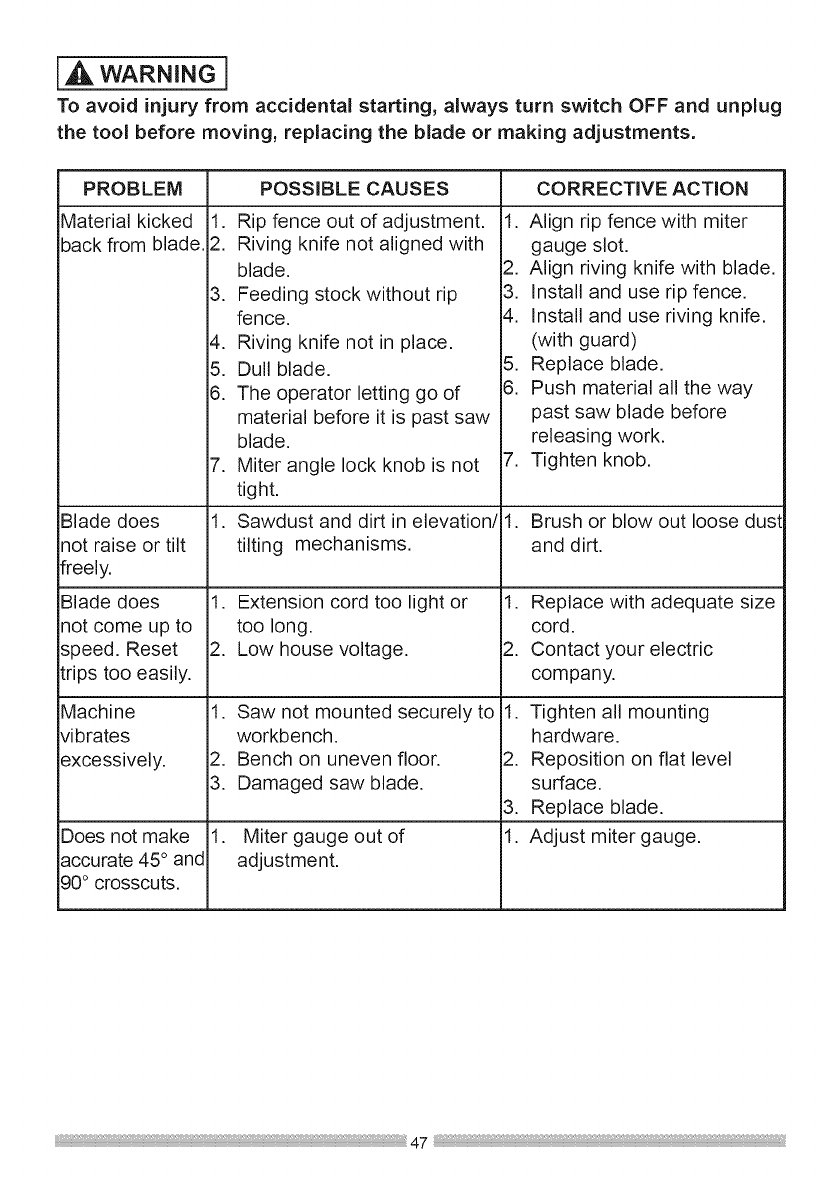
IA WARNING l
To avoid injury from accidental starting, always turn switch OFF and unplug
the tool before moving, replacing the blade or making adjustments.
PROBLEM
Material kicked
back from blade.
Blade does
not raise or tilt
freely.
Blade does
not come up to
speed. Reset
trips too easily,
Machine
vibrates
excessively.
Does not make
accurate 45° and
90° crosscuts.
POSSIBLE CAUSES
1. Rip fence out of adjustment.
2. Riving knife not aligned with
blade.
3. Feeding stock without rip
fence.
4. Riving knife not in place.
5. Dullblade.
8. The operator letting go of
material before it is past saw
blade,
7. Miter angle lock knob is not
tight.
1. Sawdust and dirt in elevation/
tilting mechanisms,
1. Extension cord too light or
too long.
2. Low house voltage.
1. Saw not mounted securely to
workbench.
2. Bench on uneven floor.
3. Damaged saw blade,
1. Miter gauge out of
adjustment.
CORRECTIVE ACTION
1. Align rip fence with miter
gauge slot.
2. Align riving knife with blade.
3. Install and use rip fence.
4. Install and use riving knife,
(with guard)
5. Replace blade.
6. Push material all the way
past saw blade before
releasing work.
7. Tighten knob,
1. Brush or blow out loose dus!
and dirt.
1. Replace with adequate size
cord.
2. Contact your electric
company,
1. Tighten all mounting
hardware.
2. Reposition on flat level
surface.
3. Replace blade,
1. Adjust miter gauge,
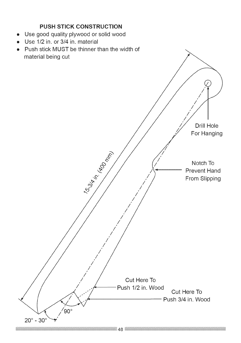
®
®
®
PUSH STICK CONSTRUCTION
Use good quality plywood or solid wood
Use 1/2 in. or 3/4 in. material
Push stick MUST be thinner than the width of
material being cut
/
/
/
/
/
Drill Hole
For Hanging
/
/
/
/
/
/
/
/
/
/
/
/
/
/
/
/
/
/
/
/
Notch To
Prevent Hand
From Slipping
Cut Here To
--Push 1/2 in. Wood Cut Here To
Push 3/4 in. Wood
//90 °
20 ° _ 30°

10iN. TABLE SAW MODEL NO. 137.415020
WARNINGj
When servicing use only CRAFTSMAN replacement parts. Use of any other parts
many create aHAZARD or cause product damage. Any attempt to repair or replace
electrical parts on this Table Saw may create aHAZARD unless repair is done by
aqualified service technician. Repair service is available at your nearest Sears
Service Center.
PARTS LiST FOR TABLE SAW -A
I.D. NO, Description Size
0901 BUSH
0908 FLAT WASHER
3176 LOCKING HANDLE ASS'Y
08VH CORD CLAMP
08W 1 BRACKET
08W2 SPACER
08WG ANGLE ROD BRACKET
08WS STRAP
08ZK FLAT WASHER
09XJ COMPRESSION SPRING
0AW8 SEGMENT GEAR
0B2B NEEDLE POINTER
0B9E BUSH
0B9M STRAP
0B9N STRAP
0BA3 ANCHOR BLOCK
0BA5 ARBOR COLLAR
0BAC SET NUT
0BAE ARBOR COLLAR
0GCM BEVEL GEAR
0J3P HEX. WRENCH
0J3Q HEX WRENCH
0J4E FLAT WASHER _p6_13-1
0J4F FLAT WASHER _p8X16-2.5
0J4Q FLAT WASHER _pl 2_21-2
0J58 FLAT WASHER _p5_14-1
0J6G FLAT WASHER _p8.2_ 18-2.0
0J6K FLAT WASHER _p6_30-4
0J6T FLAT WASHER 3/16_3/4-1/16
0J70 FLAT WASHER 1/4_3/4-7/64
0J76 FLAT WASHER 1/4_3/4-1/16
0J78 FLAT WASHER 1/4_1/2-3/32
0J8D FLAT WASHER 3/8_3/4-5/64
0J95 SPRING WASHER _p6
0JAE EXTERNAL TOOTH LOCK WASHER _p4
0JAF EXTERNALTOOTH LOCK WASHER _p5
0JPM HEX. HD. BOLT M6_1.0-70
0JYN HEX. SOC. COUNTERSUNK M6_1.0-25
HD. SCREW
0JX7 CR. RE. TRUSS HD. SCREW M6_1.0-6
0KOX HEX. HD. SCREW AND WASHER M6_1.0-16
a'ty i.D.NO.
0K2B
0K71
0K7F
0K7K
0K81
0K8C
0K8X
0K9U
0KA2
0KA4
0KA6
0KBQ
0KC7
0KC8
0KCL
0KCX
0KCY
0KCZ
0KDR
0KDW
0KF7
OKJO
OKJ6
OKJ7
OKMS
OKMT
OKMY
OKNE
OKP8
0KQX
0KQY
0KRQ
0KSM
0KTK
6 0KTR
2 2X6V
Description Size Q'ty
HEX SOC. HD. CAP SCREW M6_1.0,-16 4
CR.-RE. TRUSS HD. SCREW M5_0.8-8 1
CR. RE. ROUND WASHER HD. SCREW M5_0.8-8 3
CR. RE. ROUND WASHER HD. SCREW M6_1.0-12 5
CR. RE.COUNT HD. TAPPING SCREW M4_16-10 4
CR. RE.COUNT HD. TAPPING SCREW M4_18-10 4
CR. RE. TRUSSHD. TAPPING SCREW M5_12-12 2
HEX. HD. TAPPING SCREW M5_16-25 4
CR.RE. PAN HD. TAPPING SCREW M4_16-8 2
CR.RE. PAN HD. TAPPING SCREW M4_16-16 2
CR.RE. PAN HD. TAPPING SCREW M5_12-10 1
CR.RE. PAN HD. TAPPING SCREW M5_16-10 1
CR. RE. TRUSSHD. TAPPING SCREW M4_16-10 2
CR. RE. TRUSSHD. TAPPING SCREW M4_16-16 4
CR.RE. PAN HEAD TAPPING & M5_16-12 4
WASHER SCREW
CR. RE. PAN HD PLAIN WASHER
TAPPING SCREW
CR. RE. PAN HD PLAIN WASHER
TAPPING SCREW
CR. RE. PAN HD PLAIN WASHER
TAPPING SCREW
CR. RE. PAN HD. SCREW
CR. RE. PAN HD. SCREW
CR. RE. PAN HD. SCREW
CAP HD. SQ.NECK BOLT
CAP HD. SQ.NECK BOLT
CAP HD. SQ.NECK BOLT
HEX. NUT
HEX. NUT
HEX. NUT
HEX. NUT
HEX. NUT
NUT
LOCK NUT
SERRATED TOOTHED HEXAGON
FLANGE NUT
STRAIN RELIEF
STRAIN RELIEF
CABLE CLAMP
WRENCH
M5_0.8-10
M5_0.8 -12
M5_0.8 -16
M5_0.8-10
M6_1,0-20
M4_0.7-12
M6_1.0-16
M6_1.0-70
M8_1.25-16
M6_1.0 T=5
M8_1.28 T=5
M8_1.28 T=6.5
M6_1.0 T=5
9/16_18UNF T=8
M6_l.0T=6
M8_1.28 T=8
M6_1.0 T=6
1
2
2
2
1
1
1
2
1
2
1
3
4
8
1
2
2
1

10 IN. TABLE SAW MODEL NO. 137.415020
PARTS LiST FOR TABLE SAW SCHEMATIC - B
I.D. NO. Description Size Q'ty
0KUW TERMINAL 1
0KWU LEAD WiRE ASS'Y 1
0LSL CiRCUiT BREAKER SWITCH 1
0LWG ON/OFF ROCKER SWITCH ASS'Y 1
10GX PIVOT-SUPPORT 2
10JL RACK 1
10JN SETPLATE 2
10JR LOCATING BAR 1
10JS ROLL PIN 1
10JU ANCHOR PLATE 2
10JV LOCATING BAR 1
10JW LOCATING BAR 1
10K1 DADO iNSERT PLATE (NOT iNCLUDED) 1
10K2 BUSH 2
10K4 PARALLEL PiN 2
10K5 HEX. SOC. HD. CAP BOLT M5_0.8-8 4
10K6 HEX. SOC. HD. CAP BOLT M6_1.0-30 2
212M LEAD WiRE ASS'Y 1
213B SPACER 4
21CX FOLLOWER PLATE 1
262S POWER CORD CLAMP 2
26E8 FLAT WASHER cp5_9.5-1.2 1
275R LOCATION SEAT 1
28BN COVER 1
28C3 RACK 1
28EX NEEDLE POINTER 1
2C88 BLADE 1
2CHN SiDE TABLE 1
2QL8 HANDLE 3
2QN2 SLIDE PLATE 2
2TBR ANGLE ROD 1
2WVT REAR SiDE COVER 2
2XIT PUSH iN PiN 2
2X6N SWITCH BOX ASS'Y 1
2YFA WHEEL 1
3F5V DUST COLLECTOR 1
3F5W SCREW BAR 1
3F7F SPLITTER 1
3F7G BODY SHELL 1
3F7H RETAiNiNG CLiP 1
I.D. NO. Description Size
3F7Q HEIGHT REGULATING BOLT ASS'Y
3F9R MOTOR ASS'Y
3FA1 POWER CABLE ASS'Y
3FA2 POWER CABLE
3FAT ANTI-KICKBACK PAWLS ASS'Y
3FB4 HANDLE
3FBR POINTER BRACKET
3FDZ LOCKING ROD
3FE5 RiP FENCE RAIL-FRONT
3FE7 RiP FENCE RAIL-REAR
3FE8 PLUG-BUTTON
3FE9 PLUG-BUTTON
3FES TENSION HANDLE
3FH5 CLAMP HANDLE
3FHP BRACKET STOP
3FJY LABEL
3FJZ TABLE
3FL2 BLADE GUARD ASS'Y
3FL5 MITER GAUGE ASS'Y
3FLA PARALLEL BRACKET ASS'Y
3FLF CLAMP HANDLE ASS'Y
3FWA RIVING KNIFE ASS'Y
3G2W WARNING LABEL
3G2X WARNING LABEL
3G2Y CAUTION LABEL
3G31 CAUTION LABEL
3G33 LABEL
3G3U SCALE
3G3X WARNING LABEL
3G4Q INSTRUCTION MANUAL
3GSU SPACER
3GT4 COMPRESSION SPRING
3GVF CR.RE. PAN HD. TAPPING SCREW M5"12-12
3GZC STICKER
3H2W HANDLE
3H2X KNOB
3H2Z PUSH BLOCK
3H4M TABLE INSERTASS'Y
3H4L SCALE ASS'Y
Q'ty
1
1
1
2
1
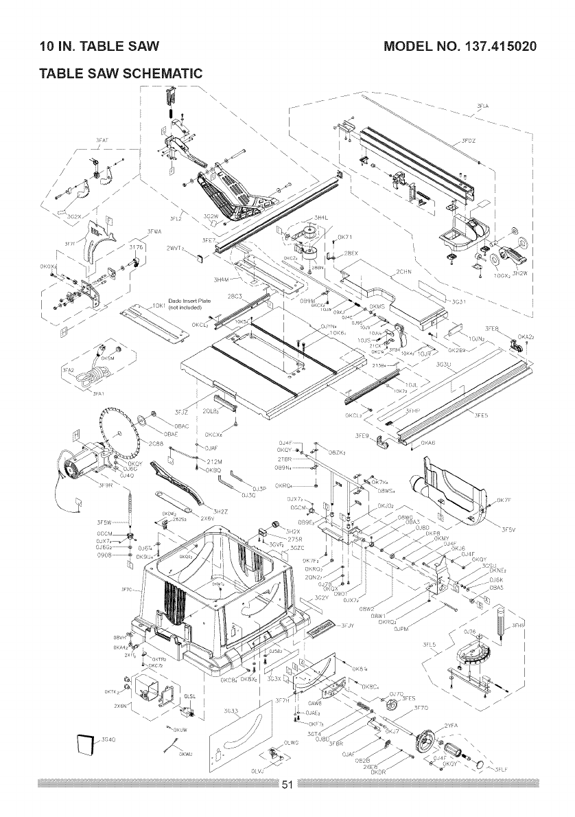
10 iN. TABLE SAW MODEL NO. 137.415020
TABLE SAW SCHEMATIC
Dado _nsert Plate
(not included)
08/,5
I
I
I
I
J
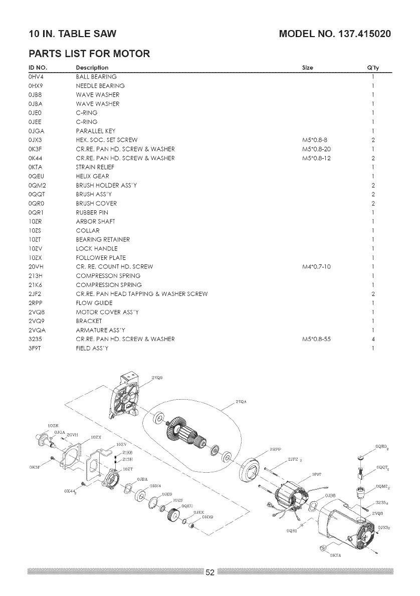
10iN. TABLE SAW MODEL NO. 137.415020
PARTS LiST FOR MOTOR
ID NO. Description
0HV4 BALL BEARING
0HX9 NEEDLE BEARING
0JB8 WAVE WASHER
0JBA WAVE WASHER
0JEO C-RING
0JEE C-RING
0JGA PARALLEL KEY
0iX3 HEX. SOC. SETSCREW
0K3F CR.RE. PAN HD. SCREW & WASHER
0K44 CR.RE. PAN HD. SCREW & WASHER
0KTA STRAIN RELIEF
0QEU HELIX GEAR
0QM2 BRUSH HOLDER ASS'Y
0QQT BRUSH ASS'Y
0QR0 BRUSH COVER
0QR1 RUBBER PIN
10ZR ARBOR SHAFT
10ZS COLLAR
10ZT BEARING RETAINER
10ZV LOCK HANDLE
10ZX FOLLOWER PLATE
20VH CR. RE. COUNT HD. SCREW
213H COMPRESSON SPRING
21 K6 COMPRESSION SPRING
2JF2 CR,RE. PAN HEAD TAPPING & WASHER SCREW
2RPP FLOW GUIDE
2VQ8 MOTOR COVER ASS'Y
2VQ9 BRACKET
2VQA ARMATURE ASS'Y
3235 CR.RE. PAN HD. SCREW & WASHER
3F9T FIELD ASS'Y
Size
M5_0.8-8
M5_0.8-20
M5_0.8 -12
M4_0.7-10
M5_0.8-55
Q'ty
oqR%
OK']A
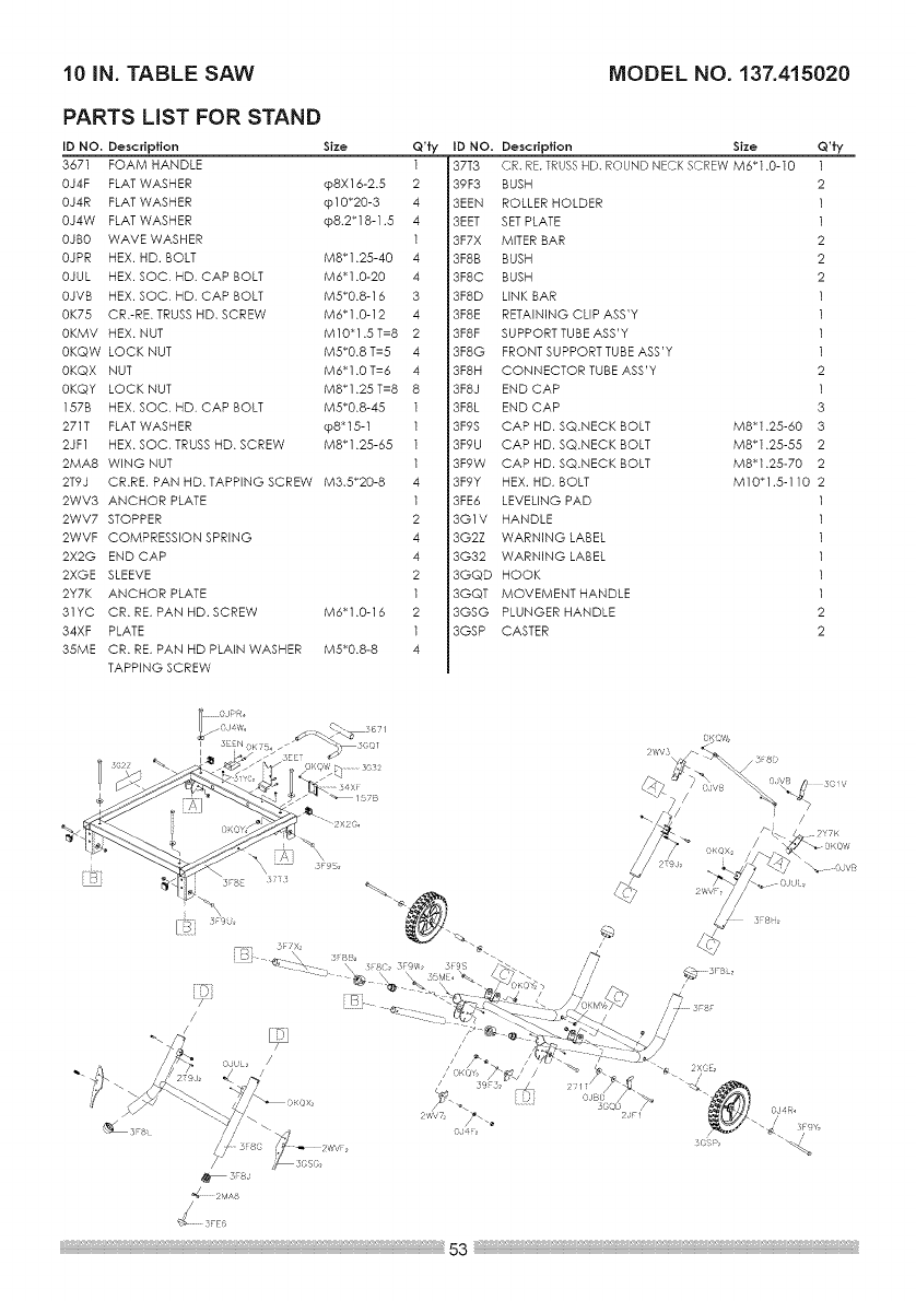
10 IN. TABLE SAW MODEL NO. 137.415020
PARTS LIST FOR STAND
ID NO. Description Size
3671 FOAM HANDLE
0J4F FLAT WASHER cp8X16-2.5
0J4R FLAT WASHER @10_20-3
0J4W FLAT WASHER cp8.2_18-1.5
0JBO WAVE WASHER
0JPR HEX. HD. BOLT M8_1.25-40
0JUL HEX. SOC. HD. CAP BOLT M6_1.0-20
0JVB HEX. SOC. HD. CAP BOLT M5_0.8-16
0K75 CR.-RE. TRUSS HD. SCREW M6_1.0-12
0KMV HEX. NUT MlO_l.5T=8
0KQW LOCK NUT M5_0.8 T=5
0KQX NUT M6_1.0 T=6
0KQY LOCK NUT M8_1.25 T=8
157B HEX. SOC. HD. CAP BOLT M5_0.8-45
271T FLAT WASHER cp8_15-1
2JF1 HEX. SOC. TRUSS HD. SCREW M8_1.25-65
2MA8 WING NUT
2T9J
2WV3 ANCHOR PLATE
2WV7 STOPPER
2WVF COMPRESSION SPRING
2X2G END CAP
2XGE SLEEVE
2Y7K ANCHOR PLATE
31YC CR. RE. PAN HD. SCREW
34XF PLATE
35ME CR. RE. PAN HD PLAIN WASHER
TAPPING SCREW
CR.RE. PAN HD. TAPPING SCREW M3.5_20-8
Q'ty
l
2
4
4
l
4
4
3
4
2
4
4
8
l
l
l
l
4
l
2
4
4
2
l
2
l
4
tD NO. Description Size
37T3 CR. RE.TRUSSHD. ROUND NECK SCREW M6_1.0-10
39F3 BUSH
3EEN ROLLER HOLDER
3EET SET PLATE
3F7X MITER BAR
3F8B BUSH
3F8C BUSH
3F8D LINK BAR
3F8E RETAiNiNG CLIP ASS'Y
3F8F SUPPORT TUBE ASS'Y
3F8G FRONT SUPPORT TUBE ASS'Y
3F8H CONNECTOR TUBE ASS'Y
3F8J END CAP
3F8L END CAP
3F9S CAP HD. SQ.NECK BOLT
3F9U CAP HD. SQ.NECK BOLT
3F9W CAP HD. SQ.NECK BOLT
3F9Y HEX. HD. BOLT
3FE6 LEVELING PAD
3G1V HANDLE
3G2Z WARNING LABEL
3G32 WARNING LABEL
3GQD HOOK
3GQT MOVEMENT HANDLE
3GSG PLUNGER HANDLE
3GSP CASTER
Q'ty
1
2
1
1
2
2
2
2
1
3
M8"1.25-60 3
M8"1.25-55 2
M8"1.25-70 2
M10"1.5-110 2
B_
J
/
/
: 80 2 ¢,/,/i
3FSJ
_._ 2r,4A8
_, OJVB

Congratu/afions on rnaking a smart purc,#ase. Your new Craftsman ® product
is designed and manufactured for years of dependable operation. But like all
products, it may require repair from time to time. That's when having a Repair
Protection Agreement can save you money and aggravation.
Here's what the Repair Protection Agreement* includes:
[] Expert service by our 10,000 professional repair specialists
[] Unlimited service and no charge for parts and labor on all covered
repairs
[] Product replacement up to $1500 if your covered product can't be fixed
[] Discount of 25% from regular price of service and related installed
parts not covered by the agreement; also, 25% off regular price of
preventive maintenance check
[] Fast help by phone - we call it Rapid Resolution - phone support from a
Sears representative. Think of us as a "talking owner's manual."
Once you purchase the Repair Protection Agreement, a simple phone call is all
that it takes for you to schedule service. You can call anytime day or night, or
schedule a service appointment online.
The Repair Protection Agreement is a risk-free purchase. If you cancel for any
reason during the product warranty period, we will provide a full refund. Or, a
prorated refund anytime after the product warranty period expires. Purchase
your Repair Protection Agreement today!
Some limitations and exclusions apply. For prices and additional
information in the U.S.A. call 1=800=827-6655.
*Coverage in Canada varies on some items. For full details call Sears
Canada at 1=800=361=6665.
Sears Installation Service
For Sears professional installation of home appliances, garage door openers,
water heaters, and other major home items, in the U.S.A. or Canada call
1-800-4-MY-HOME ®.