Craftsman 1395364812 User Manual 1/2 HP GARAGE DOOR OPENER Manuals And Guides L0411284
CRAFTSMAN Garage Door Opener Manual L0411284 CRAFTSMAN Garage Door Opener Owner's Manual, CRAFTSMAN Garage Door Opener installation guides
User Manual: Craftsman 1395364812 1395364812 CRAFTSMAN 1/2 HP GARAGE DOOR OPENER - Manuals and Guides View the owners manual for your CRAFTSMAN 1/2 HP GARAGE DOOR OPENER #1395364812. Home:Garage Door & Opener Parts:Craftsman Parts:Craftsman 1/2 HP GARAGE DOOR OPENER Manual
Open the PDF directly: View PDF ![]() .
.
Page Count: 40
Owner's Manual/Manual Del Propietario
II:RRFTSMRNI
112 HP
GARAGE DOOR OPENER
ABRIDOR DE PUERTA DE COCHERA
For Residential Use Only/Solo para uso residencial
Model/Modelos • 139.5364812
m
G3
Read and follow all safety rules
and operating instructions before
first use of this product.
Fasten the manual near the garage
door after installation.
Periodic checks of the opener are
required to ensure safe operation.
Leer y seguir todas las reglas de
seguridad y las instrucciones de
operacion antes de usar este
producto por primera vez.
Guardar este manual cerca de la
puerta de la cochera.
Se deben realizar revisiones
periodicas del abridor de puertas
para asegurar su operacion
segura.
m
Z_
O
Sears, Roebuck and Co., Hoffman Estates, IL 60179 U.S.A
www.sears.com/craftsman
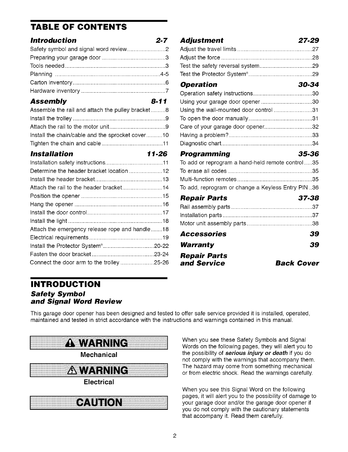
TABLE OF CONTENTS
Introduction 2-7
Safety symbol and signal word review ........................ 2
Preparing your garage door ........................................ 3
Tools needed ............................................................... 3
Planning .................................................................. 4-5
Carton inventory .......................................................... 6
Hardware inventory ..................................................... 7
Assembly 8-11
Assemble the rail and attach the pulley bracket ......... 8
Install the trolley .......................................................... 9
Attach the rail to the motor unit ................................... 9
Install the chain/cable and the sprocket cover .......... 10
Tighten the chain and cable ...................................... 11
Installation 11-26
Installation safety instructions .................................... 11
Determine the header bracket location ..................... 12
Install the header bracket .......................................... 13
Attach the rail to the header bracket ......................... 14
Position the opener ................................................... 15
Hang the opener ....................................................... 16
Install the door control ............................................... 17
Install the light ........................................................... 18
Attach the emergency release rope and handle ....... 18
Electrical requirements .............................................. 19
Install the Protector System 'R;................................ 20-22
Fasten the door bracket ....................................... 23-24
Connect the door arm to the trolley ..................... 25-26
Adjustment 27-29
Adjust the travel limits ............................................... 27
Adjust the force ......................................................... 28
Test the safety reversal system ................................. 29
Test the Protector System _:........................................ 29
Operation 30.34
Operation safety instructions ..................................... 30
Using your garage door opener ................................ 30
Using the wall-mounted door control ........................ 31
To open the door manually ........................................ 31
Care of your garage door opener .............................. 32
Having a problem? .................................................... 33
Diagnostic chart ......................................................... 34
Programming 35-36
To add or reprogram a hand-held remote control .....35
To erase all codes ..................................................... 35
Multi-function remotes ............................................... 35
To add, reprogram or change a Keyless Entry PIN ..36
Repair Parts 37.38
Rail assembly parts ................................................... 37
Installation parts ........................................................ 37
Motor unit assembly parts ......................................... 38
Accessories 39
Warranty 39
Repair Parts
and Service Back Cover
INTRODUCTION
Safety Symbol
and Signal Word Review
This garage door opener has been designed and tested to offer safe service provided it is installed, operated,
maintained and tested in strict accordance with the instructions and warnings contained in this manual.
Mechanical
Electrical
When you see these Safety Symbols and Signal
Words on the following pages, they will alert you to
the possibility of serious injury or death if you do
not comply with the warnings that accompany them.
The hazard may come from something mechanical
or from electric shock. Read the warnings carefully.
When you see this Signal Word on the following
pages, it will alert you to the possibility of damage to
your garage door and/or the garage door opener if
you do not comply with the cautionary statements
that accompany it. Read them carefully.
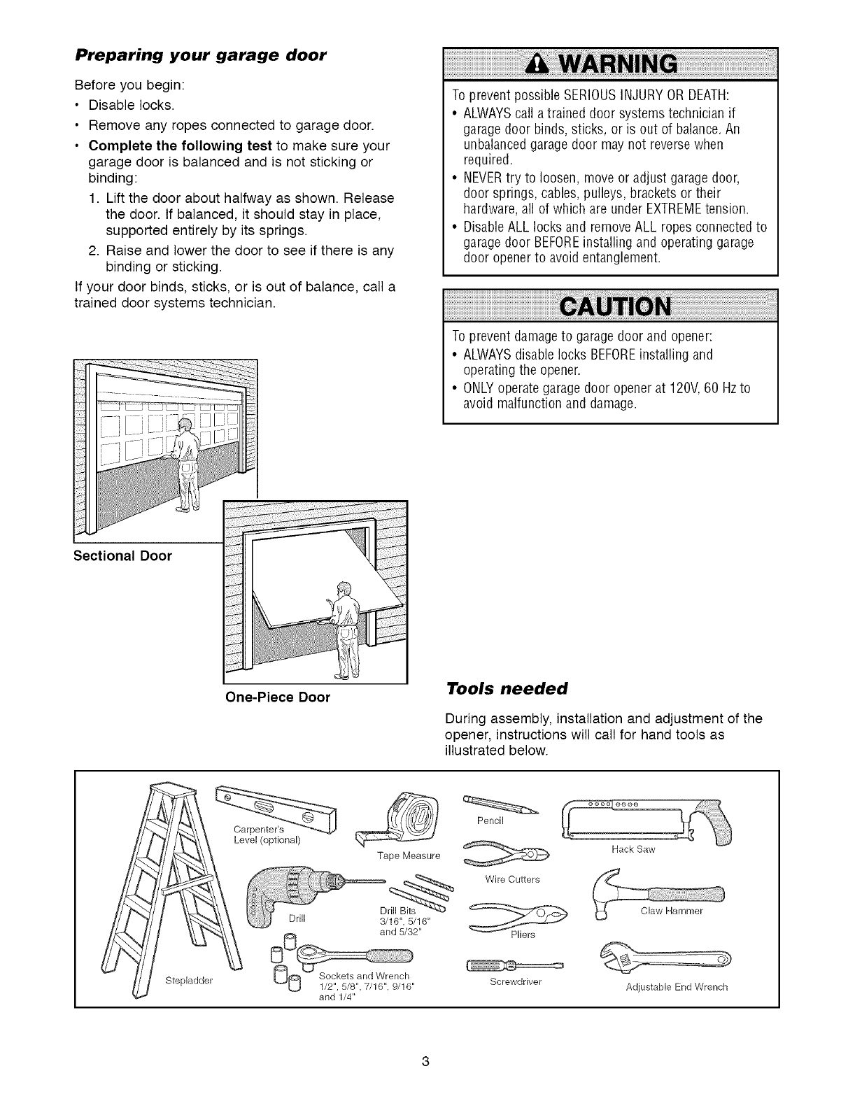
Preparing your garage door
Before you begin:
•Disable locks.
• Remove any ropes connected to garage door.
• Complete the following test to make sure your
garage door is balanced and is not sticking or
binding:
1. Lift the door about halfway as shown. Release
the door. If balanced, it should stay in place,
supported entirely by its springs.
2. Raise and lower the door to see if there is any
binding or sticking.
If your door binds, sticks, or is out of balance, call a
trained door systems technician.
Sectional Door
To prevent possible SERIOUSINJURYOR DEATH:
•ALWAYScall atrained door systems technician if
garagedoor binds, sticks, or is out of balance.An
unbalanced garagedoor may not reversewhen
required.
• NEVERtry to loosen, move or adjust garagedoor,
door springs, cables, pulleys, brackets or their
hardware,all of which are under EXTREMEtension.
• DisableALL locks and removeALL ropes connected to
garagedoor BEFOREinstalling and operating garage
door openerto avoid entanglement.
To prevent damageto garage door and opener:
•ALWAYSdisable locks BEFOREinstalling and
operating the opener.
• ONLYoperate garage door opener at 120V, 60 Hzto
avoid malfunction and damage.
One-Piece Door Tools needed
During assembly, installation and adjustment of the
opener, instructions will call for hand tools as
illustrated below.
Stepladder
Level (optional)
Tape Measure
and 5/32"
and 1/4"
Pencil
Wire Cutters
Screwdriver
Hack Saw
Adjustable End Wrench
Planning
Identify the type and height of your garage door.
Survey your garage area to see if any of the
conditions below apply to your installation. Additional
materials may be required. You may find it helpful to
refer back to this page and the accompanying
illustrations as you proceed with the installation of
your opener.
Depending on your requirements, there are several
installation steps which may call for materials or
hardware not included in the carton.
• Installation Step 1 - Look at the wall or ceiling
above the garage door. The header bracket must
be securely fastened to structural supports.
• Installation Step 5 - Do you have a finished ceiling
in your garage? If so, a support bracket and
additional fastening hardware may be required.
• Installation Step 10- Depending upon garage
construction, extension brackets or wood blocks
may be needed to install sensors.
• Installation Step 10 -Alternate floor mounting of
the safety reversing sensor will require hardware
not provided.
Do you have an access door in addition to the
garage door? If not, Model 53702 Outside Quick
Release is required. See Accessories page.
Look at the garage door where it meets the floor.
Any gap between the floor and the bottom of the
door must not exceed 1/4" (6 mm). Otherwise, the
safety reversal system may not work properly. See
Adjustment Step 3. Floor or door should be
repaired.
SECTIONAL DOOR INSTALLATIONS
• Do you have a steel, aluminum, fiberglass or glass
panel door? If so, horizontal and vertical
reinforcement is required (Installation Step 11).
• The opener should be installed above the center of
the door. If there is a torsion spring or center
bearing plate in the way of the header bracket, it
may be installed within 4 feet (1.2 m) to the left or
right of the door center. See Installation Steps 1
and 11.
• If your door is more than 7 feet (2.1 m) high, see
rail extension kits listed on Accessories page.
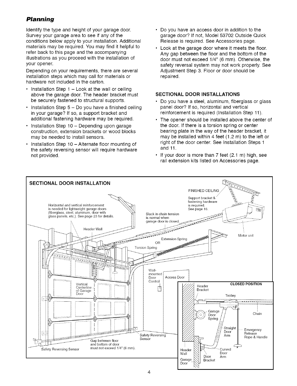
SECTIONAL DOOR INSTALLATION
Horizontal and vertical reinforcement
is needed for lightweight garage doors
(fiberglass, steel, aluminum, door with
glass panels, etc.). See page 23 for details.
\, \\ Header Wall
\
Slack in chain tension
is normal when
garage door is closed.
Extension Spring
OR
Torsion Spring
FINISHED CEILING
Support bracket &
fastening hardware
is required.
See page 16.
Motor unit
Vertical I :::::: ::"
Centerline E ! ]/
of Garage i
Door
]i}
Reversing Sensor
Gap between floor
and bottom of door
must not exceed 1/4" (6 mm).
Wall-
mounted
Door
Control
Safety Reversing
Sensor
Door
CLOSED POSITION
Header
Bracket
/' Trolley
Chain
Emergency
Release
Rope & Handle
Curved
_\ Door
Door Arm
Bracket
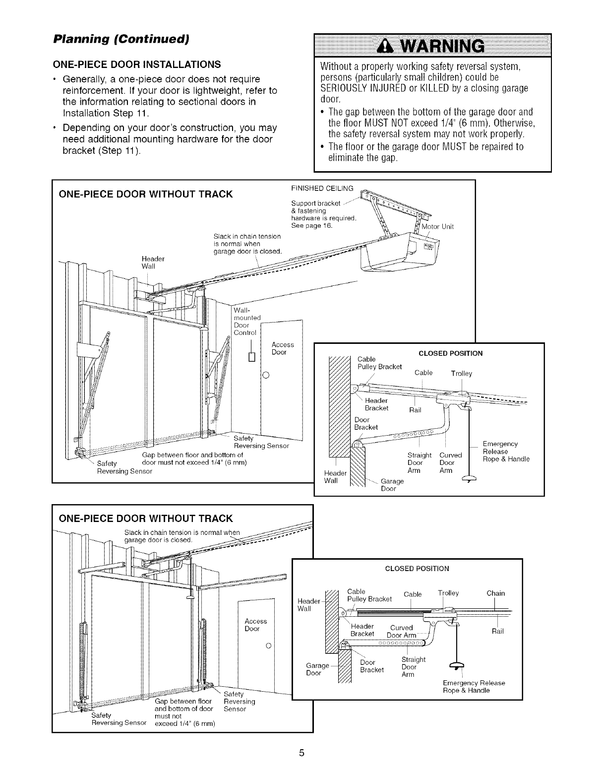
Planning (Continued)
ONE-PIECE DOOR INSTALLATIONS
•Generally, a one-piece door does not require
reinforcement. If your door is lightweight, refer to
the information relating to sectional doors in
Installation Step 11.
• Depending on your door's construction, you may
need additional mounting hardware for the door
bracket (Step 11).
Without a properly working safety reversal system,
persons (particularly small children) could be
SERIOUSLYINJUREDor KILLED by a closing garage
door.
• The gap betweenthe bottom of the garage door and
the floor MUST NOTexceed1/4" (6 mm). Otherwise,
the safety reversal system may not work properly.
• The floor or the garage door MUST be repairedto
eliminate the gap.
ONE-PIECE DOOR WITHOUT TRACK
Header
Wall
Slack in chain tension
is normal when
garage door is closed,
Wall-
mounted
Door /
Access
Door
Safet\ _.
Reversing Sensor
Gap between floor and bottom of
Safety door must not exceed 1/4" (6 ram)
Reversing Sensor
FINISHED CEILING
Support bracket
& fastening
hardware is required.
See page 16. Motor Unit
CLOSED POSITION
Cable
Pulley Bracket
Cable Trolley
o .... -
Bracket Rail _ _--
Door II
Em,ergency
_ight Curved RReleea_eHandle
Door Door H( p
_[ Arm Arm
rage .......... _
Door
ONE-PIECE DOOR WITHOUT TRACK
Slack in chain tension is normal when
garage door is closed.
Access I
Door I
, between floor
and bottom of door
Safety must not
Reversing Sensor exceed 1/4" (6 ram)
Safety
Reversing
Sensor
Hea_lder _
Garage
Door
CLOSED POSIT_ON
Cable Cable Trolley Chain
Pulley Bracket I I /
_, t_- =_<_ L._._
" F o
Header Curved
Bracket Door Arm J /I Rail
Door Straight
7J/_ Bracket Door
" Arm
//A Emergency Release
Rope & Handle
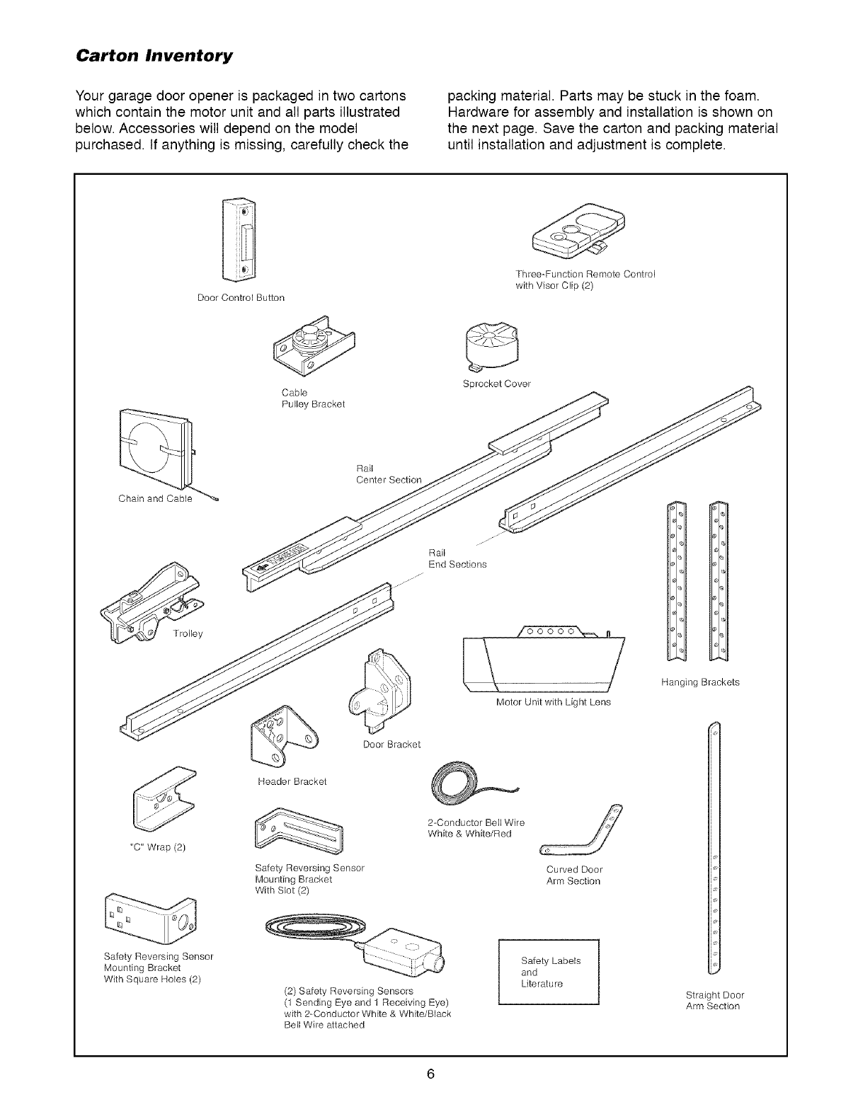
Carton Inventory
Your garage door opener is packaged in two cartons
which contain the motor unit and all parts illustrated
below. Accessories will depend on the model
purchased. If anything is missing, carefully check the
packing material. Parts may be stuck in the foam.
Hardware for assembly and installation is shown on
the next page. Save the carton and packing material
until installation and adjustment is complete.
Three-Function Remote Control
with Visor Clip (2)
Door Control Button
"C" Wrap (2)
Safety Reversing Sensor
Mounting Bracket
With Square Holes (2)
Sprocket Cover
Cable
Pulley Bracket
Rail J_ _J
Header Bracket
Door Bracket
Safety Reversing Sensor
Mounting Bracket
With Slot (2)
Motor Unit with Light Lens
2-Conductor Bell Wire
White & White/Red
Curved Door
Arm Section
(2) Safety Reversing Sensors
(1 Sending Eye and 1 Receiving Eye)
with 2-Conductor White & White/Black
Bell Wire attached
Safety Labels
and
Lite ratu re
Hanging Brackets
Straight Door
Arm Section
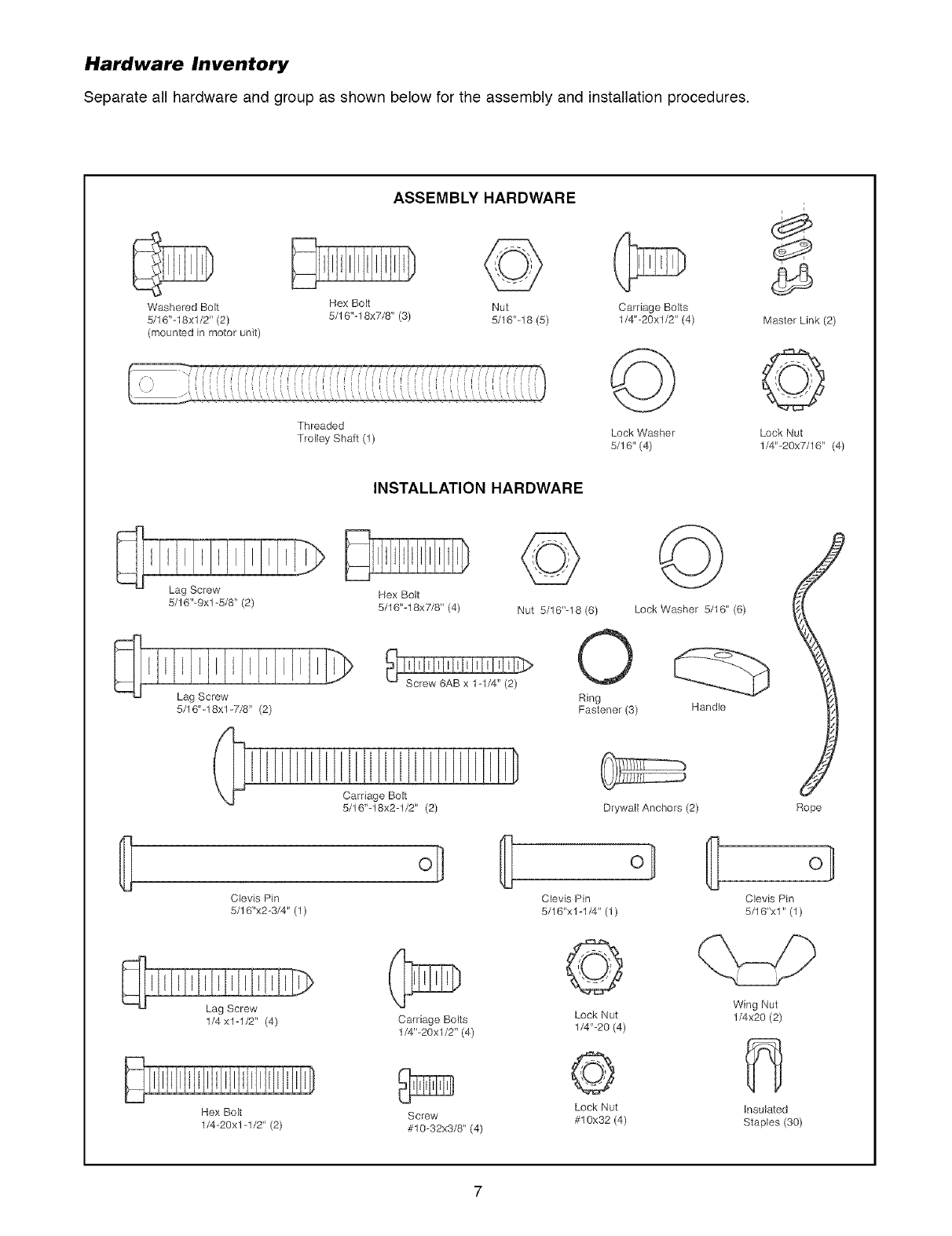
Hardware Inventory
Separate all hardware and group as shown below for the assembly and installation procedures.
ASSEMBLY HARDWARE
Washered Bolt Hex Bolt Nut Carriage Bolts
5/16"-18xl/2" (2) 5/16"-18x7/8" (3) 5/16"-18 (5) 1/4"-20xl/2" (4)
(mounted in motor unit)
Threaded
Trolley Shaft(l)
©
Lock Washer
5/16" (4)
i
Master Link (2)
©
Lock Nut
1/4"-20x7/16" (4)
INSTALLATION HARDWARE
Lag Screw
5/16"-9xl -5/8" (2) Hex Bolt
5/16"-18x7/8" (4) Nut 5/16"-18 (6)
Lag Screw
5/16"-18xl -7/8" (2)
i i [ii D
5/16"-18x2-1/2" (2)
Clevis Pin
5/16"x2-3/4" (1)
1/4 x1-1/2" (4) Carriage Bolts
1/4"-20xl/2" (4)
Hex Bolt
1/4=20xl-1/2" (2)
Screw
#10=32x3/8" (4)
©
Lock Washer 5/16" (6)
Ring
Fastener (3) Handle
Drywall Anchors (2)
ol
Clevis Pin
5/16"x1-1/4" (1)
©
Lock Nut
1/4"-20 (4)
©
Lock Nut
#10x32 (4)
Rope
o]
Clevis Pin
5/16'xl" (1)
Wing Nut
1/4x20 (2)
insulated
Staples (30)
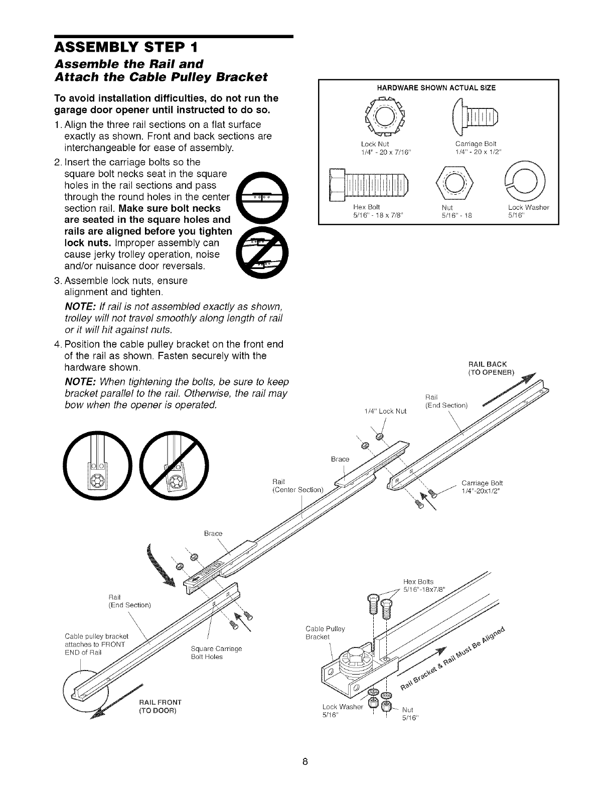
ASSEMBLY STEP 1
Assemble the Rail and
Attach the Cable Pulley Bracket
To avoid installation difficulties, do not run the
garage door opener until instructed to do so,
1. Align the three rail sections on a flat surface
exactly as shown. Front and back sections are
interchangeable for ease of assembly.
2. Insert the carriage bolts so the
square bolt necks seat in the square ,_L
holes in the rail sections and pass
through the round holes in the center
section rail. Make sure bolt necks
are seated in the square holes and
rails are aligned before you tighten
lock nuts. Improper assembly can
cause jerky trolley operation, noise
and/or nuisance door reversals.
3. Assemble lock nuts, ensure
alignment and tighten.
NOTE: If rail is not assembled exactly as shown,
trolley will not travel smoothly along length of rail
or it will hit against nuts.
4. Position the cable pulley bracket on the front end
of the rail as shown. Fasten securely with the
hardware shown.
NOTE: When tightening the bolts, be sure to keep
bracket parallel to the rail. Otherwise, the rail may
bow when the opener is operated.
Rail
(Center Section)
HARDWARE SHOWN ACTUAL SIZE
©
Lock Nut Carriage Bolt
1/4" - 20 x 7/16" 1/4" - 20 x 1/2"
Hex Bolt
5/1 6" - 18 x 7/8'
©
Nut
5/16" - 18
©
Lock Washer
5/1 6"
RAIL BACK
(TO OPENER)
Brace
Rail
(End Section)
\\\\
Rail
(End Section)
Cable pulley bracket
attaches to FRONT
END of Rail
Brace
@,
%
Square Carriage
Bolt Holes
Cable Pulley
Bracket
Hex Bolts
5/16"-18x7/8"
RAIL FRONT
(TOBooR)
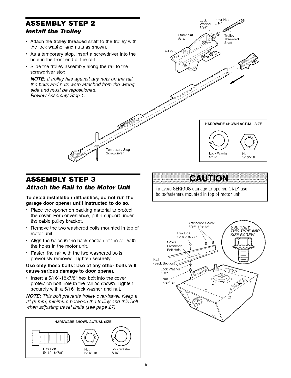
ASSEMBLY STEP 2
Install the Trolley
•Attach the trolley threaded shaft to the trolley with
the lock washer and nuts as shown.
• As a temporary stop, insert a screwdriver into the
hole in the front end of the rail.
• Slide the trolley assembly along the rail to the
screwdriver stop.
NOTE: If trolley hits against any nuts on the rail,
the bolts and nuts were attached from the wrong
side and must be repositioned.
Review Assembly Step 1.
Trolley \,
Outer Nut
5/16"
Lock Inner Nut
Washer 5116"_f
5/16"
Trolley
Threaded
Shaft
HARDWARE SHOWN ACTUAL SIZE
Temporary Stop Lock Washer
5/16"
©
Nut
5/16"-18
ASSEMBLY STEP 3
Attach the Rail to the Motor Unit
To avoid installation difficulties, do not run the
garage door opener until instructed to do so,
• Place the opener on packing material to protect
the cover. For convenience, put a support under
the cable pulley bracket.
• Remove the two washered bolts mounted in top of
motor unit.
• Align the holes in the back section of the rail with
the holes in the motor unit.
• Fasten the rail with the two washered bolts
previously removed. Tighten securely.
Use only these bolts! Use of any other bolts will
cause serious damage to door opener.
• Insert a 5/16"-18x7/8" hex bolt into the cover
protection bolt hole in the rail as shown. Tighten
securely with a 5/16" lock washer and nut.
NOTE: This bolt prevents trolley over-traveL Keep a
2" (5 mm) minimum between the trolley and this bolt
when adjusting travel limits (see page 27).
HARDWARE SHOWN ACTUAL SIZE
Hex Bolt Nut Lock Washer
5/16"-18x7/8" 5/16"-18 5/16"
To avoid SERIOUSdamageto opener, ONLYuse
bolts/fasteners mounted in top of motor unit.
Washered Screw
5/16"-18xl/2"
Hex Bolt
5/16"-18x7/8"
Cover
Protection
Bolt Hole
Rail
(Back Section
5/16"
Nut
5/16"-18
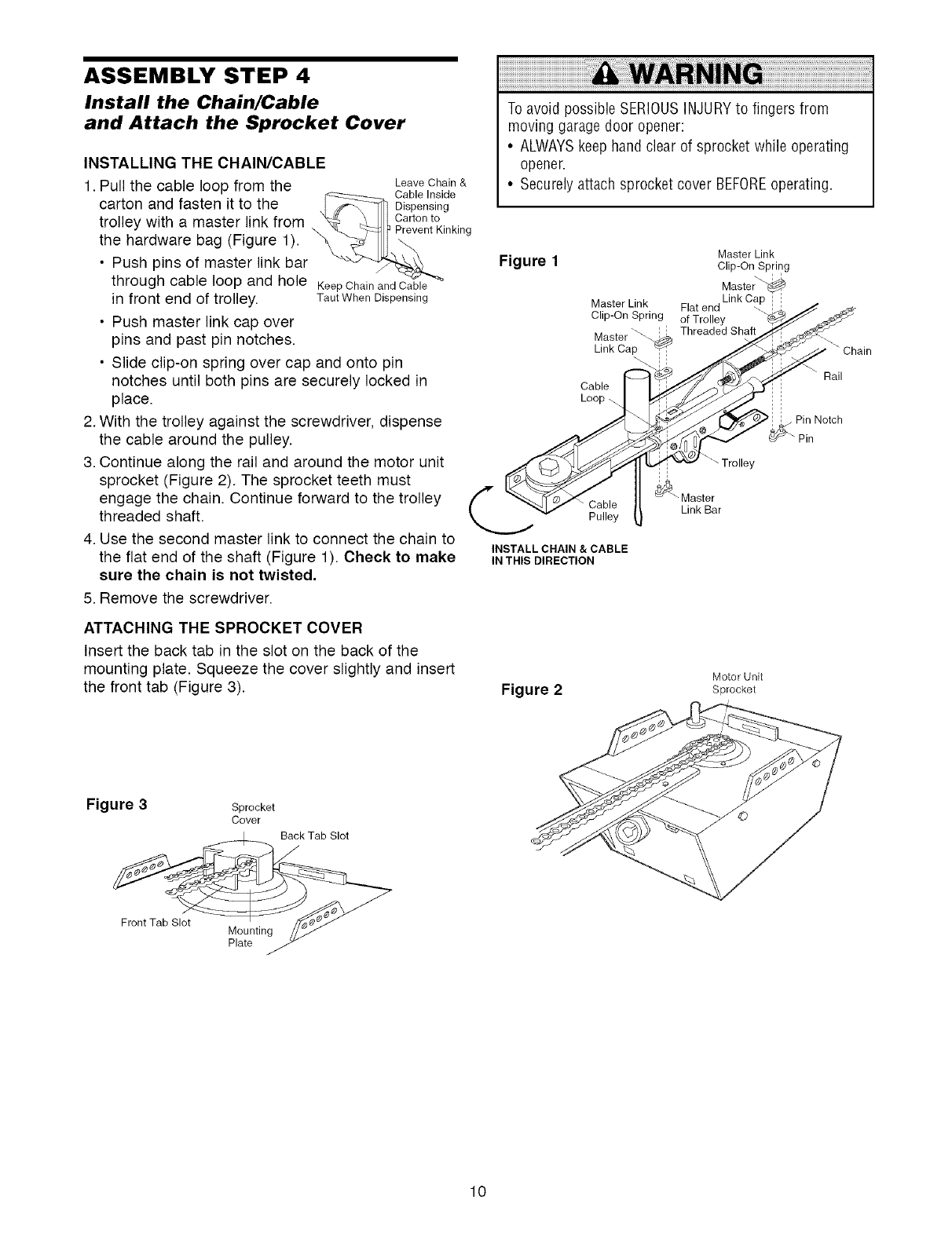
ASSEMBLY STEP 4
Install the Chain/Cable
and Attach the Sprocket Cover
INSTALLING THE CHAIN/CABLE
1. Pull the cable loop from the
carton and fasten it to the
trolley with a master link from
the hardware bag (Figure 1).
• Push pins of master link bar
Leave Chain &
Cable Inside
Dispensing
Carton to
Prevent Kinking
through cable loop and hole KeepChainandCable
in front end of trolley. TautWhen Dispensing
• Push master link cap over
pins and past pin notches.
• Slide clip-on spring over cap and onto pin
notches until both pins are securely locked in
place.
2. With the trolley against the screwdriver, dispense
the cable around the pulley.
3. Continue along the rail and around the motor unit
sprocket (Figure 2). The sprocket teeth must
engage the chain. Continue forward to the trolley
threaded shaft.
4. Use the second master link to connect the chain to
the flat end of the shaft (Figure 1). Check to make
sure the chain is not twisted,
5. Remove the screwdriver.
ATTACHING THE SPROCKET COVER
Insert the back tab in the slot on the back of the
mounting plate. Squeeze the cover slightly and insert
the front tab (Figure 3).
To avoid possible SERIOUSINJURYto fingers from
moving garage door opener:
• ALWAYSkeep hand clear of sprocket while operating
opener.
• Securelyattach sprocket cover BEFOREoperating.
Figure 1Master Link
Clip-On Sp[ing
Master_
Master Link Flat end
Clip-On Spring of Trolley
Master'_ Threaded Shaft
Link Cap
Cable
Loop
Pulley
INSTALL CHAIN & CABLE
IN THIS DIRECTION
"" \ Tro ey
_ Master
Link Bar
Rail
.Pin Notch
Pin
Figure 2Motor Unit
Sprocket
Figure 3Sprocket
Cover
10
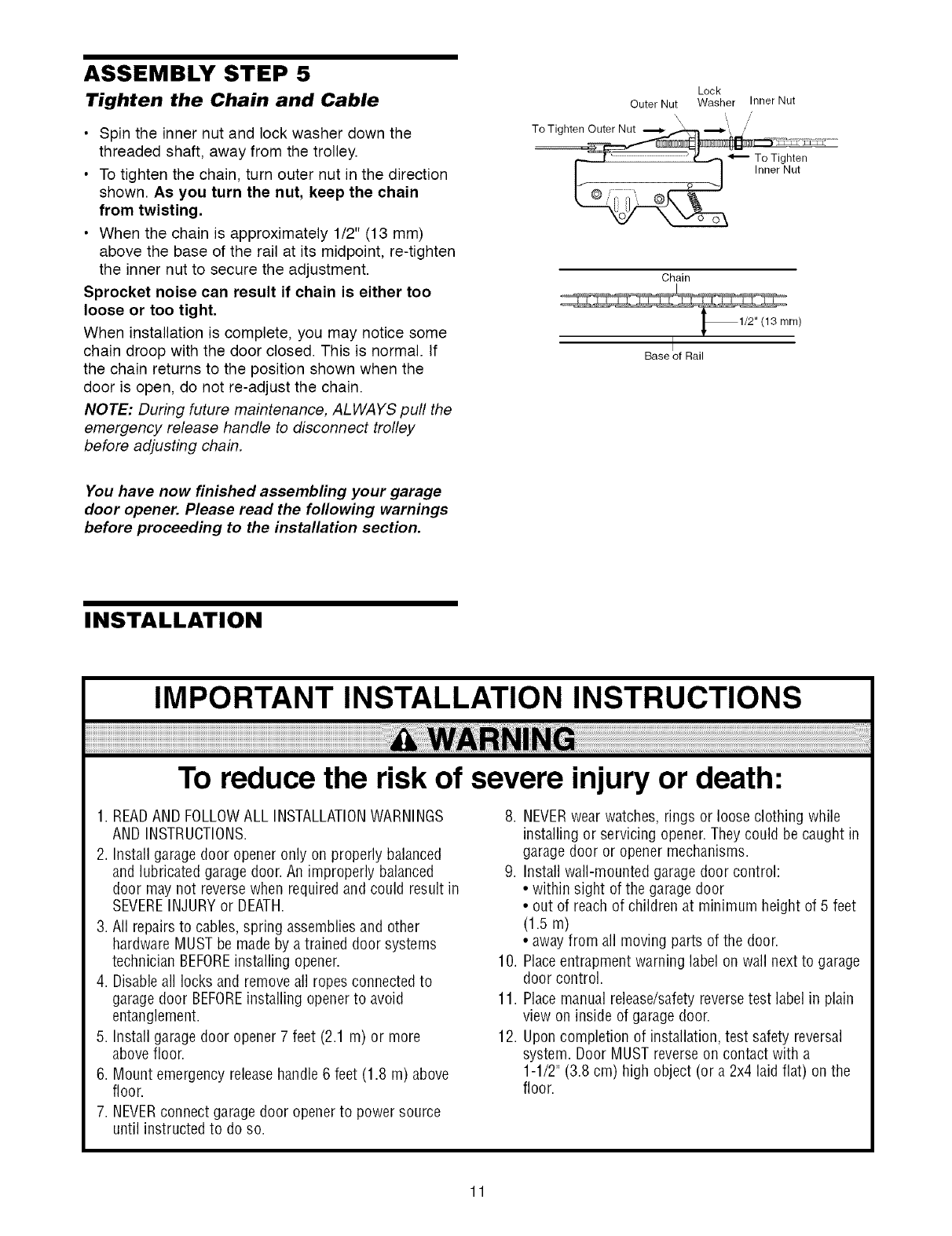
ASSEMBLY STEP 5
Tighten the Chain and Cable
•Spin the inner nut and lock washer down the
threaded shaft, away from the trolley.
• To tighten the chain, turn outer nut in the direction
shown. As you turn the nut, keep the chain
from twisting,
• When the chain is approximately 1/2" (13 mm)
above the base of the rail at its midpoint, re-tighten
the inner nut to secure the adjustment.
Sprocket noise can result if chain is either too
loose or too tight.
When installation is complete, you may notice some
chain droop with the door closed. This is normal. If
the chain returns to the position shown when the
door is open, do not re-adjust the chain.
NOTE: During future maintenance, ALWAYS pull the
emergency release handle to disconnect trolley
before adjusting chain.
Lock
Outer Nut Washer Inner Nut
,/
To Tighten Outer Nut _ _--_ //
Chain
Base of Rail
You have now finished assembling your garage
door opener. Please read the following warnings
before proceeding to the installation section.
INSTALLATION
IMPORTANT INSTALLATION INSTRUCTIONS
To reduce the risk of severe injury or death:
1. READAND FOLLOWALL INSTALLATIONWARNINGS
AND INSTRUCTIONS.
2. Install garagedoor opener only on properly balanced
and lubricated garage door. An improperly balanced
door may not reversewhen required and could result in
SEVEREINJURYor DEATH.
3. All repairs to cables,spring assemblies and other
hardware MUST be made by a trained door systems
technician BEFOREinstalling opener.
4. Disableall locks and remove all ropes connectedto
garage door BEFOREinstalling openerto avoid
entanglement.
5. Install garagedoor opener 7 feet (2.1 m) or more
above floor.
6. Mount emergency releasehandle 6 feet (1.8 m) above
floor.
7. NEVERconnect garage door openerto power source
until instructed to do so.
8. NEVERwear watches, rings or loose clothing while
installing or servicing opener. They could be caught in
garage door or opener mechanisms.
9. Install wall-mounted garagedoor control:
• within sight of the garagedoor
• out of reach of children at minimum height of 5 feet
(1.5m)
• away from all moving parts of the door.
10. Placeentrapment warning label on wall next to garage
door control.
11. Place manual release/safetyreversetest label in plain
view on inside of garage door.
12. Upon completion of installation, test safety reversal
system. Door MUST reverseon contact with a
1-1/2" (3.8 cm) high object (or a 2x4 laid flat) on the
floor.
11
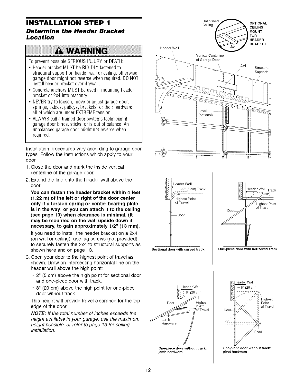
INSTALLATION STEP 1
Determine the Header Bracket
Location
To prevent possible SERIOUSINJURYor DEATH:
•Headerbracket MUST be RIGIDLYfastenedto
structural support on headerwall or ceiling, otherwise
garagedoor might not reversewhen required. DO NOT
install headerbracket over drywall.
• Concreteanchors MUST be used if mounting header
bracket or 2x4 into masonry.
• NEVERtry to loosen, move or adjust garagedoor,
springs, cables, pulleys, brackets, or their hardware,
all of which are under EXTREMEtension.
• ALWAYScall a trained door systems technician if
garagedoor binds, sticks, or is out of balance.An
unbalancedgarage door might not reversewhen
required.
Header Wall
Unllnigh_ 2x_
Vertical Centerline
of Garage Door
2x4
/
OPTIONAL
CEILING
MOUNT
FOR
HEADER
BRACKET
Structural
Supports
Installation procedures vary according to garage door
types. Follow the instructions which apply to your
door.
1. Close the door and mark the inside vertical
centerline of the garage door.
2. Extend the line onto the header wall above the
door.
You can fasten the header bracket within 4 feet
(1.22 m) of the left or right of the door center
only if a torsion spring or center bearing plate
is in the way; or you can attach it to the ceiling
(see page 13)when clearance is minimal. (It
may be mounted on the wall upside down if
necessary, to gain approximately 1/2" (13 mm).
If you need to install the header bracket on a 2x4
(on wall or ceiling), use lag screws (not provided)
to securely fasten the 2x4 to structural supports as
shown here and on page 13.
3. Open your door to the highest point of travel as
shown. Draw an intersecting horizontal line on the
header wall above the high point:
• 2" (5 cm) above the high point for sectional door
and one-piece door with track.
• 8" (20 cm) above the high point for one-piece
door without track.
This height will provide travel clearance for the top
edge of the door.
NOTE: If the total number of inches exceeds the
height available in your garage, use the maximum
height possible, or refer to page 13 for ceiling
installation.
Header Wall
_'_, 2" (5 cm) Track
---%--- I
Highe!t Point
of Travel
Door
Sectional door with curved track
_Wall
Door 9_ Hightst
One-piece door without track:
jamb hardware
Header Wall Track
"_[_, 2" (5 cm)
_Highest Point
Y of Travel
f
One-piece door with horizontal track
Header Wall
', 8" (20 cm)
L.........
.,, ',, Highest
,, Point
I I
,, of Travel
I I
Jl
ii
One-piece door without track:
pivot hardware
12
INSTALLATION STEP 2
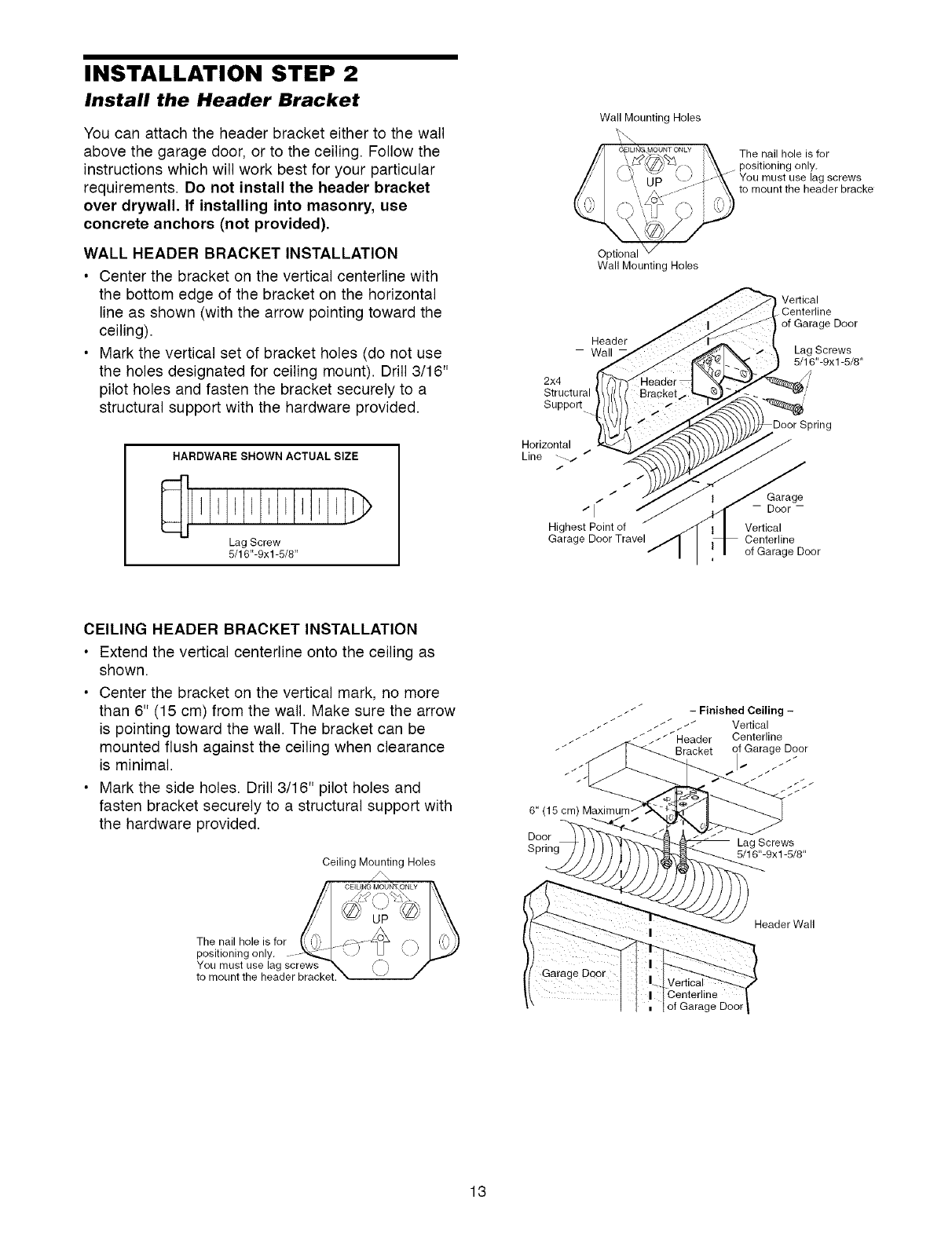
Install the Header Bracket
You can attach the header bracket either to the wail
above the garage door, or to the ceiling. Follow the
instructions which will work best for your particular
requirements. Do not install the header bracket
over drywall, If installing into masonry, use
concrete anchors (not provided),
WALL HEADER BRACKET INSTALLATION
•Center the bracket on the vertical centerline with
the bottom edge of the bracket on the horizontal
line as shown (with the arrow pointing toward the
ceiling).
• Mark the vertical set of bracket holes (do not use
the holes designated for ceiling mount). Drill 3/16"
pilot holes and fasten the bracket securely to a
structural support with the hardware provided.
HARDWARE SHOWN ACTUAL SIZE
I I I J E I J
Lag Screw
5/16"-9xl -5/8"
Wall Mounting Holes
7/
fY,_
Optional
Wall Mounting Holes
Header
- Wall
2x4
Structural
Support
The nail hole is for
positioning only.
You must use lag screws
to mount the header bracke
Vertical
Centerline
of Garage Door
Lag Screws
5/16"-9xl -5/8"
Spring
Horizontal
Line ----/ /
/
t
/
/
/ I - Door -
Highest Point of Vertical
Garage Door Travel Centerline
of Garage Door
CEILING HEADER BRACKET INSTALLATION
• Extend the vertical centerline onto the ceiling as
shown.
• Center the bracket on the vertical mark, no more
than 6" (15 cm) from the wall. Make sure the arrow
is pointing toward the wall. The bracket can be
mounted flush against the ceiling when clearance
is minimal.
• Mark the side holes. Drill 3/16" pilot holes and
fasten bracket securely to a structural support with
the hardware provided.
Ceiling Mounting Holes
_ __//- t t / _ _ _ FinishedverticalCeiling-
/ / _ _ _/Header Centerline
Bracket of Garage Door
6" (15 cm)
Door Lag Screws
5/16"-9xl -5/8"
The nail hole is for
positioning only.
You must use lag screws
to mount the header bracket.
of Garage Door
Header Wall
13
Header Wall
/Header
//_ Bracket
Cable
Pulley
Bracket
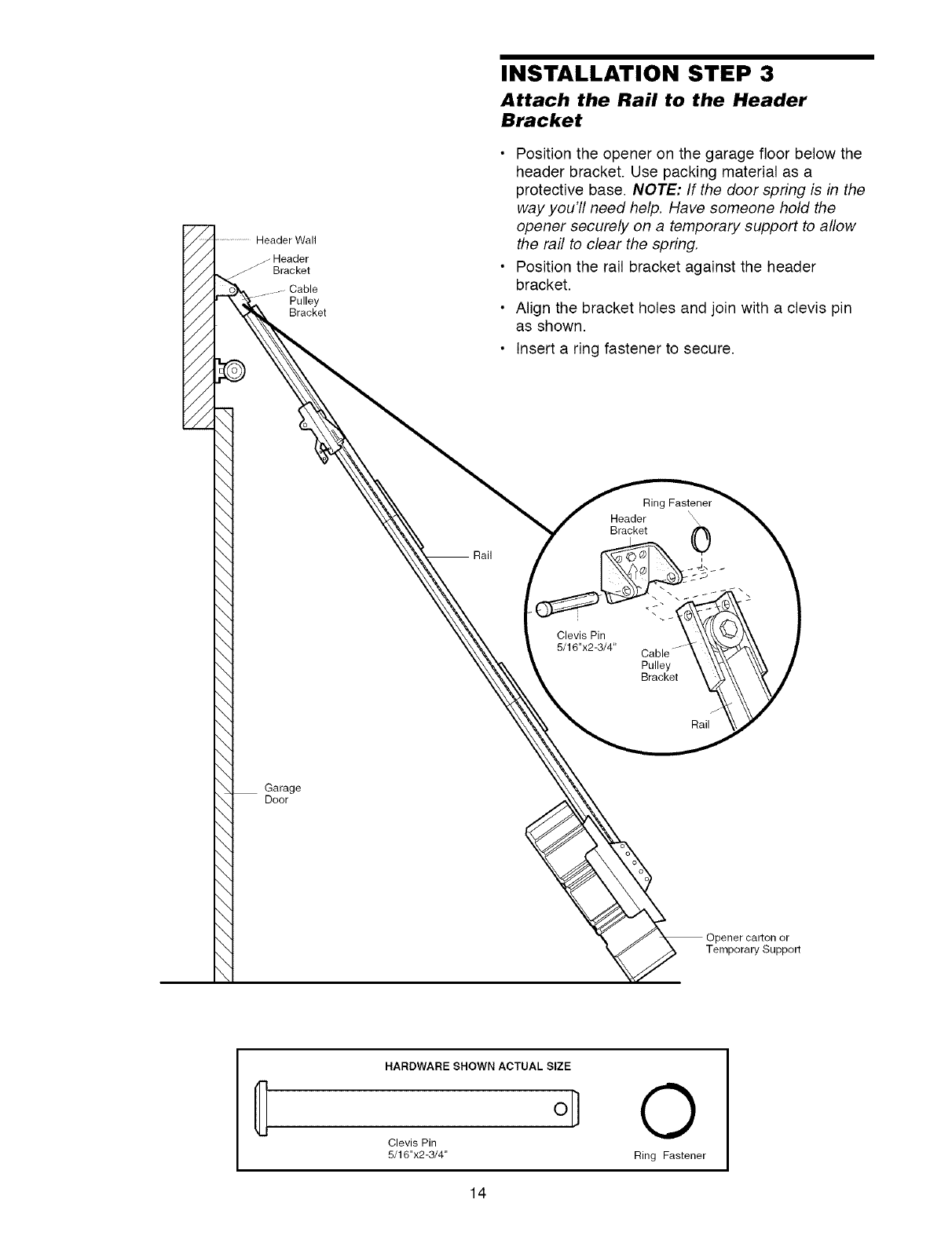
INSTALLATION STEP 3
Attach the Rail to the Header
Bracket
• Position the opener on the garage floor below the
header bracket. Use packing material as a
protective base. NOTE: If the door spring is in the
way you'll need help. Have someone hold the
opener securely on a temporary support to allow
the rail to clear the spring.
• Position the rail bracket against the header
bracket.
• Align the bracket holes and join with a clevis pin
as shown.
• Insert a ring fastener to secure.
Ring Fastener
Header
Bracket 0
i
Clevis Pin
5/16"x2-3/4"
Pulley
Bracket
Rail
Garage
Door
° o
Opener carton or
Temporary Support
HARDWARE SHOWN ACTUAL SIZE
o]
Clevis Pin
5/16"x2-3/4"
O
Ring Fastener
14
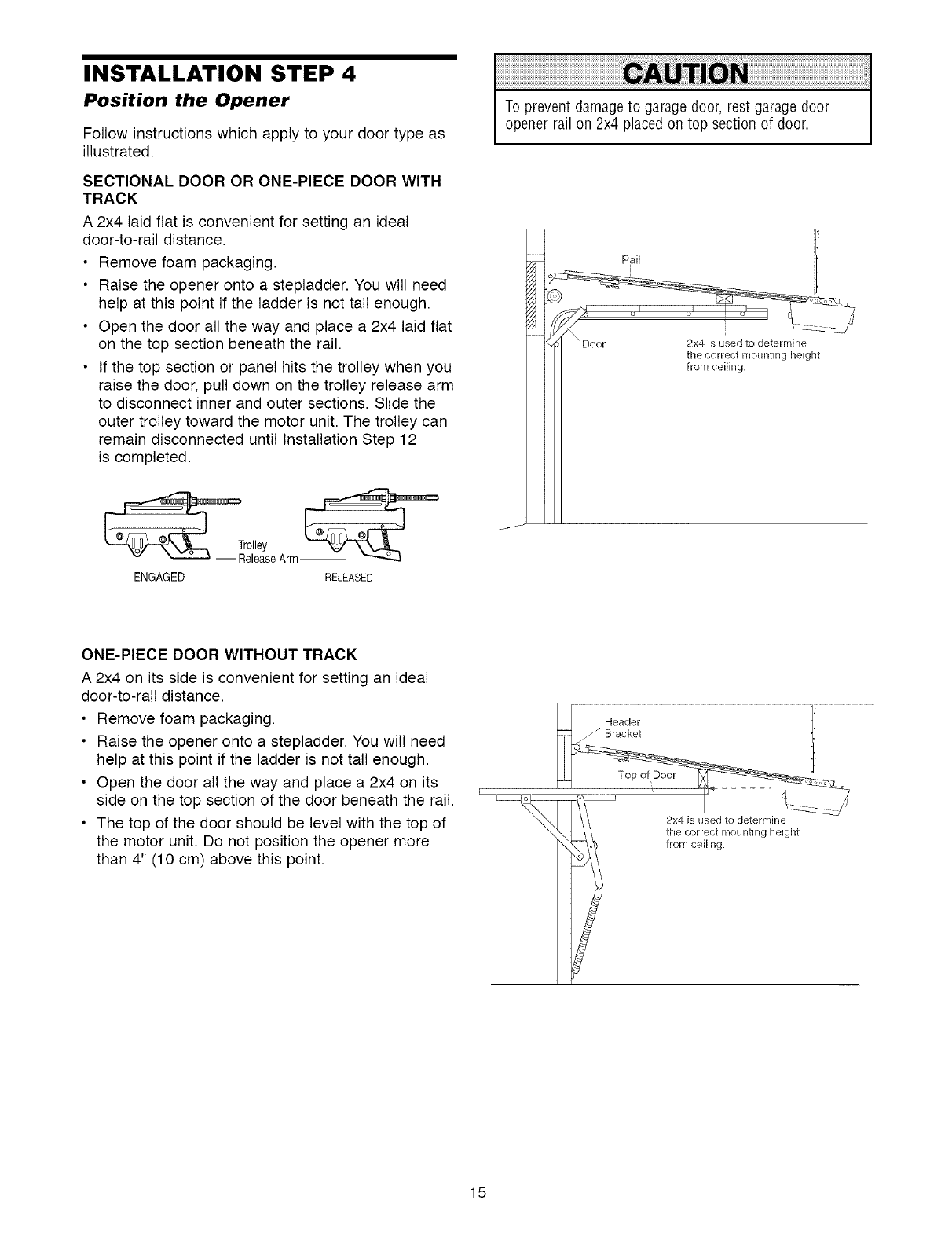
INSTALLATION STEP 4
Position the Opener
Follow instructions which apply to your door type as
illustrated.
SECTIONAL DOOR OR ONE-PIECE DOOR WITH
TRACK
A 2x4 laid flat is convenient for setting an ideal
door-to-rail distance.
• Remove foam packaging.
• Raise the opener onto a stepladder. You will need
help at this point if the ladder is not tall enough.
• Open the door all the way and place a 2x4 laid flat
on the top section beneath the rail.
• If the top section or panel hits the trolley when you
raise the door, pull down on the trolley release arm
to disconnect inner and outer sections. Slide the
outer trolley toward the motor unit. The trolley can
remain disconnected until Installation Step 12
is completed.
_- Tr°llleYseArm.-
ENGAGED RELEASED
To prevent damageto garage door, rest garage door
opener rail on 2x4 placed on top section of door.
ONE-PIECE DOOR WITHOUT TRACK
A 2x4 on its side is convenient for setting an ideal
door-to-rail distance.
• Remove foam packaging.
• Raise the opener onto a stepladder. You will need
help at this point if the ladder is not tall enough.
• Open the door all the way and place a 2x4 on its
side on the top section of the door beneath the rail.
• The top of the door should be level with the top of
the motor unit. Do not position the opener more
than 4" (10 cm) above this point.
Header [i
the correct mounting height
t from ceiling.
15
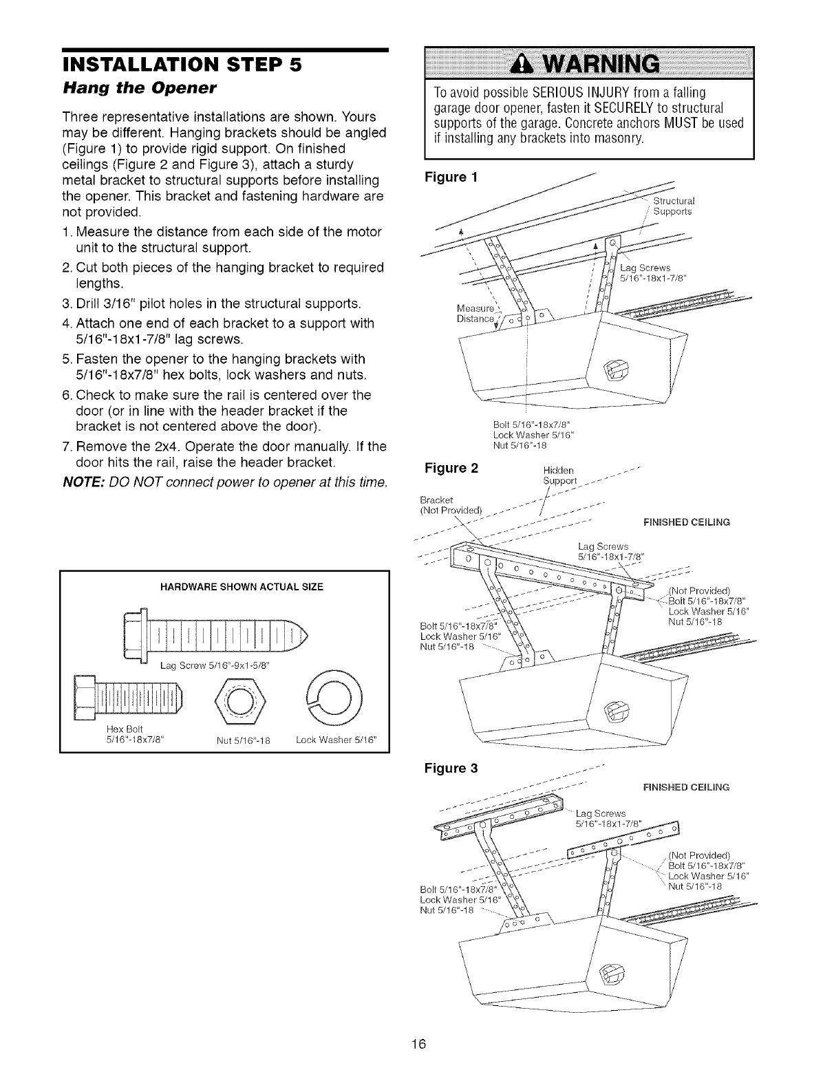
INSTALLATION STEP 5
Hang the Opener
Three representative installations are shown. Yours
may be different. Hanging brackets should be angled
(Figure 1) to provide rigid support. On finished
ceilings (Figure 2 and Figure 3), attach a sturdy
metal bracket to structural supports before installing
the opener. This bracket and fastening hardware are
not provided.
1. Measure the distance from each side of the motor
unit to the structural support.
2. Cut both pieces of the hanging bracket to required
lengths.
3. Drill 3/16" pilot holes in the structural supports.
4. Attach one end of each bracket to a support with
5/16"-18xl -7/8" lag screws.
5. Fasten the opener to the hanging brackets with
5/16"-18x7/8" hex bolts, lock washers and nuts.
6. Check to make sure the rail is centered over the
door (or in line with the header bracket if the
bracket is not centered above the door).
7. Remove the 2x4. Operate the door manually. If the
door hits the rail, raise the header bracket.
NOTE: DO NOT connect power to opener at this time.
HARDWARE SHOWN ACTUAL SIZE
Hex Bolt
5/16"-18x7/8" Nut 5/16"-18
©
Lock Washer 5/16"
To avoid possible SERIOUSINJURYfrom a falling
garage door opener,fasten it SECURELYto structural
supports of the garage. Concrete anchors MUST be used
if installing any brackets into masonry.
Figure 1
Measure '
Distance
Structural
Supports
Lag Screws
5/16"-18xl-7/8"
Bolt 5/16"-18x7/8"
Lock Washer 5/16"
Nut 5/16"-18
_ _ _ Lock Washer 5/16"
8x7/8". Nut 5/16"-18
Bolt 5/1 6"-1
Lock Washer 5/16"
Nut 5/16"-18 ....
Bolt 5/16"-18x7/8"
Lock Washer 5/16"
Nut 5/16"-18
(Not Provided)
/Bolt 5/16"-18x7/8"
Lock Washer 5/16"
Nut 5/16"-18
16
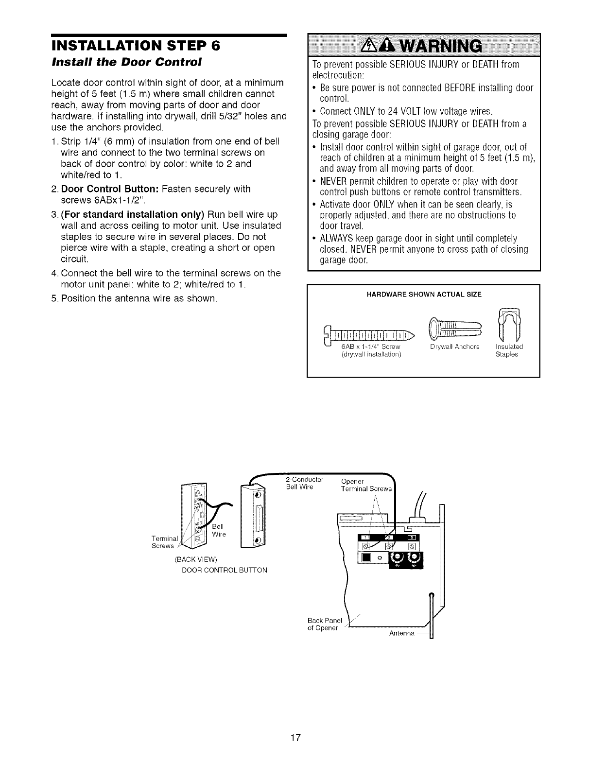
INSTALLATION STEP 6
Install the Door Control
Locate door control within sight of door, at a minimum
height of 5 feet (1.5 m) where small children cannot
reach, away from moving parts of door and door
hardware. If installing into drywall, drill 5/32" holes and
use the anchors provided.
1. Strip 1/4" (6 mm) of insulation from one end of bell
wire and connect to the two terminal screws on
back of door control by color: white to 2 and
white/red to 1.
2. Door Control Button: Fasten securely with
screws 6ABx1-1/2".
3. (For standard installation only) Run bell wire up
wall and across ceiling to motor unit. Use insulated
staples to secure wire in several places. Do not
pierce wire with a staple, creating a short or open
circuit.
4. Connect the bell wire to the terminal screws on the
motor unit panel: white to 2; white/red to 1.
5. Position the antenna wire as shown.
To prevent possible SERIOUSINJURYor DEATHfrom
electrocution:
• Besure power is not connected BEFOREinstalling door
control.
• Connect ONLYto 24 VOLTlow voltage wires.
To prevent possible SERIOUSINJURYor DEATHfrom a
closing garagedoor:
• Install door control within sight of garage door, out of
reach of children at a minimum height of 5 feet (1.5 m),
and awayfrom all moving parts of door.
• NEVERpermit children to operate or play with door
control push buttons or remote control transmitters.
• Activate door ONLYwhen it can be seen clearly, is
properly adjusted, and there are no obstructions to
door travel.
• ALWAYSkeep garagedoor in sight until completely
closed. NEVERpermit anyone to cross path of closing
garagedoor.
HARDWARE SHOWN ACTUAL SIZE
Drywall Anchors Insulate_d
(drywall installation) Staples
(BACK VIEW)
DOOR CONTROL BUqq-ON
2-Conductor
Bell Wire Opener
Terminal
/
Back Panel
of Opener Antenna
17
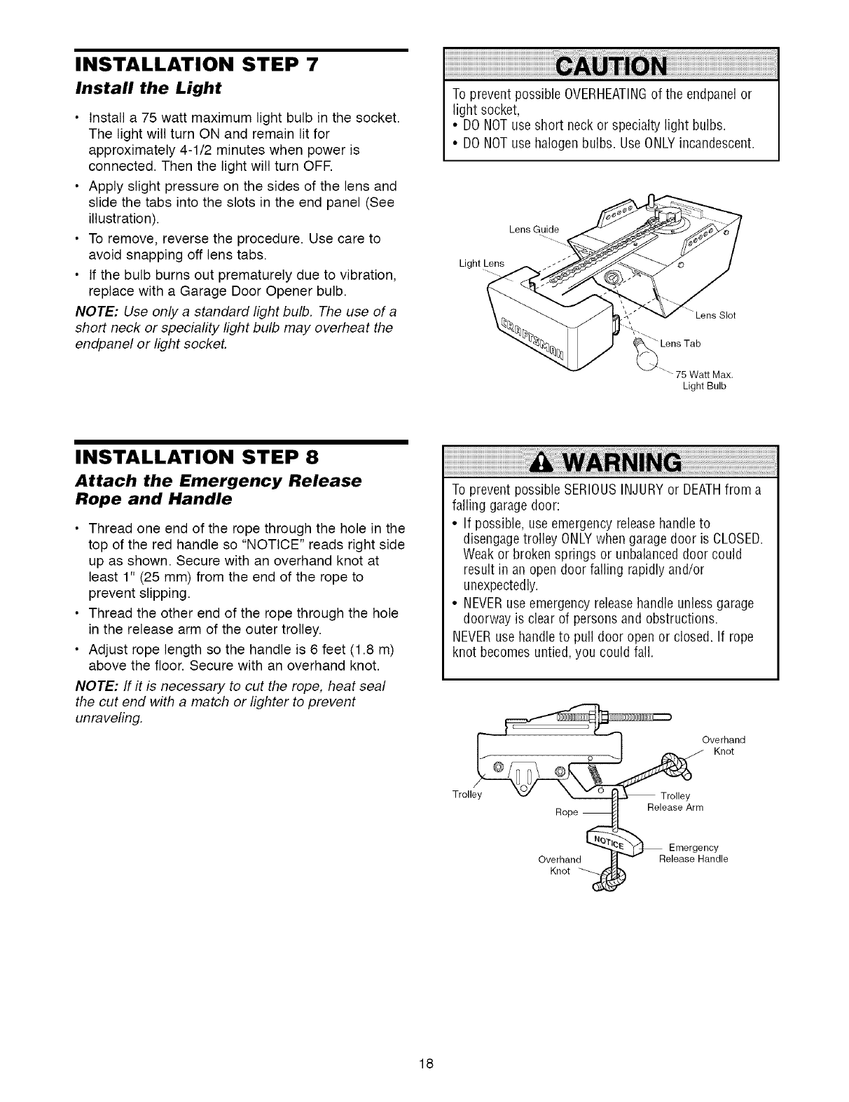
INSTALLATION STEP 7
Install the Light
•Install a 75 watt maximum light bulb in the socket.
The light will turn ON and remain lit for
approximately 4-1/2 minutes when power is
connected. Then the light will turn OFR
• Apply slight pressure on the sides of the lens and
slide the tabs into the slots in the end panel (See
illustration).
• To remove, reverse the procedure. Use care to
avoid snapping off lens tabs.
• If the bulb burns out prematurely due to vibration,
replace with a Garage Door Opener bulb.
NOTE: Use only a standard light bulb, The use of a
short neck or speciafity light bulb may overheat the
endpanel or light socket,
To prevent possible OVERHEATINGof the endpanelor
light socket,
•DO NOTuse short neck or specialty light bulbs.
•DO NOTuse halogen bulbs. Use ONLYincandescent.
Lens Guide
Light Lens
"_"Lens Tab
75 Watt Max,
Light Bulb
INSTALLATION STEP 8
Attach the Emergency Release
Rope and Handle
• Thread one end of the rope through the hole in the
top of the red handle so "NOTICE" reads right side
up as shown. Secure with an overhand knot at
least 1" (25 mm) from the end of the rope to
prevent slipping.
• Thread the other end of the rope through the hole
in the release arm of the outer trolley.
• Adjust rope length so the handle is 6 feet (1.8 m)
above the floor. Secure with an overhand knot.
NOTE: If it is necessary to cut the rope, heat seal
the cut end with a match or lighter to prevent
unraveling,
To prevent possible SERIOUSINJURYor DEATHfrom a
falling garage door:
• If possible, use emergency releasehandleto
disengage trolley ONLYwhen garage door is CLOSED.
Weak or broken springs or unbalanced door could
result in an open door falling rapidly and/or
unexpectedly.
• NEVERuse emergency releasehandle unless garage
doorway is clear of persons and obstructions.
NEVERuse handleto pull door open or closed. If rope
knot becomes untied, you could fall.
Tro,, °v h°ind
Rope Release Arm
_ Emergency
Overhand Release Handle
Knot _
18
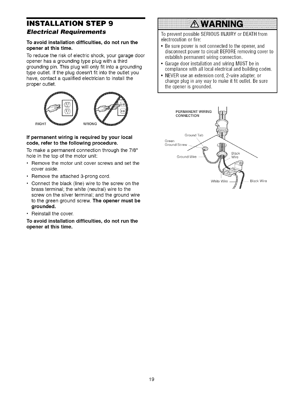
INSTALLATION STEP 9
Electrical Requirements
To avoid installation difficulties, do not run the
opener at this time.
To reduce the risk of electric shock, your garage door
opener has a grounding type plug with a third
grounding pin. This plug will only fit into a grounding
type outlet. If the plug doesn't fit into the outlet you
have, contact a qualified electrician to install the
proper outlet.
WRONG
If permanent wiring is required by your local
code, refer to the following procedure.
To make a permanent connection through the 7/8"
hole in the top of the motor unit:
• Remove the motor unit cover screws and set the
cover aside.
• Remove the attached 3-prong cord.
• Connect the black (line) wire to the screw on the
brass terminal; the white (neutral) wire to the
screw on the silver terminal; and the ground wire
to the green ground screw. The opener must be
grounded.
• Reinstall the cover.
To avoid installation difficulties, do not run the
opener at this time,
To prevent possible SERIOUSINJURYor DEATHfrom
electrocution or fire:
• Besure power is not connected to the opener, and
disconnect power to circuit BEFOREremoving cover to
establish permanentwiring connection.
• Garagedoor installation and wiring MUSTbe in
compliance with all local electrical and building codes.
• NEVERuse an extension cord, 2-wire adapter,or
change plug in any way to makeit fit outlet. Besure
the opener is grounded.
PERMANENT WiRiNG
CONNECTION
BJack Wire
19
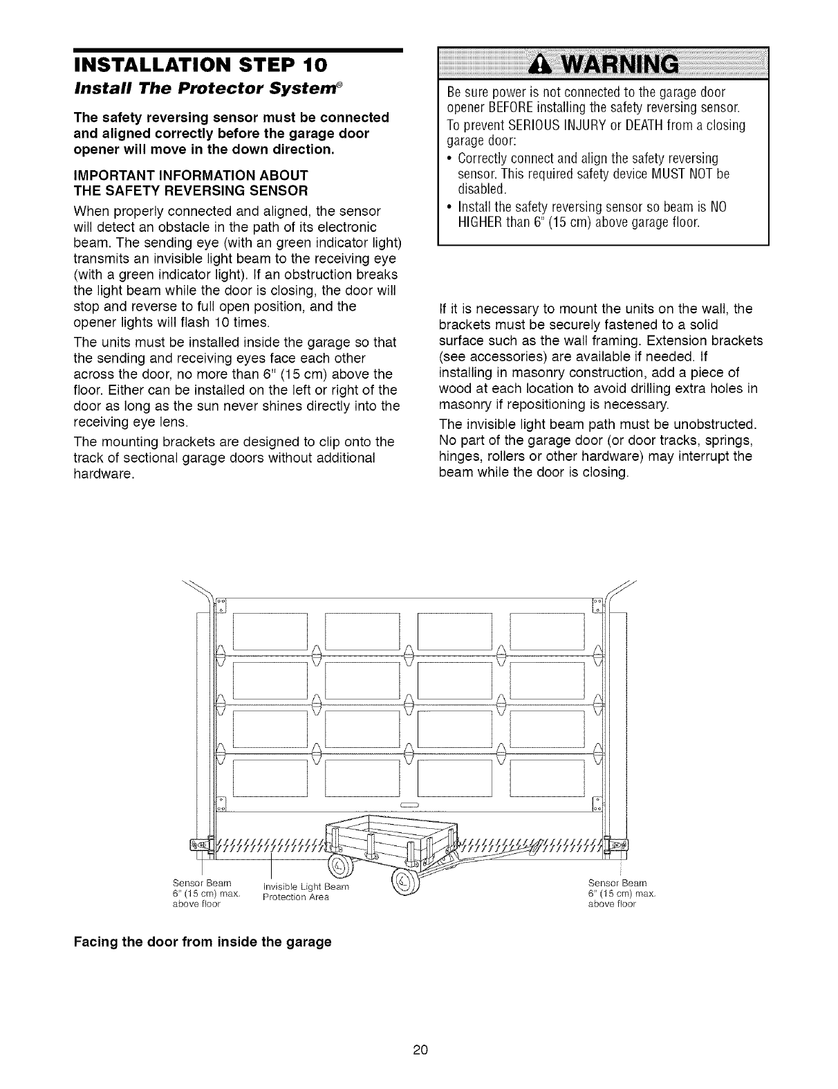
INSTALLATION STEP 10
Install The Protector System ®
The safety reversing sensor must be connected
and aligned correctly before the garage door
opener will move in the down direction,
IMPORTANT INFORMATION ABOUT
THE SAFETY REVERSING SENSOR
When properly connected and aligned, the sensor
will detect an obstacle in the path of its electronic
beam. The sending eye (with an green indicator light)
transmits an invisible light beam to the receiving eye
(with a green indicator light). If an obstruction breaks
the light beam while the door is closing, the door will
stop and reverse to full open position, and the
opener lights will flash 10 times.
The units must be installed inside the garage so that
the sending and receiving eyes face each other
across the door, no more than 6" (15 cm) above the
floor. Either can be installed on the left or right of the
door as long as the sun never shines directly into the
receiving eye lens.
The mounting brackets are designed to clip onto the
track of sectional garage doors without additional
hardware.
Be sure power is not connected to the garage door
opener BEFOREinstalling the safety reversing sensor.
To prevent SERIOUSINJURYor DEATHfrom a closing
garage door:
• Correctly connect and align the safety reversing
sensor. This required safety device MUST NOTbe
disabled.
• Install the safety reversing sensor so beam is NO
HIGHERthan 6" (15 cm) above garage floor.
If it is necessary to mount the units on the wall, the
brackets must be securely fastened to a solid
surface such as the wall framing. Extension brackets
(see accessories) are available if needed. If
installing in masonry construction, add a piece of
wood at each location to avoid drilling extra holes in
masonry if repositioning is necessary.
The invisible light beam path must be unobstructed.
No part of the garage door (or door tracks, springs,
hinges, rollers or other hardware) may interrupt the
beam while the door is closing.
6" (15 cm) max, Protection Area
above floor
Sensor Beam
6" (15 cm) max,
above floor
Facing the door from inside the garage
20
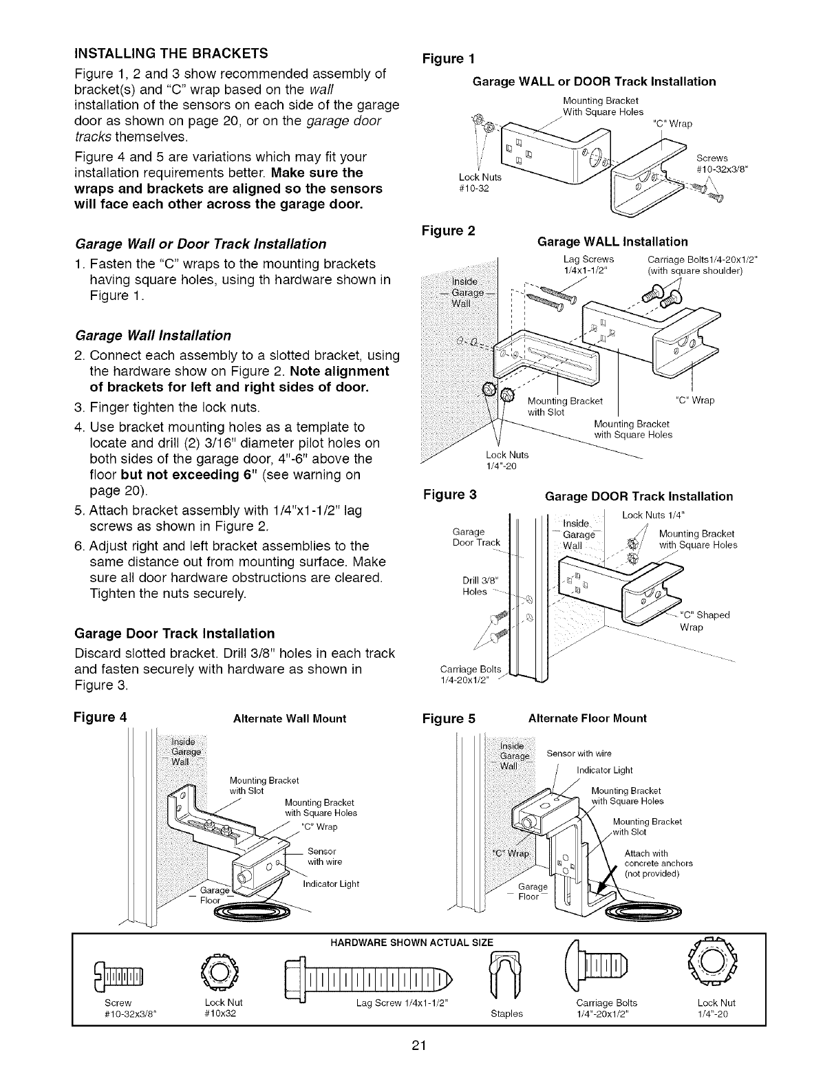
INSTALLINGTHEBRACKETS
Figure1,2 and3showrecommendedassemblyof
bracket(s)and"C"wrapbasedonthewaft
installation of the sensors on each side of the garage
door as shown on page 20, or on the garage door
tracks themselves.
Figure 4 and 5 are variations which may fit your
installation requirements better. Make sure the
wraps and brackets are aligned so the sensors
will face each other across the garage door,
Garage Wall or Door Track Installation
1. Fasten the "C" wraps to the mounting brackets
having square holes, using th hardware shown in
Figure 1.
Figure 1
Garage WALL or DOOR Track Installation
Mounting Bracket
With Square Holes
J "C" Wrap
W
v
Lock Nuts
#10-32
Screws
#10-32x3/8"
Figure 2Garage WALL Installation
Lag Screws Carriage Bolts1/4-20x1/2"
1/4x1-1/2" (with square shoulder)
Garage Wall Installation
2. Connect each assembly to a slotted bracket, using
the hardware show on Figure 2. Note alignment
of brackets for left and right sides of door,
3. Finger tighten the lock nuts.
4. Use bracket mounting holes as a template to
locate and drill (2) 3/16" diameter pilot holes on
both sides of the garage door, 4"-6" above the
floor but not exceeding 6" (see warning on
page 20).
5. Attach bracket assembly with 1/4"xl -1/2" lag
screws as shown in Figure 2.
6. Adjust right and left bracket assemblies to the
same distance out from mounting surface. Make
sure all door hardware obstructions are cleared.
Tighten the nuts securely.
Garage Door Track Installation
Discard slotted bracket. Drill 3/8" holes in each track
and fasten securely with hardware as shown in
Figure 3.
Figure 3
Lock Nuts
1/4"-20
Garage
Door Track
Drill3/8"
Holes
Carriage Bolts
1/4-20xl/2" J """
"C" Wrap
Mounting Bracket
with Square Holes
Garage DOOR Track Installation
Lock Nuts 1/4"
Inside
-- GaragU Mounting Bracket
Wall with Square Holes
.J
ped
Wrap
Figure 4
J
Alternate Wall Mount
Mounting Bracket
I with Slot
][_- L[ J Mounting Bracket
_._,_ with Square Holes
"C" Wrap
Sensor
with wire
icator Light
©
Screw Lock Nut
#10-32x3/8" #10x32
Figure 5Alternate Floor Mount
Sensor with wire
Indicator Light
Mounting Bracket
uare Holes
Mounting Bracket
,with Slot
Attach with
concrete anchors
(not provided)
Floor
HARDWARE SHOWN ACTUAL SIZE
_[] I IIIIIIIIL!lg !lc[l! 11!:!11_!/12_
Staples
Carriage Bolts
1/4"-20xl/2"
©
Lock Nut
1/4"-20
21
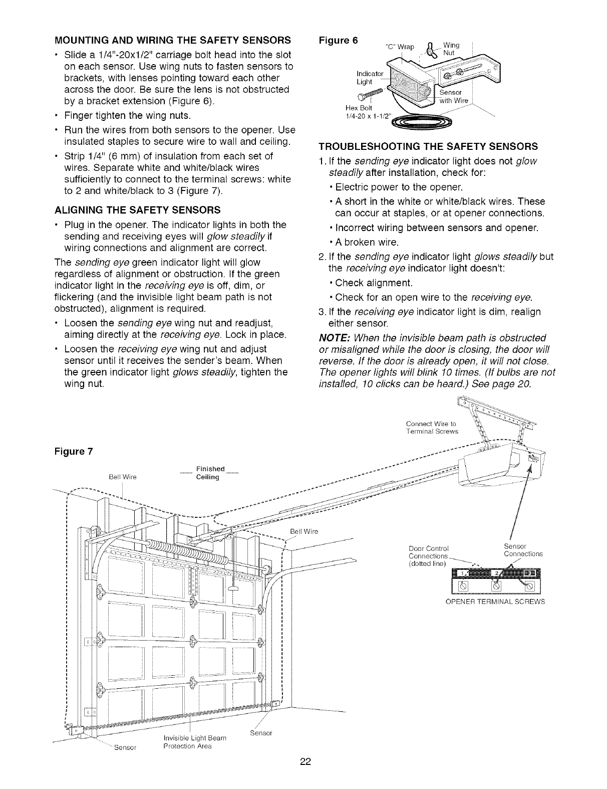
MOUNTING AND WIRING THE SAFETY SENSORS
•Slide a 1/4"-20xl/2" carriage bolt head into the slot
on each sensor. Use wing nuts to fasten sensors to
brackets, with lenses pointing toward each other
across the door. Be sure the lens is not obstructed
by a bracket extension (Figure 6).
• Finger tighten the wing nuts.
• Run the wires from both sensors to the opener. Use
insulated staples to secure wire to wall and ceiling.
• Strip 1/4" (6 mm) of insulation from each set of
wires. Separate white and white/black wires
sufficiently to connect to the terminal screws: white
to 2 and white/black to 3 (Figure 7).
ALIGNING THE SAFETY SENSORS
• Plug in the opener. The indicator lights in both the
sending and receiving eyes will glow steadily if
wiring connections and alignment are correct.
The sending eye green indicator light will glow
regardless of alignment or obstruction. If the green
indicator light in the receiving eye is off, dim, or
flickering (and the invisible light beam path is not
obstructed), alignment is required.
• Loosen the sending eye wing nut and readjust,
aiming directly at the receiving eye. Lock in place.
• Loosen the receiving eye wing nut and adjust
sensor until it receives the sender's beam. When
the green indicator light glows steadily, tighten the
wing nut.
Figure 6 "C" Wrap ____ Wing
Indicat
Light
_k_. _'_ with Wire__\
Hex Bolt _ _ _ - _ "_.
1/4 20 x 1 1/2"_ ""-
TROUBLESHOOTING THE SAFETY SENSORS
1. If the sending eye indicator light does not glow
steadily after installation, check for:
• Electric power to the opener.
• A short in the white or white/black wires. These
can occur at staples, or at opener connections.
• Incorrect wiring between sensors and opener.
• A broken wire.
2. If the sending eye indicator light glows steadily but
the receiving eye indicator light doesn't:
• Check alignment.
• Check for an open wire to the receiving eye.
3. If the receiving eye indicator light is dim, realign
either sensor.
NOTE: When the invisible beam path is obstructed
or misaligned while the door is closing, the door will
reverse. If the door is already open, it will not close.
The opener lights will blink 10 times. (If bulbs are not
installed, 10 clicks can be heard.) See page 20.
Figure 7
Finished
Bell Wire Ceiling
Connect Wire to
Terminal Screws
Bell Wire
Door Control Sensor
Connections_ Connections
(dotted line) ---'_-_
OPENER TERMINAL SCREWS
Invisible Light Beam
Sensor Protection Area
/
/
Sensor
22
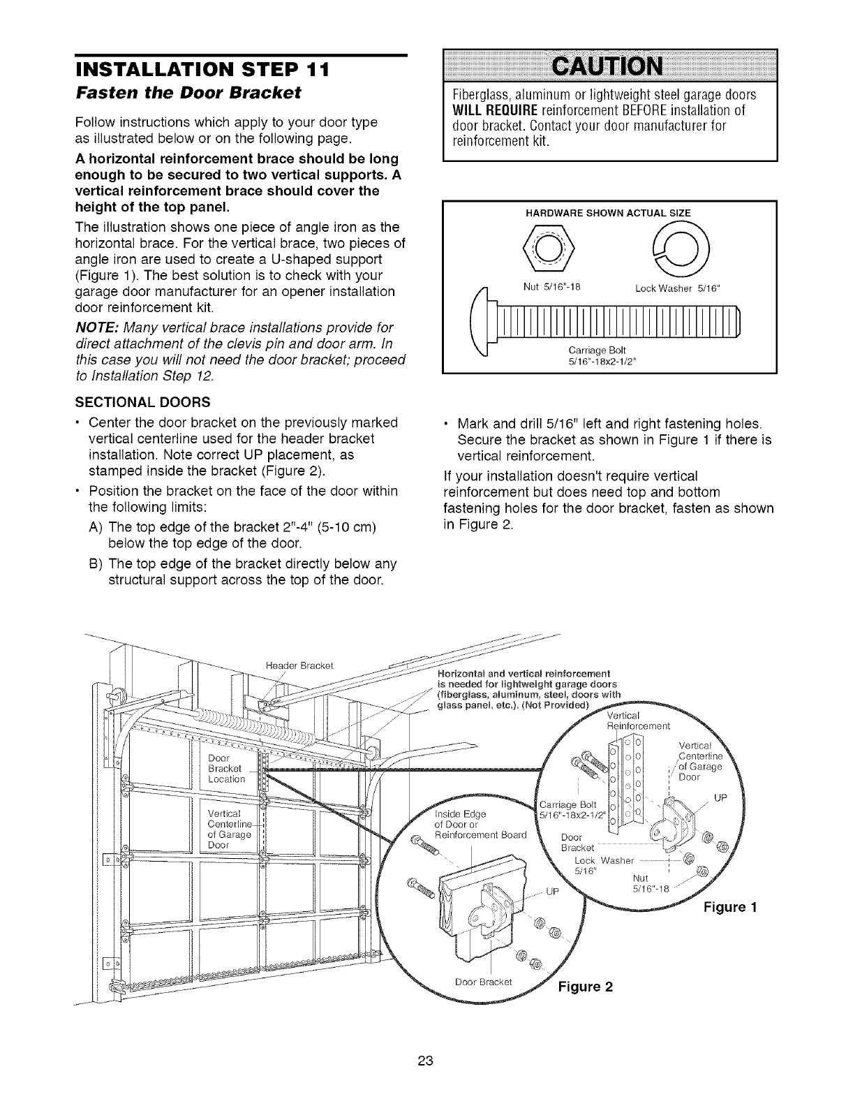
INSTALLATION STEP 11
Fasten the Door Bracket
Follow instructions which apply to your door type
as illustrated below or on the following page.
A horizontal reinforcement brace should be long
enough to be secured to two vertical supports, A
vertical reinforcement brace should cover the
height of the top panel,
The illustration shows one piece of angle iron as the
horizontal brace. For the vertical brace, two pieces of
angle iron are used to create a U-shaped support
(Figure 1). The best solution is to check with your
garage door manufacturer for an opener installation
door reinforcement kit.
NOTE: Many vertical brace installations provide for
direct attachment of the clevis pin and door arm. In
this case you will not need the door bracket; proceed
to Installation Step 12.
SECTIONAL DOORS
• Center the door bracket on the previously marked
vertical centerline used for the header bracket
installation. Note correct UP placement, as
stamped inside the bracket (Figure 2).
• Position the bracket on the face of the door within
the following limits:
A) The top edge of the bracket 2"-4" (5-10 cm)
below the top edge of the door.
B) The top edge of the bracket directly below any
structural support across the top of the door.
Fiberglass,aluminum or lightweight steel garage doors
WILL REQUIREreinforcement BEFOREinstallation of
door bracket. Contactyour door manufacturer for
reinforcement kit.
HARDWARE SHOWN ACTUAL SIZE
Nut 5/16"-18 LockWasher 5/16"
Carriage Bolt
5/16"-18x2-1/2"
• Mark and drill 5/16" left and right fastening holes.
Secure the bracket as shown in Figure 1 if there is
vertical reinforcement.
If your installation doesn't require vertical
reinforcement but does need top and bottom
fastening holes for the door bracket, fasten as shown
in Figure 2.
Header Bracket Nodzontal and vertical reinforcement
is needed for lightweight garage doors
(fiberglass, aluminum, steel, doors with
glass panel, ere.}. (Not Provided} Vertical
Reinforcement
Edge
of Door or
einforcement Board
Sarriage Bolt
5/16"-18x2-112'
Vertical
/of Garage
Door
UP
Door
Bracket
Lock Washer i (
5/16" Nut
5/16"-18 jz
Figure 1
Door Bracket Figure 2
23
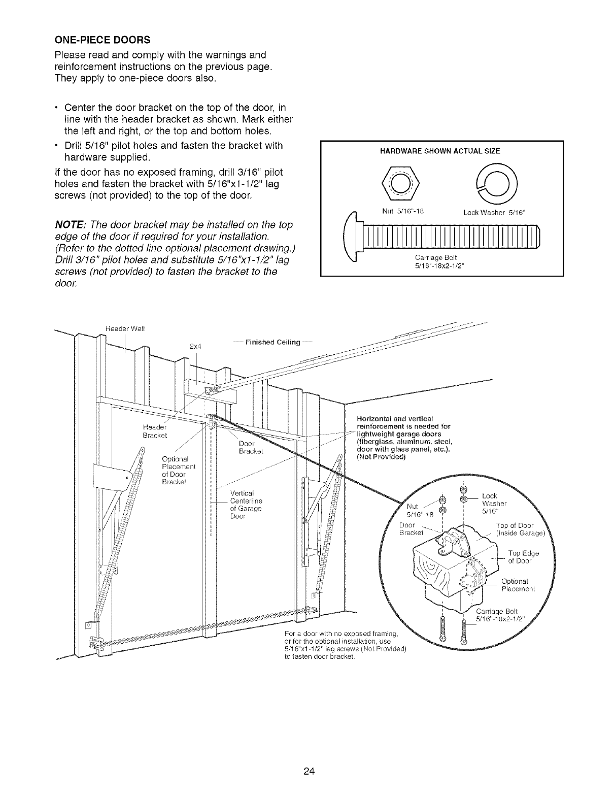
ONE-PIECEDOORS
Please read and comply with the warnings and
reinforcement instructions on the previous page.
They apply to one-piece doors also.
• Center the door bracket on the top of the door, in
line with the header bracket as shown. Mark either
the left and right, or the top and bottom holes.
• Drill 5/16" pilot holes and fasten the bracket with
hardware supplied.
If the door has no exposed framing, drill 3/16" pilot
holes and fasten the bracket with 5/16"x1-1/2" lag
screws (not provided) to the top of the door.
NOTE: The door bracket may be installed on the top
edge of the door if required for your installation.
(Refer to the dotted line optional placement drawing.)
Drill 3/16" pilot holes and substitute 5/16"x1-1/2" lag
screws (not provided) to fasten the bracket to the
door.
HARDWARE SHOWN ACTUAL SIZE
Nut 5/16"-18 LockWasher 5/16"
Carriage Bolt
5/16"-18x2-1/2"
Header Wall
2x4
Header
Bracket
Optional
Placement
of Door
Bracket
Door
Bracket
Vertical
_rline
of Garage
Door
Horizontal and verticam
reinforcement is needed for
e doors
(fiberglass, aluminum, steel,
door with glass panel, etc.).
(Not Provided)
For a door with no exposed framing,
or for the optional installation, use
5/16"xl-1/2" lag screws (Not Provided)
to fasten door bracket,
®
Lock
Washer
' 5/16"
i
i
iTop of Door
(inside Garage)
Top Edge
of Door
Optional
Placement
Carriage Bolt
5/16"-18x2-1/2"
24
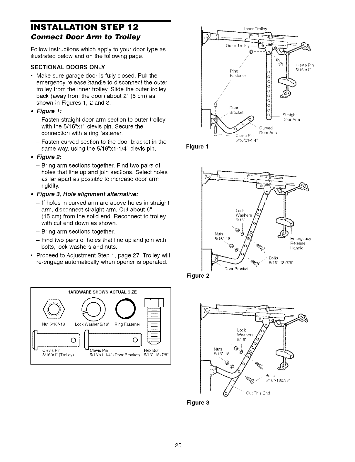
INSTALLATION STEP 12
Connect Door Arm to Trolley
Follow instructions which apply to your door type as
illustrated below and on the following page.
SECTIONAL DOORS ONLY
• Make sure garage door is fully closed. Pull the
emergency release handle to disconnect the outer
trolley from the inner trolley. Slide the outer trolley
back (away from the door) about 2" (5 cm) as
shown in Figures 1, 2 and 3.
•Figure 1:
- Fasten straight door arm section to outer trolley
with the 5/16"xl" clevis pin. Secure the
connection with a ring fastener.
- Fasten curved section to the door bracket in the
same way, using the 5/16"x1-1/4" clevis pin.
• Figure 2:
- Bring arm sections together. Find two pairs of
holes that line up and join sections. Select holes
as far apart as possible to increase door arm
rigidity.
• Figure &Hole alignment alternative:
- If holes in curved arm are above holes in straight
arm, disconnect straight arm. Cut about 6"
(15 cm) from the solid end. Reconnect to trolley
with cut end down as shown.
- Bring arm sections together.
- Find two pairs of holes that line up and join with
bolts, lock washers and nuts.
• Proceed to Adjustment Step 1, page 27. Trolley will
re-engage automatically when opener is operated.
Clevis Pin
5/16"x1-1/4"
Curved
Door Arm
Figure 1
Figure 2
Emergency
Release
Handle
/._ Bolts
5/16"-18x7/8"
Door Bracket
©
Nut 5/16"-18
Clevis Pin
5/16"xl" (Trolley)
HARDWARE SHOWN ACTUAL SIZE
Lock Washer 5/16" Ring Fastener
Clevis Pin Hex Bolt
5/16"x1-1/4" (Door Bracket) 5/16"-18x7/8"
Washers Io I II
II
.uts Zo/
o_ Cut This End
Figure 3
25
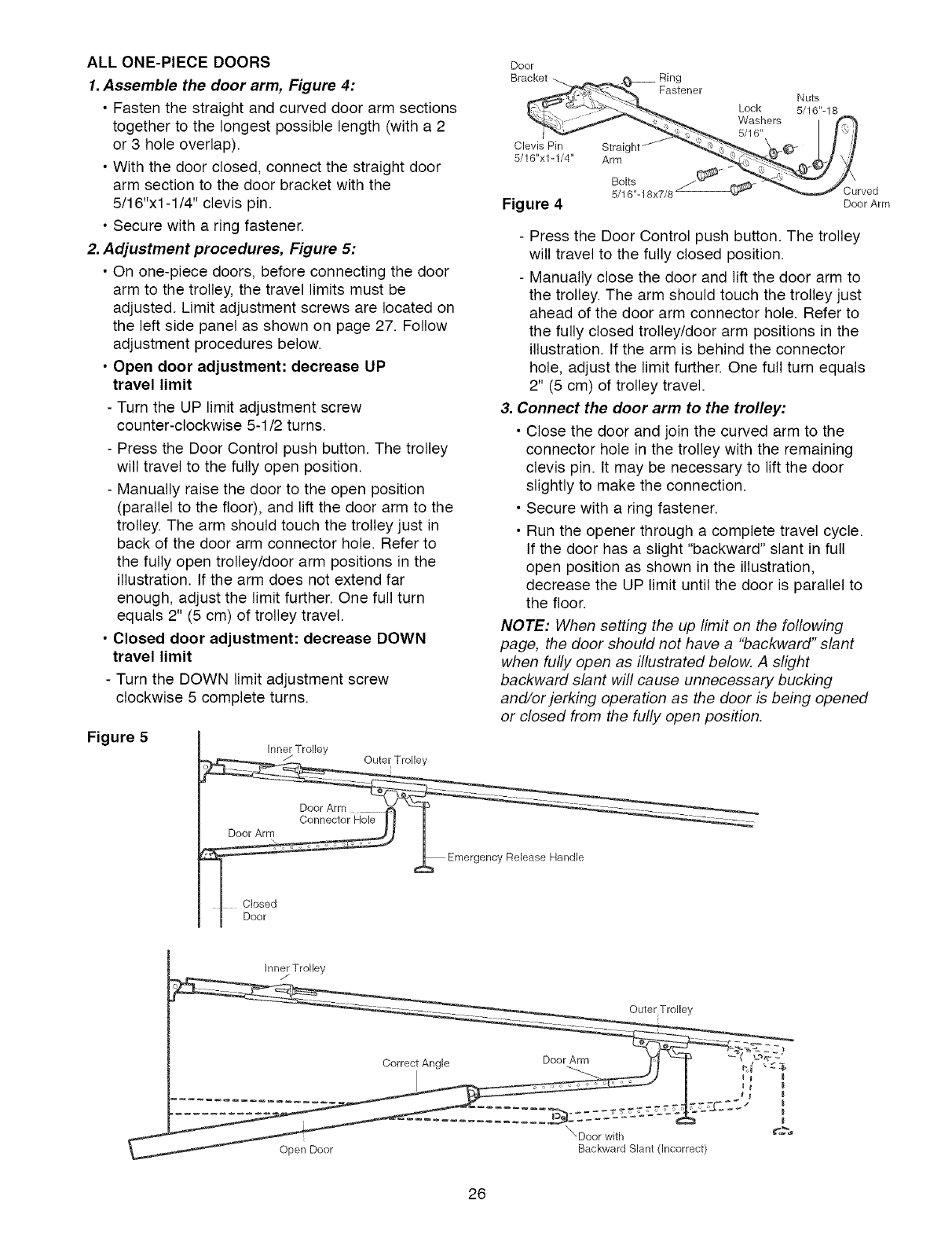
ALL ONE-PIECE DOORS
1. Assemble the door arm, Figure 4:
•Fasten the straight and curved door arm sections
together to the longest possible length (with a 2
or 3 hole overlap).
• With the door closed, connect the straight door
arm section to the door bracket with the
5/16"xl -1/4" clevis pin.
• Secure with a ring fastener.
2. Adjustment procedures, Figure 5:
• On one-piece doors, before connecting the door
arm to the trolley, the travel limits must be
adjusted. Limit adjustment screws are located on
the left side panel as shown on page 27. Follow
adjustment procedures below.
• Open door adjustment: decrease UP
travel limit
- Turn the UP limit adjustment screw
counter-clockwise 5-1/2 turns.
- Press the Door Control push button. The trolley
will travel to the fully open position.
- Manually raise the door to the open position
(parallel to the floor), and lift the door arm to the
trolley. The arm should touch the trolley just in
back of the door arm connector hole. Refer to
the fully open trolley/door arm positions in the
illustration. If the arm does not extend far
enough, adjust the limit further. One full turn
equals 2" (5 cm) of trolley travel.
• Closed door adjustment: decrease DOWN
travel limit
- Turn the DOWN limit adjustment screw
clockwise 5 complete turns.
Figure 5
Door
Clevis Pin Straight
5/16"x1-1/4" Arm
Figure 4
Ring
Fastener
Bolts
5/16"-18x7/8
Lock
Washers
5/16"
Nuts
5/16"-18
Curved
Door Arm
- Press the Door Control push button. The trolley
will travel to the fully closed position.
- Manually close the door and lift the door arm to
the trolley. The arm should touch the trolley just
ahead of the door arm connector hole. Refer to
the fully closed trolley/door arm positions in the
illustration. If the arm is behind the connector
hole, adjust the limit further. One full turn equals
2" (5 cm) of trolley travel.
3. Connect the door arm to the trolley:
• Close the door and join the curved arm to the
connector hole in the trolley with the remaining
clevis pin. It may be necessary to lift the door
slightly to make the connection.
• Secure with a ring fastener.
• Run the opener through a complete travel cycle.
If the door has a slight "backward" slant in full
open position as shown in the illustration,
decrease the UP limit until the door is parallel to
the floor.
NOTE: When setting the up limit on the following
page, the door should not have a "backward" slant
when fully open as illustrated below. A slight
backward slant will cause unnecessary bucking
and/or jerking operation as the door is being opened
or closed from the fully open position.
Inner Trolley
Conn_tor Hole ! I 1
_ Emergency Release Handle
Closed
I Door
Inner Trolley
...... Outer Trolley
s I
o..... 22222 - ,-:.L
Open Doo[ Backward Slant (Incorrect)
26
ADJUSTMENT STEP 1
Adjust the UP and DOWN Travel
Limits
Limit adjustment settings regulate the points at which
the door will stop when moving up or down.
To operate the opener, press the Door Control push
bar. Run the opener through a complete travel cycle.
• Does the door open and close completely?
• Does the door stay closed and not reverse
unintentionally when fully closed?
If your door passes both of these tests, no limit
adjustments are necessary unless the reversing test
fails (Adjustment Step 3, page 29).
Adjustment procedures are outlined below. Read the
procedures carefully before proceeding to
Adjustment Step 2. Use a screwdriver to make limit
adjustments. Run the opener through a complete
travel cycle after each adjustment.
NOTE: Repeated operation of the opener during
adjustment procedures may cause the motor to
overheat and shut off. Simply wait 15 minutes and
try again.
NOTE: If anything interferes with the door's upward
travel, it will stop. If anything interferes with the
door's downward travel (including binding or
unbalanced doors), it will reverse.
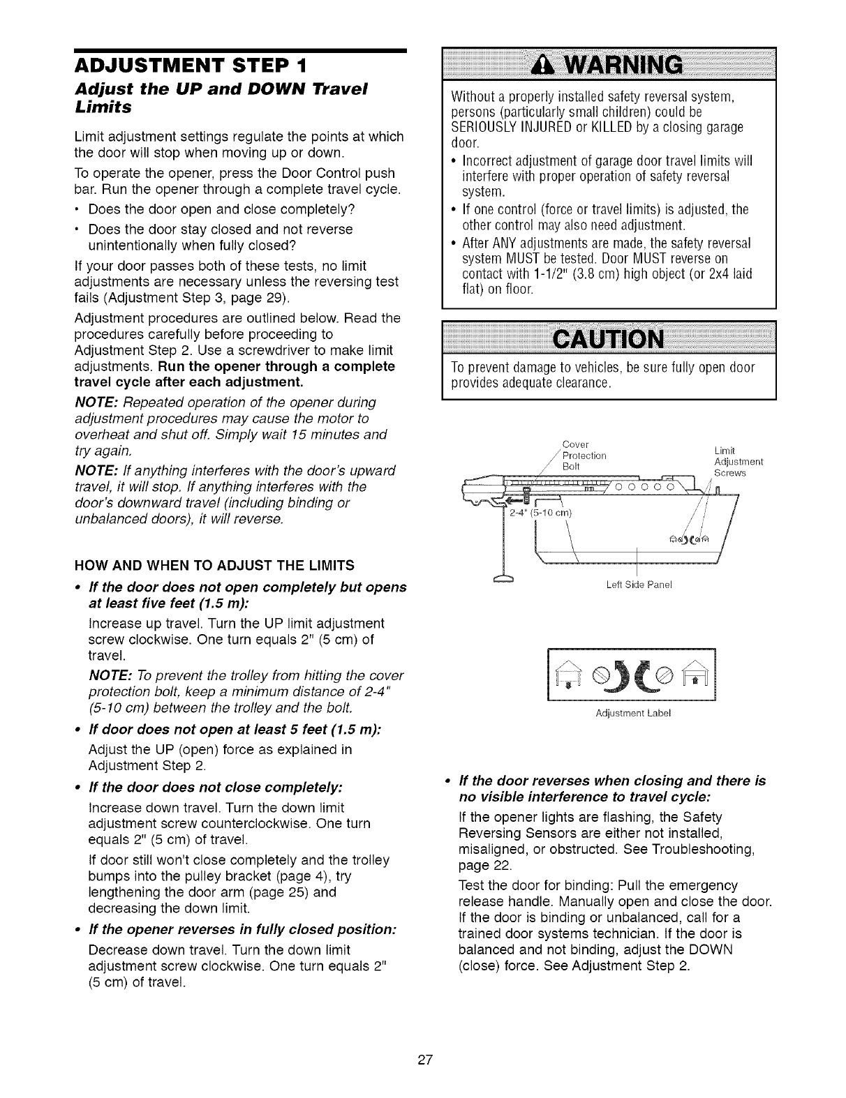
HOW AND WHEN TO ADJUST THE LIMITS
•If the door does not open completely but opens
at least five feet (1.5 m):
Increase up travel. Turn the UP limit adjustment
screw clockwise. One turn equals 2" (5 cm) of
travel.
NOTE: To prevent the trolley from hitting the cover
protection bolt, keep a minimum distance of 2-4"
(5-10 cm) between the trolley and the bolt.
• If door does not open at least 5 feet (1.5 m):
Adjust the UP (open) force as explained in
Adjustment Step 2.
• If the door does not close completely:
Increase down travel. Turn the down limit
adjustment screw counterclockwise. One turn
equals 2" (5 cm) of travel.
If door still won't close completely and the trolley
bumps into the pulley bracket (page 4), try
lengthening the door arm (page 25) and
decreasing the down limit.
• If the opener reverses in fully closed position:
Decrease down travel. Turn the down limit
adjustment screw clockwise. One turn equals 2"
(5 cm) of travel.
Without a properly installed safety reversal system,
persons (particularly small children) could be
SERIOUSLYINJUREDor KILLEDby a closing garage
door.
• Incorrect adjustment of garage door travel limits will
interfere with proper operation of safety reversal
system.
• If one control (force or travel limits) is adjusted, the
other control may also needadjustment.
• After ANY adjustments are made,the safety reversal
system MUST be tested. Door MUST reverse on
contact with 1-1/2" (3.8 cm) high object (or 2x4 laid
flat) on floor.
To prevent damageto vehicles, be sure fully open door
provides adequateclearance.
Oover
Protection Limit
Adjustment
J_ Bolt
/Screws
Left Side Panel
Adjustment Label
If the door reverses when closing and there is
no visible interference to travel cycle:
If the opener lights are flashing, the Safety
Reversing Sensors are either not installed,
misaligned, or obstructed. See Troubleshooting,
page 22.
Test the door for binding: Pull the emergency
release handle. Manually open and close the door.
If the door is binding or unbalanced, call for a
trained door systems technician. If the door is
balanced and not binding, adjust the DOWN
(close) force. See Adjustment Step 2.
27
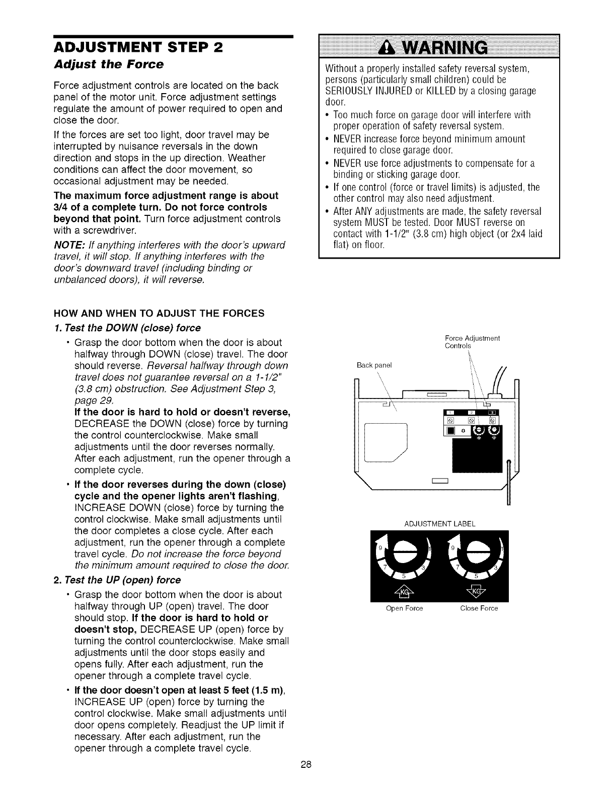
ADJUSTMENT STEP 2
Adjust the Force
Force adjustment controls are located on the back
panel of the motor unit. Force adjustment settings
regulate the amount of power required to open and
close the door.
If the forces are set too light, door travel may be
interrupted by nuisance reversals in the down
direction and stops in the up direction. Weather
conditions can affect the door movement, so
occasional adjustment may be needed.
The maximum force adjustment range is about
3/4 of a complete turn, Do not force controls
beyond that point, Turn force adjustment controls
with a screwdriver.
NOTE: If anything interferes with the door's upward
travel, it will stop. If anything interferes with the
door's downward travel (including binding or
unbalanced doors), it will reverse.
Without a properly installed safety reversal system,
persons (particularly small children) could be
SERIOUSLYINJUREDor KILLEDby a closing garage
door.
• Too much force on garage door will interfere with
proper operation of safety reversalsystem.
• NEVERincreaseforce beyond minimum amount
required to close garage door.
• NEVERuse force adjustments to compensatefor a
binding or sticking garage door.
• If one control (force or travel limits) is adjusted, the
other control may also needadjustment.
• After ANY adjustments are made,the safety reversal
system MUST be tested. Door MUST reverse on
contact with 1-1/2" (3.8 cm) high object (or 2x4 laid
flat) on floor.
HOW AND WHEN TO ADJUST THE FORCES
1. Test the DOWN (close) force
• Grasp the door bottom when the door is about
halfway through DOWN (close) travel. The door
should reverse. Reversal halfway through down
travel does not guarantee reversal on a 1-1/2"
(3.8 cm) obstruction. See Adjustment Step 3,
page 29.
If the door is hard to hold or doesn't reverse,
DECREASE the DOWN (close) force by turning
the control counterclockwise. Make small
adjustments until the door reverses normally.
After each adjustment, run the opener through a
complete cycle.
• If the door reverses during the down (close)
cycle and the opener lights aren't flashing,
INCREASE DOWN (close) force by turning the
control clockwise. Make small adjustments until
the door completes a close cycle. After each
adjustment, run the opener through a complete
travel cycle. Do not increase the force beyond
the minimum amount required to close the door.
2, Test the UP (open) force
• Grasp the door bottom when the door is about
halfway through UP (open) travel. The door
should stop. If the door is hard to hold or
doesn't stop, DECREASE UP (open) force by
turning the control counterclockwise. Make small
adjustments until the door stops easily and
opens fully. After each adjustment, run the
opener through a complete travel cycle.
• If the door doesn't open at least 5 feet (1,5 m),
INCREASE UP (open) force by turning the
control clockwise. Make small adjustments until
door opens completely. Readjust the UP limit if
necessary. After each adjustment, run the
opener through a complete travel cycle.
28
Force Adjustment
Controls
ADJUSTMENT LABEL
Open Force Close Force
ADJUSTMENT STEP 3
Test the Safety Reversal System
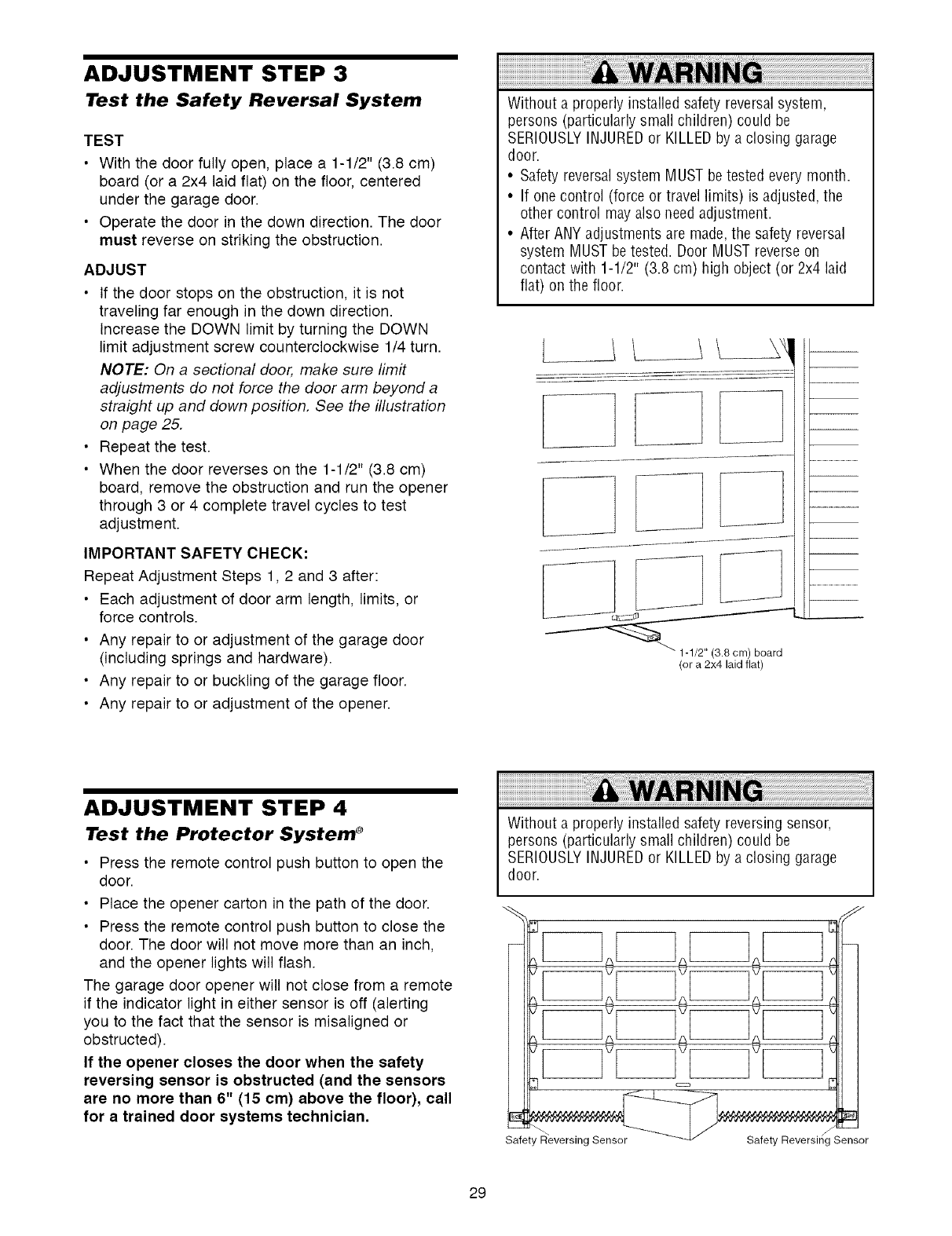
TEST
•With the door fully open, place a 1-1/2" (3.8 cm)
board (or a 2x4 laid flat) on the floor, centered
under the garage door.
• Operate the door in the down direction. The door
must reverse on striking the obstruction.
ADJUST
• If the door stops on the obstruction, it is not
traveling far enough in the down direction.
Increase the DOWN limit by turning the DOWN
limit adjustment screw counterclockwise 1/4 turn.
NOTE: On a sectional door, make sure limit
adjustments do not force the door arm beyond a
straight up and down position, See the illustration
on page 25,
• Repeat the test.
• When the door reverses on the 1-1/2" (3.8 cm)
board, remove the obstruction and run the opener
through 3 or 4 complete travel cycles to test
adjustment.
IMPORTANT SAFETY CHECK:
Repeat Adjustment Steps 1,2 and 3 after:
• Each adjustment of door arm length, limits, or
force controls.
• Any repair to or adjustment of the garage door
(including springs and hardware).
• Any repair to or buckling of the garage floor.
• Any repair to or adjustment of the opener.
Without a properly installed safety reversal system,
persons (particularly small children) could be
SERIOUSLYINJUREDor KILLEDby a closing garage
door.
• Safety reversal system MUST be tested every month.
• If one control (force or travel limits) is adjusted, the
other control may also needadjustment.
• After ANY adjustments are made,the safety reversal
system MUST be tested. Door MUST reverse on
contact with 1-1/2" (3.8 cm) high object (or 2x4 laid
flat) on the floor.
L
(or a 2x4 laid flat)
ADJUSTMENT STEP 4
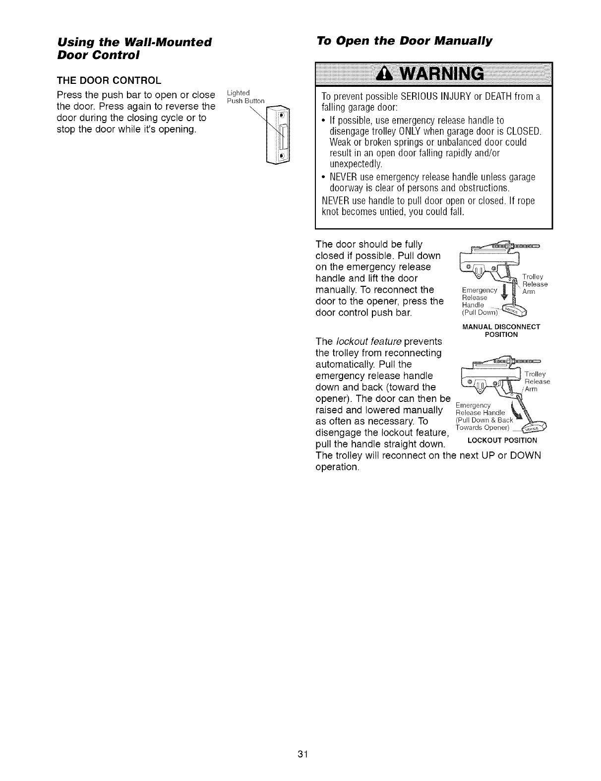
Test the Protector System ®
• Press the remote control push button to open the
door.
• Place the opener carton in the path of the door.
• Press the remote control push button to close the
door. The door will not move more than an inch,
and the opener lights will flash.
The garage door opener will not close from a remote
if the indicator light in either sensor is off (alerting
you to the fact that the sensor is misaligned or
obstructed).
If the opener closes the door when the safety
reversing sensor is obstructed (and the sensors
are no more than 6" (15 cm) above the floor), call
for a trained door systems technician,
Without a properly installed safety reversing sensor,
persons (particularly small children) could be
SERIOUSLYINJUREDor KILLEDby a closing garage
door.
Safety Reversing Sensor Safety Reversing Sensor
29
OPERATION
IMPORTANT SAFETY INSTRUCTIONS
To reducethe riskof severe injuryor death:
1. READAND FOLLOWALL WARNINGSAND
INSTRUCTIONS.
2. ALWAYSkeep remote controls out of reach of children.
NEVERpermit children to operate or play with garage
door control push buttons or remote controls.
3. ONLYactivate garage door when it can be seen clearly, it
is properly adjusted, and there are no obstructions to
door travel.
4. ALWAYSkeep garagedoor in sight until completely
closed. NO ONESHOULDCROSSTHEPATHOFTHE
MOVING DOOR.
5. NO ONESHOULDGOUNDERA STOPPED,PARTIALLY
OPENDOOR.
6. If possible, use emergency releasehandle to disengage
trolley ONLYwhen garage door is CLOSED.Weakor
broken springs or unbalanceddoor could result in an
open door failing rapidly and/or unexpectedly.
7. NEVERuse emergency release handle unlessgarage
doorway is clear of persons and obstructions.
8. NEVERuse handleto pull garage door open or closed. If
rope knot becomes untied, you could fall.
9. If one control (force or travel limits) is adjusted, the
other control mayalso needadjustment.
10. After ANY adjustments are made,the safety reversal
system MUST be tested.
11. Safety reversalsystem MUST betested every month.
Garagedoor MUST reverse on contact with 1-1/2"
(3.8 cm) high object (or a 2 x 4 laid flat) on the floor.
12. ALWAYSKEEPGARAGEDOORPROPERLYBALANCED
(see page3). An improperly balanced door may not
reversewhen required and could result in SEVERE
INJURYor DEATH.
13. All repairs to cables, spring assemblies and other
hardware,all of which are under EXTREMEtension,
MUST be made by a trained door systems technician.
14. ALWAYSdisconnect electric power to garage door
opener BEFOREmaking any repairs or removing
covers.
SAVETHESEINSTRUCTIONS.
Using Your Garage Door Opener
Your Security÷ _;opener and hand-held remote control
have been factory-set to a matching code which
changes with each use, randomly accessing over
100 billion new codes. Your opener will operate with
up to eight Security÷ '_ remote controls and one
Security÷ ® Keyless Entry System. If you purchase a
new remote, or if you wish to deactivate any remote,
follow the instructions in the Programming section.
Activate your opener with any of the following:
•The hand-held Remote Control: Hold the large
push button down until the door starts to move.
• The wall-mounted Door Control: Hold the push
button or bar down until the door starts to move.
• The Keyless Entry (See Accessories): If provided
with your garage door opener, it must be
programmed before use. See Programming.
When the opener is activated (with the safety
reversing sensor correctly installed and aligned)
1. If open, the door will close. If closed, it will open.
2. If closing, the door will reverse.
3. If opening, the door will stop.
4. If the door has been stopped in a partially open
position, it will close.
5. If obstructed while closing, the door will reverse. If
the obstruction interrupts the sensor beam, the
opener lights will blink for five seconds.
6. If obstructed while opening, the door will stop.
7. If fully open, the door will not close when the beam
is broken. The sensor has no effect in the opening
cycle.
If the sensor is not installed, or is misaligned, the
door won't close from a hand-held remote. However,
you can close the door with the Door Control, the
Outside Keylock, or Keyless Entry, if you activate
them until down travel is complete. If you release
them too soon, the door will reverse.
The opener lights will turn on under the following
conditions: when the opener is initially plugged in;
when power is restored after interruption; when the
opener is activated.
They will turn off automatically after 4-1/2 minutes.
Bulb size is 75 watts maximum.
30
Using the Wall.Mounted To Open the Door Manually
Door Control
THE DOOR CONTROL
Press the push bar to open or close
the door. Press again to reverse the
door during the closing cycle or to
stop the door while it's opening.
Lighted
Push Button To prevent possible SERIOUSINJURY or DEATHfrom a
falling garagedoor:
• If possible, use emergency release handleto
disengagetrolley ONLYwhen garage door is CLOSED.
Weakor broken springs or unbalanceddoor could
result in an open door falling rapidly and/or
unexpectedly.
• NEVERuse emergency release handle unless garage
doorway is clear of persons and obstructions.
NEVERuse handle to pull door open or closed. If rope
knot becomes untied, you could fall.
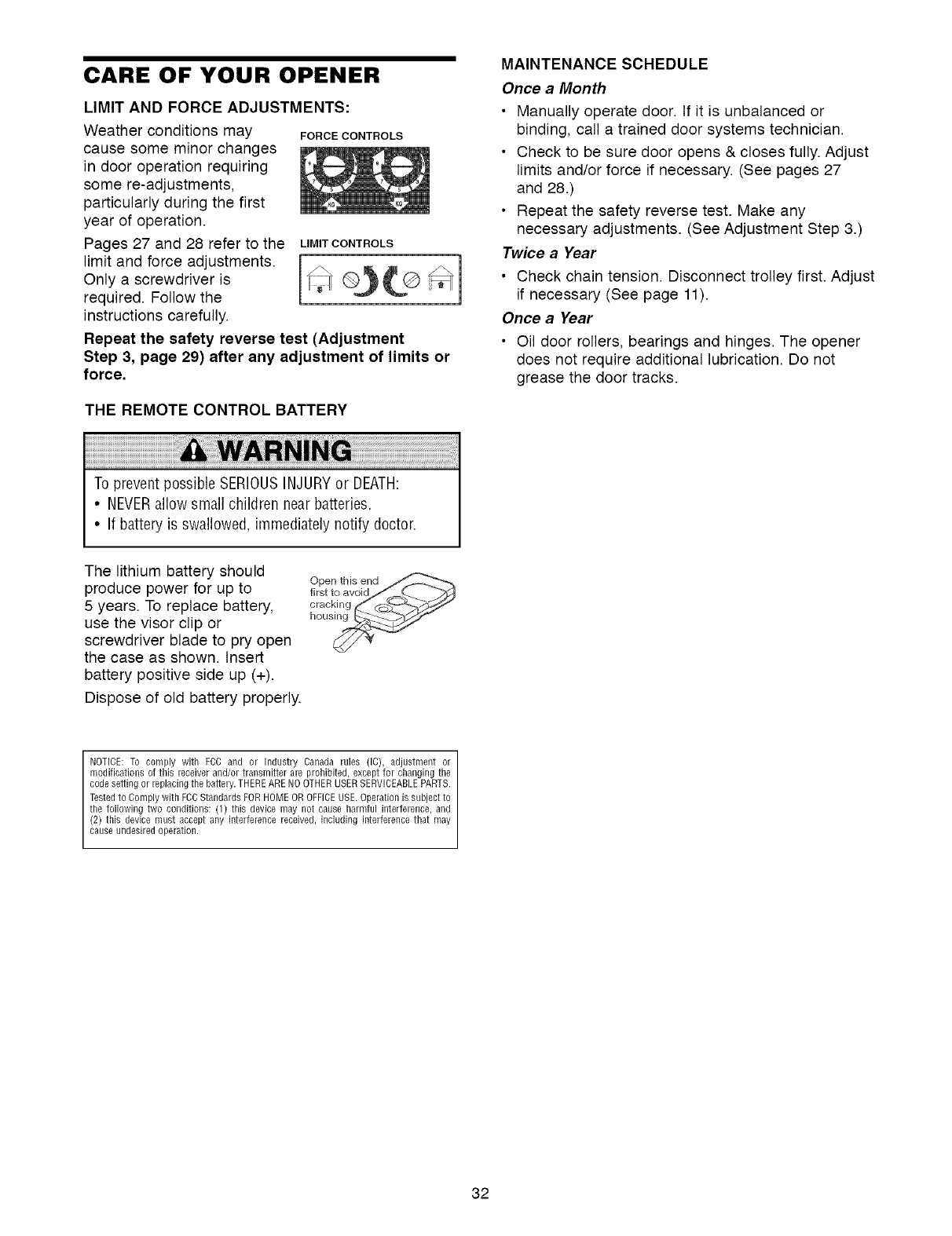
The door should be fully
closed if possible. Pull down
on the emergency release
handle and lift the door
manually. To reconnect the
door to the opener, press the
door control push bar.
MANUAL DISCONNECT
POSITION
The lockout feature prevents
the trolley from reconnecting
automatically. Pull the
emergency release handle
down and back (toward the
opener). The door can then be
raised and lowered manually
as often as necessary. To
disengage the lockout feature,
pull the handle straight down. LOCKOUTPOSITION
The trolley will reconnect on the next UP or DOWN
operation.
31
CARE OF YOUR OPENER
LIMIT AND FORCE ADJUSTMENTS:
Weather conditions may FORCECONTROLS
cause some minor changes
in door operation requiring
some re-adjustments,
particularly during the first
year of operation.
Pages 27 and 28 refer to the LIMITCONTROLS
limit and force adjustments.
Only a screwdriver is
required. Follow the
instructions carefully.
Repeat the safety reverse test (Adjustment
Step 3, page 29) after any adjustment of limits or
force,
THE REMOTE CONTROL BATTERY
MAINTENANCE SCHEDULE
Once a Month
•Manually operate door. If it is unbalanced or
binding, call a trained door systems technician.
• Check to be sure door opens & closes fully. Adjust
limits and/or force if necessary. (See pages 27
and 28.)
• Repeat the safety reverse test. Make any
necessary adjustments. (See Adjustment Step 3.)
Twice a Year
• Check chain tension. Disconnect trolley first. Adjust
if necessary (See page 11).
Once a Year
• Oil door rollers, bearings and hinges. The opener
does not require additional lubrication. Do not
grease the door tracks.
To prevent possible SERIOUSINJURYor DEATH:
•NEVERallow small children near batteries.
• If battery is swallowed, immediately notify doctor.
The lithium battery should
produce power for up to
5 years. To replace battery,
use the visor clip or
screwdriver blade to pry open
the case as shown. Insert
battery positive side up (+).
Dispose of old battery properly.
Open this end
first to avoidJ_ j_jd,J
hou__
NOTICE:To comply with FCCand or Industry Canada rules (IC), adjustment or
modifications of this receiverand/or transmitter are prohibited,except for changingthe
code settingor replacingthe battery.THEREARE NOOTHERUSERSERVICEABLEPARTS.
Testedto Complywith FCCStandards FORHOMEOR OFFICEUSE.Operationissubject to
the following two conditions: (1) this device may not cause harmful interference,and
(2) this device must accept any interference received, including interference that may
cause undesiredoperation.
32
HAVING A PROBLEM?
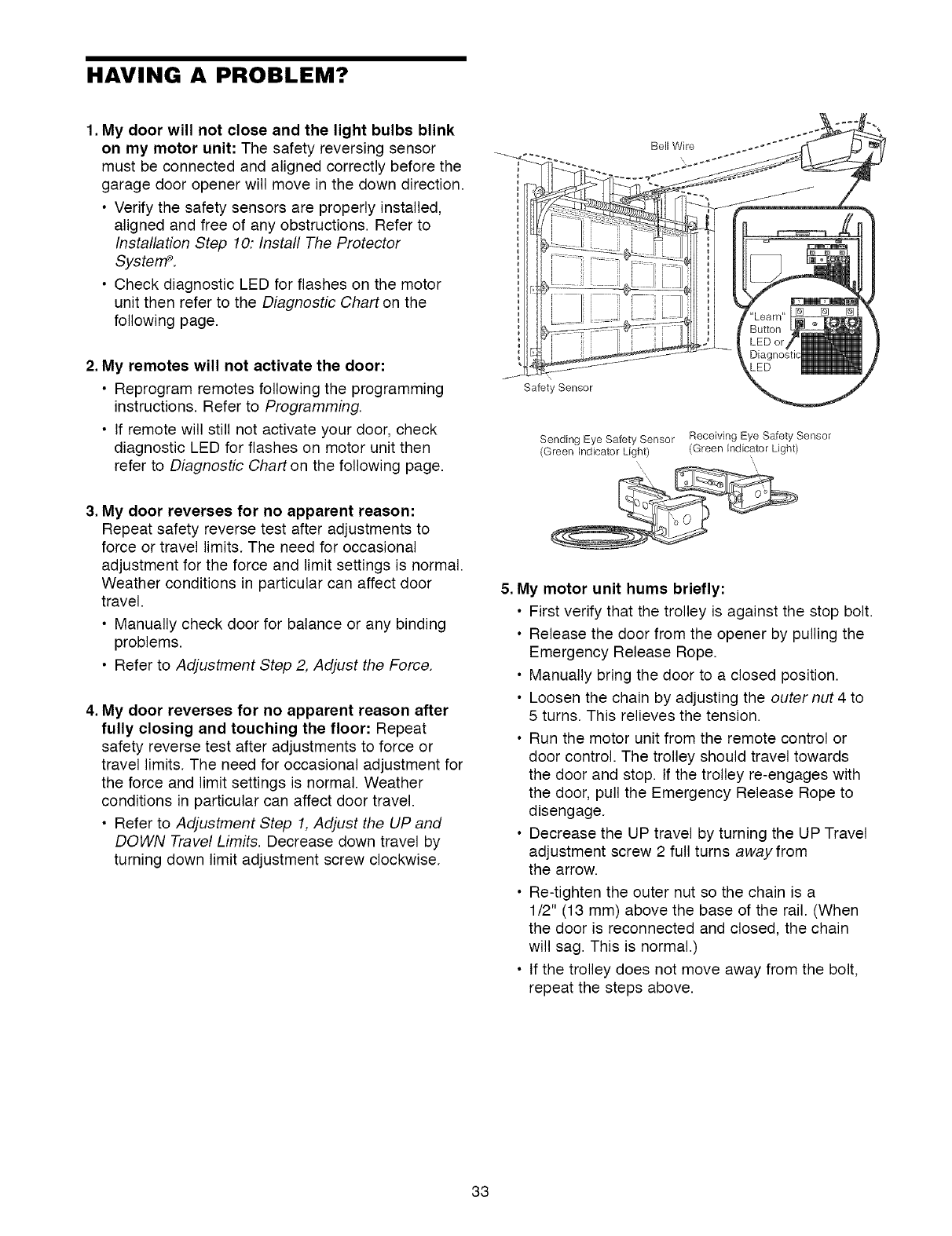
1, My door will not close and the light bulbs blink
on my motor unit: The safety reversing sensor
must be connected and aligned correctly before the
garage door opener will move in the down direction.
• Verify the safety sensors are properly installed,
aligned and free of any obstructions. Refer to
Installation Step 10: Install The Protector
SystetTP.
• Check diagnostic LED for flashes on the motor
unit then refer to the Diagnostic Chart on the
following page.
2. My remotes will not activate the door:
• Reprogram remotes following the programming
instructions. Refer to Programming.
• If remote will still not activate your door, check
diagnostic LED for flashes on motor unit then
refer to Diagnostic Chart on the following page.
Bell Wire
\
Safety Sensor
Sending Eye Safety Sensor
(Green Indicator Light)
Receiving Eye Safety Sensor
(Green Indicator Light)
3. My door reverses for no apparent reason:
Repeat safety reverse test after adjustments to
force or travel limits. The need for occasional
adjustment for the force and limit settings is normal.
Weather conditions in particular can affect door
travel.
• Manually check door for balance or any binding
problems.
• Refer to Adjustment Step 2, Adjust the Force.
4. My door reverses for no apparent reason after
fully closing and touching the floor: Repeat
safety reverse test after adjustments to force or
travel limits. The need for occasional adjustment for
the force and limit settings is normal. Weather
conditions in particular can affect door travel.
• Refer to Adjustment Step 1, Adjust the UP and
DOWN Travel Limits. Decrease down travel by
turning down limit adjustment screw clockwise.
5. My motor unit hums briefly:
• First verify that the trolley is against the stop bolt.
• Release the door from the opener by pulling the
Emergency Release Rope.
• Manually bring the door to a closed position.
• Loosen the chain by adjusting the outer nut 4 to
5 turns. This relieves the tension.
• Run the motor unit from the remote control or
door control. The trolley should travel towards
the door and stop. If the trolley re-engages with
the door, pull the Emergency Release Rope to
disengage.
• Decrease the UP travel by turning the UP Travel
adjustment screw 2 full turns awayfrom
the arrow.
• Re-tighten the outer nut so the chain is a
1/2" (13 mm) above the base of the rail. (When
the door is reconnected and closed, the chain
will sag. This is normal.)
• If the trolley does not move away from the bolt,
repeat the steps above.
33
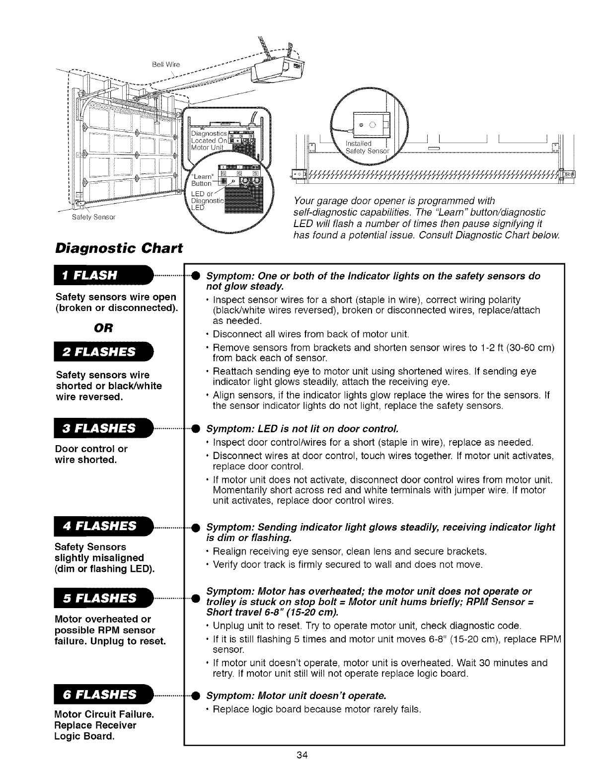
Bell Wire
Safety Sensor
Diagnostic Chart
Safety sensors wire open
(broken or disconnected).
OR
Safety sensors wire
shorted or black/white
wire reversed,
Door control or
wire shorted,
Safety Sensors
slightly misaligned
(dim or flashing LED).
Motor overheated or
possible RPM sensor
failure, Unplug to reset.
Motor Circuit Failure,
Replace Receiver
Logic Board,
Your garage door opener is programmed with
self-diagnostic capabilities. The "Learn" button/diagnostic
LED will flash a number of times then pause signifying it
has found a potential issue. Consult Diagnostic Chart below.
..e
..e
..e
..e
Symptom: One or both of the Indicator lights on the safety sensors do
not glow steady.
•Inspect sensor wires for a short (staple in wire), correct wiring polarity
(black/white wires reversed), broken or disconnected wires, replace/attach
as needed.
• Disconnect all wires from back of motor unit.
• Remove sensors from brackets and shorten sensor wires to 1-2 ft (30-60 cm)
from back each of sensor.
• Reattach sending eye to motor unit using shortened wires. If sending eye
indicator light glows steadily, attach the receiving eye.
• Align sensors, if the indicator lights glow replace the wires for the sensors. If
the sensor indicator lights do not light, replace the safety sensors.
Symptom: LED is not fit on door control.
• Inspect door control/wires for a short (staple in wire), replace as needed.
• Disconnect wires at door control, touch wires together. If motor unit activates
replace door control.
• If motor unit does not activate, disconnect door control wires from motor unit.
Momentarily short across red and white terminals with jumper wire. If motor
unit activates, replace door control wires.
Symptom: Sending indicator light glows steadily, receiving indicator light
is dim or flashing.
• Realign receiving eye sensor, clean lens and secure brackets.
• Verify door track is firmly secured to wall and does not move.
Symptom: Motor has overheated; the motor unit does not operate or
trolley is stuck on stop bolt =Motor unit hums briefly; RPM Sensor =
Short travel 6-8" (15-20 cm).
• Unplug unit to reset. Try to operate motor unit, check diagnostic code.
• If it is still flashing 5 times and motor unit moves 6-8" (15-20 cm), replace RPM
sensor.
• If motor unit doesn't operate, motor unit is overheated. Wait 30 minutes and
retry. If motor unit still will not operate replace logic board.
Symptom: Motor unit doesn't operate.
• Replace logic board because motor rarely fails.
34
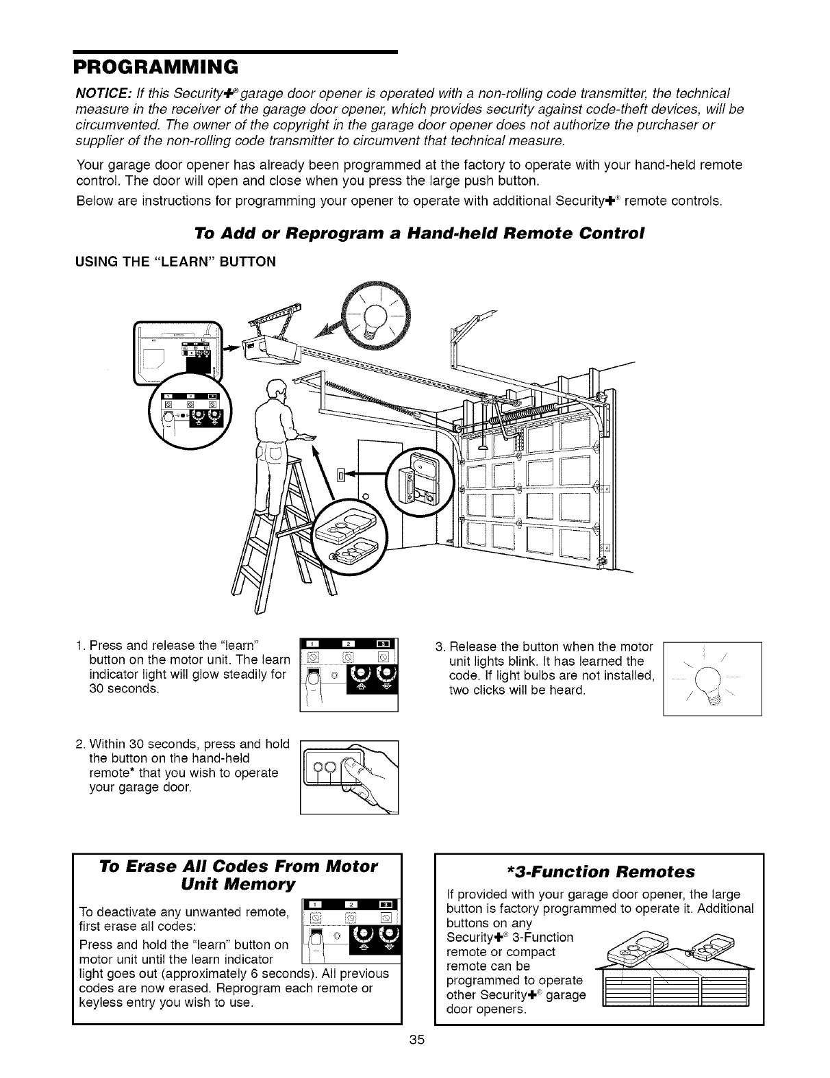
PROGRAMMING
NOTICE: If this Security+_ garage door opener is operated with a non-rolling code transmitter, the technical
measure in the receiver of the garage door opener, which provides security against code-theft devices, will be
circumvented. The owner of the copyright in the garage door opener does not authorize the purchaser or
supplier of the non-rolling code transmitter to circumvent that technical measure.
Your garage door opener has already been programmed at the factory to operate with your hand-held remote
control. The door will open and close when you press the large push button.
Below are instructions for programming your opener to operate with additional Security,I -_ remote controls.
To Add or Reprogram a Hand.held Remote Control
USING THE "LEARN" BUTTON
1. Press and release the "learn"
button on the motor unit. The learn
indicator light will glow steadily for
30 seconds.
3. Release the button when the motor
unit lights blink. It has learned the
code. If light bulbs are not installed,
two clicks will be heard.
2. Within 30 seconds, press and hold
the button on the hand-held
remote* that you wish to operate
your garage door.
To Erase All Codes From Motor
Unit Memory
To deactivate any unwanted remote, [_ []
first erase all codes: .........
Press and hold the "learn" button on
motor unit until the learn indicator
light goes out (approximately 6 seconds). All previous
codes are now erased. Reprogram each remote or
keyless entry you wish to use.
*3.Function Remotes
If provided with your garage door opener, the large
button is factory programmed to operate it. Additional
buttons on any
Security+ _ 3-Function
remote or compact
remote can be
programmed to operate
other Security÷ ®garage
door openers.
35
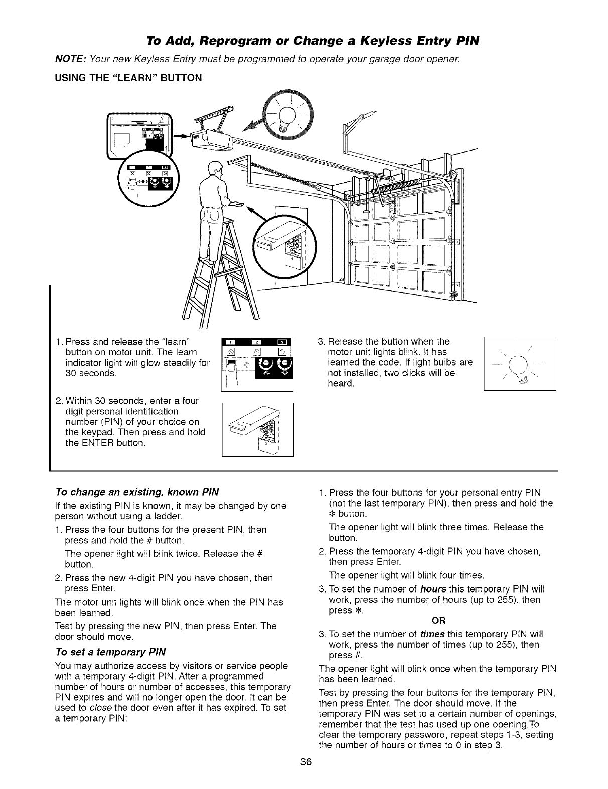
To Add, Reprogram or Change a Keyless Entry PIN
NOTE: Your new Keyless Entry must be programmed to operate your garage door opener.
USING THE "LEARN" BUTTON
1. Press and release the "learn"
button on motor unit. The learn
indicator light will glow steadily for
30 seconds.
2. Within 30 seconds, enter a four
digit personal identification
number (PIN) of your choice on
the keypad. Then press and hold
the ENTER button.
3. Release the button when the
motor unit lights blink. It has
learned the code. If light bulbs are
not installed, two clicks will be
heard.
To change an existing, known PIN
If the existing PIN is known, it may be changed by one
person without using a ladder.
1. Press the four buttons for the present PIN, then
press and hold the #button.
The opener light will blink twice. Release the #
button.
2. Press the new 4-digit PIN you have chosen, then
press Enter.
The motor unit lights will blink once when the PIN has
been learned.
Test by pressing the new PIN, then press Enter. The
door should move.
To set a temporary PiN
You may authorize access by visitors or service people
with a temporary 4-digit PIN. After a programmed
number of hours or number of accesses, this temporary
PIN expires and will no longer open the door. It can be
used to close the door even after it has expired. To set
a temporary PIN:
36
1. Press the four buttons for your personal entry PIN
(not the last temporary PIN), then press and hold the
button.
The opener light will blink three times. Release the
button.
2. Press the temporary 4-digit PIN you have chosen,
then press Enter.
The opener light will blink four times.
3. To set the number of hours this temporary PIN will
work, press the number of hours (up to 255), then
press _. OR
3. To set the number of times this temporary PIN will
work, press the number of times (up to 255), then
press #.
The opener light will blink once when the temporary PIN
has been learned.
Test by pressing the four buttons for the temporary PIN,
then press Enter. The door should move. If the
temporary PIN was set to a certain number of openings,
remember that the test has used up one opening.To
clear the temporary password, repeat steps 1-3, setting
the number of hours or times to 0 in step 3.
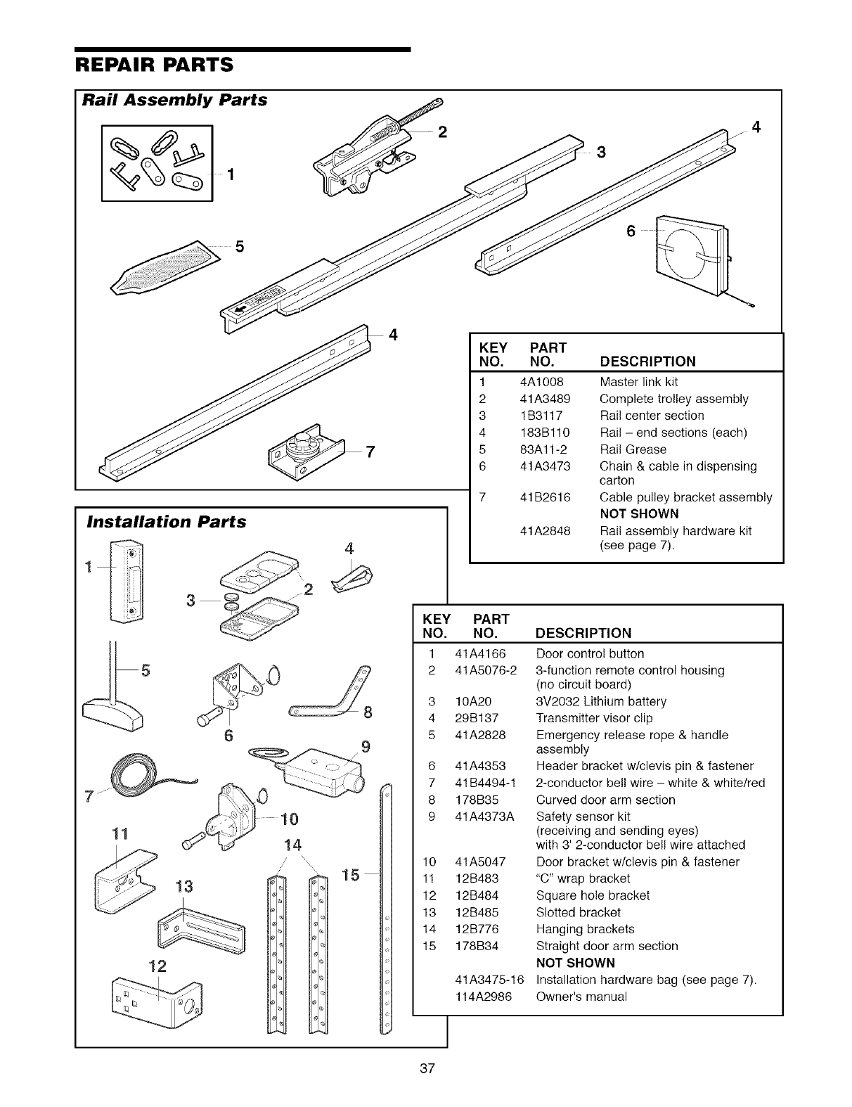
REPAIR PARTS
Rail Assembly Parts
Installation Parts
\
/\\
,\
13
12
4
9
15
KEY
NO,
1
2
3
4
5
6
KEY PART
NO, NO,
1 41A4166
2 41A5076-2
3
4
5
6
7
8
9
10
11
12
13
14
15
J
37
PART
NO, DESCRIPTION
4A1008 Master link kit
41A3489 Complete trolley assembly
1B3117 Rail center section
183Bl10 Rail - end sections (each)
83All-2 Rail Grease
41A3473 Chain & cable in dispensing
carton
41 B2616 Cable pulley bracket assembly
NOT SHOWN
41A2848 Rail assembly hardware kit
(see page 7).
10A20
29B137
41A2828
41A4353
41B4494-1
178B35
41A4373A
4tA5047
12B483
12B484
12B485
12B776
178B34
41A3475-16
114A2986
DESCRIPTION
Door control button
3-function remote control housing
(no circuit board)
3V2032 Lithium battery
Transmitter visor clip
Emergency release rope & handle
assembly
Header bracket w/clevis pin & fastener
2-conductor bell wire - white & white/red
Curved door arm section
Safety sensor kit
(receiving and sending eyes)
with 3' 2-conductor bell wire attached
Door bracket w/clevis pin & fastener
"C" wrap bracket
Square hole bracket
Slotted bracket
Hanging brackets
Straight door arm section
NOT SHOWN
Installation hardware bag (see page 7).
Owner's manual
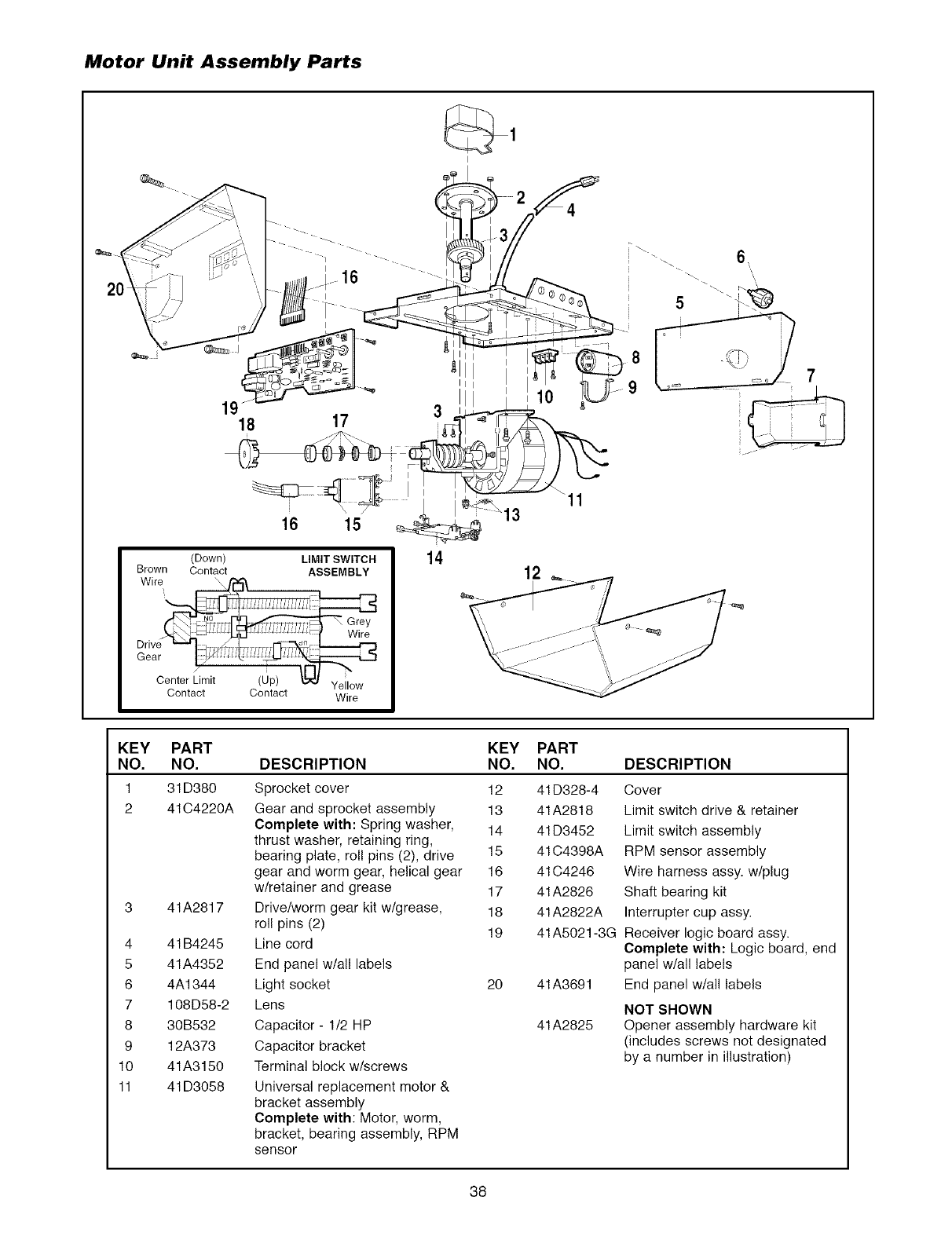
Motor Unit Assembly Parts
1918 17
I
_ 6,
7
_
Brown
16 15
(Down) LIMIT SWITCH
Contact ASSEMBLY
Contact Contact Wire
11
KEY
NO,
1
2
4
5
6
7
8
9
10
11
PART KEY PART
NO. DESCRIPTION NO. NO. DESCRIPTION
31D380 Sprocket cover 12 41D328-4 Cover
41C4220A Gear and sprocket assembly 13 41A28t8 Limit switch drive & retainer
Complete with: Spring washer, 14 41D3452 Limit switch assembly
thrust washer, retaining ring,
bearing plate, roll pins (2), drive 15 41C4398A RPM sensor assembly
gear and worm gear, helical gear 16 41C4246 Wire harness assy. w/plug
w/retainer and grease 17 41A2826 Shaft bearing kit
Drive/worm gear kit w/grease, 18 41A2822A Interrupter cup assy.
roll pins (2) 19 41A5021-3G Receiver logic board assy.
Line cord Complete with: Logic board, end
End panel w/all labels panel w/all labels
Light socket 20 End panel w/all labels
Lens NOT SHOWN
Capacitor - 1/2 HP Opener assembly hardware kit
Capacitor bracket (includes screws not designated
Terminal block w/screws by a number in illustration)
Universal replacement motor &
bracket assembly
Complete with: Motor, worm,
bracket, bearing assembly, RPM
sensor
41A2817
4 t B4245
4tA4352
4A1344
108D58-2
30B532
12A373
4tA3150
41D3058
41A3691
41A2825
38
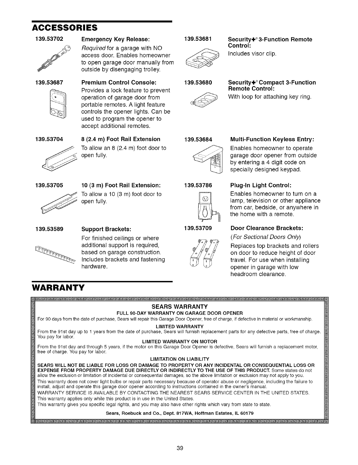
ACCESSORIES
139,53702
/Emergency Key Release:
Required for a garage with NO
access door. Enables homeowner
to open garage door manually from
outside by disengaging trolley.
139,53687 Premium Control Console:
Provides a lock feature to prevent
operation of garage door from
portable remotes. A light feature
controls the opener lights. Can be
used to program the opener to
accept additional remotes.
139,53704 8(2.4 m) Foot Rail Extension
To allow an 8 (2.4 m) foot door to
open fully.
139,53681
139,53680
139,53684
Security+_3-Function Remote
Control:
Includes visor clip.
Security+ _;Compact 3-Function
Remote Control:
With loop for attaching key ring.
Multi-Function Keyless Entry:
Enables homeowner to operate
garage door opener from outside
by entering a 4 digit code on
specially designed keypad.
139,53705 10 (3 m) Foot Rail Extension:
To allow a 10 (3 m) foot door to
open fully.
139,53786 Plug-In Light Control:
Enables homeowner to turn on a
lamp, television or other appliance
from car, bedside, or anywhere in
the home with a remote.
139,53589 Support Brackets: 139,53709
For finished ceilings or where
additional support is required,
based on garage construction.
Includes brackets and fastening
hardware.
Door Clearance Brackets:
(For Sectional Doors Only)
Replaces top brackets and rollers
on door to reduce height of door
travel. For use when installing
opener in garage with low
headroom clearance.
WARRANTY
SEARS WARRANTY
FULL 90-DAY WARRANTY ON GARAGE DOOR OPENER
For 90 days from the date of purchase, Sears will repair this Garage Door Opener, free of charge, if defective in material or workmanship.
LIMITED WARRANTY
From the 91st day up to 1 years from the date of purchase, Sears wil! furnish replacement parts for any defective parts, free of charge.
You pay for labor. LIMITED WARRANTY ON MOTOR
From the 91st day and through 5 years, if the motor on this Garage Door Opener is defective, Sears will furnish a replacement motor,
free of charge. You pay for labor.
LIMITATION ON LIABILITY
SEARS WILL NOT BE LIABLE FOR LOSS OR DAMAGE TO PROPERTY OR ANY INCIDENTAL OR CONSEQUENTIAL LOSS OR
EXPENSE FROM PROPERTY DAMAGE DUE DIRECTLY OR INDIRECTLY TO THE USE OF THIS PRODUCT, Some states do not
allow the exclusion or limitation of incidental or consequential damages, so the above limitation or exclusion may not apply to you.
This warranty does not cover light bulbs or repair parts necessary because of operator abuse or negligence, including the failure to
install, adjust and operate this garage door opener according to instructions contained in the owner's manual.
WARRANTY SERVICE IS AVAILABLE BY CONTACTING THE NEAREST SEARS SERVICE CENTER IN THE UNITED STATES.
This warranty applies only while this product is in use in the United States.
This warranty gives you specific legal rights, and you may also have other rights which vary from state to state.
Sears, Roebuck and Co., Dept. 817WA, Hoffman Estates, IL 60179
39

Your Home
iiiiiiiiiiiiiiiiii For repair-in your home-of all major brand appliances
iiiiiiiiiiiiiiiiiiiiiiiiiiiiiiiiiilawn and garden equipment, or heating and cooling systems,
iiiiiiiiiiiiiiiiiiiiiiiiiiiiiiiiil no matterwho made it, no matterwhosold it! iiiiiiiiiiiiii
iiiiiiiiiiiiiiiiiiiiiiiiiiiiiiiill For,the replacement parts accessoriesand
iiiiiiiiiiiiiiiiiiiiiiiiiiiiiiiill owners manualsthatyou needtodo-it-yourself, iiiiiiiiiiiiii
iiiiiiiiiiiiiiiil For Sears professional installation of home appliances
iiiiiiiiiiiiiiiii and items likegaragedooropeners andwaterheaters, iiiiiiiiiiiiii
1-800-4-MY-HOME ® (1-800-469-4663)
iiiiiiiiiiiiiiiiiiiiiiiiiiiiiiiiii Callanytime, dayornight(U.S.A, andOanada) iiiiiiiiiiiiii
iiiiiiiiiiiiiiiiiiiiiiiiiiiiiii!i; www.sears.com www.sears.ca iiiiiiiiiiiiii
iiiiiiiiiiiiiiiiiiiiiiiiiiiii Our Home iiiiiiiiiiiiii
For repair of carry-in items like vacuums, lawn equipment, iiiiiiiiiiiiii
and electronics, call or go on-line for the location of your nearest !!!!!!!!!!!!!!
SearsParts&RepairCenter. iiiiiiiii
iiiiiiiiiiiiiiiiii
iiiiiiiiiiiiiiiil
iiiiiiiiiiiiiiiil
iiiiiiiiiiiiiiiii:i 1-800-488-1222
iiiiiiiiiiiiiiiiiiiiiiiiiiiiiiiiii Callanytime, dayornight(U.S.A, only)
iiiiiiiiiiiiiiiiiiiiiiiiiiiiiiii!i www.sears.com iiiiiiiiiiiiiiiiiiiiiiiiiiiiiiiii
i i To purchase a protection agreement (U.S.A.)
ii!iiiiiiiiiiiiiiiiiiiiiiiiiiiiii ormaintenance agreement (Canada) on aproductserviced bySears: iiiiiiiiiiiiiiiiiiiiiiiiiiiiiiiii
i_i 1-800-827-6655 (U.S.A.) 1-800-361-6665 (Canada)
iiiiiiiiiiiiiiii Parapedirserviciode reparacien Au Canadapourserviceenfran(}ais: ii!i!i!i!i!i!i!i!i!i!i!i!i!i!
iiiiiiiiiiiiiiiii!ii!ilia domicilio, y pard ordenar piezas: 1800 LE FOYER Mc
i!iiiiiiiiiiili!i!i!! 1"888-SU'HOGARSM (1-800-533-6937) iiiiiiiiiiiiili!i!iiiiiiiiiiiil
ililililili!iiii:iiiill (1-888-784-6427) www.sears.ca !!i!!i!!i!!i!!i!!i!!i!!i!!i!!i!!i!!i!!i!!i!!ii!i!i!ii
114A2986
'_eRegistered Trademark /TMTrademark /s_Service Mark of Sears, Roebuck and Co.
(R)Marca Registrada /TMMarca de Fabrica /s_'Marca de Servicio de Sears, Roebuck and Co.
"° Marque de commerce /MD Marque deposee de Sears, Roebuck and Co
%"2004 Sears, Roebuck and Co.
Printed in Mexico
