Craftsman 13953678SRT User Manual GARAGE DOOR OPENER Manuals And Guides L9060005
CRAFTSMAN Garage Door Opener Manual L9060005 CRAFTSMAN Garage Door Opener Owner's Manual, CRAFTSMAN Garage Door Opener installation guides
User Manual: Craftsman 13953678SRT 13953678SRT CRAFTSMAN GARAGE DOOR OPENER - Manuals and Guides View the owners manual for your CRAFTSMAN GARAGE DOOR OPENER #13953678SRT. Home:Garage Door & Opener Parts:Craftsman Parts:Craftsman GARAGE DOOR OPENER Manual
Open the PDF directly: View PDF ![]() .
.
Page Count: 40
Owner's
Manual
Model No.
139.53678SRT
For Residential Use
Only
Caution:
Read and foPow a,,
safety rules and
operating Instructions
before first use of this
product.
Fasten the manual
near the garage door
after installation.
CO_ withUL 325 (_
regulalonseffective
Jar_ary 1, lSe3
CRRFTSHRN®
GARAGE DOOR OPENER
1/2 HP
• Safety Precautions
•Assembly
• Installation
•Adjustment
•Care and Maintenance
•Operation
•Troubleshooting
•"Parts List
Sears, Roebuck and Co., Hoffman Estates, IL 60179 U.S.A.
Content= Page
A review of safety alert symbols................................ .2
You'll need tools.......................................................... 3
Salety informmJonregarding garage door
locks and ropes ......................................................... 3
Tes_ng your garage door for s_cking,
bindingand balance .................................................. 3
Illustralicnof sec'donaldoor instahlJon ..................... 4
IllustralJonof one-piece door installation.................... 5
Carton inventory.......................................................... 6
Hardware inventory..................................................... 7
Assernbly ssntion - pages 8-11
Assemble T-rail ......................................................... 8
Attach cable pulley bracket....................................... 8
Installtrolley ......................................................... ,...9
Fasten T-rail to opener ............................................. 9
Installchain/cabla .................................................. "10
Attach sprocket cover ............................................. 10
T_'den the chain and cable ................................... 11
Installation section - pages 11 - 27
Installation safety i_s ................................. 11
Determine header bracket location
Sectional door ...................................................... 12
One-piece door .................................................... 13
Installthe header bracket ....................................... 14
Attach the T-rail to header bracket ......................... 15
Positionthe opener ................................................. 16
Hang the opener ..................................................... 17
Installthe door control ............................................ 18
Contents Page
Installthe lightsand lenses...................................... 19
Attach emergency relaasa rope and handle ........... 19
Electrical requirements............................................. 20
Safety reversing sensor information ....................... .21
Installthe safety reversing sensor .....................22, 23
Fasten door bracket (sectionaldoor) ....................... 24
Fasten door bracket (one-piece door) ..................... 25
Connect door arm to trolley (sectionaldoor) ..........26
Connect door arm to trolley (one-piece door)......... 27
Adjustment section -pages 28 - 30
Travel limit adjustments ........................................... 28
Force adjustments.................................................... 29
Test the safety reversing sensor.............................. 30
Test the safety reverse system ............................... 30
Operation safety insVuctJons..................................... 31
Care of your opener ................................................... 31
Maintenance schedule ............................................... 31
Operation of your opener ........................................... 32
and remote conlrol programming............... 33
Having a problem?............................................... 34, 35
Repair parts, rail assembly......................................... 36
Repair parts, installation............................................. 36
Repayparts,openerassarrt ..................................37
_.° ..=o .i ..oo.o ..o= H.°n=o.o=o *H. _*.=°, .ooo=o n..*.=.*°=. *°.= .._8
Index ........................................................................... 39
How to order repair parts ........................................... 40
Maintenance agreement ........................................... 40
Warranty ..................................................................... 40
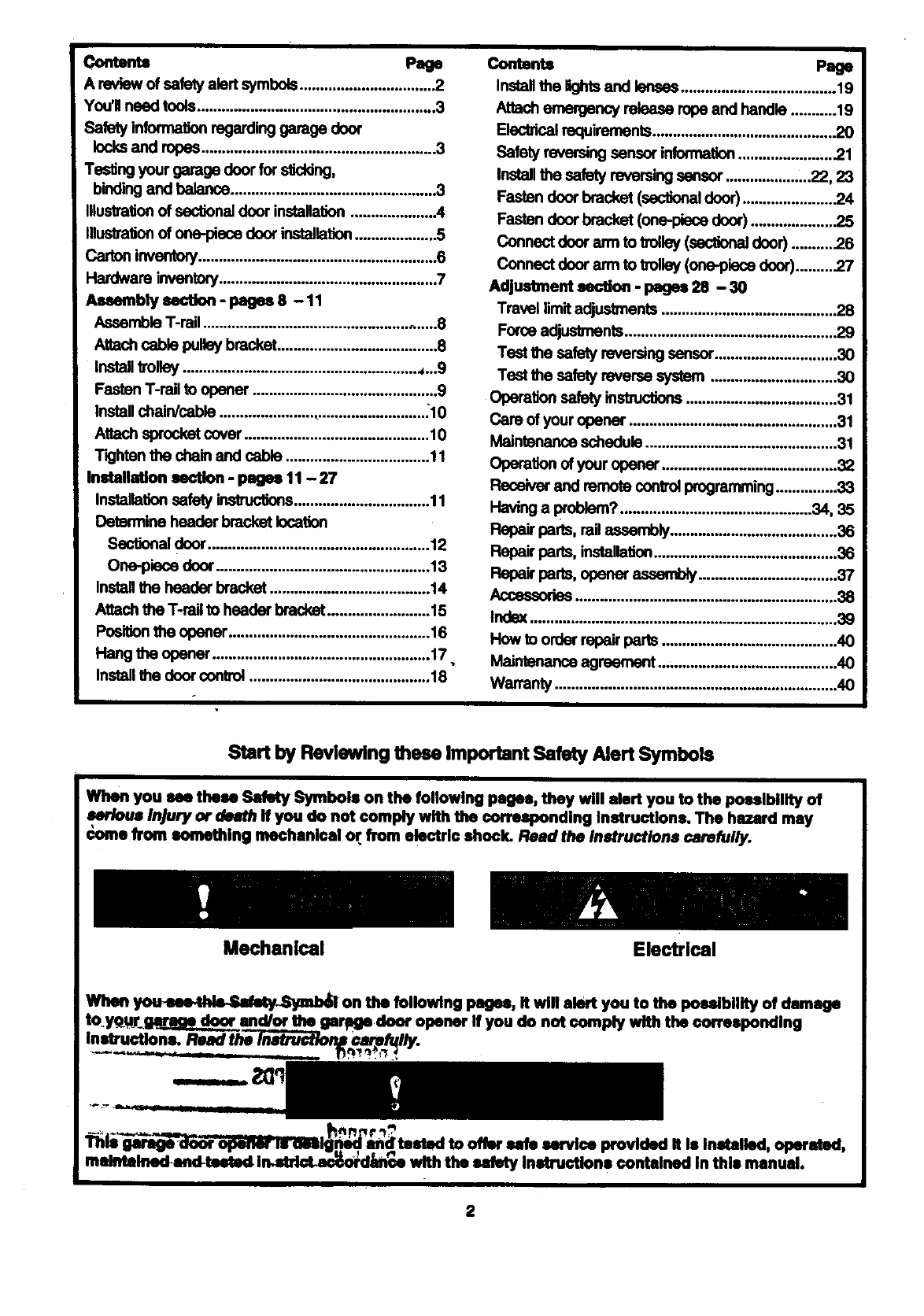
Start by Reviewing these Important Safety Alert Symbols
When you m these Safety Symbols on the following pages, they will alert you to the possibility of
awrloue Injury or death if you do not comply with the corresponding instructions. The hazard may
&=me from something mechanical oT.from electric shock. Read the Instructions carefully.
Mechanical Electrical
When you_thk_/_n:_ on the following pages, It will alert you to the possibility of damage
you do not comply with the corresponding
Instructions.
..... h, r_.
This
malMll_tsstod i_kn_e with the safety Inntruotlons contained In this manual.
2
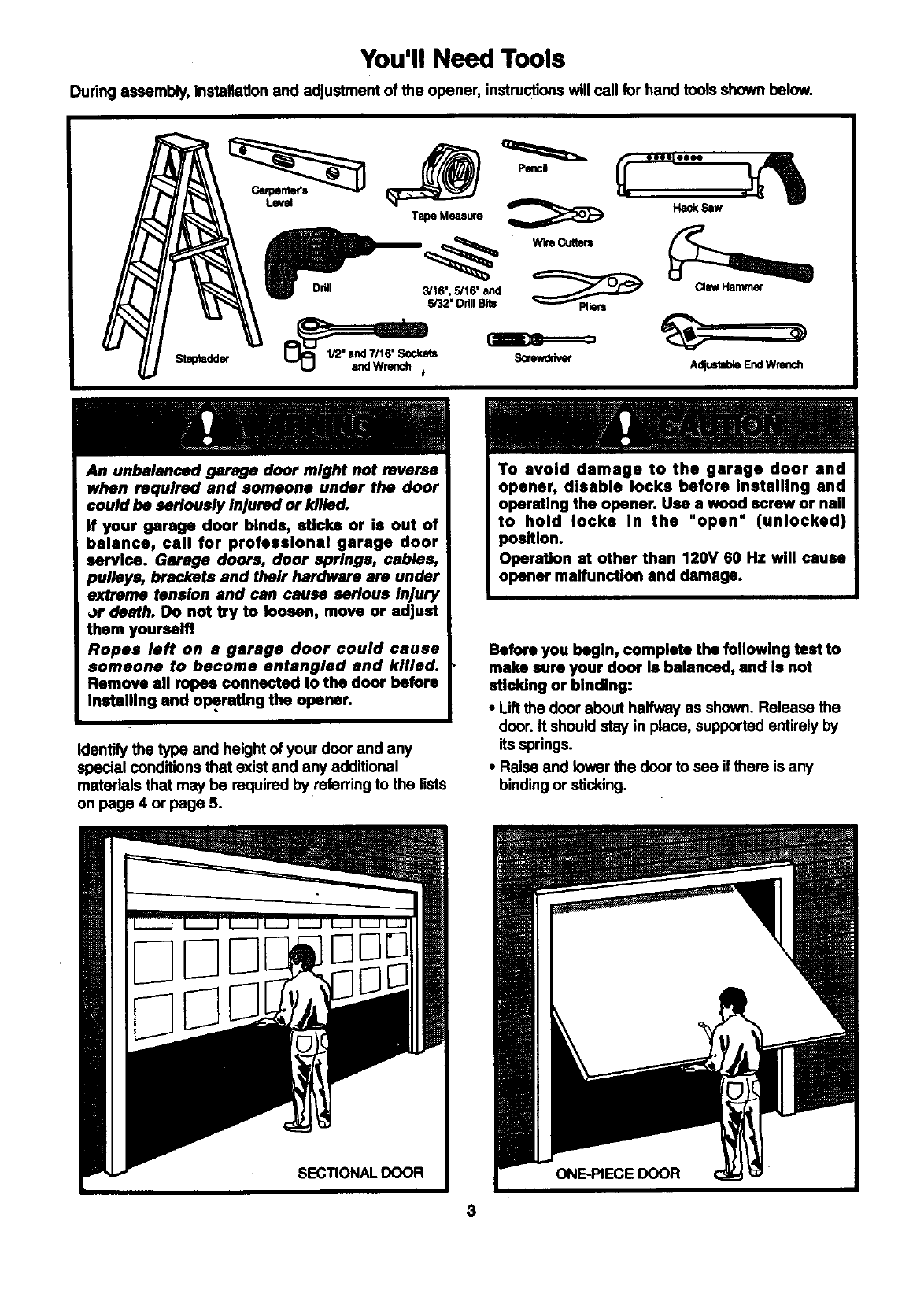
You'll Need Tools
During assembly, installation and adjustment of the opener, instructions will call for hand tools shown below.
Stepladder
Drill
Hack Saw
Tape Measure
(_ Wire Cutters
5/16" _nd _ _..._ Claw Hammer
3/16",
5/32' Drill Bits
Screwdriver AdjustableEndWrench
An unbalanced garage door might not reverse
when required and someone under the door
could be seriously Injured or killed.
If your garage door binds, sticks or is out of
balance, call for professional garage door
sorvice. Garage doors, door springs, cables,
pulleys, brackets and their hardware are under
extreme tension and can cause serious injury
or death. Do not by to loosen, move or adjust
them youreelfl
Ropes left on a garage door could cause
someone to become entangled and killed.
Remove all ropes connected to the door before
installing and operstlng the opener.
Identify the type and height of your door and any
special conditions that exist and any additional
materials that may be required by referring to the lists
on page 4 or page 5.
To avoid damage to the garage door and
opener, disable locks before installing and
operating the opener. Use a wood screw or nail
to hold locks in the "open" (unlocked)
position.
Operation at other than 120V 60 Hz will cause
opener malfunction and damage.
Before you begin, complete the following teat to
make sure your door is balanced, and is not
sticking or binding:
• Lift the door about halfway as shown. Release the
door. It should stay in place, supported entirely by
its springs.
•Raise and lower the door to see if there is any
binding or sucking.
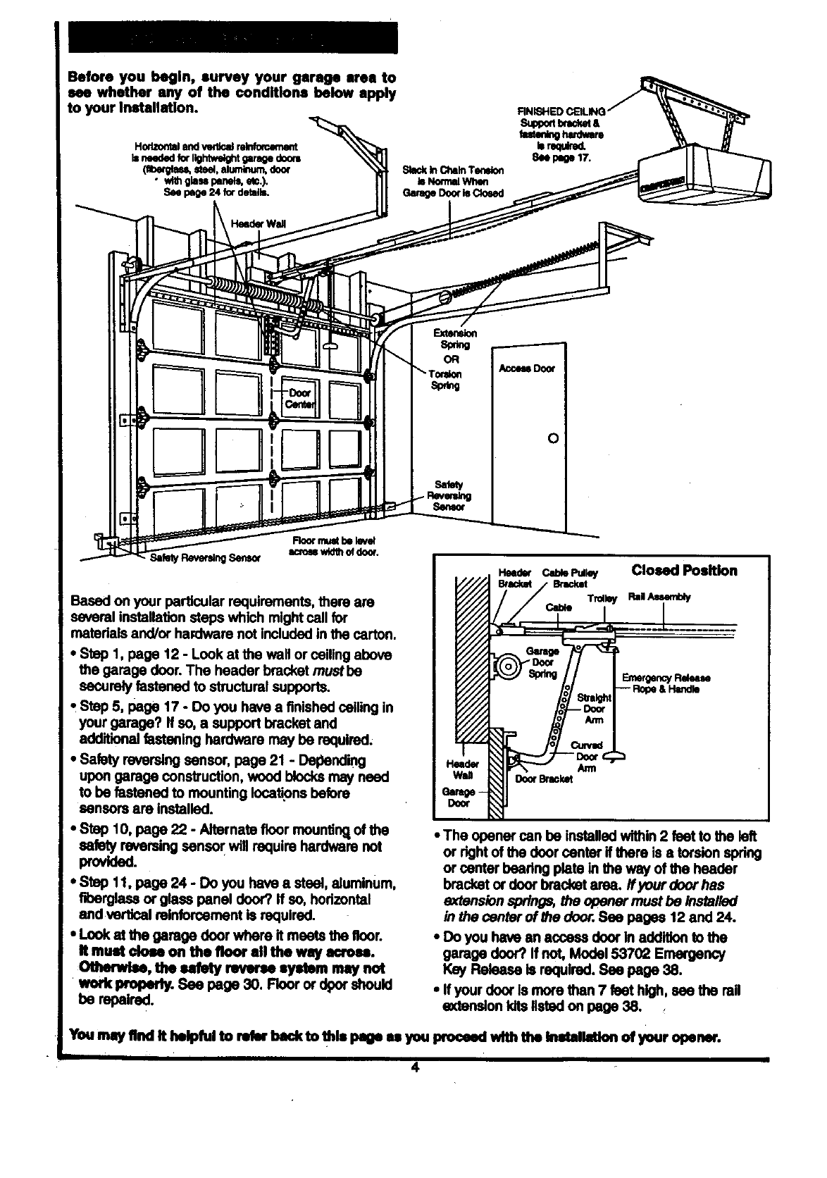
Before you begin, survey your garage urea to
see whether any of the conditions below apply
to your Installation.
0
Based on your particular requirements, there are
several installation steps which might call for
materials and/or he.ware not included in the carton.
• Step 1, page 12 - Look at the wall or ceiling above
the garage door. The header bracket mustbe
securely fastened to structural supports.
tStep 5, page 17 - Do you have a finished ceiling in
your garage? If so, a support bracket and
additional fastening hardware may be required.
•Safety reversing sensor, page 21 -Depending
upon garage construction, wood blocks may need
to be fastened to mounting locations before
sensors are installed.
•Stop 10, page 22 -Alternate floor mounting, of the
sefaty reversing sensor will require hardware not
provided.
•Step 11, page 24 - Do you have a steel, aluminum,
fiberglass or glass panel door? If so, horizontal
and vertical reinforcement is required.
• Lcok ai the garage door where it meets the floor.
It must clom on tbe floor all the way acroea.
OtluMm4se,the _ _ eystem nHy n,_t
work propedy. See page 30. Floor or dpor should
be repaired.
Ann
DoorBracket
•The opener can be installed within 2 feet to the left
or rigM of the door center if there is a torsion spring
or center beadng plate in the way of the header
bracket or door bracket area. ff your door has
extension springs, the opener must be installed
in the center of the dooa:.Sea pages 12 and 24.
• Do you have an access door In addition to the
garage door? If not, Model 53702 E_ncy
Key Release is required. See page 38.
•If your door Is more than 7 feet high, see the rail
e_enslon kits listed on page 38.
You may find it helpful to retbr back to thfa page H you proceed with the thstallation of your opeear.
I4
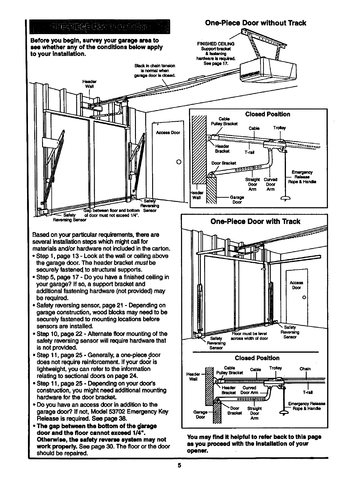
One-Place Door without Track
Before you begin, survey your garage area to
see whether any of the conditions below apply
to your inetallation.
Slack k_chaintension
_nom_ when
garagedoorIs closed.
Walt
AccessDoor
O
Rever_
betweenfloorandboltom Sensor
Salely of doormustnote_Jed 1/4".
Pawer_ngSensor
Based on your particular requirements, there are
several installation steps which might cell for
materials and/or hardware not included in the carton.
• Step 1, page 13 - Look at the wall or ceiling above
the garage door. The header bracket must be
securely fastened to structural supports.
• Step 5, page 17 - Do you have a finished ceiling in
your garage? If so, a support bracket and
additional fastening hardware (not provided) may
be required.
•Safety reversing sensor, page 21 - Depending on
garage construction, wood blocks may need to be
securely fastened to mounting locations before
sensors are installed.
•Step 10, page 22 - Alternate floor mounting of the
safety reversing sensor will require hardware that
is not provided.
•Step 11, page 25 - Generally, a one-piece door
does not require reinforcement. If your door is
lightweight, you can refer to the information
relating to sectional doors on page 24.
•Step 11, page 25 - Depending on your door's
construction, you might need additional mounting
hardware for the door bracket.
•Do you have an access door in addition to the
garage door? If not, Model 53702 Emergency Key
Release is required. See page 38.
•The gap between the bottom of the _arage
door and the floor cannot exceed 1/4",
Otherwlea, the safety reverse system may not
work properly. Sea page 30. The floor or the door
should be repaired.
5
Closed Position
Cable
P_W/Bmck_ Cable Trolley
Door
Door Doo¢
Arm Arm
Emergency
I:lek_u
Rope&Handle
One-Piece Door with Track
Safety
Reverldng
ifmy
Floor must be level Revef_ng
acroe,s widthof door Sef_ot
Closed Position
Cable Cable Tromey Chain
iBracket
S_ht
Garage- Br_ket Door
Door Arm
You may find it helpful to refer back to this page
as you proceed with the Installation of your
opener.
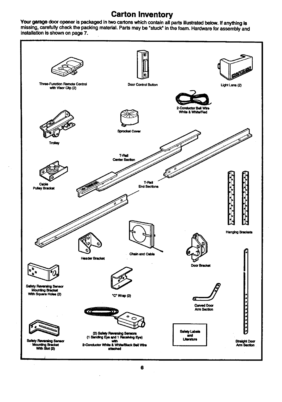
Carton Inventory
Your garage door opener is packaged in two cartons which contain all parts illustrated below. If anything is
missing, carefully check the packing material. Parts may be "stuck"in the foam. Hardware for assembly and
installation is shown on page 7.
Three-Fu_tionRemoteConvo_
v_thVt_ C_ (2) DoorConed Button _Lens(2)
s,_y Rev_ S.n_
Mo_nOem,:_
w_ Sq.m HO_ (2)
Sal_yR_,_CngS,m_
MounUnOerac_
YalhSlot_)
,, I
•c"wrap(2)
_) sd_y RGv_ Ser_om
wire
L_Corr_ WI_ &W','Vil,'l_a:k8M WI_
Cu*'ve¢lDoor
Am1S*,_Uon
Fhu_g _
ArmS_
6
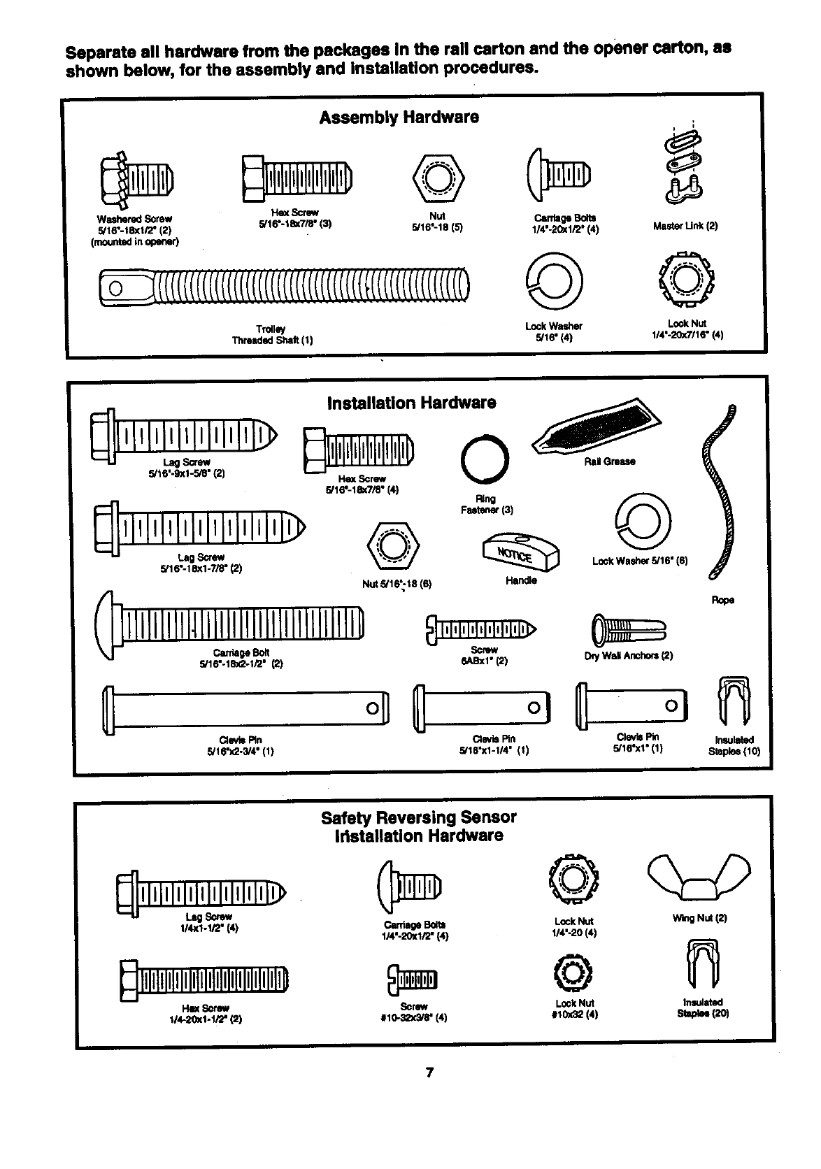
Separate all hardware from the packages in the rail carton and the opener carton, as
shown below, for the assembly and installation procedures.
Assembly Hardware
Washerecl Screw He_( Screw Nut Carriage Bolts
5/f 6"-f 8xf/2" (2) 5/16"-%_7/8" (3) 5/16:18 (5) 1/4"-2C_1/2" (4) Master Unk (2}
(mounted in opener)
@
Trdlley Lock Washer Lock Nut
11_oadsd Shaft (1) 5/18" (4) 1/4'-20x9'/16" {41
Installation Hardware
_llllllll,;,lllll,lllll,_
Lag ,Screw
Stl 6"-I 83(I -7/8" (2)
5/16".18x2-t,'2" (2)
_HGmase
ClevisPin
5/16"x2.3/4"(I)
©
Fa_u_ (3)
Handle Lock Washer S/16" 16)
6ABXl" (2) D_y Wag Anchors (2)
_oe
Pin Clevis Pin /nsukKed
5/18'X1-1/4" (t) 5/16"x1" (1) _taple_ (10)
1/4x1-1/2" (4)
_,llllllllllllllllllllllllllllll[llllll]
114-20x1-1/2" _1
Safety Reversing Sensor
Iflstallatlon Hardware
Cardage Bolts Lock Nut Wing Nut (2)
1/4"-20x1/2" (4) 114"-20 (4)
@
#I0-32x3/8' (4) #I0X32 (4) Slapkm 120)
7
Assembly Section: Pages 8 - 11
To avoid Installation difficulties, do not run the garage door opener until insb,uctad to do so.
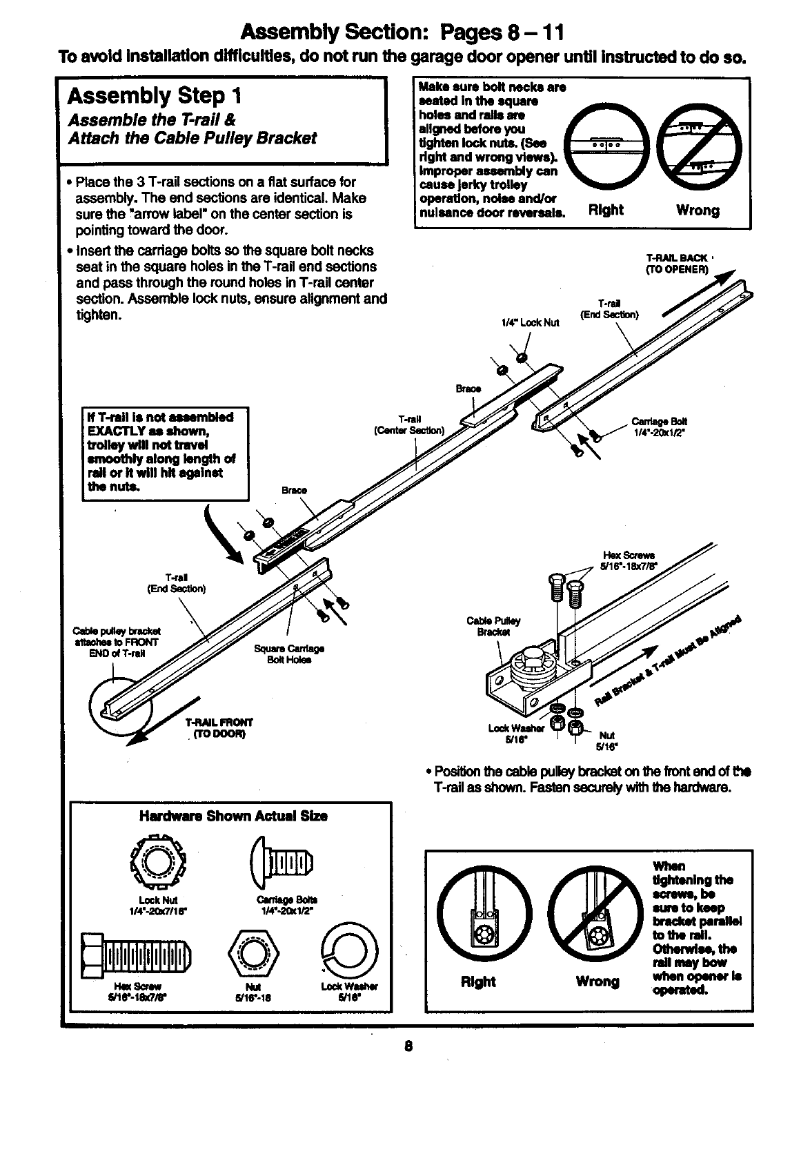
Assembly Step I
Assemble the T-rail &
Attach the Cable Pulley Bracket
Place the 3 T-rail sections on a fiat surface for
assembly. The end sections are identical. Make
sure the "arrow label" on the center section is
pointing toward the door.
, Insert the cardage bolts so the square bolt necks
seat in the square holes in the T-rail end sections
and pass through the round holes in T-rail center
section. Assemble lock nuts, ensure alignment and
tighten.
Make sure bolt necks are
seated in the sqcam
holes and ralla are _
wignedbeforeyou f _k
Ughtantooknuts.(See
right and wrong views).
Improper aesembiy can _t_ _'
cause Jerkytrolley
operation, noise 8ncl/(x
nuisance door reversals. Right Wrong
T-RAIL BACK,
(TO OPENER)
T-rd
(End Section)
1/4"LockNut
IIf T-rail Is not assembled I
EXACTLY as shown,
trolley will not travel
smoothly along length of
rail or It will hlt against
the nuts. Brace
Canlege Bolt
1/4".20_1/2"
Itex Scmws
5/16"-18X7/8"
Nut
5/16"
* Positionthe cable pulleybracketon the fronterKIof thO
T-rail ss shown. Fasten sscuroly withthe hardware.
Hudwm Shown Actual Size
©
L_ckN_I
114"-2_lallr
lqqq@lqllll)
ll4t-L_Klr2"
fd16"-18 E_I8"
I
tightening the
imrewo,be
eureto keep
bracket parallel
to the roll.
Othendes, the
rail may bow
8
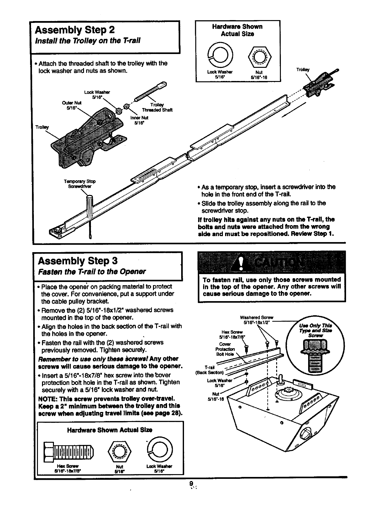
Assembly Step 2
Install the Trolley on the T-raft
•Attach the threaded shaft to the trolley with the
lock washer and nuts as shown,
Trolley
OuterNut
LockWasher
5/16"
Trolley
ThreadedShalt
InnerNut
5/16"
IHardware Shown
Actual Size
LookWasher Nut
5/16' 5/16--18
• As a temporary stop, insert a screwdriver into the
hole in the front end of the T-reil,
•Slide the trolley assembly along the rail to the
screwdriver stop.
If trolley hits against any nuts on the T-rail, the
bolts and nuts were attached from the wrong
side and must be repoeitioned. Review Step 1.
Assembly Step 3 1
Fasten the T.rail to the Opener I
•Place the opener on packing material to protect
the cover. For convenience, put a support under
the cable pulley bracket.
•Remove the (2) 5/16"-18xl/2" washered screws
mounted in the top of the opener.
•Align the holes in the back section of the T-rail with
the holes in the opener.
•Fasten the rail with the (2) washered screws
previously removed. Tighten securely.
Remember to use only these screwsl Any other
screws will cause serious damage to the opener.
•Insert a 5/16"o18X7/8' he)( screw into the t:over
protection bolt hole in the T-rail as shown. Tighten
securely with a 5/16" lock washer and nuL
NOTE: This screw prevents trolley over-travel.
Keep a2" minimum between the trolley and this
screw when adjusting travel limits (see page 28).
WasheredScrew
5/16--180(1/2'
Cover
Protection
Hardware Shown Actual Size
I'kmSorew Nut LockWuher
5/16--18X7/6- 5/18" 5/1r
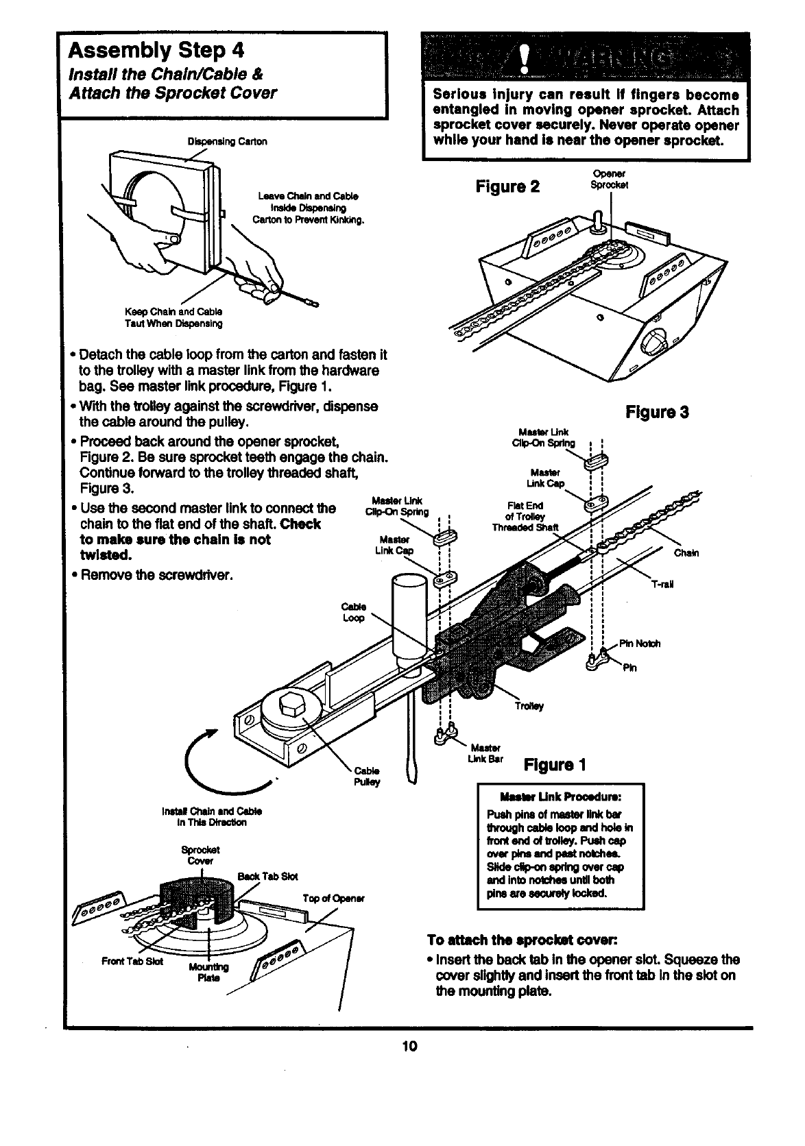
Assembly Step 4
Install the Chain/Cable &
Attach the Sprocket Cover
DispensingCarton
Leave Chainand _
tnsldeDiapering
Ce;lon to PreventKJnl_g.
KeepChain andCable
TautWhen Dispensing
• Detach the cable loop from the carton and fasten it
to the trolley with a master link from the hardware
bag. Sea master link procedure, Figure 1.
• W'_h the volley against the screwdriver, dispense
the cable around the pulley.
•Proceed back around the opener sprocket,
Figure 2. Be sure sprocket teath engage the chain.
Continue forward to the trolley threaded shaft,
Figure 3.
•Use the second master link to connect the
chain to the fiat end of the shaft. Chock
to maim suro the chain Is not
twlatod.
•Remove the screwdriver.
Master
sprocket cover securely. Never operate opener
Opener
Figure 2 s_o_
Figure 3
Muler Unk
Master
UnkCap
FlatEnd
Chain
Inltal Chlln Ind Cable
In This Dltlmtion
s_et
cover
Ikmtw Unk Pro(_lum:
Puedlplrm of mlwto( link bot
lhroughcableloop andholekt
frontendoftrolley.Pu_ c_o
ovorpN andpestnotoheL
Slideclip-onq)dng over cap
andintonotchesuntilboth
pl_ wo _MJ_:uro_jIodcod.
Moundng
Plato
To attach tho 8prockat cover:.
• Insert the back tab In the opener sloL Squeeze the
cover slightly and insert the front tab In the slot co
the mounting plate.
10
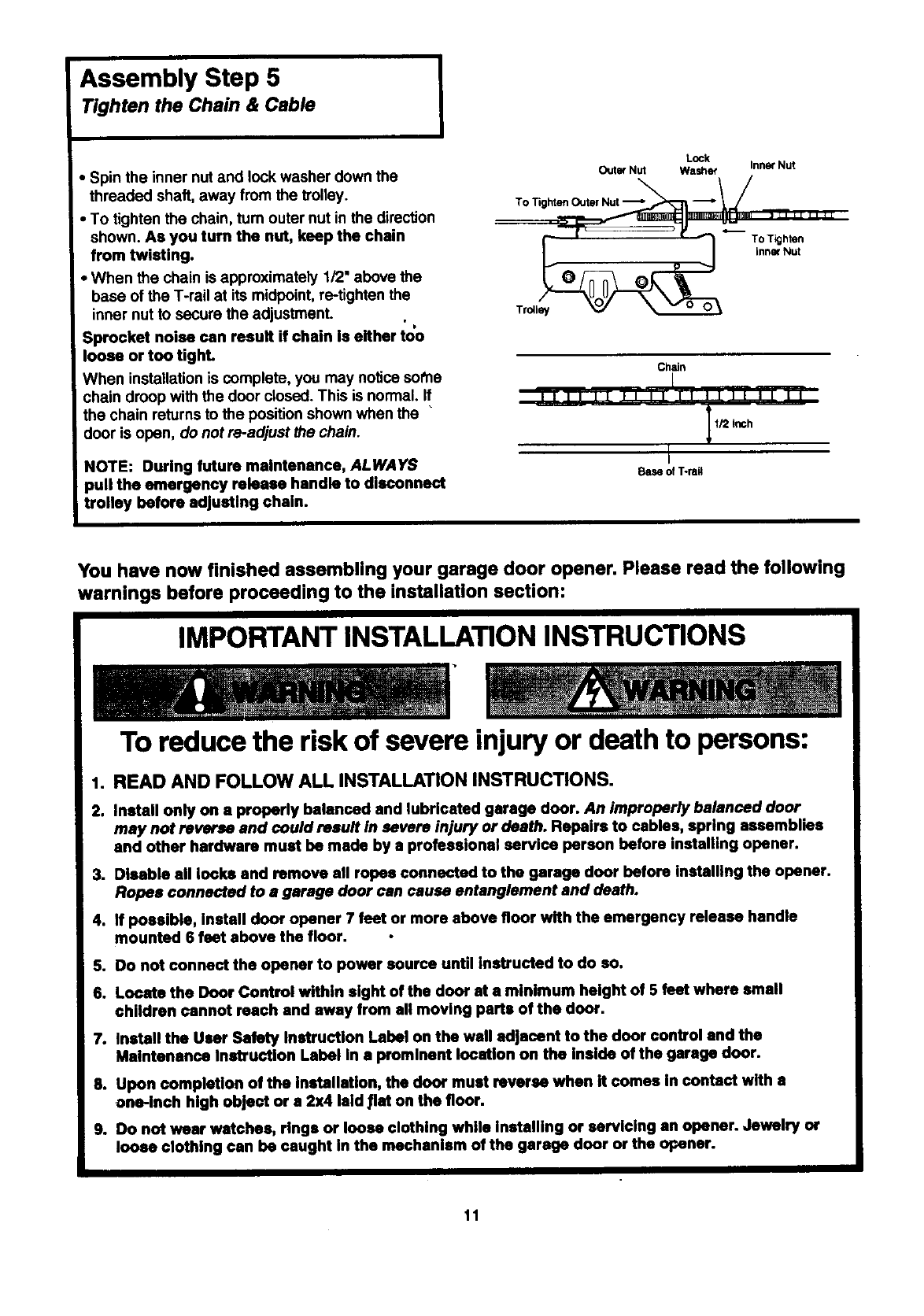
Assembly Step 5
Tighten the Chain & Cable I
• Spin the inner nutand lock washer down the
threaded shaft, away from the trolley.
•To tighten the chain, turn outer nut in the direction
shown. As you turn the nut, keep the chain
from twisting.
• When the chain is approximately 1/2" above the
base of the T-rail at its midpoint, re-tighten the
inner nut to secure the adjustment. • D
Sprocket noise can result if chain is either too
loose or too tighL
When installation is complete, you may notice sot'he
chain droop with the door closed. This is normal. If
the chain returns to the position shown when the "
door is open, do not re-adjust the chain.
NOTE: During future maintenance, ALWAYS
pull the emergency release handle to disconnect
itrolley before adjusting chain.
Outer Nut
To Tighten Outer Nut "_"
Lock
Washer InnerNut
To Tighten
inner Nut
Tr_ley
Chain
I
fill II II li II II II II il
1/2 Inch
L
Base of T-rsA
You have now finished assembling your garage door opener. Please read the following
warnings before proceeding to the installation section:
IMPORTANT INSTALLATION INSTRUCTIONS
To reduce the risk of severe injury or death to persons:
1. READ AND FOLLOW ALL INSTALLATION INSTRUCTIONS.
2. Install only on a properly balanced and lubricated garage door. An improperly balanced door
may not reverse and could result In severe injury or death. Repairs to cables, spring assemblies
and other hardware must be made by a professional service parson before installing opener.
3. Disable all looks and remove all ropes connected to the garage door before installing the opener.
Ropes connected to a garage door can cause entanglement and death.
4. If possible, install door opener 7 feet or more above floor with the emergency release handle
mounted 6 feet above the floor.
5. Do not connect the opener to power source until Instructed to do so.
6. Locate the Door Control within sight of the door st a minimum height of 5 feet where small
children cannot reach and away from all moving parts of the door.
7. Install the User Safety Instruction Label on the wall adjacent to the door control and the
Maintenance Instruction Label in a prominent location on the Inside of the garage door.
8. Upon completion of the Installation, the door must reverse when it comes In contact with a
one-inch high object or a 2x4 laid 11ston the floor.
9. Do not wear watches, rings or loose clothing while installing or servicing an opener. Jewelry or
loose clothing can be caught in the mechanism of the garage door or the opener.
11
Installation Section: Pages 12- 27
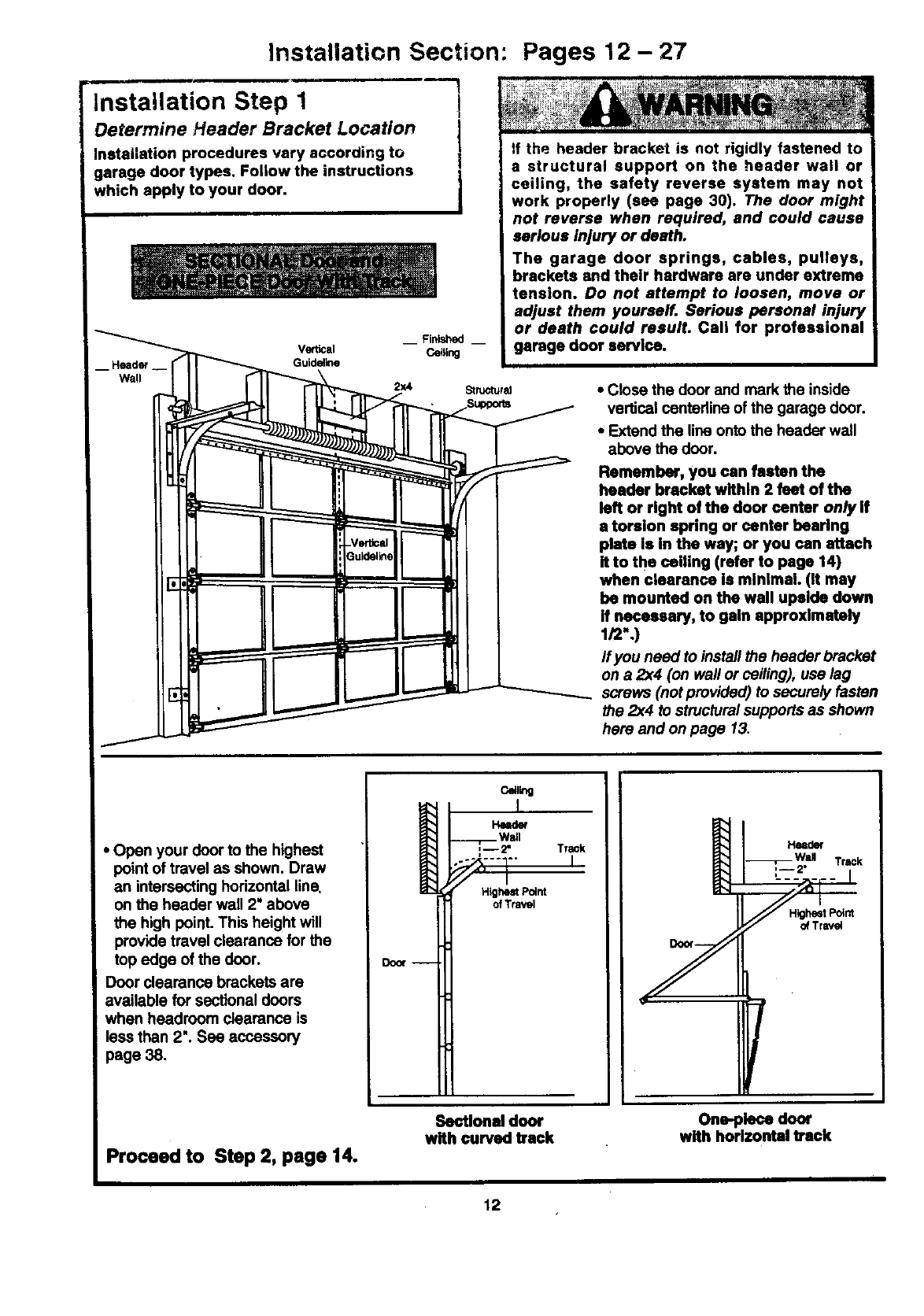
Installation Step 1
Determine Header Bracket Location
Installation procedures vary according to
garage door types. Follow the instructions
which apply to your door.
l
1
l
__ Finished __
Vertical Ce_ling
Guidal_e
tf the header bracket is not rigidly fastened to
a structural support on the header wall or
ceiling, the safety reverse system may not
work properly (see page 30). The door might
not reverse when required, and could cause
serious injury or death.
The garage door springs, cables, pulleys,
brackets and their hardware are under extreme
tension. Do not attempt to loosen, move or
adjust them yourself. Serious personal injury
or death could result. Call for professional
garage door service.
2x4 StruotursJ •Close the door and mark the inside
vertical centedine of the garage door.
•Extend the line onto the header wall
above the door.
Remember, you can fasten the
header bracket within 2 feet of the
left or right of the door center onlylf
atorsion spring or center hearing
plate Is In the way; or you can attach
It to the ceiling (refer to page 14)
when clearance is minimal. (it may
be mounted on the wall upside down
If necessary, to gain approximately
1/2".)
If you need to install the header bracket
on a 2x4 (on wall or ceiling), use lag
screws (not provided) to secure_/ fasten
the 2x4 to structural supports as shown
here and on page 13.
•Open your door to the highest
point of travel as shown. Draw
an intersecting horizontal line,
on the header wall 2" above
the high point. This height will
provide travel clearance for the
top edge of the door.
Door clearance brackets are
available for sectional doors
when headroom clearance is
less than 2". Sea accessory
page 38.
Door --
c_l_g
HNder
Wall
-- 2" Track
F1 '
Hig_ Point
ofTravel
Head<)(
Track
HighestPotrd
of Travel
Proceed to Step 2, page 14.
Sectional door
with curved track One-piece door
with horizontal track
12
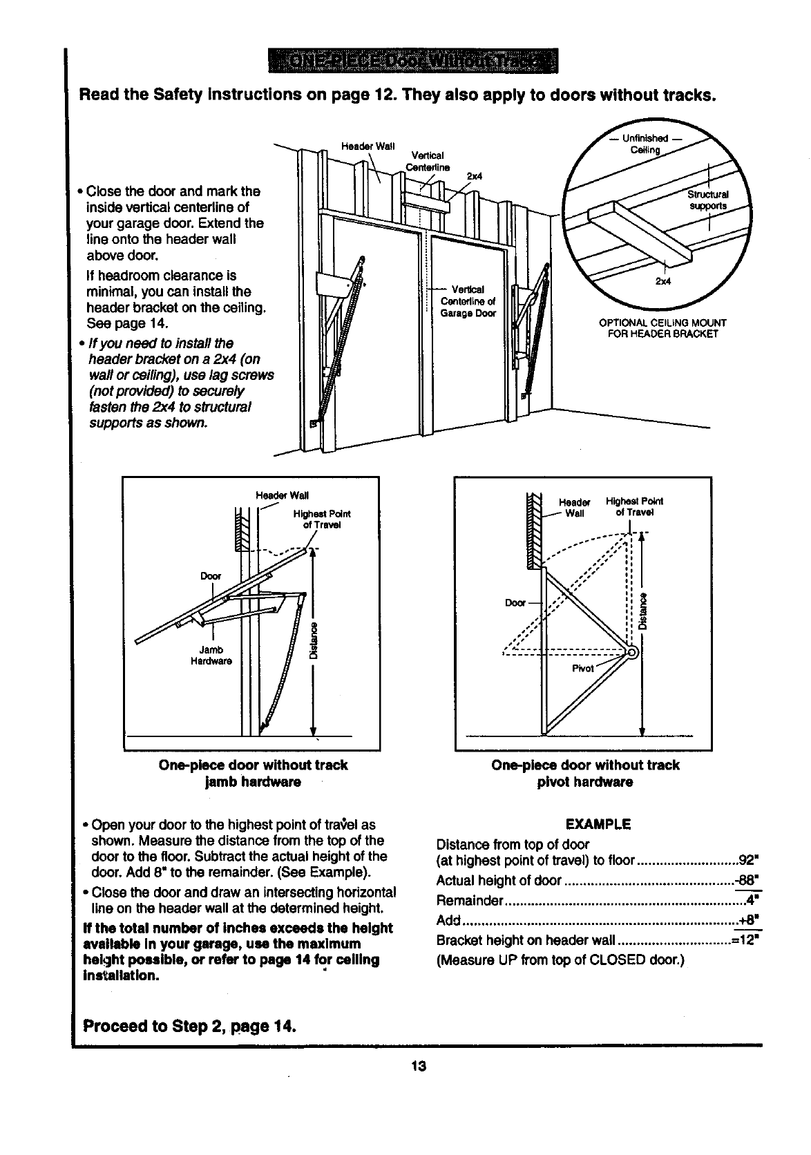
Read the Safety Instructions on page 12. They also apply to doors without tracks.
• Close the door and mark the
inside vertical centedine of
your garage door. Extend the
line onto the header wall
above door.
If headroom clearance is
minimal, you can installthe
header bracket on the ceiling.
See page 14.
• If you need to install the
header bracket on a 2x4 (on
wall or ceiling), use lag screws
(not provided) to securely
fasten the 2x4 to structural
supports as shown.
Header Wall Vertical
Centedine 2x4
OPTIONAL CEILING MOUNT
FOR HEADER BRACKET
Jamb
Hardware
Header Wall
/Higo_tr Pve_lnt
One-piece door without track
jamb hardware
Header Highest Po_t
of Travel
J
One-piece door without track
pivot hardware
•Open your door to the highest point of travel as
shown. Measure the distance from the top of the
door to the floor. Subtract the actual height of the
door. Add 8" to the remainder. (See Example).
•Close the door and draw an intersecting horizontal
line on the header wall at the determined height.
If the total number of Inches exceeds the height
available in your garage, use the maximum
bekJht possible, or refer to page 14 _r ceiling
ins_altation.
EXAMPLE
Distance from top of door
(at highest point of travel) to floor ........................... 92"
Actual height of door............................................. -88__."
Remainder ................................................................ 4"
Add ......................................................................... +8"
Bracket height on header wail ..............................
(Measure UP from top of CLOSED door.)
Proceed to Step 2, page 14.
13
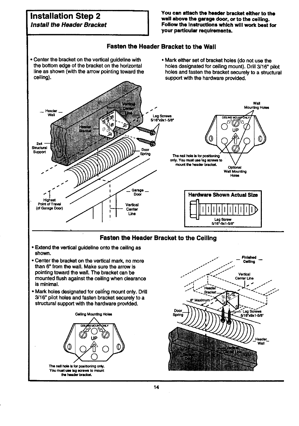
Installation Step 2 I
Install the Header Bracket
You can attach the header bracket either to the
wall above the garage door, or to the ceiling.
Follow the In=tructlons which will work best for
your particular requirements.
Fasten the Header Bracket to the Wall
•Center the bracket on the vertical guideline with
the bottom edge of the bracket on the horizontal
line as shown (with the arrow pointing toward the
ceiling).
•Mark either set of bracket holes (do not use the
holes designated for ceiling mount). Drill 3/16" pilot
holes and fasten the bracket securely to a structural
support with the hardware provided.
__ Header _
WaR
-I
Highest
Point of Tnlvel
(ofGarageDoor)
Door
Vertical
Center
Une
Hardware Shown Actual Size
II!12
5/18"-g_1-5/8"
Fasten the Header Bracket to the Ceiling
• Extend the vertical guideline onto the ceiling as
shown.
• Center the bracket on the vertical mark, no more
then 6" from the wall. Make sure the arrow is
pointing toward the wall. The bracket can be
mounted flush against the ceiling when clearance
is minimal.
•Mark holes designated for ceih'ngmount only. Drill
3/16" pilotholes and fasten bracket securely to a
structural support with the hardware proVided.
CeilingMountingHol_
Wall
0
rml ho_ Is for posi_ocdng only,
You muet UN lag =CleWS to mount
the header btacke_
14
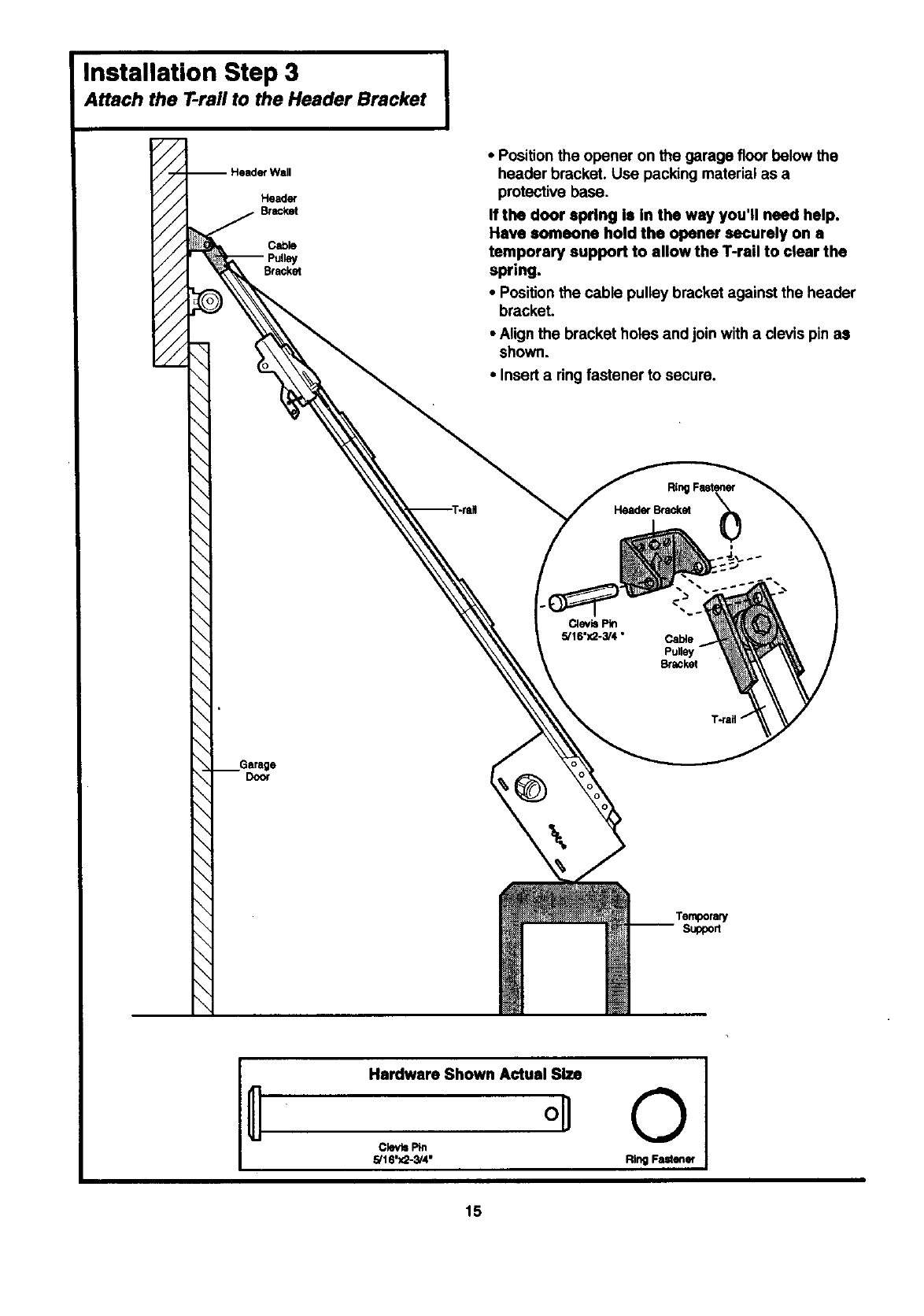
Installation Step 3
Attach the T-rail to the Header Bracket
-- Header Wall
Header
BtacP.et
Cabk)
Bracket
• Position the opener on the garage floor below the
header bracket. Use packing material as a
protective base.
If the door spring Is In the way you'll need help,
Have someone hold the opener securely on a
temporary support to allow the T-rail to clear the
spring.
•Position the cable pulley bracket against the header
bracket.
• Align the bracket holes and join with a clevis pin as
shown.
•Insert a ring fastener to secure.
Header Bracket
i
Clev_ Pin
5/16"3(2-3/4• Cable
Pulle
Bracket
Door
\
Temporary
Support
Hardware Shown Actual Size
°U
5/16'X2-3/4"
©
Ring Fastener
15
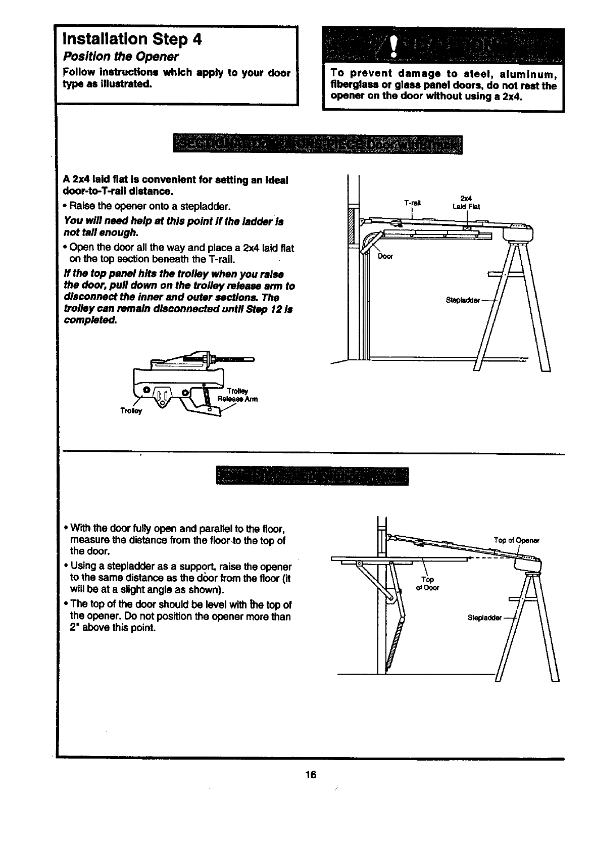
Installation Step 4
Position the Opener
Follow Instructions which apply to your door
type as illustrated.
A 2x4 laid fist is convenient for setting an Ideal
door-to-T-rail distance.
• Raise the opener onto a stepladder.
You will need help at this point ff the ladder Is
not tall enough.
•Open the door all the way and place a 2x4 laid fiat
on the top section beneath the T-rail.
ff the top panel hits the trolley when you raise
the door, pull down on the trolley release arm to
disconnect the inner and outer sections. The
trolley can remain disconnected until Step 12 Is
completed.
Ooor
2x4
T-ran Laid Flat
• With the door fully open and parallel to the floor,
measure the distance from the floorto the top of
the door.
• Using a stepladder as a support, raise the opener
to the same distance as the door from the floor (it
will be at a slight angle as shown).
•The top of the door should be level with _hetop of
the opener. Do not position the opener more than
2" above this point.
Top ofOpener
16
Installation Step 5 J
Hang the Opener I
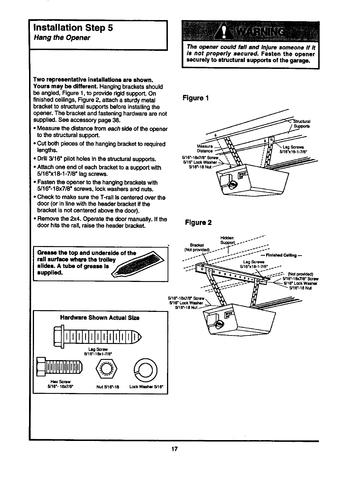
Two representative installations am shown.
Yours may be different. Hanging brackets should
be angled, Figure 1, to provide rigid support. On
finished ceilings, Figure 2, attach a sturdy metal
bracket to structural supports before installing the
opener. The bracket and fastening hardware are not
supplied. See accessory page 38.
• Measure the distance from each side of the opener
to the structural support.
•Cut both pieces of the hanging bracket to required
lengths.
• Drill 3/16" pilot holes in the structural supports.
•Attach one end of each bracket to a support with
5/16"x18-1-7/8" lag screws.
•Fasten the opener to the hanging brackets with
5/16"-18x7/8" screws, lock washers and nuts.
•Check to make sure the T-rail is centered over the
door (or in line with the header bracket if the
bracket is not centered above the door).
•Remove the 2x4. Operate the door manually. If the
door hits the rail, raise the header bracket.
Figure I
Figure 2
Hidden ...-''"
Bracket Su _PI_--....
I (NOt provlded) ..... J ..._'_. --
Grease the top and underslde of the _ .... --- _..-_._._._--- " -R.Im_ C_.ne--
supplied.reilsurfacewhec'ethe trolley /_._ -" _il
""" "_'._-_-''_ LagScrews
slldee. A tube of grease Is /"_dli_/ ..... 5/18.xlml.71s...--
..-..-..-..'.(Not_)
- 5/16"-18<7/8" Screw
. 5/16" LOCkWasher
-'" _ 5/t6"-18 Nut
5/16"-18<7/8" __
5/16" LockWasker
.5/18" 18 N
Hardware Shown Actual Size
,lllJl,l,l,l,l,l,lI
II
Lag Screw
5/18"-18<1-7/8"
P,I,,,,,,-,,!,!,J,,,I,D@ ©
5/16"- 18x7/8" Nut 5/16"-18 LockWuher 5/16"
17
Installation Step 6 I
Install the Door Control
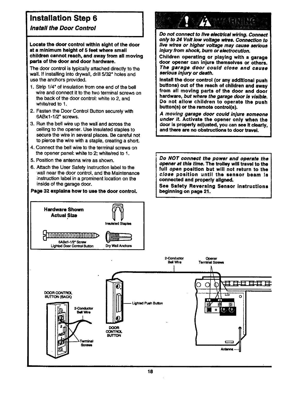
.ocate the door control within sight of the door
at s minimum height of 5 feet where small
children cannot reach, and away from all moving
parts of the door and door hardware.
The door control is typically attached directly to the
wall. If installing into drywall, drill 5/32" holes and
use the anchors provided.
1. Strip 1/4" of insulation from one end of the bell
wire and connect it to the two terminal screws on
the back of the door control: white to 2, and
white/red to 1.
2. Fasten the Door Control Button securely with
6ABxl-1/2" screws.
3. Run the bell wire up the wall and across the
ceiling to the opener. Use insulated staples to
secure the wire in several places. Be careful not
to pierce the wire with a staple, creating a short.
4. Connect the bell wire to the terminal screws on
the opener panel: white to 2; white/red to !.
5. Position the antenna wire as shown.
6. Attach the User Safety Instruction label to the
wall near the door control, and the Maintenance
;nstruction label in a prominent location on the
inside of the garage door.
Page 32 explains how to use the door control.
Do not connect to live electWcal wiring. Connect
only to 24 Volt low voltage wires. Connection to
live wires or higher voltage may cause serious
injury from shock, burn or electrocution.
Children operating or playing with a garage
door opener can injure themselves or others.
The garage door could close and cause
serious injury or death.
Install the door control (or any additional push
buttons) out of the reach of children and away
from all moving parts of the door and door
hardware, but where the garage door Is visible.
Do not allow children to operate the push
button(e) or the remote control(s).
A moving garage door could injure someone
under it. Activate the opener only when the
door is properly adjusted, you can see It clearly,
and there are no obstructions to door travel.
Do NOT connect the power and operate the
opener at this time. The trolley will travel to the
full open position but will not return to the
close position until the sensor beam Is
connected and properly aligned.
Sea Safety Reversing Sensor Instructions
beginning on page 21.
Hardware Shown
Actual Size
InsulatedStaplee
_] 111tlilJllllllllllillllililtltl_>
6ABxI-Ii2" Screw
DoorControlButton Dry Wall Anchors
2-Conductor Op_er
BeNWire Terrnk_l Sinews
DOOR CONTROL
SUTTON(SACK)
2-Conduct<x
Bel Wire
I
Screws
DCOR
CONTROL
BUTTON
18

Installation Step 7
Install the Lights and the Lenses I
Install the lights:
• Install a 75 watt maximum light bulb in each
socket. The lights will turn ON and remain lit for
approximately 4-1/2 minutes when power is
connected. Then the lights will tum OFF.
•If the bulbs bum out prematurely due to vibration,
replace them with standard neck "Garage Door
Opener" bulbs.
75 WattMax.
/_ LightBuN)
Lens
Guide
Lens
Install the lenses:
•Apply slight pressure on the sides of each lens J
and slide the tabs into the slots in the side panels.
•For convenience, the lenses may be Installed
after Adjustment Step 4 on page 30.
•Reverse the procedure to remove the lenses.
Lens
Tab
Tab
Installation Step 8
Attach the Emergency
Release Rope and Handle
•Thread one end of the rope through the hole in
the top of the red handle so "NOTICE" reads right
side up as shown. Secure with an overhand knot.
The knot should be st least 1" from the end of
the rope to prevent slipping.
•Thread the other end of the rol_ through the hole
in the release arm of the outer trolley.
•Adjust rope length so the handle is 6 feat above
the floor. Secure with an overhand knot.
If it Is necessary to cut the rope, heat seal the
cut end with a match or lighter to prevent
unraveling.
.Do not use the red handle to pull the door
open or closed. The rope knot could become
untied and you could fall. Use the emergency
release only to disengage the trolley and, if
possible, only when the door Is closed.
Garage doors are heavy. If the door is open
when the handle is pulled, the door could
close inadvertently If It Is not properly
balanced. Serious injury may result to persons
under the door. Make sure the doorway is clear
of persons and obstructions before pulling
handle when door Is open.
Tmlby ___TroHelf
- F,.ope_.,. _ Arm
Ov_)tand._- _seHand_
19
Installation Step 9
Electrical Requirements i
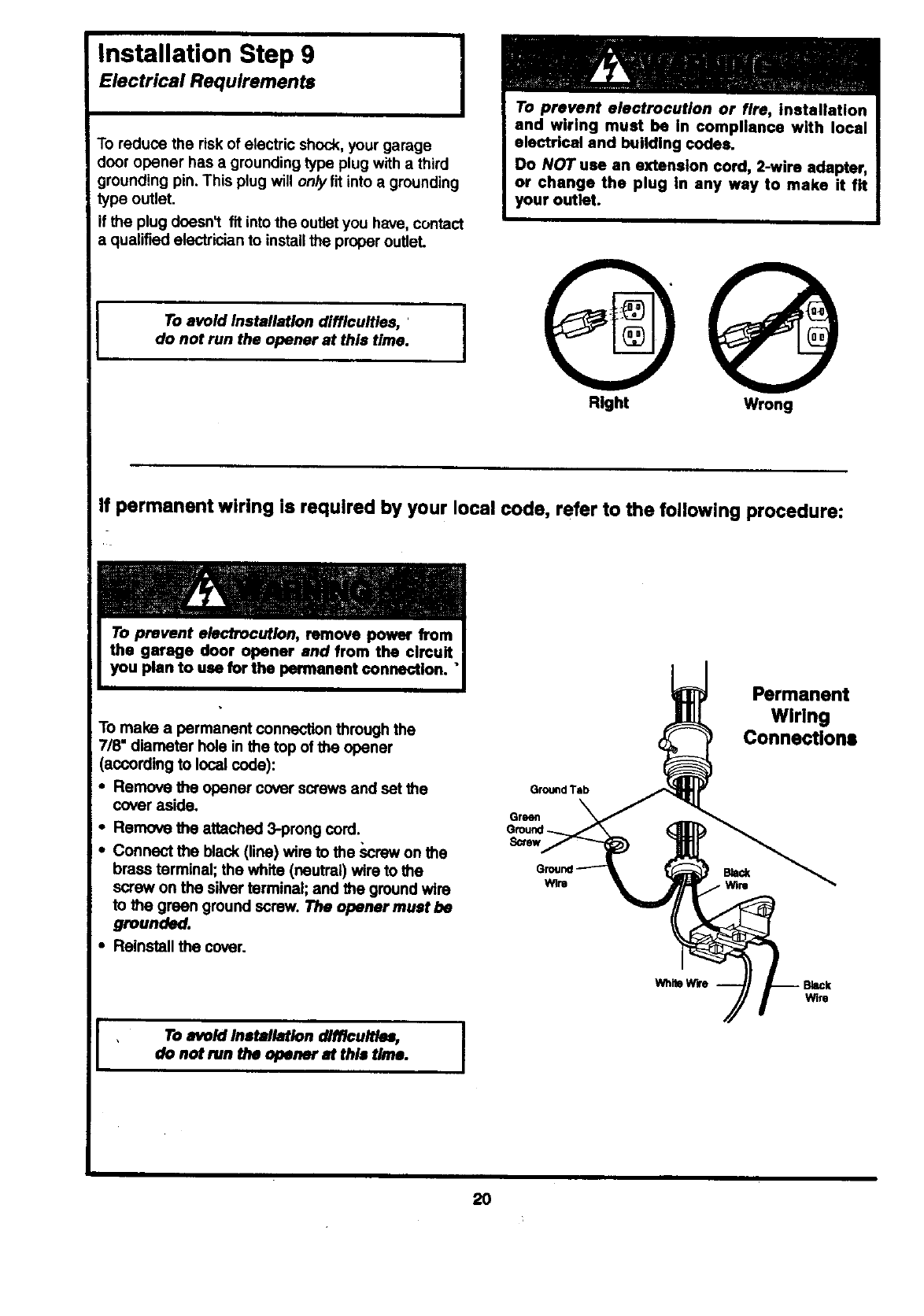
To reduce the risk of electric shock, your garage
door opener has a grounding type plug with a third
grounding pin. This plug will only fit into a grounding
type outlet.
If the plug dcesnl fit into the outlet you have, contact
a qualified electrician to installthe proper outleL
To avoid Installation difficulties,
do not run the opener at this time.
To prevent electrocution or fire, Installation
and wiring must be in compliance with local
electrical and building codes.
Do NOT use an extension cord, 2-wire adapter,
or change the plug in any way to make it fit
your outlet.
Right Wrong
If permanent wiring is required by your local code, refer to the following procedure:
I
To make a permanent connection through the
7/8" diameter hole in the top of the opener
(according to local code):
• Remove the opener cover screws and set the
cover aside.
•Remove the attached 3-prong cord.
• Connect the black (line) wire to the screw on the
brass terminal; the white (neutral) wire to the
screw on the silver terminal; and the ground wire
to the green ground screw. The opener muat be
grounded.
Reinstall the cover.
GroundTab
Green
Screw
Permanent
Wiring
Connections
wire
Whi_ W_e Wire
To avoid Installation difflcult_, I
do not run the opener at this time. I
20

The Safety Reverslng System
Information you'll need before you begin the Installation of the safety reverslng sensor.
The safety reversing sensor must be connected
and aligned correctly before the garage door
opener will move in the down direction. This is a
required safety device and cannot be disabled.
Installation procedures are the same for saclional
and one-piece doors.
Be sure power to the opener is disconnected."
The sending eye transmits an invisible light beam to
the receiving eye. The units can be installed on
either side of the garage door as long as the sun
never shines directly into the receiving eye lens.
Look at the label on the connector end of each case
to identify the sensors.
The brackets must he connected and fastened so
that the sending and receiving eyes face each other
as shown in Figure 1.
If an obstruction breaks the light beam while the
garage door is closing, the door will stop and
reverse to full open positionand the opener lights
will flash for 5 seconds.
The brackets mustbe securely fastened to a solid
surface such as the studson either side of the door,
or add apiece of wood at each location if installing in
masonry construction.
The invisible light beam path must be unobstructed.
No part of the garage door (or door tracks, springs,
hinges, rollers or other hardware) can interrupt the
beam while the door is closing. If it does, use a piece
of wood to build out each sensor mounting location to
the minimum depth required for light beam clearance.
Senso¢ Beam
4-6"
above
]]
1
]
Figure 1: Facing the door from Inside the garage
21
Installation Step 10 I
Install the Safety Reversing Sensor I
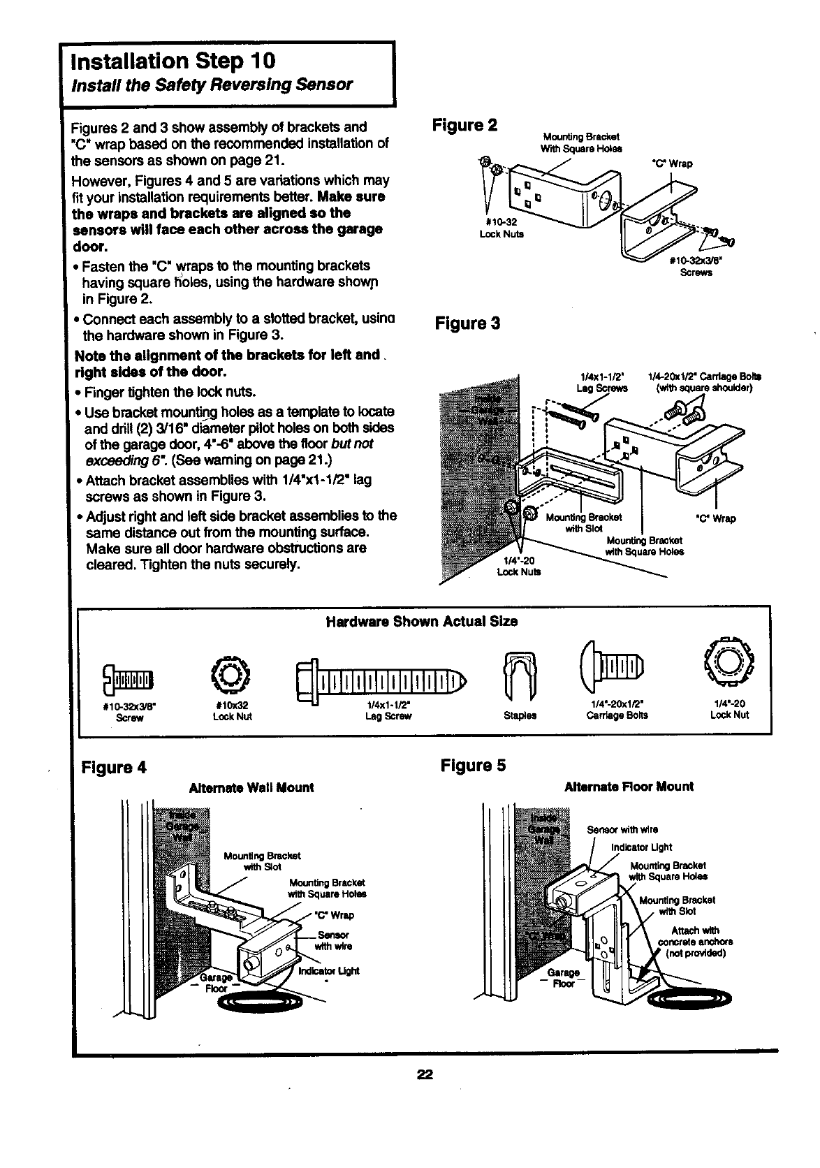
Figures 2 and 3 show assembly of brackets and
"C" wrap based on the recommended installation of
the sensors as shown on page 21.
However, Figures 4 and 5 are variations which may
fit your installation requirements batter. Make sure
the wraps and brackets are aligned so the
sensors will face each other across the garage
door.
• Fasten the "C" wraps to the mounting brackets
having square holes, us ng the hardware shown
in Figure 2.
•Connect each assembly to a slotted bracket, usino
the hardware shown in Figure 3.
Note the alignment of the brackets for left end.
right sides of the door.
• Finger tighten the lock nuts.
• Use bracket mountin_gholes as a template to locate
and drill (2) 3/16" diameter pilot holes on both sides
of the garage door, 4"-6" above the floor but not
exceeding 6". (See warning on page 21.)
•Attach bracket assemblies with 1/4"x1-1/2" lag
screws as shown in Figure 3.
•Adjust dght and left side bracket assemblies to the
same distance out from the mounting surface.
Make sure all door hardware obstructions are
cleared. Tighten the nuts securely.
Figure 2 Mounting Bracket
WithSquareHo4es
_..l_/,..,._ /_"C"Wrap
Figure 3
1/4x1-1/2' 1/4-20_ti2" CardageBolts
LagScrews (wtihsquare shoulder)
t/4"-20
Lock Nuts
MountingBracket
withSquare Holes
"C"Wrap
# 10-3_(3/8" #10X32
Screw Lock Nut
Hardware Shown Actual Size
Ih ©
1/4"-20xl/2" 1/4'-20
Lag Screw Staples Carriage Bolts Lock Nut
Figure 4 Alternate Wall Mount
Flgure 5
Alternate Roor Mount
MountingBracket
with Slot
MountingBracket
with Square HOleS
with wire
IrldloatolUght
-- Floor'
Sensorwith wire
IndloatorUght
MountingBracket
withSquare Holes
Mounting Bracket
with Slot
22
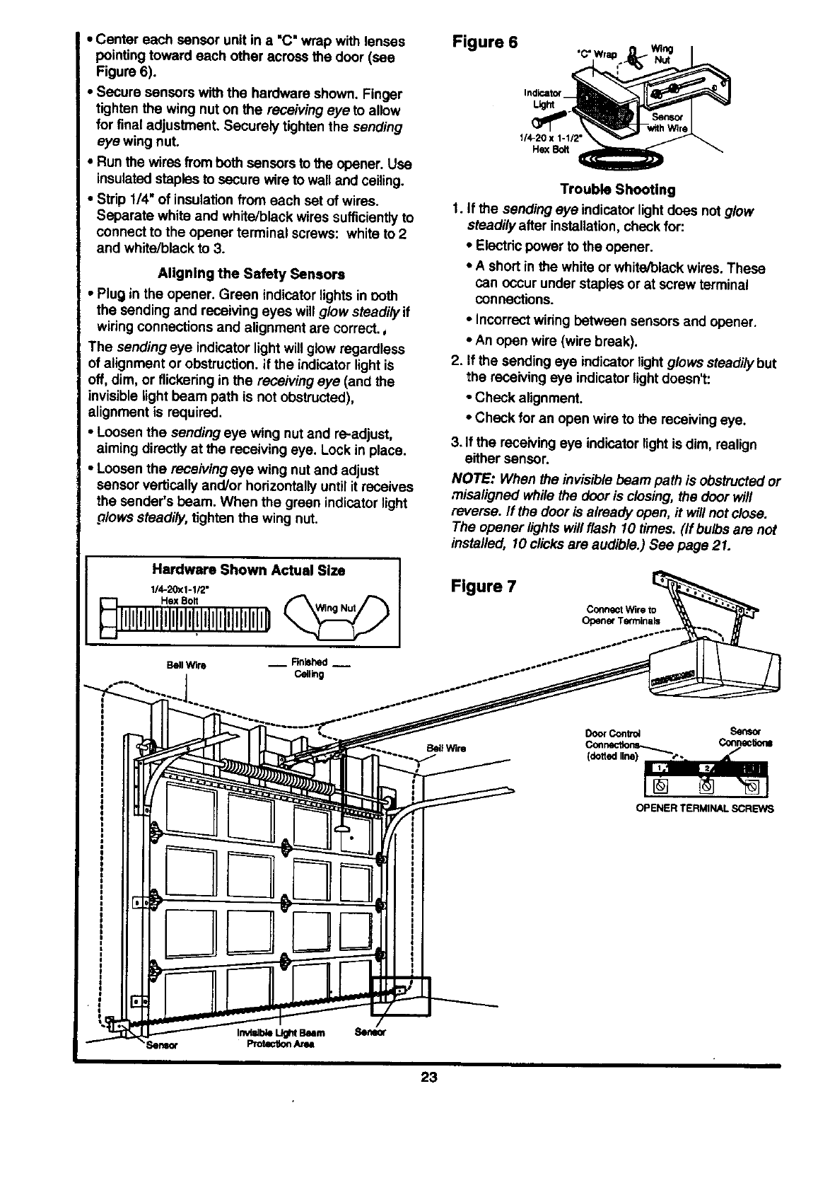
•Centereachsensorunitina "C"wrapwithlenses
pointingtowardeachotheracrossthe door (see
Figure 6).
•Secure sensors with the hardware shown. Finger
tighten the wing nut on the receiving eye to allow
for final adjustment. Securely tighten the sending
eye wing nuL
•Run the wires from both sensors to the opener. Use
insulated staples to secure wire to wall and ceiling.
•Strip 1/4" of insulation from each set of wires.
Separate white and white/black wires sufficiently to
connect to the opener terminal screws: white to 2
and white/black to 3.
Aligning the Safety Sensors
•Plug in the opener. Green indicator lights in ooth
the sending and receiving eyes will glow steadily if
wiring connections and alignment are correct.,
The sending eye indicator lightwill glow regardless
of alignment or obstruction, if the indicator light iS
off, dim, or flickering in the receiving eye (and the
invisible light beam path is not obstructed),
alignment is required.
•Loosen the sending eye wing nut and re-adjust,
aiming directly at the receiving eye. Lock in place.
•Loosen the receiving eye wing nut and adjust
sensor vertically and/or horizontally until it receives
the sender's beam. When the green indicator light
.o/owssteadily, tighten the wing nut.
Hardware Shown Actual Size
114.20x1-1/2"
Bell Wire __ Rnbhed --
Ceiling
Figure 6 'C" Wra
Indicator
_ht
114-20 x 1-1/2"
He;<Bolt
Trouble Shooting
1. if the sending eye indicator light does not glow
steadily after installation, check for:
•Electric power to the opener.
•A short in the white or white/black wires. These
can occur under staples or at screw terminal
connections.
•Incorrect wiring between sensors and opener.
•An open wire (wire break).
2. If the sending eye indicator lightglows steadily but
the receiving eye indicator lightdoesnt:
o Check alignment.
•Check for an open wire to the receiving eye.
3. If the receiving eye indicator lightis dim, realign
either sensor.
NOTE: When the invisiblebeam path is obstructed or
misaligned while the door is closing, the door will
reverse, ff the door is already open, it will not close.
The opener lights will flash 10 times. (If bulbs are not
installed, 10 clicksare audible.) See page 21.
Figure 7
Connect Wire to
Opener Te_mina_
BellWire
DoorContrd Sensor
OPENER TERMINAL SCREWS
23

Installation Step 11
Fasten Door Bracket
Follow instructions which apply to your door
type as illustrated below or on page 25.
A horizontal brace should be long enough to be secured to 2 vertical supports. A vertical brace should
cover the height of the top panel.
The Illustration shows one piece of angle iron as the horizontal brace. For the vertical brace, 2 pieces of
angle iron are used to create a "U"-ahaped support. The best solution is to check with your garage door
manufacturer for an opener installation door reinforcement kit.
Heade_
Bracket • Horizontalandverticalre_nforcemerd
ergins, alunlhlum, steel,doorsv
ReinforcementBoard
• Center the door bracket on the previously marked
vertical guideline used for the header bracket
installation. Note correct UP placement, as
stamped inside the brackeL
• Position the bracket on the face of the door within
the following limits:
A) The top edge of the bracket 2"-4" below the top
edge of the door.
B) The top edge of the bracket directly below any
structural support across the top of the door.
• Mark and drill 5/16" left and right fastening holes.
Secure the bracket as shown in Figure I if there
is vertical reinforcement,
If your installation dossn't require vertical reinforce-
ment but does need top and bottom fastening holes
for the door bracket, fasten as shown in Figure 2.
Hardware Shown Actual Size
©
Nut 5/16-18 LockWe_ler 5/16"
Illllltlllllll lllllllllll
24
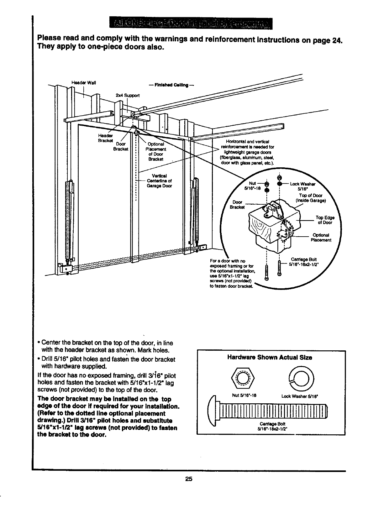
Please read and comply with the warnings and reinforcement instructions on page 24.
They apply to one-piece doors also.
Header Wall -- Flntshed Ceiling -- ___
2x4 Support
Dooi" Op_onal r "
of Door t)ghtweight garage doors
Bracket _g_n_u_r _guem,O0_,
Vertical
-- Centerline of
GarageDoor
J
use 5/16"xi-1/2" lag
•Center the bracket on the top of the door, in line
with the header bracket as shown. Mark holes.
•Drill 5/16" pilot holes and fasten the door bracket
with hardware supplied.
If the door has no exposed framing, ddll3/16" pilot
holes and fasten the bracket with 5/16"x1-1/2" lag
screws (not provided) to the top of the door.
The door bracket may be Installed on the top
edge oftbe door if required for your installation.
(Refer to the dotted line optional placement
drawing.) Drill 3/16" pilot holes and substitute
5/16"x1-1/2" lag screws (not provided) to fasten
the bracket to the door.
Hardware Shown Actual Size
@ ©
Nut 5/16"-18 Lock Washer 5/16"
5/16"-18x2-1/2"
25
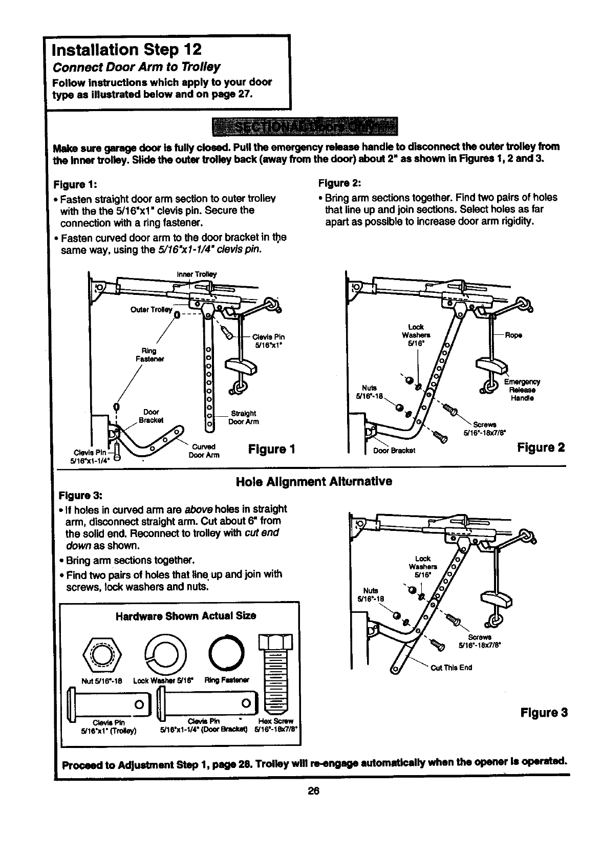
Installation Step 12
Connect Door Arm to Trolley
Fonow instructions which apply to your door
type as illustrated below and on page 27.
Make sure garage door is fully closed. Pull the emergency mleasa handle to disconnect the outer trolley from
the inner trolley. Slide the outer trolley back (away from the door) about 2" as shown in Figures 1, 2 and 3.
Figure 1:
•Fasten straight door arm section to outer trolley
with the the 5/16"x1" clevis pin. Secure the
connection with a ring fastener.
•Fasten curved door arm to the door bracket in tt_e
same way, using the 5/16"x1-1/4" clevis pin.
Figure 2:
• Bring arm sections together. Find two pairs of holes
that line up and join sections. Select holes as far
apart as possible to increase door arm rigidity.
Inner Trolk_y
Ring
Fastener
/
oBmck_
Clevis Pin • Door Arm
5/16"
5/16'XI"
DoorAnn
Figure I
Emergency
Release
Handle
Figure 2
Hole Alignment Alturnative
Figure 3:
•If holes in cuwed arm are above holes in straight
arm, disconnect straight arm. Cut about 6" from
the solid end. Reconnect to trolley with cut end
down as shown.
• Bring arm sections together.
•F nd two pairs of holes that line up and join with
screws, lock washers and nuts.
Hardware Shown Actual Size
©©
@
Nut 5/16"-18 L0ckWash_H5/16" Ring Futen_
ClevisPin Qevls Pin Hex Screw
5/16"x1" (TmNey) 5/16"x1-1/4" (Do(x B_ 5/16"-18x7m"
i
I
•Screws
5/16"-18x7/8"
End
Figure 3
Proceed to Adjustment Step 1, page 28. Trolley will re-engage automatically when the opener Is operated.
26
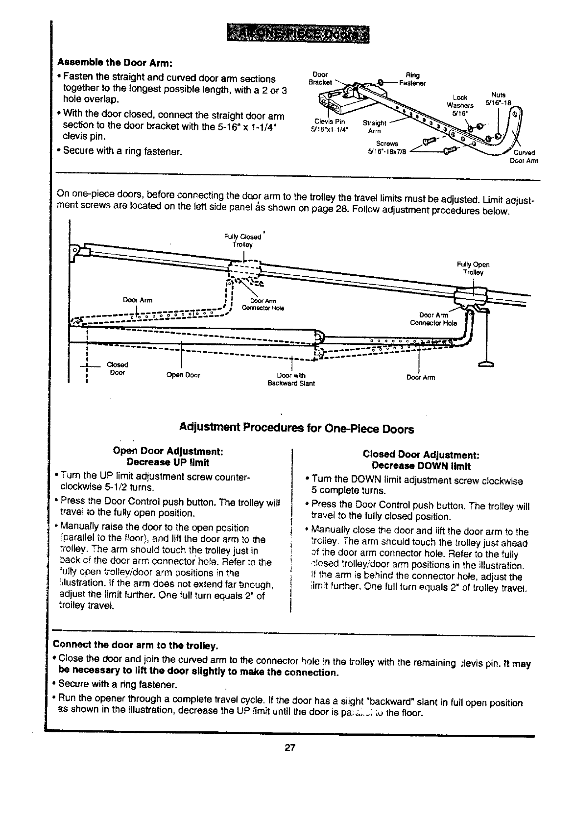
Assemble the Door Arm:
•Fasten the straight and curved door arm sections
together to the longest possible length, with a2or 3
hole overlap.
• With the door closed, connect the straight door arm
section to the door bracket with the 5-16" x 1-1/4"
clevis pin.
•Secure with a ring fastener.
DO_ Ring
Rra_ 5/16"L°ck Nuts
Washers 5/16"-18
i/'_1
Clovis Pin Straight {/_//
DOOr Arrrl
On one-piece doors, before connecting the door arm to the trolley the travel limits must be adjusted. Limit adjust-
ment screws are located on the left side panel _,sshown on page 28. Follow adjustment procedures below.
0
Fully Closed
TtOtloy
Fully Open
Trolley
........ .
J
!
__ Closed
I Door Open Door Door with
I
I Backward Slant Doer Arm
Adjustment Procedures for One-Piece Doors
open Door Adlustment:
Decrease UP limit
• Turn the UP limit adjustment screw counter-
!clockwise 5-1/2 turns.
'•Press the Door Control push button. The trolley will
travel to the fully open position.
,Manually raise the door to the open position
{parallel to the floor), and lift the door arm to the
_rolley. The arm should touch the trolley just in
back of the door arm connector hole. Refer _othe
"u!_yapen _rolleyidoor arm positions in the
!llustration. _fthe arm does not extend far _r_ough,
adjust the iimit further. One full turn equals 2" of
",roiley travel.
Closed Door Adjustment:
Decrease DOWN limit
•Turn the DOWN limit adjustment screw clockwise
5 complete turns.
•Press the Door Control push button. The trolley will
travel to the fully closed position.
• Manually close the door and !ift the door arm to the
troJley. :he arm should touch the trolley just ahead
of ",hedoor arm connector hole. Refer to the fuily
,;losed trolley/door arm positions in the illustration.
if the arm is _ehind the connector hole, adjust the
limit further. One full turn equals 2" of trolley travel.
Connect the door arm to the trolley.
•Close the door and join the curved arm to the connector hole in the trolleywith the remaining ;levis pin. It may
be necessary to lift the door slightly to make the connection.
•Secure with a ring fastener.
j•Run the opener through acomplete travel cycle. If '.he door has a slight "backward" slant in full open position
as shown in the illustration, decrease the UP !imit until the door is pa;a;..'. ;u the floor.
L
27
Adjustment Section: Pages 28 - 30
Adjustment Step 1
Adjust the UP and DOWN Limits
Do not make any limit adjustments until the
safety reversing sensors are completely
installed.
Limit adjustment settings regulate the points at
which the door will stop when moving up or down.
The door will stop in the up direction if anything
interferes with door travel. The door will rever._e in
the down direction if anything interferes with thd
door travel (including binding or unbalanced doors).
To operate the opener, press the Door Control push
button. Run the opener through a complete travel
cycle.
•Does the door open and close completely?
•Does the door stay closed and not reverse
unintentionally when fully closed?
If your door passes both of these tests, no limit
adjustments are necessary unless the reversing test
fails (See page 30).
Adjustment procedures are outlined below. Run
the opener through a complete travel cycle after
each adjustment.
Repeated operation of the opener during
adjustment procedures may cause the motor to
overheat and shut off. Simply wait 15 minutes
and try again.
Read the procedures carefully before proceeding to
Adjustment Step 2. Use a screwdriver to make limit
adjustments.
Improper adjustment of the travel limits witl
interfere with the proper operation of the
safety reverse system. The door might not
reverse properly when required and could
seriously injure or kill someone under it. Test
the safety reverse system following all
adjustments to the travel limits. See page 30.
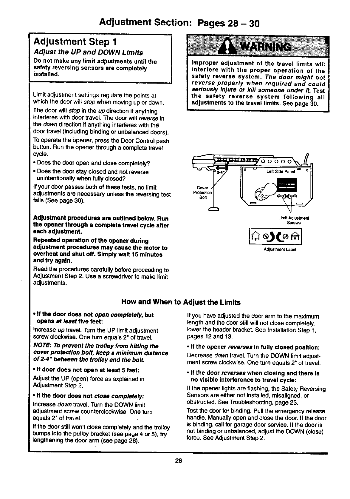
Cover /
Protection
Bolt
LimitAdjustment
Screws
Adjustment Lab_
How and When to Adjust the Limits
•ff the door does not open completely, but
opens at least five feet:
increase up travel. Turn the UP limit adjustment
screw clockwise. One turn equals 2" of travel.
NOTE: To prevent the trolley from hitting the
cover protection bolt, keep aminimum distance
of 2-4" between the trolley and the bolt.
•if door does not open at least 5 feet:
Adjust the UP (open) force as zxplained in
Adjustment Step 2.
•If the door does not close completely:
increase down travel. Turn the DOWN limit
adjustment screw counterclockwise. One turn
equals 2" of tra\el.
If the door still won't close completely and the trolley
bumps into the pulley bracket (see p.yu 4 or 5), try
i lengthening the door arm(see page 26).
I
If you have adjusted the door arm to the maximum
length and the door still will not close completely,
lower the header bracket. See Installation Step 1,
pages 12 and 13.
•If the opener reverses in fully closed position:
Decrease down travel. Turn the DOWN limit adjust-
ment screw clockwise. One turn equals 2" of travel.
•If the door reverses when closing and there is
no visible interference to travel cycle:
If the opener lightsare flashing, the Safety Reversing
Sensors are either not installed, miseligned, or
obstructed. See Troubleshooting, page 23.
Test the door for binding: Putt the emergency retease
handle. Manually open and close the door. If the door
is binding, call for garage door service. If the door is
not binding or unbalanced, adjust the DOWN (close)
force. See Adjustment Step 2.
28
Adjustment Step 2 I
Adjust the Force I
Force adjustment controls are located on the dght
side panel of the opener. Force adjustment settings
regulate the amount of power required to open and
close the door.
The door will stop in the up direction if anything
interferes with its travel. The door will reverse inthe
down direction if anything interferes with its travel
(including binding or unbalanced doors).
If the forces are set too light, door travel may be
interrupted by nuisance reversals in the down
direction and stops in the up direction. Weather
conditions can affect the door movement, so
occasional adjustment may be needed.
The maximum force adjustment range is 260 degrees,
about 3/4 of a complete turn. Do not force controls
beyond that poinL Tum force adjustment controls
with a screwdriver.
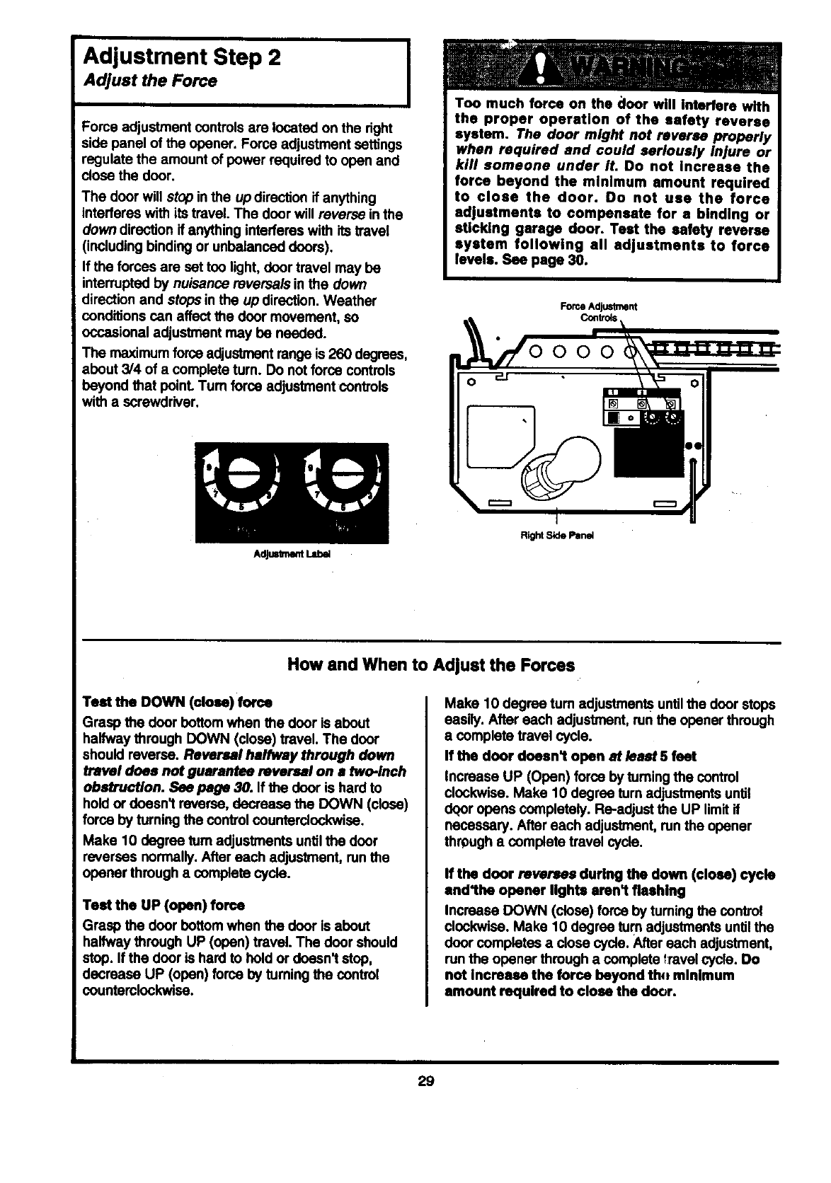
AdjustmentI.ab_
Too much force on the €loor will Interfere with
the proper operation of the safety reverse
system. The door might not reverse properly
when required and could seriously Injure or
kill someone under it. Do not Increase the
force beyond the minimum amount required
to close the door. Do not use the force
adjustments to compensate for a binding or
sticking garage door. Test the safety reverse
system following all adjustments to force
levels. See page 30.
ForceAdjustment
Right Side Pane4
How and When to Adjust the Forces
Test the DOWN (close) rome
Grasp the door bottom when the door is about
halfway through DOWN (close) travel. The door
should reverse. Reversal halfway through down
travel does not guarantee reversal on a two-inch
obstruction. See page 30. If the door is hard to
hold or doesn't reverse, decrease the DOWN (close)
force by turning the control counterclockwise.
Make 10 degree turn adjustments until the door
reverses normally. After each adjustment, run the
opener through a complete cycle.
Test the UP (open) force
Grasp the door bottom when the door is about
halfway through UP (open) travel. The door should
stop. If the door is hard to hold or doesn't stop,
decrease UP (open) force by turning the control
countemlockwise.
Make 10 degree turn adjustments untilthe door stops
easily. After each adjustment, mn the opener through
acomplete travel cycle.
If the door doesn't open at least 5 feet
Increase UP (Open) force by tuming the control
clockwise. Make 10 degree turn adjustments until
dqor opens completely. Re-adjust the UP limit if
necessary. After each adjustment, run the opener
through a complete travel cycle.
If the door reverses during the down (close) cycle
and'the opener lights arenl fleehlng
Increase DOWN (close) force by tuming the control
clockwise. Make 10 degree turn adjustments until the
door completes a close cycle. After each adjustment,
run the opener through a complete _:ravelcycle. Do
not Increase the force beyond thtt minimum
amount required to close the door.
29
Adjustment Step 3
Test The Safety Reversing Sensor
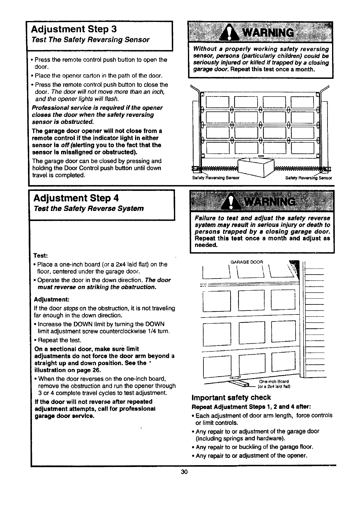
•Press the remote control push button to open the
door.
• Place the opener carton in the path of the door.
Press the remote control push button to close the
door. The door will not move more than an inch,
and the opener lights will flash.
_rofessional service is required if the opener
closes the door when the safety reversing
sensor is obstructed.
The garage door opener will not close from a
remote control if the indicator light in either
sensor is off(alerting you to the fact that the
sensor Is mlsallgned or obstructed).
The garage door can be closed by pressing and
holding the Door Control push button until down
travel is completed.
IWithout a properly working safety reversing
sensor, persons (particularly children) could be
seriously injured or killed ff trapped by a closing
garage door. Repeat this test once a month.
_iSe_o r
Adjustment Step 4
Test the Safety Reverse System
Test:
• Place a one-inch board (or a 2x4 laid flat) on the
floor, centered under the garage door.
•Operate the door in the down direction. The door
must reverse on striking the obstruction.
Adjustment:
If the door stops on the obstruction, it is not traveling
far enough in the down direction.
•Increase the DOWN limit by turning the DOWN
limit adjustment screw counterclockwise 1/4 turn.
• Repeat the test.
On a sectional door, make sure limit
adjustments do not force the door arm beyond a
straight up and down position. See the •
illustration on page 26.
•When the door reverses on the one-inch board,
remove the obstruction and run the opener through
3 or 4 complete travel cycles to test adjustment.
If the door will not reverse after repeated
adjustment attempts, call for professional
garage door service.
Important safety check
Repeat Adjustment Steps 1, 2 and 4 after:
•Each adjustment of door arm length, force controls
or limit controls.
•,A.nyrepair to or adjustment of the garage door
(including springs and hardware).
•Any repair to or buckling of the garage floor.
•Any repair to or adjustment of the opener.
3O
iii Iml I
IMPORTANT SAFETY INSTRUCTIONS
To reduce the risk of severe
1. READ AND FOLLOW ALL INSTRUCTIONS.
2. Do not permit children either to operate or to
play with the opener. Keep remote control in a
location inaccessible to children.
3. Operate opener only when the door is In full
view and free from any obstruction. Keep the
door in sight until it is completely closed; NO
ONE SHOULD CROSS THE PATH OF THE"
MOVING DOOR.
4. Check safety reversal system monthly. See,
page 30. The garage door MUST reverse on
contact with a one-inch (or a 2x4 board laid
flat) object placed on the floor. If an adjustment
Is made to either the force or the limit of travel,
both adjustments may be needed and the
safety reversal system must be checked.
Failure to properly adjust the opener may
result in severe injury or death.
injury or death to persons:
5. If possible, usa the emergency release only
when the door is In s closed position. Caution
should be taken whenever the disconnect cord
is actuated with the door open. Weak or broken
springs may cause the door to fall rapidly,
causing injury or death to persons.
6. KEEP GARAGE DOORS PROPERLY
BALANCED. See page 3. An improperly
balanced door may not reverse when required
and could result in severe injury or death.
Repairs to cables, spring assemblies and other
hardware must be made by a professional
garage door person.
7. Disconnect the electric power to the garage
door opener before making any repairs or
removing the covers.
0.SAVE THESE INSTRUCTIONS.
Care of Your Opener
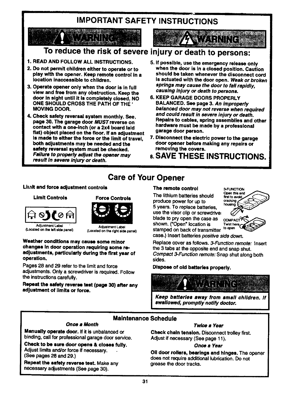
Limit and force adjustment controls
Limit Controls Force Controls
Adjustment Label Adjustment Label
(Located on the left side panel) (LOcated on the right side panel}
Weather conditions may cause some minor
changes In door operation requiring some re-
adjustments, particularly during the first year of
operation.
Pages 28 and 29 refer to the limit and force
adjustments. Only a screwdriver is required. Follow
the instructions carefully.
Repeat the safety reverse teat (page 30) after any
adjustment of limits or force.
The remote control 3-FUNCTION
Open _s end
The lithium batteries should f_t to
crackthg
produce power for up to heu,_ t__-._._,_,_
5 years. To replace batteries,
use the visor clip or screwdriver
blade to pry open the case as COMPAC_
shown. ('Open" location is T_sthere
stamped on back of transmitter toopen
case.) Insert batteries positive side down.
Replace cover as follows. 3-Function remote: Insert
the 3 tabs at the opposite end and snap shut.
Compact 3-Function remote: Snap shut along both
sides.
Dispose of old batteries properly.
Maintenance Schedule
Once a Month Twlcea Year
Manually operate door. If it is unbalanced or
binding, call for professional garage door service.
Check to be sure door opens & closes fully.
Adjust limits and/or force if necessary.
(See pages 28 and 29.)
Repeat the safety reverse teat. Make any
necessary adjustments (See page 30).
Check chain tension. Disconnect trolleyfirst.
Adjust if necessary (See page 11).
Once a Year
OII door rollers, bearings and hinges. The opener
does not require additional lubrication. Do not
grease the door tracks.
31
Operation of Your Opener
Activate the opener with any of the following:
• The Remote Control: Hold push button down
until the door starts to move,
• The Door Control: Hold push button down until
the door starts to move.
• The Outdoor Key Switch or Keyless Entry:
(See Accessories)
When the opener is activated with the safety
reversing sensor installed and correctly aligned:
1. If open, the door will close. If closed, it will open.
2. If closing, the door will reverse.
3. If opening, the door will stop (allowing space for
entry and exit of pets and for fresh air).
4. If the door has been stopped in a partially open
position, it will close.
5. If obstructed while closing, the door will reverse.
6. If obstructed while opening, the door will stop.
7. The garage door will reverse in the closing cycle
when the invisible beam is broken. If fully open,
the door will not close when the beam is broken.
The sensor has no effect in the opening cycle.
If the sensor is not installed, or is not aligned
correctly, the door won't close from any remote
transmitter. You can close the door with the Door
Control, the Outdoor Key Switch, or Keyless Entry,
however, if you activate them until down travel is
complete. If you release them too soon, the door will
reverse.
The opener lights will blink for 5 seconds when the
safety reversing sensor causes the door to reverse.
Opener Lights will turn on under the following
conditions: When the opener is initially plugged in;
when the power is interrupted; when the opener is
activated. They will turn off automatically after 4-1/2
minutes or provide constant light when the Light
feature is activated. Bulb size is 75 watts maximum.
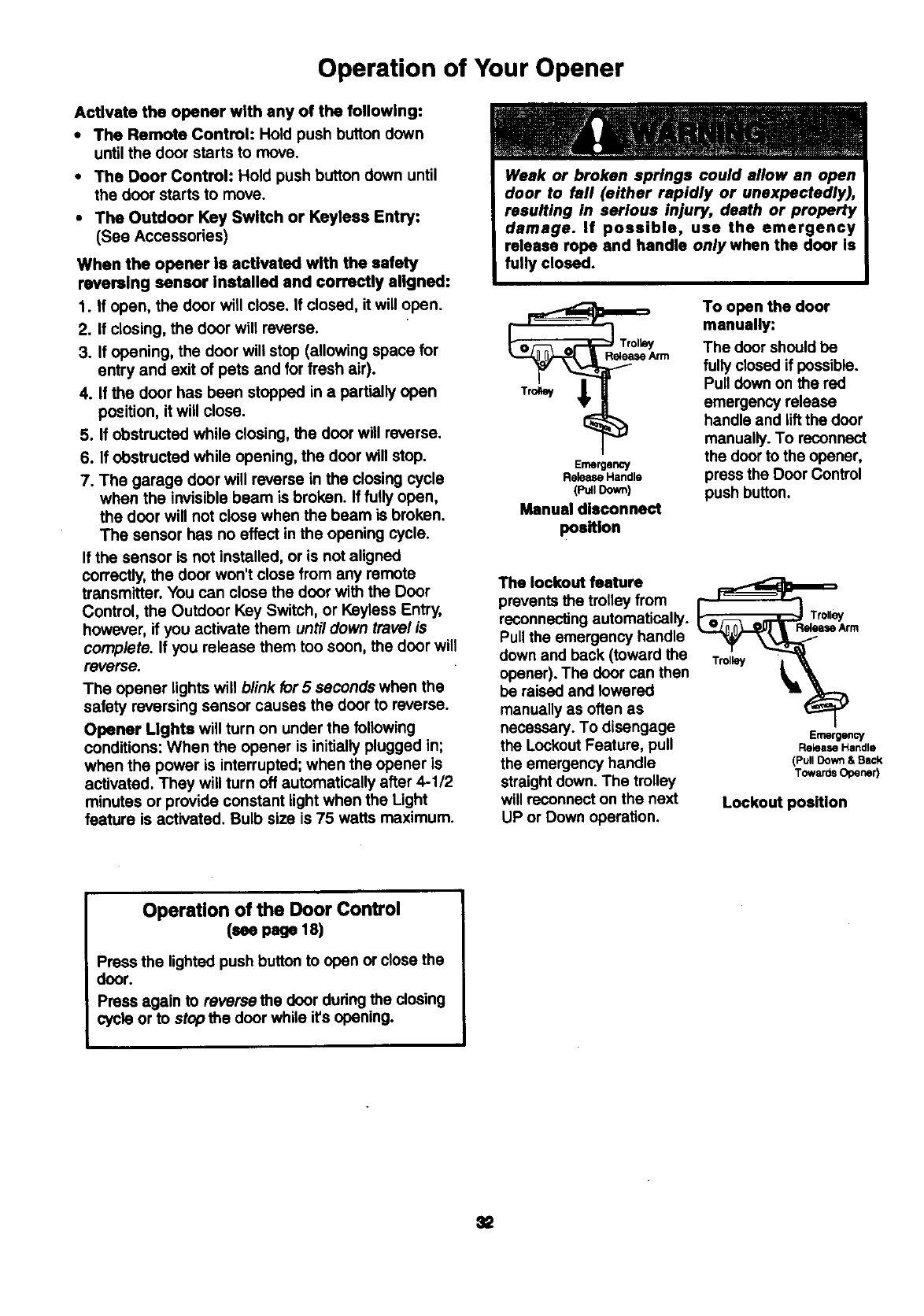
Weak or broken springs could allow an open
door to fall (either rapidly or unexpectedly),
resulting in serious injury, death or property
damage. If possible, use the emergency
release rope end handle only when the door Is
fully closed.
_rrn
Emergency
ReleaseHandle
(Pull Down)
Manual disconnect
position
To open the door
manually:
The door should be
fully closed if possible.
Pull down on the red
emergency release
handle and liftthe door
manually. To reconnect
the door to the opener,
press the Door Control
push button.
The lockout feature _
prevents the trolley from =- ""_1
reconnecting automatically. _Tr°llw
ReleaseArm
Pull the emergency handle
down and back (toward the
opener). The door can then
be raised and lowered
manually as often as
necessary. To disengage Emergency
the Lockout Feature, pull ReleaseHandle
the emergency handle (Pu,Down&8_
straight down. The trolley TowardsOpener)
will reconnect on the next Lockout position
UP or Down operation.
Operation of the Door Control
(see page 18)
_ress the lighted push button to open or close the
door.
Press again to reverse the door during the closing
cycle or to stop the door while it's opening.
Receiver and Remote Control Programming
[To comply with FCC rules, adiustment or modifications of this receiver
an(i/or transmitter are prohibited, except fo_ changing the code setting or
replaclngpARTS,the battery. THERE ARE NO OTHER USER SERVICEABLE
Models with 3-function remote controls: The
remote controls have been factory set to operate
with the large push button on the remote control.
However, you can use either of the two small
buttons, if you prefer. And, the 3-function remote
control can also activate additional garage door
openers and/or lightcontrols.
Below are instructions for programming your opener
to match the other buttons on your remote controls
and any additional remote controls you may
purchase. See available accessories on page 38:
53000SRT Series Garage Door Opener's
(With "SRT" Button)
Children operating or playing with • garage
door opener can Injure themselves or others.
The garage door could close and cause
serious injury or death. Do not allow children
to operate the door push button(s) or remote
control(s).
A moving garage door could injure or kill
someone under it. Activate the opener only
when you can see the door clearly, it is free of
obstructions, and is properly adjusted.
Figure I Selecta remotecontrolpush
buttontoeperate opener
Your =SR'T"garage door opener will operate with as
many as four =SR'I" portable remote controls and
one Multi-Function Keyless EnVy.
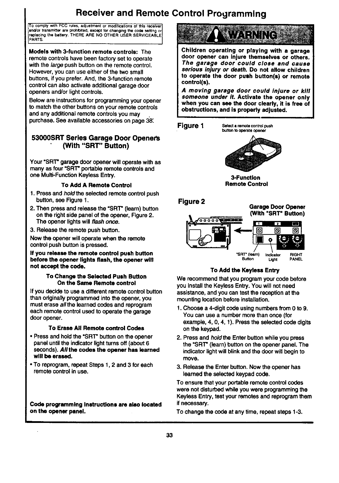
To Add A Remote Control
1. Press and holdthe selected remote control push
button, sea Figure 1.
2. Then press and release the "SRT" (learn) button
on the right side panel of the opener, Figure 2.
The opener lights will flash once.
3. Release the remote push button.
Now the opener will operate when the remote
control push button is pressed.
If you release the remote control push button
before the opener.lights flash, the opener will
not accept the code.
To Change the Selected Push Button
On the Same Remote control
If you decide to use a different remote control button
than originallyprogrammed into the opener, you
must erase allthe learned codes and reprogram
each remote control used to operate the garage
door opener.
To Erase All Remote control Codes
•Press and hold the "SR'I" button on the opener
panel untilthe indicator lightturns off (about 6
seconds). Aflthe codes the opener has learned
will be erased.
•To reprogram, repeat Steps 1,2 and 3 for each
remote control in use.
Code programming Instructions are also located
on the opener panel.
3-Function
Remote Control
Figure 2 Garage Door Opener
(With "SRT" Button)
"SRT" (learn) Indicator RIGHT
Button Light PANEL
To Add the Keylese Entry
We recommend that you program your code before
you install the Keyless Entry. You will not need
assistance, and you can test the reception at the
mounting location before installation.
1. Choose a4-digit coda using numbers from 0 to 9.
You can use a number more than once (for
example, 4, 0, 4, 1). Press the selected code digits
on the keypad.
2. Press and holdthe Enter button while you press
the =SRI"* (learn) button on the opener panel. The
indicator light will blink and the door will begin to
move.
3. Release the Enter button. Now the opener has
learned the selected keypad cede.
To ensure that your portable remote control codes
were not disturbed while you were programming the
Keyless Entry, test your remotes and reprogram them
if necessary.
To change the code at any time, repeat steps 1-3.
33
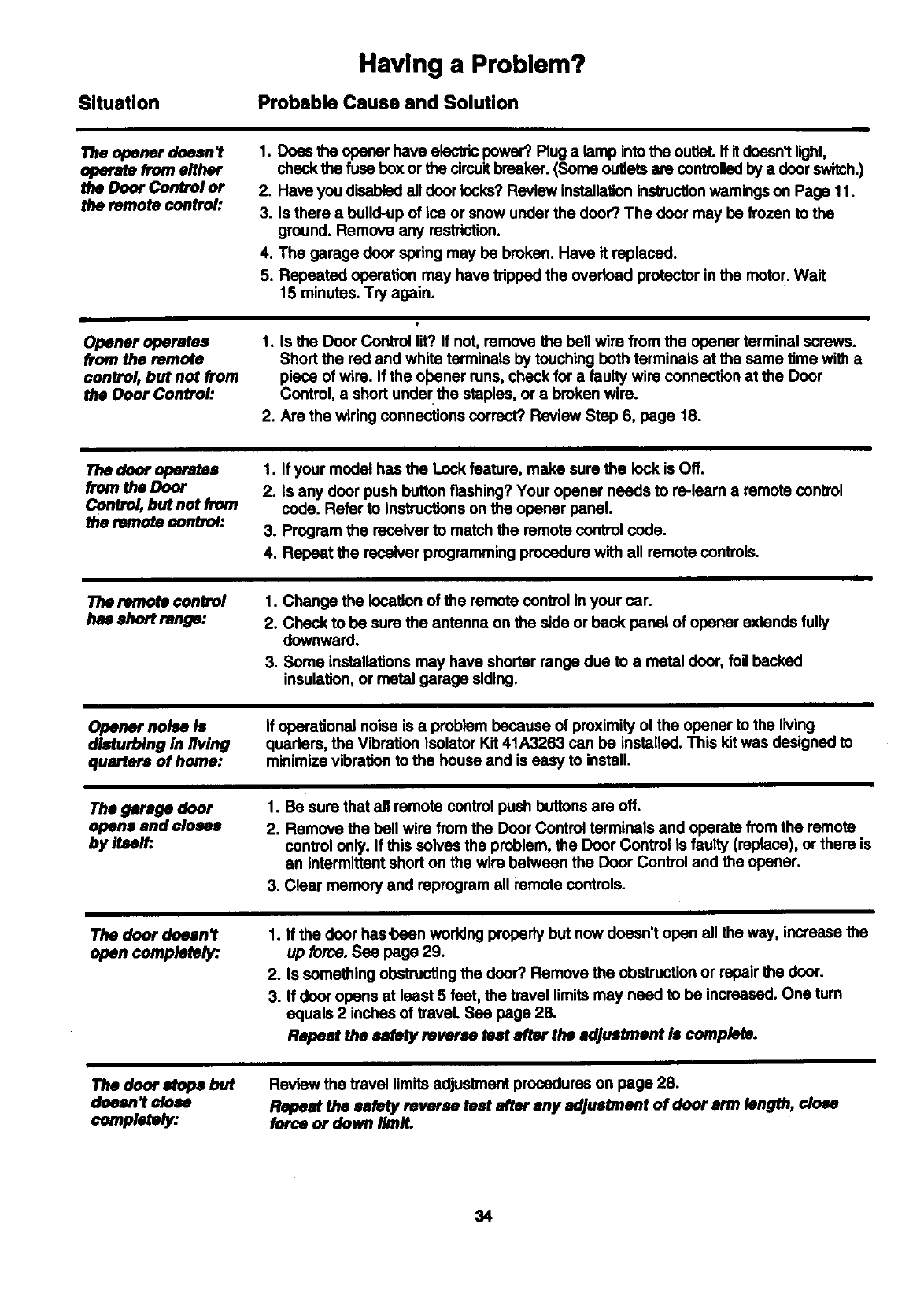
Situation
Having a Problem?
Probable Cause and Solution
The opener doesnl
operate from either
the Door Control or
the remote control:
Opener operates
from the remote
control, but not from
the Door Control:
1. Does the opener have electric power? Rug a lamp into the outleL If itdoesn't light,
check the fuse box or the circuitbreaker. (Some outlets are controlledby a doorswitch.)
2. Have you disabled all door locks? Review installation instructionwamings on Page 11.
3. Is there a build-up of ice or snow under the door? The door may be frozen to the
ground. Remove any restriction.
4. The garage door spring may be broken. Have it replaced.
5. Repeated operation may have tripped the ovedoad protector in the motor. Wait
15 minutes. Try again.
1. Is the Door Control lit?.If not, remove the bell wire from the opener terminal screws.
Short the red and white terminals by touching both terminals at the same time with a
piece of wire. If the ohener runs, check for afaulty wire connection at the Door
Control, a short under the staples, or abroken wire.
2. Are the wiring connections correct? Review Step 6, page 18.
The door oporstee
from the Door
Contro/, but not from
the remote control:
1. If your model has the Lock feature, make sure the look is Off.
2. Is any door push button flashing? Your opener needs to re-leam a remote control
code. Refer to Instrucbons on the opener panel.
3. Program the receiver to match the remote control code.
4. Repeat the receiver programming procedure with all remote controls.
The remote control
has short range:
1. Change the location of the remote control in your car.
2. Check to be sure the antenna on the side or back panel of opener extends fully
downward.
3. Some installations may have shorter range due to a metal door, foil becked
insulation, or metal garage siding.
Opener noise is
disturbing in living
quarters of home:
If operational noise is a problem because of proximity of the opener to the living
quarters, the Vibration Isolator Kit 4tA3263 can be installed. This kit was designed to
minimize vibration to the house and is easy to install.
The garage door
opens and closes
by Itself:
1. Be sure that all remote control push buttons are off.
2. Remove the bell wire from the Door Control terminals and operate from the remote
control only. If this solves the problem, the Door Control is faulty (replace), or there is
an intermittent short on the wire between the Door Control and the opener.
3. Clear memory and reprogram all remote controls.
The door dnean I
open completely:
1. If the door has'been working properly but now doesn't open all the way, increase the
up force. See page 29.
2. Is something obstructing the door? Remove the obstruction or repair the door.
3. If door opens at least 5 feet, the travel limits may need to be increased. One turn
equals 2 inches of travel. Sea page 28.
Repeat the selety reverse test after the adjustment Is complete.
The door stops but
doeen l close
completely:
Review the travel limits adjustment procedures on page 28.
Repeat the safety reverse teat after any adjustment of door arm length, close
force or down limit.
34

Situation
The door opens but
won_ close:
Having a Problem? (continued)
Probable Cause & Solution
.
2.
If the opener lights blink, check the safety reversing sensor. Sea page 23.
If the opener lights do not blink and it is anew instal|atlon, check the down force.
See Adjustment Step 2, page 29. For an existing installation, see below.
Repeat the safety reverse test after the adjustment is complete.
Thedoor reversesfor
no apparentmason
andopener I_ghts
donYblink:
.
,
3.
4.
Is something obstructing the door?.Pull the red emergency release handle. Operate
the door manually. If it is unbalanced or binding, cell for professional garage door
service.
Clear any ice or snow from the garage floor area where the door closes.
Review the force adjustment procedures on page 29.
If door reverses in the fully closed position, decrease the travel limits (page 28).
Repeat safely rever3e test after adjustments to force or travel limits, The need
for occasional adjustment of the force end limit settings is normal. Weather
conditions in particular can affect door travel.
The door reverses for
no apparent reason
andop_er lights
blink for 5 seconds
after reversing:
Check the safety reversing sensor. Remove any obstruction or align the receiving eye.
See page 23.
The opener lights:
The openerslralns or
maximumforce is
.eeded to opere_
door:.
•.. don_t turn on:
Replace the light bulbs (75 watts maximum). Use a standard neck garage door opener
bulb if regular bulb bums out.
•.. don _tturn off:.
Is the Light feature on? Turn'it off.
The door may be out of balance or the springsara Ixoken. Close the door and use the
emergency release to disconnectthe trolley.Open and closethe door manually. A properly
balanced doorwill stay in any point of travelwhiie being supperted antiraiy by itssprings,ffit
does not, disconnectthe opener and calla professionalgarage doorservicemen. Do not
increa_ the forca to operMe the opener.
The opener motor
hums briefly, then
won't work:
ii
The opener won_
operats due to
power failure:
1. The garage door springs are broken. Sea above.
2. If the problem occurs on the firstoperal_onof the opener, door may be locked. D/sab/e
the door/ock. If the chain was removed and reinstalled,the motor may be out of phase.
Remove the chain; cycle the motor to the down position.Observe the drive sprocket.
When it turns in a clockwise dires_on and stopsin the down position, reinstallthe chain.
Repeat the safety reverse teat after the adjuslment Is compiets.
1. Usa the emecgencyraleaseto disoonnect the Voney.The doorcen be spened and closed
manualy.Whenthepewerisrestored, presstheDoorControlpushbutlonandtrofleywUl
automa_ally reconnect(unlsssVolleyis inlockoutposll_.) Sea page 32.
2. The Emergency Key Release accessory (for use on garages with no service door)
disconnects the troliey from outside the garage in case of power failure.
The chain droops
or sags: It is normal for the chain to droop slightly in the closed door poait]on. Use the
emergency rak_Paeto disconnect the trolley. If the chain returns to normal height when
the trolley Is disengaged and the door reverses on a one-inch board, no adjustments
ere needed (see page 11).
35
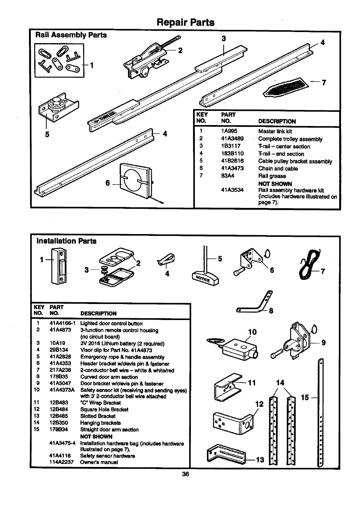
Repair Parts
Rail Assembly Parts 3
__1
2
3
4
5
6
7
41A3489
1B3117
183B110
41B2616
41A3473
83A4
41A3534
DESCRIPTION
Masterlinkkit
Completetrolleyassembly
T-rail- centersection
T-rail- endsection
Cablepulleybracketassembly
Chainand cable
Rail grease
NOT SHOWN
Rail assemblyhardwarekit
(includeshardwareillustratedon
page7).
Installation Parts
KEY PART
NO. NO.
1
2
3
4
5
6
7
8
9
10
11
12
13
14
15
41A4166-1
41A4873
10A19
29B134
41A2828
41A4353
217A238
178B35
41A5047
41A4373A
12B483
1213484
12B485
12B350
178B34
41A3475-4
41A4116
114A2237
DESCRIPTION
Ughted door controlbutton
3-function remote control housing
(no circuitboard)
3V 2016 Lithium battery (2 required)
Visor clip for Part No. 41A4873
Emergency ropa & handle assembly
Header bracket w/cfevispin & f_stener
2-conductorbell wire- white & white/red
Curved doorarm section
Door bracket w/clevlapin &fastener
Safety sensor kit (receiving and sending eyes)
with3' 2-conductor bellwire attached
"C' Wrap Bracket
Square Hole Bracket
Slotted Bracket
Hanging brackets
Straightdoor arm section
NOT _#IOWN
Installationhardware bag (Jndudsehardware
illustratedon page 7).
Safety sensor hardware
Owners manual
11 14
12 15
36
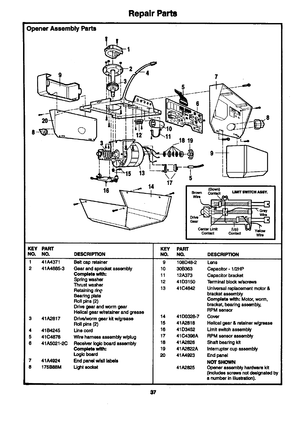
Repair Parts
Opener Assembly Parts
t_-- 2_L_._ _- 12
•..""> 9 _,._ _, /.)y--4 7
, 8
3_'_lr _7 f.18 19 ,____L_. _
",
14 17
16 _ _ e.ro_ _u.n'sw_rc.Asey.
KEY PART
NO. NO. DESCRIPTION
1
2
3
4
5
6
41A4371
41A4885-3
41A2817
41B4245
41C4876
41A5021-2C
41A4924
175B88M
Beltcap retainer
Gear endsprocketassembly
Complete with:
Spdngwasher
Thrustwasher
Retaining
Bearing plate
Rollpins(2)
Drivegear end warm gear
Helicalgearw/retainerandgrease
Drive/wormgearkitw/grease
Rollpins(2)
Une cord
Wire hame_ assemblyw/plug
Receiverlogicboardassembly
Complete with:
Logic board
Endpanelw/ell labels
Ught socket
KEY PART
NO. NO. DESCRIPTION
9 108D48-2 Lens
10 30B363 Capacitor -1i2HP
11 12A373 Capacitor bracket
12 41D3150 Terminal blockw/screws
13 41C4842 Universal replacement motor &
bracket assembly
Complete with: Motor, warm,
bracket, bearing assembly,
RPM sensor
14 41D0328-7 Cover
15 41A2818 Helical gear & retainer w/grease
16 41D3452 Limit switch assembly
17 41C4398A RPM sensor assembly
18 41A2826 Shaft beating kit
19 41A2822A Interrupter cup assembly
20 41A4923 End panel
NOT SHOWN
41A2825 Opener assembly hardware kit
(includes screws not de6tgnatad by
a number in illustration),
37
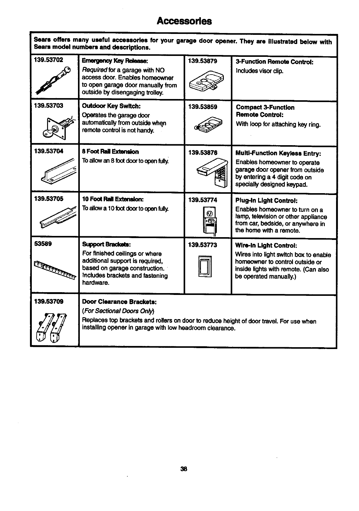
Accessodes
Sears offers many useful accessories for your garage door opener. They are illustrated below with
Sears model numbers and descriptions.
139.53702
/
139.53703
139.53704
139.53705
53589
139.53703
Requiredfor agarage with NO
access door. Enables homeowner
to open garage door manually from
outside by disengaging trolley.
Outdoor Key Swlfoh:
Operates the garage door
automaticallyfrom outsidewh_n
ramote controlis not handy.
I
$ Font Rail Extmsfon
Toallowan 8 footdoorto opanful_
10 Foot FlailExtension:
Toallowa 10 footdoorto open fully.
Support Brsckm:
For finished ceilings or where
additional support is required,
based on garage construction.
includes brackets and fastening
hardware.
139.53879
139.53859
139.53876
139.53774
138,53T/3
3-Function Remote Control:
Includesvisor clip.
Compact 3-Functien
Remote Control:
With loop for attaching key ring.
Multi-Function Keyiece Entry:
Enables homeowner to operate
garage door opener from outside
by entering a4 digit code on
specially designed keypad.
Plug-In Light Control:
Enables homeowner to turn on a
lamp, television or other appliance
from car, bedside, or anywhere in
the home with a remote.
Wire-in Light Control:
Wires into light swh'chbox to enable
homeowner to control outside or
inside lights with remote. (Can also
be operated manually.)
Door Clearance Brackets:
(For Sectional Doors Only)
Replaces top brackets and rollers on door to reduce height of door travel. For use when
installing opener in garage with _headroom clearance.
S8

Index
Access DoorlOut=Ide Key Release Accessory ............................................................................................... 4, 5
Chain Tension .............................................................................................................................................. 4, 5, 11
Electrical Safety Warnings ............................................................................................................. ........... 2, 20, 31
Garage Door
Testing for balance, binding and sticking................................................................................................... 3, 28, 31
Determining high point of travel:
Sectional door................................................................................................................................ ................... 12
One-piece door................................................................................................................................................. 13
Disabling existing locks.................................... :............................................................................................... 3, 11
Door clearance brackets (for garages with low Headroom) ........................................................................... 12, 38
Force controls
Adjustment procedures ..................................... ,........................................................................................... 4, 29
Problems that might require force adjustments .......................................................................................... 34, 35
Safety warnings .................................................. _........................................................................................ 29, 31
Door hardware ..................................................................................................................... 3, 9, 11, 12, 18, 31,32
Maintenance insb'uctionlabel ........................................................................................................................ 11, 28
Reinforcement requirements ........................................................................................................................... 4, 24
Removing of all ropes ....................................................................................................................................... 3, 11
Possible door damage ................................................................................................................................... 16, 24
Travel limits
Adjustment procedures..................................................................................................................................... 28
Problems that might require limit adjustments ............................................................................................ 34, 35
Safety warnings .......................................................................................................................................... 28, 31
Manual (Emergency) Release Rope & Handle
Lockout feature .................................................................................................................................................... 32
Manual disconnect ............................................................................................................................................... 32
Safety warnings ................................................................................................................................. 11, 19, 31,32
Opener Terminals,
Door control connections..................................................................................................................................... 18
Safety reversing sensor connections................................................................................................................... 23
Operational Noise
Sprocket noise ..................................................................................................................................................... 11
Vibration noise (isolator kit) ................................................................................................................................. 34
Recelver and Remote Control
Programming the receiver .................................................................................................................................... 33
Erasing all codes ......................... _........ ;.............................................................................................................. 33
Activating other openers ...................................................................................................................................... 33
Safety warning .................................................................................................................................................... 33
Problems with remote control operation .............................................................................................................. 34
Safety Reverse Test Procedure .......................................................................................................................... 30
Testing required................................................................................................................................. 11, 30, 34, 35
Safety reverse system problems
Securing header bracket to wall ....................................................................................................................... 12
Adjusting travel limits........................................................................................................................................ 28
Applying excessive force on the door .............................................................................................................. 29
Buckling or uneven floor ................................................................................................................................ 4, 5
Safety Warnings ........................................................ 2, 3, 9, 11, 12, 16, 18, 19, 20, 21, 24, 28, 29, 30, 31, 32, 33
User Instruction Label for garage wall ........................................................................................................ 11, 18
39

SEARSWARRANTY
FULL 90-DAY WARRANTY ON GARAGE DOOR OPENER
For90 daysfromthedate of purchase,Searswinrepairthis Garage OourOpener.free of charge,if defectivein materialor
workmanship.
LIMITED WARRANTY
Fromthe91efday untilone year fromb_edate of'purchase, Searswill fumtshreplacementpartsforany datec6ve paris,fTeeof charge.
You pay for labor.
uMrrED WARRANTY ON MOTOR
1/2HP MOTOR: AfterI year and through5 yeats, ifthe motoron thisGarage DoorOpenerisdafec6ve, Searswill fumisha replacement
rnoter,line of charge.Youpay for labor. UMITATION ON LIABILITY
BEAR8 WILL NOT BE LIABLE FOR L06S OR DAMAGE TO PROPERTY OR ANY INCIDENTAL ON CONSEQUENTIALLOSS 01t
FROM PROPERTY DAMAGE DUE DIRECTLYOR INDIRECTLY FROM THE USE OF THIS PRODUCT.Some statesdo
nof dow the exclusinnor l_mltatlonof Incklentelorcor,Nquential dlunages,sothe abovellm_tet_onor e)©luslonmay notepply toyou.
This warrentydoeonotonver lightbulbeor repairparteneceeuPj benauseof ogerathrabuseornegligence,Includingthe Mllureto
In_ldl, idJult end oparatethis g,luagedonropaner"aco_rdingte InefmcUonso_ntainodIn the ownar'smanual.
WARRANTY SERVICE IS AVAILABLEBY SIMPLY CONTACTING THE NEAREST SEARS CENTER/DEPARTMENT IN THE UNITED
STATES.
warranty_o11_ onlywhgethisproductis In L_e In theUnltedStetu.
The-wern.WO_,syouspen,Teie_ r_W, arxlyou.W me haveofherr_hts,,a_:hv_ _rornrote tem.
11,1Ag237 01907, All RightsP,mmrved PrlnisdInMe)doo
