Craftsman 13953910D User Manual GARAGE DOOR OPENER Manuals And Guides L0522096
CRAFTSMAN Garage Door Opener Manual L0522096 CRAFTSMAN Garage Door Opener Owner's Manual, CRAFTSMAN Garage Door Opener installation guides
User Manual: Craftsman 13953910D 13953910D CRAFTSMAN GARAGE DOOR OPENER - Manuals and Guides View the owners manual for your CRAFTSMAN GARAGE DOOR OPENER #13953910D. Home:Garage Door & Opener Parts:Craftsman Parts:Craftsman GARAGE DOOR OPENER Manual
Open the PDF directly: View PDF ![]() .
.
Page Count: 76
Owner's Manual/Manual Del Propietario
I RR RN I
1/2 HP
315Mx= GARAGE DOOR OPENER
ABRIDOR DE PUERTA DE COCHERA 315Mxz
For Residential Use Only/Solo para uso residencial
Model/Modelo 139.53910D
II'1
G3
m
"0
Z_
C3
Read and follow all safety rules
and operating instructions before
first use of this product.
Fasten the manual near the garage
door after installation.
Periodic checks of the opener are
required to ensure safe operation.
Leer y seguir todas las reglas de
seguridad y las instrucciones de
operacion antes de usar este
producto por primera vez.
Guardar este manual cerca de la
puerta de la cochera.
Se deben realizar revisiones
periodicas del abridor de puertas
para asegurar su operacion
segura.
Sears, Roebuck and Co., Hoffman Estates, IL 60179 U.S.A
www.sears.com/craftsman
TABLE OF CONTENTS
Introduction 2- 7
Safety symbol and signal word review ........................ 2
Preparing your garage door ........................................ 3
Tools needed ............................................................... 3
Planning .................................................................. 4-5
Carton inventory .......................................................... 6
Hardware inventory ..................................................... 7
Assembly 8.11
Assemble the rail and install the trolley ...................... 8
Fasten the rail to the motor unit and
install the idler pulley ................................................... 9
Install the chain/cable ................................................ 10
Tighten the chain ....................................................... 11
Installation 11-26
Installation safety instructions .................................... 11
Determine the header bracket location ..................... 12
Install the header bracket .......................................... 13
Attach the rail to the header bracket ......................... 14
Position the opener ................................................... 15
Hang the opener ....................................................... 16
Install the door control ............................................... 17
Install the light ........................................................... 18
Attach the emergency release rope and handle ....... 18
Electrical requirements .............................................. 19
Install The Protector System 'R;.............................. 20-22
Fasten the door bracket ....................................... 23-24
Connect the door arm to the trolley ..................... 25-26
Adjustment 27-29
Adjust the travel limits ............................................... 27
Adjust the force ......................................................... 28
Test the safety reversal system ................................. 29
Test The Protector System _:...................................... 29
Operation 30-34
Operation safety instructions ..................................... 30
Using your garage door opener ................................ 30
Using the wall-mounted Door Control ....................... 31
To open the door manually ........................................ 31
Care of your garage door opener .............................. 32
Having a problem? .................................................... 33
Diagnostic chart ......................................................... 34
Programming 35-36
To add or reprogram a hand-held remote control .....35
To erase all codes ..................................................... 35
&Function Remotes .................................................. 35
To add, reprogram or change
a Keyless Entry PIN .................................................. 36
Repair Parts 37.38
Rail assembly parts ................................................... 37
Installation parts ........................................................ 37
Motor unit assembly parts ......................................... 38
Accessories 39
Warranty 39
Repair Parts & Service Backcover
INTRODUCTION
Safety Symbol
and Signal Word Review
This garage door opener has been designed and tested to offer safe service provided it is installed, operated,
maintained and tested in strict accordance with the instructions and warnings contained in this manual.
Mechanical
Electrical
When you see these Safety Symbols and Signal
Words on the following pages, they will alert you to
the possibility of serious injury or death if you do
not comply with the warnings that accompany them.
The hazard may come from something mechanical
or from electric shock. Read the warnings carefully.
When you see this Signal Word on the following
pages, it will alert you to the possibility of damage to
your garage door and/or the garage door opener if
you do not comply with the cautionary statements
that accompany it. Read them carefully.
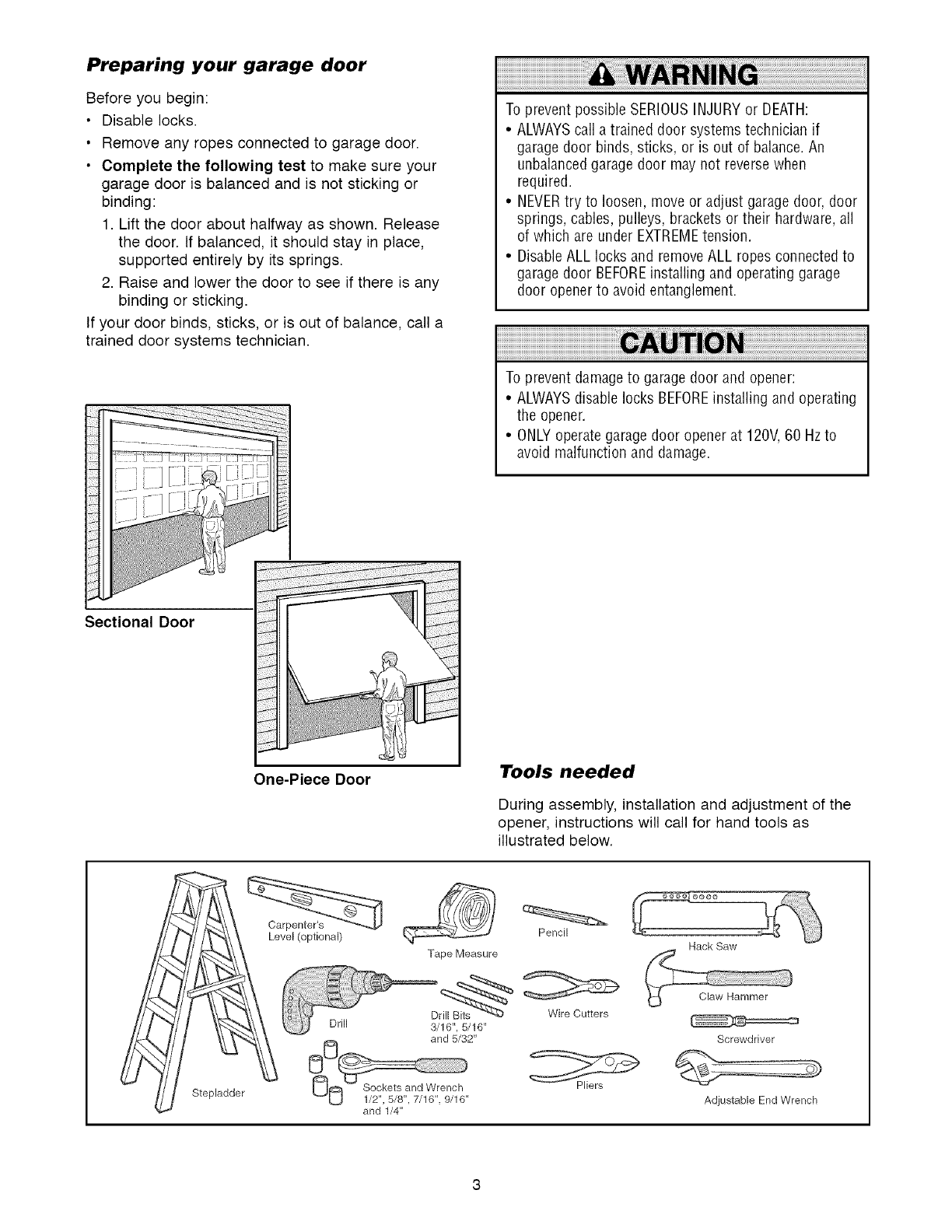
Preparing your garage door
Before you begin:
•Disable locks.
• Remove any ropes connected to garage door.
• Complete the following test to make sure your
garage door is balanced and is not sticking or
binding:
1. Lift the door about halfway as shown. Release
the door. If balanced, it should stay in place,
supported entirely by its springs.
2. Raise and lower the door to see if there is any
binding or sticking.
If your door binds, sticks, or is out of balance, call a
trained door systems technician.
To prevent possible SERIOUSINJURYor DEATH:
•ALWAYScall atrained door systems technician if
garage door binds, sticks, or is out of balance.An
unbalancedgarage door may not reverse when
required.
• NEVERtry to loosen, move or adjust garage door, door
springs, cables, pulleys, brackets or their hardware,all
of which are under EXTREMEtension.
• Disable ALL locks and removeALL ropes connected to
garage door BEFOREinstalling and operating garage
door opener to avoid entanglement.
To prevent damageto garage door and opener:
•ALWAYSdisable locks BEFOREinstalling and operating
the opener.
• ONLYoperate garagedoor opener at 120V,60 Hzto
avoid malfunction and damage.
Sectional Door
One-Piece Door Tools needed
During assembly, installation and adjustment of the
opener, instructions will call for hand tools as
illustrated below.
Stepladder
Level (optional)
Drill
Tape Measure
3/16", 5/16"
and 5/32"
and 1/4"
Pencil
Wire Cutters
Hack Saw
Screwdriver
Adjustable End Wrench
Planning
Identify the type and height of your garage door.
Survey your garage area to see if any of the
conditions below apply to your installation. Additional
materials may be required. You may find it helpful to
refer back to this page and the accompanying
illustrations as you proceed with the installation of
your opener.
Depending on your requirements, there are several
installation steps which may call for materials or
hardware not included in the carton.
• Installation Step 1 - Look at the wall or ceiling
above the garage door. The header bracket must
be securely fastened to structural supports.
• Installation Step 5 - Do you have a finished ceiling
in your garage? If so, a support bracket and
additional fastening hardware may be required.
• Installation Step 10- Depending upon garage
construction, extension brackets or wood blocks
may be needed to install sensors.
• Installation Step 10 -Alternate floor mounting of
the safety reversing sensor will require hardware
not provided.
Do you have an access door in addition to the
garage door? If not, Model 53702 Emergency Key
Release is required. See Accessories page.
Look at the garage door where it meets the floor.
Any gap between the floor and the bottom of the
door must not exceed 1/4" (6 mm). Otherwise, the
safety reversal system may not work properly. See
Adjustment Step 3. Floor or door should be
repaired.
SECTIONAL DOOR INSTALLATIONS
• Do you have a steel, aluminum, fiberglass or glass
panel door? If so, horizontal and vertical
reinforcement is required (Installation Step 11).
• The opener should be installed above the center of
the door. If there is a torsion spring or center
bearing plate in the way of the header bracket, it
may be installed within 4 feet (1.22 m) to the left or
right of the door center. See Installation Steps 1
and 11.
• If your door is more than 7 feet (2.13 m) high, see
rail extension kits listed on Accessories page.
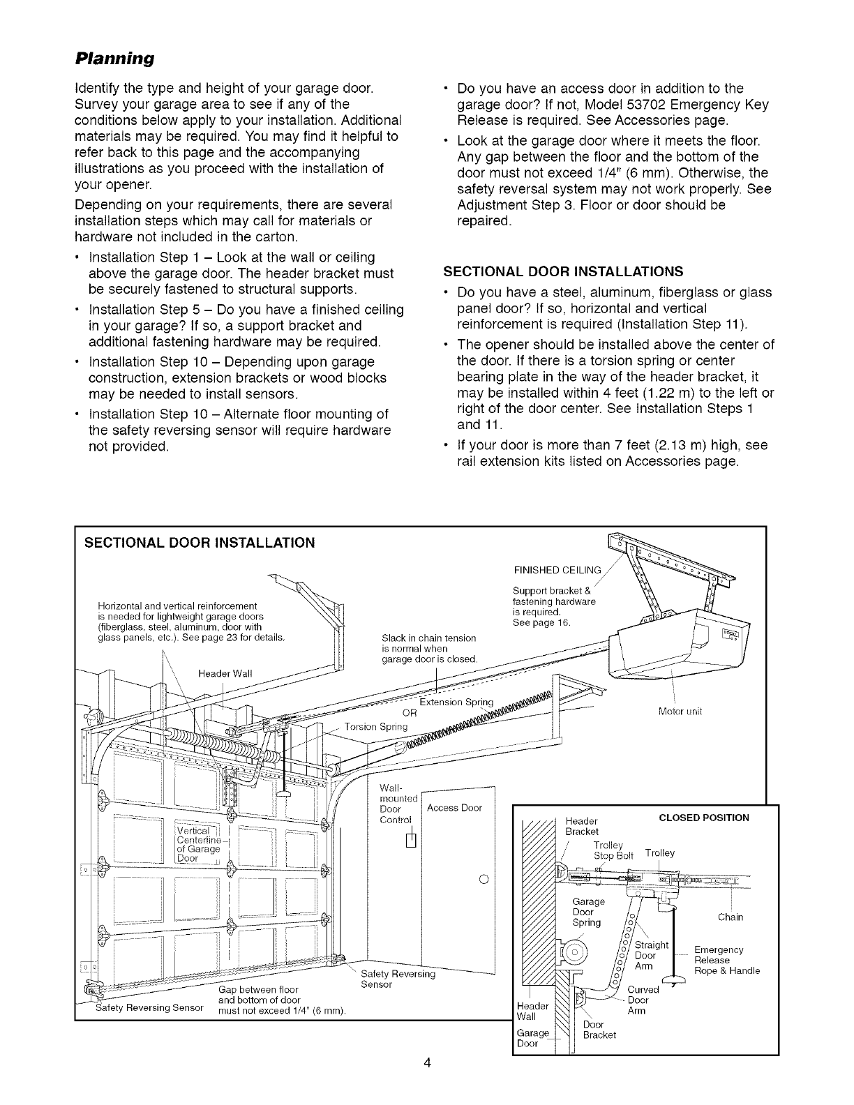
SECTIONAL DOOR INSTALLATION
Horizontal and vertical reinforcement
is needed for lightweight garage doors
(fiberglass, steel, aluminum, door with
glass panels, etc.). See page 23 for details.
k
Header Wall
Slack in chain tension
is normal when
garage door is closed.
FINISHED CEILING
Support
fastening hardware
is required.
See page 16.
OR
Torsion Spring
Motor unit
Gap between floor
and bottom of door
must not exceed 1/4" (6 mm).
Wall-
Door
Control
\" Safety Reversing
Sensor
Access Door
O
eader
rail
arage
eor
Header
Bracket
/' Trolley
,/ Stop Bolt Trolley
Garcage
Spring
__ oor
Arm
CLOSED POSITION
Chain
.......Emergency
Release
Rope & Handle
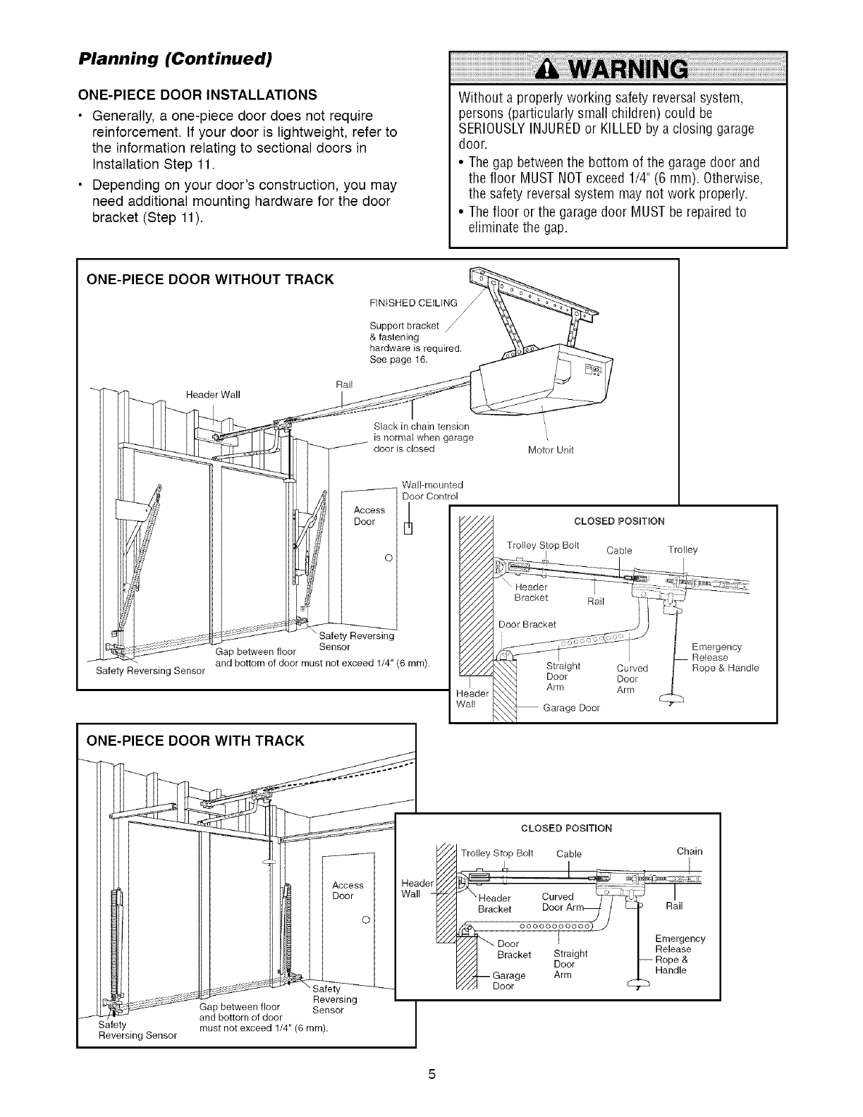
Planning (Continued)
ONE-PIECE DOOR INSTALLATIONS
•Generally, a one-piece door does not require
reinforcement. If your door is lightweight, refer to
the information relating to sectional doors in
Installation Step 11.
• Depending on your door's construction, you may
need additional mounting hardware for the door
bracket (Step 11).
Without a properly working safety reversal system,
persons (particularly small children) could be
SERIOUSLYINJUREDor KILLEDby a closing garage
door.
• The gap betweenthe bottom of the garage door and
the floor MUST NOTexceed 1/4" (6 mm). Otherwise,
the safety reversal system may not work properly.
• The floor or the garage door MUST be repairedto
eliminate the gap.
ONE-PIECE DOOR WITHOUT TRACK
FINtSHED CEILING
Support bracket
& fastening
hardware is required.
See page t6.
Safety Reversing Sensor
Header Wall Rail
Slack in chain tension
is normal when garage
door is closed
Wall-mounted
Door Control
Access E_
Door
O
Safety Reversing
Gap between floor Sensor
and bottom of door must not exceed 1/4" (6 ram).
leader
_all
",
Motor Unit
CLOSED POSIT|ON
Trolley Stop Bolt Cable Trolley
Emergency
Release
Rope & Handle
ONE-PIECE DOOR WITH TRACK
Safety
Reversing Sensor
ol
Reversing
Gap between floor Sensor
and bottom of door
must not exceed 1/4" (6 ram).
det
CLOSED POSIT_ON
Trolley Stop Bolt Cable Chain
__E23 i i
Header Curved _ Rlail
Bracket Door Ar
_, ooooooooooo) j I
_""- Door I '- I Em,ergency
• Release
Bracket Straight h _ele_?_?
///I Door" _- ,Hope,&
7//'j/_ Garage Arm _. Handle
///I Door
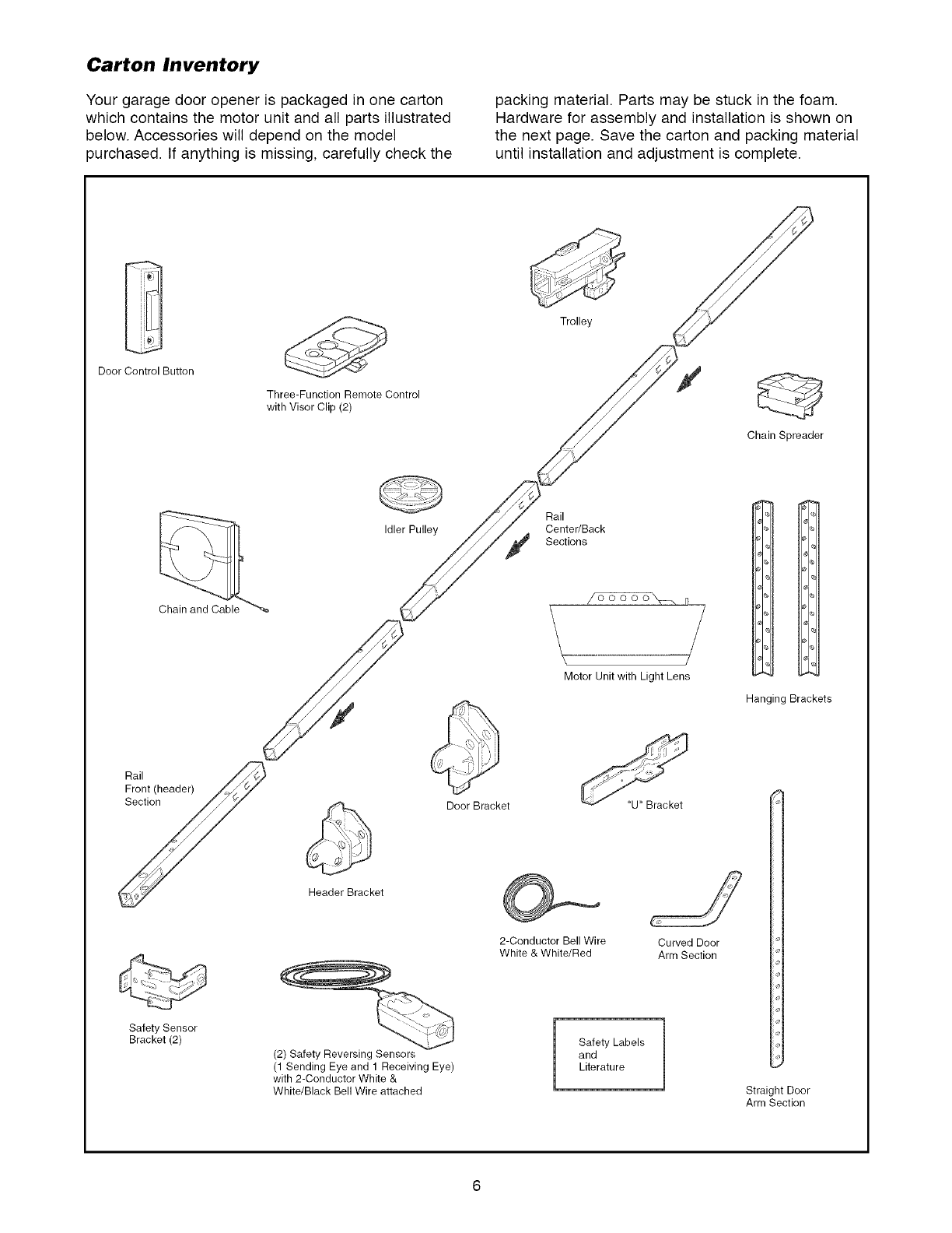
Carton Inventory
Your garage door opener is packaged in one carton
which contains the motor unit and all parts illustrated
below. Accessories will depend on the model
purchased. If anything is missing, carefully check the
packing material. Parts may be stuck in the foam.
Hardware for assembly and installation is shown on
the next page. Save the carton and packing material
until installation and adjustment is complete.
Trolley
Door Control Button
Three-Function Remote Control
with Visor Clip (2) y
Chain Spreader
Idler Pulley
Rail
Center/Back
Sections
of6_-_T6-__ n_
/
Motor Unit with Light Lens
Hanging Brackets
Door Bracket "U" Bracket
Header Bracket
2-Conductor Bell Wire
White & White/Red Curved Door
Arm Section
Safety Sensor
Bracket (2)
(2) Safety Reversing Sensors
(1 Sending Eye and 1 Receiving Eye)
with 2-Conductor White &
White/Black Bell Wire attached
Safety Labels
and
Literature
Straight Door
Arm Section
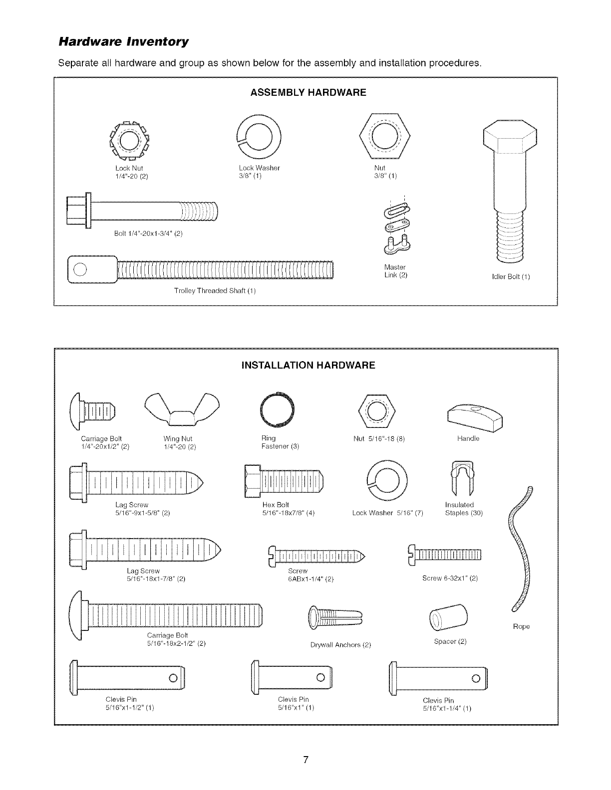
Hardware Inventory
Separate all hardware and group as shown below for the assembly and installation procedures.
ASSEMBLY HARDWARE
@
Lock Nut Lock Washer Nut
1/4"-20 (2) 3/8" (1) 3/8" (1)
Bolt 1/4"-20xl-3/4" (2)
Trolley Threaded Shaft (1)
i
Master
Link (2) Idler Bolt (1)
INSTALLATION HARDWARE
Carriage Bolt
1/4"-20xl/2" (2)
Wing Nut
1/4"-20 (2)
Lag Screw
5/16"-9xl-5/8" (2)
Lag Screw
5/16"-18xl -7/8" (2)
Carriage Bolt
5/16"-18x2-1/2" (2)
Clevis Pin
5/16"x1-1/2" (1)
Ring
Fastener (3)
Hex Bolt
5/16"-18x7/8" (4)
Screw
6ABx1-1/4" (2)
Drywall Anchors (2)
8} ol
Clevis Pin
5/16"x1" (1)
Nut 5/16"-18 (8)
©
Lock Washer 5/16" (7)
Handle
Insulated
Staples (30)
Screw 6-32xl" (2)
Spacer(2)
Clevis Pin
5/16"x1-1/4" (1)
Rope
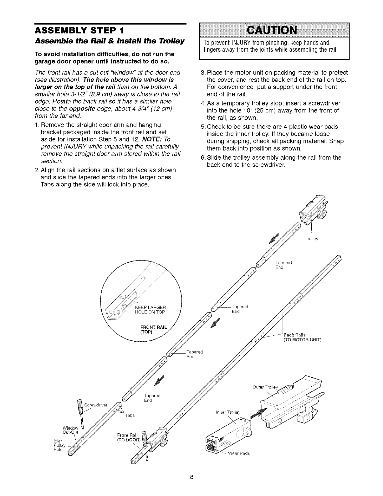
ASSEMBLY STEP 1
Assemble the Rail & Install the Trolley
To avoid installation difficulties, do not run the
garage door opener until instructed to do so.
The front rail has a cut out "window" at the door end
(see illustration). The hole above this window is
larger on the top of the rail than on the bottom. A
smaller hole 3-1/2" (8.9 cm) away is close to the rail
edge. Rotate the back rail so it has a similar hole
close to the opposite edge, about 4-3/4" (12 cm)
from the far end.
1. Remove the straight door arm and hanging
bracket packaged inside the front rail and set
aside for Installation Step 5 and 12. NOTE: To
prevent INJURY while unpacking the rail carefully
remove the straight door arm stored within the rail
section.
2. Align the rail sections on a flat surface as shown
and slide the tapered ends into the larger ones.
Tabs along the side will lock into place.
To prevent INJURYfrom pinching, keep hands and
fingers awayfrom the joints while assembling the rail.
3. Place the motor unit on packing material to protect
the cover, and rest the back end of the rail on top.
For convenience, put a support under the front
end of the rail.
4. As a temporary trolley stop, insert a screwdriver
into the hole 10" (25 cm) away from the front of
the rail, as shown.
5. Check to be sure there are 4 plastic wear pads
inside the inner trolley. If they became loose
during shipping, check all packing material. Snap
them back into position as shown.
6. Slide the trolley assembly along the rail from the
back end to the screwdriver.
Trolley
_ered
End
KEEP LARGER
HOLE ON TOP End
FRONT RAIL
(TOP) tack Rails
(TO MOTOR UNIT)
End
Window
Cut-Out
Idler
Pulley-
Hole
Screwdriver
Tabs
Front Rail
(TODO_R)_
\
/
End
Inner Trolley
Wear Pads
Outer Trolle
\
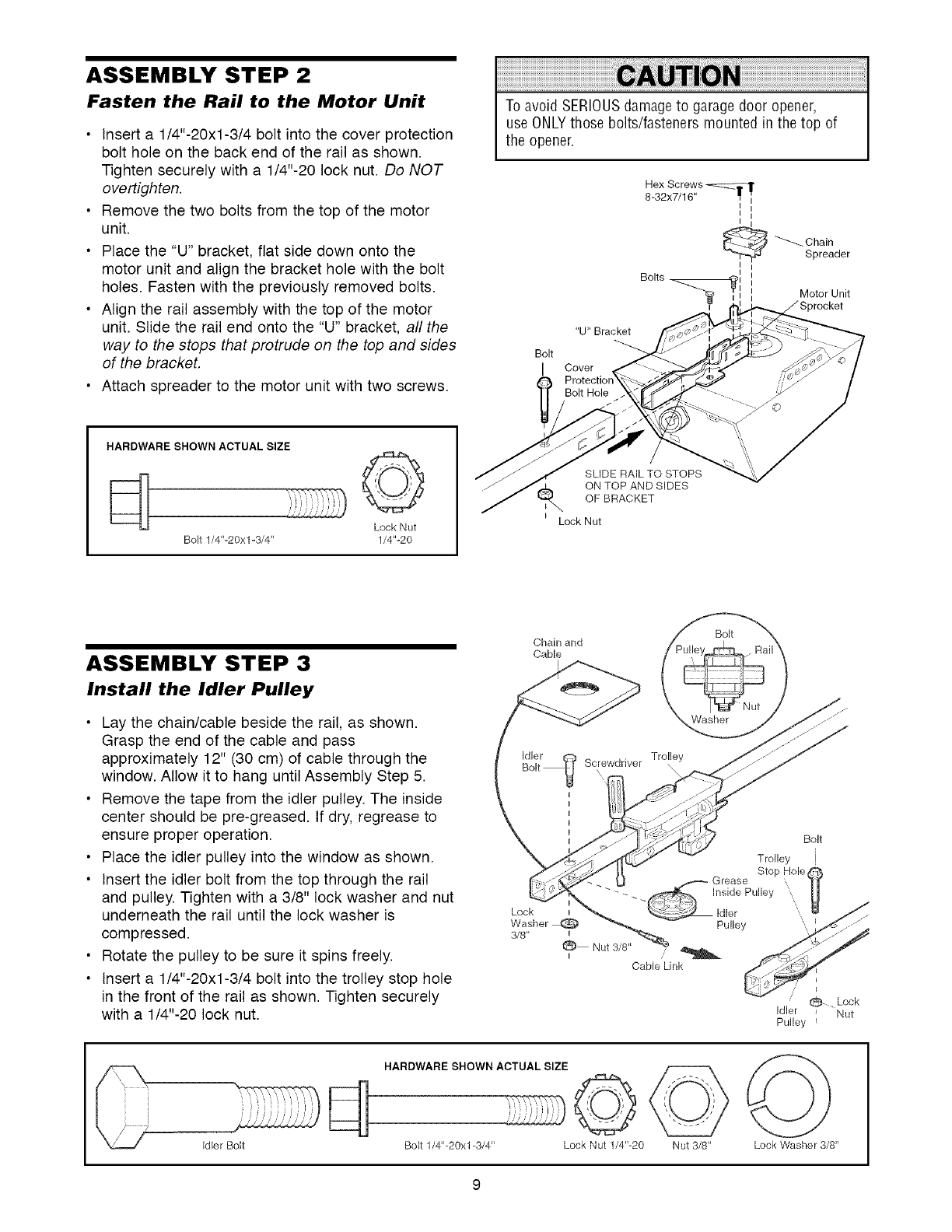
ASSEMBLY STEP 2
Fasten the Rail to the Motor Unit
•Insert a 1/4"-20xl-3/4 bolt into the cover protection
bolt hole on the back end of the rail as shown.
Tighten securely with a 1/4"-20 lock nut. Do NOT
overtighten.
• Remove the two bolts from the top of the motor
unit.
• Place the "U" bracket, flat side down onto the
motor unit and align the bracket hole with the bolt
holes. Fasten with the previously removed bolts.
• Align the rail assembly with the top of the motor
unit. Slide the rail end onto the "U" bracket, all the
way to the stops that protrude on the top and sides
of the bracket,
• Attach spreader to the motor unit with two screws.
To avoid SERIOUSdamageto garagedoor opener,
use ONLYthose bolts/fasteners mounted in the top of
the opener.
Bolt
I
"U" Bracket
Hex Screws _TT 1[
8-32x7/16" _ I
_ __Chain
Spreader
Bolts _i
Motor Unit
_rocket
Cover
HARDWARE SHOWN ACTUAL SIZE......©
Lock Nut
Bolt 1/4"-20xl-3/4" 1/4"-20
SLIDE RAIL TO STOPS
ON TOP AND SIDES
OF BRACKET
Lock Nut
ASSEMBLY STEP 3
Install the Idler Pulley
• Lay the chain/cable beside the rail, as shown.
Grasp the end of the cable and pass
approximately 12" (30 cm) of cable through the
window. Allow it to hang until Assembly Step 5.
• Remove the tape from the idler pulley. The inside
center should be pre-greased. If dry, regrease to
ensure proper operation.
• Place the idler pulley into the window as shown.
• Insert the idler bolt from the top through the rail
and pulley. Tighten with a 3/8" lock washer and nut
underneath the rail until the lock washer is
compressed.
• Rotate the pulley to be sure it spins freely.
• Insert a 1/4"-20xl-3/4 bolt into the trolley stop hole
in the front of the rail as shown. Tighten securely
with a 1/4"-20 lock nut.
Chain and
Cable
Bolt
Washer
Bolt
0 Lock
Idler _ Nut
Pulley t
HARDWARE SHOWN ACTUAL SIZE ©
Bolt 1/4"-20xl-3/4" Lock Nut 1/4"-20 Nut 3/8' Lock Washer 3/8"
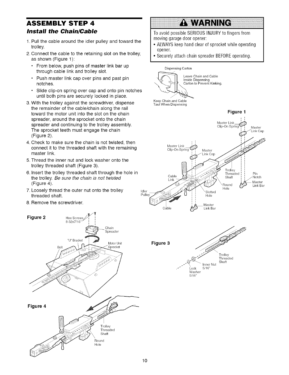
ASSEMBLY STEP 4
Install the Chain/Cable
1. Pull the cable around the idler pulley and toward the
trolley.
2. Connect the cable to the retaining slot on the trolley,
as shown (Figure 1):
• From below, push pins of master link bar up
through cable link and trolley slot.
• Push master link cap over pins and past pin
notches.
• Slide clip-on spring over cap and onto pin notches
until both pins are securely locked in place.
3. With the trolley against the screwdriver, dispense
the remainder of the cable/chain along the rail
toward the motor unit into the slot on the chain
spreader, around the sprocket onto the chain
spreader and continuing to the trolley assembly.
The sprocket teeth must engage the chain
(Figure 2).
4. Check to make sure the chain is not twisted, then
connect it to the threaded shaft with the remaining
master link.
5. Thread the inner nut and lock washer onto the
trolley threaded shaft (Figure 3).
6. Insert the trolley threaded shaft through the hole in
the trolley. Be sure the chain is not twisted
(Figure 4).
7. Loosely thread the outer nut onto the trolley
threaded shaft• Idler
Pulle
8. Remove the screwdriver•
Figure 2
Bolt
Hex Screwsj_ j7
8-32x7/16 i ii i
_Chain
Spreader
"U' Bracket _ _ Motor Unit
Sprocket
To avoid possible SERIOUSINJURYto fingers from
moving garage door opener:
• ALWAYSkeep hand clear of sprocket while operating
opener.
• Securelyattach chain spreader BEFOREoperating.
Dispensing Carton
Leave Chain and Cable
Inside Dispensing
"_ Carton to Prevent Kinking.
Keep Chain and Cable
Taut When Dispensing
k
k i
Master Link
Clip-On Spring _ Master
Cap
Figure 1
Master Link_
Clip-On Sprirlg'_'_k Master
_Link Cap
k
Cable
Link
ble
\ Slotted
iHole
i
k
k
_ Master
Link Bar
Trolley
Threaded Pin
k
Shaft k _jNotch
X _ Master
Round _Link Bar
Hole
Figure 3
., .!,r"
." #_ _ hqner Nut Shaft
• Lock 5/16"
Washer
5/16'
Figure 4
Trolley
Threaded
Shaft
Round
Hole
10
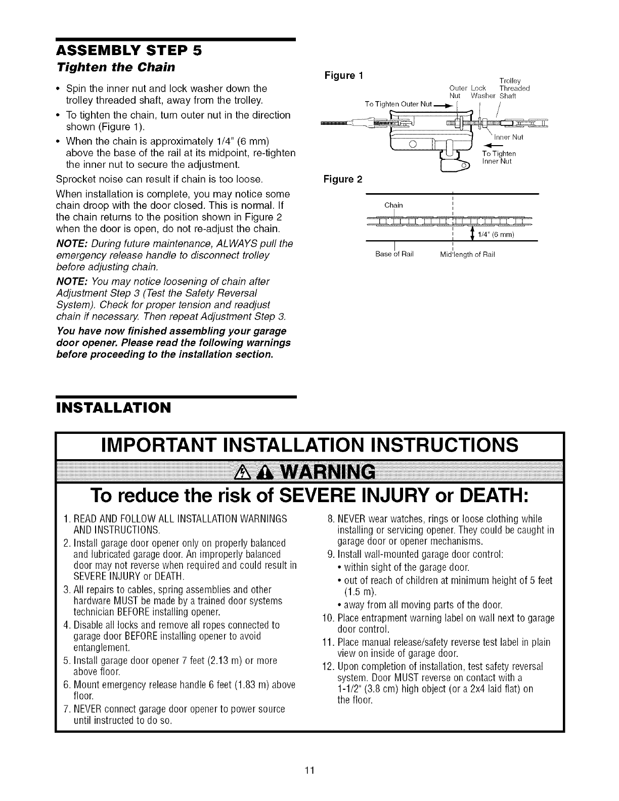
ASSEMBLY STEP 5
Tighten the Chain
•Spin the inner nut and lock washer down the
trolley threaded shaft, away from the trolley.
• To tighten the chain, turn outer nut in the direction
shown (Figure 1).
• When the chain is approximately 1/4" (6 mm)
above the base of the rail at its midpoint, re-tighten
the inner nut to secure the adjustment.
Sprocket noise can result if chain is too loose.
When installation is complete, you may notice some
chain droop with the door closed. This is normal. If
the chain returns to the position shown in Figure 2
when the door is open, do not re-adjust the chain.
NOTE: During future maintenance, ALWAYS pull the
emergency release handle to disconnect trolley
before adjusting chain.
NOTE: You may notice loosening of chain after
Adjustment Step 3 (Test the Safety Reversal
System). Check for proper tension and readjust
chain if necessary, Then repeat Adjustment Step 3.
You have now finished assembling your garage
door opener. Please read the following warnings
before proceeding to the installation section.
Figure 1 Trolley
Outer Lock Threaded
Nut Washer Shaft
Figure 2
Chain
I
Base of Rail Mid'length of Rail
INSTALLATION
IMPORTANT INSTALLATION INSTRUCTIONS
To reduce the risk of SEVERE INJURY or DEATH:
1. READAND FOLLOWALL INSTALLATIONWARNINGS
AND INSTRUCTIONS.
2. Install garage door opener only on properly balanced
and lubricated garage door. An improperly balanced
door may not reversewhen required and could result in
SEVEREINJURYor DEATH.
3. All repairs to cables, spring assembliesand other
hardware MUST be made by a trained door systems
technician BEFOREinstalling opener.
4. Disableall locks and removeall ropes connected to
garage door BEFOREinstalling opener to avoid
entanglement.
5. Install garage door opener 7 feet (2.13 m) or more
above floor.
6. Mount emergency releasehandle 6 feet (1.83 m) above
floor.
7. NEVERconnect garage door openerto power source
until instructed to do so.
8. NEVERwear watches, rings or loose clothing while
installing or servicing opener.They could be caught in
garage door or opener mechanisms.
9. Install wall-mounted garage door control:
• within sight of the garage door.
• out of reach of children at minimum height of 5 feet
(1.5 m).
•awayfrom all moving parts of the door.
10. Placeentrapment warning label on wall next to garage
door control.
11. Placemanual release/safetyreversetest label in plain
view on inside of garage door.
12. Upon completion of installation, test safety reversal
system. Door MUST reverseon contact with a
1-1/2" (3.8 cm) high object (or a 2x4 laid flat) on
the floor.
11
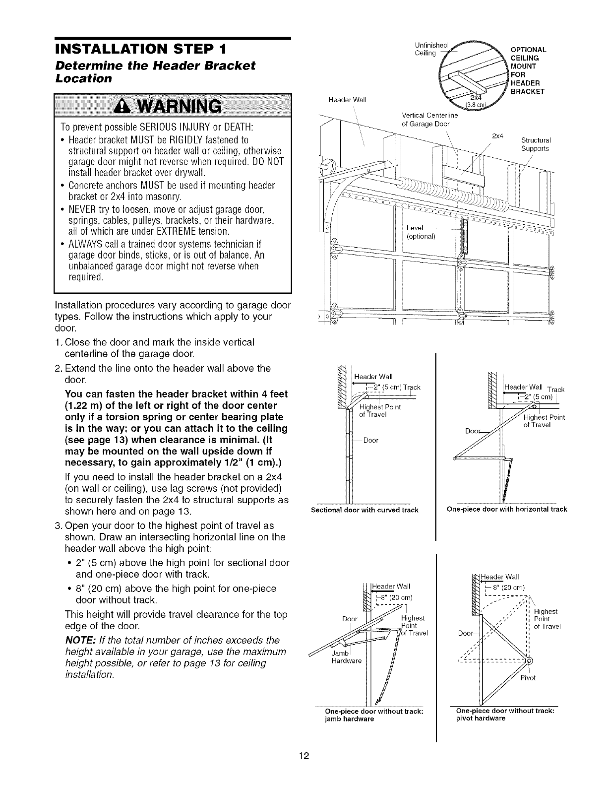
INSTALLATION STEP 1
Determine the Header Bracket
Location
To prevent possible SERIOUSINJURYor DEATH:
•Headerbracket MUST be RIGIDLYfastenedto
structural support on headerwall or ceiling, otherwise
garagedoor might not reversewhen required. DO NOT
install headerbracket over drywall.
• Concreteanchors MUST be used if mounting header
bracket or 2x4 into masonry.
• NEVERtry to loosen, move or adjust garagedoor,
springs, cables, pulleys, brackets, or their hardware,
all of which are under EXTREMEtension.
• ALWAYScall a trained door systems technician if
garagedoor binds, sticks, or is out of balance.An
unbalancedgarage door might not reversewhen
required.
Installation procedures vary according to garage door
types. Follow the instructions which apply to your
door.
1. Close the door and mark the inside vertical
centerline of the garage door.
2. Extend the line onto the header wall above the
door.
You can fasten the header bracket within 4 feet
(1.22 m) of the left or right of the door center
only if a torsion spring or center bearing plate
is in the way; or you can attach it to the ceiling
(see page 13) when clearance is minimal. (It
may be mounted on the wall upside down if
necessary, to gain approximately 1/2" (1 cm).)
If you need to install the header bracket on a 2x4
(on wall or ceiling), use lag screws (not provided)
to securely fasten the 2x4 to structural supports as
shown here and on page 13.
3. Open your door to the highest point of travel as
shown. Draw an intersecting horizontal line on the
header wall above the high point:
• 2" (5 cm) above the high point for sectional door
and one-piece door with track.
• 8" (20 cm) above the high point for one-piece
door without track.
This height will provide travel clearance for the top
edge of the door.
NOTE: If the total number of inches exceeds the
height available in your garage, use the maximum
height possible, or refer to page 13 for ceiling
installation.
Header Wall
Unfinished _ OPTIONAL
Celhng F_'_ CEILING
_ _ MOUNT
_'-..- J,._'_ _,.i_ FOR
_- "_'_ HEADER
_ BRACKET
Vertical Centerline
of Garage Door
2x4 Structural
Supports
/
/
Header Wall
_'_, 2" (5 cm) Track
---%--- I
Highe!t Point
of Travel
Door
Sectional door with curved track
Header Wall Track
_'_ 2" (5 cm)
_Highest Point
_ of Travel
L
One-piece door with horizontal track
_Wall
Door ,o htst
One-piece door without track:
jamb hardware
Header Wall
', 8" (20 cm)
L.........
,I-" ',, Highest
,, Point
,, of Travel
Q
ij
One-piece door without track:
pivot hardware
12
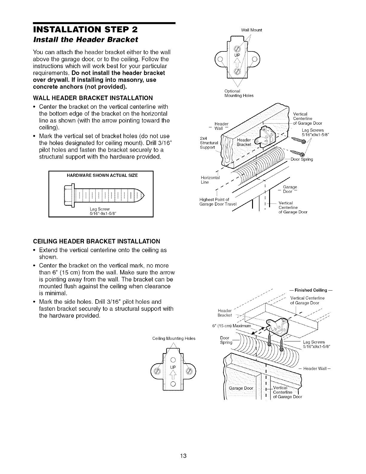
INSTALLATION STEP 2
Install the Header Bracket
You can attach the header bracket either to the wall
above the garage door, or to the ceiling. Follow the
instructions which will work best for your particular
requirements. Do not install the header bracket
over drywall. If installing into masonry, use
concrete anchors (not provided).
WALL HEADER BRACKET INSTALLATION
•Center the bracket on the vertical centerline with
the bottom edge of the bracket on the horizontal
line as shown (with the arrow pointing toward the
ceiling).
•Mark the vertical set of bracket holes (do not use
the holes designated for ceiling mount). Drill 3/16"
pilot holes and fasten the bracket securely to a
structural support with the hardware provided.
HARDWARE SHOWN ACTUAL SIZE
Lag Screw
5/16"-9xl -5/8"
Wall Mount
UP
Optional
Mounting Holes
Header
- Wall-
2x4
Structural
Support
/
I
Horizontal
Line / /
/
Highest Point of
Garage Door Travel
Vertical
Centerline
Garage Door
Lag Screws
5/16"x9x1-5/8"
/
/
Door Spring
Garage
- Door-
Vertical
Centerline
of Garage Door
CEILING HEADER BRACKET INSTALLATION
• Extend the vertical centerline onto the ceiling as
shown.
• Center the bracket on the vertical mark, no more
than 6" (15 cm) from the wall. Make sure the arrow
is pointing away from the wall. The bracket can be
mounted flush against the ceiling when clearance
is minimal.
• Mark the side holes. Drill 3/16" pilot holes and
fasten bracket securely to a structural support with
the hardware provided.
Ceiling Mounting Holes
i
Header
Bracket
6" (15 cm) Maximum
Door
Spring
-- Finished Ceiling --
Vertical Centerline
of Garage Door
/ Lag Screws
5/16"x9x1-5/8"
-- Header Wall-
Centerline
of Garage Door
13
Idler Pulley
Garage
Door
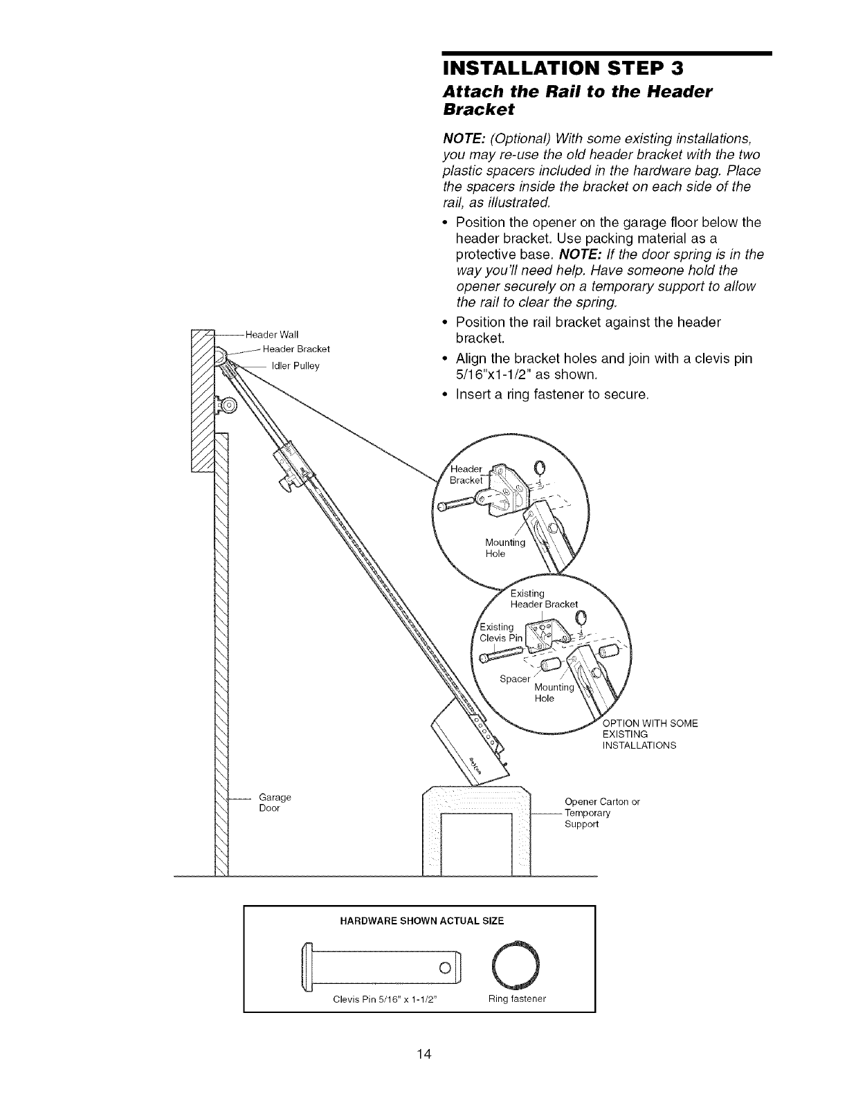
INSTALLATION STEP 3
Attach the Rail to the Header
Bracket
NOTE: (Optional) With some existing installations,
you may re-use the old header bracket with the two
plastic spacers included in the hardware bag. Place
the spacers inside the bracket on each side of the
rail, as illustrated.
• Position the opener on the garage floor below the
header bracket. Use packing material as a
protective base. NOTE: If the door spring is in the
way you'll need help. Have someone hold the
opener securely on a temporary support to allow
the rail to clear the spring.
• Position the rail bracket against the header
bracket.
• Align the bracket holes and join with a clevis pin
5/16"xl-1/2" as shown.
• Insert a ring fastener to secure.
0
/
Mounting
Hole
Header Bracket 0
Mounting
Hole
OPTION WITH SOME
EXISTING
INSTALLATIONS
Opener Carton or
Support
HARDWARE SHOWN ACTUAL SIZE
O
Clevis Pin 5/16" x 1-1/2" Ring fastener
14
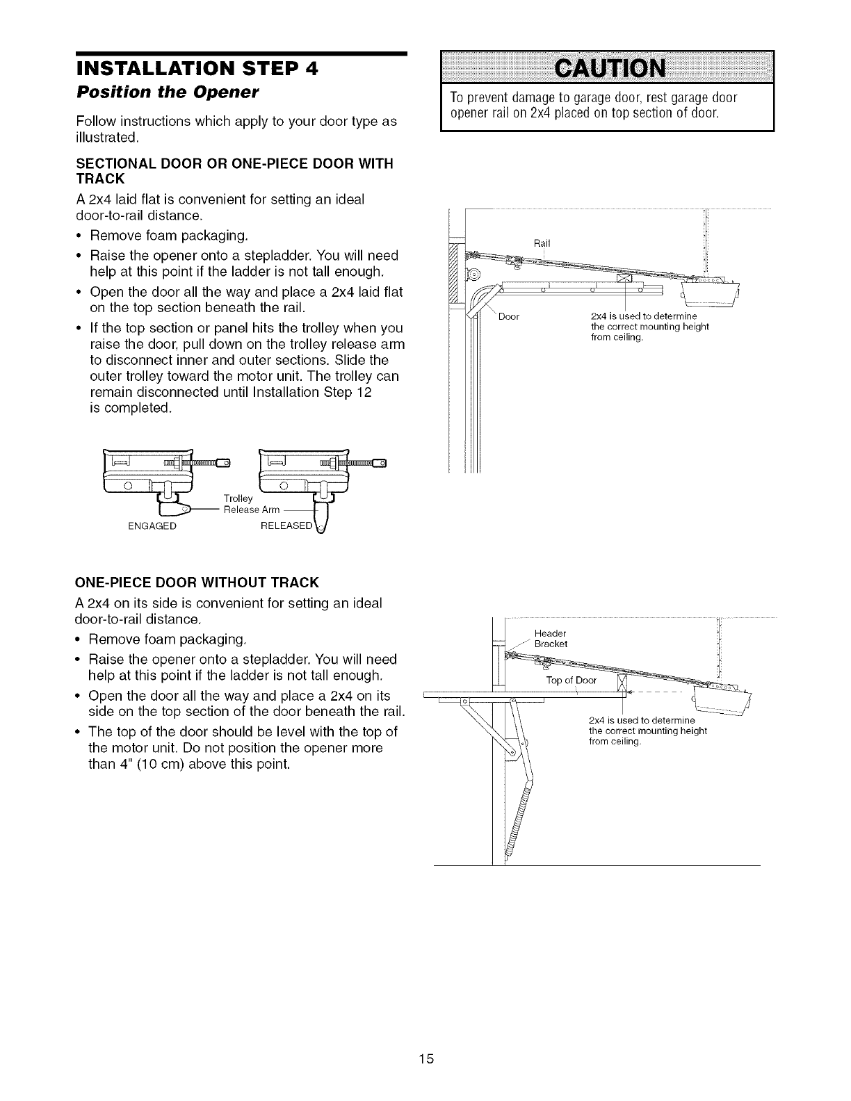
INSTALLATION STEP 4
Position the Opener
Follow instructions which apply to your door type as
illustrated.
SECTIONAL DOOR OR ONE-PIECE DOOR WITH
TRACK
A 2x4 laid flat is convenient for setting an ideal
door-to-rail distance.
• Remove foam packaging.
• Raise the opener onto a stepladder. You will need
help at this point if the ladder is not tall enough.
• Open the door all the way and place a 2x4 laid flat
on the top section beneath the rail.
• If the top section or panel hits the trolley when you
raise the door, pull down on the trolley release arm
to disconnect inner and outer sections. Slide the
outer trolley toward the motor unit. The trolley can
remain disconnected until Installation Step 12
is completed.
To prevent damageto garage door, rest garage door
opener rail on 2x4 placed on top section of door.
olley
elease Arm _ J
ENGAGED RELEASED V
ONE-PIECE DOOR WITHOUT TRACK
A 2x4 on its side is convenient for setting an ideal
door-to-rail distance.
• Remove foam packaging.
• Raise the opener onto a stepladder. You will need
help at this point if the ladder is not tall enough.
• Open the door all the way and place a 2x4 on its
side on the top section of the door beneath the rail.
• The top of the door should be level with the top of
the motor unit. Do not position the opener more
than 4" (10 cm) above this point.
2x4 is used to determine
the correct mounting height
from ceiling.
15
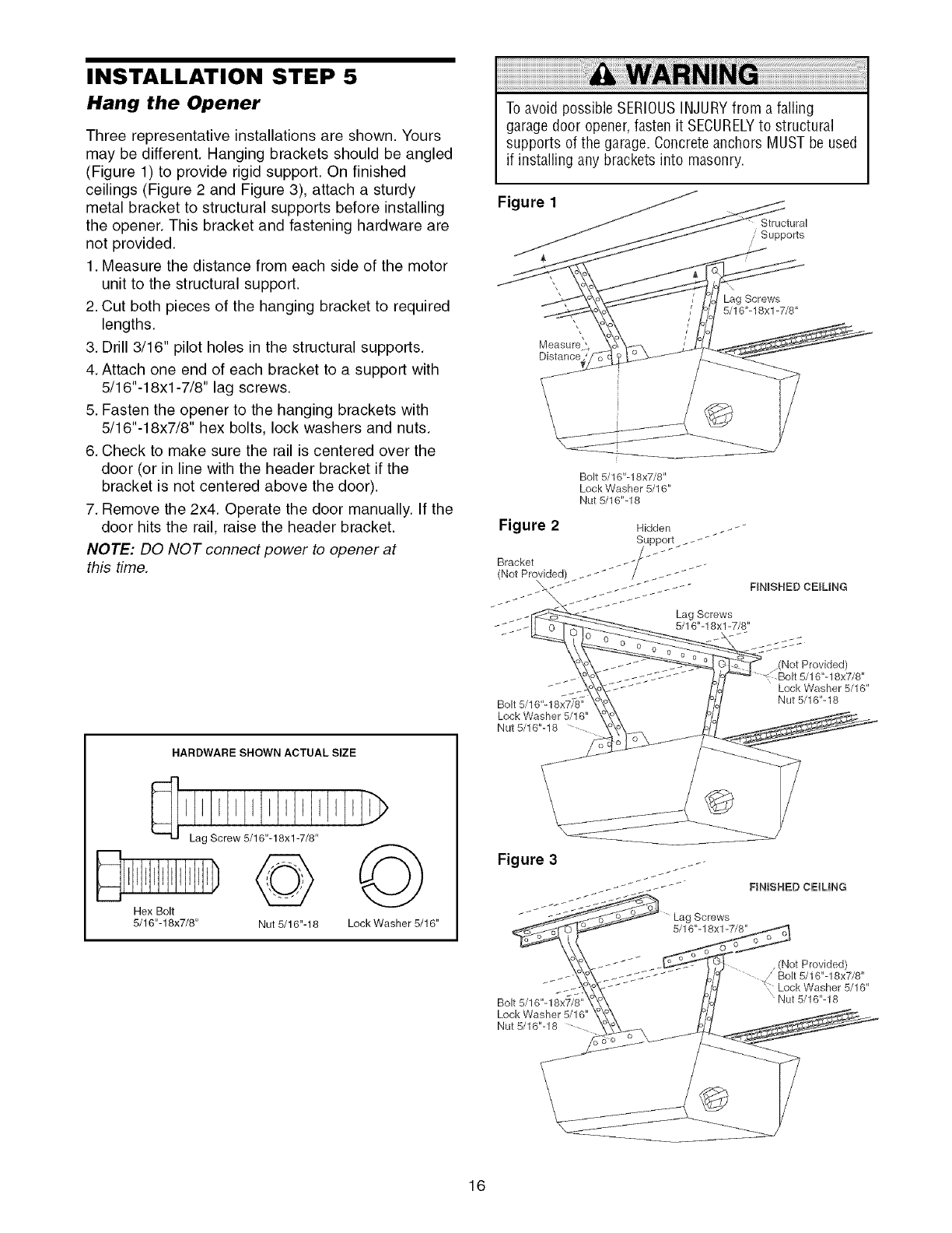
INSTALLATION STEP 5
Hang the Opener
Three representative installations are shown. Yours
may be different. Hanging brackets should be angled
(Figure 1) to provide rigid support. On finished
ceilings (Figure 2 and Figure 3), attach a sturdy
metal bracket to structural supports before installing
the opener. This bracket and fastening hardware are
not provided.
1. Measure the distance from each side of the motor
unit to the structural support.
2. Cut both pieces of the hanging bracket to required
lengths.
3. Drill 3/16" pilot holes in the structural supports.
4. Attach one end of each bracket to a support with
5/16"-18xl -7/8" lag screws.
5. Fasten the opener to the hanging brackets with
5/16"-18x7/8" hex bolts, lock washers and nuts.
6. Check to make sure the rail is centered over the
door (or in line with the header bracket if the
bracket is not centered above the door).
7. Remove the 2x4. Operate the door manually. If the
door hits the rail, raise the header bracket.
NOTE: DO NOT connect power to opener at
this time.
HARDWARE SHOWN ACTUAL SIZE
Hex Bolt
5/16"-18x7/8" Nut 5/16"-18 Lock Washer 5/16"
To avoid possible SERIOUSINJURYfrom a falling
garage door opener,fasten it SECURELYto structural
supports of the garage. Concrete anchors MUST be used
if installing any brackets into masonry.
Figure 1
Structural
Supports
Measure",
Distance
\
Lag Screws
/5/16"-18xl-7/8"
Bolt 5/16"-18x7/8"
Lock Washer 5/16"
Nut 5/16"-18
Figure 2 Hidden _ _-
Support _
(Not Provided) _ __ _ _
Lag Screws
_ __ _ 5/16"-18xl-7/8"
Bolt 5/16"-18 x 7/-8"
Lock Washer 5/16"
Nut 5/16"-18 ....
FEN_SHED CE_UNG
Not Provided)
5/16"- 18x7/8"
Lock Washer 5/16"
Nut 5/16"-18
FINISHED CEJUNG
Bolt 5/16"-18x7/8"
Lock Washer 5/16"
Nut 5/16"-18
(['.Jot Provided)
Bolt 5/16"-18x7/8"
Lock Washer 5/16"
Nut 5/16"-18
16
INSTALLATION STEP 6
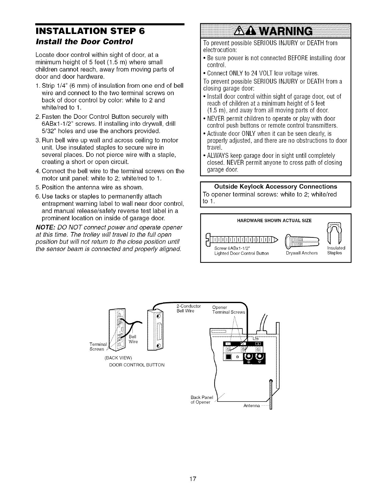
Install the Door Control
Locate door control within sight of door, at a
minimum height of 5 feet (1.5 m) where small
children cannot reach, away from moving parts of
door and door hardware.
1. Strip 1/4" (6 mm) of insulation from one end of bell
wire and connect to the two terminal screws on
back of door control by color: white to 2 and
white/red to 1.
2. Fasten the Door Control Button securely with
6ABx1-1/2" screws. If installing into drywall, drill
5/32" holes and use the anchors provided.
3. Run bell wire up wall and across ceiling to motor
unit. Use insulated staples to secure wire in
several places. Do not pierce wire with a staple,
creating a short or open circuit.
4. Connect the bell wire to the terminal screws on the
motor unit panel: white to 2; white/red to 1.
5. Position the antenna wire as shown.
6. Use tacks or staples to permanently attach
entrapment warning label to wall near door control,
and manual release/safety reverse test label in a
prominent location on inside of garage door.
NOTE: DO NOT connect power and operate opener
at this time. The trolley will travel to the full open
position but will not return to the close position until
the sensor beam is connected and properly aligned.
To prevent possible SERIOUSINJURYor DEATHfrom
electrocution:
• Besure power is not connected BEFOREinstalling door
control.
• Connect ONLYto 24 VOLT low voltage wires.
To prevent possible SERIOUSINJURYor DEATHfrom a
closing garagedoor:
• Install door control within sight of garage door, out of
reach of children at a minimum height of 5 feet
(1.5 m), and away from all moving parts of door.
• NEVERpermit children to operate or play with door
control push buttons or remote control transmitters.
• Activate door ONLYwhen it can be seen clearly, is
properly adjusted, andthere are no obstructions to door
travel.
• ALWAYSkeep garagedoor in sight until completely
closed. NEVERpermit anyone to cross path of closing
garagedoor.
Outside Keylock Accessory Connections I
To°l°Pener terminal screws: white to 2; white/red I
I
HARDWARE SHOWN ACTUAL SIZE
Screw 6ABx]-I/2" Insulated
Lighted Door Control Sutton Drywall Anchors Staples
(BACK VIEW)
DOOR CONTROL BUTi-ON
2-Conductor
Bell Wire Opener
Terminal Screw!
Back Panel /_
of Opener Antenna
17
INSTALLATION STEP 7
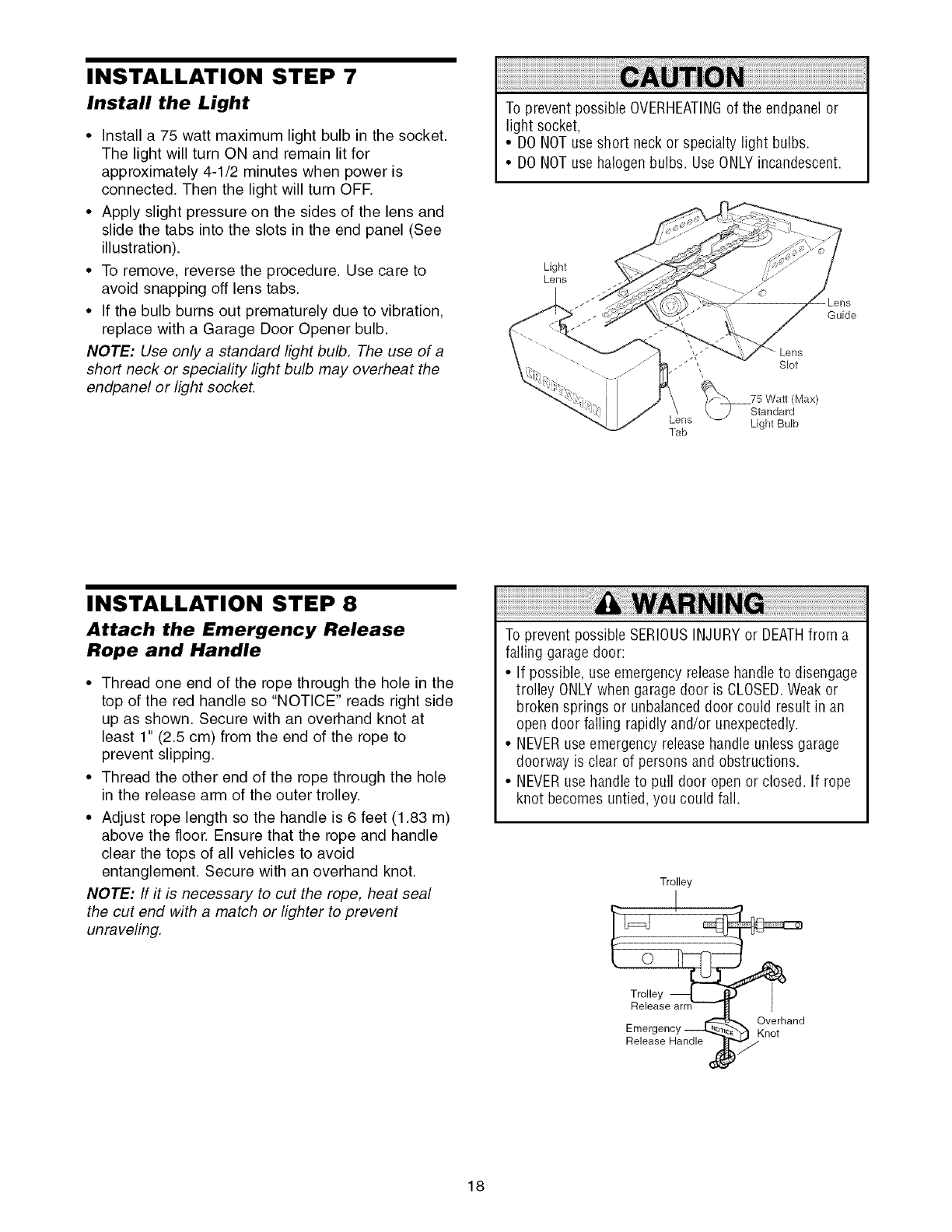
Install the Light
•Install a 75 watt maximum light bulb in the socket.
The light will turn ON and remain lit for
approximately 4-1/2 minutes when power is
connected. Then the light will turn OFF.
• Apply slight pressure on the sides of the lens and
slide the tabs into the slots in the end panel (See
illustration).
• To remove, reverse the procedure. Use care to
avoid snapping off lens tabs.
• If the bulb burns out prematurely due to vibration,
replace with a Garage Door Opener bulb.
NOTE: Use only a standard light bulb. The use of a
short neck or speciafity light bulb may overheat the
endpanel or light socket.
To prevent possible OVERHEATINGof the endpanelor
light socket,
• DO NOTuse short neck or specialty light bulbs.
• DO NOTuse halogen bulbs. Use ONLYincandescent.
Light
Lens
Guide
Lens
Slot
_fXX_75 Watt (Max)
\.._/ Standard
Lens Light Bulb
Tab
INSTALLATION STEP 8
Attach the Emergency Release
Rope and Handle
• Thread one end of the rope through the hole in the
top of the red handle so "NOTICE" reads right side
up as shown. Secure with an overhand knot at
least 1" (2.5 cm) from the end of the rope to
prevent slipping.
• Thread the other end of the rope through the hole
in the release arm of the outer trolley.
• Adjust rope length so the handle is 6 feet (1.83 m)
above the floor. Ensure that the rope and handle
clear the tops of all vehicles to avoid
entanglement. Secure with an overhand knot.
NOTE: If it is necessary to cut the rope, heat seal
the cut end with a match or lighter to prevent
unraveling.
To prevent possible SERIOUSINJURYor DEATHfrom a
falling garage door:
• If possible, use emergency releasehandleto disengage
trolley ONLYwhen garage door is CLOSED.Weakor
broken springs or unbalanced door could result in an
open door falling rapidly and/or unexpectedly.
• NEVERuse emergency releasehandle unless garage
doorway is clear of persons and obstructions.
• NEVERuse handleto pull door open or closed. If rope
knot becomes untied, you could fall.
Trolley
I
I
Trolley
Release
Emergency _
Release Handle
d'
_K Overhand
not
18
INSTALLATION STEP 9
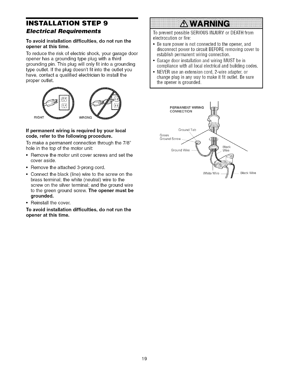
Electrical Requirements
To avoid installation difficulties, do not run the
opener at this time.
To reduce the risk of electric shock, your garage door
opener has a grounding type plug with a third
grounding pin. This plug will only fit into a grounding
type outlet. If the plug doesn't fit into the outlet you
have, contact a qualified electrician to install the
proper outlet.
To prevent possible SERIOUSINJURYor DEATHfrom
electrocution or fire:
• Besure power is not connected to the opener,and
disconnect power to circuit BEFOREremoving cover to
establish permanentwiring connection.
• Garagedoor installation and wiring MUSTbe in
compliance with all local electrical and building codes.
• NEVERuse an extension cord, 2-wire adapter,or
change plug in any way to makeit fit outlet. Besure
the opener is grounded.
PERMANENT WiRiNG
CONNECTION
If permanent wiring is required by your local
code, refer to the following procedure.
To make a permanent connection through the 7/8"
hole in the top of the motor unit:
• Remove the motor unit cover screws and set the
cover aside.
• Remove the attached 3-prong cord.
• Connect the black (line) wire to the screw on the
brass terminal; the white (neutral) wire to the
screw on the silver terminal; and the ground wire
to the green ground screw. The opener must be
grounded.
• Reinstall the cover.
To avoid installation difficulties, do not run the
opener at this time.
Ground Tab
x
Green
Ground Screw
Black
Ground Wire Wire
White Wire
19
INSTALLATION STEP 10
Install The Protector System ®
The safety reversing sensor must be connected
and aligned correctly before the garage door
opener will move in the down direction.
IMPORTANT INFORMATION ABOUT
THE SAFETY REVERSING SENSOR
When properly connected and aligned, the sensor
will detect an obstacle in the path of its electronic
beam. The sending eye (with an amber indicator
light) transmits an invisible light beam to the
receiving eye (with a green indicator light). If an
obstruction breaks the light beam while the door is
closing, the door will stop and reverse to full open
position, and the opener lights will flash 10 times.
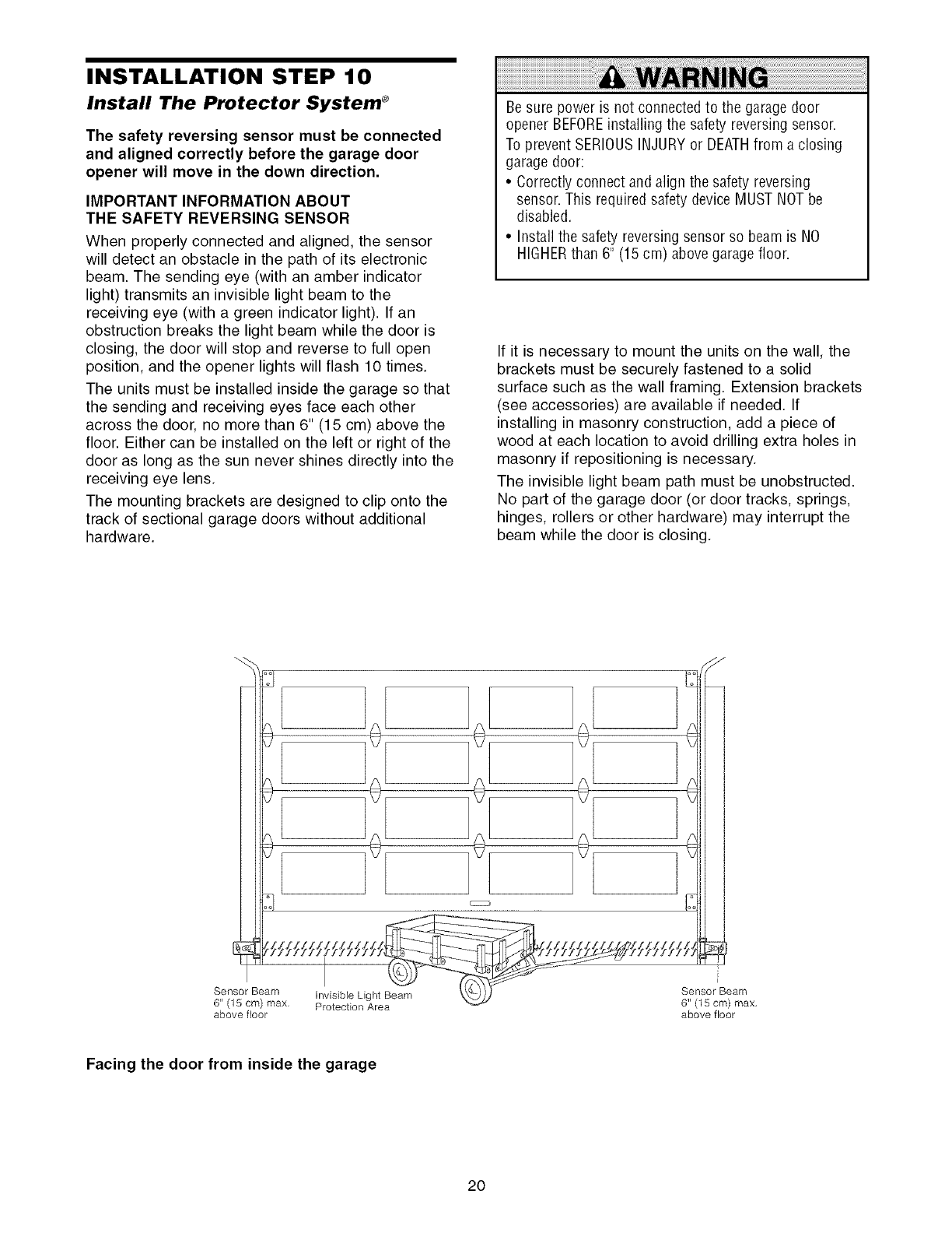
The units must be installed inside the garage so that
the sending and receiving eyes face each other
across the door, no more than 6" (15 cm) above the
floor. Either can be installed on the left or right of the
door as long as the sun never shines directly into the
receiving eye lens.
The mounting brackets are designed to clip onto the
track of sectional garage doors without additional
hardware.
Be sure power is not connected to the garage door
opener BEFOREinstalling the safety reversingsensor.
To prevent SERIOUSINJURYor DEATHfrom a closing
garage door:
• Correctly connect and align the safety reversing
sensor. This required safety device MUST NOTbe
disabled.
• Install the safety reversing sensor so beam is NO
HIGHERthan 6" (15 cm) above garage floor.
If it is necessary to mount the units on the wall, the
brackets must be securely fastened to a solid
surface such as the wall framing. Extension brackets
(see accessories) are available if needed. If
installing in masonry construction, add a piece of
wood at each location to avoid drilling extra holes in
masonry if repositioning is necessary.
The invisible light beam path must be unobstructed.
No part of the garage door (or door tracks, springs,
hinges, rollers or other hardware) may interrupt the
beam while the door is closing.
Sensor Beam Invisible Light Beam
6" (15 cm) max, Protection Area
above floor
Sensor Beam
6" (15 cm) max,
above floor
Facing the door from inside the garage
2O
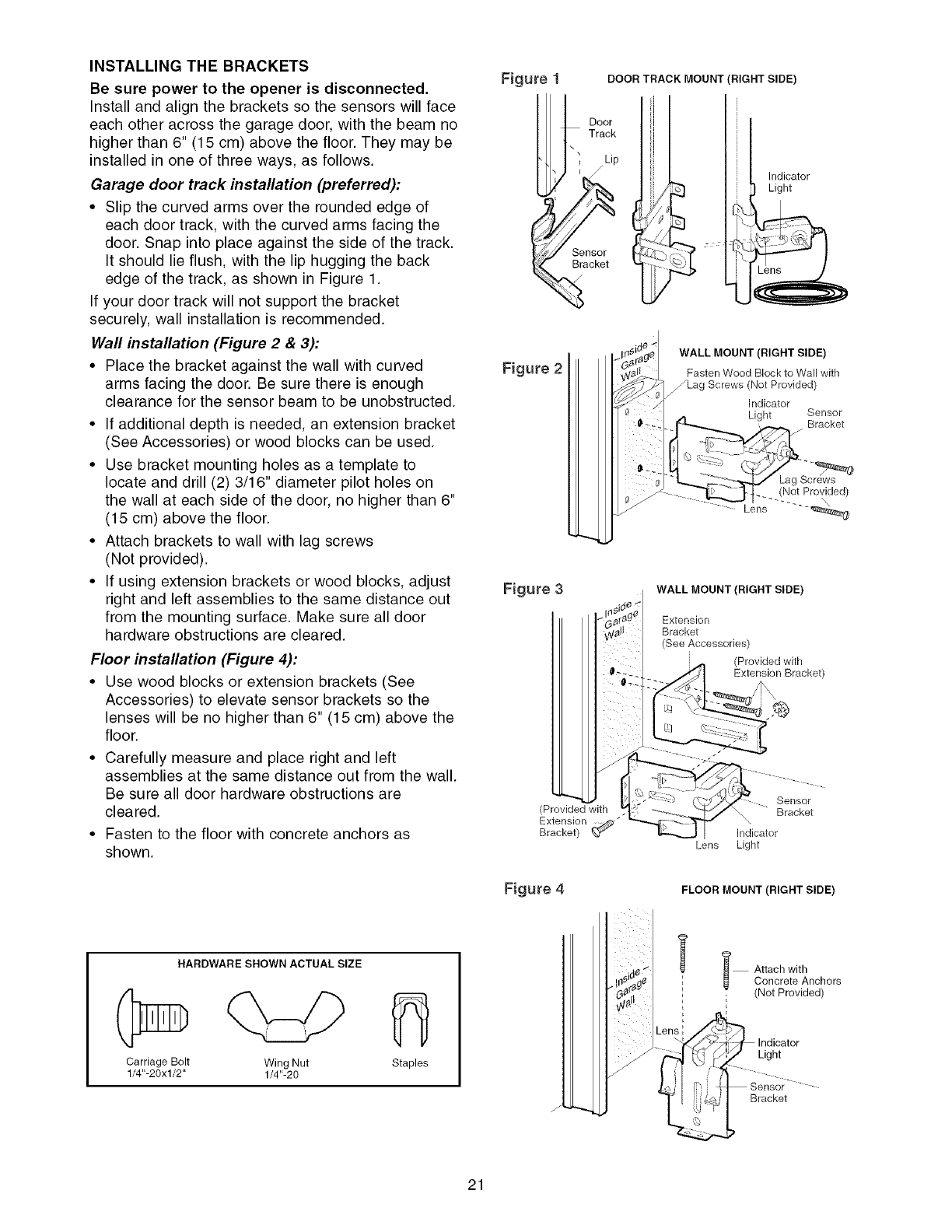
INSTALLING THE BRACKETS
Be sure power to the opener is disconnected.
Install and align the brackets so the sensors will face
each other across the garage door, with the beam no
higher than 6" (15 cm) above the floor. They may be
installed in one of three ways, as follows.
Garage door track installation (preferred):
•Slip the curved arms over the rounded edge of
each door track, with the curved arms facing the
door. Snap into place against the side of the track.
It should lie flush, with the lip hugging the back
edge of the track, as shown in Figure 1.
If your door track will not support the bracket
securely, wall installation is recommended.
Wall installation (Figure 2 & 3):
• Place the bracket against the wall with curved
arms facing the door. Be sure there is enough
clearance for the sensor beam to be unobstructed.
• If additional depth is needed, an extension bracket
(See Accessories) or wood blocks can be used.
• Use bracket mounting holes as a template to
locate and drill (2) 3/16" diameter pilot holes on
the wall at each side of the door, no higher than 6"
(15 cm) above the floor.
• Attach brackets to wall with lag screws
(Not provided).
• If using extension brackets or wood blocks, adjust
right and left assemblies to the same distance out
from the mounting surface. Make sure all door
hardware obstructions are cleared.
Floor installation (Figure 4):
• Use wood blocks or extension brackets (See
Accessories) to elevate sensor brackets so the
lenses will be no higher than 6" (15 cm) above the
floor.
• Carefully measure and place right and left
assemblies at the same distance out from the wall.
Be sure all door hardware obstructions are
cleared.
• Fasten to the floor with concrete anchors as
shown.
Figure DOOR TRACK MOUNT (RIGHT SIDE)
Door
Track
\
Lip
Sensor
Bracket
Indicator
Light
Figure 2
WALL MOUNT (RIGHT SIDE)
Fasten Wood Block to Wall with
Lag Screws (Not Provided)
Indicator
LPht Sensor
. _ Bracket
t .... (.Not Provided)
Lens .......
Figure 3 WALL MOUNT (RIGHT SIDE)
Extension
Bracket
(See Accessories)
(Provided with
Extension Bracket)
(Provided with
Extension : _,_-"
Bracket) Lens
Sensor
Bracket
Indicator
Light
Figure 4 FLOOR MOUNT (RIGHT SIDE)
HARDWARE SHOWN ACTUAL SIZE
Carriage Bolt Wing Nut
1/4"-20xl/2" 1/4"-20 Staples
i Attach with
Concrete Anchors
i; (Not Provided)
Light
Bracket
21
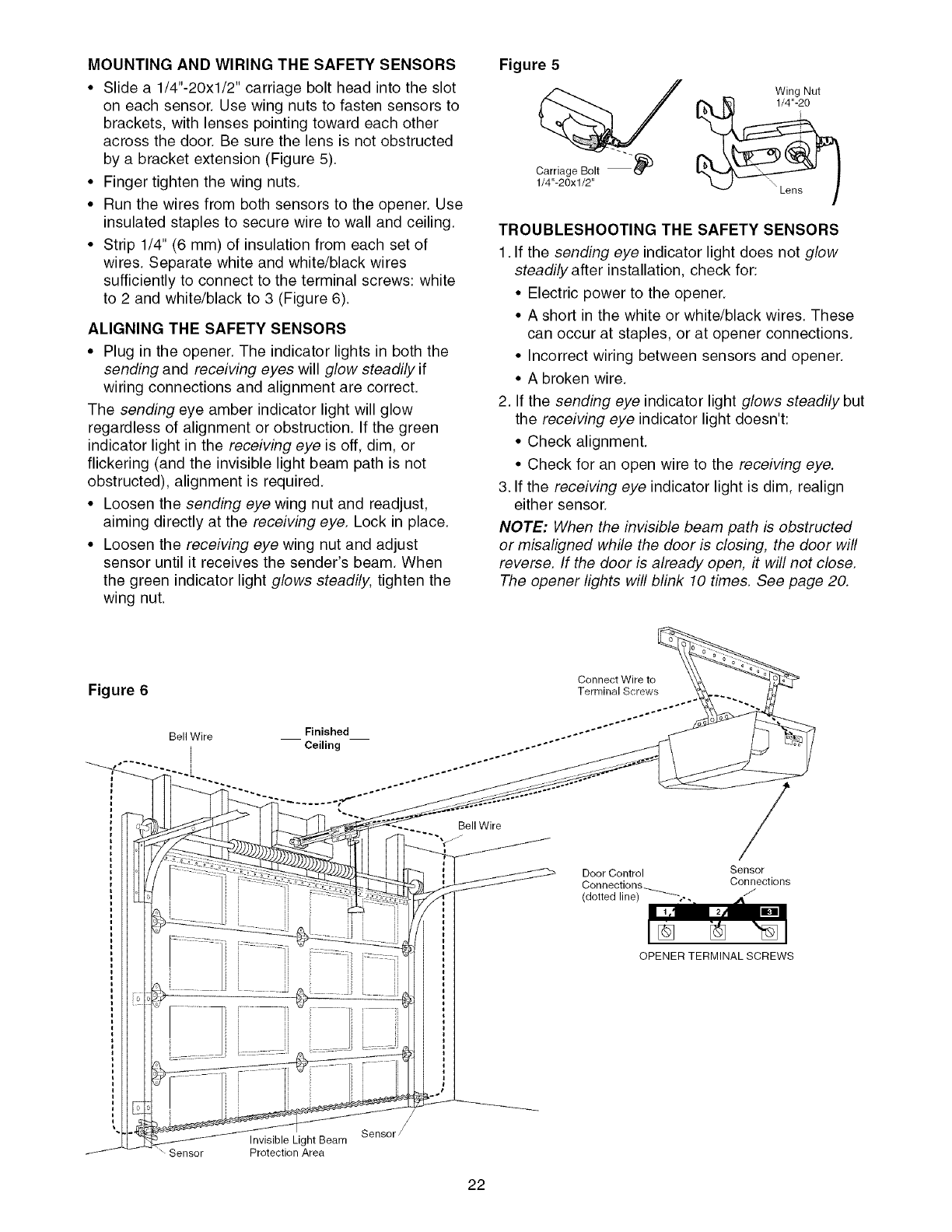
MOUNTING AND WIRING THE SAFETY SENSORS
• Slide a 1/4"-20xl/2" carriage bolt head into the slot
on each sensor. Use wing nuts to fasten sensors to
brackets, with lenses pointing toward each other
across the door. Be sure the lens is not obstructed
by a bracket extension (Figure 5).
• Finger tighten the wing nuts.
• Run the wires from both sensors to the opener. Use
insulated staples to secure wire to wall and ceiling.
• Strip 1/4" (6 mm) of insulation from each set of
wires. Separate white and white/black wires
sufficiently to connect to the terminal screws: white
to 2 and white/black to 3 (Figure 6).
ALIGNING THE SAFETY SENSORS
• Plug in the opener. The indicator lights in both the
sending and receiving eyes will glow steadily if
wiring connections and alignment are correct.
The sending eye amber indicator light will glow
regardless of alignment or obstruction. If the green
indicator light in the receiving eye is off, dim, or
flickering (and the invisible light beam path is not
obstructed), alignment is required.
• Loosen the sending eye wing nut and readjust,
aiming directly at the receiving eye. Lock in place.
• Loosen the receiving eye wing nut and adjust
sensor until it receives the sender's beam. When
the green indicator light glows steadily, tighten the
wing nut.
Figure 5
Carriage Bolt _)
1/4"-20xl/2"
Wing Nut
%
TROUBLESHOOTING THE SAFETY SENSORS
1. If the sending eye indicator light does not glow
steadily after installation, check for:
• Electric power to the opener.
• A short in the white or white/black wires. These
can occur at staples, or at opener connections.
• Incorrect wiring between sensors and opener.
• A broken wire.
2. If the sending eye indicator light glows steadily but
the receiving eye indicator light doesn't:
• Check alignment.
• Check for an open wire to the receiving eye.
3. If the receiving eye indicator light is dim, realign
either sensor.
NOTE: When the invisible beam path is obstructed
or misaligned while the door is closing, the door will
reverse. If the door is already open, it will not close.
The opener lights will blink 10 times. See page 20.
Figure 6
Bell Wire
Bell Wire
Door Control
Connections_
(dotted line)
7
Sensor
Connections
J
OPENER TERMINAL SCREWS
Sensor Invisible Light Beam
Protection Area
/
Sensor /
22
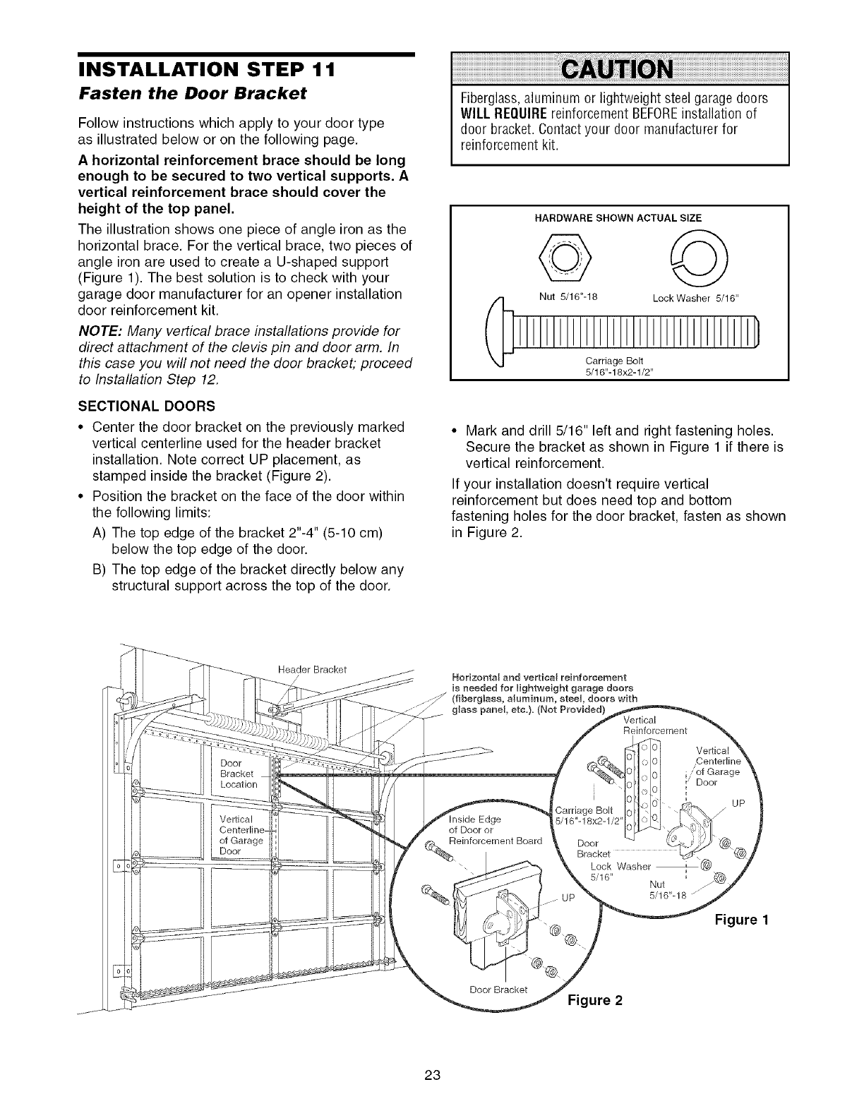
INSTALLATION STEP 11
Fasten the Door Bracket
Follow instructions which apply to your door type
as illustrated below or on the following page.
A horizontal reinforcement brace should be long
enough to be secured to two vertical supports. A
vertical reinforcement brace should cover the
height of the top panel.
The illustration shows one piece of angle iron as the
horizontal brace. For the vertical brace, two pieces of
angle iron are used to create a U-shaped support
(Figure 1). The best solution is to check with your
garage door manufacturer for an opener installation
door reinforcement kit.
NOTE: Many vertical brace installations provide for
direct attachment of the clevis pin and door arm. In
this case you will not need the door bracket; proceed
to Installation Step 12.
SECTIONAL DOORS
• Center the door bracket on the previously marked
vertical centerline used for the header bracket
installation. Note correct UP placement, as
stamped inside the bracket (Figure 2).
• Position the bracket on the face of the door within
the following limits:
A) The top edge of the bracket 2"-4" (5-10 cm)
below the top edge of the door.
B) The top edge of the bracket directly below any
structural support across the top of the door.
Fiberglass,aluminum or lightweight steel garage doors
WILL REQUIREreinforcement BEFOREinstallation of
door bracket. Contactyour door manufacturer for
reinforcement kit.
HARDWARE SHOWN ACTUAL SIZE
Nut 5/16"-18 LockWasher 5/16"
Carriage Bolt
5/16"-18x2-1/2"
• Mark and drill 5/16" left and right fastening holes.
Secure the bracket as shown in Figure 1 if there is
vertical reinforcement.
If your installation doesn't require vertical
reinforcement but does need top and bottom
fastening holes for the door bracket, fasten as shown
in Figure 2.
Door
Bracket
Location
Vertical
of Garage
Door
Header Bracket
// Horizontal and vertical reinforcement
is needed for lightweight garage doors
steel doors with
glass panel, etc.). (Not Provided) Vertical
Reinforcement
Edge
of Door or
(_bReinforcement Board
i
,Carriage Bolt
5/16"-18x2-1/2'
Vertical
"of Garage
Door
UP
Door
Bracket
Lock Washer
5/16" Nut
5/16"-18 z .....
Figure
Door Bracket Figure 2
23
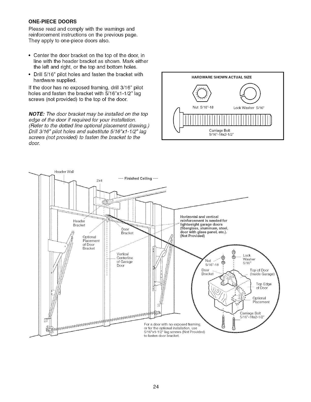
ONE-PIECEDOORS
Please read and comply with the warnings and
reinforcement instructions on the previous page.
They apply to one-piece doors also.
• Center the door bracket on the top of the door, in
line with the header bracket as shown. Mark either
the left and right, or the top and bottom holes.
• Drill 5/16" pilot holes and fasten the bracket with
hardware supplied.
If the door has no exposed framing, drill 3/16" pilot
holes and fasten the bracket with 5/16"x1-1/2" lag
screws (not provided) to the top of the door.
NOTE: The door bracket may be installed on the top
edge of the door if required for your installation.
(Refer to the dotted line optional placement drawing.)
Drill 3/16" pilot holes and substitute 5/16"xl- 1/2" lag
screws (not provided) to fasten the bracket to the
door.
HARDWARE SHOWN ACTUAL SIZE
© ©
Nut 5/16"-16 Lock Washer 5/16"
Carriage Bolt
5/16"-18x2-1/2"
Header Wall
2x4
Header
Bracket
Optional
Placement
of Door
Bracket
Door
Bracket
Vertical
of Garage
Door
Horizontal and vertical
reinforcement is needed for
lightweight garage doors
(fiberglass, aluminum, steem,
door with glass panel, etc.).
(Not Provided)
For a door with no exposed framing,
or for the optional installation, use
5/16"x1-1/2" lag screws (Not Provided)
to fasten door bracket,
®
Lock
Washer
,5/16"
Top of Door
(inside Garac
Top Edge
of Door
Optional
Placement
Carriage Bolt
_[ 5/16"-18x2-1/2"
24
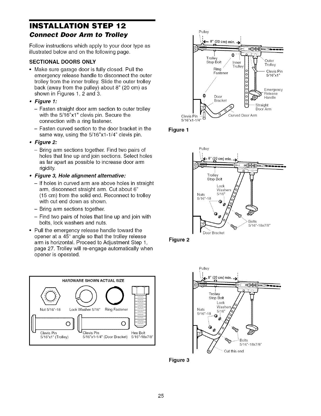
INSTALLATION STEP 12
Connect Door Arm to Trolley
Follow instructions which apply to your door type as
illustrated below and on the following page.
SECTIONAL DOORS ONLY
•Make sure garage door is fully closed. Pull the
emergency release handle to disconnect the outer
trolley from the inner trolley. Slide the outer trolley
back (away from the pulley) about 8" (20 cm) as
shown in Figures 1,2 and 3.
•Figure 1:
- Fasten straight door arm section to outer trolley
with the 5/16"x1" clevis pin. Secure the
connection with a ring fastener.
- Fasten curved section to the door bracket in the
same way, using the 5/16"x1-1/4" clevis pin.
•Figure 2:
- Bring arm sections together. Find two pairs of
holes that line up and join sections. Select holes
as far apart as possible to increase door arm
rigidity.
•Figure 3, Hole alignment alternative:
- If holes in curved arm are above holes in straight
arm, disconnect straight arm. Cut about 6"
(15 cm) from the solid end. Reconnect to trolley
with cut end down as shown.
- Bring arm sections together.
- Find two pairs of holes that line up and join with
bolts, lock washers and nuts.
• Pull the emergency release handle toward the
opener at a 45° angle so that the trolley release
arm is horizontal. Proceed to Adjustment Step 1,
page 27. Trolley will re-engage automatically when
opener is operated.
Figure 1
Pulley
Figure 2
Door Bracket
1
HARDWARE SHOWN ACTUAL SIZE
©
Nut 5/16"-18
Clevis Pin
5/16"xl" (Trolley)
Lock Washer 5/16" Ring Fastener
o-1{ el
Clevis Pin Hex Bolt
5/16"x1-1/4" (Door Bracket) 5/16"-18x7/8"
Figure 3
Pulley
', i i
",,E÷s" (20cra)rai_._[
Trolley / / f
Stop Bolt //
Lock /o/
Washers/r_7
Nuts ,i,,O_
"A "% -Be ts
// -
of_J Cut this end
25
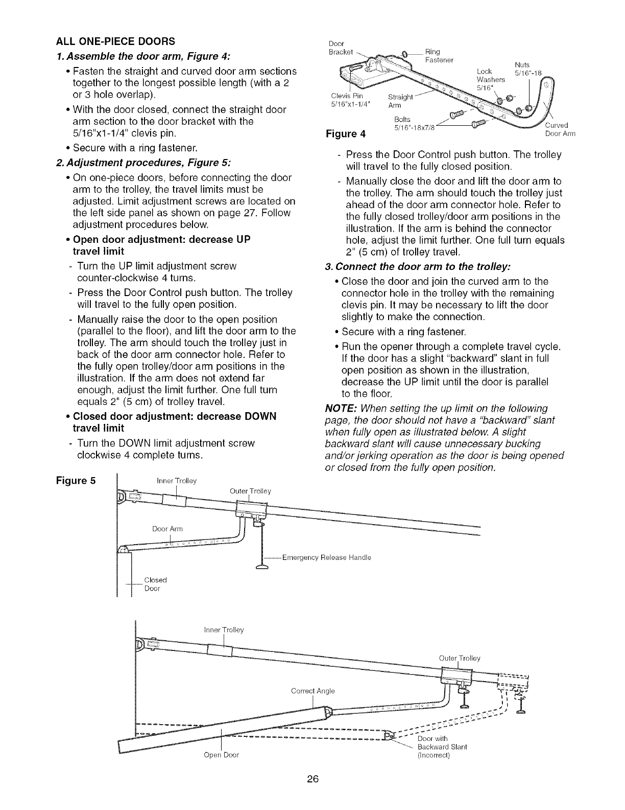
ALL ONE-PIECE DOORS
1.Assemble the door arm, Figure 4:
• Fasten the straight and curved door arm sections
together to the longest possible length (with a 2
or 3 hole overlap).
• With the door closed, connect the straight door
arm section to the door bracket with the
5/16"x1-1/4" clevis pin.
• Secure with a ring fastener.
2. Adjustment procedures, Figure 5:
• On one-piece doors, before connecting the door
arm to the trolley, the travel limits must be
adjusted. Limit adjustment screws are located on
the left side panel as shown on page 27. Follow
adjustment procedures below.
• Open door adjustment: decrease UP
travel limit
- Turn the UP limit adjustment screw
counter-clockwise 4 turns.
- Press the Door Control push button. The trolley
will travel to the fully open position.
- Manually raise the door to the open position
(parallel to the floor), and lift the door arm to the
trolley. The arm should touch the trolley just in
back of the door arm connector hole. Refer to
the fully open trolley/door arm positions in the
illustration. If the arm does not extend far
enough, adjust the limit further. One full turn
equals 2" (5 cm) of trolley travel.
• Closed door adjustment: decrease DOWN
travel limit
- Turn the DOWN limit adjustment screw
clockwise 4 complete turns.
Figure 5
Clevis Pin Straight
5/16"x1-1/4" Arm
Fastener
Lock
Washers
5/16"
Nuts
5/16"-18
Bolts
5/16"-18x7/8 Curved
Figure 4 Door Arm
- Press the Door Control push button. The trolley
will travel to the fully closed position.
- Manually close the door and lift the door arm to
the trolley. The arm should touch the trolley just
ahead of the door arm connector hole. Refer to
the fully closed trolley/door arm positions in the
illustration. If the arm is behind the connector
hole, adjust the limit further. One full turn equals
2" (5 cm) of trolley travel.
3. Connect the door arm to the trolley:
• Close the door and join the curved arm to the
connector hole in the trolley with the remaining
clevis pin. It may be necessary to lift the door
slightly to make the connection.
• Secure with a ring fastener.
• Run the opener through a complete travel cycle.
If the door has a slight "backward" slant in full
open position as shown in the illustration,
decrease the UP limit until the door is parallel
to the floor.
NOTE: When setting the up limit on the following
page, the door should not have a "backward" slant
when fully open as illustrated below. A slight
backward slant will cause unnecessary bucking
and/or jerking operation as the door is being opened
or closed from the fully open position.
Inner Trolley
cy Release Handle
Inner Trolley
Outer Trolley
==%=,4
Correct Angle ¢[ _
f-
C_CCC",
Backward Slant
Open Door (Incorrect)
26
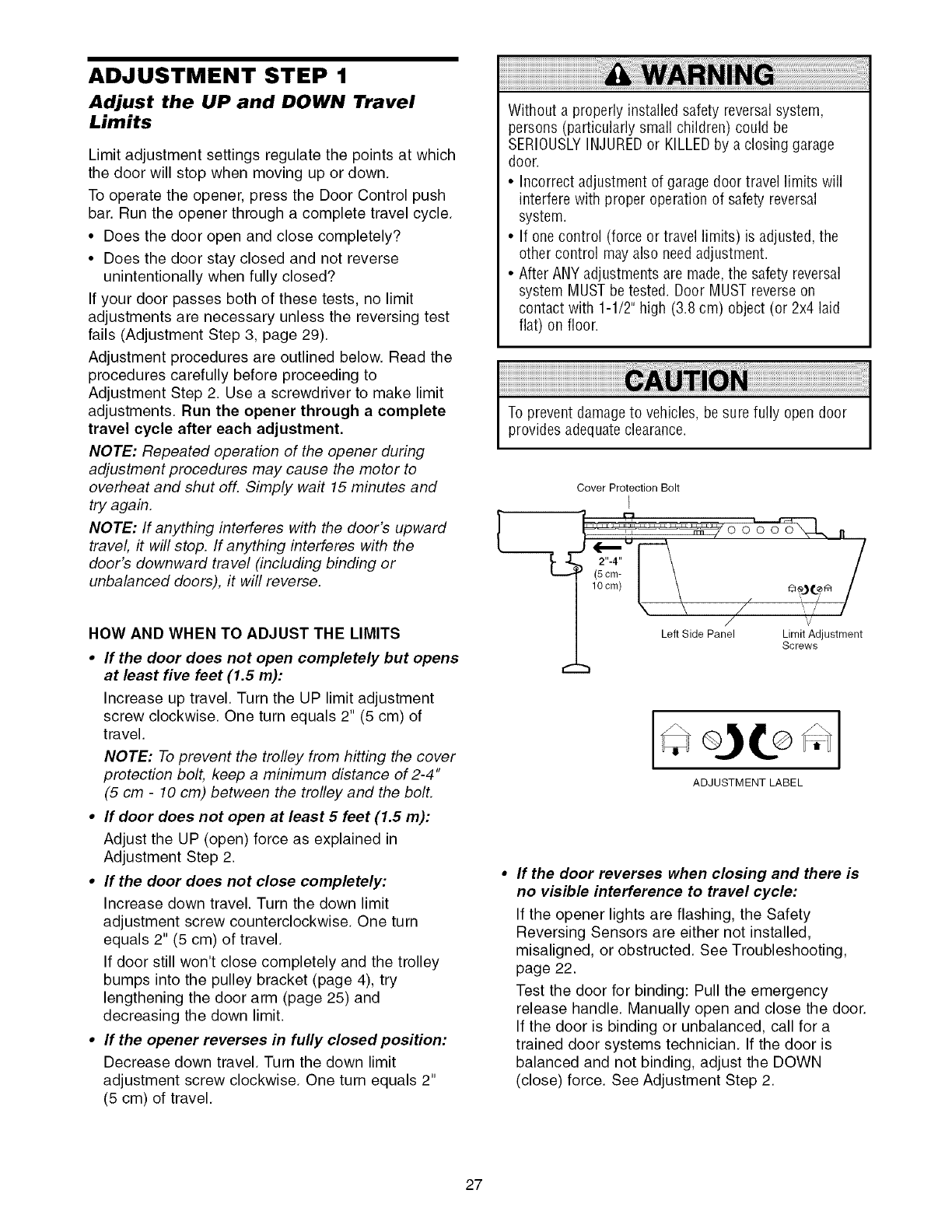
ADJUSTMENT STEP 1
Adjust the UP and DOWN Travel
Limits
Limit adjustment settings regulate the points at which
the door will stop when moving up or down.
To operate the opener, press the Door Control push
bar. Run the opener through a complete travel cycle.
• Does the door open and close completely?
• Does the door stay closed and not reverse
unintentionally when fully closed?
If your door passes both of these tests, no limit
adjustments are necessary unless the reversing test
fails (Adjustment Step 3, page 29).
Adjustment procedures are outlined below. Read the
procedures carefully before proceeding to
Adjustment Step 2. Use a screwdriver to make limit
adjustments. Run the opener through a complete
travel cycle after each adjustment.
NOTE: Repeated operation of the opener during
adjustment procedures may cause the motor to
overheat and shut off. Simply wait 15 minutes and
try again.
NOTE: If anything interferes with the door's upward
travel, it will stop. If anything interferes with the
door's downward travel (including binding or
unbalanced doors), it will reverse.
HOW AND WHEN TO ADJUST THE LIMITS
•If the door does not open completely but opens
at least five feet (1.5 m):
Increase up travel. Turn the UP limit adjustment
screw clockwise. One turn equals 2" (5 cm) of
travel.
NOTE: To prevent the trolley from hitting the cover
protection bolt, keep a minimum distance of 2-4"
(5 cm -10 cm) between the trolley and the bolt.
•If door does not open at least 5 feet (1.5 m):
Adjust the UP (open) force as explained in
Adjustment Step 2.
•If the door does not close completely:
Increase down travel. Turn the down limit
adjustment screw counterclockwise. One turn
equals 2" (5 cm) of travel.
If door still won't close completely and the trolley
bumps into the pulley bracket (page 4), try
lengthening the door arm (page 25) and
decreasing the down limit.
•If the opener reverses in fully closed position:
Decrease down travel. Turn the down limit
adjustment screw clockwise. One turn equals 2"
(5 cm) of travel.
[
Without a properly installed safety reversalsystem,
persons (particularly small children) could be
SERIOUSLYINJUREDor KILLEDby a closing garage
door.
• Incorrect adjustment of garage door travel limits will
interfere with proper operation of safety reversal
system.
• If onecontrol (force or travel limits) is adjusted, the
other control may also need adjustment.
• After ANYadjustments are made,the safety reversal
system MUSTbe tested. Door MUST reverse on
contact with 1-1/2" high (3.8 cm) object (or 2x4 laid
flat) on floor.
To prevent damage to vehicles, be sure fully open door
provides adequateclearance.
Cover Protection Bolt
I
L _ ,
i, rrn /000
/ lOom/I \ OoX ,
/ \ \ // ,,'
Left Side Panel Limit Adjustment
Screws
I
ADJUSTMENT LABEL
If the door reverses when closing and there is
no visible interference to travel cycle:
If the opener lights are flashing, the Safety
Reversing Sensors are either not installed,
misaligned, or obstructed. See Troubleshooting,
page 22.
Test the door for binding: Pull the emergency
release handle. Manually open and close the door.
If the door is binding or unbalanced, call for a
trained door systems technician. If the door is
balanced and not binding, adjust the DOWN
(close) force. See Adjustment Step 2.
27
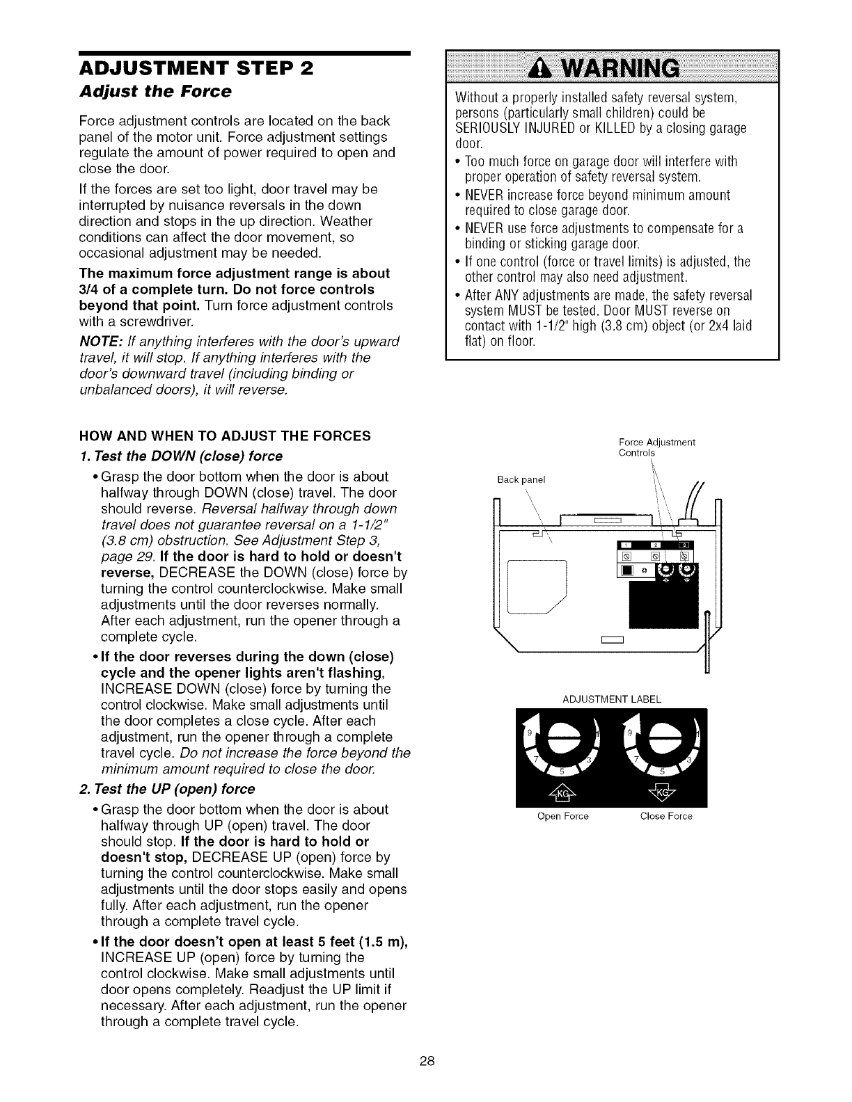
ADJUSTMENT STEP 2
Adjust the Force
Force adjustment controls are located on the back
panel of the motor unit. Force adjustment settings
regulate the amount of power required to open and
close the door.
If the forces are set too light, door travel may be
interrupted by nuisance reversals in the down
direction and stops in the up direction. Weather
conditions can affect the door movement, so
occasional adjustment may be needed.
The maximum force adjustment range is about
3/4 of a complete turn. Do not force controls
beyond that point. Turn force adjustment controls
with a screwdriver.
NOTE: If anything interferes with the door's upward
travel, it will stop. If anything interferes with the
door's downward travel (including binding or
unbalanced doors), it will reverse.
Without a properly installed safety reversalsystem,
persons (particularly small children) could be
SERIOUSLYINJUREDor KILLEDby a closing garage
door.
• Too much force on garage door will interfere with
proper operation of safety reversalsystem.
• NEVERincreaseforce beyond minimum amount
requiredto close garage door.
• NEVERuse force adjustments to compensate for a
binding or sticking garagedoor.
• If one control (force or travel limits) is adjusted, the
other control may also need adjustment.
• After ANY adjustments are made,the safety reversal
system MUST betested. Door MUST reverseon
contact with 1-1/2" high (3.8 cm) object (or 2x4 laid
flat) on floor.
HOW AND WHEN TO ADJUST THE FORCES
1. Test the DOWN (close) force
• Grasp the door bottom when the door is about
halfway through DOWN (close) travel. The door
should reverse. Reversal halfway through down
travel does not guarantee reversal on a 1-1/2"
(3.8 cm) obstruction. See Adjustment Step 3,
page 29. If the door is hard to hold or doesn't
reverse, DECREASE the DOWN (close) force by
turning the control counterclockwise. Make small
adjustments until the door reverses normally.
After each adjustment, run the opener through a
complete cycle.
• If the door reverses during the down (close)
cycle and the opener lights aren't flashing,
INCREASE DOWN (close) force by turning the
control clockwise. Make small adjustments until
the door completes a close cycle. After each
adjustment, run the opener through a complete
travel cycle. Do not increase the force beyond the
minimum amount required to close the door.
2. Test the UP (open) force
• Grasp the door bottom when the door is about
halfway through UP (open) travel. The door
should stop. If the door is hard to hold or
doesn't stop, DECREASE UP (open) force by
turning the control counterclockwise. Make small
adjustments until the door stops easily and opens
fully. After each adjustment, run the opener
through a complete travel cycle.
• If the door doesn't open at least 5 feet (1.5 m),
INCREASE UP (open) force by turning the
control clockwise. Make small adjustments until
door opens completely. Readjust the UP limit if
necessary. After each adjustment, run the opener
through a complete travel cycle.
Force Adjustment
Controls
Back panel
\\ i \
ADJUSTMENT LABEL
Open Force Close Force
28
ADJUSTMENT STEP 3
Test the Safety Reversal System
TEST
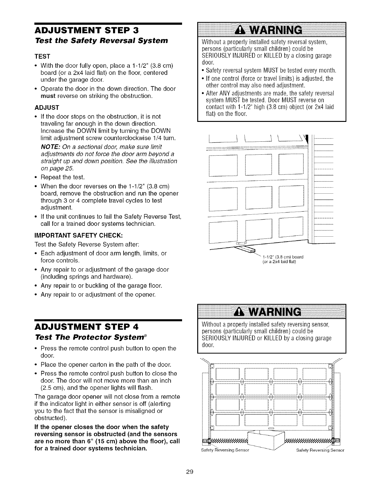
•With the door fully open, place a 1-1/2" (3.8 cm)
board (or a 2x4 laid flat) on the floor, centered
under the garage door
• Operate the door in the down direction The door
must reverse on striking the obstruction
ADJUST
• If the door stops on the obstruction, it is not
traveling far enough in the down direction.
Increase the DOWN limit by turning the DOWN
limit adjustment screw counterclockwise 1/4 turn.
NOTE: On a sectional door, make sure limit
adjustments do not force the door arm beyond a
straight up and down position. See the illustration
on page 25.
• Repeat the test.
• When the door reverses on the 1-1/2" (3.8 cm)
board, remove the obstruction and run the opener
through 3 or 4 complete travel cycles to test
adjustment.
• If the unit continues to fail the Safety Reverse Test,
call for a trained door systems technician.
IMPORTANT SAFETY CHECK:
Test the Safety Reverse System after:
• Each adjustment of door arm length, limits, or
force controls.
• Any repair to or adjustment of the garage door
(including springs and hardware).
• Any repair to or buckling of the garage floor.
• Any repair to or adjustment of the opener.
Without a properly installed safety reversalsystem,
persons (particularly small children) could be
SERIOUSLYINJUREDor KILLEDby a closing garage
door.
• Safety reversalsystem MUST betested every month.
• If one control (force or travel limits) is adjusted, the
other control mayalso needadjustment.
• After ANY adjustments are made,the safety reversal
system MUST betested. Door MUST reverseon
contact with 1-1/2" high (3.8 cm) object (or 2x4 laid
flat) on the floor.
1/2 (3 8 cm) board
(or a 2x4 laid flat)
ADJUSTMENT STEP 4
Test The Protector System ®
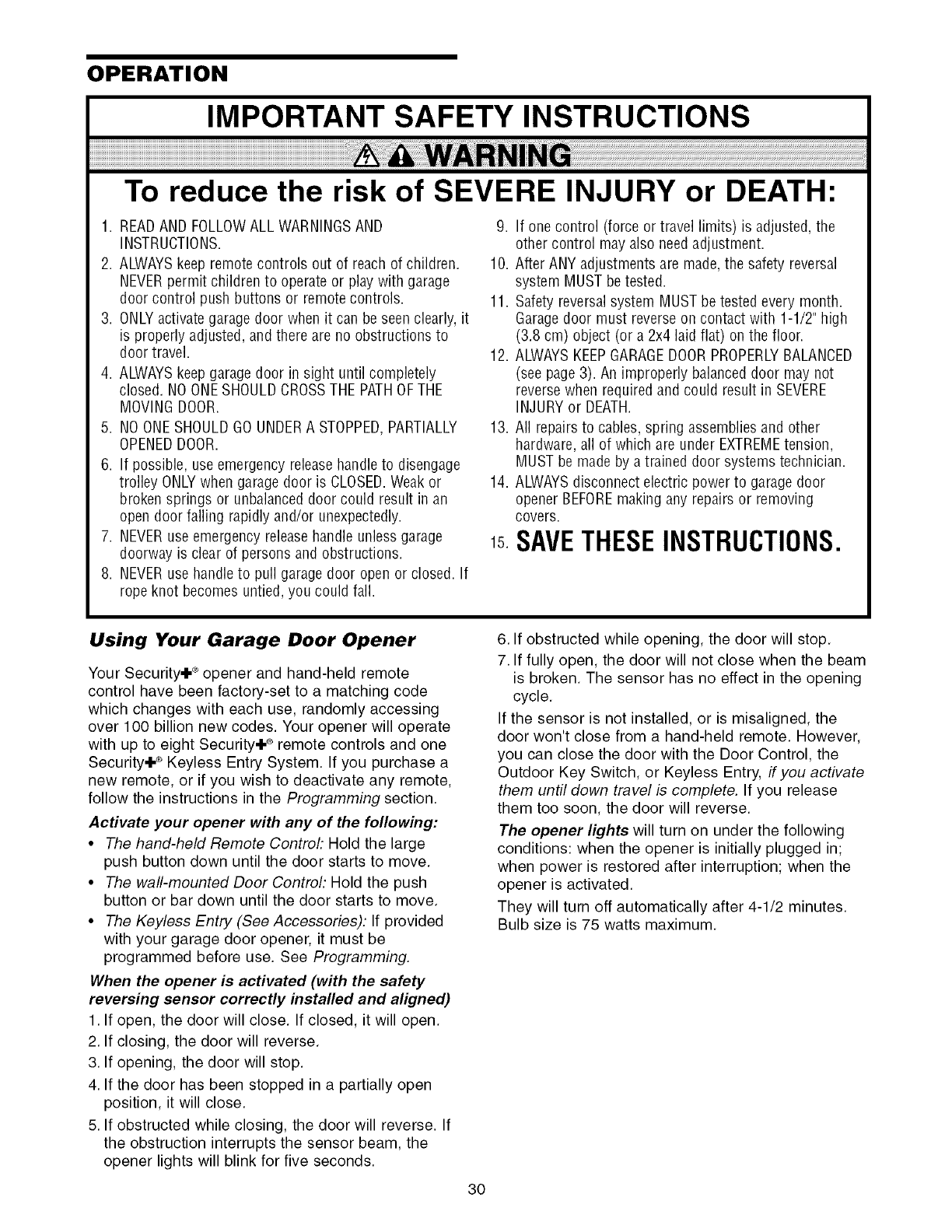
• Press the remote control push button to open the
door.
• Place the opener carton in the path of the door.
• Press the remote control push button to close the
door. The door will not move more than an inch
(2.5 cm), and the opener lights will flash.
The garage door opener will not close from a remote
if the indicator light in either sensor is off (alerting
you to the fact that the sensor is misaligned or
obstructed).
If the opener closes the door when the safety
reversing sensor is obstructed (and the sensors
are no more than 6" (15 cm) above the floor), call
for a trained door systems technician.
Without a properly installed safety reversing sensor,
persons (particularly small children) could be
SERIOUSLYINJUREDor KILLEDby a closing garage
door.
[
€
E
Safety_R'eversing Sensor'_ -'_ Safety ReversingSe_sor
29
OPERATION
IMPORTANT SAFETY INSTRUCTIONS
To reduce the risk of SEVERE INJURY or DEATH:
1. READAND FOLLOWALL WARNINGSAND
INSTRUCTIONS.
2. ALWAYSkeep remote controls out of reach of children.
NEVERpermit children to operate or play with garage
door control push buttons or remotecontrols.
3. ONLYactivate garagedoor when it can be seen clearly, it
is properly adjusted, and there are no obstructions to
door travel.
4. ALWAYSkeepgarage door in sight until completely
closed. NOONESHOULDCROSSTHE PATHOFTHE
MOVINGDOOR.
5. NO ONESHOULDGOUNDERA STOPPED,PARTIALLY
OPENEDDOOR.
6. If possible, use emergency releasehandle to disengage
trolley ONLYwhen garage door is CLOSED.Weakor
broken springs or unbalanced door could result in an
open door failing rapidly and/or unexpectedly.
7. NEVERuse emergency release handle unlessgarage
doorway is clear of persons and obstructions.
8. NEVERuse handleto pull garage door open or closed. If
rope knot becomes untied, you could fall.
9. If one control (force or travel limits) is adjusted, the
other control may also needadjustment.
10. After ANY adjustments are made,the safety reversal
system MUST be tested.
11. Safety reversalsystem MUST be tested every month.
Garagedoor must reverseon contact with 1-1/2" high
(3.8 cm) object (or a 2x4 laid flat) on the floor.
12. ALWAYSKEEPGARAGEDOORPROPERLYBALANCED
(see page3). An improperly balanced door may not
reversewhen required and could result in SEVERE
INJURY or DEATH.
13. All repairs to cables, spring assemblies and other
hardware, all of which are under EXTREMEtension,
MUST be made by a trained door systems technician.
14. ALWAYSdisconnect electric power to garage door
opener BEFOREmaking any repairs or removing
covers.
1sSAVETHESEINSTRUCTIONS.
Using Your Garage Door Opener
Your Security+ ®opener and hand-held remote
control have been factory-set to a matching code
which changes with each use, randomly accessing
over 100 billion new codes. Your opener will operate
with up to eight Security+ ®remote controls and one
Security+ ® Keyless Entry System. If you purchase a
new remote, or if you wish to deactivate any remote,
follow the instructions in the Programming section.
Activate your opener with any of the following:
•The hand-held Remote Control: Hold the large
push button down until the door starts to move.
• The wall-mounted Door Controh Hold the push
button or bar down until the door starts to move.
• The Keyless Entry (See Accessories): If provided
with your garage door opener, it must be
programmed before use. See Programming.
When the opener is activated (with the safety
reversing sensor correctly installed and aligned)
1. If open, the door will close. If closed, it will open.
2. If closing, the door will reverse.
3. If opening, the door will stop.
4. If the door has been stopped in a partially open
position, it will close.
5. If obstructed while closing, the door will reverse. If
the obstruction interrupts the sensor beam, the
opener lights will blink for five seconds.
6. If obstructed while opening, the door will stop.
7. If fully open, the door will not close when the beam
is broken. The sensor has no effect in the opening
cycle.
If the sensor is not installed, or is misaligned, the
door won't close from a hand-held remote. However,
you can close the door with the Door Control, the
Outdoor Key Switch, or Keyless Entry, if you activate
them until down travel is complete. If you release
them too soon, the door will reverse.
The opener lights will turn on under the following
conditions: when the opener is initially plugged in;
when power is restored after interruption; when the
opener is activated.
They will turn off automatically after 4-1/2 minutes.
Bulb size is 75 watts maximum.
30
Using the Wall.Mounted
Door Control
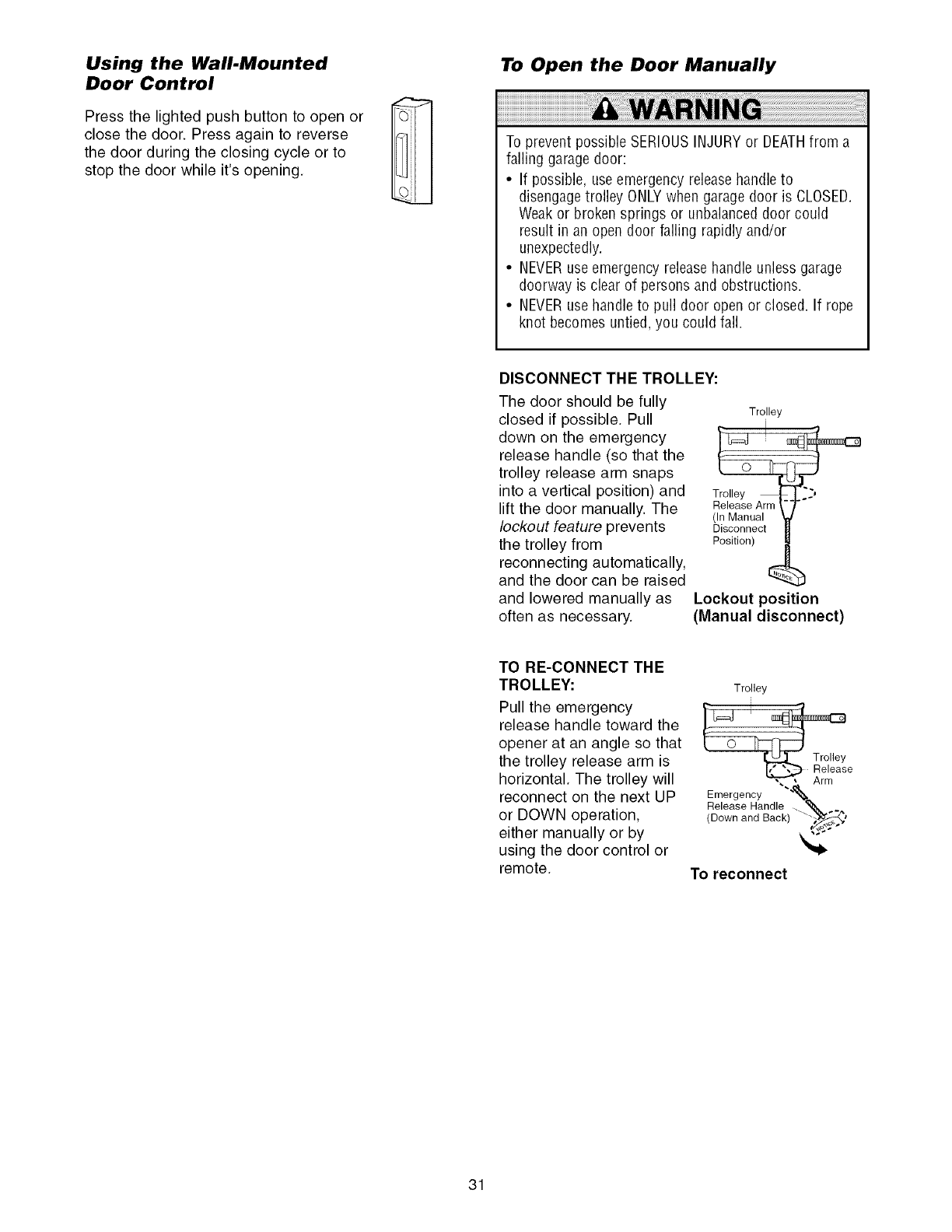
Press the lighted push button to open or
close the door. Press again to reverse
the door during the closing cycle or to
stop the door while it's opening.
To Open the Door Manually
To prevent possible SERIOUSINJURY or DEATHfrom a
failing garagedoor:
• If possible, use emergency release handleto
disengagetrolley ONLYwhen garage door is CLOSED.
Weakor broken springs or unbalanceddoor could
result in an open door failing rapidly and/or
unexpectedly.
• NEVERuse emergency releasehandle unless garage
doorway is clear of persons and obstructions.
• NEVERuse handle to pull door open or closed. If rope
knot becomes untied, you could fall.
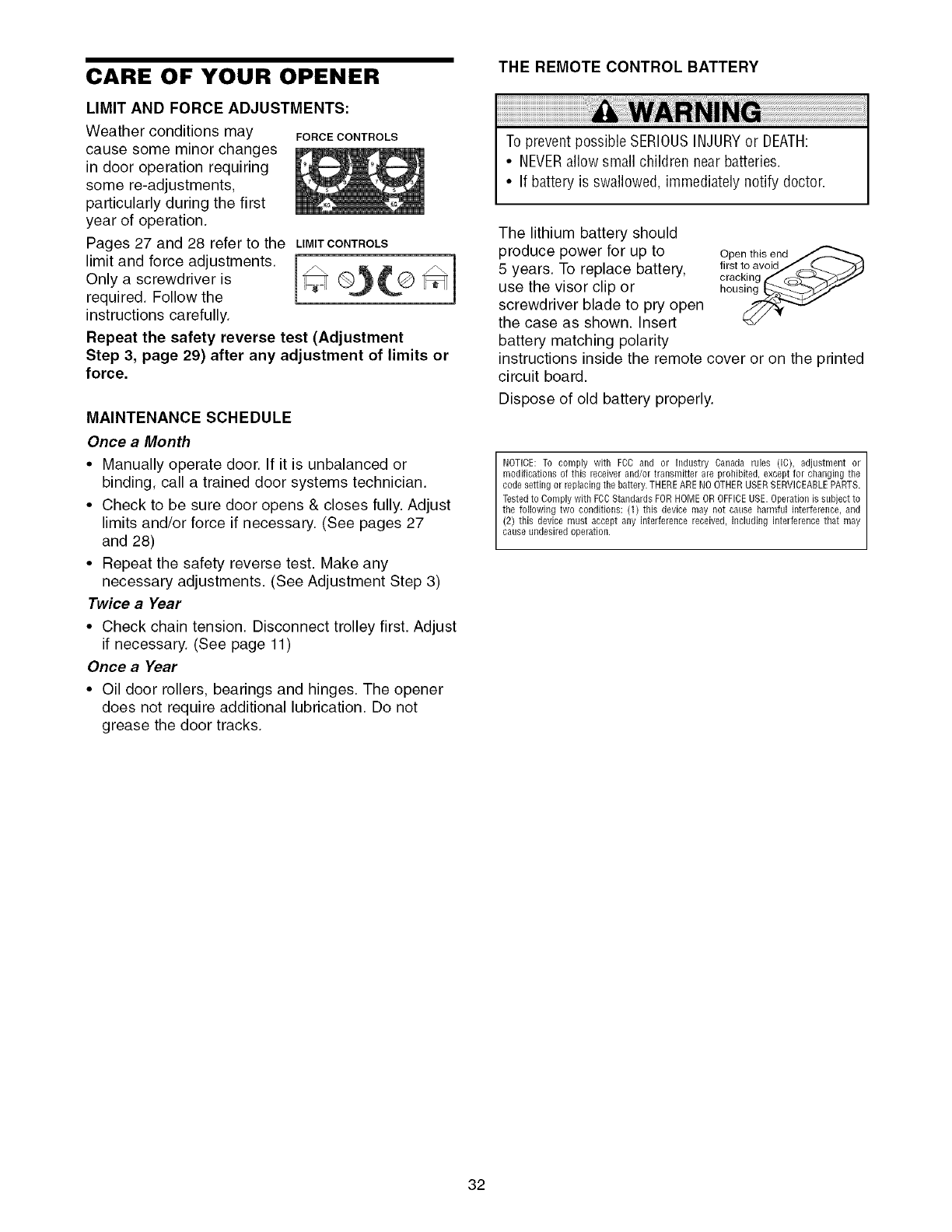
DISCONNECT THE TROLLEY:
The door should be fully
closed if possible. Pull
down on the emergency
release handle (so that the
trolley release arm snaps
into a vertical position) and
lift the door manually. The
lockout feature prevents
the trolley from
reconnecting automatically,
and the door can be raised
and lowered manually as
often as necessary.
Trolley
Trolley ..__
Release Arm
(In Manual
Disconnect
Position)
Lockout position
(Manual disconnect)
TO RE-CONNECT THE
TROLLEY:
Pull the emergency
release handle toward the
opener at an angle so that
the trolley release arm is
horizontal. The trolley will
reconnect on the next UP
or DOWN operation,
either manually or by
using the door control or
remote.
Trolley
e
Emergency "'_
Release Handle . q_. _
(Down and Back) _'_*
To reconnect
31
CARE OF YOUR OPENER
LIMIT AND FORCE ADJUSTMENTS:
Weather conditions may FORCECONTROLS
cause some minor changes
in door operation requiring
some re-adjustments,
particularly during the first
year of operation.
Pages 27 and 28 refer to the LIMITCONTROLS
limit and force adjustments.
Only a screwdriver is _ (_(_ _
required. Follow the
instructions carefully.
Repeat the safety reverse test (Adjustment
Step 3, page 29) after any adjustment of limits or
force.
MAINTENANCE SCHEDULE
Once a Month
• Manually operate door. If it is unbalanced or
binding, call a trained door systems technician.
• Check to be sure door opens & closes fully. Adjust
limits and/or force if necessary. (See pages 27
and 28)
• Repeat the safety reverse test. Make any
necessary adjustments. (See Adjustment Step 3)
Twice a Year
• Check chain tension. Disconnect trolley first. Adjust
if necessary. (See page 11)
Once a Year
• Oil door rollers, bearings and hinges. The opener
does not require additional lubrication. Do not
grease the door tracks.
THE REMOTE CONTROL BATTERY
To prevent possible SERIOUSINJURYor DEATH:
•NEVERallow small children near batteries
•If battery is swallowed, immediately notify doctor
The lithium battery should
produce power for up to
5 years. To replace battery,
use the visor clip or
screwdriver blade to pry open
the case as shown Insert
battery matching polarity
Open this end
first to avoid/ _...._
cracl_ing _ C_4-,_//_7
hous_
instructions inside the remote cover or on the printed
circuit board.
Dispose of old battery properly.
NOTICE:To comply with FCC and or Industry Canada rules (IC), adjustment or
modifications of this receiverand/or transmitter are prohibited, except for changing the
codesetting or replacingthe battery.THEREARENOOTHERUSERSERVICEABLEPARTS.
Testedto Comply with FCCStandards FORHOMEOR OFFICEUSE.Operationis snbject to
the following two conditions: (1) this device may not canse harmful interference, and
(2) this device must accept any interference received, including interference that may
canseundesiredoperation.
32
HAVING A PROBLEM?
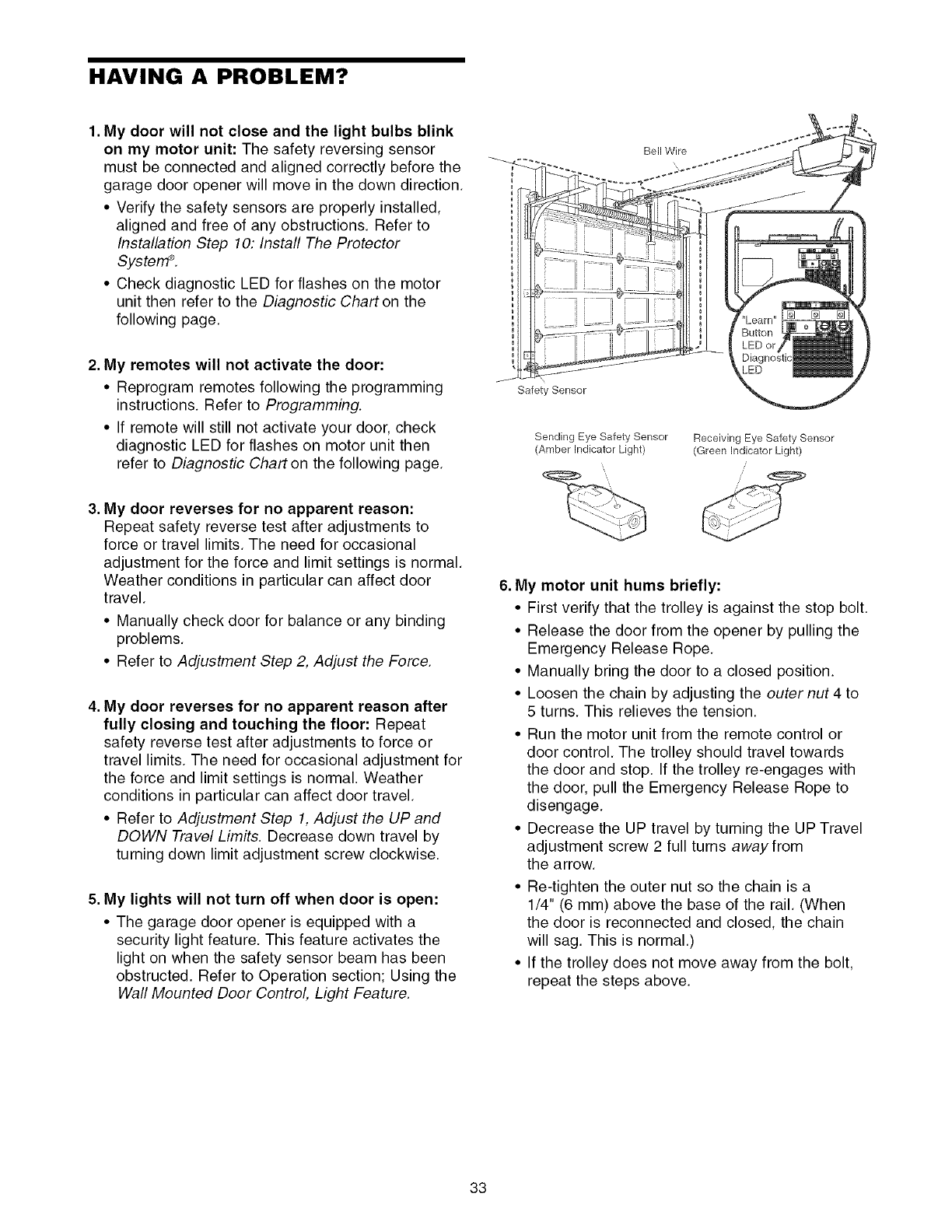
1. My door will not close and the light bulbs blink
on my motor unit: The safety reversing sensor
must be connected and aligned correctly before the
garage door opener will move in the down direction.
• Verify the safety sensors are properly installed,
aligned and free of any obstructions. Refer to
Installation Step 10: Install The Protector
SysterrP.
• Check diagnostic LED for flashes on the motor
unit then refer to the Diagnostic Chart on the
following page.
2. My remotes will not activate the door:
• Reprogram remotes following the programming
instructions. Refer to Programming.
• If remote will still not activate your door, check
diagnostic LED for flashes on motor unit then
refer to Diagnostic Chart on the following page.
3. My door reverses for no apparent reason:
Repeat safety reverse test after adjustments to
force or travel limits. The need for occasional
adjustment for the force and limit settings is normal.
Weather conditions in particular can affect door
travel.
• Manually check door for balance or any binding
problems.
• Refer to Adjustment Step 2, Adjust the Force.
4. My door reverses for no apparent reason after
fully closing and touching the floor: Repeat
safety reverse test after adjustments to force or
travel limits. The need for occasional adjustment for
the force and limit settings is normal. Weather
conditions in particular can affect door travel.
• Refer to Adjustment Step 1, Adjust the UP and
DOWN Travel Limits. Decrease down travel by
turning down limit adjustment screw clockwise.
5. My lights will not turn off when door is open:
• The garage door opener is equipped with a
security light feature. This feature activates the
light on when the safety sensor beam has been
obstructed. Refer to Operation section; Using the
Wall Mounted Door Control, Light Feature.
Bell Wire
\
Safety Sensor
Sending Eye Safety Sensor
(Amber Indicator Light) Receiving Eye Safety Sensor
(Green Indicator Light)
,,;
/;
6. My motor unit hums briefly:
• First verify that the trolley is against the stop bolt.
• Release the door from the opener by pulling the
Emergency Release Rope.
• Manually bring the door to a closed position.
• Loosen the chain by adjusting the outer nut 4 to
5 turns. This relieves the tension.
• Run the motor unit from the remote control or
door control. The trolley should travel towards
the door and stop. If the trolley re-engages with
the door, pull the Emergency Release Rope to
disengage.
• Decrease the UP travel by turning the UP Travel
adjustment screw 2 full turns away from
the arrow.
• Re-tighten the outer nut so the chain is a
1/4" (6 mm) above the base of the rail. (When
the door is reconnected and closed, the chain
will sag. This is normal.)
• If the trolley does not move away from the bolt,
repeat the steps above.
33
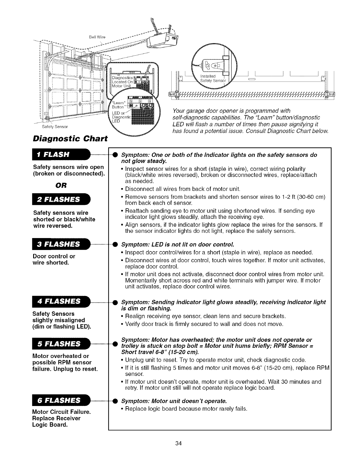
Bell Wire
Safety Sensor
Diagnostic Chart
Safety sensors wire open
(broken or disconnected).
OR
Safety sensors wire
shorted or black/white
wire reversed.
Door control or
wire shorted.
Safety Sensors
slightly misaligned
(dim or flashing LED).
Motor overheated or
possible RPM sensor
failure. Unplug to reset.
Motor Circuit Failure.
Replace Receiver
Logic Board.
Your garage door opener is programmed with
self-diagnostic capabilities. The "Learn" button/diagnostic
LED will flash a number of times then pause signifying it
has found a potential issue. Consult Diagnostic Chart below.
"e
e
Symptom: One or both of the Indicator lights on the safety sensors do
not glow steady.
• Inspect sensor wires for a short (staple in wire), correct wiring polarity
(black/white wires reversed), broken or disconnected wires, replace/attach
as needed.
• Disconnect all wires from back of motor unit.
• Remove sensors from brackets and shorten sensor wires to 1-2 ft (30-60 cm)
from back each of sensor.
• Reattach sending eye to motor unit using shortened wires. If sending eye
indicator light glows steadily, attach the receiving eye.
• Align sensors, if the indicator lights glow replace the wires for the sensors. If
the sensor indicator lights do not light, replace the safety sensors.
Symptom: LED is not fit on door control
• Inspect door control/wires for a short (staple in wire), replace as needed.
• Disconnect wires at door control, touch wires together. If motor unit activates
replace door control.
• If motor unit does not activate, disconnect door control wires from motor unit.
Momentarily short across red and white terminals with jumper wire. If motor
unit activates, replace door control wires.
"e Symptom: Sending indicator light glows steadily, receiving indicator light
is dim or flashing.
• Realign receiving eye sensor, clean lens and secure brackets.
• Verify door track is firmly secured to wall and does not move.
eSymptom: Motor has overheated; the motor unit does not operate or
trolley is stuck on stop bolt = Motor unit hums briefly; RPM Sensor =
Short travel 6-8" (15-20 cm).
• Unplug unit to reset. Try to operate motor unit, check diagnostic code.
• If it is still flashing 5 times and motor unit moves 6-8" (15-20 cm), replace RPM
sensor.
• If motor unit doesn't operate, motor unit is overheated. Wait 30 minutes and
retry. If motor unit still will not operate replace logic board.
"0 Symptom: Motor unit doesn't operate.
• Replace logic board because motor rarely fails.
34
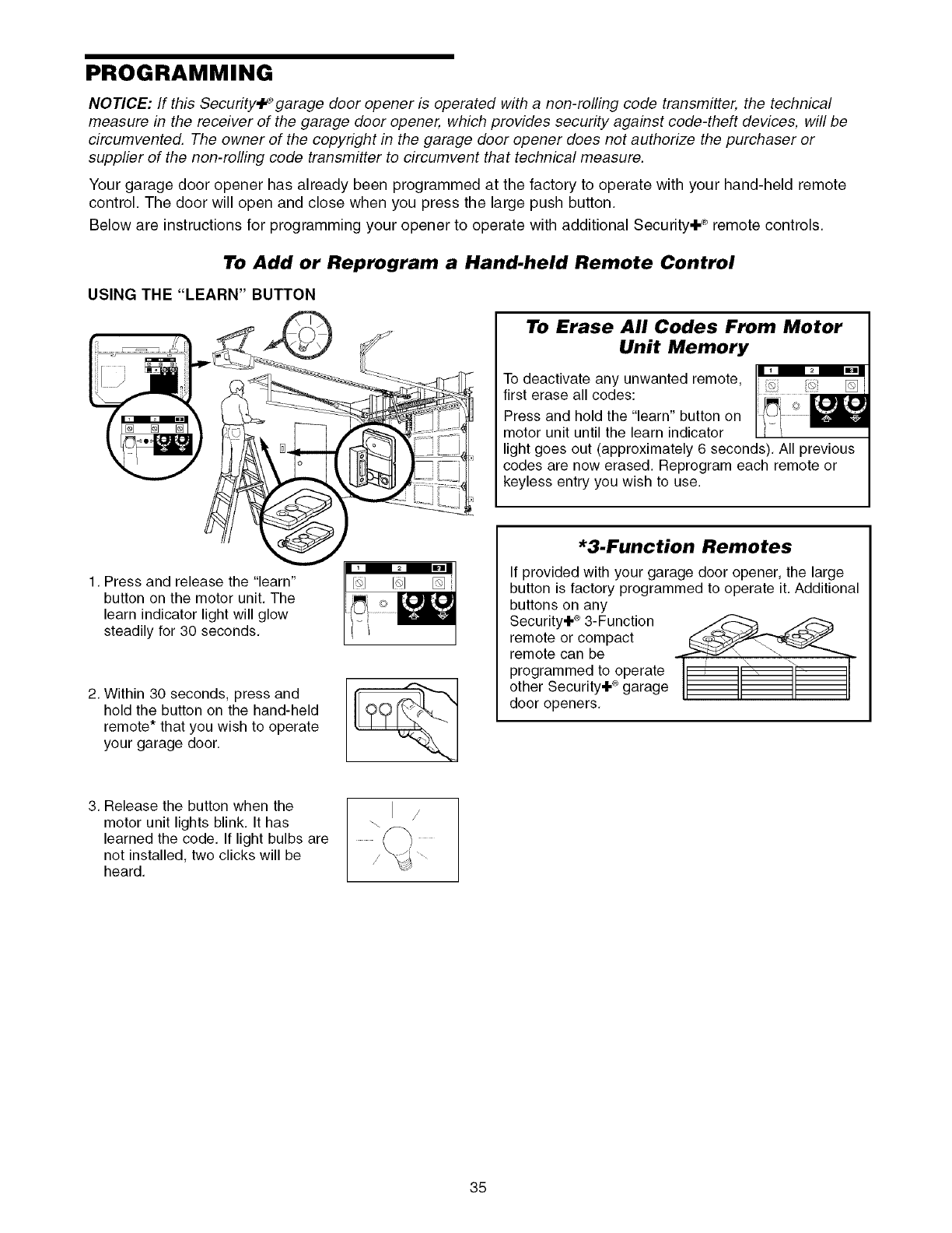
PROGRAMMING
NOTICE: If this Security.l_ garage door opener is operated with a non-rolling code transmitter, the technical
measure in the receiver of the garage door opener, which provides security against code-theft devices, will be
circumvented. The owner of the copyright in the garage door opener does not authorize the purchaser or
supplier of the non-rolling code transmitter to circumvent that technical measure,
Your garage door opener has already been programmed at the factory to operate with your hand-held remote
control, The door will open and close when you press the large push button.
Below are instructions for programming your opener to operate with additional Security+ ® remote controls,
To Add or Reprogram a Hand.held Remote Control
USING THE "LEARN" BUTTON
To Erase All Codes From Motor
Unit Memory
To deactivate any unwanted remote, 151
first erase all codes:
Press and hold the "learn" button on
motor unit until the learn indicator
light goes out (approximately 6 seconds), All previous
codes are now erased. Reprogram each remote or
keyless entry you wish to use.
1, Press and release the "learn"
button on the motor unit. The
learn indicator light will glow
steadily for 30 seconds,
2, Within 30 seconds, press and
hold the button on the hand-held
remote* that you wish to operate
your garage door.
*3-Function Remotes
If provided with your garage door opener, the large
button is factory programmed to operate it. Additional
buttons on any
Security+ ®3-Function
remote or compact
remote can be
programmed to operate
other Security+ ®garage
door openers.
3. Release the button when the
motor unit lights blink, It has
learned the code, If light bulbs are
not installed, two clicks will be
heard,
/
35
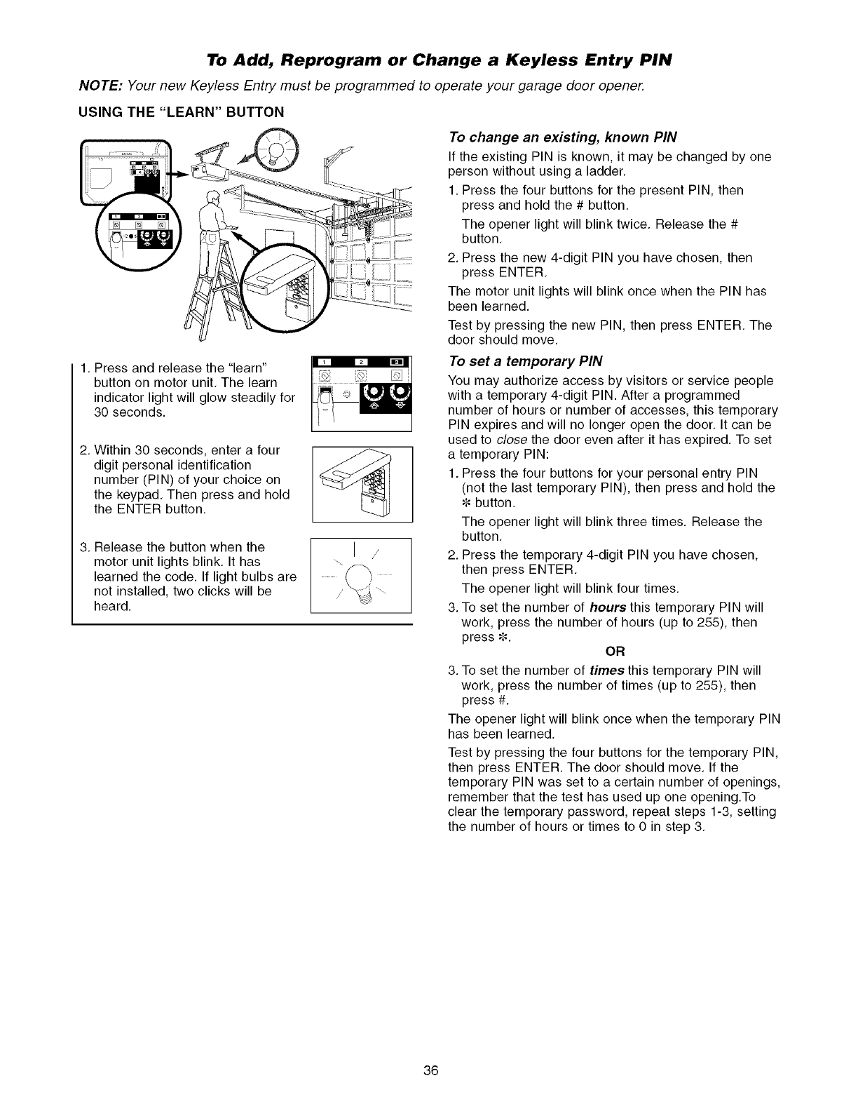
To Add, Reprogram or Change a Keyless Entry PIN
NOTE: Your new Keyless Entry must be programmed to operate your garage door opener.
USING THE "LEARN" BUTTON
1. Press and release the "learn"
button on motor unit, The learn
indicator light will glow steadily for
30 seconds.
2. Within 30 seconds, enter a four
digit personal identification
number (PIN) of your choice on
the keypad, Then press and hold
the ENTER button.
3, Release the button when the
motor unit lights blink, It has
learned the code. If light bulbs are
not installed, two clicks will be
heard,
/
To change an existing, known PIN
If the existing PIN is known, it may be changed by one
person without using a ladder,
1. Press the four buttons for the present PIN, then
press and hold the # button,
The opener light will blink twice. Release the #
button,
2. Press the new 4-digit PIN you have chosen, then
press ENTER,
The motor unit lights will blink once when the PIN has
been learned.
Test by pressing the new PIN, then press ENTER, The
door should move,
To set a temporary PIN
You may authorize access by visitors or service people
with a temporary 4-digit PIN. After a programmed
number of hours or number of accesses, this temporary
PIN expires and will no longer open the door, It can be
used to close the door even after it has expired, To set
a temporary PIN:
1. Press the four buttons for your personal entry PIN
(not the last temporary PIN), then press and hold the
button,
The opener light will blink three times, Release the
button,
2. Press the temporary 4-digit PIN you have chosen,
then press ENTER,
The opener light will blink four times,
3. To set the number of hours this temporary PIN will
work, press the number of hours (up to 255), then
press _. OR
3. To set the number of times this temporary PIN will
work, press the number of times (up to 255), then
press #,
The opener light will blink once when the temporary PIN
has been learned,
Test by pressing the four buttons for the temporary PIN,
then press ENTER. The door should move, If the
temporary PIN was set to a certain number of openings,
remember that the test has used up one opening,To
clear the temporary password, repeat steps 1-3, setting
the number of hours or times to 0 in step 3,
36
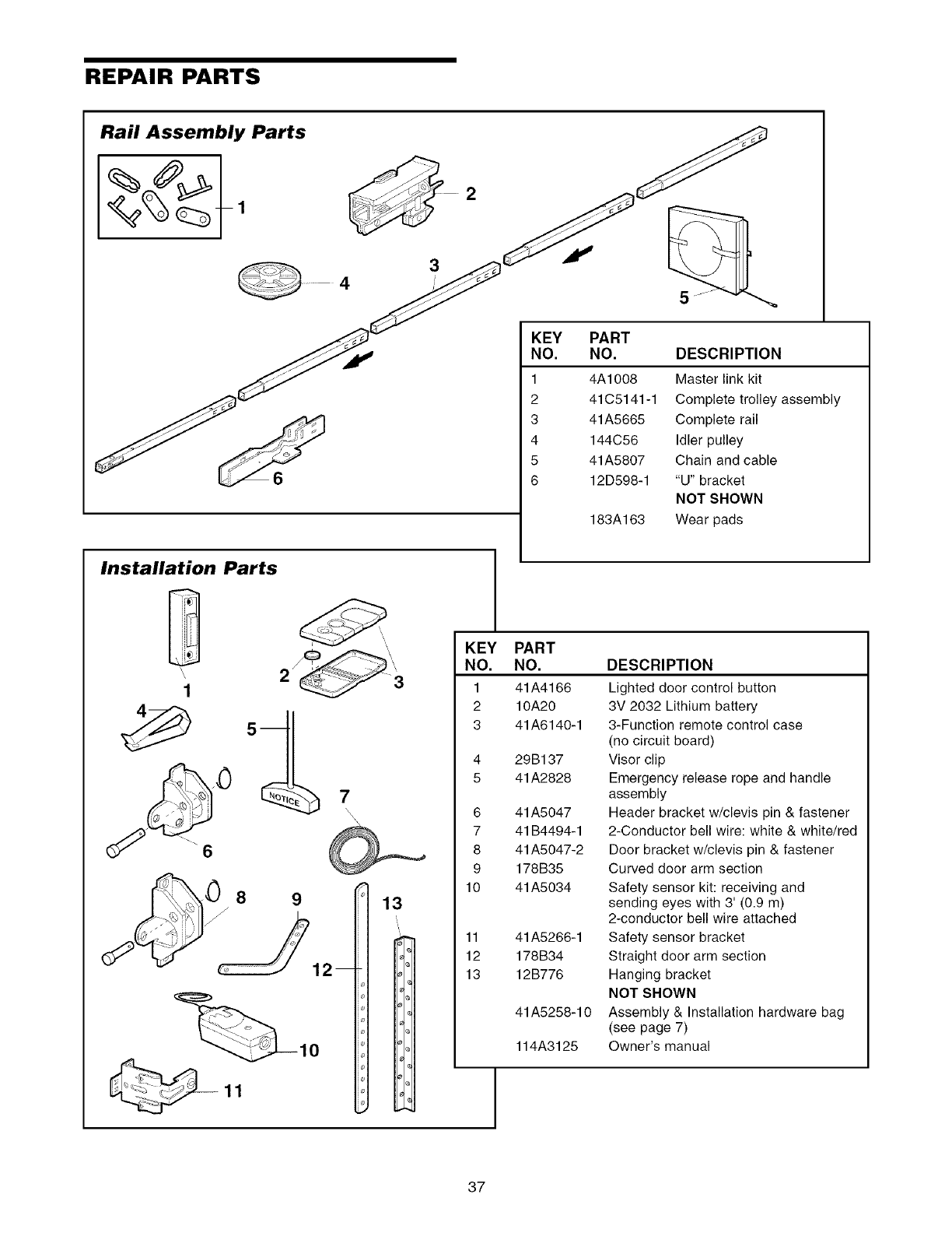
REPAIR PARTS
Rail Assembly Parts
3
KEY
NO.
1
2
3
4
5
6
PART
NO. DESCRIPTION
4A1008 Master link kit
41C5141-1 Complete trolley assembly
41A5665 Complete rail
144C56 Idler pulley
41A5807 Chain and cable
12D598-1 "U" bracket
NOT SHOWN
183A163 Wear pads
Installation Parts
D
1
KEY
NO.
1
2
3
4
5
6
7
8
9
10
11
12
13
1
PART
NO.
41A4166
10A20
41A6140-1
29B137
41A2828
41A5047
41B4494-1
41A5047-2
178B35
41A5034
41A5266-1
178B34
12B776
41A5258-10
114A3125
DESCRIPTION
Lighted door control button
3V 2032 Lithium battery
3-Function remote control case
(no circuit board)
Visor clip
Emergency release rope and handle
assembly
Header bracket w/clevis pin & fastener
2-Conductor bell wire: white & white/red
Door bracket w/clevis pin & fastener
Curved door arm section
Safety sensor kit: receiving and
sending eyes with 3' (0.9 m)
2-conductor bell wire attached
Safety sensor bracket
Straight door arm section
Hanging bracket
NOT SHOWN
Assembly & Installation hardware bag
(see page 7)
Owner's manual
37
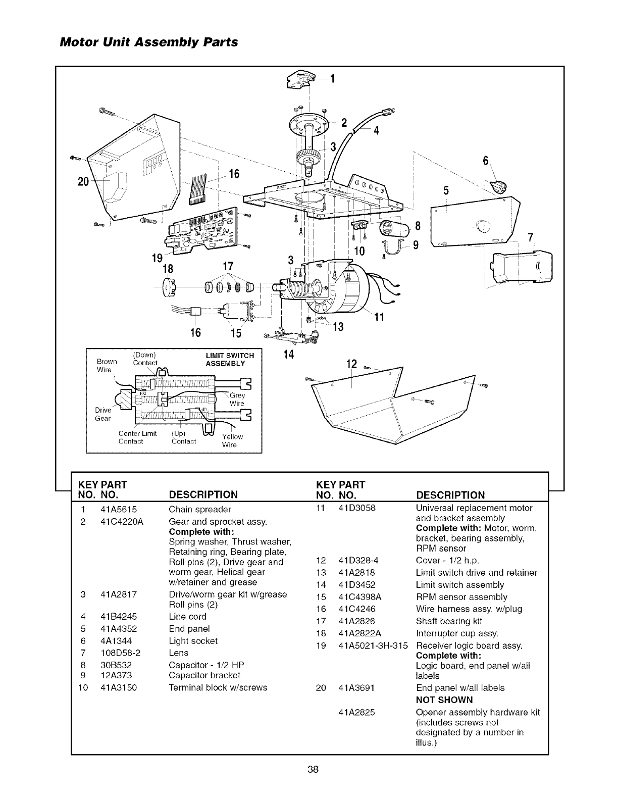
Motor Unit Assembly Parts
18 17
16 15
(Down) LIMIT SWITCH
Brown Contact ASSEMBLY
Contact Contact Wire
I
I
3
1
14 12
11
5'
7
i
i
I
i___ ,-
KEY PART
NO. NO.
1 41A5615
2 41C4220A
3 41A2817
4 41B4245
5 41A4352
6 4A1344
7 108D58-2
8 30B532
9 12A373
10 41A3150
KEY PART
DESCRIPTION NO. NO.
Chain spreader 11 41D3058
Gear and sprocket assy.
Complete with:
Spring washer, Thrust washer,
Retaining ring, Bearing plate,
Roll pins (2), Drive gear and 12 41D328-4
worm gear, Helical gear 13 41A2818
w/retainer and grease 14 41D3452
Drive/worm gear kit w/grease 15 41C4398A
Roll pins (2) 16 41C4246
Line cord 17 41A2826
End panel 18 41A2822A
Light socket 19 41A5021-3H-315
Lens
Capacitor- 1/2 HP
Capacitor bracket
Terminal block w/screws 20 41A3691
41A2825
DESCRIPTION
Universal replacement motor
and bracket assembly
Complete with: Motor, worm,
bracket, bearing assembly,
RPM sensor
Cover - 1/2 h.p.
Limit switch drive and retainer
Limit switch assembly
RPM sensor assembly
Wire harness assy. w/plug
Shaft bearing kit
Interrupter cup assy.
Receiver logic board assy.
Complete with:
Logic board, end panel w/all
labels
End panel w/all labels
NOT SHOWN
Opener assembly hardware kit
(includes screws not
designated by a number in
illus.)
38
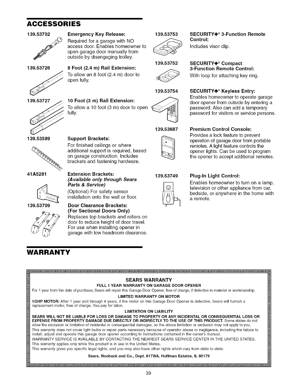
ACCESSORIES
139.53702
/Emergency Key Release:
Required for a garage with NO
access door. Enables homeowner to
open garage door manually from
outside by disengaging trolley.
139.53726
139.53727
8 Foot (2.4 m) Rail Extension:
To allow an 8 foot (2.4 m) door to
open fully.
10 Foot (3 m) Rail Extension:
To allow a 10 foot (3 m) door to open
fully.
139.53753
139.53752
139.53754
SECURITY÷ _ 3-Function Remote
Control:
Includes visor clip.
SECURITY÷ * Compact
3-Function Remote Control:
With loop for attaching key ring.
SECURITY÷ _ Keyless Entry:
Enables homeowner to operate garage
door opener from outside by entering a
password. Also can add a temporary
password for visitors or service persons.
139.53589
41A5281
139.53709
Support Brackets:
For finished ceilings or where
additional support is required, based
on garage construction. Includes
brackets and fastening hardware.
Extension Brackets:
(Available only through Sears
Parts & Service)
(Optional) For safety sensor
installation onto the wall or floor.
Door Clearance Brackets:
(For Sectional Doors Only)
Replaces top brackets and rollers on
door to reduce height of door travel.
For use when installing opener in
garage with low headroom clearance.
139.53687
139.53749
Premium Control Console:
Provides a lock feature to prevent
operation of garage door from portable
remotes. A light feature controls the
opener lights. Can be used to program
the opener to accept additional remotes.
Plug-In Light Control:
Enables homeowner to turn on a lamp,
television or other appliance from car,
bedside, or anywhere in the home with
a remote.
WARRANTY
SEARS WARRANTY
FULL 1 YEAR WARRANTY ON GARAGE DOOR OPENER
For 1 year from the date of purchase, Sears will repair this Garage Door Opener, free of charge, if defective in material or workmanship.
LIMITED WARRANTY ON MOTOR
I/2HP MOTOR: After 1 year and through 4 years, if the motor on this Garage Door Opener is defective, Sears will furnish a
replacement motor, free of charge. You pay for labor.
LIMITATION ON LIABILITY
SEARS WILL NOT BE LIABLE FOR LOSS OR DAMAGE TO PROPERTY OR ANY INCIDENTAL OR CONSEQUENTIAL LOSS OR
EXPENSE FROM PROPERTY DAMAGE DUE DIRECTLY OR INDIRECTLY TO THE USE OF THIS PRODUCT. Some states do not
allow the exclusion or limitation of incidental or consequential damages, so the above limitation or exclusion may not apply to you.
This warranty does not cover light bulbs or repair parts necessary because of operator abuse or negligence, including the failure to
install, adjust and operate this garage door opener according to instructions contained in the owner's manual.
WARRANTY SERVICE IS AVAILABLE BY CONTACTING THE NEAREST SEARS SERVICE CENTER IN THE UNITED STATES.
This warranty applies only while this product is in use in the United States.
This warranty gives you specific legal rights, and you may also have other rights which vary from state to state.
Sears, Roebuck and Co., Dept. 817WA, Hoffman Estates, IL 60179
39
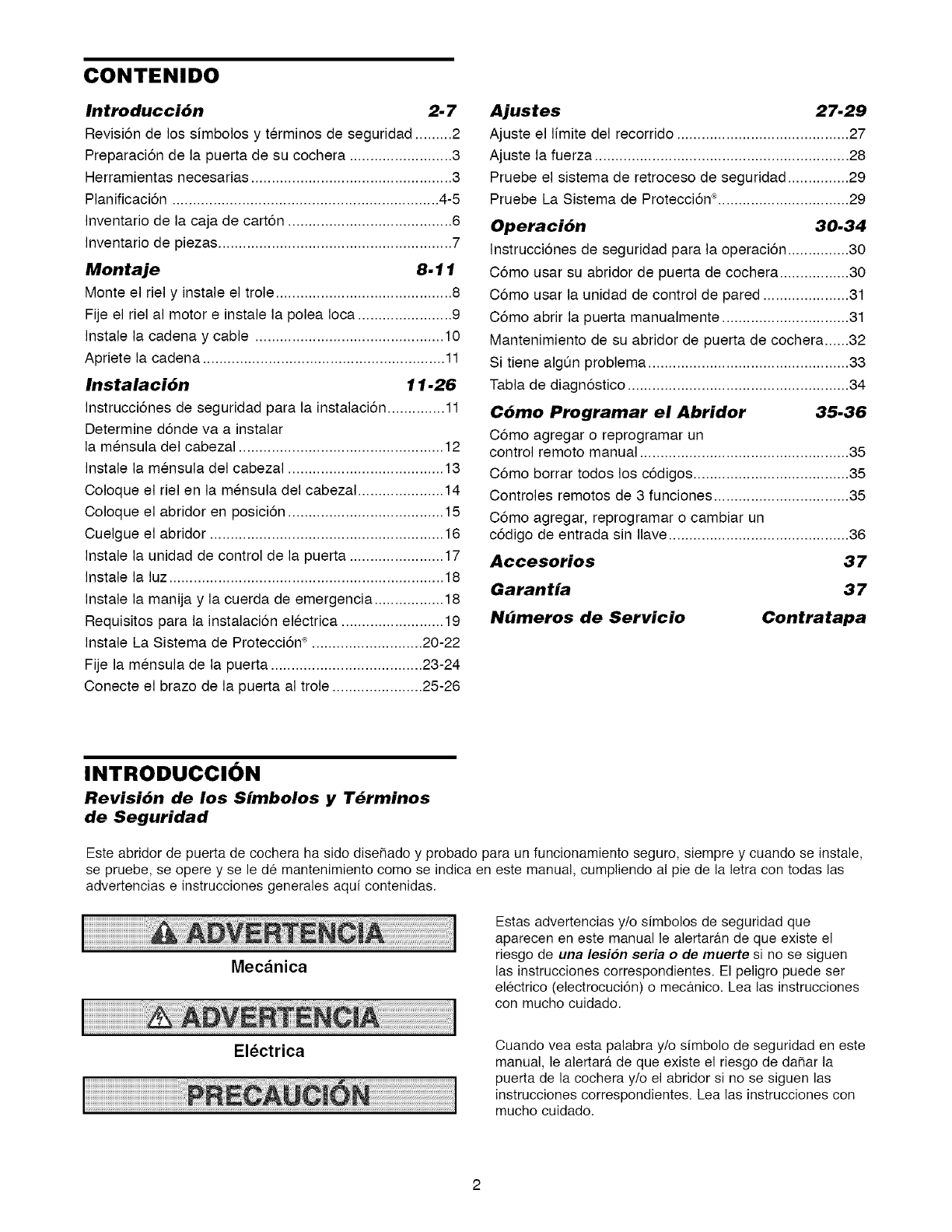
CONTENIDO
Introducci6n 2-7
Revisi6n de los simbolos y terminos de seguridad ......... 2
Preparaci6n de la puerta de su cochera ......................... 3
Herramientas necesarias ................................................. 3
Planificaci6n ................................................................. 4-5
Inventario de la caja de cart6n ........................................ 6
Inventario de piezas ......................................................... 7
Montaje 8.11
Monte el riel y instale el trole ........................................... 8
Fije el riel al motor e instale la polea Ioca ....................... 9
Instale la cadena y cable .............................................. 10
Apriete la cadena ........................................................... 11
Instalaci6n 11.26
Instrucci6nes de seguridad para la instalaci6n .............. 11
Determine d6nde va a instalar
la mensula del cabezal .................................................. 12
Instale la mensula del cabezal ...................................... 13
Coloque el riel en la mensula del cabezal ..................... 14
Coloque el abridor en posici6n ...................................... 15
Cuelgue el abridor ......................................................... 16
Instale la unidad de control de la puerta ....................... 17
Instale la luz ................................................................... 18
Instale la manija y la cuerda de emergencia ................. 18
Requisitos para la instalaci6n electrica ......................... 19
Instale La Sistema de Protecci6n ®........................... 20-22
Fije la mensula de la puerta ..................................... 23-24
Conecte el brazo de la puerta al trole ...................... 25-26
Ajustes 27.29
Ajuste el limite del recorrido .......................................... 27
Ajuste la fuerza .............................................................. 28
Pruebe el sistema de retroceso de seguridad ............... 29
Pruebe La Sistema de Protecci6n ®................................ 29
Operaci6n 30.34
Instrucci6nes de seguridad para la operaci6n ............... 30
C6mo usar su abridor de puerta de cochera ................. 30
C6mo usar la unidad de control de pared ..................... 31
C6mo abrir la puerta manualmente ............................... 31
Mantenimiento de su abridor de puerta de cochera ......32
Si tiene algQn problema ................................................. 33
Tabla de diagn6stico ...................................................... 34
C6mo Programar el Abridor 35.36
C6mo agregar o reprogramar un
control remoto manual ................................................... 35
C6mo borrar todos los c6digos ...................................... 35
Controles remotos de 3 funciones ................................. 35
C6mo agregar, reprogramar o cambiar un
c6digo de entrada sin Ilave............................................ 36
Accesorios 37
Garantia 37
Nbmeros de Servicio Contratapa
INTRODUCClON
Revisi6n de los Simbolos y T_rminos
de Seguridad
Este abridor de puerta de cochera ha sido diseRado y probado para un funcionamiento seguro, siempre y cuando se instale,
se pruebe, se opere y se le de mantenimiento como se indica en este manual, cumpliendo a! pie de la letra con todas las
advertencias e instrucciones generales aqui contenidas.
Mecanica
Electrica
Estas advertencias y/o simbolos de seguridad que
aparecen en este manual le alertaran de que existe el
riesgo de una lesion seria o de muerte si no se siguen
las instrucciones correspondientes. El peligro puede ser
electrico (electrocuci6n) o mec_tnico. Lea las instrucciones
con mucho cuidado.
Cuando vea esta palabra y/o simbolo de seguridad en este
manual, le alertara de que existe el riesgo de da_ar la
puerta de la cochera y/o el abridor si no se siguen las
instrucciones correspondientes. Lea las instrucciones con
mucho cuidado.
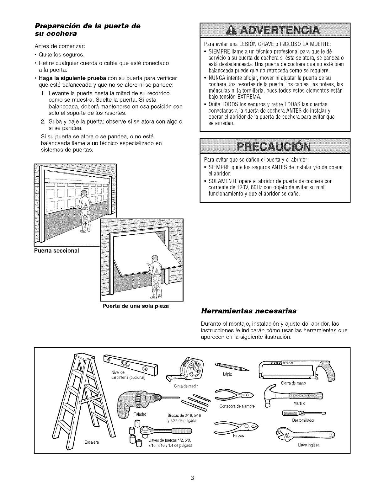
PreparaciOn de la puerta de
su cochera
Antes de comenzar:
• Quite los seguros.
• Retire cualquier cuerda o cable que este conectado
a la puerta.
•Haga la siguiente prueba con su puerta para verificar
que este balanceada y que no se atore ni se pandee:
1. Levante la puerta hasta la mitad de su recorrido
come se muestra. Suelte la puerta. Siesta.
balanceada, debera, mantenerse en esa posicion con
solo el soporte de los resortes.
2. Suba y baje la puerta; observe si se atora con algo o
si se pandea.
Si su puerta se atora o se pandea, o no esta
balanceada Ilame a un tecnico especializado en
sistemas de puertas.
Puerta seccional
Paraevitar una LESIONGRAVEo INCLUSOLA MUERTE:
• SIEMPREflame a unt_cnico profesional para que le d_
servicio a su puerta de cochera si 6sta se atora, se pandea o
est,. desbalanceada.Una puerta de cochera que no est_ bien
balanceadapuede que no retroceda como se requiere.
• NUNCAintente aflojar, mover ni ajustar la puerta de su
cochera, los resortes de la puerta, los cables, las poleas, las
m_nsulas ni la tornilleria, pues todos estos elementos est_n
bajo tension EXTREMA.
• Quite TODOSlos seguros y retire TODASlas cuerdas
conectadasa la puerta de cochera ANTESde instalar y
operar el abridor de la puerta de cochera paraevitar que
se enreden.
Para evitar que se darien el puerta y el abridor:
• SIEMPREquite los seguros ANTESde instalar y/o de operar
el abridor.
• SOLAMENTEopere el abridor de puerta de cochera con
corriente de 120V,60Hz con objeto de evitar su real
funcionamiento y que el abridor se dafie.
Puerta de una sola pieza Herramientas necesarias
Durante el montaje, instalacion y ajuste del abridor, las
instrucciones le indicaran como usar las herramientas que
aparecen en la siguiente ilustraciOn.
Escalera
Nivelde
carpinteria (opcional)
Cinta de medir
/
Taladro Brocasde 3,16, 5/16
y 5/32 de pulgada
UO 7/16,9/16 y 1/4de pu'lgad'a
Lapiz
Cortadorade alambre
Sierra de mane
Destomillador
Llaveinglesa
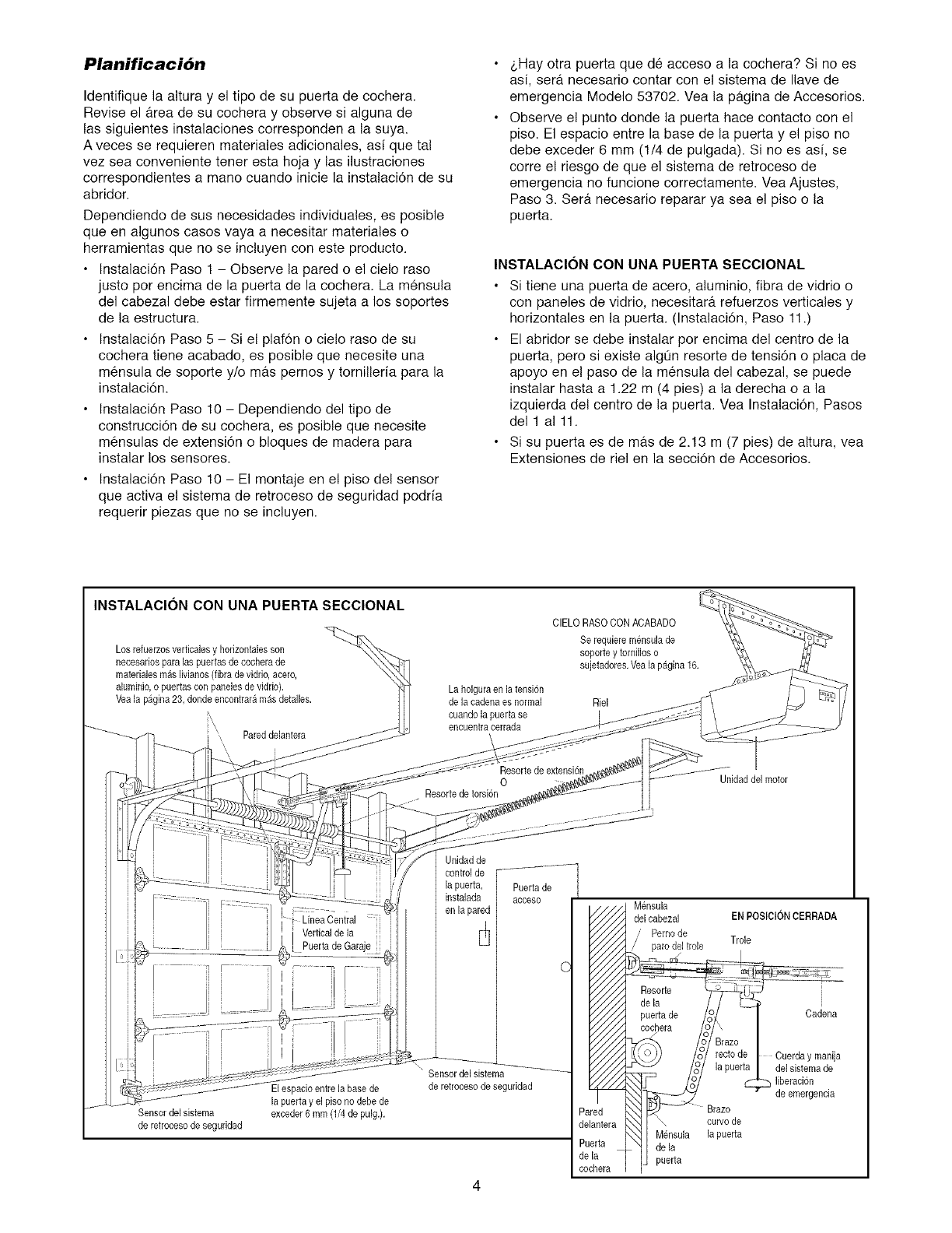
Planificaci6n
Identifique la altura y el tipo de su puerta de cochera.
Revise el area de su cochera y observe si alguna de
las siguientes instalaciones corresponden a la suya.
A veces se requieren materiales adicionales, asi que tal
vez sea conveniente tener esta hoja y las ilustraciones
correspondientes a mano cuando inicie la instalaci6n de su
abridor.
Dependiendo de sus necesidades individuales, es posible
queen algunos casos vaya a necesitar materiales o
herramientas que no se incluyen con este producto.
• Instalaci6n Paso 1 - Observe la pared o el cielo raso
justo por encima de la puerta de la cochera. La mensula
del cabezal debe estar firmemente sujeta a los soportes
de la estructura.
• Instalaci6n Paso 5 - Si el plaf6n o cielo raso de su
cochera tiene acabado, es posible que necesite una
mensula de soporte y/o mas pernos y tomilleria para la
instalaci6n.
• Instalaci6n Paso 10 - Dependiendo del tipo de
construcci6n de su cochera, es posible que necesite
mensulas de extensi6n o bloques de madera para
instalar los sensores.
• Instalaci6n Paso 10 - El montaje en e! piso del sensor
que activa e! sistema de retroceso de seguridad podria
requerir piezas que no se incluyen.
).Hay otra puerta que de acceso a la cochera? Si no es
asi, sera necesario contar con el sistema de llave de
emergencia Modelo 53702. Vea la pagina de Accesorios.
Observe el punto donde la puerta hace contacto con el
piso. El espacio entre la base de la puerta y el piso no
debe exceder 6 mm (1/4 de pulgada). Si no es asi, se
corre el riesgo de que el sistema de retroceso de
emergencia no funcione correctamente. Vea Ajustes,
Paso 3. Sera necesario reparar ya sea el piso o la
puerta.
INSTALACION CON UNA PUERTA SECCIONAL
Si tiene una puerta de acero, aluminio, fibra de vidrio o
con paneles de vidrio, necesitara refuerzos verticales y
horizontales en la puerta. (Instalaci6n, Paso 11.)
El abridor se debe instalar por encima del centro de la
puerta, pero si existe algOn resorte de tension o placa de
apoyo en el paso de la mensula del cabezal, se puede
instalar hasta a 1.22 m (4 pies) a la derecha o a la
izquierda del centro de la puerta. Vea Instalaci6n, Pasos
del 1 a111.
• Si su puerta es de mas de 2.13 m (7 pies) de altura, vea
Extensiones de riel en la secci6n de Accesorios.
INSTALACION CON UNA PUERTA SECCIONAL
Losrefuerzosverticalesy horizontalesson
necesarios para las puertasde cochera de
materialesmas livianos(libra de vidrio, acero,
aluminio,o puertas con panelesde vidrio).
Vea[a pagina23, dondeencontraramas detalies.
Pared delantera
\ i
La holguraen latension
de la cadenaes normal
cuandola puerta se
encuentracerrada
CIELO RASOCON ACABADO
Se requiere mensulade
soporte y tomilloso
sujetadores.Veala pagina 16.
Riel
Resorte de extensi6n
0
Resortede torsion
Unidad del motor
Linea Central
Verticalde la
Puerta de Garaje
Unidadde
control de
la puerta,
instalada
en la pared
Puerta de
acoeso
Sensor del sistema
de retrocesode seguridad
Elespacio entre la base de
[a puerta y el piso no debede
exceder6 mm (1/4 de puig.).
Sensordel sistema
de retrocesode seguridad
P_ed
de antera
Pt ._rta
de la
co :hera
Mensula
del cabezal ENPOSIClON CERRADA
/Pemo de
,/ paro de1trole Trole
Resor e
de la / /
poerta_ /o/ I Cadena
cochera /o/,, I
ICuerda y rnanija
_/_ueua Idel sistemade
/o°7 liberacion
_--_ "de emergencia
x_ arazo
N_ I \ curvode
I Mensula la puerta
_[[ dela
Ij puerta
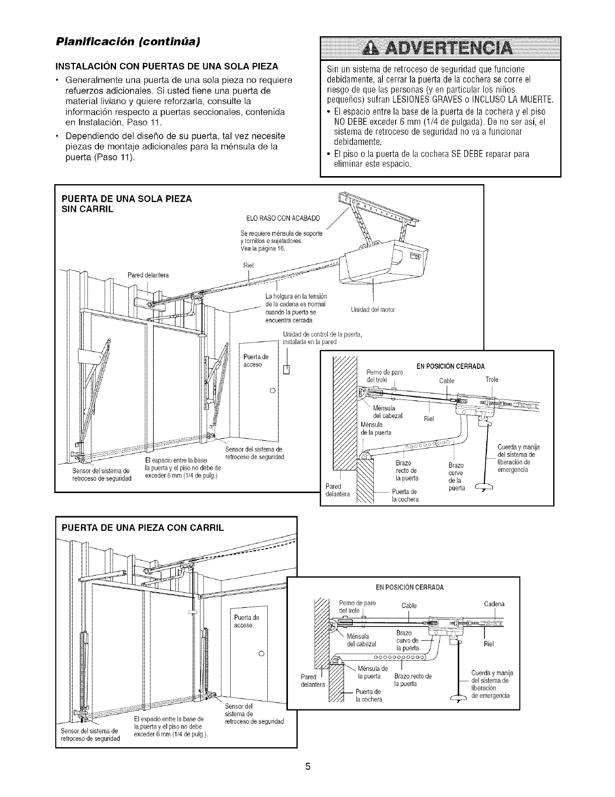
Planificaci6n (continba)
INSTALACION CON PUERTAS DE UNA SOLA PIEZA
•Generalmente una puerta de una sola pieza no requiere
refuerzos adicionales. Si usted tiene una puerta de
material liviano y quiere reforzarla, consulte la
informaci6n respecto a puertas seccionales, contenida
en Instalaci6n, Paso 11.
• Dependiende del disefie de su puerta, tal vez necesite
piezas de mentaje adicionales para la mensula de la
puerta (Paso 11).
Sin un sistema de retroceso de seguridad que funcione
debidamente, al cerrar la puerta de la cochera se corre el
riesgo de que las personas (y en particular los nifios
pequefios) sufran LESIONESGRAVESo INCLUSOLA MUERTE.
•El espacio entre la basede la puerta de la cochera y el piso
NODEBEexceder6mm (1/4 depulgada).De noserasi,el
sistema de retroceso de seguridad nova a funcionar
debidamente.
• El piso o la puerta de la cochera SE DEBEreparar para
eliminar este espacio.
PUERTA DE UNA SOLA PIEZA
SIN CARRIL
-"_ Pared delantera
Sensordel sistemade
retrocesode seguddad
ELO RASOCON ACABADO
Serequiere mensulade soporte
y tornillos osujetadores.
Vea la pagina 16.
La holgaraen la tensi6n
de la cadenaes normal
euandola puerta se Unidaddel motor
encuentracerrada
Unidad de centre[de la puerta,
/instalada en la pared
Puertade
acceso
Pemo de paro
0
Sensordel sistemade
El espacioentre la base retrocesode seguddad
la puerta y el piso no debede
exceder6 mm (1/4 de pulg.)
EN POSICIONCERRADA
I Cable Trole
J
Braze Braz0
recto de curve
la puerta de la
Puertade puerta _
la cochera
Cuerday manija
del sistemade
Iiberacionde
emergencia
PUERTA DE UNA PIEZA CON CARRIL
J El espacioentre la base de
Sensor del sistemade la puerta y el piso no debe
retroceso de seguddad exceder6 mm (1/4de pulg.).
Puertade
acceso
c
Sensor del
sistema de
retrocesode seguridad
Pare
delantera
ENPOS_C_ONCERRADA
Peme de pare Cable
del trole | I
,_ .? I
Mensula Brazo,
del cabezal curvoae _ /
la pueria j /
ooooooooooo)J
'_.. U6nsula de I
la puerta Brazorecto de
_/_ la puerta
7/_,-- Puerta de
Y/'_ la cochera
Cadena
Riel
Cuerda y manija
-- del sistemade
liberacion
de emergencia
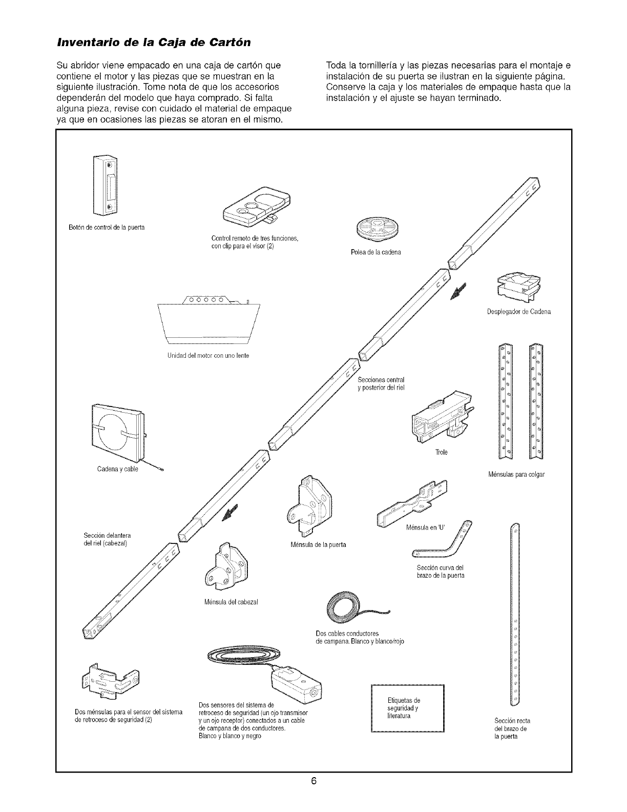
Inventario de la Caja de Cart6n
Su abridor viene empacado en una caja de carton que
contiene el motor y las piezas que se muestran en la
siguiente ilustraci6n. Tome nota de que los accesorios
dependeran del modelo que haya comprado. Si falta
alguna pieza, revise con cuidado el material de empaque
ya queen ocasiones las piezas se atoran en el mismo.
Toda la tornilleria y las piezas necesarias para el montaje e
instalacion de su puerta se ilustran en la siguiente pagina.
Conserve la caja y los materiales de empaque hasta que la
instalacion y e! ajuste se hayan terminado.
Bot6nde control de Japuerta
Controlremotode tresfunciones,
con clip para el visor (2)
Unidad del motor con Line lente
Poleade la cadena
s
Desplegadorde Cadena
Secci6ndelantera
del riel (cabezal)
Mensuladel cabezal
Seccionescentral
y posteriordel riel
Trole
Mensula de la puerta _,/
Secci6ncurva del
brazo de la puerta
Doscables conductores
de campana.Blancoy blanco/rojo
M_nsulaspara colgar
Dosm_nsulas para el sensordel sistema
de retrocesode seguridad(2)
Dossensoresdel sistema de
retrocesode seguridad(un ojo transmisor
y un ojo receptor)conectadosaun cable
de campanade dosconductores.
Blancoy blancoy negro
Etiquetasde
seguridady
literatura Seccionrecta
delbrazo de
la puerta
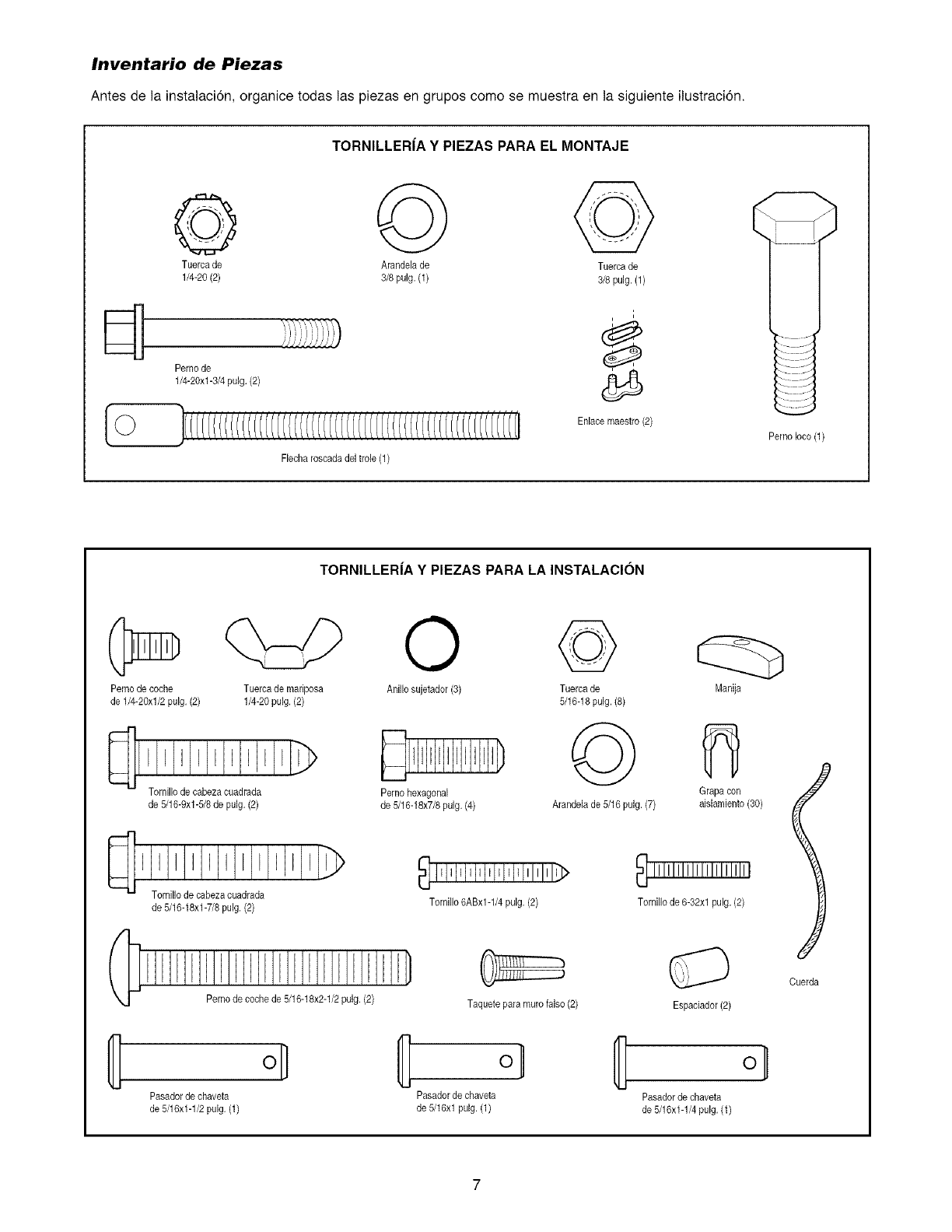
Inventario de Piezas
Antes de la instalaci6n, organice todas las piezas en grupos como se muestra en la siguiente ilustraci6n.
TORNILLERJA Y PIEZAS PARA EL MONTAJE
©
Tuerca de Arandela de Tuerca de
1/4-20 (2) 3/8 pub. (1) 3/8pub. (1)
Perno de
1/4-20xl-3/4 pulg. (2)
Fbcha roscada del trole (1)
i
d_
Enlace maestro (2)
Pemo Ioco (1)
TORNILLER|A Y PIEZAS PARA LA INSTALACION
Pernode coche
de 1/4-20xl/2 pulg. (2)
Tuercade mariposa
1/4-20 pulg. (2)
l I I EI I I I EE_)
Tornillode cabeza cuadrada
de 5/16-8xl-5/8 de pulg. (2)
de 5/16-18xl-7/8 pulg. (2)
Perno de coche de 5/16-18x2-1/2pulg. (2)
O ©
Anillo sujetador(3) Tuerca de
5/16-18puJg.(8)
E D @
Perno hexagonal
de 5/16-18x7/8pub. (4) Arandelade 5/16 pub. (7)
Taquete para murofalso (2)
Manija
Grapacon
aislamiento(30)
_ IIIIIIIIIIIIIIIIIIIII
Tornillo de 6-82xl pub. (2)
Espaciador(2)
ol
Pasadorde chaveta Pasadorde chaveta Pasadorde chaveta
de 5/16x1-1/2pulg. (1) de 5/16xl pulg. (1) de 5/16x1-1/4pulg. (1)
Cuerda
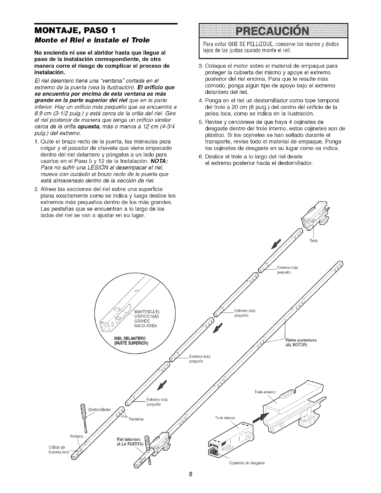
MONTAJE, PASO 1
Monte el Riel e instale el Trole
No encienda ni use el abridor hasta que Ilegue al
paso de la instalacion correspondiente, de otra
manera corre el riesgo de complicar el proceso de
instalacion.
El riel delantero tiene una "ventana" cortada en el
extremo de la puerta (vea la ilustracidn). El orificio que
se encuentra por encima de esta ventana es mas
grande en la parte superior del riel queen/a parte
inferio_ Hay un orificio mas peque_o que se encuentra a
8.9 cm (3-1/2 pulg.) y esta cerca de la orilla del riel. Gire
el riel posterior de manera que tenga un orificio similar
cerca de la orilla opuesta, mas o menos a 12 cm (4-3/4
pulg.) del extremo.
1. Quite el brazo recto de la puerta, las mensulas para
colgar y el pasador de chaveta que viene empacado
dentro del riel delantero y p6ngalos a un lado para
usarlos en el Paso 5 y 12 de la Instalaci6n. NOTA:
Para no sufrir una LESION al desempacar el riel,
mueva con cuidado el brazo recto de la puerta que
esta almacenado dentro de la seccidn de riel.
2. Alinee las secciones del riel sobre una superficie
plana exactamente como se indica y luego deslice los
extremos ma.s peque_os dentro de los mas grandes.
Las pesta_as que se encuentran a Io largo de los
lados del rie! se van a ajustar en su lugar.
ParaevitarQUESEPELLIZQUE,conservelos manosy ded0s
lejosdelasjuntascuandomonteelreil.
3. Coloque el motor sobre el material de empaque para
proteger la cubierta del mismo y apoye el extremo
posterior del riel encima. Para que le resulte mas
comodo, ponga algOn tipo de apoyo bajo e! extremo
delantero del riel.
4. Ponga en el riel un destornillador como tope temporal
del trole a 20 cm (8 pulg.) del centro del orificio de la
polea Ioca, como se indica en la ilustraci6n.
5. Revise y cerci6rese de que haya 4 cojinetes de
desgaste dentro del trole interno, estos cojinetes son de
pla.stico. Si los cojinetes se han soltado durante el
transporte, revise todo el material de empaque. Ponga
los cojinetes de desgaste en su lugar como se indica.
6. Deslice el trole a Io largo del riel desde
el extremo posterior hacia el destornillador.
Trole
Extremomgs
pequd_o
MANTENGA EL
" ORIFICIO MAS
GRANDE
HACIAARIBA
RIEL DELANTERO
(PARTESUPERIOR)
Extremomas
pequefio
Extremomas
peque_o
ieIes posteriores
(AL MOTOR}
Extremomas
pequeSo
Trole interno
Troleextemo
\
Cojinetesde desgaste
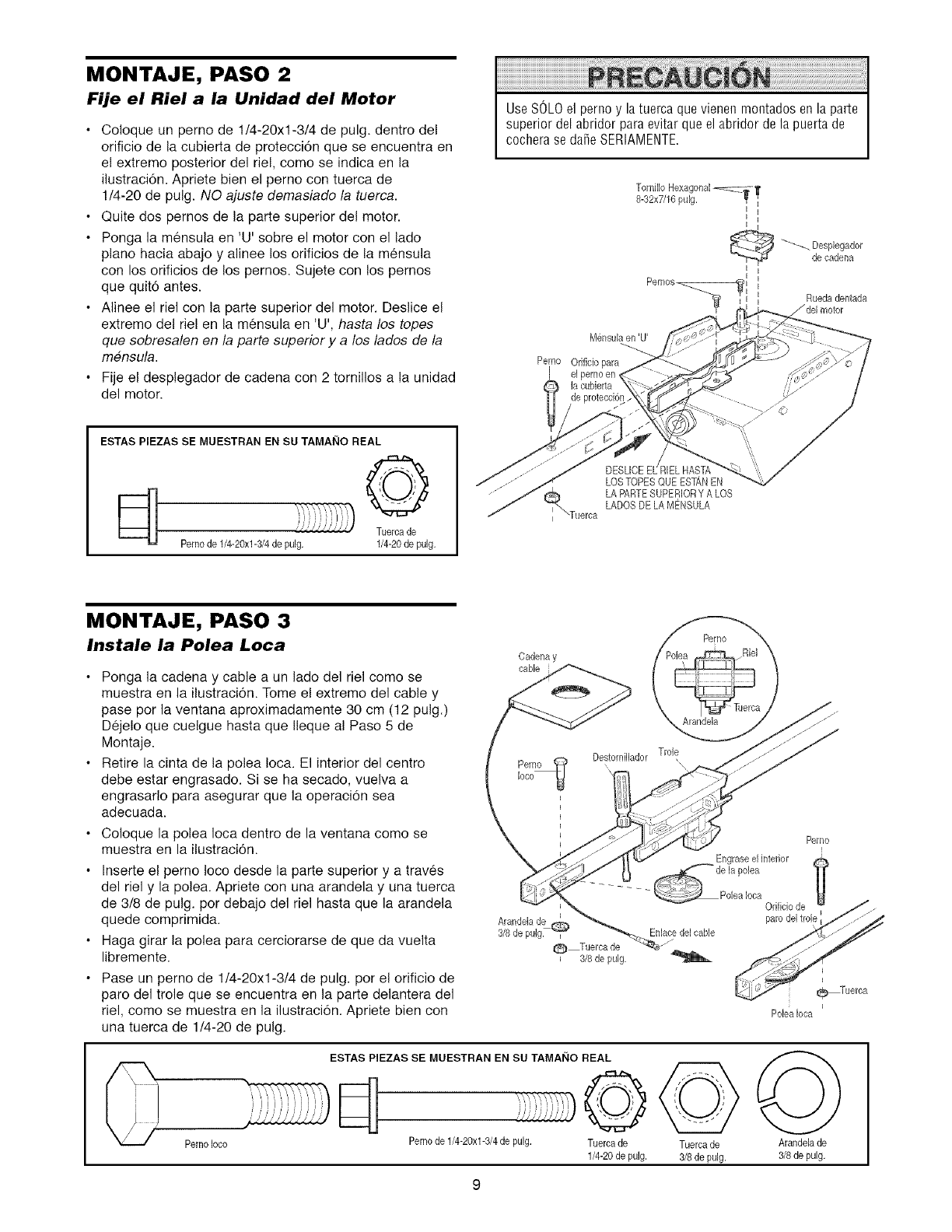
MONTAJE, PASO 2
Fije el Riel a la Unidad del Motor
Coloque un perno de t/4-20xl-3/4 de pulg. dentro del
orificio de la cubierta de proteccion que se encuentra en
el extremo posterior del riel, como se indica en la
ilustraci6n. Apriete bien el perno con tuerca de
1/4-20 de pulg. NO ajuste demasiado la tuerca.
Quite dos pernos de la parte superior del motor.
Ponga la mensula en 'U' sobre el motor con el lado
piano hacia abajo y alinee los orificios de la mensula
con los orificios de los pernos. Sujete con los pernos
que quit6 antes.
Alinee el riel con la parte superior del motor. Deslice el
extremo del riel en la mensula en 'U', hasta los topes
que sobresalen en la parte superior y a los lades de la
mensula.
Fije el desplegador de cadena con 2 tornillos a la unidad
del motor.
Use SOLOel perno y la tuerca que vienen montados en la parte
superior del abridor para evitar que el abridor de la puerta de
cochera se dafie SERIAMENTE.
Pernos_
M_nsulaen 'U'
Pemo Orificio para
I el perno en
la cubierta
de protecci@
I I
_'_ esplegador
de cadena
i
Ruedadentada
/del motor
ESTAS PIEZAS SE MUESTRAN EN SU TAMAI_IO REAL
ili _i
_'/i///"//'J Tuerca de
Perno de 1/4-20xl-3/4 de pulg. 1/4-20de pulg.
_Tuerca
LOSTOPESQUE ESTANEN
LA PARTESUPERIORY A LOS
LADOSDELA MENSULA
MONTAJE, PASO 3
Instale la Polea Loca
Ponga la cadena y cable a un lado del riel como se
muestra en la ilustracion. Tome el extremo del cable y
pase por la ventana aproximadamente 30 cm (12 pulg.)
Dejelo que cuelgue hasta que Ileque al Paso 5 de
Montaje.
Retire la cinta de la polea Ioca. El interior del centro
debe estar engrasado. Si se ha secado, vuelva a
engrasarlo para asegurar que la operaci6n sea
adecuada.
Coloque la polea Ioca dentro de la ventana como se
muestra en la ilustracion.
Inserte el perno Ioco desde la parte superior y a traves
del riel y la polea. Apriete con una arandela y una tuerca
de 3/8 de pulg. por debajo del riel hasta que la arandela
quede comprimida.
Haga girar la polea para cerciorarse de que da vuelta
libremente.
Pase un perno de 1/4-20xl-3/4 de pulg. por el orificio de
paro del trole que se encuentra en la parte delantera del
riel, como se muestra en la ilustraci6n. Apriete bien con
una tuerca de 1/4-20 de pulg.
Cadenay
cable
_) Tuercade
3/8 de pulg.
Perno
Arandela
Destornillador Trole
Perno
Engraseelinterior
_ e la polea
.... _Polealoca Orificio de
paro del tro
Enlacedelcable
Perno Ioco
ESTAS PIEZAS SE MUESTRAN EN SU TAMAI_IO REAL
©
Perno de 1/4-20xl-3/4 de pulg. Tuercade
1/4-20 de pulg.
Tuercade
3/8 de pulg.
Poleaiota
Arandelade
3/8de pulg.
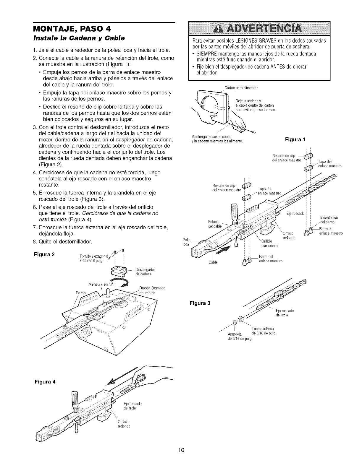
MONTAJE, PASO 4
Instale la Cadena y Cable
1. Jale el cable alrededor de la polea Ioca y hacia el trole.
2. Conecte la cable a la ranura de retencion de! trole, como
se muestra en la ilustraci6n (Figura 1):
• Empuje los pernos de la barra de enlace maestro
desde abajo hacia arriba y p4tselos a traves del enlace
del cable y la ranura del trole.
• Empuje la tapa de! enlace maestro sobre los pernos y
las ranuras de los pernos.
• Deslice el resorte de clip sobre la tapa y sobre las
ranuras de los pernos hasta que los dos pernos esten
bien colocados y seguros en su lugar.
3. Con el trole contra el destomillador, introduzca el resto
del cable/cadena a largo del riel hacia la unidad del
motor, dentro de la ranura en el desplegador de cadena,
alrededor de la rueda dentada sobre el desplegador de
cadena y continuando hacia el conjunto del trole. Los
dientes de la rueda dentada deben enganchar la cadena
(Figura 2).
4. Cerci6rese de que la cadena no este torcida, luego
conectela al eje roscado con el enlace maestro
restante.
5. Enrosque la tuerca interna y la arandela en el eje
roscado del trole (Figura 3).
6. Pase el eje roscado del trole a traves del orificio
que tiene el trole. Cercidrese de que la cadena no
este torcida (Figura 4).
7. Enrosque la tuerca externa en el eje roscado del trole,
dejandola floja.
8. Quite e! destornillador.
Figura 2 Tornillo Hexagonal,_ _
-32xTJ16pulg',
_ esplegador
de cadena
Mensula en '_ Rueda Dentada
Perno
Paraevitar posibles LESIONESGRAVESenlos dedos causadas
por las partes m6viles del abridor de puerta de cochera:
• SIEMPREmantenga las manos lejos de la rueda dentada
mientras est6funcionando el abridor.
• Fije bien el desplegador de cadena ANTESde operar
el abridor.
Carton para alimentar
oar,6o
e setuerzan.
Mantengatenses el cable
y la cadenamientras los alimente. Figura 1
i
Resortede clip
del enlace maestro "_ i Tapa del
enlace maestro
Cable
Figura 3
Eje roscado
del trole
Tuereainterna
Arandela de 5/16 de pulg,
de 5/16de pulg,
Figura 4
Eje roscado
del trole
Orificio
redondo
10
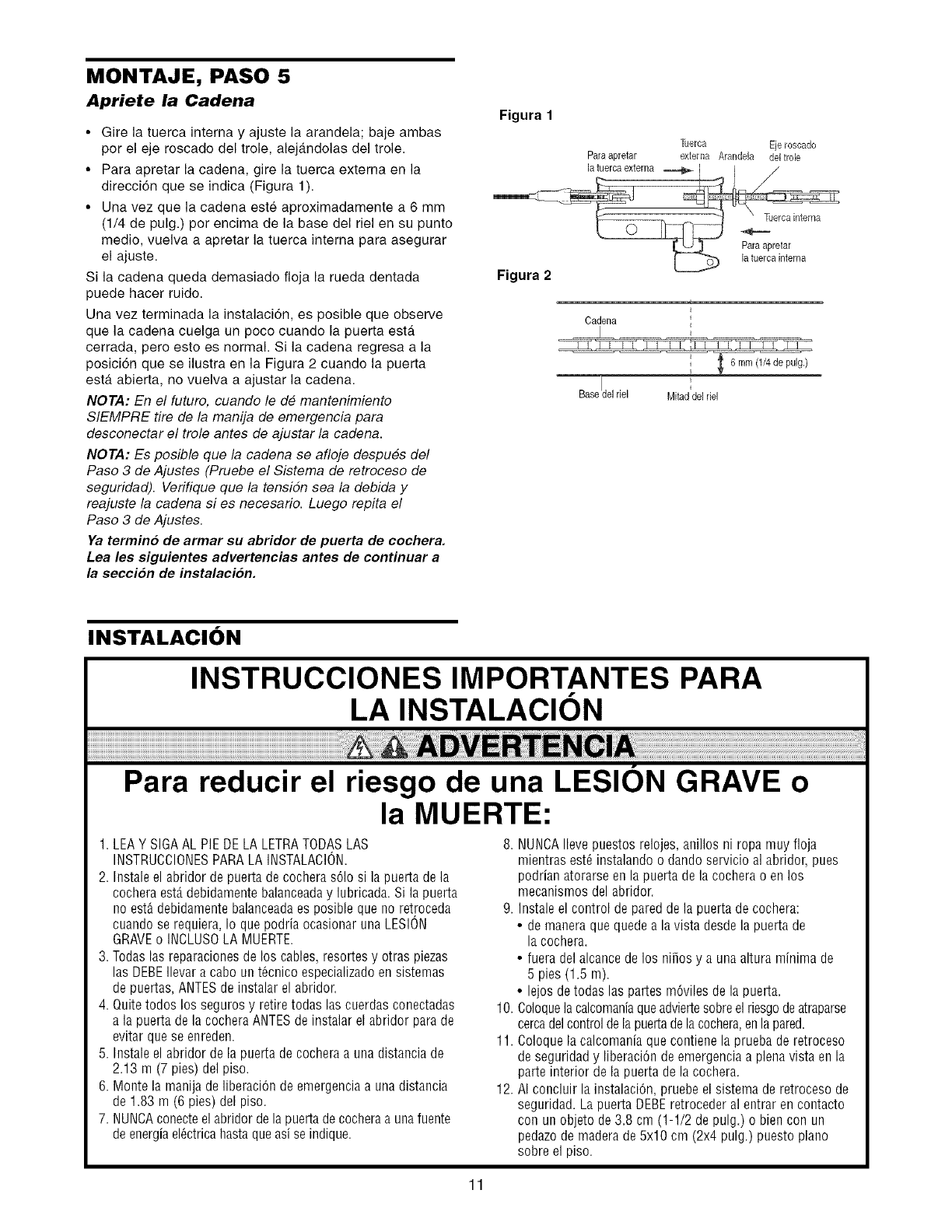
MONTAJE, PASO 5
Apriete la Cadena
•Gire la tuerca interna y ajuste la arandela; baje ambas
por el eje roscado del trole alejandolas del trole
• Para apretar la cadena gire la tuerca externa en la
direcci6n que se indica (Figura 1)
• Una vez que la cadena este aproximadamente a 6 mm
(1/4 de pulg) por encima de la base del riel en su punto
medio vuelva a apretar la tuerca interna para asegurar
el ajuste
Si la cadena queda demasiado floja la rueda dentada
puede hacer ruido
Una vez terminada la instalaci6n es posible que observe
que la cadena cuelga un poco cuando la puerta esta
cerrada pero esto es normal Si la cadena regresa a la
posici6n que se ilustra en la Figura 2 cuando la puerta
esta abierta no vuelva a ajustar la cadena
NOTA: En el futuro, cuando le de mantenimiento
SIEMPRE tire de la manija de emergencia para
desconectar el trole antes de ajustar la cadena
NOTA: Es posible que la cadena se afloje despues del
Paso 3 de Ajustes (Pruebe el Sistema de retroceso de
seguridad) Verifique que la tensiSn sea la debida y
reajuste la cadena si es necesario Luego repita el
Paso 3 de Ajustes
Ya termino de armar su abridor de puerta de cochera.
Lea les siguientes advertencias antes de continuar a
la secci6n de instalaci6n.
Figura 1
Figura 2
Paraapretar ]]Jerca Ejeroscado
externa Arandela del trole
t
Cadena
i
Basedel riel Mitad del riel
INSTALACION
INSTRUCCIONES IMPORTANTES PARA
LA INSTALACION
Para reducir el riesgo de una LESION GRAVE o
la MUERTE:
1. LEAY SIGAAL PIEDE LA LETRATODASLAS
INSTRUCCIONESPARA LA INSTALACION.
2. Instale el abridor de puerta de cochera s61osi la puerta de la
cochera est,. debidamente balanceaday lubricada. Si la puerta
no est_ debidamente balanceadaes posible que no retroceda
cuando se requiera, Io que podria ocasionar una LESION
GRAVEo INCLUSOLA MUERTE.
3. Todas las reparaciones de los cables, resortes y otras piezas
las DEBEIlevar a cabo un t6cnico especializado en sistemas
de puertas, ANTESde instalar el abridor.
4. Quite todos los seguros y retire todas las cuerdas conectadas
a la puerta de la cochera ANTESde instalar el abridor para de
evitar que se enreden.
5. Instale el abridor de la puerta de cochera a una distaocia de
2.13 m (7 pies) del piso.
6. Monte la manija de liberaci6n de emergencia a una distancia
de 1.83 m (6 pies) del piso.
7. NUNCAconecteel abridor de la puerta decochera a una fuente
de energiael6ctrica hasta queasi se indique.
8. NUNOAIlevepuestos relojes,anillos ni ropa muy floja
mientras est_ instalando odando servicio al abridor, pues
podrian atorarse en la puerta de la cochera o en los
mecanismos del abridor.
9. Instale el control de pared de la puerta de cochera:
• de manera que quede a lavista desde la puerta de
la cochera.
• fuera del alcance de los nifios y a una altura minima de
5 pies (1.5 m).
• lejos de todas las partes m6viles de la puerta.
10. Coloquelacalcomaniaqueadviertesobreel riesgodeatraparse
cercadel controlde lapuertadela cochera,en lapared.
11. Coloque la calcomania que contieoe la prueba de retroceso
de seguridad y liberaciOnde emergencia a plena vista en la
parte interior de la puerta de la cochera.
12. AI concluir la instalaci6n, pruebe el sistema de retroceso de
seguridad. La puerta DEBEretroceder al entrar en contacto
con un objeto de 3.8 cm (1-1/2 de pulg.) o bien con un
pedazode madera de 5x10 cm (2x4 pulg.) puesto piano
sobre el piso.
11
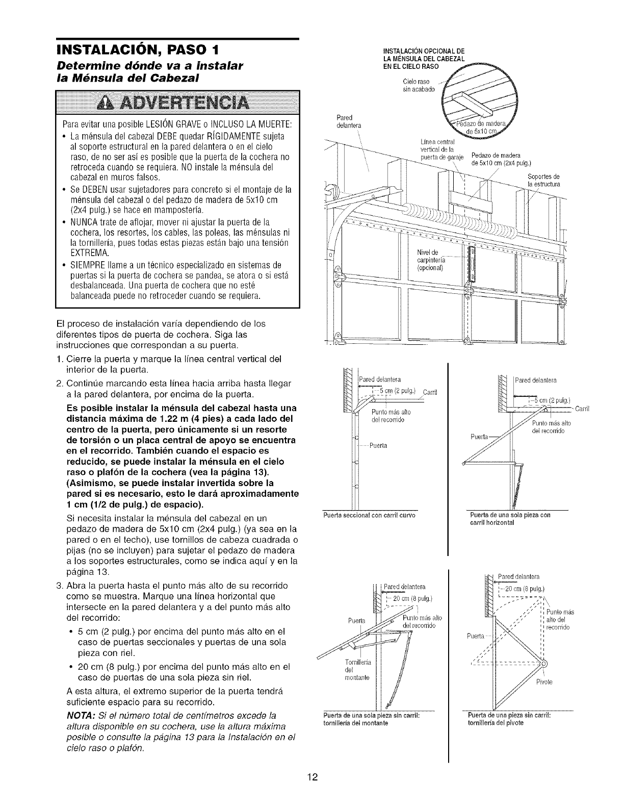
I NSTALACl ON, PASO 1 INSTALACI6NOPCIONALDE
LA MENSULA DEL eABEZAL
EN EL ClELO RASO
Determine ddnde va a instalar
la M_nsula del Cabezal Cieloraso
sin acabado
ParaevitarunaposibleLESIONGRAVEo INCLUSOLAMUERTE:
• Lam6nsuladelcabezalDEBEquedarRiGIDAMENTEsujeta
alsoporteestructuralenla pareddelanterao enelcielo
raso,deno serasies posiblequela puertadelacocherano
retrocedacuandose requiera.NOinstalela m_nsuladel
cabezalen murosraises.
• SeDEBENusarsujetadoresparaconcretesi el montajedela
m6nsuladelcabezalo delpedazodemaderade5x10cm
(2x4 pulg.)sehaceenmamposteria.
• NUNCAtratedeaflojar,moverni ajustarlapuertadela
cochera,los resortes,los cables,las poleas,las m_nsulasni
latornilleria,puestodasestaspiezasestAnbajounatension
EXTREMA.
• SIEMPREIlameaunt_cnicoespecializadoensistemasde
puertassi la puertadecocherase pandea,seatorao siestA
desbalanceada.Unapuertadecocheraquenoest6
balanceadapuedenoretrocedercuandoserequiera.
El proceso de instalaci6n varfa dependiendo de los
diferentes tipos de puerta de cochera. Siga las
instrucciones que correspondan a su puerta.
1. Cierre la puerta y marque la linea central vertical del
interior de la puerta.
2. ContinOe marcando esta linea hacia arriba hasta Ilegar
a la pared delantera, per encima de la puerta.
Es poeible instalar la m_nsula del cabezal hasta una
distancia maxima de 1.22 m(4 pies) a cada lade del
centre de la puerta, pero unicamente ei un reeorte
de torsion o un placa central de apoyo se encuentra
en el recorrido. Tambien cuando el espacio es
reducido, se puede instalar la meneula en el cielo
raso o plafon de la cochera (vea la pagina 13).
(Asimismo, se puede instalar invertida sobre la
pared ei ee necesario, eeto le dara aproximadamente
1 cm (1/2 de pulg.) de espacio).
Si necesita instalar la mensula del cabezal en un
pedazo de madera de 5x10 cm (2x4 pulg.) (ya sea en la
pared o en el techo), use tornillos de cabeza cuadrada o
pijas (no se incluyen) para sujetar el pedazo de madera
a los soportes estructurales, come se indica aqui yen la
pagina 13.
3. Abra la puerta hasta el punto mas alto de su recorrido
come se muestra. Marque una linea horizontal que
intersecte en la pared delantera y adel punto mas alto
del recorrido:
• 5 cm (2 pulg.) per encima del punto mas alto en el
case de puertas seccionales y puertas de una sola
pieza con riel.
• 20 cm (8 pulg.) per encima del punto mas alto en el
case de puertas de una sola pieza sin riel.
A esta altura, el extreme superior de la puerta tendra
suficiente espacio para su recorrido.
NOTA: Si el n#mero total de cenffmetros excede la
altura disponible en su cochera, use la altura maxima
posible o consulte la pagina 13 para la Instalacidn en el
ciele rase e plafdn.
Pared
delantera
I Paredde[antera
cm (2 pu[g.) zCam I
Punto m_salto
de[recorrido
Puerta
Puerta eeoeionaI con earri[ curve
Pared deIantera
20 cm (8 puig,)
Puerta de[ recemdo
Tornilleria
de[
montallte
Puerta de uaa sola pieza sin carri[:
tomiHeria de[ montante
Linea central
vertical de [a
puerta de garaje
\
Pedazode madera
de 5x10 cm (2x4 pulg.)
Soportes de
la estructura
Pareddelantera
_,_:-_51ZCCC-_ Cardl
Punlo mas alto
/del recorrido
Paerta de uaa sola pieza con
aarri[ horizontal
Pareddelantera
20 cm (8 pulg,)
Pivote
Puerta de una pieza sin carri[:
torniHeria de[ pivote
12
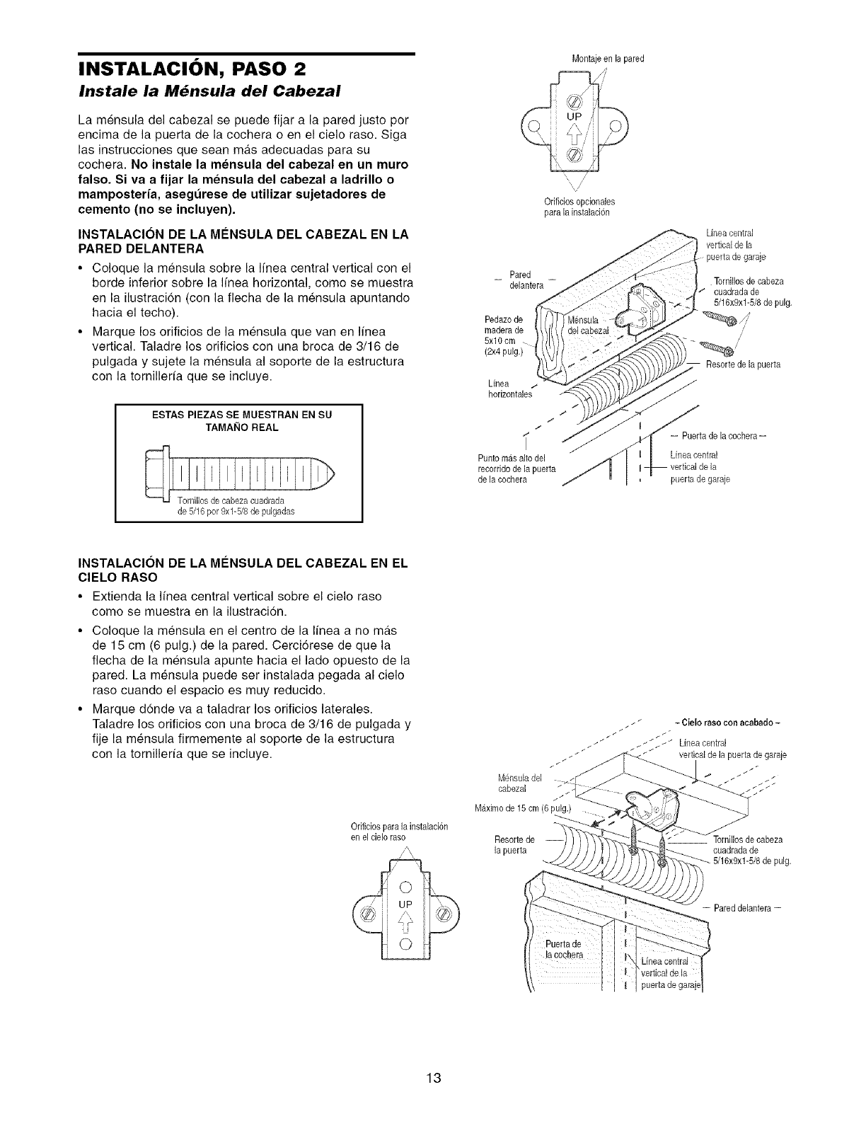
INSTALACION, PASO 2
Instale la M6nsula del Cabezal
La mensula del cabezal se puede fijar a la pared justo por
encima de la puerta de la cochera o en el cielo raso. Siga
las instrucciones que sean mas adecuadas para su
cochera. No inetale la mensula del cabezal en un muro
falso. Si va a fijar la mensula del cabezal a ladrillo o
mamposteria, asegt_reee de utilizar sujetadores de
cemento (no se incluyen).
INSTALAClON DE LA MI_NSULA DEL CABEZAL EN LA
PARED DELANTERA
• Coloque la mensula sobre la Ifnea central vertical con el
borde inferior sobre la Ifnea horizontal, come se muestra
en la ilustracion (con la fiecha de la mensula apuntando
hacia el techo).
• Marque los orificios de la mensula que van en Ifnea
vertical. Taladre los orificios con una broca de 3/16 de
pulgada y sujete la mensula al soporte de la estructura
con la tornillerfa que se incluye.
ESTAS PIEZAS SE MUESTRAN EN SU
TAMAI_IO REAL
de 5/16 por 9xl-5/8 de pulgadas
Montajeen la pared
/
Odficiosopcionales
para la instalacion
Pared
delantera
Pedazode
maderade
5x10 cm
Linea
hodzontales
Lineacentral
vertical de la
puertade garaje
Tornillos de eabeza
cuadradade
5/16x9xl-5/8 de pulg.
Resorte de la puerta
/
/
t
i= Puerta de la cochera=
Punto masalto del L[nea central
recorrido de la puerta
de la cochera puertade garaje
INSTALACION DE LA M#NSULA DEL CABEZAL EN EL
ClELO RASO
• Extienda la Ifnea central vertical sobre el cielo raso
come se muestra en la ilustracion.
• Coloque la mensula en el centre de la Ifnea a no ma.s
de 15 cm (6 pulg.) de la pared. Cerci6rese de que la
flecha de la mensula apunte hacia el lado opuesto de la
pared. La mensula puede set instalada pegada al cielo
raso cuando el espacio es muy reducido.
• Marque donde va a taladrar los orificios laterales.
Taladre los orificios con una broca de 3/16 de pulgada y
fije la mensula firmemente al soporte de la estructura
con la tornillerfa que se incluye.
Orificios para la instalacion
en el cieloraso Resorte de
la puerta cuadradade
pulg.
= Pareddelantera--
13
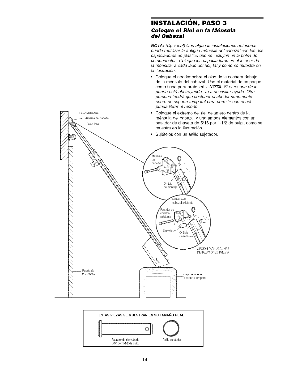
-- Pareddelantera
]a cocher8
INSTALACION, PASO 3
Coloque el Riel en la M_nsula
del Cabezal
NOTA: (Opcional) Con algunas instalaciones anteriores
puede reutilizar la antigua mensula del cabezal con los dos
espaciadores de plastice que se incluyen en la belsa de
componentes. Coloque los espaciadores en el interior de
la mensula, a cada lade del riel, tal y come se muestra en
la ilustracidn.
• Coloque el abridor sobre el piso de la cochera debajo
de la mensula del cabezal. Use el material de empaque
come base para protegerlo. NOTA: Si el resorte de la
puerta esta obstruyendo, va a necesitar ayuda. Otra
persona tendra que sostener el abridor firmemente
sobre un soporte temporal para permitir que el riel
pueda librar el resorte.
• Coloque el extreme del riel delantero dentro de la
mensula del cabezal y una ambos elementos con un
pasador de chaveta de 5/16 por 1-1/2 de pulg., come se
muestra en la ilustraci6n.
• Sujetelos con un anillo sujetador.
0
/
Odficio
de mont@
cabezal existente
0
de montaje
OPCIONPARAALGUNAS
[NSTALACIONESPREVIA
ESTAS PIEZAS SE MUESTRAN EN SU TAMAI_IO REAL
{
Pasadorde chaveta de Anillo sujetador
5/16 por 1-1/2de pulg.
14
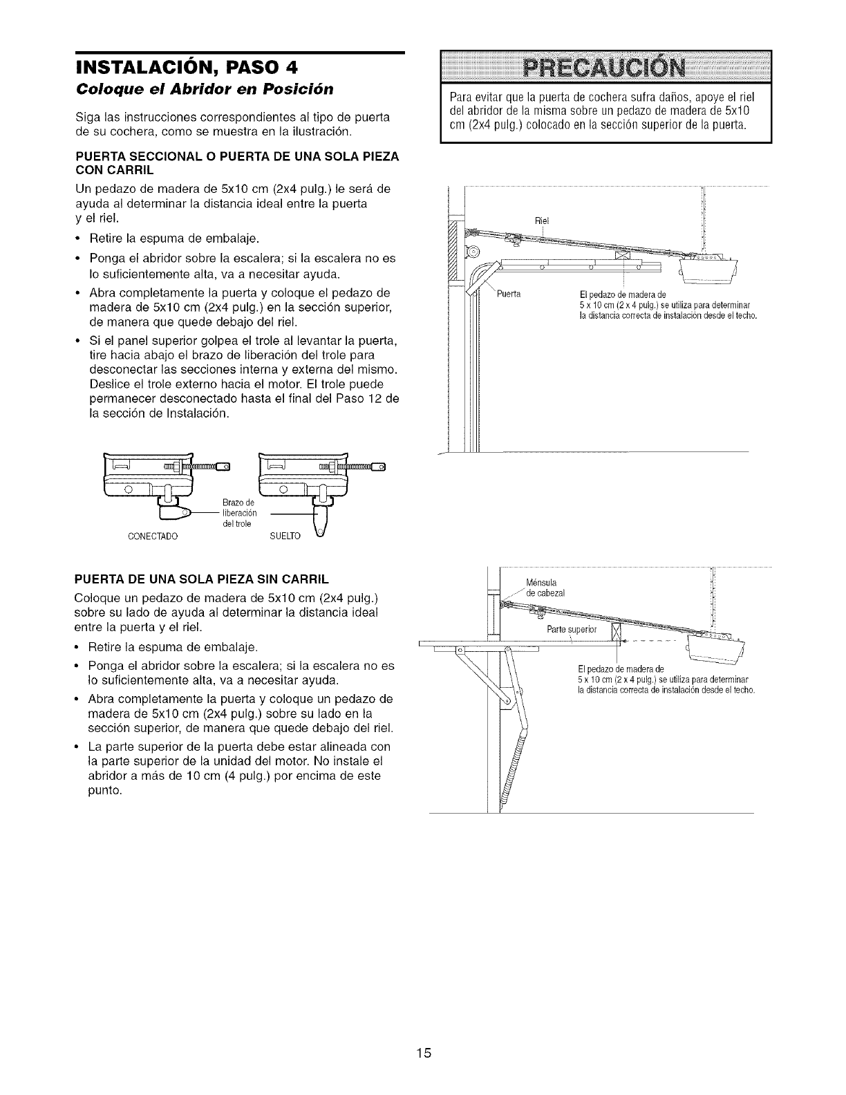
INSTALACION, PASO 4
Coloque el Abridor en Posici6n
Siga las instrucciones correspondientes al tipo de puerta
de su cochera, como se muestra en la ilustracion.
PUERTA SECClONAL O PUERTA DE UNA SOLA PIEZA
CON CARRIL
Un pedazo de madera de 5x10 cm (2x4 pulg.) le sera de
ayuda al determinar la distancia ideal entre la puerta
y el riel.
•Retire la espuma de embalaje.
• Ponga el abridor sobre la escalera; si la escalera no es
Io suficientemente alta, va a necesitar ayuda.
• Abra completamente la puerta y coloque el pedazo de
madera de 5x10 cm (2x4 pulg.) en la secci6n superior,
de manera que quede debajo del riel.
• Si el panel superior golpea el trole al levantar la puerta,
tire hacia abajo el braze de liberaci6n del trole para
desconectar las secciones intema y extema del mismo.
Deslice el trole extemo hacia el motor. El trole puede
permanecer desconectado hasta el final del Paso 12 de
la secci6n de Instalaci6n.
L==__azo de
liberaci6n
del trole
CONECTADO
Paraevitar que la puerta de cochera sufra da5os, apoye el riel
del abridor de la misma sobre un pedazode madera de 5x10
cm (2x4 pulg.) colocado enla secci6n superior de la puerta.
i niel 1
-- __PuertalI ilPiio_i° i21_x_4_iu[_)iiesUt_llizai6Paclads_eere_nlnc_h° '
PUERTA DE UNA SOLA PIEZA SIN CARRIL
Coloque un pedaze de madera de 5x10 cm (2x4 pulg.)
sobre su lade de ayuda al determinar la distancia ideal
entre la puerta y el riel.
• Retire la espuma de embalaje.
• Ponga el abridor sobre la escalera; si la escalera no es
Io suficientemente alta, va a necesitar ayuda.
• Abra completamente la puerta y coloque un pedazo de
madera de 5x10 cm (2x4 pulg.) sobre su lade en la
secci6n superior, de manera que quede debajo del riel.
• La parte superior de la puerta debe estar alineada con
la parte superior de la unidad del motor. No instale el
abridor amas de 10 cm (4 pulg.) per encima de este
punto.
Elpedazode maderade
5 x 10 cm(2 x 4 pulg.) se utilizapara determinar
la distancia correctade instalaciondesdeel techo.
15
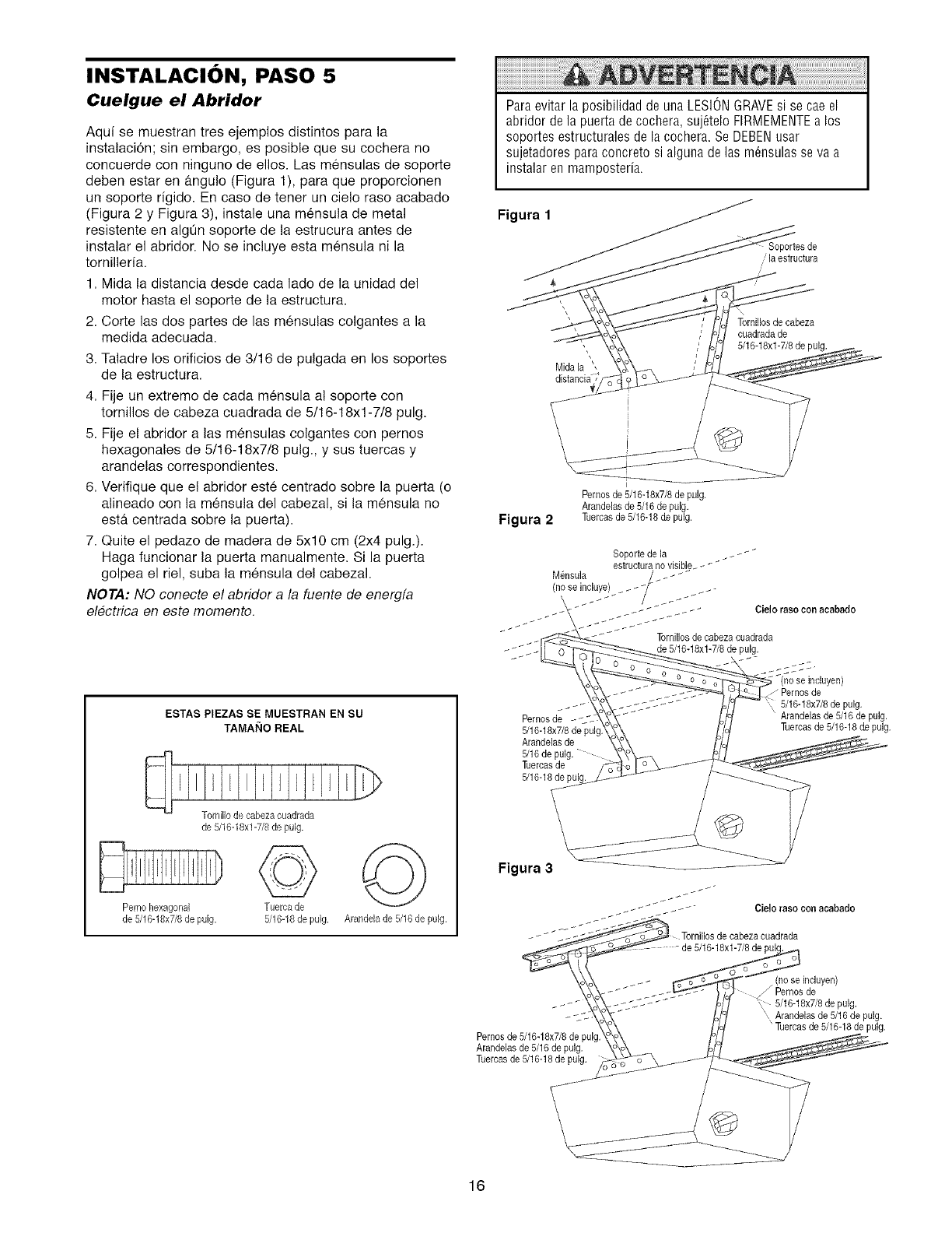
INSTALACION, PASO 5
Cuelgue el Abridor
Aqui se muestran tres ejemplos distintos para la
instalacion; sin embargo, es posible que su cochera no
concuerde con ninguno de ellos. Las mensulas de soporte
deben estar en gtngulo (Figura 1), para que proporcionen
un soporte rigido. En caso de tener un cielo raso acabado
(Figura 2 y Figura 3), instale una mensula de metal
resistente en algQn soporte de la estrucura antes de
instalar el abridor. No se incluye esta mensula ni la
tomilleria.
1. Mida la distancia desde cada lade de la unidad del
motor hasta el soporte de la estructura.
2. Corte las dos partes de las mensulas colgantes a la
medida adecuada.
3. Taladre los orificios de 3/16 de pulgada en los soportes
de la estructura.
4. Fije un extremo de cada mensula al soporte con
tornillos de cabeza cuadrada de 5/16-18xl-7/8 pulg.
5. Fije el abridor a las mensulas colgantes con pernos
hexagonales de 5/16-18x7/8 pulg., y sus tuercas y
arandelas correspondientes.
6. Verifique que el abridor este centrado sobre la puerta (o
alineado con la mensula del cabezal, si la mensula no
estgt centrada sobre la puerta).
7. Quite el pedazo de madera de 5xlO cm (2x4 pulg.).
Haga funcionar la puerta manualmente. Si la puerta
golpea el riel, suba la mensula del cabezal.
NOTA: NO conecte el abridor a la fuente de energfa
electrica en este memento.
Paraevitar la posibilidad de una LESIONGRAVEsi se cae el
abridor de la puerta de co@era, suj6telo FIRMEMENTEa los
soportes estructurales de la cochera. Se DEBENusar
sujetadores para concreto si alguna de las m_nsulas se va a
instalar en mamposteria.
Figura 1
Soportes de
.' la estructura
\
" Tornillosde cabeza
cuadradade
5/16-18xl-7/8 de pulg.
Midala ',
distancia 7
Figura 2
Pernosde 5/16-18x7/8de puIg.
Arandelas de 5/16de pulg.
Tuercasde 5/16-18de pulg.
Soporte de la _ _ _ _"
estructura novisible_ _ _
M6nsula /__ _ _
(nose incluy_/ .._ __ ......
"- "///__-_-_'///._'_- " Cielo raso con acabado
_ Tornillosde cabezacuadrade
de 5/16-18xl-7/8 de pulg.
ESTAS PIEZAS SE MUESTRAN EN SU
TAMANO REAL
Perno hexagonal
de 5/16-18x7/8de pulg.
Tornillo de cabezacuadrade
de 5/16-18xl-7/8 de pulg.
©
Tuerca de
5/18-18de pulg.
©
Arandelade 5/16de pulg.
Pernosde
5/16-18x7/8de pul_
Arandelasde
5/16de pulg.
Tuercasde
5/16-18de
." Pernos de
5/16-18x7/8de pulg. pulg.
Tuercasde 5/18-18depulg.
Figura 3
_ _ _ Cielo raso conacabado
__ Tornillosde cabezacuadrada
\o_,_x .... _,r':"_i'_o%,_ '_ _no seincluyen)
f P mosde
.._--- \_.-:_.7 ..... H7 ,, 5/16-18x7/8depulg.
.._j,\ _._ - _/o_ Arandelas de 5/16 de pulg.
_'_\ ] [oj Tuercasde 5/16-18de pulg.
Pernosde 5/161-8_,\ P,// _
Arandelasde5/16depul_ " \8\0\ _.
Tuercasde 5/16-18__
16
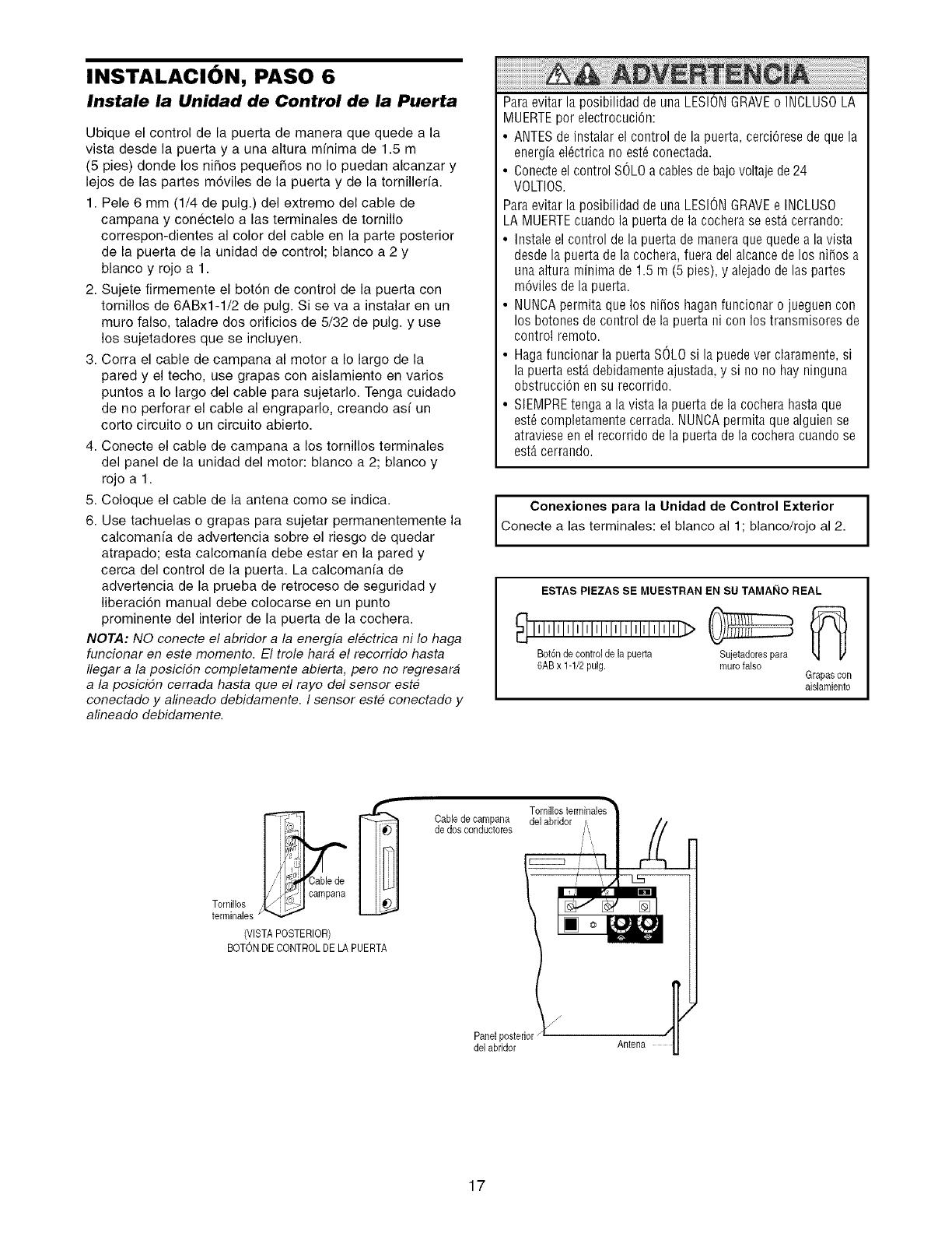
INSTALACION, PASO 6
Instale la Unidad de Control de la Puerta
Ubique el control de la puerta de manera que quede a la
vista desde la puerta y a una altura minima de 15 m
(5 pies) donde los nihos pequeSos no Io puedan alcanzar y
lejos de las partes mdviles de la puerta y de la tomillerfa
1 Pele 6 mm (1/4 de pulg) del extremo del cable de
campana y conectelo alas terminales de tornillo
correspon-dientes al color del cable en la parte posterior
de la puerta de la unidad de control; blanco a 2 y
blanco y rojo a 1
2 Sujete firmemente el botdn de control de la puerta con
tornillos de 6ABx1-1/2 de pulg Si se va a instalar en un
muro falso, taladre dos orificios de 5/32 de pulg y use
los sujetadores que se incluyen
3 Corra el cable de campana al motor a Io largo de la
pared y el techo, use grapas con aislamiento en varios
puntos a Io largo del cable para sujetarlo Tenga cuidado
de no perforar el cable al engraparlo, creando asi un
corto circuito o un circuito abierto
4 Conecte el cable de campana a los tornillos terminales
del panel de la unidad del motor: blanco a 2; blanco y
rojo a 1
5 Coloque el cable de la antena como se indica
6 Use tachuelas o grapas para sujetar permanentemente la
calcomanfa de advertencia sobre el riesgo de quedar
atrapado; esta calcomanfa debe estar en la pared y
cerca del control de la puerta La calcomania de
advertencia de la prueba de retroceso de seguridad y
liberacion manual debe colocarse en un punto
prominente del interior de la puerta de la cochera
NOTA: NO conecte el abridor a la energfa electrica ni Io haga
funcionar en este momento El trole hara el recorrido hasta
flegar a la posicidn completamente abierta, pero no regresara
a la posiciSn cerrada hasta que el rayo del sensor este
conectado y alineado debidamente I sensor este conectado y
alineado debidamente
Paraevitar la posibilidad de una LESIONGRAVEo INCLUSOLA
MUERTEpor electrocuci6n:
• ANTESde instalar el control de la puerta, cerci6rese de que la
energia el6ctrica no est6 conectada.
• Conecteel control SOLOa cablesde bajovoltaje de24
VOLTIOS.
Paraevitar la posibilidad de una LESIONGRAVEe INCLUSO
LA MUERTEcuando la puerta de la cochera se est_ cerrando:
• Instale el control de la puerta de manera que quede a lavista
desde la puerta de la cochera, fuera del alcancede los niSosa
una altura minima de 1.5 m (5 pies), y alejadode las partes
mdviles de la puerta.
• NUNCApermita que los niSos hagan funcionar o jueguen con
los botones de control de la puerta ni con los transmisores de
control remoto.
• Haga funcionar la puerta SOLOsi la puede ver claramente, si
la puerta est,. debidamenteajustada, y si no no hay ninguoa
obstruccidn en su recorrido.
• SIEMPREtenga a la vista la puerta de la cochera hasta que
est_ completamente cerrada. NUNCApermita que alguien se
atraviese en el recorrido de la puerta de la cochera cuando se
est_ cerrando.
Conexiones para la Unidad de Control Exterior i
I
Conecte alas terminales: el blanco al 1; blanco/rojo al 2.
ESTAS PIEZAS SE MUESTRAN EN SU TAMAI_IO REAL
IIlllllllllllllllllllllllllllll>
Bot6nde control de la puerta Sujetadorespara
6ABx 1-1/2pulg. murofalso Grapascon
aislamiento
I/ )11<._ I campana
Tornillos ¢_
terminales
(VISTA POSTERIOR)
BOTONDECONTROLDE LAPUERTA
Cablede carnpana
de dos conductores
Panelposterior/
del abridor
del abridor /,,
An_na
17
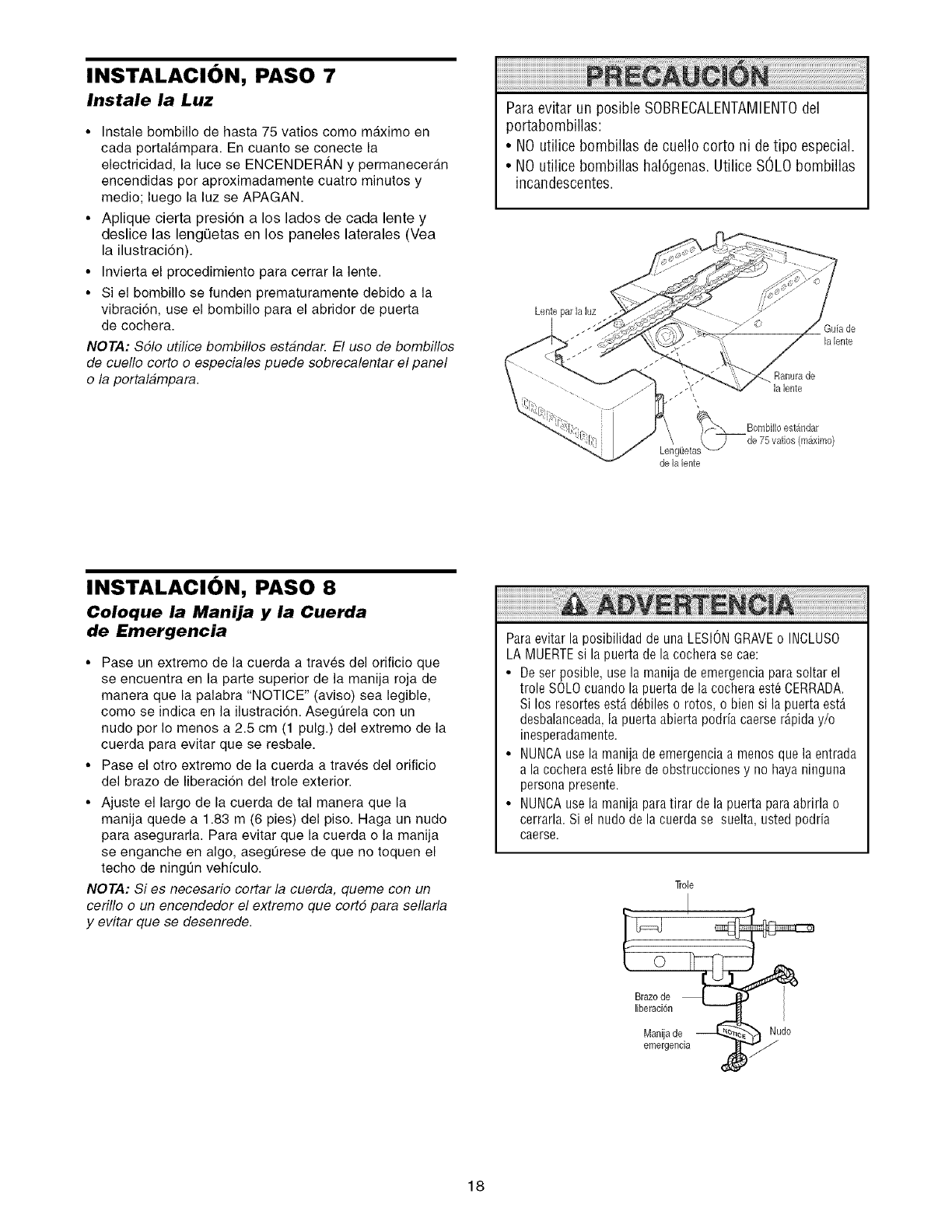
INSTALACION, PASO 7
Instale la Luz
•Instale bombillo de hasta 75 vatios como m_tximo en
cada portaldtmpara En cuanto se conecte la
electricidad, la luce se ENCENDERAN y permanecer_n
encendidas per aproximadamente cuatro minutos y
medio; luego la luz se APAGAN
• Aplique cierta presi6n a los lados de cada lente y
deslice las lengOetas en los paneles laterales (Vea
la ilustraci6n).
• Invierta el procedimiento para cerrar la lente
• Si el bombiNo se funden prematuramente debido a la
vibraci6n, use el bombNIo para el abridor de puerta
de cochera
NOTA: $61o utilice bombillos estandan El uso de bombillos
de cuello corto o especiales puede sobrecalentar el panel
o la portalampara
Paraevitar un posible SOBRECALENTAIVlIENTOdel
portabombillas:
•NO utilice bombillas de cuello cortoni detipo especial
•NO utilice bombillas hal6genas Utilice SOLObombillas
incandescentes
Lente parlaluz
Gufa de
la lente
la lente
J
delalente
INSTALACION, PASO 8
Coloque la Manija y la Cuerda
de Emergencia
• Pase un extreme de la cuerda a traves del orificio que
se encuentra en la parte superior de la manija roja de
manera que la palabra "NOTICE" (aviso) sea legible,
come se indica en la ilustracion. Asegt]rela con un
nudo per Io menos a 2.5 cm (1 pulg.) del extreme de la
cuerda para evitar que se resbale.
• Pase el otro extremo de la cuerda a traves del orificio
del braze de liberaci6n del trole exterior.
• Ajuste el largo de la cuerda de tal manera que la
manija quede a 1.83 m (6 pies) del piso. Haga un nude
para asegurarla. Para evitar que la cuerda o la manija
se enganche en algo, asegt_rese de que no toquen el
techo de ningt]n vehfculo.
NOTA: Si es necesario cortar la cuerda, queme con un
cerillo o un encendedor el extreme que cortd para sellarla
y evitar que se desenrede.
Paraevitar la posibilidad de una LESIONGRAVEo INCLUSO
LA MUERTEsi la puerta de la cochera se cae:
• De ser posible, use la manija de emergenciapara soltar el
trole SOLOcuando la puerta de la cochera est6 CERRADA
Si los resortes est&d6biles o rotos, o bien si la puerta est_
desbalanceada,la puerta abierta podria caerse r_pida y/o
inesperadamente
• NUNCAuse la manija de emergencia a menos que la entrada
a la cochera est6 libre de obstrucciones y no haya ninguna
persona presente
• NUNCAuse la manija para tirar de la puerta para abrirla o
cerrarla Si el nudo de la cuerda se suelta, usted podria
caerse
]role
0
Brazode
liberacion
Manijade _ _udoemergencia
18
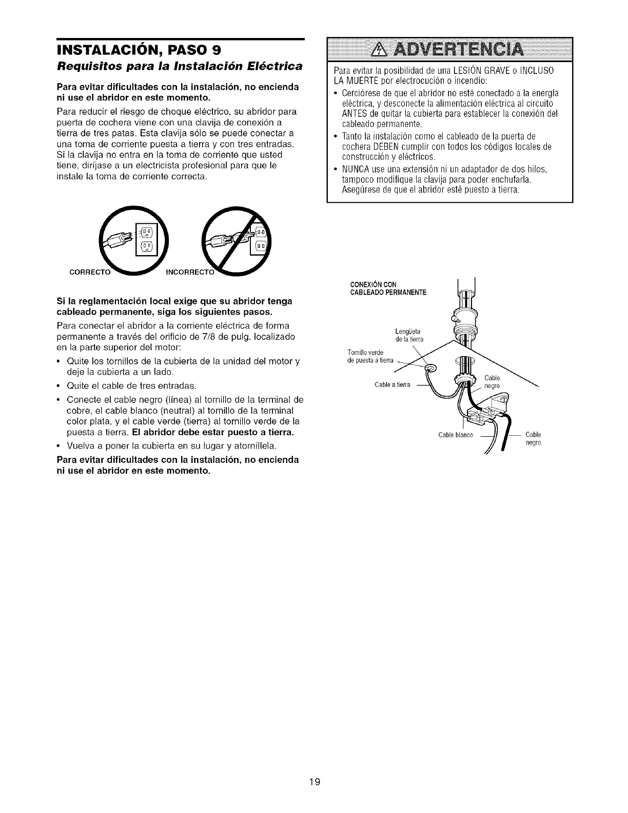
INSTALACION, PASO 9
Requisitos para la Instalaci6n El6ctrica
Para evitar dificultades con la instalacion, no encienda
ni use el abridor en este momento.
Para reducir el riesgo de choque electrico, su abridor para
puerta de cochera viene con una clavija de conexidn a
tierra de tres patas. Esta clavija solo se puede conectar a
una toma de corriente puesta a tierra y con tres entradas.
Si la clavija no entra en la toma de corriente que usted
tiene, dirfjase a un electricista profesional para que le
instale la toma de corriente correcta.
CORRECQNCORRECQ
Si la reglamentacion local exige que su abridor tenga
cableado permanente, siga los siguientes pasos.
Para conectar el abridor a la corriente electrica de forma
permanente a traves del orificio de 7/8 de pulg. Iocalizado
en la parte superior del motor:
• Quite los tornillos de la cubierta de la unidad del motor y
deje la cubierta a un lado.
• Quite el cable de tres entradas.
• Conecte el cable negro (Ifnea) al tornillo de la terminal de
cobre, el cable blanco (neutral) al tornillo de la terminal
color plata, y el cable verde (tierra) al tornillo verde de la
puesta a tierra. El abridor debe estar puesto a tierra.
• Vuelva a poner la cubierta en su lugar y atornfllela.
Para evitar dificultades con la instalacion, no encienda
ni use el abridor en este momento.
ParaevitarlaposibilidaddeunaLESIONGRAVEo INCLUSO
LA MUERTEpor electrocuci6n o incendio:
•CerciOresede que el abridor no est6 conectado a la energia
el6ctrica, y desconecte la alimentaci6n el6ctrica al circuito
ANTESde quitar la cubierta para establecer la conexi6n del
cableado permanente.
• Taoto la instalaci6o como el cableado de la puerta de
cochera DEBENcumplir con todos los c6digos locales de
construcciOn y el6ctricos.
• NUNCAuse una extensi6n ni un adaptador de dos hilos,
tampoco modifique la clavija para poder eochufarla.
Aseg_iresede que el abridor est6 puesto a tierra.
CONEXlONCON
CABLEADO PERMANENTE
Lengeeta
dela tierra
Tornilloverde
Cablea tierra Cable
/ negro
Cableblanco Cable
negro
19
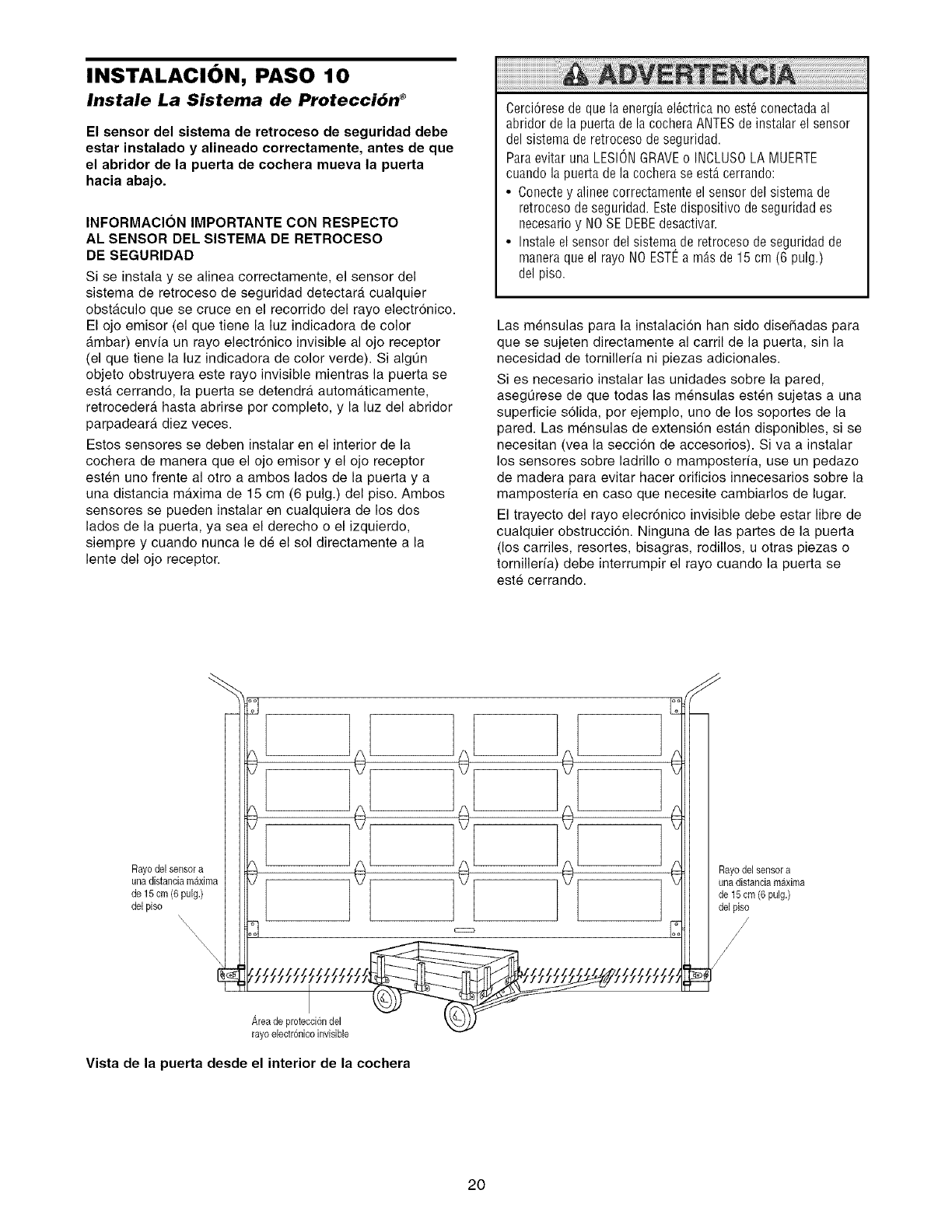
INSTALACION, PASO 10
Instale La Sistema de Protecci6n ®
El sensor del sistema de retroceso de seguridad debe
estar instalado y alineado correctamente, antes de que
el abridor de la puerta de cochera mueva la puerta
hacia abajo.
INFORMACION IMPORTANTE CON RESPECTO
AL SENSOR DEL SISTEMA DE RETROCESO
DE SEGURIDAD
Si se instala y se alinea correctamente, el sensor del
sistema de retroceso de seguridad detectara cualquier
obstgtculo que se cruce en el recorrido del rayo electronico.
El ojo emisor (el que tiene la luz indicadora de color
ambar) envfa un rayo electr6nico invisible al ojo receptor
(el que tiene la luz indicadora de color verde). Si algQn
objeto obstruyera este rayo invisible mientras la puerta se
esta cerrando, la puerta se detendrgt automgtticamente,
retrocedergt hasta abrirse per complete, y la luz del abridor
parpadeara, diez veces.
Estos sensores se deben instalar en el interior de la
cochera de manera que el ojo emisor y el ojo receptor
esten uno frente al otto a ambos lades de la puerta y a
una distancia maxima de 15 cm (6 pulg.) del piso. Ambos
sensores se pueden instalar en cualquiera de los dos
lades de la puerta, ya sea el derecho o el izquierdo,
siempre y cuando nunca le de el sol directamente a la
lente del ojo receptor.
Cerci6rese de que la energia el@trica no est6conectada a]
abridor de la puerta de la cochera ANTESde instalar el sensor
del sistema de retroceso de seguridad.
Paraevitar una LESIONGRAVEo INCLUSOLA MUERTE
cuando la puerta de la cochera se estAcerrando:
• Conecte y alinee correctamente el sensor del sistema de
retroceso de seguridad. Estedispositivo de seguridad es
necesario y NO SE DEBEdesactivar.
• Instale el sensor del sistema de retroceso de seguridad de
manera que el rayo NOESTI_ a m_s de 15 cm (6 pulg.)
del piso.
Las mensulas para la instalacion hart side disefiadas para
que se sujeten directamente al carril de la puerta, sin la
necesidad de tornilleria ni piezas adicionales.
Si es necesario instalar las unidades sobre la pared,
asegQrese de que todas las mensulas esten sujetas a una
superficie solida, per ejemplo, uno de los soportes de la
pared. Las mensulas de extensi6n estan disponibles, si se
necesitan (vea la seccion de accesorios). Siva a instalar
los sensores sobre ladrillo o mamposterfa, use un pedazo
de madera para evitar hacer orificios innecesarios sobre la
mamposterfa en case que necesite cambiarlos de lugar.
El trayecto del rayo elecr6nico invisible debe estar libre de
cualquier obstrucci6n. Ninguna de las partes de la puerta
(los carriles, resortes, bisagras, rodillos, u otras piezas o
tornillerfa) debe interrumpir el rayo cuando la puerta se
este cerrando.
l [ @/ _c::_/ _ iiiu/iiima
Areadoprotecei6ndel _._))
rayo electronicoinvisible
Vista de la puerta desde el interior de la cochera
20
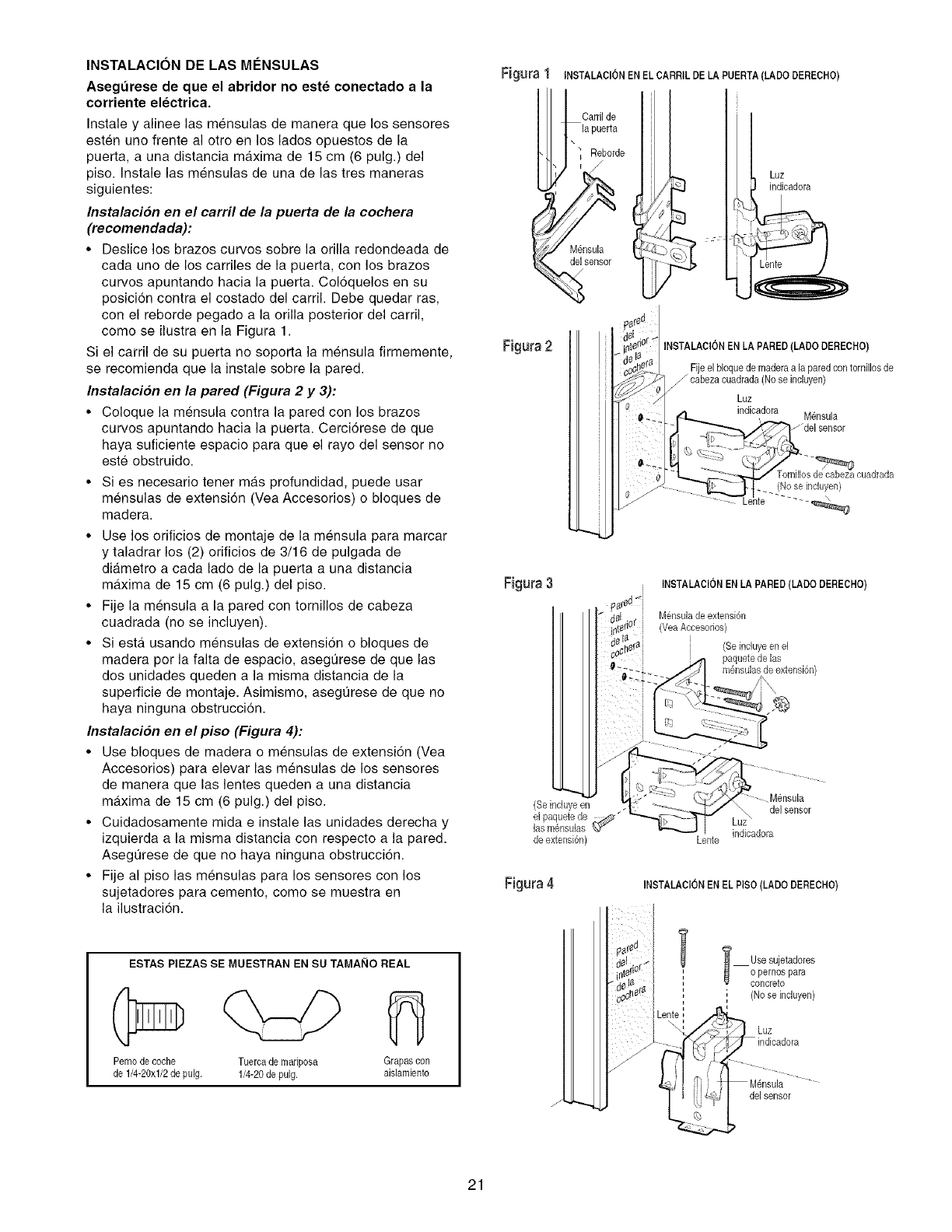
INSTALACION DE LAS MCNSULAS
Asegurese de que el abridor no este conectado a la
corriente electrica.
Instale y alinee las mensulas de manera que los sensores
esten uno frente al otto en los lados opuestos de la
puerta, a una distancia maxima de 15 cm (6 pulg.) del
piso. Instale las mensulas de una de las tres maneras
siguientes:
Instalacion en el carril de la puerta de la cochera
(recomendada):
• Deslice los brazos curvos sobre la orilla redondeada de
cada uno de los carriles de la puerta, con los brazos
curvos apuntando hacia la puerta. Col6quelos en su
posici6n contra el costado del carril. Debe quedar ras,
con el reborde pegado a la orilla posterior del carril,
como se ilustra en la Figura 1.
Si el carril de su puerta no soporta la mensula firmemente,
se recomienda que la instale sobre la pared.
Instalacion en la pared (Figura 2 y 3):
• Coloque la mensula contra la pared con los brazos
curvos apuntando hacia la puerta. Cerci6rese de que
haya suficiente espacio para que el rayo del sensor no
este obstruido.
• Si es necesario tenet mas profundidad, puede usar
mensuias de extensi6n (Vea Accesorios) o bloques de
madera.
• Use los orificios de montaje de la mensula para marcar
y taladrar los (2) orificios de 3/16 de pulgada de
diametro a cada lado de la puerta a una distancia
mAxima de 15 cm (6 pulg.) del piso.
• Fije la mensula a la pared con tornillos de cabeza
cuadrada (no se incluyen).
• Si estA usando mensulas de extensi6n o bloques de
madera por la falta de espacio, asegurese de que las
dos unidades queden a la misma distancia de la
superficie de montaje. Asimismo, asegurese de que no
haya ninguna obstruccion.
Instalacion en el piso (Figura 4):
• Use bloques de madera o mensulas de extensi6n (Yea
Accesorios) para elevar las mensuias de los sensores
de manera que las lentes queden a una distancia
maxima de 15 cm (6 pulg.) del piso.
• Cuidadosamente mida e instale las unidades derecha y
izquierda a la misma distancia con respecto a la pared.
Asegurese de que no haya ninguna obstruccion.
• Fije al piso las mensuias para los sensores con los
sujetadores para cemento, como se muestra en
la ilustracion.
ESTAS PIEZAS SE MUESTRAN EN SU TAMAI_IO REAL
Pemode coche Tuerca de mariposa Grapascon
de 1/4-20xl/2 de pulg. 1/4-20 de pulg. aislamiento
Figura "_ INSTALAClON ENEL CARRIL DE LA PUERTA (LADODERECHO)
Cardlde
\
Reborde
M_nsula
del sensor
Luz
indicadora
Figura 2 INSTALAClON EN LA PARED(LADO DERECHO)
Fije el bloque de maderaala pared con tornillosde
_ oabezacuadrada (Nose inoluyen)
Luz
indicadora Mensula
(No seinduyen)
Figura3INSTALAClON ENLA PARED (LADO DERECHO)
Mensulade extensi6n
(Vea Accesodos)
(Seinduye en el
paquetede las
T.; -L,. rno_sulasde extensi6n)
Figura 4 INSTALAClON ENEL PISO (LADO DERECHO)
l '_ Usesujetadores
V °oPerrn_tspara
, (No seincluyen)
Luz
del sensor
21
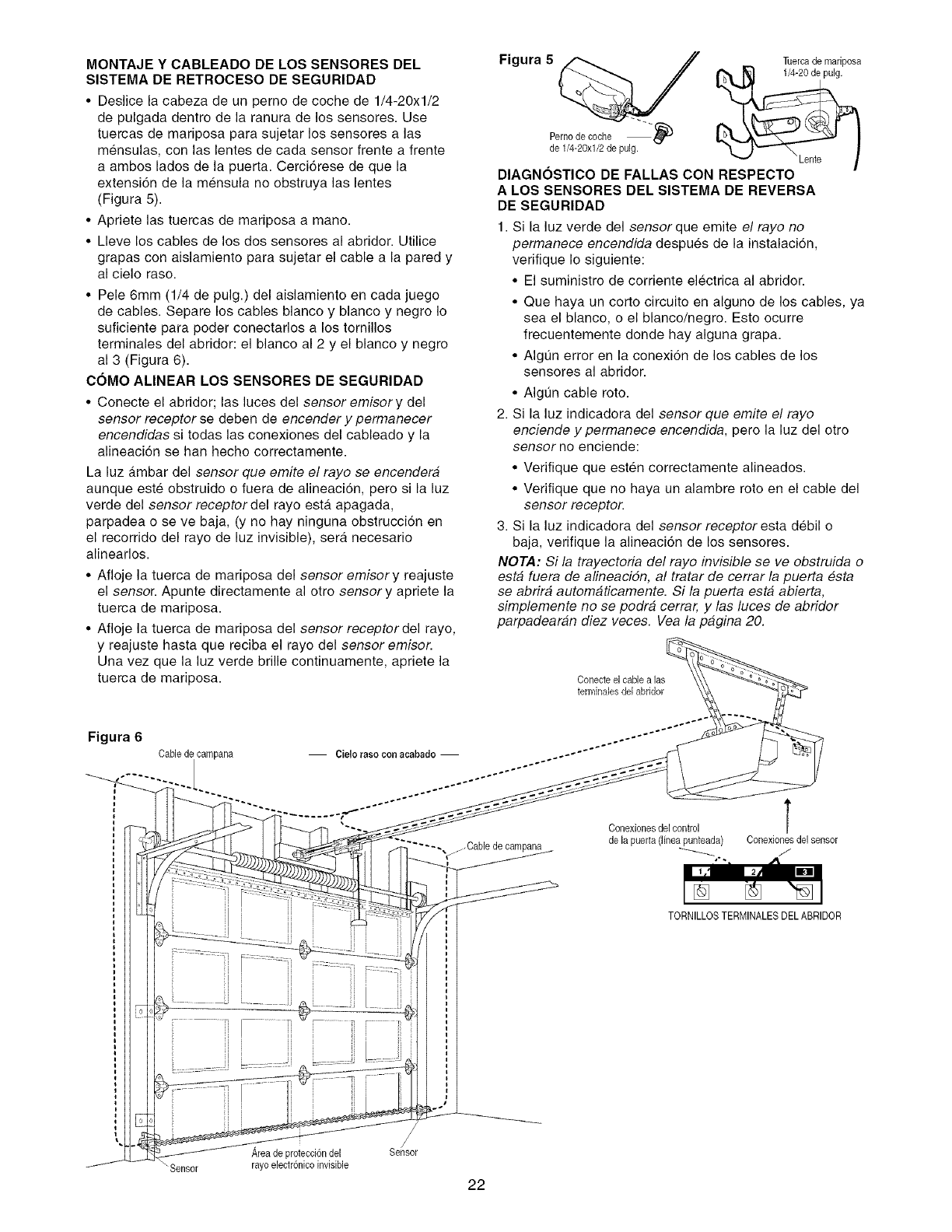
MONTAJE Y CABLEADO DE LOS SENSORES DEL
SISTEMA DE RETROCESO DE SEGURIDAD
• Deslice la cabeza de un perno de coche de 1/4-20xl/2
de pulgada dentro de la ranura de los sensores. Use
tuercas de mariposa para sujetar los sensores alas
mensulas, con las lentes de cada sensor frente a frente
a ambos lades de la puerta. Cerci6rese de que la
extensi6n de la mensula no obstruya las lentes
(Figura 5).
• Apriete las tuercas de mariposa a mano.
• Lleve los cables de los dos sensores al abridor. Utilice
grapas con aislamiento para sujetar el cable a la pared y
al cielo raso.
• Pele 6mm (1/4 de pulg.) del aislamiento en cada juego
de cables. Separe los cables blanco y blanco y negro Io
suficiente para poder conectaflos a los tornillos
terminales del abridor: el blanco al 2 y el blanco y negro
al 3 (Figura 6).
COMO ALINEAR LOS SENSORES DE SEGURIDAD
• Conecte el abridor; las luces del sensor emisory del
sensor receptor se deben de encender y permanecer
encendidas si todas las conexiones del cableado y la
alineacion se hart hecho correctamente.
La luz a.mbar del sensor que emite el rayo se encendera
aunque este obstruido o fuera de alineaci6n, pero si la luz
verde del sensor receptor del rayo esta. apagada,
parpadea o se ve baja, (y no hay ninguna obstrucci6n en
el recorrido del rayo de luz invisible), sera necesario
alinearlos.
• Afloje la tuerca de mariposa del sensor emisory reajuste
el sensor. Apunte directamente al otto sensory apriete la
tuerca de mariposa.
• Afloje la tuerca de mariposa del sensor receptordel rayo,
y reajuste hasta que reciba el rayo del sensor emisor.
Una vez que la luz verde brine continuamente, apriete la
tuerca de mariposa.
Figura 5 Tuercade mariposa
Pernode coche --_
de 1/4-20xl/2 de pulg. _ "Lente
DIAGNOSTICO DE FALLAS CON RESPECTO
A LOS SENSORES DEL SISTEMA DE REVERSA
DE SEGURIDAD
1. Si la luz verde del sensor que emite el rayo no
permanece encendida despues de la instalacion,
verifique Io siguiente:
• El suministro de corriente electrica al abridor.
• Que haya un corto circuito en alguno de los cables, ya
sea el blanco, o el blanco/negro. Esto ocurre
frecuentemente donde hay alguna grapa.
• Algun error en la conexidn de los cables de los
sensores al abridor.
• Algun cable roto.
2. Si la luz indicadora del sensor que emite el rayo
enciende y permanece encendida, pero la luz del otto
sensor no enciende:
• Verifique que esten correctamente alineados.
• Verifique que no haya un alambre roto en el cable del
sensor receptor.
3. Si la luz indicadora del sensor receptor esta debil o
baja, verifique la alineaci6n de los sensores.
NOTA: Si la trayectoria del rayo invisible se ve obstruida o
esta fuera de alineacidn, al tratar de cerrar la puerta esta
se abrira automaticamente. Si la puerta esta abierta,
simplemente no se podra cerrar, y las luces de abridor
parpadearan diez veces. Vea la pagina 20.
Conecteel cablealas
terminales del abridor
Figura 6
Cable de campana -- Cielo raso conacabado -- ..--*'"""÷'"'°""*''""
Conexionosdelcontrol
"---, j/-Cable de campana de la puerta (Nnea_punteada)
Conexionesdel sensor
/
TORNILLOSTERMINALESDEL ABRIDOR
,_reade protecci6ndel
rayo electr6nicoinvisible
/
/
Sensor
_Sensor
22
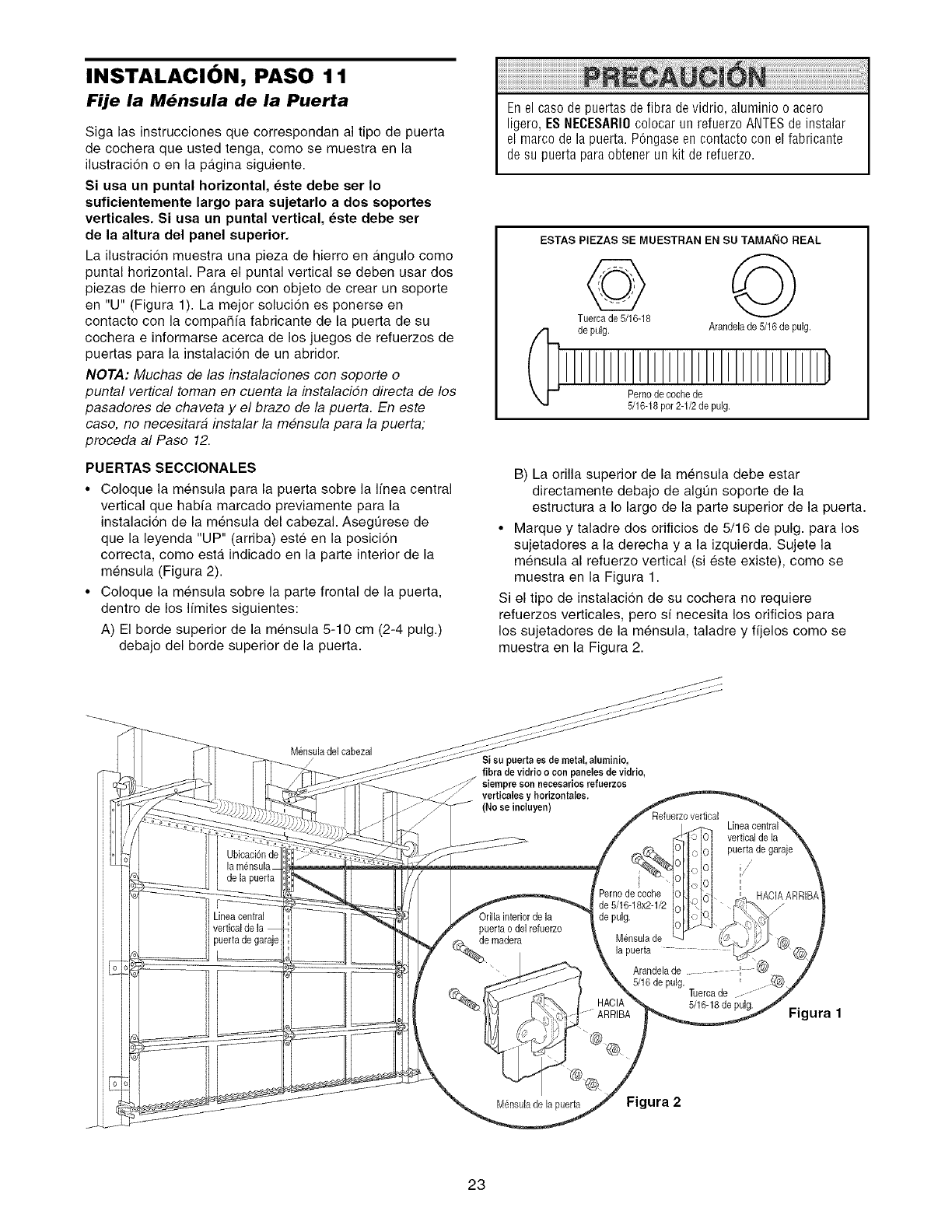
INSTALACION, PASO 1 1
Fije la M6nsula de la Puerta
Siga las instrucciones que correspondan al tipo de puerta
de cochera que usted tenga, come se muestra en la
ilustracidn o en la pagina siguiente
Si usa un puntal horizontal, este debe set Io
suficientemente largo para sujetarlo a dos soportes
verticales. Si usa un puntal vertical, este debe ser
de la altura del panel superior.
La ilustracidn muestra una pieza de hierro en angulo come
puntal horizontal Para el puntal vertical se deben usar dos
piezas de hierro en angulo con objeto de crear un soporte
en "U" (Figura 1) La mejor solucion es ponerse en
contacto con la compaSfa fabricante de la puerta de su
cochera e informarse acerca de los juegos de refuerzos de
puertas para la instalacidn de un abridor
NOTA: Muchas de las instalaciones con soporte o
puntal vertical toman en cuenta la instalaciSn directa de los
pasadores de chaveta y el braze de la puerta En este
case, no necesitara instalar la mensula pare la puerta;
proceda al Paso 12
PUERTAS SECClONALES
•Coloque la mensula para la puerta sobre la Ifnea central
vertical que habfa marcado previamente para la
instalacion de la mensula del cabezal Asegurese de
que la leyenda "UP" (arriba) este en la posicidn
correcta, come esta indicado en la parte interior de la
mensula (Figure 2)
• Coloque la mensula sobre la parte frontal de la puerta,
dentro de los limites siguientes:
A) El borde superior de la mensula 5-10 cm (2-4 pulg)
debajo del borde superior de la puerta
Enel caso de puertas de fibra devidrio, aluminio o acero
ligero, ES NECESARIOcolocar un refuerzo ANTESde instalar
el marco de la puerta. P6ngaseen contacto con el fabricante
desu puerta para obtener un kit de refuerzo.
ESTAS PIEZAS SE MUESTRAN EN SU TAMAI_IO REAL
de pulg. Arandelade 5/16 de pulg.
Perno decache de
5/16-18par 2-1/2de pulg.
B) La orilla superior de la mensula debe estar
directamente debajo de algun soporte de la
estructura a Io largo de la parte superior de la puerta
• Marque y taladre dos orificios de 5/16 de pulg para los
sujetadores ala derecha y ala izquierda Sujete la
mensula al refuerzo vertical (si este existe), come se
muestra en la Figura 1
Si el tipo de instalacion de su cochera no requiere
refuerzos verticales, pero sf necesita los orificios para
los sujetadores de la mensula, taladre y fijelos come se
muestra en la Figura 2
M_nsuladel cabezal
Ubicaci6nde
de la puerta
ineacentral
puerta de garaje
Si su puerta es de metal, aluminio,
fibra de vidrio ocon paneles de vidrio
siempre son neeesarios refuerzos
verticales y horizontales,
(No ee ineluyen)
vertical de la
puerta de garaje
puerta odel refuerzo
Pernode coche
de 5/16-18x2-1/2
de pulg.
Mensula de
Arandela de I
5/16 de pulg. Tuercade
5/16-18de pulg.
ARRIBA
HACIAARRIE
Figura 1
M_neulade la puerta Figura 2
23
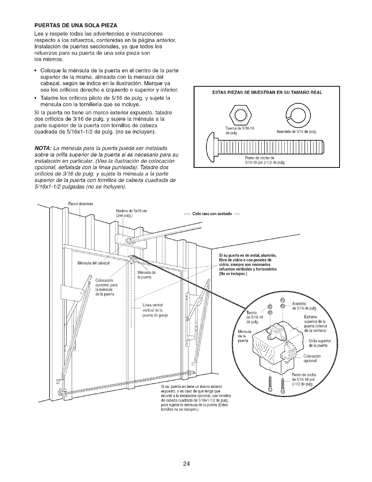
PUERTAS DE UNA SOLA PIEZA
Lea y respete todas las advertencias e instrucciones
respecto a los refuerzos, contenidas en la pa.gina anterior,
Instalaci6n de puertas seccionales, ya que todos los
refuerzos para su puerta de una sola pieza son
los mismos.
•Coloque la mensula de la puerta en el centro de la parte
superior de la misma, aNneada con la m6nsula del
cabezal, segun se indica en la ilustraci6n. Marque ya
sea los orificios derecho e izquierdo o superior y inferior.
• Taladre los orificios piloto de 5/16 de pulg. y sujete la
mensula con la tornNlerfa que se incluye.
Si la puerta no tiene un marco exterior expuesto, taladre
dos orificios de 3/16 de pulg. y sujete la mensula a la
parte superior de la puerta con tornillos de cabeza
cuadrada de 5/16x1-1/2 de pulg. (no se incluyen).
NOTA: La mensula para la puerta puede ser instalada
sobre la orilla superior de la puerta si es necesario para su
instalacidn en particular. (Vea la ilustracidn de colocacidn
opcional, sefialada con la Ifnea punteada). Taladre dos
orificios de 3/16 de pulg. y sujete la mensula a la parte
superior de la puerta con tomillos de cabeza cuadrada de
5/16xl-1/2 pulgadas (no se incluyen).
ESTAS PIEZAS SE MUESTRAN EN SU TAMAI_IO REAL
Tuerca de 5/16-18
de pulg. Arandelade 5/16 de pulg.
Pernode cache de
5/16-18par 2-1/2 de pulg.
Pared delantera
Maderade 5x10 cm
(2x4 pulg.) -- Cielo raeo con aeabado --
M_nsuladel cabezal
Coloeacion
opcional,para
la mensula
de la puerta
M_nsulade
la puerta
Lfneacentral
puerta de garaje
Si su puertaes de metal, aluminio,
fibra de vidrio ocon paneles,de
refuerzos vertiealesy horizontales
(No ee incluyen.)
Si su puerta no tiene un marcoexterior
expuesto,o en caso de que tengaque
recurdra la instalaci6nopcional, usetornillos
de cabezacuadrada de 5/16x1-1/2de pulg.
para sujetar la mensula de la puerta (Estos
tornillos no se incluyen.)
Arandela
de 5/16de
/_ pulg.
de 5/16-18 , Extreme
de pulg. ,.._ superiorde la
_.4._ _"_.z puerta (interior
Mensula_ de la eoehera)
de la f_
puerta {_\ _ "_"_,_+,_o I Orilla superior
___,_ de la puerta
-_/1,) ,._ ,_:7_:p,--
/]) ," 714-i, Colocacion
_erno de cache
de 5/16-18pot
2-1/2de pulg.
24
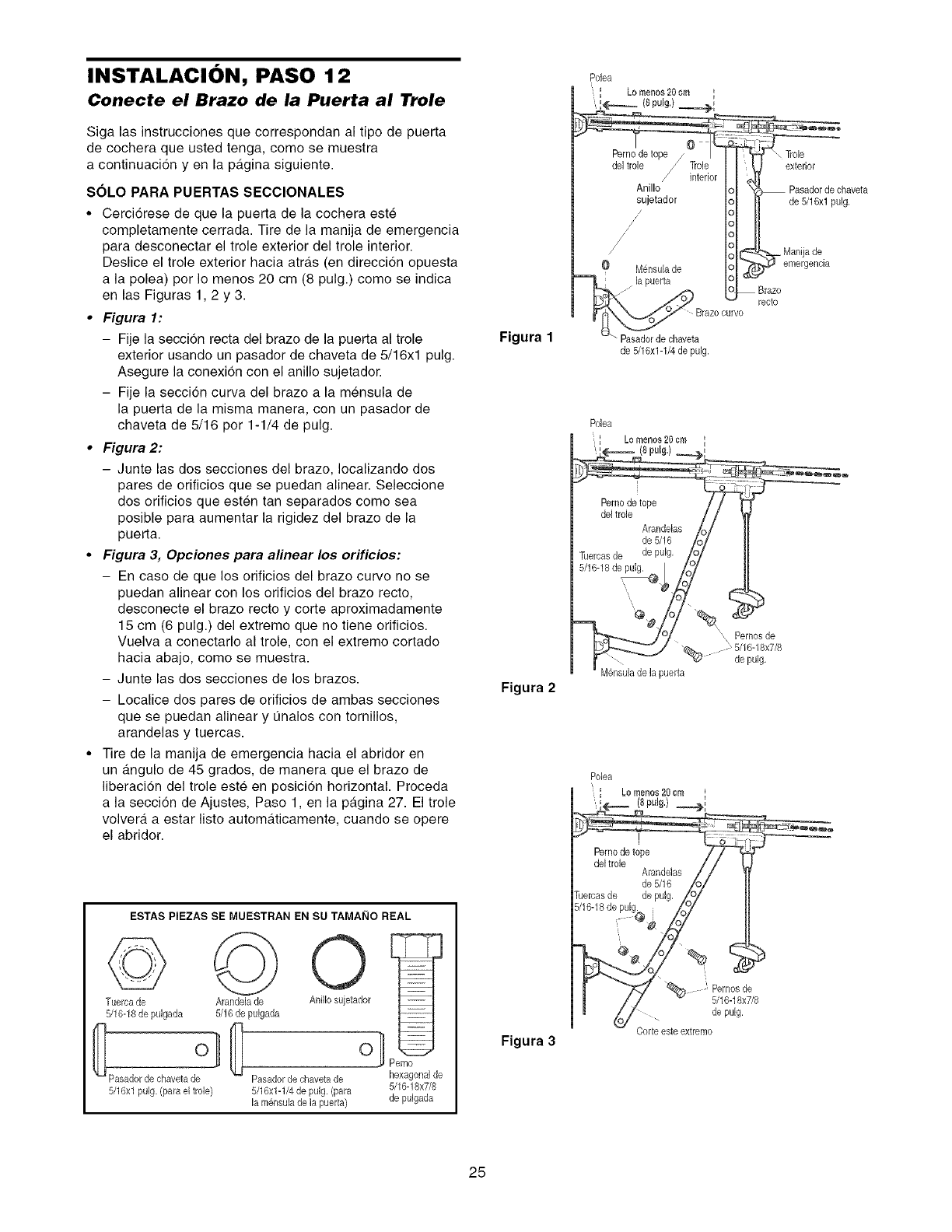
INSTALACION, PASO 12
Conecte el Brazo de la Puerta al Trole
Siga las instrucciones que correspondan al tipo de puerta
de cochera que usted tenga, come se muestra
a continuacion y en la p_.gina siguiente.
SOLO PARA PUERTAS SECClONALES
• Cerciorese de que la puerta de la cochera este
completamente cerrada. Tire de la manija de emergencia
para desconectar el trole exterior del trole interior.
Deslice el trole exterior hacia atras (en direccion opuesta
a la polea) per Io menos 20 cm (8 pulg.) come se indica
en las Figuras 1,2 y 3.
•Figura 1:
- Fije la secci6n recta del braze de la puerta al trole
exterior usando un pasador de chaveta de 5/16xl pulg.
Asegure la conexion con el anillo sujetador.
- Fije la seccidn curva del braze a la mensula de
la puerta de la misma manera, con un pasador de
chaveta de 5/16 per 1-1/4 de pulg.
•Figura 2:
- Junte las dos secciones del braze, Iocalizando dos
pares de orificios que se puedan alinear. Seleccione
dos orificios que esten tan separados come sea
posible para aumentar la rigidez del braze de la
puerta.
•Figura 3, Opciones para alinear los orificios:
- En case de que los orificios del braze curve no se
puedan alinear con los orificios del braze recto,
desconecte el braze recto y corte aproximadamente
15 cm (6 pulg.) del extreme que no tiene orificios.
Vuelva a conectarlo al trole, con el extreme cortado
hacia abajo, come se muestra.
- Junte las dos secciones de los brazes.
- Localice dos pares de orificios de ambas secciones
que se puedan alinear y Qnalos con tornillos,
arandelas y tuercas.
• Tire de la manija de emergencia hacia el abridor en
un angulo de 45 grades, de manera que el braze de
liberaci6n del trole este en posicidn horizontal. Proceda
a la seccion de Ajustes, Paso 1, en la pagina 27. El trole
volvera a estar listo automa.ticamente, cuando se opere
el abridor.
Figura 1
Figura 2
Pasadorde chaveta
de 5/16x1-1/4de pulg.
Polea
_ /o menes20 cm k
(8 putg.)
@,#
'x Pernosde
@_. : 5/16-18x7/8
-_(&' de pulg,
M6nsulade la puerta
Polea
Lo menos20cr._
i(8pulg.)
ESTAS PIEZAS SE MUESTRAN EN SU TAMAI_IO REAL
©
Tuerca de
5/16-18de pulgada
5/16xl pulg. (para el trele)
Arandela de
5/16 de puigada
Anillo sujetador
o}
Pasadordechavetade hexagonalde
5/16xlqi4depulg. (para 5/16q8x7/8
lam6neulade h puerta) de pulgada
Figura 3
" Pemosde
5/16-18x7/8
de pulg,
Corte este extreme
25
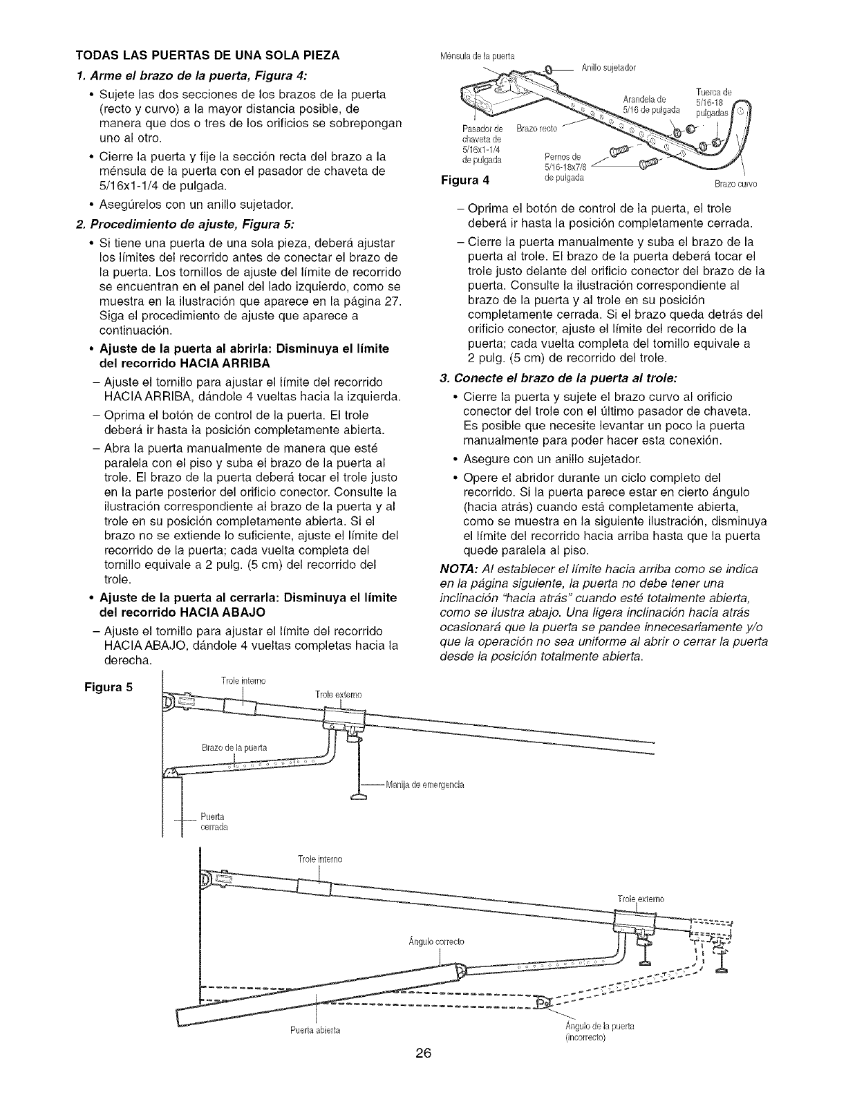
TODAS LAS PUERTAS DE UNA SOLA PIEZA
1. Arme el brazo de la puerta, Figura 4:
• Sujete las dos secciones de los brazes de la puerta
(recto y curve) a la mayor distancia posible, de
manera que dos o tres de los orificios se sobrepongan
uno al otro.
• Cierre la puerta y fije la seccion recta del braze a la
mensula de la puerta con el pasador de chaveta de
5/16x1-1/4 de pulgada.
• Aseg0relos con un anillo sujetador.
2. Procedimiento de ajuste, Figura 5:
• Si tiene una puerta de una sola pieza, debera ajustar
los limites del recorrido antes de conectar el braze de
la puerta. Los tornillos de ajuste del Ifmite de recorrido
se encuentran en el panel del lade izquierdo, come se
muestra en la ilustracion que aparece en la pagina 27.
Siga el procedimiento de ajuste que aparece a
continuacion.
•Ajuste de la puerta al abrirla: Disminuya el limite
del recorrido HACIA ARRIBA
- Ajuste el tornillo para ajustar el Ifmite del recorrido
HAClAARRIBA, dandole 4 vueltas hacia la izquierda.
- Oprima el bot6n de control de la puerta. El trole
debera, ir hasta la posici6n completamente abierta.
- Abra la puerta manualmente de manera que este
paralela con el piso y suba el brazo de la puerta al
trole. El brazo de la puerta debera tocar el trole justo
en la parte posterior del orificio conector. Consulte la
ilustracion correspondiente al brazo de la puerta y al
trole en su posici6n completamente abierta. Si el
braze no se extiende Io suficiente, ajuste el limite del
recorrido de la puerta; cada vuelta completa del
tornillo equivale a 2 pulg. (5 cm) del recorrido del
trole.
•Ajuete de la puerta al cerrarla: Disminuya el limite
del recorrido HACIA ABAJO
- Ajuste el tomillo para ajustar el Ifmite del recorrido
HAClAABAJO, dandole 4 vueltas completas hacia la
derecha.
Figura 5 Trole intemo
M6nsulade la puerta
Anillo suietador
Pasadorde Brazo recto
chavetade
5/16x1-1/4
de pulgada Pemos de
5/16-18x7/8
Figura 4 de pulgada
Tuercade
Arandelade 5/16-18
5/16 de pulgada pulgadas
Brazo curvo
- Oprima el bot6n de control de la puerta, el trole
debera ir hasta la posicion completamente cerrada.
- Cierre la puerta manualmente y suba el brazo de la
puerta al trole. El brazo de la puerta debera tocar el
trole justo delante del orificio conector del braze de la
puerta. Consulte la ilustracion correspondiente al
brazo de la puerta y al trole en su posici6n
completamente cerrada. Si el braze queda detras del
orificio conector, ajuste el Ifmite del recorrido de la
puerta; cada vuelta completa del tornillo equivale a
2 pulg. (5 cm) de recorrido del trole.
3. Conecte el brazo de la puerta al trole:
• Cierre la puerta y sujete el braze curvo al orificio
conector del trole con el t]ltimo pasador de chaveta.
Es posible que necesite levantar un poco la puerta
manualmente para poder hacer esta conexi6n.
• Asegure con un anillo sujetador.
• Opere el abridor durante un ciclo complete del
recorrido. Si la puerta parece estar en cierto a.ngulo
(hacia atras) cuando esta completamente abierta,
come se muestra en la siguiente ilustraci6n, disminuya
el limite del recorrido hacia arriba hasta que la puerta
quede paralela al piso.
NOTA: AI establecer el ffmite hacia arriba come se indica
en la pagina siguiente, la puerta no debe tener una
inclinacidn "hacia atras" cuando este totalmente abierta,
come se ilustra abajo. Una ligera inclinacidn hacia atras
ocasionara que la puerta se pandee innecesariamente y/o
que la operacidn no sea uniforme al abrir o cerrar la puerta
desde la posicidn totalmente abierta.
extemo
Puertaabierta
/_,ngulocorrecto
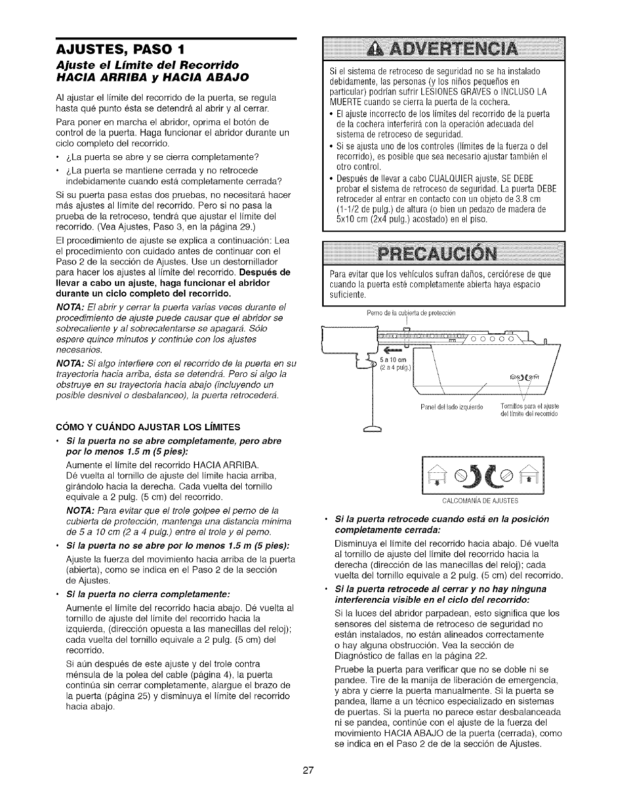
AJUSTES, PASO 1
Ajuste el Limite del Recorrido
HACIA ARRIBA y HACIA ABAJO
AI ajustar el limite del recorrido de la puerta, se regula
hasta que punto esta se detendra al abrir y al cerrar.
Para poner en marcha el abridor, oprima el boton de
control de la puerta. Haga funcionar el abridor durante un
cic!o complete de! recorrido.
• z,La puerta se abre y se cierra completamente?
• z,La puerta se mantiene cerrada y no retrocede
indebidamente cuando esta completamente cerrada?
Si su puerta pasa estas dos pruebas, no necesitar_t hacer
mas ajustes al limite del recorrido. Pero si no pasa la
prueba de la retroceso, tendra que ajustar el limite del
recorrido. (Vea Ajustes, Paso 3, en la pagina 29.)
El procedimiento de ajuste se explica a continuacion: Lea
el procedimiento con cuidado antes de continuar con el
Paso 2 de la seccion de Ajustes. Use un destornillador
para hacer los ajustes al limite del recorrido. Despues de
Ilevar a cabo un ajuste, haga funcionar el abridor
durante un ciclo completo del recorrido.
NOTA: El abrir y cerrar la puerta varias veces durante el
procedimiento de ajuste puede causar que el abrider se
sobrecaliente y al sobrecalentarse se apagara. Sdlo
espere quince minutes y continue con los ajustes
necesarios.
NOTA: Si alge interfiere con el recorrido de la puerta en su
trayectoria hacia arriba, esta se detendra. Pore si algo la
ebstruye en su trayectoria hacia abajo (incluyendo un
pesible desnivel e desbalanceo), la puerta retrecedera.
Si el sistema de retroceso de seguridad no se ha instalado
debidamente, las personas (y los nifios pequefios en
particular) podrian sufrir LESIONESGRAVESo INCLUS0 LA
MUERTEcuando se cierra la puerta de la cochera.
• Elajuste incorrecto de los limites del recorrido de la puerta
de la cochera interferir_ con la operaciOnadecuadadel
sistema de retroceso de seguridad.
• Si se ajusta uno de los controles (limites de la fuerza o del
recorrido), es posible que sea necesario ajustar tambi6n el
otro control.
• Despu_sde Ilevar a cabo CUALQUIERajuste, SE DEBE
probar el sistema de retroceso de seguridad. La puerta DEBE
retroceder al entrar en contacto con un objeto de3.8 cm
(1-1/2 de pulg.) de altura (o bien un pedazo de madera de
5x10 cm (2x4 pulg.) acostado) en el piso.
Paraevitar que los vehiculos sufran dafios, cerci6rese de que
cuando la puerta est6 completamente abierta haya espacio
suficiente.
Pemo de la cubiertade protecci6n
I
COMO Y CUANDO AJUSTAR LOS LIMITES
•Si la puerta no se abre completamente, pero abre
por Io menos 1.5 m (5 pies):
Aumente el limite del recorrido HACIA ARRIBA.
De vuelta al tornillo de ajuste del limite hacia arriba,
gir_tndolo hacia la derecha. Cada vuelta del tornillo
equivale a 2 pulg. (5 cm) del recorrido.
NOTA: Para evitar que el trele gelpee el peme de la
cubierta de proteccidn, mantenga una distancia mfnima
de 5 a 10 cm (2 a 4 pulg.) entre el trele y el peme.
•Si la puerta no se abre por Io menos 1.5 m (5 pies):
Ajuste la fuerza del movimiento hacia arriba de la puerta
(abierta), come se indica en el Paso 2 de la seccion
de Ajustes.
•Si la puerta no cierra completamente:
Aumente el limite del recorrido hacia abajo. De vuelta al
tornillo de ajuste del limite del recorrido hacia la
izquierda, (direcci6n opuesta alas manecillas del reloj);
cada vuelta del tornillo equivale a 2 pulg. (5 cm) del
recorrido.
Si aOn despues de este ajuste y del trole contra
mensula de la polea del cable (pagina 4), la puerta
continua sin cerrar completamente, alargue el braze de
la puerta (pagina 25) y disminuya el limite de! recorrido
hacia abajo.
OALOOMA[/iA DEAJUSTES
Si la puerta retrocede cuando esta en la posici6n
completamente cerrada:
Disminuya el limite del recorrido hacia abajo. De vuelta
a! tornillo de ajuste del limite del recorrido hacia la
derecha (direcci6n de las manecillas del reloj); cada
vuelta del tornillo equivale a 2 pulg. (5 cm) del recorrido.
Si la puerta retrocede al cerrar yno hay ninguna
interferencia visible en el ciclo del recorrido:
Si la luces del abridor parpadean, esto significa que los
sensores del sistema de retroceso de seguridad no
estan instalados, no est_tn alineados correctamente
o hay alguna obstrucci6n. Vea la seccion de
Diagnostico de fallas en la pagina 22.
Pruebe la puerta para verificar que no se doble ni se
pandee. Tire de la manija de liberaci6n de emergencia,
y abra y cierre la puerta manualmente. Si la puerta se
pandea, Ilame a un tecnico especializado en sistemas
de puertas. Si la puerta no parece estar desbalanceada
ni se pandea, continOe con el ajuste de la fuerza del
movimiento HACtAABAJO de la puerta (cerrada), come
se indica en e! Paso 2 de de la secci6n de Ajustes.
27
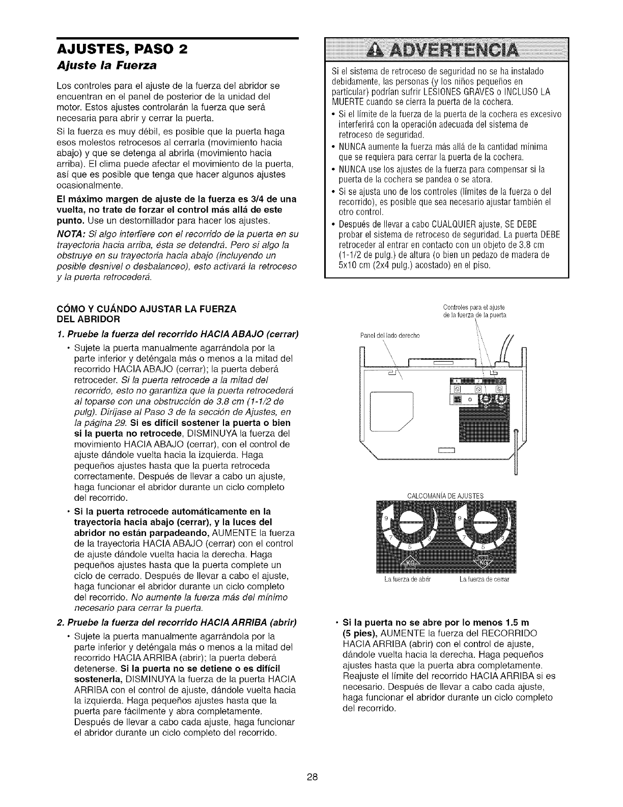
AJUSTES, PASO 2
Ajuste la Fuerza
Los controles para el ajuste de la fuerza del abridor se
encuentran en el panel de posterior de la unidad del
motor. Estos ajustes controlaran la fuerza que serif
necesaria para abrir y cerrar la puerta.
Si la fuerza es muy debil, es posible que la puerta haga
esos molestos retrocesos al cerrarla (movimiento hacia
abajo) y que se detenga al abrirla (movimiento hacia
arriba). El clima puede afectar el movimiento de la puerta,
asi que es posible que tenga que hacer algunos ajustes
ocasionalmente.
El maximo margen de ajuste de la fuerza es 3/4 de una
vuelta, no trate de forzar el control mas alia de este
punto. Use un destornillador para hacer los ajustes.
NOTA: Si algo interfiere con el recorrido de la puerta en su
trayectoria hacia arriba, #sta se detendra. Pero si algo la
obstruye en su trayectoria hacia abajo (incluyendo un
posible desnivel o desbalanceo), esto activara la retroceso
y la puerta retrocedera.
Si el sistema de retroceso de seguridad no se ha instalado
debidamente, las personas (y los nifios pequefios en
particular) podrian sufrir LESIONESGRAVESo INCLUSOLA
MUERTEcuando se cierra la puerta de la cochera.
• Si el limite de la fuerza de la puerta de la cochera es excesivo
interferirA con la operaciOn adecuadadel sistema de
retroceso de seguridad.
• NUNCAaumente la fuerza m_s all_ de la cantidad minima
que se requiera para cerrar la puerta de la cochera.
• NUNCAuselos ajustes de la fuerza para compensar si la
puerta de la cochera se pandea o se atora.
• Si se ajusta uno de los controles (limites de la fuerza o del
recorrido), es posible que sea necesario ajustar tambi@ el
otro control.
• Despu@de Ilevar a cabo CUALQUIERajuste, SE DEBE
probar el sistema de retroceso de seguridad. La puerta DEBE
retroceder al entrar en contacto con un objeto de3.8 cm
(1-1/2 de pulg.) de altura (o bien un pedazo de madera de
5x10 cm (2x4 pulg.) acostado) en el piso.
COMO Y CUANDO AJUSTAR LA FUERZA
DEL ABRIDOR
1. Pruebe la fuerza del recorrido HACIA ABAJO (cerrar)
• Sujete la puerta manualmente agarrandola per la
parte inferior y detengala mas o menos a la mitad del
recorrido HACtA ABAJO (cerrar); la puerta debera
retroceder. Si la puerta retrocede a la mitad del
recorrido, esto no garantiza que la puerta retrocedera
al toparse con una obstruccidn de 3.8 cm (1-1/2 de
pulg). Dirfjase al Paso 3 de la seccidn de Ajustes, en
la pagina 29. Si es dificU sostener la puerta o bien
si la puerta no retrocede, DISMtNUYA la fuerza del
movimiento HACIAABAJO (cerrar), con el control de
ajuste dandole vuelta hacia la izquierda. Haga
pequefies ajustes hasta que la puerta retroceda
cerrectamente. Despues de Ilevar a cabe un ajuste,
haga funcionar e! abridor durante un cic!o completo
del recerrido.
• Si la puerta retrocede automaticamente en la
trayectoria hacia abajo (cerrar), y la luces del
abridor no est_in parpadeando, AUMENTE la fuerza
de la trayectoria HACIAABAJO (cerrar) con el control
de ajuste dandole vuelta hacia la derecha. Haga
pequefies ajustes hasta que la puerta complete un
ciclo de cerrado. Despues de Ilevar a cabo el ajuste,
haga funcionar el abrider durante un cicle completo
del recerrido. No aumente la fuerza mas del mfnimo
necesario para cerrar la puerta.
2. Pruebe la fuerza del recorrido HACIA ARRIBA (abrir)
• Sujete la puerta manualmente agarrandola per la
parte inferior y detengala mas e menos a la mitad del
recerrido HACtA ARRIBA (abrir); la puerta debera
detenerse. Si la puerta no se detiene o es dificil
sostenerla, DISMINUYA la fuerza de la puerta HACIA
ARRIBA con el control de ajuste, dandole vuelta hacia
la izquierda. Haga pequefies ajustes hasta que la
puerta pare f&cilmente y abra completamente.
Despues de Ilevar a cabo cada ajuste, haga funcionar
e! abridor durante un cic!o completo de! recorrido.
Controbs para el ajuste
de la fuerzade la puerta
[] []i
CALCOMANiADEAJUSTES
La fuerza de abrir La fuerzade eerrar
•Si la puerta no se abre por Io menos 1.5 m
(5 pies), AUMENTE la fuerza del RECORRIDO
HACIA ARRIBA (abrir) con el control de ajuste,
dandele vuelta hacia la derecha. Haga pequefios
ajustes hasta que la puerta abra completamente.
Reajuste el limite del recerrido HACIA ARRIBA si es
necesario. Despues de Ilevar a cabo cada ajuste,
haga funcionar e! abridor durante un cic!o completo
del recorrido.
28
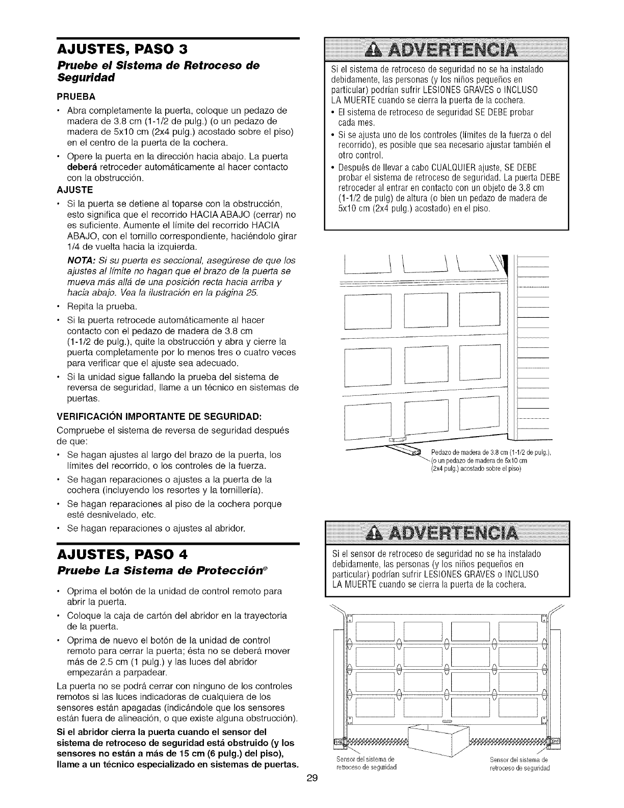
AJUSTES, PASO 3
Pruebe el Sistema de Retroceso de
Seguridad
PRUEBA
• Abra completamente la puerta, coloque un pedaze de
madera de 3.8 cm (I-1/2 de pulg.) (o un pedazo de
madera de 5x10 cm (2x4 pulg.) acostade sobre e! piso)
en e! centre de la puerta de la cochera.
• Opere la puerta en la direccion hacia abajo. La puerta
debera retroceder automaticamente a! hacer contacto
con la obstruccion.
AJUSTE
• Si la puerta se detiene al toparse con la obstrucci6n,
esto significa que el recorrido HACIAABAJO (cerrar) no
es suficiente. Aumente el limite del recorrido HACIA
ABAJO, con el tornillo correspondiente, haciendolo girar
1/4 de vuelta hacia la izquierda.
NOTA: Si su puerta es seccional, aseg#rese de que los
ajustes al Ifmite no hagan que el brazo de la puerta se
mueva mas alia de una posicidn recta hacia arriba y
hacia abajo. Vea la ilustracidn en la pagina 25.
• Repita la prueba.
• Si la puerta retrocede automaticamente al hacer
contacto con el pedazo de madera de 3.8 cm
(1-1/2 de pulg.), quite la obstrucci6n y abra y cierre la
puerta completamente per Io menos tres o cuatro veces
para verificar que el ajuste sea adecuado.
• Si la unidad sigue fallando la prueba del sistema de
reversa de seguridad, Ilame a un tecnico en sistemas de
puertas.
VERIFICAClON IMPORTANTE DE SEGURIDAD:
Compruebe e! sistema de reversa de seguridad despues
de que:
• Se hagan ajustes al largo del braze de la puerta, los
limites del recorrido, o los controles de la fuerza.
• Se hagan reparaciones o ajustes a la puerta de la
cochera (incluyendo los resortes y la tornilleria).
• Se hagan reparaciones a! piso de la cochera porque
este desnivelado, etc.
• Se hagan reparaciones o ajustes al abridor.
AJUSTES, PASO 4
Pruebe La Sistema de Protecci6n ®
• Oprima el bot6n de la unidad de control remote para
abrir la puerta.
• Coloque la caja de cart6n del abridor en la trayectoria
de la puerta.
• Oprima de nuevo el bot6n de la unidad de control
remoto para cerrar la puerta; esta no se debera mover
mas de 2.5 cm (1 pulg.) y las luces del abridor
empezaran a parpadear.
La puerta no se podra cerrar con ninguno de los controles
remotos si las luces indicadoras de cualquiera de los
sensores est&n apagadas (indicandole que los sensores
estan fuera de alineaci6n, o que existe alguna obstruccion).
Si el abridor cierra la puerta cuando el sensor del
sistema de retroceso de seguridad esta obstruido (y los
sensores no estan a mas de 15 cm (6 pulg.) del piso),
Ilame a un tecnico especializado en sistemas de puertas.
29
Si el sistema de retroceso de seguridad no se ha instalado
debidamente, las personas (y los nifios pequefios en
particular) podrian sufrir LESIONESGRAVESo INCLUSO
LA MUERTEcuando se cierra la puerta de la cochera.
• Elsistema de retroceso de seguridad SE DEBEprobar
cada rues.
• Si se ajusta uno de los controles (limites de la fuerza o del
recorrido), es posible que sea necesario ajustar tambi_n el
otro control.
• Despu6sde Ilevar a cabo CUALQUIERajuste, SE DEBE
probar el sistema de retroceso de seguridad. La puerta DEBE
retroceder al entrar en contacto con un objeto de 3.8 cm
(1-1/2 de pulg) de altura (o bien un pedazode maderade
5x10 cm (2x4 pulg.) acostado) en el piso.
(2x4 pulg.) acostadosobre el piso)
Si el sensor de retroceso de seguridad no se ha instalado
debidamente, las personas (y los nifios pequefios en
particular) podrian sufrir LESIONESGRAVESo INCLUSO
LA MUERTEcuando se cierra la puerta de la cochera.
@
Sensor del sistema de
retrocesode seguridad
Sensordel sistemade
retrocesode seguridad
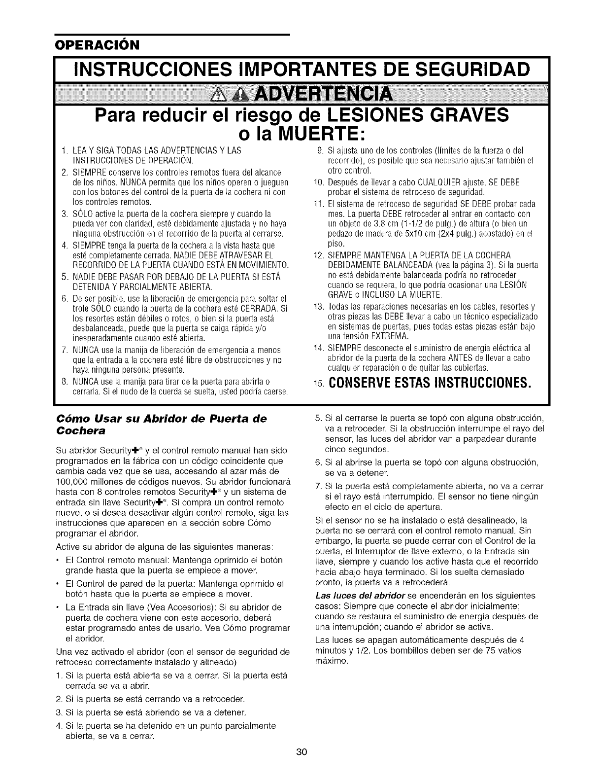
OPERACION
INSTRUCCIONES IMPORTANTES DE SEGURIDAD
Para reducir el riesgo de LESIONES GRAVES
o la MUERTE:
1. LEAYSIGATODASLASADVERTENCIASY LAS 9. Siajustaunodelos controles(limitesdela fuerzao del
INSTRUCCIONESDEOPERACION. recorrido),es posiblequeseanecesarioajustartambiOnel
2. SIEMPREconserve los controles remotos fuera del alcance
delos nifios. NUNCApermita que los nifios operen o jueguen
coo los botones del control de la puerta de la cochera ni con
los controles remotos.
3. SOLOactive la puerta de la cochera siempre y cuando la
puedaver con claridad, est_ debidamente ajustada y no haya
nioguna obstrucciOn en el recorrido de la puerta al cerrarse.
4. SlEMPREtenga la puerta de la cochera a la vista hasta que
est_completamente cerrada.NADIEDEBEATRAVESAREL
REOORRIDODE LAPUERTACUANDOESTAENMOVIMIENTO.
5. NADIEDEBEPASARPORDEBAJODE LA PUERTASI EST',
DETENIDAY PARCIALMENTEABIERTA.
6. De ser posible, use la liberaciOode emergencia para soltar el
trole SOLOcuaodo la puerta de la cocbera est_ CERRADA.Si
los resortes est_.nd_biles o rotos, o bieo si la puerta est,,
desbalanceada,puede que la puerta se caiga r_,piday/o
inesperadamentecuando est6 abierta.
7. NUNCAuse la manija de liberaciOnde emergeociaa menos
que la entrada a la cochera est_ libre de obstrucciones y no
haya ninguna personapresente.
8. NUNCAuse la manija paratirar de la puerta para abrirla o
cerrarla.Si el nudo de la cuerdase suelta, usted podria caerse.
otro control.
10. Despu_s de Ilevar a cabo CUALQUIERajuste, SE DEBE
probar el sistema de retroceso de seguridad.
11. El sistema de retroceso de seguridad SE DEBEprobar cada
rues.La puerta DEBEretroceder al entrar en contacto con
un objeto de 3.8 cm (1-1/2 de pulg.) de altura (o bien un
pedazo de madera de5x10 cm (2x4 pulg.) acostado) en el
piso.
12. SIEMPREMANTENGALA PUERTADELA COCHERA
DEBIDAMENTEBALANCEADA(vea la p_gina 3). Si la puerta
no est_ debidamente balanceadapodria no retroceder
cuaodo se requiera, Io que podria ocasiooar una LESION
GRAVEo INCLUSOLA MUERTE.
13. Todaslas reparaciones necesarias eo los cables, resortes y
otras piezaslas DEBEIlevar a cabo un t_cnico especializado
en sistemas de puertas, pues todas estas piezasest_.nbajo
unatension EXTREMA.
14. SIEMPREdesconecte el suministro de energia elOctricaal
abridor de la puerta de la cochera ANTES de Ilevar a cabo
cualquier reparaciOno de quitar las cubiertas.
CONSERVEESTASINSTRUCCIONES.
C6mo Usar su Abridor de Puerta de
Cochera
Su abridor Security'! "_ y el control remoto manual han sido
programados en la fabrica con un c6digo coincidente que
cambia cada vez que se usa, accesando al azar mas de
100,000 millones de c6digos nuevos. Su abridor funcionara
hasta con 8 controles remotos Security'k _ y un sistema de
entrada sin Ilave Security'k _. Si compra un control remoto
nuevo, o si desea desactivar algOn control remoto, siga las
instrucciones que aparecen en la secciOn sobre Como
programar el abridor.
Active su abridor de alguna de las siguientes maneras:
• El Control remoto manual: Mantenga oprimido el botOn
grande hasta que la puerta se empiece a mover.
• El Control de pared de la puerta: Mantenga oprimido e!
boton hasta que la puerta se empiece a mover.
• La Entrada sin Ilave (Vea Accesorios): Si su abridor de
puerta de cochera viene con este accesorio, debera
estar programado antes de usarlo. Vea Como programar
el abridor.
Una vez activado el abridor (con el sensor de seguridad de
retroceso correctamente instalado y alineado)
1. Si la puerta esta abierta se va a cerrar. Si la puerta esta
cerrada se va a abrir.
2. Si la puerta se esta cerrando va a retroceder.
3. Si la puerta se esta abriendo se va a detener.
4. Si la puerta se ha detenido en un punto parcialmente
abierta, se va a cerrar.
5. Sial cerrarse la puerta se topo con alguna obstruccion,
va a retroceder. Si la obstruccion interrumpe el rayo del
sensor, las luces del abridor van a parpadear durante
cinco segundos.
6. Sial abrirse la puerta se topo con alguna obstruccion,
se va a detener.
7. Si la puerta esta completamente abierta, no va a cerrar
si el rayo esta interrumpido. El sensor no tiene ningOn
efecto en el ciclo de apertura.
Si el sensor no se ha instalado o esta desalineado, la
puerta no se cerrara con el control remoto manual. Sin
embargo, la puerta se puede cerrar con el Control de la
puerta, el lnterruptor de Ilave externo, o la Entrada sin
Ilave, siempre y cuando los active hasta que el recorrido
hacia abajo haya terminado. Si los suelta demasiado
pronto, la puerta va a retroceder&
Las luces del abridor se encender_tn en los siguientes
casos: Siempre que conecte el abridor inicialmente;
cuando se restaura el suministro de energia despues de
una interrupcion; cuando el abridor se activa.
Las luces se apagan automa.ticamente despues de 4
minutos y 1/2. Los bombillos deben ser de 75 vatios
maximo.
30
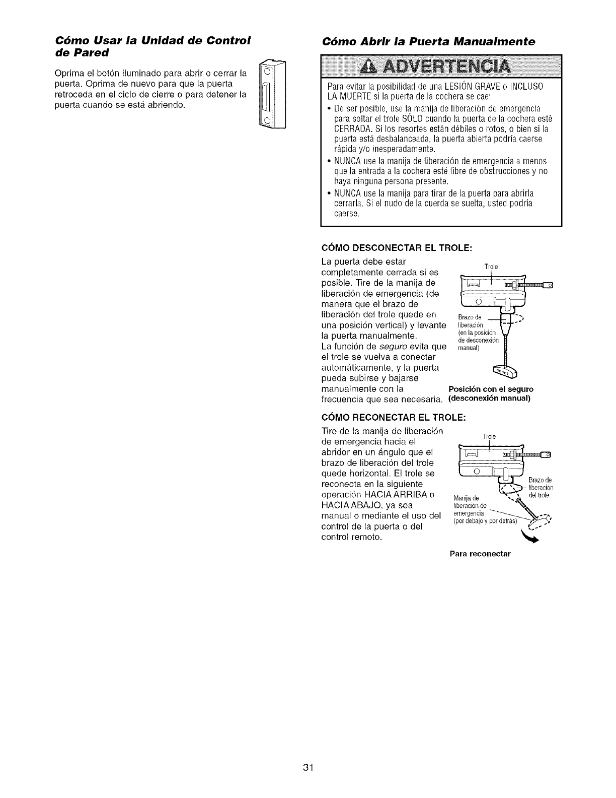
Cdmo Usar la Unidad de Control
de Pared
Oprima el bot6n iluminado para abrir o cerrar la
puerta. Oprima de nuevo para que la puerta
retroceda en el ciclo de cierre o para detener la
puerta cuando se esta abriendo.
Cdmo Abrir la Puerta Manualmente
Paraevitar la posibilidad de una LESIONGRAVEo INCLUSO
LA MUERTEsi la puerta de la cochera se cae:
• Deser posible, use la manija de liberaciOnde emergencia
para soltar el trole SOLOcuando la puerta de la cochera est6
CERRADA.Si los resortes est_n d_biles o rotos, o bien si la
puerta estAdesbalanceada,la puerta abierta podria caerse
r_,piday/o ioesperadamente.
• NUNOAuse la manija de liberaciOnde emergencia a menos
que la entrada a la cochera est_ libre de obstrucciones y no
haya nioguna personapreseote.
• NUNCAuse la manija paratirar de la puerta para abrirla
cerrarla. Si el nudo de la cuerda se suelta, usted podria
caerse.
COMO DESCONECTAR EL TROLE:
La puerta debe estar Trole
completamente cerrada si es
posible. Tire de la manija de
liberacion de emergencia (de
manera que el brazo de
liberacion del trole quede en arazode__ "',
una posicidn vertical) y levante liberaci6n
la puerta manualmente. (en la posici6n
de desconexi6n
La funcidn de seguro evita que manual)
el trole se vuelva a conectar |
automa.ticamente, y la puerta
pueda subirse y bajarse
manualmente con la Posici6ncon el seguro
frecuencia que sea necesaria. (desconexi6n manual)
COMO RECONECTAR EL TROLE:
Tire de la manija de liberaci6n
de emergencia hacia el
abridor en un angulo que el
brazo de liberacion del trole
quede horizontal. El trole se
reconecta en la siguiente
operaci6n HAClAARRIBA o
HAClAABAJO, ya sea
manual o mediante el uso del
control de la puerta o del
control remoto.
Trole
_ Brazode
Manijade -._.
liberacidnde "%-
emergencia _ "_..
(por debajoy pot det_,.f_'
Para reconectar
31
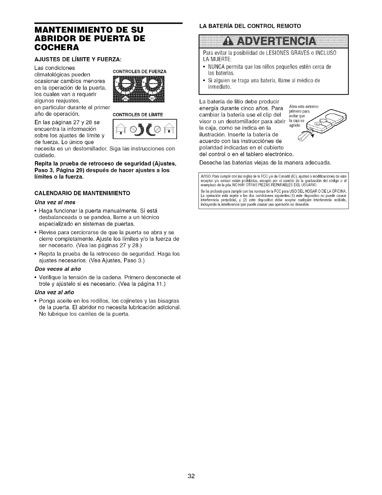
MANTENIMIENTO DE SU
ABRIDOR DE PUERTA DE
COCHERA
AJUSTES DE L|MITE Y FUERZA:
Las condiciones CONTROLES DE FUERZA
climatol6gicas pueden
ocasionar cambios menores
en la operacion de la puerta,
los cuales van a requerir
algunos reajustes,
en particular durante el primer
afio de operacion. CONTROLESDEL|MITE
En las p_.ginas 27 y 28 se
encuentra la informaci6n _ (_)_L@ _/_
sobre los ajustes de Ifmite y
de fuerza. Lo On|co que
necesita es un destornillador. Siga las instrucciones con
cuidado.
Repita la prueba de retroceso de seguridad (Ajustes,
Paso 3, Pagina 29) despues de hacer ajustes a los
limites o la fuerza.
CALENDARIO DE MANTENIMIENTO
Una vez al rues
•Haga funcionar la puerta manualmente Si esta
desbalanceada o se pan(lea, Ilame a un tecnico
especializado en sistemas de puertas
• Revise para cerciorarse de que la puerta se abra y se
cierre completamente Ajuste los Ifmites y/o la fuerza de
ser necesario (Vea las paginas 27 y 28)
• Repita la prueba de la retroceso de seguridad Haga los
ajustes necesarios (Yea Ajustes, Paso 3)
Dos veces al a_o
• Verifique la tensi6n de la cadena Primero desconecte el
trole y ajustelo si es necesario (Vea la pagina 11)
Una vez al a_o
• Ponga aceite en los rodillos, los cojinetes y las bisagras
de la puerta El abridor no necesita lubricaci6n adicional
No lubrique los carriles de la puerta
LA BATERiA DEL CONTROL REMOTO
Paraevitar la posibilidad de LESIONESGRAVESo INCLUSO
LA MUERTE:
• NUNCApermita que los niios pequeios est6n cerca de
las hater|as.
• Si alguien se traga una bateria, Ilame al m6dico de
inmediato.
La baterfa de litio debe producir
energfa durante cinco aFios. Para Abraeste extremo
prirneropara
cambiar la baterfa use el clip del evltarque /(_ -"'2all
visor o un destornillador para abrir lacaja.. _ ._.,_/se/_C_._._-"--AS/i
la caja, come se indica en la agrle__/
ilustracion. Inserte la baterfa de
acuerdo con las instrucci6nes de
polar|dad indicadas en el cubierto
del control o en el tablero electron|co.
Deseche las baterfas viejas de la manera adecuada.
AVISO: Para cuml)lir con las reglas de la FCCy/e de Canada (IC), ajustes e modificaciones de este
recel)tor y/o emisor est£n prohibidos, excel)to pot el carnbio de la graduacion del cSdigo o el
reeml)lazo de la l)ila. NO HAY OTRAS PIEZAS REPARABLES DEL USUARIO.
Se ha probado l)ara curnl)lir con las normas de la FCC para USO DEL HOGAR 0 DE LA OFICINA.
La ol)eraci6n est£ sujeta a las dos condiciones siguientes:(1) este disl)ositivo no l)uede causar
interferencia l)erjudicial, y (2) este dispositivo debe aceptar cualquier interferencia recibida,
nc uyendo a nter erenc a que puede causar una operac on no deseab e.
32
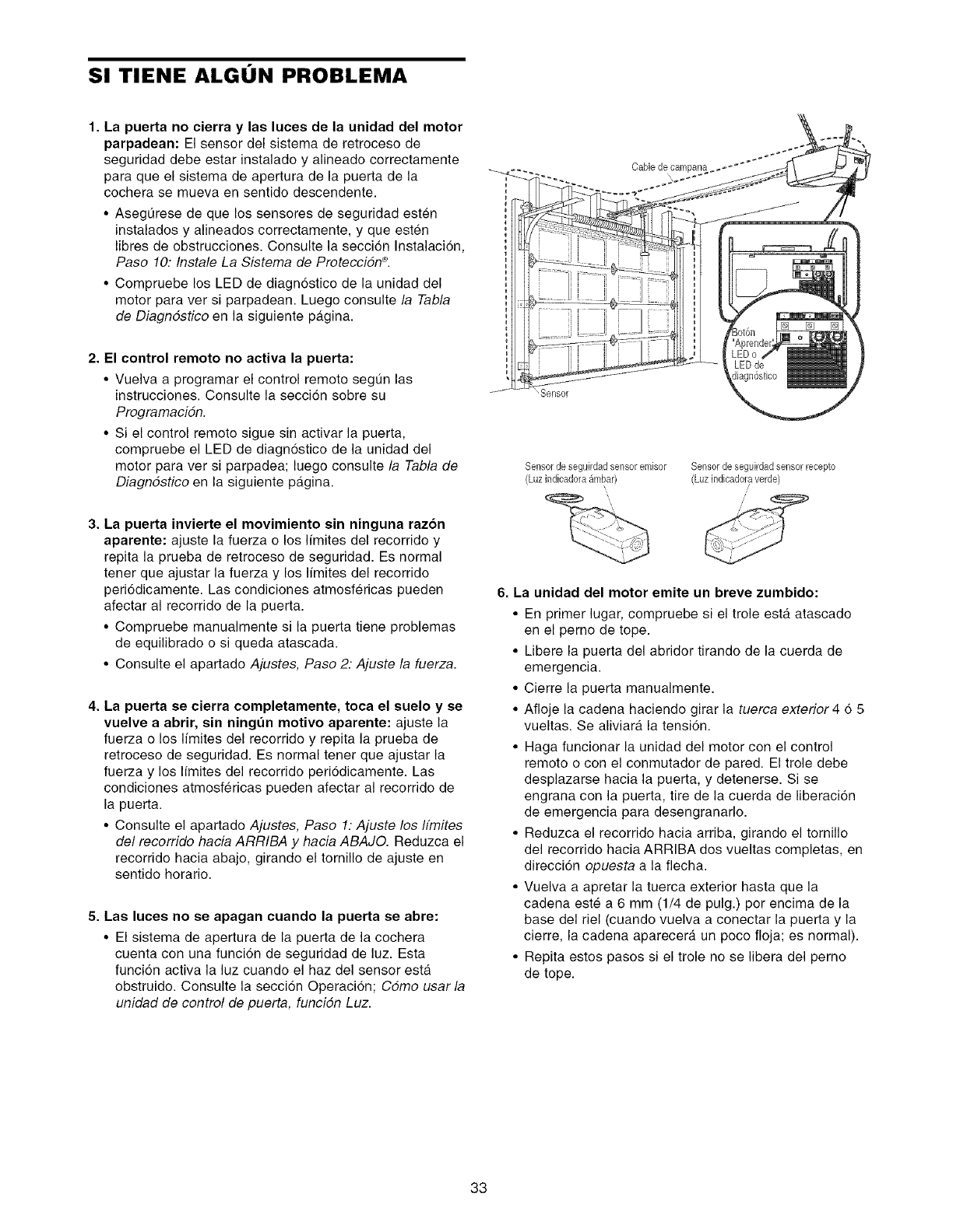
SI TIENE ALGON PROBLEMA
1. La puerta no cierra y las luces de la unidad del motor
parpadean: El sensor del sistema de retroceso de
seguridad debe estar instalado y alineado correctamente
para que el sistema de apertura de la puerta de la
cochera se mueva en sentido descendente.
•AsegQrese de que los sensores de seguridad esten
instalados y alineados correctamente, y que esten
Iibres de obstrucciones. Consulte la seccion Instalaci6n,
Paso 10: Instale La Sistema de ProtecciSn ®.
• Compruebe los LED de diagn6stico de la unidad del
motor para ver si parpadean. Luego consulte la Tabla
de Diagndstico en la siguiente pagina.
2. El control remoto no activa la puerta:
• Vuelva a programar el control remote segt]n las
instrucciones. Consulte la seccion sobre su
ProgramaciSn.
• Si el control remote sigue sin activar la puerta,
compruebe el LED de diagn6stico de la unidad del
motor para ver si parpadea; luego consulte la Tabla de
Diagndstico en la siguiente pagina.
3. La puerta invierte el movimiento sin ninguna razon
aparente: ajuste la fuerza o los Ifmites del recorrido y
repita la prueba de retroceso de seguridad. Es normal
tener que ajustar la fuerza y los Ifmites del recorrido
peri6dicamente. Las condiciones atmosfericas pueden
afectar al recorrido de la puerta.
• Compruebe manualmente si la puerta tiene problemas
de equilibrado o si queda atascada.
• Consulte el apartado Ajustes, Paso 2: Ajuste la fuerza.
4. La puerta se cierra completamente, toca el euelo y se
vuelve a abrir, sin ningt_n motivo aparente: ajuste la
fuerza o los Ifmites del recorrido y repita la prueba de
retroceso de seguridad. Es normal tener que ajustar la
fuerza y los I[mites del recorrido peri6dicamente. Las
condiciones atmosfericas pueden afectar al recorrido de
la puerta.
• Consulte el apartado Ajustes, Paso 1: Ajuste los ffmites
del recorrido hacia ARRIBA y hacia ABAJO. Reduzca el
recorrido hacia abajo, girando el tornillo de ajuste en
sentido horario.
5. Lae luces no ee apagan cuando la puerta se abre:
• El sistema de apertura de la puerta de la cochera
cuenta con una funci6n de seguridad de luz. Esta
funci6n activa la luz cuando el haz del sensor esta
obstruido. Consulte la seccion Operacion; Cdmo usar la
unidad de control de puerta, funciSn Luz.
_ensor
Sensor de seguirdadsensor emisor Sensor de seguirdad sensor recepto
(Luzindieadora g_mbar) (Luz indicadora verde)
\
6. La unidad del motor emite un breve zumbido:
• En primer lugar, compruebe si el trole esta atascado
en el perno de tope.
• Libere la puerta del abridor tirando de la cuerda de
emergencia.
• Cierre la puerta manualmente.
• Afloje la cadena haciendo girar la tuerca exterior 4 6 5
vueltas. Se aliviara la tensi6n.
• Haga funcionar la unidad del motor con el control
remote o con el conmutador de pared. El trole debe
desplazarse hacia la puerta, y detenerse. Si se
engrana con la puerta, tire de la cuerda de liberacion
de emergencia para desengranarlo.
• Reduzca el recorrido hacia arriba, girando el tornillo
del recorrido hacia ARRIBA dos vueltas completas, en
direcci6n opuesta a la fiecha.
• Vuelva a apretar la tuerca exterior hasta que la
cadena este a 6 mm (1/4 de pulg.) per encima de la
base del riel (cuando vuelva a conectar la puerta y la
cierre, la cadena aparecera un poco floja; es normal).
• Repita estos pasos si el trole no se libera del perno
de tope.
33
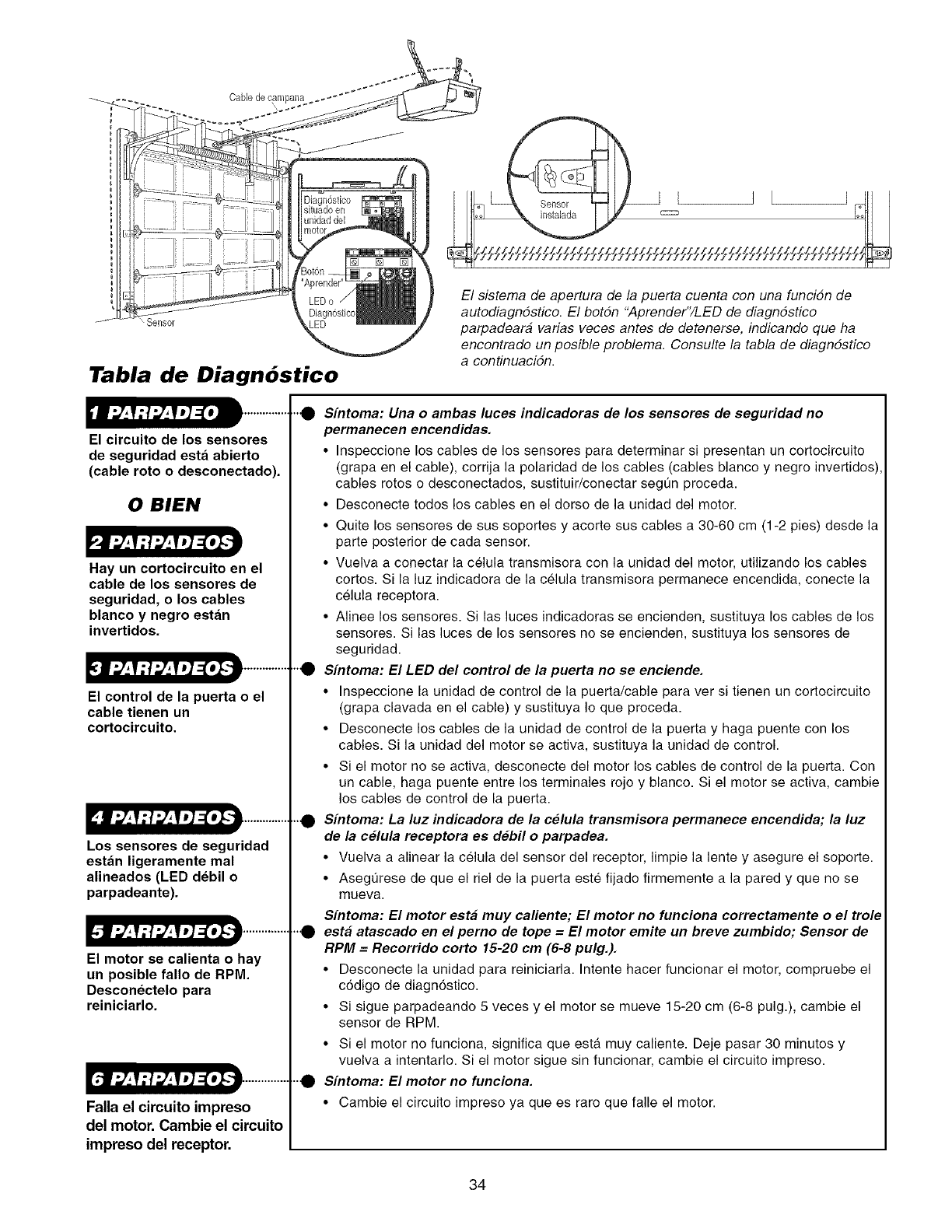
Tabla de Diagn6stico
El circuito de los sensores
de seguridad esta abierto
(cable roto o desconectado).
0 BIEN
Hay un cortocircuito en el
cable de los sensores de
seguridad, o los cables
blanco y negro estan
invertidos.
El control de la puerta o el
cable tienen un
cortocircuito.
Los sensores de seguridad
estan ligeramente mal
alineados (LED debil o
parpadeante).
El motor se calienta o hay
un posible fallo de RPM.
Desconectelo para
reiniciarlo.
[.tl _,_f:!_,_lJ] =[*I-lt ..............
Falla el circuito impreso
del motor. Cambie el circuito
impreso del receptor.
El sistema de apertura de la puerta cuenta con una funcidn de
autodiagndstico. El botdn "Aprender"/LED de diagndstico
parpadeara varias veces antes de detenerse, indicando que ha
encontrado un posible problema. Consulte la tabla de diagndstico
a centinuacidn.
,._ Sintoma: Una o ambas luces indicadoras de los sensores de seguridad no
permanecen encendidas.
• Inspeccione los cables de los sensores para determinar si presentan un cortocircuito
(grapa en el cable), corrija la polaridad de los cables (cables blanco y negro invertidos),
cables rotos o desconectados, sustituir/conectar segt]n proceda.
• Desconecte todos los cables en el dorso de la unidad del motor.
• Quite los sensores de sus soportes y acorte sus cables a 30-60 cm (1-2 pies) desde la
parte posterior de cada sensor.
• Vuelva a conectar la celula transmisora con la unidad del motor, utilizando los cables
cortos. Si la luz indicadora de la celula transmisora permanece encendida, conecte la
celula receptora.
• Alinee los sensores. Si las luces indicadoras se encienden, sustituya los cables de los
sensores. Si las luces de los sensores no se encienden, sustituya los sensores de
seguridad.
"'_ Sfntoma: El LED del control de la puerta no se enciende.
• Inspeccione la unidad de control de la puerta/cable para ver si tienen un cortocircuito
(grapa clavada en el cable) y sustituya Io que proceda.
• Desconecte los cables de la unidad de control de la puerta y haga puente con los
cables. Si la unidad del motor se activa, sustituya la unidad de control.
• Si el motor no se activa, desconecte del motor los cables de control de la puerta. Con
un cable, haga puente entre los terminales rojo y blanco. Si el motor se activa, cambie
los cables de control de la puerta.
.._ Sfntoma: La luz indicadora de la celula transmisora permanece encendida; la luz
de la celula receptora es debil o parpadea.
• Vuelva a alinear la celula del sensor del receptor, limpie la lente y asegure el soporte.
• Asegt]rese de que el riel de la puerta este fijado firmemente a la pared y que no se
mueva.
Sfntoma: El motor esta muy caliente; El motor no funciona correctamente o el trole
.._ esta atascado en el perno de tope =El motor emite un breve zumbido; Sensor de
RPM = Recorrido corto 15-20 cm (6-8 pulg.).
• Desconecte la unidad para reiniciarla. Intente hacer funcionar el motor, compruebe el
c6digo de diagn6stico.
• Si sigue parpadeando 5 veces y el motor se mueve 15-20 cm (6-8 pulg.), cambie el
sensor de RPM.
• Si el motor no funciona, significa que esta muy caliente. Deje pasar 30 minutos y
vuelva a intentarlo. Si el motor sigue sin funcionar, cambie el circuito impreso.
.._ Sfntoma: El motor no funciona.
• Cambie el circuito impreso ya que es raro que falle el motor.
34
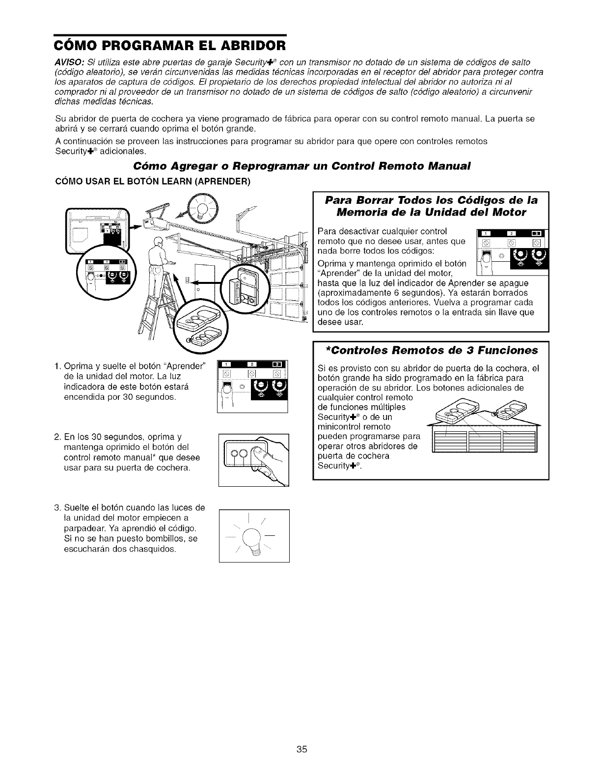
COMO PROGRAMAR EL ABRIDOR
AVI$O: Si utiliza este abre puertas de garaje Security÷ _con un transmisor no dorado de un sistema de cddigos de salto
(cddigo aleatorio), se veran circunvenidas las medidas t#cnicas incorporadas en el receptor del abridor para proteger contra
los aparatos de captura de cddigos. El propietario de los derechos propiedad intelectual del abridor no autoriza ni al
comprador ni al proveedor de un transmisor no dorado de un sistema de cddigos de salto (cddigo aleatorio) a circunvenir
dichas medidas t#cnicas.
Su abridor de puerta de cochera ya viene programado de fabrica para operar con su control remoto manual. La puerta se
abrira y se cerrara cuando oprima el boton grande.
A continuaci6n se proveen las instrucciones para programar su abridor para que opere con controles remotos
Security÷ ®adicionales.
C6mo Agregar o Reprogramar un Control Remoto Manual
COMO USAR EL BOTON LEARN (APRENDER)
Para Borrar Todos los C6digos de la
Memoria de la Unidad del Motor
Para desactivar cualquier control
remote que no desee usar, antes que
nada borre todos los c6digos:
Optima y mantenga oprimido el bot6n
"Aprender" de la unidad del motor,
hasta que la luz del indicador de Aprender se apague
(aproximadamente 6 segundos). Ya estaran borrados
todos los c6digos anteriores. Vuelva a programar cada
uno de los controles remotos o la entrada sin Ilave que
desee usar.
1. Oprima y suelte el bot6n "Aprender"
de la unidad del motor. La luz
indicadora de este bot6n estara
encendida por 30 segundos.
2. En los 30 segundos, oprima y
mantenga oprimido el bot6n del
control remoto manual* que desee
usar para su puerta de cochera.
3. Suelte el bot6n cuando las luces de
la unidad del motor empiecen a
parpadear. Ya aprendio el c6digo.
Si no se han puesto bombillos, se
escuchara.n dos chasquidos.
/
*Controles Remotos de 3 Funciones
Si es provisto con su abridor de puerta de la cochera, el
boton grande ha sido programado en la fa.brica para
operacion de su abridor. Los botones adicionales de
cualquier control remoto
de funciones mt]ltiples
Security÷ ®o de un
minicontrol remoto
pueden programarse para
operar otros abridores de
3uerta de cochera
Security÷ ®.
35
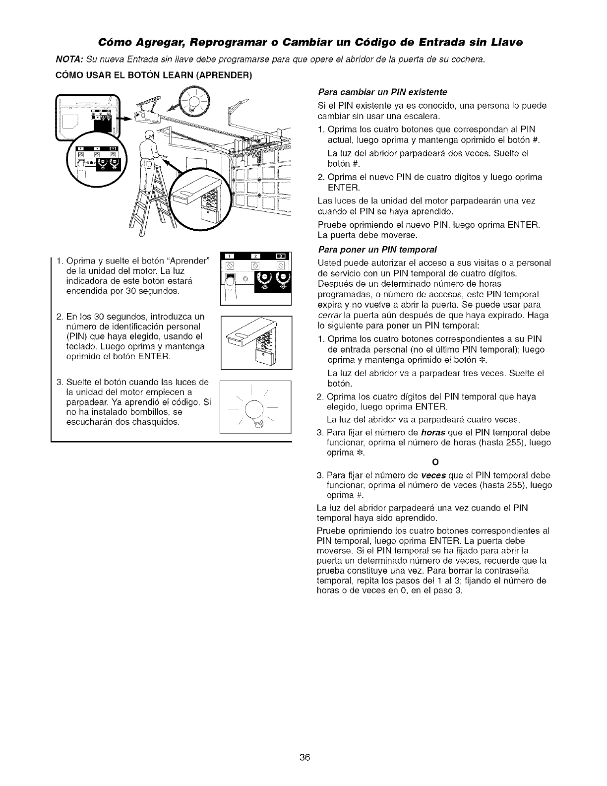
C6mo Agregar, Reprogramar o Cambiar un C6digo de Entrada sin Llave
NOTA: Su nueva Entrada sin Ilave debe programarse para que opere el abridor de la puerta de su cochera.
C6MO USAR EL BOTON LEARN (APRENDER)
Para cambiar un PIN existente
Si el PIN existente ya es conocido, una persona Io puede
cambiar sin usar una escalera.
1. Oprima los cuatro botones que correspondan al PIN
actual, luego oprima y mantenga oprimido el boton #.
La luz del abridor parpadeara dos veces. Suelte el
boton #.
2. Oprima el nuevo PIN de cuatro dfgitos y luego oprima
ENTER.
1. Oprima y suelte el bot6n "Aprender"
de la unidad del motor. La luz
indicadora de este boton estara
encendida per 30 segundos.
2. En los 30 segundos, introduzca un
nt]mero de identificaci6n personal
(PIN) que haya elegido, usando el
teclado. Luego oprima y mantenga
oprimido el bot6n ENTER.
3. Suelte el bot6n cuando las luces de
la unidad del motor empiecen a
parpadear. Ya aprendio el c6digo. Si
no ha instalado bombillos, se
escucharan dos chasquidos.
i
i/
Las luces de la unidad del motor parpadearan una vez
cuando el PIN se haya aprendido.
Pruebe oprimiendo el nuevo PIN, luego oprima ENTER.
La puerta debe moverse.
Para porter un PIN temporal
Usted puede autorizar el acceso a sus visitas o a personal
de servicio con un PIN temporal de cuatro digitos.
Despues de un determinado nt]mero de horas
programadas, o nOmero de accesos, este PIN temporal
expira y no vuelve a abrir la puerta. Se puede usar para
cerrar la puerta aOn despues de que haya expirado. Haga
Io siguiente para poner un PIN temporal:
1. Oprima los cuatro botones correspondientes a su PIN
de entrada personal (no el Oltimo PIN temporal); luego
oprima y mantenga oprimido el bot6n _.
La luz del abridor va a parpadear tres veces. Suelte el
boton.
2. Oprima los cuatro d/gitos del PIN temporal que haya
elegido, luego oprima ENTER.
La luz del abridor va a parpadeara cuatro veces.
3. Para fijar el nt]mero de horas que el PIN temporal debe
funcionar, oprima el nOmero de horas (hasta 255), luego
oprima _. O
3. Para fijar el numero de veces que el PIN temporal debe
funcionar, oprima el nOmero de veces (hasta 255), luego
oprima #.
La luz del abridor parpadeara una vez cuando el PIN
temporal haya sido aprendido.
Pruebe oprimiendo los cuatro botones correspondientes al
PIN temporal, luego oprima ENTER. La puerta debe
moverse. Si el PIN temporal se ha fijado para abrir la
puerta un determinado nOmero de veces, recuerde que la
prueba constituye una vez. Para borrar la contrase_a
temporal, repita los pasos del 1 al 3; fijando el nt]mero de
horas o de veces en 0, en el paso 3.
36
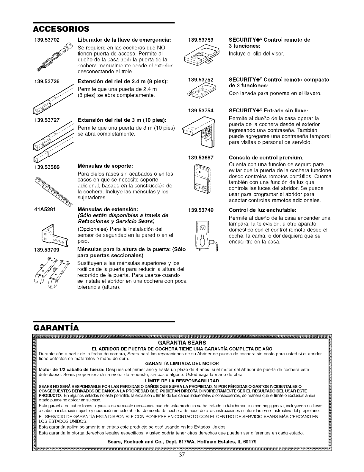
ACCESORIOS
139.53702
fLiberador de la Ilave de emergencia:
Se requiere en las cocheras que NO
tienen puerta de acceso. Permite al
duefio de la casa abrir la puerta de la
cochera manualmente desde el exterior,
desconectando el trole.
139.53726 Extension del riel de 2.4 m(8 pies):
Permite que una puerta de 2.4 m
(8 pies) se abra completamente.
139.53727 Extension del riel de 3 m (10 pies):
Permite que una puerta de 3 m (10 pies)
se abra completamente.
139.53589
41A5281
139.53709
M_nsulas de soporte:
Para cielos rasos sin acabados o en los
cases en que se necesite soporte
adicional, basado en la construcci6n de
la cochera. Incluye las mensulas y los
sujetadores.
Mensulas de extension:
(Solo estan disponibles a traves de
Refacciones y Servicio Sears)
(Opcionales) Para la instalacion del
sensor de seguridad en la pared o en el
piso.
Mensulas para la altura de la puerta: (Solo
para puertas seccionales)
Sustituyen a las mensulas superiores y los
rodillos de la puerta para reducir la altura del
recorrido de la puerta. Para usarse cuando
se instala el abridor en una cochera con poca
tolerancia (altura).
139.53753
139.53752
139.53754
139.53687
139.53749
SECURITY÷ ®Control remoto de
3funciones:
Incluye el clip del visor.
SECURITY+++®Control remoto compacto
de 3 funciones:
Con lazada para ponerse en el Ilavero.
SECURITY÷ ®Entrada sin Ilave:
Permite al duefio de la casa operar la
puerta de la cochera desde el exterior,
ingresando una contrasefia. Tambien
puede agregarse una contrasefia temporal
para visitas o personal de servicio.
Consola de control premium:
Cuenta con una funci6n de seguro para
evitar que la puerta de la cochera funcione
desde controles remotos port&tiles. Cuenta
tambien con una funci6n de luz que
controla las luces del abridor. Se puede
usar para programar el abridor para
aceptar controles remotos adicionales.
Control de luz enchufable:
Permite al duefio de la casa encender una
I&mpara, la televisi6n, u otro aparato
domestico con el control remote desde el
coche, la cama, o dondequiera que se
encuentre en la casa.
GARANTiA
GARANTiA SEARS
EL ABRIDOR DE PUERTA DE COCHERA TIENE UNA GARANTIA COMPLETA DE ANO
Duranteafio a partir dela fecha de compra,Sears haralas reparacionesdesu Abridorde puertade cocherasin costopara ustedsi el abridor
tienedefectosen materialeso manode obra. GARANTiA LIMITADADELMOTOR
Motorde 1/2 caballode fuerza: Despues del primer afio y hasta un plazo de4 aflos, si el rnotordelAbridorde puerta de cocheraesta
defectuoso, Sears proporcionaraun motorde repuesto, sin costo alguno. Ustedpaga la manodeobra.
LIMITE DELA RESPONSABILIDAD
SEARSNOSERA RESPONSABLEPORt.ASPC:RDIDAS O DAI_IOS QUESUFRALAPROPIEDAD, NIPORPI_RDIDAS OGASTOSINClDENTALESO
CONSECUENTESDERIVADOSDEDAI_IOSALAPROPIEDADQUEPUDIERANDIRECTAOINDIRECTAMENTESERELRESULTADODELUSARESTE
PRODUCTO.Enalgunos estadosnoest_permitido laexdusi6no limitedelosdafiosincidentalesoconsecuentes,demaneraqueellimiteoexclusi6narfiba
citado puedeno aplicarensucaso.
Esta garantianocubrefocosnipiezas de repuesto necesariascuandoesteproducto se ha tratadoindebidamenteocon negligencia, incluyendonoIlevar
a cabola instalaci6n, ajuste y operaci6n deesteabridordepuerta decocherade acuerdoa lasinstruccionescontenidasen elinstructivodelpropietario.
ELSERVICIODEGARANTiAEST', DISPONIBLECON PONERSEENCONTACTOCON ELCENTRODESERVICIOSEARSM,_SCERCANOEN
LOSESTADOSUNIDOS.
Esta garantia aplica solamentemientrasesteproducto se este usandoen los EstadosUnidos.
Esta garantia le otorga derechos legales especificos, y usted podrfa tenerotros derechosque pueden ser diferentesencada estado.
Sears, Roebuck and Co., Dept. 817WA, Hoffman Estates, IL 60179
37
Your Home
For repair-in your home-of all major brand appliances
lawn and garden equipment, or heating and cooling systems,
no matter who made it, no matter who sold it!
For,the replacement parts accessories and
owner s manuals that you need to do-it-yourself.
For Sears professional installation of home appliances
and items like garage door openers and water heaters.
1-800-4-MY-HOME ® (1-800-469-4663)
Ca II anytim e, day or n ight (U. S.A. and Ca nada )
www.sears.com www.sears.ca
Our Home
iiiiiiiiiiiiiiiiii For repair of carry-in items like vacuums, lawn equipment,
and electronics, call or go on-line for the location of your nearest
iiiiiiii Sears a,ts.e airCenter,
1-8oo-488-1222
iiiiiiii o,ohtIo.s. .oo, 1
www.soars.com
To purchase a protection agreement (U.S.A.)
or maintenance agreement (Canada) on a product serviced by Sears:
1-800-827-6655 (U.S.A.) 1-800-361-6665 (Canada)
Pard pedir servicio de reparaciCn Au Canada pour serv ce en fran(_a s
a domicilio, y pard ordenar piezas' 1 LE F YER Mc
•-800- - 0
1-888-S U- HOGAR SM (1-800-533-6937)
(1-888-784-6427) www.sears.ca
114A3125B
® Registered Trademark /TMTrademark /s_ Service Mark of Sears, Roebuck and Co.
® Marca Registrada /TMMarca de Fabrica /sMMarca de Servicio de Sears, Roebuck and Co.
McMarque de commerce /MDMarque deposed de Sears Roebuck and Co. © 2005 Sears, Roebuck and Co.
Printed in Mexico
