Craftsman 13953915DM User Manual GARAGE DOOR OPENER Manuals And Guides 1310206L
User Manual: Craftsman 13953915DM 13953915DM CRAFTSMAN GARAGE DOOR OPENER - Manuals and Guides View the owners manual for your CRAFTSMAN GARAGE DOOR OPENER #13953915DM. Home:Garage Door & Opener Parts:Craftsman Parts:Craftsman GARAGE DOOR OPENER Manual
Open the PDF directly: View PDF ![]() .
.
Page Count: 76
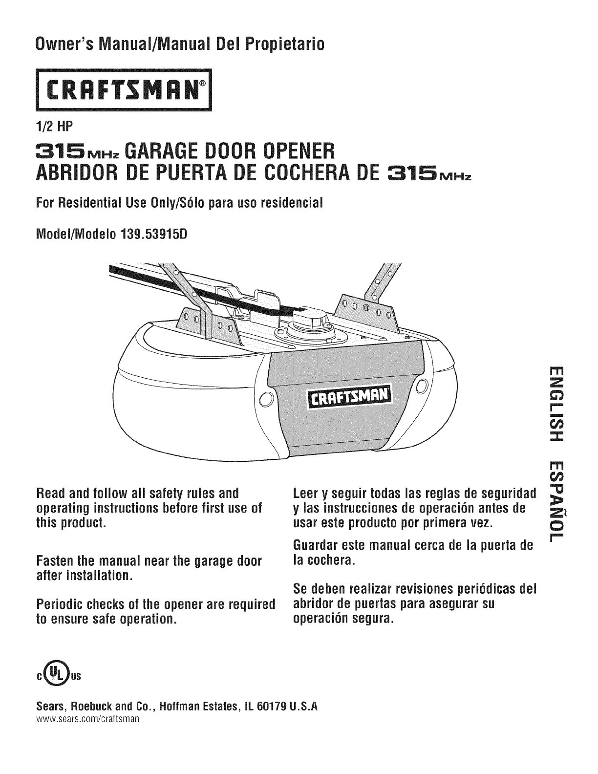
Owner'sIVianuai/iVianualDel Propietario
1/2HP
315_.=, GARAGE DOOR OPENER
ABBIDOB DE PUEBTA DE COCHEBA DE
For Residential UseOnly/S6Jopara uso residencial
31.SMNz
iVlodei/iVlodelo13g.53915D
r'T'l
z
1,,,,,,
m
f,i}
:3:
Bead and foiJowaiJ safety ruJesand
operating instructionsbefore first use of
thisproduct.
Fastenthe manualnearthegaragedoor
after installation.
Periodic checksof the opener are required
to ensure safe operation.
Leery seguirtodaslas reglasde seguridad
y las instruccionesde operaci6n antes de
usareste productopor primeravez.
Guardareste manualcercade la puertade
la cochera.
Se deben realizar revisionesperi6dicasdel
abridor de puertaspara asegurar su
operaci6n segura.
Z_
C}
I""
oQos
Sears, Roebuck and Co., HoffrnanEstates,IL 60179 U.S.A
www.sears.com/craftsman
TABLE OF CONTENTS
Introduction 2-7
Safety symbol and signal word review ..................... 2
Preparing your garagedoor ............................. 3
Tools needed ........................................ 3
Planning ........................................... 4-5
Carton inventory ...................................... 6
Hardware inventory.................................... 7
Assembly 8-11
Assemble the rail and install the trolley .................... 8
Fastenthe rail to the motor unit and Install the idler pulley ..... 9
Install the belt ....................................... 10
Tighten the belt...................................... 10
Install the sprocket cover ............................. 11
Installation 11-26
Installation safety instructions .......................... 11
Determine the headerbracket location .................... 12
Install the headerbracket .............................. 13
Attach the rail to the headerbracket...................... 14
Position the opener................................... 14
Hang the opener ..................................... 15
Install the door control ................................ 16
Install the lights ..................................... 17
Attach the emergency release rope and handle ............. 17
Electrical requirements ................................ 18
Install The Protector System®......................... 19-22
Fastenthe door bracket ............................. 23-24
Connect the door arm to the trolley .................... 25-26
Adjustment 27-29
Adjust the travel limits ................................ 27
Adjust the force ..................................... 28
Test the safety reversalsystem.......................... 29
Test The Protector System®............................ 29
Operation 30-34
Operation safety instructions ........................... 30
Using your garagedoor opener ......................... 30
Using the wall-mounted door control ..................... 31
To open the door manually............................. 31
Care of your garagedoor opener ........................ 32
Having a problem? ................................... 33
Diagnostic chart ..................................... 34
Programming 35-36
To add or reprogram a hand-held remote control ........... 35
To erase all codes.................................... 35
3-Function Remotes .................................. 35
To add, reprogram or change a KeylessEntry PIN........... 36
Repair Parts 37-38
Rail assembly parts .................................. 37
Installation parts ..................................... 37
Motor unit assembly parts ............................. 38
Accessories 39
Warranty
Repair Parts& Service
39
Back Cover
INTRODUCTION
Safety Symboland Signal WordReview
This garagedoor opener has been designed andtested to offer safe service provided it is installed, operated, maintainedand tested in
strict accordancewith the instructions and warnings contained in this manual.
Mechanical
Electrical
When you see these Safety Symbols andSignal Words on the
following pages,they will alert you to the possibility of serious
injury or deathif you do not comply with the warnings that
accompanythem. The hazardmay come from something
mechanical or from electric shock. Readthe warnings carefully.
When you see this Signal Word on the following pages, it will
alert you to the possibility of damageto your garagedoor and/or
the garagedoor opener if you do not comply with the cautionary
statements that accompany it. Readthem carefully.
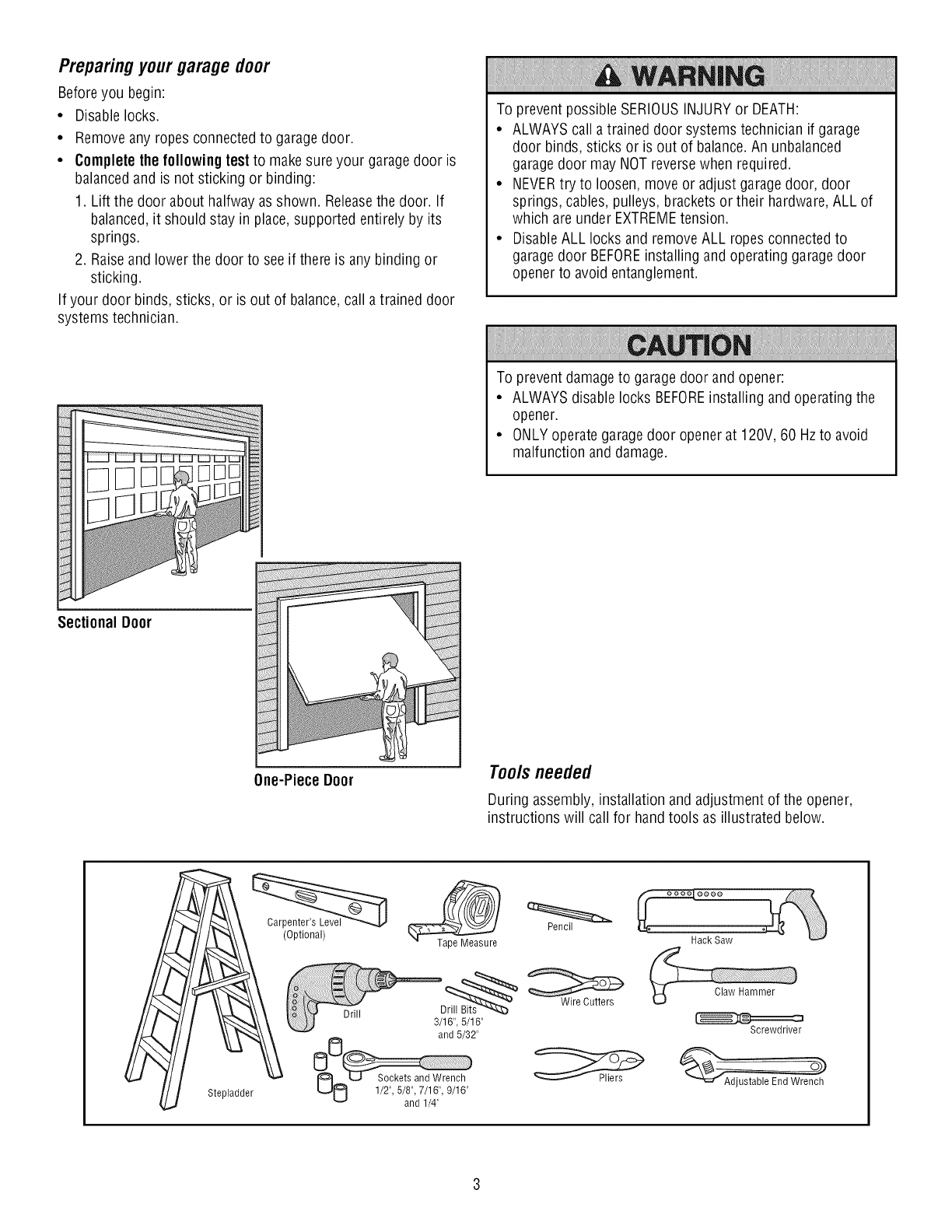
Preparingyourgarage door
Before you begin:
• Disable locks.
• Remove any ropes connected to garagedoor.
•Completethe following testto makesure your garagedoor is
balancedand is not sticking or binding:
1. Lift the door about halfway as shown. Releasethe door. If
balanced,it should stay in place, supported entirely by its
springs.
2. Raiseand lower the door to see if there is any binding or
sticking.
If your door binds, sticks, or is out of balance,call a trained door
systems technician.
To prevent possible SERIOUSINJURYor DEATH:
• ALWAYScall a trained door systems technician if garage
door binds, sticks or is out of balance.An unbalanced
garagedoor may NOTreversewhen required.
• NEVERtry to loosen, move or adjust garagedoor, door
springs, cables, pulleys, brackets or their hardware,ALL of
which are under EXTREMEtension.
• DisableALL locks and removeALL ropes connected to
garagedoor BEFOREinstalling and operating garage door
opener to avoid entanglement.
To preventdamage to garage door and opener:
• ALWAYSdisable locks BEFOREinstalling and operating the
opener.
• ONLYoperate garagedoor opener at 120V, 60 Hzto avoid
malfunction and damage.
SectionalDoor
One-Piece Door Tools needed
During assembly, installation and adjustment of the opener,
instructions will call for handtools as illustrated below.
Stepladder
(Optional) Pencil
Hack Saw
Claw Hammer
Screwdriver
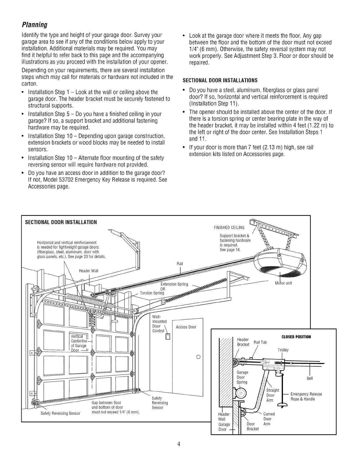
Planning
Identify the type and height of your garagedoor. Surveyyour
garageareato see if any of the conditions below apply to your
installation. Additional materials may be required. You may
find it helpful to refer back to this pageandthe accompanying
illustrations asyou proceed with the installation of your opener.
Depending on your requirements,there are severalinstallation
steps which may call for materials or hardware not included in the
carton.
• Installation Step 1 - Look at the wall or ceiling abovethe
garagedoor. The headerbracket must besecurely fastened to
structural supports.
• Installation Step 5 - Doyou havea finished ceiling in your
garage? If so, a support bracket and additional fastening
hardware may be required.
• Installation Step 10 - Dependingupon garageconstruction,
extension bracketsor wood blocks may be neededto install
sensors.
• Installation Step 10 -Alternate floor mounting of the safety
reversing sensor will require hardware not provided.
• Do you havean accessdoor in addition to the garagedoor?
If not, Model 53702 EmergencyKey Releaseis required. See
Accessories page.
Look at the garage door where it meetsthe floor. Any gap
betweenthe floor and the bottom of the door must not exceed
1/4" (6 mm). Otherwise,the safety reversalsystem may not
work properly. SeeAdjustment Step 3. Floor or door should be
repaired.
SECTIONALDOORINSTALLATIONS
• Do you havea steel, aluminum, fiberglass or glass panel
door? If so, horizontal andvertical reinforcement is required
(Installation Step 11).
• Theopener should be installed above the center of the door. If
there is atorsion spring or center bearing plate in the way of
the headerbracket, it may be installedwithin 4 feet (1.22 m) to
the left or right of the door center. See Installation Steps 1
and 11.
• If your door is more than 7 feet (2.13 m) high, see rail
extension kits listed on Accessories page.
SECTIONALDOORINSTALLATION
Horizontal and vertical reinforcement
is needed for lightweight garage doors
(fiberglass, steel, aluminum, door with
glass panels, etc.). See page 23 for details.
Header Wall
Centerline--I
of Garage
Door
Safety Reversing Sensor
Gap between floor
and bottom of door
must not exceed 1/4" (6 mm).
Rail
Extension Spring
OR
Spring
Wall-
mounted
Door \ AccessDoor
Control _[]
0
Safety
Reversing
Sensor
FINISHED CEILING
Support bracket &
fastening hardware
is required.
See page16.
tor unit
-- Header CLOSEDPOSITION
RailTab
Bracket
_ __..._._ /L Trilley
_/_ Garage _ I
V///A Door 'ol "1 Belt
Fi/A Spring /J', I
_'_ /i /:t!_ht _ EmergencyRe,ease
Aim
Header _ _ _ Curved
Wall _J \ Door
Garage _ J Door Arm
Door--I-11 Bracket
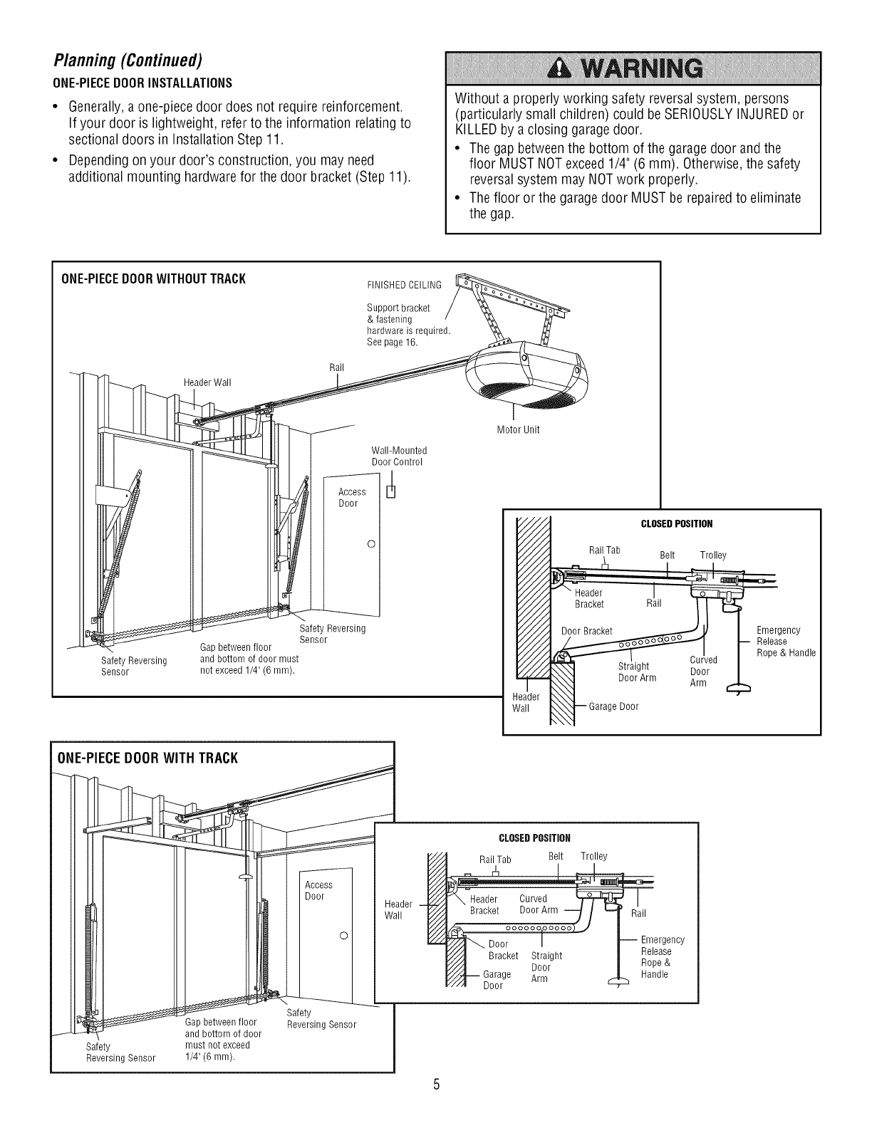
Planning(Continued)
ONE-PIECEDOORINSTALLATIONS
•Generally,aone-piece door does not require reinforcement.
If your door is lightweight, refer to the information relating to
sectional doors in Installation Step 11.
• Depending on your door's construction, you may need
additional mounting hardware for the door bracket (Step 11).
Without a properly working safety reversalsystem, persons
(particularly small children) could be SERIOUSLYINJUREDor
KILLEDby a closing garagedoor.
• The gap betweenthe bottom of the garagedoor andthe
floor MUST NOTexceed1/4" (6 mm). Otherwise,the safety
reversalsystem may NOTwork properly.
• The floor or the garagedoor MUSTbe repairedto eliminate
the gap.
ONE-PIECEDOORWITHOUTTRACK FINISHEDCEILING
Support bracket
& fastening
hardware is required.
See page 16.
SafetyReversing
Sensor
Header Wall
Rail
Wall-Mounted
Door Control
Access
Door
0
Safety Reversing
Sensor
Gap between floor
andbottomof door must
not exceed1/4"(6 mm).
Header
II
flail "safety
H__oor Reversing Sensor J
and bottom of door J
Safety must not exceed |
Reversing Sensor 1/4" (6 mm). |
/
Motor Unit
CLOSEDPOSITION
Rail Tab Belt Trolley
.__ _ _ I
Header I
Door Bracket _ J,/ I Emergency
__ I-- pReo_eaS_Handle
_irgAhlnl iii_ed 1_
,_}-- Garage Door °
CLOSEDPOSITION
Rail Tab Belt Trolley
Door
Straight
Door
Arm
Rail
Emergency
Release
Rope &
Handle
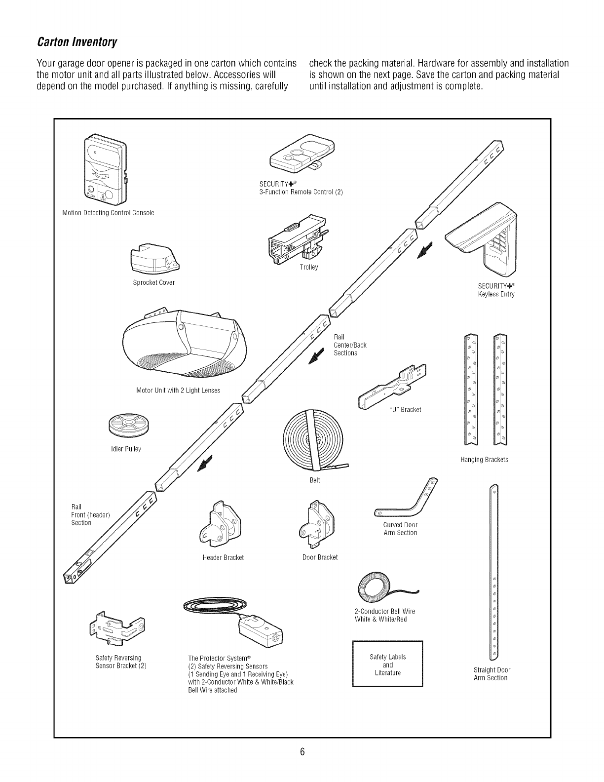
CartonInventory
Your garage door opener is packagedin one carton which contains
the motor unit and all parts illustrated below. Accessories will
dependon the model purchased. If anything is missing, carefully
check the packing material. Hardwarefor assemblyand installation
is shown on the next page. Savethe carton and packing material
until installation and adjustment is complete.
Motion Detecting Control Console
Sprocket Cover
SECURITY÷'-_
3-Function Remote Control (2)
Trolley
SECURITY÷_
Keyless Entry
Rail
Front (header)
Section
Motor Unit with 2 Light Lenses
Idler Pulley
Header Bracket
Rail
Center/Back
Sections
@
Belt
Door Bracket
Curved Door
Arm Section
Hanging Brackets
Safety Reversing
Sensor Bracket (2) The Protector System®
(2) Safety Reversing Sensors
(1 Sending Eye and 1 Receiving Eye)
with 2-Conductor White & White/Black
Bell Wire attached
2-Conductor Bell Wire
White & White/Red
Safety Labels
and
Literature Straight Door
Arm Section
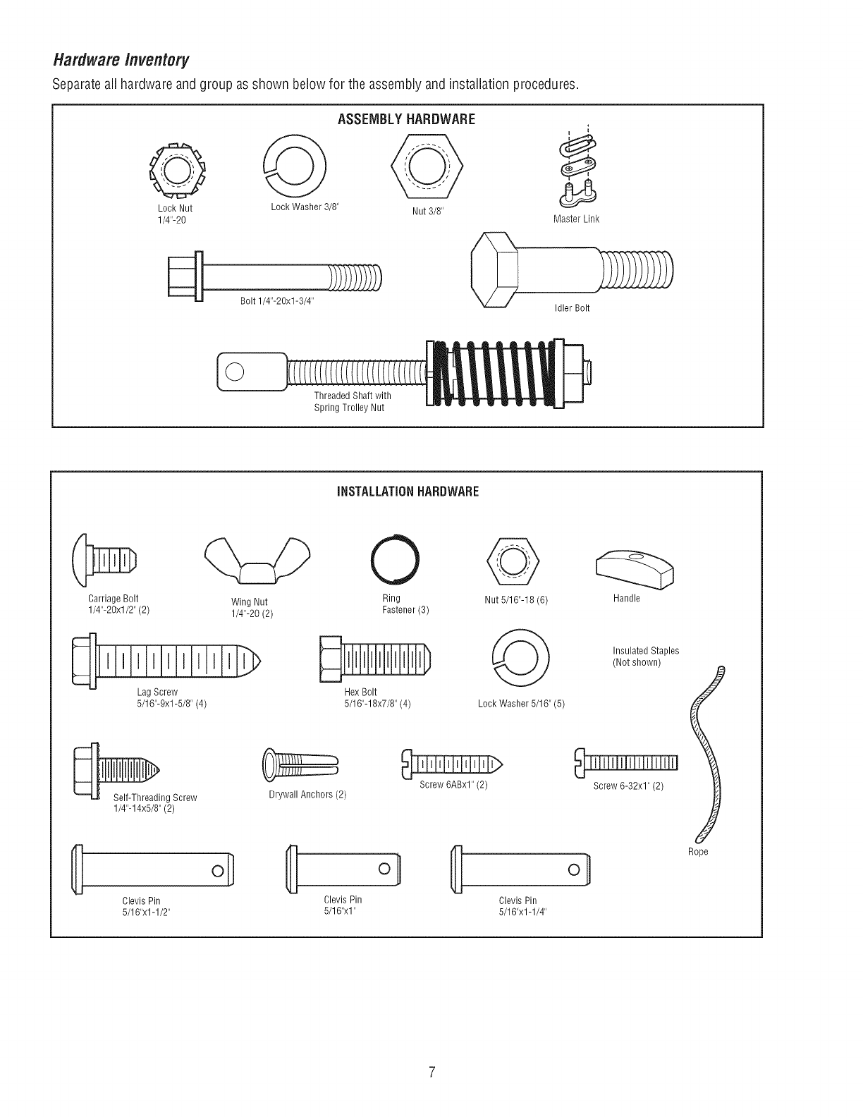
HardwareInventory
Separateall hardware andgroup as shown below for the assembly and installation procedures.
ASSEMBLYHARDWARE
I
J
Lock Nut Lock Washer 3/8" Nut 3/8"
1/4"-20 Master Link
Bolt 1/4"-20xl-3/4" _ [_
Idler Bolt
©
Threaded Shaft with
Spring Trolley Nut
iNSTALLATiONHARDWARE
Carriage Bolt
1/4"-20xl/2" (2) Wing Nut Ring Nut 5/16"-18 (6)
1/4"-20 (2) Fastener (3)
Lag Screw Hex Bolt
5/16"-9xl-5/8" (4) 5/16"-18x7/8" (4) Lock Washer 5/16" (5)
_ng Screw
1/4"-14x5/8"(2)
Drywall Anchors (2) Screw 6ABxl" (2)
{! Clevis Pin Clevis Pin
5/16"xl -1/2" 5/16"xl"
Clevis Pin
5/16"x1-1/4"
Insulated Staples
(Not shown)
Screw 6-32x1" (2)
Rope
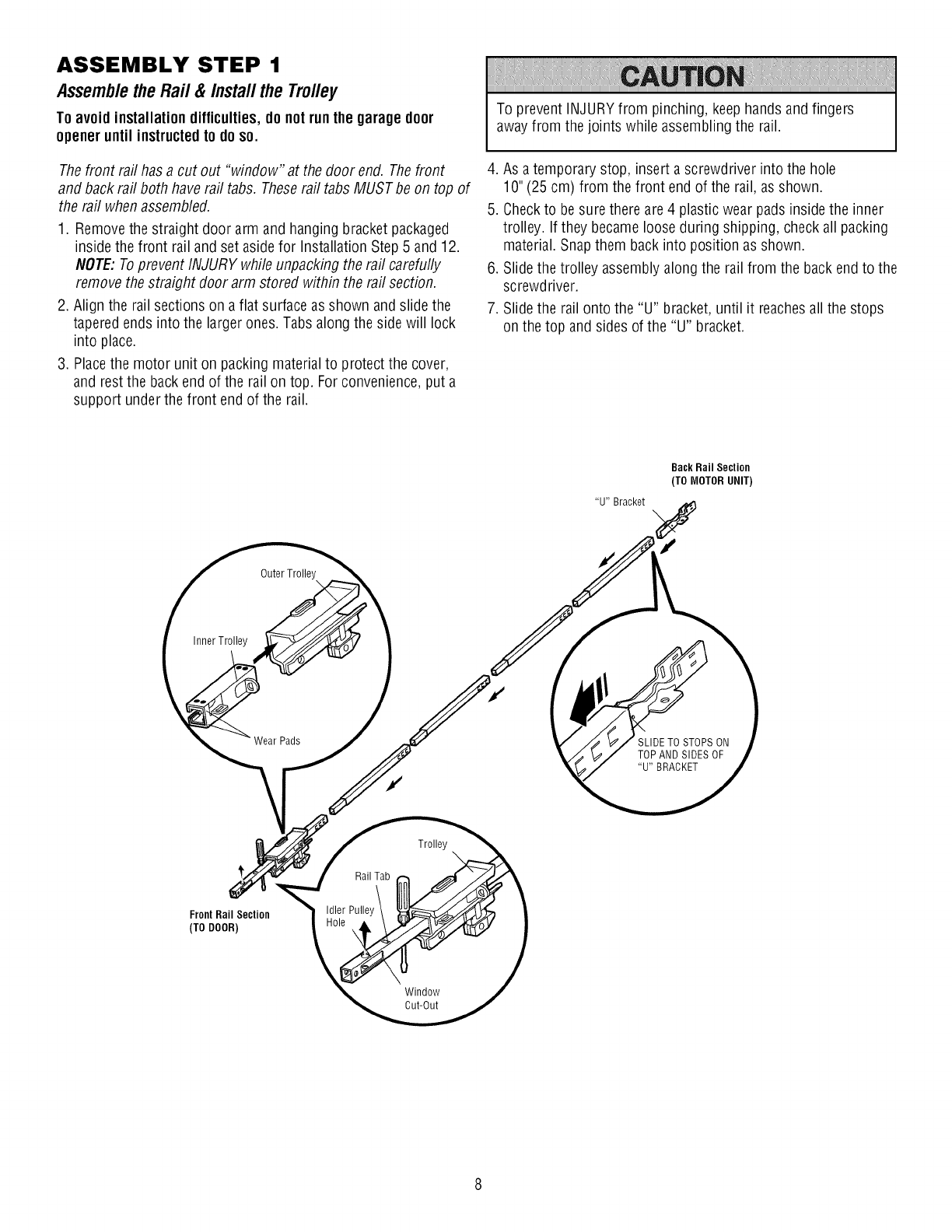
ASSEMBLY STEP 1
Assemble the Rail & Install the Trolley
Toavoid installation difficulties,do notrun the garage door
openeruntil instructedto doso.
Thefront rail has a cut out "window" at the door end. Thefront
and back rail both have rail tabs. Theserail tabs MUSTbe on top of
the rail when assembled.
1. Remove the straight door arm and hanging bracket packaged
inside the front rail and set aside for Installation Step 5 and 12.
NOTE:Toprevent INJURY while unpacking the rail carefully
remove the straight door arm stored within the rail section.
2. Align the rail sections on aflat surface as shown and slide the
tapered ends into the larger ones.Tabs along the side will lock
into place.
3. Placethe motor unit on packing material to protect the cover,
and rest the back end of the rail on top. For convenience,put a
support under the front end of the rail.
To prevent INJURYfrom pinching, keephands and fingers
awayfrom the joints while assembling the rail.
4. As atemporary stop, insert a screwdriver into the hole
10" (25 cm) from the front end of the rail, as shown.
5. Checkto be sure there are4 plastic wear pads inside the inner
trolley. If they becameloose during shipping, check all packing
material. Snapthem back into position as shown.
6. Slide the trolley assemblyalong the rail from the back endto the
screwdriver.
7. Slide the rail onto the "U" bracket, until it reachesall the stops
on the top and sides of the "U" bracket.
"U" Bracket
Back Rail Section
(TO MOTOR UNIT)
Outer Trolley
Inner Trolley
Wear Pads SLIDETO STOPS ON
TOP AND SIDES OF
"U" BRACKET
FrontRail Section
(TO DOOR)
Rail Tab
Idler Pulley
Trolley
Window
Cut-Out
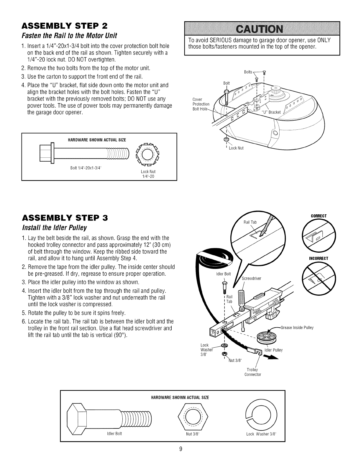
ASSEMBLY STEP 2
Fastenthe Rail to the MotorUnit
1. Insert a 1/4"-20xl-3/4 bolt into the cover protection bolt hole
on the back end of the rail as shown. Tighten securely with a
1/4"-20 lock nut. DO NOTovertighten.
2. Removethe two bolts from the top of the motor unit.
3. Usethe carton to support the front end of the rail.
4. Placethe "U" bracket,flat side down onto the motor unit and
align the bracket holes with the bolt holes. Fastenthe "U"
bracket with the previously removed bolts; DO NOTuse any
power tools. The use of power tools may permanently damage
the garagedoor opener.
HARDWARESHOWN ACTUALSIZE
Bolt 1/4"-BOx1-3/4" Lock Nut
1/4"-20
To avoid SERIOUSdamageto garagedoor opener, use ONLY
those bolts/fasteners mounted in the top of the opener.
Cover
Protection
Bolt
Bolts
I
t Lock Nut
ASSEMBLY STEP 3
Install the Idler Pulley
1. Laythe belt beside the rail, as shown. Graspthe end with the
hooked trolley connector and pass approximately 12" (30 cm)
of belt through the window. Keepthe ribbed side toward the
rail, and allow it to hang until Assembly Step 4.
2. Removethe tape from the idler pulley.The inside center should
be pre-greased. If dry, regreaseto ensure proper operation.
3. Placethe idler pulley into the window as shown.
4. Insert the idler bolt from the top through the rail and pulley.
Tighten with a 3/8" lock washer and nut underneaththe rail
until the lock washer is compressed.
5. Rotatethe pulley to be sure it spins freely.
6. Locatethe rail tab. The rail tab is betweenthe idler bolt and the
trolley in the front rail section. Usea flat headscrewdriver and
lift the rail tab until the tab is vertical (90°).
Screwdriver
._._.. _Grease InsideI
Lock
Washer tIdler Pulley
3/8" t_Nut 3/8"
Trolley
Connector
CORRECT
@
INCORRECT
@
Pulley
HARDWARESHOWN ACTUALSIZE
Idler Bolt Nut 3/8" Lock Washer 3/8"
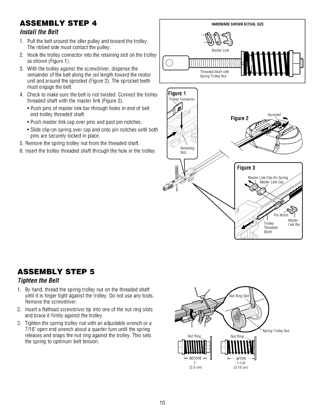
ASSEMBLY STEP 4
Install theBelt
1. Pull the belt around the idler pulley and toward the trolley.
The ribbed side must contact the pulley.
2. Hookthe trolley connector into the retaining slot on the trolley
as shown (Figure 1).
3. With the trolley againstthe screwdriver, dispense the
remainder of the belt along the rail length toward the motor
unit and around the sprocket (Figure 2). The sprocket teeth
must engagethe belt.
4. Checkto makesure the belt is not twisted. Connect the trolley
threaded shaft with the master link (Figure 3).
• Push pins of master link bar through holes in end of belt
and trolley threaded shaft.
• Push master link cap over pins and past pin notches.
• Slide clip-on spring over cap and onto pin notches until both
pins are securely locked in place.
5. Removethe spring trolley nut from the threaded shaft.
6. Insert the trolley threaded shaft through the hole in the trolley.
[©
ure I
HARDWARESHOWN ACTUALSIZE
Master Link
Threaded Shaft with
Spring Trolley Nut
Sprocket
Figure2 -,,,
Figure3
Master Link Clip-On Spring
Master Link Ca
ASSEMBLY STEP 5
Tighten the Belt
1. By hand, thread the spring trolley nut on the threaded shaft
until it is finger tight against the trolley. Do not use any tools.
Removethe screwdriver.
2. Insert a flathead screwdriver tip into one of the nut ring slots
and brace it firmly against the trolley.
3. Tighten the spring trolley nut with an adjustable wrench or a
7/16" open end wrench about a quarter turn until the spring
releasesand snaps the nut ring against the trolley. This sets
the spring to optimum belt tension.
Nut Ring
I- BEFORE-I
1"
(2.5cm)
Nut Ring _ rl
F liiiii l
1-1/4"
(3.18 cm)
"Spring Trolley Nut
10
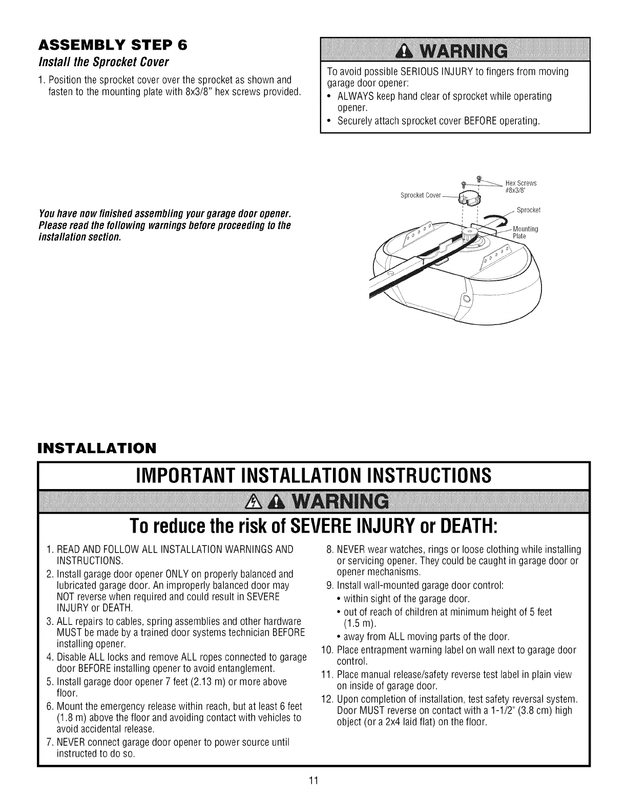
ASSEMBLY STEP 6
Install the Sprocket Cover
1. Position the sprocket cover over the sprocket as shown and
fasten to the mounting plate with 8x3/8" hex screws provided.
To avoid possible SERIOUSINJURYto fingers from moving
garagedoor opener:
• ALWAYSkeep hand clear of sprocket while operating
opener.
• Securelyattach sprocket cover BEFOREoperating.
Youhave nowfinishedassemb/ingyourgarage dooropener.
P/ease read the fo//owingwarnings beforeproceedingto the
insta//ation section.
_Hex Screws
Sprocket Cover_ #8x3/8"
,/ Sprocket
Plate
INSTALLATION
IMPORTANTINSTALLATIONINSTRUCTIONS
ToreducetheriskofSEVEREINJURYorDEATH:
1. READAND FOLLOWALL INSTALLATIONWARNINGSAND
INSTRUCTIONS.
2. Install garage door opener ONLYon properly balanced and
lubricated garage door. An improperly balanceddoor may
NOTreversewhen required and could result in SEVERE
INJURYor DEATH.
3. ALL repairs to cables, spring assembliesand other hardware
MUST be made by a trained door systemstechnician BEFORE
installing opener.
4. DisableALL locks and removeALL ropes connected to garage
door BEFOREinstalling openerto avoid entanglement.
5. Install garage door opener7 feet (2.13 m) or more above
floor.
6. Mount the emergency releasewithin reach,but at least 6 feet
(1.8 m) above the floor and avoiding contact with vehicles to
avoid accidental release.
7. NEVERconnect garagedoor openerto power source until
instructed to do so.
8. NEVERwear watches, rings or loose clothing while installing
or servicing opener. They could be caught in garagedoor or
opener mechanisms.
9. Install wall-mounted garagedoor control:
• within sight of the garage door.
• out of reach of children at minimum height of 5 feet
(1.5 m).
• awayfrom ALL moving parts of the door.
10. Placeentrapment warning labelon wall next to garage door
control.
11. Placemanual release/safetyreversetest label in plain view
on inside of garagedoor.
12. Upon completion of installation, test safety reversalsystem.
Door MUST reverseon contact with a 1-1/2" (3.8 cm) high
object (or a 2x4 laid flat) on the floor.
11
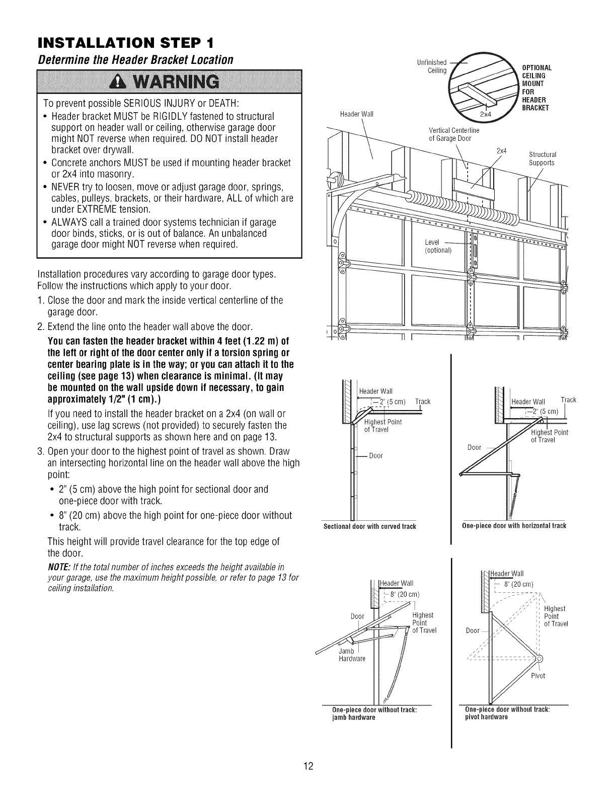
INSTALLATION STEP 1
Determinethe HeaderBracketLocation
To prevent possible SERIOUSINJURYor DEATH:
•Header bracket MUST be RIGIDLYfastened to structural
support on headerwall or ceiling, otherwise garagedoor
might NOTreversewhen required. DO NOTinstall header
bracket over drywall.
• Concrete anchors MUST be used if mounting headerbracket
or 2x4 into masonry.
• NEVERtry to loosen, move or adjust garagedoor, springs,
cables, pulleys, brackets, or their hardware, ALL of which are
under EXTREMEtension.
• ALWAYScall a trained door systems technician if garage
door binds, sticks, or is out of balance.An unbalanced
garagedoor might NOTreversewhen required.
Installation procedures vary according to garagedoor types.
Follow the instructions which apply to your door.
1. Closethe door and mark the inside vertical centerline of the
garagedoor.
2. Extendthe line onto the headerwall above the door.
Youcan fastenthe header bracketwithin4 feet (1.22 m) of
the left or rightof the doorcenteronly if a torsionspringor
centerbearing plate is inthe way;or youcan attach it to the
ceiling (see page 13) whenclearance is minimal. (It may
be mountedonthe wall upsidedownif necessary,to gain
approximately1/2"(1 cm).)
Ifyou needto install the header bracket on a 2x4 (on wall or
ceiling), use lag screws (not provided) to securely fasten the
2x4 to structural supports as shown here and on page 13.
3. Openyour door to the highest point of travel as shown. Draw
an intersecting horizontal line on the headerwall abovethe high
point:
• 2" (5 cm) above the high point for sectional door and
one-piece door with track.
• 8" (20 cm) above the high point for one-piece door without
track.
This height will provide travel clearancefor the top edge of
the door.
NOTE:If the totalnumberof inchesexceedstheheightavailablein
yourgarage,usethemaximumheightpossible,or refertopage13for
ceilinginstallation.
HeaderWall
Unfinished @
Ceiling OPTIONAL
CEiLiNG
MOUNT
FOR
HEADER
BRACKET
Vertical Centerline
of Garage Door
2x4 Structural
Supports
HeaderWall
(5cm) Track
of Travel
--Door
Sectional door with curved track
Y
Header Wall Track
T
One-piece door with horizontal track
_\\Wall
U8/2°0 /
Door__J _ig_st
_Hardware [[ of Travel
One-piece door without track:
jamb hardware
Door
HeaderWall
I 8" (20cm)
_;, Highest
Point
of Travel
Pivot
One-piece door without track:
pivothardware
12
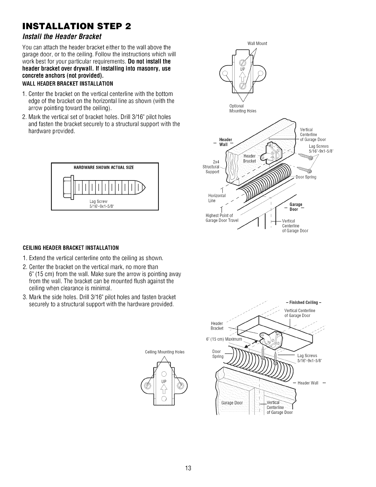
INSTALLATION STEP 2
Install theHeaderBracket
You can attachthe headerbracket either to the wall abovethe
garagedoor, or to the ceiling. Follow the instructions which will
work best for your particular requirements. Do not installthe
header bracket over drywall. If installinginto masonry,use
concreteanchors(not provided).
WALLHEADERBRACKETINSTALLATION
1. Centerthe bracket on the vertical centerline with the bottom
edgeof the bracket on the horizontal line asshown (with the
arrow pointing toward the ceiling).
2. Mark the vertical set of bracket holes. Drill 3/16" pilot holes
and fasten the bracket securely to a structural support with the
hardware provided.
HARDWARESHOWN ACTUALSIZE
LagScrew
5/16"-9xl-5/8"
Wall Mount
_p
Optional
Mounting Holes
2x4
Structural
Support
J
1
Horizontal
Line
"[ j
Highest Point of
Garage Door Travel
Vertical
Centerline
Garage Door
Lag Screws
5/16"-9xl -5/8"
Centerline
of Garage Door
CEILINGHEADERBRACKETINSTALLATION
1. Extendthe vertical centerlineonto the ceiling as shown.
2. Centerthe bracket on the vertical mark, no more than
6" (15 cm) from the wall. Makesure the arrow is pointing away
from the wall. The bracket can be mounted flush againstthe
ceiling when clearanceis minimal.
3. Mark the side holes. Drill 3/16" pilot holes andfasten bracket
securely to astructural support with the hardware provided.
Ceiling Mounting Holes
Header /
Bracket
6" (15 cm) Maximum
Door
Spring
- Finished Ceiling -
Vertical Centerline
of Garage Door
-- Lag Screws
-_ 5/16"-9xl-5/8"
- HeaderWall -
Centeriine
of Garage Door
13
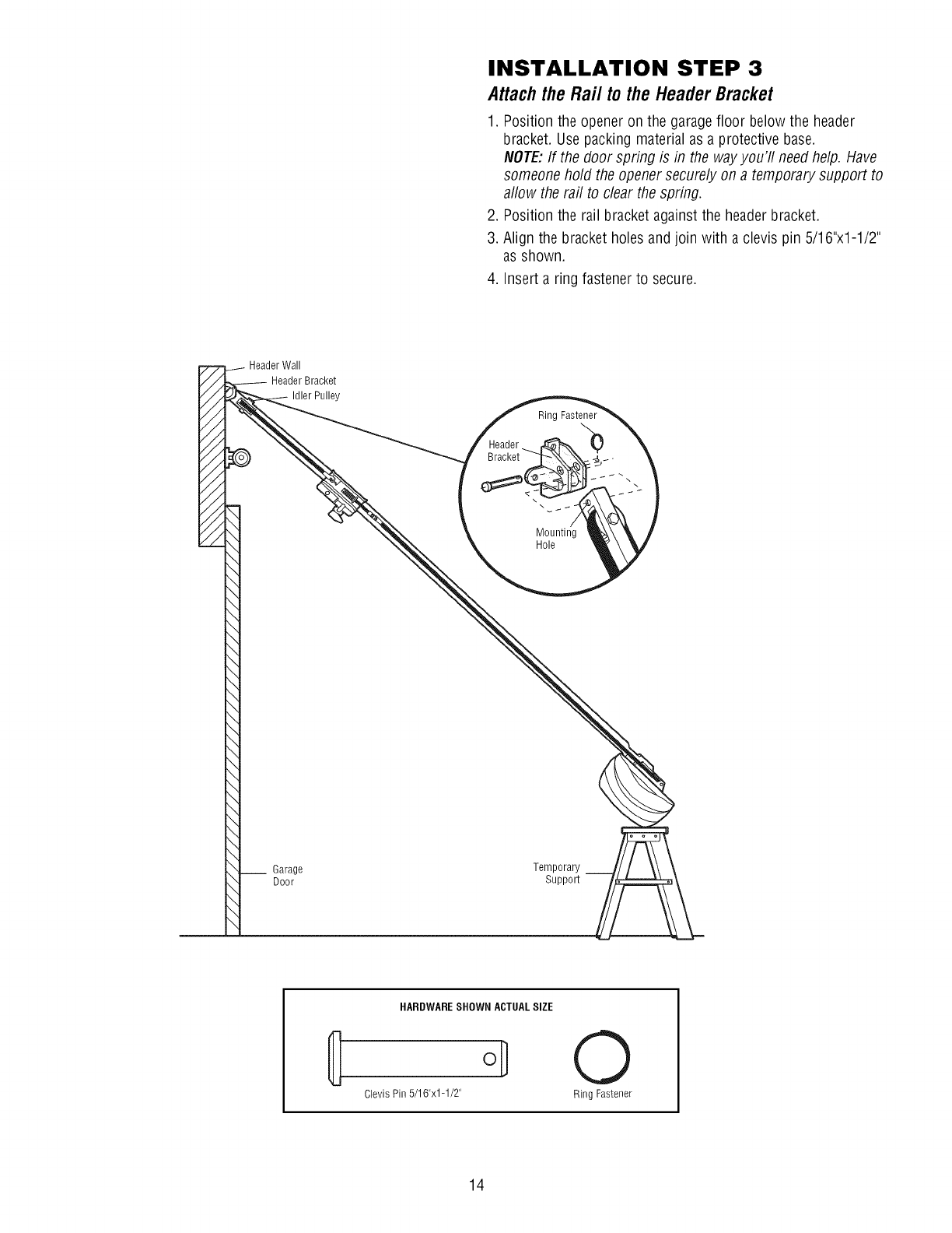
INSTALLATION STEP 3
AttachtheRail tothe HeaderBracket
1. Position the opener on the garagefloor below the header
bracket. Usepacking material as a protective base.
NOTE:If the door spring is in the wayyou'll needhelp. Have
someone hold the opener securely on atemporary support to
allow the rail to clear the spring.
2. Position the rail bracket againstthe headerbracket.
3. Align the bracket holes and join with a clevis pin 5/16"x1-1/2"
as shown.
4. Insert a ring fastener to secure.
Header Wall
Header Bracket
Idler Pulley
Rinc
\\
Mounting
Hole
__ Garage
Door
Temporary
Support
HARDWARESHOWN ACTUALSIZE
Clevis Pin 5/16"x1-1/2" 0
Ring Fastener
14
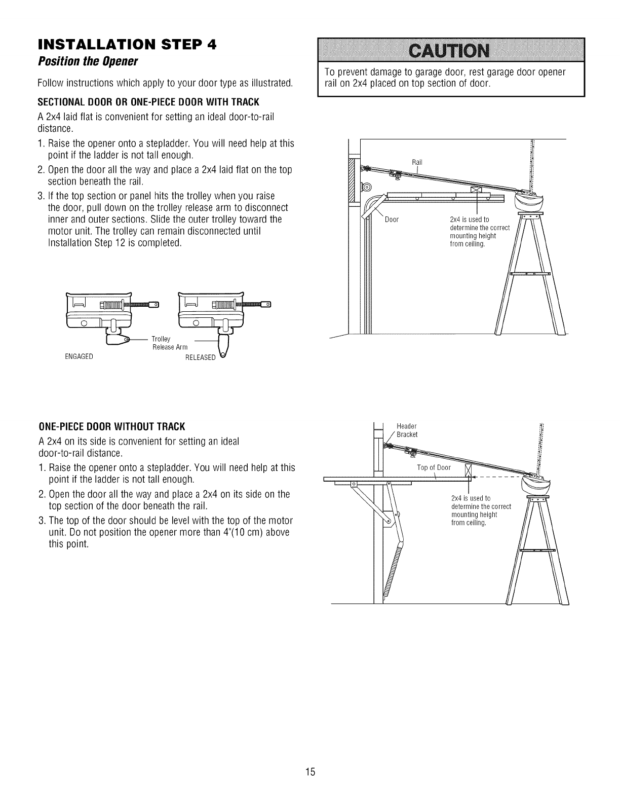
INSTALLATION STEP 4
Positionthe Opener
Follow instructions which apply to your door type as illustrated.
SECTIONALDOOROR ONE-PIECEDOORWITH TRACK
A 2x4 laid flat is convenient for setting an ideal door-to-rail
distance.
1. Raisethe opener onto a stepladder. You will need help at this
point if the ladder is not tall enough.
2. Openthe door all the way and place a 2x4 laid flat on the top
section beneath the rail.
3. If the top section or panel hits the trolley when you raise
the door, pull down on the trolley releasearm to disconnect
inner and outer sections. Slide the outer trolley toward the
motor unit. The trolley can remain disconnected until
Installation Step 12 is completed.
To prevent damage to garage door, rest garage door opener
rail on 2x4 placed on top section of door.
Rail
Door 2x4 is used to
determine the correct
mounting height
from ceiling.
Trolley
lease
ENGAGED RELEASED _._
ONE-PIECEDOORWITHOUTTRACK
A 2x4 on its side is convenient for setting an ideal
door-to-rail distance.
1. Raisethe opener onto a stepladder. You will need help at this
point if the ladder is not tall enough.
2. Openthe door all the way and place a 2x4 on its side on the
top section of the door beneaththe rail.
3. The top of the door should be level with the top of the motor
unit. Do not position the opener more than 4"(10 cm) above
this point.
Header
Bracket
Top of Door
2x4 is used to
determine the correct
mounting height
from ceiling.
15
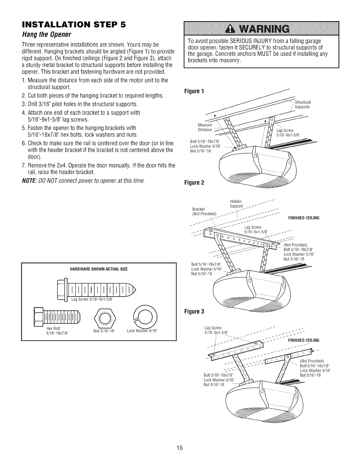
INSTALLATION STEP 5
Hangthe Opener
Three representativeinstallations are shown. Yours may be
different. Hanging brackets should be angled (Figure 1) to provide
rigid support. Onfinished ceilings (Figure 2 and Figure3), attach
a sturdy metal bracket to structural supports before installing the
opener. This bracket and fastening hardware are not provided.
1. Measurethe distance from each side of the motor unit to the
structural support.
2. Cut both pieces of the hanging bracket to required lengths.
3. Drill 3/16" pilot holes in the structural supports.
4. Attach one end of each bracket to a support with
5/16"-9xl-5/8" lag screws.
5. Fastenthe openerto the hanging bracketswith
5/16"-18x7/8" hex bolts, lock washers and nuts.
6. Checkto makesure the rail is centeredover the door (or in line
with the headerbracket if the bracket is not centered abovethe
door).
7. Removethe 2x4. Operatethe door manually. If the door hits the
rail, raisethe headerbracket.
NOTE'.DO NOTconnect power to openerat this time.
To avoid possible SERIOUSINJURYfrom a falling garage
door opener, fasten it SECURELYto structural supports of
the garage. Concreteanchors MUST be used if installing any
brackets into masonry.
Figure 1
Supports
Measure ",
Distance
Bolt 5/16"-18x7/8"
Lock Washer 5/16"
Nut 5/16"-18
Lag Screw
5/16"-9xl-5/8"
Figure 2
HARDWARESHOWN ACTUALSIZE
q Lag Screw 5/16"-9xl-5/8"
i iii]i I'hL
5/16"-18x7/8" Nut 5/16"-18 Lock Washer 5/16"
Bolt 5/16"-18x7/8"
Lock Washer 5/16"
Nut 5/16"-18
Figure 3
Bolt 5/16"-18x7/8"
Lock Washer 5/16"
Nut 5/16"-18
(Not Provided)
Bolt 5/16"-18x7/8"
Lock Washer 5/16"
Nut 5/16"-18
16
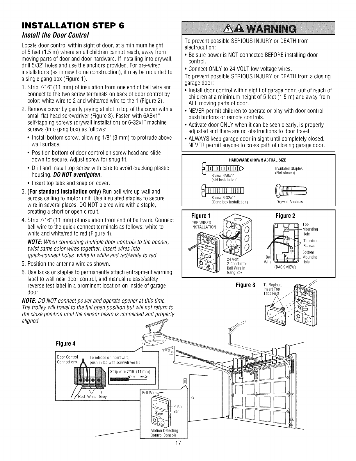
INSTALLATION STEP 6
InstalltheDoorControl
Locate door control within sight of door, at a minimum height
of 5 feet (1.5 m) where small children cannot reach, awayfrom
moving parts of door anddoor hardware.If installing into drywall,
drill 5/32" holes and use the anchors provided. For pre-wired
installations (as in new home construction), it may be mounted to
a single gang box (Figure 1).
1. Strip 7/16" (11 mm) of insulation from one end of bell wire and
connect to the two screw terminals on back of door control by
color: white wire to 2 and white/red wire to the 1 (Figure 2).
2. Removecover by gently prying at slot in top of the cover with a
small flat head screwdriver (Figure 3). Fastenwith 6ABxl"
self-tapping screws (drywall installation) or 6-32x1" machine
screws (into gang box) as follows:
• Install bottom screw, allowing 1/8" (3 mm) to protrude above
wall surface.
• Position bottom of door control on screw headand slide
down to secure. Adjust screw for snug fit.
• Drill and install top screw with care to avoid cracking plastic
housing. DO NOTovertighten.
• Insert top tabs and snap on cover.
3(For standardinstallation only) Run bell wire up wall and
across ceiling to motor unit. Useinsulated staples to secure
wire in severalplaces. DONOTpierce wire with a staple,
creating a short or open circuit.
4. Strip 7/16" (11 mm) of insulation from end of bell wire. Connect
bell wire to the quick-connect terminals as follows: white to
white andwhite/red to red(Figure 4).
NOTE:Whenconnecting multiple door controls to the opener,
twist samecolor wires together. Insert wires into
quick-connect holes: white to white and red/white to red.
5. Position the antenna wire as shown.
6. Usetacks or staples to permanently attach entrapment warning
label to wall near door control, and manual release/safety
reversetest labelin a prominent location on inside of garage
door.
NOTE:DONOTconnect power and operate openerat this time.
Thetrofley will travel to the furl openposition but will not return to
the close position until the sensor beam is connected and properly
aligned.
To prevent possible SERIOUSINJURYor DEATHfrom
electrocution:
• Besure power is NOTconnected BEFOREinstalling door
control.
• Connect ONLYto 24 VOLT low voltage wires.
To prevent possible SERIOUSINJURYor DEATHfrom a closing
garagedoor:
• Install door control within sight of garagedoor, out of reach of
children at a minimum height of 5 feet (1.5 m) and away from
ALL moving parts of door.
• NEVERpermit children to operateor play with door control
push buttons or remotecontrols.
• Activatedoor ONLYwhen it can be seen clearly, is properly
adjusted andthere are no obstructions to door travel.
• ALWAYSkeep garagedoor in sight until completely closed.
NEVERpermit anyone to cross path of closing garagedoor.
HARDWARESHOWN ACTUALSIZE
(std installation)
_ ' I 'SJcJrle'_'__'3'2'_1'' '' '' J
(Gang box installation)
Insulated Staples
(Not shown)
Drywall Anchors
Figure1
PRE-WIRED It_JJl
INSTALLATION __
_24Volt
I__- ._._'_t I 2-Conductor
_-Llt I Bell Wire in
Gang Box
Figure2
wB_._ T°p
Mounting
Hole
Terminal
Screws
Bottom
Mounting
Hole
(BACK VIEW)
Figure3 To Replace,
Insert Top ,
Tabs First
Figure4 ./l__
Door Control To release or insert wire,
Connections )ush in tab with screwdriver tip
Strip wire 7/16" (11 mm)
_,_7/16 (11 mrn)_ I
Red White Grey
J
17
Bell W_ o
Bar .---------
Motion Detecting
Control Console
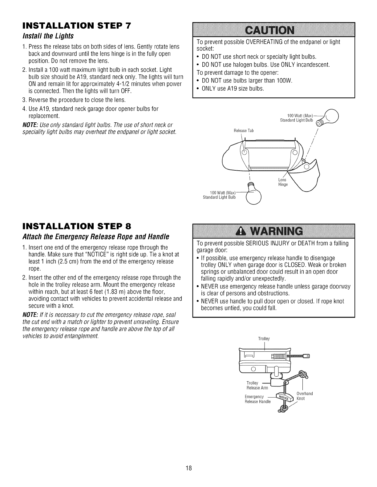
INSTALLATION STEP 7
Install the Lights
1. Pressthe releasetabs on both sides of lens. Gently rotate lens
back and downward until the lens hinge is in the fully open
position. Do not removethe lens.
2. Install a 100watt maximum light bulb in each socket. Light
bulb sizeshould beA19, standard neck only. The lights will turn
ON and remain lit for approximately4-1/2 minutes when power
is connected. Thenthe lights will turn OFF.
3. Reversethe procedure to closethe lens.
4. UseA19, standard neck garagedoor opener bulbs for
replacement.
NOTE:Useonly standard light bulbs. Theuse of short neck or
speciafity light bulbs may overheatthe endpanelor light socket.
To prevent possible OVERHEATINGof the endpanelor light
socket:
• DONOTuse short neck or specialty light bulbs.
• DONOTuse halogen bulbs. Use ONLYincandescent.
To preventdamage to the opener:
• DONOTuse bulbs larger than IOOW.
• ONLY useA19 sizebulbs.
100 Watt (Max)_
Standard Light Bulb_
Release Tab /
1 Lens X f
100 Watt (Max)___., _ Hinge "XN_
Standard Light Bulb LJ
INSTALLATION STEP 8
Attach the Emergency Release Rope and Handle
1. Insert one end of the emergency release ropethrough the
handle. Make sure that "NOTICE"is right side up. Tie a knot at
least 1 inch (2.5 cm) from the end of the emergency release
rope.
2. Insert the other end of the emergency release ropethrough the
hole in the trolley releasearm. Mount the emergency release
within reach,but at least 6 feet (1.83 m) above the floor,
avoiding contact with vehicles to prevent accidental releaseand
securewith a knot.
NOTE:If it is necessaryto cut the emergency releaserope, seal
the cut end with a match or lighter to prevent unraveling. Ensure
the emergency releaserope and handleare above the top of aft
vehicles to avoid entanglement.
To prevent possible SERIOUSINJURYor DEATHfrom a falling
garagedoor:
• If possible, use emergency releasehandle to disengage
trolley ONLYwhen garagedoor is CLOSED.Weakor broken
springs or unbalanceddoor could result in an opendoor
falling rapidly and/or unexpectedly.
• NEVERuse emergency releasehandle unlessgaragedoorway
is clear of persons and obstructions.
• NEVERuse handleto pull door open or closed. If rope knot
becomes untied, you could fall.
Trolley
Emergency _ _verhandnot
Release Handle
18
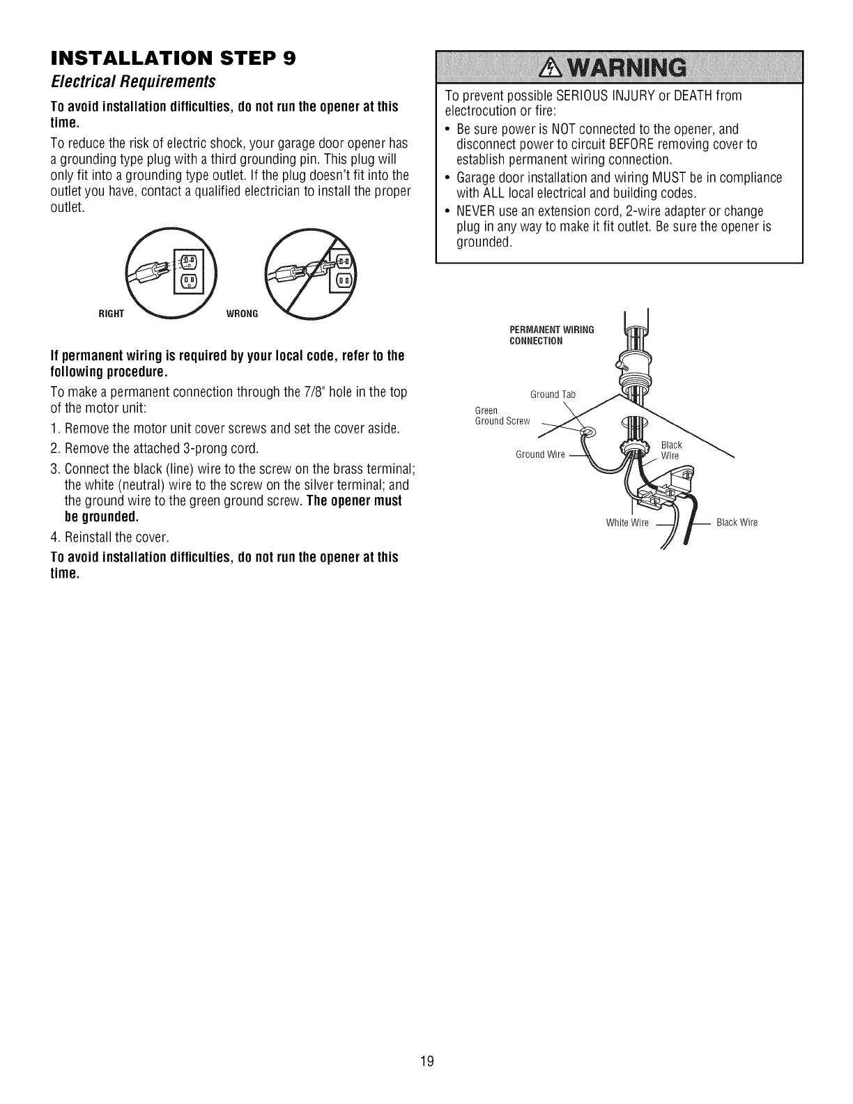
INSTALLATION STEP 9
E/ectrica/Requirements
Toavoid installation difficulties,do notrun the openerat this
time.
To reduce the risk of electric shock, your garagedoor opener has
a grounding type plug with a third grounding pin. This plug will
only fit into a grounding type outlet. If the plug doesn't fit into the
outlet you have,contact a qualified electrician to install the proper
outlet.
RIGHT_
WRONG
If permanent wiring is requiredby your local code, refer to the
followingprocedure.
To makea permanent connection through the 7/8" hole in the top
of the motor unit:
1. Removethe motor unit cover screws and set the cover aside.
2. Removethe attached3-prong cord.
3. Connectthe black (line) wire to the screw on the brass terminal;
the white (neutral) wire to the screw on the silver terminal; and
the ground wire to the greenground screw. The openermust
be grounded.
4. Reinstallthe cover.
Toavoid installation difficulties,do notrun the openerat this
time.
To prevent possible SERIOUSINJURYor DEATHfrom
electrocution or fire:
• Besure power is NOTconnected to the opener, and
disconnect power to circuit BEFOREremoving cover to
establish permanentwiring connection.
• Garagedoor installation and wiring MUSTbe in compliance
with ALL local electrical and building codes.
• NEVERuse an extension cord, 2-wire adapter or change
plug in any way to make it fit outlet. Besure the opener is
grounded.
PERMANENTWIRING
CONNECTION
Ground Tab
Green
Ground Screw
Black
Ground Wire .Wire
White Wire Black Wire
19
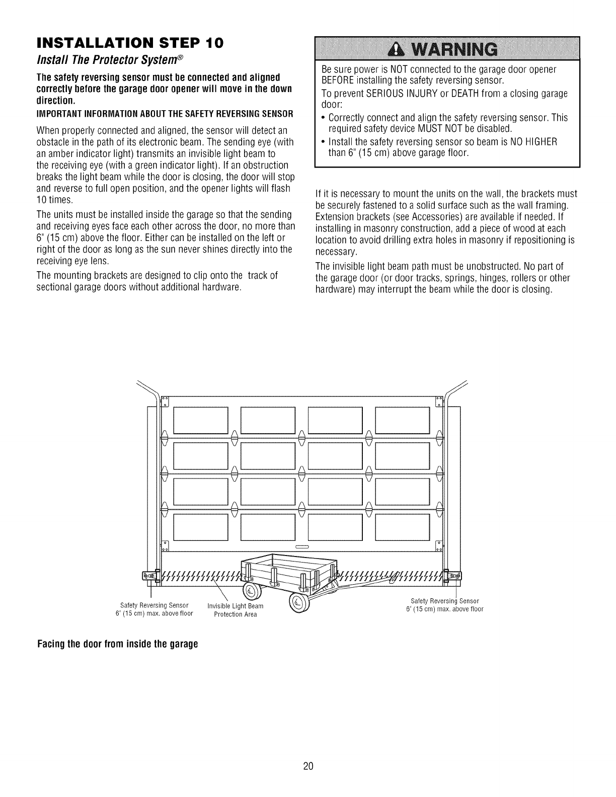
INSTALLATION STEP 10
Install The Protector System®
Thesafety reversingsensormust be connectedandaligned
correctlybeforethe garage dooropenerwill move in the down
direction.
IMPORTANTINFORMATIONABOUTTHESAFETYREVERSINGSENSOR
When properly connected andaligned, the sensor will detect an
obstacle in the path of its electronic beam.The sending eye (with
an amber indicator light) transmits an invisible light beamto
the receiving eye (with a green indicator light). If an obstruction
breaksthe light beam while the door is closing, the door will stop
and reverseto full open position, and the openerlights will flash
10 times.
The units must be installed inside the garageso that the sending
and receivingeyesface each other across the door, no more than
6" (15 cm) abovethe floor. Either can be installed on the left or
right of the door as long as the sun never shines directly into the
receiving eye lens.
The mounting brackets are designedto clip onto the track of
sectional garage doors without additional hardware.
Besure power is NOTconnected to the garagedoor opener
BEFOREinstalling the safety reversingsensor.
To preventSERIOUSINJURYor DEATHfrom a closing garage
door:
• Correctly connect andalign the safety reversing sensor. This
required safety device MUST NOTbedisabled.
• Install the safety reversing sensor so beam is NO HIGHER
than 6" (15 cm) abovegaragefloor.
If it is necessaryto mount the units on the wall, the brackets must
be securely fastened to a solid surface such as the wall framing.
Extension brackets (seeAccessories) are availableif needed.If
installing in masonry construction, add a piece of wood at each
location to avoid drilling extra holes in masonry if repositioning is
necessary.
The invisible light beam path must be unobstructed. No part of
the garagedoor (or door tracks, springs, hinges, rollers or other
hardware) may interrupt the beam while the door is closing.
!o! !÷[ !€
Safety Reversin;211111 7 2"'7ir_i_i ii [f.7;t_;tYZ 2".7"_:: 'g sor
6" (15 cm) max. abovefloor Protection Area 6" (15 cm) max. above floor
Facingthe doorfrom insidethe garage
2O
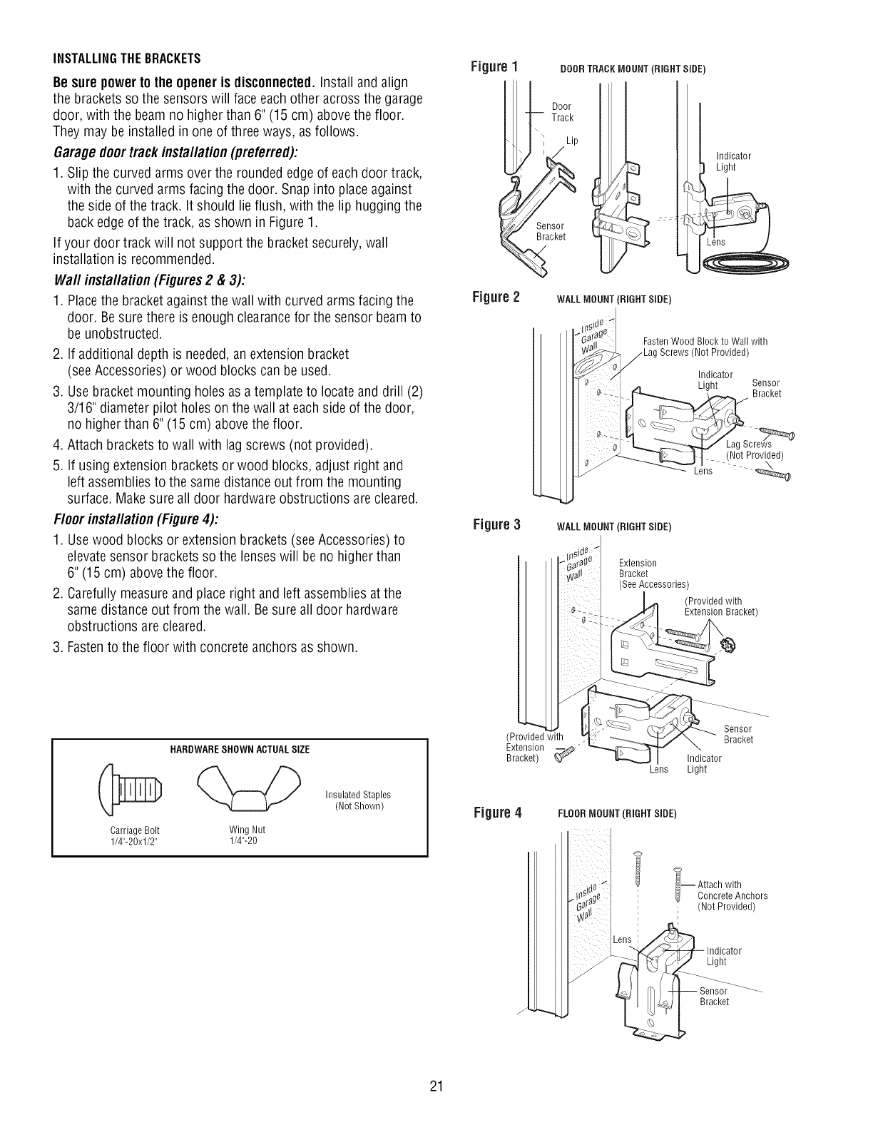
INSTALLINGTHEBRACKETS
Be surepower to the opener is disconnected.Install and align
the brackets so the sensors will face each other across the garage
door, with the beam no higher than 6" (15 cm) abovethe floor.
They may be installed in one of three ways, as follows.
Garagedoortrack installation (preferred):
1. Slip the curved arms over the rounded edgeof each door track,
with the curved arms facing the door. Snap into place against
the side of the track. It should lie flush, with the lip hugging the
back edgeof the track, as shown in Figure 1.
If your door track will not support the bracket securely, wall
installation is recommended.
Wall installation (Figures 2 & 3):
1. Placethe bracket againstthe wall with curved arms facing the
door. Besure there is enough clearancefor the sensor beamto
be unobstructed.
2. If additional depth is needed,an extension bracket
(see Accessories) or wood blocks can be used.
3. Usebracket mounting holes as a template to locate and drill (2)
3/16" diameter pilot holes on the wall at each side of the door,
no higher than 6" (15 cm) above the floor.
4. Attach bracketsto wall with lag screws (not provided).
5. If using extension bracketsor wood blocks, adjust right and
left assembliesto the same distance out from the mounting
surface. Makesure all door hardware obstructions are cleared.
Floor installation (Figure 4):
1. Usewood blocks or extension brackets (seeAccessories) to
elevatesensor brackets so the lenses will be no higher than
6" (15 cm) abovethe floor.
2. Carefully measureand place right and left assembliesat the
same distance out from the wall. Besure all door hardware
obstructions are cleared.
3. Fastento the floor with concreteanchors as shown.
Figure1
iDoor
l/I TraC p
_ seneo_r_
acket
Figure2
DOOR TRACKMOUNT (RIGHT SIDE)
WALLMOUNT (RIGHT SIDE)
Indicator
Light
Fasten Wood Block to Wall with
(Not Provided)
Indicator
Light Sensor
Bracket
(Not Provided)
Lens
Figure 3WALL MOUNT (RIGHT SIDE)
Extension
Bracket
(See Accessories)
(Provided with
Extension Bracket)
Carriage Bolt
1/4"-20xl/2"
HARDWARESHOWN ACTUALSIZE
Wing Nut
1/4"-20
Insulated Staples
(Not Shown) Figure4
(Provided with
Extension
Bracket) _J
Sensor
Bracket
Indicator
Lens Light
FLOORMOUNT (RIGHT SIDE)
¢i-- ttach with
Concrete Anchors
; (Not Provided)
J
Indicator
Light
Bracket
21
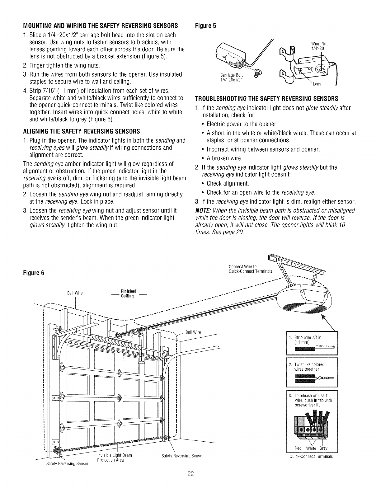
MOUNTINGANDWIRING THESAFETYREVERSINGSENSORS
1. Slide a 1/4"-20xl/2" carriage bolt headinto the slot on each
sensor. Usewing nuts to fasten sensors to brackets, with
lenses pointing toward each other across the door. Besure the
lens is not obstructed by a bracket extension (Figure 5).
2. Finger tighten the wing nuts.
3. Run the wires from both sensors to the opener. Use insulated
staples to secure wire to wall and ceiling.
4. Strip 7/16" (11 mm) of insulation from each set of wires.
Separatewhite and white/black wires sufficiently to connect to
the opener quick-connect terminals. Twist like colored wires
together. Insert wires into quick-connect holes:white to white
and white/black to grey (Figure 6).
ALIGNINGTHESAFETYREVERSINGSENSORS
1. Plug in the opener. The indicator lights in both the sending and
receiving eyeswill glow steadily if wiring connections and
alignment are correct.
The sending eye amber indicator light will glow regardlessof
alignment or obstruction. If the green indicator light in the
receiving eyeis off, dim, or flickering (and the invisible light beam
path is not obstructed), alignment is required.
2. Loosenthe sending eyewing nut and readjust, aiming directly
at the receiving eye. Lock in place.
3. Loosenthe receiving eye wing nut and adjust sensor until it
receivesthe sender's beam. When the green indicator light
glows steadily, tighten the wing nut.
Figure 5
CarriageBolt
1/4"-20xl/2"
Wing Nut
TROUBLESHOOTINGTHESAFETYREVERSINGSENSORS
1. If the sending eyeindicator light does not glow steadily after
installation, check for:
• Electric power to the opener.
• A short in the white or white/black wires. Thesecan occur at
staples, or at opener connections.
• Incorrect wiring between sensors and opener.
• A broken wire.
2. If the sending eye indicator light glows steadily but the
receiving eyeindicator light doesn't:
• Checkalignment.
• Checkfor an open wire to the receiving eye.
3. If the receiving eye indicator light is dim, realign either sensor.
NOTE:When the invisible beam path is obstructed or misaligned
while the door is closing, the door will reverse. If the door is
already open, it will not close. The openerlights will blink 10
times. Seepage 20.
Figure 6
Bell Wire Finished
-- Ceiling --
,I]r ;'ff
-Protection Area
Safety Reversing Sensor
Safety Reversing Sensor
22
Connect Wire to
Quick-Connect Terminals
2. Twist like colored
wires together
3. To release or insert
wire, push in tab with
screwdriver tip
Red White Grey
Quick-Connect Terminals
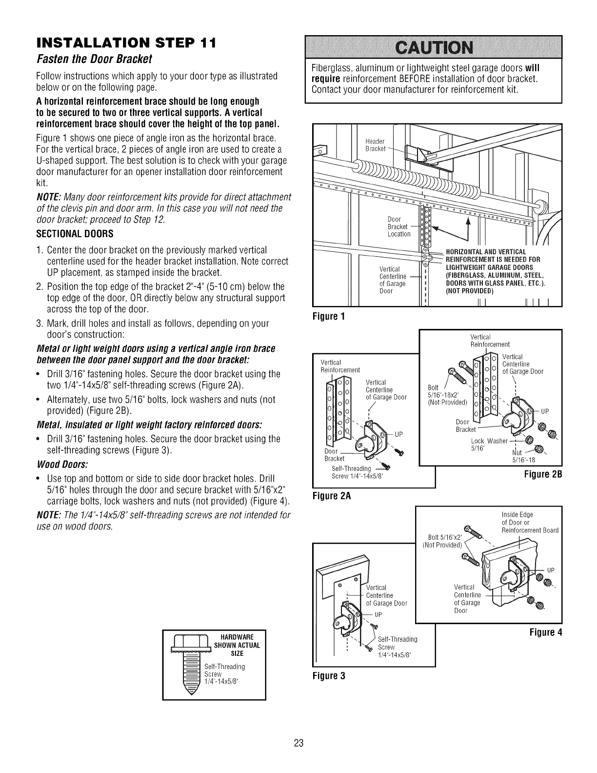
INSTALLATION STEP 11
Fastenthe DoorBracket
Follow instructions which apply to your door type as illustrated
below or on the following page.
A horizontalreinforcementbraceshouldbe longenough
to be securedto two orthree vertical supports.A vertical
reinforcementbraceshouldcoverthe heightof the top panel.
Figure 1 shows one pieceof angle iron as the horizontal brace.
For the vertical brace, 2 piecesof angleiron are used to createa
U-shapedsupport. The best solution is to check with your garage
door manufacturer for an openerinstallation door reinforcement
kit.
NOTE:Many door reinforcement kits provide for direct attachment
of the clevis pin and door arm. In this caseyou will not needthe
door bracket, proceed to Step 12.
SECTIONALDOORS
1. Centerthe door bracket on the previously marked vertical
centerline used for the headerbracket installation. Note correct
UP placement, as stamped inside the bracket.
2. Position the top edgeof the bracket 2"-4"(5-10 cm) below the
top edge of the door, OR directly below any structural support
across the top of the door.
3. Mark, drill holes and install as follows, dependingon your
door's construction:
Metal or light weight doorsusinga verticalangle iron brace
betweenthe doorpanel supportandthe doorbracket:
•Drill 3/16" fastening holes. Secure the door bracket using the
two 1/4"-14x5/8" self-threading screws (Figure 2A).
• Alternately, use two 5/16" bolts, lock washers and nuts (not
provided) (Figure 2B).
Metal, insulated or light weightfactoryreinforceddoors:
• Drill 3/16" fastening holes. Secure the door bracket using the
self-threading screws (Figure 3).
WoodDoors:
• Usetop and bottom or side to side door bracket holes. Drill
5/16" holes through the door and secure bracket with 5/16"x2"
carriage bolts, lock washers and nuts (not provided) (Figure 4).
NOTE:The 1/4"-14x5/8"self-threading screws are not intended for
use on wood doors.
HARDWARE
SHOWN ACTUAL
SIZE
If-Threading
rew
"-14x5/8"
Fiberglass,aluminum or lightweight steel garage doors will
require reinforcement BEFOREinstallation of door bracket.
Contactyour door manufacturer for reinforcement kit.
Figure 1
Door
Bracket
Location
Vertical
Centerline
of Garage
Door
Vertical
Reinforcement
Vertical
Centerline
o_arage Door
i
Self-Threading -_
Screw 1/4"-14x5/8"
Figure2A
,_rtical
Centerline
of Garage Door
UP
Screw
1/4"-14x5/8"
HORIZONTALAND VERTICAL
REINFORCEMENTIS NEEDEDFOR
LiGHTWEiGHTGARAGEDOORS
(FIBERGLASS, ALUMINUM, STEEL,
DOORSWiTH GLASSPANEL, ETC.).
(NOT PROVIDED)
III IIII
Vertical
Reinforcement
,_ Vertical
IoTl_LI Centerline
1ollololof ?rage Door
Bolt/ TIIolOl :
5/16"-18x2" IOILIbl. -
(NotProvided) HI?N
5/16" I_ut _-
5/16"-18
JFigure2B
Bolt5/16"x2"
(NotProvided)
Inside Edge
of Door or
Reinforcement Board
Vertical
Centerline
of Garage
Door
Figure 4
Figure3
23
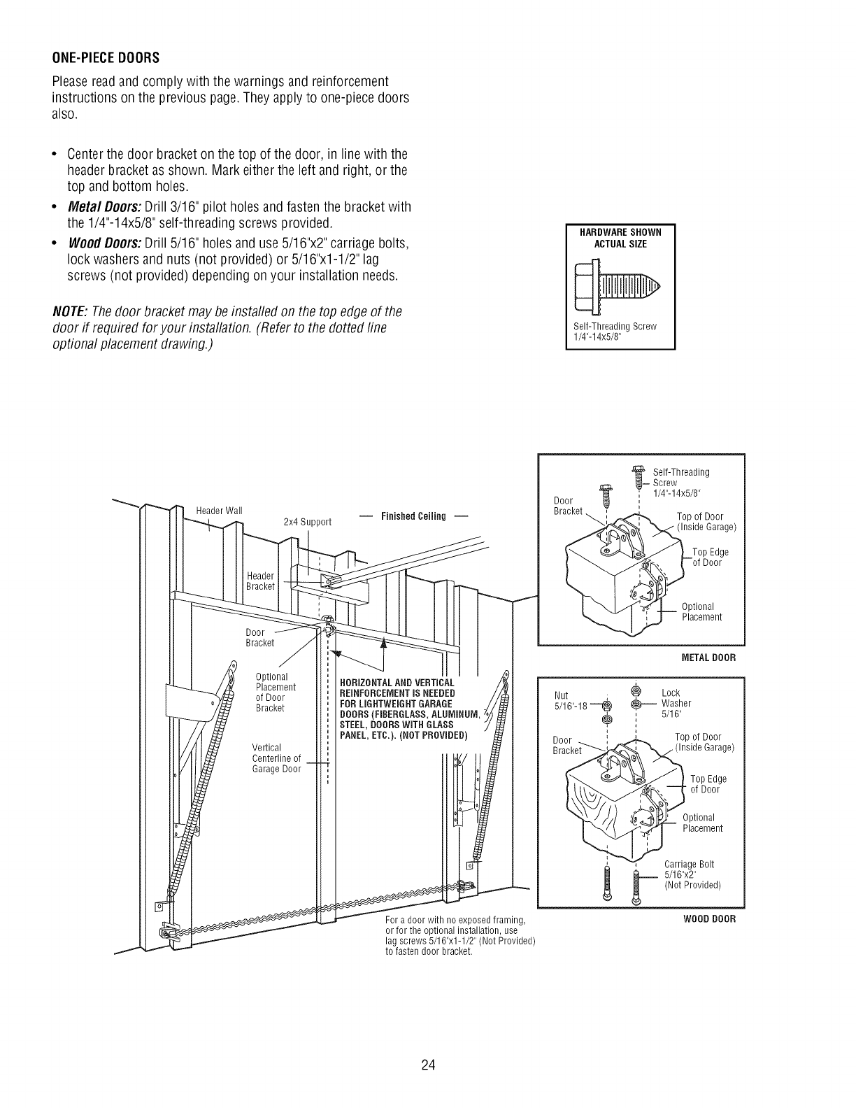
ONE-PIECEDOORS
Please readand comply with the warnings and reinforcement
instructions on the previous page.They apply to one-piece doors
also.
• Centerthe door bracket on the top of the door, in line with the
headerbracket as shown. Mark either the left and right, or the
top and bottom holes.
•Meta/Doors: Drill 3/16" pilot holes andfasten the bracket with
the 1/4"-14x5/8" self-threading screws provided.
•WoodDoors: Drill 5/16" holes and use 5/16"x2" carriage bolts,
lock washers and nuts (not provided) or 5/16"x1-1/2" lag
screws (not provided) depending on your installation needs.
NOTE:Thedoor bracket may be instated on the top edgeof the
door if required for your installation. (Refer to the dotted fine
optional placement drawing.)
HARDWARESHOWN
ACTUALSIZE
Self-ThreadingScrew
1/4"-14x5/8"
Header Wall
2x4 Support
Door
Bracket
Optional
Placement
of Door
Bracket
Vertical
Centerline of
Garage Door
HORIZONTALAND VERTICAL
REINFORCEMENTIS NEEDED
FORLIGHTWEIGHT GARAGE
BOORS(FIBERGLASS, ALUMINUM,
STEEL, DOORS WITH GLASS
PANEL,ETC.). (NOT PROVIDED)
For a door with no exposed framing,
or for the optional installation, use
lag screws 5/16"x1-1/2" (Not Provided)
to fasten door bracket.
Door
a__ Self-Threading
Screw
' 1/4"-14x5/8"
Top of Door
(Inside Garage)
Optional
Placement
METAL DOOR
_) Lock
_-- Washer
, 5/16"
i
J
i
, Top of Door
Garage)
Top Edge
of Door
Optional
Placement
b arriage Bolt
5/16"x2"
(Not Provided)
WOOD DOOR
24
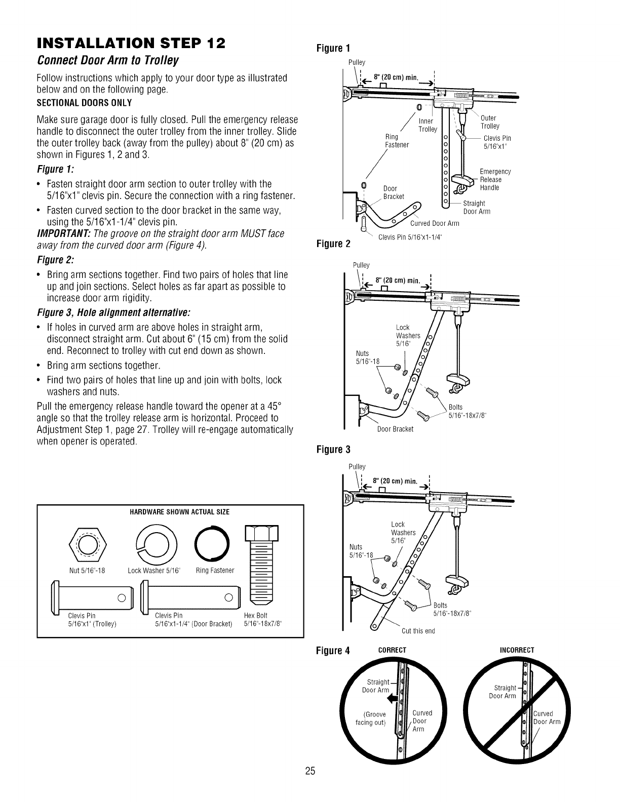
INSTALLATION STEP 12
ConnectDoorArm to Trolley
Follow instructions which apply to your door type as illustrated
below and on the following page.
SECTIONALDOORSONLY
Make sure garagedoor is fully closed. Pullthe emergency release
handleto disconnect the outer trolley from the inner trolley. Slide
the outer trolley back (awayfrom the pulley) about 8" (20 cm) as
shown in Figures1,2 and 3.
Figure 1:
•Fastenstraight door arm section to outer trolley with the
5/16"x1" clevis pin. Securethe connection with a ring fastener.
• Fastencurved section to the door bracket in the sameway,
using the 5/16"x1-1/4" clevis pin.
IMPORTANT."Thegroove on the straight door arm MUST face
away from the curved door arm (Figure 4).
Figure 2:
• Bring arm sections together. Find two pairs of holes that line
up andjoin sections. Select holes as far apart as possible to
increasedoor arm rigidity.
Figure 3, Hole alignment alternative:
• If holes in curved arm areabove holes in straight arm,
disconnect straight arm. Cut about 6" (15 cm) from the solid
end. Reconnectto trolley with cut end down as shown.
• Bring arm sections together.
• Findtwo pairs of holes that line up and join with bolts, lock
washers and nuts.
Pull the emergency releasehandle toward the opener at a 45°
angle so that the trolley releasearm is horizontal. Proceedto
Adjustment Step 1, page27. Trolley will re-engageautomatically
when opener is operated.
HARDWARESHOWN ACTUALSIZE
o Oo
Nut 5/16"-18 Lock Washer 5/16" Ring Fastener
Clevis Pin Clevis Pin
5/16"x1" (Trolley) 5/16"x1-1/4" (Door Bracket)
Hex Bolt
5/16"-18x7/8"
Figure 1
Pulley
Figure 2
Ring
Fastener
/
0 Door
Bracket
Curved Door Arm
Clevis Pin 5/16"x1-1/4"
_ Outer
Trolley
Clevis Pin
5/16"x1"
Emergency
-- elease
Handle
Straight
DoorArm
Pulley
\i-- 8"(20 cm) min. !
Lock t
Washers/<
Nuts 5/116" /o_
5/16"-18 .__ro_
Door Bracket
_ _/_lt6s._18x7/8,,
Figure 3
Pulley
_! 8" (20 cm) min. ,,
r-1 "), Oo
Lock
w;; ersb/
Nuts //o7
5/16"-18_J/_ I/
v Cut this end
Figure4
25
CORRECT INCORRECT
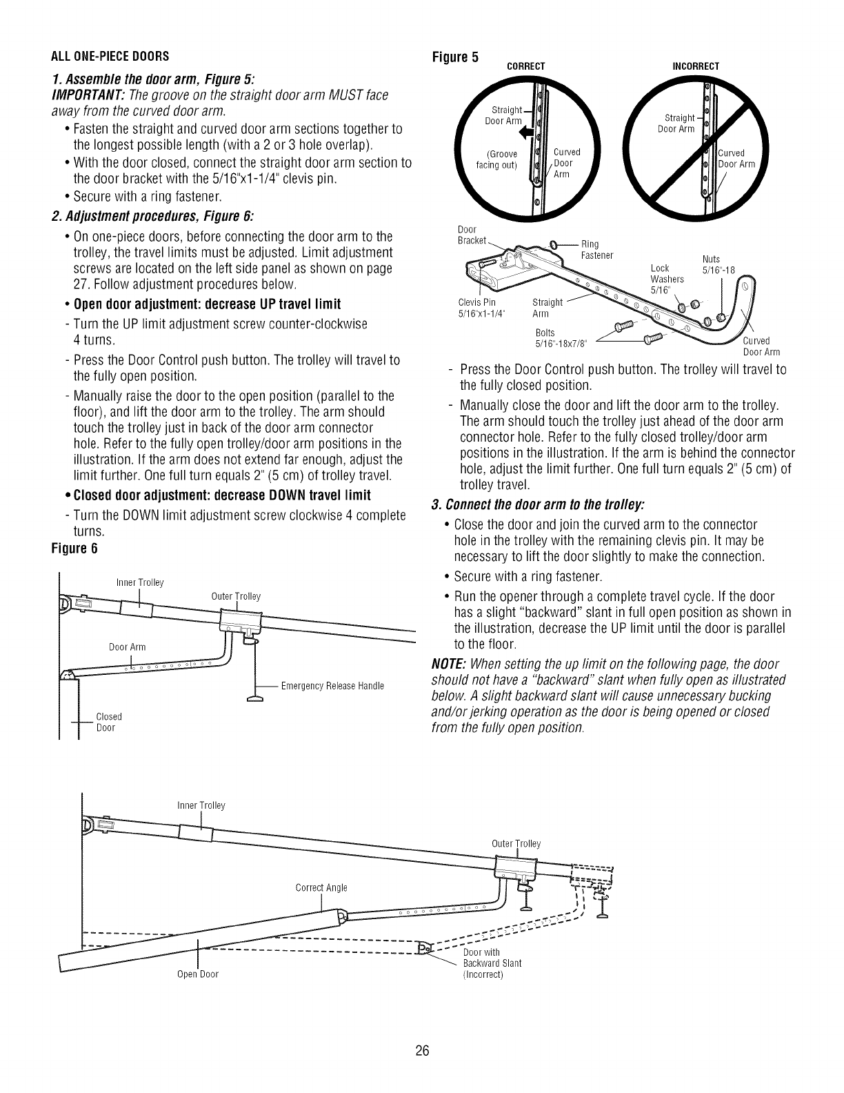
ALLONE-PIECEDOORS
1. Assemblethe doer arm, Figure5:
IMPORTANT:Thegroove on the straight door arm MUST face
away from the curved door arm.
•Fastenthe straight and curved door arm sections together to
the longest possible length (with a 2 or 3 hole overlap).
• With the door closed, connect the straight door arm section to
the door bracket with the 5/16"x1-1/4" clevis pin.
• Secure with a ring fastener.
2. Adjustmentprocedures,Figure 6:
• On one-piece doors, before connecting the door arm to the
trolley, the travel limits must be adjusted. Limit adjustment
screws are located on the left side panelas shown on page
27. Follow adjustment procedures below.
• Open dooradjustment:decreaseUP travel limit
- Turn the UP limit adjustment screw counter-clockwise
4 turns.
- Pressthe Door Control push button. The trolley will travel to
the fully open position.
- Manually raise the door to the open position (parallel to the
floor), and lift the door arm to the trolley. The arm should
touch the trolley just in back of the door arm connector
hole. Referto the fully open trolley/door arm positions in the
illustration. If the arm does not extendfar enough, adjust the
limit further. Onefull turn equals 2" (5 cm) of trolley travel.
•Closed dooradjustment:decreaseDOWNtravel limit
- Turn the DOWNlimit adjustment screw clockwise 4 complete
turns.
Figure 6
Inner Trolley
_ Emergency Release Handle
-L- Closed
jDoor
Figure 5
Door
CORRECT INCORRECT
Fastener
Lock
Washers
5/16"
Nuts
5/16"-18
Clevis Pin Straight
5/16"x1-1/4" Arm
Bolts
5/16"-18x7/8" _urved
DoorArm
Pressthe Door Control push button. The trolley will travel to
the fully closed position.
- Manually close the door and lift the door arm to the trolley.
The arm should touch the trolley just aheadof the door arm
connector hole. Referto the fully closed trolley/door arm
positions in the illustration. If the arm is behind the connector
hole, adjust the limit further. Onefull turn equals 2" (5 cm) of
trolley travel.
3. Connectthe doorarm to the trolley:
• Closethe door and join the curved arm to the connector
hole in the trolley with the remaining clevis pin. It may be
necessaryto lift the door slightly to makethe connection.
• Securewith a ring fastener.
• Run the openerthrough a complete travel cycle. If the door
has a slight "backward" slant in full open position as shown in
the illustration, decreasethe UP limit until the door is parallel
to the floor.
NOTE:Whensetting the up limit on the following page, the door
should not havea "backward"slant when fully openas illustrated
below. A slight backward slant will cause unnecessarybucking
and/or jerking operation as the door is being openedor closed
from the fully openposition.
Inner Trolley
Outer Trolley
Correct Angle - f i _"_._
Open Door (Incorrect)
26
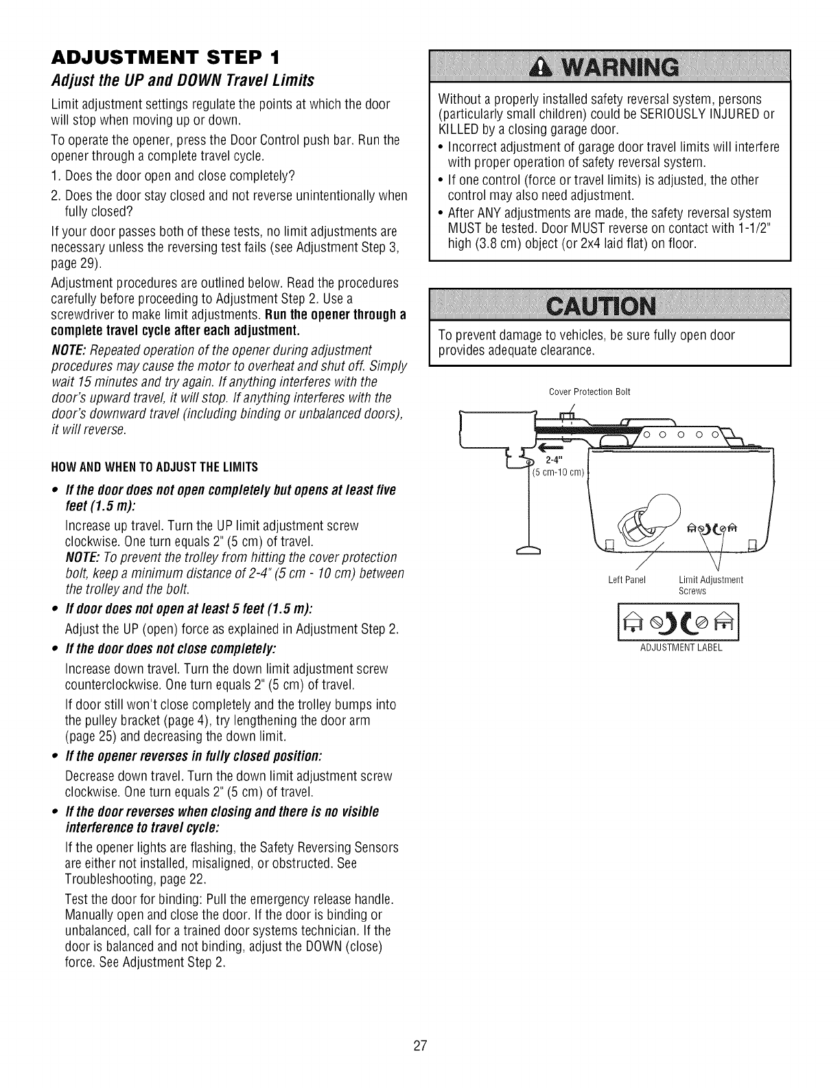
ADJUSTMENT STEP 1
Adjust the UP and DOWN Travel Limits
Limit adjustment settings regulatethe points at which the door
will stop when moving up or down.
To operate the opener, pressthe Door Control push bar. Run the
openerthrough a complete travel cycle.
1. Doesthe door open and close completely?
2. Doesthe door stay closed and not reverse unintentionally when
fully closed?
If your door passes both of these tests, no limit adjustments are
necessaryunless the reversing test fails (seeAdjustment Step 3,
page29).
Adjustment procedures areoutlined below. Readthe procedures
carefully before proceedingto Adjustment Step 2. Usea
screwdriver to make limit adjustments. Runthe openerthrougha
completetravel cycle after each adjustment.
NOTE:Repeatedoperation of the openerduring adjustment
procedures may cause the motor to overheatand shut off. Simply
wait 15minutes and try again. If anything interferes with the
door's upward travel it will stop. If anything interferes with the
door's downward travel (including binding or unbalanced doors),
it will reverse.
HOWAND WHENTOADJUSTTHELIMITS
•If the doordoesnot opencompletelybutopensat least five
feet (1.5 m):
Increaseup travel. Turn the UP limit adjustment screw
clockwise. Oneturn equals 2" (5 cm) of travel.
NOTE: Toprevent the trofley from hitting the coverprotecfion
bolt, keep a minimum distance of 2-4"(5 cm -10cm) between
the trolley and the bolt.
•If doordoesnot openat least 5 feet (1.5 m):
Adjust the UP (open) force as explained in Adjustment Step 2.
•If the doordoesnot closecompletely:
Increasedown travel. Turn the down limit adjustment screw
counterclockwise. Oneturn equals 2" (5 cm) of travel.
If door still won't close completely and the trolley bumps into
the pulley bracket (page4), try lengthening the door arm
(page 25) anddecreasing the down limit.
•If the openerreversesin fully closedposition:
Decreasedown travel. Turn the down limit adjustment screw
clockwise. Oneturn equals 2" (5 cm) of travel.
•If the doorreverseswhendosing and there is no visible
interferenceto travel cyde:
If the opener lights areflashing, the Safety ReversingSensors
are either not installed, misaligned, or obstructed. See
Troubleshooting, page22.
Test the door for binding: Pull the emergency releasehandle.
Manually open and close the door. If the door is binding or
unbalanced,call for a trained door systems technician. If the
door is balancedand not binding, adjust the DOWN(close)
force. SeeAdjustment Step 2.
Without a properly installed safety reversal system, persons
(particularly small children) could be SERIOUSLYINJUREDor
KILLEDby a closing garagedoor.
•Incorrect adjustment of garagedoor travel limits will interfere
with proper operation of safety reversalsystem.
• If one control (force or travel limits) is adjusted, the other
control may also needadjustment.
• After ANY adjustments are made,the safety reversal system
MUST be tested. Door MUST reverseon contact with 1-1/2"
high (3.8 cm) object (or 2x4 laid flat) on floor.
To preventdamage to vehicles, be sure fully open door
provides adequateclearance.
Cover Protection Bolt
LeftPanel LimitAdiustment
Screws
ADJUSTMENT LABEL
27
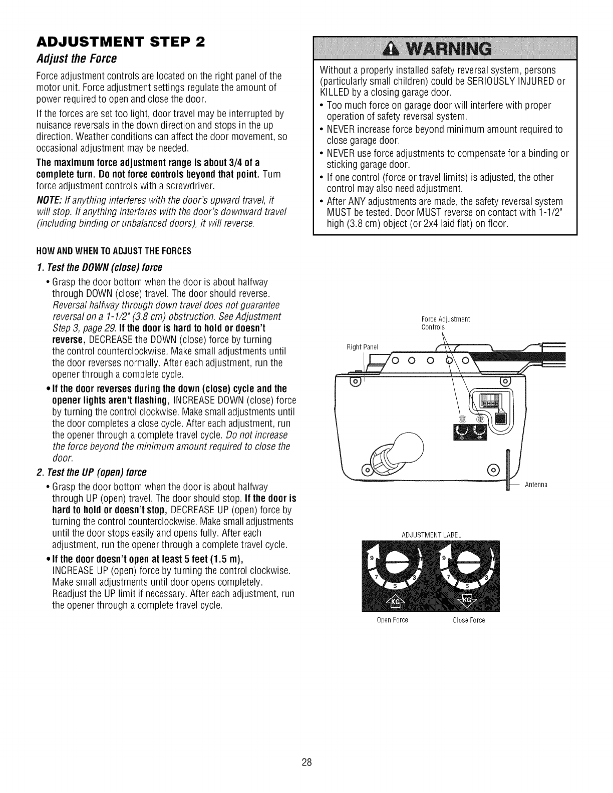
ADJUSTMENT STEP 2
AdjusttheForce
Forceadjustment controls are located on the right panelof the
motor unit. Forceadjustment settings regulatethe amount of
power required to open and close the door.
If the forces areset too light, door travel may be interrupted by
nuisance reversals in the down direction and stops in the up
direction. Weather conditions can affect the door movement, so
occasional adjustment may be needed.
The maximumforce adjustmentrange is about3/4 of a
completeturn. Do notforcecontrolsbeyondthat point. Turn
force adjustment controls with a screwdriver.
NOTE:If anything interferes with the door's upward travel it
will stop. If anything interferes with the door's downward travel
(including binding or unbalanced doors), it will reverse.
Without a properly installed safety reversal system, persons
(particularly small children) could be SERIOUSLYINJUREDor
KILLEDby a closing garagedoor.
• Too much force on garagedoor will interfere with proper
operation of safety reversalsystem.
• NEVERincreaseforce beyond minimum amount requiredto
close garagedoor.
• NEVERuse force adjustments to compensatefor a binding or
sticking garagedoor.
• If one control (force or travel limits) is adjusted, the other
control may also needadjustment.
• After ANY adjustments are made,the safety reversal system
MUST be tested. Door MUST reverseon contact with 1-1/2"
high (3.8 cm) object (or 2x4 laid flat) on floor.
HOWAND WHENTOADJUSTTHEFORCES
1. Test the DOWN (close) force
• Grasp the door bottom when the door is about halfway
through DOWN(close) travel. The door should reverse.
Reversal halfway through down travel does not guarantee
reversal on a 1-1/2" (3.8 cm) obstruction. SeeAdjustment
Step 3, page 29. If the dooris hardto holdor doesn't
reverse, DECREASEthe DOWN(close) force by turning
the control counterclockwise. Make small adjustments until
the door reverses normally. After each adjustment, run the
openerthrough a complete cycle.
• If the doorreversesduringthe down(close) cycleandthe
openerlightsaren't flashing, INCREASEDOWN(close) force
by turning the control clockwise.Makesmall adjustments until
the door completes a close cycle.After each adjustment, run
the openerthrough a complete travel cycle. Do not increase
the force beyond the minimum amount required to close the
door.
2. Testthe UP (open) force
• Grasp the door bottom when the door is about halfway
through UP (open) travel. The door should stop. If the door is
hardto holdor doesn't stop, DECREASEUP (open) force by
turning the control counterclockwise.Makesmall adjustments
until the door stops easily and opens fully. After each
adjustment, run the opener through a complete travel cycle.
•If the doordoesn't openat least 5 feet (1.5 m),
INCREASEUP (open) force by turning the control clockwise.
Make small adjustments until door opens completely.
Readjust the UP limit if necessary.After each adjustment, run
the openerthrough a complete travel cycle.
Force Adjustment
Controls
Right Panel
° °
@"_ Antenna
ADJUSTMENT LABEL
Open Force Close Force
28

ADJUSTMENT STEP 3
Testthe SafetyReversa/System
TEST
1. With the door fully open, place a 1-1/2" (3.8 cm) board (or a
2x4 laid flat) on the floor, centered underthe garagedoor.
2. Operatethe door in the down direction. The door must reverse
on striking the obstruction.
ADJUST
• If the door stops on the obstruction, it is not traveling far
enough in the down direction. Increasethe DOWNlimit by
turning the DOWNlimit adjustment screw counterclockwise 1/4
turn.
NOTE:Ona sectional door, make sure limit adjustments do not
force the door arm beyond a straight up and down position. See
the illustration on page 25.
• Repeatthe test.
• Whenthe door reverseson the 1-1/2" (3.8 cm) board, remove
the obstruction and run the openerthrough 3 or 4 complete
travel cycles to test adjustment.
• If the unit continues to fail the Safety ReverseTest, call for a
trained door systems technician.
IMPORTANTSAFETYCHECK:
Test the Safety ReverseSystem after:
• Eachadjustment of door arm length, limits, or force controls.
• Any repair to or adjustment of the garagedoor (including
springs and hardware).
• Any repair to or buckling of the garagefloor.
• Any repair to or adjustment of the opener.
Without a properly installed safety reversal system, persons
(particularly small children) could be SERIOUSLYINJUREDor
KILLEDby a closing garagedoor.
• Safety reversalsystem MUSTbe tested everymonth.
• If one control (force or travel limits) is adjusted, the other
control may also needadjustment.
• After ANY adjustments are made,the safety reversal system
MUST be tested. Door MUST reverseon contact with 1-1/2"
high (3.8 cm) object (or 2x4 laid flat) on the floor.
1 1/2 (3 8 cm) board
(or a 2x4 laid flat
ADJUSTMENT STEP 4
TestTheProtectorSystem®
1. Pressthe remote control push button to open the door.
2. Placethe opener carton in the path of the door.
3. Pressthe remote control push button to close the door. The
door will not move more than an inch (2.5 cm), and the opener
lights will flash.
The garagedoor openerwill not closefrom a remote if the
indicator light in either sensor is off (alerting you to the fact that
the sensor is misaligned or obstructed).
If the openerclosesthe doorwhenthe safety reversingsensor
is obstructed(and the sensorsare no morethan 6"(15 cm)
abovethe floor), call for a trained doorsystemstechnician.
Without a properly installed safety reversing sensor, persons
(particularly small children) could be SERIOUSLYINJUREDor
KILLEDby a closing garagedoor.
F--] F---q
Safer Sensor Safety Reversing
29
OPERATION
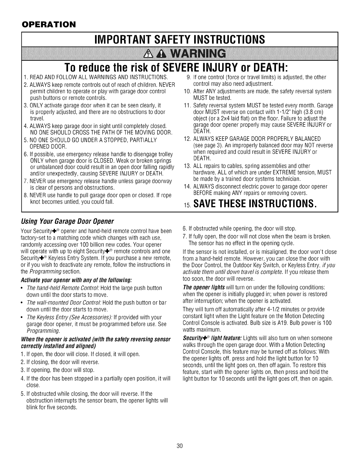
IMPORTANTSAFETYINSTRUCTIONS
To reducethe riskof SEVEREINJURYor DEATH:
1. READAND FOLLOWALL WARNINGSAND INSTRUCTIONS. 9. If one control (force or travel limits) is adjusted, the other
2. ALWAYS keep remotecontrols out of reach of children. NEVER
permit children to operate or play with garage door control
push buttons or remote controls.
3. ONLYactivategaragedoor when it can beseen clearly, it
is properly adjusted, and there areno obstructions to door
travel.
4. ALWAYS keepgaragedoor in sight until completely closed.
NOONESHOULDCROSSTHE PATHOFTHEMOVINGDOOR.
5. NOONESHOULDGO UNDERA STOPPED,PARTIALLY
OPENEDDOOR.
6. If possible, use emergency releasehandleto disengagetrolley
ONLYwhen garagedoor is CLOSED.Weakor broken springs
or unbalanced door could result in an open door falling rapidly
and/or unexpectedly,causing SEVEREINJURYor DEATH.
7. NEVERuse emergency releasehandle unless garagedoorway
is clear of persons and obstructions.
8. NEVERuse handleto pull garagedoor open or closed. If rope
knot becomes untied, you could fall.
control mayalso needadjustment.
10. After ANY adjustments are made,the safety reversalsystem
MUST be tested.
11. Safety reversal system MUST be tested everymonth. Garage
door MUST reverseon contact with 1-1/2" high (3.8 cm)
object (or a 2x4 laidflat) on the floor. Failureto adjust the
garagedoor opener properly may causeSEVEREINJURY or
DEATH.
12. ALWAYSKEEPGARAGEDOORPROPERLYBALANCED
(see page3). An improperly balanced door may NOTreverse
when required and could result in SEVEREINJURY or
DEATH.
13. ALL repairs to cables, spring assemblies and other
hardware,ALL of which are under EXTREMEtension, MUST
be made by a trained door systems technician.
14. ALWAYSdisconnect electric power to garage door opener
BEFOREmaking ANY repairs or removing covers.
is SAVETHESEINSTRUCTIONS.
Using Your Garage Door Opener
Your Security.I-®opener and hand-held remote control have been
factory-set to a matching code which changeswith each use,
randomly accessingover 100 billion new codes. Your opener
will operate with up to eight Security.I-® remote controls and one
Security4-®KeylessEntry System. If you purchase a new remote,
or if you wish to deactivateany remote, follow the instructions in
the Programming section.
Activateyour openerwithany ofthe following:
•Thehand-held Remote Controt Hold the largepush button
down until the door starts to move.
• The wall-mounted Door Controt Hold the push button or bar
down until the door starts to move.
• TheKeyless Entry (SeeAccessories): If provided with your
garagedoor opener, it must be programmed before use.See
Programming.
Whenthe openeris activated(with the safetyreversingsensor
correctlyinstalled and aligned)
1. If open, the door will close. If closed, it will open.
2. If closing, the door will reverse.
3. If opening, the door will stop.
4. If the door has beenstopped in a partially open position, it will
close.
5. If obstructed while closing, the door will reverse. If the
obstruction interrupts the sensor beam, the openerlights will
blink for five seconds.
6. If obstructed while opening, the door will stop.
7. If fully open, the door will not close when the beam is broken.
The sensor has no effect in the opening cycle.
If the sensor is not installed, or is misaligned, the door won't close
from a hand-held remote. However,you can close the door with
the Door Control, the Outdoor KeySwitch, or KeylessEntry, ifyou
activate them until down travel is complete. If you releasethem
too soon, the door will reverse.
Theopenerlightswill turn on underthe following conditions:
when the opener is initially plugged in; when power is restored
after interruption; when the opener is activated.
Theywill turn off automatically after 4-1/2 minutes or provide
constant light when the Light feature on the Motion Detecting
Control Console is activated. Bulb size is A19. Bulb power is 100
watts maximum.
Security4.° light feature:Lights will also turn on when someone
walks through the open garagedoor. With a Motion Detecting
Control Console, this feature may beturned off as follows: With
the opener lightsoff, pressand hold the lightbutton for 10
seconds, until the lightgoes on, then off again. To restore this
feature, start with the opener lightson, then press and hold the
lightbutton for 10 seconds until the lightgoes off, then on again.
3O
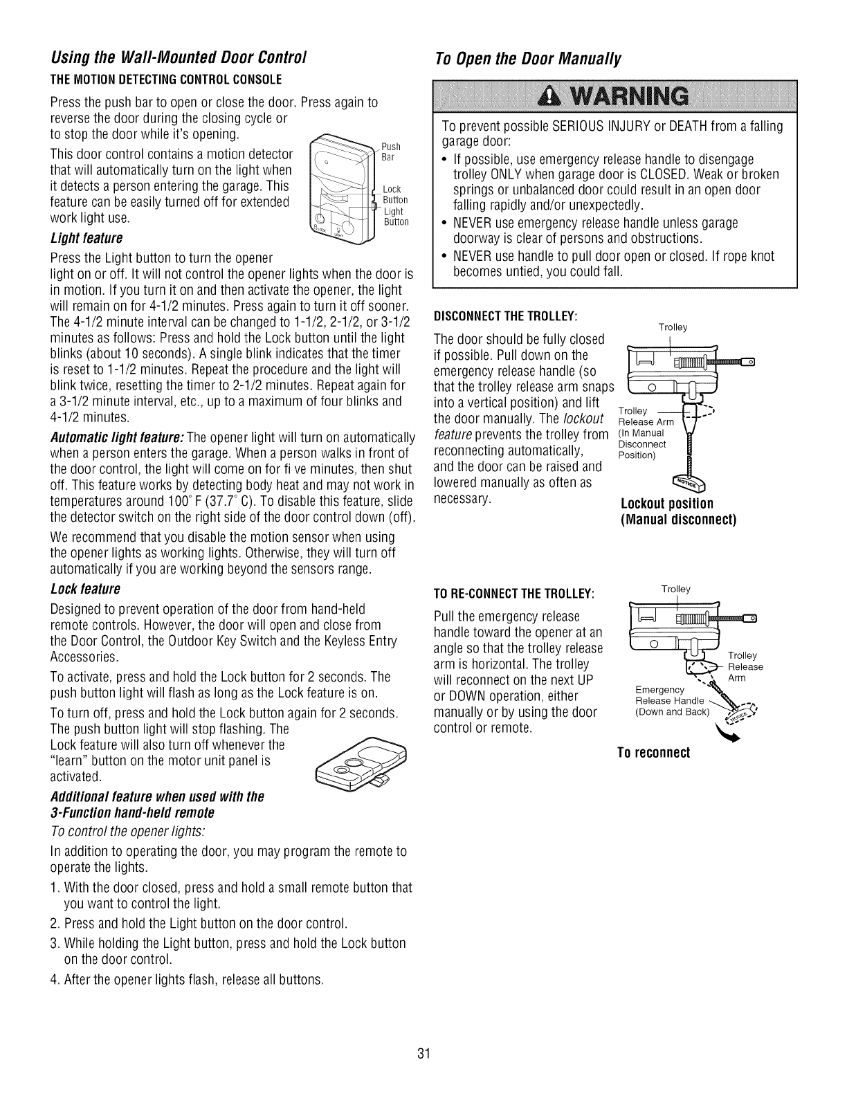
Usingthe Wall-MountedDoorControl
THEMOTIONDETECTINGCONTROLCONSOLE
Pressthe push barto open or close the door. Pressagain to
reversethe door during the closing cycle or
to stop the door while it's opening. _y_,_Push
This door control contains a motion detector __jBar
that will automatically turn on the light when II
it detects a person entering the garage. This J_Lock
feature can be easily turned off for extended _Jj_LButt°n
I_" Light
work light use. II Button
Lightfeature
Pressthe Light button to turn the opener
light on or off. It will not control the opener lights when the door is
in motion. If you turn it on and then activatethe opener, the light
will remain on for 4-1/2 minutes. Press againto turn it off sooner.
The 4-1/2 minute interval can be changed to 1-1/2, 2-1/2, or 3-1/2
minutes as follows: Press and hold the Lock button until the light
blinks (about 10 seconds). A single blink indicates that the timer
is resetto 1-1/2 minutes. Repeatthe procedure andthe light will
blink twice, resetting the timer to 2-1/2 minutes. Repeatagainfor
a 3-1/2 minute interval, etc., up to a maximum of four blinks and
4-1/2 minutes.
Automaticlight feature:The opener light will turn on automatically
when a person enters the garage.When a person walks in front of
the door control, the lightwill come on for five minutes, then shut
off. This featureworks by detecting body heat and may not work in
temperatures around 100° F (37.7° C).To disable this feature, slide
the detector switch on the right side of the door control down (off).
We recommend that you disable the motion sensor when using
the opener lightsas working lights.Otherwise,they will turn off
automatically if you are working beyond the sensors range.
Lockfeature
Designedto preventoperation of the door from hand-held
remote controls. However,the door will open and close from
the Door Control, the Outdoor Key Switch and the KeylessEntry
Accessories.
To activate, press and hold the Lock button for 2 seconds.The
push button light will flash as long as the Lockfeature is on.
To turn off, press and hold the Lock button againfor 2 seconds.
The push button light will stop flashing. The
Lock feature will also turn off wheneverthe
"learn" button on the motor unit panel is
activated.
Additionalfeature whenusedwith the
3-Functionhand-heldremote
To control the openerlights:
In addition to operating the door, you may program the remote to
operate the lights.
1. With the door closed, press and hold a small remote button that
you want to control the light.
2. Pressand hold the Light button on the door control.
3. While holding the Light button, press and hold the Lock button
on the door control.
4. After the opener lights flash, releaseall buttons.
ToOpenthe DoorManually
To prevent possible SERIOUSINJURYor DEATHfrom a falling
garagedoor:
• If possible, use emergency releasehandleto disengage
trolley ONLYwhen garagedoor is CLOSED.Weakor broken
springs or unbalanceddoor could result in an open door
falling rapidly and/or unexpectedly.
• NEVERuse emergency releasehandle unlessgarage
doorway is clear of persons and obstructions.
• NEVERuse handleto pull door open or closed. If rope knot
becomes untied, you could fall.
DISCONNECTTHETROLLEY:
The door should be fully closed
if possible. Pull down on the
emergency releasehandle (so
that the trolley releasearm snaps
into a vertical position) and lift
the door manually. The lockout
Trolley
Trolley
Release Arm
feature prevents the trolley from (In Manual
Disconnect
reconnecting automatically, Position)
and the door can be raised and
lowered manually as often as _ ,,_
necessary. Lockoutposition
(Manual disconnect)
TORE-CONNECTTHETROLLEY:
Pull the emergency release
handletoward the opener at an
angle so that the trolley release
arm is horizontal. The trolley
will reconnect on the next UP
or DOWNoperation, either
manually or by using the door
control or remote.
Trolley
_e
Emergency """ "_t11__Arm
Release Handle _ '_, ._
(Down and Back),_._'
TOreconnect
31
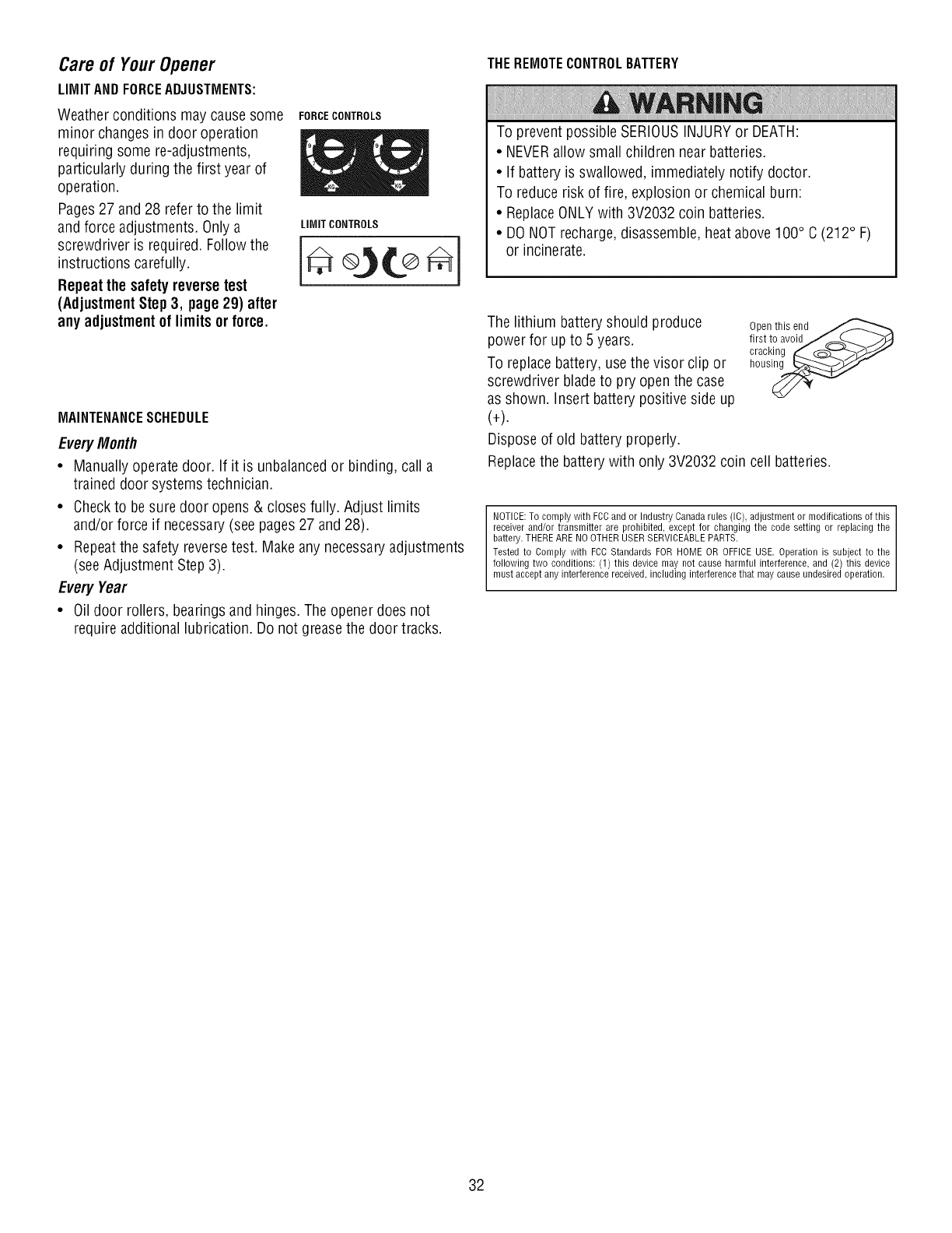
Careof YourOpener
LIMIT AND FORCEADJUSTMENTS:
Weatherconditions may causesome
minor changesin door operation
requiring some re-adjustments,
particularly during the first year of
operation.
Pages27 and 28 refer to the limit
and force adjustments. Only a
screwdriver is required. Followthe
instructions carefully.
Repeatthe safetyreversetest
(AdjustmentStep3, page29) after
any adjustmentof limits or force.
FORCECONTROLS
LIMIT CONTROLS
e o]t®
MAINTENANCESCHEDULE
EveryMonth
•Manually operate door. If it is unbalancedor binding, call a
trained door systems technician.
• Checkto be sure door opens & closes fully. Adjust limits
and/or force if necessary(see pages 27 and 28).
• Repeatthe safety reversetest. Make any necessaryadjustments
(see Adjustment Step 3).
Every Year
• Oil door rollers, bearings and hinges. The opener does not
requireadditional lubrication. Do not greasethe door tracks.
THEREMOTECONTROLBATTERY
To prevent possible SERIOUSINJURYor DEATH:
• NEVERallow small children near batteries.
• If battery is swallowed, immediately notify doctor.
To reduce risk of fire, explosion or chemical burn:
• ReplaceONLYwith 3V2032 coin batteries.
• DO NOTrecharge,disassemble, heat above 100° C (212° F)
or incinerate.
The lithium battery should produce
power for up to 5 years.
To replace battery, use the visor clip or
screwdriver bladeto pry openthe case
as shown. Insert battery positive side up
(+).
Dispose of old battery properly.
Open this end_
first to avoidJ_.._ j-_
cracking _ _Z_-_J
house-
Replacethe battery with only 3V2032 coin cell batteries.
NOTICE: To comply with FCCand or Industry Canada rules (IC), adjustment or modifications of this
receiver and/or transmitter are prohibited, except for changing the code setting or replacing the
battery. THERE ARE NO OTHER USER SERVICEABLE PARTS.
Tested to Comply with FCC Standards FOR HOME OR OFFICE USE. Operation is subject to the
following two conditions: (1) this device may not cause harmful interference, and (2) this device
must accept any interference received, including interference that may cause undesired operation.
32
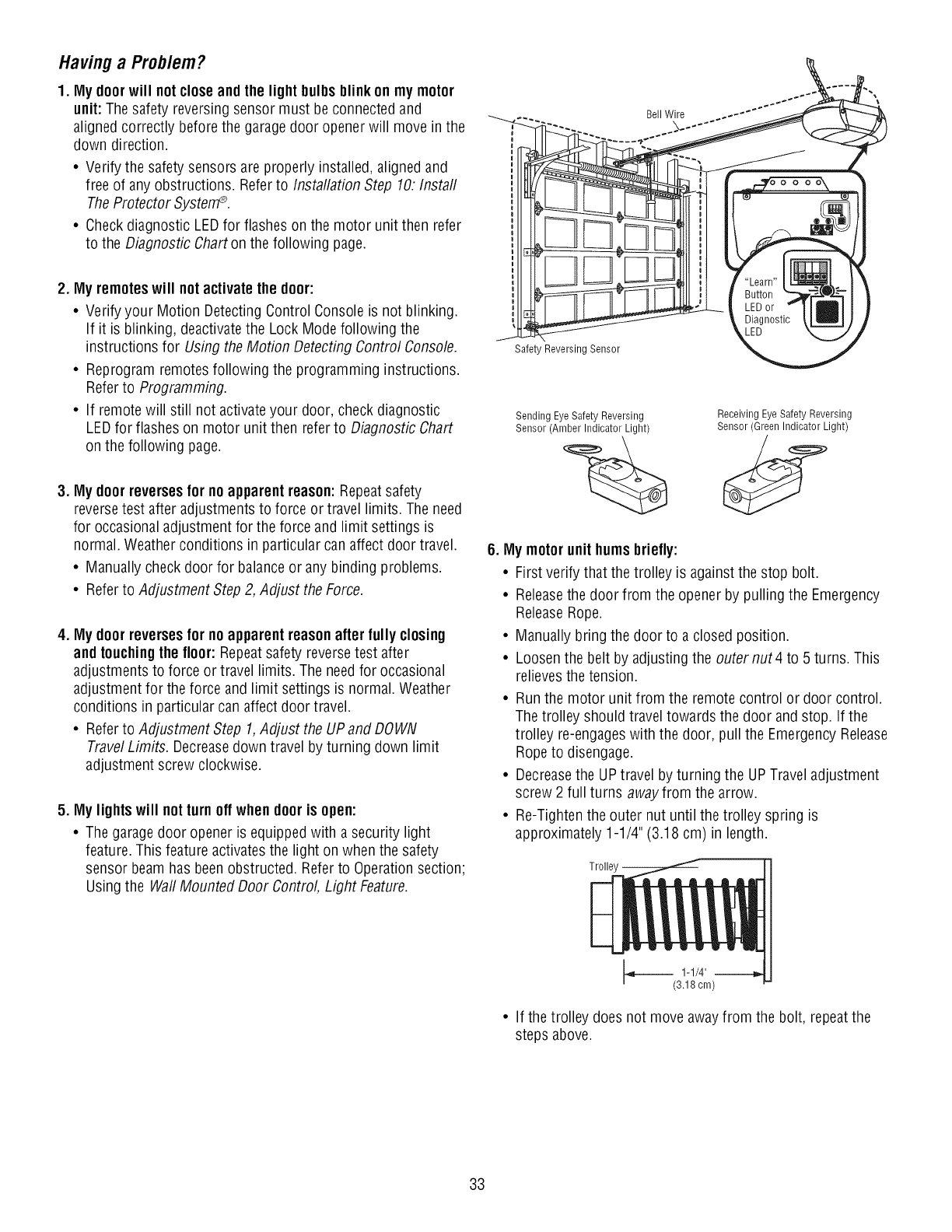
Havinga Problem?
1. My doorwill notcloseand the lightbulbsblinkon my motor
unit: The safety reversing sensor must beconnected and
aligned correctly before the garagedoor openerwill move in the
down direction.
•Verify the safety sensors are properly installed, aligned and
free of any obstructions. Referto Installation Step 10: Instal/
TheProtector System®.
• Checkdiagnostic LEDfor flashes on the motor unit then refer
to the Diagnostic Charton the following page.
2. My remoteswill not activate the door:
• Verify your Motion Detecting Control Consoleis not blinking.
If it is blinking, deactivatethe Lock Mode following the
instructions for Using the Motion Detecting Control Console.
• Reprogram remotes following the programming instructions.
Referto Programming.
• If remotewill still not activateyour door, check diagnostic
LEDfor flashes on motor unit then refer to Diagnostic Chart
on the following page.
3. My doorreversesfor noapparentreason:Repeatsafety
reversetest after adjustments to force or travel limits. The need
for occasional adjustment for the force and limit settings is
normal. Weather conditions in particular can affect door travel.
• Manually check door for balanceor any binding problems.
• Referto Adjustment Step 2, Adjust the Force.
4. My doorreversesfor noapparentreasonafter fully closing
andtouchingthe floor:Repeatsafety reversetest after
adjustments to force or travel limits. The needfor occasional
adjustment for the force and limit settings is normal. Weather
conditions in particular can affect door travel.
• Referto Adjustment Step 1,Adjust the UPand DOWN
TravelLimits. Decreasedown travel by turning down limit
adjustment screw clockwise.
5. My lightswill not turnoff when dooris open:
• The garagedoor opener is equippedwith a security light
feature. This feature activates the light on when the safety
sensor beam has beenobstructed. Referto Operationsection;
Using the WaftMounted Door Control Light Feature.
Safet, Reversing Sensor
Bell Wire
Sending EyeSafety Reversing
Sensor (Amber Indicator Light)
Receiving Eye Safety Reversing
Sensor (Green Indicator Light)
6. My motorunit humsbriefly:
• First verify that the trolley is against the stop bolt.
• Releasethe door from the opener by pulling the Emergency
ReleaseRope.
• Manually bring the door to a closed position.
• Loosen the belt by adjusting the outernut4 to 5 turns. This
relievesthe tension.
• Run the motor unit from the remote control or door control.
The trolley should travel towards the door and stop. If the
trolley re-engageswith the door, pull the Emergency Release
Rope to disengage.
• Decreasethe UPtravel byturning the UPTravel adjustment
screw 2 full turns awayfrom the arrow.
• Re-Tighten the outer nut until the trolley spring is
approximately 1-1/4" (3.18 cm) in length.
Trolley --
• If the trolley does not move awayfrom the bolt, repeatthe
steps above.
33
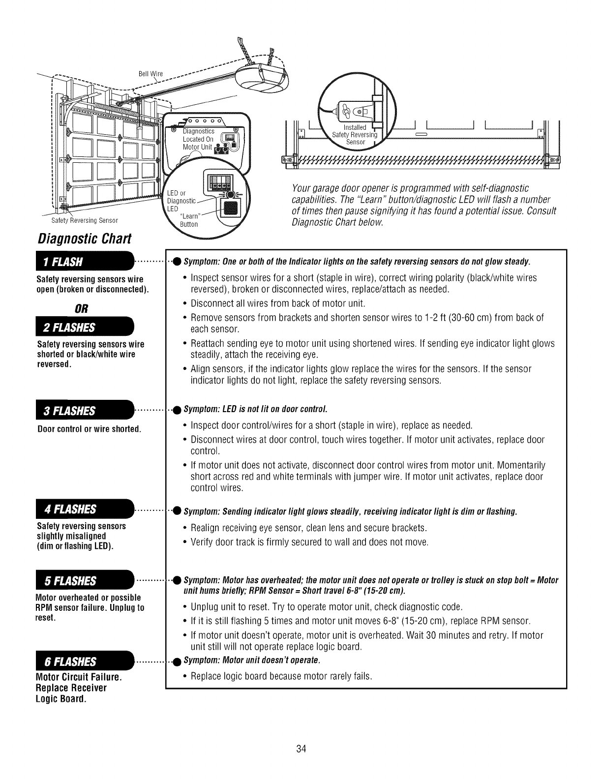
Safeb Reversing Sensor
DiagnosticChart
Safetyreversingsensorswire
open(brokenor disconnected).
Ineta,e I J I
Safety Reversing
Yourgarage door opener is programmed with self-diagnostic
capabilities. The "Learn" button/diagnostic LED will flash a number
of times then pause signifying it has found a potential issue. Consult
Diagnostic Chart below.
OR
Safetyreversingsensorswire
shortedor black/whitewire
reversed.
Doorcontrolor wireshorted.
Safetyreversingsensors
slightlymisaligned
(dimorflashingLED).
Motoroverheatedor possible
RPMsensorfailure.Unplugto
reset.
Motor CircuitFailure.
Replace Receiver
LogicBoard.
•"0 Symptom:Oneor bothof theIndicator lights onthe safetyreversingsensorsdonotglow steady•
• Inspect sensor wires for a short (staple in wire), correct wiring polarity (black/white wires
reversed), broken or disconnectedwires, replace/attachas needed.
• Disconnect all wires from back of motor unit.
• Removesensors from brackets and shorten sensor wires to 1-2 ft (30-60 cm) from back of
each sensor.
• Reattachsending eyeto motor unit using shortened wires. If sending eye indicator light glows
steadily, attach the receivingeye.
• Align sensors, if the indicator lights glow replacethe wires for the sensors. If the sensor
indicator lights do not light, replacethe safety reversing sensors.
•"0 Symptom:LEDis notI# ondoorcontrol.
• Inspect door control/wires for a short (staple in wire), replaceas needed.
• Disconnect wires at door control, touch wires together. If motor unit activates,replace door
control.
• If motor unit does not activate, disconnect door control wires from motor unit. Momentarily
short across redand white terminals with jumper wire. If motor unit activates, replacedoor
control wires.
•"0 Symptom:Sendingindicatorlight glowssteadily,receivingindicatorlightis dimorflashing•
• Realign receivingeye sensor, clean lens and secure brackets.
• Verify door track is firmly securedto wall and does not move.
•.Q Symptom:Motorhasoverheated;themotorunitdoesnotoperateortrolleyis stuckonstopbolt=Motor
unithumsbriefly;RPMSensor=Shorttravel6-8"(15-20cm)•
• Unplug unit to reset. Try to operate motor unit, check diagnostic code.
• If it is still flashing 5 times and motor unit moves 6-8" (15-20 cm), replaceRPM sensor.
• If motor unit doesn't operate,motor unit is overheated.Wait 30 minutes and retry. If motor
unit still will not operate replacelogic board.
•"0 Symptom:Motorunitdoesn'toperate.
• Replacelogic board becausemotor rarely fails.
34
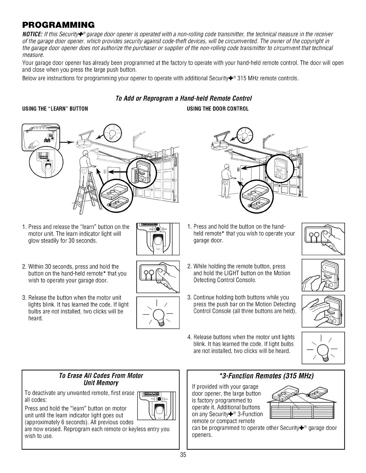
PROGRAMMING
NOTICE:If this Security÷° garage door opener is operated with a non-rolling code transmitter, the technical measurein the receiver
of the garage door opener, which provides security against code-theft devices, will be circumvented. Theowner of the copyright in
the garagedoor opener does not authorize the purchaser or suppfier of the non-rolling code transmitter to circumvent that technical
measure.
Your garage door opener has already beenprogrammed at the factory to operatewith your hand-held remote control. The door will open
and close when you pressthe large push button.
Below are instructions for programming your opener to operatewith additional Security÷ ®315 MHz remote controls.
USINGTHE"LEARN" BUTTON
ToAddor Reprograma Hand-he/dRemoteContro/
USINGTHEDOORCONTROL
1. Pressand releasethe "learn" button on the
motor unit. The learnindicator light will
glow steadily for 30 seconds.
2. Within 30 seconds, press and hold the
button on the hand-held remote* that you
wish to operate your garagedoor.
3. Releasethe button whenthe motor unit
lights blink. It has learnedthe code. If light
bulbs are not installed, two clicks will be
heard.
\J /
1. Pressand hold the button on the hand-
held remote* that you wish to operateyour
garagedoor.
2. While holding the remote button, press
and hold the LIGHTbutton on the Motion
DetectingControl Console.
3. Continue holding both buttons while you
press the push bar on the Motion Detecting
Control Console (all three buttons are held).
4. Releasebuttons when the motor unit lights
blink. It has learnedthe code. If light bulbs
are not installed, two clicks will beheard.
To Erase A// Codes From Motor
Unit Memory
To deactivateany unwanted remote, first erase I_1 1
all codes:
Pressand hold the "learn" button on motor
unit until the learn indicator light goes out
(approximately 6 seconds). All previous codes
are now erased. Reprogrameach remote or keylessentry you
wish to use.
*3-Function Remotes (315 MHz)
If provided with your garage
door opener,the large button
is factory programmed to
operate it. Additional buttons
on any Security÷ ® 3-Function
remote or compact remote
can be programmed to operate other Security÷ ®garagedoor
openers.
35
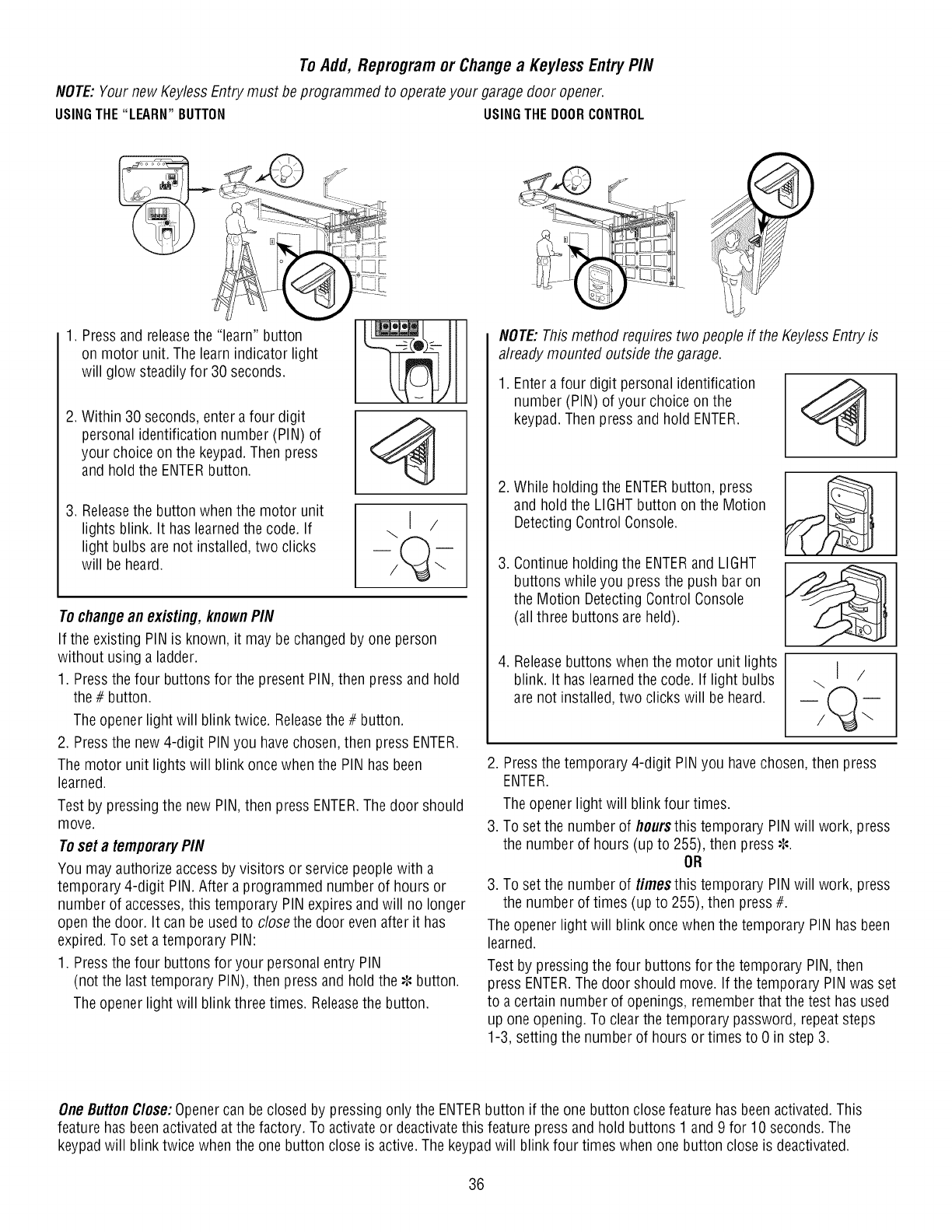
ToAdd, Reprogramor Changea Keyless EntryPIN
NOTE:Yournew KeylessEntry must beprogrammed to operateyour garagedoor opener.
USINGTHE"LEARN"BUTTON USINGTHEDOORCONTROL
oo o_
1. Pressand releasethe "learn" button
on motor unit. The learn indicator light
will glow steadily for 30 seconds.
2. Within 30 seconds, enter a four digit
personal identification number (PIN) of
your choice on the keypad.Then press
and hold the ENTERbutton.
3. Releasethe button when the motor unit
lights blink. It has learnedthe code. If
light bulbs are not installed, two clicks
will be heard.
To change an existing, known PIN
If the existing PIN is known, it may be changed by one person
without using a ladder.
1. Pressthe four buttons for the present PIN, then press and hold
the # button.
The opener light will blink twice. Releasethe # button.
2. Pressthe new 4-digit PINyou have chosen, then press ENTER.
The motor unit lights will blink once when the PIN has been
learned.
Test by pressing the new PIN, then press ENTER.The door should
move.
Toset a temporaryPIN
You may authorize accessby visitors or service peoplewith a
temporary 4-digit PIN. After a programmed number of hours or
number of accesses,this temporary PIN expiresand will no longer
open the door. It can be used to closethe door even after it has
expired. To set a temporary PIN:
1. Pressthe four buttons for your personal entry PIN
(not the lasttemporary PIN), then press and hold the _,,button.
The opener light will blink three times. Releasethe button.
NOTE:This method requires two people if the KeylessEntry is
already mounted outside the garage.
1. Enter a four digit personal identification
number (PIN) of your choice on the
keypad. Then press and hold ENTER.
,
,
,
While holding the ENTERbutton, press
and hold the LIGHTbutton on the Motion
Detecting Control Console.
Continue holding the ENTERand LIGHT
buttons while you pressthe push bar on
the Motion DetectingControl Console
(all three buttons are held).
Releasebuttons when the motor unit lights
blink. It has learnedthe code. If light bulbs
are not installed, two clicks will be heard.
\J /
2. Pressthe temporary 4-digit PINyou havechosen, then press
ENTER.
The opener light will blink four times.
3. To setthe number of floursthistemporary PIN will work, press
the number of hours (up to 255), then press_--.
OR
3. To setthe number of timesthis temporary PIN will work, press
the number of times (up to 255), then press#.
The opener light will blink once when the temporary PIN has been
learned.
Test by pressing the four buttons for the temporary PIN, then
press ENTER.The door should move. If the temporary PIN was set
to a certain number of openings, remember that the test has used
up one opening. To clear the temporary password, repeatsteps
1-3, setting the number of hours or times to 0 in step 3.
One ButtonClose: Openercan beclosed by pressing only the ENTERbutton if the one button closefeature has beenactivated. This
feature has beenactivated at the factory. To activate or deactivatethis feature press and hold buttons 1 and 9 for 10 seconds. The
keypadwill blink twice when the one button close is active.The keypadwill blink four times when one button close is deactivated.
36
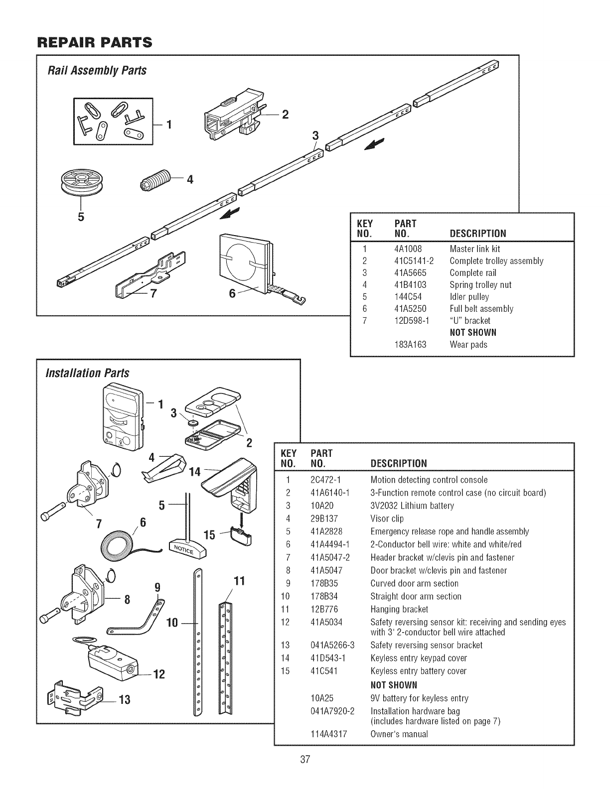
REPAIR PARTS
Rai/ Assemb/yParts
3
5
6
KEY PART
NO. NO. DESCRiPTiON
1 4A1008 Master link kit
2 41C5141-2 Completetrolley assembly
3 41A5665 Complete rail
4 41B4103 Spring trolley nut
5 144C54 idler pulley
6 41A5250 Full belt assembly
7 12D598-1 "U" bracket
NOTSHOWN
183A163 Wear pads
/nsta//ationParts
11
KEY
NO.
1
2
3
4
5
6
7
8
9
10
11
12
13
14
15
PART
NO.
2C472-1
41A6140-1
10A20
29B137
41A2828
41A4494-1
41A5047-2
41A5047
178B35
178B34
12B776
41A5034
041A5266-3
41D543-1
41C541
10A25
041A7920-2
114A4317
DESCRIPTION
Motion detecting control console
3-Function remote control case (no circuit board)
3V2032 Lithium battery
Visor clip
Emergencyreleaserope and handleassembly
2-Conductor bell wire: white and white/red
Headerbracket w/clevis pin and fastener
Door bracket w/clevis pin and fastener
Curved door arm section
Straight door arm section
Hangingbracket
Safety reversing sensor kit: receiving and sending eyes
with 3' 2-conductor bell wire attached
Safety reversing sensor bracket
Keylessentry keypad cover
Keylessentry battery cover
NOTSHOWN
9V battery for keyless entry
installation hardware bag
(includes hardware listed on page 7)
Owner's manual
37
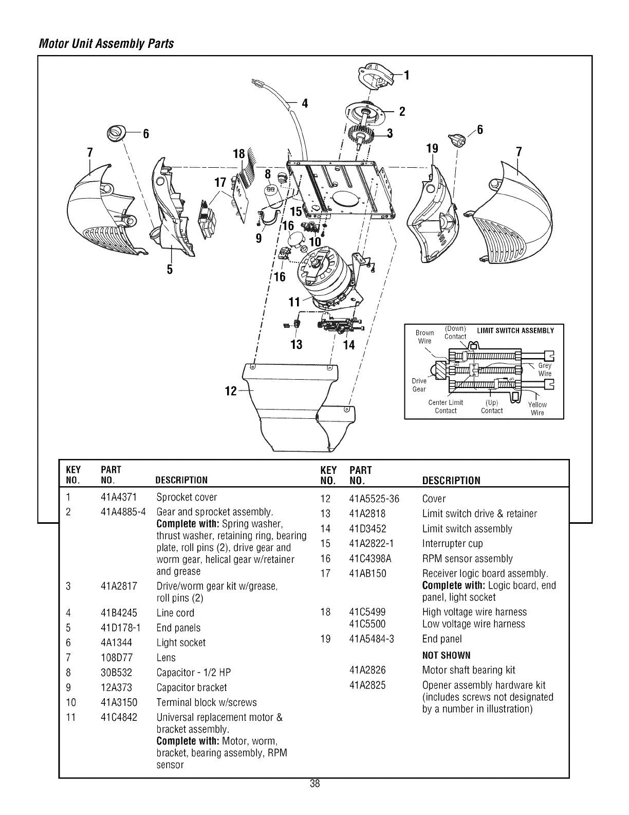
Motor Unit Assembly Parts
/
i
i
i
/
/
11
/
13 /14
i
19
Brown ,,M,TSW,TC,, SSEM,,',
'r__!!!ll,,,ll,,,,_
Drive_
Gear Center_
Contact Contact Wire
KEY PART
NO. NO.
1
2
41A4371
41A4885-4
3 41A2817
4 41B4245
5 41D178-1
6 4A1344
7 108D77
8 30B532
9 12A373
10 41A3150
11 41C4842
DESCRIPTION KEY PART
NO. NO. DESCRIPTION
Sprocket cover 12
Gearand sprocket assembly. 13
Completewith: Spring washer, 14
thrust washer, retaining ring, bearing
plate, roll pins (2), drive gear and 15
worm gear, helical gearw/retainer 16
41A5525-36
41A2818
41D3452
41A2822-1
41C4398A
Cover
Limit switch drive & retainer
Limit switch assembly
Interrupter cup
RPMsensor assembly
and grease
Drive/worm gear kit w/grease,
roll pins (2)
Line cord
End panels
Light socket
Lens
Capacitor- 1/2 HP
Capacitor bracket
Terminal block w/screws
Universal replacementmotor &
bracket assembly.
Completewith: Motor, worm,
bracket, bearing assembly, RPM
sensor
17
18
19
41AB150
41C5499
41C5500
41A5484-3
41A2826
41A2825
Receiverlogic board assembly.
Completewith: Logic board, end
panel, light socket
High voltage wire harness
Low voltage wire harness
Endpanel
NOTSHOWN
Motor shaft bearing kit
Openerassembly hardware kit
(includes screws not designated
by a number in illustration)
38
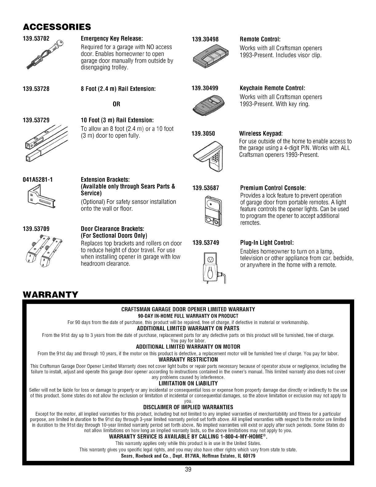
ACCESSORIES
139.53702
/EmergencyKey Release:
Requiredfor a garagewith NOaccess
door. Enableshomeowner to open
garage door manuallyfrom outside by
disengaging trolley.
139.30498 RemoteControl:
Works with all Craftsman openers
1993-Present. Includes visor clip.
139.53728 139.30499
139.53729
8 Foot(2.4 m) Rail Extension:
OR
10 Foot(3 m) Rail Extension:
To allow an 8 foot (2.4 m) or a 10 foot
(3 m) door to open fully. 139.3050
KeychainRemoteControl:
Works with all Craftsman openers
1993-Present. With key ring.
WirelessKeypad:
For use outsideof the hometo enableaccessto
the garageusing a 4-digit PIN.Works with ALL
Craftsmanopeners1993-Present.
041A5281-1 ExtensionBrackets:
[_ (Available only throughSears Parts &139.53687
Service)
(Optional) For safetysensor installation
onto the wall or floor.
139.53709 DoorClearanceBrackets:
___ (For Sectional DoorsOnly)
Replacestop brackets and rollers on door 139.53749
to reduce height of door travel. For use
when installing opener in garagewith low
headroomclearance.
WARRANTY
Premium ControlConsole:
Providesa lockfeatureto preventoperation
of garagedoor from portable remotes.A light
featurecontrols the openerlights.Canbeused
to programthe openerto acceptadditional
remotes.
Plug-In LightControl:
Enableshomeownerto turn on a lamp,
television or other appliancefrom car, bedside,
or anywhere in the home with a remote.
CRAFTSMANGARAGEDOOROPENERLIMITEDWARRANTY
90-DAYIN-HOMEFULLWARRANTYONPRODUCT
For90 daysfromthedateof purchase,this productwill berepaired,free of charge,if defectivein materialorworkmanship.
ADDITIONALLIMITED WARRANTYONPARTS
Fromthe91stdayupto 3 yearsfromthedateof purchase,replacementpartsfor anydefectivepartsonthis productwill befurnished,freeof charge.
Youpayfor labor.
ADDITIONALLIMITEDWARRANTYON MOTOR
Fromthe91stdayandthrough10years,if themotor onthis productis defective,a replacementmotorwill befurnishedfreeof charge.Youpayfor labor.
WARRANTYRESTRICTION
ThisCraftsmanGarageDoorOpenerLimitedWarrantydoesnotcoverlight bulbsor repairpartsnecessarybecauseof operatorabuseor negligence,includingthe
failureto install,adjustandoperatethis garagedooropeneraccordingto instructionscontainedin theowner'smanual.Thislimitedwarrantyalsodoesnot cover
anyproblemscausedby interference.
LIMITATIONONLIABILITY
Sellerwill notbeliablefor lossor damageto propertyor anyincidentalorconsequentiallossor expensefrompropertydamageduedirectlyor indirectlyto the use
of this product.Somestatesdo notallowtheexclusionor limitationof incidentalor consequentialdamages,so theabovelimitationorexclusionmaynot applyto
you.
DISCLAIMEROF IMPLIED WARRANTIES
Exceptfor themotor,allimpliedwarrantiesfor this product,includingbut notlimitedto anyimpliedwarrantiesofmerchantabilityandfitnessfor a particular
purpose,are limitedin durationto the91stdaythrough3-yearlimitedwarrantyperiodsetforth above.All impliedwarrantieswith respectto themotorare limited
in durationto the91st daythroughlO-yearlimitedwarrantyperiodset forth above.Noimpliedwarrantieswill existor applyaftersuchperiods.SomeStatesdo
notallowlimitationsonhow longanimpliedwarrantylasts,so theabovelimitationsmaynot applyto you.
WARRANTYSERVICEIS AVAILABLEBY CALLING1-800-4-MY-HOME®.
Thiswarrantyappliesonlywhilethis productisin usein the UnitedStates.
Thiswarrantygivesyou specificlegalrights,andyou mayalsohaveotherrightswhichvaryfrom stateto state.
Sears,RoebuckandCo., Dept.817WA,HoffmanEstates,IL60179
39
CONTENIDO
IntroducciGn 2-7
Revisi6n de los simbolos y t_rminos de seguridad ................. 2
Preparaci6n de la puerta de su cochera .......................... 3
Herramientas necesarias...................................... 3
Planificaci6n ............................................ 4-5
Inventario de la caja de cart6n ................................. 6
Inventario de piezas ......................................... 7
Montaje 8-11
Monte el riel y instale el trole .................................. 8
Fijeel riel al motor e instale la polea Ioca......................... 9
Fijeel riel a la unidad del motor y instale la polea Ioca............... 9
Instale la banda............................................ 10
Ajuste de la correa ......................................... 10
Instalaci6n de la cubierta de la rueda dentada .................... 11
InstalaciGn 11-26
Instrucci6nes de seguridad para la instalaci6n.................... 11
Determine d6nde va a instalar la m_nsula del cabezal .............. 12
Instale la m_nsula del cabezal................................. 13
Coloqueel riel en la m_nsula del cabezal........................ 14
Coloqueel abridor en posici6n ................................ 15
Cuelgueel abridor .......................................... 16
Instale la unidad de control de la puerta......................... 17
Instale las luces ........................................... 18
Instale la manija y la cuerda de emergencia ...................... 18
Requisitos para la instalaci6n el_ctrica .......................... 19
Instale la Sistema de Protecci6n®............................ 20-22
Fije la m_nsula de la puerta ................................ 23-24
Conecteel brazode la puerta al trole ......................... 25-26
Ajustes 27-29
Ajusteel limitedel recorrido............................... 27
Ajustela fuerza......................................... 28
Pruebeel sistemaderetrocesode seguridad.................. 29
Pruebela Sistemade ProtecciOn_ .......................... 29
OperaciGn 30-34
InstrucciOnesde seguridadparalaoperaciOn................. 30
COmousar su abridor de puertadecochera................... 30
COmousar la unidaddecontrol de pared..................... 31
COmoabrir la puertamanualmente ......................... 31
Mantenimientodesu abridorde puertade cochera............. 32
Si tienealgOnproblema .................................. 33
TabladediagnOstico..................................... 34
CGmoProgramar el Abridor 35-36
COmoagregaro reprogramarun control remoto manual......... 35
COmoborrartodos los cOdigos............................ 35
Controlesremotosde 3 funciones .......................... 35
COmoagregar, reprogramaro cambiarun cOdigo
de entradasin Ilave...................................... 36
Accesorios 37
Garantia 37
N_meros de Servicio Contratapa
INTRODUCClON
Revisi6n de los simbolos y t_rminos de seguridad
Esteabridor de puerta de cochera ha sido dise_ado y probado para unfuncionamiento seguro, siempre y cuando se instale, se pruebe, se opere y se le
d_ mantenimiento como se indica eneste manual, cumpliendo al pie dela letra con todas las advertencias e instrucciones generalesaqui contenidas.
Mec_inica
El_ctrica
Estasadvertenciasy/o simbolos de seguridad que aparecenen este
manual lealertar_.ndeque existe el riesgo de una lesi6n seria o de
muerte si no se siguen las instrucciones correspondientes. El peligro
puede ser el6ctrico (electrocuci6n) o mec_.nico.Lea las instrucciones con
mucho cuidado.
Cuandoveaesta palabra y/o simbolo de seguridad en este manual,
le alertar_,de que existe el riesgo de da_ar la puerta de la cochera y/o
el abridor si no se siguen las instrucciones correspondientes. Lealas
instrucciones con mucho cuidado.
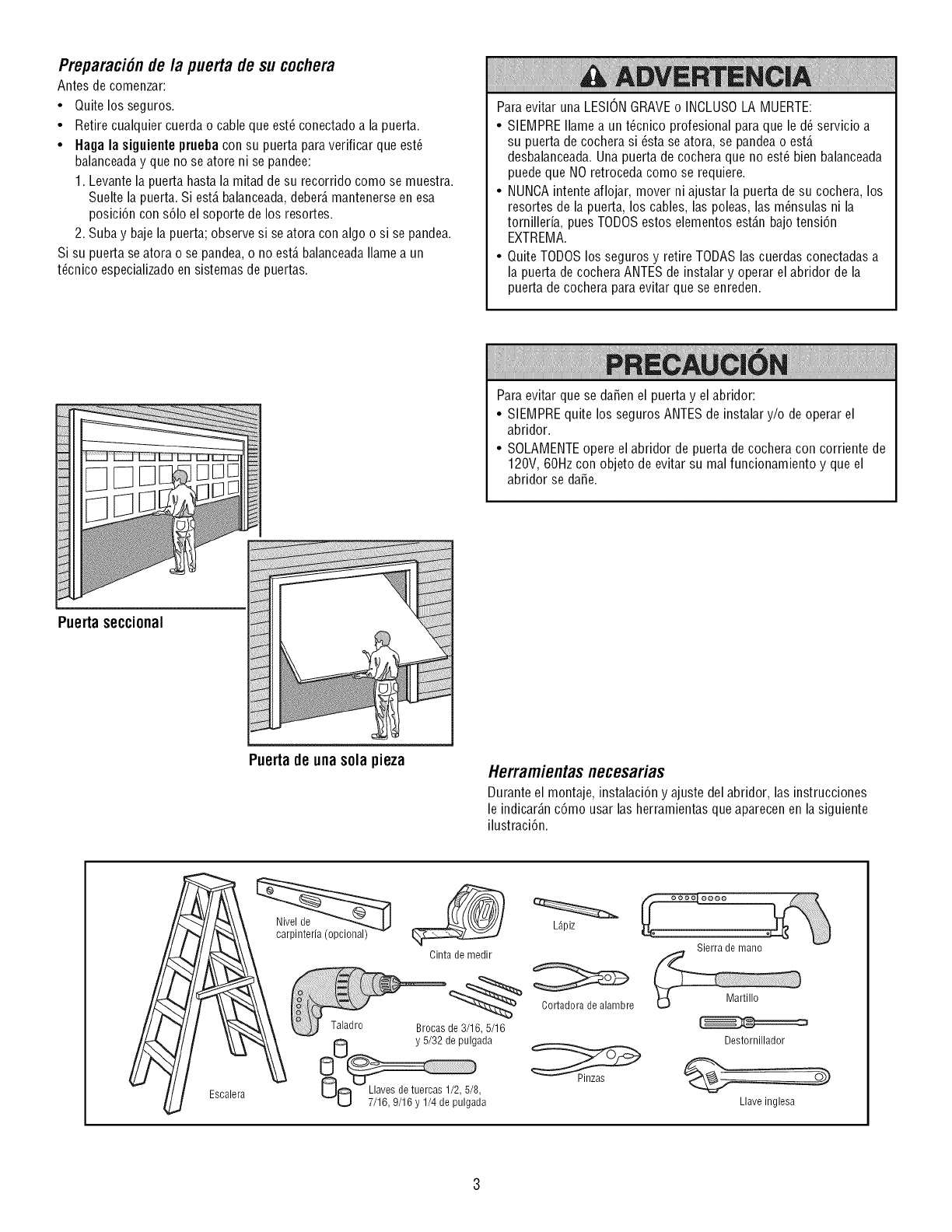
Preparaci6nde la puerta de su cochera
Antes de comenzar:
• Quite los seguros.
• Retire cualquier cuerda o cable que est6 conectadoa la puerta.
•Haga la siguiente prueba con su puerta para verificar que est6
balanceaday que no se atore ni se pandee:
1. Levante la puerta hasta la mitad de su recorrido como se muestra.
Suelte la puerta.Si est,. balanceada,deber_,mantenerseen esa
posici6n con s61oel soporte de los resortes.
2. Suba y baje la puerta;observe si se atora con algo o si se pandea.
Si su puerta se atora o se pandea,o no est,. balanceadaIlame a un
t6cnico especializadoen sistemas de puertas.
Paraevitar una LESIONGRAVEo INCLUSOLA MUERTE:
• SIEMPREIlame a un t6cnico profesional para que le d6 servicio a
su puerta de cochera si 6sta se atora, se pandeao est,.
desbalanceada.Una puerta de cochera que no est6 bien balanceada
puede que NOretroceda como se requiere.
• NUNCAintente aflojar, mover ni ajustar la puerta de su cochera, los
resortes de la puerta, los cables, las poleas, las m6nsulas ni la
tornilleria, pues TODOSestos elementos est_.nbajo tensi6n
EXTREMA.
• Quite TODOSlos seguros y retire TODASlas cuerdas conectadasa
la puerta decochera ANTES de instalar y operar el abridor de la
puerta de cochera paraevitar que se enreden.
Paraevitar que se daSenel puerta y el abridor:
• SIEMPREquite los seguros ANTESde instalar y/o de operar el
abridor.
• SOLAMENTEopere el abridor de puertade cochera con corriente de
120V, 60Hz con objeto de evitar su malfuncionamiento y que el
abridor se daSe.
Puerta seccional
Puerta de unasola pieza Herramientasnecesarias
Durante el montaje, instalaciSn y ajuste del abridor, las instrucciones
le indicar_.nc6mo usar las herramientas que aparecenen la siguiente
ilustraci6n.
Esoalera
Nivel de
carpinteria (opcional) L_.piz
Cinta de medir
Cortadora de alambre
de 3/16, 5/16
y 5/32 de pulgada
U8 7/16, 9/16 y 1/4 de p'ulga_Ja
Sierra de mano
Destornillador
Llave inglesa
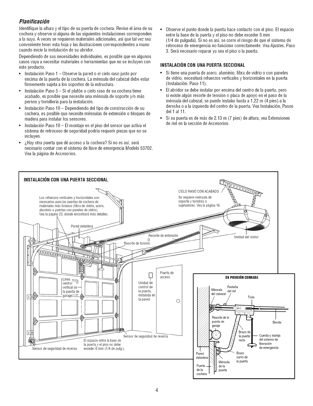
Planificaci6n
Identifique la altura y eltipo de su puerta decochera. Revise el _.reade su
cochera y observe si alguna de las siguientes instalaciones corresponden
a la suya.A veces se requierenmaterialesadicionales, asi que tal vez sea
convenientetener esta hoja y las ilustraciones correspondientes a mano
cuando inicie la instalaci6n de su abridor.
Dependiendo desus necesidadesindividuales, es posible queen algunos
casos vaya a necesitar materialeso herramientas que no se incluyen con
este producto.
• Instalaci6n Paso 1 - Observela pared o el cielo raso justo por
encima de la puerta de lacochera. La m_nsula del cabezaldebeestar
firmemente sujeta a los soportes de la estructura.
• Instalaci6n Paso5 - Si el plaf6n o cielo raso de su cochera tiene
acabado,es posible que necesite una m_nsula de soporte y/o m_.s
pernos y tornilleria para la instalaci6n.
• Instalaci6n Paso 10 - Dependiendodel tipo de construcci6n desu
cochera, es posible que necesite m_nsulas de extensi6n o bloques de
madera para instalar los sensores.
• Instalaci6n Paso 10 - Elmontaje en el piso del sensor que activa el
sistema de retroceso de seguridad podria requerir piezasque no se
incluyen.
•&Hayotra puertaque d_ acceso a la cochera? Si no es asi, ser_.
necesario contar con el sistema de Ilavede emergencia Modelo 53702.
Vea la p_.ginade Accesorios.
Observeel punto donde la puerta hacecontacto con el piso. El espacio
entre la basede la puerta y el piso no debe exceder 6 mm
(1/4 de pulgada). Si no es asi, se corre el riesgo de que el sistema de
retroceso de emergencia no funcione correctamente. VeaAjustes, Paso
3. Ser_.necesario reparar ya sea el piso o la puerta.
INSTALACIONCONUNAPUERTASECCIONAL
• Si tiene una puerta de acero, aluminio, fibra de vidrio o con paneles
de vidrio, necesitar_,refuerzosverticales y horizontales en la puerta
(Instalaci6n, Paso 11).
• Elabridor se debeinstalar por encima del centro de la puerta, pero
si existe alg_n resorte detensi6n o placade apoyo en el paso de la
m_nsula del cabezal,se puede instalar hasta a 1.22 m (4 pies) a la
derecha o a la izquierda del centro de la puerta. Vea Instalaci6n, Pasos
del 1 a111.
• Si su puerta es de m_.sde 2.13 m (7 pies) de altura, veaExtensiones
de riel en la secci6n de Accesorios.
INSTALACIONCONUNAPUERTASECCIONAL
Los refuerzos verticales y horizontales son
necesarios para las puertas de cochera de
materiales m_s livianos (fibra de vidrio, acero,
aluminio o puertas con paneles de vidrio).
Vea la p_gin 23, donde encontrar9 m_s detalles.
Pared delantera
Linea
central-ql I
vertical de--_
la puerta de I
Sensor de seguridad de reversa
Resorte de extension
0
Resorte de torsion
g Puerta de
acceso
Unidad de
control de
la puerta,
instalada en
la pared 0
Sensor de seguridad de
El espacio entre la base de
la puerta y el piso no debe
exceder 6 mm (1/4 de pulg.).
CIELO RASO CONACABADO
Se requiere mensula de
soporte y tornillos o
sujetadores. Vea la p_gina 16.
Hdad del motor
EN POSICIONCERRADA
Pesta_a
Mensula del riel
Trole
Banda
Mensula
de la
puerta
Brazo
curvode
la pueda
Cuerday manija
del sistemade
liberaci6n
de emergencia
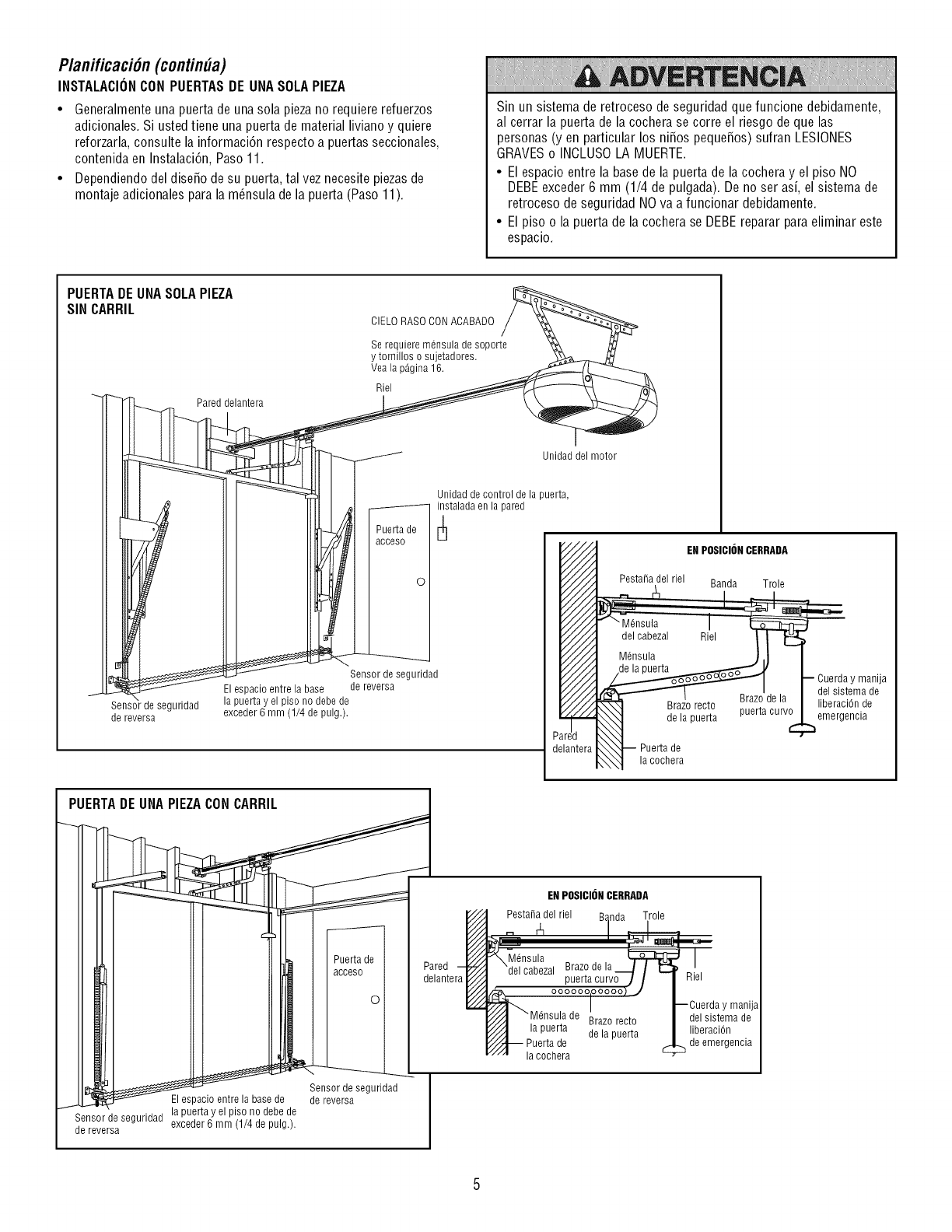
Planificaci6n(contin#a)
INSTALACIONCONPUERTASDE UNASOLAPIEZA
• Generalmenteuna puerta de una sola piezano requiere refuerzos
adicionales. Si ustedtiene una puerta de material liviano y quiere
reforzarla, consulte la informaci6n respecto a puertas seccionales,
contenida en Instalaci6n, Paso11.
• Dependiendo del dise_o de su puerta, tal vez necesite piezasde
montaje adicionales parala m_nsula de la puerta (Paso 11).
Sin un sistema de retroceso de seguridad que funcione debidamente,
al cerrar la puerta de la cochera se corre el riesgo de que las
personas (yen particular los ni_os peque_os) sufran LESIONES
GRAVESo INCLUSOLA MUERTE.
• El espacio entre la basede la puerta de la cochera y el piso NO
DEBEexceder 6 mm (1/4 de pulgada). De no ser asi, el sistema de
retroceso de seguridad NOva a funcionar debidamente.
• El piso o la puerta de la cochera se DEBEreparar paraeliminar este
espacio.
PUERTADEUNASOLAPIEZA
SIN CARRIL CIELO RASO CONACABADO
Pared delantera
Se requiere mensula de soporte
y tornillos o sujetadores.
Vea la p_gina 16.
Riel
J
Pue_a de
acceso
0
Sensor de seguridad
de reversa
Sensor de seguridad
Elespacio entre la base de reversa
la puertayel piso no debede
exceder 6 mm (1/4 de pulg.).
Unidad del motor
Unidad de control de la puerta,
instalada en la pared
,////
/////
/////
/////
/////
/////
f////_
/////
/////
///'//
/////
/////
/////
/////
/////
/////
/////
/////
/////
/////
/////
p iiHfl
d_lantera
ENPOSICIONCERRADA
Pesta_a del riel Banda Trole
-' I,
I
a
°
I cocner
PUERTADEUNA PIEZACONCARR_
I
Sensorde segurldad exceder6 mm (1/4 de pulg) I
d_ ,_,_,_ " " •
]
ENPOSICIONCERRADA
Pesta_a del riel B_ Trole
Brazo recto
la puerta de la puerta
Puerta de
la cochera
de emergencia
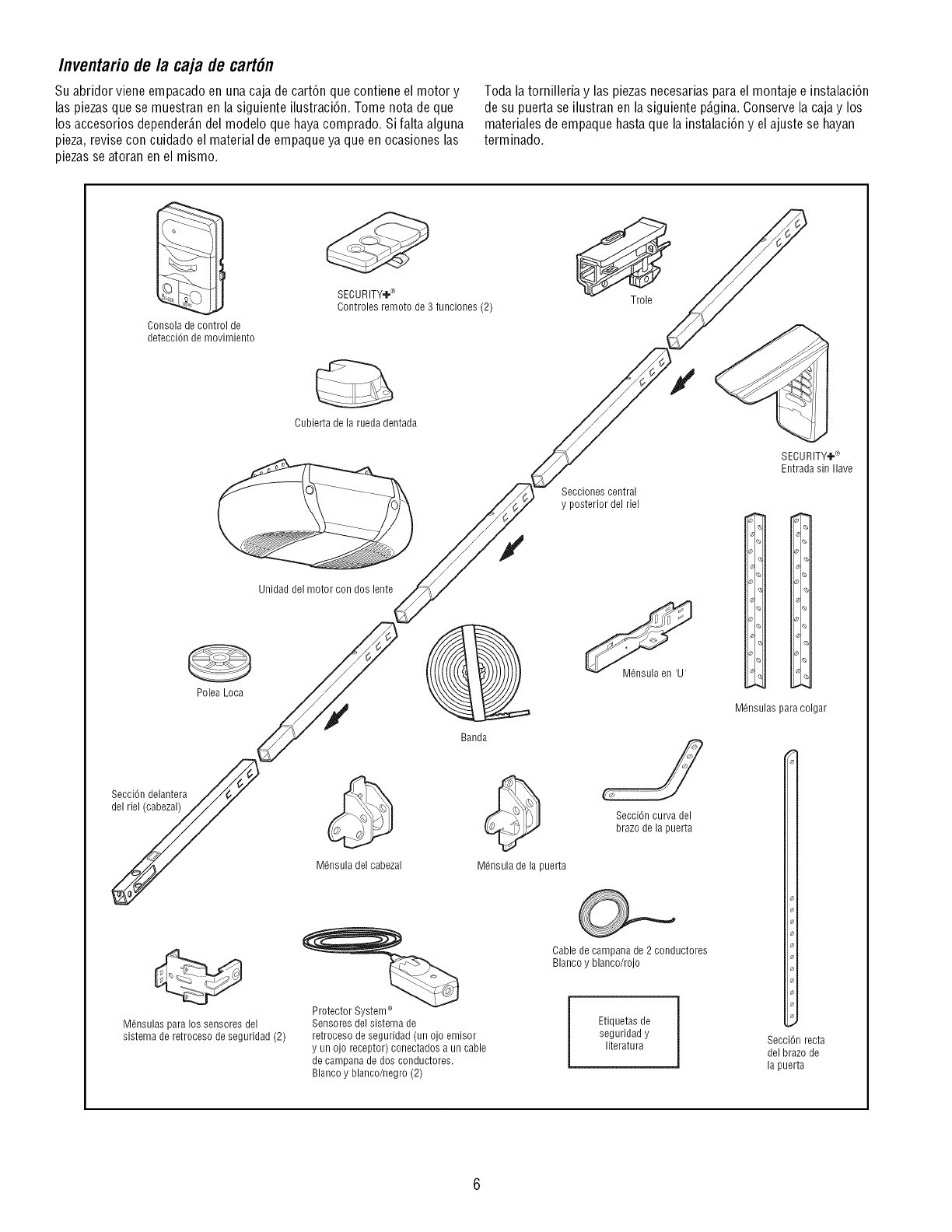
Inventafio de la caja de cart6n
Su abridor viene empacado en una caja de cart6n que contiene el motor y
las piezasque se muestran en la siguiente ilustraci6n. Tome nota de que
los accesorios depender_.ndel modelo que hayacomprado. Sifalta alguna
pieza, revise con cuidado el material de empaqueya que en ocasiones las
piezasse atoran en el mismo.
Toda la tornilleria y las piezas necesariaspara el montaje e instalaci6n
de su puerta se ilustran en la siguiente p@ina. Conserve la caja y los
materiales de empaque hastaque la instalaci6n y el ajuste se hayan
terminado.
Consola de control de
detecci6n de movimiento
Polea Loca
SecciOndelantera
delriel (cabezal)
SECURITY÷ ®
6ontroles remoto de 3 funciones (2) Trole
Cubierta de la rueda dentada
Secciones central
y posterior del riel
Unidad del motor con dos lente
M@sula del cabezal
Banda
M@sula de la puerta
M@sula en 'U'
SecciOncurva del
brazo de la puerta
SECURITY÷®
Entrada sin Ilave
_P
M@sulas para colgar
M@sulas para los sensores del
sistema de retroceso de seguridad (2)
Protector System ®
Sensores del sisterna de
retroceso de seguridad (un ojo emisor
y un ojo receptor) conectados a un cable
de campana de dos conductores.
Blanco y blanco/negro (2)
Cabledecampanade2 conductores
Blancoy blanco/rojo
Etiquetas de
seguridad y
literatura SecciOnrecta
del brazo de
la puerta
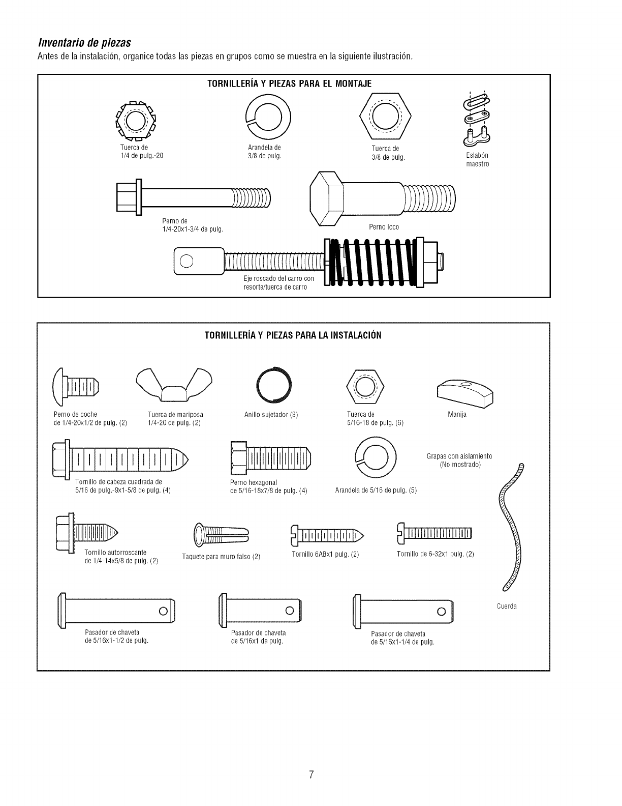
Inventario de piezas
Antes de la instalaci6n, organicetodas las piezasen grupos como se muestra en la siguiente ilustraci6n.
TORNILLERIAY PIEZASPARAELMONTAJE
@ O @
Tuerca de Arandela de Tuerca de
1/4 de pulg.-20 3/8 de pulg. 3/8 de pulg.
Perno de
1/4-20xl-3/4 de pulg. Perno Ioco
Ejeroscadodelcarrocon
resorte/tuercade carro
EslabOn
maestro
TORNILLERIAY PIEZASPARALAINSTALACION
Perno de coche
de 1/4-20xl/2 de pulg. (2)
Tuerca de mariposa
1/4-20 de pulg. (2)
@e cabezacuadrada de
5/16 de pulg.-9x1-5/8 de pulg. (4)
O
Anillo sujetador (3)
Perno hexagonal
de 5/16-18x7/8 de pulg. (4)
@
Tuerca de
5/16-18 de pulg. (6)
Arandela de 5/16 de pulg. (5)
Manija
Grapas con aislamiento
(No mostrado)
_orroscante
de 1/4-14x5/8 de pulg. (2) Taquete para muro falso (2) Tornillo 6ABxl pulg. (2) Tornillo de 6-32xl pulg. (2)
8Pasador de chaveta
de 5/16x1-1/2 de pulg.
o] 8 o/
Pasador de chaveta Pasador de chaveta
de 5/16xl de pulg. de 5/16x1-1/4 de pulg.
6uerda
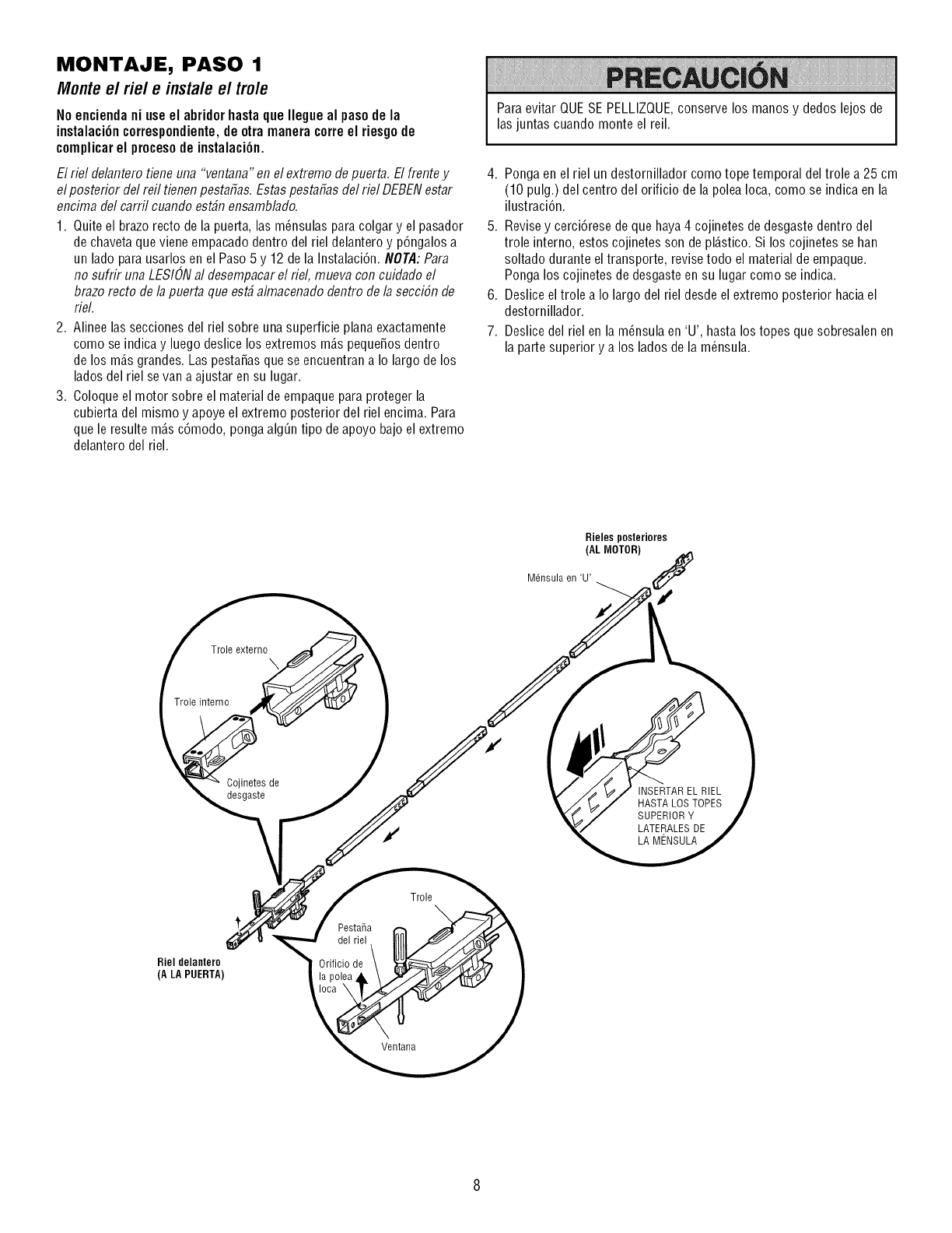
MONTAJE, PASO 1
Monteel riel e instaleel trole
Noenciendaniuseel abridorhastaqueIlegueal pasodela
instalaci6ncorrespondiente,deotra maneracorreel riesgode
complicarel procesode instalaci6n.
El riel delantero tiene una "ventana" enel extremo de puerta. El frentey
el posterior del refl tienen pestafias. Estas pestafias del riel DEBENestar
encima del carril cuando est#n ensamblado.
1. Quite el brazo recto de la puerta, las m_nsulas para colgar y el pasador
de chavetaque viene empacado dentro del riel delantero y p6ngalos a
un lado parausarlos en el Paso5 y 12 de la Instalaci6n. NOTA:Para
no sufrir una LESIONal desempacarel riel, mueva con cuidaflo el
brazo recto de la puerta que est_ almacenado dentro de la secci6n de
rieL
2. Alinee las secciones del riel sobre una superficie plana exactamente
como se indicay luego deslice los extremos m_.speque_osdentro
de los m_.sgrandes. Las pesta_asque se encuentrana Io largo de los
lados del riel se van a ajustar ensu lugar.
3. Coloqueel motor sobre el material de empaque para proteger la
cubierta del mismo y apoye el extremo posterior del riel encima. Para
que le resulte m_.sc6modo, pongaalg_n tipo de apoyo bajo el extremo
delantero del riel.
Para evitar QUESE PELLIZQUE,conserve los manos y dedos lejos de
las juntas cuando monte el reil.
4. Ponga en el riel un destornillador como tope temporal del trole a 25 cm
(10 pulg.) del centro del orificio de la polea Ioca, como se indica en la
ilustraci6n.
Revisey cerci6rese de que haya4 cojinetes de desgastedentro del
trole interno, estos cojinetes son de pl_.stico.Si los cojinetes se han
soltado durante eltransporte, revisetodo el material de empaque.
Ponga los cojinetes de desgaste ensu lugar como se indica.
Deslice el trole a Io largo del riel desde el extremo posterior haciael
destornillador.
Deslice del riel en la m_nsula en 'U', hasta los topes que sobresalenen
la parte superior y a los lados de la m_nsula.
5,
,
7.
Rieles posteriores
(AL MOTOR)
Mdnsula en 'U'
Trole externo \
Troleinterno
Cojinetes de
desgaste INSERTAREL RIEL
HASTA LOS TOPES
SUPERIOR Y
LATERALESDE
LA MENSULA
Rieldelantero
(A LA PUERTA)
Pestafia
del riel
Orificio de
Trole \
Ventana
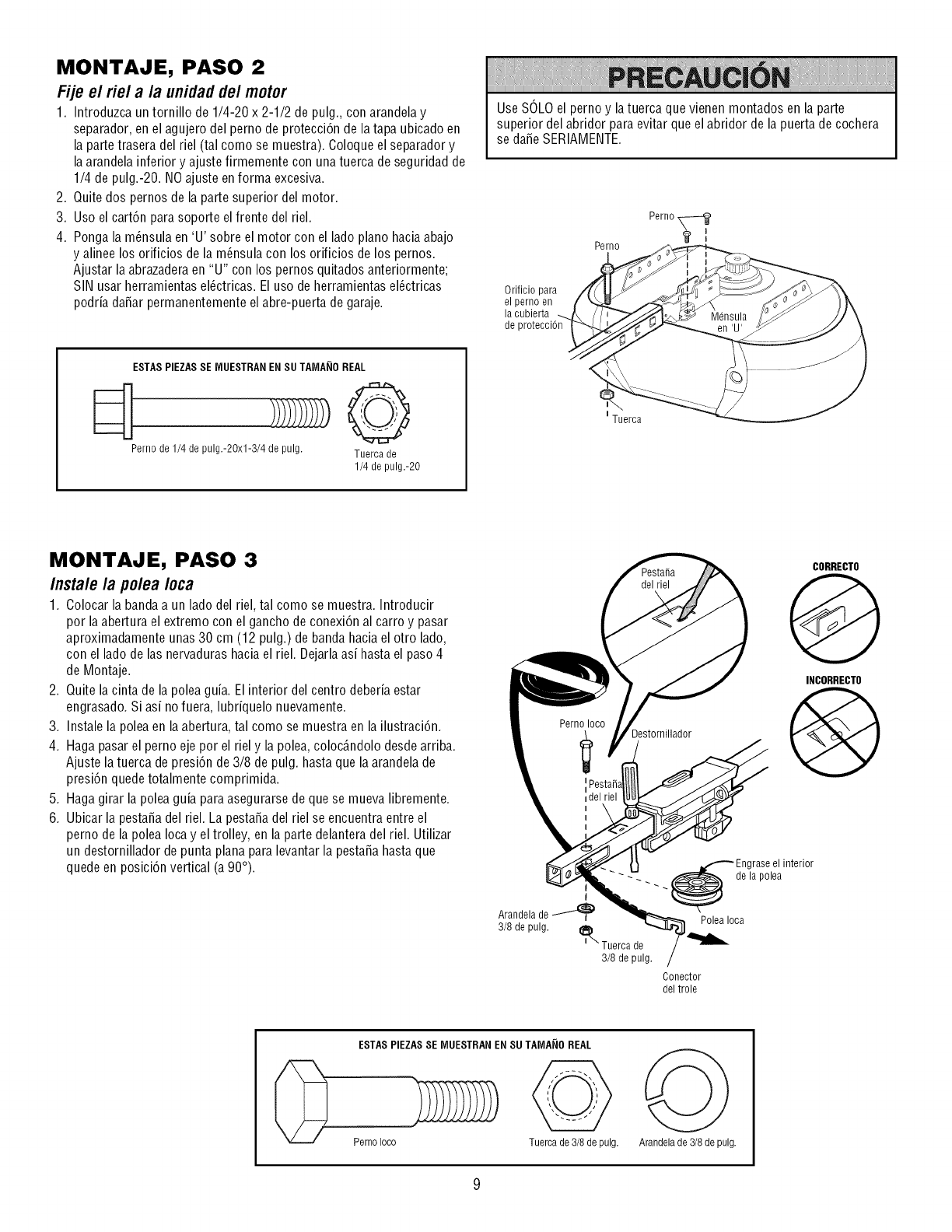
MONTAJE, PASO 2
Fije el riel a la unidad de/motor
1. Introduzca untornillo de 1/4-20 x 2-1/2 de pulg., con arandela y
separador, en el agujero del perno de protecci6n de latapa ubicado en
la parte trasera del riel (tal como se muestra). Coloque el separador y
la arandela inferior y ajuste firmemente con unatuerca de seguridad de
1/4 de pulg.-20. NO ajuste enforma excesiva.
2. Quite dos pernos de la parte superior del motor.
3. Uso el cart6n para soporte el frente del riel.
4. Ponga la m_nsula en 'U' sobre el motor con el lado piano haciaabajo
y alinee los orificios dela m_nsula con los orificios de los pernos.
Ajustar la abrazaderaen "U" con los pernos quitados anteriormente;
SIN usar herramientas el_ctricas. El uso de herramientasel_ctricas
podria da_ar permanentemente el abre-puerta degaraje.
ESTAS PIEZASSE [VIUESTRANENSU TA[VIA[IOREAL
Pernode1/4de pulg.-2Ox]-3/4de pulg. Tuercade
1/4 de pulg.-20
Use SOLOel perno y latuerca que vienen montados en la parte
superior del abridor para evitar que el abridor de la puerta de cochera
se da_eSERIAMENTE.
Orificio para
el perno en
la cubierta
de
Perno
I Tuerca
Perno_
I
MONTAJE, PASO 3
/nstale /a polea /oca
1. Colocar la bandaa un ladodel riel, tal como se muestra. Introducir
por la abertura el extremo con el gancho de conexi6n al carro y pasar
aproximadamente unas 30 cm (12 pulg.) de banda hacia el otro lado,
con el lado de las nervadurashacia el riel. Dejarlaasi hasta el paso 4
de Montaje.
2. Quite la cinta de la polea guia. Elinterior del centro deberia estar
engrasado. Si asi nofuera, lubriquelo nuevamente.
3. Instale la polea en laabertura, tal como se muestra en la ilustraci6n.
4. Hagapasarel perno eje por el riel y la polea,coloc_.ndolo desde arriba.
Ajuste la tuerca de presi6n de3/8 de pulg. hasta que la arandelade
presi6n quede totalmente comprimida.
5. Hagagirar la polea guia para asegurarsede que se mueva libremente.
6. Ubicar la pestaSadel riel. La pestaSadel riel se encuentra entre el
perno de la polea Iocay el trolley, en la parte delanteradel riel. Utilizar
un destornillador de punta plana para levantar la pestaSahastaque
quede en posici6n vertical (a 90°).
Destornillador
CORRECTO
@
INCORRECTO
@
Engraseel interior
--_._._de la polea
Arandela de _1 _Polea Ioca
3/8 de pulg. I_ Tuerca de
3/8 de pulg.
Conector
del trole
0ESTAS PIEZASSE [VIUESTRANENSU TA[VIA[IOREAL
Perno Ioco Tuerca de 3/8 depulg. @
Arandela de 3/8de pulg.
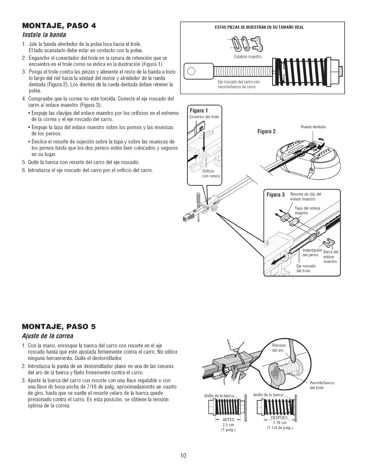
MONTAJE, PASO 4
/nsta/e /a banda
1. Jale la bandaalrededor de la polea Ioca hacia eltrole.
El ladoacanaladodebeestar en contacto con la polea.
2. Engancheel conectador del trole en la ranura de retenci6n que se
encuentra en el trole como se indica en la ilustraci6n (Figura 1).
3. Ponga eltrole contra las pinzasy alimente el resto de la bandaa todo
Io largo del riel hacia la unidad del motor y alrededor de la rueda
dentada(Figura 2). Los dientes de la rueda dentadadeben retener la
polea.
4. Compruebeque la correa no estetorcNa. Conecteel eje roscado del
carro al enlace maestro (Figura 3).
•Empuje las clavijas del enlace maestro por los orificios en el extremo
de la correa y el eje roscado del carro.
•Empuje la tapa del enlace maestro sobre los pernos y lasmuescas
de los pernos.
•Desliceel resorte de sujeci6n sobre la tapay sobre lasmuescas de
los pernos hasta que losdos pernos est6n bien colocados y seguros
ensu lugar.
5. Quite la tuerca con resorte del carro del eje roscado.
6. Introduzca el eje roscado del carro por el orificio del carro.
ESTAS PIEZASSE IVlUESTRANENSU TAMA_IOREAL
Eslab6n maestro
Eje roscado del carro con
resorte/tuerca de carro
Figura 1
Conector del trole
con ranura
Fig.ra 2Rueda dentada
r m
FJgura3Resorte de clip del
enlace maestro
/Tapa del enlace
maestro
j_//_ delperno enlace
_f_ Jnia-esiro
_ .... Eje [oscado
MONTAJE, PASO 5
Ajustede la correa
1. Con la mano, enrosque latuerca del carro con resorte en el eje
roscado hastaque este ajustada firmemente contra el carro. No utilice
ninguna herramienta. Quiteel destornillador.
2. Introduzcala punta de un destornillador piano en una de lasranuras
del aro de la tuerca y fijelo firmemente contra el carro.
3. Ajuste la tuerca del carro con resorte con una Ilaveregulable o con
una Ilavede boca ancha de 7/16 de pulg, aproximadamente un cuarto
de giro, hasta que se suelte el resorte yelaro de la tuerca quede
presionado contra el carro. Enesta posicidn, se obtiene la tensidn
6ptima de la correa.
Anillo de
_,Stro_e/t uerca
Anillo de la tuerca
_- ANTES -_
2.5 cm
(1 pulg.)
I_ESPUES
3.18 cm
(1-1/4 de pulg.)
10
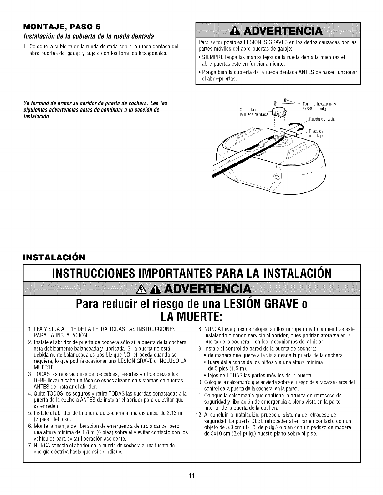
MONTAJE, PASO 6
/nsta/aci6n de/a cubierta de/a rueda dentada
1. Coloque la cubierta de la rueda dentadasobre la rueda dentadadel
abre-puertas del garajey sujete con los tornillos hexagonales.
Para evitar posibles LESIONESGRAVESen los dedos causadas por las
partes m6viles del abre-puertas de garaje:
• SIEMPREtenga las manos lejos de la rueda dentada mientras el
abre-puertas este enfuncionamiento.
• Ponga bien la cubierta de la rueda dentadaANTES de hacerfuncionar
el abre-puertas.
Yatermin#de armarsu abridordepuertade cochera.Leales
siguientesadvertenciasantesdecontinuara la secci#nde
instalaci#n.
_ Tornillo hexagonals
Cubierta de _ 8x3/8 de pulg.
la rueda dentada , dentada
Placa de
montaje
INSTALACION
INSTRUCCIONESIMPORTANTESPARALA INSTALACION
Parareducirel riesgode unaLESIONGRAVEo
LAMUERTE:
1. LEAY SIGAAL PIEDELA LETRATODASLAS INSTRUCCIONES
PARALA INSTALACION.
2. Instale el abridor depuerta de cochera s61osi la puerta de la cochera
est,. debidamente balanceaday lubricada. Si la puerta no est,.
debidamente balanceadaes posible que NOretroceda cuando se
requiera, Io que podria ocasionar una LESIONGRAVEo INCLUSOLA
MUERTE.
3. TODASlas reparaciones de los cables, resortes y otras piezaslas
DEBEIlevar a cabo un t_cnico especializadoen sistemas de puertas,
ANTES de instalar el abridor.
4. QuiteTODOSlos seguros y retire TODASlas cuerdas conectadasa la
puerta de la cocheraANTES de instalar el abridor parade evitar que
se enreden.
5. Instale el abridor dela puerta de cochera a una distancia de2.13 m
(7 pies) del piso.
6. Monte la manija de liberaci6n de emergenciadentro alcance,pero
una altura minima de 1.8 m (6 pies) sobre el y evitar contacto con los
vehiculos paraevitar liberaci6n accidente.
7. NUNCAconecteel abridor de lapuerta decocheraa unafuentede
energiael_ctricahastaqueasi se indique.
8. NUNCAIlevepuestos relojes, anillos ni ropa muy floja mientras est_
instalando o dando servicio al abridor, pues podrian atorarse en la
puerta de la cochera o en los mecanismos del abridor.
9. Instale el control de pared de la puerta de cochera:
• de manera que quedea la vista desde la puerta de la cochera.
• fuera del alcance de los ni_os y a una altura minima
de 5 pies (1.5 m).
• lejos de TODAS las partes m6viles de la puerta.
10. Coloquelacalcomaniaqueadviertesobreel riesgode atraparsecercadel
controlde la puertade lacochera,enlapared.
11. Coloquela calcomania que contiene la prueba de retroceso de
seguridad y liberaci6n de emergenciaa plenavista en la parte
interior de la puerta de la cochera.
12. AI concluir la instalaci6n, pruebe el sistema de retroceso de
seguridad. La puerta DEBEretroceder al entrar en contacto con un
objeto de 3.8 cm (1-1/2 de pulg.) o bien con un pedazode madera
de 5x10 cm (2x4 pulg.) puesto piano sobre el piso.
11
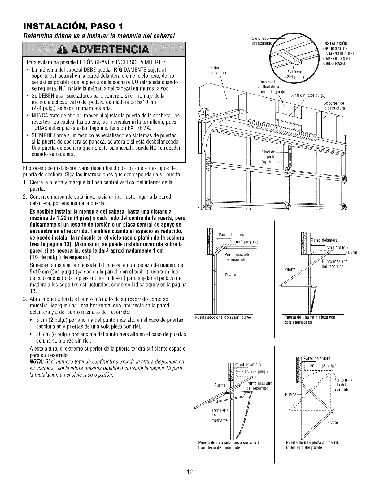
INSTALACION, PASO 1
Determine d6ndevaa insta/arla m_nsulade/cabeza/
Paraevitar una posible LESIONGRAVEo INOLUSOLA MUERTE:
• La m_nsula del cabezalDEBEquedar RfGIDAMENTEsujeta al
soporte estructural en la pared delanterao en el cielo raso, de no
ser asi es posible que la puerta de la cochera NOretroceda cuando
se requiera. NO instale la m_nsula del cabezal en muros falsos.
• Se DEBENusar sujetadores paraconcrete si el montaje de la
m_nsula del cabezalo del pedazode maderade 5x10 cm
(2x4 pulg.) se haceen mamposteria.
• NUNCAtrate deaflojar, mover ni ajustar la puertade la cochera, los
resortes, los cables, las poleas, las m_nsulas ni la tornilleria, pues
TODASestas piezasest_.nbajo una tensi6n EXTREMA.
• SIEMPREIlamea un t_cnico especializadoen sistemas de puertas
si la puerta de cochera se pandea,seatora o si est,. desbalanceada.
Una puerta de cochera que no est_ balanceadapuede NOretroceder
cuando se requiera.
El proceso deinstalaci6n varia dependiendode los diferentes tipos de
puerta decochera. Siga las instrucciones que correspondan a su puerta.
1. Cierre la puerta y marque la linea central vertical del interior de la
puerta.
2. ContinQemarcando esta lineahaciaarriba hasta Ilegara la pared
delantera, per encima de la puerta.
Esposibleinstalar la m_nsula del cabezalhasta unadistancia
m_xima de 1.22 m (4 pies) a cada lade del centrede la puerta, pero
_nicamente si un resorte detorsionoun placa centralde apoyose
encuentraen el recorrido. Tambi_ncuandoel espacio es reducido,
se puede instalar la m_nsula en el cielo rasoo plafOn de la cochera
(yea la p_gina 13). (Asimismo,se puede instalar invertidasobre la
pared si es necesario, esto le dar_ aproximadamente1 cm
(1/2 de pulg.) de espacio.)
Si necesitainstalar la m_nsula del cabezalen un pedazode madera de
5x10 cm (2x4 pulg.) (ya sea en la pared o en el techo), usetornillos
de cabezacuadrada o pijas (no se incluyen) parasujetar el pedazode
madera a los soportes estructurales, come se indica aqui yen la p_.gina
13.
3. Abra la puerta hasta el punto m_.salto desu recorrido come se
muestra. Marque una linea horizontal que intersecte en la pared
delantera y adel punto m_.salto del recorrido:
• 5 cm (2 pulg.) per encima del punto m_.salto en el case de puertas
seccionales y puertas de una sola piezacon riel.
• 20 cm (8 pulg.) per encimadel punto m_.salto en el case de puertas
de una sola piezasin riel.
A esta altura, el extreme superior de la puerta tendr_,suficiente espacio
para su recorrido.
NOTA:Si el nEimerototal decentfinetros excedela altura disponible en
su cochera, usela altura m#ximaposible o consulte la p#gina 13para
la InstalaciSnen el cielo raso o plafSn.
Cielo raso
sin acabado
Pared
delantera
Linea
vertical de la
puerta de garaje
Pared delantera
(2 pulg.) Carril
Puntom_salto
delrecorrido
Puerta
Puertaseccional con carril curve
Puerta
Tornilleria
del
montante
Pared delantera
del recorrido
Puerta de .ha sola pieza sin carril:
terniileria del montaate
INSTALACION
OPCIONALDE
LAIVlI_NSULADEL
CABEZALEN EL
CiELORASO
5x10 cm(2x4 pulg.)
SopoRes de
la estructura
_areddelantera
cm (2 pulg.)
Carril
del recorrido
Paerta de uaa sela pieza con
earril horizontal
Pared delantera
:- 20 cm (8 pulg.)
" "" ',i Punto m_.s
',',alto del
',',recorrido
Pivote
Pnerta de nna pieza sin carril:
torniileria del pivote
12
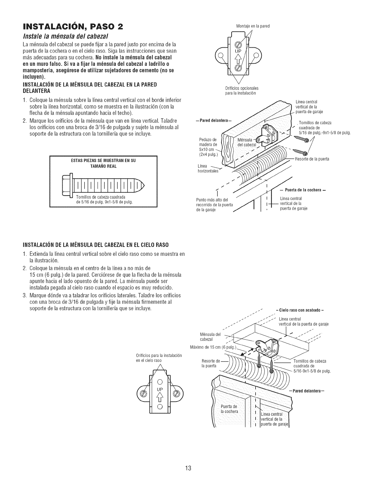
INSTALAC|ON, PASO 2
Instale la m_nsulade/cabezal
La m6nsula del cabezalse puedefijar a la paredjusto per encima de la
puerta de la cochera o en el cielo raso. Siga las instrucciones que sean
mAsadecuadaspara su cochera. No instale la m_nsula del cabezal
en an mutefalse. Si va a fijar la m_nsula del cabezalaladrillo o
mamposteda, aseg_rese de ,tiJizar sujetadoresde cernento(no se
incJuyen).
INSTALACIOHDELA iVlI_NSULADELCABEZALENLA PARED
DELANTERA
1. Coloquela m_nsula sobre la liner central vertical con el borde inferior
sobre la liner horizontal, come se muestra en la ilustracidn (con la
fiecha de la m_nsula apuntando hacia el techo).
2. Marque los orificios de la m_nsula que van en lineavertical. Taladre
los orificios con una broca de 3/16 de pulgada y sujete la m_nsula al
soporte de la estructura con latornilleria que se incluye.
ESTAS PIEZASSE IVlUESTRANENSU
TAMANOREAL
Tornillos de cabezacuadrada
de 5/16 de pulg, 9xl-5/8 de pulg,
-Pared delantera-
Pedazode
madera de
5x10 cm
(2x4 pulg.)
Linea
t
f
t
Punto m_s alto del
recorrido de la puerta
de la garaje
Montaje en la pared
Orificios opcionales
para la instalaci6n
Linea central
vertical de la
puerta de garaje
•Tornillos de cabeza
cuadrada de
5/16 de pulg.-9xl-5/8 de pulg.
de la puerta
- Puerta de la ¢echera -
Linea central
vertical de la
puerta de garaje
INSTALACIONDELAiVIF:NSULADELCABEZALENELCIELORASO
1. Extiendala lineacentral vertical sobre el cielo raso come se muestra en
la ilustraci6n.
2. Coloquela m_nsula en el centre de la liner a no m_s de
15 cm (6 pulg.) de la pared. Cerci6resede que lafiecha de la m_nsula
apunte hacia el ladeopuesto de la pared. La m_nsula puedeser
instalada pegadaal cielo raso cuando el espacio es muy reducido.
3. Marque d6nde va a taladrar los orificios laterales.Taladre los orificios
con una broca de3/16 de pulgaday fije la m_nsula firmemente al
soporte de la estructura con latornilleria que se incluye.
Orificios para la instalaciOn
en el cielo raso
/ t t - Ciele rase con acabado -
./_ _ /_J Lineacentral
_-_ _ _ _ vertical de la puerta de garaje
M6nsula del
cabezal _ ._/_'_
M_ximo de 15 cm (6
Resorte de de cabeza
la puerta cuadrada de
pulg.
-Pared delaniera-
Linea central
vertical de ]a
puerta de garaje
13
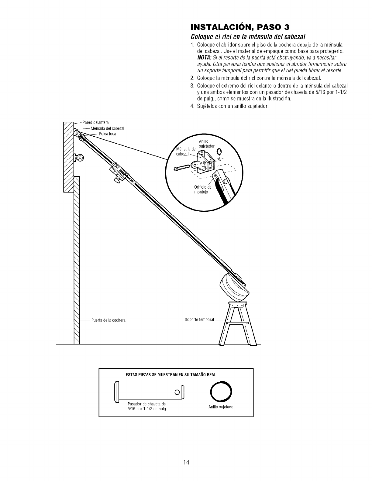
INSTALACION, PASO 3
Coloqueel rie/ en la m_nsula de/cabezal
1. Coloqueel aL)ridorsoL)reel piso de la cochera deL)ajode la m_nsula
del caL)ezal.Use el material de empaque como base paraprotegerlo.
NOTA:Si el resorte de la puerta est_ obstruyendo, va a necesitar
ayuda. Otrapersona tendr_ que sostener el abridor firmemente sobre
un soporte temporal para permitir que el riel pueda librar el resorte.
2. Coloquela m_nsula del riel contra la m_nsula del cabezal.
3. Coloqueel extremo del riel delantero dentro de la m_nsula del cabezal
y una ambos elementoscon un pasador de chavetade5/16 por 1-1/2
de pulg., como se muestra en la ilustraci6n.
4. Suj_telos con un anillo sujetador.
//
//
//
//
//
//
//
Pared delantera
cabezal
Anillo
_tador
del
cabezal ---..
\
Orificiode
montaje
0
-- Puerta de la cochera
ESTASPIEZASSE MUESTRAN EN SUTAMA_IO REAL
Pasador de chaveta de
5/16 por 1-1/2 de pulg. Anillo sujetador
14
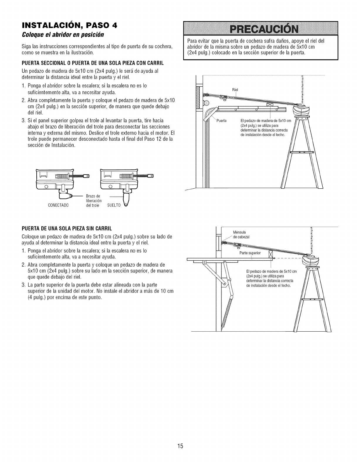
INSTALACION, PASO 4
Coloque el abridor en posici6n
Siga las instrucciones correspondientes al tipo de puerta de su cochera,
como se muestra en la ilustraci6n.
PUERTASECCIONAL0 PUERTADE UNASOLAPIEZACON CARRIL
Un pedazode madera de 5x10 cm (2x4 pulg.) le ser_.de ayudaal
determinar la distancia idealentre la puerta y el riel.
1. Ponga el abridor sobre la escalera; si la escalera no es Io
suficientemente alta, va a necesitar ayuda.
2. Abra completamente la puerta y coloque el pedazode madera de 5x10
cm (2x4 pulg.) en la secci6n superior, de maneraque quede debajo
del riel.
3. Si el panel superior golpea el trole al levantar la puerta, tire hacia
abajo el brazo de liberaci6n del trole paradesconectar las secciones
interna y externa del mismo. Deslice el trole externo hacia el motor. El
trole puede permanecerdesconectado hasta el final del Paso 12 de la
secci6n de Instalaci6n.
Paraevitar que la puerta de cochera sufra da_os, apoye el riel del
abridor de la misma sobre un pedazode maderade 5x10 cm
(2x4 pulg.) colocado en la secci6n superior de la puerta.
Riel
Elpedazo de maderade 5x10 cm
(2x4 pulg.)se utilizapara
determinarla distanciacorrecta
de instalaci6ndesde eltecho.
Braze de --
eraci6
CONECTADO del trole SUELTO
PUERTADEUNASOLAPIEZASIN CARRIL
Coloque un pedazo de maderade 5x10 cm (2x4 pulg.) sobre su lado de
ayudaal determinar la distancia idealentre la puerta y el riel.
1. Ponga el abridor sobre la escalera; si la escalera no es Io
suficientemente alta, va a necesitar ayuda.
2. Abra completamente la puerta y coloque un pedazode madera de
5x10 cm (2x4 pulg.) sobre su lado en la secci6n superior, de manera
que quede debajo del riel.
3. La parte superior de la puerta debe estar alineada con la parte
superior de la unidad del motor. No instale el abridor a m_.sde 10 cm
(4 pulg.) por encima de este punto.
Mensula
de cabezal
Partesuperior
_i_i.d
iElpedazode maderade 5x10 cm
(2x4pulg.) se utilizapara
determinar ladistancia correcta
de instalaci6ndesdeel techo.
15
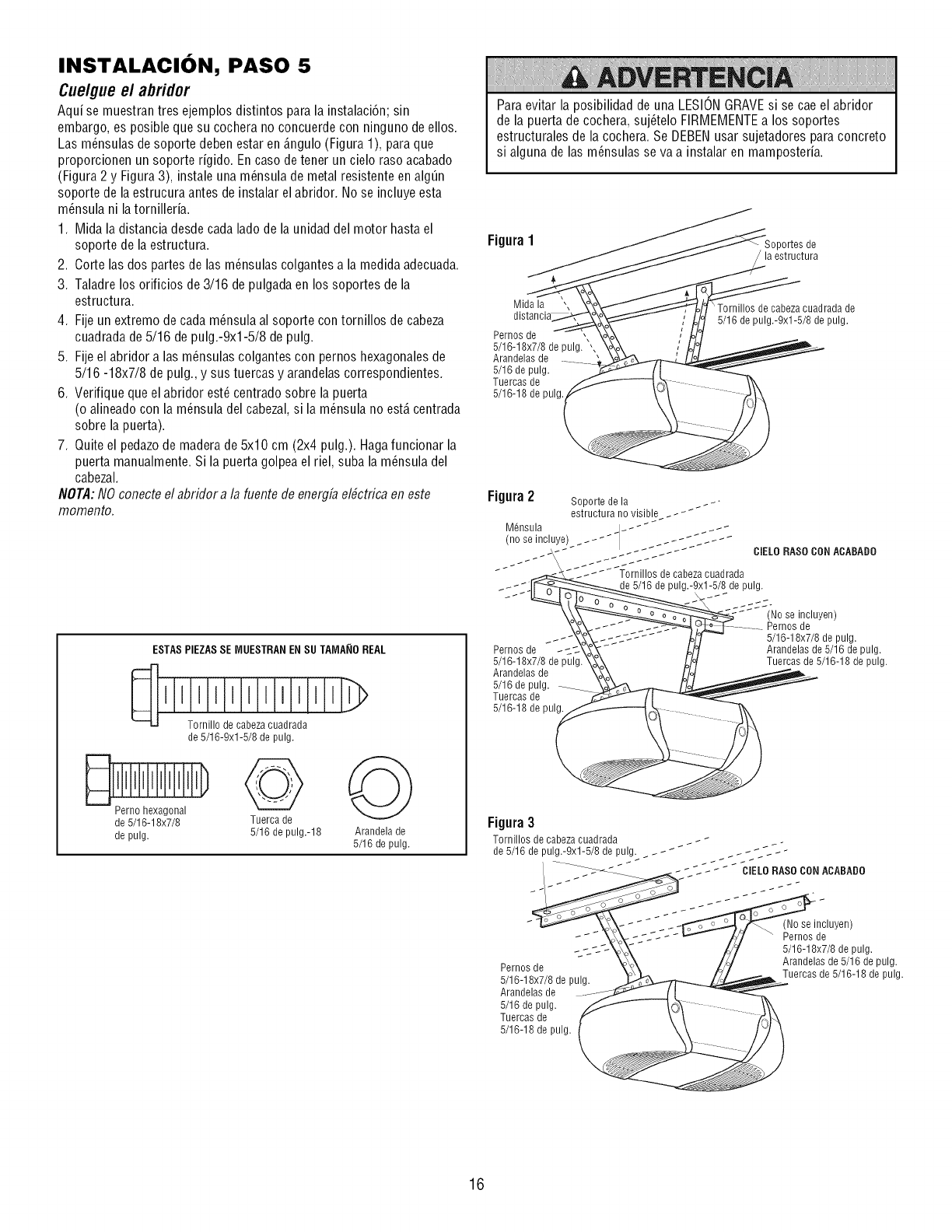
INSTALACION, PASO 5
Cue/gueel abridor
Aqui se muestran tres ejemplos distintos para la instalaci6n; sin
embargo, es posible que su cochera no concuerde con ninguno de ellos.
Las m_nsulas de soporte deben estar en _.ngulo(Figura 1), paraque
proporcionen un soporte rigido. En caso de tener un cielo raso acabado
(Figura 2 y Figura3), instale una m_nsula de metal resistente en alg_n
soporte de la estrucura antes de instalar el abridor. No se incluye esta
m_nsula ni la tornilleria.
1. Mida la distancia desdecada lado de la unidad del motor hasta el
soporte de la estructura.
2. Corte las dos partes de las m_nsulas colgantes a la medida adecuada.
3. Taladre los orificios de3/16 de pulgada en los soportes de la
estructura.
4. Fijeun extremo decada m_nsula al soporte con tornillos de cabeza
cuadrada de5/16 de pulg.-9xl-5/8 de pulg.
5. Fijeel abridor a las m_nsulas colgantes con pernos hexagonalesde
5/16 -18x7/8 de pulg., y sus tuercas y arandelas correspondientes.
6. Verifique que el abridor est_ centrado sobre la puerta
(o alineado con la m_nsula del cabezal,si la m_nsula no est,. centrada
sobre la puerta).
7. Quite el pedazode madera de 5x10 cm (2x4 pulg.). Hagafuncionar la
puerta manualmente. Si la puerta golpeael riel, suba la m_nsula del
cabezal.
NOTA:NO conecteel abridor a la fuente de energfaelbctrica en este
momento.
ESTAS PIEZASSE MUESTRAN ENSU TAMA_IO REAL
Tornillo de cabeza cuadrada
de 5/16-9xl-5/8 de pulg.
de 5/16-18x7/8 Tuerca de
de pulg. 5/16 de pulg.-18 Arandela de
5/16 de pulg.
Paraevitar la posibilidad de una LESIONGRAVEsi se cae el abridor
de la puerta de cochera, suj6telo FIRMEMENTEa los soportes
estructurales de la cochera. Se DEBENusar sujetadores para concreto
si alguna de las m_nsulas se va a instalar en mamposteria.
Figura1 Soportes de
la estructura
Mida la ,,
Pernos de ,,
5/16-18x7/8 de pulg. ',
Arandelas de
5/16 de pulg.
Tuercas de
5/16-18 de pulg.
\ Tornillos de cabezacuadrada de
5/16 de pulg.-9xl-5/8 de pulg.
Figura2 Soporte de la
estructura no visible _ _ _
M_nsula
(no se incluye) _
-CIELO RASO CONACABADO
._-f _ _]_ornillos de cabezacuadrada
_-_ Je5/16 de pulg.-9xl-5/8 de pulg.
Pernos de __.c
5/16-18x7/8 de pulg.
Arandelas de
5/16 de pulg.
Tuercas de
5/16-18 de pulg.
(No se incluyen)
........ Pernos de
5/16-18x7/8 de pulg.
Arandelas de 5/16 de pulg.
Tuercas de 5/16-18 de pulg.
Pernos de
5/16-18x7/8 de pulg.
Arandelas de
5/16 de pulg.
Tuercas de
5/16-18 de pulg.
(Noseincluyen)
Pernos de
5/16-18x7/8 de pulg.
Arandelas de 5/16 de pulg.
Tuercas de 5/16-18 de pulg.
16
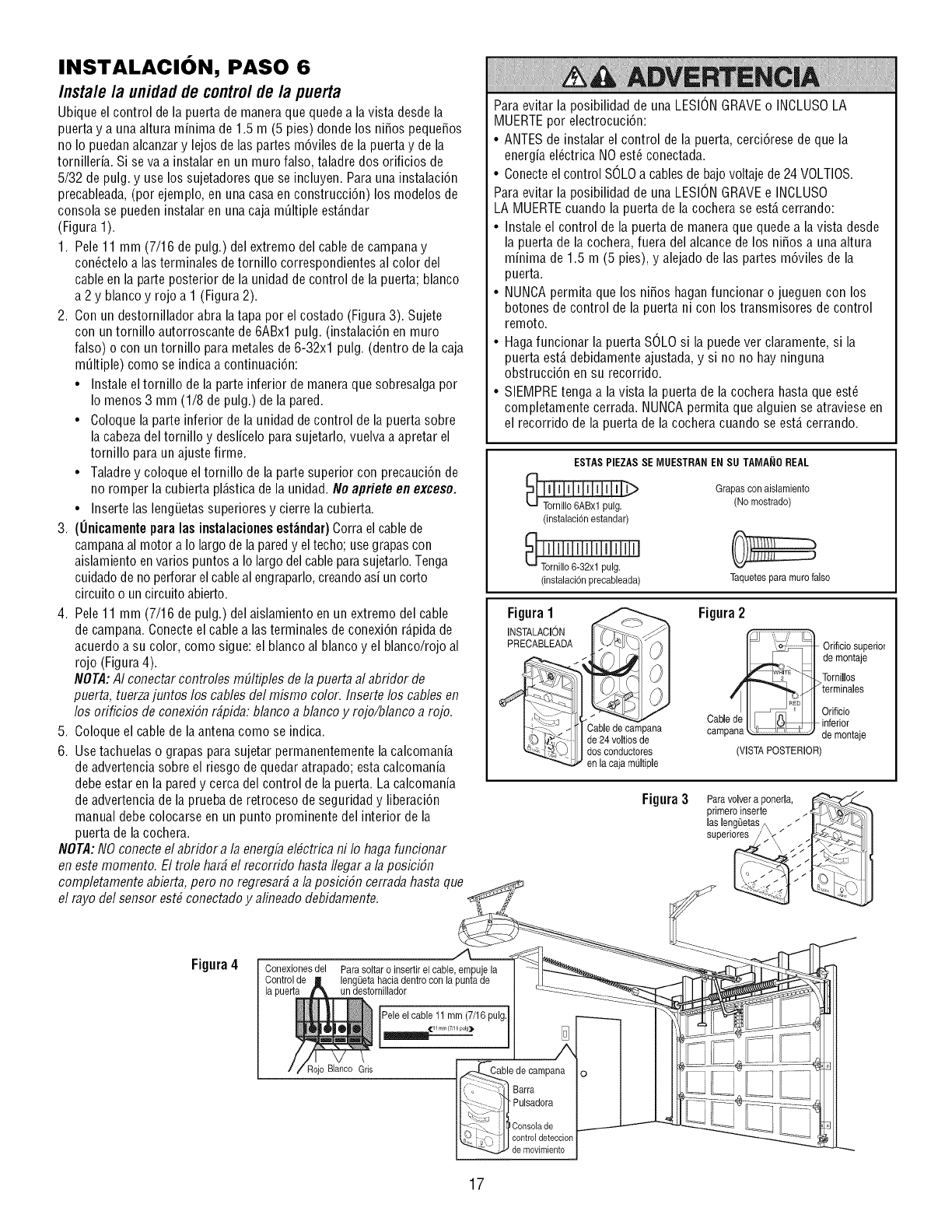
INSTALACION, PASO 6
Instale /a unidadde controlde/a puerta
Ubique el control de la puerta de maneraque quede a la vista desde la
puerta y a una altura minima de 1.5 m (5 pies) donde los nifios pequefios
no Io puedan alcanzary lejos de las partes m6viles de la puerta y de la
tornilleria. Si se va a instalar en un muro falso, taladre dos orificios de
5/32 de pulg. y use los sujetadores que se incluyen. Parauna instalaci6n
precableada,(por ejemplo, en una casa en construcci6n) los modelos de
consola se pueden instalar en una caja m01tipleest_.ndar
(Figura 1).
1. Pele 11 mm (7/16 de pulg.) del extremo del cable de campana y
con_ctelo alas terminales detornillo correspondientes al color del
cable en la parte posterior de la unidadde control de la puerta; blanco
a 2 y blanco y rojo a 1 (Figura 2).
2. Con un destornillador abra latapa por el costado (Figura 3). Sujete
con un tornillo autorroscante de 6ABxl pulg. (instalaci6n en muro
falso) o con un tornillo para metalesde 6-32xl pulg. (dentro de lacaja
m01tiple)como se indica a continuaci6n:
• Instale eltornillo de la parte inferior de manera que sobresalga por
Io menos 3 mm (1/8 de pulg.) de la pared.
• Coloque la parte inferior de la unidad de control de la puerta sobre
la cabezadel tornillo y deslicelo para sujetarlo, vuelva a apretar el
tornillo para un ajuste firme.
• Taladrey coloque el tornillo de la parte superior con precauci6n de
no romper la cubierta pl_.sticade la unidad. No apriete en exceso.
• Inserte las lengiJetassuperiores y cierre la cubierta.
3. (Onicamente para las instalaciones est_ndar) Corrael cablede
campanaal motor a Iolargo de la paredy el techo; use grapascon
aislamiento en varios puntos a Io largo del cableparasujetarlo.Tenga
cuidadode no perforarel cableal engraparlo,creandoasi un corto
circuito o un circuito abierto.
4. Pele 11 mm (7/16 de pulg.) delaislamiento en un extremo delcable
de campana.Conecte el cable alas terminales deconexi6n r_.pidade
acuerdoa su color, como sigue: el blanco al blanco y el blanco/rojo al
rojo (Figura4).
NOTA:A/conectar contro/es mEfltip/esde/a puerta a/abridor de
puerta, tuerzajuntos/os cables de/mismo color./nserte los cables en
los orificios de conexiSnr_pida: b/anco a b/ancoy rojo/b/anco a rojo.
5. Coloqueel cablede la antena como se indica.
6. Usetachuelas o grapas parasujetar permanentemente la calcomania
de advertencia sobre el riesgo de quedaratrapado; esta calcomania
debeestar en la pared y cerca del control de la puerta. Lacalcomania
de advertencia de la pruebade retroceso de seguridad y liberaci6n
manual debe colocarse en un punto prominente del interior de la
puerta de la cochera.
NOTA:NO conectee/abridor a/a energb e/#ctrica ni /o haga funcionar
en este momento. El tro/e har_ e/recorrido hasta //egar a/a posici6n
comp/etamente abierta, pero no regresar_a/a posiciSn cerrada hasta que
e/rayo de/sensor est# conectado y a/ineado debidamente.
Para evitar la posibilidad de una LESIONGRAVEo INCLUSOLA
MUERTEpor electrocuci6n:
• ANTESde instalar el control de la puerta, cerci6rese de que la
energia el_ctrica NOest_ conectada.
• Conecteel control SOLOa cablesde bajovoltaje de24 VOLTIOS.
Para evitar la posibilidad de una LESIONGRAVEe INCLUSO
LA MUERTEcuando la puerta de la cochera se est,. cerrando:
• Instale el control de la puerta de maneraque quede a la vista desde
la puerta de la cochera, fuera del alcance de los nifios a una altura
minima de 1.5 m (5 pies), y alejado de las partes m6viles de la
puerta.
• NUNCApermita que los nifios haganfuncionar o jueguen con los
botones de control de la puerta ni con los transmisores de control
remoto.
• Hagafuncionar la puerta SOLOsi la puede ver claramente, si la
puerta est,. debidamente ajustada, y si no no bay ninguna
obstrucci6n en su recorrido.
• SIEMPREtenga a la vista la puerta de la cochera hasta que est_
completamente cerrada. NUNCApermita que alguien se atraviese en
el recorrido de la puerta de la cochera cuando se est,. cerrando.
ESTASPIEZAS SE IV]UESTRANEN SU TAIV]A_IOREAL
(instalaci6nestandar)
(instalacidn Fecableada)
Grapas con aislamiento
(No rnostrado)
Taquetesparamumfalso
Figura1
INSTALACION I} __1
PRECABLEADA _
_Cable decampana
I_d,")/_ Jde 24voJtiosde
_-)- I dosconductores
-""',_.g_ en la caja multiple
Figura2
Orificio superior
demontaje
_,,,L[_ _ /'_Tornillos
/i terminales
II _ _ I Orificio
Cablede I __1_t_t inferior
campana_-u ,J u ?de montaje
(VISTAPOSTERIOR)
Figura 3
Figura4 Conexionesdel
Rojo Blanco Gris
Barra
Pulsadora
Consola de
control deteccion
de movimiento
17
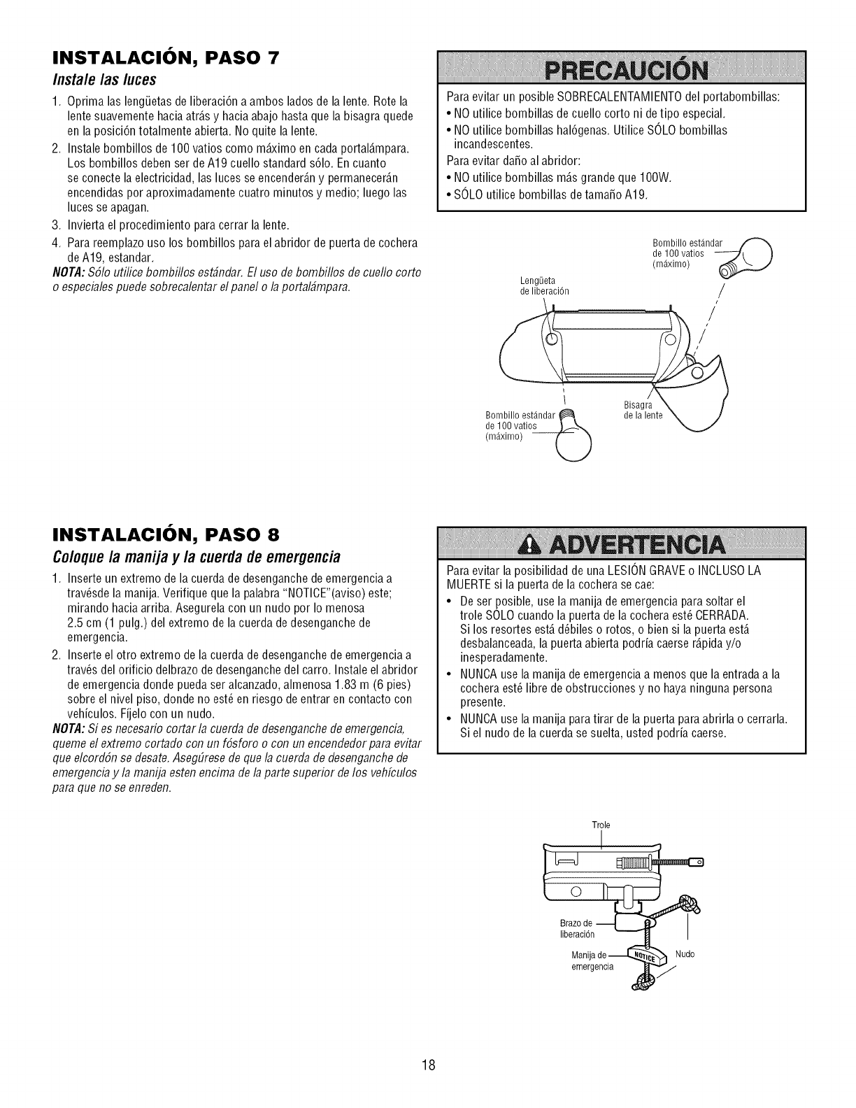
INSTALACION, PASO 7
Instale /as luces
1. Oprima las lengiJetasde liberaci6n a ambos lados de la lente. Rotela
lente suavemente haciaatr_.sy haciaabajo hasta que la bisagra quede
en la posici6n totalmente abierta. No quite la lente.
2. Instale bombillos de 100 vatios como mb<imo en cada portal_.mpara.
Los bombillos debenser deA19 cuello standard s61o.Encuanto
se conecte la electricidad, las luces se encender_.ny permanecer_.n
encendidaspor aproximadamente cuatro minutos y medio; luego las
luces se apagan.
3. Invierta el procedimiento para cerrar la lente.
4. Parareemplazo uso los bombillos para el abridor de puertade cochera
deA19, estandar.
NOTA:$61o utilice bombillos est#ndar. El uso de bombillos de cueflo corto
o especbles puede sobrecalentar el panel o la portal_mpara.
Paraevitar un posible SOBRECALENTAMIENTOdel portabombillas:
• NO utilice bombillas de cuello corto ni de tipo especial.
• NO utilice bombillas hal6genas.Utilice SOLObombillas
incandescentes.
Paraevitar dafio al abridor:
• NO utilice bombillas m_.sgrandeque 100W.
• SOLOutilice bombillas de tamafio A19.
Bombillo est_ndar
de 100 vatios ---_t )
(m_ximo)
LengQeta
de liberaci6n /
2 ,sa ra\ f
Bombillo est_ndar _ de la lente N, J
de 100 vatios )_-__
(m_ximo)
INSTALACION, PASO 8
Coloquela manijay la cuerdade emergencia
1. Inserteun extremo de la cuerda de desenganchede emergencia a
trav_sde la manija.Verifique que la palabra "NOTICE"(aviso) este;
mirando haciaarriba. Asegurela con un nudo por Io menosa
2.5 cm (1 pulg.) delextremo de la cuerda dedesenganchede
emergencia.
2. Inserteel otro extremo de la cuerda de desenganchedeemergencia a
tray,s del orificio delbrazo de desenganchedel carro. Instaleel abridor
de emergencia donde pueda ser alcanzado,almenosa 1.83 m (6 pies)
sobre el nivel piso, donde no est_ en riesgo de entrar en contacto con
vehiculos. Fijelo con un nudo.
NOTA:Si es necesario cortar la cuerda de desenganchede emergencia,
queme el extremo cortado con un f6sforo o con un encendedorpara evitar
que elcord6n se desate.AsegEiresede que la cuerda de desenganchede
emergenciay la manija esten encima de la parte superior delos vehfculos
para que no se enreden.
Paraevitar la posibilidad de una LESIONGRAVEo INOLUSOLA
MUERTEsi la puerta de la cochera se cae:
• Deser posible, usela manija de emergencia para soltar el
trole SOLOcuando la puerta de la cochera est_ CERRADA.
Si los resortes est,.d_biles o rotos, o bien si la puerta est,.
desbalanceada,la puerta abierta podria caerser_.piday/o
inesperadamente.
• NUNCAusela manija de emergenciaa menosque la entradaa la
cochera est_ libre de obstrucciones y no haya ninguna persona
presente.
• NUNCAusela manija paratirar de la puerta para abrirla o cerrarla.
Si el nudo de la cuerda se suelta, usted podria caerse.
Trole
• I
emergencia )71./,
18
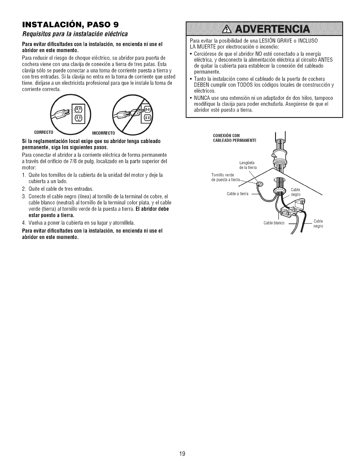
INSTALACION, PASO 9
Requisitospara la instalaci6nel ctrica
Para evitar dificultadescon la instalaci6n, no enciendani use el
abridor en este momento
Para reducir el riesgo de choque el@trico, su abridor para puerta de
cochera viene con una clavija de conexi6n a tierra detres patas. Esta
clavija s61ose puede conectar a unatoma de corriente puestaa tierra y
con tres entradas. Si laclavija no entra en la toma decorriente que usted
tiene, dirijase a un electricista profesional para que le instale la toma de
corriente correcta.
Si la reglamentaci6n local exige que su abridortenga cableado
permanente, siga los siguientespasos.
Paraconectar el abridor a lacorriente el@trica de forma permanente
a trav6s del orificio de 7/8 de pulg. Iocalizadoen la parte superior del
motor:
1. Quite los tornillos de la cubierta de la unidad del motor y deje la
cubierta a un lado.
2. Quite el cable detres entradas.
3. Conecteel cable negro (linea) al tornillo de laterminal de cobre, el
cable blanco (neutral) al tornillo de laterminal color plata,y el cable
verde (tierra) al tornillo verde de la puestaa tierra. El abridor debe
estar puesto a tierra.
4. Vuelvaa poner la cubierta ensu lugar y atornillela.
Para evitar dificultadescon la instalaci6n, no enciendani use el
abridor en este momento
Paraevitar la posibilidad de una LESIONGRAVEo INCLUSO
LA MUERTEpor electrocuci6n o incendio:
•Cerci6rese de que el abridor NOest_ conectado a la energia
el@trica, y desconectela alimentaci6n el@trica al circuito ANTES
de quitar la cubierta paraestablecer la conexi6n del cableado
permanente.
• Tanto la instalaci6n como el cableado de la puerta de cochera
DEBENcumplir con TODOSlos c6digos localesde construcci6n y
el@tricos.
• NUNCAuse una extensi6n ni un adaptador de dos hilos, tampoco
modifique la clavija para poder enchufarla. Aseg_rese de que el
abridor est_ puesto a tierra.
CONEXION CON
CABLEADO PERIVIANENTE
Leng_]eta
de la tierra
Tornillo verde
de puesta atierra_
Cable
Cable atierra . negro
Cable blanco Cable
negro
19
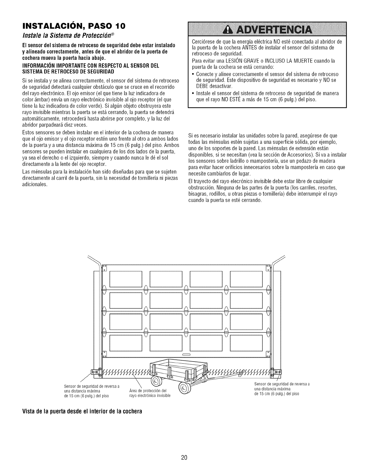
INSTALACION, PASO 10
Insta/e la Sistemade Protecci6n®
Elsensordelsistemaderetrocesodeseguridaddebeestarinstalado
y alineadocorrectamente,antesdequeel abridordela puertade
cocheramuevala puertahaciaabajo.
INFORMACIONIMPORTANTECONRESPECTOALSENSORDEL
SISTEMADERETROCESODESEGURIDAD
Si se instala y se alinea correctamente, el sensor del sistema de retroceso
de seguridad detectar_,cualquier obst_.culoque se cruce en el recorrido
del rayo electr6nico. El ojo emisor (el que tiene la luz indicadora de
color _.mbar)envia un rayo electr6nico invisible al ojo receptor (el que
tiene la luz indicadora de color verde). Si alg_n objeto obstruyera este
rayo invisible mientras la puerta se est,. cerrando, la puerta se detendr_.
autom_.ticamente,retroceder_,hasta abrirse por completo, y la luz del
abridor parpadear_,diezveces.
Estos sensores se deben instalar en el interior de la cochera de manera
que el ojo emisor y el ojo receptor est_n uno frente al otro a ambos lados
de la puerta y a una distancia m_ima de15 cm (6 pulg.) del piso. Ambos
sensores se pueden instalar en cualquiera de los dos lados de la puerta,
ya seael derecho o el izquierdo, siempre y cuando nunca le d_el sol
directamente a la lente del ojo receptor.
Las m_nsulas para la instalaci6n han sido disefiadas paraque se sujeten
directamente al carril de la puerta, sin la necesidadde tornilleria ni piezas
adicionales.
Cerci6rese de que la energia el@trica NOest_ conectada al abridor de
la puerta de la cochera ANTESde instalar el sensor del sistema de
retroceso de seguridad.
Paraevitar una LESIONGRAVEo INCLUSOLA MUERTEcuando la
puerta de la cochera se est,. cerrando:
• Conectey alinee correctamente el sensor del sistema de retroceso
de seguridad. Estedispositivo de seguridad es necesario y NOse
DEBEdesactivar.
• Instale el sensor del sistema de retroceso de seguridad de manera
que el rayo NO ESTI_ a m_.sde 15 cm (6 pulg.) del piso.
Si es necesario instalar las unidades sobre la pared, aseg_rese de que
todas las m_nsulas est_n sujetas a una superficie s61ida,por ejemplo,
uno de los soportes de la pared. Las m_nsulas de extensi6n est_.n
disponibles, si se necesitan (vea la secci6n de Accesorios). Siva a instalar
los sensores sobre ladrillo o mamposteria, use un pedazode madera
para evitar hacerorificios innecesarios sobre la mamposteria en caso que
necesitecambiarlos de lugar.
Eltrayecto del rayo elecr6nico invisible debe estar libre de cualquier
obstrucci6n. Ninguna de las partes de la puerta (los carriles, resortes,
bisagras, rodillos, u otras piezaso tornilleria) debe interrumpir el rayo
cuando la puerta se est_ cerrando.
! !÷ 1÷[ !÷[
[ !o lo[ !o[ !Jll
iii?_i!eniigumUl!:)_ ead,;irse2ersaa rAar;oe,ad! P :°fnei_vl_ 'b,e _ iii?_i!e(i? ui! .i_ e_; its(2ersaa
Vista de la puerta desdeel interiorde la cochera
2O
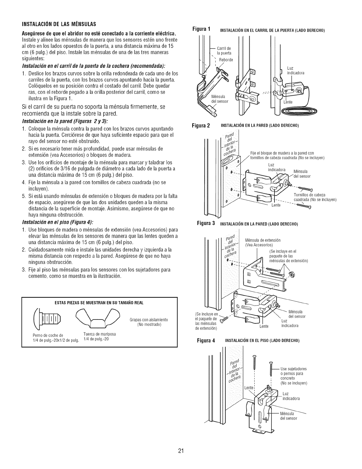
INSTALACIONDE LASMENSULAS
AsegOresede que el abridor no est_ conectadoa la corrienteel_ctrica.
Instale y alinee las m_nsulas de manera que los sensores est_n uno frente
al otro en los lados opuestos de la puerta,a una distancia mD.ximade 15
cm (6 pulg.) del piso. Instale las m_nsulas de una delas tres maneras
siguientes:
Instalaci#n en el carril de la puerta de la cochera (recomendada):
1. Deslice los brazoscurvos sobre la orilla redondeadade cada uno de los
carriles de la puerta, con los brazos curvos apuntando hacia la puerta.
Col6quelos en su posici6n contra el costado del carril. Debequedar
ras, con el reborde pegado a la orilla posterior del carril, como se
ilustra en la Figura 1.
Si el carril de su puerta no soporta la m6nsula firmemente, se
recomienda que la instale sobre la pared.
Instalaci#n en la pared (Figuras 2 y 3):
1. Coloquela m_nsula contra la pared con los brazos curvos apuntando
hacia la puerta. Cerci6rese de que hayasuficiente espacio para que el
rayo del sensor no est_ obstruido.
2. Si es necesariotener m_.sprofundidad, puede usar m_nsulas de
extensi6n (vea Accesorios) o bloques de madera.
3. Use los orificios de montaje de la m_nsula para marcar y taladrar los
(2) orificios de 3/16 de pulgada dedi_.metroa cada lado de la puerta a
una distancia m_.ximade 15 cm (6 pulg.) del piso.
4. Fijela m_nsulaa la pared con tornillos de cabezacuadrada (no se
incluyen).
5. Si estD.usando m_nsulas de extensi6n o bloques de maderapor la falta
de espacio,aseg0resede que las dos unidades quedena la misma
distancia de la superficie de montaje. Asimismo, aseg0resede que no
haya ninguna obstrucci6n.
Instalaci#n en el piso (Figura4):
1. Use bloques de maderao m_nsulas de extensi6n (veaAccesorios) para
elevar las m6nsulas de los sensores de manera que las lentes queden a
una distancia mD.ximade 15 cm (6 pulg.) del piso.
2. Cuidadosamentemida e instale las unidades derechay izquierdaa la
misma distancia con respecto a la pared.Aseg0rese de que no haya
ninguna obstrucci6n.
3. Fijeal piso las m_nsulas para los sensores con los sujetadores para
cemento, como se muestra en la ilustraci6n.
ESTAS PIEZAS SE MUESTRAN EN SUTAMANO REAL
Perno de coche de Tuerca de mariposa
1/4 de pulg.-20xl/2 de pulg. 1/4 de pulg.-20
Grapas con aislamiento
(No mostrado)
Figura 1
-- Carril de
[J[ . lapuerta
I-il _ Reborde
L_ 'J
INSTALACI6N ENEL CARRIL DELA PUERTA(LADO DERECHO)
Luz
indicadora
Figura2 INSTALACI6N EN LA PARED(LADO DERECRO}
%Fije el bloque de madera a la pared con
tornillos de cabezacuadrada (No se incluyen)
Luz
indicadora M6nsula
des nsor
_Tornillos de cabeza
__ !_.._.__J _...... cuadrada (No se incluyen)
Lente .... "_
Figura3 INSTALADii_N ENLA PARED(LADO DERECHO)
p_redr!_l M6nsula de extension
_riorq (Vea Accesorios)
'c_;!i_i'_ I _ (pmSaiii!i_ !n_:ens'0n)
(Seincluyeen ,_( _.,,,__..//'%,,, _ M,,6,nsula
de extensi6n) Lente indicadora
Figura4 iNSTALACI6N EN EL PISO(LADO DERECRO)
_ Use sujetadores
o pernos para
. concreto
i(No se incluyen)
Luz
indicadora
del sensor
J
21

MONTAJEY CABLEADODELOSSENSORESDELSISTEMADE
SEGURIDADDEREVERSA
1. Deslice la cabezade un perno de coche de 1/4-20xl/2 de pulgada
dentro de la ranura de los sensores. Usetuercas demariposa para
sujetar los sensores alas m_nsulas, con las lentes de cadasensor
frente a frente a ambos lades de la puerta.Cerci6rese de que la
extensi6n de la m_nsula no obstruya las lentes (Figura 5).
2. Apriete lastuercas de mariposa a mane.
3. Lleve los cables de los dos sensores al abridor. Utilice grapas con
aislamiento parasujetar el cablea la pared y al cielo raso.
4. Pele 11 mm (7/16 de pulg.) delaislamiento en cada juego de cables.
Separelos alambres blanco y blanco/negro los suficiente para que
pueda conectarlos alas terminales deconexi6n r_.pidadel abridor, de
la forma siguiente. Tuerzajuntos los cables del mismo color. Inserte
los cablesen los orificios deconexi6n r_.pida:el blanco al blanco y el
blanco/negro al gris (Figura 6).
COMOALINEARLOSSENSORESDESEGURIDADDEREVERSA
1. Conecteel abridor; las luces del sensor emisory del sensor receptor
se debende encendery permanecer encendidassi todas las
conexiones del cableado y la alineaci6n se ban hecho correctamente.
La luz _.mbardel sensor que emite el rayo se encender#aunque est_
obstruido o fuera de alineaci6n, pero si la luz verde del sensor receptor
del rayo est,. apagada, parpadeao se ve baja, (y no hay ninguna
obstrucci6n en el recorrido del rayo de luz invisible), ser_.necesario
alinearlos.
2. Afloje latuerca de mariposa del sensor emisory reajuste el sensor.
Apunte directamente al otro sensory apriete la tuerca de mariposa.
3. Afloje latuerca de mariposa del sensor receptor del rayo, y reajuste
hasta que reciba el rayo del sensor emisor. Una vez que la luzverde
brille continuamente, apriete la tuerca de mariposa.
Figura5
Perno de coche de "_¥"_'_
1/4 de pulg.-20xl/2 de pulg.
Tuerca de mariposa
DIAGNOSTICODEFALLASCONRESPECTOA LOSSENSORESDEL
SISTEIVIADESEGURIDADDEREVERSA
1. Si la luz verde del sensor que emite el rayo nopermanece encendida
despu6s de la instalaci6n, verifique Io siguiente:
• El suministro de corriente el_ctrica al abridor.
• Que hayaun corto circuito enalguno de los cables, ya seael
blanco, o el blanco/negro. Esto ocurre frecuentemente donde bay
alguna grapa.
• AIg_n error en la conexi6n de los cables de los sensores al abridor.
• AIg_n cable rote.
2. Si la luz indicadora del sensor que emite el rayo enciendey permanece
encendida, pero la luz del otro sensor no enciende:
• Verifique que est_n correctamente alineados.
• Verifique que no hayaun alambre rote enel cabledel sensor
receptor.
3. Si la luz indicadora del sensor receptor esta d_bil o baja, verifique la
alineaci6n de los sensores.
NOTA:Si la trayectoria del rayo invisible se ve obstruida o est_ fuera de
alineaciSn,al tratar decerrar la puerta #stase abrir# autom#ticamente.
Si lapuerta est# abierta, simplemente no sepodr# cerrar,y las luces de
abridor parpadear#ndiez veces. Veala p#gina 20.
Figura6
Cable de campana Cielo raso con acabado
Conecte el cable alas
terminales de conexi6n r_pida
Cable de campana 1. Pele el cable
11 mm (7/16 de pulg.)
2. Tuerza juntos los cables
del mismo color
Sensor de seguridad de reversa
_,reade protecciOn del
Sensor de seguridad de reversa rayo electr6nico invisible
22
3. Para introducir o soltar el
cable, empuje la leng_]eta
hacia dentro con la punta
de un destornillador
Rojo Blanco Gris
Terminales de conexi6n r_pida
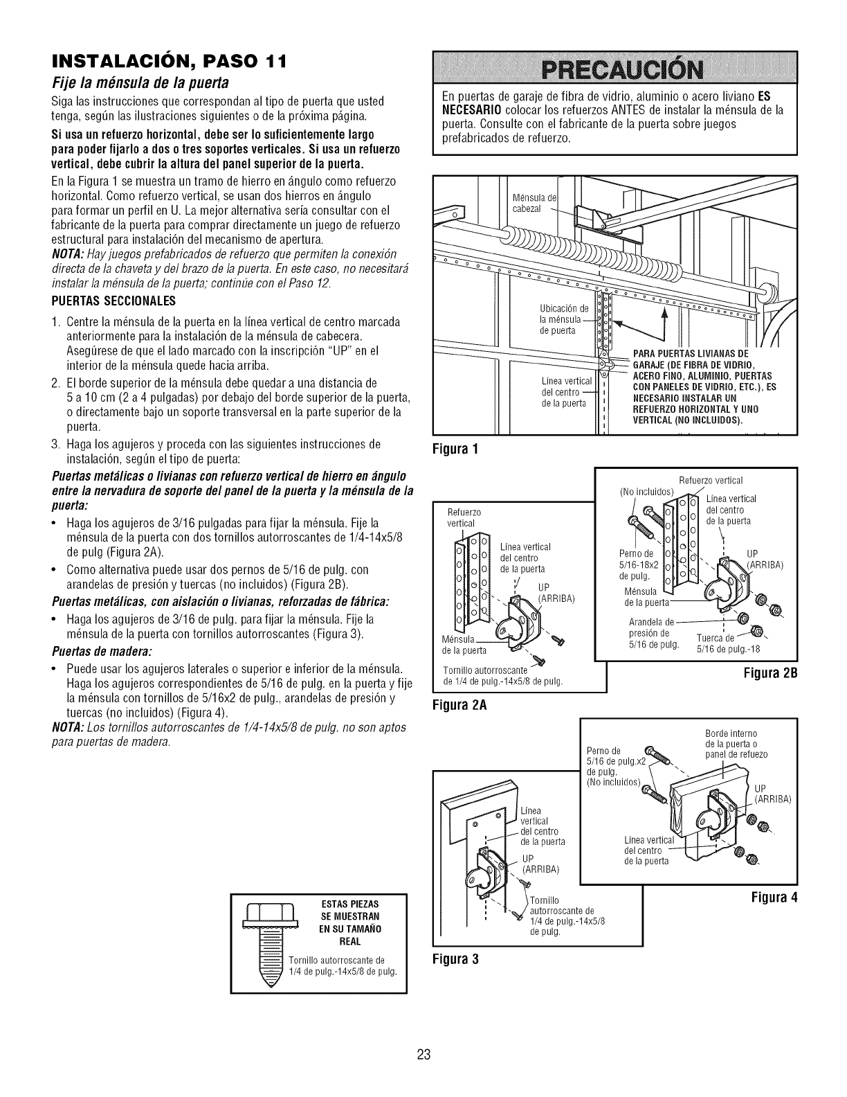
INSTALACION, PASO 11
Fije /a m_nsu/ade/a puerta
Siga las instrucciones que correspondan al tipo de puerta que usted
tenga, seg_n las ilustraciones siguientes o de la pr6xima p@ina.
Si usa unrefuerzo horizontal,debe ser Io suficientemente largo
para poderfijarlo a dos otres soportesverticales. Si usa unrefuerzo
vertical, debe cubrir la altura del panel superiorde la puerta.
Enla Figura 1 se muestra un tramo de hierro en_.ngulocomo refuerzo
horizontal. Como refuerzo vertical, se usan dos hierros en_.ngulo
paraformar un perfil enU. La mejor alternativaseria consultar con el
fabricante de la puerta para comprar directamente un juego de refuerzo
estructural parainstalaci6n del mecanismo de apertura.
NOTA:Hayjuegos prefabricados derefuerzo quepermiten la conexiSn
directa de la chavetay del brazode la puerta. En estecaso, no necesitar#
instalar la m#nsula de la puerta; continGecon el Paso 12.
PUERTASSECCIONALES
1. Centrela m_nsula de la puertaen la lineavertical de centro marcada
anteriormente para la instalaci6n de la m_nsula de cabecera.
Aseg_resede que el lado marcado con la inscripci6n "UP" en el
interior de la m_nsula quede haciaarriba.
2. El borde superior de la m_nsuladebe quedara una distancia de
5 a 10 cm (2 a 4 pulgadas) por debajo del borde superior de la puerta,
o directamente bajo un soportetransversal en la parte superior de la
puerta.
3. Hagalos agujeros y proceda con las siguientes instrucciones de
instalaci6n, seg_n el tipo de puerta:
Puertasmet_licas o/ivianas conrefuerzo verticalde hierro en _ngulo
entre/a nervadurade soportede/panel de/a puerta y/a m_nsu/a de/a
puerta:
•Hagalos agujeros de3/16 pulgadas parafijar la m_nsula. Fije la
m_nsula de la puerta con dos tornillos autorroscantes de 1/4-14x5/8
de pulg (Figura 2A).
• Como alternativa puede usar dos pernos de 5/16 de pulg. con
arandelasde presi6n y tuercas (no incluidos) (Figura 2B).
Puertasmet_licas, conaislaci#n o livianas, reforzadas de f_brica:
• Hagalos agujeros de 3/16 de pulg. parafijar la m_nsula. Fijela
m_nsula de la puerta con tornillos autorroscantes (Figura 3).
Puertas de madera:
• Puedeusar los agujeros lateraleso superior e inferior de la m_nsula.
Hagalos agujeros correspondientes de 5/16 de pulg. en la puerta y fije
la m_nsula con tornillos de 5/16x2 depulg., arandelas de presi6n y
tuercas (no incluidos) (Figura 4).
NOTA:Los tomillos autorroscantes de 1/4-14x5/8 de pulg. no son aptos
para puertas de madera.
ESTAS PIEZAS
SE MUESTRAN
EN SU TAMANO
REAL
Tornillo autorroscante de
1/4 de pulg.-14x5/8 de pulg.
En puertas de garaje de fibra de vidrio, aluminio o acero liviano ES
NECESARIOcolocar los refuerzos ANTESde instalar la m_nsula de la
puerta. Consulte con el fabricante de la puerta sobre juegos
prefabricados de refuerzo.
Ubicaci6n de
de puerta
Linea vertical
del centro
de la puerta
PARA PUERTASLIVIANAS DE
GARAJE(DE FIBRA DEVIDRiO,
ACERO FINO, ALUMINIO, PUERTAS
CONPANELESDE Vii]RIO, ETC.), ES
NECESARIOINSTALARUN
REFUERZOHORIZONTALYNNO
VERTICAL (NO iNCLNIDOS}.
Figura 1
Refuerzo
vertical
Linea vertical
del centro
de la puerta
i/up
i_ ARRiBA)
M_nsula __" "_
de la puerta "_r_',,
Tornillo autorroscante i_
de 1/4 de pulg.-14x5/8 de pulg.
Figura 2A
Refuerzo vertical
(No/incluidO_o_ Linea vertical
L&lo]lJ_,l eel centro
%lollilide i puerta
Pernode PN,J'ot. L up
s/16-18x2IOt#I:I". :' (ARR BA)
pu, Io[lCJa-,,A- ¥q
M@sula _ (('_ _l_JJ"
de la puerta
Arandela de_
presi6n de Tuerca'de _-
5/16 de pulg. 5/16 de pulg.-18
Figura2B
Linea
vertical
centro
de la puerta
UP
(ARRIBA)
_Tornillo
"_/autorroscante de
1/4 de pulg.-14x5/8
de pulg.
Borde interno
, _ de la puerta o
erno,ae , ^_,_ panel de refuezo
/lb aepulg.xz _ L,_..
de pulg. \ "" ._.._
No,nc,u,dos /
Linea vertica__ _ _\
del centro _;,"J_,_
de la puerta "_ '_"_.
Figura 4
Figura 3
23
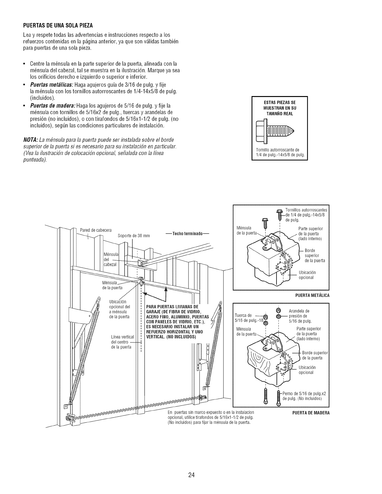
PUERTASDE UNASOLAPIEZA
Lea y respete todas las advertencias e instrucciones respecto a los
refuerzos contenidas en la p@ina anterior, ya que son v_.lidastambi_n
para puertas de unasola pieza.
• Centrela m_nsula en la parte superior de la puerta,alineada con la
m_nsula del cabezal,tal se muestra en la ilustraci6n. Marque ya sea
los orificios derecho e izquierdo o superior e inferior.
•Puertas met_licas: Hagaagujeros guia de 3/16 de pulg. y fije
la m_nsula con los tornillos autorroscantes de 1/4-14x5/8 de pulg.
(incluidos).
•Puertas de madera: Haga los agujeros de 5/16 de pulg. y fije la
m_nsula con tornillos de 5/16x2 de pulg., tuercas y arandelas de
presi6n (no incluidos), o con tirafondos de5/16x1-1/2 de pulg. (no
incluidos), seg_nlas condiciones particulares de instalaci6n.
NOTA:La m#nsu/a para /a puerta puede ser insta/ada sobre el borde
superior de/a puerta si es necesario para su insta/aciSnen particular.
(Vea/a i/ustraciSn de co/ocaciSnopciona/, sefia/ada con/a ffnea
punteada).
ESTASPIEZAS SE
[VIUESTRANEN SU
TAMANO REAL
Tornilloautorroecantede
1/4 de pulg.-14x5/8 de pulg.
Pared de cabecera
de la puerta
Soporte de 38 mm
opcional del
a m@sula
de la puerta
Linea vertical
del centro
de la puerta
PARA PUERTASLIVIANAS DE
GARAJE(BE FIBRA DEVIDRIO,
ACEROFINO, ALUMINIO, PUERTAS
CONPANELESDE Vii)RIO, ETC.),
ES NECESARIOINSTALAR tin
REFUERZOHORIZONTALY UNO
VERTICAL. (NO INCLUIDOS
M@sula
de la
En puertas sin marco expuesto o en la instalacion
opcional, utilice tirafondos de 5/16x1-1/2 de pulg.
(No incluidos) para fijar la m@sula de la puerta.
To rnillos autorroscantes
de 1/4 de pulg.-14x5/8
de pulg.
, Parte superior
de la puerta
(lado interno)
Borde
superior
de la puerta
UbicaciOn
opcional
PUERTAIVIETALICA
Tuerca de
5/16 de pulgMS_
M@sula I
dela
i_ Arandela de
presiCn de
5/16 de pulg.
Parte superior
de la puerta
(lado interno)
Borde superior
de la puerta
UbicaciOn
opcional
-Perno de 5/16 de pulg.x2
de pulg. (No incluidos)
PUERTADEIVIADERA
24
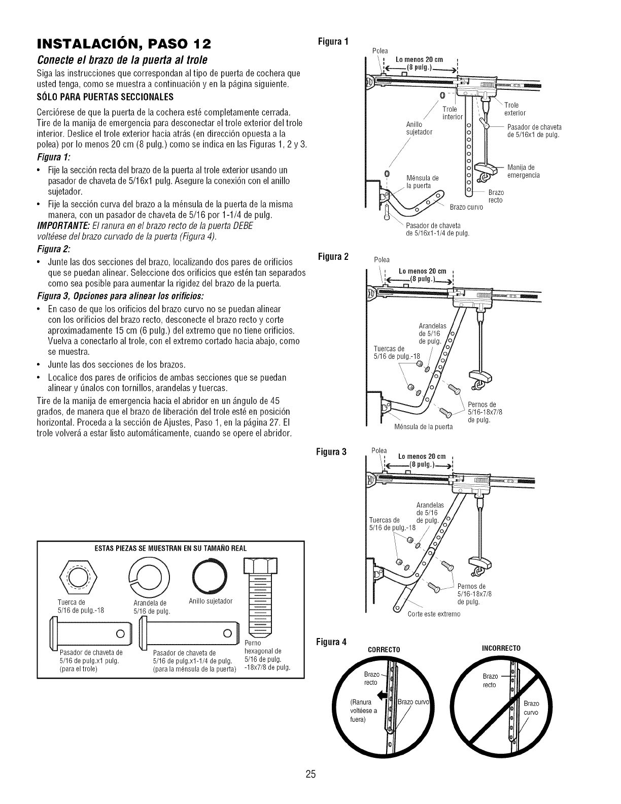
INSTALACION, PASO 12
Conectee/brazo de la puerta a/trole
Siga las instrucciones que correspondan al tipo de puerta decochera que
usted tenga, como se muestra a continuaci6n yen la p@ina siguiente.
SOLOPARAPUERTASSECCIONALES
Cerci6rese de que la puerta de la cochera est6 completamente cerrada.
Tire de la manija de emergencia paradesconectar el trole exterior del trole
interior. Deslice el trole exterior haciaatr_.s(en direcci6n opuesta a la
polea) por Io menos20 cm (8 pulg.) como se indica en las Figuras 1,2 y 3.
Figura 1:
•Fijela secci6nrectadel brazode la puertaal trole exterior usando un
pasadorde chavetade 5/16xl pulg. Asegurelaconexi6n con el anillo
sujetador.
• Fijela secci6n curva del brazo a la m6nsula de la puerta de la misma
manera, con un pasadorde chavetade 5/16 por 1-1/4 de pulg.
IMPORTANTE:El ranura enel brazorecto dela puerta DEBE
volt#esedel brazo curvado de lapuerta (Figura 4).
Figura2:
• Junte lasdos secciones del brazo, Iocalizandodos paresde orificios
que se puedan alinear. Seleccionedos orificiosque est6n tan separados
como sea posible para aumentar la rigidez del brazode la puerta.
Figura 3, Opcionespara a/inear los orificios:
• En caso de que los orificios del brazo curvo nose puedan alinear
con los orificios del brazorecto, desconecteel brazo recto y corte
aproximadamente 15 cm (6 pulg.) del extremo que no tiene orificios.
Vuelvaa conectarlo al trole, con el extremo cortado hacia abajo, como
se muestra.
• Junte las dos secciones de los brazos.
• Localice dos paresde orificios deambas secciones que se puedan
alineary _nalos con tornillos, arandelasy tuercas.
Tire de la manijade emergencia haciael abridor en un _.ngulode 45
grados, de maneraque el brazo de liberaci6n del trole est6 en posici6n
horizontal. Proceda a la secci6n de Ajustes, Paso 1, en la p_.gina27. El
trole volver_,a estar listo autom_.ticamente,cuando se opere elabridor.
Figura1
Figura2
Trol,
inte_
Anillo
sujetador
M@sula de
puerta
Brazo curvo
\ Pasador de chaveta
de 5/16x1-1/4 de pulg.
Polea
_,_ inenos cm
Lo 20
Arandelas J
de 5/16 /(
de pulg./o
Tuercas de //o/
5/16 de pulg.-18 / /o°/
M@sulade lapuerta
\Trole
Brazo
recto
Pernos de
5/16-18x7/8
de pulg.
exterior
Pasador de chaveta
de 5/16xl de pulg.
Manija de
emergencia
ESTAS PIEZASSE [VlUESTRANENSU TA[VlA_IOREAL
@
Tuerca de
5/16 de pulg.-18
_Pasadordechaveta O1 _
5/16 de pulg.xl pulg.
(para el trole)
Arandela de
5/16 de pulg.
O
Anillo sujetador
oU
Pasador de chaveta de
5/16 de pulg.xl-1/4 de pulg.
(para la m6nsula de la puerta)
Perno
hexagonal de
5/16 de pulg.
-18x7/8 de pulg.
Figura3
Figura4
Polea
aLo menos 20 cm
Arandelas / / !
de 5/16 /_ /
ruercas de de pulg. _o/
5/16 de I_8 !L_oZ
[ _ _,___--' Pernos de
j//v 5/16-18x7/8
'_ Corteeeteextremo
CORRECTO INCORRECTO
25
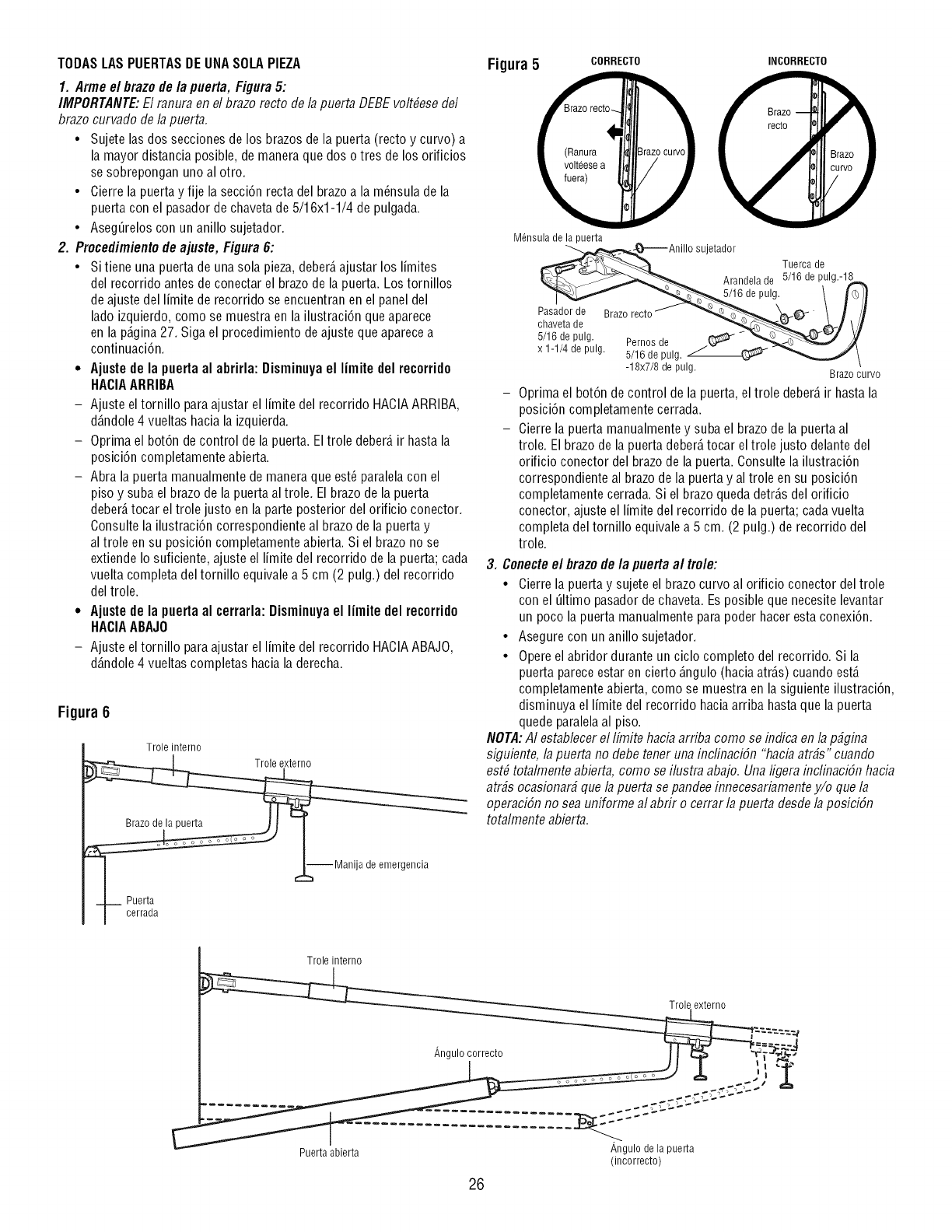
TODASLASPUERTASDEUNASOLAPIEZA
1. Arme el brazo de la puerta, Figura5:
IMPORTANTE:El ranura enel brazo recto de/a puerta DEBEvo/t#esedel
brazo curvado de lapuerta.
• Sujete las dos secciones de los brazosde la puerta (recto y curvo) a
la mayor distancia posible, de maneraque dos o tres de los orificios
se sobrepongan uno al otro.
• Cierre la puerta y fije la secci6n recta del brazoa la m_nsula de la
puerta con el pasadorde chavetade 5/16x1-1/4 de pulgada.
• Aseg_relos con un anillo sujetador.
2. Procedimientode ajuste, Figura 6:
• Si tiene una puerta de unasola pieza, deber_,ajustar los limites
del recorrido antes de conectar el brazode la puerta. Los tornillos
de ajuste del limite de recorrido se encuentran en el panel del
lado izquierdo, como se muestra en la ilustraci6n que aparece
en la p_.gina27. Siga el procedimiento deajuste que aparecea
continuaci6n.
• Ajustede la puerta al abrirla: Disminuyael limite del recorrido
HACIAARRIBA
- Ajuste el tornillo paraajustar el limite del recorrido HACIAARRIBA,
d_.ndole4 vueltas hacia la izquierda.
- Oprima el bot6n de control de la puerta. El trole deber_,ir hasta la
posici6n completamente abierta.
- Abra la puerta manualmente de maneraque est_ paralelacon el
piso y suba el brazo de la puerta al trole. Elbrazo de la puerta
deber_,tocar el trole justo en la parte posterior del orificio conector.
Consulte la ilustraci6n correspondiente al brazode la puerta y
al trole en su posici6n completamente abierta. Si el brazo no se
extiende Io suficiente, ajuste el limite del recorrido de la puerta; cada
vuelta completa del tornillo equivale a 5 cm (2 pulg.) del recorrido
del trole.
• Ajustede la puerta al cerrarla: Disminuyael limite del recorrido
HACIAABAJO
- Ajuste el tornillo paraajustar el limite del recorrido HACIAABAJO,
d_.ndole4 vueltas completas hacia la derecha.
Figura 6
Trole interno
I cerrada ,_--Maniia deemergenci4_- Puerta a
Figura 5 CORRECTO INCORRECTO
)
Mensula de la puerta
_6 deAnill° sujetador
Tuerca de
Arandela de 5/16 de pulg.-18_
+,0 l/+ii
Pasadorde Brazorecto'_- '_';_",_c_----_--_ '_(_ \ //i
x 1-1/4 ae pulg. 5/16 de pulg. _ _'__ l
-18x7/8 de pulg. Brazo curvo
- Oprima el bot6n de control de la puerta,el trole deber_,ir hasta la
posici6n completamente cerrada.
- Cierrela puerta manualmentey suba el brazode la puerta al
trole. Elbrazo de la puerta deber_,tocar el trole justo delantedel
orificio conector del brazode la puerta. Consulte la ilustraci6n
correspondiente al brazo de la puerta y altrole en su posici6n
completamente cerrada. Si el brazo queda detr_.sdel orificio
conector, ajuste el limite del recorrido de la puerta; cada vuelta
completa del tornillo equivale a 5 cm. (2 pulg.) de recorrido del
trole.
3. Conecteel brazode la puerta al trole:
• Cierre la puerta y sujete el brazo curvo al orificio conector del trole
con el Qltimo pasadorde chaveta. Esposible que necesite levantar
un poco la puerta manualmente parapoder hacer estaconexi6n.
• Asegure con unanillo sujetador.
• Opereel abridor durante un ciclo completo del recorrido. Si la
puerta parece estar en cierto _.ngulo(hacia atr_.s)cuando est,.
completamente abierta, como se muestra en la siguiente ilustraci6n,
disminuya el limite del recorrido haciaarriba hasta que la puerta
quede paralelaal piso.
NOTA:AI establecerel Ifmite hacb arriba como se indica en /a p_gina
siguiente, /apuerta no debe tener una inc/inaci6n "haciaatr_s" cuando
est# tota/mente abierta, como se i/ustra abajo. Una /igera inc/flTaci6nhacia
atr_s ocasionar_ que /a puerta se pandeeinnecesariamentey/o que /a
operaci6n no sea uniforme a/ abrir o cerrar /a puerta desde /a posici6n
tota/mente abierta.
Trole interno
Trole externo
_,ngu,o correcto !_
(incorrecto)
26
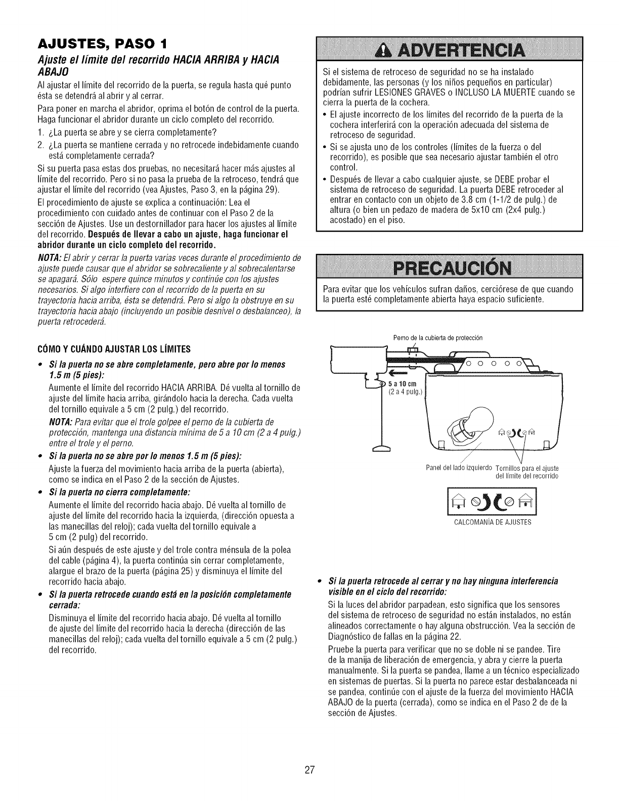
AJUSTES, PASO 1
Ajuste e//imite de/recorrido HACIA ARRIBA y HACIA
ABAJO
AI ajustar el limite del recorrido de la puerta, se regula hasta qu6 punto
_sta se detendr_,al abrir y al cerrar.
Paraponer en marcha el abridor, oprima el bot6n de control de la puerta.
Hagafuncionar el abridor durante un ciclo completo del recorrido.
1. &La puerta se abre y se cierra completamente?
2. &La puerta se mantiene cerrada y no retrocede indebidamente cuando
est,. completamente cerrada?
Si su puerta pasa estasdos pruebas, no necesitar_,hacer m_.sajustes al
limite del recorrido. Pero si no pasa la pruebade la retroceso, tendr_,que
ajustar el limite del recorrido (veaAjustes, Paso3, en la p_.gina29).
El procedimiento de ajuste se explica a continuaci6n: Lea el
procedimiento con cuidado antes de continuar con el Paso 2 de la
secci6n de Ajustes. Useun destornillador para hacerlos ajustes al limite
del recorrido. Despu_sde Ilevar a caboun ajuste, hagafuncionarel
abridor duranteun ciclo completodel recorrido.
NOTA:El abrir y cerrar lapuerta varias veces durante el procedimiento de
ajuste puede causar que el abridor se sobrecalientey al sobrecalentarse
se apagar_. $51o esperequince minutos y contin_e con los ajustes
necesarios. Si algo interfiere con el recorrido de la puerta en su
trayectoria hacb arriba, #stase detendr_.Peru si algo la obstruye en su
trayectoria hacb abajo (incluyendo un posible desnivel o desbalanceo),la
puerta retroceder_.
COMOY CUANDOAJUSTARLOSLIMITES
• Si la puerta no se abre completamente, pero abre pot Io menos
1.5 m (5 pies):
Aumente el limite del recorrido HACIAARRIBA. D_vuelta al tornillo de
ajuste del limitehaciaarriba, gir_.ndolohacia la derecha. Cadavuelta
del tornillo equivale a 5 cm (2 pulg.) del recorrido.
NOTA:Para evitar que el trole golpee el pemo de la cubierta de
protecciSn, mantenga una distancb mfi7imade 5 a 10cm (2 a 4 pulg.)
entre el trole y el pemo.
•Si la puerta no se abrepot Io menos 1.5 m (5pies):
Ajuste la fuerza del movimiento haciaarriba de la puerta (abierta),
como se indica enel Paso 2 de la secci6n de Ajustes.
•Si la puerta no cierra completamente:
Aumente el limite del recorrido hacia abajo. D_vuelta al tornillo de
ajuste del limitedel recorrido hacia la izquierda,(direcci6n opuesta a
lasmanecillas del reloj); cadavuelta del tornillo equivale a
5 cm (2 pulg) del recorrido.
Si a_n despu6s de este ajuste y del trole contra m6nsula de la polea
del cable (p_.gina4), la puerta continua sin cerrar completamente,
alargue el brazo de la puerta (p_.gina25) y disminuya el limite del
recorrido haciaabajo.
•Si la puerta retrocedecuandoest_ en la posici6ncompletamente
cerrada:
Disminuya el limite del recorrido hacia abajo. D_vuelta al tornillo
de ajuste del limite del recorrido hacia la derecha(direcci6n de las
manecillas del reloj); cada vuelta del tornillo equivale a 5 cm (2 pulg.)
del recorrido.
Si el sistema de retroceso de seguridad no se ha instalado
debidamente, las personas (y los niSos pequeSosen particular)
podrian sufrir LESIONESGRAVESo INCLUSOLA MUERTEcuando se
cierra la puerta de la cochera.
• El ajuste incorrecto de los limites del recorrido de la puerta de la
cochera interferir_,con la operaci6n adecuadadel sistema de
retroceso de seguridad.
• Si se ajusta uno de los controles (limites de la fuerza o del
recorrido), es posible que sea necesario ajustar tambi6n el otro
control.
• Despu6s de Ilevar a cabo cualquier ajuste, se DEBEprobar el
sistema de retroceso de seguridad. La puerta DEBEretroceder al
entrar en contacto con un objeto de 3.8 cm (1-1/2 de pulg.) de
altura (o bien un pedazode madera de 5x10 cm (2x4 pulg.)
acostado) en el piso.
Paraevitar que los vehiculos sufran daSos,cerci6rese de que cuando
la puerta est_ completamente abierta haya espacio suficiente.
Perno de la cubiertade proteccion
PaneldelladoizquierdoTomillosparaelajuste
dellimitedel recorrido
CALCOMANiA DEAJUSTES
Si la puerta retrocede al cerrar y no hay ningunainterferencia
visible en el ciclede/recorrido:
Si la luces del abridor parpadean,esto significa que los sensores
del sistema de retroceso de seguridad no est_.ninstalados, no est_.n
alineados correctamente o hayalguna obstrucci6n. Vea la secci6n de
Diagn6stico defallas en la p_.gina22.
Pruebe la puerta para verificar que no se doble ni se pandee.Tire
de la manija de liberaci6n de emergencia,y abray cierre la puerta
manualmente. Si la puerta se pandea, Ilame a un t_cnico especializado
en sistemas de puertas. Si la puerta no pareceestar desbalanceadani
se pandea,continue con el ajuste de lafuerza del movimiento HACIA
ABAJOde la puerta (cerrada), como se indica en el Paso 2 de de la
secci6n de Ajustes.
27
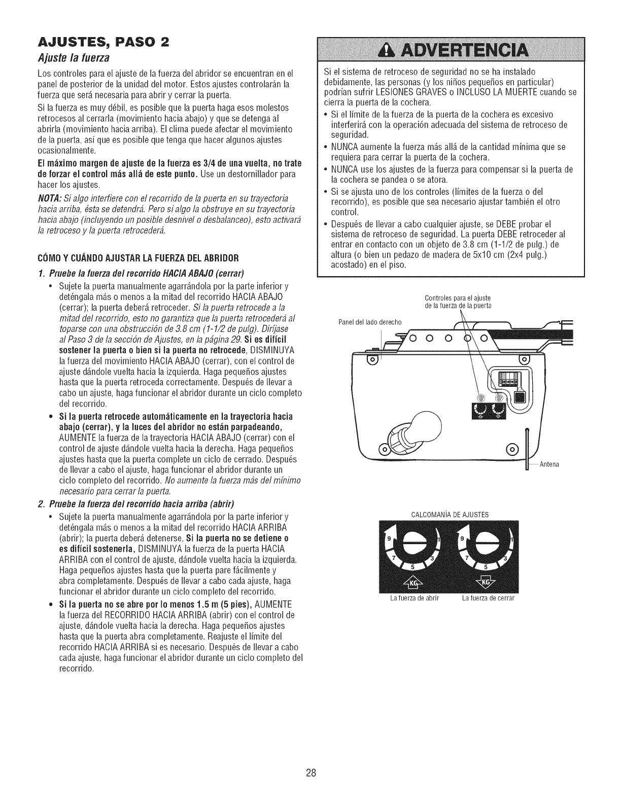
AJUSTES, PASO 2
Ajustela fuerza
Los controles parael ajuste de lafuerza del abridor se encuentran en el
panel de posterior de la unidad del motor. Estos ajustes controlar_,nla
fuerza que ser_,necesaria paraabrir y cerrar la puerta.
Si lafuerza es muy d_bil, es posible que la puerta haga esos molestos
retrocesos al cerrarla (movimiento haciaabajo) y que se detenga al
abrirla (movimiento haciaarriba). Elclima puedeafectar el movimiento
de la puerta, as[ que es posiNe quetenga que haceralgunos ajustes
ocasionalmente.
El m_ximo margen de ajuste de la fuerza es 3/4 de una vuelta, no irate
de forzar el controlm_s all_ de este punto. Useun destornillador para
hacer los ajustes.
NOT,d: Si algo interfiere con el recorrido de lapuerta ensu trayectoria
hacia arriba, bsta se detendr#, Perosi algo la obstruye en su trayectoria
hacia abajo (incluyendo un posible desnivel o desbalanceo),esto acfivad
la retrocesoy la puertaretroceder#.
COiVIOYCUANDOAJUSTARLAFUERZADELABRiDOR
1. Pruebe la fuerza del mcorfido HACIAABAJO(cerrad
•Sujete la puerta manualmente agarr_,ndolapor la parte inferior y
det_ngaia m_,so menosa la mitad dei recorrido HACIAABAJO
(cerrar); la puerta deber_,retroceder. Si la puerta retrocede a la
mitad del recorrido, esto no garantiza que la puerta retroceder# al
toparse con una obstrucci6n de 3.8 cm (1-1/2 de pulg). Dirfjase
al Paso 3 de la secci6n de Ajustes, en la p#gina 29. Si es dificil
sostenerla puerta o bien si la pueria no retrocede, DISMINUYA
la fuerza del movimiento HACIAABAJO(cerrar), con el control de
ajuste d6,ndolevuelta hacia la izquierda. Haga peque_osajustes
hasta que la puerta retroceda correctamente. Despu_s deilevar a
cabo unajuste, hagafuncionar ei abridor durante un ciclo completo
dei recorrido.
., Si la puerta retrocede autom_ticamente en la trayectofia hacia
abajo (cerrar), yla luces del abfidor no est_n parpadeando,
AUMENTEla fuerza de latrayectoria HACIAABAJO (cerrar) con el
control de ajuste d6,ndolevuelta hacia la derecha.Haga peque_os
ajustes hasta que la puerta complete un ciclo de cerrado. Despu_s
de Ilevar a cabo el ajuste, hagafuncionar el abfidor durante un
ciclo completo del recorrido. No aumente la fuerzarobs del mfnimo
necesario para cerrar la puerta.
2. Pruefle la fuerza del recorrido flacia arrifla (abrir)
•Sujete la puerta manualmente agarr_,ndolapor la parte inferior y
det_ngala m6,so menosa la mitad del recorrido HACIAARRIBA
(abrir); la puerta deber_,detenerse. Si la puerta no se detiene o
es dificil sostenefla, DISMINUYA lafuerza dela puerta HACIA
ARRIBAcon el control de ajuste, d6,ndolevuelta hacia la izquierda.
Hagapeque_os ajustes hastaque la puerta paref_.cilmentey
abra completamente. Despu_s de Ilevara cabo cadaajuste, haga
funcionar el abridor durante un ciclo completo dei recorrido.
,, Si la puerta no se abre per Io menos1.5 m(5 pies), AUMENTE
la fuerza del RECORRIDOHACIAARRIBA(abrir) con el control de
ajuste, d6,ndolevuelta hacia la derecha. Hagapeque_osajustes
hasta que la puerta abra completamente. Reajuste el limite del
recorfido HACIAARRIBAsi es necesafio. Despu_s deflevar a cabo
cada ajuste, hagafuncionar el abfidor durante un ciclo completo del
recorrido.
Si el sistema de retroceso de segufidad no se hainstahdo
debidamente, las personas (y los ni_os peque_os en particular)
podrian suffir LESIONESGRAVESo INCLUSOLA MUERTEcuando se
cierra la puerta de la cochera.
• Si el limite de la fuerza de la puerta de la cochera es excesivo
interferir_,con la operaci6n adecuadadel sistema de retroceso de
seguridad.
• NUNCAaumente la fuerza m_,sall6,de la cantidad minima que se
requiera para cerrar la puerta de la cochera.
•NUNCAuse los ajustes de lafuerza para compensar si la puerta de
la cochera se pandeao se atora.
• Si se ajusta uno de los controles (limites de la fuerza o del
recorrido), es posiNe que sea necesario ajustar tambi_n el otro
control.
•Despu_s de flevar a cabo cualquier ajuste, se DEBEprobar el
sistema de retroceso de seguridad. La puerta DEBEretroceder al
entrar en contacto con un objeto de 3.8 cm (1-1/2 de pulg.) de
altura (o bien un pedazode madera de 5x10 cm (2x4 pulg.)
acostado) en el piso.
Panel del lado derecho
Controles para el ajuste
de la fuerza de la puerta
O O
®
tena
CALCOMANiA DEAJUSTES
La fuerza de abrir La fuerza de cerrar
28
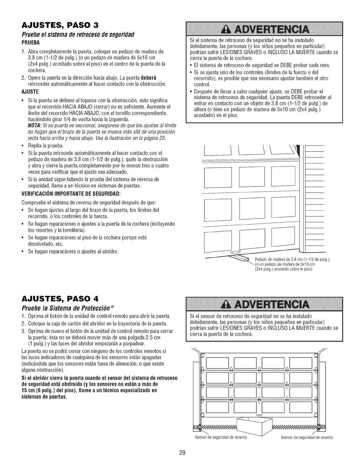
AJUSTES, PASO 3
Pruebeel sistemaderetrocesodeseguridad
PRUEBA
1. Abra completamente la puerta, coloque un pedazo de madera de
3.8 cm (1-1/2 de pulg.) (o un pedazode maderade 5x10 cm
(2x4 pulg.) acostado sobre el piso) en el centro de la puerta de la
cochera.
2. Opere la puerta en la direcci6n haciaabajo. La puerta deber_
retroceder autom_.ticamenteal hacer contacto con la obstrucci6n.
AJUSTE
•Si la puerta se detiene al toparse con la obstrucci6n, esto significa
que el recorrido HACIAABAJO(cerrar) no es suficiente. Aumente el
limite del recorrido HACIAABAJO,con eltornillo correspondiente,
haci6ndolo girar 1/4 de vuelta haciala izquierda.
NOTA:Si su puerta es seccional, asegEiresede que los ajustes al Ifmite
no hagan queel brazode la puerta se mueva m#s all# de unaposiciSn
recta haciaarriba y haciaabajo. Veala ilustraciSn enla p#gina 25.
• Repita la prueba.
• Si la puerta retrocede autom_.ticamenteal hacercontacto con el
pedazode madera de 3.8 cm (1-1/2 de pulg.), quite la obstrucci6n
y abra y cierre la puerta completamente por Io menos tres o cuatro
vecespara verificar que el ajuste seaadecuado.
• Si la unidad sigue fallando la prueba del sistema de reversa de
seguridad, Ilame a un t6cnico en sistemas depuertas.
VERIFICACIONIMPORTANTEDESEGURIDAD:
Compruebeel sistema de reversade seguridad despu6s de que:
• Se haganajustes al largo del brazode la puerta,los limites del
recorrido, o los controles de lafuerza.
• Se haganreparaciones o ajustes a la puerta de la cochera (incluyendo
los resortes y la tornilleria).
• Se haganreparacionesal piso de la cochera porque est6
desnivelado,etc.
• Se haganreparaciones o ajustes al abridor.
Si el sistema de retroceso de seguridad no se ha instalado
debidamente, las personas (y los niSos pequeSosen particular)
podrian sufrir LESIONESGRAVESo INCLUSOLA MUERTEcuando se
cierra la puerta de la cochera.
• El sistema de retroceso de seguridad se DEBEprobar cada mes.
• Si se ajusta uno de los controles (limites de la fuerza o del
recorrido), es posible que sea necesario ajustar tambi6n el otro
control.
• Despu6s de Ilevar a cabo cualquier ajuste, se DEBEprobar el
sistema de retroceso de seguridad. La puerta DEBEretroceder al
entrar en contacto con un objeto de 3.8 cm (1-1/2 de pulg.) de
altura (o bien un pedazode madera de 5x10 cm (2x4 pulg.)
acostado) en el piso.
LI L/I
_i(1-1/2de ul.,
(o un pedazo de madera de 5x10 cm P g)
(2x4 pulg.) acostado sobre el piso)
AJUSTES, PASO 4
Pruebela Sistema deProtecci6n®
1. Oprima el bot6n de la unidadde control remoto para abrir la puerta.
2. Coloquela caja de cart6n del abridor en latrayectoria de la puerta.
3. Oprima de nuevo el bot6n de la unidad de control remoto para cerrar
la puerta; 6sta no se deber_,mover m_.sde una pulgada 2.5 cm
(1 pulg.) y las luces del abridor empezar_.na parpadear.
La puerta no se podr_,cerrar con ninguno delos controles remotos si
las luces indicadorasde cualquierade los sensores est_.napagadas
(indic_.ndoleque los sensores est_.nfuera dealineaci6n, o que existe
algunaobstrucci6n).
Si el abridor cierra la puerta cuandoel sensordel sistemade retroceso
de seguridadest_ obstruido (y los sensoresno est_n a m_s de
15 cm (6 pulg.) del piso), Ilame a unt_cnicoespecializadoen
sistemasde puertas.
Si el sensor de retroceso de seguridad no se ha instalado
debidamente, las personas (y los niSos pequeSosen particular)
podrian sufrir LESIONESGRAVESo INCLUSOLA MUERTEcuando se
cierra la puerta de la cochera.
Sensor de seguridad de reversa Sensor de seguridad de reversa
29
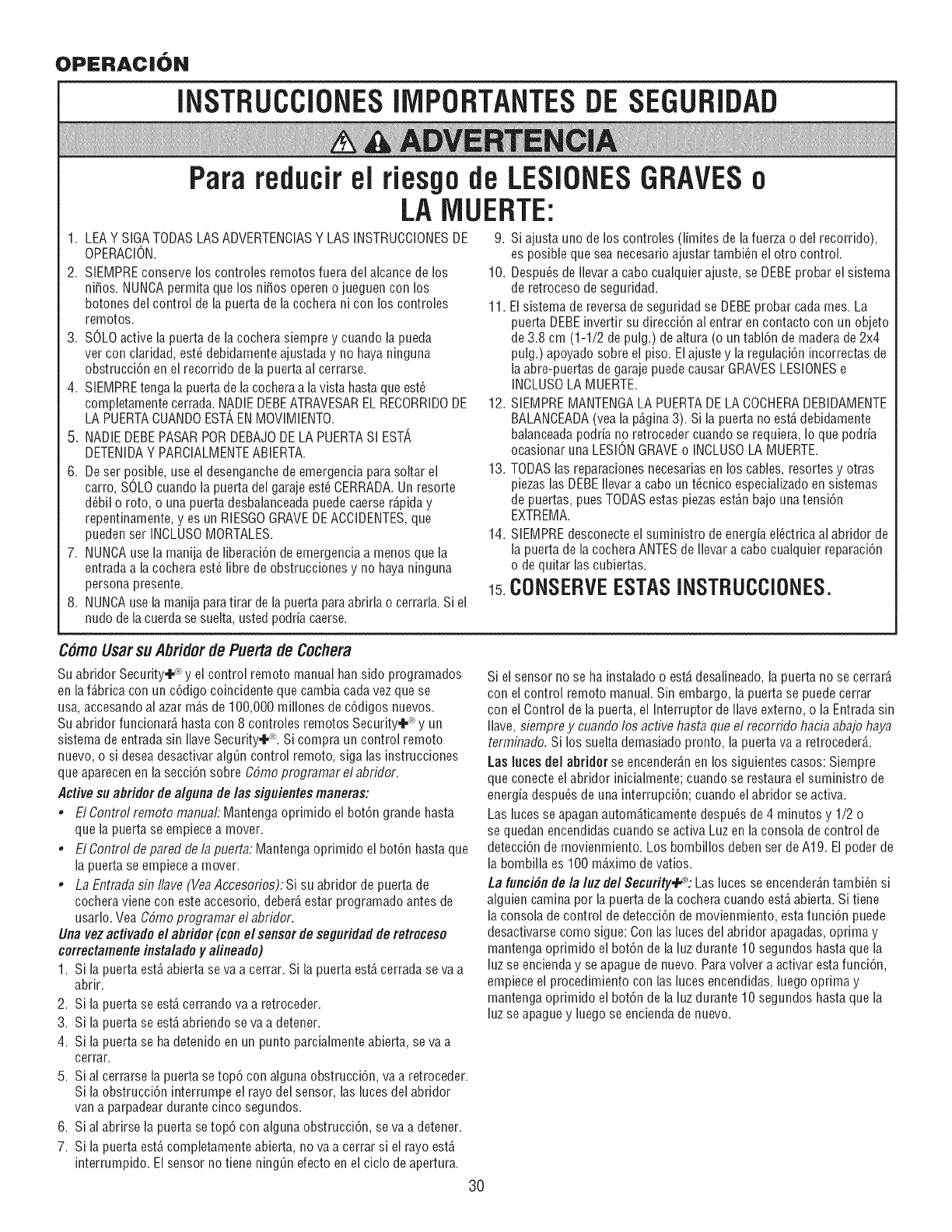
OPERAC|ON
INSTRUCCIONESllViPORTANTESDE SEGURIDAD
Para reducirel riesgode LESiONESGRAVESo
LAMUERTE:
1. LEAY SIGATODASLASADVERTENCIASY LAS INSTRUCCIONESDE 9. Si ajusta uno de los controles (l[mites de lafuerza o del recorrido),
OPERAClON. es posible que sea necesario ajustar tambi_n el otto control.
2. SIEMPREconserve los controles remotos fuera del alcance de los
ni_os. NUNCApermita que los ni_os operen o jueguen con los
botones del control de la puerta de la cochera ni con los controles
remotos.
3. SOLOactive la puerta de la cochera siempre y cuando la pueda
ver con claridad, est_ debidamente ajustaday no haya ninguna
obstrucci6n enel recorrido de la puerta al cerrarse.
4. SIEMPREtengala puertade la cocheraa lavista hastaque est_
completamente cerrada.NADIEDEBEATRAVESAREL REOORRIDODE
LAPUERTACUANDOEST',ENMOVIMIENTO.
5. NADIEDEBEPASARPORDEBAJODELA PUERTASI EST',
DETENIDAY PARCIALMENTEABIERTA.
6. Deser posible, useel desenganchede emergenciapara soltar el
carro, SOLOcuando la puerta del garaje est_ CERRADA.Un resorte
d_bil o roto, o una puerta desbalanceadapuedecaerse r_,piday
repentinamente,y es un RIESGOGRAVEDEACCIDENTES,que
pueden ser INCLUSOMORTALES.
7. NUNCAuse la manija de fiberaci6n de emergenciaa menos que la
entrada a la cochera est_ fibre de obstrucciones y no haya ninguna
personapresente.
8. NUNCAuse la manija paratirar dela puerta paraabrirla o cerrarla. Si el
nudo de la cuerdase suelta, usted podria caerse.
10. Despu@sde Ilevar a cabo cualquier ajuste, se DEBEprobar el sistema
de retroceso deseguridad.
11. El sistema de reversade seguridad se DEBEprobar cada mes. La
puerta DEBEinvertirsu direcci6n al entrar en contacto con un objeto
de 3.8 cm (1-1/2 de pulg.) de altura (o un taN6n de maderade 2x4
pulg.) apoyado sobre el piso. Elajuste y la regulaci6n incorrectas de
la abre-puertas degaraje puede causar GRAVESLESIONESe
INCLUSOLA MUERTE.
12. SIEMPREMANTENGALA PUERTADE LACOCHERADEBIDAMENTE
BALANCEADA(vea la p6,gina3). Si la puerta no est,, debidamente
balanceadapodria no retroceder cuando se requiera, Io que podria
ocasionar una LESIONGRAVEo INCLUSOLA MUERTE.
13. TODASlas reparaciones necesarias en los cables, resortes y otras
piezas las DEBEIlevar a cabo un t_cnico especializadoen sistemas
de puertas, pues TODASestas piezasest_,nbajo unatensi6n
EXTREMA.
14. SIEMPREdesconecte el suministro de energia el_ctrica al abridor de
la puerta de la cochera ANTESde Ilevar a cabo cualquier reparaci6n
o de quitar las cubiertas.
15.CONSERVEESTASINSTRUCCIONES.
C#moUsarsuAbfidordePuertade Cochera
Su abridor Security÷ _ y el control remoto manual han sido programados
en laf_,bricacon un c6digo coincidente que cambia cadavez que se
usa, accesandoal azar m_,sde 100,000 millones de c6digos nuevos.
Suabridor funcionar_,hasta con 8 controles remotos Security÷ _*y un
sistema de entradasin Ilave Security÷_L Si compra un control remoto
nuevo, o si desea desactivar alg_n control remoto, siga las instrucciones
que aparecenen la secci6n sobre C6mo programar el abridor,
Activesu abridor de algunade las siguientes maneras:
,El Control remoto manual: Mantengaoprimido el bot6n grande hasta
que la puerta se empiecea mover.
, El Control de pared de la puerta: Mantenga oprimido el bot6n hasta que
la puerta se empiece a mover.
, La Entradasin/lave (VeaAccesorios): Si su abridor de puerta de
cochera viene con este accesorio, deber_,estar programado antes de
usarlo. Vea C6mo programar el abridor.
Llnavez activado el abfidor (con el sensor de seguridad de retroceso
correctamente instaladoy alineado)
1. Si la puerta est,, abierta se va a cerrar. Si la puerta est,,cerrada se va a
abrir.
2. Si la puerta se est,,cerrando va a retroceder.
3. Si la puerta se est,,abriendo se va a detener.
4. Si la puerta se hadetenido en un punto parcialmenteabierta, se va a
cerrar.
5. Sial cerrarse la puerta setop6 con alguna obstrucci6n, va a retroceder.
Si la obstrucci6n interrumpe el rayo del sensor, las luces del abridor
vana parpadear durante cinco segundos.
6. Sial abrirse la puerta se top6 con alguna obstrucci6n, se va a detener.
7. Si la puerta est,, completamente abierta, no va a cerrar si el rayo est,,
interrumpido. Elsensor notiene ning_n efecto enel ciclo de apertura.
Si el sensor no se ha instalado o estb,desalineado,la puerta no se cerrarb,
con el control remoto manual. Sin embargo, la puerta se puede cerrar
con el Control de la puerta, el Interruptor de Ilave externo, o la Entradasin
Ilave, siempre y cuando los active hasta que el recorrido haciaabajo haya
terminado. Si los suelta demasiado pronto, la puerta va a retroceder_,.
Las laces del abridor se encender_,nen los siguientes casos: Siempre
que conecte el abridor inicialmente; cuando se restaura el suministro de
energia despu_s de una interrupci6n; cuando ei abridor se activa.
Las iuces se apaganautom_.ticamentedespu_sde 4 minutos y 1/2 o
se quedan encendidas cuando se activa Luz en la consola de control de
detecci6n de movienmiento. Los bombillos debenser de A19. El poder de
la bombiila es 100 m6,ximode vatios.
La funci#n de la luz del Security÷°: Las luces se encender_,ntambi_n si
alguien camina por la puerta de la cochera cuando est,. abierta. Si tiene
la consola de control de detecci6n de movienmiento, estafunci6n puede
desactivarse como sigue: Con las luces del abridor apagadas, oprima y
mantenga oprimido el bot6n de la luz durante 10 segundos hasta que la
luz se encienday seapague de nuevo.Paravolver a activar estafunci6n,
empiece el procedimiento con las luces encendidas,luego oprima y
mantenga oprimido el bot6n de la luz durante 10 segundos hasta que la
luz se apague y luego se enciendade nuevo.
30
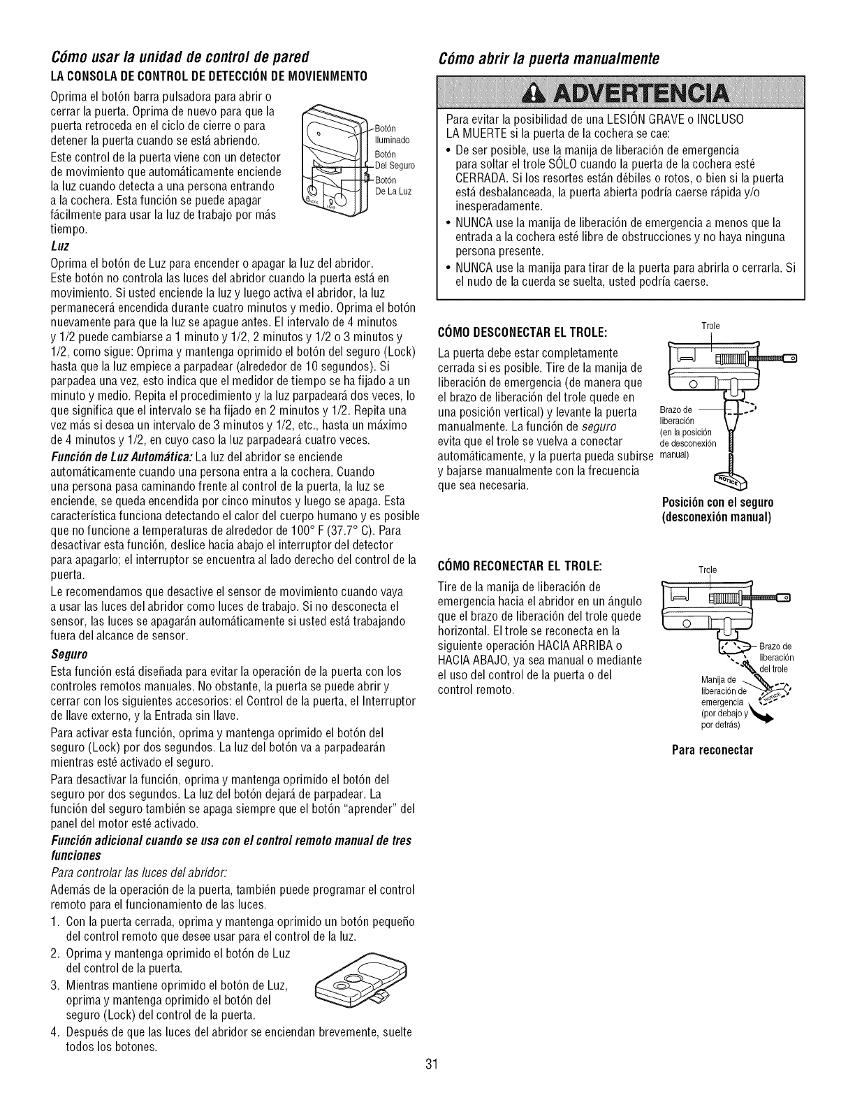
C6mousar la unidadde controldepared
LA CONSOLADECONTROLDEDETECCIONDEMOVlENMENTO
Oprima el bot6n barra pulsadora para abrir o
cerrar la puerta. Oprima de nuevo para que la
puerta retroceda en el ciclo de cierre o para
detener la puerta cuando se est,. abriendo.
Estecontrol de la puerta viene con un detector
de movimiento que autom_.ticamenteenciende
la luz cuando detectaa una persona entrando
a la cochera. Estafunci6n se puede apagar
f_.cilmentepara usar la luz detrabajo por m_.s
tiempo.
Luz
Bot6n
Iluminado
Bot6n
Del Seguro
Bot6n
De La Luz
Oprima el bot6n de Luz paraencender o apagar la luz del abridor.
Este bot6n no controla las luces del abridor cuando la puerta est,. en
movimiento. Si usted enciendela luzy luego activa el abridor, la luz
permanecer_,encendidadurante cuatro minutos y medic. Oprima el bot6n
nuevamentepara que la luz se apague antes. El intervalo de4 minutos
y 1/2 puede cambiarsea 1 minuto y 1/2, 2 minutos y 1/2 o 3 minutos y
1/2, como sigue: Optima y mantenga oprimido el bot6n del seguro (Lock)
hasta que la luz empiece a parpadear (alrededor de 10 segundos). Si
parpadeauna vez, esto indica que el medidor detiempo se ha fijado a un
minuto y medic. Repita el procedimiento y la luz parpadear_,dos veces, Io
que significa que el intervalo se hafijado en 2 minutos y 1/2. Repita una
vez m_.ssi desea un intervalo de3 minutos y 1/2, etc., hasta un mb<imo
de 4 minutos y 1/2, en cuyo caso la luz parpadear_,cuatro veces.
Funci#nde LuzAutom_tica:Laluz del abridor se enciende
autom_.ticamentecuando una persona entraa la cochera. Cuando
una personapasa caminandofrente al control de la puerta, la luz se
enciende, se queda encendidapor cinco minutos y luego se apaga. Esta
caracteristica funciona detectando el calor del cuerpo humano yes posible
que nofuncione a temperaturas de alrededor de 100° F (37.7° C). Para
desactivar estafunci6n, deslice haciaabajo el interruptor del detector
para apagarlo; el interruptor se encuentra al lado derecho del control de la
puerta.
Le recomendamos que desactive el sensor de movimiento cuando vaya
a usar las luces del abridor como luces de trabajo. Si no desconecta el
sensor, las luces se apagar_.nautom_.ticamentesi usted est,.trabajando
fuera del alcance desensor.
Seguro
Estafunci6n est,. disefiada para evitar la operaci6n de la puerta con los
controles remotos manuales. No obstante, la puerta se puedeabrir y
cerrar con los siguientes accesorios: el Control de la puerta, el Interruptor
de Ilave externo, y la Entradasin Ilave.
Paraactivar estafunci6n, oprima y mantengaoprimido el bot6n del
seguro (Lock) por dos segundos. La luz del bot6n va a parpadear_.n
mientras est_ activado el seguro.
Paradesactivar lafunci6n, oprima y mantenga oprimido el bot6n del
seguro por dos segundos. La luz del bot6n dejar_,de parpadear. La
funci6n del seguro tambi_n se apagasiempre que el bot6n "aprender" del
panel del motor est_activado.
Funci#nadicional cuandose usa con el controlremoto manual de tres
funciones
Para controlar /as luces del abridor:
Adem_.sde la operaci6n de la puerta, tambi_n puede programar el control
remoto para elfuncionamiento de las luces.
1. Con la puerta cerrada, optima y mantenga oprimido un bot6n pequefio
del control remoto que deseeusar para el control de la luz.
2. Oprima y mantenga oprimido el bot6n de Luz
del control de la puerta.
3. Mientras mantiene oprimido el bot6n de Luz,
oprima y mantenga oprimido el bot6n del
seguro (Lock) del control de la puerta.
4. Despu6s de que las luces del abridor se enciendan brevemente, suelte
todos los botones.
C6moabrir la puertamanualmente
Paraevitar la posibilidad de una LESIONGRAVEo INCLUSO
LA MUERTEsi la puerta de la cochera se cae:
• Deser posible, use la.manija de liberaci6n de emergencia
parasoltar eltrole SOLOcuando la puerta de la cochera est_
CERRADA.Si los resortes est_.nd_biles o rotos, o bien si la puerta
est,.desbalanceada,la puerta abierta podria caerser_.piday/o
inesperadamente.
• NUNCAusela manija de liberaci6n de emergenciaa menos que la
entradaa la cochera est_ libre deobstrucciones y no haya ninguna
persona presente.
• NUNCAusela manija paratirar de la puerta para abrirla o cerrarla. Si
el nudo de la cuerda se suelta, usted podria caerse.
COMODESCONECTARELTROLE:
La puerta debe estar completamente
cerrada si es posible. Tire de la manija de
liberaci6n de emergencia (de maneraque
el brazode liberaci6n del trole quede en
una posici6n vertical) y levante la puerta
manualmente. La funci6n de seguro
evita que el trole se vuelvaa conectar
Trole
(en la posicidn
dedesconexbn
autom_.ticamente,y la puerta puedasubirse manual)
y bajarse manualmente con lafrecuencia
que sea necesaria. I_
Posici6nconel seguro
(desconexi6nmanual)
COMORECONECTARELTROLE:
Tire de la manijade liberaci6n de
emergenciahacia el abridor en un _.ngulo
que el brazode liberaci6n del trole quede
horizontal. Eltrole se reconectaen la
siguiente operaci6n HACIAARRIBA o
HACIAABAJO,ya seamanual o mediante
el usodel control dela puerta o del
control remoto.
Trole
Manijade _,..,..
,iberaoi nde
emergencla • _,_
(pordebajo Y'_lb
por detras)
Parareconectar
31
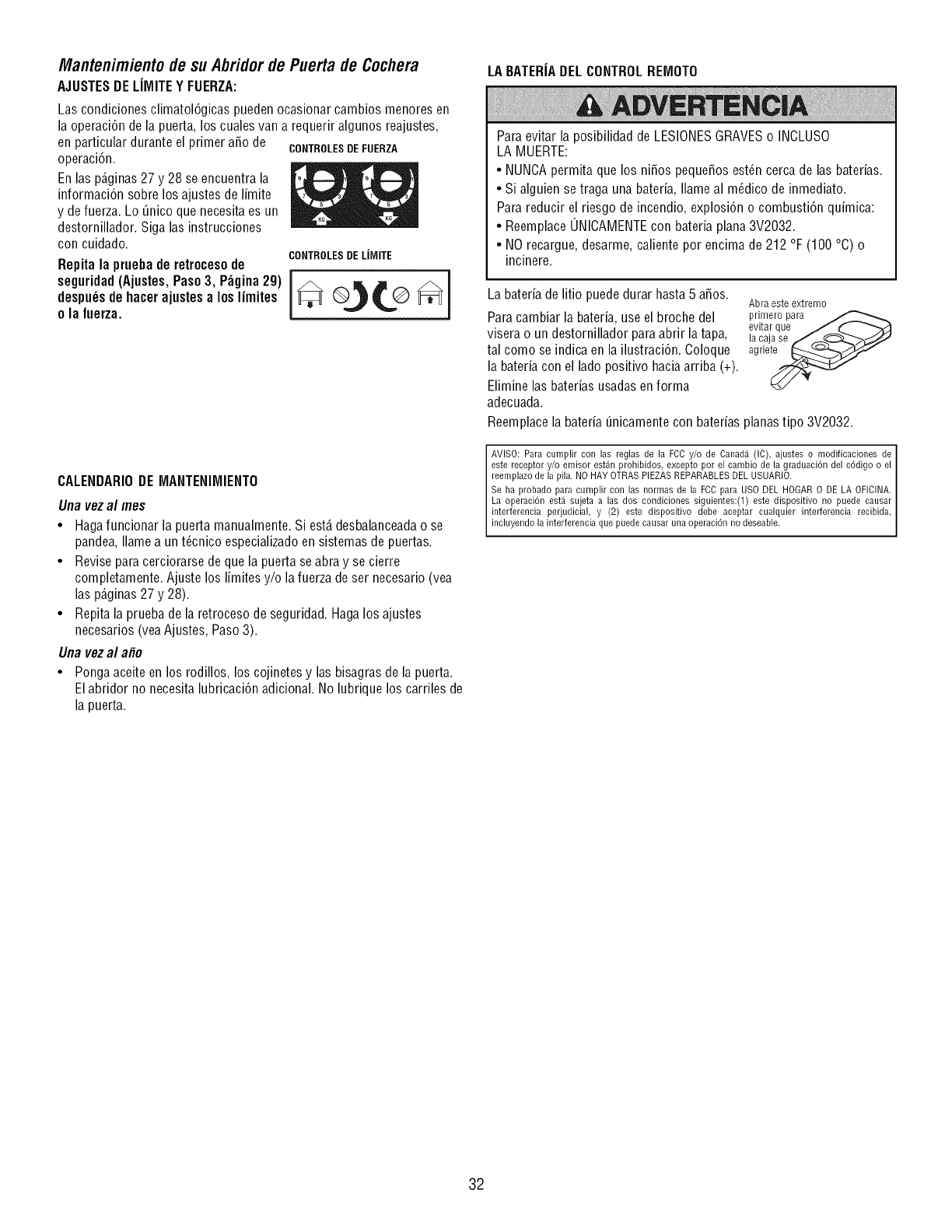
Mantenimientode suAbridorde Puertade Cochera
AJUSTESDELIMITE Y FUERZA:
Las condiciones climatol6gicas pueden ocasionar cambios menores en
la operaci6n dela puerta, los cuales van a requerir algunos reajustes,
en particular durante el primer aSo de CONTROLESDEFUERZA
operaci6n.
Enlas p_.ginas27 y 28 se encuentra la
informaci6n sobre losajustes de limite
y de fuerza. Lo _nico que necesitaes un
destornillador. Siga las instrucciones
con cuidado.
Repita la prueba de retrocesode
seguridad(Ajustes,Paso 3, P_gina 29)
despu_sde hacer ajustesa los limites
ola fuerza.
CONTROLESDE LIMITE
CALENDARIODEMANTENIMIENTO
Una vez al mes
•Hagafuncionar la puerta manualmente. Si est,. desbalanceadao se
pandea,Ilame a unt_cnico especializado ensistemas de puertas.
• Revise paracerciorarse de que la puerta se abra y se cierre
completamente. Ajuste los limites y/o la fuerza de ser necesario (vea
las p_.ginas27 y 28).
• Repita la prueba de la retroceso de seguridad. Hagalos ajustes
necesarios (yeaAjustes, Paso 3).
Una vez al a#o
• Pongaaceite en los rodillos, los cojinetes y las bisagras de la puerta.
Elabridor no necesita lubricaci6n adicional. No lubrique los carriles de
la puerta.
LA BATERIADEL CONTROLREMOTO
Paraevitar la posibilidad de LESIONESGRAVESo INCLUSO
LA MUERTE:
• NUNCApermita que los niSos pequeSosest_n cerca de las baterias.
• Si alguien se traga una bateria, Ilame al m_dico de inmediato.
Para reducir el riesgo de incendio, explosi6n o combusti6n quimica:
• ReemplaceUNICAMENTEcon bateria plana 3V2032.
• NOrecargue, desarme, caliente por encima de 212 °F (100 °C) o
incinere.
La bateria de litio puede durar hasta 5 aSos.
Para cambiar la bateria, use el broche del
visera o un destornillador paraabrir la tapa,
tal como se indica en la ilustraci6n. Coloque
la bateria con el lado positivo haciaarriba (+).
Elimine las baterias usadas enforma
adecuada.
Abra este extremo
primero para
evitar que J _ -'_C}
la caja se f..._..,_._,./_-__J_'
agrle_
Reemplacela bateria _nicamente con baterias planastipo 3V2032.
AVISO: Para cumplir con las reglas de la FCC y/o de Canada (IC), ajustes o modificaciones de I
este receptor y/o emisor estan prohibidos, excepto por el carnbio de la graduaci6n del c6digo o el
reemplazo de la pila. NO HAY OTRAS PIEZAS REPARABLES DEL USUARIO. I
Se ha probado para cumplir con las normas de la FCC para USO DEL HOGAR O DE LA OFICINA. I
La operaci6n est,1 sujeta a las dos condiciones siguientes:(1) este dispositivo no puede causar
interferencia perjudicial, y (2) este dispositivo debe aceptar cualquier interferencia recibida,
nc uyendo a nterferenc a que puede causar una operac 6n no deseab e.
32
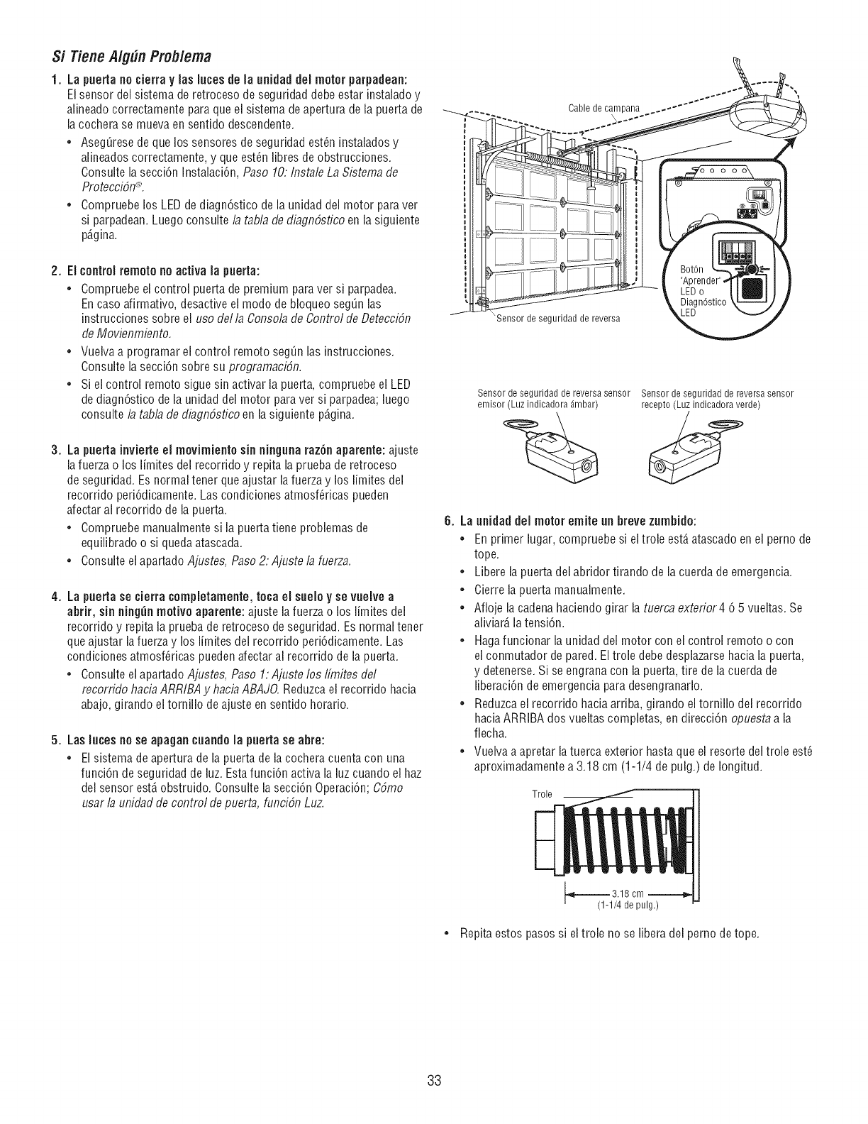
Si TieneA/gUnProb/ema
1. La puerta nocierra y las lutes de la uflidaddel motor parpadeafl:
El sensor del sistema de retroceso de seguridad debe estar instaladoy
alineado correctamente para que el sistema deapertura de la puerta de
la cochera se mueva en sentido descendente.
*AsegQresede que los sensores de seguridad est6n instaladosy
alineados correctamente, y que est_n fibres de obstrucciones.
Consulte la secci6n Instalaci6n, Paso 10:Instale La Sistemade
Protecci6n®.
.Compruebe los LED dediagn6stico de la unidad del motor paravet
si parpadean.Luego consulte la tabla de diagn6sfico en la siguiente
p6,gina.
2, El controlremote no activa la puerta:
• Compruebe el control puerta de premium paraver si parpadea.
Encase afirmativo, desactiveel mode de bioqueo seg_n las
instrucciones sobre ei use della Consolade Controlde Detecci6n
de Movienmiento,
•Vueiva a programar el control remote seg_n las instrucciones.
Consuite la secci6n sobre su programaci6n.
•Si ei control remote sigue sin activar la puerta, compruebe ei LED
de diagn6stico de ia unidad del motor paraver si parpadea;luego
consulte la tabla de diagn6sfico en la siguiente p6,gina.
3. La puerta inviette el movimiento sin ninguna raz6n aparente: ajuste
la fuerza o los limites dei recorrido y repita la prueba de retroceso
de seguridad. Es normal tener queajustar ia fuerza y los limites dei
recorrido peri6dicamente. Las condiciones atmosf_ricas pueden
afectar al recorrido de la puerta.
•Compruebe manualmentesi la puerta tiene problemas de
equiiibrado o si quedaatascada.
•Consulte el apartado Ajustes, Paso2: Ajuste la hlerza.
4. La puerta se cierra ¢ompletamente,toca el sueloy sevuelve a
abrir, sin ning_nmotive aparente: ajuste la fuerza o los limites del
recorrido y repita la pruebade retroceso de seguridad. Es normal tener
que ajustar lafuerza y los limites del recorrido peri6dicamente. Las
condiciones atmosf6ricas pueden afectar al recorrido de la puerta.
• Consulte el apartado Ajustes, Paso 1: Ajuste los Ifmites del
recorrido haciaARRIBA y haciaABAJO.Reduzcael recorrido hacia
abajo,girando el torniflo de ajuste en sentido horario.
5. Las lutes no se apagan ¢uando la puerta se abre:
=El sistema deapertura de la puerta de la cochera cuenta con una
funci6n deseguridad de luz.Estafunci6n activa la luzcuando el haz
del sensor est,, obstruido. Consulte la secci6n Operaci6n; C6mo
usar la unidadde control de puerta, funci6n Luz.
Cable de campana
x
"Sensor de seguridad de reversa
Sensor de seguridad de reversa sensor Sensor de seguridad de reversa sensor
emisor (Luz indicadora _mbar) recepto (Luz indicadora verde)
6. La unidaddel motor emite un brevezumbido:
• En primer lugar, compruebe si el trole est,, atascado en el perno de
tope.
• Libere la puertadei abridor tirando de la cuerda de emergencia.
• Cierre la puerta manualmente.
• Afloje la cadenahaciendo girar la tuerca exterior4 6 5 vueitas. Se
aliviar_,la tensi6n.
• Hagafuncionar la unidad del motor con el control remote o con
el conmutador depared. Eltrole debe desphzarse hacia la puerta,
y detenerse. Si se engrana con la puerta, tire de la cuerda de
fiberaci6n de emergencia para desengranaflo.
• Reduzcael recorrido hacia arriba, girando el tornillo del recorrido
haciaARRIBA dos vueltas completas, en direcci6n opuesta a la
flecha.
• Vuelva a apretar latuerca exterior hasta que el resorte del trole est6
aproximadamente a 3.18 cm (1-1/4 de pulg.) de Iongitud.
Trole
=--_ 3.18 cm --
(1-1/4 de pulg.)
Repita estos pasos si eltrole no se libera del perno de tope.
33
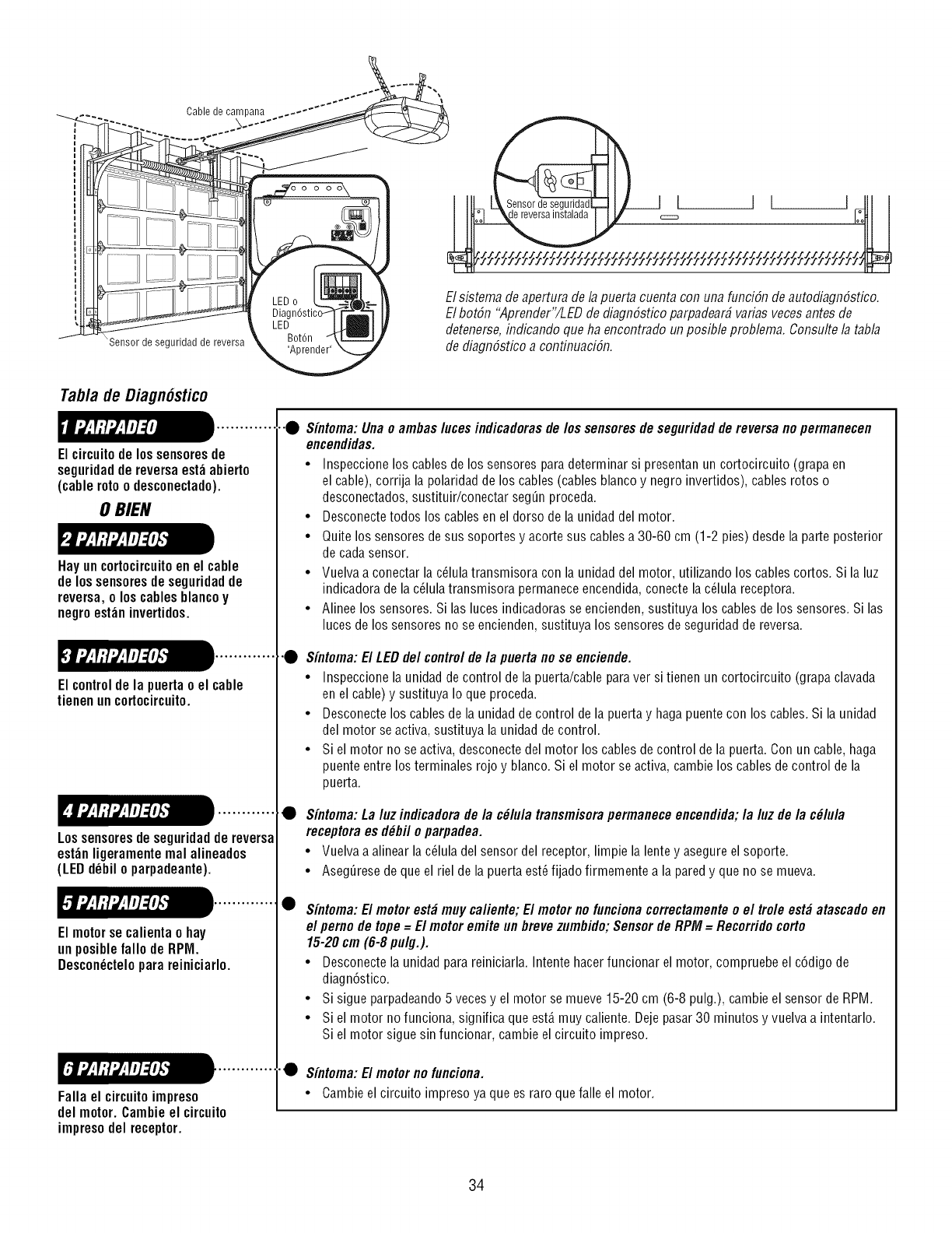
Cable de campana
_Sensor de seguridad de reversa
Elsbtema de apertura de lapuerta cuenta con una funci6n de autodiagn6stico.
Elbot6n "Aprender"/LED de diagn6stico parpadear4varias vecesantes de
detenerse,indicando que ha encontrado un posible problem& Consulte la tabla
de diagn6stico a continuaci6n.
Tab/a de Diagn6stico
.............
El circuitode los sensoresde
seguridadde reversa est_abierto
(cable roto o desconectado).
0 BIEN
Hayuncortocircuitoenel cable
delossensoresdeseguridadde
reversa,oloscablesblancoy
negroest_ninvertidos.
•"0 Sintoma: Una o ambas luces indicadorasde los sensores de seguridad de reversa nopermanecen
encendidas.
• Inspeccione los cables de los sensores para determinar si presentan un cortocircuito (grapaen
el cable), corrija la polaridad de los cables (cables blanco y negro invertidos), cables rotos o
desconectados,sustituir/conectar seg_n proceda.
• Desconectetodos los cables en el dorso de la unidad del motor.
• Quite los sensores de sus soportes y acorte sus cablesa 30-60 cm (1-2 pies) desde la parte posterior
de cadasensor.
• Vuelva a conectar la c_lulatransmisora con la unidad del motor, utilizando los cables cortos. Si la luz
indicadora de la c_lula transmisora permaneceencendida,conecte la c_lula receptora.
• Alinee los sensores. Si las luces indicadoras se encienden,sustituya los cables de los sensores. Si las
luces de los sensores no se encienden, sustituya los sensores de seguridad de reversa.
Elcontroldela puertao el cable
tienenuncortocircuito.
)............... • Sintoma: El LEDdel controlde/a puerta nose enciende.
• Inspeccione la unidad de control de la puerta/cable paraver si tienen un cortocircuito (grapa clavada
en el cable) y sustituya Io que proceda.
• Desconecte los cables de la unidad de control de la puerta y haga puente con los cables. Si la unidad
del motor seactiva, sustituya la unidad de control.
• Si el motor no se activa, desconectedel motor los cables de control de la puerta. Con un cable, haga
puente entre los terminales rojo y blanco. Si el motor se activa, cambie los cables decontrol de la
puerta.
Elmotorsecalientaohay
unposiblefallode RPM.
Los sensoresde seguridadde reversa
est_nligeramente real alineados
(LED d_bil o parpadeante).
I.............. •
Descon_ctelopara reiniciarlo.
Fallael circuitoimpreso
delmotor.Cambieel circuito
impresodel receptor.
Sintoma:Laluzindicadoradela c#lulatransmisorapermaneceencendida;la luzdela c#lula
receptoraesd_bfloparpadea.
• Vuelvaaalinearlac_luladelsensordelreceptor,limpiela lentey asegureelsoporte.
• Aseg_resedequeel rieldelapuertaest6fijadofirmementea laparedy quenose mueva.
Sintoma: El motor est_ muy ca/iente; El motor no funcionacorrectamenteo el tro/e est_ atascadoen
el pemo de tope=El motor emite un brevezumbido;Sensorde RPM =Recorridocorto
15-20 cm (6-8 pulg.).
• Desconecte la unidad para reiniciarla. Intente hacer funcionar el motor, compruebe el c6digo de
diagn6stico.
• Si sigue parpadeando5 vecesy el motor se mueve 15-20 cm (6-8 pulg.), cambie el sensor de RPM.
• Si el motor no funciona, significa que est,. muy caliente. Deje pasar30 minutos y vuelva a intentarlo.
Si el motor sigue sin funcionar, cambie el circuito impreso.
••Sintoma:Elmotornofunciona.
• Cambieelcircuitoimpresoyaqueesraroquefalleel motor.
34
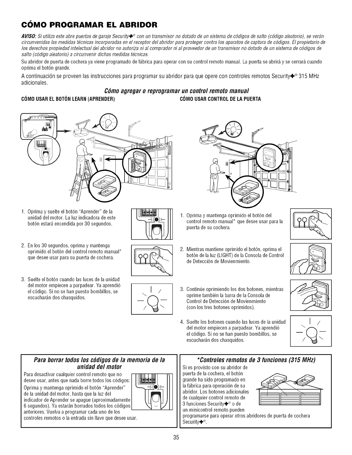
COMO PROGRAMAR EL ABRIDOR
AlflSO: Si utiliza este abrepuertas de garaje Security,l_ con un transmisor no dotado de un sistema de cSdigos de salto (cSdigoaleatofio), se ver_n
circunvenidas las medidas t#cnicas incorporadas en el receptor del abridor para proteger contra los aparatos de captura decSdigos. Elpropietario de
los derechos propiedad intelectual del abridor no autoriza ni al comprador ni al proveedor de un transmisor no dotado de un sistema decSdigos de
salto (cSdigoaleatorio) a circunvenir dichas medidas t#cnicas.
Suabridor de puerta de cochera ya viene programado de f_.bricaparaoperar con su control remoto manual. La puertase abrir_,y se cerrar_,cuando
oprima el bot6n grande.
A continuaci6n se proveen las instrucciones para programar su abridor para que opere con controles remotos Security.I -® 315 IVIHz
adicionales.
Cdmoagregaro reprogramarun controlremotomanual
COMOUSAR ELBOTONLEARN(APRENDER) COMO USARCONTROLDE LAPUERTA
1. Oprima y suelte el bot6n "Aprender" de la
unidad del motor. La luz indicadora de este
bot6n estar_,encendida por 30 segundos.
2. En los 30 segundos, oprima y mantenga
oprimido el bot6n del control remoto manual*
que deseeusar parasu puerta de cochera.
3. Suelte el bot6n cuando las luces de la unidad
del motor empiecena parpadear. Yaaprendi6
el c6digo. Si no se han puesto bombillos, se
escuchar_.ndos chasquidos.
1. Oprima y mantenga oprimido el bot6n del
control remoto manual* que desee usar para la
puerta de su cochera.
2. Mientras mantieneoprimido el bot6n, oprima el
bot6n de la luz (LIGHT)de laConsola de Control
de Detecci6n de Movienmiento.
.
.
ContinUeoprimiendo los dos botones, mientras
oprime tambi_n la barra de la Consola de
Control de Detecci6n de Movienmiento
(con los tres botones oprimidos).
Suelte los botones cuando las luces de la unidad
del motor empiecena parpadear. Yaaprendi6
el c6digo. Si no se han puesto bombillos, se
escuchar_.ndos chasquidos.
I/
Para borrartodoslos cddigosde/a memoria de/a
unidad de/motor
Paradesactivar cualquier control remoto que no I Jl I l\ I
desee usar, antes que nada borre todos los c6digos: l_ [ J
Oprima y mantenga oprimido el bot6n "Aprender" _®_ I/I
de la unidad eel motor, hasta qua la luz eel I II III
indicador deAprender se apague (aproximadamente _ LJL-J[J )J I
6 segundos). Yaestar_.nborrados todos os c6d gos X,_ - VJ
anteriores.Vuelva a programar cada uno de los
controles remotos o la entrada sin Ilaveque desee usar.
*Controles remotosde 3 funciones(315 MHz)
Si es provisto con su abridor de
puerta de la cochera, el bot6n
grande ha sido programado en
la f_.bricaparaoperaci6n desu
abridor. Los botones adicionales
de cualquier control remoto de
3 funciones Security+ ®o de
un minicontrol remoto pueden
programarse para operar otros abridores de puerta de cochera
Security,!-®.
35
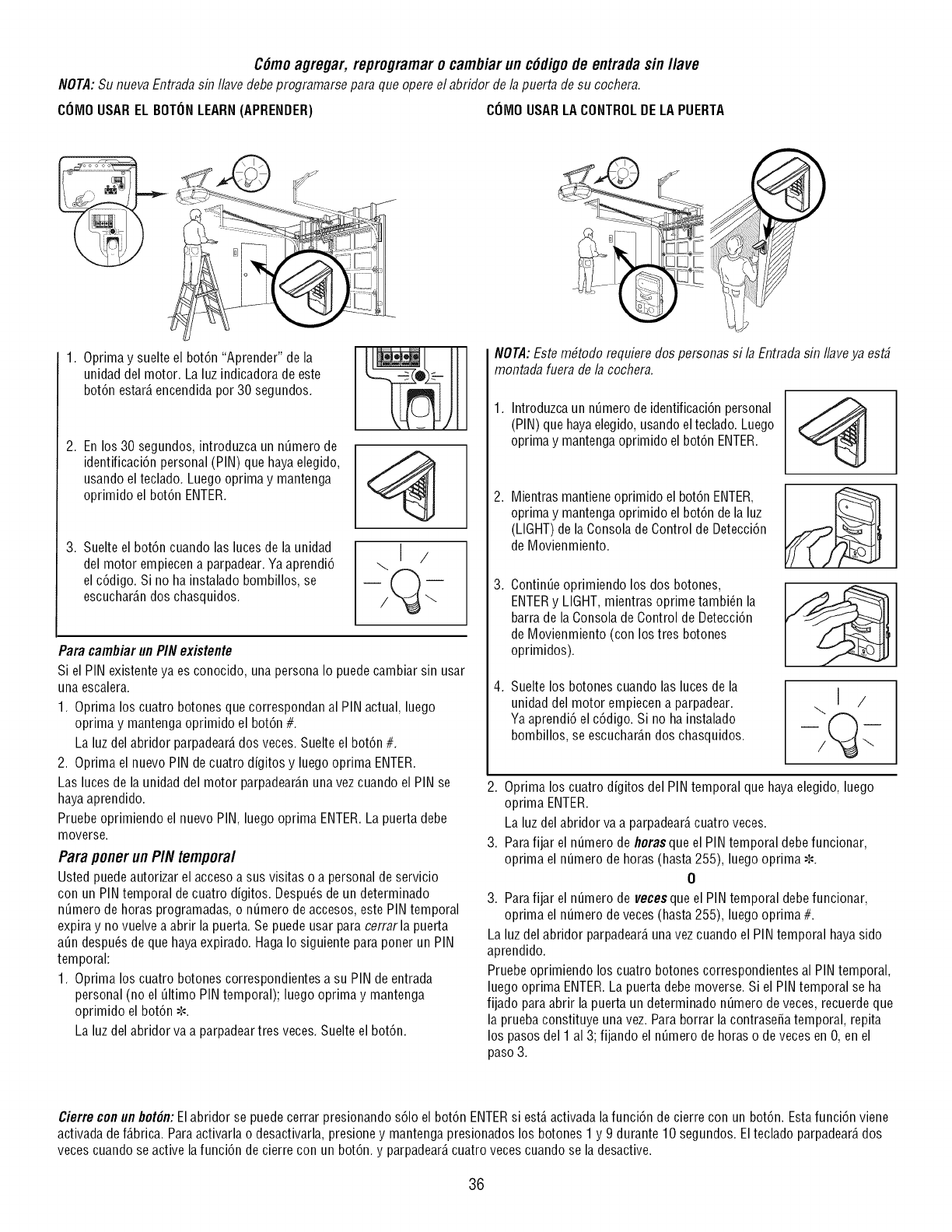
C6moagregar, reprogramaro cambiar un c#dlgode entrada sin l/ave
NOTA:Su nueva Entradasin Ilave debe programarse para que opere el abridor de la puerta de su cochera.
COMOUSAR EL BOTONLEARN(APRENDER) COMO USARLA CONTROLDE LAPUERTA
1. Oprimay suelte el bot6n "Aprender" de la
unidad del motor. La luz indicadora de este
bot6n estar_,encendidapor 30 segundos.
2. En los 30 segundos, introduzca un nQmerode
identificaci6n personal (PIN) que haya elegido,
usando el teclado. Luego oprima y mantenga
oprimido el bot6n ENTER.
3. Suelte el bot6n cuando las luces de la unidad
del motor empiecen a parpadear.Ya aprendi6
el c6digo. Si no ha instalado bombillos, se
escuchar_.ndos chasquidos.
\J /
Para cambiar un PIN existente
Si el PIN existenteya es conocido, una persona Io puede cambiar sin usar
una escalera.
1. Oprima los cuatro botones que correspondan al PIN actual, luego
optima y mantenga oprimido el bot6n #.
La luz del abridor parpadear_,dos veces. Suelte el bot6n #.
2. Oprima el nuevo PIN decuatro digitos y luego oprima ENTER.
Las luces de la unidad del motor parpadear_.nuna vezcuando el PIN se
hayaaprendido.
Pruebe oprimiendo el nuevo PIN, luego oprima ENTER.La puerta debe
moverse.
Para ponerun PIN temporal
Usted puedeautorizar el accesoa sus visitas o a personal de servicio
con un PINtemporal decuatro digitos. Despu6sde un determinado
n_mero de horas programadas, o n_mero deaccesos, este PIN temporal
expiray no vuelve a abrir la puerta. Se puedeusar para cerrarla puerta
a_n despu6s de que haya expirado. HagaIo siguiente para poner un PIN
temporal:
1. Oprima los cuatro botones correspondientes a su PIN de entrada
personal (no el _ltimo PIN temporal); luego oprima y mantenga
oprimido el bot6n _-'.
La luz del abridor va a parpadeartres veces. Suelte el bot6n.
NOTA:Estembtodorequieredospersonassi laEntradasin Ilaveya est#
montadafueradelacochera.
1. Introduzcaun n_mero de identificaci6n personal
(PIN) que hayaelegido,usandoel teclado. Luego
oprima y mantengaoprimido el bot6n ENTER.
.
.
.
Mientras mantieneoprimido el bot6n ENTER,
oprima y mantengaoprimido el bot6n dela luz
(LIGHT)de la Consola deControl de Detecci6n
de Movienmiento.
Contin@ oprimiendo los dos botones,
ENTERy LIGHT,mientras oprime tambi_n la
barra de la Consolade Control de Detecci6n
de Movienmiento (con los tres botones
oprimidos).
Suelte los botones cuando las luces de la
unidad del motor empiecen a parpadear.
Yaaprendi6 el c6digo. Si no ha instalado
bombillos, se escuchar_.ndos chasquidos.
2. Oprima los cuatro digitos del PIN temporal que haya elegido, luego
optima ENTER.
La luz del abridor va a parpadear_,cuatro veces.
3. Parafijar el n_mero de floras que el PIN temporal debe funcionar,
oprima el n_mero de horas (hasta 255), luego oprima -','-'.
0
3. Parafijar el n_mero de vecesque el PINtemporal debefuncionar,
oprima el n_mero de veces(hasta 255), luego oprima #.
La luz del abridor parpadear_,unavez cuando el PINtemporal haya sido
aprendido.
Pruebeoprimiendo los cuatro botones correspondientes al PIN temporal,
luego oprima ENTER.La puerta debe moverse. Si el PIN temporal se ha
fijado paraabrir la puerta un determinado n_mero de veces, recuerdeque
la prueba constituye una vez. Para borrar la contrase_a temporal, repita
los pasos del 1 al 3; fijando el n_mero de horas o de veces en O,en el
paso 3.
Cierre conun bot6n:Elabridor se puedecerrar presionando s61oel bot6n ENTERsi est,.activada lafunci6n decierre con un bot6n. Estafunci6n viene
activadadef_.brica. Paraactivarlao desactivarla, presione y mantenga presionados los botones 1 y 9 durante 10 segundos. El teclado parpadear_,dos
vecescuando se active lafunci6n de cierre con un bot6n, y parpadear_,cuatro veces cuando se la desactive.
36
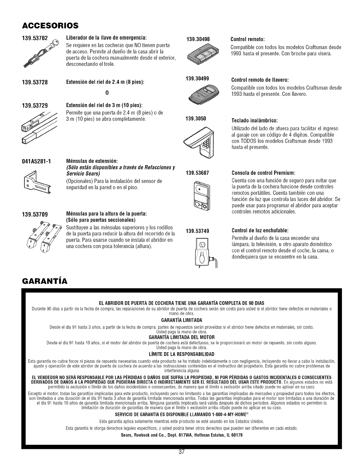
ACCESORIOS
Liberador de la Ilave de emergencia:
Se requiere en los cocheras que NOtienen puerto
de acceso. Permite al due_o de la casaabrir la
puerta de la cochera manualmentedesde el exterior,
desconectando el trole.
139.53728
139.53729
Extensi6ndelriel de2.4 m(8 pies):
0
ExtensiOndelriel de3 m(10pies):
Permitequeunapuertade2.4 m (8 pies)o de
3 m (10pies)seabracompletamente.
041A5281-1 M_nsulasdeextension:
(S#Ioest_ndisponiblesa tray,sdeRefaccionesy
ServicioSears)
(Opcionales)Paralainstalaci6ndelsensorde
seguridadenlaparedo enel piso.
139.53709 M_nsulaspara la altura de la puerto:
($61opara puertas seccionales)
Sustituyen alas m_nsulas superiores y los rodillos
de la puerta para reducir la altura del recorrido de la
puerta.Para usarsecuando se instala el abridor en
unacochera con poca tolerancia (altura).
GARANTIA
13g.30498
139.30499
139.3050
139.53687
139.53749
Control remoto:
Compatible con todos los modelos Craftsman desde
1993 hasta el presente. Con broche paravisera.
Control remoto de Ilavero:
Compatible con todos los modelos Craftsman desde
1993 hasta el presente. Con Ilavero.
Teclado inal_mbrico:
Utilizado del ladode afuera parafacilitar el ingreso
al garaje con un c6digo de 4 digitos. Compatible
con TODOSlos modelos Craftsman desde1993
hasta el presente.
Consola de controlPremium:
Cuentacon una funci6n de seguro para evitar que
la puerta de la cochera funcione desde controles
remotos port_.tiles.Cuentatambi_n con una
funci6n de luz que controla las luces del abridor. Se
puede usar para programar el abridor paraaceptar
controles remotos adicionales.
Controlde luzenchufable:
Permite al due_o dela casaencender una
I_mpara, latelevisi6n, u otro aparato dom_stico
con el control remoto desde el coche, la coma, o
dondequiera que se encuentre en la casa.
ELABRIDOR DE PUERTADE COCHERATIENEUNA GARANTIACOMPLETADE 90 DIAS
Durante90 dfasa partir de la fecha de compra,las reparacionesde su abridor de puerta de cochera ser_.nsin costo para ustedsi el abridor tiene defectosen materialeso
manode obra.
GARANTIALIMITADA
Desdeel dfa91 hasta 3 a_os, apartir de la fecha de compra, partesde repuestosser_.nproveidassi el abridor tiene defectosen materiales,sin costo.
Ustedpaga la manode obra.
GARANTIALIMITADA DELMOTOR
Desdeel dfa91 hasta 10 a_os, si el motor delabridor de puerta de cocheraest_defectuoso,sele proporcionar_,un motor de repuesto,sin costo alguno.
Ustedpaga la manode obra.
LIMITE DE LA RESPONSABILIDAD
Esta garantiano cubrefocos ni piezasde repuestonecesariascuandoesteproducto se hatratado indebidamenteo con negligencia,incluyendono Ilevara cabola instalaci6n,
ajuste y operaci6n de esteabridor de puerta de cochera de acuerdoa las instruccionescontenidasen el instructivo delpropietario. Estagarantfano cubre problemasde
interferenciaaiguna
ELVENDEDORNOSERARESPONSABLEPORLASPI_RDIDASODAIIOSQUESUFRALAPROPIEDAD,NIPORPI_RDIDASO GASTOSINCIDENTALESOCONSECUENTES
DERIVADOSDEDAIIOSA LAPROPIEDADQUEPUDIERANDIRECTA0 INDIRECTAMENTESERELRESULTADODEL USARESTEPRODUCTO.Enalgunos estadosno est_
permitido la exclusi6no limite de los da_os incidentaleso consecuentes,de maneraque el Ifmite o exclusi6narriba citado puedeno aplicar en su caso.
Exceptoel motor, todas las garantfasimplicadasparaesteproducto,incluyendo perono limitando alas garantfasimplicadas de mercadeoy propiedadparatodos los efectos,
son limitados a una duraci6n de el dfa 91 hasta 3 a_os de garantia limitadamencionadaarriba. Todaslas garantfasimplicadas parael motor son limitadas a una duraci6n de
el dfa 91 hasta 10 a_osde garantialimitadamencionadaarriba. Ningunagarantiaimplicadaser_valida despu_sde dichos periodos. Algunosestadosno permiten la
limitaci6n de duraci6n de garantiasde maneraqueel limite o exclusi6narriba citado puedeno aplicar en su caso.
SERVI61ODEGARANTiAESDISPONIBLELLAMANDO1-800-4-MY-HOME@
Estagarantfaaplicasolamentemientras esteproducto se est6usando en los EstadosUnidos.
Estagarantfale otorga derechoslegalesespedficos,y ustedpodria tenet otros derechosque puedenser diferentesen cadaestado.
Sears,Roebuckand60., Dept. 817WA,HoffmanEstates,IL 60179
37

Your Home
For troubleshooting, product manuals and expert advice:
managemylife
www.managemylife.com
For repair - in your home - of all major brand appliances,
lawn and garden equipment, or heating and cooling systems,
no matter who made it, no matter who sold it!
For the replacement parts, accessories and
owner's manuals that you need to do-it-yourself.
For Sears professional installation of home appliances
and items like garage door openers and water heaters.
1-800-4-MY-HOME ® (1-800-469-4663)
Call anytime, day or night (U.S.A. and Canada)
www.sears.com www.sears.ca
Our Home
For repair of carry-in items like vacuums, lawn equipment,
and electronics, call anytime for the location of your nearest
Sears Parts & Repair Service Center
1-800-488-1222 (U.S.A.) 1-800-469-4663 (Canada)
www.sears.com www.sears.ca
To purchase a protection agreement on a product serviced by Sears:
1-800-827-6655 (U.S.A.) 1-800-361-6665 (Canada)
Para pedir servicio de reparaci6n
a domicilio, y para ordenar piezas:
1-888-SU-HOGAR ®
(1-888-784-6427)
Au Canada pour service en frangais:
1-800-LE-FOYER Mc
(1-800-533-6937)
www.sears.ca
® Registered Trademark /TMTrademark of KCD IP, LLC in the United States, or Sears Brands, LLC in other countries
® Marca Registrada /TMMarca de Fabrica de KCD IP, LLC en Estados Unidos, o Sears Brands, LLC in otros paises
MD
MCMarque de commerce /Marque d6pos6e de Sears Brands, LLC
114A4317F ©2013 KOP IP, LLO
