Craftsman 13953963SRT User Manual GARAGE DOOR OPENER Manuals And Guides L9060009
CRAFTSMAN Garage Door Opener Manual L9060009 CRAFTSMAN Garage Door Opener Owner's Manual, CRAFTSMAN Garage Door Opener installation guides
User Manual: Craftsman 13953963SRT 13953963SRT CRAFTSMAN GARAGE DOOR OPENER - Manuals and Guides View the owners manual for your CRAFTSMAN GARAGE DOOR OPENER #13953963SRT. Home:Garage Door & Opener Parts:Craftsman Parts:Craftsman GARAGE DOOR OPENER Manual
Open the PDF directly: View PDF ![]() .
.
Page Count: 40
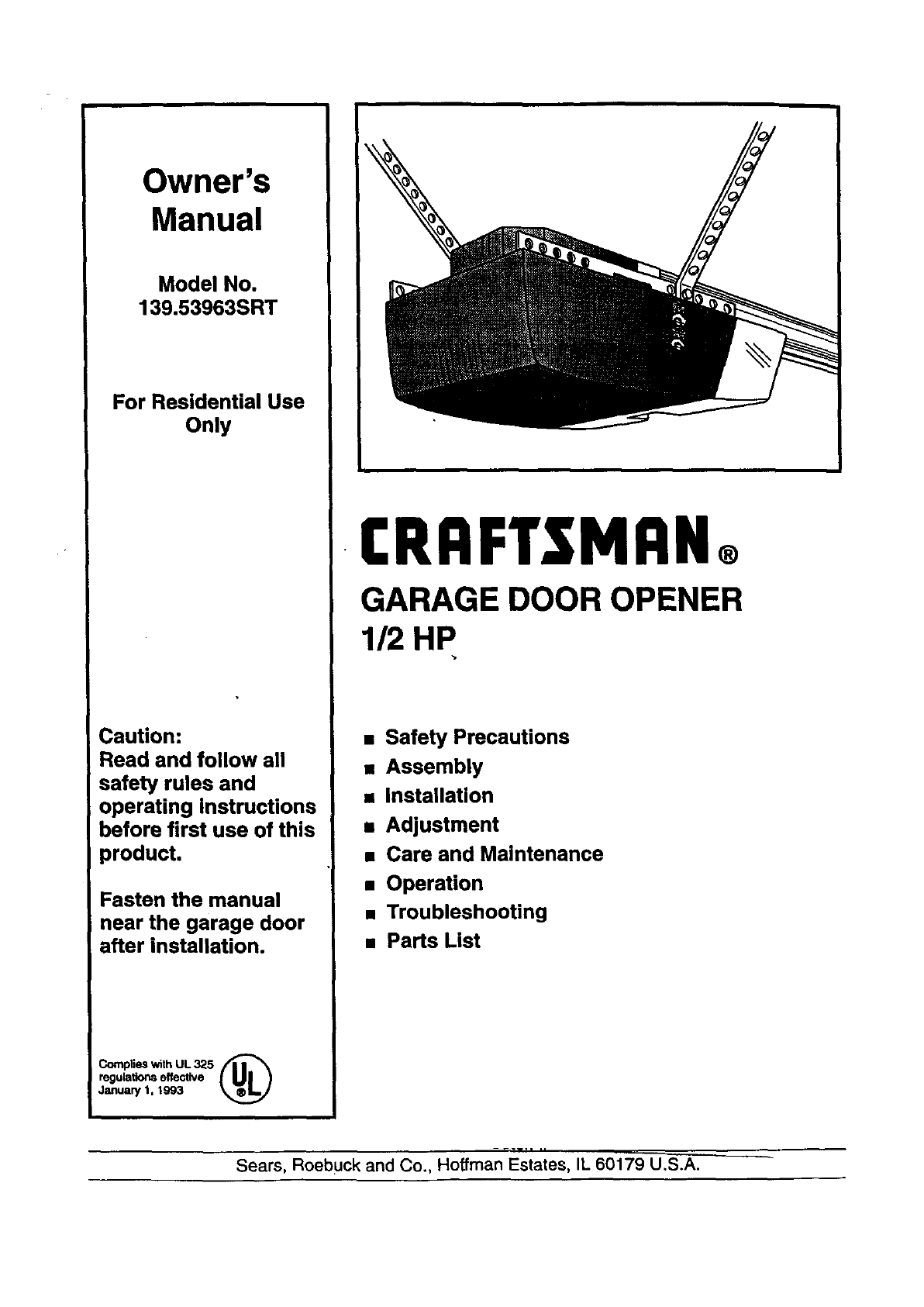
Owner's
Manual
Model No.
139.53963SRT
For Residential Use
Only
Caution:
Read and follow all
safety rules and
operating Instructions
before first use of this
product.
Fasten the manual
near the garage door
after installation.
Complies with UL 325 f|l _
regulations effective
January 1, 1993
I:RRFTSMRN®
GARAGE DOOR OPENER
1/2 HP
•Safety Precautions
•Assembly
•Installation
mAdjustment
•Care and Maintenance
•Operation
•Troubleshooting
•Parts List
-.-w.i ,,
Sears, Roebuck and Co., Hoffman Estates, IL 60179 U.S.A.
Contents
Safety alert symbol review ............................................ 2
Safety information, precautions, tools .......................... 3
Testing your garage door for binding & balance .......... 3
Carton inventory ........................................................... 4
Hardware inventory....................................................... 5
Illustrationof sectional door installation ..................... 6
Illustration of one-piece door installation ..................... 7
Assembly section - pages 8 -11
Assemble the tall ........................................................ 8
Fasten rail to power unit........................................ :...10
Install the trolley ....................................................... 10
Attach the rail brackets ............................................. | 1
Installation section - pages 12 -27
Installation safety instnlctioas .................................. 1"1
Determine the header bracket location
Sectional door ......................................................... 12
One-piece door ........................................................ 13
Install the header bracket .......................................... 14
Attach the rail to the header bracket......................... 15
Safety reversing sensor information ......................... 16
Install the safety reversing sensor ............................. 17
Position the opener .................................................... 19
Hang the opener ........................................................ 20
Install the door control and connect all wires ...........21
Electrical requirements ............................................. 22
Complete the safety reversing sensor installation.....22
Install the lights and lens .......................................... 23
Attach the emergency release rope and handle.........23
Fasten the door bracket(sectional door) ................... 24
Fasten the door bracket (one-piece door).................. 25
Connect door arm to trolley (sectional door) ............26
Connect door arm to trolley (one-piece door)...........27
Adjustment section - pages 28 -30
Travel limit adjustments............................................ 28
Force adjustments..................................................... 29
Test the safety reversing sensor ................................ 30
Test the safety reverse system .................................. 30
Operation safety instructions ...................................... 31
Care of your opener .................................................... 31
Maintenance schedule ................................................. 31
Operation of your opener ............................................ 32
Receiver & remote control programming................... 33
Troubleshooting .......................................................... 34
Repair parts,rail assembly .......................................... 36
Repair parts, installation............................................. 36
Repair parts, powerunit .............................................. 37
Accessories ................................................................. 38
Index ........................................................................... 39
How to order repair parts............................................ 40
Warranty ...................................................................... 40
Start by reviewing these important safety alert symbols:
When you see these Safety Symbols on the following pages, they will alert you to the possibility ofserions injury
or death if you do not comply with the corresponding instructions. The hazard may come from something
mechanical or from electric shock. Read the instructions carefully. I
Mechanical Electrical
When you see this Safety Symbol on the following pgg_] it will alert you to the possibility of damage to your
garage door and/or the garage door opener if yoii _o 'xi_ comply with the corresponding instructions. Read the
refuUy. .... '
instructions ca _ _'_' ._,
_" :_
This garage door opener is designed and tested to offer safe service provided it is installed, operated, maintained
and tested in strict accordance with the safety instructions contained in this manual.
Safety Information and Precautions; Tools
An unbalancedgaragedoormightnotreversewhen
requiredandsomeoneunderthedoorcouldbeseriously
injuredorkilled.
If yourgaragedoorbinds,sucksorIs outofbalance,call
forprofessionalgaragedoorservice.Garagedoors,door
springs,cables,pulleys,brackets,andtheirhardwareare
underextremetens/onand can causeseriousInju,ryor
death. Do not try to loosen, move or adjust them
yourself!
Ropesleft on a garage doorcouldcausesomeoneto
become entangled and killed. Remove all ropes
canna€tedto thedoorbeforeInstallingandoperatingthe
opener,
Toavoiddamageto thegaragedoorendopener,disable
locksbeforeInstallingand operatingthe opener.Use a
woodscrewor nailto holdlocksinthe "open'(unlocked)
position.
Operation at otherthan 120V60 Hz will cause opener
malfonctlonanddamage.
Identify the type and height of your door, any special
conditions that exist, and any additional materials that
may be required. Refer to pages 6 and 7.
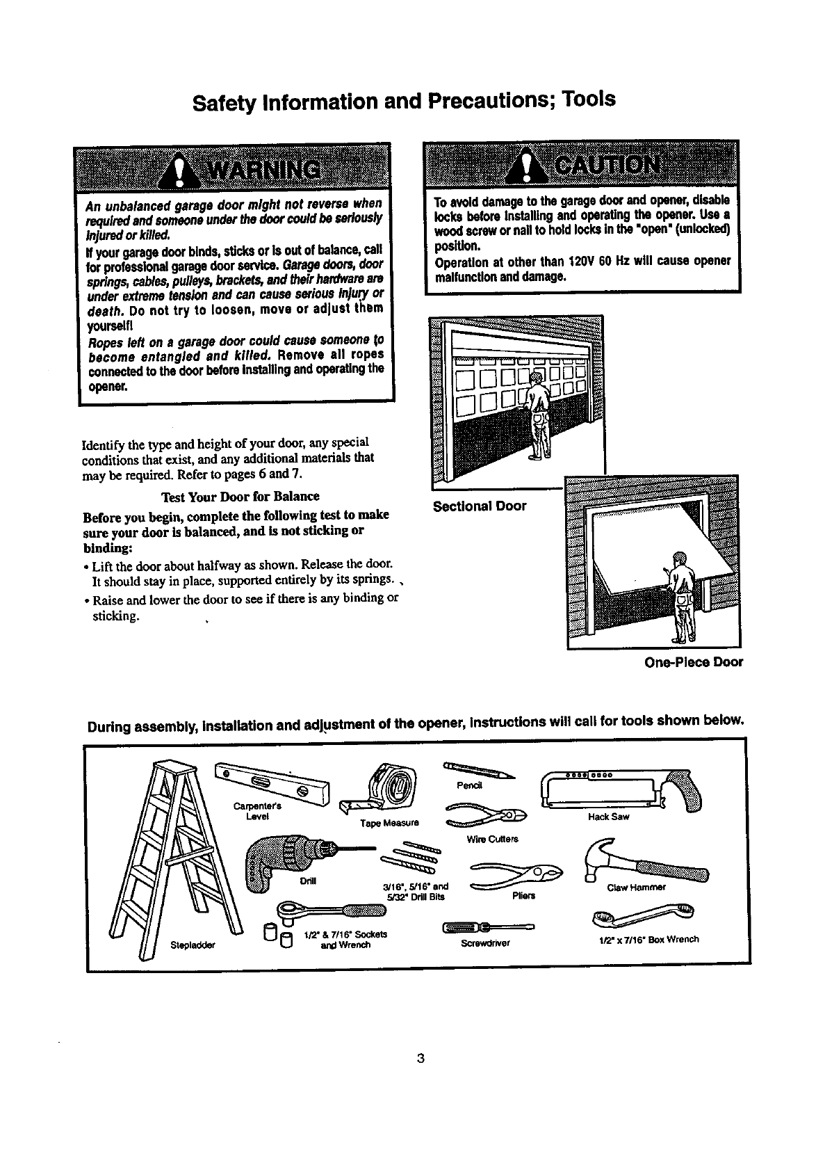
Test Your Door for Balance
Before you begin, complete the following test to make
sure your door is balanced, and is not sticking or
binding:
• Lift the door about halfway as shown. Release the door.
It should stay in place, supported entirely by its springs.,
• Raise and lower the door to see if there is any binding or
sticking.
Sectional Door
One-Piece Door
During assembly, installation and adjustment of the opener, instructions will call for tools shown below.
Lev_
3
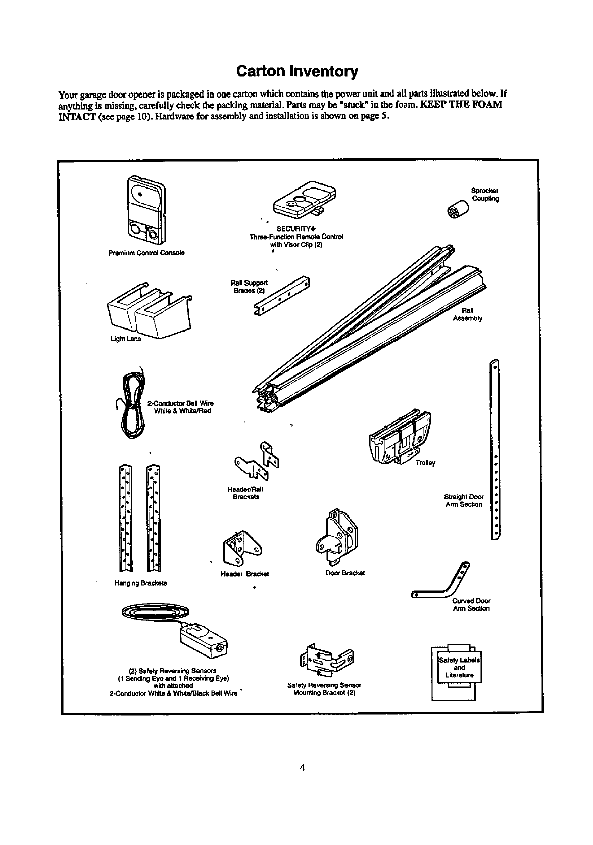
Carton Inventory
Your garage door opener is packaged in one carton which contains the power unit and all partsillustratedbelow, If
anything is missing, carefully check the packing material.Parts may be "stuck"in the foam. KEEP THE FOAM
INTACT (see page 10). Hardwarefor assembly and installation is shown on page 5.
premium Control Console
SECURITY4,
Thme*Func_on Remote Control
wlthV_r C,p(2)
Header/Rail
Brackets
Hanging Brackets
Header Bracket
(2) Safety Reversing Sensors
(1 Send_g Eye and 1 Receiving Eye)
with attached
2-Concluctor Wh_e & White/Black Bell Wire _
_Tmlley
Door Bracket
Straight Door
Arm Section
Safety Reversing Sensor
Moun_ng Bracket (2)
Hardware
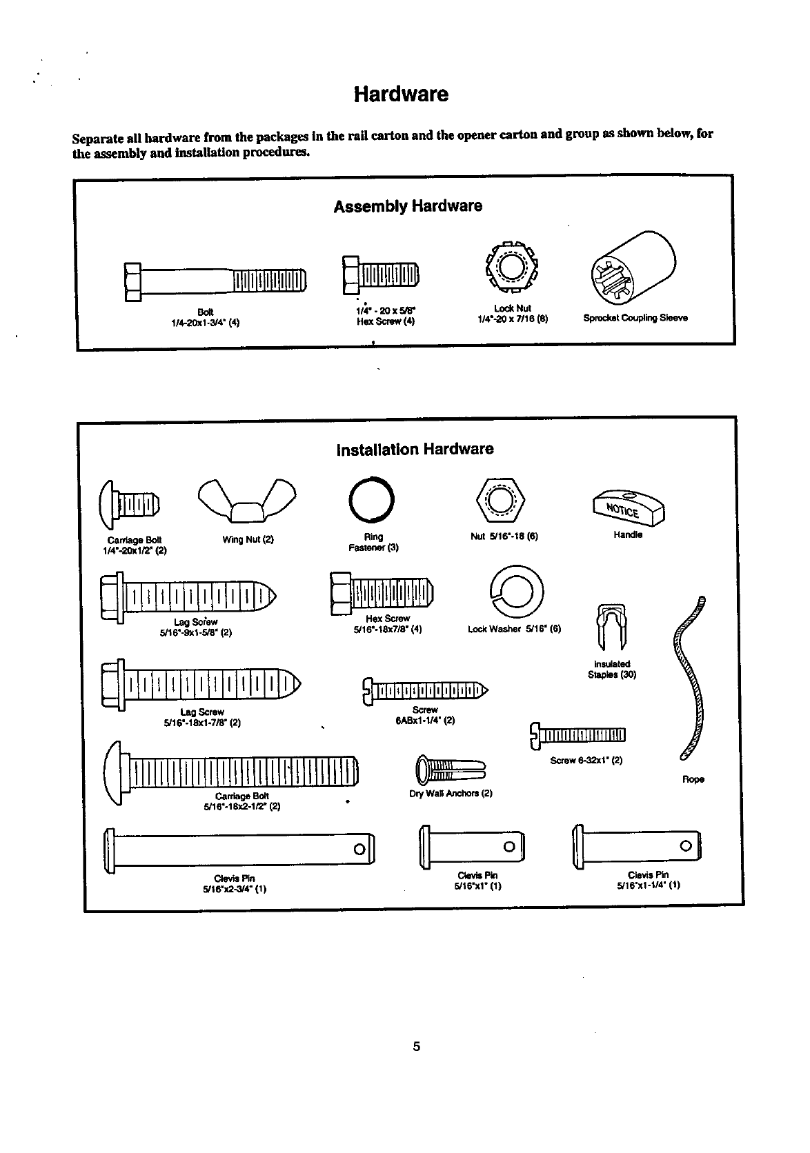
Separate all hardware from the packages In the rail carton and the opener carton and group as shown below, for
the assembly and Installation procedures,
Assembly Hardware
Bolt 114". 20 x 5/8" Lock Nut
1/4-20xl -3/4" (4) He]( Screw (4) 1/4"-20 x ?/16 (8) Sprocket Coupling Sleeve
Installation Hardware
Carriage Bolt Wing Nut (2) Ring Nut 5/16"-18 (6) Handle
1/4"-20xl/2" (2) Fastener (3)
q,,,,l,I,j0,£,J,,> ©
5/16"-9xl-5/8" (2) 5/16"-18x7/_" (4) Lock Washer 5/16" (6)
,l,lllllll,lll,lllll,l
Lag Screw
5/16"-18xl-7/8" (2)
_] l'ILl_lqq'lil'l'l'i'lq'>
Screw
6ASxl-I/4" (2)
5/16"-18x2-1/2" (2) Dry Wall Anchors (2)
Clevis Pin
5/16"x2-3L4" (1)
insulated
St_o_ (3O)
_IIIIIIIl[t I[111111111
,Screw6-32xl•(2)
Rope
C4evisPin Clevis Pin
5/16"x1" (1) 5/16"xl-I/4" (1)
5
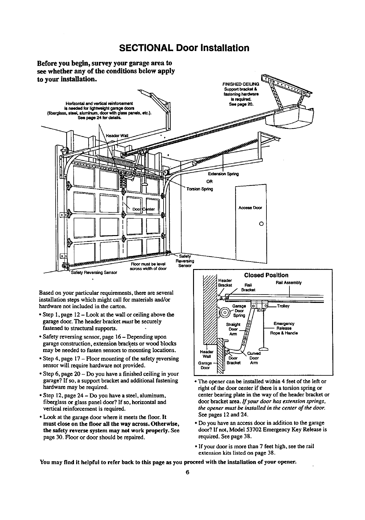
SECTIONAL Door Installation
Before you begin, survey your garage area to
see whether any of the conditions below apply
to your installation.
Horizontal and vertical reinforcement
is needed for lig_wetght garage doo_
(fiberglass, steel, aluminum, door with glass panels, etc.).
See page 24 for details.
;afety Reversing Sensor
Floo¢ must be level
across width of door
Based on your particular requiremeats, there are several
installation steps which might call for materialsand/or
hardware not included in the carton.
•Step 1,page 12 - Look at the wall or ceiling above the
garage door, The header bracket must be securely
fastened to structural supports.
• Safety reversing sensor, page 16- Depending upon
garage construction, extension bracketsor wood blocks
may be needed to fasten sensors to mounting locations.
•Step 4, page 17 - Floor mounting of the safety reversing
sensorwill require hardware not provided.
•Step 6, page 20 - Do you have a finished ceiling in your
garage? If so, a support bracket andadditional fastening
hardware may be required.
•Step 12, page 24 -Do you have a steel, aluminum,
fiberglass or glass panel door? If so, horizontal and
vertical reinforcement is required.
•Look at the garage door where it meets the floor. It
must close on the floor all the way across. Otherwise,
the safety reverse system may not work properly. See
page 30. Floor or door should be repaired.
Reversing
Sensor
Closed Position
Header Rail Assembly
Bracket Rail
B.=. I
Emergency
Arm Rope&Handle
•Curved
Door Door
Bracket Arm
•The opener can be installed within 4 feet of the left or
right of the door center if there is a torsion springor
center bearing plate in the way of theheader bracket or
door bracket area.If your door has extension springs,
the opener must be installed in the center of the door.
See pages 12 and 24.
• Do you have an access door in addition to the garage
door? If not, Model 53702 Emergency Key Release is
required. See page 38.
•If your door is more than 7 feet high, see the rail
extension kits listed on page 38.
You may find it helpful to refer back to this page as you proceed with the installation of your opener.
6
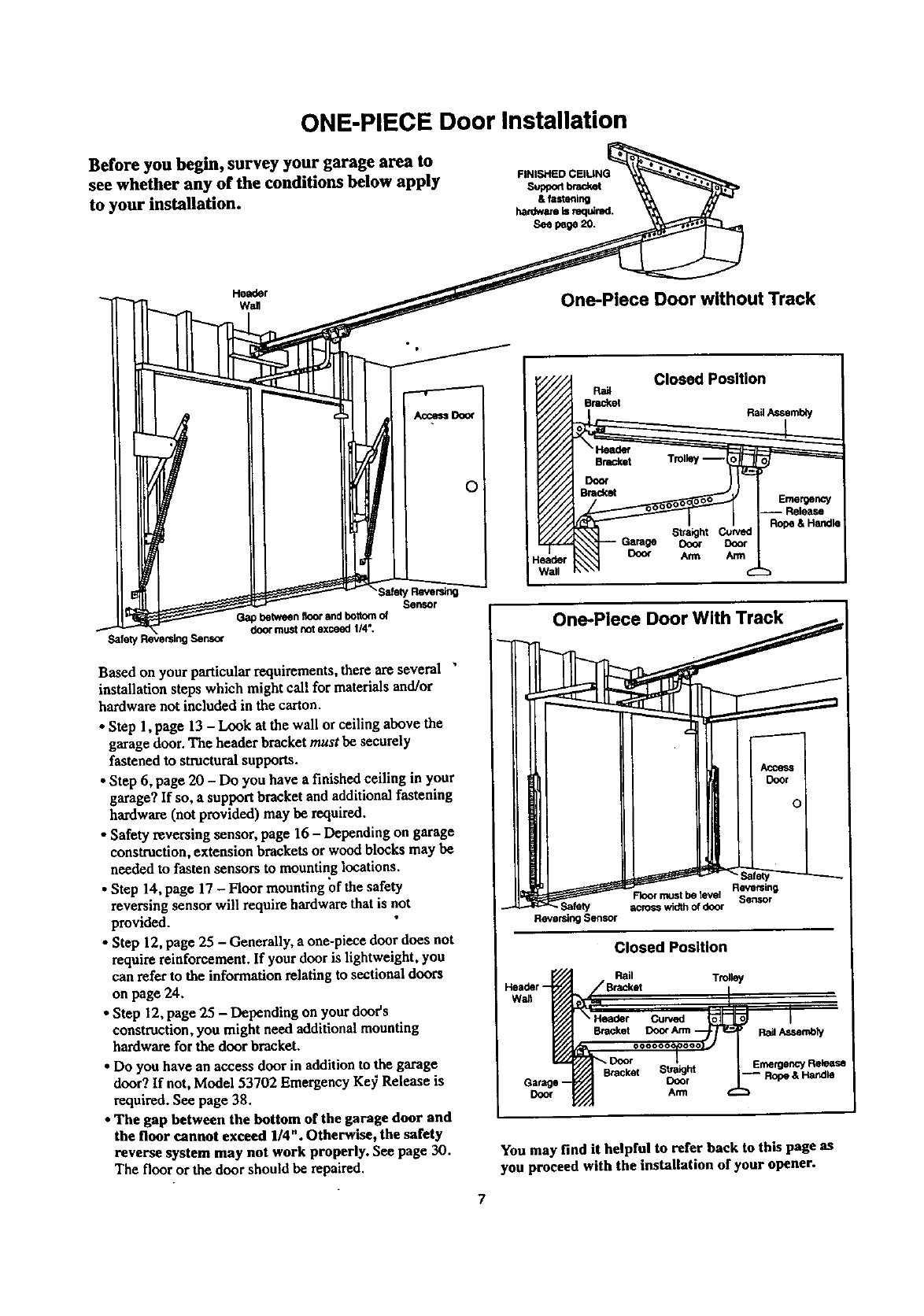
ONE-PIECE Door Installation
Before you begin, survey your garage area to
see whether any of the conditions below apply
to your installation.
FINISHED CEIUNG
supponbrad_
& fastenln9
hardware is mq_red.
Seepage20.
Header
wan One-Piece Door without Track
¸SafetyRavers_
Sensor
Gapbetweenfloorandbottomof
doormustnotexceed1/4".
Safet_ Ser_oc
Based on your particular requirements, there are several "
installation steps which might call for materials and/or
hardware not included in the carton.
•Step 1, page 13 - Look at the wall or ceiling above the
garage door. The header bracket must be securely
fastened to structural supports.
•Step 6, page 20 - Do you have a finished ceiling in your
garage? If so, a support bracket and additional fastening
hardware (not provided) may be required.
• Safety reversing sensor, page 16 - Depending on garage
construction, extension brackets or wood blocks may be
needed to fasten sensors to mounting locations.
•Step 14, page 17 - Floor mounting of the safety
reversing sensor will require hardware that is not
provided.
• Step 12, page 25 - Generally, a one-piece door does not
require reinforcement. If your door is lightweight, you
can refer to the information relating to sectional doors
on page 24.
• Step 12, page 25 - Depending on your door's
construction, you might need additional mounting
hardware for the door bracket.
• Do you have an access door in addition to the garage
door? If not, Model 53702 Emergency Ke37 Release is
required. See page 38.
•The gap between the bottom or the garage door and
the floor cannot exceed 1/4" . Otherwise, the safety
reverse system may not work properly. See page 30.
The floor or the door should be repaired.
Closed Position
Ra_
Bracket Rail Assembi'/
Garage Dora
Doo_ Arm
eader )
Wall
Reversing
Floor rt_st be _vel
across width of door
Reversl_l Sensor
Closed Position
Garage --
Door
Rail Trolley
_,_,t ooc_-i/=_ 1. _,,.._._
Bracket S_rht -- Rope & Handle
You may find it helpful to refer back to this page as
you proceed with the installation of your opener.
7
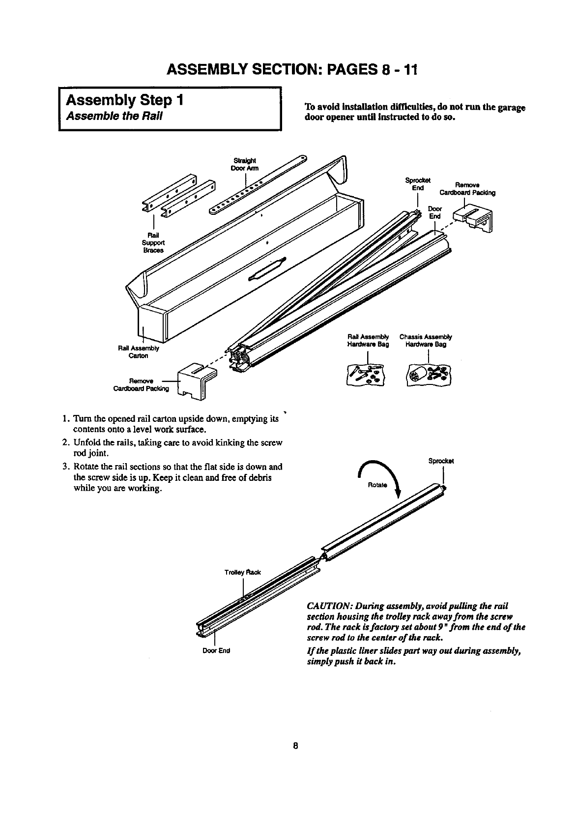
ASSEMBLY SECTION: PAGES 8 -11
I Assembly Step 1
Assemble the Rail ITo avoid installation difficulties, do not run the garage
door opener until instructed to do so.
Sprodcet
End Remove
i Cardboard Paddng
RailAssemb_/
Carton
Remove
Cardboard
1. Turn the opened rail carton upside down, emptying its
contents onto a level work surface.
2. Unfold the rails, tal_ng care to avoid kinking the screw
rod joint.
3. Rotate the rail sections so that the fiat side is down and
the screw side is up. Keep it clean and free of debris
while you are working. %Sprocket
End
CAUTION: During assembly, avoid pulling the rail
section housing the trolley rack away from the screw
rod. The rack is factory set about 9 "from the end of the
screw rod to the center of the rack.
If the plastic liner slides part way out during assembly,
simply push it back in.
8
IAssembly Step I (Continued) ]
Assemble the Rail
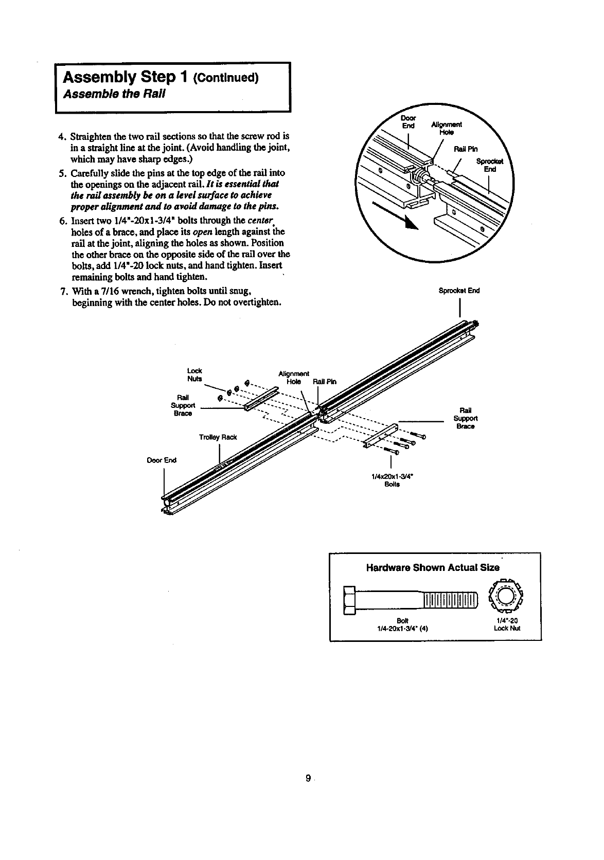
4. Straighten the two rail sections so that the screw rod is
in a straightllne at the joint. (Avoid handling thejoint,
which may have sharp edges.)
5. Carefully slide the pins at the top edge of the rail into
the openings on the adjacent rail. It is essential that
therailassemblybe on a levelsurfacetoachieve
properalignmentand toavoiddamagetothepins.
6.Inserttwo I/4"-20xi-3/4"boltsthroughthecentsr
holes of a brace, and place its open length against the
rail at the joint, aligning the holes as shown. Position
the other brace on the opposite side of the rail over the
bolts, add 1/4"-20 lock nuts, and handtighten. Insert
remaining bolts and hand tighten.
7. With a 7/16 wrench, tighten bolts until snug,
beginning with the center holes. Do not overtighten.
Sprocket End
I
Lock
Nuts
Pail
St_port
Brace
Trolley Rack
Deor End
Alignment
Hole RailPin
I
1/4x20x1-3/4"
Bo_ts
Rail
Super
Brace
Hardware Shown Actual Size
illllllllllllllllll}O
Bolt 114"-20
1/4-20x1-3/4" (4) Lock Nut
I ssembly Step 2 I
Fasten the Rad To the Power Unit
and Install the Trolley
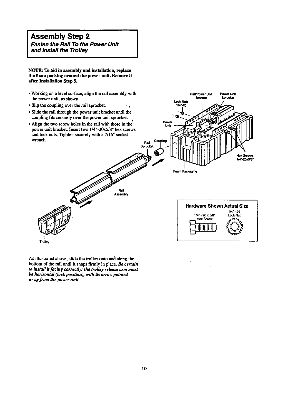
NOTE: To aid in assembly and installation, replace
the foam packing around the power unit. Remove It
after Installation Step 5.
•Working on a level surface, align the rail assembly with
the power unit, as shown.
• Slip the coupling over the rail sprocket. •,
•Slide the rail through the power unit bracket until the
coupling fits securely over the power unit sprocket. J
•Align the two screw holes in the rall with those in the
power unit bracket. Insert two 1/4"-20x5/8" hex screws
and lock nuts. Tighten securely with a 7/16" socket
wrench.
Power
Unit
Lock Nuts
1/4o-20
Rail/PowerUnit
Bmda_ PowerUn_
Sprocket
Hex Screws
114"-20x5/8"
Foam Packaging
Trolley
Hardware Shown Actual Size
1/4" -20
1/4" - 20 x 5,'8" Lock Nut
As illustrated above, slide the trolley onto anc'lalong the
bottom of the rail until it snaps firmly in place. Be certain
to install itfaclng correctly: the trolley release arm must
be horizontal (Iock pasition), with its arrow pointed
away from the power unit.
10
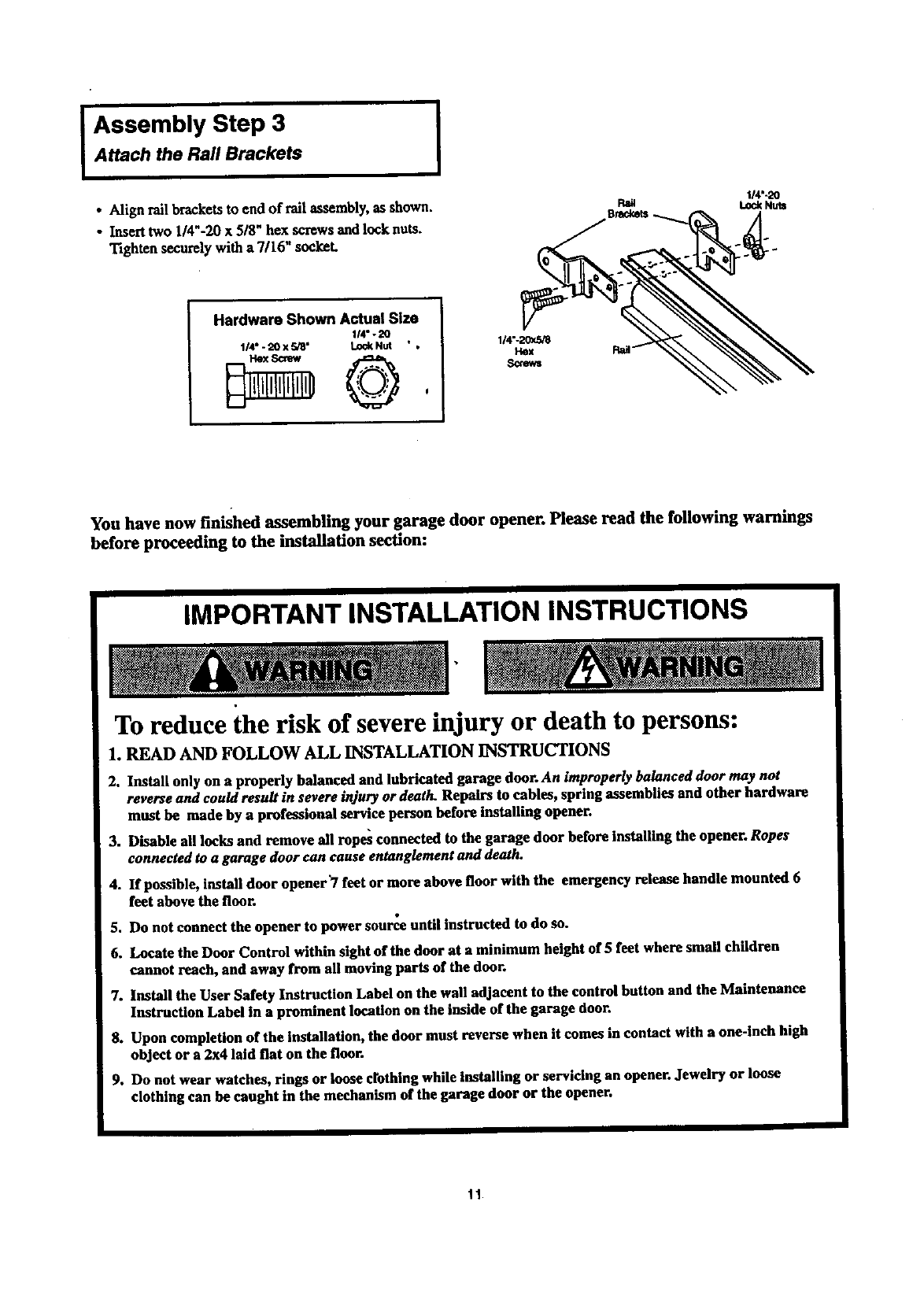
Assembly Step 3
Attach the Rail Brackets I
• Align rall br_kets to end of tall assembly, as shown.
• Insert two 1/4"-20 x5/8" bex screws and lock nuts.
Tighten securely with a 7/16" socket.
I/4"-20
t.eckNu_
Hardware Shown Actual Size
114"- 20
114" - 20 X 5/8" Lod( Nut " , 1/4"-20x5_
Hex
Screws
You have now finished assembling your garage door opener. Please read the following warnings
before proceeding to the installation section:
IMPORTANT INSTALLATION INSTRUCTIONS
To reduce the risk of severe injury or death to persons:
1. READ AND FOLLOW ALL INSTALLATION INSTRUCTIONS
2. Install only on a properly balanced and lubricated garage door. An improperly balanced door may not
reverse and could result in severe injury or death. Repairs to cables, spring assemblies and other hardware
must be made by a professional service person before Installing opener.
3. Disable all locks and remove all ropes connected to the garage door before installing the opener. Ropes
connected to a garage door can cause entanglement and death.
4. If possible, install door opener"/feet or more above floor with the emergency release handle mounted 6
feet above the floor.
5. Do not connect the opener to power somme until instructed to do so.
6. Locate the Door Control within sight of the door at a minimum height of 5 fret where small children
cannot reach, and away from all moving parts of the door.
7. Install the User Safety Instruction Label on the wall adjacent to the control button and the Maintenance
Instruction Label in a prominent location on the inside of the garage door.
8. Upon completion of the installation, the door must reverse when it comes in contact with a one-inch high
object or a 2x4 laid flat on the floor.
9. Do not wear watches, rings or loose crothing while Installing or servicing an opener. Jewelry or loose
clothing can be caught in the mechanism of the garage door or the opener.
11
INSTALLATION SECTION: PAGES 12- 27
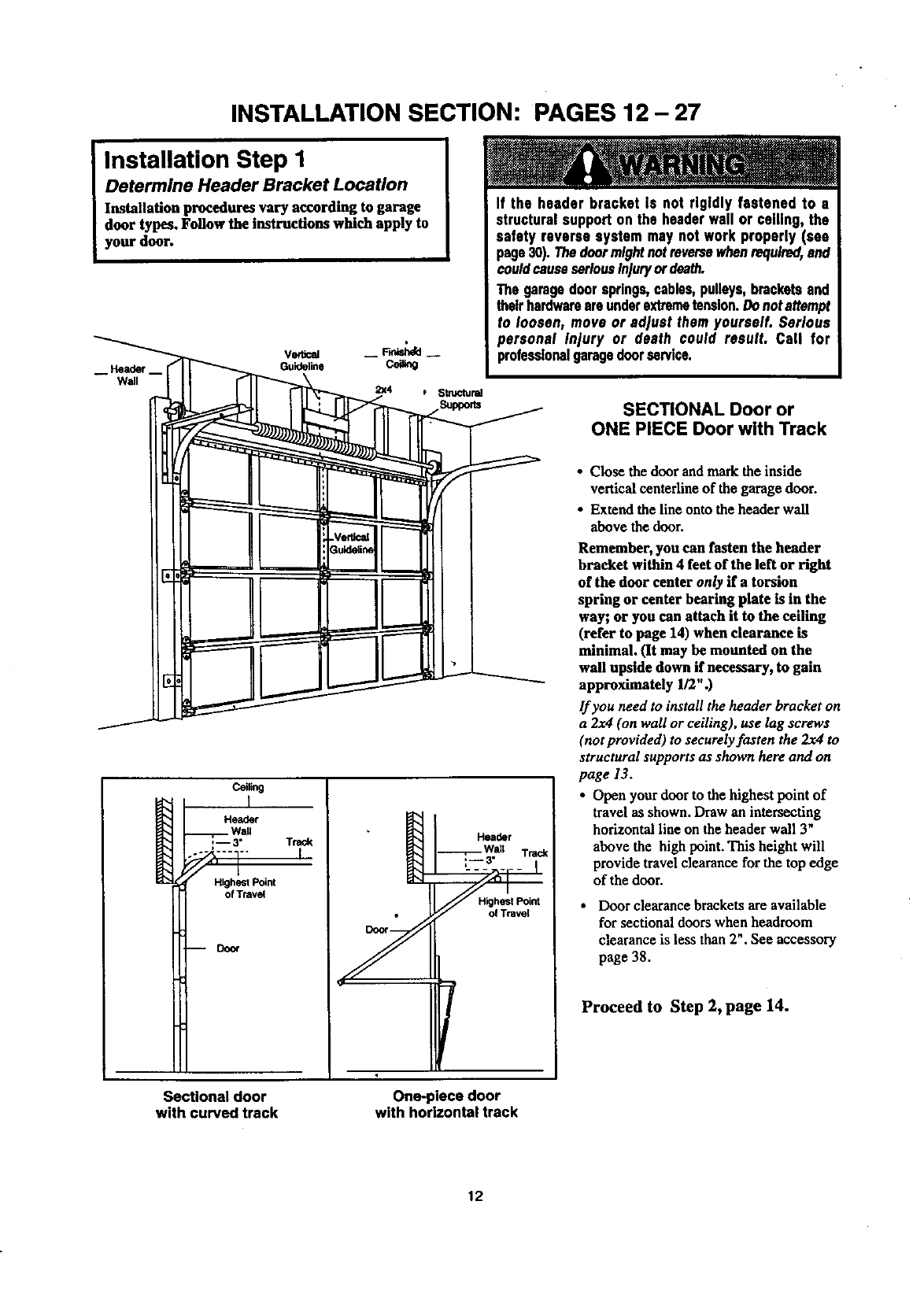
Installation Step 1
Determine Header Bracket Location
Installation procedures vary according to garage
door types. Follow the instructions which apply to
your door.
-- Header--
Wall
VedJcal -- F.dsh4d --
Guideline CeU_g
If the header bracket Is not rigidly fastened to •
structuralsupport on the headerwall or ceiling, the
safety reverse system may not work properly (see
page30). Thedoormightnotreversewhenrequired,and
couldcauseseriousInjuryordeath.
The garagedoorsprings,cables,pulleys,bracketsand
theirhardwareareunderextremetension.Donotattempt
to loosen, move or adjust them yourself. Serious
personal Injury or death could result• Call for
profeaslonslgaragedoorservice.
SECTIONAL Door or
ONE PIECE Door with Track
Ceiling
I
Header
Wall
:-- 3" Track
91 '
Highest Point
of Travel
mDoor Y
Header
Wait Trad(
Highest Point
/
• Close the door and mark the inside
vertical ceaterline of the garage door.
•Extend the line onto the header wall
above the door.
Remember, you can fasten the header
bracket within 4 feet of the left or right
of the door center only if a torsion
spring or center bearing plate is in the
way; or you can attach it to the ceiling
(refer to page 14) when clearance is
minimal. (It may be mounted on the
wall upside down if necessary, to gain
approximately 1/2".)
If you need to install the header bracket on
a 2x4 (on wall or ceiling), use lag screws
(not provided) to securely fasten the 2x4 to
structural supports as shown here and on
page 13.
• Open your door to the highest point of
travel as shown. Draw an intersecting
horizontal line on the header wall 3"
above the high point. This height will
provide travel clearance for the top edge
of the door.
•Door clearance brackets are available
for sectional doors when headroom
clearance is less than 2". See accessory
page 38.
Proceed to Step 2, page 14.
Sectional door
with curved track One-piece door
with horizontal track
12
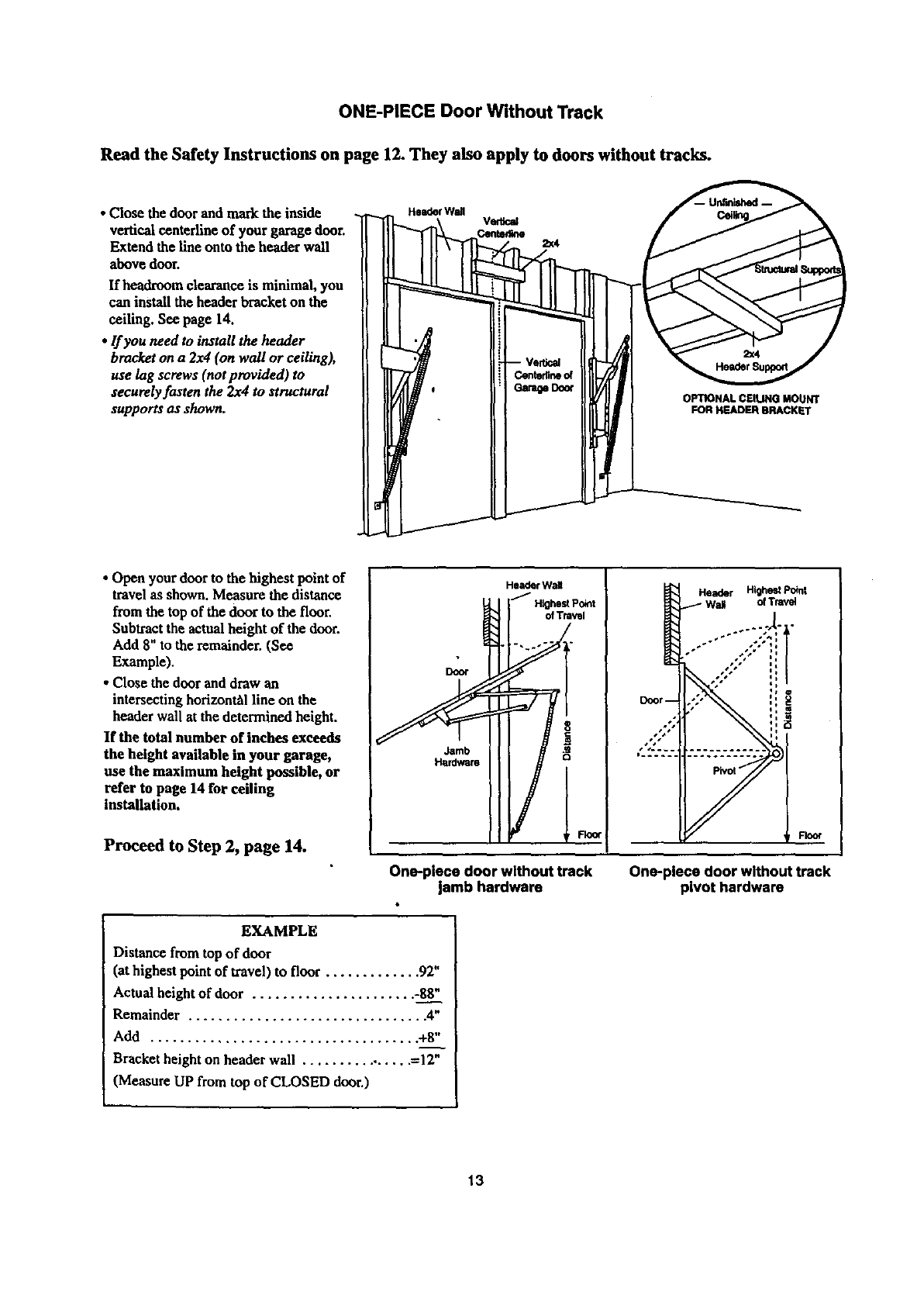
ONE-PIECE Door Without Track
Read the Safety Instructions on page 12. They also apply to doors without tracks.
• Close the door and mark the inside
vertical centerline of your garage door.
Extend the line onto the header wall
above dour.
If headroum clearance is minimal, you
can install the header bracket on the
ceiling. See page 14.
•If you need to install the header
bracket on a 2x4 (on wall or ceiling),
use lag screws (not provided) to
securely fasten the 2x4 to structural
supports us shown. OPTIONAL CEIUNG MOUNT
FOR HEADER BRACKET
• Open your door to the highest point of
travel as shown. Measure the distance
from the top of the door to the floor.
Subtract the actualheight of the dour.
Add 8" to the remainder. (See
Example).
• Close the dour and draw an
intersecting horizon_l line on the
header wall at the determined height.
If the total number of inches exceeds
the height available in your garage,
use the maximum height possible, or
refer to page 14 for ceiling
installation.
Proceed to Step 2, page 14.
Door
Jamb
Hardware
Header WaU
_/Hlghe_Po_t
Header Highest Pokl|
Wall ofTravel
'4
i
One-piece door without track
jamb hardware One-place door without track
pivot hardware
EXAMPLE
Distance from top of door
(at highest point of travel) to floor ............. 92"
Actual height of door ...................... -88"
Remainder ................................ 4"
Add .................................... +8"
Bracket height on header wall ................ =12"
(Measure UP from top of CLOSED door.)
13
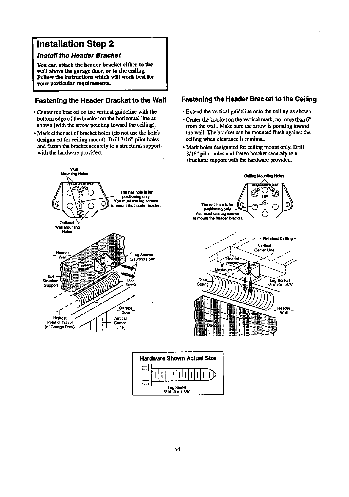
Installation Step 2
Install the Header Bracket
You can attach the header bracket either to the
wall above the garage door, or to the ceiling.
Follow the instructions which will work best for
your particular requirements.
Fastening the Header Bracket to the Wall
• Center the bracketon the vertical guideline with the
bottom edge of the bracket on the horizontal line as
shown (with the arrow pointing toward the ceiling)..
• Mark either set of bracket holes (do not use the holes
designated for ceiling mount). Drill 3/16" pilot holes
and fasten the bracket securely to a structural supporh
with the hardware provided.
Wall
Moonting Holes
Opfion_
Wall MounS_
Holes
0I \\ The.al,_._
-""-I rA\\ Youmustmml_
y _ mount the header bracket.
Header Screws
5/16"x9x1-5/8"
Structural
Suppod
Fastening the Header Bracket to the Ceiling
•Extend the vertical guideline onto the ceiling as,shown.
•Center thebracket on the verticalmark.no more than 6"
from the wall. Make sure thearrow is pointing toward
the wall. The bracket can be mounted flush against the
ceiling when clearance is minimal.
•Markholes designated for ceiling mount only. Drill
3/16" pilot holes and fasten bracketsecurely to a
structural support with the hardware provided.
c_ Mo,a_ng8o_s
"i_e na_ hoie is f_
positioningonly.
You must use lag screws
to mount the header brackeL
s,
_, is
Highest
Point of Travel
(of Garage Door)
Vertical
Center
Line,
Hardware Shown Actual Size
l,lli,lll,l'l'lll'l
5/16".9 x 1-r-J8"
14
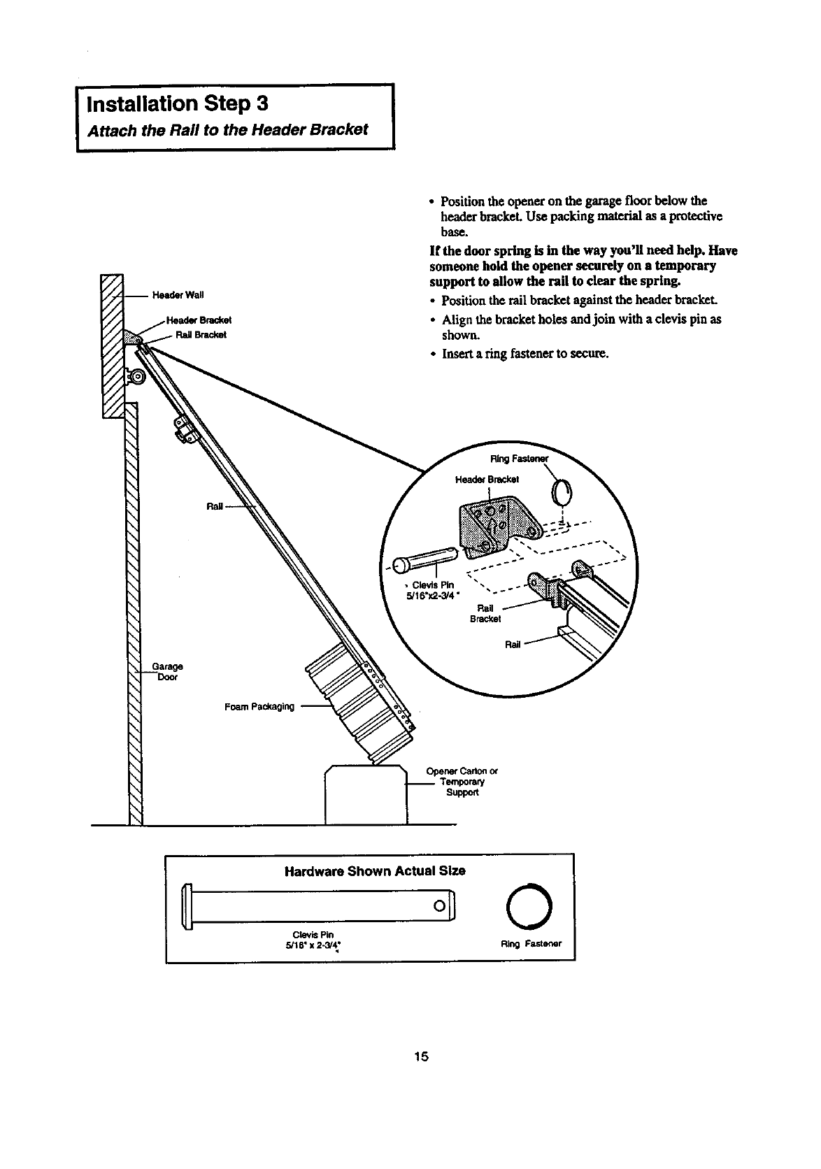
IInstallation Step 3 [
Attach the Rail to the Header Bracket
rWall
€Bracket
Foam packaging
• Position theopener on the garage floor below the
header bracket. Use packing material as a protective
base.
If the door spring is in the way you'll need help. Have
someone hold the opener securely on a temporary
support to allow the rail to clear the spring.
• Position the rail bracket against the header brackeL
• Align the bracket holes andjoin with a clevis pin as
shown.
•Inserta ring fastener to secure.
RingFastener
Head_ Bracket
• _w _
•Clevis Pin
5/I 6"x2-3/4"
Rail
BraCket
OpenerCad0n0_
Temporar/
Suppo_
Hardware Shown Actual Size
oil
Clevis Pin
5/16" x 2-_4;
©
Ring Fastener
15
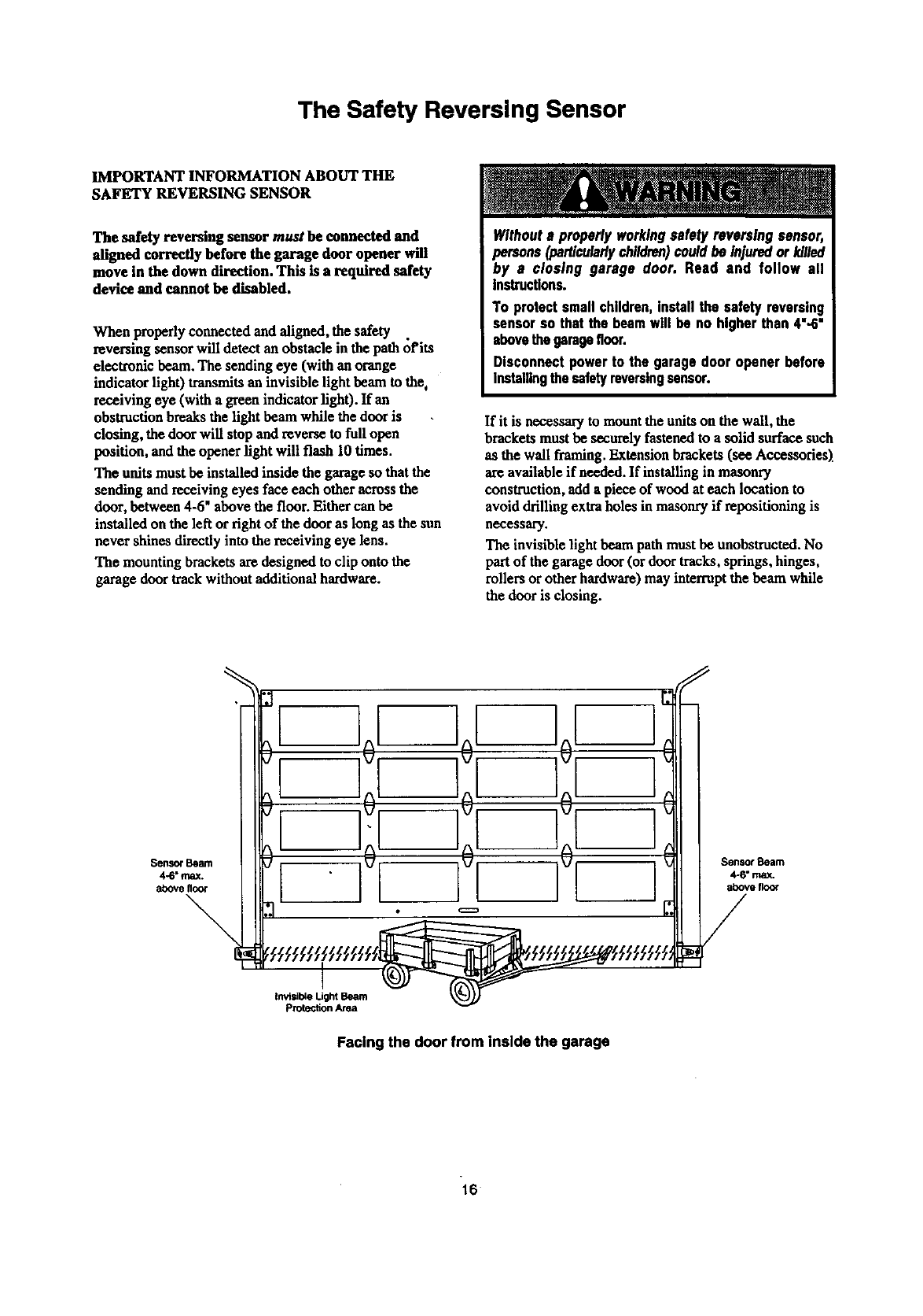
The Safety Reversing Sensor
IMPORTANT INFORMATION ABOUT THE
SAFETY REVERSING SENSOR
The safety reversing sensor must be connected and
aligned correctly before the garage door opener will
move in the down direction. This is a required safety
device and cannot be disabled.
When properly connected and aligned, the safety .
reversing sensor will detect an obstacle in the path of its
electronic beam. The sending eye (with an orange
indicator light) transmits an invisible light beam to the,
receiving eye (with a green indicator light). If an
obstruction breaks the light beam while the door is
closing, the door will stop and reverse to full open
position, and the opener light will flash 10 times.
The units must be installed inside the garage so that the
sending and receiving eyes face each other across the
door, between 4-6" above the floor. Either can be
installed on the left or right of the door as long as the sun
never shines directly into the receiving eye lens.
The mounting brackets am designed to clip onto the
garage door track without additional hardware.
Withouts properlyworkingsafetyreversing sensor,
persons (particularlychildren)couldbe injuredor killed
by a closing garage door. Read and follow all
Instructions.
To protectsmallchildren,installthe safety reversing
sensorso that the beamwill be no higherthan 4"-6"
abovethegaragefloor.
Disconnectpowerto the garagedoor openerbefore
installingthesafetyreversingsensor.
If it is necessary to mount the units on the wall, the
brackets must be securely fastened to a solid surface such
as the wall framing. Extension brackets(see Accessories)
are available if needed. If installing in masonry
construction, add a piece of wood at each location to
avoid drilling extra holes in masonry if repositioning is
necessary.
The invisible light beam path mustbe unobstructed. No
part of the garage door (ordoor tracks, springs, hinges,
rollers or other hardware)may interruptthe beam while
the door is closing.
I]0[ ]0[ If
,]11°,/,/
Facing the door from inside the garage
16
IInstallation Step 4 i
Install the Safety Reversing Sensor
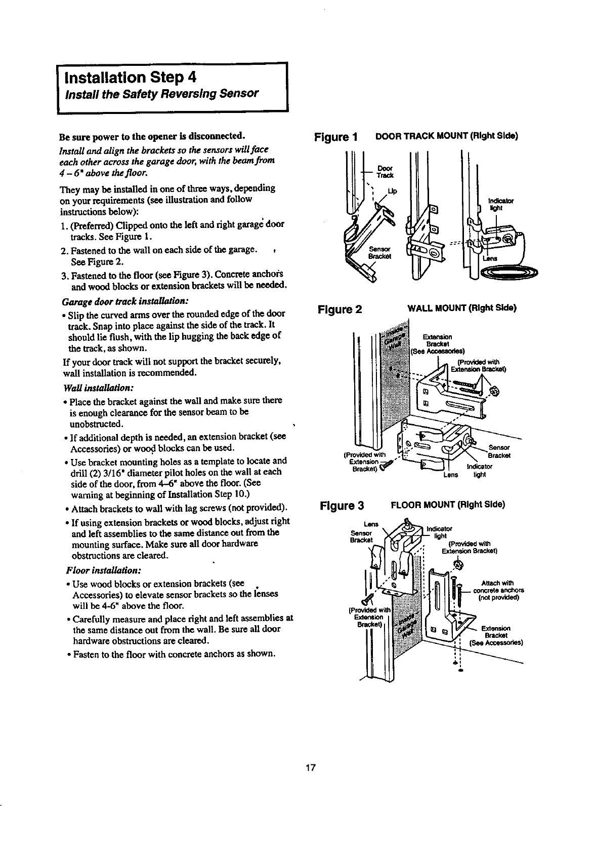
Be sure power to the opener is disconnected.
Ir_tall and align the brackets so the sensors will face
each other across the garage door, with the beam from
4-6" above thefloor.
They may be installed in one of three ways, depending
on your requirements (see illustration and follow
instructions below):
I. (Preferred) Clipped onto the left and fight garag_ door
tracks. See Figure 1.
2, Fastened to the wall on each side of the garage. ,
See Figure 2.
3. Fastened to the floor (see Figure 3). Concrete anchors
and wood blocks or extension bracketswill be needed.
Garage door track installation:
• Slip the curved arms over the rounded edge of the door
track.Snap into place against the side of the track.It
should lie flush, with the lip hugging the hack edge of
the track,as shown.
If your door track will not supportthe bracket securely,
wail installation is recommended.
Wallinstallation:
•Place the bracket against the wall and make sure there
is enough clearance for the sensor beam to be
unobstructed.
•If additional depth is needed, an extension bracket (see
Accessories) or wood blocks can be used.
• Use bracket mounting holes as a template to locate and
drill (2) 3/16' diameter pilot holes on the wall at each
side of the door, from 4-6" above the floor. (See
warning at beginning of Installation Step 10.)
• Attach brackets to wall with lag screws (not provided).
• If using extension brackets or wood blocks, adjustfight
and left assemblies to the same distance out from the
mounting surface. Make sure all door hardware
obstructions are cleared.
Floor installation:
• Use wood blocks or extension brackets(see
Accessories) to elevate sensor brackets so the lenses
will he 4-6" above the floor.
•Carefully measure and place fight and left assemblies at
the same distance out from the wall. Be sure all door
hardware obstructions are cleared.
•Fasten to the floor with concrete anchors as shown.
Figure I DOOR TRACK MOUNT (Right Side)
Figure 2 WALL MOUNT (Right Side)
Bracket
(Provided with
Extension '
Bracket) _
L_n$
Figure 3
Lens
Sensor
Brad_t
FLOOR MOUNT (Right Side)
IIndicator
,h light (Provided with
•": _Bnicket)
Inotprovided)
F.xtension
o
17
I Installation Step 4 (Continued)
Install the Safety Reversing Sensor I
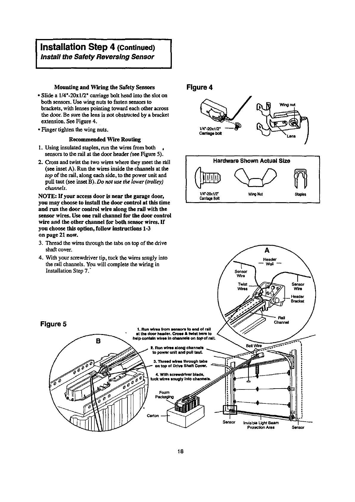
Mounting and Wiring the Safety Sensors
• Slide a1/4"-20xl/2" carriage bolt head into the slot on
both sensors. Use wing nuts to fasten sensors to
brackets, with lenses pointing toward each other across
the door. Be sure the lens is not obstructed by a bracket
extension. See Figure 4.
• Finger tighten the wing nuts.
Recommended Wire Routing
1. Using insulated staples, run the wires fromboth ,
sensors to the rail at the door header (see Figure 5).
2. Cross and twist the two wires where they meet the t_il
(see inset A). Run the wires inside the channels at the
top of the rail, along each side, to the power unit and
pull taut (see inset B). Do not we the lower (trolley)
channels.
NOTE: If your access door is near the garage door,
you may choose to install the door control at this time
and run the door control wire along the rall with the
sensor wires. Use one rail channel for the door control
wire and the other channel for both sensor wires. If
you choose this option, follow instructions 1-3
on page 21 now.
3. Thread the wires through the tabs on top of the drive
shaft cover.
4. With your screwdriver tip, tuck the wires snugly into
the rail channels. You will complete the wiring in
InstallationStep 7.'
Figure 4
can_e_
Hardware Shown Actual Size
1/4"-20xl/2" W_O Nut Staples
CarriageBolt
A
Figure 5 1. Run wlrH from een_ to end of rall
•at the door header. Crmm & twist hem to
/__,, help contain wires In channels on top of n
S. Run wires along channels
4. With screwdriver blade,
k wires snugty Into channels.
Sensor Invisible Light Beam
protection Area Senso¢
18
Installation Step 5 I
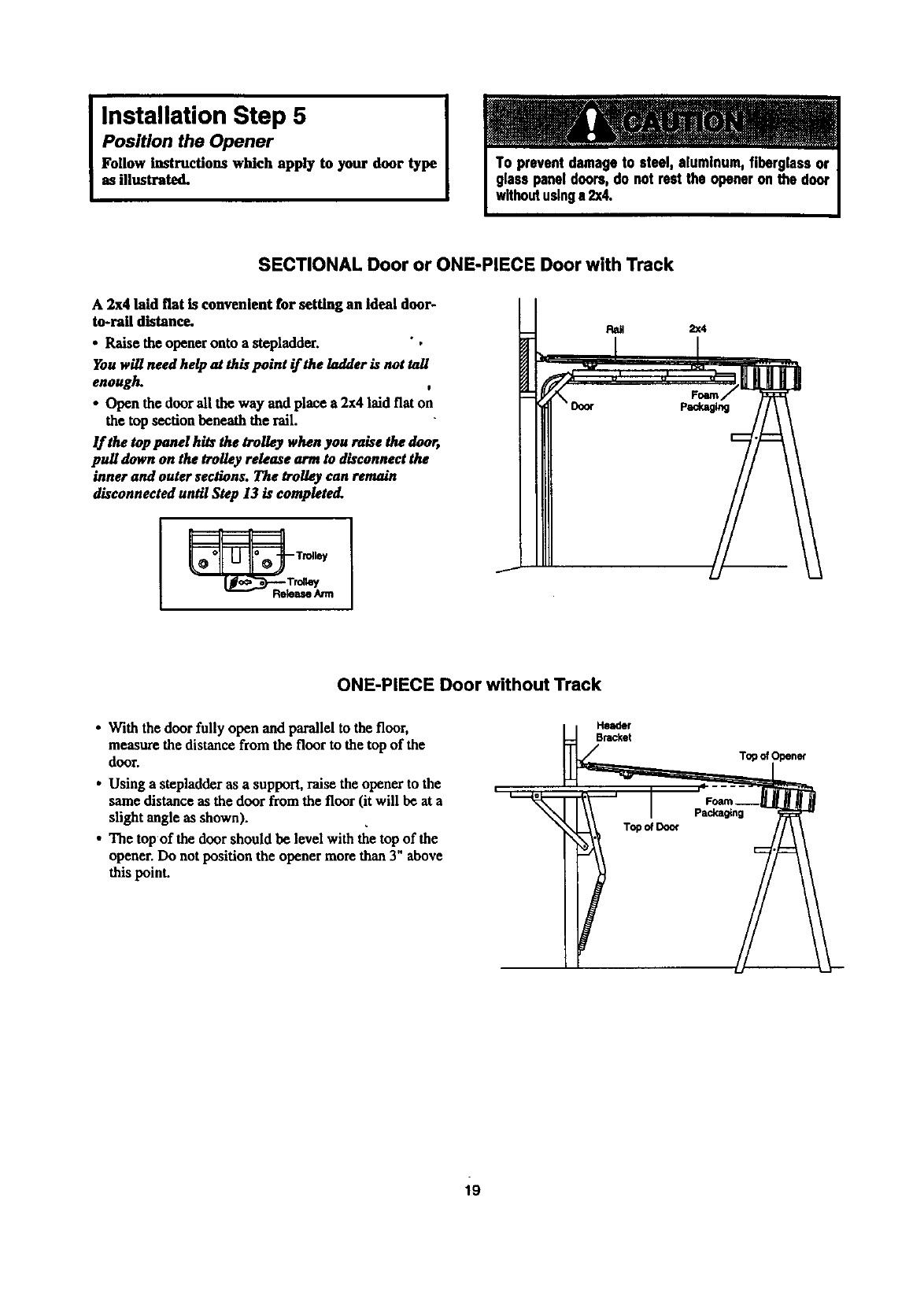
Position the Opener
Follow Instructions which apply to your door type
as illustrated.
SECTIONAL Door or ONE-PIECE Door with Track
A 2x4 laid fiat is convenient for setting an Ideal door-
to-rail distance.
• Raise the opener onto a stepladder. ",
You will need help at this point if the ladder is not tall
enough. t
•Open the doorall the way and place a 2x4 laid flat on
the top section beneath the rail.
If the top pond hits the trolley when you raise the door,
pull down on the trolley release ammto disconnect the
inner and outer sections. The trolley can remain
disconnected until Step 13 is completo(L
__ Trolley
ONE-PIECE Door without Track
•With the door fully open and parallel to the floor,
measure the distance from the floor to the top of the
door.
•Using a stepladder as a support, raise the opener to the
same distance as the door from the floor (it will be at a
slight angle as shown).
•The top of the door should be level with the top of the
opener. Do not position the opener more than 3" above
this point.
Topo_Doo_
Top of
19
IInstallation Step 6
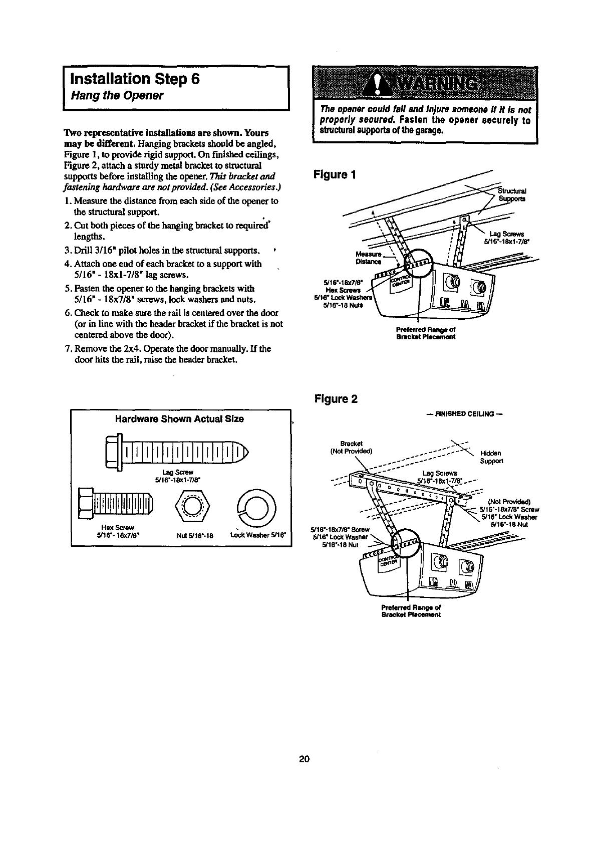
Hang the Opener
Two representative Installations are shown. Yours
may be different. Hanging brackets should be angled,
Figure 1, to provide rigid support. On finished ceilings,
Figure 2, attach a sturdymetal bracketto sh'uctoral
supports before installing the opener. This bracket and
fastening hardware are not provided. (See Accessories.)
1.Measure the distancefrom each side of the opener to
the structuralsupport.
2. Cut both pieces of the hanging bracket to required'
lengths.
3. Drill 3/16" pilot holes in the structuralsupports. ,
4. Attach one end of each bracket to a supportwith
5/16" -18xl-7/8" lag screws.
5. Fasten the opener to the hanging bracketswith
5/16" - 18x7/8" screws, lock washers and nuts.
6. Check to make sure the rail is centered over the door
(or in line with the header bracket if the bracket is not
centered above the door).
7. Remove the 2x4. Operate the doormanually. If the
door hits the rail, raise the header bracket.
I
Figure I
Distance
5/16"-18X7/8"
Hex Scn_s
5/16"-18 Nuts
Screws
5/16"-18xl-7/8"
PreferredRangeof
BracketPlacement
Hardware Shown Actual Size
IItltllllllllrlllll
Lag Screw
5/16"-18XI-7/8"
Hex _
5/16"- 18x7/8" Nut 5/16"-18 ©
Lock Washer 5/16"
Figure 2
Bracket
(Not Provided)
_÷
5/16"-18x7/8" Screw
5/16"-18 Nut
-- FINISHED CElUNG --
:.:": :":"_" Hidden
Support
Lag Screws
(Not provided)
5/16"-18x7/8" Screw
5/16" Lock Washer
5/16"-18 Nut
Preferred Range of
Bracket Plmcement
2O
IInstallation Step 7
and Connect all Wiring
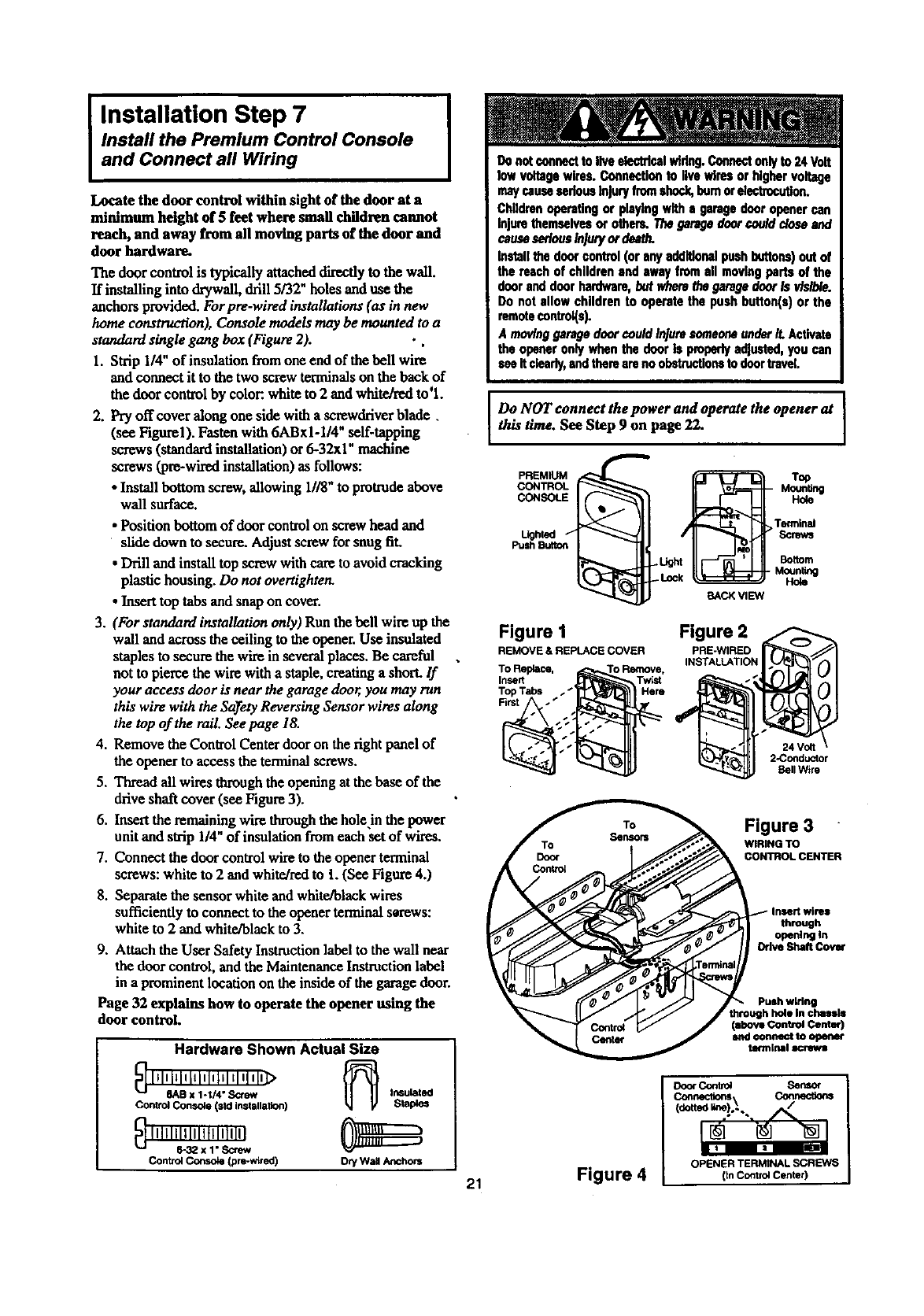
Install the Premium Control Console
Locate the door control within sight of the door at a
minimum height of 5 feet where small children cannot
reach, and away from all moving parts of the door and
door hardware.
The door control is typically attacheddirectly tothe wall.
If installing into drywall, drill 5/32" holes and use the
anchors provided. Forpre-wired installations (as in new
home construction), Console models may be mounted to a
standard single gang box (Figure 2). • ,
1. Strip 1/4" of insulation fromone end of the bell wire
and connect it to the two screwterminals on the back of
the door control by color:,white to 2 and white/red to'l.
2. Pry off cover along one side with a screwckiverblade.
(see Figurel). Fasten with 6ABxI-1/4" self-tapping
screws (standardinstallation) or 6-32xl" machine
screws (pre-wiredinstallation) as follows:
• Install bottom screw, allowing 1118"to protrudeabove
wall surface.
• Position bottom of door control on screw head and
slide down to secure. Adjust screw for snug fit.
•Drill and install top screw with care to avoid cracking
plastic housing. Do not overtighten.
•Inserttop tabs and snapon cover.
3. (For standard installation only) Run the bell wire up the
wall and across the ceiling to theopener.Use insulated
staples to secure the wire in several places. Be careful
not to pierce the wire with a staple, creating a short. If
your access door is near the garage door, you may ran
this wire with the Sa)_etyReversing Sensor wires along
the top of the rail. See page 18.
4. Remove the Control Center door on the rightpanel of
the opener to access the terminal screws.
5. Thread all wires throughthe opening at the base of the
drive shaft cover (see Figure 3).
6. Insertthe remaining wire throughthehole in the power
unit and sVip 1/4" of insulation fromeach set of wires.
7. Connect the door control wire to the opener terminal
screws: white to 2 and white/redto t. (See Figure 4.)
8. Separatethe sensor white and white/black wires
sufficiently to connect to the opener tenalnal serews:
white to 2 and white/black to 3.
9. Attach the User Safety InsUuctionlabel to the wall near
the door control, and the MaintenanceInst_ction label
in a prominent location on the inside of the garagedoor.
Page 32 explains how to operate the opener using the
door control.
Hardware Shown Actual Size
_ lllnl_lllllelllmltl q1In]>
8AB x 1-1/4" S<;few In6ul_t_
Control Console (sld installation) StaPles
Control C_ (pro-wired) Dry Wall Anchors
maycausesedansInjuryfromshock,bumorelectrocution.
Childrenopa_tlngorplayingwithagaragedooropenercan
Injure themselvesorothers.Thegaragedoorcoulddoseand
causeseriousInjuryordeath.
Inmll thedoorcontrol(oranyadditionalpushbuttons)outof
thereachofchildrenandswayfromall movingpartsofthe
dooranddoorhardware,butwherethegaragedoorIsvisible.
Donotallowchildrento operatethepushbutton(s)orthe
remotecontrol(s).
A movinggaragedoorcouldInjuresomeoneunderit.Activate
the openeronlywhenthedoorIs properlyadjusted,youcan
seeItclearly,andtherearenoobstructionstodoortravel
Do NOT connect the power and operate the opener at
this t/me. See Step 9 on page 22.
PREMIUM
CONTROL
CONSOLE
Lighled
Push Button
Figure 1
REMOVE &REPLACE COVER
To Replace, 'o Remove,
Insert Twist
Top Tabs
First
BACK VIEW
Figure 2
PRE-WlRED
INSTALLATION
Top
MounUng
Hole
Terminal
Screws
Bottom
MounUng
Hole
24 Volt
2-Conducthr
Bell Wire
Figure 3
WIRING TO
CONTROL CENTER
through
openlr_lIn
Odve ShaftCOv_
Push wiring
through hole in chassis
(above Control Center)
and €onnect to open_
tefmJrml screws
DocxContr_ Sensor
Connections Connections
_do.__.!_.,
21 Figure 4 OPENER TERMINAl SCREWS
(In Control Center)
I Installation Step 8
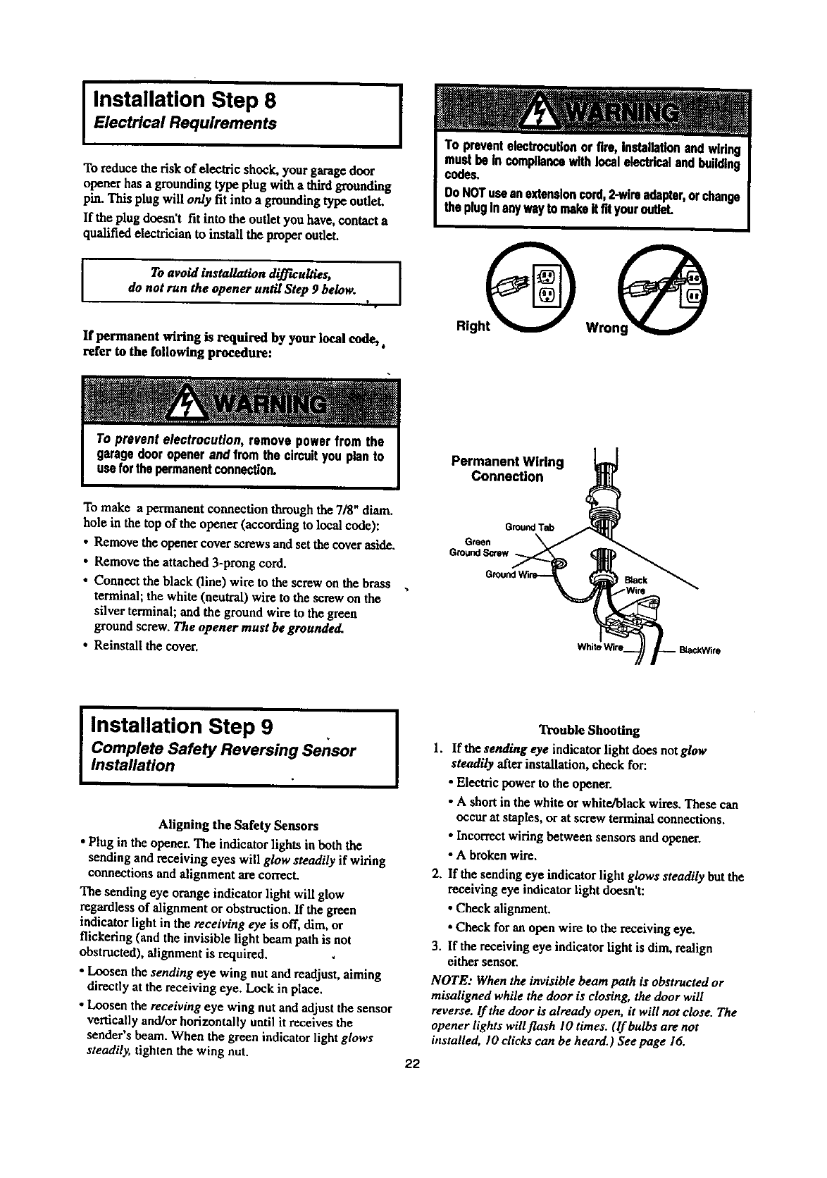
Electrical Requirements
To reduce the risk of electric shock, yourgarage door
opener has a grounding type plug with a thirdgrounding
item.Thisplug willonly fit into a grounding type outh.q.
If the plug doesn't fit into the outlet you have, contact a
qualified electrician to install the proper outlet.
ITo avoid installation difficulties, [
do not run the opener until Step 9 below.
I •
If permanent wiring is required by your local code,.
refer to the following procedure:
To make apermanent connection through the 7/8" diam.
hole in the top of the opener (according to local code):
• Remove the opener cover screws and set the cover aside.
• Remove the attached 3-prong cord.
• Connect the black (line) wire to the screw on the brass
terminal; the white (neutral) wire to the screw on the
silver terminal; and the ground wire to the green
ground screw. The opener must be grounded.
• Reinstall the cover.
Permanent Wiring
Connection
G_nd T_
Green
GroundS_ew
I Installation Step 9 , ]
Complete Safety Reversing Sensor
Installation
Aligning the Safety Sensors
• Plug in the opener, The indicator lights in both the
sending and receiving eyes will glow steadily if wiring
connections and alignment are correct.
The sending eye orange indicator light will glow
regardless of alignment or obstruction. If the green
indicator light in the receiving eye is off, dim, or
flickering (and the invisible light beam path is not
obstructed), alignment is required.
• Loosen the sending eye wing nut and readjust, aiming
directly at the receiving eye. Lock in place.
• Loosen the receiving eye wing nut and adjust the sensor
vertically and/or horizontally until it receives the
sender's beam. When the green indicator light glows
steadily, tighten the wing nut. 22
Trouble Shooting
1. If the sending eye indicator light does notglow
steadily after installation, check for:
• Electric power to the opener.
•A shortin the white or white/black wires. These can
occur at staples, or at screw terminalconnections.
•Incorrectwiring between sensors and opener.
•A broken wire.
2. If the sending eye indicator light glows steadily but the
receiving eye indicatorlight doesn't:
•Check alignment.
•Check for an open wire to the receiving eye.
3. If the receiving eye indicatorlight is dim, realign
either sensor.
NOTE: Whenthe invisible beam path is obstructed or
misaligned while the door is closing, the door will
reverse, lfthe door is already open, it will not close. The
opener lights will flash I0 times. (If bulbs are not
installed, I0 dicks can be heard.) See page 16.
I Installation Step 10
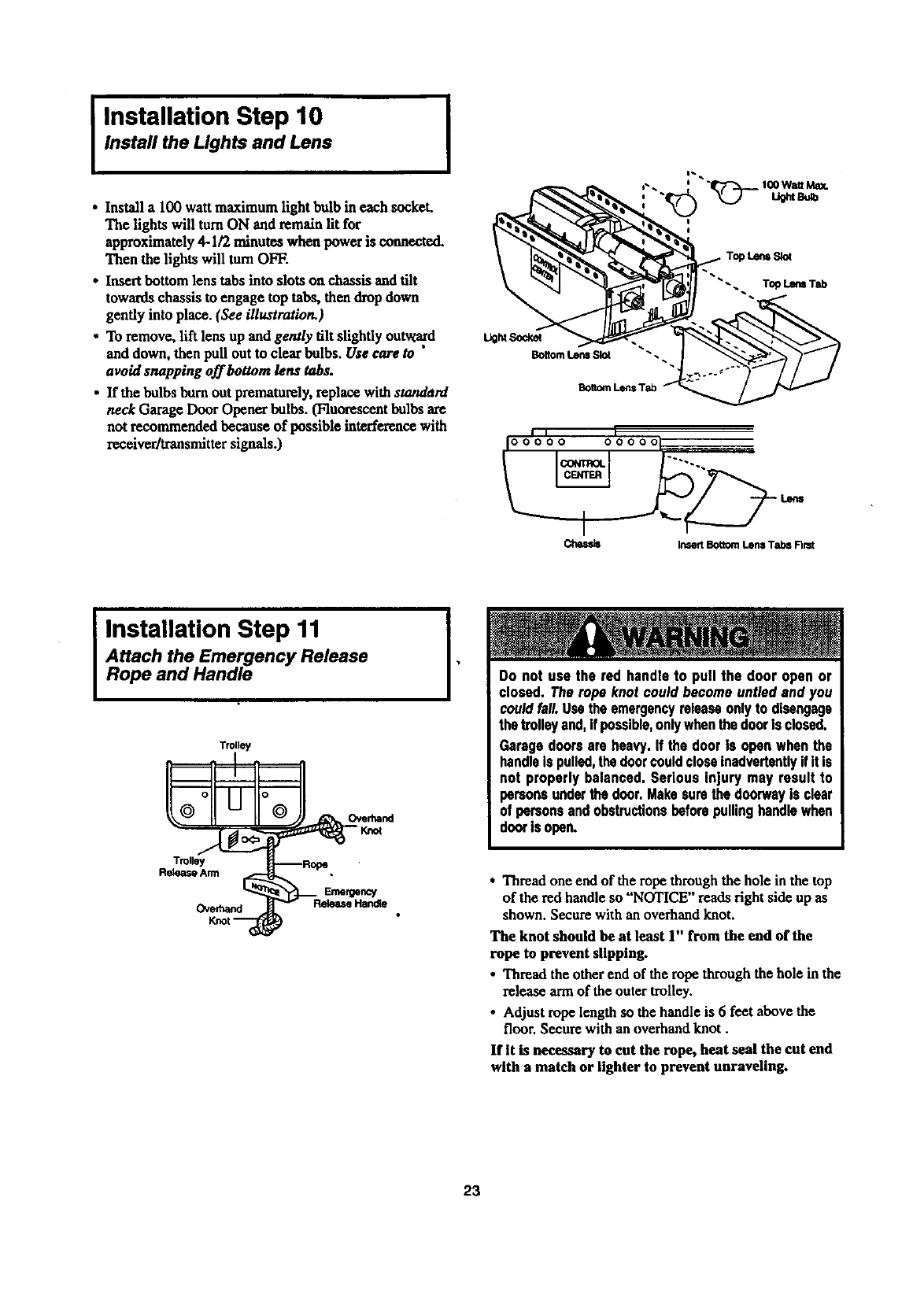
Instafl the Lights and Lens
•Install a 100 watt maximum lightbulb in each socket.
The lights will turnON and remain lit for
approximately 4-1/2 minutes when power is connected.
Then the lights will turnOFF.
• Insertbottom lens tabs into slots on chassis and tilt
towards chassis to engage top tabs, then drop down
gently into place. (See illustration.)
• To remove, lift lens up and gently tilt slightly outward
and down, then pull out to clear bulbs. Use care to "
avoid snapping off bottom lens tabs.
•If the bulbs bum out prematurely,replace with standard
neck Garage Door Opener bulbs. (Fluorescent bulbs are
not recommended because of possible interference with
receiver/transmittersignals.)
I
BottomLensSlot
BottomLensTab _'_
-. To_ Lem Tab
i, I
I00000 000001
Chassis Insert Bottom Lens Tabs Nmt
IInstallation Step 11
Attach the Emergency Release
Rope and Handle
TrUly
Trolley
Release Arm
Emergency
Overhand
I•Do not use the red handleto pull the door open or
closed. Therope knotcould becomeuntiedand you
couldfall.Usetheemergencyreleaseonlyto disengage
thetrolleyand,if possible,onlywhenthedoorisclosed.
Garagedoorsare heavy.If the dooris openwhenthe
handleIspulled,thedoorcouldcloseinadvertentlyifit Is
not properlybalanced.Serious injury may result to
personsunderthe door.Makesurethedoorwayis clear
of personsandobstructionsbeforepullinghandlewhen
doorisopen.
•Thread one end of the rope through the hole in the top
of the red handle so "NOTICE" reads right side up as
shown. Secure with an overhand knot.
The knot should be at least 1" from the end of the
rope to prevent slipping.
• Thread the other end of the rope through the hole in the
release arm of the outer trolley.
•Adjust rope length so the handle is 6feet above the
floor. Secure with an overhand knot.
If It is necessary to cut the rope, heat seal the cut end
with a match or lighter to prevent unraveling.
23
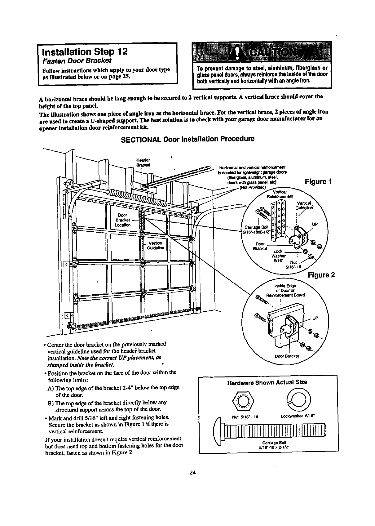
Installation Step 12
Fasten Door Bracket
Follow instructions which apply to your door type
as illustrated below or on page 25.
A horizontal brace should be long enough to be secured to 2 vertical supports. A vertical brace should cover the
height of the top panel.
The illustration shows one piece of angle iron as the horizontal brace. For the vertical brace, 2 pieces of angle iron
are used to create a U.shaped support. The best solution is to check with your garage door manufacturer for an
opener installation door reinforcement kiL
SECTIONAL Door Installation Procedure
Header
Bracket
Figure I
Verti_
Figure 2
• Center the doorbracket on the previously marked
vertical guideline used for the headel bracket
installation. Note the correct UP placement, as
stamped inside the brackeL
• Position the bracketon the face of the door within the
following limits:
A) The top edge of the bracket 2--4"below the top edge
of the door,
B) The top edge of the bracket directly below any
structuralsupportacross the top of the door.
•Markand drill 5116" left and right fastening holes.
Secure the bracketas shown in Figure I if thereis
vertical reinforcement.
If your installation doesn't require vertical reinforcement
but does need top and bottom fastening holes for the door
bracket, fasten as shown in Figure 2.
Hardware Shown Actual Size
© ©
NUt 5/16" -18 Lock.washer 5/16"
lJlJltllllllltllllllltlllltllllJlJtD
5/16"-18 x 2-1/2"
24
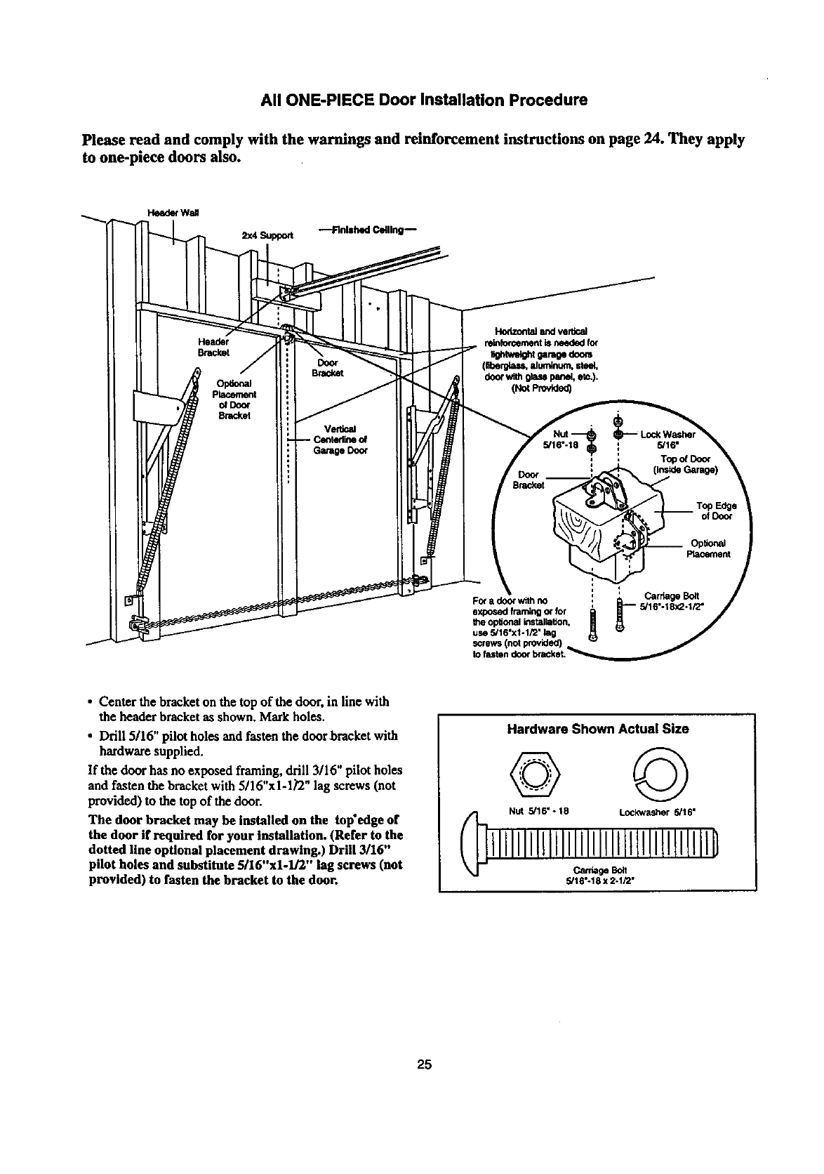
All ONE-PIECE Door Installation Procedure
Please read and comply with the warnings and reinforcement instructions on page 24. They apply
to one-piece doors also.
Header
Bracket
Opt_al
placement
o_Doo¢
8racket
Door
Bracket
Fo( a door with no
exposed framing or for
the opltonal tnstallatton.
use 5/16"x1-1/2" lag
screws (not provided)
to
•Center the bracket on the top of the door, in line with
the header bracket as shown. Markholes.
• Drill 5116" pilot holes and fasten the door bracket with
hardware supplied.
If the door has no exposed framing, drill 3/16" pilot holes
and fasten the bracket with 5/16"x1-1_2" lag screws (not
provided) to the top of the door.
The door bracket may be installed on the tap'edge of
the door if required for your installation. (Refer to the
dotted line optional placement drawing.) Drill 3/16"
pilot holes and substitute 5/16"xl-lJ2" lag screws (not
provided) to fasten the bracket to the door.
Hardware Shown Actual Size
© ©
Nut 5/16" - 18 Lockwasher 5/16"
lllllllllllllllllllllltllllllllllllB
_ge _lt
5/18"-18 x 2-1/2"
25
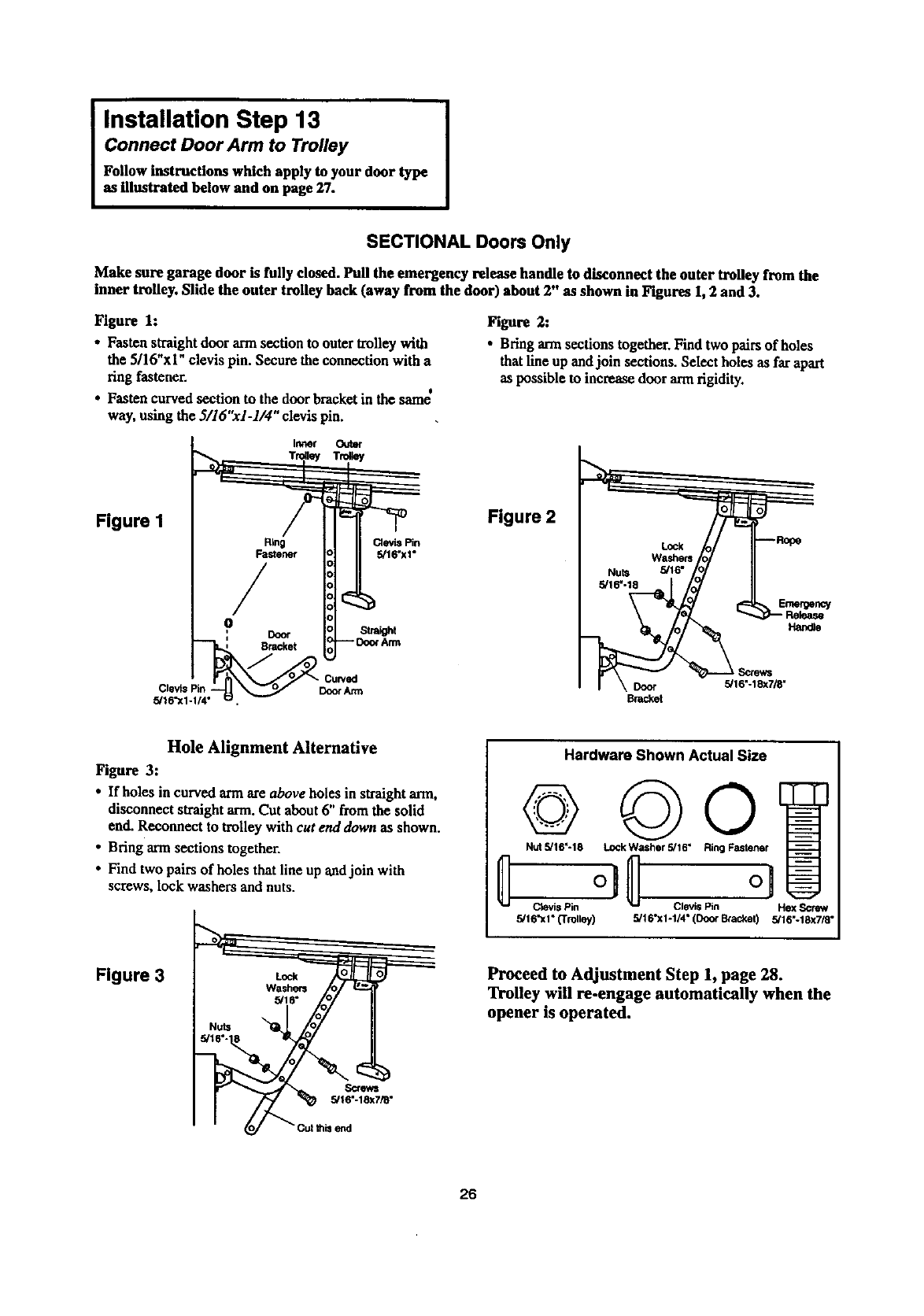
I nstallation Step 13 I
Connect Door Arm to Trolley
Follow instructions which apply to your door type
as illustrated below and on page 27.
SECTIONAL Doors Only
Make sure garage door is fully dosed. Pull the emergency release handle to disconnect the outer trolley from the
inner trolley. Slide the outer trolley back (away from the door) about 2" as shown in Figures 1,2 and 3.
Figure 1:
• Fasten straightdoor arm section to outer trolley with
the 5/16"xi" clevis pin. Secure the connection with a
ring fastener.
• . t
• Fasten cawed scctaon to the door bracketm the same
way, using the 3/16"x1-1/4" clevis pin.
Figure 2:
• Bring ann sections together. Find two pairs of holes
that line up andjoin sections. Select holes as far apart
as possible to increase door armrigidity.
Figure I
Ring Clevis Pin
Fastener 5/16"xi"
/
r_
Figure 2
5/16"
Emergency
Ha_e
Door 5/16"-18x7/8"
Brac_t
Hole Alignment Alternative
Figure 3:
•If holes in curved armare above holes in straight arm,
disconnect straightarm. Cut about6" from the solid
end. Reconnect to trolley with cut end down as shown.
•Bring armsections together.
•Find two pairs of holes that line up andjoin with
screws, lock washers and nuts.
Figure 3
Screws
5/16"-18x7/8"
send
Hardware Shown Actual Size
©
Nut 5/16"-18
Ctevis Pin
5/16"xi" (Trolley)
RingF.,-,]
c,. io
5/16"x1-1/4" (Doo¢ Bcacket) 5/16"-18x7/8"
Proceed to Adjustment Step 1, page 28.
Trolley will re-engage automatically when the
opener is operated.
26
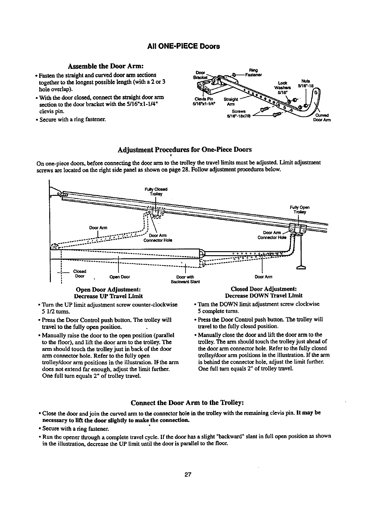
All ONE-PIECE Doors
Assemble the Door Arm:
• Fasten the straight and curved door ann sections
together to the longest possible length (with a 2 or 3
hole overlap).
• With the door closed, connect the straightdoor arm
section m the door bracket with the 5/16"x1-1/4"
clevis pin.
•Secure with a ring fastener.
cl_.s Pin s_t
5/1ff'Xl-t14" Arm
Scrsws
5/16"-18x7/_
Lock
Washers
5/t6"
Doo¢/um
Adjustment Procedures for One-Piece Doors
I
On one-piece doors, before connecting the door armto the trolley the travel limits must be adjusted. Limit adjustment
screws are located on the right side panel as shown on l_ge 28. Follow adjustmentprocedures below.
Fully Open
Trolley
: C_ed
Door Open Door Door with
Backward Slant
Open Door Adjustment:
Decrease UP Travel Limit
•Turn the UP limit adjustment screw counter-clockwise
51/2 toms.
•Press the Door Control push button. The trolley will
travel to the fully open position.
•Manually raise the door to the open position (parallel
to the floor), and lift the door arm to the trolley. The
arm should touch the trolley just in back of the door
arm connector hole. Refer to the fully open
trolley/door arm positions in the illustration. I_ the arm
does not extend far enough, adjust the limit further.
One full turn equals 2" of trolley travel.
DoorArm
Closed Door Adjustment:
Decrease DOWN Travel Limit
• "lurethe DOWN limit adjustment screw clockwise
5complete turns.
• Press the Door Control push button. The trolley will
travel to the fully closed position.
• Manually close the door and lift the door armto the
trolley. The armshould touch the trolleyjust aheadof
the door armconnector hole. Refer to the fully closed
trolley/door arm positions in the illustration. If the arm
is behind the connector hole, adjust the limit further.
One full turnequals 2" of trolley travel.
Connect the Door Arm to the Trolley:
• Close the door and join the curved arm to the connector hole in the trolley with the remaining clevis pin. It may be
nec_ry to lift the door slightly to make the connection.
•Secure with a ring fastener.
•Run the opener through acomplete travel cycle. If the door has aslight "backward" slant in full open position as shown
in the illustration, decrease the UP limit until the door is parallel to the floor.
27
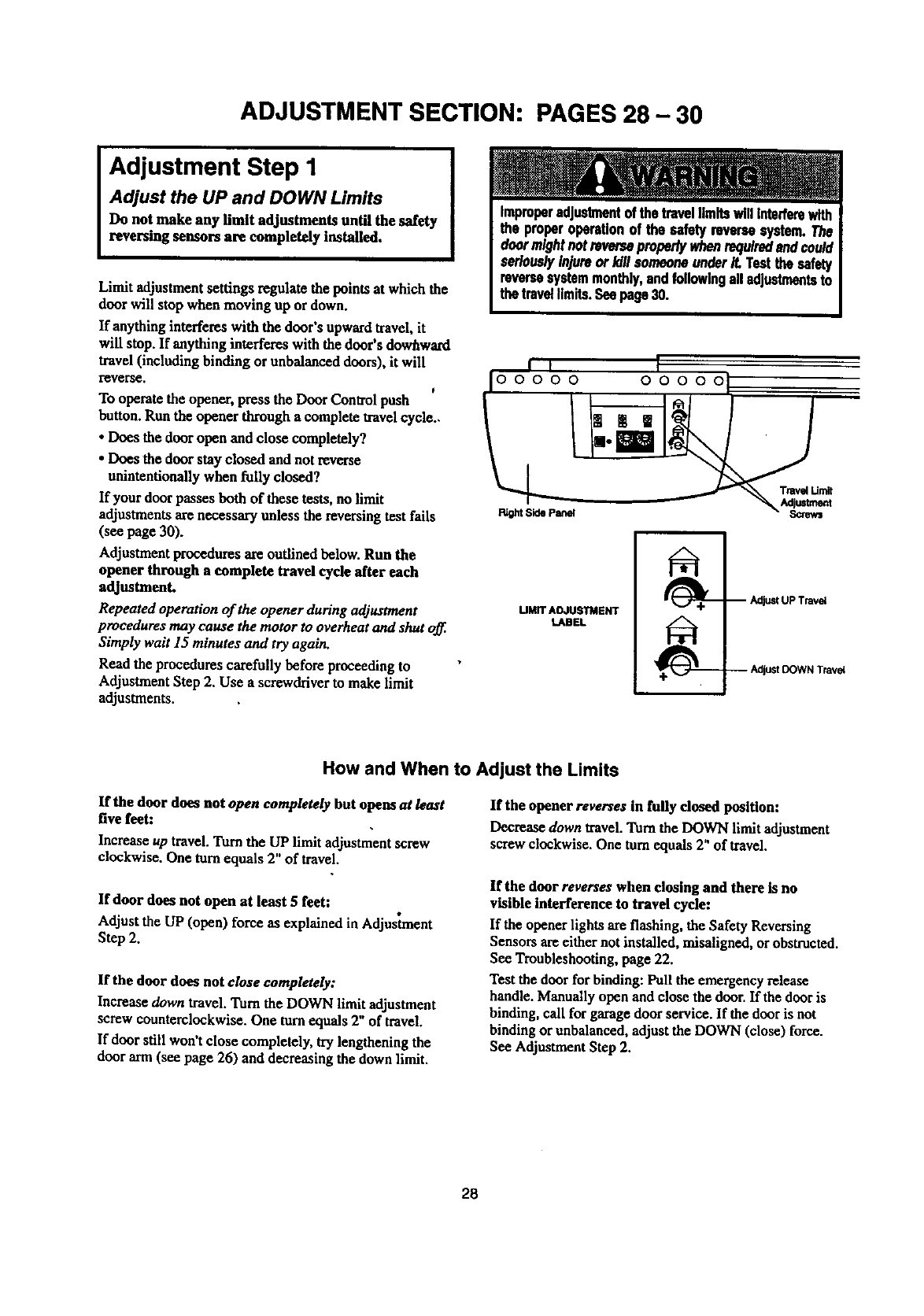
ADJUSTMENT SECTION: PAGES 28 - 30
Adjustment Step 1
Adjust the UP and DOWN Limits
Do not make any limit adjustments until the safety
reversing sensors are completely installed.
Limit adjustment settings regulate the points at which the
door will stop when moving up or down.
If anything interferes with the door's upwardtravel,it
will stop. If anything interferes with the door's dowhward
travel (including binding or unbalanced doors), it will
reverse. t
To operate the opener, press the Door Contsol push
button. Run the opener through a complete travelcycle..
• Does the door open and close completely?
• Does the door stay closed and not reverse
unintentionally when fully closed?
If your door passes both of these tests, no limit
adjustments are necessary unless the reversing test falls
(see page 30).
Adjustment procedures are outlined below. Run the
opener through a complete travel cycle after each
adjustment.
Repeated operation of the opener during adjustment
procedures may cause the motor to overheat and shut off.
Simply wait 15 minutes and try again.
Read the procedures carefully before proceeding to
Adjustment Step 2. Use a screwdriver to make limit
adjustments.
i ) I
ooooo ooooo IJ
UMff ADJUSTMENT
LABEL
-- AdjustUPTravel
-- Adjust DOWN Travel
How and When to Adjust the Limits
If the door does not open completely but opens at least
five feet:
Increase up travel.Turn the UP limit adjustmentscrew
clockwise. One torn equals 2" of travel.
If door does not open at least 5 feet:
Adjust the UP (open) force as explained in Adjustment
Step 2.
If the door does not close completely:
Increase down travel. Turn the DOWN limit adjustment
screw counterclockwise. One turn equals 2" of travel.
If door still won't close completely, try lengthening the
door arm (see page 26) and decreasing the down limit.
If the opener reverses in fully dosed position:
Decrease down travel Turn the DOWN limit adjustment
screw clockwise. One tom equals 2" of travel.
If the door reverses when closing and there is no
visible interference to travel cycle:
If the opener lights are flashing, the Safety Reversing
Sensors are either not installed, misaligned, or obstructed.
See Troubleshooting, page 22.
Test the door for binding: Pull the emergency release
handle. Manually open and close the door. If the door is
binding, call for garage door service. If the door is not
binding or unbalanced, adjust the DOWN (close) force.
See Adjustment Step 2.
28
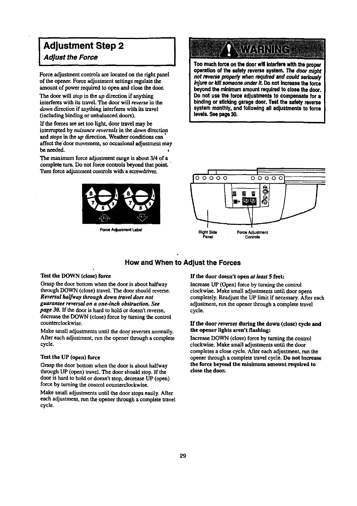
IAdjustment Step 2Adjust the Force
Force adjustment controls are located on the fight panel
of the opener. Force adjustment settings regulate the
amount of power required to open and close the door.
The door will stop in the up direction if anything
interferes with its travel. The door will reverse in the
down direction if anything interferes with its travel
(including binding or unbalanced doors),
If the forces are set too light, door travel may be
interruptedby nuisance reversals in the down direction
and stops in the up direction. Weather conditions can
affect the door movement, so occasional adjustment may
be needed.
The maximum force adjustment range is about3/4 of a
complete turn.Do not force controls beyond that poinL "
Turnforce adjustmentcontrols with a screwdriver.
Feme Adlt_ment I.abel
IToomuchforceonthedoorwillinterferewiththeproper
operationof the safetyreversesystem.Thedoormight
not reverseproperlywhenrequiredand couldseriously
injureor killsomeoneunderiL DonotIncreasetheforce
beyondtheminimumamountrequiredto closethedoor.
Do not usethe forceadjustmentsto compensatefor a
bindingor stlcldnggaragedoor.Testthe safetyreverse
systemmonthly,andfollowingall adjustmentsto fo_'e
levels.Seepage30.
i, I
Io0000 00000
Right Side Force Adjustment
Panel Controls
How and When to Adjust the Forces
Test the DOWN (close) force
Grasp the door bottom when the door is abouthalfway
through DOWN (close) travel. The door should reverse.
Reversal halfway through down travel does not
guarantee reversal on a one-inch obstruction. See
page 30. If the door is hard to hold or doesn't reverse,
decrease the DOWN (close) force by turning the control
counterclockwise.
Make small adjustments until the door reverses normally.
After each adjustment, run the opener through a complete
cycle.
Test the UP (open) force
Grasp the door bottom when the door is about halfway
through UP (open) travel. The door should stop. If the
door is hard to hold or doesn't stop, decrease UP (open)
force by turningthe control counterclockwise.
Make small adjustments until the door stops easily. After
each adjustment, run the opener through a complete travel
cycle.
If the door doesn't open at/east 5 feet:
Increase UP (Open) force by turning the control
clockwise. Make small adjustments until door opens
completely. Readjust the UP limit if necessary. After each
adjustment, mn the opener through a complete travel
cycle.
If the door reverses during the down (close) cyde and
the opener lights aren't flashing:
Increase DOWN (close) force by turning the control
clockwise. Make small adjustments until the door
completes a close cycle. After each adjustment, runthe
opener through a complete travel cycle. Do not increase
the force beyond the minimum amount required to
close the door.
29
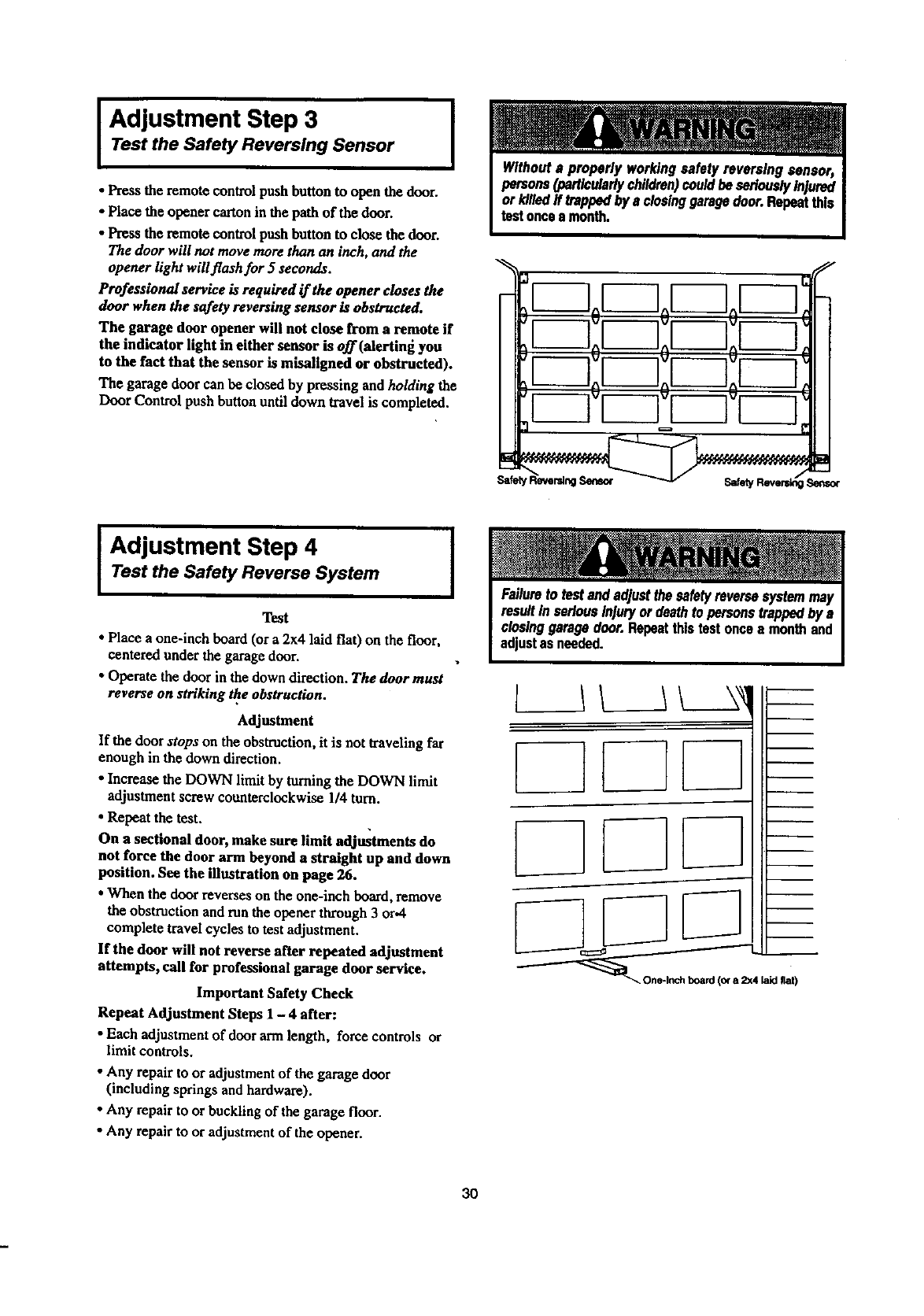
I Adjustment Step 3 I
Test the Safety Reversing Sensor
•Press the remote control push button to open the door.
•Place the opener cartonin the path of the door.
•Press the remote control push button to close the door.
The door will not move more than an inch, and the
opener light will flash for 5 seconds.
Professional service is required if the opener closes the
door when the safety reversing sensor is obstructed.
The garage door opener will not close from a remote if
the indicator light in either sensor is off (alextlng you
to the fact that the sensor is misallgned or obstructed).
The garage door can be closed by pressing and holding the
Door Control push button until down travel is completed.
r--7oF-7oF-
r-lr-
Adjustment Step 4 I
Test the Safety Reverse System
Test
• Place aone-inch beard (or a 2x4 laid flat) on the floor,
centered under the garage door.
•Operate the door in the down direction. The door must
reverse on striking the obstruction.
Adjustment
If the door stops on the obstruction, it is not traveling far
enough in the down direction.
•Increase the DOWN limit by turningthe DOWN limit
adjustment screw counterclockwise 1/4 turn.
• Repeat the test.
On a sectional door, make sure limit adjustments do
not force the door arm beyond a straight up and down
position. See the illustration on page 26.
•When the door reverses on the one-inch board,remove
the obstruction and mn the opener through3 or.4
complete travel cycles to test adjustment.
If the door will not reverse after repeated adjustment
attempts, call for professional garage door service.
Important Safety Check
Repeat Adjustment Steps 1 - 4 after:
•Each adjustment of door armlength, force controls or
limit controls.
•Any repairto or adjustment of the garage door
(including springs and hardware),
•Any repairto or buckling of the garage floor.
•Any repairto or adjustment of the opener.
L
[
1L__IL_A
/
board (o¢a2x4 laid fiat)
3O
IMPORTANT SAFETY INSTRUCTIONS
To reduce the risk of severe injury or death to persons:
1. READ AND FOLLOW ALL INSTRUCTIONS.
2. Do not permit children either to operate or to play with the opener. Keep remote control in a location
inaccessible to children.
3. Operate opener only when the door is in full view and free from any obstruction. Keep the door in sight until
it is completely closed. NO ONE SHOULD CROSS THE PATH OF THE MOVING DOOR.
4. Check safety reversal system monthly. See page 30. The garage door MUST reverse on contact with a one
inch object (or a 2x4 board laid fiat) placed on the floor. If an adjustment is made to one of the controls
(either force or limits of travel), the other control may need to be adjusted also, and the safety reversal system
must be checked. Failure to properly adjust the opener may result in severe injury or death.
5. If possible, use the emergency release only when the door is in n closed position. Caution should be taken
whenever the disconnect cord is actuated with the door open. Weak or broken springs may cause the door to
fall rapidly, causing injury or death to persons.
6. KEEP GARAGE DOORS PROPERLY BALANCED. See page 3. An improperly balanced door may not
reverse when required, and could result in severe injury or death. Repairs to cables, spring ussembfias and
other hardware must be made by n professional garage door person.
7. Disconnect the electric power to the garage door opener before making any repairs or removing the covers.
SAVE THESE INSTRUCTIONS
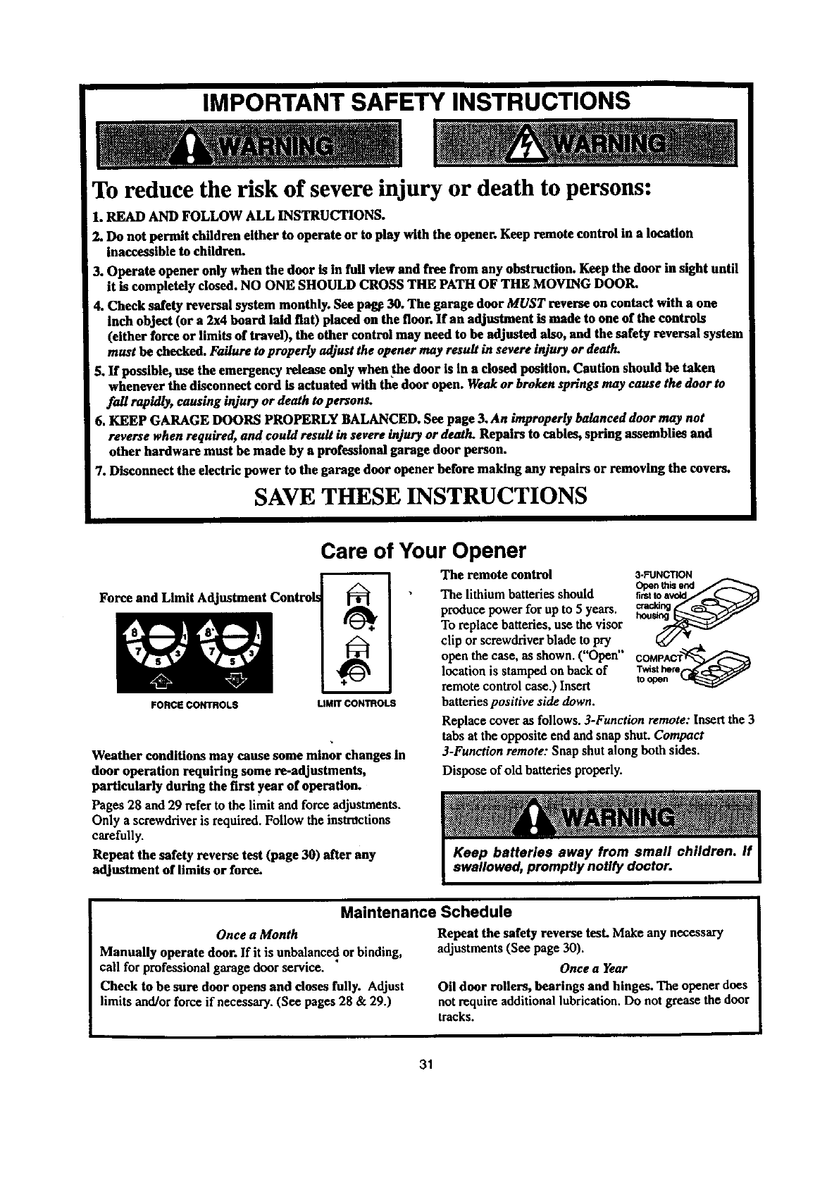
Force and Limit A(
FORCE CONTROLS
Care of Your Opener
LIMIT CONTROLS
The remote control
The lithium batteries should
produce power for upto 5years,
To replace batteries, use the visor
Weather conditions may cause some minor changes in
door operation requiring some re-adjustments,
particularly during the first year of operation.
Pages 28 and 29 refer to the limit and force adjustments.
Only a screwdriver is required.Follow the instrdctions
carefully.
Repeat the safety reverse test (page 30) after any
adjustment of limits or force.
3-FUNCTION
clip or screwdriver blade to pry _ __,
open the case,asshown.("Open" COMPACT
locationis stampedonhackof Twisthere
remote controlcase.)Insert toopen
batteries positive side down.
Replace cover as follows. 3-Function remote: Insert the 3
tabs at the opposite end and snap shut. Compact
3-Function remote: Snap shut along both sides.
Dispose of old batteries properly.
Maintenance Schedule
Once a Month
Manually operate door. If it is unbalance_,or binding,
call for professional garage door service.
Check to be sure door opens and doses fully. Adjust
limits and/or force if necessa_. (See pages 28 & 29.)
Repeat the safety reverse tesLMake any necessary
adjustments (See page 30).
Once a Year
Oil door rollers, bearings and hinges. The opener does
not require additional lubrication.Do not grease the door
tracks.
31
Operation of Your Opener
Activate the opener with any of the following:
• The Remote Control: Hold push buttondown until the
door startsto move.
• The Door Control: Hold push baror buttondown until
the door starts to move.
• The Outdoor Key Switch or Keyless Entry:
(See Accessories)
When the opener is activated with the safety reversing
sensor installed and correctly aligned:
1. If open, the door will close. If closed, it will open.
2. If closing, the door will reverse. •,
3. If opening, the door will stop (allowing space for entry
and exit of pets and for fresh air).
• . w
4. If the door has been stopped ma paxttally open position,
it will close.
5. If obstructed while closing, the door will reverse.
6. If obstructedwhile opening, the door will stop.
7. The garage door will reverse in the closing cycle, and
the opener tights will blink for 5seconds, when the
invisible beam is broken. If fully open, the door will not
close when the beam is broken. The sensor has no effect
in the opening cycle.
If the sensor is not installed, or is not aligned correctly,the
door won't close fromany remote control. You can close
the door with the Door Control, the Outdoor Key Switch,
or Keylass Entry, however, if you activatethem until down
travel is complete. If you release them too soon, the door
will reverse.
The Opener Lights will turnon under the following
conditions:When theopener is initially plugged in; when the
poweris interrupted;when the opener is activated.Itwill
turnoff automaticallyafter4-1/2 minutesor provide
constant light when the Light featureon the Premium
Control Console is activated. Bulb size is 100 watts
maximum.
SECURITY+ models: Lights will also turn on when
someone walks through the open garage door. With a
Premium Control Console, this feature may he turned off
as follows: With the opener lights off, press anll hold the
light button for I0 seconds, until the light goes on and off
again. To restore this feature, start with the opener lights
on, then press and hold the light button t'or 10 seconds.
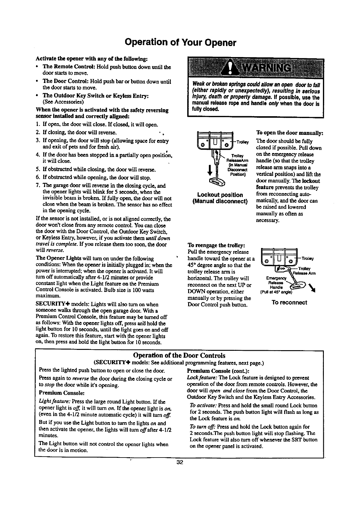
Lockout position
(Manual disconnect)
To open the door manually:
The door should be fully
closedif possible. Pull down
on the emergency release
handle (so that the trolley
release ann snaps into a
vertical position) and lift the
door manually. The lockout
feature prevents the trolley
from reconnecting auto-
matically, and the door can
be raised and lowered
manually as often as
necessary.
To reengage the trolley:
Pull the emergency release
handle toward the opener at a
45 ° degree angle so that the
trolley release arm is
horizontal. The trolley will
reconnect on the next UP or
DOWN operation, either
manually or by pressing the
Door Control push button.
_e_enc
Handle
(Pull at 45" angle)
To reconnect
Operation of the Door Controls
(SECURITY÷ models: See additional programming features, next page.)
Press the lighted push button to open or close the door.
Press again to reverse the door during the closing cycle or
to stop the door while it's opening.
Premium Console:
Light feature: Press the large round Light button. If the
opener light is off, it will turn on. If the opener light is on,
(even in the 4-1/2 minute automatic cycle) it will turn off.
But if you use the Light button to tom the lightson and
then activatethe opener,the lights will turn offafter 4-1/2
minutes,
The Light button will not control the opener lights when
the door is in motion.
Premium Console (conL):
Lock feature: The Lock feature is designed to prevent
operation of the door from remote controls. However, the
door will open and close from the Door Control, the
Outdoor Key Switch and the Keyleas Entry Accessories.
To activate: Press and hold the small round Lock button
for 2 seconds. The push button light will flash as long as
the Lock feature is on.
To turn off." Press and hold the Lock button again for
2 seconds.The push button light will stop flashing. The
Lock feature will also turn off whenever the SRT button
on the opener panel is activated.
32
Receiver and Remote Control Programming
SECUBlri'T,I;
Your garage door opener receiver and remote control
have been pre-set at the factory. The door will open
when you press the LARGE remote control push button.
The code between the remote control and the receiver
changes with each use, randomly accessing over 100
billion new codes.
The 3-funetlon remote control can also activate
additional SECURITY+ garage door openers and/or
light controls. •,
Your SECURITY+ opener will operate with:
• severalSECURITY'I" remote controls(with blue ,
pushbuttons)utilizingup to 8 functions.
•oneSECURITY+ l_ylvss Entry System(Model
139.53684).
Follow the instructions below to program your opener to
ma_h any additional remotes you may purchase. See
Accessories on page 38.
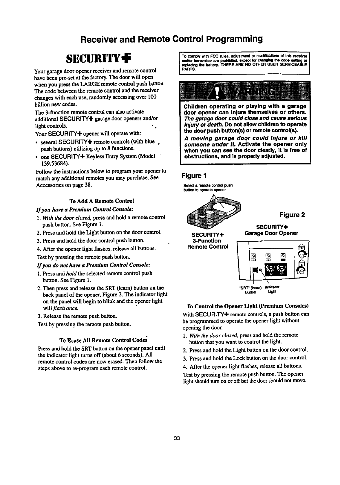
To Add A Remote Control
If you have aPremium Control Console:
1. With the door closed, press and hold a remote control
push button. See Figure I.
2. Press and hold the Light button on the door control.
3. Press and hold the door control push button.
4. After the opener light flashes, release all buttons.
Test by pressing the remote push button.
If you do not have a Premium Control Console:
1.Press and ho/d the selected remote control push
button. See Figure 1.
2. Then press and release the SRT (learn) button on the
back panel of the opener, Figure 2. The indicator light
on the panel will begin to blink and the opener light
will flash once.
3. Release the remote push button.
Test by pressing the remote push button.
To Erase All Remote Control Code_
Press and hold the SRT button on the opener panel until
the indicator light turns off (about 6seconds). All
remote control codes are now erased. Then follow the
steps above to re-program each remote control.
To complywith FCC miss. adjustmentor modificationsof thisr_e_r I
s_Por tmnsmitteram I_.l_ted, except_chan_g me cndeset,rigor
pAR_ the battery.THERE ARE NO OTHER USER SERViCEABlE
Children operating or playing with a garage
door opener can injure themselves or others.
The garage door could close and cause serious
Injury or death. Do not allow children to operate
the door push button(s) or remote control(s).
Amoving garage doqr could Injure or kill
someone under It. Activate the opener only
when you can see the door clearly, it Is free of
obstructions, and Is properly adjusted.
Figure I
Setect a remote contvo4 push
bu_on to operate opener
SECURITY+
3-Function
Remote Control
Figure 2
SECURITY+
Garage Door Opener
"SRT"(learn) indicator
Button Ught
To Control the Opener Light (Premium Consoles)
With SECURITY'I, remote controls, a push button can
be programmed to operate the opener light without
opening the door.
1. With the door closed, press and hold the remote
button that you want to control the light.
2. Press and hold the Light button on the door control.
3. Press and hold the Lock button on the door control.
4. After the opener light flashes, release all buttons.
Test by pressing the remote push button. The opener
light should turn on or offbut the door should not move.
33
Situation
Troubleshooting
Probable Cause & Solution
The opener doesn't
operate from either
the door control or
the remote control:
I. Does the opener have electric power?Plug a lamp into the outlet. Ifit doesn't fight, check the
fuse box or the circuitbreaker.(Some outlets arecontrolled by a wall switch.)
2. Have you disabled all door locks? Review installation instructionwarningson Page 11.
3. Is there a build-up of ice or snow underthe door? The door may be frozen to the ground.
Remove any restriction.
4. The garage door spring may be broken. Have it replaced.
5. Repeated operation may have trippedthe overload protector in the motor.Wait
15 minutes. Try again.
Opener operates from
the remote control, but
notfrom the door
control:
1. Is the door control push bar lit? If not, Remove the bell wire from the opener terminal
screws. Short the redand white terminals by touching both terminals at the same time with
apiece of wire. If the opener runs,check for a faulty wire connection at the door control, a
shortunderthe staples, or a broken wire.
2. Are the wiring connections correct?Review Installation Step 7, page 21.
The door operates from
the door control, but not
from the remote
control:
1. Is any door push button flashing? If your model has the Lock feature, make sure it is off.
2. Youropener needs to re-learo aremote control code. Refer to instructionson the opener
panel.
3. Programthe receiver to matchthe remote control code.
4. Repeat the receiver programming procedurewith all remote controls.
The remote control has 1. Change the location of the remote control in yourcar.
short range: 2. Check to be sum the antenna on the right side panel of opener extends fully.
3. Some installations may have shorterrange due to a metal door, foil backed insulation, or
metal garage siding. (AnteL_naExtender Kit 41A3504)
Opener noise is
disturbing in living
quarters of home:
If operational noise is a problem because of proximity of the opener to the living quarters,the
Vibration Isolator Kit 41A3263 can be installed. This kit was designed to minimize vibration
to the house and is easy to install.
The garage door
opens and closes by
itself."
1. Be surethat all remotecontrol push buttons are off.
2. Remove the bell wire from the door control terminals and operatefrom the remote control
only. If this solves the problem, the door control is faulty (replace), or there is an
intermittentshort on the wire between the door control and the opener.
3. Clear rflemoryand reprogramall remote controls.
The door doesn't open
completely: I. Is something obstructing the door? Remove the obstruction or repairthedoor.
2. If the door has been working properly but now doesn't open all the way, increase the up
force. See page 29.
3. If door opens at least 5feet, the travel limits may need to be increased. One turnequals
2 inches of travel. See page 28.
Repeat the safety reverse test after the adjustment is complete.
The door stops but
doesn't close
completely:
Review the travel"limits adjustment procedureson page 28.
Repeat the safety reverse test after any adjustment of door arm length, close force or down
limit.
34
Situation
Troubleshooting (continued)
Probable Cause & Solution
The door opens but
won't close: 1. If the opener lights blink, check the safety reversing sensor. See page 22.
2. If the opener fights do not blink and it is a new installation, check the down force. See
Adjustment Step 2, page 29. For an existing installation, see below.
Repeat the safety reverse test after the adjustment is complete.
The door reversesfor no
apparent reason and
opener lights don't
blink:
1. Is something obstructing the door? Pull the emergency release handle. Operate the door
manually. If it is unbalanced or binding, call for professional garage door service.
2. Clear any ice or sno_ from the garage floor areawhere the doorcloses.
3. Review the force adjustmentprocedures on page 29.
4. If door reverses in the fully closed position, decrease the travellimits (page 28).
0, • •
Repeat the safety reverse test after adjustments to force or travel limits. The need for
occasional adjustment of the force and limit settings is normal Weather conditions in
particular can affect door travel
Thedoor reversesfor no
apparent reason and
opener lights blink for
5 seconds after
reverse:
The opener lights...
Check the safety reversing sensor. Remove any obstruction or align the receiving eye. See
pages 12 and 22.
don't turn on:
Replace the light bulb(s) (100 watts maximum). Use a standard neck garage door opener bulb
if regular bulb burns out.
don°t turn off:
Is the Light feature on? "Darnit off.
The opener strains or
maximum force is
needed to operate door:
The door may be out of balance or the springs are broken. Close the door and use the
emergency release handle to disconnect the trolley. Open and close thedoor manually. A
properly balanced door will stay in any point of travel while being supportedentirely by its
springs. If it does not, disconnect the opener and call for professional garage door service.
Do not increase the force to operate the opener.
The opener motor
hums briefly, then
won't work:
1. The garage door springs arebroken. See above.
2. If the Rroblem occurs on the first operation of the opener, door may be locked. Disable the
door lock.
Repeat the safety reverse test after the adjustment is complete.
The opener won °t
operate due to power
failure:
1. Use the emergency release handle to disconnect the trolley. The door can be opened and
closed manually. When power is restored, press the Door Control push button and trolley
will automatically reconnect (unless trolley is in lockout position.) See page 32.
2. The Emergency Key Release accessory (for use on garages with no service door)
disconnects the trolley from outside the garage in case of power failure.
35
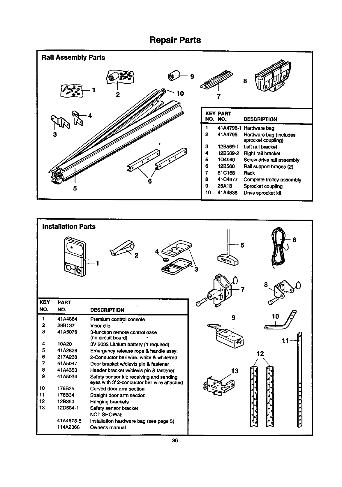
Rail Assembly Parts
5
Repair Parts
_9
10 7
KEY PART
NO. NO. DESCRIPTION
1 41A4796-1 Hardware bag
2 41A4795 Hardware bag (includes
sprocketcoupling)
12B569-1 Left rail bracket
12B569-2 Rightrailbracket
6
5 1D4940 Screw drive rail assembly
6 12B560 Rail support braces (2)
7 81C168 Rack
8 41C4677 Complete trolleyassembly
9 25A18 Sprocketcoupling
10 41A4836 Drivesprocket kit
Installation Parts
KEY PART
NO. NO. DESCRIPTION
1
2
3
4
5
6
7
8
9
10
11
12
13
41A4884
29B137
41A5076
10A,?_0
41A2828
217A238
41A5047
41A4353
41A5034
178B35
178B34
12B350
12D584-1
41A4675-5
114A2368
Premium control console
Visorclip
3-functionremote control case
(no cimuit board)
3V 2032 Lithiumbattery (1 required)
Emergency release rope & handleassy.
2-Conductor bell wire: white & white/red
Door bracket w/clevis pin & fastener
Header bracket w/clevis pin & fastener
Safety sensor kit:receiving and sending
eyes with 3' 2-conductorbell wireattached
Curved door arm section
Straight doorarm section
Hangingbrackets
Safety sensor bracket
NOT SHOWN:
Installationhardware bag (see page 5)
Owner's manual
9
13
11
12
\
36
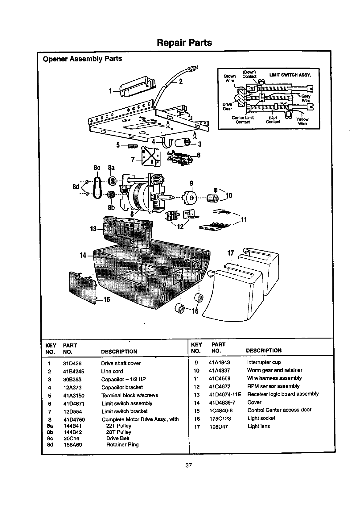
Repair Parts
Opener Assembly Parts
I--S
emwn _MMIT SWITr._I A_qY.
Center _[Up) _""""'_ Yegow
Contact Contact Wire
13 /
KEY PART
NO. NO. DESCRIPTION
1 31D426 Drive shaft cover
2 41B4245 Line cord
3 30B363 Capacitor - 1/2 HP
4 12A373 Capacitor bracket
5 41A3150 Terminal blockw/screws
6 41D4671 Limit switchassembly
7 12D554 Limitswitchbracket
8 41 D4759 Complete Motor Drive Assy.,with
8a 144B41 22T Pulley
8b 144B42 28T Pulley
8c 20Ct4 Ddve Belt
8d 158A69 Retainer Ring
KEY PART
NO. NO. DESCRIPTION
9 41A4843 Interruptercup
10 41A4837 Worm gear and retainer
11 41C4669 Wire harness assembly
12 41C4672 RPM sensor assembly
13 41D4674-11E Receiver logicboard assembly
14 41D4839-7 Cover
15 1C4840-6 Control Center access door
16 175C123 Lightsccket
17 108D47 Light lens
37
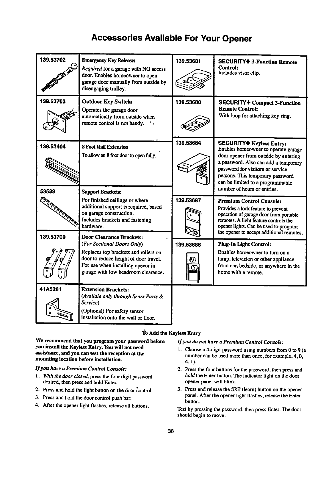
Accessories Available For Your Opener
139.53702 Emergency Key Release:
/
139.53703
139.53404
Required for a garage with NO access
door. Enables homeowner to open
garage door manually fromoutside by
disengaging trolley.
Outdoor Key Switch:
Operates the garage door
automatically from outside when
remote control is not handy. ' •
I
8 Foot Rail Extansion
To allow an 8 foot door to open fuUy.
139.53681
139.53680
139.53684
SECURITY÷ 3-Function Remote
Control:
Includes visor clip.
SECURITY÷ Compact 3-Function
Remote Control:
With loop for attaching key ring.
SECURITY÷ Keyless Entry:
Enables homeowner to operate garage
door opener from outside by entering
53589 Support Brackets:
a password. Also canadd a temporary
password for visitors or service
persons. This temporarypassword
can be limited to a programmable
numberof hoursor entries.
139.53709
41A5281
For finished ceilings or where
additional support is required,based
on garage construction.
Includes brackets and fastening
hardware.
Door Clearance Brackets:
(For Sectional Doors Only)
Replaces top brackets and rollers on
door to reduce height of door travel.
For use when installing opener in
garage with low headroom clearance.
Extension Brackets:
(Availale only through Sears Parts &
Service)
(Optional) For safety sensor
installation onto the wall or floor.
139.53687
139.53686
Premium Control Console:
Provides a lock feature to prevent
operation of garage door from portable
remotes. A light feature controls the
opener lights. Can be used to program
the opener to accept additional remotes.
Plug-In Light Control:
Enables homeowner to turnon a
lamp, television or other appliance
from car,bedside, or anywhere in the
home with a remote.
"1_oAdd the Keyless Entry
We recommend that you program your password before lf you do not have a Premium Control Console:
you install the Keyless Entry. You will not need 1. Choose a4-digit password using numbers from 0 to 9 (a
assistance, and you can test the reception at the number can be used more than once, for example, 4, 0,
mounting location before installation.
lf you have a Premium Control Console:
1. With the door dosed, press the four digit password
desired, then press and hold Enter.
2. Press and hold the light button on the door control.
3. Press and hold the door control push bar.
4. After the opener light flashes, release all buttons.
4,1).
2. Press the four buttons for the password, then press and
hold the Enter button. The indicator light on the door
opener panel will blink.
3. Press and release the SRT (learn) button on the opener
panel. After the opener light flashes, release the Enter
button.
Test by pressing the password, then press Enter. The door
should begin to move.
38
Index
Access Door/Emergency Key Release Accessory ............................................................................................... 6, 7, 35, 36
Electrical Safety Warnings ...................................................................................................................................... 2, 22, 31
Garage Door
Testing for balance, binding and sticking ................................................................................................................. 3, 28, 31
Determining high point of travel:
Sectional door.................................................................................................................................................................. 12
One-piece door ................................................................................................................................................................ 13
Disabling existing locks ................................................................................................................................................. 3, 11
Force controls
Adjustment procedures ......................................... .%....................................................................................................... 29
Problems that might reclaimforce adjustments ......................................................................................................... 34, 35
Safety warnings ......................................................................................................................................................... 29, 31
Door hardware ............................................................. .'................................................................................ 3, 11, 12, 31, 32
Maintenance ................................................................. ........................................................................................... 11, 28-31
Reinforcement requirements .................................................................................................................................... 4, 24, 25
Removing of all ropes .................................................................................................................................................... 3, 11
Possible door damage............................................................................................................................................... 3, 19, 24
Travel limits
Adjustment procedures .............................................................................................................................................. 27, 28
Problems that might require limit adjustments ......................................................................................................... 34, 35
Safety warnings ......................................................................................................................................................... 28, 31
Emergency Release Rope &Handle
Lockout feature ................................................................................................................................................................. 32
Manual disconnect ....................................................................................................................................................... 32, 35
Safety warnings ............................................................................................................................................... 11, 23, 31, 32
Opener Terminals
Door control connections ................................................. .:............................................................................................... 21
Safety reversing sensor connections ............................................................................................................................ 21, 22
Receiver &Remote Controls
Programming the receiver ................................................................................................................................................. 33
Erasing all codes................................................................................................................................................................ 33
Safety warning................................................................................................................................................................... 33
Problems with remote control transmitteroperation ......................................................................................................... 34
Safety Reversing Sensor ........................................................................................................................................ 16-18, 30
Safety Reverse Test Procedure .......................................................................................................................................... 30
Testing required ............................... :............................................................................................................... 11, 30, 34, 35
Safety reverse system problems
Securing header bracket to wall ..................... ,,............................................................................................................... 12
Adjusting travel limits ..................................................................................................................................................... 28
Applying excessive force on the door ............................................................................................................................. 29
Buckling or uneven floor ....................................... :....................................................................................................... 4, 5
Safety Warnings ...................................................................... 2, 3, 11, 12, 16, 19, 20, 21, 22, 23, 24, 28, 29, 30, 31, 32, 33
Troubleshooting ............................................................................................................................................................ 34, 35
User Instruction Label for Garage Wall .................................................................................................................... 11, 21
Vibration Noise (isolator kit) ............................................................................................................................................. 34
39

For in-home major brand repair service:
Call 24 hours a day, 7 days aweek
1"800-4-MY-HOME =(1-800-469-4663)
For the repair or replacement parts you need:
Call 7 am - 7 pm, 7 days a week
t-800-366-PART (1-800-366-7278)
I •
For the location of a Sears Parts and Repair Center in your area:
Call 24 hour_;a day, 7 days a week
t-8OO-488-1 222
For information on purchasing a Sears Maintenance Agreement
or to inquire about an existing Agreement:
Call 9 am - 5 pro, Monday - Saturday
1-800-827-6655
SEARS
HomeCentral"
TheServiceSideofSears"
SEARS WARRANTY
FULL 90-D_Y WARRANTY ON GARAGE DOOR OPENER
For 90 days from the date of purchase, Sears willrepair this Garage Door Opener, free of charge, if defective in material or
workmanship.
UMITED WARRANTY
From the 91st day until one year from the date of purchase, Sears will furnishreplacement partsfor any defective pads, free of charge.
You pay for labor. LIMITED WARRANTY ON MOTOR
1/2HP MOTOR: After 1 year and through 5 years, if the motor on this Garage Door Opener is defective, Sears Willfumish a replacement
motor, free of charge. You pay for labor.
LIMITATION ON LIABILITY
SEARS WILL NOT BE LIABLE FOR LOSS OR DAMAGE TO PROPERTY OR ANY INCIDENTAL OR CONSEQUENTIAL LOSS OR
EXPENSE FROM PROPERTY DAMAGE DUE DIRECTLy OR INDIRECTLY FROM THE USE OF THIS PRODUCT. Some states do
not allow the exclusion or limitationof incidentalor consequential damages, so the above limitationor exclusion may notapply to you.
This warranty does not cover light bulb_ or repair parts necessary because of operatorabuse or negligence, includingthe failure to
install, adjust and operate this garage door opener according to Instructionscontainedin the owner's manuel.
WARRANTY SERVICE IS AVAILABLE BY SIMPLY CONTACTING THE NEAREST SEARS CENTER/DEPARTMENT IN THE UNITED
STATES.
This warranty applies only while this productis in usein the United States.
This warranty gives you specificlegal rights, and you may also have other dghtswhich very from state to state.
Sears, Roebuck and Co., Dept. 817WA, Roffman Estates, IL 60179
114A2368 ©1999, All Rights Reserved Printed in Mexico
