Craftsman 13953964SRT User Manual GARAGE DOOR OPENER Manuals And Guides L0309312
CRAFTSMAN Garage Door Opener Manual L0309312 CRAFTSMAN Garage Door Opener Owner's Manual, CRAFTSMAN Garage Door Opener installation guides
User Manual: Craftsman 13953964SRT 13953964SRT CRAFTSMAN GARAGE DOOR OPENER - Manuals and Guides View the owners manual for your CRAFTSMAN GARAGE DOOR OPENER #13953964SRT. Home:Garage Door & Opener Parts:Craftsman Parts:Craftsman GARAGE DOOR OPENER Manual
Open the PDF directly: View PDF  .
.
Page Count: 76
Owner's Manual/Manual Del Propietario
1/2 HP
GARAGE DOOR OPENER
ABRIDOR DE PUERTA DE COCHERA
For Residential Use Only/S61o para uso residencial
Model/Modelo 139.53964SRT
I11
I11
O'J
Z_
Read and follow all safety rules
and operating instructions before
first use of this product.
Fasten the manual near the garage
door after installation.
Leer y seguir todas las reglas de
seguridad y las instrucciones de
operacibn antes de usar este
producto por primera vez.
Guardar este manual cerca de la
puerta de la cochera.
Periodic checks of the opener are
required to ensure safe operation.
Se deben realizar revisiones
peribdicas del abridor de puertas
para asegurar su operacibn
segura.
Sears, Roebuck and Co., Hoffman Estates, IL 60179 U.S.A
www.sears.com/craftsman
TABLE OF CONTENTS
Introduction 2. 7
Safety symbol and signal word review ...................... .2
Preparing your garage door ........................................ 3
Tools needed ............................................................... 3
Planning ................................................................ ..4-5
Carton inventory ......................................................... .6
Hardware inventory ..................................................... 7
Assembly 8-11
Assemble the rail and install trolley. .......................... .8
Fasten rail to motor unit and install idler pulley ......... .9
Install belt and attach belt cap retainer .................... 10
Set the belt tension .................................................... 11
Installation 11.27
Installation safety instructions .................................... 11
Determine the header bracket location ................ 12-13
Install the header bracket .......................................... 14
Attach the rail to the header bracket ......................... 15
Position the opener ................................................ 16
Hang the opener ...................................................... .17
Install the door control ............................................... 18
Install the lights ...................................................... .19
Attach the emergency release rope and handle ...... 19
Electrical requirements ............................................ .20
Install the Protector System ®............................... .21-23
Fasten the door bracket .................................... ..24-25
Connect the door arm to the trolley ..................... 26-27
Adjustment 28-30
Adjust the travel limits .............................................. .28
Adjust the force ........................................................ .29
Test the safety reversal system ................................ .30
Test the Protector System ®....................................... .30
Operation 31.34
Operation safety instructions .................................... .31
Using your garage door opener ................................ 31
Using the walt-mounted door control ....................... .32
To open the door manually ....................................... .32
Care of your garage door opener. ............................ .33
Having a problem? ................................................... .34
Programming 35-36
To add a hand-held remote control .......................... .35
To erase all codes ................................................... .35
3-Function Remotes Controls .................................. .35
To add or change a Keyless Entry PIN ................... .36
Repair Parts 37.38
Rail assembly parts ................................................... 37
Installation parts .................................................... 37
Motor unit assembly parts ........................................ .38
Accessories 39
Warranty
Service Numbers
39
40
INTRODUCTION
Safety Symbol
and Signal Word Review
This garage door opener has been designed and tested to offer safe service provided it is installed, operated,
maintained and tested in strict accordance with the instructions and warnings contained in this manual.
Mechanical
Electrical
When you see these Safety Symbols and Signal
Words on the following pages, they will alert you to
the possibility of serious injury or death if you do
not comply with the warnings that accompany them.
The hazard may come from something mechanical
or from etectdc shock. Read the warnings carefully.
When you see this Signal Word on the following
pages, it wilt alert you to the possibility of damage to
your garage door and/or the garage door opener if
you do not comply with the cautionary statements
that accompany it. Read them carefully.
2
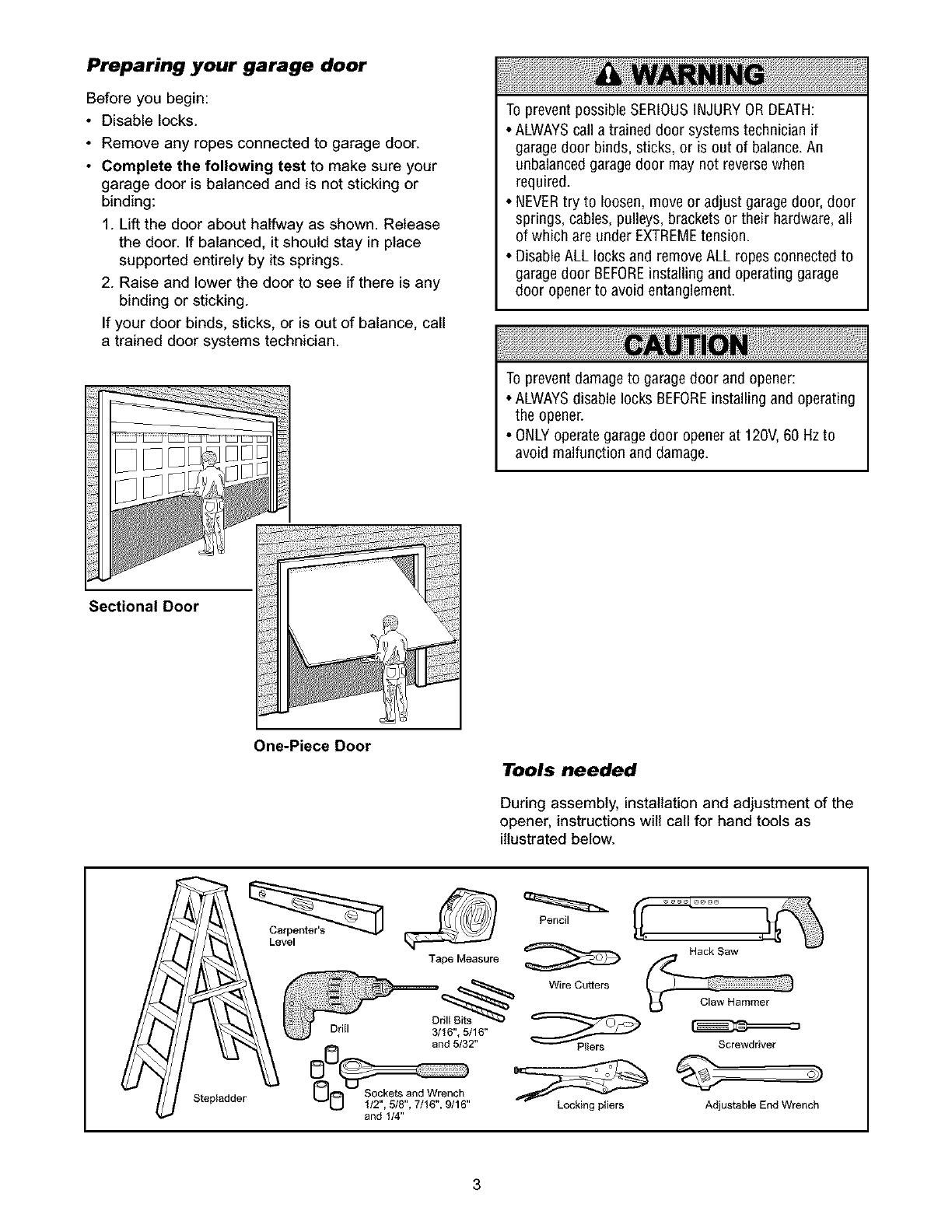
Preparing your garage door
Before you begin:
•Disable locks.
• Remove any ropes connected to garage door.
• Complete the following test to make sure your
garage door is balanced and is not sticking or
binding:
1. Lift the door about halfway as shown. Release
the door. If balanced, it should stay in place
supported entirely by its springs.
2. Raise and lower the door to see if there is any
binding or sticking.
If your door binds, sticks, or is out of balance, call
a trained door systems technician.
To prevent possible SERIOUSINJURYOR DEATH:
•ALWAYScall a trained door systems technician if
garagedoor binds, sticks, or is out of balance.An
unbalanced garagedoor may not reverse when
required.
• NEVERtry to loosen, move or adjust garagedoor, door
springs, cables, pulleys, brackets or their hardware,all
of which are under EXTREMEtension.
• DisableALL locks and remove ALL ropes connected to
garagedoor BEFOREinstalling and operating garage
door openerto avoid entanglement.
To prevent damage to garage door and opener:
• ALWAYSdisable locks BEFOREinstalling and operating
the opener.
• ONLYoperate garagedoor opener at 120V, 60 Hzto
avoid malfunction and damage.
Sectional Door
One-Piece Door
Level
Tools needed
During assembly, installation and adjustment of the
opener, instructions will call for hand tools as
illustrated below.
Pencil
Stepladder
Tape Measure
D_ Wire Cutters
Drill 3/16", 5/16" ff_
and 5/32" "--"-_P_iers
", ", ", " Locking ptiers
and 1/4"
Screwdriver
o)
Adjustable End Wrench
3
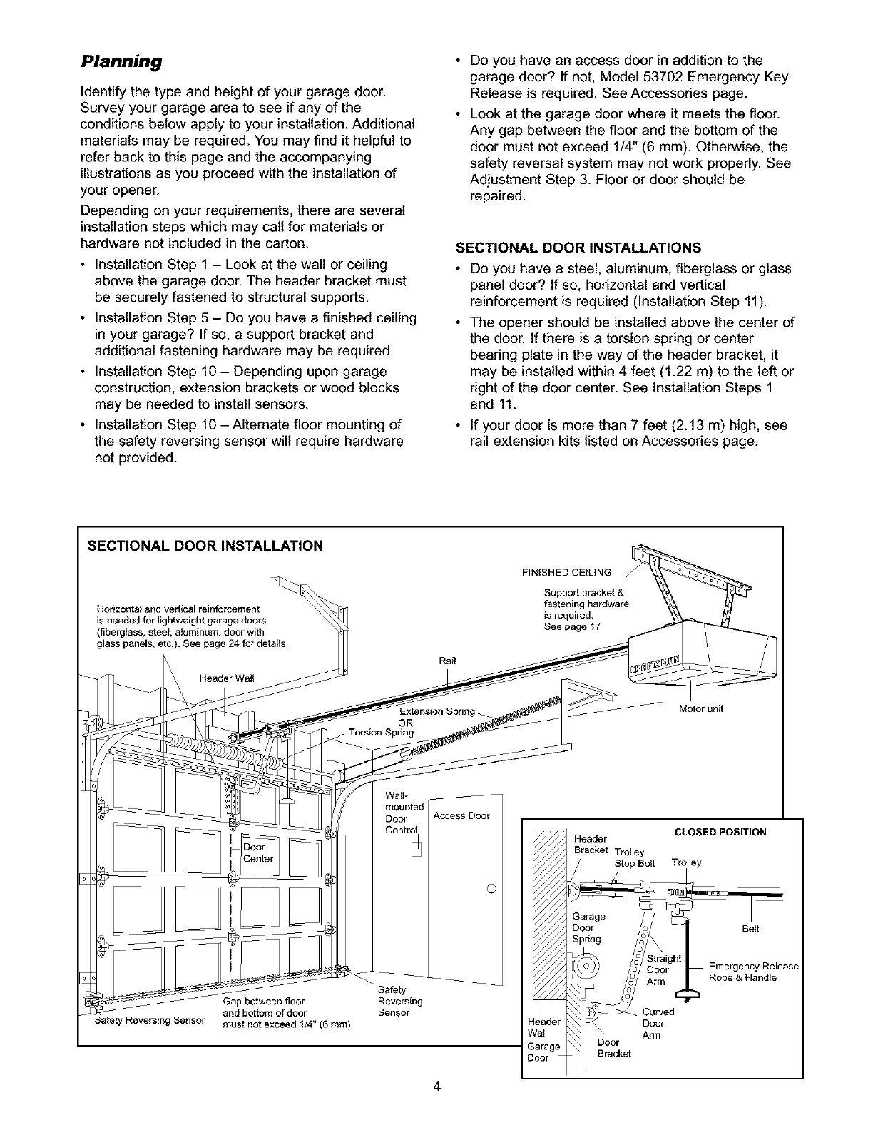
Planning
Identify the type and height of your garage door.
Survey your garage area to see if any of the
conditions below apply to your installation. Additional
materials may be required. You may find it helpful to
refer back to this page and the accompanying
illustrations as you proceed with the installation of
your opener.
Depending on your requirements, there are several
installation steps which may call for materials or
hardware not included in the carton.
• Installation Step 1 - Look at the walt or ceiling
above the garage door. The header bracket must
be securely fastened to structural supports.
• Installation Step 5 - Do you have a finished ceiling
in your garage? If so, a support bracket and
additional fastening hardware may be required.
• Installation Step 10 - Depending upon garage
construction, extension brackets or wood blocks
may be needed to install sensors.
• Installation Step 10-Alternate floor mounfing of
the safety reversing sensor will require hardware
not provided.
Do you have an access door in addition to the
garage door? If not, Model 53702 Emergency Key
Release is required. See Accessories page.
Look at the garage door where it meets the floor.
Any gap between the floor and the bottom of the
door must not exceed 1/4" (6 mm). Otherwise, the
safety reversal system may not work properly. See
Adjustment Step 3. Floor or door should be
repaired.
SECTIONAL DOOR INSTALLATIONS
Do you have a steel, aluminum, fiberglass or glass
panel door? If so, horizontal and vertical
reinforcement is required (Installation Step 11).
The opener should be installed above the center of
the door. If there is a torsion spring or center
bearing plate in the way of the header bracket, it
may be installed within 4 feet (1.22 m) to the left or
right of the door center. See Installation Steps 1
and 11.
• If your door is more than 7 feet (2.13 m) high, see
rail extension kits listed on Accessories page.
SECTIONAL DOOR INSTALLATION
Horizontal and vertical reinforcement
is needed for lightweight garage doors
(fiberglass, steel, aIuminum, door with
glass panels, etc.). See page 24 for details.
Header Wall
Rail
Extension Spring
OR
f Torsion Spring
FINISHED CEILING
SuppoA bracket&
ravening hardware
is required.
See page 17
Motor unit
Wail-
mounted
Door
Control
Access Door
O
Safe, Reversing Sensor
Gap between floor
and bottom of door
must not exceed 1/4" (6 ram)
Safety
Reversing
Sensor eader
/all
arage
oor
CLOSED POSITION
Header
Bracket Tr011ey
Stop Bolt Trolley
Garage
Door
Spring
Belt
Emergency Release
Rope & Handle
Curved
Door
Arm
Bracket
4
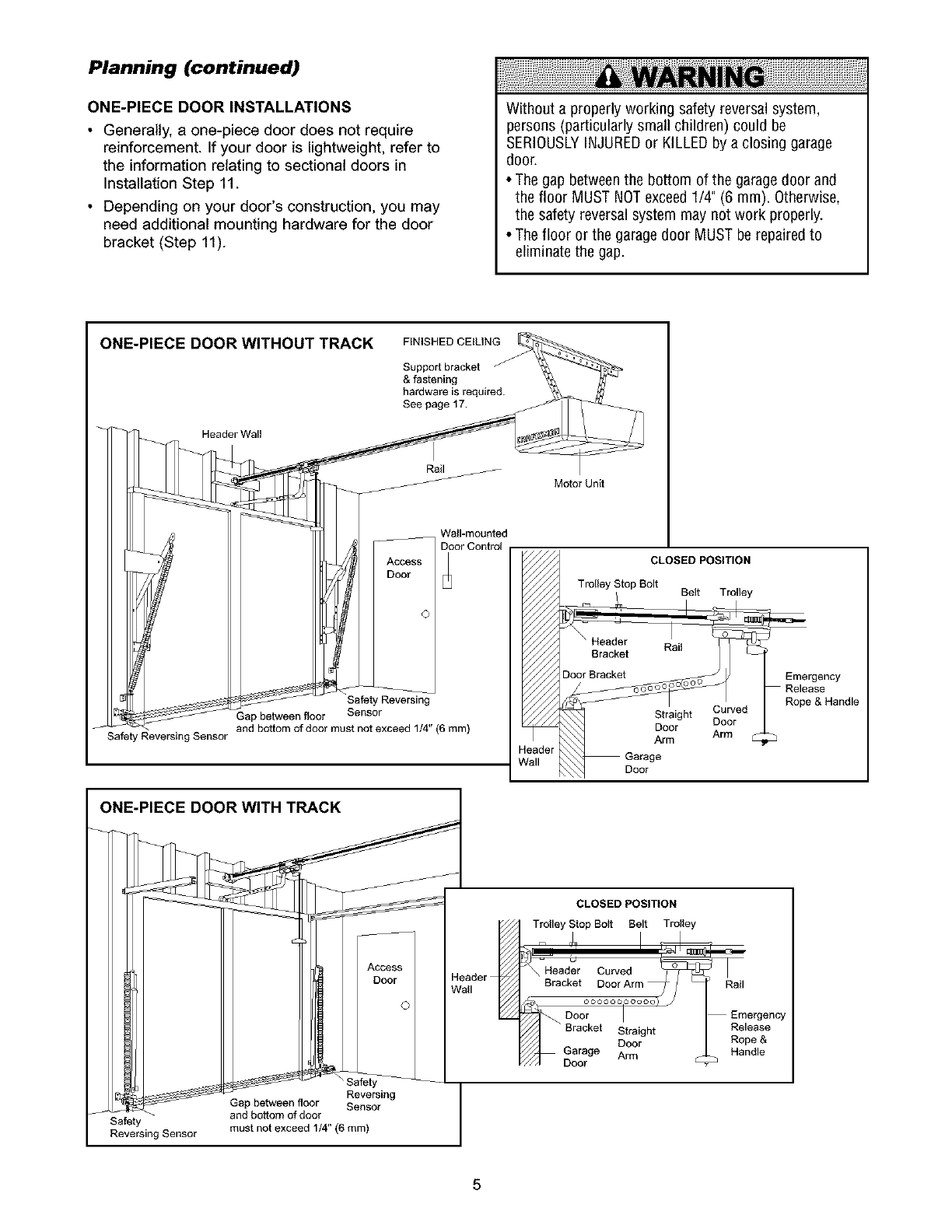
Planning (continued)
ONE-PIECE DOOR INSTALLATIONS
•Generally, a one-piece door does not require
reinforcement. If your door is lightweight, refer to
the information relating to sectional doors in
Installation Step 11.
• Depending on your door's construction, you may
need additional mounting hardware for the door
bracket (Step 11).
Without a properly working safety reversal system,
persons (particularly small children) could be
SERIOUSLYINJUREDor KILLEDby a closing garage
door.
• The gap betweenthe bottom of the garage door and
the floor MUST NOTexceed1/4" (6 ram). Otherwise,
the safety reversal system may not work properly.
• The floor or the garagedoor MUST be repaired to
eliminate the gap.
ONE-PIECE DOOR WITHOUT TRACK
Header Wall
FINISHED CEILING
Support bracket
& fastening
hardware is required.
See page f 7.
Rail
Motor Unit
Access
Door
©
Safety Reversing Sensor
Safety_
Gap between floor Sensor
and bottom of door must not exceed 1/4" (6 ram)
ONE-PIECE DOOR WITH TRACK
Wall-mounted
Door Control
leader
_'all
CLOSED POSITION
Trolley Stop Bolt
Bracket
_r_edD°°rBracket Straight Curved
Door Door
Emergency
Release
Rope & Handle
Reversing
Gap between floor Sensor
and bottom of door
Safety must not exceed 1/4" (6 ram)
Reversing Sensor
CLOSED POSITION
Trolley Stop Bolt Belt Trolley
_-Header Cu_ed _
Bracket Door Arm
Door I
_ Bracket Straight
Door
Garage Arm
Emergency
Release
Rope &
Handle
5
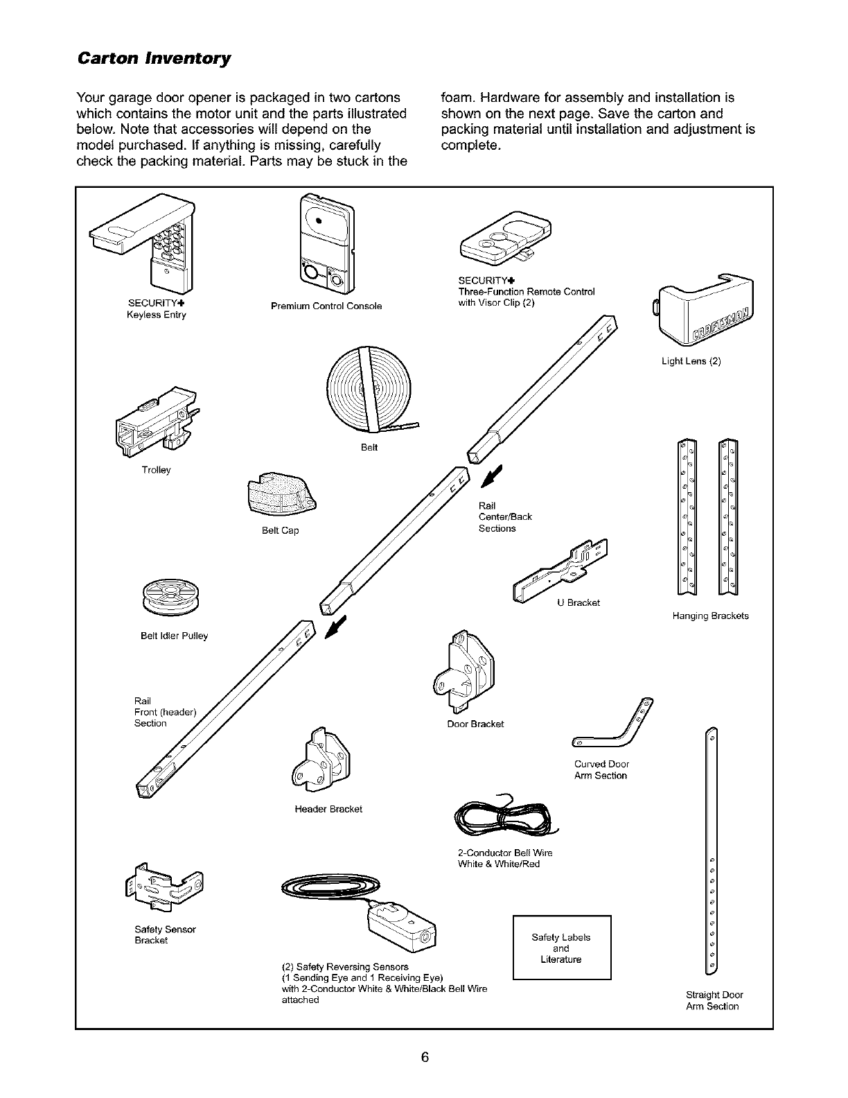
Carton Inventory
Your garage door opener is packaged in two cartons
which contains the motor unit and the parts illustrated
below. Note that accessories will depend on the
model purchased. If anything is missing, carefully
check the packing material. Parts may be stuck in the
foam. Hardware for assembly and installation is
shown on the next page. Save the carton and
packing material until installation and adjustment is
complete.
SECURITY÷
Keyless Entry
Trolley
@
Belt Idler Pulley
Rail
Front (header)
Section
Safety Sensor
Bracket
Premium Control Console
SECURITY÷
Three-Function Remote Control
with Visor Clip (2)
Belt Cap
Belt
I
Rail
Center/Back
Sections
Door Bracket
HeaderBracket
2-Conductor Bell Wire
White & White/Red
(2) Safety Reversing Sensors
(1 Sending Eye and 1 Receiving Eye)
with 2-Conductor White & White/Black Bell Wire
a_ached
J
Curved Door
Arm Section
Safety Labels
and
Literature
Light Lens (2)
IH
Hanging Brackets
Straight Door
Arm Section
6
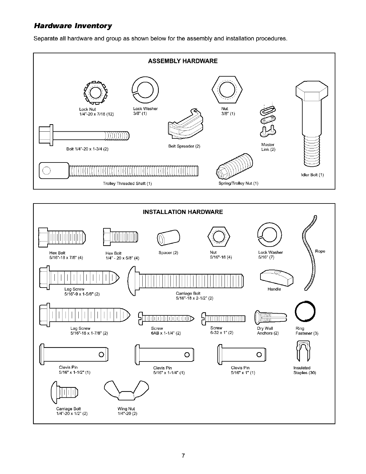
Hardware Inventory
Separate all hardware and group as shown below for the assembly and installation procedures.
ASSEMBLY HARDWARE
© ©
Lock Nut Lock Washer t"_A
1/4"-20 x 7/16 (12) 3/8" (1)
_] Belt Spreader (2)
Bolt 1/4"-20 x 1-3/4 (2)
©
Nut
3/8" (1)
i
Master
Link (2)
Trolley Threaded Shaft (1) Spring/Trolley Nut (1)
Idler Bolt (1)
Hex Bolt Hex Bo_t
5/16"-18 x 7/8" (4) 1/4" - 20 x 5/8" (4)
INSTALLATION HARDWARE
© ©
Spacer (2) Nut Lock Washer
5/16"-18 (4) 5/16" (7)
Rope
@
5/16"-9 x 1-5/8" (2)
Lag Screw Screw
5/16"-18 x 1-7/8" (2) 6AB x 1-1/4" (2)
o] _ oJ
Clevis Pin Clevis Pin
5/16" x 1-1/2" (1) 5/16" x 1-1/4" (1)
Carriage Bolt Wing Nut
1/4"-20 x 1/2" (2) 1/4"-20 (2)
Carriage Bolt
5/16"-18 x 2-1/2" (2)
Handle ©
Screw Dry Wall Ring
6-32 x 1" (2) Anchors (2) Fastener (3)
Clevis Pin Insulated
5/16" x 1" (1) Staples (30)
7
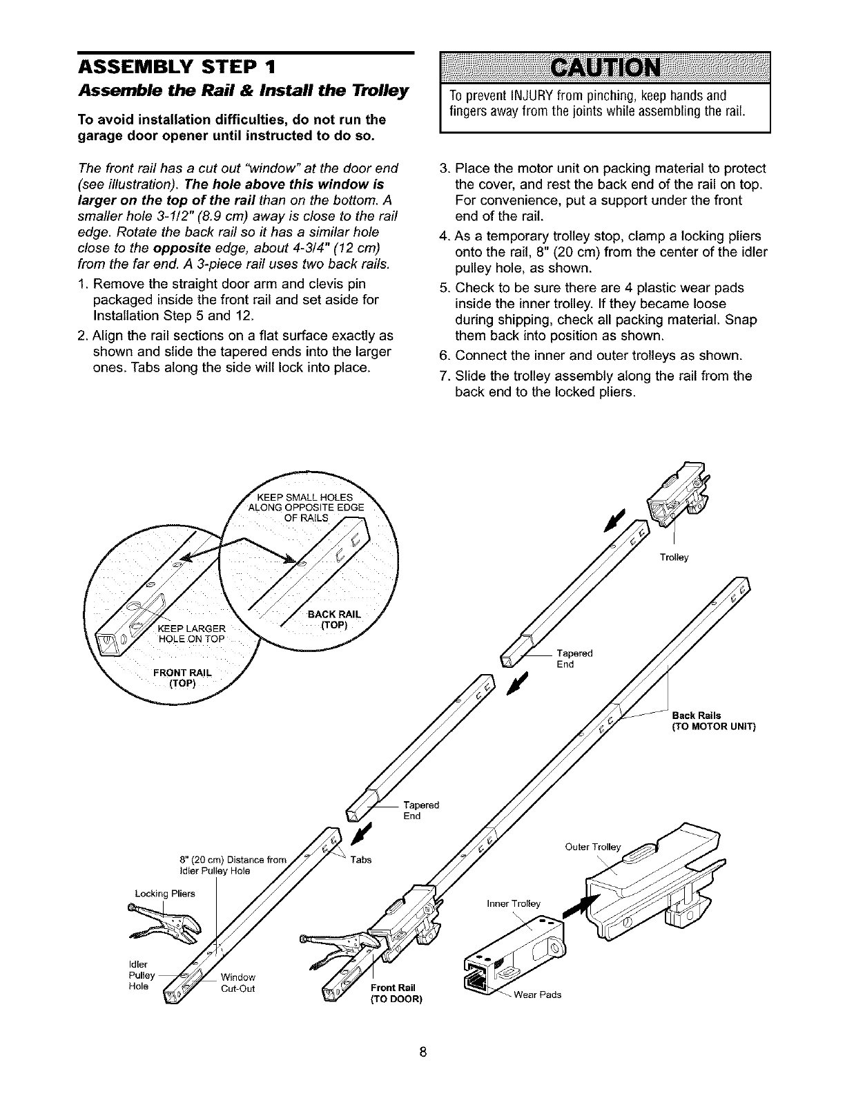
ASSEMBLY STEP 1
Assemble the Rail & Install the Trolley
To avoid installation difficulties, do not run the
garage door opener until instructed to do so.
The front rail has a cut out "window" at the door end
(see illustration). The hole above this window is
larger on the top of the rail than on the bottom. A
smaller hole 3-1/2" (8.9 cm) away is close to the rail
edge. Rotate the back rail so it has a similar hole
close to the opposite edge, about 4-3/4" (12 cm)
from the far end. A 3-piece rail uses two back rails.
1. Remove the straight door arm and clevis pin
packaged inside the front rail and set aside for
Installation Step 5 and 12.
2. Align the rail sections on a flat surface exactly as
shown and slide the tapered ends into the larger
ones. Tabs along the side wilt lock into place.
To prevent INJURYfrom pinching, keep hands and
fingers away from the joints while assembling the rail.
3. Place the motor unit on packing material to protect
the cover, and rest the back end of the rail on top.
For convenience, put a support under the front
end of the rail.
4. As a temporary trolley stop, clamp a locking pliers
onto the rail, 8" (20 cm) from the center of the idler
pulley hole, as shown.
5. Check to be sure there are 4 plastic wear pads
inside the inner trolley. If they became loose
during shipping, check all packing material. Snap
them back into position as shown.
6. Connect the inner and outer trolleys as shown.
7. Slide the trolley assembly along the rail from the
back end to the locked pliers.
End
Tapered
Back Rails
(TO MOTOR UNIT)
8" (20 cm) Distance from
Idler Pulley Hole
Locking Pliers
Idler
Window
Hole Cut-Out
Tabs
Inner Trolley
Front Rail
(TO DOOR)
Outer Trolley
-Wear Pads
8
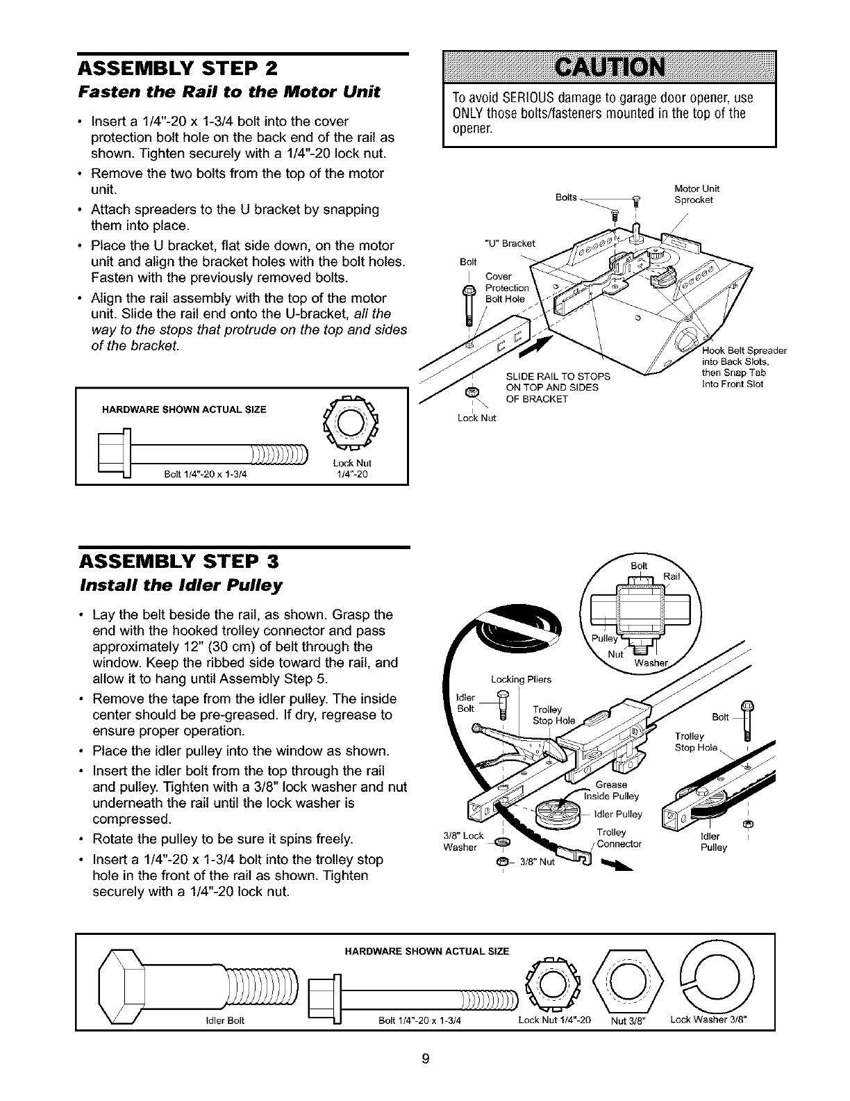
ASSEMBLY STEP 2
Fasten the Rail to the Motor Unit
•Insert a 1/4"-20 x 1-3/4 bolt into the cover
protection bolt hole on the back end of the rail as
shown. Tighten securely with a 1/4"-20 lock nut.
• Remove the two bolts from the top of the motor
unit.
• Attach spreaders to the U bracket by snapping
them into place.
• Place the U bracket, flat side down, on the motor
unit and align the bracket holes with the bolt holes.
Fasten with the previously removed bolts.
• Align the rail assembly with the top of the motor
unit. Slide the rail end onto the U-bracket, all the
way to the stops that protrude on the top and sides
of the bracket.
HARDWARE SHOWN ACTUAL SIZE _"r'-'_'_"l
q Lock Nut
Bolt 1/4"-20 x I-3/4 1/4"-20
To avoid SERIOUSdamage to garagedoor opener, use
ONLYthose bolts/fasteners mounted in the top of the
opener.
Motor Unit
Bolts _ Sprocket
"U" Bracket
Bolt
Cover
Logk Nut
SLIDE RAIL TO STOPS
ON TOP AND SIDES
OF BRACKET
ook Belt Spreader
into Back Slots,
then Snap Tab
Into Front SIot
ASSEMBLY STEP 3
Install the Idler Pulley
• Lay the belt beside the rail, as shown. Grasp the
end with the hooked trolley connector and pass
approximately 12" (30 cm) of belt through the
window. Keep the ribbed side toward the rail, and
allow it to hang until Assembly Step 5.
• Remove the tape from the idler pulley. The inside
center should be pre-greased. If dry, regrease to
ensure proper operation.
• Place the idler pulley into the window as shown.
• Insert the idler bolt from the top through the rail
and pulley. Tighten with a 3/8" tock washer and nut
underneath the rail until the lock washer is
compressed.
• Rotate the pulley to be sure it spins freely.
• Insert a 1/4"-20 x 1-3/4 bolt into the trolley stop
hole in the front of the rail as shown. Tighten
securely with a 1/4"-20 lock nut.
Grease
Inside Pulley
3/8" Lock Trolley Idler
Washer Pulley
0HARDWARE SHOWN ACTUAL SIZE @ @
idler Bolt Bolt 114"-20 x 1-3/4 Lock Nut 1/4"-20 Nut 3/8" Lock Washer 3/8"
9
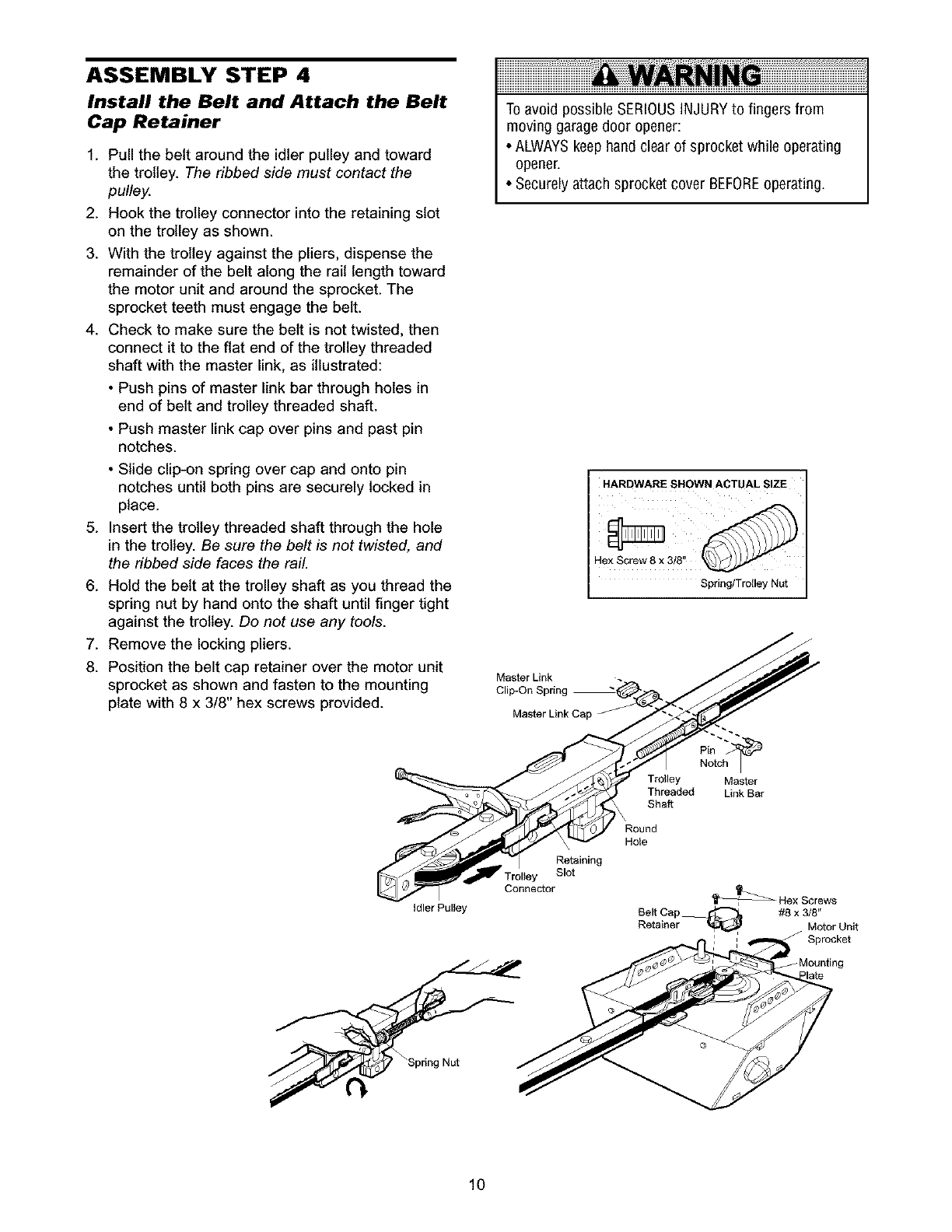
ASSEMBLY STEP 4
Install the Belt and Attach the Belt
Cap Retainer
1. Pull the belt around the idler pulley and toward
the trolley. The ribbed side must contact the
pulley.
2. Hook the trolley connector into the retaining slot
on the trolley as shown.
3. With the trolley against the pliers, dispense the
remainder of the belt along the rail length toward
the motor unit and around the sprocket. The
sprocket teeth must engage the belt.
4. Check to make sure the belt is not twisted, then
connect it to the flat end of the trolley threaded
shaft with the master link, as illustrated:
Toavoid possible SERIOUSINJURYto fingers from
moving garage door opener:
• ALWAYSkeep hand clear of sprocket while operating
opener.
• Securelyattach sprocket cover BEFOREoperating.
• Push pins of master link bar through holes in
end of belt and trolley threaded shaft.
• Push master link cap over pins and past pin
notches.
• Slide clip-on spring over cap and onto pin
notches until both pins are securely locked in
place.
5. Insert the trolley threaded shaft through the hole
in the trolley. Be sure the belt is not twisted, and
the ribbed side faces the rail.
6. Hold the belt at the trolley shaft as you thread the
spring nut by hand onto the shaft until finger tight
against the trolley. Do not use any tools.
HARDWARE SHOWN ACTUAL SIZE
Hex Screw 8 x 3/8"
Spring/Trolley Nut
7. Remove the locking pliers. /___
8. Position the belt cap retainer over the motor unit /_/j/
•Master Link .
sprocket as shown and fasten to the mounting Cli On_rin "_ /_/_'/
•.p- bp g
plate with 8 x 3/8" hex screws provided. __
Master Link Cap _- /.. "
Pin
Trolley Master
Threaded Link Bar
Shaft
Round
Hole
Retaining
Troltey Slot
_Hex Screws
Idler Pulley Belt Cap _ #8 x 3/8"
Retainer _ Motor Unit
J Sprocket
_Spdng Nut
10
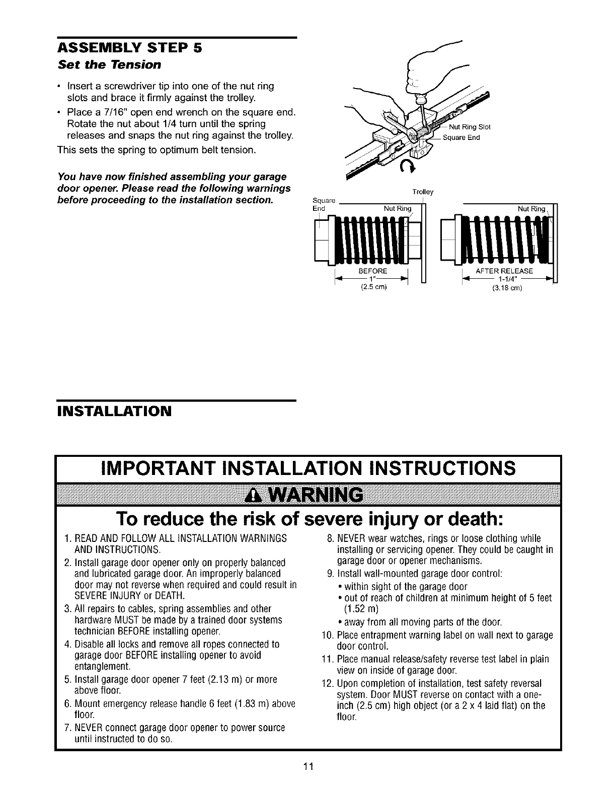
ASSEMBLY STEP 5
Set the Tension
•Insert a screwdriver tip into one of the nut ring
slots and brace it firmly against the trolley.
• Place a 7/16" open end wrench on the square end.
Rotate the nut about 1/4 turn until the spring
releases and snaps the nut ring against the trolley.
This sets the spring to optimum belt tension.
You have now finished assembling your garage
door opener. Please read the following warnings
before proceeding to the installation section. End
Trolley
Nut Ring
(2.5 cm)
Nut Ring Slot
! End
Nut Ring /
(3.18 cm)
INSTALLATION
IMPORTANT INSTALLATION INSTRUCTIONS
To reduce the risk of severe injury or death:
1. READAND FOLLOWALL INSTALLATIONWARNINGS 8. NEVERwear watches, rings or loose clothing while
AND INSTRUCTIONS.
2. Install garage door opener only on properly balanced
and lubricated garage door. An improperly balanced
door may not reversewhen required and could result in
SEVEREINJURYor DEATH.
3. All repairs to cables, spring assembliesand other
hardware MUST be made by a trained door systems
technician BEFOREinstalling opener.
4. Disableall locks and removeall ropes connected to
garagedoor BEFOREinstalling openerto avoid
entanglement.
5. Install garage door opener 7 feet (2.13 m) or more
above floor.
6. Mount emergency releasehandle6 feet (1.83 m) above
floor.
7. NEVERconnect garagedoor openerto powersource
until instructed to do so.
installing or servicing opener.They could be caught in
garage door or opener mechanisms.
9. Install wall-mounted garagedoor control:
• within sight of the garagedoor
• out of reach of children at minimum height of 5 feet
(1.52m)
• awayfrom all moving parts of the door.
10. Placeentrapment warning label on wall next to garage
door control.
11. Placemanual release/safetyreverse test label in plain
view on inside of garagedoor.
12. Upon completion of installation, test safety reversal
system. Door MUST reverse on contact with a one-
inch (2.5 cm) high object (or a 2 x 4 laidflat) on the
floor.
11
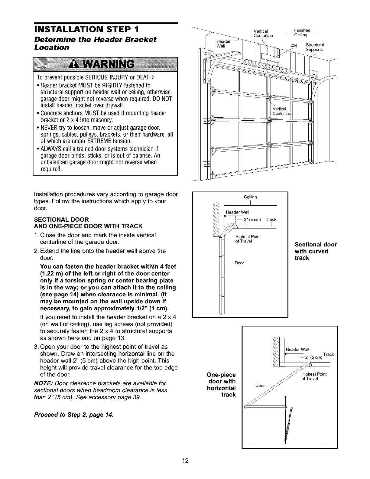
INSTALLATION STEP 1
Determine the Header Bracket
Location
To prevent possible SERIOUSINJURYor DEATH:
•Header bracket MUST be RIGIDLYfastened to
structural support on headerwall or ceiling, otherwise
garagedoor might not reversewhen required. DO NOT
install header bracket over drywall.
• Concreteanchors MUST be used if mounting header
bracket or 2 x 4 into masonry.
• NEVERtry to loosen, move or adjust garagedoor,
springs, cables, pulleys, brackets, or their hardware,all
of which are under EXTREMEtension.
• ALWAYScall a trained door systems technician if
garagedoor binds, sticks, or is out of balance.An
unbalancedgarage door might not reversewhen
required.
Vertical
Center_ine
Finished
Ceiling
2x4 Structural
Supports
Installation procedures vary according to garage door
types. Follow the instructions which apply to your
door.
SECTIONAL DOOR
AND ONE-PIECE DOOR WITH TRACK
1. Close the door and mark the inside vertical
centerline of the garage door.
2. Extend the line onto the header wall above the
door.
You can fasten the header bracket within 4 feet
(1.22 m) of the left or right of the door center
only if atorsion spring or center bearing plate
is in the way; or you can attach it to the ceiling
(see page 14) when clearance is minimal. (It
may be mounted on the wall upside down if
necessary, to gain approximately 1/2" (1 cm).
If you need to install the header bracket on a 2 x 4
(on wall or ceiling), use lag screws (not provided)
to securely fasten the 2 x 4 to structural supports
as shown here and on page 13.
3. Open your door to the highest point of travel as
shown. Draw an intersecting horizontal line on the
header walt 2" (5 cm) above the high point. This
height will provide travel clearance for the top edge
of the door.
NOTE: Door clearance brackets are available for
sectional doors when headroom clearance is less
than 2" (5 cm). See accessory page 39.
Proceed toStep _page 14.
Ceiling
Header Wall
I--2" (5cm) Track
i
Highest Point
of Travel
Door
Sectional door
with curved
track
One-piece
door with
horizontal
track
Header Wa_l
Track
H_rhraeSvteP°int
Highest Point
of Travel
12
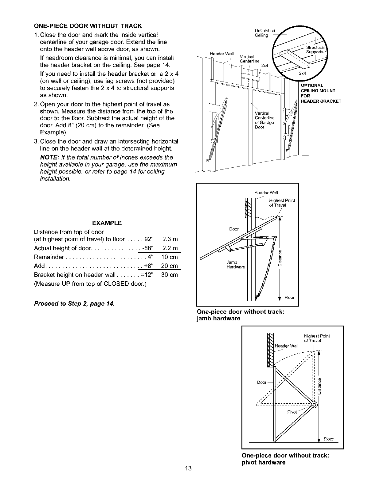
ONE-PIECE DOOR WITHOUT TRACK
1. Close the door and mark the inside vertical
centerline of your garage door. Extend the line
onto the header wall above door, as shown.
If headroom clearance is minimal, you can install
the header bracket on the ceiling. See page 14.
If you need to install the header bracket on a 2 x 4
(on wall or ceiling), use lag screws (not provided)
to securely fasten the 2 x 4 to structural supports
as shown.
2. Open your door to the highest point of travel as
shown. Measure the distance from the top of the
door to the floor. Subtract the actual height of the
door. Add 8" (20 cm) to the remainder. (See
Example).
3. Close the door and draw an intersecting horizontal
line on the header wall at the determined height.
NOTE: If the total number of inches exceeds the
height available in your garage, use the maximum
height possible, or refer to page 14 for ceiling
installation.
EXAMPLE
Distance from top of door
(at highest point of travel) to floor ..... 92" 2.3 m
Actual height of door ............... -88" 2.2 m
Remainder ........................ 4" 10 cm
Add ............................. +8" 20 cm
Bracket height on header wall ....... =12" 30 cm
(Measure UP from top of CLOSED door.)
Proceed to Step 2, page 14.
Unfinished
Ceiling
Header Wall Vertical
Center_ine 2x4
DOlOr 1
Header Wal!
Highest Point
of Travel
Y
rFloor
One-piece door without track:
jamb hardware
OPTIONAL
CEILING MOUNT
FOR
HEADER BRACKET
I Highest Point
of Travel
Header Wall T
.-- ,,/, ,,
7f j
One-piece door without track:
pivot hardware
13
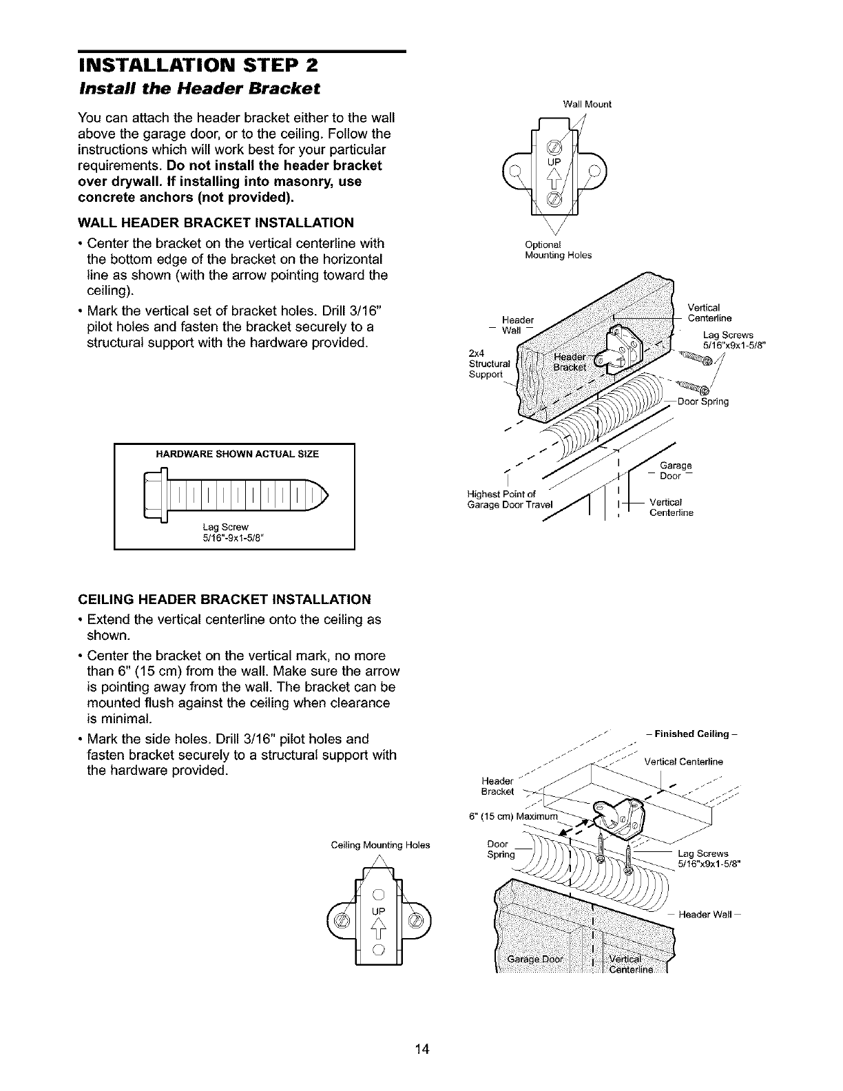
INSTALLATION STEP 2
Install the Header Bracket
You can attach the header bracket either to the wall
above the garage door, or to the ceiling. Follow the
instructions which will work best for your particular
requirements. Do not install the header bracket
over drywall. If installing into masonry, use
concrete anchors (not provided).
WALL HEADER BRACKET INSTALLATION
•Center the bracket on the vertical centerline with
the bottom edge of the bracket on the horizontal
line as shown (with the arrow pointing toward the
ceiling).
• Mark the vertical set of bracket holes. Drill 3/16"
pilot holes and fasten the bracket securely to a
structural support with the hardware provided.
HARDWARESHOWNACTUALSIZE
Lag Screw
5/16"-9xl-5/8"
Wall Mount
Optional
Mounting Holes
Header
Wall
2x4
Structural
Suppo_
/
/
/
if
Highest Point of
Garage Door Travel
Ve_ical
Centerline
Lag Screws
5/16"x9x1-5/8"
Door Spring
f
Garage
Door
Centerline
CEILING HEADER BRACKET INSTALLATION
• Extend the vertical centerline onto the ceiling as
shown.
• Center the bracket on the vertical mark, no more
than 6" (15 cm) from the wall. Make sure the arrow
is pointing away from the walt. The bracket can be
mounted flush against the ceiling when clearance
is minimal.
• Mark the side holes. Drill 3/16" pilot holes and
fasten bracket securely to a structural support with
the hardware provided.
Ceiling Mounting Holes
6" (15 cm) Maximul
Door
/
/
J
Lag Screws
5/16"x9x1-5/8"
Header Wall
14
Header Wall
/ Header Bracket
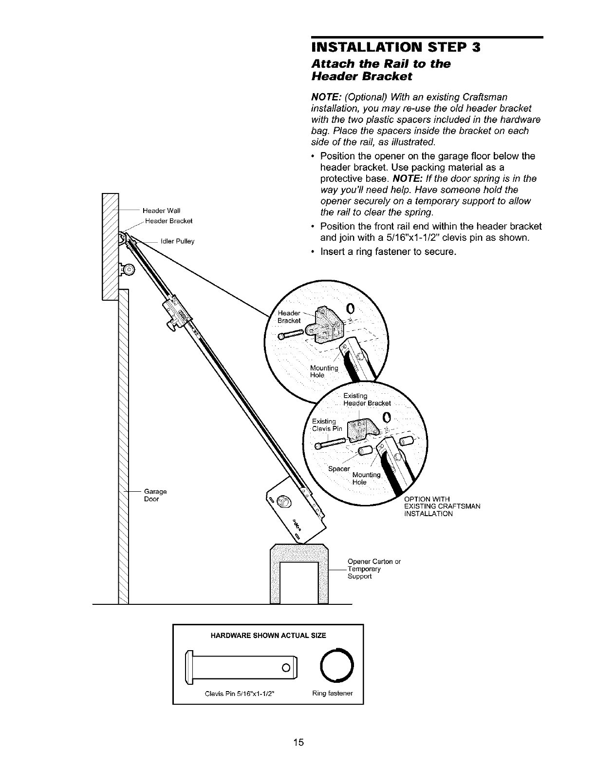
INSTALLATION STEP 3
Attach the Rail to the
Header Bracket
NOTE: (Optional) With an existing Craftsman
installation, you may re-use the old header bracket
with the two plastic spacers included in the hardware
bag. Place the spacers inside the bracket on each
side of the rail, as illustrated.
• Position the opener on the garage floor below the
header bracket. Use packing material as a
protective base. NOTE: If the door spring is in the
way you'll need help. Have someone hold the
opener securely on a temporary support to allow
the rail to clear the spring.
• Position the front rail end within the header bracket
and join with a 5/16"x1-1/2" clevis pin as shown.
• Insert a ring fastener to secure.
Mounting
MOle
Door
Spacer Mounting
Hole
OPTION WITH
EXISTING CRAFTSMAN
INSTALLATION
Opener Carton or
Support
HARDWARE SHOWN ACTUAL SIZE
O
Clevis Pin 5/16"x1-I12" Ring fastener
15
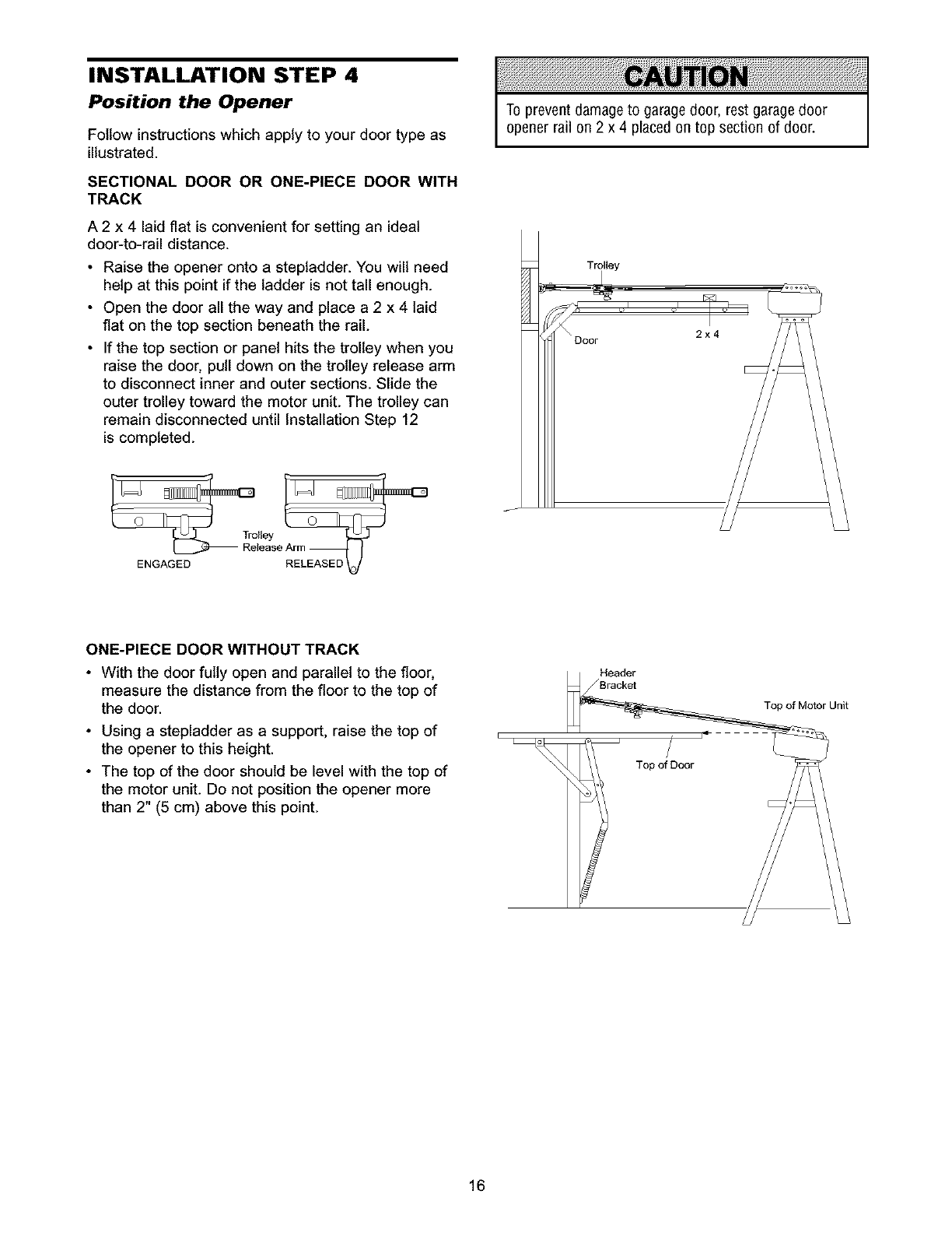
INSTALLATION STEP 4
Position the Opener
Follow instructions which apply to your door type as
illustrated.
SECTIONAL DOOR OR ONE-PIECE DOOR WITH
TRACK
A 2 x 4 laid flat is convenient for setting an ideal
door-to-rail distance.
• Raise the opener onto a stepladder. You will need
help at this point if the ladder is not tall enough.
• Open the door all the way and place a 2 x 4 laid
flat on the top section beneath the rail.
• If the top section or panel hits the trolley when you
raise the door, pull down on the trolley release arm
to disconnect inner and outer sections. Slide the
outer trolley toward the motor unit. The trolley can
remain disconnected until Installation Step 12
is completed.
To prevent damageto garage door, rest garage door
opener rail on 2 x 4 placed on top section of door.
ENGAGED
ONE-PIECE DOOR WITHOUT TRACK
• With the door fully open and parallel to the floor,
measure the distance from the floor to the top of
the door.
• Using a stepladder as a support, raise the top of
the opener to this height.
• The top of the door should be level with the top of
the motor unit. Do not position the opener more
than 2" (5 cm) above this point.
Header
/Bracket
i q
i
_1 Top of Door
Top of Motor Unit
16
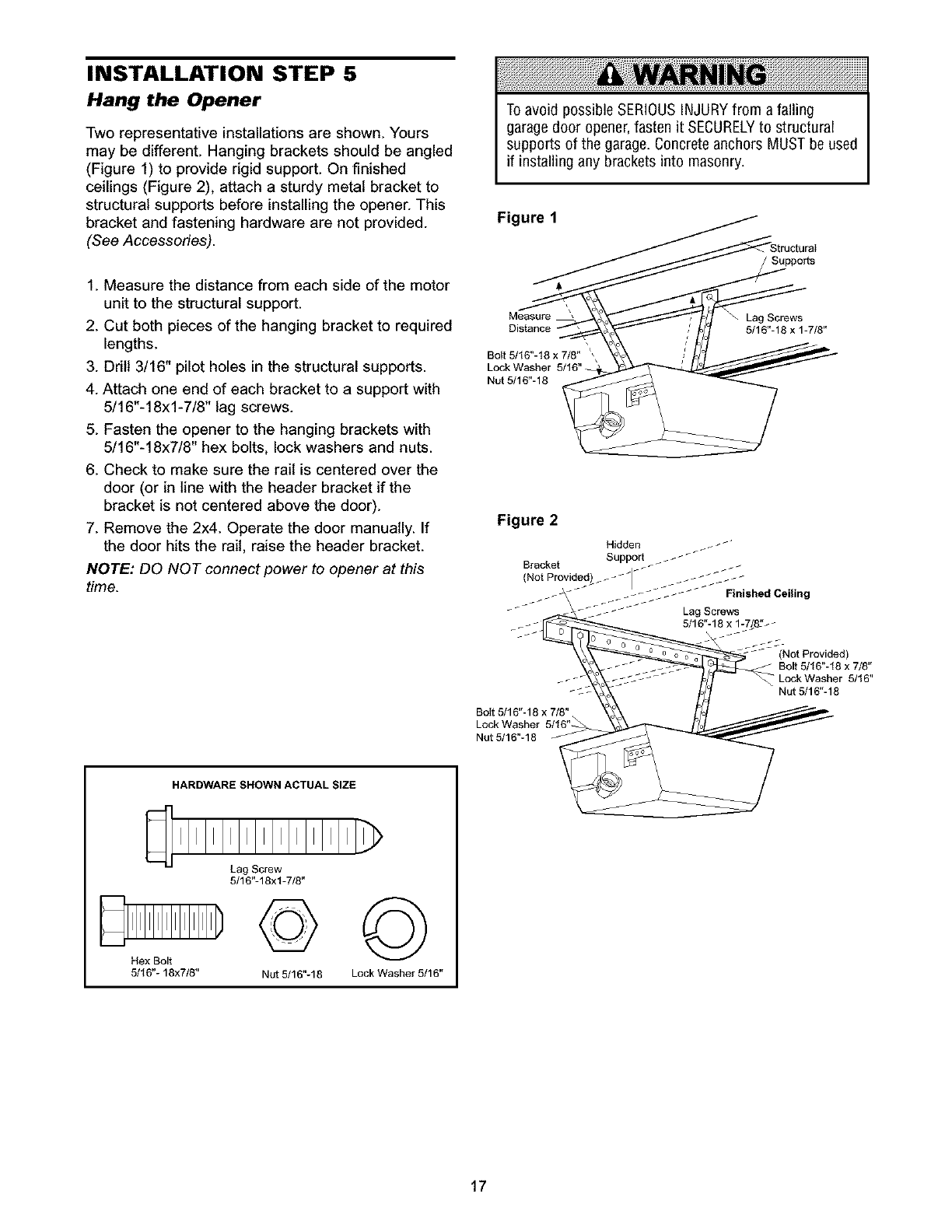
INSTALLATION STEP 5
Hang the Opener
Two representative installations are shown. Yours
may be different. Hanging brackets should be angled
(Figure 1) to provide rigid support. On finished
ceilings (Figure 2), attach a sturdy metal bracket to
structural supports before installing the opener. This
bracket and fastening hardware are not provided.
(See Accessories).
1. Measure the distance from each side of the motor
unit to the structural support.
2. Cut both pieces of the hanging bracket to required
lengths.
3. Drill 3/16" pilot holes in the structural supports.
4. Attach one end of each bracket to a support with
5/16"-18xl-7/8" lag screws.
5. Fasten the opener to the hanging brackets with
5/16"-18x7/8" hex bolts, lock washers and nuts.
6. Check to make sure the rail is centered over the
door (or in line with the header bracket if the
bracket is not centered above the door).
7. Remove the 2x4. Operate the door manually. If
the door hits the rail, raise the header bracket.
NOTE: DO NOT connect power to opener at this
time.
To avoid possible SERIOUSINJURYfrom afalling
garagedoor opener,fasten it SECURELYto structural
supports of the garage. Concrete anchors MUST be used
if installing any brackets into masonry.
Figure 1
Supports
Measure
Distance
Bolt 5/16"-18 x 7/8" ',
Lock Washer
Nut 5/16"-18
Lag Screws
5/16"-18 x 1-7/8"
Figure 2
(Not Provided)
Bolt 5/16"-18 x 7/8"
- Lock Washer 5/16"
Nut5/16"-18
Bolt 5/16"-18 x 7/8"
Lock Washer 5/16"_.
Nut 5/16"-18
HARDWARE SHOWN ACTUAL SIZE
Hex Bolt
5/16"- 18x7/8"
Lag Screw
5/16"-18xl-7/8"
©
Nut 5/16"-18
©
Lock Washer 5/16"
17
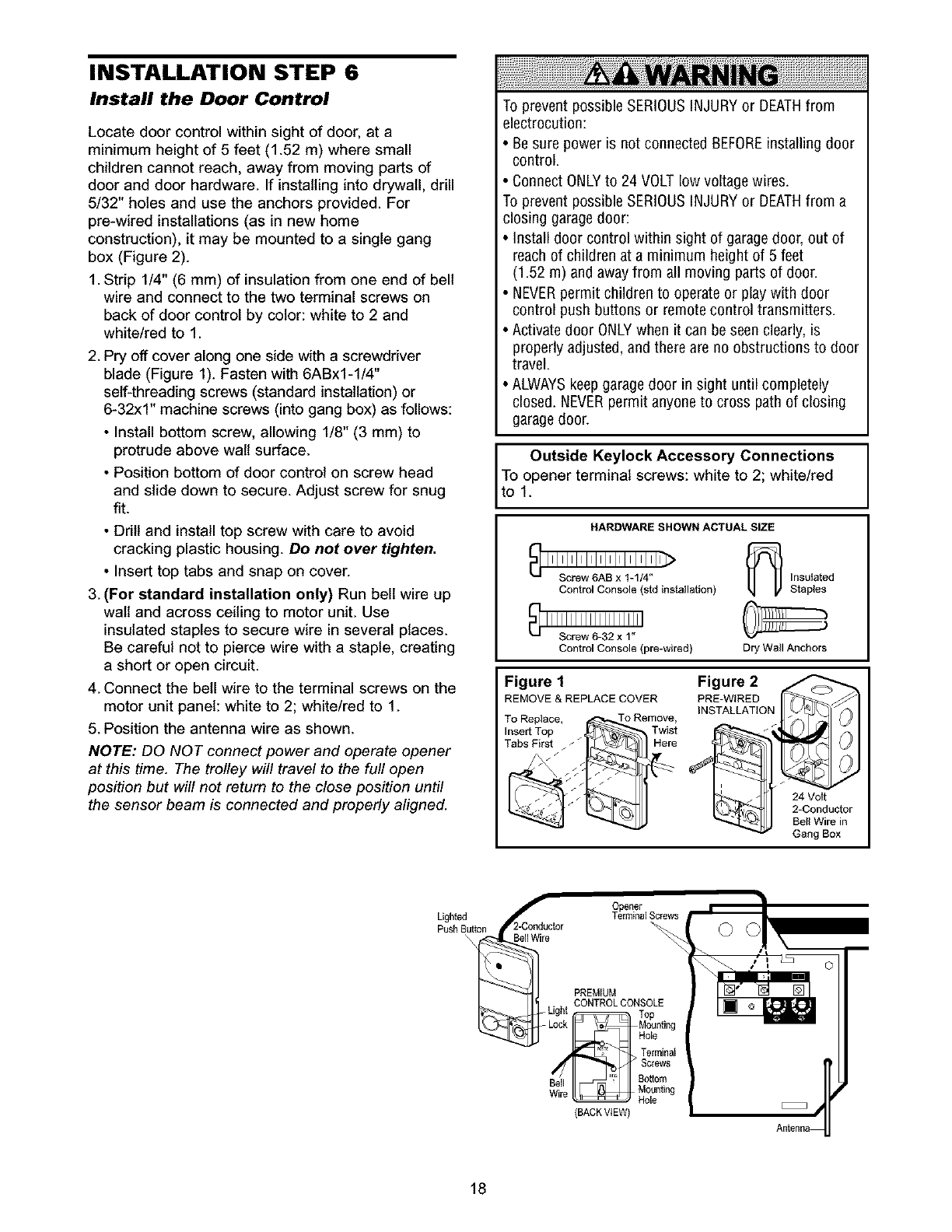
INSTALLATION STEP 6
Install the Door Control
Locate door control within sight of door, at a
minimum height of 5 feet (1.52 m) where small
children cannot reach, away from moving parts of
door and door hardware. If installing into drywall, drill
5/32" holes and use the anchors provided. For
pre-wired installations (as in new home
construction), it may be mounted to a single gang
box (Figure 2).
1. Strip 1/4" (6 mm) of insulation from one end of bell
wire and connect to the two terminal screws on
back of door control by color: white to 2 and
white/red to 1.
2. Pry off cover along one side with a screwdriver
blade (Figure 1). Fasten with 6ABx1-1/4"
self-threading screws (standard installation) or
6-32x1" machine screws (into gang box) as follows:
• Install bottom screw, allowing 1/8" (3 mm) to
protrude above walt surface.
• Position bottom of door control on screw head
and slide down to secure. Adjust screw for snug
fit.
• Drill and install top screw with care to avoid
cracking plastic housing. Do not over tighten.
• Insert top tabs and snap on cover.
3. (For standard installation only) Run bell wire up
walt and across ceiling to motor unit. Use
insulated staples to secure wire in several places.
Be careful not to pierce wire with a staple, creating
a short or open circuit.
4. Connect the bell wire to the terminal screws on the
motor unit panel: white to 2; white/red to 1.
5. Position the antenna wire as shown.
NOTE: DO NOT connect power and operate opener
at this time. The trolley will travel to the full open
position but will not return to the close position until
the sensor beam is connected and properly aligned.
To prevent possible SERIOUSINJURYor DEATHfrom
electrocution:
•Be sure power is not connected BEFOREinstalling door
control.
• Connect ONLYto 24 VOLT low voltage wires.
To prevent possible SERIOUSINJURYor DEATHfrom a
closing garagedoor:
• Install door control within sight of garage door, out of
reach of children at a minimum height of 5 feet
(1.52 m) and away from all moving parts of door.
• NEVERpermit children to operate or play with door
control push buttons or remote control transmitters.
• Activate door ONLYwhen it can be seen clearly, is
properly adjusted, and there are no obstructions to door
travel.
• ALWAYSkeep garagedoor in sight until completely
closed. NEVERpermit anyone to cross path of closing
garagedoor.
Outside Keylock Accessory Connections
I ToOlo.pener terminal screws: white to 2; white/red
HARDWARE SHOWN ACTUAL SIZE
Control Console (std installation) _r _ Insulated
Staples
Control Console (we-wired) Dry Wall Anchors
Figure 1
REMOVE & REPLACE COVER
To Replace, To Remove,
Insert Top _ / Twist
Tabs_;_First _, Here
Figure 2
PRE-WIRED
INSTALLATION
24 Volt
2-Conductor
Bell Wire in
Gang Box
Lighted
PushButton
\
Opener
2_"-Conductor TerminalScrews
BellWire
PREMIUM
CONTROLCONSOLE
Light Top
Lock Mounti_J
Terminal
Bell Bottom
Wire Mounti_J
Hole
(BACKVIEW)
18
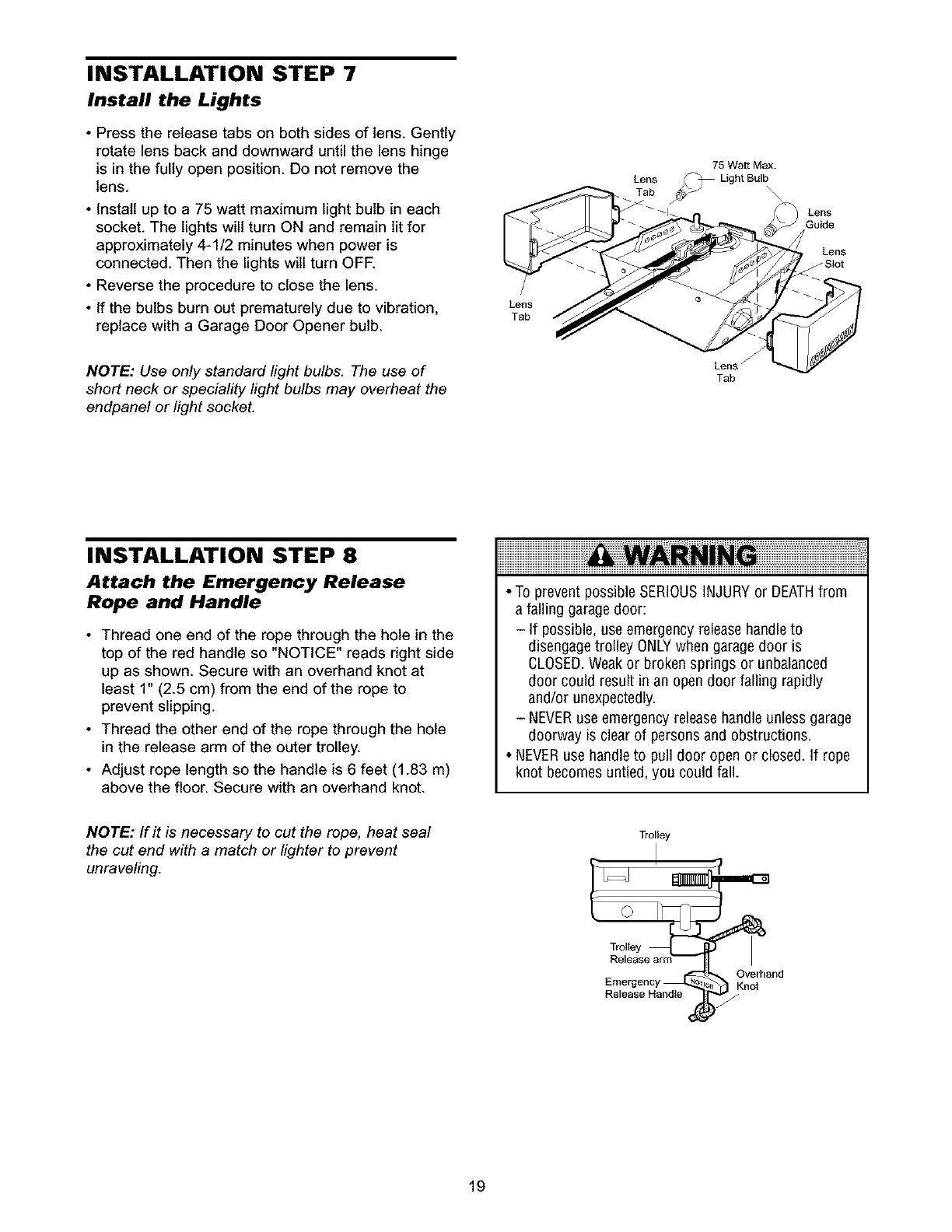
INSTALLATION STEP 7
Install the Lights
•Press the release tabs on both sides of lens. Gently
rotate lens back and downward until the lens hinge
is in the fully open position. Do not remove the
lens.
• Install up to a 75 watt maximum light bulb in each
socket. The lights will turn ON and remain lit for
approximately 4-1/2 minutes when power is
connected. Then the lights will turn OFE
• Reverse the procedure to close the lens.
• If the bulbs burn out prematurely due to vibration,
replace with a Garage Door Opener bulb.
NOTE: Use only standard fight bulbs. The use of
short neck or speciality light bulbs may overheat the
endpanel or light socket.
Lens
Tab
Lens
75 Watt Max.
Lens f
Tab
Lens
Guide
Lens
JS_ot
INSTALLATION STEP 8
Attach the Emergency Release
Rope and Handle
• Thread one end of the rope through the hole in the
top of the red handle so "NOTICE" reads right side
up as shown. Secure with an overhand knot at
least 1" (2.5 cm) from the end of the rope to
prevent slipping.
• Thread the other end of the rope through the hole
in the release arm of the outer trolley.
• Adjust rope length so the handle is 6 feet (1.83 m)
above the floor. Secure with an overhand knot.
•To prevent possible SERIOUSINJURYor DEATHfrom
a falling garagedoor:
- If possible, use emergency release handleto
disengage trolley ONLYwhen garage door is
CLOSED.Weakor broken springs or unbalanced
door could result in an open door falling rapidly
and/or unexpectedly.
- NEVERuse emergency releasehandle unless garage
doorway is clear of persons and obstructions.
• NEVERuse handle to pull door open or closed. If rope
knot becomes untied, you could fall.
NOTE: If it is necessary to cut the rape, heat seal
the cut end with a match or lighter to prevent
unraveling.
Trolley
Trolley _
Tro!tey
Release arm
Emergency _ _ KOnve[hand
Release Handle )_-
19
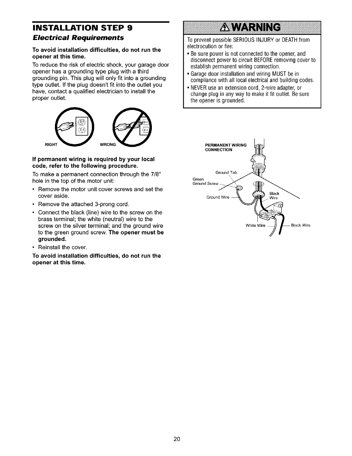
INSTALLATION STEP 9
Electrical Requirements
To avoid installation difficulties, do not run the
opener at this time.
To reduce the risk of electric shock, your garage door
opener has a grounding type plug with a third
grounding pin. This plug will only fit into a grounding
type outlet. If the plug doesn't fit into the outlet you
have, contact a qualified electrician to install the
proper outlet.
@wo@
If permanent wiring is required by your local
code, refer to the following procedure.
To make a permanent connection through the 7/8"
hole in the top of the motor unit:
•Remove the motor unit cover screws and set the
cover aside.
• Remove the attached 3-prong cord.
• Connect the black (line) wire to the screw on the
brass terminal; the white (neutral) wire to the
screw on the silver terminal; and the ground wire
to the green ground screw. The opener must be
grounded.
• Reinstall the cover.
To avoid installation difficulties, do not run the
opener at this time.
To prevent possible SERIOUSINJURYor DEATHfrom
electrocution or fire:
•Be sure poweris not connected to the opener, and
disconnect power to circuit BEFOREremoving cover to
establish permanentwiring connection.
• Garagedoor installation and wiring MUST be in
compliance with all local electrical and building codes.
• NEVERuse an extension cord, 2-wire adapter,or
change plugin any way to makeit fit outlet. Be sure
the opener is grounded.
PERMANENT WIRING
CONNECTION
Ground Tab
Green
Ground Screw_
Black
_ Wire
White Wire
2O
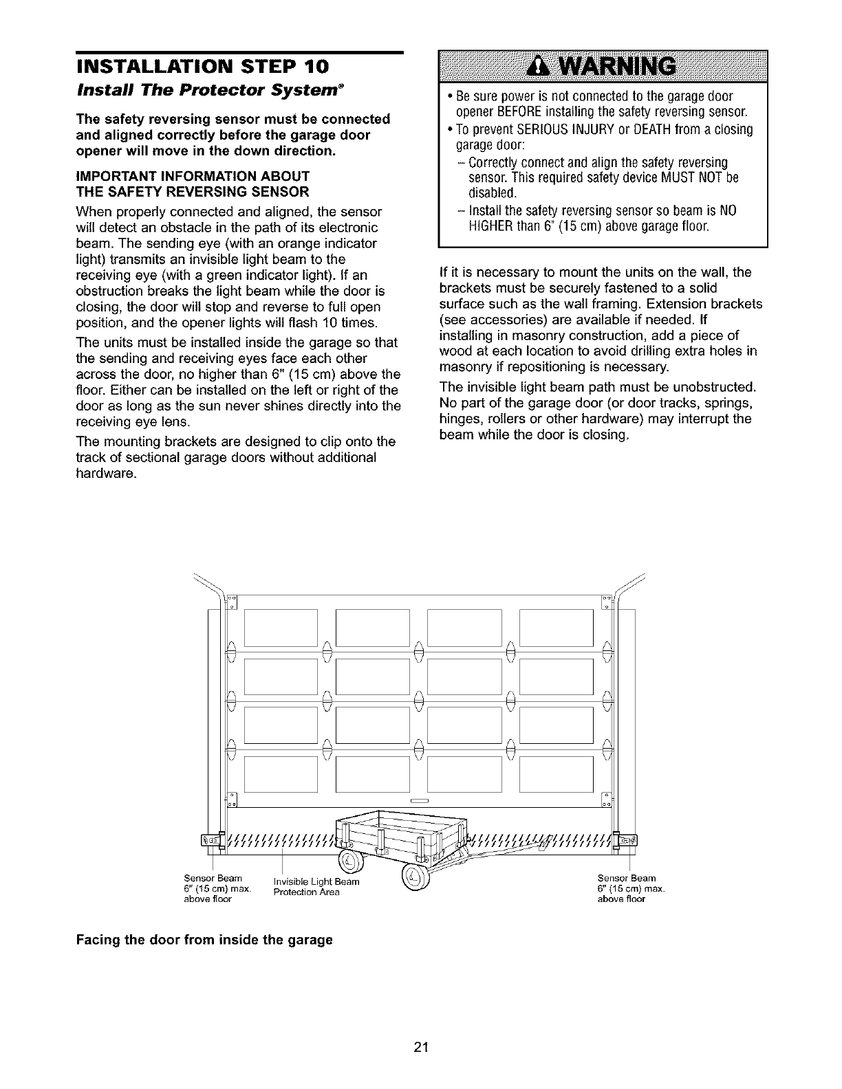
INSTALLATION STEP 10
Install The Protector System _
The safety reversing sensor must be connected
and aligned correctly before the garage door
opener will move in the down direction.
IMPORTANT INFORMATION ABOUT
THE SAFETY REVERSING SENSOR
When properly connected and aligned, the sensor
will detect an obstacle in the path of its electronic
beam. The sending eye (with an orange indicator
light) transmits an invisible light beam to the
receiving eye (with a green indicator light). If an
obstruction breaks the light beam while the door is
closing, the door wilt stop and reverse to full open
position, and the opener lights will flash 10 times.
The units must be installed inside the garage so that
the sending and receiving eyes face each other
across the door, no higher than 6" (15 cm) above the
floor. Either can be installed on the left or right of the
door as long as the sun never shines directly into the
receiving eye lens.
The mounting brackets are designed to clip onto the
track of sectional garage doors without additional
hardware.
•Be sure power is not connected to the garage door
openerBEFOREinstalling the safety reversing sensor.
• To prevent SERIOUSINJURY or DEATHfrom a closing
garagedoor:
- Correctly connect and align the safety reversing
sensor. This required safety device MUST NOTbe
disabled.
- Install the safety reversing sensor so beam is NO
HIGHERthan 6" (15 cm) above garage floor.
If it is necessary to mount the units on the wall, the
brackets must be securely fastened to a solid
surface such as the wall framing. Extension brackets
(see accessories) are available if needed, if
installing in masonry construction, add a piece of
wood at each location to avoid drilling extra holes in
masonry if repositioning is necessary.
The invisible light beam path must be unobstructed.
No part of the garage door (or door tracks, springs,
hinges, rollers or other hardware) may interrupt the
beam while the door is closing.
6" (15 cm) max. Protection Area
above f_oor
Sensor Beam
6" (15 cm) max.
above floor
Facing the door from inside the garage
21
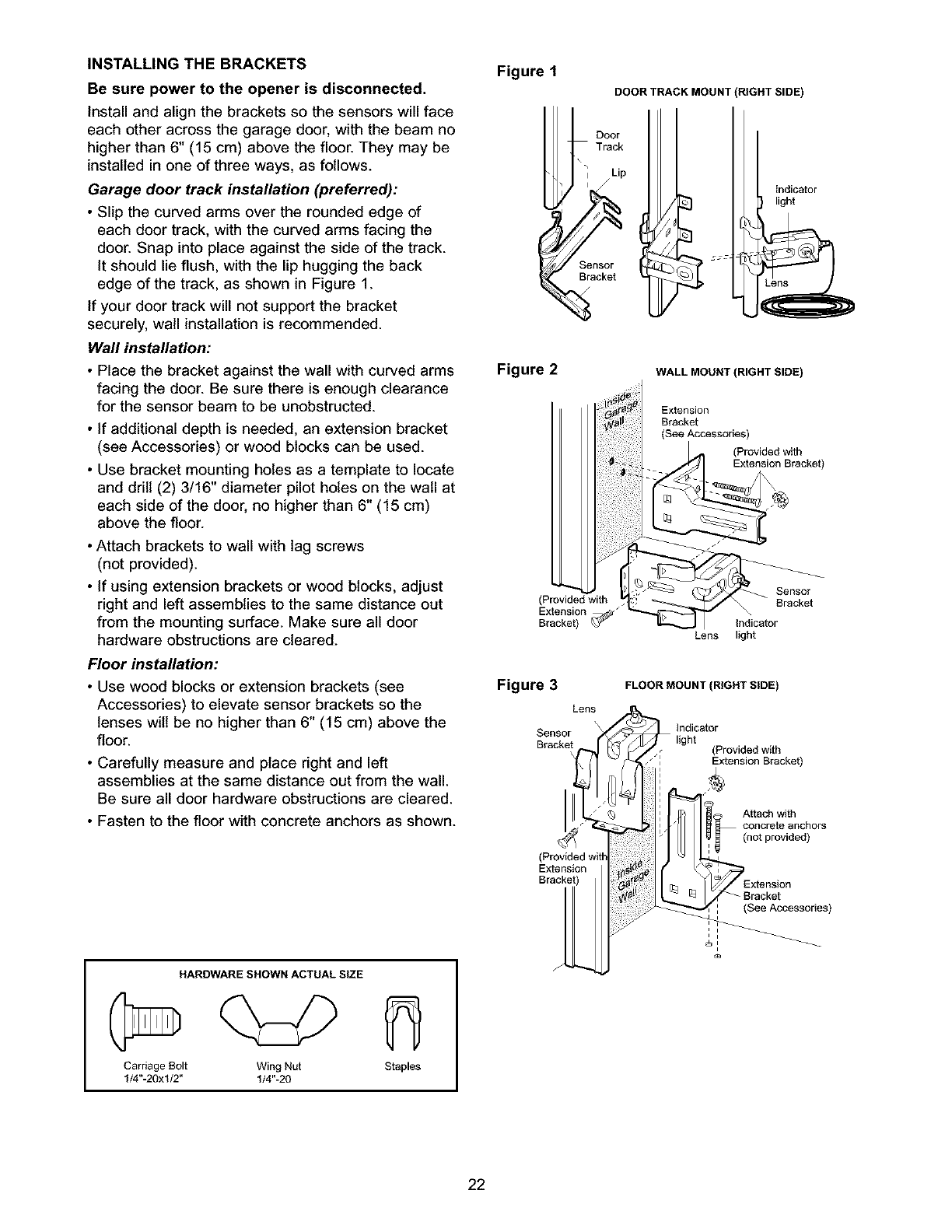
INSTALLING THE BRACKETS
Be sure power to the opener is disconnected.
Install and align the brackets so the sensors will face
each other across the garage door, with the beam no
higher than 6" (15 cm) above the floor. They may be
installed in one of three ways, as follows.
Garage door track installation (preferred):
•Slip the curved arms over the rounded edge of
each door track, with the curved arms facing the
door. Snap into place against the side of the track.
It should lie flush, with the lip hugging the back
edge of the track, as shown in Figure 1.
If your door track will not support the bracket
securely, wall installation is recommended.
Wall installation:
• Place the bracket against the wall with curved arms
facing the door. Be sure there is enough clearance
for the sensor beam to be unobstructed.
• If additional depth is needed, an extension bracket
(see Accessories) or wood blocks can be used.
• Use bracket mounting holes as a template to locate
and drill (2) 3/16" diameter pilot holes on the wall at
each side of the door, no higher than 6" (15 cm)
above the floor.
• Attach brackets to wall with lag screws
(not provided).
• If using extension brackets or wood blocks, adjust
right and left assemblies to the same distance out
from the mounting surface. Make sure all door
hardware obstructions are cleared.
Floor installation:
• Use wood blocks or extension brackets (see
Accessories) to elevate sensor brackets so the
lenses will be no higher than 6" (15 cm) above the
floor.
• Carefully measure and place right and left
assemblies at the same distance out from the wall.
Be sure all door hardware obstructions are cleared.
• Fasten to the floor with concrete anchors as shown.
HARDWARESHOWNACTUALSIZE
Carriage Bolt Wing Nut Staples
1/4"-20xl/2" 1/4"-20
Figure 1
DOOR TRACK MOUNT (RIGHT SIDE)
Door
Track
\
Sensor
Bracket
Indicator
light
Figure 2 WALL MOUNT (RIGHT SIDE)
Extension
Bracket
(See Accessories)
(Provided with
-_ /_1 Extension Bracket)
(Provided with
Extension
Bracket) indicator
Lens light
Sensor
Bracket
Figure 3
Lens
Sensor
Bracket
(
Extension
Bracket)
FLOOR MOUNT (RIGHT SIDE)
Indicator
(Provided with
•" Extension Bracket)
A_achwith
(notprovided)
Bracket
(See Accessories)
i i
i i
22
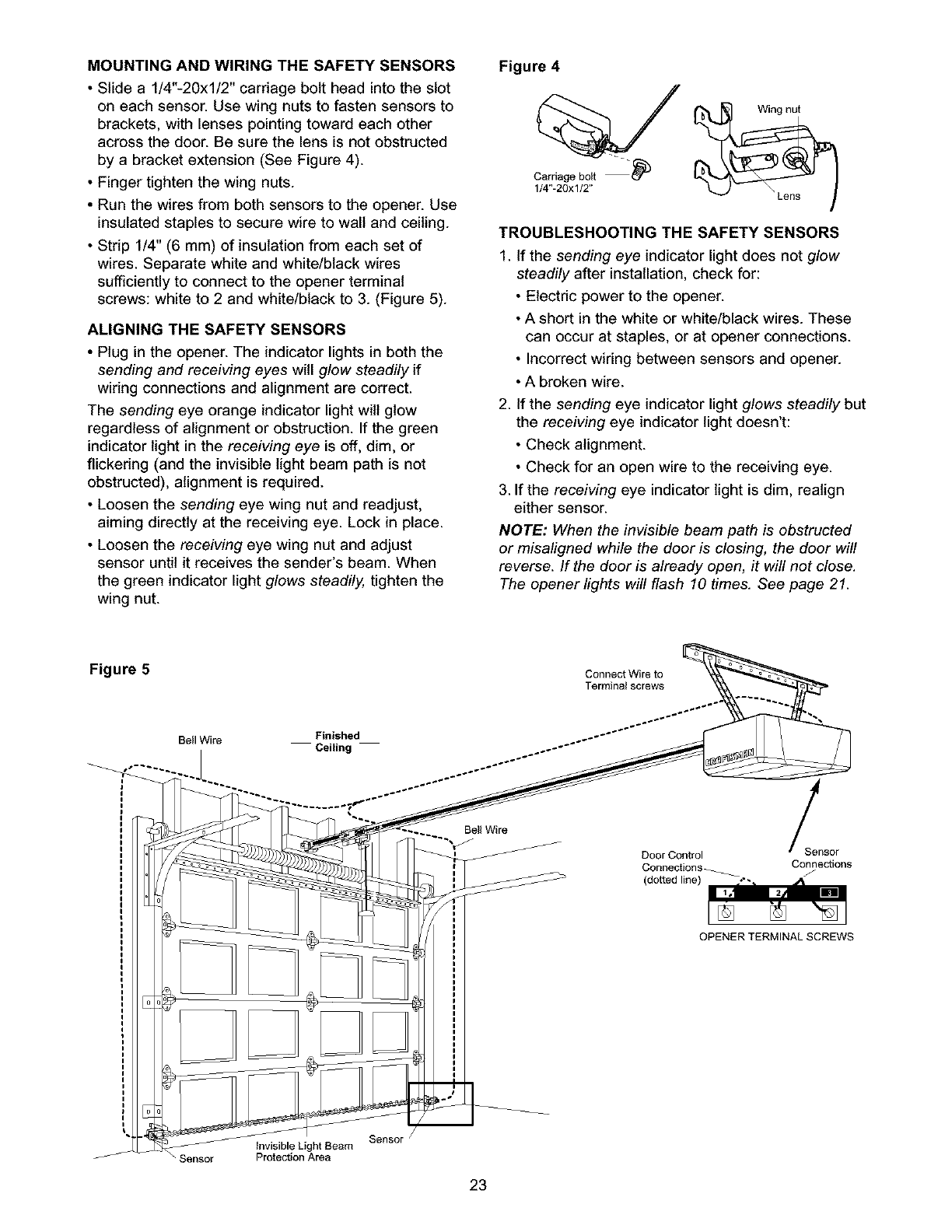
MOUNTING AND WIRING THE SAFETY SENSORS
• Slide a 1/4"-20xl/2" carriage bolt head into the slot
on each sensor. Use wing nuts to fasten sensors to
brackets, with lenses pointing toward each other
across the door. Be sure the lens is not obstructed
by a bracket extension (See Figure 4).
• Finger tighten the wing nuts.
• Run the wires from both sensors to the opener. Use
insulated staples to secure wire to wall and ceiling.
• Strip 1/4" (6 mm) of insulation from each set of
wires. Separate white and white/black wires
sufficiently to connect to the opener terminal
screws: white to 2 and white/black to 3. (Figure 5).
ALIGNING THE SAFETY SENSORS
• Plug in the opener. The indicator lights in both the
sending and receiving eyes will glow steadily if
wiring connections and alignment are correct.
The sending eye orange indicator light will glow
regardless of alignment or obstruction. If the green
indicator light in the receiving eye is off, dim, or
flickering (and the invisible light beam path is not
obstructed), alignment is required.
• Loosen the sending eye wing nut and readjust,
aiming directly at the receiving eye. Lock in place.
• Loosen the receiving eye wing nut and adjust
sensor until it receives the sender's beam. When
the green indicator light glows steadily, tighten the
wing nut.
Figure 4
Carriogobolt-'P
1/4"-20xl/2"
Wing nut
TROUBLESHOOTING THE SAFETY SENSORS
1. If the sending eye indicator light does not glow
steadily after installation, check for:
•Electric power to the opener.
• A short in the white or white/black wires. These
can occur at staples, or at opener connections.
•Incorrect wiring between sensors and opener.
• A broken wire.
2. If the sending eye indicator light glows steadily but
the receiving eye indicator light doesn't:
• Check alignment.
• Check for an open wire to the receiving eye.
3. If the receiving eye indicator light is dim, realign
either sensor.
NOTE: When the invisible beam path is obstructed
or misaligned while the door is closing, the door will
reverse. If the door is already open, it will not close.
The opener lights will flash 10 times. See page 21.
Figure 5 Connect Wire to
Terminal screws
Bell Wire Finished
Ceiling
Door Control
Connections_
(dotted line)
Sensor
Connections
/
OPENER TERMINAL SCREWS
Sensor
/
invisible Light Beam
Protection Area
Eensor
23
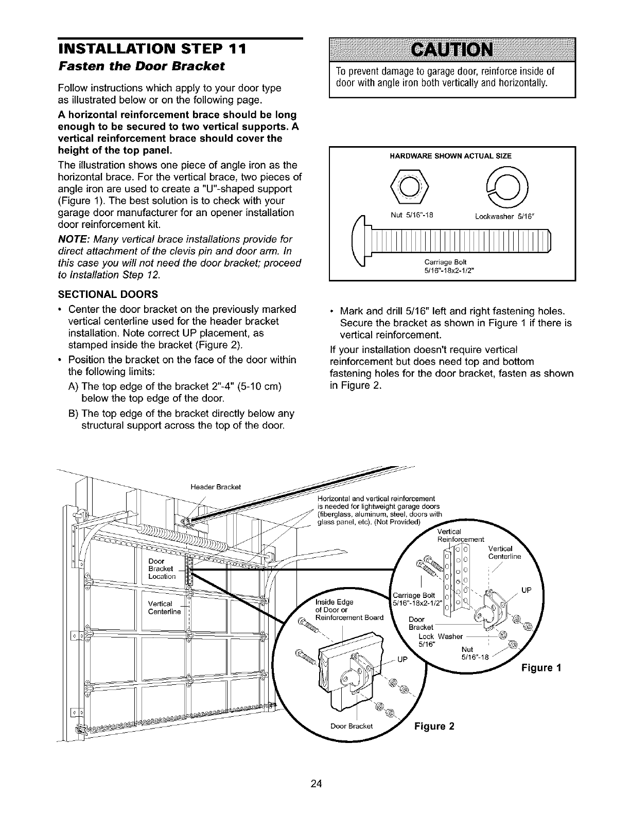
INSTALLATION STEP 11
Fasten the Door Bracket
Follow instructions which apply to your door type
as illustrated below or on the following page.
A horizontal reinforcement brace should be long
enough to be secured to two vertical supports. A
vertical reinforcement brace should cover the
height of the top panel.
The illustration shows one piece of angle iron as the
horizontal brace. For the vertical brace, two pieces of
angle iron are used to create a "U"-shaped support
(Figure 1). The best solution is to check with your
garage door manufacturer for an opener installation
door reinforcement kit.
NOTE: Many vertical brace installations provide for
direct attachment of the clevis pin and door arm. In
this case you will not need the door bracket; proceed
to Installation Step 12.
SECTIONAL DOORS
• Center the door bracket on the previously marked
vertical centerline used for the header bracket
installation. Note correct UP placement, as
stamped inside the bracket (Figure 2).
• Position the bracket on the face of the door within
the following limits:
A) The top edge of the bracket 2"-4" (5-10 cm)
below the top edge of the door.
B) The top edge of the bracket directly below any
structural support across the top of the door.
To prevent damage to garage door, reinforce inside of
door with angle iron both vertically and horizontally.
HARDWARE SHOWN ACTUAL SIZE
© ©
Nut 5/16"-18 Lockwasher 5/16"
Carriage Bolt
5/16"-18x2-1/2"
• Mark and drill 5/16" left and right fastening holes.
Secure the bracket as shown in Figure 1 if there is
vertical reinforcement.
If your installation doesn't require vertical
reinforcement but does need top and bottom
fastening holes for the door bracket, fasten as shown
in Figure 2.
HeaderBracket
Horizontal and vertical reinforcement
is needed for lightweight garage doors
(fiberglass, aluminum, steel, doors with
Figure 1
Figure 2
24
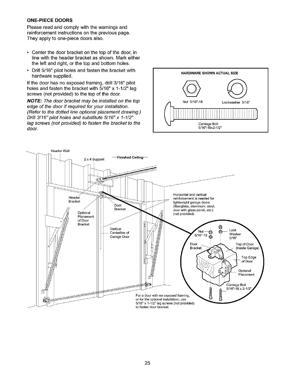
ONE-PIECE DOORS
Please read and comply with the warnings and
reinforcement instructions on the previous page.
They apply to one-piece doors also.
• Center the door bracket on the top of the door, in
line with the header bracket as shown. Mark either
the left and right, or the top and bottom holes.
• Drill 5/16" pilot holes and fasten the bracket with
hardware supplied.
If the door has no exposed framing, drill 3/16" pilot
holes and fasten the bracket with 5/16" x 1-1/2" lag
screws (not provided) to the top of the door.
NOTE: The door bracket may be installed on the top
edge of the door if required for your installation.
(Refer to the dotted line optional placement drawing.)
Drill 3/16" pilot holes and substitute 5/16" x 1-1/2"
lag screws (not provided) to fasten the bracket to the
door.
HARDWARE SHOWN ACTUAL SIZE
© ©
Nut 5/16"-18 Lockwasher 5/16"
Carriage Bolt
5/16"-18x2-1/2"
Header Wall
2 x 4 Support Finished Ceiling
Horizontal and vertical
reinforcement is needed for
lightweight garage doors
(fiberglass, aluminum, steel,
door with glass panel, etc.)
(not provided).
For a door with no exposed framing,
or for the optional installation, use
5/16" x 1-1/2" lag screws (not provided)
to fasten door bracket.
25
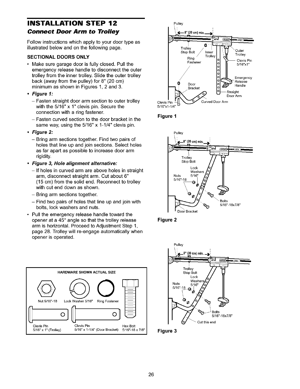
INSTALLATION STEP 12
Connect Door Arm to Trolley
Follow instructions which apply to your door type as
illustrated below and on the following page.
SECTIONAL DOORS ONLY
•Make sure garage door is fully closed. Pull the
emergency release handle to disconnect the outer
trolley from the inner trolley. Slide the outer trolley
back (away from the pulley) for 8" (20 cm)
minimum as shown in Figures 1, 2 and 3.
•Figure 1:
- Fasten straight door arm section to outer trolley
with the 5/16" x 1" clevis pin. Secure the
connection with a ring fastener.
- Fasten curved section to the door bracket in the
same way, using the 5/16" x 1-1/4" clevis pin.
•Figure 2:
-Bring arm sections together. Find two pairs of
holes that line up and join sections. Select holes
as far apart as possible to increase door arm
rigidity.
• Figure 3, Hole alignment alternative:
- If holes in curved arm are above holes in straight
arm, disconnect straight arm. Cut about 6"
(15 cm) from the solid end. Reconnect to trolley
with cut end down as shown.
-Bring arm sections together.
- Find two pairs of holes that line up and join with
bolts, lock washers and nuts.
• Pull the emergency release handle toward the
opener at a 45° angle so that the trolley release
arm is horizontal. Proceed to Adjustment Step 1,
page 28. Trolley will re-engage automatically when
opener is operated.
HARDWARESHOWNACTUALSIZE
© ©0
Nut 5/16"-18 Lock Washer 5/16" Ring Fastener
Clevis Pin Clevis Pin Hex Bolt
5/16" x t" (Trolley) 5/16" x 1-1/4" (Door Bracket) 5/16"-18 x 7/8"
Pulley '
i i
8" (20 cm) min,._)l
Trolley //
Stop Bolt Inner _' Outer
_ Trolley
Ring Trolley Clevis Pin
Fastener 5/t6"x1"
/
/
/Emergency
0 Door Release
:Bracket
Straight
Door Arm
Clevis Pin Curved Door Arm
5/t6"x1
Figure 1
Pulley
/i(.--8"(20cm) min. ,=L
Trolley
Stop Bolt
Lock
Washers
Nuts 5/16"
5/16"-18
Door Bracket
Figure 2
Pulley
/ i_.--8" (20 cm) rain._.)i
_- Trto'!eYolt // " _
Ly_Ckhers
Nuts 5/16"
5/16". _
8 8"
Figure 3
26
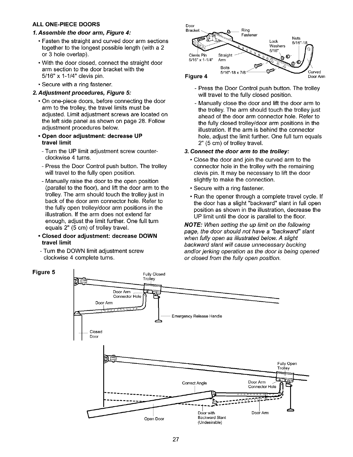
ALL ONE-PIECE DOORS
1.Assemble the door arm, Figure 4:
•Fasten the straight and curved door arm sections
together to the longest possible length (with a 2
or 3 hole overlap).
• With the door closed, connect the straight door
arm section to the door bracket with the
5/16" x 1-1/4" clevis pin.
• Secure with a ring fastener.
2. Adjustment procedures, Figure 5:
• On one-piece doors, before connecting the door
arm to the trolley, the travel limits must be
adjusted. Limit adjustment screws are located on
the left side panel as shown on page 28. Follow
adjustment procedures below.
• Open door adjustment: decrease UP
travel limit
- Turn the UP limit adjustment screw counter-
clockwise 4 turns.
- Press the Door Control push button. The trolley
will travel to the fully open position.
- Manually raise the door to the open position
(parallel to the floor), and lift the door arm to the
trolley. The arm should touch the trolley just in
back of the door arm connector hole. Refer to
the fully open trolley/door arm positions in the
illustration. If the arm does not extend far
enough, adjust the limit further. One full turn
equals 2" (5 cm) of trolley travel.
• Closed door adjustment: decrease DOWN
travel limit
- Turn the DOWN limit adjustment screw
clockwise 4 complete turns.
Door
Bracket
I
Clevis Pin Straight
5/16"x 1-I/4" Arm
Ring
Fastener
Lock
Washers
5/16"
Bolts
5/16"-18 x 7/8 Curved
Figure 4 Door Arm
- Press the Door Control push button. The trolley
will travel to the fully closed position.
- Manually close the door and lift the door arm to
the trolley. The arm should touch the trolley just
ahead of the door arm connector hole. Refer to
the fully closed trolley/door arm positions in the
illustration. If the arm is behind the connector
hole, adjust the limit further. One full turn equals
2" (5 cm) of trolley travel.
3. Connect the door arm to the trolley:
• Close the door and join the curved arm to the
connector hole in the trolley with the remaining
clevis pin. It may be necessary to lift the door
slightly to make the connection.
• Secure with a ring fastener.
• Run the opener through a complete travel cycle. If
the door has a slight "backward" slant in full open
position as shown in the illustration, decrease the
UP limit until the door is parallel to the floor.
NOTE: When setting the up limit on the following
page, the door should not have a "backward" slant
when fully open as illustrated below. A slight
backward slant will cause unnecessary bucking
and/or jerking operation as the door is being opened
or closed from the fully open position.
Figure 5 Fully Closed
Trolley
Door Arm
Connector Hole
_Door Arm
Emergency Release Handle
Closed
(Undesirable)
27
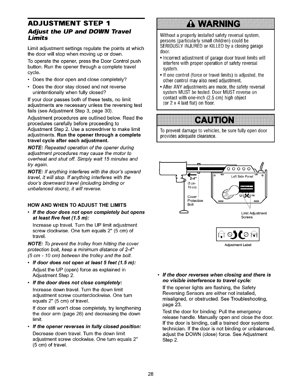
ADJUSTMENT STEP 1
Adjust the UP and DOWN Travel
Limits
Limit adjustment settings regulate the points at which
the door will stop when moving up or down.
To operate the opener, press the Door Control push
button. Run the opener through a complete travel
cycle.
• Does the door open and close completely?
• Does the door stay closed and not reverse
unintentionally when fully closed?
If your door passes both of these tests, no limit
adjustments are necessary unless the reversing test
fails (see Adjustment Step 3, page 30).
Adjustment procedures are outlined below. Read the
procedures carefully before proceeding to
Adjustment Step 2. Use a screwdriver to make limit
adjustments. Run the opener through acomplete
travel cycle after each adjustment.
NOTE: Repeated operation of the opener during
adjustment procedures may cause the motor to
overheat and shut off. Simply wait 15 minutes and
try again.
NOTE: ff anything interferes with the door's upward
travel, it will stop. If anything interferes with the
door's downward travel (including binding or
unbalanced doors), it will reverse.
Without a properly installed safety reversal system,
persons (particularly small children) could be
SERIOUSLYINJUREDor KILLEDby a closing garage
door.
• Incorrect adjustment of garage door travel limits will
interfere with proper operation of safety reversal
system.
• If one control (force or travel limits) is adjusted, the
other control may also needadjustment.
• After ANY adjustments are made,the safety reversal
system MUST be tested. Door MUST reverseon
contact with one-inch (2.5 cm) high object
(or 2 x 4 laid flat) on floor.
To prevent damage to vehicles, besure fully open door
provides adequate clearance.
HOW AND WHEN TO ADJUST THE LIMITS
•If the door does not open completely but opens
at least five feet (1.5 m):
Increase up travel. Turn the UP limit adjustment
screw clockwise. One turn equals 2" (5 cm) of
travel.
NOTE: To prevent the trolley from hitting the cover
protection bolt, keep a minimum distance of 2-4"
(5 cm -10 cm) between the trolley and the bolt.
• If door does not open at least 5 feet (1.5 m):
Adjust the UP (open) force as explained in
Adjustment Step 2.
•If the door does not close completely:
Increase down travel. Turn the down limit
adjustment screw counterclockwise. One turn
equals 2" (5 cm) of travel.
If door still won't close completely, try lengthening
the door arm (page 26) and decreasing the down
limit.
•If the opener reverses in fully closed position:
Decrease down travel. Turn the down limit
adjustment screw clockwise. One turn equals 2"
(5 cm) of travel.
Limit Adjustment
Screws
Adjustment Label
If the door reverses when closing and there is
no visible interference to travel cycle:
If the opener lights are flashing, the Safety
Reversing Sensors are either not installed,
misaligned, or obstructed. See Troubleshooting,
page 23.
Test the door for binding: Pull the emergency
release handle. Manually open and close the door.
If the door is binding, call a trained door systems
technician. If the door is not binding or unbalanced,
adjust the DOWN (close) force. See Adjustment
Step 2.
28
ADJUSTMENT STEP 2
Adjust the Force
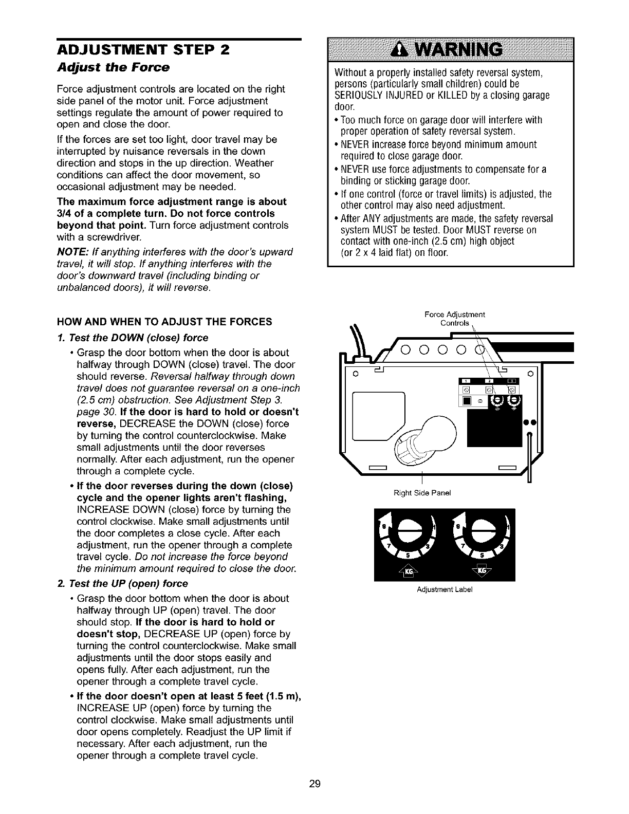
Force adjustment controls are located on the right
side panel of the motor unit. Force adjustment
settings regulate the amount of power required to
open and close the door.
If the forces are set too light, door travel may be
interrupted by nuisance reversals in the down
direction and stops in the up direction. Weather
conditions can affect the door movement, so
occasional adjustment may be needed.
The maximum force adjustment range is about
3/4 of acomplete turn. De not force controls
beyond that point. Turn force adjustment controls
with a screwdriver.
NOTE: If anything interferes with the door's upward
travel, it will stop. If anything interferes with the
door's downward travel (including binding or
unbalanced doors), it will reverse.
Without a properly installed safety reversal system,
persons (particularly small children) could be
SERIOUSLYINJUREDor KILLEDby a closing garage
door.
• Too much force on garagedoor will interfere with
proper operation of safety reversalsystem.
• NEVERincreaseforce beyond minimum amount
required to close garagedoor.
• NEVERuse force adjustments to compensate for a
binding or sticking garage door.
• If one control (force or travel limits) is adjusted, the
other control may also needadjustment.
• After ANY adjustments are made,the safety reversal
system MUST be tested. Door MUST reverseon
contact with one-inch (2.5 cm) high object
(or 2 x 4 laid flat) on floor.
HOW AND WHEN TO ADJUST THE FORCES
1. Test the DOWN (close) force
•Grasp the door bottom when the door is about
halfway through DOWN (close) travel. The door
should reverse. Reversal halfway through down
travel does not guarantee reversal on a one-inch
(2.5 cm) obstruction. See Adjustment Step 3.
page 30. If the door is hard to hold or doesn't
reverse, DECREASE the DOWN (close) force
by turning the control counterclockwise. Make
small adjustments until the door reverses
normally. After each adjustment, run the opener
through a complete cycle.
• If the door reverses during the down (close)
cycle and the opener lights aren't flashing,
INCREASE DOWN (close) force by turning the
control clockwise. Make small adjustments until
the door completes a close cycle. After each
adjustment, run the opener through a complete
travel cycle. Do not increase the force beyond
the minimum amount required to close the door.
2. Test the UP (open) force
• Grasp the door bottom when the door is about
halfway through UP (open) travel. The door
should stop. If the door is hard to hold or
doesn't stop, DECREASE UP (open) force by
turning the control counterclockwise. Make small
adjustments until the door stops easily and
opens fully. After each adjustment, run the
opener through a complete travel cycle.
• If the door doesn't open at least 5 feet (1.5 m),
INCREASE UP (open) force by turning the
control clockwise. Make small adjustments until
door opens completely. Readjust the UP limit if
necessary. After each adjustment, run the
opener through a complete travel cycle.
Force Adjustment
Controls
Right Side Panel
Adjustment Label
29
ADJUSTMENT STEP 3
Test the Safety Reversal System
TEST
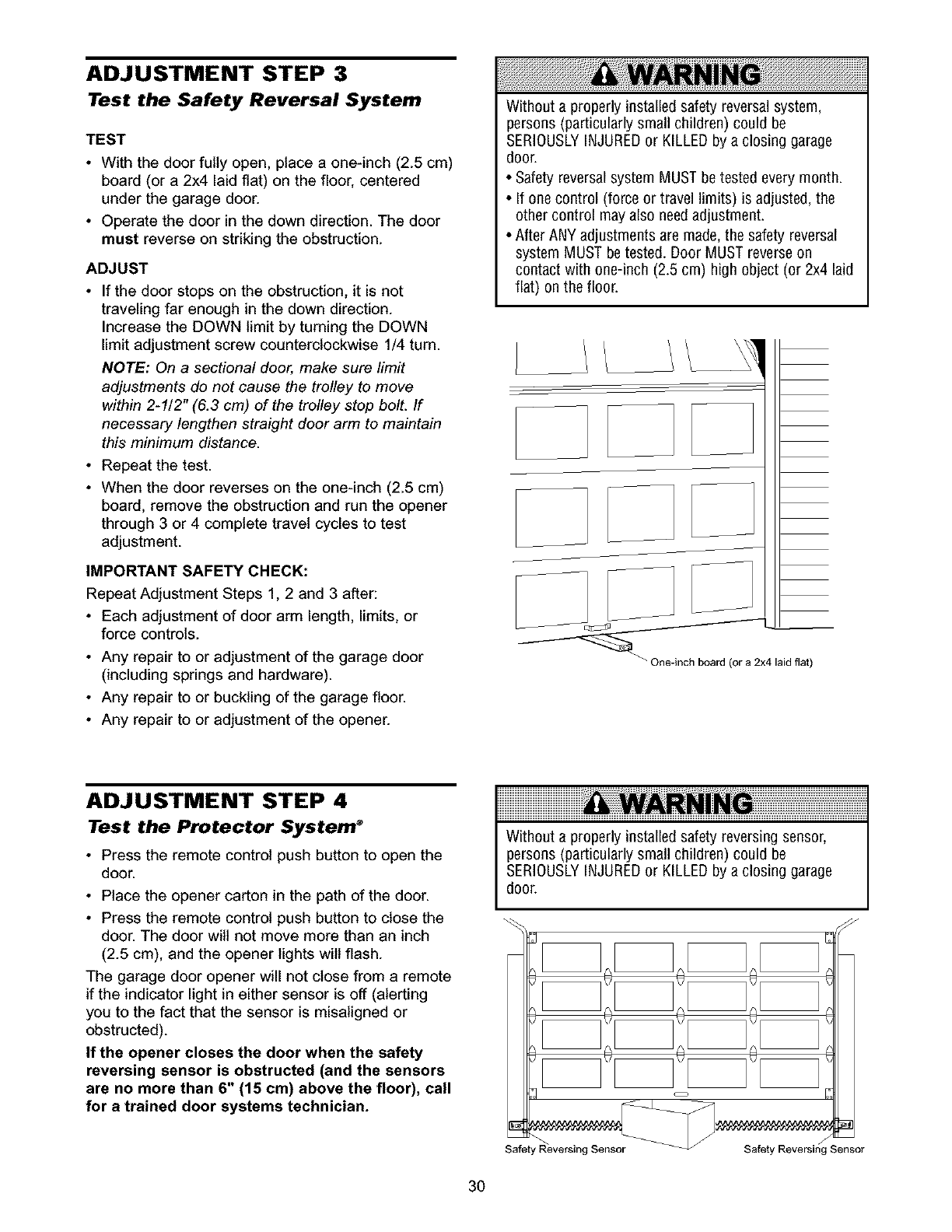
•With the door fully open, place a one-inch (2.5 cm)
board (or a 2x4 laid flat) on the floor, centered
under the garage door.
• Operate the door in the down direction. The door
must reverse on striking the obstruction.
ADJUST
•If the door stops on the obstruction, it is not
traveling far enough in the down direction.
Increase the DOWN limit by turning the DOWN
limit adjustment screw counterclockwise 1/4 turn.
NOTE: On a sectional door, make sure limit
adjustments do not cause the trolley to move
within 2-1/2" (6.3 cm) of the trolley stop bolt. If
necessary lengthen straight door arm to maintain
this minimum distance.
• Repeat the test.
• When the door reverses on the one-inch (2.5 cm)
board, remove the obstruction and run the opener
through 3 or 4 complete travel cycles to test
adjustment.
IMPORTANT SAFETY CHECK:
Repeat Adjustment Steps 1, 2 and 3 after:
• Each adjustment of door arm length, limits, or
force controls.
• Any repair to or adjustment of the garage door
(including springs and hardware).
• Any repair to or buckling of the garage floor.
• Any repair to or adjustment of the opener.
Without a properly installed safety reversal system,
persons (particularly small children) could be
SERIOUSLYINJUREDor KILLEDby a closing garage
door.
• Safety reversal system MUST be tested every month.
• If one control (force or travel limits) is adjusted, the
other control may also needadjustment.
• After ANY adjustments are made,the safety reversal
system MUST be tested. Door MUST reverseon
contact with one-inch (2.5 cm) high object (or 2x4 laid
flat) on the floor.
ADJUSTMENT STEP 4
Test the Protector System ®
• Press the remote control push button to open the
door.
• Place the opener carton in the path of the door.
• Press the remote control push button to close the
door. The door will not move more than an inch
(2.5 cm), and the opener lights wilt flash.
The garage door opener will not close from a remote
if the indicator light in either sensor is off (alerting
you to the fact that the sensor is misaligned or
obstructed).
If the opener closes the door when the safety
reversing sensor is obstructed (and the sensors
are no more than 6" (15 cm) above the floor), call
for atrained door systems technician.
Without a properly installed safety reversing sensor,
persons (particularly small children) could be
SERIOUSLYINJUREDor KILLEDby a closing garage
door.
Safety Reversing Sensor
3O
OPERATION
IMPORTANT SAFETY INSTRUCTIONS
To reduce the risk of severe injury or death:
1. READAND FOLLOWALL WARNINGSAND
INSTRUCTIONS.
2. ALWAYSkeep remote controls out of reach of children.
NEVERpermit children to operate or play with garage
door control push buttons or remote controls.
3. ONLYactivate garagedoor when it can be seen clearly, it
is properly adjusted, and there are no obstructions to
door travel.
4. ALWAYSkeep garage door in sight until completely
closed. NO ONESHOULDCROSSTHE PATHOFTHE
MOVINGDOOR.
5. NO ONESHOULDGOUNDERA STOPPED,PARTIALLY
OPENDOOR.
6. If possible, use emergency releasehandle to disengage
trolley ONLYwhen garage door is CLOSED.Weak or
broken springs or unbalanceddoor could result in an
open door falling rapidly and/or unexpectedly.
7. NEVERuse emergency release handleunless garage
doorway is clear of persons and obstructions.
8. NEVERuse handleto pull garage door open or closed.
If rope knot becomes untied, you could fall.
9. If one control (force or travel limits) is adjusted, the
other control may also needadjustment.
10. After ANY adjustmentsare made, the safety reversal
system MUST betested.
11. Safety reversalsystem MUST betested every month.
Garagedoor MUST reverse on contact with one-inch
(2.5 cm) high object (or a 2x4 laid flat) on the floor.
12. ALWAYSKEEPGARAGEDOORPROPERLYBALANCED
(see page3). An improperly balanceddoor may not
reverse when required and could result in SEVERE
INJURYor DEATH.
13. All repairs to cables, spring assemblies and other
hardware, all of which are under EXTREMEtension,
MUST be made by a trained door systemstechnician.
14. ALWAYSdisconnect electric power to garage door
opener BEFOREmaking any repairs or removing
covers.
15SAVETHESEINSTRUCTIONS•
Using Your Garage Door Opener
Your Security÷ opener and hand-held remote control
have been factory-set to a matching code which
changes with each use, randomly accessing over
100 billion new codes. Your opener will operate with
up to eight Security÷ remote controls and one
Security÷ Keytess Entry System. If you purchase a
new remote, or if you wish to deactivate any remote,
follow the instructions in the Programming section.
Activate your opener with any of the following:
•The hand-held Remote Controk Hold the large
push button down until the door starts to move.
•The wall-mounted Door Control'. Hold the push
button down until the door starts to move.
•The Keyless Entry (See Accessories): If provided
with your garage door opener, it must be
programmed before use. See Programming.
When the opener is activated (with the safety
reversing sensor correctly installed and aligned)
1. If open, the door will close. If closed, it will open.
2. If closing, the door wilt reverse.
3. If opening, the door will stop.
4. If the door has been stopped in apartially open
position, it will close.
5. If obstructed while closing, the door will reverse. If
the obstruction interrupts the sensor beam, the
opener lights will blink for five seconds.
6. If obstructed while opening, the door will stop.
7. If fully open, the door will not close when the beam
is broken. The sensor has no effect in the opening
cycle.
If the sensor is not installed, or is misaligned, the
door won't close from a hand-held remote. However,
you can close the door with the Door Control, the
Outdoor Key Switch, or Keytess Entry, if you activate
them until down travel is complete. If you release
them too soon, the door wilt reverse.
The opener lights will turn on under the following
conditions: when the opener is initially plugged in;
when power is restored after interruption; when the
opener is activated.
They will turn off automatically after 4-1/2 minutes or
provide constant light when the Light feature on the
Premium Control Console is activated. Bulb size is
75 watts maximum.
Security÷ Light Feature: Lights will also turn on
when someone walks through the open garage door.
With a Premium Control Console, this feature may be
turned off as follows: With the opener lights off, press
and hold the light button for 10 seconds, until the
light goes on and off again. To restore this feature,
start with the opener lights on, then press and hold
the light button for 10 seconds until the light goes off,
then on again.
31
Using the Wall.Mounted
Door Control
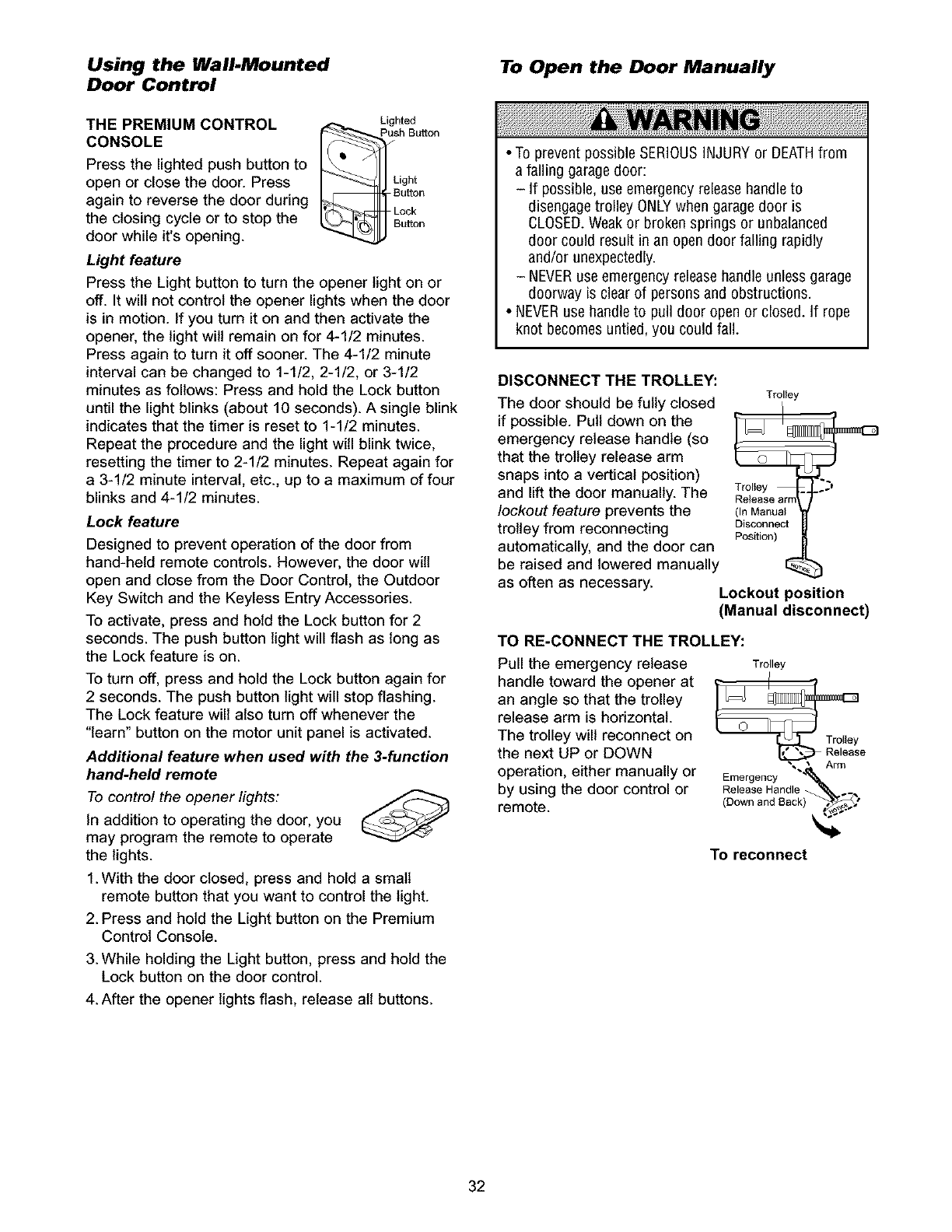
THE PREMIUM CONTROL
CONSOLE
Press the lighted push button to
open or close the door. Press
again to reverse the door during
the closing cycle or to stop the
door while it's opening.
Lighted
Push Buffon
L_Bght
Button
Lock
u_on
Light feature
Press the Light button to turn the opener light on or
off. It will not control the opener lights when the door
is in motion. If you turn it on and then activate the
opener, the light will remain on for 4-1/2 minutes.
Press again to turn it off sooner. The 4-1/2 minute
interval can be changed to 1-1/2, 2-1/2, or 3-1/2
minutes as follows: Press and hold the Lock button
until the light blinks (about 10 seconds). A single blink
indicates that the timer is reset to 1-1/2 minutes.
Repeat the procedure and the light will blink twice,
resetting the timer to 2-1/2 minutes. Repeat again for
a 3-1/2 minute interval, etc., up to a maximum of four
blinks and 4-1/2 minutes.
Lock feature
Designed to prevent operation of the door from
hand-held remote controls. However, the door will
open and close from the Door Control, the Outdoor
Key Switch and the Keyless Entry Accessories.
To activate, press and hold the Lock button for 2
seconds. The push button light will flash as long as
the Lock feature is on.
To turn off, press and hold the Lock button again for
2 seconds. The push button light will stop flashing.
The Lock feature will also turn off whenever the
"learn" button on the motor unit panel is activated.
Additional feature when used with the 3-function
hand-held remote
To control the opener lights:
In addition to operating the door, you
may program the remote to operate
the lights.
1. With the door closed, press and hold a small
remote button that you want to control the light.
2. Press and hold the Light button on the Premium
Control Console.
3. While holding the Light button, press and hold the
Lock button on the door control.
4. After the opener lights flash, release all buttons.
To Open the Door Manually
•To prevent possible SERIOUSINJURYor DEATHfrom
a falling garagedoor:
- If possible, use emergency release handleto
disengage trolley ONLYwhen garage door is
CLOSED.Weakor broken springs or unbalanced
door could result in an open door falling rapidly
and/0r unexpectedly.
- NEVERuse emergency releasehandle unless garage
doorway is clear of persons and obstructions.
• NEVERuse handle to pull door open or closed. If rope
knot becomes untied, you could fall.
DISCONNECT THE TROLLEY:
Trolley
The door should be fully closed
if possible. Pull down on the
emergency release handle (so
that the trolley release arm
snaps into a vertical position)
and lift the door manually. The Trolley ._'
Release arff
lockout feature prevents the (InManual
trolley from reconnecting Disconnect
Position)
automatically, and the door can
be raised and lowered manually I_
as often as necessary. Lockout position
(Manual disconnect)
TO RE-CONNECT THE TROLLEY:
Pull the emergency release Trolley
handle toward the opener at
an angle so that the trolley
release arm is horizontal.
The trolley will reconnect on Trolley
the next UP or DOWN Release
operation, either manually or Emergency
by using the door control or ReleaseHandle _.._
remote. (Down and Back) t__
To reconnect
32
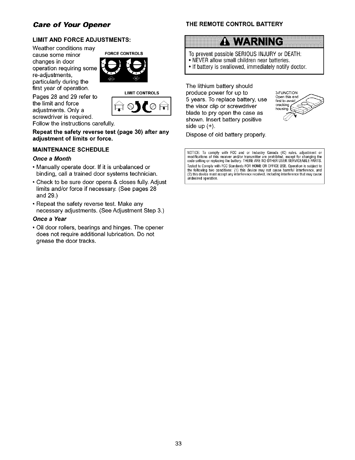
Care of Your Opener THE REMOTE CONTROL BATTERY
LIMIT AND FORCE ADJUSTMENTS:
Weather conditions may
cause some minor
changes in door
operation requiring some
re-adjustments,
particularly during the
first year of operation.
Pages 28 and 29 refer to
the limit and force
adjustments. Only a
screwdriver is required.
FORCECONTROLS
LIMIT CONTROLS
Follow the instructions carefully.
Repeat the safety reverse test (page 30) after any
adjustment of limits or force.
MAINTENANCE SCHEDULE
Once a Month
• Manually operate door. If it is unbalanced or
binding, call a trained door systems technician.
• Check to be sure door opens & closes fully. Adjust
limits and/or force if necessary. (See pages 28
and 29.)
• Repeat the safety reverse test. Make any
necessary adjustments. (See Adjustment Step 3.)
Once a Year
• Oil door rollers, bearings and hinges. The opener
does not require additional lubrication. Do not
grease the door tracks.
To prevent possible SERIOUSINJURYor DEATH:
•NEVERallow small children near batteries.
• If battery is swallowed, immediately notify doctor.
The lithium battery should
produce power for up to
5 years. To replace battery, use
the visor clip or screwdriver
blade to pry open the case as
shown. Insert battery positive
side up (+).
Dispose of old battery properly.
3*FUNCTION
Open this end
first to avoid
cracking
NOTICE: To comply with FCC and or Mdustry Canada (_C) rules, adjustment or
modifications ot this receiverand/or transmitter are prohibited,except for changit]g the
code setting or rep_acit]gthe battery THEREARENO OTHERUSERSERVICEABLEPARTS.
the following two conditions: (_) this device may not cause harmful inten'erence,and
Testedto Comply with FCGStandardsFORHOMEOROFFICEUSE.Operationis subject to
(2) this devicemustacceptany interferencereceived,including interferencethat maycause
undesiredopera ion
33
Having a Problem?
1. The opener doesn't operate from either the Door
Control or the remote control:
Does the opener have electric power? Plug a lamp into the
outlet. If it doesn't light, check the fuse box or the circuit
breaker. (Some outlets are controlled by a wall switch.)
• Have you disabled all door locks? Review installation
instruction warnings on page 11.
• Is there a build-up of ice or snow under the door? The door
may be frozen to the ground. Remove any restriction.
• The garage door spring may be broken. Have it replaced.
• Repeated operation may have tripped the overload
protector in the motor. Wait 15 minutes and try again.
2. Opener operates from the remote, but not from the
Door Control:
• Is the door control lit? If not. reverse the wires. If the
opener runs, check for a faulty wire connection at the door
control, a short under the staples, or a broken wire.
• Are the wiring connections correct? Review Installation
Step 6, page 18.
3. The door operates from the Door Control, but not from
the remote control:
• Is the door push button flashing? If your model has the
Lock feature, make sure it is off.
• Program the opener to match the remote control code.
(Refer to instructions on the motor unit panel.) Repeat with
all remotes.
4. The remote control has short range:
• Change the location of the remote control in your car.
• Check to be sure the antenna on the side or back panel of
motor unit extends fully downward.
• Some installations may have shorter range due to a metal
door. foil backed insulation, or metal garage siding.
(Antenna Extender Kit 41A3504)
5. Opener noise is disturbing in living quarters of home:
• If operational noise is aproblem because of proximity of
the opener to the living quarters, the Vibration Isolator Kit
41A3263 can be installed. This kit was designed to
minimize vibration to the house and is easy to install.
6. The garage door opens and closes by itself:
• Be sure that all remote control push buttons are off.
• Remove the bell wire from the door control terminals and
operate from the remote only. If this solves the problem, the
door control is faulty (replace). or there is an intermittent short
on the wire between the door control and the motor unit.
• Clear memory and re-program all remote controls.
7. The door doesn't open completely:
• Is something obstructing the door? Is it out of balance, or
are the springs broken? Remove the obstruction or repair
the door.
• If the door is in good working order but now doesn't open
all the way, increase the up force. See Adjustment Step 2
• If the door opens at least 5 feet (1.5 m), the travel limits
may need to be increased. One turn equals 2 inches (5 cm)
of travel. See Adjustment Step 1
Repeat the safety reverse test after the adjustment is
complete.
8. The door stops but doesn't close completely:
•Review the travel limits adjustment procedures on page 28.
Repeat the safety reverse test after any adjustment of door
arm length, close force or down limit.
9. The door opens but won't close:
• If the opener lights blink, check the safety reversing sensor.
See Installation Step 10.
• If the opener lights don't blink and it is a new installation.
check the down force. See Adjustment Step 2. For an
existing installation, see below.
Repeat the safety reverse test after the adjustment is complete
10. The door reverses for no apparent reason and opener
lights don't blink:
• Is something obstructing the door? Pull the emergency
release handle. Operate the door manually. If it is unbalanced
or binding, call a trained door systems technician.
• Clear any ice or snow from the garage floor area where
the door closes.
• Review Adjustment Step 2
• If door reverses in the fully closed position, decrease the
travel limits (Adjustment Step 1).
Repeat safety reverse test after adjustments to force or travel
limits. The need for occasional adjustment of the force and
limit settings is normal. Weather conditions in particular can
affect door travel
11. The door reverses for no apparent reason and opener
lights blink for 5 seconds after reversing:
• Check the safety reversing sensor. Remove any obstruction
or align the receiving eye. See Installation Step 10.
12, The opener lights don't turn on:
• Replace the light bulbs (75 watts maximum). Use astandard
neck garage door opener bulb if regular bulb burns out.
13, The opener lights don't turn off:
• Is the Light feature on? Turn it off.
14. The opener strains or maximum force is needed to
operate door:
• The door may be out of balance or the springs may be
broken. Close the door and use the emergency release
handle to disconnect the trolley. Open and close the door
manually. A properly balanced door will stay in any point of
travel while being supported entirely by its springs. If it
does not, disconnect the opener and call a trained door
systems technician. Do net increase the force to operate
the opener.
15. The opener motor hums briefly, then won't work:
•The garage door springs may be broken. See above.
• If the problem occurs on the first operation of the opener,
door may be locked. Disable the door lock. If the belt was
removed and reinstalled, the motor may be out of phase.
Remove the belt; cycle the motor to the down position.
Observe the drive sprocket. When it turns in aclockwise
direction and stops in the down position, reinstall the belt.
Repeat the safety reverse test after the adjustment is
complete
16. The opener won't operate due to power failure:
• Use the emergency release handle to disconnect the
trolley. The door can be opened and closed manually.
When power is restored, press the Door Control push
button and trolley will automatically reconnect (unless
trolley is in lockout position.) See page 32.
• The Emergency Key Release accessory (for use on
garages with no service door) disconnects the trolley from
outside the garage in case of power failure.
34
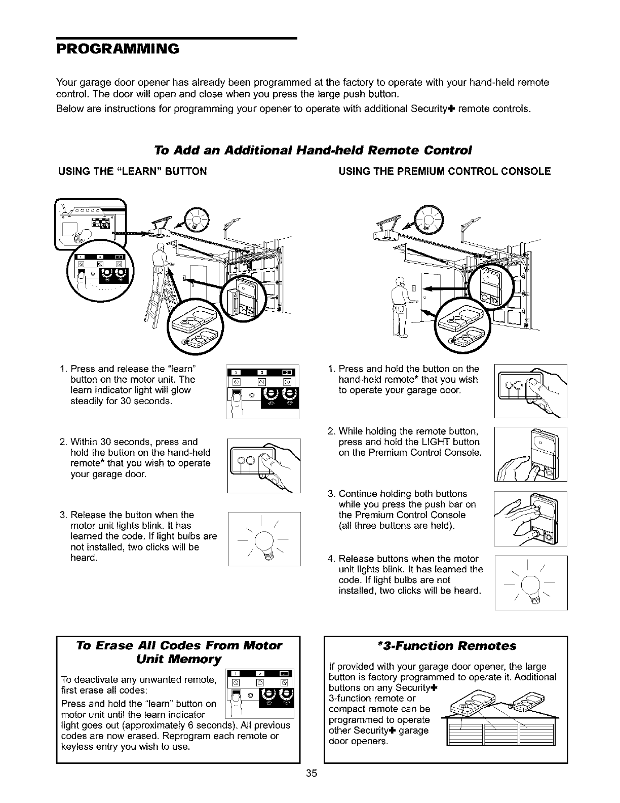
PROGRAMMING
Your garage door opener has already been programmed at the factory to operate with your hand-held remote
control. The door will open and close when you press the large push button.
Below are instructions for programming your opener to operate with additional Security+ remote controls.
To Add an Additional Hand-held Remote Control
USING THE "LEARN" BUTTON USING THE PREMIUM CONTROL CONSOLE
1. Press and release the "learn"
button on the motor unit. The
learn indicator light will glow
steadily for 30 seconds.
2. Within 30 seconds, press and
hold the button on the hand-held
remote* that you wish to operate
your garage door.
3. Release the button when the
motor unit lights blink. It has
learned the code. If light bulbs are
not installed, two clicks will be
heard.
1,
2,
3,
4,
Press and hold the button on the
hand-held remote* that you wish
to operate your garage door.
While holding the remote button,
press and hold the LIGHT button
on the Premium Control Console.
Continue holding both buttons
while you press the push bar on
the Premium Control Console
(all three buttons are held).
Release buttons when the motor
unit lights blink. It has learned the
code. If light bulbs are not
installed, two clicks will be heard.
To Erase All Codes From Motor
Unit Memory
To deactivate any unwanted remote, []
first erase all codes:
Press and hold the 'learn" button on
motor unit until the learn indicator
light goes out (approximately 6 seconds). All previous
codes are now erased. Reprogram each remote or
keyless entry you wish to use.
*3.Function Remotes
If provided with your garage door opener, the large
button is factory programmed to operate it. Additional
buttons on any Security+
3-function remote or .,,,,,_,_C-C-__ s/_
compact remote can be
programmed to operate
other Security+ garage
door openers.
35
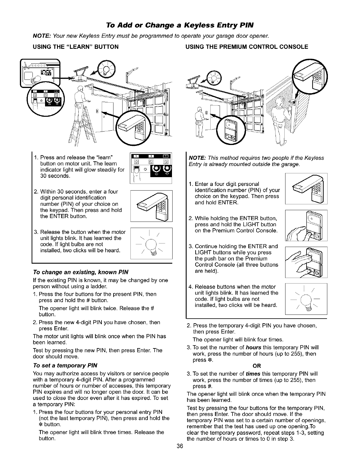
To Add or Change a Keyless Entry PIN
NOTE: Your new Keyless Entry must be programmed to operate your garage door opener.
USING THE "LEARN" BUTTON USING THE PREMIUM CONTROL CONSOLE
1. Press and release the "learn"
button on motor unit. The learn
indicatorlight will glow steadily for
30 seconds.
2. Within 30 seconds, enter a four
digit personal identification
number (PIN) of your choice on
the keypad. Then press and hold
the ENTER button.
3. Release the button when the motor
unit lights blink. It has learned the
code. If light bulbs are not
installed,two clicks will be heard.
To change an existing, known PiN
If the existing PIN is known, it may be changed by one
person without using a ladder.
1. Press the four buttons for the present PIN, then
press and hold the # button.
The opener light will blink twice. Release the #
button.
2. Press the new 4-digit PIN you have chosen, then
press Enter.
The motor unit lights will blink once when the PIN has
been learned.
Test by pressing the new PIN, then press Enter. The
door should move.
To set a temporary PiN
You may authorize access by visitors or service people
with a temporary 4-digit PIN. After a programmed
number of hours or number of accesses, this temporary
PIN expires and will no longer open the door. It can be
used to close the door even after it has expired. To set
a temporary PIN:
1. Press the four buttons for your personal entry PIN
(not the last temporary PIN), then press and hold the
button.
The opener light will blink three times. Release the
button.
NOTE: This method requires two people if the Keyless
Entry is already mounted outside the garage.
1. Enter a four digit personal
identificationnumber (PIN) of your
choice on the keypad. Then press
and hold ENTER.
2. While holding the ENTER button,
press and hold the LIGHT button
on the Premium Control Console.
3. Continue holding the ENTER and
LIGHT buttons while you press
the push bar on the Premium
Control Console (all three buttons
are held).
4. Release buttons when the motor
unit lightsblink. It has learned the
code. If lightbulbs are not
installed,two clicks will be heard.
36
2. Press the temporary 4-digit PIN you have chosen,
then press Enter.
The opener light will blink four times.
3. To set the number of hours this temporary PIN will
work, press the number of hours (up to 255), then
press _. OR
3. To set the number of times this temporary PIN will
work, press the number of times (up to 255), then
press #.
The opener light will blink once when the temporary PIN
has been learned.
Test by pressing the four buttons for the temporary PIN,
then press Enter. The door should move. If the
temporary PIN was set to a certain number of openings,
remember that the test has used up one opening.To
clear the temporary password, repeat steps 1-3, setting
the number of hours or times to 0 in step 3.
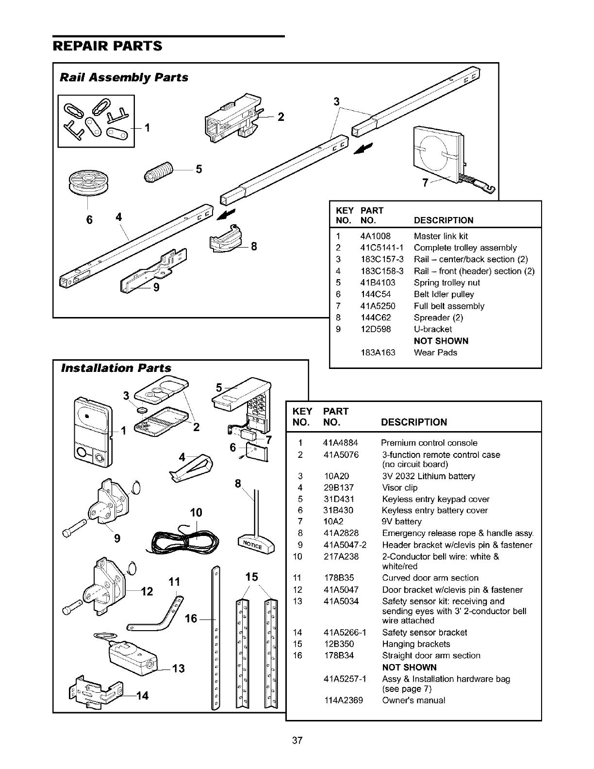
REPAIR PARTS
Rail Assembly Parts
64
\\
Installation Parts
_ I:1
1G
3
KEY PART
NO. NO. DESCRIPTION
1 4A1008 Master link kit
2 41C5141-1 Complete trolley assembly
3 183C157-3 Rail- center/back section (2)
4 183C158-3 Rail - front (header) section (2)
5 41B4103 Spring trolley nut
6 144C54 Belt Idler pulley
7 41A5250 Full belt assembly
8 144C62 Spreader (2)
9 12D598 U-bracket
NOT SHOWN
Wear Pads183A163
KEY PART
NO. NO. DESCRIPTION
41A4884
41A5076
3 10A20
4 29B137
5 31D431
6 31B430
7 10A2
8 41A2828
9 41A5047-2
10 217A238
11 178B35
12 41A5047
13 41A5034
14 41A5266-1
15 12B350
16 178B34
41A5257-1
114A2369
Premium control console
3-function remote control case
(no circuit board)
3V 2032 Lithium battery
Visor clip
Keyless entry keypad cover
Keyless entry battery cover
9V battery
Emergency release rope & handle assy.
Header bracket w/clevis pin & fastener
2-Conductor bell wire: white &
white/red
Curved door arm section
Door bracket w/clevis pin & fastener
Safety sensor kit: receiving and
sending eyes with 3' 2-conductor bell
wire attached
Safety sensor bracket
Hanging brackets
Straight door arm section
NOT SHOWN
Assy & Installation hardware bag
(see page 7)
Owner's manual
37
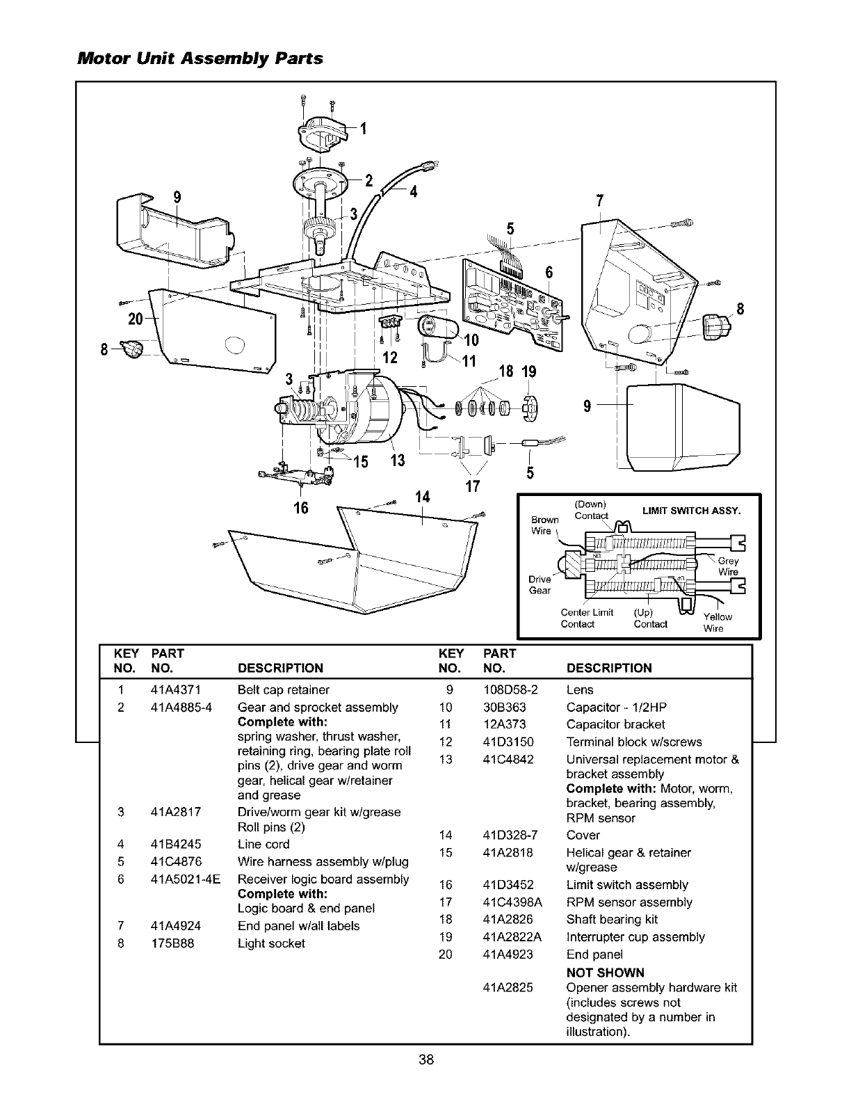
Motor Unit Assembly Parts
16
15 13
5
18 19
5
17
14
7
(Down)
Brown Contact
Wire /
LIMIT SWITCH ASSY.
Wire
Gear
Center Limit (Up) Yellow
Contact Contact Wire
KEY PART KEY PART
NO. NO. DESCRIPTION NO. NO. DESCRIPTION
1 41A4371
2 41A4885-4
3 41A2817
4 41B4245
5 41C4876
6 41A5021-4E
7 41A4924
8 175B88
Belt cap retainer
Gear and sprocket assembly
Complete with:
spring washer, thrust washer,
retaining ring, bearing plate roll
pins (2), drive gear and worm
gear, helical gear w/retainer
and grease
Drive/worm gear kit w/grease
Roll pins (2)
Line cord
Wire harness assembly w/plug
Receiver logic board assembly
Complete with:
Logic board & end panel
End panel w/all labels
Light socket
9 108D58-2 Lens
10 30B363 Capacitor - 1/2HP
11 12A373 Capacitor bracket
12 41D3150 Terminal block w/screws
13 41C4842 Universal replacement motor &
bracket assembly
Complete with: Motor, worm,
bracket, bearing assembly,
RPM sensor
14 41D328-7 Cover
15 41A2818 Helical gear & retainer
w/grease
16 41D3452 Limit switch assembly
17 41C4398A RPM sensor assembly
18 41A2826 Shaft bearing kit
19 41A2822A interrupter cup assembly
20 41A4923 End panel
NOT SHOWN
41A2825 Opener assembly hardware kit
(includes screws not
designated by a number in
illustration),
38
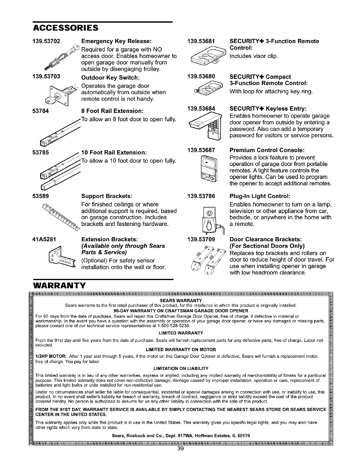
ACCESSORIES
139.53702
139.53703
53784
Emergency Key Release:
Required for agarage with NO
access door. Enables homeowner to
open garage door manually from
outside by disengaging trolley.
Outdoor Key Switch:
Operates the garage door
automatically from outside when
remote control is not handy.
8 Foot Rail Extension:
,pen fully.
139.53681
139.53680
139.53684
SECURITY+ 3-Function Remote
Control:
Includes visor clip.
SECURITY+ Compact
3-Function Remote Control:
With loop for attaching key ring.
SECURITY+ Keyless Entry:
Enables homeowner to operate garage
door opener from outside by entering a
password. Also can add a temporary
password for visitors or service persons.
53785 10 Foot Rail Extension:
,pen fully.
139.53687 Premium Control Console:
Provides a lock feature to prevent
operation of garage door from portable
remotes. A light feature controls the
opener lights. Can be used to program
the opener to accept additional remotes.
53589
41A5281
Support Brackets:
For finished ceilings or where
additional support is required, based
on garage construction. Includes
brackets and fastening hardware.
Extension Brackets:
(Available only through Sears
Parts & Service)
(Optional) For safety sensor
installation onto the walt or floor.
139.53786
139.53709
Plug-In Light Control:
Enables homeowner to turn on a lamp,
television or other appliance from car,
bedside, or anywhere in the home with
aremote.
Door Clearance Brackets:
(For Sectional Doors Only)
Replaces top brackets and rollers on
door to reduce height of door travel. For
use when installing opener in garage
with low headroom clearance.
WARRANTY
SEARS WARRANTY
Sears warrants to the first retail purchaser of this product, for the residence in which this product is originally installed.
90-DAY WARRANTY ON CRAFTSMAN GARAGE DOOR OPENER
For 90 days from the date of purchase, Sears will repair this Craftsman Garage Door Opener, free of charge, if defective in material or
workmanship. In the event you have a question with the assembly or operation of your garage door opener, or have any damaged or missing parts,
_Ieasecontact one of our technical service representatives at 1-800-528_5236.
LIMITED WARRANTY
From the 91st day until five years from the date of purchase, Sears will furnish replacement parts for any defective parts, free of charge. Labor not
included. LIMITED WARRANTY ON MOTOR
I/2HP MOTOR: After 1 year and through 5 years, if the motor on this Garage Door Opener is defective, Sears will furnish a replacement motor,
free of charge. You pay for labor.
LIMITATION ON LIABILITY
This limited warranty is in lieu of any other warranties, express or implied, including any implied warranty of merchantability of fitness for a particular
purpose. This limited warranty does not cover non-defective damage, damage caused by improper installation, operation or care, replacement of
batteries and light bulbs or units installed for nomresidential use.
Under no circumstances shall seller be liable for consequential, incidental or special damages arising in connection with use, or inability to use, this
,roduct. In no event shall seller's liability for breach of warranty, breach of contract, negligence or strict liability exceed the cost of the product
covered hereby. No person is authorized to assume for us any other liability in connection with the sale of this product.
FROM THE 91ST DAY, WARRANTY SERVICE IS AVAILABLE BY SIMPLY CONTACTING THE NEAREST SEARS STORE OR SEARS SERVICE
CENTER IN THE UNITED STATES.
This warranty applies only while this product is in use in the United States. This warranty gives you specific legal rights, and you may also have
other rights which vary from state to state.
Sears, Roebuck and Co., Dept. 817WA, Hoffman Estates, IL 60179
39
CONTENIDO
Introduccibn 2. 7
Reviel6n de los sFrnbolosy t_rminos de seguddad .___
Preparaci6n de la puerta de su cochera ........................ .3
Herramientas necesarias ................................................ .3
Planificad6n .......................................... .4-5
Inventario de la caja de cart6n ...................................... 6
Inventario de piezas ........................................................ ,7
Montaje 8-11
Montaje el fie[ y insta[eel tro[e ............ 8
Fije el riel a la unidad del motor y instele la polea [oca ,_)
Instale la banda y sujete el ret_n
de la cubierta de la banda ........................................... 10
Fije la tensi6n de la banda ............................................. 11
Instalacibn 11-27
Instrucciones de seguridad para la instalaci6n .............. 11
Determine d6nde va a instalar
la m_nsula del cabezal. ........................................ _12-13
Instale la mensula del cabezal ..................................... 14
Coloque el nelen la mensula del cabezal ..................... 15
Coloque el abridor en posici6n ..................................... 16
Cuelgue el abridor ......................................................... 17
Instale la unidad de control de la puerta ...................... 18
Instale las luces ............................................................. 19
Instale la manija y la cuerda de emergencia ................. 19
Requisitos para la instalaci6n el_ctdca ....................... .20
Instale la Sistema de Protecel6n®............................ ,21-23
Fije la mensula de la puerta .................................... ,24-25
Conecte el brazo de la puerta al trole ..................... ,26-27
Ajustes 28.30
Ajuste el limite del recorrido ......................................... .28
Ajuste la fuerza ............................................................. 29
Pruebe el sistema de retroceso de seguridad ............... 30
Pruebe la Sistema de Protecci6n ®................................. 30
Operacibn 31.34
Instrucciones de seguddad para la operad6n ............... 31
C6mo usar su abridor de puerta de cochera ................ 31
C6mo usar la unidad de control de pared ..................... 32
C6mo abrir la puerta manualmente ............................... 32
Mantenimiento de su abridor de puerta de cochera..,..,33
Si tiene alg_n problema ................................................. 34
Cbmo Programar el Abridor 35.36
C6mo agregar un control remoto manual ...................... 35
C6mo borrar todos los c6digos ...................................... 35
Control remotos de tres funciones ................................. 35
Para agregar o cambiar el PIN de
enterada sin Uave ....................................................... 36
Accesorios 37
Garantia 37
Numeros de Servicio Contratapa
INTRODUCCI(_N
Revisibn de los Simbolos y T_rminos
de Seguridad
Este abridor de puerta de cochera ha sido diseSado y probado para un funcionamiento seguro, siempre y cuando se instale,
se pruebe, se opere y se le de mantenimiento como se indica en este manual, cumpliendo al pie de la letra con todas las
advertencias e instrucciones generales aqu{ contenidas.
Mecbnica
El_ctrica
Estas advertencias y/o elmbolos de segundad que
aparecen en este manual le elertar_n de que existe el
riesgo de una lesi6n seria ode muerte si no se siguen
las instrucciones correspondientes. El peligro puede ser
el6ctrico (electrocuci6n) o mecbnico. Lea las instrucciones
con mucho cuidado.
Cuando yea esta pelabra y/o elmbolo de seguridad en este
manual, le alertar_ de que existe el nesgo de daSar la
puerta de la cochera y/o el abridor si no se siguen las
instrucciones correspondientes. Lea las instrucciones con
mucho cuidado.
2
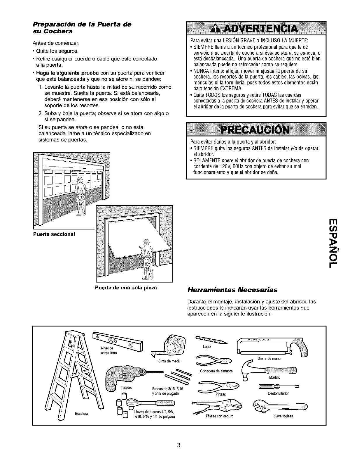
Preparacibn de la Puerta de
su Cochera
Antes de comenzar:
•Quite los seguros
• Retire cualquier cuerda o cable que est6 conectado
a la puerta
•Haga la siguiente prueba con su puerta para verificar
que est6 balanceada y que no se atore ni se pandee:
1 Levante la puerta hasta la mitad de su recorrido como
se muestra Suelte la puerta Si est_ balanceada,
deber_ mantenerse en esa posici6n con s61o el
soporte de los resortes
2 Suba y baje la puerta; observe si se atora con algo o
si se pandea
Si su puerta se atora o se pandea, o no est_
balanceada Ilame a un t6cnico especializado en
sistemas de puertas
ParaevitarunaLESIONGRAVEo INCLUSOLAMUERTE:
•SIEMPREIlamea unt_cnicoprofesionalparaquele d_
servicioasu puertadecocherasi _staseatora,sepandea,o
est_desbalanceadaUnapuertade cocheraquenoest_bien
balanceadapuedeno retrocedercomoserequiere
• NUNCAintenteaflojar,moverniajustarla puertadesu
cochera,los resortesdela puerta,los cables,laspoleas,las
m_nsulasni la tornilleria,puestodosestoselementosest_n
bajotensi6nEXTREMA
• QuiteTODOSlos segurosy retireTODASlascuerdas
conectadasa lapuertadecocheraANTESdeinstalary operar
elabridordelapuertadecocheraparaevitarqueseenreden
Paraevitardafiosa lapuertay al abridor:
• SIEMPREquite lossegurosANTESde instalary/o deoperar
elabridor
• SOLAMENTEopereelabridorde puertadecocheracon
corrientede120V,60Hzconobjetodeevitarsu real
funcionamientoy queel abridorsedaSe
Pue_a seccional
Zz
0
Puerta de una sola pieza Herramientas Necesarias
Durante el montaje, instalaci6n y ajuste del abridor, las
instrucciones le indicar_n usar las herramientas que
aparecen en la siguiente ilustraci6n
Cintade medir
Taladro Brocasde 3/16,5/16
y 5132de pulgada
Ul!_l Uaves de tuercas I/2, 5/8,
L.J 7/16,9/16 y 1/4de pulgada
L_piz
Corladorade alarnbre
_inzas con S_guro
Sierra d_ mano
Destornillador
Uave inglesa
3
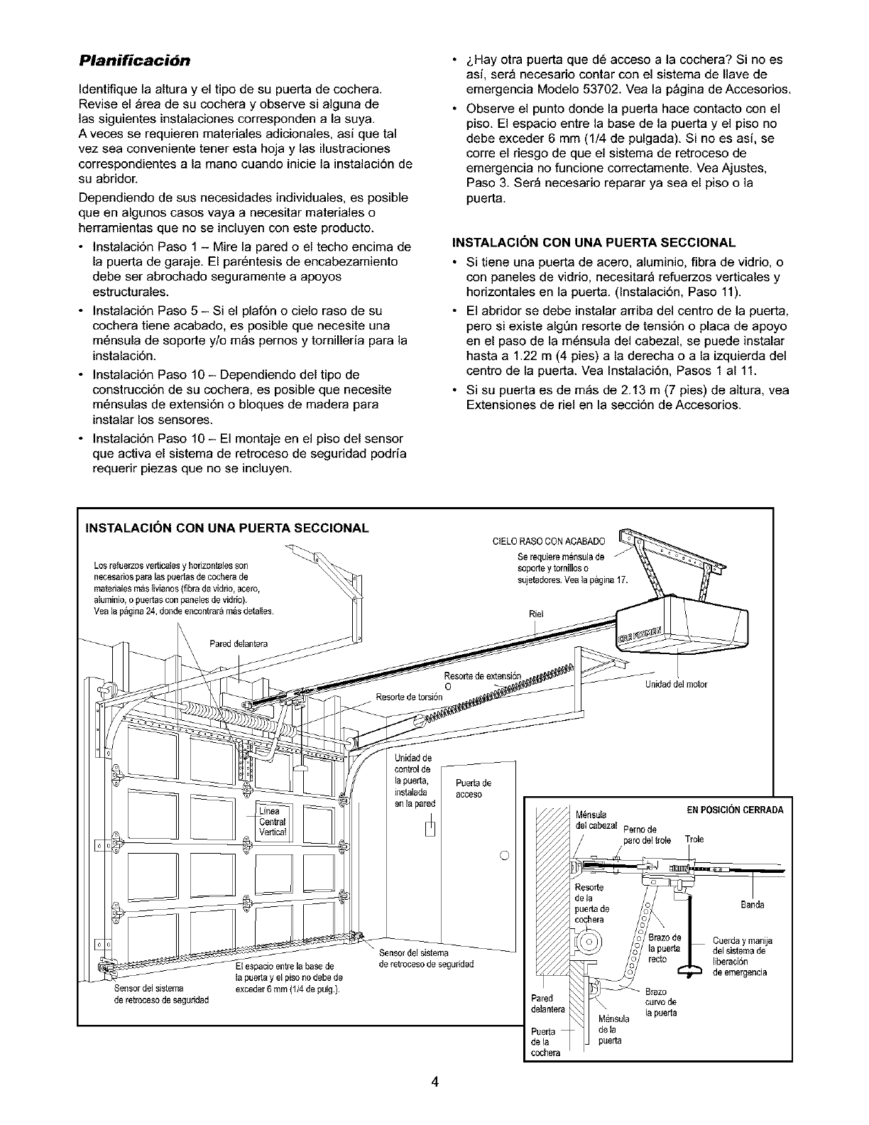
Planificacibn
Identifique la altura y el tipo de su puerta de cochera.
Revise el _rea de su cochera y observe si alguna de
]as siguientes instalaciones corresponden a la suya.
A veces se requieren materiales adicionales, asi que tal
vez sea conveniente tener esta hoja y las ilustraciones
cerrespondientes a la mano cuando inicie la instalaci6n de
su abridor.
Dependiendo de sus necesidades individuales, es posible
que en algunos cases vaya a necesitar materiales o
herramientas que no se incluyen con este producto
• Instalaci6n Paso 1 - Mire la pared o el techo encima de
la puerta de garaje El par6ntesis de encabezamiento
debe ser abrochado seguramente a apoyos
estructurales
• ]nstalaci6n Paso 5 - Si el plaf6n o cielo raso de su
cochera tiene acabado, es posib]e que necesite una
m6nsula de soporte y/o m_s pernos y tornilleria para la
instalaci6n.
• ]nstalaci6n Paso 10 - Dependiendo del tipo de
construcci6n de su cochera, es posible que necesite
m6nsulas de extensi6n o bloques de madera para
instalar los sensores
• ]nstalaci6n Paso 10 - El montaje en el piso del sensor
que activa el sistema de retroceso de seguridad podria
requerir piezas que no se incluyen.
&Hay otra puerta que d6 acceso a la cochera? Si no es
asi, ser_ necesario contar con el sistema de llave de
emergencia Modelo 53702. Vea la p_gina de Accesorios.
Observe el punto donde la puerta hace contacto con el
piso. El espacio entre la base de la puerta y el piso no
debe exceder 6 mm (1/4 de pulgada). Si no es asi, se
corre el riesgo de que el sistema de retroceso de
emergencia no funcione correctamente. Vea Ajustes,
Paso 3. Ser_ necesario reparar ya sea el piso o la
puerta.
INSTALACI(3N CON UNA PUERTA SECCIONAL
•Si tiene una puerta de acero, aluminio, fibra de vidrio, o
con paneles de vidrio, necesitar_ refuerzos verticales y
horizontales en la puerta. (Instalaci6n, Paso 11).
• El abridor se debe instalar arriba del centro de la puerta,
pero si existe algen resorte de tensi6n o placa de apoyo
en el paso de la m6nsula del cabezal, se puede instalar
hasta a 122 m (4 pies) a la derecha o a la izquierda del
centro de la puerta. Vea Instalaci6n, Pasos 1 a111.
• Si su puerta es de m_s de 213 m (7 pies) de altura, vea
Extensiones de riel en la secci6n de Accesorios.
INSTALACI(3N CON UNA PUERTA SECCIONAL
Los refuerzosverticalesy borizontales son
necesariospara las puertas de cochera de
materialesm_slivianos (flbrade viddo, acero,
aNminio,o puertascon panelesde viddo).
Vea la p_gina24, dondeencontrar_ m_sdetailes
Pared delantera
CtELO RASO CONACABADO
Serequiem m_nsulade
soportey torniiloso
sujetadores Veala p_gina 17.
Riel
Resorte de extensi6n
0
_sorte de torsi6n
J
Unidaddel motor
Unidad de
control de
la puerla, Puertade
instalada acceso
en la pared
Sensor del sistema
de rettocesode seguddad
El espacio entrela base de
la puertay el piso no debe de
exceder6 mm (1/4 de pulg)
Sensor del sistema
de retroceso de seguddad
O
M_nsula
detcabezal Pemode
Brazo
ared
elantera _ \ curvo de
M_sula la puerta
uerta _ de ta
ela puerta
3chera
EN POSICI()NCERRADA
Trole
Banda
Cuerda y manija
del sistema de
liberacidn
de emergencia
4
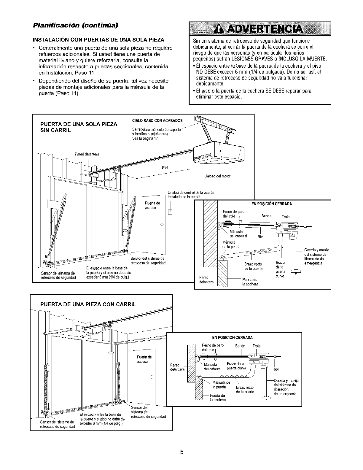
Planificacibn (continua)
|NSTALACI(3N CON PUERTAS DE UNA SOLA PIEZA
•Generalmente una puerta de una sola pieza no requiere
refuerzos adicionales. Si usted tiene una puerta de
material liviano y quiere reforzarla, consulte la
informaci6n respecto a puertas seccionales, contenida
en Instalaci6n, Paso 11.
• Dependiendo del diseSo de su puerta, tal vez necesite
piezas de montaje adicionales para la m6nsula de la
puerta (Paso 11).
Sinun sistemade retrocesodeseguridadquefuncione
debidamente,alcerrarla puertadela cocherasecorreel
riesgodequelaspersonas(y enparticularlos niSos
pequeSos)sufranLESlONESGRAVESo INCLUSOLAMUERTE.
• Elespacioentrela basede lapuertadelacocheray el piso
NODEBEexceder6 mm(1/4 depulgada).Denoserasi,el
sistemaderetrocesodeseguridadnovaa funcionar
debidamente.
• B piso o lapuertadelacocheraSEDEBErepararpara
eliminaresteespacio.
PUERTA DE UNA SOLA P|EZA
SIN CARRIL
CIELO RASO CONACABADOS
Se requie_em_nsulade soporie
y tomiiloso sujetadores
Yea la p_gina 17
Riel
Unidad delmotor
Sensordelsistema de
retrccesode seguridad
J
Puerta de
acceso
Sensordel sistemade
retrocesode seguridad
El espacioentre la base de
la puerta y el piso nodeba de
exceder6 mm (1/4de pulg)
PUERTA DE UNA PIEZA CON CARRIL
Unidad de control de la pueda,
instalada en ta pared
Perno de paro
ENPOSICII_NCERRADA
Banda Trole
Cue_ay man_a
delsis_made
liberacidnde
eme_ei_ia
El espado entre la base de
J - la puetta y el piso no debede
Sensor del sistema de exceder6 mm {114de pulg)
retroceso de seguridad
J
J
Puerta de
acceso
©
J
Pared a_
delanter
Sensordei
sistemade
retrocesode segeddad
EN POSICIONCERRADA
Pemo de paro Banda Trole
2'trole
_M,nsu_ Brazode ,a _
de,cabeza, puertacurvo _/
de,°pue a
I
Riel
Cuerday manija
del sistemade
libaracidn
de emergeilcia
5
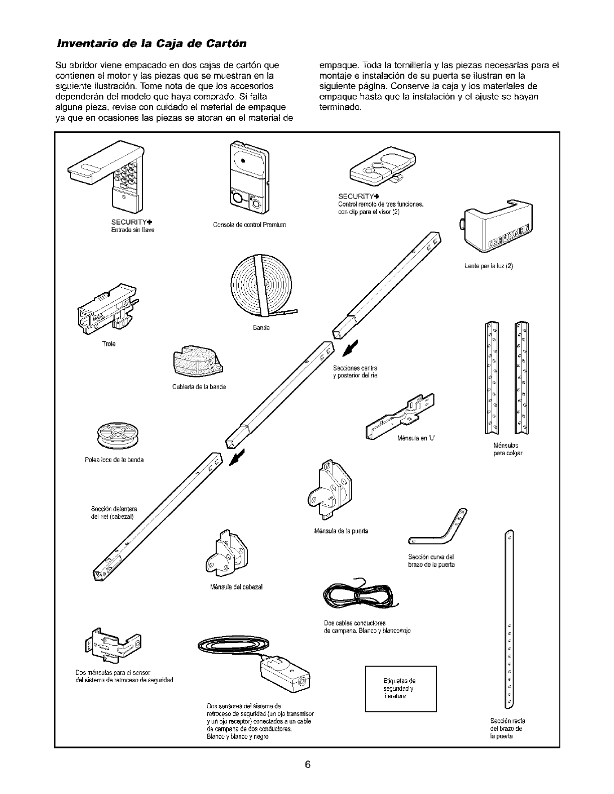
Inventario de la Caja de Cartbn
Su abridor viene empacado en dos cajas de cart6n que
contienen el motor y las piezas que se muestran en la
siguiente ilustraci6n, Tome nota de que los accesorios
depender_n del modelo que haya comprado. Si falta
alguna pieza, revise con cuidado el material de empaque
ya queen ocasiones las piezas se atoran en el material de
empaque. Toda la tornilleria y las piezas necesarias para el
montaje e instalaci6n de su puerta se ilustran en la
siguiente p_gina, Conserve la caja y los materiales de
empaque hasta que la instalaci6n y el ajuste se hayan
terminado.
SECURITY.I"
Entrada sin Ilave Consoia de controlPremium
SECURITY'I"
Control remotode tres funciones,
con ctip para elvisor (2)
Lente parla luz (2)
Banda
Secciones central
postedordel riel
Cubier[ade la banda
, , t
P pue
Dos m_nsulasparael sensor
del sistemade retrocesode seguridad
M_nsuladel cabezal
Dos cablesconductores
de campana.Biancoy blanco/rojo
Etiquetas de
seguridady
Iiteratura
DossensoresdeI sistemade
re&'ocesode seguridad {un ojo transmisor
y un o_oreceptor) conectadosa uncane
de campanade dos conductores
8Ianco y blanco y negro
IH
M_nsuias
para colgar
Secci6nrecta
del brazo de
la pueda
6
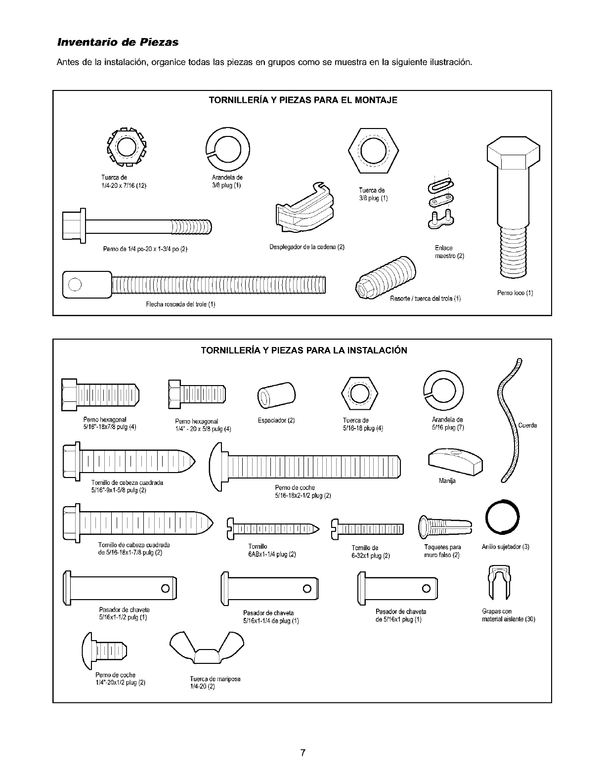
Inventario de Piezas
Antes de la instalacign, organice todas las piezas en grupos como se muestra en la siguiente ilustraci6n.
TORNILLERiA Y PIEZAS PAPA EL MONTAJE
© ©
Tuerca de Arandelade
_ I/4-20 x 7/16 (12) 318plug (1)
Pemo de 1/4po-20 x 1-3/4 po (2) Despiegadorde la cadena (2)
©
Tuerca de
3/8plug (I)
i
En_ace
maestro (2)
Fiecha roscadadel trole (I) Resode/tuercadet trole (1) Pemo loco (1)
G
TORNILLER|A Y PIEZAS PARA LA INSTALACI(3N
Pernohexagonal Pemohexagonal Espaciador(2)
5/1g"-18x7/8pulg (4) 1/4"- 20 x 5/8 pulg(4)
Tomillode cabezacuadrada
5/16"-9xi-5/8 putg(2)
Tomillode cabezacuadrada
de 5/16-18xl-7/8 pulg(2)
oj C
Pasadorde chaveta
5116xi-I/2 putg(1)
Perno de coche Tuerca de mariposa
1/4"-20x1/2plug (2) 1/4-20 (2)
©
Tuerca de
5/1g-18plug (4)
Pernode coche
5/16-18x2-I/2 p_ug(2)
Tomillo
6ABxI-II4 plug(2)
Pasadorde chaveta
5/16x1-1/4de plug (1)
Tomillode
6-32xi plug (2)
©
Arandela de
5/16plug (7)
Maniia
Taquetespara
murofalso (2)
Pasadorde chaveta
de 5/16xl plug (1)
O
Aniilosujetador (3)
Grapascon
materialais_ante(30)
7
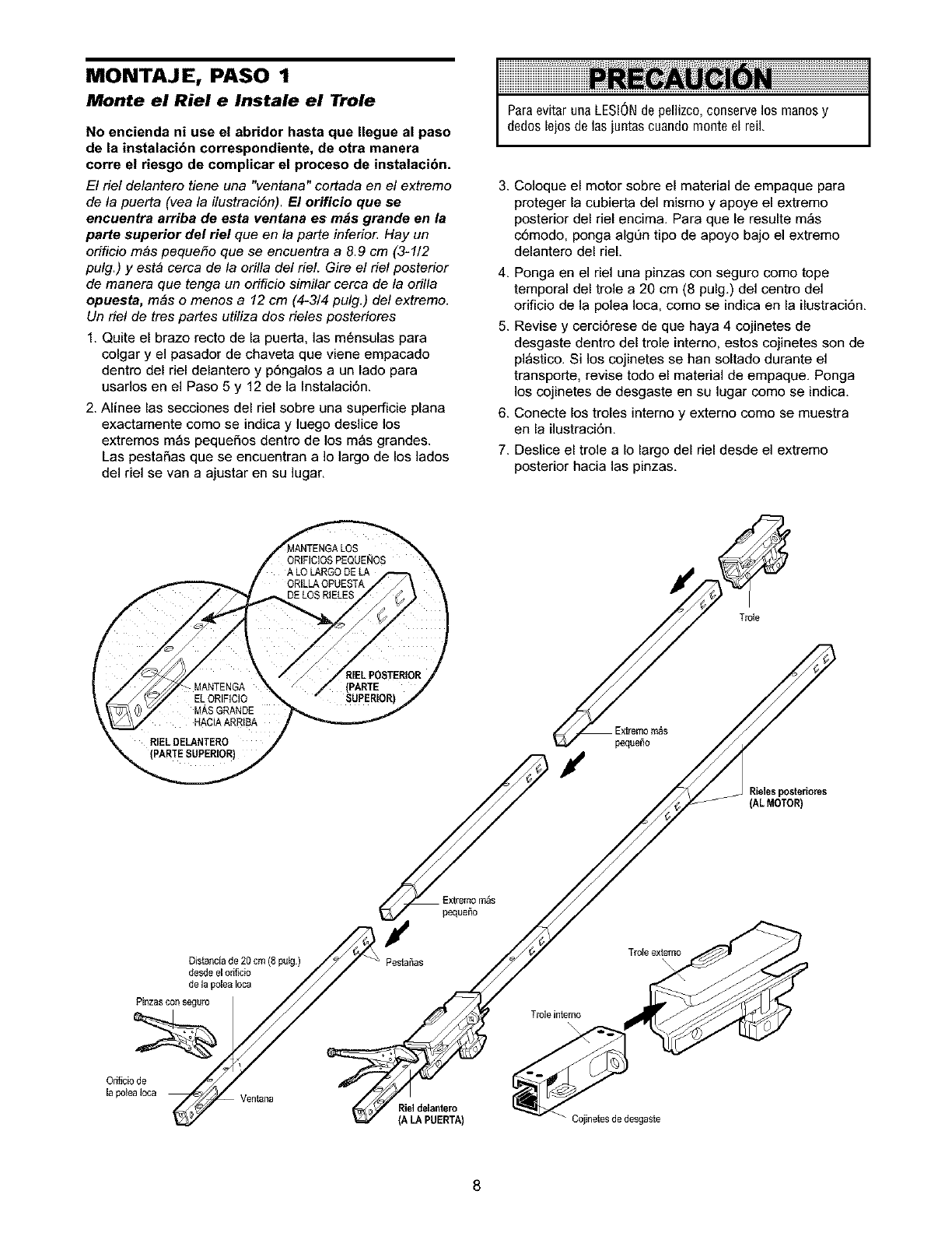
MONTAJE, PASO 1
Monte el Riel e Instale el Trole
No encienda ni use el abridor hasta que Ilegue al paso
de la instalacibn correspondiente, de otra manera
corre el riesgo de complicar el proceso de instalacibn.
El riel delantero tiene una "ventana" cortada en el extremo
de la puerta (yea la ilustraciSn). El orificio que ee
encuentra arriba de esta ventana es m_s grande en la
parte superior del riel queen/a parte inferio_ Hay un
orificio m_s peque_o que se encuentra a 8.9 cm (3-1/2
pulg.) y est& cerca de la orilla del riel. Gire el riel posterior
de manera que tenga un orificio similar cerca de la orilla
opuesta, m&s o menos a 12 cm (4-3/4 pulg.) del extremo.
Un riel de tres partes utiliza dos rieles posteriores
1. Quite el brazo recto de la puerta, las m6nsulas para
colgar y el pasador de chaveta que viene empacado
dentro del riel delantero y p6ngalos a un lado para
usados en el Paso 5 y 12 de la Instalaci6n.
2. Alinee las secciones del riel sobre una superficie plana
exactamente como se indica y luego deslice los
extremos m_s pequeSos dentro de los m_s grandes.
Las pestaSas que se encuentran a Io largo de los lados
del riel se van a ajustar en su lugar.
ParaevitarunaLESIONde pellizco,conservelos manosy
dedoslejosdelasjuntascuandomonteel reiL
3. Coloque el motor sobre el material de empaque para
proteger la cubierta del mismo y apoye el extremo
posterior del riel encima. Para que le resulte m_s
c6modo, ponga algQn tipo de apoyo bajo el extremo
delantero del rieL
4. Ponga en el riel una pinzas con seguro como tope
temporal del trole a20 cm (8 pulg.) del centro del
orificio de la polea Ioca, como se indica en la ilustraci6n.
5. Revise y cerci6rese de que haya 4 cojinetes de
desgaste dentro del trole interno, estos cojinetes son de
pl_stico. Si los cojinetes se hart soltado durante el
transporte, revise todo el material de empaque. Ponga
los cojinetes de desgaste en su lugar como se indica.
6. Conecte los troles interno y externo como se muestra
en la ilustraci6n.
7. Deslice el trole aIo largo del riel desde el extremo
posterior hacia las pinzas.
Extremom_s
_tana (A LA PUERTA) - Coiinetesde desgaste
8
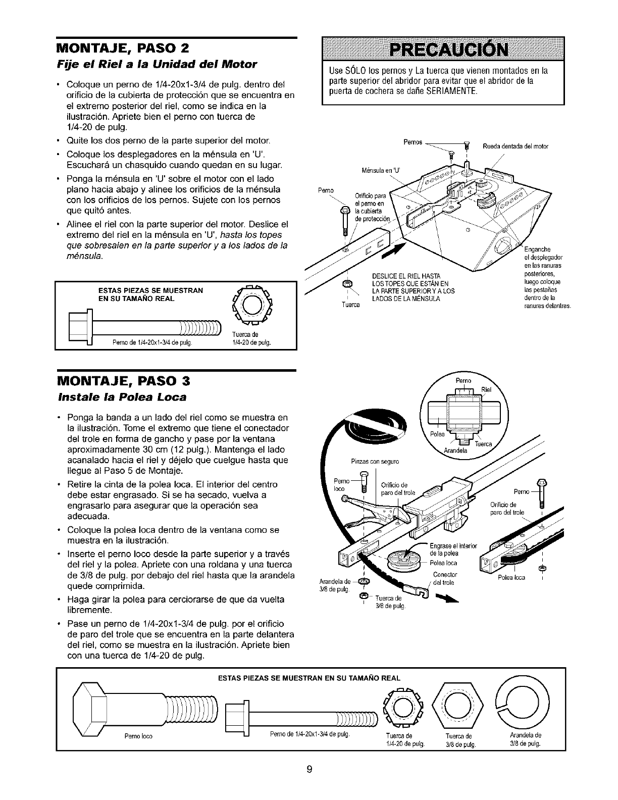
MONTAJE, PASO 2
Fije el Riel a la Unidad del Motor
•Coloque un perno de 1/4-20xl-3/4 de pulg dentro del
orificio de la cubierta de protecci6n que se encuentra en
el extremo posterior del riel, como se indica en la
ilustraci6n Apriete bien el pemo con tuerca de
1/4-20 de pulg
• Quite los dos perno de la parte superior del motor
• Coloque los desplegadores en la m6nsula en 'U'
Escuchar_ un chasquido cuando quedan en su ]ugar
• Ponga la m6nsula en 'U' sobre el motor con el lado
piano hacia abajo y alinee los orificios de la m6nsula
con los orificios de los pernos Sujete con los pernos
que quit6 antes
• Alinee el riel con la parte superior del motor Deslice el
extremo del riel en la m6nsula en 'U', hasta los topes
que sobresalen en la parte superior y a los lados de la
m6nsula
ESTAS PIEZAS SE MUESTRAN
EN SU TAMANO REAL
[_ Tuerca de
Perno de 114-20xl-314de putg 114-20de pulg.
UseSOLOlos pernosy Latuercaquevienenrnontadosenla
partesuperiordelabridorparaevitarqueel abddorde la
puertadecocherasedafieSERIAMENTE
Pemo_ Orificiopara 1
_- el pernoen
la cubierta
eprotecc_n
I
Tuerc8
DESLICEEL RIELHASTA
LOSTOPESQUE ESTANEN
LA PARTESUPERIORY A LOS
LADOSDE LAMENSULA
[nganche
el desplegador
en 13s ranuras
postedo_es,
luego coloque
las pesta_as
dentro de la
ranuras del_ntras.
MONTAJE, PASO 3
Instale la Polea Loca
• Ponga la banda a un lado del riel como se muestra en
la ilustraci6n Tome el extremo que tiene el conectador
del trole en forma de gancho y pase por la ventana
aproximadamente 30 cm (12 pulg) Mantenga el lado
acanalado hacia el riel y d6jelo que cuelgue hasta que
llegue al Paso 5 de Montaje
• Retire la cinta de la polea Ioca El interior del centro
debe estar engrasado Si se ha secado, vuelva a
engrasarlo para asegurar que la operaci6n sea
adecuada
• Coloque la polea Ioca dentro de la ventana como se
muestra en la ilustraci6n
• ]nserte el pemo Ioco desde la parte superior y a trav6s
del riel y la pole& Apriete con una roldana y una tuerca
de 3/8 de pulg por debajo del riel hasta que la arandela
quede comprimida
• Haga girar la polea para cerciorarse de que da vuelta
libremente
• Pase un pemo de 1/4-20xl-3/4 de pulg por el orificio
de paro del trole que se encuentra en la parte delantera
del riel, como se muestra en la ilustraci6n Apriete bien
con una tuerca de 1/4-20 de pulg
I
Arandelade
3/8de pulg t
I_ Tuercade
I 3/8de pulg
del trole
Pemoloco
ESTAS PIEZAS SE MUESTRAN EN sa TAMANO REAL
)/)/)/)/)/3
Perno de 1/4-20xl-3/4 de pukj. Tuerca de
I/4-20 de putg.
Tuercade
3/8de pulg
Polea _ca
©
Arandela de
3/8de pulg.
9
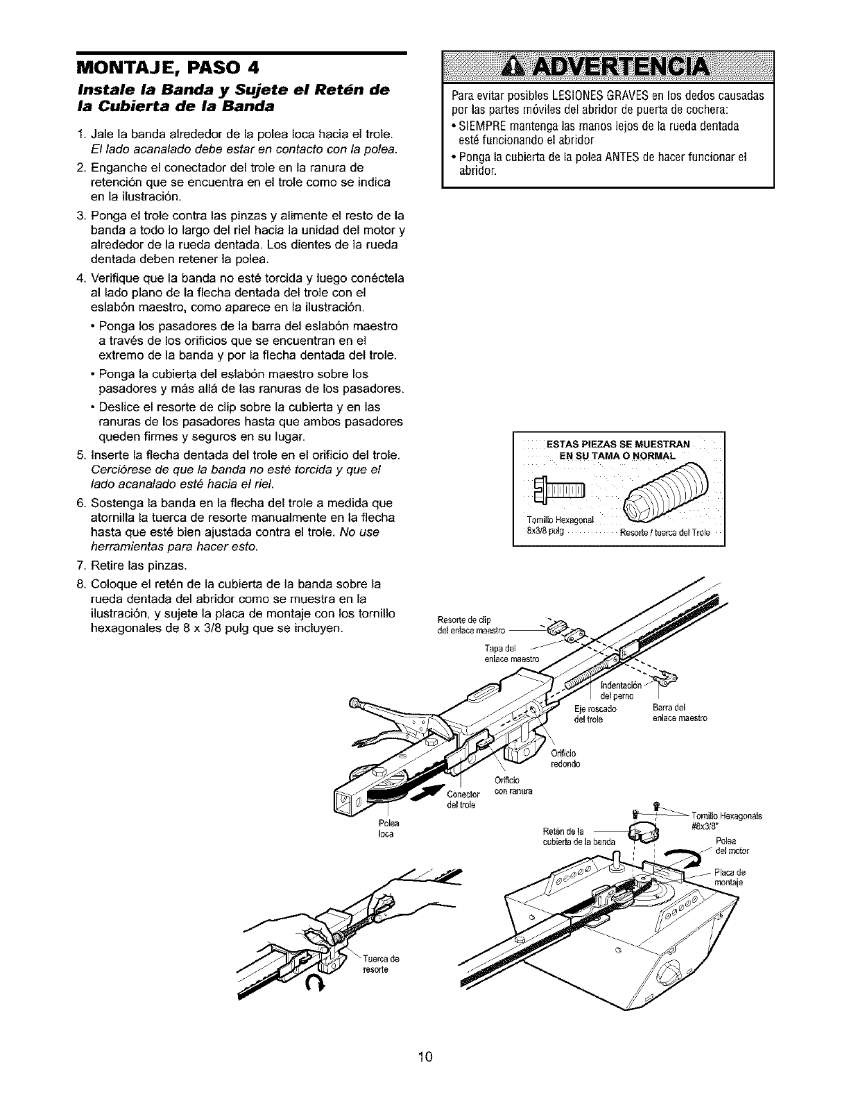
MONTAJE, PASO 4
Instale la Banda y Sujete el Ret_n de
la Cubierta de la Banda
1. Jale la banda alrededor de la polea Ioca hacia el trole.
El lado aeanalado debe estar en contacto con la pole&
2. Enganche el conectador del trole en la ranura de
retenci6n que se encuentra en el trole como se indica
en la ilustraci6n.
Paraevitar posibles LESIONESGRAVESen los dedos causadas
per las partes rn6viles del abridor de puerta de cochera:
• SlEMPRE mantenga las rnanos lejos de la rueda dentada
est_ funcionando el abridor
• Ponga la cubierta de la polea ANTESde hacerfuncionar el
abridor.
3. Ponga el trole contra las pinzas y alimente el resto de la
banda a todo Io largo del riel hacia la unidad del motor y
alrededor de la rueda dentada. Los dientes de la rueda
dentada deben retener la polea.
4. Verifique que la banda no est6 torcida y luego con6ctela
al lado piano de la flecha dentada del trole con el
eslab6n maestro, como aparece en la ilustraci6n.
• Ponga los pasadores de la barra del eslab6n maestro
a trav6s de los orificios que se encuentran en el
extremo de la banda y por la flecha dentada del trole.
• Ponga la cubierta del eslab6n maestro sobre los
pasadores y m_s all_ de las ranuras de los pasadores.
• Deslice el resorte de clip sobre la cubierta yen las
ranuras de los pasadores hasta que ambos pasadores
queden firmes y seguros en su lugar.
5. Inserte la flecha dentada del trole en el orificio del trole.
Cerci6rese de que la banda no este torcida y que el
lado acanalado este hacia el riel.
6. Sostenga la banda en la flecha del trole a medida que
atomilla la tuerca de resorte manualmente en la flecha
hasta que est6 bien ajustada contra el trole. No use
herramientas para hacer esto.
ESTAS PIEZAS SE MUESTRAN
EN SU TAMA O NORMAL
Tornillo Hexagona!
8x3/8 pulg Resorie /tuerca del Trole
7. Retire las pinzas.
8. Coloque el ret6n de la cubierta de la banda sobre la /j
rueda dentada del abridor como se muestra en la //_-//-I_
ilustraci6n, y sujete la placa de montaje con los tornillo . /_r'r_,_'/
hexagonales de 8 x 3/8 pulg que se incluyen, delenlacemaestro
de t c"
del trole enlacemaestro
Orificio
redondo
Orificio
Conector con ranura
del trole
illoHexagonals
Polea , _ #8x3/8"
oca Retende la
cubieria de la banda _ r-_l Poea
Tuerc de
10
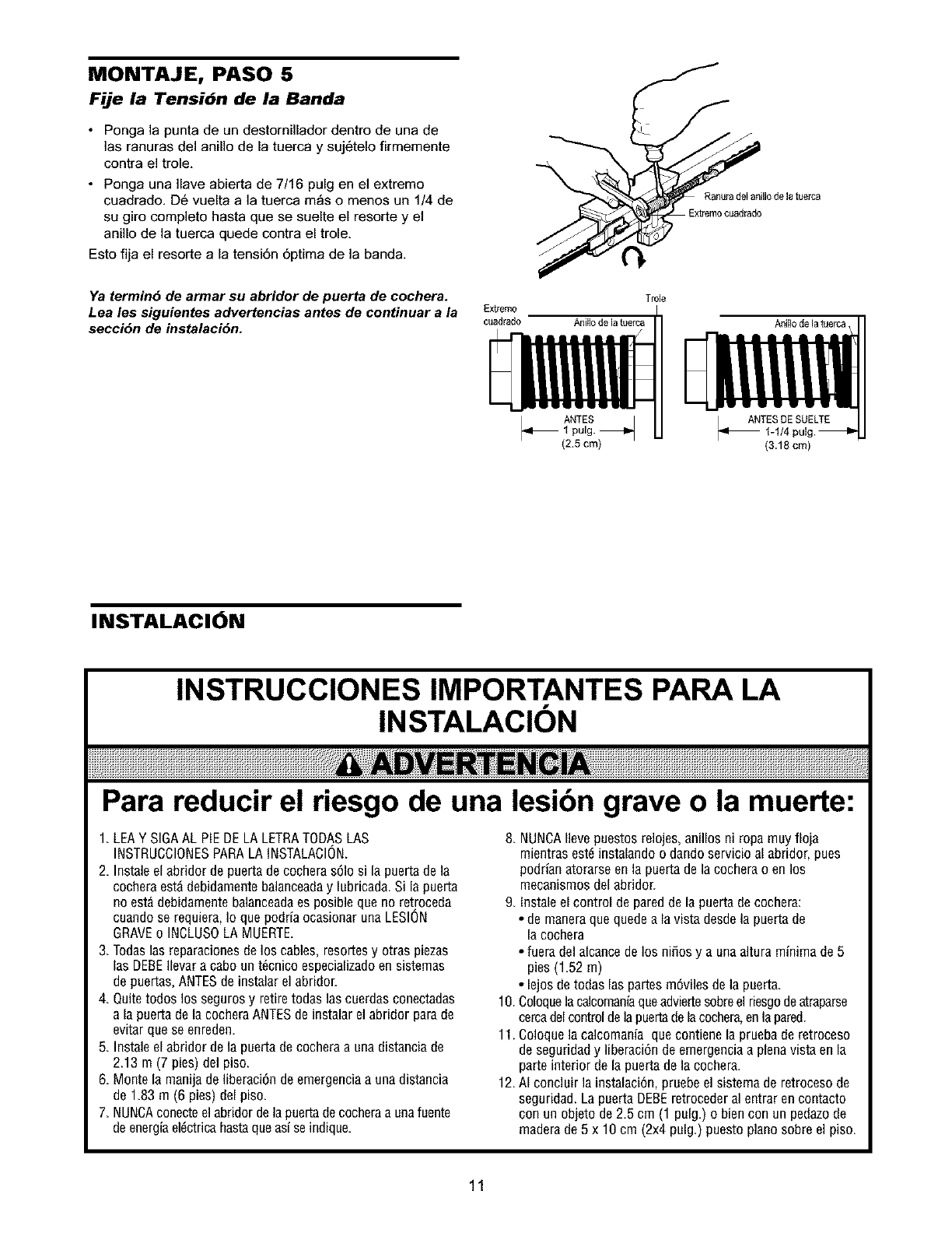
MONTAJE, PASO 5
Fije la Tensibn de la Banda
•Ponga la punta de un destornillador dentro de una de
]as ranuras del anillo de la tuerca y suj6telo firmemente
contra el trole,
• Ponga una Ilave abierta de 7/16 pulg en el extremo
cuadrado, D6 vuelta a la tuerca m_s o menos un 1/4 de
su giro complete hasta que se suelte el resorte y el
anillo de la tuerca quede contra el trole,
Esto fija el resorte a la tensi6n 6ptima de la banda.
Ya termin5 de armar su abridor de puerta de cochera.
Lea lee siguientes advertencias antes de continuar a la
seccidn de instalacidn.
Trole
Aniilo de la tuerca
Ranurade$anillo de latuerca
ANTES Ibll ANTES DESUELTE_ AN 1_1/41 pulg.
(2.5 cm) (3.18 cm)
INSTALACION
Para reducir el riesgo de una lesibn grave o la muerte:
1. LEAYSIGAALPIEDELALETRATODASLAS
INSTRUCCIONESPARALAINSTALACION.
2. Instaleelabridordepuertadecocherasolo si lapuertadela
cocheraest_debidamentebalanceaday lubricada.Si lapuerta
noest_debidamentebalanceadaesposiblequenoretroceda
cuandoserequiera,Io quepodriaocasionarunaLESION
GRAVEo INCLUSOLAMUERTE.
3. Todas1asreparacionesdelos cables,resortesy otraspiezas
lasDEBEIlevara cabount6cnicoespecializadoensistemas
depuertas,ANTESde instalarelabridor
4. Quitetodoslos segurosy retiretodas1ascuerdasconectadas
a lapuertadela cocheraANTESdeinstalarel abridorparade
evitarqueseenreden.
5. Instaleelabridordelapuertadecocheraaunadistanciade
2.13 m (7 pies)delpiso.
6. Montela manijadeliberaciOndeemergenciaa unadistancia
de 1.83m (6 pies)delpiso.
7. NUNCAconecteelabridordelapuertadecocheraaunafuente
deenergiael_ctricahastaqueasiseindique.
8. NUNCAIlevepuestosrelojes,anillosni ropamuyfloja
mientrasest6instalandoo dandoservicioal abridor,pues
podrianatorarseen lapuertadelacocherao enlos
mecanismosdelabridor.
9. Instaleelcontroldepareddelapuertadecochera:
• de maneraquequedealavista desdela puertade
lacochera
• fueradelalcancedelos ni_osy a unaalturaminimade5
pies(1.52m)
• lejosdetodaslas partesmOvilesdela puerta.
10.Coloquelacalcomaniaqueadviertesobreelriesgodeatraparse
cercadelcontroldelapuertadelacochera,enlapared.
11.Coloquelacalcomaniaquecontienelapruebade retroceso
deseguddady liberaciOndeemergenciaa plenavistaenla
parteinteriorde lapuertadelacochera.
12.AI concluirlainstalaciOn,pruebeelsistemaderetrocesode
seguridad.LapuertaDEBEretrocederal entraren contacto
con unobjetode 2.5cm (1 pulg.)o biencon unpedazode
maderade5 x 10cm (2x4pulg.)puestopianosobreel piso.
11
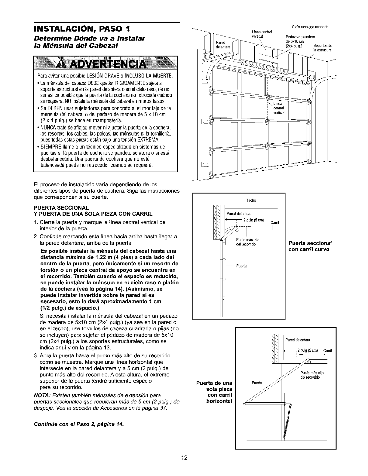
|NST_LAC|_N r _SO 1_ Lineacentral Cie_orasoconacabado
ve_cat
Determine Dbnde va a Instalar
la M_nsula del Cabezal
Pedazo de madera
de 5xl 0 cm
(2x4 pulg) Soportes de
18 _slrucur8
ParaevitarunaposibleLESIONGRAVEo INCLUSOLAMUERTE:
•Lam_nsuladelcabezalDEBEquedarR[GIDAMENTEsujetaal
soporteestructuralenlapareddelanteraoenelcieloraso,deno
seras[esposiblequelapaertadelacocheranoretrocedacuando
se requiera.NOinstalelam_nsuladelcabezalenmurosfalsos.
• SeDEBENusarsujetadoresparaconcretosi el montajedela
m_nsuladelcabezalo delpedazodemaderade5 x 10cm
(2x 4 pulg.)sehaceenmamposteria.
• NUNCAtratedeaflojar,moverniajustarlapuertadelacochera,
losresortes,loscables,laspoleas,lasm_nsulasnilatornillerfa,
puestodasestaspiezasest_nbajounatensionEXTREMA.
• SIEMPREIlamea unt_cnicoespecializadoensistemasde
puertassi lapuertadecocherasepandea,seatorao si est_
desbalanceada.Unapuertadecocheraqueno est_
balanceadapuedeno retrocedercuandose requiera.
El proceso de instalaciSn vada dependiendo de los
diferentes tipos de puerta de cochera. Siga las instrucciones
que correspondan a su puerta.
PUERTA SECCIONAL
Y PUERTA DE UNA SOLA PIEZA CON CARRIL
1. Cierre la puerta y marque la linea central vertical del
interior de la puerta.
2. ContinDe marcando esta linea hacia arriba hasta Ilegar a
]a pared delantera, arriba de la puerta.
Es posible instalar la m_nsula del cabezal hasta una
distancia m&xima de 1.22 m (4 pies) a cada lado del
centre de la puerta, pero t_nicamente si un resorte de
torsibn o un placa central de apoyo se encuentra en
el recerride. Tambi6n cuando el espacio es reducido,
se puede instalar la m_nsula en el cielo raso o plafbn
de la cochera (vea la p&gina 14). (Asimismo, se
puede instalar invertida sobre la pared si es
necesario, esto le darb aproximadamente 1 cm
(1/2 pulg.) de espacio.)
Si necesita instalar la m6nsula del cabezal en un pedazo
de madera de 5x10 cm (2x4 pulg.) (ya sea en la pared o
en el techo), use tornillos de cabeza cuadrada o pijas (no
se incluyen) para sujetar el pedazo de madera de 5x10
cm (2x4 pulg.) a los soportes estructurales, come se
indica aqui yen la p_gina 13.
3. Abra la puerta hasta el punto m_s alto de su recorrido
como se muestra. Marque una linea horizontal que
intersecte en la pared delantera y a 5 cm (2 pulg.) del
punto m_s alto del recorrido. A esta altura, el extremo
superior de la puerta tendr_ suficiente espacio
para su recorrido.
NOTA: Existen tambi6n m6nsulas de extensibn para
puertas seccienales que requieran m&s de 5 cm (2 pulg.) de
despeje. Vea la secciSn de Accesorios en la p&gina 37.
ContinUe con el Paso 2, p_gina 14.
Techo
Pared delantera
2pulg(5cm) Carril
Punto m_sa_
del recorrido
Puet_
Puerta seccional
con carril curve
Pared delantera
CarriI
Puerta de una
sola pieza
con carril
horizontal
Punto m_salto
de_recorddo
12
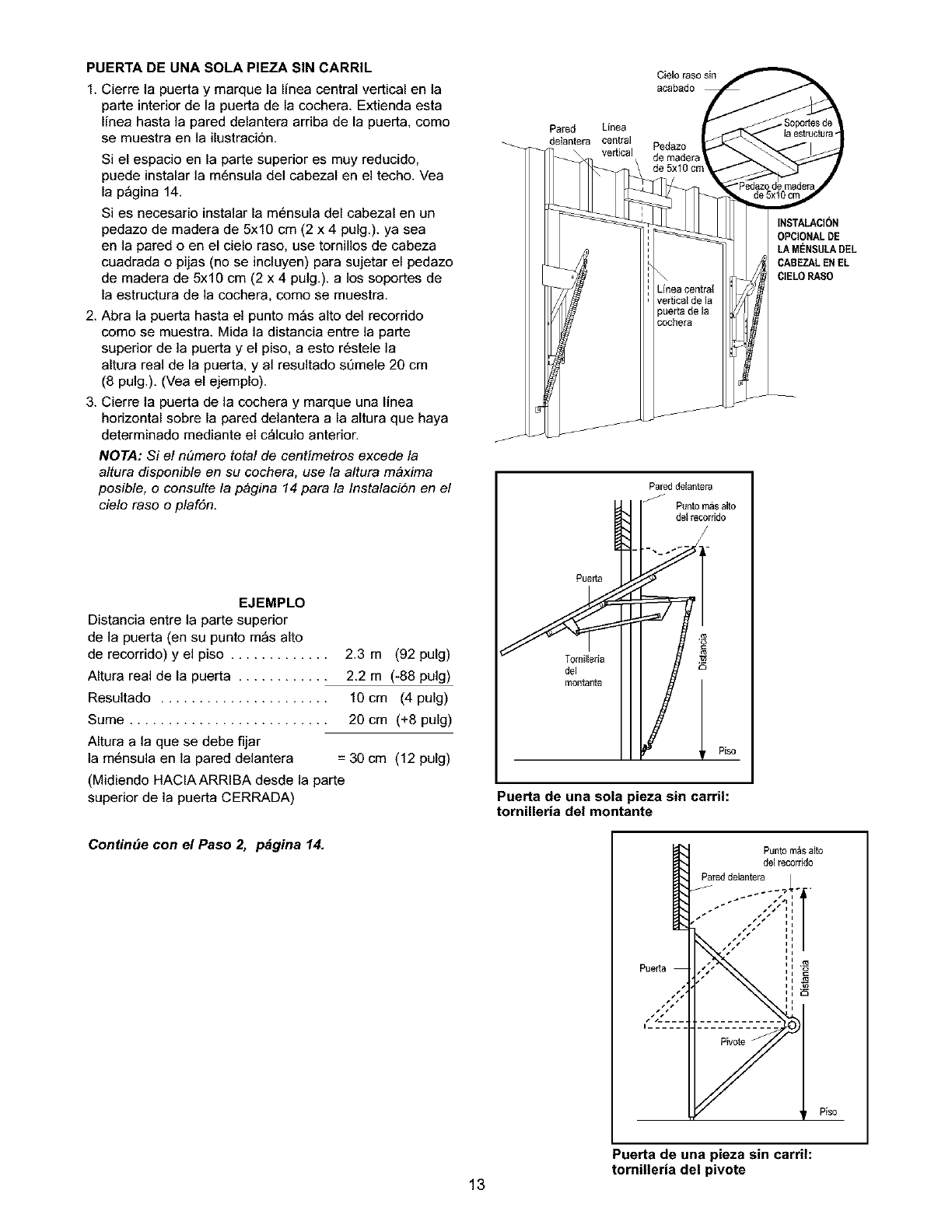
PUERTA DE UNA SOLA PIEZA SIN CARRIL
1. Cierre la puerta y marque la linea central vertical en la
parte interior de la puerta de la cochera. Extienda esta
linea hasta la pared delantera arriba de la puerta, como
se muestra en la ilustraci6n.
Si el espacio en la parte superior es muy reducido,
puede instalar la m6nsula del cabezal en el techo. Vea
la p_gina 14.
Si es necesario instalar la m6nsula del cabezal en un
pedazo de madera de 5x10 cm (2 x 4 pulg.), ya sea
en la pared o en el cielo raso, use tornillos de cabeza
cuadrada o pijas (no se incluyen) para sujetar el pedazo
de madera de 5x10 cm (2 x 4 pulg.), a los soportes de
la estructura de la cochera, como se muestra.
2. Abra la puerta hasta el punto m_s alto del recorrido
como se muestra. Mida la distancia entre la parte
superior de la puerta y el piso, a esto r6stele la
altura real de la puerta, y al resultado sQmele 20 cm
(8 pulg.). (Vea el ejemplo).
3. Cierre la puerta de la cochera y marque una linea
horizontal sobre la pared delantera a la altura que haya
determinado mediante el c_lculo anterior.
NOTA: Si el n#mero total de centimetros excede la
altura disponible en su cochera, use la altura m&xima
posible, o consulte la p&gina 14 para la InstalaciSn en el
cielo raso o plafSn.
EJEMPLO
Distancia entre la parte superior
de la puerta (en su punto m_s alto
de recorrido) y el piso ............. 2.3 m (92 pulg)
Altura real de la puerta ............ 2.2 m (-88 pulg)
Resultado ...................... 10 cm (4 pulg)
Sume .......................... 20 cm (+8 pulg)
Altura a la que se debe fijar
la m6nsula en la pared delantera = 30 cm (12 pulg)
(Midiendo HAClAARRIBA desde la parte
superior de la puerta CERRADA)
ContinUe con el Paso 2, p_gina 14.
Cielo raso sin
acabado
Pared Lfnea
delantera central Pedazo
vertical de madera
INSTALACI(_N
OPCIONALDE
LA MENSULADEL
CABEZALEN EL
ClELOPASO
Puerta 1
dlo o,o
Pared delaotera
Punto m_salto
detrecorddo
Puerta de una sola pieza sin carril:
tornilleria de! montante
Puerta de una pieza sin carril:
tomilleria del pivote
13
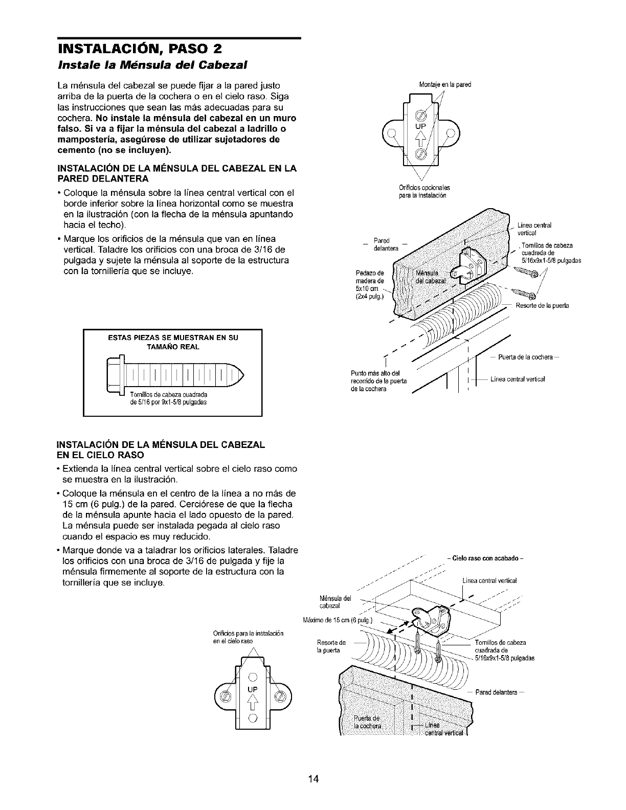
INSTALACION, PASO 2
Instale la M,Jnsula del Cabezal
La m6nsula del cabezal se puede fijar a la pared justo
arriba de la puerta de la cochera o en el cielo raso, Siga
las instrucciones que sean las m_s adecuadas para su
cochera. NO instale la m6nsula del cabezal en un muro
falso. Si va a fijar la m6nsula del cabezal a ladrino o
mamposteria, asegt_rese de utilizar sujetadores de
cemento (no se incluyen).
INSTALACI(3N DE LA MENSULA DEL CABEZAL EN LA
PARED DELANTERA
•Coloque la m6nsula sobre la linea central vertical con el
borde inferior sobre la linea horizontal como se muestra
en la ilustraci6n (con la flecha de la m6nsula apuntando
hacia el techo).
• Marque los orificios de la m6nsula que van en linea
vertical, Taladre los orificios con una broca de 3/16 de
pulgada y sujete la m6nsula al seperte de la estructura
con la tornilleda que se incluye.
ESTAS PIEZAS SE MUESTRAN EN SU
TAMAI_IO REAL
de 5/16pot9xl -5/8p_lgadas
Montajeen _apared
OriSciosopcionales
para ta instalaci6n
Pared
de_antera
Pedazode
maderade
5xl0cm
(2x4 pulg.)
/
/
/
Puntom_salto del
recom:dode la pueda
de lacochera
Linea cen_al
vertical
•TomiIIosde cabeza
cuadradade
5/16xgxl-5/8 putgadas
Resottede la puerta
PuedadeIa cochera
INSTALACION DE LA MENSULA DEL CABEZAL
EN EL ClELO PASO
• Extienda la linea central vertical sobre el cielo raso come
se muestra en la ilustraci6n,
•Coloque la m6nsula en el centro de la linea a no m_s de
15 cm (6 pulg.) de la pared. Cerci6rese de que la flecha
de la m6nsula apunte hacia el lado opuesto de la pared,
La m6nsula puede ser instalada pegada al cielo raso
cuando el espacio es muy reducido.
• Marque donde va a taladrar los orificios laterales, Taladre
los orificios con una broca de 3/16 de pulgada y fije la
m6nsula firmemente al soporte de la estructura con la
tornilleria que se incluye.
Orificiospara la instalaci6n
en el cieIoraso
oResoffede lecabeza
lapuefla ouadradade
pulgadas
Pared delantera
14
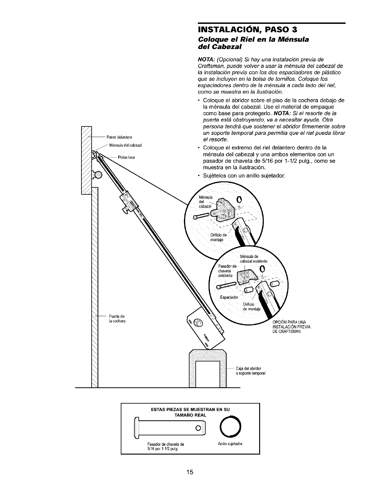
//
Puertade
lacochera
INSTALACION, PASO 3
Coloque el Riel en la M_nsula
del Cabezal
NOTA: (Opcional) Si hay una instalaci6n previa de
Craftsman, puede velvet a usar la m6nsula del cabezal de
la instalaci6n previa con los dos espaciadores de pl&stico
que se incluyen en la bolsa de tornillos. Coloque los
espaciadores dentro de la m6nsula a cada lado del riel,
come se muestra en la ilustraciSn.
•Coloque el abridor sobre el piso de la cochera debajo de
la m6nsula del cabezaL Use el material de empaque
como base para protegerlo. NOTA: Si el resorte de la
puerta est& obstruyendo, va a necesitar ayuda. Otra
persona tendr& que sostener el abridor firmemente sobre
un soporte temporal para permitia que el riel pueda librar
el resorte.
• Coloque el extremo del riel delantero dentro de la
m6nsula del cabezal y una ambos elementos con un
pasador de chaveta de 5/16 por 1-1/2 pulg., como se
muestra en la ilustraci6n.
• Suj6telos con un anil]o sujetador.
0
o
Orificiode
m0ntaje
•/
Espac_ador
Orificio
de montaje
3PCION PARAURA
INSTALACIONPREVIA
DE CRAFTSMAN
Cajadel abridor
o soporte temporal
ESTAS PIEZAS SE MUESTRAN EN SU
TAMA_IO REAL
G O
Pasadorde chaveta de Anillo sujetador
5116por 1-I/2 pulg
15
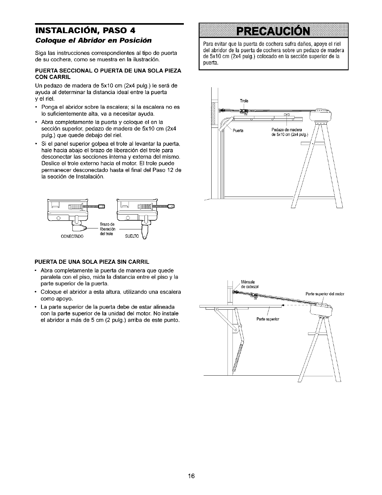
INSTALACION, PASO 4
Coloque el Abridor en Posicibn
Siga las instrucciones correspondientes al tipo de puerta
de su cochera, como se muestra en la ilustraci6n
PUERTA SECCIONAL O PUERTA DE UNA SOLA PIEZA
CON CARRIL
Un pedazo de madera de 5x10 cm (2x4 pulg.) le ser_ de
ayuda al determinar la distancia ideal entre la puerta
y el riel.
• Ponga el abridor sobre la escalera; si la escalera no es
Io suflcientemente alta, va a necesitar ayuda.
• Abra completamente la puerta y coloque el en la
secci6n superior, pedazo de madera de 5x10 cm (2x4
pulg.) que quede debajo del riel.
• Si el panel superior golpea el trole al levantar la puerta,
hale hacia abajo el brazo de liberaci6n del trole para
desconectar las secciones interna y extema del mismo.
Deslice el trole externo hacia el motor. El trole puede
permanecer desconectado hasta el final del Paso 12 de
la secci6n de Instalaci6n.
Paraevitar que la puerta de cochera sufra dafios, apoyeel riel
del abrider de la puerta de cochera sobre un pedazode madera
de 5x10 cm (2x4 pulg) colocado en la secci6n superior de la
puerta.
del trole
CONECTAOO
PUERTA DE UNA SOLA PIEZA SIN CARRIL
•Abra completamente la puerta de manera que quede
paralela con el piso, mida la distancia entre el piso y la
parte superior de la puerta
•Coloque el abridor a esta altura, utilizando una escalera
como apoyo
• La parte superior de la puerta debe de estar alineada
con la par_e superior de la unidad del motor No instale
el abridor a m_s de 5 cm (2 pulg) arriba de este punto
M_nsula
/de cabezat
i19
Parle superior
Patte superior del motor
16
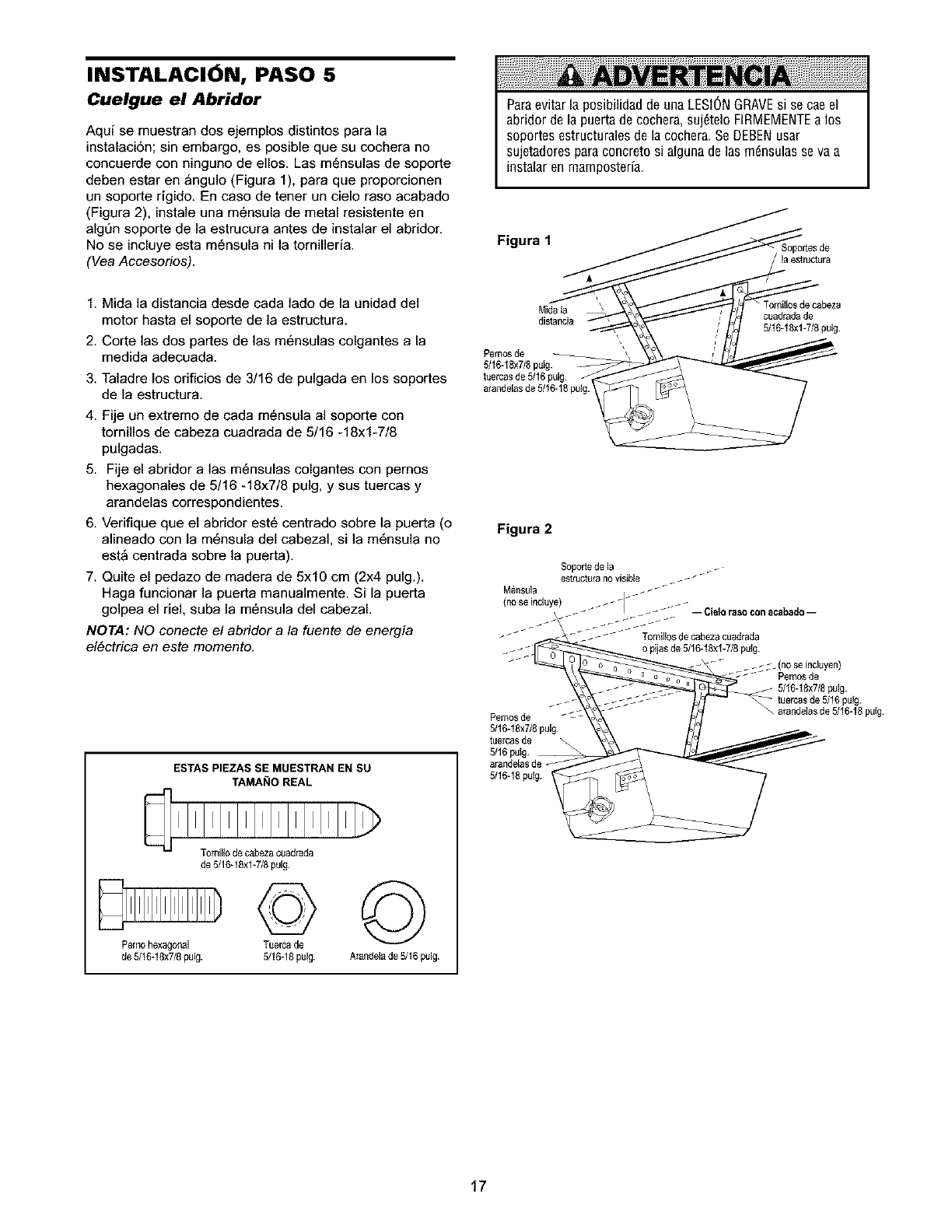
INSTALACION, PASO 5
Cuelgue el Abridor
Aqui se muestran dos ejemplos distintos para la
instalaci6n; sin embargo, es posible que su cochera no
concuerde con ninguno de ellos. Las m6nsulas de soporte
(:leben estar en _ngulo (Figura 1), para que proporcionen
un soporte rigido. En caso de tener un cielo raso acabado
(Figura 2), instale una m6nsula de metal resietente en
algt]n soporte de la estrucura antes de instalar el abridor.
No se incluye esta m6nsula ni la tornilleria.
(Vea Accesorios).
ParaevitarlaposibilidaddeunaLESIONGRAVEsi se caeel
abridordelapuertadecochera,suj61eloFIRMEMENTEalos
soportesestructuralesdelacochera,SeDEBENusar
sujetadoresparaconcretosi algunadelas m_nsulasseva a
instalaren mamposterfa.
Figura 1 SopoAesde
'laestructura
1. Mida la distancia desde cada lado de ia unidad del
motor hasta el soporte de la estructura.
2. Corte las dos partes de las m6nsulas colgantes a la
medida adecuada.
3. Taladre los orificios de 3/16 de pulgada en los soportes
de la estructura,
4. Fije un extremo de cada m6nsula al soporte con
tornillos de cabeza cuadrada de 5/16 -18xl-7/8
pulgadas.
5. Fije el abridor alas m6nsulas colgantes con pemos
hexagonales de 5/16 -18x7/8 pulg, y sus tuercas y
arandelas correspondientes.
6. Verifique que el abridor est6 centrado sobre la puerta (o
alineado con la m6nsula del cabezal, si la m6nsula no
est_ centrada sobre la puerta).
7. Quite el pedazo de madera de 5x10 cm (2x4 puig.).
Haga funcionar la puerta manualmente. Si la puerta
golpea el riel, suba la m6nsula del cabezal.
NOTA: NO conecte el abridor a la fuente de energia
el6ctrica en este momento.
ESTAS PIEZAS SE MtJESTRAN EN SU
TAMA I;I0 REAL
T0milio de cabezacuadrada
de 5/16qSxl-7/8 pulg.
©©
Pemo hexagoaal Tuercade
de 5/16-18x7/8pulg. 5/16-18pulg. A_andelade 5/t6 pulg.
Mida la
distancia
_rnos de
5/16-18x7/8pulg.
tuercasde 5/16pulg
arap,delas de 5J16-18pulg.
Tomillosde cabeza
cuadradade
5/16-18xl-718pulg
Figura 2
Pernosde - %c
5/16-18x7/8pulg
tuercas de \
5/16 pulg. __
_. (no se incluyen)
Pemosde
5/16-18x7/8pulg.
; pulg.
\ arandelasde 5/16-18putg
5/16-18pulg.
17
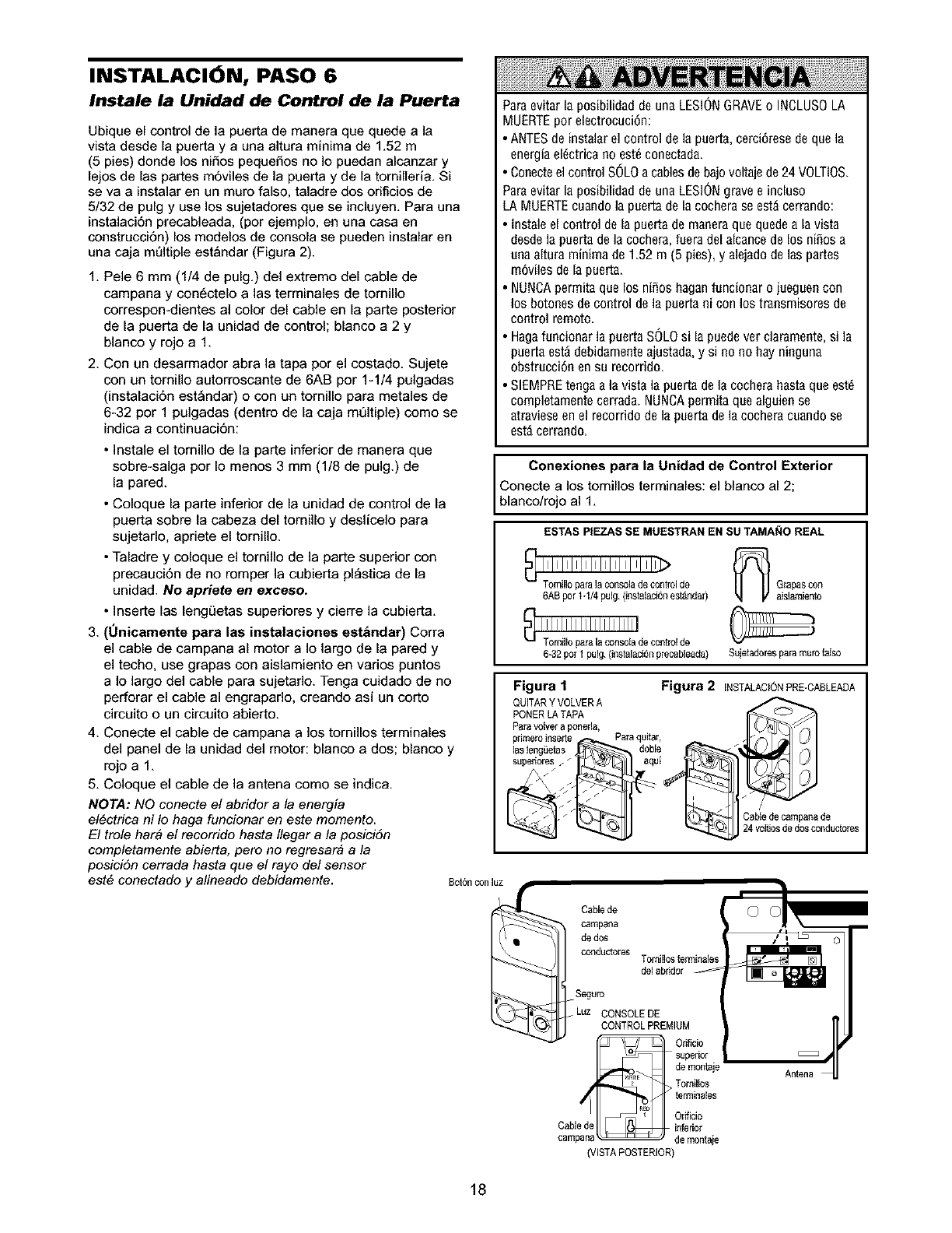
INSTALACION, PASO 6
Instale la Unidad de Control de la Puerta
Ubique el control de la puerta de manera que quede a la
vista desde la puerta y a una altura minima de 1.52 m
(5 pies) donde los niSos pequeSos no Io puedan alcanzar y
lejos de las partes m6viles de la puerta y de la tornilleria. Si
se va a instalar en un muro falso, taladre dos orificios de
5/32 de pulg y use los sujetadores que se incluyen. Para una
instalaci6n precableada, (por ejemplo, en una casa en
construcci6n) los modelos de consola se pueden instalar en
una caja m_ltiple estandar (Figura 2).
1. Pele 6 mm (1/4 de pulg.) del extremo del cable de
campana y con6ctelo alas terminales de tomillo
correspon-dientes al color del cable en la parte posterior
de la puerta de la unidad de control; blanco a 2 y
blanco y rojo a1.
2. Con un desarmador abra la tapa por el costado. Sujete
con un tornillo autorroscante de 6AB por 1-1/4 pulgadas
(instalaci6n est_ndar) o con un tornillo para metales de
6-32 por 1 pulgadas (dentro de la caja mt]ltiple) como se
indica a continuaci6n:
•]nstale el tornillo de la parte inferior de manera que
sobre-salga por Io menos 3 mm (1/8 de pulg.) de
la pared.
• Coloque la parte inferior de la unidad de control de la
puerta sobre la cabeza del tornillo y deslicelo para
sujetarlo, apriete el tornillo.
• Taladre y coloque el tornillo de la parte superior con
precauci6n de no romper la cubierta pl_stica de la
unidad. No apriete en exceso.
• ]nserte las lengL_etas superiores y cierre la cubierta.
3. (Onicamente para las instalaciones est&ndar) Corra
el cable de campana al motor a Io largo de la pared y
el techo, use grapas con aislamiento en varios puntos
a Io largo del cable para sujetarlo. Tenga cuidado de no
perforar el cable al engrapado, creando asi un corto
circuito o un circuito abierto.
4. Conecte el cable de campana a los tornillos terminales
del panel de la unidad del motor: blanco a dos; blanco y
rojoa 1.
5. Coloque el cable de la antena como se indic&
NOTA: NO conecte el abridor a la energia
el6ctrica ni Io haga funcionar en este momento.
El trole hat# el recorrido hasta Ilegar a la posici6n
completamente abierta, pero no regresar& a la
posici6n cerrada hasta que el rayo del sensor
est# conectado y alineado debidamente.
Paraevitar la posibilidad de una LESIONGRAVE0 INCLUSOLA
MUERTEpot electrocuci6n:
• ANTESde instalarel control de la puerta, cerci6resede que la
energiael6ctrica no est_conectada.
C0necteel controlsOLo a cablesde baj0voltajede24 VOLTIOS.
Paraevitar la posibilidad de una LESIONgravee incluso
LAMUERTEcuand0 la puerta de la cochera se est_cerrando:
Instale el control de la puerta de maneraque quedea la vista
desde la puerta de la cochera, faeradel alcancede los niS0sa
una altura minima de 1.52 m (5 pies), y alejado delas partes
rn6viles de la puerta.
NUNCAperrnitaque 10sniS0s haganfancionar o jaeguen con
los b0t0nes de control de la puerta ni con los transmis0res de
control rem0to.
Hagafancionar la puerta SOLOsi la puedever clararnente,si la
puerta est_ debidamenteajustada,y si no no hay ninguna
0bstrucci6n ensu rec0rrido.
SIEMPREtengaa la vista la puerta de la cocherahasta que 6st_
cornpletamentecerrada. NUNCApermita que alguien se
atravieseenel recorrido dela puerta de lacochera cuand0 se
est_cerrando.
Conexiones para la Unidad de Control Exterior
Conecte a los tornillos terminales: el blanco al 2;
blanco/rojo al 1.
ESTAS PIEZAS SE MUESTRAN EN SU TAMANO REAL
_ Grapas con
6AB pot t-1/4 pulg.(instalaciSnes_lda 0 aislamiento
6-32 por1pulg.(instalaciSnprecableada) Sujetadorespara muro falso
Figura 1 Figura 2 INSTALACtONPRE-CASLEADA
QUITARY VOLVERA
PONERLA TAP __
Paravolver a poneria,
pdmeroinserte Paraquitar,
lasleng_Jetas doble
superiores z / aqui
/•
_- _ _ _ Oab'e de CaI_p al_a lie
24 vottJosde dosco_ductores
8ot6n con luz
Cablede
campana
de dos
:o:°'ioO.SOo EO,Oot
!!,2111:
Or_icb
Cable de inferior
cam de montaie
(VISTAPOSTERIOR)
r
/iL_ o
Antena
18
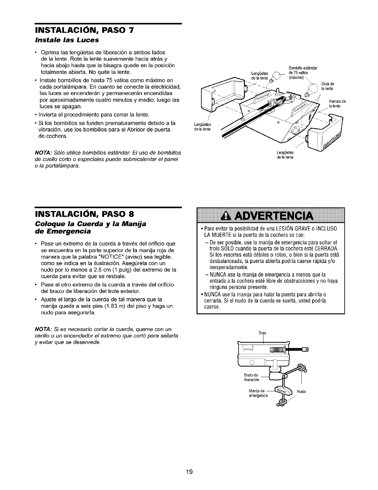
INSTALACION, PASO 7
Instale las Luces
•Oprima las lengLietas de liberaci6n a ambos lades
de la lente Rote la lente suavemente hacia atr_s y
hacia abajo hasta que la bisagra quede en la posici6n
totalmente abierta No quite la lente
•Instale bombillos de hasta 75 vatios como m_ximo en
cada portal_mpara En cuanto se conecte la electricidad,
las luces se encender_n y permanecer_n encendidas
por aproximadamente cuatro minutos y medio; luego las
]uces se apagan
• Invierta el procedimiento para cerrar la lente
• Si los bombillos se funden prematuramente debido a la
vibraci6n, use los bombillos para el Abridor de puerta
de cochera
NOTA: S61o utilice bombillos est&nda_ El uso de bombillos
de cuello corte o especiales puede sobrecalentar el panel
o la portalbmpara.
/
Leng_ietas
de Ia lente
Leng(Jetas
de latente
Bombilloest_ndar
de 75 vatios
(m_ximo) ,
INSTALACI6N, PASO 8
Coloque la Cuerda y la Manila
de Emergencia
• Pase un extreme de la cuerda a trav6s del orificio que
se encuentra en la parte superior de la manija roja de
manera que la palabra "NOTICE" (aviso) sea legible,
como se indica en la ilustraci6n AsegOrela con un
nudo por Io menos a 25 cm (1 pulg) del extremo de la
cuerda para evitar que se resbale
• Pase el otto extremo de la cuerda a trav6s del orificio
del brazo de liberaci6n del trole exterior
• Ajuste el largo de la cuerda de tal manera que la
manija quede a seis pies (183 m) del piso y haga un
nudo para asegurarla
•Para evitar la posibilidad de una LESIONGRAVEo INCLUSO
LA MUERTEsi la puerta de la cochera se cae:
- De set posible, use la manija de emergenciapara soltar el
trole SOLOcuando la puerta de la cochera est_ CERRADA
Si los resertes est_ d6biles e rotos, o bien si la puerta est_
desbalanceada,la puerta abierta podria caerse r_pida y/o
inesperadamente
- NUNCAuse la rnanijade emergencia a menos que la
entrada a la cochera est_ libre de obstrucciones y no haya
ninguna persona presente.
• NUNCA use la manija parahalar la puerta para abrida o
cerrarla. Si el nudo de la cuerda se suelta, usted podria
caerse,
NOTA: Si es necesario cortar la cuerda, queme con un
cerillo oun encendedor el extremo que cort6 para sellarla
y evitar que se desenrede.
T[o]e
Manijade
emergencia Nudo
19
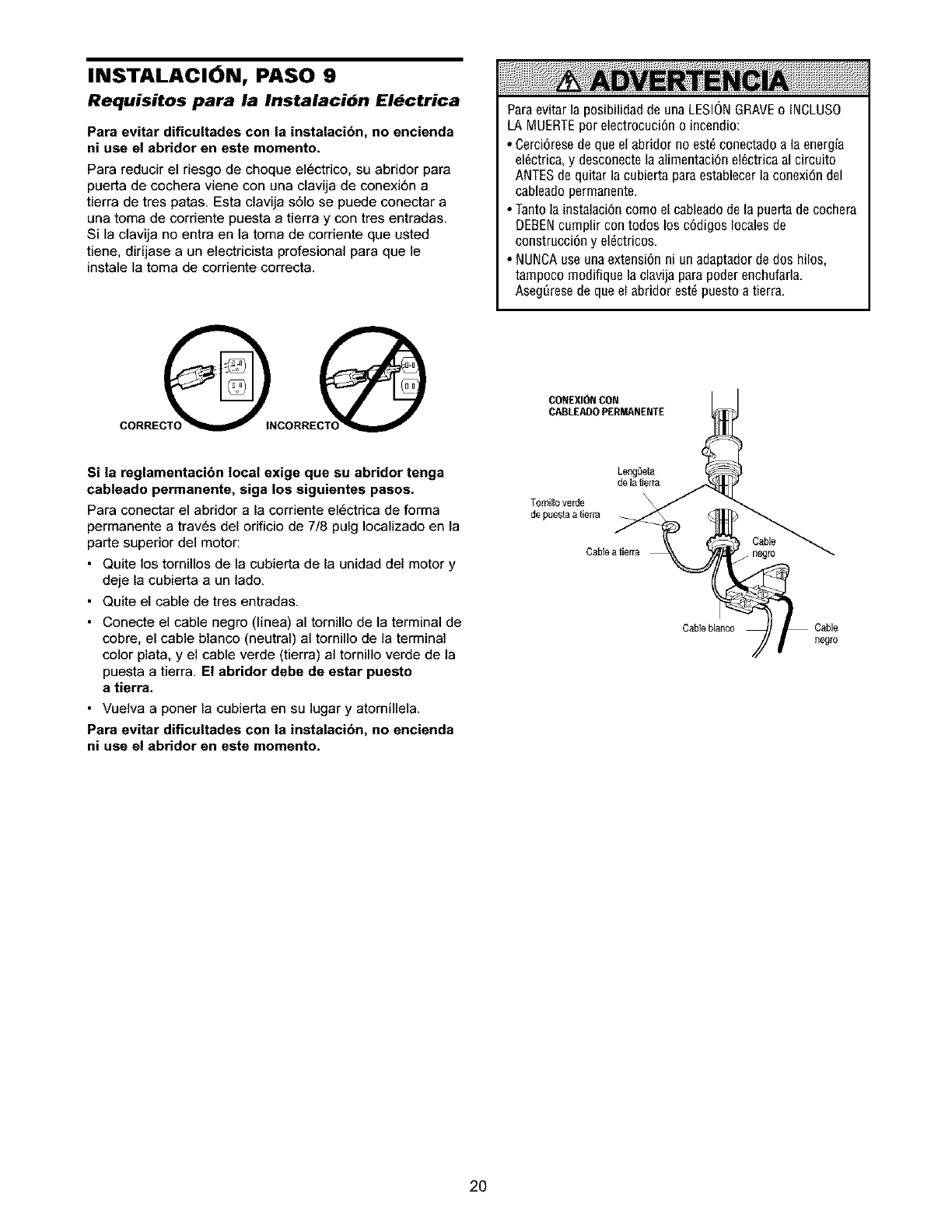
INSTALACION, PASO 9
Requisitos para la Instalacibn El_ctrica
Para evitar dificultades con la instalacibn, no encienda
ni use el abridor en este momento.
Para reducir el riesgo de cheque el6ctrico, su abridor para
puerta de cochera viene con una clavija de conexi6n a
tierra de tres patas. Esta clavija s61o se puede conectar a
una toma de corriente pueeta a tierra y con tres entradas.
Si la clavija no entra en la toma de corriente que usted
tiene, dirijase a un electricista profesional para que le
instale la toma de corriente correcta.
Paraevitar la posibilidad de una LESIONGRAVEo INCLUSO
LA MUERTEpor electrocuciOno incendio:
• Cerci6rese de que el abridor no est_ conectado a la energia
el_ctrica, y desconecte la alimentaci6n el_ctrica al circuito
ANTESde quitar la cubierta paraestablecer la conexi6n del
cableado permanente.
• Tanto la instalaci6n co[no el cableadode la puerta de cochera
DEBENcurnplir con todos los cOdigoslocales de
construcci6n y eldctricos.
• NUNCAuse una extensi6n ni un adaptador de dos hilos,
tarnpoco rnodifique ]a clavija para poder enchufada.
Aseg_resede que el abridor estd puesto a tierra.
CONEXIONCON
CABLEADOPERMANENTE
Si la reglamentacibn local exige que su abridor tenga
cableado permanente, siga los siguientes pasos.
Para conectar el abridor a la corriente el6ctrica de forma
permanente a trav6s del orificio de 7/8 pulg Iocalizado en la
parte superior del motor:
•Quite los tornillos de la cubierta de la unidad deI motor y
deje la cubierta aun lade.
• Quite el cable de tree entradas.
• Conecte el cable negro (linea) al tornillo de la terminal de
cobre, el cable blanco (neutral) al tornillo de la terminal
color plata, y el cable verde (tierra) al tornillo verde de la
puesta a tierra. El abridor debe de estar puesto
a tierra.
• Vuelva a porter la cubierta en su lugar y atornillela.
Para evitar dificultades con la instalaci6n, no encienda
ni use el abridor en este momento.
Lengdeta
de la tierra
T0mill0 verde
de puesta a tierra
Cabie atierra
Cabie blanco
Cable
.negro
negro
2O
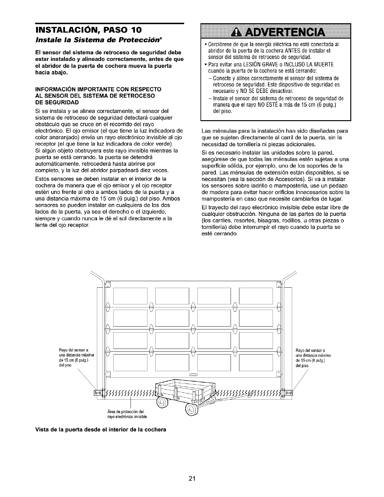
INSTALACION, PASO 10
Instale la Sistema de Proteccibn _
El sensor del sistema de retroceso de seguridad debe
estar instalado y alineado correctamente, antes de que
el abridor de la puerta de cochera mueva la puerta
hacia abajo.
INFORMACI(_N IMPORTANTE CON RESPECTO
AL SENSOR DEL SISTEMA DE RETROCESO
DE SEGURIDAD
Si se instala y se alinea correctamente, el sensor del
sistema de retroceso de seguridad detectar_ cualquier
obst_culo que se cruce en el recorrido del rayo
electr6nico. El ojo emisor (el que tiene la luz indicadora de
color anaranjado) envia un rayo electr6nico invisible al ojo
receptor (el que tiene la luz indicadora de color verde).
Si alg{]n objeto obstruyera este rayo invisible mientras la
puerta se est_ cerrando, la puerta se detendr_
autom_ticamente, retroceder_ hasta abrirse por
completo, y la luz del abridor parpadear_ diez veces.
Estos sensores se deben instalar en el interior de la
cochera de manera que el ojo emisor y el ojo receptor
est6n uno frente al otro a ambos lados de la puerta y a
una distancia m_xima de 15 cm (6 pulg.) del piso. Ambos
sensores se pueden instalar en cualquiera de los dos
lados de la puerta, ya sea el derecho o el izquierdo,
siempre y cuando nunca le d6 el sol directamente a la
lente del ojo receptor.
•Oerci6resedequelaenergfael6ctricano est6conectadaal
abridordela puertade lacocheraANTESde instalarel
sensordelsistemaderetrocesode seguridad.
•ParaevitarunaLESIONGRAVEo INCLUSOLAMUERTE
cuandolapuertadelacocheraseest_cerrando:
- Conectey alfneecorrectamenteelsensordelsistemade
retrocesodeseguridad.Estedispositivodeseguridades
necesarioy NOSEDEBEdesactivar.
- Instaleel sensordelsistemaderetrocesodeseguridadde
maneraqueelrayoNOESTEa m_sde 15cm (6pulg.)
delpiso,
Las m6nsulas para la instalaci6n han sido diseSadas para
que se sujeten directamente al carril de la puerta, sin la
necesidad de tornilleria ni piezas adicionales.
Si es necesario instalar las unidades sobre la pared,
aseg{]rese de que todas las m6nsulas est6n sujetas a una
superficie s61ida, por ejemplo, uno de los soportes de la
pared. Las m6nsulas de extensi6n est_n disponibles, si se
necesitan (vea la secci6n de Accesorios). Siva a instalar
los sensores sobre ladrillo o mamposteria, use un pedazo
de madera para evitar hacer orificios innecesarios sobre la
mamposteria en caso que necesite cambiados de lugar.
El trayecto del rayo elecr6nico invisible debe estar libre de
cualquier obstrucci6n. Ninguna de las partes de la puerta
(los carriles, resortes, bisagras, rodillos, u otras piezas o
tornilleria) debe interrumpir el rayo cuando la puerta se
est6 cerrando.
Rayo del sensor a
una distanciam_xima
de 15cm (6 pulg.)
del piso
Rayo de_sensor a
una distanciam_xima
de 15 cm (6 putg)
del piso
Area de protecci6ndel
rayoelectr6nico invisible
Vista de la puerta desde el interior de la cochera
21
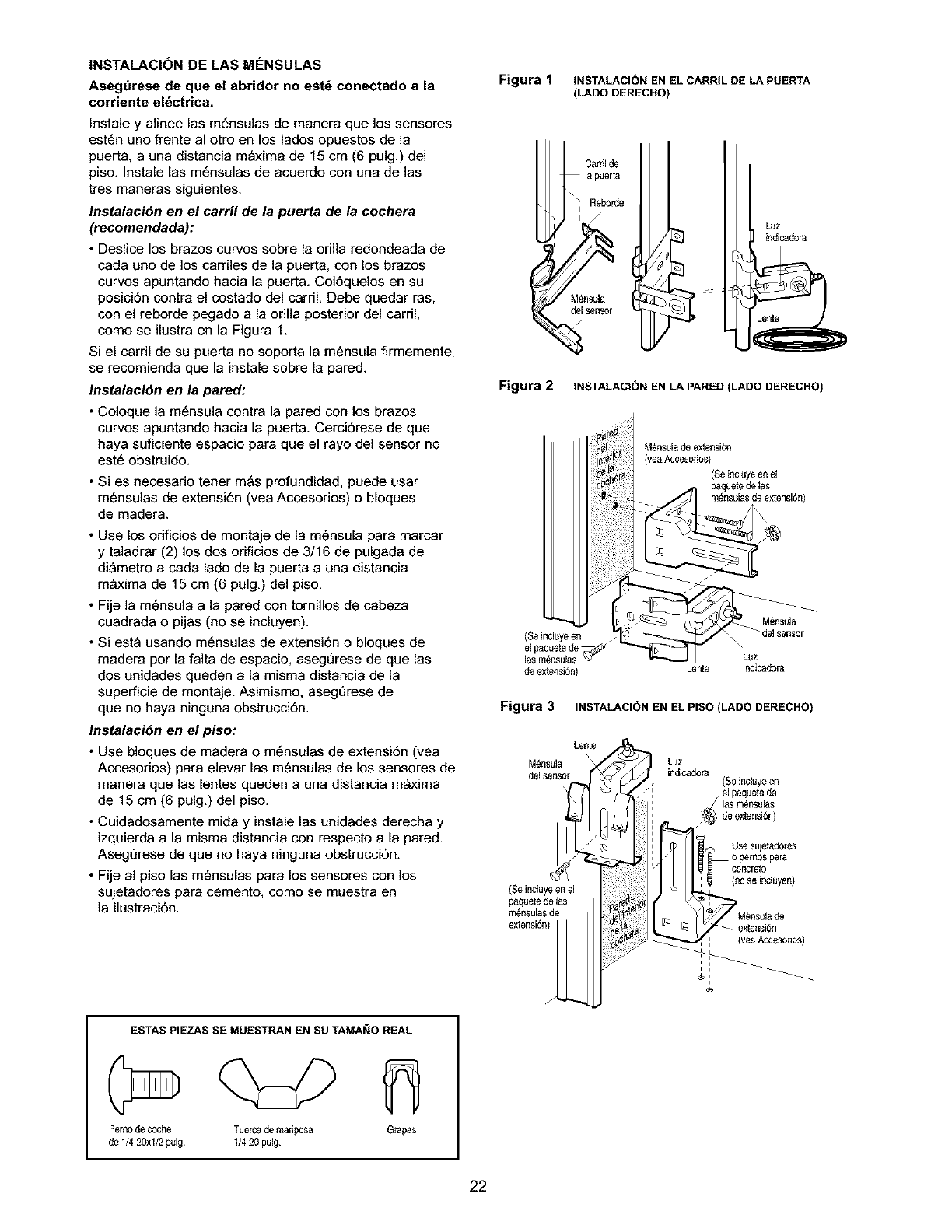
INSTALACI6N DE LAS MF:NSULAS
Aseg_rese de que el abridor no est6 conectado a la
corriente el6ctrica.
Instale y alinee las m6nsulas de manera que los sensores
est6n uno frente al otro en los lados opuestos de la
puerta, a una distancia m_xima de 15 cm (6 pulg.) del
piso. Instale las m6nsulas de acuerdo con una de las
tres maneras siguientes.
Instalaci6n en el carril de la puerta de la cochera
(recomendada) :
• Deslice los brazos curvos sobre la orilia redondeada de
cada uno de los carriles de la puerta, con los brazos
curvos apuntando hacia la puerta. Col6quelos en su
posici6n contra el costado del carriL Debe quedar ras,
con el reborde pegado a la orilla posterior del carril,
como se ilustra en la Figura 1.
Si el carril de su puerta no soporta la m6nsula firmemente,
se recomienda que la instale sobre la pared.
Instalaci6n en la pared:
• Coloque la m6nsula contra la pared con los brazos
curvos apuntando hacia la puerta. Cerci6rese de que
haya suficiente espacio para que el rayo del sensor no
est6 obstruido.
• Si es necesario tener m_s profundidad, puede usar
m6nsulas de extensi6n (vea Accesorios) o bloques
de madera.
• Use los orificios de montaje de la m6nsula para marcar
y taladrar (2) los dos orificios de 3/16 de pulgada de
di_metro a cada lado de la puerta a una distancia
m_xima de 15 cm (6 pulg.) del piso.
• Fije ]a m6nsula a la pared con tornillos de cabeza
cuadrada o pijas (no se incluyen).
• Si est_ usando m6nsulas de extensi6n o bloques de
madera por la falta de espacio, asegerese de que las
dos unidades queden a la misma distancia de la
superficie de montaje. Asimismo, aseg6rese de
que no haya ninguna obstrucci6n.
Instalaci6n en el piso:
• Use bioques de madera o m6nsulas de extensi6n (vea
Accesorios) para elevar las m6nsulas de los sensores de
manera que las lentes queden a una distancia m_xima
de 15 cm (6 pulg.) del piso.
• Cuidadosamente mida y instale las unidades derecha y
izquierda a la misma distancia con respecto a la pared.
Aseg6rese de que no haya ninguna obstrucci6n.
• Fije al piso las m6nsulas para los sensores con los
sujetadores para cemento, como se muestra en
]a ilustraci6n.
ESTAS PIEZAS SE MUESTRAN EN SU TAMANO REAL
Pern0de c0che Tuercade mdep0sa G_apas
de 1/4-20xl/2 pulg. 1/4-20 pulg.
Figura 1 INSTALACION EN EL CARRIL DE LA PUERTA
(LADO DERECHO)
Carrilde
la puerta
\_ Rebor_
Mdesula
del sen._r
Luz
indicadora
Figura 2 INSTALACI(_N EN LA PARED (LADO DERECHO)
M_nsulade extensidn
(yeaAcce_odes)
(Se incluyeen et
dequete de tas
m_nsulasde extensi6n)
Mensula
(Se incluyeen
el padeetede_._" \
lasmdesulas LUz
deextensi6n) Lente indicadora
Figura 3 INSTALACI(_N EN EL PISO (LADO DERECHO)
Lente
Mdesula
del sensor
(Se inc_uyeen el
padeetec_elas
mdesulasde
extensi6n)
J
Luz
indicadera (Seincluyeen
_' el padeetede
las mdesulas
deextenside)
i_ USe SUiet_d0'eS
0pemospara
concret0
[g (nose incluyen)
M_nsuiade
extenside
7 (veaAccesodes)
, i
i ,
22
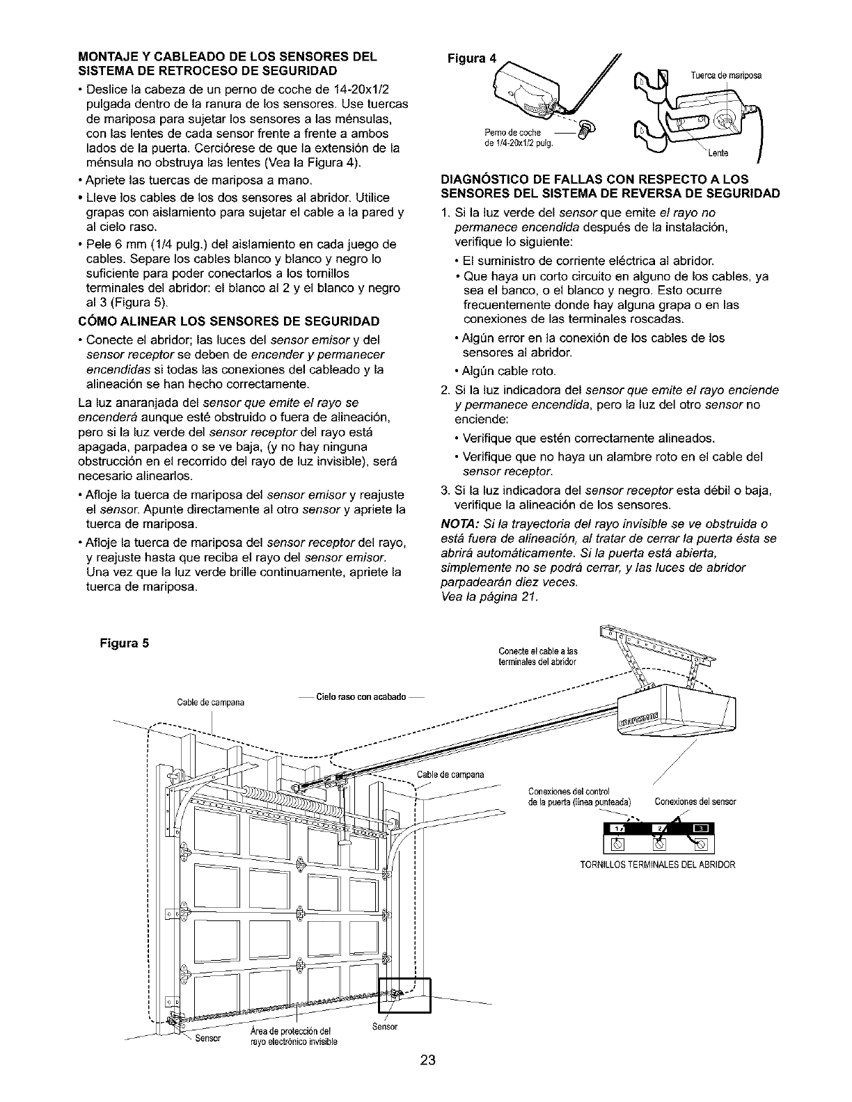
MONTAJE Y CABLEADO DE LOS SENSORES DEL
SISTEMA DE RETROCESO DE SEGURIDAD
• Deslice la cabeza de un perno de coche de 14-20xl/2
pulgada dentro de la ranura de los sensores. Use tuercas
de mariposa para sujetar los sensores alas m6nsulas,
con las lentes de cada sensor frente a frente a ambos
lados de la puerta. Cerci6rese de que la extensi6n de la
m6nsula no obstruya las lentes (Vea la Figura 4).
• Apriete las tuercas de mariposa a mano.
•Lleve los cables de los dos sensores al abridor. Utilice
grapas con aislamiento para sujetar el cable a la pared y
al cielo raso.
• Pele 6 mm (1/4 pulg.) del aislamiento en cada juego de
cables. Separe los cables blanco y blanco y negro Io
suficiente para poder conectados a los tornillos
terminales del abridor: el blanco al 2 y el blanco y negro
al 3 (Figura 5).
C_MO AMNEAR LOS SENSORES DE SEGURIDAD
• Conecte el abridor; las luces del sensor emisor y del
sensor receptor se deben de encender y permanecer
encendidas si todas las conexiones del cableado y la
alineaci6n se han hecho correctamente.
La luz anaranjada del sensor que emite el rayo se
encender& aunque est6 obstruido o fuera de alineaci6n.
pero si la luz verde del sensor receptor del rayo est_
apagada, parpadea o se ve baja, (y no hay ninguna
obstrucci6n en el recorrido del rayo de luz invisible), ser_
necesario alineados.
• Afloje la tuerca de mariposa del sensor emisor y reajuste
el sensoE Apunte directamente al otro sensor y apriete la
tuerca de mariposa.
• Afloje la tuerca de mariposa del sensor receptor del rayo,
y reajuste hasta que reciba el rayo del sensor emisor.
Una vez que la luz verde brille continuamente, apriete la
tuerca de mariposa.
Figura 4
Pemode ccche "_'
de I/4-20xl/2 puig.
DIAGN_STICO DE FALLAS CON RESPECTO A LOS
SENSORES DEL SISTEMA DE REVERSA DE SEGURIDAD
Si la luz verde del sensor que emite e/rayo no
permanece encendida despu6s de la instalaci6n.
verifique Io siguiente:
•El suministro de corriente el6ctrica al abridor.
• Que haya un corto circuito en alguno de los cables, ya
sea el banco, o el bianco y negro. Esto ocurre
frecuentemente donde hay alguna grapa o en las
conexiones de las terminales roscadas.
• AIgDn error en la conexi6n de los cables de los
sensores al abridoE
2.
• AIgDn cable roto.
Si ]a luz indicadora del sensor que emite el rayo enciende
y permanece encendida, pero la luz del otro sensor no
enciende:
• Veriflque que est6n correctamente alineados.
• Veriflque que no haya un alambre roto en el cable del
sensor receptor.
3. Si la luz indicadora del sensor receptor esta d6bil o baja,
verifique la alineaci6n de los sensores.
NOTA: Si la trayectoria del rayo invisible se ve obstruida o
est& fuera de alineaci6n, al tratar de cerrar la puerta 6sta se
abrir& autom&ticamente. Si la puerta est& abierta,
simplemente no se podr& cerrar, y las luces de abridor
parpadear&n diez veces.
Vea la p&gina 21.
Figura 5 Conecteel cablea _as
terminales del abridor
Cablede campana
Sen_
Cielo raso con acabado
Cablede campana
/
/
/
Conexionesdel control
de la pueda (lineapiJnteada) Conexionesdel sensor
TORNILLOSTERMINALESDELABRIDOR
,_,reade protecci6ndel Sensor
rayoelectr6nico invisible
23

INSTALACION, PASO 11
Fije la Mdnsula de la Puerta
Siga las instrucciones que correspondan al tipo de puerta
de cochera que usted tenga, como se muestra en la
ilustraci6n o en la p_gina siguiente.
Si usa un puntal horizontal, _ste debe de ser Io
suficientemente largo para sujetarlo a dos soportes
verticales. Si usa un puntal vertical, _ste debe de ser
de la altura del panel superior.
La ilustraci6n muestra una pieza de hierro en _ngulo como
puntal horizontal. Para el puntal vertical se deben usar dos
piezas de hierro en _ngulo con objeto de crear un soporte
en "U" (Figura 1). La mejor soluci6n es ponerse en
contacto con la compaSia fabricante de la puerta de su
cochera e informarse acerca de los juegos de refuerzos de
puertas para la instalaci6n de un abridor.
NOTA: Muchas de las instalaciones con soporte o
puntal vertical toman en cuenta la instalaciSn directa de
los pasadores de chaveta y el brazo de la puerta. En este
case, no necesitar& instalar la m_nsula para la puerta;
proceda al Paso 12.
PUERTASSECCIONALES
•Coloque la m6nsula para la puerta sobre la linea
central vertical que habia marcado previamente para
la instalaci6n de la m6nsula del cabezaL Aseg6rese
de que la leyenda "UP" (arriba) est6 en la posici6n
correcta, como est_ indicado en la parte interior de
la m6nsula (Figura 2).
• Coloque la m6nsula sobre la parte frontal de la puerta,
dentro de los limites siguientes:
A) El borde superior de la m6nsula 5-10 cm (2-4 pulg.)
debajo del borde superior de la puerta.
Paraevitar que la puerta de la cochera se daSe, refuerceel
interior de la puerta con _ngulos de hierro tanto vertical como
horizontalmente.
ESTAS PIEZAS SE MUESTRAN EN SU TAMAIqO REAL
Pemo de cochede
5/16-18pot 2-1/2pulgada
B) La orilla superior de la m6nsula debe de estar
directamente debajo de alg0n soporte de la
estructura a Io largo de la parte superior de la puerta.
• Marque y taladre dos orificios de 5/16 de pulg para los
sujetadores a la derecha y a la izquierda. Sujete la
m6nsula al refuerzo vertical (si 6ste existe), como se
muestra en la Figura 1.
Si el tipo de instalaci6n de su cochera no requiere refuerzos
verticales, pero si necesita los orificios para los sujetadores
de la m6nsula, taladre y fijelos como se muestra
en la Figura 2.
Si supue_ es de metal,abminio,
panelesde vidrio,
Figura 1
ura 2
24
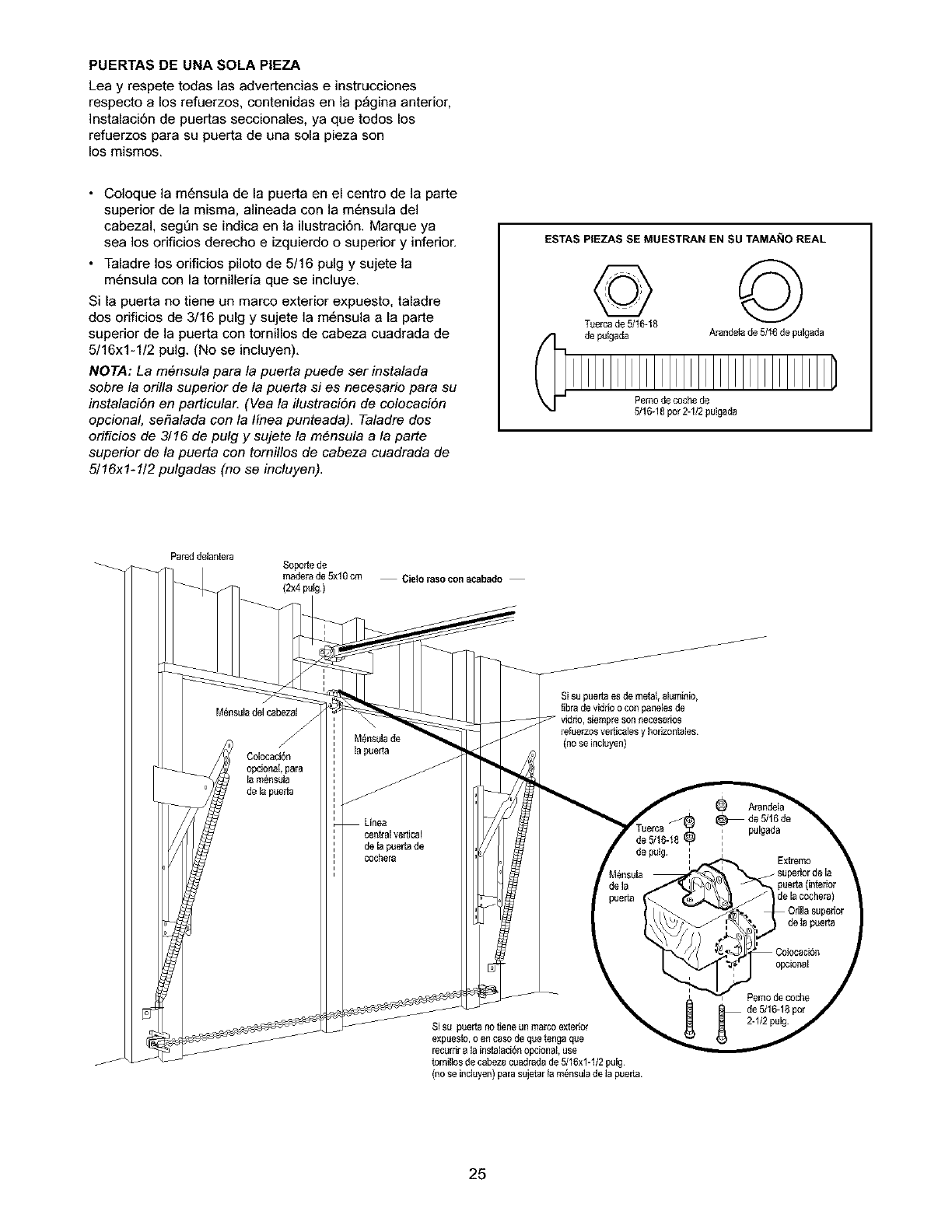
PUERTAS DE UNA SOLA PIEZA
Lea y respete todas las advertencias e instrucciones
respecto a los refuerzos, contenidas en la p_gina anterior,
]nstalaci6n de puertas seccionales, ya que todos los
refuerzos para su puerta de una sola pieza son
los mismos.
•Coloque la m6nsula de la puerta en el centro de la parte
superior de la misma, alineada con la m6nsula del
cabezal, segt'in se indica en la ilustraci6n. Marque ya
sea los orificios derecho e izquierdo o superior y inferior.
• Taladre los orificios piloto de 5/16 pulg y sujete la
m6nsula con la tornilleria que se incluye.
Si la puerta no tiene un marco exterior expuesto, taladre
dos orificios de 3/16 pulg y sujete la m6nsula a la parte
superior de la puerta con tornillos de cabeza cuadrada de
5/16x1-1/2 pulg. (No se incluyen).
NOTA: La m6nsula para la puerta puede ser instalada
sobre la orilla superior de la puerta si es necesario para su
instalaciSn en particular. (Vea la ilustraciSn de colocaciSn
opcional, seflalada con la linea punteada). Taladre dos
orificios de 3/16 de pulg y sujete la m6nsula a la parte
superior de la puerta con tornillos de cabeza cuadrada de
5/16x1-1/2 pulgadas (no se incluyen).
ESTAS PIEZAS SE MUESTRAN EN SU TAMA_IO REAL
T@8©
de puSgada Arandela de 5/16de pulgada
Pemo de coche de
5/16-18por 2-1/2 pulgada
Pared delantera Sopor_ede
maderade 5xl 0 cm
(2x4 puig) Cieloraso con acabado
Sisu puerta es de metal, alumioio,
librade vidrio o con panelesde
vidrio, siempreson necesarios
refuerzosvertic_lesy hedzontaJes
(no se incluyen)
Si su puerta no tiene un marco exterior
expuesto, o en ca.so de qL_etenga que
recL_rrir ala iostalaci_ opcional, use
tomilios de cabeza cuadrada de 5/16x1-1/2 pulg
(no se iocluyen) para sujetar in _sula de la pueda
25
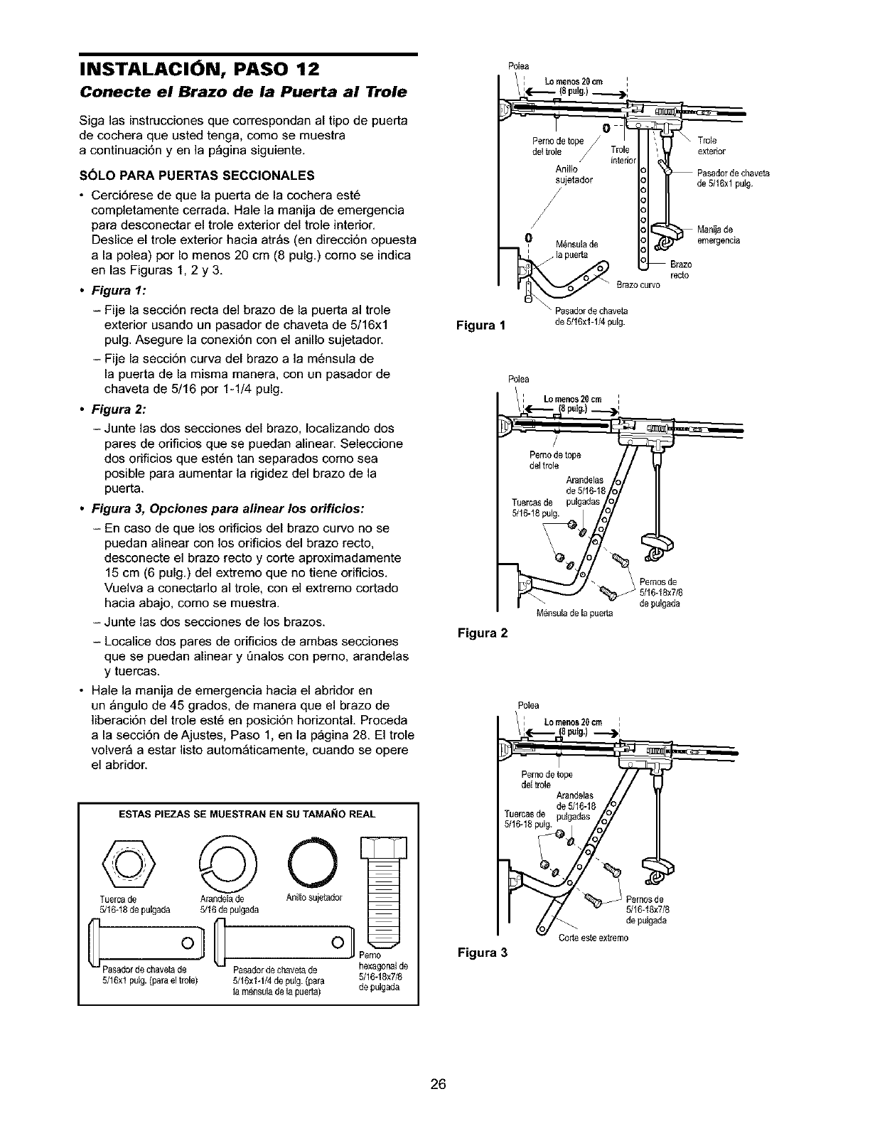
INSTALACI6N, PASO 12
Conecte el Brazo de la Puerta al Trole
Siga las instrucciones que correspondan al tipo de puerta
de cochera que usted tenga, como se muestra
a continuaci6n y en la p_gina siguiente.
SOLO PARA PUERTAS SECCIONALES
•Cerci6rese de que la puerta de la cochera est6
completamente cerrada. Hale la manija de emergencia
para desconectar el trole exterior del trole interior.
Deslice el trole exterior hacia atr_s (en direcci6n opuesta
a la polea) por Io menos 20 cm (8 pulg.) como se indica
en las Figuras 1, 2 y 3.
•Figura 1:
-Fije la secci6n recta del brazo de la puerta al trole
exterior usando un pasador de chaveta de 5/16xl
pulg. Asegure la conexi6n con el anillo sujetador.
- Fije la secci6n curva del brazo a la m6nsula de
la puerta de la misma manera, con un pasador de
chaveta de 5/16 por 1-1/4 pulg.
•Figura 2:
- Junte las dos secciones del brazo, Iocalizando dos
pares de orificios que se puedan alinear. Seleccione
dos orificios que est6n tan separados como sea
posibie para aumentar la rigidez del brazo de la
puerta.
•Figura 3, Opciones para alinear los orificios:
-En caso de que los onficios del brazo curvo no se
puedan alinear con los orificios del brazo recto,
desconecte el brazo recto y corte aproximadamente
15 cm (6 pulg.) del extremo que no tiene orificios.
Vuelva a conectarlo al trole, con el extremo cortado
hacia abajo, como se muestra.
- Junte las dos secciones de los brazos.
- Localice dos pares de orificios de ambas secciones
que se puedan alinear y Qnalos con perno, arandelas
y tuercas.
•Hale la manija de emergencia hacia el abridor en
un _ngulo de 45 grados, de manera que el brazo de
]iberaci6n del trole est6 en posici6n horizontal. Proceda
a la secci6n de Ajustes, Paso 1, en la p_gina 28. El trole
volver_ a estar listo autom_ticamente, cuando se opere
el abridor.
ESTAS PIEZAS SE MUESTRAN EN SU TAMANO REAL
©
Ty0 #+%p°,00 o An,l,0s0j0,oder
Pasaderdechaveta de Pasaderde chaveta de hexagonalde
5/16xl puN. (parael trole) 5/16xlq/4 de pulg. (para 5/16-18x7/8
ta rndesula de la pueda) de pulgada
Poba
:Lomenos20 cm :
/_,_._, (8petg)___.):
Pernode tope Trole
do,ro,o #:o
Anillo Pasade dechaveta
sujetador de 5/16xl pelg.
, M_nsula de emergencla
Brazo curvo recto
\ Pasadorde chaveta
Figura 1 de 5/16x1-1/4pulg.
Polea
Lo men0s 20 cm
spu+g)__):
Pemo de tope
del trob
Arai_delas
de 5/16-18
Tuercasde pulgadas
5/16-18pelg.
Figura 2
Mensulade la puer[a
Pemos de
5/16-18x7/8
de pelgada
Polea
Lomenos20cm
petg)---)I
Pemo de tope
de+trole
Arandelas
de 5/16-18
Tuercasde
5/16-18putg. =
i
i
Figura 3
5/16-18x7/8
de pulgada
Code esteextremo
26
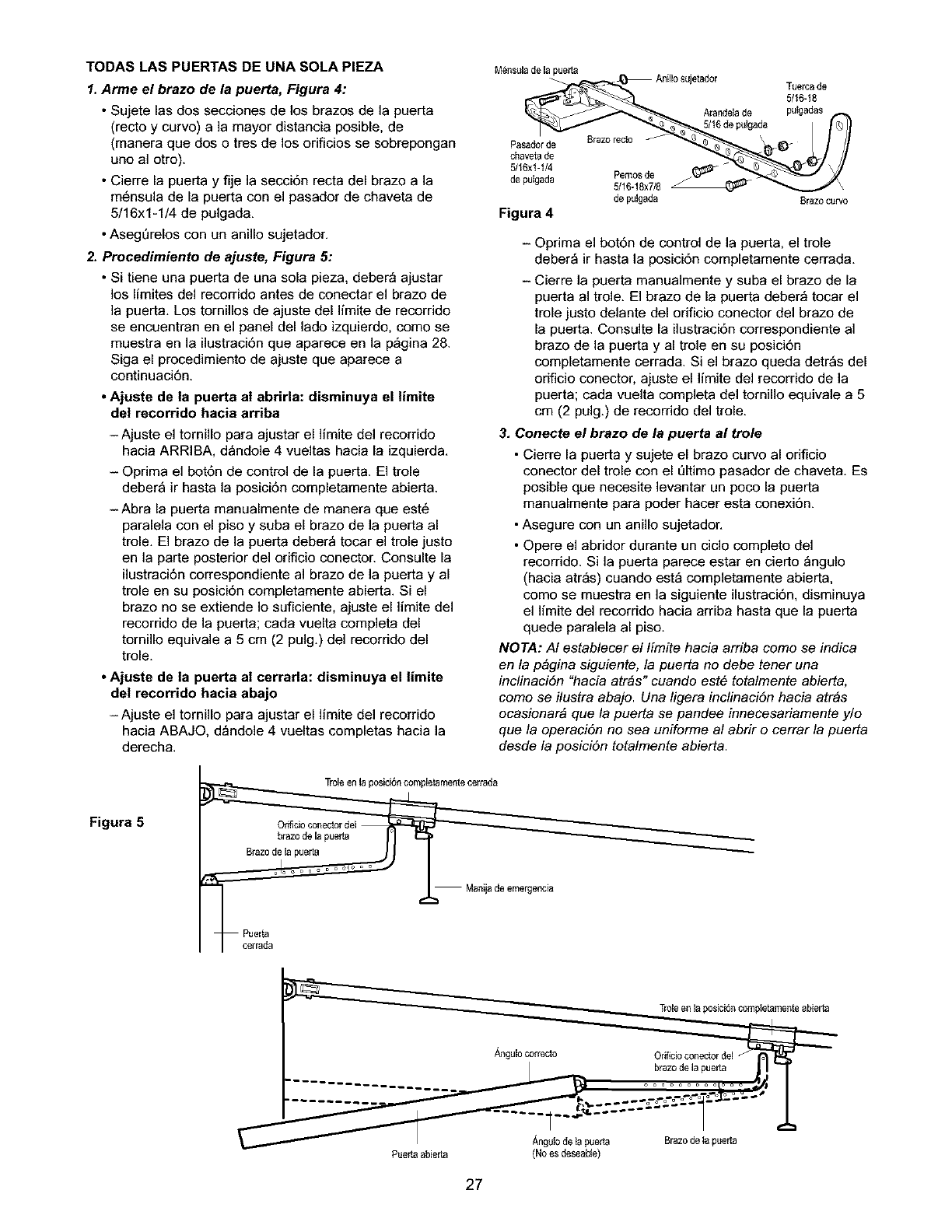
TODAS LAS PUERTAS DE UNA SOLA PIEZA
1. Arme el brazo de la puerta, Figura 4:
•Sujete las dos secdones de los brazos de la puerta
(recto y curvo) a la mayor distanda posible, de
(manera que dos o tres de los orifidos se sobrepongan
uno al otro).
• Cierre la puerta y fije la secd6n recta del brazo a la
m6nsula de la puerta con el pasador de chaveta de
5/16x1-1/4 de pulgada.
• AsegDrelos con un anillo sujetador.
2. Procedimiento de ajuste, Figura 5:
• Si tiene una puerta de una sola pieza, deber_ ajustar
los limites del recorrido antes de conectar el brazo de
la puerta. Los tornillos de ajuste del limite de recorrido
se encuentran en el panel del lado izquierdo, como se
muestra en la ilustrad6n que aparece en la p_gina 28.
Siga el procedimiento de ajuste que aparece a
continuaci6n.
•Ajuste de la puerta a! abrirla: disminuya el |imite
de! recorrido hacia arriba
-Ajuste el tornillo para ajustar el limite del recorrido
hada ARRIBA, d_ndole 4 vueltas hada la izquierda.
- Oprima el bot6n de control de la puerta. El trole
deber_ ir hasta la posid6n completamente abierta.
-Abra la puerta manualmente de manera que est6
paralela con el piso y suba el brazo de la puerta al
trole. El brazo de la puerta deber_ tocar el trole justo
en la parte posterior del orificio conectoE Consulte la
ilustrad6n correspondiente al brazo de la puerta y al
trole en su posid6n completamente abierta. Si el
brazo no se extiende Io sufidente, ajuste el limite del
recorndo de la puerta; cada vuelta completa del
tornillo equivale a 5 cm (2 pulg.) del recorrido del
trole.
•Ajuste de la puerta at cerrarla: disminuya el limite
del recorrido hacia abajo
-Ajuste el tornillo para ajustar el limite del recorrido
hacia ABAJO. d_ndole 4 vueltas completas hacia la
derecha.
Mensulade la puer[a
Pasadorde
chaveta de
5/16xI-I/4
de pulgada
Figura 4
Pemo$ de
5/16-18x7/8 \
de pulgada Brazo curvo
- Oprima el bot6n de control de la puerta, el trole
deber_ ir hasta la posici6n completamente cerrada.
- Cierre la puerta manualmente y suba el brazo de la
puerta al trole. El brazo de la puerta deber_ tocar el
trole justo delante del orificio conector del brazo de
la puerta. Consulte la ilustraci6n correspondiente al
brazo de la puerta y al trole en su posiciSn
completamente cerrada. Si el brazo queda detr_s del
oriflcio conector, ajuste el limite del recorrido de la
puerta; cada vuelta completa del tornillo equivale a 5
cm (2 pulg.) de recorrido del trole.
3. Conecte el brazo de la puerta al trole
• Cierre la puerta y sujete el brazo curvo al orificio
conector del trole con el Qltimo pasador de chaveta, Es
posible que necesite levantar un poco la puerta
manualmente para poder hacer esta conexiSn.
• Asegure con un anillo sujetador.
• Opere el abridor durante un ciclo completo del
recorrido. Si la puerta parece estar en cierto _ngulo
(hacia atr_s) cuando est_ completamente abierta,
como se muestra en la siguiente ilustraci6n, disminuya
el limite del recorrido hacia arriba hasta que la puerta
quede paralela al piso.
NOTA: AI establecer el limite hacia arriba como se indica
en la p&gina siguiente, la puerta no debe tener una
inclinaciSn "hacia arras" cuando este totalmente abierta,
como se ilustra abajo. Una ligera inclinaciSn hacia arras
ocasionar& que la puerta se pandee innecesariamente y/o
que la operaciSn no sea uniforme al abrir o cerrar la puerta
desde la posiciSn totalmente abierta.
Figura 5
Troieen la posici6n compietamentecerrada
Onficioconector del
brazo de la pueda
_Brazo de la pue_
Manija de emergencia
Puer_a
Troleen la posici6n completamenteablerta
A_guloco,recto Or_ficioconector del
brazode la puerta
.................. oooooo oooooomils
Angut0de ta puerta Brazo de ta puerta
Puetta abieda (Noes deseab{e)
27
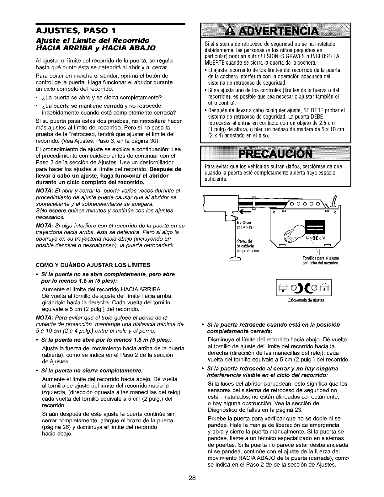
AJUSTES, PASO 1
Ajuste el Limite del Recorrido
HACIA ARRIBA y HACIA ABAJO
AI ajustar el limite del recorrido de la puerta, se regula
hasta qu6 punto 6sta se detendr_ al abrir y al cerrar.
Para porter en marcha el abridor, oprima el bot6n de
control de la puerta. Haga funcionar el abridor durante
un ciclo competo del recorrido.
•&La puerta se abre y se cierra completamente?
•&La puerta se mantiene cerrada y no retrocede
indebidamente cuando est_ completamente cerrada?
Si su puerta pasa estas dos pruebas, no necesitar_ hacer
m_s ajustes al limite del recorrido. Pero si no pasa la
prueba de la "retroceso, tendr_ que ajustar el limite del
recorrido. (Vea Ajustes, Paso 3, en la p_gina 30).
El procedimiento de ajuste se explica a continuaci6n: Lea
el procedimiento con cuidado antes de continuar con el
Paso 2 de la secci6n de Ajustes. Use un destomillador
para hacer los ajustes al limite del recorrido. Despu6s de
Ilevar a eabo un ajuste, haga funeionar el abridor
durante un ciclo completo del recorrido.
NOTA: El abrir ycerrar /a puerta varias veces duranle e/
procedimiento de ajuste puede causar que el abridor se
sobrecaliente y al sobrecalentarse se apagar4.
$51o espere quince minutos y continQe con los ajustes
necesarios.
NOTA: Si algo interfiere con el recorrido de la puerta en su
trayectoria hacia arriba, 6sta se detendr4. Pero si algo la
obstruye en su trayectoria hacia abajo (incluyendo un
posible desnivel o desbalanceo), la puerta retroceder4.
C6MO YCUANDO AJUSTAR LOS L|MITES
•Si la puerta no se abre completamente, pero abre
por Io menos 1.5 m (5 pies):
Aumente el limite del recorrido HACIA ARRIBA.
D6 vuelta al tornillo de ajuste del limite hacia arriba,
gir_ndolo hacia la derecha. Cada vuelta del tornillo
equivale a 5 cm (2 pulg.) del recorrido.
NOTA: Para evitar que el trole golpee el perno de la
cubierta de protecciSn, mantenga una distancia minima de
5 a 10 cm (2 a 4 pulg.) entre el trole y el perno.
•Si la puerta no abre por Io menos 1.5 m (5 pies):
Ajuste la fuerza del movimiento hacia arriba de la puerta
(abierta), como se indica en el Paso 2 de la secci6n
de Ajustes.
•Si la puerta no cierra completamente:
Aumente el ]imite del recorrido hacia abajo. D6 vuelta
al tornillo de ajuste del limite del recorrido hacia la
izquierda, (direcci6n opuesta a las manecillas del reloj);
cada vuelta del tornillo equivale a 5 cm (2 pulg.) del
recorrido.
Si at]n despu6s de este ajuste la puerta contin6a sin
cerrar completamente, alargue el brazo de la puerta
(p_gina 26) y disminuya el limite del recorrido
hacia abajo.
Si el sistema de retroceso de seguridad no se ha instalado
debidamente, las personas (y los niSos pequefios en
particular) podrian sufrir LESlONESGRAVESo INCLUSOLA
MUERTEcuando se cierra la puerta de la cochera.
•El ajuste incorrecto de los Ifmites del recorrido de la puerta
de la cochera interferir_ con la operaci6n adecuadadel
sistema de retroceso de seguridad.
•Si se ajusta uno de los controles (limites de la fuerza o del
recorrido), es posible que seanecesario ajustar tambi_n el
otro control.
•Despuds de Ilevar a cabo cualquier ajuste, SE DEBEprobar el
sistema de retroceso de seguridad. La puerta DEBE
retroceder al entrar en contacto con un objeto de 2.5 cm
(1 pulg) de altura, o bien un pedazode madera de 5 x 10 cm
(2 x 4) acostado en el piso.
Paraevitarquelos vehiculossufrandafios,cerci6resedeque
cuandola puertaestdcompletamenteabiertahayaespacio
suficiente.
Tomiilospara el ajuste
del limite del recorrido
Catcomaniade ajustes
Si la puerta retrocede cuando est_ en la posici6n
completamente cerrada:
Disminuya el limite del recorrido hacia abajo, D6 vuelta
al tornillo de ajuste del limite del recorrido hacia la
derecha (direcci6n de las manecillas del reloj); cada
vuelta del tornillo equivale a 5 cm (2 pulg,) del recorrido.
Si la puerta retrocede al cerrar y no hay ninguna
interferencia visible en el ciclo del recorrido:
Si la luces del abridor parpadean, esto significa que los
sensores del sistema de retroceso de seguridad no
est_n instalados, no est_n alineados correctamente,
o hay alguna obstrucci6n. Vea la secci6n de
Diagn6stico de fallas en la p_gina 23.
Pruebe la puerta para verificar que no se doble ni se
pandee. Hale la manija de liberaci6n de emergencia,
y abra y cierre la puerta manualmente. Si la puerta se
pandea, Ilame a un t6cnico especializado en sistemas
de puertas. Si la puerta no parece estar desbalanceada
ni se pandea, continQe con el ajuste de la fuerza del
movimiento HAClAABAJO de la puerta (cerrada), como
se indica en el Paso 2 de de la secci6n de Ajustes.
28
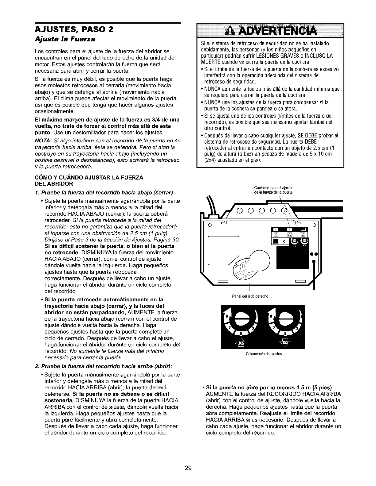
AJUSTES, PASO 2
Ajuste la Fuerza
Los controles para el ajuste de la fuerza del abridor se
encuentran en el panel del lado derecho de la unidad del
motor. Estos ajustes controlar_n la fuerza que ser_
necesaria para abrir y cerrar la puerta.
Si la fuerza es muy d6bil, es posible que la puerta haga
esos molestos retrocesos al cerrada (movimiento hacia
abajo) y que se detenga al abrida (movimiento hacia
arriba). El clima puede afectar el movimiento de la puerta,
asi que es posible que tenga que hacer algunos ajustes
ocasionalmente.
El mbximo margen de ajuste de la fuerza es 3/4 de una
vuelta, no trate de forzar el control mbs all_ de este
punto. Use un destornillador para hacer los ajustes,
NOTA: Si a/go interfiere con e/recorrido de la puerta en su
trayectoria hacia arriba, esta se detendr& Pero si algo la
obstruye en su trayectoria hacia abajo (incluyendo un
posible desnivel o desbalanceo), esto activar& la retroceso
y la puerta retroceder&
COMO YCUANDO AJUSTAR LA FUERZA
DEL ABRIDOR
1. Pruebe la fuerza del recorrido hacia abajo (cerrar)
•Sujete la puerta manualmente agarr_ndola por la parte
inferior y det6ngala m_s o menos a la mitad del
recorrido HAClAABAJO (cerrar); la puerta deber_
retroceder. Si la puerta retrocede a la mitad del
recorrido, esto no garantiza que la puerta retroceder_
al toparse con una obstrucciSn de 2.5 cm (1 pulg).
Dirijase al Paso 3 de la secci6n de Ajustes, Pagina 30.
Si es dificil sostener la puerta, o bien si la puerta
no retrocede, DISMINUYA la fuerza del movimiento
HACIAABAJO (cerrar), con el control de ajuste
d_ndole vuelta hacia la izquierda. Haga pequeSos
ajustes hasta que la puerta retroceda
correctamente. Despu6s de Ilevar a cabo un ajuste,
haga funcionar el abridor durante un ciclo completo
del recorrido.
•Si la puerta retrocede autombticamente en la
trayectoria hacia abajo (cerrar), y la luces del
abridor no estbn parpadeando, AUMENTE la fuerza
de la trayectoria hacia abajo (cerrar) con el control de
ajuste d_ndole vuelta hacia la derecha. Haga
pequeSos ajustes hasta que la puerta complete un
ciclo de cerrado. Despu6s de Ilevar a cabo el ajuste,
haga funcionar el abridor durante un ciclo completo del
recorrido. No aumente la fuerza robs del minimo
necesario para cerrar la puerta
2. Pruebe la fuerza del recorrido hacia arriba (abrir):
• Sujete la puerta manualmente agarr_ndola por la parte
inferior y det6ngala m_s o menos a la mitad del
recorrido HAClAARRIBA (abrir); la puerta deber_
detenerse. Si la puerta no se detiene o es dificil
sostenerla, DISMINUYA la fuerza de la puerta HACIA
ARRIBA con el control de ajuste, d_ndole vuelta hacia
la izquierda. Haga pequeSos ajustes hasta que la
puerta pare fbcilmente y abra completamente.
Despu6s de Ilevar a cabo cada ajuste, haga funcionar
el abridor durante un ciclo completo del recorrido.
Si el sisterna de retroceso de seguridad no se ha instalado
debidarnente, las personas (y los nifios pequeSosen
particular) podrian sufrir LESl0NES GRAVESo INCLUS0 LA
MUERTEcuando se cierra la puerta de la cochera.
• Si el lirnite de la fuerza de la puerta de la cochera es excesivo
interferir_ con la operaci6n adecuadadel sisterna de
retroceso de seguridad.
• NUNCAaurnente la fuerza rn_s all_ de la cantidad minima que
se requiera para cerrar la puerta de la cochera.
• NUNCAuse los ajustes de la fuerza para cornpensar si la
puerta de la cochera se pandea o se atora.
• Si se ajusta uno de los controles (lirnites de la fuerza o del
recorrido), es posible que sea necesario ajustar tarnbi_n el
otro control.
• Despu_s de Ilevar a cabo cualquier ajuste, SE DEBEprobar el
sisterna de retroceso de seguridad. La puerta DEBE
retroceder al entrar en contacto con un objeto de 2.5 crn (1
pulg) dealtura (o bien un pedazo de rnaderade 5 x 10 crn
(2x4) acostado en el piso.
Controlespara el ajuste
de Ia fuerzade la puerla
Paneldel ladoderecho
CaIcomsni8 de ajustes
• Si la puerta no abre por Io menos 1.5 m (5 pies),
AUMENTE la fuerza del RECORRIDO HACIAARRIBA
(abrir) con el control de ajuste, d_ndole vuelta hacia la
derecha. Haga pequeSos ajustes hasta que la puerta
abra completamente. Reajuste el limite del recorrido
HACIAARRIBA si es necesario. Despu6s de Ilevar a
cabo cada ajuste, haga funcionar el abridor durante un
ciclo completo del recorrido.
29
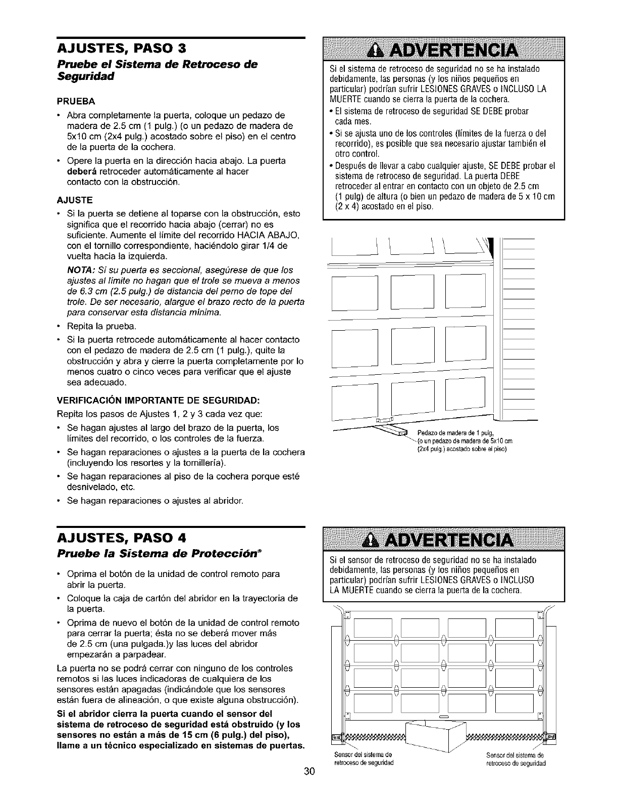
AJUSTES, PASO 3
Pruebe el Sistema de Retroceso de
Seguridad
PRUEBA
•Abra completamente la puerta, coloque un pedazo de
madera de 2.5 cm (1 pulg.) (o un pedazo de madera de
5x10 cm (2x4 pulg.) acostado sobre el piso) en el centro
de la puerta de la cochera.
• Opere la puerta en la direcci6n hacia abajo. La puerta
deber_ retroceder autom_ticamente al hacer
contacto con la obstrucci6n.
AJUSTE
• Si la puerta se detiene al toparse con la obstrucci6n, esto
significa que el recorrido hacia abajo (cerrar) no es
suficiente. Aumente el limite del recorrido HACIA ABAJO,
con el tornillo correspondiente, haci6ndolo girar 1/4 de
vuelta hacia la izquierda.
NOTA: Si su puerta es seccional, aseg#rese de que los
ajustes al limite no hagan que el trole se mueva a menos
de 6.3 cm (2.5 pulg.) de distancia del perno de tope del
trole. De ser necesario, alargue el brazo recto de la puerta
para conservar esta distancia minima.
• Repita la prueba.
• Si la puerta retrocede autom_ticamente al hacer contacto
con el pedazo de madera de 2.5 cm (1 pulg.), quite la
obstrucci6n y abra y cierre la puerta completamente par Io
menos cuatro o cinco veces para verificar que el ajuste
sea adecuado.
VERIFICACI(3N IMPORTANTE DE SEGURIDAD:
Repita los pasos de Ajustes 1, 2 y 3 cada vez que:
• Se hagan ajustes al largo del brazo de la puerta, los
limites del recorrido, o los controles de la fuerza
• Se hagan reparaciones o ajustes a la puerta de la cochera
(incluyendo los resortes y la tomilleria)
• Se hagan reparaciones al piso de la cochera porque est6
desnivelado, etc
• Se hagan reparaciones o ajustes al abridor
Si el sistema de retroceso de seguridad no se ha instalado
debidamente, las personas (y los niSos pequeSosen
particular) podrian sufrir LESlONESGRAVESe INCLUSOLA
MUERTEcuando se cierra la puerta de la cochera
• El sistema de retroceso de seguridad SE DEBEprobar
cada mes
• Si se ajusta uno de los controles (limites de la fuerza o del
recorrido), es posible que sea neeesarioajustar tambi_n el
otro control
• Despu6s de Ilevar a cabe cualquier ajuste, SE DEBEprobar el
sistema de retroceso de seguridad La puerta DEBE
retroceder al entrar en contacto con un objeto de 25 cm
(1 pulg) de altura (e bien un pedazode madera de 5 x 10 cm
(2 x 4) acostado en el piso
J
J
__ de maderade 1
22/2 xlo om
(2x4 pulg) acostadosobre el piso)
AJUSTES, PASO 4
Pruebe la Sistema de Proteccibn _
• Oprima el bot6n de la unidad de control remoto para
abrir la puerta
• Coloque ]a caja de cart6n del abridor en la trayectoria de
la puerta
• Oprima de nuevo el bot6n de la unidad de control remoto
para cerrar la puerta; 6sta no se deber_ mover m_s
de 25 cm (una pulgada )y las luces del abridor
empezar_n a parpadear
La puerta no se podr_ cerrar con ninguno de los controles
remotos si las luces indicadoras de cualquiera de los
sensores est_n apagadas (indic_ndole que los sensores
est_n fuera de alineaci6n, o que existe alguna obstrucci6n)
Si el abridor cierra la puerta cuando el sensor de!
sistema de retroceso de seguridad estb obstruido (y !os
sensores no estbn a mbs de 15 cm (6 pulg.) del piso),
Ilame a un t6cnico especializado en sistemas de puertas.
3O
Siel sensorderetrocesodeseguridadnose hainstalado
debidamente,las personas(y los ni_ospeque_osen
particular)poddansufrir LESlONESGRAVESe INCLUSO
LAMUERTEcuandose cierrala puertade lacochera
Sensor del sistemade
ret_ocesode segu_dad
Sensor del sistemade
_etrocesode seguddad
OPERACION
INSTRUCCIONES IMPORTANTES DE SEGURIDAD
Para reducir el riesgo de lesiones graves o la muerte:
1. LEA Y SIGATODAS LASADVERTENCIASY LAS
INSTRUCCIONESDE OPERACI6N.
2. SIEMPREconserve los controles remotos fuera del alcance
de los ni_os. NUNCApermita que los niSos operen o jueguen
con los botones del control de la puerta de la cochera ni con
los controles remotos.
3. S6LO active la puerta de la cochera siempre y cuando la
puedan ver con claridad, est6 debidamente ajustaday no haya
ninguna obstrucci6n en el recorrido de la puerta al cerrarse.
4. SIEMPREtenga la puerta dela cocheraa la vista hasta que estd
completamente cerrada.NADIEDEBEATRAVESAREL
RECORRIDODELA PUERTACUANDOEsTA ENMOVIMIENTO.
5. NADIE DEBEPASARPORDEBAJODELA PUERTASI EST/_
DETENIDAY PARCIALMENTEABIERTA.
6 De ser p0sible, use la liberaci6n de emergencia para s01tarel
trole SOLOcuando la puerta de la cochera estd CERRADA.Si
los resortes est_n d_biles o rotos, o bien si la puerta est_
desbalanceada,la puerta se caiga rdpida y/o inesperadamente
cuando est_ abierta.
7. NUNCAuse la manija de liberaci6n de ernergenciaa menos
que la entrada a la cochera eetd libre de obstrucciones y no
haya ninguna persona presente.
8. NUNCAusela manija parahalar la puerta paraabrida o
cerrada. Si el nudo de la cuerda se suelta, usted podria caerse.
9. Si se ajusta uno de los controles (limites de la fuerza o del
recorrido), es posible que sea necesario ajustar tambi_n el
otto control.
10. Despu_s de Ilevar a cabo cualquier ajuste, SE DEBEprobar
el sistema de retroceso de seguridad.
11. El sistema de retroceso de seguridad SEDEBEprobar cada
rues. Lapuerta DEBEretroceder al entrar en contacto con un
objeto de 2.5 crn (1 pulg) de altura o bien un pedazode
madera de 5 x 10 cm (2x4) acostado en el piso.
12. SIEMPREMANTENGALA PUERTADELA COCHERA
DEBIDAMENTEBALANCEADA(vea la pdgina3). Si la puerta
no estd debidamente balanceadapodria no retroceder
cuando se requiera, Io que podria ocasionar una LESION
GRAVEo INCLUSOLA MUERTE
13. Todaslas reparaciones necesariasen los cables, resortes y
otras piezas las DEBEIlevar a cabo un t_cnico especializado
en sistemas de puertas, pues todas estas piezas estdn bajo
una tensi6n EXTREMA.
14. SIEMPREdesconecte el suministro deenergia eldctrica al
abridor de la puerta de la cochera ANTESde Ilevar a cabo
cualquier reparaci6n o de quitar las cubiertas.
15.CONSERVEESTASINSTRUCCIONES.
Cdmo usar su abridor de puerta de
cochera
Su abridor Security÷ y el control remoto manual han sido
programados en la f_brica con un c6digo coincidente que
cambia cada vez que se usa, accesando al azar m_s de
100,000 millones de c6digos nuevos Su abridor funcionar_
hasta con 8 controles remotos Security÷ y un sistema de
entrada sin Ilave Security÷ Si compra un control remoto
nuevo, o si desea desactivar algL_ncontrol remoto, siga las
instrucciones que aparecen en la secci6n sobre C6mo
programar el abrido_
Active su abridor de alguna de las siguientes maneras:
•El Control remoto manual: Mantenga oprimido el bot6n
grande hasta que la puerta se empiece a mover
• El Control de pared de la puerta: Mantenga oprimido el
bot6n hasta que la puerta se empiece a mover
• La Entrada sin Ilave (vea Accesorios): Si su abridor de
puerta de cochera viene con este accesorio, deber_
estar programado antes de usarlo Vea C6mo programar
el abrido_
Una vez activado el abridor (con el sensor de seguridad
de retroceso correctamente instalado y alineado)
1. Si la puerta est_ abierta se va a cerrar. Si la puerta est_
cerrada se va a abrin
2. Si la puerta se est_ cerrando va a retroceden
3. Si la puerta se est_ abriendo se va a detener.
4. Si la puerta se ha detenido en un punto parcialmente
abierta, se va a cerran
5. Sial cerrarse la puerta se top6 con alguna obstrucci6n.
va a retroceder. Si la obstrucci6n interrumpe el rayo del
sensor, las luces del abridor van a parpadear durante
cinco segundos.
6. Sial abrirse la puerta se top6 con alguna obstrucci6n,
se va a detenen
7. Si la puerta est_ completamente abierta, no va a cerrar
si el rayo est_ interrumpido. El sensor no tiene ningtTn
efecto en el ciclo de apertura.
Si el sensor no se ha instalado o est_ desalineado, la
puerta no cerrar_ con el control remoto manual. Sin
embargo, la puerta se puede cerrar con el Control de la
puerta, el Interruptor de Ilave externo, o la Entrada sin
Ilave, siempre y cuando los active hasta que el reeorrido
hacia abajo haya terminado. Si suelta demasiado pronto, la
puerta va a retroceder_.
I-as luces del abridor se encender_n en los siguientes
casos: siempre que conecte el abridor inicialmente; cuando
se restaura el suministro de energia despu6s de una
interrupci6n; cuando el abridor se activa.
Las luces se apagan autom_ticamente despu6s de cuatro
minutos y medio, o se quedan encendidas cuando se
activa Luz en la Consola de control de Premium. Los
bombillos deben ser de 75 vatios m_ximo.
La caracteristica de la luz del Security÷: Las luces se
encender_n tambi6n si alguien camina por la puerta de la
cochera cuando est_ abierta Si tiene la Consola de control
Premium, esto puede desactivarse como sigue: Con las
luces del abridor apagadas, oprima y mantenga oprimido el
bot6n de la luz durante 10 segundos hasta que la ]uz se
encienda y se apague de nuevo Para volver a activar esta
caracteristica, empiece el procedimiento con las luces
encendidas, luego oprima y mantenga oprimido el bot6n de
la luz durante 10 segundos hasta que la luz se apague y
luego se encienda de nuevo
31
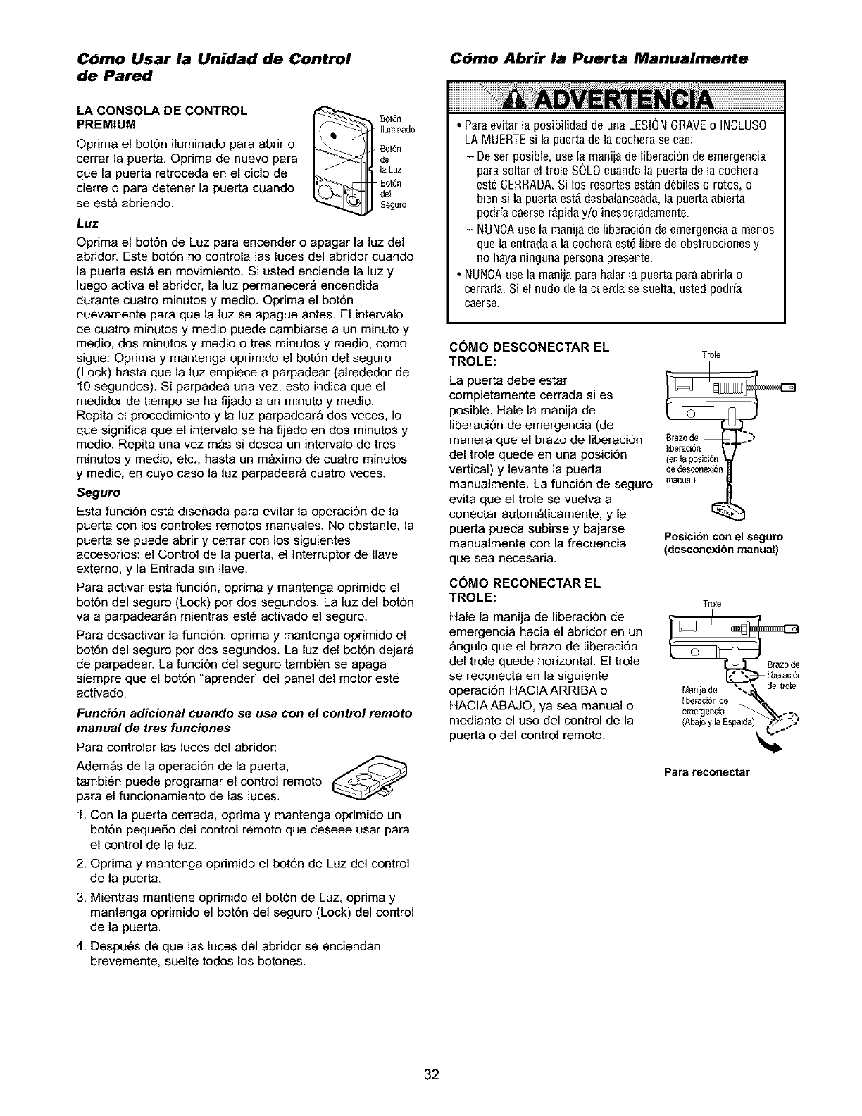
Cbmo Usar la Unidad de Control
de Pared
Cbmo Abrir la Puerta Manualmente
LA CONSOLA DE CONTROL
PREMIUM
Oprima el bot6n iluminado para abrir o
cerrar la puerta. Oprima de nuevo para
que la puerta retroceda en el ciclo de
cierre o para detener la puerta cuando
se est_ abriendo.
Luz
I _ £ot6n
lltsminado
dBeOt6n
la Luz
Bot6n
del
Seguro
Oprima el bot6n de Luz para encender o apagar la luz del
abridor. Este bot6n no controla las luces del abridor cuando
la puerta est_ en movimiento. Si usted enciende la luz y
]uego activa el abridor, la luz permanecer_ encendida
durante cuatro minutos y medic. Oprima el bot6n
nuevamente para que la luz se apague antes. El intervalo
de cuatro minutos y medic puede cambiarse a un minuto y
medic, dos minutos y medic o tres minutos y medic, como
sigue: Oprima y mantenga oprimido el bot6n del seguro
(Lock) hasta que la luz empiece a parpadear (alrededor de
10 segundos). Si parpadea una vez, esto indica que el
medidor de tiempo se ha fijado a un minuto y medic.
Repita el procedimiento y la luz parpadear_ dos veces, Io
que significa que el intervalo se ha fijado en dos minutos y
medic. Repita una vez m_s si desea un intervalo de tres
minutos y medic, etc., hasta un m_ximo de cuatro minutos
y medic, en cuyo caso la luz parpadear_ cuatro veces.
Seguro
Esta funci6n est_ disefiada para evitar la operaci6n de la
puerta con los controles remotos manuales. No obstante, la
puerta se puede abrir y cerrar con los siguientes
accesorios: el Control de la puerta, el ]nterruptor de Ilave
extemo, y la Entrada sin Ilave.
Para activar esta funci6n, oprima y mantenga oprimido el
bot6n del seguro (Lock) por dos segundos. La luz del bot6n
va a parpadear_n mientras est6 activado el seguro.
Para desactivar la funci6n, oprima y mantenga oprimido el
bot6n del seguro por dos segundos. La luz del bot6n dejar_
de parpadear. La funci6n del seguro tambi6n se apaga
siempre que el bot6n "aprender" del panel del motor est6
activado.
Funcidn adicional cuando se usa con el control remoto
manual de tres funciones
Para controlar las luces del abridor:
Adem_s de la operaci6n de la puerta,
tambi6n puede programar el control remoto
para el funcionamiento de las luces.
1. Con la puerta cerrada, oprima y mantenga oprimido un
bot6n pequefio del control remoto que deseee usar para
el control de la luz.
2. Oprima y mantenga oprimido el bot6n de Luz del control
de la puerta.
3. Mientras mantiene oprimido el bot6n de Luz, oprima y
mantenga oprimido el bot6n del seguro (Lock) del control
de la puerta.
4. Despu6s de que las luces del abridor se enciendan
brevemente, suelte todos los botches.
• Para evitar la posibilidad de una LES!ONGRAVEo INCLUSO
LA MUERTEsi la puerta de la cochera se cae:
- De ser posible, use la manija de liberaci6n de emergencia
para soltar el trole SOLOcuando la puerta de la cochera
estd CERRADA.Si los resortes estdn ddbiles o rotos, o
bien si la puerta estd desbalanceada,la puerta abierta
podria caerse rdpiday/o inesperadamente.
- NUNCAuse la manija de liberaci6n de emergencia a menos
que la entrada a la cochera eetd libre de obstrucciones y
no haya ninguna persona presente.
• NUNCAuse la manija para halar la puerta para abrirla o
cerrada. Si el nudo de la cuerda se suelta, usted podria
caerse.
COMO DESCONECTAR EL
TROLE:
La puerta debe estar
completamente cerrada si es
posible. Hale la manija de
liberaci6n de emergencia (de
manera que el brazo de liberaci6n
del trole quede en una posici6n
vertical) y levante la puerta
manualmente. La funci6n de seguro
evita que el trole se vuelva a
conectar autom_ticamente, y la
puerta pueda subirse y bajarse
manualmente con la frecuencia
que sea necesaria.
COMO RECONECTAR EL
TROLE:
Hale la manija de liberaci6n de
emergencia hacia el abridor en un
_ngulo que el brazo de liberaci6n
del trole quede horizontal. El trole
se reconecta en la siguiente
operaci6n HACIAARRIBA o
HACIAABAJO, ya sea manual o
mediante el uso del control de la
puerta o del control remoto.
Tro[e
Brazo de
liberaci6n
(en ta p0sici6n
de desconexi6n
manua0
Posicibn con el seguro
(desconexibn manual)
T_e
I
Brazode
tiberaci6n
liberaci6nde _--
emergencia ..
/Abo yloEspo
Para reconectar
32
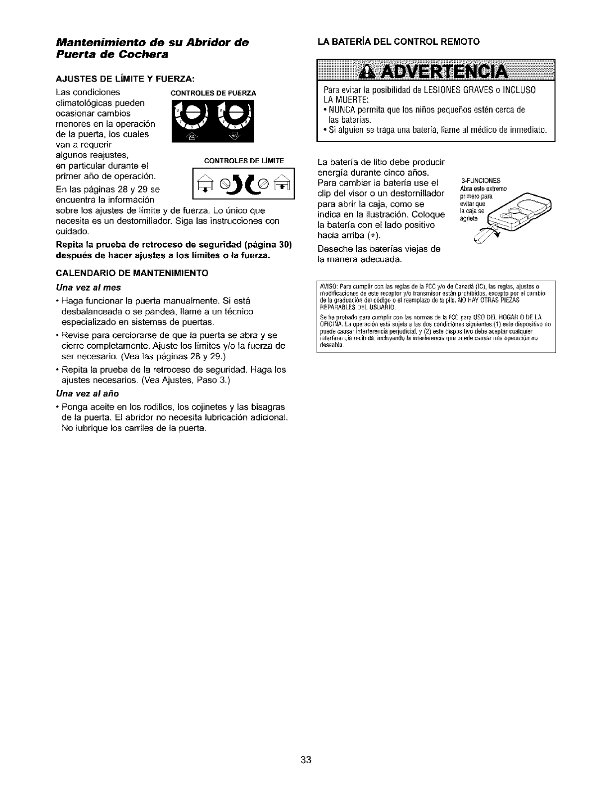
Mantenimiento de su Abridor de LA BATERiA DEL CONTROL REMOTO
Puerta de Cochera
AJUSTES DE L|MITE Y FUERZA:
Las condiciones
climatol6gicas pueden
ocasionar cambios
menores en la operaci6n
de la puerta, los cuales
van a requerir
algunos reajustes,
en particular durante el
primer aSo de operaci6n.
En las p_ginas 28 y 29 se
encuentra la informaci6n
CONTROLESDEFUERZA
CONTROLES DE LiMITE
sobre los ajustes de limite y de fuerza. Lo enico que
necesita es un destomillador. Siga las instrucciones con
cuidado.
Repita la prueba de retroceso de seguridad (pdgina 30)
despuds de hacer ajustes a los limites o |a fuerza.
CALENDARIO DE MANTENIMIENTO
Una vez al rues
• Haga funcionar la puerta manualmente. Si est_
desbalanceada o se pandea, Ilame a un t@cnico
especializado en sistemas de puertas.
• Revise para cerciorarse de que la puerta se abra y se
cierre completamente. Ajuste los limites y/o la fuerza de
ser necesario. (Vea las p_ginas 28 y 29.)
• Repita la prueba de la retroceso de seguridad. Haga los
ajustes necesarios. (Vea Ajustes, Paso 3.)
Una vez al a_o
•Ponga aceite en los rodillos, los cojinetes y las bisagras
de la puerta. El abridor no necesita lubricaci6n adicional.
No lubrique los carriles de la puerta.
Paraevitarla posibilidaddeLESIONESGRAVESoINOLUSO
LAMUERTE:
• NUNCApermitaquelos niSospequeSosestdncercade
las baterias.
• Sialguiense tragaunabateria,Ilameal mddicodeinmediato.
La bateria de litio debe producir
energia durante cinco aSos.
Para cambiar la bateria use el
clip del visor o un destomillador
para abrir la caja, como se
indica en la ilustraci6n. Coloque
]a bateria con el lado positivo
hacia arriba (+).
Deseche las baterias viejas de
]a manera adecuada.
3-FUNCIONES
Abra este extremo
primeropara
evitar que
lacgiase
AVISO:Paracumpiir con _asregtasde _aFCCy/o de Canad&(IC), las reglas, ajustes o
modif_cacionesde este receptor y/o bansmisor est_n prohibidos,excepto pot el cambio
de la g_aduaci6ndel c6digo o el ieempbzo de ia pila. NOHAYOIRAS PIEZAS
REPARABLESDEL USUARIO
Seha plobadopala Cumplircon las normas de la FCCpala USODEL HOGAR0 DELA
OFICINA.La operaci6nest_ sujeta alas dos condiciones siguientes:(1) estedispositivo no
puedecausar il]terferenciaperiudicial,y (2) este dispositivo debe aceptar cualquier
interferenciarecibida,inciuyendoia interfe_enciaque puedecausar una ope_aci(_nno
deseabIe
33
Si Tiene Algun Problema
1. El abridor no fonciona con el control de la puerta ni con el
control remote:
•_,Est_ el abridor conectado a la electficidad? Conecte una lampara
a la toma de corriente. Si no se enciende, revise la caja de fusibles
o el disyuntor. (AIgunas tomas de cornente se controlan con un
interrupter de pared).
•&Ha desactivado todos los seguros de las puertas? Revise las
advertencias de las instrucciones de instalaci6n que aparecen en la
pagina 11.
•&Hay nieve o hielo acumulado debajo de la puerta? La puerta
puede congelarse y quedarse pegada al piso. Elimine esta
restricci6n.
• El resorte de la puerta de la cochera puede estar rote. Haga que Io
cambien.
• Es posible que las repetidas operaciones hayan disparado el
protector de sobrecarga del motor. Espere 15 minutes y vuelva a
intentar.
2. El abridor opera con el control remote, pore no funciona con el
control de la puerta:
• 6Esta iluminado el control? Si no 1o est& invierta los cables. Si el
abridor funciona, revise que los alambres est6n bien conectados en
el control de la puerta, vea si hay algt_n corto circuito debajo de las
grapas o algtin alambre rote.
• _.Las conexiones del cableado son correctas? Revise el Paso 6 de
la secci6n de Instalaci6n en la p_gina 18.
3. La puerta funciona con el control de la puerta, pore no funciona
con el control remoto:
• 6Esta parpadeando el bot6n del control de la puerta? Si el modelo
de su abridor tiene la funci6n de seguro (Lock), cerci6rese de que
est6 apagada.
• Programe el abridor para que coincida con el c6digo del control
remote. (Consulte las instrucciones que se encuentran en el panel
del motor). Repita esto con todos los controles remotos.
4. El control remote tiene corto alcance:
• Cambie la ubicaci6n del control remote en su coche.
• Revise y cerci6rese de que la antena que se encuentra a un lade o
en el panel posterior de la unidad del motor se extienda hacia abajo
completamente.
• Algunas instalaciones pueden tenor monet alcance si las puertas
son de metal, tienen aislamiento con capa met_lica, o el
recubrimiento externo de la cochera es de metal. (Estuche de
extensi6n de antena 41A3504).
5. El roido que hate el abridor molesta en las habitaciones de la
casa:
• Si el ruido de la operaci6n del abridor es un probiema porque las
habitaciones de la casa est6n muy cerca, se puede instalar un
Aislador de vibraci6n 41A3263. Este accesorio esta diseSado para
minimizar [a vibraci6n en la casa yes f_cil de instalar.
6. La puerta de la cochera se abre y se cierra per si sola:
• Aseg_rese de que todos los botones del control remote est_n
apagados.
• Quite el alambre de campana de las terminales del control de ia
puerta y haga funcionar la puerta solamente con el control remote.
Si esto resuelve el problem& el control de la puerta tiene alguna
falla (cambielo), o hay algtin corto circuito intermitente en el
alambre entre el control de la puerta y la unidad del motor.
• Borre la memoria y vuelva a programar todos los controles remotos.
7. La puerta no abre completamente:
• 6Hay aigo que est_ obstruyendo la puerta? _.Esta desbalanceada, o
los resortes estan rotes? Eiimine la obstrucci6n o repare la puerta.
• Si la puerta esta en buenas condiciones pete no abre completamente,
aumente la fuerza hacia arriba. Vea Ajustes, Paso 2.
• Si la puerta abre per Io menos cinco pies (1.5 m), es posible que se
tengan que aumentar los limites del recorrido. Una vuelta equivale a
5 cm (2 pulg.) del recorrido. Vea Ajustes, Paso 1.
Repita la prueba de retroceso de seguridad despues de terminar el ajuste,
8. La puerta se detiene pete no cierra completamente:
•Revise los procedimientos de ajuste de los Ifmites de] recorride que
aparecen en la p_gina 28.
Repita la prueba de retroceso de seguridad despu_s de realizar
cualquier ajuste al largo del braze de la puerta, a la fuerza o a! limite
hacia abajo, 34
9. La puerta se abre pero no se cierra:
• Si las luces del abridor parpadean, revise el sensor de retroceso de
seguridad. Vea la secci6n de InstalaciOn, Paso 10.
• Si las luces del abridor no parpadean y se trata de una instalaci6n
nueva, revise la fuerza hacia abajo. Vea la secciSn de Ajustes,
Paso 2. Si se trata de una instalaci6n ya existente, vea a
continuaci6n.
Repita la prueba de retroceso de seguridad despues de terminar
el ajuste.
10. La puerta retrocede sin raz6n aparente y las luces del abridor
no parpadean:
• 6Hay algo que est_ obstruyendo la puerta? Jale la manija de
liberaci6n de emergencia. Opere ia puerta manualmente. Siesta
desbalanceada o se pandea, Ilame a un t6cnico especializado en
sistemas de puertas.
• Limpie el piso de la cochera si tiene hielo o nieve en el punto
donde la puerta cierra.
• Revise Ajustes, Paso 2.
• Si la puerta retrocede en la posici6n completamente cerrada,
disminuya los limites de recorrido (Ajustes, Paso 1).
Repita la prueba de retroceso de seguridad despues de hacer los
ajustes a la fuerza o a los limites del recorrido. La necesidad de un
ajuste ocasional de la fuerza y del Iirnite es normal. Las condiciones
cfimatol6gicas en particular pueden afectar el recorrido de la puerta.
11. La puerta retrocede sin raz6n aparente y las luces del abridor
parpadean per cinco segundos despu_s de que retrocede:
•Revise el sensor de retroceso de seguridad, Quite cualquier
obstrucci6n o alinee el ojo receptor. Vea la secci6n de Instalaci6n,
Paso 10,
12. Las luces del abridor no se encienden:
• Cambie los bombillos (de 75 vatios maximo). Use un bombillo
est&ndar para puerta de cochera, si el bombillo se funde.
13. Las lutes del abridor no se apagan:
• 6Est& activada la funci6n de luz? Si es asi, apaguela.
14. El abridor necesita la m#xima fuerza para operar la puerta:
• La puerta podria estar desbalanceada, o los resortes podrlan
estar rotes. Cierre la puerta y use la manija de liberaci6n de
emergencia para desconectar el trole. Abra y cierre la puerta
manualmente. Si la puerta est& bien equilibrada se sostiene en
cualquier punto del recorrido con s61o el soporte de sus resortes. Si
esto no ocurre, desconecte el abridor y Ilame a un t_cnico
especializado en sistemas de puertas. No aumente la fuerza
para operar el abridor.
15. El motor hace un ruido brevemente pore luego no funciona:
•Los resortes de la puerta de la cochera podrian estar rotes. Vea los
p_rrafos anteriores.
• Si el problema se presenta la primera vez que opera el abridor,
puede ser que la puerta est6 con seguro. Quite el seguro de la
puerta. Si ha quitado la cadena y la ha vuelto a instalar, el motor
podria estas desfasado. Quite la cadena; corra el ciclo del motor
hasta la posici6n hacia abajo. Observe la o rueda dentada, si gira a
la derecha, y se detiene en la posici6n hacia abajo, vuelva a
instalar la cadena.
Repita la prueba de retroceso de seguridad despues de terminar
el ajuste.
16. El abridor no funciona debido a una falla en el suministro
de energia:
• Use la manija de liberaci6n de emergencia para desconectar el
trole. La puerta se puede abrir y cerrar manualmente. Cuando se
restaure el suministro de energia, oprima el bot6n de control de la
puerta y el trole se vuelve a conectar automaticamente (a menos
que est6 con seguro). Vea la p_gina 32.
• El accesorio Llave de liberaci6n de emergencia (que se usa
solamente en las cocheras que no tienen una puerta de servicio)
desconecta el trole desde fuera de la cochera en caso de una falla
en el suministro de energia.
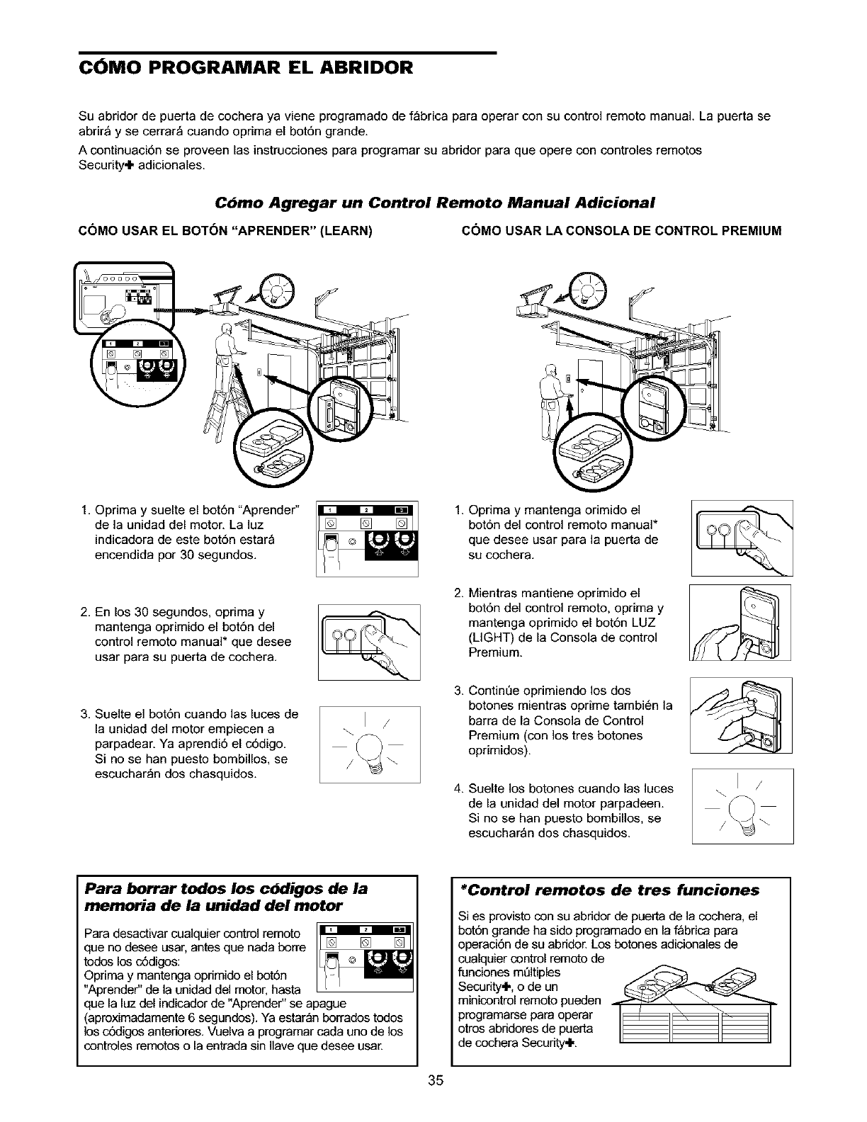
C6MO PROGRAMAR EL ABRIDOR
Su abridor de puerta de cochera ya viene programado de f_brica para operar con su control remoto manual. La puerta se
abrir_ y se cerrar_ cuando oprima el bot6n grande.
A continuaci6n se proveen las instrucciones para programar su abridor para que opere con controles remotos
Security÷ adicionales.
Cbmo Agregar un Control Remoto Manual Adicional
COMO USAR EL BOT6N "APRENDER" (LEARN) COMO USAR LA CONSOLA DE CONTROL PREMIUM
1. Oprima y suelte el bot6n "Aprender"
de la unidad del motor. La luz
indicadora de este bot6n estar_
encendida por 30 segundos.
2. En los 30 segundos, oprima y
mantenga oprimido el bot6n del
control remoto manual* que desee
usar para su puerta de cochera.
3. Suelte el bot6n cuando las luces de
la unidad del motor empiecen a
parpadear. Ya aprendi6 el c6digo.
Si no se han puesto bombillos, se
escuchar_n dos chasquidos.
1. Oprima y mantenga orimido el
bot6n del control remoto manual*
que desee usar para la puerta de
su cochera.
2. Mientras mantiene oprimido el
bot6n del control remoto, oprima y
mantenga oprimido el bot6n LUZ
(LIGHT) de la Consola de control
Premium.
3. Continee oprimiendo los dos
botones mientras oprime tambi6n la
barra de la Consola de Control
Premium (con los tres botones
oprimidos).
4. Suelte los botones cuando las luces
de la unidad del motor parpadeen.
Si no se han puesto bombillos, se
escuchar_n dos chasquidos.
Para borrar todos los cbdigos de la
memoria de la unided del motor
Para desactivar cualquier control remoto
que no desee usar, antes que nada borre [] []
todos los c6digos:
Oprima y mantenga oprimido el bot6n
"Aprende¢' de la unidad del motor, hasta
que la luz del indicador de "Aprende¢' se apague
(aproximadamente 6 segundos). Ya estar_n borrados todos
los cd_igos anteriores. Vuelva a programar cada uno de los
controles remotos o la entrada sin Ilave que desee usar.
*Control remotos de tres funciones
Si es provisto con su abridor de puerta de la cochera, el
bot6n grande ha sido programado en la f_brica para
operaci6n de su abddor. Los botones adicionales de
cualquier control remoto de
funciones m61tiples __
Security÷, o de un
minicontrol remoto pueden
programarse para operar
otros abridores de puerta
de cochera Security÷.
35
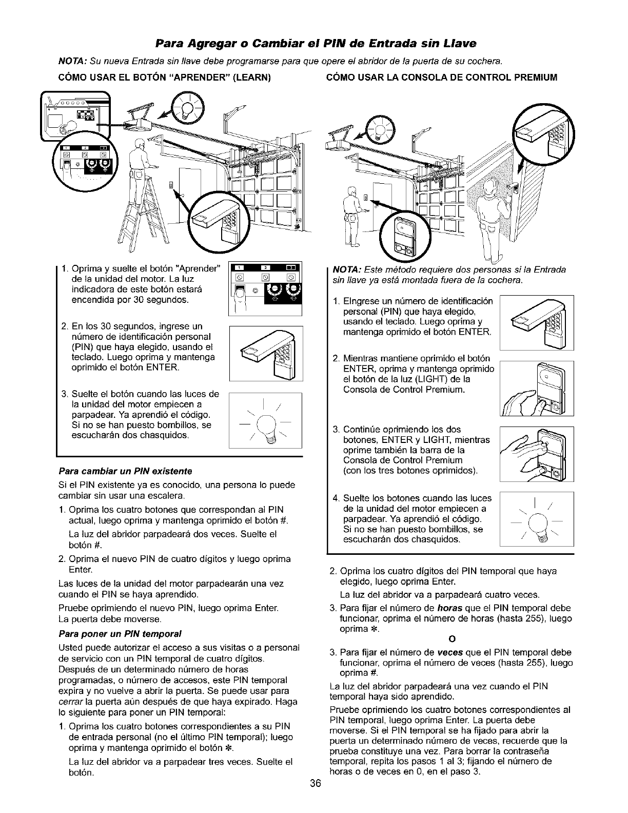
Para Agregar o Cambiar el PIN de Entrada sin Llave
NOTA: Su nueva Entrada sin Ilave debe programarse para que opere el abridor de la puerta de su cochera.
COMO USAR EL BOT(_N "APRENDER" (LEARN) COMO USAR LA CONSOLA DE CONTROL PREMIUM
1. Oprima y suelte el bot6n "Aprender"
de la unidad del motor. La luz
indicadora de este bot6n estar_
encendida por 30 segundos.
2. En los 30 segundos, ingrese un
n_mero de identificaci6n personal
(PIN) que haya elegido, usando el
teclado. Luego optima y mantenga
oprimido el bot6n ENTER.
3. Suelte el bot6n cuando las luces de
la unidad del motor empiecen a
parpadear. Ya aprendi6 el c6digo.
Si no se han poesto bombillos, se
escuchar_n dos chasquidos.
Para cambiar un PIN existente
Si el PIN existente ya es conocido, una persona Io puede
cambiar sin usar una escalera.
1. Optima los cuatro botones que correspondan al PIN
actual, luego oprima y mantenga oprimido el bot6n #.
La luz del abridor parpadear_ dos veces. Suelte el
bot6n #.
2. Opdma el nuevo PIN de cuatro digitos y luego optima
Enter.
Las luces de la unidad del motor parpadear_n una vez
cuando el PIN se haya aprendido.
Pruebe oprimiendo el nuevo PiN, luego optima Enter.
La puerta debe moverse.
Para poner un PIN temporal
Usted puede autorizar el acceso a sus visitas o a personal
de servicio con un PIN temporal de cuatro digitos.
Despu6s de un determinado nL)mero de horas
programadas, o nt_mero de accesos, este PIN temporal
expira y no vuelve aabrir la puerta. Se puede usar para
cerrar la puerta at_n despu6s de que haya expirado. Haga
Io siguiente para poner un PIN temporal:
1. Optima los cuatro botones correspondientes a su PIN
de entrada personal (no el L_ltimoPIN temporal); luego
oprima y mantenga oprimido el bot6n _:.
La luz del abridor va a parpadear tres veces. Suelte el
bot6n.
36
NOTA: Este m6todo requiere dos personas si la Entrada
sin Ilave ya est& montada fuera de la cochera.
1,
2,
3,
Elngrese un nt_mero de identificaci6n
personal (PIN) que haya elegido,
usando el teclado. Luego optima y
mantenga oprimido el bot6n ENTER.
Mientras mantiene oprimido el bot6n
ENTER, oprima y mantenga oprimido
el bot6n de la luz (LIGHT) de la
Consola de Control Premium.
Contint]e oprimiendo los dos
botones, ENTER y LIGHT, mientras
oprime tambi6n la barra de la
Consola de Control Premium
(con los tres botones oprimidos).
4, Suelte los botones cuando las luces
de la unidad del motor empiecen a
parpadear. Ya aprendi6 el c6digo.
Si no se han puesto bombillos, se
escuchar_n dos chasquidos.
2. Optima los cuatro digitos de] PIN temporal que haya
elegido, luego oprima Enter.
La luz del abridor va a parpadear_ cuatro veces.
3. Para fijar el nt_mero de horas que el PIN temporal debe
funcionar, optima el nt]mero de horas (hasta 255), luego
optima _. O
3. Para fijar el nt_mero de veces que el PiN temporal debe
funcionar, optima el nt]mero de veces (hasta 255), luego
optima #.
La luz del abridor parpadear_ una vez cuando el PIN
temporal haya side aprendido.
Pruebe oprimiendo los cuatro botones cerrespondientes al
PIN temporal, luego optima Enter. La poerta debe
moverse. Si el PIN temporal se ha fijado para abrir la
puerta un determinado nL_mero de veces, recuerde que la
prueba constituye una vez. Para borrar la contraseSa
temporal, repita los pasos 1 al 3; fijando el nL_mero de
horas o de veces en O, en el paso 3.
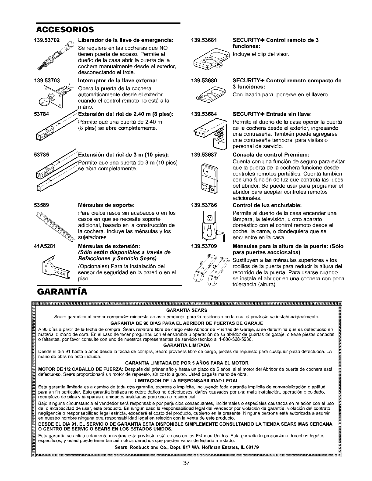
ACCESORIOS
139.53702
139.53703
53784
Liberador de la Ilave de emergencia:
Se requiere en las cocheras que NO
tienen puerta de acceso. Permite al
due_o de la casa abrir la puerta de la
cochera manualmente desde el exterior,
desconectando el trole.
Interruptor de la gave externa:
Opera la puerta de la cochera
autom_ticamente desde el exterior
cuando el control remoto no est_ a la
mano.
del de 2.40 m(8 pies):
:_ueuna puerta de 2.40 m
(8 pies) se abra completamente.
53785 Extensibn del riel de 3 m(10 pies):
lue una puerta de 3 m (10 pies)
se abra completamente.
53589
41A5281
M6nsulas de soporte:
Para cielos rasos sin acabados o en los
casos en que se necesite soporte
adicional, basado en la construcci6n de
la cochera. Incluye las m6nsulas y los
sujetadores.
Mdnsulas de extensibn:
($61o est_n disponibles a tray,s de
Refacciones y Servicio Sears)
(Opcionales) Para la instalaci6n del
sensor de seguridad en la pared o en el
piso.
GARANT|A
139.53681
139.53680
139.53684
139.53687
139.53786
139.53709
SECURITY+ Control remoto de 3
funciones:
Incluye el clip del visor.
SECURITY+ Control remoto compacto de
3 funciones:
Con lazada para ponerse en el Ilavero.
SECURITY+ Entrada sin Ilave:
Permite al dueSo de la casa operar la puerta
de la cochera desde el exterior, ingresando
una contraseF_a. Tambi6n puede agregarse
una contraseF_a temporal para visitas o
personal de servicio.
Consola de control Premium:
Cuenta con una funci6n de seguro para evitar
que la puerta de la cochera funcione desde
controles remotos port,tiles. Cuenta tambi6n
con una funci6n de luz que controla las luces
del abridor. Se puede usar para programar el
abridor para aceptar controles remotos
adicionales.
Control de luz enchufable:
Permite al dueSo de la casa encender una
]_mpara. la televisi6n, u otro aparato
dom6stico con el control remoto desde el
coche, la cama. o dondequiera que se
encuentre en la casa.
M_nsulas para la altura de la puerta: ($61o
para puertas seccionales)
Sustituyen alas m6nsulas superiores y los
rodillos de la poerta para reducir la altura del
recorrido de la puerta. Para usarse cuando
se instala el abridor en una cochera con poca
tolerancia (altura).
GARANTIA SEARS
Searsgarantizaal primercompradorminoristade esteproducto,parala residenciaen la cualel productose instal6originalmente.
GARANTIADE90 DIAS PAPAELABRIDOR DE PUERTASDE GARAJE
A 90 dias a partirde la fecha decompra,Searsreparar_libre decargoesteAbridor de Puertasde Garaje,si se determinaque es defectuosoen
materialo manodeobra. En el caso de tener preguntascon el ensambleu operaci6nde su abridorde puertasde garaje,o tiene piezasdaSadas
o faltantes,porfavor consulteconuno de nuestrosrepresentantesde serviciot6cnico al 1-800-528_5236.
GARANTIALIMITADA
Desdeel dia 91 hasta5 afiosdesde la fecha de compra,Searsproveer_librede cargo,piezasde repuestoparacualquierpiezadefectuosa.LA
manode obrano est&incluida.
GARANTIAMMITADADE POR 5 AI_IOS PARAELMOTOR
MOTORDE1/2 CABALLO DE FUERZA:Despu_sdel primerafio y hastaun plazode 5 a_os, si el motor del Abridorde puertade cocheraest_
defectuoso,Searsproporcionar_un motorde repuesto,sin costoalguno.Ustedpaga la manode obra.
LIMITAClONDE LA RESPONSABIMDADLEGAL
Estagarantia limitadaes a cambiodetoda otragarantia,expresao implicita,incluyendotoda garantiaimplicitade comercializaci6no aptitud
paraunfin particular.Estagarantialimitadano cubredaSosno defectuosos,daSoscausadospot una malainstalaci6n,operaci6no cuidado,
reemplazode pilas y I_mparaso unidadesinstaladasparausono residencial.
Bajoningunacircunstanciael vendedorser_ responsablepor perjuiciosconsecuentes,incidentaleso especialescausadosenrelaci6nconel uso
de, o incapacidadde usar,este producto.En ning_ncaso la responsabilidadlegaldel vendedorpotviolaci6ndegarantia,violaci6ndelcontrato,
negligenciao responsabilidadlegalestricta,exceder_el costodel producto,cubiertoen la presente.Ninguna personaest_autorizadaa asumir
ennuestro nombreningunaotra responsabilidadlegalen relaci6ncon la ventade este producto.
DESDEELDIA91, EL SERVIClODEGARANTIAESTADISPONIBLESIMPLEMENTECONSULTANDOLATIENDASEARS MAS CERCANA
OCENTRODESERVICIOSEARSEN LOS ESTADOSUNIDOS.
Estagarantia se aplicasolamentemientraseste productoest_ en uso en los EstadosUnidos.Estagarantiale proporcionaderechoslegales
especificos,y usted puedetenertambi@notros derechosque puedenvariarde Estadoa Estado.
Sears, Roebuckand Co., Dept. 817 WA, Hoffman Estates, IL60179
37
Your Home
For repair-in your home-of all major brand appliances,
lawn and garden equipment, or heating and cooling systems,
no matter who made it, no matter who sold it!
For the replacement parts, accessories and
owner's manuals that you need to do-it-yourself.
For Sears professional installation of home appliances
and items like garage door openers and water heaters.
1-800-4-MY-HOME ®(1-800-469-4663)
Call anytime, day or night (U.S.A. and Canada)
www.sears.com www.sears.ca
Our Home
For repair of carry-in items like vacuums, lawn equipment,
and electronics, call or go on-line for the location of your nearest
Sears Parts & Repair Center.
1-800-488-1222
Call anytime, day or night (U.S.A. only)
www.sears.com
To purchase aprotection agreement (U.S.A.)
or maintenance agreement (Canada) on a product serviced by Sears:
1-800-827-6655 (U.S.A,) 1-800-361-6665 (Canada)
Para pedir servicio de reparaci6n
a domicilio, y para ordenar piezas:
1-888-SU-HOGAR _
(1-888-784-6427)
Au Canada pour service en fran_:ais:
1-800-LE-FOYER M°
(1-600-533-6937)
www.sears.ca
114A2369D
® Registered Trademark /_ Trademark /sMService Mark of Sears, Roebuck and Co.
® Marca Registrada /_Marca de F_brica /s,.,Marca de Servicio de Sears, Roebuck and Co.
_{_Marque de commerce /MD Marque d6pos_e de Sears, Roebuck and Co.
© 2003 Sears, Roebuck and Co.
Printed in Mexico
