Craftsman 13953985DM User Manual GARAGE DOOR OPENER Manuals And Guides L0906399
CRAFTSMAN Garage Door Opener Manual L0906399 CRAFTSMAN Garage Door Opener Owner's Manual, CRAFTSMAN Garage Door Opener installation guides
User Manual: Craftsman 13953985DM 13953985DM CRAFTSMAN GARAGE DOOR OPENER - Manuals and Guides View the owners manual for your CRAFTSMAN GARAGE DOOR OPENER #13953985DM. Home:Garage Door & Opener Parts:Craftsman Parts:Craftsman GARAGE DOOR OPENER Manual
Open the PDF directly: View PDF ![]() .
.
Page Count: 76

Owner's Manual/Manual Del Propietario
/
315MM-GARAGE DOOR OPENER
ABRIDOR DE PUERTA DE COCHERA
For Residential Use Only/Solo para uso residencial
DE 315MM=
Models/Modelos •139.53985DM
Read and follow all safety rules
and operating instructions before
first use of this product.
Fasten the manual near the
garage door after installation.
Periodic checks of the opener are
required to ensure safe operation.
Leer y seguir todas las reglas de
seguridad y las instrucciones de
operacion antes de usar este
producto por primera vez.
Guardar este manual cerca de la
puerta de la cochera.
Se deben realizar revisiones
periodicas del abridor de puertas
para asegurar su operacion
segura.
m
z
r-
m
"0
Z_
O
r-
00°s
Sears, Roebuck and Co., Hoffman Estates, IL 60179 U.S.A
www.sears.com/craftsman
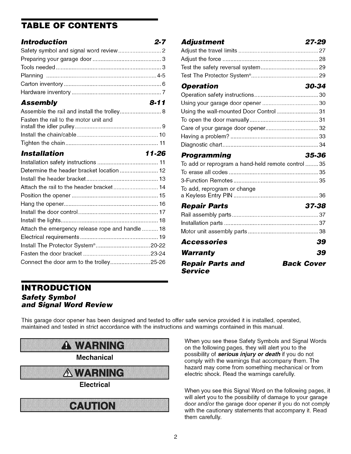
TABLE OF CONTENTS
Introduction 2- 7
Safety symbol and signal word review ........................... 2
Preparing your garage door ........................................... 3
Tools needed .................................................................. 3
Planning ..................................................................... 4-5
Carton inventory ............................................................. 6
Hardware inventory ........................................................ 7
Assembly 8-11
Assemble the rail and install the trolley .......................... 8
Fasten the rail to the motor unit and
install the idler pulley ...................................................... 9
Install the chain/cable ................................................... 10
Tighten the chain .......................................................... 11
Installation 11-26
Installation safety instructions ...................................... 11
Determine the header bracket location ........................ 12
Install the header bracket ............................................. 13
Attach the rail to the header bracket ............................ 14
Position the opener ...................................................... 15
Hang the opener ........................................................... 16
Install the door control .................................................. 17
Install the lights ............................................................. 18
Attach the emergency release rope and handle .......... 18
Electrical requirements ................................................. 19
Install The Protector System ° .................................. 20-22
Fasten the door bracket .......................................... 23-24
Connect the door arm to the trolley ......................... 25-26
Adjustment 27-29
Adjust the travel limits .................................................. 27
Adjust the force ............................................................ 28
Test the safety reversal system .................................... 29
Test The Protector System _.......................................... 29
Operation 30-34
Operation safety instructions ........................................ 30
Using your garage door opener ................................... 30
Using the wall-mounted Door Control .......................... 31
To open the door manually ........................................... 31
Care of your garage door opener ................................. 32
Having a problem? ....................................................... 33
Diagnostic chart ............................................................ 34
Programming 35-36
To add or reprogram a hand-held remote control ........ 35
To erase all codes ........................................................ 35
3-Function Remotes ..................................................... 35
To add, reprogram or change
a Keyless Entry PIN ..................................................... 36
Repair Parts 37-38
Rail assembly parts ...................................................... 37
Installation parts ........................................................... 37
Motor unit assembly parts ............................................ 38
Accessories 39
Warranty
Repair Parts and
Service
39
Back Cover
INTRODUCTION
Safety Symbol
and Signal Word Review
This garage door opener has been designed and tested to offer safe service provided it is installed, operated,
maintained and tested in strict accordance with the instructions and warnings contained in this manual.
Mechanical
Electrical
When you see these Safety Symbols and Signal Words
on the following pages, they will alert you to the
possibility of serious injury or death if you do not
comply with the warnings that accompany them. The
hazard may come from something mechanical or from
electric shock. Read the warnings carefully.
When you see this Signal Word on the following pages, it
will alert you to the possibility of damage to your garage
door and/or the garage door opener if you do not comply
with the cautionary statements that accompany it. Read
them carefully.
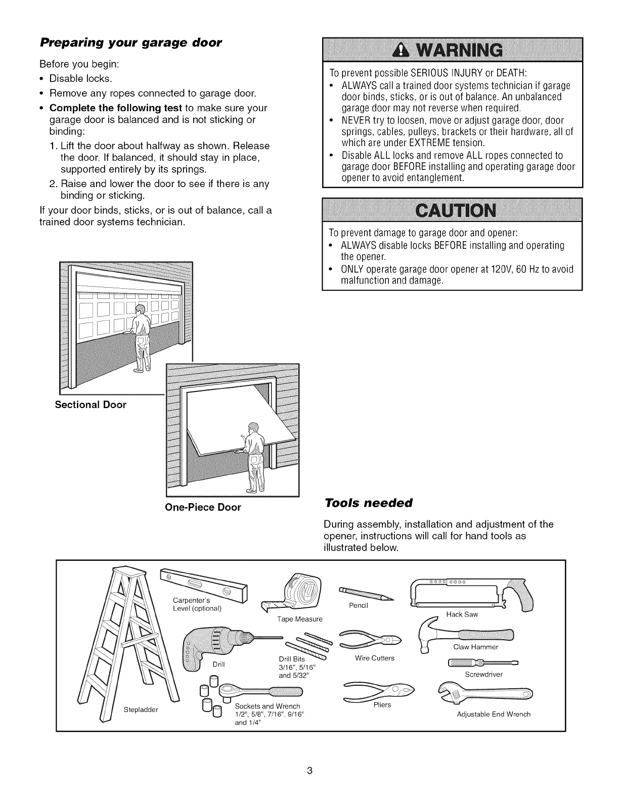
Preparing your garage door
Before you begin:
•Disable locks.
• Remove any ropes connected to garage door.
• Complete the following test to make sure your
garage door is balanced and is not sticking or
binding:
1. Lift the door about halfway as shown. Release
the door. If balanced, it should stay in place,
supported entirely by its springs.
2. Raise and lower the door to see if there is any
binding or sticking.
If your door binds, sticks, or is out of balance, call a
trained door systems technician.
To prevent possible SERIOUSINJURYor DEATH:
• ALWAYScall a trained door systems technician if garage
door binds, sticks, or is out of balance.An unbalanced
garage door may not reverse when required.
• NEVERtry to loosen, move or adjust garage door, door
springs, cables, pulleys, brackets or their hardware, all of
which are under EXTREMEtension.
• DisableALL locks and removeALL ropes connected to
garage door BEFOREinstalling and operating garage door
opener to avoid entanglement.
To prevent damage to garagedoor and opener:
• ALWAYSdisable locks BEFOREinstalling and operating
the opener.
• ONLYoperate garage door opener at 120V, 60 Hzto avoid
malfunction and damage.
Sectional Door
One-Piece Door Tools needed
During assembly, installation and adjustment of the
opener, instructions will call for hand tools as
illustrated below.
Stepladder
Level (optional) Pencil
Tape Measure
Dr_ Wire Cutters
Drill 3/16", 5/16"
and 5/32"
_0 s2'c _5t/8"a,7116W':e9/ih'' Pliers
and 1/4"
Hack Saw
Screwdriver
Adjustable End Wrench
Planning
Identify the type and height of your garage door. Survey
your garage area to see if any of the conditions below
apply to your installation. Additional materials may be
required. You may find it helpful to refer back to this page
and the accompanying illustrations as you proceed with
the installation of your opener.
Depending on your requirements, there are several
installation steps which may call for materials or
hardware not included in the carton.
• Installation Step 1 - Look at the wall or ceiling above
the garage door. The header bracket must be securely
fastened to structural supports.
• Installation Step 5 - Do you have a finished ceiling in
your garage? If so, a support bracket and additional
fastening hardware may be required.
• Installation Step 10 - Depending upon garage
construction, extension brackets or wood blocks may
be needed to install sensors.
• Installation Step 10 - Alternate floor mounting of the
safety reversing sensor will require hardware not
provided.
Do you have an access door in addition to the garage
door? If not, Model 53702 Emergency Key Release is
required. See Accessories page.
Look at the garage door where it meets the floor. Any
gap between the floor and the bottom of the door must
not exceed 1/4" (6 mm). Otherwise, the safety reversal
system may not work properly. See Adjustment Step 3.
Floor or door should be repaired.
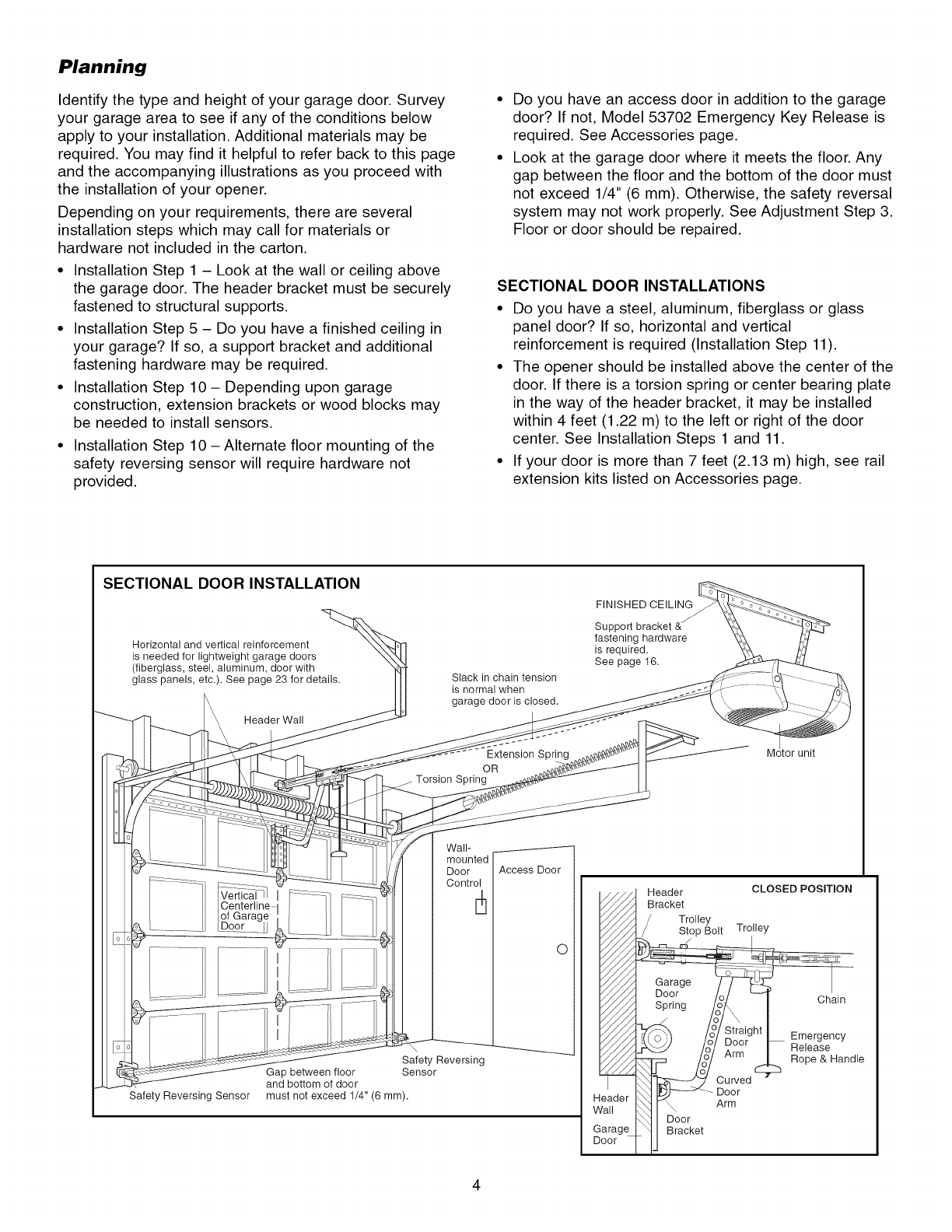
SECTIONAL DOOR INSTALLATIONS
• Do you have a steel, aluminum, fiberglass or glass
panel door? If so, horizontal and vertical
reinforcement is required (Installation Step 11).
• The opener should be installed above the center of the
door. If there is a torsion spring or center bearing plate
in the way of the header bracket, it may be installed
within 4 feet (1.22 m) to the left or right of the door
center. See Installation Steps 1 and 11.
• If your door is more than 7 feet (2.13 m) high, see rail
extension kits listed on Accessories page.
SECTIONAL DOOR INSTALLATION
Horizontal and vertical reinforcement
is needed for lightweight garage doors
(fiberglass, steel, aluminum, door with
glass panels, etc.). See page 23 for details.
Header Wall
Slack in chain tension
is normal when
garage door is closed.
Extension Spring
OR
Torsion Spring
FINISHED CEILING
Su
fastening hardware
is required.
See page 16.
M unit
Wall-
mounted
Door
Control
Safety Reversing Sensor
Safety Reversing
Gap between floor Sensor
and bottom of door
must not exceed 1/4" (6 mm).
Access Door
O
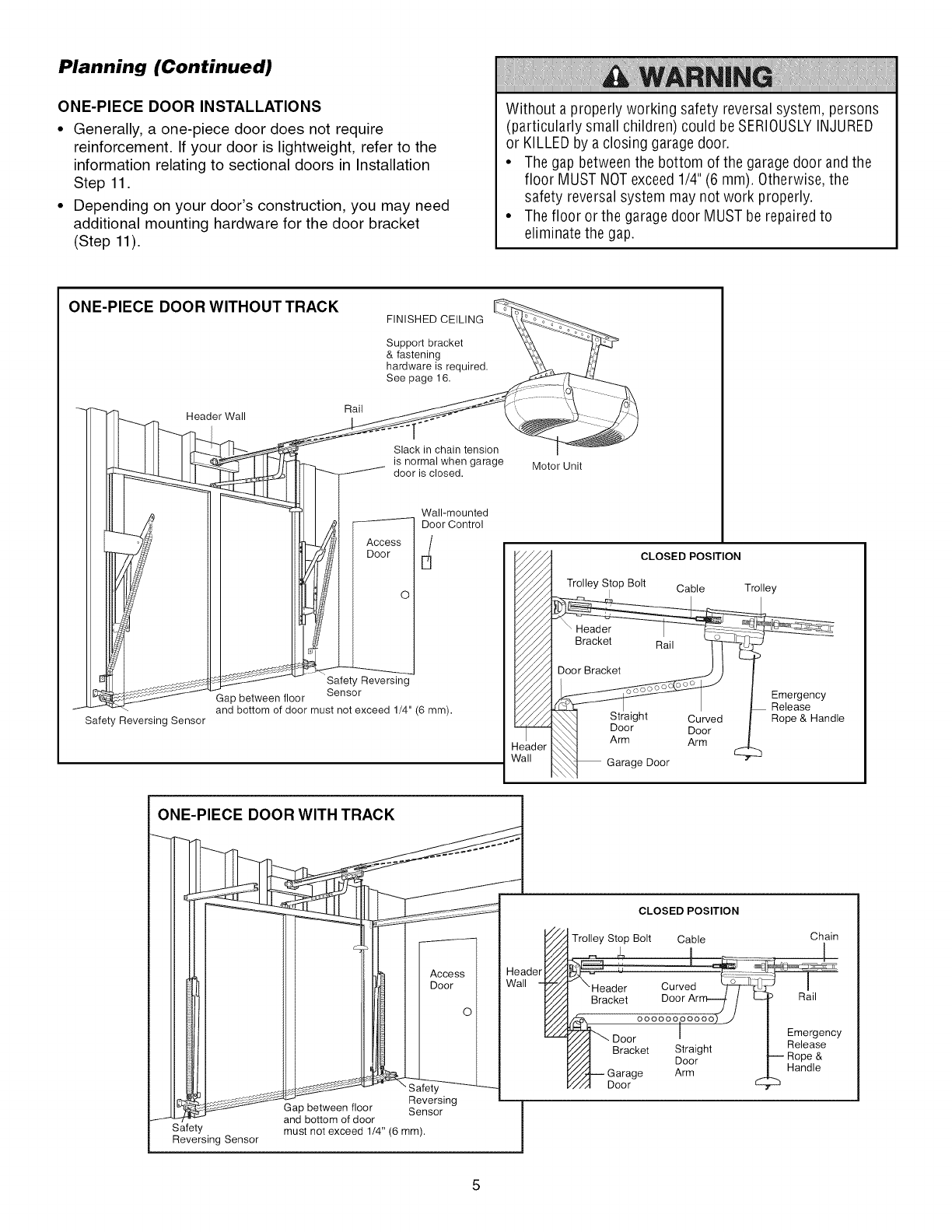
Planning (Continued)
ONE-PIECE DOOR INSTALLATIONS
•Generally, a one-piece door does not require
reinforcement. If your door is lightweight, refer to the
information relating to sectional doors in Installation
Step 11.
• Depending on your door's construction, you may need
additional mounting hardware for the door bracket
(Step 11).
Without a properly working safety reversal system, persons
(particularly small children) could be SERIOUSLYINJURED
or KILLEDby a closing garage door.
• The gap between the bottom of the garagedoor and the
floor MUST NOTexceed 1/4"(6 mm). Otherwise, the
safety reversal system may not work properly.
• The floor or the garage door MUST be repairedto
eliminate the gap.
ONE-PIECE DOOR WITHOUT TRACK FINISHED CEILING
Support bracket
& fastening
hardware is required.
See page 16.
t
Safety Reversing Sensor
Header Wall Rail
Slack in chain tension
is normal when garage
_-_ door is closed.
Wall-mounted
----------- Door Control
Access E_
Door
O
Safety Reversing
Sensor
Gap between floor
and bottom of door must not exceed 1/4" (6 mm).
I ONE-PIECE DOOR WITH TRACK
Motor Unit
CLOSED POSITION
Trolley Stop Bolt Cable Trolley
r
Emergency
Release
Rope & Handle
Safety
Reversing Sensor
Reversing
Gap between floor Sensor
and bottom of door
must not exceed 1/4" (6 ram).
CLOSED POSITION
Trolley Stop Bolt Cable
J \Header Curved
Bracket Door Arm--_ /L_
ooooooooooo) j
/_ Door I
V_/-/i] " Bracket Straight
Door
Y/z'l--- Garage Arm
Y,/'_ Door
Chain
Rail
Emergency
Release
J Rope &
Handle
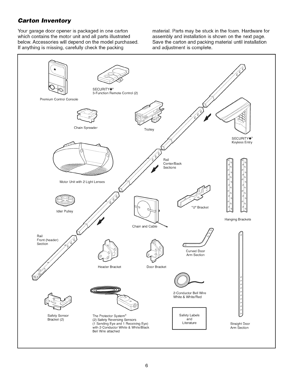
Carton Inventory
Your garage door opener is packaged in one carton
which contains the motor unit and all parts illustrated
below. Accessories will depend on the model purchased.
If anything is missing, carefully check the packing
material. Parts may be stuck in the foam. Hardware for
assembly and installation is shown on the next page.
Save the carton and packing material until installation
and adjustment is complete.
Premium Control Console
Chain Spreader
SECURITY÷ ®
3-Function Remote Control (2)
Trolley
SECURITY÷ ®
Keyless Entry
Rail
Center/Back
Sections
Motor Unit with 2 Light Lenses
Idler Pulley
Safety Sensor
Bracket (2)
Chain and Cable
Header Bracket Door Bracket
The Protector System ®
(2) Safety Reversing Sensors
(1 Sending Eye and 1 Receiving Eye)
with 2-Conductor White & White/Black
Bell Wire attached
Curved Door
Arm Section
2-Conductor Bell Wire
White & White/Red
Safety Labels
and
Literature
31
01.
Hanging Brackets
Straight Door
Arm Section
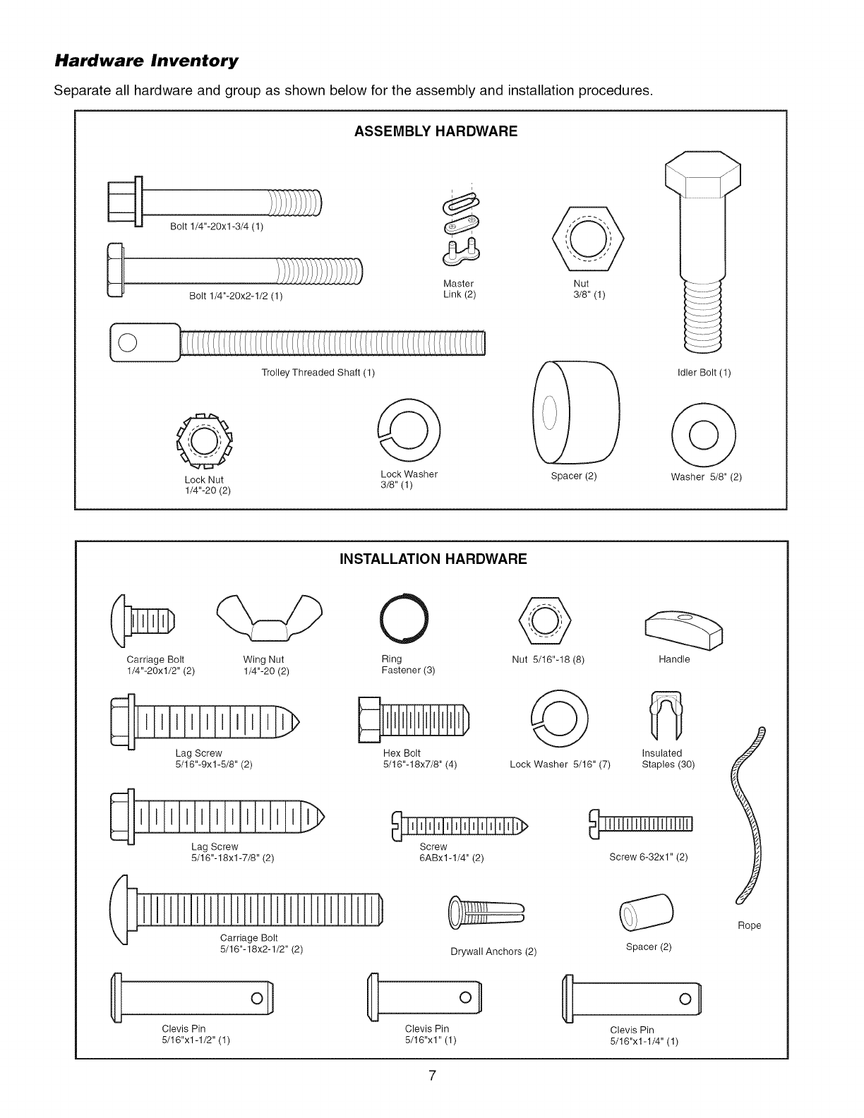
Hardware Inventory
Separate all hardware and group as shown below for the assembly and installation procedures.
ASSEMB_ HARDWARE
Bolt 1/4"-20xl-3/4 (1)
Master Nut
Bolt 1/4"-20x2-1/2 (1) Link (2) 3/8" (1)
Trolley Threaded Shaft (1)
@ @
Lock Washer
Lock Nut 3/8" (1)
1/4"-20 (2)
Spacer (2)
Idler Bolt (1)
Washer 5/8" (2)
INSTALLATION HARDWARE
Carriage Bolt
1/4"-20xl/2" (2)
Wing Nut
1/4"-20 (2)
Lag Screw
5/16"-9xl -5/8" (2)
Lag Screw
5/16"-18xl-7/8" (2)
Carriage Bolt
5/16"-18x2-1/2" (2)
Clevis Pin
5/16"x1-1/2" (1)
O
Ring
Fastener (3)
Hex Bolt
5/16"-18x7/8" (4)
@
Nut 5/16"-18 (8)
@
Lock Washer 5/16" (7)
Screw
6ABx1-1/4" (2)
Drywall Anchors (2)
o_
Clevis Pin
5/16"x1" (1)
Handle
Insulated
Staples (30)
Screw 6-32x1" (2)
Spacer (2)
o_
Clevis Pin
5/16"x1-1/4" (1)
Rope
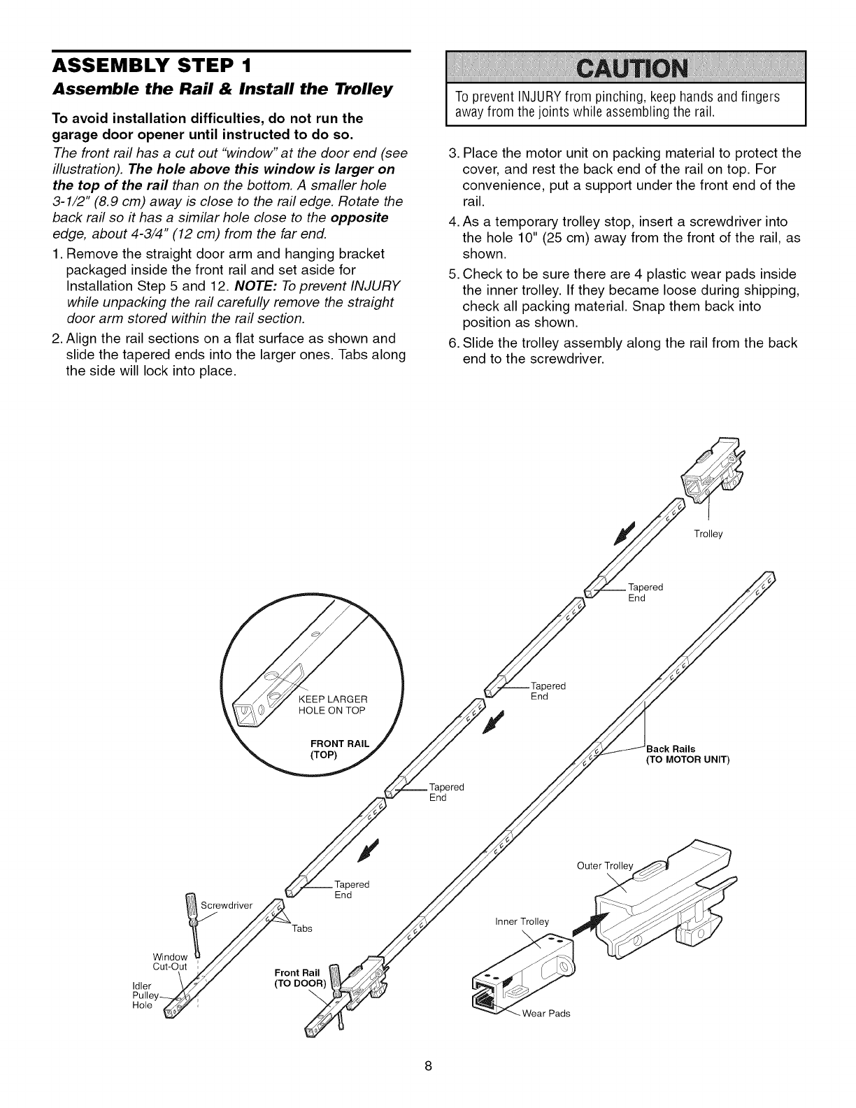
ASSEMBLY STEP 1
Assemble the Rail & Install the Trolley
To avoid installation difficulties, do not run the
garage door opener until instructed to do so.
The front rail has a cut out "window" at the door end (see
illustration). The hole above this window is larger on
the top of the rail than on the bottom. A smaller hole
3-1/2" (8.9 cm) away is close to the rail edge. Rotate the
back rail so #has a similar hole close to the opposite
edge, about 4-3/4" (12 cm) from the far end.
1. Remove the straight door arm and hanging bracket
packaged inside the front rail and set aside for
Installation Step 5 and 12. NOTE: To prevent INJURY
while unpacking the rail carefully remove the straight
door arm stored within the rail section.
2. Align the rail sections on a flat surface as shown and
slide the tapered ends into the larger ones. Tabs along
the side will lock into place.
To prevent INJURYfrom pinching, keep hands and fingers
away from the joints while assembling the rail.
3. Place the motor unit on packing material to protect the
cover, and rest the back end of the rail on top. For
convenience, put a support under the front end of the
rail.
4. As a temporary trolley stop, insert a screwdriver into
the hole 10" (25 cm) away from the front of the rail, as
shown.
5. Check to be sure there are 4 plastic wear pads inside
the inner trolley. If they became loose during shipping,
check all packing material. Snap them back into
position as shown.
6. Slide the trolley assembly along the rail from the back
end to the screwdriver.
Trolley
_red
End
KEEP LARGER
HOLE ON TOP
red
End
FRONT RAIL
(TOP)
#
red
End
_red
End
Back Rails
(TO MOTOR UNIT)
Outer Trolley
Inner Trolley
_'_ Wear Pads
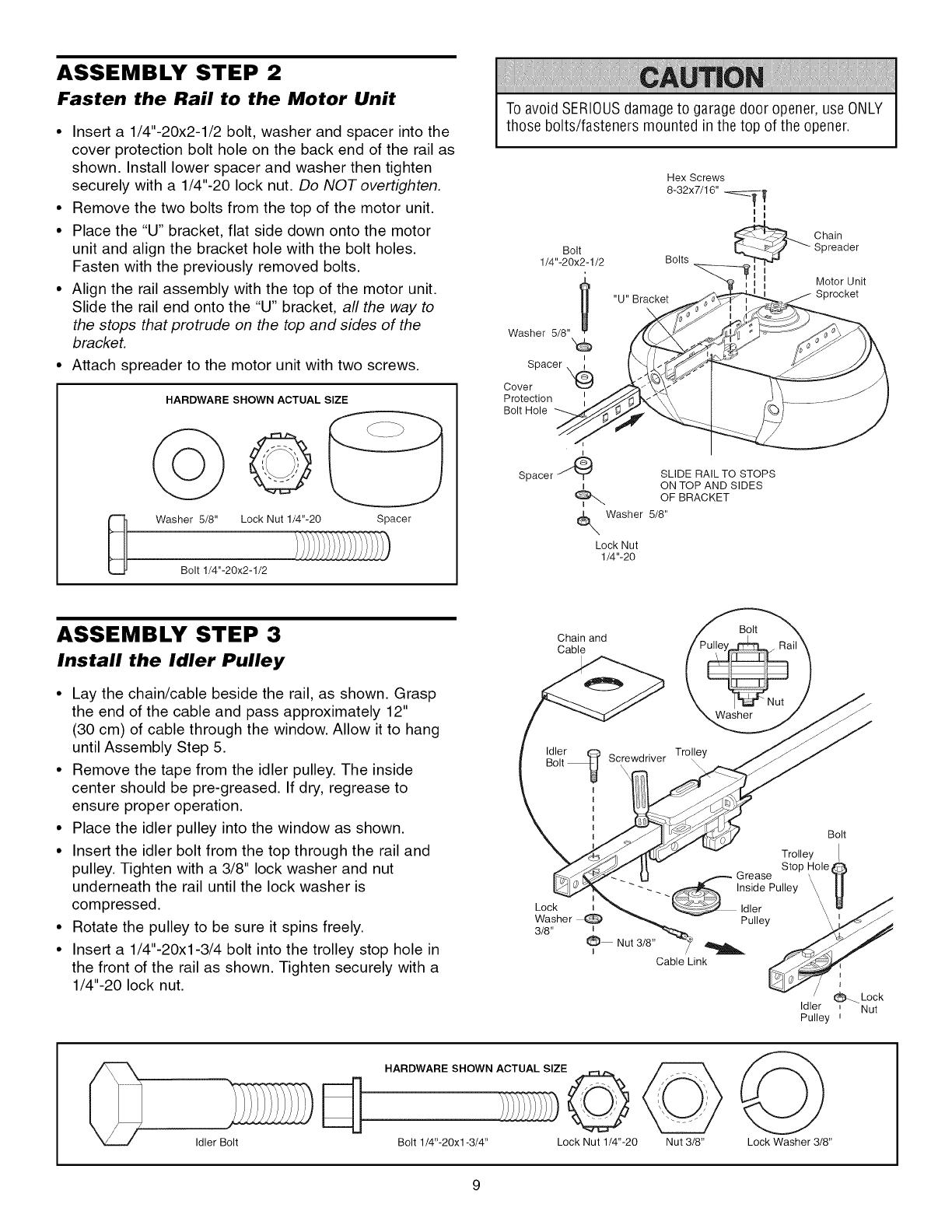
ASSEMBLY STEP 2
Fasten the Rail to the Motor Unit
•Insert a 1/4"-20x2-1/2 bolt, washer and spacer into the
cover protection bolt hole on the back end of the rail as
shown. Install lower spacer and washer then tighten
securely with a 1/4"-20 lock nut. Do NOT overtighten.
• Remove the two bolts from the top of the motor unit.
• Place the "U" bracket, flat side down onto the motor
unit and align the bracket hole with the bolt holes.
Fasten with the previously removed bolts.
• Align the rail assembly with the top of the motor unit.
Slide the rail end onto the "U" bracket, all the way to
the stops that protrude on the top and sides of the
bracket.
• Attach spreader to the motor unit with two screws.
0
Lock Nut 1/4"-20
HARDWARE SHOWN ACTUAL SIZE
Washer 5/8" Spacer
Bolt 1/4"-20x2-1/2
To avoid SERIOUSdamage to garage door opener, use ONLY
those b01ts/fasteners mounted in the top of the opener.
Bolt
1/4"-20x2-1/2
u
Washer 5/8"
Spacer
Cover X,@
Protection
Bolt Hole
Hex Screws
832x7/16" -_Ti _
_ Chain
_ Spreader
Bolts
I
_= Motor Unit
Sprocket
Spacer J "_'_" SLIDE RAIL TO STOPS
t ON TOP AND SIDES
OF BRACKET
_ Washer 5/8"
Lock Nut
1/4"-20
ASSEMBLY STEP 3
Install the Idler Pulley
• Lay the chain/cable beside the rail, as shown. Grasp
the end of the cable and pass approximately 12"
(30 cm) of cable through the window. Allow it to hang
until Assembly Step 5.
• Remove the tape from the idler pulley. The inside
center should be pre-greased. If dry, regrease to
ensure proper operation.
• Place the idler pulley into the window as shown.
• Insert the idler bolt from the top through the rail and
pulley. Tighten with a 3/8" lock washer and nut
underneath the rail until the lock washer is
compressed.
• Rotate the pulley to be sure it spins freely.
• Insert a 1/4"-20xl-3/4 bolt into the trolley stop hole in
the front of the rail as shown. Tighten securely with a
1/4"-20 lock nut.
Chain and
Cable
Bolt
Washer
Idler_ Trolley
Bolt _ Screwdriver
I
I
I
I
IBolt
Trolley
Stop Hole
_/_-- Grease
-- _lnside Pulley _\
Lock i "_ Idler \\
Washer _ Pulley
3/8" I
I Nut 3/8" _ __j
Cable Link
t
_Lock
Idler ,Nut
Pulley i
Idler Bolt
HARDWARE SHOWN ACTUAL SIZE
Bolt 1/4"-20x1-3/4" Lock Nut 1/4"-20 Nut 3/8" Lock Washer 3/8"
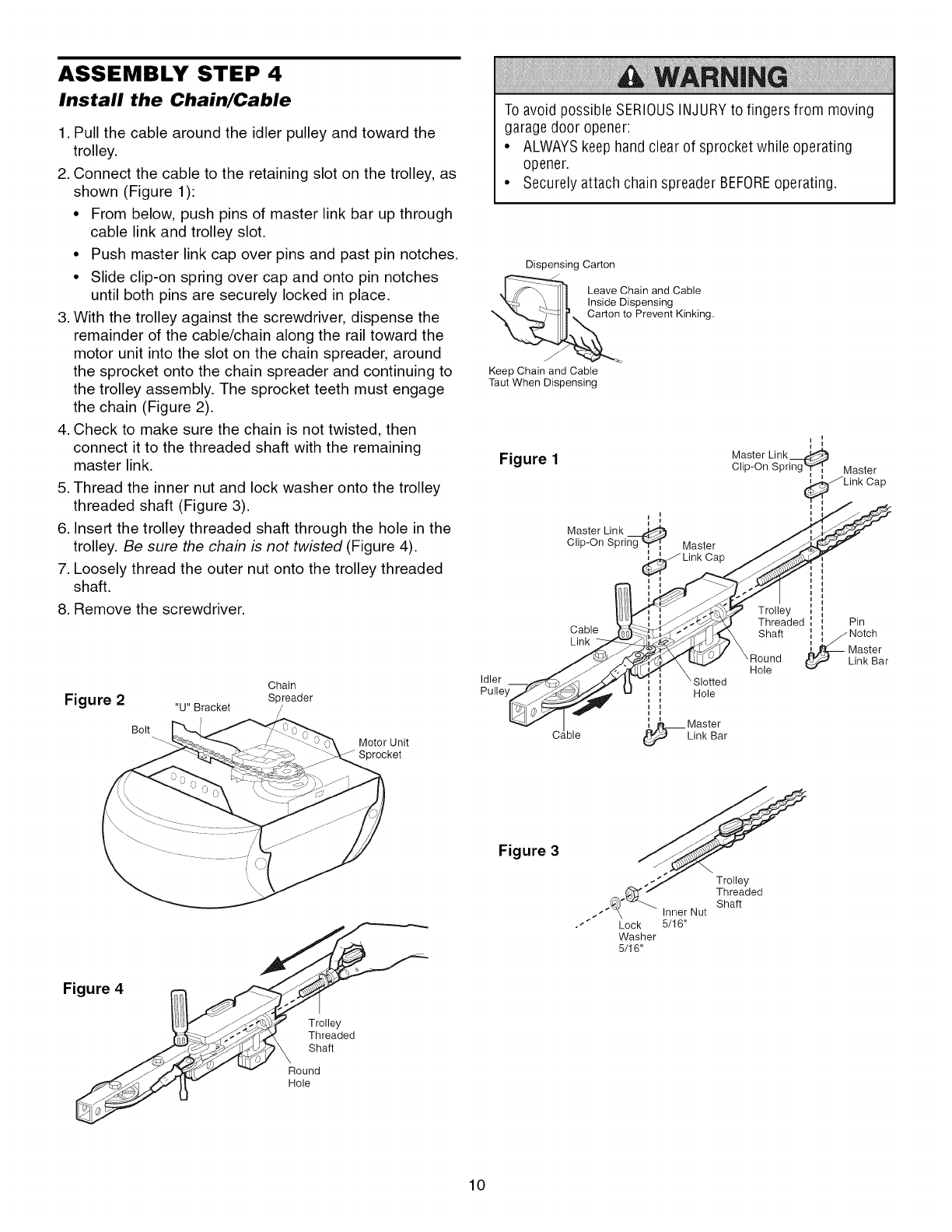
ASSEMBLY STEP 4
Install the Chain/Cable
1. Pull the cable around the idler pulley and toward the
trolley.
2. Connect the cable to the retaining slot on the trolley, as
shown (Figure 1):
• From below, push pins of master link bar up through
cable link and trolley slot.
• Push master link cap over pins and past pin notches.
• Slide clip-on spring over cap and onto pin notches
until both pins are securely locked in place.
3. With the trolley against the screwdriver, dispense the
remainder of the cable/chain along the rail toward the
motor unit into the slot on the chain spreader, around
the sprocket onto the chain spreader and continuing to
the trolley assembly. The sprocket teeth must engage
the chain (Figure 2).
4. Check to make sure the chain is not twisted, then
connect it to the threaded shaft with the remaining
master link.
5. Thread the inner nut and lock washer onto the trolley
threaded shaft (Figure 3).
6. Insert the trolley threaded shaft through the hole in the
trolley. Be sure the chain is not twisted (Figure 4).
7. Loosely thread the outer nut onto the trolley threaded
shaft.
8. Remove the screwdriver.
Chain
2Spreader
I-igure "u" Bracket
Bolt
Motor Unit
Sprocket
To avoid possible SERIOUSINJURYto fingers from moving
garage door opener:
• ALWAYSkeep hand clear of sprocket while operating
opener.
• Securely attach chain spreader BEFOREoperating.
Dispensing Carton
_ea_e Cihspin2s?dgCabIe
to Prevent Kinking.
Keep Chain and Cable
Taut When Dispensing
II
Figure 1Master Link_
Clip-On Spring'ff_q, Master
Link Cap_ _
Master Link
Clip-On Spring _ Master J_,_
L,nk cap
I i _ i II
i _ II I
ly
__'_ Th_edl i Pin
Cable ___._¢_ Shaft i i /Notch
Link _ _-_:_Jjq_4Ji_ \ i ! J
J__/ \ _ Master
JL_ _ ',Ruond _t_ Link Bar
_ _._', _, \ -Hole
Idler _ ..-___/J I,-vl ;\Slotted
Pu ,,ey_Jj,,_ U ! i Hole
i I
i i
i_Master
Cable _ Link Bar
Figure 3
.J_" Inner Nut
•_" Lock 5/16"
Washer
5/16"
Trolley
Threaded
Shaft
Figure 4
Trolley
Threaded
Shaft
Round
Hole
10
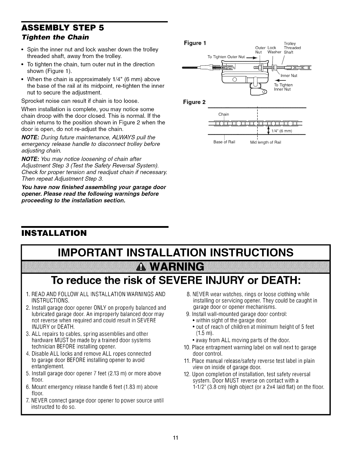
ASSEMBLY STEP 5
Tighten the Chain
•Spin the inner nut and lock washer down the trolley
threaded shaft, away from the trolley.
• To tighten the chain, turn outer nut in the direction
shown (Figure 1).
• When the chain is approximately 1/4" (6 mm) above
the base of the rail at its midpoint, re-tighten the inner
nut to secure the adjustment.
Sprocket noise can result if chain is too loose.
When installation is complete, you may notice some
chain droop with the door closed. This is normal. If the
chain returns to the position shown in Figure 2 when the
door is open, do not re-adjust the chain.
NOTE: During future maintenance, ALWAYS pull the
emergency release handle to disconnect trolley before
adjusting chain.
NOTE: You may notice loosening of chain after
Adjustment Step 3 (Test the Safety Reversal System).
Check for proper tension and readjust chain if necessary.
Then repeat Adjustment Step 3.
You have now finished assembling your garage door
opener. Please read the following warnings before
proceeding to the installation section.
Figure 1 Trolley
Outer Lock Threaded
Nut Washer Shaft
Figure 2 1
Chain
Base of Rail
1/4" (6 mm)
Mid length of Rail
INSTALLATION
IMPORTANT INSTALLATION INSTRUCTIONS
To reduce the risk of SEVERE INJURY or DEATH:
1. READAND FOLLOWALL INSTALLATIONWARNINGSAND
INSTRUCTIONS.
2. Install garage door opener ONLYon properly balanced and
lubricated garage door. An improperly balanced door may
not reversewhen required and could result in SEVERE
INJURYor DEATH.
3. ALL repairs to cables, spring assemblies and other
hardware MUST be made by atrained door systems
technician BEFOREinstalling opener.
4. Disable ALL locks and remove ALL ropes connected
to garage door BEFOREinstalling opener to avoid
entanglement.
5. Install garage door opener 7 feet (2.13 m) or more above
floor.
6. Mount emergency releasehandle 6 feet (1.83 m) above
floor.
7. NEVERconnect garage door opener to power source until
instructed to do so.
8. NEVERwear watches, rings or loose clothing while
installing or servicing opener. They could be caught in
garage door or opener mechanisms.
9. Install wall-mounted garagedoor control:
• within sight of the garagedoor.
• out of reachof children at minimum height of 5 feet
(1.5 m).
• away from ALL moving parts of the door.
10. Placeentrapment warning label on wall next to garage
door control.
11. Place manual release/safety reversetest label in plain
view on inside of garage door.
12. Upon completion of installation, test safety reversal
system. Door MUST reverseon contact with a
1-1/2"(3.8 cm) high object (or a 2x4 laid flat) on the floor.
11
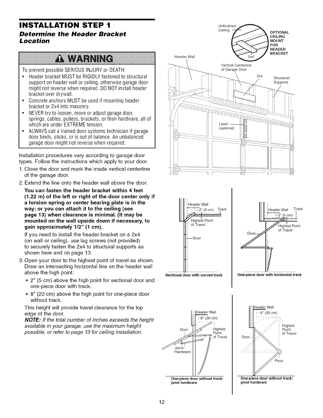
INSTALLATION STEP 1
Determine the Header Bracket
Location
To prevent possible SERIOUSINJURY or DEATH:
•Headerbracket MUST be RIGIDLYfastened to structural
support on headerwall or ceiling, otherwise garage door
might not reversewhen required. DONOTinstall header
bracket over drywall.
• Concrete anchors MUST be used if mounting header
bracket or 2x4 into masonry.
• NEVERtry to loosen, move or adjust garagedoor,
springs, cables, pulleys, brackets, or their hardware, all of
which are under EXTREMEtension.
• ALWAYScall atrained door systems technician if garage
door binds, sticks, or is out of balance.An unbalanced
garage door might not reverse when required.
Installation procedures vary according to garage door
types. Follow the instructions which apply to your door.
1. Close the door and mark the inside vertical centerline
of the garage door.
2. Extend the line onto the header wall above the door.
You can fasten the header bracket within 4 feet
(1.22 m) of the left or right of the door center only if
a torsion spring or center bearing plate is in the
way; or you can attach it to the ceiling (see
page 13) when clearance is minimal. (It may be
mounted on the wall upside down if necessary, to
gain approximately 1/2" (1 cm).
If you need to install the header bracket on a 2x4
(on wall or ceiling), use lag screws (not provided)
to securely fasten the 2x4 to structural supports as
shown here and on page 13.
3. Open your door to the highest point of travel as shown.
Draw an intersecting horizontal line on the header wall
above the high point:
• 2" (5 cm) above the high point for sectional door and
one-piece door with track.
• 8" (20 cm) above the high point for one-piece door
without track.
This height will provide travel clearance for the top
edge of the door.
NOTE: If the total number of inches exceeds the height
available in your garage, use the maximum height
possible, or refer to page 13 for ceiling installation.
Header Wall
Unfinished
Ceiling _ CEILINGOPTIONALBRACKETHEADERFORMOUNT
Vertical Centerline
of Garage Door
2x4 Structural
Suppor[s
Header Wall
_---'r-i---2" (5 cm) Track
Highest Point
of Travel
--Door
Sectional door with curved track
Header Wall Track
nt
One-piece door with horizontal track
_Wall
0oor °Ci:hos
Point
_Hardware i of Travel
One-piece door without track:
jamb hardware
Doe
Header Wall
8" (20 ore)
Highest
Point
of Travel
Pivot
One-piece door without track:
pivot hardware
12
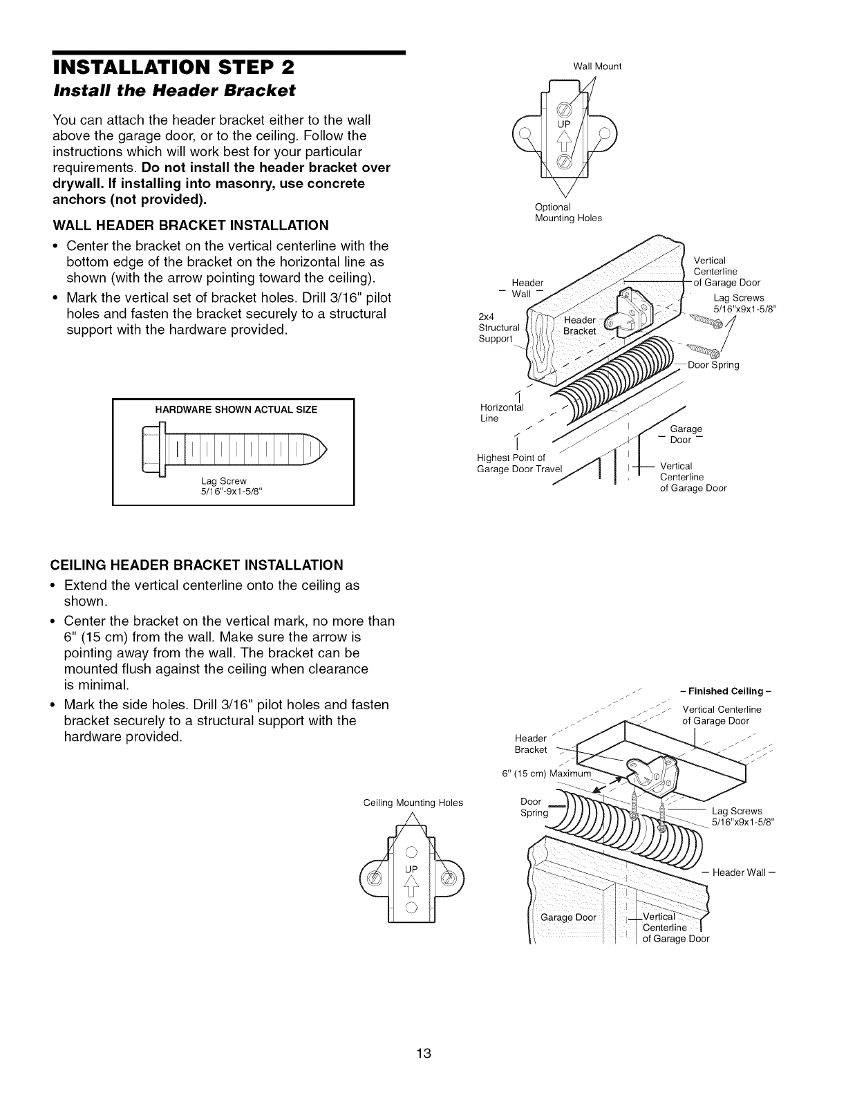
INSTALLATION STEP 2
Install the Header Bracket
You can attach the header bracket either to the wall
above the garage door, or to the ceiling. Follow the
instructions which will work best for your particular
requirements. Do not install the header bracket over
drywall. If installing into masonry, use concrete
anchors (not provided).
WALL HEADER BRACKET INSTALLATION
•Center the bracket on the vertical centerline with the
bottom edge of the bracket on the horizontal line as
shown (with the arrow pointing toward the ceiling).
• Mark the vertical set of bracket holes. Drill 3/16" pilot
holes and fasten the bracket securely to a structural
support with the hardware provided.
HARDWARE SHOWN ACTUAL SIZE
Lag Screw
5/16"-9xl -5/8"
Header
- Wall-
2x4
Structural
Support
I
Horizontal
Line
j
Highest Point of
Garage Door Travel
Wall Mount
Optional
Mounting Holes
Vertical
Centerline
Door
Lag Screws
5/16"x9x1-5/8"
Spring
Garage
-- Door-
Vertical
Centerline
of Garage Door
CEILING HEADER BRACKET INSTALLATION
• Extend the vertical centerline onto the ceiling as
shown.
• Center the bracket on the vertical mark, no more than
6" (15 cm) from the wall. Make sure the arrow is
pointing away from the wall. The bracket can be
mounted flush against the ceiling when clearance
is minimal.
• Mark the side holes. Drill 3/16" pilot holes and fasten
bracket securely to a structural support with the
hardware provided.
Ceiling Mounting Holes
i
Header _
Bracket
6" (15 cm) Maximurr
Door
Spring
- Finished Ceiling -
Vertical Centerline
of Garage Door
-- Lag Screws
5/16"x9x1-5/8"
-- Header Wall --
Center!ine
of Garage Door
13
Wall
Header Bracket
Idler Pulley
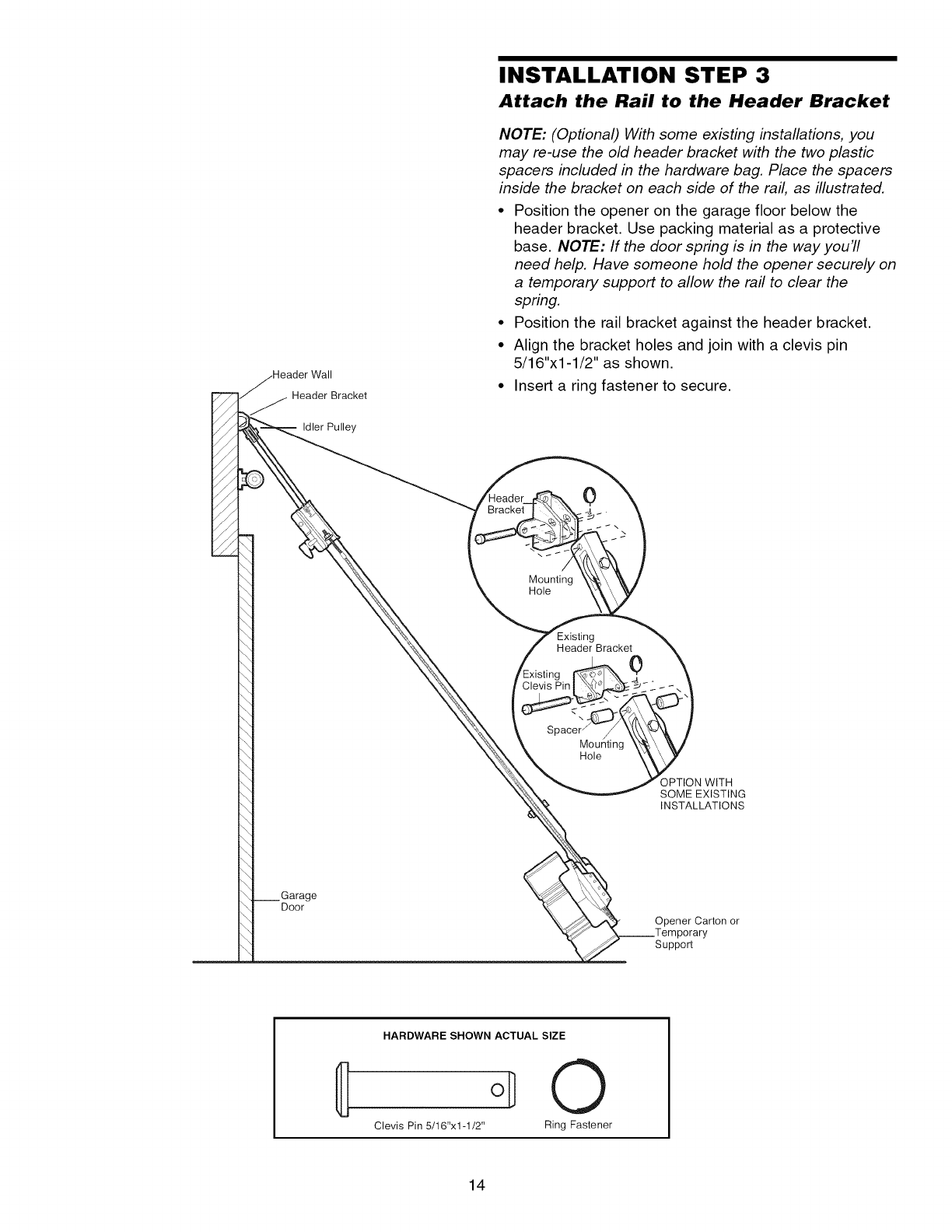
INSTALLATION STEP 3
Attach the Rail to the Header Bracket
NOTE: (Optional) With some existing installations, you
may re-use the old header bracket with the two plastic
spacers included in the hardware bag. Place the spacers
inside the bracket on each side of the rail, as illustrated.
• Position the opener on the garage floor below the
header bracket. Use packing material as a protective
base. NOTE: If the door spring is in the way you'll
need help. Have someone hold the opener securely on
a temporary support to allow the rail to clear the
spring.
• Position the rail bracket against the header bracket.
• Align the bracket holes and join with a clevis pin
5/16"x1-1/2" as shown.
• Insert a ring fastener to secure.
0
Mounting
Hole
Existing
Header Bracket 0
Spacer j
Mou¢
Hole
OPTION WITH
SOME EXISTING
INSTALLATIONS
Door
°°__ __ Opener Carton or
_.._Temporary
_Suppor[
HARDWARE SHOWN ACTUAL SIZE
oD0
Clevis Pin 5/16"x1-1/2" Ring Fastener
14
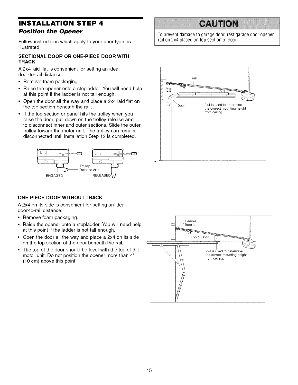
INSTALLATION STEP 4
Position the Opener
Follow instructions which apply to your door type as
illustrated.
SECTIONAL DOOR OR ONE-PIECE DOOR WITH
TRACK
A 2x4 laid flat is convenient for setting an ideal
door-to-rail distance.
• Remove foam packaging.
• Raise the opener onto a stepladder. You will need help
at this point if the ladder is not tall enough.
• Open the door all the way and place a 2x4 laid flat on
the top section beneath the rail.
• If the top section or panel hits the trolley when you
raise the door, pull down on the trolley release arm
to disconnect inner and outer sections. Slide the outer
trolley toward the motor unit. The trolley can remain
disconnected until Installation Step 12 is completed.
To prevent damage to garagedoor, rest garage door opener
rail on 2x4 placed on top section of door.
Rail
ENGAGED
ONE-PIECE DOOR WITHOUT TRACK
A 2x4 on its side is convenient for setting an ideal
door-to-rail distance.
• Remove foam packaging.
• Raise the opener onto a stepladder. You will need help
at this point if the ladder is not tall enough.
• Open the door all the way and place a 2x4 on its side
on the top section of the door beneath the rail.
• The top of the door should be level with the top of the
motor unit. Do not position the opener more than 4"
(10 cm) above this point.
L-.-
I
Header !ii
2x4 is used to determine
the correct mounting height
from ceiling.
15
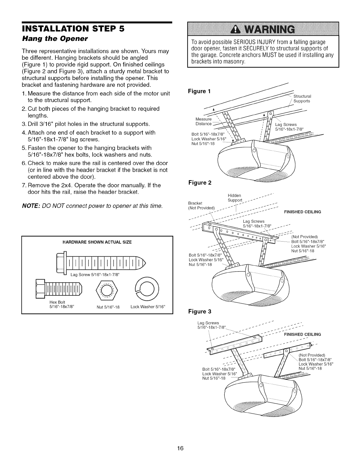
INSTALLATION STEP 5
Hang the Opener
Three representative installations are shown. Yours may
be different. Hanging brackets should be angled
(Figure 1) to provide rigid support. On finished ceilings
(Figure 2 and Figure 3), attach a sturdy metal bracket to
structural supports before installing the opener. This
bracket and fastening hardware are not provided.
1. Measure the distance from each side of the motor unit
to the structural support.
2. Cut both pieces of the hanging bracket to required
lengths.
3. Drill 3/16" pilot holes in the structural supports.
4. Attach one end of each bracket to a support with
5/16"-18xl -7/8" lag screws.
5. Fasten the opener to the hanging brackets with
5/16"-18x7/8" hex bolts, lock washers and nuts.
6. Check to make sure the rail is centered over the door
(or in line with the header bracket if the bracket is not
centered above the door).
7. Remove the 2x4. Operate the door manually. If the
door hits the rail, raise the header bracket.
NOTE: DO NOT connect power to opener at this time.
HARDWARE SHOWN ACTUAL SIZE
Lag Screw 5/16"-18xl -7/8"
Hex Bolt
5/16"- 18x7/8" Nut 5/16"- 18 Lock Washer 5/16"
To avoid possible SERIOUSINJURYfrom afalling garage
door opener, fasten it SECURELYto structural supports of
the garage. Concrete anchors MUST be used if installing any
brackets into masonry.
Figure 1
/Supports
Measure ',
Distance Lag Screws
5/16"- 18x 1-7/8"
Bolt 5/16"-18x7/8" ,,
Lock Washer 5/16"
Nut 5/16"-18
Figure 2
Bolt 5/16"-18x7/8"
Lock Washer 5/16'
Nut 5/16"-18
FmNISHED CEmLING
SS-
(Not Provided)
......... Bolt 5/16"- 18x7/8"
Lock Washer 5/16"
Nut 5/16"-18
Figure 3
Lag Screws
5/16"-18xl -7/8".
Bolt 5/16"- 18x7/8"
Lock Washer 5/18"
Nut 5/16"-18
(Not Provided)
Lock Washer 5/18"
Nut 5/16"-18
16
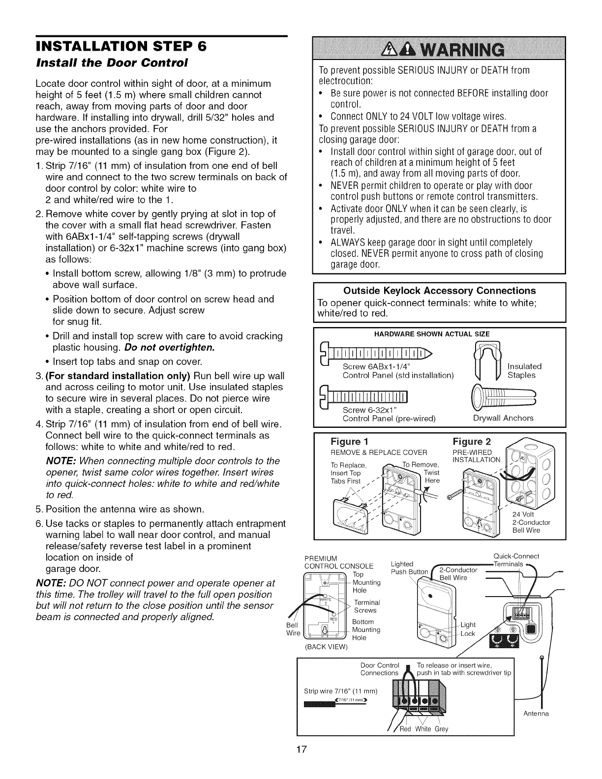
INSTALLATION STEP 6
Install the Door Control
Locate door control within sight of door, at a minimum
height of 5 feet (1.5 m) where small children cannot
reach, away from moving parts of door and door
hardware. If installing into drywall, drill 5/32" holes and
use the anchors provided. For
pre-wired installations (as in new home construction), it
may be mounted to a single gang box (Figure 2).
1. Strip 7/16" (11 mm) of insulation from one end of bell
wire and connect to the two screw terminals on back of
door control by color: white wire to
2 and white/red wire to the 1.
2. Remove white cover by gently prying at slot in top of
the cover with a small flat head screwdriver. Fasten
with 6ABx1-1/4" self-tapping screws (drywall
installation) or 6-32x1" machine screws (into gang box)
as follows:
• Install bottom screw, allowing 1/8" (3 mm) to protrude
above wall surface.
• Position bottom of door control on screw head and
slide down to secure. Adjust screw
for snug fit.
• Drill and install top screw with care to avoid cracking
plastic housing. Do not overtighten.
• Insert top tabs and snap on cover.
3. (For standard installation only) Run bell wire up wall
and across ceiling to motor unit. Use insulated staples
to secure wire in several places. Do not pierce wire
with a staple, creating a short or open circuit.
4. Strip 7/16" (11 mm) of insulation from end of bell wire.
Connect bell wire to the quick-connect terminals as
follows: white to white and white/red to red.
NOTE: When connecting multiple door controls to the
opener, twist same color wires together. Insert wires
into quick-connect holes: white to wh#e and red/wh#e
to red.
5. Position the antenna wire as shown.
6. Use tacks or staples to permanently attach entrapment
warning label to wall near door control, and manual
release/safety reverse test label in a prominent
location on inside of
garage door.
NOTE: DO NOT connect power and operate opener at
this time. The trolley will travel to the full open position
but will not return to the close position until the sensor
beam is connected and properly aligned.
To prevent possible SERIOUSINJURY or DEATHfrom
electrocution:
• Besure power is not connected BEFOREinstalling door
control.
• Connect ONLYto 24 VOLT low voltage wires.
To prevent possible SERIOUSINJURY or DEATHfrom a
closing garage door:
• Install door control within sight of garage door, out of
reach of children at a minimum height of 5 feet
(1.5 m), and away from all moving parts of door.
• NEVERpermit children to operate or play with door
control push buttons or remote control transmitters.
• Activate door ONLYwhen it can be seen clearly, is
properly adjusted, and there are no obstructions to door
travel.
• ALWAYSkeep garage door in sight until completely
closed. NEVERpermit anyone to cross path of closing
garage door.
Outside Keylock Accessory Connections
To opener quick-connect terminals: white to white;
white/red to red.
HARDWARE SHOWN ACTUAL SIZE
Control Panel (std installation)
Control Panel (pre-wired)
insulated
Staples
DrywallAnchors
Figure 1
REMOVE & REPLACE COVER
TOReplace,
Insert Top
Tabs First / _ _'
Twist
Here
Figure 2
PRE-WIRED
INSTALLATION
24 Volt
2-Conductor
Bell Wire
PREMIUM Quick-Connect
Lighted _Terminals
CONTROL CONSOLE Push Button jr 2-Conductor
Top
I _t Mounting
Ho,e
,,_L_ _ _ Terminal
/I "_1_[ Screws
BellI_"_ _ I Bottom
Wire I __ Mounting I;_.'_.-_ L_ Li!
"_ Hole ....Lc
(BACK VIEW)
Door Control To release or insert wire,
Connections 3ush in tab with screwdriver tip
Strip wire 7/16" (11 mm)
7/16" (11 mrn)_
\
_ed White Grey
Antenna
17
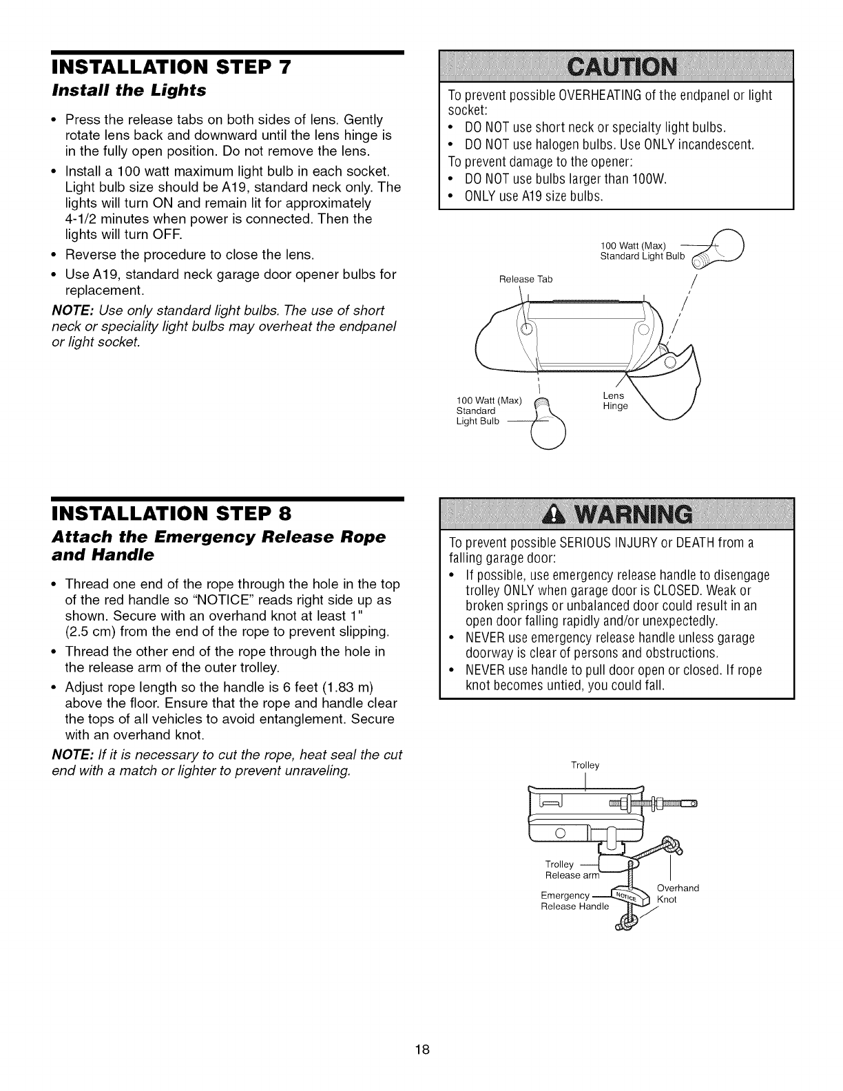
INSTALLATION STEP 7
Install the Lights
•Press the release tabs on both sides of lens. Gently
rotate lens back and downward until the lens hinge is
in the fully open position. Do not remove the lens.
• Install a 100 watt maximum light bulb in each socket.
Light bulb size should be A19, standard neck only. The
lights will turn ON and remain lit for approximately
4-1/2 minutes when power is connected. Then the
lights will turn OFR
• Reverse the procedure to close the lens.
• Use A19, standard neck garage door opener bulbs for
replacement.
NOTE: Use only standard light bulbs. The use of short
neck or speciality light bulbs may overheat the endpanel
or light socket.
To prevent possible OVERHEATINGof the endpanel or light
socket:
• DO NOTuse short neck or specialty light bulbs.
• DO NOTuse halogen bulbs. UseONLYincandescent.
To prevent damage to the opener:
• DO NOTuse bulbs largerthan IOOW.
• ONLYuse A19 size bulbs.
Release Tab
100 Watt (Max)
Standard Light Bulb
/
/
/
/
100 Watt (Max)
Standard
Light Bulb --
Lens
Hinge
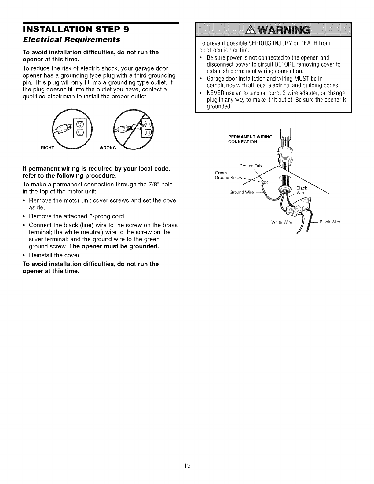
INSTALLATION STEP 8
Attach the Emergency Release Rope
and Handle
• Thread one end of the rope through the hole in the top
of the red handle so "NOTICE" reads right side up as
shown. Secure with an overhand knot at least 1"
(2.5 cm) from the end of the rope to prevent slipping.
• Thread the other end of the rope through the hole in
the release arm of the outer trolley.
• Adjust rope length so the handle is 6 feet (1.83 m)
above the floor. Ensure that the rope and handle clear
the tops of all vehicles to avoid entanglement. Secure
with an overhand knot.
NOTE: If it is necessary to cut the rope, heat seal the cut
end with a match or lighter to prevent unraveling.
To prevent possible SERIOUSINJURYor DEATHfrom a
falling garage door:
• If possible, use emergency release handleto disengage
trolley ONLYwhen garage door is CLOSED.Weakor
broken springs or unbalanced door could result in an
open door falling rapidly and/or unexpectedly.
• NEVERuse emergency release handle unless garage
doorway is clear of persons and obstructions.
• NEVERuse handle to pull door open or closed. If rope
knot becomes untied, you could fall.
Trolley
!
Release arm
Emergency _ _verhandnot
Release Handle
d
18
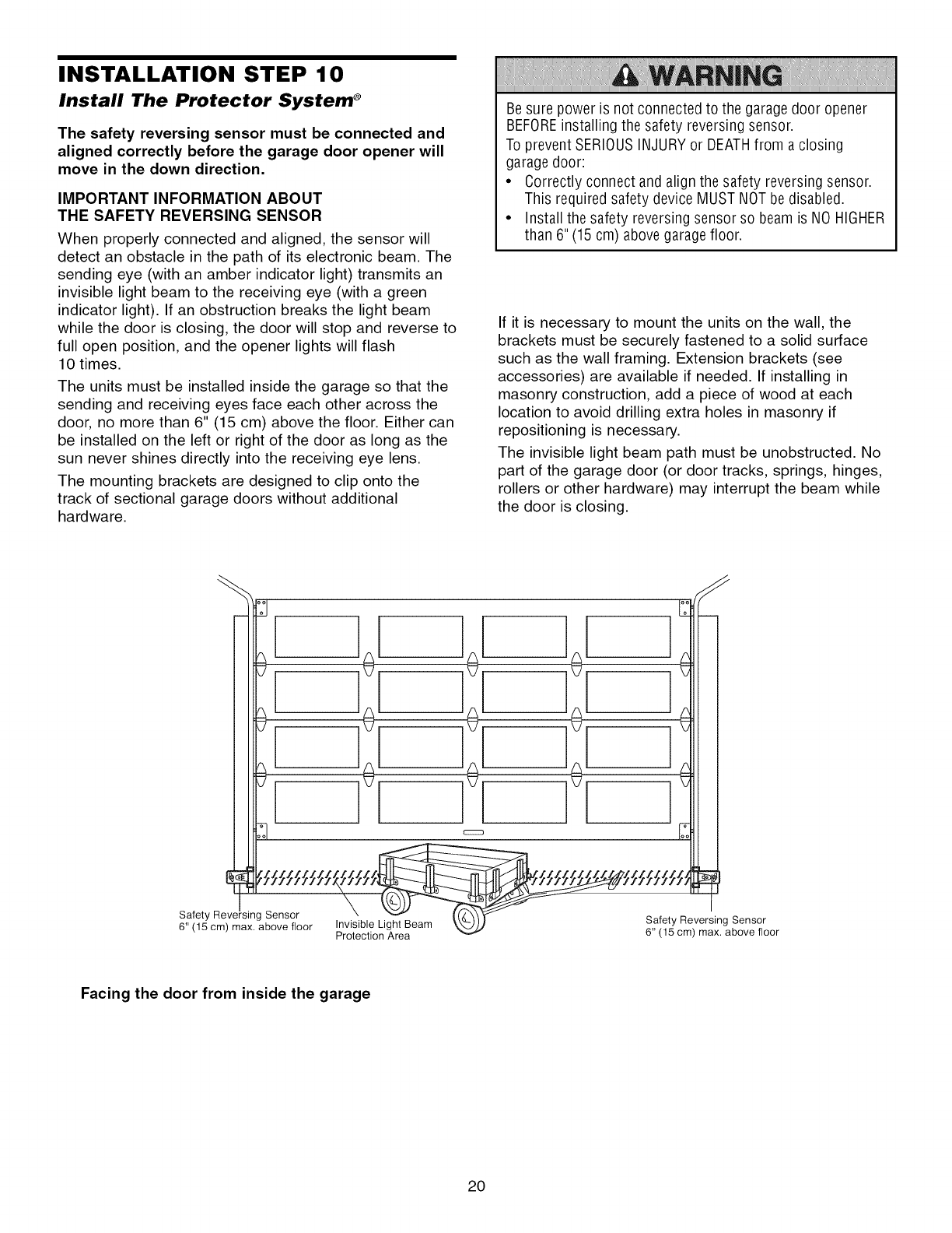
INSTALLATION STEP 9
Electrical Requirements
To avoid installation difficulties, do not run the
opener at this time.
To reduce the risk of electric shock, your garage door
opener has a grounding type plug with a third grounding
pin. This plug will only fit into a grounding type outlet. If
the plug doesn't fit into the outlet you have, contact a
qualified electrician to install the proper outlet.
To prevent possible SERIOUSINJURYor DEATHfrom
electrocution or fire:
• Besure power is not connected to the opener, and
disconnect power to circuit BEFOREremoving cover to
establish permanent wiring connection.
• Garagedoor installation and wiring MUST be in
compliance with all local electrical and building codes.
• NEVERuse an extension cord, 2-wire adapter,or change
plug in any way to make it fit outlet. Be sure the opener is
grounded.
PERMANENT WIRING
CONNECTION
If permanent wiring is required by your local code,
refer to the following procedure.
To make a permanent connection through the 7/8" hole
in the top of the motor unit:
• Remove the motor unit cover screws and set the cover
aside.
• Remove the attached 3-prong cord.
• Connect the black (line) wire to the screw on the brass
terminal; the white (neutral) wire to the screw on the
silver terminal; and the ground wire to the green
ground screw. The opener must be grounded.
• Reinstall the cover.
To avoid installation difficulties, do not run the
opener at this time.
Ground Tab
Green
Ground Screw
Black
Ground Wire Wire
White Wire Black Wire
19
INSTALLATION STEP 10
Install The Protector System ®
The safety reversing sensor must be connected and
aligned correctly before the garage door opener will
move in the down direction.
IMPORTANT INFORMATION ABOUT
THE SAFETY REVERSING SENSOR
When properly connected and aligned, the sensor will
detect an obstacle in the path of its electronic beam. The
sending eye (with an amber indicator light) transmits an
invisible light beam to the receiving eye (with a green
indicator light). If an obstruction breaks the light beam
while the door is closing, the door will stop and reverse to
full open position, and the opener lights will flash
10 times.
The units must be installed inside the garage so that the
sending and receiving eyes face each other across the
door, no more than 6" (15 cm) above the floor. Either can
be installed on the left or right of the door as long as the
sun never shines directly into the receiving eye lens.
The mounting brackets are designed to clip onto the
track of sectional garage doors without additional
hardware.
Be sure power is not connected to the garagedoor opener
BEFOREinstalling the safety reversing sensor.
To prevent SERIOUSINJURYor DEATHfrom a closing
garage door:
• Correctly connect and align the safety reversing sensor.
This required safety device MUST NOTbedisabled.
• Install the safety reversing sensor so beam is NO HIGHER
than 6" (15 cm) above garage floor.
If it is necessary to mount the units on the wall, the
brackets must be securely fastened to a solid surface
such as the wall framing. Extension brackets (see
accessories) are available if needed. If installing in
masonry construction, add a piece of wood at each
location to avoid drilling extra holes in masonry if
repositioning is necessary.
The invisible light beam path must be unobstructed. No
part of the garage door (or door tracks, springs, hinges,
rollers or other hardware) may interrupt the beam while
the door is closing.
Facing the door from inside the garage
20
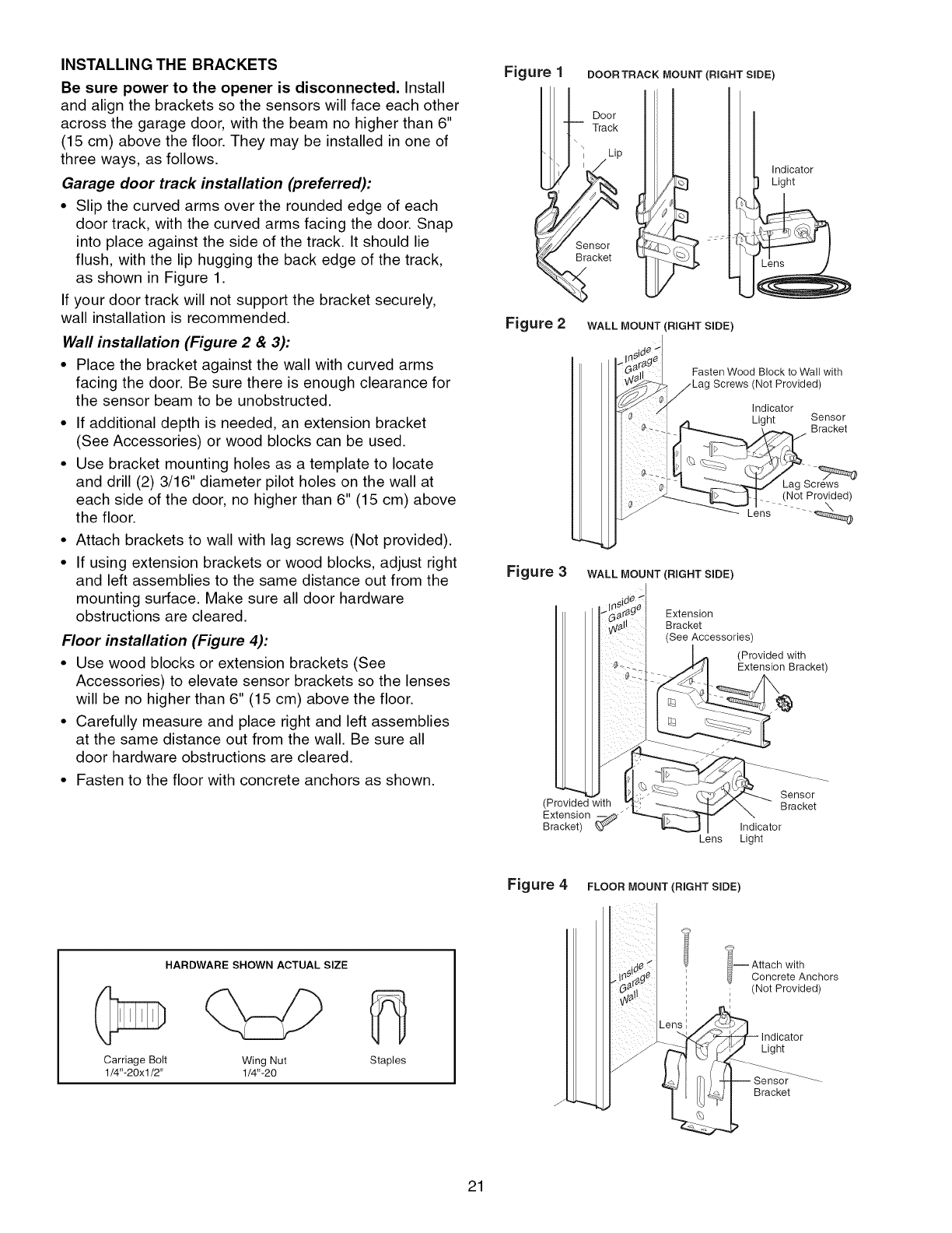
INSTALLING THE BRACKETS
Be sure power to the opener is disconnected. Install
and align the brackets so the sensors will face each other
across the garage door, with the beam no higher than 6"
(15 cm) above the floor. They may be installed in one of
three ways, as follows.
Garage door track installation (preferred):
•Slip the curved arms over the rounded edge of each
door track, with the curved arms facing the door. Snap
into place against the side of the track. It should lie
flush, with the lip hugging the back edge of the track,
as shown in Figure 1.
If your door track will not support the bracket securely,
wall installation is recommended.
Wall installation (Figure 2 & 3):
• Place the bracket against the wall with curved arms
facing the door. Be sure there is enough clearance for
the sensor beam to be unobstructed.
• If additional depth is needed, an extension bracket
(See Accessories) or wood blocks can be used.
• Use bracket mounting holes as a template to locate
and drill (2) 3/16" diameter pilot holes on the wall at
each side of the door, no higher than 6" (15 cm) above
the floor.
• Attach brackets to wall with lag screws (Not provided).
• If using extension brackets or wood blocks, adjust right
and left assemblies to the same distance out from the
mounting surface. Make sure all door hardware
obstructions are cleared.
Floor installation (Figure 4):
• Use wood blocks or extension brackets (See
Accessories) to elevate sensor brackets so the lenses
will be no higher than 6" (15 cm) above the floor.
• Carefully measure and place right and left assemblies
at the same distance out from the wall. Be sure all
door hardware obstructions are cleared.
• Fasten to the floor with concrete anchors as shown.
Figure 1 DOOR TRACK MOUNT (RIGHT SIDE)
Figure 2
Door
Track
Sensor
Bracket
WALL MOUNT (RIGHT SIDE)
Indicator
Light
Figure 3
Fasten Wood Block to Wall with
Not Provided)
Indicator
Light Sensor
_ Bracket
_'_ Lens ......
WALL MOUNT (RIGHT SIDE)
Extension
Bracket
(See Accessories)
(Provided with
Extension Bracket)
(Provided with
Extension __
Bracket) _
Sensor
Bracket
Indicator
Lens Light
Figure 4 FLOOR MOUNT (RIGHT SIDE)
HARDWARE SHOWN ACTUAL SIZE
Carriage Bolt Wing Nut
1/4"-20xl/2" 1/4"-20 Staples
J
-- ttach with
Concrete Anchors
(Not Provided)
Light
Bracket
21
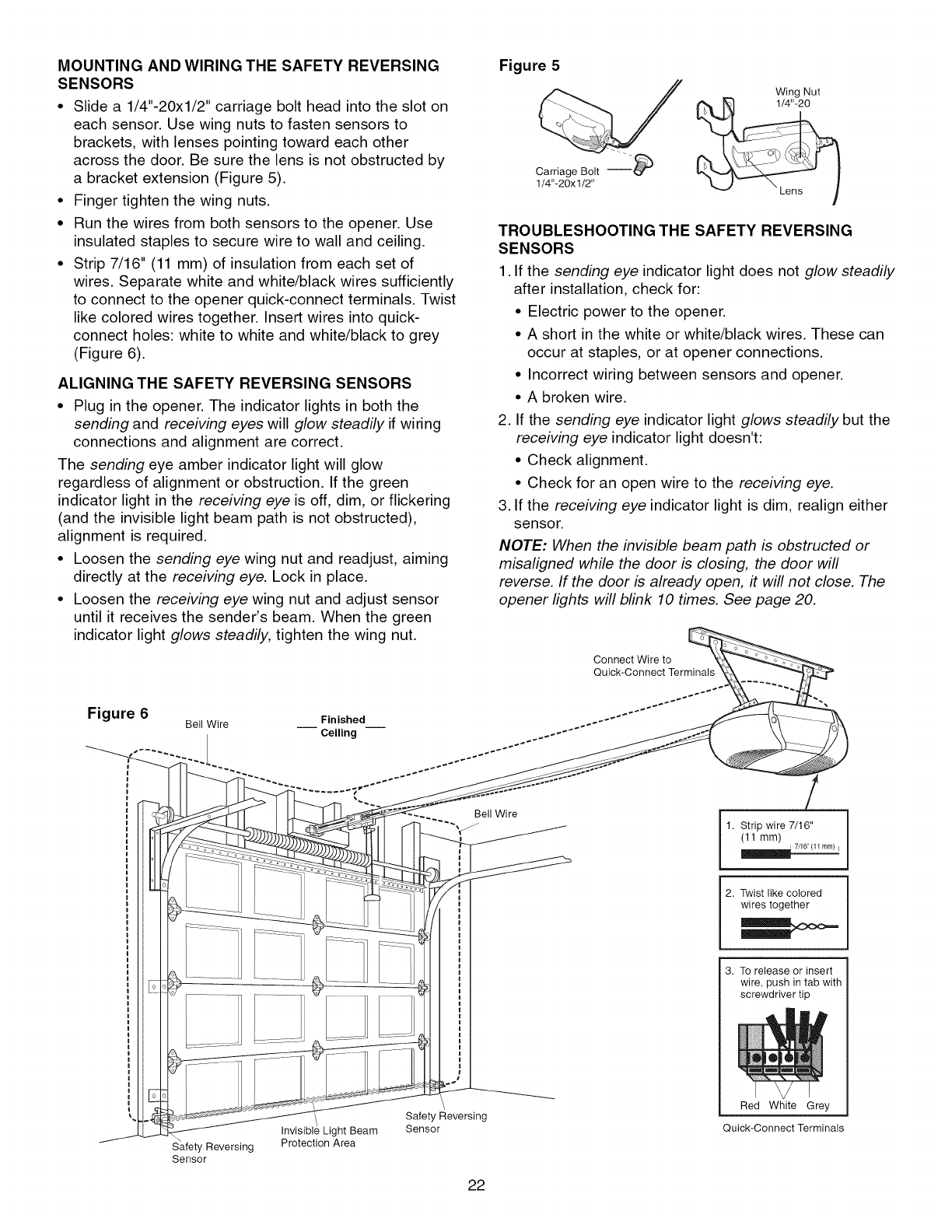
MOUNTING AND WIRING THE SAFETY REVERSING
SENSORS
• Slide a 1/4"-20xl/2" carriage bolt head into the slot on
each sensor. Use wing nuts to fasten sensors to
brackets, with lenses pointing toward each other
across the door. Be sure the lens is not obstructed by
a bracket extension (Figure 5).
• Finger tighten the wing nuts.
• Run the wires from both sensors to the opener. Use
insulated staples to secure wire to wall and ceiling.
• Strip 7/16" (11 mm) of insulation from each set of
wires. Separate white and white/black wires sufficiently
to connect to the opener quick-connect terminals. Twist
like colored wires together. Insert wires into quick-
connect holes: white to white and white/black to grey
(Figure 6).
ALIGNING THE SAFETY REVERSING SENSORS
• Plug in the opener. The indicator lights in both the
sending and receiving eyes will glow steadily if wiring
connections and alignment are correct.
The sending eye amber indicator light will glow
regardless of alignment or obstruction. If the green
indicator light in the receiving eye is off, dim, or flickering
(and the invisible light beam path is not obstructed),
alignment is required.
• Loosen the sending eye wing nut and readjust, aiming
directly at the receiving eye. Lock in place.
• Loosen the receiving eye wing nut and adjust sensor
until it receives the sender's beam. When the green
indicator light glows steadily, tighten the wing nut.
Figure 6 Bell Wire __ Finished
Ceiling
Figure 5
Wing Nut
TROUBLESHOOTING THE SAFETY REVERSING
SENSORS
1. If the sending eye indicator lightdoes not glow steadily
after installation, check for:
• Electric power to the opener.
• A short in the white or white/black wires. These can
occur at staples, or at opener connections.
• Incorrect wiring between sensors and opener.
• A broken wire.
2. If the sending eye indicator light glows steadily but the
receiving eye indicator light doesn't:
• Check alignment.
• Check for an open wire to the receiving eye.
3. If the receiving eye indicator light is dim, realign either
sensor.
NOTE: When the invisible beam path is obstructed or
misaligned while the door is closing, the door will
reverse. If the door is already open, #will not close. The
opener lights will blink 10 times. See page 20.
Connect Wire to
Quick-Connect Terminals
Safety Reversing
Sensor
Invisible Light Beam
Protection Area
Bell Wire
Safet Reversing
Sensor
22
1. Strip wire 7/16"
(11 mm)
2. Twist like colored
wires together
3. To release or insert
wire, push in tab with
screwdriver tip
Red White Grey
Quick-Connect Terminals
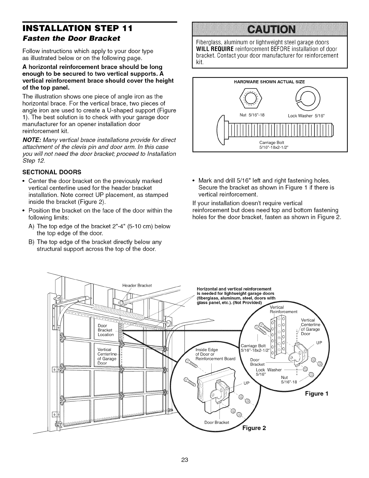
INSTALLATION STEP 11
Fasten the Door Bracket
Follow instructions which apply to your door type
as illustrated below or on the following page.
A horizontal reinforcement brace should be long
enough to be secured to two vertical supports. A
vertical reinforcement brace should cover the height
of the top panel.
The illustration shows one piece of angle iron as the
horizontal brace. For the vertical brace, two pieces of
angle iron are used to create a U-shaped support (Figure
1). The best solution is to check with your garage door
manufacturer for an opener installation door
reinforcement kit.
NOTE: Many vertical brace installations provide for direct
attachment of the clevis pin and door arm. In this case
you will not need the door bracket; proceed to Installation
Step 12.
SECTIONAL DOORS
• Center the door bracket on the previously marked
vertical centerline used for the header bracket
installation. Note correct UP placement, as stamped
inside the bracket (Figure 2).
• Position the bracket on the face of the door within the
following limits:
A) The top edge of the bracket 2"-4" (5-10 cm) below
the top edge of the door.
B) The top edge of the bracket directly below any
structural support across the top of the door.
Fiberglass, aluminum or lightweight steel garage doors
WILL REQUIREreinforcement BEFOREinstallation of door
bracket. Contact your door manufacturer for reinforcement
kit.
HARDWARE SHOWN ACTUAL SIZE
Nut 5/16"-18 Lock Washer 5/16"
Carriage Bolt
5/16"-18x2-1/2'
• Mark and drill 5/16" left and right fastening holes.
Secure the bracket as shown in Figure 1 if there is
vertical reinforcement.
If your installation doesn't require vertical
reinforcement but does need top and bottom fastening
holes for the door bracket, fasten as shown in Figure 2.
Header Bracket
/Horizontal and vertical reinforcement
is needed for lightweight garage doors
(fiberglass, aluminum, steel, doors with
glass panel, etc.). (Not Provided) Vertical
Reinforcement
ge
of Door or
einforcement Board
Carriage Bolt
5/16"- 18x2-1/2'
Door
Bracket
_@ Lock Washer
Door Bracket
Figure 2
Door
UP
=
Nut
5/16"-18
Figure 1
23
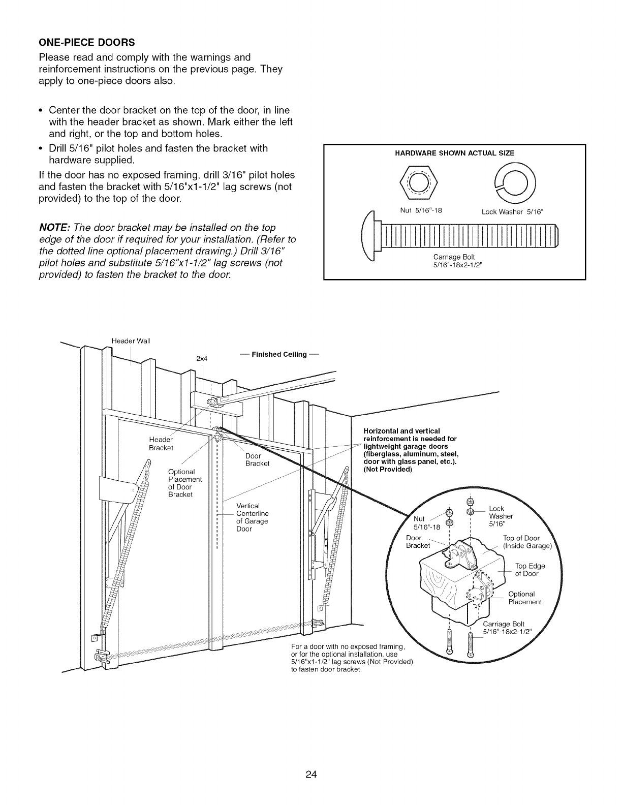
ONE-PIECEDOORS
Please read and comply with the warnings and
reinforcement instructions on the previous page. They
apply to one-piece doors also.
• Center the door bracket on the top of the door, in line
with the header bracket as shown. Mark either the left
and right, or the top and bottom holes.
• Drill 5/16" pilot holes and fasten the bracket with
hardware supplied.
If the door has no exposed framing, drill 3/16" pilot holes
and fasten the bracket with 5/16"x1-1/2" lag screws (not
provided) to the top of the door.
NOTE: The door bracket may be installed on the top
edge of the door if required for your installation. (Refer to
the dotted line optional placement drawing.) Drill 3/16"
pilot holes and substitute 5/16"x1-1/2" lag screws (not
provided) to fasten the bracket to the door.
HARDWARE SHOWN ACTUAL SIZE
Nut 5/16"-18 Lock Washer 5/16"
Carriage Bolt
5/16"-18x2-1/2"
Header Wall
2x4 -- Finished Ceiling --
Header
Bracket
Optional
Placement
of Door
Bracket
Door
Bracket
Vertical
Centerline
of Garage
Door
Horizontal and vertical
reinforcement is needed for
edoors
(fiberglass, aluminum, steel,
door with glass panel, etc.).
(Not Provided)
5/16"-18_
Door
For a door with no exposed framing,
or for the optional installation, use
5/16"x1-1/2" lag screws (Not Provided)
to fasten door bracket.
®
LockWasher
5/16"
Top of Door
Top Edge
of Door
Optional
Placement
Carriage Bolt
5/16"-18x2-1/2"
24
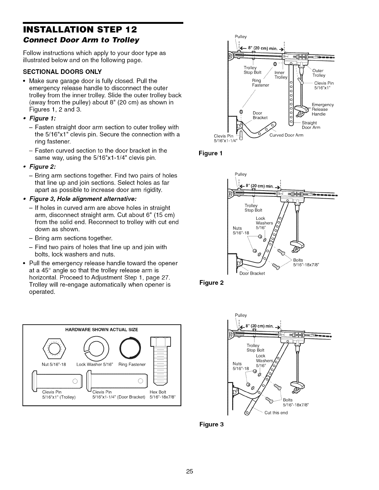
INSTALLATION STEP 12
Connect Door Arm to Trolley
Follow instructions which apply to your door type as
illustrated below and on the following page.
SECTIONAL DOORS ONLY
• Make sure garage door is fully closed. Pull the
emergency release handle to disconnect the outer
trolley from the inner trolley. Slide the outer trolley back
(away from the pulley) about 8" (20 cm) as shown in
Figures 1, 2 and 3.
•Figure 1:
-Fasten straight door arm section to outer trolley with
the 5/16"xl" clevis pin. Secure the connection with a
ring fastener.
- Fasten curved section to the door bracket in the
same way, using the 5/16"x1-1/4" clevis pin.
•Figure 2:
- Bring arm sections together. Find two pairs of holes
that line up and join sections. Select holes as far
apart as possible to increase door arm rigidity.
•Figure 3, Hole alignment alternative:
- If holes in curved arm are above holes in straight
arm, disconnect straight arm. Cut about 6" (15 cm)
from the solid end. Reconnect to trolley with cut end
down as shown.
- Bring arm sections together.
- Find two pairs of holes that line up and join with
bolts, lock washers and nuts.
• Pull the emergency release handle toward the opener
at a 45° angle so that the trolley release arm is
horizontal. Proceed to Adjustment Step 1, page 27.
Trolley will re-engage automatically when opener is
operated.
Figure 1
Pulley
Figure 2
Door Bracket
_ Bolts
5/16"-18x7/8"
HARDWARE SHOWN ACTUAL SIZE
Nut 5/16'L18 Lock Washer 5/16"
Clevis Pin Clevis Pin
5/16"xl" (Trolley)
Ring Fastener
Hex Bolt
5/16"x1-1/4" (Door Bracket) 5/16"-18x7/8"
Figure 3
Pulley
/ L_" 8" (20 cm) min. -,_.!
Trolley _ -]
stopBolt / /
Lock A/
... Washers/o7
N_t_ 5/16" /O_
r '_ % ..... _Bolts
I/L - a ,e,,18x7 8,,
o(oJ _ Cut this end
25
ALL ONE-PIECE DOORS
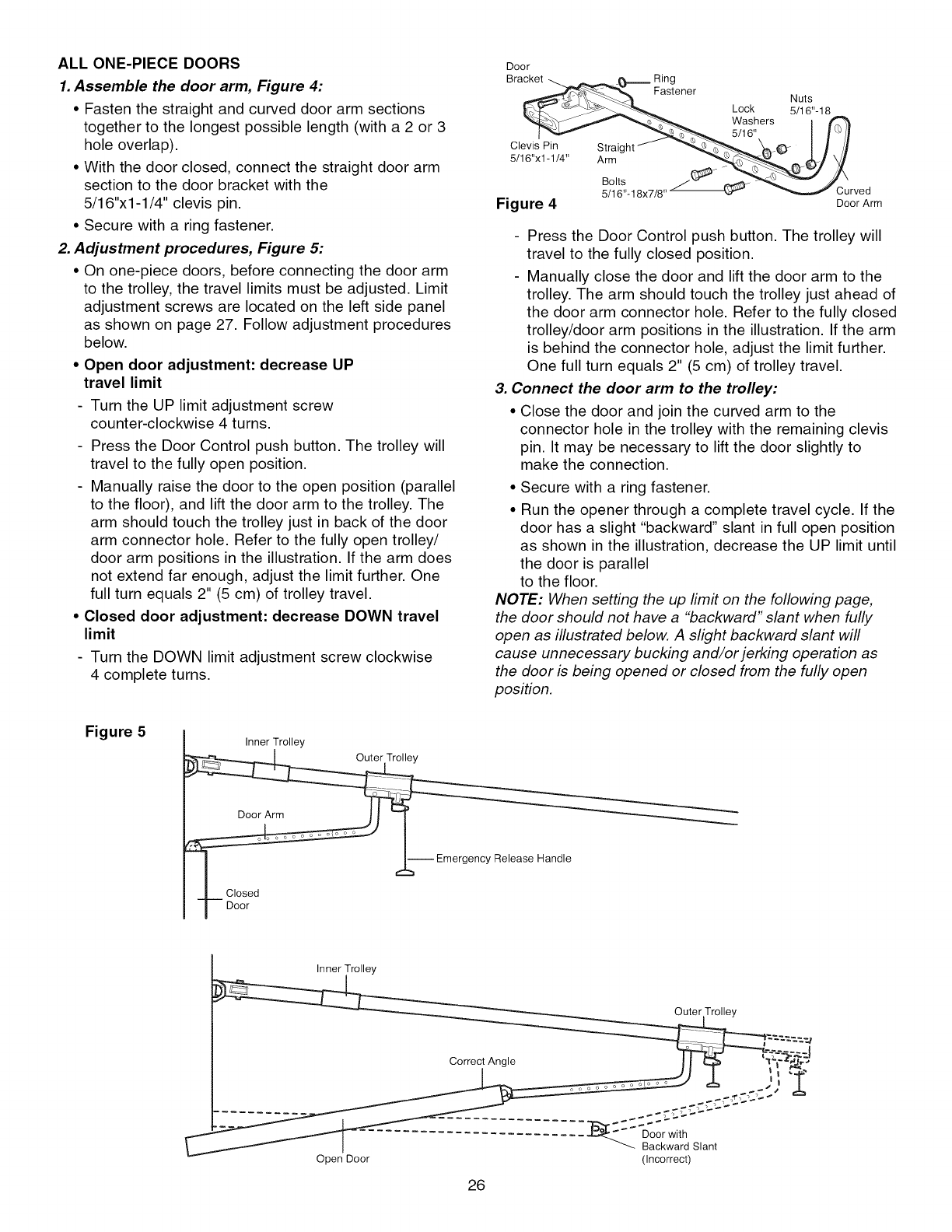
1. Assemble the door arm, Figure 4:
• Fasten the straight and curved door arm sections
together to the longest possible length (with a 2 or 3
hole overlap).
• With the door closed, connect the straight door arm
section to the door bracket with the
5/16"xl -1/4" clevis pin.
• Secure with a ring fastener.
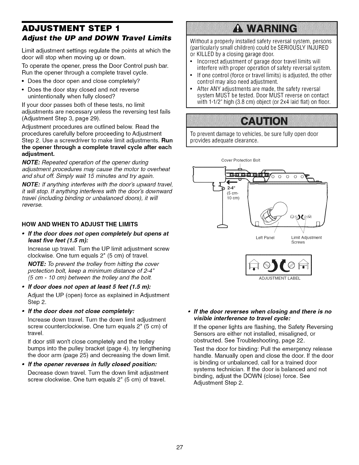
2. Adjustment procedures, Figure 5:
• On one-piece doors, before connecting the door arm
to the trolley, the travel limits must be adjusted. Limit
adjustment screws are located on the left side panel
as shown on page 27. Follow adjustment procedures
below.
• Open door adjustment: decrease UP
travel limit
- Turn the UP limit adjustment screw
counter-clockwise 4 turns.
- Press the Door Control push button. The trolley will
travel to the fully open position.
- Manually raise the door to the open position (parallel
to the floor), and lift the door arm to the trolley. The
arm should touch the trolley just in back of the door
arm connector hole. Refer to the fully open trolley/
door arm positions in the illustration. If the arm does
not extend far enough, adjust the limit further. One
full turn equals 2" (5 cm) of trolley travel.
• Closed door adjustment: decrease DOWN travel
limit
- Turn the DOWN limit adjustment screw clockwise
4 complete turns.
Door
Bracket __j_,,_,._b=------ Ring
__.<_ Fastener Nuts
|_ _-___ Lock 5/16"-18
_"_-_ _._ Washers [ _
Clev_traig ht_ "__ t_-_ [///
Bolts _ / " _ 'Curved
Figure 4Door Arm
- Press the Door Control push button. The trolley will
travel to the fully closed position.
- Manually close the door and lift the door arm to the
trolley. The arm should touch the trolley just ahead of
the door arm connector hole. Refer to the fully closed
trolley/door arm positions in the illustration. If the arm
is behind the connector hole, adjust the limit further.
One full turn equals 2" (5 cm) of trolley travel.
3. Connect the door arm to the trolley:
• Close the door and join the curved arm to the
connector hole in the trolley with the remaining clevis
pin. It may be necessary to lift the door slightly to
make the connection.
• Secure with a ring fastener.
• Run the opener through a complete travel cycle. If the
door has a slight "backward" slant in full open position
as shown in the illustration, decrease the UP limit until
the door is parallel
to the floor.
NOTE: When setting the up limit on the following page,
the door should not have a "backward" slant when fully
open as illustrated below. A slight backward slant will
cause unnecessary bucking and/or jerking operation as
the door is being opened or closed from the fully open
position.
Figure 5 Inner Trolley
Emerge..L_ncy Release Handle
Closed
Door
Inner Trolley
Outer Trolley
Open Door
26
( Inco rrect)
ADJUSTMENT STEP 1
Adjust the UP and DOWN Travel Limits
Limit adjustment settings regulate the points at which the
door will stop when moving up or down.
To operate the opener, press the Door Control push bar.
Run the opener through a complete travel cycle.
• Does the door open and close completely?
• Does the door stay closed and not reverse
unintentionally when fully closed?
If your door passes both of these tests, no limit
adjustments are necessary unless the reversing test fails
(Adjustment Step 3, page 29).
Adjustment procedures are outlined below. Read the
procedures carefully before proceeding to Adjustment
Step 2. Use a screwdriver to make limit adjustments. Run
the opener through a complete travel cycle after each
adjustment.
NOTE: Repeated operation of the opener during
adjustment procedures may cause the motor to overheat
and shut off. Simply wa# 15 minutes and try again.
NOTE: If anything interferes with the door's upward travel,
#will stop. If anything interferes with the door's downward
travel (including binding or unbalanced doors), #will
reverse.
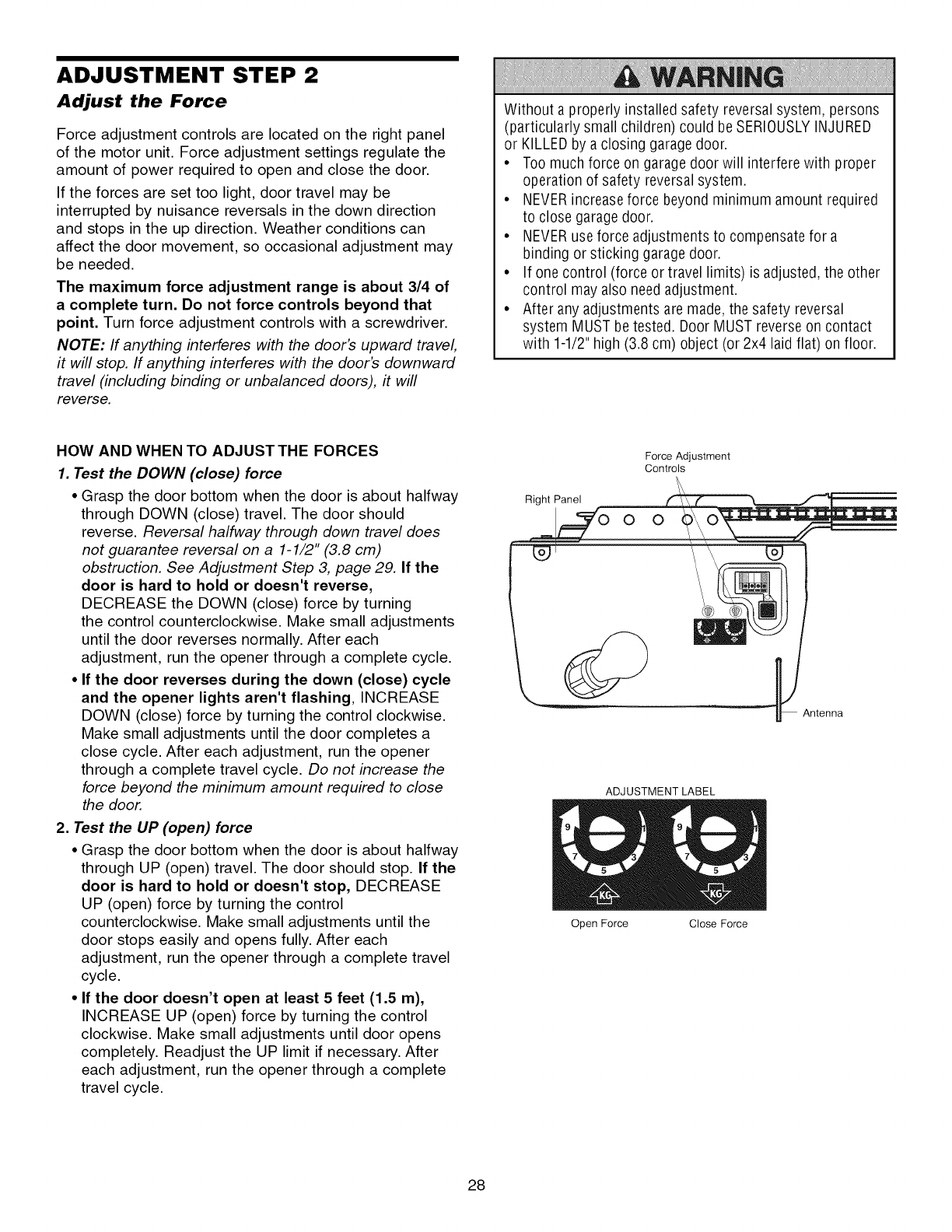
HOW AND WHEN TO ADJUST THE LIMITS
•ff the door does not open completely but opens at
least five feet (1.5 m):
Increase up travel. Turn the UP limit adjustment screw
clockwise. One turn equals 2" (5 cm) of travel.
NOTE: To prevent the trolley from hitting the cover
protection bolt, keep a minimum distance of 2-4"
(5 cm -10 cm) between the trolley and the bolt.
•ff door does not open at least 5 feet (1.5 m):
Adjust the UP (open) force as explained in Adjustment
Step 2.
•ff the door does not close completely:
Increase down travel. Turn the down limit adjustment
screw counterclockwise. One turn equals 2" (5 cm) of
travel.
If door still won't close completely and the trolley
bumps into the pulley bracket (page 4), try lengthening
the door arm (page 25) and decreasing the down limit.
•ff the opener reverses in fully closed position:
Decrease down travel. Turn the down limit adjustment
screw clockwise. One turn equals 2" (5 cm) of travel.
Without a properly installed safety reversal system, persons
(particularly small children) could be SERIOUSLYINJURED
or KILLEDby a closing garage door.
• Incorrect adjustment of garage door travel limits will
interfere with proper operation of safety reversal system.
• If one control (force or travel limits) is adjusted, the other
control may also need adjustment.
• After ANY adjustments are made, the safety reversal
system MUST betested. Door MUST reverseon contact
with 1-1/2" high (3.8 cm) object (or 2x4 laid flat) on floor.
To prevent damage to vehicles, be sure fully open door
provides adequate clearance.
Cover Protection Bolt
Left Panel Limit Adjustment
Screws
ADJUSTMENT LABEL
If the door reverses when closing and there is no
visible interference to travel cycle:
If the opener lightsare flashing, the Safety Reversing
Sensors are either not installed, misaligned, or
obstructed. See Troubleshooting, page 22.
Test the door for binding: Pull the emergency release
handle. Manually open and close the door. If the door
is binding or unbalanced, call for a trained door
systems technician. If the door is balanced and not
binding, adjust the DOWN (close) force. See
Adjustment Step 2.
27
ADJUSTMENT STEP 2
Adjust the Force
Force adjustment controls are located on the right panel
of the motor unit. Force adjustment settings regulate the
amount of power required to open and close the door.
If the forces are set too light, door travel may be
interrupted by nuisance reversals in the down direction
and stops in the up direction. Weather conditions can
affect the door movement, so occasional adjustment may
be needed.
The maximum force adjustment range is about 3/4 of
a complete turn. Do not force controls beyond that
point. Turn force adjustment controls with a screwdriver.
NOTE: If anything interferes with the door's upward travel,
it will stop. If anything interferes with the door's downward
travel (including binding or unbalanced doors), it will
reverse.
Without a properly installed safety reversal system, persons
(particularly small children) could be SERIOUSLYINJURED
or KILLEDby a closing garage door.
• Too much force on garage door will interfere with proper
operation of safety reversal system.
• NEVERincreaseforce beyond minimum amount required
to close garagedoor.
• NEVERuse force adjustments to compensate for a
binding or sticking garage door.
• If one control (force or travel limits) is adjusted, the other
control may also need adjustment.
• After any adjustments are made, the safety reversal
system MUST betested. Door MUST reverseon contact
with 1-1/2" high (3.8 cm) object (or 2x4 laid flat) on floor.
HOW AND WHEN TO ADJUST THE FORCES
1. Test the DOWN (close) force
• Grasp the door bottom when the door is about halfway
through DOWN (close) travel. The door should
reverse. Reversal halfway through down travel does
not guarantee reversal on a 1-1/2" (3.8 cm)
obstruction. See Adjustment Step 3, page 29. If the
door is hard to hold or doesn't reverse,
DECREASE the DOWN (close) force by turning
the control counterclockwise. Make small adjustments
until the door reverses normally. After each
adjustment, run the opener through a complete cycle.
• If the door reverses during the down (close) cycle
and the opener lights aren't flashing, INCREASE
DOWN (close) force by turning the control clockwise.
Make small adjustments until the door completes a
close cycle. After each adjustment, run the opener
through a complete travel cycle. Do not increase the
force beyond the minimum amount required to close
the door.
2. Test the UP (open) force
• Grasp the door bottom when the door is about halfway
through UP (open) travel. The door should stop. If the
door is hard to hold or doesn't stop, DECREASE
UP (open) force by turning the control
counterclockwise. Make small adjustments until the
door stops easily and opens fully. After each
adjustment, run the opener through a complete travel
cycle.
• If the door doesn't open at least 5 feet (1.5 m),
INCREASE UP (open) force by turning the control
clockwise. Make small adjustments until door opens
completely. Readjust the UP limit if necessary. After
each adjustment, run the opener through a complete
travel cycle.
Force Adjustment
Controls
Right Panel f'_\ t_
oo i
"_ Antenna
ADJUSTMENT LABEL
Open Force Close Force
28
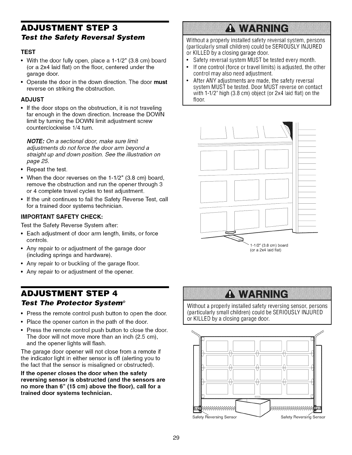
ADJUSTMENT STEP 3
Test the Safety Reversal System
TEST
• With the door fully open, place a 1-1/2" (3.8 cm) board
(or a 2x4 laid flat) on the floor, centered under the
garage door.
• Operate the door in the down direction. The door must
reverse on striking the obstruction.
ADJUST
• If the door stops on the obstruction, it is not traveling
far enough in the down direction. Increase the DOWN
limit by turning the DOWN limit adjustment screw
counterclockwise 1/4 turn.
NOTE: On a sectional door, make sure limit
adjustments do not force the door arm beyond a
straight up and down position. See the illustration on
page 25.
Repeat the test.
When the door reverses on the 1-1/2" (3.8 cm) board,
remove the obstruction and run the opener through 3
or 4 complete travel cycles to test adjustment.
If the unit continues to fail the Safety Reverse Test, call
for a trained door systems technician.
IMPORTANT SAFETY CHECK:
Test the Safety Reverse System after:
• Each adjustment of door arm length, limits, or force
controls.
• Any repair to or adjustment of the garage door
(including springs and hardware).
• Any repair to or buckling of the garage floor.
• Any repair to or adjustment of the opener.
Without a properly installed safety reversal system, persons
(particularly small children) could be SERIOUSLYINJURED
or KILLEDby a closing garage door.
• Safety reversal system MUST be tested every month.
• If one control (force or travel limits) is adjusted, the other
control may also need adjustment.
• After ANY adjustments are made, the safety reversal
system MUST betested. Door MUST reverseon contact
with 1-1/2" high (3.8 cm) object (or 2x4 laid flat) on the
floor.
(or a 2x4 laid flat)
ADJUSTMENT STEP 4
Test The Protector System ®
• Press the remote control push button to open the door.
• Place the opener carton in the path of the door.
• Press the remote control push button to close the door.
The door will not move more than an inch (2.5 cm),
and the opener lights will flash.
The garage door opener will not close from a remote if
the indicator light in either sensor is off (alerting you to
the fact that the sensor is misaligned or obstructed).
If the opener closes the door when the safety
reversing sensor is obstructed (and the sensors are
no more than 6" (15 cm) above the floor), call for a
trained door systems technician.
Without a properly installed safety reversing sensor, persons
(particularly small children) could be SERIOUSLYINJURED
or KILLEDby a closing garage door.
Safety Reversing Sensor
m
7
Safety Reversing Sensor
29
OPERATION
IMPORTANT SAFETY INSTRUCTIONS
To reduce the risk of SEVERE INJURY or DEATH:
1. READAND FOLLOWALL WARNINGSAND INSTRUCTIONS.
2. ALWAYSkeep remote controls out of reach of children.
NEVERpermit children to operate or play with garage door
control push buttons or remote controls.
3. ONLYactivate garage door when it can be seen clearly, it
is properly adjusted, and there are no obstructions to door
travel.
4. ALWAYSkeep garage door in sight until completely closed.
NO ONESHOULDCROSSTHEPATHOFTHEMOVING
DOOR.
5. NO ONESHOULDGOUNDERA STOPPED,PARTIALLY
OPENEDDOOR.
6. If possible, use emergency release handleto disengage
trolley ONLYwhen garage door is CLOSED.Weakor broken
springs or unbalanced door could result in an open door
falling rapidly and/or unexpectedly.
7. NEVERuse emergency release handle unless garage
doorway is clear of persons and obstructions.
8. NEVERuse handle to pull garagedoor open or closed. If
rope knot becomes untied, you could fall.
9. If one control (force or travel limits) is adjusted, the other
control may also need adjustment.
10. After ANY adjustments are made, the safety reversal
system MUST betested.
11. Safety reversalsystem MUST be tested every month.
Garagedoor must reverse on contact with 1-1/2" high
(3.8 cm) object (or a 2x4 laid flat) on the floor.
12. ALWAYSKEEPGARAGEDOORPROPERLYBALANCED
(see page 3). An improperly balanced door may not
reverse when required and could result in SEVERE
INJURY or DEATH.
13. All repairs to cables, spring assemblies and other
hardware, all of which are under EXTREMEtension, MUST
be made by a trained door systems technician.
14. ALWAYSdisconnect electric power to garage door opener
BEFOREmaking ANY repairs or removing covers.
15SAVETHESEINSTRUCTIONS.
Using Your Garage Door Opener
Your Security÷ _ opener and hand-held remote control
have been factory-set to a matching code which changes
with each use, randomly accessing over 100 billion new
codes. Your opener will operate with up to eight
Security÷ _ remote controls and one Security÷ ° Keyless
Entry System. If you purchase a new remote, or if you
wish to deactivate any remote, follow the instructions in
the Programming section.
Activate your opener with any of the following:
•The hand-held Remote Control'. Hold the large push
button down until the door starts to move.
• The wall-mounted Door Control: Hold the push button
or bar down until the door starts to move.
• The Keyless Entry (See Accessories): If provided with
your garage door opener, it must be programmed
before use. See Programming.
When the opener is activated (with the safety
reversing sensor correctly installed and aligned)
1. If open, the door will close. If closed, it will open.
2. If closing, the door will reverse.
3. If opening, the door will stop.
4. If the door has been stopped in a partially open
position, it will close.
5. If obstructed while closing, the door will reverse. If the
obstruction interrupts the sensor beam, the opener
lights will blink for five seconds.
6. If obstructed while opening, the door will stop.
7. If fully open, the door will not close when the beam is
broken. The sensor has no effect in the opening cycle.
If the sensor is not installed, or is misaligned, the door
won't close from a hand-held remote. However, you can
close the door with the Door Control, the Outdoor Key
Switch, or Keyless Entry, if you activate them until down
travel is complete. If you release them too soon, the door
will reverse.
The opener lights will turn on under the following
conditions: when the opener is initially plugged in; when
power is restored after interruption; when the opener is
activated.
They will turn off automatically after 4-1/2 minutes or
provide constant light when the Light feature on the
Motion Detecting Control Console is activated. Bulb size
is A19. Bulb power is 100 watts maximum.
Security'_ _light feature: Lights will also turn on when
someone walks through the open garage door. With a
Premium Control Console, this feature may be turned off
as follows: With the opener lights off, press and hold the
light button for 10 seconds, until the light goes on, then
off again. To restore this feature, start with the opener
lights on, then press and hold the light button for 10
seconds until the light goes off, then on again.
30
Using the Wall-Mounted
Door Control To Open the Door Manually
THE PREMIUM CONTROL CONSOLE
Press the lighted push button to open
or close the door. Press again to
reverse the door during the closing
cycle or to stop the door while it's
opening.
Light feature
Press the Light button to turn the
opener light on or off. It will not control
Li0h4edutton
ight
utton
ock
utton
the opener lights when the door is in motion. If you turn it
on and then activate the opener, the light will remain on
for 4-1/2 minutes. Press again to turn it off sooner. The
4-1/2 minute interval can be changed to 1-1/2, 2-1/2, or
3-1/2 minutes as follows: Press and hold the Lock button
until the light blinks (about 10 seconds). A single blink
indicates that the timer is reset to 1-1/2 minutes. Repeat
the procedure and the light will blink twice, resetting the
timer to 2-1/2 minutes. Repeat again for a 3-1/2 minute
interval, etc., up to a maximum of four blinks and 4-1/2
minutes.
Lock feature
Designed to prevent operation of the door from
hand-held remote controls. However, the door will open
and close from the Door Control, the Outdoor Key Switch
and the Keyless Entry Accessories.
To activate, press and hold the Lock button for 2 seconds.
The push button light will flash as long as the Lock
feature is on.
To turn off, press and hold the Lock button again for
2 seconds. The push button light will stop flashing. The
Lock feature will also turn off whenever the "learn" button
on the motor unit panel is activated.
Additional feature when used with the 3-Function
hand-held remote
To control the opener lights:
In addition to operating the door, you
may program the remote to operate the
lights.
1. With the door closed, press and hold
a small remote button that you want to control the light.
2. Press and hold the Light button on the door control.
3. While holding the Light button, press and hold the Lock
button on the door control.
4. After the opener lights flash, release all buttons.
To prevent possible SERIOUSINJURYor DEATHfrom a
falling garage door:
• If possible, use emergency releasehandle to disengage
trolley ONLYwhen garage door is CLOSED.Weakor
broken springs or unbalanced door could result in an
open door falling rapidly and/or unexpectedly.
• NEVERuse emergency release handle unless garage
doorway is clear of persons and obstructions.
• NEVERuse handle to pull door open or closed. If rope
knot becomes untied, you could fall.
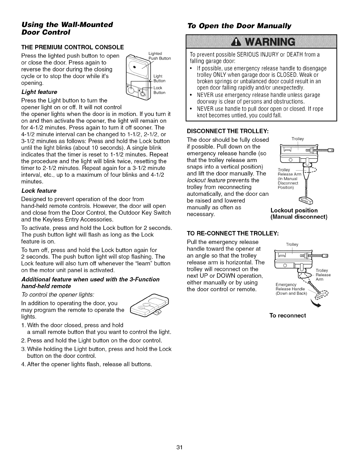
DISCONNECT THE TROLLEY:
The door should be fully closed
if possible. Pull down on the
emergency release handle (so
that the trolley release arm
snaps into a vertical position)
and lift the door manually. The
lockout feature prevents the
trolley from reconnecting
automatically, and the door can
be raised and lowered
manually as often as
necessary.
Trolley
I
(In Manual
Disconnect
Position)
Lockout position
(Manual disconnect)
TO RE-CONNECT THE TROLLEY:
Pull the emergency release
handle toward the opener at
an angle so that the trolley
release arm is horizontal. The
trolley will reconnect on the
next UP or DOWN operation,
either manually or by using
the door control or remote.
Trolley
Trolley
Rre/ease
_. Arm
Emergency "%
Release Handle _ _ =
<DownandBack)
To reconnect
31
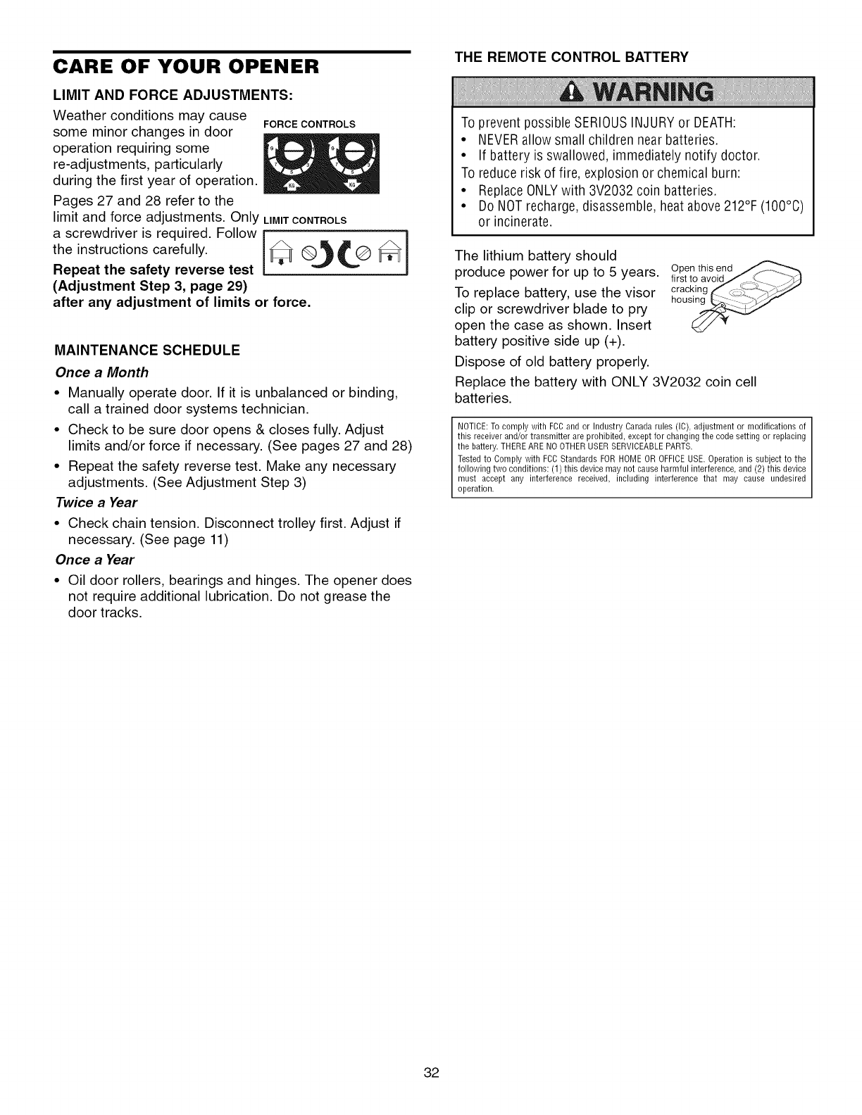
CARE OF YOUR OPENER
LIMIT AND FORCE ADJUSTMENTS:
Weather conditions may cause FORCE CONTROLS
some minor changes in door
operation requiring some
re-adjustments, particularly
during the first year of operation.
Pages 27 and 28 refer to the
limit and force adjustments. Only LIMITCONTROLS
a screwdriver is required. Follow
the instructions carefully. _@_L@_
Repeat the safety reverse test
(Adjustment Step 3, page 29)
after any adjustment of limits or force.
MAINTENANCE SCHEDULE
Once a Month
• Manually operate door. If it is unbalanced or binding,
call a trained door systems technician.
• Check to be sure door opens & closes fully. Adjust
limits and/or force if necessary. (See pages 27 and 28)
• Repeat the safety reverse test. Make any necessary
adjustments. (See Adjustment Step 3)
Twice a Year
• Check chain tension. Disconnect trolley first. Adjust if
necessary. (See page 11)
Once a Year
• Oil door rollers, bearings and hinges. The opener does
not require additional lubrication. Do not grease the
door tracks.
THE REMOTE CONTROL BATTERY
To prevent possible SERIOUSINJURYor DEATH:
• NEVERallow small children near batteries.
• If battery is swallowed, immediately notify doctor.
To reduce risk of fire, explosion or chemical burn:
• ReplaceONLYwith 3V2032 coin batteries.
• Do NOTrecharge, disassemble, heat above 212°F (100°C)
or incinerate.
The lithium battery should
produce power for up to 5 years.
To replace battery, use the visor
clip or screwdriver blade to pry
open the case as shown. Insert
battery positive side up (+).
Dispose of old battery properly.
Open this end
first to avoid_ _ _)_
cracking f _- _/_-_
hous_
Replace the battery with ONLY 3V2032 coin cell
batteries.
NOTICE: To comply with FCC and or Industry Canada rules (IC), adjustment or modifications of
this receiver and/or transmitter are prohibited, except for changing the code setting or replacing
the battery, THERE ARE NO OTHER USER SERVICEABLE PARTS.
Tested to Comply with FCC Standards FOR HOME OR OFFICE USE. Operation is subject to the
following two conditions: (1) this device may not cause harmful interference, and (2) this device
must accept any interference received, including interference that may cause undesired
operation.
32
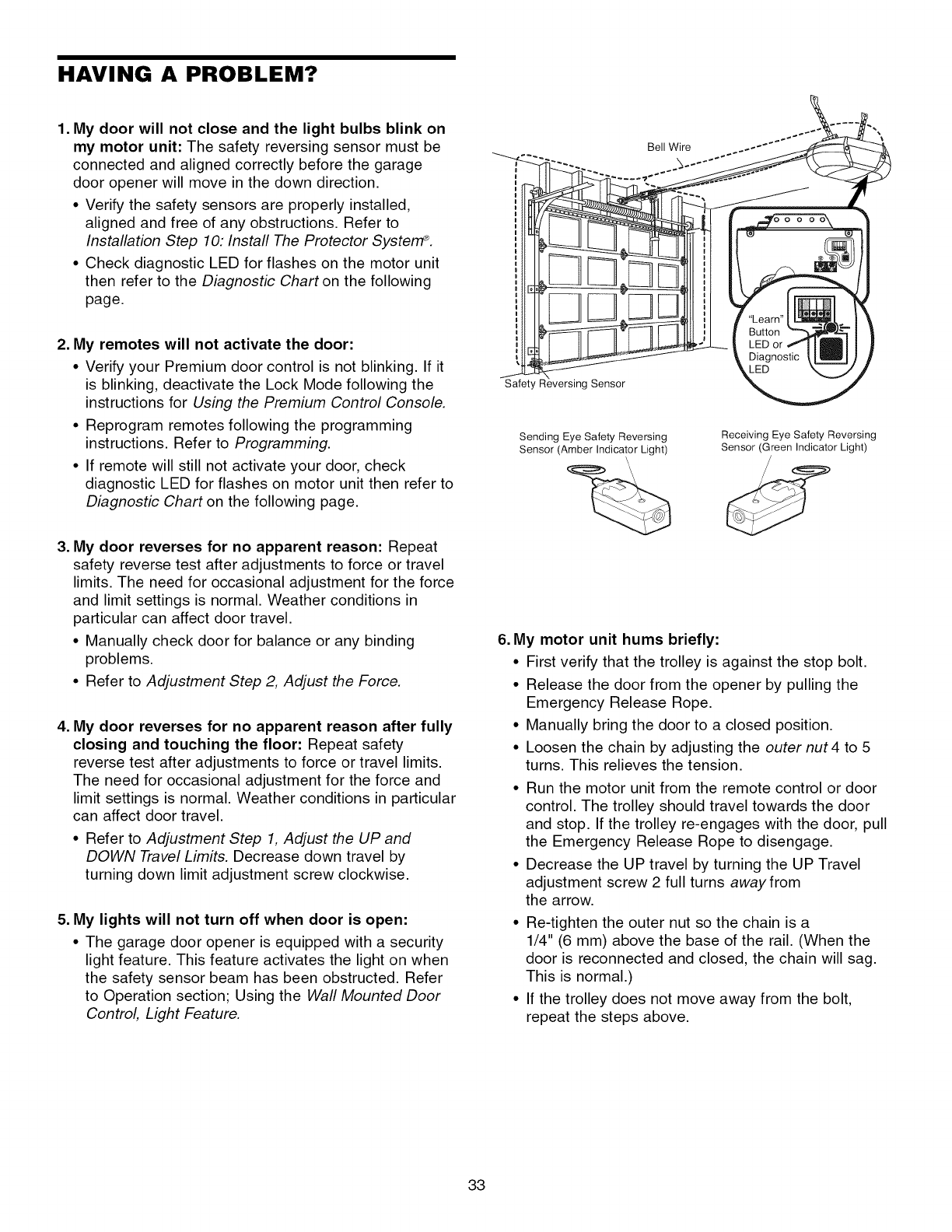
HAVING A PROBLEM?
1. My door will not close and the light bulbs blink on
my motor unit: The safety reversing sensor must be
connected and aligned correctly before the garage
door opener will move in the down direction.
• Verify the safety sensors are properly installed,
aligned and free of any obstructions. Refer to
Installation Step 10: Install The Protector Systerff _.
• Check diagnostic LED for flashes on the motor unit
then refer to the Diagnostic Chart on the following
page.
2. My remotes will not activate the door:
• Verify your Premium door control is not blinking. If it
is blinking, deactivate the Lock Mode following the
instructions for Using the Premium Control Console.
• Reprogram remotes following the programming
instructions. Refer to Programming.
• If remote will still not activate your door, check
diagnostic LED for flashes on motor unit then refer to
Diagnostic Chart on the following page.
3. My door reverses for no apparent reason: Repeat
safety reverse test after adjustments to force or travel
limits. The need for occasional adjustment for the force
and limit settings is normal. Weather conditions in
particular can affect door travel.
• Manually check door for balance or any binding
problems.
• Refer to Adjustment Step 2, Adjust the Force.
4. My door reverses for no apparent reason after fully
closing and touching the floor: Repeat safety
reverse test after adjustments to force or travel limits.
The need for occasional adjustment for the force and
limit settings is normal. Weather conditions in particular
can affect door travel.
• Refer to Adjustment Step 1, Adjust the UP and
DOWN Travel Limits. Decrease down travel by
turning down limit adjustment screw clockwise.
5. My lights will not turn off when door is open:
• The garage door opener is equipped with a security
light feature. This feature activates the light on when
the safety sensor beam has been obstructed. Refer
to Operation section; Using the Wall Mounted Door
Control, Light Feature.
iSafety Reversing Sensor
Bell Wire
Sending Eye Safety Reversing
Sensor (Amber Indicator Light)
\
Receiving Eye Safety Reversing
Sensor (Green Indicator Light)
u
6. My motor unit hums briefly:
• First verify that the trolley is against the stop bolt.
• Release the door from the opener by pulling the
Emergency Release Rope.
• Manually bring the door to a closed position.
• Loosen the chain by adjusting the outer nut 4 to 5
turns. This relieves the tension.
• Run the motor unit from the remote control or door
control. The trolley should travel towards the door
and stop. If the trolley re-engages with the door, pull
the Emergency Release Rope to disengage.
• Decrease the UP travel by turning the UP Travel
adjustment screw 2 full turns awayfrom
the arrow.
• Re-tighten the outer nut so the chain is a
1/4" (6 mm) above the base of the rail. (When the
door is reconnected and closed, the chain will sag.
This is normal.)
• If the trolley does not move away from the bolt,
repeat the steps above.
33
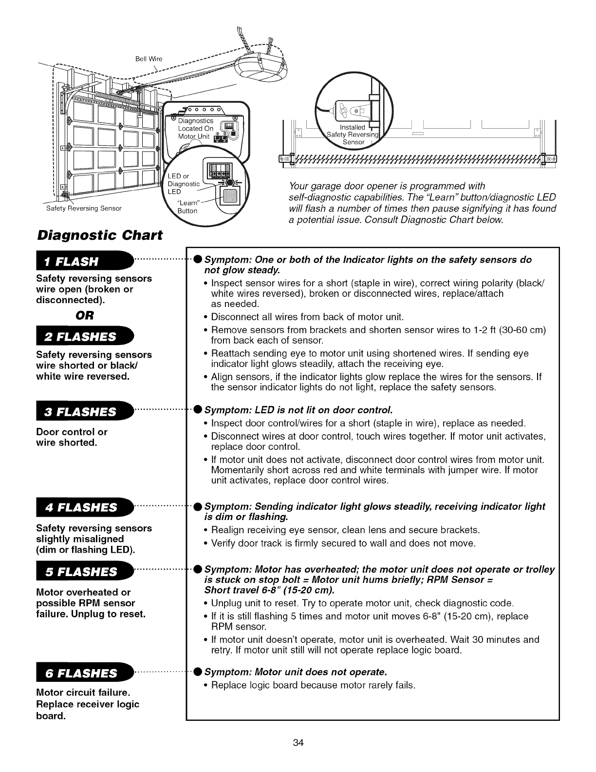
Bell Wire
Safety Reversing Sensor
Diagnostic Chart
Safety reversing sensors
wire open (broken or
disconnected).
OR
Safety reversing sensors
wire shorted or black/
white wire reversed.
Door control or
wire shorted.
................
Safety reversing sensors
slightly misaligned
(dim or flashing LED).
Motor overheated or
possible RPM sensor
failure. Unplug to reset.
Motor circuit failure.
................
Replace receiver logic
board.
Your garage door opener is programmed with
self-diagnostic capabilities. The "Learn" button/diagnostic LED
will flash a number of times then pause signifying #has found
a potential issue. Consult Diagnostic Chart below.
•"• Symptom: One or both of the Indicator lights on the safety sensors do
not glow steady.
•Inspect sensor wires for a short (staple in wire), correct wiring polarity (black/
white wires reversed), broken or disconnected wires, replace/attach
as needed.
• Disconnect all wires from back of motor unit.
• Remove sensors from brackets and shorten sensor wires to 1-2 ft (30-60 cm)
from back each of sensor.
• Reattach sending eye to motor unit using shortened wires. If sending eye
indicator light glows steadily, attach the receiving eye.
• Align sensors, if the indicator lights glow replace the wires for the sensors. If
the sensor indicator lights do not light, replace the safety sensors.
•"• Symptom: LED is not lit on door control.
• Inspect door control/wires for a short (staple in wire), replace as needed.
• Disconnect wires at door control, touch wires together. If motor unit activates,
replace door control.
• If motor unit does not activate, disconnect door control wires from motor unit.
Momentarily short across red and white terminals with jumper wire. If motor
unit activates, replace door control wires.
•"•Symptom: Sending indicator light glows steadily, receiving indicator light
is dim or flashing.
• Realign receiving eye sensor, clean lens and secure brackets.
• Verify door track is firmly secured to wall and does not move.
•"•Symptom: Motor has overheated; the motor unit does not operate or trolley
is stuck on stop bolt = Motor unit hums briefly; RPM Sensor =
Short travel 6-8" (15-20 cm).
• Unplug unit to reset. Try to operate motor unit, check diagnostic code.
• If it is still flashing 5 times and motor unit moves 6-8" (15-20 cm), replace
RPM sensor.
• If motor unit doesn't operate, motor unit is overheated. Wait 30 minutes and
retry. If motor unit still will not operate replace logic board.
•Symptom: Motor unit does not operate.
• Replace logic board because motor rarely fails
34
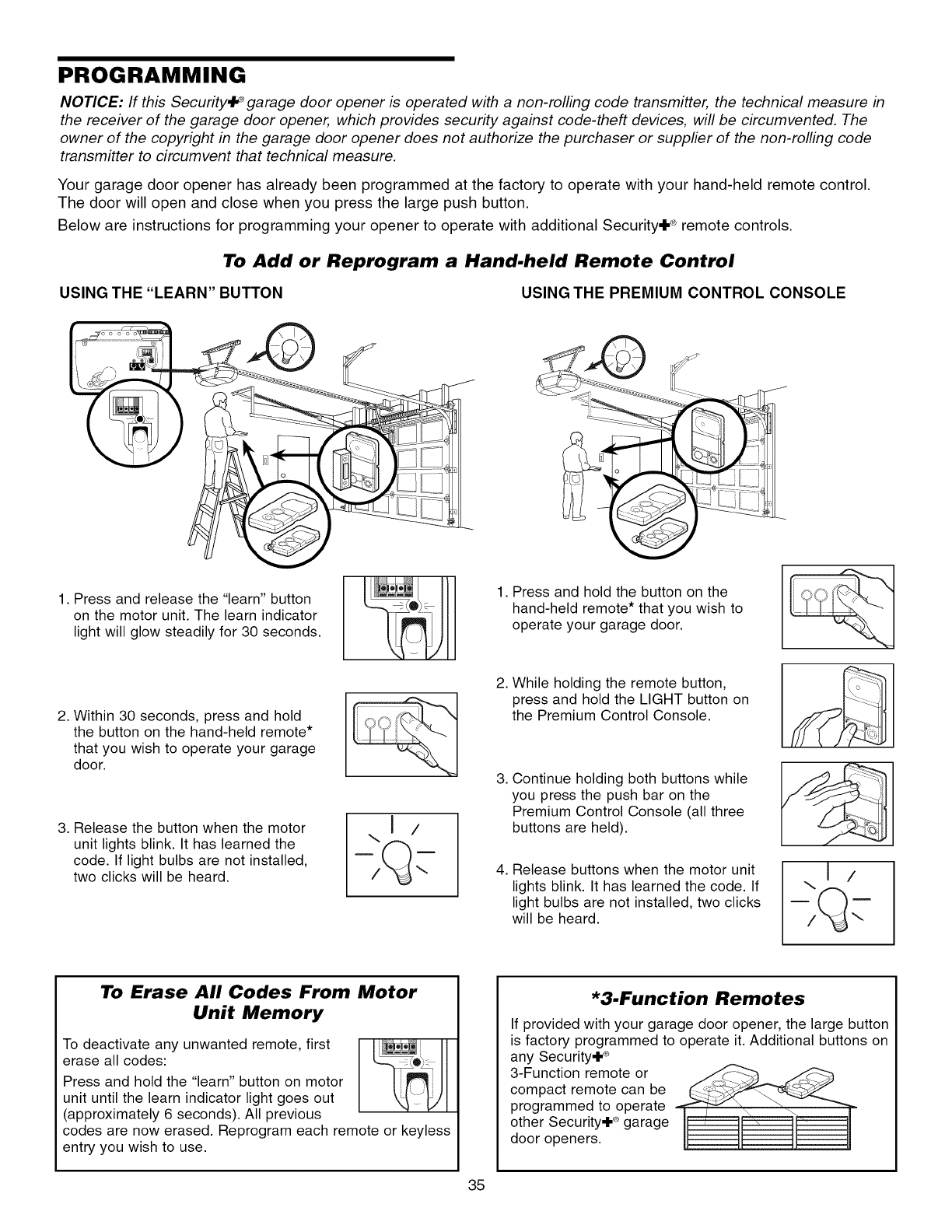
PROGRAMMING
NOTICE: If this Security'i_ _garage door opener is operated with a non-rolling code transmitter, the technical measure in
the receiver of the garage door opener, which provides security against code-theft devices, will be circumvented. The
owner of the copyright in the garage door opener does not authorize the purchaser or supplier of the non-rolling code
transmfter to circumvent that technical measure.
Your garage door opener has already been programmed at the factory to operate with your hand-held remote control.
The door will open and close when you press the large push button.
Below are instructions for programming your opener to operate with additional Security+ ° remote controls.
To Add or Reprogram a Hand-held Remote Control
USING THE "LEARN" BUTTON USING THE PREMIUM CONTROL CONSOLE
1. Press and release the "learn" button
on the motor unit. The learn indicator
light will glow steadily for 30 seconds.
2. Within 30 seconds, press and hold
the button on the hand-held remote*
that you wish to operate your garage
door.
3. Release the button when the motor
unit lights blink. It has learned the
code. If light bulbs are not installed,
two clicks will be heard.
1. Press and hold the button on the
hand-held remote* that you wish to
operate your garage door.
2. While holding the remote button,
press and hold the LIGHT button on
the Premium Control Console.
3, Continue holding both buttons while
you press the push bar on the
Premium Control Console (all three
buttons are held).
4. Release buttons when the motor unit
lights blink. It has learned the code. If
light bulbs are not installed, two clicks
will be heard.
\1/
To Erase All Codes From Motor
Unit Memory
To deactivate any unwanted remote, first
erase all codes:
Press and hold the "learn" button on motor
unit until the learn indicator light goes out
(approximately 6 seconds). All previous
codes are now erased. Reprogram each
entry you wish to use.
iote or keyless
*3-Function Remotes
If provided with your garage door opener, the large button
is factory programmed to operate it. Additional buttons on
any Security+ e>
3-Function remote or _3 .,,,__
compact remote can be
programmed to operate
other Security÷ _ garage
door openers.
35
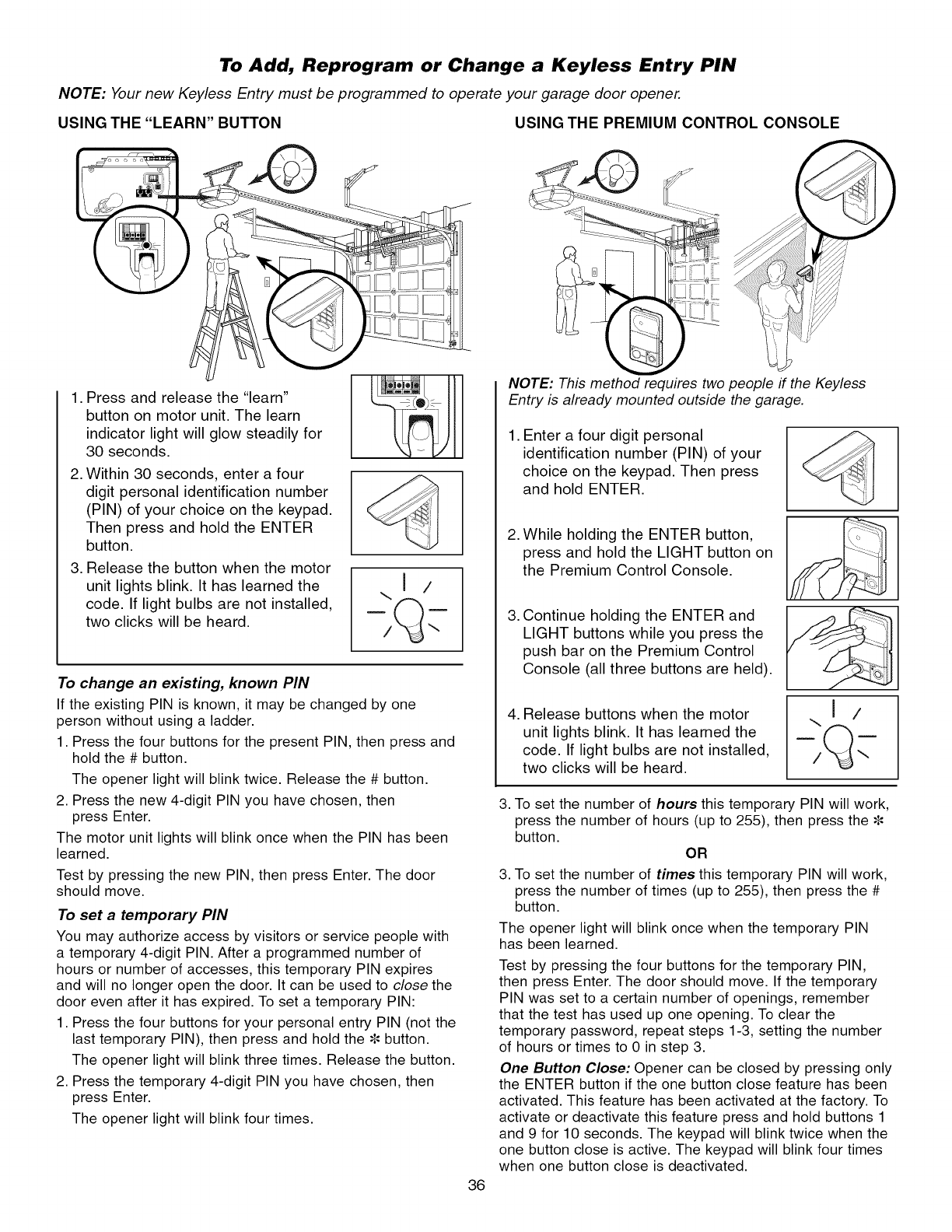
NOTE:
USING
To Add, Reprogram or Change a Keyless Entry PIN
Your new Keyless Entry must be programmed to operate your garage door opener.
THE "LEARN" BUTTON USING THE PREMIUM CONTROL CONSOLE
1. Press and release the "learn"
button on motor unit. The learn
indicator light will glow steadily for
30 seconds•
2. Within 30 seconds, enter a four
digit personal identification number
(PIN) of your choice on the keypad•
Then press and hold the ENTER
button•
3. Release the button when the motor
unit lights blink• It has learned the
code. If light bulbs are not installed,
two clicks will be heard•
To change an existing, known PIN
If the existing PIN is known, it may be changed by one
person without using a ladder•
1. Press the four buttons for the present PIN, then press and
hold the # button•
The opener light will blink twice• Release the # button•
2. Press the new 4-digit PIN you have chosen, then
press Enter•
The motor unit lights will blink once when the PIN has been
learned•
Test by pressing the new PIN, then press Enter• The door
should move.
To set a temporary PIN
You may authorize access by visitors or service people with
a temporary 4-digit PIN. After a programmed number of
hours or number of accesses, this temporary PIN expires
and will no longer open the door. It can be used to close the
door even after it has expired• To set a temporary PIN:
1. Press the four buttons for your personal entry PIN (not the
last temporary PIN), then press and hold the • button•
The opener light will blink three times• Release the button•
2. Press the temporary 4-digit PIN you have chosen, then
press Enter•
The opener light will blink four times•
NOTE: This method requires two people if the Keyless
Entry is already mounted outside the garage.
•Enter a four digit personal
identification number (PIN) of your
choice on the keypad• Then press
and hold ENTER•
2. While holding the ENTER button,
press and hold the LIGHT button on
the Premium Control Console.
.Continue holding the ENTER and
LIGHT buttons while you press the
push bar on the Premium Control
Console (all three buttons are held).
4. Release buttons when the motor
unit lights blink. It has learned the
code. If light bulbs are not installed,
two clicks will be heard.
...J /
36
3. To set the number of hours this temporary PIN will work,
press the number of hours (up to 255), then press the
button•
OR
3. To set the number of times this temporary PIN will work,
press the number of times (up to 255), then press the #
button•
The opener light will blink once when the temporary PIN
has been learned•
Test by pressing the four buttons for the temporary PIN,
then press Enter• The door should move. If the temporary
PIN was set to a certain number of openings, remember
that the test has used up one opening• To clear the
temporary password, repeat steps 1-3, setting the number
of hours or times to 0 in step 3.
One Button Close: Opener can be closed by pressing only
the ENTER button if the one button close feature has been
activated• This feature has been activated at the factory. To
activate or deactivate this feature press and hold buttons 1
and 9 for 10 seconds• The keypad will blink twice when the
one button close is active• The keypad will blink four times
when one button close is deactivated•
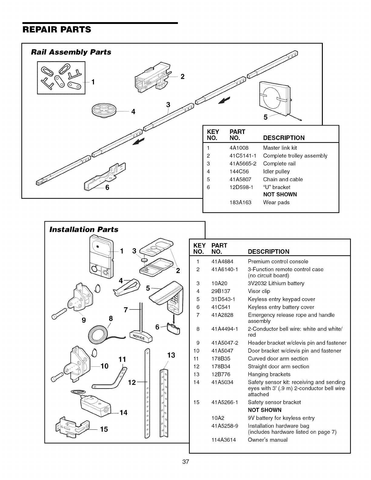
REPAIR PARTS
Rail Assembly Parts
6
KEY
NO.
1
2
3
4
5
6
PART
NO.
4A1008
41C5141-1
41A5665-2
144C56
41A5807
12D598-1
183A163
DESCRIPTION
Master link kit
Complete trolley assembly
Complete rail
Idler pulley
Chain and cable
"U" bracket
NOT SHOWN
Wear pads
Installation Parts _1
KEY
NO.
1
2
3
4
5
6
7
9
10
11
12
13
14
15
PART
NO.
41A4884
41A6140-1
10A20
29B137
31 D543-1
41 C541
41A2828
41A4494-1
41A5047-2
41A5047
178B35
178B34
12B776
41A5034
41A5266-1
10A2
41A5258-9
114A3614
DESCRIPTION
Premium control console
3-Function remote control case
(no circuit board)
3V2032 Lithium battery
Visor clip
Keyless entry keypad cover
Keyless entry battery cover
Emergency release rope and handle
assembly
2-Conductor bell wire: white and white/
red
Header bracket w/clevis pin and fastener
Door bracket w/clevis pin and fastener
Curved door arm section
Straight door arm section
Hanging brackets
Safety sensor kit: receiving and sending
eyes with 3' (.9 m) 2-conductor bell wire
attached
Safety sensor bracket
NOT SHOWN
9V battery for keyless entry
Installation hardware bag
(includes hardware listed on page 7)
Owner's manual
37
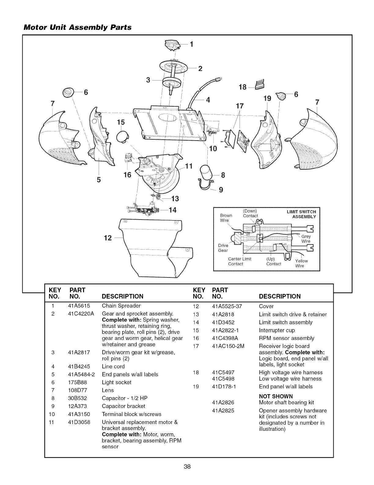
Motor Unit Assembly Parts
1
7
Q 6
\
\
5
12
7
1 14 (Down) LIMIT SWITCH
Brown Contact ASSEMBLY
Wire
/ iiiiii_i!i
center Limit (Up) _ Yellow
Contact Contact Wire
KEY PART KEY PART
NO. NO. DESCRIPTION NO. NO. DESCRIPTION
1 41A5615
2 41C4220A
3 41A2817
4 41B4245
5 41A5484-2
6 175B88
7 108D77
8 30B532
9 12A373
10 41A3150
11 41D3058
Chain Spreader 12
Gear and sprocket assembly. 13
Complete with: Spring washer, 14
thrust washer, retaining ring,
bearing plate, roll pins (2), drive 15
gear and worm gear, helical gear 16
w/retainer and grease 17
Drive/worm gear kit w/grease,
roll pins (2)
Line cord
End panels w/all labels
Light socket
Lens
Capacitor- 1/2 HP
Capacitor bracket
Terminal block w/screws
Universal replacement motor &
bracket assembly.
Complete with: Motor, worm,
bracket, bearing assembly, RPM
sensor
18
19
41A5525-37
41A2818
41 D3452
41A2822-1
41 C4398A
41AC150-2M
41 C5497
41 C5498
41D178-1
41A2826
41A2825
Cover
Limit switch drive & retainer
Limit switch assembly
Interrupter cup
RPM sensor assembly
Receiver logic board
assembly. Complete with:
Logic board, end panel w/all
labels, light socket
High voltage wire harness
Low voltage wire harness
End panel w/all labels
NOT SHOWN
Motor shaft bearing kit
Opener assembly hardware
kit (includes screws not
designated by a number in
illustration)
38
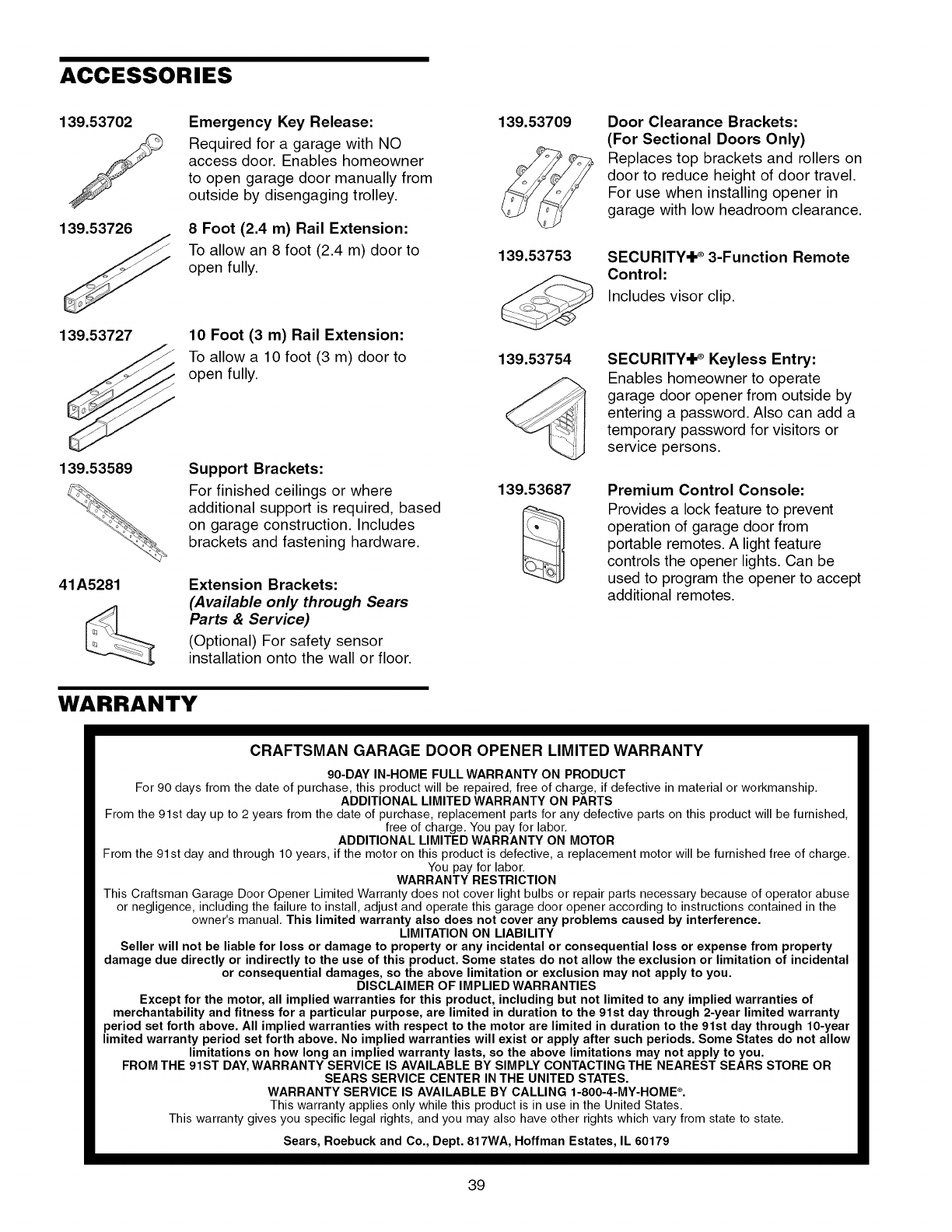
ACCESSORIES
139.53702
J
139.53726
139.53727
139.53589
41A5281
Emergency Key Release:
Required for a garage with NO
access door. Enables homeowner
to open garage door manually from
outside by disengaging trolley.
8 Foot (2.4 m) Rail Extension:
To allow an 8 foot (2.4 m) door to
open fully.
10 Foot (3 m) Rail Extension:
To allow a 10 foot (3 m) door to
open fully.
Support Brackets:
For finished ceilings or where
additional support is required, based
on garage construction. Includes
brackets and fastening hardware.
Extension Brackets:
(Available only through Sears
Parts &Service)
(Optional) For safety sensor
installation onto the wall or floor.
139.53709
139.53753
139.53754
139.53687
Door Clearance Brackets:
(For Sectional Doors Only)
Replaces top brackets and rollers on
door to reduce height of door travel.
For use when installing opener in
garage with low headroom clearance.
SECURITY@ ®3-Function Remote
Control:
Includes visor clip.
SECURITY@ ®Keyless Entry:
Enables homeowner to operate
garage door opener from outside by
entering a password. Also can add a
temporary password for visitors or
service persons.
Premium Control Console:
Provides a lock feature to prevent
operation of garage door from
portable remotes. A light feature
controls the opener lights. Can be
used to program the opener to accept
additional remotes.
WARRANTY
CRAFTSMAN GARAGE DOOR OPENER LIMITED WARRANTY
90-DAY IN-HOME FULL WARRANTY ON PRODUCT
For 90 days from the date of purchase, this product will be repaired, free of charge, if defective in material or workmanship.
ADDITIONAL LIMITED WARRANTY ON PARTS
From the 91st day up to 2 years from the date of purchase, replacement parts for any defective parts on this product will be furnished,
free of charge, You pay for labor,
ADDITIONAL LIMITED WARRANTY ON MOTOR
From the 91 st day and through 10 years, if the motor on this product is defective, a replacement motor will be furnished free of charge,
You pay for labor,
WARRANTY RESTRICTION
This Craftsman Garage Door Opener Limited Warranty does not cover light bulbs or repair parts necessary because of operator abuse
or negligence, including the failure to install, adjust and operate this garage door opener according to instructions contained in the
owner's manual, This limited warranty also does not cover any problems caused by interference.
LIMITATION ON LIABILITY
Seller will not be liable for loss or damage to property or any incidental or consequential loss or expense from property
damage due directly or indirectly to the use of this product. Some states do not allow the exclusion or limitation of incidental
or consequential damages, so the above limitation or exclusion may not apply to you.
DISCLAIMER OF IMPLIED WARRANTIES
Except for the motor, all implied warranties for this product, including but not limited to any implied warranties of
merchantability and fitness for a particular purpose, are limited in duration to the 91st day through 2-year limited warranty
period set forth above. All implied warranties with respect to the motor are limited in duration to the 91st day through 10-year
limited warranty period set forth above. No implied warranties will exist or apply after such periods. Some States do not allow
limitations on how long an implied warranty lasts, so the above limitations may not apply to you.
FROM THE 91ST DAY, WARRANTY SERVICE IS AVAILABLE BY SIMPLY CONTACTING THE NEAREST SEARS STORE OR
SEARS SERVICE CENTER IN THE UNITED STATES.
WARRANTY SERVICE IS AVAILABLE BY CALLING 1-800-4-MY-HOME ®.
This warranty applies only while this product is in use in the United States,
This warranty gives you specific legal rights, and you may also have other rights which vary from state to state,
Sears, Roebuck and Co., Dept. 817WA, Hoffman Estates, IL 60179
39
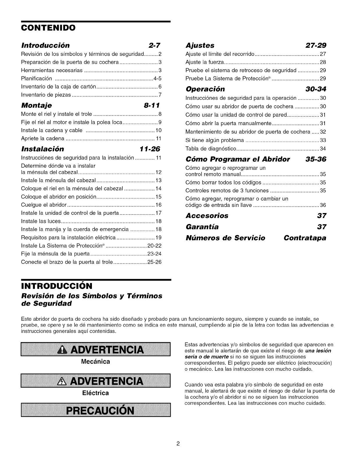
CONTENIDO
Introduccibn 2-7
Revisi6n de los simbolos y terminos de seguridad ......... 2
Preparaci6n de la puerta de su cochera ......................... 3
Herramientas necesarias ................................................ 3
Planificaci6n ................................................................ 4-5
Inventario de la caja de cart6n ........................................ 6
Inventario de piezas ........................................................ 7
Montaje 8-11
Monte el riel y instale el trole .......................................... 8
Fije el riel al motor e instale la polea Ioca ....................... 9
Instale la cadena y cable ............................................. 10
Apriete la cadena .......................................................... 11
Instalaci6n 11-26
Instrucci6nes de seguridad para la instalaci6n ............. 11
Determine d6nde va a instalar
la mensula del cabezal .................................................. 12
Instale la mensula del cabezal ...................................... 13
Coloque el riel en la mensula del cabezal .................... 14
Coloque el abridor en posici6n ...................................... 15
Cuelgue el abridor ......................................................... 16
Instale la unidad de control de la puerta ....................... 17
Instale las luces ............................................................. 18
Instale la manija y la cuerda de emergencia ................ 18
Requisitos para la instalaci6n electrica ......................... 19
Instale La Sistema de Protecci6n ® ........................... 20-22
Fije la mensula de la puerta ..................................... 23-24
Conecte el brazo de la puerta al trole ...................... 25-26
Ajustes 27.29
Ajuste el limite del recorrido .......................................... 27
Ajuste la fuerza .............................................................. 28
Pruebe el sistema de retroceso de seguridad .............. 29
Pruebe La Sistema de Protecci6n ® ............................... 29
Operaci6n 30-34
Instrucci6nes de seguridad para la operaci6n .............. 30
C6mo usar su abridor de puerta de cochera ................ 30
C6mo usar la unidad de control de pared ..................... 31
C6mo abrir la puerta manualmente ............................... 31
Mantenimiento de su abridor de puerta de cochera ..... 32
Si tiene algOn problema ................................................ 33
Tabla de diagn6stico ...................................................... 34
C6mo Programar el Abridor 35-36
C6mo agregar o reprogramar un
control remoto manual ................................................... 35
C6mo borrar todos los c6digos ..................................... 35
Controles remotos de 3 funciones ................................ 35
C6mo agregar, reprogramar o cambiar un
c6digo de entrada sin Ilave ........................................... 36
Accesorios 37
Garantia 37
Nbmeros de Servicio Contratapa
INTRODUCClON
Revisi6n de los Simbolos y T_rminos
de Seguridad
Este abridor de puerta de cochera ha sido diseSado y probado para un funcionamiento seguro, siempre y cuando se instale, se
pruebe, se opere y se le d_ mantenimiento como se indica en este manual, cumpliendo al pie de la letra con todas las advertencias e
instrucciones generales aqui contenidas.
Mecanica
El_ctrica
Estas advertencias y/o simbolos de seguridad que aparecen en
este manual le alertaran de que existe el riesgo de una lesion
seria o de muerte si no se siguen las instrucciones
correspondientes. El peligro puede ser el_ctrico (electrocuci6n)
o mecanico. Lea las instrucciones con mucho cuidado.
Cuando vea esta palabra y/o simbolo de seguridad en este
manual, le alertara de que existe el riesgo de daSar la puerta de
la cochera y/o el abridor si no se siguen las instrucciones
correspondientes. Lea las instrucciones con mucho cuidado.
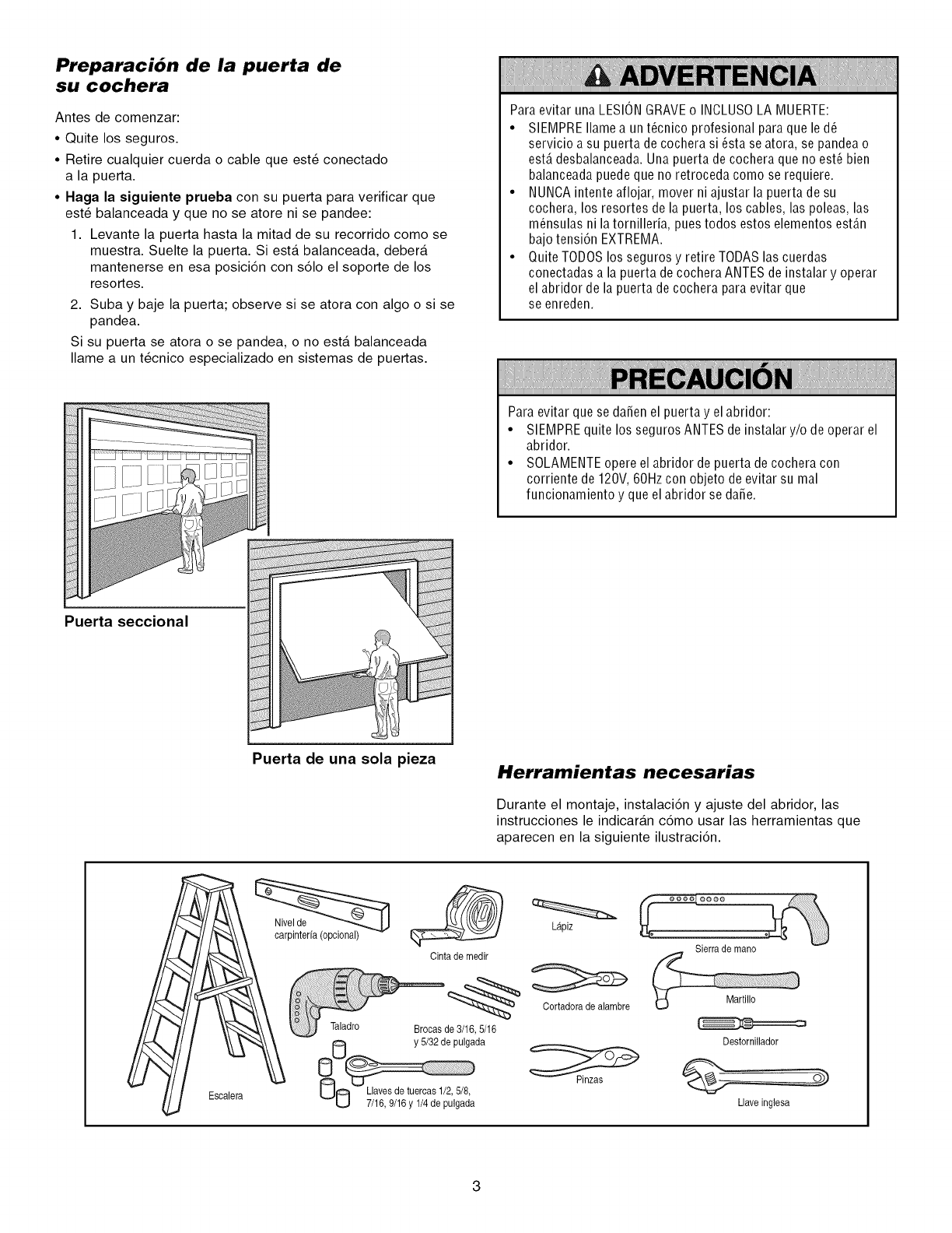
Preparaci6n de la puerta de
su cochera
Antes de comenzar:
•Quite los seguros.
•Retire cualquier cuerda o cable que est6 conectado
a la puerta.
•Haga la siguiente prueba con su puerta para verificar que
est6 balanceada y que no se atore ni se pandee:
1. Levante la puerta hasta la mitad de su recorrido como se
muestra. Suelte la puerta. Siesta balanceada, debera
mantenerse en esa posici6n con s61o el soporte de los
resortes.
2. Suba y baje la puerta; observe si se atora con algo o si se
pandea.
Si su puerta se atora o se pandea, o no esta balanceada
Ilame a un t6cnico especializado en sistemas de puertas.
Paraevitar una LESIONGRAVEo INOLUSOLA MUERTE:
•SIEMPREIlamea unt_cnico profesional paraque le d_
servicio a su puerta de cochera si _sta se atora, se pandea o
estA desbalanceada. Una puerta de cochera que no est_ bien
balanceada puede que no retroceda como se requiere.
• NUNCAintente aflojar, mover ni ajustar la puerta de su
cochera, los resortes de la puerta, los cables, las poleas, las
m_nsulas ni la tornilleria, pues todos estos elementos est_n
bajo tensi6n EXTREMA.
• Quite TODOS los seguros y retire TODAS las cuerdas
conectadas a la puerta decochera ANTES de instalar y operar
el abridor de la puerta de cochera para evitar que
se enreden.
Para evitar que se darien el puerta y el abridor:
• SIEMPREquite los seguros ANTES de instalar y/o de operar el
abridor.
• SOLAMENTEopere el abridor de puerta de cochera con
corriente de 120V, 60Hz con objeto de evitar su mal
funcionamiento y que el abridor se darie.
Puerta seccional
Puerta de una sola pieza Herramientas necesarias
Durante el montaje, instalaci6n y ajuste del abridor, las
instrucciones le indicaran c6mo usar las herramientas que
aparecen en la siguiente ilustraci6n.
Escalera
Taladro
y 5/32 de pulgada
NO 7/16, 9/16y 1/4de pulgad'a
(__ Lapiz
Cinta de medir
Cortadora de alambre
Brocasde 3/16,5/16
Sierra de mano
Destornillador
Llaveinglesa
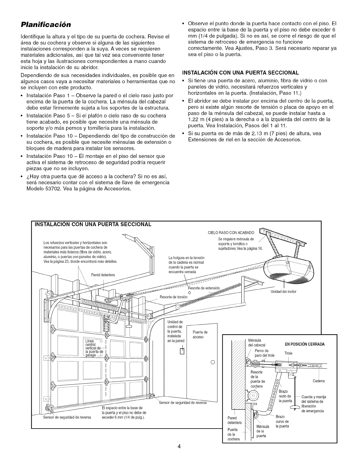
Planificaci6n
Identifique la altura y el tipo de su puerta de cochera. Revise el
Area de su cochera y observe si alguna de las siguientes
instalaciones corresponden a la suya. A veces se requieren
materiales adicionales, asi que tal vez sea conveniente tener
esta hoja y las ilustraciones correspondientes a mano cuando
inicie la instalaci6n de su abridor.
Dependiendo de sus necesidades individuales, es posible queen
algunos casos vaya a necesitar materiales o herramientas que no
se incluyen con este producto.
•Instalaci6n Paso 1 -Observe la pared o el cielo raso justo por
encima de la puerta de la cochera. La m_nsula del cabezal
debe estar firmemente sujeta a los soportes de la estructura.
• Instalaci6n Paso 5 - Si el plaf6n o cielo raso de su cochera
tiene acabado, es posible que necesite una m_nsula de
soporte y/o mas pernos y tornilleria para la instalaci6n.
• Instalaci6n Paso 10 - Dependiendo del tipo de construcci6n de
su cochera, es posible que necesite m_nsulas de extensi6n o
bloques de madera para instalar los sensores.
• Instalaci6n Paso 10 - El montaje en el piso del sensor que
activa el sistema de retroceso de seguridad podria requerir
piezas que no se incluyen.
• _,Hay otra puerta que d_ acceso a la cochera? Si no es asi,
sera necesario contar con el sistema de Ilave de emergencia
Modelo 53702. Vea la pagina de Accesorios.
Observe el punto donde la puerta hace contacto con el piso. El
espacio entre la base de la puerta y el piso no debe exceder 6
mm (1/4 de pulgada). Si no es asi, se corre el riesgo de que el
sistema de retroceso de emergencia no funcione
correctamente. Vea Ajustes, Paso 3. Sera necesario reparar ya
sea el piso o la puerta.
INSTALACl0N CON UNA PUERTA SECClONAL
• Si tiene una puerta de acero, aluminio, fibra de vidrio o con
paneles de vidrio, necesitara refuerzos verticales y
horizontales en la puerta. (Instalaci6n, Paso 11.)
• El abridor se debe instalar por encima del centro de la puerta,
pero si existe algt]n resorte de tensi6n o placa de apoyo en el
paso de la m_nsula del cabezal, se puede instalar hasta a
1.22 m (4 pies) a la derecha o a la izquierda del centro de la
puerta. Vea Instalaci6n, Pasos del 1 a111.
• Si su puerta es de mas de 2.13 m (7 pies) de altura, vea
Extensiones de riel en la secci6n de Accesorios.
INSTALAClON CON UNA PUERTA SECClONAL
Los refuerzosverticalesy horizontalesson
necesarios para las puertasde cocherade
materialesm_s livianos (fibrade vidria, acero,
aluminia,a puertascon panelesde vidria).
Vea lap_gina 23, donde encontraramasdetalles.
Pareddelantera
La holgura en latensi6n
de la cadenaes normal
cuandola puerta se
encuentracerrada
CIELO RASOCON ACABADO
Se requiere mensulade
soparte y tornilloso
sujetadores.Veala p_gina 16.
Resortede extensi6n
0
Resortede torsi6n
Unidad del motor
Unidad de
control de
la puerta,
instalada
en la pared
4
Puerta de
acceso
de seguridadde reversa
El espacioentre la base de
la puerta y el piso no debede
exceder6 mm (1/4de pulg.).
Sensor de seguridadde
0
Mensula
del cabezal ENPOSIClON CERRADA
Perno de
__ar_e _BBrazo, ICadena
I_YY_ _\"/J /o/ [ec_0ae _ Cuerday manija
_/_l,r.__,__m_ /_/ la puer_a Idel sistemade
_lJ- 1,2/ _ liberaci6n
__,_ " deemergencia
Pared _ -- _Brazo,
delantera _'_1 \ curvode
, _,_] I Uensula la puerta
_'uer,a _ 1 I dela
de,, I IJpuerta
cocnera i I
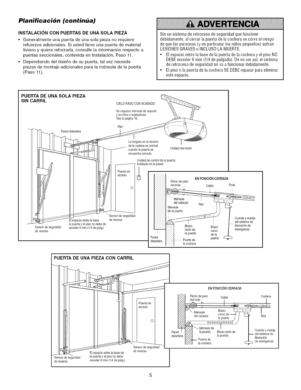
Planificaci6n (continba)
INSTALACION CON PUERTAS DE UNA SOLA PIEZA
•Generalmente una puerta de una sola pieza no requiere
refuerzos adicionales. Si usted tiene una puerta de material
liviano y quiere reforzarla, consulte la informaci6n respecto a
puertas seccionales, contenida en Instalaci6n, Paso 11.
•Dependiendo del disefio de su puerta, tal vez necesite
piezas de montaje adicionales para la m_nsula de la puerta
(Paso 11).
Sin un sistema de retroceso de seguridad que funcione
debidamente, al cerrar la puerta de la cochera se corre el riesgo
de que las personas (y en particular los nifios pequefios) sufran
LESIONESGRAVESo INCLUSOLA MUERTE.
•El espacio entre la base de la puerta de la cochera y el piso NO
DEBEexceder 6 mm (1/4 de pulgada). De no ser asi, el sistema
de retroceso de seguridad no va a funcionar debidamente.
• El piso o la puertade lacocheraSE DEBEreparar paraeliminar
este espacio.
PUERTA DE UNA SOLA PIEZA
SIN CARRIL CIELO RASOCON ACABADO
Se requieremensulade soporte
y tornillos osujetadores.
Veala p_.gina16.
Riel
Pareddelantera
dtfl
\
Sensorde seguridad
de reversa
La holguraen la tensi6n
de la cadenaes normal
"_-------_/_ euando la puerta se
encuentracerrada.
J
Puertade
acceso
0
"Sensor de seguridad
Eles)acio entrela base de reversa
puerta y el piso no debe de
exceder6 mm (1/4 de pulg.)
Unidaddel motor
Unidad de controlde la puerta,
instalada en la pared
ENPOSICIONCERRADA
Perno de pare
del trole I Cable Trole
"-,\\_t tJrazo Brazo
_] recto de curve
_ Puertade ;uerta
_] lacochera
r
Cuerda y manija
del sistemade
liberaci6nde
emergencia
iPUERTA DE UNA PIEZA CON CARRIL i
El espaeioentre la base de
Sensor de seguridad la puerta y el pisono debe
de reversa exceder6 mm (1/4de pulg.).
Sensor de seguridad
de reversa
v//
v//
l///
Pare_
delantera
ENPOSIClON CERRADA
Pernode pare Cable
del trole | I
,8? 1_Mens'u;a Braze
del cabezal ,curvede _ /
lapuerta J /
oooooooooooL_J
_X_ Mensulade I
la puerta Brazerecto de
la puerta
1"/.4_ Puerta de
_//_ la cochera
Cadena
Riel
Cuerda y manija
-- del sistemade
liberaci6n
de emergencia
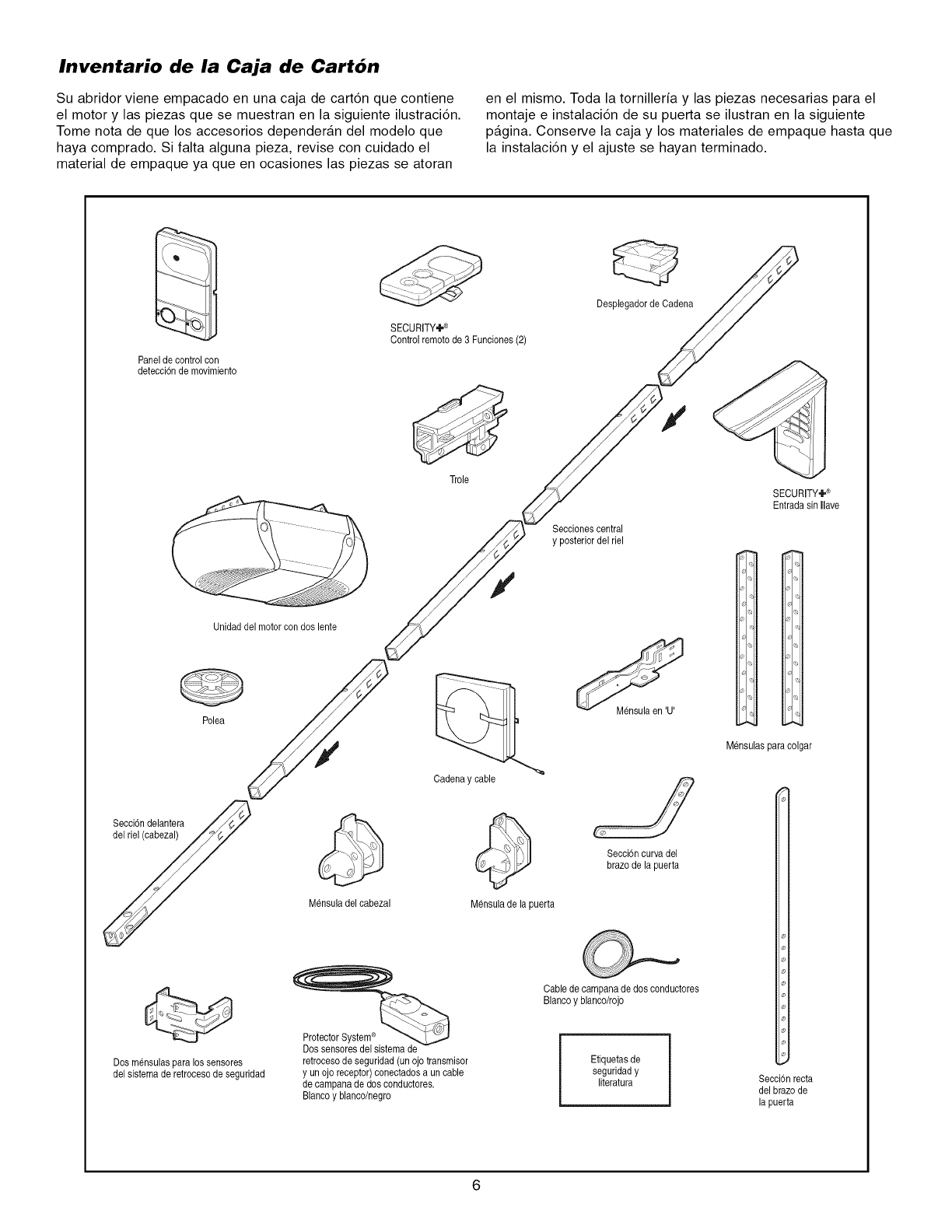
Inventario de la Caja de Cart6n
Su abridor viene empacado en una caja de cart6n que contiene
el motor y las piezas que se muestran en la siguiente ilustraci6n.
Tome nota de que los accesorios dependeran del modelo que
haya comprado. Si falta alguna pieza, revise con cuidado el
material de empaque ya que en ocasiones las piezas se atoran
en el mismo. Toda la tornilleria y las piezas necesarias para el
montaje e instalaci6n de su puerta se ilustran en la siguiente
pagina. Conserve la caja y los materiales de empaque hasta que
la instalaci6n y el ajuste se hayan terminado.
Panelde control con
detecci6nde movimiento
Unidaddel motorcon dos lente
Polea
SECURITY÷®
Controlremotode 3 Funciones(2)
Desplegadorde Cadena
Trole
Seccionescentral
y posteriordel riel
Secci6ndelantera //_
Mensuladel cabezal
Cadena y cable
Mensulade lapuerta
Mensulaen 'U'
Seccbn curvadel
brazode la puerta
SECURITY÷®
Entrada sin Ilave
ol
_,1
I_
is
ol
Mensulaspara colgar
Dos mensulaspara lossensores
del sistemade retrocesode seguridad
ProtectorSystem®
Dos sensoresdel sistemade
retrocesode seguridad (unojo transmisor
y unojo receptor)conectadosa un cable
de campanade dos conductores.
Blancoy blanco/negro
Cablede campanade dos conductores
Blancoy blaneo/rojo
Etiquetas de
seguridady
literatura Secci6nrecta
del brazo de
la puerta
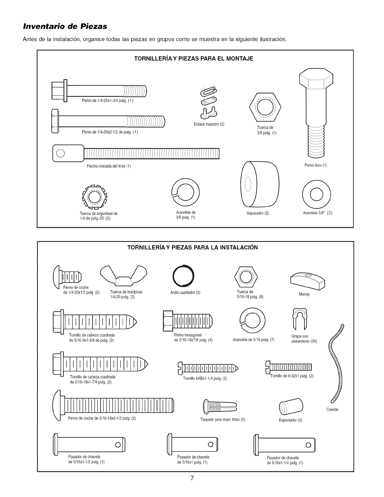
Inventario de Piezas
Antes de la instalaci6n, organice todas las piezas en grupos como se muestra en la siguiente ilustraci6n.
TORNILLER|AY PIEZAS PARA EL MONTAJE
Perno de 1/4-20xl-3/4 pulg. (1)
Enlacemaestro(2) Tuerca de
Perno de 1/4-20x2-1/2de pulg, (1) 3/8 pulg. (1)
Fleeharoscada del trole (1)
@ @
Tuercade seguridadde Arandela de
1/4 de pulg.-20 (2) 3/8 pulg. (1)
Separador(2)
Perno Ioco(1)
Arandela 5/8" (2)
TORNILLER|AY PIEZAS PARA LA INSTALAClON
_oche
de 1/4-20xl/2 pulg.(2) Tuercade mariposa
1/4-20 pulg. (2)
de 5/16-9xl-5/8 de pulg. (2)
D>
_] Tornillo decabeza cuadrada
de 5/16-18xl-7/8 pulg. (2)
O @
Anillo sujetador(3) Tuercade
5/16-18pulg. (8)
Perno hexagonal
de 5/16-18x7/8pulg. (4)
Tornillo 6ABx1-1/4pulg. (2)
Arandela de 5/16 pulg. (7)
Manija
Grapa con
aislamiento (30)
Perno de coche de 5/16-18x2-1/2pulg. (2) Taquete para murofalso (2) Espaciador(2)
Cuerda
oH oi
Pasadordechaveta Pasadorde chaveta Pasadorde chaveta
de 5/16x1-1/2pulg. (1) de 5/16xl pulg. (1) de 5/16x1-1/4pulg. (1)
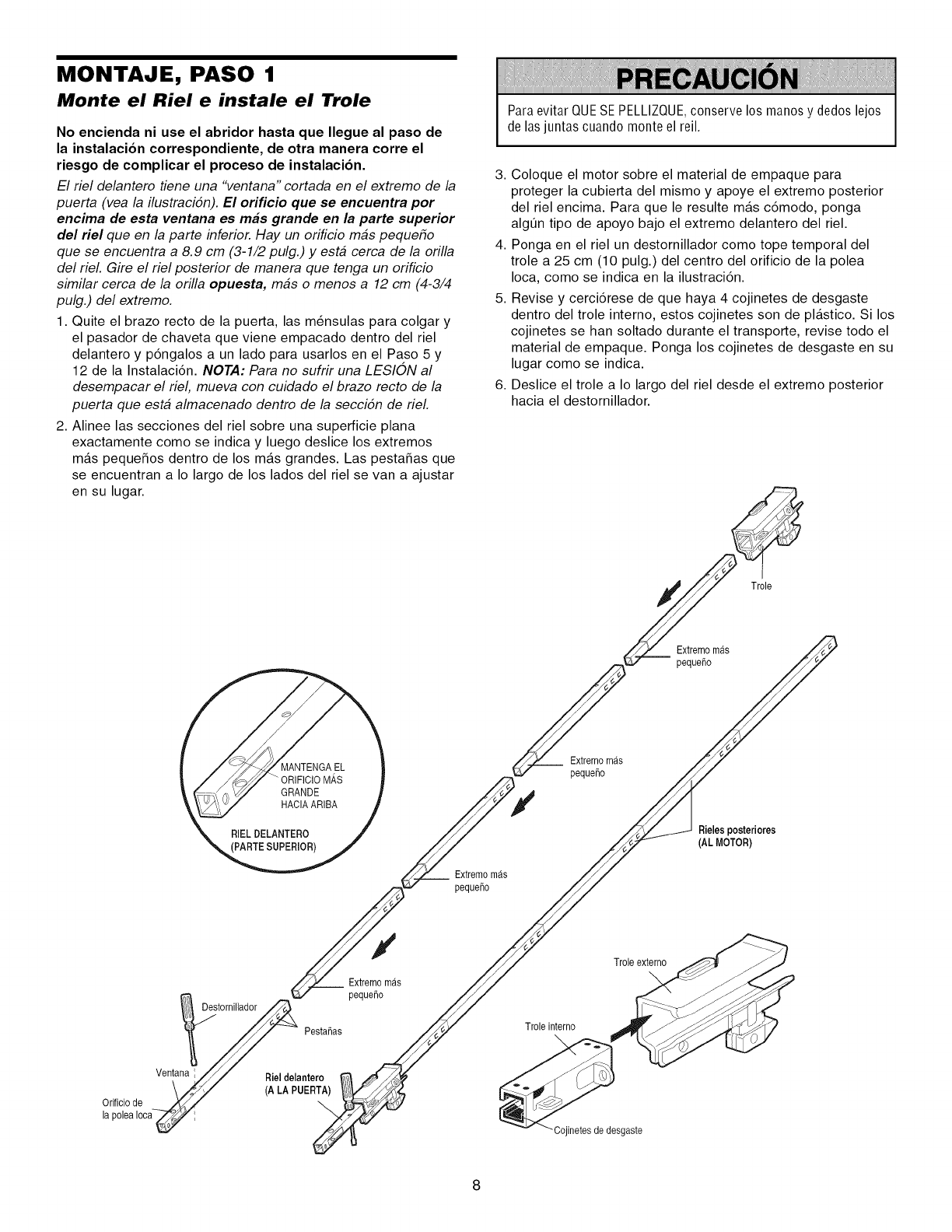
MONTAJE, PASO 1
Monte el Riel e instale el Trole
No encienda ni use el abridor hasta que Ilegue al paso de
la instalacion correspondiente, de otra manera corre el
riesgo de complicar el proceso de instalacion.
El riel delantero tiene una "ventana" cortada en el extremo de la
puerta (vea la ilustracidn). El orifi¢ie que se eneuentra per
encima de esta ventana es robs grande en la parte superior
del riel queen la parte inferior. Hay un orificio mas pequeho
que se encuentra a 8.9 cm (3-1/2 pulg.) y esta cerca de la orilla
del rieL Gire el riel posterior de manera que tenga un orificio
similar cerca de la orilla opuesta, mas o menos a 12 cm (4-3/4
pulg.) del extremo.
1. Quite el brazo recto de la puerta, las m_nsulas para colgar y
el pasador de chaveta que viene empacado dentro del riel
delantero y p6ngalos a un lado para usarlos en el Paso 5 y
12 de la Instalaci6n. NOTA: Para no sufrir una LESION al
desempacar el riel, mueva con cuidado el brazo recto de la
puerta que esta almacenado dentro de la seccidn de rieL
2. Alinee las secciones del riel sobre una superficie plana
exactamente como se indica y luego deslice los extremos
mas peque_os dentro de los mas grandes. Las pesta_as que
se encuentran a Io largo de los lados del riel se van a ajustar
en su lugar.
Para evitar QUESE PELLIZQUE,conserve los manos y dedos lejos
de las juntas cuando monte el reil.
3. Coloque el motor sobre el material de empaque para
proteger la cubierta del mismo y apoye el extremo posterior
del riel encima. Para que le resulte mas c6modo, ponga
algt]n tipo de apoyo bajo el extremo delantero del riel.
4. Ponga en el riel un destornillador como tope temporal del
trole a 25 cm (10 pulg.) del centro del orificio de la polea
Ioca, como se indica en la ilustraci6n.
5. Revise y cerci6rese de que haya 4 cojinetes de desgaste
dentro del trole interno, estos cojinetes son de plastico. Si los
cojinetes se han soltado durante el transporte, revise todo el
material de empaque. Ponga los cojinetes de desgaste en su
lugar como se indica.
6. Deslice el trole a Io largo del riel desde el extremo posterior
hacia el destornillador.
Trole
Extremomas
peque_o
Extremomas
peque_o
Extremomas
peque_o
Rieles posteriores
(AL MOTOR)
_tornillador_ Pesta_as
Ventan!_el delantero
Orificio de -_ z_,//
la poleaIoca _ ;
Y
Extremomas
peque_o
Trole interno
_-Cojinetes de desgaste
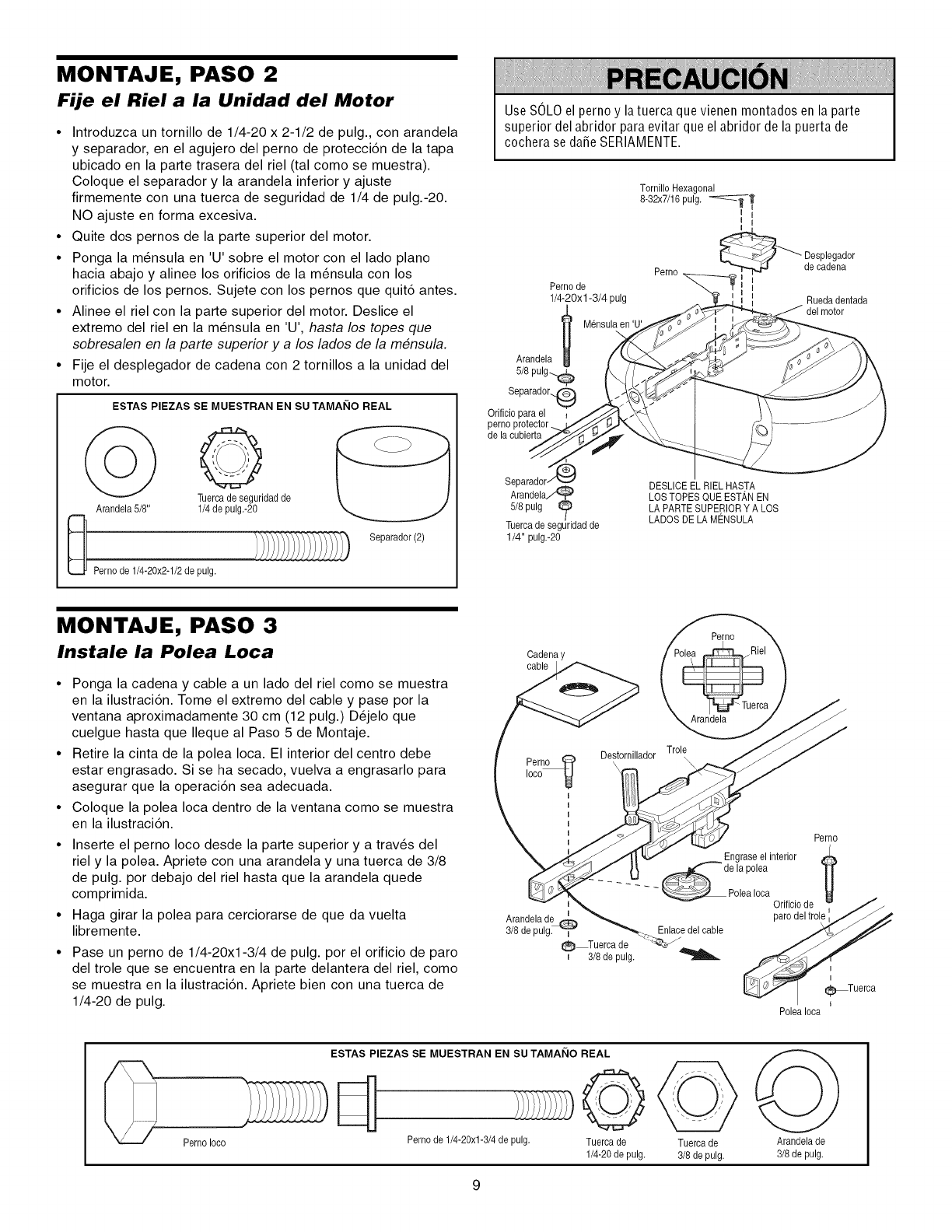
MONTAJE, PASO 2
Fije el Riel a la Unidad del Motor
•Introduzca un tornillo de 1/4-20 x 2-1/2 de pulg., con arandela
y separador, en el agujero del perno de protecci6n de la tapa
ubicado en la parte trasera del riel (tal como se muestra).
Coloque el separador y la arandela inferior y ajuste
firmemente con una tuerca de seguridad de 1/4 de pulg.-20.
NO ajuste en forma excesiva.
•Quite dos pernos de la parte superior del motor.
•Ponga la m6nsula en 'U' sobre el motor con el lado piano
hacia abajo y alinee los orificios de la m6nsula con los
orificios de los pernos. Sujete con los pernos que quit6 antes.
•Alinee el riel con la parte superior del motor. Deslice el
extremo del riel en la m6nsula en 'U', hasta los topes que
sobresalen en la parte superior y a los lados de la mensula.
•Fije el desplegador de cadena con 2 tornillos a la unidad del
motor.
ESTAS PIEZAS SE MUESTRAN EN SU TAMANO REAL
Arandela 5/8"
_ Pernode 1/4-20x2-1/2de pulg.
0
Tuereade seguridadde
1/4de pulg.-20
Separador(2)
Use SOLOel perno y la tuerca que vienen montados en la parte
superior del abridor para evitar que el abridor de la puerta de
cochera se da_eSERIAMENTE.
Perno de
1/4-20x 1-3/4 pulg
/
Mensulaen 'U'
U
Arandela
5/8 pulg_
Orificiopara el
de la cubierta
Tornillo Hexagonal
8-32x7/16pulg. '_---_
I
_ Desplegador
Perno -_ de cadena
i Ruedadentada
Separador
Arandela_
5/8pulg _
Tuercade seguridadde
1/4" pulg.-2O
DESLICEELRIEL HASTA
LOSTOPES QUE ESTAN EN
LAPARTE SUPERIORY A LOS
LADOSDELA MENSULA
MONTAJE, PASO 3
Instale la Polea Loca
• Ponga la cadena y cable a un lado del riel como se muestra
en la ilustraci6n. Tome el extremo del cable y pase por la
ventana aproximadamente 30 cm (12 pulg.) D6jelo que
cuelgue hasta que Ileque al Paso 5 de Montaje.
• Retire la cinta de la polea Ioca. El interior del centro debe
estar engrasado. Si se ha secado, vuelva a engrasarlo para
asegurar que la operaci6n sea adecuada.
• Coloque la polea Ioca dentro de la ventana como se muestra
en la ilustraci6n.
• Inserte el perno Ioco desde la parte superior y a trav6s del
riel y la polea. Apriete con una arandela y una tuerca de 3/8
de pulg. por debajo del riel hasta que la arandela quede
comprimida.
• Haga girar la polea para cerciorarse de que da vuelta
libremente.
• Pase un perno de 1/4-20xl-3/4 de pulg. por el orificio de paro
del trole que se encuentra en la parte delantera del riel, como
se muestra en la ilustraci6n. Apriete bien con una tuerca de
1/4-20 de pulg.
Cadena y
cable
Arandelade
3/8de pulg.
Perno
Arandela
Trole
Destornillador
Perno
Engraseel interior
.... e la polea
- - - _ PoleaIocaOrificio de //
paro del trole _
Enlaoe elea le
i_Tuerca
I
(_ Tuercade
i 3/8 de pulg.
PoleaIoca
ESTAS PIEZAS SE MUESTRAN EN SU TAMAI_IO REAL
Perno Ioco Perno de 1/4-20xl-3/4 de pulg. Tuerca de
1/4-20 de pulg.
Tuerca de
3/8 de pulg.
Arandelade
3/8de pulg,
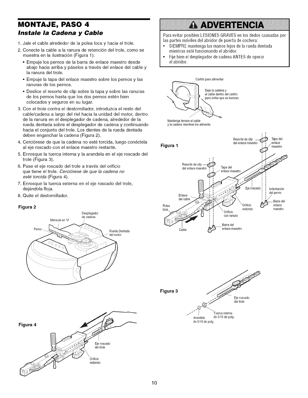
MONTAJE, PASO 4
Instale la Cadena y Cable
1. Jale el cable alrededor de la polea Ioca y hacia el trole.
2. Conecte la cable a la ranura de retenciCn del trole, como se
muestra en la ilustraciCn (Figura 1):
• Empuje los pernos de la barra de enlace maestro desde
abajo hacia arriba y paselos a trav_s del enlace del cable y
la ranura del trole.
• Empuje la tapa del enlace maestro sobre los pernos y las
ranuras de los pernos.
• Deslice el resorte de clip sobre la tapa y sobre las ranuras
de los pernos hasta que los dos pernos estCn bien
colocados y seguros en su lugar.
3. Con el trole contra el destornillador, introduzca el resto del
cable/cadena a largo del riel hacia la unidad del motor, dentro
de la ranura en el desplegador de cadena, alrededor de la
rueda dentada sobre el desplegador de cadena y continuando
hacia el conjunto del trole. Los dientes de la rueda dentada
deben enganchar la cadena (Figura 2).
4. CerciCrese de que la cadena no est6 torcida, luego conCctela
al eje roscado con el enlace maestro restante.
5. Enrosque la tuerca interna y la arandela en el eje roscado del
trole (Figura 3).
6. Pase el eje roscado del trole a trav_s del orificio
que tiene el trole. CerciCrese de que la cadena no
este torcida (Figura 4).
7. Enrosque la tuerca externa en el eje roscado del trole,
dejandola floja.
8. Quite el destornillador.
Figura 2
Perno_
Mensulaen 'U'
Desplegador
de cadena
RuedaDentada
del motor
Paraevitar posibles LESIONESGRAVESen los dedos causadas por
las partes mCviles del abridor de puerta de cochera:
• SIEMPREmantenga las manos lejos de la rueda dentada
mientras est_ funcionando el abridor.
• Fije bien el desplegador de cadena ANTES de operar
el abridor.
CartCnpara alimentar
_ De_e'b,aeO(_de_aYe,cart6n
"_ ,"_, - III, ,,_ evitarque se tuerzan"
Maetengatensoselcable
ylaoadenamientraslosalimente.
I i
I i
Resorte de clip _ Tapadel
_. _ del enlace maestro h'-[ .enlace
t-lgura i_maestro
Resortede clip
del enlacemaestro'_i Tapadel J _
enlace maestro ,t"_, _ I I
,,', , ] ',,
i s 10 I I____r scado IndentaciCn
I I
_"__ i i delpemo
Enlace _ _-_'_,_ I_ [ ;/'
eel cabl_ __X _Barra eel
Polea J _ _ ;__ Orifioio _ enlaoe
Ioca\ _,_ _ /_.141 "=_'4f__:^ redondo - maestro
___f, _. [ ! con ranura
I [ _ Barraeel
Cable _ enlaoemaestro
Figura 4
Eje roscado
del trole
Orificio
redondo
Figura 3
Ejeroscado
del trole
•. _"" Tuercainterna
Arandela de 5/16de pulg.
de 5/16 de pulg.
10
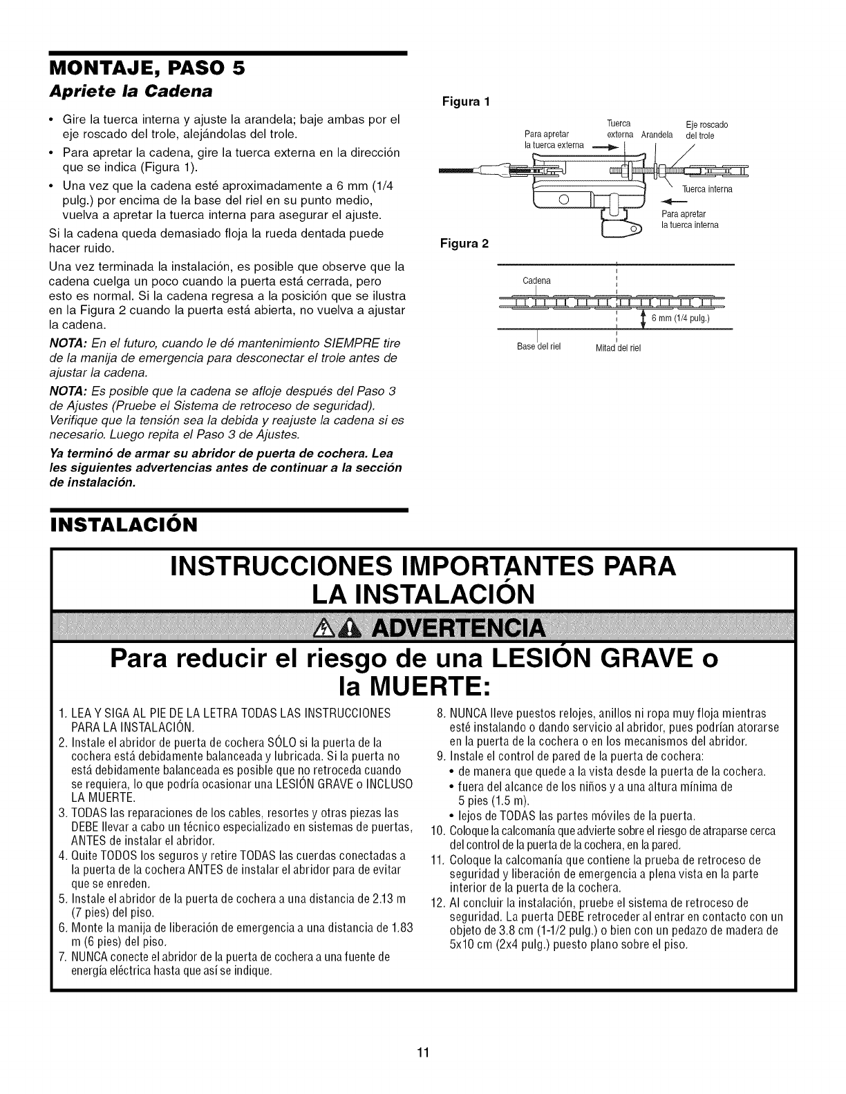
MONTAJE, PASO 5
Apriete la Cadena
•Gire la tuerca interna y ajuste la arandela; baje ambas por el
eje roscado del trole, alejandolas del trole.
•Para apretar la cadena, gire la tuerca externa en la direcci6n
que se indica (Figura 1).
•Una vez que la cadena est6 aproximadamente a 6 mm (1/4
pulg.) por encima de la base del riel en su punto medio,
vuelva a apretar la tuerca interna para asegurar el ajuste.
Si la cadena queda demasiado floja la rueda dentada puede
hacer ruido.
Una vez terminada la instalaci6n, es posible que observe que la
cadena cuelga un poco cuando la puerta esta cerrada, pero
esto es normal. Si la cadena regresa a la posici6n que se ilustra
en la Figura 2 cuando la puerta esta abierta, no vuelva a ajustar
la cadena.
NOTA: En el futuro, cuando le de mantenimiento SIEMPRE tire
de la manija de emergencia para desconectar el trole antes de
ajustar la cadena.
NOTA: Es posible que la cadena se afloje despues del Paso 3
de Ajustes (Pruebe el Sistema de retroceso de seguridad).
Verifique que la tensidn sea la debida y reajuste la cadena si es
necesario. Luego repita el Paso 3 de Ajustes.
Ya termino de armar su abridor de puerta de cochera. Lea
les siguientes advertencias antes de continuar a la seccion
de instalacion.
Figura 1
Tuerca Eje roscado
Para apretar externa Arandela deltrole
la tuercaexterna _ t I /
Fa_aapretar
_ la tuerca interna
Figura 2
Cadena
Base Jel riel
6 mm (1/4pulg,)
Mitaddel riel
INSTALACION
Para reducir el riesgo de una LESION GRAVE o
la MUERTE:
1. LEAY SIGA AL PIEDE LA LETRA TODAS LAS INSTRUCCIONES
PARALA INSTALACION.
2. Instale el abridor de puerta de cochera SOLOsi la puerta de la
cochera est_ debidamente balanceada y lubricada. Si la puerta no
estA debidamente balanceada es posible que no retroceda cuando
se requiera, Io que podria ocasionar una LESIONGRAVEo INOLUSO
LA MUERTE.
3. TODAS las reparaciones de los cables, resortes y otras piezas las
DEBEIlevar a cabo un t@nico especializado en sistemas de puertas,
ANTES de instalar el abridor.
4. Quite TODOS los seguros y retire TODAS las cuerdas conectadas a
la puerta de la cochera ANTES de instalar el abridor para de evitar
que se enreden.
5. Instale el abridor de la puerta de cochera a una distancia de 2.13 m
(7 pies) del piso.
6. Monte la manija de liberaci6n de emergencia a una distancia de 1.83
m (6 pies) del piso.
7. NUNCAconecteel abridor de la puerta de cochera a una fuente de
energia el_ctrica hasta que asi se indique.
8. NUNCAIleve puestos relojes, anillos ni ropa muy floja mientras
est6 instalando o dando servicio al abridor, pues podrian atorarse
en la puerta de la cochera o en los mecanismos del abridor.
9. Instale el control de pared de la puerta de cochera:
• de manera que quede a la vista desde la puerta de la cochera.
• fuera del alcance de los ni_os y a una altura minima de
5 pies (1.5 m).
• lejos de TODAS las partes m6viles de la puerta.
10. Coloquelacalcomaniaqueadviertesobreel riesgo deatraparsecerca
del control de la puertade lacochera,enla pared.
11. Coloque la calcomania que contiene la prueba de retroceso de
seguridad y liberaci6n de emergencia a plenavista en la parte
interior de la puerta de la cochera.
12. AI concluir la instalaci6n, pruebe el sistema de retroceso de
seguridad. La puerta DEBEretroceder al entrar en contacto con un
objeto de3.8 cm (1-1/2 pulg.) o bien con un pedazode madera de
5x10 cm (2x4 pulg.) puesto piano sobre el piso.
11
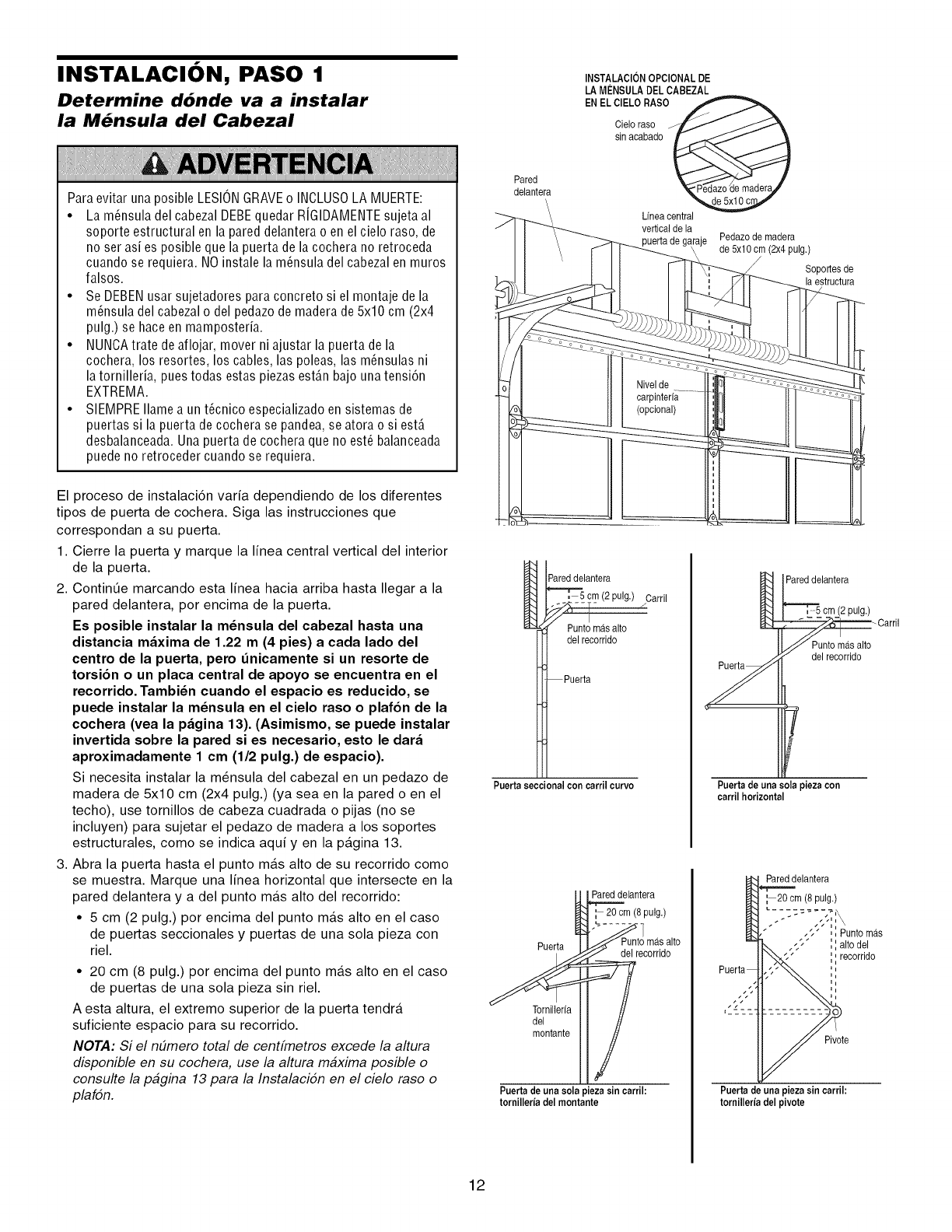
INSTALACION, PASO 1
Determine d6nde va a instalar
la M_nsula del Cabezal
Para evitar una posible LESIONGRAVEo INOLUSOLA MUERTE:
• La m_nsula del cabezal DEBEquedar RiGIDAMENTEsujeta al
soporte estructural en la pared delantera o en el cielo raso, de
no ser asi es posible que la puerta de la cochera no retroceda
cuando se requiera. NO instale la m_nsula del cabezal en muros
falsos.
• Se DEBENusar sujetadores para concreto si el montaje de la
m_nsula del cabezalo del pedazo de madera de5x10 cm (2x4
pulg.) se hace en mamposteria.
• NUNCAtrate de aflojar, mover ni ajustar la puerta de la
cochera, los resortes, los cables, las poleas, las m_nsulas ni
la tornilleria, pues todas estas piezas est_.nbajo una tensi6n
EXTREMA.
• SIEMPRE Ilame a un t_cnico especializado en sistemas de
puertas si la puerta decochera se pandea, se atora o si est,.
desbalanceada. Una puerta de cochera que no est_ balanceada
puede no retroceder cuando se requiera.
Pared
delantera
\
INSTALACIONOPCIONALDE
LA MENSULADEL CABEZAL
ENEL CIELORASO
Cie'a°crab°d°
Lfnea central
vertical de la Pedazode madera
de 5x10 cm (2x4 pulg.)
Soportesde
la estructura
El proceso de instalaci6n varia dependiendo de los diferentes
tipos de puerta de cochera. Siga las instrucciones que
correspondan a su puerta.
1. Cierre la puerta y marque la linea central vertical del interior
de la puerta.
2. Contint]e marcando esta linea hacia arriba hasta Ilegar a la
pared delantera, por encima de la puerta.
Es posible instalar la m_nsula del cabezal hasta una
distancia maxima de 1.22 m(4 pies) a cada lado del
centro de la puerta, pero _nicamente si un resorte de
torsion o un placa central de apoyo se encuentra en el
recorrido. Tambi_n cuando el espacio es reducido, se
puede instalar la m_nsula en el cielo raso o plafon de la
cochera (vea la pagina 13). (Asimismo, se puede instalar
invertida sobre la pared si es necesario, esto le dara
aproximadamente 1 cm (1/2 pulg.) de espacio).
Si necesita instalar la m6nsula del cabezal en un pedazo de
madera de 5x10 cm (2x4 pulg.) (ya sea en la pared o en el
techo), use tornillos de cabeza cuadrada o pijas (no se
incluyen) para sujetar el pedazo de madera a los soportes
estructurales, como se indica aqui yen la pagina 13.
3. Abra la puerta hasta el punto mas alto de su recorrido como
se muestra. Marque una linea horizontal que intersecte en la
pared delantera y a del punto mas alto del recorrido:
• 5 cm (2 pulg.) por encima del punto mas alto en el caso
de puertas seccionales y puertas de una sola pieza con
riel.
• 20 cm (8 pulg.) por encima del punto mas alto en el caso
de puertas de una sola pieza sin riel.
A esta altura, el extremo superior de la puerta tendra
suficiente espacio para su recorrido.
NOTA: Si el n#mero total de centfmetros excede la altura
disponible en su cochera, use la altura maxima posible o
consulte la pagina 13 para la Instalacidn en el cielo raso o
plafdn.
Pareddelantera
Carril
Punto masalto
del recorrido
Puertaseccionalcon carrilcurvo
Puerta
Tornillerfa
del
montante
Pareddelantera
'_ 20 cm (8pulg.)
del recorrido
Puertade una sola pieza sincarril:
tornilleria del montante
Pared delantera
J
Puertade una sola pieza con
carrilhorizontal
cm (2pulg.)
Carril
del recorrido
Pareddelantera
:20 cm (8 pulg.)
,;1" ',',Punto mas
',',alto del
',,,recorrido
Pivote
Puerta de una pieza sin carril:
tornilleria del pivote
12
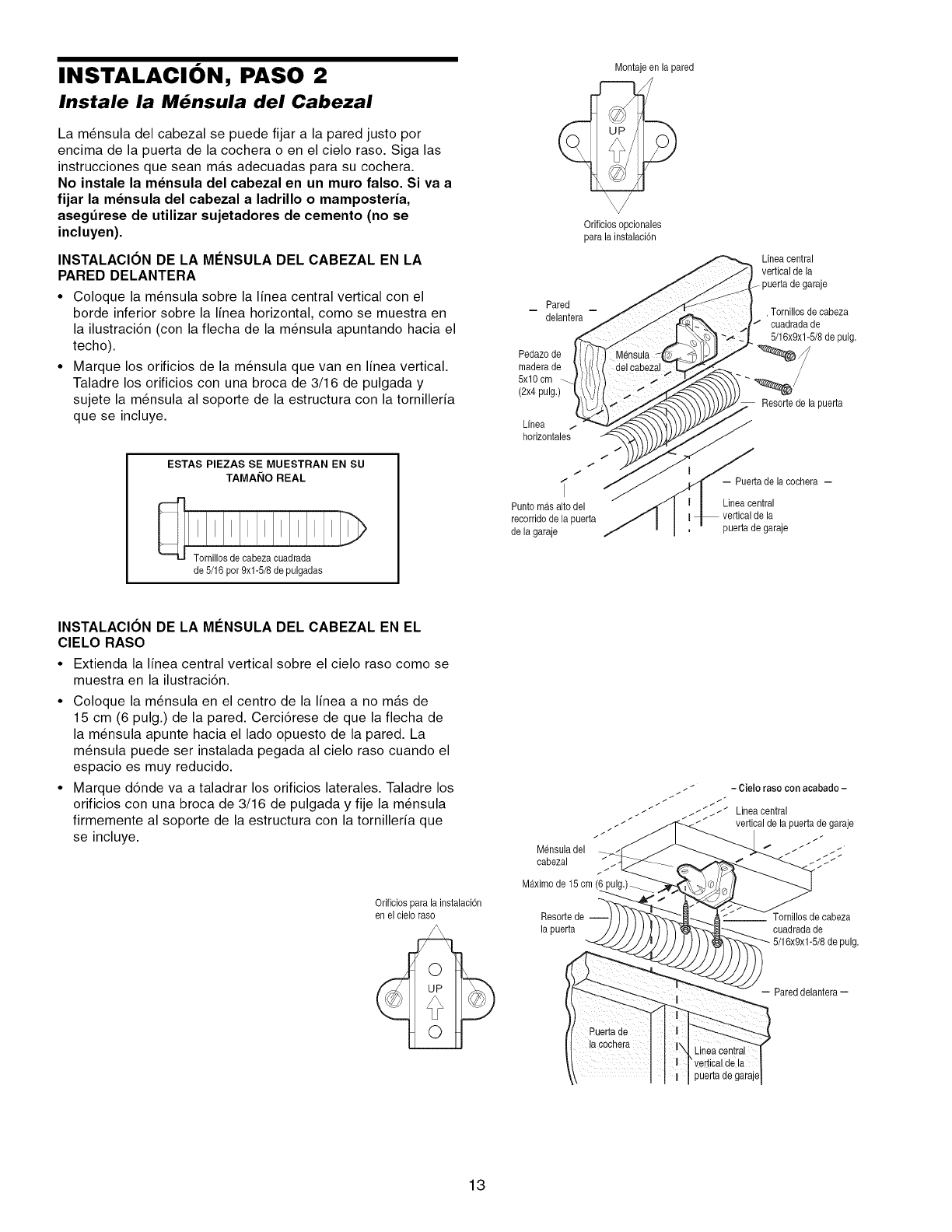
INSTALACION, PASO 2
Instale la M_nsula del Cabezal
La m_nsula del cabezal se puede fijar a la pared justo por
encima de la puerta de la cochera o en el cielo raso. Siga las
instrucciones que sean mas adecuadas para su cochera.
No instale la m_nsula del cabezal en un muro falso. Si va a
fijar la m_nsula del cabezal a ladrillo o mamposteria,
asegdrese de utilizar sujetadores de cemento (no se
incluyen).
INSTALACION DE LA MI_NSULA DEL CABEZAL EN LA
PARED DELANTERA
•Coloque la m_nsula sobre la linea central vertical con el
borde inferior sobre la linea horizontal, como se muestra en
la ilustraciTn (con la flecha de la m_nsula apuntando hacia el
techo).
• Marque los orificios de la m_nsula que van en linea vertical.
Taladre los orificios con una broca de 3/16 de pulgada y
sujete la m_nsula al soporte de la estructura con la tornilleria
que se incluye.
ESTAS PIEZAS SE MUESTRAN EN SU
TAMAI_IO REAL
de 5/16 por 9xl-5/8 de pulgadas
Montajeen la pared
Orificiosopcionales
para la instalacidn
Pared
delantera
Pedazode
maderade
5xl Ocm
(2x4 pulg.)
Linea .i
horizontales
i
Punto mAsalto del
recorridode la puerta
de la garaje
Linea central
vertical de la
puerta de garaje
, Tornillosde cabeza
cuadradade
5/16x9x1-5/8de pulg,
Resorte de la puerta
-- Puertade lacochera --
Linea central
puerta de garaje
INSTALACION DE LA MI_NSULA DEL CABEZAL EN EL
CIELO RASO
• Extienda la linea central vertical sobre el cielo raso como se
muestra en la ilustraciTn.
• Coloque la m_nsula en el centro de la linea a no mas de
15 cm (6 pulg.) de la pared. CerciTrese de que la flecha de
la m_nsula apunte hacia el lado opuesto de la pared. La
m_nsula puede ser instalada pegada al cielo raso cuando el
espacio es muy reducido.
• Marque dTnde va a taladrar los orificios laterales. Taladre los
orificios con una broca de 3/16 de pulgada y fije la m_nsula
firmemente al soporte de la estructura con la tornilleria que
se incluye.
Orificios para la instalaci6n
en el cieloraso
jj _ -Cielorasoconacabado-
_ ___ __ _ _ ;Lineacentra{
/ _t verticalde la puertade garaje
/ /
Mensuladel / /
cabezal / _ / /
Maximo de 15 cm (6 pulg.)__
Resorte de cabeza
la puerta cuadrada de
pulg.
- Pared delantera-
Lineacentral
'vertical de la
puertade garaje
13
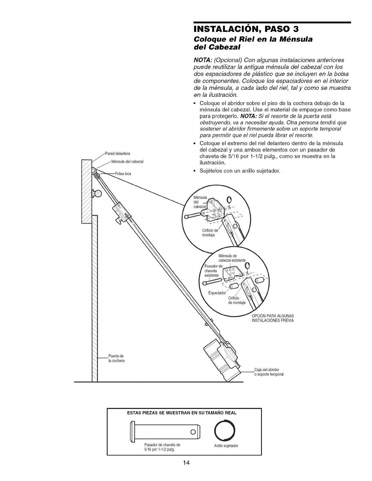
Ioca
INSTALACION, PASO 3
Coloque el Riel en la M_nsula
del Cabezal
NOTA: (Opcional) Con algunas instalaciones anteriores
puede reutilizar la antigua m#nsula del cabezal con los
dos espaciadores de pl_stico que se incluyen en la bolsa
de componentes. Coloque los espaciadores en el interior
de la m#nsula, a cada lado del riel, tal y como se muestra
en la ilustraci6n.
•Coloque el abridor sobre el piso de la cochera debajo de la
m_nsula del cabezal. Use el material de empaque como base
para protegerlo. NOTA: Si el resorte de la puerta est#
obstruyendo, va a necesitar ayuda. Otra persona tendr# que
sostener el abridor firmemente sobre un soporte temporal
para permitir que el riel pueda librar el resorte.
•Coloque el extremo del riel delantero dentro de la m_nsula
del cabezal y una ambos elementos con un pasador de
chaveta de 5/16 por 1-1/2 pulg., como se muestra en la
ilustraci6n.
•Suj_telos con un anillo sujetador.
0
montaje
Mensulade
cabezalexistente
0
Orificio
de montaje
OPCIONPARAALGUNAS
INSTALACIONESPREVlA
Puerta de
la cochera
_C a_apdo_leabrid_rora'
ESTAS PIEZAS SE MUESTRAN EN SU TAMAI_IO REAL
0
Pasadorde chavetade Anillosujetador
5/16 por 1-1/2pulg.
14
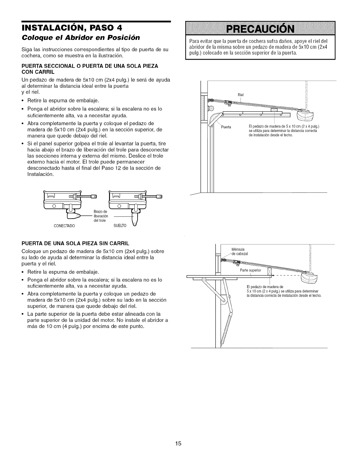
INSTALACION, PASO 4
Coloque el Abridor en Posici6n
Siga las instrucciones correspondientes al tipo de puerta de su
cochera, como se muestra en la ilustraci6n.
PUERTA SECClONAL OPUERTA DE UNA SOLA PIEZA
CON CARRIL
Un pedazo de madera de 5x10 cm (2x4 pulg.) le sera de ayuda
al determinar la distancia ideal entre la puerta
y el riel.
• Retire la espuma de embalaje.
• Ponga el abridor sobre la escalera; si la escalera no es Io
suficientemente alta, va a necesitar ayuda.
• Abra completamente la puerta y coloque el pedazo de
madera de 5x10 cm (2x4 pulg.) en la secci6n superior, de
manera que quede debajo del riel.
• Si el panel superior golpea el trole al levantar la puerta, tire
hacia abajo el brazo de liberaci6n del trole para desconectar
las secciones interna y externa del mismo. Deslice el trole
externo hacia el motor. El trole puede permanecer
desconectado hasta el final del Paso 12 de la secci6n de
Instalaci6n.
deiia°oc,ide6en
CONECTADO
Para evitar que la puerta de cochera sufra dafios, apoye el riel del
abridor de la misma sobre un pedazo de madera de 5x10 cm (2x4
pulg.) colocado en la secci6n superior de la puerta.
J
iRiel
"_ _ Puerta P ( p Ig,)
I I se utilizapara determinarla distanciacorrecta
de instalacbn desdeel techo.
PUERTA DE UNA SOLA PIEZA SIN CARRIL
Coloque un pedazo de madera de 5x10 cm (2x4 pulg.) sobre
su lado de ayuda al determinar la distancia ideal entre la
puerta y el riel.
• Retire la espuma de embalaje.
• Ponga el abridor sobre la escalera; si la escalera no es Io
suficientemente alta, va a necesitar ayuda.
• Abra completamente la puerta y coloque un pedazo de
madera de 5x10 cm (2x4 pulg.) sobre su lado en la secci6n
superior, de manera que quede debajo del riel.
• La parte superior de la puerta debe estar alineada con la
parte superior de la unidad del motor. No instale el abridor a
mas de 10 cm (4 pulg.) por encima de este punto.
I I Mensula _j':
",,,_,'k,,,I ,\,_ ,5a_ll,_c_i_2cxo4p_'ag,)eseu_',izapardaeds_ter_i_a_o"
!
15
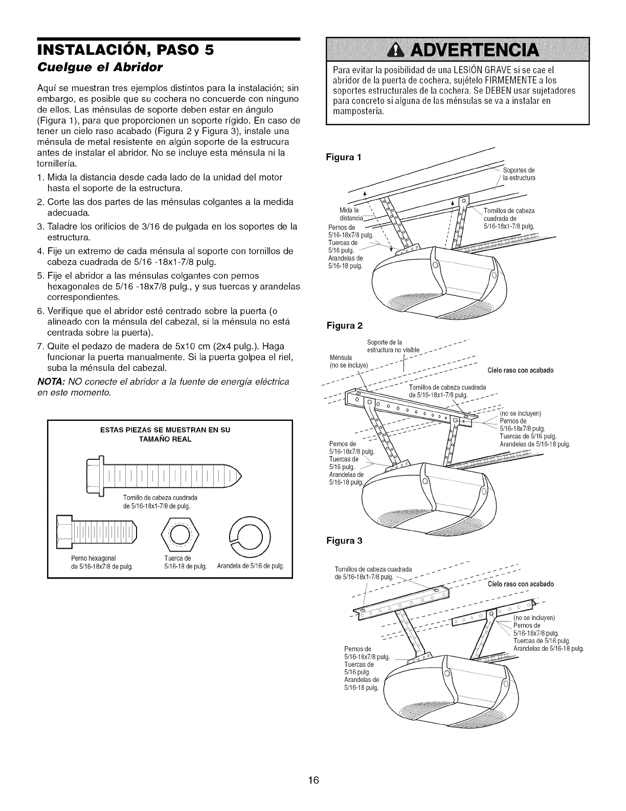
INSTALACION, PASO 5
Cuelgue el Abridor
Aqui se muestran tres ejemplos distintos para la instalaci6n; sin
embargo, es posible que su cochera no concuerde con ninguno
de ellos. Las m_nsulas de soporte deben estar en angulo
(Figura 1), para que proporcionen un soporte rigido. En caso de
tener un cielo raso acabado (Figura 2 y Figura 3), instale una
m_nsula de metal resistente en algt]n soporte de la estrucura
antes de instalar el abridor. No se incluye esta m_nsula ni la
tornilleria.
1. Mida la distancia desde cada lado de la unidad del motor
hasta el soporte de la estructura.
2. Corte las dos partes de las m_nsulas colgantes a la medida
adecuada.
3. Taladre los orificios de 3/16 de pulgada en los soportes de la
estructu ra.
4. Fije un extremo de cada m_nsula al soporte con tornillos de
cabeza cuadrada de 5/16 -18xl -7/8 pulg.
5. Fije el abridor alas m_nsulas colgantes con pernos
hexagonales de 5/16 -18x7/8 pulg., y sus tuercas y arandelas
correspondientes.
6. Verifique que el abridor est6 centrado sobre la puerta (o
alineado con la m_nsula del cabezal, si la m_nsula no esta
centrada sobre la puerta).
7. Quite el pedazo de madera de 5x10 cm (2x4 pulg.). Haga
funcionar la puerta manualmente. Si la puerta golpea el riel,
suba la m_nsula del cabezal.
NOTA: NO conecte el abridor a la fuente de energfa electrica
en este momento.
ESTAS PIEZAS SE MUESTRAN EN SU
TAMANO REAL
Tornillode cabezaeuadrada
de 5/16-18xl-7/8 de pulg,
Perno hexagonal
de 5/16-18x7/8de pulg.
Tuerca de
5/16-18de pulg, Arandelade 5/16 de pulg.
Para evitar la posibilidad de una LESIONGRAVEsi se cae el
abridor de la puerta de cochera, suj_telo FIRMEMENTEa los
soportes estructurales de la cochera. Se DEBENusar sujetadores
para concreto si alguna de las m_nsulas se va a instalar en
mamposteria.
Figura 1
la estructura
Mida la
Pernosde
5/16-18x7/8pulg.
Tuercas de
5/16 pulg.
Arandelas de
5/16-18 pulg.
Tornillos de eabeza
cuadrada de
5/16-18xl -7/8 pulg,
Figura 2
__ _ de 5/16-18xl-7/8 pulg.
Pernos de
5/16-18x7/8pulg,
Tuercasde \
5/16 pulg.
Arandelas de
5/16-18pulg.
(no se incluyen)
Pernos de
5/16-18x7/8pulg,
Tuercasde 5/16 pulg.
Arandelasde 5/16-18 pulg,
Figura 3
Tornillosde cabezacuadrada //._ " C_C C_C'-
de 5/16-18xl-7/8 pulg. _ _ _ _ _ _ _ - Cielo raso con acabado
Pernos de
5/16-18x7/8pulg.
Tuercasde
5/16 pulg.
Arandelas de
5/16-18pulg,
(no se incluyen)
Pernosde
5/16-18x7/8pulg.
Tuercas de 5/16 pulg.
Arandelas de 5/16-18pulg.
16
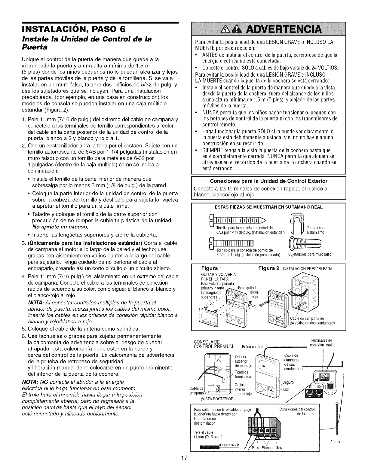
INSTALACION, PASO 6
Instale la Unidad de Control de la
Puerta
Ubique el control de la puerta de manera que quede a la
vista desde la puerta y a una altura minima de 1.5 m
(5 pies) donde los ni_os peque_os no Io puedan alcanzar y lejos
de las partes meviles de la puerta y de la tornilleria. Si se va a
instalar en un muro falso, taladre dos orificios de 5/32 de pulg. y
use los sujetadores que se incluyen. Para una instalacien
precableada, (por ejemplo, en una casa en construccien) los
modelos de consola se pueden instalar en una caja mQItiple
estandar (Figura 2).
1. Pele 11 mm (7/16 de pulg.) del extremo del cable de campana y
conectelo alas terminales de tornillo correspondientes al color
del cable en la parte posterior de la unidad de control de la
puerta; blanco a 2 y blanco y rojo a 1.
2. Con un destornillador abra la tapa por el costado. Sujete con un
tornillo autorroscante de 6AB por 1-1/4 pulgadas (instalacien en
muro falso) o con un tornillo para metales de 6-32 por
1 pulgadas (dentro de la caja mQItiple) como se indica a
continuacien:
• Instale el tornillo de la parte inferior de manera que
sobresalga por Io menos 3 mm (1/8 de pulg.) de la pared.
• Coloque la parte inferior de la unidad de control de la puerta
sobre la cabeza del tornillo y deslicelo para sujetarlo, vuelva
a apretar el tornillo para un ajuste firme.
•Taladre y coloque el tornillo de la parte superior con
precauci6n de no romper la cubierta plastica de la unidad.
No apriete en exceso.
•Inserte las leng(Jetas superiores y cierre la cubierta.
3. (Unicamente para las instalaciones estandar) Corra el cable
de campana al motor a Io largo de la pared y el techo; use
grapas con aislamiento en varios puntos a Io largo del cable
para sujetarlo. Tenga cuidado de no perforar el cable al
engraparlo, creando asi un corto circuits o un circuits abierto.
4. Pele 11 mm (7/16 pulg.) del aislamiento en un extremo del cable
de campana. Conecte el cable alas terminales de conexi6n
rapida de acuerdo a su color, corns sigue: el blanco al blanco y
el blanco/rojo al rojo.
NOTA: AI conectar controles m_ltiples de la puerta al
abridor de puerta, tuerza juntos los cables del mismo color.
Inserte los cables en los orificios de conexien rapida: blanco a
blanco y rojo/blanco a rojo.
5. Coloque el cable de la antena como se indica.
6. Use tachuelas o grapas para sujetar permanentemente
la calcomania de advertencia sobre el riesgo de quedar
atrapado; esta calcomania debe estar en la pared y
cerca del control de la puerta. La calcomania de advertencia
de la prueba de retroceso de seguridad
y liberacien manual debe colocarse en un punto prominente
del interior de la puerta de la cochera.
NOTA: NO conecte el abridor a la energfa
electrica ni Io haga funcionar en este momento.
El trole hara el recorrido hasta Ilegar a la posicien
completamente abierta, pero no regresara a la
posicien cerrada hasta que el rayo del sensor
este conectado y alineado debidamente.
Para evitar la posibilidad de una LESIONGRAVEo INOLUSOLA
MUERTEpor electrocucien:
•ANTES de instalar el control de la puerta, cercierese de que la
energia el_ctrica no est_ conectada.
• Conecte el control SOLOa cables debajo voltaje de 24VOLTIOS.
Para evitar la posibilidad de una LESIONGRAVEe INCLUSO
LA MUERTEcuando la puerta de la cochera se estAcerrando:
• Instale el control de la puertade maneraque quedealavista
desde la puerta de la cochera, fuera del alcancede los niSos
a una altura minima de 1.5 m (5 pies), y alejado de las partes
meviles de la puerta.
• NUNOA permita que los niSos hagan funcionar o jueguen con
los botones de control de la puerta ni con los transmisores de
control remoto.
• Hagafuncionar la puerta SOLOsi la puede ver claramente, si
la puerta estA debidamente ajustada, y si no no hay ninguna
obstruccien en su recorrido.
• SIEMPREtenga a la vista la puerta de la cochera hasta que
est_ completamente cerrada. NUNCA permita que alguien se
atraviese en el recorrido de la puerta de la cochera cuando se
est_ cerrando.
Conexiones para la Unidad de Control Exterior
Conecte alas terminales de conexion rapida: el blanco al
blanco; blanco/rojo al rojo.
ESTAS PIEZAS SE MUESTRAN EN SU TAMAI_IO REAL
_ir_'l ol de
6AB por 1-1/4de pulg. (instalacbn est_ndar)
_de control de
6-32 por 1 pulg.(instalaci6nprecableada)
_ Grapas con
aislarniento
Sujetadorespara murofalso
Figura 1 Figura 2 INSTALACIONPRECABLEADA
QUITARYVOLVERA __ _,
PONERLATAPA <-_
Paravolver a ponerla,
primers inserte ,_-._. Para quitarla, ]_]
/ aqul
Cablede sarnpana de
24voltiosde dos sondustores
17
CONSOLADE
CONTROLPREMIUM Botenconluz
Orificio _ Cable de
[ _ ;1- superior I ?_:_-_C_ carnpana
I_,,. I_1demontaje I_'_ _',i'] dedos.
_E_L Torn,llos FX - ;] conauctores
_.]: _1z1 terminales I
'1! il Orifisio - 1!i1--Segur°
Cablede ]i _t_ inferior - Luz
campana_-__ de montaje
(VISTAPOSTERIOR)
Para soltaro insertir el cable, empuje Conexionesdel control
la lengOetahasiadentrocon de la puerta
la punta de un
destornillador
Pele el cable
11 mm (7/16 pulg.)
\
Rojo BlancoGris
Terminalesde
conexi6n r_pida
Antena
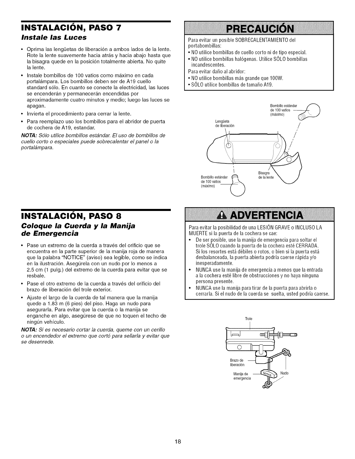
INSTALACION, PASO 7
Instale las Luces
•Oprima las lengQetas de liberaci6n a ambos lados de la lente.
Rote la lente suavemente hacia atras y hacia abajo hasta que
la bisagra quede en la posici6n totalmente abierta. No quite
la lente.
•Instale bombillos de 100 vatios como maximo en cada
portalampara. Los bombillos deben ser de A19 cuello
standard s61o. En cuanto se conecte la electricidad, las luces
se encenderan y permaneceran encendidas por
aproximadamente cuatro minutos y medio; luego las luces se
apagan.
•Invierta el procedimiento para cerrar la lente.
•Para reemplazo uso los bombillos para el abridor de puerta
de cochera de A19, estandar.
NOTA: Sdlo utilice bombillos estandar. El uso de bombillos de
cuello corto o especiales puede sobrecalentar el panel o la
portalampara.
Para evitar un posible SOBRECALENTAMIENTOdel
portabombillas:
•NOutilice bombillas de cuello corto ni de tipo especial.
• NOutilice bombillas hal6genas. Utilice SOLObombillas
incandescentes.
Para evitar da_oal abridor:
• NOutilice bombillas m_s grande que IOOW.
• SOLO utilice bombillas detama_o A19.
LengQeta
de liberaci6n
Bombillo estandar
de 100vatios --
(maximo)
/
/
/
/
/
Bombillo estandar
de 100 vatios
(maximo)
Bisagra
de la lente
INSTALACION, PASO 8
Coloque la Cuerda y la Manija
de Emergencia
• Pase un extremo de la cuerda a trav_s del orificio que se
encuentra en la parte superior de la manija roja de manera
que la palabra "NOTICE" (aviso) sea legible, como se indica
en la ilustraci6n. AsegQrela con un nudo por Io menos a
2.5 cm (1 pulg.) del extremo de la cuerda para evitar que se
resbale.
• Pase el otro extremo de la cuerda a trav_s del orificio del
brazo de liberaci6n del trole exterior.
• Ajuste el largo de la cuerda de tal manera que la manija
quede a 1.83 m (6 pies) del piso. Haga un nudo para
asegurarla. Para evitar que la cuerda o la manija se
enganche en algo, asegQrese de que no toquen el techo de
ningt]n vehiculo.
NOT,4: Si es necesario cortar la cuerda, queme con un cerillo
o un encendedor el extremo que cort6 para sellarla y evitar que
se desenrede.
Para evitar la posibilidad de una LESIONGRAVEo INOLUSOLA
MUERTEsi la puerta de la cochera se cae:
• De ser posible, usela manija de emergencia para soltar el
trole SOLOcuando la puerta de la cochera est_ CERRADA.
Si los resortes est_ d_biles o rotos, o bien si la puerta estA
desbalanceada, la puerta abierta podria caerse rApida y/o
inesperadamente.
• NUNCA use la manijade emergenciaa menos que laentrada
a la cochera est_ libre de obstrucciones y no haya ninguna
persona presente.
• NUNCA use la manija para tirar de la puerta para abrirla o
cerrarla. Si el nudo de la cuerda se suelta, usted podria caerse.
Trole
Man,jade Nudo
emergencia )_
d
18
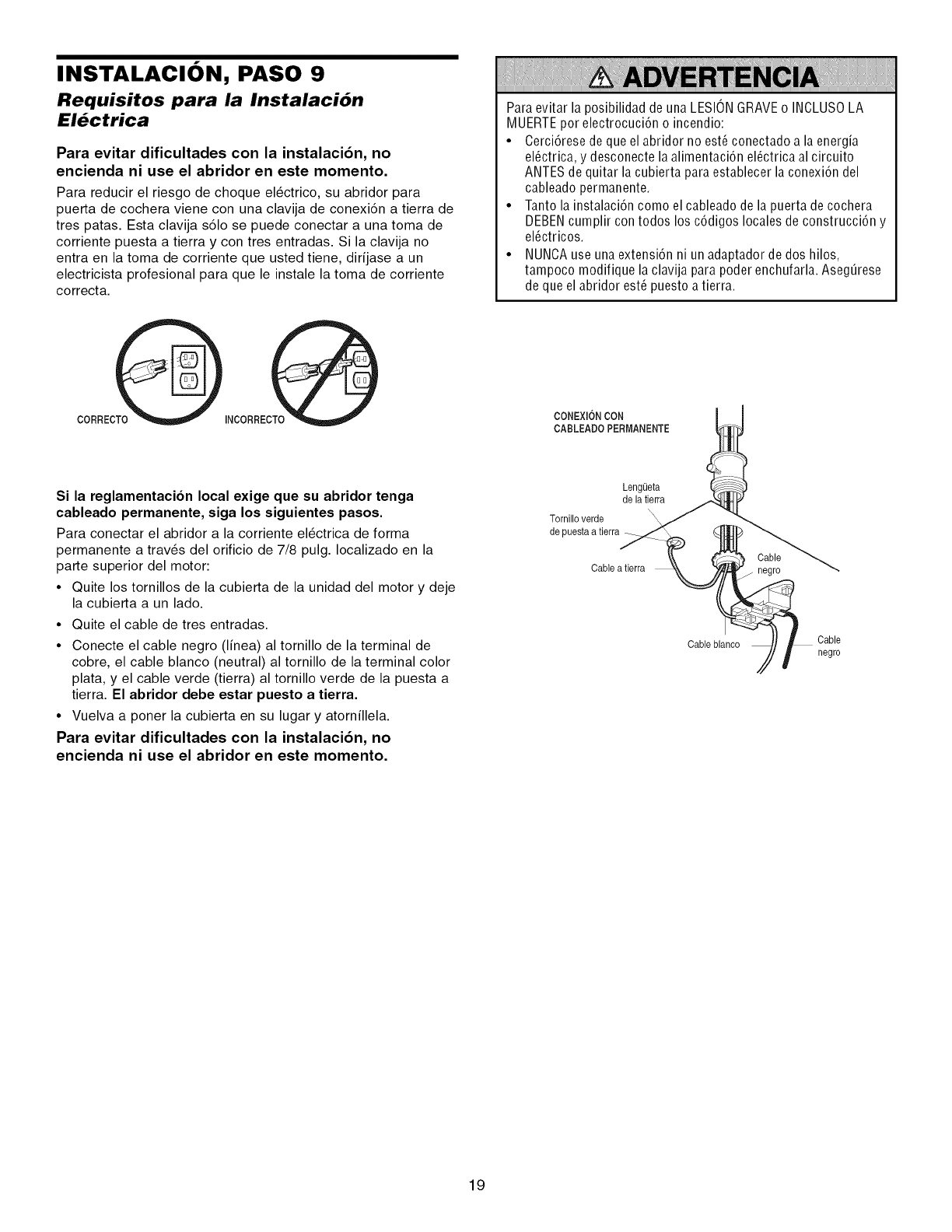
INSTALACION, PASO 9
Requisitos para la Instalaci6n
El_ctrica
Para evitar dificultades con la instalaci6n, no
encienda ni use el abridor en este momento.
Para reducir el riesgo de choque el_ctrico, su abridor para
puerta de cochera viene con una clavija de conexi6n a tierra de
tres patas. Esta clavija s61o se puede conectar a una toma de
corriente puesta a tierra y con tres entradas. Si la clavija no
entra en la toma de corriente que usted tiene, dirfjase a un
electricista profesional para que le instale la toma de corriente
correcta.
Para evitar la posibilidad de una LESIONGRAVEo INCLUSOLA
MUERTEpor electrocuci6n o incendio:
• Cerci6rese de que el abridor no est6 conectado a la energia
el_ctrica, y desconecte la alimentaci6n el_ctrica al circuito
ANTES de quitar la cubierta para establecer la conexi6n del
cableado permanente.
• Tanto la instalaci6n como el cableado de la puerta de cochera
DEBENcumplir contodos los c6digos locales de construcci6n y
el_ctricos.
• NUNCA use una extensi6n ni un adaptador de dos hilos,
tampoco modifique la clavija para poder enchufarla. AsegOrese
de que el abridor est_ puesto a tierra.
CONEXION CON
CABLEADO PERMANENTE
Si la reglamentacion local exige que su abridor tenga
cableado permanente, siga los siguientes pasos.
Para conectar el abridor a la corriente el_ctrica de forma
permanente a trav_s del orificio de 7/8 pulg. Iocalizado en la
parte superior del motor:
• Quite los tornillos de la cubierta de la unidad del motor y deje
la cubierta a un lado.
• Quite el cable de tres entradas.
• Conecte el cable negro (Ifnea) al tornillo de la terminal de
cobre, el cable blanco (neutral) al tornillo de la terminal color
plata, y el cable verde (tierra) al tornillo verde de la puesta a
tierra. El abridor debe estar puesto a tierra.
• Vuelva a poner la cubierta en su lugar y atornillela.
Para evitar dificultades con la instalaci6n, no
encienda ni use el abridor en este momento.
LengOeta
de la tierra
\
Tornilloverde \
de puestaa tierra
Cable a tierra
Cable blaneo
Cable
negro
Cable
negro
19
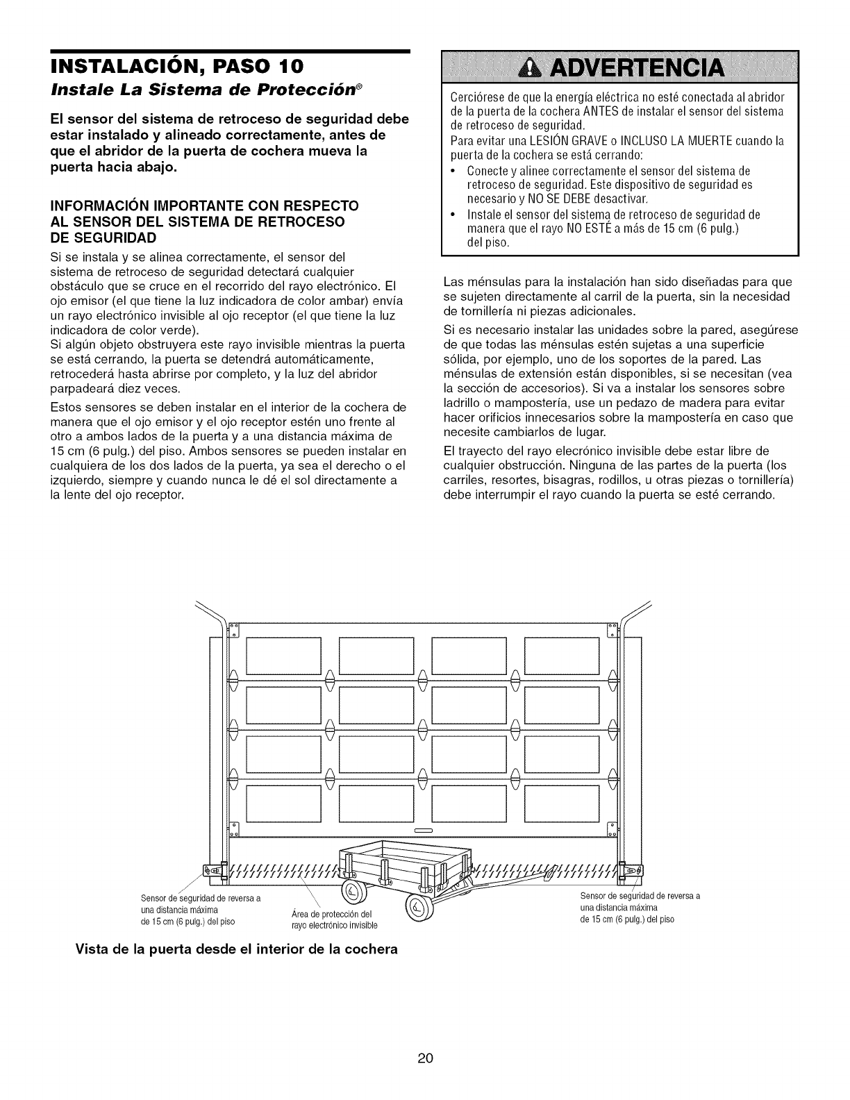
INSTALACION, PASO 10
Instale La Sistema de Protecci6n ®
El sensor del sistema de retroceso de seguridad debe
estar instalado y alineado correctamente, antes de
que el abridor de la puerta de cochera mueva la
puerta hacia abajo.
INFORMACION IMPORTANTE CON RESPECTO
AL SENSOR DEL SISTEMA DE RETROCESO
DE SEGURIDAD
Si se instala y se alinea correctamente, el sensor del
sistema de retroceso de seguridad detectara cualquier
obstaculo que se cruce en el recorrido del rayo electr6nico. El
ojo emisor (el que tiene la luz indicadora de color ambar) envia
un rayo electr6nico invisible al ojo receptor (el que tiene la luz
indicadora de color verde).
Si algQn objeto obstruyera este rayo invisible mientras la puerta
se esta cerrando, la puerta se detendra automaticamente,
retrocedera hasta abrirse por completo, y la luz del abridor
parpadeara diez veces.
Estos sensores se deben instalar en el interior de la cochera de
manera que el ojo emisor y el ojo receptor est6n uno frente al
otro a ambos lados de la puerta y a una distancia maxima de
15 cm (6 pulg.) del piso. Ambos sensores se pueden instalar en
cualquiera de los dos lados de la puerta, ya sea el derecho o el
izquierdo, siempre y cuando nunca le d_ el sol directamente a
la lente del ojo receptor.
Cerci6rese de que la energia el6ctrica no est6 conectada al abridor
de la puerta de la cochera ANTES de instalar el sensor del sistema
de retroceso de seguridad.
Para evitar una LESIONGRAVEo INCLUSOLA MUERTEcuando la
puerta de la cochera se estAcerrando:
• Conecte y alinee correctamente el sensor del sistema de
retroceso de seguridad. Estedispositivo de seguridad es
necesario y NO SE DEBEdesactivar.
• Instale el sensor del sistema de retroceso de seguridad de
manera que el rayo NOESTI_a mAsde 15 cm (6 pulg.)
del piso.
Las m_nsulas para la instalaci6n han sido dise_adas para que
se sujeten directamente al carril de la puerta, sin la necesidad
de tornilleria ni piezas adicionales.
Si es necesario instalar las unidades sobre la pared, asegQrese
de que todas las m_nsulas est_n sujetas a una superficie
s61ida, por ejemplo, uno de los soportes de la pared. Las
m_nsulas de extensi6n estan disponibles, si se necesitan (vea
la secci6n de accesorios). Siva a instalar los sensores sobre
ladrillo o mamposteria, use un pedazo de madera para evitar
hacer orificios innecesarios sobre la mamposteria en caso que
necesite cambiarlos de lugar.
El trayecto del rayo elecr6nico invisible debe estar libre de
cualquier obstrucci6n. Ninguna de las partes de la puerta (los
carriles, resortes, bisagras, rodillos, u otras piezas o tornilleria)
debe interrumpir el rayo cuando la puerta se est_ cerrando.
_eanSd_tda_S:gu_iaddereversaa Aaryoad_c iOtneCoCiO_nvldsele una distanciagmU_ximde reversaa
delsom 6pu,g} e,p,so, o150m 6pu,g} , ,se
Vista de la puerta desde el interior de la cochera
20
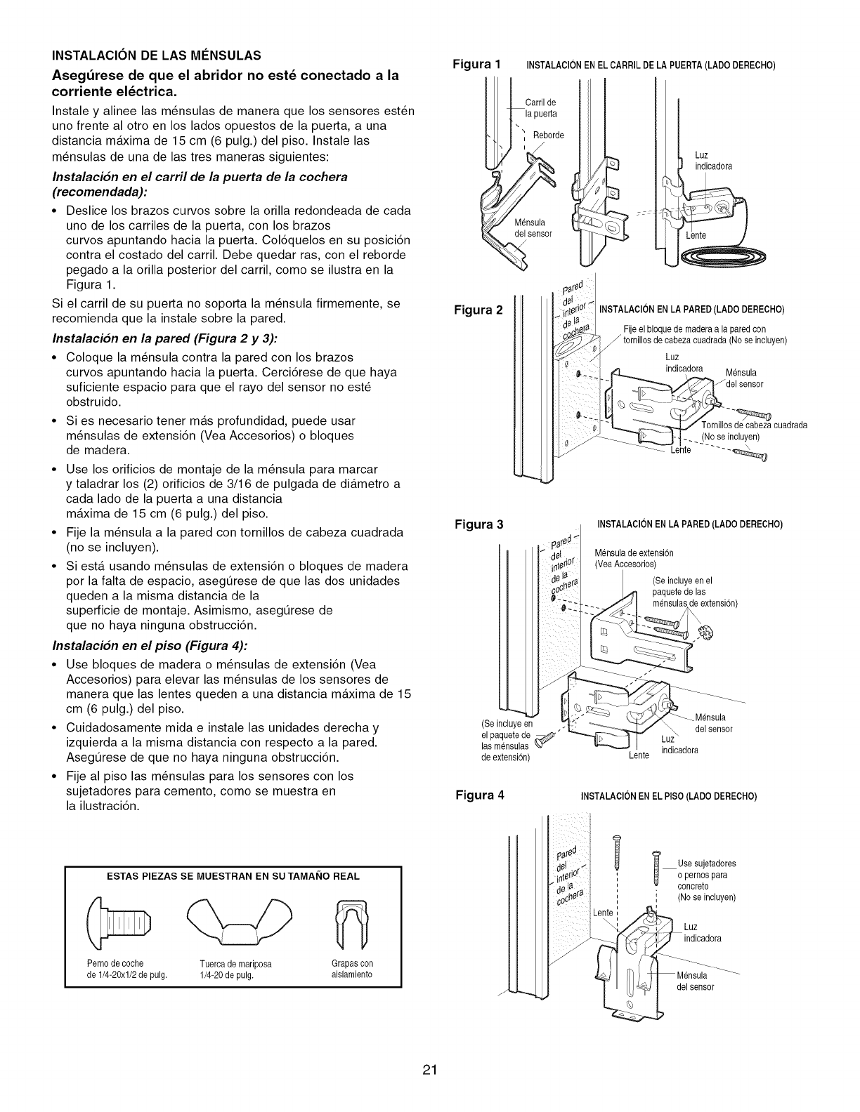
INSTALACION DE LAS MI_NSULAS
Asegdrese de que el abridor no estd conectado a la
corriente eldctrica.
Instale y alinee las m_nsulas de manera que los sensores est_n
uno frente al otro en los lados opuestos de la puerta, a una
distancia maxima de 15 cm (6 pulg.) del piso. Instale las
m_nsulas de una de las tres maneras siguientes:
Instalacion en el carril de la puerta de la cochera
(recomendada):
• Deslice los brazos curvos sobre la orilla redondeada de cada
uno de los carriles de la puerta, con los brazos
curvos apuntando hacia la puerta. Col6quelos en su posici6n
contra el costado del carril. Debe quedar ras, con el reborde
pegado a la orilla posterior del carril, como se ilustra en la
Figura 1.
Si el carril de su puerta no soporta la m_nsula firmemente, se
recomienda que la instale sobre la pared.
Instalacion en la pared (Figura 2 y 3):
• Coloque la m_nsula contra la pared con los brazos
curvos apuntando hacia la puerta. Cerci6rese de que haya
suficiente espacio para que el rayo del sensor no est6
obstruido.
• Si es necesario tener mas profundidad, puede usar
m_nsulas de extensi6n (Vea Accesorios) o bloques
de madera.
• Use los orificios de montaje de la m_nsula para marcar
y taladrar los (2) orificios de 3/16 de pulgada de diametro a
cada lado de la puerta a una distancia
maxima de 15 cm (6 pulg.) del piso.
• Fije la m_nsula a la pared con tornillos de cabeza cuadrada
(no se incluyen).
• Siesta usando m_nsulas de extensi6n o bloques de madera
por la falta de espacio, asegQrese de que las dos unidades
queden a la misma distancia de la
superficie de montaje. Asimismo, asegQrese de
que no haya ninguna obstrucci6n.
Instalacion en el piso (Figura 4):
• Use bloques de madera o m_nsulas de extensi6n (Vea
Accesorios) para elevar las m_nsulas de los sensores de
manera que las lentes queden a una distancia maxima de 15
cm (6 pulg.) del piso.
• Cuidadosamente mida e instale las unidades derecha y
izquierda a la misma distancia con respecto a la pared.
AsegQrese de que no haya ninguna obstrucci6n.
• Fije al piso las m_nsulas para los sensores con los
sujetadores para cemento, como se muestra en
la ilustraci6n.
Figura INSTALAClON EN ELCARRIL DE LA PUERTA(LADO DERECHO)
Carril de
Reborde
i
Mensula
sensor
Figura 2
re_
Luz
indicadora
_ jz7
INSTALAClON EN LA PARED(LADO DERECHO)
Fije el bloque de maderaa la paredcon
tornillosde cabeza cuadrada (No se incluyen)
Luz
indicadora Mensula
Tornillos de cabezacuadrada
(No seincluyen)
\
Figura 3INSTALAClON ENLA PARED (LADO DERECHO)
Mensulade extensi6n
(YeaAccesorios)
(Seincluye en el
paquetede las
_eextensi6n)
(Se incluyeen
el paquetede ,._'"
las mensulas LXY
de extensi6n)
Mensula
del sensor
indicadora
Lente
Figura 4 INSTALAClONENEL PISO(LADO DERECHO)
ESTAS PIEZAS SE MUESTRAN EN SU TAMAI_IO REAL
Pernode coche
de 1/4-20xl/2 de pulg. Tuercade mariposa
1/4-20 de pulg.
Grapas con
aislamiento
f
Usesujetadores
o pernospara
concreto
' (Nose incluyen)
Luz
indicadora
del sensor
21
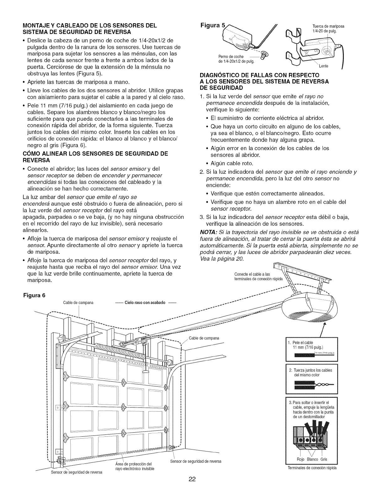
MONTAJE Y CABLEADO DE LOS SENSORES DEL
SISTEMA DE SEGURIDAD DE REVERSA
• Deslice la cabeza de un perno de coche de 1/4-20xl/2 de
pulgada dentro de la ranura de los sensores. Use tuercas de
mariposa para sujetar los sensores alas m_nsulas, con las
lentes de cada sensor frente a frente a ambos lados de la
puerta. Cerci6rese de que la extensi6n de la m_nsula no
obstruya las lentes (Figura 5).
• Apriete las tuercas de mariposa a mano.
• Lleve los cables de los dos sensores al abridor. Utilice grapas
con aislamiento para sujetar el cable a la pared y al cielo raso.
• Pele 11 mm (7/16 pulg.) del aislamiento en cada juego de
cables. Separe los alambres blanco y blanco/negro los
suficiente para que pueda conectarlos alas terminales de
conexi6n rapida del abridor, de la forma siguiente. Tuerza
juntos los cables del mismo color. Inserte los cables en los
orificios de conexi6n rapida: el blanco al blanco y el blanco/
negro al gris (Figura 6).
COMO ALINEAR LOS SENSORES DE SEGURIDAD DE
REVERSA
• Conecte el abridor; las luces del sensor emisory del
sensor receptor se deben de encender y permanecer
encendidas si todas las conexiones del cableado y la
alineaci6n se han hecho correctamente.
La luz ambar del sensor que emite el rayo se
encendera aunque est_ obstruido o fuera de alineaci6n, pero si
la luz verde del sensor receptor del rayo esta
apagada, parpadea o se ve baja, (y no hay ninguna obstrucci6n
en el recorrido del rayo de luz invisible), sera necesario
alinearlos.
• Afloje la tuerca de mariposa del sensor emisory reajuste el
sensor. Apunte directamente al otro sensor y apriete la tuerca
de mariposa.
• Afloje la tuerca de mariposa del sensor receptor del rayo, y
reajuste hasta que reciba el rayo del sensor emisor. Una vez
que la luz verde brille continuamente, apriete la tuerca de
mariposa.
Figura 6
Cable de campana
Sensor de seguridadde reversa
Figura Tuercade mariposa
Pernodecoche
de 1/4-20x1/2 de pulg.
DIAGNOSTICO DE FALLAS CON RESPECTO
A LOS SENSORES DEL SISTEMA DE REVERSA
DE SEGURIDAD
1. Si la luz verde del sensor que emite el rayo no
permanece encendida despu_s de la instalaci6n,
verifique Io siguiente:
• El suministro de corriente el_ctrica al abridor.
• Que haya un corto circuito en alguno de los cables,
ya sea el blanco, o el blanco/negro. Esto ocurre
frecuentemente donde hay alguna grapa.
• AIg_n error en la conexi6n de los cables de los
sensores al abridor.
• AIgQn cable roto.
2. Si la luz indicadora del sensor que emite el rayo enciende y
permanece encendida, pero la luz del otro sensor no
enciende:
• Verifique que est6n correctamente alineados.
• Verifique que no haya un alambre roto en el cable del
sensor receptor.
3. Si la luz indicadora del sensor receptor esta d_bil o baja,
verifique la alineaci6n de los sensores.
NOTA: Si la trayectoria del rayo invisible se ve obstruida o esta
fuera de alineacidn, al tratar de cerrar la puerta esta se abrira
automaticamente. Si la puerta esta abierta, simplemente no se
podra cerrar, y las luces de abridor parpadearan diez veces.
Vea la pagina 20.
Conecteel cablealas
terminalesde conexbn rapida
-_,,/Cable de campana
Areade protecci6ndel
rayoelectr6nico invisible
Sensorde seguridadde reversa
f
1. Pele el cable
11mm (7/16pulg.)
2. Tuerzajuntos los cables
del mismocolor
3. Para soltaro insertir el
cable, empuje la lengL)eta
haciadentrocon lapunta
de un destornillador
Rojo Blanco Gris
Terminalesde conexi6n rapida
22
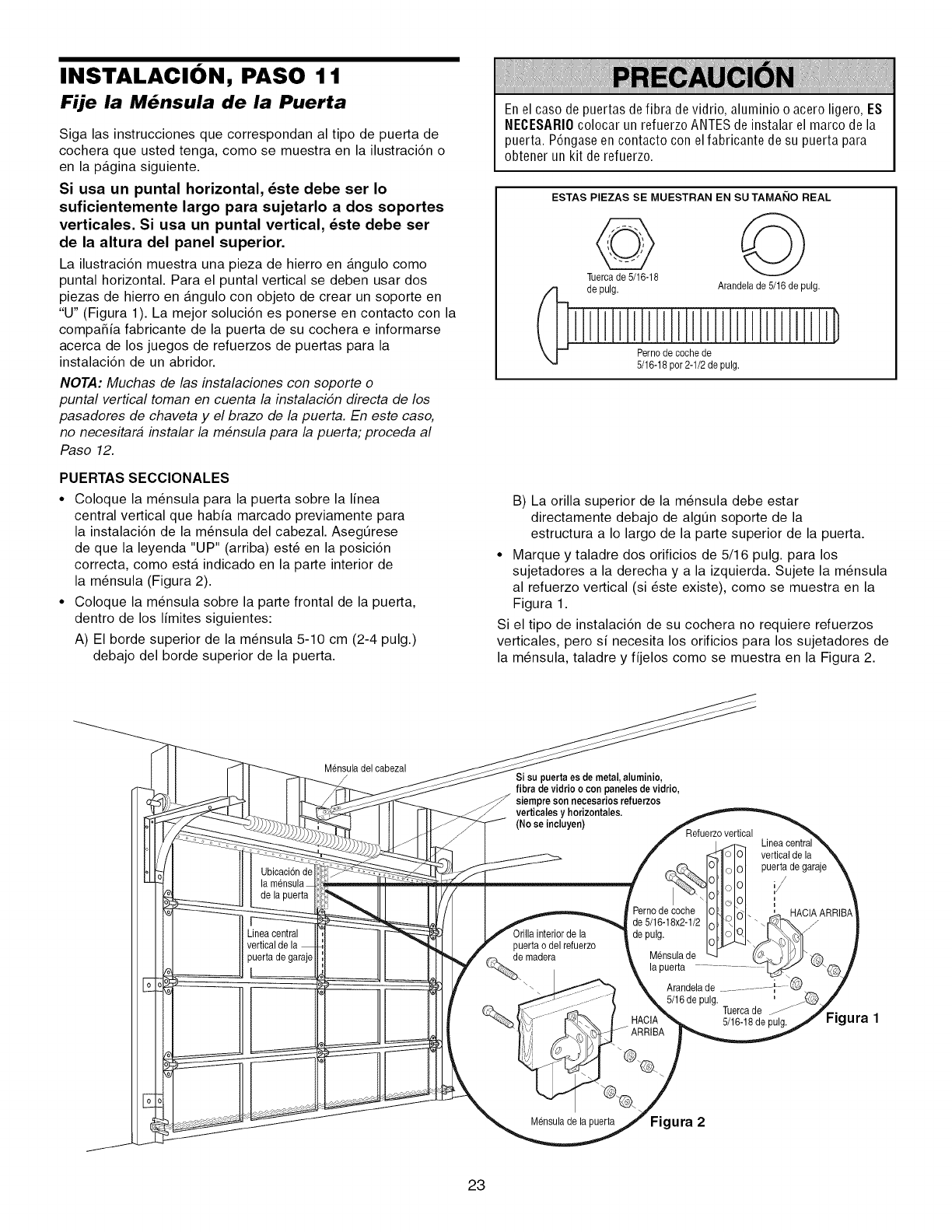
INSTALACION, PASO 11
Fije la M_nsula de la Puerta
Siga las instrucciones que correspondan al tipo de puerta de
cochera que usted tenga, como se muestra en la ilustraci6n o
en la pagina siguiente.
Si usa un puntal horizontal, _ste debe ser Io
suficientemente largo para sujetarlo a dos soportes
verticales. Si usa un puntal vertical, _ste debe ser
de la altura del panel superior.
La ilustraci6n muestra una pieza de hierro en angulo como
puntal horizontal. Para el puntal vertical se deben usar dos
piezas de hierro en angulo con objeto de crear un soporte en
"U" (Figura 1). La mejor soluci6n es ponerse en contacto con la
compaSia fabricante de la puerta de su cochera e informarse
acerca de los juegos de refuerzos de puertas para la
instalaci6n de un abridor.
NOTA: Muchas de las instalaciones con soporte o
puntal vertical toman en cuenta la instalacidn directa de los
pasadores de chaveta y el brazo de la puerta. En este caso,
no necesitara instalar la mensula para la puerta; proceda al
Paso 12.
PUERTAS SECClONALES
•Coloque la m_nsula para la puerta sobre la linea
central vertical que habia marcado previamente para
la instalaci6n de la m_nsula del cabezal. Asegt]rese
de que la leyenda "UP" (arriba) est6 en la posici6n
correcta, como esta indicado en la parte interior de
la m_nsula (Figura 2).
•Coloque la m_nsula sobre la parte frontal de la puerta,
dentro de los limites siguientes:
A) El borde superior de la m_nsula 5-10 cm (2-4 pulg.)
debajo del borde superior de la puerta.
Enel caso de puertas defibra de vidrio, aluminio o acero ligero, E$
NECESARI0 colocar un refuerzo ANTESde instalar el marco de la
puerta. P6ngase en contacto con el fabricante de su puerta para
obtener un kit de refuerzo.
ESTAS PIEZAS SE MUESTRAN EN SU TAMAI_IO REAL
Tuercade 5/16-18
de pulg. Arandelade 5/16 de pulg.
Pernode coche de
5/16-18por 2-1/2de pulg.
B) La orilla superior de la m_nsula debe estar
directamente debajo de algQn soporte de la
estructura a Io largo de la parte superior de la puerta.
• Marque y taladre dos orificios de 5/16 pulg. para los
sujetadores a la derecha y a la izquierda. Sujete la m_nsula
al refuerzo vertical (si _ste existe), como se muestra en la
Figura 1.
Si el tipo de instalaci6n de su cochera no requiere refuerzos
verticales, pero si necesita los orificios para los sujetadores de
la m_nsula, taladre y fijelos como se muestra en la Figura 2.
Ubicaci6nde
de la puerta
Lineacentral
vertical
puerta de garaje
Mensuladel cabezal
/Si su puerta es de metal,aluminio,
fibra de vidrio ocon paneles de vidrio,
siempre son necesarios refuerzos
verticales y horizontales.
(No se incluyen) Refuerzovertical
vertical de la
puerta de garaje
i
Perno de coche HAClA ARRIBA
de 5/16-18x2-1/2
de pulg.
puerta o del refuerzo
e madera Mensula de
la puerta
Arandelade ................... i.....
_. "@'@. 5/16de pulg.
............. ARR_A Tuercade: 5/16-18de pulg.
Mensulade la puerta Figura 2
Figura 1
23
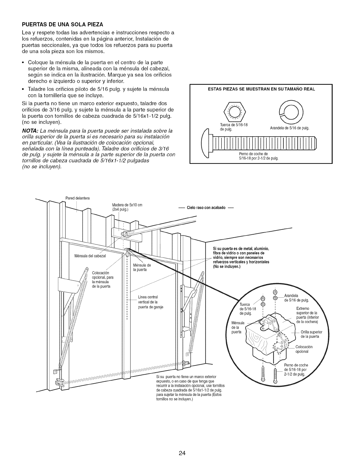
PUERTAS DE UNA SOLA PIEZA
Lea y respete todas las advertencias e instrucciones respecto a
los refuerzos, contenidas en la pagina anterior, Instalaci6n de
puertas seccionales, ya que todos los refuerzos para su puerta
de una sola pieza son los mismos.
• Coloque la m_nsula de la puerta en el centro de la parte
superior de la misma, alineada con la m_nsula del cabezal,
segQn se indica en la ilustraci6n. Marque ya sea los orificios
derecho e izquierdo o superior y inferior.
• Taladre los orificios piloto de 5/16 pulg. y sujete la m_nsula
con la tornilleria que se incluye.
Si la puerta no tiene un marco exterior expuesto, taladre dos
orificios de 3/16 pulg. y sujete la m_nsula a la parte superior de
la puerta con tornillos de cabeza cuadrada de 5/16xl-1/2 pulg.
(no se incluyen).
NOTA: La mensula para la puerta puede ser instalada sobre la
orilla superior de la puerta si es necesario para su instalacidn
en particular. (Vea la ilustracidn de colocacidn opcional,
sehalada con la Ifnea punteada). Taladre dos orificios de 3/16
de pulg. y sujete la mensula a la parte superior de la puerta con
tornillos de cabeza cuadrada de 5/16xl-1/2 pulgadas
(no se incluyen).
ESTAS PIEZAS SE MUESTRAN EN SU TAMAI_IO REAL
de pulg. Arandelade 5/16 de pulg.
Pernode coche de
5/16-18por2-1/2 de pulg.
Pareddelantera
Maderade 5x10 cm
(2x4 pulg.) -- Cielo rasocon acabado --
Mensuladel cabezal
Colocaci6n
opcional, para
la mensula
de la puerta
Mensulade
la puerta
Lineacentral
vertical de la
puerta de garaje
Si su puertaes de metal, aluminio,
fibra de vidrioo con paneles de
refuerzosverticalesy horizontales
(No se incluyen.)
Si su puerta no tiene un marco exterior
expuesto,o en caso de quetengaque
recurrir a la instalacbn opcional,use tornillos
de cabezacuadrada de 5/16x1-1/2de pulg.
para sujetar la mensulade la puerta (Estos
tornillos no se incluyen.)
_Arandela
"_' de 5/16de pulg.
de 5/16-18 ', Extremo
i
de pulg. , superiorde la
__ puerta (interior
Mensula _de la cochera)
de la J;
puerta _ Orilla superior
i_ delapuerta
_.' Colocacbn
opcional
Perno de coche
de 5/16-18por
2-1/2 de pulg.
24
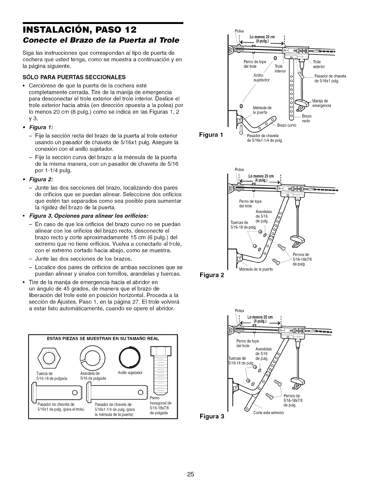
INSTALACION, PASO 12
Conecte el Brazo de la Puerta al Trole
Siga las instrucciones que correspondan al tipo de puerta de
cochera que usted tenga, como se muestra a continuaci6n y en
la pagina siguiente.
SOLO PARA PUERTAS SECCIONALES
•Cerci6rese de que la puerta de la cochera est_
completamente cerrada. Tire de la manija de emergencia
para desconectar el trole exterior del trole interior. Deslice el
trole exterior hacia atras (en direcci6n opuesta a la polea) por
Io menos 20 cm (8 pulg.) como se indica en las Figuras 1,2
y3.
•Figura 1:
- Fije la secci6n recta del brazo de la puerta al trole exterior
usando un pasador de chaveta de 5/16xl pulg. Asegure la
conexi6n con el anillo sujetador.
- Fije la secci6n curva del brazo a la m_nsula de la puerta
de la misma manera, con un pasador de chaveta de 5/16
por 1-1/4 pulg.
• Figura 2:
- Junte las dos secciones del brazo, Iocalizando dos pares
de orificios que se puedan alinear. Seleccione dos orificios
que est6n tan separados como sea posible para aumentar
la rigidez del brazo de la puerta.
•Figura 3, Opciones para alinear los orificios:
- En caso de que los orificios del brazo curvo no se puedan
alinear con los orificios del brazo recto, desconecte el
brazo recto y corte aproximadamente 15 cm (6 pulg.) del
extremo que no tiene orificios. Vuelva a conectarlo al trole,
con el extremo cortado hacia abajo, como se muestra.
- Junte las dos secciones de los brazos.
- Localice dos pares de orificios de ambas secciones que se
puedan alinear y Qnalos con tornillos, arandelas y tuercas.
• Tire de la manija de emergencia hacia el abridor en
un angulo de 45 grados, de manera que el brazo de
liberaci6n del trole est6 en posici6n horizontal. Proceda a la
secci6n de Ajustes, Paso 1, en la pagina 27. El trole volvera
a estar listo automaticamente, cuando se opere el abridor.
ESTAS PIEZAS SE MUESTRAN EN SU TAMAI_IO REAL
Tuerca de Arandelade
5/16-18de pulgada 5/16de pulgada
_Pasador de chaveta d7 1 _ Pasadorde chavetade
5/16xl de pulg. (para el trole) 5/16xl-1/4 de pulg. (para
la mensulade la puerta)
O
Anillo sujetador
Perno
hexagonalde
5/16-18x7/8
de pulgada
Figura 1
Figura 2
Figura 3
0
Perno detope
del trole Trole
interi
Anillo
sujetador
0 Mensulade
la puerta
_-Brazo ourvo
Pasadorde chaveta
de 5/16x1-1/4de pulg.
Trole
exterior
Pasadorde chaveta
de 5/16xl pulg.
_Manijade
emergencia
recto
Polea
Lomenos20 cm
(8pulg.)
_ ernos de
5/16-18x7/8
de pulg.
Mensulade la puerta
Polea
ILomenos20cm I
,_ (8pulg.) _,
eeQll
del trole / / I
Arandelas / / 1
de 5/16 /o/
Tuercasde de pulg, Lo/
5/16-18de pulg_ /y/
r _"_ ..... _ Pernosde
I/i v 5/16-18x7/8
I _°'_Gorte este extremede palg"
-- Corte este extremo
25
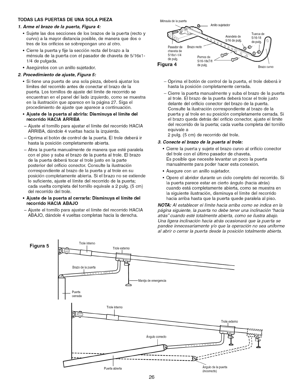
TODAS LAS PUERTAS DE UNA SOLA PIEZA
1. Arme el brazo de la puerta, Figura 4:
• Sujete las dos secciones de los brazos de la puerta (recto y
curvo) a la mayor distancia posible, de manera que dos o
tres de los orificios se sobrepongan uno al otro.
• Cierre la puerta y fije la secci6n recta del brazo a la
m_nsula de la puerta con el pasador de chaveta de 5/16xl -
1/4 de pulgada.
• Asegerelos con un anillo sujetador.
2. Procedimiento de ajuste, Figura 5:
• Si tiene una puerta de una sola pieza, deber& ajustar los
limites del recorrido antes de conectar el brazo de la
puerta. Los tornillos de ajuste del limite de recorrido se
encuentran en el panel del lado izquierdo, como se muestra
en la ilustraci6n que aparece en la p&gina 27. Siga el
procedimiento de ajuste que aparece a continuaci6n.
• Ajuste de la puerta al abrirla: Disminuya el limite del
recorrido HAClA ARRIBA
- Ajuste el tornillo para ajustar el limite del recorrido HACIA
ARRIBA, d&ndole 4 vueltas hacia la izquierda.
- Oprima el bot6n de control de la puerta. El trole deber& ir
hasta la posici6n completamente abierta.
- Abra la puerta manualmente de manera que est6 paralela
con el piso y suba el brazo de la puerta al trole. El brazo
de la puerta deber& tocar el trole justo en la parte
posterior del orificio conector. Consulte la ilustraci6n
correspondiente al brazo de la puerta y al trole en su
posici6n completamente abierta. Si el brazo no se extiende
Io suficiente, ajuste el limite del recorrido de la puerta;
cada vuelta completa del tornillo equivale a 2 pulg. (5 cm)
del recorrido del trole.
• Ajuste de la puerta al cerrarla: Disminuya el limite del
recorrido HAClA ABAJO
- Ajuste el tornillo para ajustar el limite del recorrido HACIA
ABAJO, d&ndole 4 vueltas completas hacia la derecha.
Mensulade la puerta
_._6 de puAnill° sujetador
Tuerca de
Arandelade 5/16-18
Ig. de pulg. _ L'_/_
chavetade __ _0-/ V/
5/16xl y
Figura 4de pulg. Brazocurvo
-- Oprima el bot6n de control de la puerta, el trole debera ir
hasta la posici6n completamente cerrada.
- Cierre la puerta manualmente y suba el brazo de la puerta
al trole. El brazo de la puerta debera tocar el trole justo
delante del orificio conector del brazo de la puerta.
Consulte la ilustraci6n correspondiente al brazo de la
puerta y al trole en su posici6n completamente cerrada. Si
el brazo queda detras del orificio conector, ajuste el limite
del recorrido de la puerta; cada vuelta completa del tornillo
equivale a
2 pulg. (5 cm) de recorrido del trole.
3. Conecte el brazo de la puerta al trole:
• Cierre la puerta y sujete el brazo curvo al orificio conector
del trole con el eltimo pasador de chaveta.
Es posible que necesite levantar un poco la puerta
manualmente para poder hacer esta conexi6n.
• Asegure con un anillo sujetador.
• Opere el abridor durante un ciclo completo del recorrido. Si
la puerta parece estar en cierto &ngulo (hacia atr&s)
cuando esta completamente abierta, como se muestra en
la siguiente ilustraci6n, disminuya el limite del recorrido
hacia arriba hasta que la puerta quede paralela al piso.
NOTA: AI establecer el Ifmite hacia arriba como se indica en la
pagina siguiente, la puerta no debe tener una inclinacidn "hacia
atras" cuando este totalmente abierta, como se ilustra abajo.
Una ligera inclinacidn hacia atras ocasionara que la puerta se
pandee innecesariamente y/o que la operacidn no sea uniforme
al abrir o cerrar la puerta desde la posicidn totalmente abierta.
Figura 5 Trole interno
Manijad@e emergencia
Puerta
I cerrada
Trole interno
Puertaabierta
26
Angulo de la puerta
(incorrecto)
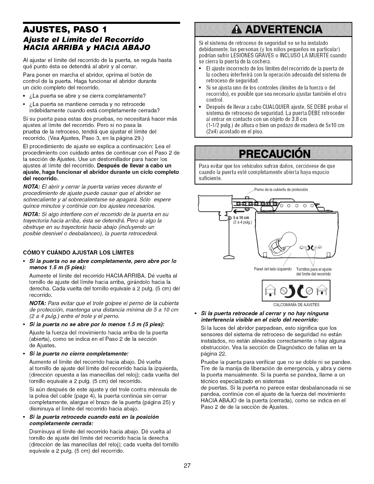
AJUSTES, PASO 1
Ajuste el Limite del Recorrido
HACIA ARRIBA y HACIA ABAJO
AI ajustar el limite del recorrido de la puerta, se regula hasta
qu6 punto _sta se detendra al abrir y al cerrar.
Para poner en marcha el abridor, oprima el bot6n de
control de la puerta. Haga funcionar el abridor durante
un ciclo completo del recorrido.
•&La puerta se abre y se cierra completamente?
•&La puerta se mantiene cerrada y no retrocede
indebidamente cuando esta completamente cerrada?
Si su puerta pasa estas dos pruebas, no necesitara hacer mas
ajustes al limite del recorrido. Pero si no pasa la
prueba de la retroceso, tendra que ajustar el limite del
recorrido. (Vea Ajustes, Paso 3, en la pagina 29.)
El procedimiento de ajuste se explica a continuaci6n: Lea el
procedimiento con cuidado antes de continuar con el Paso 2 de
la secci6n de Ajustes. Use un destornillador para hacer los
ajustes al limite del recorrido. Despu_s de Ilevar a cabo un
ajuste, haga funcionar el abridor durante un ciclo completo
del recorrido.
NOTA: El abrir y cerrar la puerta varias veces durante el
procedimiento de ajuste puede causar que el abridor se
sobrecaliente y al sobrecalentarse se apagara. S51o espere
quince minutos y continue con los ajustes necesarios.
NOTA: Si algo interfiere con el recorrido de la puerta en su
trayectoria hacia arriba, esta se detendra. Pero si algo la
obstruye en su trayectoria hacia abajo (incluyendo un
posible desnivel o desbalanceo), la puerta retrocedera.
COMO Y CUANDO AJUSTAR LOS LJMITES
•Si la puerta no se abre completamente, pero abre por Io
menos 1.5 m (5 pies):
Aumente el limite del recorrido HACIAARRIBA. D_ vuelta al
tornillo de ajuste del limite hacia arriba, girandolo hacia la
derecha. Cada vuelta del tornillo equivale a 2 pulg. (5 cm) del
recorrido.
NOTA: Para evitar que el trole golpee el perno de la cubierta
de proteccidn, mantenga una distancia mfnima de 5 a 10 cm
(2 a 4 pulg.) entre el trole y el perno.
•Si la puerta no se abre por Io menos 1.5 m (5 pies):
Ajuste la fuerza del movimiento hacia arriba de la puerta
(abierta), como se indica en el Paso 2 de la secci6n
de Ajustes.
•Si la puerta no cierra completamente:
Aumente el limite del recorrido hacia abajo. D_ vuelta
al tornillo de ajuste del limite del recorrido hacia la izquierda,
(direcci6n opuesta alas manecillas del reloj); cada vuelta del
tornillo equivale a 2 pulg. (5 cm) del recorrido.
Si at]n despu6s de este ajuste y del trole contra m_nsula de
la polea del cable (page 4), la puerta contint]a sin cerrar
completamente, alargue el brazo de la puerta (pagina 25) y
disminuya el limite del recorrido hacia abajo.
•Si la puerta retrocede cuando est# en la posicion
completamente cerrada:
Disminuya el limite del recorrido hacia abajo. D_ vuelta al
tornillo de ajuste del limite del recorrido hacia la derecha
(direcci6n de las manecillas del reloj); cada vuelta del tornillo
equivale a 2 pulg. (5 cm) del recorrido.
iiiiiiiiiiiiiiiiiiiiiiiiiiiiiiiiiiiiiiiiiiiiiiiiiiiiiiiiiiiiiiiiiiiiiiiiiiiiiiiiiiiiiiiiiiiiiiiiiiiiiiiiiiiiiiiiiiiiiiiiiiiiiiiiiiiiiiiiiiiiiiiiiiiiiiiiiiiiiiiiiiiiiiiiiiiiiiiiiiiiiiiiiiiiiiiiiiiiiiiiiiiiiiiiiiiiiiiiiiiiiiiiiiiiiiiiiiiiiiiiiiiiiiiiiiiiiiiiiiiiiiiiiiiiiiiiiiiiiiiiiiiiiiiiiiiiiiiiiiiiiiiiiiiiiiiiiiiiiiiiiiiiiiiiiiiiiiiiiiiiiiiiiiiiiiiiiiiiiiiiiiiiiiiiiiiiiiiiiiiiiiiiiiiiiiiiiiiiiiiiiiiiiiiiiiiiiiiiiiiiiiiiiiiiiiiiiiiiiiiiiiiiiiiiiiiiiiiiiiiiiiiiiiiiiiiiiiiiiiiiiiiiiiiiiiiiiiiiiiiiiiiiiiiiiiiiiiiiiiiiiiiiiiii
Si el sistema de retroceso de seguridad no se ha instalado
debidamente, las personas (y los niSos pequeSosen particular)
podrian sufrir LESIONESGRAVESo INCLUS0 LA MUERTEcuando
se cierra la puerta de la cochera.
• El ajuste incorrecto de los limites del recorrido de la puerta de
la cochera interferir_, con la operaci6n adecuada del sistema de
retroceso de seguridad.
• Si se ajusta uno de los controles (limites de lafuerza o del
recorrido), es posible que sea necesario ajustar tambi_n el otro
control.
• Despu_s de Ilevar a cabo CUALQUIERajuste, SE DEBEprobar el
sistema de retroceso de seguridad. La puerta DEBEretroceder
al entrar encontacto con un objeto de 3.8 cm
(1-1/2 pulg.) dealtura o bien un pedazo de madera de 5x10 cm
(2x4) acostado en el piso.
Para evitar que los vehiculos sufran daSos, cerci6rese de que
cuando la puerta est_ completamente abierta haya espacio
suficiente.
zjPerno de la cubiertade protecci6n
oooo
-- I(2 a4 pulg.) _..
Panel del lado izquierdo Tomillos para el ajuste
dellimitedelrecorrido
CALCOMANIADEAJUSTES
Si la puerta retrocede al cerrar y no hay ninguna
interferencia visible en el ciclo del recorrido:
Si la luces del abridor parpadean, esto significa que los
sensores del sistema de retroceso de seguridad no estan
instalados, no estan alineados correctamente o hay alguna
obstrucci6n. Vea la secci6n de Diagn6stico de fallas en la
pagina 22.
Pruebe la puerta para verificar que no se doble ni se pandee.
Tire de la manija de liberaci6n de emergencia, y abra y cierre
la puerta manualmente. Si la puerta se pandea, Ilame a un
t6cnico especializado en sistemas
de puertas. Si la puerta no parece estar desbalanceada ni se
pandea, contint]e con el ajuste de la fuerza del movimiento
HACIA ABAJO de la puerta (cerrada), como se indica en el
Paso 2 de de la secci6n de Ajustes.
27
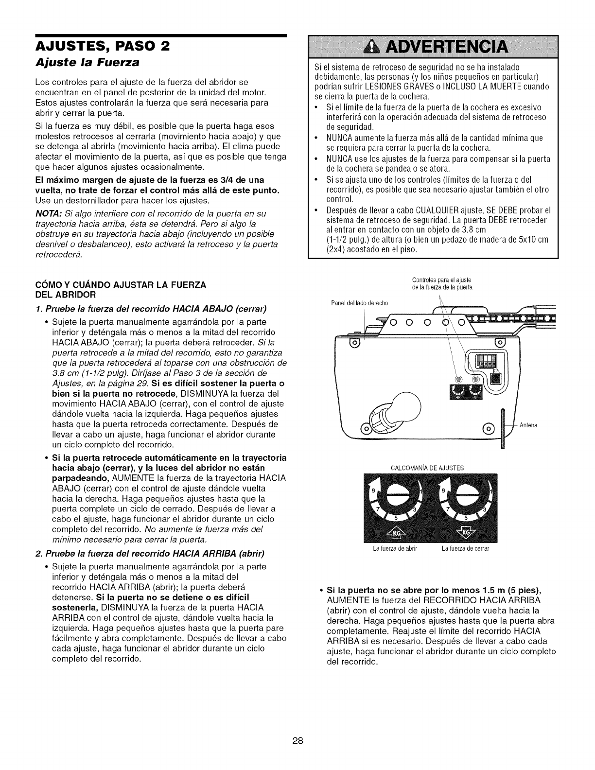
AJUSTES, PASO 2
Ajuste la Fuerza
Los controles para el ajuste de la fuerza del abridor se
encuentran en el panel de posterior de la unidad del motor.
Estos ajustes controlaran la fuerza que sera necesaria para
abrir y cerrar la puerta.
Si la fuerza es muy d6bil, es posible que la puerta haga esos
molestos retrocesos al cerrarla (movimiento hacia abajo) y que
se detenga al abrirla (movimiento hacia arriba). El clima puede
afectar el movimiento de la puerta, asi que es posible que tenga
que hacer algunos ajustes ocasionalmente.
El maximo margen de ajuste de la fuerza es 3/4 de una
vuelta, no trate de forzar el control mas alia de este punto.
Use un destornillador para hacer los ajustes.
NOTA: Si algo interfiere con el recorrido de la puerta en su
trayectoria hacia arriba, esta se detendra. Pero si algo la
obstruye en su trayectoria hacia abajo (incluyendo un posible
desnivel o desbalanceo), esto activara la retroceso y la puerta
retrocedera.
Si el sistema de retroceso de seguridad no se ha instalado
debidamente, las personas (y los niSos pequeSosen particular)
podrian sufrir LESIONESGRAVESo INCLUS0 LA MUERTEcuando
se cierra la puerta de la cochera.
• Si el limite de la fuerza de la puerta de la cochera es excesivo
interferirA con la operaci6n adecuada del sistema de retroceso
de seguridad.
• NUNCAaumente la fuerza mAsalia de la cantidad minima que
se requiera para cerrar la puerta de la cochera.
• NUNCAuse los ajustes de lafuerza para compensar si la puerta
de la cochera se pandeao se atora.
• Si se ajusta uno de los controles (limites de lafuerza o del
recorrido), es posible que sea necesario ajustar tambi_n el otro
control.
• Despu_s de Ilevar a cabo CUALQUIERajuste, SE DEBEprobar el
sistema de retroceso deseguridad. La puerta DEBEretroceder
al entrar en contacto con un objeto de3.8 cm
(1-1/2 pulg.) de altura (o bien un pedazo de madera de 5x10 cm
(2x4) acostado en el piso.
COMO Y CUANDO AJUSTAR LA FUERZA
DEL ABRIDOR
1. Pruebe la fuerza del recorrido HACIA ABAJO (cerrar)
•Sujete la puerta manualmente agarrandola por la parte
inferior y det6ngala mas o menos a la mitad del recorrido
HACIAABAJO (cerrar); la puerta debera retroceder. Si la
puerta retrocede a la mitad del recorrido, esto no garantiza
que la puerta retrocedera al toparse con una obstrucci6n de
3.8 cm (1-1/2 pulg). Dirfjase al Paso 3 de la secci6n de
Ajustes, en la pagina 29. Si es dificil sostener la puerta o
bien si la puerta no retrocede, DISMINUYA la fuerza del
movimiento HACIAABAJO (cerrar), con el control de ajuste
dandole vuelta hacia la izquierda. Haga pequeSos ajustes
hasta que la puerta retroceda correctamente. Despu6s de
Ilevar a cabo un ajuste, haga funcionar el abridor durante
un ciclo completo del recorrido.
•Si la puerta retrocede automaticamente en la trayectoria
hacia abajo (cerrar), y la luces del abridor no estan
parpadeando, AUMENTE la fuerza de la trayectoria HACIA
ABAJO (cerrar) con el control de ajuste dandole vuelta
hacia la derecha. Haga pequeSos ajustes hasta que la
puerta complete un ciclo de cerrado. Despu6s de Ilevar a
cabo el ajuste, haga funcionar el abridor durante un ciclo
completo del recorrido. No aumente la fuerza mbs del
mfnimo necesario para cerrar la puerta.
2. Pruebe la fuerza del recorrido HACIA ARRIBA (abrir)
•Sujete la puerta manualmente agarrandola por la parte
inferior y det6ngala mas o menos a la mitad del
recorrido HACIA ARRIBA (abrir); la puerta debera
detenerse. Si la puerta no se detiene o es dificil
sostenerla, DISMINUYA la fuerza de la puerta HACIA
ARRIBA con el control de ajuste, dandole vuelta hacia la
izquierda. Haga pequeSos ajustes hasta que la puerta pare
facilmente y abra completamente. Despu6s de Ilevar a cabo
cada ajuste, haga funcionar el abridor durante un ciclo
completo del recorrido.
Controles para elajuste
de lafuerza de la puerta
Paneldel ladoderecho _ ..=._ _=====
O O O O
-J _'__ntena
CALCOMANfADEAJUSTES
La fuerza de abrir La fuerza deeerrar
•Si la puerta no se abre por Io menos 1.5 m(5 pies),
AUMENTE la fuerza del RECORRIDO HACIAARRIBA
(abrir) con el control de ajuste, dandole vuelta hacia la
derecha. Haga pequeSos ajustes hasta que la puerta abra
completamente. Reajuste el limite del recorrido HACIA
ARRIBA si es necesario. Despu6s de Ilevar a cabo cada
ajuste, haga funcionar el abridor durante un ciclo completo
del recorrido.
28
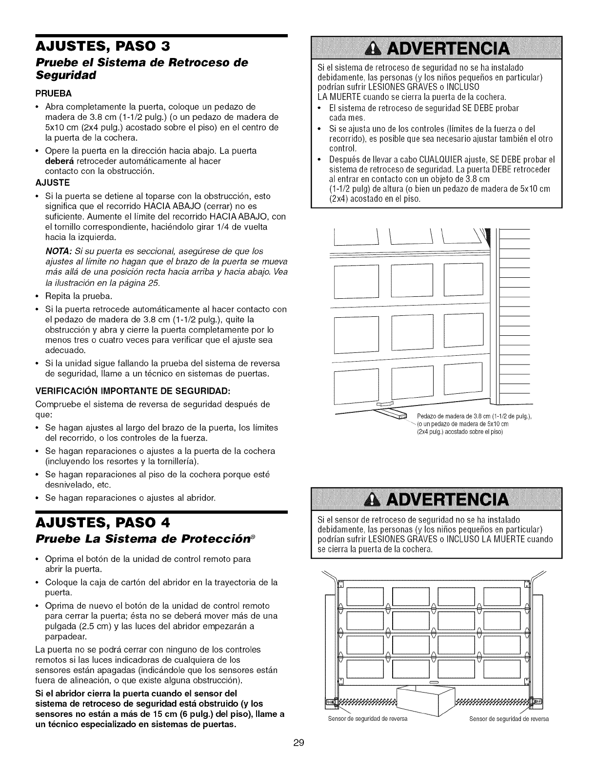
AJUSTES, PASO 3
Pruebe el Sistema de Retroceso de
Seguridad
PRUEBA
•Abra completamente la puerta, coloque un pedazo de
madera de 3.8 cm (1-1/2 pulg.) (o un pedazo de madera de
5x10 cm (2x4 pulg.) acostado sobre el piso) en el centro de
la puerta de la cochera.
•Opere la puerta en la direcci6n hacia abajo. La puerta
debera retroceder automaticamente al hacer
contacto con la obstrucci6n.
AJUSTE
•Si la puerta se detiene al toparse con la obstrucci6n, esto
significa que el recorrido HACIA ABAJO (cerrar) no es
suficiente. Aumente el Iimite del recorrido HACIAABAJO, con
el tornillo correspondiente, haci6ndolo girar 1/4 de vuelta
hacia la izquierda.
NOTA: Si su puerta es seccional, aseg_rese de que los
ajustes al Ifmite no hagan que el brazo de la puerta se mueva
m#s all# de una posici6n recta hacia arriba y hacia abajo. Vea
la ilustraci6n en la p#gina 25.
• Repita la prueba.
• Si la puerta retrocede automaticamente al hacer contacto con
el pedazo de madera de 3.8 cm (1-1/2 pulg.), quite la
obstrucci6n y abra y cierre la puerta completamente por Io
menos tres o cuatro veces para verificar que el ajuste sea
adecuado.
• Si la unidad sigue fallando la prueba del sistema de reversa
de seguridad, Ilame a un t6cnico en sistemas de puertas.
VERIFICACION IMPORTANTE DE SEGURIDAD:
Compruebe el sistema de reversa de seguridad despu6s de
que:
• Se hagan ajustes al largo del brazo de la puerta, los Iimites
del recorrido, o los controles de la fuerza.
• Se hagan reparaciones o ajustes a la puerta de la cochera
(incluyendo los resortes y la tornilleria).
• Se hagan reparaciones al piso de la cochera porque est6
desnivelado, etc.
• Se hagan reparaciones o ajustes al abridor.
Si el sistema de retroceso de seguridad no se ha instalado
debidamente, las personas (y los niSos pequeSosen particular)
podrian sufrir LESIONESGRAVESo INCLUS0
LA MUERTEcuando se cierra la puerta de la cochera.
•El sistema de retroceso de seguridad SE DEBEprobar
cada mes.
• Si se ajusta uno de los controles (limites de lafuerza o del
recorrido), es posible que sea necesario ajustar tambi_n el otro
control.
• Despu_s de Ilevar a cabo CUALQUIERajuste, SE DEBEprobar el
sistema de retroceso deseguridad. La puerta DEBEretroceder
al entrar encontacto con un objeto de 3.8 cm
(1-1/2 pulg) de altura (o bien un pedazo de madera de 5x10 cm
(2x4) acostado en el piso.
k
]
_(1 1/2de u
pig)
_-(o un pedazode maderade 5x10em
(2x4 pulg.) acostadosobre el piso)
AJUSTES, PASO 4
Pruebe La Sistema de Protecci6n ®
• Oprima el bot6n de la unidad de control remoto para
abrir la puerta.
• Coloque la caja de cart6n del abridor en la trayectoria de la
puerta.
• Oprima de nuevo el bot6n de la unidad de control remoto
para cerrar la puerta; 6sta no se debera mover mas de una
pulgada (2.5 cm) y las luces del abridor empezaran a
parpadear.
La puerta no se podra cerrar con ninguno de los controles
remotos si las luces indicadoras de cualquiera de los
sensores estan apagadas (indicandole que los sensores estan
fuera de alineaci6n, o que existe alguna obstrucci6n).
Si el abridor cierra la puerta cuando el sensor del
sistema de retroceso de seguridad esta obstruido (y los
sensores no estan a mas de 15 cm (6 pulg.) del piso), Ilame a
un t6cnico especializado en sistemas de puertas.
Si elsensorderetrocesodeseguridadnose hainstalado
debidamente,laspersonas(y los niSospequeSosenparticular)
podriansufrir LESIONESGRAVESo INCLUS0LA MUERTEcuando
se cierralapuertadelacochera.
r-q F r-qll I
I--q i--q
Sensorde seguridadde reversa Sensor de seguridadde reversa
29
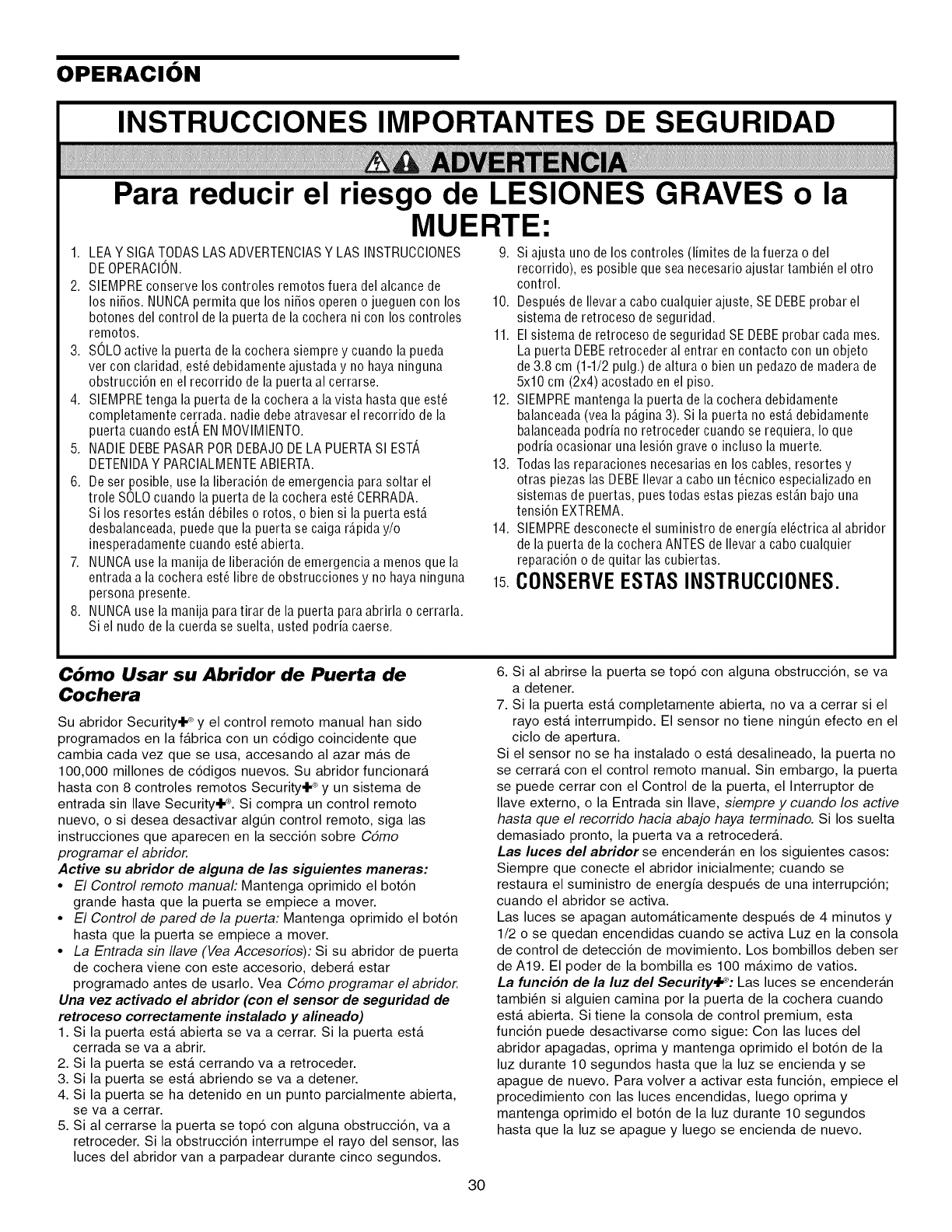
OPERACION
INSTRUCCIONES IMPORTANTES DE SEGURIDAD
Para reducir el riesgo de LESIONES GRAVES o la
MUERTE:
1. LEA Y SIGATODAS LAS ADVERTENCIASY LAS INSTRUCCIONES
DEOPERACION.
2. SIEMPRE conserve los controles remotos fuera del alcance de
los ni_os. NUNCApermita que los ni_os operen o jueguen con los
botones del control de la puerta de la cochera ni con los controles
remotos.
3. SOLOactive la puerta de la cochera siempre y cuando la pueda
ver con claridad, est_ debidamente ajustada y no haya ninguna
obstrucci6n en el recorrido de la puerta al cerrarse.
4. SIEMPREtenga la puerta de la cochera a la vista hasta que est_
completamente cerrada, nadie debe atravesar el recorrido de la
puerta cuando estA EN MOVIMIENTO.
5. NADIE DEBEPASARPOR DEBAJODE LA PUERTASI ESTA
DETENIDAY PARCIALMENTEABIERTA.
6. De ser posible, use la liberaci6n de emergencia para soltar el
trole SOLOcuando la puerta de la cochera est_ CERRADA.
Si los resortes est_.nd_biles o rotos, o bien si la puerta est,.
desbalanceada, puede que la puerta se caiga r_.piday/o
inesperadamente cuando est_ abierta.
7. NUNCAuse la manija de liberaci6n de emergencia a menos que la
entrada a la cochera est_ libre de obstrucciones y no haya ninguna
persona presente.
8. NUNCAuse la manija para tirar de la puerta paraabrirla o cerrarla.
Si el nudo de la cuerda se suelta, usted podria caerse.
9. Si ajusta uno de los controles (limites de la fuerza o del
recorrido), es posible que sea necesario ajustar tambi6n el otro
control.
10. Despu6s de Ilevar a cabo cualquier ajuste, SE DEBEprobar el
sistema de retroceso de seguridad.
11. El sistema de retroceso de seguridad SE DEBEprobar cada mes.
La puerta DEBEretroceder al entrar en contacto con un objeto
de3.8 cm (1-1/2 pulg.) de altura o bien un pedazo de madera de
5x10 cm (2x4) acostado enel piso.
12. SIEMPREmantenga la puerta de la cochera debidamente
balanceada (vea la p_.gina3). Si la puerta no est,. debidamente
balanceada podria no retroceder cuando se requiera, Io que
podria ocasionar una lesi6n grave o incluso la muerte.
13. Todas las reparaciones necesarias en los cables, resortes y
otras piezas las DEBEIlevar a cabo un t@nico especializado en
sistemas de puertas, pues todas estas piezasest_.n bajo una
tensi6n EXTREMA.
14. SIEMPREdesconecte el suministro deenergia el@trica al abridor
de la puerta de la cochera ANTES de Ilevara cabo cualquier
reparaci6n o dequitar las cubiertas.
15.CONSERVEESTASINSTRUCCIONES.
C6mo Usar su Abridor de Puerta de
Cochera
Su abridor Security.IP y el control remoto manual han sido
programados en la f_.brica con un c6digo coincidente que
cambia cada vez que se usa, accesando al azar m_.s de
100,000 millones de c6digos nuevos. Su abridor funcionara
hasta con 8 controles remotos Security+ ®y un sistema de
entrada sin Ilave Security+ ®. Si compra un control remoto
nuevo, o si desea desactivar algt]n control remoto, siga las
instrucciones que aparecen en la secci6n sobre Cdmo
programar el abridor.
Active su abridor de alguna de las siguientes maneras:
•El Control remoto manual: Mantenga oprimido el bot6n
grande hasta que la puerta se empiece a mover.
•El Control de pared de la puerta: Mantenga oprimido el bot6n
hasta que la puerta se empiece a mover.
• La Entrada sin Ilave (Vea Accesorios): Si su abridor de puerta
de cochera viene con este accesorio, debera estar
programado antes de usarlo. Vea Cdmo programar el abridor.
Una vez activado el abridor (con el sensor de seguridad de
retroceso correctamente instalado y alineado)
1. Si la puerta est,. abierta se va a cerrar. Si la puerta est,.
cerrada se va a abrir.
2. Si la puerta se est,. cerrando va a retroceder.
3. Si la puerta se esta abriendo se va a detener.
4. Si la puerta se ha detenido en un punto parcialmente abierta,
se va a cerrar.
5. Si al cerrarse la puerta se top6 con alguna obstrucci6n, va a
retroceder. Si la obstrucci6n interrumpe el rayo del sensor, las
luces del abridor van a parpadear durante cinco segundos.
30
6. Sial abrirse la puerta se top6 con alguna obstrucci6n, se va
a detener.
7. Si la puerta esta completamente abierta, no va a cerrar si el
rayo esta interrumpido. El sensor no tiene ningt]n efecto en el
ciclo de apertura.
Si el sensor no se ha instalado o esta desalineado, la puerta no
se cerrara con el control remoto manual. Sin embargo, la puerta
se puede cerrar con el Control de la puerta, el Interruptor de
Ilave externo, o la Entrada sin Ilave, siempre y cuando los active
hasta que el recorrido hacia abajo haya terminado. Si los suelta
demasiado pronto, la puerta va a retrocedera.
Las luces del abridor se encenderan en los siguientes casos:
Siempre que conecte el abridor inicialmente; cuando se
restaura el suministro de energia despu6s de una interrupci6n;
cuando el abridor se activa.
Las luces se apagan automaticamente despu_s de 4 minutos y
1/2 o se quedan encendidas cuando se activa Luz en la consola
de control de detecci6n de movimiento. Los bombillos deben ser
de A19. El poder de la bombilla es 100 maximo de vatios.
La funcion de la luz del Securityd_: Las luces se encenderan
tambi_n si alguien camina por la puerta de la cochera cuando
esta abierta. Si tiene la consola de control premium, esta
funci6n puede desactivarse como sigue: Con las luces del
abridor apagadas, oprima y mantenga oprimido el bot6n de la
luz durante 10 segundos hasta que la luz se encienda y se
apague de nuevo. Para volver a activar esta funci6n, empiece el
procedimiento con las luces encendidas, luego oprima y
mantenga oprimido el bot6n de la luz durante 10 segundos
hasta que la luz se apague y luego se encienda de nuevo.
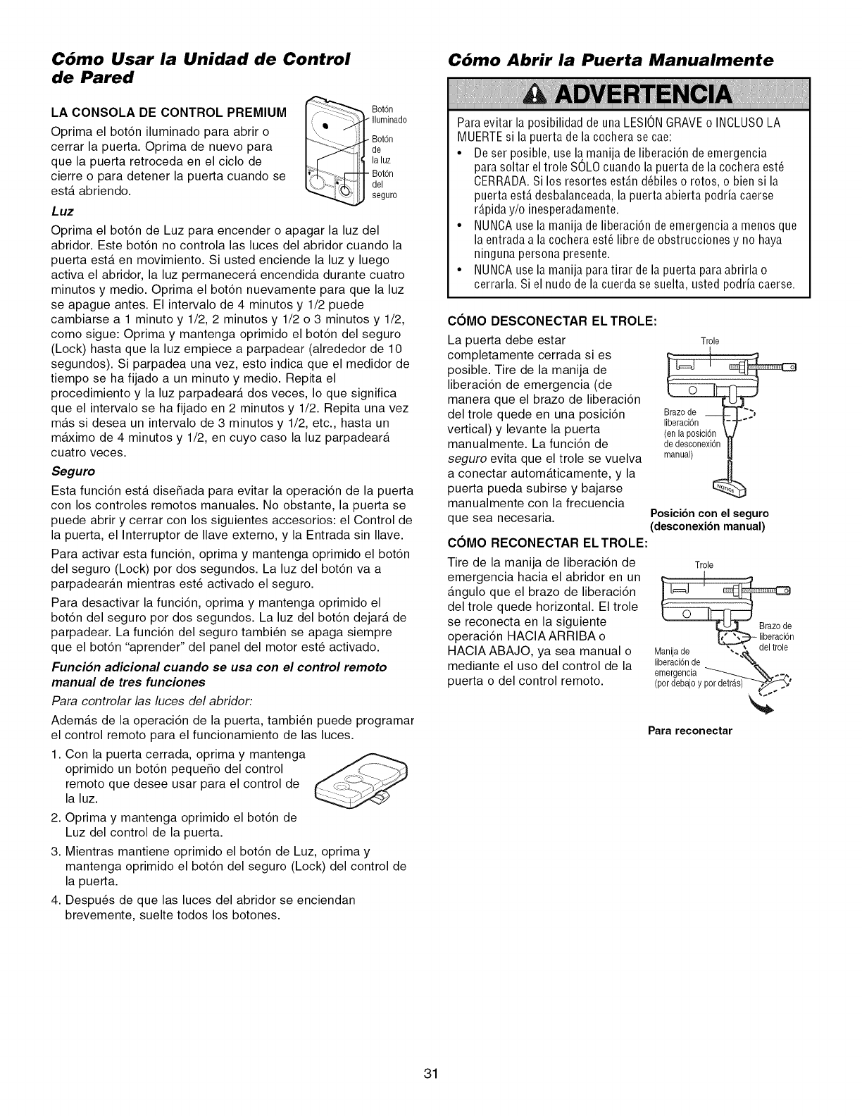
Cbmo Usar la Unidad de Control
de Pared
LA CONSOLA DE CONTROL PREMIUM I/-'_-'_,. Bot6n
Iluminado
Oprima el bot6n iluminado para abrir o - Bot6n
cerrar la puerta. Oprima de nuevo para de
que la puerta retroceda en el ciclo de laluz
cierre o para detener la puerta cuando se - Bot6n
del
esta abriendo, seguro
Luz
Oprima el bot6n de Luz para encender o apagar la luz del
abridor. Este bot6n no controla las luces del abridor cuando la
puerta esta en movimiento. Si usted enciende la luz y luego
activa el abridor, la luz permanecera encendida durante cuatro
minutos y medio. Oprima el bot6n nuevamente para que la luz
se apague antes. El intervalo de 4 minutos y 1/2 puede
cambiarse a 1 minuto y 1/2, 2 minutos y 1/2 o 3 minutos y 1/2,
como sigue: Oprima y mantenga oprimido el bot6n del seguro
(Lock) hasta que la luz empiece a parpadear (alrededor de 10
segundos). Si parpadea una vez, esto indica que el medidor de
tiempo se ha fijado a un minuto y medio. Repita el
procedimiento y la luz parpadeara dos veces, Io que significa
que el intervalo se ha fijado en 2 minutos y 1/2. Repita una vez
mas si desea un intervalo de 3 minutos y 1/2, etc., hasta un
maximo de 4 minutos y 1/2, en cuyo caso la luz parpadeara
cuatro veces.
Seguro
Esta funci6n esta dise_ada para evitar la operaci6n de la puerta
con los controles remotos manuales. No obstante, la puerta se
puede abrir y cerrar con los siguientes accesorios: el Control de
la puerta, el Interruptor de Ilave externo, y la Entrada sin Ilave.
Para activar esta funci6n, oprima y mantenga oprimido el bot6n
del seguro (Lock) por dos segundos. La luz del bot6n va a
parpadearan mientras est_ activado el seguro.
Para desactivar la funci6n, oprima y mantenga oprimido el
bot6n del seguro por dos segundos. La luz del bot6n dejara de
parpadear. La funci6n del seguro tambi_n se apaga siempre
que el bot6n "aprender" del panel del motor est_ activado.
Funcion adicional cuando se usa con el control remoto
manual de tres funciones
Para controlar las luces del abridor:
Ademas de la operaci6n de la puerta, tambi_n puede programar
el control remoto para el funcionamiento de las luces.
1. Con la puerta cerrada, oprima y mantenga
oprimido un bot6n peque_o del control
remoto que desee usar para el control de
la luz.
2. Oprima y mantenga oprimido el bot6n de
Luz del control de la puerta.
3. Mientras mantiene oprimido el bot6n de Luz, oprima y
mantenga oprimido el bot6n del seguro (Lock) del control de
la puerta.
4. Despu_s de que las luces del abridor se enciendan
brevemente, suelte todos los botones.
Cdmo Abrir la Puerta Manualmente
Para evitar la posibilidad de una LESIONGRAVEo INCLUSOLA
MUERTEsi la puerta de la cochera se cae:
• De ser posible, use la manija de liberaci6n de emergencia
para soltar eltrole SOLOcuando la puerta de la cochera est6
CERRADA.Si los resortes est_.nd6biles o rotos, o bien si la
puerta est,. desbalanceada, la puerta abierta podria caerse
r_.piday/o inesperadamente.
• NUNCA use la manija de liberaci6n de emergencia a menos que
la entrada a la cochera est6 libre de obstrucciones y no haya
ninguna persona presente.
• NUNCA use la manija para tirar de la puerta para abrirla o
cerrarla. Si el nudo de la cuerda se suelta, usted podria caerse.
COMO DESCONECTAR EL TROLE:
La puerta debe estar
completamente cerrada si es
posible. Tire de la manija de
liberaci6n de emergencia (de
manera que el brazo de liberaci6n
del trole quede en una posici6n
vertical) y levante la puerta
manualmente. La funci6n de
seguro evita que el trole se vuelva
a conectar automaticamente, y la
puerta pueda subirse y bajarse
manualmente con la frecuencia
que sea necesaria.
COMO RECONECTAR ELTROLE:
Tire de la manija de liberaci6n de
emergencia hacia el abridor en un
angulo que el brazo de liberaci6n
del trole quede horizontal. El trole
se reconecta en la siguiente
operaci6n HAClAARRIBA o
HAClA ABAJO, ya sea manual o
mediante el uso del control de la
puerta o del control remoto.
Trole
dedeaconexidn
manual)
Posici6ncon el seguro
(desconexibnmanual)
Trole
__n
Manijade -'_"_, _ del trole
_bme_aCg_6ncile_"_
(por debajoy par detras)-_--_--_%'
Para reconectar
31
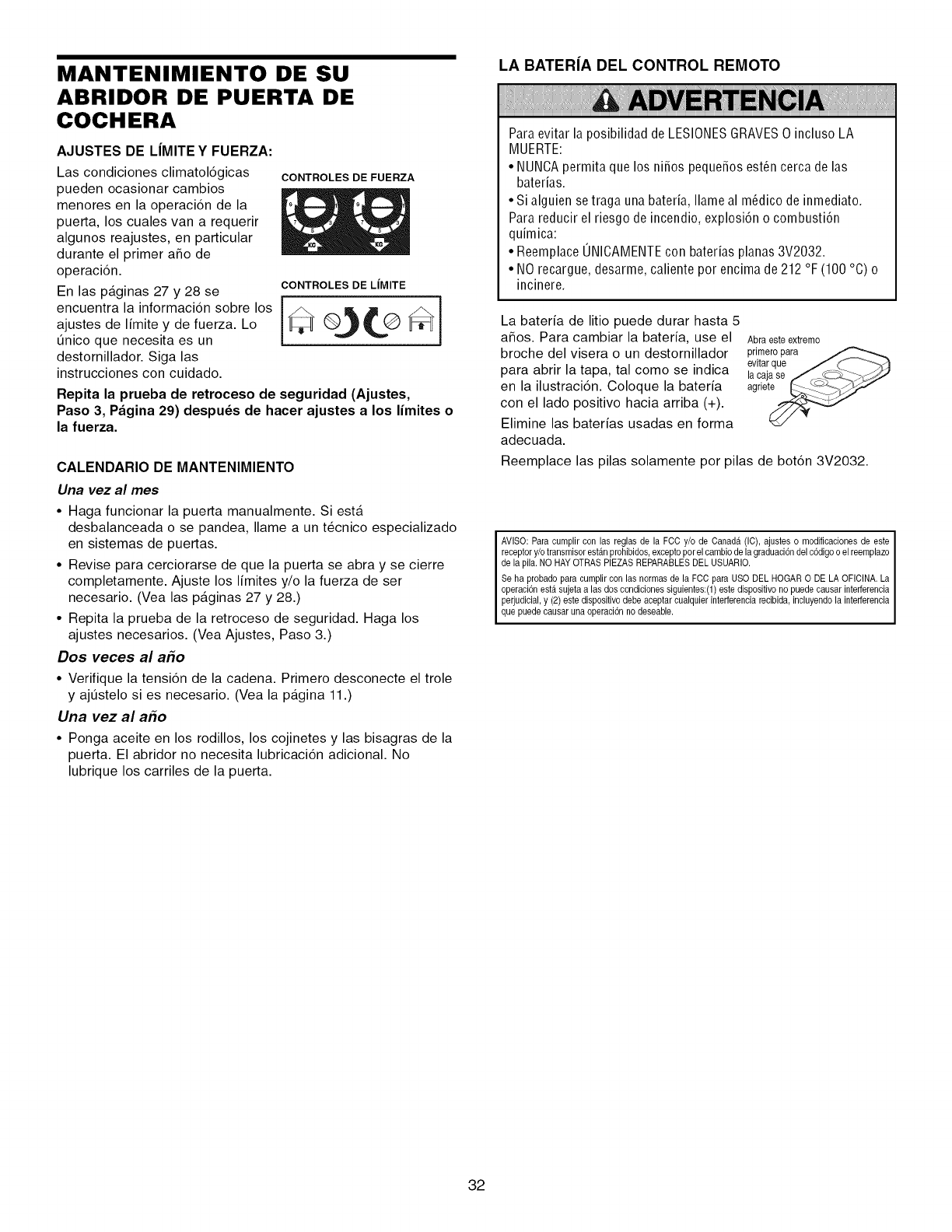
MANTENIMIENTO DE SU
ABRIDOR DE PUERTA DE
COCHERA
AJUSTES DE L|MITE Y FUERZA:
Las condiciones climatol6gicas CONTROLESDEFUERZA
pueden ocasionar cambios
menores en la operaci6n de la
puerta, los cuales van a requerir
algunos reajustes, en particular
durante el primer afio de
operaci6n.
CONTROLES DE LIMITE
En las paginas 27 y 28 se
encuentralainformaci6nsobrelos _ @_L@_
ajustes de limite y de fuerza. Lo
enico que necesita es un
destornillador. Siga las
instrucciones con cuidado.
Repita la prueba de retroceso de seguridad (Ajustes,
Paso 3, Pagina 29) despu_s de hacer ajustes a los limites o
la fuerza.
CALENDARIO DE MANTENIMIENTO
Una vez al mes
• Haga funcionar la puerta manualmente. Si est&
desbalanceada o se pandea, Ilame a un t6cnico especializado
en sistemas de puertas.
• Revise para cerciorarse de que la puerta se abra y se cierre
completamente. Ajuste los limites y/o la fuerza de ser
necesario. (Vea las p&ginas 27 y 28.)
°Repita la prueba de la retroceso de seguridad. Haga los
ajustes necesarios. (Vea Ajustes, Paso 3.)
Dos veces al a_o
•Verifique la tensi6n de la cadena. Primero desconecte el trole
y ajt]stelo si es necesario. (Yea la p&gina 11.)
Una vez al a_o
• Ponga aceite en los rodillos, los cojinetes y las bisagras de la
puerta. El abridor no necesita lubricaci6n adicional. No
lubrique los carriles de la puerta.
LA BATER|A DEL CONTROL REMOTO
Paraevitar la posibilidad de LESIONESGRAVES0 incluso LA
MUERTE:
• NUNCApermita que los nifios pequefios est_n cerca de las
baterias.
• Si alguien setraga una bateria, Ilame al m_dico de inmediato.
Para reducir el riesgo de incendio, explosi6n o combusti6n
quimica:
• Reemplace UNICAMENTEcon baterias planas 3V2032.
• NO recargue, desarme, caliente por encima de 212 °F (100 °C) o
incinere.
La bateria de litio puede durar hasta 5
afios. Para cambiar la bateria, use el
broche del visera o un destornillador
para abrir la tapa, tal como se indica
en la ilustraci6n. Coloque la bateria
con el lado positivo hacia arriba (+).
Elimine las baterfas usadas en forma
adecuada.
Abraeste extremo
primeropara
evitarque J _ -_s¢}
la c.ajase f_; _._>-_/_'_-"
agrle_
Reemplace las pilas solamente por pilas de bot6n 3V2032.
I AVlSO:Paracumplircon las reglasde la FCCy/o de Canada1(IC).ajustes o modificacionesde este
receptory/o transmisorest_inprohibidos,exceptoporel cambiodela graduaci6ndel c6digoo elreemplazo
dela pila.NO HAYOTRASPIEZASREPARABLESDELUSUARIO.
Seha probadoparaeumplircon lasnormasde la FCCpara USODELHOGAR0 DELAOFICINA.La
operaei6nest,1sujetaalas doscondicionessiguientes:(1)estedispositivono puedecausarinterferencia
perjudicial,y (2)estedispositivodebeaceptarcualquierinterferenciarecibida,incluyendola interferencia
quepuedeeausaruna operaci6nnodeseable.
32
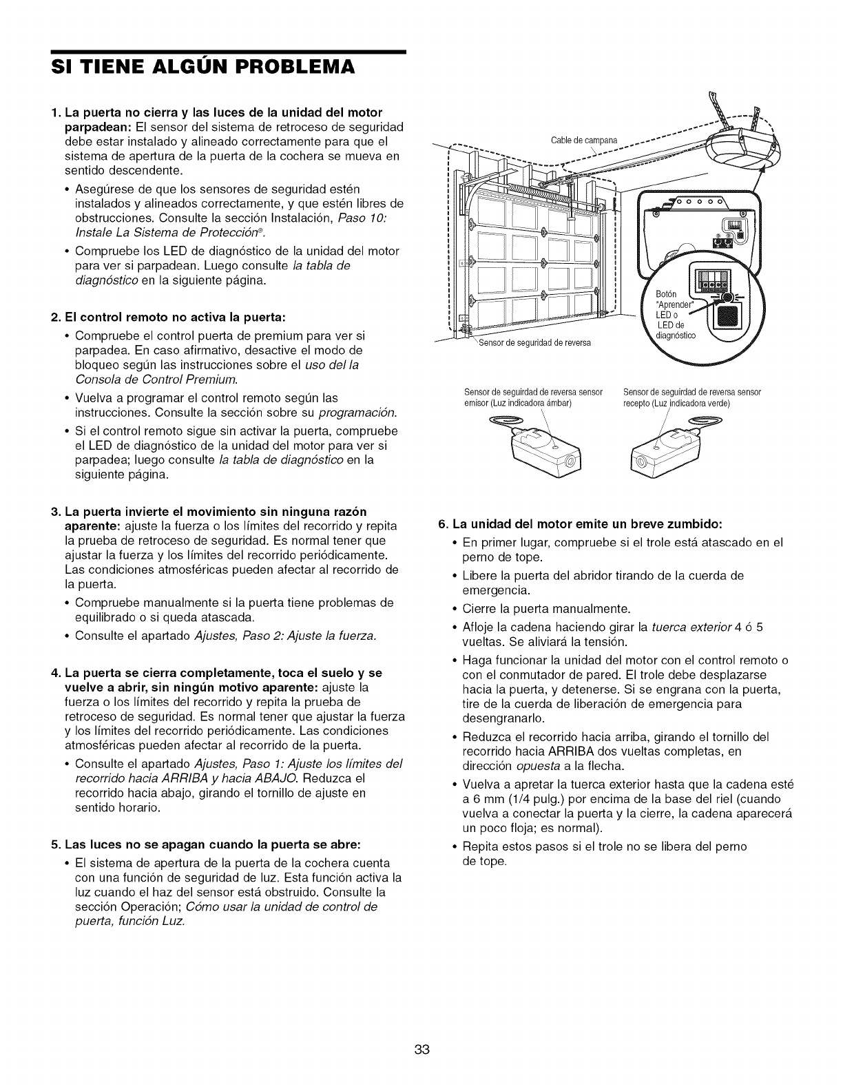
SI TIENE ALGON PROBLEMA
1. La puerta no cierra y las luces de la unidad del motor
parpadean: El sensor del sistema de retroceso de seguridad
debe estar instalado y alineado correctamente para que el
sistema de apertura de la puerta de la cochera se mueva en
sentido descendente
•Asegerese de que los sensores de seguridad est6n
instalados y alineados correctamente, y que est6n libres de
obstrucciones Consulte la secci6n Instalaci6n, Paso 10:
Instale La Sistema de Proteccidn _
• Compruebe los LED de diagn6stico de la unidad del motor
para ver si parpadean Luego consulte la tabla de
diagndstico en la siguiente pagina
2. El control remoto no activa la puerta:
•Compruebe el control puerta de premium para ver si
parpadea En caso afirmativo, desactive el modo de
bloqueo segen las instrucciones sobre el uso della
Consola de Control Premium
• Vuelva a programar el control remoto segen las
instrucciones Consulte la secci6n sobre su programacidn
• Si el control remoto sigue sin activar la puerta, compruebe
el LED de diagn6stico de la unidad del motor para ver si
parpadea; luego consulte la tabla de diagndstico en la
siguiente pagina
Cable de carnpana
'Sensor de seguridadde reversa
Sensorde seguirdadde reversa sensor
emisor (Luzindicadoraambar)
Sensorde seguirdadde reversasensor
re.e)
3. La puerta invierte el movimiento sin ninguna razon
aparente: ajuste la fuerza o los limites del recorrido y repita
la prueba de retroceso de seguridad. Es normal tener que
ajustar la fuerza y los limites del recorrido peri6dicamente.
Las condiciones atmosf@icas pueden afectar al recorrido de
la puerta.
• Compruebe manualmente si la puerta tiene problemas de
equilibrado o si queda atascada.
• Consulte el apartado Ajustes, Paso 2: Ajuste la fuerza.
4. La puerta se cierra completamente, toca el suelo y se
vuelve a abrir, sin ningdn motivo aparente: ajuste la
fuerza o los limites del recorrido y repita la prueba de
retroceso de seguridad. Es normal tener que ajustar la fuerza
y los limites del recorrido peri6dicamente. Las condiciones
atmosf@icas pueden afectar al recorrido de la puerta.
• Consulte el apartado Ajustes, Paso 1: Ajuste los Ifmites del
recorrido hacia ARRIBA y hacia ABAJO. Reduzca el
recorrido hacia abajo, girando el tornillo de ajuste en
sentido horario.
5. Las luces no se apagan cuando la puerta se abre:
• El sistema de apertura de la puerta de la cochera cuenta
con una funci6n de seguridad de luz. Esta funci6n activa la
luz cuando el haz del sensor esta obstruido. Consulte la
secci6n Operaci6n; Cdmo usar la unidad de control de
puerta, funcidn Luz.
6. La unidad del motor emite un breve zumbido:
• En primer lugar, compruebe si el trole esta atascado en el
perno de tope.
• Libere la puerta del abridor tirando de la cuerda de
emergencia.
•Cierre la puerta manualmente.
• Afloje la cadena haciendo girar la tuerca exterior 4 6 5
vueltas. Se aliviara la tensi6n.
• Haga funcionar la unidad del motor con el control remoto o
con el conmutador de pared. El trole debe desplazarse
hacia la puerta, y detenerse. Si se engrana con la puerta,
tire de la cuerda de liberaci6n de emergencia para
desengranarlo.
• Reduzca el recorrido hacia arriba, girando el tornillo del
recorrido hacia ARRIBA dos vueltas completas, en
direcci6n opuesta a la flecha.
• Vuelva a apretar la tuerca exterior hasta que la cadena est6
a 6 mm (1/4 pulg.) por encima de la base del riel (cuando
vuelva a conectar la puerta y la cierre, la cadena aparecera
un poco floja; es normal).
• Repita estos pasos si el trole no se libera del perno
de tope.
33
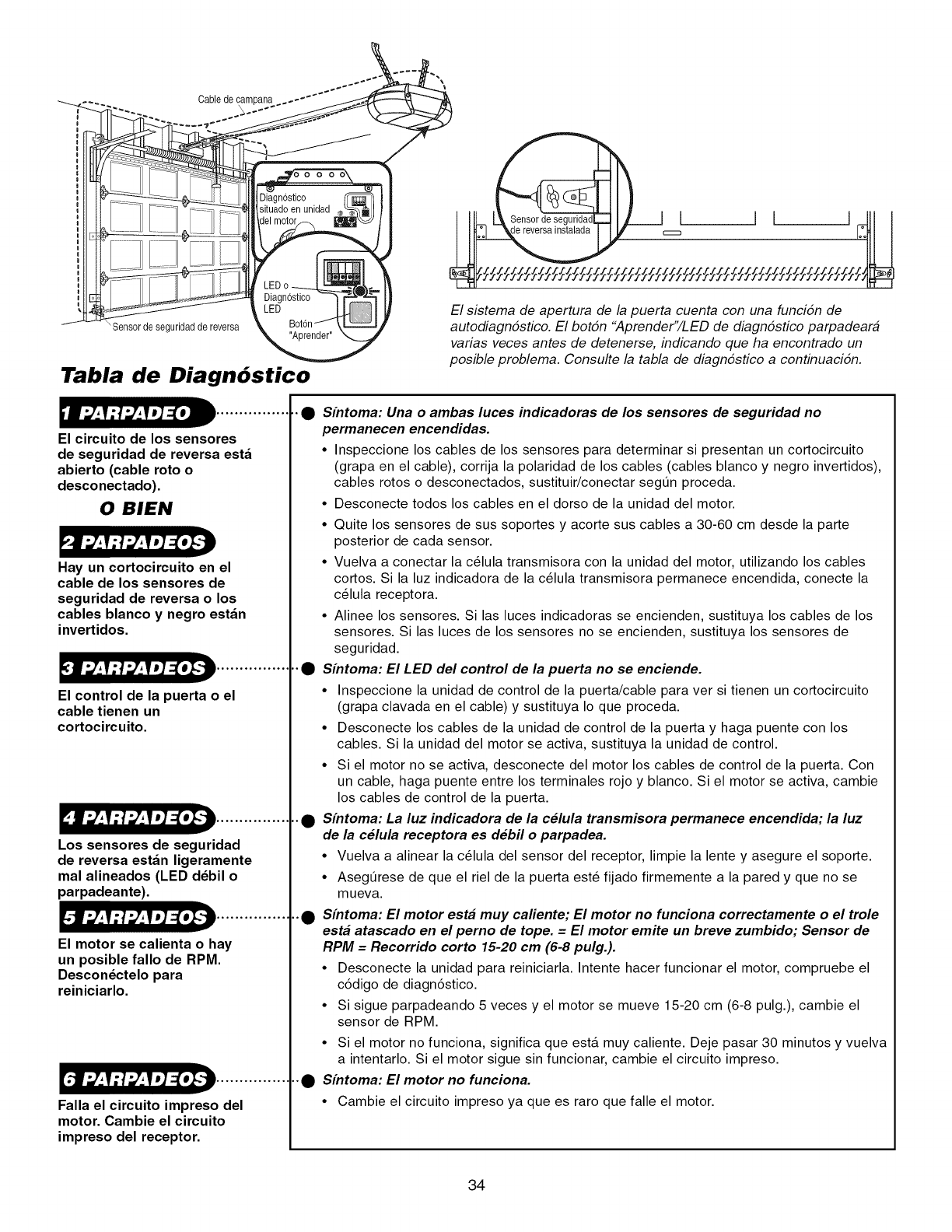
Cablede
Sensor de seguridadde reversa
Tabla de Diagn6stico
El circuito de los sensores
de seguridad de reversa esta
abierto (cable roto o
desconectado).
0 BIEN
Hay un cortocircuito en el
cable de los sensores de
seguridad de reversa o los
cables blanco y negro estan
invertidos.
El control de la puerta o el
cable tienen un
cortocircuito•
Los sensores de seguridad
de reversa estan ligeramente
mal alineados (LED d_bil o
parpadeante).
El motor se calienta o hay
un posible fallo de RPM•
Descon_ctelo para
reiniciarlo.
Falla el circuito impreso del
motor• Cambie el circuito
impreso del receptor•
El sistema de apertura de la puerta cuenta con una funcidn de
autediagndstice. El botdn "Aprender"/LED de diagndstice parpadeara
varias veces antes de detenerse, indicando que ha encentrado un
pesible preblema. Censulte la tabla de diagndstice a centinuacidn.
•_ Sintoma: Una o ambas luces indicadoras de los sensores de seguridad no
permanecen encendidas.
• Inspeccione los cables de los sensores para determinar si presentan un cortocircuito
(grapa en el cable), corrija la polaridad de los cables (cables blanco y negro invertidos),
cables rotos o desconectados, sustituir/conectar segQn proceda.
• Desconecte todos los cables en el dorso de la unidad del motor.
• Quite los sensores de sus soportes y acorte sus cables a 30-60 cm desde la parte
posterior de cada sensor.
• Vuelva a conectar la c_lula transmisora con la unidad del motor, utilizando los cables
cortos. Si la luz indicadora de la c_lula transmisora permanece encendida, conecte la
c_lula receptora.
° Alinee los sensores. Si las luces indicadoras se encienden, sustituya los cables de los
sensores. Si las luces de los sensores no se encienden, sustituya los sensores de
seguridad.
• _ Sintoma: El LED del control de la puerta no se enciende.
• Inspeccione la unidad de control de la puerta/cable para ver si tienen un cortocircuito
(grapa clavada en el cable) y sustituya Io que proceda.
• Desconecte los cables de la unidad de control de la puerta y haga puente con los
cables. Si la unidad del motor se activa, sustituya la unidad de control.
• Si el motor no se activa, desconecte del motor los cables de control de la puerta. Con
un cable, haga puente entre los terminales rojo y blanco. Si el motor se activa, cambie
los cables de control de la puerta.
• _ Sintoma: La luz indicadora de la celula transmisora permanece encendida; la luz
de la celula receptora es debil o parpadea.
• Vuelva a alinear la c_lula del sensor del receptor, limpie la lente y asegure el soporte.
• AsegQrese de que el riel de la puerta est6 fijado firmemente a la pared y que no se
mueva.
.._ Sintoma: El motor est# muy caliente; El motor no funciona correctamente o el trole
est# atascado en el perno de tope. = El motor emite un breve zumbido; Sensor de
RPM =Recorrido corto 15-20 cm (6-6 pulg.).
• Desconecte la unidad para reiniciarla. Intente hacer funcionar el motor, compruebe el
c6digo de diagn6stico.
• Si sigue parpadeando 5 veces y el motor se mueve 15-20 cm (6-8 pulg.), cambie el
sensor de RPM.
• Si el motor no funciona, significa que esta muy caliente. Deje pasar 30 minutos y vuelva
a intentarlo. Si el motor sigue sin funcionar, cambie el circuito impreso.
,._ Sintoma: El motor no funciona.
• Cambie el circuito impreso ya que es raro que falle el motor.
34
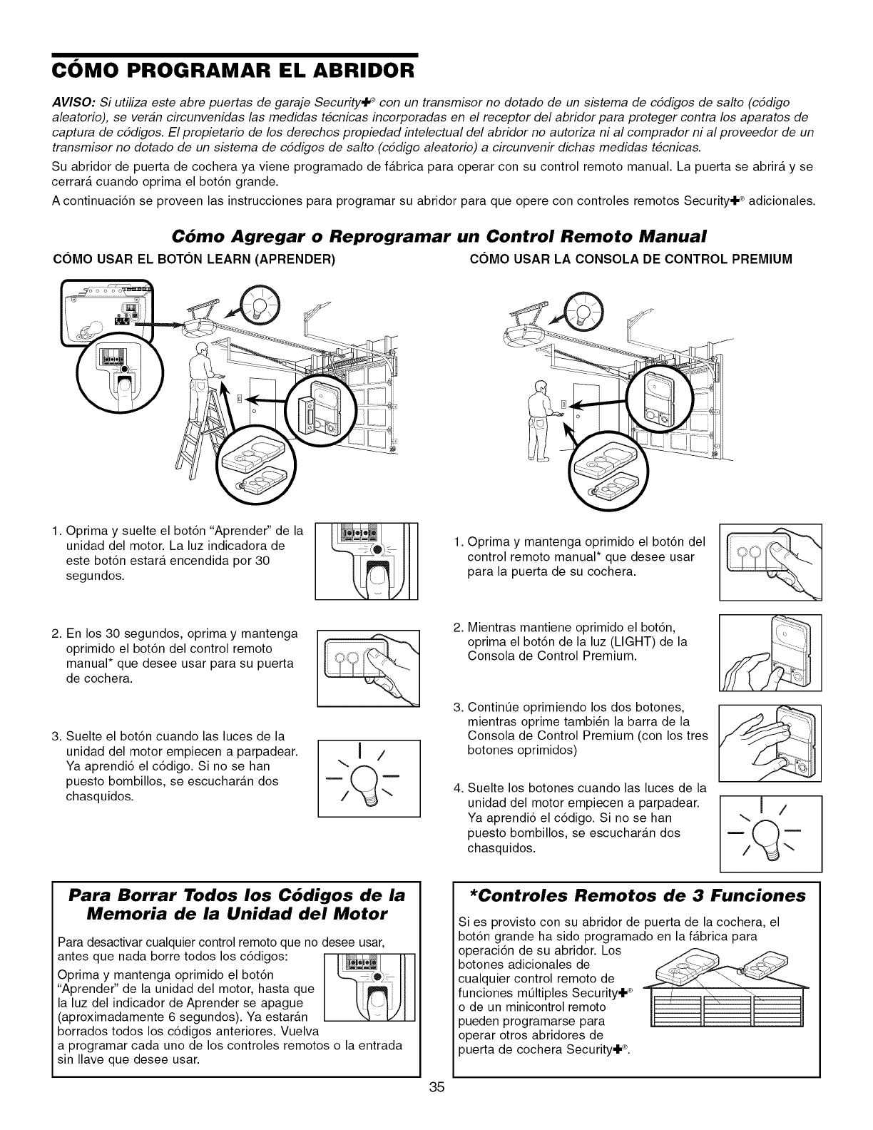
COMO PROGRAMAR EL ABRIDOR
AVISO: Si utiliza este abre puertas de garaje Security,J_ con un transmisor no dotado de un sistema de cddigos de salto (cddigo
aleatorio), se veran circunvenidas las medidas tecnicas incorporadas en el receptor del abridor para proteger contra los aparatos de
captura de cddigos. El propietario de los derechos propiedad intelectual del abridor no autoriza ni al comprador ni al proveedor de un
transmisor no dotado de un sistema de cddigos de salto (cddigo aleatorio) a circunvenir dichas medidas tecnicas.
Su abridor de puerta de cochera ya viene programado de fabrica para operar con su control remoto manual. La puerta se abrira y se
cerrara cuando oprima el bot6n grande.
A continuaci6n se proveen las instrucciones para programar su abridor para que opere con controles remotos Security_ adicionales.
C6mo Agregar o Reprogramar un Control Remoto Manual
C6MO USAR EL BOTON LEARN (APRENDER) C6MO USAR LA CONSOLA DE CONTROL PREMIUM
1. Oprima y suelte el bot6n "Aprender" de la
unidad del motor. La luz indicadora de
este bot6n estar& encendida por 30
segundos.
1. Oprima y mantenga oprimido el bot6n del
control remoto manual* que desee usar
para la puerta de su cochera.
2. En los 30 segundos, oprima y mantenga
oprimido el bot6n del control remoto
manual* que desee usar para su puerta
de cochera.
3. Suelte el bot6n cuando las luces de la
unidad del motor empiecen a parpadear.
Ya aprendi6 el c6digo. Si no se han
puesto bombillos, se escuchar&n dos
chasquidos.
2. Mientras mantiene oprimido el bot6n,
oprima el bot6n de la luz (LIGHT) de la
Consola de Control Premium.
3. Contint]e oprimiendo los dos botones,
mientras oprime tambi_n la barra de la
Consola de Control Premium (con los tres
botones oprimidos)
4. Suelte los botones cuando las luces de la
unidad del motor empiecen a parpadear.
Ya aprendi6 el c6digo. Si no se han
puesto bombillos, se escuchar&n dos
chasquidos.
..I /
Para Borrar Todos los C6digos de la
Memoria de la Unidad del Motor
Para desactivar cualquier control remoto que no desee usar,
antes que nada borre todos los c6digos:
Oprima y mantenga oprimido el bot6n
"Aprender" de la unidad del motor, hasta que
la luz del indicador de Aprender se apague
(aproximadamente 6 segundos). Ya estaran
borrados todos los c6digos anteriores. Vuelva
a programar cada uno de los controles remotos o la entrada
sin Ilave que desee usar.
35
*Controles Remotos de 3 Funciones
Si es provisto con su abridor de puerta de la cochera, el
bot6n grande ha sido programado en la fabrica para
operaci6n de su abridor. Los
botones adicionales de
cualquier control remoto de
funciones mQltiples Security÷ ®
o de un minicontrol remoto
pueden programarse para
operar otros abridores de
3uerta de cochera Security÷ ®.
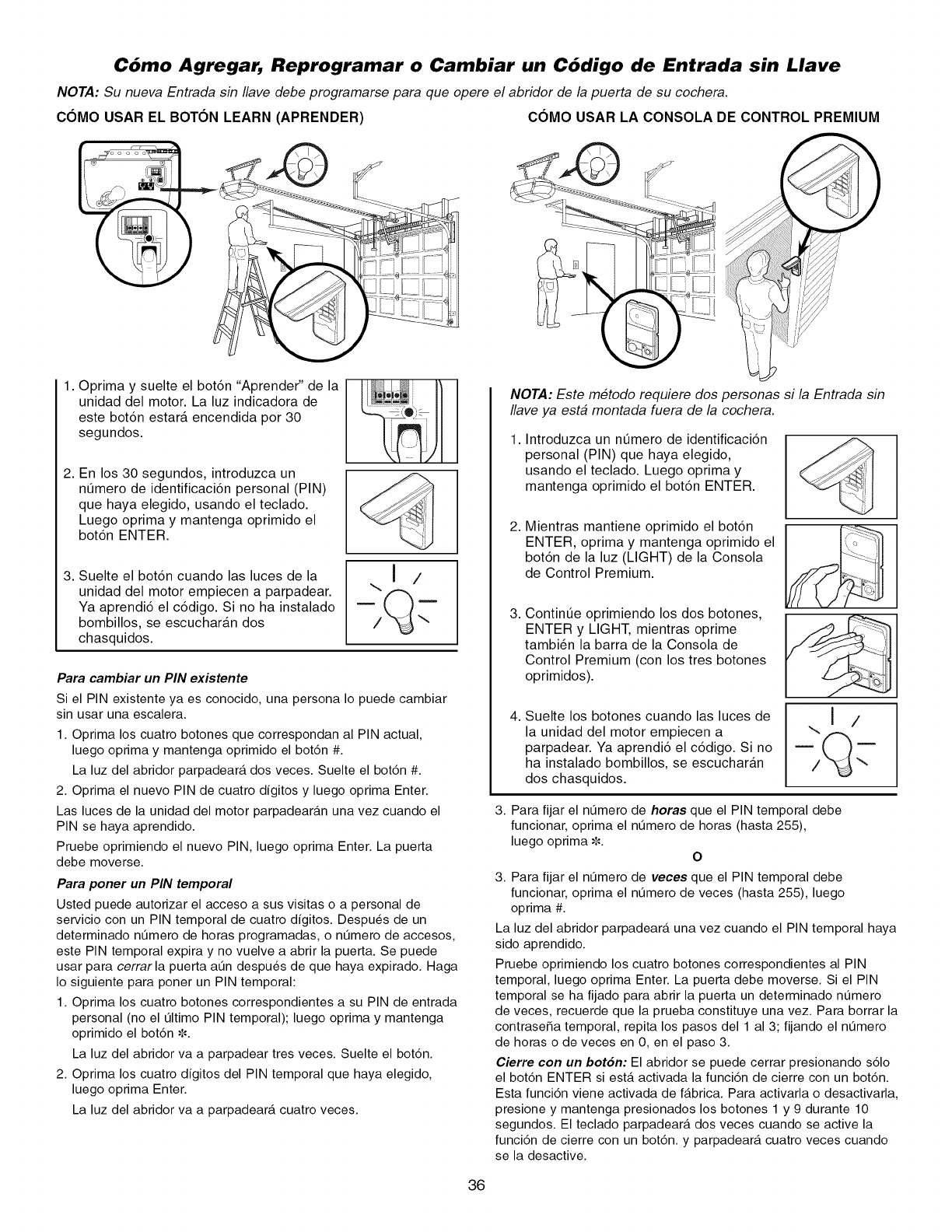
Cbmo Agregar, Reprogramar o Cambiar un Cbdigo de Entrada sin Llave
NOTA: Su nueva Entrada sin Ilave debe programarse para que opere el abridor de la puerta de su cochera.
COMO USAR EL BOTON LEARN (APRENDER) COMO USAR LA CONSOLA DE CONTROL PREMIUM
1. Oprima y suelte el bot6n "Aprender" de la
unidad del motor. La luz indicadora de
este bot6n estara encendida por 30
segundos.
2. En los 30 segundos, introduzca un
nt]mero de identificaci6n personal (PIN)
que haya elegido, usando el teclado.
Luego oprima y mantenga oprimido el
bot6n ENTER.
3. Suelte el bot6n cuando las luces de la
unidad del motor empiecen a parpadear.
Ya aprendi6 el c6digo. Si no ha instalado
bombillos, se escucharan dos
chasquidos.
\11
Para cambiar un PIN existente
Si el PIN existente ya es conocido, una persona Io puede cambiar
sin usar una escalera.
1. Oprima los cuatro botones que correspondan al PIN actual,
luego oprima y mantenga oprimido el bot6n #.
La luz del abridor parpadear_, dos veces. Suelte el bot6n #.
2. Oprima el nuevo PIN de cuatro dfgitos y luego oprima Enter.
Las luces de la unidad del motor parpadear_.n una vez cuando el
PIN se haya aprendido.
Pruebe oprimiendo el nuevo PIN, luego oprima Enter. La puerta
debe moverse.
Para poner un PIN temporal
Usted puede autorizar el acceso a sus visitas o a personal de
servicio con un PIN temporal de cuatro dfgitos. Despu_s de un
determinado nt3mero de horas programadas, o nt3mero de accesos,
este PIN temporal expira y no vuelve a abrir la puerta. Se puede
usar para cerrarla puerta at3n despu_s de que haya expirado. Haga
Io siguiente para poner un PIN temporal:
1. Oprima los cuatro botones correspondientes a su PIN de entrada
personal (no el t31timo PIN temporal); luego oprima y mantenga
oprimido el bot6n _.
La luz del abridor va a parpadear tres veces. Suelte el bot6n.
2. Oprima los cuatro dfgitos del PIN temporal que haya elegido,
luego oprima Enter.
La luz del abridor va a parpadear_, cuatro veces.
)
NOTA: Este metodo requiere dos personas si la Entrada sin
Ilave ya esta montada fuera de la cochera.
Introduzca un nt]mero de identificaci6n
personal (PIN) que haya elegido,
usando el teclado. Luego oprima y
mantenga oprimido el bot6n ENTER.
2,
3,
4,
Mientras mantiene oprimido el bot6n
ENTER, oprima y mantenga oprimido el
bot6n de la luz (LIGHT) de la Consola
de Control Premium.
Contint]e oprimiendo los dos botones,
ENTER y LIGHT, mientras oprime
tambi_n la barra de la Consola de
Control Premium (con los tres botones
oprimidos).
Suelte los botones cuando las luces de
la unidad del motor empiecen a
parpadear. Ya aprendi6 el c6digo. Si no
ha instalado bombillos, se escucharan
dos chasquidos.
...I /
3. Para fijar el nt3mero de horas que el PIN temporal debe
funcionar, oprima el nt3mero de horas (hasta 255),
luego oprima -,_.
O
3. Para fijar el nt3mero de veces que el PIN temporal debe
funcionar, oprima el nt3mero de veces (hasta 255), luego
oprima #.
La luz del abridor parpadear_, una vez cuando el PIN temporal haya
sido aprendido.
Pruebe oprimiendo los cuatro botones correspondientes al PIN
temporal, luego oprima Enter. La puerta debe moverse. Si el PIN
temporal se ha fijado para abrir la puerta un determinado nt3mero
de veces, recuerde que la prueba constituye una vez. Para borrar la
contrase_a temporal, repita los pasos del 1 al 3; fijando el nt3mero
de horas o de veces en O, en el paso 3.
Cierre con un bot6n: El abridor se puede cerrar presionando s61o
el bot6n ENTER si est,. activada la funci6n de cierre con un bot6n.
Esta funci6n viene activada de f_.brica. Para activarla o desactivarla,
presione y mantenga presionados los botones 1 y 9 durante 10
segundos. El teclado parpadear_t dos veces cuando se active la
funci6n de cierre con un bot6n, y parpadear_, cuatro veces cuando
se la desactive.
36
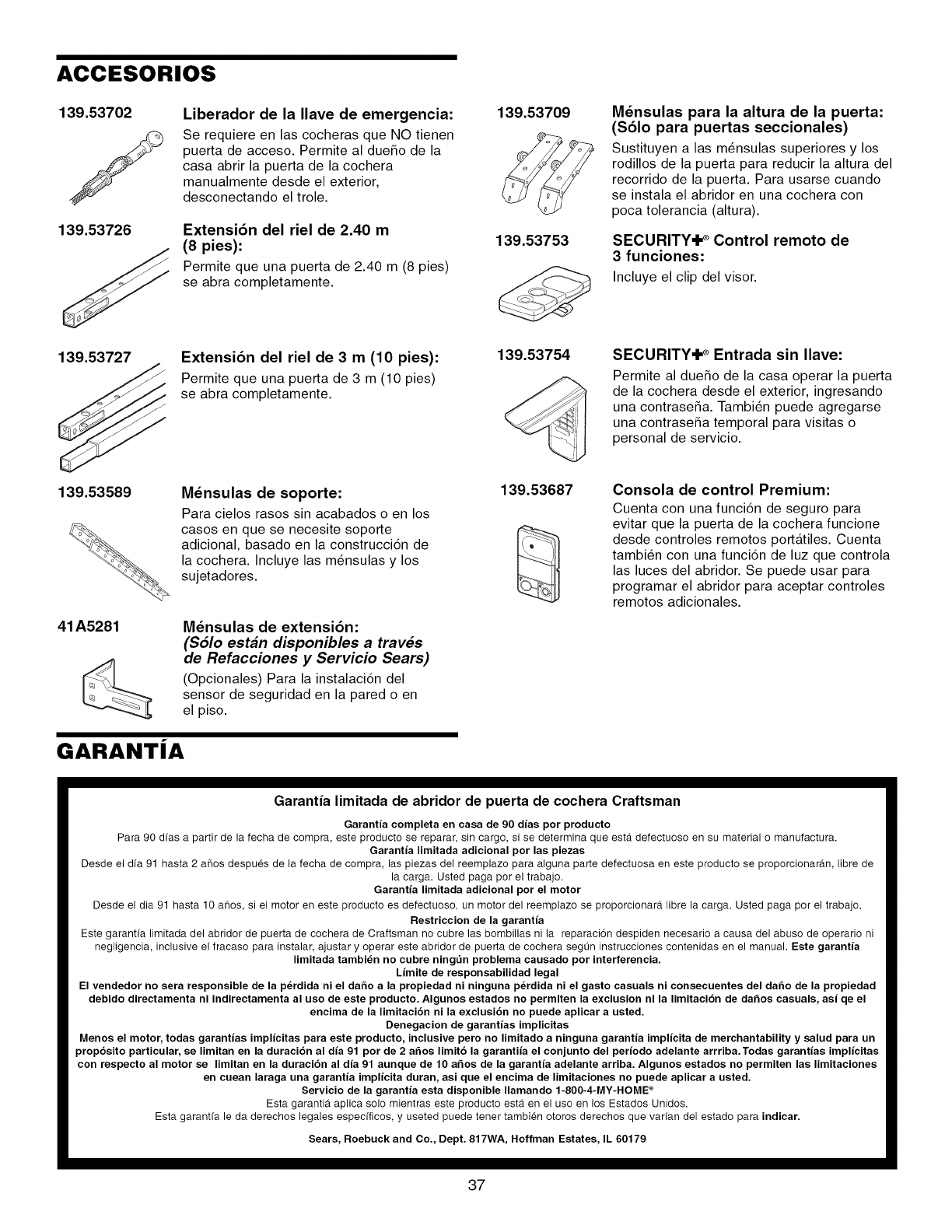
ACCESORIOS
139.53702
J
139.53726
Liberador de la Ilave de emergencia:
Se requiere en las cocheras que NO tienen
puerta de acceso. Permite al due_o de la
casa abrir la puerta de la cochera
manualmente desde el exterior,
desconectando el trole.
Extensi6n del riel de 2.40 m
(8 pies):
Permite que una puerta de 2.40 m (8 pies)
se abra completamente.
139.53709
139.53753
Mdnsulas para la altura de la puerta:
($61o para puertas seccionales)
Sustituyen alas m_nsulas superiores y los
rodillos de la puerta para reducir la altura del
recorrido de la puerta. Para usarse cuando
se instala el abridor en una cochera con
poca tolerancia (altura).
SECURITY'Ik ®Control remoto de
3 funciones:
Incluye el clip del visor.
139.53727 Extensi6n del riel de 3 m(10 pies):
Permite que una puerta de 3 m (10 pies)
se abra completamente.
139.53754 SECURITY'IP Entrada sin Ilave:
Permite al due_o de la casa operar la puerta
de la cochera desde el exterior, ingresando
una contrase_a. Tambi_n puede agregarse
una contrase_a temporal para visitas o
personal de servicio.
139.53589 M_nsulas de soporte:
Para cielos rasos sin acabados o en los
casos en que se necesite soporte
adicional, basado en la construcci6n de
la cochera. Incluye las m_nsulas y los
sujetadores.
41A5281 M_nsulas de extensi6n:
($61o est#n disponibles a trav#s
de Refacciones y Servicio Sears)
(Opcionales) Para la instalaci6n del
sensor de seguridad en la pared o en
el piso.
GARANTJA
139.53687 Consola de control Premium:
Cuenta con una funci6n de seguro para
evitar que la puerta de la cochera funcione
desde controles remotos portatiles. Cuenta
tambi_n con una funci6n de luz que controla
las luces del abridor. Se puede usar para
programar el abridor para aceptar controles
remotos adicionales.
Garantia limitada de abridor de puerta de cochera Craftsman
Garantia completa en casa de 90 dias por producto
Para 90 dfas a partir de la fecha de compra, este producto se reparar, sin cargo, si se determina que est_ defectuoso en su material o manufactura.
Garantia limitada adicional por las piezas
Desde el dfa 91 hasta 2 afios despues de la fecha de compra, las piezas del reemplazo para alguna parte defectuosa en este producto se proporcionar_m, libre de
la carga. Usted paga por el trabajo.
Garantia limitada adicional por el motor
Desde el dia 91 hasta 10 afios, si el motor en este producto es defectuoso, un motor del reemplazo se proporcionarA libre la carga. Usted paga por el trabajo.
Restriccion de la garantia
Este garantfa limitada del abridor de puerta de cochera de Craftsman no cubre las bombilias ni ]a reparacion despiden necesario a causa del abuso de operario ni
negligencia, inclusive el fracaso para instalar, ajustar y operar este abridor de puerta de cochera seg0n instrucciones contenidas en el manual. Este garantia
limitada tambi_n no cubre ningt_n problema causado por interferencia.
Limite de responsabilidad legal
El vendedor no sera responsible de la p_rdida ni el da6o a la propiedad ni ninguna p_rdida ni el gasto casuals ni consecuentes del da6o de la propiedad
debido directamenta ni indirectamenta al uso de este producto. Algunos estados no permiten la exclusion ni la limitacibn de da6os casuals, asi qe el
encima de la limitacibn ni la exclusibn no puede aplicar a usted.
Denegacion de garantias implicitas
Menos el motor, todas garantias implicitas para este producto, inclusive pero no limitado a ninguna garantia implicita de merchantability y salud para un
propbsito particular, se limitan en la duracibn al dia 91 por de 2 a6os limit6 la garantiia el conjunto del periodo adelante arrriba.Todas garantias implicitas
con respecto al motor se limitan en la duracibn al dia 91 aunque de 10 a6os de la garantia adelante arriba. Algunos estados no permiten las limitaciones
en cuean laraga una garantia implicita duran, asi que el encima de limitaciones no puede aplicar a usted.
Servicio de la garantia esta disponible Ilamando 1-800-4-MY-HOME *
Esta garantia aplica solo mientras este producto est,. en el uso en los Estados Unidos.
Esta garantfa le da derechos legales especfficos, y useted puede tener tambien otoros derechos que varfan del estado para indicar.
Sears, Roebuck and Co., Dept. 817WA, Hoffman Estates, IL 60179
37
Your Home
For repair-in your home-of all major brand appliances,
lawn and garden equipment, or heating and cooling systems,
no matter who made it, no matter who sold it!
For the replacement parts, accessories and
owner's manuals that you need to do-it-yourself.
For Sears professional installation of home appliances
and items like garage door openers and water heaters.
1-800-4-MY-HOME ® (1-800-469-4663)
Call anytime, day or night (U.S.A. and Canada)
www.sears.com www.sears.ca
Our Home
For repair of carry-in items like vacuums, lawn equipment,
and electronics, call or go on-line for the location of your nearest
Sears Parts & Repair Center.
1-800-488-1222
Call anytime, day or night (U.S.A. only)
www.sears.com
To purchase a protection agreement (U.S.A.)
or maintenance agreement (Canada) on a product serviced by Sears:
1-800-827-6655 (U.S.A.) 1-800-361-6665 (Canada)
Para pedir servicio de reparaci6n
a domicilio, y para ordenar piezas:
1-888-SU-HOGAR sM
(1-888-784-6427)
Au Canada pour service en fran(_ais:
1-800-LE-FOYER M°
(1-800-533-6937)
www.sears.ca
114A3614
TM
® Registered Trademark /Trademark /sMService Mark of Sears, Roebuck and Co.
sM
® Marca Registrada /TMMarca de F_.brica /Marca de Servicio de Sears, Roebuck and Co.
McMarque de commerce /,_DMarque deposee de Sears, Roebuck and Co.
38
© 2008 Sears, Roebuck and Co.
