Craftsman 14637634 User Manual DUST COLLECTOR Manuals And Guides 1403709L
User Manual: Craftsman 14637634 14637634 CRAFTSMAN DUST COLLECTOR - Manuals and Guides View the owners manual for your CRAFTSMAN DUST COLLECTOR #14637634. Home:Vacuums & Floor Care Parts:Craftsman Parts:Craftsman DUST COLLECTOR Manual
Open the PDF directly: View PDF ![]() .
.
Page Count: 40

Owner's Manual
CRFIFrSMFIN
1 1/2 Horsepower (continuous duty)
1200 C.F.IVi.
3450 R.P.IVl. (no load R.P.IVl.)
DUST COLLECTOR
IVlodel No.
37634
®
C US
226002
CAUTION:
FOR YOUR OWN SAFETY; Read
and follow all of the Safety and
Operating Instructions before
Operating this Dust Collector.
Customer Helpline
1-855-758-0015
Please have your Model No.
and Serial No. available.
Sears Brands Management Corporation, Hoffman Estates, IL 60179 U.S.A.
www.oraftsman.oom
EspaSol pg. 21
SECTION PAGE
Warranty ..................................................................................... 2
Product Specifications ......................................................................... 2
Safety Instructions ............................................................................ 3
Grounding Instructions ......................................................................... 5
Specific Safety Instructions for Dust Collectors .................................................... 6
Accessories and Attachments ................................................................... 7
Carton Contents .............................................................................. 8
Know Your Dust Collector ..................................................................... 10
Assembly Instructions ........................................................................ 11
Operating the Dust Collector ................................................................... 13
Dust Collector in the Shop ..................................................................... 15
Maintenance ................................................................................. 17
Troubleshooting Guide ........................................................................ 17
Parts List ................................................................................... 18
Service Information ........................................................................... 40
CRAFTSMAN ONEYEAR FULL WARRANTY
FOR ONE YEAR from the date of purchase, this product is warranted against defects in material or workmanship. A defective
product will receive free repair or replacement if repair is unavailable.
For warranty coverage details to obtain free repair or replacement, visit the web site: www.craftsman.com
This warranty does not cover the filter bags or collector bags, which are expendable parts that can wear out from normal use
within the warranty period.
This warranty gives you specific legal rights, and you may also have other rights which vary from state to state.
Sears Brands Management Corporation, Hoffman Estates, IL 60179
Induction Motor
Continious duty HP
Amps
Volts
Hertz
RPM
Standard Bag Top
Collection Hose
Maximum C. R M.
Maximum static pressure
in inches of water
Collection Bag Capacity
Weight
Shipping Weight
1 1/2
16/8
115/230
60
3450 R.P.M.
(no load R.RM.)
5 micron
4-inch Flexible Hose
1200
6.6
30 gallons
94 Ibs.
105 Ibs.
To avoid electrical shock to yourself and damage to the
Dust Collector, use proper circuit protection. Do not
expose to rain, or use in a damp environment.
The Dust Collector is factory wired for 115V, 60 Hz,
operation and can use for 230v by change wiring.
The motor can be use with 120v or 240v power.
When using ,connect to a 120V, 15 amp branch circuit
and use a 15 amp time delay fuse or circuit breaker.
The electrical circuit cannot have any wire size
less than #14. To avoid shock or fire, replace power
cord immediately if it is damaged in any way.
GENERAL SAFETY INSTRUCTIONS
Operating a Dust Collector can be dangerous if safety
and common sense are ignored. The operator must be
familiar with the operation of the tool. Read this manual
to understand this Dust Collector. DO NOT operate this
Dust Collector if you do not fully understand the limita-
tions of this tool. DO NOT modify this Dust Collector in
any way. REMEMBER: Your personal safety is your
responsibility.
BEFORE USING THE DUST COLLECTOR
r!_l,Vlv/_,l..l#ii#[ell
To avoid serious injury and damage to the tool, read
and follow all of the Safety and Operating Instructions
before operating the Dust Collector.
Jr!_l,Vlv/.'l-'l#II#[ell
1. Some dust created by using power tools contains
chemicals known to the State of California to cause
cancer, birth defects, or other reproductive harm.
Some examples of these chemicals are:
• Lead from lead-based paints.
• Crystalline silica from bricks, cement, and other
masonry products.
• Arsenic and chromium from chemically treated
lumber.
Your risk from these exposures varies, depending
on how often you do this type of work. To reduce
your exposure to these chemicals: work in a well-
ventilated area, and work with approved safety
equipment, such as those dust masks that are
specially designed to filter out microscopic particles.
2. READ the entire Owner's Manual. LEARN how to
use the tool for its intended applications.
3. GROUND ALL TOOLS. If the tool is supplied with a
3-prong plug, it must be plugged into a 3-contact
electrical receptacle. The 3rd prong is used to
ground the tool and provide protection against
accidental electric shock. DO NOT remove the 3rd
prong. See Grounding Instructions.
4. AVOID A DANGEROUS WORKING ENVIRON-
MENT. DO NOT use electrical tools in a damp
environment or expose them to rain.
5. DO NOT use electrical tools in the presence of
flammable liquids or gasses.
6. ALWAYS keep the work area clean, well lit, and
organized. DO NOT work in an environment with
floor surfaces that are slippery from debris, grease,
and wax.
7, KEEP VISITORS AND CHILDREN AWAY. DO NOT
permit people to be in the immediate work area,
especially when the electrical tool is operating.
8, DO NOT FORCE THE TOOL to perform an opera-
tion for which it was not designed. It will do a safer
and higher quality job by only performing operations
for which the tool was intended.
9. WEAR PROPER CLOTHING. DO NOT wear loose
clothing, gloves, neckties, or jewelry. These items
can get caught in the machine during operations
and pull the operator into the moving parts. The
user must wear a protective cover on their hair, if
the hair is long, to prevent it from contacting any
moving parts.
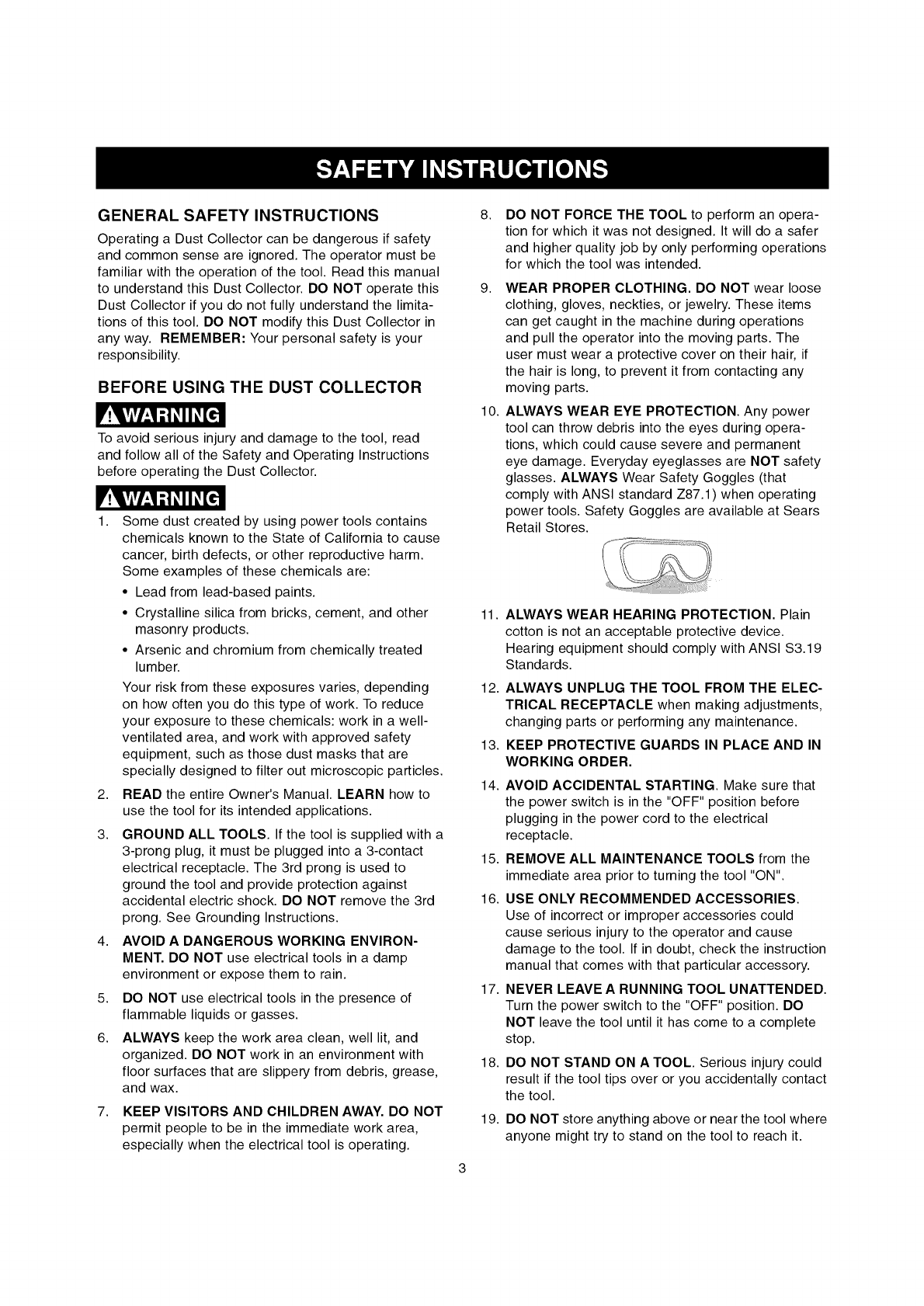
10. ALWAYS WEAR EYE PROTECTION. Any power
tool can throw debris into the eyes during opera-
tions, which could cause severe and permanent
eye damage. Everyday eyeglasses are NOT safety
glasses. ALWAYS Wear Safety Goggles (that
comply with ANSI standard Z87.1) when operating
power tools. Safety Goggles are available at Sears
Retail Stores.
11.
12.
13.
14.
ALWAYS WEAR HEARING PROTECTION. Plain
cotton is not an acceptable protective device.
Hearing equipment should comply with ANSI S3.19
Standards.
ALWAYS UNPLUG THE TOOL FROM THE ELEC-
TRICAL RECEPTACLE when making adjustments,
changing parts or performing any maintenance.
KEEP PROTECTIVE GUARDS IN PLACE AND IN
WORKING ORDER.
AVOID ACCIDENTAL STARTING. Make sure that
the power switch is in the "OFF" position before
plugging in the power cord to the electrical
receptacle.
15. REMOVE ALL MAINTENANCE TOOLS from the
immediate area prior to turning the tool "ON".
16. USE ONLY RECOMMENDED ACCESSORIES.
Use of incorrect or improper accessories could
cause serious injury to the operator and cause
damage to the tool. If in doubt, check the instruction
manual that comes with that particular accessory.
17. NEVER LEAVE A RUNNING TOOL UNATTENDED.
Turn the power switch to the "OFF" position. DO
NOT leave the tool until it has come to a complete
stop.
18. DO NOT STAND ON A TOOL. Serious injury could
result if the tool tips over or you accidentally contact
the tool.
19. DO NOT store anything above or near the tool where
anyone might try to stand on the tool to reach it.
20.MAINTAIN YOUR BALANCE. DO NOT extend your-
self over the tool. Wear oil resistant rubber-soled
shoes. Keep floor clear of debris, grease, and wax.
21. MAINTAIN TOOLS WITH CARE. Always keep tools
clean and in good working order. Keep all blades
and tool bits sharp.
22. EACH AND EVERY TIME, CHECK FOR DAM-
AGED PARTS PRIOR TO USING THE TOOL.
Carefully check all guards to see that they operate
properly, are not damaged, and perform their
intended functions. Check for alignment, binding or
breaking of moving parts. A guard or other part that
is damaged should be immediately repaired or
replaced.
23. CHILDPROOF THE WORKSHOP AREA by remov-
ing switch keys, unplugging tools from the electrical
receptacles, and using padlocks.
24. DO NOT OPERATE TOOL IF UNDER THE INFLU-
ENCE OF DRUGS OR ALCOHOL.
25. SECURE ALL WORK. When it is possible, use
clamps or jigs to secure the work-piece. This is
safer than attempting to hold the work-piece with
your hands.
26. STAY ALERT, WATCH WHAT YOU ARE DOING,
AND USE COMMON SENSE WHEN OPERATING
A POWER TOOL. DO NOT USE A TOOL WHILE
TIRED OR UNDER THE INFLUENCE OF DRUGS,
ALCOHOL, OR MEDICATION. A moment of
inattention while operating power tools may result
in serious personal injury.
27. ALWAYS WEAR A DUST MASK TO PREVENT
INHALING DANGEROUS DUST OR AIRBORNE
PARTICLES, including wood dust, crystalline silica
dust and asbestos dust. Direct particles away
from face and body. Always operate tool in well
ventilated area and provide for proper dust removal.
Use dust collection system whenever possible.
Exposure to the dust may cause serious and
permanent respiratory or other injury, including
silicosis (a serious lung disease), cancer, and
death. Avoid breating the dust, and avoid prolonged
contact with dust. Allowing dust to get into your
mouth or eyes, or lay on your skin may promote
absorption of harmful material. Always use properly
fitting NIOSH/OSHA approved respiratory protection
appropriate for the dust exposure, and wash
exposed areas with soap and water.
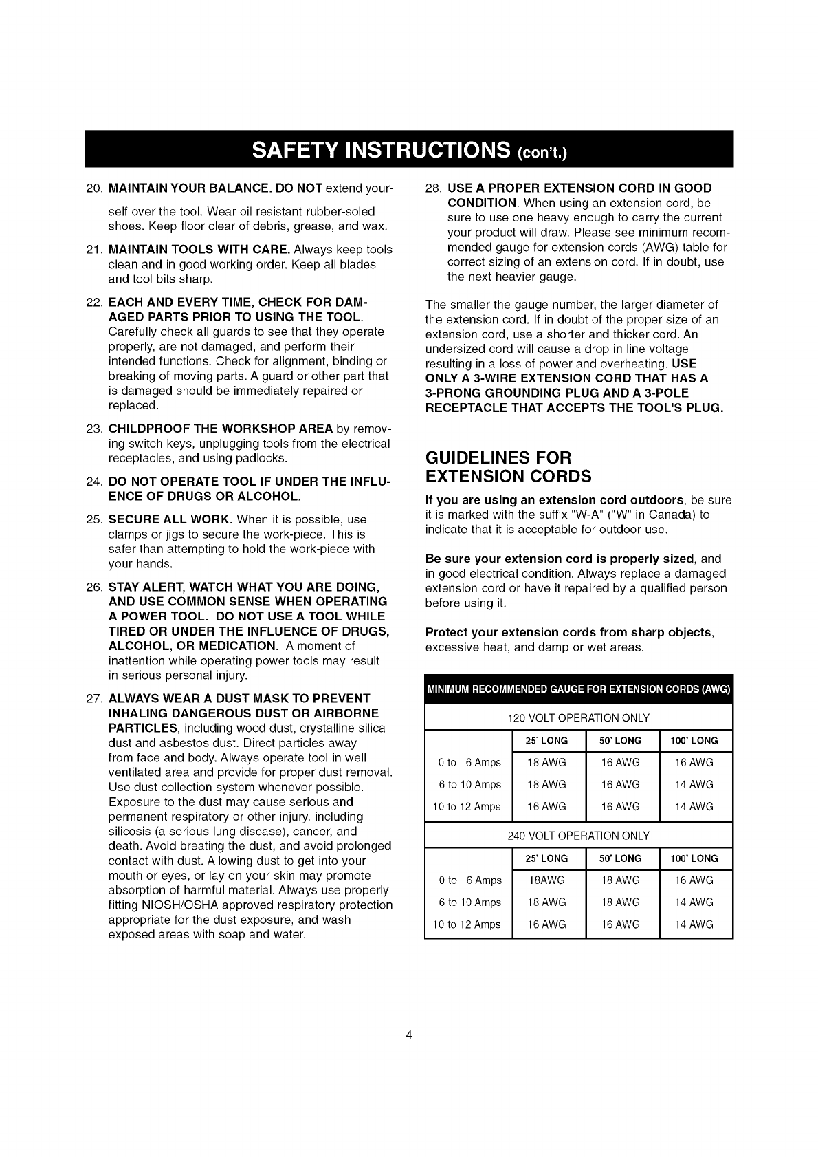
28. USE A PROPER EXTENSION CORD IN GOOD
CONDITION. When using an extension cord, be
sure to use one heavy enough to carry the current
your product will draw. Please see minimum recom-
mended gauge for extension cords (AWG) table for
correct sizing of an extension cord. If in doubt, use
the next heavier gauge.
The smaller the gauge number, the larger diameter of
the extension cord. If in doubt of the proper size of an
extension cord, use a shorter and thicker cord. An
undersized cord will cause a drop in line voltage
resulting in a loss of power and overheating. USE
ONLY A 3-WIRE EXTENSION CORD THAT HAS A
3-PRONG GROUNDING PLUG AND A 3-POLE
RECEPTACLE THAT ACCEPTS THE TOOL'S PLUG.
GUIDELINES FOR
EXTENSION CORDS
If you are using an extension cord outdoors, be sure
it is marked with the suffix "W-A" ("W" in Canada) to
indicate that it is acceptable for outdoor use.
Be sure your extension cord is properly sized, and
in good electrical condition. Always replace a damaged
extension cord or have it repaired by a qualified person
before using it.
Protect your extension cords from sharp objects,
excessive heat, and damp or wet areas.
0 to 6Amps
6 to 10 Amps
10 to 12 Amps
0 to 6Amps
6 to 10 Amps
10 to 12 Amps
120 VOLT OPERATION ONLY
25' LONG 50' LONG
18 AWG 16 AWG
18 AWG 16 AWG
16 AWG 16 AWG
240 VOLT OPERATION ONLY
25' LONG 50' LONG
18AWG 18 AWG
18 AWG 18 AWG
16 AWG 16 AWG
100' LONG
16 AWG
14 AWG
14 AWG
100' LONG
16 AWG
14 AWG
14 AWG
THIS TOOL MUST BE GROUNDED WHILE iN USE TO
PROTECT THE OPERATOR FROM ELECTRIC SHOCK.
IN THE EVENT OF A MALFUNCTION OR BREAK-
DOWN, grounding provides the path of least resistance
for electric current and reduces the risk of electric
shock. This toot is equipped with an electric cord that
has an equipment-grounding conductor and a ground-
ing plug. The plug MUST be plugged into a matching
electrical receptacle that is properly installed and
grounded in accordance with ALL local codes and
ordinances.
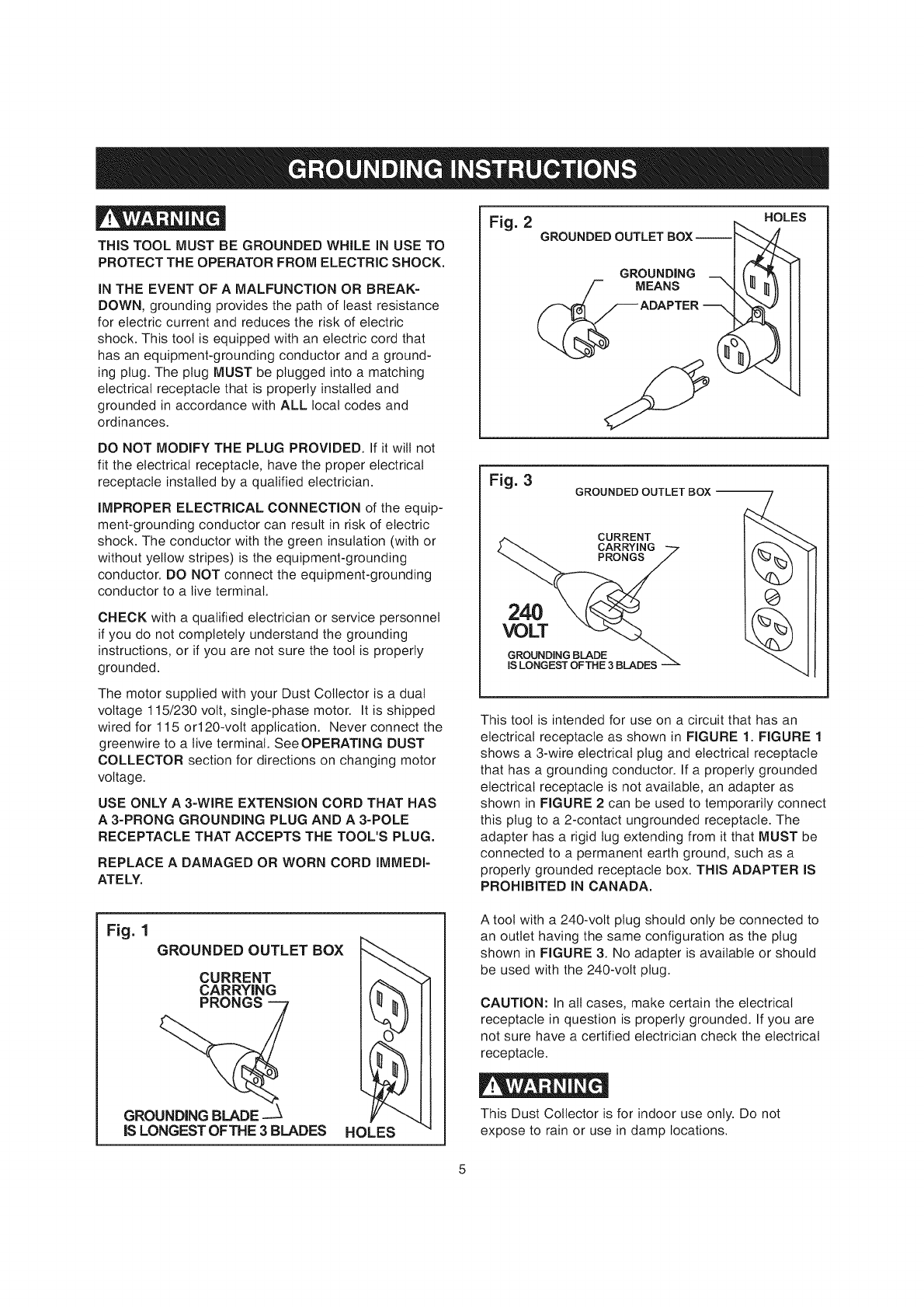
Fig. 2 , HOLES
GROUNDEDOUTLET BOX-
GROUNDING
MEANS
DO NOT MODIFY THE PLUG PROVIDED. If it will not
fit the electrical receptacle, have the proper electrical
receptacle installed by a qualified electrician.
IMPROPER ELECTRICAL CONNECTION of the equip-
ment-grounding conductor can result in risk of electric
shock. The conductor with the green insulation (with or
without yellow stripes) is the equipment-grounding
conductor. DO NOT connect the equipment-grounding
conductor to a live terminal.
CHECK with a qualified electrician or service personnel
if you do not completely understand the grounding
instructions, or if you are not sure the toot is properly
grounded.
The motor supplied with your Dust Collector is a dual
voltage 115/230 volt, single-phase motor. It is shipped
wired for 115 orl20-volt application. Never connect the
greenwire to a live terminal. See OPERATING DUST
COLLECTOR section for directions on changing motor
voltage.
USE ONLY A 3-WIRE EXTENSION CORD THAT HAS
A 3-PRONG GROUNDING PLUG AND A 3-POLE
RECEPTACLE THAT ACCEPTS THE TOOL'S PLUG.
REPLACE A DAMAGED OR WORN CORD IMMEDI-
ATELY.
Fig. 3GROUNDED
CURRENT
CARRYING
PRONGS
240
VOLT
GROUNDING BLADE
IS LONGEST OFTHE 3BLADES
This tool is intended for use on a circuit that has an
electrical receptacle as shown in FIGURE 1. FIGURE 1
shows a 3-wire electrical plug and electrical receptacle
that has a grounding conductor. If a properly grounded
electrical receptacle is not available, an adapter as
shown in FIGURE 2 can be used to temporarily connect
this plug to a 2-contact ungrounded receptacle. The
adapter has a rigid tug extending from it that MUST be
connected to a permanent earth ground, such as a
properly grounded receptacle box. THIS ADAPTER IS
PROHIBITED IN CANADA.
Fig. 1
GROUNDED OUTLET BOX _,,_
CURRENT I.__ _,_
CARRYING I ft,"""% II
GROUNDING BLADE --_ Y""__ I
IS LONGEST OFTHE 3BLADES HOLE"-S '"
A tool with a 240-volt plug should only be connected to
an outlet having the same configuration as the plug
shown in FIGURE 3. No adapter is available or should
be used with the 240-volt plug.
CAUTION: In all cases, make certain the electrical
receptacle in question is properly grounded. If you are
not sure have a certified electrician check the electrical
receptacle.
This Dust Collector is for indoor use only. Do not
expose to rain or use in damp locations.
TheoperationofanyDustCollectorcanresultindebris
beingthrownintoyoureyes,whichcanresultinsevere
eyedamage.ALWAYSWearSafetyGoggles(thatcom-
plywithANSIstandardZ87.1)whenoperatingtheDust
Collector.SafetyGogglesareavailableatSearsRetail
Stores.Keepyourthumbsandfingersawayfromintake
ports.
Basicprecautionsshouldalwaysbefollowedwhenusing
yourdustcollector.Toreducetheriskofinjury,electrical
shockorfire,complywiththesafetyruleslistedbelow:
1. READandunderstandtheinstructionmanual
beforeoperatingthedustcollector.
2. DO NOT OPERATE THIS MACHINE until it is
assembled and installed according to the instruc-
tions.
3. OBTAIN ADVICE FROM YOUR SUPERVISOR,
instructor, or another qualified person if you are not
familiar with the operation of this machine.
4, DO NOT leave the dust collector plugged into the
electrical outlet. Unplug dust collector from the out-
let when not in use and before servicing, changing
bags, unclogging and cleaning.
5. ALWAYS turn the power switch "OFF" before
unplugging the dust collector.
6. TO REDUCE THE RISK OF ELECTRICAL
SHOCK, do not use outdoors. Do not expose to
rain. Store indoors. Use only for dry pick up.
7, FOLLOW all electrical and safety codes, including
the National Electric Code (NEC) and the Occu-
pational Safety and Health Regulations (OSHA). All
electrical connections and wiring should be made
by qualified personnel only.
8. DO NOT handle the plug or dust collector with wet
hands.
9, DO NOT use the dust collector to pick up flam-
mable or combustible liquids, such as gasoline.
NEVER use the dust collector near any flammable
or combustible liquids.
10. USE the dust collector to pick up wood materials
only. DO NOT use the dust collector to pick up
metal shavings, metal dust, or parts.
11. NEVER use the dust collector to dissipate fumes or
smoke. NEVER pick up anything that is burning or
smoking, such as cigarettes, matches or hot ashes.
12.
13.
14.
15.
16.
17.
18.
19.
20.
21.
22.
23.
24.
USE only as described in this manual. USE acces-
sories only recommended by Sears.
DO NOT pull the dust collector by the power cord.
NEVER allow the power cord to come in contact
with sharp edges, hot surfaces, oil or grease.
DO NOT unplug the dust collector by pulling on the
power cord. ALWAYS grasp the plug, not the cord.
REPLACE a damaged cord immediately. DO NOT
use a damaged cord or plug. If the dust collector is
not operating properly, or has been damaged, left
outdoors or has been in contact with water, return it
to a Sears Service Center.
DO NOT use the dust collector as a toy. DO NOT
use near or around children.
DO NOT insert fingers or foreign objects into the
dust intake port. Keep hair, loose clothing, fingers,
and all body parts away from openings and moving
parts of the dust collector.
DO NOT use the dust collector without the dust
collection bag in place and properly secured.
ALWAYS use safety gates or caps to cover dust
ports when the dust collector is not in use or
mounted to a supporting surface for storage.
PERIODICALLY INSPECT dust bag for any cuts,
rips or tears. NEVER operate the dust collector with
a damaged bag or vacuum hose.
The dust collector is designed for home use or light
commercial duty ONLY.
CONNECT dust collector to a properly grounded
outlet only. See grounding instructions.
ADDITIONAL INFORMATION regarding the safe
and proper operation of this product is available
from the National Safety Council, 1121 Spring Lake
Drive, Itasca, IL 60143-3201 in the Accident Pre-
vention Manual for Industrial Operation and also in
the Safety Data Sheets provided by the NSC.
Please also refer to the American National Stand-
ards Institute ANSI 01.1 Safety Requirements for
Woodworking Machinery and the U.S. Department
of Labor OSHA 1910.213 Regulations.
SAVE THESE INSTRUCTIONS. Refer to them
frequently and use them to instruct other users.

AVAILABLE ACCESSORIES
Visit your Sears Hardware Department or see the Sears
Power and Hand Tool Catalog for accessories.
Various accessory fittings See catalog or store
Do not use any accessory unless you have completely
read the Owner's Manual for that accessory.
V!ykVlVl_4;i _11_[_
Use only accessories recommended for this Dust
Collector. Using other accessories may cause serious
injury and cause damage to the Dust Collector.
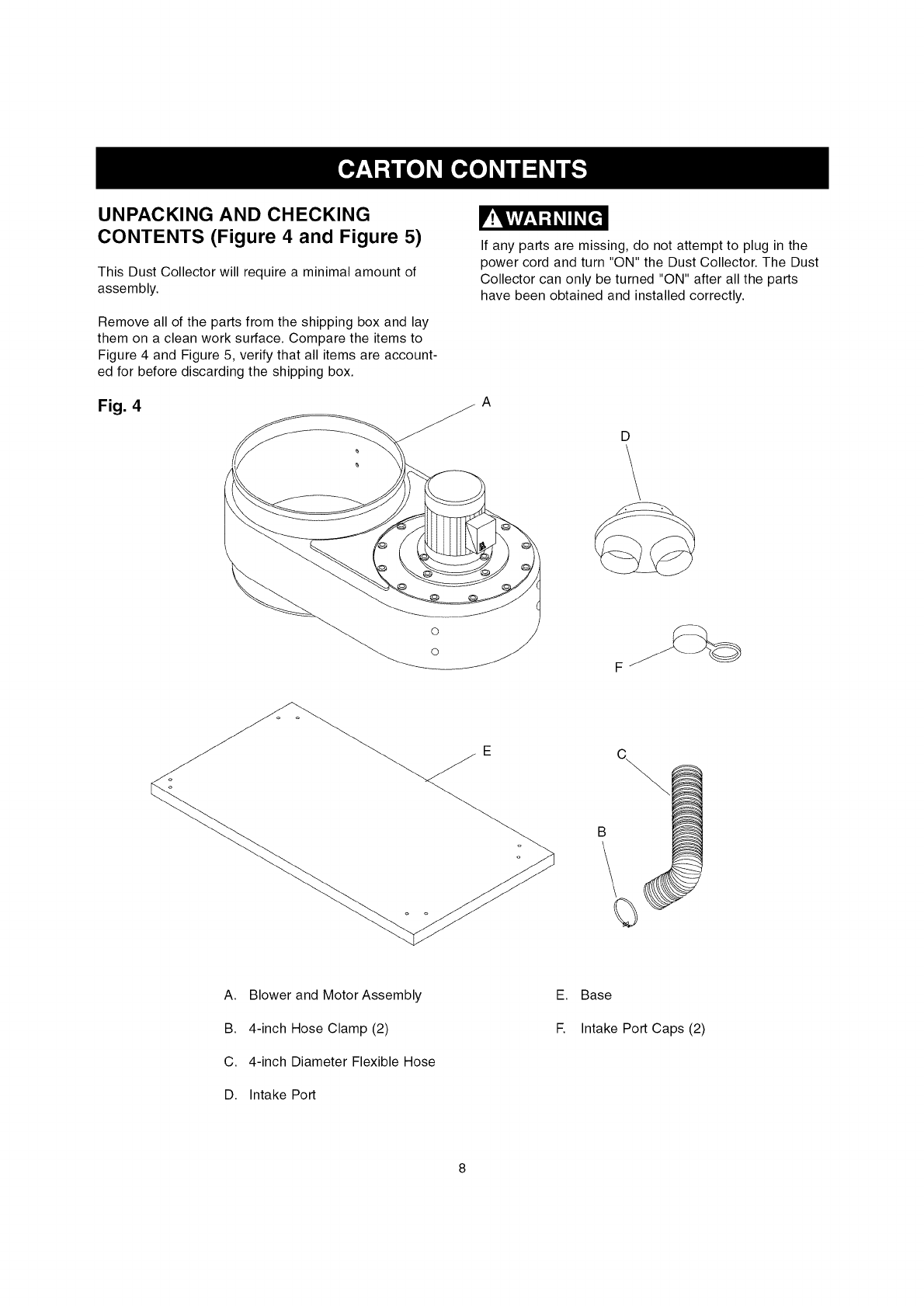
UNPACKING AND CHECKING
CONTENTS (Figure 4 and Figure 5)
This Dust Collector will require a minimal amount of
assembly.
Remove all of the parts from the shipping box and lay
them on a clean work surface. Compare the items to
Figure 4 and Figure 5, verify that all items are account-
ed for before discarding the shipping box.
Fig. 4
V!ykvlv/_4;i _11_[_
If any parts are missing, do not attempt to plug in the
power cord and turn "ON" the Dust Collector. The Dust
Collector can only be turned "ON" after all the parts
have been obtained and installed correctly.
A
D
\
Eo
B!
J
A. Blower and Motor Assembly
B. 4-inch Hose Clamp (2)
C. 4-inch Diameter Flexible Hose
D. Intake Port
E. Base
E Intake Port Caps (2)
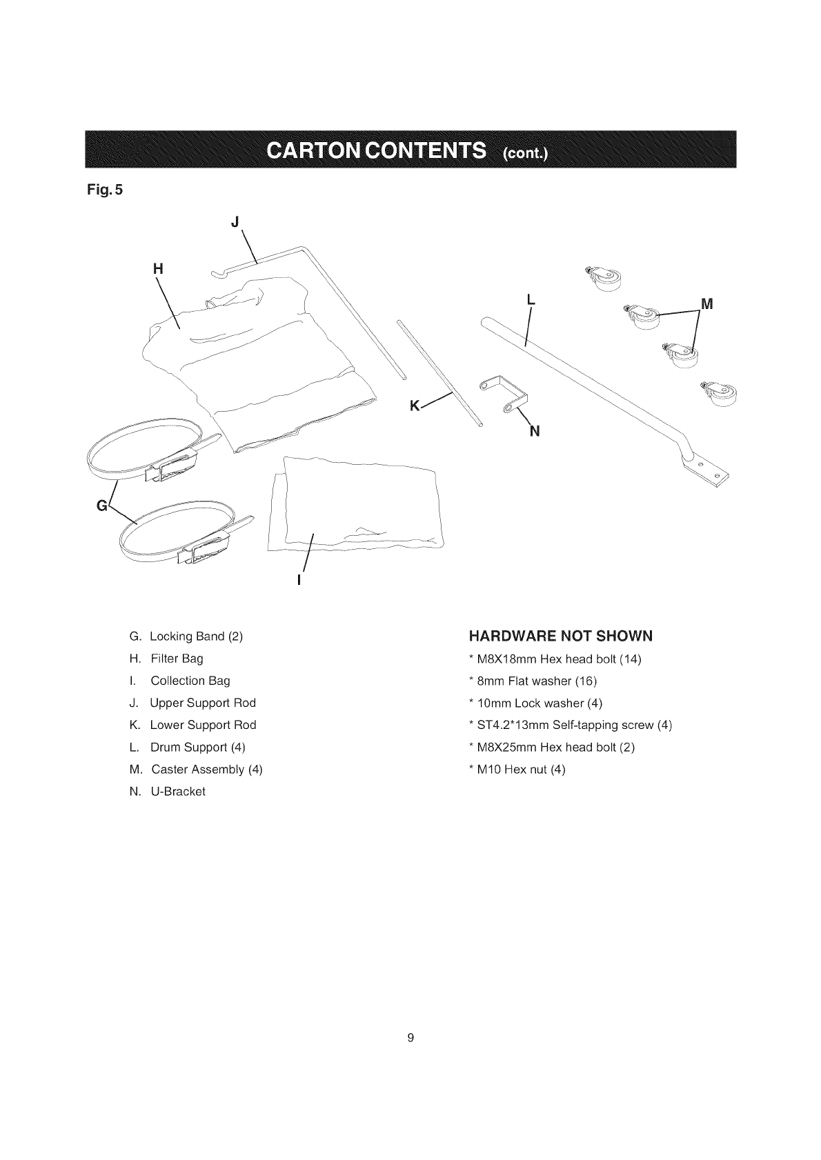
Fig.5
J
H
_\\\\\
G. Locking Band (2)
H. Filter Bag
I. Collection Bag
J. Upper Support Rod
K. Lower Support Rod
L Drum Support (4)
M. Caster Assembly (4)
N. U-Bracket
HARDWARE NOT SHOWN
*M8X18mm Hex head bolt (14)
*8ram Flat washer (t6)
*10ram Lock washer (4)
*ST4.2*13mm Self-tapping screw (4)
*M8X25mm Hex head bolt (2)
*MI0 Hex nut (4)
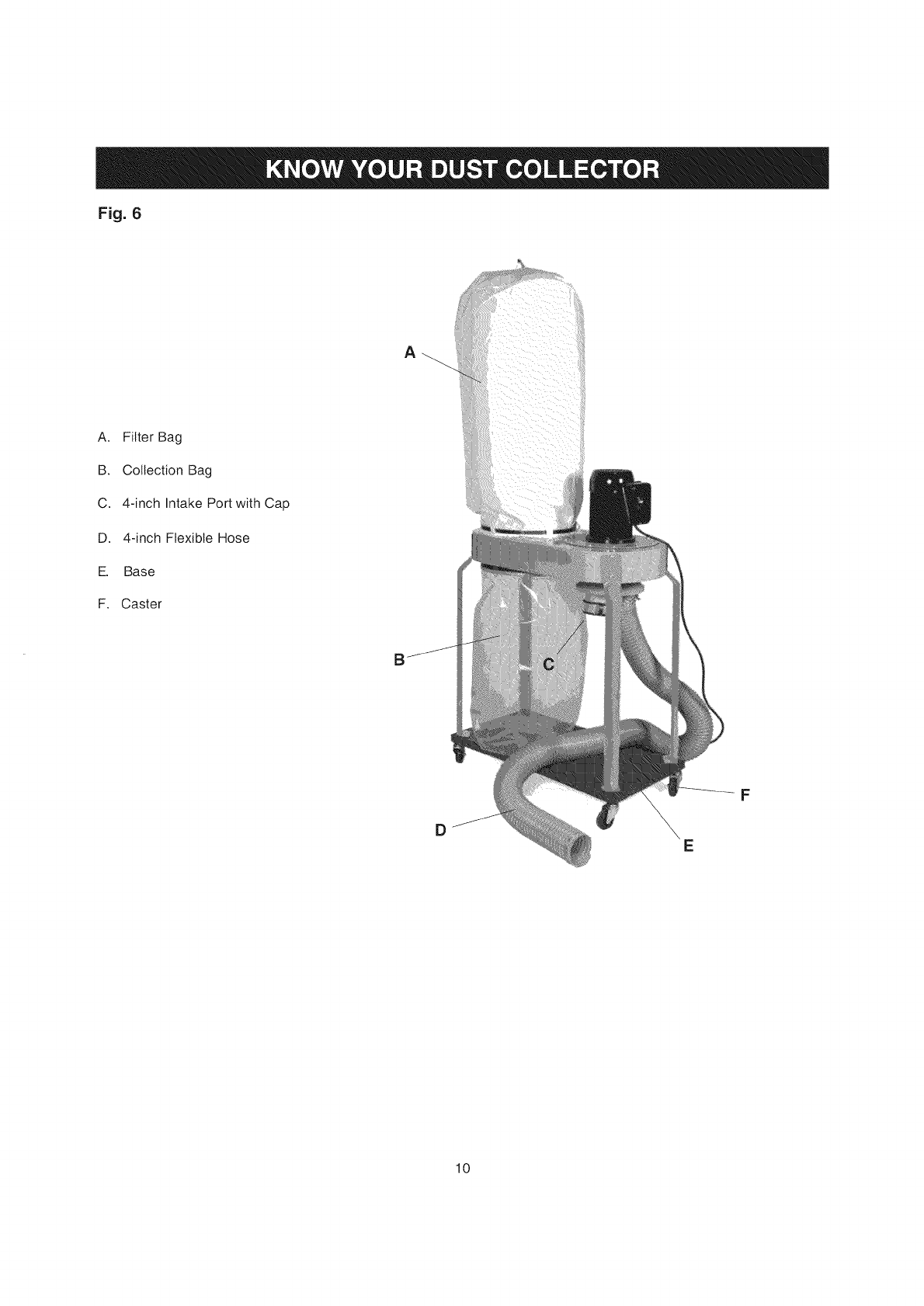
Fig. 6
A. Filter Bag
B. Collection Bag
C. 4-inch Intake Port with Cap
D. 4-inch Flexible Hose
E. Base
F. Caster
A
DE
F
10
V!IkVlrl__l;l_11_[€!
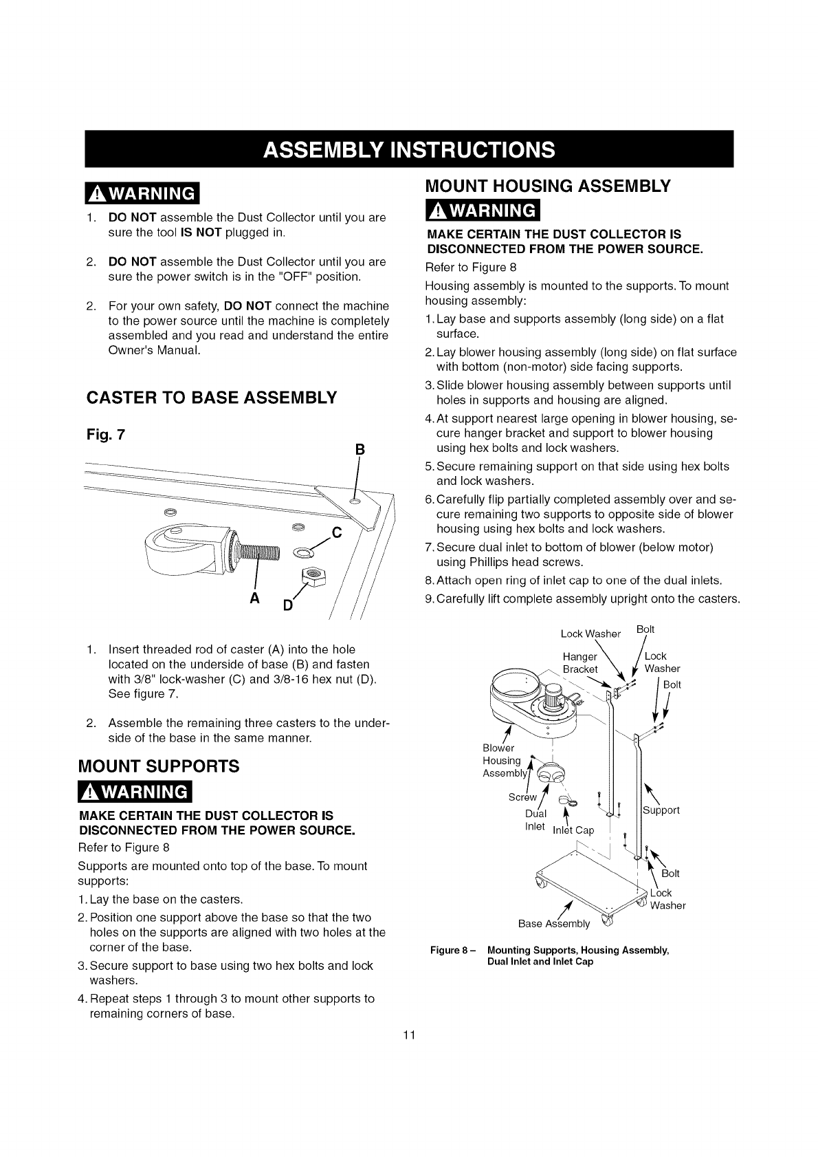
1. DO NOT assemble the Dust Collector until you are
sure the tool IS NOT plugged in.
2. DO NOT assemble the Dust Collector until you are
sure the power switch is in the "OFF" position.
2, For your own safety, DO NOT connect the machine
to the power source until the machine is completely
assembled and you read and understand the entire
Owner's Manual.
CASTER TO BASE ASSEMBLY
Fig. 7 B
@
A
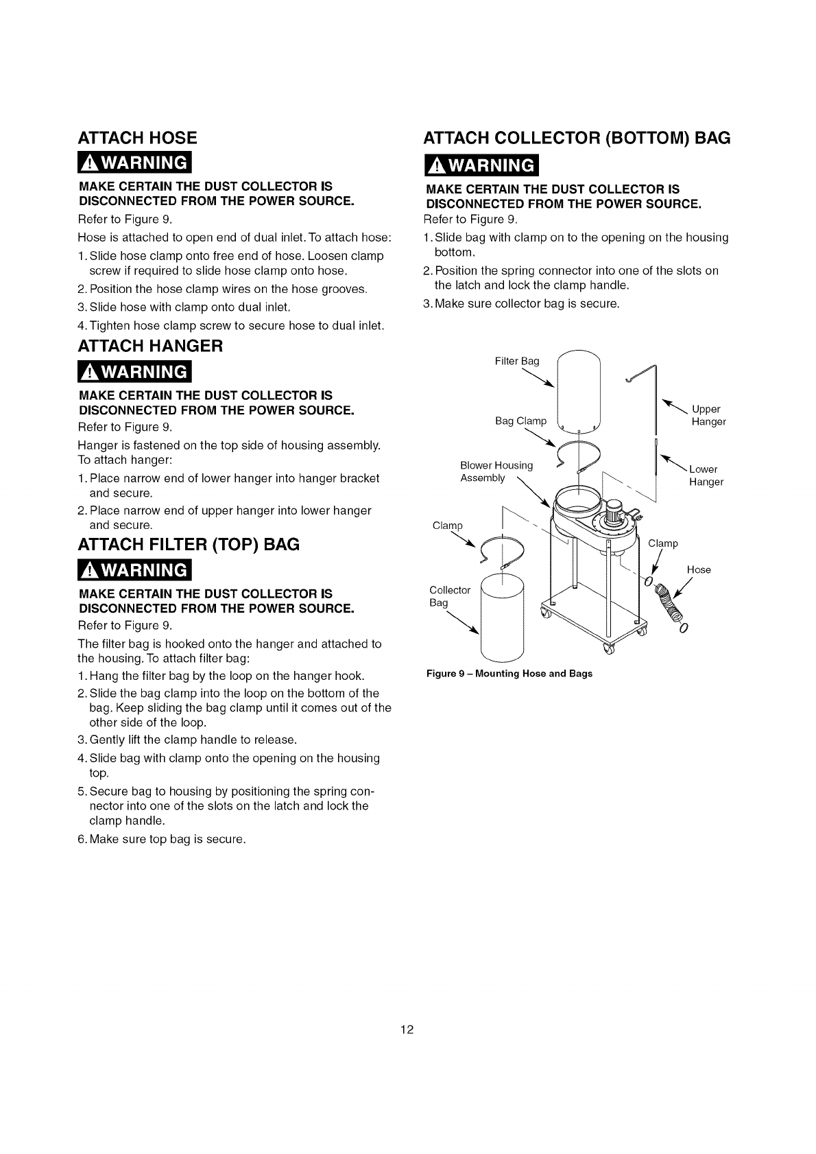
MOUNT HOUSING ASSEMBLY
V!YAv/"-I-'I#11_,[_1
MAKE CERTAIN THE DUST COLLECTOR IS
DISCONNECTED FROM THE POWER SOURCE.
Refer to Figure 8
Housing assembly is mounted to the supports. To mount
housing assembly:
1. Lay base and supports assembly (long side) on a flat
surface.
2. Lay blower housing assembly (long side) on flat surface
with bottom (non-motor) side facing supports.
3. Slide blower housing assembly between supports until
holes in supports and housing are aligned.
4. At support nearest large opening in blower housing, se-
cure hanger bracket and support to blower housing
using hex bolts and lock washers.
5. Secure remaining support on that side using hex bolts
and lock washers.
6. Carefully flip partially completed assembly over and se-
cure remaining two supports to opposite side of blower
housing using hex bolts and lock washers.
7. Secure dual inlet to bottom of blower (below motor)
using Phillips head screws.
8. Attach open ring of inlet cap to one of the dual inlets.
9. Carefully lift complete assembly upright onto the casters.
1, Insert threaded rod of caster (A) into the hole
located on the underside of base (B) and fasten
with 3/8" lock-washer (C) and 3/8-16 hex nut (D).
See figure 7.
2. Assemble the remaining three casters to the under-
side of the base in the same manner.
MOUNT SUPPORTS
V!_l,Viv/,3;1_,i i#[dl
MAKE CERTAIN THE DUST COLLECTOR IS
DISCONNECTED FROM THE POWER SOURCE.
Refer to Figure 8
Supports are mounted onto top of the base. To mount
supports:
1. Lay the base on the casters.
2. Position one support above the base so that the two
holes on the supports are aligned with two holes at the
corner of the base.
3. Secure support to base using two hex bolts and lock
washers.
4. Repeat steps 1 through 3 to mount other supports to
remaining corners of base.
Figure 8 -
Lock Washer
Hanger
/
Blower
Housing j_
Assemblyf _
Screw ',_
Dual _,
Inlet Inlet Cap
Bolt
_ock
Washer
Bolt
\
Support
Bolt
Washer
iI
Mounting Supports, Housing Assembly,
Dual Inlet and Inlet Cap
11
MAKE CERTAIN THE DUST COLLECTOR IS
DISCONNECTED FROM THE POWER SOURCE.
Refer to Figure 9.
Hose is attached to open end of dual inlet. To attach hose:
1. Slide hose clamp onto free end of hose. Loosen clamp
screw if required to slide hose clamp onto hose.
2. Position the hose clamp wires on the hose grooves.
3. Slide hose with clamp onto dual inlet.
4. Tighten hose clamp screw to secure hose to dual inlet.
ATTACH HANGER
V!l, viv/,_l;1_,II_[.€']l
MAKE CERTAIN THE DUST COLLECTOR IS
DISCONNECTED FROM THE POWER SOURCE.
Refer to Figure 9.
Hanger is fastened on the top side of housing assembly.
To attach hanger:
1. Place narrow end of lower hanger into hanger bracket
and secure.
2. Place narrow end of upper hanger into lower hanger
and secure.
ATTACH FILTER (TOP) BAG
V!l,v_v/_,l;i _II_[€-]l
MAKE CERTAIN THE DUST COLLECTOR IS
DISCONNECTED FROM THE POWER SOURCE.
Refer to Figure 9.
The filter bag is hooked onto the hanger and attached to
the housing. To attach filter bag:
1. Hang the filter bag by the loop on the hanger hook.
2. Slide the bag clamp into the loop on the bottom of the
bag. Keep sliding the bag clamp until it comes out of the
other side of the loop.
3. Gently lift the clamp handle to release.
4. Slide bag with clamp onto the opening on the housing
top.
5. Secure bag to housing by positioning the spring con-
nector into one of the slots on the latch and lock the
clamp handle.
6. Make sure top bag is secure.
ATTACH COLLECTOR (BOTTOM) BAG
V!VAv/_'I;I#II_,[_e]l
MAKE CERTAIN THE DUST COLLECTOR IS
DISCONNECTED FROM THE POWER SOURCE.
Refer to Figure 9.
1. Slide bag with clamp on to the opening on the housing
bottom.
2. Position the spring connector into one of the slots on
the latch and lock the clamp handle.
3. Make sure collector bag is secure.
Filter Bag
BagClamp
Blower Housing
Assembly
Cla_,_,
Collector
Bag
Figure 9 - Mounting Hose and Bags
C_/_mp Hose
12
FOROPERATORSAFETY,keepfingersandallforeign
objectsoutoftheintakeports.Therotatingfaninside
theblowerhousingisaccessiblethroughtheintake
portsandishazardous.Donotwearlooseclothingor
jewelry.Makecertainthateachintakeportwhichisnot
beingusedorattachedtoadustcollectionsystemis
coveredwithanintakeportcap.
CONNECTING TOOL TO
POWER SOURCE
A separate electrical circuit should be used for your
tools. This circuit should not be less than #14 A. W. G.
wire and should be protected with a 15-amp time lag
fuse. Have a qualified electrician repair or replace dam-
aged or worn cord immediately. Before connecting the
motor to the power line, make certain the switch is in
the "OFF" position and be sure that the electric current
is of the same characteristics as stamped on the motor
nameplate. All line connections should make good con-
tact. Running on low voltage will damage the motor.
DO NOT EXPOSE THE DUST COLLECTOR TO RAIN
OR OPERATE THE MACHINE IN DAMP LOCATIONS.
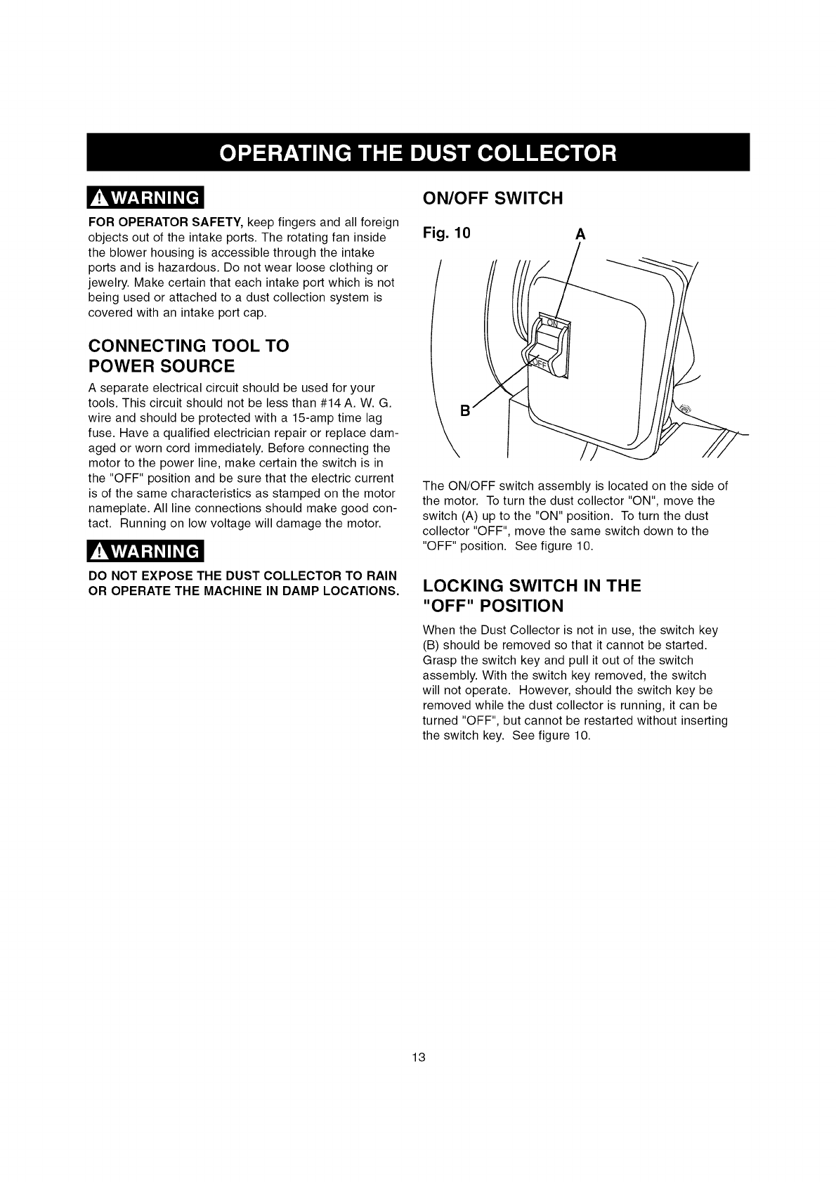
ON/OFF SWITCH
Fig. 10 A
/
\°
The ON/OFF switch assembly is located on the side of
the motor. To turn the dust collector "ON", move the
switch (A) up to the "ON" position. To turn the dust
collector "OFF", move the same switch down to the
"OFF" position. See figure 10.
LOCKING SWITCH IN THE
"OFF" POSITION
When the Dust Collector is not in use, the switch key
(B) should be removed so that it cannot be started.
Grasp the switch key and pull it out of the switch
assembly. With the switch key removed, the switch
will not operate. However, should the switch key be
removed while the dust collector is running, it can be
turned "OFF", but cannot be restarted without inserting
the switch key. See figure 10.
13
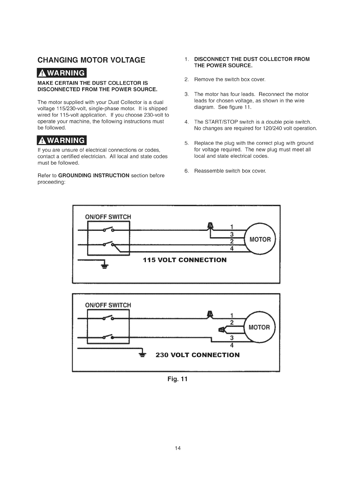
CHANGING MOTOR VOLTAGE
MAKE CERTAIN THE DUST COLLECTOR IS
DISCONNECTED FROM THE POWER SOURCE.
The motor supplied with your Dust Collector is a dual
voltage 115/230-volt, single-phase motor. It is shipped
wired for 115-volt application. If you choose 230-volt to
operate your machine, the following instructions must
be followed.
If you are unsure of electrical connections or codes,
contact a certified electrician. All local and state codes
must be followed.
Refer to GROUNDING INSTRUCTION section before
proceeding:
1. DISCONNECT THE DUST COLLECTOR FROM
THE POWER SOURCE.
2. Remove the switch box cover.
3. The motor has four beads. Reconnect the motor
leads for chosen voltage, as shown in the wire
diagram. See figure 11.
4. The START/STOP switch is a double pole switch.
No changes are required for 120/240 volt operation.
5. Replace the plug with the correct plug with ground
for voltage required. The new plug must meet all
local and state electrical codes.
6. Reassemble switch box cover.
1 15 VOLT CONNECTION
4
4
230 VOLT CONNECTION
Fig. 11
14
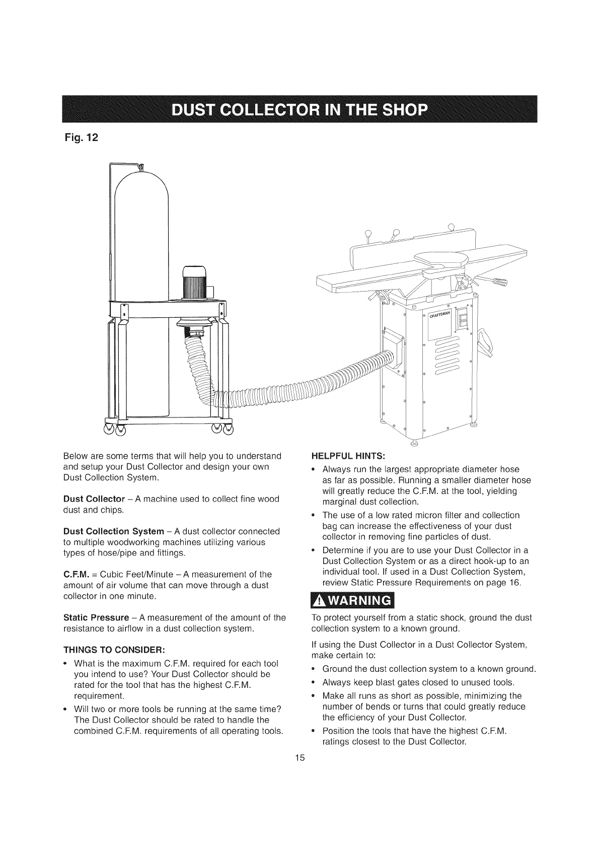
Fig. 12
Below are some terms that will help you to understand
and setup your Dust Collector and design your own
Dust Collection System.
Dust Collector - A machine used to collect fine wood
dust and chips.
Dust Collection System - A dust collector connected
to multiple woodworking machines utilizing various
types of hose/pipe and fittings.
C.F.M. = Cubic Feet/Minute - A measurement of the
amount of air volume that can move through a dust
collector in one minute.
Static Pressure - A measurement of the amount of the
resistance to airflow in a dust collection system.
THINGS TO CONSIDER:
,, What is the maximum C.F.M. required for each tool
you intend to use? Your Dust Collector should be
rated for the tool that has the highest C.F.M.
requirement.
,, Will two or more tools be running at the same time?
The Dust Collector should be rated to handle the
combined C.F.M. requirements of all operating tools.
15
HELPFUL HINTS:
,, Always run the largest appropriate diameter hose
as far as possible. Running a smaller diameter hose
will greatly reduce the C.F.M. at the tool, yielding
marginal dust collection.
• The use of a low rated micron filter and collection
bag can increase the effectiveness of your dust
collector in removing fine particles of dust.
,, Determine if you are to use your Dust Collector in a
Dust Collection System or as a direct hook-up to an
individual tool. If used in a Dust Collection System,
review Static Pressure Requirements on page 16.
To protect yourself from a static shock, ground the dust
collection system to a known ground.
If using the Dust Collector in a Dust Collector System,
make certain to:
Ground the dust collection system to a known ground.
,, Always keep blast gates closed to unused tools.
• Make all runs as short as possible, minimizing the
number of bends or turns that could greatly reduce
the efficiency of your Dust Collector.
,, Position the tools that have the highest C.F.M.
ratings closest to the Dust Collector.
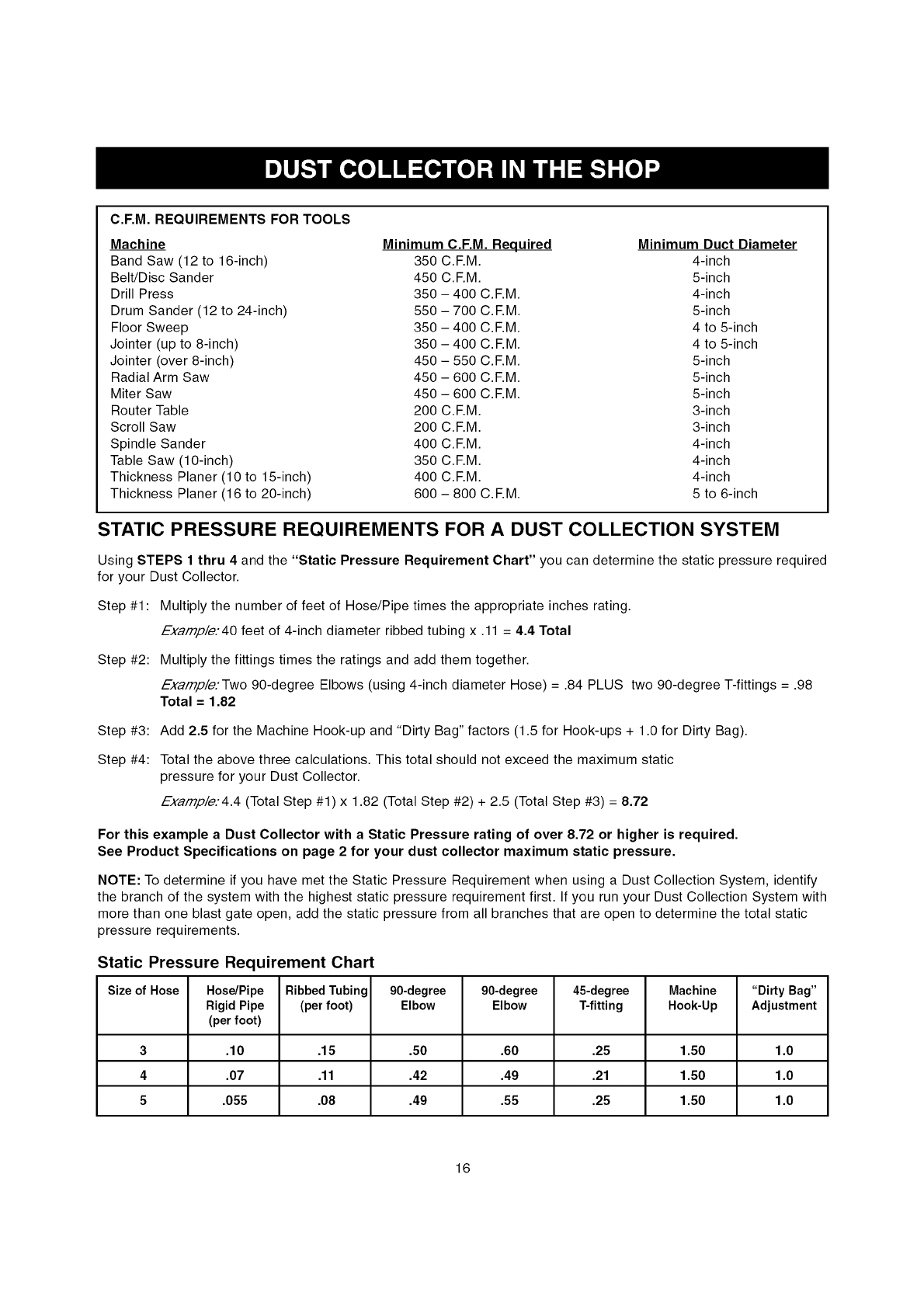
C.F.M. REQUIREMENTS FOR TOOLS
Machine Minimum C.F.M. Required Minimum Duct Diameter
Band Saw (12 to 16-inch) 350 C.F.M. 4-inch
Belt/Disc Sander 450 C.EM. 5-inch
Drill Press 350 - 400 C.EM. 4-inch
Drum Sander (12 to 24-inch) 550 - 700 C.EM. 5-inch
Floor Sweep 350 - 400 C.EM. 4 to 5-inch
Jointer (up to 8-inch) 350 - 400 C.EM. 4 to 5-inch
Jointer (over 8-inch) 450 - 550 C.EM. 5-inch
Radial Arm Saw 450 - 600 C.EM. 5-inch
Miter Saw 450 - 600 C.EM. 5-inch
Router Table 200 C.EM. 3-inch
Scroll Saw 200 C.EM. 3-inch
Spindle Sander 400 C.EM. 4-inch
Table Saw (10-inch) 350 C.EM. 4-inch
Thickness Planer (10 to 15-inch) 400 C.EM. 4-inch
Thickness Planer (16 to 20-inch) 600 - 800 C.EM. 5 to 6-inch
STATIC PRESSURE REQUIREMENTS FOR A DUST COLLECTION SYSTEM
Using STEPS 1 thru 4 and the "Static Pressure Requirement Chart" you can determine the static pressure required
for your Dust Collector.
Step #1 : Multiply the number of feet of Hose/Pipe times the appropriate inches rating.
Examp/e.'40 feet of 4-inch diameter ribbed tubing x .11 = 4.4 Total
Step #2: Multiply the fittings times the ratings and add them together.
Examp/e.'Two 90-degree Elbows (using 4-inch diameter Hose) = .84 PLUS two 90-degree T-fittings = .98
Total = 1.82
Step #3:
Step #4:
Add 2.5 for the Machine Hook-up and "Dirty Bag" factors (1.5 for Hook-ups + 1.0 for Dirty Bag).
Total the above three calculations. This total should not exceed the maximum static
pressure for your Dust Collector.
Examp/e.'4.4 (Total Step #1) x 1.82 (Total Step #2) + 2.5 (Total Step #3) = 8.72
For this example a Dust Collector with a Static Pressure rating of over 8.72 or higher is required.
See Product Specifications on page 2 for your dust collector maximum static pressure.
NOTE: To determine if you have met the Static Pressure Requirement when using a Dust Collection System, identify
the branch of the system with the highest static pressure requirement first. If you run your Dust Collection System with
more than one blast gate open, add the static pressure from all branches that are open to determine the total static
pressure requirements.
Static Pressure Requirement Chart
Size of Hose Hose/Pipe RibbedTubing 90-degree 90-degree 45-degree Machine "Dirty Bag"
Rigid Pipe (per foot) Elbow Elbow T-fitting Hook-Up Adjustment
(perfoot)
3 .10 .15 .50 .60 .25 1.50 1.0
4 .07 .11 .42 .49 .21 1.50 1.0
5 .055 .08 .49 .55 .25 1.50 1.0
16
Turn the power switch "OFF" and unplug the power
cord from its power source prior to any maintenance.
Always make sure that the intake port caps covers the
intake port when a hose is not connected to the dust
collector.
air may damage insulation. The operator should always
wear eye protection when using compressed air.
Do not allow chips and dust to accumulate under dust
collector. Keep area clean and in safe order.
LUBRICATION
The Dust Collector has sealed lubricated bearings in
the motor housing that does not require any additional
lubrication from the operator.
CLEANING
With the Dust Collector unplugged, blow off motor with
low pressure air to remove dust or dirt. Air pressure
above 50 P. S. I. should not be used as high-pressured
CAUTION: DO NOT USE FLAMMABLE MATERIALS
to clean Dust Collector.
Repairs to the Dust Collector should be performed by
trained personnel only. Contact your nearest Sears
Service Center for authorized service. Unauthorized
repairs or replacement with non-factory parts could
cause serious injury to the operator and damage to the
Dust Collector.
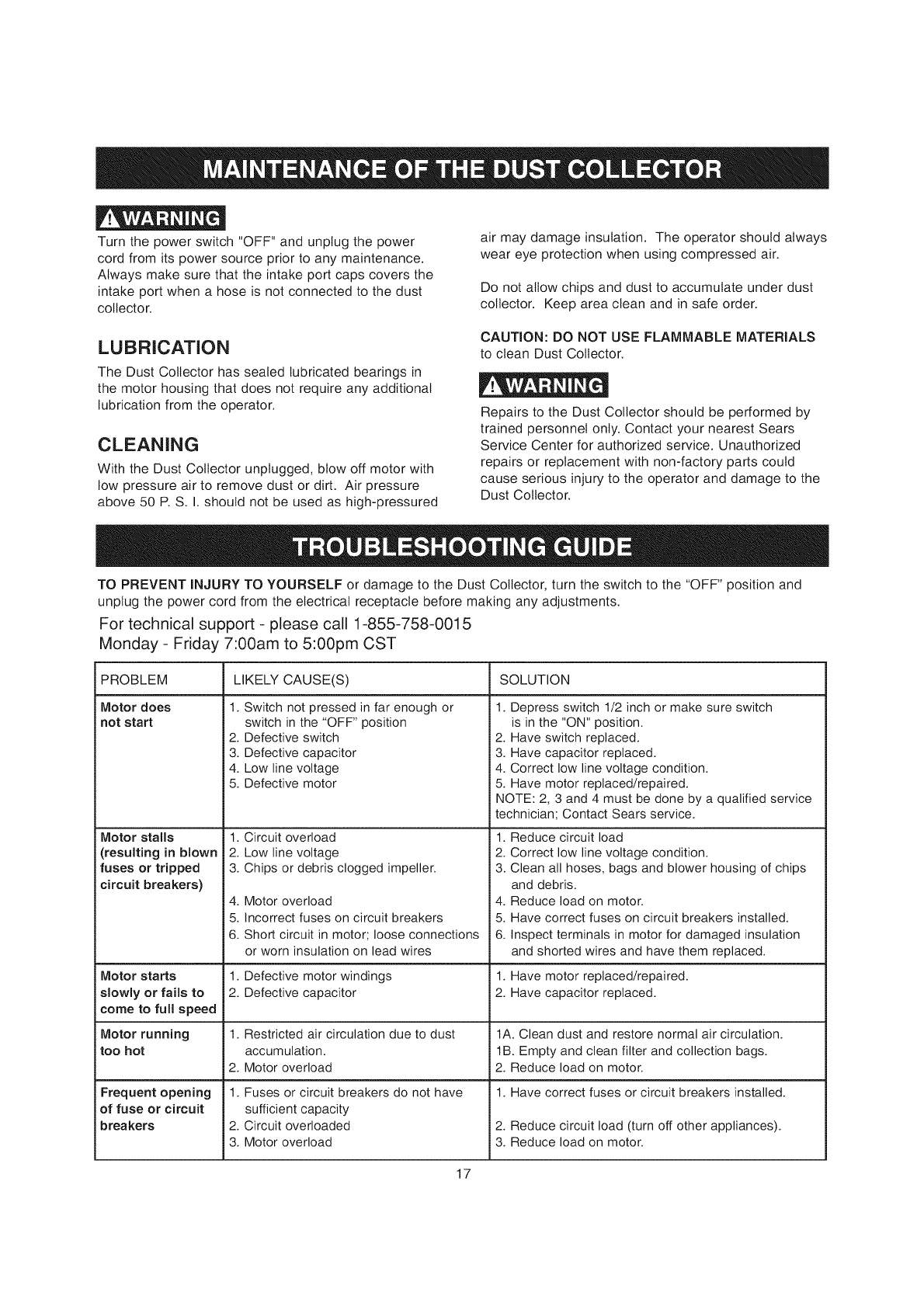
TO PREVENT iNJURY TO YOURSELF or damage to the Dust Collector, turn the switch to the "OFF" position and
unplug the power cord from the electrical receptacle before making any adjustments.
For technical support - please call 1-855-758-0015
Monday - Friday 7:00am to 5:00pm CST
PROBLEM
Motor does
not start
Motor stalls
(resulting in blown
fuses or tripped
circuit breakers)
Motor starts
slowly or fails to
come to full speed
Motor running
Itoo hot
Frequent opening
l of fuse or circuit
breakers
LIKELY CAUSE(S) SOLUTION
1. Switch not pressed in far enough or
switch in the "OFF" position
i2. Defective switch
3. Defective capacitor
14. Low line voltage
i5. Defective motor
1.
2.
i3.
4,
i5.
6.
1.
2.
1,
12.
1.
2.
i3.
1. Depress switch 1/2 inch or make sure switch
is in the "ON" position.
2. Have switch replaced.
3. Have capacitor replaced.
4. Correct low line voltage condition.
5. Have motor replaced/repaired.
NOTE: 2, 3 and 4 must be done by a qualified service
technician; Contact Sears service.
Circuit overload 1.
Low line voltage 2.
Chips or debris clogged impeller. 3.
Motor overload 4.
Incorrect fuses on circuit breakers 5.
Short circuit in motor; loose connections 6.
or worn insulation on lead wires
Defective motor windings 1.
Defective capacitor 2.
Restricted air circulation due to dust
accumulation.
Motor overload
Fuses or circuit breakers do not have
sufficient capacity
Circuit overloaded
Motor overload
Reduce circuit load
Correct low line voltage condition.
Clean all hoses, bags and blower housing of chips
and debris.
Reduce load on motor.
Have correct fuses on circuit breakers installed.
Inspect terminals in motor for damaged insulation
and shorted wires and have them replaced.
Have motor replaced/repaired.
Have capacitor replaced.
1A. Clean dust and restore normal air circulation.
lB. Empty and clean filter and collection bags.
2. Reduce load on motor.
1. Have correct fuses or circuit breakers installed.
2. Reduce circuit load (turn off other appliances).
3. Reduce load on motor.
17
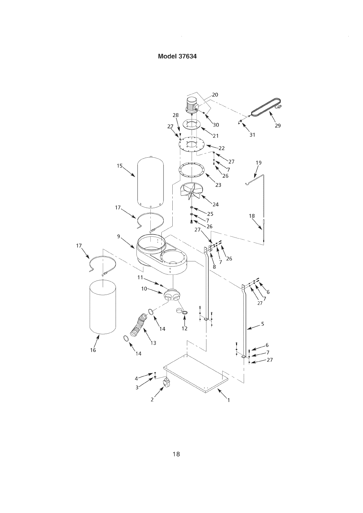
Model 37634
17\
/
16
8
27
5
18
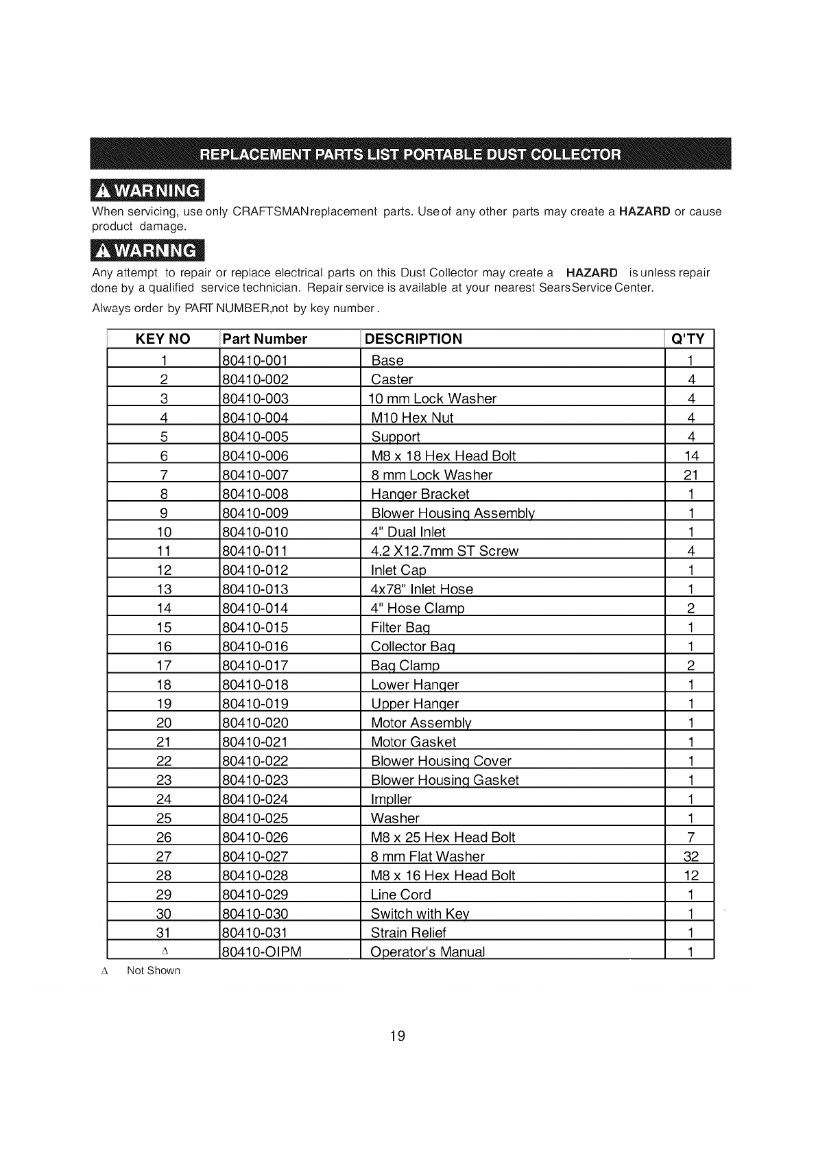
When servicing, use only CRAFTSMANreplacement parts. Useof any other parts may create a HAZARD or cause
product damage.
Any attempt to repair or replace electrical parts on this Dust Collector may create a HAZARD is unless repair
done by a qualified service technician. Repairservice is available at your nearest SearsService Center.
Always order by PARTNUMBER,not by key number.
KEY NO
1
2
3
4
5
6
7
8
9
10
11
12
13
14
15
16
17
18
19
2O
21
22
23
24
25
26
27
28
29
3O
31
A
Not Shown
Part Number
80410-001
80410-002
80410-003
80410-004
80410-005
80410-006
80410-007
80410-008
80410-009
80410-010
80410-011
80410-012
80410-013
80410-014
80410-015
80410-016
80410-017
80410-018
80410-019
80410-020
80410-021
80410-022
80410-023
80410-024
80410-025
80410-026
80410- 027
DESCRIPTION
Base 1
Caster 4
10 mm Lock Washer 4
M10 Hex Nut 4
Support 4
M8 x 18 Hex Head Bolt 14
8 mm Lock Washer 21
Hanqer Bracket 1
Blower Housinq Assembly 1
4" Dual Inlet 1
4.2 X12.7mm ST Screw 4
Inlet Cap 1
4x78" Inlet Hose 1
4" Hose Clamp 2
Filter Baq 1
Collector Ba,q 1
Ba,q Clamp 2
Lower Han,qer 1
Upper Han,qer 1
Motor Assembly 1
Motor Gasket 1
Blower Housin,q Cover 1
Blower Housin,q Gasket 1
Impller 1
Washer 1
M8 x 25 Hex Head Bolt 7
8 mm Flat Washer 32
80410-028
80410-029
80410-030
80410-031
80410-OIPM
M8 x 16 Hex Head Bolt 12
Line Cord 1
Switch with Key 1
Strain Relief 1
Operator's Manual 1
19

•NOTES •
20
Manual del Propietario
CRRFrSMRN
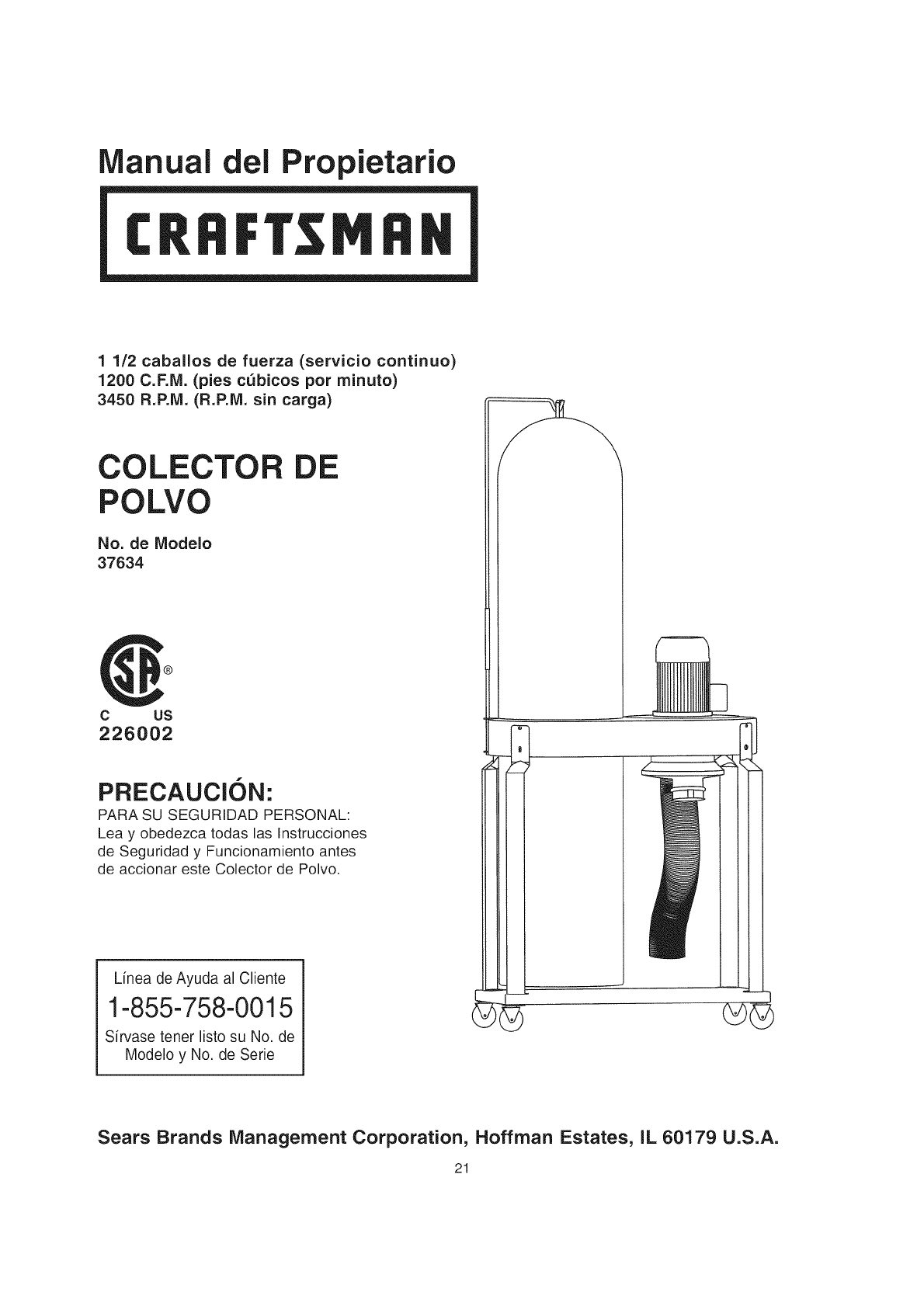
1 1/2 caballos de fuerza (servicio continuo)
1200 C.F.IVi. (pies c_bicos por minuto)
3450 R.P.IVl. (R.P.IVl. sin carga)
COLECTOR
POLVO
No. de Modelo
37634
®
DE
c us
226002
!
PRECAUCION:
PARA SU SEGURIDAD PERSONAL:
Lea y obedezca todas las Instrucciones
de Seguridad y Funcionamiento antes
de accionar este Colector de Polvo.
Linea de Ayuda al Cliente
1-855-758-0015
Sfrvase tener listo su No. de
Modelo y No. de Serie
Sears Brands Management Corporation, Hoffman Estates, IL 60179 U.S.A.
21
SECCION PAGINA
Garantia ......................................................................................................................................................................... 22
Especificaciones del Producto ................................................................................................................................... :22
Instrucciones de Seguridad ........................................................................................................................................ :23
Instrucciones de Conexi6n a Tierra ........................................................................................................................... :25
Instrucciones de Seguridad Especfficas para los Colectores de Potvo ................................................................ :26
Accesorios y Aditamentos .......................................................................................................................................... 27
Contenido de BaCaja .................................................................................................................................................... 28
Conozca su Colector de Polvo .................................................................................................................................... 30
Instrucciones de IVlontaje ............................................................................................................................................. 31
Accionando el Colector de Polvo ................................................................................................................................ 33
Colector de Polvo en el Taller ...................................................................................................................................... 35
Bt]antenimiento .............................................................................................................................................................. ,37
Guia de Localizaci6n de Averias ................................................................................................................................ ,37
Informaci6n de Servicio .......................................................................................................................... Contraportada
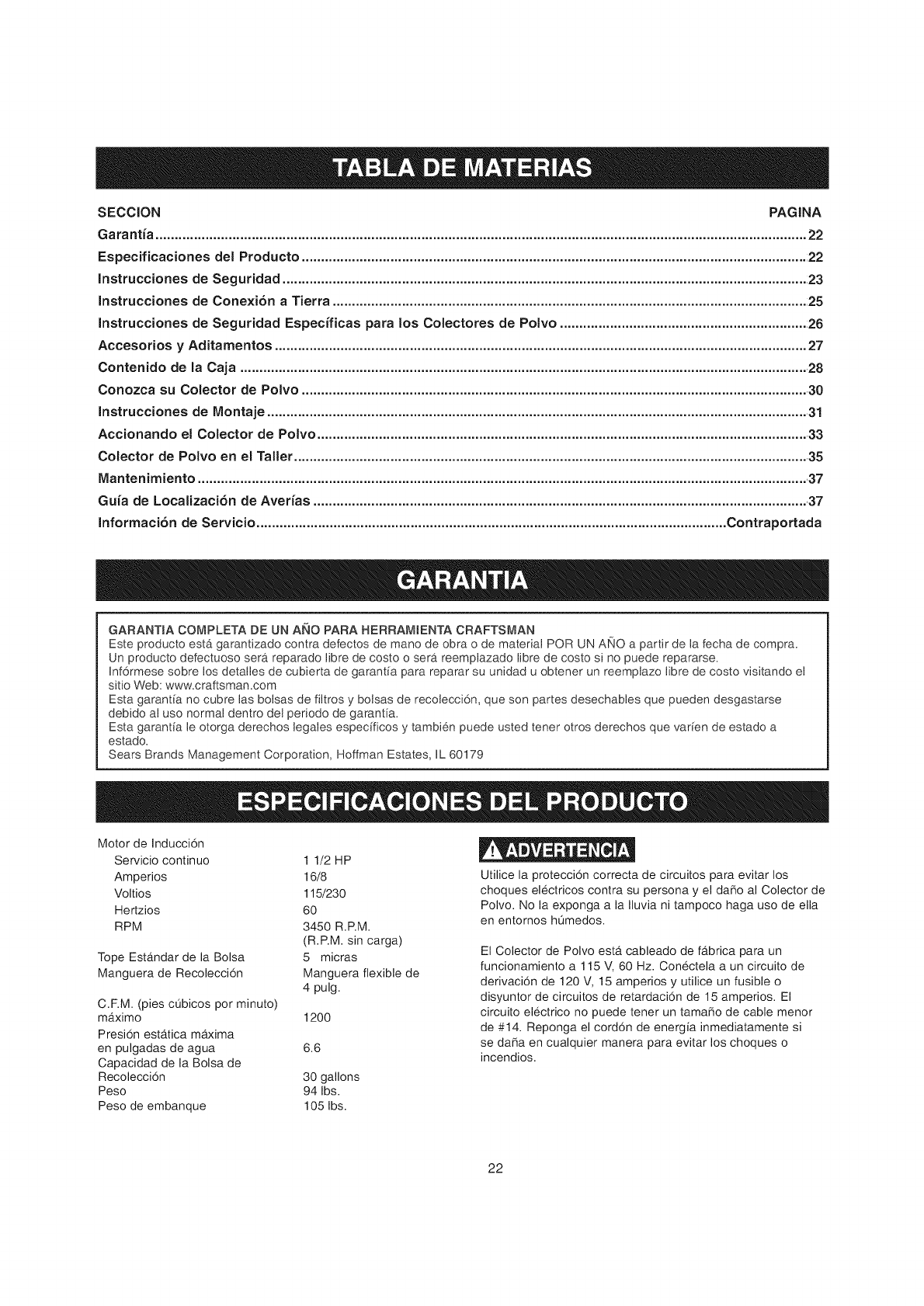
GARANTSA COMPLETA DE UN ANO PARA HERRAMIENTA CRAFTSMAN
Este producto esta garantizado contra defectos de mano de obra o de material POR UN ANO a partir de la fecha de compra_
Un producto defectuoso sera reparado libre de costo o sera reemplazado libre de costo si no puede repararse.
Inf6rmese sobre los detalles de cubierta de garantia para reparar su unidad u obtener un reemplazo libre de costo visitando el
sitio Web: www.craflsman.com
Esta garantia no cubre las bolsas de fiJtros y bolsas de recolecci6n, que son partes desechables que pueden desgastarse
debido al uso normal dentro de1 periodo de garantia.
Esta garantia le otorga derechos legales especificos y tambien puede usted tener otros derechos que varien de estado a
estado.
Sears Brands Management Corporation, Hoffman Estates, IL 60179
Motor de Inducci6n
Servicio continuo
Amperios
Voltios
Hertzios
RPM
Tope EstAndar de la Bolsa
Manguera de Recoleccion
1 1/2 HP
16/8
115/230
60
3450 R.RM.
(R.RM. sin carga)
5 micras
Manguera flexible de
4 pulg.
C.RM. (pies cObicos por minuto)
mAximo 1200
Presion estAtica maxima
en pulgadas de agua 6.6
Capacidad de la Bolsa de
Recoleccion 30 gallons
Peso 94 Ibs.
Peso de embanque 105 Ibs.
Utilice la proteccion correcta de circuitos para evitar los
choques electricos contra su persona y el daSo al Colector de
Polvo. No la exponga a la Iluvia ni tampoco haga uso de ella
en entornos hQmedos.
El Colector de Polvo esta cableado de fabrica para un
funcionamiento a 115 V, 60 Hz. Conectela a un circuito de
derivacion de 120 V, 15 amperios y utilice un fusible o
disyuntor de circuitos de retardacion de 15 amperios. El
circuito electrico no puede tener un tamaSo de cable menor
de #14. Reponga el cordon de energia inmediatamente si
se daSa en cualquier manera para evitar los choques o
incendios.
22

INSTRUCCIONES GENERALES DE
SEGURIDAD
El funcionamiento de un Colector de Polvo puede resultar
peligroso si se hace caso omiso de la seguridad y del sentido
comt_n, El operario debe estar familiarizado con el fun-
cionamiento de la herramienta, Lea este manual para enten-
der su Colector de Polvo, NO OPERE este Colector de Polvo
si no entiende cabalmente las limitaciones de dicha her-
ramienta, NO realice modificaciones de cualquier tipo a este
Colector de Polvo, RECUERDE: Usted es responsable de su
propia seguridad,
ANTES DE UTILIZAR EL COLECTOR DE
POLVO
_'!V-,I m_vj=l-'t/=1_[_ P_,l
Para evitar las heridas graves y el daSo a la herramienta, lea
y obedezca todas las instrucciones de Seguridad y Operaci6n
antes de operar el Colector de Polvo,
_'!V-,I m_vj=l-'t/=1_[_ P_,l
1, Parte del polvo que se crea usando las herramientas
electricas contiene productos quimicos que el estado de
California reconoce como causantes de cancer, defectos
de nacimiento, o daSos en el sistema reproductivo,
Algunos ejemplos de estos productos quimicos son:
• El plomo de pinturas con base de plomo
• El Silic6n cristalino de ladrillos, cemento, y de otros
productos de albaSileria
• El arsenico y el cromo de la madera de construcci6n
quimicamente tratada
El riesgo de estas exposiciones varia, dependiendo de
cuantas veces se realiza este tipo de trabajo, Para
reducir tu exposici6n a estos productos quimicos, trabaje
en un Area bien ventilada, y trabaje con el equipo
aprobado de seguridad, tal como mascaras diseSadas
para el polvo,
2,
3,
4,
5,
6,
7,
LEA a consciencia el Manual del Propietario, APRENDA
c6mo hacer uso de esta herramienta para sus aplica-
ciones diseSadas,
CONECTE TODAS LAS HERRAMIENTAS ATIERRA,
Si la herramienta se suministra con un enchufe de 3
machos, se le debe enchufar a un tomacorrientes que
disponga de 3 contactos electricos, El tercer macho se
utiliza para conectar la herramienta a tierra y ofrecer
protecci6n contra los choques electricos accidentales,
NO quite el tercer macho, Vea las Instrucciones de
Conexi6n a Tierra,
EVlTE UN ENTORNO LABORAL PELIGROSO. NO
utilice las herramientas electricas en un entomo ht_medo,
ni tampoco las exponga a Iluvia,
NO utilice herramientas electricas si hay gases o liquidos
inflamables presentes,
MANTENGA SIEMPRE su zona de trabajo limpia, bien
alumbrada y organizada, NO TRABAJE en un entorno
con superficies de piso resbalosas a consecuencia de los
escombros, la grasa y la cera,
MANTENGA ALEJADOS A LOS NINOS Y VlSlTANTES.
NO permita que haya personas en la zona inmediata de
trabajo, particularmente cuando la herramienta electrica
se encuentre en funcionamiento,
23
8,
9,
10,
NO FUERCE LA HERRAMIENTA a realizar operaciones
para las cuales no rue diseSada, Realizara una labor mas
segura y de mejor calidad si se le utiliza solamente para
realizar operaciones para las cuales rue diseSada,
UTILICE VESTIMENTA APROPIADA. NO vista ropa
holgada, guantes, corbatas ni articulos de joyeria, Estos
articulos pueden quedar atrapados en la maquina
durante las operaciones y tirar del operario, atrayendolo
hacia las piezas en movimiento, El usuario debe Ilevar
una cubierta protectora sobre el cabello, si tiene
cabellera larga, para impedir el contacto con cualquier
pieza en movimiento,
UTILICE PROTECClON OCULAR SlEMPRE, Cualquier
herramienta mecAnica puede expulsar escombros hacia
los ojos durante las operaciones, causando daSo ocular
grave y permanente, Los anteojos de uso cotidiano NO
son gafas de seguridad, Utilice gafas de seguridad
SlEMPRE (que cumplan con la normativa Z87,1 de ANSI)
cuando vaya a operar herramientas mecAnicas, Las
gafas de seguridad estAn disponibles en las tiendas de
Ventas al Detal de Sears,
11,
12,
13,
14,
15,
16,
17,
18,
19,
20,
UTILICE PROTECCION AUDITIVA SIEMPRE. El
algod6n por si solo no constituye un dispositivo de
protecci6n aceptable, El equipo auditivo debe cumplir
con las normativas $3,19 de ANSI,
SIEMPRE DESENCHUFE LA HERRAMIENTA DEL
TOMACORRIENTES cuando vaya a realizar ajustes,
cambiar piezas o realizar cualquier clase de
mantenimiento,
MANTENGA LOS ESCUDOS DE PROTECClON EN SU
SlTIO YEN BUEN ESTADO DE FUNClONAMIENTO,
EVITE EL ARRANQUE ACCIDENTAL, Asegt_rese de
que el interruptor de potencia se encuentre en la posici6n
de "APAGADO" antes de enchufar el cord6n de potencia
en el tomacorrientes,
QUITE TODAS LAS HERRAMIENTAS DE MANTENI-
MIENTO de la zona inmediata antes de encender la
herramienta,
SOLO UTILICE ACCESORIOS RECOMENDADOS, El
uso de accesorios incorrectos o poco apropiados puede
ocasionar heridas graves al operario y ocasionar daSo a
la herramienta, Si tiene dudas, consulte el manual de
instrucciones que se adjunta con el accesorio especifico,
JAMAS DEJE UNA HERRAMIENTA EN FUNCIONA-
MIENTO SIN ATENDER, Conmute el interruptor de
energia a la posici6n de apagado, NO abandone la
herra-mienta hasta que esta se haya detenido por com-
pleto,
NO SE PARE SOBRE LA HERRAMIENTA, Pueden pro-
ducirse heridas graves si la herramienta se vuelca o si
usted hace contacto con la herramienta accidentalmente,
NO ALMACENE nada por encima ni cerca de la maquina
en donde alguien pueda intentar pararse en la herra-
mienta para alcanzarlo,
MANTENGA SU EQUlLIBRIO. NO se extienda sobre la
herramienta, Haga uso de zapatos con suela de caucho
resistente al aceite, Mantenga el piso libre de escombros,
grasa o cera,
21,MANTENGA SUS HERRAMIENTAS CUIDADOSA-
MENTE. Mantenga sus herramientas limpias yen buen
estado, Mantenga afiladas todas las hojas y brocas,
22, REVISE SI HAY PIEZAS DANADAS ANTES DE CADA
USO DE LA HERRAMIENTA, Revise todos los protec-
tores cuidadosamente para comprobar que funcionan
correctamente y que no estan daSados, y que realizan
sus funciones diseSadas correctamente, Revise el
alineamiento, la fijaci6n o la ruptura de las piezas en
movimiento, Cualquier protector u otra pieza que se
encuentre daSada debe repararse o reemplazarse
inmediatamente,
23, HAGA SU TALLER APRUEBA DE NINOS quitando las
Naves del interruptor, desenchufando las herramientas de
los tomacorrientes, y mediante el uso de candados,
24, NO OPERE LA HERRAMIENTA BAJO LA INFLUENClA
DE LAS DROGAS O DEL ALCOHOL,
25, AFIANCE TODO EL MATERIAL, Siempre que resulte
posible, utilice abrazaderas o plantillas para asegurar el
material, Esto ofrece mayor seguridad que intentar
sujetar el material con sus propias manos,
26, MANTENGASE ALERTA, ESTE CONSCIENTE DE LO
QUE HACE, Y UTILICE SENTIDO COMUN CUANDO
VAYA A OPERAR UNA HERRAMIENTA ELECTRICA.
NO UTILICE LA HERRAMIENTA Sl ESTA CANSADO O
BAJO LA INFLUENClA DE DROGAS, ALCOHOL O
MEDICAMENTOS, Un momento de descuido durante el
uso de herramientas electricas puede resultar en
lesiones personales graves,
27, UTILICE SIEMPRE UNA CARETA CONTRA EL POLVO
PARA EVlTAR ASPIRAR POLVOS PELIGROSOS O
PARTICULAS EN EL AIRE, incluyendo polvo e madera,
polvo de since cristalino y polvo de asbesto, Dirija las
particulas en direcci6n opuesta al rostro y el cuerpo,
Opere la herramienta siempre en una zona bien ventilada
y proporcione la remoci6n apropiada del polvo, Utilice un
sistema de recolecci6n de polvo siempre que sea posi-
ble, La exposici6n al polvo puede ocasionar daSos respi-
ratorios graves y permanentes u otras heridas, incluyen-
do silicosis (una enfermedad pulmonar grave), cancer y
la muerte, Evite aspirar el polvo y evite el contacto pro-
Iongado con el polvo, El permitir la entrada del polvo en
su boca u ojos, o dejar que permanezca sobre su piel,
puede promover al absorci6n de material daSino, Utilice
protecci6n respiratoria de ajuste correcto, aprobada por
NIOSH/OSHA y apropiada para la exposici6n al polvo, y
lave las zonas expuestas con jab6n y agua,
28, UTILICE UNA EXTENSION ELECTRICA CORRECTA Y
EN BUEN ESTADO, Cuando vaya a hacer uso de una
extensi6n electrica, asegL_rese de utilizar una que sea Io
suficientemente fuerte como para transportar la corriente
a ser utilizada por su herramienta, Tenga la bondad de
referirse al cuadro de calibres recomendados (AWG)
para las extensiones electricas para el dimensionamiento
correcto de la extensi6n electrica, Si tiene dudas, utilice
la siguiente extensi6n de mayor calibre,
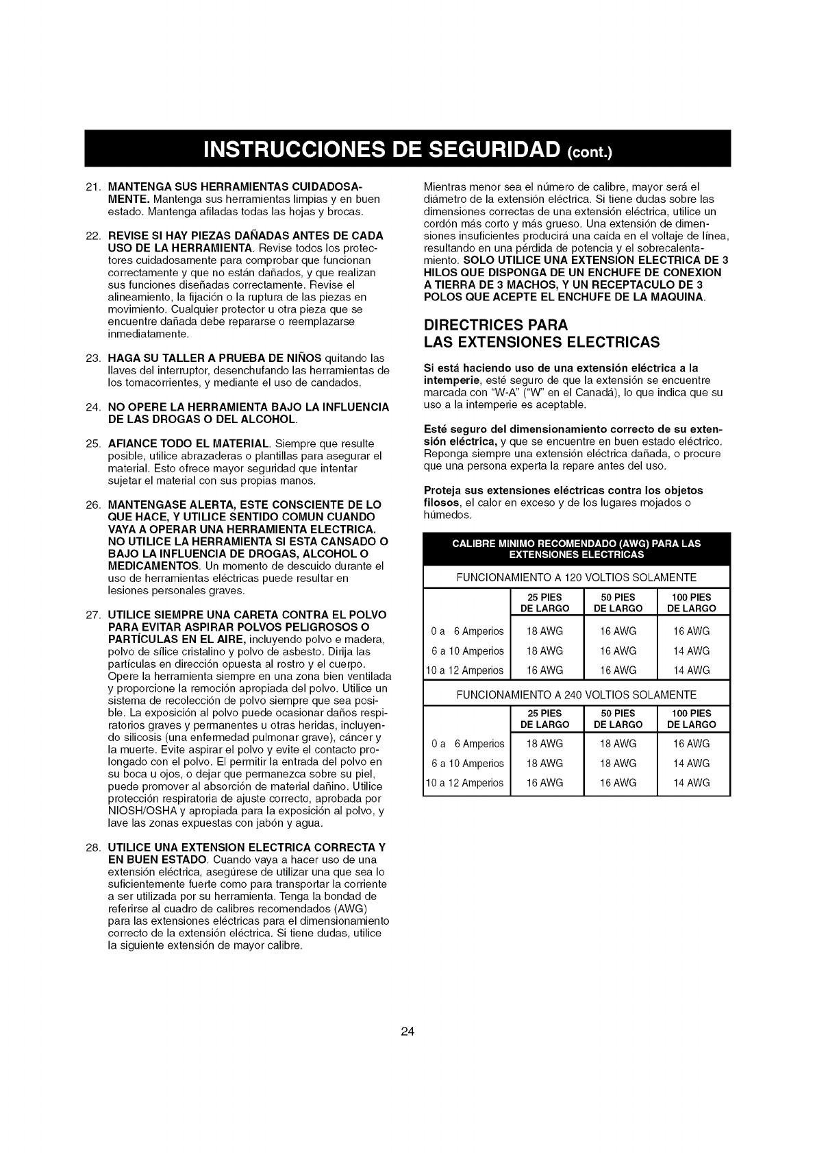
Mientras menor sea el numero de calibre, mayor sera el
diametro de la extensi6n electrica, Si tiene dudas sobre las
dimensiones correctas de una extensi6n electrica, utilice un
cord6n mas corto y mas grueso, Una extensi6n de dimen-
siones insuficientes producira una caida en el voltaje de linea,
resultando en una p@dida de potencia y el sobrecalenta-
miento, SOLO UTILICE UNA EXTENSION ELECTRICA DE 3
HILOS QUE DISPONGA DE UN ENCHUFE DE CONEXlON
A TIERRA DE 3 MACHOS, Y UN RECEPTACULO DE 3
POLOS QUE ACEPTE EL ENCHUFE DE LA MAQUlNA,
DIRECTRICES PARA
LAS EXTENSlONES ELECTRICAS
Si est_ haciendo uso de una extensi6n el_ctrica a la
intemperie, este seguro de que la extensi6n se encuentre
marcada con "W-A" ("W" en el Canada), Io que indica que su
uso a la intemperie es aceptable,
Est_ seguro del dimensionamiento correcto de su exten-
si6n el_ctrica, y que se encuentre en buen estado electrico,
Reponga siempre una extensi6n electrica daSada, o procure
que una persona experta la repare antes del uso,
Proteja sus extensiones el_ctricas contra los objetos
filosos, el calor en exceso y de los lugares mojados o
ht_medos,
FUNCIONAMIENTO A 120 VOLTIOS SOLAMENTE
25 PIES 50 PIES 100 PIES
DE LARGO DE LARGO DE LARGO
0 a 6 Amperios 18 AWG 16 AWG 16 AWG
6 a 10 Amperios 18 AWG 16 AWG 14 AWG
10a 12 Amperios 16AWG 16AWG 14AWG
FUNCIONAMIENTO A 240 VOLTIOS SOLAMENTE
0 a 6Amperios
6 a 10 Amperios
10 a 12 Amperios
25 PIES
DE LARGO
18 AWG
18 AWG
16 AWG
50 PIES
DE LARGO
18 AWG
18 AWG
16 AWG
100 PIES
DE LARGO
16 AWG
14 AWG
14 AWG
24
pP'!v-,Im_vA_l-'tul_1_[o,]p'_,l
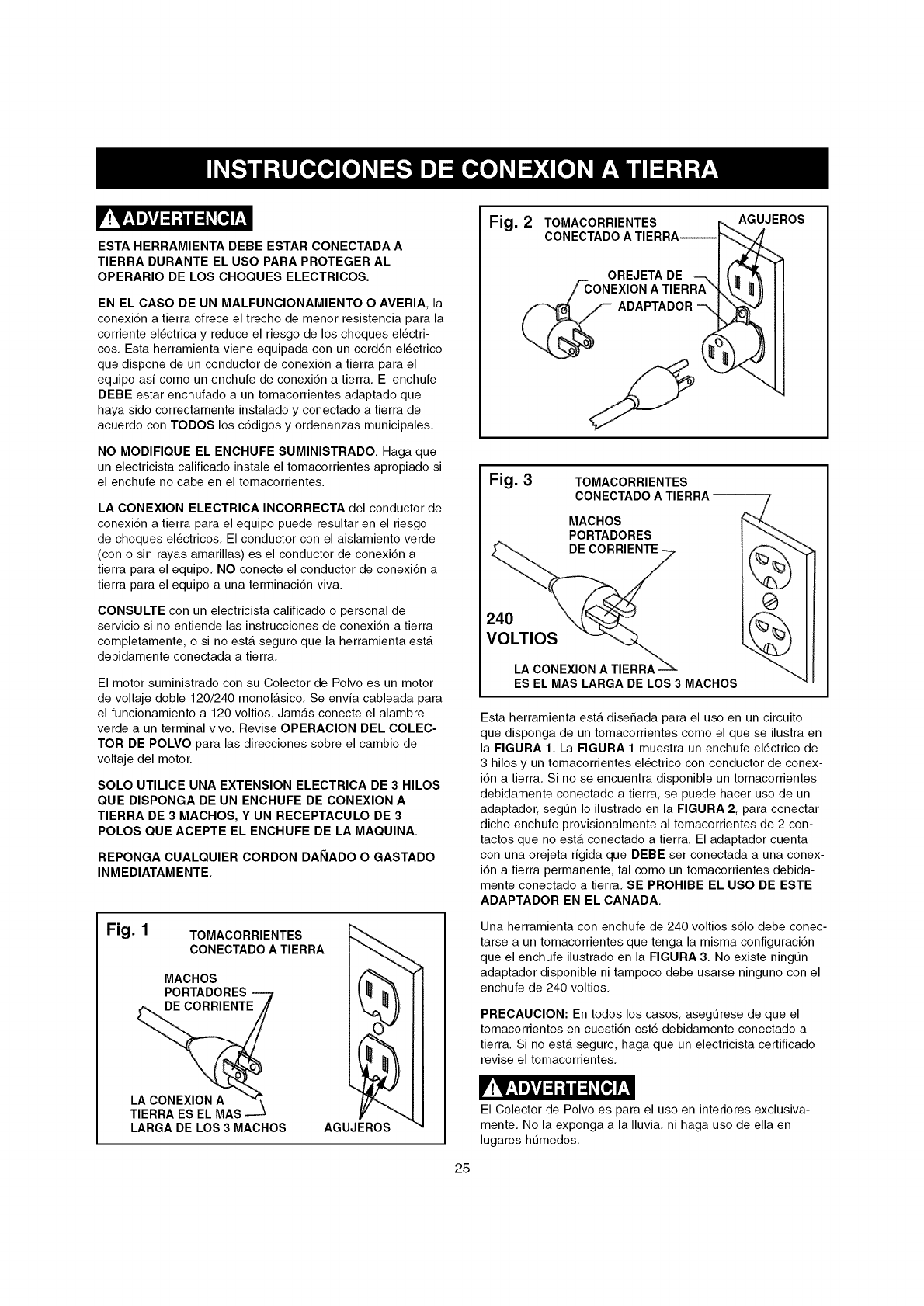
ESTA HERRAMIENTA DEBE ESTAR CONECTADA A
TIERRA DURANTE EL USO PARA PROTEGER AL
OPERARIO DE LOS CHOQUES ELECTRICOS.
EN EL CASO DE UN MALFUNCIONAMIENTO O AVERIA, la
conexi6n a tierra ofrece el trecho de menor resistencia para la
corriente electrica y reduce el riesgo de los choques electri-
cos, Esta herramienta viene equipada con un cord6n electrico
que dispone de un conductor de conexi6n a tierra para el
equipo asi como un enchufe de conexi6n a tierra, El enchufe
DEBE estar enchufado a un tomacorrientes adaptado que
haya sido correctamente instalado y conectado a tierra de
acuerdo con TODOS los c6digos y ordenanzas municipales,
NO MODIFIQUE EL ENCHUFE SUMINISTRADO, Haga que
un electricista calificado instale el tomacorrientes apropiado si
el enchufe no cabe en el tomacorrientes,
LA CONEXION ELECTRICA INCORRECTA del conductor de
conexi6n a tierra para el equipo puede resultar en el riesgo
de choques electricos, El conductor con el aislamiento verde
(con o sin rayas amarillas) es el conductor de conexi6n a
tierra para el equipo, NO conecte el conductor de conexi6n a
tierra para el equipo a una terminaci6n viva,
CONSULTE con un electricista calificado o personal de
servicio si no entiende las instrucciones de conexi6n a tierra
completamente, o si no esta seguro que la herramienta esta
debidamente conectada a tierra,
El motor suministrado con su Colector de Polvo es un motor
de voltaje doble 120/240 monofasico, Se envia cableada para
el funcionamiento a 120 voltios, Jamas conecte el alambre
verde a un terminal vivo, Revise OPERAClON DEL COLEC-
TOR DE POLVO para las direcciones sobre el cambio de
voltaje del motor,
SOLO UTILICE UNA EXTENSION ELECTRICA DE 3 HILOS
QUE DISPONGA DE UN ENCHUFE DE CONEXlON A
TIERRA DE 3 MACHOS, Y UN RECEPTACULO DE 3
POLOS QUE ACEPTE EL ENCHUFE DE LA MAQUlNA,
REPONGA CUALQUlER CORDON DANADO O GASTADO
INMEDIATAMENTE,
Fig. 1 TOMACORRIENTES _-
co..cT.OO.T,...,j
MACHOS I(_m"_-_
PORTADORES_ J _ m'_ i i
LA CONEXION A"_ 117---. I I
TIERRA ES EL MAS _ V "_',,.l J
LARGA DE LOS 3 MACHOS AGUJEROS _4
Fig. 2 TOMACORRIENTES AGUJEROS
CONECTADO ATIERRA
OREJETA DE
A
ADAPTADOR
Fig. 3 TOMACORRIENTES
CONECTADO A
MACHOS
PORTADORES
DE
25
240
VOLTIOS
LA CONEXIONATIERRA
ES EL MASLARGADE LOS 3 MACHOS
Esta herramienta esta diseSada para el uso en un circuito
que disponga de un tomacorrientes como el que se ilustra en
la FIGURA 1, La FIGURA 1 muestra un enchufe electrico de
3 hilos y un tomacorrientes electrico con conductor de conex-
i6n a tierra, Si no se encuentra disponible un tomacorrientes
debidamente conectado a tierra, se puede hacer uso de un
adaptador, segt_n Io ilustrado en la FIGURA 2, para conectar
dicho enchufe provisionalmente al tomacorrientes de 2 con-
tactos que no esta conectado a tierra, El adaptador cuenta
con una orejeta rigida que DEBE ser conectada a una conex-
i6n a tierra permanente, tal como un tomacorrientes debida-
mente conectado a tierra, SE PROHIBE EL USO DE ESTE
ADAPTADOR EN EL CANADA,
Una herramienta con enchufe de 240 voltios s61o debe conec-
tarse a un tomacorrientes que tenga la misma configuraci6n
que el enchufe ilustrado en la FIGURA 3, No existe ningL_n
adaptador disponible ni tampoco debe usarse ninguno con el
enchufe de 240 voltios,
PRECAUCION: En todos los casos, asegL_rese de que el
tomacorrientes en cuesti6n este debidamente conectado a
tierra, Si no esta seguro, haga que un electricista certificado
revise el tomacorrientes,
_!V-'Im_VA=1;t111=1#[_]Eli
El Colector de Polvo es para el uso en interiores exclusiva-
mente, No la exponga a la Iluvia, ni haga uso de ella en
lugares ht_medos,
INSTRUCCIONES DE SEGURIDAD
ESPECIFICAS PARA LOS
COLECTORES DE POLVO
El funcionamiento de cualquier colector de polvo puede tener
como consecuencia la expulsi6n de escombros hacia sus
ojos, Io que puede resultar en heridas oculares graves,
UTILICE SlEMPRE Gafas de Protecci6n (que cumplan con la
normativa Z87,1 de ANSI) cuando vaya a hacer uso del
colector de polvo, Las Gafas de Seguridad est&n disponibles
en las tiendas Sears de ventas al detal, Mantenga los pul-
gares y los dedos alejados de los puertos de admisi6n,
Las precauciones basicas deben acatarse en todo momento
cuando se utiliza un colector de polvo, Cumpla con las
instrucciones indicadas a continuaci6n para reducir el riesgo
de lesiones, choques electricos o incendios:
1, LEA y entienda el manual de instrucciones antes de
poner el colector de polvo en funcionamiento,
2, NO OPERE ESTA MAQUlNA hasta que se encuentre
ensamblada e instalada conforme alas instrucciones,
3, ASESORESE CON SU SUPERVISOR, instructor u otra
persona experta si no esta familiarizado con el uso de
esta maquina,
4, NO PERMITA el colector de polvo permanezca enchufa-
do al tomacorrientes, El colector de polvo debe desen-
chufarse del tomacorrientes cuando no se encuentre en
uso y antes de rendir servicio, cambiar bolsas, destupir y
limpiar,
5, COLOQUE SIEMPRE el interruptor de energia en
"APAGADO" antes de desenchufar el colector de polvo,
6, PARA REDUClR EL RIESGO DE CHOQUES ELECTRI-
COS, no utilice la mAquina a la intemperie, No la expon-
ga a la Iluvia, Almacenela bajo techo, Utilicela para
recoger material seco solamente,
7, OBEDEZCA todos los c6digos electricos y de seguridad,
incluyendo el C6digo Electrico Nacional (NEC) y las
Normas de Salud y Seguridad en el Trabajo (OSHA),
Todas las conexiones y cableado electrico deben ser
realizados s61o por personal competente,
8, NO maneje el enchufe ni el colector de polvo con las
manos mojadas,
9, NO UTILICE el colector de polvo para recoger liquidos
inflamables o combustibles, tales como la gasolina,
JAMAS utilice el colector de polvo cerca de cualquier
liquido inflamable o combustible,
10, UTILICE el colector de polvo para recoger materiales de
madera solamente, NO LO UTILICE para recoger viru-
tas, polvo ni piezas de metal,
11, JAMAS utilice el colector de polvos para disipar emana-
ciones o humo, JAMAS recoja cualquier cosa que este
ardiendo o emitiendo humo, asi como cigarrillos, f6sforos
o cenizas calientes,
26
12, UTILICELO s61o como se describe en este manual,
SOLO utilice los accesorios recomendados por Sears,
13, NO tire del colector de polvo mediante el cord6n de
energia, JAMAS permita que el cord6n de potencia entre
en contacto con bordes filosos, superficies calientes,
aceite o grasa,
14, NO desenchufe el colector de polvo tirando del cord6n de
energia, SIEMPRE agarre el enchufe en vez del cord6n,
15, REPONGA un cord6n daSado inmediatamente, NO util-
ice un cord6n o enchufe que esten daSados, Si el colec-
tor de polvo no funciona debidamente, o si ha sido daSa-
do, dejado a la intemperie o si ha entrado en contacto
con el agua, devuelvalo a un Centro de Servicio Sears
para recibir servicio,
16, NO utilice el colector de polvo como juguete, NO LO
UTILICE si hay niSos presentes,
17, NO inserte los dedos o cuerpos extra_os dentro del
puerto de entrada de polvo, Debe alejar el cabello, la
ropa holgada, los dedos y demas extremidades de las
aberturas y piezas en movimiento del colector de polvo,
18, NO utilice el colector de polvo sin que la bolsa guarda-
polvo se encuentre en su sitio y debidamente asegurada,
19, UTILICE SlEMPRE compuertas de seguridad para cubrir
los puertos de polvo cuando el colector de polvo no se
encuentre en uso o cuando se estA montado sobre una
superficie de apoyo para el almacenamiento,
20, La bolsa guardapolvo debe ser INSPECClONADA PERIO-
DICAMENTE por si existe cualquier cortadura, desgarre
o rompedura, JAMAS opere el colector de polvo con una
bolsa o manguera de vacio que este daSada,
21, El colector de polvo SOLO esta diseSado para el uso
domestico o el uso industrial ligero,
22, CONECTE el colector de polvo a un tomacorrientes
debidamente conectado a tierra, Vea las instrucciones de
conexi6n a tierra,
23, INFORMAClON ADIClONAL sobre el funcionamiento
seguro y correcto de este producto esta disponible de
parte del National Safety Council, 1121 Spring Lake
Drive, Itasca, IL 60143-3201 en el Manual de Prevenci6n
de Accidentes para Operaciones Industriales asi como en
las Hojas de Datos de Seguridad suministradas por el
NSC, Tenga la bondad de referirse tambien al ANSI 01,1,
Requisitos de Seguridad para la Maquinaria de
Ebanisteria de la American National Standards Institute, y
el Reglamento 1910,213 OSHA del U,S, Department of
Labor,
24, GUARDE ESTAS INSTRUCCIONES, Refierase a elias
con frecuencia y utilicelas para instruir a otros usuarios,

ACCESORIOS DISPONIBLES
Visite su Departamento de Ferreteria de Sears o consulte el
Catalogo de Herramientas Electricas y de Mano de Sears
para accesorios,
No utilice ningt_n accesorio a menos que haya leido cabal-
mente el Manual del Propietario para dicho accesorio,
_!V-'Nmlvj=1-'t111=1#[=,]!'_,11
$61o utilice accesorios recomendados para este Colector de
Polvo, El uso de otros accesorios puede ocasionar lesiones
graves y producir daSo al Colector de Polvo,
27
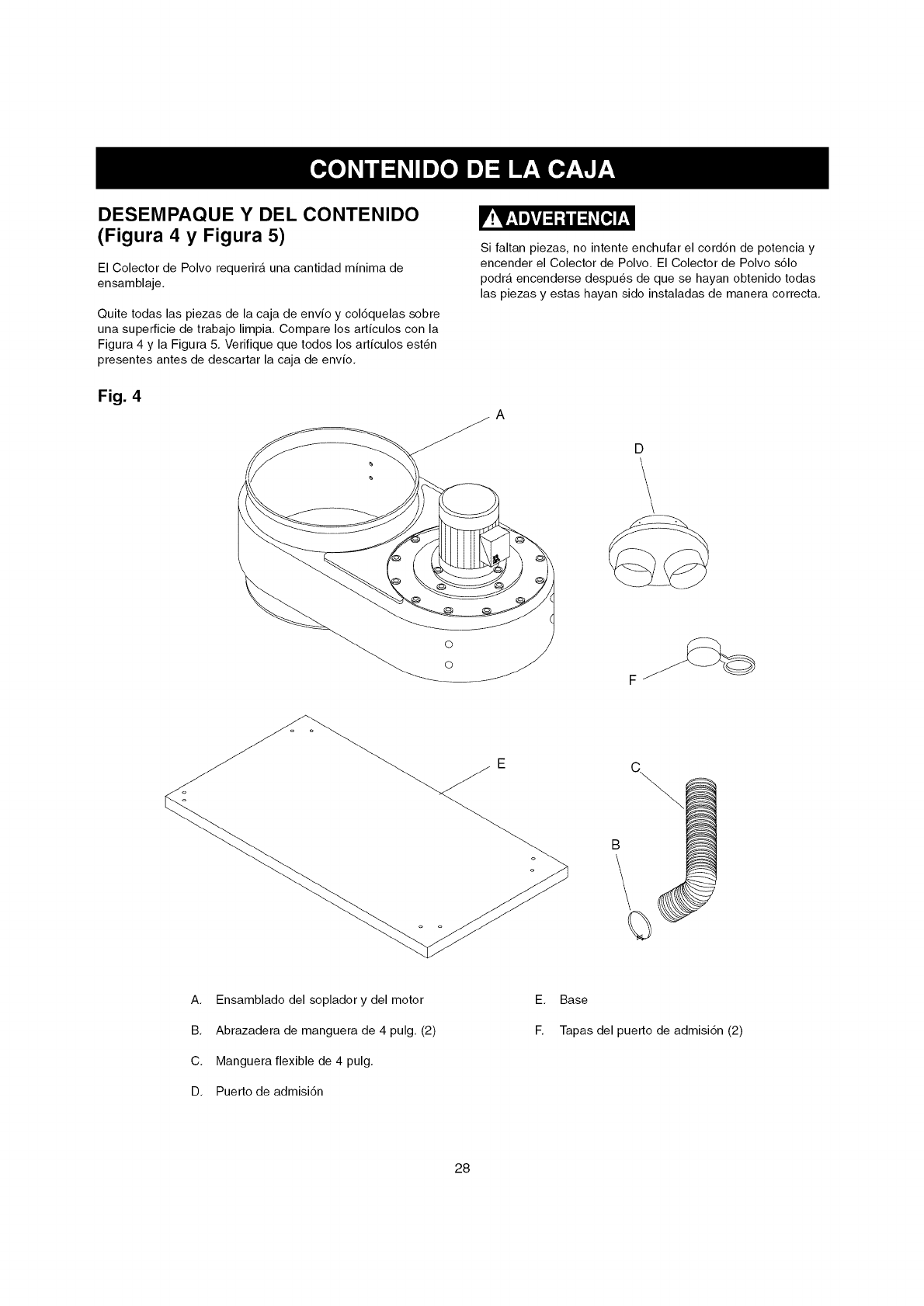
DESEMPAQUE Y DEL CONTENIDO
(Figura 4 y Figura 5)
El Colector de Polvo requerira una cantidad minima de
ensamblaje.
Quite todas las piezas de la caja de envio y col6quelas sobre
una superficie de trabajo limpia. Compare los articulos con la
Figura 4 y la Figura 5. Verifique que todos los articulos esten
presentes antes de descartar la caja de envio.
Fig. 4
Si faltan piezas, no intente enchufar el cord6n de potencia y
encender el Colector de Polvo. El Colector de Polvo s61o
podra encenderse despues de que se hayan obtenido todas
las piezas y estas hayan sido instaladas de manera correcta.
A
D
o
o
E!
A. Ensamblado del soplador y del motor
B. Abrazadera de manguera de 4 pulg. (2)
C. Manguera flexible de 4 pulg.
D. Puerto de admisi6n
E. Base
F. Tapas del puerto de admisi6n (2)
28
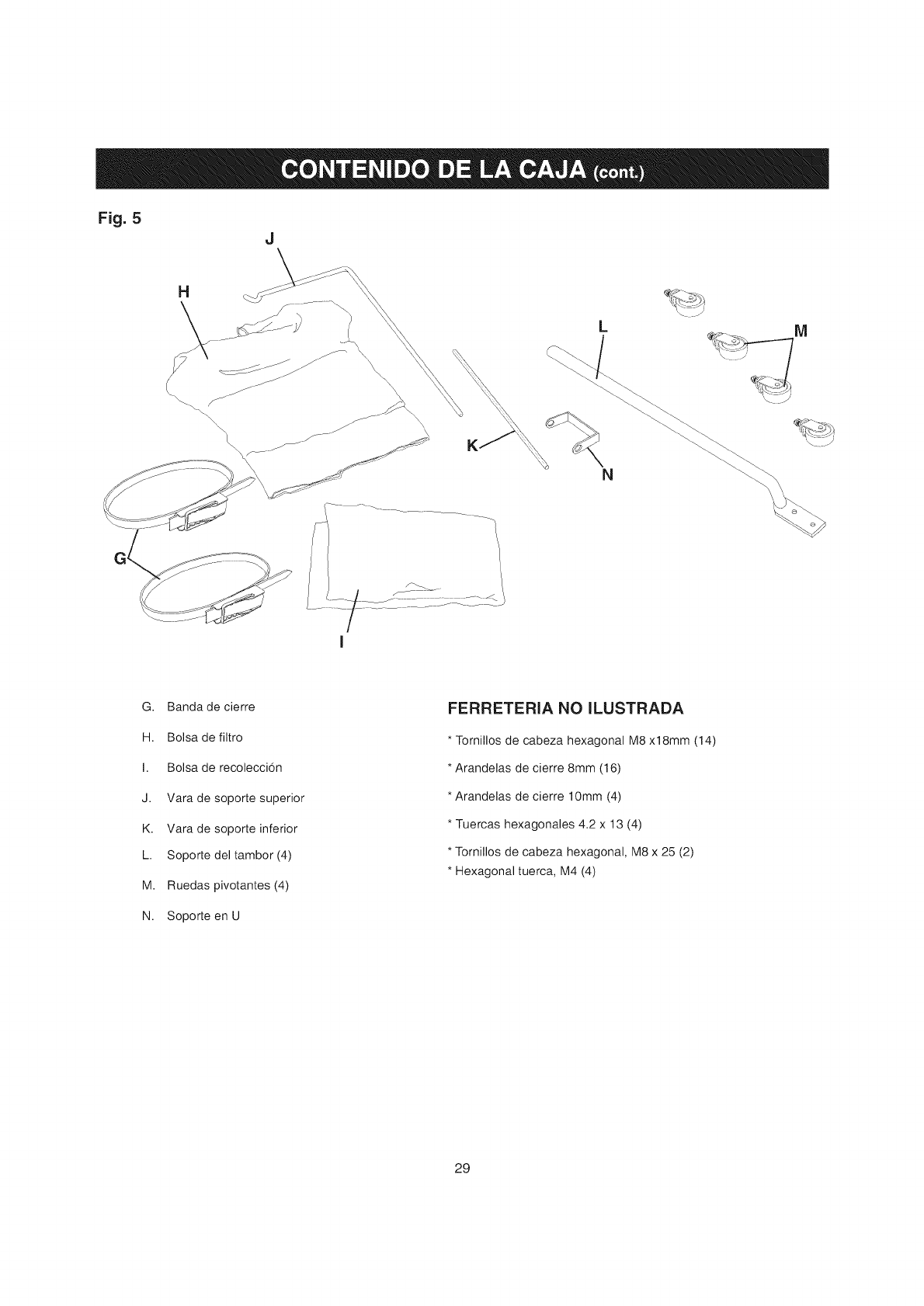
Fig. 5 J
G. Bandade cierre
H. Bolsa de filtro
I. Bolsa de recoleccion
J. Vara de soporte superior
K. Vara de soporte inferior
L. Soporte del tambor (4)
M. Ruedas pivotantes (4)
N. Soporte en U
FERRETERIA NO ILUSTRADA
* Tornillos de cabeza hexagonal M8 x18mm (14)
* Arandelas de cierre 8mm (16)
* Arandelas de cierre 10mm (4)
* Tuercas hexagonales 4.2 x 13 (4)
* Tornillos de cabeza hexagonal, M8 x 25 (2)
* Hexagonal tuerca, M4 (4)
29
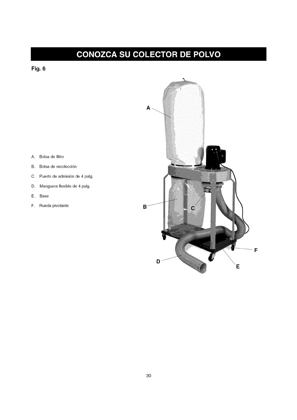
Fig. 6
A
A, Bolsa de filtro
B, Bolsa de recolecci6n
C, Puerto de admisi6n de 4 pulg,
D, Manguera flexible de 4 pulg,
E, Base
F, Rueda pivotante
DE
F
3O
2.
3.
NO inicie el ensamblaje hasta que este seguro de que la
herramienta NO ESTA enchufada.
NO ensamble el Colector de Polvo hasta que este seguro
de que el interruptor de energia se encuentre en la posi-
ci6n de "APAGADO".
Para su propia seguridad, NO CONECTE la maquina a la
fuente de energia hasta que la maquina se encuentre
completamente ensamblada y usted haya leido y
entendido cabalmente el Manuel del Propietario.
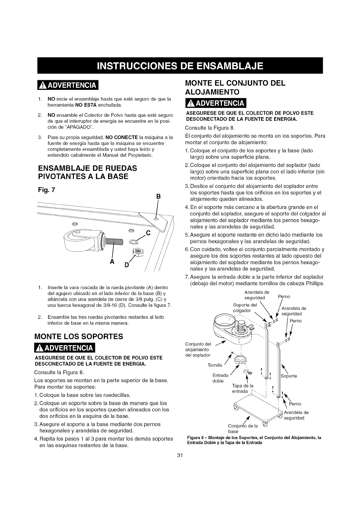
ENSAMBLAJE DE RUEDAS
PIVOTANTES A LA BASE
Fig. 7 B
@
A
Inserte la vara roscada de la rueda pivotante (A) dentro
del agujero ubicado en el lado inferior de la base (B) y
afiancela con una arandela de cierre de 3/8 pulg. (C) y
una tuerca hexagonal de 3/8-16 (D). Consulte la figura 7.
2. Ensamble las tres ruedas pivotantes restantes al lado
inferior de base en la misma manera.
MONTE LOS SOPORTES
V!V_,Im_Vj=1-'t/ __[_ r;I
ASEGURESE DE QUE EL COLECTOR DE POLVO ESTE
DESCONECTADO DE LA FUENTE DE ENERGIA.
Consulte la Figura 8.
Los soportes se montan en la parte superior de la base.
Para montar los soportes:
1. Coloque la base sobre las ruedecillas.
2. Coloque un soporte sobre la base de manera que los
dos orificios en los soportes queden alineados con los
dos orificios en la esquina de la base.
3. Asegure el soporte a la base mediante dos pernos
hexagonales y arandelas de seguridad.
4. Repita los pasos 1 al 3 para montar los dem_.s soportes
en las esquinas restantes de la base.
MONTE EL CONJUNTO DEL
ALOJAMIENTO
V!V_,Im_vj=1-'t/ =_[_ r;I
ASEGURESE DE QUE EL COLECTOR DE POLVO ESTE
DESCONECTADO DE LA FUENTE DE ENERGIA.
Consulte la Figura 8.
El conjunto del alojamiento se monta en los soportes. Para
montar el conjunto de alojamiento:
1.Coloque el conjunto de los soportes y la base (lado
largo) sobre una superficie plana.
2.Coloque el conjunto del alojamiento del soplador (lado
largo) sobre una superficie plana con el lado inferior (sin
motor) orientado hacia los soportes.
3. Deslice el conjunto del alojamiento del soplador entre
los soportes hasta que los orificios en los soportes y el
alojamiento queden alineados.
4. En el soporte m_.s cercano a la abertura grande en el
conjunto del soplador, asegure el soporte del colgador al
alojamiento del soplador mediante los pernos hexago-
nales y las arandelas de seguridad.
5.Asegure el soporte restante en dicho lado mediante los
pernos hexagonales y las arandelas de seguridad.
6.Con cuidado, voltee el conjunto parcialmente montado y
asegure los dos soportes restantes al lado opuesto del
alojamiento del soplador mediante los pernos hexago-
nales y las arandelas de seguridad.
7.Asegure la entrada doble a la parte inferior del soplador
(debajo del motor) mediante tornillos de cabeza Phillips.
Arandela de
seguridad
Soporte del
colgador ,.
Conjuntodel _
alojamiento
del soplador ./4'_
Tapade la
entrada
Perno
Arandela de
_'_ _ seguri;_d °
, Soporte
Arandela de
uridad
Conjl
base
Figura 8 - Montaje de los Soportes, el Conjunto del Alojamiento, la
Entrada Doble y laTapa de la Entrada
31
8.Acopleelaroabiertodelatapadelaentradaaunade
lasentradasdoble.
9.Concuidado,coloqueelconjuntomontadodemanera
verticalsobrelasruedecillas.
INSTALE LA MANGUERA
V!V_,Im_vj=l-'tl| =1#[_ !'_,11
ASEGURESE DE QUE EL COLECTOR DE POLVO ESTE
DESCONECTADO DE LA FUENTE DE ENERGIA.
Consulte la Figura 9.
La manguera est,. acoplada al extremo abierto de la en-
trada doble. Para conectar la manguera:
1. Deslice la abrazadera de la manguera por el extremo
libre de la manguera. Afloje el tornillo de la abrazadera
si es necesario para deslizar la abrazadera de la
manguera sobre la manguera.
2. Coloque los alambres de la abrazadera de la manguera
en las ranuras de la manguera.
3. Deslice la manguera con la abrazadera hacia la entrada
doble.
4. Apriete el tornillo de la abrazadera de la manguera para
fijar la manguera en la entrada doble.
AOOPLE EL COLGADOR
V!V_,Im_Vj=l-'tl| =1#[_ !'_'11
ASEGURESE DE QUE EL COLECTOR DE POLVO ESTE
DESCONECTADO DE LA FUENTE DE ENERGIA.
Consulte la Figura 9.
El colgador se encuentra sujetado al lado superior del
conjunto del alojamiento. Para acoplar el colgador:
1. Coloque el extremo estrecho del colgador inferior en el
soporte del colgador y asegt]relo.
2. Coloque el extremo estrecho del colgador superior en el
colgador inferior y asegt]relo.
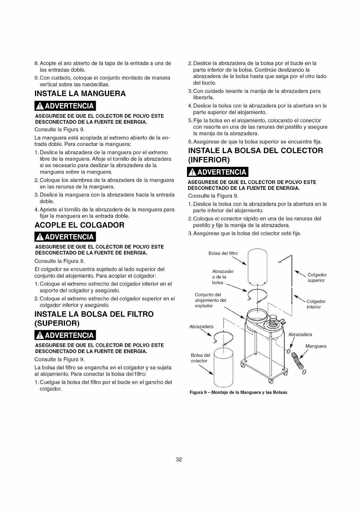
INSTALE LA BOLSA DEL FILTRO
(SUPERIOR)
V!V.,I m_vj=l-'tl| =1_[=,]!'.'1
ASEGURESE DE QUE EL COLECTOR DE POLVO ESTE
DESCONECTADO DE LA FUENTE DE ENERGIA.
Consulte la Figura 9.
La bolsa del filtro se engancha en el colgador y se sujeta
al alojamiento. Para conectar la bolsa del filtro:
1.Cuelgue la bolsa del filtro por el bucle en el gancho del
colgador.
2. Deslice la abrazadera de la bolsa por el bucle en la
parte inferior de la bolsa. Contint]e deslizando la
abrazadera de la bolsa hasta que salga por el otro lado
del bucle.
3. Con cuidado levante la manija de la abrazadera para
liberarla.
4. Deslice la bolsa con la abrazadera por la abertura en la
parte superior del alojamiento.
5. Fije la bolsa en el alojamiento, colocando el conector
con resorte en una de las ranuras del pestillo y asegure
la manija de la abrazadera.
6. Asegt]rese de que la bolsa superior se encuentre fija.
INSTALE LA BOLSA DEL COLEOTOR
(INFERIOR)
V!V.,I m_vj=1-'t111=1_[Hr.,I
ASEGURESE DE QUE EL COLECTOR DE POLVO ESTE
DESCONECTADO DE LA FUENTE DE ENERGIA.
Consulte la Figura 9.
1. Deslice la bolsa con la abrazadera por la abertura en la
parte inferior del alojamiento.
2. Coloque el conector r_tpido en una de las ranuras del
pestillo y fije la manija de la abrazadera.
3. Asegt]rese que la bolsa del colector est_ fija.
Bolsa del filtro
Abrazader
a de la
bolsa
Conjunto del
alojamiento del
soplador
Abrazadera
--.<
Bolsa del
colector
Figura 9 - Montaje de la Manguera y las Bolsas
Abrazadera
Manguera
32
r!v_,1m_vj_l..tUl_1_[o,]p,_,l
PARA LA SEGURIDAD DEL OPERARIO, mantenga los
dedos y todos los cuerpos extraSos fuera de los puertos de
admisi6n. El acceso al ventilador girante dentro de la caja del
soplador es posible a traves de los puertos de admisi6n yes
peligroso. No utilice vestimenta holgada ni articulos de
joyeria. Asegurese de que cada puerto de admisi6n que no
este en uso, o conectado a un sistema de recolecci6n de
polvo, se encuentre cubierto por una tapa de puerto de
admisi6n.
CONECTANDO LA HERRAMIENTA A
LA FUENTE DE ENERGIA
Debe utilizar un circuito electrico independiente para sus
herramientas. Este circuito no debe set menor que el alambre
#14 A.W.G. y debe estar protegido pot un fusible de retar-
daci6n de 15 Amperios. Haga que un electricista competente
reponga o repare inmediatamente cualquier cord6n desgasta-
do. Antes de conectar el motor a la linea de energia,
asegt_rese de que el interruptor este en la posici6n de APA-
GADO y asegt_rese de que la corriente electrica sea de las
mismas caracteristicas que Io indicado pot la placa de nota-
ciones del motor. Todas las conexiones de linea deben hacer
buen contacto. El funcionamiento a bajo voltaje perjudicara el
motor.
r!v_,1m_vj=l..t|=1_[_ !_,11
NO EXPONGA ESTE COLECTOR DE POLVO A LA LLUVIA
NI HAGA USO DE LA MAQUINA EN LUGARES HUMEDOS.
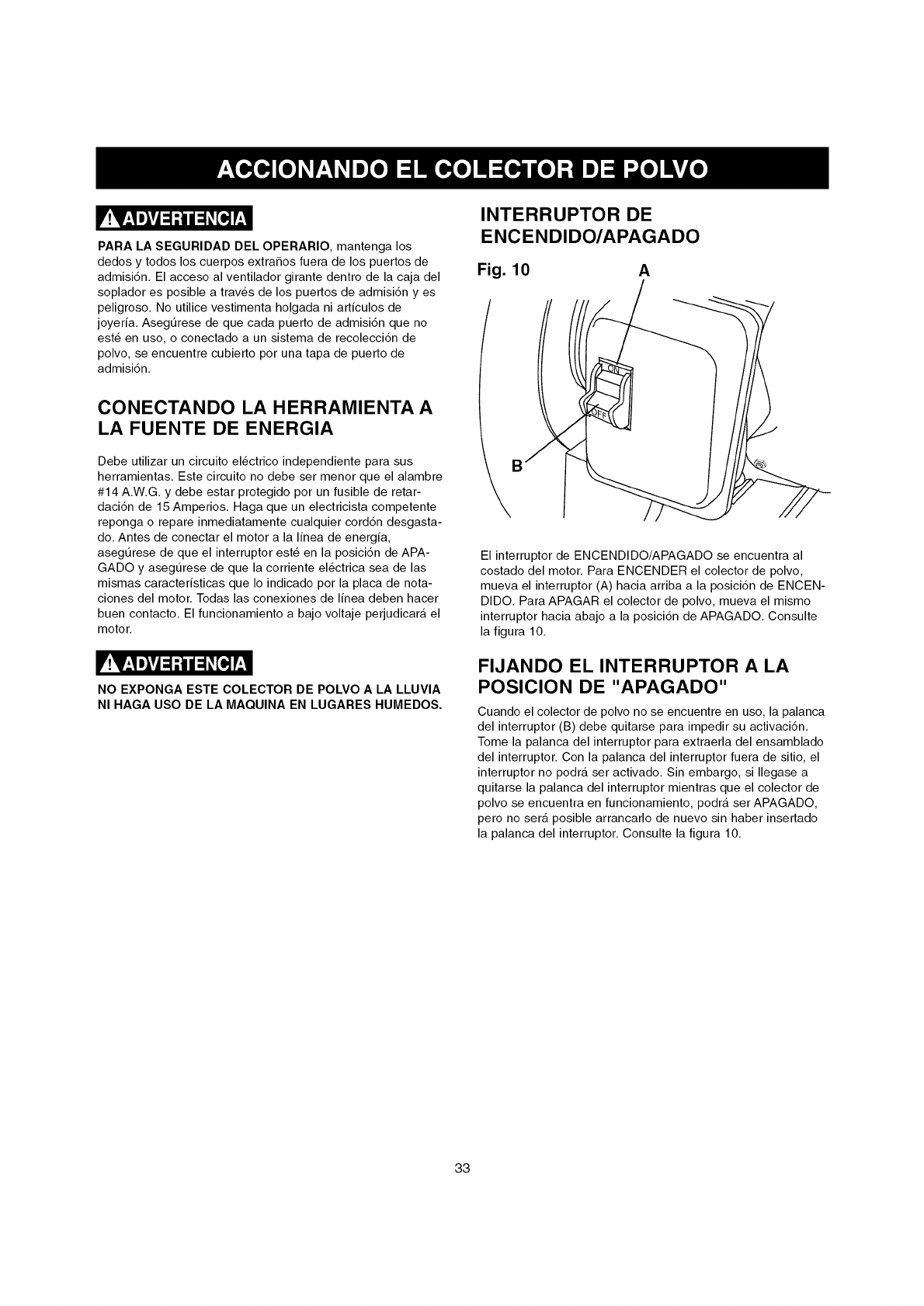
INTERRUPTOR DE
ENCENDIDO/APAGADO
Fig. 10 A
/
\
El interruptor de ENCENDIDO/APAGADO se encuentra al
costado del motor. Para ENCENDER el colector de polvo,
mueva el interruptor (A) hacia arriba a la posici6n de ENCEN-
DIDO. Para APAGAR el colector de polvo, mueva el mismo
interruptor hacia abajo a la posici6n de APAGADO. Consulte
la figura 10.
FIJANDO EL INTERRUPTOR A LA
POSICION DE "APAGADO"
Cuando el colector de polvo no se encuentre en uso, la palanca
del interruptor (B) debe quitarse para impedir su activaci6n.
Tome la palanca del interruptor para extraerla del ensamblado
del interruptor. Con la palanca del interruptor fuera de sitio, el
interruptor no podra set activado. Sin embargo, si Ilegase a
quitarse la palanca del interruptor mientras que el colector de
polvo se encuentra en funcionamiento, podra set APAGADO,
pero no sera posible arrancarlo de nuevo sin haber insertado
la palanca del interruptor. Consulte la figura 10.
33
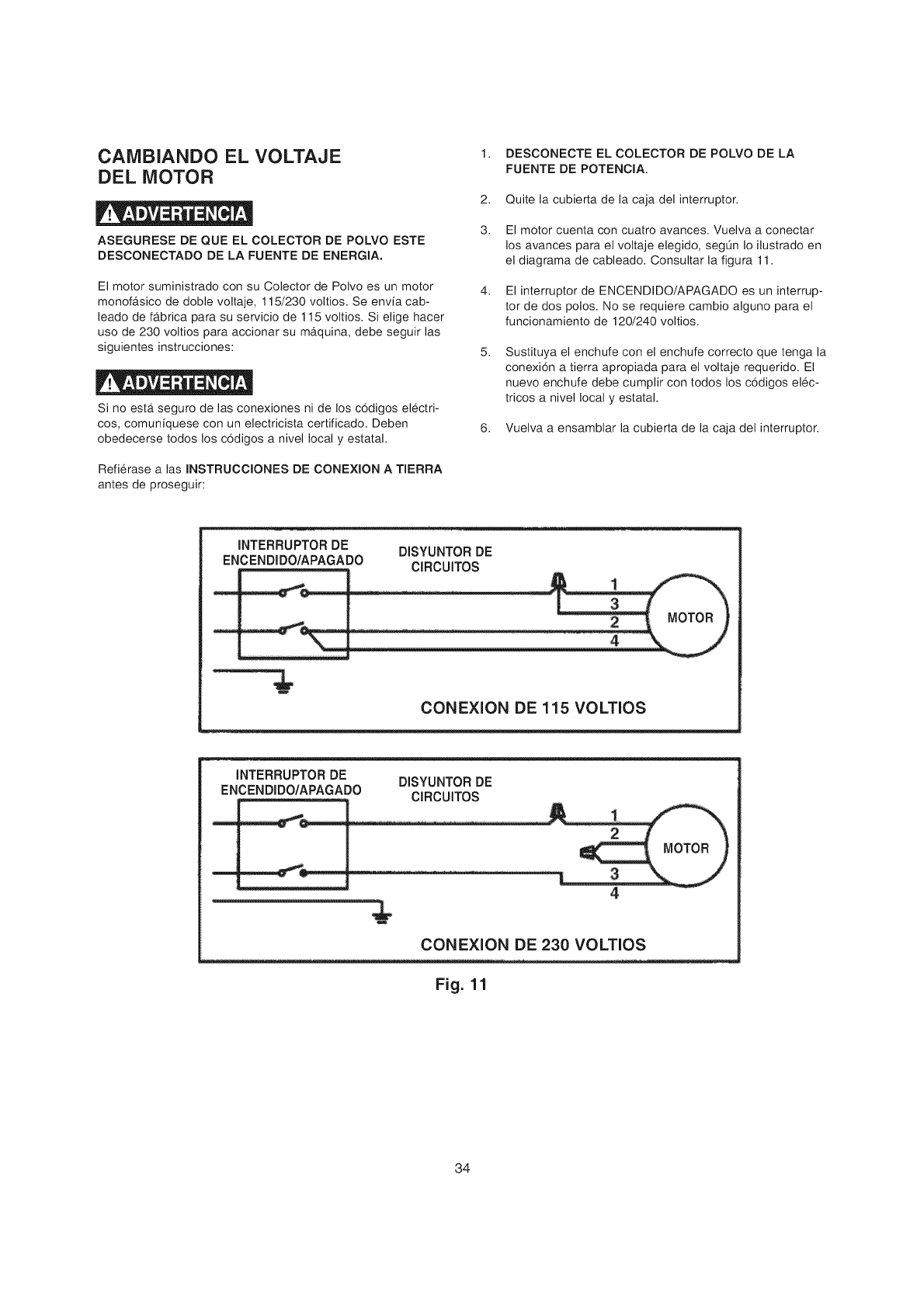
CAMBIANDO EL VOLTAJE
DEL MOTOR
ASEGURESE DE QUE EL COLECTOR DE POLVO ESTE
DESCONECTADO DE LA FUENTE DE ENERGIA,
El motor suministrado con su Colector de Polvo es un motor
monofb,sico de doble voltaje, 115/230 voltios. Se envia cab-
leado de fa_brica para su servicio de 115 voltios. Si elige hacer
uso de 230 voltios para accionar su ma_quina, debe seguir las
siguientes instrucciones:
Si no esta_seguro de las conexiones ni de los codigos electri-
cos, comuniquese con un electricista certificado. Deben
obedecerse todos los codigos a nivel local y estatal.
Refierase a las INSTRUCCIONES DE CONEXION A TIERRA
antes de proseguir:
1. DESCONECTE EL COLECTOR DE POLVO DE LA
FUENTE DE POTENClA.
2. Quite la cubierta de la caja del interruptor.
3. El motor cuenta con cuatro avances. Vuelva a conectar
los avances para el voltaje elegido, segQn Io ilustrado en
el diagrama de cableado. Consultar la figura 11.
4. El interruptor de ENCENDIDO/APAGADO es un interrup-
tor de dos polos. No se requiere cambio alguno para el
funcionamiento de 120/240 voltios.
5, Sustituya el enchufe con el enchufe correcto que tenga la
conexion a tierra apropiada para el voltaje requerido. El
nuevo enchufe debe cumplir con todos los codigos elec-
tricos a nivel local y estatal.
6. Vuelva a ensamblar la cubierta de la caja del interruptor.
INTERRUPTOR DE DISYUNTOR DE
ENCENDIDO/APAGADO ClRCUITOS
CONEXION DE 115 VOLTIOS
INTERRUPTOR DE DISYUNTOR DE
ENCENDIDO/APAGADO ClRCUITOS
4
CONEXION DE 230 VOLTIOS
Fig. 11
34
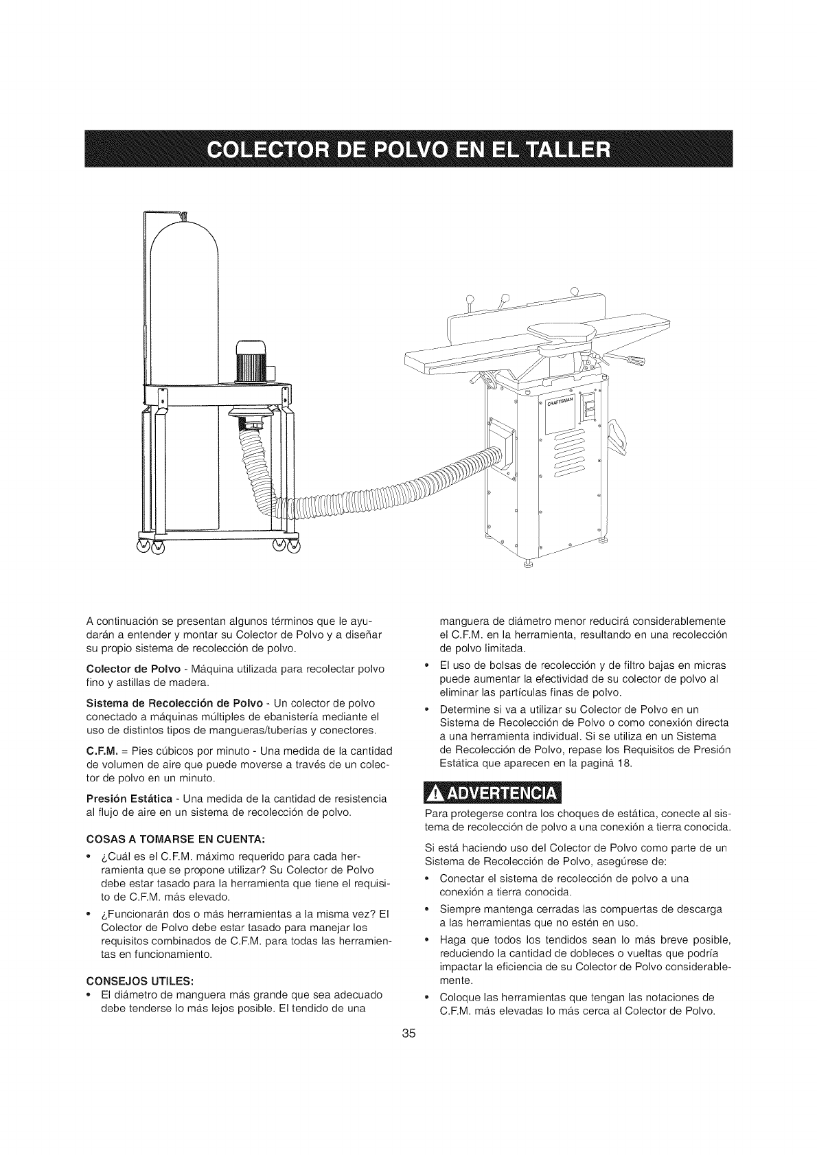
A continuacion se presentan algunos terminos que le ayu-
dara_n a entender y montar su Colector de Polvo y a disefiar
su propio sistema de recoleccion de polvo.
Colector de Polvo - Ma_quina utilizada para recolectar polvo
fino y astillas de madera.
Sistema de Recolecci6n de Polvo - Un colector de polvo
conectado a ma.quinas mQItiples de ebanisteria mediante el
uso de distintos tipos de mangueras/tuberias y conectores.
C.F.M. = Pies cQbicos por minuto - Una medida de la cantidad
de volumen de aire que puede moverse a traves de un colec-
tor de polvo en un minuto.
Presi6n Estbtica - Una medida de la cantidad de resistencia
al fiujo de aire en un sistema de recoleccion de polvo.
COSAS A TOMARSE EN CUENTA:
-8Cua-I es el C.RM. ma_ximo requerido para cada her-
ramienta que se propone utilizar? Su Colector de Polvo
debe estar tasado para la herramienta que tiene el requisi-
to de C.F.M. ma_selevado.
• 8Funcionarb.n dos o mb,s herramientas a la misma vez? El
Colector de Polvo debe estar tasado para manejar los
requisitos combinados de C.RM. para todas las herramien-
tas en funcionamiento.
CONSEJOS UTILES:
,, El dib,metro de manguera ma_sgrande que sea adecuado
debe tenderse Io ma_slejos posible. El tendido de una
35
manguera de dib.metro menor reducira_ considerablemente
el C.F.M. en la herramienta, resultando en una recoleccion
de polvo limitada.
El uso de bolsas de recoleccion y de filtro bajas en micras
puede aumentar la efectividad de su colector de polvo al
eliminar las particulas finas de polvo.
Determine siva a utilizar su Colector de Polvo en un
Sistema de Recoleccion de Polvo o como conexion directa
a una herramienta individual. Si se utiliza en un Sistema
de Recoleccion de Polvo, repase los Requisitos de Presion
Esta_tica que aparecen en la pagina_ 18.
Para protegerse contra los choques de esta_tica, conecte al sis-
tema de recoleccion de polvo a una conexion a tierra conocida.
Siesta_ haciendo uso del Colector de Polvo como parte de un
Sistema de Recoleccion de Polvo, asegQrese de:
Conectar el sistema de recoleccion de polvo a una
conexion a tierra conocida.
Siempre mantenga cerradas las compuertas de descarga
alas herramientas que no esten en uso.
Haga que todos los tendidos sean Io mb.s breve posible,
reduciendo la cantidad de dobleces o vueltas que podria
impactar la eficiencia de su Colector de Polvo considerable-
mente.
o Coloque las herramientas que tengan las notaciones de
C.RM. ma_selevadas Io ma_scerca al Colector de Polvo.
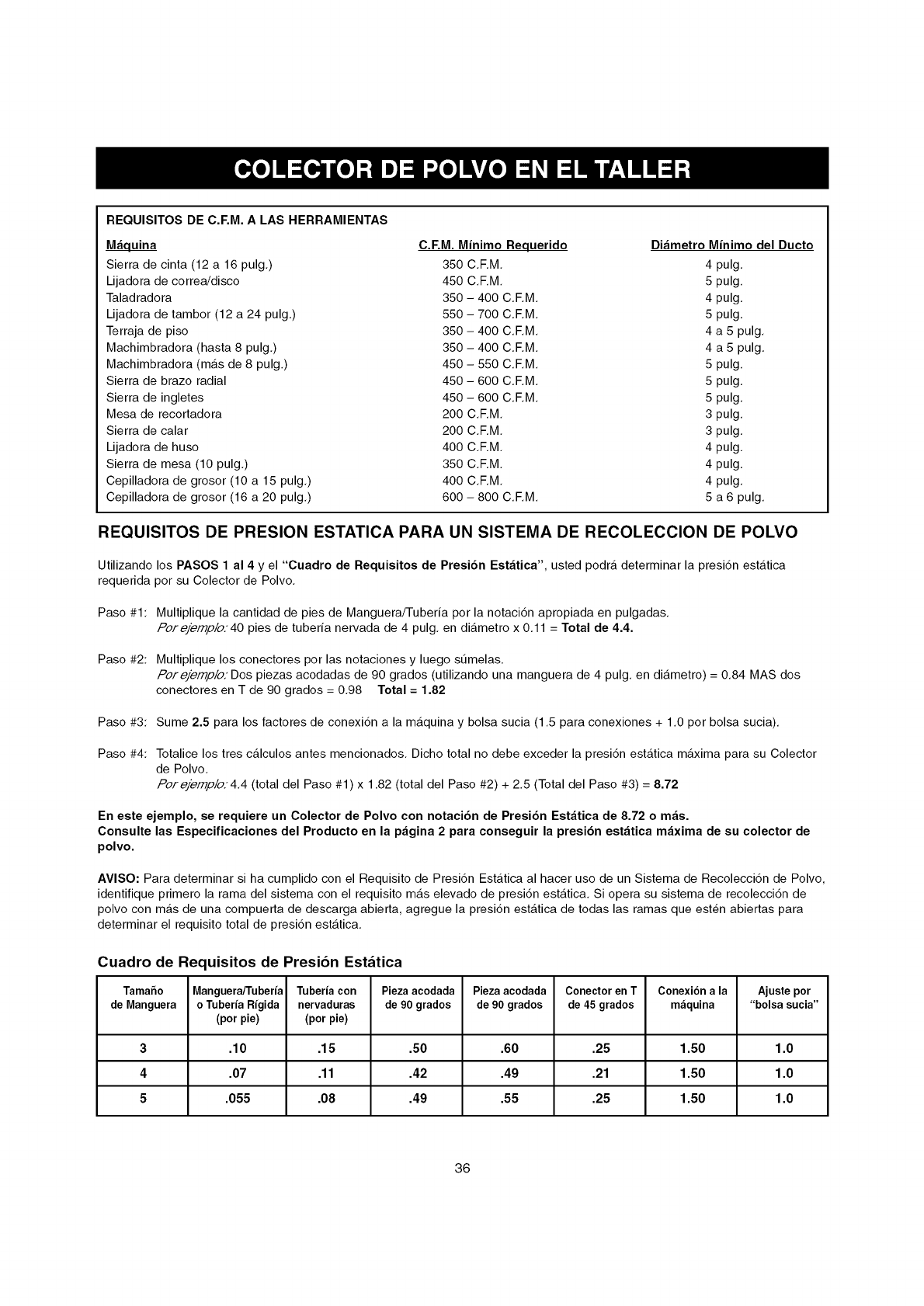
REQUISITOS DE C.F,M. A LAS HERRAMIENTAS
_uina C.F,M. Minimo Requerido Di_metro Minimo del Ducto
Sierra de cinta (12 a 16 pulg.) 350 C.F.M. 4 pulg.
Lijadora de correa!disco 450 C.F.M. 5 pulg.
Taladradora 350 - 400 C.F.M. 4 pulg.
Lijadora de tambor (12 a 24 pulg.) 550 - 700 C.F.M. 5 pulg.
Terraja de piso 350 - 400 C.F.M. 4 a 5 pulg.
Machimbradora (hasta 8 pulg.) 350 - 400 C.F.M. 4 a 5 pulg.
Machimbradora (mas de 8 pulg.) 450 - 550 C.F.M. 5 pulg.
Sierra de brazo radial 450 - 600 C.F.M. 5 pulg.
Sierra de ingletes 450 - 600 C.F.M. 5 pulg.
Mesa de recortadora 200 C.F.M. 3 pulg.
Sierra de calar 200 C.F.M. 3 pulg.
Lijadora de huso 400 C.F.M. 4 pulg.
Sierra de mesa (10 pulg.) 350 C.F.M. 4 pulg.
Cepilladora de grosor (10 a 15 pulg.) 400 C.F.M. 4 pulg.
Cepilladora de grosor (16 a 20 pulg.) 600 - 800 C.F.M. 5 a 6 pulg.
REQUlSlTOS DE PRESlON ESTATICA PARA UN SlSTEMA DE RECOLECClON DE POLVO
Utilizando los PASOS 1 al 4 y el "Cuadro de Requisitos de Presibn Est_tica", usted podra determinar la presi6n estatica
requerida por su Colector de Polvo.
Paso #1: Multiplique la cantidad de pies de Manguera/Tuberia por la notaci6n apropiada en pulgadas.
Pore/emp/o.'40 pies de tuberia nervada de 4 pulg. en diametro x 0.11 = Total de 4.4.
Paso #2: Multiplique los conectores por las notaciones y luego sumelas,
/>or e/emp/o: Dos piezas acodadas de 90 grados (utilizando una manguera de 4 pulg. en diametro) = 0.84 MAS dos
conectores en T de 90 grados = 0.98 Total = 1.82
Paso #3: Sume 2.5 para los factores de conexi6n a la maquina y bolsa sucia (1.5 para conexiones + 1.0 por bolsa sucia).
Paso #4: Totalice los tres calculos antes mencionados. Dicho total no debe exceder la presi6n estatica maxima para su Colector
de Polvo.
/>or e/em/3/o: 4.4 (total del Paso #1) x 1.82 (total del Paso #2) + 2.5 (Total del Paso #3) = 8.72
En este ejemplo, se requiere un Colector de Polvo con notacibn de Presibn Est_tica de 8.72 o m_s.
Consulte las Especificaciones del Producto en la p_gina 2 para conseguir la presibn est_tica m_xima de su colector de
polvo.
AVISO: Para determinar si ha cumplido con el Requisito de Presi6n Estatica al hacer uso de un Sistema de Recolecci6n de Polvo,
identifique primero la rama del sistema con el requisito mas elevado de presi6n estatica. Si opera su sistema de recolecci6n de
polvo con mas de una compuerta de descarga abierta, agregue la presi6n estatica de todas las ramas que esten abiertas para
determinar el requisito total de presi6n estatica.
Cuadro de Requisitos de Presibn Est_tica
Tama5o Manguera/Tuberia Tuberiacon Piezaacodada Pieza acodada Conector enT Conexiona la Ajuste por
de Manguera o Tuberia Rigida nervaduras de 90 grados de 90 grados de 45 grados maquina "bolsa sucia"
(por pie) (por pie)
3 .10 .15 .50 .60 .25 1.50 1.0
4 .07 .11 .42 .49 .21 1.50 1.0
5 .055 .08 .49 .55 .25 1.50 1.0
36
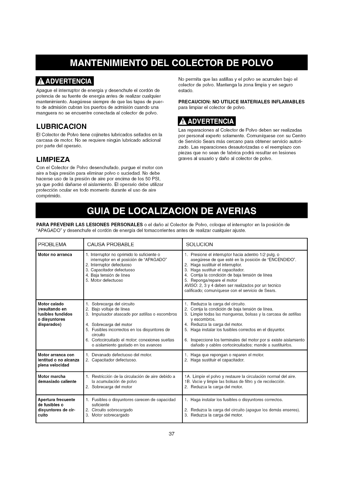
r!v_,1m_v4;i.1 Ul;1_[o,]p,_,l
Apague el interruptor de energia y desenchufe el cord6n de
potencia de su fuente de energia antes de realizar cualquier
mantenimiento, Asegt_rese siempre de que las tapas de puer-
to de admisi6n cubran los puertos de admisi6n cuando una
manguera no se encuentre conectada al colector de polvo,
LUBRICAClON
El Colector de Polvo tiene cojinetes lubricados sellados en la
carcasa de motor, No se requiere ningt_n lubricado adicional
por parte del operario,
LIMPIEZA
Con el Colector de Polvo desenchufado, purgue el motor con
aire a baja presi6n para eliminar polvo o suciedad, No debe
hacerse uso de la presi6n de aire por encima de los 50 PSI,
ya que podra daSarse el aislamiento, El operario debe utilizar
protecci6n ocular en todo momento durante el uso de aire
comprimido,
No permita que las astillas y el polvo se acumulen bajo el
colector de polvo, Mantenga la zona limpia yen seguro
estado,
PRECAUClON: NO UTILICE MATERIALES INFLAMABLES
para limpiar el colector de polvo,
V!V_,Imlvl=1-1II=1#[=,]!'_,11
Las reparaciones al Colector de Polvo deben ser realizadas
por personal experto solamente, Comuniquese con su Centro
de Servicio Sears mas cercano para obtener servicio autori-
zado, Las reparaciones desautorizadas o el reemplazo con
piezas que no sean de fabrica podra resultar en lesiones
graves al usuario y daSo al colector de polvo,
PARA PREVENIR LAS LESIONES PERSONALES o el daSo al Colector de Polvo, coloque el interruptor en la posici6n de
"APAGADO" y desenchufe el cord6n de energia del tomacorrientes antes de realizar cualquier ajuste,
PROBLEMA CAUSA PROBABLE SOLUCION
Motor no arranea
Motor calado
(resultando en
fusibles fundidos
o disyuntores
disparados)
Motor arranca con
lentitud o no alcanza
plena velocidad
Motor marcha
demasiado caliente
Apertura frecuente
de fusibles o
disyuntores de cir-
cuito
1. Interruptor no oprimido Io suficiente o
interruptor en el posici6n de "APAGADO"
2. Interruptor defectuoso
3. Capacitador defectuoso
4. Baja tensi6n de I[nea
5. Motor defectuoso
1.
2.
3.
4.
5.
6.
1.
2.
1.
2.
1.
2.
3.
Sobrecarga del circuito 1.
Bajo voltaje de IJnea 2.
Impulsador atascado por astillas o escombros 3.
Sobrecarga del motor 4.
Fusibles incorrectos en los disyuntores de 5.
circuito
Cortocircuitado el motor; conexiones sueltas 6.
o aislamiento gastado en los avances
Devanado defectuoso del motor. 1.
Capacitador defectuoso. 2.
Restricci6n de la circulaci6n de aire debido a
la acumulaci6n de polvo
Sobrecarga del motor
Fusibles o disyuntores carecen de capacidad
suficiente
Circuito sobrecargado
Motor sobrecargado
1. Presione el interruptor hacia adentro 1/2 pulg. o
asegt]rese de que este en la posici6n de "ENCENDIDO".
2. Haga sustituir el interruptor.
3. Haga sustituir el capacitador.
4. Corrija la condici6n de baja tensi6n de linea
5. Reponga/repare el motor
AVISO: 2, 3 y 4 deben ser realizados pot un tecnico
calificado; comuniquese con el servicio de Sears.
Reduzca la carga del circuito.
Corrija la condici6n de baja tensi6n de I[nea.
Limpie todas las mangueras, bolsas y la carcasa de astillas
yescombros.
Reduzca la carga del motor.
Haga instalar los fusibles correctos en el disyuntor.
Inspeccione los terminales del motor por si existe aislamiento
dadado y cables cortocircuitados; mande a sustituirlos.
Haga que repongan o reparen el motor.
Haga sustituir el capacitador.
1A. Limpie el polvo y restaure la circulaci6n normal del aire.
1B. Vacie y limpie las bolsas de filtro y de recolecci6n.
2. Reduzca la carga del motor.
1. Haga instalar los fusibles o disyuntores correctos.
2. Reduzca la carga del circuito (apague los dem,_s enseres).
3. Reduzca la carga del motor.
37

e, NOTAS e,
38

e, NOTAS e,
39

Your Home
For troubleshooting, product manuals and expert advice:
managemylife
www.managemylife.com
For repair - in your home - of all major brand appliances,
lawn and garden equipment, or heating and cooling systems,
no matter who made it, no matter who sold it!
For the replacement parts, accessories and
owner's manuals that you need to do-it-yourself.
For Sears professional installation of home appliances
and items like garage door openers and water heaters.
1-800-4-MY-HOME ®(1-800-469-4663)
TM
® Registered Trademark /Trademark of KCD IP, LLC in the United States, or Sears Brands, LLC in other countries
TM
® Marca Registrada /Marca de F_brica de KCD IP, LLC en Estados Unidos, o Sears Brands, LLC in otros paises
MCMarque de commerce /MDMarque d6pos6e de Sears Brands, LLC
