Craftsman 152219070 User Manual CHISEL MORTISER Manuals And Guides L0521114
CRAFTSMAN Mortiser Manual L0521114 CRAFTSMAN Mortiser Owner's Manual, CRAFTSMAN Mortiser installation guides
User Manual: Craftsman 152219070 152219070 CRAFTSMAN CHISEL MORTISER - Manuals and Guides View the owners manual for your CRAFTSMAN CHISEL MORTISER #152219070. Home:Tool Parts:Craftsman Parts:Craftsman CHISEL MORTISER Manual
Open the PDF directly: View PDF ![]() .
.
Page Count: 56

truction anu
®
C
C S
FOR YOUR OWN SAFETY; Read
and foUlow all of the Safety and
Operating Instructions before
Operating this Mortiser.
Customer Helpline
1-800-897-7709
PRease have your Model No.
and SedaR No. availabUe.
Sears, Roebuck and Co., Hoffman Estates, JL 60179 U.S.A.
Part No. OR93760
Revision A EspaSoU, pg. 29

SECTION PAGE
Warranty .......................................................................................................................................................................... 2
Product Specifications ................................................................................................................................................... 2
Safety Instructions ......................................................................................................................................................... 3
Guidelines for extension cords ..................................................................................................................................... 4
Grounding Instructions .................................................................................................................................................. 5
Specific Safety Instructions .......................................................................................................................................... 6
Accessories and Attachments ...................................................................................................................................... 7
Carton Contents ............................................................................................................................................................. 8
Know Your Mortiser ........................................................................................................................................................ 9
Assembly Instructions ................................................................................................................................................. 10
Operations and Adjustment ........................................................................................................................................ 16
Maintenance .................................................................................................................................................................. 24
Troubleshooting Guide ................................................................................................................................................ 25
Part List ......................................................................................................................................................................... 26
Espaffo[ .......................................................................................................................................................................... 29
Service Information ........................................................................................................................................ Back Page
ONE-YEAR FULL WARRANTY ON CRAFTSMAN TOOL
if this Craftsman tool fails due to a defect in material or workmanship within one year from the date of purchase,
CALL 1-800-4-MY-HOME <R>TO ARRANGE FOR FREE REPAIR,
if this tool is used for commercial or rental purposes, this warranty wiii apply for only ninety days from the date of
purchase,
This warranty applies only while this tool is in the United States,
This warranty gives you specific legal rights, and you may also have other rights, which vary from state to state,
Sears, Roebuck and Co,, Dept 817WA, Heffman Estates, IL 60179
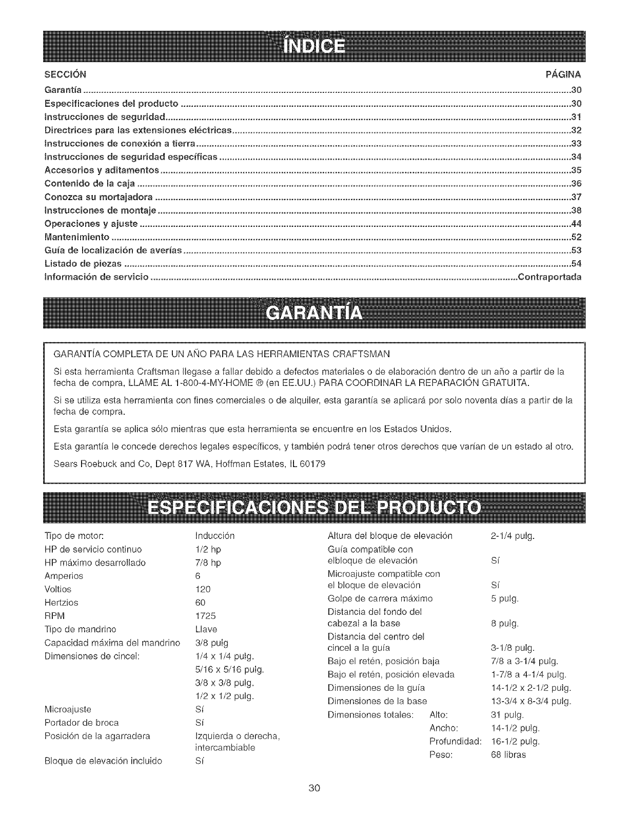
Motor type: induction Riser block included Yes
Continuous duty HP 1/2 hp Riser block height 2-1/4"
Maximum Developed HP 7/8 hp Fence compatible with riser Yes
Amps 6 Micro-adjust compatible with riser Yes
Volts 120 Maximum stroke: 5"
Hertz 60 Under head to base: 8"
RP M 1725 Chisel center to fence: 3-1/8"
Chuck type Keyed Under hold down, down position: 7/8" to 3-1/4"
Chuck Maximum capacity 3/8" Under hold down, up position: 1-7/8" to 4-1/4"
Chisel sizes: 1/4" x 1/4" Fence size: 14-1/2" x 2-1/2"
5/16" x 5/16" Base size: 13-3/4" x 8-3/4"
3/8" x 3/8" Overall dimensions: Height: 31"
1/2" x 1/2" Width: 14-1/2"
Yes Depth: 16-1/2"
Bit Holder Yes Weight: 68 Ibs,
Handle position Left or right,
GENERAL SAFETY iNSTRUCTiONS
Operating a Mortiser can be dangerous if safety and
common sense are ignored, The operator must be
familiar with the operation of the tool, Read this manual
to understand this Mortiser, DO NOT operate this
Mortiser if you do not fully understand the limitations
of this tool, DO NOT modify this Mortiser in any way,
REMEMBER: Your personal safety is your
responsibility,
BEFORE USUNG THE MORTISER
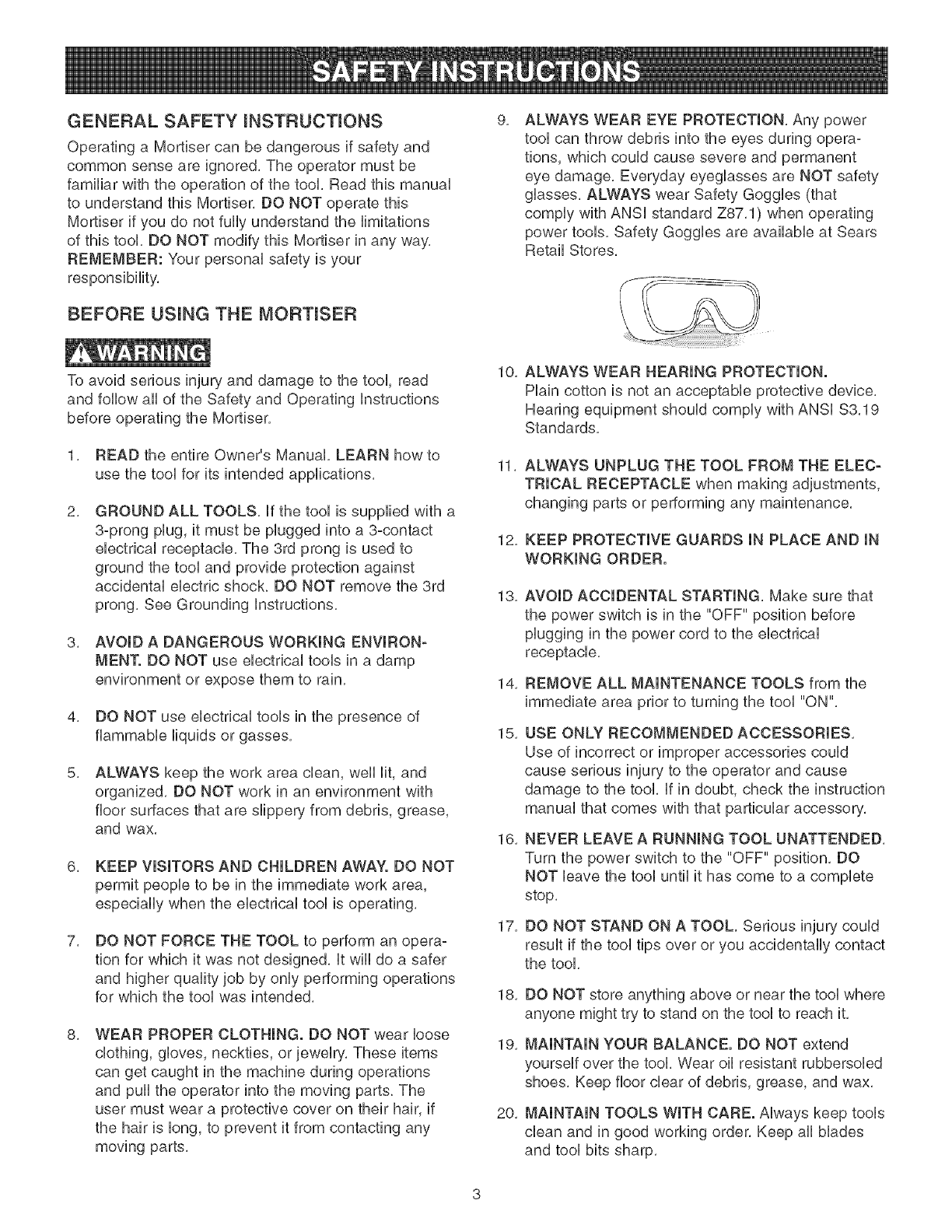
9, ALWAYS WEAR EYE PROTECTmON, Any power
tool can throw debris into the eyes during opera-
tions, which could cause severe and permanent
eye damage, Everyday eyeglasses are NOT safety
glasses, ALWAYS wear Safety Goggles (that
comply with ANSi standard Z87,1) when operating
power tools, Safety Goggles are available at Sears
Retail Stores,
S
I
\
To avoid serious injury and damage to the tool, read
and follow all of the Safety and Operating instructions
before operating the Mortiser,
1, READ the entire Owner's Manual, LEARN how to
use the tool for its intended applications,
2, GROUND ALL TOOLS, if the tool is supplied with a
3-prong plug, it must be plugged into a 3-contact
electrical receptacle, The 3rd prong is used to
ground the tool and provide protection against
accidental electric shock, DO NOT remove the 3rd
prong, See Grounding instructions,
3, AVOID A DANGEROUS WORKmNG ENVIRON-
MEN'[. DO NOT use electrical tools in a damp
environment or expose them to rain,
4, DO NOT use electrical tools in the presence of
flammable liquids or gasse&
5, ALWAYS keep the work area clean, well lit, and
organized, DO NOT work in an environment with
floor surfaces that are slippery from debris, grease,
and wax,
6, KEEP VISITORS AND CHILDREN AWAY. DO NOT
permit people to be in the immediate work area,
especially when the electrical tool is operating,
7, DO NOT FORCE THE TOOL to perform an opera-
tion for which it was not designed, it wiii do a safer
and higher quality job by only performing operations
for which the tool was intended,
8, WEAR PROPER CLOTHING. DO NOT wear loose
clothing, gloves, neckties, or jewelry, These items
can get caught in the machine during operations
and pull the operator into the moving parts, The
user must wear a protective cover on their hair, if
the hair is long, to prevent it from contacting any
moving parts,
10,
11,
12,
13,
14,
15,
16,
17,
18,
19,
20,
ALWAYS WEAR HEARING PROTECTION.
Plain cotton is not an acceptable protective device,
Hearing equipment should comply with ANSi $3,19
Standards,
ALWAYS UNPLUG THE TOOL FROM THE ELEC-
TRICAL RECEPTACLE when making adjustments,
changing parts or performing any maintenance,
KEEP PROTECTIVE GUARDS IN PLACE AND IN
WORKING ORDER.
AVOID ACCIDENTAL STARTING, Make sure that
the power switch is in the "OFF" position before
plugging in the power cord to the electrical
receptacle,
REMOVE ALL MAINTENANCE TOOLS from the
immediate area prior to turning the tool "ON",
USE ONLY RECOMMENDED ACCESSORIES,
Use of incorrect or improper accessories could
cause serious injury to the operator and cause
damage to the tool, if in doubt, check the instruction
manual that comes with that particular accessory,
NEVER LEAVE A RUNNING TOOL UNATTENDED,
Turn the power switch to the "OFF" position, DO
NOT leave the tool until it has come to a complete
stop,
DO NOT STAND ON A TOOL, Serious injury could
result if the tool tips over or you accidentally contact
the tool,
DO NOT store anything above or near the tool where
anyone might try to stand on the tool to reach it,
MAINTAIN YOUR BALANCE. DO NOT extend
yourself over the tool, Wear oil resistant rubbersoled
shoes, Keep floor clear of debris, grease, and wax,
MAINTAIN TOOLS WITH CARE. Always keep tools
clean and in good working order, Keep all blades
and tool bits sharp,
21,EACHAND EVERY TIME, CHECK FOR DAM-
AGED PARTS PRIOR TO USING THE TOOL,
Carefully check aH guards to see that they operate
properly, are not damaged, and perform their
intended functions, Check for afignment, binding or
breaking of moving parts, A guard or other part that
is damaged shouUd be immediateUy repaired or
repUaced,
22, CHILDPROOF THE WORKSHOP AREA by remov-
ing switch keys, unplugging tools from the electrical
receptacles, and using padlocks,
23, DO NOT OPERATE TOOL IF UNDER THE INFLU-
ENCE OF DRUGS OR ALCOHOL,
24, SECURE ALL WORK, When it is possible, use
clamps or jigs to secure the workpiece, This is safer
than attempting to hold the workpiece with your
hands,
25, STAY ALERT, WATCH WHAT YOU ARE DOING,
AND USE COMMON SENSE WHEN OPERATING
A POWER TOOL. DO NOT USE A TOOL WHILE
TIRED OR UNDER THE INFLUENCE OF DRUGS,
ALCOHOL, OR MEDICATION, A moment of
inattention while operating power tools may result
in serious personal injury,
26, ALWAYS WEAR A DUST MASK TO PREVENT
INHALING DANGEROUS DUST OR AIRBORNE
PARTICLES, including wood dust, crystalline silica
dust and asbestos dust, Direct particles away
from face and body, AUwaysoperate tool in well
ventilated area and provide for proper dust removal,
Use dust collection system whenever possible,
Exposure to the dust may cause serious and
permanent respiratory or other injury, including
silicosis (a serious lung disease), cancer, and
death, Avoid breathing the dust, and avoid pro-
longed contact with dust, Allowing dust to get into
your mouth or eyes, or lay on your skin may pro-
mote absorption of harmful material, Always use
properly fitting NIOSH/OSHA approved respiratory
protection appropriate for the dust exposure, and
wash exposed areas with soap and water,
27, USE A PROPER EXTENSION CORD IN GOOD
CONDITION, When using an extension cord, be
sure to use one heavy enough to carry the current
your product will draw, Please see minimum recom-
mended gauge for extension cords (AWG) table for
correct sizing of an extension cord, if in doubt, use
the next heavier gauge,
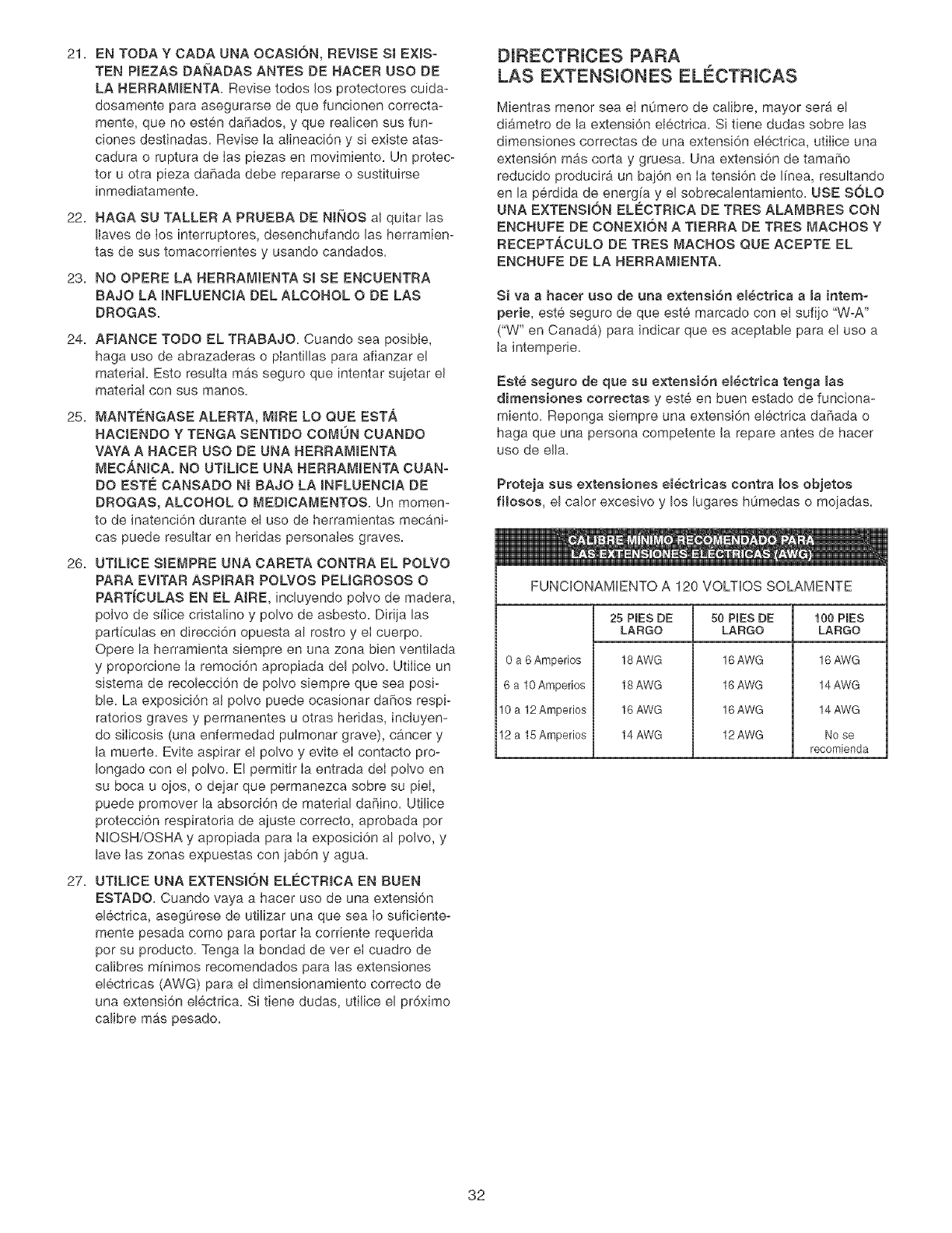
GUIDELINES FOR EXTENSION CORDS
The smaller the gauge number, the larger diameter of
the extension cord is, if in doubt of the proper size of an
extension cord, use a shorter and thicker cord, An
undersized cord wHUcause a drop in Hne voUtage resuUt-
ing in a bss of power and overheating, USE ONLY A
3-WIRE EXTENSION CORD THAT HAS A 3-PRONG
GROUNDING PLUG AND A 3-POLE RECEPTACLE
THAT ACCEPTS THE TOOL'S PLUG,
If you are using an extension cord outdoors, be sure
it is marked with the suffix "W-A" ("W" in Canada) to
indicate that it is acceptable for outdoor use,
Be sure your extension cord is property sized, and
in good electrical condition, Always replace a damaged
extension cord or have it repaired by a qualified person
before using it,
Protect your extension cords from sharp objects,
excessive heat, and damp or wet areas,
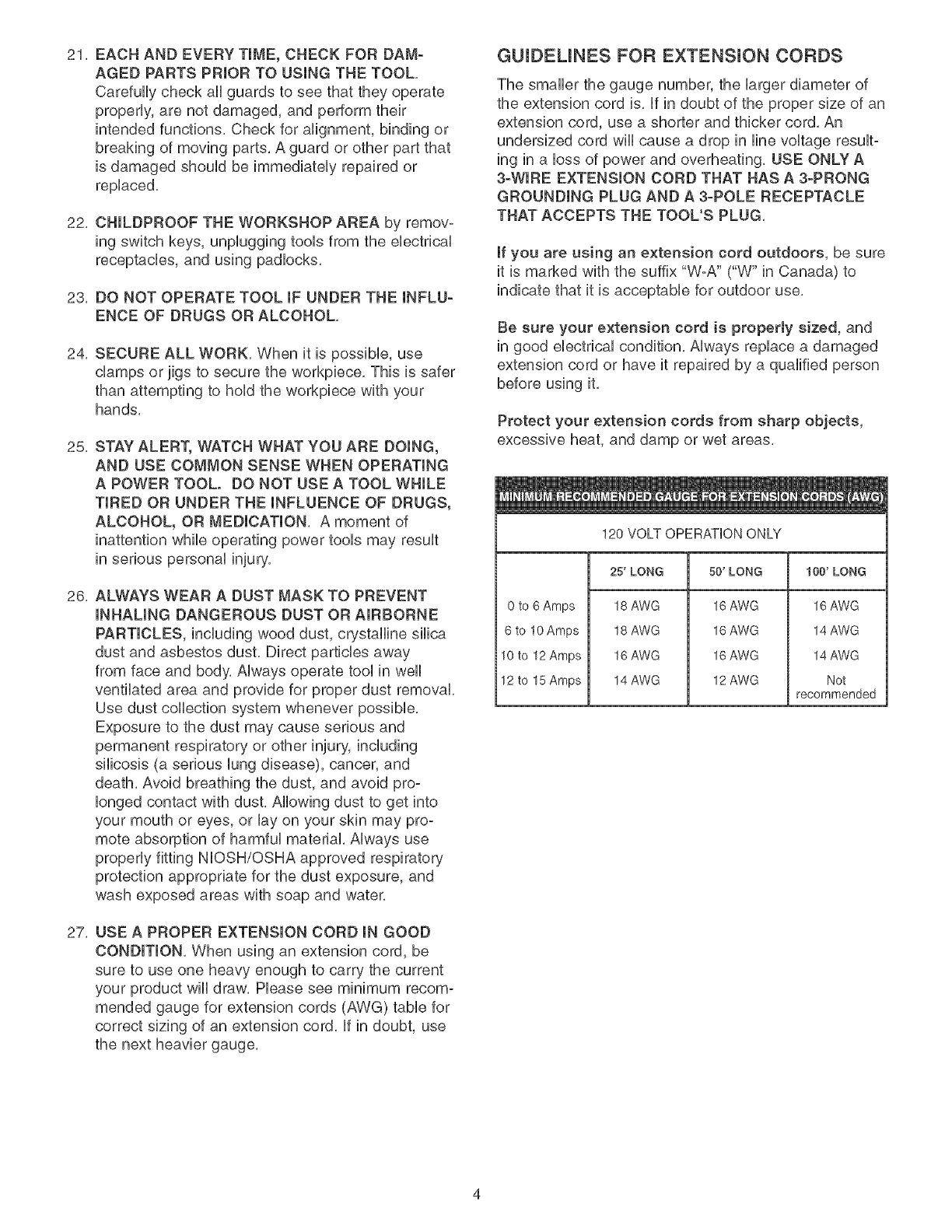
120 VOLT OPERATION ONLY
25' LONG 50' LONG 100' LONG
0 to 6 Amps
6 to 10 Amps
10 to 12 Amps
12 to 15 Amps
18 AWG
18 AWG
16 AWG
14 AWG
16 AWG
16 AWG
16 AWG
12 AWG
16 AWG
14 AWG
14 AWG
Not
recommended
THINSTOOL MUST BE GROUNDED WHmLE mNUSE
TO PROTECT THE OPERATOR FROM ELECTRmC
SHOCK.
mNTHE EVENT OF A MALFUNCTmON OR BREAK-
DOWN, grounding provides the path of bast resistance
for eUectriccurrent and reduces the risk of eUectric
shock. This tooUis equipped with an eUectric cord that
has an equipment-grounding conductor and a ground-
ing pUug.The pUugMUST be pUugged into a matching
eUectricaUreceptacle that is properUy installed and
grounded in accordance with ALL bcaU codes and
ordinances.
DO NOT MODIFY THE PLUG PROVIDED, if it wHUnot
fit the eUectrbaUreceptacb, have the proper eUectrbaU
receptacle installed by a qualified electrician.
IMPROPER ELECTRICAL CONNECTION of the equip°
ment-grounding conductor can result in risk of electric
shock. The conductor with the green insulation (with or
without yellow stripes) is the equipment-grounding
conductor. DO NOT connect the equipment-grounding
conductor to a live terminal if repair or replacement of
the electric cord or plug is necessary.
CHECK with a qualified electrician or service personnel
if you do not completely understand the grounding
instructions, or if you are not sure the tool is properly
grounded.
The motor supplied with your Mortiser is a 120°volt,
singb-phase motor. It is shipped wired for 120°volt
application. Never connect the green wire to a live
terminal.
USE ONLY A 3-WIRE EXTENSION CORD THAT HAS
A3=PRONG GROUNDING PLUG AND A 3-POLE
RECEPTACLE THAT ACCEPTS THE TOOL'S PLUG.
REPLACE A DAMAGED OR WORN CORD
IMMEDIATELY.
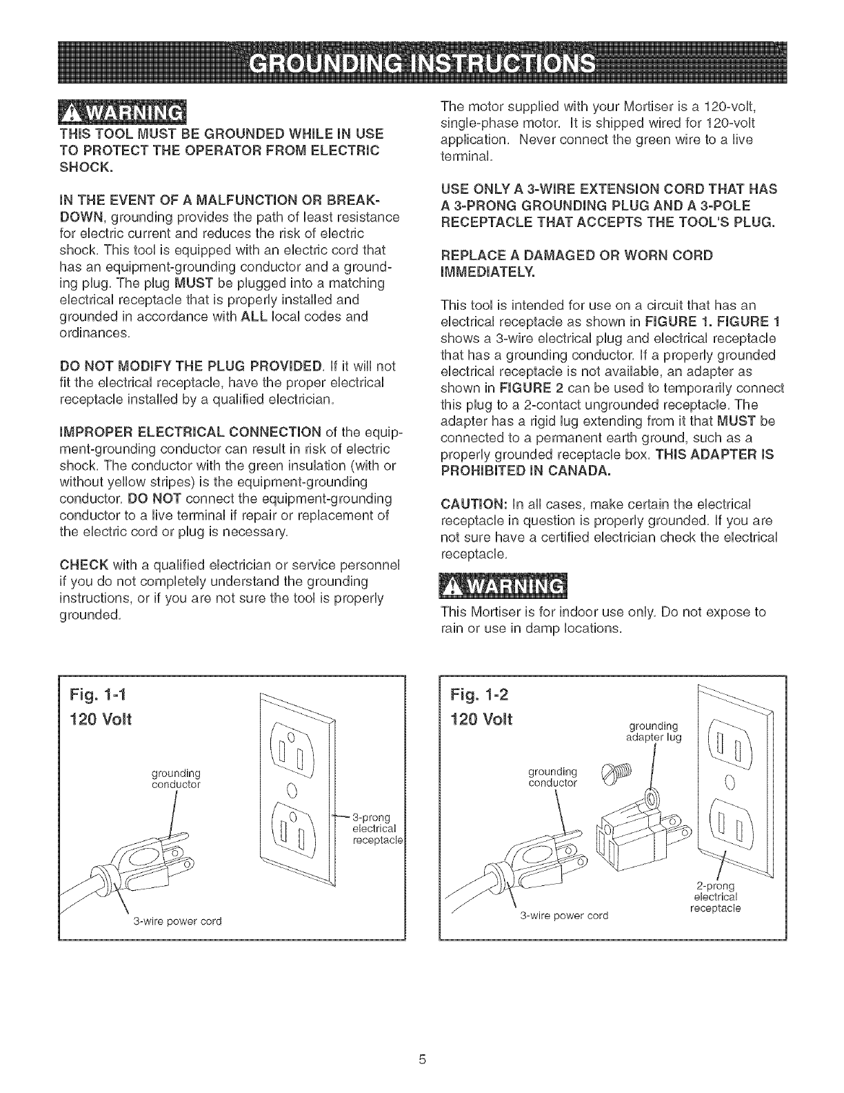
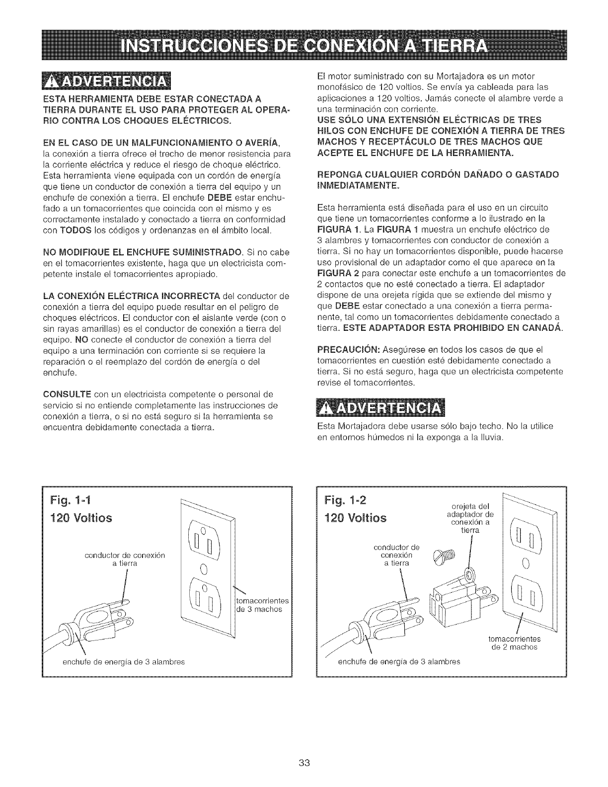
This tool is intended for use on a circuit that has an
electrical receptacle as shown in FIGURE 1. FIGURE 1
shows a 3-wire electrical plug and electrical receptacle
that has a grounding conductor. If a properly grounded
electrical receptacle is not available, an adapter as
shown in FIGURE 2 can be used to temporarily connect
this plug to a 2-contact ungrounded receptacle. The
adapter has a rigid lug extending from it that MUST be
connected to a permanent earth ground, such as a
properly grounded receptacle box. THIS ADAPTER IS
PROHIBITED IN CANADA.
CAUTION: In all cases, make certain the electrical
receptacle in question is properly grounded. If you are
not sure have a certified electrician check the electrical
receptacle.
This Mortiser is for indoor use only, Do not expose to
rain or use in damp locations,
Fig. 1-1
120 Volt
grounding
conductor
3-wire power cord
3-prong
electrical
receptacle
Fig. 1-2
120 Volt
grounding
conductor
3-wire power cord
grounding
2-prong
electrical
receptacle

SPECIFIC SAFETY iNSTRUCTiONS
ALWAYS WEAR EYE PROTECTmON, Any power tool
can throw debris into the eyes during operations, which
could cause severe and permanent eye damage.
Everyday eyeglasses are NOT safety glasses.
ALWAYS wear Safety Goggbs (that comply with ANSi
standard Z87.1) when operating power toob. Safety
Goggbs are availabb at Sears Retaib Stores.
Basic precautions should always be followed when
using any power tool. To reduce the risk of injury,
ebctrbal shock or fire, comply with the safety rubs
listed below:
1. READ and understand the instruction manual
before operating this power tool.
2, DO NOT OPERATE THIS MACHINE until it is
assembled and installed according to the instruc-
tions,
3. OBTAIN ADVICE FROM YOUR SUPERVISOR,
instructor, or another qualified person if you are not
familiar with the operations of this power tool.
4. DO NOT leave any power tool plugged into the
electrical outlet. Unplug it from the outlet when not
in use and before servicing and cleaning.
5, TO REDUCE THE RISK OF ELECTRICAL
SHOCK, do not use outdoors, Do not expose to
rain, Store indoors,
6, FOLLOW all electrical and safety codes, including
the National Electric Code (NED) and the Occu-
pational Safety and Health Regulations (OSHA).
All electrical connections and wiring should be
made by qualified personnel only.
7. DO NOT handle the plug or mortiser with wet
hands.
8. CONNECT power tool to a properly grounded outlet
only. See grounding instructions.
9, SECURE THE MACHINE TO A SUPPORTING
SURFACE, Vibration can cause the machine to
slide, walk, or tip over,
10, NEVER START THE MACHINE with the drill bit or
cutting tool against the workpiece, Loss of control of
the workpiece can cause serious injury.
11. PROPERLY LOCK THE DRILL BIT OR CUTTING
TOOL IN THE UNIT before operating this machine.
12. ADJUST the depth stop to avoid drilling into the
table.
13. DO NOT attempt to mortise material that does not
have a fiat surface, unless a suitable support is
used.
14.
15.
16.
17.
18.
19.
20.
21.
22.
23.
24.
USE ONLY DRILL BITS, CUTTING TOOLS, OR
OTHER ACCESSORIES with shank size recom-
mended in your instruction manual. The wrong size
accessory can cause damage to the machine
and/or serious injury.
USE ONLY DRILL BITS OR CUTTING TOOLS
that are not damaged. Damaged items can cause
malfunctions that lead to injuries.
ALWAYS position the hold-down directly over the
workpiece to prevent the workpiece from lifting
during operation. Loss of control of the workpiece
can cause serious injury.
TURN THE MACHINE "OFF" AND WAIT FOR
THE DRILL BIT, CUTTING TOOL, OR SANDING
DRUM TO STOP TURNING prior to cleaning the
work area, removing debris, removing or securing
work-piece, or changing the angle of the table, A
moving drill bit or cutting tool can cause serious
injury.
PROPERLY SUPPORT LONG OR WIDE work-
pieces, loss of control of the workpiece can cause
severe injury.
NEVER PERFORM LAYOUT, ASSEMBLY OR
SET-UP WORK on the table/work area when the
machine is running, Serious injury can result,
TURN THE MACHINE "OFF", disconnect the
machine from the power source, and clean the
table/work area before leaving the machine.
REMOVE THE SWITCH KEY to prevent unauthor-
ized use. Someone else might accidentally start the
machine and cause serious injury to themselves.
REPLACE a damaged cord immediately. DO NOT
use a damaged cord or plug. if the power tool is not
operating properly, or has been damaged, left out-
doors or has been in contact with water, return it to
a Sears Service Center.
USE only as described in this manual. USE acces-
sories only recommended by Sears.
ADDITIONAL INFORMATION regarding the safe
and proper operation of this product is available
from the National Safety Council, 1121 Spring Lake
Drive, Itasca, IL 60143-3201 in the Accident
Prevention Manual for Industrial Operation and also
in the Safety Data Sheets provided by the NSC.
Please also refer to the American National
Standards institute ANSi 01.1 Safety Requirements
for Woodworking Machinery and the U.S.
Department of Labor OSHA 1910.213 Regulations.
SAVE THESE INSTRUCTIONS. Refer to them fie-
quently and use them to instruct other users.

AVAILABLE ACCESSORUES
Visit your Sears Hardware Department or see the
Craftsman Power and Hand Tool Catalog for the followo
ing accessories:
iTEM
1/4" Mortising Drill Bit
5/16" Mortising Drill Bit
3/8" Mortising Drill Bit
1/2" Mortising Drill Bit
1/4" Mortising Chisel
5/16" Mortising Chisel
3/8" Mortising Chisel
1/2" Mortising Chisel
STOCK NUMBER
26411
26412
26413
26414
26415
26416
26417
26418
Sears may recommend other accessories not listed in
this manual,
See your nearest Sears Hardware Department or
Craftsman Power and Hand Tool Catalog for other
accessories,
Do not use any accessory unless you have completely
read the instruction Manual for that accessory,
Use only accessories recommended for this mortiser,
Using other accessories may cause serious injury and
cause damage to the mortiser,
UNPACKUNG AND CHECKUNG CONTENTS
This mortiser wiii require some amount of assembly,
Three L handle allen wrenches (8mm, 6mm and 5mm)
and one T handle allen wrench (4mm) are provided for
assembly,
Remove all protective materials and coatings from the
parts, The protective coatings can be removed by
spraying WD°40 on a part and wiping it off with a soft
cloth, This may need to be redone several times before
all of the protective coatings are removed completely,
CAUTmON: DO NOT use acetone, gasoline or lacquer
thinner to remove any protective coatings,
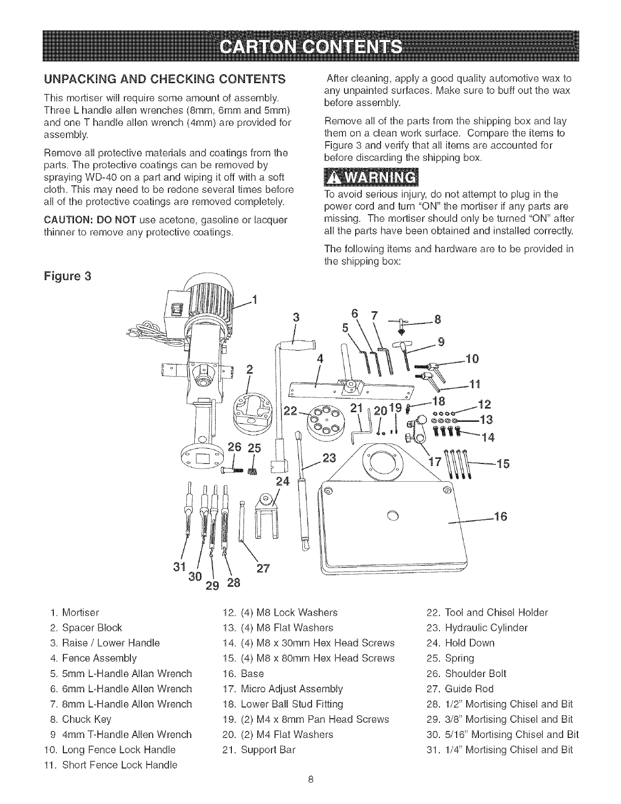
Figure 3
2
26 25
After cleaning, apply a good quality automotive wax to
any unpainted surfaces, Make sure to buff out the wax
before assembly,
Remove all of the parts from the shipping box and lay
them on a dean work surface, Compare the items to
Figure 3 and verify that all items are accounted for
before discarding the shipping box,
To avoid serious injury, do not attempt to plug in the
power cord and turn "ON" the mortiser if any parts are
missing, The mortiser should only be turned "ON" after
all the parts have been obtained and installed correctly,
The following items and hardware are to be provided in
the shipping box:
4
3!1
30 29
1, Mortiser
2, Spacer Block
3, Raise /Lower Handle
4, Fence Assembly
5, 5ram L-Handle Allan Wrench
6, 6ram L-Handle Allen Wrench
7, 8ram L-Handle Allen Wrench
8, Chuck Key
9 4ram ToHandle Allen Wrench
10, Long Fence Lock Handle
11, Short Fence Lock Handle
24
27
28
©
12, (4) M8 Lock Washers
13, (4) M8 Fiat Washers
14, (4) M8 x 30mm Hex Head Screws
15, (4) M8 x 80mm Hex Head Screws
16, Base
17, Micro Adjust Assembly
18, Lower Ball Stud Fitting
19, (2) M4 x 8mm Pan Head Screws
20, (2) M4 Fiat Washers
21, Support Bar
22, Tool and Chisel Holder
23, Hydraulic Cylinder
24, Hold Down
25, Spring
26, Shoulder Bolt
27, Guide Rod
28, 1/2" Mortising Chisel and Bit
29, 3/8" Mortising Chisel and Bit
30, 5/16" Mortising Chisel and Bit
31, 1/4" Mortising Chisel and Bit
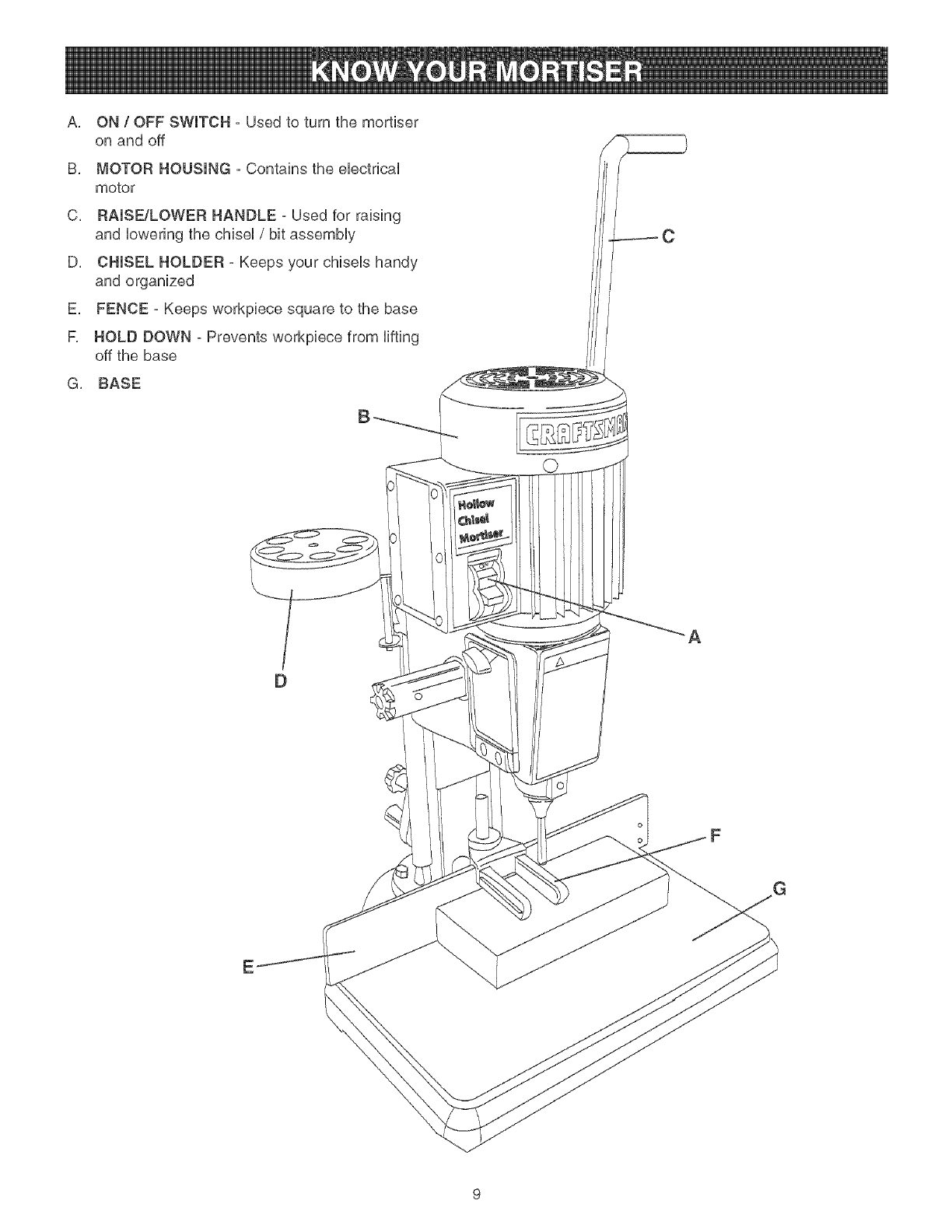
A, ON/OFF SWITCH - Used to turn the mortiser
on and off
B, MOTOR HOUSING - Contains the eUectdcaU
motor
C, RAISE/LOWER HANDLE - Used for raising
and Uowedng the chiseU/bit assemMy
D, CHISEL HOLDER - Keeps your chiseUs handy
and organized
E, FENCE - Keeps workpiece square to the base
F, HOLD DOWN - Prevents workpiece from Hfting
off the base
G, BASE
B
A
oF
E
Four different size allen wrenches are provided to assist BASE ASSEMBLY
in the assemMy of the Mortiser,
1, DO NOT assembb the Mortiser until you are sure
the tooUis disconnected from the power source,
2, DO NOT assembb the Mortiser until you are sure
the power switch is in the off position,
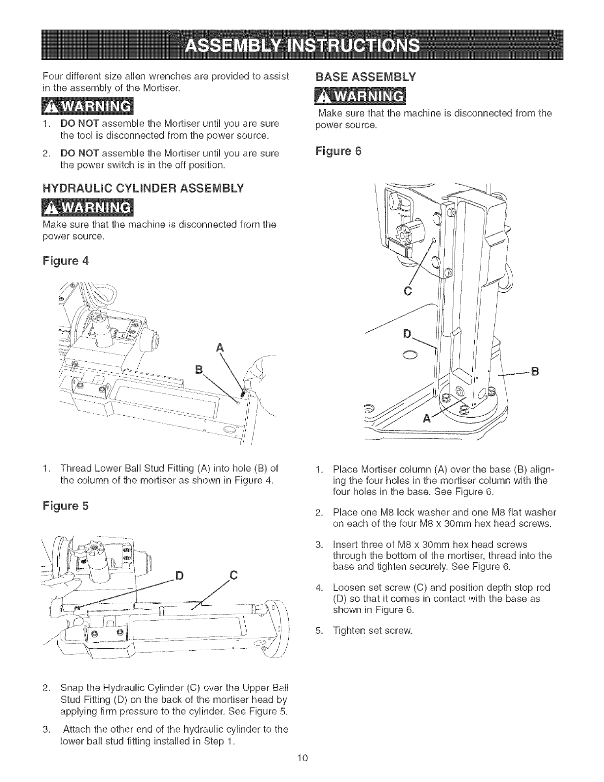
HYDRAULIC CYLINDER ASSEMBLY
Make sure that the machine is disconnected from the
power source,
Figure 4
\
A
B
i
/
/
/
Make sure that the machine is disconnected from the
powe r sou rce,
Figure 6
C
0
1, Thread Lower Ball Stud Fitting (A) into hob (B) of
the column of the mortiser as shown in Figure 4,
Figure 5
C
1,
2,
3,
4,
Place Mortiser column (A) over the base (B) align-
ing the four hobs in the mortiser column with the
four hobs in the base, See Figure 6,
Place one M8 lock washer and one M8 fiat washer
on each of the four M8 x 30mm hex head screws,
insert three of M8 x 30mm hex head screws
through the bottom of the mortiser, thread into the
base and tighten securely, See Figure 6,
Loosen set screw (C) and position depth stop rod
(D) so that it comes in contact with the base as
shown in Figure 6,
5, Tighten set screw,
2, Snap the Hydraulic Cylinder (C) over the Upper Ball
Stud Fitting (D) on the back of the mortiser head by
applying firm pressure to the cylinder, See Figure 5,
3, Attach the other end of the hydraulic cylinder to the
lower ball stud fitting installed in Step 1,
10
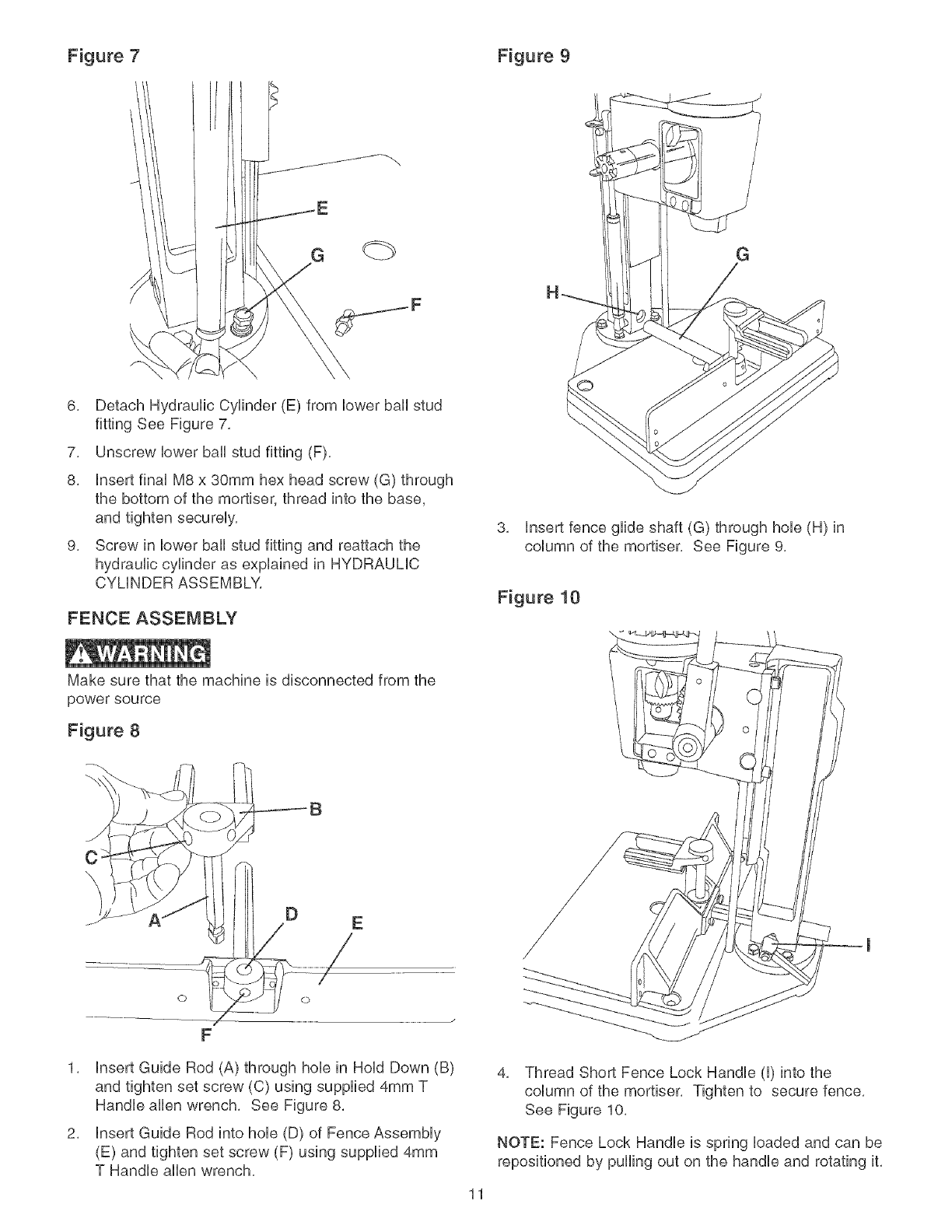
Figure 7 Figure 9
G
\
6, Detach Hydraufic Cyfinder (E) from bwer bah stud
fitting See Figure 7,
7, Unscrew bwer bail stud fitting (F),
8, insert finaUM8 x 30mm hex head screw (G) through
the bottom of the mortiser, thread into the base,
and tighten secureUy,
9, Screw in bwer bail stud fitting and reattach the
hydraulic cylinder as expUained in HYDRAUMC
CYMNDER ASSEMBLY,
FENCE ASSEMBLY
Make sure that the machine is disconnected from the
power source
Figure 8
C
\
E
F
1, insert Guide Rod (A) through hob in HoUdDown (B)
and tighten set screw (C) using supplied 4mm T
Handb aflen wrench, See Figure 8,
2, insert Guide Rod into hob (D) of Fence AssemMy
(E) and tighten set screw (F) using supplied 4mm
T Handle allen wrench,
G
3, Insert fence glide shaft (G) through hole (H) in
column of the mortiser, See Figure 9,
Figure 10
\
11
4. Thread Short Fence Lock Handle (I) into the
column of the mortiser. Tighten to secure fence.
See Figure 10.
NOTE: Fence Lock Handle is spring loaded and can be
repositioned by puffing out on the handle and rotating it,
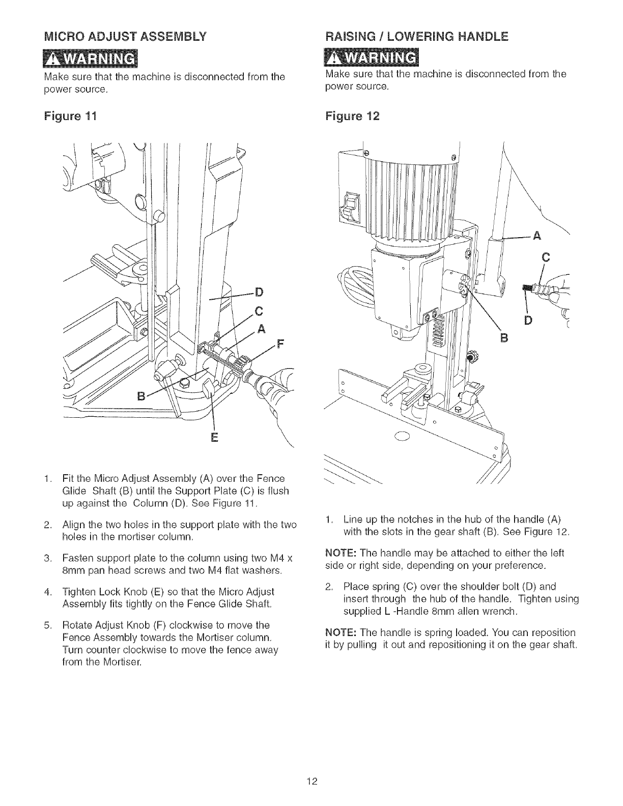
MICF{O ADJUST ASSEMBLY F_AISUNG /LOWERING HANDLE
Make sure that the machine is disconnected from the
power source.
Figure 11
Make sure that the machine is disconnected from the
powe r sou rce,
Figure 12
A
C
D c
B
2,
3,
4,
5,
Fit the Micro Adjust Assembly (A) over the Fence
Glide Shaft (B) until the Support Hate (C) is flush
up against the Column (D), See Figure 11,
Align the two hobs in the support plate with the two
hobs in the mortiser column,
Fasten support plate to the column using two M4 x
8mm pan head screws and two M4 fiat washers,
Tighten Lock Knob (E) so that the Micro Adjust
Assembly fits tightly on the Fence Glide Shaft,
Rotate Adjust Knob (F) clockwise to move the
Fence Assembly towards the Mortiser column,
Turn counter clockwise to move the fence away
from the Mortiser,
1, Line up the notches in the hub of the handle (A)
with the slots in the gear shaft (B), See Figure 12,
NOTE: The handle may be attached to either the left
side or right side, depending on your preference,
2, Place spring (C) over the shoulder bolt (D) and
insert through the hub of the handle, Tighten using
supplied L =Handle 8mm allen wrench,
NOTE: The handle is spring loaded, You can reposition
it by pulling it out and repositioning it on the gear shaft,
12
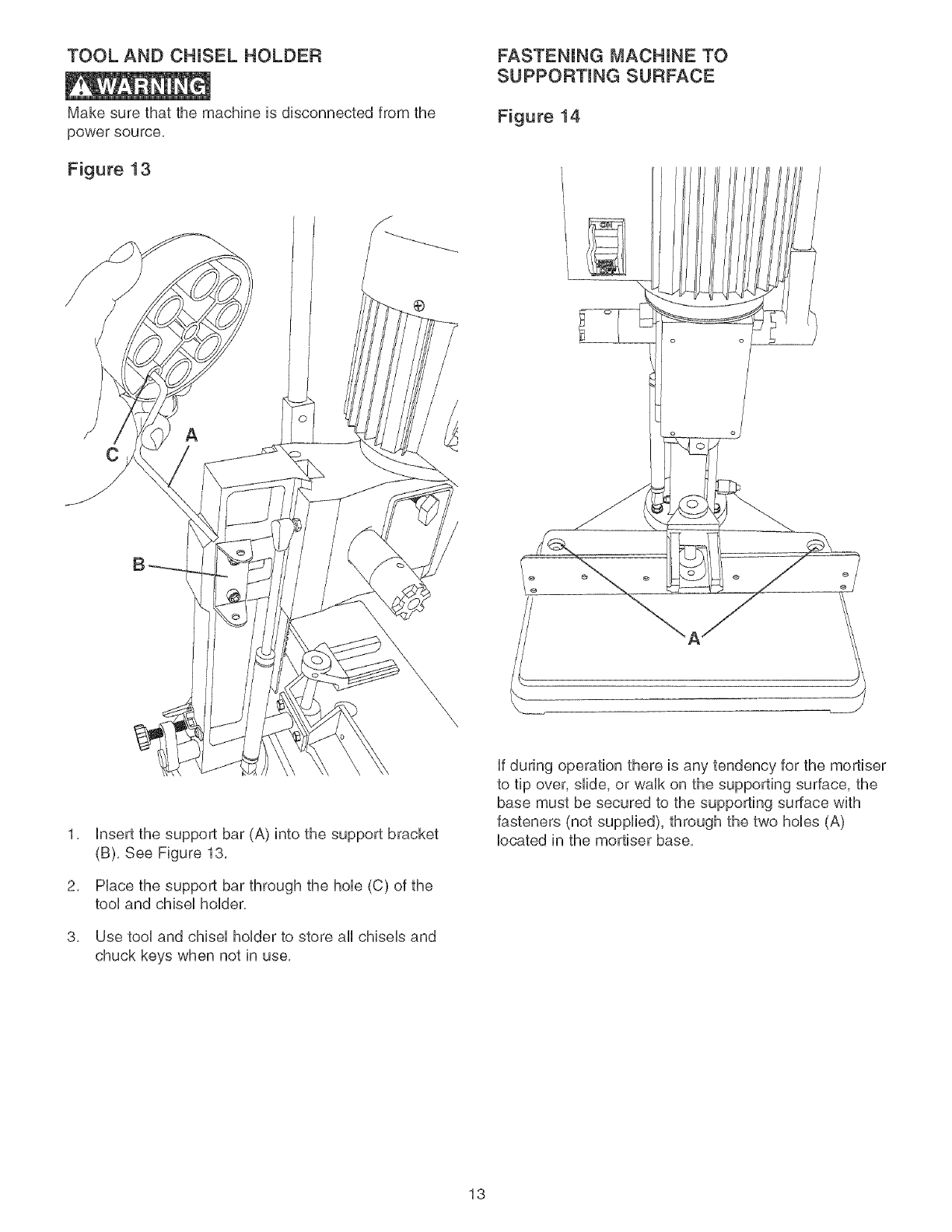
TOOL AND CHUSEL HOLDER FASTENING MACHINE TO
SUPPORTING SURFACE
Make sure that the machine is disconnected from the
power source,
Figure 13
Figure 14
2,
3,
®
C
\\\,
insert the support bar (A) into the support bracket
(B), See Figure 13,
PUacethe support bar through the hob (C) of the
tooUand chbeU hoUder,
Use tool and chisel holder to store all chisels and
chuck keys when not in use,
,__ J
if during operation there is any tendency for the mortiser
to tip over, slide, or walk on the supporting surface, the
base must be secured to the supporting surface with
fasteners (not supplied), through the two hobs (A)
located in the mortiser base,
13
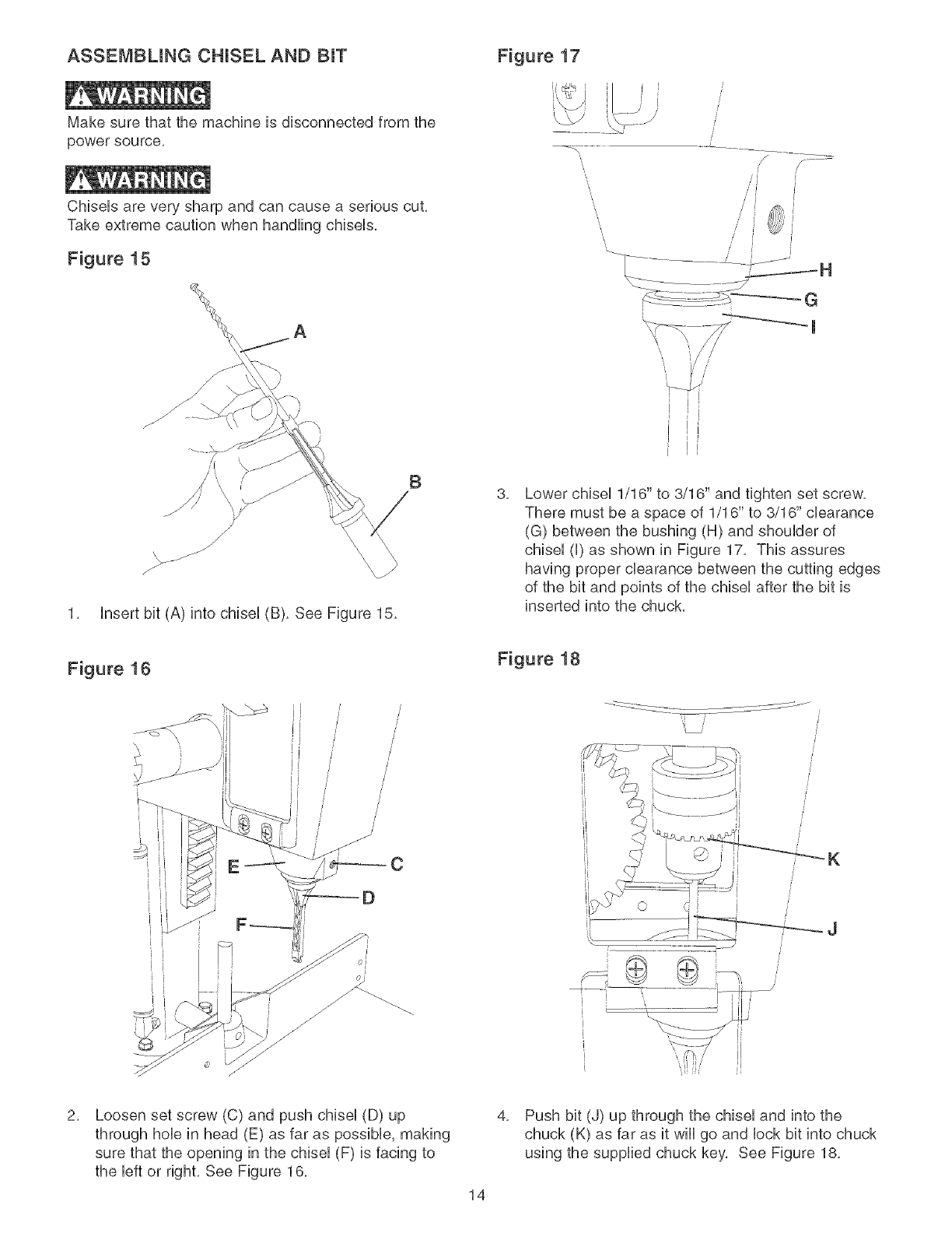
ASSEMBLING CHUSEL AND BIT
Make sure that the machine is disconnected from the
power source.
ChbeUs are very sharp and can cause a serious cut.
Take extreme caution when handling chiseUs.
Figure 15
Figure 17
/J //
/ / _'i
1. Insert bit (A) into chisel (B). See Figure 15.
B
3, Lower chiseU 1/16" to 3/16" and tighten set screw.
There must be a space of 1/16" to 3/16" cbarance
(G) between the bushing (H) and shouUder of
chiseU (U)as shown in Figure 17. This assures
having proper clearance between the cutting edges
of the bit and points of the chiseUafter the bit is
inserted into the chuck.
Figure 16
E
} /
/
/
/
/
J
/
/
/
/
/
/
C
Figure 18
/
/
K
[[
[
i
[[
2, Loosen set screw (C) and push chisel (D) up
through hole in head (E) as far as possible, making
sure that the opening in the chisel (F) is facing to
the left or right. See Figure 16.
4,
14
Push bit (J) up through the chisel and into the
chuck (K) as far as it will go and lock bit into chuck
using the supplied chuck key, See Figure 18,
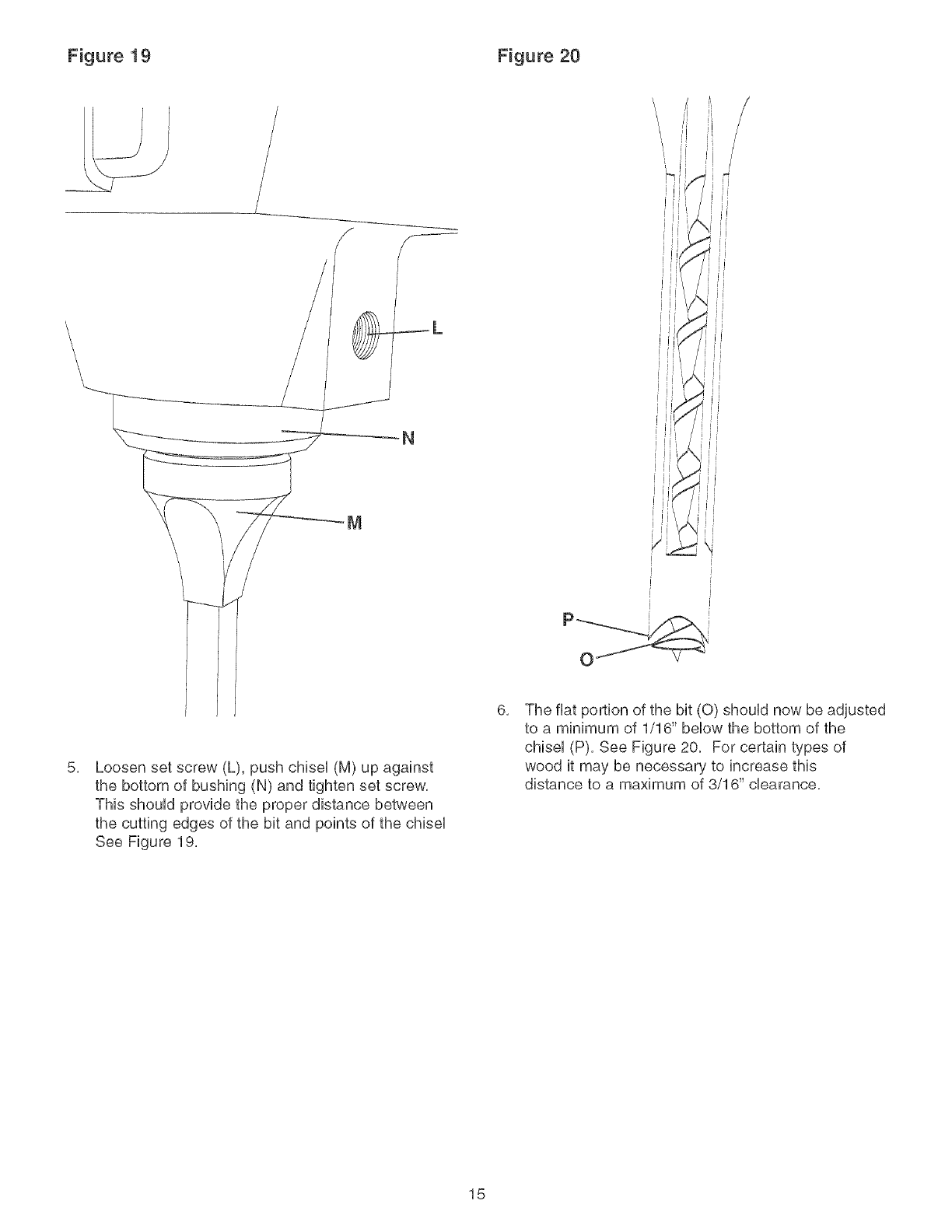
Figure 19 Figure 20
\\\\\
_L
N
i
i
i
5, Loosen set screw (L), push chiseU (M) up against
the bottom of bushing (N) and tighten set screw,
This shouUd provide the proper distance between
the cutting edges of the bit and points of the chiseU
See Figure 19,
6, The fiat portion of the bit (0) shouUd now be adjusted
to a minimum of 1/16" beUowthe bottom of the
chiseU (P), See Figure 20, For certain types of
wood it may be necessary to increase this
distance to a maximum of 3/16" clearance,
15

ON-OFF SWITCH
The switch is Uocatedon the side of the motor, To turn
the machine on flip the switch up to the "ON" position,
To turn the machine off, move the switch down to the
"OFF" position,
Figure 21
A_
@
When the tooUis not in use, the switch shouUd be Uocked
in the "OFF" position to prevent unauthorized use, This
can be done by grasping the switch toggUe (A) and
pulling it out of the switch, With the switch toggUe
removed, the switch wHUnot operate, ShouUd the toggUe
be removed while the machine is running, the switch
can be turned off once, but cannot be restarted without
inserting the switch toggUe, See Figure 21,
RAISUNG AND LOWERUNG THE HEAD
Figure 22
B
DEPTH STOP ROD
Figure 23
A
The depth stop rod is provided to Hmit the depth of the
chisel, See Figure 23,
1,
2,
To adjust the depth stop rod (A), loosen set screw
(B) using provided 4mm T handle allen wrench,
Lower head until the chisel(C) is at the desired
depth,
3, Lower depth stop rod until it contacts the base (D),
4, Tighten set screw,
The head is raised and lowered by using the lever, For
maximum leverage during the mortising operation, the
lever can be repositioned by pulling out the hub (A) of
the lever assembly and repositioning hub on the pinion
shaft (B), See figure 22,
16
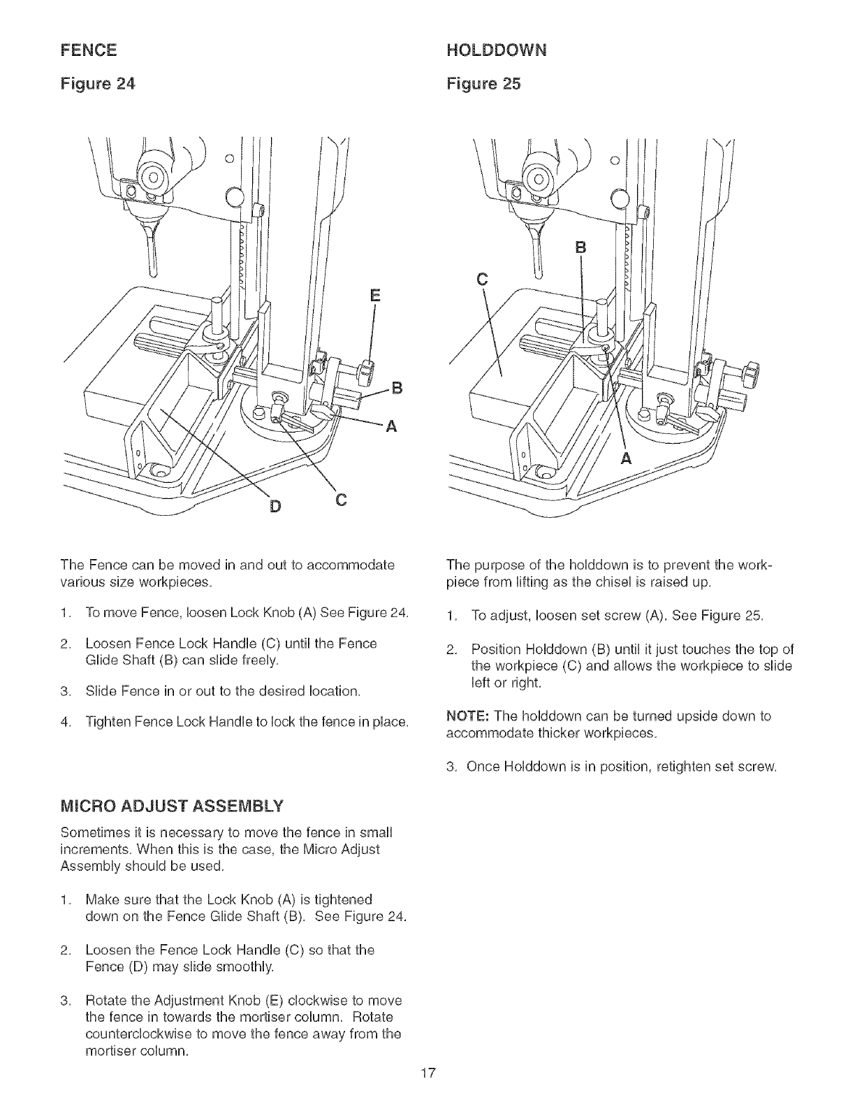
FENCE
Figure 24
HOLDDOWN
Figure 25
\O
C
C
O
The Fence can be moved in and out to accommodate
various size workpbces,
1, To move Fence, bosen Lock Knob (A) See Figure 24,
2, Loosen Fence Lock Handb (C) until the Fence
GUideShaft (B) can slide freeUy,
3, SHde Fence in or out to the desired bcation,
4, Tighten Fence Lock Handb to bck the fence in pUace,
MICRO ADJUST ASSEMBLY
Sometimes it is necessary to move the fence in small
increments, When this is the case, the Micro Adjust
AssemMy shouUd be used,
1, Make sure that the Lock Knob (A) is tightened
down on the Fence GUideShaft (B), See Figure 24,
2, Loosen the Fence Lock Handb (C) so that the
Fence (D) may slide smootHy,
3, Rotate the Adjustment Knob (E) clockwise to move
the fence in towards the mortiser column, Rotate
counterclockwise to move the fence away from the
mortiser column,
The purpose of the holddown is to prevent the work-
piece from lifting as the chisel is raised up,
1, To adjust, loosen set screw (A), See Figure 25,
2, Position HoUddown (B) until it just touches the top of
the workpbce (C) and allows the workpbce to slide
left or right,
NOTE: The holddown can be turned upside down to
accommodate thicker workpieces,
3, Once Holddown is in position, retighten set screw,
17
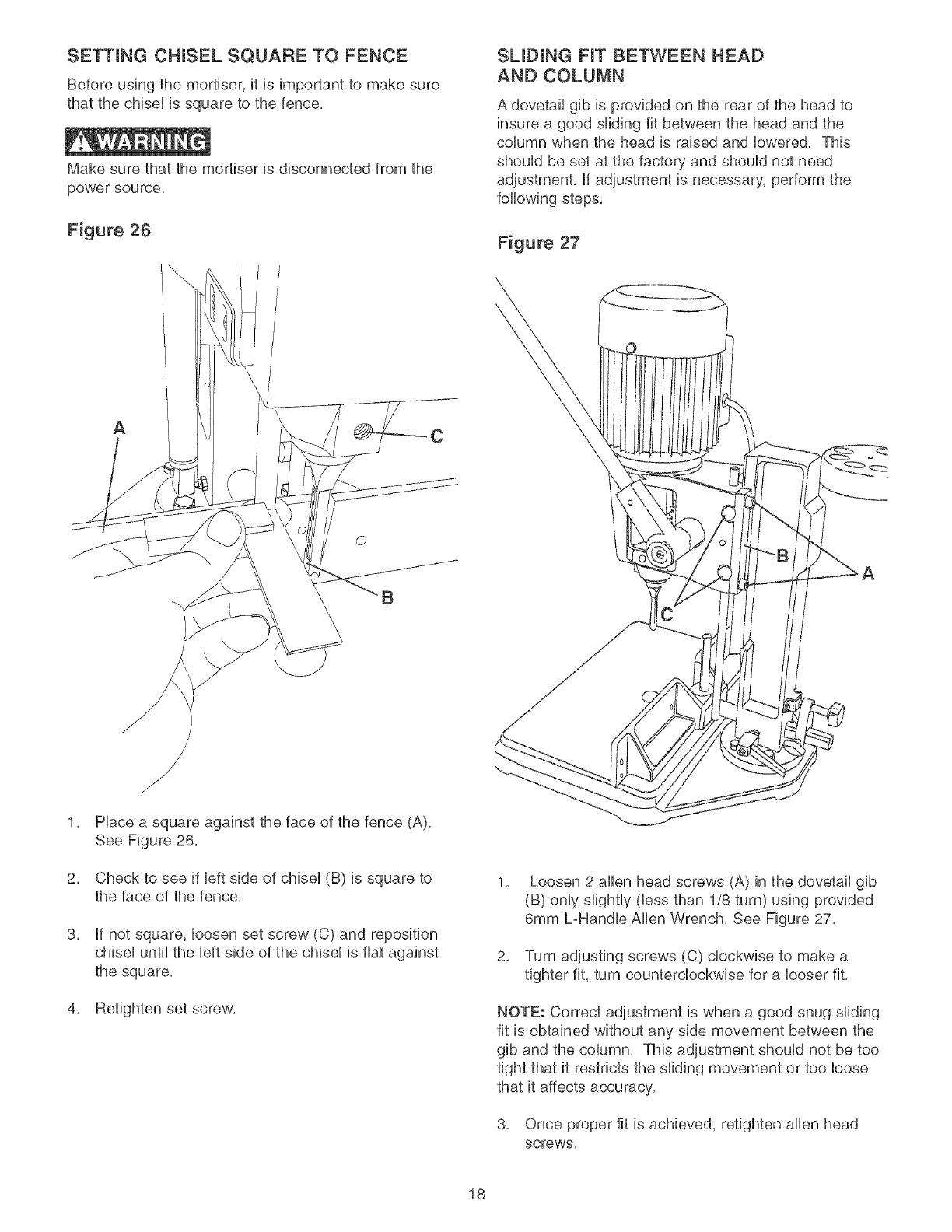
SETTING CHUSEL SQUARE TO FENCE
Before using the mortber, it is important to make sure
that the chiseUis square to the fence,
Make sure that the mortiser is disconnected from the
power source,
Figure 26
SUDUNG FIT BETWEEN HEAD
AND COLUMN
A dovetail gib is provided on the rear of the head to
insure a good sliding fit between the head and the
column when the head is raised and lowered, This
should be set at the factory and should not need
adjustment, if adjustment is necessary, perform the
following steps,
Figure 27
AC
©
B
2,
3,
/
f
Place a square against the face of the fence (A),
See Figure 26,
Check to see if left side of chisel (B) is square to
the face of the fence,
if not square, loosen set screw (C) and reposition
chisel until the left side of the chisel is fiat against
the square,
4, Retighten set screw,
1, Loosen 2 allen head screws (A) in the dovetail gib
(B) only slightly (bss than 1/8 turn) using provided
6mm L-Handle Allen Wrench, See Figure 27,
2, Turn adjusting screws (C) clockwise to make a
tighter fit, turn counterclockwise for a looser fit,
NOTE: Correct adjustment is when a good snug sliding
fit is obtained without any side movement between the
gib and the column, This adjustment should not be too
tight that it restricts the sliding movement or too loose
that it affects accuracy,
3, Once proper fit is achieved, retighten allen head
screws,
18
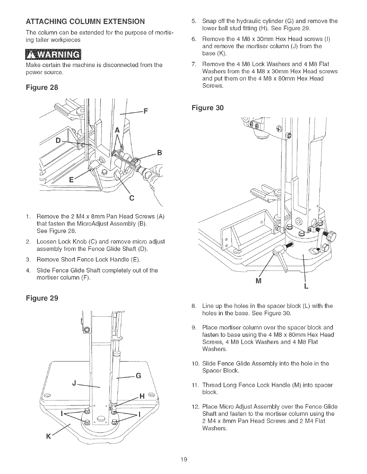
ATTACHUNG COLUMN EXTENSUON
The coUumn can be extended for the purpose of mortis-
ing taller workpbces
Make certain the machine is disconnected from the
power source,
Figure 28
5, Snap off the hydraulic cylinder (G) and remove the
lower ball stud fitting (H), See Figure 29,
6, Remove the 4 M8 x 30ram Hex Head screws (I)
and remove the mortiser column (J) from the
base (K),
7, Remove the 4 M8 Lock Washers and 4 M8 Fiat
Washers from the 4 M8 x 30ram Hex Head screws
and put them on the 4 M8 x 80mm Hex Head
Screws,
C
1, Remove the 2 M4 x 8mm Pan Head Screws (A)
that fasten the MicroAdjust Assembly (B),
See Figure 28,
2, Loosen Lock Knob (C) and remove micro adjust
assembly from the Fence Glide Shaft (D),
3, Remove Short Fence Lock Handle (E),
4, Slide Fence Glide Shaft completely out of the
mortiser column (F),
Figure 29
Figure 30
8,
9,
10,
11,
12,
Line up the hobs in the spacer block (L) with the
hobs in the base, See Figure 30,
Place mortiser column over the spacer block and
fasten to base using the 4 M8 x 80mm Hex Head
Screws, 4 M8 Lock Washers and 4 M8 Fiat
Washers,
Slide Fence Glide Assembly into the hob in the
Spacer Block,
Thread Long Fence Lock Handle (M) into spacer
block,
Place Micro Adjust Assembly over the Fence Glide
Shaft and fasten to the mortiser column using the
2 M4 x 8ram Pan Head Screws and 2 M4 Fiat
Washers,
19
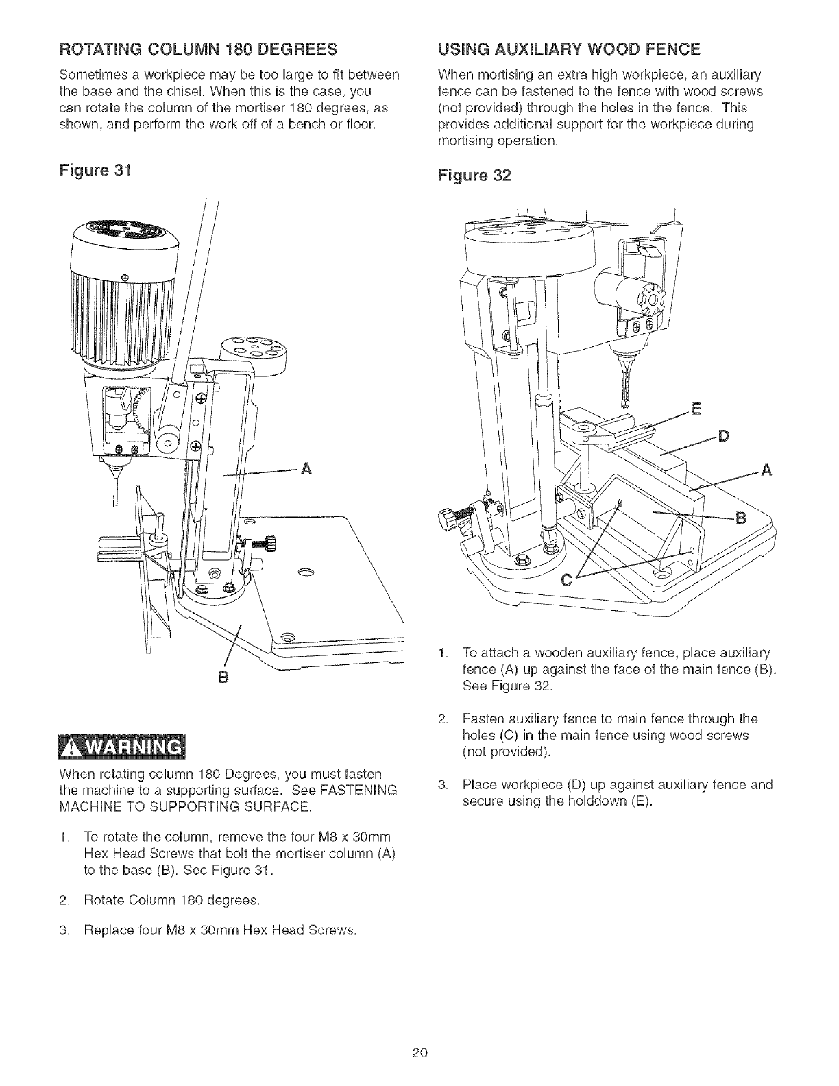
ROTATING COLUMN 180 DEGREES
Sometimes a workpbce may be too iarge to fit between
the base and the chisei, When this is the case, you
can rotate the column of the mortber 180 degrees, as
shown, and perform the work off of a bench or floor,
Figure 31
USUNG AUXUUARY WOOD FENCE
When mortising an extra high workpbce, an auxiliary
fence can be fastened to the fence with wood screws
(not provided) through the hobs in the fence, This
provides additionai support for the workpbce during
mortising operation,
Figure 32
A
B
When rotating column 180 Degrees, you must fasten
the machine to a supporting surface, See FASTENING
MACHINE TO SUPPORTING SURFACE,
1, To rotate the coHumn, remove the four M8 x 30mm
Hex Head Screws that bolt the mortber column (A)
to the base (B), See Figure 31,
2, Rotate Column 180 degrees,
3, RepHace four M8 x 30mm Hex Head Screws,
1,
2,
3,
To attach a wooden auxiliary fence, piace auxiliary
fence (A) up against the face of the main fence (B),
See Figure 32,
Fasten auxiliary fence to main fence through the
hobs (C) in the main fence using wood screws
(not provided),
Place workpiece (D) up against auxiliary fence and
secure using the holddown (E),
2O
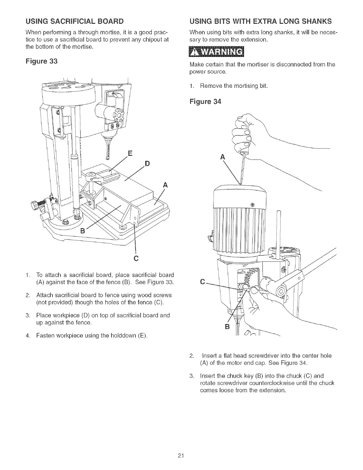
USUNG SACF{IFICIAL BOARD
When performing a through mortise, it is a good prac-
tice to use a sacrificial board to prevent any chipout at
the bottom of the mortise,
Figure 33
A
2,
3,
C
To attach a sacrificial board, place sacrificial board
(A) against the face of the fence (B), See Figure 38,
Attach sacrificial board to fence using wood screws
(not provided) though the hobs of the fence (C),
Place workpiece (D) on top of sacrificial board and
up against the fence,
4, Fasten workpiece using the holddown (E),
USUNG BITS WITH EXTRA LONG SHANKS
When using bits with extra long shanks, it wiii be neces-
sary to remove the extension,
Make certain that the mortiser is disconnected from the
power source.
1, Remove the mortising bit,
Figure 34
A
\
B
2,
3,
insert a fiat head screwdriver into the center hob
(A) of the motor end cap, See Figure 34,
insert the chuck key (B) into the chuck (C) and
rotate screwdriver counterclockwise until the chuck
comes loose from the extension,
21
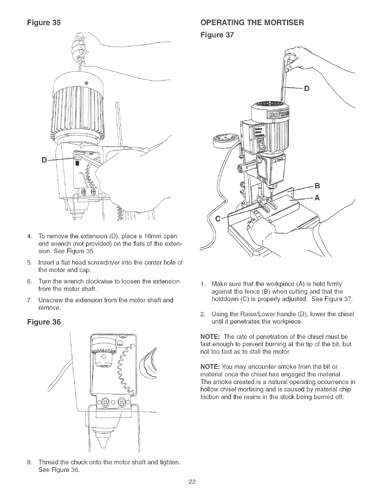
Figure 35 OPERATING THE MORTISER
Figure 37
D_
4. To remove the extension (D). pUacea 16mm open
end wrench (not provided) on the flats of the exten-
sion. See Figure 35.
5. Insert a fiat head screwdriver into the center hoUeof
the motor end cap.
6. Turn the wrench clockwise to Uoosenthe extension
from the motor shaft.
7. Unscrew the extension from the motor shaft and
remove.
Figure 36
1. Make sure that the workpiece (A) is heUdfirmUy
against the fence (B) when cutting and that the
hoUddown (C) is propedy adjusted. See Figure 37.
2. Using the Raise/Lower handUe (D), Uowerthe chiseU
until it penetrates the workpiece.
NOTE: The rate of penetration of the chiseU must be
fast enough to prevent burning at the tip of the bit, but
not too fast as to staff the motor.
NOTE: You may encounter smoke from the bit or
matedaU once the chiseU has engaged the material.
The smoke created is a natural operating occurrence in
hollow chisel mortising and is caused by material chip
friction and the resins in the stock being burned off.
8. Thread the chuck onto the motor shaft and tighten.
See Figure 36.
22

Figure 38 Figure 39
3, When making next penetration, leave a gap
between the first and second holes, See Figure 38,
4, Once the desired Uengthof the mortise is achieved,
go back and chiseUout the remaining gaps, This
wHUensure a smooth, dean mortise, See Figure 39,
NOTE: BUuing of the chiseU is not indicative of a dull
chisel but a combination of friction and resin buildup
on the cutting faces of the chisel A dull chiseU can be
detected by the amount of excess force required to
compUete a cut,
23
Repairsto thispowertoolshouldbeperformedby
trainedpersonnelonly,ContactyournearestSears
ServiceCenterforauthorizedservice,Unauthorized
repairsor replacementwithnon-factorypartscould
causeseriousinjurytotheoperatoranddamageto
Topreventinjurytoyourselfordamageto themachine,
turntheswitchtothe"OFF"positionandunplugthe
powercordfromtheelectricalreceptaclebeforemaking
anyadjustments,
TheMortiserwilloperatebestif it is keptinproper
operatingcondition,Keepunitadjustedasdescribedin
OPERATIONSANDADJUSTMENTS,
Turnthepowerswitch"OFF"andunplugthepower
cordfromitspowersource,
Donotallowgumandpitchto accumulateoncutting
tool.
Donotallowchipstoaccumulateonoraroundthe
machine,
Keepchiselsandbitssharp,Keepingasparesetof
chiselsandbitsonhandisrecommended,Replace-
mentchiselsandbitsareavailableat Sears,
CAUTION:DONOTUSEFLAMMABLEMATERIALS
tocleanthismachine,Acleandryragor brushisall
thatisneededto removedustanddebrisbuildup,
PROTECTING CAST iRON TABLE
FROM RUST
To clean and maintain the unpainted cast iron surfaces:
Apply a heavy coat of WD-40 onto the unpainted cast
iron surface,
Use a fine steel wool pad to buff the unpainted cast
iron, Make sure to buff in a "front to rear" direction
only, A sideoto-side buffing motion will show in the
finely ground cast iron as a flaw, defect or scratches,
Reapply WD-40 and buff the unpainted cast iron
surfaces until the stain is removed, Make sure you
use the same frontoto-rear buffing direction to avoid
scratching or marring the cast iron surface,
After all stains and/or rust have been removed,
clean aii oil and dirt from the table saw using a soft
cloth or rag,
Lastly, you need to apply a good automotive paste
wax to all unpainted cast iron surfaces, This will help
to protect the saw from rusting from further contact
with moisture or oily hands,
The Mortiser has sealed lubricated bearings in the
motor housing that do not require any additional
lubrication from the operator,
Fence guide and elevation screws should be cleaned
of debris and greased as needed,
Occasionally apply a few drops of light machine oil to
gibs to keep tables free in relation to base,
MAKE CERTAIN to turn the power "OFF" and unplug
the power cord from its power source,
The environment and frequency of human contact can
have a very detrimental impact on unpainted cast iron
surfaces, Moisture, humidity and oils (from human
hands!) can cause the unpainted cast iron surfaces to
mar or rust, so it is important to conduct routine main°
tenance to keep your mortiser looking new, Cleaning
and waxing the cast iron surfaces on a regular main°
tenance schedule is recommended as follows:
24
TOPREVENTINJURYTOYOURSELFordamageto themortiser,turntheswitchtotheOFFpositionandunplugthe
powercordfromtheelectricalreceptaclebeforemakinganyadjustments,
PROBLEM
Motor does not
start or does not
come up to futl
speed
Motor stalls or
circuit breakers
open frequently
Motor running
too hot
Drill bit stalls
or s_ips
Drilm bit or matedam
smokes or burns
Excessive ddH bit
runout or wobbme
LIKELY CAUSE(S)
1. Switch key is removed.
2. Defective switch
3. Defective capacitor
4. Low line voltage
5. Defective motor
1. Circuit overload
2. Low line voltage
3. Motor overload
4. Incorrect fuses on circuit breakers
5. Short circuit in motor; !oose
connections or worn insulation on
lead wires.
1. Restricted air circulation due to dust
accumulation.
2. Motor overload
1. Drill bit is not securely tightened in
chuck.
1. incorrect spindle speed.
2. Chips not exiting out of drill hole.
3. Dull drill bit.
1. Bent drill bit.
2. Drill bit not properly installed in chuck.
SOLUTION
1. Insert switch key.
2. Have switch replaced.
3. Have capacitor replaced.
4. Correct low line voltage condition. If machine is
plugged into an extension cord, disconnect and plug
directly into wail outlet.
5. Have motor replaced.
NOTE: 3 and 4 must be done by a qualified service
technician; Consult Sears service.
1,
2.
3,
4.
5,
Reduce circuit load (turn off other appliances).
Correct low line voltage condition. Check line voltage
with a multi-meter. If mortiser is plugged into an
extension cord, unplug mortiser from extension cord
and plug mortiser directly to wall outlet.
Reduce load on motor, slow down feed rate.
Have correct fuses on circuit breakers installed by a
qualified electrician.
inspect terminals in motor for damaged insulation and
shorted wires and have them replaced. Check all
power lead connections.
1. Clean dust and restore normal air circulation around
motor.
2. Reduce load on motor, slow down feed rate.
1. Install dril! bit properly. See ASSEMBLING CHISEL AND
BIT in ASSEMBLY INSTRUCTIONS.
1. Reduce spindle speed. See speed diagram on the
under side of the belt cover.
2. Retract drill bit frequently during drilling operation to
clear chips from hole.
3. Replace or sharpen drill bit.
1. Replace with a straight or new drill bit.
2. install drill bit properly. See ASSEMBLING CHISEL
AND BiT in ASSEMBLY iNSTRUCTiONS.
25

HOLLOWCHmSELMORTmSER MODELN0.152.219070
Whenservicing,useonlyCRAFTSMANreplacementparts,Useof anyotherpartsmaycreatea HAZARDorcause
productdamage,
Anyattemptto repairor replaceelectricalpartsonthisMortisermaycreatea HAZARDunlessrepairisdonebya
qualifiedservicetechnician,RepairserviceisavailableatyournearestSearsServiceCenter,
AlwaysorderbyPARTNUMBER,notbykeynumber,
KEY PART KEY PART
NO. NO. DESCRIPTION QTY. NO. NO. DESCRIPTION
1 0R93300 MOTOR MAIN ASSY (INCL, 1A,1B,1C,2,3,4,5,6,7,8,9)
1A 0R9330! MOTOR ASSY. INCL: 1/2HP 120V6A 1720RPM
1B 0R93354 POWER CORD
10 0R93353 STRAIN RELIEF
2 0R9376! CRAFTSMAN LABEL
3 0R93302 SW_TCH BOX COVER
4 0R93763 SPECIFiCATiON LABEL
5 0R93383 2,9 X 12MM SELF TAP PAN HD SCREW
6 0R93303 CAPACITOR 16UF
7 0R93304 SWITCH
8 0R93305 SWITCH KEY
9 0R93762 NAMEPLATE
10 0R93306 ADAPTER
1! 0R93307 CHUCK
11A 0R93352 CHUCK KEY
12 0R93308 DEPTH STOP ROD
13 0R93309 MOTOR SPACER
14 0R93376 M6 X 30MM SPRING PIN
15 0R93310 GEAR SHAFT JOINT
16 0R93311 PLASTIC WASHER
17 0R93312 LOCK KNOB
18 0R93313 SPACER
19 0R90507 M5 X 8MM PAN HD SCREW
20 0R93314 HINGE
21 0R93315 COVER
22 0R93311 PLASTIC WASHER
23 STD840610 M6 HEX NUT
24 0R93316 LOCK PLATE
25 0R93370 M6 NYLOK NUT
26 0R91821 M8 X 20MM HEX SOC SET SCREW
27 0R93317 BUSHING
28 0R93377 M6 X 45MM HEX SOC HD SCREW
29 0R93318 HEAD CASTING
30 0R93764 WARNING LABEL
30A 0R93369 3MM DRIVE RIVET
31 0R93380 M8 X 15MM HEX SOC SET SCREW
32 0R93379 M8 X IOMM TRUSS HD SCREW
33 0R93319 COLUMN GUIDE GIB
34 0R93381 M8 X 20MM HEX SOC HD SCREW
35 0R93320 GEAR
36 0R93321 COLLAR
37 0R93323 M5 X 5MM HEX SOC SET SCREW
38 0R93322 GEAR SHAFT
39 0R93376 M6 X 30MM SPRING PIN
40 0R93310 GEAR SHAFT JOINT
41 0R93324 HANDLE JOINT
42 0R93325 SPR_NG
43 0R93326 SHOULDER BOLT
44 0R93375 M6 X 20MM SPR_NG P_N
45 0R93327 GRiP
46 0R93328 HANDLE SHAFT
47 0R93329 KEY
48 0R93312 LOCK KNOB
49 0R93311 PLASTIC WASHER
50 0R93311 PLASTIC WASHER
51 STD840610 M6 HEX NUT
1
1
1
1
1
1
1
6
1
1
1
1
1
1
1
1
1
1
1
1
1
1
2
1
1
1
1
1
1
1
1
4
1
1
52 0R93370 M6 NYLOK NUT
53 0R93316 LOCK PLATE
54 0R93315 COVER
55 0R93314 H_NGE
56 0R90507 M5 X 8MM PAN HD SCREW
57 0R93330 T-HANDLE WRENCH
58 0R93331 CHISEL HOLDER
59 0R93332 SUPPORT BAR
60 0R93333 SUPPORT BRACKET
61 0R93372 M6 X 12MM REX SOC HD SCREW
62 STD852006 M6 LOCKWASHER
63 0R93334 COLUMN
64 0R93370 M6 NYLOK NUT
65 STD851004 M4 FLAT WASHER
66 0R90346 M4 X 8MM PAN HD SCREW
67 0R93335 SUPPORT PLATE
68 STD851006 M6 FLAT WASHER
69 0R93336 ADJUST KNOB
70 0R93337 LOCK KNOB
71 0R93338 ADJUST BRACKET
72 STD835030 M8 X 30MM HEX HD SCREW
73 STD852008 M8 LOCKWASHER
74 STD851008 M8 FLAT WASHER
75 0R93339 HANDLE ASSEMBLY (SHORT)
76 0R93340 BASE
77 STD851006 M6 FLATWASHER
78 STD852006 M6 LOCKWASHER
79 0R93374 M6 X 20MM HEX SOC HD SCREW
80 0R93341 FENCE GUDE PAD
81 0R93342 FENCE GUDE ASSY
82 0R93343 FENCE
83 0R93378 M8 X IOMM HEX SOD SET SCREW
84 0R93344 HOLD DOWN
85 0R93378 M8 X IOMM HEX SOD SET SCREW
86 0R93345 GUIDE ROD
87 0R93346 STABIUZER
88 0R93347 BALL STUD
89 0R93348 JUNCTION SCREW
90 STD840610 M6 HEX NUT
91 0R93373
92 0R93349
93 0R9337!
94 0R93382
95 0R93350
96 0R93351
97 0R93355
98 0R93356
99 0R93359
100 0R93362
101 0R93365
102 0R91728
103 0R90806
104 0R90292
106 0R93760
QTY.
M6 X 16MM HEX SOC RD SCREW
RACK GEAR
M6 x IOMM HEX SOC HD SCREW
M8 X 90MM HEX HD SCREW
SPACER BLOCK
HANDLE ASSEMBLY (LONG)
CHISELAND DRILL BITASSEMBLY KF
(INCL, 98, 99, 100, 101) (NOT SHOWN) 1
1/4" CHISELAND DRILL B_TASSEMBUY (NOT SHOWN) 1
5/16" CHISEL AND DRILL BF ASSEMBLY (NOT SHOWN) 1
3/8" CHISEL AND DR_LL BIT ASSEMBLY (NOT SHOWN) 1
1/2" CHISEL AND DR_LL BIT ASSEMBLY (NOT SHOWN) 1
5MM HEX WRENCH (NOT SHOWN) 1
6MM HEX WRENCH (NOT SHOWN) 1
8MM HEX WRENCH (NOT SHOWN) 1
INSTRUCTION MANUAL (NOT SHOWN) 1
1
1
1
1
2
1
1
1
1
2
2
1
1
2
2
1
2
1
1
1
4
4
4
1
1
2
2
2
2
1
1
1
1
1
1
1
2
2
2
2
1
1
4
1
1
26

HOLLOWCHmSELMORTmSER MODELN0.152.219070
94 (4)
96
25
56 (2)
83 80 (2)-.
66
67
(4)
(4)
(4)
(2)
41
49
/4s
27

28
®
CE
No. de Modelo
152.219070
C S
PARA SU SEGURRDAD PER-
SONAL: Lea y obedezca todas
las Instrucciones de Seguridad y
Funcionamiento antes de hacer
uso de la Mortajadora.
Linea deAyudaaLQiente
1-800-897-7709
Sirvase tenor listo su
No. de Modelo y No. de Sede
Sears, Roebuck and Co., Hoffman Estates, JL 60179 U.S.A.
No. de Pieza OR93760
Rev. A 29
SECCION PAGJNA
Garantia .............................................................................................................................................................................................. 30
Especificaciones demproducto ........................................................................................................................................................ 30
tnstrucciones de seguddad .............................................................................................................................................................. 31
Directr}ces para Basextensiones e_ctrJcas .................................................................................................................................... 32
tnstrucciones de conexJ6n a tierra .................................................................................................................................................. 33
tnstrucc}ones de seguridad especff{cas ......................................................................................................................................... 34
Accesorios y aditamentos ................................................................................................................................................................ 35
Conten}do de la caja ......................................................................................................................................................................... 38
Conozca su mortajadora .................................................................................................................................................................. 37
tnstrucc}ones de montaje ................................................................................................................................................................. 38
Operaciones y ajuste ........................................................................................................................................................................ 44
Mantenimiento ................................................................................................................................................................................... 52
Guia de JocaHzaci6n de averias ....................................................................................................................................................... 53
Listado de piezas .............................................................................................................................................................................. 54
tnformaci6n de serv}c}o ............................................................................................................................................... Contraportada
GARANTiA COMPLETA DE UN ANO PARA LAS HERRAMIENTAS CRAFTSMAN
Siesta herramienta Craftsman Ilegase a fallar debido a defectos materiates o de elaboraci6n dentro de un aRo a partir de la
fecha de compra, LLAME AL 1-800-4-MY-HOME @ (en EE.UU.) PARA COORDINAR LA REPARACION GRATUITA.
Si se utiliza esta herramienta con fines comerciales o de alquiler, esta garantfa se aplicara por solo noventa dias a partir de la
fecha de compra.
Esta garanfia se aplica s61o mientras que esta herramienta se encuentre en los Estados Unidos.
Esta garanfia le concede derechos legales especfficos, y tambien podra tener otros derechos que varfan de un estado al otro.
Sears Roebuck and Co, Dept 817 WA, Hoffman Estates, IL 60179
Tipo de motor: Inducci6n Attura deI bloque de elevaci6n 2-1/4 pulg.
HP de servicio continuo 1/2 hp Gufa compatible con
HP maximo desarrollado 7/8 hp elbloque de elevaci6n Si
Amperios 6 Microajuste compatible con
Voltios 120 el bloque de etevaci6n Sf
Hertzios 60 Golpe de carrera maximo 5 pulg.
RPM 1725 Distancia deI fondo deI
cabezal a la base 8 pulg.
Tipo de mandrino Llave Distancia deI centro del
Capacidad m_xima del mandrino 3/8 pulg cince! a la guia 3-1/8 pulg.
Dimensiones de cincel: 1/4 x 1/4 pulg. Bajo el reten, posici6n baja 7/8 a 3-1/4 pulg.
5/16 x 5/16 pulg. Bajo el reten, posici6n elevada 1-7/8 a 4-1/4 pulg.
3/8 x 3/8 putg. Dimensiones de la gu[a 14-1/2 x 2-1/2 putg.
1/2 x 1/2 putg. Dimensiones de la base 13-3/4 x 8-3/4 putg.
Microaiuste S[ Dimensiones totales: Alto: 31 pulg.
Portador de broca Si Ancho: 14-1/2 putg.
Posici6n de la agarradera Izquierda o derecha, Profundidad: 16-1/2 putg.
intercambiable
Bloque de elevaci6n incluido Si Peso: 68 libras
3O
INSTRUCCIONES GENERALES
DE SEGURIDAD
El uso de una Mortajadora puede ser peligroso si se hace
case omiso de la seguridad y el sentido comun. El operario
debe estar famiIiarizado con eI funcionamiento de esta her-
ramienta. NO OPERE esta Mortajadora si no entiende plena-
mente Ias limitaciones de esta herramienta. NO MODIF_QUE
este Mortajadora de ninguna manera. REOUERDE: Su
seguridad personal es su responsabilidad.
ANTES DE HACER USO
DE LA MORTAJADORA
Lea y obedezca todas las instrucciones de Seguridad y
Operaci6n antes de operar la Mortajadora para evitar heridas
graves y dare a la herramienta.
1. LEA el Manual de Instrucciones cabalmente. APRENDA
come usar la herramienta para su aplicaci6n propuesta.
2. CONECTE TODAS LAS HERRAMIENTAS A TJERRA.
Si la herramienta viene equipada con un enchufe de tres
roaches, se le debe enchufar en un tomacorrientes de
tres contactos. El tercer macho se utiliza para conectar la
herramienta a tierra y ofrecer protecci6n contra los
cheques el6ctricos accidentales. NO QUITE et tercer
macho. Ver Instrucciones de conexi6n a tierra.
3. EVITE UN ENTORNO DE TRABAJO PELIGROSO. NO
utilice las herramientas el6ctricas en entornos hOmedos
ni las exponga a Ia Iluvia.
4. NO utilice herramientas el6ctricas en Ia presencia de
I[quidos o gases infiamables.
5. Mantenga Ia zona de trabajo limpia, bien iluminada y
organizada EN TODO MOMENTO. NO trabaje en un
entorno con superficies de piso resbalosas debido a los
escombros, grasas y cera.
6, MANTENGA ALEJADOS A LOS VlSJTANTES Y NINOS.
NO permita que haya gente en la zona inmediata de
trabajo, sobre todo cuando Ia herramienta electrica se
encuentre en funcionamiento.
7=
8=
NO FUERCE LA HERRAMJENTA para realizar una
operaci6n para Ia que no fue diseRada. Realizara un
trabajo mas seguro y de mayor catidad s6!o efectuando
aquellas operaciones para las que fue diseRada.
UTtUCE LA VESTIMENTA CORRECTA. NO utilice ropa
hotgada, guantes, corbatas ni artfculos de joyerfa. Estos
arficu!os pueden quedar atrapados en la m_quina
durante Ias operaciones y arrastrar al operario hacia Ias
piezas en movimiento. El usuario debe Ilevar una cubier-
ta protectiva sobre su cabeIIo, si tiene cabello largo, para
protegedo contra el contacto con cualquier pieza en
movimiento.
g= UTlUCE PROTECCION OCULAR SlEMPRE. Cuatquier
herramienta mec_,nica puede expulsar escombros hacia
los oios durante las operaciones, causando daRo ocular
grave y permanente. Los anteojos de use cotidiano NO
son gafas de seguridad. Utilice gafas de seguridad
SIEMPRE (que cumplan con la normativa Z87.1 de
ANSI) cuando vaya a operar herramientas mec#,nicas.
Las gafas de seguridad estan disponibles en las tiendas
de Ventas al Detai de Sears.
10.
11.
12.
13.
UTlUCE PROTECCION AUDITtVA SJEMPRE. El algo-
d6n per sf solo no constituye un dispositivo de protecci6n
aceptable. El equipo auditivo debe cumplir con las
normativas $3.19 de ANSI.
DESENCHUFE LA HERRAMIENTA DEL TOMA-
CORRIENTES SJEMPRE que vaya a realizar cuatquier
ajuste, recambio de piezas o Ilevar a cabo cualquier
tarea de mantenimiento.
MANTENGA TODOS LOS PROTECTORES EN SUS
SIT_OS Y EN BUENAS CONDICIONES DE TRABAJO.
EVlTE LOS ARRANQUES ACCIDENTALES. Aseg0rese
de que e! interrupter de energia se encuentre en la posi-
ci6n de "OFF" (apagado) antes de enchufar el cord6n de
potencia y causar daRo a la herramienta.
14. RETIRE TODAS LAS HERRAMIENTAS DE MANTENI-
M_ENTO de la zona inmediata antes de ENCENDER la
herramienta.
15. SOLO UTlUCE LOS AOOESORIOS RECOMENDADOS.
El use de accesorios incorrectos o indebidos puede
resultar en heridas graves al operario y causar dare a la
herramienta. Si tiene dudas, consuIte eI manual de
instrucciones que viene con ese accesorio en particular.
16. NUNCA DEJE UNA MAQUINA EN FUNCIONAM_ENTO
SiN ATENDER. Mueve eI interruptor de energia a Ia
posici6n de "OFF" (apagado). NO se aJeje de la maquina
hasta que se haya detenido per complete.
17. NO SE PARE SOBRE LA HERRAMtENTA. Esto podr[a
resultar en heridas graves si la herramienta se vuelca o
si usted hace contacto accidental con la herramienta.
18. NO almacene nada sobre o cerca de Ia herramienta
deride alguien pueda intentar pararse sobre la herra-
mienta para alcanzarlo.
19. MANTENGA SU EQUJUBRIO, NO se extienda sobre la
herramienta. UtiIice calzado con sueIas de caucho y
resistentes al aceite. Mantenga el piso despejado de
escombros, grasas o oera.
20. MANTENGA SUS HERRAMIENTAS CON CUIDADO.
Mantenga sus herramientas limpias yen buen estado de
funcionamiento siempre. Mantenga filosas todas las
hoias y las brocas.
31
21. EN TODA Y CADA UNA OCASI6N, REVISE Sl EXiSo
TEN PIEZAS DAf_ADAS ANTES DE HACER USO DE
LA HERRAMIENTA. Revise todos los protectores cuida-
dosamente para asegurarse de que funcionen correcta-
mente, que no esten daBados, y que realicen sus fun-
clones desdnadas. Revise la alineaci6n y si exbte atas-
cadura o ruptura de Ias piezas en movimiento. Un protec-
tor u otra pieza daRada debe repararse o sustituirse
inmediatamente.
22. HAGA SU TALLER A PRUEBA DE NINOS ai quitar las
Ilaves de los interruptores, desenchufando bs herramien-
tas de sus tomacorrientes y usando candados.
23. NO OPERE LA HERRAMIENTA Sl SE ENCUENTRA
BAJO LA INFLUENCIA DEL ALCOHOL O DE LAS
DROGAS.
24. AFIANCE TODO EL TRABAJO. Cuando sea posiMe,
haga use de abrazaderas o plantillas para afianzar eJ
material. Esto resuka mas seguro que intentar sujetar el
material con sus manes.
25. MANTE';NGASE ALERTA, MiRE LO QUE ES%&
HACIENDO Y TENGA SENTIDO COMON CUANDO
VAYA A HACER USO DE UNA HERRAMIENTA
MECANICA. NO UTILICE UNA HERRAMIENTA CUAN_
DO ESTE CANSADO Nl BAJO LA INFLUENCIA DE
DROGAS, ALCOHOL O MEDICAMENTOS. Un memen-
to de inatenci6n durante el use de herramientas mecb,ni-
cas puede resultar en heridas personaJes graves.
26. UTJLiCE SJEMPRE UNA CARETA CONTRA EL POLVO
PARA EWTAR ASPJRAR POLVOS PEUGROSOS O
PART_CULAS EN EL AJRE, induyendo polvo de madera,
polvo de sflice cristalino y poivo de asbesto. Dirija las
partfculas en direcci6n opuesta al rostro y el cuerpo.
Opere la herramienta siempre en una zona bien ventilada
y proporcione Ia remoci6n apropiada del polvo. Utilice un
sJstema de recolecci6n de polvo siempre que sea posF
bb. La exposici6n al polvo puede ocasionar danes respP
ratorios graves y permanentes u otras heridas, incluyen-
do silicosis (una enfermedad puImonar grave), cb,ncer y
la muerte. Evite aspirar el polvo y evite el contacto pro-
Iongado con el polvo. El permitir Ia entrada deI polvo en
su boca u ojos, o deiar que permanezca sobre su pieI,
puede promover la absorci6n de material daRino. Utilice
protecci6n respiratoria de aiuste correcto, aprobada per
NIOSH/OSHA y apropiada para Ia exposici6n al poJvo, y
lave Jas zonas expuestas con jab6n y agua.
27. UTILICE UNA EXTENSION EL¢:CTRICA EN BUEN
ESTADO. Cuando vaya a hacer use de una extensi6n
el6ctrica, asegurese de utilizar una que sea Io suficiente-
mente pesada como para portar Ia corriente requerida
por su producto. Tenga la bondad de ver el cuadro de
calibres m[nimos recomendados para bs extensJones
el6ctricas (AWG) para el dJmensionamiento correcto de
una extensi6n electrica. Si tiene dudas, utiJice el pr6ximo
calibre mas pesado.
DIRECTRJCES PARA
LAS EXTENSJONES ELECTRJCAS
Mientras menor sea el n0mero de calibre, mayor sera el
dib,metro de la extensi6n eiectrica. Si tiene dudas sobre las
dimensiones correctas de una extensi6n eIectrica, utiIice una
extensJ6n mas corta y gruesa. Una extensi6n de tamaRo
reducido producira un baj6n en Ia tensi6n de I[nea, resultando
en la perdida de energ[a y el sobrecalentamiento. USE SOLO
UNA EXTENSION EL¢:CTRICA DE TREe ALAMBRES CON
ENCHUFE DE CONEXJON A TIERRA DE TREe MACHOS Y
RECEPTACULO DE TRES MACHOS QUE ACEPTE EL
ENCHUFE DE LA HERRAM_ENTA.
Siva a hacer uso de aria e×tensi6n electrica ama intem-
perie, este seguro de que este marcado con eI sufijo "W-A"
("W" en Canada) para indicar que es aceptabb para el use a
Ja intemperie.
Este seguro de que su e×tension em_ctrica tenga mas
dimensiones correctas y este en buen estado de funciona-
miento. Reponga siempre una extensi6n el6ctrica daRada o
haga que una persona competente Ja repare antes de hacer
use de eJla.
Proteja sue extensiones emectricas contra Jos objetos
fHoeos, el cater excesivo y los Jugares h0medas o mojadas.
FUNCIONAMIENTO A 120 VOLTIOS SOLAMENTE
0 a 6 Amperios
6 a 10 Amperios
10 a 12 Amperios
12 a 15 Amperios
25 PIES DE
LARGO
18AWG
18AWG
16 AWG
14 AWG
50 PRESDE
LARGO
16AWG
16 AWG
16AWG
12AWG
100 PBES
LARGO
16 AWG
14 AWG
14 AWG
No se
recomienda
32
ESTA HERRAM_ENTA DEBE ESTAR CONECTADA A
TJERRA DURANTE EL USO PARA PROTEGER AL OPERA-
R_O CONTRA LOS CHOQUES ELECTR_COS,
EN EL CASO DE UN MALFUNCIONAMJENTO O AVERiA,
Jaconexi6n a tierra ofrece el trecho de menor resistencia para
Jacorriente electdca y reduce el riesgo de choque el6ctrico.
Esta herramienta viene equipada con un cord6n de energfa
que tiene un conductor de conexi6n a tierra del equipo y un
enchufe de conexi6n a tierra. El enchufe DEBE estar enchu-
fado a un tomacorfientes que coincida con el mismo yes
correctamente instalado y conectado a tierra en conformidad
con TODOS los c6digos y ordenanzas en el ambito local.
NO MODJFJQUE EL ENCHUFE SUMINtSTRADO. Si no cabe
en e! tomacorrientes existente, haga que un eJectrJcista com-
petente instale el tomacorrientes apropiado.
LA CONEXtON ELECTRJCA _NCORRECTA del conductor de
conexi6n a tierra deI equipo puede resultar en el peligro de
choques electricos. El conductor con el aislante verde (con o
sin rayas amarillas) es et conductor de conexi6n a tierra deJ
equipo. NO conecte el conductor de conexi6n a tierra del
equipo a una terminaci6n con corriente si se requiere Ia
reparaci6n o el reemplazo deJ cord6n de energ(a o deJ
enchufe.
CONSULTE con un electricista competente o personal de
servicio si no entiende completamente las instrucciones de
conexi6n a tierra, o si no esta seguro si Ia herramienta se
encuentra debidamente conectada a tierra.
El motor suministrado con su Mortajadora es un motor
monof_sico de 120 voltios. Se env[a ya cableada para Ias
aplicaciones a 120 voltios. Jam_.s conecte eJ aJambre verde a
una terminaci6n con corriente.
USE SOLO UNA EXTENSION EL¢:CTR_CAS DE TRES
H_LOS CON ENCHUFE DE CONEXJON A TIERRA DE TRES
MACHOS Y RECEPTACULO DE TRES MACHOS QUE
ACEPTE EL ENCHUFE DE LA HERRAMJENTA.
REPONGA CUALQUJER CORDON DANADO O GASTADO
tNMEDJATAMENTE.
Esta herramienta esta dise5ada para el uso en un circuito
que tiene un tomacorfientes conforme a Io ilustrado en la
FIGURA 1. La F_GURA 1 muestra un enchufe ei6.ctrico de
3 alambres y tomacorrientes con conductor de conexi6n a
tierra. Si no hay un tomacorrientes disponible, puede hacerse
uso provisional de un adaptador como el que aparece en Ia
FIGURA 2 para conectar este enchufe a un tomacorrientes de
2 contactos que no est6. conectado a tierra. El adaptador
dispone de una orejeta r[gida que se extiende de! mismo y
que DEBE estar conectado a una conexi6n a tierra perma-
nente, tal como un tomacorrientes debidamente conectado a
tierra. ESTE ADAPTADOR ESTA PROHtBIDO EN CANAD.&.
PRECAUCION: Asegurese en todos los casos de que el
tomacorrientes en cuesti6n este debidamente conectado a
tierra. Si no est_ seguro, haga que un eJectricista competente
revise el tomacorrientes.
Esta Mortajadora debe usarse s6io bajo techo. No la utH[ce
en entornos h0medos ni la exponga a Ja Iluv[a.
Fig. 1-1
120 Vo_tios
conductor de conexi6n
a tierra
enchufe de energia de 3 alambres
tomacorrientes
de 3 machos
Fig. 1-2 orejeta del
120 Vo tios adaptador de
conexi6n a
tierra
conductor de
conexi6n _)_)
a tierra
enchufe de energia de 3 alambres
tomacorrientes
de 2 machos
33
INSTRUCCIONES ESPECiFICAS DE
SEGURIDAD
UTJLICE PROTECCI6N OCULAR StEMPRE. Cualquier
herramienta mecb,nica puede expulsar escombros hacia los
ojos durante Ias operaciones, Io que puede causar daho
ocular grave y permanente. Los anteojos cotidianos NO son
gafas de seguridad. Utilice Gafas de Seguridad (que cumpIan
con la normativa Z87.1 de ANSb SJEIVlPRE cuando vaya a
operar herramientas mecanicas. Las gafas de seguridad
est_in disponibles en Jas tiendas de Ventas al Detal de Sears.
Se deben obedecer ciertos procedimientos basicos durante
el uso de cualquier herramienta mec_nica. Para reducir el
riesgo de heridas, choques electricos o incendios, cumpla con
Jas reglas de seguridad que aparecen a continuaci6n:
1. LEA y entienda ei manuaI de instrucciones antes de
operar esta herramienta mecb,nica.
2. NO OPERE ESTA MAQUINA hasta que haya sido mon-
tada e instalada de acuerdo con Jas instrucciones.
3. ASESORESE CON SU SUPERVISOR, instructor u otra
persona capacitada si no esta familiarizado con las
operaciones de esta herramienta mecanica.
4. NO deje ninguna herramienta mecanica enchufada al
tomacorrientes. Desenchofela del tomacorrientes cuando
no este en uso y antes de rendir servicio o Iimpieza.
5, PARA REDUCIR EL PELIGRO DE LOS CHOQUES
ELE_CTRICOS, no use ta herramJenta a la intemperie.
No Ja exponga a Ja JJuvia.Almacenela bajo techo.
6. OBEDEZCA todos los c6digos electricos y de seguridad,
incIuyendo el C6digo Electrico Nacionai (NEC) y los
Reglamentos de Seguridad y Saiud en el Trabajo
(OSHA). Todas las conexiones y cableado deben ser
realizadas per personaI competente solamente.
7. NO maneje el enchufe ni la mortajadora con las manos
mojadas.
8. CONECTE la herramienta mecanica a un tomacorrientes
debidamente conectado a tierra. ConsuIte las instruc-
clones de conexiOn a tierra.
9. AFIANCE LA M,4QUINA A UNA SUPERFICIE DE
APOYO. Las vibraciones pueden hacer que Jamb,quina
se deslice, camine o se vuelque.
10. JAMAS ARRANQUE LA MAQUINA con la broca o la
herramienta de corte contra el material. La perdida de
control del materiat puede resultar en heridas graves.
11. ENCIERRE LA BROCA O HERRAMIENTA CORTANTE
EN LA UNIDAD antes de hacer uso de la maquina.
12. AJUSTE el tope de profundidad para evitar perforar la
mesa.
13.
14.
15.
16.
17.
18.
19.
20.
21.
22.
23.
24.
NO intente amortajar material que no tenga una super-
ficie pJana a menos que se utilice una apoyo adecuado.
USE SOLO BROCAS, HERRA_,_IENTAS CORTANTES
U OTROS ACCESORJOS con el tamaSo de espiga
recomendada en su manual de servicio. El accesorio de
tamaSo incorrecto puede ocasionar daflo a la maquina
y/o heridas graves.
USE SOLO BROCAS O HERRAMIENTAS CORTANTES
que no esten dafladas. Los art[cuIos dat_ados pueden
causar aver[as que resultan en heridas.
SIEMPRE posicione e! reten directamente sobre e!
materiaJ para impedir que el tevantamiento deI material
durante Ia operaci6n. La pO,rdida de controJ deJ material
puede resultar en Jesiones graves.
APAGUE LA M,&QUJNA YESPERE A QUE LA BROCA,
HERRAMIENTA DE CORTE O TAMBOR DE LIJADO
DEJEN DE GiRAR antes de Iimpiar la zona de trabajo,
retirar los escombros, quitar o asegurar e! material, o
cambiar el _.ngulo de Ia mesa. Una broca o herramienta
cortante en movimiento puede ocasionar heridas graves.
APOYE ADECUADAMENTE LOS MATERIALES
LARGOS O ANCHOS. La perdida de control del
material puede resultar en hefidas graves.
JAM_,S REAUCE LABORES DE TRAZADO, ENSAMo
BLADO O MONTAJE sobre Ia mesa /zona de trabajo
cuando la maquina este funcionando. Esto puede resultar
en heddas graves.
APAGUE LA MAQUJNA, desconecte la maquina de Ia
fuente de energia y Jimpie la mesa /zona de trabajo
antes de apartarse de ia maquina. QUITE LA LLAVE
DEL INTERRUPTOR para impedir ei use desautorizado.
Otra persona podr_ arrancar Jam_iquina accidentalmente
y hefirse gravemente.
REPONGA cualquier cord6n dahado inmediatamente.
NO utiiice un cord6n o enchufe daflado. Si la herramienta
mec&nica no funciona correctamente, o si se ha dahado,
dejado a Ia intemperie o entrado en contacto con agua,
devueivala a un centre de servicio Sears.
TILiCELA sOlo conforme a Io descrito en este manual.
SOLO utilice accesorios recomendados per Sears.
INFORMACJ6N ADJCIONAL acerca dei funcionamiento
seguro y correcto de este producto esta disponible de
parte del National Safety Council, 1121 Spring Lake
Drive, Itasca, IL 60143-3201 en ei Manual de Prevenci6n
de Accidentes para Operaciones Industriales, y tambien
en Ias Hojas de Dates de Seguridad suministradas por la
NSC. Tenga ia bondad de referirse tambiOn a ANSI 01.1,
Requisitos de Seguridad para M&quinas de Ebanister[a
de ia American National Standards Institute, y ei
Regiamento 1910.213 de Ja OSHA dei Departamento del
Trabajo de los EE.UU.
GUARDE ESTAS JNSTRUCCIONES. Refierase a elias
frecuentemente y utilicelas para capacitar a otros
usuarios.
34
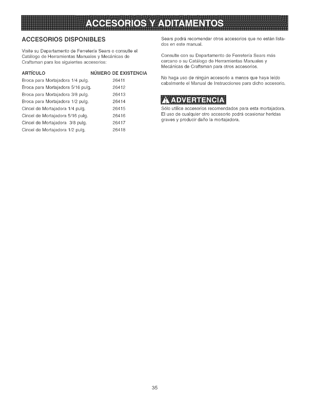
ACCESORUOS DmSPONIBLES
Visite su Departamento de Ferreterfa Sears o consulte el
Catalogo de Herramientas Manuales y Mecanicas de
Craftsman para los siguientes accesorios:
ARTICULO NOMERO DE EXJSTENCIA
Broca para Mortajadora 1/4 pulg. 26411
Broca para Mortajadora 5/16 pulg. 26412
Broca para Mortajadora 3/8 pulg. 26413
Broca para Mortajadora 1/2 pulg. 26414
Cincel de Mortajadora 1/4 pulg. 26415
Cincel de Mortajadora 5/16 pulg. 26416
Cincel de Mortajadora 3/8 pulg. 26417
Cincel de Mortajadora 1/2 pulg. 26418
Sears podra recomendar otros accesorios que no estan lista-
dos en este manual.
ConsuLte con su Departamento de Ferreterfa Sears mas
cercano o su Cat,logo de Herramientas Manuales y
Mecanicas de Craftsman para otros accesorios.
No haga use de ningOn accesorio a menos que haya Iefdo
cabaImente el Manual de hstrucciones para dicho accesorio.
$61o utilice accesorios recomendados para esta mortajadora.
El uso de cualquier otro accesorio podra ocasionar heridas
graves y producir dare la mortajadora.
35
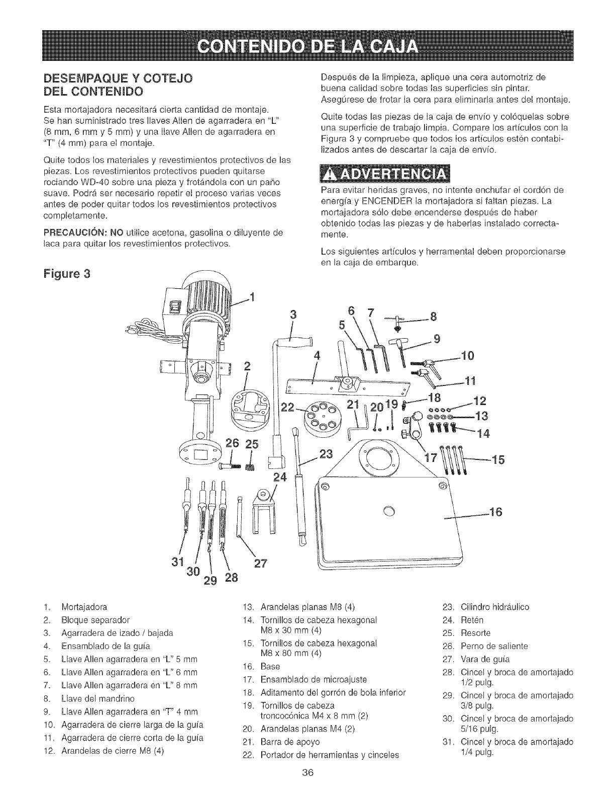
DESEMPAQUE Y COTEJO
DEL CONTENIOO
Esta mortajadora necesitara cierta cantidad de montaje.
Se han suministrado tres Ilaves Allen de agarradera en "L"
(8 mm, 6 mm y 5 mm) y una IIave Allen de agarradera en
"T" (4 ram) para el montaje.
Quite todos los materiales y revestimientos protectivos de las
piezas. Los revestimientos protectivos pueden quitarse
rociando WD-40 sobre una pieza y frotandola con un patio
suave. Podra ser necesar[o repetir ei proceso varias veces
antes de poder quitar todos los revestimientos protectivos
compJetamente.
PRECAUClON: NO utilice acetona, gasolina o diluyente de
laca para quitar los revestimientos protectivos.
Figure 3
] 2
\v/
26 25
Despues de la limpieza, apJique una cera automotriz de
buena calidad sobre todas Ias superficies sin pintar.
AsegOrese de frotar Ia cera para eliminarla antes del montaje.
Quite todas las piezas de Ia caja de env[o y col6quelas sobre
una superficie de trabajo limpia. Compare los art[culos con la
Figura 3 y compruebe que todos los arf[cu!os esten contabi-
lizados antes de descartar la caja de envio.
Para evitar heridas graves, no intente enchufar el cord6n de
energ[a y ENCENDER Ia mortajadora s[ faltan piezas. La
mortajadora sOlo debe encenderse despues de haber
obtenido todas las piezas y de haberlas instalado correcta-
mente.
Los siguientes art[culos y herramental deben proporcionarse
en la caja de embarque.
4
2019
L,L
3!I
30 29
24
27
28
©
1. Mortajadora
2. B!oque separador
3. Agarradera de izado /bajada
4. Ensamblado de la guia
5. Llave Allen agarradera en 'L" 5 mm
6. Llave Allen agarradera en 'L" 6 mm
7. Llave Allen agarradera en 'L" 8 mm
8. Llave del mandrino
9. Llave Allen agarradera en "T" 4 mm
10. Agarradera de cierre larga de la guia
11. Agarradera de cierre corta de la guia
12. Arandelas de cierre M8 (4)
13. Arandelas ptanas M8 (4)
14. Tomillos de cabeza hexagonal
M8 x 30 mm (4)
15. Tomillos de cabeza hexagonal
M8 x 80 mm (4)
16. Base
17. Ensamblado de microajuste
18. Aditamento del gorr6n de bola inferior
19. Tomillos de cabeza
troncoc6nica M4 x 8 mm (2)
20. Arandelas planas M4 (2)
21. Barra de apoyo
22. Portador de herramientas y cinceles
36
23. Cilindro hidraulico
24. Reten
25. Resorte
26. Pemo de saliente
27. Vara de guia
28. Cincel y broca de amortajado
1/2 pulg.
29. Cincel y broca de amortajado
3/8 pulg.
30. Cincel y broca de amortajado
5/16 pulg.
31. Cincel y broca de amortajado
1/4 pulg.
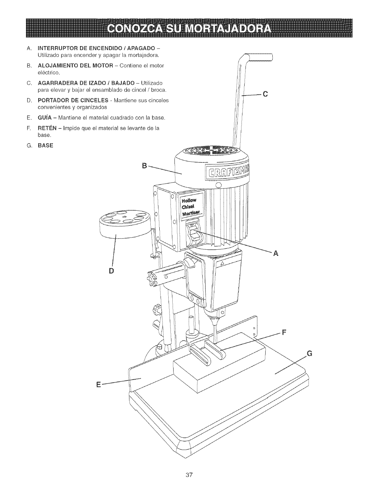
A, _NTERRUPTORDEENCENDJDO/APAGADO -
Utilizado para encender y apagar la mortajadora,
B, ALOJAM_ENTO DEL MOTOR - Contiene el motor
el6ctrico,
C, AGARRADERA DE JZADO /BAJADO - UtiJizado
para elevar y bajar el ensamblado de cincel /broca,
D, PORTADOR DE CJNCELES - Mantiene sus cinceJes
convenientes y organizados
E, GUiA - Mantiene el materiaJ cuadrado con la base,
F, RET¢:N - Impide que el material se levante de la
base.
G, BASE
B
A
oF
37
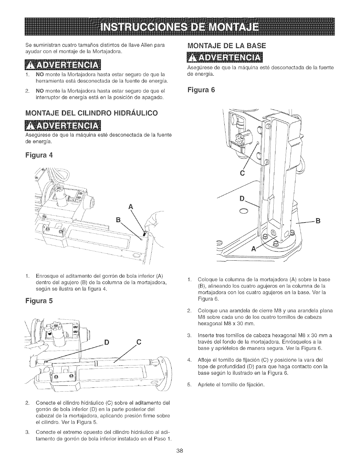
Se suministran cuatro tama_os distintos de JJaveAlien para MONTAJE DE LA BASE
ayudar con el monta]e de la Morta]adora=
1= NO monte Ia Mortajadora hasta estar seguro de que la
herramienta esta desconectada de la fuente de energ[a=
2= NO monte Ia Mortajadora hasta estar seguro de que eI
interruptor de energ[a esta en Ja posici6n de apagado=
MONTAJE DEL ClLINDRO HIBRAULICO
Aseg0rese de que la maquina este desconectada de Jafuente
de energ[a=
Figura 4
\
A
B
i
/
/
/
1. Enrosque et aditamento del gorr6n de bota inferior (A)
dentro deI agujero (B) de Ia columna de Jamortajadora,
segOn se [lustra en Jafigura 4.
Figura 5
C
Asegurese de que Ja maquina este desconectada de la fuente
de energ[a.
Figura 6
C
O
1=
2=
3=
4=
Coloque la columna de la mortajadora (A) sobre la base
(B), alineando los cuatro agujeros en Ia columna de Ia
mortajadora con los cuatro agujeros en la base= Ver Ja
Figura 6.
Co!oque una arandela de cierre M8 y una arandela plana
M8 sobre cada uno de los cuatro tornillos de cabeza
hexagonal M8 x 30 mm.
Inserte tres tornillos de cabeza hexagonal M8 x 30 mm a
traves deI fondo de la mortajadora. Enr6squeJos a la
base y aprietelos de manera segura. Ver Ja Figura 6.
Afloje el tornilIo de fijaci6n (C) y posicione la vara del
tope de profundidad (D) para que haga contacto con la
base segOn Io [lustrado en la Figura 6.
5. Apriete el torniJJode fijaci6n.
2. Conecte el cilindro hidraulico (C) sobre el aditamento del
gorr6n de bola inferior (D) en la parte posterior del
cabezal de Ia mortajadora, aplicando presi6n firme sobre
el cilindro. Ver Ia Figura 5.
3. Conecte el extremo opuesto det cilindro hidr_.ulico al adi-
tamento de gorr6n de boJa inferior instalado en el Paso 1.
38
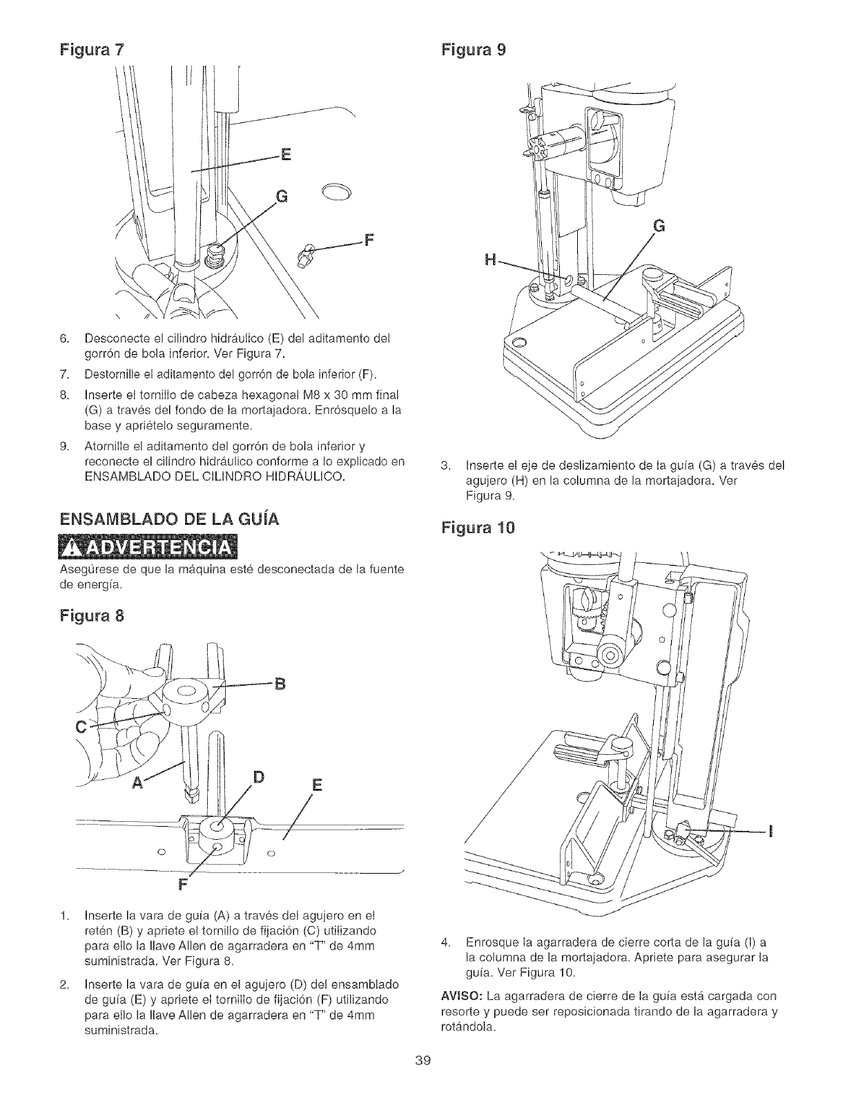
Figura 7 Figura 9
6. Desconecte el cilindro hidraulico (E) del aditamento del
gorr6n de bo!a inferior. Ver Figura 7.
7. Destomille el aditamento del gorron de bola inferior (F).
8. Inserte el tornilIo de cabeza hexagonal M8 x 30 mm final
(G) a traves del fondo de Ia mortajadora. Enr6sque!o a !a
base y aprietelo seguramente.
9. AtomiIie el aditamento del gorr6n de bola inferior y
reconecte el ci!indro hidrau!ico conforme a !o explicado en
ENSAMBLADO DEL CILINDRO HIDRA,ULICO.
ENSAMBLADO DE LA GUJA
G
3. Inserte el eje de des!izamiento de Ia gufa (G) a traves del
agujero (H) en la columna de la mortaiadora. Ver
Figura 9.
Figura 10
Aseg0rese de que !a maquina este desconectada de Jafuente
de energ(a.
Figura 8
iii Ylli,°
......................0¢4 /
F
1. Inserte la vara de guia (A) a traves del agujero en et
reten (B) y apriete e! torni!Io de fijaci6n (C) utilizando
para eI!o !a !lave Men de agarradera en "T" de 4mm
suministrada. Ver Figura 8.
2. Inserte !a vara de guia en el aguiero (D) del ensamblado
de gu[a (E) y apriete el tornilIo de fijac!6n (F) utilizando
para eI!o !a !lave Men de agarradera en "T" de 4mm
suministrada.
4. Enrosque Ia agarradera de cierre corta de la guia (I) a
la columna de la mortajadora. Apr!ete para asegurar Ja
guia. Ver Figura 10.
AWSO: La agarradera de cierre de Ia guia est_ cargada con
resorte y puede ser reposicionada tirando de Ja agarradera y
rot_indoJa.
39
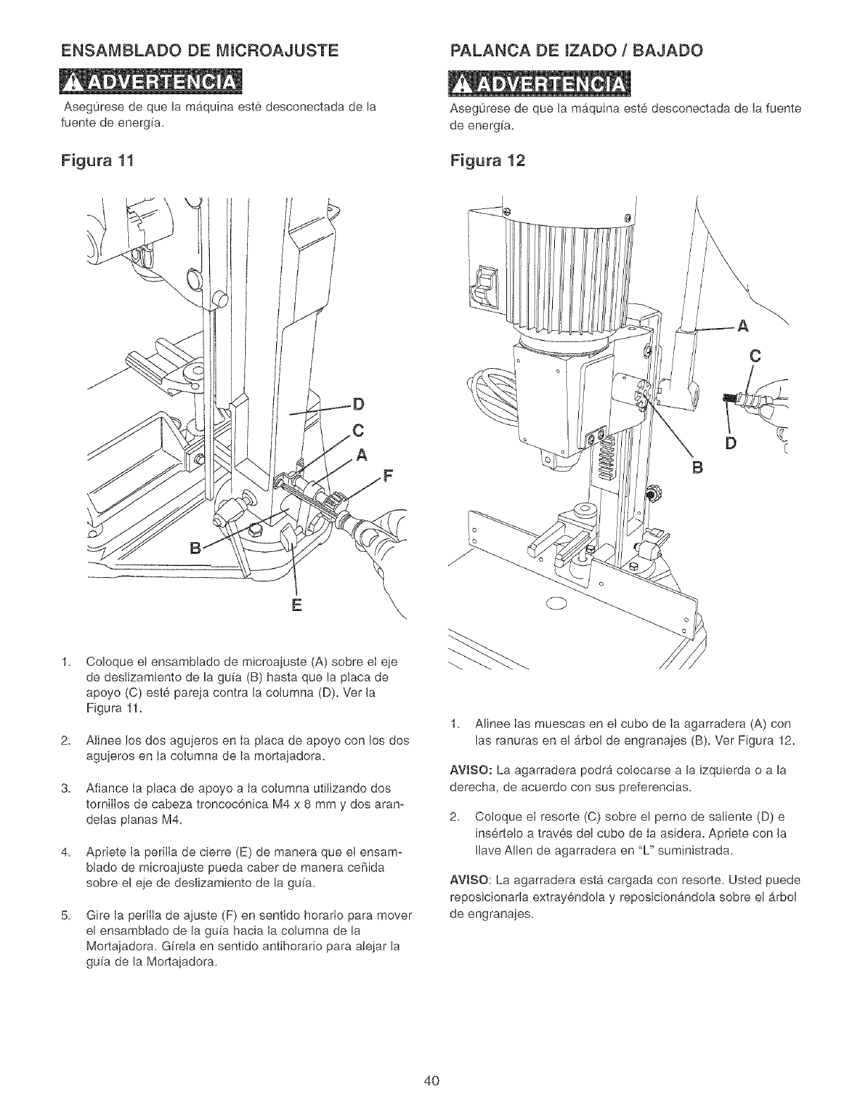
ENSAMBLADO DE MICROAJUSTE PALANCA DE IZADO /BAJADO
Aseg0rese de que la maquina este desconectada de Ja
fuente de energfa.
Figura 11
Asegurese de que Jamb,quina este desconectada de la fuente
de energfa.
Figura 12
A
C
D c
B
2.
3.
4.
5.
Coloque el ensamblado de microajuste (A) sobre eI eje
de desIizamiento de la gu[a (B) hasta que la pIaca de
apoyo (C) este pareja contra la columna (D). Ver Ja
Figura 11.
AJinee los dos agujeros en Ia placa de apoyo con Jos dos
agujeros en Ia columna de Ja mortajadora.
Afiance Ia placa de apoyo a Ia columna utilizando dos
tornilIos de cabeza troncoc6nica M4 x 8 mm y dos aran-
deJas pJanas M4.
Apriete Ia perilIa de cierre (E) de manera que et ensam-
blado de microajuste pueda caber de manera ceBida
sobre el eje de desJizamiento de la gu[a.
Gire Ja perilIa de ajuste (F) en sentido horario para mover
el ensamblado de la gufa hacia Ia columna de la
Mortajadora. Gffela en sentido antihorario para alejar Ja
gu[a de Ja Mortajadora.
1. Alinee Ias muescas en et cubo de Ia agarradera (A) con
las ranuras en el b,rbol de engranajes (B). Ver Figura 12.
AVtSO: La agarradera podra colocarse a la izquierda o a la
derecha, de acuerdo con sus preferencias.
2. Coloque el resorte (C) sobre el perno de saliente (D) e
insertelo a traves del cubo de Ia asidera. Apriete con Ja
Ilave Allen de agarradera en "L" suministrada.
AVJSO: La agarradera est& cargada con resorte. Usted puede
reposicionada extrayendoJa y reposicionandoJa sobre el b,rbol
de engranajes.
4O
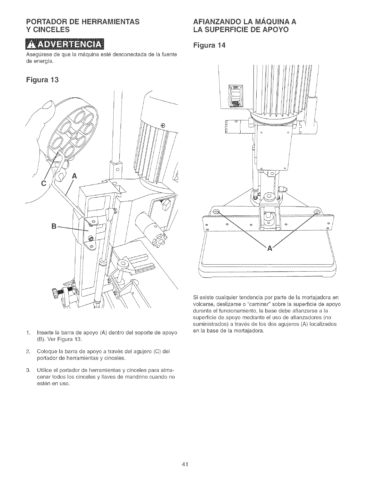
PORTADOR DE HERRAMIENTAS
Y CINCELES
Aseg0rese de que la maquina este desconectada de la fuente
de energ[a,
AFIANZANDO LA M._QUINA A
LA SUPERFICIE DE APOYO
Figura 14
Figura 13
®
C
1.
2,
3,
Inserte la barra de apoyo (A) dentro del soporte de apoyo
(B), Ver Figura 13,
Coloque la barra de apoyo a traves del agujero (C) del
portador de herramientas y cinceles,
Utilice el portador de herramientas y cinceIes para atma-
cenar todos Ios cinceles y llaves de mandnno cuando no
esten en uso,
,_ J
Si existe cualquier tendencia per parte de Ia mortajadora en
voIcarse, deslizarse o "camina¢' sobre Ia superficie de apoyo
durante eI funcionamiento, la base debe afianzarse a la
superficie de apoyo mediante el uso de afianzadores (no
suministrados) a traves de Ios dos agujeros (A) Iocalizados
en la base de la mortajadora,
41
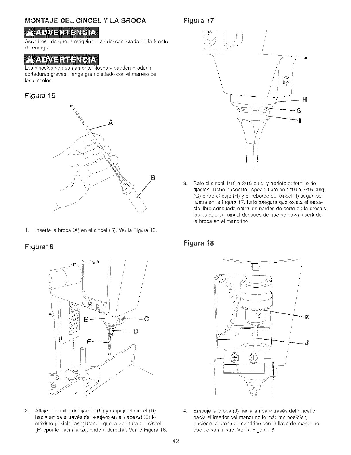
MONTAJE DEL CINCEL Y LA BROCA
Aseg0rese de que la maquina este desconectada de la fuente
de energ[a.
Los cincebs son sumamente filosos y pueden producir
cortaduras graves. Tenga gran euidado con el manejo de
los cineeles.
Figura 15
Figura 17
f------
/J //
ij /_'i
B
1. Inserte la broca (A) en el cincel (B). Vet la Figura 15.
Figura16
E
/
/
/
/
/
C
3. Baje ei cincel 1/16 a 3/16 pulg. y apriete el tornilIo de
fijaci6n. Debe haber un espacio libre de 1/16 a 3/16 pulg.
(G) entre el buje (H) y el reborde del cinceI (I) seg0n se
ilustra en Ia Figura 17. Esto asegura que exista el espa-
cio Iibre adecuado entre los bordes de corte de la broca y
las puntas del cincel despues de que se haya insertado
la broca en el mandrino.
Figura 18
K
i
2. Afioje el tornillo de fijaci6n (C) y empuje et cincel (D)
hacia arriba a traves de! agujero en el cabezal (E) Io
maximo posibIe, asegurando que Ia abertura del cinceI
(F) apunte hacia la izquierda o derecha. Vet la Figura 16.
4.
42
Empqe la broca (J) hacia arriba a traves deI cincei y
hacia el interior del mandrino Io maximo posibb y
encierre la broca al mandrino con la llave de mandrino
que se suministra. Vet la Figura 18.
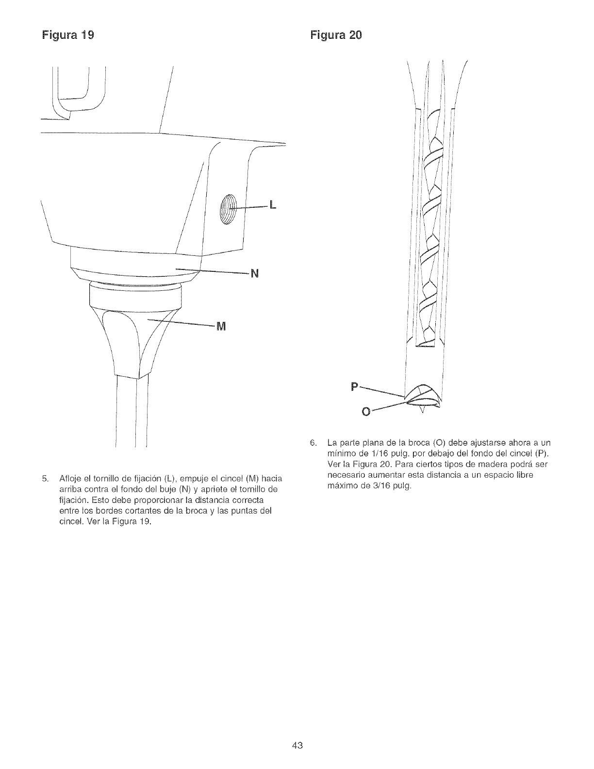
Figura 19 Figura 20
\\\\\
_L
N
5. Afioje el tornillo de fijaci6n (L), empuje el cincei (M) hacia
arriba contra el fondo del buje (N) y apriete el tornillo de
fijaci6n. Esto debe proporcionar Ia distancia correcta
entre los bordes cortantes de la broca y las puntas del
cincel. Ver la Figura 19.
6. La parte plana de Ia broca (0) debe ajustarse ahora a un
mfnimo de 1/16 pulg. per debajo del fondo del cinceI (P).
Ver Ia Figura 20. Para ciertos tipos de madera podrb, ser
necesario aumentar esta distancia a un espacio libre
maximo de 3/16 pulg.
43
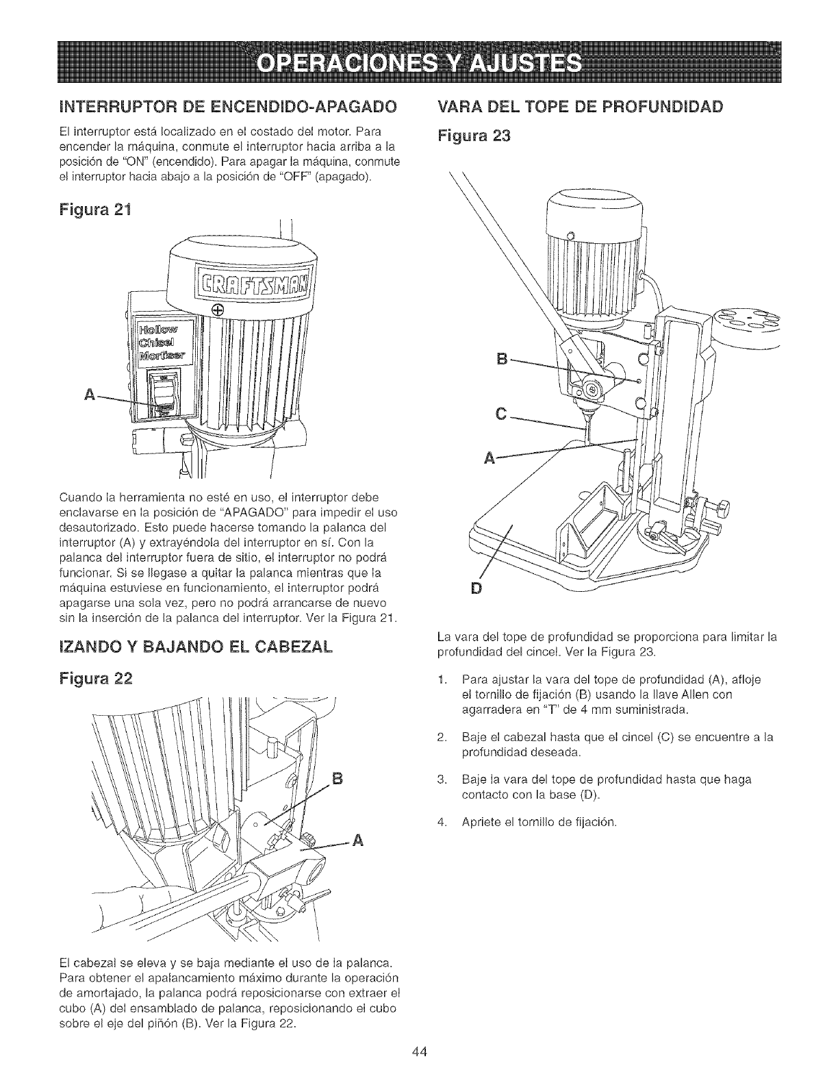
INTERRUPTOR DE ENCENZ)IZ)O°APAGAZ)O
El interruptor esta Iocalizado en el costado deI motor. Para
encender la m_iquina, conmute el interruptor hacia arriba a la
posici6n de "ON" (encendido). Para apagar Ia maquina, conmute
el interruptor hacia abaio a la posici6n de "OFF" (apagado).
Figura 21
A_
@
Cuando Ia herramienta no este en uso, el interruptor debe
enclavarse en Ia posici6n de "APAGADO" para impedir eI uso
desautorizado. Esto puede hacerse tomando la palanca del
interruptor (A) y extrayendola del interruptor en sf. Con la
palanca del interruptor fuera de sitio, e! interruptor no podra
funcionar. Si se Ilegase a quitar la palanca mientras que Ia
maquina estuviese en funcionamiento, e! interruptor podra
apagarse una sola vez, pero no podra arrancarse de nuevo
sin la inserci6n de la palanca del interruptor. Ver la Figura 21.
IZANDO Y BAJANDO EL CABEZAL
Figura 22
B
VARA Z)EL TOPE DE PROFUNDIDAD
Figura 23
A
La vara del tope de profundidad se proporciona para limitar la
profundidad del cinceL Ver la Figura 23.
1. Para ajustar la vara del tope de profundidad (A), afioje
e! tornillo de fijaci6n (B) usando la Ilave Allen con
agarradera en "T" de 4 mm suministrada.
2. Baje el cabezal hasta que el cincel (C) se encuentre a la
profundidad deseada.
3. Baje Ia vara del tope de profundidad hasta que haga
contacto con la base (D).
4. Apriete el tornillo de fijaci6n.
E! cabezal se eleva y se baja mediante eI uso de Ia palanca.
Para obtener el apatancamiento mb,ximo durante la operaci6n
de amortajado, la palanca podrb, reposicionarse con extraer eI
cubo (A) deI ensamblado de palanca, reposicionando el cubo
sobre el eje del pi_i6n (B). Ver la Figura 22.
44
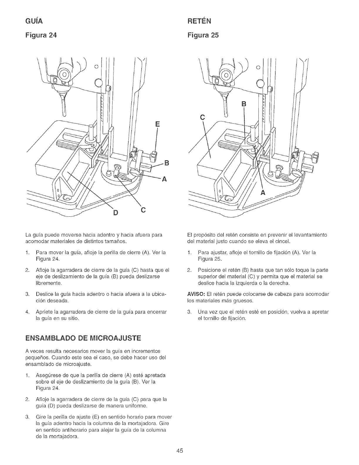
GUiA
Figura 24 Figura 25
\O
DC
C
O
La guia puede moverse hacia adentro y hacia afuera para
acomodar materiabs de distintos tamaffos.
1.
2.
Para mover Ja gu[a, afioie la perilla de cierre (A). Ver la
Figura 24.
Afioje Ia agarradera de cierre de la gu[a (C) hasta que eJ
qe de desIizamiento de Ia gu[a (B) pueda deslizarse
Hbremente.
3. Deslice la gu[a hacia adentro o hacia afuera a la ubica-
d6n deseada.
4. Apriete Ia agarradera de cbrre de la gu[a para encerrar
la gu[a en su sit[o.
El prop6sito del reten consiste en prevenir el bvantamiento
del material justo cuando se ebva el cincel.
1. Para ajustar, afloje el torn[llo de fijaci6n (A). Ver la
Figura 25.
2. Posicione el reten (B) hasta que tan s6Io toque Ia parte
superior deI material (C) y permita que el material se
deslice hacia la [zquierda o Ia derecha.
AV[SO: El reten puede colocarse de cabeza para acomodar
los materia[es mas gruesos.
3. Una vez que el reten este en posici6n, vuelva a apretar
el torn[llo de fijaci6n.
ENSAMBLADO DE M[CROAJUSTE
A veces resu[ta necesarios mover Ia guia en [ncrementos
pequeffos. Cuando este sea el caso, se debe hacer uso del
ensamblado de microajuste.
1. Asegurese de que Ja perilIa de cierre (A) este apretada
sobre el eje de desJizamiento de la gu[a (B). Vet Ja
Figura 24.
2. Afioje Ia agarradera de cierre de la gu[a (C) para que la
gu[a (D) pueda deslizarse de manera uniforme.
3. Gire Ia perilIa de ajuste (E) en sentido horar[o para mover
la gu[a adentro hacia la co[umna de Ia mortajadora. Gire
en sentido antihorario para abjar Ja gu[a de la columna
de la mortajadora.
45
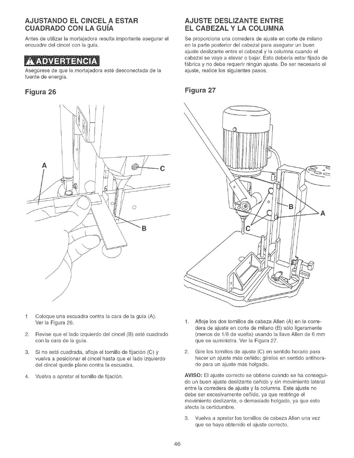
AJUSTANDO EL CINCEL A ESTAR
CUADRADO CON LA GUiA
Antes de utilizar la mortajadora resulta importante asegurar el
encuadre del cincel con la gu[a.
Aseg0rese de que la mortaiadora este desconectada de la
fuente de energfa.
Figura 26
AC
O
AJUSTE DESLIZANTE ENTRE
EL CABEZAL Y LA COLUMNA
Se proporciona una corredera de ajuste en corte de milano
en la parte posterior del cabezaI para asegurar un buen
ajuste deslizante entre el cabeza! y la columna cuando el
cabeza! se vaya a elevar o bajar. Esto debeffa estar fijado de
fabrica y no debe requerir ningun ajuste. De ser necesario el
ajuste, realice los siguientes pasos.
Figura 27
1
2.
3.
Coloque una escuadra contra la cara de la gufa (A).
Ver la Figura 26.
Revise que el lade izquierdo del cincel (B) este cuadrado
con la cara de la gufa.
Si no esta cuadrada, aftoje el tornilIo de fijaci6n (C) y
vuelva a posicionar e! cinceI hasta que e[ lade izquierdo
del cincel quede piano contra la escuadra.
4. Vuelva a apretar el tornillo de fijaci6n.
1.
2.
Afloje los dos tornillos de cabaza Allen (A) en la corre-
dera de ajuste en corte de milano (B) s61o ligeramente
(menos de 1/8 de vuelta) usando la Ilave Allen de 6 mm
que se suministra. Ver Ia Figura 27.
Gire los tomillos de ajuste (C) en sentido horario para
hacer un ajuste mas ceffido; g[relos en sentido antihora-
rio para un ajuste mas holgado.
AVISO: El ajuste correcto se obtiene cuando se ha consegui-
do un buen ajuste deslizante ceffido y sin movimiento lateral
entre Ia corredera de ajuste y la columna. Este ajuste no
debe ser excesivamente ceffido, ya que restringe et
movimiento deslizante, o demasiado holgado, ya que esto
afecta la certidumbre.
3. Vuelva a apretar los tornillos de cabeza Allen una vez
que se haya obtenido el ajuste correcto.
46
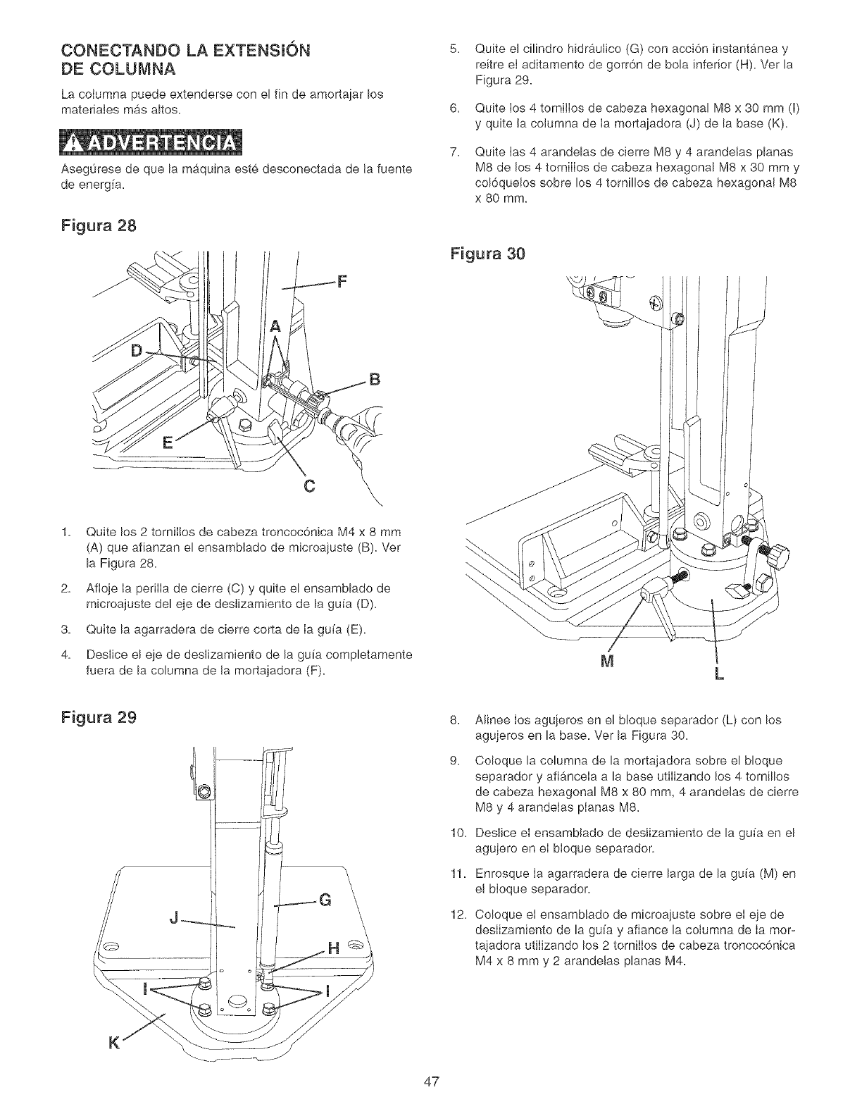
CONECTANDO LA EXTENSION
DE COLUMNA
La cotumna puede extenderse con el fin de amortajar los
materiales mas altos.
Aseg0rese de que la maquina este desconectada de la fuente
de energfa,
Figura 28
C
2.
3.
4.
Quite los 2 torniI!os de cabeza troncoc6nica M4 x 8 mm
(A) que afianzan el ensamblado de microajuste (B), Ver
la Figura 28,
Afloje la periiia de cierre (C) y quite el ensamblado de
microajuste del eje de deslizamiento de la gufa (D),
Quite la agarradera de cierre corta de Ia gufa (E).
Deslice el eje de deslizamiento de la gufa completamente
fuera de la columna de la mortajadora (F).
6.
7.
Quite el cilindro hidrautico (G) con acci6n instantanea y
reitre el aditamento de gorr6n de bola inferior (H). Ver la
Figura 29.
Quite los 4 tornilIos de cabeza hexagonal M8 x 30 mm (I)
y quite la columna de Ia mortaiadora (J) de la base (K).
Quite Ias 4 arandelas de cierre M8 y 4 arandelas planas
M8 de los 4 torniIIos de cabeza hexagonal M8 x 30 mm y
col6quelos sobre los 4 tornillos de cabeza hexagonal M8
x 80 mm.
Figura 30
Figura 29 8.
9.
10.
\ 11.
12.
Alinee los agujeros en el bloque separador (L) con los
agujeros en la base. Ver la Figura 30.
Coloque la columna de la mortajadora sobre el bloque
separador y afi_.ncela a la base utilizando los 4 tomillos
de cabeza hexagonal M8 x 80 ram, 4 arandelas de eierre
M8 y 4 arandelas planas M8.
Deslice el ensamblado de deslizamiento de la gufa en el
agujero en el bloque separador.
Enrosque Ia agarradera de cierre larga de la gufa (M) en
el bloque separadon
Coloque el ensamblado de microajuste sobre el eje de
deslizamiento de la gufa y afiance la columna de Ia mor-
tajadora utilizando los 2 tornilIos de cabeza troncoc6nica
M4 x 8 mm y 2 arandelas planas M4.
K
47
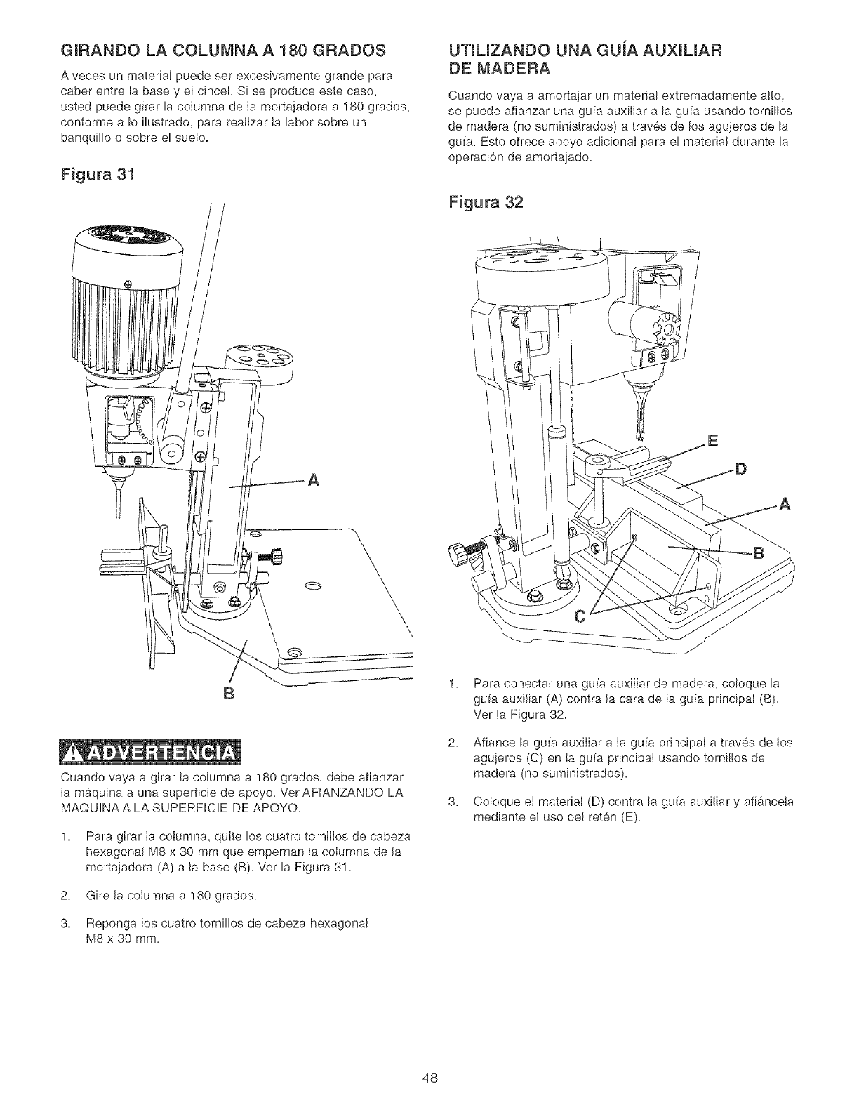
GIRANDO LA COLUMNA A 180 GRADOS
A veces un materiaI puede set excesivamente grande para
caber entre la base y eI cinceL Si se produce este caso,
usted puede girar la columna de Ia mortajadora a 180 grados,
conforme a Io ilustrado, para reaJizar la labor sobre un
banquillo o sobre el suelo.
Figura 31
UTlUZANDO UNA GUJA AUXILIAR
DE MADERA
Cuando vaya a amortajar un material extremadamente alto,
se puede afianzar una gufa auxiliar a la gufa usando tornillos
de madera (no suministrados) a traves de los agujeros de la
gufa. Esto ofrece apoyo adicionaJ para el material durante la
operaci6n de amortajado.
Figura 32
A
B
Cuando vaya a girar la coiumna a 180 grados, debe afianzar
la maquina a una superficie de apoyo. Ver AFIANZANDO LA
MAQUINAA LA SUPERFICIE DE APOYO.
1. Para girar Ia coIumna, quite los cuatro torniIIos de cabeza
hexagonal M8 x 30 mm que empeman Ja coJumna de la
mortajadora (A) a la base (B). Ver la Figura 31.
2. Gire la columna a 180 grados.
3. Reponga !os cuatro tornillos de cabeza hexagonal
M8 x 30 mm.
1.
2.
3.
Para conectar una gu[a auxiIiar de madera, coloque la
gu[a auxiliar (A) contra la cara de la guia principal (B).
Vet la Figura 32.
Afiance la gu[a auxiIiar a Ia gu[a principal a traves de los
agujeros (C) en la gu[a principal usando tornillos de
madera (no suministrados).
Coloque ei material (D) contra la gu[a auxiliar y afiancela
mediante el uso del reten (E).
48
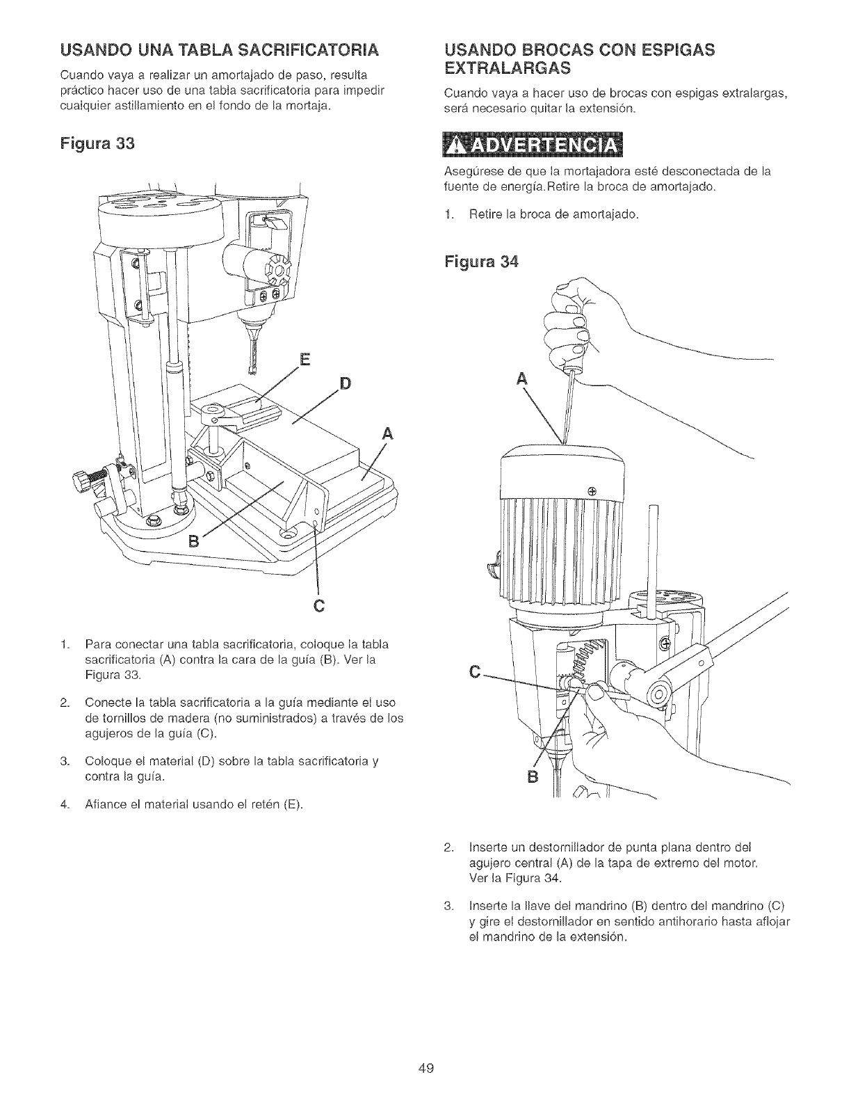
USANDO UNA TABLA SACRJFICATORJA
Cuando vaya a realizar un amortajado de paso, resulta
practico hacer uso de una tabIa sacrificatoria para impedir
cualquier astiilamiento en el fondo de la mortaja.
Figura 33
E
D
A
2.
3.
4.
C
Para conectar una tabla sacrificatoria, coloque ia tabia
sacrificatoria (A) contra Jacara de la gufa (B). Ver Ja
Figura 33.
Conecte la tabla sacrificatoria a la gufa mediante eI uso
de tornillos de madera (no suministrados) a traves de los
agujeros de Ja gufa (C).
Coloque el material (D) sobre la tabJa sacrificatoria y
contra la gufa.
Afiance el materiaI usando el reten (E).
USANDO BROCAS CON ESPIGAS
Cuando vaya a hacer uso de brocas con espigas extralargas,
sera necesano quitar Ja extensi6n.
Asegurese de que Ia mortajadora este desconectada de la
fuente de energfa.Retire la broca de amortajado.
1. Retire la broca de amortajado.
Figura 34
B
2.
3.
Inserte un destorniJlador de punta pbna dentro det
agujero central (A) de la tapa de extremo deJ motor.
Ver Ja Figura 34.
Inserte la Ibve deJ mandrJno (B) dentro del mandrino (C)
y gire el destornillador en sentido antihorario hasta afiojar
el mandrino de la extensi6n.
49
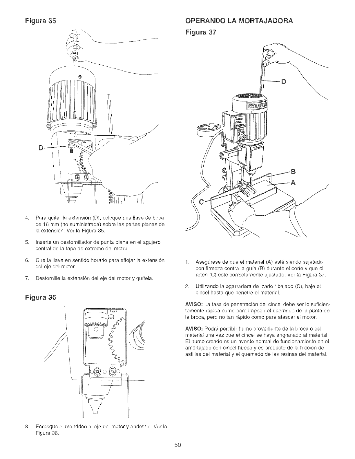
Figura 35 OPERANDO LA MORTAJADORA
Figura 37
D_
4=
5=
6,
7,
Para quitar la extensi6n (D), coloque una IIave de boca
de 16 mm (no suministrada) sobre las partes planas de
la extensi6n= Ver la Figura 35=
Inserte un destomiIIador de punta plana en el agujero
central de la tapa de extremo del motor.
Gire Ia Ilave en sentido horatio para afioiar la extensi6n
del eje del motor.
Destomille la extensi6n del eie del motor y qu[tela=
Figura 36
1. Aseg0rese de que eI matedal (A) este siendo sujetado
con firmeza contra Ia gu[a (B) durante el corte y que el
reten (C) este correctamente ajustado= Vet Ia Figura 37=
2. Utilizando la agarradera de izado /bajado (D), baje el
clncel hasta que penetre el material.
AVISO: La tasa de penetraci6n deI cincel debe ser Io suficien-
temente rapida como para impedir el quemado de Ia punta de
la broca, pero no tan rapido como para atascar el motor.
AVlSO: Podr_. perclbir humo proveniente de Ia broca o deI
material una vez que el cincel se haya engranado a! material.
El humo creado es un evento normal de funcionamiento en e!
amortaiado con cinceI hueco yes producto de la fdcci6n de
astillas del material y el quemado de las resinas del material.
8. Enrosque el mandrino al eie del motor y apdetelo. Vet la
Figura 36.
5O
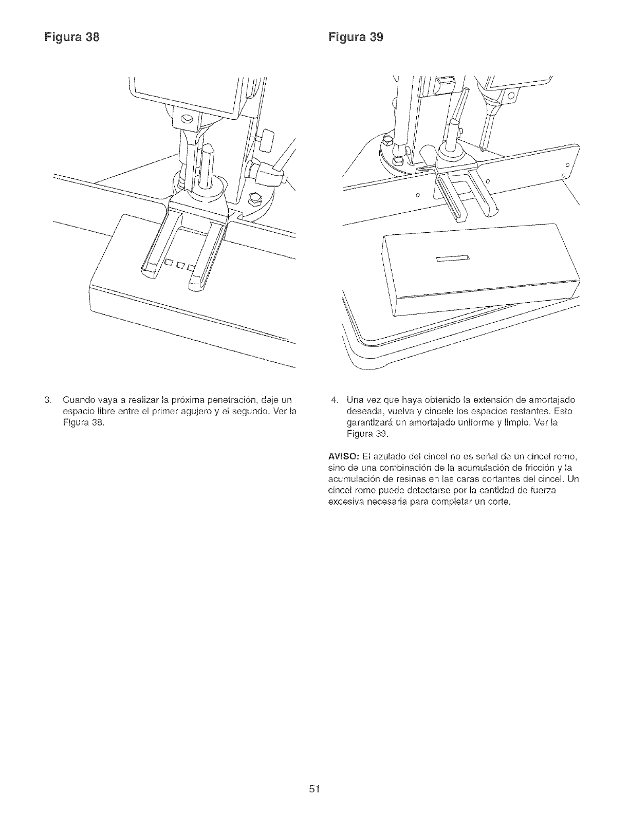
Figura 38 Figura 39
3= Cuando vaya a reaiizar la pr6xima penetraci6n, deje un
espacio libre entre el primer agujero y el segundo= Ver la
Figura 38=
4= Una vez que haya obtenido la extensi6n de amortajado
deseada, vuelva y cincele los espacios restantes. Esto
garantizarA un amortajado uniforme y limpio= Ver la
Figura 39=
AVJSO: El azulado deI cincel no es sepal de un cincel rome,
sine de una combinaci6n de la acumulaci6n de fricci6n y Ia
acumulaci6n de resinas en Jas caras cortantes del cincel= Un
cincet rome puede detectarse per Ia cantidad de fuerza
excesiva necesaria para completar un corte=
51
Las reparaciones a esta herramienta mecanica s6Io deben
ser realizadas por personal capacitado. Comun[quese con su
Centro de Servic[o Sears mas cercano para recibir servicio
autorizado. Las reparaciones desautofizadas o el recamb[o
con piezas que no sean de fabrica pueden producir heridas
graves al operar[o y dafio a su mb,quina.
Para prevenir Ias heridas a s[ mismo o el dafio a su maquina,
gire el [nterruptor a Ia posici6n de "APAGADO" y desenchufe
el cord6n de energ[a del tomacorrientes antes de realizar
cualquier ajuste.
La Mortajadora funcionara mejor si se Ie mantiene en condi-
ciones 6ptimas de funcionamiento. Mantenga la unidad ajus-
tada segOn Io descrito en OPERACHONES Y AJUSTES.
o APAGUE el interruptor de energ[a y desenchufe el cord6n
de energ[a del tomacorrientes.
o No permita que la goma y la resina se acumulen sobre la
herramienta cortante.
o No permita que las astillas se acumulen sobre la maquina o
alrededor de ella.
o Mantenga los cinceles y Ias brocas afiladas. Se recomienda
tener a mano un juego extra de cinceles y brocas. Los
cinceles y las brocas de recamb[o estan disponibles en
Sears.
PRECAUCION: NO UTILICE MATERIALES CO_,_BUSTI-
BLES para Iimpiar esta maquina. S61o se necesita un patio
seco o un cepillo para quitar la acumulacidn de polvo y de
escombros.
PF{OTEGIENDO LA MESA DE HIERRO
MOLDEADO CONTRA LA OXIDACION
Para limpiar y mantener las superficies de hierro moldeado
sin pintar:
o Aplique una capa gruesa de WD-40 sobre la superficie de
hierro moldeado sin pintar.
Use Iana de acero fina para pulir el hierro moldeado sin
pintar. Aseg0rese de pulir en sentido "adelante hacia atrb_s"
solamente. Un movimiento de pulido de lado a lado podra
percibirse como una [mperfecci6n, defecto o rayaduras
sobre el hierro moldeado fino.
Vuelva a aplicar WD-40 y pula Ias superficies de hierro
moldeado sin pintar hasta que haya quitado Ia mancha.
AsegOrese de usar el mismo movimiento de pulido "ade-
lante hacia atrb,s" para evitar rayar o desmejorar la super-
ficie de hierro moldeado.
Despues de haber quitado todas las manchas y/u oxida-
ci6n, limpie todo el aceite y suciedad de la mesa con un
pa[io o trapo suave.
Por 01timo, debe aplicar una cera automotriz en pasta de
buena calidad para proteger todas las superficies de hierro
moldeado sin pintar. Esto ayudara a proteger la herramienta
contra la oxidaci6n debido al contacto posterior con la
humedad o manos grasosas.
LUBRICACION
La Mortajadora tiene cojinetes Iubricados y sellados en et
alojamiento del motor que no requieren lubricaci6n adicional
de parte deI operario.
Los escombros deben quitarse de la guia y de los tornillos
de elevaci6n, que deben ser engrasados seg0n sea nece-
sar[o.
Aplique ocasionalmente algunas gotas de aceite liviano
para maquinaria sobre Ias chavetas para mantener las
mesas libres en relaci6n con la base.
ASEGORESE de APAGAR la energia y desenchufar ei
cord6n de energ[a de su fuente de suministro.
El entorno y Ia frecuencia det contacto humano podran tener
un impacto sumamente nocivo sobre las superficies de hierro
sin pintar. La humedad y las grasas (iprovenientes de manos
humanas!) pueden causar el deterioro o Ia oxidaci6n de las
superficies de hierro moldeado sin pintar, as[ que resulta
importante realizar mantenimiento rutinario para conservar su
mortajadora como s[ fuese nueva. Se recomienda Ia Iimpieza
y el encerado de Ias superficies de hierro moldeado en la
siguiente manera:
52
PARA EVSTAR HERIRSE A Si r_llSMO o causar daSo a la mortjadora, conmute el interruptor a Ja posici6n de apagado (OFF) y
desenchufe el cord6n de energ[a del tomacorrientes antes de realizar cualquier ajuste.
PROBLEMA CAUSA(S) POSJBLES SOLUCJ6N
Motor no arranca
O no a_canza
vemoeidad pmena,
Motor ee ahoga
o los disyuntoree
de circuito ee
dieparan con
frecuencia
EBmotor ee
recalienta
La broca se ataeca
o se reebala
La broca o el
material deepiden
humo o arden
Exceeo de deriva
o bambomeo pot
parte de mabroca
1. Llave deI interrupter fuera de su sitio.
2. Interrupter defectuoso
3. Capacitador defectuoso
4. Baja tensi6n de IFnea
5. Motor defectuoso
1. Sobrecarga del circuito
2. Baja tensi6n de IFnea
3. Sobrecarga del motor
4. Fusibles incorrectos an los disyuntores
de circuito
5. Cortocirculto del motor; conexiones
sueltas o aistamiento desgastado en
los avances
1. Restricci6n en la circulaci6n de! aire
debido a Ia acumulaci6n de polvo.
2. Sobrecarga deI motor
1. La broca no esta afianzada de manera
segura dentro del mandrino.
1. Velocidad incorrecta del huso.
2. Astillas no estan siendo expubadas per
el agujero de pefforaci6n.
3. Broca roma.
1. Broca torcida.
2. Broca incorrectamente instalada al
mandrino.
1. Inserte Ia Ilave del interruptor.
2. Mande a reponer el interruptor.
3. Mande a reponer el capacitador.
4. Corrija la condici6n de baja tensi6n de I[nea. Sila
mb_quina estb, enchufada a una extensi6n electrica,
desconectela y ench0fela directamente aI tomacorrientes
5. Mande a recambiar e! motor.
AWSO: 3 y 4 deben ser realizados por an tecnico de
servicio competente; consulte con el servicio de Sears.
1.
2.
3.
4.
5.
Reduzca Ia carga del circuito (apague otros aparatos).
Corfija la condici6n de baja tensi6n de I[nea. Revise Ia
tensi6n de linea con an mult[metro. Sila mortajadora
esta conectada a una extensi6n electrica, desenchufe
Ja mortajadora det cord6n de extensi6n y enchufe Ja
mortajadora directamente a un tomacorrientes.
Reduzca Ia carga al motoq reduzca el ritmo de
aIimentaci6n.
Haga qua un electricista competente instab toe fusibles
correctos al disyuntor
Inspeccione bs terminaciones del motor por si existe
aislamiento da_ado y alambres cortocircuitados y haga
que sean reemplazados. Revise todos las conexiones
de avances de energia.
1.
2.
Limpie el polvo y restaure la cimulaci6n normal del aire
en torno al motor.
Reduzca Ia carga al motor; reduzca el ritmo de
alimentaci6n.
1. InstaIe la broca correctamente. Ver MONTAJE DEL
CINCEL Y LA BROCA an INSTRUCCIONES DE
MONTAJE.
1.
2.
3.
Reduzca Ia ve!ocidad deI huso. Vea el diagrama de
velocidades en el fondo de Ia cubierta de Ia correa.
Retracte Ia broca frecuentemente durante la operaci6n
de perforaci6n para exputsar astillas del agujero.
Reponga o afib la broca.
1. Rep6ngala con una broca recta o nueva.
2. Instale la broca correctamente. Vet MONTAJE DEL
CINCEL Y LA BROCA en INSTRUCCIONES DE
MQNTAJE.
53

MORTAJADORA DE CINCEL HUECO NO. DE MODELO 152,219070
Cuando vaya a rendir servicio, s61o utilice piezas de recambio CRAFTSMAN. El use de cualquier otro tipo de piezas podrb, crear
un PEUGRO o producir daho al producto.
Cualquier intento per reparar o reemptazar Ias piezas electricas en esta Mortajadora podra crear un PEUGRO a menos que la
reparaci6n sea efectuada por un tecnico de servicio competente. El servicio do reparaci6n esta disponible en su Centre de
Servicio Sears mas cercano.
Encargue siempre per NOMERO DE HEZA y no per nOmero de clave.
No, deNo, de No, deNo, de
Clave Pieza Cant, C_ave Pieza
Dese_'ipci6n
1 0R93300 ENSAMBLADO PRINCIPAL DEL MOTOR
(INOL, 1A, 1B, 10, 2, 3, 4, 5, 6, 7, 8, 9)
1A 0R93301 ENSAMBLADO DEL MOTOR, INCL: 1/2 HP, 120 V, 6A, 120 RPM
1B 0R93354 CORDON DE ENERGIA
1C 0R93353 DESCARGA DE TENSION
2 0R93761 PLACA DE CRAFTSMAN
3 0R93302 CUBERTA DE LA CAJA DE INTERRUPTORES
4 0R93763 ETIQUETA DE ESPECJFICACJONES
5 0R93383 TORNILLO AUTOROSCADOR DE CABEZA TRONCOCONICA 2,9 X 12 MM
6 0R93303 CAPACITADOR 16 UF
7 0R93304 INTERRUPTOR
8 0R93305 LLAME DEL INTERRUPTOR
9 0R93762 PLACA DE NOTACIONES
10 0R93306 ADAPTADOR
11 0R93307 MANDRINO
11A 0R93352 LLAVE DEL MANDRINO
12 0R93308 VARA DEL TOPE DE PROFUNDIDAD
13 0R93309 SEPARADOR DEL MOTOR
14 0R93376 PASADOR DE RESORTE M6 X 30 MM
15 0R93310 JUNTA DEL ARBOL DE ENGRANAJES
16 0R93311 ARANDELA DE PLA,STICO
17 0R93312 PERILLA DE CIERRE
18 0R93313 SEPARADOR
19 0R90507 TORNILLO DE CAB, TRONOOCONICA M5 X 8 MM
20 0R93314 BISAGRA
21 0R93315 CUBERTA
22 0R93311 ARANDELA PLA,STICA
23 STD840610 TUERCA HEXAGONALM6
24 0R93316 PLACA DE CIERRE
25 0R93370 TUERCA NYLOK M6
26 0R91821 TORNILLO DE FUACION CAB, HUECA HEX, M8 X 20 MM
27 0R93317 BUJE
28 0R93377 TORNILLO DE CAB, HUECA NEX M6 X 45 MM
29 0R93318 PIEZA FUNDIDA DEL CABEZAL
30 0R93764 ETIQUETA DE ADVERTENCIA
30A 0R93369 REMACHE DE MARCHA3 MM
31 0R93380 TORNILLO DE FIJACION CAB, HUECA NEX, M8 X 15 MM
32 0R93379 TORNILLO DE ARMADURA M8 X 10 MM
33 0R93319 CRAVETA DE LA GUiA DE COLUMNA
34 0R93381 TORNILLO DE CAB, HUECA HEX, M8 X 20 MM
35 0R93320 ENGRANE
36 0R93321 COLLARiN
37 0R93323 TORNILLO DE CAB, NUECA NEX, M5 X 5 MM
38 0R93322 ARBOL DE ENGRANAJES
39 0R93376 PASADOR DE RESORTE M6 X 30 MM
40 0R93310 JUNTA DEL ARBOL DE ENGRANAJES
41 0R93324 JUNTA DE LAAGARRADERA
42 0R93325 RESORTE
43 0R93326 PERNO DE SALENTE
44 0R93375 PERNO DE RESORTE M6 X 20 MM
45 0R93327 EMPUNADURA
46 0R93328 EJE DE AGARRADERA
47 0R93329 LLAVE
48 0R93312 PERILLA DE CIERRE
49 0R93311 ARANDELA PLA,STICA
50 0R93311 ARANDELA PLA,STICA
51 STD840610 TUERCA NEX, M6
52 0R93370 TUERCA NYLOK M6
Deseripci6n Cant.
53 0R93316 PLACA DE CIERRE 1
54 0R93315 CUBIERTA 1
55 0R93314 BISAGRA 1
56 0R90507 TORNILLO DE CAB, TRONCOCONICA M5 X 8 MM 2
57 0R93330 LLAVE DE AGARRADERA EN T" 1
58 0R93331 PORTADOR DE CINCEL 1
59 0R93332 BARRA DE APOYO 1
60 0R93333 ABRAZADERA DE SOPORTE 1
61 0R93372 TORNILLO DE CAB, HUEOA HEX, M6 X 12 MM 2
62 STD852006 ARANDELA DE CIERRE M6 2
63 0R93334 COLUMNA 1
64 0R93370 TUEROA NYLOK M6 1
65 STD851004 ARANDELA PLANA M4 2
66 0R90346 TORNILLO DE CAB, TRONCOCONIOA M4 X 8 MM 2
67 0R93335 PLACA DE APOYO 1
68 STD851006 ARANDELA PLANA M6 2
69 0R93336 PERILLA DE AJUSTE 1
70 0R93337 PERILLA DE CERRE 1
71 0R93338 ABRAZADERA DE AJUSTE 1
72 STD835030 TORNILLO DE CAB, HEX M8 X 30 MM 4
73 STD852008 ARANDELA DE CIERRE M8 4
74 STD851008 ARANDELA PLANA M8 4
7,5 0R93339 ENSAMBLADO DE AGARRADERA (CORTO) 1
76 0R93340 BASE 1
77 STD851006 ARANDELA PLANA M6 2
78 STD852006 ARANDELA DE CIERRE M6 2
79 0R93374 TORNILLO DE CAB, HUEOA HEX M6 X 20 MM 2
80 0R93341 ALMORADILLA DE DESLIZAMIENTO DE GUiA 2
81 0R93342 ENSAMBLADO DE DESLIZAMIENTO DE GUiA 1
82 0R93343 GUiA 1
83 0R93378 TORNILLO DE FIJACION CAB, HUECA HEX, M8 X 10 MM 1
84 0R93344 RETEN 1
85 0R93378 TORNILLO DE FIJACION CAB, HUECA HEX, M8 X 10 MM 1
86 0R93345 VARA DE GUiA 1
87 0R93346 ESTABILIZADOR 1
88 0R93347 GORRON DE BOLA 2
89 0R93348 TORNILLO DE EMPALME 2
90 STD840610 TUEROA HEX, M6 2
91 0R93373 TORNILLO DE CAB, HUEOA HEX, M6 X 16 MM 2
92 0R93349 ENGRANAJE DE ARMAZON 1
93 0R93371 TORNILLO DE CAB. RUECA HEX M6 X 10 MM 1
94 0R93382 TORNILLO DE CAB, HEX M8 X 90 MM 4
95 0R93350 BLOQUE SEPARADOR 1
96 0R93351 ENSAMBLADO DE AGARRADERA (LARGO) 1
97 0R93355 ESTUOHE DE MONTAJE DE CINCEL Y BROCA
dNCL, 98, 99, 100, 101) (NO ILUSTRADO} 1
98 0R93356 ENSAMBLADO DE CINCEL Y BROCA 1/4 PULG,
(NO ILUSTRADO) 1
99 0R93359 ENSAMBLADO DE CINCEL Y BROCA 5/16 PULG,
(NO ILUSTRADO) 1
100 0R93362 ENSAMBLADO DE ClNCEL Y BROCA 3/8 PULG,
(NO ILUSTRADO) 1
101 0R93365 ENSAMBLADO DE CINCEL Y BROCA 1/2 PULG,
(NO ILUSTRADO) 1
102 0R91728 LLAVE HEXAGONAL 5 MM (NO ILUSTRADA) 1
103 0R90806 LLAVE HEXAGONAL¢ MM (NO ILUSTRADA) 1
104 0R90292 LLAVE HEXAGONAL8 MM (NO ILUSTRADA) 1
106 0R93760 MANUAL DE INSTRUCCIONES (NO ILUSTRADO) 1
54
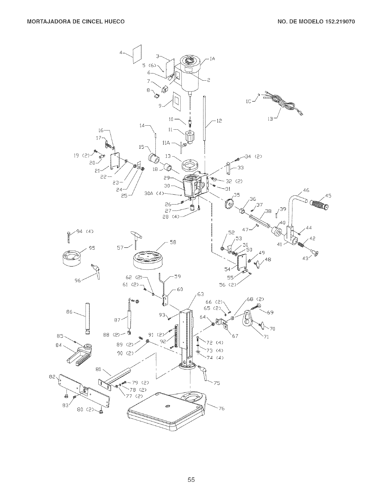
MORTAJADORA DE CINCEL HUECO NO, DE MODELO 152,219070
94 (4)
96
25
83 80 (2)-.
66
67
(4)
(4)
(4)
75
(2)
41
49
/4s 43 /
55

Your Home
iiiiiiiiiiiiiiiiii
For repair-in your home-of all major brand appliances,
lawn and garden equipment, or heating and cooling systems,
no matter who made it, no matter who sold it!
For the replacement parts, accessories and
owner's manuals that you need to do-it-yourself.
For Sears professional installation of home appliances
and items like garage door openers and water heaters.
1-800-4-MY-HOME ® (1-800-469-4663)
Call anytime, day or night (U.S.A. and Canada)
www.sears.com www.sears.ca
Our Home
For repair of carry-in items like vacuums, lawn equipment,
and electronics, call or go on-line for the location of your nearest
Sears Parts & Repair Center.
1-800-488-1222
Call anytime, day or night (U.S.A. only)
www.sears.com
To purchase a protection agreement (U.S.A.)
or maintenance agreement (Canada) on a product serviced by Sears:
1-800-827-6655 (U.S.A.)
Para pedir servicio de reparacion
a domicilio, y para ordenar piezas:
1-800-361-6665 (Canada)
Au Canada pour service en frangais:
1-800-LE-FOYER M°
(1-800-533-6937)
www.sears.ca
iiiiiiiiiiiiiiiii
iiii
iiii!;!i_i;,i,;.....
TM
® Registered Trademark /Trademark /SM Service Mark of Sears Brands, LLC
® Marca TM
Registrada /Marca de Fabrica /SM Marca de Servicio de Sears Brands, LLC
MO
MCMarque de commerce /Marque d6pos6e de Sears Brands, LLC ® Sears Brands, LLC
56
