Craftsman 152229020 User Manual BENCH DRILL PRESS Manuals And Guides L0520639
CRAFTSMAN Drill Press Manual L0520639 CRAFTSMAN Drill Press Owner's Manual, CRAFTSMAN Drill Press installation guides
User Manual: Craftsman 152229020 152229020 CRAFTSMAN BENCH DRILL PRESS - Manuals and Guides View the owners manual for your CRAFTSMAN BENCH DRILL PRESS #152229020. Home:Tool Parts:Craftsman Parts:Craftsman BENCH DRILL PRESS Manual
Open the PDF directly: View PDF ![]() .
.
Page Count: 56

_truction anu
1 Horsepower (continuous duty)
2 Horsepower (maximum developed)
9°Speed, Step Pulley
150 -2200 R.P.M. Drill Speed Range
Model No.
152.229020
iLL P ESS
C
CAUTION:
FOR YOUR OWN SAFETY; Read
and follow all of the Safety and
Operating Instructions before
Operating this DdH Press.
Customer Helpline
1-800-897-7709
PRease have your Model No.
and SedaR No. availabUe.
Sears, Roebuck and Co.
Hoffman Estates, JL 60179 U.S.A.
Part No. 0R93514 EspaSoLpg, 29

SECTmON PAGE
Warranty..........................................................................................................................................................................2
ProductSpecifications...................................................................................................................................................3
Safetymnstructions.........................................................................................................................................................4
Guidelinesfor extension cords ..................................................................................................................................... 5
Grounding mnstructions .................................................................................................................................................. 6
Specific Safety mnstructions .......................................................................................................................................... 7
Accessories and Attachments ...................................................................................................................................... 8
Know Your Machine ....................................................................................................................................................... 9
Carton Contents ............................................................................................................................................................ 11
AssembJy mnstructions ................................................................................................................................................. 13
Operations and Adjustments ...................................................................................................................................... 17
Maintenance .................................................................................................................................................................. 23
Troubleshooting Guide ................................................................................................................................................ 24
Part List ......................................................................................................................................................................... 25
EspaSol .......................................................................................................................................................................... 29
Service mnformation ........................................................................................................................................ Back Page
ONE-YEAR FULL WARRANTY ON CRAFTSMAN TOOL
if this Craftsman tool fails due to a defect in material or workmanship within one year from the date of purchase,
CALL 1-800-4-MY-HOME _)TO ARRANGE FOR FREE REPAIR,
This warranty applies only while this tool is in the United States,
This warranty gives you specific legal rights, and you may also have other rights, which vary from state to state,
Sears, Roebuck and Co,, Dept 817WA, Hoffman Estates, IL 60179

20qn. Drill Press
Motor Specifications:
Motor type induction
Continuous duty HP 1
Maximum developed HP 2
Amps 12/6
Volts 120/240
Phase Single
Hertz 60
R,P,M, 1725 (no load)
Product Specifications:
Belt Type
Pulley Type
Number of Speeds
Drill Speeds
Spindle Taper
Chuck TaperJacobs Taper
Chuck Type
Chuck capacity
Chuck to Table dimension
Min,
Chuck to Table dimension
Max,
Chuck to Base dimension
Quill Diameter
Quill Travel
Quill Lock
V-Belt
Step
Motor slide
9
150, 275,325, 460, 500,
540, 1150, 1550, 2200
#3 Morse Taper
#3
Keyed
3/32" ° 3/4" (3 ° 19mm)
2o3/16"
23o5/8"
43"
4o3/4"
Yes
Handb Operation 360 degree rotation
Motor Control Industrial push button
ON/OFF switch with
OFF paddb
Tabb Size 18-3/4" wide x 16-3/4"
depth
Table Tilt Yes
Table Movement Rack and pinion
Table Material Cast iron
Depth Stop Yes
Depth Stop Type Quick Set
Depth Scab Yes
Column Diameter 3o5/8" (92mm)
Base Work Area 16" wide x 13" depth
Depth of Throat 10"
Height 68-1/2"
Width 18"
Depth 34"
Weight 321 pounds
Convenience:
Light Yes
To avoid electrical shock to yourself and damage to the
drill press, use proper circuit protection, Do not expose
to rain, or use in a damp environment,
The drill press is factory wired for 120V, 60 Hz, opera°
tion, Connect to a 120V, 15 amp branch circuit and use
a 15 amp time delay fuse or circuit breaker, The electri-
cal circuit cannot have any wire size less than #14, To
avoid shock or fire, replace power cord immediately if it
is damaged in any way,

GENERAL SAFETY iNSTRUCTiONS
Operating a drill press can be dangerous if safety and
common sense are ignored, The operator must be
familiar with the operation of the tool, Read this manual
to understand this drill press, DO NOT operate this drill
press if you do not fully understand the limitations of
this tool, DO NOT modify this drill press in any way,
REMEMBER: Your personal safety is your responsibility,
BEFORE USUNG THE DF_ULL PRESS
To avoid serious injury and damage to the tool, read
and follow all of the Safety and Operating instructions
before operating the drill press,
1, READ the entire instruction Manual, LEARN how to
use the tool for its intended applications,
2, ALWAYS WEAR EYE PROTECTION, Any power
tool can throw debris into the eyes during opera-
tions, which could cause severe and permanent
eye damage, Everyday eyeglasses are NOT safety
glasses, ALWAYS wear Safety Goggles (that
comply with ANSi standard Z87,1) when operating
power tools, Safety Goggles are available at Sears
Retail Stores,
3, ALWAYS WEAR HEARING PROTECTION, Plain
cotton is not an acceptable protective device,
Hearing equipment should comply with ANSi
$3,19 Standards,
4, ALWAYS WEAR A DUST MASK TO PREVENT
INHALING DANGEROUS DUST OR AIRBORNE
PARTICLES, including wood dust, crystalline silica
dust and asbestos dust, Direct particles away from
face and body, Always operate tool in well ventilat-
ed area and provide for proper dust removal, Use
dust collection system whenever possible,
Exposure to the dust may cause serious and per-
manent respiratory or other injury, including silicosis
(a serious lung disease), cancer, and death, Avoid
breathing the dust, and avoid prolonged contact
with dust, Allowing dust to get into your mouth or
eyes, or lay on your skin may promote absorption of
harmful material, Always use properly fitting
NIOSH/OBHA approved respiratory protection
appropriate for the dust exposure, and wash
exposed areas with soap and water,
5, ALWAYS keep the work area clean, well lit, and
organized, DO NOT work in an environment with
floor surfaces that are slippery from debris, grease,
and wax,
6, ALWAYS unplug the tool from the electrical recep-
tacle when making adjustments, changing parts or
performing any maintenance,
7,
8,
9,
10,
11,
12,
13,
14,
15,
16,
17,
18,
19,
AVOID ACCIDENTAL STARTING, Make sure that
the power switch is in the "OFF" position before
plugging in the power cord to the electrical
receptacle,
AVOID A DANGEROUS WORKING ENVIRON-
MENT. DO NOT Use electrical tools in a damp
environment or expose them to rain.
CHILDPROOF THE WORKSHOP AREA by remov-
ing switch keys, unplugging tools from the electrical
receptacles, and using padlocks,
DO NOT use electrical tools in the presence of
flammable liquids or gasses,
DO NOT FORCE THE TOOL to perform an opera-
tion for which it was not designed, it wiii do a safer
and higher quality job by only performing operations
for which the tool was intended,
DO NOT stand on a tool, Serious injury could result
if the tool tips over or you accidentally contact the
tool,
DO NOT store anything above or near the tool
where anyone might try to stand on the tool to
reach it,
DO NOT operate tool if under the influence of drugs
or alcohol,
EACH AND EVERY TIME, CHECK FOR DAMAGED
PARTS PRIOR TO USING THE TOOL. Carefully
check all guards to see that they operate properly,
are not damaged, and perform their intended func-
tions, Check for alignment, binding or breaking of
moving parts, A guard or other part that is damaged
should be immediately repaired or replaced,
GROUND ALL TOOLS, if the tool is supplied with a
3-prong plug, it must be plugged into a 3-contact
electrical receptacle, The 3rd prong is used to
ground the tool and provide protection against
accidental electric shock, DO NOT remove the 3rd
prong, See Grounding instructions,
KEEP VISITORS AND CHILDREN AWAY from the
drill press, DO NOT permit people to be in the
immediate work area, especially when the electrical
tool is operating,
KEEP PROTECTIVE GUARDS IN PLACE AND IN
WORKING ORDER,
MAINTAIN YOUR BALANCE. DO NOT extend
yourself over the tool. Wear oil resistant rubber-
soled shoes. Keep floor clear of debris, grease, and
wax,
20, MAINTAIN TOOLS WITH CARE, Always keep tools
clean and in good working order, Keep all blades
and tool bits sharp,
21, NEVER LEAVE A RUNNING TOOL UNATTENDED,
Turn the power switch to the OFF position, DO
NOT leave the tool until it has come to a complete
stop,
22, REMOVE ALL MAINTENANCE TOOLS from the
immediate area prior to turning the tool ON,
23, SECURE ALL WORK, When it is possibb, use
damps or jigs to secure the workpbce, This is safer
than attempting to hold the workpbce with your
hands,
24, STAY ALERT, watch what you are doing, and use
common sense when operating a power tool, DO
NOT USE a tool wNe tired or under the influence
of drugs, abohol, or medication, A moment of
inattention whib operating power tools may resWt
in serious personal injury,
25, USE ONLY RECOMMENDED ACCESSORIES,
Use of incorrect or improper accessories could
cause serious injury to the operator and cause
damage to the tool, if in doubt, check the instruction
manual that comes with that particular accessory,
26, USE A PROPER EXTENSION CORD IN GOOD
CONDITION, When using an extension cord, be
sure to use one heavy enough to carry the current
your product will draw, Please see "MiNiMUM
RECOMMENDED GAUGE FOR EXTENSION
CORDS (AWG)" table for correct sizing of an exten-
sion cord, if in doubt, use the next heavier gauge,
27, WEAR PROPER CLOTHING. DO NOT wear loose
clothing, gloves, neckties, or jewelry, These items
can get caught in the machine during operations
and pull the operator into the moving parts, Users
must wear a protective cover on their hair, if the
hair is long, to prevent it from contacting any
moving parts,
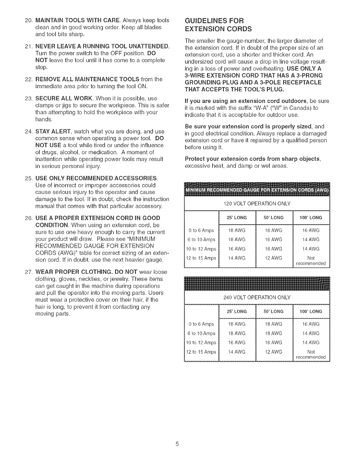
GUIDEUNES FOR
EXTENSUON CORDS
The smaller the gauge-number, the larger diameter of
the extension cord, if in doubt of the proper size of an
extension cord, use a shorter and thicker cord, An
undersized cord wiii cause a drop in line voltage result-
ing in a loss of power and overheating, USE ONLY A
3-WIRE EXTENSION CORD THAT HAS A 3-PRONG
GROUNDING PLUG AND A 3-POLE RECEPTACLE
THAT ACCEPTS THE TOOL'S PLUG.
if you are using an extension cord outdoors, be sure
it is marked with the suffix "W-A" ("W" in Canada) to
indicate that it is acceptable for outdoor use,
Be sure your extension cord is property sized, and
in good electrical condition, Always replace a damaged
extension cord or have it repaired by a qualified person
before using it,
Protect your extension cords from sharp objects,
excessive heat, and damp or wet areas,
120 VOLT OPERATION ONLY
25' LONG 50' LONG 100' LONG
0 to 6 Amps
6 to 10 Amps
10to 12 Amps
12 to 15 Amps
18 AWG
18 AWG
16 AWG
14 AWG
16 AWG
16 AWG
16 AWG
12 AWG
16 AWG
14 AWG
14 AWG
Not
recommended
240 VOLT OPERATION ONLY
0 to 6 Amps
6 to 10 Amps
10to 12 Amps
12 to 15 Amps
25' LONG
18 AWG
18 AWG
16 AWG
14 AWG
50' LONG
18 AWG
18 AWG
16 AWG
12 AWG
100' LONG
16 AWG
14 AWG
14 AWG
Not
recommended
THINSTOOL MUST BE GROUNDED WHmLE mNUSE
TO PROTECT THE OPERATOR FROM ELECTRmC
SHOCK.
mNTHE EVENT OF A MALFUNCTmON OR BREAK-
DOWN, grounding provides the path of Ueastresistance
for eUectriccurrent and reduces the risk of eUectric
shock. This tooUis equipped with an eUectric cord that
has an equipment-grounding conductor and a ground-
ing pUug.The pUugMUST be pUugged into a matching
eUectdcaUreceptacle that is properly installed and
grounded in accordance with ALL UocaUcodes and
ordinances.
DO NOT MODIFY THE PLUG PROVIDED. ff it wHUnot
fit the eUectdcaUreceptacUe, have the proper eUectdcaU
receptacle installed by a qualified electrician.
IMPROPER ELECTRICAL CONNECTION of the equip°
ment-grounding conductor can result in risk of electric
shock. The conductor with the green insulation (with or
without yellow stripes) is the equipment-grounding
conductor. DO NOT connect the equipment-grounding
conductor to a live terminal if repair or replacement of
the electric cord or plug is necessary.
CHECK with a qualified electrician or service personnel
if you do not completely understand the grounding
instructions, or if you are not sure the tool is properly
grounded.
The motor supplied with your Drill Press is a dual
voltage 120/240 volts, 60 hertz alternating current,
single phase motor, It is shipped wired for 120 volts
application, Never connect the green or ground wire to
a live terminal,
USE ONLY A 3-WIRE EXTENSION CORD THAT HAS
A 3-PRONG GROUNDING PLUG AND A 3-POLE
RECEPTACLE THAT ACCEPTS THE TOOL'S PLUG.
REPLACE A DAMAGED OR WORN CORD IMMED-
IATELY.
FOR GROUNDED, CORD-CONNECTED MACHINES
INTENDED FOR USE ON A SUPPLY CIRCUIT HAVING
A NOMINAL RATING LESS THAN 150 VOLTS.
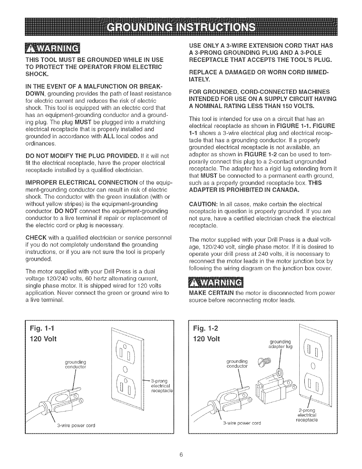
This tool is intended for use on a circuit that has an
electrical receptacle as shown in FIGURE 1-1. FIGURE
1-1 shows a 3-wire electrical plug and electrical recep-
tacle that has a grounding conductor. If a properly
grounded electrical receptacle is not available, an
adapter as shown in FIGURE 1-2 can be used to tem-
porarily connect this plug to a 2-contact ungrounded
receptacle. The adapter has a rigid lug extending from it
that MUST be connected to a permanent earth ground,
such as a properly grounded receptacle box. THIS
ADAPTER IS PROHIBITED IN CANADA.
CAUTION: In all cases, make certain the electrical
receptacle in question is properly grounded. If you are
not sure, have a certified electrician check the electrical
receptacle.
The motor supplied with your Drill Press is a dual volt-
age, 120/240 volt, single phase motor. If it is desired to
operate your drill press at 240 volts, it is necessary to
reconnect the motor leads in the motor junction box by
following the wiring diagram on the junction box cover.
MAKE CERTAIN the motor is disconnected from power
source before reconnecting motor leads.
Fig. 1-1
120 Volt
grounding
conductor
3-wire power cord
3-prong
electrical
receptacle
Fig. 1-2
120 Volt
grounding
conductor
3-wire power cord
grounding
2-prong
electrical
receptacle

it is aUsonecessary to repUacethe 120 voUtpUug,sup-
plied with the motor, with a UL/CSA Listed pUugsuitabb
for 240 voUtsand rated current of the drHUpress, Contact
a bcaU qualified eUectrbian for proper procedures to
install the pUug,The drHUpress must compUy with aH
bcaU and nationaU eUectrbaUcodes after the 240 voUt
pUugis installed,
The drHUpress with a 240 voUtpUugshouUd onUybe
connected to an outlet having the same configuration
as the pUugshown in FIGURE 1-3, No adapter is avaiP
able or should be used with the 240 volt plug,
Fig. 1-3
240 Volt
current carrying
prongs
grounding blade is
longest of the 3 blades
grounded outlet box
(9
MAKE CERTAIN the receptacle in question is properly
grounded, If you are not sure have a qualified ebctric-
ian check the receptacle,
This Drill Press is for indoor use only, Do not expose to
rain or use in damp locations,
SPECIFIC SAFETY INSTRUCTIONS
The operation of any drill press can result in debris
being thrown into your eyes, which can result in severe
eye damage, ALWAYS WEAR EYE PROTECTION, Any
power tool can throw debris during operations, which
could cause severe and permanent eye damage,
Everyday eyeglasses are NOT safety glasses,
ALWAYS wear Safety Goggles (that comply with ANSI
standard Z87,1) when operating power tools, Safety
Goggles are available at Sears Retail Stores,
Basic precautions should always be followed when
using your drill press, To reduce the risk of injury, ebc-
trical shock or fire, comply with the safety rules listed
below:
1, READ and understand the instruction manual
before operating the drill press,
2, AVOID AWKWARD OPERATIONS AND HAND
POSITIONS, A sudden slip could cause a serious
injury,
3,
4,
5,
6,
7,
8,
9,
10,
11,
12,
13,
14,
15,
16,
17,
18,
CHECK all drill bits, cutting tools, sanding drums, or
other accessories for damage before installing in
the drill press chuck, Damaged items can cause
damage to the drill press and or serious injury,
Before leaving the drill press, LOCK or REMOVE
the ON/OFF switch/key to prevent unauthorized
use,
DO NOT install or use any drill bit that exceeds
7-inches in length or that extends 6-inches below
the chuck jaws, The drill bit can suddenly bend or
break,
DO NOT try to drill a workpiece that is too small to
be securely held to the table or in a vise,
DO NOT operate this drill press until it is assembled
and installed according to the instruction manual,
DO NOT leave the drill press plugged into the elec-
trical outlet, Unplug the drill press from the outlet
when not in use and before servicing, changing bits
and cleaning,
DO NOT USE router bits, shaper cutters, circle (fly)
cutters, rotary planers or wire wheels in this drill
press,
FOLLOW all electrical and safety codes, including
the National Electric Code (NEC) and the
Occupational Safety and Health Regulations
(OSHA), All electrical connections and wiring should
be made by qualified personnel only,
LET THE CHUCK REACH FULL SPEED before
starting drill operations,
MAKE SURE there are no foreign objects, nails,
stones in the workpiece,
NEVER PERFORM LAYOUT, ASSEMBLY OR
SETUP WORK on the table/work area when the
drill press is running,
NEVER START THE DRILL PRESS BEFORE
CLEANING THE TABLE OF ALL OBJECTS (tools,
scrap pieces, etc,), Debris can be thrown at high
speed,
NEVER START THE DRILL PRESS with the drill
bit, cutting tool, or sanding drum against the work-
piece, Loss of control of the workpiece can cause
serious injury,
OBTAIN ADVICE FROM YOUR SUPERVISOR,
instructor, or another qualified person if you are not
familiar with the operation of this drill press,
PROPERLY SUPPORT long or wide workpiece and
clamp to the table,
PROPERLY SECURE the drill bit, cutting tool, or
sanding drum in the chuck before operating the drill
press,
19,REPLACEadamagedcordimmediately,DONOT
useadamagedcordorplug,if theddllpressis not
operatingproperly,orhasbeendamaged,bft out-
doorsorhasbeenincontactwithwater,returnit to
a SearsServiceCenter,
20,SECUREthedrillpresstothefloororworkbench,
Vibrationcancausethedrillpresstoslide,walkor
tipover,
21,SECUREtheworkpbcefirmlyagainstthetabb,
Donotattempttodrilla workpbcethatdoesnot
haveafiatsurfaceagainstthetabb,orthatisnot
securedbya vise, Preventtheworkpbcefrom
rotatingbydampingit tothetabborbysecuringit
againstthedrillpresscolumn,Lossof controlof
theworkpbcecancauseseriousinjury,
22,SECURELYLOCKtheheadandtabbsupportto
thecolumn,andthetabbto thetabbsupport
beforeoperatingthedrillpress,
23,Thedrillpressisdesignedforhomeuseorlight
commercialdutyONLY,
24,TOREDUCETHERISKOFELECTRICAL
SHOCK,donotuseoutdoors,Donotexposeto
rain,Storeindoorsina dryarea,
25,TURNTHEDRILLPRESSOFFandunplugfrom
powersource,Waitforthedrillbit,cuttingtool,or
sandingdrumtocometoa completeSTOPbefore
cleaningoffthetable/workarea,removingorsecur-
ingworkpiece,orchangingsetup,
26,
27,
28,
29,
30,
USEonlydrillbits,cuttingtools,sandingdrums,or
otheraccessorieswithpropershanksizerecom-
mendedinthisinstructionmanual,Thewrongsize
shankcancausedamagetothedrillpressand/or
seriousinjury,
USEonlyasdescribedinthisinstructionmanual,
USEaccessoriesonlyrecommendedbySears,
USERECOMMENDEDSPEEDSforalloperations,
Otherspeedsmaycausethemachinetomalfunc-
tioncausingdamagetothedrillpressandor
seriousinjury,
informationregardingthesafeandproperoperation
ofthistoolisalsoavailablefromthefollowing
sources:
PowerToolinstitute
1300SummerAvenue
Cleveland,OH44115o2851
www@owertoolinstitute,orq
NationalSafetyCouncil
1121SpringLakeDrive
Itasca,IL60143-3201
AmericanNationalStandardsinstitute
25West43rdStreet,4thfloor
NewYork,NY10036
ANSi01,1SafetyRequirementsfor
WoodworkingMachines,andthe
U,S,Departmentof Laborregulations
www,osha,g£y_
SAVETHESEINSTRUCTIONS,Referto them
frequentlyandusethemto instructotherusers,
AVAILABLE ACCESSORIES
Visit your Sears Hardware Department or see the
Craftsman Power and Hand Tool Catalog for the
following accessories,
ITEM STOCK NUMBER
* Circle Cutter 25293
* Clamping Lit 26426
* 8-in, Vise 24077
* 4-in, Vise 24081
* 3-in, Vise 24071
* 21 pc, Sanding Drum Kit 25262
* 7 pc, Forstner Bit Set 25389
Sears may recommend other accessories not listed in
this manual,
See your nearest Sears Hardware Department or
Craftsman Power and Hand Tool Catalog for other
accessories,
Do not use any accessory unless you have completely
read the instruction Manual for that accessory,
Use only accessories recommended for this drill press,
Using other accessories may cause serious injury and
cause damage to the drill press,
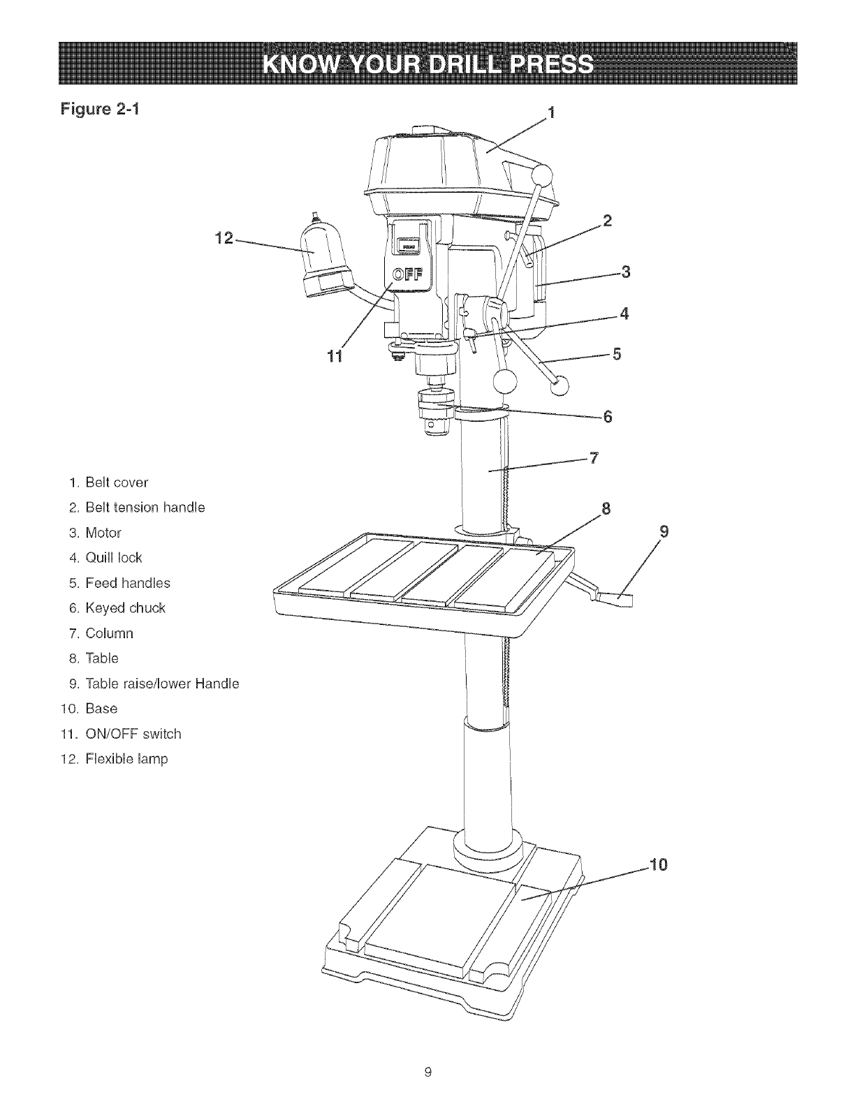
Figure 2-1
11
1, BeHtcover
2, BeHttension handHe
3, Motor
4, QuHHHock
5, Feed handHes
6, Keyed chuck
7, CoHumn
8, TaMe
9, TaMe raise/Hower HandHe
1O, Base
11, ON/OFF switch
12, FHexibHeHamp
9
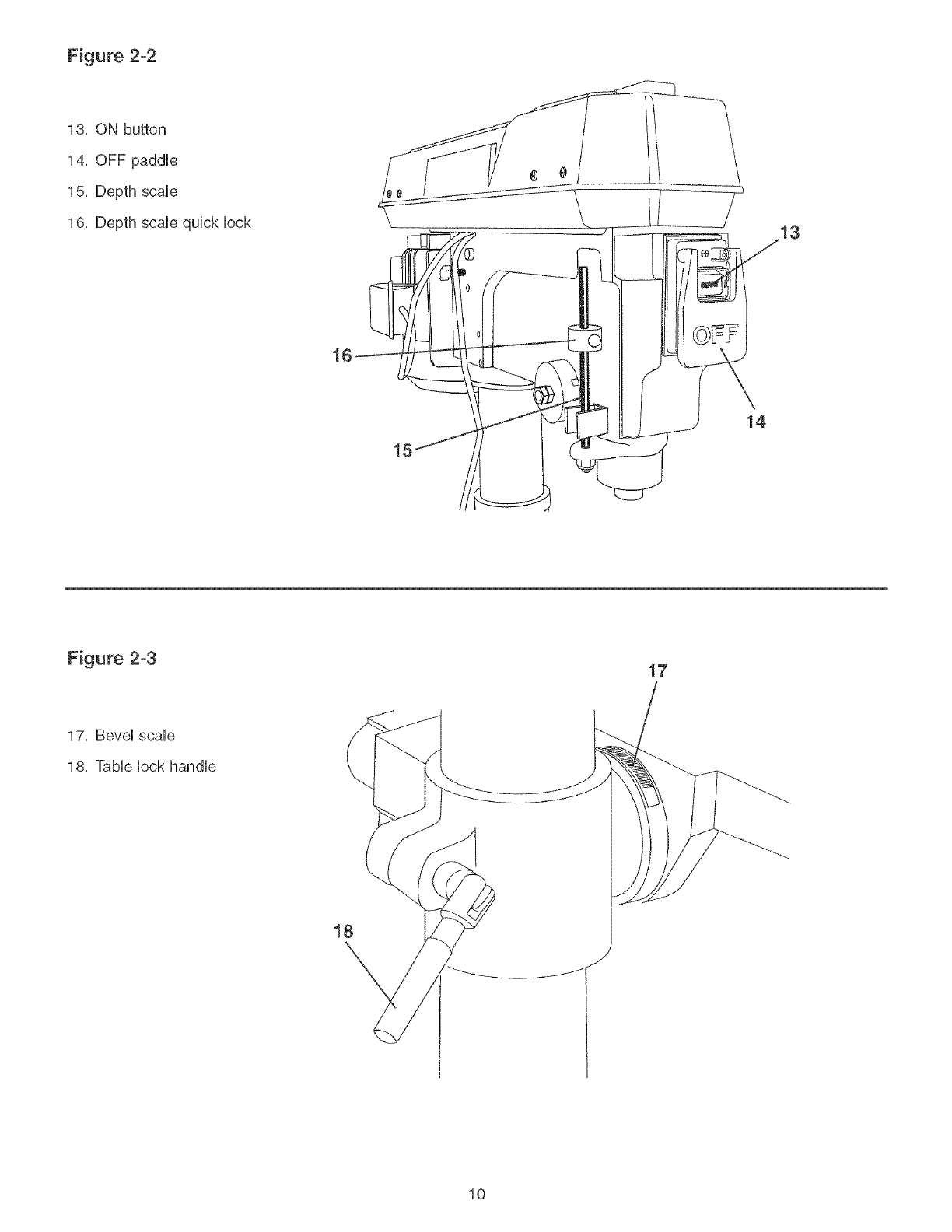
Figure 2-2
13, ON button
14, OFF paddHe
15, Depth scaHe
16, Depth scaHequick Hock
16
15
14
Figure 2-3 17
17, BeveHscaHe
18, TaMe HockhandHe
18
10
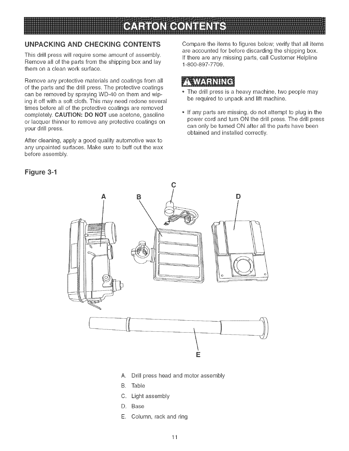
UNPACKUNG AND CHECKUNG CONTENTS
This drHUpress wHUrequire some amount of assemMy,
Remove aH of the parts from the shipping box and Uay
them on a clean work surface,
Remove any protective materiab and coatings from aH
of the parts and the drHUpress, The protective coatings
can be removed by spraying WD°40 on them and wip-
ing it off with a soft cloth, This may need redone severaU
times before aH of the protective coatings are removed
compbteUy, CAUTION: DO NOT use acetone, gasoline
or Uacquer thinner to remove any protective coatings on
your drHUpress,
After cleaning, apply a good quality automotive wax to
any unpainted surfaces, Make sure to buff out the wax
before assembly,
Compare the items to figures below; verify that all items
are accounted for before discarding the shipping box,
if there are any missing parts, call Customer Helpline
1°800°897°7709,
The drill press is a heavy machine, two people may
be required to unpack and lift machine,
if any parts are missing, do not attempt to plug in the
power cord and turn ON the drill press, The drill press
can only be turned ON after all the parts have been
obtained and installed correctly,
Figure 3-1
A
C
D
rq
E
A, Drill press head and motor assembly
B, Table
C, Light assembly
D, Base
E, Column, rack and ring
11
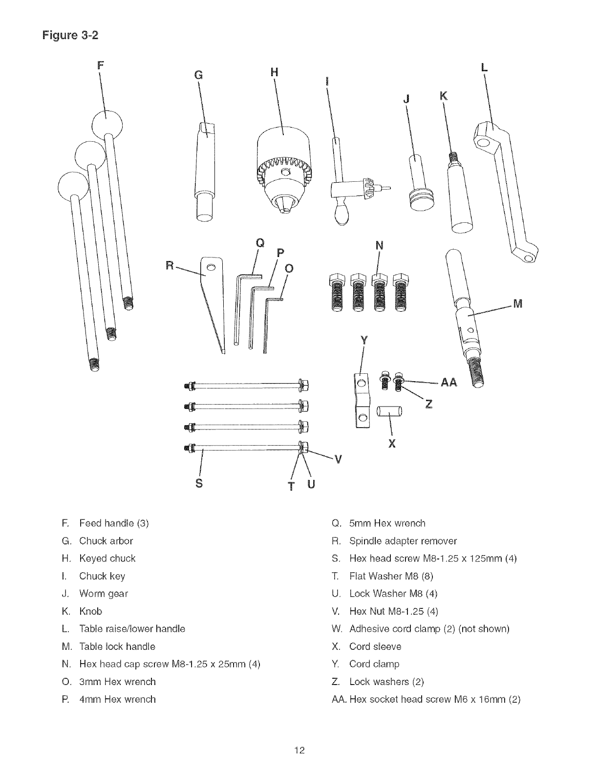
Figure 3-2
G
F_
S
H
QP
T U
m
J
N
K
Y
X
L
M
R Feed handHe (3)
G, Chuck arbor
H, Keyed chuck
H, Chuck key
J, Worm gear
K, Knob
L, TaMe raise/Hower handHe
M, TaMe HockhandHe
N, Hex head cap screw M8-1,25 x 25mm (4)
O, 3mm Hex wrench
R 4mm Hex wrench
Q, 5mm Hex wrench
R, SpindHe adapter remover
S, Hex head screw M8-1,25 x 125mm (4)
T, FHatWasher M8 (8)
U, Lock Washer M8 (4)
V, Hex Nut M8-1,25 (4)
W, Adhesive cord champ (2) (not shown)
X, Cord sHeeve
Y, Cord champ
Z, Lock washers (2)
AA, Hex socket head screw M6 x 16mm (2)
12
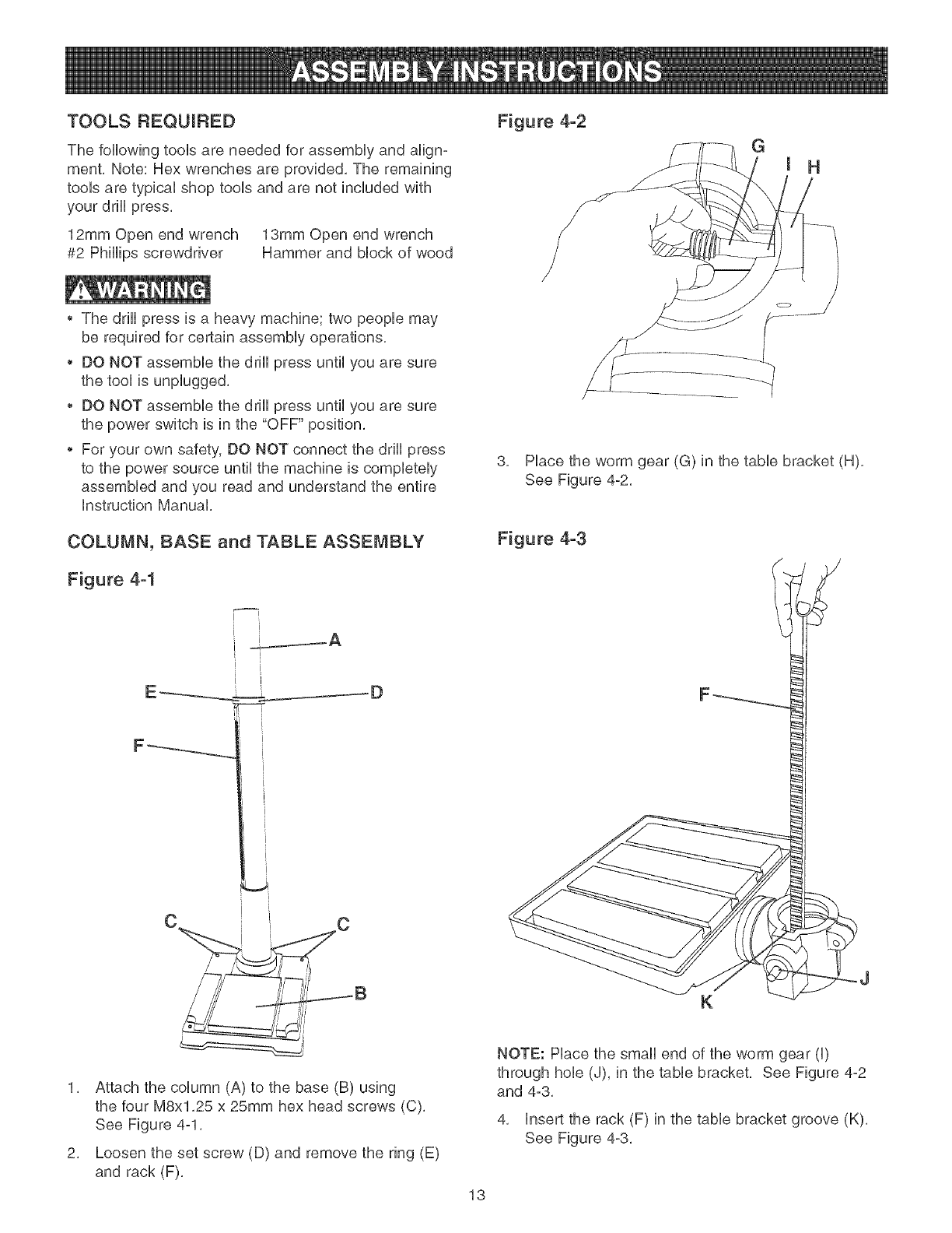
TOOLS REQUIRED
The following toob are needed for assemMy and align-
ment, Note: Hex wrenches are provided, The remaining
toob are typbaU shop tooUsand are not included with
your ddH press,
12mm Open end wrench 13mm Open end wrench
#2 PhHHpsscrewdriver Hammer and Mock of wood
*The drHUpress is a heavy machine; two peopb may
be required for certain assemMy operations,
*DO NOT assembb the ddH press until you are sure
the tooUis unpUugged,
*DO NOT assembb the ddH press until you are sure
the power switch is in the "OFF" position,
*For your own safety, DO NOT connect the drHUpress
to the power source untiUthe machine is completely
assembled and you read and understand the entire
Instruction Manual,
COLUMN, BASE and TABLE ASSEMBLY
Figure 4-1
i i
I
I
C
1, Attach the column (A) to the base (B) using
the four M8x1,25 x 25mm hex head screws (C),
See Figure 4-1,
2, Loosen the set screw (D) and remove the ring (E)
and rack (F),
Figure 4-2
3, Place the worm gear (G) in the table bracket (H),
See Figure 4-2,
Figure 4-3
K
NOTE: Place the small end of the worm gear (I)
through hob (J), in the table bracket, See Figure 4-2
and 4-3,
4, insert the rack (F) in the table bracket groove (K),
See Figure 4-3,
13
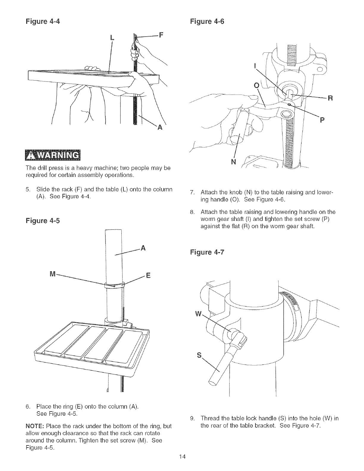
Figure 4-4 Figure 4-6
L
The drill press is a heavy machine; two people may be
required for certain assembly operations,
5, Slide the rack (F) and the table (L) onto the column
(A), See Figure 4-4,
Figure 4-5
O
P
N
7,
8,
Attach the knob (N) to the table raising and lower-
ing handle (O), See Figure 4-6,
Attach the table raising and lowering handle on the
worm gear shaft (I) and tighten the set screw (P)
against the fiat (R) on the worm gear shaft,
Figure 4-7
S
6, Place the ring (E) onto the column (A),
See Figure 4-5,
NOTE: Hace the rack under the bottom of the ring, but
allow enough clearance so that the rack can rotate
around the column, Tighten the set screw (M), See
Figure 4-5,
9,
14
Thread the table lock handle (S) into the hole (W) in
the rear of the table bracket, See Figure 4-7,
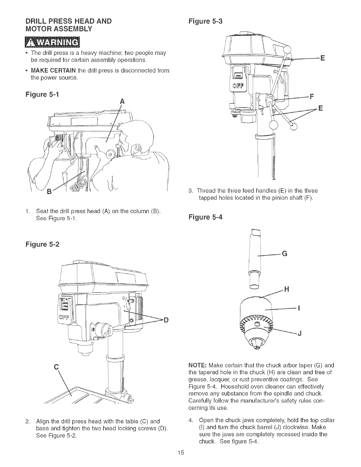
DRILL PRESS HEAD AND Figure 5-3
MOTOR ASSEMBLY
The ddH press is a heavy machine; two peopb may
be required for certain assemMy operations,
MAKE CERTAIN the ddH press is disconnected from
the power source,
Figure 5-1 A
1, Seat the ddH press head (A) on the coUumn (B),
See Figure 5-1,
Figure 5-2
C
2, Align the drill press head with the table (C) and
base and tighten the two head locking screws (D),
See Figure 5-2,
E
F
E
3, Thread the three feed handles (E) in the three
tapped hobs located in the pinion shaft (F),
Figure 5-4
IG
15
NOTE: Make certain that the chuck arbor taper (G) and
the tapered hob in the chuck (H) are clean and free of
grease, lacquer, or rust preventive coatings, See
Figure 5-4_ Household oven cleaner can effectively
remove any substance from the spindle and chuck,
Carefully follow the manufacturer's safety rubs con-
cerning its use,
4, Open the chuck jaws completely, hold the top collar
(I) and turn the chuck barrel (J) clockwise, Make
sure the jaws are completely recessed inside the
chuck, See figure 5-4,

Figure 5-5 FASTENING DRILL PRESS
Figure 5-6
5, Scat the chuck onto the drHUpress spindb as far as
it wHUgo, Carefully drive the chuck onto the spindb
by pUacinga wooden Mock (K) under the chuck (L)
and tap the Mock up with a hammer (M),
IMPORTANT: DO NOT tap the chuck directly with a
mctaU hammer,
A
To help reduce the tendency of the drill press to tip
over, slide, or walk, it can be fastened to the floor
surface, The machine base has four hobs (A), one at
each corner where it can be fastened (hardware not
included), See Figure 6-1,
16
,, DO NOT expose the drHHpress to rain or operate the
in damp Hocations.
,, MAKE SURE aHHparts have been assembHed correctly
and are in working order.
SWITCH OPERATION
CHILDPROOF THE WORKSHOP AREA by removing
switch keys, unpHugging tooHsfrom the eHectricaHrecep-
tacHes, and using padHocks.
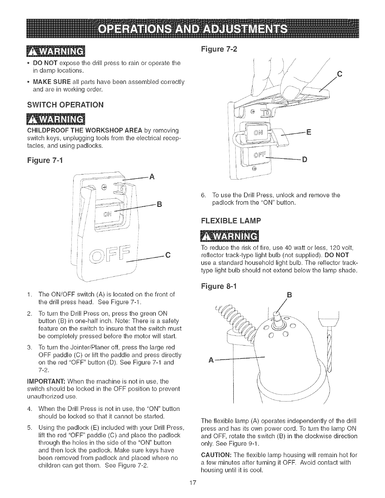
Figure 7-1
p- ............... \
1. The ON/OFF switch (A) is located on the front of
the drill press head. See Figure 7-1.
2. To turn the Drill Press on, press the green ON
button (B) in one-half inch. Note: There is a safety
feature on the switch to insure that the switch must
be completely pressed before the motor wiil start.
3. To turn the Jointer/Pianer off, press the large red
OFF paddle (C) or lift the paddle and press directly
on the red "OFF" button (D). See Figure 7-1 and
7-2.
IMPORTANT: When the machine is not in use, the
switch shouHdbe Hocked in the OFF position to prevent
unauthorized use.
4,
5.
When the Drill Press is not in use, the "ON" button
should be Hockedso that it cannot be started.
Using the padlock (E) included with your Drill Press,
lift the red "OFF" paddle (C) and place the padlock
through the holes in the side of the "ON" button
and then Hockthe padlock. Make sure keys have
been removed from padlock and placed where no
children can get them. See Figure 7-2.
Figure 7-2
6. To use the Drill Press, unlock and remove the
padlock from the "ON" button.
FLEXIBLE LAMP
To reduce the risk of fire, use 40 watt or less, 120 volt,
reflector track-type Hightbulb (not supplied). DO NOT
use a standard household Hightbulb. The reflector track°
type Hightbulb should not extend below the lamp shade.
Figuce 8-1 B
The fHexibHeHamp(A) operates independently of the drHH
press and has its own power cord. To turn the HampON
and OFF, rotate the switch (B) in the cHockwise direction
onHy.See Figure 9-1.
CAUTION: The flexibHe Hamphousing wiHHremain hot for
a few minutes after turning it OFF. Avoid contact with
housing untiHit is cool
17
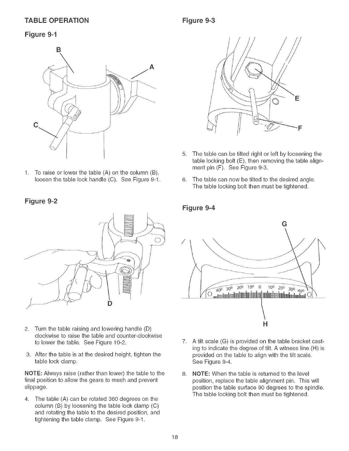
TABLE OPERATION
Figure 9-I
B
Figure 9-3
1. To raise or bwer the tame (A) on the coUumn (B),
bosen the tame bck handb (C). See Figure 9-1.
Figure 9-2
F
5,
6,
The tame can be tilted right or bft by bosening the
tame bcMng bout (E), then removing the tame align-
ment pin (F). See Figure 9-3.
The table can now be tilted to the desired angle.
The table locking bolt then must be tightened.
Figure 9-4
G
200 100 0 10° 200 300
2. Turn the tame raising and [owering handUe (D)
c[ockwise to raise the tame and counter-cUockwise
to [ower the tame. See Figure 10-2.
3, After the tame is at the desired height, tighten the
tame bck damp.
NOTE: AUways raise (rather than bwer) the tame to the
finaUposition to allow the gears to mesh and prevent
slippage.
4, The table (A) can be rotated 360 degrees on the
column (B) by loosening the table lock clamp (C)
and rotating the table to the desired position, and
tightening the table clamp. See Figure 9-1.
H
7,
8,
A tilt scale (G) is provided on the table bracket cast°
ing to indicate the degree of tilt. A witness line (H) is
provided on the table to align with the tilt scale.
See Figure 9-4.
NOTE: When the table is returned to the level
position, replace the table alignment pin, This wiii
position the table surface 90 degrees to the spindle,
The table locking bolt then must be tightened,
18
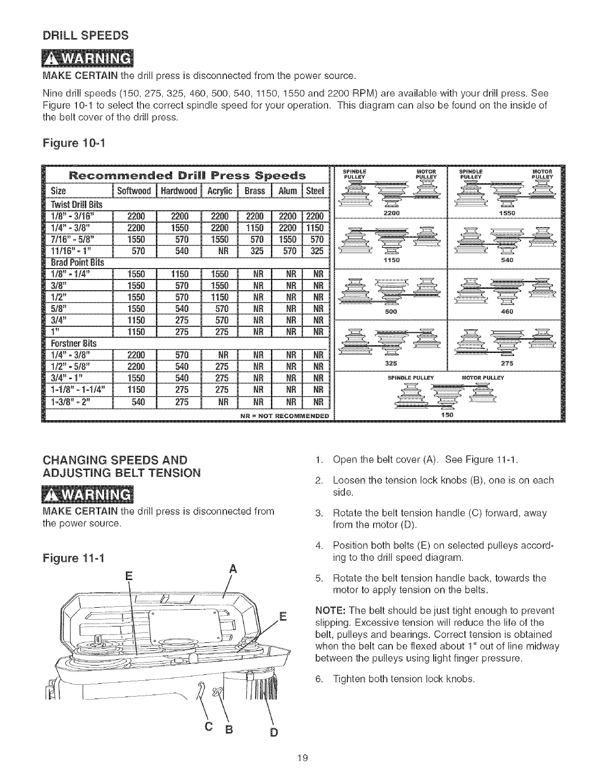
DRULL SPEEDS
MAKE CERTAIN the drill press is disconnected from the power source,
Nine drill speeds (150, 275, 325, 460,500,540, 1150, 1550 and 2200 RPM) are available with your drill press, See
Figure 10-1 to select the correct spindle speed for your operation, This diagram can also be found on the inside of
the belt cover of the drill press,
Figure 10-1
Recommended Dri|| Press Speeds
Size JSoftwo0d JHardw0odJ AcryibJ Brass _ Steel
Twist}]rill }]its
!/0" -3/10"
1/4" -3/8"
7/16" -5/0"
11116"- t"
BradPointBits
!/8" - 1/4"
310"
1/2"
5/8"
3/4"
1 _
Forstner8its
I/4" " 3/8"
I12" - 510"
3/4"- 1"
I-I18" - 1-114"
1-310"- 2"
2200 2200 2200 2200 2200 12200
2200 1550 2200 tt50 2200 11t50
1550 570 1550 570 1550 570
570 540 NR 325 570 325
1550
1550
1550
1550
1!50
1150
1150 1550 NR NR NR
570 1550 NR NR NR
570 1150 NR NR F==_
540 570 NR NR NR
275 570 NR NR NR
275 275 NR NR NR
2200
2200
1550
1t50
540
570 NR NR NR NR
540 275 NR NR NR
540 275 NR NR NR
275 275 NR NR NR
275 NR NR NR NR
NR =NOT RECOMMENDED
SPINDLE MOTOR
PULLEY PULLEY
2200
1t50
EGG
SPINDLE MOTOR
PULLEY PULLEY
MOTOR PULLEY
15G
t550
540
460
2'75
CHANGING SPEEDS AND
ADJUSTING BELT TENSION
MAKE CERTAIN the drill press is disconnected from
the power source,
Figure 11-1
EA
C B
E
D
1, Open the belt cover (A), See Figure 11=1,
2, Loosen the tension lock knobs (B), one is on each
side,
3, Rotate the belt tension handle (C) forward, away
from the motor (D),
4, Position both belts (E) on selected pulleys accord-
ing to the drill speed diagram,
5, Rotate the belt tension handle back, towards the
motor to apply tension on the belts,
NOTE: The belt should be just tight enough to prevent
slipping, Excessive tension will reduce the life of the
belt, pulleys and bearings, Correct tension is obtained
when the belt can be flexed about 1" out of line midway
between the pulleys using light finger pressure,
6, Tighten both tension lock knobs,
19
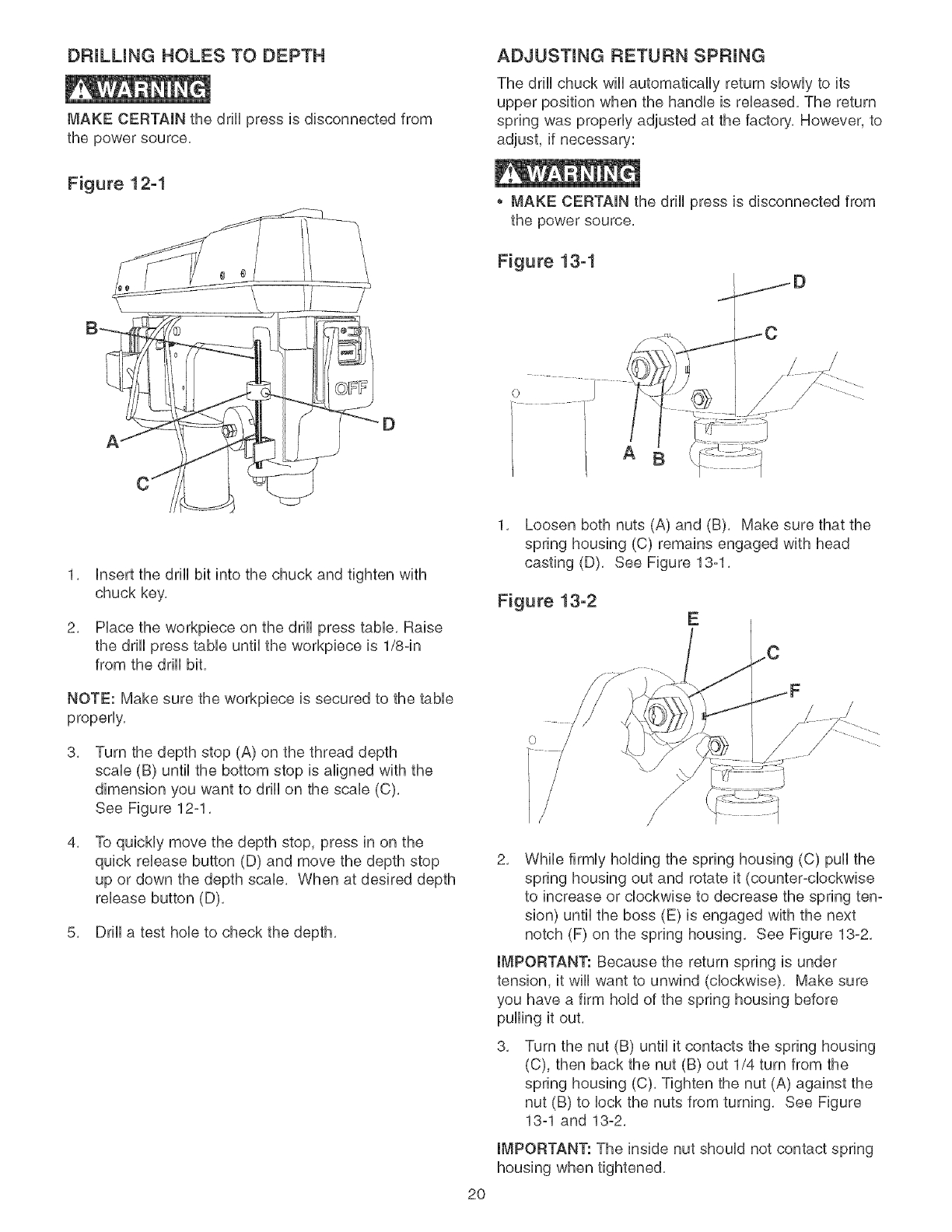
DRULLING HOLES TO DEPTH
MAKE CERTAIN the drill press is disconnected from
the power source.
Figure 12-1
ADJUSTING RETURN SPRUNG
The drHUchuck wHUautomatically return sUowUyto its
upper position when the handUe is reUeased, The return
spring was properUy adjusted at the factory, However, to
adjust, if necessary:
MAKE CERTAIN the drHUpress is disconnected from
the power source.
Figure 13-1
A
1. Unsert the drHUbit into the chuck and tighten with
chuck key.
2. Hace the workpiece on the drHUpress tame. Raise
the drHUpress tame until the workpiece is 1/8-in
from the drHUbit.
NOTE: Make sure the workpiece is secured to the table
properly.
3, Turn the depth stop (A) on the thread depth
scale (B) until the bottom stop is aligned with the
dimension you want to drill on the scale (C).
See Figure 12ol.
4, To quickly move the depth stop, press in on the
quick release button (D) and move the depth stop
up or down the depth scale. When at desired depth
release button (D).
5. Drill a test hole to check the depth.
2O
1. Loosen both nuts (A) and (B). Make sure that the
spring housing (C) remains engaged with head
casting (D). See Figure 13-1.
Figure 13-2 E
2. While firmly holding the spring housing (C) pull the
spring housing out and rotate it (counter-clockwise
to increase or clockwise to decrease the spring ten°
sion) until the boss (E) is engaged with the next
notch (F) on the spring housing. See Figure 13-2.
IMPORTANT: Because the return spring is under
tension, it will want to unwind (clockwise). Make sure
you have a firm hold of the spring housing before
pulling it out.
3. Turn the nut (B) until it contacts the spring housing
(C), then back the nut (B) out 1/4 turn from the
spring housing (C). Tighten the nut (A) against the
nut (B) to lock the nuts from turning. See Figure
13-1 and 13-2.
IMPORTANT: The inside nut should not contact spring
housing when tightened.
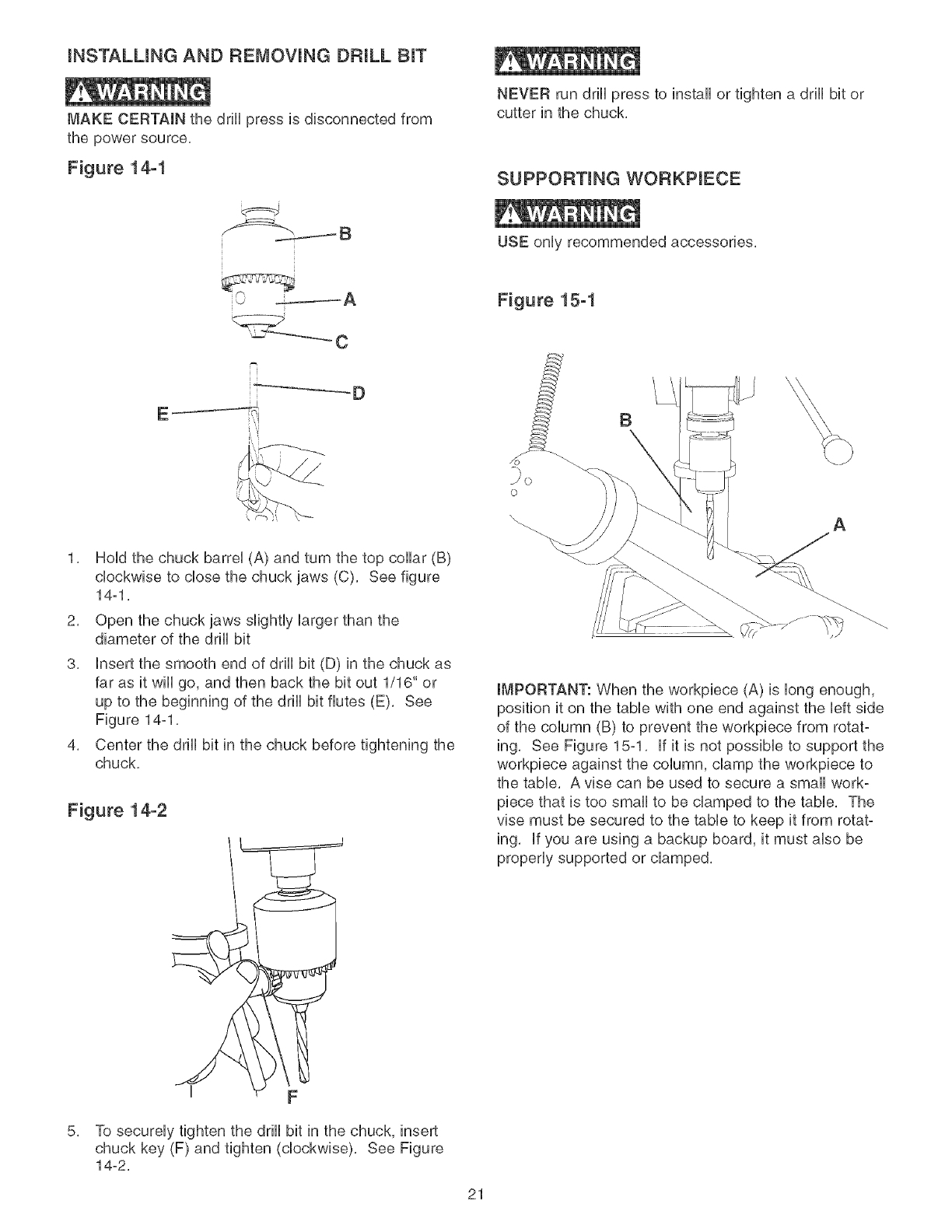
iNSTALLiNG AND REMOVING DRULL BIT
MAKE CERTAIN the drill press is disconnected from
the power source.
Figure 14-1
NEVER run drill press to install or tighten a drill bit or
cutter in the chuck.
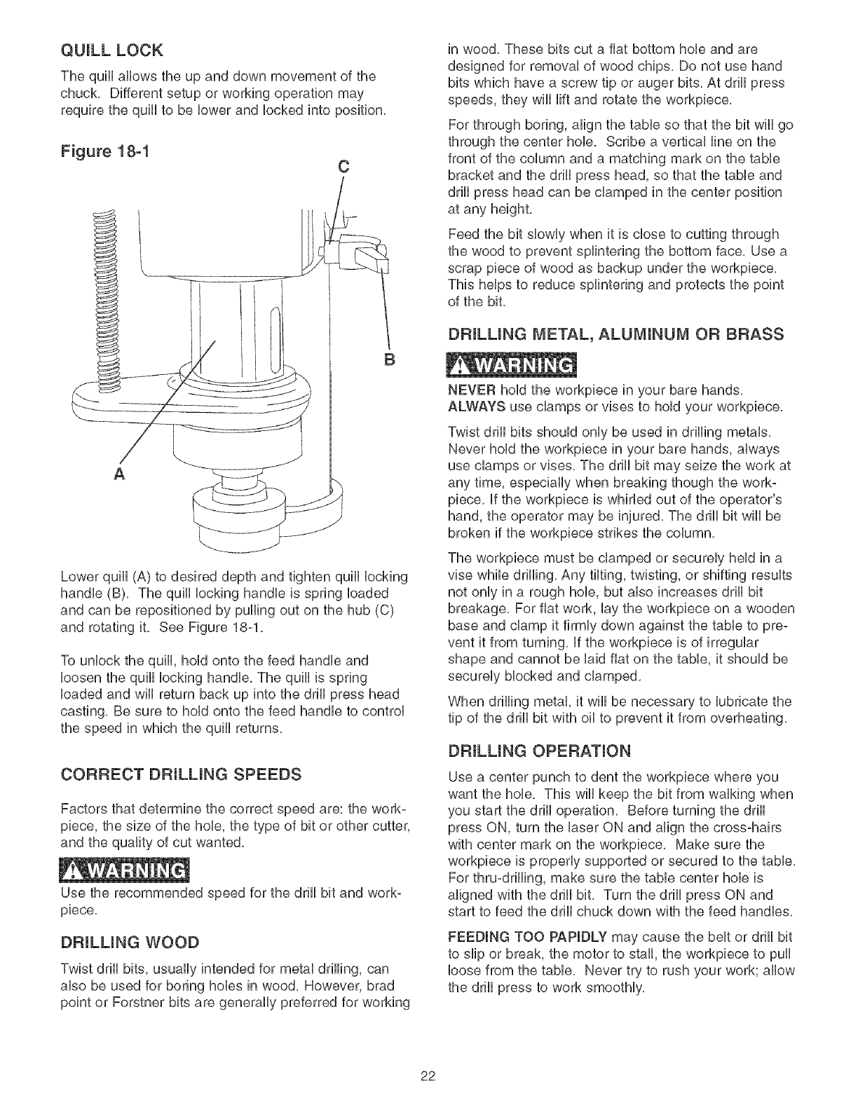
SUPPORTING WORKPIECE
USE only recommended accessories.
Figure 15-1
B
1, Hold the chuck barrel (A) and turn the top collar (B)
clockwise to dose the chuck jaws (C), See figure
14-1.
2. Open the chuck jaws slightly larger than the
diameter of the drill bit
3. insert the smooth end of drill bit (D) in the chuck as
far as it will go, and then back the bit out 1/16" or
up to the beginning of the drill bit flutes (E). See
Figure 14-1.
4. Center the drill bit in the chuck before tightening the
chuck.
Figure 14-2
o
\A
IMPORTANT: When the workpiece (A) is long enough,
position it on the table with one end against the left side
of the column (B) to prevent the workpiece from rotat-
ing. See Figure 15-1. if it is not possible to support the
workpiece against the column, clamp the workpiece to
the table. A vise can be used to secure a small work-
piece that is too small to be clamped to the table. The
vise must be secured to the table to keep it from rotat-
ing. If you are using a backup board, it must also be
properly supported or clamped.
5,
I F
To securely tighten the drill bit in the chuck, insert
chuck key (F) and tighten (clockwise). See Figure
14-2.
21
QUILL LOCK
The quill allows the up and down movement of the
chuck, Different setup or working operation may
require the quill to be lower and locked into position,
Figure 18-1 C
B
A
Lower quill (A) to desired depth and tighten quill locking
handle (B), The quill locking handle is spring loaded
and can be repositioned by pulling out on the hub (C)
and rotating it, See Figure 18-1,
To unlock the quill, hold onto the feed handle and
loosen the quill locking handle, The quill is spring
loaded and wiii return back up into the drill press head
casting, Be sure to hold onto the feed handle to control
the speed in which the quill returns,
CORRECT DRULUNG SPEEDS
Factors that determine the correct speed are: the work-
piece, the size of the hob, the type of bit or other cutter,
and the quality of cut wanted,
Use the recommended speed for the drill bit and work-
piece,
DRULUNG WOOD
Twist drill bits, usually intended for metal drilling, can
also be used for boring hobs in wood, However, brad
point or Forstner bits are generally preferred for working
in wood, These bits cut a fiat bottom hob and are
designed for removal of wood chips, Do not use hand
bits which have a screw tip or auger bits, At drill press
speeds, they will lift and rotate the workpiece,
For through boring, align the table so that the bit will go
through the center hob, Scribe a vertical line on the
front of the column and a matching mark on the table
bracket and the drill press head, so that the table and
drill press head can be clamped in the center position
at any height,
Feed the bit slowly when it is close to cutting through
the wood to prevent splintering the bottom face, Use a
scrap piece of wood as backup under the workpiece,
This helps to reduce splintering and protects the point
of the bit,
DRiLLiNG METAL, ALUMINUM OR BRASS
NEVER hold the workpiece in your bare hands,
ALWAYS use clamps or vises to hold your workpiece,
Twist drill bits should only be used in drilling metals,
Never hold the workpiece in your bare hands, always
use clamps or vises, The drill bit may seize the work at
any time, especially when breaking though the work-
piece, if the workpiece is whirled out of the operator's
hand, the operator may be injured, The drill bit wiii be
broken if the workpiece strikes the column,
The workpiece must be damped or securely held in a
vise while drilling, Any tilting, twisting, or shifting results
not only in a rough hob, but also increases drill bit
breakage, For fiat work, lay the workpiece on a wooden
base and clamp it firmly down against the table to pre-
vent it from turning, if the workpiece is of irregular
shape and cannot be laid fiat on the table, it should be
securely blocked and clamped,
When drilling metal, it will be necessary to lubricate the
tip of the drill bit with oil to prevent it from overheating,
DRULUNG OPERATION
Use a center punch to dent the workpiece where you
want the hob, This will keep the bit from walking when
you start the drill operation, Before turning the drill
press ON, turn the laser ON and align the cross-hairs
with center mark on the workpiece, Make sure the
workpiece is properly supported or secured to the table,
For thru-drilling, make sure the table center hob is
aligned with the drill bit, Turn the drill press ON and
start to feed the drill chuck down with the feed handles,
FEEDING TOO PAPIDLY may cause the belt or drill bit
to slip or break, the motor to stall, the workpiece to pull
loose from the table, Never try to rush your work; allow
the drill press to work smoothly,
22

CHANGmNG MOTOR VOLTAGE
MAKE CERTAIN to disconnected the machine from the
power source before working on motor.
Have a certified eUectrbian make aft eUectrbaUconnec-
tions. Aft UocaUand state codes must be maintained.
The motor supplied with the DrHUPress is a duaUvoUtage
120/240°voUt, singb phase motor. The motor is wired
from the factory for 120°voUtoperation. To change to
240°voUtoperation, proceed with the foflowing instruc-
tions, it is aUsonecessary to repUacethe 120 voUtpUug,
suppfied with your machine, with a UL/CSA Listed pUug
(not included) suitable for 240 volts and the rated cur-
rent of the motor. The motor with a 240 volt plug
should only be connected to an outlet having the same
configuration as the plug. No adapter is available or
should be used with the 240 volt plug.
1, Make sure switch is OFF and disconnect power
cord from power source,
2. Verify on the motor tag that motor is dual voltage.
3. if motor tag states that it is dual voltage remove
junction box cover on motor.
4, Using wiring diagram on inside of junction box
cover, reconnect motor leads for 240°volt operation,
5. Replace junction box cover.
6. Replace 120 volt plug with a UL/CSA Listed 240
volt plug rated for current of the motor.
7. The ON/OFF switch is a 4-pole switch and does not
need any modifications.
Turn the power switch OFF and unplug the power cord
from its power source,
The drift press has sealed lubricated bearings in the
motor housing that do not require any additional lubrica-
tion from the operator,
The quill and spindle assemblies should be periodically
lubricated, Lower the quill assembly and squirt or wipe
a thin film of lightweight machine oil on the entire sur-
face, Place a few drops of light machine oil down the
spindle assembly, Raise and lower the quill several
times to distribute the oil evenly,
With the drift press unplugged, blow off motor with low°
pressure air to remove dust or dirt, Air pressure above
50 P, S, I, should not be used as high-pressured air
may damage insulation, The operator should always
wear eye protection when using compressed air,
Do not use a shop vacuum to clean metal shavings.
The metal shavings can cause an explosion or fire.
Do not allow chips and dust to accumulate under drift
press, Keep area clean and in safe order,
CAUTION: DO NOT USE FLAMMABLE MATERIALS
to clean the drift press.
After cleaning, apply a good quality automotive wax to
any unpainted surfaces, Make sure to buff out the wax
before assembly,
ONLY trained personnel should perform repairs to the
drill press, Contact your nearest Sears Service Center
for authorized service, Unauthorized repairs or replace°
ment with non-factory parts could cause serious injury
to the operator and damage to the drift press,
23
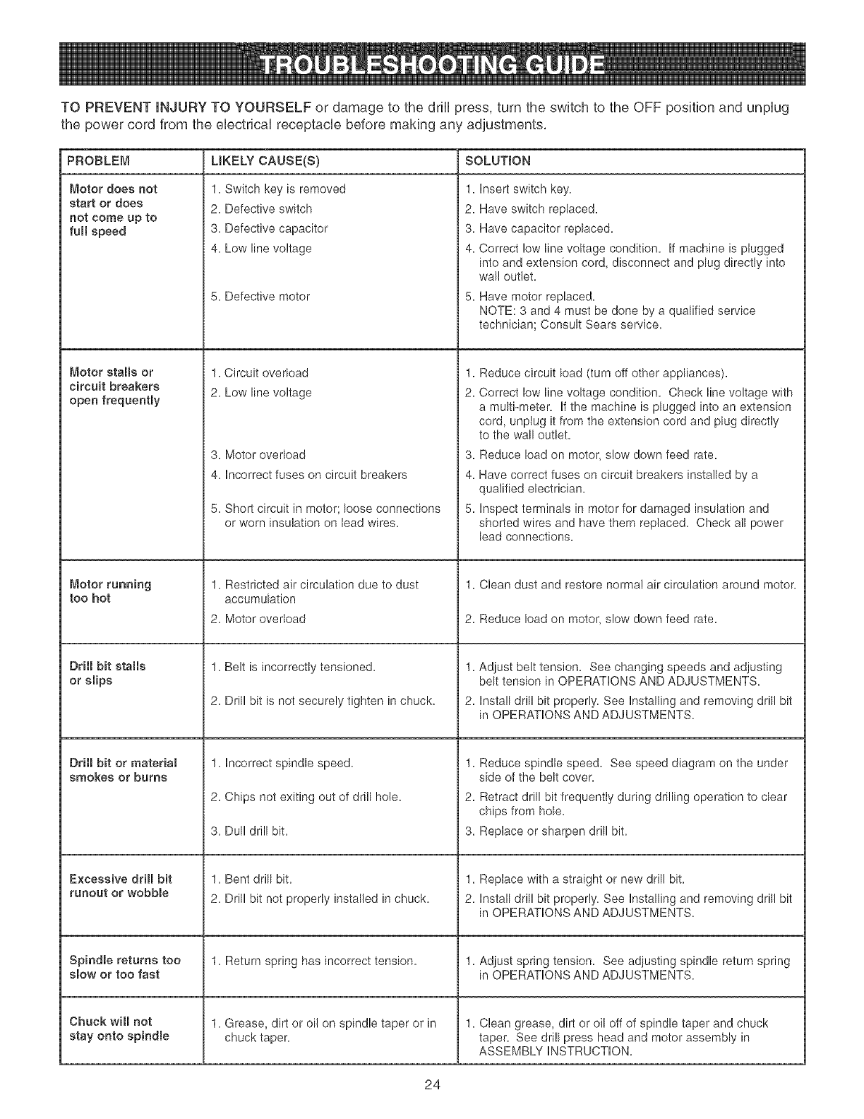
TOPREVENTINJURYTOYOURSELFordamageto thedrHUpress,turntheswitchtotheOFFpositionandunpUug
thepowercordfromtheeUectricaUreceptaclebeforemakinganyadjustments,
PROBLEM UKELY CAUSE(S) SOLUTION
Motor does not
start or does
not come up to
full speed
Motor stalls or
circuit breakers
open frequently
Motor running
too hot
Drill bit or material
smokes or burns
Excessive drill bit
runout or wobble
Spindle returns too
slow or too fast
Chuck will not
stay onto spindle
1. Switch key is removed
2. Defective switch
3. Defective capacitor
4. Low line voltage
5. Defective motor
1. Circuit overload
2. Low line voltage
3. Motor overload
4. Incorrect fuses on circuit breakers
5. Short circuit in motor; loose connections
or worn insulation on lead wires.
1. Restricted air circulation due to dust
accumulation
2. Motor overload
1. Belt is incorrectly tensioned.
2. Drill bit is not securely tighten in chuck.
1. incorrect spindle speed.
2. Chips not exiting out of drill hole.
3. Dull drill bit.
1. Bent drill bit.
2. Drill bit not properly installed in chuck.
1. Return spring has incorrect tension.
1. Grease, dirt or oil on spindle taper or in
chuck taper.
1. insert switch key.
2. Have switch replaced.
3. Have capacitor replaced.
4. Correct low line voltage condition, if machine is plugged
into and extension cord, disconnect and plug directly into
wall outlet.
Have motor replaced.
NOTE: 3 and 4 must be done by a qualified service
technician; Consult Sears service.
1.
2.
Reduce circuit load (turn off other appliances).
Correct low line voltage condition. Check line voltage with
a multi-meter, if the machine is plugged into an extension
cord, unplug it from the extension cord and plug directly
to the wall outlet.
3. Reduce load on motor, slow down feed rate.
4. Have correct fuses on circuit breakers installed by a
qualified electrician.
5. inspect terminals in motor for damaged insulation and
shorted wires and have them replaced. Check all power
lead connections.
1. Clean dust and restore normal air circulation around motor.
2. Reduce load on motor, slow down feed rate.
1.
2.
Adjust belt tension. See changing speeds and adjusting
belt tension in OPERATIONS AND ADJUSTMENTS.
Install drill bit properly. See Installing and removing drill bit
in OPERATIONS AND ADJUSTMENTS.
1.
2.
3.
Reduce spindle speed. See speed diagram on the under
side of the belt cover.
Retract drill bit frequently during drilling operation to clear
chips from hole.
Replace or sharpen drill bit.
1. Replace with a straight or new drill bit.
2. Install drill bit properly. See Installing and removing drill bit
in OPERATIONS AND ADJUSTMENTS.
1. Adjust spring tension. See adjusting spindle return spring
in OPERATIONS AND ADJUSTMENTS.
1. Clean grease, dirt or oil off of spindle taper and chuck
taper. See drill press head and motor assembly in
ASSEMBLY iNSTRUCTiON.
24

204n.BenchDrill Press MODELN0.152.229020
Whenservicing,useonlyCRAFTSMANreplacementparts,Useof anyotherpartsmaycreatea HAZARDorcause
productdamage,
Anyattemptto repairor replaceelectricalpartsonthisdrillpressmaycreatea HAZARDunlessaqualifiedservice
techniciandoesrepairs,RepairserviceisavailableatyournearestSearsServiceCenter,
AlwaysorderbyPARTNUMBER,
KEY PART KEY PART
NO. NO. DESCRiPTiON QTY. NO. NO.
0R92430 Pulley Cover Assy const of, (1,2,3,4,5,6,7,8,9) 1 47 0R90362
1 OR92431 Top Guard 1 48 0R90507
2 OR92434 Bottom Guard 1 49 QR93532
3 OR9!774 M4xlOmm Cheese Hd Screw 4 50 QR90343
4 OR90078 M4 Hex Nut 4 5! QR91060
5 QR90431 M4.3 Ext Tooth Washer 4 52 0R91040
6 0R93453 Speed Chart 1 53 QR93529
7 0R93541 M3.Sx9,5mm Pan Hd Tap Screw 4 54 QR92472
8 0R92433 Nameplate 2 55 QR92473
9 OR93542 M4.2x9 5mm Pan Hd Tap Screw 1 56 QR92471
10 0R90241 M6x12mm Cheese Hd Screw 4 57 QR92470
1! OR90059 M6.4 Fiat Washer 4 58 QR93522
12 OR92435 Sbeve 1 59 QR93537
13 OR92436 Retaining Ring 1 60 QR93533
14 OR93522 Ball Bearing 6206 1 6! 0R90306
15 OR92437 Spacer 1 62 QR92467
16 OR93522 Ball Bearing 6206 1 63 QR93525
17 OR92436 Retaining Ring 1 64 QR90235
OR93540 Pinion Assy const of, (18,19,20,21) 1 65 QR92349
18 OR92456 Pinion 1 66 0R92466
19 OR92458 Ring 1 67 QR92465
20 0R92457 Hub 1 68 0R98366
21 OR92721 M5x2Omm Spring Pin 1 69 QR92464
22 0R92455 Handb 3 70 0R92463
23 0R92331 Knob 3 71 QR92462
24 0R93523 Ext Ret Ring 1 72 0R93535
25 OR92454 Tension Handle 1 73 0R92722
26 OR90310 M8x16mm Hex Hd Screw 1 74 QR92459
27 OR92328 Eccentric 1 75 QR93527
28 OR92329 Pin 1 76 QR92460
29 QR92327 Foam Washer 4 77 0R90030
30 0R90382 M5x16mm Cheese Hd Screw 1 78 QR92468
31 OR92324 Clamp 1 79 QR92469
32 QR93524 M10x12mm Hex Soc Set Screw 2 80 QR92353
33 OR93534 M8x24mm Spring Pin 2 8! 0R92354
34 0R92453 Lock Screw 2 82 QR92355
35 0R92452 Headstock incl, (36,37,38,39) 1 83 0R92356
36 0R93455 Serial Number Label 1 84 0R9353!
37 OR92728 5mm Drive Screw 4 88 QR92474
38 OR92325 Warning Label 1 86 QR90222
39 OR92728 5ram Drive Screw 4 87 QR92475
40 OR90228 M!O Hex Nut 1 88
41 0R90647 3/8" Lock Washer 2 89
42 0R92489 Special Screw 1 90
43 OR92488 Lock Handle 1 92
44 OR93536 M8x3Omm Hex Soc Hd Screw 2 94
45 OR92461 Switch Box 1 95
46 OR90501 M6x16mm Cheese Hd Screw 2 96
not by key number,
DESCRiPTiON QTY.
M53 Ext Tooth Washer 4
MSx8mm Pan Hd Screw 2
M6x3Omm Pan Hd Screw 2
Push Button Switch 1
Swich Cover Assy 1
Switch Paddle 1
M4x2Omm Pan Hd Tap Screw 2
Chuck incl, (55) 1
Key 1
Arbor 1
Spindle 1
Ball Bearing 6206 1
Thrust Ball Bearing 1
M6x45mm Hex Hd Screw 1
M6x12mm Hex Soc Set Screw 1
Stop Collar 1
M12mm Lock Nut 1
M6 Hex Nut 1
Shifter 1
Quill 1
Rubber Washer 1
Ball Bearing 6204 1
Flat Washer 1
Ring 1
Nut 1
M8x25mm Hex Soc Hd Screw 1
M6x16mm Spring Pin 1
Spring Seat 1
M2 5x!Omm Spring Pin 1
Spring Assy 1
1/2" Hex Nut 2
Depth Rod incl, (79) 1
Depth Scab 1
Stop Nut Assy incl, (81,82) 1
Spring 1
Quick Release Nut 1
Mounting Bracket 1
M6x12mm Flat Hd Screw 2
Ring 1
M6x!Omm Hex Soc Set Screw 1
Table Bracket Assy incl, (88,89,90,91,92,93,94,95,96,97) 1
0R924!3 Shaft
QR92364 Pinion Gear
0R92477 Special Hex Hd Screw
QR924!4 Lock Pin
QR92476 Scab
QR92728 5mm Drive Screw
QR92728 5mm Drive Screw
1
1
1
1
1
2
2
25

20-in.BenchDrill Press MODELN0.152.229020
KEY PART
NO= NO= DESCRIPTION
97 0R92366
98 0R92484
99 0R92485
100 0R92725
101 0R9!499
102 0R90248
103 QR90307
104 QR93526
105 QR92483
106 QR93524
107 QR90222
108 QR92482
109 QR92481
1!0 QR92480
1!1 QR92415
1!2 0R90290
1!3 QR90291
1!4 QR91728
1!5 QR92375
1!6 QR9!317
1!7 QR92377
1!8 0R9!758
1!9 QR90502
120 0R92376
121 QR92487
122 0R92446
Indicator
Rack
Base
M8x125mm Hex Hd Screw
M8.4 Flat Washer
M8.1 Lock Washer
M8 Hex Nut
M12x45mm Hex Hd Screw
Column Assy incl (106)
M10x12mm Hex Soc Set Screw
M6xlOmm Hex Soc Set Screw
Handle
Crank Handle
Worm Gear
Lock Handle Assy
3ram Hex Wrench
4mm Hex Wrench
5mm Hex Wrench
Light Assy incl, (1!6)
Light Warning Label
Light Cord Clamp
M6x16mm Hex Soc Hd Screw
M6 Lock Washer
Cord Clamp
Cord Sleeve
Motor incJ, (123,124,125)
QTY,
1
1
1
4
8
4
4
4
1
1
1
1
1
1
1
1
1
1
1
1
2
2
2
1
1
1
KEY PART
NO. NO. DESCRPTUON
123 QR92450
124 QR93456
125 QR93454
126 QR93538
127 QR92443
128 ©R92442
129 QR92438
130 QR92445
131 QR92444
132 0R90280
133 QR93539
134 ©R92447
135 QR92448
136 QR92449
137 QR90307
138 QR91499
139 QR90308
140 QR92441
141 QR92440
142 QR90075
143 QR92439
144 QR9245!
145 ©R92322
146 QR90375
147 QR93514
Motor Cord
Wiring Diagram 110/220V, Forward/Reverse
Motor Specification Label
M8x12mm Hex Soc Set Screw
Motor Pulley
Key
V-Belt (A33)
Spindle Pulley Rut
Spindle Pulley
M12 Hex Rut
1/2" Lock Washer
Motor Bracket
Motor Tension Rod-R,H
Motor Tension Rod-L,H
M8 Hex Nut
M84 Flat Washer
M8x2Omm Hex Hd Screw
Eccentric
Center Pulley
Ball Bearing (6202)
V-Belt (A29)
Power Cord
Tie wire
Padlock Assy (Not Shown)
OwneCs Manual (Not Shown)
QTY,
1
1
1
1
1
1
1
1
1
2
2
1
1
1
4
8
4
1
1
2
1
1
2
1
1
26

20-in.BenchDrill Press MODELN0.152.229020
1.43
<2}
51
5_
27

28

1 Cabalio de Fuerza (servicio continuo)
2Cabamios de Fuerza (m_×imo desarrotiado)
9 Velocidades, Polea Escatonada
Gama de Venocidades de PerforaciOn
150°2200 R.P.M
Modelo No.
152.229020
C
PARA SU SEGURJDAD PERSONAL, Reay
obedezca todas Uaslnstrucciones de
Seguddad y Operaci6n antes de operar
esta Taladradora de Banco
L_
Linea de Ayuda al Qiente
1-800-897-7709
Sirvase tenor listo su
No. de Modelo y No. de Sede
Sears, Roebuck and Co.
Hoffman Estates, JL (}0179 U.S.A.
No. de Pieza OR93514
29
SECO[ON PAG[NA
Garant_a.........................................................................................................................................................................30
Especificacionesde[producto....................................................................................................................................31
[nstruccionesdeseguridad.........................................................................................................................................32
Directricespara[ase×tensiones e[_ctricas ............................................................................................................... 33
[nstrucciones de cone×i6n a tierra ............................................................................................................................. 34
[nstrucciones de seguridad especfficas .................................................................................................................... 35
Accesorios y aditamentos ........................................................................................................................................... 36
Conozca su m&quina .................................................................................................................................................. 37
Contenido de [a caja .................................................................................................................................................... 39
[nstrucciones de montaje ............................................................................................................................................ 41
Operaciones y aiuste ................................................................................................................................................... 45
Mantenimiento .............................................................................................................................................................. 51
Guia de [oca[izaci6n de averias .................................................................................................................................. 52
Listado de piezas .......................................................................................................................................................... 53
[nformaci6n de $ervicio .......................................................................................................................... Contraportada
GARANTiA COMPLETA DE UN ANO PARA LAS HERRAMIENTAS CRAFTSMAN
Siesta herramienta Craftsman Ibgase a failar debido a defectos materiabs o de elaboraci6n dentro de un aho a partir de la
fecha de compra, LLAME AL 1-800-4-MY*HQME @ (en EE,UU,) PARA CQQRDINAR LA REPARACION GRATUITA,
Si se utiliza esta herramienta con fines comereiaies o de alquiler, esta garant[a se aplicara por s6io noventa d[as a partir de la
fecha de compra,
Esta 9arantfa se apliea s61o mientras que esta herramienta se encuentre en los Estados Unidos,
Esta garantfa le concede derechos bgabs espeeifieos, y tambien podrb_tenet otros derechos que var[an de un estado al otto,
Sears Roebuck and Co, Dept 817 WA, Hoffman Estates, iL 60179
3O
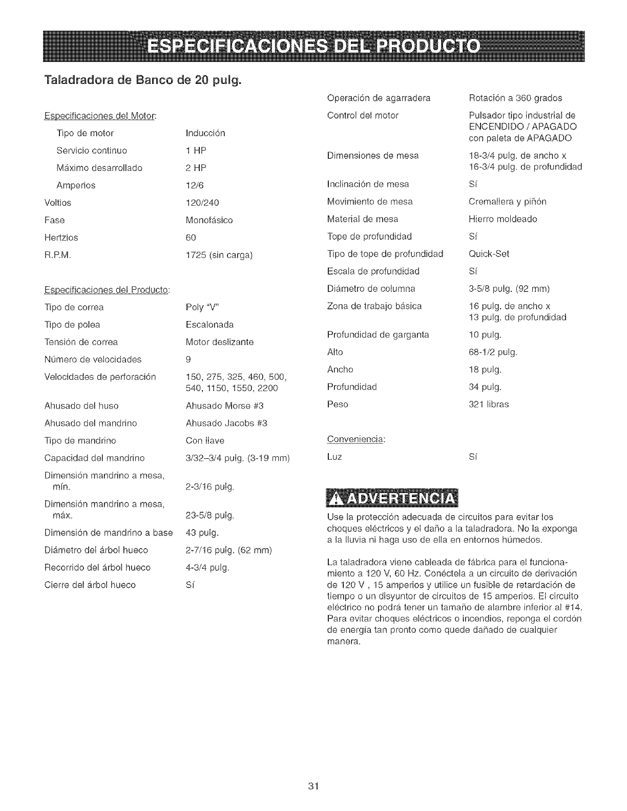
Ta[adradora de Banco de 20 pu[g°
_ecificaciones deI Motor:
Tipo de motor Inducci6n
Servicio continuo 1 HP
Maximo desarrollado 2 HP
Amperios 12/6
Voltios 120/240
Fase Monofasico
Hertzios 60
R.RM. 1725 (sin carga)
_ecificaciones de! Producto:
Tipo de correa
Tipo de potea
Tensi6n de correa
NOmero de vetocidades
Velocidades de perforaci6n
Ahusado del huso
Ahusado del mandrino
Tipo de mandrino
Capacidad del mandrino
Dimensi6n mandrino a mesa,
mfn.
Dimensi6n mandrino a mesa,
max.
Dimensi6n de mandrino a base
Diametro deI arbol hueco
Recorrido del arbol hueco
Cierre del arbol hueco
Poly "V"
Escalonada
Motor deslizante
9
150, 275,325, 460, 500,
540, 1150, 1550, 2200
Ahusado Morse #3
Ahusado Jacobs #3
Con Ilave
3/32-3/4 pulg. (3-19 mm)
2-3/16 pulg.
23-5/8 pulg.
43 pulg.
2-7/16 pulg. (62 ram)
4-3/4 pulg.
S[
Operaci6n de agarradera
Control del motor
Dimensiones de mesa
Inclinaci6n de mesa
Movimiento de mesa
Material de mesa
Tope de profundidad
Tipo de tope de profundidad
Escala de profundidad
Diametro de coJumna
Zona de trabajo b_isica
Profundidad de garganta
Alto
Ancho
Profundidad
Peso
Conveniencia:
Luz
Rotaci6n a 360 grados
Pulsador tipo industrial de
ENCENDIDO /APAGADO
con paleta de APAGADO
18-3/4 pulg. de ancho x
16-3/4 pulg. de profundidad
S[
CremalIera y piff6n
Hierro moldeado
Sf
Quick-Set
Si
3-5/8 pulg. (92 mm)
16 pulg. de ancho x
13 pulg. de profundidad
10 pulg.
68-1/2 putg.
18 pulg.
34 pulg.
321 libras
S_
Use la protecci6n adecuada de circuitos para evitar los
choques etectricos y el daffo a la taladradora. No Ia exponga
a la Iluvia ni haga uso de ella en entornos h0medos.
La taladradora viene cableada de fabrica para el funciona-
miento a 120 V, 60 Hz. Conectela a un circuito de derivaci6n
de 120 V, 15 amperios y utilice un fusible de retardaci6n de
tiempo o un disyuntor de circuitos de 15 amperios. El circuito
electrico no podr_, tener un tamaho de alambre inferior al #14.
Para evitar choques electricos o incendios, reponga el cord6n
de energia tan pronto como quede dahado de cualquier
manera.
31
INSTRUCCIONES GENERALES
DE SEGURIDAD
El uso de una taIadradora puede ser peligroso si se hace
caso cruise de la seguridad y el sentido comon. El operario
debe estar famifiarizado con et funcionamiento de esta herra-
mienta. Lea este manual para entender esta taladradora. NO
OPERE esta taladradora si no entiende plenamente las Iimita-
ciones de esta herramienta. NO MODIFIQUE este taIadradora
de ninguna manera. REOUERDE: Su seguridad personal es
su responsabiiidad.
ANTES DE HACER USO
DE LA TALADRADORA
Lea y obedezca todas las instrucciones de Seguridad y
Operaci6n antes de operar la taladradora para evitar hendas
graves y daRo a la herramienta.
1. LEA el Manual de Instrucciones cabalmente. APRENDA
como usar la herramienta para su aplicaci6n propuesta.
2. UTILICE PROTECCION OCULAR SlEMPRE. Cualquier
herramienta mecanica puede expuIsar escombros hacia
los ojos durante Ias operaciones, causando daRo ocular
grave y permanente. Los anteojos de use cotidiano NO
son gafas de seguridad. Utiiice gafas de seguridad (que
cumplan con la normativa Z87.1 de ANSb StEMPRE
cuando vaya a operar herramientas mec_inicas. Las
gafas de seguridad estg,n disponibles en las tiendas de
Ventas al Detal de Sears.
3. UTILICE PROTECCION AUDmVA SlE_,_PRE. El algo-
d6n por sf solo no constituye un dispositivo de protecci6n
aceptable. El equipo auditNo debe eumplir con las
normativas S3.19 de ANSI.
4. UTJUCE SlEMPRE UNA CARETA CONTRA EL POLVO
PARA EVITAR ASPIRAR POLVOS PEUGROSOS O
PART_CULAS EN EL AtRE, incluyende polvo de madera,
pelvo de sflice cdstalino y polvo de asbesto. Didja las
partfcuias en direcci6n opuesta a! rostro y ei cuerpo.
Opere la herramienta siempre en una zona bien ventilada
y proporcione Ia remoci6n apropiada de! polvo. UtiIice un
sistema de recolecci6n de polvo siempre que sea posF
ble. La exposici6n al polvo puede ocasionar dares respi-
ratodos graves y permanentes u otras heridas, inciuyen-
do silicosis (una enfermedad pulmonar grave), cancer y
la muerte. Evite aspirar el polvo y evite e! contacto pro-
Iongado con el polvo. El permitir Ia entrada deI polvo en
su boca u oios, o deiar que permanezca sobre su pieI,
puede promover la absorci6n de material daRino. Utilice
protecci6n respiratoria aprobada per NIOSH/OSHA, de
ajuste correcto y apropiada para la exposici6n ai polvo, y
lave Ias zonas expuestas con iab6n y agua.
5. Mantenga Ia zona de trabaio limpia, bien iIuminada y
organizada EN TODO MOMENTO. NO trabaje en un
entomo con superficies de piso resbalosas debido a los
escombros, grasas y cera.
6. Desenchufe la herramienta del tomacorrientes SIEMPRE
que vaya a reaiizar cuaIquier ajuste, recambio de piezas
o Ilevar a cabo cuatquier tarea de mantenimiento.
7. EVITE LOS ARRANQUES ACCIDENTALES. Aseg0rese
de que el interrupter de energ[a se encuentre en la posi-
ci6n de "OFF" (apagado) antes de enchufar el cord6n de
potencia y causar dare a la herramienta.
8. EVITE UN ENTORNO DE TRABAJO PEUGROSO. NO
utilice Ias herramientas electricas en entornos h0medos
ni las exponga a la Iluvia.
9. HAGA SU TALLER A PRUEBA DE NINOS al quitar las
Ilaves de los interruptores, desenchufando Ias herramien-
tas de sus tomacorrientes y usando candados.
10. NO utilice herramientas electricas en la presencia de
I[quidos o gases inflamables.
11. NO FUERCE LA HERRAMiENTA a realizar una
operaci6n para la que no fue diseRada. Realizarb, un
trabajo m_s seguro y de mayor calidad s61o efectuando
aqueilas operaciones para las que fue diseRada.
12.
13.
14.
15.
NO se pare sobre la herramienta. Esto podrfa resultar en
heridas graves si la herramienta se vuelca o si usted
hace contacto accidental con la herramienta.
32
NO almacene nada sobre o cerca de Ia herramienta
deride alguien pueda intentar pararse sobre la herra-
mienta para alcanzarto.
NO opere la herramienta si se encuentra bajo la infiuen-
cia del alcohol o de las drogas.
EN TODA Y CADA OCAS_0N, REVISE SJ EXtSTEN
PIEZAS DANADAS ANTES DE OPERAR LA HERRA-
MIENTA. Revise todos los protectores cuidadosamente
para asegurarse de que funcionen correctamente, que no
esten daRados, y que realicen sus funciones destinadas.
Revise la alineaci6n y busque Ia atascadura o ruptura de
todas las piezas en movimiento. Un protector, una pieza
de inserci6n u otra pieza daRada debe repararse y susti-
tuirse inmediatamente.
16. CONECTE TODAS LAS HERRAMIENTAS A TIERRA.
Si Ia herramienta viene equipada con un enchufe de tres
roaches, se Ie debe enchufar en un tomacorrientes de
tres contactos. El tercer macho se utiliza para conectar la
herramienta a tierra y ofrecer protecci6n contra !os
cheques electricos accidentales. NO quite ei tercer
macho. Ver Instrucciones de Conexi6n a Tierra.
17. MANTENGA ALEJADOS A LOS VISITANTES Y NtNOS
de la taladradora. NO permita que haya gente en la zona
inmediata de trabajo, sobre todo cuando Ia herramienta
electrica se encuentre en funcionamiento.
18.
19.
20.
MANTENGA TODOS LOS PROTECTORES EN SUS
SITIOS Y EN BUENAS CONDICIONES DE TRABAJO.
MANTENGA SU EQUILIBRIO, NO se extienda sobre la
herramienta. Utilice calzado con suetas de caucho y
resistentes al aceite. Mantenga el piso despejado de
escombros, grasas o cera.
MANTENGA SUS HERRAMIENTAS CON CUIDADO.
Mantenga sus herramientas limpias yen buen estado de
funcionamiento siempre. Mantenga filosas todas las
hoias y las brocas.
21.NUNCADEJEUNAM_,QU_NAENFUNCJONAM_ENTO
SiNATENDERApagueelinterrupterdeenerg[aaIa
posici6nde"OFF"(apagado).NOsealejedeJamb,quina
hastaquesehayadetenidopercompbto.
22.RETIRETODASLASHERRAMJENTASDEMANTEN_-
M_ENTOdeIazonainmediataantesdeENCENDERla
herramienta.
23.AFJANCETODOELTRABAJO.Cuandoseaposible,
hagausedeabrazaderasopJantilbsparaposicionar
paraafianzareEmateriakEstoresuitam_.sseguroque
intentarsqetarelmaterialconsusmanes.
24.MANT¢:NGASEALERTA,mireIoqueestahaciendoy
tengasentidocomuncuandovayaahacerusedeuna
herramientamecanica.NOUT_UOEunaherramienta
cuandoestecansadonibajoIaJnfiuenciadedrogas,
alcoho!omedicamentos.Unmementodeinatenci6n
duranteetusedeherramientasmecb,nicaspuederesultar
enheridaspersonabsgraves.
25.SOLOUTJLJCELOSACCESOR_OSRECOMENDADOS.
Etusodeaccesoriosincorrectosoindebidospuede
resultarenheridasgravesaIoperarioycausardafioala
herramienta.SJtienedudas,consulteelmanualde
instruccionesquevieneconeseaccesorioenparticular.
26.UTIUCEUNAEXTENSKSNEL¢:CTRJCAENBUEN
ESTADQCuandovayaahacerusodeunaextensi6n
el6ctrica,aseguresedeutilizarunaqueseaIosuficiente-
mentepesadacomoparaportarIacorrienterequerida
persuproducto.TengalabondaddevereJcuadro
"CALIBRESM[NIMOSRECOMENDADOSPARALAS
EXTENSIONESELE_CTRICAS(AWG)"paraeldimen-
sionamientocorrectodeunaextensi6nelectrica.Sitiene
dudas,utiliceelpr6ximocalibremaspesado.
27.UTJLJCELAVESTJMENTACORRECTA.NOutiliceropa
holgada,guantes,corbatasniartfcu!osdejoyerfa.Estos
artfculospuedenquedaratrapadosenlamaquina
duranteIasoperacionesyarrastraraloperariohaciaIas
piezasenmovimiento.ElusuariodebeIlevarunacubier-
taprotectivasobresucabelIo,sitienecabellolargo,para
proteger!ocontraelcontactoconcuaJquierpiezaen
movimiento.
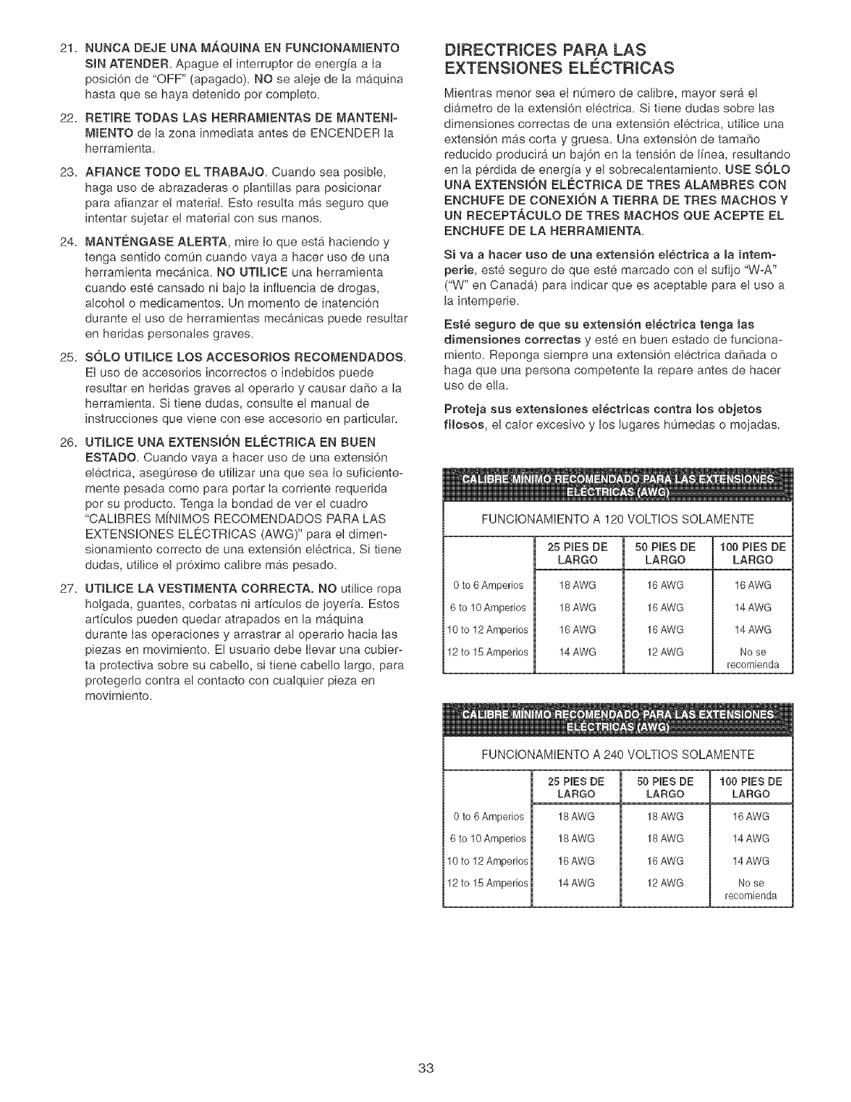
DIRECTRJCES PARA LAS
EXTENSUONES ELECTRICAS
Mientras menor sea el n0mero de calibre, mayor sera el
diametro de la extensi6n electrica. Si tiene dudas sobre las
dimensiones correctas de una extensi6n electrica, utilice una
extensi6n mas corta y gruesa. Una extensi6n de tama_o
reducido producira un baj6n en Ia tensi6n de linea, resultando
en la perdida de energ!a y el sobrecalentamiento. USE SOLO
UNA EXTENSION ELECTR_OA DE TRES ALAMBRES CON
ENCHUFE DE CONEX_6N A TJERRA DE TRES MACHOS Y
UN RECEPTACULO DE TRES MACHOS QUE ACEPTE EL
ENCHUFE DE LA HERRAM_ENTA.
Siva ahacer uso de aria e×tension eBectrica ama intemo
perie, este seguro de que este marcado con el sufijo "W-A"
("W" en Canadb,) para indicar que es aceptable para el use a
Ja intemperie.
Est_ seguro de que su e×tensi6n em_ctrica tenga mas
dimensiones correctas y este en buen estado de funciona-
miento. Reponga siempre una extensJ6n el6ctrica daSada o
haga que una persona competente Ja repare antes de hacer
use de ella.
Proteja sus extensiones em_ctricae contra los objetos
fHosos, el caJor excesivo y los Jugares hOmedas o mojadas.
FUNCIONAMIENTO A 120 VOLTIOS SOLAMENTE
0 to 6 Amperios
6 to !0 Amperios
10 to 12 Amperios
12 to 15 Amperios
25 PIES DE
LARGO
18 AWG
18 AWG
16 AWG
14 AWG
50 PIES DE
LARGO
16 AWG
16 AWG
16 AWG
12 AWG
100 PINESDE
LARGO
16 AWG
14 AWG
14 AWG
No se
recomienda
FUNCIONAMIENTO A 240 VOLTIOS SOLAMENTE
0 to 6 Amperios
6 to 10 Amperios
10 to 12 Amperios
12 to 15 Amperios
25 PIES DE
LARGO
18AWG
18 AWG
16 AWG
14 AWG
50 PIES DE
LARGO
18 AWG
18 AWG
16 AWG
12 AWG
100 PIES DE
LARGO
16 AWG
14 AWG
14 AWG
No se
recomienda
33
ESTA HERRAM_ENTA DEBE ESTAR CONECTADA A
TIERRA DURANTE EL USO PARA PROTEGER AL
OPERAR_O CONTRA LOS CHOQUES ELECTR_COS.
EN EL CASO DE UN MALFUNCJONAMJENTO O AVERJA,
Jaconexi6n a tJerra ofrece eJ trecho de menor resistencia para
Jacorriente electrica y reduce el riesgo de choque el6ctrico.
Esta herramienta viene equipada con un cord6n de energ[a
que tiene un conductor de conexi6n a tierra del equipo y un
enchufe de conexi6n a tierra. El enchufe DEBE estar enchu-
fado a un tomacorrientes que coincida con el mismo y este
conectado a tierra en conformidad con TODOS los c6digos y
ordenanzas en el _4mbito local.
NO MODJFJQUE EL ENCHUFE SUMINJSTRADO. Si no cabe
en el tomacorrientes existente, haga que un eJectricista com-
petente instale el tomacorrientes apropiado_
LA CONEXION ELEOTRJOA _NCORREOTA del conductor de
conexi6n a tierra deI equipo puede resultar en e! peligro de
choques electricos. El conductor con el aislante verde (con o
sin rayas amarillas) es el conductor de conexi6n a tierra deJ
equipo. NO conecte el conductor de conexi6n a tierra del
equipo a una terminaci6n con corriente si se requJere Ia
reparaci6n o el reemplazo del cord6n de energ[a o deJ
enchufe.
CONSULTE con un electricista competente o personat de
servicio si no entiende completamente las instrucciones de
conexi6n a tierra, o si no esta seguro si la herramienta se
encuentra debidamente conectada a tierra.
El motor suministrado con su Taladradora es un motor
monofasico de voltaje doble de 120/240 voltios, 60 hertzios,
corriente alternante. Se env[a ya cableado de fg,brica para las
aplicaciones a 120 voJtios. Jamg,s conecte el alambre verde a
una terminaci6n con corriente.
SOLO UT_L_CE UNA EXTENSJ0N ELE_CTRJCA DE TRES
ALAMBRES QUE TENGA UN ENCHUFE DE CONEXION A
TIERRA CON 3 MACHOS Y UN TOMACORR_ENTES PARA
3 MACHOS QUE ACEPTE EL ENCNUFE DE LA NERRA-
MIENTAo
REPONGA _NMEDJATAMENTE CUALQUJER CORDON
DANADO O GASTADOo
PARA MAQUINAS CONECTADAS A TJERRA, CONEC-
TADAS POR CORDON, DJSENADAS PARA EL USO EN
UN CIRCUJTO DE SUM_N_STRO QUE TENGA UNA
CLASJFJCAC_0N NOMINAL _NFERJOR A LOS 150
VOLTIOS,
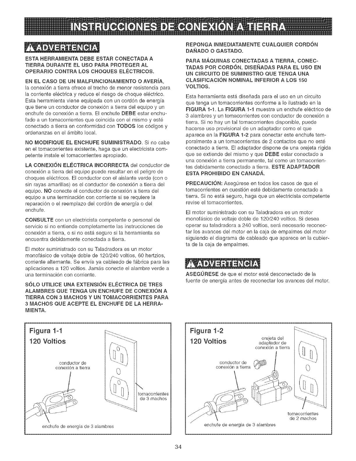
Esta herramienta esta diseFiada para el uso en un circuito
que tenga un tomacorrientes conforme a Io ilustrado en la
FIGURA 1-1. La FIGURA 1-1 muestra un enchufe el6ctrico de
3 alambres y un tomacorrientes con conductor de conexi6n a
tierra. Si no hay un tal tomacorrientes disponible, puede
hacerse uso provisional de un adaptador como el que
aparece en Ia FIGURA 1-2 para conectar este enchufe tem-
poralmente a un tomacorrientes de 2 contactos que no este
conectado a tierra. EI adaptador dispone de una orejeta rigida
que se extiende del mismo y que DEBE estar conectado a
una conexi6n a tierra permanente, taI como un tomacorrien-
tes debidamente conectado a tierra. ESTE ADAPTADOR
ESTA PROHIBIDO EN CANAD._.
PRECAUCION: Aseg0rese en todos los casos de que el
tomacorrientes en cuesti6n este debidamente conectado a
tierra. Si no est_ seguro, haga que un eJectricista competente
revise el tomacorrientes.
El motor suministrado con su Taladradora es un motor
monof_sico de voJtaje doble de 120/240 voltios. Si desea
operar su taladradora a 240 voJtios, serb, necesario reconec-
tar tos avances del motor en la caja de empatmes det motor
siguiendo el diagrama de cabJeado que aparece en la cubier-
ta de Jacaja de empalmes.
ASEGURESE de que el motor este desconectado de la
fuente de energfa antes de reconectar Jos avances del motor.
Figura 1-1
120 Vo_tios
conductor de
conexi6n a tierra
enchufe de energia de 3 alambres
\
tomacorrientes
de 3 machos
Figura 1-2
120 Vo_tios orejeta del
adaptador de
conexi6n tierra
conductor de _),_
conexi6n a tierra
enchufe de energia de 3 alambres
0
tomacorrientes
de 2 machos
34
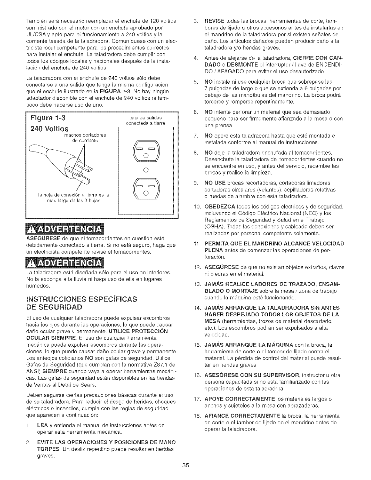
Tambien ser_. necesario reemplazar el enchufe de 120 voltios
suministrado con el motor con un enchufe aprobado pot
UL/CSA y apto para el funcionamiento a 240 voltios y la
corriente tasada de la taladradora. Comunfquese con un elec-
tricista local competente para los procedimientos correctos
para instalar e! enchufe. La taladradora debe cumplir con
todos los c6digos locales y nacionales despues de la insta-
laci6n del enchufe de 240 vottios.
La taladradora con el enchufe de 240 voltios s61o debe
conectarse a una salida que tenga la misma configuraci6n
que el enchufe ilustrado en Ia FIGURA 1o3. No hay ning0n
adaptador disponible con el enchufe de 240 voltios ni tam-
)oco debe hacerse uso de uno.
Figura 1-3
240 Voltios machos poltadores
de corriente
la hoia de conexi6n a tierra es la
mas larga de las 3 hojas
caja de salidas
conectada a tierra
@
ASEGURESE de que el tomacorfientes en cuesti6n este
debidamente conectado a tierra. Si no esta seguro, haga que
un electricista competente revise el tomacorrientes.
La taladradora esta diseF_ada s61o para el uso en interiores.
No la exponga a la Iluvia ni haga uso de ella en lugares
h0medos.
INSTRUCCIONES ESPECIFICAS
DE SEGURIDAD
El uso de cualquier taladradora puede expulsar escombros
hacia los ojos durante Ias operaclones, Io que puede causar
daF_oocular grave y permanente. UTILICE PROTECCt6N
OCULAR SJEMPRE. El uso de cualquier herramienta
mec_.nica puede expulsar escombros durante Ias opera-
ciones, Io que puede causar daBo ocular grave y permanente.
Los anteojos cotidianos NO son gafas de seguridad. Utilice
Gafas de Seguridad (que cumplan con la normativa Z87.1 de
ANSI) SlEMPRE cuando vaya a operar herramientas mecani-
cas. Las gafas de seguridad estan disponibles en las tiendas
de Ventas al Detal de Sears.
1.
2.
Deben seguirse ciertas precauciones bgsicas durante el uso
de su taladradora. Para reducir el riesgo de heridas, choques
electricos o incendios, cumpla con las reglas de seguridad
que aparecen a continuaci6n:
LEA y entienda el manual de instrucciones antes de
operar esta herramienta mecb,nlca.
EVITE LAS OPERACIONES Y POSICIONES DE MANO
TORPES. Un desliz repentino puede resultar en hefidas
graves.
7.
8.
3. REVISE todas Ias brocas, herramientas de corte, tam-
bores de lijado u otros accesorios antes de instalarlas en
el mandrino de la taladradora por si existen seFiales de
da5o. Los artfculos da5ados pueden producir daho a la
taladradora y/o heridas graves.
4. Antes de alejarse de la taladradora, ClERRE CON CAN-
DADO o DESMONTE el interruptor /Ilave de ENCENDI-
DO /APAGADO para evitar el uso desautorizado.
5. NO instale ni use cualquier broca que sobrepase Ias
7 pulgadas de largo o que se extienda a 6 pulgadas por
debajo de las mandfbulas del mandrino. La broca podrb,
torcerse y romperse repentinamente.
6. NO intente perforar un material que sea demasiado
peque5o para ser firmemente afianzado a la mesa o con
una prensa.
NO opere esta taladradora hasta que este montada e
instalada conforme al manual de instrucciones.
35
g.
NO deje la taladradora enchufada at tomacorrientes.
Desenchufe la taladradora det tomacorrientes cuando no
se encuentre en uso, y antes del servicio, recambie las
brocas y realice Ia limpieza.
NO USE brocas recortadoras, cortadoras Iimadoras,
cortadoras circulares (volantes), cepilIadoras rotativas
o ruedas de alambre con esta taladradora.
10. OBEDEZCA todos los c6digos electricos y de seguridad,
incluyendo et C6digo Electrico Nacional (NEC) y los
Reglamentos de Seguridad y Salud en el Trabajo
(OSHA). Todas las conexiones y cableado deben set
reatizadas por personal competente solamente.
11. PERMITA QUE EL MANDRJNO ALCANCE VELOCIDAD
PLENA antes de comenzar las operaciones de per-
foraci6n.
12. ASEGURESE de que no existan objetos extraSos, clavos
ni piedras en el material.
13. JAM,_S REALICE LABORES DE TRAZADO, ENSAMo
BLADO O MONTAJE sobre Ia mesa / zona de trabajo
cuando la maquina este funcionando.
14. JAM,_,S ARRANQUE LA TALADRADORA SIN ANTES
HABER DESPEJADO TODOS LOS OBJETOS DE LA
MESA (herramientas, trozos de material descartado,
etc.). Los escombros podran ser expulsados a alta
velocidad.
15. JAM_,S ARRANQUE LA M,_,QUINA con la broca, la
herramienta de oorte o el tambor de lijado contra el
material. La perdida de control del material puede resuI-
tar en heridas graves.
16. ASESORESE CON SU SUPERVISOR, instructor u otra
persona capacitada si no est,. familiarizado con las
operaciones de esta taladradora.
17. APOYE CORRECTAMENTE Ios materiales largos o
anchos y sujetelos a la mesa con abrazaderas.
18. AFIANCE CORRECTAMENTE la broca, Ia herramienta
de corte o el tambor de lijado en el mandrino antes de
operar la taladradora.
19.REPONGAcualquiercord6ndaBadoinmediatamente.
NOutiliceuncord6noenchufedaRado.SiIataladradora
nofuncionacorrectamente,osisehadaRado,deiadoa
Haintemperieoentradoencontactoconagua,devueJvala
auncentredeservicioSears.
20.AFJANCElataladradoraalsuelooaunbancodetraba-
jo.Lasvibracionespuedenhacerquelamaquinase
deslice,camineosevuelque.
21.AFIANCEel materialfirmementecontralamesa.No
intenteperforarunmaterialquenotengaunasuperficie
planacontralamesa,oquenoesteafianzadaconun
tornilIodebanco.ImpidaqueeImaterialgireabraz_'mdolo
alamesaoafianzandolocontraIacotumnadeIaprensa.
LaperdidadecontrolsobreeJmaterialpuederesultaren
heridasgraves.
22.ENCLAVEelapoyodeicabezaly delamesaaJacotum-
nafirmemente,ylamesaalapoyodeJamesa,antesde
operarIataladradora.
23.LataladradoraestadiseBadaparaelusedomesticooel
usecomerciaJligeroSOLAMENTE.
24.PARAREDUCERELPEUGRODELOSCNOQUES
EL¢:CTRICOS,nouseJaherramientaalaintemperie=No
laexpongaalaIluvia=Almacenelabajotecho=
25=APAGUELATALADRADORAydesench0feladela
fuentedeenergfa.Espereaquelabroca,herramientade
corteotambordelijadodejendegirarantesdelimpiarIa
mesa/zonadetrabajo,retiraroasegurarelmaterial,o
cambiarelmontaje.
26.USEs6iobrocas,herramientascortantes,tamboresde
lijadouotrosaccesoriosconeltamaRodeespiga
recomendadaenestemanualdeservicio.Eiaccesorio
detamaRoincorrectopuedeocasionardarealatala-
dradoray/oheridasgraves.
27.SOLOutiliceestamaquinadeacuerdoconestemanual
deinstrucciones.SOLOutilicelosaccesoriosrecomen-
dadosporSears.
28.UTlUCELASVELOCIDADESRECOMENDADASpara
todaslasoperaciones=Otrasvelocidadespodrancausar
e!maifuncionamientodelamaquina,causandodareala
taladradoray/oheridasgraves=
29=_NFORMACJ0NADJCIONALacercadetfuncionamiento
seguroycorrectodeesteproductoest.4disponibbde
partedelassiguientesfuentes:
PowerToolsInstitute
1300SummerAvenue
ClevelandOH44115-2851
30.
Nationa!SafetyCouncil,
1121SpringLakeDrive
Itasca,IL60143-3201
AmericanNationalStandardsinstitute
25West43rdStreet4thfloor
NewYork,NY10036
ANSi01.1,RequisitosdeSeguridadpara
MaquinasdeEbanister[a,y losreglamentos
delDepartamentodeJTrabajodelosEE.UU.
GUARDEESTASJNSTRUCCIONES.Refieraseaelias
frecuentementey utilicelasparacapacitaraotros
usuarios=
ACCESORJOS DISPONIBLES
Visite su Departamento de Ferreteffa Sears o consulte el
Catatogo de Herramientas Manuales y Mecb_nicas de
Craftsman para los siguientes accesofios:
ARTICULO NO. DE EXISTENCJA
*Cortadora de Circulos 25293
*Estuche de Abrazaderas 26426
*Tornillo de Banco de 8 puIg. 24077
*Tornillo de Banco de 4 pulg. 24081
*Tornillo de Banco de 3 pulg. 24071
*Estuche de [amber de Liiado de 21 piezas 25262
*Conjunto de Brocas Forstner de 7 piezas 25389
Sears podr4, recomendar otros accesorios que no estan Jista-
dos en este manual.
Consulte con su Departamento de Ferreter[a Sears mas cer-
cano o su Cata!ogo de Herramientas Manuales y Mecb_nicas
de Craftsman para otros accesofios.
No haga uso de ning0n accesofio a menos que haya Iefdo
cabatmente el Manual de Instrucciones para dicho accesorio.
S61o utilice accesorios recomendados para esta taladradora.
El uso de cualquier otro accesorio podra ocasionar heridas
graves y producir dafie Jataladradora.
36
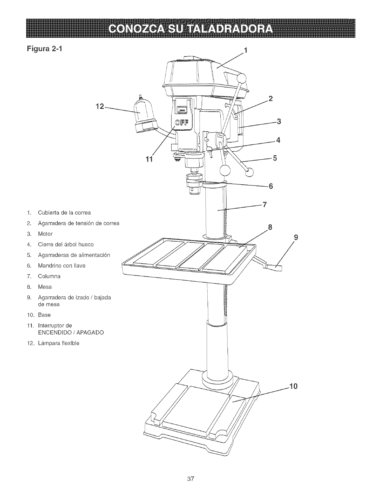
Figura 2-1
11
1, Cubierta de la correa
2, Agarradera de tensi6n de correa
3, Motor
4, Cierre del arbol hueco
5, Agarraderas de alimentaci6n
6, Mandrino con Ilave
7, Columna
8, Mesa
9, Agarradera de izado /bajada
de mesa
10, Base
11, hterruptor de
ENCENDDO /APAGADO
12, Lampara flexible
9
37
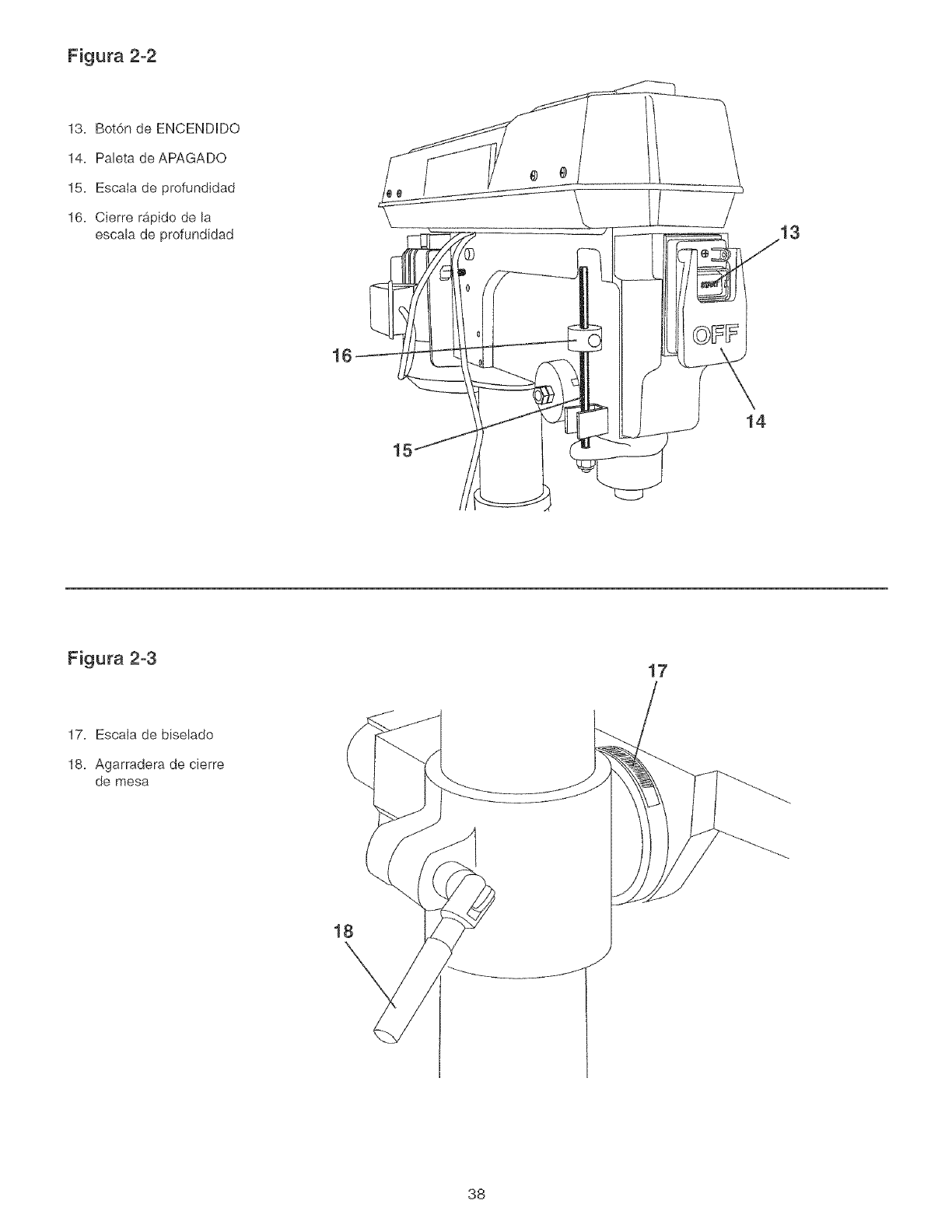
Figura 2-2
13. Bot6n de ENCENDDO
14. Paleta deAPAGADO
15. Escala de profundidad
16. Cierre rapido de la
escala de profundidad
16
15
14
Figura 2-3 17
17. Escala de biselado
18. Agarradera de cierre
de mesa
18
38
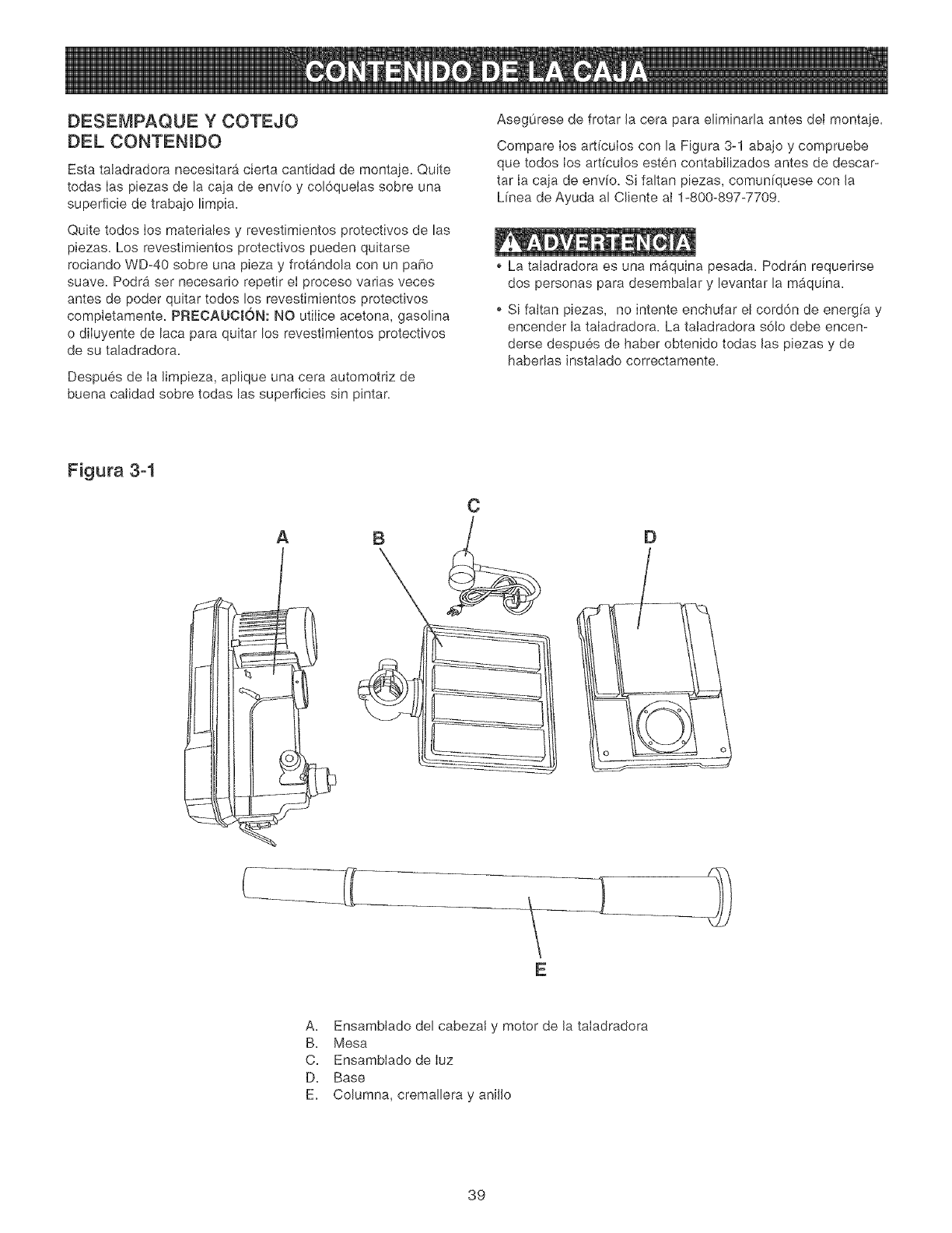
DESEMPAQUE Y COTEJO
DEL CONTENIDO
Esta taladradora necesitara cierta cantidad de montaje. Quite
todas Ias piezas de la caja de env[o y col6queias sobre una
superficie de trabajo limpia.
Quite todos Ios materiales y revestimientos protectivos de las
piezas. Los revestimientos protectivos pueden quitarse
rociando WD-40 sobre una pieza y frotandola con un paho
suave. Podra ser necesario repetir eI proceso varias veces
antes de poder quitar todos los revestimientos protectivos
completamente. PREOAUCION: NO utiIice acetona, gasolina
o diIuyente de laca para quitar los revestimientos protectivos
de su taladradora.
Despues de Ia limpieza, aplique una cera automotriz de
buena calidad sobre todas las superficies sin pintar.
Asegurese de frotar la cera para eliminada antes dei montaje.
Compare los art[culos con la Figura 3-1 abajo y compruebe
que todos los art[culos esten contabilizados antes de descar-
tar Ia caja de envio. Si faltan piezas, comun[quese con la
L[nea de Ayuda al Cliente aI 1-800-897-7709.
La taladradora es una maquina pesada. Podrb_n requerirse
dos personas para desembaJar y levantar la m_.quina.
o Si fakan piezas, no intente enchufar el cord6n de energ[a y
encender la taIadradora. La tatadradora s6!o debe encen-
derse despues de haber obtenido todas las piezas y de
habedas instatado correctamente.
Figura 3-1
A
C
E
A. Ensamblado del cabezaJ y motor de la taIadradora
B. Mesa
C. EnsambIado de Iuz
D. Base
E. Columna, cremallera y anillo
39
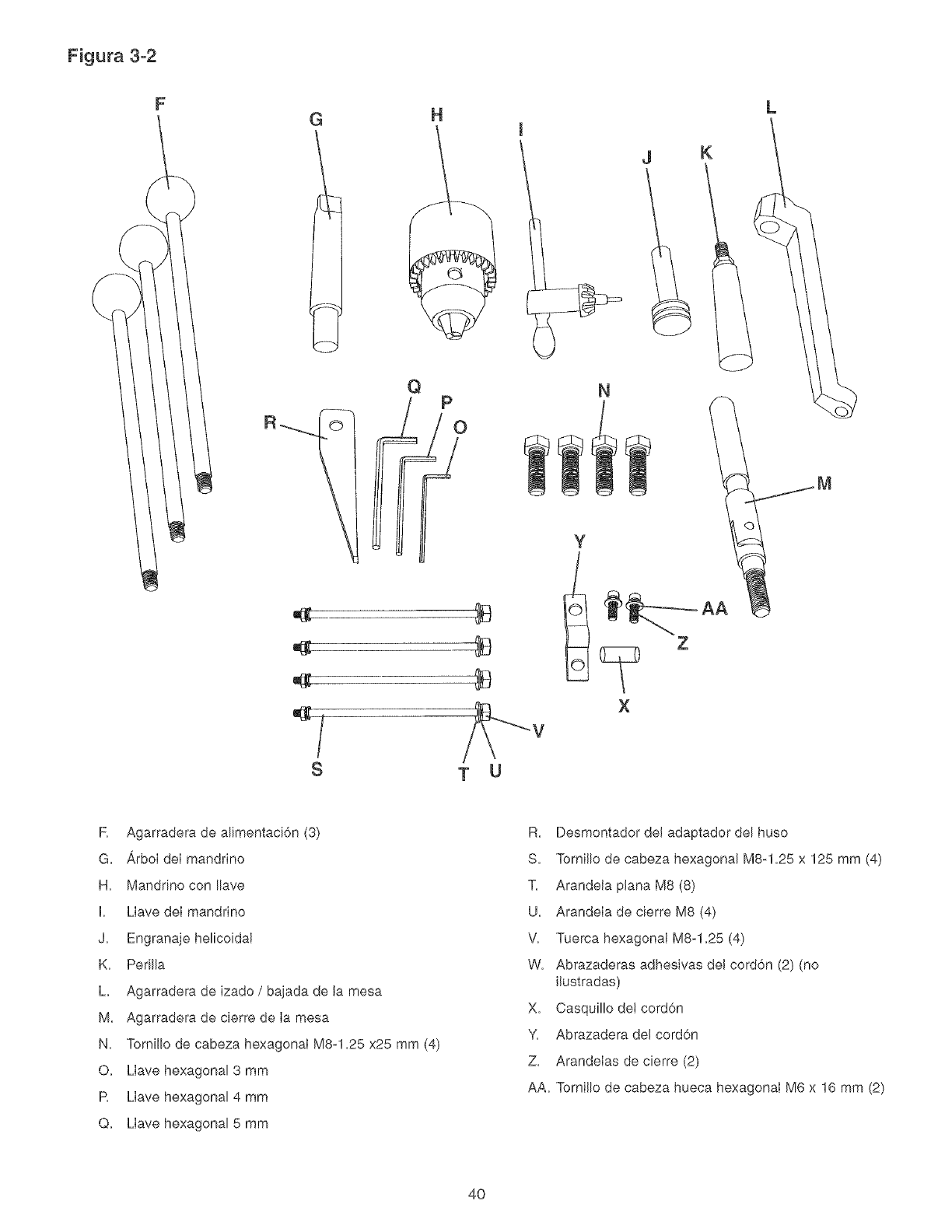
Figura 3-2
R
G
S
H
QP
T U
I
J
N
K
Y
X
L
M
R Agarradera de alimentaci6n (3)
G. _,rboI deI mandrino
H. Manddno con Ilave
I. Llave deI mandrino
J. Engranaje helicoidal
K. Perilla
h Agarradera de izado /bajada de la mesa
M. Agarradera de cierre de Ia mesa
N. Tornillo de cabeza hexagonal M8-1.25 x25 mm (4)
O. Llave hexagonal 3 mm
R Llave hexagonal 4 mm
Q. Llave hexagonal 5 mm
R. Desmontador del adaptador del huso
S. Tornillo de cabeza hexagonal M8-1.25 x 125 mm (4)
T. Arandela plana M8 (8)
U. Arandela de cierre M8 (4)
V. Tuerca hexagonal M8-1.25 (4)
W. Abrazaderas adhesivas del cord6n (2) (no
ilustradas)
X. Casquillo det cord6n
Y. Abrazadera del cord6n
Z. Arandelas de cierre (2)
AA. Tomillo de cabeza hueca hexagonal M6 x 16 mm (2)
4O
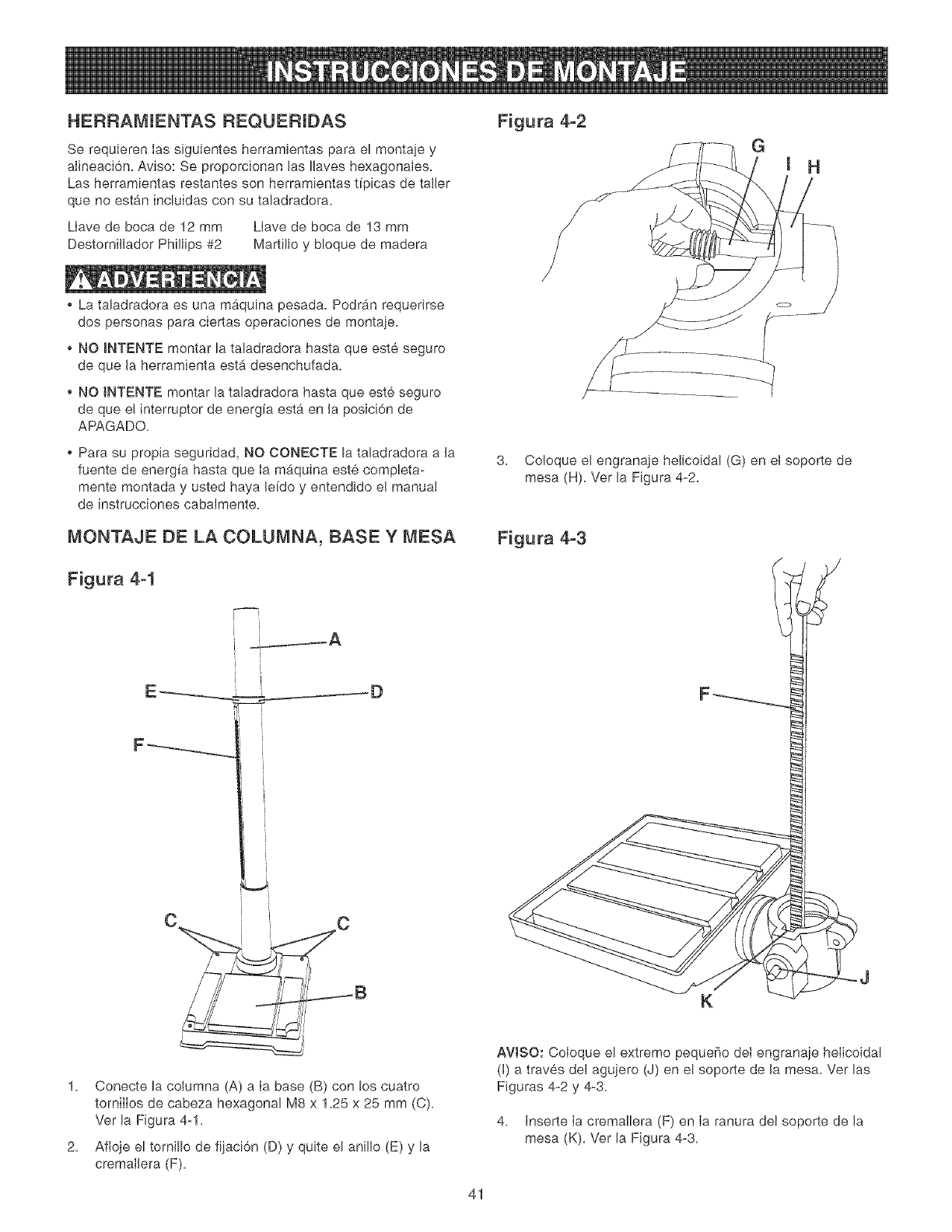
HERRAMIENTAS REQUEF_IDAS
Se requieren Ias siguientes herramientas para el montaje y
alineaci6n. Aviso: Se proporcionan las !laves hexagonales.
Las herramientas restantes son herramientas t[picas de taller
que no estan incluidas con su taladradora.
Llave de boca de 12 mm Llave de boca de 13 mm
Destornillador Phillips #2 Martillo y bloque de madera
* La taladradora es una mAquina pesada. Podr_n requerirse
dos personas para ciertas operaciones de montaje.
NO INTENTE montar la taladradora hasta que este seguro
de que la herramienta est,. desenchufada.
NO JNTENTE montar la taladradora hasta que este seguro
de que el interruptor de energfa esta en la posici6n de
APAGADO.
* Para su propia seguridad, NO CONECTE la taladradora a la
fuente de energ_a hasta que Ia maquina este completa-
mente montada y usted haya le[do y entendido el manual
de instrucciones cabalmente.
MONTAJE BE LA COLUMNA, BASE Y MESA
Figura 4-1
i
i i
I
I
C
1. Conecte la columna (A) a Ia base (B) con los cuatro
torniIIos de cabeza hexagonal M8 x 1.25 x 25 mm (C).
Ver la Figura 4-1=
2= Afioje el tornillo de fijaci6n (D) y quite el anillo (E) y la
cremallera (F)=
Figura 4-2
3. Coloque el engranaje helicoidal (G) en el soporte de
mesa (H)=Ver la Figura 4-2=
Figura 4-3
K
AVtSO: Coloque el extremo pequefio det engranaje helicoidal
(I) a traves del agujero (J) en el soporte de la mesa. Ver las
Figuras 4-2 y 4-3.
4. Inserte Ia cremallera (F) en Ia ranura del soporte de la
mesa (K). Ver la Figura 4-3.
41
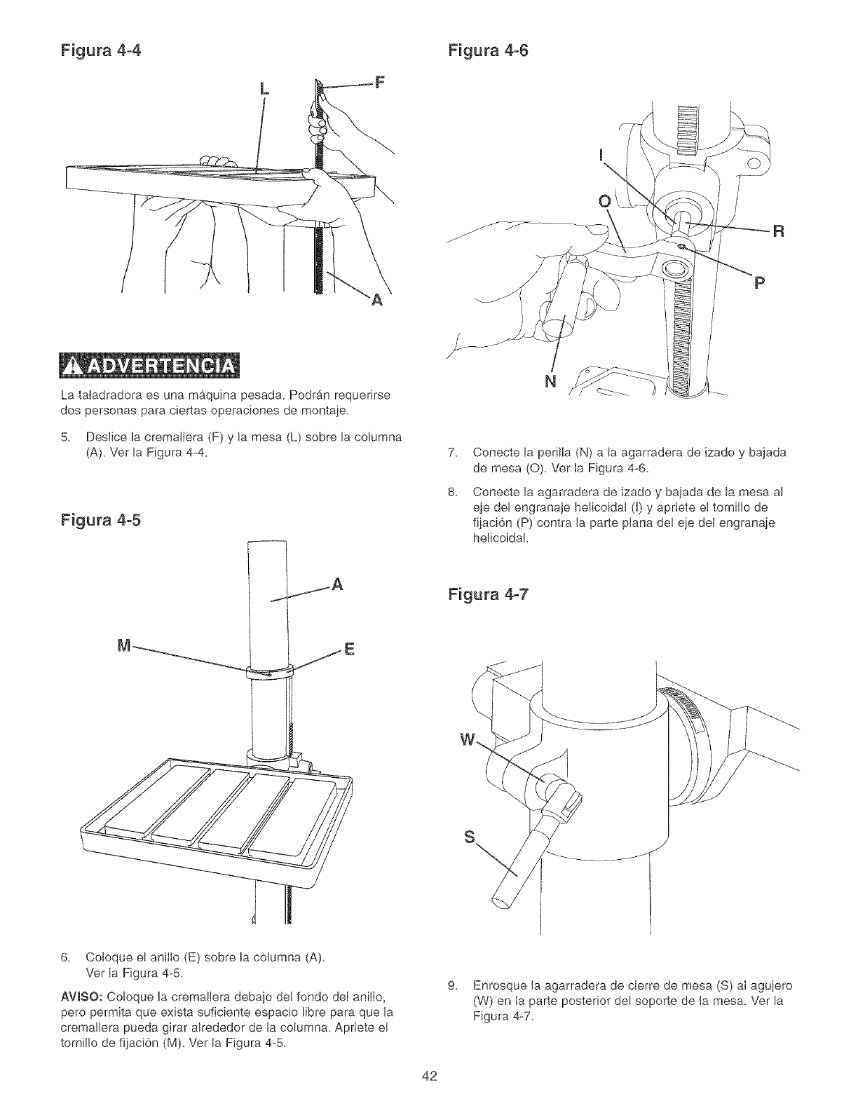
Figura 4-4 Figura 4-6
L
La taIadradora es una mb,quina pesada. Podr_.n requerirse
dos personas para ciertas operaciones de montaje.
5. Deslice la cremalIera (F) y la mesa (L) sobre la columna
(A). Ver la Figura 4-4.
Figura 4-5
0
P
N
7. Conecte la perilla (N) a la agarradera de izado y bajada
de mesa (0). Vet Ia Figura 4-6.
8. Conecte la agarradera de izado y bajada de la mesa al
eje del engranaje helicoidal (H)y apriete el tomillo de
fijaci6n (P) contra la parte plana del eje del engranaje
helicoidal.
Figura 4-7
S
6. Coloque el anilIo (E) sobre la columna (A).
Vet Ia Figura 4-5.
AWSO: Coloque la cremallera debajo det fondo deI anilIo,
pero permita que exista suficiente espacio libre para que la
cremallera pueda girar alrededor de la columna. Apriete el
tornillo de fijaci6n (M). Vet la Figura 4-5.
9. Enrosque la agarradera de cierre de mesa (S) al agujero
(W) en Ia parte posterior del soporte de la mesa. Ver la
Figura 4-7.
42
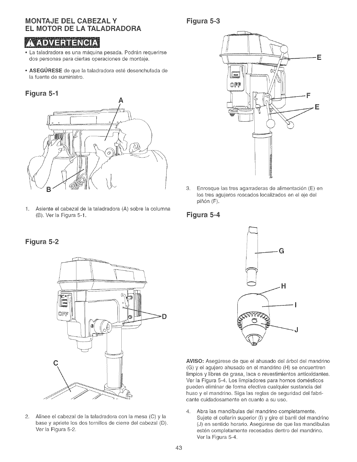
MONTAJE DEL CABEZAL Y Figura 5-3
EL MOTOR DE LA TALADRADORA
o La taladradora es una maquina pesada. Podran requerirse
dos personas para ciertas operac[ones de montaje.
o ASEGORESE de que Ia taladradora este desenchufada de
la fuente de suministro.
Figura 5-1 A
1. Asiente el cabezal de la taladradora (A) sobre la columna
(B). Ver la F[gura 5-1.
Figura 5-2
C
2. Alinee el cabezal de Ia taladradora con la mesa (C) y la
base y apriete los dos tornilios de cierre del cabezal (D).
Ver la Figura 5-2.
43
3. Enrosque Ias tres agarraderas de alimentaci6n (E) en
los tres agujeros roscados IocaIizados en el eje del
piB6n (F).
Figura 5-4
IG
AVISO: Aseg0rese de que el ahusado del &rboI del mandrino
(G) y el agujero ahusado en el mandrino (H) se encuentren
limpios y Iibres de grasa, laca o revestimientos antioxidantes.
Ver la Figura 5-4. Los Iimpiadores para hornos domesticos
pueden eliminar de forma efectiva cualquier sustancia del
huso y el mandrino. Siga Ias reglas de seguddad det fabr[-
cante cuidadosamente en cuanto a su use.
4. Abra ias mand[bulas del manddno completamente.
Sujete el collar[n superior (I) y gire el barr[I det mandrino
(J) en sentido horatio. AsegOrese de que Ias mandibulas
esten completamente recesadas dentro del manddno.
Ver Ja Figura 5-4.
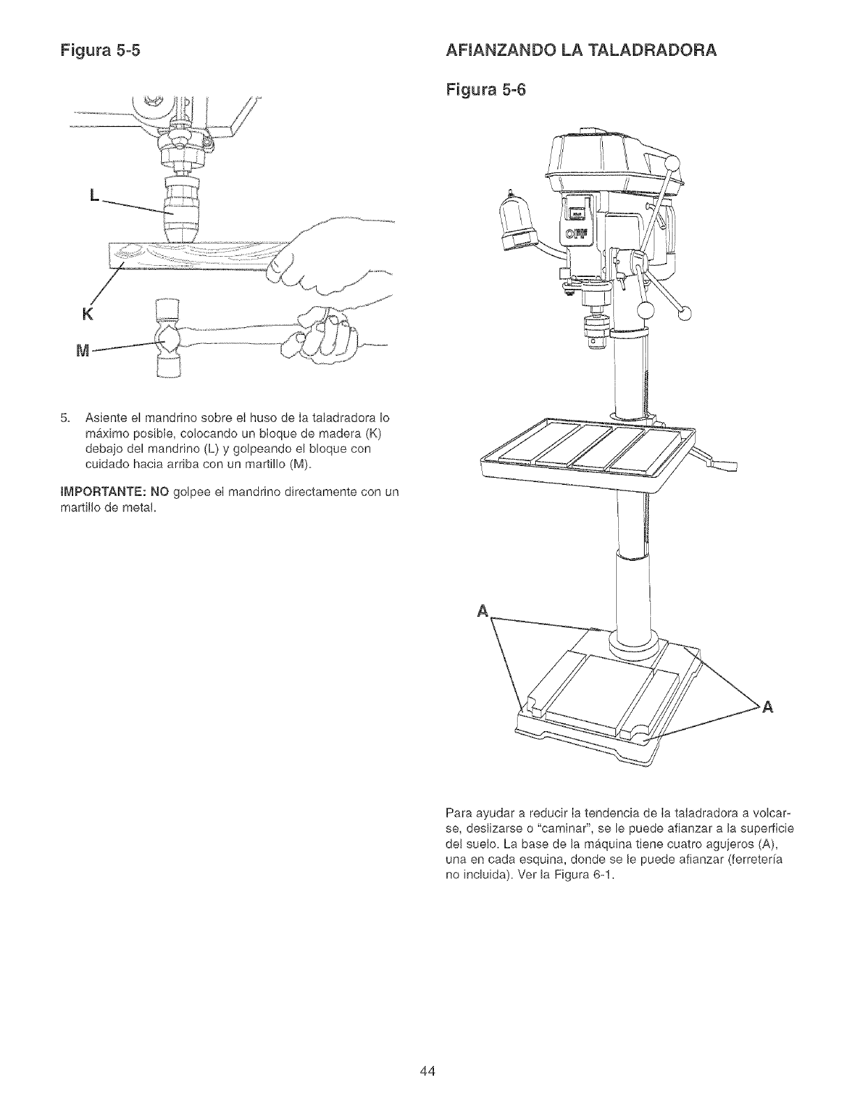
Figura 5-5 AFIANZANDO LA TALADRADORA
Figura 5-6
5. Asiente el manddno sobre eI huso de Ia tatadradora Io
m_ximo posible, co!ocando un bloque de madera (K)
debajo del mandrino (L) y golpeando el bloque con
cuidado hacia arfiba con un martillo (M).
tMPORTANTE: NO golpee el mandrino directamente con un
martillo de metal.
A
Para ayudar a reducir Ia tendencia de Ia taladradora a volcar-
se, deslizarse o "caminar", se le puede afianzar a la superficie
de! suelo. La base de la maquina tiene cuatro aguieros (A),
una en cada esquina, donde se le puede afianzar (ferreter[a
no induida). Ver la Figura 6-1.
44
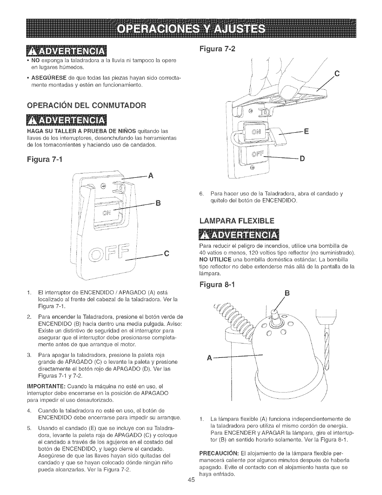
NO exponga Ia ta[adradora a la Iluvia n[ tampoco la opere
en lugares h0medos.
o ASEGURESE de que todas ias piezas hayan side correcta-
mente montadas y esten en funcionamiento.
OPERACION DEL CONMUTADOR
HAGA SU TALLER A PRUEBA DE NIItOS quitando las
Ilaves de los interruptores, desenchufando Ias herramientas
de los tomacorrientes y haciendo use de candados.
Figura 7-1
p- ............... \
1. El interrupter de ENCENDDO/APAGADO (A) est&
Iocalizado aI frente del cabezaI de la taladradora. Ver la
Figura 7-1.
2. Para encender la Taladradora, presione e! bot6n verde de
ENCENDDO (B) hacia dentro una media pulgada. Aviso:
Existe un distintivo de seguridad en et [nterruptor para
asegurar que el interrupter debe presionarse completa-
mente antes de que arranque el motor.
3. Para apagar la taladradora, presione la paleta roja
grande de APAGADO (C) o levante la paleta y presione
directamente el bot6n rojo de APAGADO (D). Ver las
Figuras 7q y 7_2.
tMPORTANTE: Cuando Ia m_.quina no este en uso, el
interrupter debe encerrarse en Ia posici6n de APAGADO
para impedir el use desautorizado.
4. Cuando la taladradora no este en use, el bot6n de
ENCENDIDO debe encerrarse para [mpedir su arranque.
5. Usando el candado (E) que se [ncluye con su Taladra-
dora, Ievante la paleta ro]a de APAGADO (C) y coloque
el candado a traves de los agujeros en el costado del
bot6n de ENCENDIDO, y luego cierre el candado.
Asegurese de que Ias Ilaves hayan side quitadas del
candado y que se hayan colocado d6nde ning0n niho
pueda alcanzadas. Ver la Figura 7-2.
45
Figura 7-2
i
/ /
/c
IX.....................
6. Para hacer uso de Ia Taladradora, abra el candado y
quitelo del bot6n de ENCENDIDO.
LAMPARA FLEXIBLE
Para reducir el peligro de [ncendios, utilice una bombilla de
40 vatios o menos, 120 voltios tipo reflector (no suministrado).
NO UTILJOE una bombilla domestica est_4ndar. La bombilla
tipo reflector no debe extenderse mb_sallb_de la pantalla de la
Ibmpara.
Figura 8-1 B
1. La I_mpara flexible (A) funciona independientemente de
la taladradora pero utiliza el mismo cord6n de energia.
Para ENCENDER y APAGAR Ia Ib,mpara, gire el interrup-
ter (B) en sentido horar[o solamente. Ver Ia Figura 8-1.
PRECAUC_6N: El alojamiento de Ia Ib_mparaflexible per-
manecera caliente per algunos minutes despues de haberla
apagado. Evite el contacto con el alojamiento hasta que se
haya enfriado.
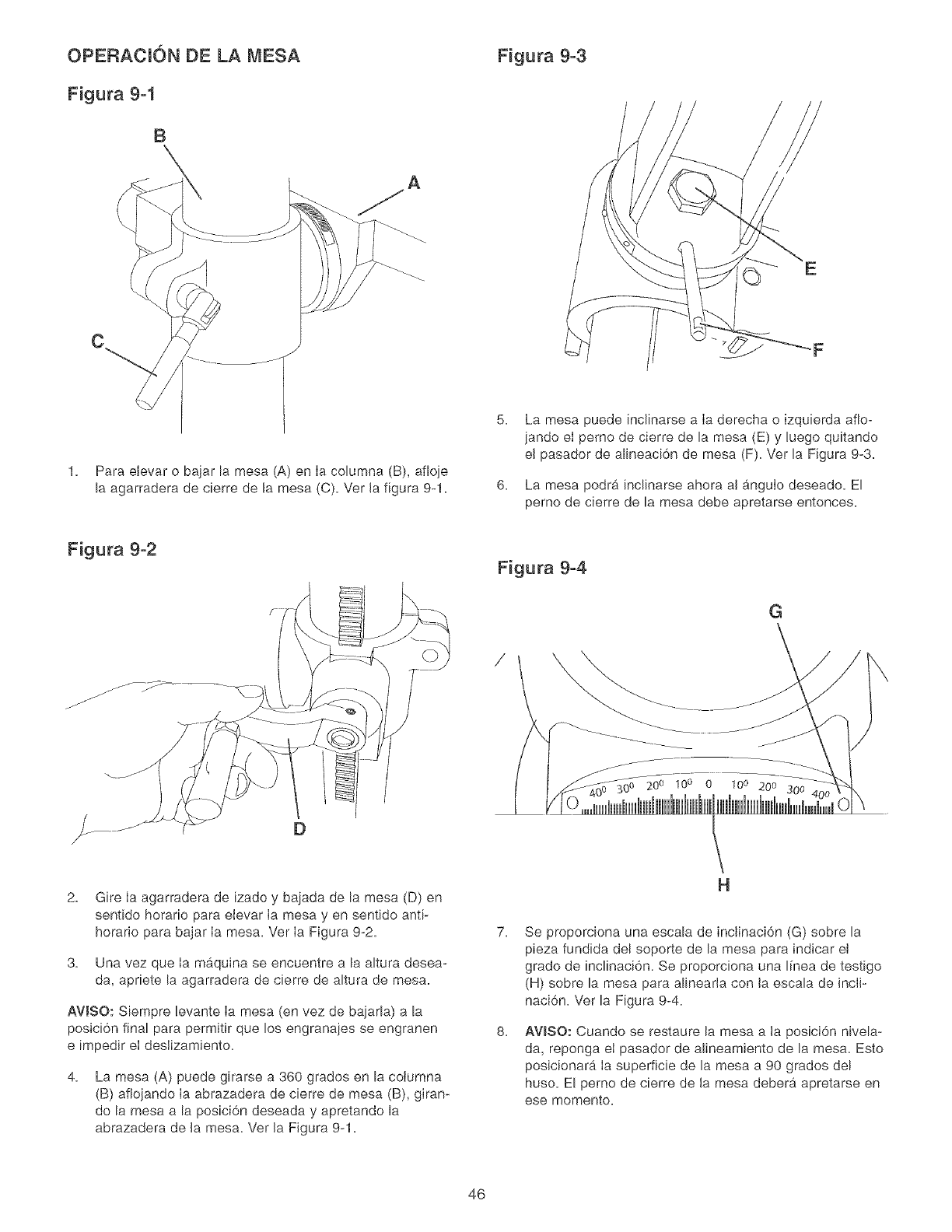
OPERACI6N DE LA MESA
Figura 9-1
B
Figura 9-3
Para elevar o bajar la mesa (A) en Ia columna (B), afioje
la agarradera de cierre de la mesa (C). Vet la figura 9-1.
F
6.
La mesa puede inclinarse a Ia derecha o izquierda afio-
jando el perno de cierre de la mesa (E) y Luego quitando
el pasador de alineaci6n de mesa (F). Ver la Figura 9-3.
La mesa podra indinarse ahora al anguIo deseado. El
perno de cierre de la mesa debe apretarse entonces.
Figura 9-2 Figura 9-4
G
200 100 0 10° 200 300
2. Gire la agarradera de izado y bajada de la mesa (D) en
sentido horario para elevar la mesa yen sentido anti-
horario para bajar ia mesa. Ver ia Figura 9-2.
3. Una vez que la maquina se encuentre a la altura desea-
da, apriete la agarradera de cierre de altura de mesa.
AVlSO: Siempre levante Ia mesa (en vez de bajada) a la
posici6n final para permitir que los engranajes se engranen
e impedir el deslizamiento.
4. La mesa (A) puede girarse a 360 grados en la coiumna
(B) aflojando Ia abrazadera de cierre de mesa (B), giran-
do la mesa a la posici6n deseada y apretando la
abrazadera de la mesa. Ver la Figura 9-1.
H
7.
8.
Se proporciona una escala de inclinaci6n (G) sobre la
pieza fundida del soporte de la mesa para indicar el
grade de inclinaci6n. Se proporciona una I[nea de testigo
(H) sobre la mesa para alinearla con la escala de incli-
naci6n. Ver la Figura 9-4.
AWSO: Cuando se restaure la mesa a la posici6n nivela-
da, reponga et pasador de alineamiento de la mesa. Esto
posicionar_. Ia superficie de la mesa a 90 grados del
huso. El perno de cierre de la mesa debera apretarse en
ese memento.
46
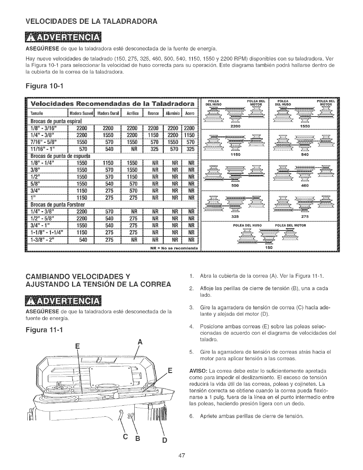
VELOCIDADES DE LA TALADRADORA
ASEGURESE de que la taladradora este desconectada de Ia fuente de energ[a.
Hay nueve velocidades de taEadrado (150, 275, 325, 460, 500, 540, 1150, 1550 y 2200 RPM) disponibles con su taladradora. Ver
la Figura 10-1 para seIeccionar la velocidad de huso correcta para su operaci6n. Este diagrama tambien podra hallarse dentro de
la cubierta de la correa de la tatadradora.
Figura 10-1
m
Ve|ecidades Recemendadas de |a Ta|adradera
Tamale
grocas de puntaespitai
1/8" - 3/10" 2200
1/4" - 3/8" 2200
7/t6" -5/8" 1550
11/16" -!" 570
Br0cas de punta de espuela
1/0" " 1/4" 1550
3/0" 1550
1t2" 1550
5/8" 1550
3/4" 1150
1" 1150
Brocas de punta Ferstner
!/4" - 3/8" 2200
1/2" - 5/8" 2200
314"- I" 1550
!-!18" - 1-1/4" 1150
1-3f8" - 2" 540
lo0°0r0Suave'lO0°0r000r0,I Ao,,,,ooI 0'°°°°1"°°'°'°1
2200 2200 2200 2200 2200
1550 2200 1150 2200 1t50
570 1550 570 t550 570
540 NR 325 570 325
1t50 1550 NR NR NR
570 1550 NR NR NR
570 1150 NR NR
540 570 NR NR NR
275 570 NR NR NR
275 275 NR NR
570 NR RR RR NR
540 275 NR NR NR
540 275 NR NR NR
275 275 NR NR NR
275 NR NR NR NR
NR =Ne $e rec@_ienda
POLEA POLEA DEL
DELHUSO MOTOR
2200
1150
POLEA PULEA DEL
_LHUSO MOTOR
t550
540
4¢{)5{){)
325 275
POLEA DEL HUSO POLEA DEL MOTOR
CAMBIANDO VELOCIDADES Y
AJUSTANDO LA TENSKSN DE LA CORREA
ASEGURESE de que la taladradora este desconectada de la
fuente de energia.
Figura 11-1
A
E
E
1. Abra la cubierta de Ia correa (A). Ver la Figura 11-1.
2. Afloje las perillas de cierre de tensi6n (B), una a cada
lado.
3= Gire la agarradera de tensi6n de correa (C) hacia ade-
lante y alejada del motor (D).
4, Posicione ambas correas (E) sobre las poteas selec-
cionadas de acuerdo con el diagrama de velocidades del
taladro.
5. Gire la agarradera de tensi6n de correas atras hacia el
motor para aplicar tensi6n alas correas.
AWSO: La correa debe estar Io suficientemente apretada
como para impedir el deslizamiento. El exceso de tensi6n
reducir& la vida util de las correas, poleas y cojinetes. La
tensi6n correcta se obtiene cuando la correa pueda fiexio-
narse a 1 pulg. fuera de Ia Ifnea en eI punto intermedio entre
las poleas, haciendo presi6n ligera con un dedo.
6. Apriete ambas perillas de cierre de tensi6n.
47
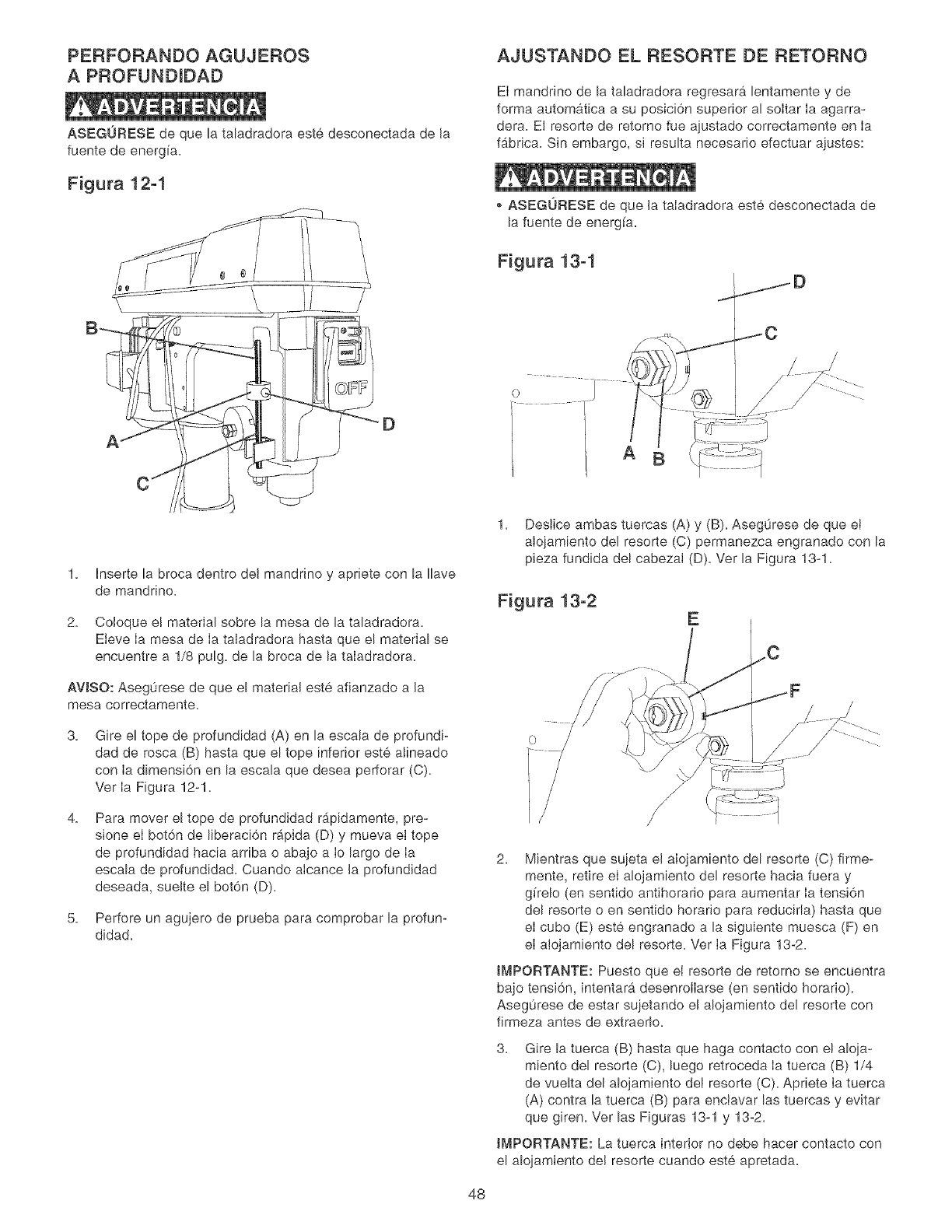
PERFORANDO AGUJEROS
A PROFUNDIZ)AZ)
ASEGURESE de que la taladradora este desconectada de Ja
fuente de energ[a.
Figura 12-1
AJUSTANDO EL RESORTE DE RETORNO
El mandrino de la taladradora regresara lentamente y de
forma automatica a su posici6n superior al soItar Ia agarra-
dera. El resorte de retorno fue ajustado correctamente en Ia
fabrica. Sin embargo, si resulta necesario efectuar ajustes:
ASEGORESE de que Jataladradora este desconectada de
la fuente de energ[a.
Figura 13-1
A
1. hserte la broca dentro deJ mandrino y apriete con la Ilave
de mandrino.
2. Coloque e! material sobre la mesa de la taladradora.
Eieve Ia mesa de Ia taladradora hasta que el material se
encuentre a 1/8 pulg. de la broca de la taIadradora.
AVISO: Aseg0rese de que el material este afianzado a Ja
mesa correotamente.
3, Gire el tope de profundidad (A) en la escala de profundi-
dad de rosca (B) hasta que el tope inferior est6, a!ineado
con Ia dimensi6n en la escala que desea perforar (C).
Ver Ia Figura 12-1.
4, Para mover el tope de profundidad rb,pidamente, pre-
sione el bot6n de liberaci6n rapida (D) y mueva et tope
de profundidad hacia arriba o abajo a Io largo de Ia
escala de profundidad. Cuando alcance Ja profundidad
deseada, sueJte el bot6n (D).
5. Perfore un agujero de prueba para comprobar la profun-
didad.
1. Deslice ambas tuercas (A) y (B). Aseg0rese de que et
alojamiento del resorte (C) permanezca engranado con la
pieza fundida del cabezaI (D). Ver la Figura 13-1.
Figura 13-2 E
48
2. Mientras que sujeta el alojamiento del resorte (C) firme-
mente, retire el alojamiento del resorte hacia fuera y
gffelo (en sentido antihorar[o para aumentar Ia tensi6n
del resorte o en sentido horarJo para reducirla) hasta que
el cubo (E) este engranado a la siguiente muesca (F) en
el alojamiento del resorte. Ver Ia Figura 13-2.
tMPOF{TANTE: Puesto que eI resorte de retorno se encuentra
bajo tensi6n, intentarb, desenroilarse (en sentido horario).
Asegurese de estar sujetando eJ alojamiento del resorte con
firmeza antes de extraerlo.
3. Gire la tuerca (B) hasta que haga contacto con el aloja-
miento del resorte (C), luego retroceda Ia tuerca (B) 1/4
de vuelta del alojamiento del resorte (C). Apriete Ia tuerca
(A) contra la tuerca (B) para enciavar las tuercas y evitar
que giren. Ver las Figuras 13-1 y 13-2.
tMPOF{TANTE: La tuerca interior no debe hacer contacto con
el alojamiento deJ resorte cuando este apretada.
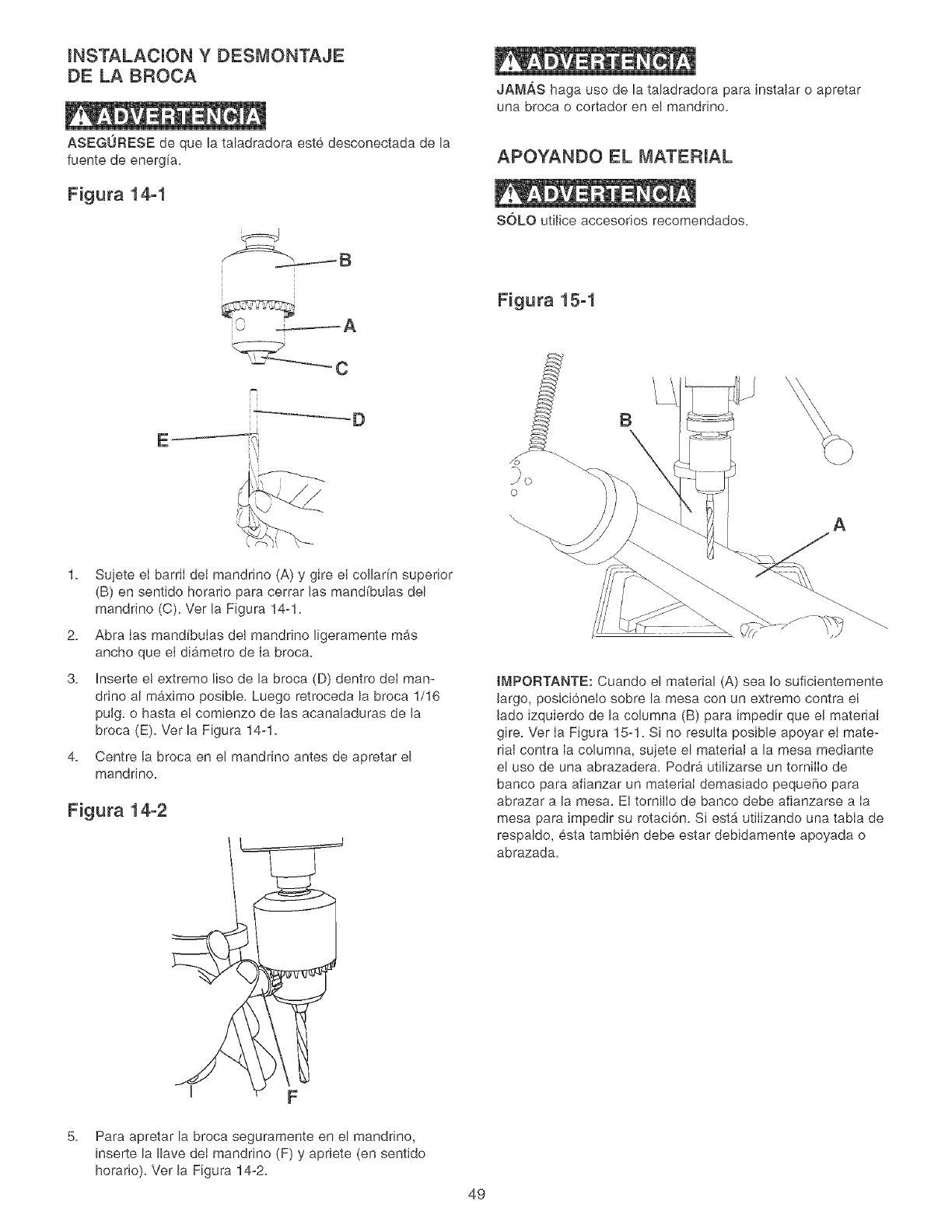
INSTALACION Y DESMONTAJE
DE LA BROCA
ASEGURESE de que la taladradora este desconectada de Ja
fuente de energ[a.
Figura 14-1
i %" I A
JAMAS haga uso de la taladradora para instatar o apretar
una broca o cortador en el mandrino.
APOYANDO EL MATERIAL
SOLO utiiice accesorios recomendados.
Figura 15-1
-"_C
B
1. Sujete eI barriI dei mandrino (A) y gire el collar[n superior
(B) en sentido horario para cerrar Jas mand[bulas del
mandrino (C). Vet Ja Figura 14-1.
2. Abra Ias mand[buIas deI mandnno ligeramente mas
ancho que eI dib,metro de Ia broca.
3. Inserte e! extremo %0 de la broca (D) dentro deI man-
drino al maximo posible. Luego retroceda la broca 1/16
puJg. o hasta e! comienzo de Jas acanaladuras de Ja
broca (E). Ver la Figura 14-1.
4. Centre la broca en eJ mandnno antes de apretar el
manddno.
Figura 14-2
o
\A
tMPORTANTE: Cuando el material (A) sea io suficientemente
largo, posici6neio sobre la mesa con un extremo contra el
Jado izquierdo de la columna (B) para impedir que e! material
gire. Ver ia Figura 15-1. Si no resutta posible apoyar ei mate-
rial contra ia columna, sujete el material a la mesa mediante
el uso de una abrazadera. Podra utilizarse un torniiio de
banco para afianzar un material demasiado pequeSo para
abrazar a la mesa. El tornilio de banco debe afianzarse a ia
mesa para Jmpedir su rotaci6n. Si est,. utJiizando una tabia de
respaldo, esta tambien debe estar debidamente apoyada o
abrazada.
5.
I F
Para apretar la broca seguramente en el mandrino,
inserte la Ilave dei mandrino (F) y apriete (en sentido
horario). Ver la Figura 14-2.
49
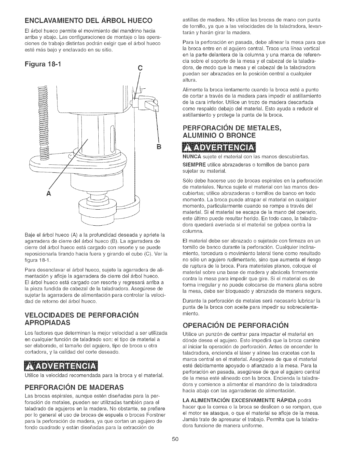
ENCLAVAMIENTO DEL ARBOL HUECO
El _.rbol hueco permite el movimiento de! mandrino hacia
arriba y abajo. Las configuraciones de montaje o las opera-
c[ones de trabajo distintas podran exigir que el arbol hueco
este m#ts bajo y enclavado en su sitio.
Figura 18-1 C
astiIlas de madera. No utilice las brocas de mane con punta
de torn[llo, ya que a Ias velocidades de la taIadradora, levan-
taran y haran girar la madera.
Para la perforaci6n en pasada, debe alinear Ia mesa para que
la broca entre en el agujero central. Trace una Fnea vertica!
en la parte deIantera de la columna y una marca de referen-
cia sobre el soporte de la mesa y el cabezal de Ia taladra-
dora, de mode que la mesa y eI cabezal de Ia taladradora
puedan set abrazadas en la posici6n central a cualquier
altura.
Aiimente la broca Ientamente cuando Ia broca este a punto
de cortar a traves de la madera para [mpedir el astillamiento
de la cara inferior. UtiJice un trozo de madera descartada
como respaldo debajo del material Esto ayuda a reducir el
astiJlamiento y protege la punta de la broca.
PERFORACION DE METALES,
ALUMINIO O BRONCE
B
A
Baje el _.rbol hueco (A) a la profundidad deseada y apriete Ia
agarradera de cierre det _rboI hueco (B). La agarradera de
cierre deI arbol hueco esta cargado con resorte y se puede
reposicionarla tirando hacia fuera y girando el cube (C). Ver la
figura 18-1.
Para desenclavar el arbol hueco, sujete la agarradera de alp
mentaci6n y afloje Ia agarradera de cierre deI arbol hueco.
El arbol hueco esta cargado con resorte y regresara arriba a
la pieza fundida de cabezaJ de Ia taladradora. Asegurese de
sujetar Ia agarradera de alimentaci6n para controlar la velocP
dad de retorno del arbol hueco.
VELOCIDADES DE PERFORACION
APROPIADAS
Los factores que determinan Ia meier velocidad a set utiIizada
en cualquier funci6n de taIadrado son: et tipo de material a
ser eIaborado, e! tama[io de! agujero, tipo de broca u otra
cortadora, y la catidad del corte deseado.
UtiJice la velocidad recomendada para la broca y el material.
PERFORACI6N DE MADERAS
Las brocas espirales, aunque esten dise[iadas para la per-
foraci6n de metales, pueden ser utilizadas tambien para el
taIadrado de agujeros en la madera. No obstante, se prefiere
per Io general el use de brocas de espuela o brocas Forstner
para Ia perforaci6n de madera, ya que cortan un agujero de
fondo cuadrado y est#_ndisefiadas para la extracci6n de
NUNCA suiete el material con Ias manes descubiertas.
SIEMPRE utilice abrazaderas o tornillos de banco para
sujetar su material.
S61o debe hacerse use de brocas espirales en la perforaci6n
de materiales. Nunca suiete el material con Ias manes des-
cubiertas; utilice abrazaderas o tornillos de banco en todo
momento. La broca puede atrapar el material en cualquier
momento, particularmente cuando se rompe a traves de!
material. Si el material se escapa de la mano deI operario,
este Oltimo puede resultar herido. En todo caso, la taladra-
dora quedara averiada si el material se goipea contra la
oolumna.
El material debe set abrazado o sujetado con firmeza en un
tornilIo de banco durante la perforaei6n. Cualquier inciina-
miento, torcedura o movimiento lateral tiene como resultado
no s61o un agujero rudimentario, sino que aumenta el riesgo
de ruptura de la broca. Para materiales ptanos, eoloque e!
material sobre una base de madera y abraceta firmemente
contra la mesa para [mpedir que gire. S[ el material es de
forma irregular y no puede colocarse de manera plana sobre
la mesa, debe ser bloqueado y abrazada de manera segura.
Durante Ia perforaci6n de metales sera necesar[o lubricar la
punta de la broea con aceite para impedir su sobrecalenta-
miento.
OPERACI6N DE PERFORACION
Uti!ice un punz6n de centrar para [mpactar el material en
d6nde desea el agujero. Esto impedira que Ia broca camine
al iniciar Ia operaci6n de perforaci6n. Antes de encender la
taladradora, encienda el I_ser y alinee Ias crucetas con Ia
marca central en el material. Aseg0rese de que el material
este debidamente apoyado o afianzado a la mesa. Para la
perforaci6n en pasada, aseg0rese de que el aguiero central
de la mesa este alineado con la broca. Encienda la taladra-
dora y comience a alimentar el mandrino de la taladradora
hacia abajo con las agarraderas de alimentaci6n.
LA ALIMENTACI6N EXCESIVAMENTE R,_PIDA podr4,
hacer que la correa o la broca se deslicen o se rompan, que
el motor se atasque, o que el material se afioje de Ia mesa.
Jamas trate de apresurar el trabajo. Permita que la taladra-
dora funcione de manera uniforme.
5O
CAMBIO DEL VOLTAJE DEL MOTOR LUBRICACK_N
ASEGURESE de desconectar la maquina de Ia fuente de
alimentaci6n antes de trabajar en el motor.
P[dale a un electricista certificado que haga todas Ias co-
nexiones electricas. Se deben mantener todos los c6digos
locales y estatales. EI motor que se suministra con Ia
Taladradora es un motor monofasico de doble voltaje para
120/240 V. E! motor esta alambrado de fabrica para funcionar
con 120 V. Para cambiar su funcionamiento a 240 V, siga las
instrucciones que se dan abajo. Para hacer esto tambien es
necesario cambiar eI enchufe de 120 V que se suministra con
la maquina por un enchufe certificado por UL/CSA (que no se
incluye) adecuado para 240 V y que acepte la corriente nomi-
nal indicada para el motor. El motor con el enchufe de 240 V
debe conectarse solamente a un tomacorrientes que tenga Ia
misma configuraci6n del enchufe. Para el tomacorrientes de
240 V no se ofrece ni debe usarse ningOn adaptador.
1. Asegurese de que el interruptor este APAGADO y des-
conecte el cord6n el6ctrico de la fuente de alimentaci6n.
2. Verifique en el r6tulo del motor que el voltaje del motor
sea doble.
3. Si eI r6tulo dei motor dice que eI voltaje es doble, quite la
tapa de la caja de empalmes del motor.
4. Utilizando el diagrama electrico que esta dentro de la
tapa de Ia caja de empalmes, reconecte los cables del
motor para funcionar con 240 V.
5. Vuelva a ponerle Ia tapa a Ia caja de empalmes.
6. Reemplace el enchufe de 120 V por un enchufe de 240 V
certificado por UL/CSA y dasificado para la corriente del
motor.
7. Et interruptor de ENCENDIDO/APAGADO es un
interruptor de cuatro (4) polos y no necesita ninguna
modificaci6n.
APAGUE el interruptor y desenchufe el cord6n de energia de
la fuente de suministro=
La taladradora tiene cojinetes lubricados sellados en eI
a!ojamiento deI motor que no requieren lubricaci6n adicional
por parte del operario.
Los ensamblados de arbol hueco y huso deben recibir Iubri-
caci6n peri6dica. Baje el ensambIado del arbol hueco y
exprima o frote una pelfcula Iigera de aceite para maquinaria
sobre Ia superficie completa= Coloque algunas gotas de
aceite liviano para maquinaria a Io largo deI ensamblado del
huso. Levante y baje eI arboI hueco varias veces para dis-
tribuir el aceite de manera uniforme=
LIMPIEZA
Con Ia taladradora desenchufada, expulse los escombros
del motor con aire a baja presi6n para quitar el polvo y Ia
suciedad. Evite eI uso de presiones de aire superiores a
50 PSI, ya que esto puede dafiar et aislamiento= EI operario
siempre debe utilizar protecci6n ocular al hacer uso de aire
comprimido=
No utilice una aspiradora de taller para limpiar las limaduras
de metal= Las Iimaduras de metal pueden causar una
explosi6n o incendio.
No permita que Ias astiIIas y el polvo se acumulen debajo de
la taladradora= Mantenga la zona limpia yen buenas condi-
ciones de seguridad=
PRECAUCION: NO UT_LICE MATERIALES COM-
BUSTIBLES para limpiar la taladradora.
Tras Ia limpieza, aplique una cera automotriz de buena
calidad a todas las superficies sin pintar. Aseg0rese de pulir
la cera antes del montaie.
SOLO personai competente debe realizar reparaciones a la
taladradora. Comunfquese con su Centro de Servicio Sears
mas cercano para recibir servicio autorizado. Las repara-
ciones o recambios desautorizados con piezas que no sean
de fabrica podran causar heridas graves al operario y daho a
la taladradora.
51
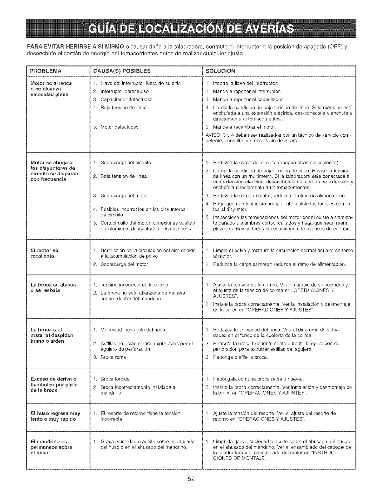
PARA EVSTAR HERIRSE A Si rWlSMO o causar daf_o a la taladradora, conmute el interruptor a la posici6n de apagado (OFF) y
desenchufe el cord6n de energ[a del tomacorrientes antes de realizar cuaIquier ajuste=
PROBLEMA CAUSA(S} POSIBLES SOLUCJ6N
Motor 130 arranca
OnO aIcal3za
velocidad plena
_,_otor se ahoga o
los dieyuntores de
eireuito se disparan
con frecueneia
ERmotor se
recalienta
La broea se atasca
o ee resbala
La broea o el
material despiden
humo o arden
E×ceso de deriva o
bamboReo pot parte
de la broca
El huso regresa muy
lento o muy r&pido
El rnaadrino no
permanece eobre
eBhuso
1. Llave de! interruptor fuera de su sitio
2. Interruptor defectuoso
3. Capacitador defectuoso
4. Baja tensi6n de linea
5. Motor defectuoso
1. Sobrecarga de! circuito
2. Baja tensi6n de linea
3. Sobrecarga de! motor
4. Fusibles incorrectos en los disyuntores
de circuito
5. Cortocircuito del motor; conexiones sueltas
o aislamiento desgastado en los avances
1. Restricci6n en la circulacidn de! aire debido
a la acumulaci6n de polvo
2. Sobrecarga del motor
1. Tensi6n incorrecta de la correa
2. La broca no esta afianzada de manera
segura dentro de! mandrino
1. Velocidad incorrecta de! huso
2. Astillas no est_,n siendo expulsadas pot e!
agujero de perforaci6n
3. Broca roma
1. Broca torcida
2 Broca incorrectamente instalada al
mandrino
1. El resolle de retorno tiene la tensi6n
incorrecta
1. Grasa, suciedad o aceite sobre el ahusado
de! huso o en el ahusado de! mandrino.
1. Inserte la Ilave del interruptor.
2. Mande a reponer e! interruptor.
3. Mande a reponer el capacitador.
4. Corriia la condici6n de baia tensi6n de linea. Si la maquina esta
enchufada a una extensi6n electrica, des-conectela y enchL]fela
directamente al tomacorrientes.
5. Mande a recambiar el motor.
AVlSO: 3 y 4 deben set realizados por un tecnico de servicio com-
petente; consulte con el servicio de Sears.
1.
2.
Reduzca la carga del circuito (apague otras aplicaciones).
Corriia la condici6n de baia tensi6n de linea. Revise la tensi6n
de linea con un multimetro. Si la taladradora estb, conectada a
una extensi6n electrica, desench0feia del cord6n de extensi6n y
enchOfela directamente a un tomacorrientes.
3. Reduzca la carga al motor; reduzca el ritmo de alimentaci6n.
4. Haga que un electricista competente instale los fusibles correc-
tos al disyuntor.
5. Inspeccione las terminaciones del motor por si existe aislamien-
to da[iado y alambres cortocircuitados y haga que sean reem-
plazados. Revise todos las conexiones de avances de energia.
1. Limpie et polvo y restaure la circulaci6n normal del aire en torno
al motor.
2. Reduzca la carga al motor; reduzca el ritmo de alimentaci6n.
Aiuste la tensi6n de la correa. Vet el cambio de velocidades y
el ajuste de la tensi6n de correa en 'OPERACIONES Y
AJUSTES'.
Instale la broca correctamente. Ver la instalaci6n y desmontaje
de la broca en 'OPERACIONES Y AJUSTES'.
1.
2.
3.
Reduzca la velocidad del huso. Yea el diagrama de veloci-
dades en e! fondo de la cubierta de la correa.
Retracte la broca frecuentemente durante la operaci6n de
perforaci6n para expulsar astillas de! aguiero.
Reponga o afile la broca.
1. Rep6ngala con una broca recta o nueva.
2. Instale la broca correctamente. Vet instalaci6n y desmontaie de
la broca en 'OPERACIONES Y AJUSTES'.
1. Aiuste la tensi6n del resorte. Ver el ajuste del resorte de
retorno en 'OPERACIONES Y AJUSTES'.
1. Limpie la grasa, suciedad o aceite sobre el ahusado del huso o
en el ahusado del mandrino. Ver el ensamblado de! cabeza! de
la taladradora y el ensamblado del motor en 'INSTRUC-
CLONES DE MONTAJE".
52

Taladradora de Banco de 20 Pulg, NO. DE MODELO 152,229020
Cuando vaya a rendir servicio, s61o utilice piezas de recamb[o CRAFTSMAN. El use de cualquier otro tipo de piezas podrb, crear
un PELJGRO o producir dahe al producto.
CuaIquier intento per reparar o reemptazar Ias piezas electricas de esta taladradora podrb, crear un PELIGRO a menos que la
reparaci6n sea efectuada por un tecnico de servicio competente. El servicio de reparaci6n esta disponible en su Centre de
Servicio Sears mas cercano.
Encargue siempre per NOMERO DE HEZA y no per nOmero de clave.
No de No. de No de No. de
Clave Piezae Oescfipci6n Cant. Clave Piezas Deaeripci6n Cant.
0R92430 Ensamblado de cubierta de poleas, consiste en (1,2, 3, 4, 5, 6, 7, 8, 9) 1 47 0R90362 Arande[a con dientes ext. M5.3 4
1 0R92431 Protector superior 1 48 0R90507 Tomillo de cabeza troncoc6nica M5 x 8 mm 2
2 0R92434 Protector inferior 1 49 0R93532 Tomillo de cabeza troncoc6nica M6 x 30 mm 2
3 0R91774 Tomillo de cabeza cilindrica plana M4 x 10 mm 4 50 0R90343 Interruptor de bot6n 1
4 0R90078 Tuerca hex. M4 4 51 0R91060 Ensamblado de cubierta del interruptor 1
5 0R90431 Arandela con dientes ext. M4.3 4 52 0R91040 Paleta del interruptor 1
6 0R93453 Cuadro de velocidades 1 53 0R93529 Tomillo roscador de cabeza troncoc6nica M4 x 20 mm 2
7 0R93541 Tomillo roscador de cab. troncoc6nico M3.5 x 9.5 mm 4 54 0R92472 Mandrino, incl. (55) 1
8 0R92433 Placa de notaciones 2 55 0R92473 Llave 1
9 0R93542 Tomillo roscador de cab. troncoc6nico M4.2 x 9.5 mm 1 56 0R92471 Arbol 1
10 0R90241 Tomillo de cabeza cilindrica plana M6 x 12 mm 4 57 0R92470 Huso 1
11 0R90059 Arandela plana M6.4 4 58 0R93522 Cojinete 6206 1
12 0R92435 Casquillo 1 59 0R93537 Cojinete de impulso
13 0R92436 Anillo de reten 1 60 0R93533 Tornillo de cabeza hexagonal M6 x 45 mm
14 0R93522 Cojinete 6206 1 61 0R90306 Tomillo de fijaci6n de cab. hueca hex. M6 x 12 mm
15 0R92437 Separador 1 62 0R92467 Collarin de parada
16 0R93522 Cojinete 6206 1 63 0R93525 Tuerca de cierre M12
17 0R92436 Anillo de ret6n 1 64 0R90235 Tuerca hex. M6
0R93540 Ensam. del pi56n, consisfiendo en (18, 19, 20, 21) 1 65 0R92349 Cambiador
18 0R92456 Pi[16n 1 66 0R92466 Arbol hueco
19 0R92458 Anillo 1 67 0R92465 Arandela de caucho
20 0R92457 Cubo 1 68 0R90366 Cojinete 6204
21 0R92721 Pasador de resorte M5 x 20 mm 1 69 0R92464 Arandela plana 1
22 0R92455 Agarradera 3 70 0R92463 Anillo 1
23 0R92331 Perilla 3 71 0R92462 Tuerca 1
24 0R93523 Anillo de ret6n ext. 1 72 0R93535 Tomillo de cabeza hueca hex. M8 x 25 mm 1
25 0R92454 Agarradera de tensi6n 1 73 0R92722 Pasador del resorte M6 x 16 mm 1
26 0R90310 Tomillo de cabeza hex. M8 x 16 mm 1 74 0R92459 Asiento del resorte 1
27 0R92328 Exc_ntrica 1 75 0R93527 Pasador del resorte M2.5 x 10 mm 1
28 0R92329 Pasador 1 76 0R92460 Ensamblado del resorte 1
29 0R92327 Arandela de espuma 4 77 0R90030 Tuerca hex. 1/2 pulg. 2
30 0R90382 Tomillo de cabeza cilindrica plana M5 x 16 mm 1 78 0R92468 Vara de profundidad, incl. (79) 1
31 0R92324 Abrazadera 1 79 0R92469 Escala de profundidad 1
32 0R93524 Tomillo de fijaci6n cab. hueca hex. MIO x 12 ram 2 80 0R92353 Ensam. de tuerca de parada, incl. (81,82) 1
33 0R93534 Pasador de resorte M8 x 24 mm 2 81 0R92354 Resorte 1
34 0R92453 Tomillo de cierre 2 82 0R92355 Tuerca de liberaci6n rapida 1
35 0R92452 Cabezal, incl. (36, 37, 38, 39) 1 83 OR92356 Soporte de montaje 1
36 0R93455 Etiqueta del numero de serie 1 84 0R93531 Tomillo cab. plana M6 x 12 mm 2
37 0R92728 Tomillo de marcha 5 mm 4 85 0R92474 Anillo
38 0R92325 Etiqueta de advertencia 1 86 0R90222 Tomillo de cab. hueca hex. M6 x 10 mm
39 0R92728 Tomillo de marcha 5 mm 4 87 0R92475 Ensam. de soporte de la mesa, incl. (88, 88, 90, 91,92, 93, 94, 88, 96, 97)
40 0R90228 Tuerca hex. MIO 1 88 0R92413 Eje
41 0R90647 Arandela de cierre 3/8 pulg. 2 89 0R92364 Engranaje del pi[16n
42 0R92489 Tomillo especial 1 90 0R92477 Tomillo de cab. hex. especial 1
43 0R92488 Agarradera de cierre 1 92 0R92414 Pasador de cierre 1
44 0R93536 Tomillo de cabeza hueca hex. M8 x 30 mm 2 94 0R92476 Escala 1
45 0R92461 Caja del interruptor 1 95 0R92728 Tomillo de marcha 8 mm 2
46 0R90501 Tomillo de cabeza cilindrica plana M6 x 16 mm 2 96 0R92728 Tomillo de marcha 5 mm 2
53

Tatadradora de Banco de 20 Pumg, NO. DE MODELO 152,229020
No de No. de
Clave Piezas Descripci6n
97 OR92366 Indicador
98 OR92484 Cremall÷ra
99 OR92485 Base
100 OR92725 Tornillo de cab, hex M8 x 125 mm
101 OR91499 Arandela plana M8.4
102 OR90248 Arandela de cierre M8,1
103 OR90307 Tuerca hex, M8
104 OR93526 Tuerca de cabeza hex, M12 x 45 mm
105 OR92483 Ensam, de columna, incl, (106)
106 OR93524 Tornillo fijaci6n cab, hueca hex, M10 x 12 mm
107 OR90222 Tornillo fijaci6n cab, hueca hex, M6 x 10 mm
108 OR92482 Agarradera
109 OR92481 Agarradera de manivela
110 OR92480 Engranaje helicoidal
111 OR92415 Ensam, agarradera de cierre
112 OR90290 Llave hex 3 mm
113 OR90291 Llave hex 4 mm
114 OR91728 Llave hex 5 mm
115 OR92375 Ensam, luz, incl, (116)
116 OR91317 Eflqueta advertencia de luz
117 OR92377 Abrazadera del cord6n de luz
118 OR91758 Tornillo de cab, hueca hex M6 x 16 mm
119 OR90502 Arandela de cierre M6
120 OR92376 Abrazadera del corddn
121 OR92487 Oasquillo d÷lcord6n
122 OB92446 Motor, incL (123, 124, 125)
Cant,
1
1
1
4
8
4
4
4
1
1
1
1
1
1
1
2
2
2
1
1
1
No de No. de
Clave Piezas Descripci6n
123 0R92450 Cord6n del motor
124 0R93456 Diagrama de cableado 120/220V - Avante/Reversa
125 0R93454 Etiqueta espec, motor
126 0R93538 Tornillo de fijaci6n cab, hueca hex, M8 x 12 mm
127 0R92443 Polea del motor
128 0R92442 Uave
129 0R92438 Correa en 'V" (A33)
130 0R92445 Tuerca de pob÷a d÷l huso
131 0R92444 Polea del huso
132 0R90280 Tuerca hex, M12
133 0R93539 Arandela de cierre 1/2 pulg,
134 0R92447 Soporte del motor
135 0R92448 Vara de tensi6n del motor (derecha)
136 0R92449 Vara de tensi6n del motor (izquierda)
137 0R90307 Tuerca hex, M8
138 0R91499 Arandela plana M8,4
139 0R90308 Tornillo cab, hex, M8 x 20 mm
140 0R92441 Exc_ntrica
141 0R92440 Polea central
142 0R90075 Cojinete (6202)
143 0R92439 Correa en 'V" (A29)
144 0R92451 Cord6n de energ[a
145 0R92322 Atadura
146 OR90375 Ensam, del candado (no ilustrado)
147 OR93514 Manual del propietario (no ilustrado)
Cant,
1
1
1
1
1
1
1
1
1
2
2
1
1
1
4
8
4
1
1
2
1
1
2
1
1
54
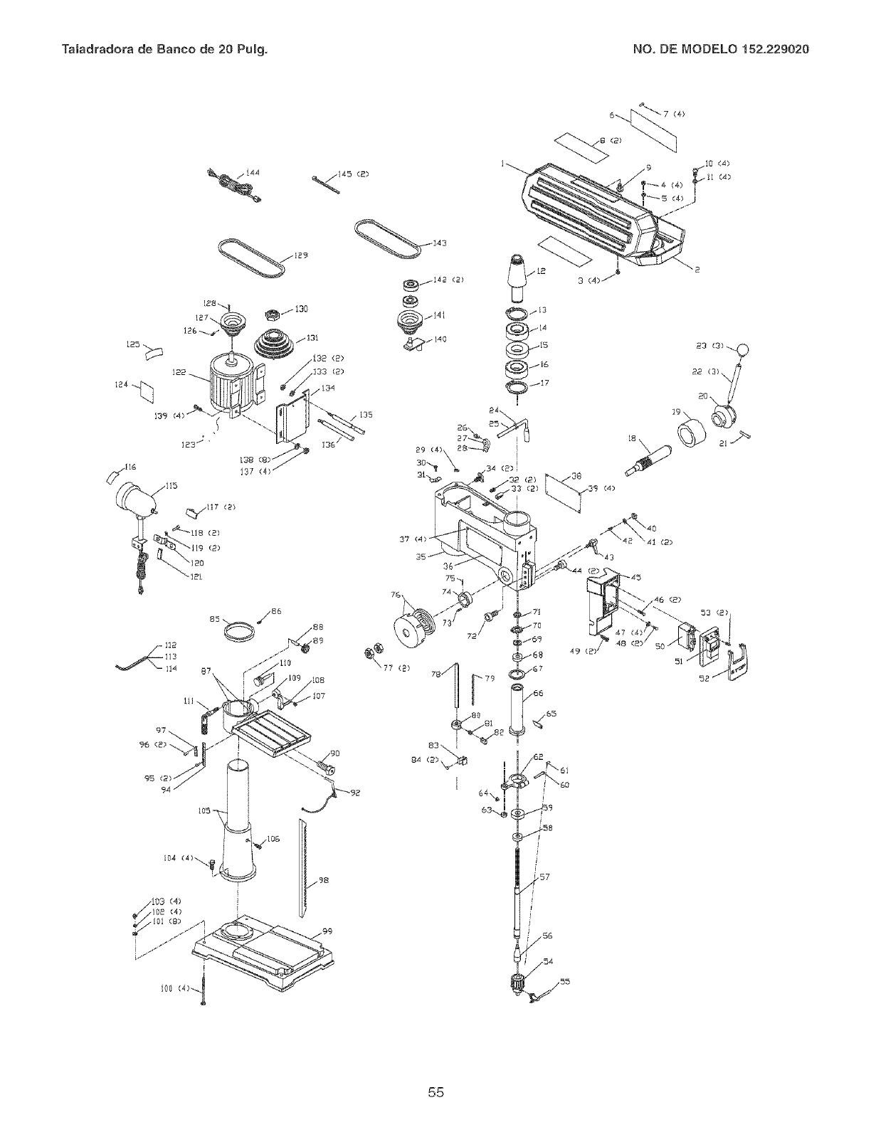
Tatadradora de Banco de 20 Pumg, NO, DE MODELO 152,229020
95
g4
105
(2}
55

iiiiiiiiiiiiiiiiiiiiiiii!_...... You r Home
For repair-in your home-of all major brand appliances,
lawn and garden equipment, or heating and cooling systems,
no matter who made it, no matter who sold it!
For,the replacement parts, accessories and
owner s manuals that you need to do-it-yourself.
For Sears professional installation of home appliances
and items like garage door openers and water heaters.
1-800-4-MY-HOME ® (1-800-469-4663)
Call anytime, day or night (U.S.A. and Canada)
www.sears.com www.sears.ca
Our Home
For repair of carry-in items like vacuums, lawn equipment,
and electronics, call or go on-line for the location of your nearest
Sears Parts & Repair Center. ....
1-800-4 88-12 22
iiiiiiii Ca,, anytime, day or night (U.S.A. only)
www.sears.cor.
(1-800-533-6937)
www.sears.ca
® Registered Trademark /TMTrademark /SMService Mark of Sears Brands, LLC
® March Registrada /TM March de Fabrica /SMMarch de Servicio de Sears Brands, LLC
MCMarque de commerce /MDMarque deposed de Sears Brands, LLC ® Sears Brands, LLC
56
