Craftsman 17224360 User Manual 10 COMPOUND MITER SAW Manuals And Guides L0408143
CRAFTSMAN Miter Saw Manual L0408143 CRAFTSMAN Miter Saw Owner's Manual, CRAFTSMAN Miter Saw installation guides
User Manual: Craftsman 17224360 17224360 CRAFTSMAN 10 COMPOUND MITER SAW - Manuals and Guides View the owners manual for your CRAFTSMAN 10 COMPOUND MITER SAW #17224360. Home:Tool Parts:Craftsman Parts:Craftsman 10 COMPOUND MITER SAW Manual
Open the PDF directly: View PDF ![]() .
.
Page Count: 44
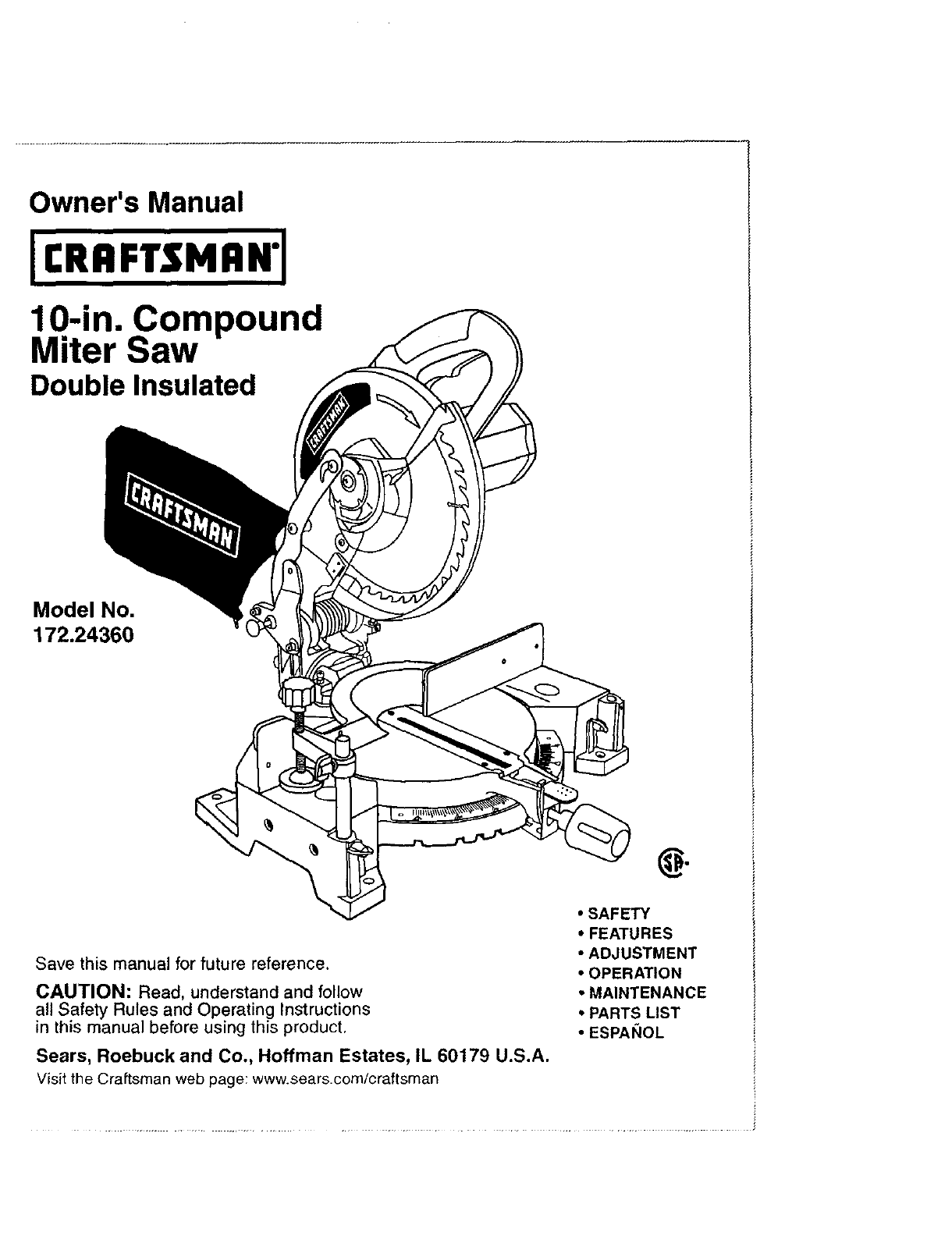
Owner's Manual
10-in. Compound
Miter Saw
Double Insulated
Model No,
172.24360
g
Save this manual for future reference.
CAUTION: Read, understand and follow
all Safety Rules and Operating Instructions
in this manual before using this product.
Sears, Roebuck and Co., Hoffman Estates, IL 60179 U.S.A.
Visit the Craftsman web page: www.sears.com/craftsman
•SAFETY
•FEATURES
• ADJUSTMENT
•OPERATION
•MAINTENANCE
° PARTS LIST
•ESPANOL
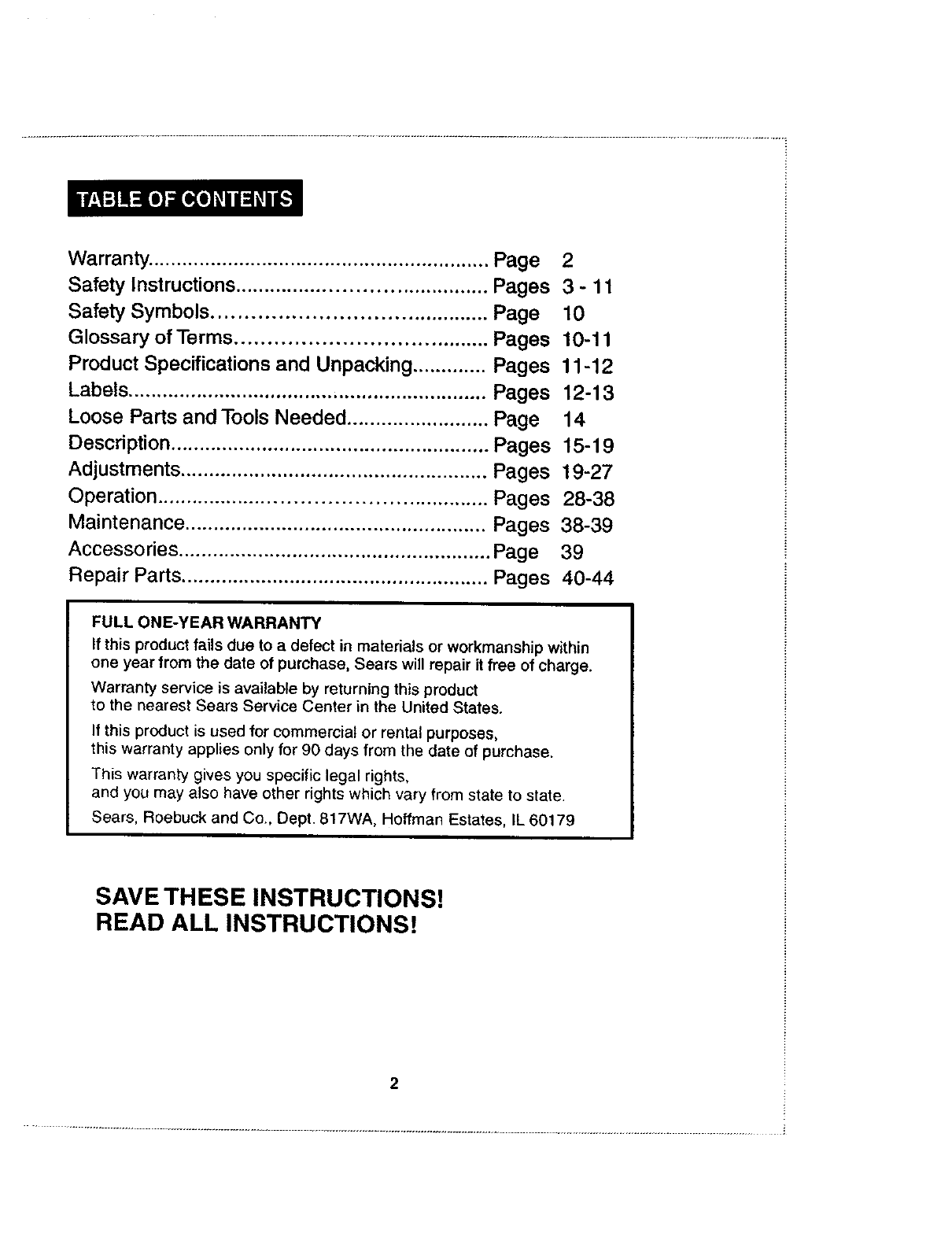
Warranty. ........................................................... Page 2
Safety Instructions .......................................... Pages 3 - 11
Safety Symbols ........................................... Page 10
Glossary of Terms ....................................... Pages 10-11
Product Specifications and Unpacking ............. Pages 11-12
Labels ............................................................... Pages 12-13
Loose Parts and Tools Needed ......................... Page 14
Description ........................................................ Pages 15-19
Adjustments ...................................................... Pages 19-27
Operation ...................................................... Pages 28-38
Maintenance ..................................................... Pages 38-39
Accessories ....................................................... Page 39
Repair Parts ...................................................... Pages 40-44
FULLONE-YEARWARRANTY
If this product fails due to a defect in materials or workmanship within
one year from the date of purchase, Sears will repair it free of charge.
Warranty service is available by returning this product
to the nearest Sears Service Center in the United States.
If this product is used for commercial or rental purposes,
this warranty applies only for 90 days from the date of purchase.
This warranty gives you specific legal rights,
and you may also have other rights which vary from state to state.
Sears, Roebuck and Co., Dept. 817WA, Hoffman Estates, IL 60179
SAVE THESE INSTRUCTIONS!
READ ALL INSTRUCTIONS!
.............................................................................................................................................................................................................. i
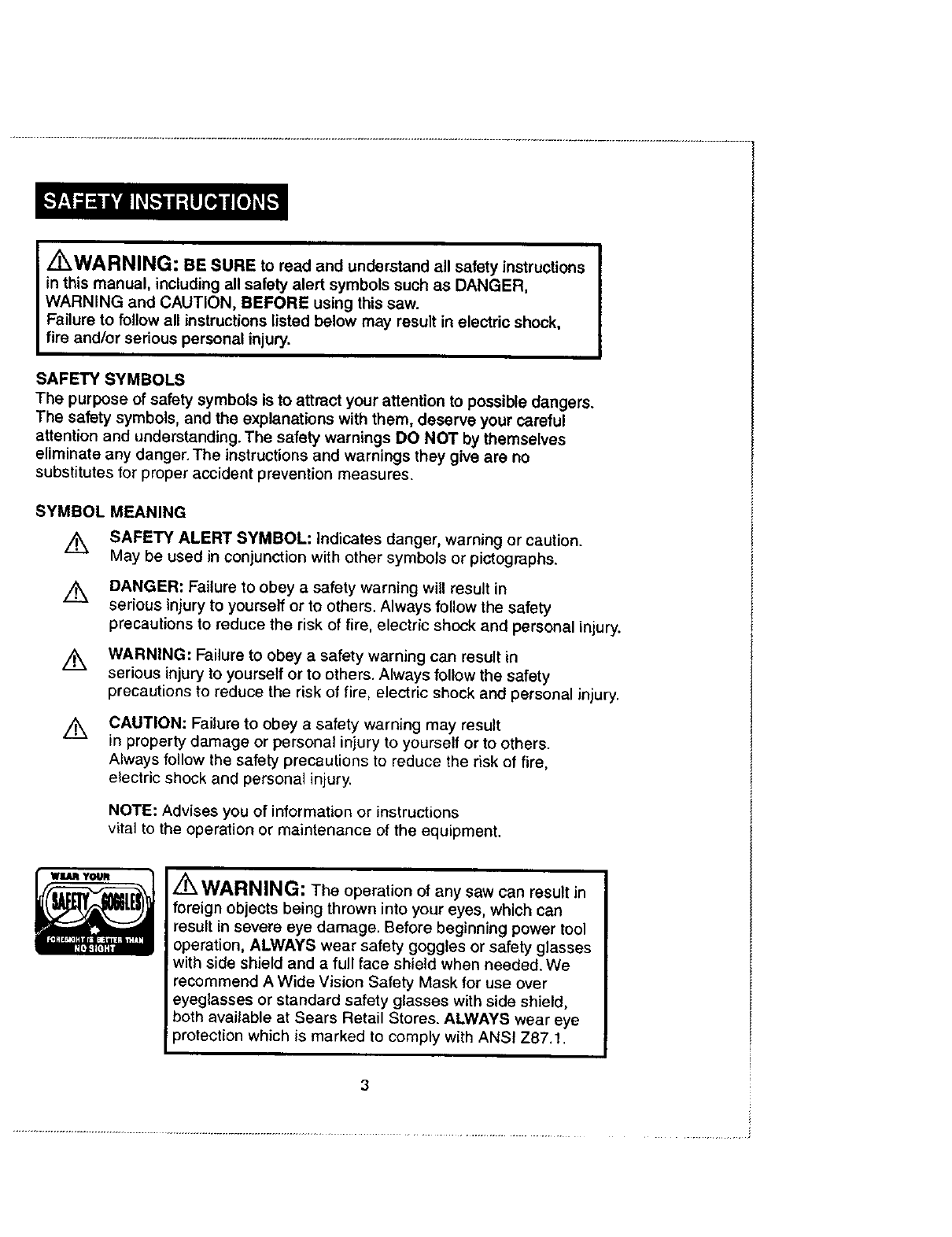
Z_WARNING: BE SURE to read and understand all safety instructions
in this manual, including all safety alert symbols such as DANGER,
WARNING and CAUTION, BEFORE using this saw.
Failure to follow all instructions listed below may result in electric shock,
fire and/or serious personal injury.
SAFETY SYMBOLS
The purpose of safety symbols is to attract your attention to possible dangers.
The safety symbols, and the explanations with them, deserve your careful
attention and understanding. The safety warnings DO NOT by themselves
eliminate any danger. The instructions and warnings they give are no
substitutes for proper accident prevention measures.
SYMBOL
Ak
/k
/k
MEANING
SAFETY ALERT SYMBOL: Indicates danger, warning or caution.
May be used in conjunction with other symbols or pictographs.
DANGER: Failure to obey a safety warning will result in
serious injury to yourself or to others. Always follow the safety
precautions to reduce the risk of fire, electric shock and personal injury.
WARNING: Failure to obey a safety warning can result in
serious injury to yourself or to others. Always follow the safety
precautions to reduce the risk of fire, electric shock and personal injury.
CAUTION: Failure to obey a safety warning may result
in property damage or personal injury to yourself or to others.
Always follow the safety precautions to reduce the risk of fire,
electric shock and persona_ injury.
NOTE: Advises you of information or instructions
vital to the operation or maintenance of the equipment.
/'rk WARNING: The operation of any saw can result in
foreign objects being thrown into your eyes, which can
result in severe eye damage. Before beginning power tool
operation, ALWAYS wear safety goggles or safety glasses
with side shield and a full face shield when needed. We
recommend A Wide Vision Safety Mask for use over
eyeglasses or standard safety glasses with side shield,
both available at Sears Retail Stores. ALWAYS wear eye
protection which is marked to comply with ANSI Z87.1.
3
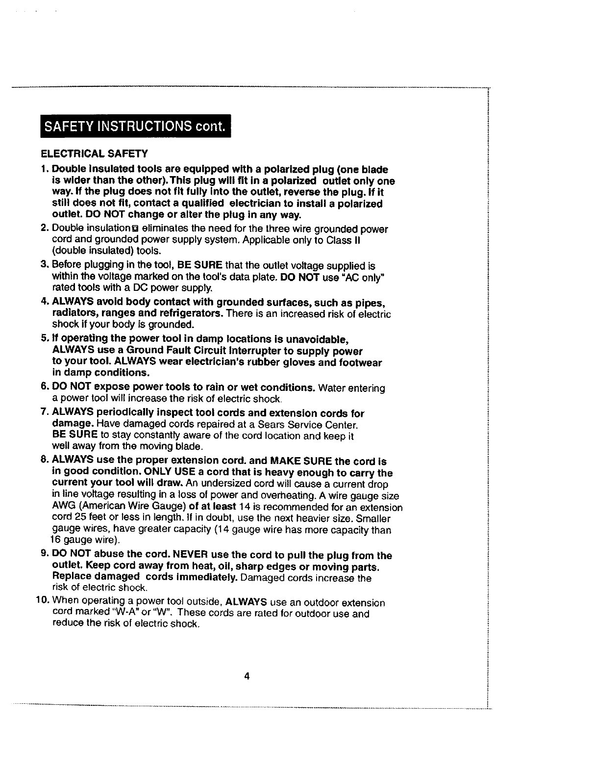
ELECTRICAL SAFETY
1. Double Insulated tools are equipped with a polarized plug (one blade
is wider than the other).Thls plug will fit in a polarized outlet only one
way. If the plug does not fit fully into the outlet, reverse the plug. If it
still does not fit, contact a qualified electrician to install a polarized
outlet. DO NOT change or alter the plug in any way.
2. Double insulationu eliminates the need for the three wire grounded power
cord and grounded power supply system. Applicable only to Class II
(double insulated) tools.
3. Before plugging in the tool, BE SURE that the outlet voltage supplied is
within the voltage marked on the tool's data plate. DO NOT use "AC only"
rated tools with a DC power supply.
4. ALWAYS avoid body contact with grounded surfaces, such as pipes,
radiators, ranges and refrigerators. There is an increased risk of electric
shock if your body is grounded.
5. If operating the power tool in damp locations is unavoidable,
ALWAYS use a Ground Fault Circuit Interrupter to supply power
to your tool. ALWAYS wear electrician's rubber gloves and footwear
in damp conditions.
6. DO NOT expose power tools to rain or wet conditions. Water entering
a power tool will increase the risk of electric shock.
7. ALWAYS periodically inspect tool cords and extension cords for
damage. Have damaged cords repaired at a Sears Service Center.
BE SURE to stay constantly aware of the cord location and keep it
well away from the moving blade.
8. ALWAYS use the proper extension cord. and MAKE SURE the cord is
in good condition. ONLY USE a cord that is heavy enough to carry the
current your tool will draw. An undersized cord will cause a current drop
in line voltage resulting in a loss of power and overheating. A wire gauge size
AWG (American Wire Gauge) of at least 14 is recommended for an extension
cord 25 feet or less in length. If in doubt, use the next heavier size. Smaller
gauge wires, have greater capacity (14 gauge wire has more capacity than
16 gauge wire).
9. DO NOT abuse the cord. NEVER use the cord to pull the plug from the
outlet. Keep cord away from heat, o11,sharp edges or moving parts.
Replace damaged cords Immediately. Damaged cords increase the
risk of electric shock.
10. When operating apower tool outside, ALWAYS use an outdoor extension
cord marked "W-A" or "W". These cords are rated for outdoor use and
reduce the risk of electric shock.
4
............................................................................................................................................................................................................. i..
WORK AREA SAFETY
1. ALWAYS keep your work area clean and well lit. DO NOT leave tools or
pieces of wood on the saw while it is in operation. Cluttered benches and
dark areas invite accidents.
2. DO NOT operate power tools In explosive atmospheres, such as in the
presence of flammable liquids, gases, or dust. Power tools create sparks
which may ignite the dust or fumes.
3. ALWAYS keep bystanders, children and visitors away while operating a
power tool. Distractions can cause you to lose control.
4. ALWAYS make your workshop childproof with padlocks and master
switches or by removing starter keys.
5. ALWAYS make sure the work area has ample lighting so you can see the
work and that there are no obstructions that will interfere with safe operation
BEFORE using your saw.
PERSONAL SAFETY
1. ALWAYS know your power tool. Read the operator's manual carefully,
learn the saw's applications and limitations, as well as, the specific potential
hazards related to this tool.
2. ALWAYS stay alert, watch what you are doing and use common sense
when operating a power tool. DO NOT use tool while tired or under the
influence of drugs, alcohol or medication. A moment of inattention while
operating power tools may result in serious personal injury.
3. ALWAYS dress properly. DO NOT wear loose clothing, gloves, neckties,
rings, bracelets or other jewelry that can get caught and draw you into
moving parts. Non-slip footwear is also recommended. Pull back long
hair. Keep your hair, clothing and gloves away from moving parts.
Loose clothing, jewelry or long hair can be caught in moving parts.
4. ALWAYS remove adjusting keys or wrenches before turning the tool on.
A wrench or a key that is left attached to a rotating part of the tool may result
in personal injury.
5. ALWAYS wear safety glasses with side shields. Everyday eyeglasses
have only impact resistant lenses, they are NOT safety glasses.
6. ALWAYS wear a dust mask to keep you from inhaling fine particles.
7. ALWAYS protect your hearing. Wear hearing protection during extended
periods of operation.
8. ALWAYS secure your work. Use clamps or a vise to hold work when
practical. It is safer than using your hand and frees both hands to operate tool.
9. DO NOT overreach. ALWAYS keep proper footing and balance at all
times. Proper footing and balance enables better control of the tool in
unexpected situations
5
PERSONAL SAFETY cont.
10. ALWAYS avoid accidental starting.
BE SURE switch Is in the "Off" posVaonbefore plugging In.
11. NEVER stand on tool. Serious injury could occur if the tool is tipped or
if the blade is accidentally contacted.
TOOL USE AND CARE SAFETY
1. NEVER leave the tool running unattended. ALWAYS turn it off.
DO NOT leave the tool until it comes to a complete stop.
2. DO NOT use the tool if the switch does not turn tt "On" or "Off". Any
tool that cannot be controlled with the switch is dangerous. ALWAYS have
defective switches replaced at a Sears Service Center.
3. ALWAYS disconnect the plug from the power source before making any
adjustments, changing accessories or storing the tool. Such preventive
safety measures reduce the risk of starting the tool accidentally.
4. ALWAYS store idle tools out of the reach of children and other
untrained persons. Tools are dangerous in the hands of untrained users.
5. ALWAYS maintain tools with care. Keep cutting tools sharp and clean.
Properly maintained tools with sharp cutting edges are less likely to
bind and are easier to control. Follow instructions for lubricating and
changing accessories.
6. DO NOT force the tool, it will do the job better and more safely at the
rate for which it was designed.
7. ALWAYS use the right tool for the job. DO NOT force the tool or attachment
to do a job it was not designed for. Use it only the way it was intended.
8. Before using this saw, ALWAYS check for damaged parts, including
guards for proper operation and performance. Also ALWAYS check the
alignment of moving parts, binding of moving parts, breakage of parts,
saw stability, mounting and any other condition that may affect the
tool's operation. If damaged, have the tool serviced at a Sears Service
Center before using. Many accidents are caused by poorly maintained tools.
J/_WARNING: USE OF ACCESSORIES THAT ARE NOT I
I
RECOMMENDED FOR USE WITH THIS TOOL MAY CREATE I
A HAZARDOUS CONDITION.
9. ALWAYS use only accessories that are recommended for this tool.
Using improper accessories may cause the risk of serious injury.
See accessories section of this manual for proper accessories.
.................................................................................................................................................................................................................. i
ADDITIONAL SPECIFIC SAFETY RULES FOR MITER SAWS
1. Know your power tool. Read operator's manual carefully. Learn the
applications and limitations, as well as the specific potential hazards
related to this tool. Following this rule will reduce the risk of electric
shock, fire or serious injury.
2. ALWAYS firmly clamp or bolt your miter saw to a workbench or table
at approximately hip height.
3. ALWAYS be sure that all adjustments are secure BEFORE making a cut.
4. ALWAYS make sure that the miter table and saw (bevel function) are
locked in position BEFORE operating your saw. Lock the motor table by
securely tightening the miter lock handle. Lock the saw arm (bevel function)
by securely tightening the bevel lock knob.
5. ALWAYS use a clamp to secure the workpiece, when possible.
6. ALWAYS be sure the blade path is free of nails. ALWAYS carefully inspect
lumber and remove all nails BEFORE cutting.
7. ALWAYS be sure that the blade clears the workpiece. NEVER start the
saw with the blade touching the workpiece. ALWAYS allow the motor to come
up to full speed BEFORE starting a cut.
8. ALWAYS support long workpieces when cutting to minimize the risk of
the blade pinching or kickback. The saw may slip, walk or slide while
cutting long or heavy boards.
9. NEVER use a length stop on the free (scrap end) of aclamped workpiece.
NEVER hold onto or bind the free scrap end of the workpiece in any operation.
If a work clamp and length stop are used together, THEY MUST BOTH BE
INSTALLED on the same side of the saw table to prevent the saw from
catching the loose end and kicking up.
10. NEVER cut more than one piece at a time. DO NOT STACK more than
one workpiece on the saw table at a time.
11. ALWAYS avoid awkward operations and hand positions where a sudden
slip could cause your hand to move into the blade. ALWAYS make
sure that you have good balance. NEVER operate your saw on the floor
or in a crouched position.
12. NEVER stand or have any part of your body in line with the path of the blade.
13. ALWAYS only use the correct blades. Use the right blade size, style and
cutting speed for the material and the type of cut. DO NOT use blades with
incorrect size holes. NEVER use blade washers or blade bolts that are
defective or incorrect. The maximum blade capacity for this saw is 10 inches.
7
ADDITIONAL SPECIFIC SAFETY RULES FOR MITER SAWS cont.
14. ALWAYS keep blades clean, sharp and with the sufficient set.
Sharp blades minimize stalling and kickback.
15. DO NOT use dull or damaged blades. Bent blades can break easily,
or cause kickback.
16. DO NOT remove the saw's blade guards. NEVER operate the saw with
any guard or cover removed. MAKE SURE that all guards are operating
properly BEFORE each use.
17. NEVER hand hold a workplece that is too small to be clamped.
ALWAYS keep your hands clear of the '_o hands' zone.
18. NEVER perform any operaUon freehand. ALWAYS place the workpiece
to be cut on the miter table and position it firmly against the fence as a
backstop. ALWAYS use the fence.
19. ALWAYS keep your hands away from cutting area. DO NOT reach under
the material being cut or in the blade's cutting path with your fingers or hand
for any reason. ALWAYS turn the power off.
Z_WARNING: Blade continues to turn after power to saw cuts off.To avoid
possible serious injury, after releasing trigger switch to cut power, allow the saw
blade to stop rotating BEFORE raising the blade out of the workpiece.
20. NEVER reach behind, under or within three inches of the blade and its
cutting path with your hands or fingers for any reason.
21. NEVER reach to pick up a workpiece, a piece of scrap, or anything else
that is in or near the cutting path of the blade.
22. NEVER, for any reason, touch the blade or other moving parts during use.
23. ALWAYS release the power switch and allow the saw blade to stop
rotating BEFORE raising it out of the workpiece.
24. DO NOT turn the motor switch on and off rapidly. This could cause the
blade to loosen which could create a hazard. Should this ever occur, stand
clear and allow the saw blade to come to a complete stop. Disconnect the
saw from the power source and securely tighten the blade bolt.
25. ALWAYS turn off the saw before disconnecting it to avoid accidental
starting when reconnecting the saw to a power supply. NEVER leave
the saw unattended while connected to a power supply.
26. NEVER lift this tool by gripping the sliding miter fence.
27. SAVE THESE INSTRUCTIONS. Refer to them frequently and use them
to instruct others who may use this tool. If someone borrows this tool,
make sure they have these instructions also.
............................................................................................................................................................................................................................ i
ADDITIONAL SPECIFIC SAFETY RULES FOR MITER SAWS cont.
Z_ WARNING: Some dust partlcles created by power sanding,
sawing, grlndlng, drilllng and other construction jobs contain
chemlcals known to cause cancer, birth defects or other reproductive
harm. Some examples of these chemicals are:
•Lead from lead-based paints.
• Crystalline silica from bricks and cement and other masonry products.
• Arsenic and chromium from chemically-treated lumber.
Your risk from these exposures varies, depending upon how often you do this
type of work. To reduce your exposure to these chemicals:
• Work in a well-ventilated area.
• Work with approved safety equipment, such as those dust
masks that are specially designed to filter out microscopic
particles.
Z_ WARNING: The operation of any saw can
result in foreign objects being thrown into your eyes,
which can result in severe eye damage. Before
beginning power tool operation, ALWAYS wear
safety goggles or safety glasses with side shield
and a full face shield when needed. We recommend
aWide Vision Safety Mask for use over eyeglasses
or standard safety glasses with side shield, both available
at Sears Retail Stores.
SERVICE SAFETY
1. If any part of this miter saw is missing or should break, bend, or fail in
any way; or should any electrical component fail to perform properly:
ALWAYS shut off the power switch and remove the miter saw plug from
the power source and have the missing, damaged or failed parts
replaced BEFORE resuming operation.
2.Tool service must be performed only at a Sears Service Center. Service
or maintenance performed by unqualified personnel could result in a risk of injury.
3.When servicing a tool, ALWAYS use only identical replacement parts.
Follow instructions in the Maintenance Section of this manual. Use of
unauthorized parts or failure to follow Maintenance Instructions may create
a risk of electric shock or injury.
9
SERVICESAFETYcont.
Thelabelon yourtool may Include the following symbols.
V........................................................................... Volts
A........................................................................... Amperes
Hz......................................................................... Hertz
W.......................................................................... Watts
mln ....................................................................... Minutes
"_" ........................................................................ Alternating current
----===--................................................................... Direct current
no ........................................................................ No-load speed
[] ........................................................................ Class II construction
.../rain ................................................................... Revolutions or
reciprocation per minute
./_ ...................................................................... Indicates danger, warning
caution. It means attention!!f
Your safety is involved.
IMPORTANT! READ ALL INSTRUCTIONS
GLOSSARY OF TERMS FOR WOODWORKING
Arbor
The shaft on which a blade or cutting tool is mounted.
Bevel Cut
Acutting operation made with the blade at any angle other than
90 ° to the miter table.
Cross Cut
A cutting or shaping operation made against the grain of the workpiece.
Compound Miter Cut
Acompound miter cut is acut made using a miter angle and bevel
angle at the same time.
Freehand
Performing acut without using a fence, miter gauge, fixture, work clamp, or
other proper device to keep the workpiece from twisting or moving during the cut.
Gum
A sticky, sap-based residue from wood products.
Miter Cut
Acutting operation made with the blade at any angle other than 90°to the fence.
Resin
A sticky, sap-based substance that has hardened.
Revolutions per Minute (RPM)
The number of turns completed by a spinning object in one minute.
Saw Blade Path
The area over, under, behind, or in front of the blade, as it applies
to the workpiece°That area which will be or has been cut by the blade.
10
GLOSSARY OF TERMS FOR WOODWORKING cont.
Set
The distance that the saw blade tooth is bent
(or set) outward from the face of the blade.
Throw-Back
Throwing of aworkpiece in a manner similar to a kickback. Usually associated
with a cause other than the kerr closing, such as a workpiece not being against
the fence, being dropped into the blade, or being placed inadvertently in contact
with the blade.
Through Sawing
Any cutting operation where the blade extends
completely through the thickness of the workpiece.
Workpiece
The item on which the cutting operation is being done. The surfaces of a
workpiece are commonly referred to as faces, ends and edges.
Throat Plate
Aplastic throat plate inserted in the miter table that allows for blade clearance.
No Hands Zone
The area between the marked lines on the left and right side of the miter table
base. This zone is identified by no hands zone labels placed inside the marked
lines on the miter table base.
11
Your Compound Miter Saw has been shipped fully assembled,
except for the blade, miter lock handle, dust guide and dust bag.
1. Remove all packing materials from around your saw.
2. Carefully lift the saw from carton and place it on a level work surface.
The saw is heavy, so get help, if you need it, to help avoid injuring your back.
3. Do not discard the packing materials until you have carefully inspected
the saw for loose or damaged parts and successfully operated the saw.
4. This saw has been shipped with the saw arm secured in the down position.
To release the saw arm, push down on the top of the saw arm and cut the
tie wrap. Lift the saw arm by the handle.
IMPORTANT: Keep hand pressure on the saw arm while cutting
the tie wrap to prevent it from suddenly raising the wrapping if fully cut.
5. Carefully inspect all parts of the saw to make sure that no breakage
or damage has occurred during shipping.
/_WARNING: If any parts are missing, DO NOT operate this toot until
the missing parts are replaced. Failure to do so could result in possible
serious injury.
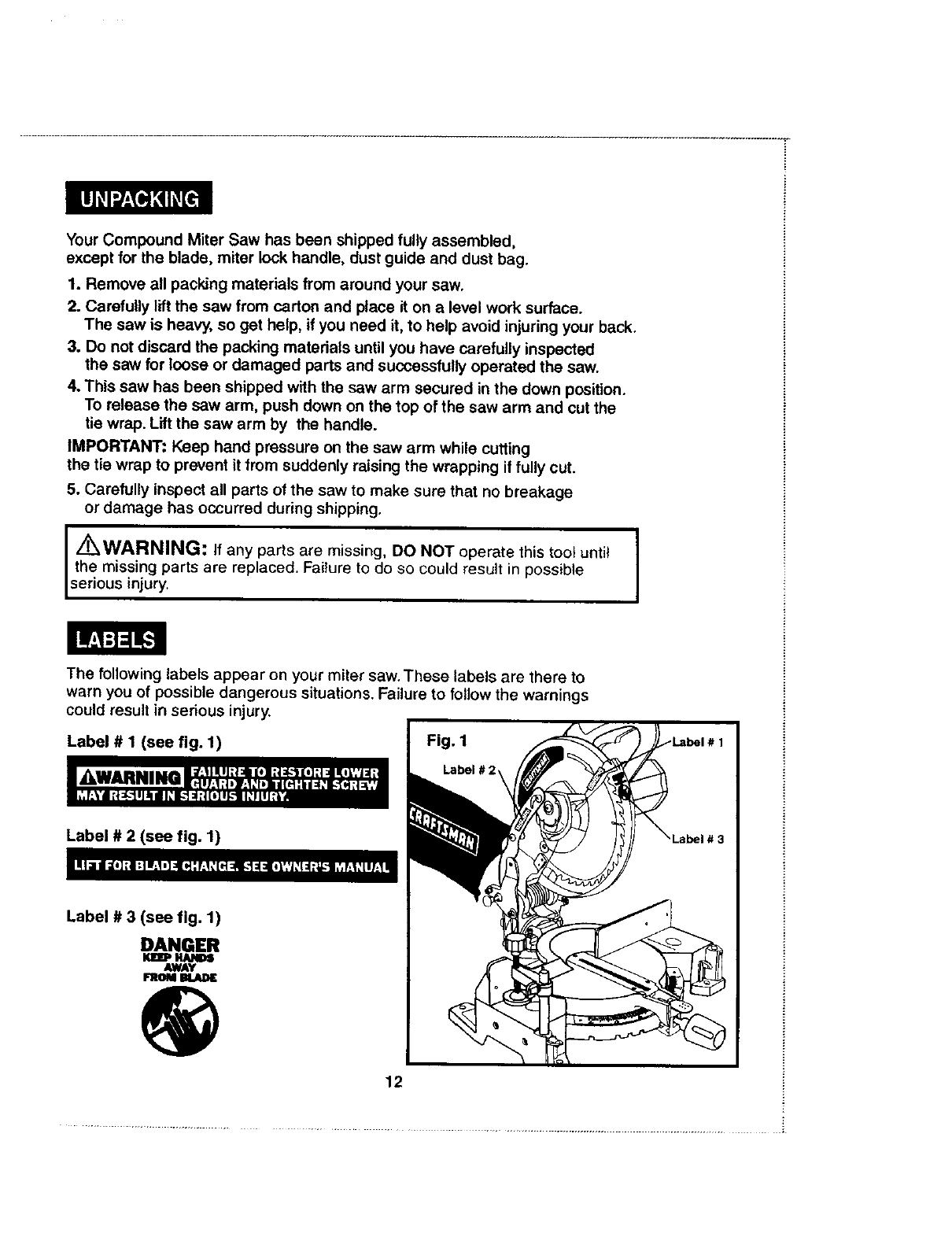
The following labels appear on your miter saw. These labels are there to
warn you of possible dangerous situations. Failure to follow the warnings
could result in serious injury.
Label #1 (see fig. 1)
Label #2 (see fig. 1)
Label # 3 (see fig. 1)
DANGER
KUP HANDS
AWAY
FROM
12
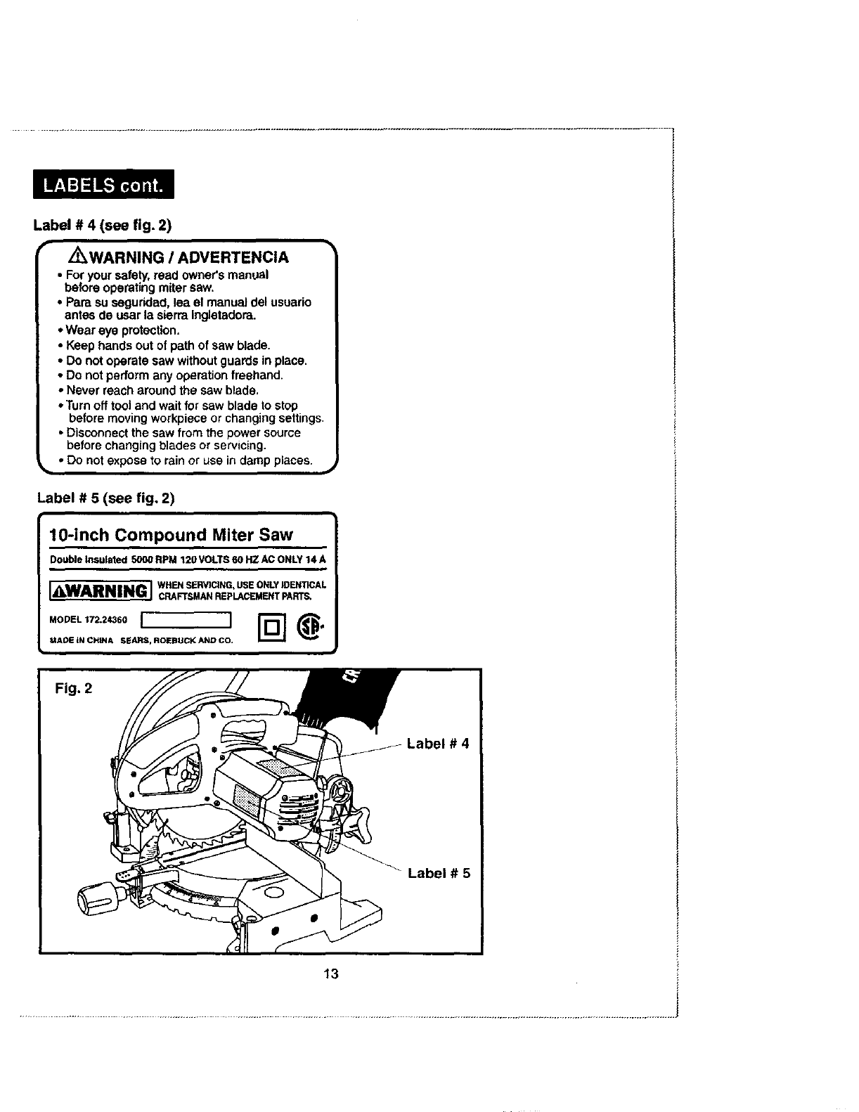
Label#4 (see fig. 2)
rZ_WARNING /ADVERTENCIA •
• For your safety, read owner's manual
before operating metersaw,
• Para su seguridad, lea el manual del usuario
antes de usar la sierra ingletadora,
,,Wear eye protection.
• Keep hands out of path of saw blade.
• Do not operate saw without guards in place.
•Do not perform any operation freehand.
•Never reach around the saw blade,
• Turn off tool and wait for saw blade to stop
before moving workpiece or changing settings.
•Disconnect the saw from the power source
before changing blades or servicing.
••Do not expose to rain or use in damp places. ,_
Label #5 (see fig. 2)
10-inch Compound Miter Saw
DoubleInsulated5000RPM120VOLTS60HZACONLY14A
[_,WARNING WHEN SERVICING, USE ONLYIDENTICAL
!. CRAFTSMAN REPLACEMENT PARTS.
.OO,L,O.2-°oI '
MADE tN CHtNA S_ARSf ROEBUCK AND CO.
13
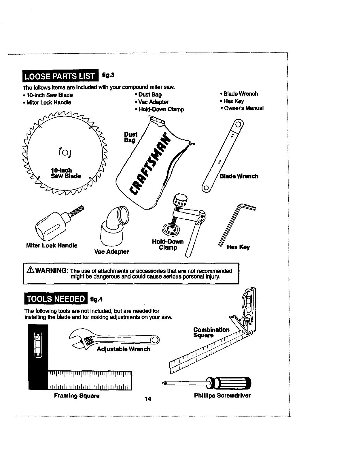
fig.3
The followsitems are includedwi_ your compoundmiter saw.
•10-1nchSaw Blade • Dust Bag
•Miter Lock Handle • Vex:Adapter
•Hold-Down Clamp
•Blade Wrench
*He_ Key
• Owners Manual
DuM _ren
Beg
ch
Clamp U
Z_IWARNING: The use of attachments or acsessodes that are not recommended I
might be dangerous and coud cause sar ous personal injury. I
I
riga
The followingtools are not included, but are needed for
installingthe blade and for making adjustments on your saw.
CO
dJustable Wrench
Combination
Squam
Framing Square 14 Phillips Screwdrlver
KNOWYOURSAW(see fig. 5)
Your miter saw has many built-in convenience features for fast, efficient cutting.
Before attempting to use your saw, familiarize yourself with all of the operating
features and safety requirements.
IZ_WARNING: DO NOT allow familiarity with your saw to make
you careless. Remember that a careless fraction of a second is
sufficient to inflict serious injury.
14-,Amp Motor
This powerful motor provides sufficient power to handle awide variety
of heavy-duty cutting jobs. It has permanently lubricated ball bearings
for long life and smooth operation,
10-inch Blade
The blade included with your compound miter saw will cut avariety
of materials up to 5 1/2 in. wide and 3 1/2 in. thick, depending upon
the angle at which the cut is made.
CUTTING CAPACITIES
When the miter angle (miter table) is set at 0°
and the bevel angle is set at 0°:
Your saw will cut materials up to a maximum of 51/2 in. wide x 3t/2 in. thick.
When the miter angle (miter table) is set at 45°
and the bevel angle is set at 0°:
Your saw will cut materials up to a maximum of 41/8 in. wide x 31/2 in. thick.
When the miter angle (miter table) is set at 0°
and the bevel angle is set at 45°:
Your saw will cut materials up to a maximum of 51/2 in. wide x 19/16in, thick.
When the miter angle (miter table) is set at 45 °
and the bevel angle is set at 45°:
Your saw will cut materials up to a maximum of 41/8 in. wide x 19/16in. thick.
15

KNOWYOURSAWcont, (seefig, 5)
Flg.5 Upper
Blade Guard
Dust Bag
Saw Arm
Motor Housing
Lower Blade Guard
Fence
Dust
Guide
for Vac
Hook-up
"No Hands Zone" Label
Hands Zone"
Boundary Line
Throat Plate
Miter
Table Frame Positive
Stops
Miter
Lock Handle
Lock Knob
16
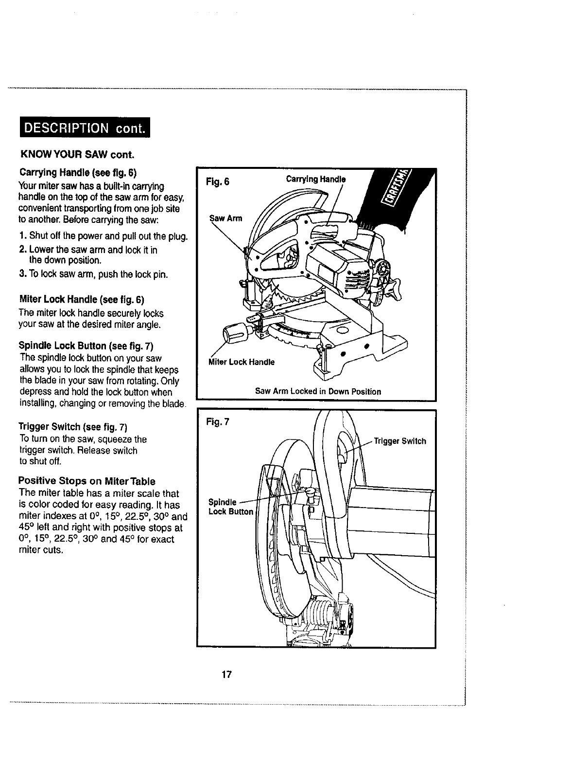
KNOWYOURSAW cont.
Carrying Handle (see fig. 6)
Yourmitersaw has abuilt-in carrying
handle on the topof the saw arm for easy,
convenienttransportingfromonejob site
to another.Before carryingthe saw:
1. Shutolf the power and pulloutthe plug.
2. Lowerthe saw arm and lock itin
the down position.
3. To lock saw arm, push the lock pin.
Miter Lock Handle (see fig. 6)
The miter lock handlesecurelylocks
your saw at the desired miter angle.
Spindle Lock Button (see fig. 7)
The spindle lock button on yoursaw
allowsyou to lockthe spindlethat keeps
the blade in yoursawfrom rotating,Only
depressand holdthe lockbutton when
installing,changingorremovingthe blade.
Trigger Switch (see fig. 7)
To turnon the saw, squeeze the
triggerswitch.Release switch
to shut off.
Positive Stops on Miter Table
The miter table has a miter scale that
is color coded 1or easy reading. It has
miter indexes at 0°, 15°, 22.5 °, 30° and
45° left and right with positive stops at
0°, 15°, 22.5 °, 30° and 450 for exact
miter cuts.
17
KNOWYOURSAWcont.
BevelLockKnob
The bevel lock knob securely locks your compound miter saw at the desired bevel angles.
Positive stop adjustment screws have been provided on each side of the saw arm. These
adjustment screws are for making fine adjustments at 0° and 45°. See pages 29 to 31.
Miter Fence
Hold the workpiece securely against the miter fence when making all cuts.
The left side is larger to provide additional support.
Self-Retracting Lower Blade Guard
The lower blade guard is made of shock-resistant, see-through plastic and it provides protection
from each side of blade. It retracts over the upper blade guard as blade is lowered intothe workpiece.
Id ={e,_l[Cj I,,'] d=[I] Id[€/Z_][_ !
Blade Diameter 10 in.
Blade Arbor 518in.
No-Load Speed 5000 RPM
Ratin_l 14 Amperes
Input 120 Volts, 60 Hz AC Only
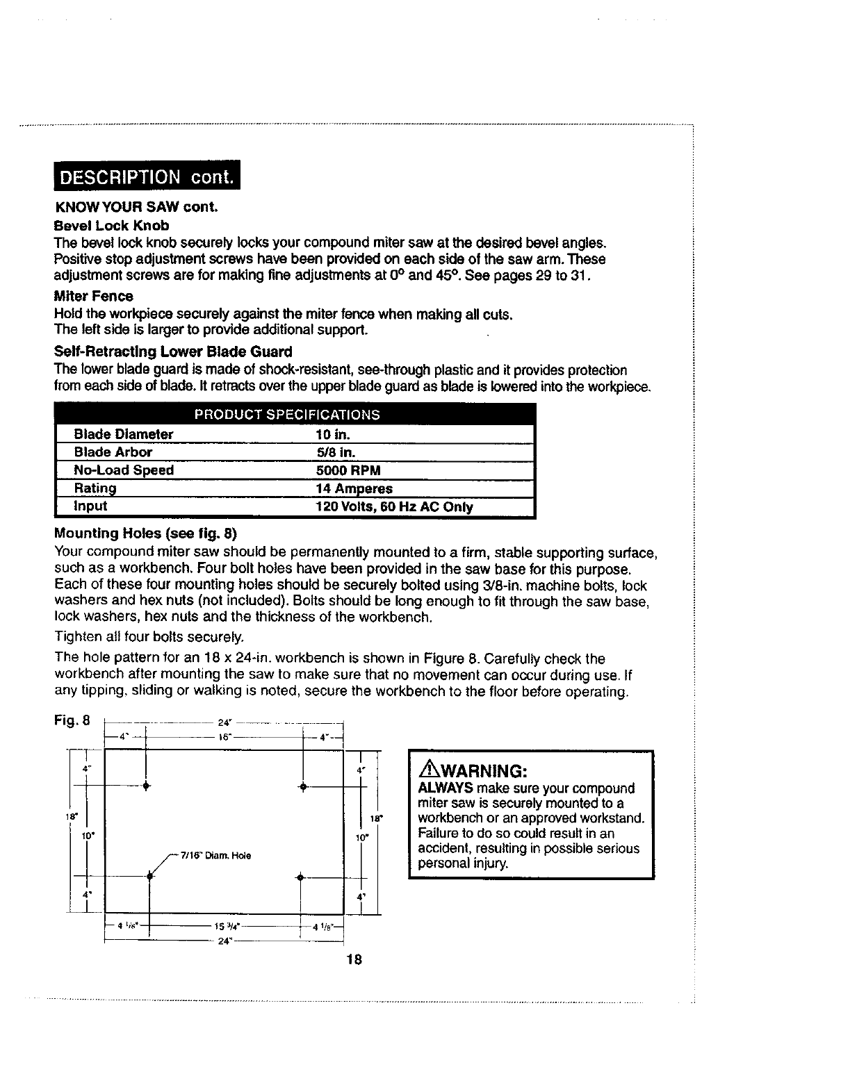
Mounting Holes (see fig. 8)
Your compound miter saw should be permanently mounted to a firm, stable supporting surface,
such as a workbench, Four bolt holes have been provided in the saw base for this purpose.
Each of these four mounting holes should be securely bolted using 3/8-in. machine bolts, lock
washers and hex nuts (not included). Bolts should be long enough to fit through the saw base,
lock washers, hex nuts and the thickness of the workbench.
Tighten all four bolts securely.
The hole pattern for an 18 x 24-in. workbench is shown in Figure 8. Carefully check the
workbench after mounting the saw to make sure that no movement can occur during use. If
any tipping, sliding or walking is noted, secure the workbench to the floor before operating.
F- 7,'16" Diam. Hole
i_WARNING:
ALWAYS make sure your compound
miter sew is securely mounted to a
workbench or an approved workstand.
Failure to do so could result in an
accident, resulting in possible serious
personal injury.
18
KNOWYOURSAWcont.
ElectricalConnection
Yoursawhasaprecision-builtelectricmotor.Itshouldbeconnectedtoapower supply that is
120 volts, 60 Hz AC only (normal household current), DO NOT operate this tool on direct
current (DC). A substantial voltage drop will cause a loss of power and the motor will overheat.
If your tool does not operate when plugged into an outlet, double-check the power supply.
I,/_WARNING: DO NOT attempt to modify this tool or create accessories not I
I
recommended for use with this tool, Any such alteration or modification is a misuse t
and could result in ahazardous condition leading to possible serious personal injury.
I,/_WARNING: To prevent accidental starting that could cause possible serious I
I
personal injury,ALWAYS assemble all parts to your saw BEFORE connecting it to the I
power supply. The saw should NEVER be connected to a power supply when you are
assembling parts, making adjustments, installing or removing blades, or when not in use.
Your compound miter saw has been factory assembled and adjusted. The blade, miter
lock handle, dust guide and dust bag are the only parts that have to be installed.
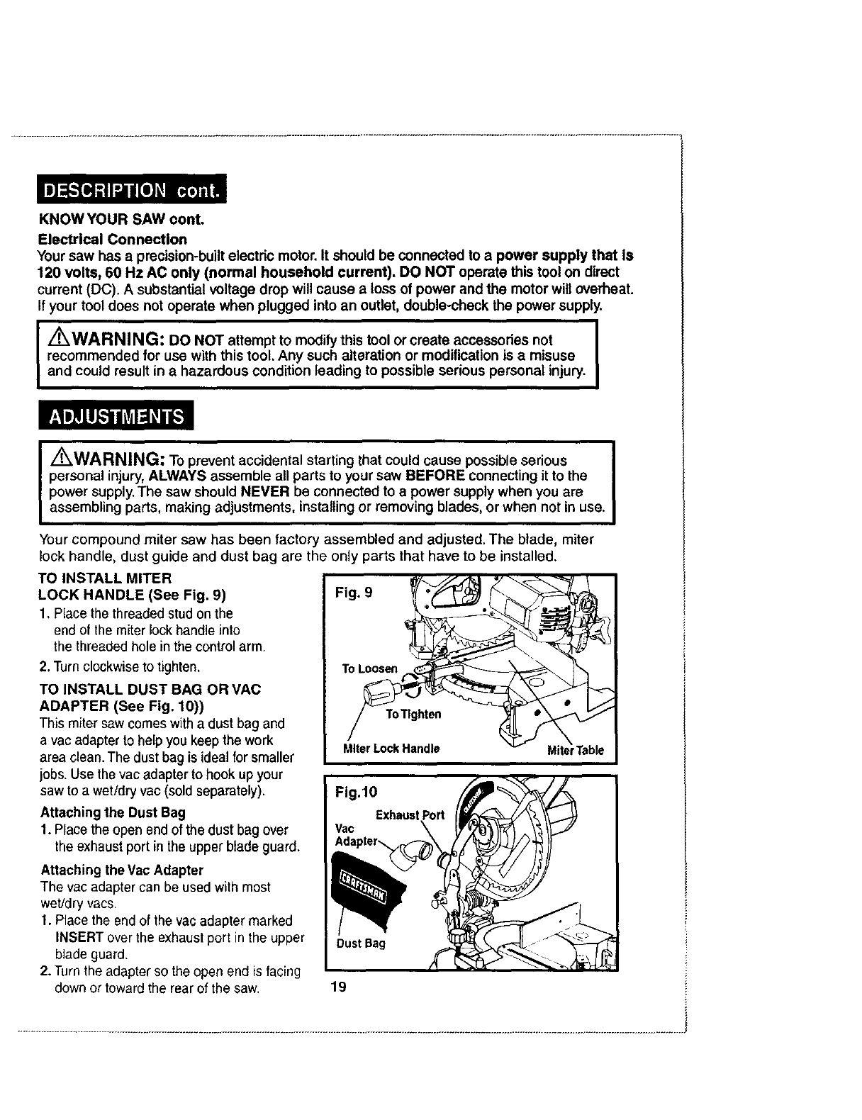
TO INSTALL MITER
LOCK HANDLE (See Fig. 9)
1, Place the threaded stud on the
end of the miter lock handle into
the threaded hole in the control arm.
2. Turnclockwise to tighten,
TO INSTALL DUST BAG OR VAC
ADAPTER (See Fig. 10))
This miter saw comeswitha dust bag and
a vacadapter to help youkeep the work
area clean. The dustbag is ideal for smaller
jobs. Use the vac adapter to hook up your
saw to awet/dry vac(sold separately).
Attaching the Dust Bag
1. Place the open end of the dust bag over
the exhaustport in the upperblade guard.
Attaching the Vac Adapter
The vac adapter can be used with most
weVdry vacs.
1. Place the end of the vac adapter marked
INSERT over the exhaust port in the upper
blade guard,
2. Turn the adapter so the open end is facing
down or toward the rear of the saw.
DustBag
19
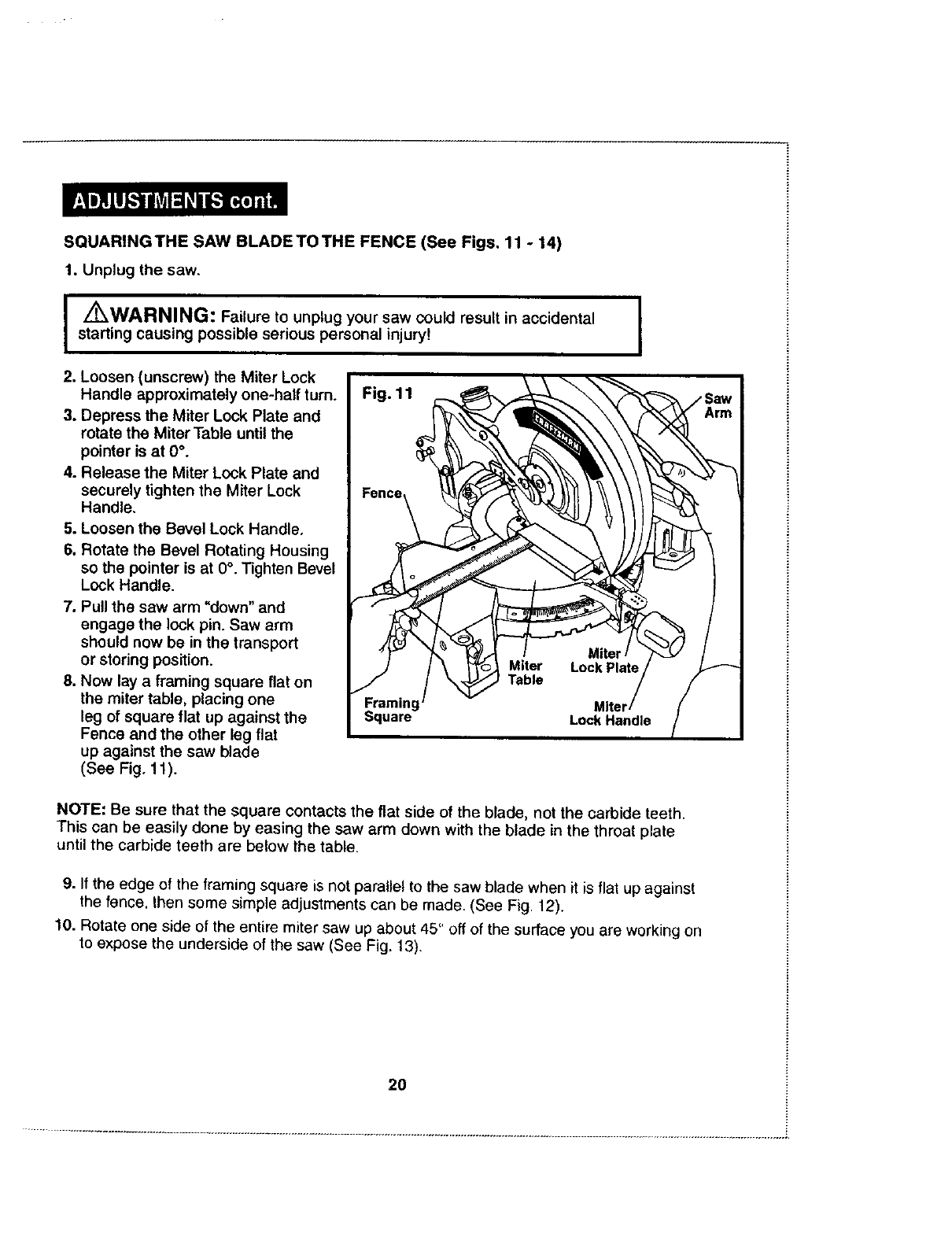
SQUARINGTHE SAW BLADETOTHE FENCE (See Figs. 11 -14)
1. Unplug the saw.
/KWARNING: Failure to unplug your saw could result in accidental
starting causing possible serious personal injury!
2. Loosen (unscrew) the Miter Lock
Handle approximately one-half turn.
3. Depress the Miter Lock Plate and
rotate the Miter Table until the
pointer is at 0°.
4. Release the Miter Lock Plate and
securely tighten the Miter Lock
Handle.
5. Loosen the Bevel Lock Handle.
6. Rotate the Bevel Rotating Housing
so the pointer is at 0°. Tighten Bevel
Lock Handle.
7. Pull the saw arm "down" and
engage the lock pin. Saw arm
should now be in the transport
or storing position.
8. Now lay a framing square flat on
the miter table, placing one
leg of square flat up against the
Fence and the other leg flat
up against the saw blade
(See Fig. 11).
L
NOTE: Be sure that the square contacts the flat side of the blade, not the carbide teeth.
This can be easily done by easing the saw arm down with the blade in the throat plate
until the carbide teeth are below the table.
9. If the edge of the framing square is not parallel to the saw blade when it is flat up against
the fence, Ihen some simple adjustments can be made. (See Fig. 12).
10. Rotate one side of the entire miter saw up about 45" off of the surface you are working on
to expose the underside of the saw (See Fig. 13).
2O
SQUARINGTHESAWBLADETOTHEFENCE(SeeFigs,11-14) cont.
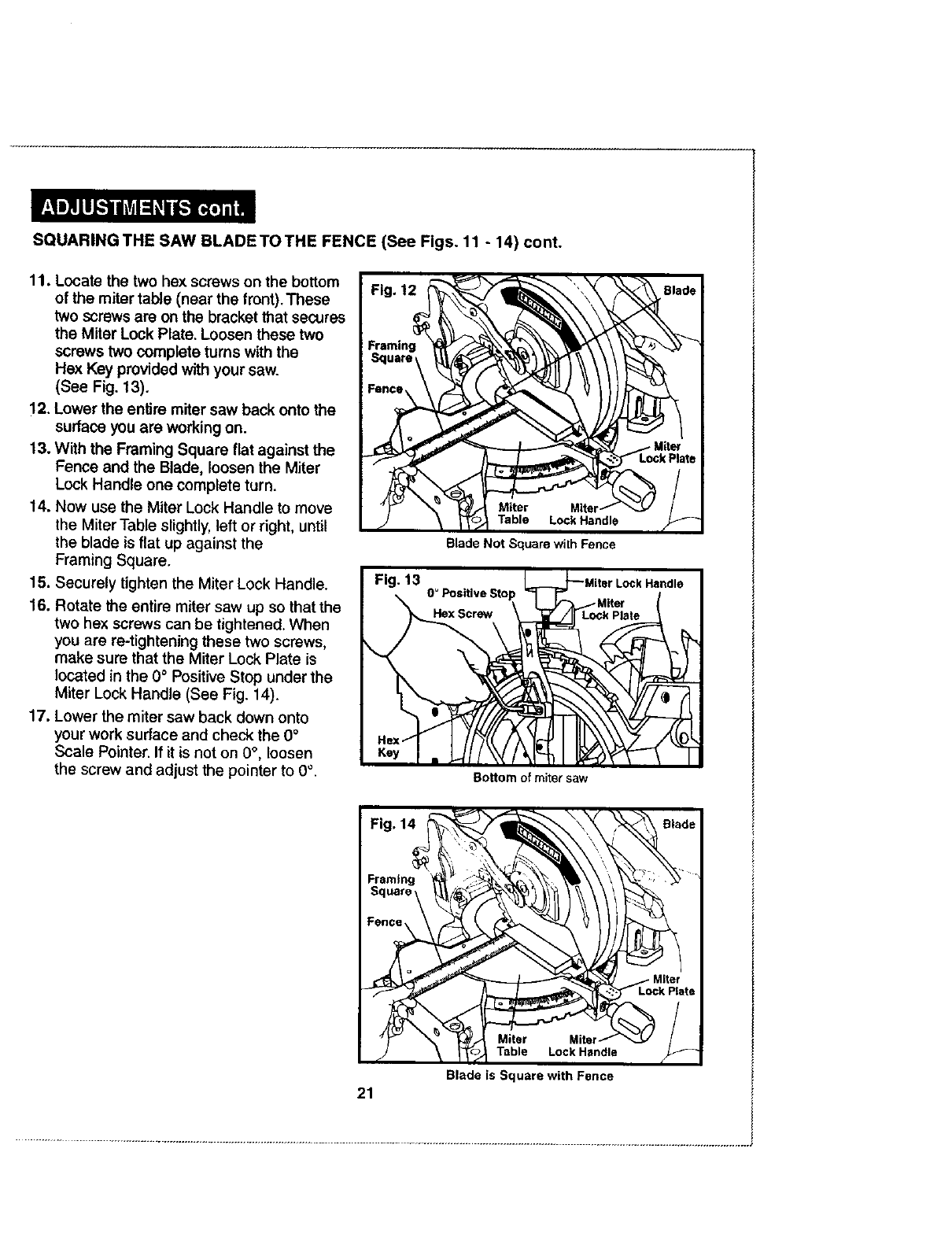
11. Locate the two hex screws on the bottom
of the miter table (near the front). These
two screws are on the bracket that secures
the Miter Lock Plate, Loosen these two
screws two complete turns with the
Hex Key provided with your saw.
(See Fig. 13).
12. Lower the entire miter saw back onto the
surface you are working on.
13. With the Framing Square flat against the
Fence and the Blade, loosen the Miter
Lock Handle one complete turn.
14. Now use the Miter Lock Handle to move
the Miter Table slightly, left or right, until
the blade is flat up against the
Framing Square.
15. Securely tighten the Miter Lock Handle.
16. Rotate the entire miter saw up so that the
two hex screws can be tightened. When
you are re-tightening these two screws,
make sure that the Miter Lock Plate is
located in the 0° Positive Stop under the
Miter Lock Handle (See Fig. 14).
17. Lower the miter saw back down onto
your work surface and check the 0°
Scale Pointer. If it is not on 0°, loosen
the screw and adjust the pointer to 0°.
Blade Not Square wilh Fence
Fig. 13 L._.._Miter Lock Handle
0_P°sitlveSt°p 7_ _:_/Miter (
__Hax Screw DLock Plate
Bottom of miter saw
21
Table
Blade is Square with Fence
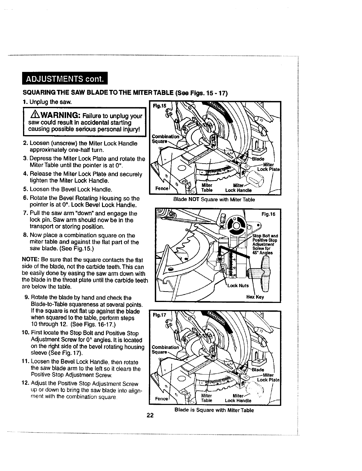
SQUARINGTHE SAW BLADETO THE MITERTABLE (See Figs. 15 - 17)
1. Unplug the saw.
IL WARNING: Failure to unplug your I
saw coutd result in acddentat starting |
causing possible sedous personal injury! I
I
2. Loosen (unscrew) the Miter Lock Handle
approximately one-half turn.
3. Depress the Miter Lock Plate and rotate the
Miter Table until the pointer is at 0".
4. Release the Miter Lock Plate and securely
tighten the Miter Lock Handle.
5. Loosen the Bevel Lock Handle.
6. Rotate the Bevel Rotating Housing so the
pointer is at 0°. Lock Bevel Lock Handle.
7. Pull the saw arm "down" and engage the
lock pin. Saw arm should now be in the
transport or storing position.
8. Now place acombination square on the
miter table and against the ttat part of the
saw blade. (See Fig.15.)
Blade NOTSquare withMiterTable
NOTE: Be sure that the square contacts the flat
side of the blade, not the carbide teeth. This can
be easily done by easing the saw arm down with
the blade in the throat plate until the carbide teeth
are below the table.
9. Rotate the blade by hand and check the
Blade-to-Tablesquareness at severalpoints.
If the square is not flat up against the blade
when squared to the table, perform steps
10through 12. (See Figs. 16-17.)
10. First locate the Stop Bolt and PositiveStop
Adjustment Screw for 0°angles. It is located
on the rightside of the bevel rotatinghousing
sleeve (See Fig. 17).
11. Loosen the Bevel Lock Handle, then rotate
the saw blade arm to the left so it clears the
Positive Stop Adjustment Screw
12. Ad}ust the PositiveStop Adjustment Screw
up or down to bring the saw blade into align-
ment with the combination square Table Lock Handle
22 Blade is Square with Miter Table
SQUARING THE SAW BLADETO THE MITER TABLE (See Figs. 15 -17) cont.
NOTE: MAKE ONLY SLIGHT ADJUSTMENTSTOTHE SCREW, THEN ROTATETHE
SAW ARM BACKTO 0°, CHECK BLADE WITH SQUARE. REPEAT THIS PROCESS
UNTIL THE BLADE IS SQUARED TO THE FENCE.
13. After you have the blade squared to the fence, tighten the lock nut that
holds the Positive Stop Adjustment Screw.
14. Rotate the saw blade arm back to 0°on the bevel scale, then tighten the
Bevel Lock Handle, Repeat steps 9 through 12 for 45° stop.
Your saw has two scale pointers. One is on the Bevel scale and one is on the Miter
scale. After any blade squaring adjustments are made, it may be necessary to
loosen the screws that hold the clear red pointers and adjust them back to 0°.
THROAT PLATE SLOT
For your convenience the slot in the zero clearance throat plate has been pre-cut at the
factory to allow complete blade clearance at any angle between 0°and 45".
PIVOT ADJUSTMENTS
NOTE: These adjustments were made at the factory and
under normal cimumstances do not require readjustment.
Travel Pivot Adjustment
Your saw arm should rise completely to the up position by itself.
To avoid risk of personal injury, if your saw arm does not rise by
itself or if there is play in the pivot joints, have your saw serviced
at a Sears Service Center before using.
Bevel Pivot Adjustment
Your compound miter saw arm should bevel easily by loosening the bevel lock knob
and tilting the saw arm to the left.
To avoid risk of personal injury, if movement is tight or if there is play in
the pivot, have your saw serviced at a Sears Service Center before using
DEPTH STOP
The depth stop limitsthe downward travel of the blade. It allows the blade to go below the
miter table enough to maintain full cutting capacities. The depth stop positions the blade
1/4-inch from the miter table support.
NOTE: The miter table support is located inside the miter table.
The depth stop is factory set to provide maximum cutting capacity for the 10-inch blade
included with your saw. Therefore the blade included with your saw should never need
adjustments.
However, when the diameter of the blade has been reduced due to sharpening, it may
become necessary to adjust the depth stop in order to provide the maximum cutting capacity.
23
DEPTH STOP (conL)
Also, when a new blade is installed, it is necessary to check the clearance of the blade
to the miter table support before starting the saw. Make adjustments if necessary,
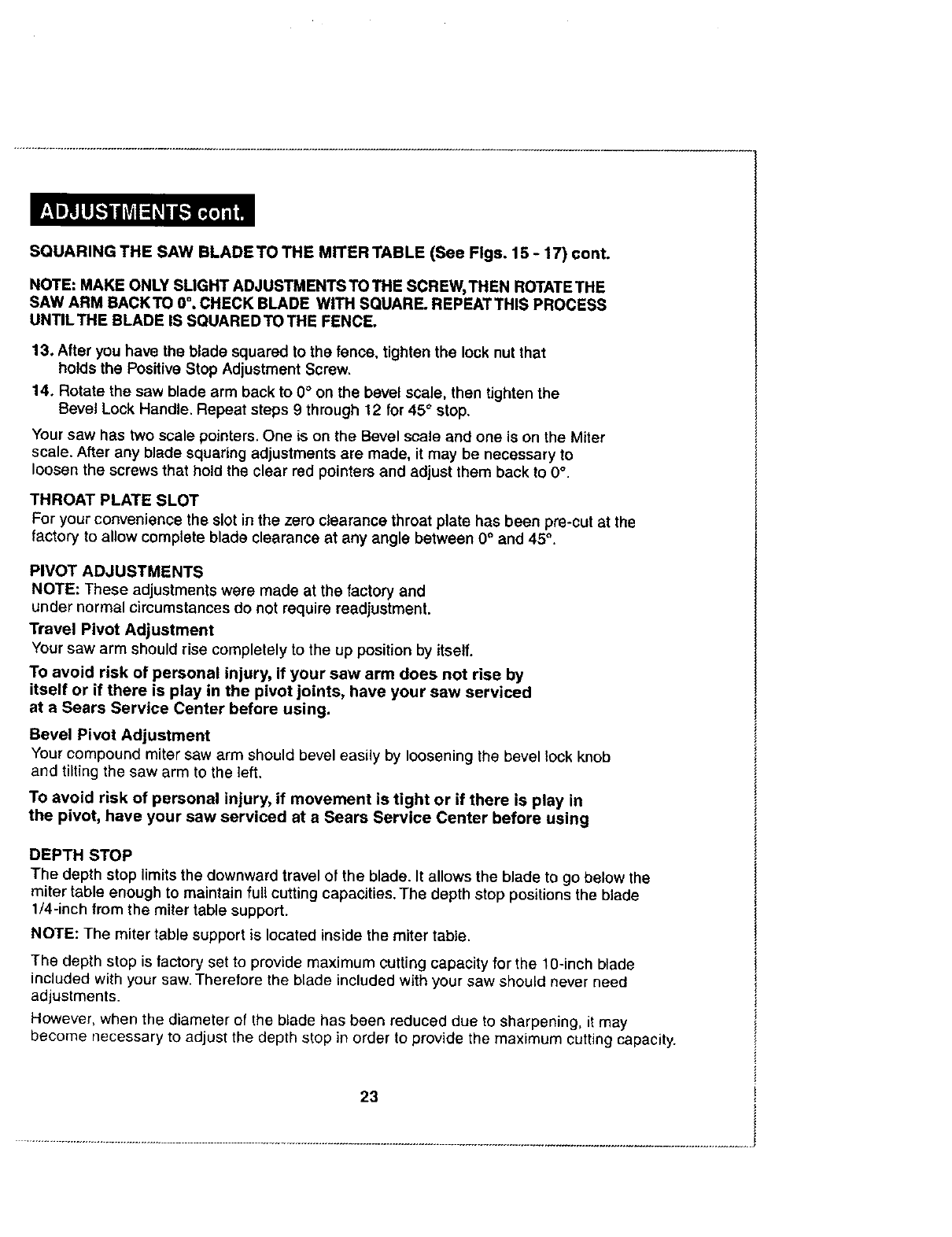
Depth Stop Adjustments (See Figure 18)
1. Unplug the saw.
I Z_WARNING: To prevent personal injury, ALWAYS disconnect the I
I
plug from power source BEFORE assembling parts, making adjustments I
or changing blades.
2. To adjust the depth stop use
hex key (included) to loosen the
hex nut at the rear of the miter
saw arm.
3. Use the hex key (included)
to adjust the depth stop
adjustment screw,
4. To lower the blade, turn
the screw counterclockwise.
5. To raise the blade,
turn the screw clockwise.
6. Lower the blade into the
throat plate of the miter table.
7. Check blade clearance and
maximum cutting distance
(distance from fence where
blade enters) to front of miter
table slot.
8. Readjust if necessary,
I/_WARNING: DO NOT start your compound miter saw without I
I
checking for interference between the blade and the miter table support. I
The blade could be damaged if it strikes the miter table support during
operation of the saw.
9. Tighten the screw with hex key (included).
10. To prevent the depth stop adjustment screw from turning while tightening the
hex nut, carefully hold it with the hex key while tightening the hex nut with a wrench.
24
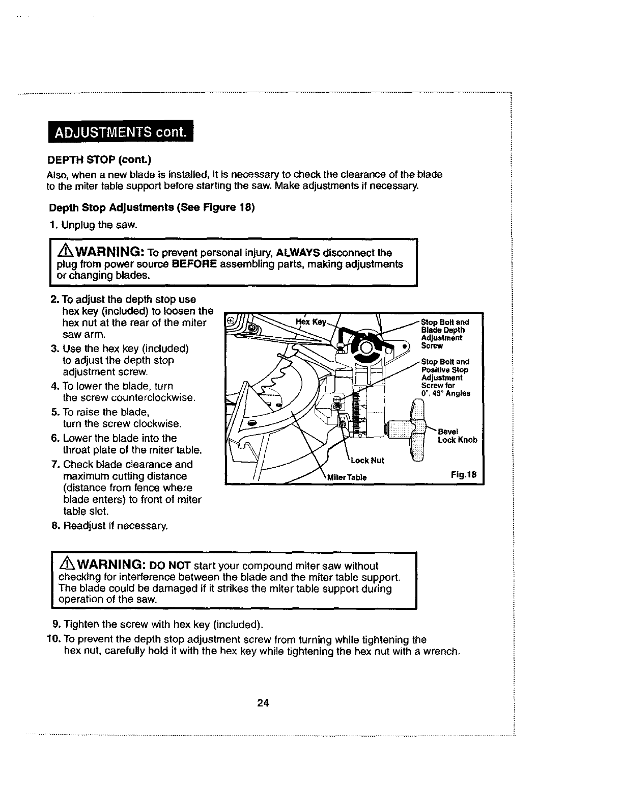
TOREPLACEBLADE(SeeFigs.19-21)
IZ_WARNING: A10-inch blade is the maximum blade capacity of your saw. A larger
than 10-inch blade willcome in contact with the blade guards. Also, NEVER use a blade
that is so thick that it prevents the outer blade washer from engaging with the flat side of
the spindle. Blades that are too large or too thick can result in an accident causing serious
personal injury.
1. Unplug the saw.
I,/_WARNING: To prevent personal injury, ALWAYS disconnect the plug from power
source BEFORE assembling parts, making adjustments or changing blades.
2. Push down on saw arm and
pull out the lock pin to release
saw arm.
3. Raise saw arm to its full raised
position. Be cautious because
saw arm is spring loaded to raise,
4. Loosen the Phillips screw on the
blade bolt cover until blade bolt
cover can be raised
(see Figures 19 and 20).
5. Gently raise the lower blade
guard bracket to release the
lower blade guard from the notch,
This will allow the lower blade
guard and the blade bolt cover
to be rotated up and back to
expose the blade bolt
(see Figures 19 and 20).
6. Rotate the lower blade guard
and the blade bolt cover up and
back to expose the blade bolt
(see Figures 19 and 20).
7. Press the spindle lock button
and rotate the blade bolt until
the spindle locks (see Figure 21).
25
TO REPLACE BLADE (See Figs. 19 - 21) cont.
8. Use the blade wrench (included) to loosen and remove the blade bolt.
Turn the blade bolt clockwise to loosen.
9. Remove the outer blade washer.Then carefully remove old blade.
DO NOT remove the inner blade washer.
10. Wipe a drop of oil onto the inner blade washer and the outer blade
washer where they come in contact with the blade.
IZ_WARN'NG: If the inner blade washer has been removed, replace it BEFORE I
placing blade on the spindle. Failure to do so could cause an accident because the
blade will not tighten properly.
11. Fit the saw blade inside the lower blade guard and onto the inner blade
washer. The blade teeth should point downward at the front of the saw
as shown in Figure 20.
Z_ CAUTION: ALWAYS install the blade with the blade teeth and the arrow I
printed on the side of the blade pointing down at the front of the saw. The direction I
of blade rotation is also stamped with an arrow on the upper blade guard.
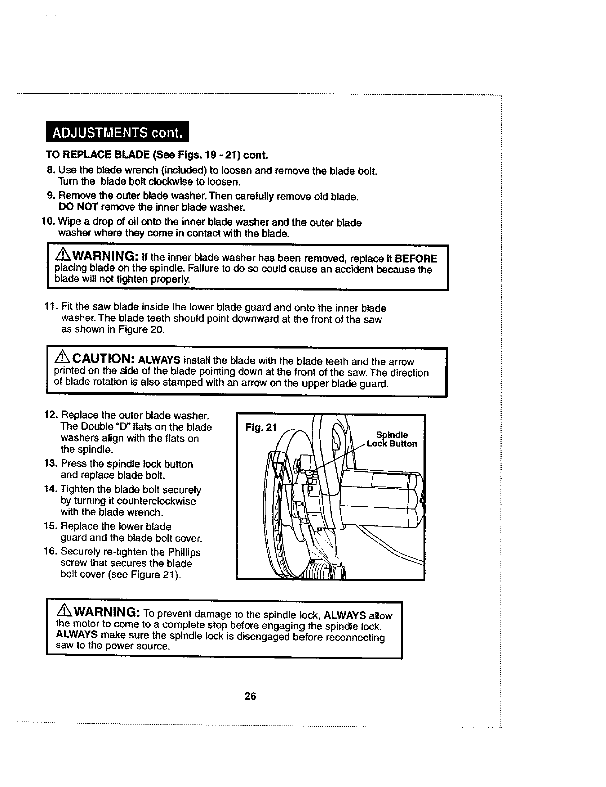
12, Replace the outer blade washer.
The Double "D" flats on the blade
washers align with the flats on
the spindle.
13. Press the spindle lock button
and replace blade bolt.
14. Tighten the blade bolt securely
by turning it counterclockwise
with the blade wrench.
15. Replace the lower blade
guard and the blade bolt cover.
16. Securely re-tighten the Phillips
screw that secures the blade
bolt cover (see Figure 21).
Iz_WARNING: To prevent damage to the spindle lock, ALWAYS allow I
the motor to come to acomplete stop before engaging the spindle lock. I
ALWAYS make sure the spindle lock is disengaged before reconnecting
saw to the power source.
26
TO REPLACE BLADE (See Figs. 19 - 21) cont.
Your compound miter saw has been adjusted at the factory for making very
accurate cuts. However, some of the components may have been jarred out
of alignment during shipping. Also over a period of time, some readjustment
will probably become necessary due to wear. After unpacking your saw, check
the following adjustments BEFORE using your saw. Make any adjustments that
are necessary and periodically checks the parts alignment to be sure that your
saw is cutting accurately.
I _WARNING: Your saw should NEVER be connected to a power I
source when you are assembling parts, making adjustments, installing I
or removing blades, or when not in use. Disconnecting your saw will prevent
accidental starting that could cause serious injury.
NOTE: Many of the drawings in this manual show only portions of your
compound miter saw. This was intentional, so we can clearly illustrate the
points being made. NEVER operate your saw without all the guards securely
in place and in good operating condition.
27
APPLICATIONS
Only use your compound miter saw for the purposes listed below:
•Crosscutting wood and plastic
•Crosscutting miters, joints, etc., for picture frames,
moldings, door casings, and fine joinery
NOTE: The blade included with this saw is ideal for a wide variety of wood
cutting operations. However, for fine joinery cuts or cutting plastic, we
recommend using one of the accessory blades sold separately at your
local Sears Store.
I/KWARNING: BEFORE starting any cutting operation, clamp or bolt I
I
your compound miter saw to a work bench. NEVER operate your miter saw I
on the floor or in a crouched position. Failure to heed this warning could
result in serious personal injury.
CUTTING WITH YOUR COMPOUND MITER SAW
/_WARNING: When using a hold-down clamp or C-clamp to secure the
workpiece, clamp workpiece on one side of the blade only.The workpiece
MUST remain free on one side of the blade to prevent the blade from binding
in the workpiece. The workpiece binding the blade will cause the motor to stall
and cause kickback, resulting in possible serious personal injury.
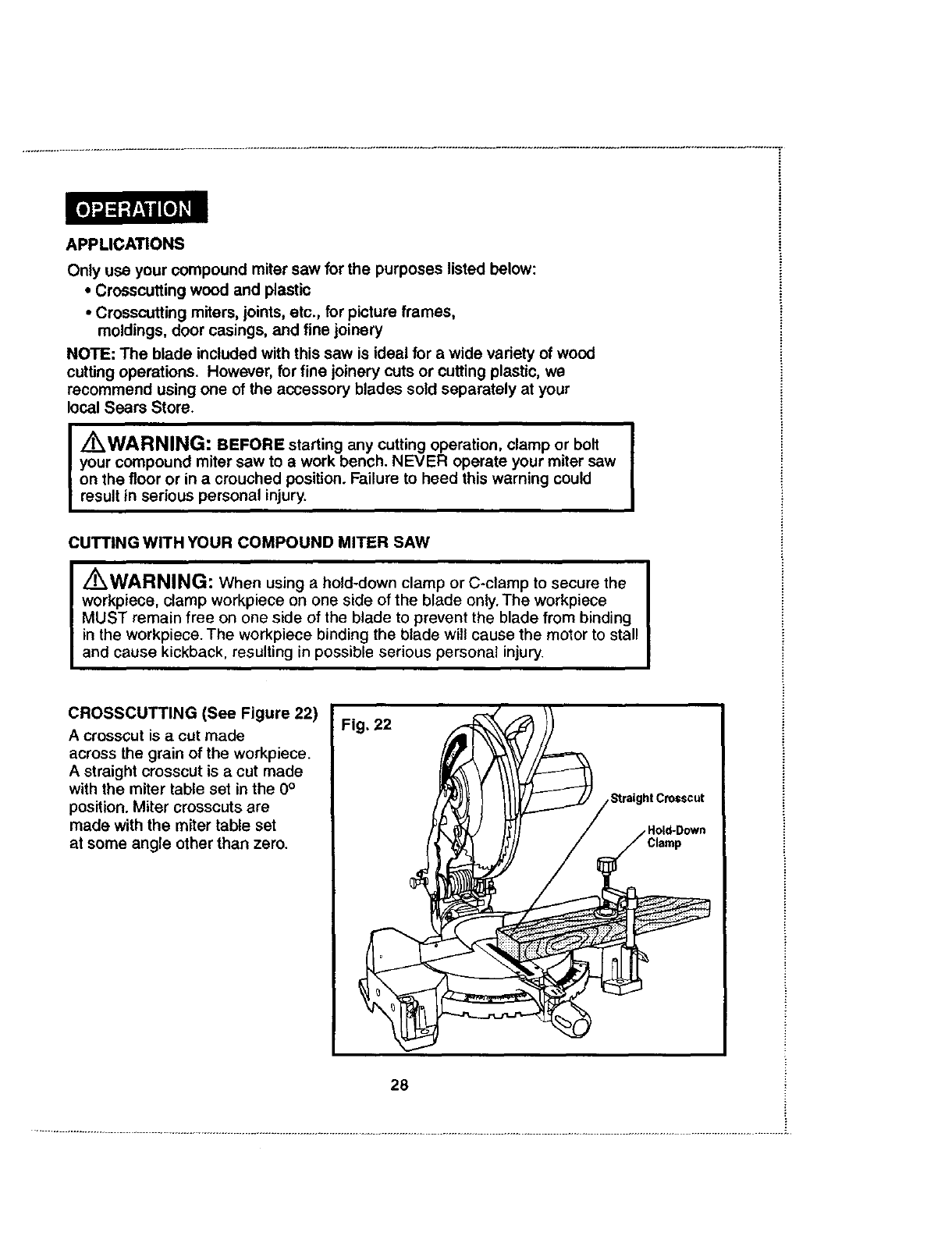
CROSSCUTTING (See Figure 22)
A crosscut is acut made
across the grain of the workpiece.
A straight crosscut is acut made
with the miter table set in the 0°
position. Miter crosscuts are
made with the miter table set
at some angle other than zero.
28
ToCrosscutWithYourMiterSaw
1. Unplugthe saw.
I/K WARNING: To prevent personal injury, ALWAYS disconnect the I
I
plug from power source BEFORE assembling parts, making adjustments I
or changing blades.
2. Pull out the lock pin and lift the saw arm to its full height.
3. Loosen (unscrew) the Miter Lock Handle approximately
one-haft turn,
4. Press miter lock plate down with your thumb and hold.
5. Rotate the control arm until the pointer
aligns with the desired angle on the miter scale.
6. Release the miter lock plate.
NOTE: You can quickly locate 0°, 15°, 221/2°, 30 ° left or right, and 450 left or right by
releasing the lock plate as you rotate the control arm. The lock plate will seat
itself in one of the positive stop notches, located in the miter table frame.
7. Tighten the miter lock handle securely.
J/K WARNING: To avoid serious personal injury, ALWAYS tighten the I
I
miter lock handle securely BEFORE making a cut. Failure to do so could I
result in movement of the control arm or miter table while making a cut.
8. Place workpiece flat on the miter table with one edge securely against the
fence, If the board is warped, place the convex side against the fence.
If the concave edge of the board is against the fence, the board could
collapse on the blade at the end of the cut and jam the blade.
(See Figures 29 and 30 on page 37.)
9. When cutting long pieces of lumber or molding, support the opposite
end of the stock with a roller stand or with another work surface that
is level with the saw table.
10. Align cutting line on the workpiece with the edge on the saw blade.
11. Hold the stock firmly with one hand and secure it against the fence.
Use the hold-down clamp or a C-clamp to secure the workpiece when possible.
(See Figure 26.)
JZ_WARNING: To avoid serious personal injury, ALWAYS keep your hands outside ]
I
the "no hands zone"(red lines); at least 3 inches from blade. Also, NEVER perform any I
cutting operation "freehand" (i.e. without holding workpiece against the fence); the blade
could grab the workpiece, causing it to slip and twist.
29
To Crosscut With Your Miter Saw cont.
12. BEFORE turning on the saw, perform adry run of the cutting operation
just to make sure that no problems will occur when the cut is made.
13. Hold the saw handle firmly, when squeezing the trigger switch.
Allow several seconds for the blade to reach maximum speed.
14. Slowly lower the blade into and through the workpiece, (See Figure 22.)
15. Release the trigger switch and allow the saw blade to stop rotating BEFORE
raising the blade out of the workplece.Wait until the electric brake stops the
blade from turning BEFORE removing the workpiece from the miter table.
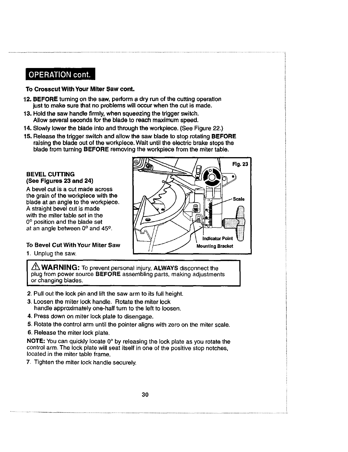
BEVEL CU'I-FING
(See Figures 23 and 24)
A bevel cut is a cut made across
the grain of the workpiece with the
blade at an angle to the workpiece.
A straight bevel cut is made
with the miter table set in the
0° position and the blade set
at an angle between 0° and 45 o.
To Bevel Cut With Your Miter Saw
1. Unplug the saw.
/_ WARNING: To prevent personal injury, ALWAYS disconnect the
plug from power source BEFORE assembling parts, making adjustments
or changing blades.
2. Pull out the lock pin and lift the saw arm to its full height.
3. Loosen the miter lock handle. Rotate the miter lock
handle approximately one-half turn to the left to loosen,
4. Press down on miter lock plate to disengage.
5. Rotate the control arm until the pointer aligns with zero on the miter scale.
6. Release the miter lock plate.
NOTE: You can quickly locate 0°by releasing the lock plate as you rotate the
control arm, The lock plate will seat itself in one of the positive stop notches,
located in the miter table frame.
7. Tighten the miter lock handle securely.
I
3O
To Bevel Cut With Your Miter Saw cont.
I/_WARNING: To avoid serious personal injury, ALWAYS tighten the
miter lock handle securely BEFORE making a cut. Failure to do so could
result in movement of the control arm or miter table while making a cut.
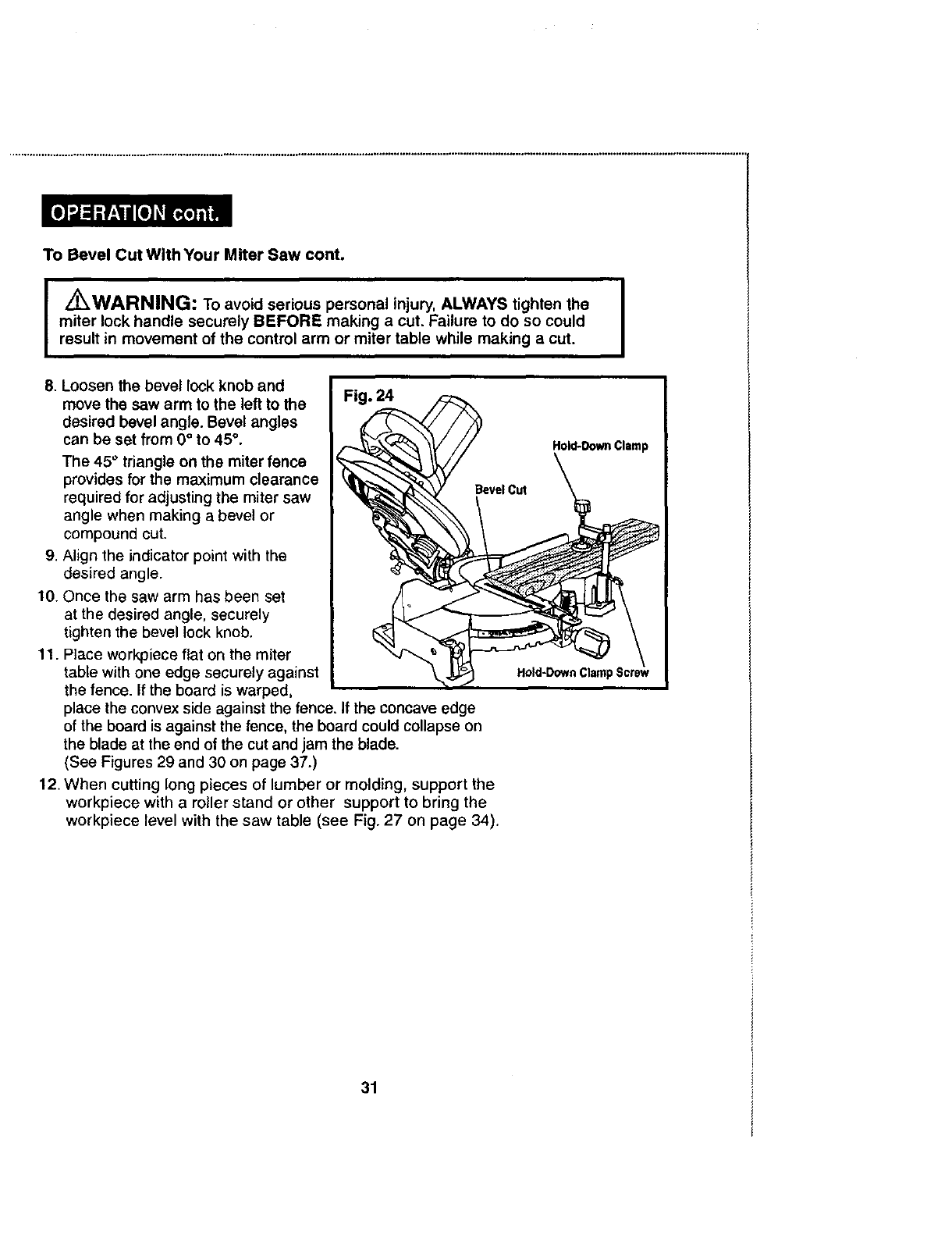
8. Loosen the bevel lock knob and
move the saw arm to the left to the
desired bevel angle. Bevel angles
can be set from 0°to 45 °.
The 45° triangle on the miter fence
provides for the maximum clearance
required for adjusting the miter saw
angle when making a bevel or
compound cut.
9. Align the indicator point with the
desired angle.
10. Once the saw arm has been set
at the desired angle, securely
tighten the bevel lock knob.
11. PEaceworkpiece flat on the miter
table with one edge securely against
the fence. If the board is warped,
place the convex side against the fence. If the concave edge
of the board is against the fence, the board could collapse on
the blade at the end of the cut and jam the blade.
(See Figures 29 and 30 on page 37.)
12. When cutting long pieces of lumber or molding, support the
workpiece with a roller stand or other support to bring the
workpiece level with the saw table (see Fig. 27 on page 34).
31
To Bevel Cut With Your Miter Saw cont.
13. Align cutting line on the workpiece with the edge on the saw blade.
14. Hold the stock firmly with one hand and secure it against the fence.
Use the hold-down clamp or a C-clamp to secure the workpiece when possible.
(See Figure 24.)
I Z_WARNING: To avoid serious personal injury, ALWAYS keep your hands outside I
I
the "no hands zone"(red lines); at least 3 inches from blade. Also, NEVER perform any I
cutting operation "freehand" (i.e. without holding workpiece against the fence); the blade
could grab the workpiece, causing it to slip and twist.
15. MAKE SURE that there will be no obstructions to interfere with making the cut.
16, Hold the saw handle firmly when squeezing the trigger switch.
Allow several seconds for the blade to reach maximum speed.
17. Slowly lower the blade into and through the workpiece. (See Figure 24.)
18. Release the trigger switch and allow the saw blade to stop rotating BEFORE
raising the blade out of the workpiece. Wait until the electric brake stops the
blade from turning BEFORE removing the workpiece from the miter table.
COMPOUND MITER CUTTING
Acompound miter cut is a cut made using a miter angle and a bevel angle
at the same time. This type of cut is used for moldings, picture frames, and
boxes with sloping sides.
To make this type of cut the control arm on the miter table must be rotated
to the correct angle and the saw arm must be tilted to the correct bevel angle,
ALWAYS take special care when making compound
miter setups due to the interaction of the two angle settings.
Adjustments of miter and bevel settings are dependent on one another.
Each time you adjust the miter setting, you change the effect of the bevel
setting. Also, each time you adjust the bevel setting, you change the effect
of the miter setting.
It may take several settings to obtain the desired cut.
The first angle setting should be checked after setting
the second angle, since adjusting the second angle affects the first.
Once the two correct settings for a particular cut have been obtained, ALWAYS
make a test cut in scrap material BEFORE making a finish cut in good material.
32
ToMakea Compound MiterCutWithYour MiterSaw
1.Unplugthesaw.
I _WARNING: To prevent personal injury, ALWAYS disconnect the
plug from power source BEFORE assembling parts, making adjustments
or changing blades.
2. Pull out the lock pin and liftthe saw arm to its full height.
3. Loosen the miter lock handle. Rotate the miter lock
handle approximately one-half turn to the left to loosen.
4. Lift miter lock plate to disengage.
5. Rotate the control arm until the pointer
aligns with the desired angle on the miter scale.
6. Release the miter lock plate.
NOTE: You can quickly locate 0°, 15°, 22_/2°, 30° and 45° left or right by
releasing the miter lock plate as you rotate the control arm. The miter lock plate
will seat itself in one of the positive stop notches, located in the miter table frame.
7. Tighten the miter lock handle securely.
I/_kWARNING: To avoid serious personal injury, ALWAYS tighten the J
miter lock handle securely BEFORE making a cut. Failure to do so could I
result in movement of the control arm or miter table while making a cut.
The 45 ° triangle on the miter fence provides for the maximum
clearance required for adjusting the miter saw angle when
making abevel or compound cut.
8. Loosen the bevel lock knob and move the
saw arm to the left to the desired bevel angle.
Bevel angles can be set from 0° to 45 °.
9. Align the indicator point with the desired angle.
10. Once the saw arm has been set at the
desired angle, securely tighten the bevel lock knob.
11. Bevel angles can be set from 0° to 45 °.
33
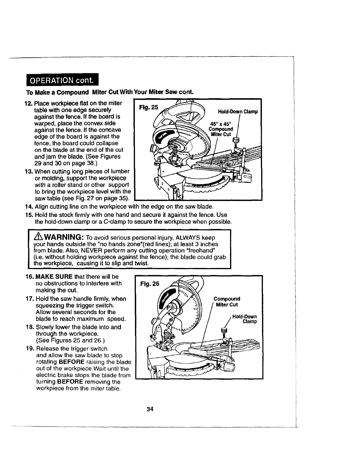
ToMakea Compound MiterCutWithYourMiterSaw cont,
12. Place workpiece fiat on the miter
table with one edge securely Fig. 25
against the fence. If the board is
warped, place the convex side
against the fence. If the concave
edge of the board is against the
fence, the board could collapse
on the blade at the end of the cut
and jam the blade. (See Figures
29 and 30 on page 38.)
13. When cutting long pieces of lumber
or molding, support the workpiece
with a roller stand or other support
to bring the workpiece level with the
saw table (see Fig. 27 on page 35).
14. Align cutting line on the workpiece with the edge on the saw blade.
15. Hold the stock firmly with one hand and secure it against the fence. Use
the hold-down clamp or a C-clamp to secure the workpiece when possible.
Z_WARNING: To avoid serious personal injury, ALWAYS keep
your hands outside the "no hands zone"(red lines); at least 3 inches
from blade. Also, NEVER perform any cutting operation "freehand"
(i.e. without holding workpiece against the fence); the blade could grab
the workpiece, causing it to slip and twist.
16. MAKE SURE that there will be
no obstructions to interfere with
making the cut.
17. Hold the saw handle firmly, when
squeezing the trigger switch.
Allow several seconds for the
blade to reach maximum speed.
18. Slowly lower the blade into and
through the workpiece.
(See Figures 25 and 26.)
19. Release the trigger switch
and allow the saw blade to stop
rotating BEFORE raising the blade
out of the workpiece.Wait until the
electric brake stops the blade from
turning BEFORE removing the
workpiece from the miter table.
34
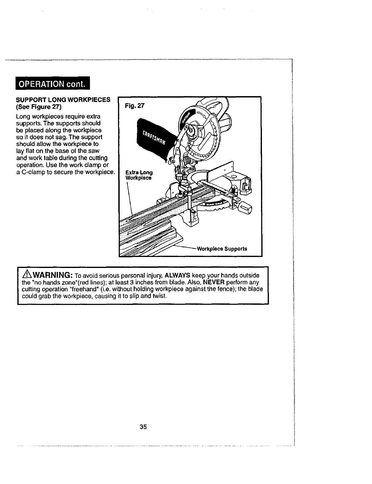
SUPPORTLONGWORKPIECES
(SeeFigure27)
Long workpieces require extra
supports. The supports should
be placed along the workpiece
so it does not sag. The support
should allow the workpiece to
lay flat on the base of the saw
and work table during the cutting
operation. Use the work clamp or
a C-clamp to secure the workpiece.
I _WARNING: To avoid serious personal injury, ALWAYS keep your hands outside
the "no hands zone"(red lines); at least 3 inches from blade. Also, NEVER perform any
cutting operation "freehand" (i.e. without holding workpiece against the fence); the blade
could grab the workpiece, causing it to slip and twist.
35
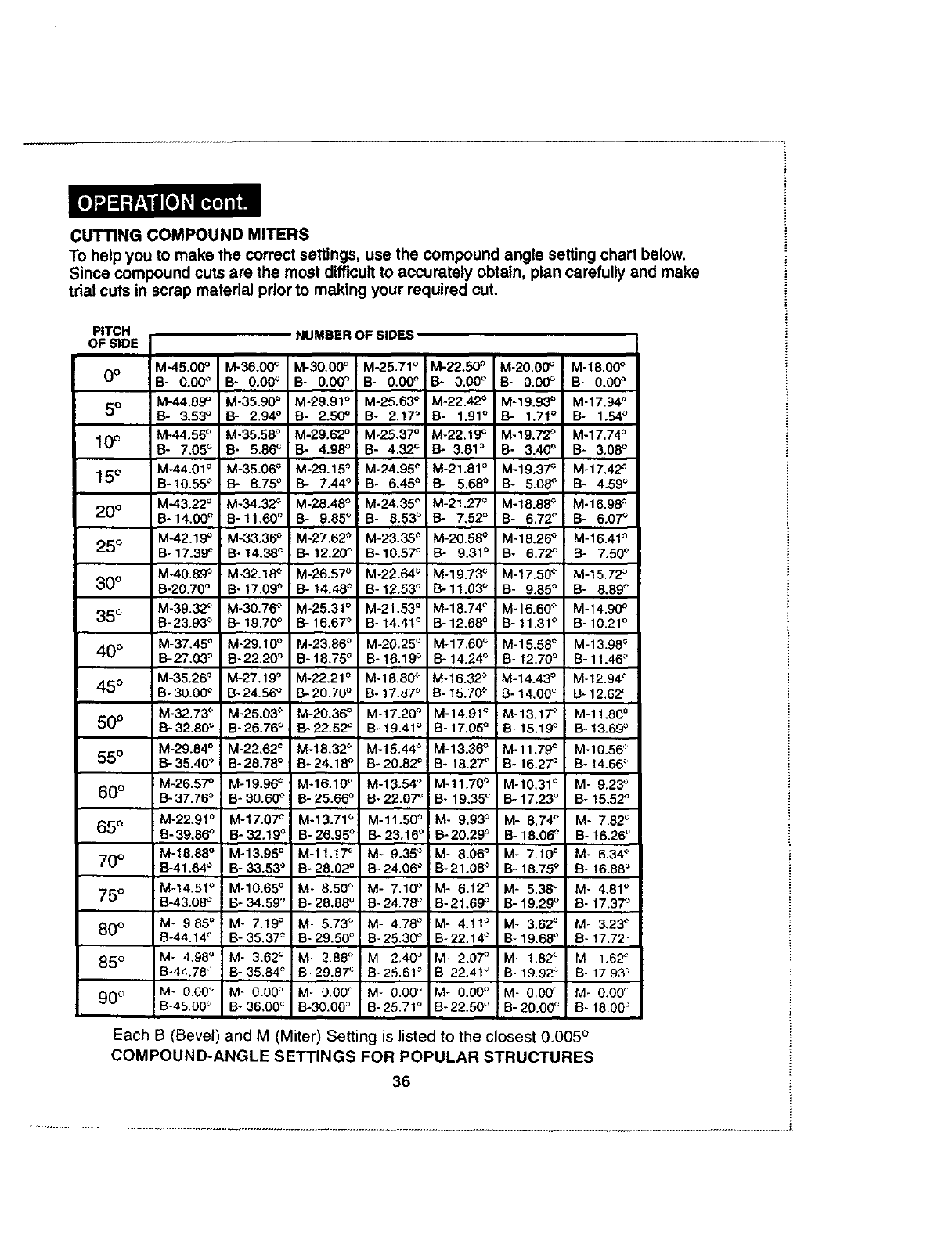
CUTTING COMPOUND MITERS
To help you to make the correct settings, use the compound angle setting chart below.
Since compound cuts are the most difficult to accurately obtain, plan carefully and make
trial cuts in scrap material prior to making your required cut.
PITCH
OF SIDE
0o
5°
10°
15°
20 °
25°
30°
35 °
40 °
45 °
5O°
55 °
6O0
65 °
70 °
75°
80°
85 °
90 °
M-45.00O
B- 0.00 °
M-44.59 _
B- 3.53 _
M-44.56 °
B- 7.05_
M-44.01 °
B- 10.55°
M-43.22 °
B- 14.00_
M-42,19 °
B- 17.39_
M-40.89"
B-20.70 °
M-39.32 °
B- 23.93<'
M-37.48 °
B-27.03 _
M-35.26 _
B- 30.00°
M-32.73<'
B- 32.80 _
M-29.84 °
B- 35.40 '_
M-26.57 °
_. 37.76 °
M-22.91 °
B- 39.86o
M-18.88o
B-41.64°
M-14.51 °
B-43.08_
M- 9.85_
B-44.14°
M- 4.98° :
B-44.78 ,'
M- 0.00"
B-45.00:'
M-36.00_
B- 0.00O
M-35.90 _
13- 2.94 °
M-35.58 °
B- 5.86 _
M-35.06 _
B- 8.75 °
M-34.32 _"
B- 11,60 _
M-33.36 °
B- 14.38c
M.32.18 c'
B" 17,09°
M.30,76 >
B- 19,70°
M-29.10 o
B- 22.20O
M-27.19 °
Bo24.56_
M-25.03 >
B- 26,76_
M-22.62 c
B- 28,78°
M.19.96 c
B- 30.60 _"
M-17.07O
B- 32.19°
M-13.95 c
B- 33.53°
M-10.65 =
B- 34.59"
M- 7.19°
B- 35.37_"
M- 3.62_
B- 35.84°
M- O.O0_'
B- 36.00_
M-30.00 °
B- 0.00"
M-29.91 °
B- 2.50°
M-29.62 o
13- 4.98°
M -29,15"
B- 7.44°
M-28.48 _'
B- 9.55*'
M-27.62"
B- 12.20c"
M-26.57O
B- !4.48 _
M-25.31 °
B- 16.67'_
M-23.86 °
B- 18.75°
M-22.21 _
B- 20.70°
M-20.36 o
13-22.52_
M.18.32 _,
8-24.18 °
M.16.10 '_'
B- 25.66 °
M-13.71 _
B- 26.95"
M-11.1 "T'
B- 28.02u
M- 8.50O
B- 28,58°
M- 5.73"_
B- 29.50°
M- 2.88 _'
B_29.87 _
M- 0.00_
B-30.0O "_
M-25.71 _
B- 0.00°
M-25.63 °
B- 2.17"
M-25.37 °
B- 4.32 _
M-24.95 _
B- 6.45_
M-24,35 °
B- 8.53 _
M-23.38 _
B- 10.5"_
M-22.64 °
B- 12.53_
M-21,53 °
B- 14.41':
M-20.25 _
B- 16.19_
M-18.80 c
B- 17,57°
M-17.20 o
B- 19.41°
M-15.44 °
B- 20.82 _
M-13.54 o
B- 22.07_
M-11.50O
B- 23.160
M- 9.35 °
B- 24.06 °
M- 7,10°
B- 24.78 °
M- 4.78 °
B- 25,30 _
M- 2.40 °
B- 25.61 °
M- O.OO°
B- 25.71 °
M-22.50 ° M-20.00_
13- 0.00° B- 0.00 °
M-22.42 ° M-19.93"_
B- 1.91°B- 1.71°
M-22.19 _ M-19.72"_
B- 3.81 _ B- 3.40 °
M-21.51 °M-19.37 _
B- 5.68 °B- 5.08_
M-21.27 °M-18.55 _
B- 7.52" B- 6.72 °
M-20.58 °M-18.26 _
B- 9.31 a B- 6.72 c
M-19.73 _ M-17.50 (
B-11.00O B- 9.85 °
M-18.74 °M.16.60 c'
B- 12.68° B- 11.31°
M-17.60O i M-15.58 "_
B- 14.24_ ! B- 12.70_
M-16.32 '> M-14.43 °
B-15.70 _" B- 14,00 _
M-14,91 _ M-13.1T"
B- 17,05_B- 15.19°
M-13.36_ M-11.79 _
B- 18.27°B- 16.27°
M-11.70 _ M-10.31 c
i B- 19,35_ B- 17.23°
I M- 9.93_ M- 5.74'
i B-20.29 _ B- 18.06_
M- 8.06 ° M- 7.10 _
B- 21.05 '_ B- 18.75 °
M- 8.12_ M- 5.38_
B- 21.69°B- 19.29°
M- 4.11°M- 3.62_
B-22.14 ° B- 19.65"
M- 2.07° M- 1.82_
B-22.41" B- 19.92"
M- 0.00O M- 0.00 _'
B-22.50 °B- 20.00_'
i
M-18.00 °
B- 0.00O
M-17.94 °
B- 1.54:"_
M-17.74 _
B- 3.08 °
M-17,42 "_
B- 4.59 _
M-16.98 =
B- 6.07 _
M-16.41 _
B- 7.50 °
M-15.72 _
B- 8.89 _
M-14.90 °
B- 10.21 °
M-13.98 _
B- 11.46 °
M-12.94 _
B- 12.62 _
M-11.80 =
B- 13.69"
M-10.56"
B- 14.66 °
M- 9,23 °
B- 15,52 °
M- 7.82 _
B- 16.25 '_
M- 6,34 °
B- 16.88'
M- 4.81 °
B- 17.37 _
M- 3.23 °
B- 17.72 _
M- 1.62 °
B- 17.93 °
M- O.OO_"
B- 15.00 '_
Each B (Bevel) and M (Miter) Setting is listed to the closest 0.005 °
COMPOUND-ANGLE SETTINGS FOR POPULAR STRUCTURES
36
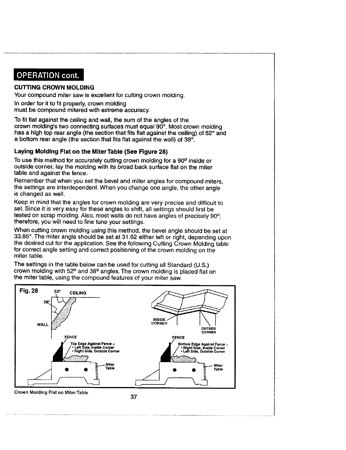
CUTTING CROWN MOLDING
Your compound miter saw is excellent for cutting crown molding.
In order for it to fit propedy, crown molding
must be compound mitered with extreme accuracy.
To fit flat against the ceiling and wall, the sum of the angles of the
crown molding's two connecting surfaces must equal 90 °. Most crown molding
has a high top rear angle (the section that fits flat against the ceiling) of 52° and
abottom rear angle (the section that fits flat against the wall) of 38 °.
Laying Molding Flat on the Miter Table (See Figure 28)
To use this method for accurately cutting crown molding for a 90 ° inside or
outside corner, lay the molding with its broad back surface flat on the miter
table and against the fence.
Remember that when you set the bevel and miter angles for compound miters,
the settings are interdependent. When you change one angle, the other angle
is changed as well.
Keep in mind that the angles for crown molding are very precise and difficult to
set. Since it is very easy for these angles to shift, all settings should first be
tested on scrap molding. Also, most wails do not have angles of precisely 90 ° ,
therefore, you will need to fine tune your settings.
When cutting crown molding using this method, the bevel angle should be set at
33+85°. The miter angle should be set at 31.62 either left or right, depending upon
the desired cut for the application. See the following Cutting Crown Molding table
for correct angle setting and correct positioning of the crown molding on the
miter table.
The settings in the table below can be used for cutting all Standard (U.S.)
crown molding with 52° and 38 °angles. The crown molding is placed flat on
the miter table, using the compound features of your miter saw.
WALL
52° CEILING INSIDE
OUTSIDE
CORNER
_t Side, Outside Comer
• Table
Crown Molding Flat on Miter Table 37
/
Table
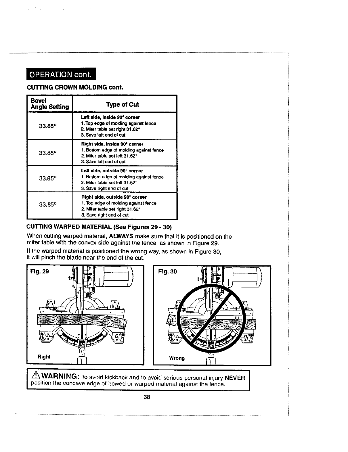
CUTTING CROWN MOLDING cont.
Bevel
Angle Setting Type of Cut
Left side, Inside 90 =corner
1.Top edge ol molding against fence
2. Miter table set right 31.62 _
3. Save left end of cut
33.85 °
Right side, Inside 90 °corner
1. Bottom edge of molding against fence
33'85° 2. Miter table set left 31,62 °
3. Save left end of cut
Left side, outside 90 °corner
33.850 t. Bottom edge of molding against fence
2. Miter table sat left 31.62"
3. Save right end of cut
33.85 °
Right side, outside 90" corner
1. Top edge of molding against fence
2. Miter table set right 31,62 °
3. Save dght end of cut
CUTTING WARPED MATERIAL (See Figures 29 -30)
When cutting warped material, ALWAYS make sure that it is positioned on the
miter table with the convex side against the fence, as shown in Figure 29.
If the warped material is positioned the wrong way, as shown in Figure 30,
it will pinch the blade near the end of the cut.
[Z_WARNING: To avoid kickback and to avoid serious personal injury NEVER
position the concave edge of bowed or warped material against the fence,
38
........................................................................................................................................................................................................................... i
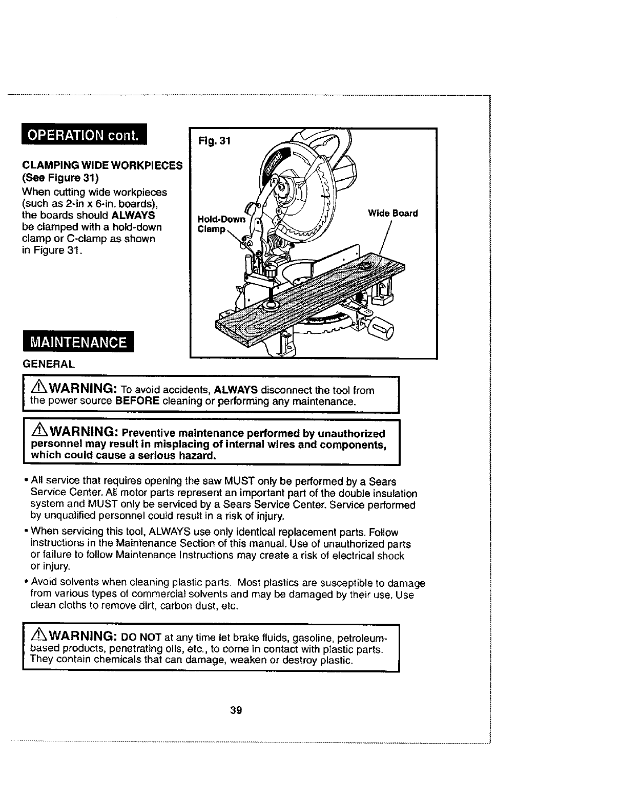
CLAMPING WIDE WORKPIECES
(See Figure 31)
When cutting wide workpieces
(such as 2-in x 6-in. boards),
the boards should ALWAYS
be clamped with a hold-down
clamp or C-clamp as shown
in Figure 31.
GENERAL
I
I
Z_WARNING: To avoid accidents, ALWAYS disconnect the tool from
the power source BEFORE cleaning or performing any maintenance.
/I'_WAHHIHLi: Preventive maintenance performed by unauthorized
personnel may result in misplacing of internal wires and components,
which could cause a serious hazard.
I
I
•All service that requires opening the saw MUST only be performed by a Sears
Service Center. All motor parts represent an important part of the double insulation
system and MUST only be serviced by a Sears Service Center. Service performed
by unqualified personnel could result in a risk of injury.
•When servicing this tool, ALWAYS use only identical replacement parts. Follow
instructions in the Maintenance Section of this manual. Use of unauthorized parts
or failure to follow Maintenance Instructions may create a risk of electrical shock
or injury.
•Avoid solvents when cleaning plastic parts. Most plastics are susceptible to damage
from various types of commercial solvents and may be damaged by their use. Use
clean cloths to remove dirt, carbon dust, etc.
I Z_WARNING: DO NOT at any time let brake fluids, gasoline, petroleum- I
I
based products, penetrating oils, etc., to come in contact with plastic parts. I
They contain chemicals that can damage, weaken or destroy plastic.
39
GENERAL cont.
It is a known fact that electric tools are subject to accelerated wear and possible
premature failure when they are used to work on fiber glass boats and sports
cars, wallboard, spackling compounds or plaster. The chips and grindings from
these materials are highly abrasive to electrical tool parts, such as bearings,
brushes, commutators, etc. Consequently, it is not recommended that this tool
be used for extended work on any fiber glass material, wallboard, spackling
compound, or plaster. During any use on these materials, it is extremely
important that the tool is cleaned frequently by blowing with an air jet.
IZ WARNING: ALWAYS wear safety goggles or safety glasses
with side shields when using this tool or blowing dust. If operation
is dusty, also wear a dust mask.
LUBRICATION
All of the bearings in this tool are lubricated with asufficient amount of
high-grade lubricant for the life of the tool under normal operating conditions.
Therefore, no further lubrication is required.
Sears offers a large selection of blades, table extensions, roller tables,
extension cords and more that are ideal for use with your 10-inch compound
miter saw for a variety of cutting needs.
EXTENSION CORDS
The use of any extension cord will cause some loss of power. To keep the loss
at a minimum and to prevent overheating, use an extension cord that is heavy
enough to carry the current that the tool will draw
Awire gauge (AWG) of at least 14 is recommended for an extension cord 25
feet or less in length. When working outdoors ALWAYS use an extension cord
that is suitable for outdoor use. The cord's jacket will be marked WA.
I_CAUTION: Keep extension cords away from the cutting area,
and position the cord so it will not get caught on lumber, tools, etc.
during the cutting operation.
IKWARNING: Check extension cord before each use. If damaged,
replace it immediately. NEVER use a tool with a damaged cord because
touching the damaged area could cause electrical shock, resulting in
serious injury.
IZ_WARNING: The use of attachments or accessories that are
not recommended might be dangerous.
4O

=.
10-in. Compound Miter Saw Model No. 172.24360
The Model Number will be foundon the Nameplate. Always mention the Model No, in all correspondence regarding your tool.
No. Part No, Description Quantity
1 GB6170-86 Nut M6 1
2 GB77-85 Screw M6X16 1
3 GB70-88 Screw M6X16 3
4 M1S-250B.01-12 Bracing Head 1
5 MIS-250B.01-12 Bracing Block 1
6 M1S-250B,01-08 OrientationPush-Button 1
7 MIS-250B.01-09 Push-Button Jacket 1
8 MIS-250B.01-20 Warning Label 2
9 MIS-250A.03.01.02 Knob 2
10 M1S-250B.04.01 Lock Brace 1
11 M1S-250B.04-02 Clamp 1
12 M1S-250B.04-01 Bracing Piece 1
13 M1S-250A,03.01-03 Cleat 1
14 M1S-250A,03,01-04 Cleat Cushion 1
15 GB848-85 Washer 3
16 GB818-85 Bolt M4X6 2
17 GB627-86 Rivet 4
18 M1S-250C.01-04 Scale Label 1
19 M1S-250C-01 Warning Label 2
20 M1S-250C.01-01 Pressure Board 1
21 M1S-250C.01-07 Connecting Stud t
22 GB955-87 Washer 1
23 GB95-85 Washer 5
24 GB889-86 Nut M8 1
25 M1S-250B.01-16 Knob 4
26 GB845-85 Bolt ST4.2X19-F 1
27 M1S-250B.03-07 Back Cover 1
28 M1S-250B.03-01 Brush Box InnerTube 2
29 M1S-250C.03-01-01 Brush Assembly 2
30 M1S-250B.03-01-0tBrush Box housing 2
31 GB818-85 Bolt M5X40 4
No, Part No. Description Quantity
32 Cable 1
33 GB859-87 Washer -5 3
34 GB848-85 Washer -5 3
35 M1Y-190(200}-02 Cable Holder 1
36 GB845-85 Bolt BT4.2X2.2-F 7
37 Motor Label 1
38 M1S-?.50B.03-01 Cover 1
39 M1Y-160-0_ Cord Holder 1
40 GB845-85 Bolt BT4,2X13-F 2
41 Coolinq Pil3e 2
42 Carbon BrushCard ! 2
43 M1S-250C.03.02 Stator Assembl,/ 1
44 G8818-85 Bolt M5X75 2
45 CB22 Switch 1
46 M1S-250B.03-06 Switch Handle 1
47 M1S-250B.03-03 Air Guard 1
48 M1S-250B,03.05 Handle 1
49 M1$-250B.01-04 Pad 2
50 GB818-85 Bolt M4XlO 2
51 M1S-250B,01-_ Protector 1
52 M1S-250B.01-02 Workbench 1
53 GB818-85 Bolt M5X10 3
54 M1S-250B.01 Slant Pointer 3
55 GB70-88 Bolt M6X20 3
56 GB819-85 Bolt M4XlB 3
57 M1S-250B.01-06 Chuck 1
58 M1S-250B.01.01 Handle 1
59 M1S-250C.01-02 Pointer 1
60 GB859-87 Washer -4 3
61 M1S-250B.01-10 Lock Washer 1
62 GB70-88 Bolt M8X30 1
To order parts call 1-800--4-MY-HOME® (1-800-469-4663)

10-in. Compound Miter Saw Model No. 172.24360
The Model Number will be found on the Nameplate. Always mention the Model No. in all correspondence regarding your tool.
NO.
63
64
65
66
67
68
69
7O
71
72
73
74
75
76
77
78
79
80
81
82
83
84
85
86
87
88
89
90
91
92
93
94
Part No.
M1S-250C.01-63
GB889-86
M1S-250B.02-12
MIS-250B.02-11
M1S-250B.02-09
M1S-250&02-10
M1S-250B.02-13
M1S-250B.02-15
M1S-250B.(_-03
M1S-250B-03
M1S-250B.03-11
GB889-85
M1S-250B.03-10
M1S-250C.02-02
M1S-250B.03-12
M1S-250B.02-08
M1S-250B,02-07
M1S-250B.02-06
MlS-250B,02-16
GB278-82
M1S-250B.02-04
GB70-88
GB859-87
GB848-85
GB96-85
M1X-355E-21
GB3452,1-82
M1S-250B.02.02-01
M1S-2508.02-01
GB73-85
M1S-250B.02.13
Description
PositionerBoard
Nut M5
La,rgeCoverBoard
TorsionSpring
Guard Cover
SmallCover Board
Sheild Cover Bolt
ConnectingRod Bolt
Link
Locking Bolt
BladePressurePlate
Blade250x15,875x2,8
Bolt M5Xl0
Blade Seat
I BladeGuardCover
I,Rubber Check Rin_l
DepthTorsionSDrina
Pivot casing
Pivot
Rivet
695Ballbearin£1-5o13-5
LinkSupport
Bolt M6X12
Washer -6
Washer -6
Washer -6
Lockouthandle
0TypeJointRing-5.6-1.8
Inserted Pin
Support
Bolt M5X14
Pivot Screw
Quantity
1
1
1
1
1
2
2
1
1
1
1
1
1
1
1
1
1
1
I
1
1
1
1
2
2
1
1
1
1
1
1
1
No. Part No. Description !Quantity
95 GB77-85 Bolt M8X12 1
96 M1S-250B.02-17 SupportScale Label 1
97 MtS-250B,02-02 Buffer Stopper 1
98 GB818-85 Bolt M6X16 1
99 Ml$-250B.02-01 AngleLockSpanner 1
100 GB889-86 Nut M8 1
101 GB889-86 Washer -10 1
102 GB95-&5 Washer -12 1
103 GB77-85 Bolt M6X20 1
104 GB_5-87 Washer -12 1
105 GB6560-86 Bolt M4X10 3
106 M1S-250B.03.04-04 Cover Board 1
107 GB1096-79A Flat key 5XSX10 1
108 M1S-250B.03.04-01TransmissionShaft 1
109 GB278-82 80203 BallBearing 1
110 GB894-2-86 Circular -17 1
111 GB6560-86 Bolt M5X12 3
112 M1S-250B.03.04,-03 Gear Box Hatch 1
113 M1S-250B.03.04-02 Large Gear 1
! 14 GB894-2-86 Circular -15 1
115 M1Y-t09(200)-26 Bearing-FZ2175 1
116 M1S-250B.03,05 StopRn 1
117 GB894-2-86 Circular -8 1
118 MlX-355E.02-04 ThumbLatchSpdn_, 1
119 MIS-250B.03-04 GearBox 1
120 GB70.-88 Belt MSx20 4
121 GB278-82 80102BellBea_, 1
122 M1S-2.50C,03.03 RotorAssembly 1
123 GB278-82 80100 BellBssring 1
124 MIS-250B,03-02 BallBearin,qCheckRing, 1
125 M1S-250C-02 DustBe_AdapterPipe 1
126 M1S-250-04-03 SocketWre_ch 1
To order parts call 1-800-4-MY-HOME® (1-800-469-4663)

¢o

H
Your Home
For repair in your home of all major brand appliances,
lawn and garden equipment, or heating and cooling systems,
no matter who made it, no matter who sold it!
For the replacement parts, accessories and
owner's manuals that you need to do-it-yourself.
For Sears professional installation of home appliances
and items like garage door openers and water heaters.
1-800-4-MY-HOME _D Anytime, day or night
(1-800-469-4663) (U,S.A. and Canada)
www.sears,com www.sears.ca
Our Home
For repair of carry-in products like vacuums, lawn equipment,
and electronics, call or go on-line for the nearest
Sears Parts and Repair Center.
1-800-488-1222 Anytime,dayornight(U.S.A.only)
www.sears.com
H
_iiii_i_i!ili!il.............
To purchase a protection agreement (U.S.A.) or maintenance
agreement (Canada) on a product serviced by Sears:
1-800-827-6655 (U.S.A.) 1-800-361-6665 (Ca_fa)
Para pedir servicio de mparacibn
adomicilio, y paraotdenar plezas:
1.888-SU..HOGAR s_
(1-,888-784-6427)
Au Canada pour service en fran(}ais:
1-800-LE-FOYER Mc
(1-8(x_
www._0i_rs.ca
i!iiiii!i_ili
i
iiiililiiiiiii
H
® Registered Trademark /Tradomark /- Service Mark of Sears, Roebuck a_d CO
®Marc_ Registruda /!t_ Mar¢_ de Fboca /s_ Marca de Serv=cio de Sears, Roebuck and Ce.
_._cMarque de cernmerce !M_Marque depos_e de Sears, Roebuck and CO
44
