Craftsman 196223800 User Manual WELDING CART Manuals And Guides L0407661
CRAFTSMAN Welder Manual L0407661 CRAFTSMAN Welder Owner's Manual, CRAFTSMAN Welder installation guides
User Manual: Craftsman 196223800 196223800 CRAFTSMAN WELDING CART - Manuals and Guides View the owners manual for your CRAFTSMAN WELDING CART #196223800. Home:Tool Parts:Craftsman Parts:Craftsman WELDING CART Manual
Open the PDF directly: View PDF ![]() .
.
Page Count: 2
5
1
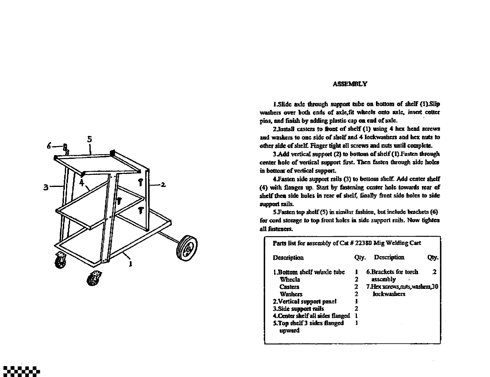
ASSEMBLY
l.Slidc axl= tl_ough suppmt tub© oa bottom of skeJf (l).Slip
washezs over 5o_h ends of axle,i'd v_keels oato axle,, _zse.xt cottur
pint, aed finish by adding plastic cap ea cad of axlc.
2JastaH casters to fsont of s_If(l) ruing 4 hcx head screws
and wardzet'sto mac sidc ofsbelf and 4 iockwashr.rs and Itcx nuts to
mhelr side of shelf. Hngcr tight all screws madnuts until compk'tc.
3.Add wftical sttppoqrt(2) to bottom of shelf (l).Fns_rt.nIhmuglt
ce_te_ hole of_lica! supt0olt fu_. Then fasten through sidc holm
in bottom ofveAical support.
4.Fasrzn side sttl_pozt rails (3) io botlmn _tclf. Add ccatex skcff
(4) with flanges up_ Staxt by fastening crater kolc towards zcar of
skelft_m side holes in rear of shclf, nna]ly _ont side holm to side
suppedrai_
S.Fastcnt_ d_lf(5) in similar f_shioa, b_t includcbs'_€_cts(G)
for €ord s_omgc to top frmtt holes in side ,_Ul_por'ttruth.Now tightcu
all fusZenm.
Parts list for mscmbly of Cat # 22380 Mig Welding Cart
Dmm'iplio4a Qty. Dcscriptimx Qty.
l.Bo_om shelf wlax]e tube I
Whc_la 2
Casters 2
Wagte_ 2
2.Ve_ical stq)podI_mcl i
3.Side suppmS mils 2
4.Ck:ot_ slzelf atl sides fl_gcd !
S.Top shelf 3sides flanged 1
6.Bz_ f_ tmr.h 2
asu_bly
Iod_washcz-s
PART8 LIST
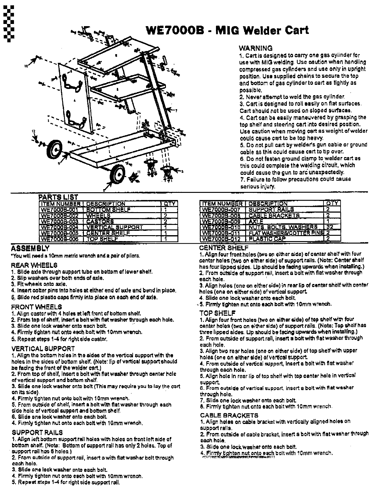
WE7OOOB - MIG Welder Cart
WARNING
1. Cart is designed to -,arty one gas cylinder for
use withMIG welding. Use Mution when handling
compressedgas cylinders anduse only inupright
position. Use suppliedchainsto secure the top
and bottom of gas €ylinderto cart as tightly as
possible.
2. Never attempt to weld the gas cylinder•
3. Cart is designed to roll easily on fiat surfaces,
Cart should not be used on Sloped surfs€as.
4. Cart can ba ea;Jly maneuvered by graspingthe
top shelfand steetLng cart into desired position.
Use caution when m€ving€art as weight of welder
€ouldcauseoarsto be top heavy.
5. DOnot pull cart by welder's gun cable or ground
cable as thlso0uldcause oarsto tip over.
6. Do not fasten ground€lamp towelder cart as
this could completethe welding ¢ii'cuit,which
couldcausethe gun to arc unexpectedly.
7, Failure to follow precautionscouldcause
seriousinjury. imR
ITEM NUM
ASSEMBLY
"Youwill nesda10ramrnettk:wrenchand•psir ofpliers.
REAR WHEELS
1. Slide axisthroughsupporttubeonbottomsf lowershelf,
2. Slipwashersoverbot_endsof exle.
3. Fitwheelsonto ode.
4. In_ertoeiter pinsIntoholesat eitherendofaxle andbend inplace.
_. Slide red plasticcapsfirmlyINtoplace oNeach end of axle,
FRONT WHEELS
1. Nigh cestorwith 4 holtsatla_ frontat bottomshe(f.
2. Fromtopof shelf,insertaboltwithfiat washer_rough each hole.
3. Slide onelockwasherontoeachbelt.
4. Firmlytightennut ontoeachbar with10ramwrench.
5. Repeatsteps1-4fordght sidecaster.
VERTICAL 8UPPORT
1.Alignthe bottom holes]nthe rides of the vertical support withthe
holesin the aidesof bottomshaft.(Nat.",lipofverticalsupportshould
be facingthefrontof the wsld_ cart.)
2. Fromtopofshelf, Inserts boltwl_ fiatwesharthrough center hole
of verticel supportandhoftomshelf.
3, Sllde onelockwasherontobolt(Thismayrequireyouto laythe cart
anit:;side)•
4. Firmlytightennut ontobolt wi_ 10ramwrench.
5, Fromou_de of shelf,insert• boltwith fiatwasherthrough each
sidehole of va_csi supportandbottom,shelf.
6, Slideonelookw_her ontoeachboll
4, Firmlytighten nut onto eachboltwill1 10ramwrench.
SUPPORT RAILS
1. Align lef_ bottomsupport rail flsies with holes on frontiers side of
bottom shelf. (Nat,: Bottom of support rail has only 2 holes. Top af
• support rail h_ 5 holes.)
2. From outside of support rail, insert swish flat washer bolt through
each hole.
3. Slide €Me lockwasher onto each bolt.
4. Firmly tighten nut ontoeach bolt with t0mm wrench.
5. Repeat _=ps 1.-4for rightside supportrail.
CENTER SHELF
1.Alignfourfrontholes (_o oneitherside)Ofoer,ter shelf withfour
center holes(twoon eitherside}ofsupport rails.(Note:Centershelf
hasfourlippedsides, Lipshouldbe facingupwardswheninstalling.)
2, Fromoutsideofsupport rail,insertaboltwithfiat washerthrough
each hole.
3, Align holes(oneoneither'side)inrearli0 ofcanter shelf withcenter
holes(oneoneither side)o_verlJcalsupport.
4, Slideone lockwasherontoeach bolt,
5. Rrmly tightennut ontoe_h bolt with10ramwrench,
TOP SHELF
1.Align four fi'onthates (twooneithsrside)of topshelfwith four
canterholes(,twooneitherside)of supportroils.(Note:Topshelfhas
threelippede_des,Lipshould befacingupwardswheninstalling,)
2. Fromoutsideof supportrail,insert• boilwithfiatwasherthrough
eachhole,
3, Aligntwo rearholes(oneon eitherside)oftopshelf withupper
holes (one on eitherside)ofverticalsupport.
4, Fromoutsideof verticalsupport.Ineerf• _olt withfiat washer
througheeohhole,
5, Allgi"_hole In rearlip oftopshelf withtop canter holeinverb€at
support.
6. Fromcutsl¢leofverticatsupport,insert• boltwith fiat washer
throughhole.
7, Slide one lock washer onto eachbolt,
8, Firmlytighten nutontoe_Chboltwith10ramwrench.
CABLE BRACKETS
1, Alignholes oncable b'acke=withve_caUyalignedholes on
supportrails.
2. Fromouts;deof cablebracket,inserta bolt withfiatwashert_rough
eachhole,
3. Slide onelockwesherontoeachbolt.
4. Firmlytightennut onto eachboltwith 10rnmwrench.
