Craftsman 22252 User Manual ADJUSTABLE UNIVERSAL MOBILE BASE Manuals And Guides L9070038
CRAFTSMAN Tool Base Manual L9070038 CRAFTSMAN Tool Base Owner's Manual, CRAFTSMAN Tool Base installation guides
User Manual: Craftsman 22252 22252 CRAFTSMAN ADJUSTABLE UNIVERSAL MOBILE BASE - Manuals and Guides View the owners manual for your CRAFTSMAN ADJUSTABLE UNIVERSAL MOBILE BASE #22252. Home:Tool Parts:Craftsman Parts:Craftsman ADJUSTABLE UNIVERSAL MOBILE BASE Manual
Open the PDF directly: View PDF ![]() .
.
Page Count: 4

Operators Manual
CRIIFTSMIIN°
Adjustable Universal
MOBILE BASE
Model No. 22252
•Safety
• Assembly
•Operation
•Parts
CAUTION:
Before using this product,
read this manual and follow
all its Safety Rules and
Operating Instructions.
Sears, Roebuck and Co., Hoffman Estates, IL 60179 U.S.A.
Visit our Craftsman website: www.sears.com/craftsman
General Safety Instructions for Power Tools
U_ng powertod_ of any kk_lcan be dangerousif safe opera,rigproceduresare
noflolowed. Recogn_ tbe haza_s _each toc_and usng themwith respect
and cau_xw,_ll co_ imit tbe pcssibailyof pemc,'_ lejury. _, if
_fely p_au_ns am igno_l, personaliniufy_1_ukaly result.Alwaysusecon_
m0nseine - your pemonlesofelyle your _spc_==Jt_ity
I. Knowyour powertobl. Fieadand understandlhe Owners Manual and
_mewarr_gsand_nswcUon_be_sarlXed_otbetcd.
Propedygromd_ tods.
3. Keepgua_slep_ce.
4. Flen!o_eadjus_ngkeysand wrenches.
5. l<eepwod<area c_eanand d_
6. Keepchi_Venaway.
7. Never leave ham;rigmachines,t:_<_unattendnd.
8. Dleconneclto_s from se_qce.
9. Begulady rnainie_ too_s.
10.LBe conact tools lot the job.
11.New'force a tod.
12.v_arsa_yappe_.
13.u_ s_y g_assesOogg_.
15.Rep_cebemaged_ Vnrnnd_ely
16.Ma_ sum yourwch<p_tfc_n L_suff_ sturdyto doIbe
med_cjchatbend.
17. Use po_w_tools _ a we_llitareawttha k_ surfaceonwhichto stand tbetis
dean andfree Imm anyobl_tk_.
18.o_ng*orkpiecesecur_y.
16. Prc_oedya_cho_powertoolsto w_k siends.
20. Use co_ect blade _r job berg done.
21."1111nkSafe. Sa_ofyis a combina_onof operatorawareness,commo_sense
and _r_ess atedl_nes.
Safety Instructions for Mobile Bases
1. Be caretulwben nxMng to Imit a_'_yr*_gerpinchpo_ts.
2- P_e bese w a iove_sv_ace and a_t_ levele_ belo_ p_:=_ the vr_k_e in
p_Ben. TI_ sttouUkeep Ibe _ _m roddng,v,t_e ios_ng _for sblt_.
3. Testfor stabililyin both_e up (on_e castors)and the do,m positions.
_cau_o_,,,A_entosting the sblbahyoft_p heavy mac_nes (ditil
Ixesses, bandsaws, e_c,).
4. Un_ug any powerto_ beforemow_ or _ng your toot
5. A_ tost your setup for sieb_ityand safelya_er mpos_oblng.
Cam chould be taken wbenpbnrmg Ibe odenta_ of tbe machineoofo the
univ_ rno_ bese.Tmn_ of_eiQ_to_ofthe_/elersto_he_ v_l
resultin_e machiee fiBeg 1/2" towardthe tixnd whets. Wben posit_o_ng
top heavy toole suchas a ditgpress or b_mdsaw, take ndvant_ge of tbe o_-
terof gmv6y,=xI positionso thatItwil rem_n _whileoncasters.
7. Ne_e_useyour machinewhileit is suspendedon the two swivelcastem.
N_ys lowertbe _oofo6_e no_ddd k_elers beforeopera_g.
e. _mov,ng,=_,,,,six_-,_ebase,notthemchlee.
Assembly Instructions
Tools required: 7/16", 1i'Z', 9/16_wrench, 7/16" soc_ tape rr_asure, pliers.
1. Unpack and identifyail componentsand hardware. Make sure there are
no m_sing ber_ and t_ them le noShil_oingbernage.
Note: Read instructic_sthoroughlybefore proceeding.
2. Carefully measure tbe footprint of your machlee (or whatover you are
md_l_dng) and add about 1"to tbe dime_. (1" bllows dea_ tor
the fasteners), Keep in mindthe base adjusts in 1"increments.
Note: Most macblnes w_th4-ioggndstandsare sornewbet ndj_cabie, by
Iooseflingand mtightening1heboRsthat holdtbem together.
3. First en._,umthe machine le stable onthe mobliebase, then determtoe
_rect_n of ro=.Carefu_ reviow assemUy _ chown below toheko
you _the fixed wheel, c_sterand ieveler p_ement. As theseam
exampiosonly, you mustdetermine what bestsuits your padleofar
marine's requirementsfor stability.
4. Select and anange tbe Side Rail sizes as necessaryto assembie Ihe
base to your machine's footprint.
Note: If be4pto lilt your macblne intotbe bese le notavailabie, you may
want toassemble tbe base aroundyour machlee. Use 2 x 4's to
blockthe machineup.
5. Bolfthe Side Rai_sto the comers and each other usingthese simple
rules:
A: AIJconnectionsrequire_e use of (2) 1/4"-20 x 1/2" bolts(Q) and
(2) 1/4"-20 nuts (R) at each end of the connections.
B: PositionSide Rails intocomers as far as is practical.
C: It le recommended you keep your machiee stand symmetrical by
using tbe sarne size and posi6oblngof Side Rails on opposite sides.
Note: blsert boltsso thst tbe nutsare on tbe insideof the
movie base.
6. Re-check dimenstons,_en _hten all boitsand nuts.
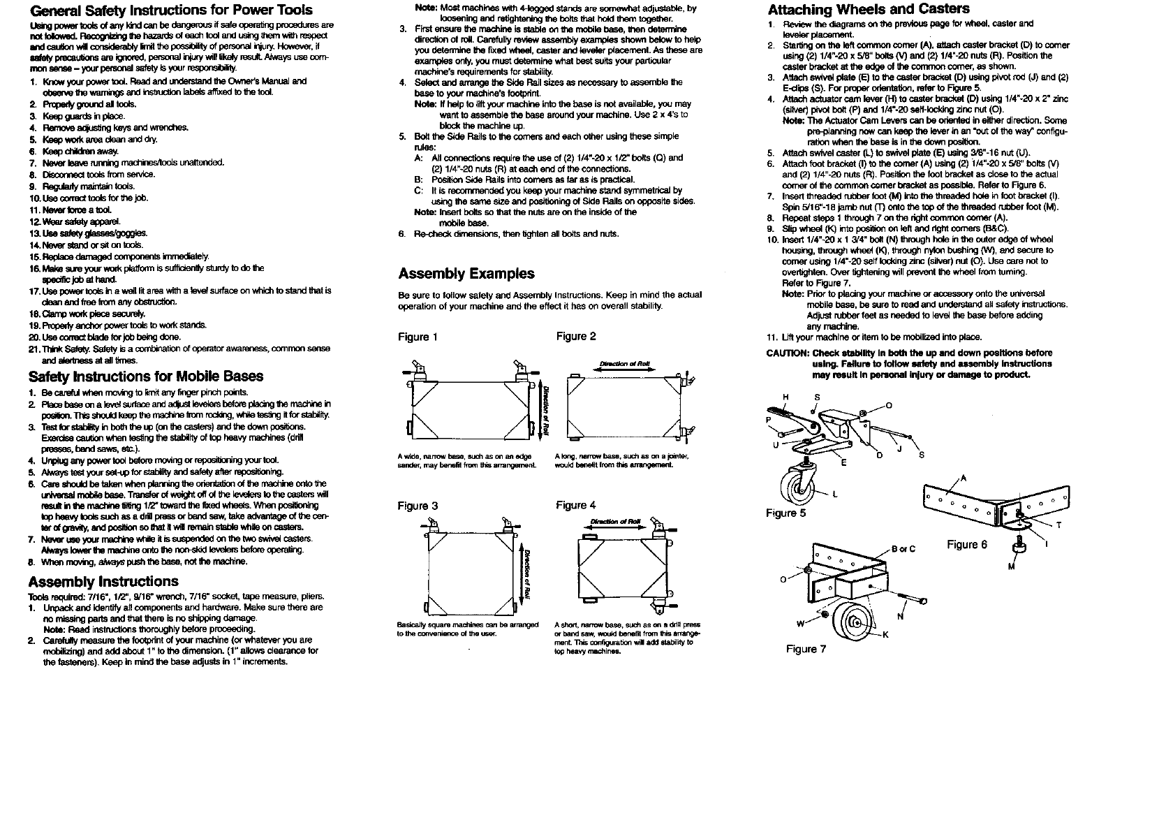
Assembly Examples
Be sure to fof_w safely and Assembly Instructions. Keep in mind the actual
operation of your machine and the effect it has on overall stabilit_
Figure 1 Figure 2
A wide, narrowb_se, suchas on _t edge
sander, may berm_ from th_ amangement. A k:_g,narrow base, such Mc_ a jointer,
wouldbe_e_t thornb_s anarq3,ecnent.
Figure 3
Badcallysquaremaddne_canbe ar_nged
Figure 4
A_'_, nanowbase,suchasona_1, pre_
Attaching Wheels and Casters
1. Review the diagrams o_ the p_ page for wheel, caste_and
ieve_ placement.
2. Star_g on tbe left convnon comer (A), attach caster bracket (D) to comer
using (2) 1/4"-20 x 5/8" bo6s {V) and (2) 114"-20nuts(R). Positionthe
caster bracketat tbe edge of tbe common comer, as shown.
3, Attochsw_v_ p4_te(E) to the caste_bracket (D) using pivotrod (J) and (2)
E-clips (S). Fo_proper obeofation,refer to F_jure 5.
4. Attochack_tor cam lever (H) to casto_brack_ (D) using 1/4"-20 x 2"zinc
(silver) pivotbblt (P) and 1/4"-20 se/f-lodd_j zinc nut(O).
NOto: "l_heActuatorCam Leverscan be odentedin eitherdirection.Sonm
pre-plenblngnow can keep tbe lever in an '_ut of the way_ configu-
ra6onwhen tbe bese is in the downposi0on.
5. Attachswivel caster (L) to swivel prate(E) using 3_8"-16nut (U).
6. Attachfootbrachet(I)tothe¢omer(A)u_ng(2)l/4"-2Ox518"bolbl(V)
and (2) 114"-20nuts (R). Positionthe footbracketas closeto the actual
comer of tbe comrnoncomer brad<et as pos=bio. Refer to Rgure 6.
7. InsertI_readnd mt:t_r foot(M) iofo the threaded hole infoot brackel (I).
Sple 5/16"-18 jamb nut (T) onto the top of the threadedrL_ber foot (M).
8. Repeat steps 1 through7 o_ f_e dght commoncomer (A).
g. S6p wheel (K) into po_i_ onleft and dght comers (B&C).
10. Insert1/4"-20 x t 3/4" bolt (N) through holeinthe outer edge of wheel
housk_, throughwhee_(K), _nylo_bushing(W), and secureto
comer using I/4"-20 self ioddng zinc (silver)nut (O). Use care not to
over_ghten.Ove_ itghte_ing w_llpreventthe wheel Imm toming.
Refer to Rgure 7.
Note: Priorto plating your machine or acces,soryonto the ur_vemal
mobile b_se, be sure to read and understandall sofelyinstructions.
Adjust _feet as needed to iove_the bese before adding
any machine.
11. Liftyour machineor itemto be mobilized intop_ace.
CALI13CN:Check stability In bout the up and down po_itions before
using. Failure to follow safety and assembly Instructions
may mult In personal InJuq/o_rdamage to product.
Figure 5
w_I
Figure
H S
8orC

FULL ONE YEAR WARRANTY
If this Craftsman Mobile Base fails to give complete satisfaction
within one year from the date of purchase, RETURN IT TO (OR
CONTACT) THE NEAREST SEARS SERVICE CENTER IN THE
UNITED STATES, and Sears will repair it, free of charge.
This warranty gives you specific legal rights and you may also have
other rights which vary from state to state.
Sears, Roebuck and Co.,
Dept. 817WA, Hoffman Estates, IL 60179
K
H
I o
S
ForG
M
ACorner
B Corner, Left
C Comer, Right
D Caster Bracket
ESwivel Plate
FSide Rail, 12"
G Side Rail, 18"
H Actuator Cam
I Foot Bracket
J Pivot Rod
K Wheel, 3"
L Swivel Caster
M Rubber Foot
N 1/4"-20 Bolts, Axle 13/4"
O 1/4"-20 Nuts, Self Locking, Zinc (Silver)
P 1/4"-20 Bolts, Pivot 1/4 Zinc (Silver)
Q 1/4" -20 Bolts, 1/2" (Black)
R 1/4"-20 Nuts, Flanged/Serrated
S E-Clips
T 5/16"-18 Nuts
U 3/8"-16 Nuts, Flanged/Serrated
V 1/4"-20 5/8" Bolts (Silver)
W Nylon Wheel Bushing
2751 2
2751L 1
2751R 1
2764 2
2763 2
2748 4
2749 4
2762 2
2765 4
2766 2
G-703 2
G-704 2
G-208 4
D-115 2
D-117 4
D-116 2
D-114 24
D-118 32
D-909 4
C-202 4
C-405 2
D-122 12
A-102 2

For In-home major brand repair service:
Call 24 hours a day, 7 days a week
1-800-4-MY-HOME s"(1-800-469-4663)
Para ped ir servicio de mparaci6n - 1-800-676-5811
For the repair and replacement parts you need:
Call 6 am - 11 pm CST, 7 days a week
PartsDirect
1-800-336-PART (1-800-366-7278)
Para ordenar plezas - 1-800-659-7084
For the location of a
Sears Service Center in your area:
Call 24 hours a day, 7 days a week
1-800-488-1222
To purchase or inquire about a
Sears Maintenance Agreement:
Call 7 a.m.-5 p.m: CST, Monday -Saturday
1-800-488'6655
SEARS
HomeCentral"
