Craftsman 22299 User Manual MITER SAW STAND Manuals And Guides L0309511
CRAFTSMAN Miter Saw Manual L0309511 CRAFTSMAN Miter Saw Owner's Manual, CRAFTSMAN Miter Saw installation guides
User Manual: Craftsman 22299 22299 CRAFTSMAN MITER SAW STAND - Manuals and Guides View the owners manual for your CRAFTSMAN MITER SAW STAND #22299. Home:Tool Parts:Craftsman Parts:Craftsman MITER SAW STAND Manual
Open the PDF directly: View PDF ![]() .
.
Page Count: 8
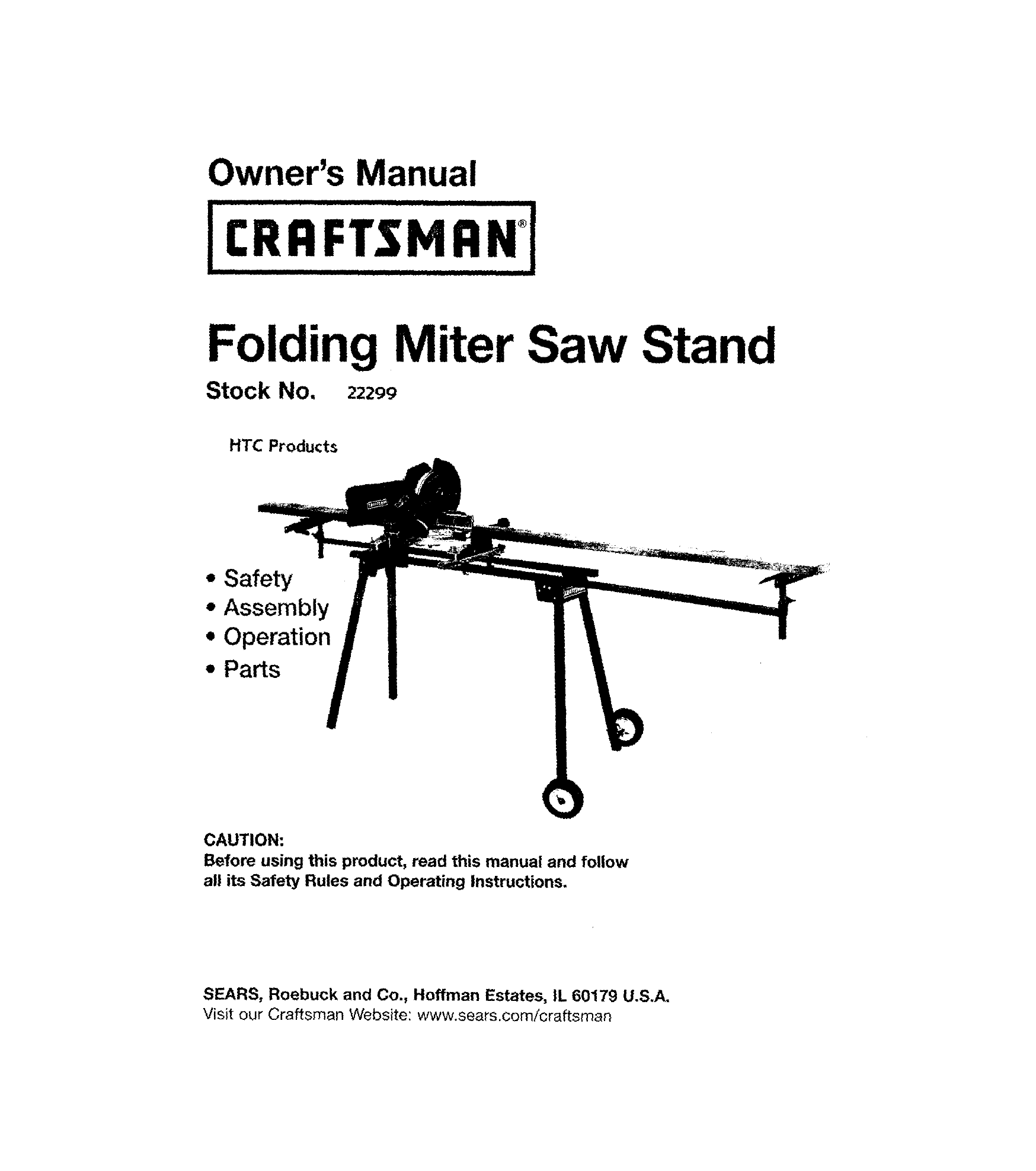
Owner's Manual
[ I
I,CR"FTS"nNI!
Folding Miter Saw Stand
Stock No. 22200
HTC Products
•Safety
•Assembly
•Operation
• Parts
CAUTION:
Before using this product, read this manual and follow
all its Safety Rules and Operating Instructions.
SEARS, Roebuck and Co., Hoffman Estates, IL 60179 U.S.A.
Visit our Craftsman Website: www.sears.com/craftsman
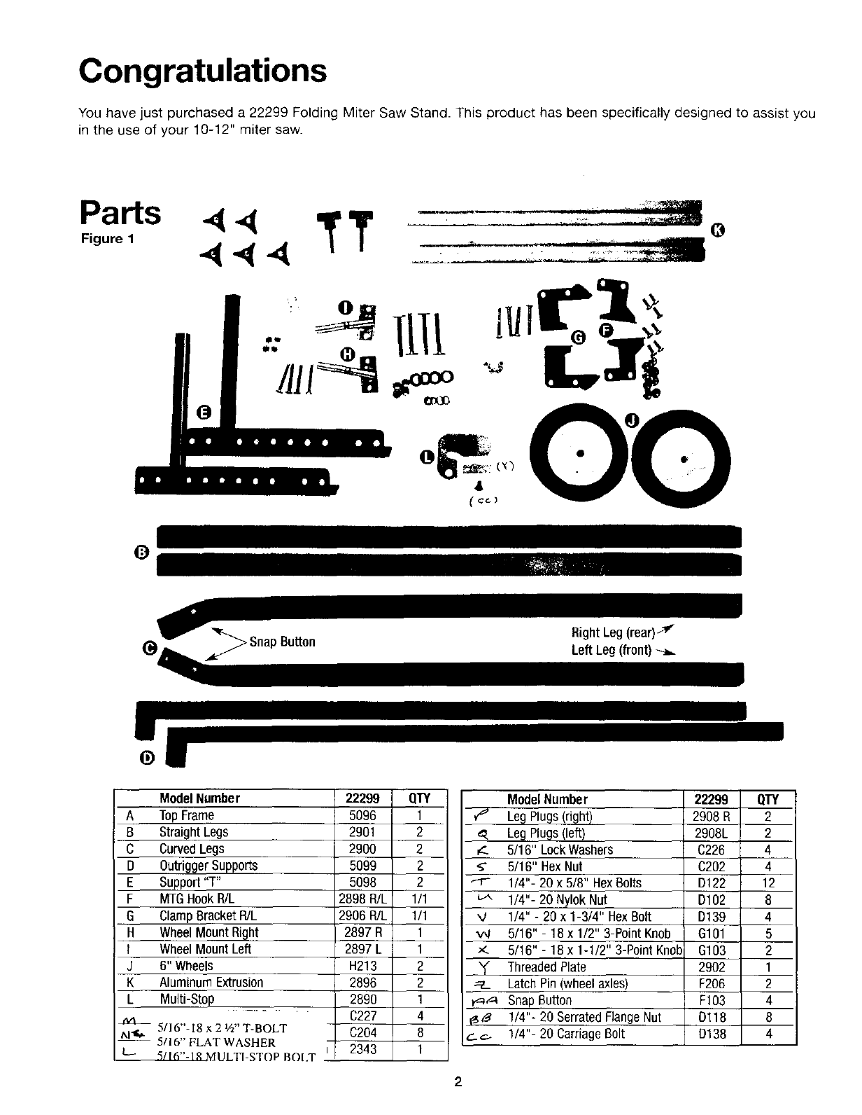
Congratulations
You have just purchased a 22299 Folding Miter Saw Stand. This product has been specifically designed to assist you
in the use of your 10-12" miter saw.
Parts 44 TT
Figure, 4"_ 4
0
0
_Snap Button RightLeg(rear)_
(_ _LeftLeg(front)
ModelNumber
ATopFrame
B StraightLegs
C CurvedLegs
DOutriggerSupports
ESupport"T"
F MTGHookR/L
GClampBracketR/L
H WheelMountRight
I WheelMountLeft
J 6" Wheels
K AluminumExtrusion
L Multi-Stop
5/16"-18 x 2 W' T-BOLT
t,.l"_
-- 5/16" FLAT WASHER
L- 5/16"-18 MULTI-STOP BOI.T
22299 ffl'Y
5096 1
2901 2
2900 2
5099 2
5098 2
2898R/L 1/1
2906R/L 1/1
2897 R 1
2897 L 1
H213 2
2896 2
2890 1
C227 4
C204 8
2343 1
ModelNumber 22299 QTY
¢_" Leg Plugs(right) 2908R 2
_. Leg Plugs(left) 2908L 2
_. 5/16" LockWashers C226 4
_" 5/16" HexNut C202 4
---r- 1/4"- 20 x 5/8" HexBolts D122 12
u... 1/4"- 20 Nylok Nut D102 8
"4 1/4" - 20 x 1-3/4" HexBolt D139 4
",N 5/16" - 18 x 1/2" 3-PointKnob G101 5
5/16" - 18 x 1-1/2" 3-Point Knob G103 2
"!" ThreadedPlate 2902 1
__ LatchPin(wheelaxles) F206 2
#=_,.-4SnapButton F103 4
X_' 1/4"- 20 SerratedFlangeNut Dl18 8
¢_.-_ 1/4"- 20 CarriageBolt D138 4
2
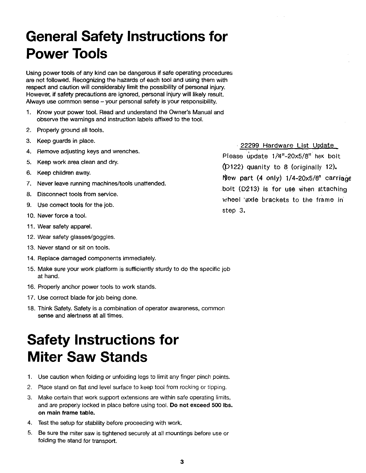
General Safety Instructions for
Power Tools
Using power tools of any kind can be dangerous if safe operating procedures
are not followed. Recognizing the hazards of each tool and using them with
respect and caution will considerably limit the possibility of personal injury.
However, if safety precautions are ignored, personal injury will likely result.
Always use common sense - your personal safety is your responsibility.
1. Know your power tool. Read and understand the Owner's Manual and
observe the warnings and instruction labels affixed to the tool.
2. Properly ground all tools.
3. Keep guards in place.
4. Remove adjusting keys and wrenches.
5. Keep work area clean and dry.
6. Keep children away.
7. Never leave running machines/tools unattended,
8. Disconnect tools from service.
9. Use correct tools for the job.
10. Never force a tool.
22299 Hardware List Update
Please update lt'4"-20x5/8" he× bolt
(_)122) quanity to 8 (originally 12).
I_ew part (4 only) 1/4-20x5/8" carriage
.bolt (D213) is for u$e When attaching
v#heel "e{xle brackets to the frame in
step 3.
11. Wear safety apparel.
12. Wear safety glasses/goggles.
13. Never stand or sit on tools.
14. Replace damaged components immediately.
15. Make sure your work platform is sufficiently sturdy to do the specific job
at hand.
16. Properly anchor power tools to work stands.
17. Use correct blade for job being done.
18. Think Safety. Safety is a combination of operator awareness, common
sense and alertness at all times.
Safety Instructions for
Miter Saw Stands
1. Use caution when folding or unfolding legs to limit any finger pinch points.
2. Place stand on flat and level surface to keep tool from rocking or tipping.
3. Make certain that work support extensions are within safe operating limits,
and are properly locked in place before using tool. De not exceed 500 Ibs.
on main frame table.
4. Test the setup for stability before proceeding with work.
5. Be sure the miter saw is tightened securely at all mountings before use or
folding the stand for transport.
3
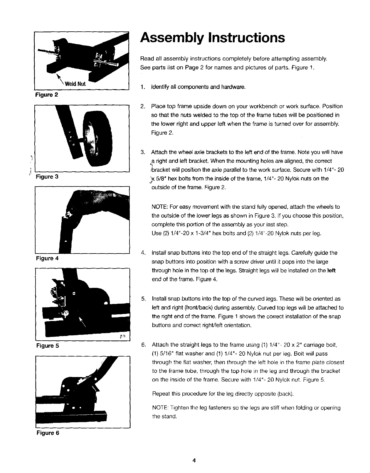
_Weld Nut
Figure 2
Figure 3
Assembly Instructions
Read all assembly instructions completely before attempting assembly.
See parts list on Page 2 for names and pictures of parts. Figure 1.
1. identify all components and hardware.
2. Place top frame upside down on your workbench or work surface. Position
so that the nuts welded to the top of the frame tubes will be positioned in
the lower right and upper left when the frame is turned over for assembly.
Figure 2.
3. Attach the wheel axle brackets to the left end of the frame. Note you will have
a right and left bracket. When the mounting holes are aligned, the correct
_bracket will position the axle parallel to the work surface. Secure with 1/4"- 20
_X5/8" hex bolts from the inside of the frame, 1/4"- 20 Nylok nuts on the
outside of the frame. Figure 2.
NOTE: For easy movement with the stand fully opened, attach the wheers to
the outside of the lower legs as shown in Figure 3. If you choose this position,
complete this portion of the assembly as your last step.
Use (2) 1/4"-20 x 1-3/4" hex bolts and (2) 1/4"-20 Nylok nuts per leg.
Figure 4
Figure 5
Figure 6
4.
,
6_
Install snap buttons intothe top end of the straight legs. Carefully guide the
snap buttons into position with a screw driver until it pops into the large
through hole in the top of the legs. Straight legs will be installedon the left
end of the frame. Figure 4.
Installsnap buttons into the top of the curved legs. These will be oriented as
left and right (front/back) during assembly. Curved top legs will be attached to
the right end of the frame. Figure 1 shows the correct installation of the snap
buttons and correct right/left orientation.
Attach the straight legs to the frame using (1) 1/4"- 20 x 2" carriage bolt,
(1) 5/16" flat washer and (1) 1/4"- 20 Nylok nut per leg. Bolt will pass
through the flat washer, then through the left hole in the frame plate closest
to the frame tube, through the top hole in the leg and through the bracket
on the inside of the frame. Secure with 1/4"- 20 Nylok nut. Figure 5.
Repeat this procedure for the leg directly opposite (back).
NOTE: Tighten the leg fasteners so the legs are stiff when folding or opening
the stand.
4
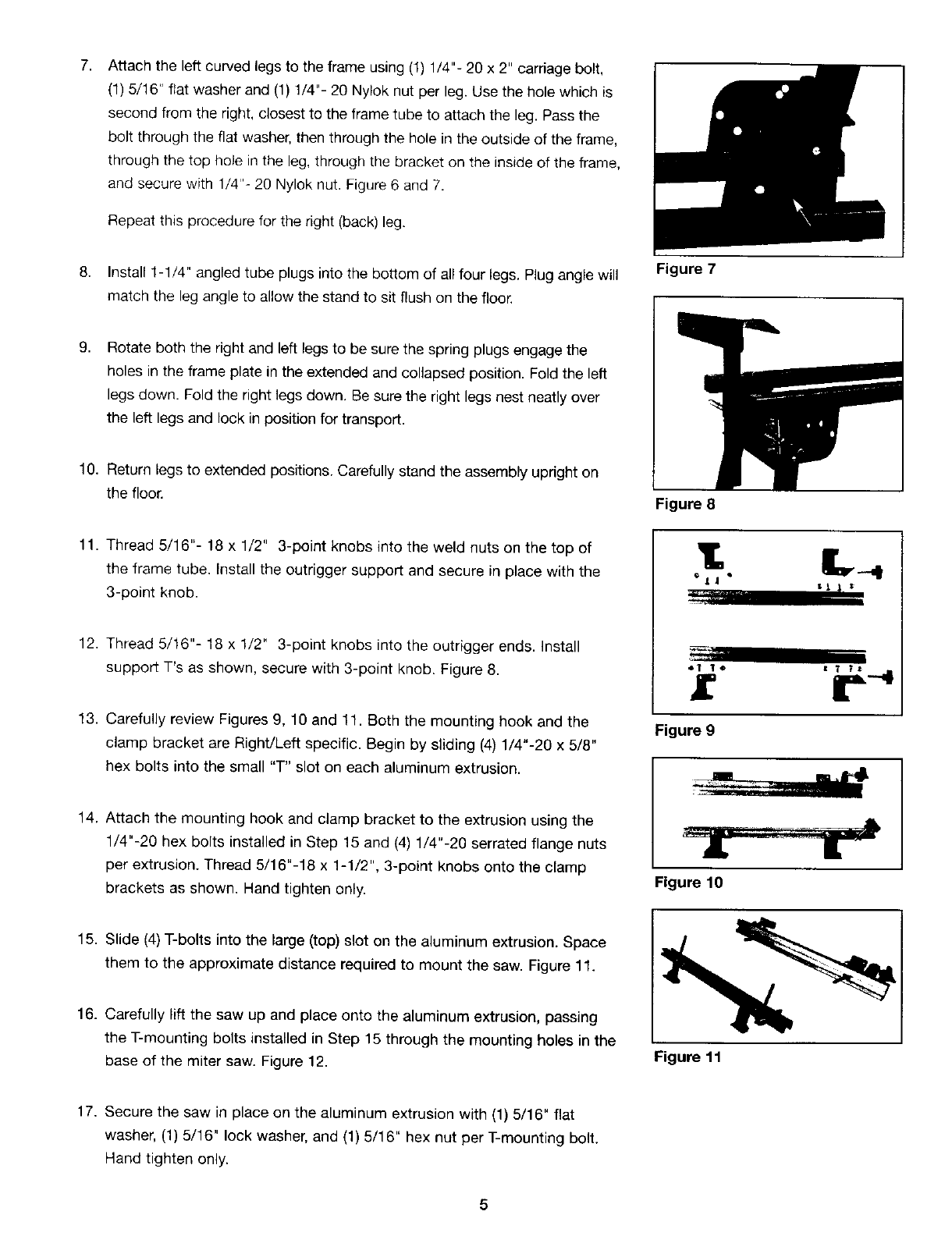
7, Attach the left curved legs to the frame using (1) 1/4"- 20 x 2" carriage bolt,
(1) 5/16" flat washer and (1) 1/4"- 20 Nylok nut per leg. Use the hole which is
second from the right, closest to the frame tube to attach the leg. Pass the
bolt through the flat washer, then through the hole in the outside of the frame,
through the top hole in the leg, through the bracket on the inside of the frame,
and secure with 1/4"- 20 Nylok nut. Figure 6 and 7.
Repeat this procedure for the right (back) leg.
8. Install 1-1/4" angled tube plugs into the bottom of all four legs. Plug angle will
match the leg angle to allow the stand to sit flush on the floor.
Figure 7
9, Rotate both the right and left legs to be sure the spring plugs engage the
holes in the frame plate in the extended and collapsed position. Fold the left
legs down. Fold the right legs down. Be sure the right legs nest neatly over
the left legs and lock in position for transport.
10. Return legs to extended positions. Carefully stand the assembly upright on
the floor. Figure 8
11. Thread 5/16"- 18 x 1/2" 3-point knobs into the weld nuts on the top of
the frame tube. Install the outrigger support and secure in place with the
3-point knob.
12. Thread 5/16"- 18 x 1/2" 3-point knobs into the outrigger ends. Install
support T's as shown, secure with 3-point knob. Figure 8.
13. Carefully review Figures 9, 10 and 11. Both the mounting hook and the
clamp bracket are Right/Left specific. Begin by sliding (4) 1/4"-20 x 5/8"
hex bolts into the small "T" slot on each aluminum extrusion.
14. Attach the mounting hook and clamp bracket to the extrusion using the
1/4"-20 hex bolts installed in Step 15 and (4) 1/4"-20 serrated flange nuts
per extrusion. Thread 5/16"-18 x 1-1/2", 3-point knobs onto the clamp
brackets as shown. Hand tighten only.
15. Slide (4) T-bolts into the large (top) slot on the aluminum extrusion. Space
them to the approximate distance required to mount the saw. Figure 11.
16. Carefully lift the saw up and place onto the aluminum extrusion, passing
the T-mounting bolts installed in Step 15 through the mounting holes in the
base of the miter saw. Figure 12.
1; L
"_'!L 11]
Figure 11
17. Secure the saw in place on the aluminum extrusion with (1) 5/16" flat
washer, (1) 5/16" lock washer, and (1) 5/16" hex nut per T-mounting bolt.
Hand tighten only.
5
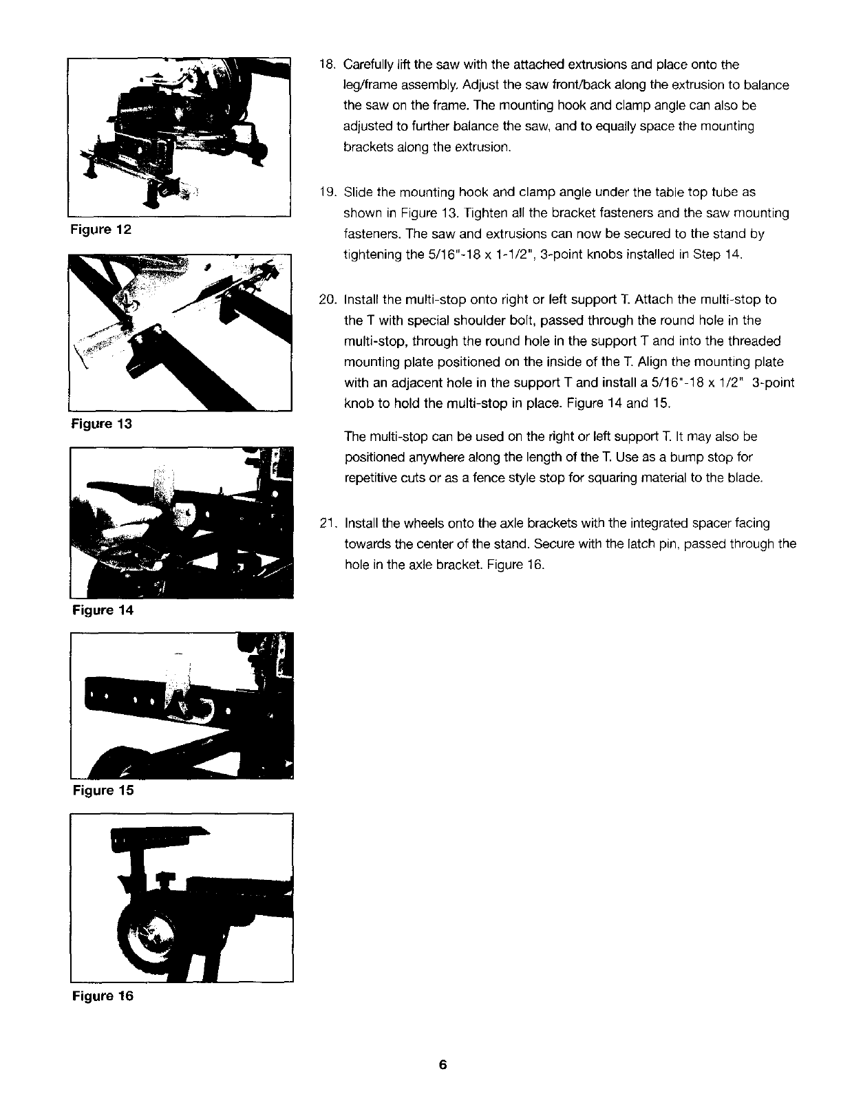
Figure 12
s
f
Figure 13
I
Figure 14
18,
19.
20.
21.
Carefully lift the saw with the attached extrusions and place onto the
leg/frame assembly, Adjust the saw front/back along the extrusion to balance
the saw on the frame. The mounting hook and clamp angle can also be
adjusted to further balance the saw, and to equally space the mounting
brackets along the extrusion.
Slide the mounting hook and clamp angle under the table top tube as
shown in Figure 13. Tighten all the bracket fasteners and the saw mounting
fasteners. The saw and extrusions can now be secured to the stand by
tightening the 5/16"-18 x 1-1/2", 3-point knobs installed in Step 14.
Install the multi-stop onto right or left support T. Attach the multi-stop to
the T with special shoulder bolt, passed through the round hole in the
multi-stop, through the round hole in the support T and into the threaded
mounting plate positioned on the inside of the T. Align the mounting plate
with an adjacent hole in the support T and install a 5/16"-18 x 1/2" 3-point
knob to hold the multi-stop in place. Figure 14 and 15.
The multi-stop can be used on the right or left support T. It may also be
positioned anywhere along the length of the T. Use as a bump stop for
repetitive cuts or as a fence style stop for squaring material to the blade.
Install the wheels onto the axle brackets with the integrated spacer facing
towards the center of the stand. Secure with the latch pin, passed through the
hole in the axle bracket. Figure 16.
Figure 15
Figure 16
6
Set-up /Knockdown
Procedure
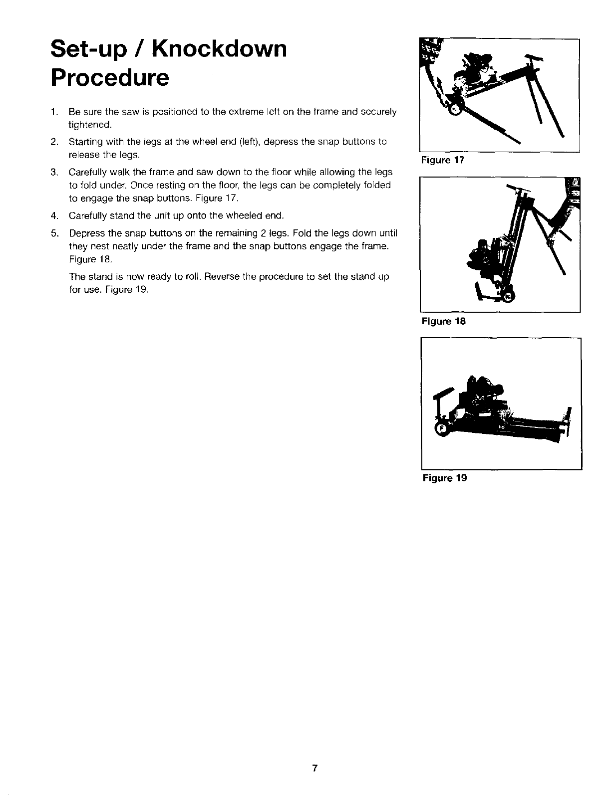
1. Be sure the saw is positioned to the extreme left on the frame and securely
tightened.
2. Starting with the legs at the wheel end (left), depress the snap buttons to
release the legs.
3. Carefully walk the frame and saw down to the floor while allowing the legs
to fold under. Once resting on the floor, the legs can be completely folded
to engage the snap buttons. Figure 17.
Carefully stand the unit up onto the wheeled end.
4,
5. Depress the snap buttons on the remaining 2 legs. Fold the legs down until
they nest neatly under the frame and the snap buttons engage the frame.
Figure 18.
The stand is now ready to roll. Reverse the procedure to set the stand up
for use. Figure 19.
Figure 17
Figure 18
Figure 19
7

Get it fixed, at your home or ours!
Your Home
For repair-in your home-of all major brand appliances,
lawn and garden equipment, or heating and cooling systems,
no matter who made it, no matter who sold it!
For the replacement parts, accessories and
owner's manuals that you need to do-it-yourself.
For Sears professional installation of home appliances
and items like garage door openers and water heaters.
1-800-4-MY-HOME ® (1-800-469-4663)
Call anytime, day or night (U.S.A, and Canada)
www.sears.com www.sears.ca
Our Home
For repair of carry-in items like vacuums, lawn equipment,
and electronics, call or go on-line for the location of your nearest
Sears Parts & Repair Center.
1-800-488-1222
Call anytime, day or night (U.S.A. only)
www.sears.com
To purchase a protection agreement (U.S.A.)
or maintenance agreement (Canada) on a product serviced by Sears:
1-800-827-6655 (U.S.A.) 1-800-361-6665 (Canada
Para pedir servicio de reparacion
a domicilio, y para ordenar piezas:
1-888-SU-HOGAR s_
(1-888-784-6427)
Au Canada pour service en fran£a_s:
1-800-LE-FOYER "c
(1-800-533-6937)
www.sears.ca
® Registered Trademark /TMTrademark /_ Service Mark of Sears, Roebuck and Co.
TM SM
® Marea Registrada /Marca de Fabriea /Marea de Servicio de Sears, Roebuck and Co,
MCMarque de commerce /MDMarque deposee de Sears, Roebuck and Co. © Sears, Roebuck and Co.
