Craftsman 247240193 User Manual TWO BIN BAGGER Manuals And Guides 1303228L
User Manual: Craftsman 247240193 247240193 CRAFTSMAN TWO BIN BAGGER - Manuals and Guides View the owners manual for your CRAFTSMAN TWO BIN BAGGER #247240193. Home:Lawn & Garden Parts:Craftsman Parts:Craftsman TWO BIN BAGGER Manual
Open the PDF directly: View PDF ![]() .
.
Page Count: 32

perator's
I:RnFrSMRN°
TWO BiN BAGGER
Model No. 247.240193
•Espanol, p. 18
iMPORTANT:
Read and follow all Safety
Rules and instructions before
operating this equipment.
For answers to your questions about
this product, call:
1-800=659=5917
CraftsmanTractorHelp Line
7am = 7 pm CT, Mort. =Sun.
Sears Brands Management Corporation, Hoffman Estates, IL 60179 U.S.A.
Visit our website: www.craftsman.com FormNo.769-08766
(February1,2013)

Safe Operation Practices ..........................................................3-4
Slope Guide ......................................................................................5
Contents of Carton & Hardware Packs ................................6-7
Assembly and Installation .....................................................8-14
Operation ........................................................................................15
Parts List .....................................................................................16-17
Espaffol .............................................................................................18
CRAFTSMAN ONE YEAR FULL WARRANTY
FORONEYEARfromthedateof purchase,this productis warrantedagainstanydefectsin materialorworkmanship.Adefectiveproductwill bereplacedfreeof
charge.
Forwarrantycoveragedetailsto obtainfreereplacement,visit thewebsite:www.craftsman.com
Thiswarrantyis voidifthisproductiseverusedwhileprovidingcommercialservicesorif rentedto anotherperson.
Thiswarrantygivesyouspecificlegalrights,andyoumayalsohaveotherrightswhichvaryfromstateto state.
SearsBrandsManagement, Hoffman Estates,IL60179
© SearsBrands,LLC 2
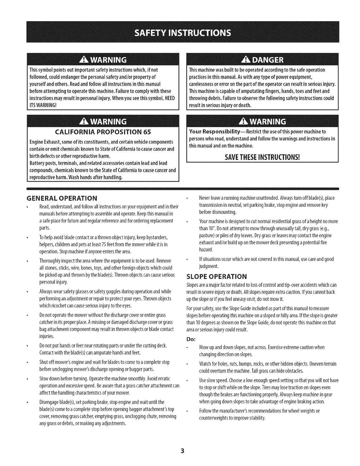
Thissymbolpointsoutimportantsafety instructionswhich,if not
followed, couldendangerthe personalsafetyand/orproperty of
yourselfandothers. Readandfollow all instructionsinthis manual
beforeattempting to operatethis machine.Failureto complywith these
instructionsmayresultinpersonalinjury.Whenyouseethis symbol,HEED
ITSWARNING!
CALiFORNiA PROPOSITION 65
EngineExhaust,someof itsconstituents,andcertainvehiclecomponents
containoremit chemicalsknownto Stateof Californiato causecancerand
birth defectsor other reproductiveharm.
Battery posts,terminals,and relatedaccessoriescontain leadand lead
compounds,chemicalsknownto the Stateof Californiatocausecancerand
reproductiveharm.Washhandsafter handling.
Thismachinewasbuilt to beoperatedaccordingto thesafeoperation
practicesinthis manual.Aswith anytype of powerequipment,
carelessnessorerroronthe partof theoperatorcanresultinseriousinjury.
Thismachineiscapableof amputating fingers, hands,toesandfeet and
throwingdebris.Failureto observethefollowing safety instructionscould
resultinseriousinjuryor death.
Your Responsibility--Restrict theuseof this powermachineto
personswho read,understandandfollow thewarningsand instructionsin
thismanualandonthemachine.
SAVETHESEINSTRUCTIONS!
GENERAL OPERATION
Read,understand,andfollowall instructionsonyourequipmentandintheir
manualsbeforeattemptingto assembleandoperate.Keepthismanualin
asafeplaceforfutureandregularreferenceandfor orderingreplacement
parts.
Tohelpavoidbladecontactora thrownobjectinjury,keepbystanders,
helpers,childrenandpetsat least75feetfromthemowerwhileitisin
operation.Stopmachineifanyoneentersthearea.
Thoroughlyinspecttheareawheretheequipmentisto beused.Remove
allstones,sticks,wire,bones,toys,andotherforeignobjectswhichcould
bepickedupandthrownbytheblade(s).Thrownobjectscancauseserious
personalinjury.
Alwayswearsafetyglassesorsafetygogglesduringoperationandwhile
performinganadjustmentor repairto protectyoureyes.Thrownobjects
whichricochetcancauseseriousinjuryto theeyes.
Donotoperatethemowerwithoutthedischargecoverorentiregrass
catcherinitsproperplace.A missingordamageddischargecoverorgrass
bagattachmentcomponentmayresultinthrownobjectsorbladecontact
injuries.
Donotputhandsorfeetnearrotatingpartsorunderthecuttingdeck.
Contactwith theblade(s)canamputatehandsandfeet.
Shutoff mower'sengineandwait forbladesto cometo acompletestop
beforeuncloggingmower'sdischargeopeningorbaggerparts.
Slowdownbeforeturning.Operatethemachinesmoothly.Avoiderratic
operationandexcessivespeed.Beawarethata grasscatcherattachmentcan
affectthehandlingcharacteristicsofyourmower.
Disengageblade(s),setparkingbrake,stopengineandwaituntil the
blade(s)cometo a completestopbeforeopeningbaggerattachment'stop
cover,removinggrasscatcher,emptyinggrass,uncloggingchute,removing
anygrassordebris,or makinganyadjustments.
Neverleavea runningmachineunattended.Alwaysturnoff blade(s),place
transmissioninneutral,setparkingbrake,stopengineandremovekey
beforedismounting.
Yourmachineisdesignedto cut normalresidentialgrassof aheightno more
than 10".Donotattemptto mowthroughunusuallytall, drygrass(e.g.,
pasture)orpilesofdryleaves.Drygrassorleavesmaycontacttheengine
exhaustand/orbuilduponthemowerdeckpresentinga potentialfire
hazard.
Ifsituationsoccurwhicharenotcoveredinthismanual,usecareandgood
judgment.
SLOPE OPERATION
Slopesarea majorfactorrelatedto lossofcontrolandtip-overaccidentswhichcan
resultinsevereinjuryordeath.Allslopesrequireextracaution.Ifyoucannotback
uptheslopeorifyoufeeluneasyonit,donotmowit.
Foryoursafety,usethe SlopeGuideincludedaspartofthismanualto measure
slopesbeforeoperatingthismachineonaslopedorhilly area.Iftheslopeis greater
than 10degreesasshownontheSlopeGuide,do notoperatethismachineon that
areaorseriousinjurycouldresult.
Do;
Mowupanddownslopes,notacross.Exerciseextremecautionwhen
changingdirectionon slopes.
Watchforholes,ruts,bumps,rocks,orotherhiddenobjects.Uneventerrain
couldoverturnthemachine.Tallgrasscanhideobstacles.
Useslowspeed.Choosealowenoughspeedsettingsothatyouwill nothave
to stoporshift whileontheslope.Tiresmaylosetractiononslopeseven
thoughthe brakesarefunctioningproperly.Alwayskeepmachineingear
whengoingdownslopesto takeadvantageof enginebrakingaction.
Followthemanufacturer'srecommendationsforwheelweightsor
counterweightsto improvestability.
Keepallmovementontheslopesslowandgradual.Donotmakesudden
changesinspeedordirection.Rapidengagementorbrakingcouldcause
thefrontofthemachinetoliftandrapidlyflipoverbackwardswhichcould
causeseriousinjury.
Avoidstartingorstoppingona slope.Iftireslosetraction,disengagethe
blade(s)andproceedslowlystraightdowntheslope.
Do Not:
Donotturnonslopesunlessnecessary;then,turnslowlyandgradually
downhill,ifpossible.
Donotmowneardrop-offs,ditchesorembankments.Themowercould
suddenlyturnoverif awheelisovertheedgeof acliff,ditch,orifanedge
cavesin.
Donottryto stabilizethemachinebyputtingyourfooton theground.
Donotuseagrasscatcheronsteepslopes.
Donotmowonwetgrass.Reducedtractioncouldcausesliding.
GENERAL SERVICE
Beforecleaning,repairing,orinspecting,makecertaintheblade(s)andall
movingpartshavestopped.Disconnectthesparkplugwire andground
againstthe engineto preventunintendedstarting.
Keepallnuts,bolts,andscrewstightto besuretheequipmentisinsafeworking
condition.
Nevertamperwith your mower'ssafetyinterlocksystemorother safetydevices.
Checktheir properoperationregularly.
Neverattempt to makeadjustmentsor repairswhile the mower'sengineisrunning.
Grasscatchercomponentsandthe dischargecoveraresubjectto wearanddamage
which couldexposemovingpartsor allow objectsto bethrown. Forsafety
protection,frequentlycheckcomponentsandreplaceimmediatelywith original
equipmentmanufacturer's(O.E.M.)partsonly,listedinthis manual.Useof parts
which donot meetthe originalequipmentspecificationsmayleadto improper
performanceandcompromisesafety!
Maintainorreplacesafetyandinstructionlabels,asnecessary.
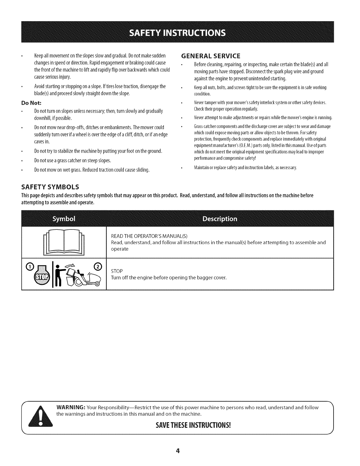
SAFETY SYMBOLS
Thispagedepictsanddescribessafetysymbolsthat mayappearonthis product. Read,understand,andfollow all instructionsonthe machinebefore
attempting to assembleand operate.
%
READ THE OPERATOR'S MANUAL(S)
Read, understand, and follow all instructions in the manual(s) before attempting to assemble and
operate
STOP
Turn off the engine before opening the bagger cover.
WARNING: Your Responsibility--Restrict the use of this power machine to persons who read, understand and follow
the warnings and instructions in this manual and on the machine.
SAVETHESEINSTRUCTIONS!
4
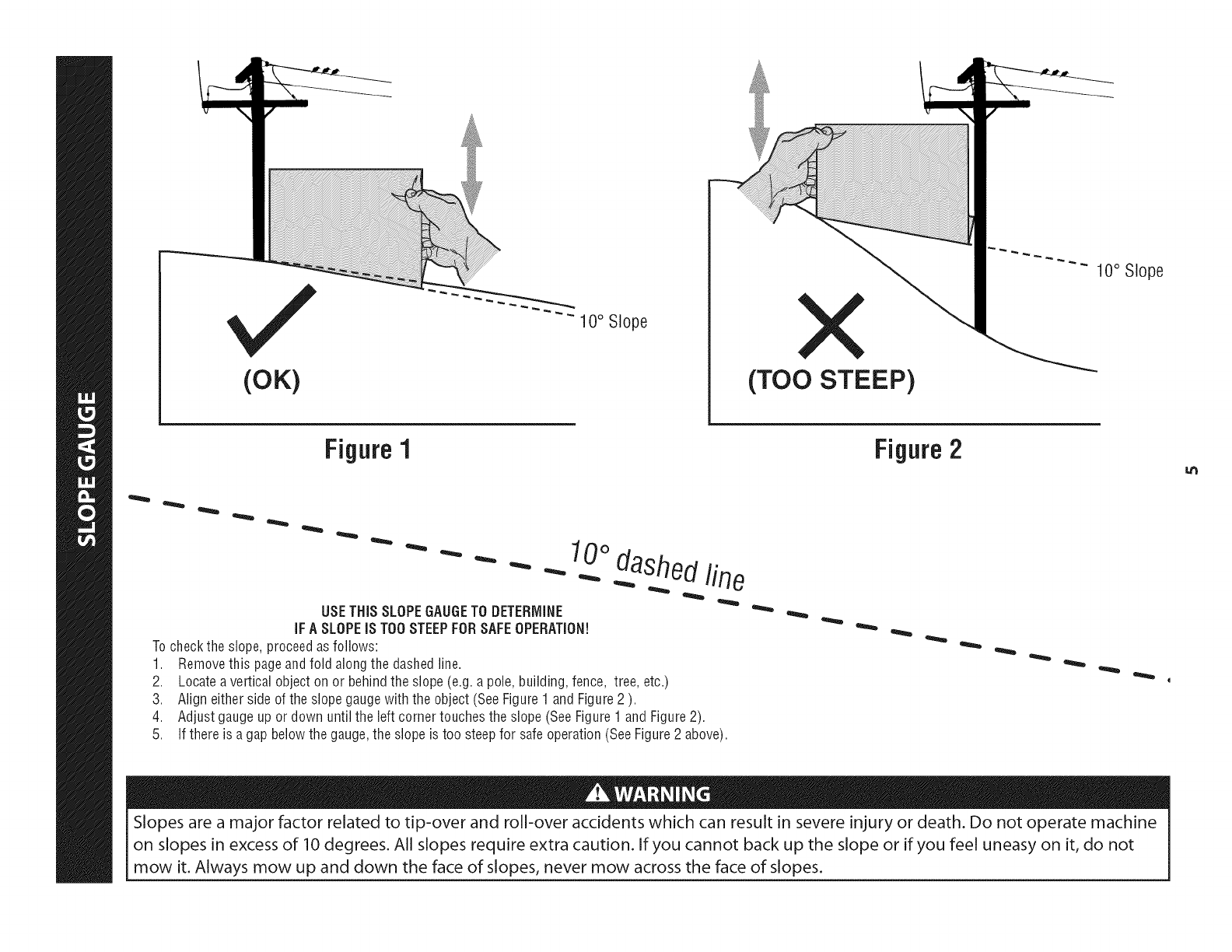
(OK)
10° Slope
(TOO STEEP)
10° Slope
Figure 1
USETHiSSLOPEGAUGETO DETERMINE
iFA SLOPEiS TOOSTEEPFORSAFEOPERATION!
Tocheckthe slope,proceedas follows:
1. Removethis pageandfold alongthe dashedline.
2. Locateavertical objectonor behindthe slope(e.g.a pole,building,fence, tree,etc.)
3. Aligneither sideof the slopegaugewiththe object(SeeFigure1 andFigure2 ).
4. Adjustgaugeup or down until the left cornertouchesthe slope(SeeFigure1 andFigure2).
5.
10odashedline
If there is a gapbelowthe gauge,the slope is too steepfor safeoperation(SeeFigure2 above).
Figure2
Slopes are a major factor related to tip-over and roll-over accidents which can result in severe injury or death. Do not operate machine
on slopes in excess of 10 degrees. All slopes require extra caution. If you cannot back up the slope or if you feel uneasy on it, do not
mow it. Always mow up and down the face of slopes, never mow across the face of slopes.
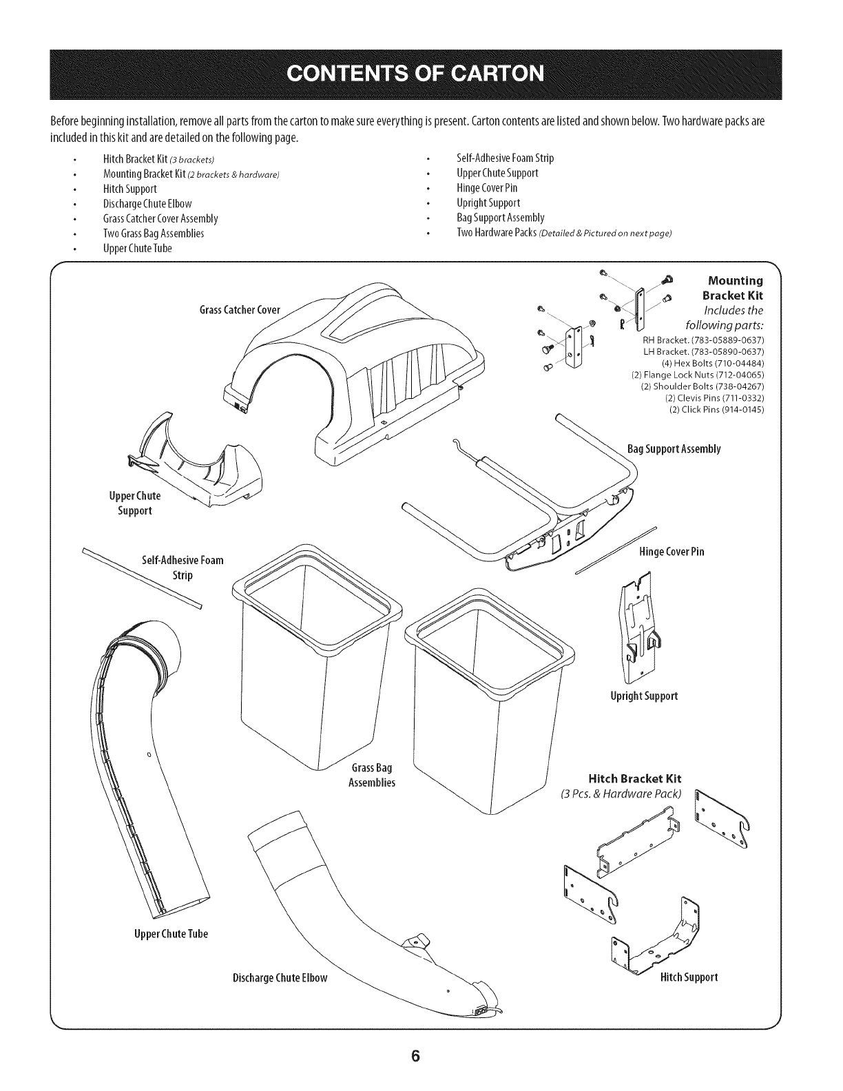
Beforebeginninginstallation,removeallpartsfromthecartonto makesureeverythingis present.Cartoncontentsarelistedandshownbelow.Twohardwarepacksare
includedinthiskit andaredetailedonthefollowingpage.
HitchBracketKit(3brackets)
MountingBracketKit(2brackets & hardware)
HitchSupport
DischargeChuteElbow
GrassCatcherCoverAssembly
TwoGrassBagAssemblies
UpperChuteTube
Self-AdhesiveFoamStrip
UpperChuteSupport
HingeCoverPin
UprightSupport
BagSupportAssembly
TwoHardwarePacks(Detailed & Pictured on next page)
GrassCatcherCover
UpperChute
Support
%_If-Adhesive Foam
_"_ \ ._ Mounting
/,,,"I'_ _ _ Bracket Kit
_'_ IJI/ Includes the
\\\_z_ ['_ following parts:
/__ RH Bracket. (783-05889-0637)
LH Bracket. (783-05890-0637)
_p- _ (4) Hex Bolts (710-04484)
(2) Flange Lock Nuts (712-04065)
(2) Shoulder Bolts (738-04267)
(2) Clevis Pins (711-0332)
(2) Click Pins (914-0145)
gSupportAssembly
_ge CoverPin
UprightSupport
UpperChuteTube
GrassBag
Assemblies Hitch Bracket Kit
(3 Pcs.& Hardware Pack)
DischargeChuteElbow Hitch Support
6
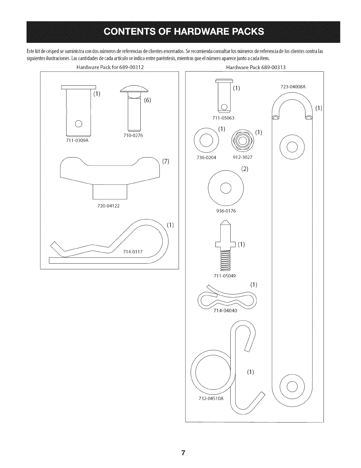
Estekitdec#spedsesuministracondosnumerosdereferendasdeclientesencerrados.5erecomiendaconsuitarlosnumerosdereferenciadelosclientescontralas
siguientesilustraciones.Lascantidadesdecadaartkuloseindicaentrepar#ntesis,mientrasqueel ntimeroaparecejuntoacadaitem.
Hardware Packfor 689-00312 Hardware Pack689-00313
I
©
711-0309A
I
(1)
)
710-0276
__ ._ (7)
720-04122
714-0117
1)
(1)723-04008/__.
711-05063
(1)
736-0204 912-3027
936-0176
711-05049
714-04040
732-04510A
(1)
(1)
7
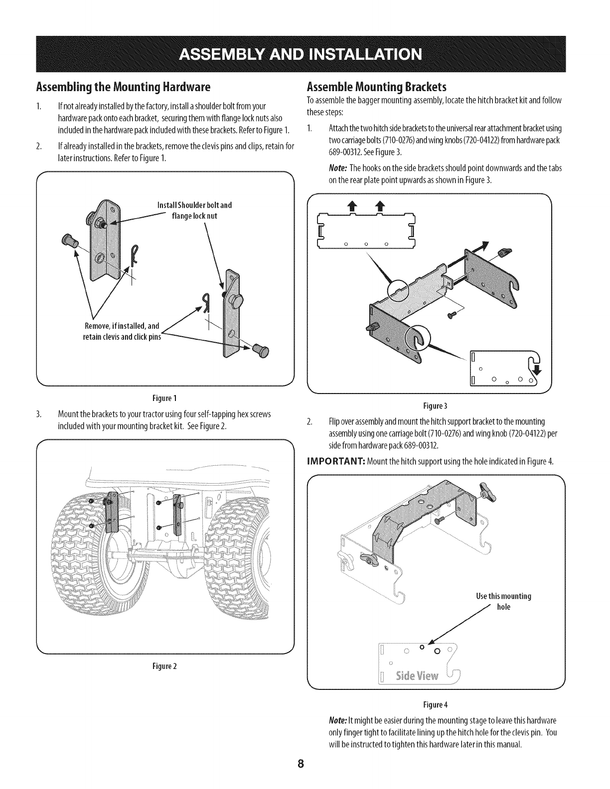
Assemblingthe Mounting Hardware
1. If notalreadyinstalledbythefactory,installashoulderboltfromyour
hardwarepackontoeachbracket,securingthemwith flangelocknutsalso
includedinthehardwarepackincludedwiththesebrackets.Referto Figure1.
2. If alreadyinstalledinthebrackets,removetheclevispinsandclips,retainfor
laterinstructions.Referto Figure1.
Figure1
3. Mountthebracketsto yourtractorusingfourself-tappinghexscrews
includedwith yourmountingbracketkit. SeeFigure2.
f
Figure2
AssembleMountingBrackets
Toassemblethebaggermountingassembly,locatethehitchbracketkitandfollow
thesesteps:
1. Attachthetwohitchsidebracketstotheuniversalrearattachmentbracketusing
twocarriagebolts(710-0276)andwingknobs(720-04122)fromhardwarepack
689-00312.SeeFigure3.
Note: Thehookson thesidebracketsshouldpointdownwardsandthetabs
ontherearplatepointupwardsasshownin Figure3.
Io
0 o 0
J
Figure3
2. Flipoverassemblyandmountthe hitchsupportbracketto themounting
assemblyusingonecarriagebolt(710-0276)andwingknob(720-04122)per
sidefromhardwarepack689-00312.
IMPORTANT: MountthehitchsupportusingtheholeindicatedinFigure4.
Usethismounting
hole
Figure4
Note:It mightbeeasierduringthemountingstageto leavethishardware
onlyfingertight to facilitatelining upthehitchholefortheclevispin. You
winbeinstructedto tightenthishardwarelaterin thismanual.
8
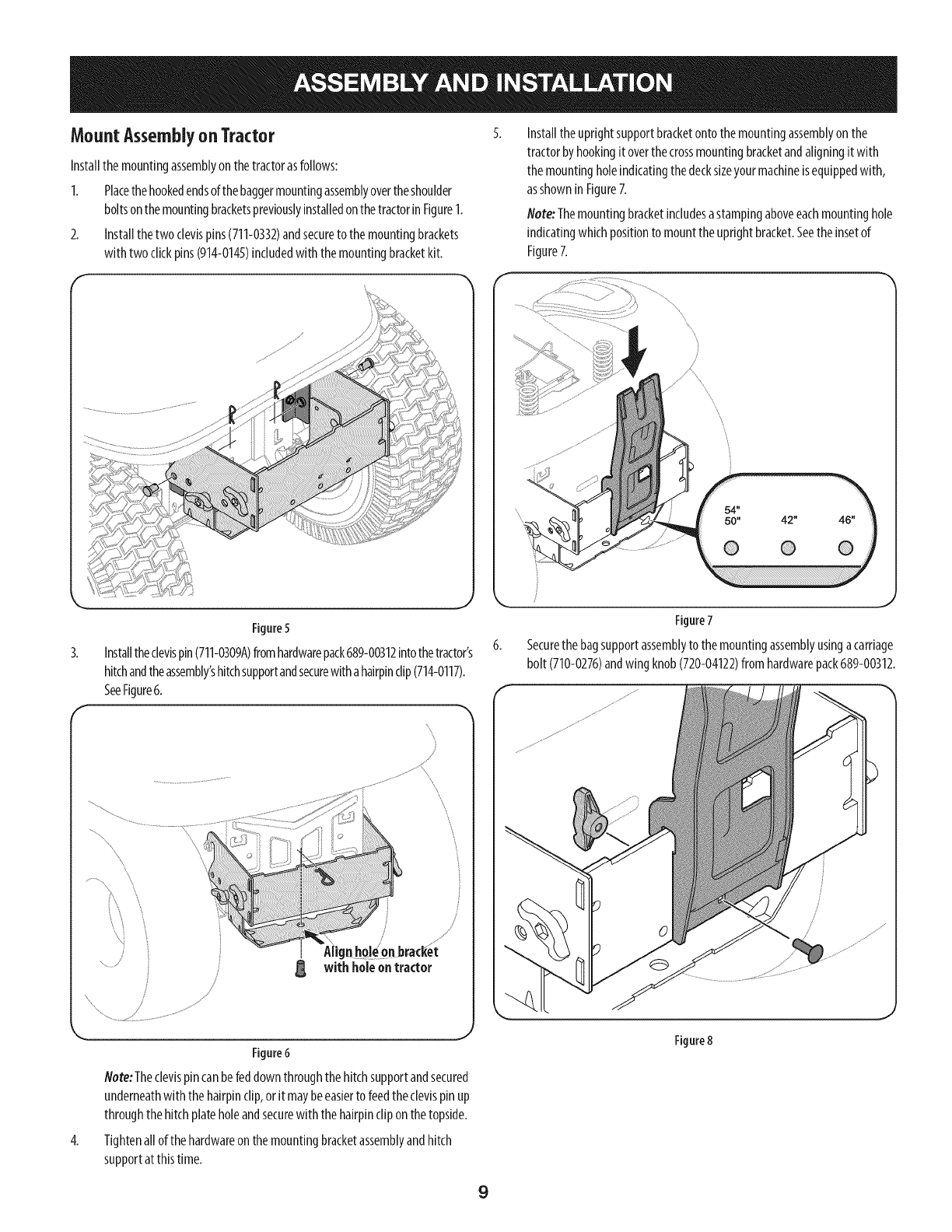
MountAssemblyonTractor
Installthemountingassemblyonthetractorasfollows:
1. Placethehookedendsofthebaggermountingassemblyovertheshoulder
boltsonthemountingbracketspreviouslyinstalledonthetractorinFigure1.
2. Installthetwo clevispins(711-0332)andsecureto themountingbrackets
with twoclickpins(914-0145)includedwiththemountingbracketkit.
Installtheuprightsupportbracketontothemountingassemblyonthe
tractorbyhookingit overthecrossmountingbracketandaligningitwith
themountingholeindicatingthedecksizeyourmachineisequippedwith,
asshownin Figure7.
Note:Themountingbracketincludesastampingaboveeachmountinghole
indicatingwhichpositionto mounttheuprightbracket.Seetheinsetof
Figure7.
4.
Figure5
Installtheclevispin(711-0309A)fromhardwarepack689-00312intothetractor's
hitchandtheassembly'shitchsupportandsecurewithahairpinclip(714-0117).
SeeFigure6.
/
F\
with holeon tractor
Figure6
Note:Theclevispincanbefeddownthroughthe hitchsupportandsecured
underneathwiththe hairpinclip,or itmaybeeasierto feedtheclevispin up
throughthehitchplateholeandsecurewith thehairpincliponthetopside.
Tightenallof thehardwareon themountingbracketassemblyandhitch
supportatthistime.
Figure7
6. Securethe bagsupportassemblyto themountingassemblyusingacarriage
bolt (710-0276)andwing knob(720-04122)fromhardwarepack689-00312.
Figure8
9
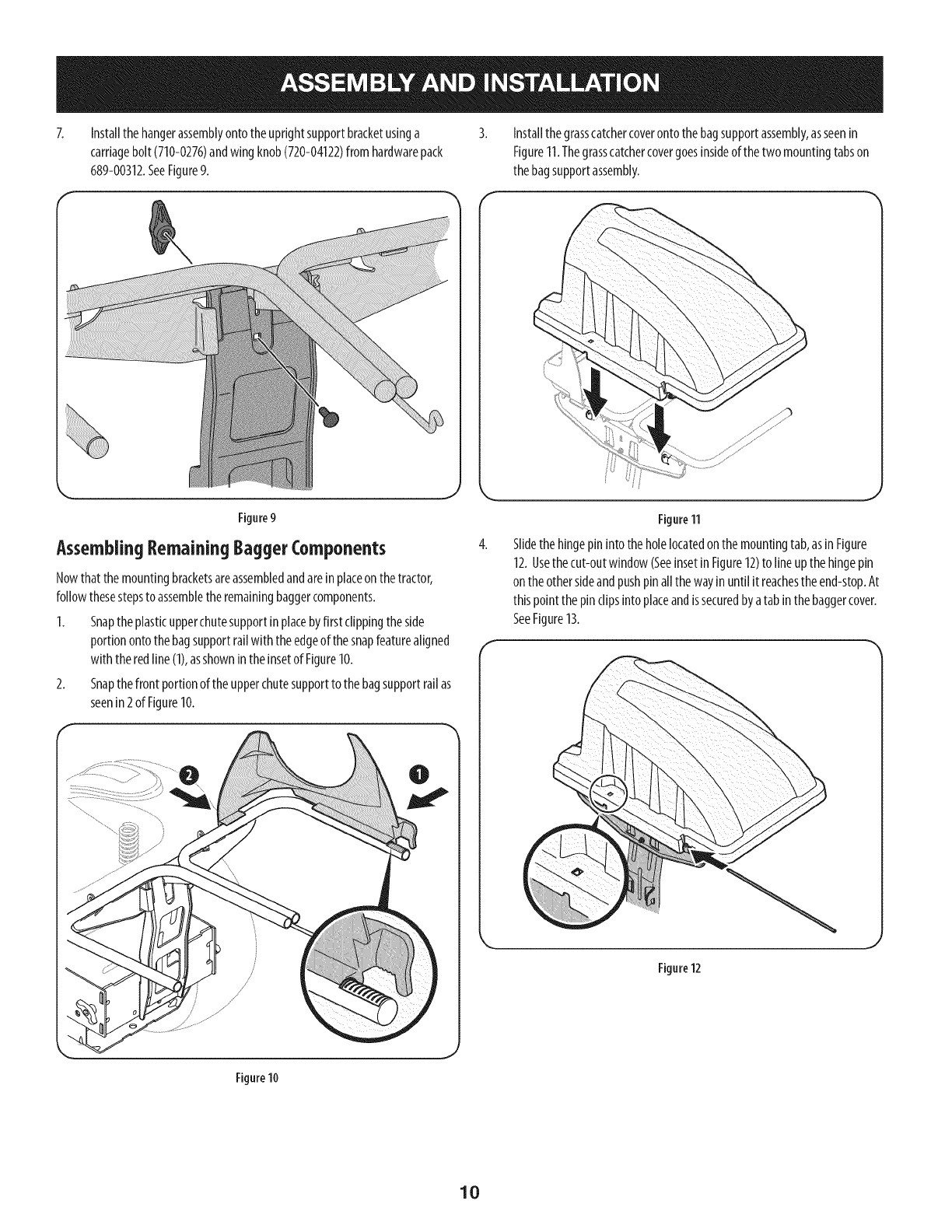
Installthe hangerassemblyontotheuprightsupportbracketusinga
carriagebolt(710-0276)andwingknob(720-04122)fromhardwarepack
689-00312.SeeFigure9.
Installthegrasscatchercoverontothebagsupportassembly,asseenin
Figure11.Thegrasscatchercovergoesinsideof thetwo mountingtabson
thebagsupportassembly.
AssemblingRemainingBaggerComponents
Nowthat themountingbracketsareassembledandareinplaceonthetractor,
followthesestepsto assemblethe remainingbaggercomponents.
1. Snaptheplasticupperchutesupportinplacebyfirstclippingtheside
portionontothebagsupportrailwith theedgeof thesnapfeaturealigned
with theredline (1),asshownin theinsetof Figure10.
2. Snapthefront portionof theupperchutesupportto the bagsupportrailas
seenin2 of Figure10.
Figure 11
Slidethe hingepin intotheholelocatedonthemountingtab,asinFigure
12.Usethecut-outwindow(SeeinsetinFigure12)to lineupthehingepin
ontheothersideandpushpinallthewayinuntil it reachestheend-stop.At
thispointthepin clipsintoplaceandissecuredbyatabin the baggercover.
SeeFigure13.
Figure12
Figure10
10
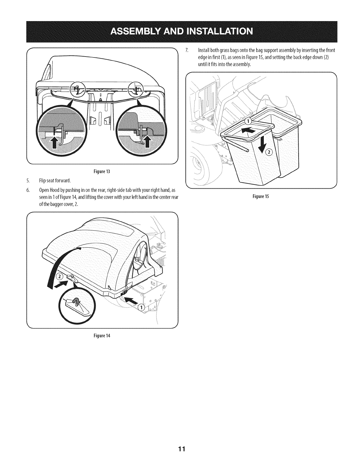
f "_ 7.
5.
6.
Figure13
Flipseatforward.
OpenHoodbypushingin ontherear,right-sidetabwith yourrighthand,as
seenin1ofFigure14,andlifting thecoverwith yourleft handinthecenterrear
ofthebaggercover,2.
Installbothgrassbagsontothebagsupportassemblybyinsertingthefront
edgein first (1),asseeninFigure15,andsettingthebackedgedown(2)
until it fits into theassembly.
Figure15
Figure 14
11
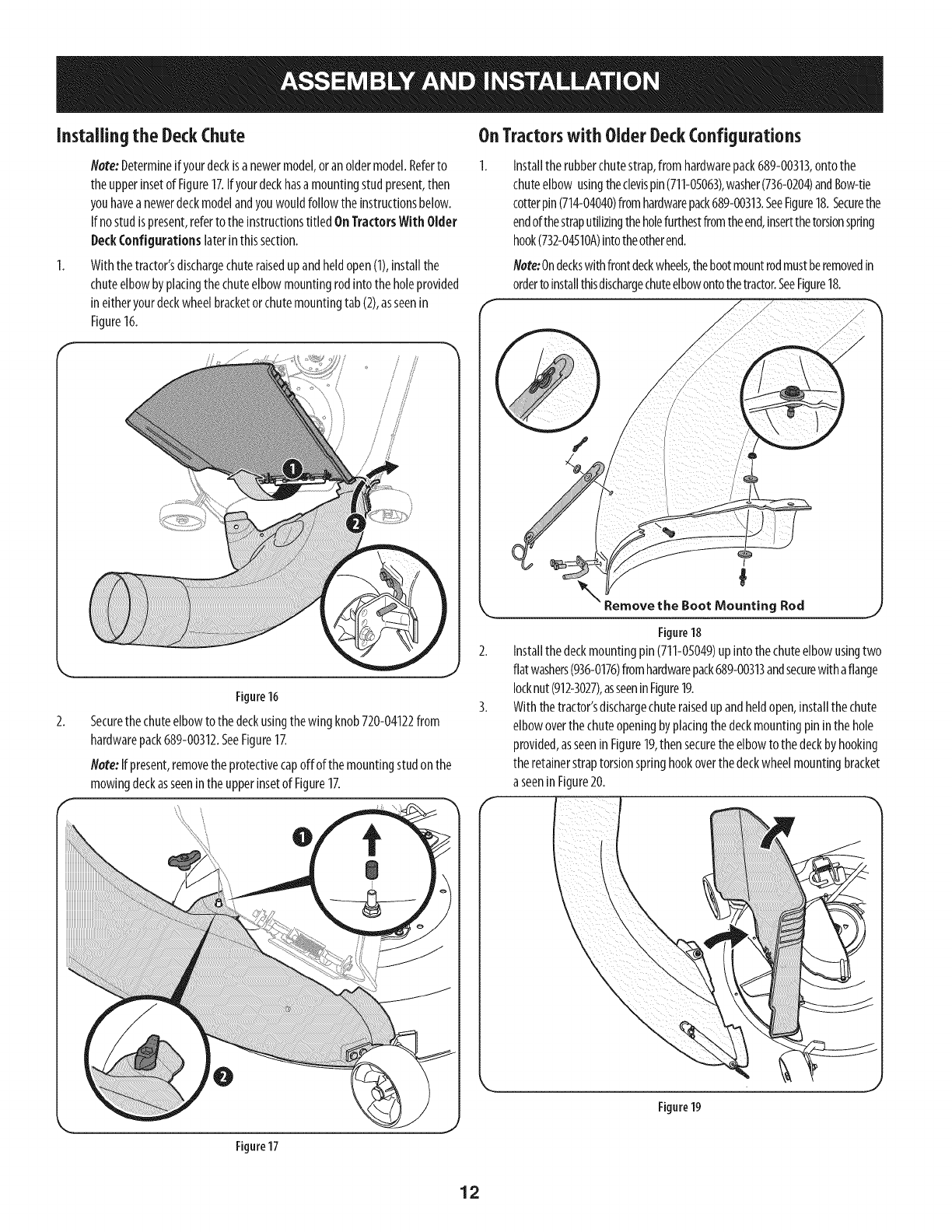
Installingthe DeckChute
Note:Determineifyourdeckisa newermodel,oranoldermodel.Referto
theupperinsetof Figure17.Ifyourdeckhasa mountingstudpresent,then
youhaveanewerdeckmodelandyouwouldfollowtheinstructionsbelow.
If nostudispresent,referto theinstructionstitled OnTractorsWith Older
DeckConfigurationslaterinthissection.
Withthetractor'sdischargechuteraisedupandheldopen(1),installthe
chuteelbowbyplacingthe chuteelbowmountingrodintotheholeprovided
ineitheryourdeckwheelbracketorchutemountingtab(2),asseenin
Figure16.
Figure16
Securethechuteelbowtothedeckusingthewingknob720-04122from
hardwarepack689-00312.SeeFigure17.
Note:Ifpresent,removetheprotectivecapoffof themountingstudonthe
mowingdeckasseeninthe upperinsetof Figure17.
OnTractorswith OlderDeckConfigurations
Installtherubberchutestrap,fromhardwarepack689-00313,ontothe
chuteelbow usingtheclevispin(711-0S063),washer(736-0204)andBow-tie
cotterpin(714-04040)fromhardwarepack689-00313.SeeFigure18.Securethe
endofthestraputilizingtheholefurthestfromtheend,insertthetorsionspring
hook(732-04510A)intotheotherend.
Note:Ondeckswithfrontdeckwheels,thebootmountrodmustberemovedin
orderto installthisdischargechuteelbowontothetractor.SeeFigure18.
Remove the Boot Rod
Figure18
Installthedeckmountingpin (711-05049)upinto thechuteelbowusingtwo
flat washers(936-0176)fromhardwarepack689-00313andsecurewithaflange
locknut(912-3027),asseeninFigure19.
Withthetractor'sdischargechuteraisedupandheldopen,installthechute
elbowoverthechuteopeningbyplacingthedeckmountingpin inthehole
provided,asseeninFigure19,thensecuretheelbowto thedeckby hooking
theretainerstraptorsionspringhookoverthedeckwheelmountingbracket
a seeninFigure20.
0
Figure17
Figure19
12
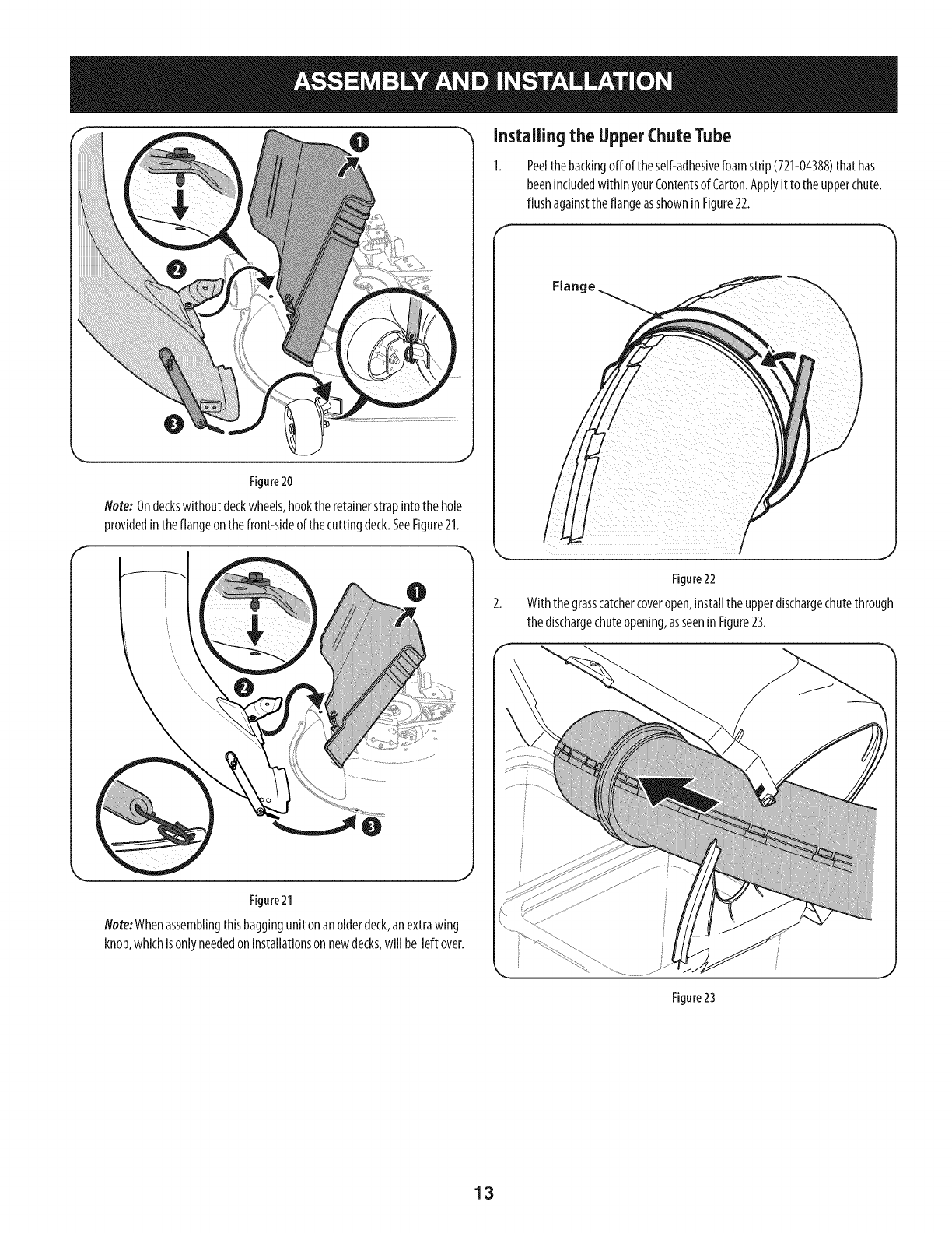
0Installingthe UpperChuteTube
Figure20
Note:Ondeckswithoutdeckwheels,hookthe retainerstrapintothehole
providedintheflangeonthefront-sideof thecuttingdeck.SeeFigure21.
Figure21
Note:Whenassemblingthisbaggingunitonanolderdeck,anextrawing
knob,whichisonlyneededon installationson newdecks,will be left over.
Peelthebackingoff of theself-adhesivefoamstrip(721-04388)that has
beenincludedwithinyourContentsof Carton.Applyit to theupperchute,
flushagainsttheflangeasshowninFigure22.
/
Figure22
Withthegrasscatchercoveropen,installthe upperdischargechutethrough
thedischargechuteopening,asseeninFigure23.
Figure23
13
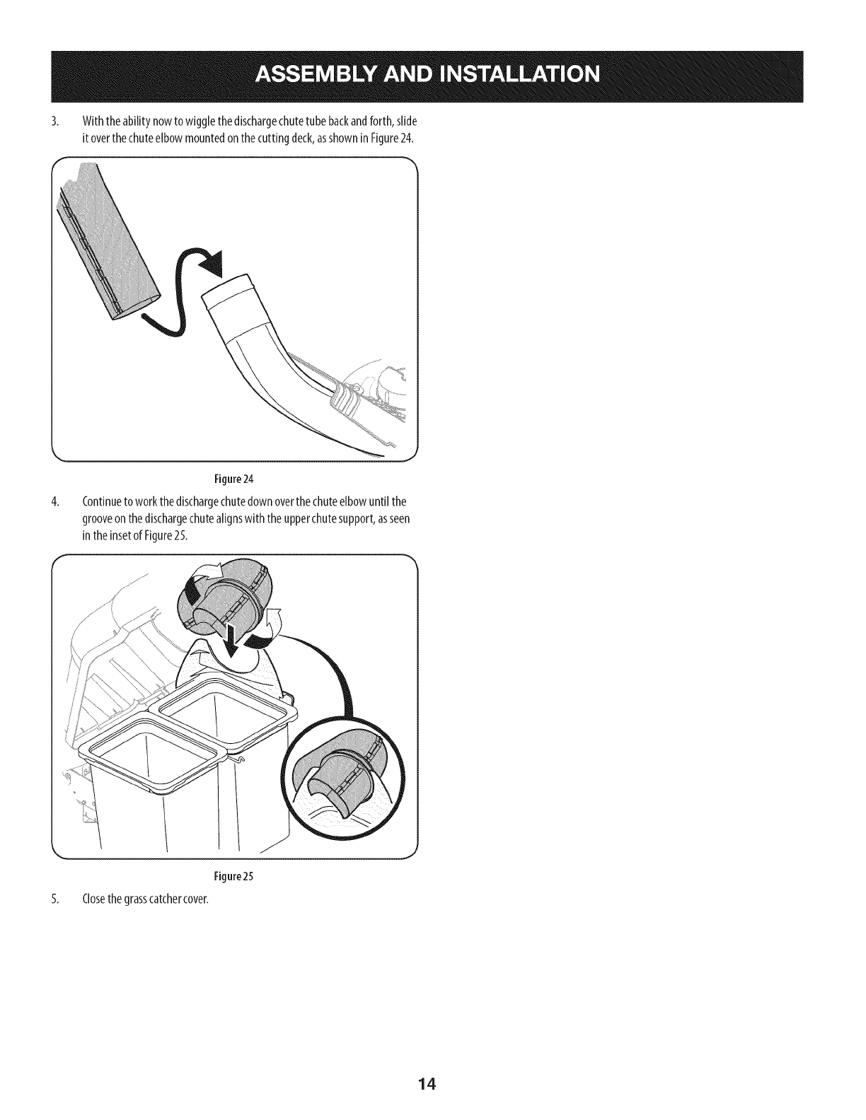
3. Withtheability nowto wigglethedischargechutetubebackandforth,slide
it overthechuteelbowmountedon thecuttingdeck,asshownin Figure24.
4.
Figure24
Continueto workthedischargechutedownoverthe chuteelbowuntil the
grooveonthedischargechutealignswith theupperchutesupport,asseen
intheinsetof Figure25.
5.
Figure25
Closethegrasscatchercover.
14
BaggerOperation
NOTE:Whenbothgrassbagsarefull, placethetractoronafirm, levelsurface,
disengagethe PTO(BladeEngage),turnthetractorengineoffandsetthe parking
brake.
1.
2.
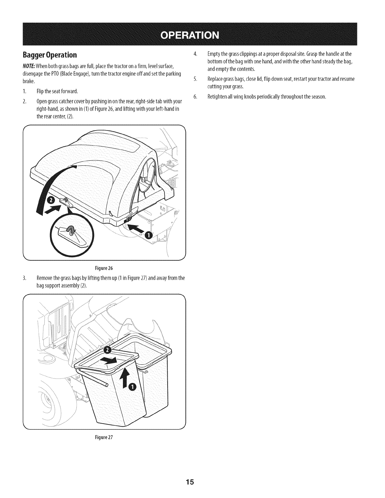
Fliptheseatforward.
Opengrasscatchercoverbypushinginontherear,right-sidetabwith your
right-hand,asshownin (1)of Figure26,andlifting with yourleft-handin
therearcenter,(2).
4. Emptythegrassclippingsat aproperdisposalsite.Graspthehandleat the
bottomof thebagwith onehand,andwiththeotherhandsteadythebag,
andemptythecontents.
5. Replacegrassbags,closelid,flip downseat,restartyourtractorandresume
cuttingyourgrass.
6. Retightenall wingknobsperiodicallythroughouttheseason.
Figure26
Removethegrassbagsbylifting them up(1inFigure27)andawayfromthe
bagsupportassembly(2).
Figure 27
15
2O
22
28
25
19j
j29
16

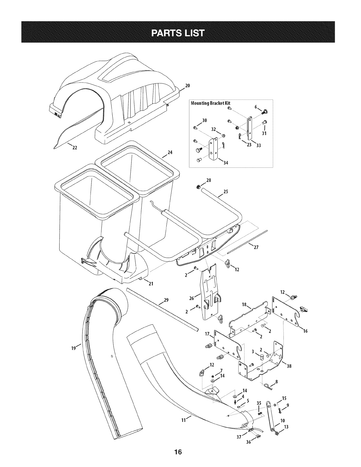
CRAFTSMANTWOBINBAGGERModelNo.247.240193
Topurchasereplacementparts,call1-800-469-4663
!
Ref, IPart Number
1. 689-00304
2. 710-0276
3. 711-0309A
4. 711-05049
5. 711-05063
6. 738-04267
7. 912-3027
8. 714-0117
9. 714-04040
10. 723-04008A
11. 731-09173
12. 720-04122
13. 732-04510A
14. 936-0176
15. 736-0204
16. N/A _
17. N/A _
18. 783-08056-0637
19. 931-04295A
20. 931-04292
21. 731-06497
22. 731-06504
23. 914-0145
24. 964-04096A
25. 683-04461-0637
26. 683-04519-0637
27. 711-04988
28. 735-0246A
29. 721-04388
30. 710-04484
31. 911-0332
32. 712-04065
33. 783-05890A-0637
34. 783-05889A-0637
35. 712-04064
36. 710-0751
37. 747-06043
38. 783-08129
Description
Mounting Bracket Kit (Incl. ref. 16, 17, 18)
Carriage Screw, 5/16-18 x 1.00"
Clevis Pin, .62" Dia.
Attachment Pin, 1/4 x 0.66 Lg.
Clevis Pin, 5/16 x .75 Lg.
Shoulder Screw, .625 x .412
Flange Lock Nut, 1/4-20
Internal Cotter Pin, .148 x 3.00
Bow-Tie Cotter Pin, 72
Chute Strap, 6.00 Lg.
Bagger Discharge Chute Elbow
Wing Knob, 5/16-18
Torsion Spring Hook
Flat Washer, .265 x .938 x .120
Flat Washer, .344 x .62 x .033
Mounting Bracket, LH (Orderltem 1)
Mounting Bracket, RH (Orderltem 1)
Universal Bracket Support
Upper Discharge Chute
Double Bagger Cover Assembly
Upper Chute Support
Bagger Cover Screen
Click Pin, .092 x 1.64 Lg.
Grass-bag Assembly
Double Bag Support Assembly
Vertical Support Bracket
Cover Hinge Pin
End Plug
Self-Adhesive Foam Strip
Tap Screw, 5/16-18 x .750
Clevis Pin
Flange Lock Nut, 3/8-16
Mounting Bracket, LH
Mounting Bracket, RH
Flange Lock Nut, 1/4-20
Hex Head Screw, 1/4-20 x 620
Boot Mounting Rod
Hitch Support Bracket
_Order Reference 1
17
Sinstrucciones De Seguridad ............................................... 19-21
Contenido de la Caja ............................................................. 22-23
Montaje e Instalaci6n ........................................................... 24-30
Operaci6n ................................................................................... 31
Lista de piezas ...................................................................... 16-17
GARANTiACOMPLETADE UNANODE ARTESANO
DURANTEunaSodesde lafechadecompra,esteproductoestAgarantizadocontracualquierdefectode materialo manode obra.Unproducto
defectuososer_reemplazadosin cargo.
Paraquedetallesde lacoberturadegarantiaobtenerun reemplazolibre,visiteel sitioweb:www.craftsman.com
EstagarantiaserAnulasi esteproductose utilizamientrasqueproporcionaservicioscomercialeso Sialquilaa otra persona.
Estagarantiale otorgaderechoslegalesespecificos,y ustedtambi_npuedetenerotrosderechosquevariandeestadoa estado.
Sears Brands ManagementCorporation., Hoffman Estates, IL 60179
© SEARSBRANDS,LLC 18
Lapresenciadeeste sirnboloindicaque setratade instrucciones
irnportantesde seguridadquese debenrespetarparaevitar
ponerenpeligrosu seguridadpersonaly/o materialy lade otras
personas.Leay siga todaslas instruccionesdeestemanualantes
de poneren funcionarnientoestarn_quina.Si no respetaestas
instruccionespodriaprovocarlesionespersonales.Cuandoveaeste
sirnbolo,ipresteatenci6na la advertencia!
PROPOSICION 65 DE CALIFORNIA
Elescapedel motordeesteproducto,algunosde suscornponentes
y algunoscornponentesdelvehiculocontieneno liberansustancias
quirnicasqueelestadodeCaliforniaconsideraque puedenproducir
c_ncer,defectosde nacirnientouotrosproblernasreproductivos.
Losbornesdela bateriay los accesoriosafinescontienenplornoy
cornpuestosde plorno,sustanciasquirnicasque segOnIo estableci-
do pot el Estadode Californiacausanc_ncery da_osenel sisterna
reproductivo.Ldveselas manos despu_sde estaren contacto
con estoscomponentes.
Estarn&quinarueconstruidaparaseroperadadeacuerdocon
las reglasde seguridadcontenidasenestemanual.AI igualque
concualquiertipo deequipornotorizado,undescuidoo errorpor
partedeloperadorpuedeproducirlesionesgraves.Estarn&quina
es capazde arnputarrnanosy piesy dearrojarobjetoscon gran
fuerza.Deno respetarlas instruccionesde seguridadsiguientesse
puedenproducirlesionesgraveso larnuerte.
Su responsabilidad--Restrinja el usode estarn_quina
rnotorizadaalas personasque lean,cornprendany respetenlas
advertenciase instruccionesqueaparecenen estemanualyen la
rn_quina.
iGUARDEESTASINSTRUCCIONES!
Fundonamiento general
1. Lea, comprenda y respete todas las instrucciones que figuran
en el equipo yen los manuales antes de intentar armarlo y
hacerlo funcionar. Guarde este manual en un lugar seguro
para consultas futuras y peri6dicas, asi como para solicitar
repuestos.
2. Para ayudar a evitar una lesidn pot contacto con las cuchillas
o con un objeto que sea arrojado, mantenga a las personas
que observan, a los ayudantes, ni_os y mascotas alejados a no
menos de 25 metros de la m_quina mientras est_ funcionando.
Detenga la m_quina si alguien entra en la zona.
3. Revise minuciosamente el _irea donde se va a usar el equipo.
Retire todas las piedras, palos, cables, huesos, juguetes y otros
objetos extrahos que podrian ser recogidos y arrojados por la
accidn de las cuchillas. Los objetos arrojados por la m_quina
pueden causar lesiones graves.
4. Para protegerse los ojos, utilice siempre galas o lentes de
seguridad mientras opera la m&quina o mientras la ajusta
o repara. Los objetos arrojados que rebotan pueden causar
lesiones oculares graves.
5. Nunca opere la cortadora de c_sped sin tenet bien colocada
la cubierta de descarga o el colector de c_sped. Si falta o
est_ da_ada la cubierta de descarga oun componente del
accesorio embolsador puede resultar en lesiones por contacto
con la cuchilla o con objetos arrojados.
6. No ponga las manos ni los pies cerca de las piezas rotatorias ni
debajo de la plataforma de corte. El contacto con las cuchillas
puede resultar en la amputacidn de una mano o pie.
7. Apague el motor de la cortadora de c_sped y espere que
las cuchillas se detengan totalmente antes de desbloquear
la abertura de descarga de la cortadora o las piezas de la
embolsadora.
8. Reduzca la velocidad antes de girar. Opere la m_quina de
forma pareja. Evite el funcionamiento err_tico y la velocidad
excesiva. Tenga en cuenta que el accesorio colector de c6sped
puede afectar las caracteristicas de manejo de su cortadora.
Fundonamiento en pendientes
Las pendientes son un factor importante en los accidentes
ocasionados por p_rdida de control y vuelcos que pueden causar
lesiones graves e incluso la muerte. Los accesorios tambien pueden
afectar la estabilidad de la m_iquina. La operaci6n en pendiente
requiere mayor precaucidn.
Para seguridad, use el medidor de pendientes que se incluye como
parte de este manual para estimar el _ingulo de la pendiente antes
de hacer funcionar la m_iquina en una zona inclinada. Si la pendiente
es mayor a 10 grados en el medidor, no opere la cortadora con el
accesorio embolsador en ese sector, pues podria causar lesiones
graves.
I-lagaIo siguiente:
1. Corte hacia arriba y abajo de las pendientes, no en forma
transversal. Tenga sumo cuidado al cambiar de direcci6n en
una pendiente.
2. Est_ atento a los hoyos, surcos, baches, rocas, u otros objetos
ocultos. El terreno desnivelado puede voltear la m_quina. El
pasto alto puede ocultar obst_iculos.
3. Conduzca a baja velocidad. Elija una velocidad Io
suficientemente baja como para no tenet que detenerse
o cambiar de marcha mientras est,1 en la pendiente. Los
neum&ticos pueden perder tracci6n en las pendientes aun
cuando los frenos funcionen correctamente. Mantenga
la m_quina siempre en velocidad cuando desciende una
pendiente, para poder frenar con el motor.
19
4. Siga las recomendaciones del fabricante sobre pesos y
contrapesos de las ruedas, para mejorar la estabilidad.
5. Haga que todos los movimientos en las pendientes sean
lentos y graduales. No cambie repentinamente la velocidad
ni la direcci6n. Un frenado o cambio de velocidad repentinos
pueden causar que el frente de la m_iquina se levante y d_ una
voltereta hacia atr_is, Io que podria causar lesiones graves.
6. Evite arrancar o detenerse en una pendiente. Si los neum_iticos
pierden traccidn, desenganche las cuchillas y descienda
lentamente la pendiente.
No haga Iosiguiente:
I. No gire en una pendiente a menos que sea imprescindible. De
ser posible, gire lenta y gradualmente cuesta abajo.
2. No corte el c_sped cerca de barrancos, zanjas o terraplenes. La
cortadora de c_sped podria volcarse repentinamente si una de
las ruedas estuviera sobre el borde de un acantilado o zanja, o
si un borde se desmoronara.
3. No intente estabilizar la m_iquina poniendo el pie en el suelo.
4. No utilice un colector de c_sped en pendientes empinadas.
5. No corte el c_sped humedo. Una reducci6n en tracci6n puede
causar derrapes.
Sewido general
I. Antes de limpiar, reparar o inspeccionar la m_quina,
compruebe que las cuchillas y todas las piezas m6viles se
hayan detenido. Desconecte el cable de la bujia y p6ngalo
haciendo masa contra el motor para evitar que arranque
accidentalmente.
2. Mantenga todas las tuercas, pernos y tornillos bien ajustados
para asegurarse de que el equipo est,1 en condiciones seguras
de operaci6n.
3. Nunca intente violar el sistema de bloqueo de seguridad u
otros mecanismos de seguridad de la cortadora. Controle
peri6dicamente que funcionan correctamente.
4. No intente nunca hacer ajustes o reparaciones a la cortadora
mientras el motor est,1 en marcha.
5. Los componentes del colector de c_sped y la cubierta de
descarga est_fin sujetos a desgaste y dahos que podrian dejar
expuestas piezas que se mueven o permitir que se arrojen
objetos. Para proteger su seguridad, verifique frecuentemente
todos los componentes y reempl_icelos inmediatamente
unicamente con piezas de los fabricantes del equipo original
(O.E.M.) indicados en este manual. El uso de piezas que no
cumplen con las especificaciones del equipo original puede
resultar en rendimiento inadecuado y puede poner en peligro
la seguridad.
6. Mantenga o reemplace las etiquetas de seguridad y de
instrucciones segun sea necesario.
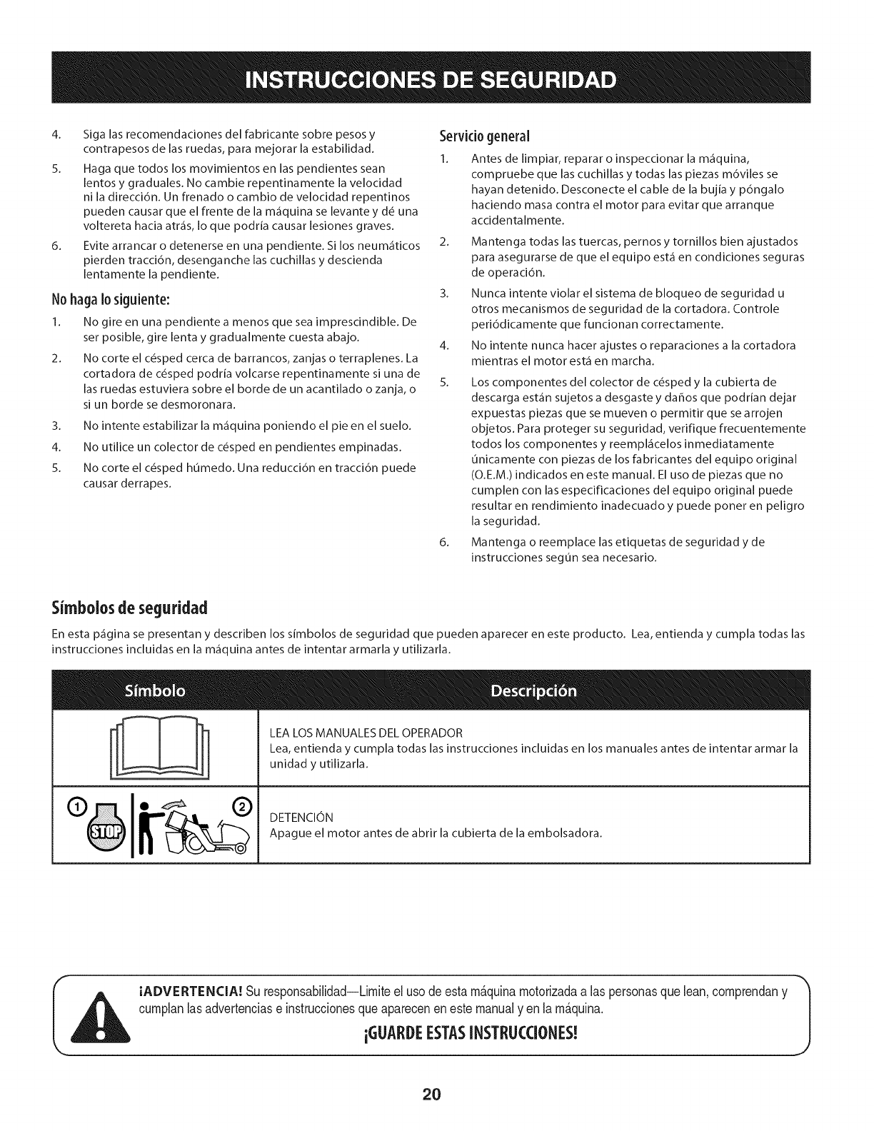
Simbolosde seguridad
En esta p_gina se presentan y describen los simbolos de seguridad que pueden aparecer en este producto. Lea, entienda y cumpla todas las
instrucciones incluidas en la m_quina antes de intentar armarla y utilizarla.
LEA LOS MANUALES DEL OPERADOR
Lea, entienda y cumpla todas las instrucciones incluidas en los manuales antes de intentar armar la
unidad y utilizarla.
DETENCION
Apague el motor antes de abrir la cubierta de la embolsadora.
IADVERTENCIA! Su responsabilidad--Limiteel uso deestam&quinamotorizadaalas personasquelean,comprendany
cumplanlasadvertenciase instruccionesqueapareceneneste manualyen lam&quina.
iGLIARDEESTASINSTRL!CCIONES!
2O
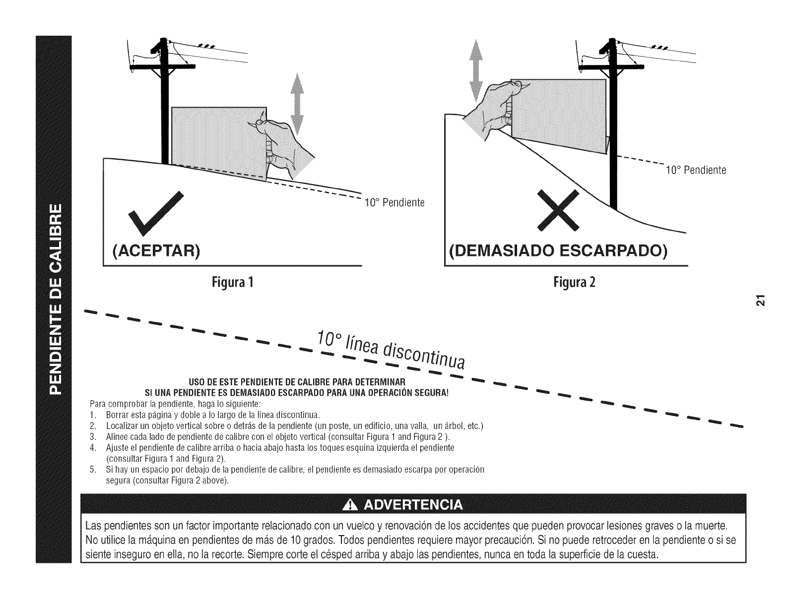
(ACEPTAR)
Figura1
"" 10° Pendiente
10° Pendiente
(DEiVIASlADO ESCARPADO)
Figura2
0oI[nea
- - " "" - _ .-...diSC°ntinua
US0 DEESTEPENDIENTEDECALIBREPARADETERiVIINAR
SI UNAPENDiENTEESDEIV1ASiADOESCARPADOPARAUNAOPERACi(_NSEGURA!
Paracomprobarlapendiente,hagaIosiguiente:
1. Borrarestap_.ginay dobleaIo largodelalineadiscontinua.
2.
3.
4.
Localizarun objetoverticalsobreo detrJ.sdelapendiente(unposte,unedificio,unavalla, un _.rbol,etc.)
Alineecadaladodependientedecalibrecon elobjetovertical(consultarFigura1 andFigura2 ).
Ajusteel pendientedecalibrearribao haciaabajohastalos toquesesquinaizquierdael pendiente
(consultarFigura1andFigura2).
Sihayun espaciopordebajodela pendientedecalibre,el pendientees demasiadoescarpaporoperaciOn
segura(consultarFigura2 above).
Las pendientesson un factor importante relacionadocon un vuelco y renovaci6nde los accidentesque pueden provocar lesionesgraves o la muerte.
No utilice la m_.quinaen pendientes de m_.sde 10grados. Todos pendientesrequiere mayorprecauci6n.Si no puede retrocederen la pendiente o si se
siente inseguro en ella, no la recorte. Siempre corte el cesped arriba y abajo laspendientes, nunca en toda la superficiede la cuesta.
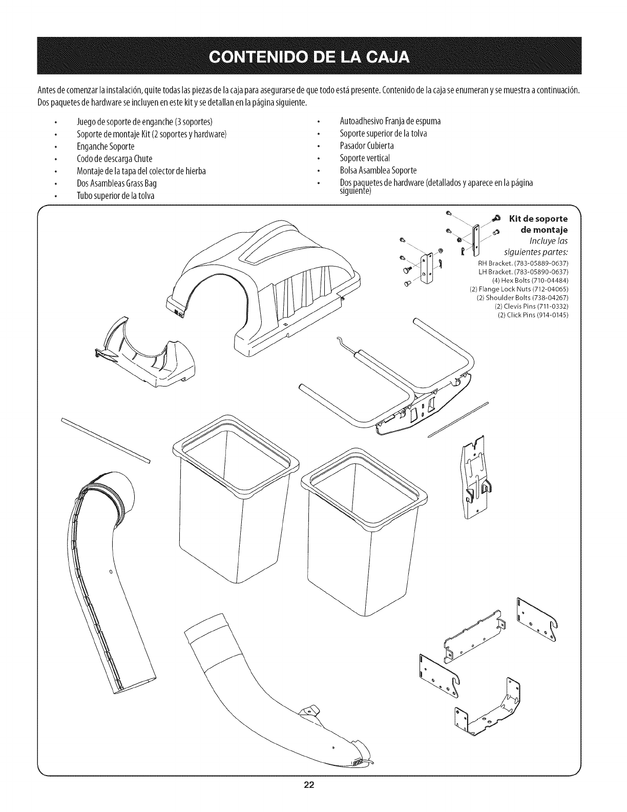
Antesde comenzarlainstalad6n,quitetodaslaspiezasdelacajaparaasegurarsedequetodoest_presente.Contenidodelacajaseenumeranysemuestraacontinuad6n.
Dospaquetesde hardwareseincluyenenestekitysedetallanen lap_ginasiguiente.
Juegodesoportedeenganche(3soportes)
SoportedemontajeKit(2soportesyhardware)
EngancheSoporte
CododedescargaChute
Montajede latapadelcolectordehierba
DosAsambleasGrassBag
Tubosuperiorde latolva
AutoadhesivoFranjadeespuma
Soportesuperiordelatolva
PasadorCubierta
Soportevertical
BolsaAsambleaSoporte
D.ospaquetesdehardware(detalladosyapareceenlap_gina
slgulen_e)
e_
z,,g,
_.\ /_11_ Kit desoporte
de montaje
/_ Incluye las
siguientespartes:
RH Bracket. (783-05889-0637)
LH Bracket. (783-05890-0637)
(4) Hex Bolts (710-04484)
(2) Flange Lock Nuts (712-04065)
(2) Shoulder Bolts (738-04267)
(2) Clevis Pins (711-0332)
(2) Click Pins (914-0145)
22
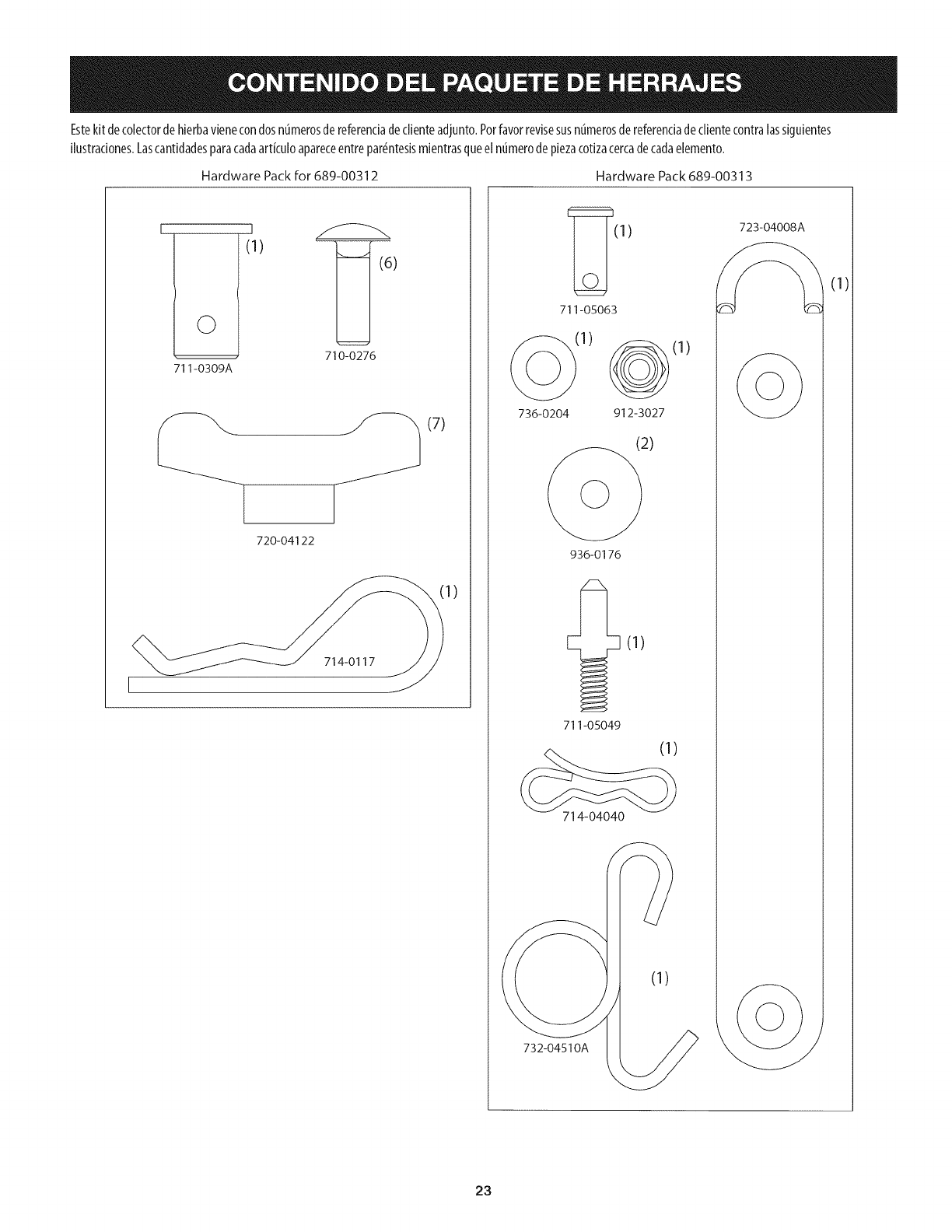
Estekitdecolectordehierbavienecondosnt_merosdereferendadedienteadjunto.Porfavorrevisesusnt_merosdereferendadeclientecontralassiguientes
Hustradones.LascantMadesparacadaartkuloapareceentrepar_ntesismientrasqueelntimerodepiezacotizacercadecadaelemento.
HardwarePackfor689-00312 HardwarePack689-00313
I
©
711-0309A
_.J
(1)
710-0276
(7)
720-04122
714-0117
1)
_(1) 723-04008/_
711-05063
:1)
736-0204 912-3027
936-0176
711-05049
714-04040
732-04510A
(1)
(1)
23
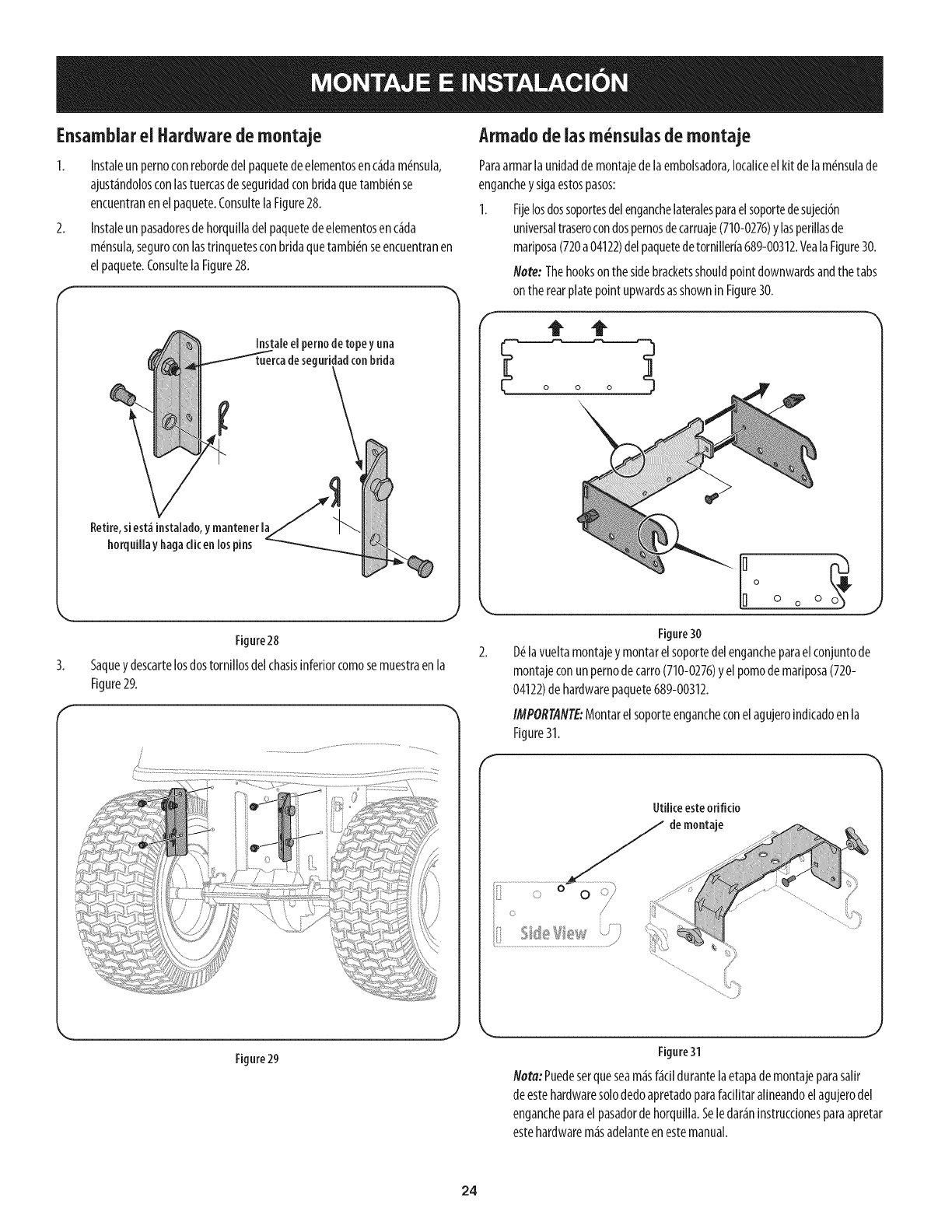
Ensamblarel Hardware demontaje
1. Instaleunpernoconrebordedelpaquetedeelementosenc_dam6nsula,
ajust_ndolosconlastuercasdeseguridadconbridaquetambi6nse
encuentranenelpaquete.ConsultelaFigure28.
2. Instaleunpasadoresdehorquilladelpaquetedeelementosenc_da
m6nsula,seguroconlastrinquetesconbridaquetambi_nseencuentranen
elpaquete.ConsultelaFigure28.
Instale el pernode topey una
seguridad conbrida
Retire,siest_ instalado,y mantener la
horquillayhagadic en los pins
Figure28
Saquey descartelosdostornfllosdelchasisinferiorcomosemuestraenla
Figure29.
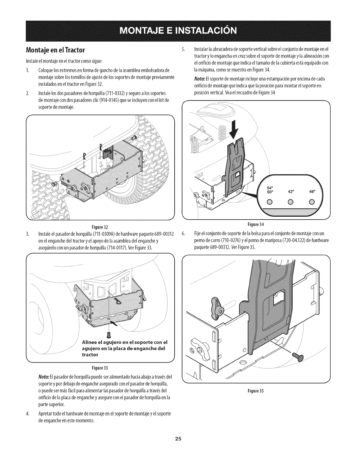
Armadodeiasm nsuias de montaje
Paraarmarlaunidadde montajedelaembolsadora,Iocaliceelkitdelam_nsulade
engancheysigaestospasos:
1. Fljelosdossoportesdelenganchelateralesparaelsoportedesujeci6n
universaltraserocondospernosdecarruaje(710-0276)ylasperfllasde
marlposa(720a04122)delpaquetedetornlller[a689-00312.VealaFigure30.
Note: Thehookson thesidebracketsshouldpointdownwardsandthetabs
ontherearplatepointupwardsasshownin Figure30.
Figure30
D_lavueltamontajeymontarelsoportedelengancheparaelconjuntode
montajeconunpernodecarro(710-0276)yel pomodemariposa(720-
04122)dehardwarepaquete689-00312.
IMPORTANTE:Montarelsoporteengancheconelagujeroindicadoenla
Figure31.
Utiliceesteorifido
demontaje
Figure 29 Figure31
I_ota:Puedeserqueseam_sf_dl durantelaetapade montajeparasallr
deestehardwaresolodedoapretadoparafadlitaralineandoelagujerodel
engancheparaelpasadordehorquilla.Seledar_n[nstrucdonesparaapretar
estehardwarem_sadelanteenestemanual.
24
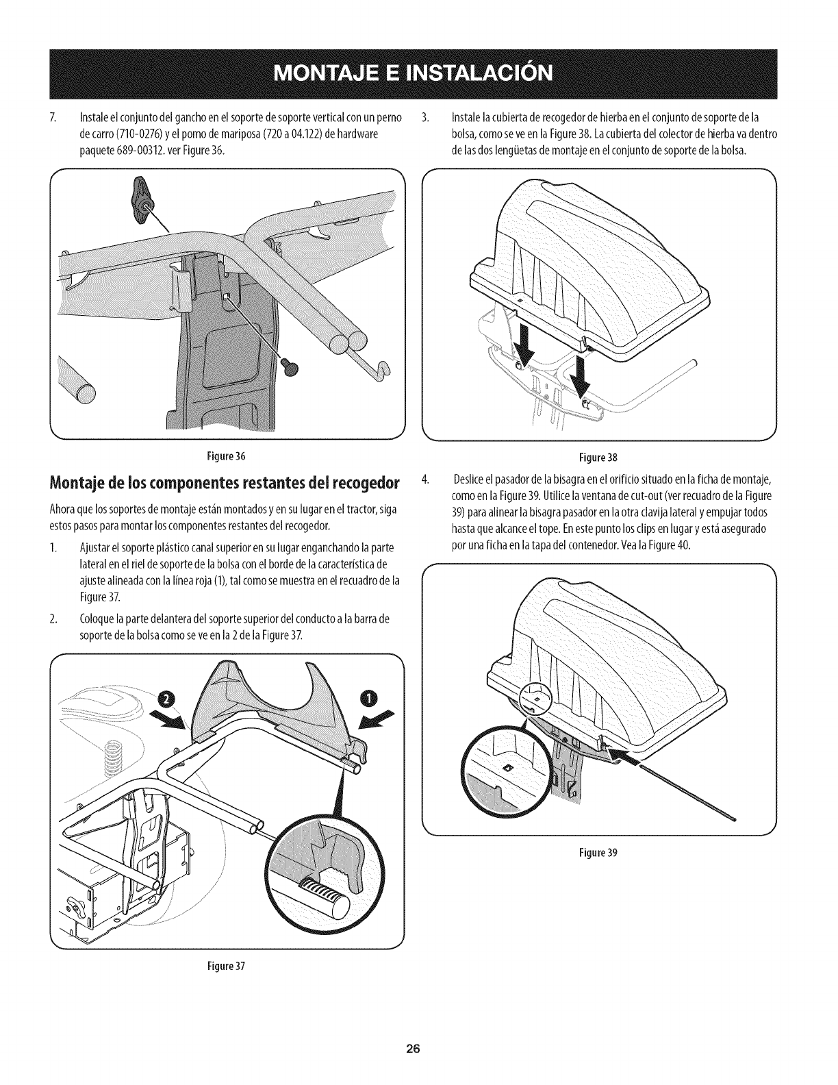
Montajeenel Tractor
Instaleel montajeeneltractorcomosigue:
1. Coloquelosextremosenformadeganchodelaasambleaembolsadorade
montajesobrelostornillosdeajustedelossoportesdemontajepreviamente
instaladoseneltractorenFigure32.
2. Instalelosdospasadoresdehorquilla(711-0332)yseguroa lossoportes
demontajecondospasadoresclic(914-0145)queseincluyenconelkit de
soportedemontaje.
Instalarlaabrazaderadesoporteverticalsobreel conjuntodemontajeenel
tractoryIoenganchaencruzsobreel soportedemontajey laalineaci6ncon
elorificiodemontajequeindicaeltamaffodelacubiertaest_equipadocon
la m_quina,comosemuestraen Figure34.
Nora: Elsoportedemontajeincluyeunaestampaci6nporencimadecada
orificiodemontajequeindicaquelaposici6nparamontarelsoporteen
posici6nvertical.VeaelrecuadrodeFigure34
3.
Figure32
Instaleel pasadordehorquilla(711-0309A)dehardwarepaquete689-00312
enelenganchedeltractoryelapoyode laasambleadelenganchey
asegureloconunpasadordehorquilla(714-0117).VerFigure33.
/
\
/
/
j g
/Alinee el agujero en el soporte con el
agujero en la placa de enganche del
tractor
Figure33
Nora:Elpasadordehorquiilapuedeseralimentadohaciaabajoatrav_sdel
soporteypordebajodeengancheaseguradoconel pasadordehorquilla,
opuedeserm_sf_cilparaalimentarlaspasadordehorquillaatray,s del
orificiodela piacadeengancheyasegureconelpasadorde horquillaenla
partesuperior.
4. Apretartodoelhardwarede montajeenelsoportedemontajeyel soporte
deengancheenestemomento.
Figure34
Fijeelconjuntodesoportedelabolsaparaelconjuntodemontajeconun
pernodecarro(710-0276)y elpomode mariposa(720-04.122)dehardware
paquete689-00312.VetFigure35.
Figure35
25
Instaleelconjuntodelganchoenelsoportedesoporteverticalconun perno
decarro(710-0276)yelpomodemariposa(720a04.122)dehardware
paquete689-00312.verFigure36.
Instalelacubiertade recogedordehierbaenelconjuntodesoportedela
bolsa,comoseveen laFigure38.Lacubiertadelcolectordehierbavadentro
delasdoslengiJetasdemontajeenelconjuntodesoportedelabolsa.
Figure36
Montajede ioscomponentes restantesdelrecogedor 4.
Ahoraquelossoportesdemontajeest_inmontadosyensulugareneltractor,siga
estospasosparamontarloscomponentesrestantesdelrecogedor.
1. Ajustarel soportepl_isticocanalsuperiorensulugarenganchandolaparte
lateralenel rieldesoportedelabolsaconelbordedelacaracteristicade
ajustealineadaconlaI[nearoja(1),tal comosemuestraenel recuadrode la
Figure37.
2. Coloquelapartedelanteradelsoportesuperiordel conductoalabarrade
soportedelabolsacomoseveenla2delaFigure37.
Figure38
Deslkeelpasadordelabisagraenelorificiosituadoenlafichademontaje,
comoenla Figure39.Utilicelaventanadecut-out(vetrecuadrodela Figure
39)paraalinearlabisagrapasadorenlaotra clavijalateralyempujartodos
hastaquealcanceeltope.Enestepuntolosclipsenlugaryest_asegurado
porunafichaen latapadelcontenedor.YealaFigure40.
Figure39
Figure37
26
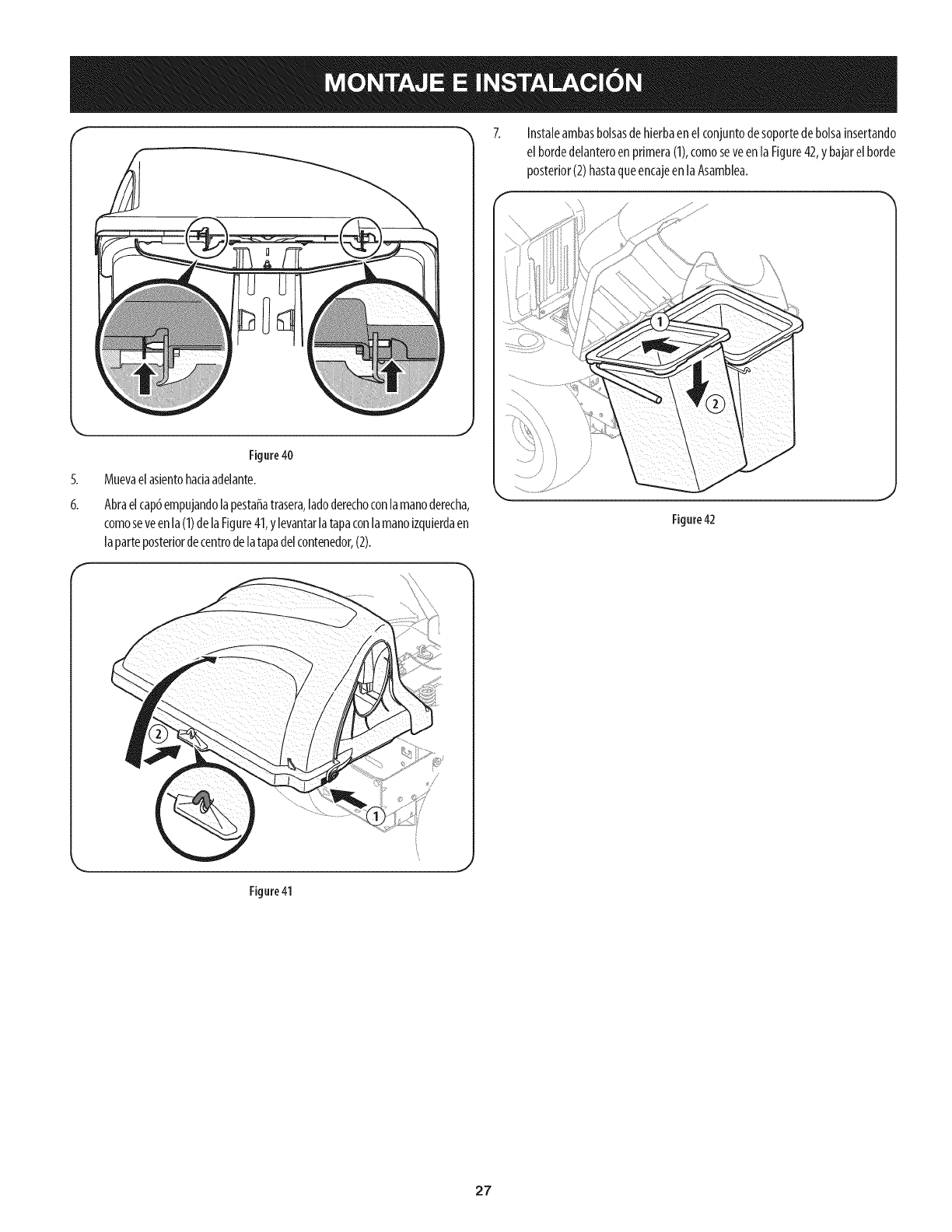
f "_ 7.
Figure40
Muevaelaslentohadaadelante.
6, Abraelcap6empujandolapestaffatrasera,ladoderechoconlamanoderecha,
comoseveenla(1)delaFigure41,ylevantarlatapaconlamanoizquierdaen
laparteposteriordecentrodelatapadelcontenedor,(2).
Instaleambasbolsasdehierbaenelconjuntodesoportedebolsainsertando
el bordedelanteroenprimera(1),comoseveenla Figure42,y bajarelborde
posterior(2)hastaqueencajeenlaAsamblea.
Figure42
Figure41
27
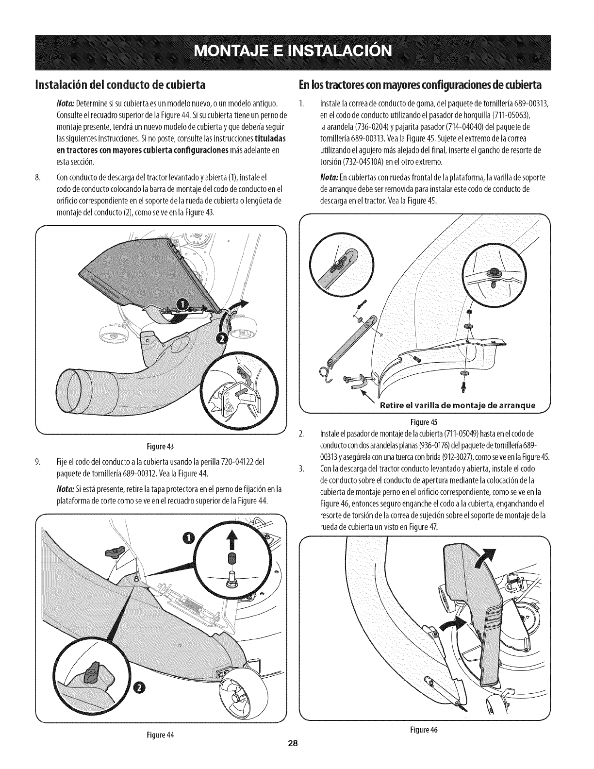
Instalaci6ndeiconductodecubierta
8.
Hera:Determinesisucubiertaesunmodelonuevo,o un modeloantiguo.
ConsulteelrecuadrosuperiordelaFigure44.Sisucubiertatieneunpernode
montajepresente,tendr_unnuevomodelodecubiertayquedeberiaseguir
lassiguientesinstrucciones.Sinoposte,consultelasinstruccionestituladas
entractores conmayorescubiertaconfiguradonesm_sadelanteen
estasecci6n.
Conconductodedescargadeltractorlevantadoyabierta(1),instaleel
cododeconductocolocandolabarrademontajedelcododeconductoenel
orificiocorrespondienteenelsoportedelaruedade cubiertao lengiJetade
montajedelconducto(2),comoseveenla Figure43.
9.
Figure43
Fijeelcododelconductoa lacubiertausandolaperilla720-04122del
paquetedetornilleria689-00312.Veala Figure44.
Nota:Siest_presente,retirelatapaprotectoraenel pernodefijaci6nenla
plataformadetortecomoseveenel recuadrosuperiorde laFigure44.
Enlostractoresconmayoresconfiguradonesdecubierta
Instalelacorreadeconductodegoma,delpaquetedetorniller[a689-00313,
enelcododeconductoutilizandoel pasadordehorquilla(711-05063),
laarandela(736-0204)y pajaritapasador(714-04040)del paquetede
tornilleria689-00313.Veala Figure45.Sujeteelextremodelacorrea
utilizandoelagujerom_salejadodelfinal, inserteelganchoderesortede
torsi6n(732-04510A)en elotroextremo.
Nora: Encubiertasconruedasfrontaldelaplataforma,lavarilladesoporte
dearranquedebeserremovidaparainstalarestecododeconductode
descargaeneltractor.Yeala Figure45.
I
Retire el varilla de montaje de arranque
Figure45
Instaleelpasadordemontajedelacubierta(711-05049)hastaenelcodode
conductocondosarandelasplanas(936-0176)delpaquetedetornilleria689-
00313yasegurelaconunatuercaconbrida(912-3027),comoseveenlaFigure45.
Conladescargadeltractorconductolevantadoyabierta,instaleel codo
deconductosobreel conductodeaperturamediantelacolocaci6ndela
cubiertademontajepernoenel orificiocorrespondiente,comoseveen la
Figure46,entoncesseguroengancheelcodoalacubierta,enganchandoel
resortedetorsi6nde lacorreadesujeci6nsobreel soportedemontajedela
ruedadecubiertaunvistoenFigure4Z
Figure46
Figure44 28
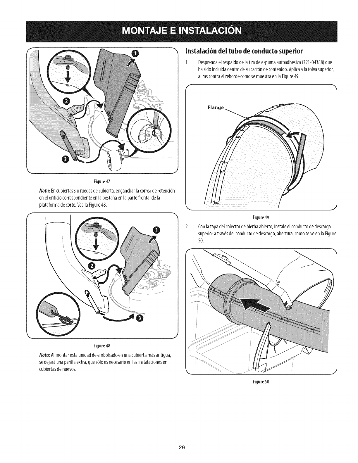
0Instalad6ndei tubodeconductosuperior
Figure47
Nora:Encubiertassinruedasdecubierta,engancharlacorreaderetenci6n
enelorificiocorrespondienteenlapestaffaenla partefrontalde la
plataformadecorte.Veala Figure48.
Figure48
Nora:AImontarestaunidaddeembolsadoenunacubiertam_santigua,
sedejar_unaperiilaextra,ques61oesnecesarioen lasinstalacionesen
cubiertasde nuevos.
Desprendaelrespaldode latiradeespumaautoadhesiva(721-04388)que
hasidoincluidadentrodesucart6ndecontenido.Aplicaa latolvasuperior,
al rascontraelrebordecomosemuestraen laFigure49.
Figure49
Conlatapadelcolectordehierbaabierto,instaleel conductodedescarga
superiora tray,sdelconductodedescarga,abertura,comoseveen laFigure
50.
Figure50
29
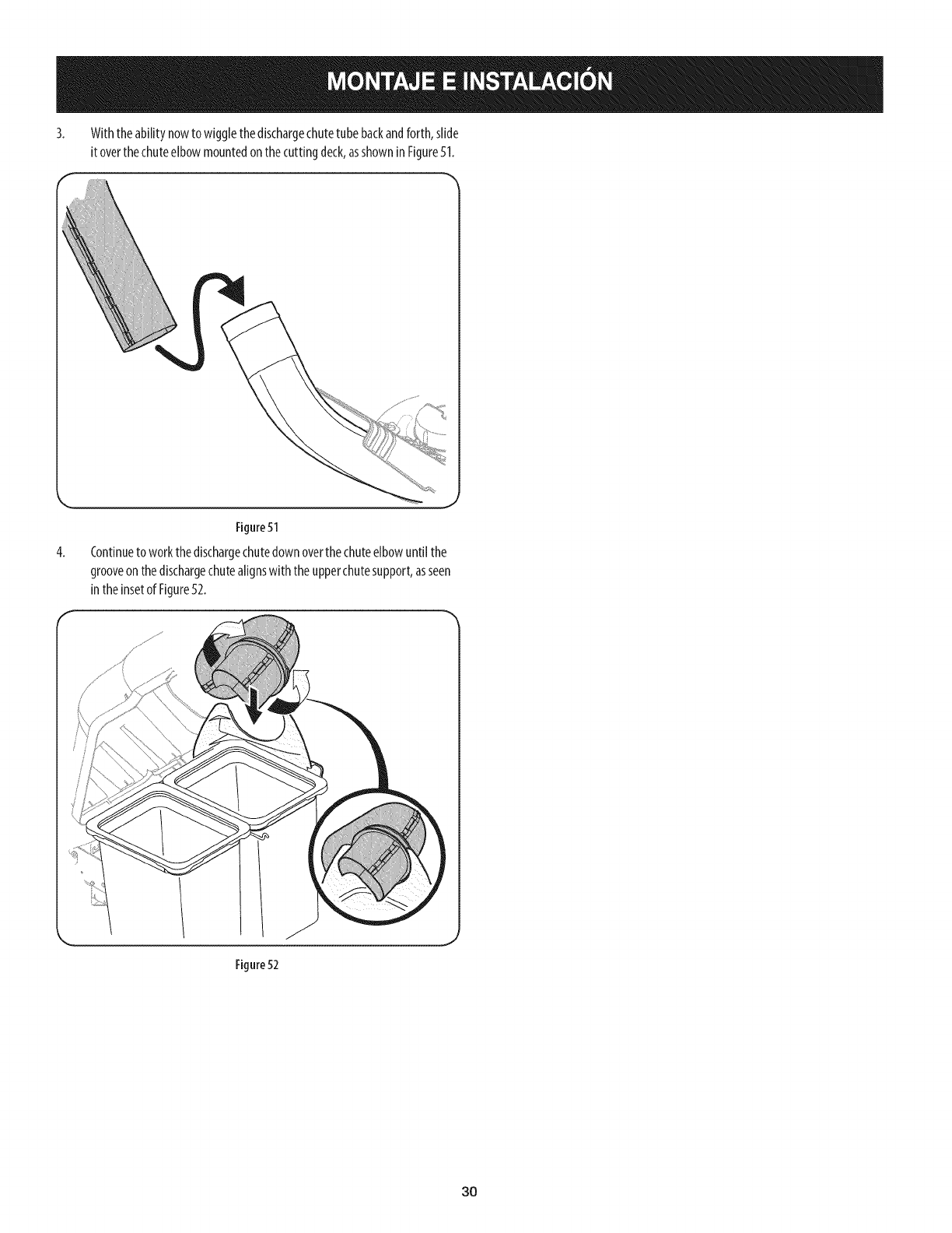
3. Withtheabilitynowtowigglethedischargechutetubebackandforth,slide
itoverthechuteelbowmountedonthecuttingdeck,asshowninFigure51.
4,
Figure51
Continueto workthedischargechutedownoverthe chuteelbowuntil the
grooveonthedischargechutealignswith theupperchutesupport,asseen
intheinsetof Figure52.
Figure 52
30
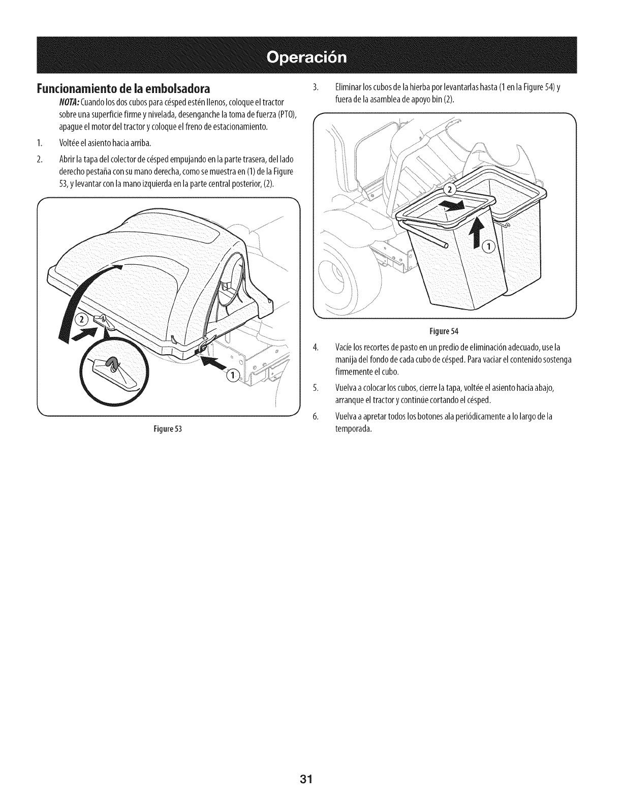
Fundonamiento de ia embolsadora
NOTA:Cuandolosdoscubosparac_spedest_nIlenos,coloqueeltractor
sobreunasuperfidefirmeynivelada,desenganchelatomadefuerza(PTO),
apagueel motordeltractorycoloqueelfrenodeestadonamiento.
1. Volt_eelasientohadaarriba.
Abrirlatapadelcolectordec_spedempujandoenla partetrasera,dellado
derechopestafiaconsumanoderecha,comosemuestraen(1)delaFigure
53,ylevantarconlamanoizquierdaenlapartecentralposterior,(2).
Eliminarloscubosde laHerbaporlevantarlashasta(1enla Figure54)y
fueradelaasambleadeapoyobin(2).
Figure53
Figure54
Vacielosrecortesdepastoenunprediode eliminadbnadecuado,usela
manijadelrondodecadacubodec_sped.Pararadar elcontenidosostenga
firmementeelcubo.
5. Vuelvaacolocarloscubos,derrelatapa,volt_eel asientohadaabajo,
arranqueeltractorycontinuecortandoelc_sped.
6. Vuelvaaapretartodoslosbotonesalaperi6dicamentea Iolargodela
temporada.
31

This page intentionally left blank. Use this page to make any notes regarding your bagger.
32
