Craftsman 247794520 User Manual Log Splitter Manuals And Guides 98110159
CRAFTSMAN Log Splitter Manual 98110159 CRAFTSMAN Log Splitter Owner's Manual, CRAFTSMAN Log Splitter installation guides
User Manual: Craftsman 247794520 247794520 CRAFTSMAN Log Splitter - Manuals and Guides View the owners manual for your CRAFTSMAN Log Splitter #247794520. Home:Lawn & Garden Parts:Craftsman Parts:Craftsman Log Splitter Manual
Open the PDF directly: View PDF ![]() .
.
Page Count: 28
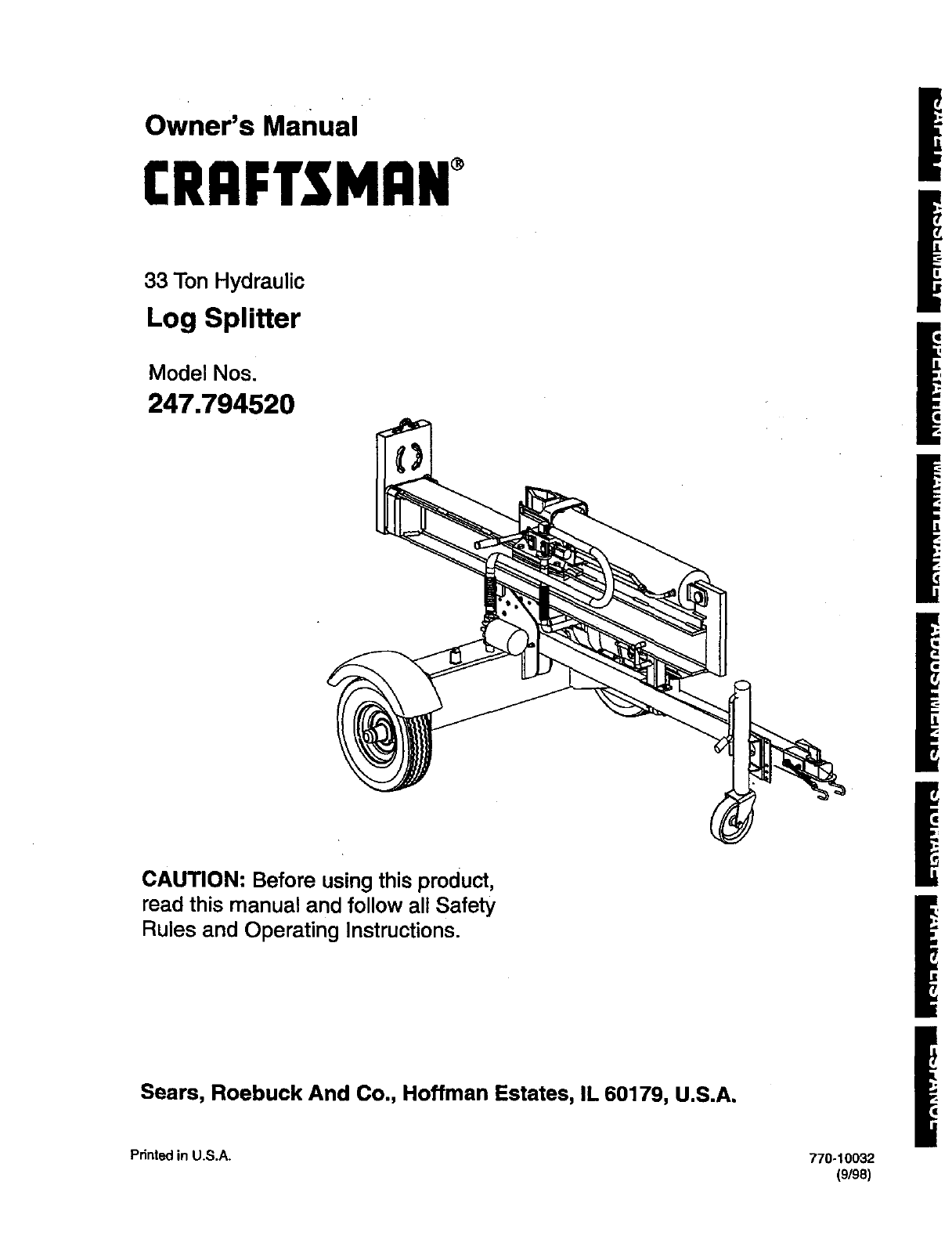
Owner's Manual
CRRFTSMRN°
33 Ton Hydraulic
Log Splitter
Model Nos'
247.794520
CAUTION: Before using this product,
read this manual and follow all Safety
Rules and Operating Instructions.
Sears, Roebuck And Co., Hoffman Estates, IL 60179, U.S.A.
Printed in U.S.A. 770-10032
(9/98)
Content Page
Warranty Information ......................................... 2
Safe Operation Practices................................... 3
Accessories....................................................... 6
Assembly ........................................................... 7
Operation ........................................................... 9
Maintenance ...................................................... 13
Content Page
Service & Adjustment ........................................ 15
Off-Season Storage ........................................... 17
Trouble-Shooting ............................................... 18
Parts Ust............................................................ 20
Spanish version............................................... .. 27
ONE-YEAR WARRANTY ON CRAFTSMAN LOG SPLI'I-I'ER
For one year from the date of purchase, when this Craftsman log splitter is maintained, lubricated, and tuned up
according to the operating and maintenance instructions in the operator's manual, Sears will repair, free of
charge, any defect in material orworkmanship.
This warranty excludes the tires, spark plug, oil filter and air cleaner, which are expendable parts and become
worn during normal use.
If this log splitter is used for commercial or rental purposes, this warranty applies for only 30 days from the date
of purchase.
Warranty service is available by contacting the nearest Sears service center in the United States. This warranty
applies only while this product is in use in the United States.
This warranty givesyou specific legal rights, and you may also have other rights which vary from state to state.
Sears, Roebuck And Co., DEPT. 817WA, Hoffman Estates, IL 60179
Horsepower: ............ :_........... 9
Engine Oil.............................. SAE 30/26 ounces
Fuel Capacity: ....................... unleeded/1 gallon
Hydraulic Fluid ...................... Daxron III/7 gallons
Tire Pressure......................... 30 p.s.i, max.
'Spark Piug(Gap .030").......... Champion RJ19LM
Model Number...247.79452..0. ...................................
Sedal Number ...........................................................
Date of Purchase ......................................................
Record model number, serial number and date of
purchase of the log splitter and keep in asafe place
for futura reference.
2
This symbol points out important safety instructions which, if not followed, could endanger the per-
sonal safety and/or property of yourself and others. Read and follow all instructions in this manual before
attempting to operate your log splitter. Failure to comply with these instructions may result in personal injury.
When you see this symbol--heed its warning. !
I_lb Yourlog splitterwas builtto be operatedaccording to the rules for safe operation In this I
I
DANGER: manual. As withany type of powerequipment, carelessness orerror onthe partof the oper-
injury to yourself or others.
atorcan resultinserious njury.If you vio ate any of these ru es, you may cause eer ous
i_ The engine exhaust from this product contains chemicals known to the state of California to cause
cancer, birthdefects or other reproductive harm.
Towing
• This unit should notbe towed on any street,
highway or publicroad withoutcheckingthe
existingfederal, local or state requirements.
Such informationmay be obtained by callingyour
state or local bureau of motor vehicles.Any
licensingor modificationsneeded to comply with
federal, local or state vehicle requirements is the
sole responsibilityof the purchaser.*
•Make sure you followthe wiring diagram color
codes when installingthe lightkit on the log
splitter. (e.g. groundto ground, leftturn to left
turn, etc.). Failure to wire unitcorrectlymay
cause the tow vehicle wiringto overheat and/or
the log splitterlightsto operate incorrectly.It may
be necessary to replace the turn signalflasher
unit inyour tow vehicle if it is not capable of
operatingthe additional lightson the log splitter.
•Before towingthe log splitteron a street, highway
or publicroad, vedfy that all lightsare functioning
properlyand the yellow side reflectorsare in
position.Replace bulbsif they are burntout.
• Before towing, always check to be certain the log
splitteris correctlyand securely attached to the
tow vehicle, and safety chains are inplace.
Leave slack inchains for turning allowance.
•Use a class Ior higher hitchwith a 1-7/8' ball.
Keep ball socket and clamp face lubricatedwith
chassisgrease.
•Be sure the coupler is secured to the hitchball
and the lock lever is down tight and locked.
•Checkvehicle hitch, ball and couplerfor signs of
wear ordamage. Replace any partsthat are worn
or damaged before towing.
•The coupler must be secured to the log splitter
tonguetube with the original equipment bolts and
nuts. See your authorized service dealer for
replacement parts. Coupler nutsshould be
tightened securely (20 foot pounds).
•Make sure beam assembly is securely latched in
the horizontal positionandjack stand(if provided)
is pivoted and secured In the up positionbefore
towing log splitter. Never tow withthe beam in
vertical position.
•Do not tow the log splitterfaster than 45 MPH.
Higher speeds may damage log splitter.
Excessive highspeeds may cause the log splitter
to "fishtail" or otherwise become unstable.
•Check the tire pressure onthe logsplittertires. It
should not exceed 30 p.s.i, for highwaytravel.
•When parking, storing or usingyour log splitter,
keep the coupler off the groundso dirt will not
build up inthe ball socket.
•Do not allow anyone to sit or ride on your log
splitter. They can easily fall off and be seriously
injured.
Training
•Before operating this log splitter, read and
understand this operator's manual completely.
Become familiar with it for your own safety.To fail
to do so may cause serious injury. Do not allow
anyone to operate your log splitter who has not
read this manual. Keep this manual in a safe
place for future and regular reference and for
ordering replacement parts.
•Never use your splitterfor any other purposethan
splittingwood. It is designed for this use and any
other use may cause an injury.Your logsplitteris
a precision piece of power equipment, nota toy.
Therefore, exemise extreme cautionat all times.
•Never allow children to operate your logsplitter.
Do not allow adults to operate it withoutproper
instruction. Only persons well acquainted with
these rules of safe operation shouldbe allowedto
use your log splitter.
Only the operator is to be near your log splitter
during use. Keep all others, includingpets and
children, aminimum of 20 feet away fromyour
work zone. Flying wood can be hazardous. If a
helper is assisting in loading logs, neveractivate
thecontroluntilthehelperisclearofthearea.
Moreaccidents occur when more than one
person operates the logsplitterthan at any other
time.
No one should operate this unitwhile intoxicated
or while taking medication that impairs the
senses or reactions. A clear mind is essential for
safety. Never allow a person who istired or
otherwise not alert to use your log splitter.
Preparation
•Never wear loose clothingor jewelry that can be
caught by moving parts of your log splitter and
pullyou into it. Keep clothing away from all
movingpads of your log splitter.
• Wear proper head gear to keep hair away from
moving parts. Always wear protective hearing
devices as needed.
•Always wear safety shoes. A dropped log can
seriously injure your foot.
•Always wear safety glasses or goggles while
operating your splitter. A piece of splittinglog
couldfly off and hit your eyes.
•Wear leather work gloves. Be sure they are tight
fittingwithout loose cuffs ordraw strings.
•Use your log splitter indaylight, or under good
artificial light.
•Never operate your splitteron slippery, wet,
muddy or icy surfaces. Safe footing is essential
in preventing accidents.
•Never operate your splitterwhile attached to a
towingvehicle.
Onlyoperate your splitteron level ground and
not onthe side of a hill. Itcould tip, or rollinglogs
or poor footing could cause an accident.
Operating the splitter on level ground also
prevents the spillage of gasoline from the fuel
tank.
Never attempt to move the log splitter over hilly
or uneven terrain without a tow vehicle or
adequate help.
•Always block the wheels to prevent movement
of log splitterwhile in operation.
•Check the fuel before startingthe engine.
Gasoline is an extremely flammable fuel. Do not
fill the gasoline tank indoors, when the engine is
running, or while the engine is still hot. Replace
gasoline cap securely and wipe off any spilled
gasoline before startingthe engine as it may
cause a fire or explosion.
Bothends of each log must be cut as square as
possible to help prevent the log from ridingoutof
the splitterduring operation.
Operation
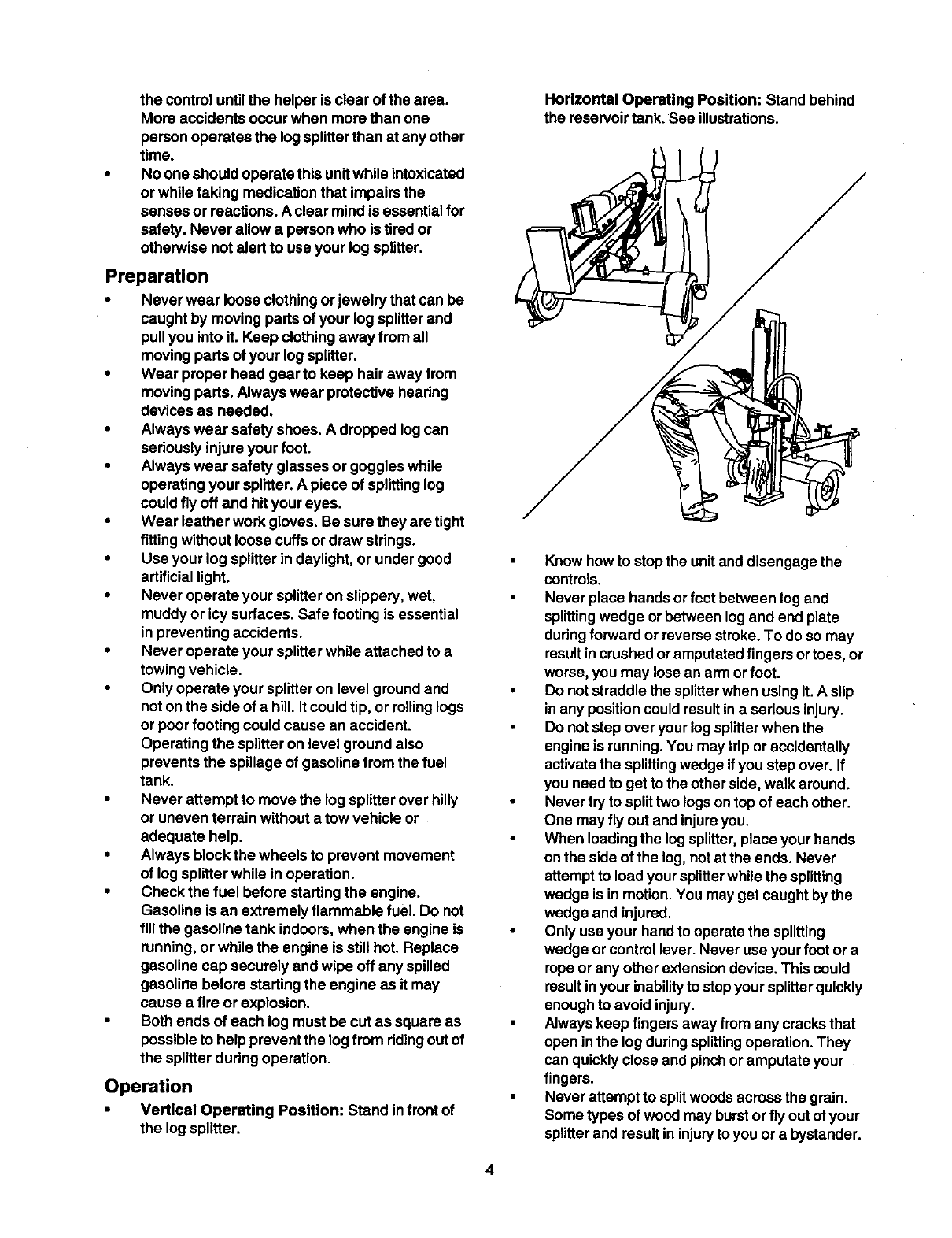
Vertical Operating Position: Stand infront of
the log splitter.
Horizontal Operating Position: Stand behind
the reservoir tank. See illustrations.
• Know how to stop the unit and disengage the
controls.
•Never place hands or feet between log and
splittingwedge or between log and end plate
dudng forward or reverse stroke.To do so may
resultincrushed oramputated fingers or toes, or
worse, you may losean arm or foot.
•Do not straddlethe splitterwhen usingit.A slip
in any positioncould resultin a serious injury.
•Do notstep over your log splitterwhen the
engine is running.You may trip or accidentally
activate the splittingwedge ifyou step over. If
you need to get to the other side, walk around.
•Never try to splittwo logsontop of each other.
One may fly out and injureyou.
•When loadingthe log splitter,place your hands
on the side of the log, notat the ends. Never
attempt to load your splitterwhile the splitting
wedge is in motion. You may get caught by the
wedge and injured.
•Only use your hand to operate the splitting
wedge or control lever.Never use your foot or a
rope or any other extensiondevice. This could
resultinyour inabilityto stopyour splitterquickly
enough to avoid injury.
•Always keep fingers away from any cracksthat
open inthe log duringsplittingoperation. They
can quicklyclose and pinchor amputate your
fingers.
•Never attempt to splitwoods acrossthe grain.
Some types of wood may burstor fly out of your
splitterand result ininjury to you or abystander.
•For logs that are not cut square, the longest
portionof the log should be rotated down and
the most square end placed against the splitting
wedge.
•Keep your work area clean. Immediately
remove split wood around your splittersothat
you do notstumble over it. Clean chips and dirt
off end plate (wood platform)after each log is
split, orwhenever necessary to maintainflat
contact between wood and end plate (platform).
•Never move the log splitterwhile the engine is
running.
•Never leave your log splitterunattended withthe
engine running. Shut off the engine if you are
leaving your splitter, even for a short periodof
time. Someone could accidentally activatethe
splittingwedge and be injured.
•Do not run engine Inan enclosed area. Exhaust
gases contain carbon monoxide.This ododess
gas can be deadly when inhaled.
•Be careful notto touch the muffler afterthe
engine has been running.It will be HOT!
•If the equipment should start to vibrate
abnormally, stop the engine and check
immediately for the cause. Vibration is generally
a warning of trouble.
When cleaning, repairing or inspecting,make
certain all movingparts have stopped.
Disconnect the spark plugwire and keep the
wire away from the plugto prevent accidental
starting.
Customer Responsibilities
•Do not operate your splitter inpoor mechanical
condition or when in need of repair.
• Periodically check that all nuts, bolts, screws,
hose clamps and hydraulic fittings are tight to be
sure equipment is in safe working condition.
Where appropriate, check all safety guards and
shields to be surethey are in the proper position.
Never operate your splitter with safety guards,
shields or other protective features removed.
These safety devices era for your protection.
• Replace all damaged or worn parts such as
hydraulic hoses and fittings immediately with
manufacturer approved replacement parts.
• Do not change the engine governor settings or
over_peed the engine. This increases the
hazard of personal injury. The maximum engine
speed is preset by the manufacturer and is
within safety limits.
• Do not alter your log splitter in any manner such
as attaching a rope or extensionto the control
lever or adding to the width or height of the
wedge. Such alterations may cause your splitter
to be unsafe.
Perform all recommended maintenance
procedures before you use your splitter.
Do not service or repairyour log splitterwithout "
disconnectingthe spark plug wire and moving it
away from the spark plug.
Never storethe equipment with gasoline inthe
tank insideof a buildingwhere ignitionsources
are present, such as hotwater and space
heaters, clothesdryers and the like. Allowthe
engine to cool before stodngin any enclosure.
Always store gasoline in an approved, tightly
sealed container. Store the container in a cool,
dry place. Do not store in abuildingwhere
ignitionsources are present.
To reduce fire hazard, keep enginefree of grass,
leaves, wood chips, and excessive grease and
oil.
The hydraulicsystemof your log splitterrequires
careful inspection,along withthe mechanical
parts. Be sure to replace frayed, kinked, or
otherwise damaged hydrauliccomponents.
Fluid escaping from a vary small hole can be
almost invisible. Do notcheck for leaks withyour
hand. Escapingfluid under pressure can have
sufficientforce to penetrate skin, causing
serious personal injury.Leaks can be located by
passinga piece of cardboard or wood over the
suspected leak and lookingfor discoloration.
Should it become necessary to loosenor
remove any hydraulicfitting or line, be sure to
relieve all pressure by shuttingoff the engine
and movingthe controlhandle back and forth
several times.
Do not removethe cap from the hydraulictank or
reservoirwhile your log splitteris running.Hot oil
underpressure could cause injury.
The pressure relief valve on your splitteris
preset at the factory. Do not adjust the valve.
Onlya qualifiedsentice technician should
performthisadjustment.
Completely drain fuel tank priorto storage. This
guardsagainst accumulationof fuel fumes
which could result in afire hazard.
Never store log splitteroutside withouta
waterproof cover. Rain will cause ruston the
insideof the cylinder.
Important Information
Always:
•Use clean fluid and check fluid level regularly
•Use Daxron III AutomaticTransmission Fluid or
10W non-foaming hydraulicfluid.
•Use a filter (clean or replace regularly)
Use a breather cap on fluid reservoir
5
•Make certain pump is mounted and aligned
properly
• Use a flexible "spider" type coupling between
engine and pump drive shafts
•Keep hosesclear and unblocked
•Bleed airout of hosesbefore operating
•Flush and clean hydraulicsystem before start-
upafter any malfunctionor servicing
•Use "pipe dope" on all hydraulicfittings
•Allowtime for warm-up before splittingwood
•Prime the pump before initialstart-up by turning
over the enginewith spark plugdisconnected
•Split wood withthe grain (lengthwise) only
Never:
•Use when fluid is below 20° F, orabove 150°F.
•Use a solid engine/pump coupling
•Force pump when mounting
•Operate through relief valve for several seconds
•Attempt to adjust unloadingor reliefvalve
settings without pressure gauges
•Operate with air in hydraulic system
•Use Teflon tape on hydraulicfittings
Attempt to cut wood across the grain.
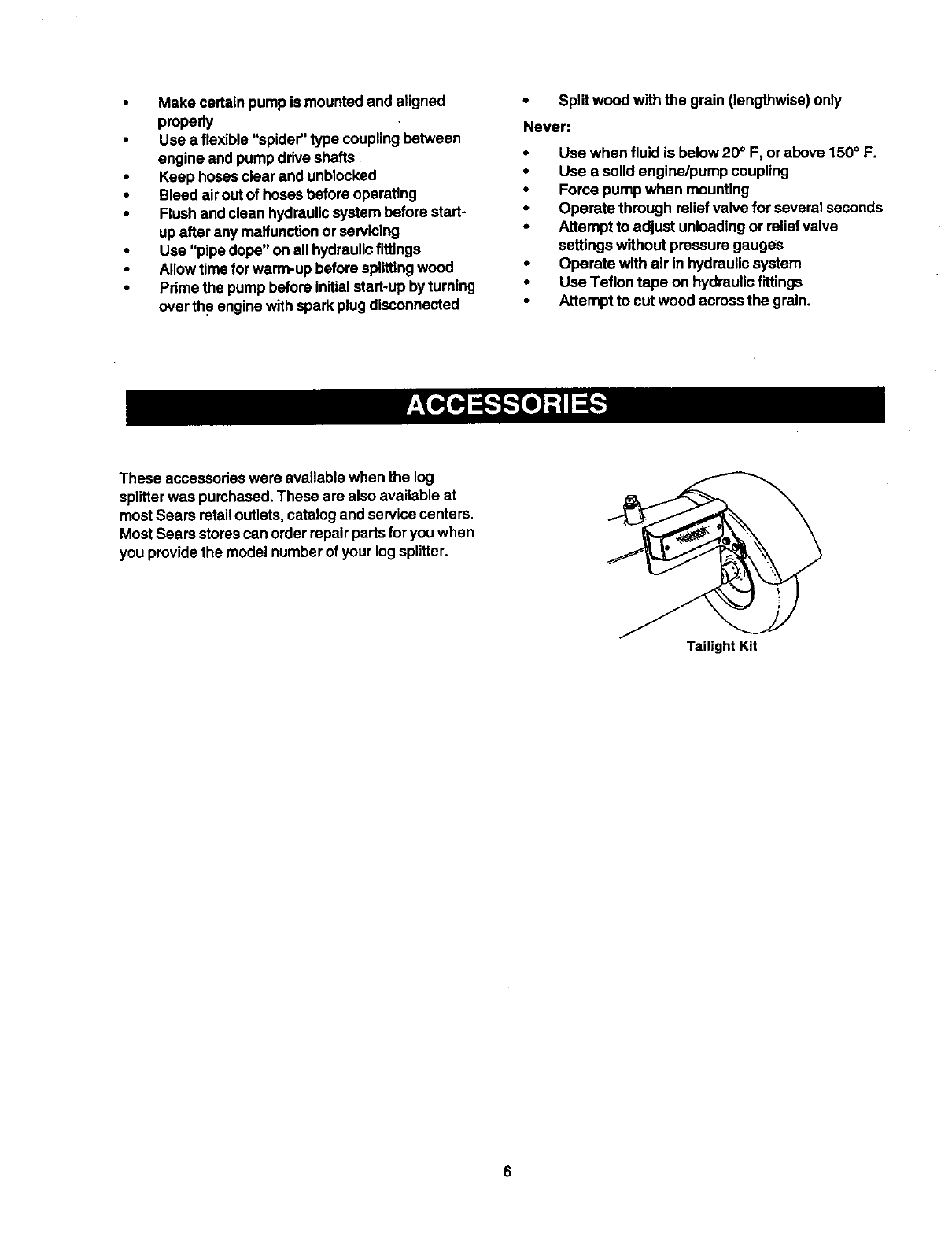
These accessodaswere available when the log
splitterwas purchased.These are also available at
most Sears retail outlets,catalog and service centers.
Most Sears storescan orderrepair partsforyou when
you provide the model number of your log splitter.
Tailight Kit
IMPORTANT: This unit is shipped without gasoline
in the engine. After assembly, see OPERATION
section of this manual for proper fuel fill-up.
Tools and Other Items Required
Crowbar or large screwdriver
A pair of 9/16' or adjustable wrenches*
Screwdriver
Cutters
Engine oil
Unleaded gasoline
Dexron III automatic transmission fluid or 10W non-
foaming hydraulicfluid (approximately 7 gallons)
Unpacking from Crate
WARNING: Exercise extreme caution as
parts are very heavy. Mechanical handling
equipment or sufficient manpower should
be used to prevent injury.
• Pry the top, sides and ends off crate usinga
crowbar or large screwdriver.
•Set panels aside to avoid tire punctures or
personal injury.
•Remove and discard plastic bag that covers
unit.
Note: Do not remove the banding from around the
tank until the log splitter is assembled.
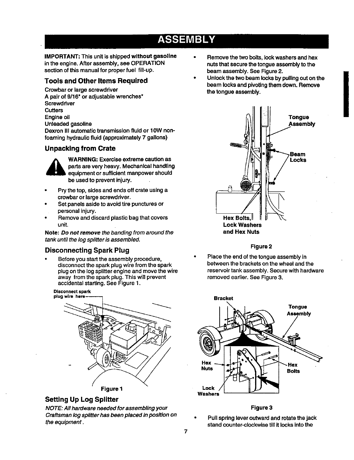
Disconnecting Spark Plug
•Before you start the assembly procedure,
disconnectthe spark plug wire fromthe spark
plugonthe log splitterengine and move the wire
away from the spark plug. This witlprevent
accidentalstarting. See Figure 1.
Disconnect spark
plug
Remove the two bolts, lockwashers and hex
nuts that Securethe tongue assembly to the
beam assembly. See Figure 2. II
Unlockthe two beam locksby pullingouton the i
beam locks and pivotingthem down. Remove
the tongue assembly.
Itl ,ongue
Lock Washers
and Hex Nuts
Figure 2
Place the end of the tongue assembly in
between the brackets on the wheel and the
reservoir tank assembly. Secure with hardware
removed earlier. See Figure 3.
Bracket
Tongue
Assembly
Hex
Botts
Figure 1
Setting Up Log Splitter
NOTE: All hardware needed for assembling your
Craftsman log splitter has been placed in position on
the equipment.
7
Lock
Figure 3
Pull spring leveroutward and rotate the jack
stand counter-clockwise tillit locksintothe
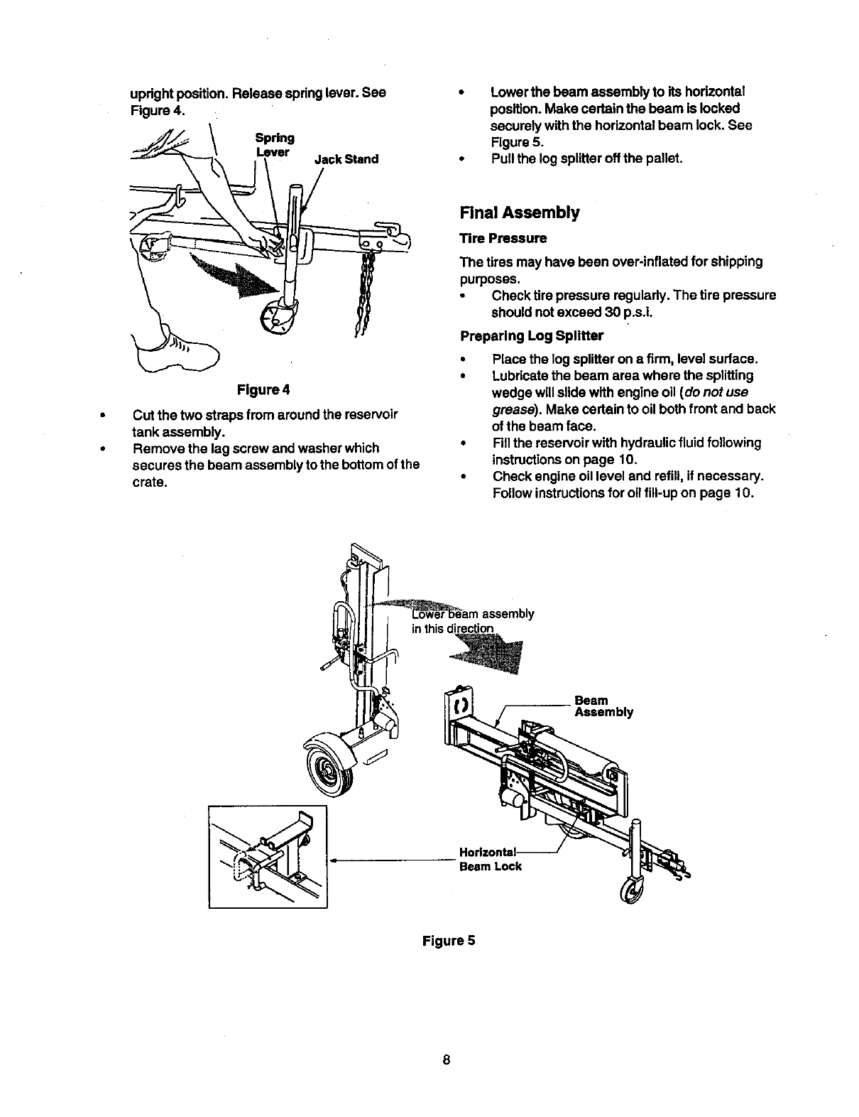
upright position. Release spring lever. See
Figure 4.
Spring
Lever Jack Stand
• Lower the beam assembly to its horizontal
position.Make certain the beam is locked
securely withthe horizontalbeam lock. See
Figure 5.
•Pull the log splitteroff the pallet.
Figure 4
•Cut the two straps from around the reservoir
tank assembly.
• Remove the leg screw and washer which
secures the beam assembly to the bottom ofthe
crate.
Final Assembly
Tire Pressure
The tires may have been over-inflated for shipping
purposes.
•Check tire pressure regularly.The tire pressure
should not exceed 30 p.s.L
Preparing Log Splitter
•Place the log splitteron afirm, levelsurface.
•Lubricate the beam area where the splitting
wedge will slide with engine oil (do not use
grease). Make certain to oil bothfront and back
of the beam face.
•Fillthe reservoirwith hydraulicfluid following
instructionson page 10.
•Check engine oil level and refill, if necessary.
Followinstructionsfor oil fill-up on page 10.
inthisdirection
Horizontal-
" Beam Lock
Beam
Assembly
Figure 5
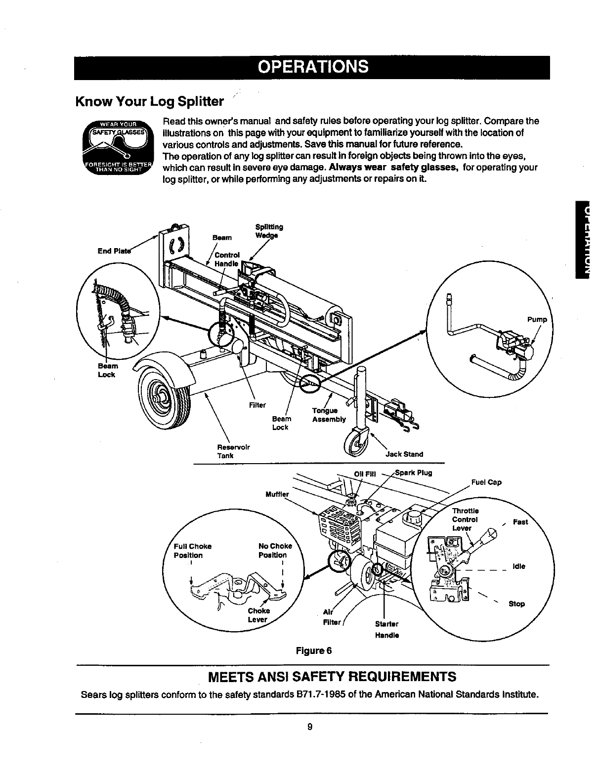
Know Your Log Splitter "
Read this owner's manual and safety rules before operating your log splitter.Compare the
illustrationson this pagewithyour equipment to familiarize yourselfwiththe locationof
various controlsand adjustments.Save this manual for future reference.
The operation of any logsplittercan result in foreign objects being thrownintothe eyes,
which can result in severe eye damage. Always wear safety glasses, foroperating your
log splitter, or while performingany adjustments or repairs on it.
End
Splitting
Beam kedg e
Beam
Lock
Beam
Lock
Reservoir
Tank Jack Stand
Fuel Cap
Rlter Starter
Handle
Figure 6
MEETS ANSI SAFETY REQUIREMENTS
Sears log splitters conformto the safety standards B71.7-1985 of the Amedcan National Standards institute.
9
OPERATING CONTROLS
(See Figure 6.)
WARNING: Before usingyour log splitter,
again referto the safety rules on pages 3-6
of thismanual. Always be careful.
Do not operate the !ogsplitterwithoutthe
proper amount of hydraulicoil inthe
reservoirtank. Failure to refillthe tank will
void your warranty.
Beam Locks
Located on the tongue and reservoirtank assemblies,
these are usedto securethe beam inthe horizontalor
the vertical position.
Choke Lever
Used to enrichthe fuel mixture inthe carburetorwhen
startinga cold engine.
Starter Handle
Used to manuallystart the engine.
Throttle Control
Permitsselection of fast orslow engine speed.
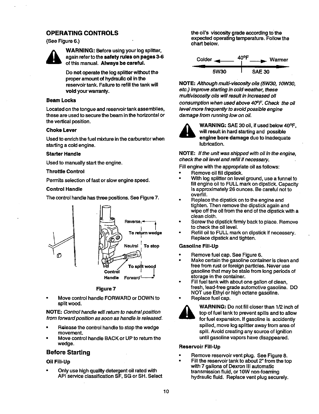
Control Handle
The controlhandlehas threepositions.See Figure7.
it wood
Control I
Handle Forward
Figure 7
Move controlhandle FORWARD or DOWN to
split wood.
NOTE: Controlhandle willreturn to neutral position
fromforwardposition as soon as handle is released.
•Release the controlhandle to stopthe wedge
movement.
•Move control handle BACK or UP to return the
wedge.
Before Starting
Oil Fill-Up
•Only use highqualitydetergent oil rated with
API service classificationSF, SG or SH. Select
the oil's viscosity grade accordingtothe
expected operating temperature. Followthe
chart below.
Colder _1_ 40°F Warmer
__ I
5W30 I SAE 30
NOTE: Although multi-viscosityoils(5W30, 10W30,
etc.) improve starting in cold weather, these
multiviscosity oils will result inincreased oil
consumption when used above 40°F. Check the oil
level more frequently to avoidpossible engine
damage fromrunning low on oil.
AWARNING: SAE 30 oil, if used below 40°F,
will result in hard startingand possible
engine bore damage due to inadequate
lubrication.
NOTE: Iftheunitwasshippedwithoilintheengine,
check the oil level and refillif necessary.
Fill engine with the appropriate oil as follows:
•Remove oilfill dipstick.
•With log splitteron level ground, use a funnelto
fill engine oil to FULL mark on dipstick. Capacity
is approximately 26 ounces. Be careful notto
overfill.
Replace the dipstickon to the engine and
tighten. Then remove the dipstickagain and
wipe off the oil fromthe end of the dipstickwitha
clean cloth.
•Screw the dipstickfirmly back to place. Remove
to check the oil level.
Refill oil to FULL mark ondipstickif necessary.
Replace dipstickand tighten.
Gasoline Fill-Up
Remove fuel cap. See Figure 6.
Make certain the gasoline container is clean and
free from rustor foreign particles. Never use
gasoline that may be stale from long periods of
storage inthe container.
Fill fuel tank withabout one gallon of clean,
fresh, lead-free grade automotive gasoline. DO
NOT use Ethylor highoctane gasoline.
Replace fuel cap.
WARNING: Do notfill closerthan 1/2 inch of
top of fuel tank to prevent spillsand to allow
for fuel expansion. If gasoline is accidently
spilled,move logsplitteraway from area of
spill.Avoid creating any source of ignition
untilgasoline vapors have disappeared.
Reservoir Fill-Up
Remove reservoir vent plug. See Figure 8.
Fill the reservoir tank to about 2"from the top
with 7 gallons of Dexron III automatic
transmission fluid, or 10W non-foaming
hydraulicfluid. Replace vent plugsecurely.
10
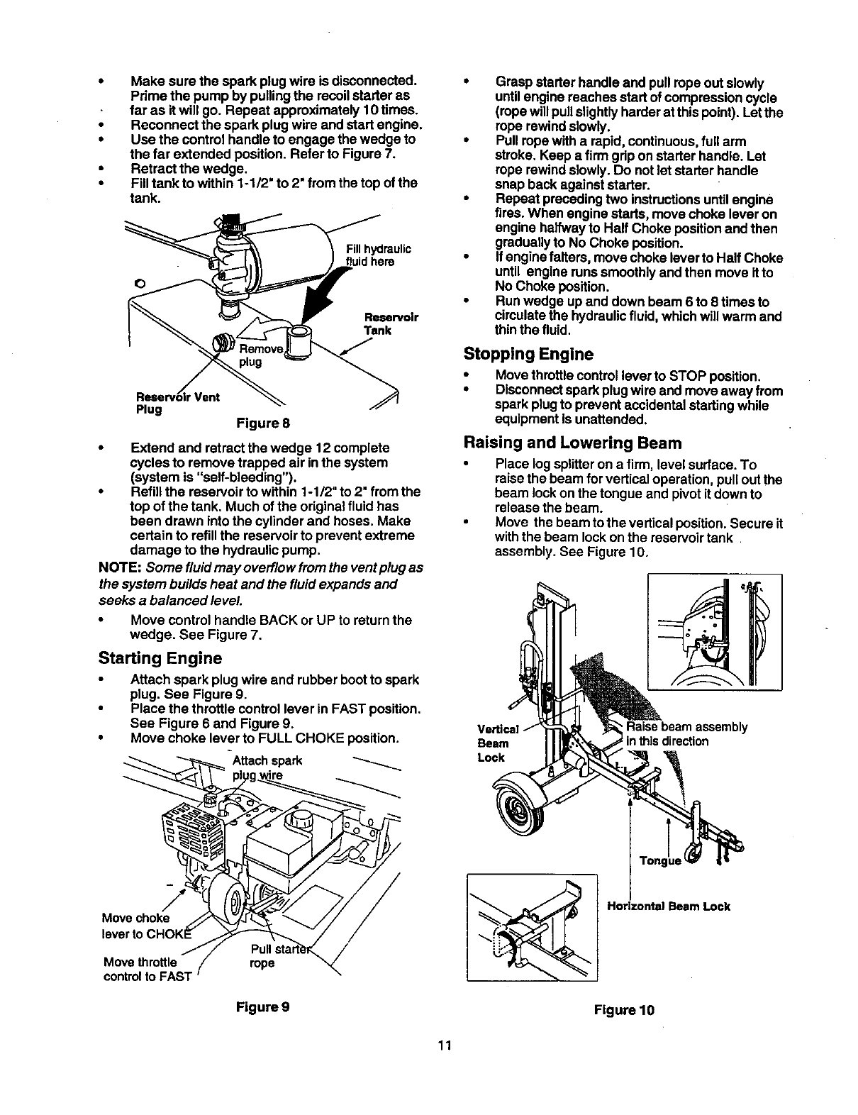
•Make sure the spark plugwire is disconnected.
Pdme the pump by pullingthe recoilstarter as
far as it will go. Repeat approximately 10 times.
•Reconnect the spark plug wire and start engine.
•Use the control handle to engage the wedge to
the far extended position. Refer to Figure 7.
•Retract the wedge.
•Filltank to within 1-1/2" to 2" from the top of the
tank.
Fillhydraulic
fluidhere
Reservoir
Tank
Bseerv Yen, 9
Plug Figure 8
•Extend and retract the wedge 12 complete
cycles to remove trapped air inthe system
(system is "self-bleeding").
•Refill the reservoir to within 1-1/2" to 2" fromthe
top of the tank. Much of the original fluid has
been drawn intothe cylinder and hoses. Make
certain to refillthe reservoir to prevent extreme
damage to the hydraulicpump.
NOTE: Some fluidmay overflow fromthe ventplug as
the system builds heat and the fluidexpands and
seeks a balanced level.
•Move control handle BACK or UP to return the
wedge. See Figure 7.
Starting Engine
Attach spark plugwire and rubber bootto spark
plug. See Figure 9.
•Place the throttle control lever in FAST position.
See Figure 6 and Figure 9.
•Move choke lever to FULL CHOKE position.
Attachspark
•Grasp starter handle and pullrope outslowly
untilengine reaches start of compressioncycle
(rope willpullslightlyharder at thispoint). Let the
rope rewind slowly.
•Pull rope with a rapid, continuous, full arm
stroke. Keep a firmgrip on starter handle. Let
rope rewind slowly.Do notlet starter handle
snap back against starter.
•Repeat precedingtwo instructionsuntilengine
fires. When engine starts, move choke lever on
engine halfwayto Halt Choke positionand then
graduallyto No Choke position.
•If engine falters, move choke leverto Half Choke
until engine runs smoothlyand then move itto
No Choke position.
•Run wedge up and down beam 6 to 8 times to
circulatethe hydraulicfluid, which willwarm and
thin the fluid.
Stopping Engine
•Move throttlecontrol lever to STOP position.
•Disconnectspark plugwire and move away from
spark plugto prevent accidental startingwhile
equipment is unattended.
Raising and Lowering Beam
•Place log splitteron a firm, level surface. To
raisethe beam forvertical operation, pullout the
beam lockon the tongue and pivot it down to
release the beam.
•Move the beam to the vertical position. Secure it
withthe beam lockon the reservoirtank
assembly. See Figure 10.
Ve_ica!
Beam
Lock
_Raise beam assembly
in this direction
Movechoke
Movethrottle rope /
controlto FAST
Figure 9 Figure 10
Lock
11
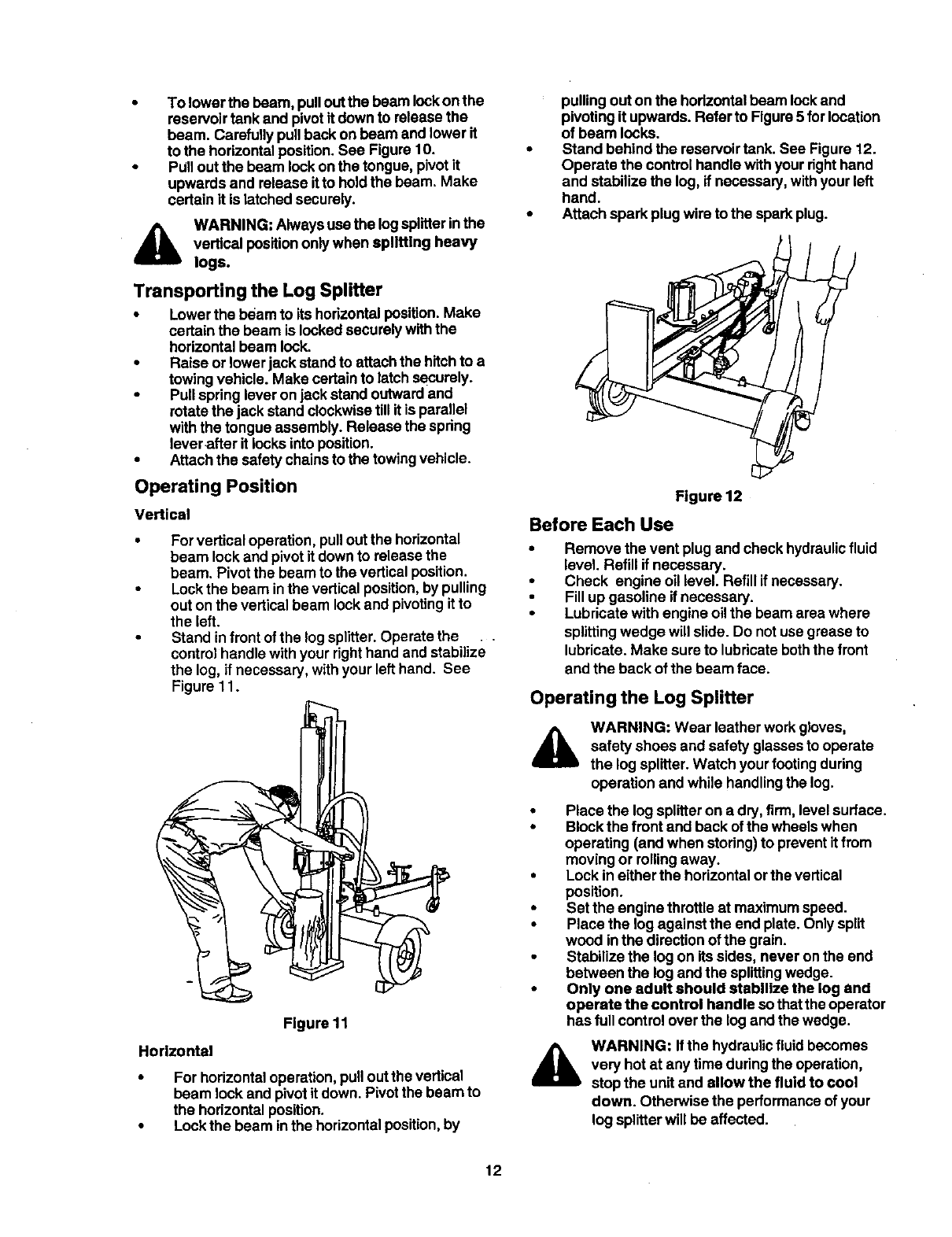
• Tolowerthebeam,pulloutthebeamlockonthe
reservoir tank and pivotit down to release the
beam. Carefully pullback on beam and lower it
to the horizontalposition.See Figure 10.
•PUlloutthe beam lockonthe tongue, pivot it
upwards and release itto holdthe beam. Make
certain it is latched securely.
WARNING: Alwaysuse the logsplitterinthe
vertical position only when splitting heavy
logs.
Transporting the Log Splitter
•Lowerthe beam to its horizontalposition. Make
certain the beam is lockedsecurely withthe
horizontalbeam lock.
•Raise or lower jack standto attachthe hitchto a
towingvehicle. Make certainto latch securely.
•Pull spring leveron jack stand outwardand
rotatethe jack stand clockwisetill it is parallel
with the tongue assembly. Release the spring
leverafter it locksintoposition.
•Attachthe safety chainsto the towingvehicle.
Operating Position
Vertical
•For vertical operation, pullout the horizontal
beam lockand pivot itdown to release the
beam. Pivotthe beam to the vertical position.
•Lockthe beam inthe vertical position,by pulling
out onthe verticalbeam lockand pivotingitto
the left.
•Stand infront of the log splitter.Operate the .
control handle withyour righthand and stabilize
the log, if necessary, withyour left hand. See
Figure 11.
Figure 11
Horizontal
•For horizontaloperation, pullout the vertical
beam lock and pivot it down. Pivotthe beam to
the horizontalposition.
•Lockthe beam inthe horizontalposition,by
pulling out on the horizontalbeam lockand
pivotingit upwards. Refer to Figure5 forlocation
of beam locks.
•Stand behind the reservoirtank. See Figure 12.
Operate the control handlewithyour righthand
and stabilize the log, if necessary, withyour left
hand.
•Attach spark plug wireto the sparkplug.
L
Figure 12
Before Each Use
•Remove the vent plug and check hydraulicfluid
level. Refill if necessary.
•Check engine oil level. Refill ifnecessary.
Fillup gasoline if necessary.
•Lubricate withengine oil the beam area where
splittingwedge will slide. Do notuse grease to
lubricate. Make sure to lubricateboththe front
and the back of the beam face.
Operating the Log Splitter
WARNING: Wear leather workgloves,
safety shoes and safety glassesto operate
the log splitter.Watch your footing during
operation and while handlingthe log.
• Place the log splitteron a dry, firm, levelsurface.
•Block the front and back of the wheels when
operating (and when storing) to prevent it from
movingor rollingaway.
•Lock in either the horizontalor the vertical
position.
•Set the engine throttle at maximum speed.
•Place the log against the end plate. Only split
wood inthe directionof the grain.
•Stabilize the log on its sides, never onthe end
between the log andthe splittingwedge.
•Only one adult should stabilize the log and
operate the control handle so that the operator
has full control overthe log and the wedge.
AWARNING: If the hydraulicfluid becomes
very hot at any time duringthe operation,
stop the unit and allow the fluid to cool
down. Otherwise the performanceof your
log splitterwill be affected.
12
"6
,-z
"O
O
O.
G)
t-
=m
LLI
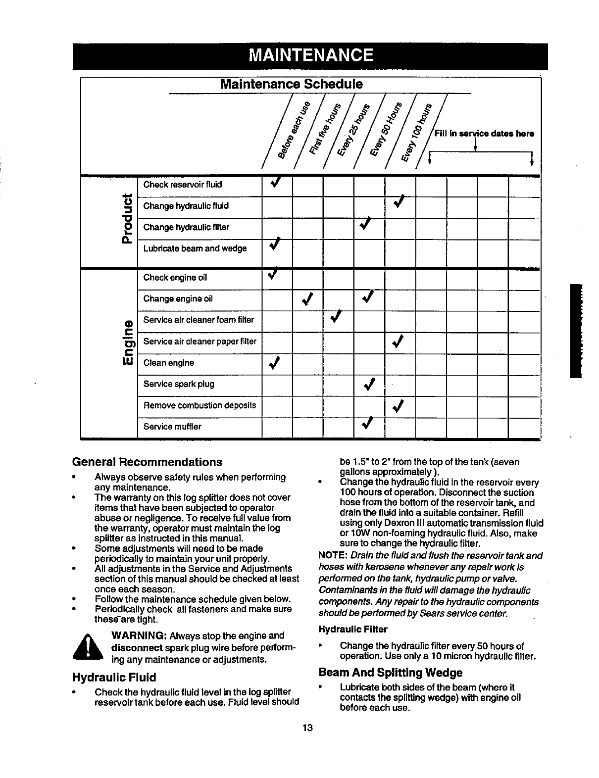
Maintenance Schedule:ooOi,ooo/U
Check reservoirfluid
Change hydraulic fluid
Change hydraulic filter
Lubricate beam and wedge
Check engine oil V /
Change engine oil _
Service air cleaner foam filter
servicedates here
l
Service air cleaner paper filter
Clean engine
Service spark plug
Remove combustion deposits
Service muffler '_
General Recommendations
• Always observe safety rules when performing
any maintenance.
•The warranty on this log splitterdoes not cover
items that have been subjected to operator
abuse or negligence. To receive fullvalue from
the warranty, operator must maintainthe log
splitter as instructed inthis manual.
•Some adjustments will need to be made
periodicallyto maintain your unitproperly.
•All adjustments inthe Service and Adjustments
section of this manual should be checked at least
once each season.
•Follow the maintenance schedule given below.
•Periodically check all fasteners and make sure
these-are tight.
4_ WARNING: Always stopthe engine and
disconnect spark plug wire before perform-
ing any maintenance or adjustments.
Hydraulic Fluid
•Check the hydraulicfluid level inthe logsplitter
reservoir tank before each use. Fluid levelshould
be 1.5" to 2" fromthe top of the tank (seven
gallonsapproximately).
•Change the hydraulicfluid inthe reservoir every
100 hoursof operation. Disconnectthe suction
hosefrom the bottomof the reservoirtank, and
drainthe fluid into a suitablecontainer. Refill
usingonly Dexmn III automatic transmissionfluid
or 10W non-foaminghydraulicfluid. Also, make
sureto change the hydraulicfilter.
NOTE: Drain the fluidand flush the reservoir tank and
hoses with kerosene whenever any repair work is
performed on the tank, hydraulicpump or valve.
Contaminantsin the fluidwill damage the hydraulic
components.Any repair to the hydrauliccomponents
should be performed by Sears service center.
Hydraulic Filter
Change the hydraulicfilter every 50 hoursof
operation. Use only a10 micronhydrsulicfilter.
Beam And Splitting Wedge
•Lubricate beth sidesof the beam (where it
contactsthe splittingwedge) withengine oil
before each use.
13
However,normalwearwilloccur.Pedodicallyadjust
theboltsonthesideofthewedgeplateasfollowsto
eliminateexcessspacebetweenthewedgeplateand
thebeam.
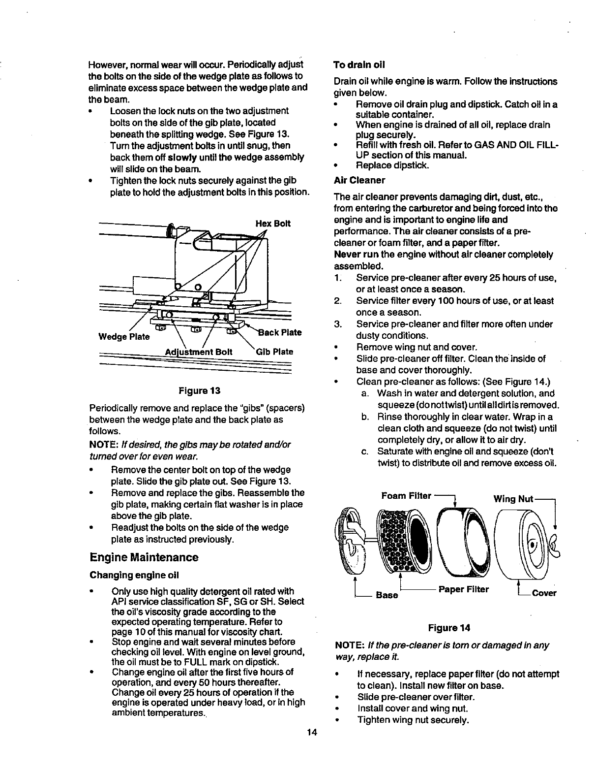
•Loosenthe lock nutson the two adjustment
bolts onthe side of the gib plate, located
beneath the splittingwedge. See Figure 13.
Turn the adjustmentbolts in untilsnug, then
backthem off slowly untilthe wedge assembly
will slide on the beam.
•Tighten the locknutssecurely against the gib
plateto holdthe adjustment bolts inthis position.
Hex Bolt
Wedge Plate
Ad't
Figure 13
Periodicallyremove and replace the "gibs" (spacers)
between the wedge plate and the back plate as
follows.
NOTE: If desired, the gibs may be rotated and/or
turnedover for even wear.
•Remove the center bolt ontop of the wedge
plate. Slide the gib plate out. See Figure 13.
•Remove and replace the gibs. Reassemble the
gib plate, making certain flat washer is in place
abovethe gib plate.
•Readjustthe bolts onthe side of the wedge
plate as instructedpreviously.
Engine Maintenance
Changing engine oil
•Only use highqualitydetergent oil ratedwith
API service classificationSF, SG or SH. Select
the oil's viscositygrade accordingto the
expected operatingtemperature. Refer to
page 10 of this manual for viscositychart.
• Stop engine and wait several minutes before
checkingoil level. With engine on level ground,
the oil mustbe to FULL mark on dipstick.
•Change engine oil after the firstfive hoursof
operation, and every 50 hoursthereafter.
Change oilevery 25 hours of operationif the
engine is operated under heavy load, or in high
ambient temperatures.
14
To drain oli
Drain oil while engine iswarm. Followthe instructions
given below.
•Remove oil drain plugand dipstick. Catchoil in a
suitable container.
•When engine is drained of alloil, replace drain
plug securely.
•Refillwith fresh oil. Refer to GAS AND OIL FILL-
UP section of this manual.
•Replace dipstick.
Air Cleaner
The air cleaner prevents damaging dirt, dust, etc.,
from entering the carburetor and being fomed intothe
engine and is impodant to engine lifeand
performance. The air cleaner consists of a pre-
cleaner or foam filter, and a paper filter.
Never run the engine withoutair cleaner completely
assembled.
1. Service pre-cleaner after every 25 hoursof use,
or at least once aseason.
2. Service filter every 100 hoursof use, or at least
once a season.
3. Service pre-cleaner and filter more often under
dusty conditions.
•Remove wing nut and cover.
•Slide pre-cleaner off filter. Clean the insideof
base and cover thoroughly.
•Clean pre-cleaner as follows: (See Figure 14.)
a. Wash in water and detergent solution,and
squeeze (donottwist)untilandirfisremoved.
b. Rinse thoroughly in clear water. Wrap in a
clean cloth and squeeze (do nottwist) until
completely dry, or allow if to air dry.
c. Saturate with engineoil and squeeze (don't
twist) to distributeoil and removeexcessoil.
°mt3wiu
_Base -- Paper Filter --Cover
Figure 14
NOTE: If the pre-cleaner is tom or damaged in any
way, replace it.
•If necessary, replace paper filter (do not attempt
to clean). Install new filter on base.
•Slide pre-cleaner over filter.
•Install cover and wing nut.
Tighten wing nut securely.
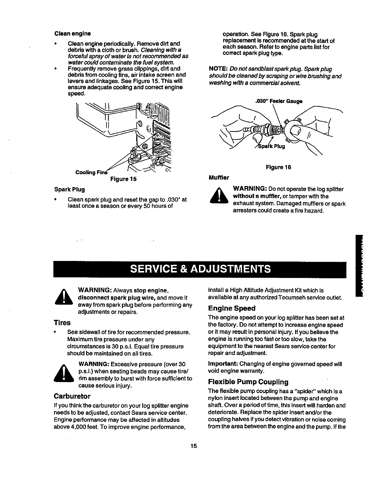
Cleanengine
Cleanengineperiodically.Removedirtand
debdswithaclothorbrush.Cleaning with a
forcefulspray of water is net recommended as
water couldcontaminate the fuel system.
Frequently remove grass clippings,dirt and
debds from coolingfins, air intake screen and
levers and linkages. See Figure 15. This will
ensure adequate cooling and correct engine
speed.
operation. See Figure 16. Spark plug
replacement is recommended atthe start of
each season. Refer to engine parts listfor
correct spark plugtype.
NOTE: Do notsandblast sparkplug. Sparkplug
should be cleaned by scrapingor wirebrushing and
washing witha commercialsolvent.
.030" Feeler Gauge
€Plug
Cooling Find Figure 15
Spark Plug
•Clean spark plug and reset the gap to .030" at
least once a season or every 50 hoursof
Muffler
A
Figure 16
WARNING: Do notoperate the log splitter
without amuffler, or tamper withthe
exhaust system. Damaged mufflers or spark
arresters could create a firehazard.
Tires
WARNING: Always stop engine,
disconnect spark plug wire, and move it
away from spark plug before performing any
adjustments or repairs.
See sidewall of tirefor recommended pressure.
Maximum tire pressure under any
cimumstances is 30 p.s.i. Equal tire pressure
should be maintained on alltires.
WARNING: Excessive pressure (over 30
p.s.i.) when seating beads may cause tire/
rim assemblyto burst with force sufficientto
cause serious injury.
Carburetor
If youthink the carburetor on your log splitterengine
needs to be adjusted, contact Sears service center.
Engineperformance may be affected in altitudes
above 4,000 feet. To improve engine performance,
install a High AltitudeAdjustment Kitwhich is
available at any authorizedTecumseh serviceoutlet.
Engine Speed
The engine speed on your logsplitterhas been set at
the factory. Do notattempt to increase engine speed
or it may result in personalinjury. Ifyou believe the
engine is runningtoo fast or too slow,take the
equipment to the nearest Sears servicecenter for
repair and adjustment.
Important: Changing of engine governed speed will
void engine warranty.
Flexible Pump Coupling
The flexible pump couplinghas a "spider" which is a
nylon insert located between the pump and engine
shaft. Over a period oftime, this insertwill harden and
deteriorate. Replace the spiderinsertand/or the
coupling halves if you detectvibrationor noisecoming
from the area between the engine andthe pump. If the
15
spiderfailscompletely,youwillexperience a lossof
power.
_lb ARNING: Never hitthe engine shaft in
any manner, as a blow willcause permanent
damage to the engine orthe pump.
Follow the instructionscarefullyas the alignmentof
the couplings is critical.
•Disconnect the spark plugwire fromthe spark
plug, and keep it away from the sparkplug.
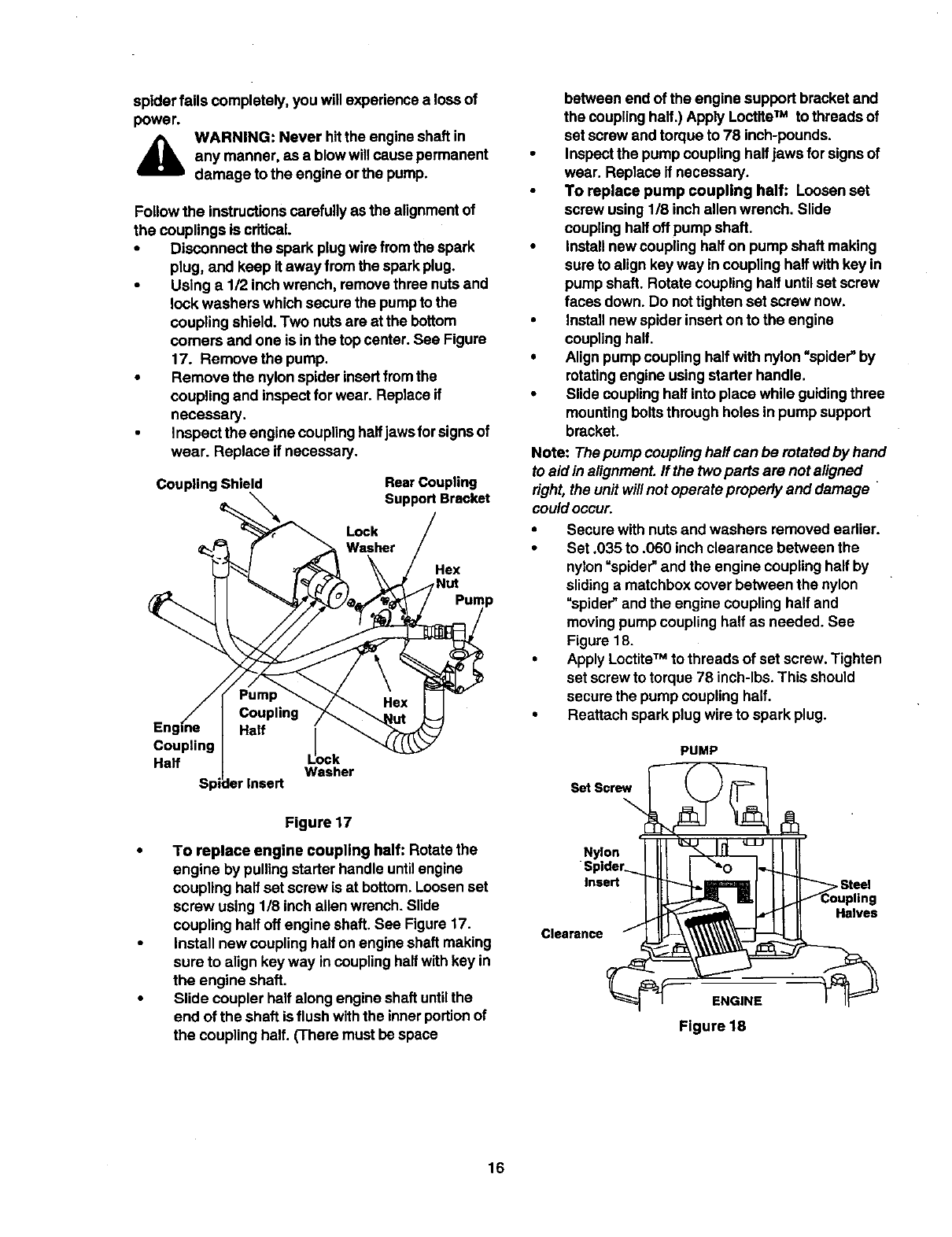
•Using a 112inch wrench, removethree nuts and
look washers which secure the pumpto the
coupling shield. Two nuts are at the bottom
comers and one is inthe top center. See Figure
17. Remove the pump.
•Remove the nylonspider insertfrom the
coupling and inspect for wear. Replace if
necessary.
• Inspect the engine couplinghalfjawsfor signsof
wear. Replace if necessary.
Coupling Shield Rear Coupling
Support Bracket
Lock
Washer
Hex
Coupling lo
Half ck
Washer
Figure 17
•To replace engine coupling half: Rotatethe
engine by pulling starter handle untilengine
coupling half set screw is at bottom.Loosen set
screw using 1/8 inch allen wrench. Slide
coupling half off engine shaft.See Figure 17.
•install new coupling half onengine shaft making
sure to align key way incoupling halfwithkey in
the engine shaft.
• Slide coupler half along engine shaft until the
end of the shaft is flush withthe inner portion of
the coupling half. (There must be space
between end of the engine support bracket and
the couplinghalf.) Apply LoctifeTM to threads of
set screw and torqueto 78 inch-pounds.
Inspectthe pump coupling halfjaws forsigns of
wear. Replace if necessary.
To replace pump coupling half: Loosenset
screw using1/8 inch allen wrench. Slide
coupling halfoff pump shaft.
Install new couplinghalf on pump shaft making
sure to alignkey way in coupling halfwith key in
pump shaft. Rotate coupling half untilset screw
faces down. Do not tightenset screw now.
Install new spider insert onto the engine
coupling half.
Align pumpcoupling half with nylon"spider" by
rotatingengine using starter handle.
Slide couplinghalf intoplace while guiding three
mountingbolts through holes in pump support
bracket.
Note: The pump couplinghalf can be rotated by hand
to aid inalignment, ff the twoparts are not aligned
dght, the unit willnot operate propedy and damage
couldoccur.
•Secure with nutsand washers removed earlier.
•Set .035 to .060 inchclearance between the
nylon=spider" and the engine coupling halfby
slidingamatchbox coverbetween the nylon
"spider" and the engine couplinghalf and
movingpump couplinghalf as needed. See
Figure 18.
•Apply LoctiteTM to threads of set screw. Tighten
set screw to torque 78 inch-lbs.This should
securethe pump couplinghalf.
• Reattach sparkplug wire to spark plug.
PUMP
Set Screw
Nylon
Insert
Clearance
ENGINE
Figure 18
•Steel
Halves
16
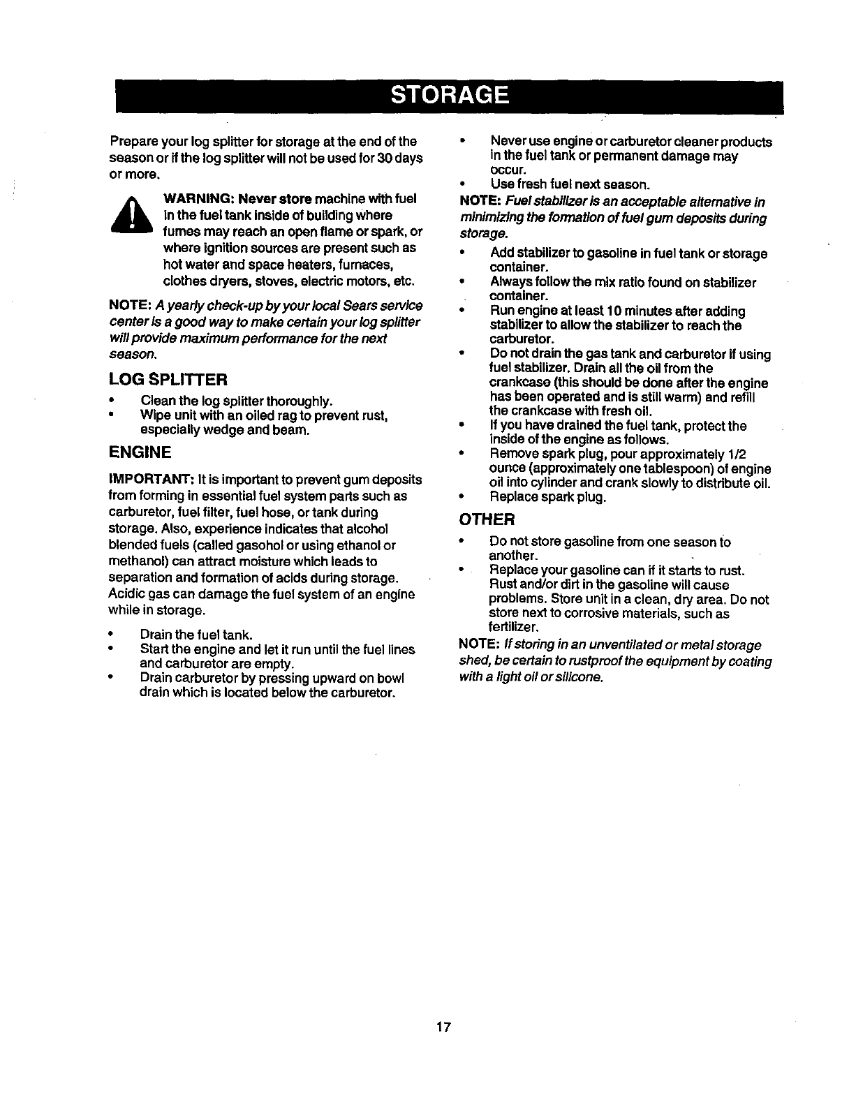
Prepareyourlogsplitterforstorageattheendofthe
seasonorifthelogsplitterwillnotbeusedfor30days
ormore.
AWARNING: Never store machine withfuel
in the fuel tank insideof buildingwhere
fumes may reach an openflame orspark, or
where ignitionsources are present such as
hotwater and space heaters, furnaces,
clothes dryers, stoves, electric motors,etc.
NOTE: A yearly check-up byyour local Sears service
center is a good way to make certain your log splitter
will provide maximum performance forthe next
season.
LOG SPLITTER
•Clean the log splitterthoroughly.
•Wipe unitwRh an oiled ragto prevent rust,
especially wedge and beam.
ENGINE
IMPORTANT: It is importantto prevent gumdeposits
from forming in essential fuel system partssuchas
carburetor, fuel filter, fuel hose, ortank during
storage. Also, experience indicatesthat alcohol
blended fuels (called gasohol or usingethanolor
methanol) can attract moisturewhich leads to
separation and formation of acidsduringstorage.
Acidic gas can damage the fuel systemof an engine
while in storage.
Drain the fuel tank.
Start the engine and let it run untilthe fuel lines
and carburetor are empty.
Drain carburetor by pressingupward on bowl
drainwhich is located below the carburetor.
•Never use engineor carburetorcleaner products
in the fueltank or permanent damage may
Occur.
•Use fresh fuel next season.
NOTE: Fuel stabilizaris an acceptable alternative in
minimizingthe formation of fuelgum depositsduring
storage.
•Add stabilizerto gasoline infuel tank orstorage
container.
•Alwaysfollowthe mix ratio found onstabilizer
container.
•Run engine at least 10 minutes after adding
stabilizerto allow the stabilizerto reachthe
carburetor.
•Do notdrainthe gas tank and carburetorif using
fuel stabilizer. Drain allthe oil from the
crankcase (thisshould be done after the engine
has been operated and is stillwarm) and refill
the crankcasewithfresh oil.
•If you have drained the fuel tank, protectthe
insideofthe engine as follows.
•Remove spark plug, pour approximately 112
ounce (approximatelyonetablespoon) of engine
oil into cylinderand crank slowly to distributeoil.
•Replace spark plug.
OTHER
•Do notstore gasoline fromone season to
another.
Replace your gasoline can if it starts to rust.
Rustand/or dirt inthe gasoline will cause
problems.Store unit in a clean, dryarea. Do not
store nextto corrosive materials, suchas
fertilizer.
NOTE: ffstoringinan unventilatedor metal storage
shed, be certainto rustproofthe equipment by coating
witha lightoil orsilicone.
17
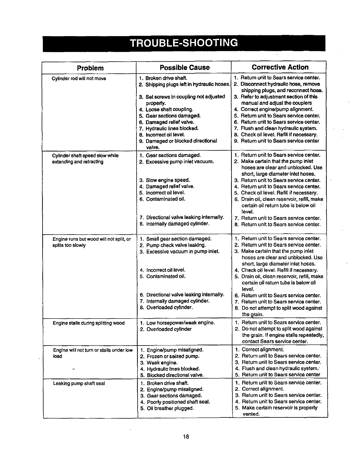
Problem Corrective Action
Cylinderrodwillnot move
Cylindershaftspeed slowwhile
extendingand retracting
Engine runsbutwoodwillnotsplit,or
splitstooslowly
Engine stalls during splitting wood
Enginewillnotturnor staFIsunderlow
load
Leakingpumpshaftseal
Possible Cause
1. Broken ddva shaft.
2. Shippingplugs left in hydraulic hoses,
3. Set screws in coupling not adjusted
properly.
4. Loose shaft coupling.
5. Gear sections damaged.
6. Damaged reliefvalve.
7. Hydraulic lines blocked.
8. InsorrectoUlevel.
9. Damaged or blockeddirectional
valve.
1. Gear sections damaged.
2. Excessive pump inlet vacuum.
3. Slow engine speed.
4. Damaged relief valve.
5. Incorrectoil level.
I6. Contaminated oil.
7. Directionalvalve leaking internally.
8. Internallydamaged cylinder.
1. Small gear sectiondamaged.
2. Pump check valve leaking.
3. Excessive vacuum in pump inlet.
4. Incorrectoil level.
5. Contaminated oil.
6. Directionalvalve leaking internally.
7. Internallydamaged cylinder.
8. Overloaded cylinder.
1. Lowhomepower/weak engine.
2. Overloaded cylinder
1. Engine/pump misaligned.
2. Frozen orseized pump.
3. Weak engine.
4. Hydraulic lines blocked.
5. Blocked directionalvalve.
1. Broken drive shaft.
2. Engine/pump miselignsd.
3. Gear sections damaged.
4. Poody positionedshaft seal.
5. Oil breather plugged.
1. Return unit to Sears service center.
2. Disconnect hydraulic hose, remove
shipping plugs, and reconnect hose.
3. Refer to adjustment secfion of this
manual and adjust the oouplers
4. Correct engine/pump alignment.
5. Return unit to Sears service center.
6. Return unit to Sears service center.
7. Flush and clean hydraulicsystem.
I8. Check oil level. Refill if necessary.
9. Return unit to Sears servise osnter
1. Return unit to Sears service center.
2. Make certain that the pump inlet
hoses are clear and unblocked. Use
short, large diameter inlet hoses.
3. Return unit to Sears service center.
4. Return unit to Sears service center.
5. Check oil level. Refill if necessary.
6. Drain oil, clean reservoir, refill,make
certain oil return tube is below oil
level.
7. Return unit to Sears service center.
8. Return unit to Sears service center.
1. Return unit to Sears service center.
2. Return unit to Sears service center.
3. Make certain that the pump inlet
hoses are clear and unblocked. Use
short, large diameter inlet hoses.
4. Check oil level. Refill it necessary.
5. Drain oil, clean reservoir, refill, make
certain oil return tube is below oil
level.
6. Return unit to Sears service center.
7. Return unit to Sears service center.
8. Do not attempt to split wood against
the grain.
1. Return unitto Sears service center.
2. Do not attempt to split wood against
the grain. If engine stalls repeatedly,
contact Sears service center.
1. Correct alignment.
2. Return unit to Sears service center.
3. Return unit to Sears service center.
4. Flush and clean hydraulic system."
5. Return unit to Sears service center
1. Return unit to Sears service center.
2. Correct alignment.
3. Return unit to Sears service center.
4. Return unit to Sears service center.
5. Make certain reservoir is properly
vented.
18
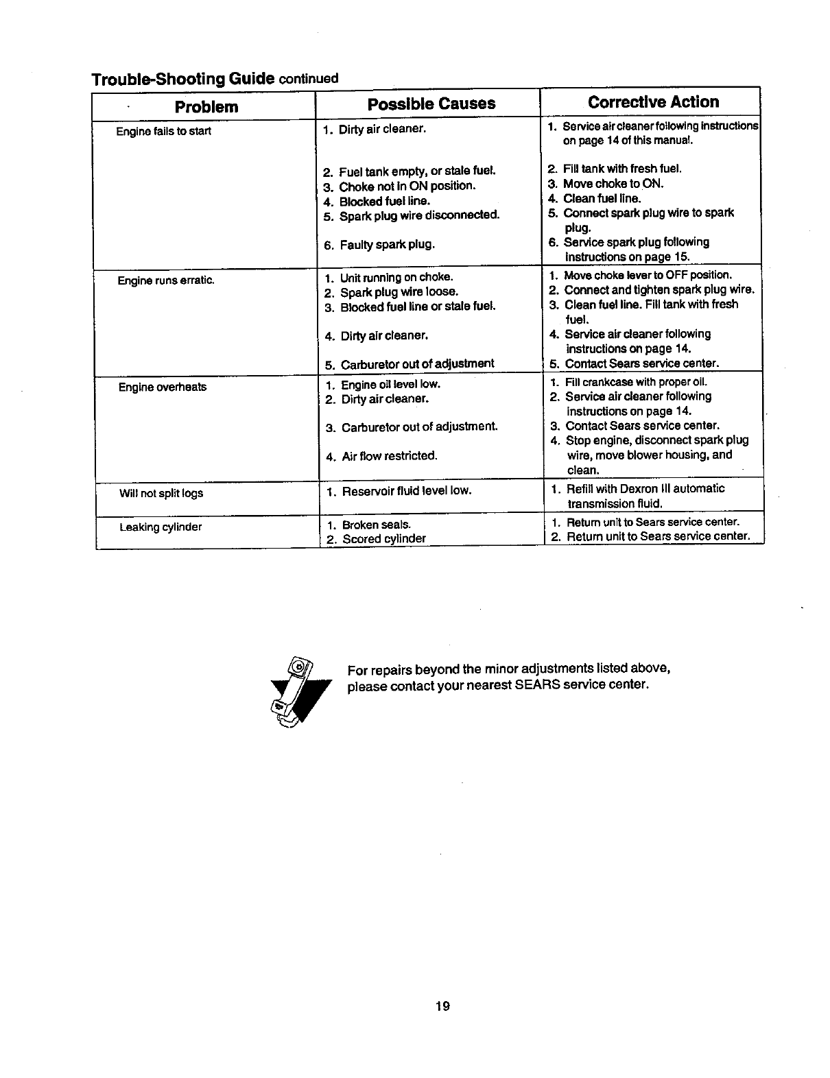
Trouble-Shooting Guide continued
Problem Possible Causes
Engine failsto stad 1. Dirty air cleaner. 1.
Enginerunserratic,
Engine overheats
Will not split logs
Leaking cylinder
2. Fuel tank empty, or stale fuel.
3. Choke not inON position.
4. BIcokedfuel line.
5. Spark plug wire disconnected.
6. Faulty spark plug.
1. Unitrunningon choke.
2. Spark plugwire loose.
3. Blocked fuel line or stale fuel.
4. Dirty air cleaner.
5. Carburetor out of adjustment
1. Engineoil level low.
2. D)rtyair oleaner,
3. Carburetor out of adjustment.
4. Air flow restricted,
1. Reservoir fluid level low.
Correctlve Action
ServiceaircleanerfollowingInstruction,=
on page 14of thismanual.
2. Fill tank with fresh fuel.
3. Move choke to ON.
4. Clean fuel line.
5. Connect spark plugwire to spark
plug.
6. Service spark plugfollowing
ir'.strucflonson page 15.
1. Move chokelever toOFF position.
2. Connect and tighten spark plug wire,
3. Clean fuel line. Fill tank with fresh
fuel.
4. Service aircleaner following
instructions on page 14.
5. Contact Sears service center.
1.
2.
3.
4.
Fillcrankcasewithproperoil.
Service aircleaner following
instructionson page 14.
Contact Sears service center.
Stop engine, disconnectspark plug
wire, move blower housing,and
clean.
1.
1.
2.
Refill with Dexron III automatic
transmissionfluid.
1. Brokenseals. Retumunitto Searsservicecenter.
2. Scored cylinder Return unit to Sears service center.
For repairs beyond the minoradjustments listed above,
please contact your nearest SEARS service center.
19
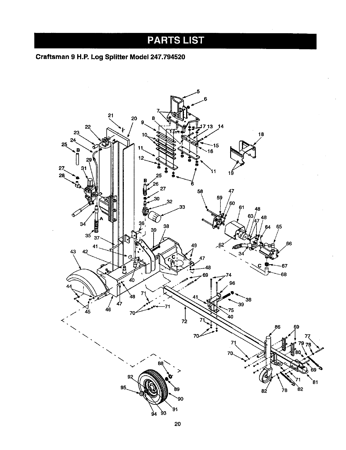
Craftsman 9 H.P. Log Splitter Model 247.794520
35
43 42
44
20 8
46
38
1713 14
72
18
96
86
82 78
69
\81
82
2O
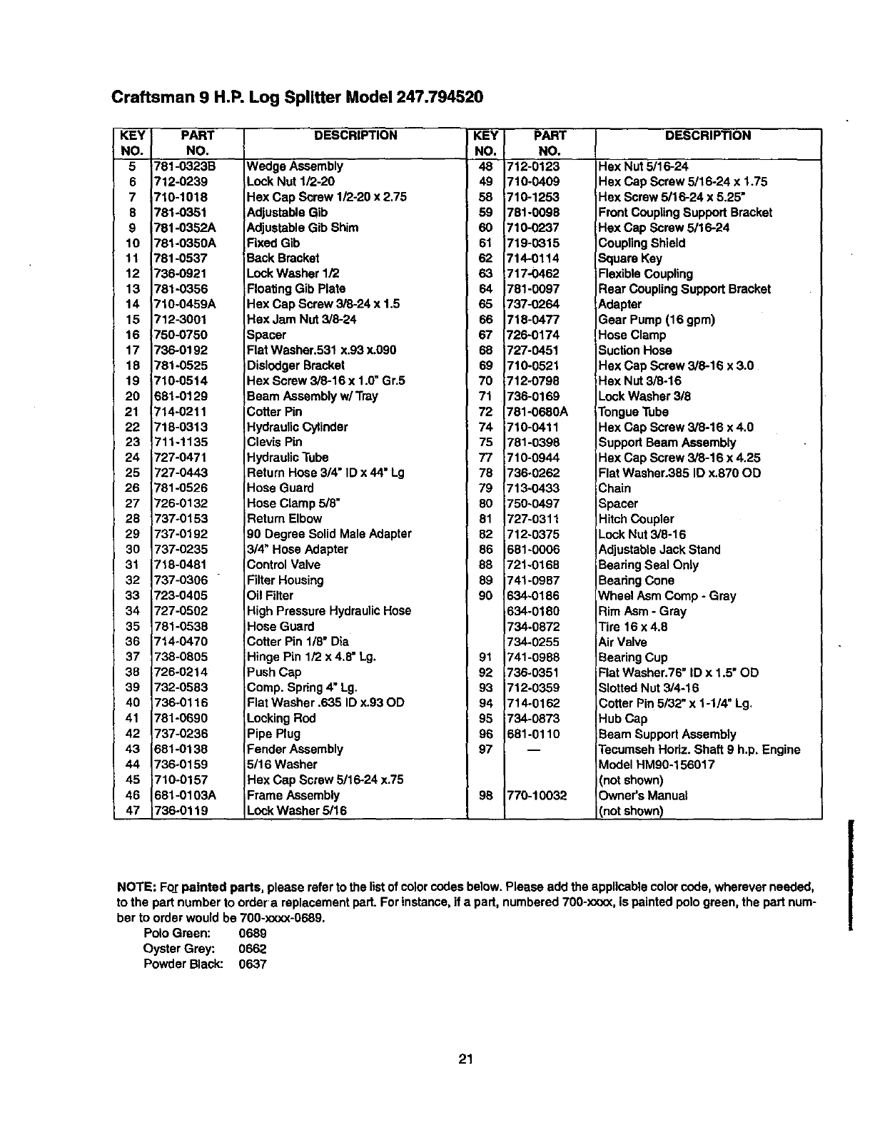
Craftsman 9 H.P. Log Splitter Model 247.794520
KEY PART
NO. NO,
5 781-0323B
6 712-0239
7 716-1018
8 781-0351
9 781-0352A
10 781-0350A
11 781-0537
12 736-0921
13 781-0366
14 716-0459A
15 712-3001
16 750-0760
17 736-0192
18 781-0525
19 710-0514
20 681-0129
21 714-0211
22 718-0313
23 711-1135
24 727-0471
25 727-0443
26 781-0526
27 726-0132
28 737-0153
29 737-0192
30 737-0235
31 718-0481
32 737-0306
33 723-0405
34 727-0502
35 781-0538
36 714-0470
37 738-0805
38 726-0214
39 732-0683
40 736-0116
41 781-0690
42 737-0236
43 681-0138
44 736-0159
45 710-0157
46 681-0103A
47 736-0119
DESCRIPTION KEY PART
NO. NO.
Wedge Assembly 48 712-0123
Lock Nut 1/2-20 49 710-0409
Hax Cap Screw 1/2-20 x 2.75 58 710-1253
Adjustable Gib 59 781-0098
Adjustable Gib Shim 60 710-0237
Fixed Gib 61 719-0315
Back Bracket 62 714-0114
Lock Washer 1/2 63 717-O462
Floating Gib Plate 64 781-0097
Hex Cap Screw 3/8-24 x 1.5 65 737-0264
Hax Jam Nut 3/8-24 66 718-0477
Spacer 67 726-0174
Flat Washer.531 x.93 x.090 68 727-0451
Dislodger Bracket 69 710-0521
Hex Screw 3/8-16 x 1.0"Gr.5 70 712-0798
Beam Assembly w/Tray 71 736-0169
Cotter Pin 72 781-0680A
Hydraulic Cylinder 74 710-0411
Clevis Pin 75 781-0398
Hydraulic Tube 77 710-0944
Return Hose 3/4" ID x 44" Lg 78 736-0262
Hose Guard 79 713-0433
Hose Clamp 5/8" 80 756-0497
Return Elbow 81 727-0311
90 Degree Solid Male Adapter 82 712.0375
3/4" Hose Adapter 86 681-0006
Control Valve 88 721-0168
Filter Housing 89 741-0987
Oil Filter 90 634-0186
High Pressure HydraulicHose 634-0180
Hose Guard 734-0872
Cotter Pin 1/8" Dta 734.0255
Hinge Pin 1/2 x 4.8" Lg. 91 741-0988
Push Cap 92 736-0351
Comp. Spring4" Lg. 93 712-0359
Flat Washer .635 ID x.93 OD 94 714-0162
Locking Rod 95 734-0873
Pipe Plug 96 681-0110
Fender Assembly 97 --
5/16 Washer
Hex Cap Screw 5/16-24 x.75
Frame Assembly 98 770-10032
Lock Washer 5/16
DESCRIPTION
Hex Nut 5/16-24
Hex Cap Screw 5/16,24 x 1.75
PlexScrew 5/16-24 x 5.25"
Front Coupling Support Bracket
Hex Cap Screw 5/16-24
_,oupling Shield
Square Key
Flexible Coupling
Rear Coupling Support Bracket
_.dapter
Sear Pump (16 gpm)
Hose Clamp
Suction Hose
Hex Cap Screw 3/6-16 x 3.0
Hex Nut 3/8-16
LockWasher 3/8
1"enguaTube
Hex Cap Screw 3/8-16 x 4.0
Support Beam Assembly
Hex Cap Screw 3/8-16 x 4.25
Flat Washer.385 ID x.870 OD
Chain
Spacer
Hitch Coupler
Lock Nut 3/8-16
AdjustableJack Stand
E3earingSeal Only
ECearingCone
Nheel Asm Comp - Grey
Rim Asm - Gray
Tire 16 x 4.8
Air Valve
ECearingCup
Flat Washer.76" ID x 1.5" OD
Slotted Nut 3/4-16
Cotter Pin 5/32" x 1-1/4" Lg.
Hub Cap
Beam Support Assembly
Tecumseh Hodz. Shaft 9 h.p. Engine
Model HM90-156017
not shown)
Owner's Manual
(not shown)
NOTE: FoJ;painted parts, please refer to the listof color codes below. Please add the applicable color code, wherever needed,
to the part number to order a replacement part. For instance, if a part, numbered 700-xxxx, is painted pologreen, the part num-
ber to order would be 700-x:<xx-0689.
Polo Green: 0689
Oyster Grey: 0662
Powder Black: 0637
21
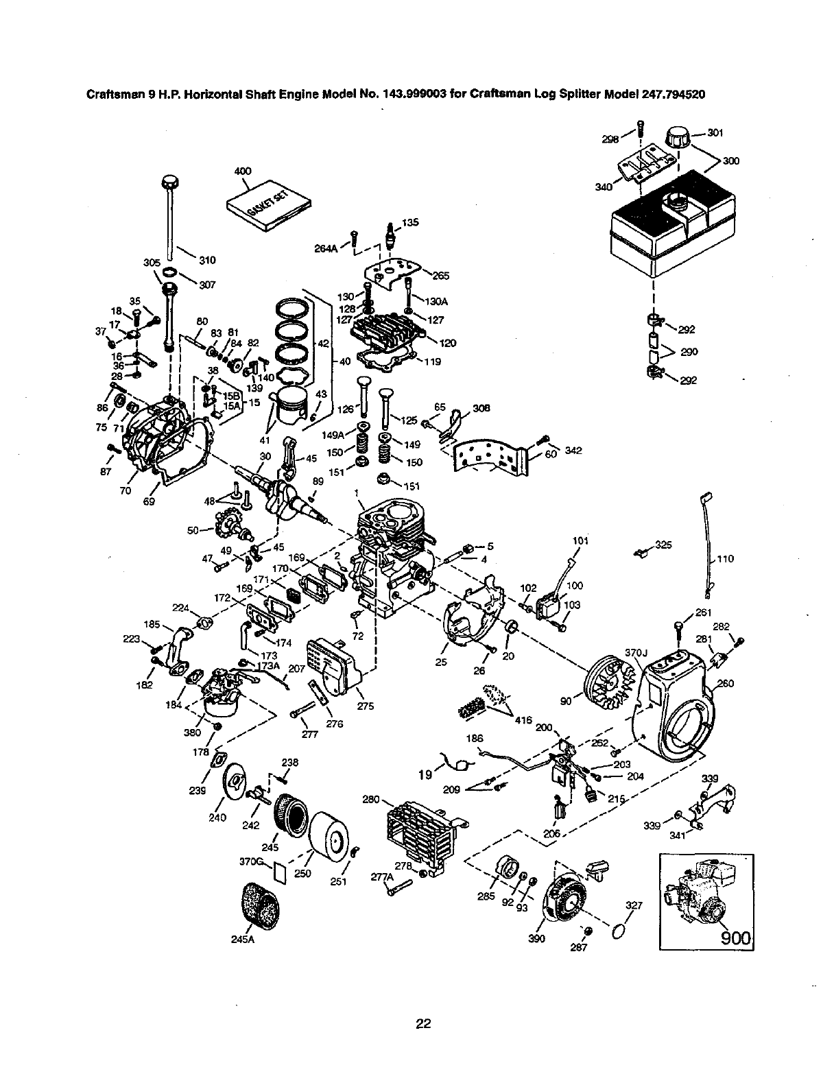
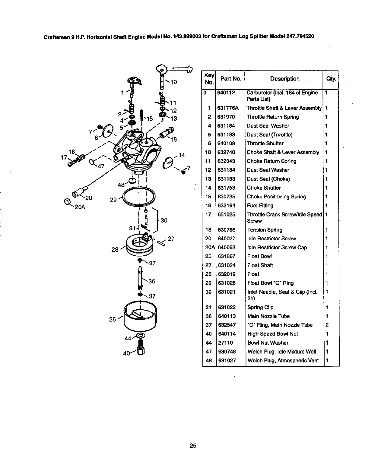
Craftsman 9 H.P. Horizontal Shaft Engine Model No. 143.999003 for Craftsman Log Splitter Model 247.794520
>3OO
I
I
2gO
75
/
87
70 69
182
184 <" 275
276
38O 277
178 238
/r-,d
240
245
370G_] 250 251
245A
89 _1"_.151
1
•342
--5 101 _:32.5 110
25 26
/261282
186
22
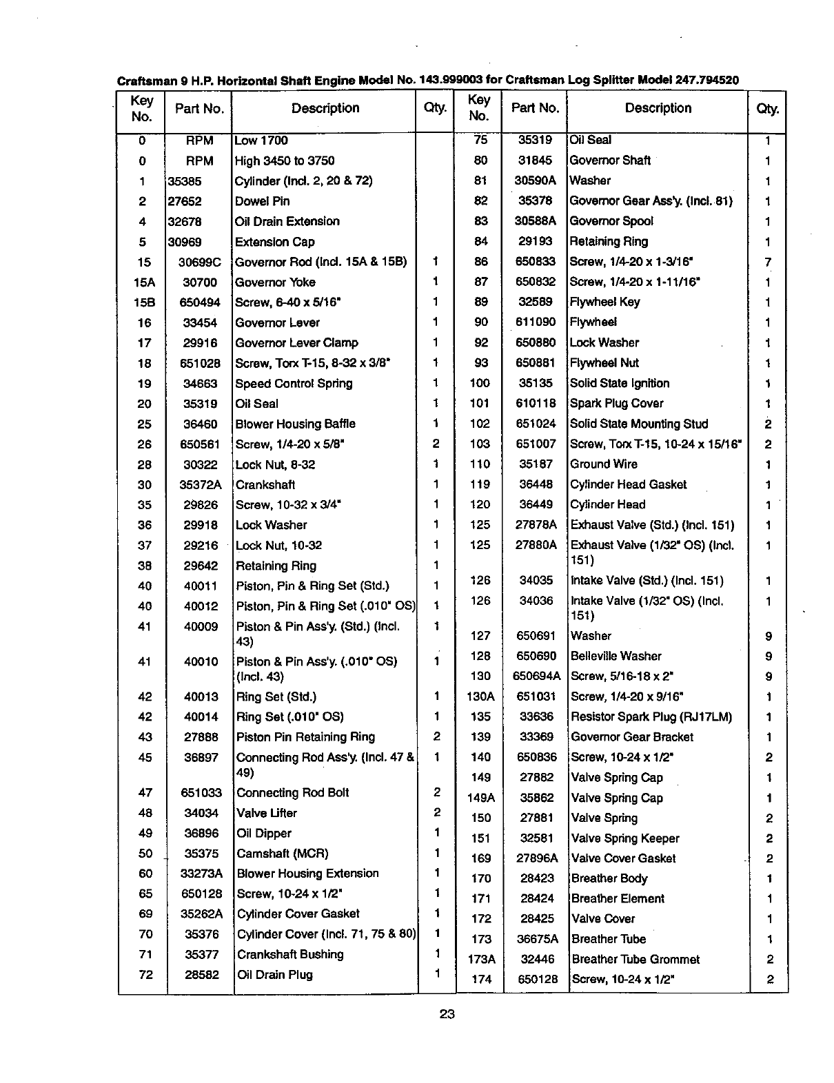
Craftsman 9 H.P. Horizontal Shaft Engine Model No. 143.999003 for Craftsman
• Key Part No. Description Qty. Part No.
No.
0
1
2
4
5
15
15A
15B
16
17
18
19
2O
25
26
28
30
35
36
37
38
40
40
41
41
42
42
43
45
47
48
49
50
60
65
69
70
71
72
Log Splitter Model 247.794520
RPM
RPM
35385
27652
32678
30969
30699C
30700
650494
33454
29916
651028
34663
35319
36460
650561
30322
35372A
29826
29918
29216
29642
40011
40012
40009
40010
40013
40014
27888
36897
651033
34034
36896
35375
33273A
650128
35262A
35376
35377
28582
Low 1700
High 3450 to 3750
Cylinder (Incl. 2, 20 & 72)
Dowel Pin
Oil Drain Extension
Extension Cap
Governor Rod (ind. 15A & 1513)
Governor Yoke
Screw, 6-40 x 5/16"
Govemor Lever
Govemor Lever Clamp
Screw, Torx T-15, 8-32 x 3/8"
Speed Contml Spring
Oil Seal
Blower Housing Baffle
Screw, 1/4-20 x 5/8"
Lock Nut, 8-32
Crankshaft
Screw, 10-32 x 3/4"
Lock Washer
Lock Nut, 10-32
Retaining Ring
Piston, Pin & Ring Set (Std.)
Piston, Pin & Ring Set (.010" OS'
Piston & Pin Ass'y. (Std.) (Incl.
43)
Piston & Pin Ass'y. (.010" OS)
(Incl. 43)
Ring Set (Std.)
Ring Set (.010" OS)
Piston Pin Retaining Ring
Connecting Rod Ass'y. (Incl. 47 &
49)
Connecting Rod Bolt
Valve Ufter
Oil Dipper
Camshaft (MCR)
Blower Housing Extension
Screw, 10-24 x 1/2"
Cytinder Cover Gasket
Cylinder Cover (Incl. 71, 75 & 801
iCrankshaft Bushing
foil Drain Plug
1
1
1
1
1
1
1
1
1
2
1
1
1
1
1
1
1
1
1
1
1
2
1
2
2
1
1
1
1
1
1
1
1
Key
No.
75
80
81
82
83
84
86
87
89
9o
92
93
lOO
lOl
102
103
110
119
12o
125
125
126
126
127
128
130
130A
135
139
140
149
149A
150
151
169
170
171
172
173
173A
174
35319
31845
30590A
35378
30588A
29193
650833
650832
32589
611090
650880
650881
35135
610118
651024
651007
35187
36448
36449
27878A
27880A
34035
34036
650691
650690
650694A
651031
33636
33369
650836
27882
35862
27881
32581
27896A
28423
28424
28425
36675A
32446
650128
Description
Oil Seal
Governor Shaft
Washer
Govemor Gear Ass'y.(Incl. 81)
Governor Spool
Retaining Ring
Screw, 1/4-20 x 1-3/16"
Screw, 114-20 x 1-11/16"
Flywheel Key
Flywheel
Lock Washer
Flywheel Nut
Solid State Ignition
Spark Plug Cover
Solid State Mounting Stud
Screw, TorxT-15, 10-24 x 15/16"
Ground Wire
Cylinder Head Gasket
Cylinder Head
Exhaust Valve (Std.) (Incl. 151)
Exhaust Valve (1/32" OS) (Incl.
151)
Intake Valve (Std.) (Incl. 151)
Intake Valve (1/32" OS) (Incl.
!151)
lWasher
Belleville Washer
Screw, 5116-18 x 2"
Screw, 1/4-20 x 9/16"
ResistorSpark Plug (RJ17LM)
Govemor Gear Bracket
Screw, 10-24 x 1/2"
Valve Spring Cap
Valve SpringCap
Valve Spring
Valve Spring Keeper
Valve Cover Gasket
Breather Body
Breather Element
Valve Cover
Breather Tube
BreatherTube Grommet
Screw, 10-24 x 1/2"
Qty.
1
1
1
1
1
1
7
1
1
1
1
1
1
1
2
1
1
1
1
1
9
9
9
1
1
1
2
1
1
2
2
2
1
1
1
1
2
2
23
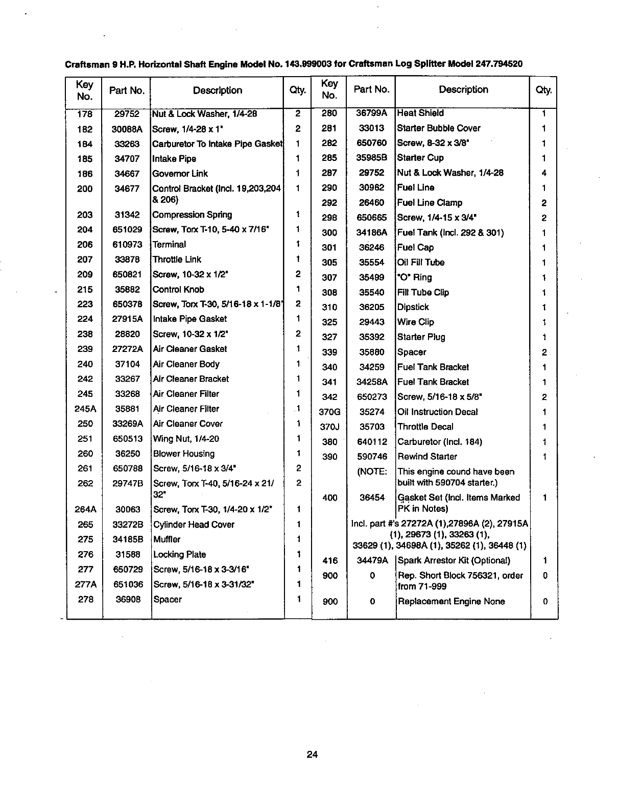
Craftsman 9 H.P. Horizontal Shaft Engine Model No. 143.999003 for Craftsmen Log Splitter Model 247.794520
Key Part No.
No.
178 29752
182 30088A
184 33263
185 34707
186 34667
200 34677
203
204
206
207
209
215
223
224
238
239
240
242
245
245A
250
251
260
261
262
264A
265
275
276
277
277A
278
31342
651029
610973
33878
650821
35882
650378
Key
Description Qty. No.
Nut & LockWasher, 114-28 2280
Screw, 1/4-28 x 1' 2 281
Carburetor To Intake Pipe Gasket 1 282
Intake Pipe 1 285
P-ovemorUnk 1 287
Control Bracket (Incl. 19,203,204 1 290
8,206) 292
Compression Spring 1 298
Screw, TorxT-1O, 5-40 x 7/16" 300
Terminal
Throttle Link
Screw, 10-32 x 1/2"
Control Knob
Screw, TorxT-30, 5/16-16 x 1-1/8'
27915A Intake Pipe Gasket
28820 Screw, 10-32 x 1/2"
27272A Air Cleaner Gasket
37104 Air Cleaner Body
33267 Air Cleaner Bracket
33268 Air Cleaner Filter
35881 ._irCleaner Filter
33269A Air Cleaner Cover
650513 Wing Nut, 114-20
36250 Blower Housing
650788 Screw, 5/16-18x3/4"
Part No.
36799A
33013
65076O
35985B
29752
30962
26460
650665
1 34186A
t 301 36246
t 305 35554
2 307 35499
1 308 35540
2 310 36205
1 325 29443
2 327 35392
1 339 35880
1 340 34259
1 341 34258A
1 342 650273
1 370G 35274
1 370J 35703
1 380 640112
1 390 590746
2(NOTE:
29747B
30063
Screw,Torx T-4O,5/16-24 x 21/
32"
Screw, Torx T-30, 1/4-20 x 1/2"
2
1
400 36454
Description
Heat Shield
Starter Bubble Cover
Screw, 6-32 x 3/8"
Starter Cup
Nut & Lock Washer, 1/4-28
Fuel Line
Fuel Line Clamp
Screw, 1/4-15 x 3/4"
Fuel Tank (Incl. 292 & 301)
Fuel Cap
Oil Fill Tube
"O" Ring
Fill Tube Clip
Dipstick
Wire Clip
Starter Plug
Spacer
Fuel Tank Bracket
Fuel Tank Bracket
Screw, 5/16-18 x5/8"
Oil Instruction Decal
Throttle Decal
Carburetor (Incl. 184)
Rewind Starter
This engine coundhave been
builtwith 590704 starter.)
GaxsketSet (Incl. Items Marked
PK in Notes)
33272B Cylinder Head Cover
34185B Muffler
31588 Locking Plate
650729 Screw, 5/16-18 x 3-3/16"
651036 Screw, 5/16-18 x 3-31/32"
36908 Spacer
1416
1900
1
1 900
Incl. part #'s 27272A (1),27896A (2), 27915A
(1), 29673 (1), 33263 (1),
33629 (1), 346.9eA (1), 35262 (1), 36448 (11
34479A Spark Arrestor Kit (Optional) 1
0 Rep. Short Block 756321, order O
from 71-999
0 Replacement Engine None 0
Qty.
1
1
1
1
4
1
2
2
1
1
1
1
1
1
1
1
2
1
1
2
1
1
1
1
24
Craftsman 9 H.P. Horizontal Shaft Engine Model No. 143.999003 for Craftsman Log Splitter Model 247.794520
I
Key
No. Part No. Description Qty.
o !64Oll 2 Carburetor(Incl.184of Engine 1
1
2
4
5
6
10
11
12
13
14
15
16
17
18
20
2OA
25
27
28
29
30
31
36
37
40
44
47
48
;31776A
631970
631184
631183
640109
632740
632O43
631184
631183
631753
630735
632164
651025
630766
640027
640053
631867
631024
632019
631028
631021
631022
640113
632547
640114
27110
630748
631027
Parts Ust)
Throttle Shaft & Lever Assembly
Throttle Return Spdng
Dust Seal Washer
Dust Seal (Throttle)
Throttle Shutter
Choke Shaft & Lever Assembly
Choke Return Spring
Dust Seal Washer
Dust Seal (Choke)
Choke Shutter
Choke Positioning Spring
Fuel Fitting
Throttte Crack Screw/Idle Speed
Screw
Tension Spnng
Idle Restdctor Screw
idle Restdctor Screw Cap
Float Bowl
Float Shaft
Float
Float Bowl "O" Ring
Inlet Needle, Seat & Clip (Incl.
31)
Spring Clip
Main Nozzle Tube
"O"Ring, Main Nozzle Tube
High Speed Bowl Nut
Bowl Nut Washer
Welch Plug, Idle Mixture Well
Welch Plug, Atmeaphedc Vent
1
11
11
1
1
1
1
1
1
1
1
1
1
1
1
1
1
2
1
1
1
1
25

Craftsman 9 H.P. Horizontal Shaft Engine Model No. 143.999003 for Craftsmen Log Splitter Model 247.794520
12
Key Part No.
No,
1
2
3
4
5
6
7
8
11
12
13
1590704
590599A
_90600
590696
590601
590697
590698
590699
590700
590705
590535
590701
Description
Recoil Starter
Spring Pin (Incl. 4)
Washer
Retainer
Washer
Brake Spring
Starter Dog
Dog Spring
Pulley & Rewind Spring Ass'y.
Starter Housing Ass'y.
Starter Rope ( 98" X 9/64" dia.)
Starter Handle
aty,
1"
1
1
1
1
2
2
1
1
1
1
Key Part No. Description Qty.
No.
1
2
3
4
5
6
7
8
11
12
13
590746
590599A
590600
590679
590601
590678
590680
590412
_90681
590747
590535
590701
Recoil Starter
Spring Pin (Incl. 4) 1
Washer 1
Retainer 1
Washer 1
Brake Spring 1
Starter Dog 2
Dog Spring 2
Pulley & Rewind Spring Assembly 1
Starter Housing Assembly 1
Starter Rope (Length 98" x 9/64" dia.) 1
Starter Handle 1
26
13 12
O4
O--2

For in-home major brand repair service:
Call 24 hoursa day, 7 days a week
1-800-4-MY-HOME (1-800-469-4663)
Para pedir servicio de reparaci6n a domicilio -- 1-800-676-5811
In Canada for all your service and parts needs call 1-800-665-4455
Au Canada pour tout le service ou les pi_ces 1-800-665-4455
For the repair or replacement parts you need:
Call 7 am - 7 pm, 7 days a week
1-800-366-PART (1-800-366-7278)
Para ordenar piezas con entrega a domicllio -- 1-800-659-7084
For the location of a Sears Parts and Repair Center in your area:
Call 24 hours a day, 7 days a week
1-800-488-1222
For information on purchasing e Sears Maintenance Agreement
or to inquire about an existing Agreement:
Call 9 am -5 pro, Monday - Saturday
1-800-827-6655
omeCentral
TheServiceSideofSearss=

