Craftsman 247883971 User Manual SNOWTHROWER Manuals And Guides 1306518L
User Manual: Craftsman 247883971 247883971 CRAFTSMAN SNOWTHROWER - Manuals and Guides View the owners manual for your CRAFTSMAN SNOWTHROWER #247883971. Home:Lawn & Garden Parts:Craftsman Parts:Craftsman SNOWTHROWER Manual
Open the PDF directly: View PDF ![]() .
.
Page Count: 47
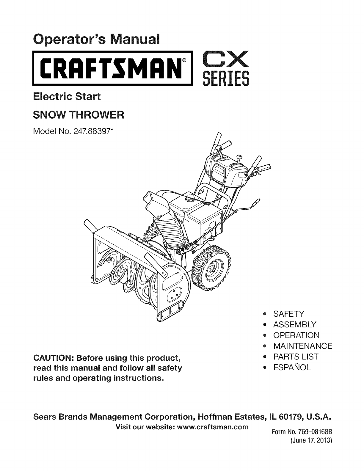
perator's nual
I:RRFrSMAN+
Electric Start
SNOW THROWER
Model No. 247.883971
CXIES
CAUTION" Before using this product,
read this manual and follow all safety
rules and operating instructions.
,, SAFETY
o ASSEMBLY
OPERATION
MAINTENANCE
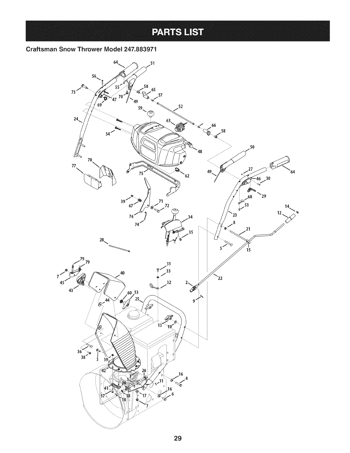
PARTS LIST
o ESPANOL
Sears Brands Management Corporation, Hoffman Estates, IL 60179, U.S.A.
Visit our website: www.craftsman.com Form No. 769-08168B
(June 17,2013)
Warranty Statement .................................. Page 2
Safe Operation Practices .......................... Page 3
Assembly .................................................. Page 7
Operation .................................................. Page 12
Service and Maintenance ......................... Page 17
Off-Season Storage .................................. Page 25
Troubleshooting ........................................ Page 27
Parts List ................................................... Page 28
Repair Protection Agreement ................... Page 47
Espa_ol ..................................................... Page 48
Service Numbers ...................................... Back Cover
CRAFTSMANCXTWOYEAR FULLWARRANTY
FORTWOYEARSfromthe dateof purchase,thisproductis warrantedagainstanydefectsin materialor workmanship.A defective
productwill receivefree repairor replacementif repairis unavailable.
Forwarranty coverage details to obtain free repairor replacement,visitthe web site: www.craftsman.com
Thiswarranty coversONLYdefects in material andworkmanship. Warranty coveragedoes NOTinclude:
• Expendableitemsthatcan wearoutfromnormalusewithinthe warrantyperiod,includingbutnot limitedto augers,augerpaddles,
driftcutters,skidshoes,shaveplate,shearpins,sparkplug,aircleaner,belts,andoil filter.
•Standardmaintenanceservicing,oilchanges,or tune-ups.
•Tire replacementor repaircausedby puncturesfromoutsideobjects,suchas nails,thorns,stumps,or glass.
•Tireor wheelreplacementor repairresultingfromnormalwear,accident,or improperoperationor maintenance.
•Repairsnecessarybecauseof operatorabuse,includingbut notlimitedto damagecausedbyover-speedingthe engine,or from
impactingobjectsthat bendthe frame,augershaft,etc.
•Repairsnecessarybecauseof operatornegligence,includingbutnot limitedto,electricaland mechanicaldamagecausedby
improperstorage,failureto usethe propergradeandamountof engineoil,or failureto maintainthe equipmentaccordingto the
instructionscontainedinthe operator'smanual.
•Engine(fuel system)cleaningor repairscausedbyfuel determinedto becontaminatedor oxidized(stale). Ingeneral,fuel shouldbe
usedwithin30 daysof its purchasedate.
•Normaldeteriorationandwearof the exteriorfinishes,orproductlabelreplacement.
Thiswarrantyis void if this productisever usedwhileprovidingcommercialservicesor if rentedto anotherperson.
Thiswarrantygivesyou specificlegalrights,andyoumayalsohaveother rightswhichvaryfromstateto state.
Sears Brands ManagementCorporation, Hoffman Estates, IL 60179
EngineOilType: 5W-30
EngineOilCapacity: 37ounces
FuelCapacity: Approx.5 Quarts
SparkPlug: F6RTC(951-10292)
SparkPlugGap: .020"to .030"
Model Number.................................................................
Serial Number .................................................................
Dateof Purchase.............................................................
Recordthe modelnumber,serialnumber
anddateof purchaseabove
© SearsBrands,LLC
2
Thissymbolpointsout importantsafety instructionswhich, if not
followed, couldendangerthe personalsafetyand/or property of
yourselfand others.Readandfollow all instructions inthis manual
beforeattempting to operatethis machine.Failureto complywith these
instructionsmayresultinpersonalinjury.Whenyouseethis symbol, HEED
ITSWARNING!
CALIFORNIA PROPOSITION 65
EngineExhaust,someof its constituents,and certainvehiclecomponents
containor emit chemicalsknownto Stateof Californiato causecancerand
birth defectsorother reproductiveharm.
Thismachinewasbuilt to beoperatedaccordingto thesafeoperation
practicesinthis manual.Aswith anytype of powerequipment,
carelessnessorerroronthe part ofthe operatorcanresultinseriousinjury.
Thismachineiscapableof amputating fingers, hands,toesandfeet and
throwingdebris.Failureto observethefollowing safety instructionscould
resultinseriousinjuryor death.
Your Responsibility--Restrict theuseof this powermachineto
personswhoread,understandandfollow thewarningsand instructionsin
this manualandonthe machine.
SAVETHESEINSTRUCTIONS!
TRAINING
Read,understand,andfollowall instructionsonthemachineandinthe
manual(s)beforeattemptingto assembleandoperate.Failureto dosocan
resultinseriousinjurytotheoperatorand/orbystanders.Keepthis manual
inasafeplaceforfutureandregularreferenceandfororderingreplacement
parts.
Befamiliarwith allcontrolsandtheir properoperation.Knowhowto stop
themachineanddisengagethemquickly.
Neverallowchildrenunder14yearsof ageto operatethis machine.Children
14andovershouldreadandunderstandtheinstructionsandsafeoperation
practicesinthis manualandonthemachineandbetrainedandsupervised
byanadult.
Neverallowadultsto operatethismachinewithout properinstruction.
Thrownobjectscancauseseriouspersonalinjury.Planyoursnow-throwing
patternto avoiddischargeof materialtowardroads,bystandersandthelike.
Keepbystanders,petsandchildrenat least75feetfrom themachinewhileit
isin operation.Stopmachineif anyoneentersthearea.
Exercisecautionto avoidslippingorfalling,especiallywhenoperatingin
reverse.
PREPARATION
Thoroughlyinspecttheareawheretheequipmentisto beused.Removeall
doormats,newspapers,sleds,boards,wiresandotherforeignobjects,which
couldbetrippedoverorthrownbytheauger/impeller.
Alwayswearsafetyglassesoreyeshieldsduringoperationandwhile
performinganadjustmentor repairto protectyoureyes.Thrownobjects
whichricochetcancauseseriousinjuryto theeyes.
Donotoperatewithout wearingadequatewinteroutergarments.Donot
wearjewelry,longscarvesorotherlooseclothing,whichcouldbecome
entangledinmovingparts.Wearfootwearwhichwill improvefootingon
slipperysurfaces.
Usea groundedthree-wireextensioncordandreceptacleforallmachines
with electricstartengines.
Disengageallcontrolleversbeforestartingtheengine.
Adjustcollectorhousingheightto cleargravelorcrushedrocksurfaces.
Neverattemptto makeanyadjustmentswhileengineisrunning,except
wherespecificallyrecommendedintheoperator'smanual.
Letengineandmachineadjustto outdoortemperaturebeforestartingto
clearsnow.
Safe Handling of Gasoline:
Toavoidpersonalinjuryor property damageuseextreme careinhandling
gasoline.Gasolineisextremely flammable andthe vaporsareexplosive.
Seriouspersonalinjurycanoccurwhengasolineis spilledonyourselforyour
clotheswhichcanignite. Washyour skinandchangeclothesimmediately.
Useonlyanapprovedgasolinecontainer.
Neverfill containersinsidea vehicleorona truckortrailerbedwitha plastic
liner.Alwaysplacecontainersonthegroundawayfromyourvehiclebefore
filling.
Whenpractical,removegas-poweredequipmentfromthetruckor
trailerandrefuelit ontheground.Ifthisis notpossible,thenrefuelsuch
equipmentonatrailerwith aportablecontainer,ratherthanfromagasoline
dispensernozzle.
Keepthenozzleincontactwith therimofthefueltankorcontaineropening
at alltimesuntil fuelingiscomplete.Donotusea nozzlelock-opendevice.
Extinguishall cigarettes,cigars,pipesandothersourcesof ignition.
Neverfuel machineindoors.
Neverremovegascaporaddfuel whiletheengineishotorrunning.Allow
engineto coolat leasttwo minutesbeforerefueling.
Neveroverfill fueltank.Filltankto nomorethan1/2inchbelowbottomof
filler neckto allowspacefor fuelexpansion.
Replacegasolinecapandtightensecurely.
Ifgasolineisspilled,wipeit offthe engineandequipment.Moveunitto
anotherarea.Wait.5minutesbeforestartingtheengine.
Toreducefirehazards,keepmachinefreeofgrass,leaves,orotherdebris
build-up.Cleanupoilorfuelspillageandremoveanyfuelsoakeddebris.
Neverstorethemachineorfuelcontainerinsidewherethereisanopen
flame,sparkorpilotlightasonawaterheater,spaceheater,furnace,clothes
dryerorothergasappliances.
OPERATION
Donotputhandsorfeetnearrotatingparts,intheauger/impellerhousing
orchuteassembly.Contactwith therotatingpartscanamputatehandsand
feet.
Theauger/impellercontrolleverisasafetydevice.Neverbypassits
operation.Doingsomakesthemachineunsafeandmaycausepersonal
injury.
Thecontrolleversmustoperateeasilyin bothdirectionsandautomatically
returnto thedisengagedpositionwhenreleased.
Neveroperatewith amissingordamagedchuteassembly.Keepallsafety
devicesinplaceandworking.
Neverrunanengineindoorsor inapoorlyventilatedarea.Engineexhaust
containscarbonmonoxide,anodorlessanddeadlygas.
Donotoperatemachinewhileundertheinfluenceof alcoholordrugs.
Mufflerandenginebecomehotandcancauseaburn.Donottouch.Keep
childrenaway.
Exerciseextremecautionwhenoperatingonorcrossinggravelsurfaces.Stay
alertforhiddenhazardsortraffic.
Exercisecautionwhenchangingdirectionandwhileoperatingonslopes.Do
notoperateonsteepslopes.
Planyoursnow-throwingpatternto avoiddischargetowardswindows,
walls,carsetc.Thus,avoidingpossiblepropertydamageorpersonalinjury
causedbyaricochet.
Neverdirectdischargeat children,bystandersandpetsor allowanyonein
frontof the machine.
Donotoverloadmachinecapacitybyattemptingto clearsnowat toofastof
arate.
Neveroperatethismachinewithoutgoodvisibilityorlight.Alwaysbesureof
yourfootingandkeepafirm holdonthehandles.Walk,neverrun.
Disengagepowerto theauger/impellerwhentransportingor notin use.
Neveroperatemachineat hightransportspeedsonslipperysurfaces.Look
downandbehindandusecarewhenbackingup.
If the machineshouldstartto vibrateabnormally,stoptheengine,
disconnectthesparkplugwire andgrounditagainsttheengine.Inspect
thoroughlyfordamage.Repairanydamagebeforestartingandoperating.
Disengageallcontrolleversandstopenginebeforeyouleavetheoperating
position(behindthehandles).Waituntil theauger/impellercomesto
acompletestopbeforeuncloggingthechuteassembly,makingany
adjustments,orinspections.
Neverputyourhandin thedischargeorcollectoropenings.Donotunclog
chuteassemblywhileengineis running.Shutoff engineandremainbehind
handlesuntil allmovingpartshavestoppedbeforeunclogging.
Useonlyattachmentsandaccessoriesapprovedbythemanufacturer(e.g.
wheelweights,tirechains,cabsetc.).
Whenstartingengine,pull cordslowlyuntil resistanceisfelt,thenpull
rapidly.Rapidretractionofstartercord(kickback)will pullhandandarm
towardenginefasterthanyoucanletgo.Brokenbones,fractures,bruisesor
sprainscouldresult.
Ifsituationsoccurwhicharenotcoveredinthismanual,usecareandgood
judgment.
CLEARING A CLOGGED DISCHARGE CHUTE
Handcontactwith therotatingimpellerinsidethedischargechuteisthemost
commoncauseof injuryassociatedwith snowthrowers.Neveruseyourhandto
cleanoutthedischargechute.
Toclearthechute:
a. SHUTTHEENGINEOFF!
b. Wait10secondsto besuretheimpellerbladeshavestopped
rotating.
c. Alwaysuseaclean-outtool,notyourhands.
MAINTENANCE &STORAGE
Nevertamperwith safetydevices.Checktheirproperoperationregularly.
Referto themaintenanceandadjustmentsectionsof thismanual.
Beforecleaning,repairing,orinspectingmachinedisengageallcontrol
leversandstoptheengine.Waituntil theauger/impellercometo acomplete
stop.Disconnectthesparkplugwire andgroundagainsttheengineto
preventunintendedstarting.
Checkboltsandscrewsforpropertightnessat frequentintervalsto keepthe
machineinsafeworkingcondition.Also,visuallyinspectmachineforany
damage.
Donotchangetheenginegovernorsettingorover-speedtheengine.The
governorcontrolsthemaximumsafeoperatingspeedof theengine.
Snowthrowershaveplatesandskidshoesaresubjectto wearanddamage.
Foryoursafetyprotection,frequentlycheckallcomponentsandreplace
with originalequipmentmanufacturer's(OEM)partsonlyaslistedinthe
Partspagesofthisoperator'smanual.Useof partswhichdonot meetthe
originalequipmentspecificationsmayleadto improperperformanceand
compromisesafety!
Checkcontrolleversperiodicallyto verifytheyengageanddisengage
properlyandadjust,if necessary.Referto theadjustmentsectioninthis
operator'smanualfor instructions.
Maintainorreplacesafetyandinstructionlabels,asnecessary.
Observeproperdisposallawsandregulationsforgas,oil,etc.to protectthe
environment.
Priorto storing,runmachineafewminutesto clearsnowfrom machineand
preventfreezeupof auger/impeller.
Neverstorethemachineorfuelcontainerinsidewherethereisanopen
flame,sparkorpilot light suchasa waterheater,furnace,clothesdryeretc.
Alwaysreferto theoperator'smanualforproperinstructionsonoff-season
storage.
4
Checkfuelline,tank,cap,andfittingsfrequentlyfor cracksor leaks.Replace
if necessary.
Donotcrankenginewith sparkplugremoved.
Accordingto theConsumerProductsSafetyCommission(CPSC)andthe
U.S.EnvironmentalProtectionAgency(EPA),thisproducthasanAverage
Useful Lifeof seven(7)years,or60 hoursofoperation.Attheendof
theAverage Useful Lifehavethemachineinspectedannuallybyan
authorizedservicedealerto ensurethat all mechanicalandsafetysystems
areworkingproperlyandnotwornexcessively.Failureto dosocanresultin
accidents,injuriesordeath.
DO NOT MODIFY ENGINE
Toavoidseriousinjuryordeath,donotmodifyengineinanyway. Tampering
with the governorsetting canleadto arunawayengineandcauseit to
operateat unsafespeeds.Nevertamper with factory setting of engine
governor.
NOTICE REGARDING EMiSSiONS
Engineswhich are certifiedto complywith Californiaandfederal EPA
emissionregulationsfor SORE(SmallOff RoadEquipment)arecertified
to operateon regularunleadedgasoline,and mayincludethe following
emissioncontrolsystems:EngineModification (EM),OxidizingCatalyst(0C),
SecondaryAir injection(SAI)andThreeWayCatalyst(TWC)if soequipped.
SPARK ARRESTOR
e
Thismachineisequippedwith aninternalcombustionengineandshould
not beusedonornearanyunimprovedforest-covered,brushcoveredor
grass-coveredland unlessthe engine'sexhaustsystemisequippedwith a
sparkarrestormeeting applicable localorstate laws(if any).
Ira sparkarrestoris used,it shouldbemaintainedin effective working order
bythe operator.In the State of Californiathe aboveisrequired bylaw (Section
4442of the CaliforniaPublicResourcesCode).Otherstates mayhavesimilar
laws.Federallawsapplyonfederal lands.
Asparkarrestorfor the muffler is availablethroughyour nearestSearsParts
andRepairServiceCenter.
SAFETY SYMBOLS
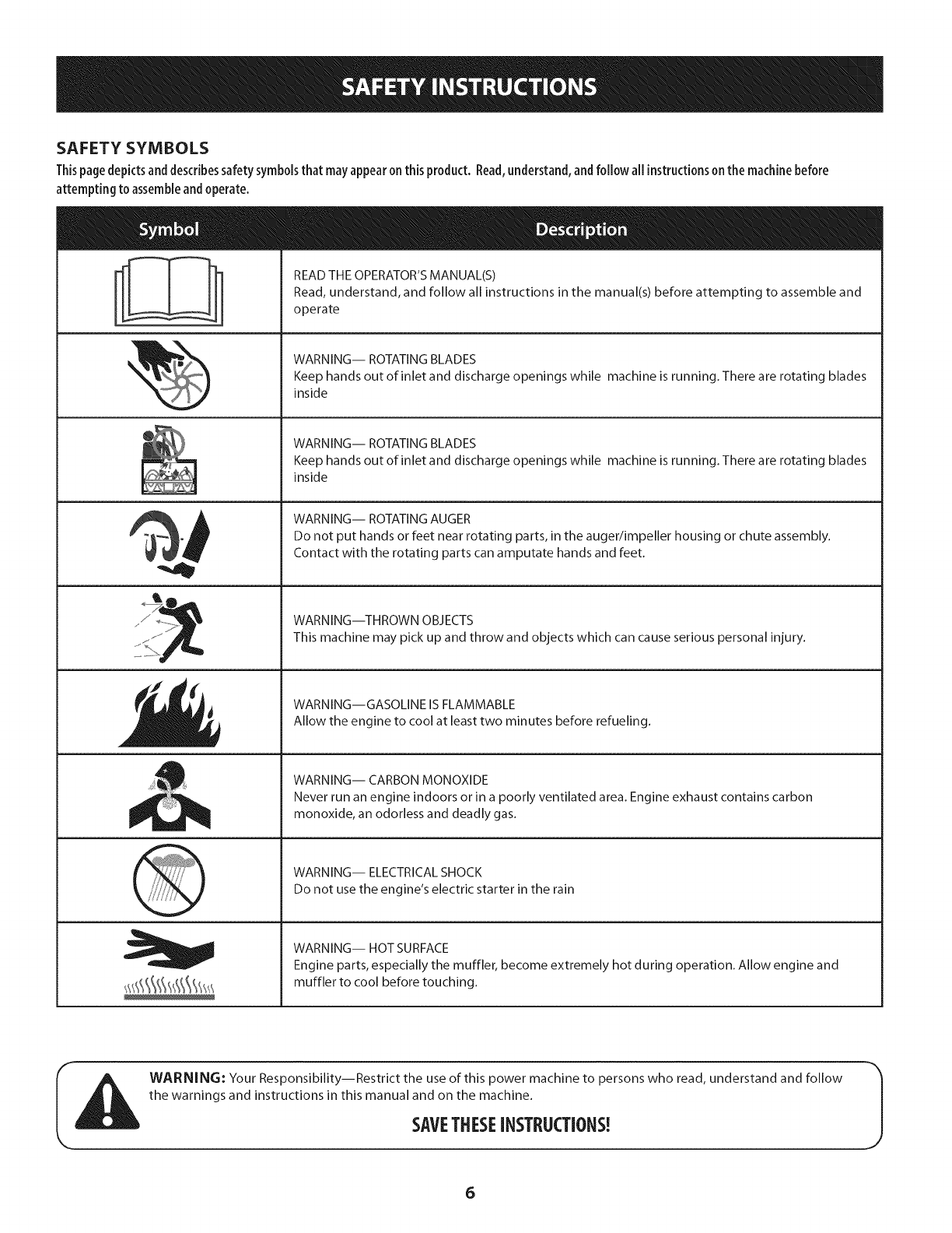
Thispage depicts and describes safety symbols that may appear on this product. Read, understand, and follow all instructions on the machine before
attempting to assemble and operate.
READ THE OPERATOR'S MANUAL(S)
Read, understand, and follow all instructions in the manual(s) before attempting to assemble and
operate
WARNING-- ROTATING BLADES
Keep hands out of inlet and discharge openings while machine is running. There are rotating blades
inside
WARNING-- ROTATING BLADES
Keep hands out of inlet and discharge openings while machine is running. There are rotating blades
inside
WARNING-- ROTATING AUGER
Do not put hands or feet near rotating parts, in the auger/impeller housing or chute assembly.
Contact with the rotating parts can amputate hands and feet.
WARNING--THROWN OBJECTS
This machine may pick up and throw and objects which can cause serious personal injury.
WARNING--GASOLINE IS FLAMMABLE
Allow the engine to cool at least two minutes before refueling.
WARNING-- CARBON MONOXIDE
Never run an engine indoors or in a poorly ventilated area. Engine exhaust contains carbon
monoxide, an odorless and deadly gas.
WARNING-- ELECTRICAL SHOCK
Do not use the engine's electric starter in the rain
WARNING-- HOT SURFACE
Engine parts, especially the muffler, become extremely hot during operation. Allow engine and
muffler to cool before touching.
WARNING: Your Responsibility--Restrict the use of this power machine to persons who read, understand and follow
the warnings and instructions in this manual and on the machine.
SAVETHESEiNSTRUCTIONS!
6
NOTE:Referencesto rightorleft sideof thesnowthroweraredeterminedfromthe
operatingpositionlookingforwardto thefront of themachine.
Removing From (:rate
1. Removescrewsfromthebottomofthecratesecuringthesides,andendsof
theshippingcrate.
2. Liftoff thetopoff of thecrateandsetoutof thewayoftheassemblyarea.
3. Removeanddiscardplasticbagthat coversunit.
4. Removeanyloosepartsincludedwith unit(e.g.,Operator'sManual,etc.).
5. Pushdownonthe lowerhandleandpullunit backoutof crate.
6. Makecertainthecratehasbeencompletelyemptiedbeforediscardingit.
Assembly
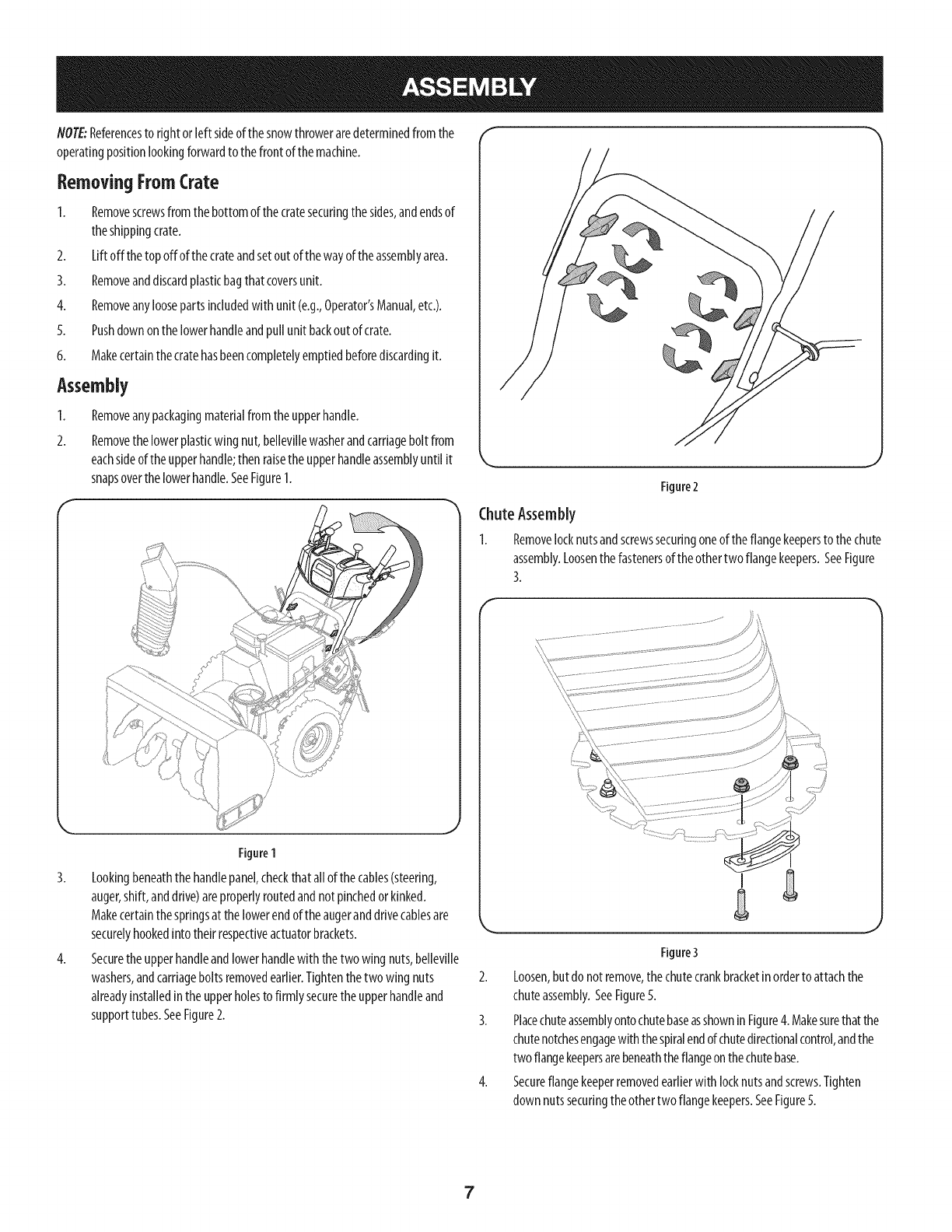
1. Removeanypackagingmaterialfromtheupperhandle.
2. Removethelowerplasticwing nut,bellevillewasherandcarriageboltfrom
eachsideof theupperhandle;then raisetheupperhandleassemblyuntil it
snapsoverthelowerhandle.SeeFigure1.
"_,r ,,J
Figure2
ChuteAssembly
1. Removelocknutsandscrewssecuringoneoftheflangekeepersto thechute
assembly.Loosenthefastenersof theothertwo flangekeepers.SeeFigure
3.
f
Figure1
3. Lookingbeneaththehandlepanel,checkthatall of thecables(steering,
auger,shift,anddrive)areproperlyroutedandnotpinchedorkinked.
Makecertainthespringsat thelowerendoftheaugeranddrivecablesare
securelyhookedinto theirrespectiveactuatorbrackets.
4. Securetheupperhandleandlowerhandlewiththetwo wing nuts,belleville
washers,andcarriageboltsremovedearlier.Tightenthetwowing nuts
alreadyinstalledin the upperholesto firmly securethe upperhandleand
supporttubes.SeeFigure2.
Figure3
2. Loosen,butdonotremove,thechutecrankbracketinordertoattachthe
chuteassembly.SeeFigure5.
3. PlacechuteassemblyontochutebaseasshowninFigure4. Makesurethatthe
chutenotchesengagewith thespiralendof chutedirectionalcontrol,andthe
two flangekeepersarebeneaththeflangeonthechutebase.
4. Secureflangekeeperremovedearlierwith locknutsandscrews.Tighten
downnutssecuringtheothertwo flangekeepers.SeeFigure5.
7
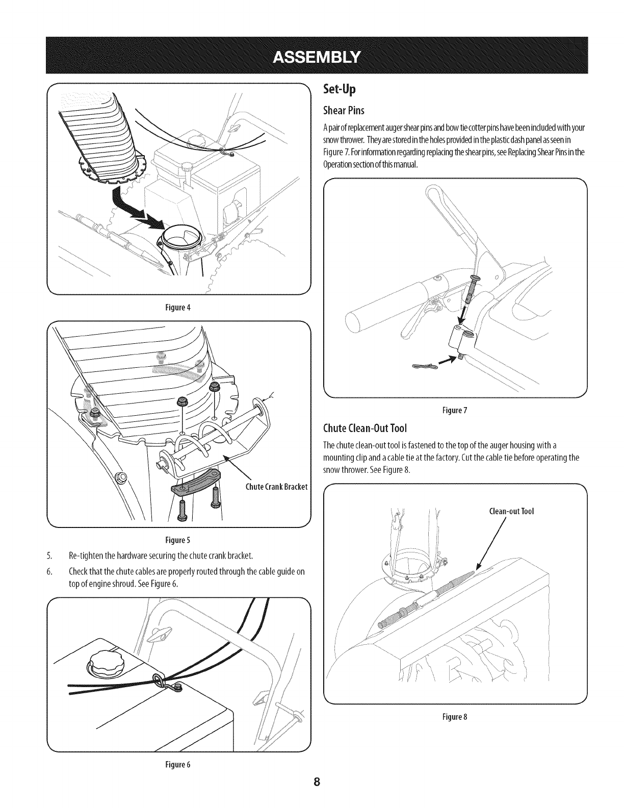
Figure 4
/ /
//
Set-Up
ShearPins
Apairofreplacementaugershearpinsandbowtiecotterpinshavebeenincludedwithyour
snowthrower.Theyarestoredintheholesprovidedintheplasticdashpanelasseenin
Figure7.Forinformationregardingreplacingtheshearpins,seeReplacingShearPinsinthe
Operationsectionofthismanual.
......
Figure7
ChuteClean-OutTool
Thechutedean-outtool isfastenedto thetopof theaugerhousingwitha
mountingclipandacabletie at thefactory.Cutthecabletie beforeoperatingthe
snowthrower.SeeFigure8.
5.
6.
Figure5
Re-tightenthehardwaresecuringthechutecrankbracket.
Checkthatthechutecablesareproperlyroutedthroughthecableguideon
topof engineshroud.SeeFigure6.
/
/
/
/
/
Clean-outTool
J
Figure8
Figure 6
8
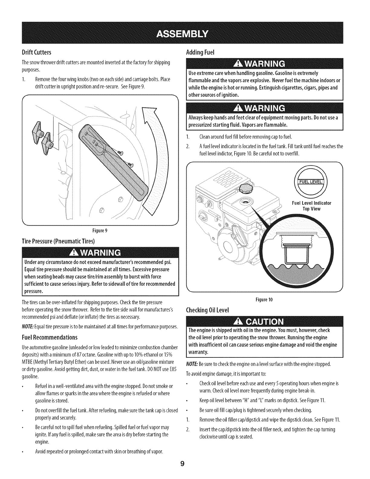
Drift Cutters
Thesnowthrowerdrift cuttersaremountedinvertedat thefactoryforshipping
purposes.
1. Removethefourwing knobs(twooneachside)andcarriagebolts.Place
drift cutterinuprightpositionandre-secure.SeeFigure9.
Figure9
J
TirePressure(Pneumatic Tires)
Underanycircumstancedonot exceedmanufacturer'srecommendedpsi.
Equaltire pressureshould be maintainedat all times. Excessivepressure
whenseating beadsmaycausetire/rim assemblyto burstwithforce
sufficient to causeseriousinjury.Referto sidewallof tire for recommended
pressure.
Thetirescanbeover-inflatedfor shippingpurposes.Checkthetire pressure
beforeoperatingthesnowthrower.Referto thetire sidewall formanufactures's
recommendedpsianddeflate(orinflate)thetiresasnecessary.
NOTE:Equaltire pressureisto bemaintainedat all timesforperformancepurposes.
FuelRecommendations
Useautomotivegasoline(unleadedorlowleadedto minimizecombustionchamber
deposits)witha minimumof87 octane.Gasolinewith upto 10%ethanolor1__%
MTBE(MethylTertiaryButylEther)canbeused.Neveruseanoil/gasolinemixture
ordirtygasoline.Avoidgettingdirt, dust,orwaterinthefueltank.DONOTuseE85
gasoline.
Refuelinawell-ventilatedareawith theenginestopped.Donotsmokeor
allowflamesorsparksintheareawheretheengineisrefueledorwhere
gasolineisstored.
Donotoverfillthefueltank.Afterrefueling,makesurethetankcapisclosed
properlyandsecurely.
Becarefulnot to spillfuelwhenrefueling.Spilledfuelorfuelvapormay
ignite.Ifanyfuelisspilled,makesuretheareaisdrybeforestartingthe
engine.
Avoidrepeatedorprolongedcontactwith skinorbreathingof vapor.
Adding Fuel
Useextreme carewhen handling gasoline.Gasolineisextremely
flammable andthe vaporsareexplosive. Neverfuel the machineindoorsor
whiletheengineishotorrunning.Extinguishcigarettes,cigars,pipesand
othersourcesof ignition.
Alwayskeephandsandfeet clearof equipment movingparts.Donot usea
pressurizedstarting fluid. Vaporsareflammable.
1. Cleanaroundfuelfillbeforeremovingcapto fuel.
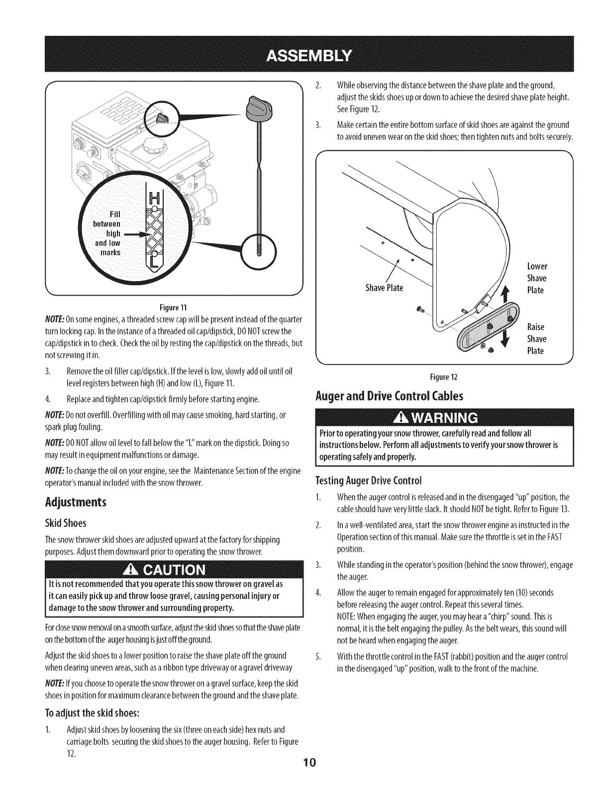
2. Afuel levelindicatoris locatedinthefueltank.Filltankuntilfuelreachesthe
fuel levelindictor,Figure10,Becarefulnot to overfill,
FuelLevelIndicalor
TopView
Figure10
CheckingOil Level
Theengineisshippedwith oilintheengine.Youmust, however,check
the oiilevel priorto operatingthe snowthrower. Runningthe engine
with insufficientoilcancauseseriousenginedamageandvoidthe engine
warranty.
NOTE:Besureto checktheengineona levelsurfacewith theenginestopped.
Toavoidenginedamage,it isimportantto:
Checkoil levelbeforeeachuseandevery5 operatinghourswhenengineis
warm.Checkoillevelmorefrequentlyduringenginebreak-in.
Keepoil levelbetween"H"and"L"marksondipstkk.SeeFigure11.
Besureoil fillcap/plugistightenedsecurelywhenchecking.
1. Removetheoil fillercap/dipstickandwipethedipstickclean.SeeFigure11.
2. Insertthecap/dipstickintotheoil fillerneck,andtightenthecapturning
clockwiseuntil capisseated.
9
f
Figure11
NOTE:Onsomeengines,athreadedscrewcapwill bepresentinsteadof thequarter
turn lockingcap.In theinstanceof athreadedoil cap/dipstkk,DONOTscrewthe
cap/dipstkkinto check.Checktheoil byrestingthecap/dipstkkon thethreads,but
notscrewingit in.
3. Removetheoilfiller cap/dipstick.Ifthelevelislow,slowlyaddoil until oil
levelregistersbetweenhigh(H)andlow(L),Figure11.
4. Replaceandtightencap/dipstkkfirmlybeforestartingengine.
NOTE:Donotoverfill.Overfillingwith oil maycausesmoking,hardstarting,or
sparkplugfouling.
NOTE:DONOTallowoil levelto fall belowthe"L" markonthedipstick.Doingso
mayresultinequipmentmalfunctionsordamage.
NOTE"Tochangetheoil on yourengine,seethe MaintenanceSectionoftheengine
operator'smanualincludedwith thesnowthrower.
Adjustments
Skid Shoes
Thesnowthrowerskidshoesareadjustedupwardat thefactoryforshipping
purposes.Adjustthemdownwardpriortooperatingthesnowthrower.
It isnotrecommendedthat you operatethis snow thrower on gravelas
it caneasilypickupand throw loosegravel,causingpersonalinjury or
damageto the snowthrower and surroundingproperty.
Forclosesnowremovalonasmoothsurface,adjusttheskidshoessothattheshaveplate
onthebottomofthe augerhousingisjustofftheground.
Adjustthe skidshoesto a lowerpositionto raisethe shaveplateoffthe ground
whenclearingunevenareas,suchasa ribbontypedrivewayoragraveldriveway
NOTE:Ifyouchooseto operatethesnowthroweron agravelsurface,keeptheskid
shoesin positionformaximumclearancebetweenthegroundandtheshaveplate.
Toadjust the skid shoes:
1. Adjustskidshoesbylooseningthesix(threeoneachside)hexnutsand
carriagebolts securingtheskidshoesto theaugerhousing.Referto Figure
12.
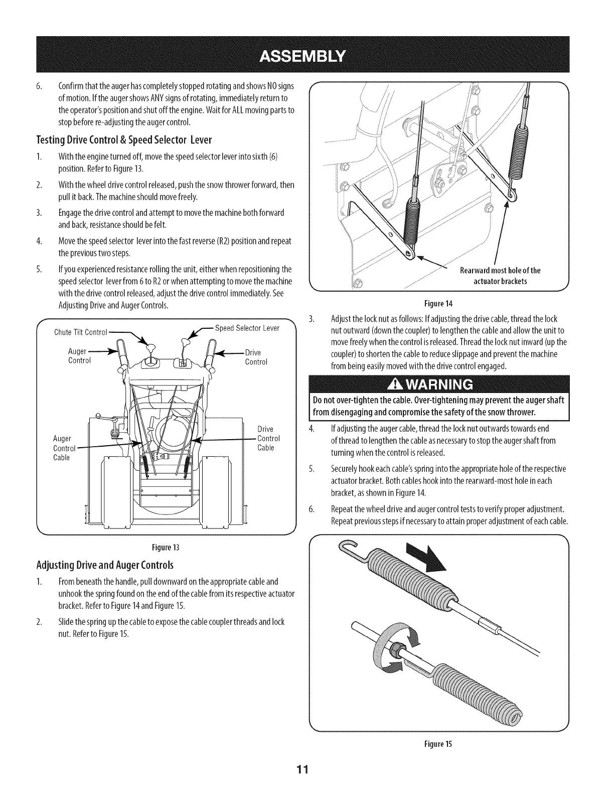
2. Whileobservingthedistancebetweentheshaveplateandtheground,
adjusttheskidsshoesupordowntoachievethedesiredshaveplateheight.
SeeFigure12.
3. Makecertaintheentirebottomsurfaceofskidshoesareagainsttheground
to avoidunevenwearontheskidshoes;thentightennutsandboltssecurely.
ShavePlate
Lower
Shave
Plate
Raise
Shave
Plate
Figure12
_J
Augerand DriveControl Cables
Priorto operatingyoursnowthrower,carefullyreadandfollow all
instructionsbelow.Performall adjustmentsto verifyyoursnowthrower is
operatingsafelyandproperly.
Testing AugerDrive Control
1. Whentheaugercontrolis releasedandinthedisengaged"up" position,the
cableshouldhaveverylittle slack.It shouldNOTbetight. Referto Figure13.
2. Inawell-ventilatedarea,startthesnowthrowerengineasinstructedinthe
Operationsectionofthis manual.Makesurethethrottle issetinthe FAST
position.
3. Whilestandingintheoperator'sposition(behindthesnowthrower),engage
theauger.
4. Allowtheaugerto remainengagedforapproximatelyten(10)seconds
beforereleasingtheaugercontrol.Repeatthisseveraltimes.
NOTE:Whenengagingtheauger,youmayheara"chirp"sound.Thisis
normal,it isthe beltengagingthepulley.Asthebelt wears,thissoundwill
not beheardwhenengagingtheauger.
5. Withthethrottlecontrolinthe FAST(rabbit)positionandtheaugercontrol
in thedisengaged"up" position,walk to thefrontof the machine.
10
6. Confirmthat theaugerhascompletelystoppedrotatingandshowsNOsigns
of motion.IftheaugershowsANYsignsof rotating,immediatelyreturnto
theoperator'spositionandshutoffthe engine.WaitforALLmovingpartsto
stopbeforere-adjustingtheaugercontrol.
Testing DriveControl& SpeedSelector Lever
1. Withtheengineturnedoff,movethespeedselectorleverintosixth(6)
position.Referto Figure13.
2. Withthewheeldrivecontrolreleased,pushthesnowthrowerforward,then
pull it back.Themachineshouldmovefreely.
3. Engagethedrivecontrolandattemptto movethemachinebothforward
andback,resistanceshouldbefelt.
4.
5.
Movethespeedselectorleverintothefast reverse(R2)positionandrepeat
theprevioustwosteps.
If youexperiencedresistancerollingtheunit,eitherwhenrepositioningthe
speedselectorleverfrom6to R2orwhenattemptingto movethemachine
with thedrivecontrolreleased,adjustthedrivecontrolimmediately.See
AdjustingDriveandAugerControls.
ChuteTilt _eedSelector Lever
Auc
Control Control
Auger
Control
Cable
Drive
--Control
Cable
Figure 13
Adjusting Drive and AugerControls
1. Frombeneaththehandle,pull downwardontheappropriatecableand
unhookthe springfoundontheendof thecablefromits respectiveactuator
bracket.Referto Figure14andFigure15.
2. Slidethe springupthecableto exposethecablecouplerthreadsandlock
nut.Referto Figure15.
/
Figure14
Adjustthelocknutasfollows:If adjustingthedrivecable,threadthelock
nutoutward(downthecoupler)to lengthenthecableandallowtheunit to
movefreelywhenthecontrolisreleased.Threadthelocknutinward(upthe
coupler)to shortenthecableto reduceslippageandpreventthemachine
frombeingeasilymovedwith thedrivecontrolengaged.
Donotover-tightenthe cable.Over-tighteningmaypreventthe augershaft
from disengagingandcompromisethe safetyof the snowthrower.
4. Ifadjustingtheaugercable,threadthelocknutoutwardstowardsend
of threadto lengthenthecableasnecessarytostoptheaugershaftfrom
turningwhenthecontrolisreleased.
5. Securelyhookeachcable'sspringintotheappropriateholeof therespective
actuatorbracket.Bothcableshookinto therearward-mostholeineach
bracket,asshownin Figure14.
6. Repeatthewheeldriveandaugercontrolteststo verifyproperadjustment.
Repeatpreviousstepsif necessaryto attainproperadjustmentofeachcable.
Figure15
11
WheelDriveControl
Headlight _eedSelectorLever
ChutePitch Control"
FuelTank erControl
FuelCap
OilFill WheelSteeringControl
Drift Cutter
ChuteAssemb[
Auger Housing
Auger _Skid Shoe
ChuteDirectionalControl
OilFiller
Cap/Dipstick
Primer I ,-- FuN Fill
_Electric
_Start
Button
f Bectric
tL_ Switch Box
Ch_ - StarterHandle
Oil Drain
Figure16
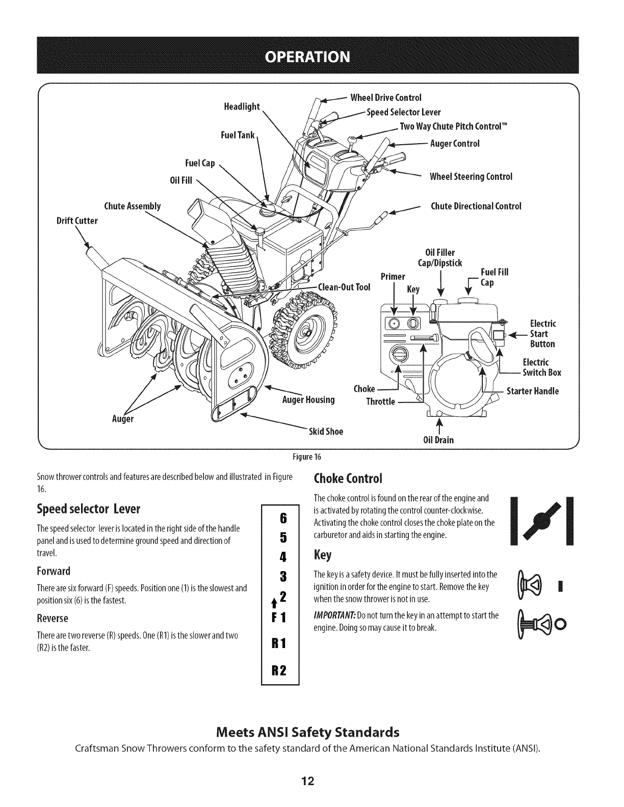
SnowthrowercontrolsandfeaturesaredescribedbelowandillustratedinFigure
16.
Speedselector Lever
Thespeedselectorleverislocatedintheright sideofthe handle
panelandisusedto determinegroundspeedanddirectionof
travel.
Forward
Therearesixforward(F)speeds.Positionone(1)istheslowestand
positionsix(6)isthe fastest.
Reverse
Therearetwo reverse(R)speeds.One(R1)isthe slowerandtwo
(R2)isthefaster.
6
5
4
3
t2
F1
R1
R2
ChokeControl
Thechokecontrolisfoundontherearoftheengineand
isactivatedbyrotatingthecontrolcounter-clockwise.
Activatingthechokecontrolclosesthechokeplateonthe
carburetorandaidsinstartingtheengine.
Key
Thekeyisasafetydevice.It mustbefully insertedintothe
ignitioninorderfortheengineto start. Removethekey
whenthesnowthrowerisnotin use.
IMPORTAfl#Donotturnthe keyinanattemptto startthe
engine.Doingsomaycauseit to break.
Meets ANSi Safety Standards
Craftsman Snow Throwers conform to the safety standard of the American National Standards institute (ANSI).
12
ThrottleControl AugerControl
===..__
Thethrottlecontrolislocatedontherearoftheengine.It regulatesthespeedofthe
engineandwill shutoffthe enginewhenmovedintotheSTOPposition.
Primer
Pressingtheprimerforcesfueldirectlyintotheengine's I _,_P_.._.L
carburetorto aidinstartinga"Cold"engine,orrestartinga
warmengine.
OilFill
Engineoillevelcanbecheckedandoiladdedthroughtheoil fill.
OilDrain
Engineoilcanbedrainedthroughtheoil drain.
FuelCap
Un-threadthegascapto addgasolineto thefuel tank.
Muffler
Engineexhaustexiststheengineviathemuffler.
ElectricStarterOutlet
Requirestheuseof athree-prongoutdoorextensioncordanda 120Vpowersource/
walloutlet.
RecoilStarter Handle
Thishandleisusedto manuallystarttheengine.
ElectricStarterButton
Pressingtheelectricstarterbuttonengagestheengine'selectricstarterwhen
pluggedintoa 120Vpowersource.
Auger
Whenengaged,theaugerbladesrotateanddrawsnowintotheaugerhousing.
ChuteAssembly
Snowdrawnintotheaugerhousingisdischargedoutthechuteassembly.
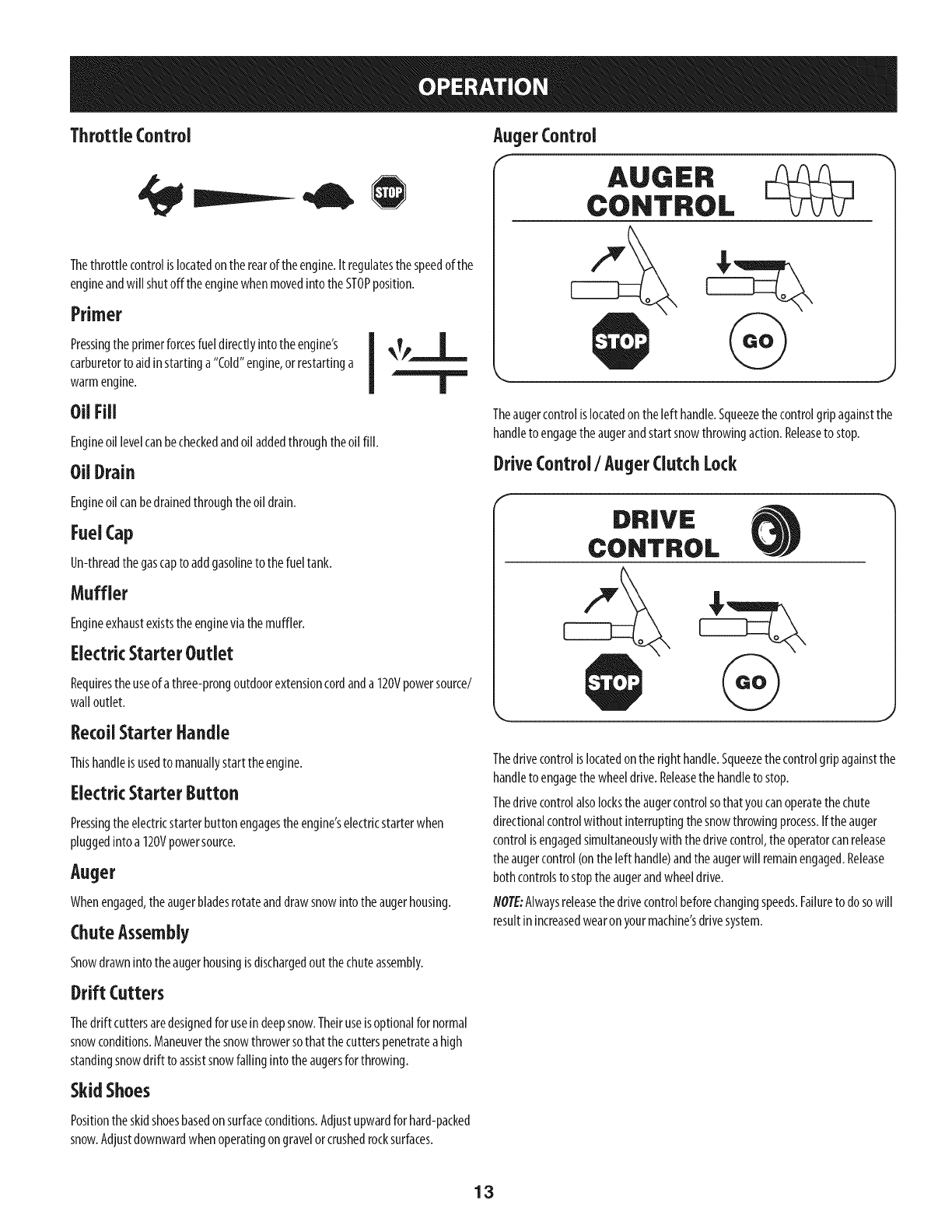
Theaugercontrolislocatedontheleft handle.Squeezethecontrolgripagainstthe
handleto engagetheaugerandstartsnowthrowingaction.Releaseto stop.
DriveControl/AugerClutch Lock
Thedrivecontrolislocatedontheright handle.Squeezethecontrolgripagainstthe
handleto engagethewheeldrive.Releasethe handleto stop.
Thedrivecontrolalsolockstheaugercontrolsothatyoucanoperatethechute
directionalcontrolwithoutinterruptingthesnowthrowingprocess.Iftheauger
controlisengagedsimultaneouslywiththedrivecontrol,theoperatorcanrelease
theaugercontrol(ontheleft handle)andthe augerwill remainengaged.Release
bothcontrolsto stoptheaugerandwheeldrive.
NOTE:Alwaysreleasethedrivecontrolbeforechangingspeeds.Failureto dosowill
resultinincreasedwearonyourmachine'sdrivesystem.
Drift Cutters
Thedrift cuttersaredesignedforusein deepsnow.Theiruseisoptionalfor normal
snowconditions.Maneuverthesnowthrowersothatthecutterspenetratea high
standingsnowdrift to assistsnowfallinginto theaugersforthrowing.
SkidShoes
Positiontheskidshoesbasedonsurfaceconditions.Adjustupwardforhard-packed
snow.Adjustdownwardwhenoperatingongravelorcrushedrocksurfaces.
13
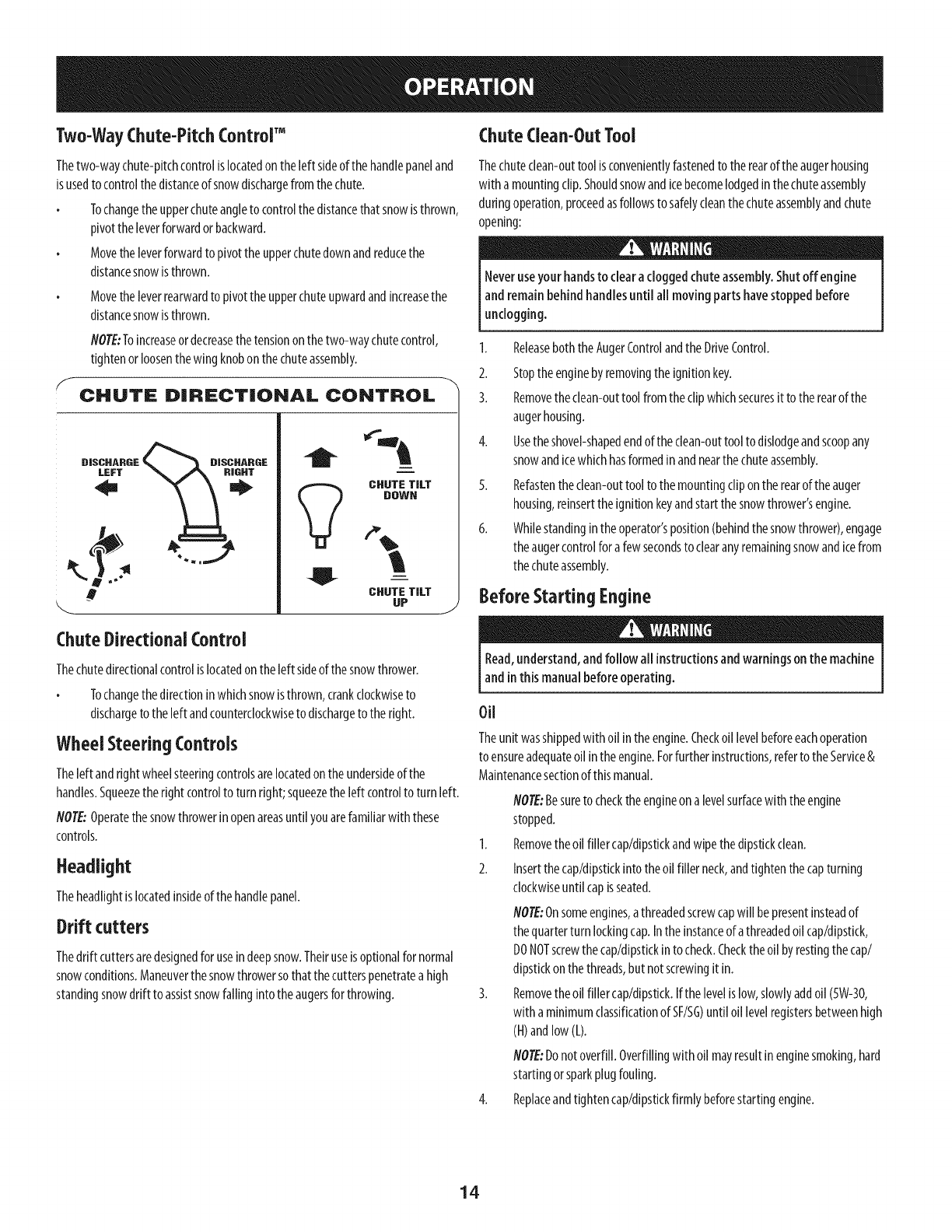
Two-WayChute-PitchControlTM
Thetwo-waychute-pitchcontrolis locatedon the[eftsideofthe handlepaneland
isusedto controlthedistanceof snowdischargefrom thechute.
Tochangetheupperchuteangleto controlthedistancethatsnowisthrown,
pivotthe[everforwardorbackward.
Movethe[everforwardto pivotthe upperchutedownandreducethe
distancesnowisthrown.
Movetheleverrearwardtopivottheupperchuteupwardandincreasethe
distancesnowisthrown.
NOTE:Toincreaseordecreasethetensiononthetwo-waychutecontrol,
tightenorloosenthewingknobonthechuteassembly.
CHUTE DiRECTiONAL CONTROL
D|SCHABGE _D|SCHARGE
m
i
CHUTE TILT
DOWN
CHUTE TILT
UP J
Chute Clean-Out Tool
Thechuteclean-outtoolisconvenientlyfastenedtotherearof theaugerhousing
with a mountingclip.Shouldsnowandicebecomelodgedinthechuteassembly
duringoperation,proceedasfollowsto safelycleanthechuteassemblyandchute
opening:
Neveruseyour handsto clearacloggedchute assembly.Shutoff engine
and remainbehindhandlesuntilall movingpartshavestoppedbefore
unclogging.
1. ReleaseboththeAugerControlandtheDriveControl.
2. Stoptheenginebyremovingtheignitionkey.
3. Removetheclean-outtool fromtheclipwhichsecuresit to therearof the
augerhousing.
4. Usetheshovel-shapedendoftheclean-outtooltodislodgeandscoopany
snowandicewhichhasformedinandnearthechuteassembly.
5. Refastentheclean-outtool to themountingclip ontherearof theauger
housing,reinserttheignitionkeyandstartthesnowthrower'sengine.
6. Whilestandingintheoperator'sposition(behindthesnowthrower),engage
theaugercontrolfora fewsecondsto clearanyremainingsnowandicefrom
thechuteassembly.
Before Starting Engine
ChuteDirectional Control
Thechutedirectionalcontrolislocatedonthe left sideof thesnowthrower.
Tochangethedirectioninwhichsnowisthrown,crankclockwiseto
dischargeto theleft andcounterclockwiseto dischargeto theright.
Wheel Steering Controls
Theleft andrightwheelsteeringcontrolsarelocatedonthe undersideofthe
handles.Squeezetheright controlto turn right; squeezetheleft controlto turn left.
NOTE:Operatethesnowthrowerinopenareasuntil youarefamiliarwith these
controls.
Headlight
Theheadlightis locatedinsideofthehandlepanel.
Drift cutters
Thedrift cuttersaredesignedfor useindeepsnow.Theiruseisoptionalfor normal
snowconditions.Maneuverthesnowthrowersothatthecutterspenetratea high
standingsnowdrift to assistsnowfallinginto theaugersforthrowing.
Read,understand,andfollow all instructionsand warningsonthe machine
and inthis manualbeforeoperating.
Oil
Theunit wasshippedwith oil intheengine.Checkoil levelbeforeeachoperation
to ensureadequateoil intheengine.Forfurtherinstructions,referto the Service&
Maintenancesectionof thismanual.
NOTE:Besureto checktheengineona levelsurfacewith theengine
stopped.
1. Removetheoil filler cap/dipstickandwipethe dipstickclean.
2. Insertthecap/dipstickinto theoil filler neck,andtightenthe capturning
clockwiseuntil capisseated.
NOTE:Onsomeengines,athreadedscrewcapwill bepresentinsteadof
thequarterturnlockingcap.Inthe instanceof athreadedoil cap/dipstick,
DONOTscrewthecap/dipstkkinto check.Checktheoil byrestingthecap/
dipstickonthethreads,but notscrewingit in.
3. Removetheoil filler cap/dipstick.Ifthe levelislow,slowlyaddoil (5W-30,
with a minimumclassificationof SF/SG)untiloil levelregistersbetweenhigh
(H)andlow(L).
NOTE:Donotoverfill.Overfillingwithoil mayresultinenginesmoking,hard
startingorsparkplugfouling.
4. Replaceandtightencap/dipstickfirmly beforestartingengine.
14
Gasoline
Useextreme carewhenhandling gasoline.Gasolineisextremely flammable
and thevaporsareexplosive.Neverfuel the machineindoorsor while the
engine ishot or running. Extinguishcigarettes,cigars,pipesand other
sourcesof ignition.
Useautomotivegasoline(unleadedorlowleadedto minimizecombustionchamber
deposits)witha minimumof87 octane.Gasolinewith up to 10%ethanolor15%
MTBE(MethylTertiaryButylEther)canbeused.Neveruseanoil/gasolinemixture
ordirtygasoline.Avoidgettingdirt, dust,orwaterinthefuel tank.DONOTuseE85
gasoline.
Refuelin awell-ventilatedareawith theenginestopped.Donotsmokeor
allowflamesorsparksintheareawheretheengineisrefueledorwhere
gasolineisstored.
Donotoverfillthefuel tank.Afterrefueling,makesurethetankcapisclosed
properlyandsecurely.
Becarefulnot to spillfuel whenrefueling.Spilledfuel orfuelvapormay
ignite.Ifanyfuelisspilled,makesuretheareaisdrybeforestartingthe
engine.
Avoidrepeatedorprolongedcontactwith skinor breathingof vapor
1. Cleanaroundfuel fill beforeremovingcapto fuelto preventdebrisfrom
enteringfueltank..
2. Afuel levelindicatorislocatedin thefueltank.Filltankuntil fuel reachesthe
fuel levelindictor.SeeFigure10inset.Becarefulnotto overfill.
Starting TheEngine
Alwayskeephandsandfeet clearof moving parts.Donot usea pressurized
starting fluid. Vaporsareflammable.
flOTE:Allowtheenginetowarmupforafew minutesafterstarting.Theenginewill
notdevelopfull poweruntil it reachesoperatingtemperatures.
1. Makecertainboth theaugercontrolanddrivecontrolareinthedisengaged
(released)position.
2. Insertkeyintoslot.Makesureit snapsintoplace.Donotattemptto turnthe
key.
NOTE:Theenginecannotstartwithout thekeyisfully insertedintothe ignition
switch.
Electric Starter
Theoptional electricstarter isequippedwith a groundedthree-wire power
plug,and isdesignedto operateon 120volt AChouseholdcurrent. It mustbe
usedwith a properly groundedthree-prongextensioncordandreceptacle
at all timesto avoidthe possibilityof electricshock.Followall instructions
carefully priorto operatingthe electric starter.DONOTuseelectricstarter in
the rain.
Determinethat yourhome'swiringisathree-wiregroundedsystem.Aska licensed
electricianifyouarenotcertain.
Theextensioncordcanbeany length, but must be ratedfor 15ampsat 125
volts,groundedand ratedfor outdooruse.
Ifyouhaveagroundedthree-prongreceptacle,proceedasfollows.If youdonot
havethe properhousewiring,DONOTusetheelectricstarterunderanyconditions.
1. Plugtheextensioncordintotheoutlet locatedontheengine'ssurface.Plug
theotherendof extensioncordintoa three-prong120-volt,grounded,AC
outlet inawell-ventilatedarea.
2. Movethrottlecontrolto FAST(rabbit)_j_ position.
3. Movechoketo theCHOKEposition[,j €[ (coldenginestart).
4. NOTE:Iftheengineisalreadywarm,placechokecontrolin theRUNposition
insteadof CHOKEI."1
position.
5. Pushprimerthreetimes(3x),makingsureto covervent holeinprimerbulb
whenpushing.If engineiswarm,pushprimeronlyonce.Alwayscovervent
holewhenpushing.Coolweathermayrequireprimingto berepeated.
6. Pushstarterbuttonto startengine.Oncetheenginestarts,immediately
releasestarterbutton.Electricstarterisequippedwith thermaloverload
protection;systemwill temporarilyshut-downto allowstarterto coolif
electricstarterbecomesoverloaded.
Toprolong starter life, useshortstarting cycles(5secondsmaximum, then
wait oneminute).
7. Astheenginewarms,slowlyrotatethechokecontroltothe RUNposition.If
theenginefalters,restartengineandrunwith chokeat half-chokeposition
fora shortperiodof time,andthenslowlyrotatethechokeintotheRUN
position.
8. Afterengineis running,disconnectpowercordfromelectricstarter.When
disconnecting,alwaysunplugtheendat thewall outlet beforeunplugging
theoppositeendfromtheengine.
RecoilStarter
Donot pull the starter handlewhilethe enginerunning.
1. Movethrottlecontrolto FAST(rabbit)_ position.
2. Movechoketo theCHOKEI,"lpos t on co,denginestart).Ifengineis
warm,placechokeintheRUNposition.
3. Pushprimerthreetimes,makingsureto coverventholewhenpushing.
Ifengineiswarm,pushprimeronlyonce.Alwayscoverventholewhen
pushing.Coolweathermayrequireprimingto berepeated.
4. Pullgentlyonthestarterhandleuntilit beginsto resist,thenpullquicklyand
forcefullyto overcomethe compression.Engineshouldstart.Donotreleasethe
handleandallowit to snapback.ReturnropeSLOWLYto originalposition.If
required,repeatthisstep.
5. Astheenginewarms,slowlyrotatethechokecontroltothe RUNposition.If
theenginefalters,restartengineandrunwith chokeat half-chokeposition
fora shortperiodof time,andthenslowlyrotatethechokeintotheRUN
position.
15
Toavoidunsupervisedengineoperation, neverleavethe machine
unattendedwith the enginerunning.Turnthe engineoff after useand
removekey.
StoppingTheEngine
Afteryouhavefinishedsnow-throwing,runengineforafew minutesbefore
stoppingto helpdryoffany moistureontheengine.
1. Movethrottle controlto STOP@ position.
ine.Backfire oreric ,occur.
2. Removethekey.Removingthe keywill reducethepossibilityof
unauthorizedstartingof theenginewhileequipmentisnotin use.Keepthe
keyinasafeplace.Theenginecannotstartwithoutthe key.
3. Wipeallsnowandmoisturefromtheareaaroundtheengineaswell asthe
areainandaroundthewheeldrivecontrolandaugercontrol.Also,engage
andreleasebothcontrolsseveraltimes.
ToEngageDrive
1. Withthethrottle controlin theFast(rabbit)_ position,movespeed
selectorleverinto oneof thesixforward(F)positionsortwo reverse(R)
positions.Selecta speedappropriateforthesnowconditionsandapace
you'recomfortablewith.
NOTE: Whenselectinga DriveSpeed,usethe slowerspeeds
untilyouare comfortableandfamiliarwiththe operationof the
snowthrower.
2. Squeezethedrivecontrolagainstthehandleandthesnow
throwerwill move.Releaseit anddrivemotionwill stop.
NOTE:NEVERrepositionthespeedselectorlever(changespeedsordirectionof
travel)without firstreleasingthedrivecontrolandbringingthe snowthrowerto a
completestop.Doingsowill resultinprematurewearto thesnowthrower'sdrive
system.
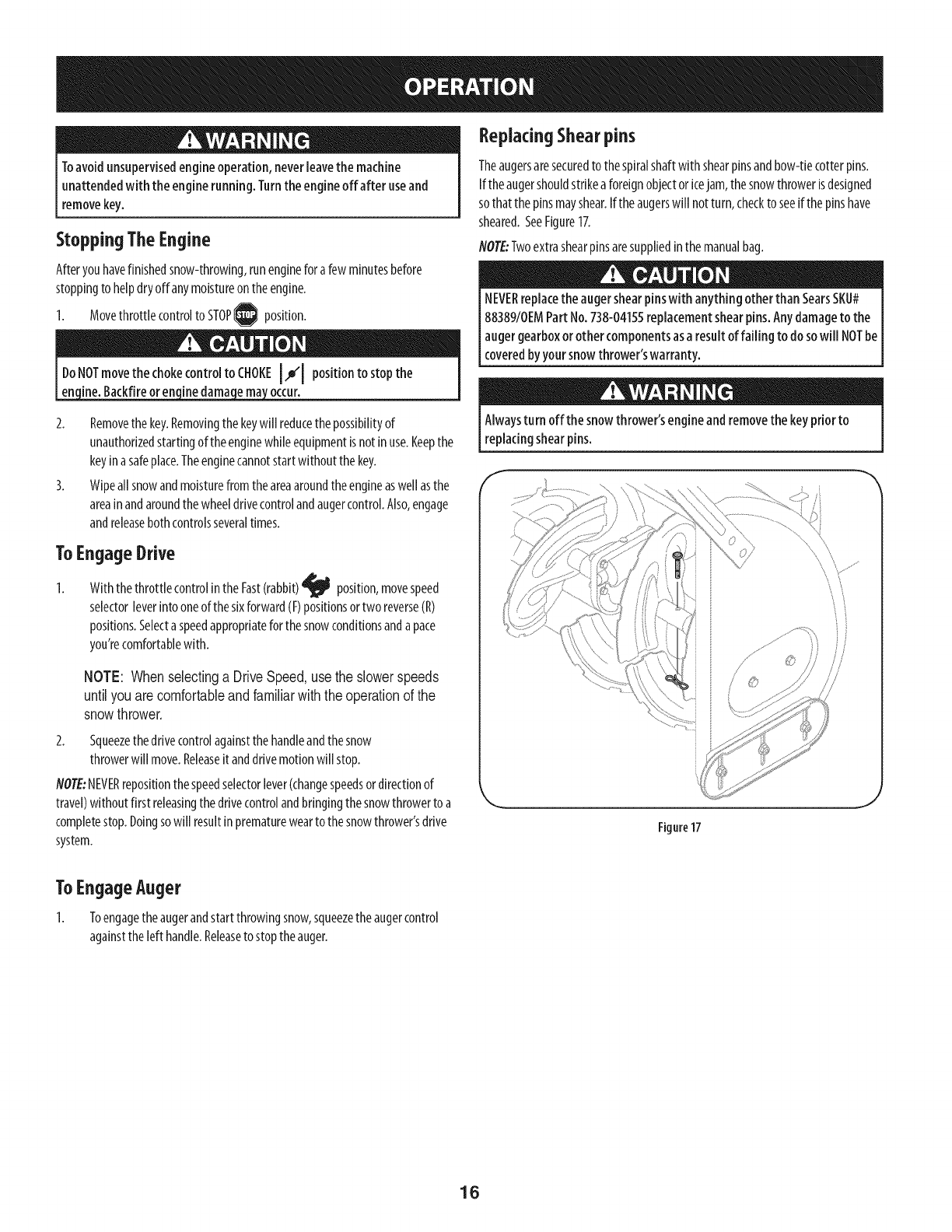
ReplacingShearpins
Theaugersaresecuredto thespiralshaftwith shearpinsandbow-tiecotterpins.
Iftheaugershouldstrikea foreignobjectoricejam,thesnowthrowerisdesigned
sothatthe pinsmayshear.Iftheaugerswill notturn,checkto seeif thepinshave
sheared.SeeFigure17.
NOTE:Twoextrashearpinsaresuppliedin themanualbag.
NEVERreplacethe augershearpinswith anything otherthan SearsSKU#
88389/0EMPart No.738-0415Sreplacementshearpins.Anydamageto the
augergearboxorother componentsasaresult of failing to do sowill NOTbe
coveredbyyoursnowthrower'swarranty.
Alwaysturn off the snowthrower's engineand removethe key priorto
replacingshearpins.
J
Figure17
ToEngageAuger
1. Toengagetheaugerandstartthrowingsnow,squeezetheaugercontrol
againstthe left handle.Releaseto stoptheauger.
16
MAINTENANCE SCHEDULE
Beforeperforminganytypeof maintenance/service,disengageall controls
andstoptheengine.Waituntil all moving partshavecometo acomplete
stop.Removethekeyto preventunintendedstarting. Alwayswearsafety
glassesduringoperation orwhile performingany adjustmentsor repairs.
Followthemaintenanceschedulegivenbelow.Thischartdescribesservice
guidelinesonly.UsetheServiceLogcolumnto keeptrackofcompleted
maintenancetasks.TolocatethenearestSearsServiceCenterorto scheduleservice,
simplycontactSearsat 1-800-4-MY-HOME®.
EachUse
1st5- 8 hours
25hours
50hours
Annuallyor100hours
BeforeStorage 1. Fuelsystem 1.
1.
2.
3.
1.
1.
2.
1.
1.
Engineoil level
Looseormissinghardware
Unitandengine.
Engineoil
Engineoilf
Controllinkagesandpivots
Engineoil
Sparkplug
Under heavy load or in high temperatures
EngineMaintence
1.
2.
3.
1.
1.
2.
1.
1.
CheckingEngine0il
Beforelubricating, repairing,orinspecting,disengageall controlsand stop
Iengine.Waituntil all moving parts havecometo a completestop.Remove
_thekeyto prevent unintendedfiring of the engine.
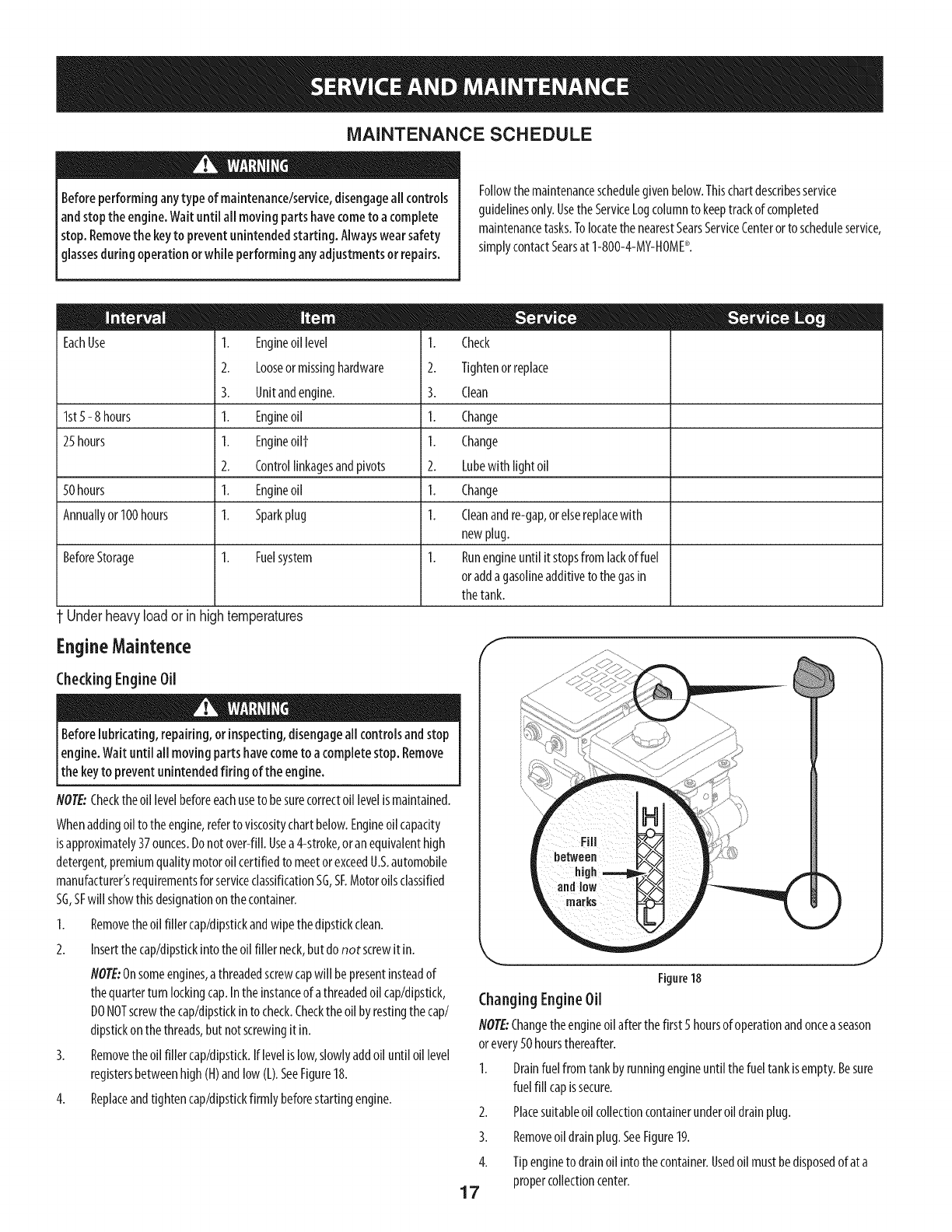
NOTE:Checktheoil levelbeforeeachuseto besurecorrectoillevelismaintained.
Whenaddingoil to theengine,referto viscositychartbelow.Engineoilcapacity
isapproximately37ounces.Donotover-fill.Usea4-stroke,oranequivalenthigh
detergent,premiumqualitymotoroilcertifiedto meetorexceedU.S.automobile
manufacturer'srequirementsforserviceclassificationSG,SF.Motoroilsclassified
SG,SFwill showthisdesignationonthecontainer.
1. Removetheoilfiller cap/dipstickandwipethedipstickclean.
2. Insertthecap/dipstickintotheoilfiller neck,butdo not screwitin.
NOTE:Onsomeengines,athreadedscrewcapwill bepresentinsteadof
thequarterturnlockingcap.Intheinstanceof athreadedoilcap/dipstick,
DONOTscrewthecap/dipstickinto check.Checktheoilby restingthecap/
dipstickonthethreads,butnotscrewingitin.
3. Removetheoilfiller cap/dipstick.Iflevelislow,slowlyaddoil until oillevel
Check
Tightenorreplace
Clean
Change
Change
Lubewith light oil
Change
Cleanandre-gap,orelsereplacewith
new plug.
Runengineuntil itstopsfromlackof fuel
oradda gasolineadditiveto thegasin
thetank.
registersbetweenhigh(H)andlow(L).SeeFigure18.
Replaceandtightencap/dipstickfirmlybeforestartingengine.
J
4.
1. Drainfuelfromtankbyrunningengineuntil thefuel tankisempty.Besure
fuelfill capissecure.
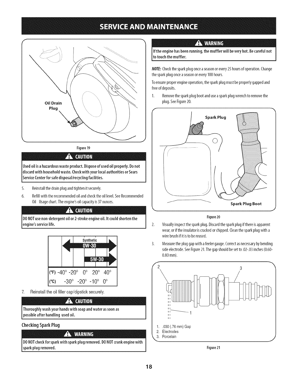
2. Placesuitableoil collectioncontainerunderoildrainplug.
3. Removeoildrainplug.SeeFigure19.
4. Tipengineto drainoilintothecontainer.Usedoil mustbedisposedof ata
propercollectioncenter.
17
Figure18
Changing EngineOil
NOTE:Changetheengineoilafterthefirst 5 hoursof operationandonceaseason
orevery50hoursthereafter.
f
Oil Drain
Plug
Figure19
Usedoil isahazardouswaste product.Disposeof usedoil properly.Donot
discardwith householdwaste.Checkwith your localauthoritiesor Sears
ServiceCenterfor safedisposal/recyclingfacilities.
5. Reinstallthedrainplugandtightenitsecurely.
6. Refillwith therecommendedoilandchecktheoil level.SeeRecommended
Oil Usagechart.Theengine'soilcapacityis37ounces.
Ifthe enginehasbeenrunning,the muffler willbe veryhot. Becarefulnot
to touchthe muffler.
NOTE:Checkthesparkplugonceaseasonorevery25hoursof operation.Change
thesparkplugonceaseasonorevery100hours.
Toensureproperengineoperation,thesparkplugmustbeproperlygappedand
freeof deposits.
1. Removethesparkplug bootanduseasparkplugwrenchto removethe
plug.SeeFigure20.
Spark Plug
Spark Plug Boot
DONOTusenon-detergent oil or2-strokeengineoil. It couldshortenthe
engine'sservicelife.
(°F)-40 o -20 o 0o 200 400
(oc) -30o -20o -10 o 0o
7. Reinstallthe oilfillercap/dipsticksecurely.
Thoroughlywashyour handswith soapandwater assoonas
possibleafter handling usedoil.
CheckingSparkPlug
DONOTcheckfor sparkwith sparkplugremoved.DONOTcrankenginewith
sparkplugremoved.
Figure20
Visuallyinspectthesparkplug.Discardthesparkplugifthereisapparent
wear,oriftheinsulatoriscrackedorchipped.Cleanthesparkplugwith a
wire brushifitisto bereused.
Measurethepluggapwith afeelergauge.Correctasnecessarybybending
sideelectrode.SeeFigure21.Thegapshouldbesetto .02-.03inches(0.60-
0.80mm).
1..030 (.76 mm) Gap
2. Electrodes
3. Porcelain
Figure21
18
4. Checkthatthesparkplugwasherisingoodconditionandthreadthespark
pluginbyhandto preventcross-threading.
5. Afterthesparkplugisseated,tightenwith asparkplugwrenchto compress
thewasher.
NOTE:Wheninstallinganewsparkplug,tighten1/2-turnafterthespark
plugseatsto compressthewasher.Whenreinstallingausedsparkplug,
tighten1/8- to 1/4-turnafterthesparkplugseatsto compressthewasher.
' hot andcandamagetheengine.
Carburetor Adjustment
Thecarburetorisnotuseradjustable.ContactSearsParts& Repairforadjustment.
Lubrication
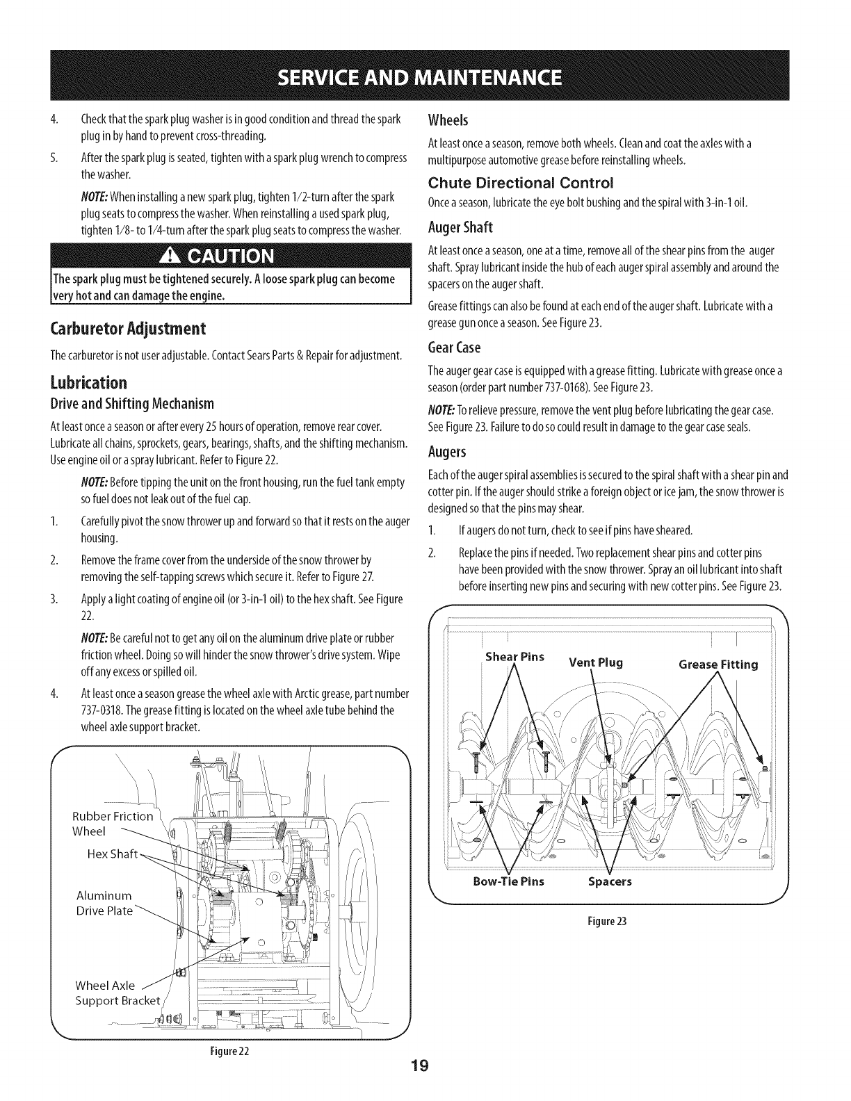
Driveand Shifting Mechanism
Atleastonceaseasonorafterevery25hoursof operation,removerearcover.
Lubricateallchains,sprockets,gears,bearings,shafts,andtheshiftingmechanism.
Useengineoil oraspraylubricant.Referto Figure22.
NOTE:Beforetippingthe uniton thefronthousing,runthefueltankempty
sofuel doesnot leakoutof the fuelcap.
1. Carefullypivotthesnowthrowerupandforwardsothat it restsontheauger
housing.
2. Removetheframecoverfromtheundersideof thesnowthrowerby
removingtheself-tappingscrewswhichsecureit. Referto Figure27.
3. Applya lightcoatingof engineoil (or3-in-1oil) to thehexshaft.SeeFigure
22.
NOTE:Becarefulnotto get anyoilonthe aluminumdriveplateorrubber
frktion wheel.Doingsowill hinderthesnowthrower'sdrivesystem.Wipe
offanyexcessorspilledoil.
AtleastonceaseasongreasethewheelaxlewithArcticgrease,partnumber
737-0318.Thegreasefitting islocatedonthewheelaxletube behindthe
wheelaxlesupportbracket.
4.
f
Rubber Friction
Wheel
Aluminum
Drive
Wheel Axle
Support Bracket
Figure22
Wheels
At leastonceaseason,removebothwheels.Cleanandcoattheaxleswith a
multipurposeautomotivegreasebeforereinstallingwheels.
Chute Directional Control
Onceaseason,lubricatetheeyebolt bushingandthespiralwith 3-in-1oil.
Auger Shaft
At leastonceaseason,oneat atime,removeall oftheshearpinsfromthe auger
shaft.Spraylubricantinsidethehubof eachaugerspiralassemblyandaroundthe
spacersontheaugershaft.
Greasefittingscanalsobefoundat eachendoftheaugershaft.Lubricatewith a
greasegunonceaseason.SeeFigure23.
GearCase
Theaugergearcaseisequippedwith agreasefitting. Lubricatewith greaseoncea
season(orderpartnumber737-0168).SeeFigure23.
NOTE:Torelievepressure,removetheventplugbeforelubricatingthegearcase.
SeeFigure23.Failureto do socouldresultindamageto the gearcaseseals.
Augers
Eachof theaugerspiralassembliesissecuredto the spiralshaftwith ashearpin and
cotterpin.If theaugershouldstrikeaforeignobjectoricejam,thesnowthroweris
designedsothatthepinsmayshear.
1. Ifaugersdonotturn,checkto seeif pinshavesheared.
2. Replacethepinsifneeded.Tworeplacementshearpinsandcotterpins
havebeenprovidedwith thesnowthrower.Sprayanoil lubricantintoshaft
beforeinsertingnewpinsandsecuringwith newcotterpins.SeeFigure23.
Bow-Tie Pins Spacers
Figure23
19
ShavePlateand SkidShoes
Theshaveplateandskidshoesonthebottomofthesnowthroweraresubjectto
wear.Theyshouldbecheckedperiodicallyandreplacedwhennecessary.
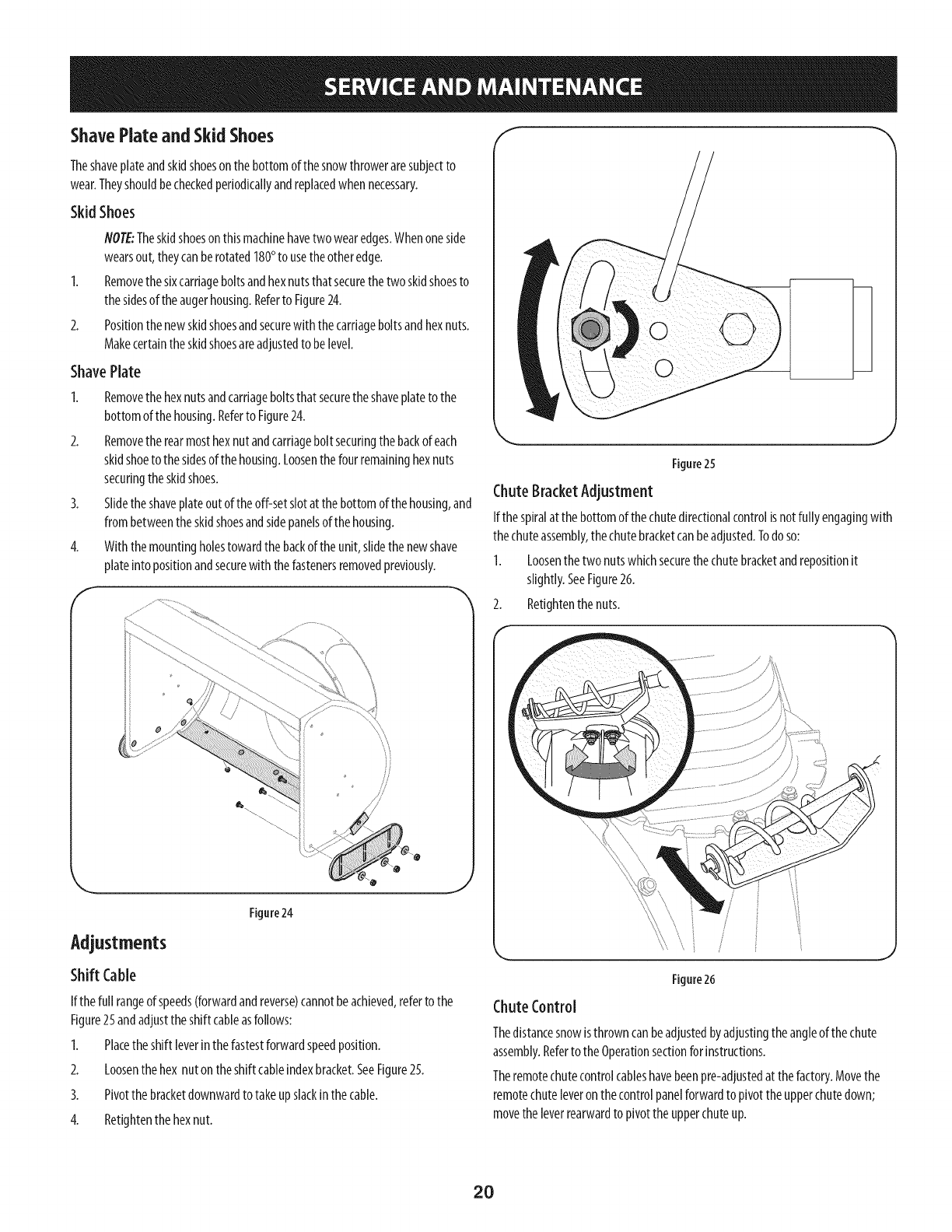
Skid Shoes
2.
NOTE:Theskidshoesonthismachinehavetwo wearedges.Whenoneside
wearsout,theycanberotated180°to usetheotheredge.
Removethesixcarriageboltsandhexnutsthatsecurethetwo skidshoesto
thesidesoftheaugerhousing.Referto Figure24.
Positionthenewskidshoesandsecurewith thecarriageboltsandhexnuts.
Makecertaintheskidshoesareadjustedto belevel.
ShavePlate
1. Removethehexnutsandcarriageboltsthat securetheshaveplatetothe
bottomofthe housing.Referto Figure24.
2. Removetherearmosthexnutandcarriagebolt securingthebackof each
skidshoeto thesidesofthehousing.Loosenthefourremaininghexnuts
securingthe skidshoes.
3. Slidetheshaveplateoutoftheoff-setslotat thebottomof the housing,and
frombetweentheskidshoesandsidepanelsofthehousing.
4. Withthemountingholestowardthe backof theunit, slidethenewshave
plateinto positionandsecurewiththefastenersremovedpreviously.
f
Figure24
Adjustments
Shift Cable
If the full rangeof speeds(forwardandreverse)cannotbeachieved,referto the
Figure25andadjustthe shift cableasfollows:
I. Placetheshift leverinthefastestforwardspeedposition.
2. Loosenthehex nutontheshift cableindexbracket.SeeFigure25.
3. Pivotthebracketdownwardtotakeupslackinthecable.
4. Retightenthehexnut.
Figure25
ChuteBracketAdjustment
Ifthespiralatthebottomof thechutedirectionalcontrolis notfully engagingwith
thechuteassembly,thechutebracketcanbeadjusted.Todoso:
I. Loosenthetwo nutswhichsecurethechutebracketandrepositionit
slightly.SeeFigure26.
2. Retightenthe nuts.
Figure26
ChuteControl
Thedistancesnowisthrowncanbeadjustedbyadjustingthe angleof thechute
assembly.Referto theOperationsectionforinstructions.
Theremotechutecontrolcableshavebeenpre-adjustedat thefactory.Movethe
remotechuteleveronthecontrolpanelforwardto pivot theupperchutedown;
movetheleverrearwardto pivotthe upperchuteup.
2O
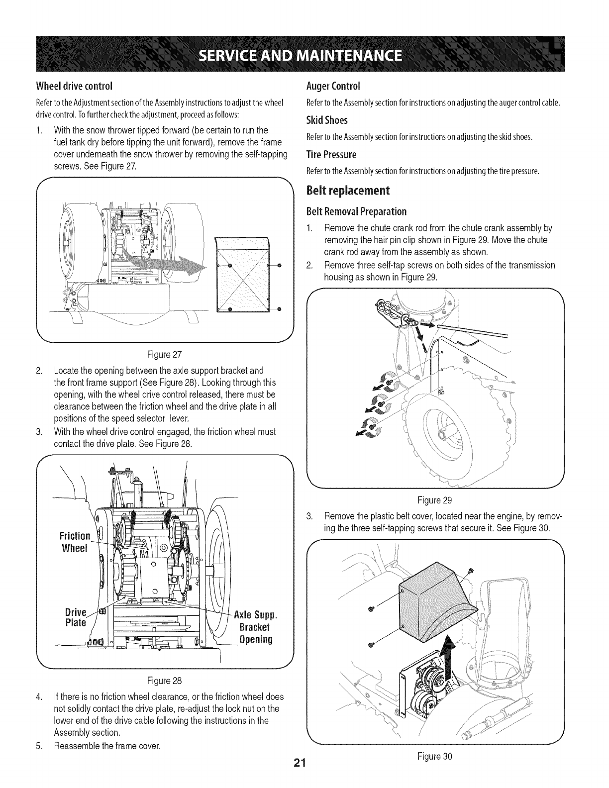
Wheeldrivecontrol
RefertotheAdjustmentsectionoftheAssemblyinstructionstoadjustthewheel
drivecontrol.Tofurtherchecktheadjustment,proceedasfollows:
1. Withthe snowthrowertippedforward(be certainto runthe
fueltankdry beforetippingthe unitforward),removethe frame
coverunderneaththe snowthrowerby removingthe self-tapping
screws.SeeFigure27.
f
.
.
f
_ ___11/_...... _ !........ ..........
%
Figure27
Locatethe openingbetweenthe axle supportbracketand
thefrontframesupport(SeeFigure28). Lookingthroughthis
opening,withthe wheeldrivecontrolreleased,theremustbe
clearancebetweenthefrictionwheelandthe driveplatein all
positionsof the speedselector lever.
Withthe wheeldrivecontrolengaged,the frictionwheelmust
contactthedrive plate.SeeFigure28.
Figure28
4. Ifthere is nofrictionwheelclearance,or the frictionwheeldoes
not solidlycontactthe driveplate,re-adjustthe locknuton the
lowerendof thedrive cablefollowingthe instructionsin the
Assemblysection.
5. Reassemblethe framecover.
Auger Control
RefertotheAssemblysectionforinstructionsonadjustingtheaugercontrolcable.
Skid Shoes
RefertotheAssemblysectionforinstructionsonadjustingtheskidshoes.
Tire Pressure
RefertotheAssemblysectionforinstructionsonadjustingthetirepressure.
Beltreplacement
Belt RemovalPreparation
I. Removethe chutecrankrodfromthechutecrankassemblyby
removingthe hairpinclip shownin Figure29. Movethechute
crankrod awayfromthe assemblyas shown.
2. Removethreeself-tapscrewson bothsidesof the transmission
housingas shownin Figure29.
Figure29
3. Removethe plasticbeltcover,locatednearthe engine,by remov-
ing thethree self-tappingscrewsthatsecureit. See Figure30.
21 Figure30
J
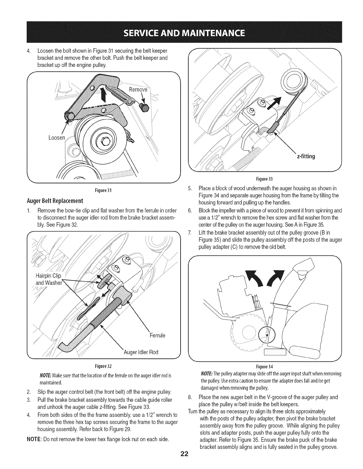
4. LoosentheboltshowninFigure31securingthebeltkeeper
bracketandremovetheotherbolt.Pushthebeltkeeperand
bracketupofftheenginepulley.
f
Loosen
Figure31
Auger Belt Replacement
1. Removethebow-tieclip andflatwasherfromtheferruleinorder
to disconnectthe augeridlerrodfromthe brakebracketassem-
bly.SeeFigure32.
Figure32
ger Idler Rod
NOTE:Makesurethat thelocationof theferruleon theaugeridler rodis
maintained.
2. Slipthe augercontrolbelt (thefrontbelt) offthe enginepulley.
3. Pullthe brakebracketassemblytowardsthe cableguideroller
andunhookthe augercable z-fitting.SeeFigure33.
4. Fromboth sidesof the the frameassembly,use a 1/2" wrenchto
removethe threehex tap screwssecuringthe frameto the auger
housingassembly.Referbackto Figure29.
NOTE:Do not removethe lowerhexflangelocknuton eachside.
22
z-fitting
Figure33
5. Placeablockof woodunderneaththeaugerhousingas shownin
Figure34andseparateaugerhousingfromtheframebytiltingthe
housingforwardandpullingupthe handles.
6. Blocktheimpellerwitha pieceofwoodto preventitfromspinningand
usea 1/2"wrenchto removethehexscrewandflatwasherfromthe
centerofthe pulleyontheaugerhousing.SeeAin Figure35.
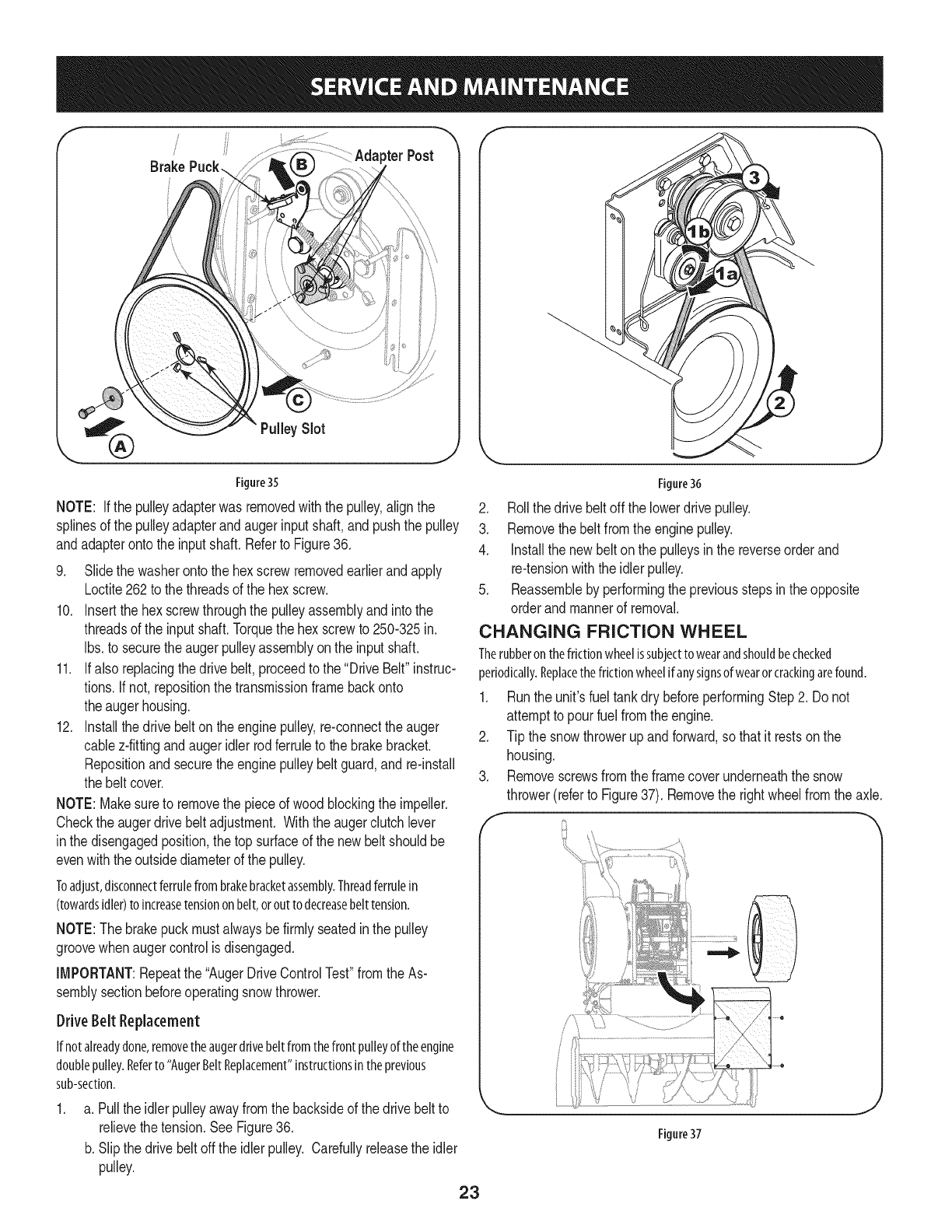
7. Liftthe brakebracketassemblyout of the pulleygroove(B in
Figure35)andslide the pulleyassemblyoff the postsof the auger
pulleyadapter(C) to removethe oldbelt.
Figure34
NOTE:Thepulleyadaptermayslideofftheaugerinputshaftwhenremoving
thepulley.Useextracautiontoensuretheadapterdoesfalland/orget
damagedwhenremovingthepulley.
8. Placethe newaugerbeltin the V-grooveof the augerpulleyand
placethe pulleyw/belt insidethebelt keepers.
Turnthe pulleyas necessaryto alignitsthreeslotsapproximately
withthepostsof thepulleyadapter,thenpivotthe brakebracket
assemblyawayfromthe pulleygroove. Whilealigningthe pulley
slotsandadapterposts,pushtheaugerpulleyfullyonto the
adapter.Referto Figure35. Ensurethebrakepuckof the brake
bracketassemblyalignsandis fully seatedin the pulleygroove.
!
/
Brake pterPost
%
PulleySlot
J\ J
Figure 35
NOTE: If the pulleyadapterwas removedwiththepulley,alignthe
splinesof the pulleyadapterandaugerinputshaft,andpushthe pulley
andadapterontothe inputshaft.Referto Figure36.
9. Slidethe washerontothe hex screwremovedearlierandapply
Loctite262to thethreadsof the hex screw.
10. Insertthe hexscrewthroughthe pulleyassemblyandintothe
threadsof the inputshaft.Torquethe hex screwto 250-325in.
Ibs.to securethe augerpulleyassemblyon the inputshaft.
11. Ifalso replacingthe drivebelt,proceedto the "DriveBelt"instruc-
tions.If not,repositionthe transmissionframebackonto
theaugerhousing.
12. Installthedrive belton theenginepulley,re-connectthe auger
cablez-fittingandaugeridler rodferruleto the brakebracket.
Repositionand securethe enginepulleybelt guard,and re-install
the beltcover.
NOTE:Makesureto removethe pieceof woodblockingthe impeller.
Checkthe augerdrivebeltadjustment. Withthe augerclutchlever
inthe disengagedposition,thetop surfaceof the newbelt shouldbe
evenwiththeoutsidediameterof the pulley.
Toadjust,disconnectferrulefrombrakebracketassembly.Threadferrulein
(towardsidler)toincreasetensiononbelt,orouttodecreasebelttension.
NOTE:Thebrakepuckmustalwaysbefirmly seatedinthe pulley
groovewhenaugercontrolisdisengaged.
IMPORTANT:Repeatthe "AugerDriveControlTest"fromthe As-
semblysectionbeforeoperatingsnowthrower.
Drive Belt Repla(ement
Ifnotalreadydone,removetheaugerdrivebeltfromthefrontpulleyoftheengine
doublepulley.Referto"AugerBeltReplacement"instructionsintheprevious
sub-section.
a. Pullthe idlerpulleyawayfromthe backsideof the drivebeltto
relievethetension.SeeFigure36.
b. Slipthe drivebelt offthe idlerpulley. Carefullyreleasethe idler
pulley.
Figure36
2. Rollthe drivebeltoff the lowerdrivepulley.
3. Removethe belt fromthe enginepulley.
4. Installthe newbelton the pulleysin the reverseorderand
re-tensionwiththe idlerpulley.
5. Reassembleby performingthe previousstepsin theopposite
orderand mannerof removal.
CHANGING FRICTION WHEEL
Therubberonthefrictionwheelissubjecttowearandshouldbechecked
periodically.Replacethefrictionwheelifanysignsofwearorcrackingarefound.
1. Runthe unit'sfuel tankdry beforeperformingStep2. Donot
attemptto pourfuel fromthe engine.
2. Tip the snowthrowerupand forward,sothat it restsonthe
housing.
3. Removescrewsfromtheframecoverunderneaththe snow
thrower(referto Figure37). Removethe rightwheelfromthe axle.
J
Figure37
23
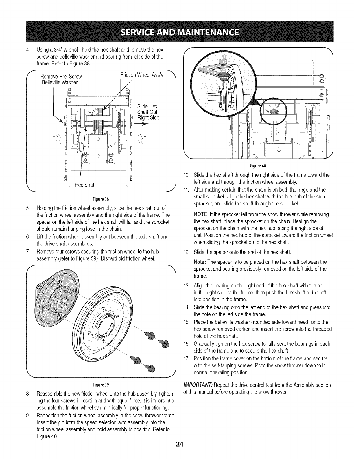
.Usinga 3/4" wrench,holdthe hex shaftandremovethe hex
screwandbellevillewasherand bearingfromleft sideof the
frame.Referto Figure38.
f RemoveHexScrew
BellevilleWasher
l.
FrictionWheelAss'y.
/
SlideHex
ShaftOut
RightSide
Figure38
5. Holdingthe frictionwheelassembly,slidethe hex shaftoutof
the frictionwheelassemblyandthe rightsideof theframe.The
spaceronthe left sideof the hex shaftwillfall andthe sprocket
shouldremainhanginglosein the chain.
6. Liftthe frictionwheelassemblyout betweenthe axle shaftand
the driveshaftassemblies.
7. Removefourscrewssecuringthe frictionwheelto the hub
assembly(referto Figure39). Discardoldfrictionwheel.
f
.
.
©
Figure40
10. Slidethe hexshaft throughthe rightside of the frametowardthe
Idt sideandthroughthe frictionwheelassembly.
11. Aftermakingcertainthatthe chainis on boththe largeandthe
smallsprocket,alignthe hex shaftwiththe hexhubof the small
sprocket,andslidethe shaftthroughthe sprocket.
NOTE:Ifthe sprocketfell fromthe snowthrowerwhileremoving
the hex shaft,placethe sprocketonthe chain.Realignthe
sprocketonthe chainwiththe hex hubfacingthe rightsideof
unit.Positionthe hexhubof the sprockettowardthe frictionwheel
whenslidingthe sprocketon to the hexshaft.
12. Slidethe spacerontothe endof the hex shaft.
Note: The spaceris to be placedon the hexshaftbetweenthe
sprocketandbearingpreviouslyremovedonthe Idt sideof the
frame.
13. Alignthe bearingonthe rightendof thehex shaftwiththe hole
inthe rightside of the frame,then pushthe hexshaftto the left
intopositioninthe frame.
14. Slidethe bearingontothe leftendof the hex shaftandpressinto
the holeon theleft sidethe frame.
15. Placethe bellevillewasher(roundedside towardhead)ontothe
hexscrewremovedearlier,andinsertthescrewinto thethreaded
holeof the hex shaft.
16. Graduallytightenthe hexscrewto fullyseatthe bearingsineach
sideof the frameandto securethe hex shaft.
17. Positionthe framecoveron the bottomof the frameand secure
withthe self-tappingscrews.Pivotthe snowthrowerdownto it
normaloperatingposition.
Figure39
Reassemblethe newfrictionwheelontothe hubassembly,tighten-
ingthefourscrewsinrotationandwithequalforce,itisimportantto
assemblethefrictionwheelsymmetricallyfor properfunctioning.
Repositionthe frictionwheelassemblyinthe snowthrowerframe.
insertthe pinfromthe speedselector armassemblyintothe
frictionwheelassemblyandholdassemblyinposition.Referto
Figure40. 24
IMPORTANT:Repeatthe drivecontroltestfromthe Assemblysection
of this manualbeforeoperatingthe snowthrower.
If the snowthrowerwill notbeusedfor 30daysorlonger,orif it is theendof thesnowseasonwhenthelastpossibilityof snowisgone,the equipmentneedsto bestored
properly.Followstorageinstructionsbelowto ensuretopperformancefrom thesnowthrowerformanymoreyears.
PreparingEngine
Enginesstoredover30daysneedto bedrainedof fuel to preventdeteriorationand
gumfromforminginfuelsystemoronessentialcarburetorparts.If thegasolinein
yourenginedeterioratesduringstorage,youmayneedto havethe carburetor,and
otherfuelsystemcomponents,servicedorreplaced.
1. Removeall fuelfromtankbyrunningengineuntil it stops.Donotattemptto
pourfuelfromtheengine.
2. Changetheengineoil.
3. Removesparkplugandpourapproximately1oz.(30ml)ofcleanengineoil
into thecylinder.Pulltherecoilstarterseveraltimesto distributetheoil, and
reinstallthesparkplug.
4. Cleandebrisfromaroundengine,andunder,around,andbehindmuffler.
Applya lightfilm ofoil on anyareasthat aresusceptibleto rust.
Storeinaclean,dryandwell ventilatedareaawayfromanyappliancethat
operateswith aflameorpilot light,suchasa furnace,waterheater,or
clothesdryer.Avoidanyareawitha sparkproducingelectricmotor,orwhere
powertoolsareoperated.
If possible,avoidstorageareaswith highhumidity.
Keeptheenginelevelinstorage.Tiltingcancausefueloroil leakage.
!
Neverstore snowthrower with fuel intank indoorsor inpoorlyventilated J
areas,where fuel fumesmayreachan openflame, sparkor pilotlight asonaJ
I
fumace,water heater,cothesdryerorgasapp ante. j
PreparingSnowThrower
Whenstoringthe snowthrowerin anunventilatedormetalstorageshed,
careshouldbetakento rustprooftheequipment.Usinga lightoil orsilicone,
coattheequipment,especiallyanychains,springs,bearingsandcables.
Removeall dirtfromexteriorof engineandequipment.
Followlubricationrecommendations.
Storeequipmentinaclean,dryarea.
Inflatethe tiresto themaximumPSI.Referto tire sidewall.
25
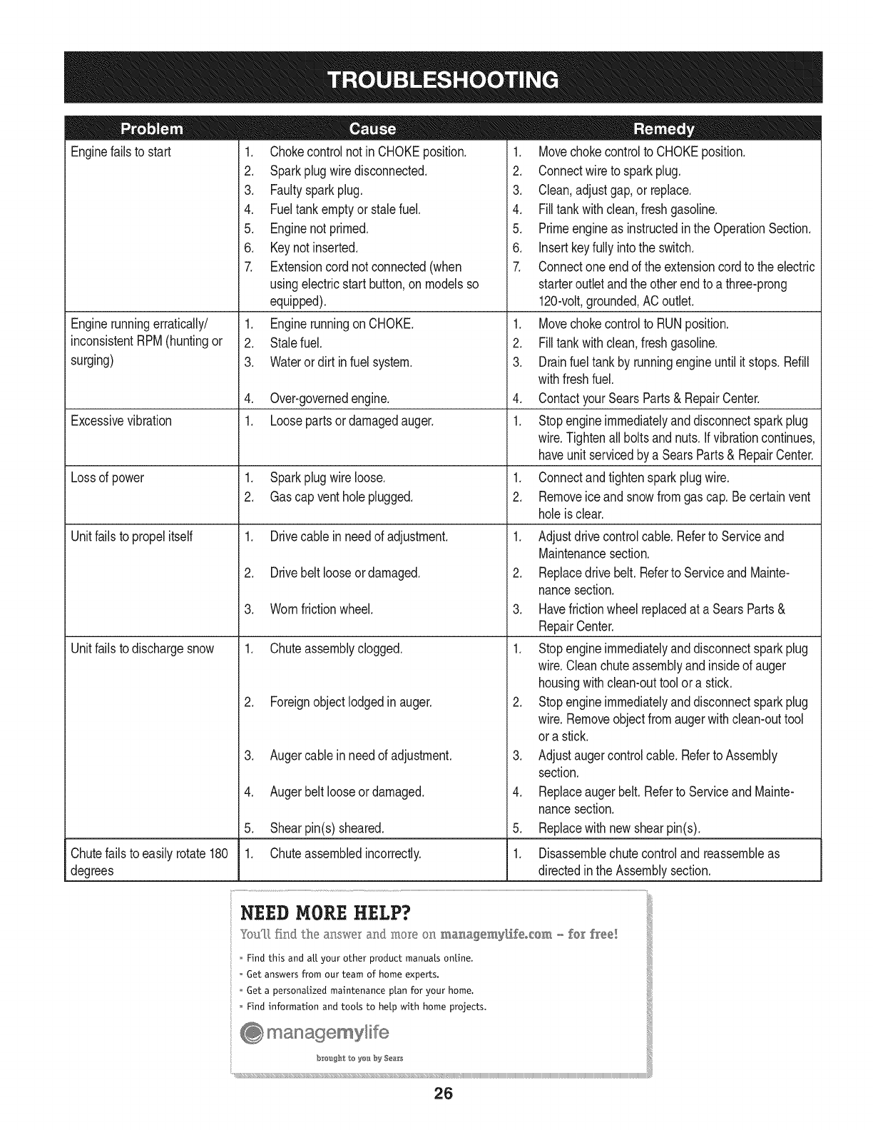
Enginefailsto start
Enginerunningerratically/
inconsistentRPM(huntingor
surging)
Excessivevibration
Lossof power
Unitfailsto propelitself
Unitfailsto dischargesnow
1. Chokecontrolnot inCHOKEposition.
2. Sparkplugwire disconnected.
3. Faultysparkplug.
4. Fueltankemptyor stalefuel.
5. Enginenot primed.
6. Keynot inserted.
7. Extensioncordnot connected(when
usingelectricstartbutton,on modelsso
equipped).
1. EnginerunningonCHOKE.
2. Stalefuel.
3. Waterordirt infuel system.
4. Over-governedengine.
1. Loosepartsor damagedauger.
1. Sparkplugwire loose.
2. Gascap ventholeplugged.
1. Drivecable inneedof adjustment.
2. Drivebelt looseor damaged.
3. Wornfrictionwheel.
1. Chuteassemblyclogged.
2. Foreignobjectlodgedin auger.
3. Augercablein needof adjustment.
4. Augerbelt looseordamaged.
5. Shearpin(s) sheared.
1. Chuteassembledincorrectly.
1. Movechokecontrolto CHOKEposition.
2. Connectwireto sparkplug.
3. Clean,adjustgap,or replace.
4. Filltankwith clean,freshgasoline.
5. Primeengineas instructedinthe OperationSection.
6. Insertkeyfully intothe switch.
7. Connectoneendof the extensioncordto the electric
starteroutletandthe otherendto a three-prong
120-volt,grounded,ACoutlet.
1. Movechokecontrolto RUNposition.
2. Filltankwith clean,freshgasoline.
3. Drainfueltankby runningengineuntil it stops.Refill
withfreshfuel.
4. ContactyourSearsParts& RepairCenter.
1. Stopengineimmediatelyand disconnectsparkplug
wire.Tightenall boltsand nuts.Ifvibrationcontinues,
haveunit servicedbya SearsParts& RepairCenter.
1. Connectandtightensparkplugwire.
2. Removeiceand snowfromgascap. Becertainvent
holeis clear.
1. Adjustdrivecontrolcable.Referto Serviceand
Maintenancesection.
2. Replacedrive belt.Referto Serviceand Mainte-
nancesection.
3. Havefrictionwheelreplacedat a SearsParts&
RepairCenter.
1. Stopengineimmediatelyand disconnectsparkplug
wire.Cleanchuteassemblyandinsideof auger
housingwithclean-outtoolor a stick.
2. Stopengineimmediatelyand disconnectsparkplug
wire.Removeobjectfromaugerwith clean-outtool
ora stick.
3. Adjustaugercontrolcable.Referto Assembly
section.
4. Replaceaugerbelt.Referto Serviceand Mainte-
nancesection.
5. Replacewith newshearpin(s).
Chutefailsto easilyrotate180 1. Disassemblechutecontroland reassembleas
degrees directedinthe Assemblysection.
NEED HORE HELP?
Yot,Fttfind. th_ answer a!ld mo_e on ma_age_y_ifeocom _ for free]
Find this and att your other product manua[s ontine.
Get answers from our team of home experts.
Get a personalized maintenance p[an for your home.
Find information and tools to he[p with home projects.
managemylife
b_e'_g_t_/_eyeu by Sea_s
26
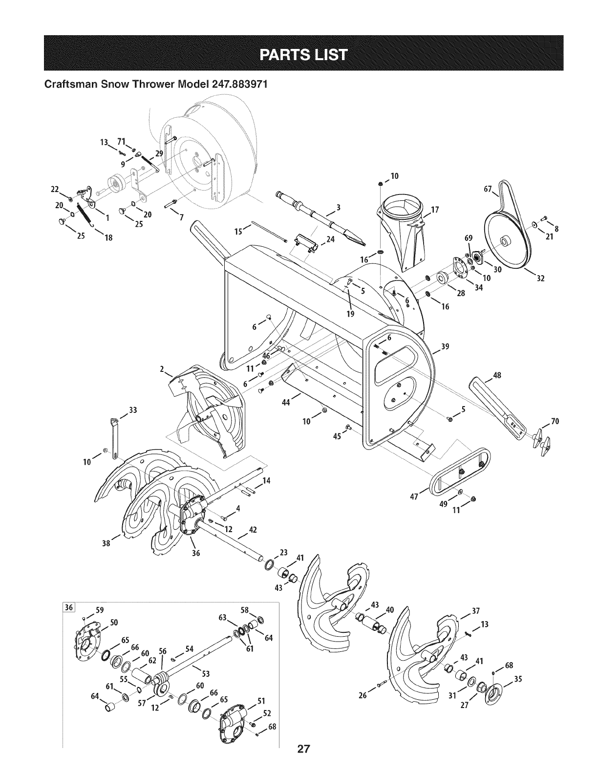
Craftsman Snow Thrower Model 247.883971
\
22
20.
2
19
10
14
4
42
J
65
6660
64
64
60 66
27
43 41
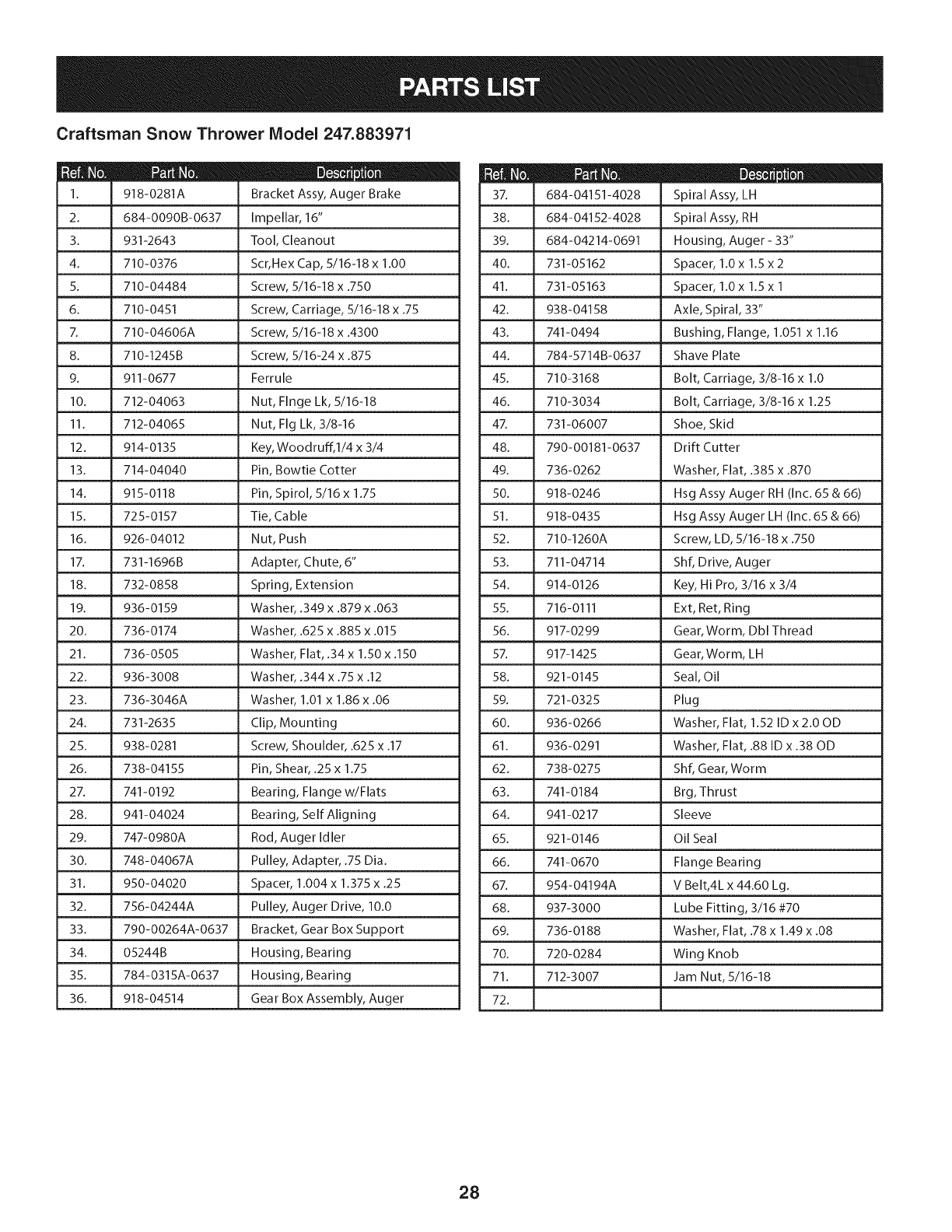
Craftsman Snow Thrower Model 247.883971
! = 0 0
918-0281A Bracket Assy, Auger Brake
2. 684-0090B-0637 Impellar, 16"
3. 931-2643 Tool, Cleanout
4. 710-0376 Scr,Hex Cap, 5/16-18 x 1.00
5. 710-04484 Screw, 5/16-18 x .750
6. 710-0451 Screw, Carriage, 5/16-18 x .75
7. 710-04606A Screw, 5/16-18 x .4300
8. 710-1245B Screw, 5/16-24 x .875
9. 911-0677 Ferrule
10. 712-04063 Nut, Flnge Lk, 5/16-18
11. 712-04065 Nut, Fig Lk, 3/8-16
12. 914-0135 Key, Woodruff, l/4 x 3/4
13. 714-04040 Pin, Bowtie Cotter
14. 915-0118 Pin, Spirol, 5/16 x 1.75
15. 725-0157 Tie, Cable
16. 926-04012 Nut, Push
17. 731-1696B Adapter, Chute, 6"
18. 732-0858 Spring, Extension
19. 936-0159 Washer, .349 x .879 x .063
20. 736-0174 Washer, .625 x .885 x .015
21. 736-0505 Washer, Flat, .34 x 1.50 x .150
22. 936-3008 Washer, .344 x .75 x .12
23. 736-3046A Washer, 1.01 x 1.86 x .06
24. 731-2635 Clip, Mounting
25. 938-0281 Screw, Shoulder, .625 x .17
26. 738-04155 Pin, Shear, .25 x 1.75
27. 741-0192 Bearing, Flange w/Flats
28. 941-04024 Bearing, Self Aligning
29. 747-0980A Rod, Auger Idler
30. 748-04067A Pulley, Adapter, .75 Dia.
31. 950-04020 Spacer, 1.004 x 1.375 x .25
32. 756-04244A Pulley, Auger Drive, 10.0
33. 790-00264A-0637 Bracket, Gear Box Support
34. 05244B Housing, Bearing
35. 784-0315A-0637 Housing, Bearing
36. 918-04514 Gear Box Assembly, Auger
D = B II
684-04151-4028 Spiral Assy, LH
38. 684-04152-4028 Spiral Assy, RH
39. 684-04214-0691 Housing, Auger - 33"
40. 731-05162 Spacer, 1.0 x 1.5 x 2
41. 731-05163 Spacer, 1.0 x 1.5 x 1
42. 938-04158 Axle, Spiral, 33"
43. 741-0494 Bushing, Flange, 1.051 x 1.16
44. 784-5714B-0637 Shave Plate
45. 710-3168 Bolt, Carriage, 3/8-16 x 1.0
46. 710-3034 Bolt, Carriage, 3/8-16 x 1.25
47. 731-06007 Shoe, Skid
48. 790-00181-0637 Drift Cutter
49. 736-0262 Washer, Flat, .385 x .870
50. 918-0246 Hsg Assy Auger RH (Inc. 65 & 66)
51. 918-0435 Hsg Assy Auger LH (Inc. 65 & 66)
52. 710-1260A Screw, LD, 5/16-18 x .750
53. 711-04714 Shf, Drive, Auger
54. 914-0126 Key, Hi Pro, 3/16 x 3/4
55. 716-0111 Ext, Ret, Ring
56. 917-0299 Gear, Worm, Dbl Thread
57. 917-1425 Gear, Worm, LH
58. 921-0145 Seal, Oil
59. 721-0325 Plug
60. 936-0266 Washer, Flat, 1.52 ID x 2.00D
61. 936-0291 Washer, Flat, .88 ID x .38 OD
62. 738-0275 Shf, Gear, Worm
63. 741-0184 Brg, Thrust
64. 941-0217 Sleeve
65. 921-0146 Oil Seal
66. 741-0670 Flange Bearing
67. 954-04194A V Belt,4L x 44.60 Lg.
68. 937-3000 Lube Fitting, 3/16 #70
69. 736-0188 Washer, Flat, .78 x 1.49 x .08
70. 720-0284 Wing Knob
71. 712-3007 Jam Nut, 5/16-18
72.
28
Craftsman Snow Thrower Model 247.883971
65
57
79 79
40
/
/
/
/
66
_\ 7 58
5O
3O
21
15
64
38 3 39
\
29
m _ O O
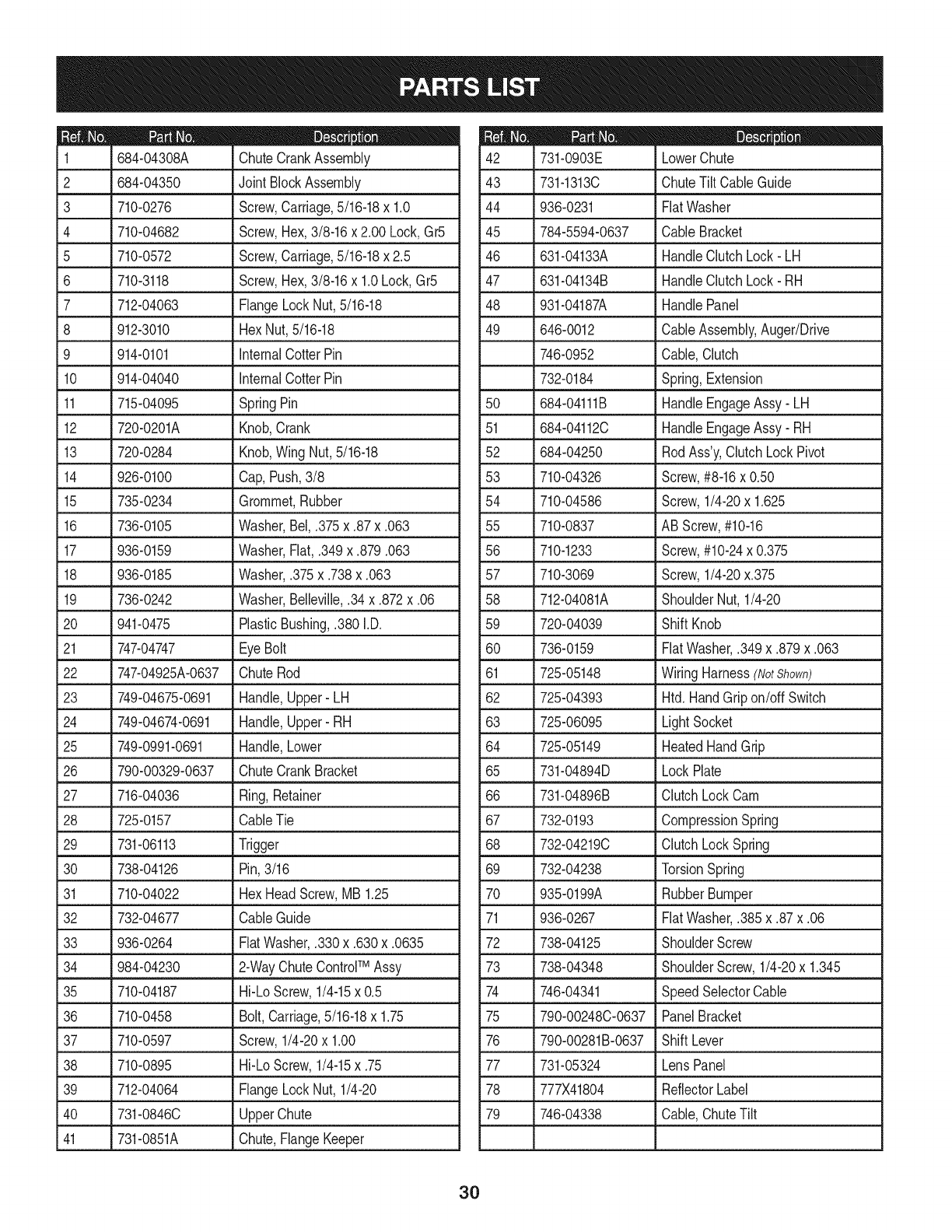
684-04308A ChuteCrankAssembly
2 684-04350 JointBlockAssembly
3 710-0276
4 710-04682
5 710-0572
6 710-3118
7 712-04063
8 912-3010
9 914-0101
10 914-04040
Screw,Carriage,5/16-18x 1.0
Screw,Hex,3/8-16x 2.00 Lock,Gr5
Screw,Carriage,5/16-18x 2.5
Screw,Hex,3/8-16x 1.0Lock,Gr5
FlangeLockNut,5/16-18
HexNut,5/16-18
internalCotterPin
internalCotterPin
11 715-04095 SpringPin
12 720-0201A Knob,Crank
13 720-0284 Knob,WingNut, 5/16-18
14 926-0100 Cap,Push,3/8
15 735-0234 Grommet,Rubber
16 736-0105 Washer,Bel,.375x.87x.063
17 936-0159 Washer,Fiat,.349x.879.063
18 936-0185 J Washer,.375x.738x.063
19 736-0242 Washer,Belleville,.34x.872x.06
20 941-0475 PlasticBushing,.380I.D.
21 747-04747 _ EyeBolt
22 747-04925A-0637 ChuteRod
23 749-04675-0691 Handle,Upper- LH
24 749-04674-0691 Handle,Upper- RH
25 749-0991-0691 Handle,Lower
26 790-00329-0637 ChuteCrankBracket
27 716-04036 Ring,Retainer
28 725-0157 CableTie
29 731-06113 . Trigger
30 738-04126 Pin,3/16
31 710-04022 HexHeadScrew,MB1.25
32 732-04677 CableGuide
33 936-0264 FiatWasher,.330x.630x.0635
TM
34 984-04230 J 2-WayChuteControl Assy
35 710-04187 Hi-LoScrew,1/4-15x 0.5
36 710-0458 Bolt,Carriage,5/16-18x 1.75
37 710-0597 Screw,1/4-20x 1.00
38 710-0895 Hi-LoScrew,1/4-15x .75
39 712-04064 FlangeLockNut, 1/4-20
40 731-0846C UpperChute
41 731-0851A Chute,FlangeKeeper
D _ O
731-0903E LowerChute
43 731-1313C ChuteTiltCableGuide
44 936-0231 FiatWasher
45 784-5594-0637 CableBracket
46 631-04133A HandleClutchLock- LH
47 631-04134B HandleClutchLock- RH
48 931-04187A HandlePanel
49 646-0012 CableAssembly,Auger/Drive
746-0952 Cable,Clutch
732-0184 Spring,Extension
50 684-04111B HandleEngageAssy- LH
51 684-04112C HandleEngageAssy- RH
52 684-04250 RodAss'y,ClutchLockPivot
53 710-04326 Screw,#8-16x 0.50
54 710-04586 Screw,1/4-20x 1.625
55 710-0837 ABScrew,#10-16
56 710-1233 Screw,#10-24x 0.375
57 710-3069 Screw,1/4-20x.375
58 712-04081A ShoulderNut,1/4-20
59 720-04039 ShiftKnob
60 736-0159 FiatWasher,.349x.879x.063
61 725-05148 WiringHarness(NotShown)
62 725-04393 Htd. HandGripon/off Switch
63 725-06095 LightSocket
64 725-05149 HeatedHandGrip
65 731-04894D LockPlate
66 731-04896B ClutchLockCam
67 732-0193 CompressionSpring
68 732-04219C ClutchLockSpring
69 732-04238 TorsionSpring
70 935-0199A RubberBumper
71 936-0267 FiatWasher,.385x.87x.06
72 738-04125 ShoulderScrew
73 738-04348 ShoulderScrew,1/4-20x 1.345
74 746-04341 SpeedSelectorCable
75 790-00248C-0637 PanelBracket
76 790-00281B-0637 ShiftLever
77 731-05324 LensPanel
78 777X41804 ReflectorLabel
79 746-04338 Cable,ChuteTilt
3O
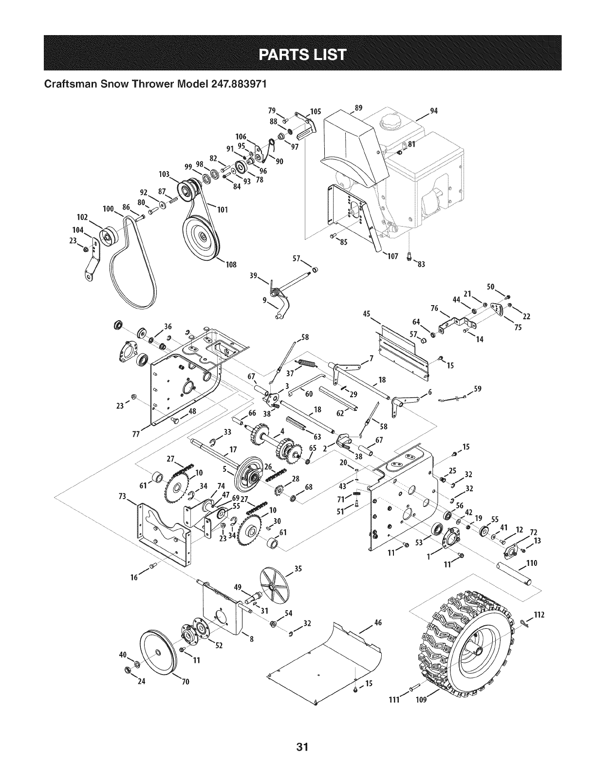
Craftsman Snow Thrower Model 247.883971
88
102
104
23
100
92
77
24
36
27
91
34 74
11
"93 78
33
17
45
/7
18
18
31
67
z
111 10
15
25 32
32
_3 56
19 55
1j
11
72
112
31
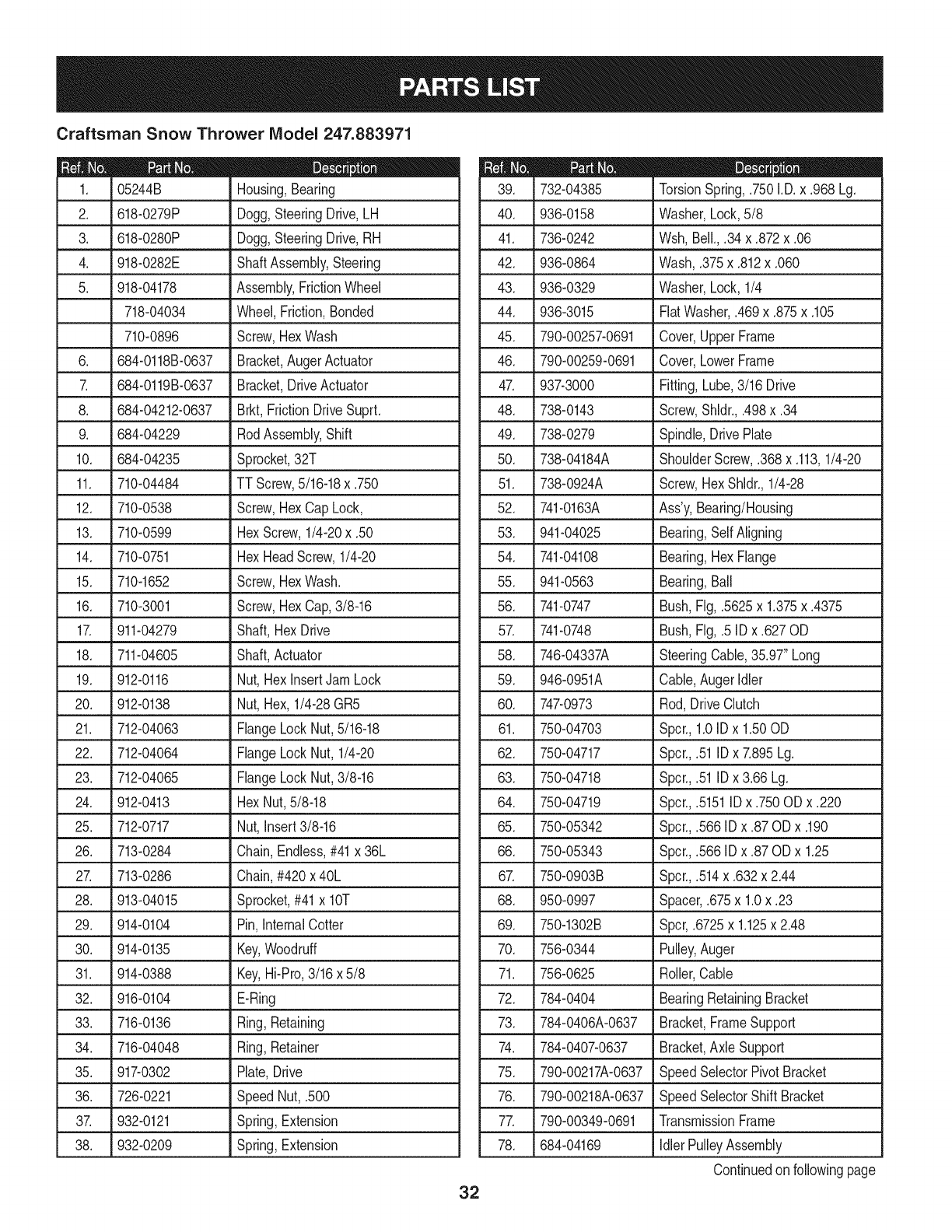
05244B
2. 618-0279P
3. 618-0280P
Craftsman Snow Thrower Model 247.883971
|= o e
Housing,Bearing
Dogg,SteeringDrive,LH
Dogg,SteeringDrive,RH
4. 918-0282E
5. 918-04178
718-04034
710-0896
6. 684-0118B-0637
684-0119B-0637
8. 684-04212-0637
9. 684-04229
ShaftAssembly,Steering
Assembly,FrictionWheel
Wheel,Friction,Bonded
Screw,HexWash
Bracket,AugerActuator
Bracket,DriveActuator
Brkt, FrictionDriveSuprt.
RodAssembly,Shift
10. 684-04235 Sprocket,32T
11. 710-04484 TTScrew,5/16-18x .750
12. 710-0538 Screw,HexCapLock,
13. 710-0599 HexScrew,1/4-20x .50
14. 710-0751 HexHeadScrew,1/4-20
15. 710-1652 Screw,HexWash.
16. 710-3001 Screw,HexCap,3/8-16
17. 911-04279 Shaft,HexDrive
18. 711-04605 Shaft,Actuator
19. 912-0116 Nut,HexInsertJamLock
20. 912-0138 Nut,Hex, 1/4-28GR5
21. 712-04063 FlangeLockNut,5/16-18
22. 712-04064 FlangeLockNut, 1/4-20
23. 712-04065 FlangeLockNut,3/8-16
24. 912-0413 HexNut,5/8-18
25. 712-0717 Nut,Insert3/8-16
26. 713-0284 Chain,Endless,#41x 36L
27. 713-0286 Chain,#420x 40L
28. 913-04015 Sprocket,#41x lOT
29. 914-0104 Pin,InternalCotter
30. 914-0135 Key,Woodruff
31. 914-0388 Key,Hi-Pro,3/16x 5/8
32. 916-0104 E-Ring
33. 716-0136 Ring,Retaining
34. 716-04048 Ring,Retainer
35. 917-0302 Plate,Drive
36. 726-0221 SpeedNut, .500
37. 932-0121 Spring,Extension
38. 932-0209 Spring,Extension
D = Q m
732-04385 TorsionSpring,.750I.D.x .968 Lg.
40. 936-0158 Washer,Lock,5/8
41. 736-0242 Wsh,Bell.,.34x.872x.06
42. 936-0864 Wash,.375x.812x.060
43. 936-0329 Washer,Lock,1/4
44. 936-3015 FiatWasher,.469x.875x.105
45. 790-00257-0691 Cover,UpperFrame
46. 790-00259-0691 Cover,LowerFrame
47. 937-3000 Fitting,Lube,3/16 Drive
48. 738-0143 Screw,Shldr.,.498x.34
49. 738-0279 Spindle,DrivePlate
50. 738-04184A ShoulderScrew,.368x.113,1/4-20
51. 738-0924A Screw,HexShldr.,1/4-28
52. 741-0163A Ass'y,Bearing/Housing
53. 941-04025 Bearing,Self Aligning
54. 741-04108 Bearing,HexFlange
55. 941-0563 Bearing,Ball
56. 741-0747 Bush,Fig,.5625x 1.375x .4375
57. 741-0748 Bush,Fig,.5 IDx .627OD
58. 746-04337A SteeringCable,35.97"Long
59. 946-0951A Cable,AugerIdler
60. 747-0973 Rod,DriveClutch
61. 750-04703 Spcr.,1.0IDx 1.50OD
62. 750-04717 Spcr.,.51IDx 7.895Lg.
63. 750-04718 Spcr.,.51IDx 3.66Lg.
64. 750-04719 Spcr.,.5151ID x .750ODx .220
65. 750-05342 Spcr.,.566IDx .87 ODx .190
66. 750-05343 Spcr.,.566IDx .87 ODx 1.25
67. 750-0903B Spcr.,.514x.632x 2.44
68. 950-0997 Spacer,.675x 1.0x .23
69. 750-1302B Spcr,.6725x 1.125x 2.48
70. 756-0344 Pulley,Auger
71. 756-0625 Roller,Cable
72. 784-0404 BearingRetainingBracket
73. 784-0406A-0637 Bracket,FrameSupport
74. 784-0407-0637 Bracket,AxleSupport
75. 790-00217A-0637 SpeedSelectorPivotBracket
76. 790-00218A-0637 SpeedSelectorShift Bracket
77. 790-00349-0691 TransmissionFrame
78. 684-04169 IdlerPulleyAssembly
Continuedonfollowingpage
32
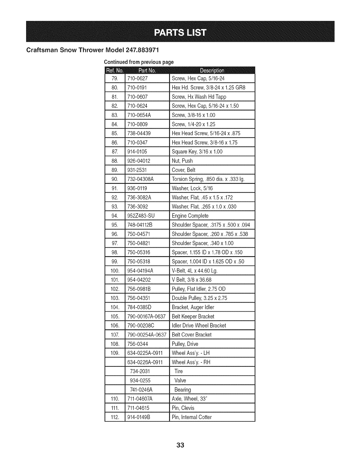
Craftsman Snow Thrower IViodel 247.883971
Continuedfrom previouspage
|= o 0
710-0627
80. 710-0191
81. 710-0607
82. 710-0624
Screw,HexCap,5/16-24
HexHd.Screw,3/8-24x 1.25GR8
Screw,HxWashHdTapp
Screw,HexCap,5/16-24x 1.50
83. 710-0654A Screw,3/8-16x 1.00
84. 710-0809 Screw,1/4-20x 1.25
85. 738-04439 HexHeadScrew,5/16-24x .875
86. 710-0347 HexHeadScrew,3/8-16x 1.75
87. 914-0105 SquareKey,3/16 x 1.00
88. 926-04012 Nut,Push
89. 931-2531 Cover,Belt
90. 732-04308A TorsionSpring,.850dia.x .333 Ig.
91. 936-0119 Washer,Lock,5/16
92. 736-3082A Washer,Flat, .45x 1.5x .172
93. 736-3092 Washer,Fiat, .265x 1.0x .030
94. 952Z483-SU EngineComplete
95. 748-04112B ShoulderSpacer,.3175x.500x.094
96. 750-04571 ShoulderSpacer,.260x.785x.538
97. 750-04821 ShoulderSpacer,.340x 1.00
98. 750-05316 Spacer,1.155IDx 1.78ODx .150
99. 750-05318 Spacer,1.004IDx 1.625ODx .50
100. 954-04194A V-Belt,4Lx44.60 Lg.
101. 954-04202 V Belt,3/8 x 36.68
102. 756-0981B Pulley,FlatIdler,2.75OD
103. 756-04351 DoublePulley,3.25 x 2.75
104. 784-0385D Bracket,AugerIdler
105. 790-00167A-0637 Belt KeeperBracket
106. 790-00208C IdlerDriveWheelBracket
107. 790-00254A-0637 BeltCoverBracket
108. 756-0344 Pulley,Drive
109. 634-0225A-0911 WheelAss'y.-LH
634-0226A-0911 WheelAss'y.-RH
734-2031 Tire
934-0255 Valve
741-0246A Bearing
110. 711-04607A Axle,Wheel,33"
111. 711-04615 Pin,Clevis
112. 914-0149B Pin,InternalCotter
33
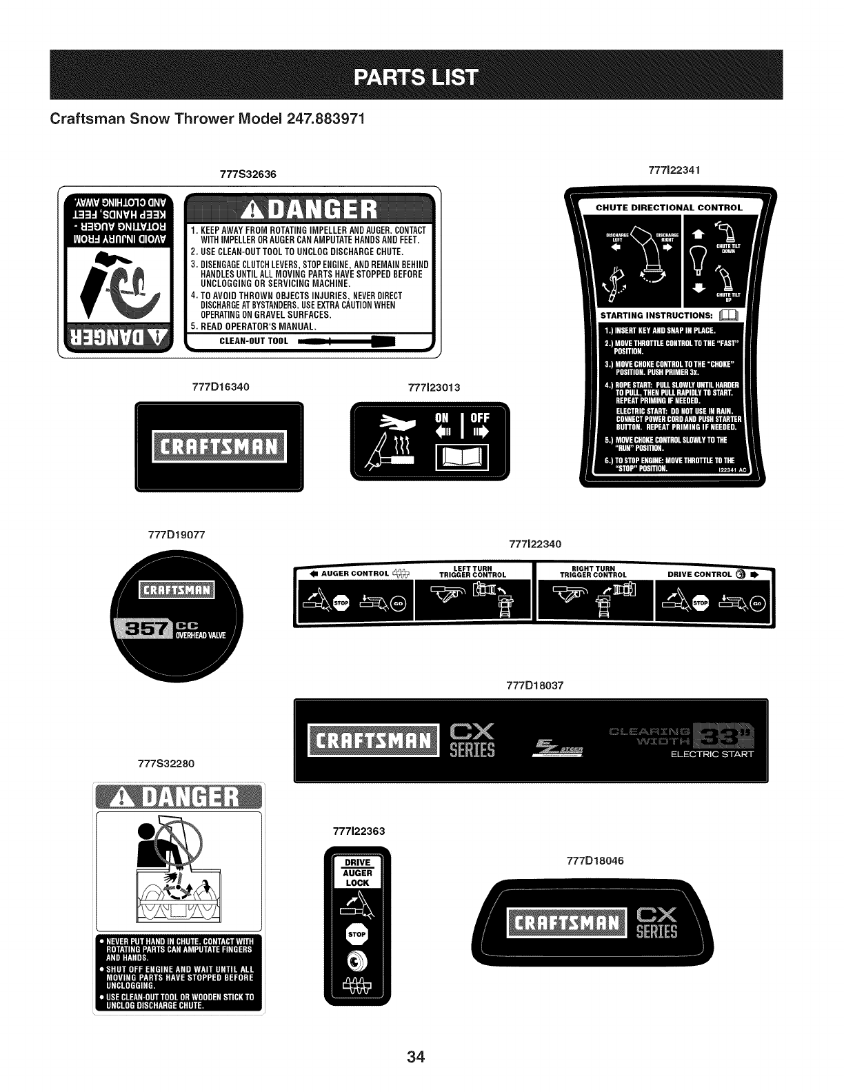
Craftsman Snow Thrower Model 247.883971
777S32636 777122341
1. KEEPAWAYFROMROTATINGIMPELLERANDAUGER.CONTACT
WITHIMPELLERORAUGERCANAMPUTATEHANDSANDFEET.
2. USECLEAN-OUTTOOLTOUNCLOGDISCHARGECHUTE,
3. DISENGAGECLUTCHLEVERS,STOPENGINE,ANDREMAINBEHIND
HANDLESUNTILALLMOVINGPARTSHAVESTOPPEDBEFORE
UNCLOGGINGOR SERVICINGMACHINE,
4. TOAVOIDTHROWNOBJECTSINJURIES,NEVERDIRECT
DISCHARGEATBYSTANDERS.USEEXTRACAUTIONWHEN
OPERATINGONGRAVELSURFACES.
5. READ OPERATOR'SMANUAL.
k=, CLEAN-OUTTOOL i1_
777D16340 777123013
777D19077 777122340
777D18037
777S32280
777122363
777D18046
3,1
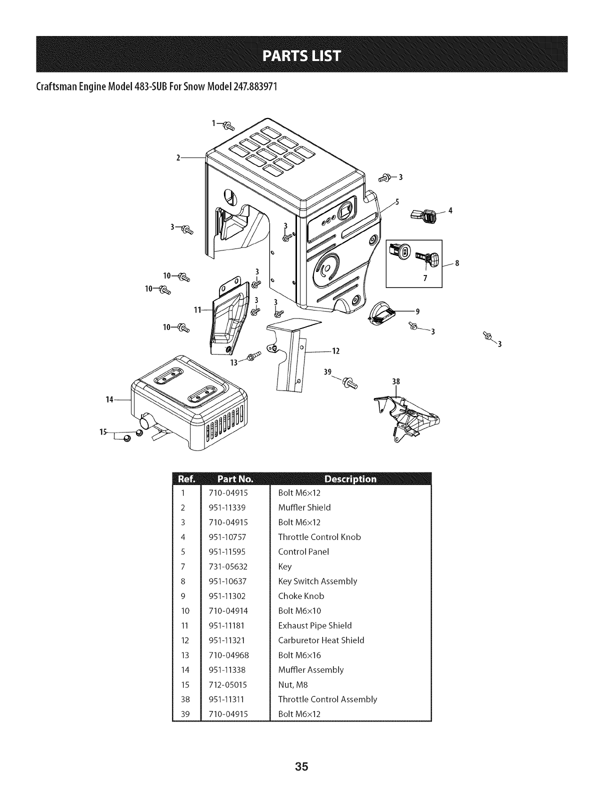
Craftsman EngineModel 483-$UBForSnow Model 247.883971
m
i
i 1
i
i
i
i 2
!
i
i 3
i
i
i
i 4
i
i
i 5
!
!
i
i 7
i
i
i 8
!
i
i 9
i
i
i
i 10
i
i
i 11
i
i
i
i 12
i
i
i 13
!
i
i 14
i
i
i
i 15
!
i
i 38
i
i
i
i 39
i
710-04915
951-11339
710-04915
951-10757
951-11595
731-05632
951-10637
951-11302
710-04914
951-11181
951-11321
710-04968
951-11338
712-05015
951-11311
710-04915
II _ o 0
Bolt M6x12
Muffler Shield
Bolt M6x12
Throttle Control Knob
Control Panel
Key
Key Switch Assembly
Choke Knob
Bolt M6xlO
Exhaust Pipe Shield
Carburetor Heat Shield
Bolt M6x16
MuFfler Assembly
Nut, M8
Throttle Control Assembly
Bolt M6x12
35
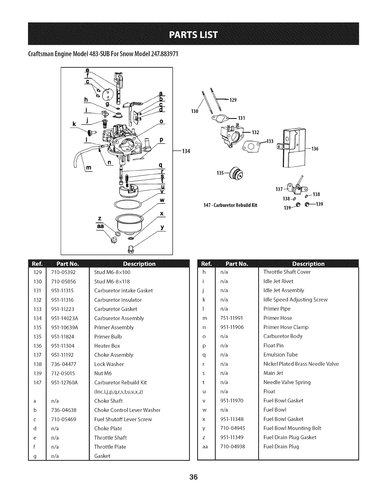
Craftsman EngineModel 483-SLIBForSnow Model 247.883971
129
130
131
132
133
134
135
135
136
137
138
139
147
a
b
C
d
e
f
g
f
h
i
I
O
m
710-05392
710-05056
951-11315
951-11316
951-11223
951-14023A
951-10639A
--134
951-11824
951-11304
951-11192
736-04477
712-05015
951-12760A
n/a
736-04638
710-05469
n/a
n/a
n/a
n/a
ID -o 0
Stud M6-8x100
Stud M6-8x118
Carburetor Intake Gasket
Carburetor Insulator
Carburetor Gasket
Carburetor Assembly
Primer Assembly
Primer Bulb
Heater Box
Choke Assembly
LockWasher
NutM6
Carburetor Rebuild Kit
(In c.i,j,p,q,r,s,t,u,v,x,z)
Choke Shaft
Choke Control Lever Washer
Fuel Shutoff Lever Screw
Choke Plate
Throttle Shaft
Throttle Plate
Gasket
131
33 0136
135--_ 137138__0/138
147-Carburetor RebuildKit 139_ _139
h
I
J
k
I
m
n
o
P
q
r
s
t
U
V
W
X
Y
Z
aa
n_
n_
n_
n_
n_
751-11991
951-11906
n_
n_
n_
n_
n_
n_
n_
951-11970
n_
951-11348
710-04945
951-11349
710-04938
D-o 0
Throttle Shaft Cover
Idle Jet Rivet
Idle Jet Assembly
Idle Speed Adjusting Screw
Primer Pipe
Primer Hose
Primer Hose Clamp
Carburetor Body
Float Pin
Emulsion Tube
Nickel Plated Brass Needle Valve
Main Jet
Needle Valve Spring
Float
Fuel Bowl Gasket
Fuel Bowl
Fuel Bowl Gasket
Fuel Bowl Mounting Bolt
Fuel Drain Plug Gasket
Fuel Drain Plug
36
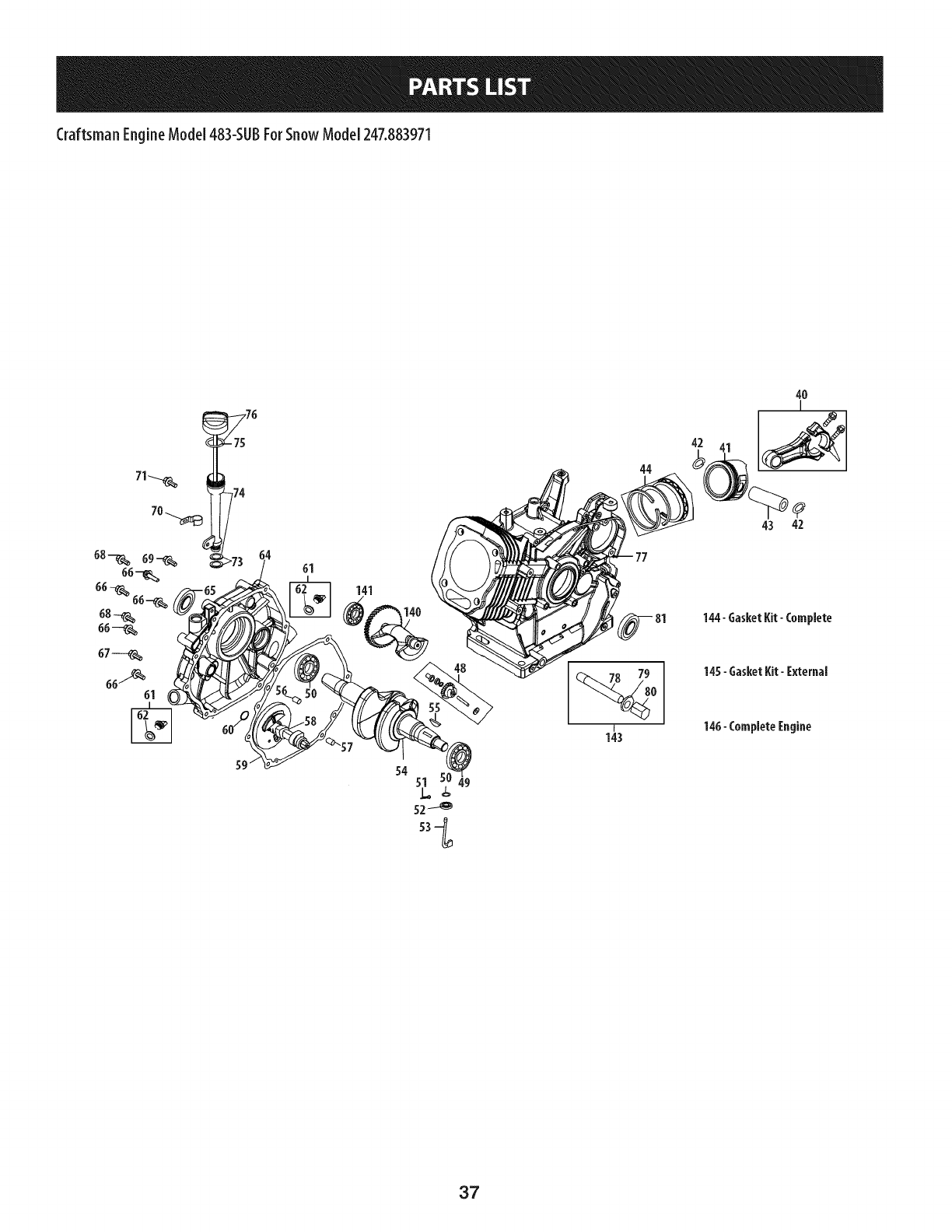
Craftsman EngineModel 483-$UBForSnow Model 247.883971
61
141
140
44
42
4O
I
43 42
144- GasketKit- Complete
145- GasketKit- External
146- CompleteEngine
49
37
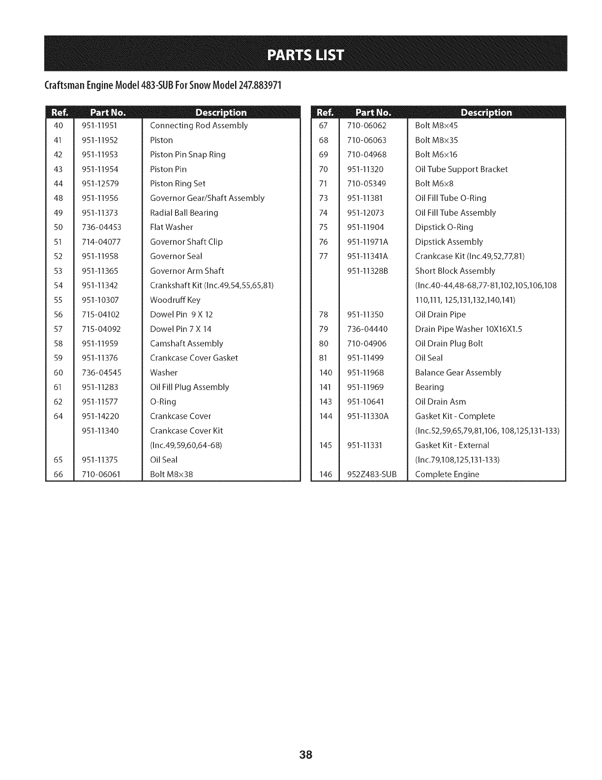
Craftsman EngineModel 483-$UBForSnow Model 247.883971
4O
41
42
43
44
48
49
5O
51
52
53
54
55
56
57
58
59
6O
61
62
64
65
66
951-11951
951-11952
951-11953
951-11954
951-12579
951-11956
951-11373
736-04453
714-04077
951-11958
951-11365
951-11342
951-10307
715-04102
715-04092
951-11959
951-11376
736-04545
951-11283
951-11577
951-14220
951-11340
951-I1375
710-06061
D - o o
Connecting Rod Assembly
Piston
Piston Pin Snap Ring
Piston Pin
Piston Ring Set
Governor Gear/Shaft Assembly
Radial Ball Bearing
Flat Washer
Governor Shaft Clip
Governor Seal
Governor Arm Shaft
Crankshaft Kit (Inc.49,54,55,65,81)
Woodruff Key
Dowel Pin 9 X 12
Dowel Pin 7 X 14
Camshaft Assembly
Crankcase Cover Gasket
Washer
Oil Fill Plug Assembly
O-Ring
Crankcase Cover
Crankcase Cover Kit
(Inc.49,59,60,64-68)
Oil Seal
Bolt M8x38
67
68
69
70
71
73
74
75
76
77
78
79
80
81
140
141
143
144
145
146
710-06062
710-06063
710-04968
951-11320
710-05349
951-11381
951-12073
951-11904
951-11971A
951-11341A
951-11328B
951-11350
736-04440
710-04906
951-11499
951-11968
951-11969
951-10641
951-11330A
951-11331
952Z483-SU B
D - o 0
Bolt M8x45
Bolt M8x35
Bolt M6x16
Oil Tube Support Bracket
Bolt M6x8
Oil Fill Tube O-Ring
Oil Fill Tube Assembly
Dipstick O-Ring
Dipstick Assembly
Crankcase Kit (Inc.49,52,77,81)
Short Block Assembly
(Inc.40-44,48-68,77-81,102,105,106,108
110,111,125,131,132,140,141)
Oil Drain Pipe
Drain Pipe Washer 10X16X1.5
Oil Drain Plug Bolt
Oil Seal
Balance Gear Assembly
Bearing
Oil Drain Asm
Gasket Kit - Complete
(Inc.52,59,65,79,81,106, 108,125,131-133)
Gasket Kit- External
(Inc.79,108,125,131-133)
Complete Engine
38
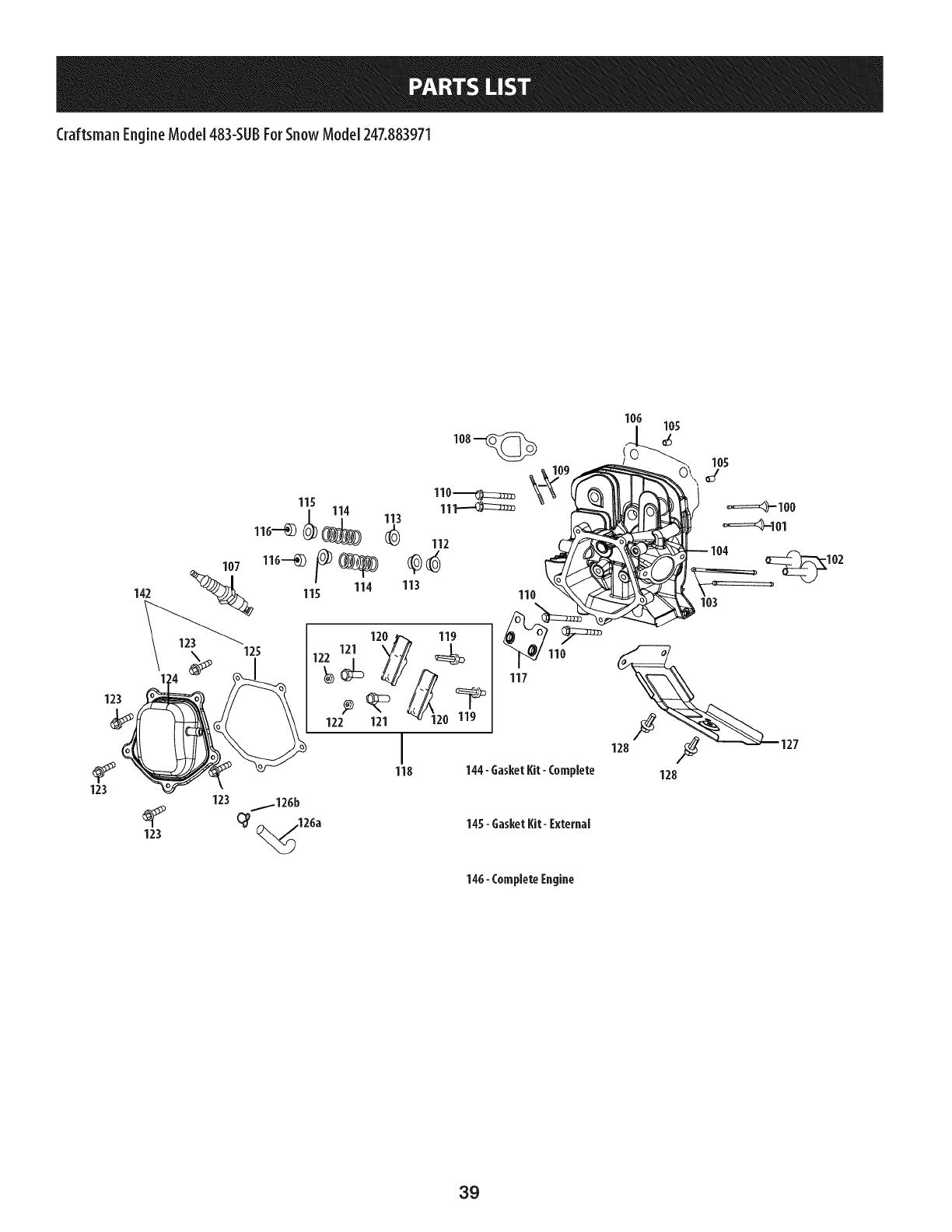
Craftsman EngineModel 483-$UBForSnow Model 247.883971
142
123
123
123
123
11o_
11s 11_
_11311s -- 112 11o
116"--_) (_ I
114 113 o
122 121 120 119
I1127
118 144-GasketKit-Coreplete 128
145- GasketKit- I:xternal
146-CompleteEngine
123
39
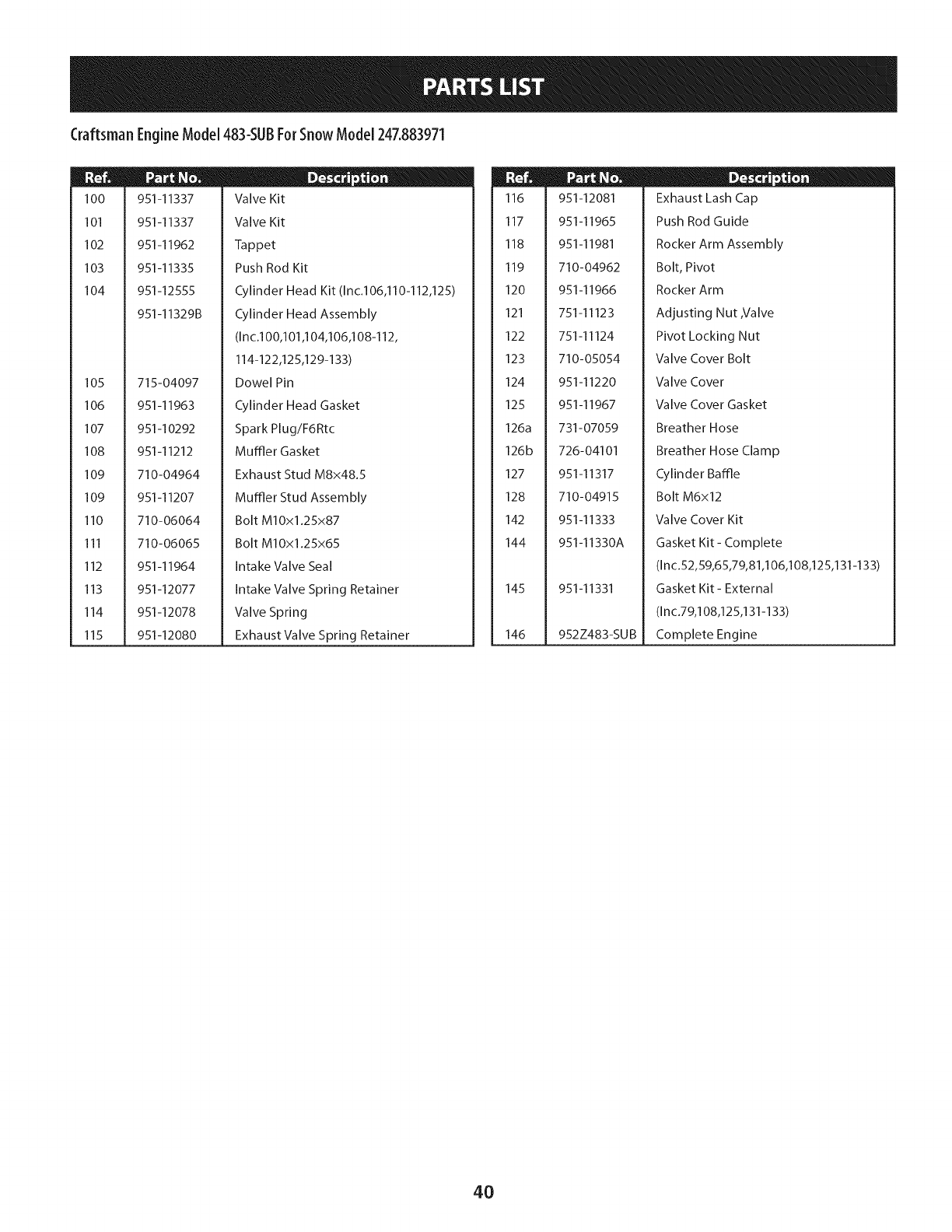
Craftsman EngineModel 483-$UBForSnow Model 247.883971
100
101
102
103
104
105
106
107
108
109
109
110
111
112
113
114
115
951-11337
951-11337
951-11962
951-11335
951-12555
951-11329B
715-04097
951-11963
951-10292
951-11212
710-04964
951-11207
710-06064
710-06065
951-11964
951-12077
951-12078
951-12080
D _ o o
Valve Kit
Valve Kit
Tappet
Push Rod Kit
Cylinder Head Kit (Inc.106,110-112,125)
Cylinder Head Assembly
(Inc.100,101,104,106,108-112,
114-122,125,129-133)
Dowel Pin
Cylinder Head Gasket
Spark Plug/F6Rtc
Muffler Gasket
Exhaust Stud M8x48.5
Muffler Stud Assembly
Bolt MlOxl.25x87
Bolt MlOx1.25x65
Intake Valve Seal
Intake Valve Spring Retainer
Valve Spring
Exhaust Valve Spring Retainer
116
117
118
119
120
121
122
123
124
125
126a
126b
127
128
142
144
145
146
951-12081
951-11965
951-11981
710-04962
951-11966
751-11123
751-11124
710-05054
951-11220
951-11967
731-07059
726-04101
951-11317
710-04915
951-11333
951-11330A
951-11331
952Z483-SU B
D _ o o
Exhaust Lash Cap
Push Rod Guide
Rocker Arm Assembly
Bolt, Pivot
Rocker Arm
Adjusting Nut ,Valve
Pivot Locking Nut
Valve Cover Bolt
Valve Cover
Valve Cover Gasket
Breather Hose
Breather Hose Clamp
Cylinder Baffle
Bolt M6x12
Valve Cover Kit
Gasket Kit - Complete
(In c.52,59,65,79,81,106,108,125,131-133)
Gasket Kit - External
(In c.79,108,125,131-133)
Complete Engine
4O
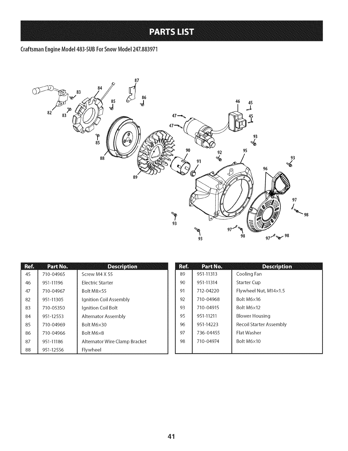
Craftsman EngineModel 483-$UBForSnow Model 247.883971
82
84
85
88
85
87
89
86
91
46 45
g
92 9S
96
98
97
45
46
47
82
83
84
85
86
87
88
710-04965
951-11196
710-04967
951-11305
710-05350
951-12553
710-04969
710-04966
951-11186
951-12556
D _ o w
Screw M4 X 55
Electric Starter
Bolt M8x55
Ignition Coil Assembly
Ignition Coil Bolt
Alternator Assembly
Bolt M6x30
Bolt M6x8
Alternator Wire Clamp Bracket
Flywheel
89
90
91
92
93
95
96
97
98
951-11313
951-11314
712-04220
710-04968
710-04915
951-11211
951-14223
736-04455
710-04974
D _ o 0
Cooling Fan
Starter Cup
Flywheel Nut, M14x1.5
Bolt M6x16
Bolt M6x12
Blower Housing
Recoil Starter Assembly
Flat Washer
Bolt M6xl0
41
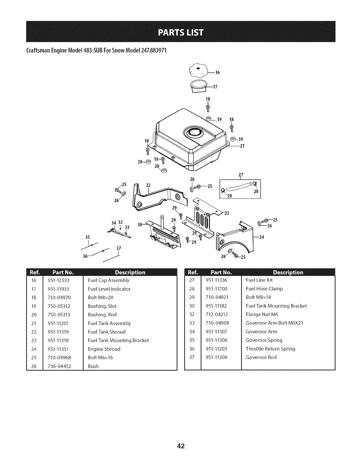
Craftsman EngineModel 483-$UBForSnow Model 247.883971
16
17
18
19
20
21
22
23
24
25
26
/25
%
26/
18
26 27
I
34 32
24
951-12533
951-I 1933
710-04970
750-05312
750-05313
951-11201
951-11319
951-11318
951-11351
710-04968
736-04452
D _ o o
Fuel Cap Assembly
Fuel Level Indicator
Bolt M8x20
Bushing, Slot
Bushing, Rnd
Fuel Tank Assembly
Fuel Tank Shroud
Fuel Tank Mounting Bracket
Engine Shroud
Bolt M6x16
Bush
27
28
29
30
32
33
34
35
36
37
951-11336
951-11700
710-04921
951-11182
712-04212
710-04908
951-11307
951-11306
951-11203
951-11309
D _ o 0
Fuel Line Kit
Fuel Hose Clamp
Bolt M8x14
Fuel Tank Mounting Bracket
Flange Nut M6
Governor Arm Bolt M6X21
Governor Arm
Governor Spring
Throttle Return Spring
Governor Rod
42
FEDERALand/or CALIFORNIAEMISSIONCONTROLWARRANTYSTATEMENT
YOURWARRANTYRIGHTSANDOBLIGATIONS
MTD Consumer Group Inc, the United States Environmental Protection Agency (EPA), and for those products certified for sale in the state of
California, the California Air Resources Board (CARB) are pleased to explain the emission (evaporative and/or exhaust) control system (ECS)
warranty on your 2013 and later small off-road spark-ignited engine and equipment (outdoor equipment engine). In California, new outdoor
equipment engines must be designed, built and equipped to meet the State's stringent anti-smog standards (in other states, outdoor
equipment engines must be designed, built, and equipped to meet the U.S. EPA small off-road spark ignition engine regulations). MTD
Consumer Group Inc must warrant the ECSon your outdoor equipment engine for the period of time listed below, provided there has been no
abuse, neglect, or improper maintenance of the outdoor equipment engine.
Your ECS may include parts such as the carburetor, fuel-injection system, ignition system, catalytic converter, fuel tanks, fuel lines, fuel caps,
valves, canisters, filters, vapor hoses, clamps, connectors, and other associated emission-related components.
Where a warrantable condition exists, MTD Consumer Group Inc will repair your outdoor equipment engine at no cost to you including
diagnosis, parts, and labor.
MANUFACTURER'SWARRANTYCOVERAGE:
This emission control system is warranted for two years. If any emission-related part on your outdoor equipment engine is defective, the
part will be repaired or replaced by MTD Consumer Group Inc. In the event that a component is covered for longer than two years by the
Manufacturer's equipment warranty, the longer coverage period will apply.
/
OWNERSWARRANTYRESPONSIBILITIES:
As the outdoor equipment engine owner, you are responsible for performance of the required maintenance listed in your owner's manual. MTD
Consumer Group Inc recommends that you retain all receipts covering maintenance on your outdoor equipment engine, but MTD Consumer
Group Inc cannot deny warranty solely for the lack of receipts.
As the outdoor equipment engine owner, you should however be aware that MTD Consumer Group Inc may deny you warranty coverage if
your outdoor equipment engine or a part has failed due to abuse, neglect, improper maintenance, or unapproved modifications.
You are responsible for presenting your outdoor equipment engine to MTD Consumer Group Inc's distribution center or service center as soon
as the problem exists. The warranty repairs should be completed in a reasonable amount of time, not to exceed 30 days. If you have a question
regarding your warranty coverage, you should contact the MTD Consumer Group Inc Service Department at 1-800-800-7310 or at
http://su pport.mtd prod ucts.com.
GENERALEMISSIONSWARRANTYCOVERAGE:
MTD Consumer Group Inc warrants to the ultimate purchaser and each subsequent purchaser that the outdoor equipment engine is: (1)
designed, built, and equipped so as to conform with all applicable regulations; and (2) free from defects in materials and workmanship that
cause the failure of a warranted part for a period of two years.
The warranty period begins on the date the outdoor equipment engine is delivered to an ultimate purchaser or first placed into service.
Subject to certain conditions and exclusions as stated below, the warranty on emission-related parts is as follows:
1. Any warranted part that is not scheduled for replacement as required maintenance in the written instructions supplied is warranted for
the warranty period stated above. If the part fails during the period of warranty coverage, the part will be repaired or replaced by MTD
Consumer Group Inc according to subsection (4) below. Any such part repaired or replaced under warranty will be warranted for the
remainder of the period.
2. Any warranted part that is scheduled only for regular inspection in the written instructions supplied is warranted for the warranty period
stated above. Any such part repaired or replaced under warranty will be warranted for the remaining warranty period.
3. Any warranted part that is scheduled for replacement as required maintenance in the written instructions supplied is warranted for the
period of time before the first scheduled replacement date for that part. If the part fails before the first scheduled replacement, the part
will be repaired or replaced by MTD Consumer Group Inc according to subsection (4) below. Any such part repaired or replaced under
warranty will be warranted for the remainder of the period prior to the first scheduled replacement point for the part.
Repair or replacement of any warranted part under the warranty provisions herein must be performed at a warranty station at no charge
to the owner.
4.
5. Notwithstanding the provisions herein, warranty services or repairs will be provided at all of our distribution centers that are franchised to
service the subject engines or equipment.
6. The outdoor equipment engine owner will not be charged for diagnostic labor that is directly associated with diagnosis of a defective,
emission-related warranted part, provided that such diagnostic work is performed at a warranty station.
7. MTD Consumer Group Inc is liable for damages to other engine or equipment components proximately caused by a failure under
warranty of any warranted part.
8. Throughout the off-road engine and equipment warranty period stated above, MTD Consumer Group Inc will maintain a supply of
warranted parts sufficient to meet the expected demand for such parts.
9. Any replacement part may be used in the performance of any warranty maintenance or repairs and must be provided without charge to
the owner. Such use will not reduce the warranty obligations of MTD Consumer Group Inc.
10. Add-onormodifiedpartsthatarenotexemptedbytheAirResourcesBoardmaynotbeused.Theuseofanynon-exemptedadd-onor
modifiedpartsbytheultimatepurchaserwillbegroundsfordisallowingawarrantyclaims.MTDConsumerGroupIncwillnotbeliableto
warrantfailuresofwarrantedpartscausedbytheuseofanon-exemptedadd-onormodifiedpart.
WARRANTEDPARTS:
The repair or replacement of any warranted part otherwise eligible for warranty coverage may be excluded from such warranty coverage if
MTD Consumer Group Inc demonstrates that the outdoor equipment engine has been abused, neglected, or improperly maintained, and that
such abuse, neglect, or improper maintenance was the direct cause of the need for repair or replacement of the part. That notwithstanding,
any adjustment of a component that has a factory installed, and properly operating, adjustment limiting device is still eligible for warranty
coverage. Further, the coverage under this warranty extends only to parts that were present on the off-road engine and equipment purchased.
The following emission warranty parts are covered (if applicable):
1. Fuel Metering System
Cold start enrichment system (soft choke)
Carburetor and internal parts (or fuel injection system)
Fuel pump
Fuel tank
2. Air Induction System
Air cleaner
Intake manifold
3. Ignition System
Spark plug(s)
Magneto ignition system
4. Exhaust System
Catalytic converter
SAI (Reed valve)
5. Miscellaneous Items Used in Above System
Vacuum, temperature, position, time sensitive valves and switches
Connectors and assemblies
6. Evaporative Control
Fuel hose
Fuel hose clamps
Tethered fuel cap
Carbon canister
Vapor lines
050790 Rev.A
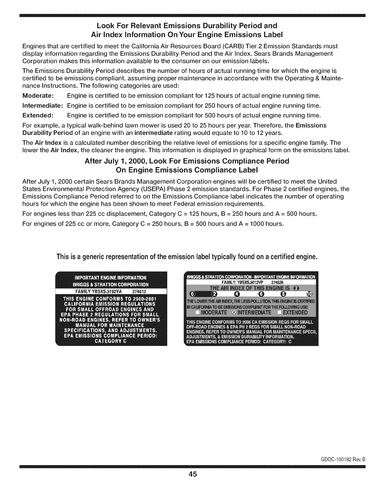
Look For Relevant Emissions Durability Period and
Air index information On Your Engine Emissions Label
Engines that are certified to meet the California Air Resources Board (CARB) Tier 2 Emission Standards must
display information regarding the Emissions Durability Period and the Air Index. Sears Brands Management
Corporation makes this information available to the consumer on our emission labels.
The Emissions Durability Period describes the number of hours of actual running time for which the engine is
certified to be emissions compliant, assuming proper maintenance in accordance with the Operating & Mainte-
nance Instructions. The following categories are used:
Moderate: Engine is certified to be emission compliant for 125 hours of actual engine running time.
Intermediate: Engine is certified to be emission compliant for 250 hours of actual engine running time.
Extended: Engine is certified to be emission compliant for 500 hours of actual engine running time.
For example, a typical walk-behind lawn mower is used 20 to 25 hours per year. Therefore, the Emissions
Durability Period of an engine with an intermediate rating would equate to 10 to 12 years.
The Air index is a calculated number describing the relative level of emissions for a specific engine family. The
lower the Air Index, the cleaner the engine. This information is displayed in graphical form on the emissions label.
After July 1,2000, Look For Emissions Compliance Period
On Engine Emissions Compliance Label
After July 1, 2000 certain Sears Brands Management Corporation engines will be certified to meet the United
States Environmental Protection Agency (USEPA) Phase 2 emission standards. For Phase 2 certified engines, the
Emissions Compliance Period referred to on the Emissions Compliance label indicates the number of operating
hours for which the engine has been shown to meet Federal emission requirements.
For engines less than 225 cc displacement, Category C = 125 hours, B = 250 hours and A = 500 hours.
For engines of 225 cc or more, Category C = 250 hours, B = 500 hours and A = 1000 hours.
This is ageneric representation of the emission label typically found on a certified engine.
FAMILYYBSXS.3192VA 274812
GDOC-100182Rev.B
45
Congratulations on making a smart purchase. Your new Craftsman® product is designed and
manufactured for years of dependable operation. But like all products, it may require repair
from time to time. That's when having a Repair Protection Agreement can save you money and
aggravation.
Here's what the Repair Protection Agreement* includes:
[] Expert service by our 10,000 professional repair specialists
[] Unlimited service and no charge for parts and labor on all covered repairs
[] Product replacement up to $1500 if your covered product can't be fixed
[] Discount of 25% from regular price of service and related installed parts not covered by the
agreement; also, 25% off regular price of preventive maintenance check
[] Fast help by phone - we call it Rapid Resolution - phone support from a Sears representative.
Think of us as a "talking owner's manual."
Once you purchase the Repair Protection Agreement, a simple phone call is all that it takes for you
to schedule service. You can call anytime day or night, or schedule a service appointment online.
The Repair Protection Agreement is a risk-free purchase. If you cancel for any reason during the
product warranty period, we will provide a full refund. Or, a prorated refund anytime after the
product warranty period expires. Purchase your Repair Protection Agreement today!
Some limitations and exclusions apply. For prices and additional information in the U.S.A.
call 1=800=827=6655.
*Coverage in Canada varies on some items. For full details call Sears Canada at 1=800=361=
6665.
Sears Installation Service
For Sears professional installation of home appliances, garage door openers, water heaters, and
other major home items, in the U.S.A. or Canada call 1=800=4=MY=HOME®.
46

Your Home
For troubleshooting, product manuals and expert advice:
managernylife
www.managemylife.com
For repair - in your home - of all major brand appliances,
lawn and garden equipment, or heating and cooling systems,
no matter who made it, no matter who sold it!
For the replacement parts, accessories and
owner's manuals that you need to do-it-yourself.
For Sears professional installation of home appliances
and items like garage door openers and water heaters.
1-800-4-MY-HOME ®(1-800-469-4663)
Call anytime, day or night (U.S.A. and Canada)
www.sears.com www.sears.ca
Our Home
For repair of carry-in items like vacuums, lawn equipment,
and electronics, call anytime for the location of your nearest
Sears Parts & Repair Service Center
1-800-488-1222 (U.S.A.) 1-800-469-4663 (Canada)
www.sears.com www.sears.ca
To purchase a protection agreement on a product serviced by Sears:
1-800-827-6655 (U.S.A.) 1-800-361-6665 (Canada)
Para pedir servicio de reparaci6n
a domicilio, y para ordenar piezas:
1-888-SU-HOGAR ®
(1-888-784-6427)
www.sears.com
Au Canada pour service en frangais:
1-800-LE-FOYER Mc
(1-800-533-6937)
www.sears.ca
® Registered Trademark /TMTrademark of KCD IP, LLC in the United States, or Sears Brands, LLC in other countries
® Marca Registrada !TMMarca de Fabrica de KCD IP, LLC en Estados Unidos, o Sears Brands, LLC in otros paises
MCMarque de commerce !MDMarque deposee de Sears Brands, LLC
