Craftsman 247885500 User Manual SNOW THROWER Manuals And Guides L0810513
CRAFTSMAN Snowthrower, Gas Manual L0810513 CRAFTSMAN Snowthrower, Gas Owner's Manual, CRAFTSMAN Snowthrower, Gas installation guides
User Manual: Craftsman 247885500 247885500 CRAFTSMAN SNOW THROWER - Manuals and Guides View the owners manual for your CRAFTSMAN SNOW THROWER #247885500. Home:Lawn & Garden Parts:Craftsman Parts:Craftsman SNOW THROWER Manual
Open the PDF directly: View PDF ![]() .
.
Page Count: 40
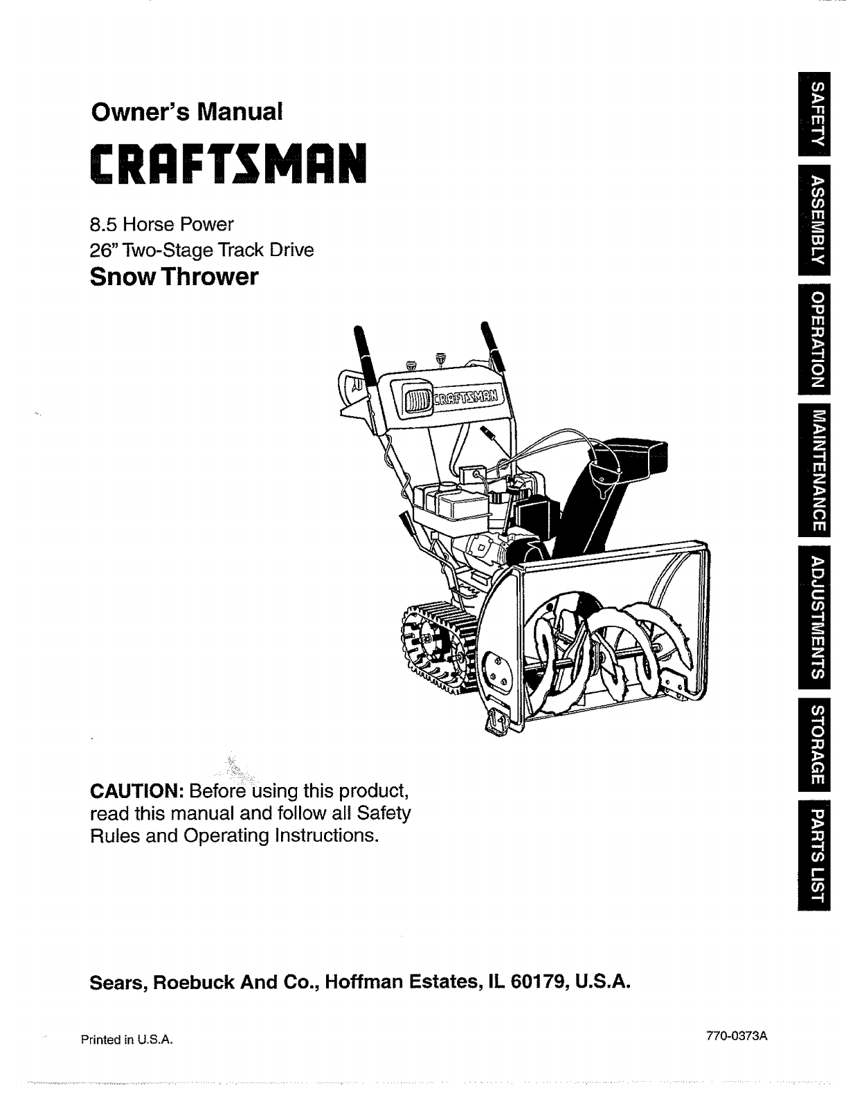
Owner's Manual
CRRFTSHRN
8.5 Horse Power
26" Two-Stage Track Drive
Snow Thrower
CAUTION: Before using this product,
read this manual and follow all Safety
Rules and Operating Instructions.
Sears, Roebuck And Co., Hoffman Estates, IL 60179, U.S.A.
Printed in U.S.A. 770-0373A
Content Page Content Page
Warranty Information 2 Maintenance 17
Safe Operation Practices 3 Service & Adjustment 20
Accessories 5Off-Season Storage 24
Assembly 7 Trouble-Shooting 25
Operation 12 Repair Parts 26
Two -Year Warranty on Craftsman Snow Thrower
For two years from the date of purchase, when this Craftsman Snow Thrower is maintained, lubricated and tuned
up according to the instructions in the owner's manual, Sears will repair, free of charge, any defect in material
and workmanship.
If this Craftsman snow thrower is used for commercial or rental purposes, this warranty applies for only 30 days
from the date of purchase.
This warranty does not cover:
Expendable items which become worn during normal use, such as skid shoes, shave plate and spark
plugs.
Repairs necessary because of operator abuse or negligence, including bent crankshafts and the failure to
maintain the equipment according to the instructions contained in the owner's manual.
WARRANTY SERVICE IS AVAILABLE BY RETU RNING THE CRAFTSMAN SNOWTH ROWER TO THE NEAREST
SEARS SERVICE CENTER/DEPARTMENT INTHE UNITED STATES.
This warranty applies only while this product is in use in the United States.
This warranty gives you specific legal rights and you may also have other rights which may vary from state to state.
SEARS, ROEBUCK AND CO., D/817WA, HOFFMAN ESTATES, IL 60179
Horsepower: 8.5
Engine Oil SAE 5W30 oil
Fuel Capacity: 1 gallon
'Spark Plug: RJ-19LM
Engine: 143.988501
Model Number 247.885500
Serial Number ...........................................................
Date of Purchase ......................................................
Record both serial number and date of purchase
and keep in a safe place for future reference.
2
This symbol points out important safety instructions which, if not followed, could endanger the
personal safety and/or property of yourself and others. Read and follow all instructions in this manual
before attempting to operate your snow thrower. Failure to comply with these instructions may result in
personal injury. When you see this symbol--heed its warning.
Your snow thrower was built to be operated according to the rules for safe operation inthis manual. As
_ll= DANGER: with any type of power equipment, carelessness or error on the part of the operator can result in serious
injury. If you violate any of these rules, you may cause serious injury to yourself or others.
This unit is equipped with an internal combustion engine and should not be used on or near any unimproved
forest-covered, brush-covered or grass-covered land unless the engine's exhaust system is equipped with a
spark arrester meeting applicable local or state laws (if any). If a spark arrester is used, it should be
maintained in effective working order by the operator.
In the State of California the above is required by taw (Section 4442 of the California Public Resources
Code). Other states may have similar laws. Federal laws apply on federal lands. A spark arrester for the
muffler is available through your nearest Sears Authorized Service Center (See the REPAIR PARTS section
of this manual.)
TRAINING
• Read this owner's guide carefully in its entirety before
attempting to assemble or operate this machine. Be
completely familiar with the controls and the proper
use of this machine before operating it. Keep this
manual in a safe place for future and regular
reference and for ordering replacement parts.
•Never allow children under 14 years old to operate a
snow thrower. Chitdren 14 years old and over should
only operate a snow thrower under close parental
supervision. Only persons well acquainted with these
rules of safe operation should be allowed to use your
snow thrower.
•No one should operate this unit while intoxicated or
while taking medication that impairs the senses or
reactions.
°Keep the area of operation clear of all persons,
especially small children and pets.
•Exercise caution to avoid slipping or falling, especially
when operating in reverse.
Thoroughly inspect the area where the equipment is
to be used and remove all door mats, sleds, boards,
wires and other foreign objects.
Do not operate equipment without wearing adequate
outer garments for winter. Do not wear jewelry, long
scarfs or other loose clothing which could become
entangled in moving parts. Wear footwear which will
improve footing on slippery surfaces.
Before working with gasoline, extinguish all cigarettes
and other sources of ignition. Check the fuel before
starting the engine. Gasoline is an extremely
flammable fuel. Do not fill the gasoline tank indoors,
while the engine is running, or until engine has been
allowed to cool at least two minutes. Replace gasoline
cap securely and wipe off any spilled gasoline before
starting the engine as it may cause a fire or explosion.
•Use a grounded three wire plug-in for all units with
electric drive motors or electric starting motors.
•Adjust collector housing height to clear gravel or
crushed rock surface.
° Never attempt to make any adjustments while engine
is running (except where specifically recommended
by manufacturer).
• Let engine and machine adjust to outdoor
temperature before starting to clear snow.
•Always wear safety glasses or eye shields during
operation or while performing an adjustment or repair,
to protect eyes from foreign objects that may be
thrown from the machine in any direction.
OPERATION
Do not put hands or feet near or under rotating parts.
Keep clear of discharge opening and auger at all
times.
Exercise extreme caution when operating on or
crossing gravel drives, walks, or roads. Stay alert for
hidden hazards or traffic.
Do not carry passengers.
After striking a foreign object, stop the engine, remove
wire from the spark plug and thoroughly inspect the
snow thrower for any damage. Repair the damage
before restarting and operating the snow thrower.
If the snow thrower starts to vibrate abnormally, stop
the engine and check immediately for the cause.
Vibration is generally a warning of trouble.
Stop the engine whenever you leave the operating
position, before unclogging the collectodimpeller
housing or discharge guide and before making any
repairs, adjustments, or inspections. Never place your
o
o
hand in the discharge or collector openings. Use a
stick or wooden broom handle to unclog the
discharge opening.
Take all possible precautions when leaving the unit
unattended. Disengage the collector/impeller, stop
the engine and remove the key.
When cleaning, repairing, or inspecting, make
certain coilectodimpeller and all moving parts have
stopped. Disconnect spark plug wire and keep away
from ptug to prevent accidental starting.
Do not run the engine indoors, except when starting it
and!or transporting the snow thrower in or out of
building. Open doors before starting the engine in that
case. Exhaust fumes are dangerous.
Do not clear snow across the face of slopes. Exercise
extreme caution when changing direction on slopes.
Do not attempt to clear steep slopes.
Never operate the snow thrower without guards,
plates or other safety protection devices in place.
Never operate the snow thrower near glass
enclosure, automobiles, window wells, drop off, etc.,
without proper adjustments of snow thrower
discharge angle. Keep children and pets away.
Do not overload machine capacity by attempting to
clear snow at too fast a rate. Never operate the
machine at high transport speeds on slippery
surfaces. Look behind and use care when backing.
Never direct discharge at bystanders or allow anyone
in front of unit while throwing snow.
Disengage power to collector/impeller of the snow
thrower when transporting it orwhen the unit is not in use.
Use only attachments and accessories (such as
wheel weights, counter weights, cabs, etc.) approved
by the snow thrower manufacturer.
•Never operate the snow thrower without good visibility
or light. Always be sure of your footing and keep a firm
hold on the handles. Walk, never run.
• Muffler and engine become hot and can cause severe
burn injury. Do not touch the muffler orthe engine
while starting or operating the snow thrower.
MAINTENANCE AND STORAGE
• Check shear bolts, engine mounting bolts, etc., at
frequent intervals for proper tightness, thus ensuring
that the equipment is in safe working condition.
• Never store the machine with fuel in the fuel tank
inside a building where ignition sources are present,
such as hot water heaters, space heaters, clothes
dryers and the like. Allow engine to cool before storing
in any enclosure.
•Always refer to owner's guide instructions for
important details if the snow thrower is to be stored for
an extended period.
°Run machine a few minutes after throwing snow to
prevent freeze-up of the collector/impeller.
• Check clutch controls periodically to verify that these
engage and disengage properly and readjust if
necessary. Refer to Service and Adjustments section
page 20 of this owner's guide.
YOUR RESPONSIBILITY
Restrict the use of this power machine to persons who
read, understand and follow the warnings and
instructions in this manual and on the machine.
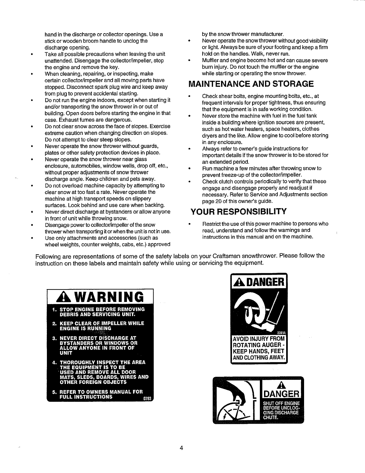
Following are representations of some of the safety labels on your Craftsman snowthrower. Please follow the
instruction on these labels and maintain safety while using or servicing the equipment.
AWARNING ,A.DANGER
,A
DANGER
4
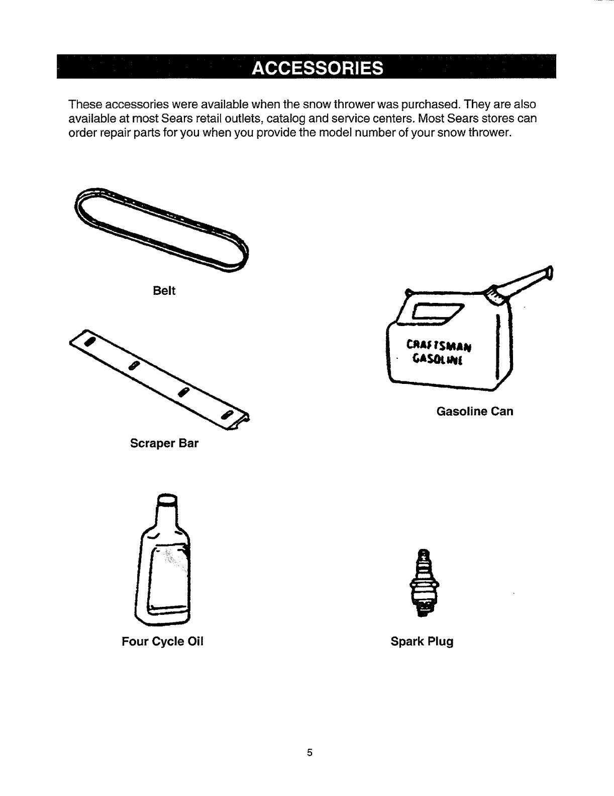
These accessories were available when the snow thrower was purchased. They are also
available at most Sears retail outlets, catalog and service centers. Most Sears stores can
order repair parts for you when you provide the model number of your snow thrower.
Belt
II I II ..wl
Gasoline Can
Scraper Bar
=
Four Cycle Oil Spark Plug
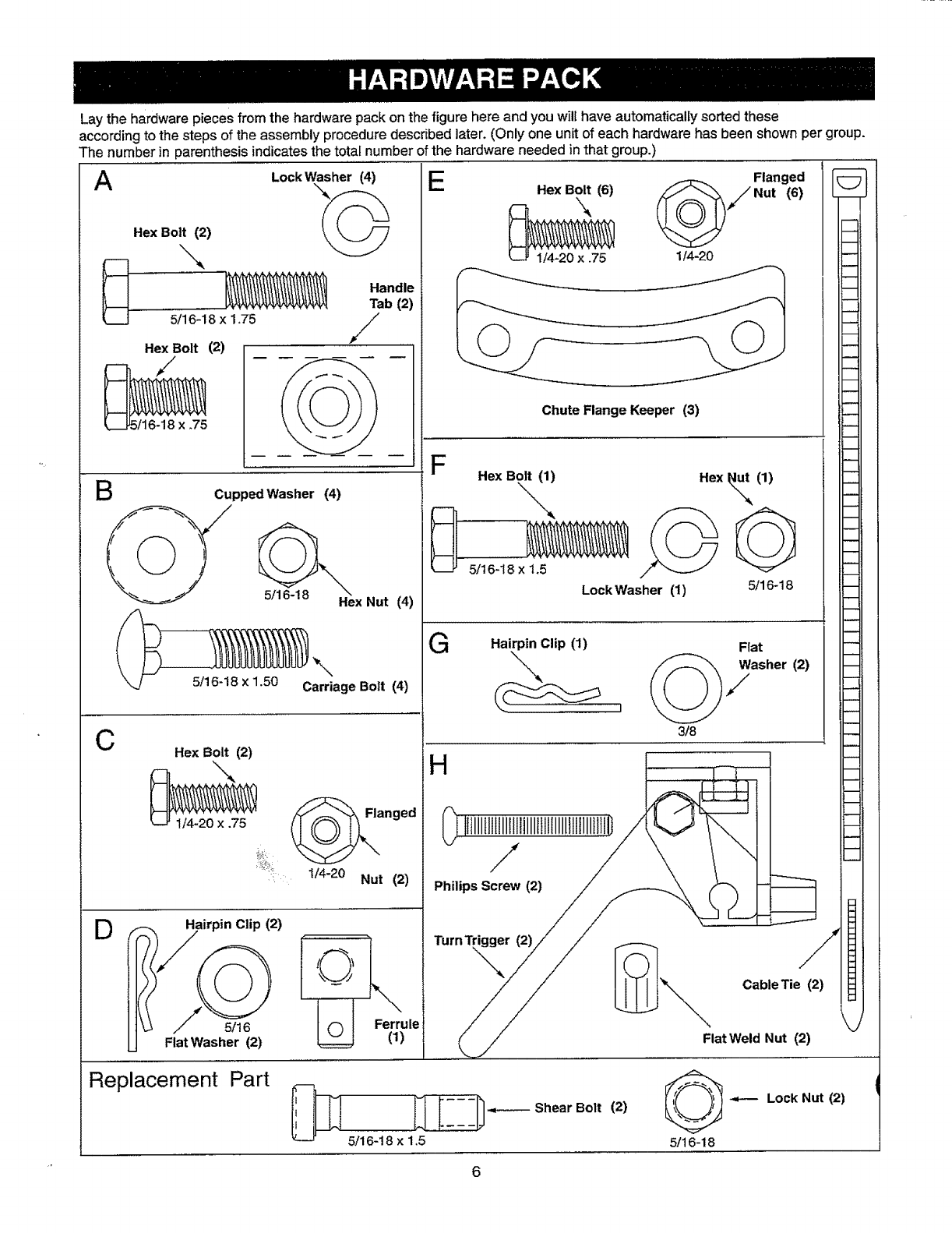
Lay the hardware pieces from the hardware pack on the figure here and you will have automatically sorted these
according to the steps of the assembly procedure described later. (Only one unit of each hardware has been shown per group.
The number in parenthesis indicates the total number of the hardware needed in that group.)
A LookWasher(4) E
Hex Bolt (2)
__ ",,,
)--- _Handle
Tab 121
_._ 5/16-18 x 1.75 //
/
Hex Bolt (2)
5/16-18 x .75
gCupped Washer (4)
Hex Nut (4)
k_J 5!16-18 x 1.50 Carriage Bolt (4)
CHex Bolt (2)
1/4-20 x .75 (J.O_ "-nged
1/4-20 Nut io_
g, Hairpin Clip (2)
I ........ '_"x
Ferrule
Fiat Washer (2) O
Replacement Part ,,;_,
1
1
Flanged
HexBolt (6) Z_/Nut (6)
F- \ _
_ -
1/4-20 x .75 114-20
m
Chute Flange Keeper (3)
P
-- Hex Bolt (1) Hex (1)
_",,, _
5/16-18 x 1.5
Lock Washer (1) 5/16-18
GHairpin Clip (1) Flat
3/8
H __
0_"'"'"""'!"'"'""'"'"'""'"'_/:L:_
,u,o<yi /
•/I [ "_ CableTie (2)
m
m
m
W
I_l [:-_-.----- Shear Bolt (2)
5/16-18 x 1,5
-_-- Lock Nut (2)
5/16-18
6
/
Chute
Traction Drive
Control Handle
Panel
Handles
Rear
Front
Crank _Shift
Rod
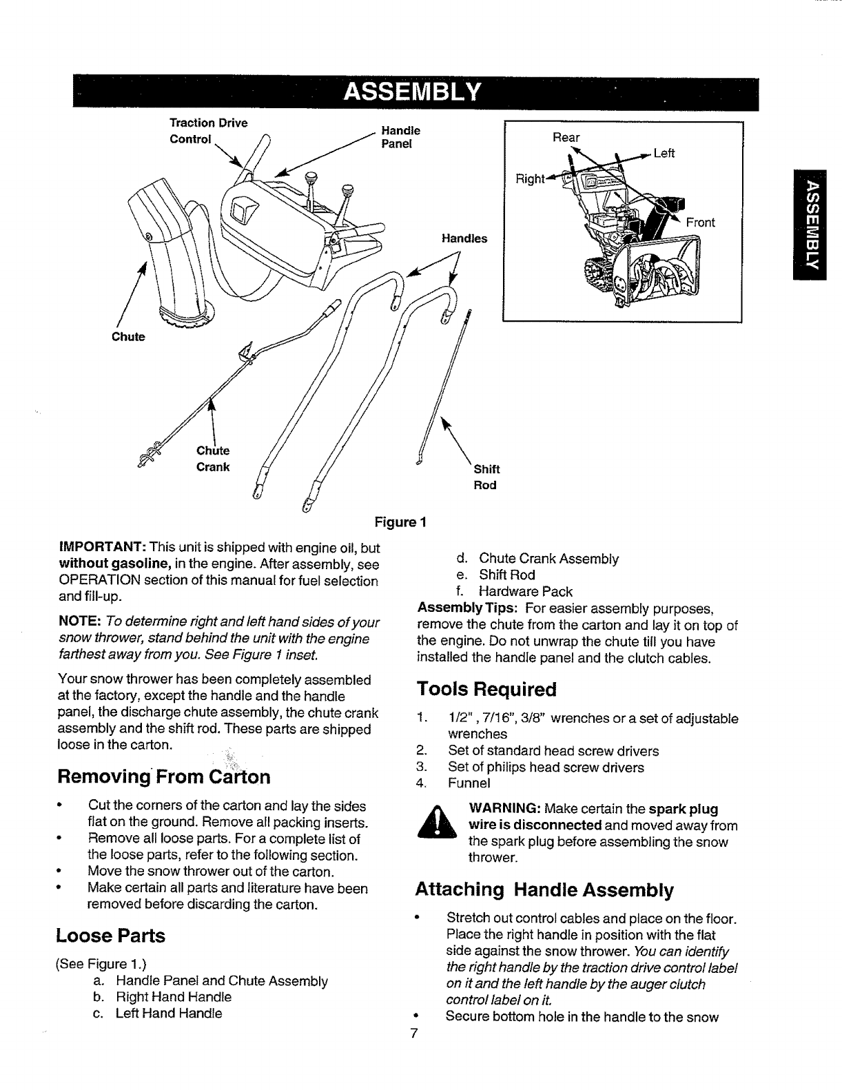
Figure I
IMPORTANT: This unit is shipped with engine oil, but
without gasoline, in the engine. After assembly, see
OPERATION section of this manual for fuel selection
and fill-up.
NOTE: To determine right and left hand sides of your
snow thrower, stand behind the unit with the engine
farthest away from you. See Figure 1 inset.
Your snow thrower has been completely assembled
at the factory, except the handle and the handle
panel, the discharge chute assembly, the chute crank
assembly and the shift rod. These parts are shipped
loose in the carton.
Removing From ca on
d. Chute Crank Assembly
e. Shift Rod
f. Hardware Pack
AssernblyTips: For easier assembly purposes,
remove the chute from the carton and lay it on top of
the engine. Do not unwrap the chute till you have
installed the handle panel and the clutch cables.
Tools Required
1. 1/2", 7/16", 3/8" wrenches ora set of adjustable
wrenches
2. Set of standard head screw drivers
3. Set of philips head screw drivers
4. Funnel
Cut the corners of the carton and lay the sides
fiat on the ground. Remove all packing inserts.
Remove all loose parts. For a complete list of
the loose parts, refer to the following section.
Move the snow thrower out of the carton.
Make certain all parts and literature have been
removed before discarding the carton.
Loose Parts
(See Figure 1.)
a. Handle Panel and Chute Assembly
b. Right Hand Handle
c. Left Hand Handle
WARNING: Make certain the spark plug
wire is disconnected and moved away from
the spark plug before assembling the snow
thrower.
Attaching Handle Assembly
7
Stretch out control cables and place on the floor.
Place the right handle in position with the flat
side against the snow thrower. "Youcan identify
the right handle by the traction drive control label
on it and the left handle by the auger clutch
control label on it.
Secure bottom hole in the handle to the snow
o
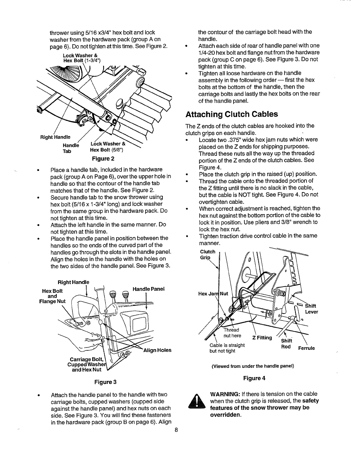
thrower using 5/16 x3/4" hex bolt and lock
washer from the hardware pack (group A on
page 6). Do not tighten at this time. See Figure 2.
LockWasher&
Hex Bolt (I-3/4")
/
Right Handle
Handle ;k Washer &
Tab Hex Bolt (5/8")
Figure 2
Place a handle tab, included in the hardware
pack (group A on Page 6), over the upper hole in
handle so that the contour of the handle tab
matches that of the handle. See Figure 2.
Secure handle tab to the snow thrower using
hex bolt (5/I6 x 1-3/4" long) and lock washer
from the same group in the hardware pack. Do
not tighten at this time.
Attach the left handle in the same manner. Do
not tighten at this time.
Place the handle panel in position between the
handles so the ends of the curved part of the
handles go through the slots in the handle panel.
Align the holes in the handle with the holes on
the two sides of the handle panel. See Figure 3.
the contour of the carriage bolt head with the
handle.
Attach each side of rear of handle panel with one
1/4-20 hex bolt and flange nut from the hardware
pack (group C on page 6). See Figure 3. Do not
tighten at this time.
Tighten all loose hardware on the handle
assembly in the following order -- first the hex
bolts at the bottom of the handle, then the
carriage bolts and lastly the hex bolts on the rear
of the handle panel.
Attaching Clutch Cables
The Z ends of the clutch cables are hooked into the
clutch grips on each handle.
• Locate two .375" wide hex jam nuts which were
placed on the Z ends for shipping purposes.
Thread these nuts all the "wayup the threaded
portion of the Zends of the clutch cables. See
Figure 4.
•Place the clutch grip in the raised (up) position.
• Thread the cable onto the threaded portion of
the Zfitting untilthere is no slack in the cable,
but the cable is NOT tight. See Figure 4. Do not
overtighten cable.
- When correct adjustment is reached, tighten the
hex nut against the bottom portion of the cable to
lock it in position. Use pliers and 3/8" wrench to
lock the hex nut.
•Tighten traction drive control cable in the same
manner.
Clutch
Gri
Handle Panel
Carriage Bolt,
CuppedWashel
and Hex Nut
Figure 3
Attach the handle panel to the handle with two
carriage bolts, cupped washers (cupped side
against the handle panel) and hex nuts on each
side. See Figure 3. You will find these fasteners
in the hardware pack (group B on page 6). Align
8
Hex
Thread
nut here
Cable is straight
but not tight
Lever
Z Fitting Shift \
\
Rod Ferrule
(Viewed from under the handle panel)
Figure 4
WARNING: If there is tension on the cable
when the clutch grip is released, the safety
features of the snow thrower may be
overridden.
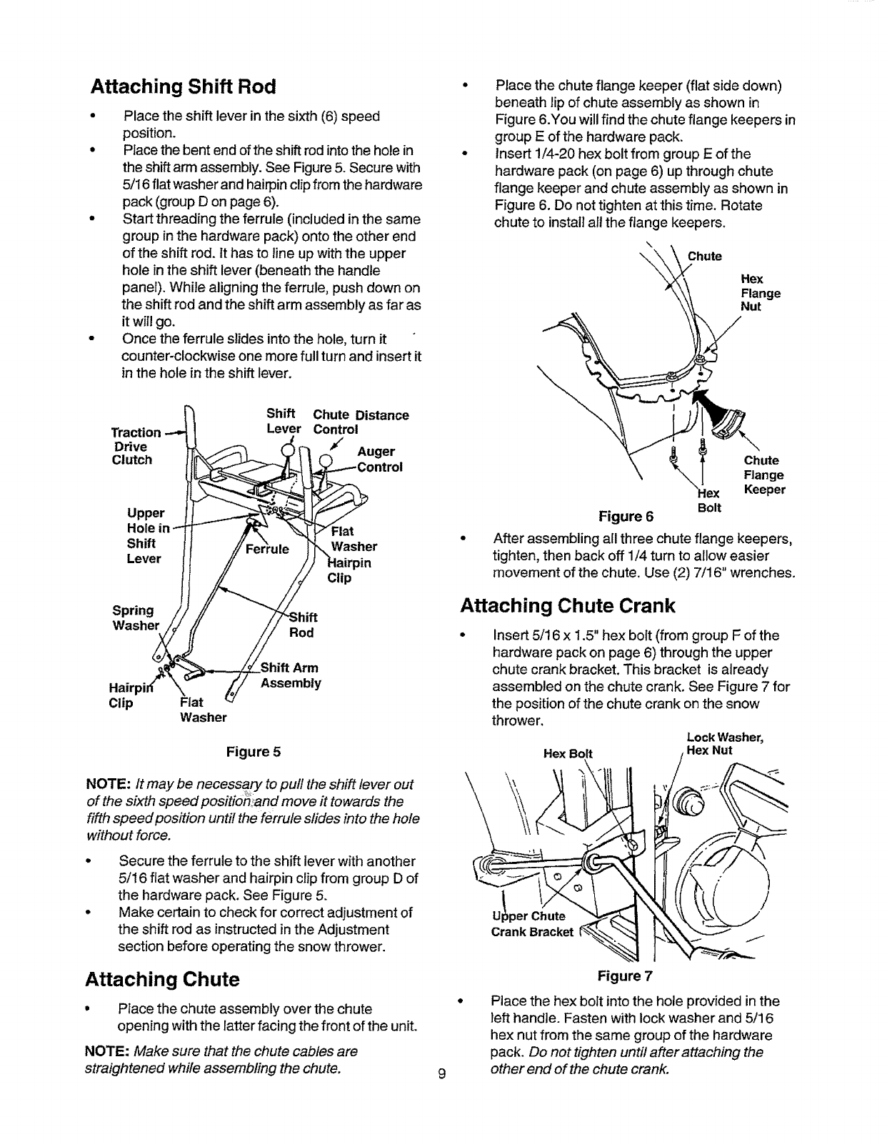
Attaching Shift Rod
Place the shift lever in the sixth (6) speed
position.
Place the bent end of the shift rod into the hole in
the shift arm assembly. See Figure 5. Secure with
5/16 flat washer and hairpin clip from the hardware
pack (group D on page 6).
Start threading the ferrule (included in the same
group in the hardware pack) onto the other end
of the shift rod. It has to line up with the upper
hole in the shift lever (beneath the handle
panel). Whi_e aligning the ferrule, push down on
the shift rod and the shift arm assembly as far as
it will go.
Once the ferrule slides into the hole, turn it
counter-clockwise one more full turn and insert it
in the hole in the shift lever.
Shift Chute Distance
Traction Lever Control
Drive Auger
Clutch ,ntrol
Upper
Hole in Flat
Shift Washer
Lever
Spring
Washer Rod
Clip
Clip Fiat
Washer
Shift Arm
Assembly
Figure 5
NOTE: It may be necessary to pull the shift lever out
of the sixth speed positio_tand move it towards the
fifth speed position until the ferrule slides into the hole
without force.
Secure the ferrule to the shift lever with another
5/16 flat washer and hairpin clip from group D of
the hardware pack. See Figure 5.
Make certain to check for correct adjustment of
the shift rod as instructed in the Adjustment
section before operating the snow thrower.
Attaching Chute
• Place the chute assembly over the ch ute
opening with the latter facing the front of the unit.
NOTE: Make sure that the chute cables are
straightened while assembling the chute. 9
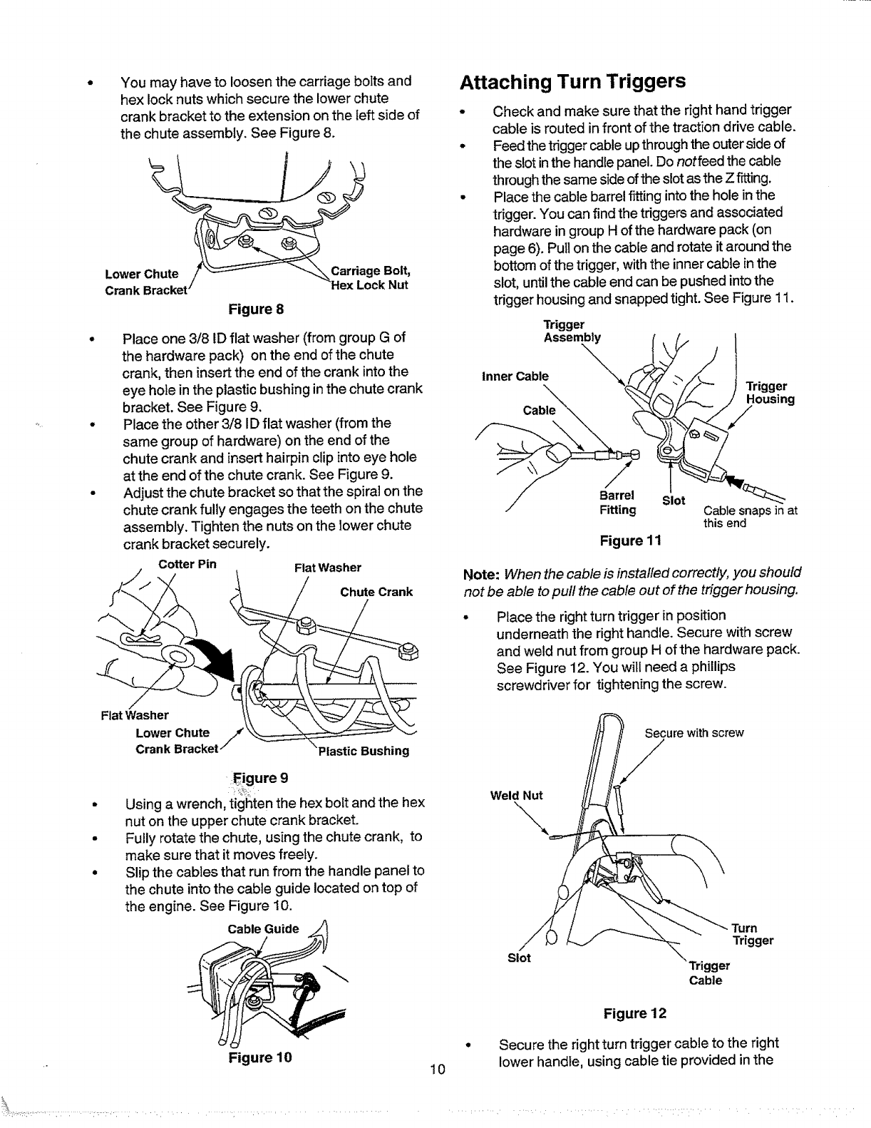
Place the chute flange keeper (flat side down)
beneath lip of chute assembly as shown in
Figure 6.You will find the chute flange keepers in
group E of the hardware pack.
Insert !/4-20 hex bolt from group E of the
hardware pack (on page 6) up through chute
flange keeper and chute assembly as shown in
Figure 6. Do not tighten at this time. Rotate
chute to install all the flange keepers.
\
\Chute
Hex
Flange
Nut
Chute
Flange
Keeper
Bolt
Figure 6
After assembling all three chute flange keepers,
tighten, then back off 1/4 turn to allow easier
movement of the chute. Use (2) 7/16" wrenches.
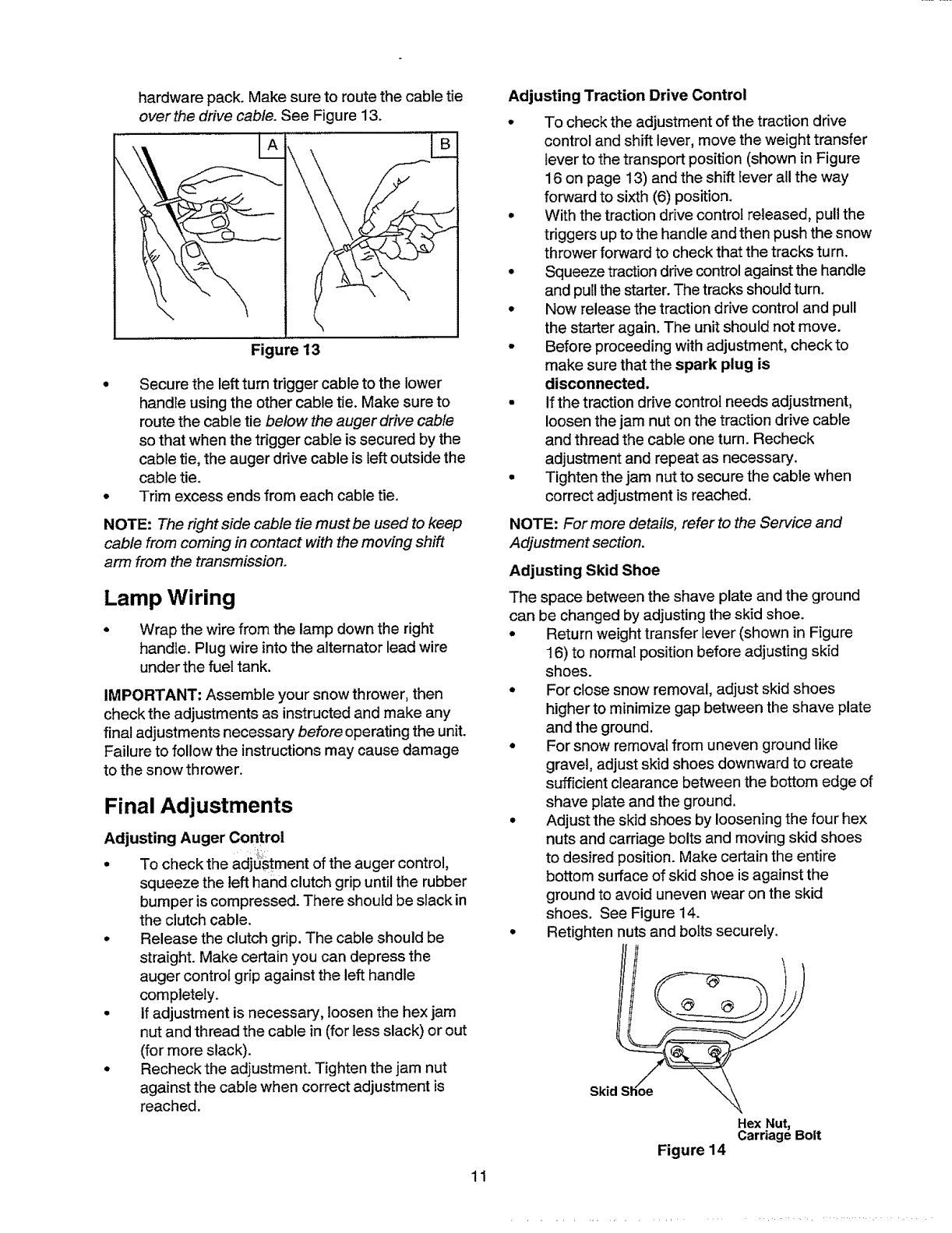
Attaching Chute Crank
Insert 5116 x 1.5" hex bolt (from group F of the
hardware pack on page 6) through the upper
chute crank bracket. This bracket is already
assembled on the chute crank, See Figure 7 for
the position of the chute crank on the snow
thrower.
Lock Washer,
Hex Bolt Hex Nut
\
U!per Chute /
Crank Bracket .1t
Figure 7
Place the hex bolt into the hole provided in the
left handle. Fasten with lock washer and 5/16
hex nut from the same group of the hardware
pack. Do not tighten until after attaching the
other end of the chute crank.
You may have to loosen the carriage boits and
hex lock nuts which secure the lower chute
crank bracket to the extension on the left side of
the chute assembly. See Figure 8.
Lower
Crank
Figure 8
Place one 3/8 ID flat washer (from group G of
the hardware pack) on the end of the chute
crank, then insert the end of the crank into the
eye hote in the plastic bushing in the chute crank
bracket. See Figure 9.
Place the other 3/8 ID flat washer (from the
same group of hardware) on the end of the
chute crank and insert hairpin clip into eye hole
at the end of the chute crank. See Figure 9.
Adjust the chute bracket so that the spiral on the
chute crank fully engages the teeth on the chute
assembly. Tighten the nuts on the lower chute
crank bracket securely.
Cotter Pin FlatWasher
Chute Crank
Flat Washer
Lower Chute
Plastic Bushing
._igure 9
Using a wrench, tighten the hex bolt and the hex
nut on the upper chute crank bracket.
Fully rotate the chute, using the chute crank, to
make sure that it moves freely.
Slip the cables that run from the handle panel to
the chute into the cable guide located on top of
the engine. See Figure 10.
Cable Guide
Figure 10 10
Attaching Turn Triggers
Check and make sure that the right hand trigger
cable is routed in front of the traction drive cable.
Feed the trigger cable up through the outer side of
the slot inthe handle panel. Do notfeed the cable
through the same side of the slot as the Z f'rtting.
Place the cable barrel fitting into the hole in the
trigger. You can find the triggers and associated
hardware in group H of the hardware pack (on
page 6). Pull on the cable and rotate it around the
bottom of the trigger, with the inner cable inthe
slot, until the cable end can be pushed into the
trigger housing and snapped tight. See Figure 11.
Trigger
Assembly {
Inner Cable _/_
Cal
Barrel
Fitting
___'_ I THriggsenrg
Cable snapsinat
this end
Figure 11
Note: When the cable is installed correctly, you should
not be able to pull the cable out of the trigger housing.
Place the right turn trigger in position
underneath the right handle. Secure with screw
and weld nut from group H of the hardware pack.
See Figure 12. You will need a phillips
screwdriver for tightening the screw.
Secure with screw
Weld Nut
\.
Slot
"rMrn
Trigger
Trigger
Cable
Figure 12
Secure the right turn trigger cable to the right
lower handle, using cable tie provided in the
hardwarepack.Makesuretoroutethecabletie
overthe drive cable. See Figure 13.
\
Figure 13
Secure the left turn trigger cable to the lower
handle using the other cable tie. Make sure to
route the cable tie below the auger drive cable
so that when the trigger cable is secured by the
cable tie, the auger drive cable is left outside the
cable tie.
Trim excess ends from each cable tie.
NOTE: The right side cable tie must be used to keep
cable from coming in contact with the moving shift
arm from the transmission.
Lamp Wiring
Wrap the wire from the lamp down the right
handle. Plug wire into the alternator lead wire
under the fuel tank.
IMPORTANT: Assemble your snow thrower, then
check the adjustments as instructed and make any
final adjustments necessary before operating the unit.
Failure to follow the instructions may cause damage
to the snow th rower.
Final Adjustments
Adjusting Auger Control
•7ochecktheadjUStmentoftheaugercontrol,
squeeze the left hand clutch grip until the rubber
bumper is compressed. There should be slack in
the clutch cable.
°Release the clutch grip. The cable should be
straight. Make certain you can depress the
auger control grip against the left handle
completely.
•If adjustment is necessary, loosen the hex jam
nut and thread the cable in (for less slack) or out
(for more slack).
°Recheck the adjustment. Tighten the jam nut
against the cable when correct adjustment is
reached.
11
Adjusting Traction Drive Control
° To check the adjustment of the traction drive
control and shift lever, move the weight transfer
lever to the transport position (shown in Figure
16 on page 13) and the shift lever all the way
forward to sixth (6) position,
° With the traction drive control released, pull the
triggers up to the handle and then push the snow
thrower forward to check that the tracks turn.
°Squeeze traction drive control against the handle
and pull the starter. The tracks should turn.
•Now release the traction drive control and pull
the starter again. The unit should not move.
•Before proceeding with adjustment, check to
make sure that the spark plug is
disconnected.
•If the traction drive control needs adjustment,
loosen the jam nut on the traction drive cable
and thread the cable one turn. Recheck
adjustment and repeat as necessary.
•Tighten the jam nut to secure the cable when
correct adjustment is reached,
NOTE: For more details, refer to the Service and
Adjustment section.
Adjusting Skid Shoe
The space between the shave plate and the ground
can be changed by adjusting the skid shoe.
°Return weight transfer lever (shown in Figure
16) to normal position before adjusting skid
shoes.
°For close snow removal, adjust skid shoes
higher to minimize gap between the shave plate
and the ground.
°For snow removal from uneven ground like
gravel, adjust skid shoes downward to create
sufficient clearance between the bottom edge of
shave plate and the ground,
°Adjust the skid shoes by loosening the four hex
nuts and carriage bolts and moving skid shoes
to desired position. Make certain the entire
bottom surface of skid shoe is against the
ground to avoid uneven wear on the skid
shoes. See Figure 14.
°Retighten nuts and bolts securely.
Ski
Hex Nut,
Carriage Bolt
Figure 14
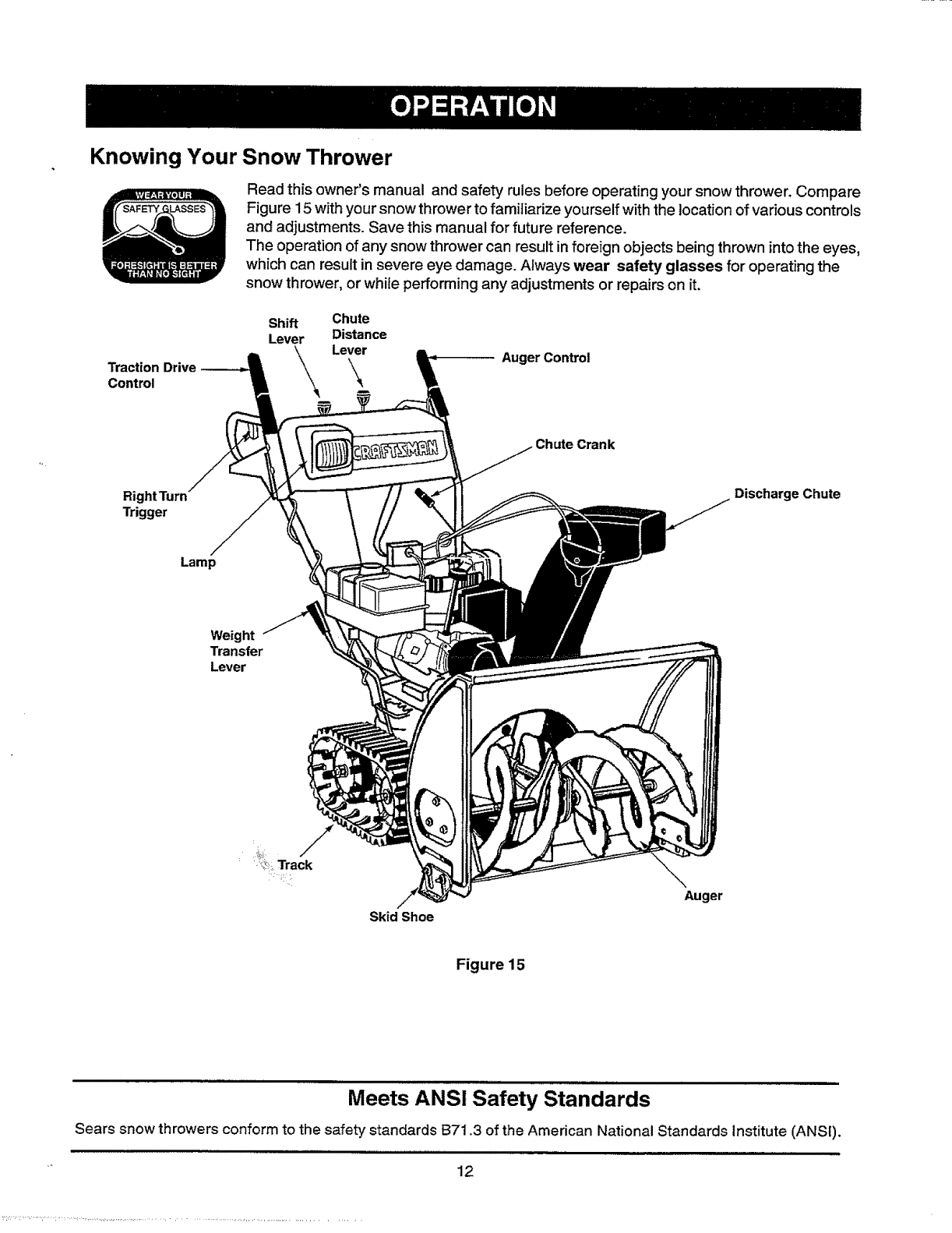
Knowing Your Snow Thrower
Read this owner's manual and safety rules before operating your snow thrower. Compare
Figure 15 with your snow thrower to familiarize yourself with the location of various controls
and adjustments. Save this manual for future reference.
The operation of any snow thrower can result in foreign objects being thrown into the eyes,
which can result in severe eye damage. Always wear safety glasses for operating the
snow thrower, or while performing any adjustments or repairs on it.
Traction Drive
Control
Shift
Lever
Chute
Distance
Lever Auger Control
RightTurn
Trigger
Chute Crank
Discharge Chute
Lamp
Weight
Transfer
Lever
Skid Shoe
Auger
Figure 15
Meets ANS! Safety Standards
Sears snow throwers conform to the safety standards B71.3 of the American National Standards Institute (ANSI).
_ 12
Operating Controls
(See Figure 15.)
Chute Crank
The chute crank is located on the left hand side of the
snow thrower. To change the direction in which snow
is thrown, turn chute crank as follows:
turn clockwise to discharge to the left;
turn counterclockwise to discharge to the right.
Throttle Control
The throttle control is located on the engine. It
regulates the speed of the engine.
Safety Ignition Switch
The ignition key must be inserted into the switch for
the unit to start. Remove the ignition key when the
snow thrower is not in use.
Left And Right Turn Trigger
The left and right turn triggers are located on the
underside of the handles and are used to assist in
steering your snow thrower. Squeeze the right turn
trigger when turning right, squeeze the left turn trigger
when turning left. Operate your snow thrower in open
areas until you become familiar with these controls.
Shift Lever
The shift lever is located in the center of the handle
panel. It may be moved into one of eight positions:
a. Forward_one of six speeds; position one (1)
isthe slowest and position six (6) is the
fastest.
b. Reverse--two reverse (R) speeds; R2 is
faster.
Use the shift lever to determine ground speed.
Auger Control
The auger control is located on the left handle.
Squeeze the auger control against the handle to
engage the augers; release to disengage the augers.
(Traction drive control mu_t;!ats0 be released.)
Traction Drive Control
The traction drive control is located on the right
handle. Squeeze the traction drive control to engage
the track drive; release to stop.
This same lever also locks the auger control so
that you can turn the chute crank without interrupting
the snow throwing process. If the auger control is
engaged with the traction drive control engaged, you
can release the auger control (on the left handle) and
the augers will remain engaged. Release the traction
drive control to stop both the augers and the track
drive. (Auger control must also be released).
Chute Distance Control
The distance that snow is thrown can be adjusted by
adjusting the angle of the chute assembly. Move the
chute distance control forward to decrease the
distance, toward the rear to increase the distance.
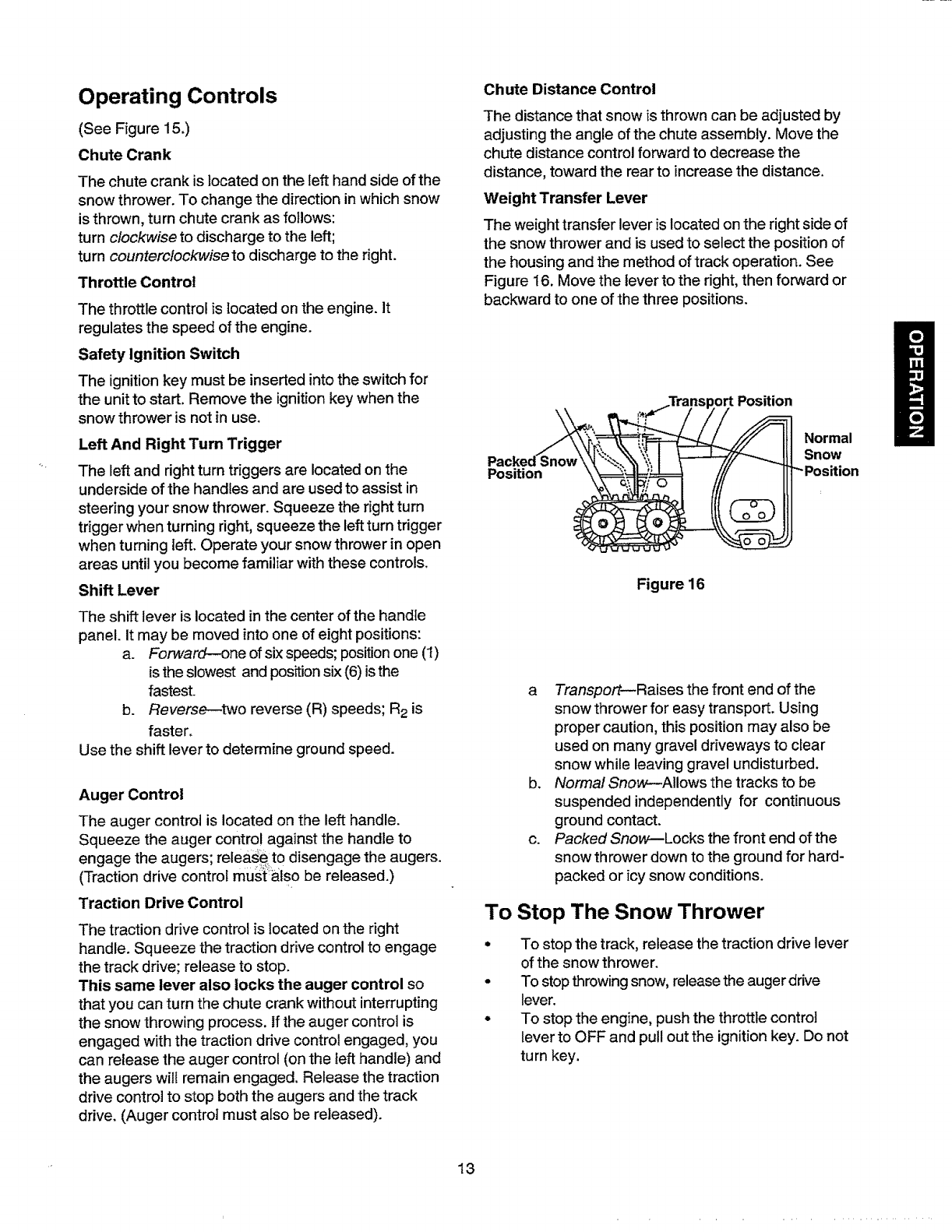
Weight Transfer Lever
The weight transfer lever is located on the right side of
the snow thrower and is used to select the position of
the housing and the method of track operation. See
Figure 16. Move the tever to the right, then forward or
backward to one of the three positions.
Position
Normal
Snow
Figure 16
aTransportmRaises the front end of the
snow thrower for easy transport. Using
proper caution, this position may also be
used on many gravel driveways to clear
snow while leaving gravel undisturbed.
b. Normal Snow--Allows the tracks to be
suspended independently for continuous
ground contact.
c. Packed Snow--Locks the front end of the
snow thrower down to the ground for hard-
packed or icy snow conditions.
To Stop The Snow Thrower
oTo stop the track, release the traction drive lever
of the snow thrower.
To stop throwing snow, release the auger drive
lever.
To stop the engine, push the throttle control
lever to OFF and pull out the ignition key. Do not
turn key.
13
Before Starting Engine
Fill Gas
D
0
WARNING: Gasoline is flammable and cau-
tion must be used when handling or storing it.
Do not fill fuel tank while the snow thrower is
running, when it is hot or when it is in an
enclosed area.
Keep your snow thrower away from any
open flame or an electrical spark and do not
smoke while filling the fuel tank.
Never fill the fuel tank completely. Fill the
tank to within 1/4"-1/2" from the top to
provide space for expansion of fuel.
Always fillthe fuel tank outdoors and use a
funnel or spout to prevent spilling.
Make sure to wipe off any spilled fuel before
starting the engine.
Store gasoline in a clean, approved container
and keep the cap in place on the container.
Make sure that the container from which you
pour the gasoline is clean and free from rust or
other foreign particIes.
Fill fuel tank with clean, fresh, unleaded grade
automotive gasoline.
At the end of the job, empty the fuel tank if the
snow thrower is not going to be used for 30 days
or longer. See storage instructions on page 24
of this manual.
CAUTION: Experience indicates that alcohol
blended fuels (called gasohol) or those using etha-
nol or methanol can attract moisture which leads to
separation and formation of acids during storage.
Acidic gas can damage the fuel system of an engine
while in storage.
To avoid engine problems, the fuel system should be
emptied before storage for 30 days or longer. Drain
the gas tank, start thei_engine and let it run until the
fuel lines and carburetor are empty. Use fresh fuel
next season. See storage Instructions on page 24
for additional information.
Never use engine or carburetor cleaner products in
the fuel tank or permanent damage may occur.
To Start Engine
WARNING: Be sure no one other than
the operator is standing near the snow
thrower while starting or operating. Do not
operate this snow thrower unless the
discharge chute assembly has been
properly installed and is secured.
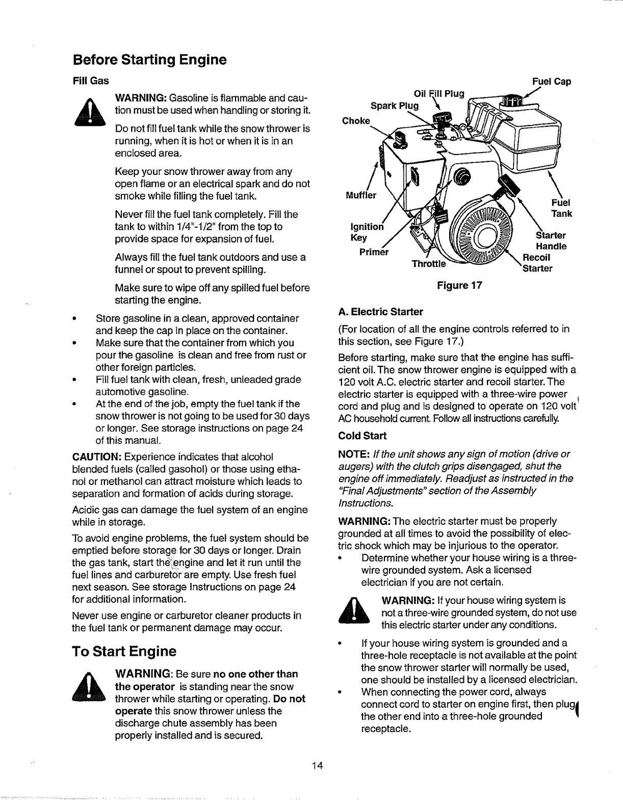
Oil
Spark Plug
Choke
Plug
Fuel Cap
Muffler Fuel
Tank
Key
Primer
Figure 17
Handle
Recoil
Starter
A. Electric Starter
(For location of all the engine controls referred to in
this section, see Figure 17.)
Before starting, make sure that the engine has suffi-
cient oil. The snow thrower engine is equipped with a
120 volt A.C. electric starter and recoil starter. The
electric starter is equipped with athree-wire power
cord and p ug and is designed to operate on 120 volt
AC household current. Follow all instructions carefully.
Cold Start
NOTE: If the unit shows any sign of motion (drive or
augers) with the clutch grips disengaged, shut the
engine off immediately. Readjust as instructed in the
"Final Adjustments" section of the Assembly
Instructions.
WARNING: The electric starter must be properly
grounded at all times to avoid the possibility of elec-
tric shock which may be injurious to the operator.
•Determine whether your house wiring is a three-
wire grounded system. Ask a licensed
electrician if you are not certain.
WARNING: If your house wiring system is
not athree-wire grounded system, do not use
this electric starter under any conditions.
If your house wiring system is grounded and a
three-hole receptacle is not available at the point
the snow thrower starter will normally be used,
one should be installed by a licensed electrician.
When connecting the power cord, always
connect cord to starter on engine first, then plug|
the other end into a three-hole grounded I
receptacle.
14
o
When disconnecting the power cord, always
unplug the end from the three-hole, grounded
receptacle first.
Attach spark plug wire to spark plug.
Make sure that the auger drive and the traction
drive levers are in the disengaged RELEASED
position.
Move throttle control lever to FAST position.
Remove the keys from the plastic bag. Push key
into the ignition slot. Make sure it snaps into
place. Do not turn key. Keep the second key in a
safe place.
Rotate the choke knob to FULL choke position.
Connect the power cord to the switch box on the
engine.
Ptug the other end of the power cord into a
three-hole, grounded 120 volt A.C. receptacle.
WARNING: Do not use primer while
starting the engine with an electric starter.
Push down on the starter button until the engine
starts. Do not crank for more than 10 seconds at
a time. This electric starter is thermally
protected. If overheated, it will stop
automatically and can be restarted only when it
has cooled to a safe temperature (a wait of
about 5 to 10 minutes is required).
When the engine starts, release the starter
button and slowly rotate the choke to OFF
position. If the engine falters, rotate the choke to
FULL and then gradually to OFF.
Disconnect the power cord from the receptacle
first and then from the switch box on the engine.
Allow the engine to warm up for a few minutes
because the engine will not develop full power
until it reaches operating temperature.
Operate the engine at full throttle (FAST) when
throwing snow.
Warm Start
If restarting a wa_ engine after a shut down,
rotate choke to OFE instead of FULL and press
the starter button.
B. Recoil Starter
Make sure that the engine has sufficient oit and the
auger drive and the traction drive levers are released.
• Move throttle control to FAST position.
•Push key into the ignition slot so that it snaps
into place. Do not turn key. Remove plastic bag
and keep the second key in a safe place.
• Rotate choke contro! to FULL choke position.
• Push the primer button while covering the vent
hole. Remove your finger from the primer between
primes. Do not prime if temperature is above
50°F; prime two times between 50o F and 15° F;
and pdme four times below 15°F.
• Pull the starter handle rapidly. Do not allow the
handle to snap back, but allow it to rewind slowly
while keeping a firm hold on the starter handle.
• As the engine warms up and begins to operate
evenly, rotate the choke knob slowly to OFF
position. If the engine falters, return to FULL
choke, then slowly move to OFF choke position.
•Allow the engine to warm up for a few minutes
because the engine will not develop fufl power
until it reaches operating temperature.
• Operate the engine at full throttle (FAST) when
throwing snow.
Warm Start
If restarting a warm engine after atemporary
shut down, rotate choke to OFF instead of FULL
and do notprime. Press the starter button.
Frozen Recoil Starter
If the starter is frozen and will not turn the engine,
proceed as follows:
o Pull as much rope out of the starter as possible.
• Release the starter handle and let it snap back
against the starter.
• Ifthe engine still fails to start, repeat the first two
steps. If continued attempts do not free starter,
follow the electric starter procedures to start.
•Avoid possible freezing of recoil starter and the
engine controls.
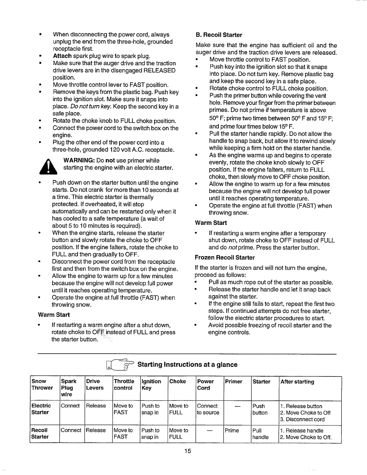
Snow
Thrower
Electric
Starter
Recoil
!Starter
Spark
Plug
wire
Connect
Connect
_Starting Instructions at a glance
Drive
Levers
Release
Release
Throttle Ignition
control Key
Moveto Push to
FAST snap in
Move to Pushto
FAST snap in
Choke Power
Cord
Moveto Connect
FULL to source
Move to
FULL
Primer
iPrime
Starter
Push
button
Pull
handle
After starting
t. Release button
2. Move Choke to Off
3. Disconnect cord
1. Release handle
2. Move Choke to Off.
15
Operating Snow Thrower
To Engage Drive
•With the engine running near top speed, move
shift lever to one of six FORWARD positions or
two REVERSE positions. Select a speed
appropriate for the snow conditions that exist.
Use slower speeds until you are familiar with the
operation of the snow thrower.
•Squeeze the traction drive clutch grip against
the right handle and the snow thrower will move.
Release it and the drive motion will stop.
To Engage Augers
•To engage the augers and start snow throwing,
squeeze the left hand auger clutch grip against
the left handle. Release to stop augers.
•While the auger control is engaged, squeeze the
traction drive control to move, release to stop.
Do not shiftspeeds while the drive is engaged.
NOTE: This same lever also locks the auger control
so you can turn the chute crank without interrupting
the snow throwing process.
Release the auger control; the interlock
mechanism should keep the auger control
engaged until the traction drive control is
released.
Release the traction drive control to stop both
the augers and the wheel drive.
WARNING: To stop the auger, both levers
must be released.
To Throw Snow
CAUTION: Check the area to be cleared for foreign
objects. Remove, if any.
Move the weight transfer lever to the right, then
backward or forward to the desired position.
Start the engine foll0wing Starting instructions.
Rotate the discharge_chute to the desired
direction, away from bystanders and/or
buildings. Move the chute distance control
forward or backward to adjust the distance the
snow is to be thrown.
Select the speed according to the snow
condition.
CAUTION: Never move the shift lever without first
releasing the drive clutch.
Engage the auger control and traction drive
control levers following the preceding
instructions.
The interlock feature will allow you to remove
your left hand from the auger control lever.
When clearing the first pass through the snow,
control the traction speed of the snow thrower 16
according to the depth and condition of snow.
•To turn the unit left, squeeze left trigger; to turn
right, squeeze right trigger.
• On each succeeding pass, readjust the chute
deflector to the desired position and slightly
overlap the previously cleared path.
•After the area is cleared, stop the snow thrower
following instructions given below.
OPERATING TIPS
NOTE: Allow the engine to warm up for a few minutes
as the engine will not develop full power until it
reaches operating temperature.
_arning: The temperature of muffler and
surrounding areas may exceed 150° F.
Avoid these areas.
• For most efficient snow removal, remove snow
immediately after it falls.
•Discharge snow downwind whenever possible.
Slightly overlap each previous swath.
• Set the skid shoes 1/4" below the scraper bar for
normal usage. The skid shoes may be adjusted
upward for hard-packed snow. Adjustskid shoes
downward when using on gravel or crushed rock.
• Clean the snow thrower thoroughly after each use.
Before Stopping
Run engine for a few minutes to help dry off any
moisture on engine.
To a void possible freeze-up of the starter, follow
these steps:
Recoil Starter
a. With the engine running, pull the starter
rope with a rapid, continuous full arm stroke
three or four times.
Electric Starter
a. Connect power cord to switch box, then to
120 Volt AC receptacle.
b. While the engine is running, push the
starter button and spin the starter for
several seconds.
c. Disconnect power cord from the receptacle
first, then from the snow thrower.
NOTE: The unusual sound from pulling the starter
rope in the case of the recoil starter, or from spinning
the starter in the case of the electric starter, will not
harm the engine.
To Stop The Snow Thrower
To stop the track, release the traction drive lever
on the snow thrower.
To stop throwing snow, release auger drive lever.
To stop the engine, push the throttle control
lever to OFF and pull out the ignition key. Do not
turn key.
General Recommendations
oAlways observe safety rules when performing
any maintenance.
The warranty on this snow thrower does not
cover items that have been subjected to operator
abuse or negligence. To receive full value from
the warranty, operator must maintain the snow
thrower as instructed in this manual.
Some adjustments wilt have to be made
periodically to maintain your unit properly.
All adjustments in the Service and Adjustments
section of this manual should be checked at least
once each season.
e
Follow the maintenance schedule given below.
Periodically check all fasteners and make sure
these are tight.
_, ARNING: Always stop the engine and
disconnect the spark plug wire before
performing any maintenance or adjustments.
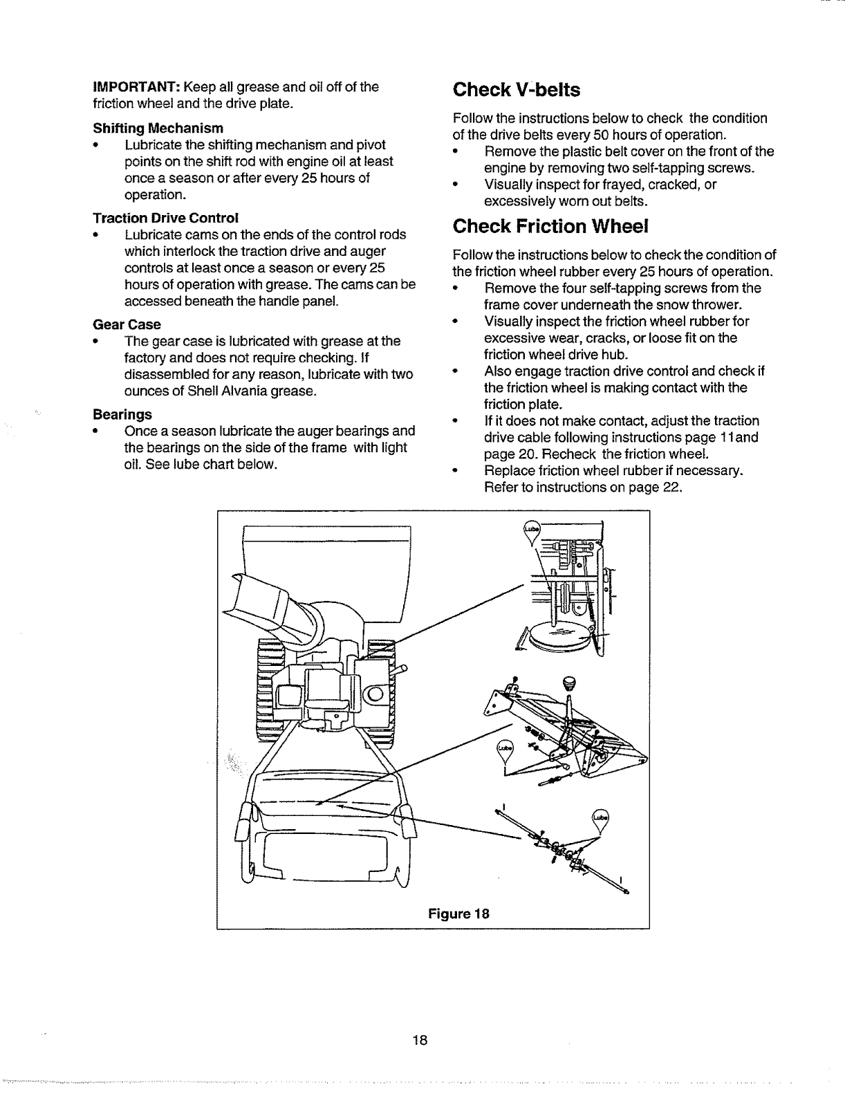
Lubrication
For a view of the lubrication points on the snow
thrower, see Figure 18.
Sprocket Shaft
• Lubricate the sprocket shaft with grease at least
once a season or after every 25 hours of operation.
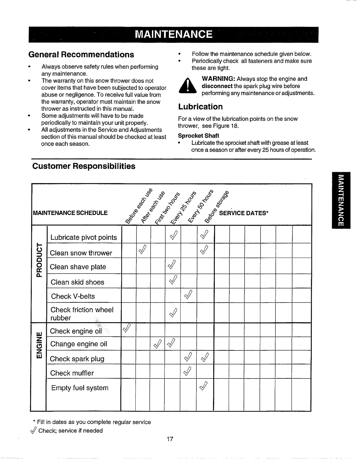
Customer Responsibilities
MAINTENANCE SCHEDULE ////
_o_e ,_ ._e _,,_,_ ,_o_SERVIOEDATES *
y..................................................
Lubricate pivot points
I--
0 Clean snow thrower <_
Clean shave plate
Clean skid shoes
Check V-belts <_
Check friction wheel
rubber
Check engine oil
ZChange engine oil _
Z
w Checkspark plug q_
Check muffler <_
Empty fuel system
* Fill in dates as you complete regular service
Check; service if needed
17
IMPORTANT:Keepallgreaseandoiloffofthe
frictionwheelandthedriveplate.
Shifting Mechanism
•Lubricate the shifting mechanism and pivot
points on the shift rod with engine oil at least
once a season or after every 25 hours of
operation.
Traction Drive Control
•Lubricate cams on the ends of the control rods
which interlock the traction drive and auger
controls at least once aseason or every 25
hours of operation with grease. The cams can be
accessed beneath the handle panel.
Gear Case
•The gear case is lubricated with grease at the
factory and does not require checking, tf
disassembled for any reason, lubricate withtwo
ounces of Shell AIvania grease.
Bearings
•Once aseason lubricate the auger bearings and
the bearings on the side of the frame with light
oil. See lube chart below.
Check V'belts
Follow the instructions below to check the condition
of the drive belts every 50 hours of operation.
• Remove the plastic belt cover on the front of the
engine by removing two self-tapping screws.
• Visually inspect for frayed, cracked, or
excessively worn out belts.
Check Friction Wheel
Follow the instructionsbelow to check the condition of
the friction wheel rubber every 25 hours of operation.
• Remove the four self-tapping screws from the
frame cover underneath the snow thrower.
• Visually inspect the friction wheel rubber for
excessive wear, cracks, or loose fit on the
friction wheel drive hub.
- Also engage traction drive control and check if
the friction wheel is making contact with the
friction plate.
• If it does not make contact, adjust the traction
drive cable following instructions page 11and
page 20. Recheck the friction wheei.
• Replace friction wheel rubber if necessary'.
Refer to instructions on page 22.
Figure 18
18
Engine Maintenance
Engine Oil
Only use high quality detergent oiI rated with API
service classification SF, SG or SH. Select the oil's
SAE viscosity grade according to the expected
operating temperature.
colder _ 32 ° _" warmer
!_llh.,,
5W30 _ I r SAE30
Viscosity Chart
NOTE: Although multi-viscosity oils (5W30, 10W30
etc.) improve starting in cold weather, these multi-
viscosity oils will result in increased oil consumption
when used above 32°F. Check your snow throwers
engine oil level more frequently to avoid possible
engine damage from running low on oil.
Refer to the viscosity chart for proper selection of
engine oil.
Checking Oil Level
Before operating the snow thrower, check the oil
level.
With engine on level ground, the oil must be to
FULL mark on dipstick.
Stop engine and wait several minutes before
checking oil level. Remove oil fill cap and
dipstick.
Wipe dipstick clean, insert it into oil fill hole and
tighten securely.
Remove dipstick and check. If oil is not up to the
FULL mark on dipstick, add 5W30 oil.
Changing Oil
Change engine oil after the first two hours of
operation and every 25 hours thereafter.
in order to do that you will have to first drain the spent
engine oil from the engine and then refill with fresh oil.
• Drain oil while engine is "warm. Remove oil drain
cap located at the bottom of the recoil starter of
the engine. Catch oil in a suitable container.
• When engine is drained of all oil, replace drain
plug securely.
• Remove the dipstick from the oil fill plug. For
location of the oil fill plug, see Figure 17. Pour
fresh oil stowiy through the plug. Replace
dipstick.
• Check and make sure that the level of oil is up to
the FULL mark on the dipstick,
WARNING; Temperature of muffler and
nearby areas may exceed 150 °F(65°0).
Avoid these areas.
Spark Plug
•Clean area around the spark plug base.
-Remove and inspect the spark plug.
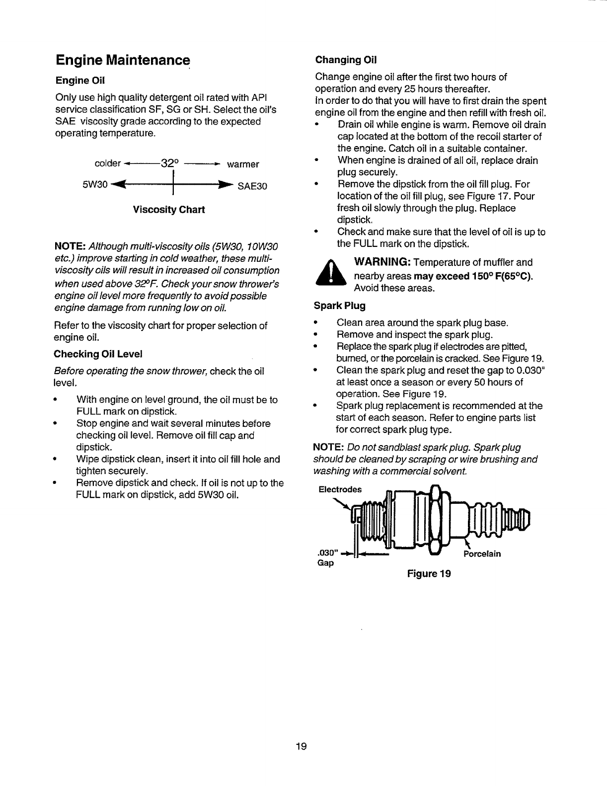
• Replace the spark plug ifelectrodes are pitted,
bumed, orthe porcelainis cracked. See Figure 19.
• Clean the spark plug and reset the gap to 0.030"
at least once aseason or every 50 hours of
operation. See Figure 19.
• Spark plug replacement is recommended at the
start of each season. Refer to engine parts list
for correct spark plugtype.
NOTE: Do not sandblast spark plug. Spark plug
should be cleaned by scraping or wire brushing and
washing with a commercial solvent.
Electrodes
Figure 19
Porcelain
19
WARNING: Always stop the engine, dis-
connect spark plug wire and move it away
from the spark plug before performing any
adjustments or repairs.
Never attempt to clean the chute or make
any adjustments while the engine is running.
Adjustments
Traction Drive Control
Refer to the Final Adjustment section of the Set-Up
Instructions to adjust the traction drive control. If you
are not sure of proper adjustment, check as follows.
• Drain the gasoline or place plastic film under the
gas cap if the snow thrower has already been
operated.
o Tip the snow thrower forward and remove the
four self-tapping screws that hold the frame
cover underneath the snow thrower.
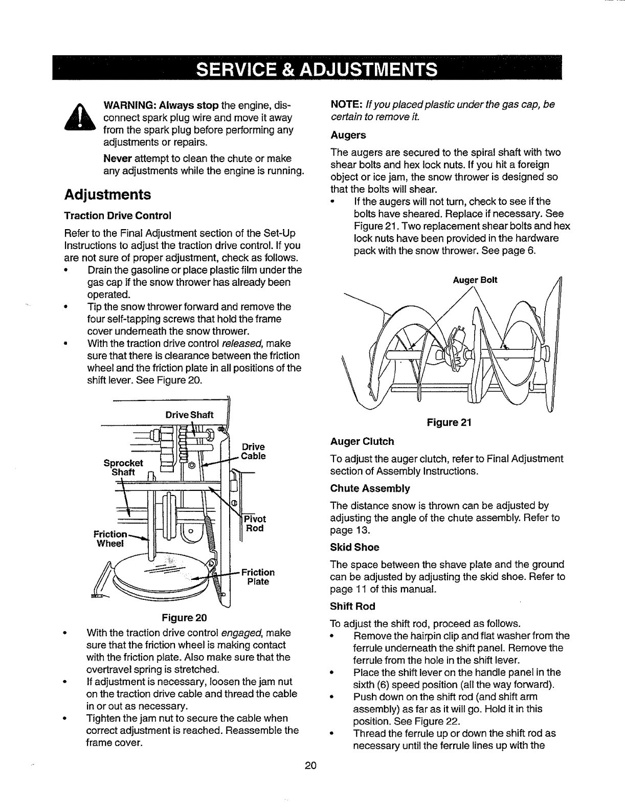
• With the traction drive control released, make
sure that there is clearance between the friction
wheel and the friction plate in all positions of the
shift lever. See Figure 20.
NOTE: If you placed plastic under the gas cap, be
certain to remove it.
Augers
The augers are secured to the spiral shaft with two
shear bolts and hex lock nuts. If you hit a foreign
object or ice jam, the snow thrower is designed so
that the bolts will shear.
• If the augers will not turn, check to see if the
bolts have sheared. Replace if necessary. See
Figure 21. Two replacement shear bolts and hex
lock nuts have been provided in the hardware
pack with the snow thrower. See page 6.
Auger Bolt
Drive Shaft
Sprocket
Shaft
Drive
Wheel
Pivot
Rod
Plate
Figure 20
With the traction drive control engaged, make
sure that the friction wheel is making contact
with the friction plate. Also make sure that the
overtravel spring is stretched.
If adjustment is necessary, loosen the jam nut
on the traction drive cable and thread the cable
in or out as necessary.
Tighten the jam nut to secure the cable when
correct adjustment is reached. Reassemble the
frame cover.
20
Figure 21
Auger Clutch
To adjust the auger clutch, refer to Final Adjustment
section of Assembly Instructions.
Chute Assembly
The distance snow is thrown can be adjusted by
adjusting the angle of the chute assembly. Refer to
page 13.
Skid Shoe
The space between the shave plate and the ground
can be adjusted by adjusting the skid shoe. Refer to
page 11 of this manual.
Shift Rod
To adjust the shift rod, proceed as follows.
•Remove the hairpin clip and flat washer from the
ferrule underneath the shift panel. Remove the
ferrule from the hole inthe shift lever.
°Place the shift lever on the handle panel in the
sixth (6) speed position (all the way forward).
° Push down on the shift rod (and shift arm
assembly) as far as it will go. Hold it in this
position. See Figure 22.
• Thread the ferrule up or down the shift rod as
necessary until the ferrule lines up with the
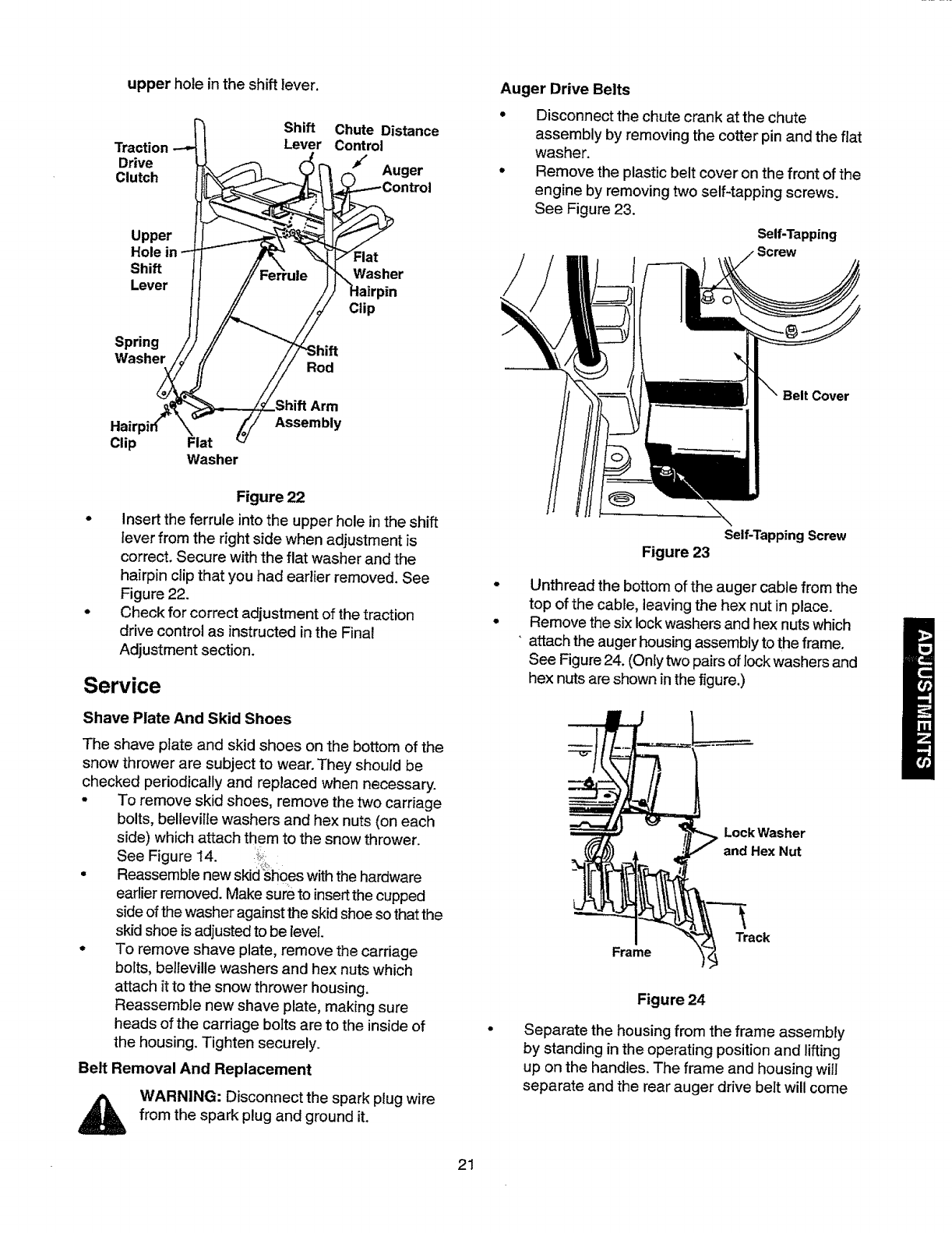
upper hole in the shift lever,
Traction
Drive
Clutch
Shift
Lever Chute Distance
Control
Auger
Upper
Hole
Shift
Lever
Spring
Washer Rod
Flat
Washer
Clip
Hair
Clip Fiat
Washer
Arm
Assembly
Figure 22
Insert the ferrule into the upper hole inthe shift
lever from the right side when adjustment is
correct. Secure with the flat washer and the
hairpin clip that you had earlier removed. See
Figure 22.
Check for correct adjustment of the traction
drive control as instructed in the Final
Adjustment section.
Service
Shave Plate And Skid Shoes
The shave plate and skid shoes on the bottom of the
snow thrower are subject to wear. They should be
checked periodically and replaced when necessary.
•To remove skid shoes, remove the two carriage
bolts, bellevilte washers and hex nuts (on each
side) which attach them to the snow thrower.
See Figure 14. _z,_:
• Reassemble new skid_shoes with the hardware
earlier removed. Make sure to insert the cupped
side of the washer against the skid shoe so that the
skid shoe is adjusted to be level.
• To remove shave plate, remove the carriage
bofts, belleville washers and hex nuts which
attach it to the snow thrower housing.
Reassemble new shave plate, making sure
heads of the carriage bolts are to the inside of
the housing. Tighten securely.
Belt Removal And Replacement
WARNING: Disconnect the spark plug wire
from the spark plug and ground it.
Auger Drive Belts
•Disconnect the chute crank at the chute
assembly by removing the cotter pin and the flat
washer.
•Remove the plastic belt cover on the front of the
engine by removing two self-tapping screws.
See Figure 23.
Self-Tapping
'ew
Belt Cover
°
°
Self-Tapping Screw
Figure 23
Unthread the bottom of the auger cable from the
top of the cable, leaving the hex nut in place.
Remove the six lock washers and hex nuts which
"attach the auger housing assembly to the frame.
See Figure 24. (Only two pairs of lock washers and
hex nuts are shown in the figure.)
Lock Washer
and Hex Nut
Frame Track
Figure 24
Separate the housing from the frame assembEy
by standing in the operating position and lifting
up on the handles. The frame and housing will
separate and the rear auger drive belt will come
21

offthepulleys.SeeFigure25.
FrontAuger
Drive Belt
\_pulley
Figure 25
To remove the front auger drive belt, push the
idler pulley to the left and lift front auger drive
be]t from the front auger pulley. See Figure 25.
Replace both auger drive belts by following the
preceding instructions.
NOTE: When reassembling the two halves of the unit,
make sure that the auger drive cable is routed
through the cable roller guide.
Drive Belt
o
o
o
o
Remove the plastic belt cover on the front of the
engine by removing the two self-tapping screws.
See Figure 23.
Drain the gasoline from the snow thrower, or
place a piece of plastic under the gas cap.
Tip the snow thrower up and forward so that it
rests on the auger housing.
Remove four self-tapping screws from the frame
cover underneath the snow thrower.
Pulling the idler pulley upward, roll the belt off
the idler pulley and the engine pulley and lift belt
off friction wheel disc. See Figure 26.
Removeold
belt from
here
F_iction
Wheel
o
o
Support
Bracket
Figure 26
Back out the stop bolt untilthe support bracket
drops on the auger pulley. See Figure 26.
Slip belt between friction wheel and friction disc
plate and remove the belt. See Figure 26.
Reassemble with new drive belt.
22
NOTE: The support bracket must rest on the stop bolt
afterthe new belt has been assembled. See Figure 26.
Friction Wheel Rubber
The rubber on the friction wheel is subject to wear and
should be checked after the first 25 hours of operation
and periodically thereafter. Replace the fdction wheel
rubber if any signs of wear or cracking are found.
• Drain the gasoline from the snow thrower, or
place a piece of plastic under the gas cap.
°Tip the snow thrower up and forward, so that it
rests on the housing.
•Remove four self-tapping screws from the
frame cover underneath the snow thrower.
° Using a 7/8" wrench to hold the shaft, loosen,
but do not completely remove, the hex bolt and
bell washer from the left end of the shaft. See
Figure 27.
f
Hex Bolt, 0
BellWasher
Figure 27
Move the weight transfer lever to the packed
snow position. Refer to Figure 16.
Lightly tap the head of the bolt to dislodge the
batl bearing from the right side of the frame; then
remove the hex bolt and the bell washer from left
end of the shaft.
Sliding the shaft to the right, remove the spacer,
the sprocket and the friction wheel assembly
from the shaft. See Figure 28.
Remove the six screws from the friction wheel
assembly (three from each side). Remove the
friction wheel rubber from between the friction
wheel plate.
Reassemble the new friction wheel rubber to the
friction wheel assembly tightening the six screws
in rotation and with equal force.
Position the friction wheel assembly up onto the
pin of the shift rod assembly and slide the shaft
through the friction wheel. See Figure 28.
Slide the shaft into the hex I.D. of the sprocket,
the spacer and the left ball bearing and secure
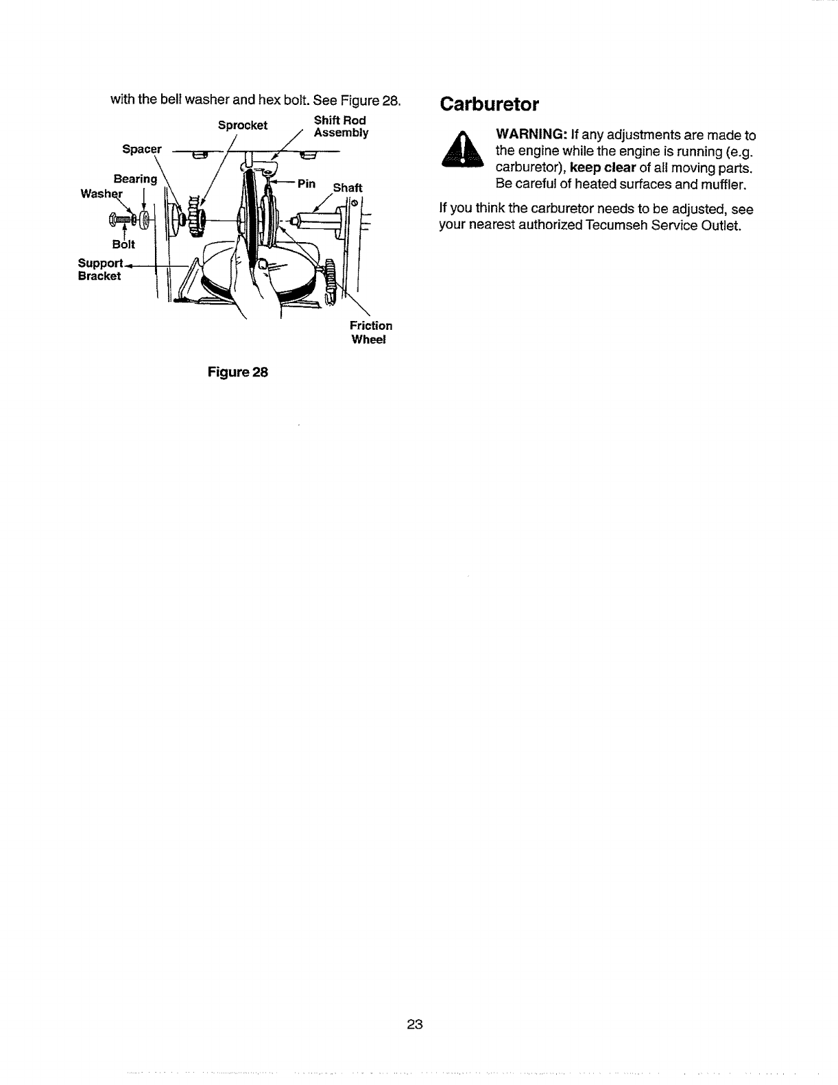
with the bell washer and hex bolt. See Figure 28.
Sprocket Shift Rod
Assembly
Spacer
Bearing
Washe_ Shaft
Carburetor
WARNING: If any adjustments are made to
the engine while the engine is running (e.g.
carburetor), keep clear of att moving parts.
Be careful of heated surfaces and muffler.
If you think the carburetor needs to be adjusted, see
your nearest authorized Tecumseh Service Outlet.
Bracket
Figure 28
Friction
Wheel
23
Ifyoursnowthrowerisleftunusedfor30daysor
longer,it needsto bepreparedforstorage.Also,at
theendofthesnowseason,youshouldfollowthe
samesetofinstructionsandstorethesnowthrower
properlyfortheoff-season.Properstorageensures
longerlifeofthesnowthrower.
Preparing Engine
WARNING: Never store snow th rower with
fuel in tank indoors or in poorly ventilated
areas, where fuel fumes may reach an open
flame, spark or pilot light as on a furnace,
water heater, clothes dryer or gas
appliance.
It is important to prevent gum deposits from
forming in essential fuel system parts of the
engine such as the carburetor, fuel fiIter,
fuel hose or tank during storage.
Also experience indicates that alcohol
blended fuels (called gasohol or using
ethanol or methanol) can attract moisture
which leads to separation and formation of
acids during storage. Acidic gas can
damage the fuet system of an engine while
in storage.
To avoid engine problems, the fuel system shouldbe
emptied before storage for 30 days or longer. Follow
these instructions to prepare your snow thrower for
storage:
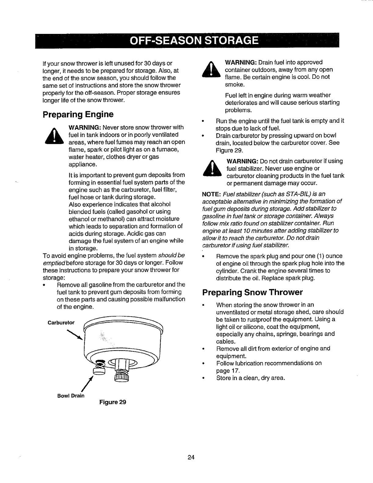
• Remove all gasoline from the carburetor and the
fuel tank to prevent gum deposits from forming
on these parts and causing possible malfunction
of the engine.
WARNING: Drain fuel into approved
container outdoors, away from any open
flame. Be certain engine is cool. Do not
smoke.
Fuel left inengine during warm weather
deteriorates and will cause serious starting
problems.
Run the engine until the fuel tank is empty and it
stops due to lack of fuel.
Drain carburetor by pressing upward on bowl
drain, located below the carburetor cover. See
Figure 29.
WARNING: Do not drain carburetor if using
fueI stabilizer. Never use engine or
carburetor cleaning products inthe fuel tank
or permanent damage may occur.
NOTE: Fuel stabilizer (such as STA-BIL) is an
acceptable alternative in minimizing the formation of
fue! gum deposits during storage. Add stabilizer to
gasoline in fuel tank or storage container. Always
follow mix ratio found on stabilizer container. Run
engine at least 10 minutes after adding stabilizer to
allow it to reach the carburetor. Do not drain
carburetor if using fuel stabilizer.
Remove the spark plug and pour one (1) ounce
of engine oil through the spark plug hole into the
cylinder. Crankthe engine several times to
distribute the oil. Replace spark plug.
Preparing Snow Thrower
When storing the snow thrower in an
unventilated or metal storage shed, care should
be taken to rustproof the equipment. Using a
light oil or silicone, coat the equipment,
especially any chains, springs, bearings and
cables.
Remove all dirt from exterior of engine and
equipment.
Follow lubrication recommendations on
page 17.
Store in a clean, dry area.
Bowl Drain
Figure 29
24
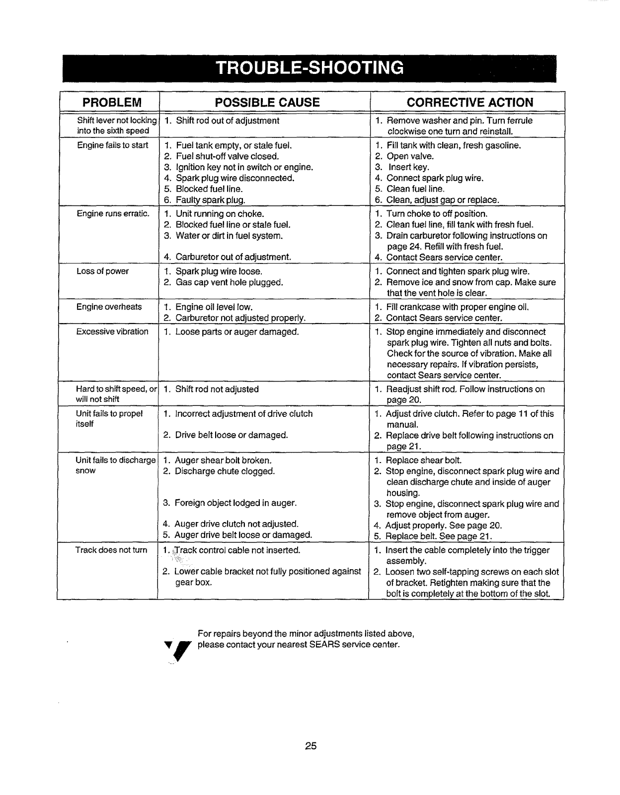
PROBLEM POSSIBLE CAUSE CORRECTIVE ACTION
1. Shift rod out of adjustment ........i. Remove washer and pin. Turn ferrule
clockwise one turn and reinstall.
Shift lever noi locking
into the sixth speed
Engine fails to start
Engine runs erratic.
1. Fuel tank empty, or stale fuel, 1,
2. Fuel shut-off valve closed. 2.
&ignition key not in switch or engine. 3.
4. Spark plug wire disconnected. 4.
5. Blocked fuel line. 5.
6. Faulty spark plug. .6.
1. Unit running on choke. 1.
2. Blocked fuel lineor stale fuel. 2.
3. Water or dirt in fuel system. 3.
............. 4. Carburetor out 0! adjustment.
Loss of power 1. Spark plug wire loose.
2. Gas cap vent hole plugged.
Engine overheats 1. Engine oil level low.
2. Carburetor not adjusted properly.
Excessive vibration 1. Loose parts or auger damaged,
Hard to shift speed, or 1. Shift rod not adjusted
willnot shift
............ L,,
Unit fails to propel 1.
itself
2.
Unit fails to discharge 1.
snow 2.
3.
4.
5.
Track does not turn
4.
1.
2.
.
2.
1.
1÷
incorrect adjustment of drive clutch 1.
Drive belt loose or damaged.
AugershearboJibroken.
Discharge chute clogged.
Foreign object lodged in auger.
2,
1.
2.
3.
Auger drive clutch not adjusted. 4.
Auger drive belt loose or damaged. 5.
1. :,Track control cable not inserted. 1.
2. Lower cable bracket not fully positioned against 2.
gear box.
Fill tank with clean, fresh gasoline,
Open valve.
Insert key.
Connect spark plug wire,
Clean fuel line.
Clean, adjus t ga#....orreplace.. .............
Turn choke to off position.
Clean fuel line, fill tank with fresh fuel.
Drain carburetor following instructions on
page 24. Refill with fresh fuel.
Contact Sears service center.
Connect and tighten spark plug wire.
Remove ice and snow from cap. Make sure
that the vent hole is clear.
Fill crankcase with proper engine oil,
Contact Sears service center.
Stop engine immediately and disconnect
spark plug wire. Tighten all nuts and bolts.
Check for the source of vibration. Make all
necessary repairs. If vibration persists,
contact Sears service center.
Readjust shift rod. Foilow instructions on
page 20. ..................
Adjust drive clutch. Refer to page 11 of this
manual.
Replace drive belt following instructions on
..page 21.. ..................................
Replace shear bolt.
Stop engine, disconnect spark plug wire and
clean discharge chute and inside of auger
housing.
Stop engine, disconnect spark plug wire and
remove object from auger.
Adjust properly. See page 20.
Replace belt. See page 21.
Insert the cable completeiy into the trigger
assembly.
Loosen two self-tapping screws on each slot
of bracket. Retighten making sure that the
bolt is completely at the bottom of the slot.
For repairs beyond the minor adjustments listed above,
Yf please contact your nearest SEARS service center.
'IF
25
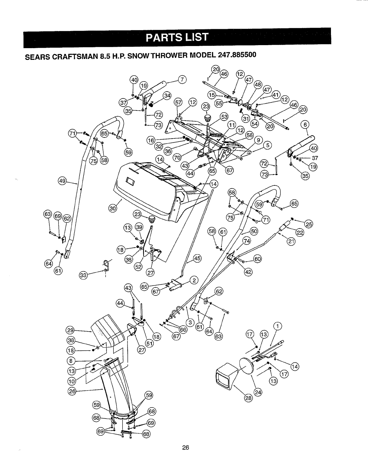
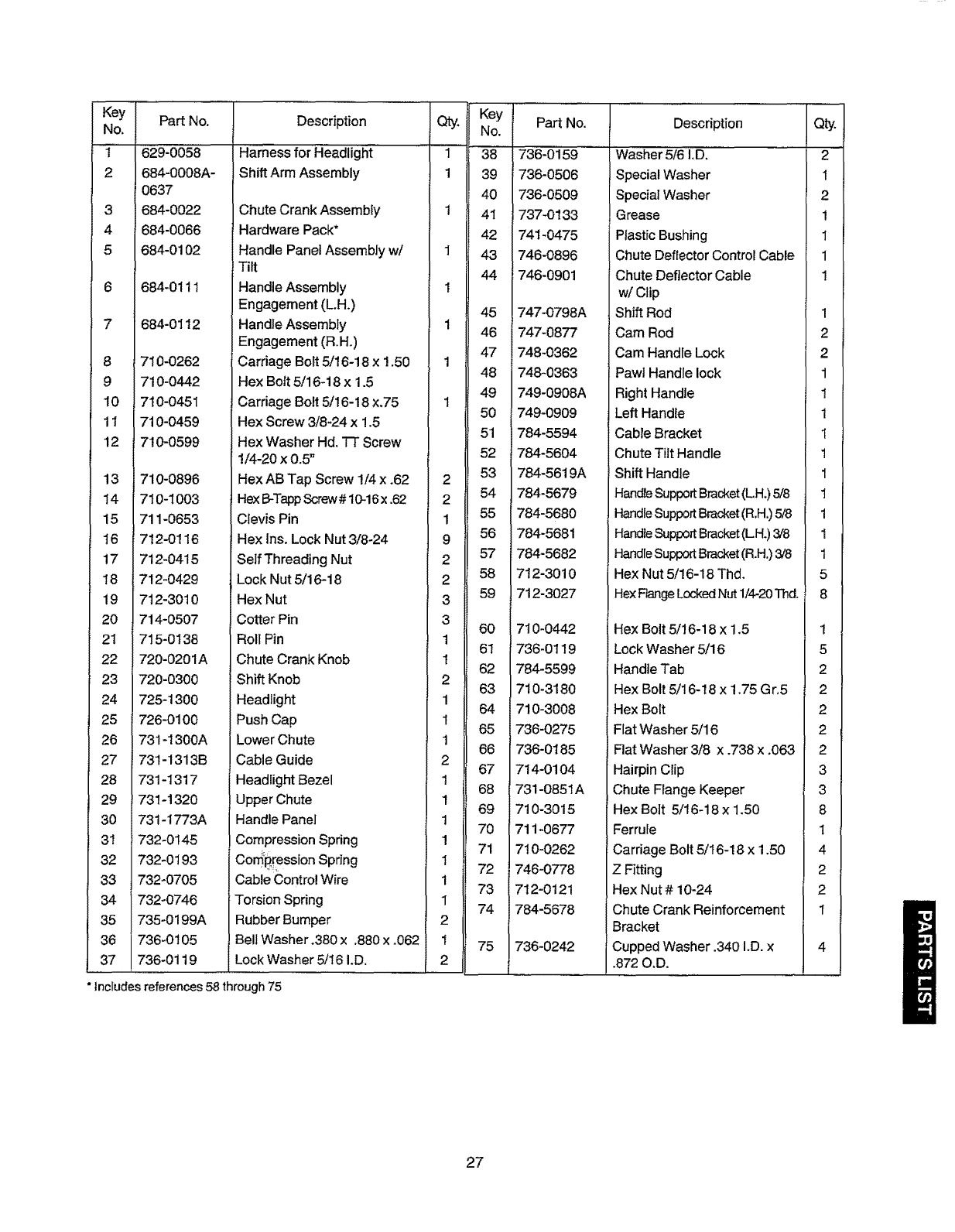
SEARS CRAFTSMAN 8.5 H.P. SNOWTHROWER MODEL 247.885500
-O
@
26
Key
No.
1
2
3
4
5
7
8
9
10
11
12
Part No.
629-0058
684-0008A-
0637
684-0022
684-0066
684-0102
684-0111
684-0112
710-0262
710-0442
710-045I
710-0459
710-0599
13 710-0896
14 710-1003
15 711-0653
16 712-0116
17 712-0415
18 712-0429
19 712-3010
20 714-0507
21 715-0138
22 720-0201A
23 720-0300
24 725-1300
25 726-0100
26 731-1300A
27 731-1313B
28 731-1317
29 731-1320
30 731-I773A
31 732-0145
32 732-0193
33 732-0705
34 732-0746
35 735-0199A
736-0105
736-0119
Description
Shift Arm Assembly
Chute Crank Assembly
Hardware Pack*
Handle Panel Assembly w/
Tilt
Handle Assembly
Engagement (LH.)
Handle Assembly
Engagement (R.H.)
Carriage Bolt 5/16-18 x 1.50
Hex Bolt 5/16-18 x 1.5
Carriage Bolt 5/16-18 x.75
Hex Screw 3/8-24 x 1.5
Hex Washer Hd. TT Screw
1/4-20 x 0.5 _
Hex AB Tap Screw 1/4 x .62
Hex B-TappScrew# 10-16x .62
Clevis Pin
Hex lns. Lock Nut 3/8-24
Self Threading Nut
Lock Nut 5/16-18
Hex Nut
Cotter Pin
Roll Pin
Chute Crank Knob
Shift Knob
Headlight
Push Cap
Lower Chute
Cable Guide
Headlight Bezel
Upper Chute
Handle Panel
Compression Spring
Con_Rression Spring
Cable Control Wfre
Torsion Spring
Rubber Bumper
Bell Washer .380 x .880 x .062
Lock Washer 5/16 I.D.
Qty.
1
1
1
1
1
1
1
1
2
2
1
9
2
2
3
3
1
1
2
1
1
1
2
1
1
1
1
1
1
1
2
1
2
Key
No.
38
39
40
41
42
43
44
45
46
47
48
49
5O
51
52
53
54
55
56
57
58
59
60
61
62
63
64
65
66
67
68
69
70
71
72
73
74
75
Part No.
736-0i'59 ...................
736-0506
736-0509
737-0133
741-0475
746-0896
746-0901
747-0798A
747-0877
748-0362
748-0363
749-0908A
749-0909
784-5594
784-5604
784-5619A
784-5679
784-5680
i784-5681
!784-5682
712-3010
712-3027
710-0442
736-0119
784-5599
710-3180
710-3008
736-0275
736-0185
714-0104
731-0851A
710-3015
711-0677
710-0262
746-0778
712-0121
784-5678
736-0242
Description
Washer 5/6 I.D. .........
Special Washer
Special Washer
Grease
Plastic Bushing
Chute Deflector Control Cable
Chute Deflector Cable
w/Clip
Shift Rod
Cam Rod
Cam Handle Lock
Pawl Handle lock
Right Handle
Left Handle
Cable Bracket
Chute Tilt Handle
Shift Handle
HandleSupportBracket(LH.) 5/8
HandleSupportBracket(R.H.)5/8
HandleSupportBracket(LH.) 3/8
HandleSupportBracket(R.H.)3/8
Hex Nut 5/16-18 Thd.
Hex Range LockedNut 1/4-20Thd.
Hex Bolt 5/16-18 x 1.5
Lock Washer 5/16
Handle Tab
Hex Bolt 5/16-18 x 1.75 Gr,5
Hex Bolt
Flat Washer 5/16
Flat Washer 3/8 x .738 x .063
Hairpin Clip
Chute Flange Keeper
Hex Bolt 5/16-18 x 1.50
Ferrule
Carriage Bolt 5/16-18 x 1.50
Z Fitting
Hex Nut # 10-24
Chute Crank Reinforcement
Bracket
Cupped Washer .340 I.D. x
.872 O.D.
"Includes references 58 through 75
Qty.
2
1
2
1
1
1
1
1
2
2
1
1
1
1
1
1
1
1
1
1
5
8
1
5
2
2
2
2
2
3
3
8
1
4
2
2
1
27
@
@@
28
Key
No,
1
2
3
4
7
9
10
12
14
17
18
19
2O
21
22
23
24
25
27
28
29
3O
33
36
37
38
39
40
Part No.
611-0053
618-0043
618-0O44
618-0169
683-OO24
684-0014B
684-0021
684-0031
684-0042B
710-0538
710-0599
710-0602
710-0604
710-0654A
710-0788
710-0809
710-0875
710-0896
710-1233
711-0911
711-!042
712-0127
712-0324
712-0711
713-0233
713-0413
713-0437
714-0474
Description
Axle Assembly
Dogg Assembly: R,H.
Dogg Assembly: L,H.
Shift Assembly: Track Drive
Hub Assembly: Track Drive
Shift Rod Assembly
Friction Wheer Support
Bracket Assembly
Frame Assembly
Friction Wheel Bearing
Assembly
Hex Lock Screw 5/16-18 x
.625 Grade 5
Hex Washer Hd, TT Screw
Hex Washer Hd, TT Screw
Hex Washer Hd. TT Screw
Hex Washer Hd, TT Screw
Hex Washer Screw
Hex Washer Screw
TT Screw
Hex Washer Head AB Screw
Oval C-Sunk Screw
Actuator Shaft
Hex Shaft: Track Drive
Flanged Weld Nut #10-24
Top Lock Nut 1/4-20
Jam Nut 3/8-24
Chain Links
Sprocket: 10T
Chain
Cotter Pin
Qty, Key Pa_ No.
No.
2 719-0295A!
1 725-0157
1 732-0209
1 732-0264
2 736-0105
1 _736-0160
1 736-0176
736-O242
'736-O270
736-0287
738-0924
741-0339
741-0563
741-0597
746-0897
746-0898
746-0948
746-0950
748-0190
748-0234
750-0903
750-0904
750-0997
756-0625
784-5590
784-5609
784-5648
784-5687
784-5688
784-5689A
41
43
46
47
48
49
5O
51
1 52
1 54
58
4 59
6O
261
862
663
464
165
166
267
10 70
271
174
175
276
177
18O
18I
182
283
1
84
Description
710-0371
Track Housing
Cable Tie
Extension Spring
Extension Spring
Berl Washer
Flat Washer
Fiat Washer
Bell Washer
Bell Washer
Flat Washer
Shoulder Screw
Flange Bearing
Ball Beadng
Hex Flange Bearing
Auger Clutch Cable
Drive Clutch Cable
Track Steering Cable
Trigger Control
Spacer
Shoulder Spacer
Split Spacer
Split Spacer
Spacer
Roller Cable
Shift Bracket
Steering Cable Bracket
Frame Cover
Auger Clutch Cable Bracket
Drive cabJe Bracket
Front Support Bracket
He× Screw
Qty,
1
2
2
1
1
1
2
5
2
2
3
4
2
2
1
1
2
2
1
2
2
1
1
3
1
1
1
1
1
1
2
29
®
®@®
®
®
®
3O
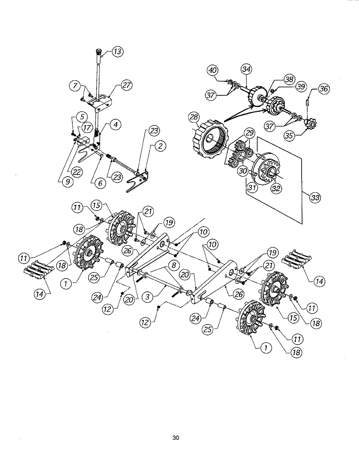
Key
NO.
t
2
3
4
5
6
7
8
9
11
12
13
14
15
17
18
19
20
21
22
Part No,
631-0032
684-0009
684-0024
684-0038
710-0157
710-0459
710-0604
710-1231
712-02t 4
712-0346
712-0429
720-0223
731 -1292
731-1538A
736-0242
736-0272
736-0406
737-017O
738-0140
748-0353A
Description
wheel Assembly idler
Rod Track Pivot
Axle Assembly
Handle Assembly
Screw
Screw
Screw
Screw
Lock Nut
Jam Nut
Hex Nut
Grip
Track
Wheel-Track Drive
Qty.
2
1
1
1
1
1
2
2
1
4
6
1
2
2
Key
No.
23
24
25
26
27
28
29
30
31
32
33
34
35
36
Part No.
750-0547
750-0909
750-0995
784-5639-048_
784-5642
717-1211
717-1209
717-1210
741-0542
718-0188
618-0046
711-0912
713-0414
715-0120
Description
Spacer
Spacer
Spacer
Plate-Track Side
Plate-Track Lockout
Gear Ring
Gear 12-Tooth
Gear 18-Tooth
Pin Dowel
Carrier
Carrier Assembly
Shaft--Track Drive
Sprocket--13 Tooth
Spring Pin
Bell Washer
Flat Washer
Flat Washer
Lubricant
Shoulder Screw
Lift-Shaft Drive
1
4
4
1
4
1
37 736-0502
38 736-0336
39 716-0115
40 716-0114
Flat Washer
Flat Washer
Snap Ring ,625" Shaft
Snap Ring .56" Shaft
Qty,
2
2
2
2
1
2
6
2
6
2
2
1
1
1
6
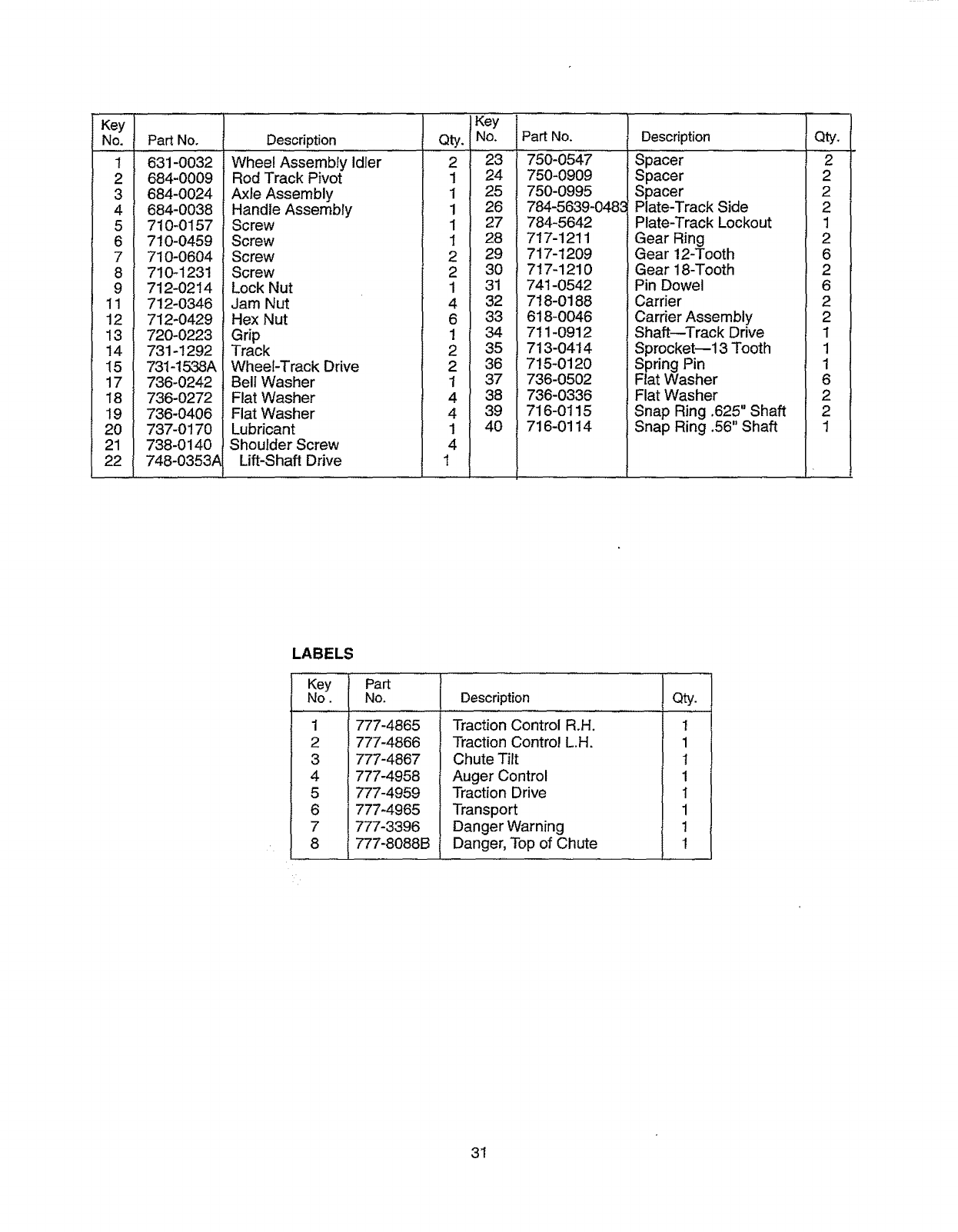
LABELS
Key
No.
1
2
4
5
8
Pan
No.
777-4865
777-4866
777-4867
777-4958
777-4959
777-4965
777-3396
777-8088B
Description
Traction Control R.H,
Traction Control L.H.
Chute Tilt
Auger Control
Traction Drive
Transport
Danger Warning
Danger, Top of Chute
Qty.
1
1
!
1
1
1
1
1
31
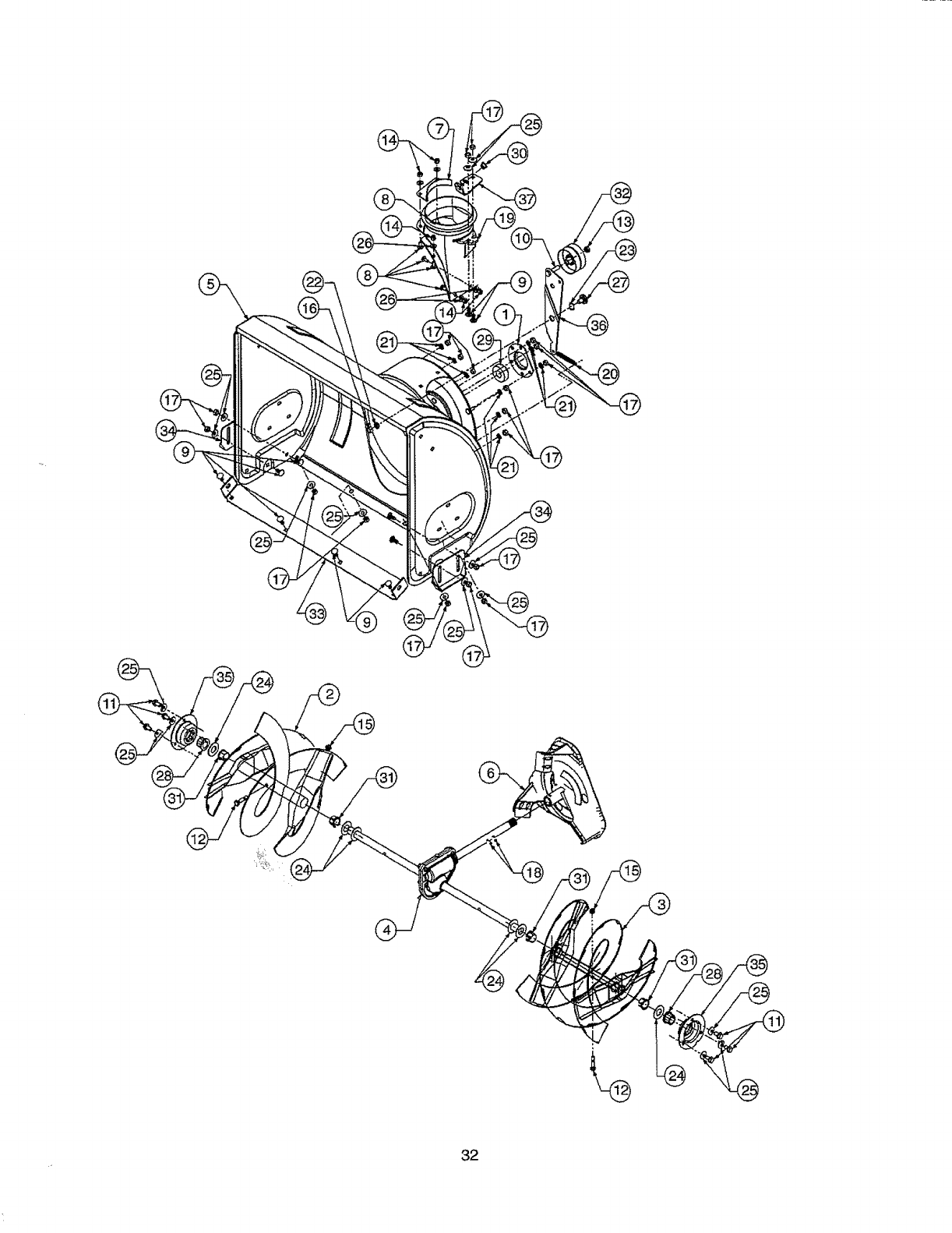
82
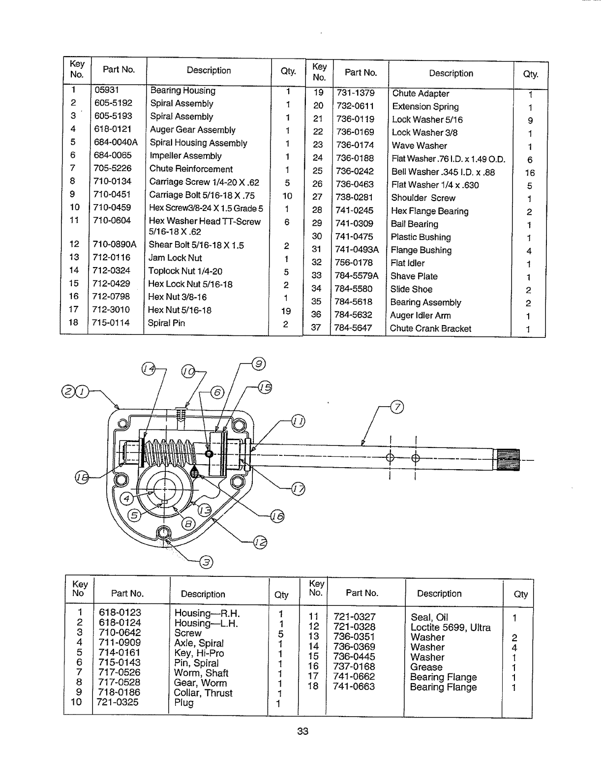
Key
No.
1
2
3
4
5
6
7
8
9
10
11
Part No.
05931
605-5192
605-5193
618-0121
684-0040A
684-0065
705-5226
710-0134
710-0451
710-0459
710-0604
12 710-0890A
13 712-0116
14 712-0324
15 712-0429
16 712-0798
17 712-3010
18 ,715-0t14
Key
Description Qty. No.
Bearing Housing 1 19
Spiral Assembly I 20
Spiral Assembly 1 21
Auger Gear Assembly 1 22
Spiral Housing Assembly 1 23
Impeller Assembly 1 24
Chute Reinforcement 1 25
Carriage Screw 1/4-20 X .62 5 26
Carriage Bolt 5/16-18 X .75 10 27
Hex Screw3!8-24 X 1.5 Grade 5 1 28
Hex Washer Head TT-Screw 6 29
5/16-18 X .62 30
Shear Bolt 5/t6-!8 X 1.5 2 31
Jam Lock Nut 1 32
Toplock Nut 1/4-20 5 33
Hex Lock Nut 5/16-18 2 34
Hex Nut 3/8-16 1 35
Hex Nut 5/16-18 19 36
Spiral Pin 2 37
Part No.
731-1379
732-0611
736-01t9
736-0169
736-0174
736-0188
736-0242
736-0463
738-0281
741-0245
741-0309
741-0475
741-0493A
756- 0178
784-5579A
784-5580
784-5618
784-5632
784-5647
Description
Chute Adapter
Extension Spring
Lock Washer 5/16
Lock Washer 3/8
Wave Washer
Flat Washer.76 I.D. x 1.49 O.D.
Bell Washer .345 I.D. x .88
Flat Washer 1/4 x .630
Shoulder Screw
Hex Flange Bearing
Ball Bearing
Plastic Bushing
Flange Bushing
Flat Idler
Shave Plate
Slide Shoe
Bearing Assembly
Auger Idler Arm
Chute Crank Bracket
Qty.
1
1
9
1
1
6
16
5
1
2
1
1
4
1
1
2
2
1
1
•]
¢--÷
t J
Key
No
1
2
3
4
5
6
9
lO
l Part No.
618-0123
618-0124
710-0642
711-0909
714-0161
715-0143
717-0526
717-0528
718-0186
721-0325
Description
Housing--R.H.
Housing--L.H.
Screw
Axle, Spiral
Key, Hi-Pro
Pin, Spiral
Worm, Shaft
Gear, Worm
Collar, Thrust
Plug
Qty
t
1
1
1
1
1
1
1
Key
No.
11
12
13
14
t5
16
17
18
Part No.
721-0327
721 -O328
736-0351
736-0369
736-0445
737-0168
741-0662
741-0663
Description
Seal, Oil
Loctite 5699, Ultra
Washer
Washer
Washer
Grease
Bearing Flange
Bearing Flange
I Qty
1
2
4
1
1
1
1
33
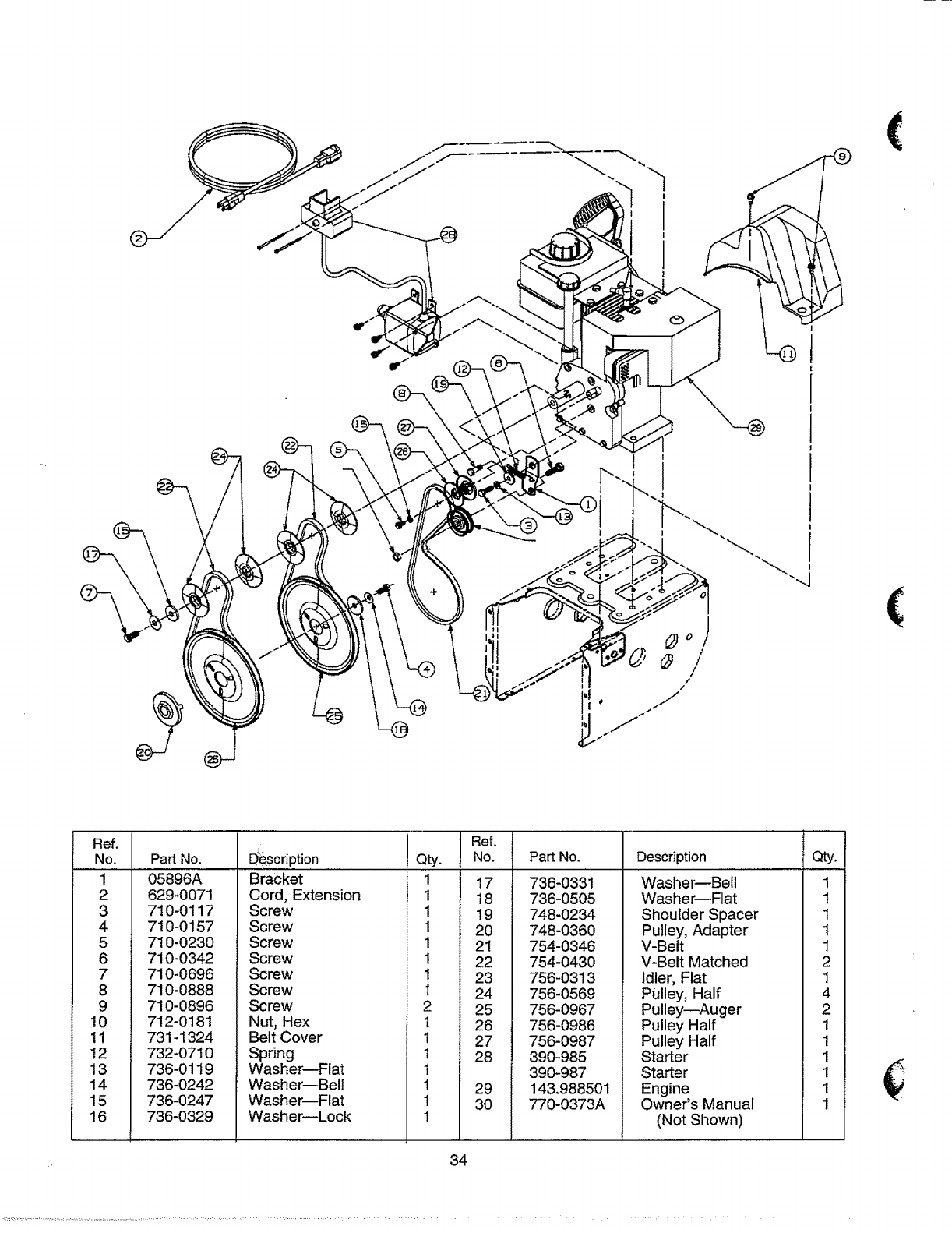
"h
|
I
I
1
!
(
1
!
| I
)(
Ref.
NO.
1
2
3
4
5
6
7
8
9
10
11
12
13
14
15
16
Part No.
05896A
629_0071
710-0117
710-0157
710-0230
710-0342
710-0696
710-0888
710-0896
712-0181
731-1324
732-0710
736-0119
736-0242
736-0247
736-0329
D_esonption....
Bracket
Cord, Extension
Screw
Screw
Screw
Screw
Screw
Screw
Screw
Nut, Hex
Belt Cover
Spring
Washer--Flat
Washer--Bell
Washer--Flat
Washer--Lock
Qty.
Ref,
No.
1
1
1
1
1
1
1
1
2
1
1
1
1
1
1
I
Part No.
17 736-0331
18 736-0505
19 748-0234
20 748-0360
21 754-0346
22 754-0430
23 756-0313
24 756-0569
25 756-0967
26 756-0986
27 756-0987
28 390-985
390-987
29 143.988501
30 770-0373A
Description
Washer--Bell
Washer--Flat
Shoulder Spacer
Pu]Iey, Adapter
V-Belt
V-Belt Matched
Idler, Flat
Pulley, Half
Pulleys--Auger
Pulley Half
Pulley Half
Starter
Starter
Engine
Owner's Manual
(Not Shown)
Qty.
1
1
1
1
1
2
1
4
2
1
1
1
1
1
1
34
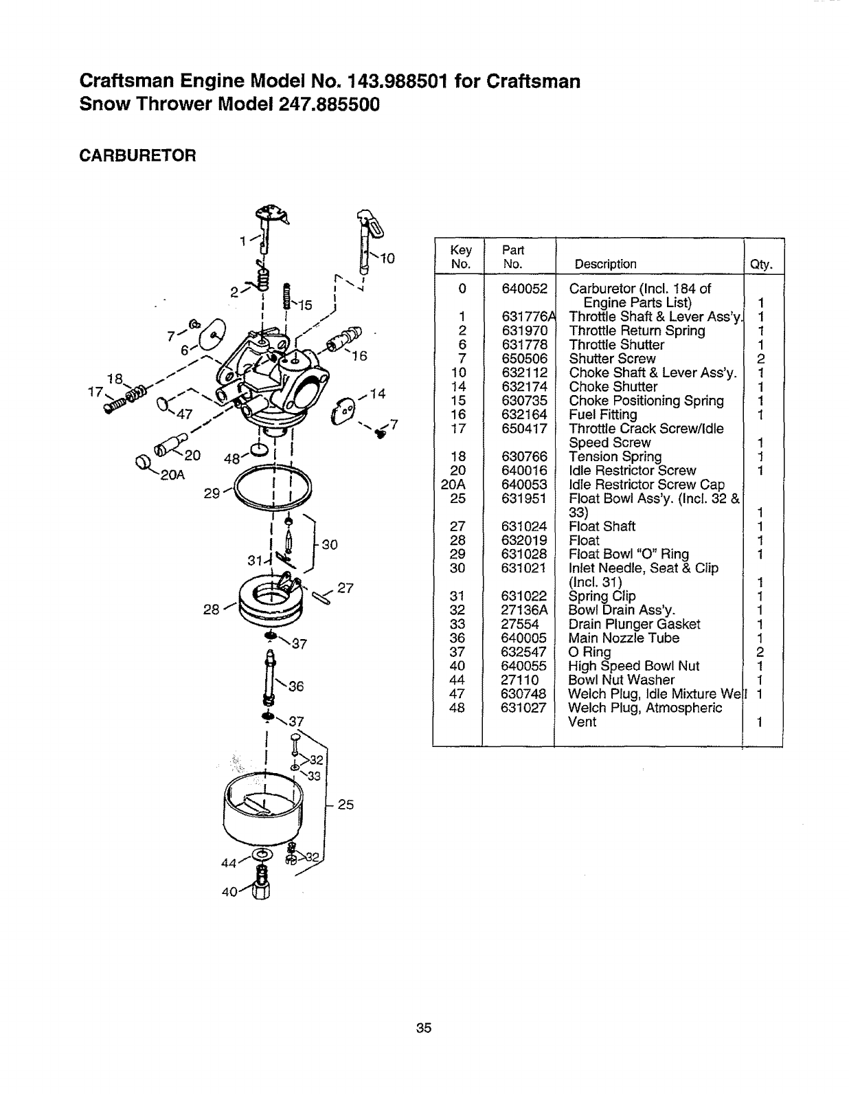
Craftsman Engine Model No. 143.988501 for Craftsman
Snow Thrower Model 247.885500
CARBURETOR
I
I 30
28 27
z_iL 1
4o_ _
Key Part
No. No, Description Qty.
0 640052
1 631776#
2 631970
6 631778
7 650506
10 632112
14 632174
15 630735
16 632164
17 65O417
18 63O766
20 640016
20A 640053
25 631951
27 631024
28 632019
29 631O28
30 631021
31 631O22
32 27136A
33 27554
36 640005
37 632547
40 640055
44 27110
47 630748
48 631027
Carburetor (Incl. 184 of
Engine Parts List)
Throttle Shaft & Lever Ass'y
Throttle Return Spring
Throttle Shutter
Shutter Screw
Choke Shaft & Lever Ass'y.
Choke Shutter
Choke Positioning Spring
Fuel Fitting
Throttle Crack Screw/Idle
Speed Screw
Tension Spring
Idle Restrictor Screw
Idle Restrictor Screw Cap
Float Bowl Ass'y. (Incl. 32 &
33)
Float Shaft
Float
Float Bowl "O" Ring
Inlet Needle, Seat & Clip
(Incl. 3I)
Spring Clip
Bowl Drain Ass'y.
Drain Plunger Gasket
Main Nozzle Tube
O Ring
High Speed Bowl Nut
Bowl Nut Washer
Welch Plug, Idle Mixture We
Welch Plug, Atmospheric
Vent
1
1
1
1
2
1
1
1
1
1
1
1
1
1
1
1
1
1
1
1
1
2
1
I
1
35
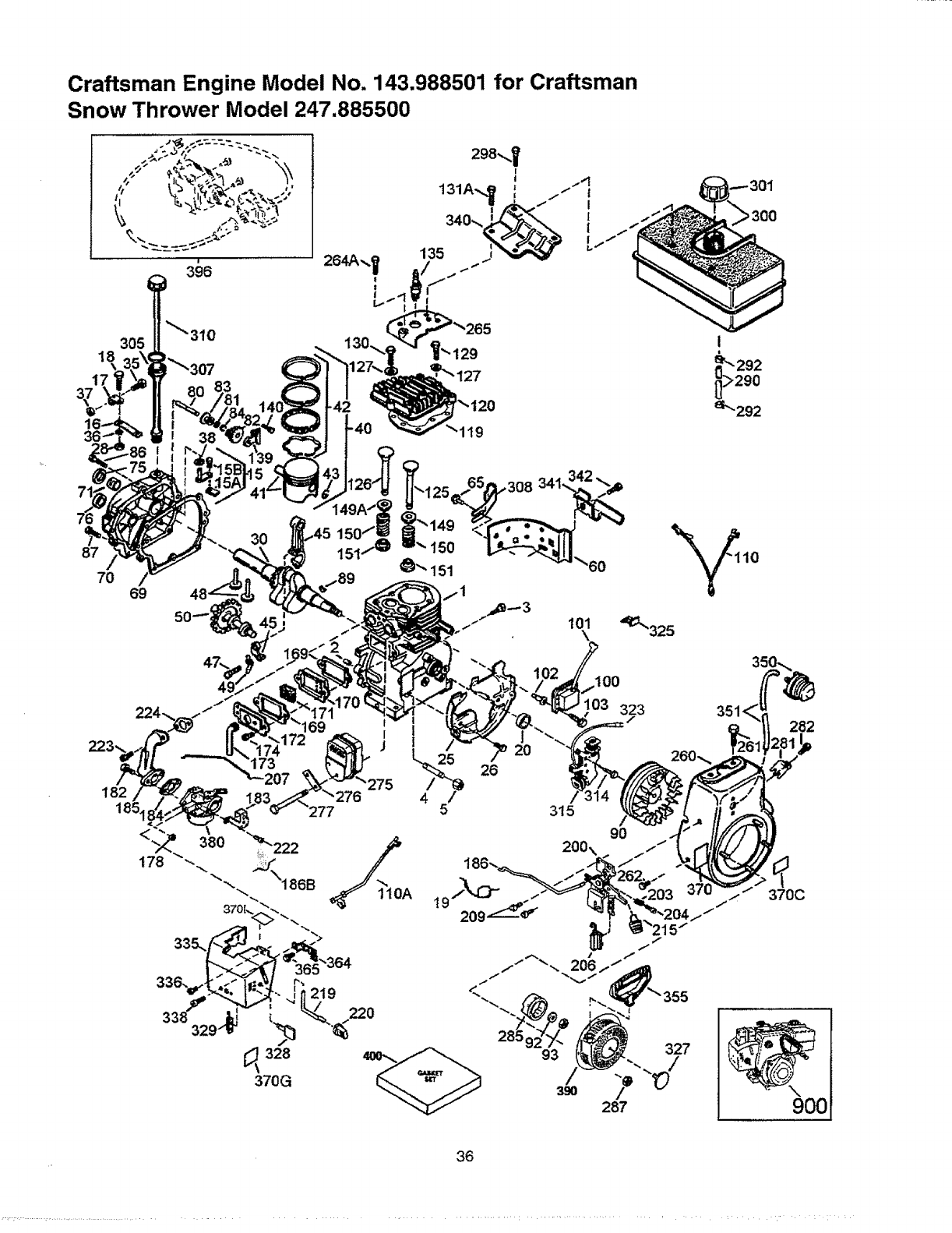
Craftsman Engine Model No. 143.988501 for Craftsman
Snow Thrower Model 247.885500
18
\
17
87
70 69
3O
,308
101
\
182 207
03 323
26
/
315
282
370C
9OO
36
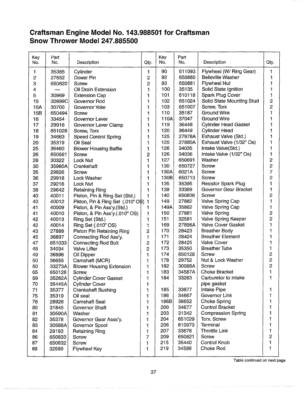
Craftsman Engine Model No. 143.988501 for Craftsman
Snow Thrower Model 247,885500
Key
No. Pa_
No.
35385
27652
650820
30969
30699C
15A 30700
15B 650494
16 33454
17 29916
18 651028
19 34663
20 35319
25 36460
26 650561
28 30322
30 35980A
35 29826
36 29918
37 29216
38 29642
40 40011
40 40012
41 40009
41 40010
42 40013
42 40014
43 27888
45 36897
47 651033i
48 34034
49 36896
50 36655
60 33273A
65 650128
69 35262Ai
70 35445A
71 35377
75 35319
76 28926
80 31845
81 30590A
82 35378
83 30588A
84 29193
86 650833
87 650832
89 32589
Description Qty.
Cylinder 1
Dowel Pin 2
Screw 2
Oil Drain Extension 1
Extension Cap 1
Governor Rod 1
Governor Yoke 1
Screw 1
Governor Lever 1
Governor Lever Clamp 1
Screw, Torx t
Speed Control Spring 1
Oil Seal 1
Blower Housing Baffle 1
Key
No.
90
92
93
100
t0!
102
103
110
110A
119
120
125
125
126
Screw
Lock Nut
Crankshaft
Screw
Lock Washer
Lock Nut
Retaining Ring
2 126
1 127
1 130
1 130A
1 130B
1 135
1 139
Piston, Pin & Ring Set (Std.)
Piston, Pin & Ring Set (.010" O_
Piston, & Pin Ass'y.(Std.)
Piston, & Pin Ass'y.(.010" OS)
Ring Set (Std.)
Ring Set (.010" OS)
Piston Pin Retaining Ring
Connecting Rod Ass'y.
Connecting Rod Bolt
"ValveLifter
Oil Dipper
Camshaft (MCR)
Blower Housing Extension
Screw
Cylind_er Cover Gasket
t 140
1 149
! 149A
1 150
1 151
1 169
2 170
1 171
2 172
2 173
1 174
1 178
1 182
1 183
1 184
Cylinder Cover
Crankshaft Bushing
Oil seal
Camshaft Seal
Governor Shaft
Washer
Governor Gear Asss'y.
Governor Spool
Retaining Ring
Screw
Screw
Flywheel Key
1
1 185
1 186
1 186B
1 200
1 203
1 204
1 206
1 207
7 209
1 215
1 219
Part
No.
611093
650880
650881
35135
610118
651024
651007
35187
37047
36448
36449
27878A
27880A
34035
34036
650691
650727
6021A
650713
35395
33369
650836
27882
35862
27881
32581
27896A
28423
28424
28425
35350
650128
29752
30088A
34587A
33263
33877
34667
36652
34677
31342
651029
610973
33878
650821
35440
34586
Description
Flywheel (W/Ring Gear)
Bellevilie Washer
Flywheel Nut
Solid State Ignition
Spark Plug Cover
Solid State Mounting Stud
Screw, Torx
Ground Wire
Ground Wire
Cylinder Head Gasket
Cylinder Head
Exhaust Valve (Std.)
Exhaust Valve (1/32" Os)
Intake Valve(Std.)
Intake Valve (1/32" Os)
Washer
Screw
Screw
Screw
Resistor Spark Plug
Governor Gear Bracket
Screw
Valve Spring Cap
Valve Spring Cap
Valve Spring
Valve Spring Keeper
Valve Cover Gasket
Breather Body
Breather Element
Valve Cover
Breather Tube
Screw
Nut & Lock Washer
Screw
Choke Bracket
Carburetor to intake
pipe gasket
Intake Pipe
Governor Link
Choke Spring
Control Bracket
Compression Spring
Torx. Screw
Terminal
Throttle Link
Screw
Control Knob
Choke Rod
Qty.
1
1
1
1
1
2
2
I
1
1
1
1
1
1
1
2
2
7
2
1
1
2
1
1
2
2
1
1
1
1
1
2
2
2
1
1
1
I
1
1
1
1
1
1
2
1
I
Table continued on next page
37
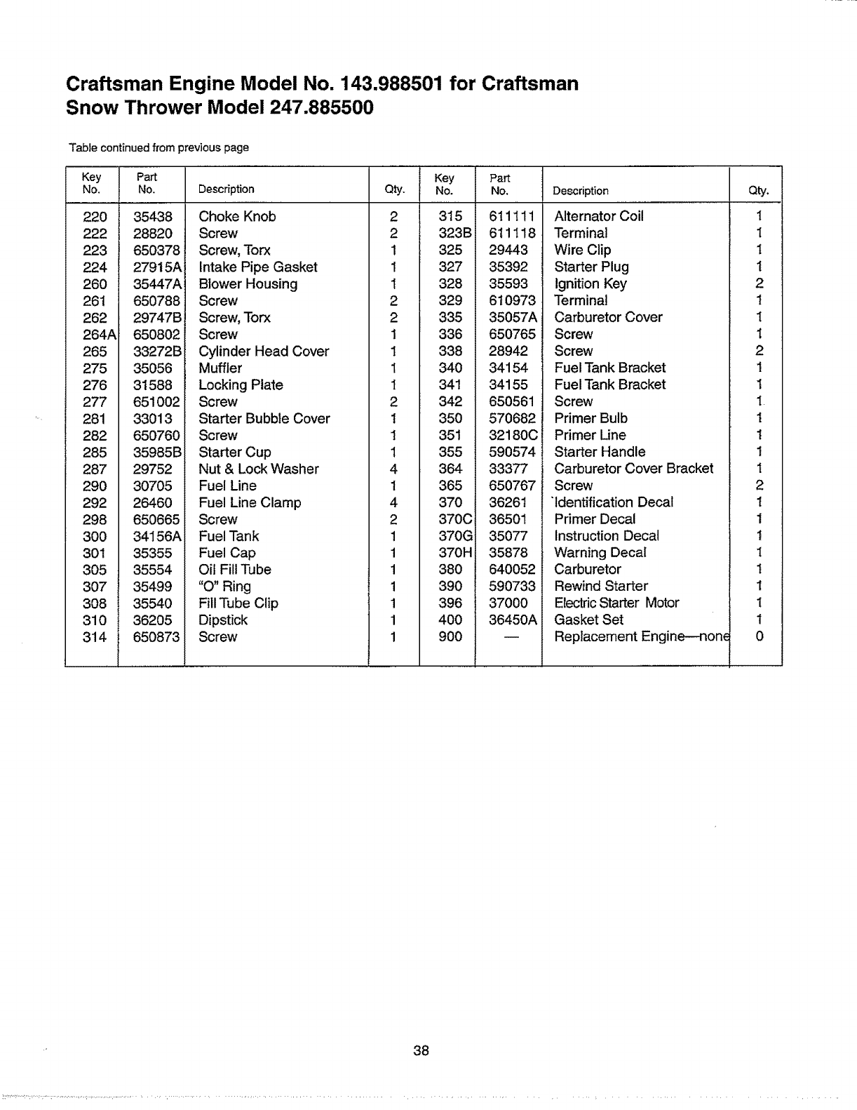
Craftsman Engine Model No. 143.988501 for Craftsman
Snow Thrower Model 247.885500
Table continued from previous page
Key
No.
220
222
223
224
260
261
262
264A
265
275
276
277
281
282
285
287
29O
292
298
3OO
301
3O5
307
3O8
310
314
Part
No.
35438
28820
650378
27915A
35447A
650788
29747B
650802
33272B
35056
31588
651002
33013
650760
35985B
29752
30705
26460
650665
34156A
35355
35554
35499
35540
36205
650873
Description
Choke Knob
Screw
Screw, Torx
intake Pipe Gasket
Blower Housing
Screw
Screw, Torx
Screw
Cylinder Head Cover
Muffler
Locking Plate
Screw
Starter Bubble Cover
Screw
Starter Cup
Nut & Lock Washer
Fuel Line
Fuel Line Clamp
Screw
Fuel Tank
Fuel Cap
Oil Fill Tube
"O" Ring
Fill Tube Clip
Dipstick
Screw
Key
Qty. No.
2 315
2 323B
1 325
1 327
1 328
2 329
2 335
1 336
1 338
1 340
1 341
2 342
1 350
1 351
1 355
4 364
1 365
4 370
2 370C
1 370G
1 370H
1 380
1 390
1 396
1 400
1 900
Part
No.
611111
611118
29443
35392
35593
610973
35057A
650765
28942
34154
34155
650561
570682
32180C
590574
33377
650767
36261
36501
35077
35878
640052
590733
37000
36450A
Description
Alternator Coil
Terminal
Wire Clip
Starter Plug
Ignition Key
Terminal
Carburetor Cover
Screw
Screw
Fuel Tank Bracket
Fuel Tank Bracket
Screw
Primer Bulb
Primer Line
Starter Handle
Carburetor Cover Bracket
Screw
"Identification Decal
Primer Decal
Instruction Decal
Warning Decal
Carburetor
Rewind Starter
Electric Starter Motor
Gasket Set
Replacement Engine--non_
Qty.
1
1
I
1
2
1
1
1
2
1
t
I
1
1
1
1
2
1
1
1
I
1
1
1
1
0
38
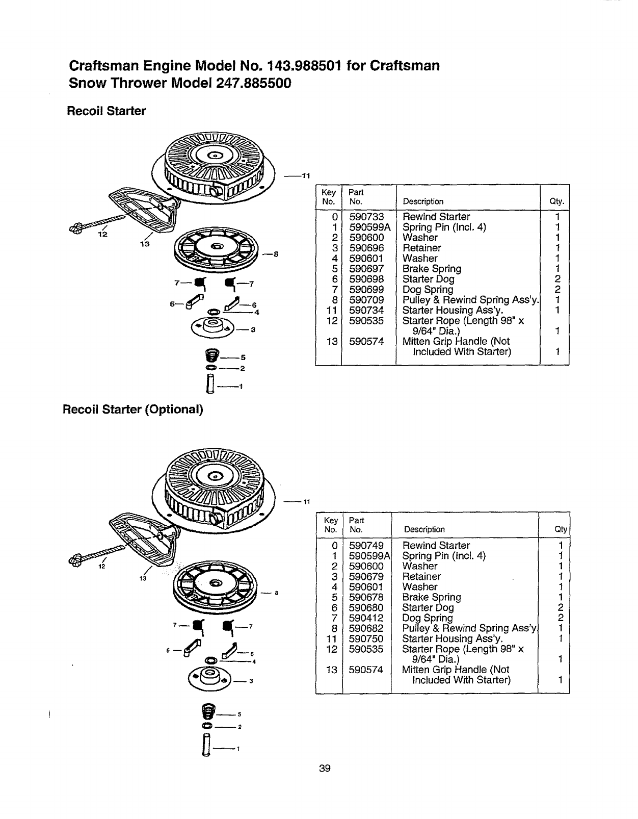
Craftsman Engine Model No. 143.988501 for Craftsman
Snow Thrower Model 247.885500
Recoil Starter
13
Recoil Starter (Optional)
..............Part .....
No. No.
0
1
2
3
4
5
6
7
8
11
12
13
59O733
590599A
590600
590696
590601
590697
590698
590699
590709
590734
590535
590574
Description
Rewind Starter .............
Spring Pin (Incl. 4)
Washer
Retainer
Washer
Brake Spring
Starter Dog
Dog Spring
Pulley & Rewind Spring Ass'y.
Starter Housing Ass'y.
Starter Rope (Length 98" x
9/64" Dia.)
Mitten Grip Handle (Not
Included With Starter)
Qty.
1
1
1
t
1
1
2
2
1
1
/
12
Key Pa_
No. No.
0 590749
1 590599A
2 590600
3 590679
4 590601
5 590678
6590680
7 590412
8 590682
11 59075O
12 590535
13 590574
Description
Rewind Starter
Spring Pin (Incl. 4)
Washer
Retainer
Washer
Brake Spring
Starter Dog
Dog Spring
Pulley & Rewind Spring Ass'y
Starter Housing Ass'y.
Starter Rope (Length 98" x
9/64" Dia.)
Mitten Grip Handle (Not
Included With Starter)
Qty
1
1
1
i
1
1
2
2
1
1
39
Forthe repair or replacement parts you need
delivered directly to your home
Call 7 am - 7 pro, 7 days a week
1
(1-800-366-7278)
Forin-homemajorbrandrepairservice
Call24 hours a day,7 daysa week
1-800-4-REPAIR
(1-800-473-7247)
Forthe locationofa
SearsPartsandRepairCenterin yourarea
Call 24 hours a day, 7 days a week
1-800-488-1222 mmmmmm
mnmmmm
For information on purchasinga Sears
Maintenance Agreement or to inquire
about an existing Agreement
call 9 am - 5 prn, Monday-Saturday
1-800-827-6655
America's Repair Speciatist$
............ :......... ,........ , = ,..... ,: ....... : .......
