Craftsman 247886640 User Manual SNOW BLOWER Manuals And Guides L0308228
CRAFTSMAN Snowthrower, Gas Manual L0308228 CRAFTSMAN Snowthrower, Gas Owner's Manual, CRAFTSMAN Snowthrower, Gas installation guides
usermanual247886640 db575bd8-6a00-ac84-21d1-8695c82dec6e Craftsman Snow Blower 247.88664 User Guide |
User Manual: Craftsman 247886640 247886640 CRAFTSMAN SNOW BLOWER - Manuals and Guides View the owners manual for your CRAFTSMAN SNOW BLOWER #247886640. Home:Lawn & Garden Parts:Craftsman Parts:Craftsman SNOW BLOWER Manual
Open the PDF directly: View PDF ![]() .
.
Page Count: 49
Owner's Manual
5 Horse Power
24" Two-Stage
Snow Thrower
Model No.
247.886640
CAUTION: Before
using this product,
read this manual and
follow all safety rules
and operating
instructions.
•Safety
•Assembly
•_peration
•Service
° Maintenance
•EspaSol, p. 30
Sears, Roebuck And Co., Hoffman Estates, IL 60179, U.S.A.
Visit our website: www.sears.com/craftsman
PRINTED IN U,S,A. FORM NO. 770-10433F
(7/2003)
Content Page
Warranty Information ......................................... 2
Safe Operation Practices ................................... 3
Assembly ........................................................... 5
Operation ........................................................... 8
Maintenance ...................................................... 11
Content Page
Service & Adjustment ......................................... 14
Off-Season Storage ........................................... 17
Troubleshooting ................................................. 18
Parts List............................................................ 20
Espanbl .............................................................. 30
Two -Year Warranty on Craftsman Snow Thrower
For two years from the date of purchase, when this Craftsman Snow Thrower is maintained, lubricated and tuned up according to the instruc-
tions in the owner's manual, Sears will repair, free of charge, any defect in material and workmanship.
If this Craftsman snow thrower is used for commercial or rental purposes, this warranty applies for only 30 days from the date of purchase.
This warranty does not cover:
Expendable items which become worn during normal use, such as skid shoes, shave plate and spark plugs.
Repairs necessary because of operator abuse or negligence, including bent crankshafts and the failure to maintain the equipment
according to the instructions contained in the owner's manual.
WARRANTY SERVICE IS AVAILABLE BY RETURNING THE CRAFTSMAN SNOW THROWER TO THE NEAREST SEARS PARTS & REPAIR
CENTER IN THE UNITED STATES.
This warranty applies only while this product is in use in the United States.
This warranty gives you specific legal rights and you may also have other rights which may vary from state to state.
SEARS, ROEBUCK AND CO., D/817WA, HOFFMAN ESTATES, IL 60179
Repair Protection Agreements
Congratulations on making a smart purchase.Your new Craftsman®
product is designed and manufactured for years of dependable
operation. But like all products, it may require repair from time to
time. That's when having a Repair Protection Agreement can save
you money and aggravation.
Here's what's included in the Agreement:
,_ Expert service bY °Ur12_OOO prefessional repair
specialists
,jr Unlimited service and no charge for parts and labor on
"all covered repairs
Product replacement if your covered product can't be
fixed
Discount of 10% from regular price of service and service-
related parts not covered by the agreement; also, 10% off
regular price of preventive maintenance check
Fast help by phone - phone support from a Sears
technician on products requiring in-home repair, plus
convenient repair scheduling
Purchase a Repair Protection Agreement now and protect yourself
from unexpected hassle and expense.
Once you purchase the Agreement, a simple phone call is all that it
takes for you to schedule service. You can call anytime day or night,
or schedule a service appointment online. Sears has over 12,000
professional repair specialists, who have access to over 4.5 million
quality parts and accessories. That's the kind of professionalism you
can count on to help prolong the life of your new purchase for years
to come. Purchase your Repair Protection Agreement today!
Some limitations and exclusions apply. For prices and additional
information call 1-800-827-6655.
Sears Installation Service
For Sears professional installation of home appliances, garage door
openers, water heaters, and other major home items, in the U.S.A.
call 1-800-4-MY-HOME®.
Horsepower: 5
Engine Oil: SAE 5W30
Fuel: Unleaded Regular
Spark Plug: RJ19LM
Eng he: Craftsman Eng ne Moode 143.045001
Model Number a safe
Serial Number ...........................................................
Date of Purchase ......................................................
Record both serial number and date of purchase and keep in
,lace for future reference.
_lb WARNING: This symbol points out important safety instructions which, if not followed, could endanger
the personal safety and/or property of yourself and others. Read and follow all instructions in this manual
before attempting to operate this machine. Failure to comply with these instructions may result in personal
injury. When you see this symbol--heed its warning.
,_ WARNING: Engine Exhaust, some of its constituents, and certain vehicle components contain or emit
chemicals known to State of California to cause cancer and birth defects or other reproductive harm.
DANGER: This machine was built to be operated according to the rules for safe operation in this manual. As with
any type of power equipment, carelessness or error on the part of the operator can result in serious injury. This
machine is capable of amputating hands and feet and throwing objects. Failure to observe the following safety
instructions could result in serious injury or death.
Training
1. Read, understand, and follow all instructions on the
machine and in the manual(s) before attempting to
assemble and operate. Keep this manual in a safe place
for future and regular reference and for ordering
replacement parts.
2. Be familiar with all controls and their operation. Know
how to stop the machine and disengage controls.
3. Never allow children under 14 years old to operate this
machine. Children 14 years old and over should read and
understand the operation instructions and safety rules in
this manual and should be trained and supervised by a
parent.
4. Never allow adults to operate this machine without
proper instruction.
5. Thrown objects can cause serious personal injury. Plan
your snow-throwing pattern to avoid discharge of material
toward roads, bystanders and the like.
6. Keep bystanders, helpers, pets and children at least 75
feet from the machine while it is in operation. Stop
machine if anyone enters the area.
7. Exercise caution to avoid slipping or falling, especially
when operating in reverse.
Preparation
1. Thoroughly inspect the area where the equipment is to
be used. Remove all doormats, newspapers, sleds,
boards, wires and other foreign objects, which could be
tripped over or thrown by the auger/impeller.
2. Always wear safety glasses or eye shields during
operation and while performing an adjustment or repair to
protect your eyes. Thrown objects which ricochet can
cause serious injury to the eyes.
3. Do not operate without wearing adequate winter outer
garments. Do not wear jewelry, long scarves or other
loose clothing, which could become entangled in moving
parts. Wear footwear which will improve footing on
slippery surfaces.
4. Use a grounded three-wire extension cord and
receptacle for all units with electric start engines.
5. Adjust collector housing height to clear gravel or crushed
rock surfaces.
6. Disengage all clutch levers before starting the engine.
7. Never attempt to make any adjustments while engine is
running, except where specifically recommended in the
operator's manual.
8. Let engine and machine adjust to outdoor temperature
before starting to clear snow.
9. To avoid personal injury or property damage use extreme
care in handling gasoline. Gasoline is extremely
flammable and the vapors are explosive. Serious
personal injury can occur when gasoline is spilled on
yourself or your clothes, which can ignite. Wash your skin
and change clothes immediately.
a. Use only an approved gasoline container.
b. Extinguish all cigarettes, cigars, pipes and other
sources of ignition.
c. Never fuel machine indoors.
d. Never remove gas cap or add fuel while the
engine is hot or running.
e. Allow engine to cool at least two minutes before
refueling.
f. Never over fill fuel tank. Fill tank to no more than
½ inch below bottom of filler neck to provide space
for fuel expansion.
g. Replace gasoline cap and tighten securely.
h. If gasoline is spilled, wipe it off the engine and
equipment. Move machine to another area. Wait 5
minutes before starting the engine.
i. Never store the machine or fuel container inside
where there is an open flame, spark or pilot light
(e.g. furnace, water heater, space heater, clothes
dryer etc.).
j. Allow unit to cool for 5 minutes before storing.
Operation
1. Do not put hands or feet near rotating parts, in the auger/
impeller housing or discharge chute. Contact with the
rotating parts can amputate hands and feet.
2. The auger/impeller clutch lever is a safety device. Never
bypass its operation. Doing so makes the machine
unsafe and may cause personal injury.
3. The clutch levers must operate easily in both directions
and automatically return to the disengaged position when
released.
4. Never operate with a missing or damaged discharge
chute. Keep all safety devices in place and working.
5. Never run an engine indoors or in apoorly ventilated
area. Engine exhaust contains carbon monoxide, an
odorless and deadly gas.
6. Do not operate machine while under the influence of
alcohol or drugs.
7. Mufflerandenginebecomehotandcancauseaburn.Do
nottouch.
8. Exerciseextremecautionwhenoperatingonorcrossing
gravelsurfaces.Stayalertforhiddenhazardsortraffic.
9. Exercisecautionwhenchangingdirectionandwhile
operatingonslopes.
10.Planyoursnow-throwingpatterntoavoiddischarge
towardswindows,walls,carsetc.Thus,avoiding
possiblepropertydamageorpersonalinjurycausedbya
ricochet.
11.Neverdirectdischargeatchildren,bystandersandpets
orallowanyoneinfrontofthemachine.
12.Donotoverloadmachinecapacitybyattemptingtoclear
snowattoofastofarate.
13.Neveroperatethismachinewithoutgoodvisibilityor
light.Alwaysbesureofyourfootingandkeepafirmhold
onthehandles.Walk,neverrun.
14.Disengagepowertotheauger/impellerwhen
transportingornotin use.
15. Never operate machine at high transport speeds on
slippery surfaces. Look down and behind and use care
when in reverse.
16. If the machine should start to vibrate abnormally, stop the
engine, disconnect the spark plug wire and ground it
against the engine. Inspect thoroughly for damage.
Repair any damage before starting and operating.
17. Disengage all clutch levers and stop engine before you
leave the operating position (behind the handles). Wait
until the augedimpeller comes to a complete stop before
unclogging the discharge chute, making any
adjustments, or inspections.
18. Never put your hand in the discharge or collector
openings. Always use the clean-out tool provided to
unclog the discharge opening. Do not unclog discharge
chute while engine is running. Before unclogging, shut off
engine and remain behind handles until all moving parts
have stopped completely.
19. Use only attachments and accessories approved by the
manufacturer (e.g. wheel weights, tire chains, cabs etc.).
20. If situations occur which are not covered in this manual,
use care and good judgment. Contact Sears service
center for assistance.
Maintenance & Storage
1. Never tamper with safety devices. Check their proper
operation regularly. Refer to the maintenance and
adjustment sections of this manual.
2. Before cleaning, repairing, or inspecting machine
disengage all clutch levers and stop engine. Wait until the
auger/impeller come to a complete stop. Disconnect the
spark plugwire and ground against the engine to prevent
unintended starting.
3. Check bolts and screws for proper tightness at frequent
intervals to keep the machine in safe working condition.
Also, visually inspect machine for any damage.
4. Do not change the engine governor setting orover-speed
the engine. The governor controls the maximum safe
operating speed of the engine.
5. Snow thrower shave plates and skid shoes are subject to
wear and damage. For your safety protection, frequently
check all components and replace with original
equipment manufacturer's (OEM) parts only. "Use of
parts which do not meet the original equipment
specifications may lead to improper performance and
compromise safety!"
6. Check clutch controls periodically to verify they engage
and disengage properly and adjust, if necessary. Refer to
the adjustment section in this operator's manual for
instructions.
7. Maintain/replace safety/instruction labels, as necessary.
8. Observe proper disposal laws and regulations for gas,
oil, etc. to protect the environment.
9. Prior to storing, run machine afew minutes to clear snow
from machine and prevent freeze up of auger/impeller.
10. Never store the machine or fuel container inside where
there is an open flame, spark or pilot light such as a water
heater, furnace, clothes dryer etc.
11. Always refer to the operator's manual for proper
instructions on off-season storage.
Your Responsibility
Restrict the use of this power machine to persons who read,
understand and follow the warnings and instructions in this
manual and on the machine. The safety labels are shown
below for your reference.
Do not modify engine
To avoid serious injury or death, do not modify engine in any
way. Tampering with the governor setting can lead to a
runaway engine and cause it to operate at unsafe speeds.
Never tamper with factory setting of engine governor.
Notice regarding emissions
Engines which are certified to comply with California and
federal EPA emission regulations for SORE (Small Off Road
Equipment) are certified to operate on regular unleaded
gasoline, and may include the following emission control
systems: Engine Modification (EM) and Three Way Catalyst
(TWC) if so equipped.
Engine Identification Decal
This decal indicates the engine's model number, specification
and teh date of manufacture. Please look at the decal on the
engine of your equipment and record these information for
future reference.
The engine identification decal also includeds engine life
specifications for the emissions-related useful life period of
the engine. This period relates to the emission compliance life
as certified by EPA and/or CARB. To find teh life period
specification of the engine, please read the engine decal and
and locate the letter (enclosed by quotation marks) between
the words Moderate and Life Period. Match one of the
following letters with the letter printed on your decal. For
example, HSSK models are designated as:
"C"-- 125 hours
"B" -- 250 hours
"A" -- 500 hours
Unpacking
1. Remove screws from the top sides and ends of the
shipping crate.
2. Set crate panels aside to avoid tire punctures or
personal injury.
3. Remove and discard plastic bag that covers unit.
4. Remove any loose parts included with unit (i.e.,
Operator's Manual, etc).
5. Roll unit out of crate.
Hardware Pack
Following items make up the hardware pack for your
snow thrower:
1. Shear bolts and lock nuts (2)
The augers are secured to the auger
shaft with two shear bolts and hex
lock nuts. If you hit aforeign object
or ice jam, these bolts may shear.
Two replacement shear bolts and
lock nuts are provided for your
convenience. Save these until
needed.
2. Z fittings and hex nuts (2)
These four hardware pieces will be
required inthe assembly of the snow
thrower. Identify the items and use
as instructed.
®
®
Hardware not drawn
to size here
Setting Up The Snow Thrower
Your snow thrower was fully assembled at the factory
and needs minimum set-up.
NOTE: All references in this manual to left, right, top or
bottom is from the operating position only. Exceptions, if
any, will be specified.
1. Disconnect spark plug wire and ground it against
the engine to prevent unintended starting.
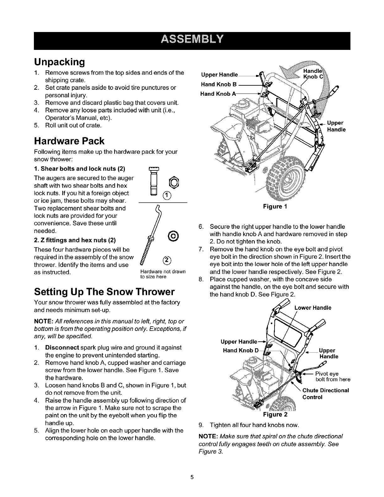
2. Remove hand knob A, cupped washer and carriage
screw from the lower handle. See Figure 1. Save
the hardware.
3. Loosen hand knobs B and C, shown in Figure 1, but
do not remove from the unit.
4. Raise the handle assembly up following direction of
the arrow in Figure 1. Make sure not to scrape the
paint on the unit by the eyebolt when you flip the
handle up.
5. Align the lower hole on each upper handle with the
corresponding hole on the lower handle.
Hand Knob B
Upper
Handle
Figure 1
6. Secure the right upper handle to the lower handle
with handle knob A and hardware removed in step
2. Do not tighten the knob.
7. Remove the hand knob on the eye bolt and pivot
eye bolt in the direction shown in Figure 2. Insert the
eye bolt into the lower hole of the left upper handle
and the lower handle respectively. See Figure 2.
8. Place cupped washer, with the concave side
against the handle, on the eye bolt and secure with
the hand knob D. See Figure 2.
Lower Handle
Upper
Hand Knob Handle
ye
bolt from here
Directional
Control
Figure 2
9. Tighten all four hand knobs now.
NOTE: Make sure that spiral on the chute directional
control fully engages teeth on chute assembly. See
Figure 3.
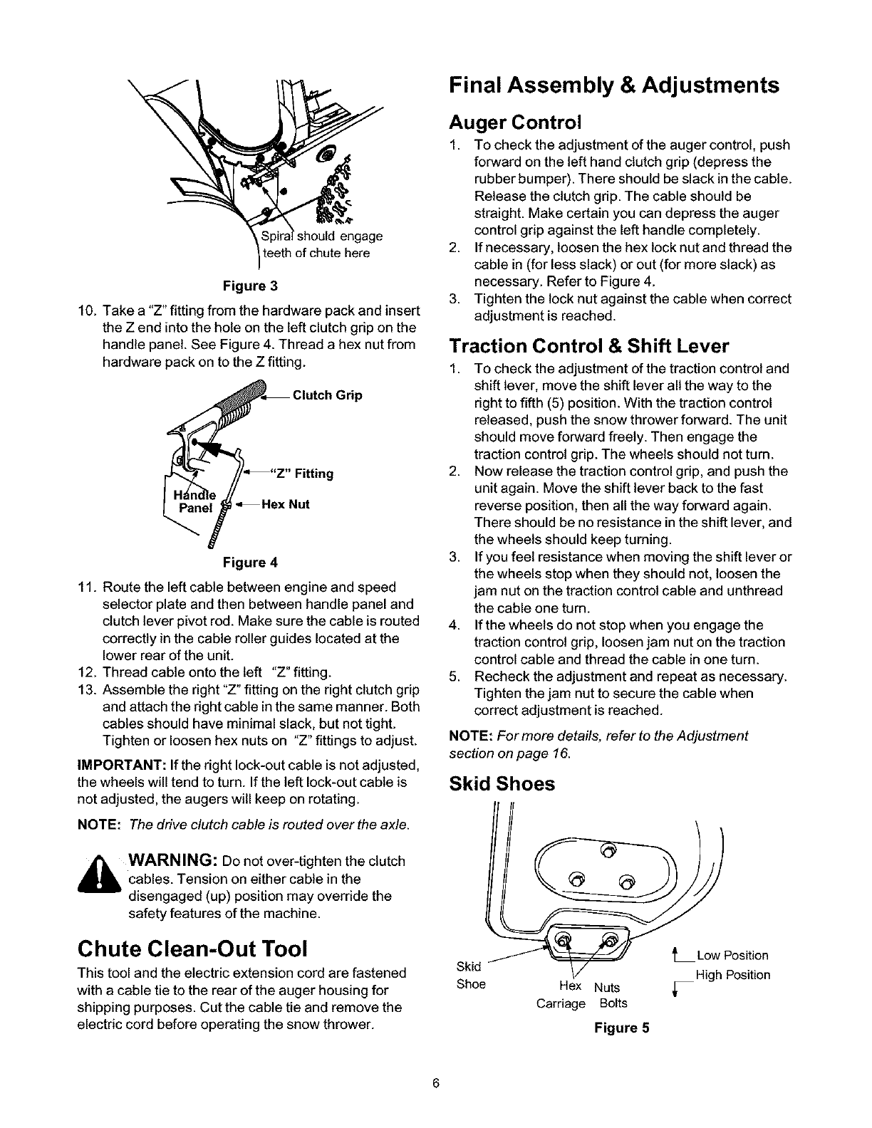
Figure 3
10. Take a "Z" fitting from the hardware pack and insert
the Z end into the hole on the left clutch grip on the
handle panel. See Figure 4. Thread a hex nut from
hardware pack on to the Z fitting.
P
Hex Nut
Figure 4
11. Route the left cable between engine and speed
selector plate and then between handle panel and
clutch lever pivot rod. Make sure the cable is routed
correctly in the cable roller guides located at the
lower rear of the unit.
12. Thread cable onto the left "Z" fitting.
13. Assemble the right "Z" fitting on the right clutch grip
and attach the right cable in the same manner. Both
cables should have minimal slack, but not tight.
Tighten or loosen hex nuts on "Z" fittings to adjust.
IMPORTANT: If the right lock-out cable is not adjusted,
the wheels will tend to turn. If the left lock-out cable is
not adjusted, the augers will keep on rotating.
NOTE: The drive clutch cable is routed overthe axle.
_bb WARNING: Do not over-tighten the clutch
cables. Tension on either cable in the
disengaged (up) position may override the
safety features of the machine.
Chute Clean-Out Tool
This tool and the electric extension cord are fastened
with a cable tie to the rear of the auger housing for
shipping purposes. Cut the cable tie and remove the
electric cord before operating the snow thrower.
Final Assembly & Adjustments
Auger Control
1. To check the adjustment of the auger control, push
forward on the left hand clutch grip (depress the
rubber bumper). There should be slack in the cable.
Release the clutch grip. The cable should be
straight. Make certain you can depress the auger
control grip against the left handle completely.
2. If necessary, loosen the hex lock nut and thread the
cable in (for less slack) or out (for more slack) as
necessary. Refer to Figure 4.
3. Tighten the lock nut against the cable when correct
adjustment is reached.
Traction Control & Shift Lever
1. To check the adjustment of the traction controt and
shift lever, move the shift lever all the way to the
right to fifth (5) position. With the traction control
released, push the snow thrower forward. The unit
should move forward freely. Then engage the
traction control grip. The wheels should not turn.
2. Now release the traction control grip, and push the
unit again. Move the shift lever back to the fast
reverse position, then all the way forward again.
There should be no resistance in the shift lever, and
the wheels should keep turning.
3. If you feel resistance when moving the shift lever or
the wheels stop when they should not, loosen the
jam nut on the traction control cable and unthread
the cable one turn.
4. If the wheels do not stop when you engage the
traction control grip, loosen jam nut on the traction
control cable and thread the cable in one turn.
5. Recheck the adjustment and repeat as necessary.
Tighten the jam nut to secure the cable when
correct adjustment is reached.
NOTE: For more details, refer to the Adjustment
section on page 16.
Skid Shoes
Low Position
Skid
Shoe Hex Nuts _High Position
Carriage Bolts
Figure 5
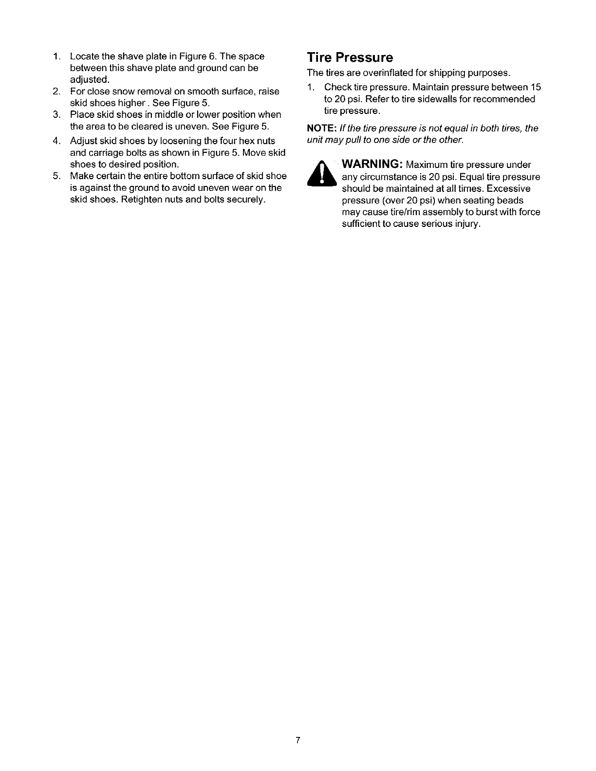
1. Locate the shave plate in Figure 6. The space
between this shave plate and ground can be
adjusted.
2. For close snow removal on smooth surface, raise
skid shoes higher. See Figure 5.
3. Place skid shoes in middle or lower position when
the area to be cleared is uneven. See Figure 5.
4. Adjust skid shoes by loosening the four hex nuts
and carriage bolts as shown in Figure 5. Move skid
shoes to desired position.
5. Make certain the entire bottom surface of skid shoe
is against the ground to avoid uneven wear on the
skid shoes. Retighten nuts and bolts securely.
Tire Pressure
The tires are overinflated for shipping purposes.
1. Check tire pressure. Maintain pressure between 15
to 20 psi. Refer to tire sidewalls for recommended
tire pressure.
NOTE: If the tire pressure is not equal in beth tires, the
unit may pull to ene side or the ether.
_WARNING: Maximum tire under
pressure
any circumstance is 20 psi. Equal tire pressure
should be maintained at all times. Excessive
pressure (over 20 psi) when seating beads
may cause tire!rim assembly to burst with force
sufficient to cause serious injury.
Operating Controls
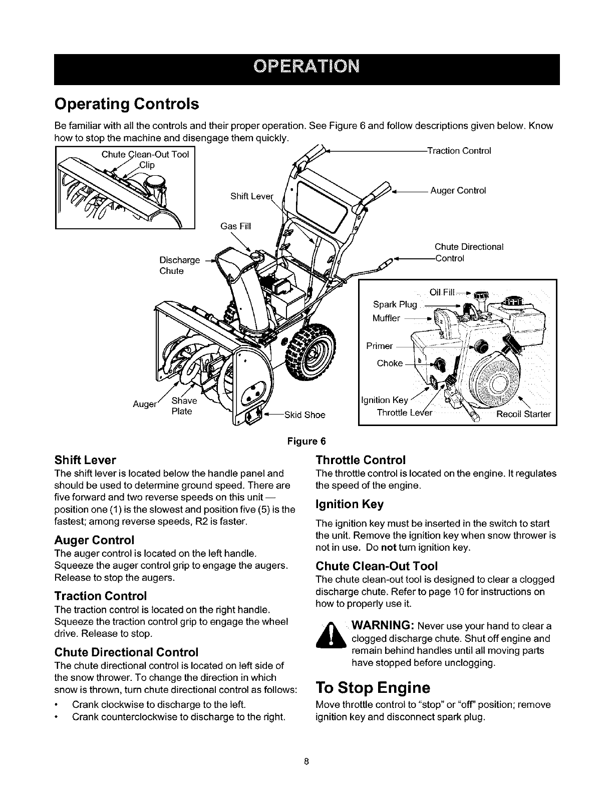
Be familiar with all the controls and their proper operation. See Figure 6 and follow descriptions given below. Know
how to stop the machine and disengage them quickly.
Chute ( Traction Control
Shift Leve_ ger Control
Gas Fill
Discharge
Chute
Chute Directional
,.--Control
Auger Plate *_Skid Shoe
Figure 6
Shift Lever
The shift lever is located below the handle panel and
should be used to determine ground speed. There are
five forward and two reverse speeds on this unit--
positionone (1) is the slowest and positionfive (5) is the
fastest; among reverse speeds, R2 is faster.
Auger Control
The auger control is located on the left handle.
Squeeze the auger control grip to engage the augers.
Release to stop the augers.
Traction Control
The traction control is located on the right handle.
Squeeze the traction control grip to engage the wheel
drive. Release to stop.
Chute Directional Control
The chute directional control is located on left side of
the snow thrower. To change the direction in which
snow is thrown, turn chute directional control as follows:
Crank clockwise to discharge to the left.
Crank counterclockwise to discharge to the right.
Throttle Control
The throtttecontrol is located on the engine. It regulates
the speed of the engine.
Ignition Key
The ignition key must be inserted in the switch to start
the unit. Remove the ignition key when snow thrower is
not in use. Do not turn ignition key.
Chute Clean-Out Tool
The chute clean-out tool is designed to clear a clogged
discharge chute. Refer to page 10 for instructions on
how to properly use it.
,_ WARNING: Never use hand to clear a
your
clogged discharge chute. Shut off engine and
remain behind handles until all moving parts
have stopped before unclogging.
To Stop Engine
Move throttle control to "stop" or "off" position; remove
ignition key and disconnect spark plug.
Before Starting
_WARNING: Read, understand, and follow all
instructions and warnings on the machine and
in this manual before operating.
Fill Oil
1. The engine was shipped with oil. Check the oil level
before operating. After the initial use, you will have
to fill up as necessary. Be careful not to overfill.
2. Before filling up gas in the engine for the first
time, open the gas tank cap, and locate a white
plastic cap underneath. Remove this cap and
discard it.
3. The spark plug wire was disconnected for safety.
Attach spark plug wire to spark plug before starting.
Fill Gas
_lb ARNING: Gasoline is flammable and
caution must be used when handling or storing
it. Do not fill fuel tank while the snow thrower is
running, when it is hot or when it is in an
enclosed area. Keep your snow thrower away
from any open flame or an electrical spark and
do not smoke while filling the fuel tank.
NOTE: Make sure that the containerfrem which you
pour gasoline is clean and rust-free .
1. Fill fuel tank with clean, fresh, unleaded grade
automotive gasoline only.
2. Never fill fuel tank completely. Fill the tank to within
1/4"-1/2" from the top to provide for fuel expansion.
3. Always fill fuel tank outdoors and use a funnel or
spout to prevent spilling.
4. Make sure to wipe off any spilled fuel before
starting the engine.
5. Store gasoline in a clean, approved container and
keep the cap in place on the container.
To Start Engine
1. Attach spark plug wire to spark plug. Make certain
the metal loop on the end of the spark plug wire
(inside the boot) is fastened securely over the metal
tip on the spark plug.
2. Make certain the auger and drive clutch levers are
in the disengaged (released) position.
3. Turn fuel valve counter-clockwise to OPEN.
4. Move throttle control up to FAST position. Insert
ignition key into slot. Make sure it snaps into place.
Do not turn key.
NOTE: Engine will not start unless ignition key is
inserted into ignition slot in carburetor cover.
Electric Starter
,_ WARNING: The electric starter is equipped
with a grounded three-wire power cord and
plug, and is designed to operate on 120 volt AC
household current. It must be used with a
propedy grounded three-prong receptacle at all
times to avoid the possibility of electdc shock.
Follow all instructions carefully prior to
operating the electric starter.
1. Determine that your house widng is a three-wire
grounded system. Ask a licensed electrician if you
are not certain.
If your house wiring system is not athree-wire
grounded system, do not use this electdc starter
under any conditions.
If your home electrical system is grounded, but
a three-hole receptacle is not available, one should
be installed by a licensed electrician before using
the electric starter.
2. Rotate choke knob to OFF position.
3. Push primer three times to pdme the engine.
4. Connect power cord to switch box on engine. Plug
the other end of power cord into a three-prong 120-
volt, grounded, AC receptacle.
5. Push starter button to crank engine. As you crank
the engine, move choke knob to FULL choke
position. Do not operate electdc starer for more
than 5 seconds on each attempt.
6. When engine starts, release starter button, and
move choke gradually to OFF. If engine falters,
move choke immediately to FULL and then
gradually to OFF.
7. When disconnecting the power cord, always unplug
from the three-prong receptacle first, and then from
the snow thrower.
Recoil Starter
1. Rotate choke knob to FULL choke position (cold
engine start).
2. If engine is warm, place choke in OFF position
instead of FULL.
3. Push pdmer button two or three times for cold
engine start.
4. If engine is warm, push primer button only once.
NOTE: Always cover vent hole in primer button when
pushing. Additional priming may be necessary for first
start if tempereture is below 15 degrees Fahrenheit.
Grasp starter handle and pull rope out slowly, until
it pulls slightly harder. Let rope rewind slowly.
Pull starter handle rapidly. Do not allow handle to
snap back. Allow it to rewind slowly while keeping a
firm hold on the starter handle.
As engine warms up and begins to operate evenly,
rotate choke knob slowly to OFF position. If engine
falters, return to FULL choke, then slowly move to
OFF position.
Frozen Recoil Starter
If the starter is frozen and wilt not turn the engine,
proceed as follows:
1. Pull as much rope out of the starter as possible.
2. Release the starter handle and let it snap back
against the starter.
3. If the engine still fails to start, repeat the first two
steps. If continued attempts do not free starter,
follow the electric starter procedures to start.
4. Avoid freezing of the recoil starter by following
instructions below.
Before Stopping
1. Run engine for a few minutes to help dry off any
moisture on engine.
2. Avoid freezing of the starter by following these
steps before stopping the snow thrower:
Recoil Starter
a. With the engine running, pull the starter rope
with a rapid, continuous full arm stroke three
or four times.
Electric Starter
a. Connect power cord to switch box, then to
120 Volt AC receptacle.
b. While engine is running, push starter button
and spin the starter for several seconds.
c. Disconnect power cord from the receptacle
first, then from the snow thrower.
NOTE: The unusual sound from pulling the starter rope
in the case of the recoil starter, or from spinning the
starter in the case of the electric starter, will not harm
the engine.
To Stop Engine
1. Move throttle control to "stop" or "off' position.
2. Remove the ignition key. Do not turn key.
3. Disconnect the spark plug wire from the spark plug
to prevent accidental starting while equipment is
unattended.
NOTE: Do not lose ignition key. Keep it in a safe place.
Engine will not start without the ignition key.
4. Wipe all snow and moisture from the carburetor
cover in the area of the control levers. Also, move
control levers back and forth several times.
To Engage Drive
1. With the engine running near top speed, move shift
lever into one of the five FORWARD positions or
two REVERSE positions. Select a speed
appropriate for the snow conditions that exist. Use
the slower speeds until you are familiar with the
operation of the snow thrower.
2. Squeeze the auger control grip and the augers will
turn. Release it and the augers wilt stop.
3. Squeeze traction control grip and the snow thrower
will move. Release it and drive motion will stop.
4. NEVER move shift lever without releasing drive
clutch.
To Engage Augers
To engage the augers and start throwing snow,
squeeze the auger control grip against the left handle.
Release to stop the augers.
Operating Tips
Allow the engine to warm up for a few minutes as
the engine will not develop full power until it
reaches operating temperature.
_WARNING: Muffler, engine and surrounding
areas become hot and can cause a burn. Do
not touch.
For most efficient snow removal, remove snow
immediately after it falls.
Discharge snow downwind whenever possible.
Slightly overlap each previous swath.
Set the skid shoes 1/4" below the scraper bar for
normal usage. The skid shoes may be adjusted
upward for hard-packed snow. Adjust downward
when using on gravel or crushed rock.
Be certain to follow the precautions listed under "To
Stop Engine" to prevent possible freeze-up.
Clean the snow thrower thoroughly after each use.
Tire Chains (ifequipped)
Tire chains, if equipped, should be used whenever
extra traction is needed.
Chute Clean-Out Tool
The chute clean-out tool is conveniently fastened to the
rear of the auger housing with a mounting clip. Never
use your hand to clean a clogged chute.
1. Release both the auger control lever and the
traction/auger control locklever.
2. Stop the engine by removing the ignition key.
3. Remove the clean-out tool from the clip which
secures it to the rear of the auger housing. See
Figure 6.
4. Use the shovel-shaped end of the clean-out tool to
remove any snow and ice in the discharge chute.
5. Re-fasten the clean-out tool to the mounting clip on
the rear of the auger housing and restart engine.
6. While standing in the operator's position (behind
the snow thrower), engage the auger clutch lever
for a few seconds to clear any remaining snow or
ice from the discharge chute before continuing to
clear snow.
10
General Recommendations
Always observe safety rules when performing any
maintenance.
The warranty on this snow thrower does not cover
items that have been subjected to operator abuse
or negligence. To receive full value from the
warranty, operator must maintain the snow thrower
as instructed in this manual.
Follow the maintenance schedule given below.
Periodically check all fasteners and make sure
these are tight.
_ WARNING: Before lubricating, repairing, or
inspecting, disengage all clutch levers and stop
engine. Wait until all moving parts have come
to a complete stop. Disconnect spark plug wire
and ground it against the engine to prevent
unintended starting.
Maintenance Schedule
Maint. Tasks Before Aftereach &fterfirst2 Every25 Every50 Before Service Dates
_=achuse use hours hours hours storage
operation operation operation
Product: , , ,
Lubricate pivotpoints I I I I _ I
Clean equipment
Clean skid shoe
Check V belts
Engine:
Check engine oil
Change engine oil _
Check spark plug II I I
Empty fuel system
,/
,/
iiiiiiiiiii
,/
,/
Lubrication
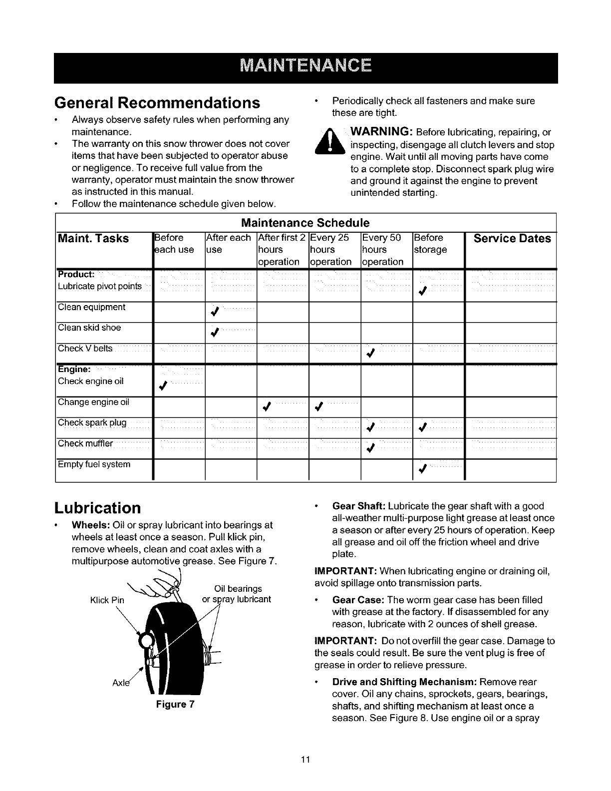
Wheels: Oil or spray lubricant into bearings at
wheels at least once a season. Pull ktick pin,
remove wheels, clean and coat axles with a
multipurpose automotive grease. See Figure 7.
Oil bearings
Klick Pin , lubricant
Figure 7
Gear Shaft: Lubricate the gear shaft with a good
all-weather multi-purpose light grease at least once
a season or after every 25 hours of operation. Keep
all grease and oil off the friction wheel and drive
plate.
IMPORTANT: When lubricating engine or draining oil,
avoid spillage onto transmission parts.
Gear Case: The worm gear case has been filled
with grease at the factory. If disassembled for any
reason, lubricate with 2 ounces of shell grease.
IMPORTANT: Do not overfill the gear case. Damage to
the seals could result. Be sure the vent plug is free of
grease in order to relieve pressure.
Drive and Shifting Mechanism: Remove rear
cover. Oil any chains, sprockets, gears, bearings,
shafts, and shifting mechanism at least once a
season. See Figure 8. Use engine oil or a spray
11
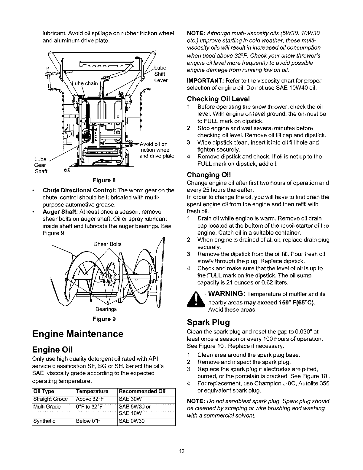
lubricant. Avoid oil spillage on rubber friction wheel
and aluminum drive plate.
Lever
Lube
Gear
Sha_
friction wheel
and drive plate
Figure 8
Chute Directional Control: The worm gear on the
chute control should be lubricated with multi-
purpose automotive grease.
Auger Shaft: At least once a season, remove
shear bolts on auger shaft. Oil or spray lubricant
inside shaft and lubricate the auger bearings. See
Figure 9.
Shear Bolts
Bearings
Figure 9
Engine Maintenance
Engine Oil
Only use high quality detergent oil rated with API
service classification SF, SG or SH. Select the oil's
SAE viscosity grade according to the expected
operating temperature:
Oil Type Temperature Recommended Oil
Straight Grade Above 32°F SAE 3OW
Multi Grade 0°F to 32°F SAE 5W30 or
SAE 10W
Synthetic Below O°F SAE 0W30
NOTE: Although multi-viscosity oils (5W30, 10W30
etc.) improve starting in cold weather, these multi-
viscosity oils will result in increased oil consumption
when used above 32°F. Check your snow thrower's
engine oil level more frequently to avoid possible
engine damage from running low on oil.
IMPORTANT: Refer to the viscosity chart for proper
selection of engine oil. Do not use SAE 10W40 oil.
Checking Oil Level
1. Before operating the snow thrower, check the oil
level. With engine on level ground, the oil must be
to FULL mark on dipstick.
2. Stop engine and wait several minutes before
checking oil level. Remove oil fill cap and dipstick.
3. Wipe dipstick clean, insert it into oil fill hole and
tighten securely.
4. Remove dipstick and check. If oil is not up to the
FULL mark on dipstick, add oil.
Changing Oil
Change engine oil after first two hours of operation and
every 25 hours thereafter.
In order to change the oil, you will have to first drain the
spent engine oil from the engine and then refill with
fresh oil.
1. Drain oil while engine is warm. Remove oil drain
cap located at the bottom of the recoil starter of the
engine. Catch oil in a suitable container.
2. When engine is drained of all oil, replace drain plug
securely.
3. Remove the dipstick from the oil fill. Pour fresh oil
slowly through the plug. Replace dipstick.
4. Check and make sure that the level of oil is up to
the FULL mark on the dipstick. The oil sump
capacity is 21 ounces or 0.62 liters.
_i_ WARNING: Temperature of muffler and its
nearby areas may exceed 150° F(65°C).
Avoid these areas.
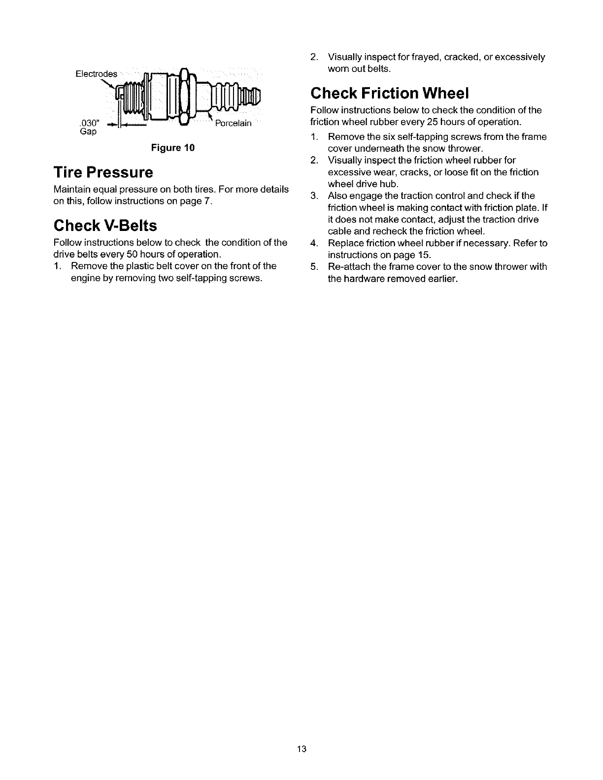
Spark Plug
Clean the spark plug and reset the gap to 0.030" at
least once a season or every 100 hours of operation.
See Figure 10. Replace if necessary.
1. Clean area around the spark plug base.
2. Remove and inspect the spark plug.
3. Replace the spark plug if electrodes are pitted,
burned, or the porcelain is cracked. See Figure 10.
4. For replacement, use Champion J-8C, Autolite 356
or equivalent spark plug.
NOTE: Do not sandblast spark plug. Spark plug should
be cleaned by scraping or wire brushing and washing
with a commercial solvent.
12
2. Visually inspect for frayed, cracked, or excessively
Electrodes worn out belts.
.030" Porcelain
Gap
Figure 10
Tire Pressure
Maintain equal pressure on both tires. For more details
on this, follow instructions on page 7.
Check V-Belts
Follow instructions below to check the condition of the
drive belts every 50 hours of operation.
1. Remove the plastic belt cover on the front of the
engine by removing two self-tapping screws.
Check Friction Wheel
Follow instructions below to check the condition of the
friction wheel rubber every 25 hours of operation.
1. Remove the six self-tapping screws from the frame
cover underneath the snow thrower.
2. Visually inspect the friction wheel rubber for
excessive wear, cracks, or loose fit on the friction
wheel drive hub.
3. Also engage the traction control and check if the
friction wheel is making contact with friction plate. If
it does not make contact, adjust the traction drive
cable and recheck the friction wheel.
4. Replace friction wheel rubber if necessary. Refer to
instructions on page 15.
5. Re-attach the frame cover to the snow thrower with
the hardware removed earlier.
13
i_hl WARNING: Beforeservicing,repairing,or
inspecting,disengageallclutchleversandstop
engine.Waituntilallmovingpartshavecome
toacompletestop.Disconnectsparkplug wire
and ground it against the engine to prevent
unintended starting.
All adjustments in the Service and Adjustments
section of this manual should be checked at least
once each season.
Servicing Augers
The augers are secured to the spiral shaft with two
shear bolts and hex lock nuts. See Figure 9. If you hit a
hard foreign object or ice jam, the snow thrower is
designed so that the bolts may shear.
1. If the augers will not turn, check to see if the bolts
have sheared.
2. Replace as needed. Replacement shear bolts and
hex lock nuts have been provided with the snow
thrower. When replacing bolts, spray an oil
lubricant into shaft before inserting new bolts.
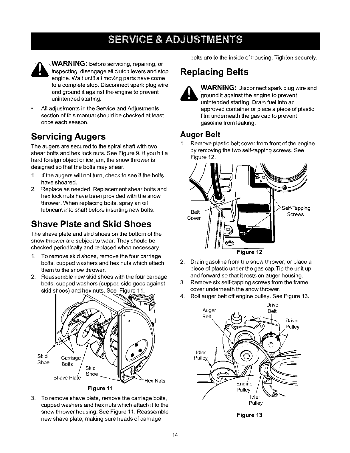
Shave Plate and Skid Shoes
The shave plate and skid shoes on the bottom of the
snow thrower are subject to wear. They should be
checked periodically and replaced when necessary.
1. To remove skid shoes, remove the four carriage
bolts, cupped washers and hex nuts which attach
them to the snow thrower.
2. Reassemble new skid shoes with the four carriage
bolts, cupped washers (cupped side goes against
skid shoes) and hex nuts. See Figure 11.
bolts are to the inside of housing. Tighten securely.
Replacing Belts
_i WARNING: Disconnect spark plug wire and
ground it against the engine to prevent
unintended starting. Drain fuel into an
approved container or place a piece of plastic
film underneath the gas cap to prevent
gasoline from leaking.
Auger Belt
1. Remove plastic belt cover from front of the engine
by removing the two self-tapping screws. See
Figure 12.
Belt
Cover Screws
2.
3.
4.
Figure 12
Drain gasoline from the snow thrower, or place a
piece of plastic under the gas cap.Tip the unit up
and forward so that it rests on auger housing.
Remove six self-tapping screws from the frame
cover underneath the snow thrower.
Roll auger belt off engine pulley. See Figure 13.
Drive
Auger Belt
Belt
X Drive
Pulley
Skid Carriage
Shoe Bolts
3.
Shave Nuts
Figure 11
To remove shave plate, remove the carriage bolts,
cupped washers and hex nuts which attach it to the
snow thrower housing. See Figure 11. Reassemble
new shave plate, making sure heads of carriage
Idler
Pulley
Pulley
Figure 13
14
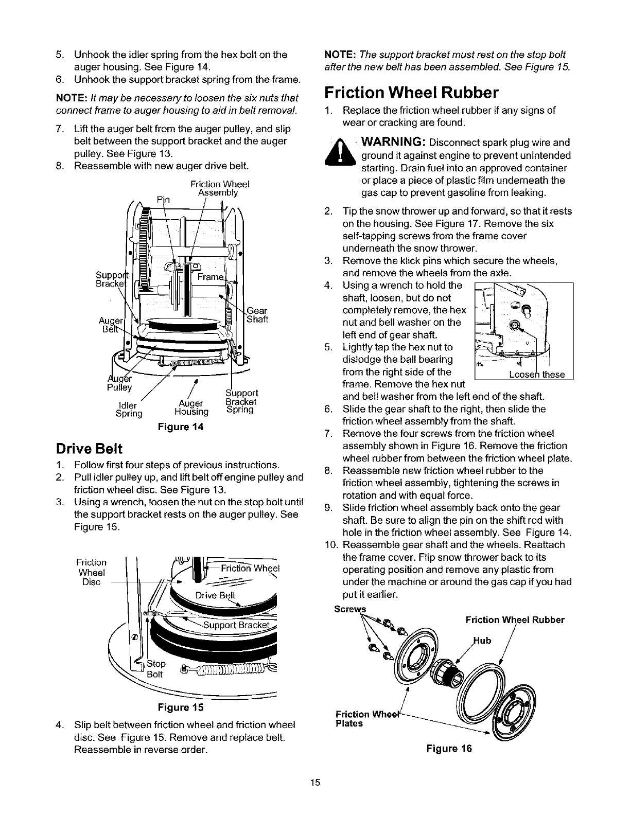
5. Unhook the idler spring from the hex bolt on the
auger housing. See Figure 14.
6. Unhook the support bracket spring from the frame.
NOTE: It may be necessary to loosen the six nuts that
connect frame to auger housing to aid in belt removal.
7. Lift the auger belt from the auger pulley, and slip
belt between the support bracket and the auger
pulley. See Figure 13.
8. Reassemble with new auger drive belt.
Friction Wheel
Assembly
Pin
Pulley /
Idler Auger Bracket
Spring Housing Spring
Figure 14
Drive Belt
1. Follow first four steps of previous instructions.
2. Pull idler pulley up, and lift belt off engine pulley and
friction wheel disc. See Figure 13.
3. Using a wrench, loosen the nut on the stop bolt until
the support bracket rests on the auger pulley. See
Figure 15.
Friction
Wheel
Disc
NOTE: The support bracket must rest on the stop bolt
afterthe new belt has been assembled. See Figure 15.
Friction Wheel Rubber
1. Replace the friction wheel rubber if any signs of
wear or cracking are found.
_b WARNING: Disconnect spark plug wire and
ground it against engine to prevent unintended
starting. Drain fuel into an approved container
or place a piece of plastic film underneath the
gas cap to prevent gasoline from leaking.
2.
3.
4.
5.
.
7.
8.
9.
10.
Tip the snow thrower up and forward, so that it rests
on the housing. See Figure 17. Remove the six
self-tapping screws from the frame cover
underneath the snow thrower.
Remove the ktick pins which secure the wheels,
and remove the wheels from the axle.
Using a wrench to hold the
shaft, loosen, but do not
completely remove, the hex
nut and bell washer on the
left end of gear shaft.
Lightly tap the hex nut to
dislodge the ball bearing
from the right side of the
frame. Remove the hex nut
and bell washer from the left end of the shaft.
Slide the gear shaft to the right, then slide the
friction wheel assembly from the shaft.
Remove the four screws from the friction wheel
assembly shown in Figure 16. Remove the friction
wheel rubber from between the friction wheel plate.
Reassemble new friction wheel rubber to the
friction wheel assembly, tightening the screws in
rotation and with equal force.
Slide friction wheel assembly back onto the gear
shaft. Be sure to align the pin on the shift rod with
hole in the friction wheel assembly. See Figure 14.
Reassemble gear shaft and the wheels. Reattach
the frame cover. Flip snow thrower back to its
operating position and remove any plastic from
under the machine or around the gas cap if you had
put it eadier.
Friction Wheel Rubber
4.
Figure 15
Slip belt between friction wheel and friction wheel
disc. See Figure 15. Remove and replace belt.
Reassemble in reverse order.
Plates
Figure 16
15
Making Adjustments
_bb WARNING: Never attempt to make any
adjustments while the engine is running,
except where specified in operator's manual.
Chute Assembly
The distance snow is thrown can be controlled by
adjusting the angle of the top section of the chute
assembly.
Skid Shoe
The space between the shave plate and the ground can
be adjusted. Refer to the Final Assembly and
Adjustments section on page 6.
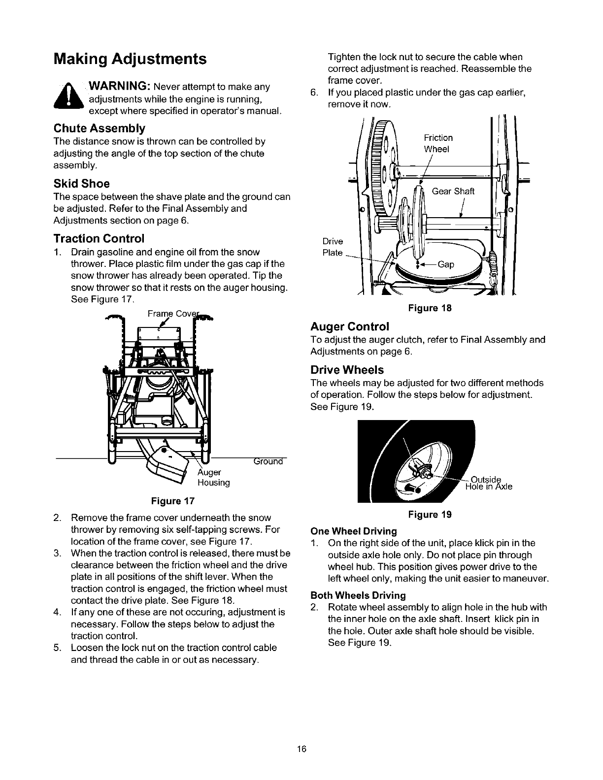
Traction Control
1. Drain gasoline and engine oil from the snow
thrower. Place plastic film under the gas cap if the
snow thrower has already been operated. Tip the
snow thrower so that it rests on the auger housing.
See Figure 17.
Fram_
.
Tighten the lock nut to secure the cable when
correct adjustment is reached. Reassemble the
frame cover.
If you placed plastic under the gas cap earlier,
remove it now.
Figure 18
Auger Control
To adjust the auger clutch, refer to Final Assembly and
Adjustments on page 6.
Drive Wheels
The wheels may be adjusted for two different methods
of operation. Follow the steps below for adjustment.
See Figure 19.
_round
Housing
Figure 17
2. Remove the frame cover underneath the snow
thrower by removing six self-tapping screws. For
location of the frame cover, see Figure 17.
3. When the traction control is released, there must be
clearance between the friction wheel and the ddve
plate in all positions of the shift lever. When the
traction control is engaged, the friction wheel must
contact the drive plate. See Figure 18.
4. If any one of these are not occuring, adjustment is
necessary. Follow the steps below to adjust the
traction control.
5. Loosen the lock nuton the traction control cable
and thread the cable in or out as necessary.
Figure 19
One Wheel Driving
1. On the right side of the unit, place ktick pin in the
outside axle hole only. Do not place pin through
wheel hub. This position gives power drive to the
left wheel only, making the unit easier to maneuver.
Both Wheels Driving
2. Rotate wheel assembly to align hole in the hub with
the inner hole on the axle shaft. Insert klick pin in
the hole. Outer axle shaft hole should be visible.
See Figure 19.
16
Ifthesnowthrowerwiltnotbeusedfor30daysor
longer,orattheendofthesnowseasonwhenthelast
possibilityofsnowisgone,theequipmentneedsto be
storedproperly.
_b WARNING: Never store snow thrower with
fuel in tank indoors or in poorly ventilated
areas, where fuel fumes may reach an open
flame, spark or pilot light as on a furnace, water
heater, clothes dryer or gas appliance.
1. Remove all gasoline from the carburetor and the
fuel tank to prevent gum deposits from forming on
these parts and harming the engine.
IMPORTANT: Fuel left in engine during warm weather
deteriorates and will cause serious starting problems.
NOTE: Fuel stabilizer (such as STA-BIL) is an
acceptable alternative in minimizing the formation of
fuel gum deposits during storage. Add stabilizer to
gasoline in fuel tank or storage container. Always follow
mix ratio found on stabilizer container. Run engine at
least 10 minutes after adding stabilizer to allow it to
reach the carburetor. Do not drain carburetor if using
fuel stabilizer.
_ WARNING: Drain fuel into approved
container outdoors, away from any open flame.
Be certain engine is cool. Do not smoke.
2. Run the engine until the fuel tank is empty and it
stops due to lack of fuel
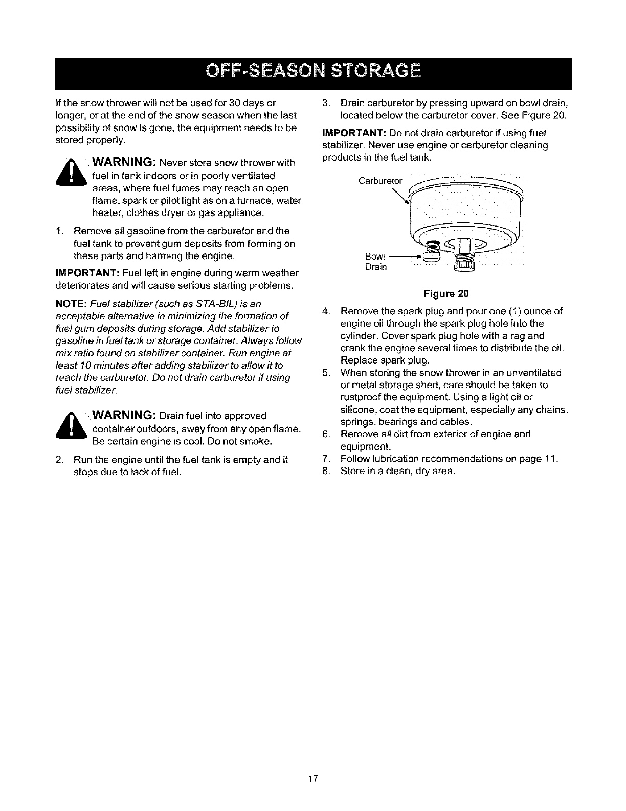
3. Drain carburetor by pressing upward on bowl drain,
located below the carburetor cover. See Figure 20.
IMPORTANT: Do not drain carburetor if using fuel
stabilizer. Never use engine or carburetor cleaning
products in the fuel tank.
Carburetor
Bowl
Drain
Figure 20
4. Remove the spark plug and pour one (1) ounce of
engine oil through the spark plug hole into the
cylinder. Cover spark plug hole with a rag and
crank the engine several times to distribute the oil.
Replace spark plug.
5. When storing the snow thrower in an unventilated
or metal storage shed, care should be taken to
rustproof the equipment. Using a light oil or
silicone, coat the equipment, especially any chains,
springs, bearings and cables.
6. Remove all dirt from exterior of engine and
equipment.
7. Follow lubrication recommendations on page 11.
8. Store in a clean, dry area.
17

Trouble Possible Cause(s) Corrective Action
Engine fails to start Fuel tank empty,or stalefuel,
Engine runs erratic
Water or dirt in fuel system,
Loss of power Spark plug wire loose,
Gas cap vent hole plugged.
Exhaust port plugged.
Engine overheats Carburetor not adjusted
properly.
Blocked fuel line,
Choke not in ON position
Faulty spark plug.
Key not in switch on engine,
Spark plug wire disconnected.
Primer button not depressed.
Unit running on CHOKE.
Blocked fuel line or stale fuel,
Fill tank with clean, flesh gasoline. Fuel will not last over thirty
days unless a fuel stabilizer is used.
Clean fuel line,
Move switch to ON position
Clean, adjust gap or replace.
Insert key,
Connect spark plug wire.
Prime engine 5 times, See instructions for starting engine.
Move choke lever to OFF position.
Clean fuel line; fill tank with clean flesh gasoline, Fuel will not last
over thirty days unless a fuel stabilizer is used,
Drain fuel tank. Refill with fresh fuel.
Connect and tighten spark plug wire.
Remove ice and snow from cap, Be certain vent hole is clear.
Clean engine.
Contact Sears service center,
Incorrect fuel mixture. Drain fuel tank. Refill with proper fuel mixture,
Excessive vibration Loose parts or damaged auger. Stop engine immediately and disconnect spark plug wire. Tighten
all bolts and nuts, Make all necessary repairs. If vibration
continues, have unit serviced by an authorized service dealer,
Unit fails to propel Incorrect adjustment of drive cable. Adjust drive cable. Refer to page 9 of this manual.
itself Drive belt loose or damaged. Replace drive belt. Refer to page 17 of this manual.
Unit fails to Discharge chute clogged, Stop engine immediately and disconnect spark plug wire. Clean
discharge snow discharge chute and inside of auger housing,
Foreign object lodged in auger. Stop engine immediately and disconnect spark plug wire. Remove
incorrect adjustment of drive cable, object from auger,
Drive belt loose or damaged. Adjust drive cable. Refer to page 9 of this manual.
Shear bolts have sheared. Replace drive belt. Refer to page 17 of this manual.
Replace with new shear bolts,
NOTE: This section addresses minor service issues. For further details, contact Sears service center or call the
numbers listed on the back of this manual.
California & U.S. EPA Emission Control Warranty Statement
The U. S. Environmental Protection Agency ("EPA'), the California Air
Resources Board ("CARB") and Tecumseh Products Co. are pleased
to explain the Federal and California Emission Control Systems
Warranty on your new small off-road engine.
In California, new 1995 and later small off-road engines must be
designed, built and equipped to meet the State's stringent anti-smog
standards. In other states, new 1997 and later model year engines
must be designed, built and equipped, at the time of sale, to meet the
U.S. EPA regulations for small non-road engines.
Tecumseh Products Co. will warrant the emission control system on
your small off-road engine for the periods of time listed below,
provided there has been no abuse, neglect, unapproved modification,
or improper maintenance of your small off-road engine. Your
emission control system may include parts such as the carburetor,
ignition system and exhaust system. Also included may be the
compression release system and other emission-related assemblies.
Where a warrantable condition exists, Tecumseh Products Co. will
repair your small off-road engine at no cost to you for diagnosis, parts
and labor.
Manufacturer's Emission Control System Warranty
Emission control systems on 1995 and later model year California
small off-road engines are warranted for two years as hereinafter
noted. In other states, 1997 and later model year engines are also
warranted for two years, if, during such warranty period, any
emission-related part on your engine is defective in materials or
workmanship, the part will be repaired or replaced by Tecumseh
Products Co.
Owner's Warranty Responsibilities
As the small off-road engine owner, you are responsible for the
performance of the required maintenance listed in your Owner's
Manual, but Tecumseh Products Co. will not deny warranty solely
due to the lack of receipts or for your failure to provide written
evidence of the performance of all scheduled maintenance.
As the small off-road engine owner, you should, however, be aware
that Tecumseh Products Co. may deny you warranty coverage if your
small off-road engine or a part thereof has failed due to abuse,
neglect, improper maintenance or unapproved modifications. You are
responsible for presenting your small off-road engine to a Tecumseh
Authorized Service Outlet (any Tecumseh Registered Service Dealer,
Tecumseh Authorized Service Distributor or Tecumseh Central
Warehouse Distributor) as soon as a problem exists. The warranty
repairs should be completed in a reasonable amount of time, not to
exceed 30 days.
Warranty service can be arranged by contacting either Authorized
18

Tecumseh Servicing Dealer or bycontacting Tecumseh Products Co.,
c/o Service Manager, Engine and Transmission Group Service
Division, 900 North Street, Grafton, W153024-1499. Telephone 1-262-
377-2700 [or in USA/Canada call 1-800-558-5402] or see your local
telephone yellow pages under "Engines, Gasoline" for the name,
address and telephone number of a Authorized Tecumseh Servicing
Dealer near you.
Important Note
This warranty statement explains your rights and obligations under the
Emission Control System Warranty ("ECS Warranty") which is provided
to you by Tecumseh Products Co. pursuant to California law.
Tecumseh Products Co. also provides to original purchasers of new
Tecumseh Products Co. engines. The Tecumseh Products Co. Limited
Warranties for New Tecumseh Engine and Electronic Ignition Modules
("Tecumseh Products Co. Warranty") which is enclosed with all new
Tecumseh Products Co. engines on a separate sheet.
The ECS Warranty applies only to the emission control system of your
new engine.To the extent that there is any conflict in terms between the
ECS Warranty and the Tecumseh Products Co. Warranty, the ECS
Warranty shall apply except in any circumstances in which the
Tecumseh Products Co. Warranty may provide a longer warranty
pedod. Both the ECS Warranty and the Tecumseh Products Co.
Warranty describe important dghts and obligations with respect to your
new engine.
Warranty service can only be performed by a Tecumseh Products Co.
Authorized Servicing Dealer. At the time of requesting warranty
service, evidence must be presented of the date of sale to the odginal
purchaser. The purchaser shall pay any charges for making service
calls and/or for transporting the products to and from the place where
the inspection and/or warranty work is performed. The purchaser shall
be responsible for any damage or loss incurred in connection with the
transportation of any engine or any part(s) thereof submitted for
inspection and/or warranty work.
If you have any questions regarding your warranty rights and
responsibilities, you should contact Tecumseh Products Co. at 1-262-
377-2700 or in USA/Canada call 1-800-558-5402.
Emission Control System Warranty
Emission Control System Warranty ("ECS Warranty") for 1995 and
later model year California small off-road engines (for other states,
1997 and later model year engines):
A, APPLICABILITY: This warranty shall apply to 1995 and later
model year California small off-road engines (for other
states, 1997 and later model year engines). The ECS Warranty Period
shall begin on the date the new engine or equipment is delivered to its
original, end-use purchaser, and shall continue for 24 consecutive
months thereafter.
warranted for the remainder of the ECS Warranty Pedod prior to the
first scheduled replacement point for such emissions-related part.
4. Repair or replacement of any warranted, emissionsrelated part
under this ECS Warranty shall be performed at no charge to the owner
at a Tecumseh Authorized Service Outlet.
5. The owner shall not be charged for diagnostic labor which leads to
the determination that a part covered by the ECS Warranty is in fact
defective, provided that such diagnostic work is performed at a
Tecumseh Authorized Service Outlet.
B, GENERAL EMISSIONS WARRANTY COVERAGE:
Tecumseh Products Co. warrants to the original, end-use purchaser of
new engine or equipment and to each subsequent purchaser that its
small off-road engines are:
1. Designed, built and equipped so as to conform with all applicable
regulations adopted by the Air Resources
Board pursuant to its authority in Chapters 1 and 2, Part 5, Division 26
of the Health and Safety Code, and
2. Free from defects in materials and workmanship which,at any time
during the ECS Warranty Period, will cause a warranted emissions-
related part to fail to be identical in all material respects to the part as
described in the engine manufacturer's application for certification.
6. Tecumseh Products Co. shall be liable for damages to other original
engine components or approved modifications proximately caused by
a failure under warranty of an emissiomrelated part covered by the
ECS Warranty.
7. Throughout the ECS Warranty Period, Tecumseh Products Co. shall
maintain a supply of warranted emission-related parts sufficient to
meet the expected demand for such emission-related parts.
8. Any Tecumseh Products Co. authorized and approved emission-
related replacement part may be used in the performance of any ECS
Warranty maintenance or repair and will be provided without charge to
the owner. Such use shall not reduce Tecumseh Products Co. ECS
Warranty obligations.
C. The ECS Warranty only pertains to emissions-related parts on your
engine, as follows:
1. Any warranted, emissions-related parts which are not scheduled for
replacement as required maintenance in the Owner's Manual shall be
warranted for the ECS Warranty Pedod. If any such part fails during the
ECS Warranty Period, it shall be repaired or replaced by Tecumseh
Products Co. according to Subsection 4 below. Any such part repaired
or replaced under the ECS Warranty shall be warranted for any
remainder of the ECS Warranty Period.
2. Any warranted, emissions-related part which is scheduled only for
regular inspection as specified in the Owner's Manual shall be
warranted for the ECS Warranty Pedod. A statement in such written
instructions to the effect of "repair or replace as necessary", shall not
reduce the ECS Warranty Pedod. Any such part repaired or replaced
under the ECS Warranty shall be warranted for the remainder of the
ECS Warranty Period.
3. Any warranted, emissions-related part which is scheduled for
replacement as required maintenance in the Owner's Manual, shall be
warranted for the period of time prior to the first scheduled replacement
point for that part. If the part fails prior to the first scheduled
replacement, the part shall be repaired or replaced by Tecumseh
Products Co. according to Subsection 4 below. Any such emissions-
9. Unapproved add-on or modified parts may not be used to modify or
repair a Tecumseh Products Co. engine. Such use voids this ECS
Warranty and shall be sufficient grounds for disallowing an ECS
Warranty claim. Tecumseh Products Co. shall not be liable hereunder
for failures of any warranted parts of a Tecumseh Products Co. engine
caused by the use of such an unapproved add-on or modified part.
Emission-Related Parts include the following:
1. Carburetor Assembly and its Internal Components
a. Fuel filter
b. Carburetor gaskets
c. Intake pipe
2. Air Cleaner Assembly
a. Air filterelement
3. ignition System, including:
a. Spark plug
b. Ignition module
c. Flywheel assembly
4. Catalytic Muffler (if so equipped)
a. Muffler gasket (if so equipped)
b. Exhaust manifold (ifsoequipped)
5. Crankcase Breather Assembly and its Components
a. Breather connection tube
related part repaired or replaced under the ECS Warranty, shall be
19
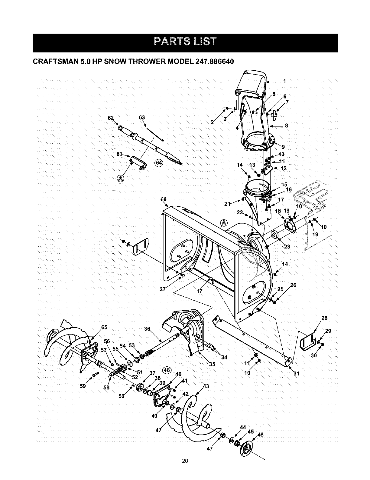
CRAFTSMAN 5.0 HP SNOW THROWER MODEL 247.886640
6_ 6_
14 13
14
/
65 36\
/\
4O
.41
28
/
3O
/43
/
44
47
20
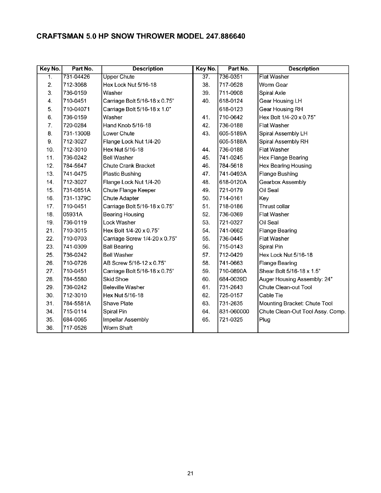
CRAFTSMAN 5.0 HP SNOW THROWER MODEL 247.886640
Key No. Part No.
1, 731-04426
2, 712-3068
3, 736-0159
4, 710-0451
5, 710-04071
6, 736-0159
7, 720-0284
8, 731-1300B
9, 712-3027
10. 712-3010
11. 736-0242
12. 784-5647
13. 741-0475
14. 712-3027
15. 731-0851A
16. 731-1379C
17. 710-0451
18. 05931A
19. 736-0119
21. 710-3015
22. 710-0703
23. 741-0309
25. 736-0242
26. 710-0726
27. 710-0451
28. 784-5580
29. 736-0242
30. 712-3010
31. 784-5581A
34. 715-0114
35. 684-0065
36. 717-0526
Description Key No. Part No.
Upper Chute 37, 736-0351
Hex Lock Nut 5/16-18 38, 717-0528
Washer 39, 711-0908
Carriage Bolt 5/16-18 x 0.75" 40, 618-0124
Carriage Bolt 5/16-18 x 1.0" 618-0123
Washer 41, 710-0642
Hand Knob 5/16-18 42, 736-0188
Lower Chute 43, 605-5189A
Flange Lock Nut 1/4-20 605-5188A
Hex Nut 5/16-18 44, 736-0188
Bell Washer 45, 741-0245
Chute Crank Bracket 46, 784-5618
Plastic Bushing 47, 741-0493A
Flange Lock Nut 1/4-20 48, 618-0120A
Chute Flange Keeper 49, 721-0179
Chute Adapter 50, 714-0161
Carriage Bolt 5/16-18 x 0.75" 51, 718-0186
Bearing Housing 52, 736-0369
Lock Washer 53, 721-0327
Hex Bolt 1/4-20 x 0,75" 54, 741-0662
Carriage Screw 1/4-20 x 0,75" 55, 736-0445
Ball Bearing 56, 715-0143
Bell Washer 57, 712-0429
AB Screw 5/16-12 x 0.75" 58, 741-0663
Carriage Bolt 5/16-18 x 0.75" 59, 710-0890A
Description
Flat Washer
Worm Gear
Spiral Axle
Gear Housing LH
Gear Housing RH
Hex Bolt 1/4-20 x 0,75"
Flat Washer
Spiral Assembly LH
Spiral Assembly RH
Flat Washer
Hex Flange Bearing
Hex Bearing Housing
Flange Bushing
Gearbox Assembly
Oil Seal
Key
Thrust collar
Flat Washer
Oil Seal
Flange Bearing
Flat Washer
Spiral Pin
Hex Lock Nut 5/16-18
Flange Bearing
Shear Bolt 5/16-18 x 1,5"
Skid Shoe 60, 684-0039D
Beleville Washer 61, 731-2643
Hex Nut 5/16-18 62, 725-0157
Shave Plate 63, 731-2635
Spiral Pin 64, 831-060000
Impellar Assembly 65, 721-0325
Worm Shaft
Auger Housing Assembly: 24"
Chute Clean-out Tool
Cable Tie
Mounting Bracket: Chute Tool
Chute Clean-Out Tool Assy. Comp,
Plug
21
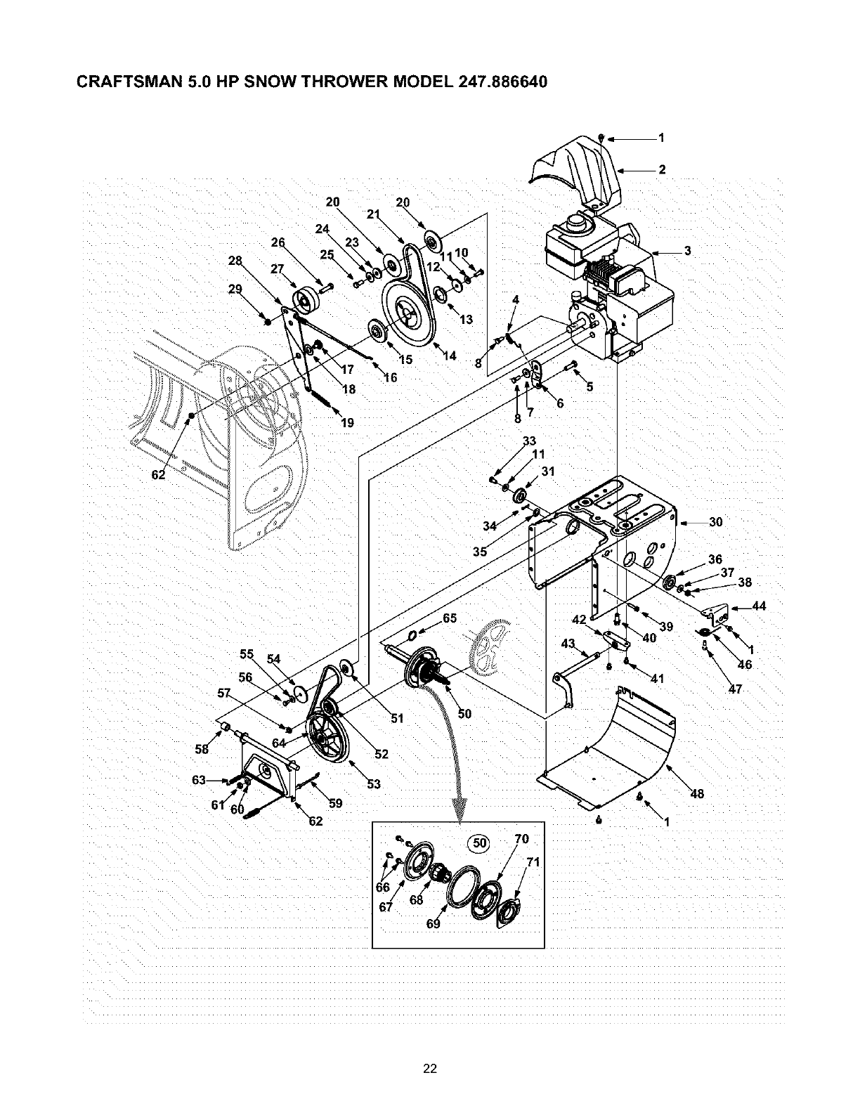
CRAFTSMAN 5.0 HP SNOW THROWER MODEL 247.886640
20
24
4
\6
I1
.31
36
®
\"48
22
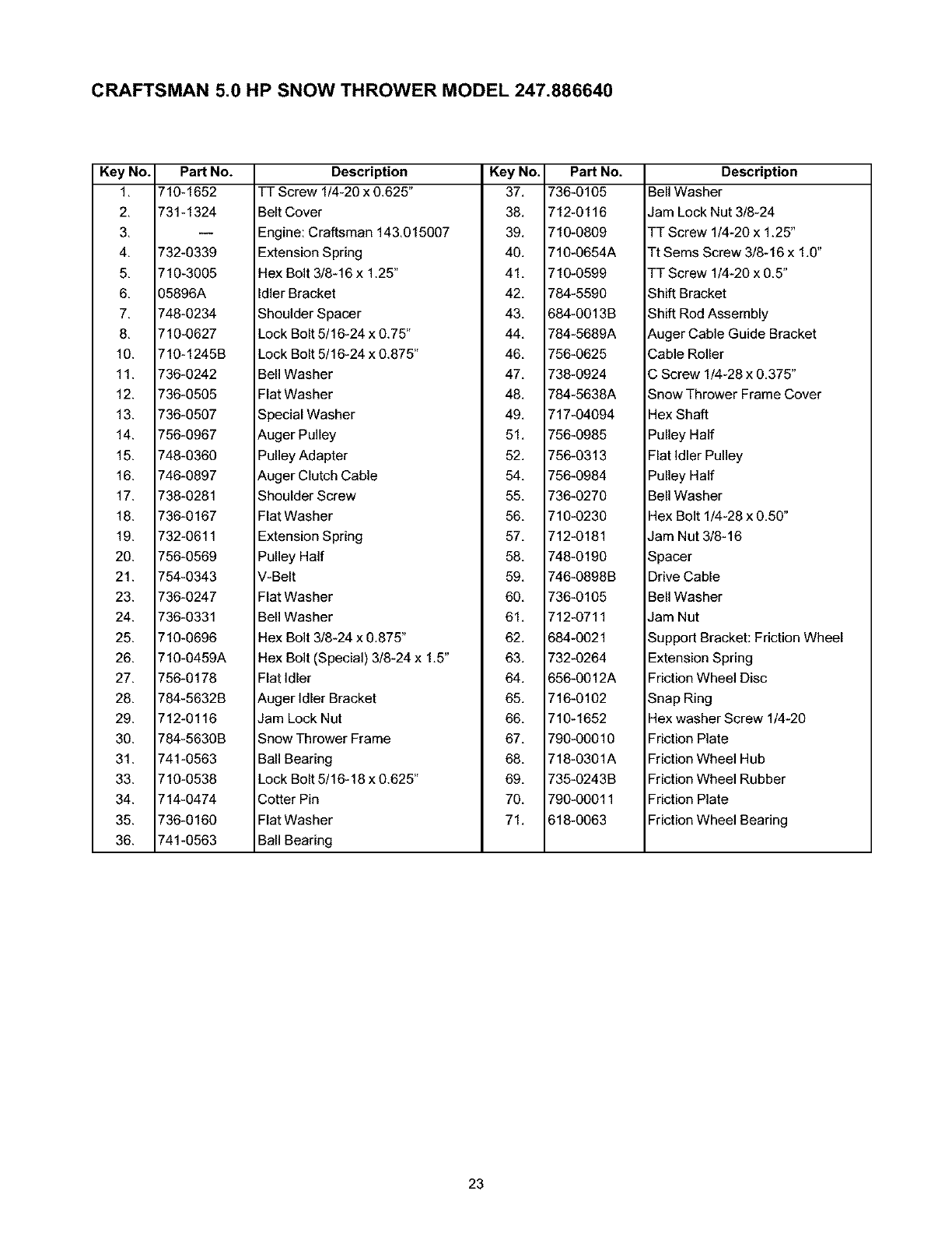
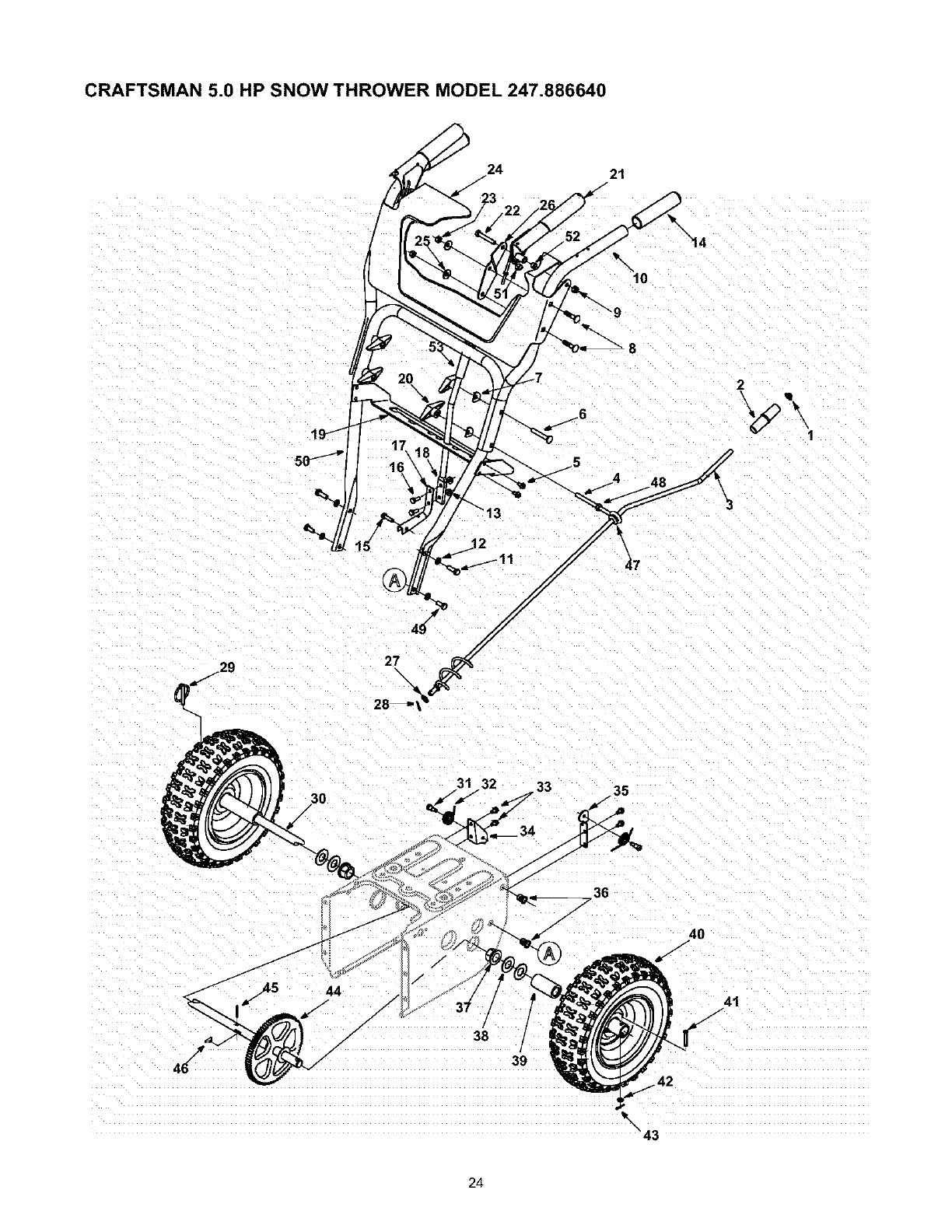
CRAFTSMAN 5.0 HP SNOW THROWER MODEL 247.886640
Key No. Part No.
1, 710-1652
2, 731-1324
3,
4, 732-0339
5, 710-3005
6, 05896A
7, 748-0234
8, 710-0627
10. 710-1245B
11. 736-0242
12. 736-0505
13. 736-0507
14. 756-0967
15. 748-0360
16. 746-0897
17. 738-0281
18. 736-0167
19. 732-0611
20. 756-0569
21. 754-0343
23. 736-0247
24. 736-0331
25. 710-0696
26. 710-0459A
27. 756-0178
28. 784-5632B
29. 712-0116
30. 784-5630B
31. 741-0563
33. 710-0538
34. 714-0474
35. 736-0160
36. 741-0563
Description Key No. Part No.
TT Screw 1/4-20 x 0.625" 37, 736-0105
Belt Cover 38, 712-0116
Engine: Craftsman 143,015007 39, 710-0809
Extension Spring 40, 710-0654A
Hex Bolt 3/8-16 x 1.25" 41, 710-0599
Idler Bracket 42, 784-5590
Shoulder Spacer 43, 684-0013B
Lock Bolt 5/16-24 x 0.75" 44, 784-5689A
Lock Bolt 5/16-24 x 0.875" 46, 756-0625
Bell Washer 47, 738-0924
Flat Washer 48, 784-5638A
Special Washer 49, 717-04094
Auger Pulley 51, 756-0985
Pulley Adapter 52, 756-0313
Auger Clutch Cable 54, 756-0984
Shoulder Screw 55, 736-0270
Flat Washer 56, 710-0230
Extension Spring 57, 712-0181
Pulley Half 58, 748-0190
V-Belt 59, 746-0898B
Flat Washer 60, 736-0105
Bell Washer 61, 712-0711
Hex Bolt 3/8-24 x 0,875" 62, 684-0021
Hex Bolt (Special) 3/8-24 x 1.5" 63, 732-0264
Flat Idler 64, 656-0012A
Auger Idler Bracket 65, 716-0102
Jam Lock Nut 66, 710-1652
Snow Thrower Frame 67, 790-00010
Ball Bearing 68, 718-0301A
Lock Bolt 5/16-18 x 0,625" 69, 735-0243B
Cotter Pin 70, 790-00011
Flat Washer 71, 618-0063
Ball Bearing
Description
Bell Washer
Jam Lock Nut 3/8-24
TT Screw 1/4-20 x 1,25"
Tt Sems Screw 3/8-16 x 1,0"
TT Screw 1/4-20 x 0,5"
Shift Bracket
Shift Rod Assembly
Auger Cable Guide Bracket
Cable Roller
C Screw 1/4-28 x 0,375"
Snow Thrower Frame Cover
Hex Shaft
Pulley Half
Flat Idler Pulley
Pulley Half
Bell Washer
Hex Bolt 1/4-28 x 0,50"
Jam Nut 3/8-16
Spacer
Drive Cable
Bell Washer
Jam Nut
Support Bracket: Friction Wheel
Extension Spring
Friction Wheel Disc
Snap Ring
Hex washer Screw 1/4-20
Friction Plate
Friction Wheel Hub
Friction Wheel Rubber
Friction Plate
Friction Wheel Bearing
23
CRAFTSMAN 5.0 HP SNOW THROWER MODEL 247.886640
24 21
\"14
8
2
\ •
\3
3O
/
31 33 35
45
/
44
/38
/
/39
_42
\43
24
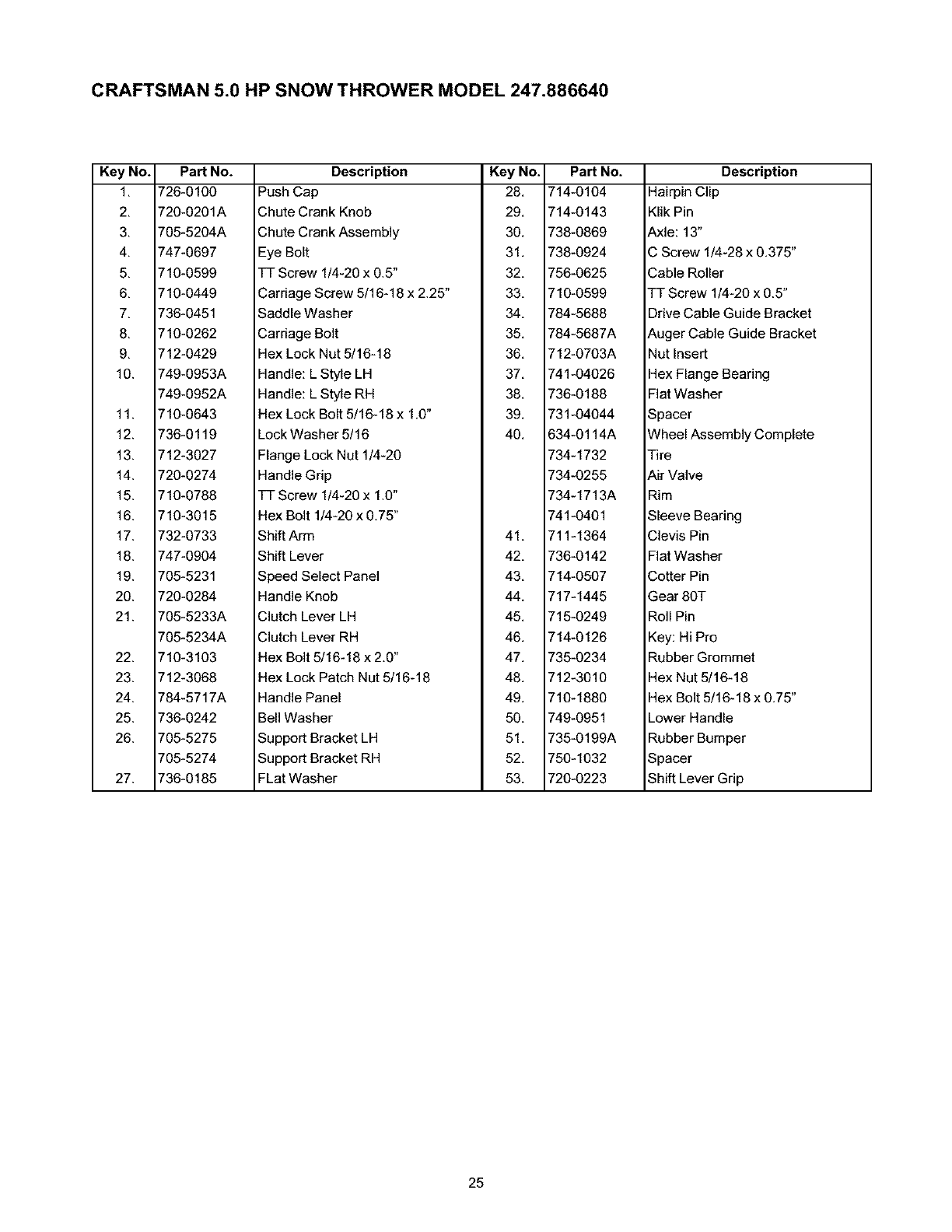
CRAFTSMAN 5.0 HP SNOW THROWER MODEL 247.886640
Key No. Part No.
1, 726-0100
2, 720-0201A
3, 705-5204A
4, 747-0697
5, 710-0599
6, 710-0449
7, 736-0451
8, 710-0262
9, 712-0429
10. 749-0953A
749-0952A
11. 710-0643
12. 736-0119
13. 712-3027
14. 720-0274
15. 710-0788
16. 710-3015
17. 732-0733
18. 747-0904
19. 705-5231
20. 720-0284
21. 705-5233A
705-5234A
22. 710-3103
23. 712-3068
24. 784-5717A
25. 736-0242
26. 705-5275
705-5274
27. 736-0185
Description Key No. Part No.
Push Cap 28, 714-0104
Chute Crank Knob 29, 714-0143
Chute Crank Assembly 30, 738-0869
Eye Bolt 31, 738-0924
TT Screw 1/4-20 x 0.5" 32, 756-0625
Carriage Screw 5/16-18 x 2.25" 33, 710-0599
Saddle Washer 34, 784-5688
Carriage Bolt 35, 784-5687A
Hex Lock Nut 5/16-18 36, 712-0703A
Handle: L Style LH 37, 741-04026
Handle: L Style RH 38, 736-0188
Hex Lock Bolt 5/16-18 x 1,0" 39, 731-04044
Lock Washer 5/16 40, 634-0114A
Flange Lock Nut 1/4-20 734-1732
Handle Grip 734-0255
TT Screw 1/4-20 x 1.0" 734-1713A
Hex Bolt 1/4-20 x 0,75" 741-0401
Shift Arm 41, 711-1364
Shift Lever 42, 736-0142
Speed Select Panel 43, 714-0507
Handle Knob 44, 717-1445
Clutch Lever LH 45, 715-0249
Clutch Lever RH 46, 714-0126
Hex Bolt 5/16-18 x 2,0" 47, 735-0234
Hex Lock Patch Nut 5/16-18 48, 712-3010
Handle Panel 49, 710-1880
Bell Washer 50, 749-0951
Support Bracket LH 51, 735-0199A
Support Bracket RH 52, 750-1032
FLat Washer 53, 720-0223
Description
Hairpin Clip
Klik Pin
Axle: 13"
C Screw 1/4-28 x 0,375"
Cable Roller
TT Screw 1/4-20 x 0.5"
Drive Cable Guide Bracket
Auger Cable Guide Bracket
Nut Insert
Hex Flange Bearing
Flat Washer
Spacer
Wheel Assembly Complete
Tire
Air Valve
Rim
Sleeve Bearing
Clevis Pin
Flat Washer
Cotter Pin
Gear 80T
Roll Pin
Key: Hi Pro
Rubber Grommet
Hex Nut 5/16-18
Hex Bolt 5/16-18 x 0,75"
Lower Handle
Rubber Bumper
Spacer
Shift Lever Grip
25
CRAFTSMAN 5.0 HP ENGINE 143.045001 FOR SNOW THROWER MODEL 247.886640
275_
364,
_2-3ol
219 370B
262
400
t328
26
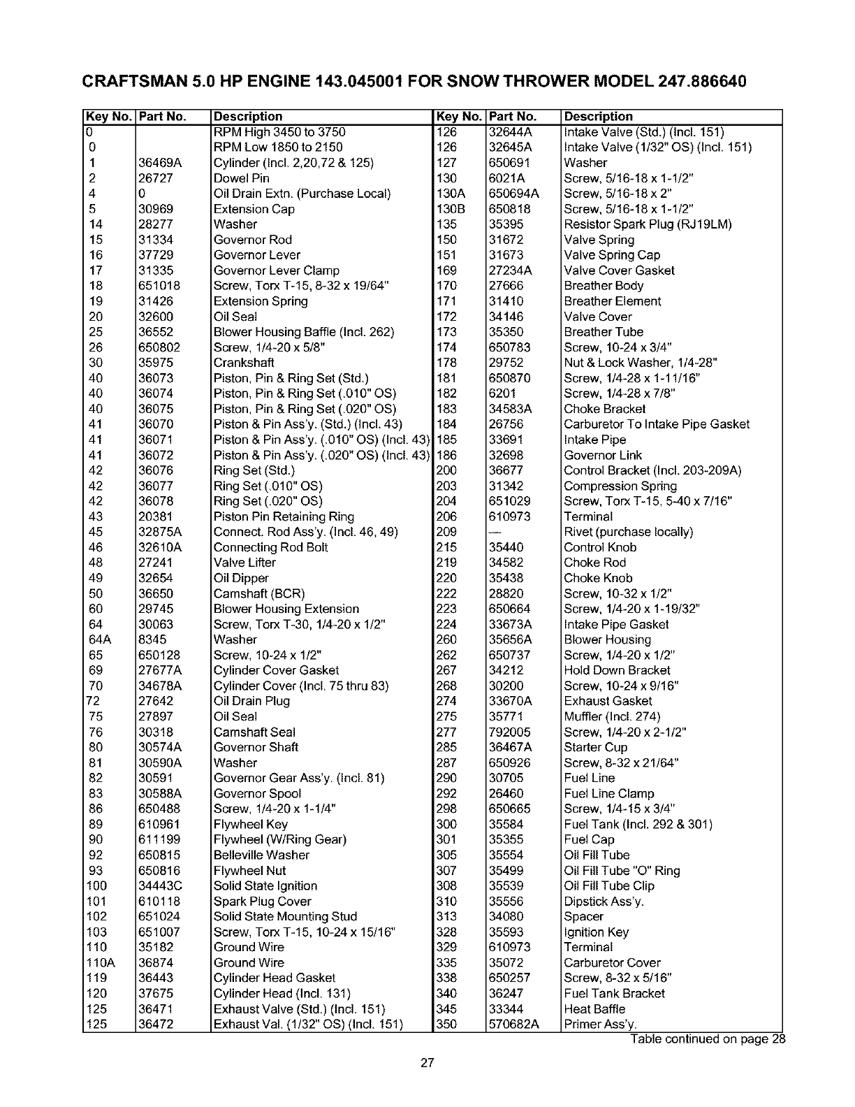
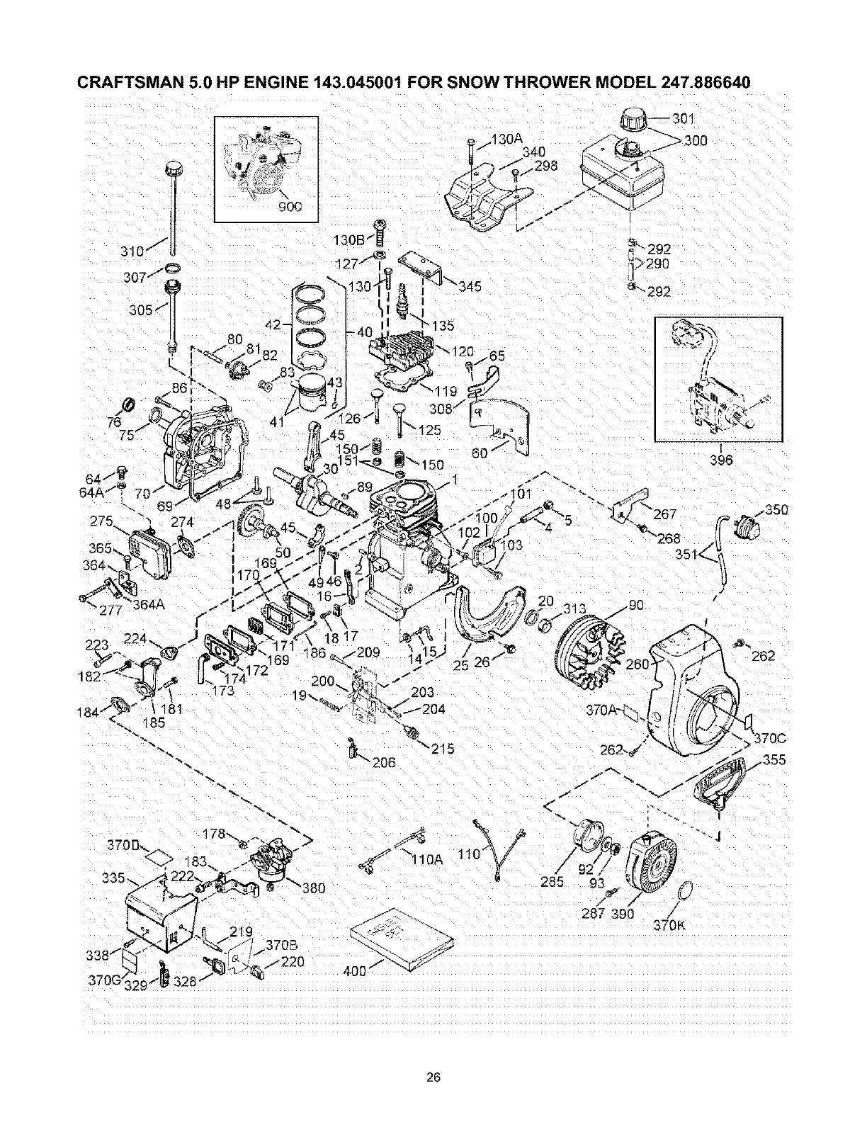
CRAFTSMAN 5.0 HP ENGINE 143.045001 FOR SNOW THROWER MODEL 247.886640
Key No. Part No. Description Key No. Part No.
0 RPM High 3450 to 3750 126 32644A
0 RPM Low 1850 to 2150 126 32645A
1 36469A Cylinder (Incl. 2,20,72 & 125) 127 650691
2 26727 Dowel Pin 130 6021A
4 0 Oil Drain Extn. (Purchase Local) 130A 650694A
5 30969 Extension Cap 130B 650818
14 28277 Washer 135 35395
15 31334 Governor Rod 150 31672
16 37729 Governor Lever 151 31673
17 31335 Governor Lever Clamp 169 27234A
18 651018 Screw, Torx T-15, 8-32 x 19/64" 170 27666
19 31426 Extension Spring 171 31410
20 32600 Oil Seal 172 34146
25 36552 Blower Housing Baffle (Incl. 262) 173 35350
26 650802 Screw, 1/4-20 x 5/8" 174 650783
30 35975 Crankshaft 178 29752
40 36073 Piston, Pin & Ring Set (Std.) 181 650870
40 36074 Piston, Pin & Ring Set (.010" OS) 182 6201
40 36075 Piston, Pin & Ring Set (.020" OS) 183 34583A
41 36070 Piston & Pin Ass'y. (Std.) (Incl. 43) 184 26756
41 36071 Piston & Pin Ass'y. (.010" OS) (Incl. 43) 185 33691
41 36072 Piston & Pin Ass'y. (.020" OS) (incl. 43) 186 32698
42 36076 Ring Set (Std.) 200 36677
42 36077 Ring Set (.010" OS) 203 31342
42 36078 Ring Set (.020" OS) 204 651029
43 20381 Piston Pin Retaining Ring 206 610973
45 32875A Connect. Rod Ass'y. (incl. 46, 49) 209 --
46 32610A Connecting Rod Bolt 215 35440
48 27241 Valve Lifter 219 34582
49 32654 Oil Dipper 220 35438
50 36650 Camshaft (BCR) 222 28820
60 29745 Blower Housing Extension 223 650664
64 30063 Screw, Torx T-30, 1/4-20 x 1/2" 224 33673A
64A 8345 Washer 260 35656A
65 650128 Screw, 10-24 x 1/2" 262 650737
69 27677A Cylinder Cover Gasket 267 34212
70 34678A Cylinder Cover (Inci. 75 thru 83) 268 30200
72 27642 Oil Drain Plug 274 33670A
75 27897 Oil Seal 275 35771
76 30318 Camshaft Seal 277 792005
80 30574A Governor Shaft 285 36467A
81 30590A Washer 287 650926
82 30591 Governor Gear Ass'y. (Incl. 81) 290 30705
83 30588A Governor Spool 292 26460
86 650488 Screw, 1/4-20 x 1-1/4" 298 650665
89 610961 Flywheel Key 300 35584
90 611199 Flywheel (W/Ring Gear) 301 35355
92 650815 Beiieviiie Washer 305 35554
93 650816 Flywheel Nut 307 35499
100 34443C Solid State Ignition 308 35539
101 610118 Spark Plug Cover 310 35556
102 651024 Solid State Mounting Stud 313 34080
103 651007 Screw, Torx T-15, 10-24 x 15/16" 328 35593
110 35182 Ground Wire 329 610973
110A 36874 Ground Wire 335 35072
119 36443 Cylinder Head Gasket 338 650257
120 37675 Cylinder Head (inci. 131) 340 36247
125 36471 Exhaust Valve (Std.) (Incl. 151) 345 33344
125 36472 Exhaust Vai. (1/32" OS) (IncL 151) 350 570682A
Description
intake Valve (Std,) (IncL 151)
intake Valve (1/32" OS) (IncL 151 )
Washer
Screw, 5/16-18 x 1-1/2"
Screw, 5/16-18 x 2"
Screw, 5/16-18 x 1-1/2"
Resistor Spark Plug (RJ 19LM)
Valve Spring
Valve Spring Cap
Valve Cover Gasket
Breather Body
Breather Element
Valve Cover
Breather Tube
Screw, 10-24 x 3/4"
Nut & Lock Washer, 1/4-28"
Screw, 1/4-28 x 1-11/16"
Screw, 1/4-28 x 7/8"
Choke Bracket
Carburetor To Intake Pipe Gasket
Intake Pipe
Governor Link
Control Bracket (Incl. 203-209A)
Compression Spring
Screw, Torx T-15, 5-40 x 7/16"
Terminal
Rivet (purchase locally)
Control Knob
Choke Rod
Choke Knob
Screw, 10-32 x 1/2"
Screw, 1/4-20 x 1-19/32"
Intake Pipe Gasket
Blower Housing
Screw, 1/4-20 x 1/2"
Hold Down Bracket
Screw, 10-24 x 9/16"
Exhaust Gasket
Muffler (Incl. 274)
Screw, 1/4-20 x 2-1/2"
Starter Cup
Screw, 8-32 x 21/64"
Fuel Line
Fuel Line Clamp
Screw, 1/4-15 x 3/4"
Fuel Tank (inci. 292 & 301 )
Fuel Cap
Oil Fill Tube
Oil Fill Tube "O" Ring
Oil Fill Tube Clip
Dipstick Ass'y,
Spacer
Ignition Key
Terminal
Carburetor Cover
Screw, 8-32 x 5/16"
Fuel Tank Bracket
Heat Baffle
Primer Ass'y.
Table continued on page 28
27
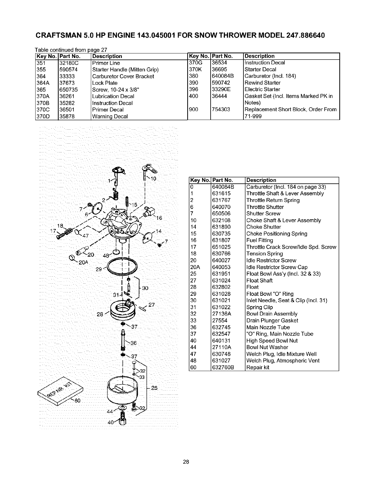
CRAFTSMAN 5.0 HP ENGINE 143.045001 FOR SNOW THROWER MODEL 247.886640
Table continued from
Key No.
351
355
364
364A
365
370A
370B
370C
370D
Pad No.
32180C
590574
33333
37673
650735
36261
35282
36501
35878
age 27
Description
Primer Line
Starter Handle (Mitten Grip)
Carburetor Cover Bracket
Lock Plate
Screw, 10-24 x 3/8"
Lubrication Decal
Instruction Decal
Primer Decal
Warning Decal
Key No. Pad No.
370G 36534
370K 36695
380 640084B
390 590742
396 33290E
400 36444
900 754303
Description
Instruction Decal
Starter Decal
Carburetor (IncL 184)
Rewind Starter
Electric Starter
Gasket Set (IncL Items Marked PK in
Notes)
Replacement Short Block, Order From
71-999
I
I ,3o
_'_37
Key No. Pad No.
0 640084B
1 631615
2 631767
6 640070
7 650506
10 632108
14 631890
15 630735
16 631807
17 651025
18 630766
20 640027
20A 640053
25 631951
27 631024
28 632802
29 631028
30 631021
31 631022
32 27136A
33 27554
36 632745
37 632547
40 640131
44 27110A
47 630748
48 631027
60 632760B
Description
Carburetor (IncL 184 on page 33)
Throttle Shaft & Lever Assembly
Throttle Return Spring
Throttle Shutter
Shutter Screw
Choke Shaft & Lever Assembly
Choke Shutter
Choke Positioning Spring
Fuel Fitting
Throttle Crack Screw/Idle Spd. Screw
Tension Spring
Idle Restrictor Screw
Idle Restrictor Screw Cap
Float Bowl Ass'y (Incl. 32 & 33)
Float Shaft
Float
Float Bowl "O" Ring
Inlet Needle, Seat & Clip (Incl. 31)
Spring Clip
Bowl Drain Assembly
Drain Plunger Gasket
Main Nozzle Tube
"O" Ring, Main Nozzle Tube
High Speed Bowl Nut
Bowl Nut Washer
Welch Plug, Idle Mixture Well
Welch Plug, Atmospheric Vent
Repair kit
- 25
28
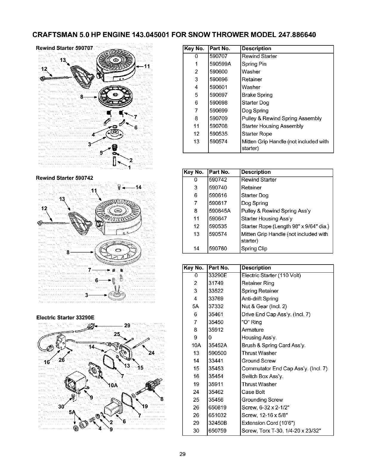
CRAFTSMAN 5.0 HP ENGINE 143.045001 FOR SNOW THROWER MODEL 247.886640
Rewind Starter 590707
12 '
Key No.
0
1
2
3
4
5
6
7
8
11
12
13
Part No.
590707
590599A
590600
590696
590601
590697
590698
590699
590709
590708
590535
590574
Description
Rewind Starter
Spring Pin
Washer
Retainer
Washer
Brake Spring
Starter Dog
Dog Spring
Pulley & Rewind Spring Assembly
Starter Housing Assembly
Starter Rope
Mitten Grip Handle (not included with
starter)
Rewind Starter 590742
7_ _ U
Electric Starter 33290E
Key No.
0
3
6
7
8
11
12
13
14
Key No.
0
2
3
4
5A
6
7
8
9
10A
13
14
15
16
19
24
25
26
26
29
3O
Part No.
590742
590740
590616
590617
590645A
590647
590535
590574
590760
Description
Rewind Starter
Retainer
Starter Dog
Dog Spring
Pulley & Rewind Spring Ass'y
Starter Housing Ass'y
Starter Rope (Length 98" x 9/64" dia,)
Mitten Grip Handle (not included with
starter)
Spring Clip
Part No.
33290E
31749
33522
33769
37332
35461
35450
35912
0
35452A
590500
33441
35453
35454
35911
35462
35456
650819
651032
32450B
650759
Description
Electric Starter (110 Volt)
Retainer Ring
Spring Retainer
Anti-drift Spring
Nut & Gear (Incl. 2)
Drive End Cap Ass'y. (Incl. 7)
"O" Ring
Armature
Housing Ass'y.
Brush & Spring Card Ass'y.
Thrust Washer
Ground Screw
Commutator End Cap Ass'y. (Incl. 7)
Switch Box Ass'y.
Thrust Washer
Case Bolt
Grounding Screw
Screw, 6-32 x 2-1/2"
Screw, 12-16 x 5/8"
Extension Cord (10'6")
Screw, Torx T-30, 1/4-20 x 23/32"
29
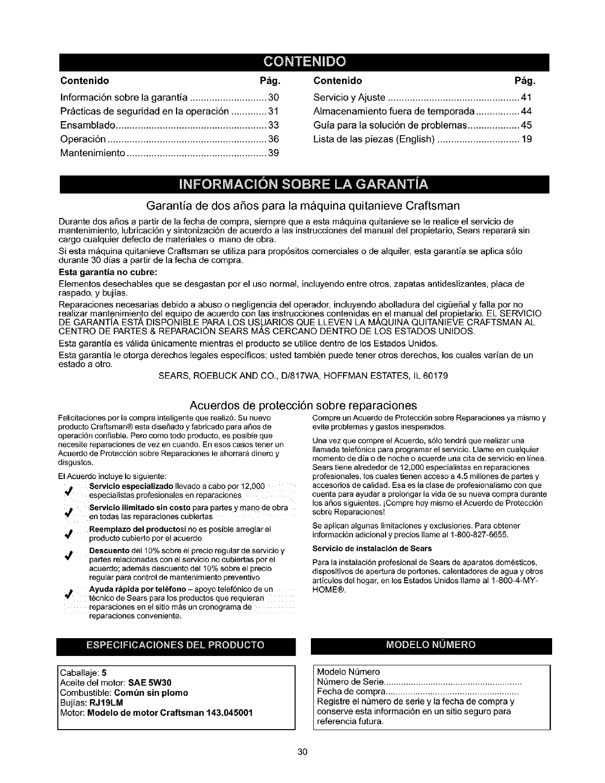
Contenido P_g.
Informaci6n sobre la garantia ............................ 30
Pr&cticas de seguridad en la operaci6n ............. 31
Ensamblado ....................................................... 33
Operaci6n .......................................................... 36
Mantenimiento ................................................... 39
Contenido P&g.
Servicio y Ajuste ................................................ 41
Almacenamiento fuera de temporada ................ 44
Guia para la soluci6n de problemas ................... 45
Lista de las piezas (English) .............................. 19
Garantia de dos aSos para la maquina quitanieve Craftsman
Durante dos aSos a partir de la fecha de compra, siempre que a esta m_quina quitanieve se le realice el servicio de
mantenimiento, lubricaci6n y sintonizaci6n de acuerdo alas instrucciones del manual del propietario, Sears reparar_ sin
cargo cualquier defecto de materiales o mano de obra.
Siesta m_quina quitanieve Craftsman se utiliza para prop6sitos comerciales o de alquiler, esta garantia se aplica s61o
durante 30 dias a partir de la fecha de compra.
Esta garantia no cubre:
Elementos desechables que se desgastan por el uso normal, incluyendo entre otros, zapatas antideslizantes, placa de
raspado, y bujias.
Reparaciones necesarias debido a abuso o negligencia del operador, incluyendo abolladura del cigL_eSaly falla por no
realizar mantenimiento del equipo de acuerdo con las instrucciones contenidas en el manual del propietario. EL SERVICIO
DE GARANTiA ESTA DISPONIBLE PARA LOS USUARIOS QUE LLEVEN LA MAQUINA QUITANIEVE CRAFTSMAN AL
CENTRE) DE PARTES & REPARACI_)N SEARS M,g.SCERCANO DENTRO DE LOS ESTADOS UNIDOS.
Esta garantia es v_lida Qnicamente mientras el producto se utilice dentro de los Estados Unidos.
Esta garantia le otorga derechos legales especificos; usted tambi6n puede tener otros derechos, los cuales varian de un
estado a otro.
SEARS, ROEBUCK AND CO., D/817WA, HOFFMAN ESTATES, IL 60179
Acuerdos de protecci6n sobre reparaciones
Felicitaciones per la compra inteligeate que realiz6+ Su nuevo
producto Craftsman@ esta disefLado y fabricado para aSos de
operacidn confiable+ Pero como todo producto, es posible que
necesite reparaciones de vez en cuando+ En esos casos tenet un
Acuerdo de Protecci6n sobre Reparaciones le ahorrara dinero y
disgustos,
El Acuerdo incluye Io siguiente:
,_ Servicio especializado Ilevado a cabo per 12,000
especialistas profesiona!es en reparaciones
Compre un Acuerdo de Protecci6n sobre Reparaciones ya mismo y
evite problemas y gastos inesperados+
Una vez que compre el Acuerdo, s61otendr_ que realizar una
Ilamada telef6nica para programar el servicio, Llame en cualquier
momento de dia o de aoche o acuerde una cita de servicio en Iinea+
Sears tiene alrededor de 12,000 especialistas en reparaciones
profesionales, los cuales tienen acceso a 4.5 millones de partes y
accesorioa de calidad+ Esa es la clase de profesionalisrno con que
cuenta para ayudar a prolongar la vida de su nueva compra durante
los afros siguientes+ iCompre hoy mismo el Acuerdo de Protecci6n
Servicio ilimitado sin costo para partes y man0 de obra sobre Reparaciones!
en todas las reparacioaes cubiertas
,_ Reemplazo del productosi no es posible arreglar el
producto cubierto por el acuerdo
Descuento de110% sobre el precio regular de servicio y
partes relacionadas con el servicio no cubiertas por el
acuerdo; adem_s descuento de110% sobre el precio
regular para control de mantenimiento preventivo
Ayuda r&pida por tel_fono- apoyo telef6nico de un
t_cnico de Sears para los productos que requieran
reparaciones en el sitio mas un cronograma de
reparaciones conveniente,
Se aplican algunas limitaciones y exclusiones+ Para obtener
informaci6n adicional y precios Ilame al 1-800-827-6655+
Servicio de instalacion de Sears
Para la instalacidn profesional de Sears de aparatos domesticos,
dispositivos de apertura de portones, calentadores de agua y otros
articulos del hogar, en los Estados Unidos Ilame al 1-800-4-MY-
HOME@.
Caballaje: 5
Aceite del motor: SAE 5W30
Combustible: Com_n sin plomo
Bujias: RJ19LM
Motor: Mode ode motor Craftsman 143.045001
Modelo Nemero
NQmero de Serie ........................................................
Fecha de compra ......................................................
Registre el n_mero de serie y la fecha de compra y
conserve esta informaci6n en un sitio seguro para
referencia futura.
3O
_lb ADVERTENClA: Este simbolo indica instrucciones de seguridad importantes que de no seguirse,
podrian poner en peligro la seguridad personal y!o la propieclad suya y de terceros. Lea y siga todas las
instrucciones en este manual antes de iniciar la operaciOn de esta maquina. En caso de no seguir estas
instrucciones podrian producirse lesiones personales. Cuando yea este simbolo_preste atencion a la
advertencia..
d_lb ADVERTENCIA: El escape del motor de este producto, algunos de sus componentes y algunos
componentes del vehiculo contienen o emiten productos quimicos que el estado de California considera
que pueclen proclucir c&ncer, defectos de nacimiento u otros problemas reproductivos.
PELIGRO: Esta m_quina est_ diseOada para ser utilizada respetando las reglas de seguridad contenidas en este manual. AI
igual que con cualquier tipo de equipo elOctrico, una falla o error de parte del operador puede producir graves lesiones. Esta
m_quina es capaz de amputar manos y pies y de arrojar objetos con gran fuerza. De no respetar las instrucciones de seguridad
siguientes se pueden producir lesiones graves o la muerte.
Capacitacibn
1. Lea. comprenda y respete todas las instrucciones que figuran
en la m_quina o en este(os) manual(es) antes de proceder al
ensamblado y operaci0n del equipo. Guarde este manual en un
lugarseguro para referencias futuras y regulares y para
solicitar partes de reemplazo.
2. Familiaricese contodos los controles y con su funcionamiento.
Sepa c0mo detener la m&quinay cOmodesengranar los
controles.
3. Nunca permitaque niOosmenores de 14 aOosoperen esta
m_quina. Los niOosde 14 aOosy mayores de 14a5os deben
leer y comprender las instrucciones de operaciOny las reglas
deseguridad contenidas en este manual y deben ser
entrenados y supervisados per uno de los padres.
4. Nunca permitaque adultos sin los conocimientos adecuados
acercade la m_quina la operen.
5. Losobjetos arrojados por la m_quina pueden producir lesiones
graves. Planifique el patron en el que va air arrojando nieve
para evitar que la descarga de material se realice hacia los
caminos, losobservadores,etc.
6. Mantenga a los observadores, ayudantes, mascotas y a los
niOospor Io menos a 75 pies de la m_quina mientras la misma
est_en funcionamiento. Detenga la m&quina si alguien entra en
la zona.
7. Sea precavido para evitar patinarse o caerse especialmente
cuando opera la m&quina en revers&
Preparativos
1. Revise minuciosamente la zona donde se utilizar_ elequipo.
Saque redes los felpudos, peri0dicos, trineos, tablas, cables y
otrosobjetos extra_os con los que podria tropezar o que
podrian ser arrojados per la barrena /motor.
2. Para protegerse los ojos utilice siempre anteojos o antiparras
deseguridad mientras opera la m&quina o mientras la ajusta o
repara. Los objetos arrojados que rebotan pueden lesionar
gravemente la vista.
3. No epere la m_quina sin la vestimenta adecuada paraestar al
aire libre en invierno. No utilice alhajas, bufandas largas uotras
prendassueltas que podrian enredarse en las partes m0viles.
Utilice un calzado especial para superficies resbaladizas.
4. Use un cordon prolongador y untomacorriente detres cables
conconexi0n a tierra para todas las unidades con motores con
encendido elOctdco.
5. Ajuste la altura de la caja del tomacorriente para limpiar la
gravao las superficies con piedras trituradas.
6. Desengranetodas las palancas de embrague antes de
arrancar el motor.
7,
8.
9.
Nunca intente realizar ajustes mientras el motor est&en
marcha excepto en los casesespecificamente recomendados
en el manual del operador.
Deje que el motor y la m&quina se adapten a la temperatura
exterior antes de comenzar a sacar la nieve.
Sea sumamente cuidadoso al manipular la gasolina para evitar
lesiones o dafos. La gasolina es altamente inflamable y los
vapores son explosivos. Se puede lesionar gravemente si
derrama gasolina sobre usted o sobre la ropa ya que se puede
prender fuego. Lave la piel y c_mbiese de ropa de inmediato.
a. Utilice s01orecipientes para gasolina aprobados.
b. Apague todos los cigarrillos, cigarros, pipas y otras
fuentes de combustion.
c. Nunca cargue combustible en la m_quina en un
espacio cerrado.
d. Nunca saque la tapa del combustible ni agregue
combustible mientras el motor est_ caliente o en
marcha.
e. Deje que el motor se enfrie per Io menos dos minutes
antes de velvet a cargar combustible.
f. Nunca recargue el tanque de combustible. Llene el
tanque nom_s de 1/2 pulgada por debajo de la base
del cuello del filtro para dejar espacio para la dilataciOn
del combustible.
g. Vuelva a colocar la tapa de la gasolina y ajt]stela bien.
h. Limpie la gasolina derramada sobre el motor y el
equipo. Traslade la m_quina a otra zona. Espere 5
minutos antes de encender el motor.
i. Nunca almacene lam_quina o el recipiente de
combustible en unespacio cerrado donde haya fuego.
chispas o luz piloto (per ejemplo, homes, calentadores
de agua, calefactores, secadores de ropa. etc.).
j. Deje que la m&quina se enfrie durante 5 minutos antes
de almacenada.
Operacibn
1. No ponga las manos o los piescerca de las piezas rotatorias.
en la caja de la barrena /motor o en el canal de descarga. El
contacto con piezas rotatorias puede amputar manes y pies.
2. Lapalanca del embrague de la barrena /motor es un
dispositivo de seguridad. Nunca pase per alto su
funcionamiento. Dehacedo la operaciOnde la m_quina es
riesgosa y puede ocasionar lesiones.
3. Laspalancas del embrague deben funcionar bien en ambas
direcciones y regresar autom_ticamente a la posici0n de
desengrane cuando se las suelta.
31
4. Nuncaoperelam_quinasifaltauncanaldedescargaoel
mismoest_dafiado.Mantengatodoslosdispositivosde
seguridadensulugaryenfuncionamiento.
5. Nuncaenciendaelmotorenespacioscerradosoenunazona
pocoventilada.Elescapedelmotorcontienemon6xidode
carbono,ungasinodoroyletaL
6. Nooperelam_quinaestandobajolosefectosdelalcoholode
drogas.
7. Elsilenciadoryelmotorsecalientanyproducenuna
quemadura.Nolostoque.
8. Seasumamenteprecavidocuandooperelam_quinasobreuna
superficiecongravaocuandolacruce.Mant6ngasealertapor
sisepresentanpeligrosocultosotr_nsito.
9. Tengacuidadocuandocambiededirecci6nocuandooperela
m_quinaenpendientes.
10.Planifiqueelpatr6nenelquevaairarrojandonieveparaevitar
queladescargadematerialseproduzcahacialasventanas,
lasparedes,losautom6viles,etc.paraevitarposiblesdaSos
materialesolesionesproducidasporlosrebotes.
11.Nuncadirijaladescargahacialosnifios,losobservadoresylas
mascotasnidejequenadieseparedelantedelam&quina.
12.Nosobrecarguelacapacidaddelam_quinatratandodesacar
lanievemuyr&pidamente.
13.Nuncaopereestam&quinasinotienebuenavisibilidado
iluminaci6n.Siempredebeestarsegurodequeest_bien
afirmadoysostengabienlasmanijas.Camine,nuncacorra.
14.Cortelacorrientealabarrena/motor cuando transporte la
m_quina o cuando lamisma no est_ en uso.
15. Nunca opere la m_quina a alta velocidad de desplazamiento
sobresuperficies resbaladizas. Mire hacia abajo y hacia atr&sy
tenga cuidado cuando la use en reversa.
16. Si la m_quina comenzara a vibrar de manera anormal, detenga
el motor, desconecte el cable de labujia y p6ngala de manera
que haga masa contra el motor. Inspeccione la m_quina
minuciosamente para ver si est& da_ada. Repare todos los
daSos antes de encender yoperar la m_quina.
17. Desengrane todas las palancas de embrague y detenga el
motor antes de dejar la posici6n de operaci6n (detr_s de las
manijas). Espere a que la barrena /motor se detenga por
completo antes de destapar el canalde descarga, de realizar
ajustes o inspecciones.
18. Nunca ponga las manos en las aberturas de descarga o de
recolecci6n. Utilice siempre la herramienta de limpieza que se
adjunta para destapar la abertura de descarga. No destape el
canal de descarga mientras el motor est_ en march& Antes de
destaparlo, apague el motor y permanezca detr_s de las
manijas hasta que todas las partes mSvilesse hayan detenido
completamente.
19. Use s61ouniones y accesorios aprobados por el fabricante (por
ejemplo, pesas para las ruedas, cadenas para los neum_ticos,
cabinas, etc.).
20. Si se presentan situaciones que no est_n previstas eneste
manual sea cuidadoso y useel sentido corot)n.Contacte al
centre de servicio Sears para obtener asistencia.
Mantenimiento & Almacenamiento
1. Nunca manipule los dispositivos de seguridad de manera
imprudente. Controle peri6dicamente que funcionen de forma
adecuada. Remitase alas secciones de mantenimiento y
ajuste de este manual.
2. Antes de realizar la limpieza, de reparar o de revisar la
m_quina,desengrane todas las palancas de embrague y
detengael motor. Espere a que la barrena /motor se detenga
porcompleto. Desconecte el cable de la bujia y p(_ngalode
manera que hagamasa contra el motor para evitar que se
encienda de manera accidental
3. Verifique frecuentemente que los pemos y tornillos est6n
ajustados correctamente para asegurarse de que la m_quina
est6trabajando de manera segura. Adem&s realice una
inspecci6n visual de la m&quina paracontrolar si la misma est_
da5ada.
4. Nocambie la configuraci6n del regulador del motor ni acelere
demasiado el mismo. El regulador controla la velocidad
maxima segura de operaci6n del motor.
5. Lasplacasde raspadoy las zapatas antideslizantes que se
usan con la m&quinaquitanieve se desgastan y se daSan. Para
proteger su seguridad, verifique frecuentemente todos los
componentes y reempl_celos s61ocon partes de los fabricantes
de equipos originales (OEM). "La utilizaci6n de partes que no
cumplan con las especificaciones de equipos originales podria
tener come resultado un rendimiento incorrecto y adem&s la
seguridad podriaestar comprometida"
6. Revise los controles del embrague peri6dicamentepara
verificar que engranen y desengranen adecuadamente y
air)steles si es necesario. Consulte la secci6n de ajustes en
este manual del operador para obtener instrucciones.
7. Mantenga/reemplace las etiquetas/instrucciones de seguridad
segt]n sea necesario.
8. Respete las leyes y reglamentaciones referentes a la
disposici6n correcta de combustible, aceite, etc. para proteger
el medio ambiente.
9. Antes de almacenar la m&quina enci6ndala unos minutos para
sacar la nieve que haya quedado en la misma y para evitar asi
que se congele la barrena /motor.
10. Nunca almacene la m&quinao el recipiente de combustible en
un espacio cerrado donde haya fuego, chispas o luz piloto
como por ejemplo, calentadores de agua, hornos, secadores
de ropa, etc.
11. Siempre consulte el manual del operador para obtener
instrucciones correctas acerca del almacenamiento fuera de
temporada.
Su responsabilidad
S61opermita que usen esta m_quina el6ctrica las personas que
lean, comprendan y respeten las advertencias y las instrucciones
que aparecen en este manual yen la m_quina. A continuaci6n se
muestran las etiquetas de seguridad parasu referencia.
No modifique el motor
Para evitar lesiones graves o la muerte, no modifique el motor
bajo ninguna circunstancia. Si cambia la configuraci6n del
regulador el motor puede descontrolarse y operar a
velocidades inseguras. Nunca cambie la configuraci6n de
f_brica del regulador del motor.
Aviso referido a emisiones
Los motoresque est_n certificados y cumplen con las regulaciones
de emisiones federales EPA y de California para SORE (Equipos
SmallOff Road Equipment) est_n certificados para operar con
gasolina comt)nsin plomo y poeden induir los siguientes sistemas
de control de emisiones: Modificaci6n de motor (EM) y catalizador
de tres vias (TWC) si est_ equipado de esa manera.
Calcomania de identificacibn del motor
Esta calcomania indica el m_merodel modelo del motor, las
especificaciones y lafecha de fabricaci6n. Por favor mire la
calcomania en el motor de su equipo y registre esa informaci6n para
referencia futura.
La calcomaniade identificaci6ndel motortambi6nincluye
especificacienessobreel periedode vida QtildeImotor relacienadocon
lasemisiones.Esteperiodo est_relacienadocon lavida 5til en
conformidadcon las emisionessegQnIocertificadoper EPAy/o CAR&
Para hallarla especificaciSndel periodede vida t_tildel motor,pot favor
leala calcomaniadel motory ubiquela)etra (entrecomillas)entre las
palabrasMederadoy Periadede VidaUtil. Cenecteuna delas
siguientesletrascon la letra impresaen su calcomania.Porejemplo,a
losmodelosHMSK80 se losdesignacome:
"C" -- 250 horas; "B" -- 500 horas; "A" -- 1000 horas
32
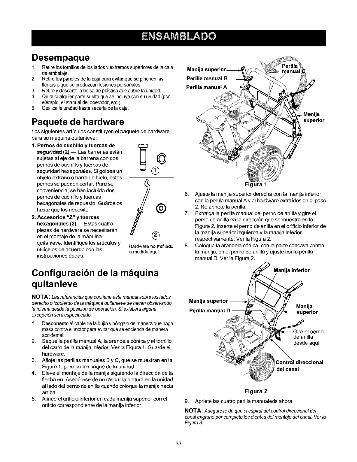
Desempaque
1. Retire los tornillos de los lades y extremos superiores de la caja
deembalaje.
2. Retire los panelesde la caja paraevitar que se pinchen las
Ilantas o que se produzcanlesiones personales.
3. Retire y descarte la bolsa de pl&sticoque cubre la unidad.
4. Quite cualquier parte suelta que se incluyacon su unidad (por
ejemplo, el manual del operador, etc.).
5. Deslice la unidad hasta sacarla de la caja.
Paquete de hardware
Los siguientes articulos constituyen el paquete de hardware
para su m_quina quitanieve:
1. Pernos de cuchillo y tuercas de __ 0
seguridad (2)-- Las barrenas est_n
sujetas al eje de la barrena con dos
pernos de cuchillo y tuercas de
seguridad hexagonales. Si golpea un 1_
objeto extra5o o barra de hielo, estos
pernos se pueden cortar. Para su
conveniencia, se han incluido dos
pernos de cuchillo y tuercas
hexagonales de repuesto. Gu_rdelos
hasta que los necesite.
2. Accesorios "Z" y tuercas
hexagonales (2) i Estas cuatro
piezas de hardware se necesitar_n
en el montaje de la m_quina
quitanieve. Identifique los artfculos y
utilicelos de acuerdo con las
instrucciones dadas.
®
Hardware no trefilado
a medida aqui
Configuracibn de la mbquina
quitanieve
NOTA: Las referencias que contiene este manual sobre los lados
derecho o izquierdo de la m4quina quitanieve se hacen observando
la misma desdela posiciSnde operaci6n. Si existiera afguna
excepci6n sera especificado.
1. Desconecte el cable de la bujia y p6ngalo de manera que haga
masa contra el motor para evitar que se encienda de manera
accidental.
2. Saque la perilla manual A, la arandela c6nica y el tornillo
del carro de la manija inferior. Ver la Figura 1. Guarde el
hardware.
3. Afloje las perillas manuales B y C, que se muestran en la
Figura 1, pero no las saque de la unidad.
4. Eleve el montaje de la manija siguiendo la direcci6n de la
flecha en. Asegtirese de no raspar la pintura en la unidad
al lade del perno de anilla cuando coloque la manija hacia
arriba.
5. Alinee el orificio inferior en cada manija superior con el
orifcio correspondiente de la manija inferior.
Mani"
Perilla manual
Perilla
supedor
Figura 1
6. Ajuste la manija superior derecha con la manija inferior
con la perilla manual A y el hardware extraidos en el paso
2. No apriete la perilla.
7. Extraiga la perilla manual del perno de anilla y gire el
pemo de anilla en la direccibn que se muestra en la
Figura 2. Inserte el perno de anilla en el orificio inferior de
la manija superior izquierda y la manija inferior
respectivamente. Ver la Figura 2.
8. Coloque la arandela c6nica, con la parte c6ncava contra
la manija, en el perno de anilla y ajuste conla perilla
manual D. Ver la Figura 2.
Manija inferior
Manija
Manija
perno
de anilla
desde aqui
del canal
Figura 2
9, Apriete las cuatro perilla manualeds ahora,
NOTA: Aseg#resedequeelespiraldefcontroldireccionaldef
canalengraneporcompfetolosdientesdelmontajedelcanal Verla
Figura3.
33
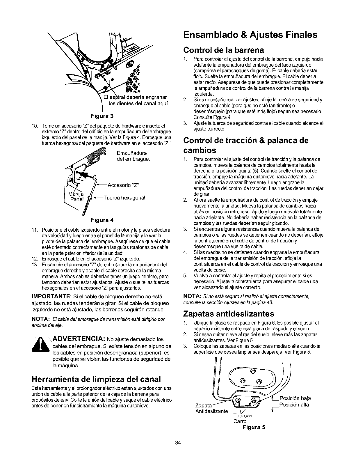
,iral deberia engranar
los dientes del canal aqu[
Figura 3
10. Tome un accesorio "Z" del paquete de hardware e inserte el
extremo"Z" dentro del orificio en la empuSaduradel embrague
izquierdo del panel de la manija, Ver la Figura 4. Enrosque una
tuerca hexagonal del paquete de hardware en el accesorio "Z."
_ Empufiadura
_ del embrague.
Accesorio "Z"
L_e _-. Tuerca hexagonal
Figura 4
11. Posicione el cable izquierdo entre el motor y la placa selectora
develocidad y luego entre el panel de la manija y lavarilla
pivote de la palanca del embrague. Aseg6rese de que el cable
est6orientado correctamente en las guias rotatorias de cable
en la parte psterior inferior de]a onidad.
12. Enrosque el cable en el accesorio "Z" izquierdo.
13. Ensamble el accesorio "Z" derecho sobre la empufiadura del
embrague derecho y acople el cable derecho de la misma
manera. Ambos cables deberian tener unjuego minimo, pero
tampoco deberian estar ajustados. Ajuste o suelte lastuercas
hexagonales en el accesorio "Z" para ajustados.
IMPORTANTE: Si el cable de bloqueo derecho no est_
ajustado, las ruedas tender_n a girar. Si el cable de bloqueo
izquierdo no est_ ajustado, las barrenas seguir_n rotando.
NOTA: El cable del embrague de transmisiSn est& dirigido por
encima del eje.
_lb ADVERTENCIA: No ajuste demasiado los
cables del embrague. Si existe tensi6n en alguno de
los cables en posici6n desengranada (superior), es
posible que se violen las funciones de seguridad de
la m_quina.
Herramienta de limpieza del canal
Esta herramienta y el prolongador el6ctrico est_n ajustados con una
uni6n de cable a la parte psteriorde la caja de la barrena para
prop6sitos de env. Corte la uni6n del cabley saque el cable el6ctrico
antes de poner en funcionamiento ]a m_quina quitanieve.
Ensamblado & Ajustes Finales
Control de la barrena
1, Paracontrolar el ajuste del control de la barrena, empuje hacia
adelante la empufiadura del embrague del lado izquierdo
(comprima el parachoques de goma). Elcable deberia estar
flojo, Suelte la empufiadura del embrague. El cable deberia
estar recto. Aseg6rese de que puede presionar completamente
la empuSadura de control de la barrena contra la manija
izquierda,
2, Si es necesario realizar ajustes, afloje latuerca de seguridad y
enrosque el cable (para que noest6 tan tirante) o
desenr6squelo (para que est_ m_sflojo) segt_nsea necesario.
Consulte Figura 4.
3, Ajuste la tuerca de seguridad contra el cable cuando alcance el
ajuste correcto.
Control de traccibn & palanca de
cambios
1, Paracontrolar el ajuste del control de tracci6n y la palanca de
cambios, mueva la palanca de cambios totalmente hasta la
derecha a la posici6n quinta (5).Cuando suelte el control de
tracci6n, empuje la m_quina quitanieve hacia adelante, La
unidad deberia avanzar libremente. Luego engrane la
empuSaduradel control de tracci6n. Las roedas deberian dejar
de girar,
2, Ahora suelte la empufiadura de control detracci6n y empuje
nuevamente la unidad, Mueva la palanca de cambios hacia
atr&s en posici6n retroceso r_pido y luego mu6vala totalmente
hacia adelante. No deberia haber resistencia en la palancade
cambios y las ruedas debedan seguir girando.
3, Si encuentra alguna resistencia cuando mueva la palanca de
cambios o si lasruedas se detienen cuando no deberian, afloje
la contratuerca en el cable decontrol detracci6n y
desenrosque una vuelta decable,
4, Si las ruedas no se detienen cuando engrana la empuSadura
del embrague de la transmisi6n de tracci6n, afloje la
contratuerca en el cable de control de tracci6n y enrosque una
vuelta decable,
5, Vuelva a controlar el ajuste y repita el procedimiento si es
necesario, Ajuste la contratuerca para asegurar el cable una
vez alcanzado el ajuste correcto.
NOTA: Sino est&seguro si realiz5 el ajuste correctamente,
consultela secciSn Ajustes en fa p&gina 43.
Zapatas antideslizantes
1, Ubique la placa de raspadoen Figura6, Es posible ajustar el
espacio existente entre esta placa de raspado y el suelo.
2, Sidesea quitar nieve al ras del suelo, eleve m&slas zapatas
antideslizantes. Ver Figura 5.
3, Coloque laszapatas en las posiciones media o alta cuando la
superficie que desea limpiar seadespareja. Ver Figura 5.
Zapat Ci n ,'a a
Antideslizante Tu_rcas v
Carro
Figura 5
34
4, Ajustelaszapatasantideslizantesaflojandolascuatrotuercas
hexagonalesylospernosdecarrotalcomesemuestraen
Figura5.Muevalaszapatasantideslizantesalaposici6n
deseada.
5, Compruebequetodalasuperficieinferiordelaszapatas
antideslizantesest6contraelsueloparaevitarundesgaste
desparejedelasmismas.Vuelvaaajustarbienlastuercasylos
pemos.
Presibn de los neumbticos
Los neum_ticos tienen un exceso de aire para el embarque.
I, Compruebe la presi6n de los neum&tices,Mantenga la presi6n
entre 15a 20 psi. Consulte en los laterales de los neum&ticosla
presi6n recomendada.
NOTA: Sila presi6n de losneumDticos noes igual en ambos
neumDticos,es posible que la unidad se incline hacia un fade u otro.
_ib ADVERTENCIA: La presi6n m_xima de los
neum_ticas en cualquier circunstancia es de 20 psi.
Se debe mantener una presi6n uniforme en tode
momento. Una presi6n excesiva (superior a los 20
psi), al pisar un reborde puede causar que el
montaje de neum_tico/llanta explote con una fuerza
suficiente como para causar lesiones graves.
35
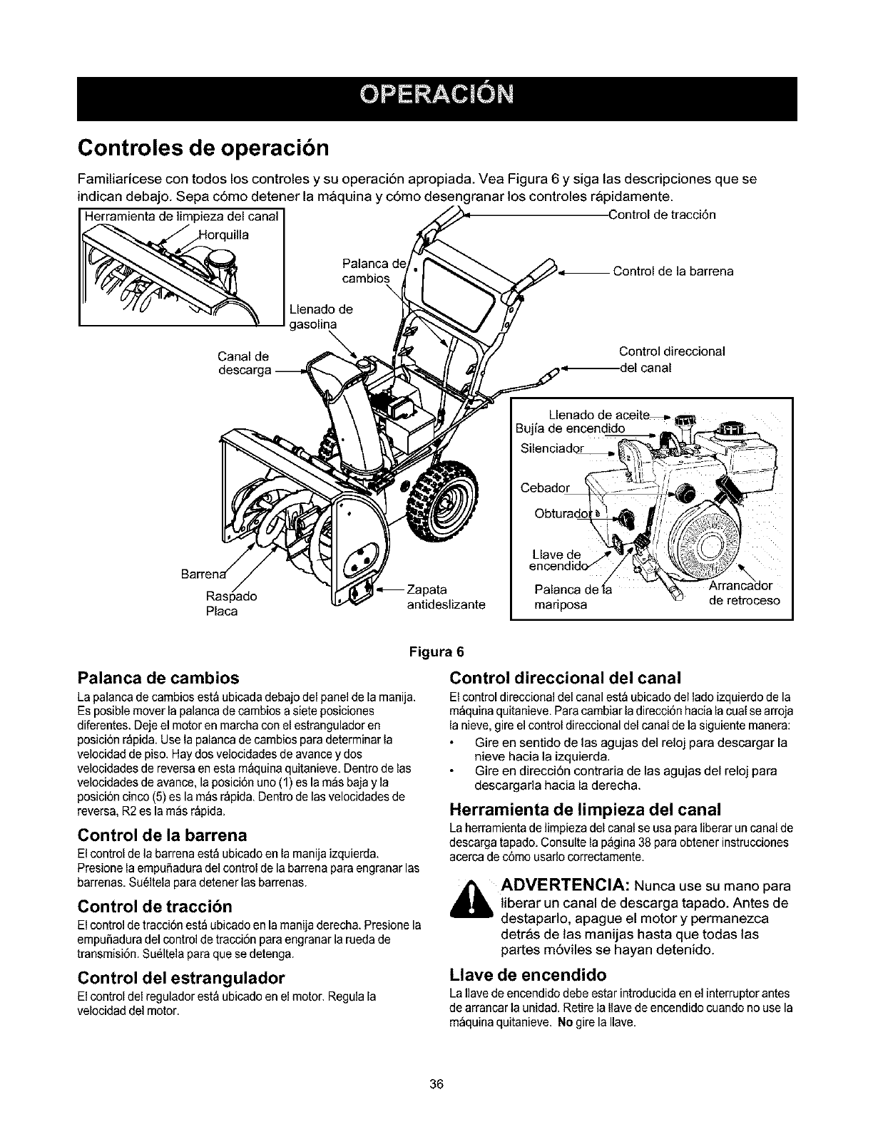
Controles de operacibn
Familiaricese con todos los controles y su operaci6n apropiada. Yea Figura 6 y siga las descripciones que se
indican debajo. Sepa c6mo detener la maquina y c6mo desengranar los controles rapidamente.
Herramienta de limpieza del canal Control de tracci6n
;ontrol de la barrena
cambios\
Llenado de
gasolina
Canal de
desca_
Silenciador
Control direccional
Cebador
Placa
,_Zapata Palanca de_
antideslizante mariposa de retroceso
Figura 6
Palanca de cambios
La palanca de cambios est_ ubicada debajo del panel de la manija.
Es posible mover la palancade cambios a siete posiciones
diferentes. Deje el motor en marcha con el estrangulador en
posici6n r_pida. Use la palanca de cambios para determinar la
velocidad de piso. Hay dos velocidades de avance y dos
velocidades de reversa en esta m&quinaquitanieve. Dentro de las
velocidades de avance, la posici6n uno (1) es la m_s bajay la
posici6n cinco (5) es la m_s r_pida. Dentro de las velocidades de
revers& R2 es la m_s r&pida.
Control de la barrena
El control de la barrena est_ ubicado en la manija izquierda.
Presione la empuSaduradel control de la barrena para engranar las
barrenas. Su61telapara detener las barrenas.
Control de traccibn
El control detracci6n est_ ubicado en la manija derecha. Presione la
empuSaduradel control de tracci6n para engranar la rueda de
transmisi6n. Su61telapara que se detenga.
Control del estrangulador
El control del regulador est&ubicado en el motor. Regula la
velocidad del motor.
Control direccional del canal
El controldireccional del canal est_ ubicadodel lado izquierdo de la
m_quina quitanieve. Para cambiar la direcci6n hacia la coal se arroja
la nieve, gire el control direccional del canal de la siguiente manera:
Gire en sentido de las agujas del reloj para descargar la
nieve hacia la izquierda.
Gire en direcci6n contraria de las agujas del reloj para
descargada hacia la derecha.
Herramienta de limpieza del canal
Laherramienta de limpieza del canal se usa para liberar un canal de
descarga tapado, Consolte la p_gina 38 paraobtener instrucciones
acercade c6mo usarlo correctamente,
_hb ADVERTENCIA: Nunca use su mano para
tiberar un canal de descarga tapado. Antes de
destaparlo, apague el motor y permanezca
detras de las manijas hasta que todas las
pares m6viles se hayan detenido.
Llave de encendido
LaIlave deencendido debe estar introducida en el interruptor antes
de arrancar la unidad. Retire la Ilavede encendido cuando no use la
m_quina quitanieve. No gire la Ilave.
36
Antes de encender
,_ ADVERTENCIA: Lea, comprenda y siga
todas las instrucciones y advertencias que
aparecen en la maquina yen este manual
antes de operarla.
Llenado de aceite
1. El motor se envia sin aceite. Compruebe el nivel de aceite
antes de operar. Despu6s del uso inicial, tendr_ que tlenarlo
hasta el nivel necesario. Tenga cuidado de no Ilenar enexceso.
2. Antes de Ilenar de gasolina el motor por primeravez, abra la
tapa del tanque de gasotina y ubique una tapa de pl_stico
blanco debajo. Saque y tire esta tapa.
3. El cablede la bujia fue desconectado porseguridad. Enchufe el
cable de la bujia a la bujia antes de encender la m_quina.
Llenado de gasolina
_ADVERTENCIA: La gasolina es
inflamable; tenga precauci6n cuando la
manipule o la almacene. No llene el tanque de
combustible mientras la maquina quitanieve
esta en marcha, cuando est_ caliente o cuando
esta en un _rea cerrada. Evite que su maquina
quitanieve entre en contacto con llamas
abiertas o chispas y no fume mientras llena el
tanque de combustible.
NOTA: Aseggrese de que el recipiente desde el cual vierte la
gasolina est6 limpioy sin 5xido.
1. Uene el tanque de combustible s61ocon gasolina para
automotores sin plomo, limpia y fresca.
2. Nunca Ilene comptetamente el tanque. Llene el tanque hasta 1/
4-1/2 de pulgadapor debajo del tope dejando asi espacio para
la dilataci6n del combustible.
3. Siempre Ireneel tanque de combustible al aire libre y useun
embudoo pico paraevitar derramamientos.
4. Aseg6rese de limpiar el combustible que se haya derramado
antes de arrancar el motor.
5. Almacene ta gasolina en un recipiente aprobado limpioy
coloque la tapa enel recipiente.
6. AI finalizar el trabajo,vacie el tanque decombustible si la
m_quina quitanieve no ser_ utilizada durante los siguientes 30
dias o m_s. Vea las instrucciones de almacenamiento.
Para encender el motor
1, Conecte el cable de la bujia a la misma. Compruebe que el
bucle de metaldel extremo de la bujia est6 bien ajustado
(dentro de ]amanga) sobre la punta met_lica de la bujia.
2, Aseg6rese de que las palancas de la barrena y el embrague de
transmisi6n esten en posici6n desengranada (no presionada).
3, Gire lav_lvula de mezcla decombustible ensentido contrario al
reloj a posici6n ABRIR.
4, Mueva el control de] estrangulador a la posici6n FAST (r_pido),
Inserte laIlave de encendido en la ranura. Asegt3resede que
entre a presi6n en so lugar. No gire la Ilave.
NOTA: El motor no arrancar& a menos que la flave de encendido
est6 introducida dentro de la ranura deencendido en la tapa def
carburador,
Arrancador el ctrico
,_ ADVERTENCIA: El arrancador electrico esta
equipadocon uncable dealimentaci6n y un enchufe
detres terminales conectados a tierra y esta
diseSadopara operar con corriente domestica de
120voltios. Este debe ser utilizadocon un
recept_culo de tres terminales correctamente
conectado a tierra entodo memento para evitar la
posibilidad de descargas electricas. Siga todas las
instrucciones cuidadosamente para operar el
arrancador electrico.
1. Determinesi el cableado de su hogar es unsistema de tres
cables conectado a tierra. Consulte con unelectricista
matriculado si noest& seguro.
Si su sistema de cableado dom6stico no es un
sistema de tres terminales con conexibn a tierra, no
utilice este motor el6ctrico bajo ningL)n tipo de
condiciones.
Si su sistema de cableado dom6stico es un sistema
con conexibn a tierra, pero no cuenta con un
recept_culo de tres terminales, debe indicarle a un
electricista con experiencia que Io instale antes de utilizar
el arrancador el6ctrico.
2. Rote la palanca de obturaci6n a posici6n OFF (apagado).
3. Presione el cebador tres veces para cebar el motor.
4. Conecte el cable de alimentaci6n a la caja del interrupter del
motor. Enchufe el otro extremo del cable de alimentaci6n en un
recept_culo de CA con conexi6n a tierra de tres terminates de
120 voltios.
5. Presione el bot6n del arrancador para arrancar el motor con la
manivela. A medida que intenta encender el motor con la
manivela, mueva la perillade obturaci6n hacia la posici6n de
obturaci6n FULL. Noopere el arrancador electrico por m&sde 5
segundos en cada intento.
6. Cuando se inicia el motor, suelte el bot6n del arrancador, y
mueva el obturador gradualmente a la posici6nOFF (apagado).
Si el motor fall& mueva el obturador inmediatamente a posici6n
FULL y luego gradualmente a OFF.
7. Cuando desconecte el cable de alimentaci6n, siempre
desencht_feloen primer lugar del recept&culode tres
terminales, y luego de la m_quina quitanieve.
Arrancador de retroceso
1. Rote la perilla de obturaci6n a posici6n de obturaci6n FULL
(encendido con el motor enfrio).
2. Si el motor est&caliente, ubique el obturador en posici6n OFF
en lugar de FULL.
3. Presione el bot6n delcebador dos o tres veces para iniciarel
motor enfdo.
4. Si el motor est&caliente, presione el bot6ndel cebador una
sola vez.
NOTA: Siempre cubra el orificio de ventilaei6n enel bot6n cebador
cuando Io presiona. Tal vez sea necesario un cebado adicional para
iniciar el equipo por primera vez si fa temperatura es menor a 15
grados Fahrenheit,
Tome con firmeza la manija del arrancador y tire de la soga
lentamente basra que quede un poco m&stirante. Deje que la
soga se enrosque lentamente.
Tire de la manija del arrancador r_pidamente. No permita que
la manija se desenganche. Permita que se enrosque
lentamente mientras mantiene firmemente la manija del
arrancador.
Mientras el motor se calienta y comienza a funcionar de
manera pareja, rote la perilla del obturador lentamente bacia la
37
posici6nOFF.Sielmotorfalla,girehaciaelobturadorFULL.
luegomuevalentamentehaciaposici6nOFF.
Arrancador de retroceso congelado
Si el arrancador est_ congelado y no enciende el motor, proceda de
la siguiente manera:
1. Saque la mayor cantidad de coerda posible del arrancador.
2. Suelte la manija del arrancador y deje que golpee contra el
arrancador.
3. Si contin6a teniendo problemas para arrancar el motor, repita
los dos primeros pasos. Si despu6s de intentos socesivos no
puede liberar el arrancador, siga los procedimientos del
arrancador el6ctrico para arrancar.
4. Trate de evitar que el arrancador de retroceso se congele
siguiendo las instrucciones de la p_gina.
Antes de detener la mdquina
1. Deje encendido el motor durante algunos minutos para permitir
que se sequela humedad en el mismo.
2. Para evitar que se congele el arrancador siga estos pasos
antes de detener la m_quina quitanieve:
Arrancador de retroceso
a. Con el motor en funcionamiento, tire con fuerza
de la soga del arrancador tres o cuatro veces de
manera continua y seguida.
Arrancador el_ctrico
a, Conecte el cable de alimentaci6n a la caja del
interruptor y luego al recept&culo de 120 voltios CA.
b. Con el motor en marcha, presione el bot6n del
arrancador y deje girar el arrancador por varios
segundos.
c. Desconecte el cable de alimentaci6n primero del
recept_culo y despu6s de la m_quina quitanieve.
NOTA: El ruido inusual producto de tirar defa cuerda de arranque,
si se trata del arrancador de retroceso, o el que realiza elarrancador
af girar, si se trata del arrancador el_ctrico, no daF_aaf motor.
Para detener el motor
1. Mueva el control de estrangulaci6n a posici6n "stop" u "off".
2. Retire la Ilavedel encendido. No gire la Ilave.
3. Desconecte el cable de la bujia paraevitar que se encienda
accidentalmente mientras no se est_ prestando atenci6n al
equipo.
NOTA: No pierda la Ilave de encendido. Gu_rdela en un fugar
seguro. El motor no arrancar& sin la Ilave de encendido.
4. Limpie toda la nieve y la humedad de la tapa del carburador en
el &reade las palancas de control. Adem_s, mueva las
palancas de control hacia delante y hacia atr&s varias veces.
Procedimiento para engranar la
transmisibn
1, Con el motor en marcha y cerca de lavelocidad m_xima,
mueva la palanca de cambios a una de las cinco posiciones
AVANCE o a las dos posiciones de REVERSA. Seleccione la
velocidad adecuada para el estado de la nieve existente. Use
las velocidades m_s lentas hasta haberse familiarizado con el
funcionamiento de lam_quina quitanieve.
2. Apriete la empuSadura decontrol de la barrena y las barrenas
rotar&n.Su_ltela y las barrenas se detendr&n.
3. Apriete la empuSaduradecontrol detracci6n y ]am_quina
quitanieve se mover& Su6ltela y se detiene la transmisi6n de
movimiento.
4. NUNCA mueva la palanca decambios sin soltar el embrague
de transmisi6n.
Procedimiento para engranar
las barrenas
Paraengranar las barrenas y comenzar a quitar la nieve, apriete la
empuSaduradel control de la barrena contra la manija izquierda.
Sueltelapara detener las barrenas.
Consejos de operacibn
Deje que el motor se caliente unos minutos ya que el
mismo no desarrolla la potencia m_xima hasta que
alcanza la temperatura de funcionamiento.
_lb ADVERTENCIA: El silenciador, el motor y
tas areas circundantes se recalientan y pueden
causar quemaduras. No los toque.
Paraque el quitado de la nievesea m_s eficiente debe hacerlo
inmediatamente despu6s de la caida de la misma.
En Io posible, descargue la nieve en direcci6n al viento.
Traslape levemente las pasadas anteriores.
Configure las zapatas antideslizantes 1/4" por debajo de
la barra de raspado para un uso normal. Las zapatas
antideslizantes se pueden ajustar hacia arriba cuando la
nieve est6 muy compactada. Aj6stelas hacia abajo
cuando usa la m_quina en gravas o superficies con
piedras trituradas.
AsegDrese de seguir las precauciones enumeradas en la
secci6n "Procedimiento para detener el motor" para
evitar un posible congelamiento.
Limpie cuidadosamente la m_quina quitanieve despu6s
de cada uso.
Cadenas para los neum ticos (siestan
incluidas)
Lascadenas para los neum_ticos, si est_n incluidas, deberian
utilizarse siempre que se necesite tracci6n extra.
Herramienta de limpieza del
canal
La herramienta de limpieza del canal est_ ajustada
convenientemente a la parle posterior de la caja de la barrena con
unpasador de ensamblado. No use nunca las manos para limpiar
uncanal tapado.
1. Suelte tanto la palanca de control de la barrena como la
palanca de bloqueo del control de tracci6n/barrena.
2. Paradetener el motor saque la llave de encendido.
3. Saque la herramienta de limpieza del pasador qoe la ajusta a la
parte posterior de la caja de la barrena. Ver Figura6.
4. Use el extremo con forma de palade la herramienta de
limpieza para eliminar la nieve yel hielo existentes en el canal
de descarga.
5. Vuelva a ajustar la herramienta de limpieza al pasador de
ensamblado ubicado en la parte posterior de la caja de la
barrena y vuelva a encender el motor.
6. Paradoen la posici6n de] operador (detr_s de la m_quina
quitanieve), engrane la palanca del embrague de la barrena
durante unos segundos para eliminar la nieve o el hielo que
hayan qoedado en el canal de descarga antes de continuar
quitando la nieve.
38
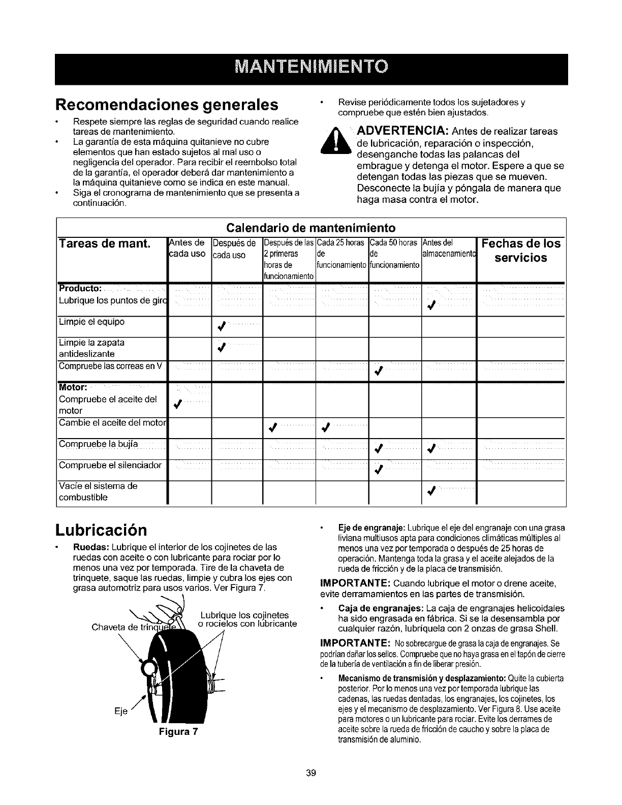
Recomendaciones generales
Respete siempre las reglas de seguridad cuando realice
tareas de mantenimiento.
La garantia de esta m_quina quitanieve no cubre
elementos que hart estado sujetos al real uso o
negligencia del operador. Para recibir el reembolso total
de la garantia, el operador deber_ dar mantenimiento a
la m_quina quitanieve como se indica en este manual.
Siga el cronograma de mantenimiento que se presenta a
continuaci6n.
Revise peri6dicamente todos los sujetadores y
compruebe que est6n bien ajustados.
,i_ ADVERTENCIA: Antes de realizar tareas
de lubricaci6n, reparaci6n o inspecci6n,
desenganche todas las palancas del
embrague y detenga el motor. Espere a que se
detengan todas las piezas que se mueven.
Desconecte la bujia y p6ngala de manera que
haga masa contra el motor.
Tareas de mant.
Producto:
Lubrique !os puntos de gir_
Limpie el equipo
Limpie la zapata
antideslizante
Compruebe las correas en V
Motor:
Compruebe el aceite del
motor
_.ntes de
sada uso
Calendario de mantenimiento
_)espu6sde Despu_sdelas Cada25horas Cada50horas
sadaus0 2 prirneras de de
horasde funcionarnientofuncionamiento
funcionamiento
I I I I
Fechas de los
servicios
Antesdel
alrnacenarnientc
qt I
I I
,/
Cambie el aceite del motol _ ,_
c0mpruebe la buJia I I I ,_
Compruebe el silenciador
Vacie el sistema de
combustible
Lubricacibn
Ruedas: Lubrique el interior de los cojinetes de las
ruedas con aceite o con lubricante para rociar por Io
menos una vez por temporada. Tire de la chaveta de
trinquete, saque las ruedas, limpie y cubra los ejes con
grasa automotriz para usos varios. Ver Figura 7.
Chaveta de
Lubrique los cojinetes
o rocielos con lubricante
Figura 7
Eje de engranaje: Lubriqueel eje del engranaje con una grasa
IMana multiusos apta para condiciones clim_ticas mt)ltiples al
menos una vez per temporada o despu6s de 25 horas de
operaci6n. Mantenga toda la grasa y el aceite alejados de la
rueda de fricci6n y de la placa de transmisi6n.
IMPORTANTE: Cuando lubrique el motor o drene aceite,
evite derramamientos en las partes de transmisi6n.
Caja de engranajes: La caja de engranajes helicoidales
ha sido engrasada en f_brica. Si se la desensambla por
cualquier raz6n, lubriquela con 2 onzas de grasa Shell.
IMPORTANTE: NOsobrecarguede grasalacajadeengranajes.Se
pedriandaSarlossellos.Cornpruebequenohayagrasaeneltap6ndecierre
delatuberiadeventilaci6nafin deliberarpresi6n.
Mecanismode transmisibny desplazamiento:Quitela cubierta
posterior.Por Iornenosunavez por ternporadalubriquelas
cadenas,lasruedasdsntadas, losengranajes,los cojinetes,los
ejes yel rnecanisrnode desplazarniento.Vet Figura8. Useaceite
paramotoreso unlubricantepararociar.Evite losderramesde
aceitesobrela ruedadefricci6n de cauchoy sobrelaplacade
transrnisi6ndealurninio.
39
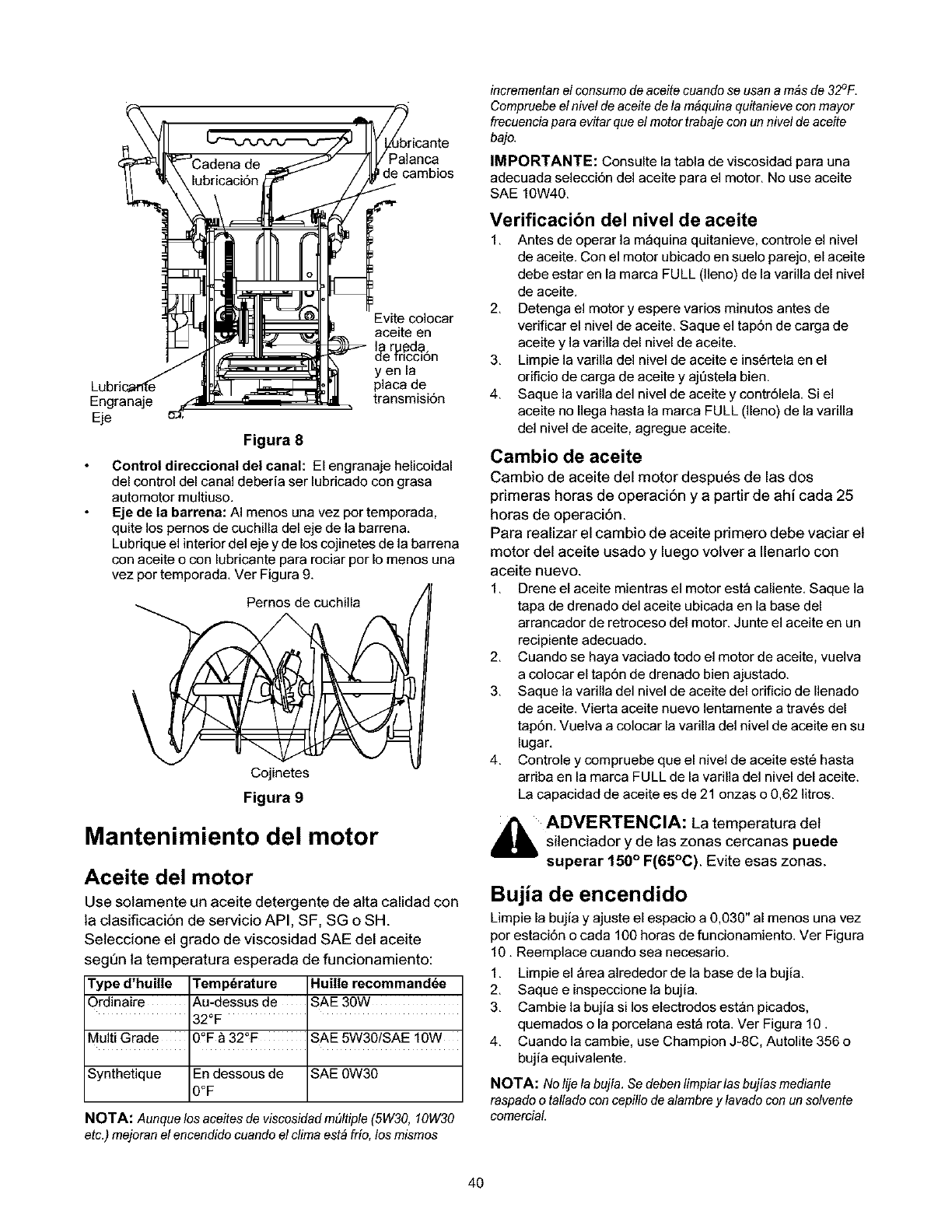
Palanca
decambios
Engranaje
Eje
Evite colocar
aceite en
_er_de.
1rlcclon
yen la
placa de
transmisi6n
Figura 8
Control direccional del canal: El engranaje helicoidal
del control del canal deberia ser lubricado con grasa
automotor multiuso,
Eje de la barrena: AI menos una vez por temporada,
quite los pernos de cuchilla del eje de la barren&
Lubrique el interior del eje y de los cojinetes de la barrena
con aceite o con lubricante para rociar por Io menos una
vez por temporada. Ver Figura 9.
Pernos de cuchilla
Cojinetes
Figura 9
Mantenimiento del motor
Aceite del motor
Use solamente un aceite detergente de alta calidad con
la ctasificaci6n de servicio API, SF, SG oSH.
Seleccione el grado de viscosidad SAE del aceite
segQn la temperatura esperada de funcionamiento:
Type d'huille Temp6rature Huille recommand6e
Ordinaire Au-dessus de SAE 30W
_2°F
Multi Grade 0_F &32°F SAE 5W30/SAE 10W
Synthetique En dessous de SAE 0W30
0OF
NOTA: Aunque los aceites de viscosidad m(lltiple (5W30, 10W30
etc.) mejoranel encendido cuando el clima estb frio, los mismos
incrementan el consumo de aceite cuando se usan a m&sde 32°F.
Compruebe el nivefde aceite defa m_quina quitanieve conmayor
frecuenciapara evitar que el motor trabaje con un nivel de aceite
bajo.
IMPORTANTE: Consulte la tabla de viscosidad para una
adecuada selecci6n del aceite para el motor, No use aceite
SAE 10W40,
Verificacibn del nivel de aceite
1. Antes de operar la m_quina quitanieve, controle el nivel
de aceite. Con el motor ubicado en suelo parejo, el aceite
debe estar en la marca FULL (lleno) de la varilla del nivel
de aceite.
2. Detenga el motor y espere varies minutos antes de
verificar el nivel de aceite. Saque el tap6n de carga de
aceite y la varilla del nivel de aceite.
3. Limpie la varilla del nivel de aceite e ins6rtela en el
orificio de carga de aceite y aj0stela bien.
4. Saque la varilla del nivel de aceite y contr61ela. Si el
aceite no Ilega hasta la marca FULL (lleno) de la varilla
del nivel de aceite, agregue aceite.
Cambio de aceite
Cambio de aceite del motor despues de las dos
primeras horas de operaci6n y a partir de ahi cada 25
horas de operaci6n.
Para realizar el cambio de aceite primero debe vaciar el
motor del aceite usado y luego volver a Ilenarlo con
aceite nuevo.
1. Drene el aceite mientras el motor est_ caliente. Saque la
tapa de drenado del aceite ubicada en la base del
arrancador de retroceso del motor. Junte el aceite en un
recipiente adecuado.
2. Cuando se haya vaciado todo el motor de aceite, vuelva
a colocar el tap6n de drenado bien ajustado.
3. Saque la varilla del nivel de aceite del orificio de Ilenado
de aceite. Vierta aceite nuevo lentamente a trav6s del
tap6n. Vuelva a colocar la varilla del nivel de aceite en su
lugar.
4. Controle y compruebe que el nivel de aceite est6 hasta
arriba en la marca FULL de la varilla del nivel del aceite.
La capacidad de aceite es de 21 onzas o 0,62 litros.
_lb ADVERTENCIA: La temperatura del
silenciador y de las zonas cercanas puede
superar 150°F(65°C). Evite esas zonas.
Bujia de encendido
Limpie la bujia y ajuste el espacio a 0,030" al menos una vez
por estaci6n o cada 100 horas de funcionamiento. Ver Figura
10. Reemplace cuando sea necesario.
1. Limpie el _rea alrededor de la base de la bujia.
2. Saque e inspeccione la bujia.
3. Cambie la bujia si los electrodos est_n picados,
quemados o la porcelana est_ rota. Ver Figura 10.
4. Cuando la cambie, use Champion J-8C, Autolite 356 o
bujia equivalente.
NOTA: No/ije/a bujia. Sedeben limpiarfas bujias mediante
raspadoo tallado con cepillo de alambre y lavado con un sofvente
comerciaL
4O
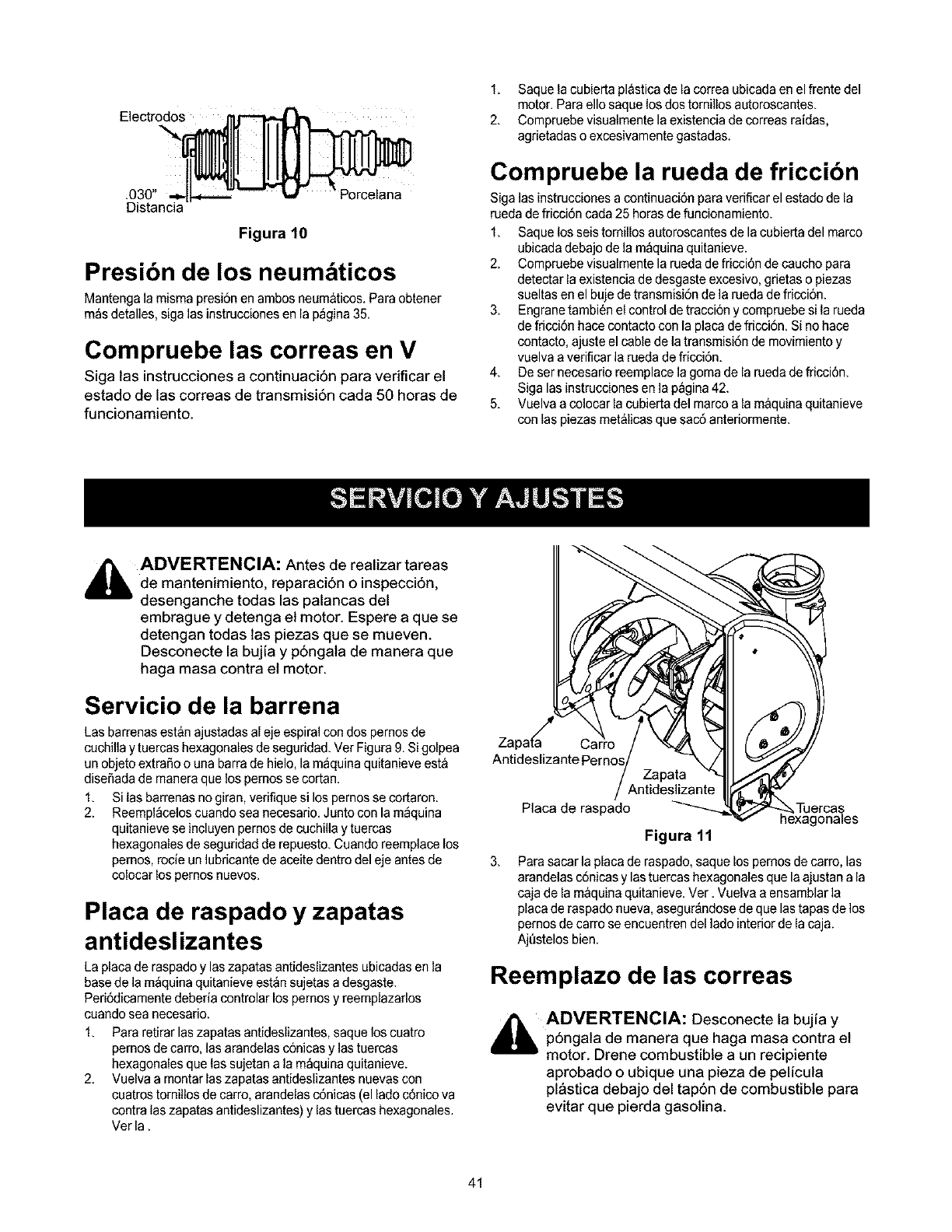
Electrodos
.030"
Distancia Porcelana
Figura 10
Presibn de los neum ticos
Mantenga la misma presi6n en ambos neum_ticos. Paraobtener
m_s detalles, siga las instrucciones en la p_gina 35.
Compruebe las correas en V
Siga las instrucciones a continuaci6n para verificar el
estado de las correas de transmisi6n cada 50 horas de
funcionamiento.
1. Saque ia cubie[ta pl&sticade la correa ubicada en el frente del
motor. Para ello saque losdos tomillos autoroscantes.
2. Compruebe visualmente la existencia decorreas raidas,
agrietadas o excesivamente gastadas.
Compruebe la rueda de friccibn
Siga las instrucciones a continuaci6n para verificar el estado de la
rueda de fricci6n cada 25 horas defuncionamiento.
1. Saque los seis tornillos autoroscantes de la cubie[ta del marco
ubicada debajo dela m_quina quitanieve.
2. Compruebe visualmente la rueda de fricci6n de caucho para
detectar la existencia de desgaste excesivo, grietas o piezas
sueltas en el buje de transmisi6n de la rueda de fricci6n.
3. Engranetambien el control de tracci6n y compruebe si la rueda
de fricci6n hace contacto con la placa de fricci6n. Si no hace
contacto, ajuste el cable de la transmisi6n de movimiento y
vuelva a verificar la rueda defricci6n.
4. Deser necesario reemplace la goma de la rueda de fficci6n.
Siga las instrucciones en la p_gina 42.
5. Vuelva a colocar la cubie[ta del marco a la m&quina quitanieve
con las piezas met&licas que sac6 anteriormente.
,_ ADVERTENCIA: Antes de realizar tareas
de mantenimiento, reparaci6n o inspecci6n,
desenganche todas las palancas del
embrague y detenga el motor. Espere a que se
detengan todas las piezas que se mueven.
Desconecte la bujia y p6ngala de manera que
haga masa contra el motor.
Servicio de la barrena
Las barrenas est&n ajustadas al eje espiral con dos pernos de
cuchilla y tuercas hexagonales de seguridad. Ver Figura 9. Sigolpea
un objetoextraSo o una barra de hielo, la m_quina quitanieve est&
disef_adade maneraque los pemos se co[tan.
1. Si las barrenas no giran, verifique si los pemos se cor[aron.
2. Reempl_celos cuando sea necesario. Junto con la m_quina
quitanieve se incluyen pemos de cuchilla y tuercas
hexagonales de seguridad de repuesto. Cuando reemplace los
pernos, rocie un lubricante de aceite dentro del eje antes de
colocar los pemos nuevos.
Placa de raspado y zapatas
antideslizantes
La placa de raspado y las zapatas antideslizantes ubicadas en la
base de la m_quina quitanieve est_n sujetas a desgaste.
Peri6dicamente deberia controlar los pemos y reemplazarlos
cuando sea necesario.
1. Para retirar las zapatas antideslizantes, saque los cuatro
pernos de carro, las arandelas c6nicas y lastuercas
hexagonales que las sujetan a la m_quina quitanieve.
2. Vuelva a montar las zapatas antideslizantes nuevas con
cuatros tomillos de carro, arandelas c6nicas (el lado c6nico va
contra las zapatas antideslizantes) y lastuercas hexagonales.
Vet la.
ZapatKa Car
Antideslizante
3,
Placa de raspado
Figura 11
Parasacar la placa de raspado, saque los pemos de carro, las
arandelas c6nicas y lastuercas hexagonales que la ajustan a la
caja de la m&quina quitanieve. Vet. Vuelva a ensamblar la
placa de raspado nueva, asegur_ndose de que lastapas de los
pemos de carro se encuentren del lade interior de la caja.
Ajt_stelosbien.
Reemplazo de las correas
_llli ADVERTENCIA: Desconecte la bujia y
p6ngala de manera que haga masa contra el
motor. Drene combustible a un recipiente
aprobado o ubique una pieza de pelicula
pl&stica debajo del tap6n de combustible para
evitar que pierda gasolina.
41
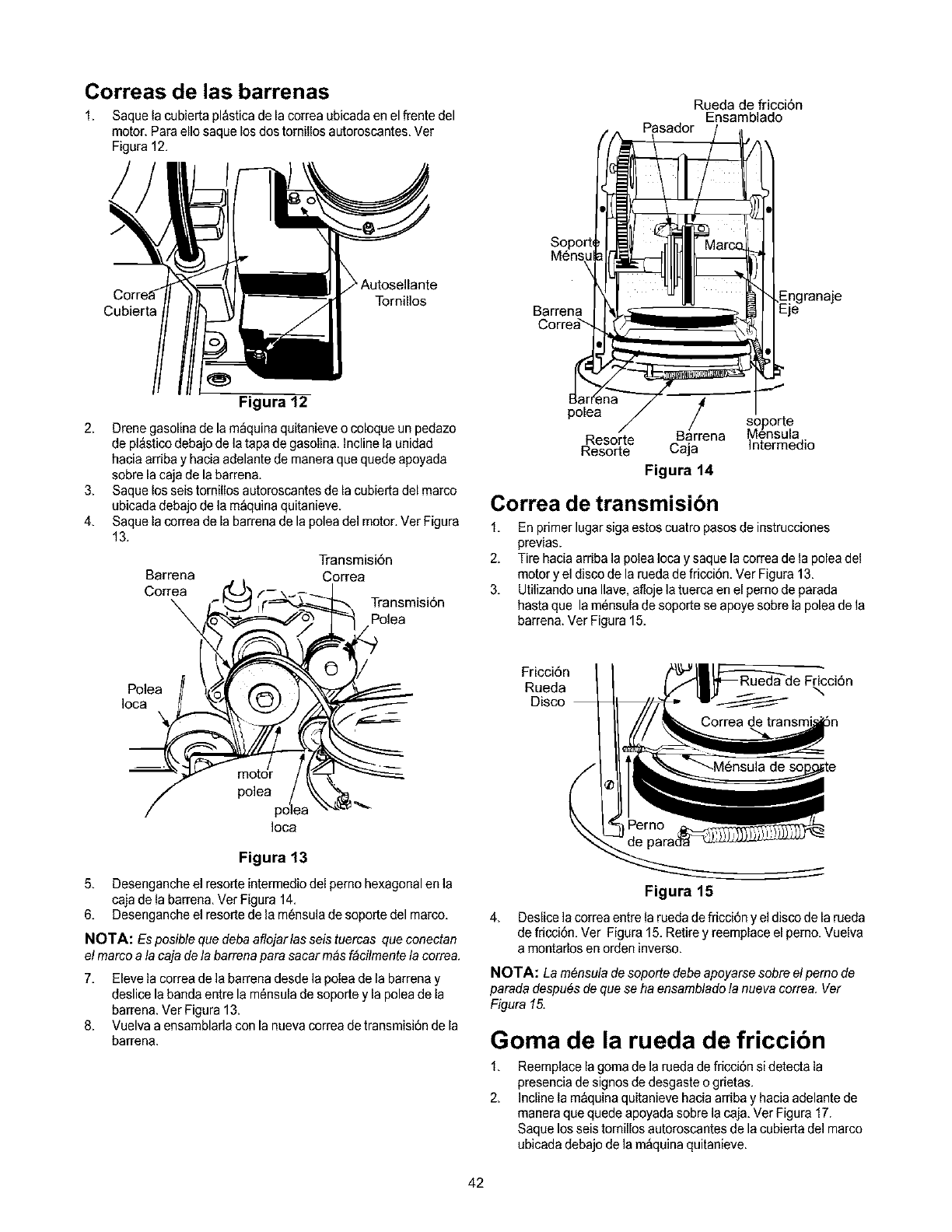
Correas de las barrenas Rueda de fricci6n
Ensamblado
Pasador
1. Saque la cubierta pl&sticade la correa ubicada en el frente del
motor. Para ello saque los dos tomillos autoroscantes, Ver
Figura 12,
Cubierta
Autosellante
Tornillos
Figura 12
2, Drene gasolina de la m_quina quitanieve o coloque un pedazo
de pl&sticodebajo de la tapa de gasolina. Incline la unidad
hacia arriba y hacia adelante de manera que quede apoyada
sobre la caja de la barrena.
3, Saque los seis tomillos autoroscantes de la cubierta del marco
ubicada debajo de la m_quina quitanieve.
4, Saque la correa de la barrena de la polea del motor, Ver Figura
13,
Barrena
Correa
\
Transmisi6n
Correa
Transmisi6n
Polea
Soport
M6ns_
Barrena
Correa_
polea
Resorte
Resorte
ar/re soporte
B na Mensula
Caja Intermedio
Figura 14
Correa de transmisibn
1, Enprimer lugar siga estos cuatro pasos de instrucciones
previas.
2, Tire hacia arriba la polea Iocay saque la correa de la polea del
motor y el disco de la rueda de fricci6n. Ver Figura 13,
3, Utilizando una Ilave, afloje la tuerca en el pemo de parada
hasta que la m6nsula de soporte se apoye sobre la polea de la
barrena. Vet Figura 15,
Polea
]oca
Fricci6n
Rueda
Disco
Ioca
Figura 13
5, Desenganche el resorte intermedio del perno hexagonal en la
caja de la barren& Ver Figura 14,
6, Desenganche el resorte de la m6nsula de soporte del marco,
NOTA: Es posible que deba aflojarlas seis tuercas que conectan
el marco a fa caja dela barrena para sacar m_,af&cilmentefa correa.
7, Eleve la correa de la barrena desde la polea de la barrena y
deslice la banda entre la m6nsula de soporte y la polea de la
barrena. Ver Figura 13,
8, Vuelva a ensamblarla con la nueva correa detransmisi6n de la
barrena.
4,
Figura 15
Deslice la correa entre larueda defricci6n yel disco de la rueda
de fricci6n. Ver Figura 15. Retire y reemplace el pemo, Vuelva
a montarlos en orden inverso,
NOTA: La m6nsula de soporte debeapoyarse sobre elpemo de
parada despu6s de que se ha ensamblado fa nueva correa, Ver
Figura 15.
Goma de la rueda de friccibn
1,
2,
Reemplace la goma de la rueda de fricci6n si detecta la
presencia de signos de desgaste o grietas,
Incline la m&quinaquitanieve hacia arriba y hacia adelante de
manera que quede apoyada sobre la caja, Ver Figura 17.
Saque los seis tornillos autoroscantes de la cubierta del marco
ubicada debajo dela m_quina quitanieve.
42
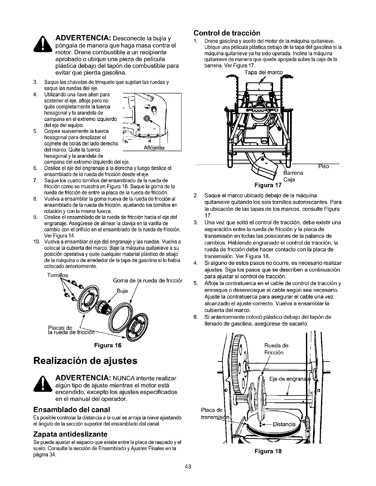
_ADVERTENCIA: Desconecte la bujia y
p6ngala de manera que haga masa contra et
motor. Drene combustible a un recipiente
aprobado o ubique una pieza de pelicula
pl&stica debajo del tap6n de combustible para
evitar que pierda gasotina.
3, Saque las chavetas detrinquete que sujetan las ruedas y
saque las ruedas del eje,
4. Utilizando una Ilave alien para =_ -....._---_
sostener el eje, afloje pero no
quite completamente la tuerca _ 'd _
hexagonal y la arandela de _% _
campana en el extremo izquierdo
del eje del equipo,
5. Golpeesuavementelatuerca I
hexagonal para desplazar el [£_ /
cojinete de bolas del lado derecho
de]marco. Quite la tuerca Afl6jel_s
hexagonal y la arandela de
campanadel extremo izquierdo del eje.
6. Deslice el eje del engranaje a la derecha y luego deslice el
ensamblado de la rueda de fricci6n desde el eje.
7. Saque los cuatro tornillos del ensamblado de la rueda de
fricci6n como se muestra en Figura 16.Saque la goma de la
rueda de fricci6n de entre la placa de la rueda defricci6n.
8. Vuelva a ensamblar la goma nueva de la rueda de fricci6n al
ensamblado de la rueda de fricci6n, ajustando los tornillos en
rotaci6n y con la misma fuerza.
9. Deslice el ensamblado de la rueda de fricci6n haciael ejedel
engranaje.AsegQresede alinear la clavija en la varilla de
cambio conel orificio en el ensamblado de la rueda de fricci6n.
Ver Figura 14.
10. Vuelva a ensamblar el eje del engranaje y las ruedas. Vuelva a
colocar la cubierta del marco. Baje la m_quina quitanieve a su
posici6n operativa y quite cualquier material pl&sticode abajo
de la m_quina o de alrededor de la tapa de gasolina si Io habia
colocado anteriormente.
Goma de la rueda de fricci6r
Placas de
Control de traccibn
1. Drenegasolina y aceite del motor de la m_quina quitanieve.
Ubique una pelicula pl_stica debajo de la tapa del gasolina si la
m_quina quitanieve ya hasido operada. Incline la m_quina
quitanieve de manera que quede apoyada sobre la caja de la
barrena. Vet Figura 17.
Tapa del marco
Piso
na
Figura 17
2. Saque el marco ubicado debajo de la m_quina
quitanieve quitando los seis tornillos autoroscantes. Para
la ubicaci6n de las tapas de los marcos, consulte Figura
17.
3. Una vez que solt6 el control de tracci6n, debe existir una
separaci6n entre la rueda de fricci6n y la placa de
transmisi6n en todas las posiciones de la palanca de
cambios. Habiendo engranado el control de tracci6n, la
rueda de fricci6n debe hacer contacto con la placa de
transmisi6n. Ver Figura 18.
4. Si alguno de estos pasos no ocurre, es necesario realizar
ajustes. Siga los pasos que se describen a continuaci6n
para ajustar el control de tracci6n.
5. Afloje la contratuerca en el cable de control de tracci6n y
enrosque o desenrosque el cable seg_n sea necesario.
Ajuste la contratuerca para asegurar el cable una vez
alcanzado el ajuste correcto. Vuelva a ensamblar la
cubierta del marco.
6. Si anteriormente coloc6 pl_stico debajo del tap6n de
Ilenado de gasolina, asegQrese de sacarlo.
Figura 16
Realizacibn de ajustes
d_lb ADVERTENCIA: NUNCA intente realizar
algQn tipo de ajuste mientras el motor est&
encendido, excepto los ajustes especificados
en el manual del operador.
Ensamblado del canal
Es posibie controlar ladistancia a la cual se arroja la nieve ajustando
el _ngulo de la secci6n superior del ensamblado del canal.
Zapata antideslizante
Sepuede ajustar el espacio que existe entre la placa de raspadoy el
suelo. Consulte la secci6n de Ensamblado yAjustes Finales en la
p&gina34.
Placa de
Rueda de
Fricci6n
Figura 18
43
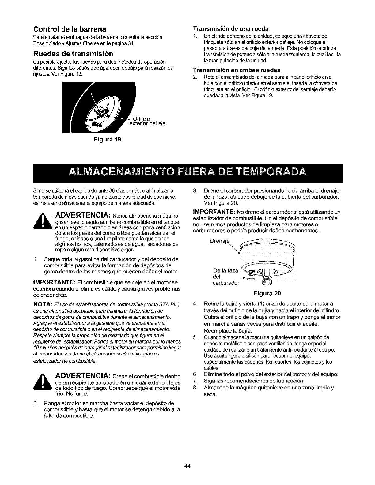
Control de la barrena
Para ajustar el embrague de la barren& consulte la secci6n
Ensamblado y Ajustes Finales en la p_gina 34.
Ruedas de transmisibn
Es posible ajustar las ruedas para dos m_todos de operaci6n
diferentes. Siga los pasos que aparecen debajo pararealizar los
ajustes. Ver Figura 19.
Figura 19
Transmision de una rueda
1. Enel lade derecho de la unidad, coloque una chaveta de
trinquete s6lo en el orificio exterior del eje. No coloque el
pasador a trav6s del buje de la rueda. Esta posici6n le brinda
transmisiSn de potencia s61oa la rueda izquierda, Io cual facilita
la manipulaci6n de la unidad.
Transmision en ambas ruedas
2. Roteel ensamblado de la rueda para alinear el orificioen el
buje con el odficiointerior en el semieje. Inserte la chaveta de
trinquete enel orificio. El orificio exterior del semieje deberia
quedar a la vista. Ver Figura 19.
.Orificio
exterior del eje
Si no se utilizar& el equipo durante 30 dias o m_s, o al finalizar la
temporada de nieve cuando ya no existe posibilidad de que nieve,
es necesarie almacenar el equipo de manera adecuada.
_ADVERTENCIA: Nunca almacene la m&quina
quitanieve, cuando at)n tiene combustible en el tanque,
en un espacio cerrado o en &reas con poca ventilaci6n
donde los gases del combustible puedan alcanzar el
fuego, chispas o una luz piloto come la que tienen
algunos hornos, calentadores de agua, secadores de
ropa o algOnotro dispositivo a gas.
1. Saque toda la gasolina del carburador y del dep6sito de
combustible para evitar la formaci6n de dep6sitos de
goma dentro de los mismos que pueden daSar el motor.
IMPORTANTE: El combustible que se deje en el motor se
deteriora cuando el clima es c_lido y causa graves problemas
de encendido.
NOTA: El uso de estabilizadores de combustible (como STA-BIL)
es una altemativa aceptable para minimizar la formaci6n de
dep6sitos de goma de combustible durante el afmacenamiento.
Agregue el estabilizador a la gasolina que se encuentra en el
dep6sito de combustible o en el recipiente de almacenamiento.
Respete siempre laproporciSn de mezcfado que figura en el
recipiente def estabifizador. Ponga el motor en marcha por fo menos
10minutos despu6s deagregar el estabifizador para permitirle Ilegar
af carburador. No drene el carburador si est_ utilizando un
estabilizador de combustible.
i_ll ADVERTENCIA: Drene el combustible dentro
de un recipiente aprobado en un lugar exterior, lejos
de todo tipo de fuego. Compruebe que el motor est6
frio. No fume.
2. Ponga el motor en marcha hasta vaciar el dep6sito de
combustible y hasta que el motor se detenga debido a la
falta de combustible.
3. Drene el carburador presionando hacia arriba el drenaje
de la taza, ubicado debajo de la cubierta del carburador.
Ver Figura 20.
IMPORTANTE: No drene el carburador si est_ utilizando un
estabilizador de combustible. En el dep6sito de combustible
no use nunca productos de limpieza para motores o
carburadores o podria producir daSos permanentes.
Drenaj
De la taza _ _
del _
carburador --
Figura 20
4. Retire la bujia y vierta (1) onza de aceite para motor a
trav6s del orificio de la bujia y hacia el interior del cilindro.
Cubra el orificio de la bujia con un trapo y ponga el motor
en marcha varias veces para distribuir el aceite.
Reemplace la bujia.
5. Cuando almacene la m_quina quitanieve en un galp6n de
dep6sito met_lico o con poca ventilaci6n, tenga especial
cuidado de realizade un tratamiento anti- oxidante al equipo.
Useaceite ligero o silic6n para recubrir el equipo.
especialmente lascadenas, los resortes, los cojinetes y los
cables.
6. Elimine todo el polvo del exterior del motor y del equipo.
7. Siga las recomendaciones de lubricaci6n.
8. Almacene la m_quina quitanieve en una zona limpia y
seca.
44
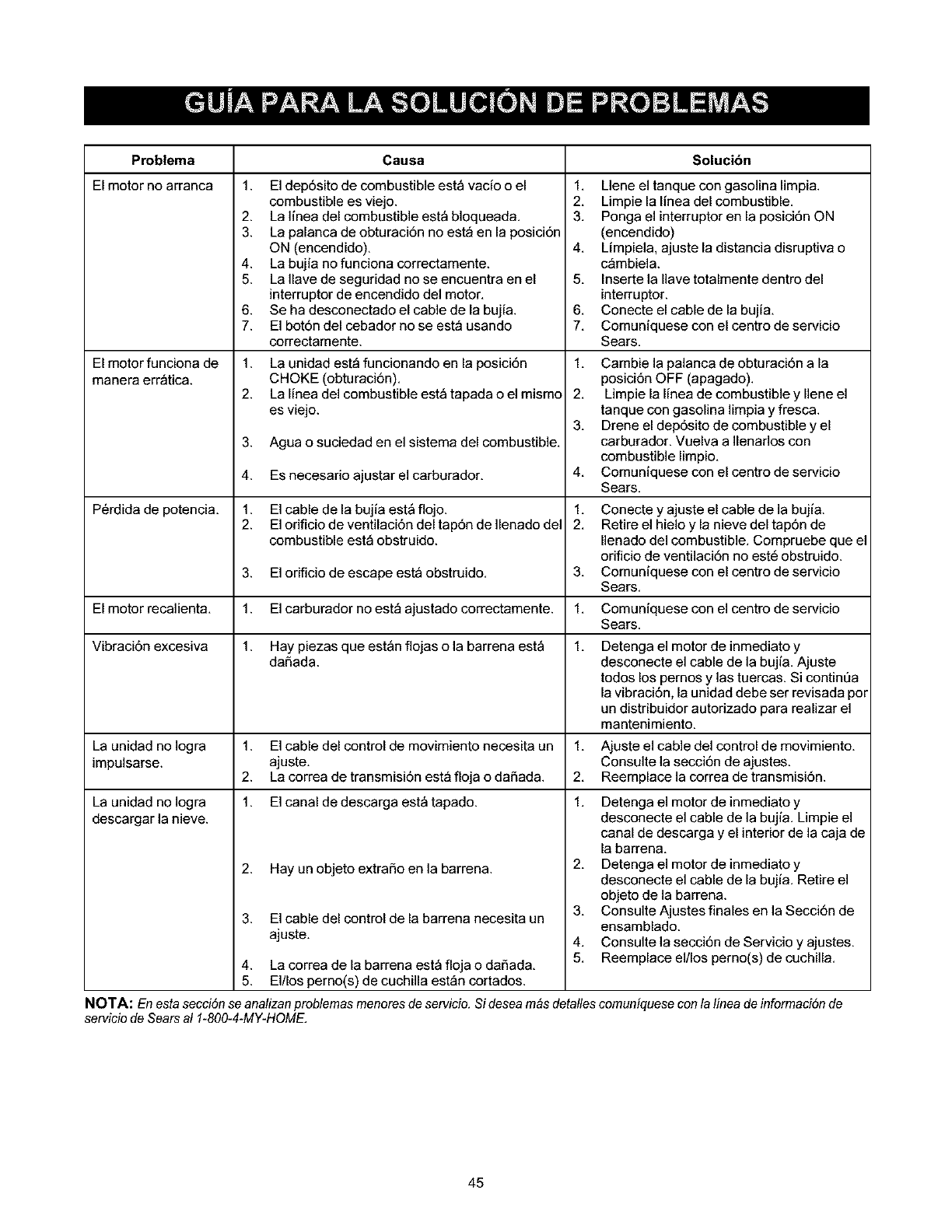
Problema Causa Solucibn
El motor no arranca 1. El dep6sito de combustible est_ vacio o el
combustible es viejo.
2. La linea del combustible est_ bloqueada,
3. La palanca de obturaci6n no est_ en la posici6n
ON (encendido).
4. La bujia nofunciona correctamente.
5. La Ilave de seguridad no se encuentra en el
interruptor de encendido del motor,
6. Se ha desconectado el cable de la bujia.
7. El bot6n del cebador no se est_ usando
correctamente.
El motor funciona de 1.
manera err_tica. 2.
3.
4.
P6rdida de potencia, 1.
2.
3.
El motor recalienta, 1.
Vibraci6n excesiva 1.
La unidad no Iogra 1.
impulsarse. 2.
La unidad no Iogra 1.
descargar la nieve.
2.
3.
La unidad est_ funcionando en la posici6n
CHOKE (obturaci6n),
La linea del combustible est_ tapada o el raising
es viejo.
Agua o suciedad en el sistema del combustible,
1, Llene el tanque con gasolina limpia.
2, Limpie la linea del combustible.
3. Ponga el interruptor en la posici6n ON
(encendido)
4. Limpiela, ajuste la distancia disruptiva o
c_mbiela.
5. Insertela Ilave totalmente dentro del
interruptor.
6, Conecte el cable de la bujia,
7, Comuniquese con el centro de servicio
Sears.
1, Cambie la palanca de obturaci6n a la
posici6n OFF (apagado).
2, Limpie la linea de combustible y Ilene el
tanque con gasolina limpia y fresca.
3, Drene el dep6sito de combustible y el
carburador. Vuelva a Ilenados con
combustible limpio,
Comuniquese con el centro de servicio
Sears.
Es necesario ajustar el carburador, 4,
El cable de la bujia est_ flojo. 1, Conecte y ajuste el cable de la bujia.
El orificio de ventilaci6n del tap6n de Ilenado de1 2, Retire el hielo y la nieve del tap6n de
combustible est_ obstruido. Ilenado del combustible. Compruebe que el
orificio de ventilaci6n no est6 obstruido.
El orificio de escape est_ obstruido, 3, Comuniquese con el centro de servicio
Sears.
El carburador no est_ ajustado correctamente. 1, Comuniquese con el centro de servicio
Sears.
Hay piezas que est_n flojas o la barrena est_ 1, Detenga el motor de inmediato y
daSada, desconecte el cable de la bujia, Ajuste
todos los pernos y las tuercas. Si contint]a
la vibraci6n, la unidad debe ser revisada por
un distribuidor autorizado para realizar el
mantenimiento,
El cable del control de movimiento necesita un 1, Ajuste el cable del control de movimiento,
ajuste. Consulte la secci6n de ajustes.
La correa de transmisi6n est_ floja o daSada. 2, Reemplace la correa de transmisi6n.
El canal de descarga est_ tapado. 1,
Hay un objeto extraSo en la barrena.
El cable del control de la barrena necesita un
ajuste.
4. La correa de la barrena est_ floja o daSada,
5. El/los pemo(s) de cuchilla est_n cortados.
Detenga el motor de inmediato y
desconecte el cable de la bujia, Limpie el
canal de descarga y el interior de la caja de
la barren&
2, Detenga el motor deinmediatoy
desconecte el cable de la bujia, Retire el
objeto de la barrena.
3, Consulte Ajustes finales en la Secci6n de
ensamblado.
4, Consulte la secci6n de Servicio y ajustes,
5, Reemplaceel/Ios pemo(s) de cuchilla,
NOTA: En esta secciSnse analizan probfemas menores deservicio. Si desea mas detaffes comuniquese con lalinea de informaci6n de
servicio de Sears al 1-800-4-MY-HOME,
45
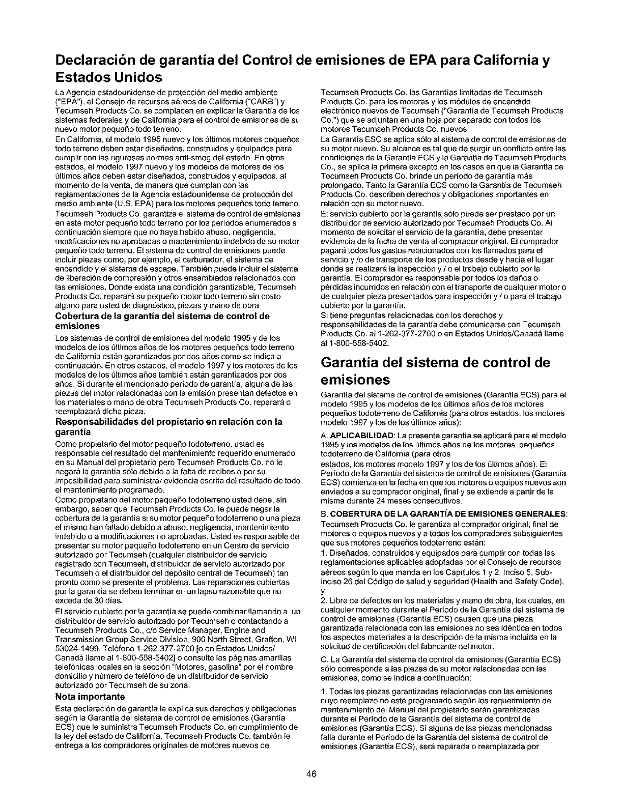
Declaracibn de garantia del Control de emisiones de EPA para California y
Estados Unidos
La Agencia estadounidense de proteccidn del medio ambiente
("EPA"), el Consejo de recursos a_reos de California ("CARB") y
Tecumseh Products Co. se complacen en explicar la Garantia de los
sistemas federales y de California para el control de emisiones de su
nuevo motor pequeSo todo terreno.
En California, el modelo 1995 nuevo y los Qltimos motores pequefios
todo terreno deben estar disefiados, construidos y equipados para
cumplir con las rigurosas normas anti-smog del estado. En otros
estados, el modelo 1997 nuevo y los modelos de motores de los
t)ltimos afios deben estar diseSados, construidos y equipados, al
momento de la venta, de manera que cumplan con las
reglamentaciones de la Agencia estadounidense de protecci6n del
medio ambiente (U.S. EPA) para los motores pequeSos todo terreno.
Tecumseh Products Co. garantiza el sistema de control de emisiones
en este motor pequefio todo terreno por los periodos enumerados a
continuaci6n siempre que no haya habido abuso, negligencia,
modificaciones no aprobadas o mantenimiento indebido de su motor
pequefio todo terreno. El sistema de control de emisiones puede
incluir piezas como, pot ejemplo, el carburador, el sistema de
enceodido y el sistema de escape. Tambi_n puede incluir el sistema
de liberaci6n de compresi6n y otros ensamblados relacionados con
las emisiones. Donde exista una condici6n garantizable, Tecumseh
Products Co. reparar_ su pequefio motor todo terreno sin costo
alguno para usted de diagn6stico, piezas y mano de obra
Cobertura de la garantia del sistema de control de
emisiones
Los sistemas de control de emisiones del modelo 1995 y de los
modelos de los Qltimos aSos de los motores pequeSos todo terreno
de California est&n garantizados por dos afios como se indica a
continuaci6n. En otros estados, el modelo 1997 y los motores de los
modelos de los Qltimos afios tambi_n est&n garantizados por dos
afios. Si durante el mencionado periodo de garantia, alguna de las
piezas del motor relacionadas con la emisi6n presentan defectos en
los materiales o mano de obra Tecumseh Products Co. reparara o
reemplazara dicha pieza.
Responsabilidades del propietario en relaci6n con la
garantia
Como propietado del motor peque_o todoterreno, usted es
responsable del resultado del mantenimiento requerido enumerado
en su Manual del propietario pero Tecumseh Products Co. no le
negar& la garantia solo debido a la falta de recibos o por su
imposibilidad para suministrar evidencia escrita del resultado de todo
el mantenimiento programado.
Como propietado del motor pequefio todoterreno usted debe, sin
embargo, saber que Tecumseh Products Co. le puede negar la
cobertura de la garantia si su motor pequefio todoterreno o una pieza
el mismo han fallado debido a abuso, negligencia, mantenimiento
indebido o a modificaciones no aprobadas. Usted es responsable de
presentar su motor pequeSo todoterreno en un Centro de servicio
autorizado por Tecumseh (cualquier distribuidor de servicio
registrado con Tecumseh, distribuidor de servicio autorizado por
Tecumseh o el distribuidor del dep6sito central de Tecumseh) tan
pronto como se presente el problema. Las reparaciones cubiertas
por la garantia se deben terminar en un lapso razonable que no
exceda de 30 dias.
El servicio cubierto por la garantia se puede combinar Ilamaodo a un
distribuidor de servicio autorizado pot Tecumseh o contactando a
Tecumseh Products Co., c/o Service Manager, Engine and
Transmission Group Service Division, 900 North Street, Grafton, Wl
53024-1499. Tel6fono 1-262-377-2700 [o en Estados Unidos/
Canad_ Ilame al 1-800-558-5402] o consulte Ins p&ginas amarillas
telef6nicas locales en la secci6n "Motores, 9asolina" por el hombre,
domicilio y nt'lmero de tel6fono de un distribuidor de servicio
autodzado por Tecumseh de su zona.
Nota importante
Esta declaracion de garantia le explica sus derechos y obligaciones
segt)n la Garantia del sistema de control de emisiones (Garantia
ECS) que le suministra Tecumseh Products Co. en cumplimiento de
la ley del estado de California. Tecumseh Products Co. tambi6n le
entrega a los compradores originales de motores nuevos de
Tecumseh Products Co. las Garantias limitadas de Tecumseh
Products Co. para los motores y los modulos de enceodido
electr6nico nuevos de Tecumseh ("Garantia de Tecumseh Products
Co.") que se adjuntan en una hoja por separado con todos los
motores Tecumseh Products Co. nuevos.
La Garantia ESC se aplica s61o al sistema de control de emisiones de
su motor nuevo. Su alcance es tal que de surgir un conflicto entre Ins
condiciones de la Garantia ECS y la Garantia de Tecumseh Products
Co., se aplica la primera excepto en los casos en que la Garantia de
Tecumseh Products Co. bdode un periodo de 9arantia m_s
prolongado. Tanto la Garantia ECS como la Garantia de Tecumseh
Products Co. describen derechos y obligaciones importantes en
relaci6n con su motor nuevo.
El servicio cubierto por la garantia s61o puede ser prestado por un
distribuidor de servicio autorizado pot Tecumseh Products Co. AI
momento de solicitar el servicio de la 9arantia, debe presentar
evidencia de la fecha de venta al comprador original. El comprador
pagar& todos los gastos relacionados con los Ilamados para el
servicio y/o de transporte de los productos desde y hacia el lugar
donde se realizara la inspeccion y /o el trabajo cubierto por la
garantia. El comprador es responsable por todos los dafios o
p_rdidas incurddos en relaci6n con el transporte de cualquier motor o
de cualquier pieza presentados para inspecci6n y /o para el trabajo
cubierto por la garantia.
Si tiene preguntas relacionadas con los derechos y
responsabilidades de la garantia debe comunicarse con Tecumseh
Products Co. al 1-262-377-2700 o en Estados Unidos/Canada Ilame
al 1-800-558-5402.
Garantia del sistema de control de
emisiones
Garantia del sistema de control de emisiones (Garantia ECS) para el
modelo 1995 y los modelos de los _ltimos aSos de los motores
pequefios todoterreno de California (para otros estados, los motores
modelo 1997 y los de los t_ltimos afios):
A. APLICABILIDAD: La presente garantia se aplicara para el modelo
1995 y los modelos de los Qltimos afios de los motores pequefios
todoterreno de California (para otros
estados, los motores modelo 1997 y los de los _ltimos aSos). El
Periodo de la Garantia del sistema de control de emisiones (Garantia
ECS) comienza en la fecha en que los motores o equipos nuevos son
enviados a su comprador original, final y se extiende a partir de la
misma durante 24 meses consecutivos.
B. COBERTURA DE LA GARANTIA DE EMISIONES GENERALES:
Tecumseh Products Co. le garantiza al comprador original, final de
motores o equipos nuevos y a todos los compradores subsiguientes
que sus motores pequefios todoterreno estan:
1. Disefiados, construidos y equipados para cumplir con todas las
reglamentaciones aplicables adoptadas por el Consejo de recursos
a_reos segtTn Ioque manda en los Capitulos 1 y 2, Inciso 5, Sub-
inciso 26 del C6digo de salud y seguridad (Health and Safety Code),
Y
2. Libre de defectos en los materiales y mano de obra, los cuales, en
cualquier momento durante el Pedodo de la Garantia del sistema de
control de emisiones (Garantia ECS) causen que una pieza
garantizada relacionada con las emisiones no sea id_ntica en todos
los aspectos materiales a la descripcidn de la misma incluida en la
solicitud de certificaci6n del fabricante del motor.
C. La Garantia del sistema de control de emisiones (Garantia ECS)
s61ocorrespoode a las piezas de su motor relacionadas con las
emisiones, como se iodica a continuacion:
1. Todas las piezas garantizadas relacionadas con las emisiones
cuyo reemplazo no est6 programado segtTn los requerimiento de
mantenimiento del Manual del propietario ser&n 9arantizadas
durante el Periodo de la Garantia del sistema de control de
emisiones (Garantia ECS). Si alguna de las piezas mencionadas
falla durante el Periodo de la Garantia del sistema de control de
emisiones (Garantia ECS), sera reparada o reemplazada pot
46
Tecumseh Products Co. en cumplimiento del inciso 4 siguiente.
Todas las piezas mencionadas reparadas o reemplazadas segQn la
Garantia del sistema de control de emisiones (Garantia ECS) seran
garantizadas pot todo el resto del Periodo de la Garantia del sistema
de control de emisiones (Garantia ECS).
2. Todas las piezas garantizadas relacionadas con las emisiones que
esten programadas para su inspecci6n normal segt_n Io determina el
Manual del propietario seran garantizadas durante el Periodo de la
Garantia del sistema de control de emisiones (Garantia ECS). Una
declaraci6n en dichas instrucciones escritas al efecto de "reparar o
reemplazar segt_n resulte necesario", no reducir_ el Periodo de la
Garantia del sistema de control de emisiones (Garantia ECS)
Cualquiera de esas piezas reparadas o reemplazadas segt_n la
Garantia del sistema de control de emisiones
seran garantizadas por el resto del Periodo de la Garantia del
sistema de control de emisiones (Garantia ECS).
3. Todas las piezas garantizadas relacionadas con las emisiones que
esten programadas para su reemplazo para cumplir con los
requisitos de mantenimiento del Manual del propietario seran
garantizadas por el periodo anterior al primer reemplazo programado
para dicha pieza. Si la pieza falla antes del primer reemplazo
programado, la misma ser_ reparada o reemplazada pot Tecumseh
Products Co. en cumplimiento del inciso 4 siguiente. Todas esas
piezas relacionadas con las emisiones reparadas o reemplazadas
segt)n la Garantia del sistema de control de emisiones (Garantia
ECS), ser_n garantizadas por el resto del Periodo de la Garantia del
sistema de control de emisiones (Garantia ECS) anterior al primer
reemplazo programado para dicha pieza.
4. La reparaci6n o reemplazo de todas las piezas garantizadas
relacionadas con las emisiones de acuerdo con la presente Garantia
del sistema de control de emisiones (Garantia ECS) ser_n realizados
sin costo para el propietario en un Centro autorizado de servicio de
Tecumseh.
5. AI propietario no se le cobrara el trabajo de diagn6stico, el cual
determina si un pieza cubierta por la Garantia del sistema de control
de emisiones (Garantia ECS) es de hecho defectuosa, siempre que
dicho trabajo de diagn6stico sea realizado en un Centro autorizado
de servicio de Tecumseh.
6. Tecumseh Products Co. es responsable per los daSos aotras
piezas odginales del motor o pot las modificaciones aprobadas
causados directamente pot una falla durante la garantia de una pieza
relacionada con las emisiones que est6 cubierta por la garantia
Garantia del sistema de control de emisiones (Garantia ECS).
7. Durante todo el Periodo de la Garantia del sistema de control de
emisiones (Garantia ECS), Tecumseh Products Co. manteodr_ un
abastecimiento de piezas garantizadas relacionadas con las
emisiones que sea suficiente para satisfacer la demanda esperada
de dichas piezas.
8. Todas las piezas de reemplazo relacionadas con las emisiones
autodzadas y aprobadas pot Tecumseh Products Co. se pueden
usar para Ilevar a cabo el mantenimiento o las reparaciones cubiertos
pot la Garantia del sistema de control de emisiones (Garantia ECS) y
ser&n suministradas al propietario sin cargo. Dicho uso no reducir_
las obligaciones de Tecumseh Products Co. en relaci6n con la
Garantia del sistema de control de emisiones (Garantia ECS).
9. Las piezas incorporadas o modificadas no aprobadas no se
pueden usar para modificar o reparar un motor de Tecumseh
Products Co.. Dicho use anula esta Garantia del sistema de control
de emisiones (Garantia ECS) yes causal suficiente para rechazar un
reclamo relacionado con dicha garantia. Tecumseh Products Co. no
es responsable por el presente documento por las fallas de cualquier
pieza garantizada de un motor Tecumseh Products Co. causadas pot
el uso de dichas piezas incorporadas o modificadas no aprobadas.
Las piezas relacionadas con las emisiones incluyen las
siguientee:
1. El ensamblado del carburador y sus piezas interiores
a. Filtro de combustible
b. Juntas obturadoras del carburador
c. Tubodetoma
2. Montaje del depurador de aire
a. Componentedeldepurador de aire
3. Sistema de enceodido, incluido:
a. Bujia de encendido
b. M6dulodeencendido
c. Ensamblado del volante
4. Silenciador catalitico (siesta incluido)
a. Junta obturadora del silenciador (si est_ incluida)
b. Colector de escape (si esta incluido)
5. Ensamblado del respiradero del c&rter y sus piezas
a. Tubode conexi6n delrespiradero
47

Your Home
For repair-in your home-of all major brand appliances,
lawn and garden equipment, or heating and cooling systems,
no matter who made it, no matter who sold it!
For the replacement parts, accessories and
owner's manuals that you need to do-it-yourself.
For Sears professional installation of home appliances
and items like garage door openers and water heaters.
1-800-4-MY-HOME ®(1-800-469-4663)
Call anytime, day or night (U.S.A. and Canada)
www.sears.com www.sears.ca
Our Home
For repair of carry-in items like vacuums, lawn equipment,
and electronics, call or go on-line for the location of your nearest
Sears Parts & Repair Center.
1-800-488-1222
Call anytime, day or night (U.S.A. only)
www.sears.com
To purchase a protection agreement (U.S.A.)
or maintenance agreement (Canada) on a product serviced by Sears:
1-800-827-6655 (U.S.A.) 1-800-361-6665 (Canada)
Para pedir servicio de reparaci6n
a domicilio, y para ordenar piezas:
1-888-SU-HOGAR sM
(1-888-784-6427)
Au Canada pour service en fran_:ais:
1-800-LE-FOYER Mc
(1-800-533-6937)
www.sears.ca
TM SM
® Registered Trademark /Trademark /Service Mark of Sears, Roebuck and Co.
® Marca Registrada /TMMarca de F_ n SMb ca /Marca de Servicio de Sears, Roebuck and Co.
MC MD
Marque de commerce /Marque d_pos6e de Sears, Roebuck and Co. @Sears, Roebuck and Co.
LITERATURE - LIS COVERSHEET
Total Pages: _L_
Total Models:' Paper doc:
# Notes: ! Pdf doc:
//1
Workflow - LITERATURE _ /_"iL_/_ (_(_}o2=/-z Initial and Date each section below as it is completed:
Received Batched Scanried TA Index QA/IE
L0308228
NUMBER:
FIGURE PROPERTIES
Tit,e:___,_ _ _ _ _ \- _ _ L_ _ a_ _-
Chassis:
Prod Type: _ _ _::,-"_ _ _
DocType: SERVM [] OWNM _REFER [] TECHM [] INSTL []
Doc Class Code: WARM _HOT []
Date Received: _-_- _.__ _ (_ "_
Date Published: _-_ -- _ _ Cb "3
Publication,: "_'-_ 4"-" )_L_ ._
Pricing -Div: N/A
Pdcing -Source: N/A
MODEL INFORMATION
NUMBERS:
Type: REG '_----_ REG []
Mfr. Class: STD [] SBP _]_ STD []
Status: ACTIVEC__ NPA [] ACTWE []
_.d #: _ __-7
Comments:
Exported
DBQA
[]
SBP []
NPA []
Rev 0 47101 -HOF
