Craftsman 247888160 User Manual SNOW THROWER Manuals And Guides L0201064
CRAFTSMAN Snowthrower, Gas Manual L0201064 CRAFTSMAN Snowthrower, Gas Owner's Manual, CRAFTSMAN Snowthrower, Gas installation guides
User Manual: Craftsman 247888160 247888160 CRAFTSMAN SNOW THROWER - Manuals and Guides View the owners manual for your CRAFTSMAN SNOW THROWER #247888160. Home:Lawn & Garden Parts:Craftsman Parts:Craftsman SNOW THROWER Manual
Open the PDF directly: View PDF ![]() .
.
Page Count: 64
Owner's Manual
CRRFTSMR
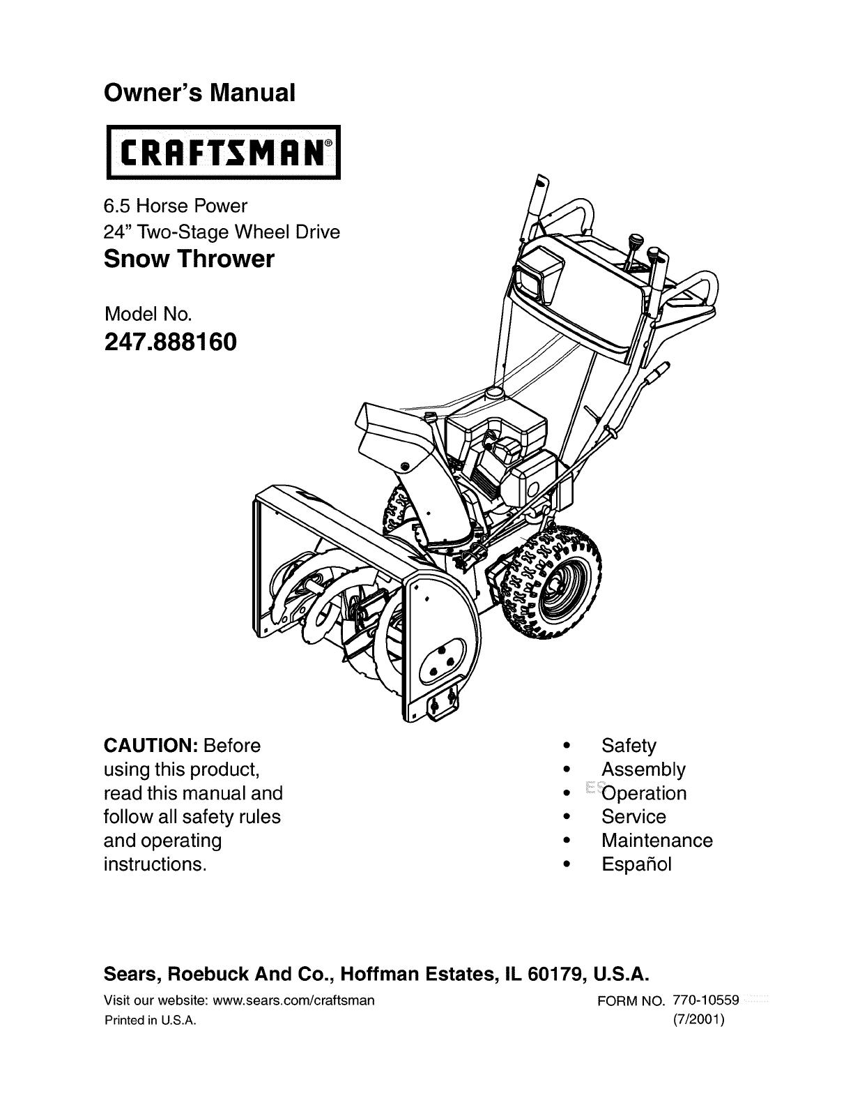
6.5 Horse Power
24" Two-Stage Wheel Drive
Snow Thrower
Model No.
247.888160
CAUTION: Before
using this product,
read this manual and
follow all safety rules
and operating
instructions.
Safety
Assembly
Service
Maintenance
EspaSol
Sears, Roebuck And Co., Hoffman Estates, IL 60179, U.S.A.
Visit our website: www.sears.com/craftsman FORM NO. 770-10559
Printed in U.S.A. (7/2001)
Content Page
Warranty Information ............................... 2
Safe Operation Practices ......................... 3
Hardware Pack ........................................ 5
Assembly ................................................. 6
Operation ................................................. 11
Maintenance ............................................ 15
Content Page
Service & Adjustment ............................. 17
Off-Season Storage ................................ 21
Trouble-Shooting .................................... 22
Parts List ................................................. 24
Espanbl ................................................... 39
Customer Service ................................... 64
Two -Year Warranty on Craftsman Snow Thrower
For two years from the date of purchase, when this Craftsman Snow Thrower is maintained, lubricated and tuned
up according to the instructions in the owner's manual, Sears will repair, free of charge, any defect in material
and workmanship.
If this Craftsman snow thrower is used for commercial or rental purposes, this warranty applies for only 30 days
from the date of purchase.
This warranty does not cover:
Expendable items which become worn during normal use, such as skid shoes, shave plate and spark
plugs.
Repairs necessary because of operator abuse or negligence, including bent crankshafts and the failure to
maintain the equipment according to the instructions contained in the owner's manual.
WARRANTY SERVICE IS AVAILABLE BY RETURNING THE CRAFTSMAN SNOW THROWER TO THE NEAREST
SEARS SERVICE CENTER/DEPARTMENT INTHE UNITED STATES.
This warranty applies only while this product is in use in the United States.
This warranty gives you specific legal rights and you may also have other rights which may vary from state to state.
SEARS, ROEBUCK AND CO., D/817WA, HOFFMAN ESTATES, IL 60179
Horsepower: ......................... 6.5
Engine Oil ............................. SAE 5W30
Capacity ................................ 21 ounces
Fuel ...................................... Unleaded Regular
Capacity: ............................... 4 quarts
Spark Plug: ........................... RN4C
Engine: .................................. 143.026503
Model Number 247.888160
Serial Number ...........................................................
Date of Purchase ......................................................
Record both serial number and date of purchase and
keep in a safe place for future reference.
SECTION1: IMPORTANTSAFEOPERATIONPRACTICES
This symbol points out important safety instructions which, if not followed, could endanger the personal
safety and/or property of yourself and others. Read and follow all instructions in this manual before
attempting to operate this machine. Failure to comply with these instructions may result in personal
injury. When you see this symbol--heed its warning.
WARNING: Engine Exhaust, some of its constituents, and certain vehicle components contain or emit
chemicals known to State of California to cause cancer and birth defects or other reproductive harm.
DANGER: This machine was built to be operated according to the rules for safe operation in this
manual. As with any type of power equipment, carelessness or error on the part of the operator can
result in serious injury. This machine is capable of amputating hands and feet and throwing objects.
Failure to observe the following safety instructions could result in serious injury or death.
Training
1. Read, understand, and follow all instructions on the
machine and in the manual(s) before attempting to
assemble and operate. Keep this manual in a safe place
for future and regular reference and for ordering
replacement parts.
2. Be familiar with all controls and their proper operation.
Know how to stop the machine and disengage them
quickly.
3. Never allow children under 14 years old to operate this
machine. Children 14 years old and over should read and
understand the operation instructions and safety rules in
this manual and should be trained and supervised by a
parent.
4. Never allow adults to operate this machine without proper
instruction.
5. Thrown objects can cause serious personal injury. Plan
your snow throwing pattern to avoid discharge of material
toward roads, bystanders and the like.
6. Keep bystanders, helpers, pets and children at least 75
feet from the machine while it is in operation. Stop
machine if anyone enters the area.
7. Exercise caution to avoid slipping or falling, especially
when operating in reverse.
Preparation
1. Thoroughly inspect the area where the equipment is to be
used. Remove all door mats, newspapers, sleds, boards,
wires and other foreign objects which could be tripped
over or thrown by the auger/impeller.
2. Always wear safety glasses or eye shields during
operation and while performing an adjustment or repair to
protect your eyes. Thrown objects which ricochet can
cause serious injury to the eyes.
3. Do not operate without wearing adequate winter outer
garments. Do not wear jewelry, long scarves or other
loose clothing which could become entangled in moving
parts. Wear footwear which will improve footing on
slippery surfaces.
4. Use a grounded three wire extension cord and receptacle
for all units with electric start engines.
5. Adjust collector housing height to clear gravel or crushed
rock surfaces.
6. Disengage all clutch levers before starting the engine.
7.
8.
9.
Never attempt to make any adjustments while engine is
running, except where specifically recommended in the
operator's manual.
Let engine and machine adjust to outdoor temperature
before starting to clear snow.
To avoid personal injury or property damage use extreme
care in handling gasoline. Gasoline is extremely
flammable and the vapors are explosive. Serious
personal injury can occur when gasoline is spilled on
yourself or your clothes which can ignite. Wash your skin
and change clothes immediately.
a. Use only an approved gasoline container.
b. Extinguish all cigarettes, cigars, pipes and other
sources of ignition.
c. Neverfuel machine indoors.
d. Never remove gas cap or add fuel while the
engine is hot or running.
e. Allow engine to cool at least two minutes before
refueling.
f. Never over fill fuel tank. Fill tank to no more than 1/2
inch below bottom of filler neck to provide space
for fuel expansion.
g. Replace gasoline cap and tighten securely.
h. If gasoline is spilled, wipe it off the engine and
equipment. Move machine to another area. Wait 5
minutes before starting the engine.
i. Never store the machine or fuel container inside
where there is an open flame, spark or pilot light
(e.g. furnace, water heater, space heater, clothes
dryer etc.).
j. Allow machine to cool at least 5 minutes before
storing.
Operation
1. Do not put hands or feet near rotating parts, in the auger/
impeller housing or discharge chute. Contact with the
rotating parts can amputate hands and feet.
2. The auger/impeller clutch lever is a safety device. Never
bypass its operation. Doing so, makes the machine
unsafe and may cause personal injury.
3. The clutch levers must operate easily in both directions
and automatically return to the disengaged position when
released.
4. Never operate with a missing or damaged discharge
chute. Keep all safety devices in place and working.
5. Neverrunanengineindoorsorinapoorlyventilated
area.Engineexhaustcontainscarbonmonoxide,an
odorlessanddeadlygas.
6. Donotoperatemachinewhileundertheinfluenceof
alcoholordrugs.
7. Mufflerandenginebecomehotandcancauseaburn.Do
nottouch.
8. Exerciseextremecautionwhenoperatingonorcrossing
gravelsurfaces.Stayalertforhiddenhazardsortraffic.
9. Exercisecautionwhenchangingdirectionandwhile
operatingonslopes.
10.Planyoursnowthrowingpatterntoavoiddischarge
towardswindows,walls,carsetc.Toavoidproperty
damageorpersonalinjurycausedbyaricochet.
11.Neverdirectdischargeatchildren,bystandersandpets
orallowanyoneinfrontofthemachine.
12.Donotoverloadmachinecapacitybyattemptingtoclear
snowattoofastofarate.
13.Neveroperatethismachinewithoutgoodvisibilityor
light.Alwaysbesureofyourfootingandkeepafirmhold
onthehandles.Walk,neverrun.
14.Disengagepowertotheauger/impellerwhen
transportingornotinuse.
15.Neveroperatemachineathightransportspeedson
slipperysurfaces.Lookdownandbehindandusecare
wheninreverse.
16.Ifthemachineshouldstarttovibrateabnormally,stopthe
engine,disconnectthesparkplugandgrounditagainst
theengine.Inspectthoroughlyfordamage.Repairany
damagebeforestartingandoperating.
17.Disengageallclutchleversandstopenginebeforeyou
leavetheoperatingposition(behindthehandles).Wait
untiltheauger/impellercomestoacompletestopbefore
uncloggingthedischargechute,makingany
adjustments,orinspections.
18.Neverputyourhandinthedischargeorcollector
openings.Alwaysuseaclearingtooltounclogthe
dischargeopening.
19.Useonlyattachmentsandaccessoriesapprovedbythe
manufacturer(e.g.wheelweights,tirechains,cabsetc.).
20.Ifsituationsoccurwhicharenotcoveredinthismanual,
usecareandgoodjudgment.ContactyournearestSears
storeforassistanceorcallCustomerService.
Maintenance And Storage
1. Never tamper with safety devices. Check their proper
operation regularly.
2. Disengage all clutch levers and stop engine. Wait until
the auger/impeller come to a complete stop. Disconnect
the spark plug wire and ground against the engine to
prevent unintended starting before cleaning, repairing, or
inspecting.
3. Check bolts, and screws for proper tightness at frequent
intervals to keep the machine in safe working condition.
Also, visually inspect machine for any damage.
4. Do not change the engine governor setting or over-speed
the engine. The governor controls the maximum safe
operating speed of the engine.
5. Snow thrower shave plates and skid shoes are subject to
wear and damage. For your safety protection, frequently
check all components and replace with original
equipment manufacturer's (O.E.M.) parts only. "Use of
parts which do not meet the original equipment
specifications may lead to improper performance and
compromise safetyF
6. Check clutch controls periodically to verify they engage
and disengage properly and adjust, if necessary. Refer to
the adjustment section in this operator's manual for
instructions.
7. Maintain or replace safety and instruction labels, as
necessary.
8. Observe proper disposal laws and regulations for gas,
oil, etc. to protect the environment.
9. Prior to storing, run machine a few minutes to clear snow
from machine and prevent freeze up of auger/impeller.
10. Never store the machine or fuel container inside where
there is an open flame, spark or pilot light such as a water
heater, furnace ,clothes dryer etc.
11. Always refer to the operator's manual for proper
instructions on off-season storage.
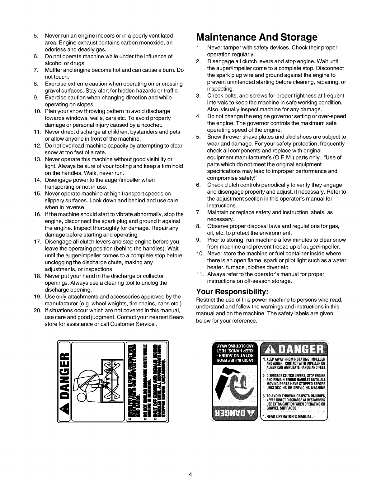
Your Responsibility:
Restrict the use of this power machine to persons who read,
understand and follow the warnings and instructions in this
manual and on the machine. The safety labels are given
below for your reference.
o o o
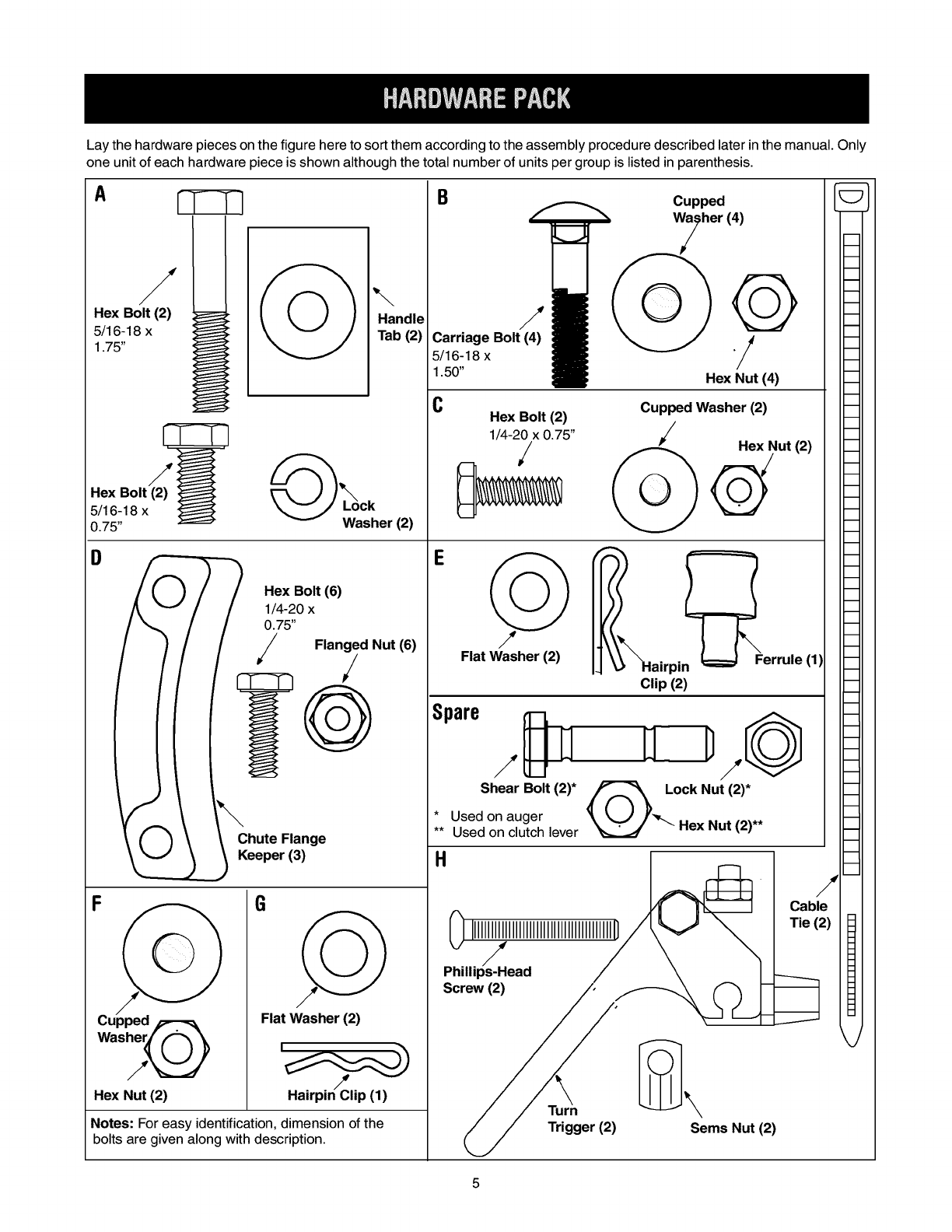
Lay the hardware pieces on the figure here to sort them according to the assembly procedure described later in the manual. Only
one unit of each hardware piece is shown although the total number of units per group is listed in parenthesis.
A_B_Cupped [
_._ Wyher{4)
Hex Bolt (2) '_ _ _ ,, iHandle
5/16,_18 x !_ \ _ /I Tab (2) Carriage Bolt (4) ,"mR ___ J /4
i_ _ 1.50" !_ Hex Nu't (4)
C Hex Bolt (2) Cup ,ped Washer (2)
__ 1/4-20 x 0.75" /Rex Nut (2)
i!17i_B;Itx {2_))_ @hw,ker (2) :_ _ Q
/('_ ; ; Hex Bolt (6) E ,;
o(4- ox
/1// /Flanged Nut (6) FI "_
_! _ _ at as e ()i_%airpin t_Clip(2) Ferrule(I)
I{Spare -
_; _'OK;:plr(3) *Use:h::::e_rrlt(2)* _"_L'_-kJ)'jckNut")--**
_,ange " OseOooc,utch,ever_:J .ex.u.,.,
H
F/_ _Screw(2)"2)//, _-_ cable_
[] IIIIIIIIIIIIIIIIIIIIIIIIIIIIIIIIIIIIIIIIID/\k,J_Tie (2)
_/ /\ \
Phillips-Head /\
Cupped F-_- _ I Flat Washer (2) -_
__e !t _ /_Tu_rn _'_ _'_,
;tiwfi_ _°ns _// Trigger (2) Sems Nut (2)
IMPORTANT: This unit is shipped with engine oil in the
engine, but without gasoline. After assembly, see
OPERATION section of this manual for fuel selection
and fill-up.
NOTE: To determine right and left sides of your snow
thrower, stand behind the unit in the operating position.
Your snow thrower has been assembled at the factory
except the handles and the handle panel, the discharge
chute assembly, the chute directional control assembly
and the shift rod. These parts are shipped loose in the
carton.
Removing From Carton
• Cut the corners of the carton and lay the sides flat
on the ground. Remove all packing inserts.
• Remove all loose parts. For a complete list of the
loose parts, refer to the following section.
• Move the snow thrower out of the carton.
• Make certain all parts and literature have been
removed before discarding the carton.
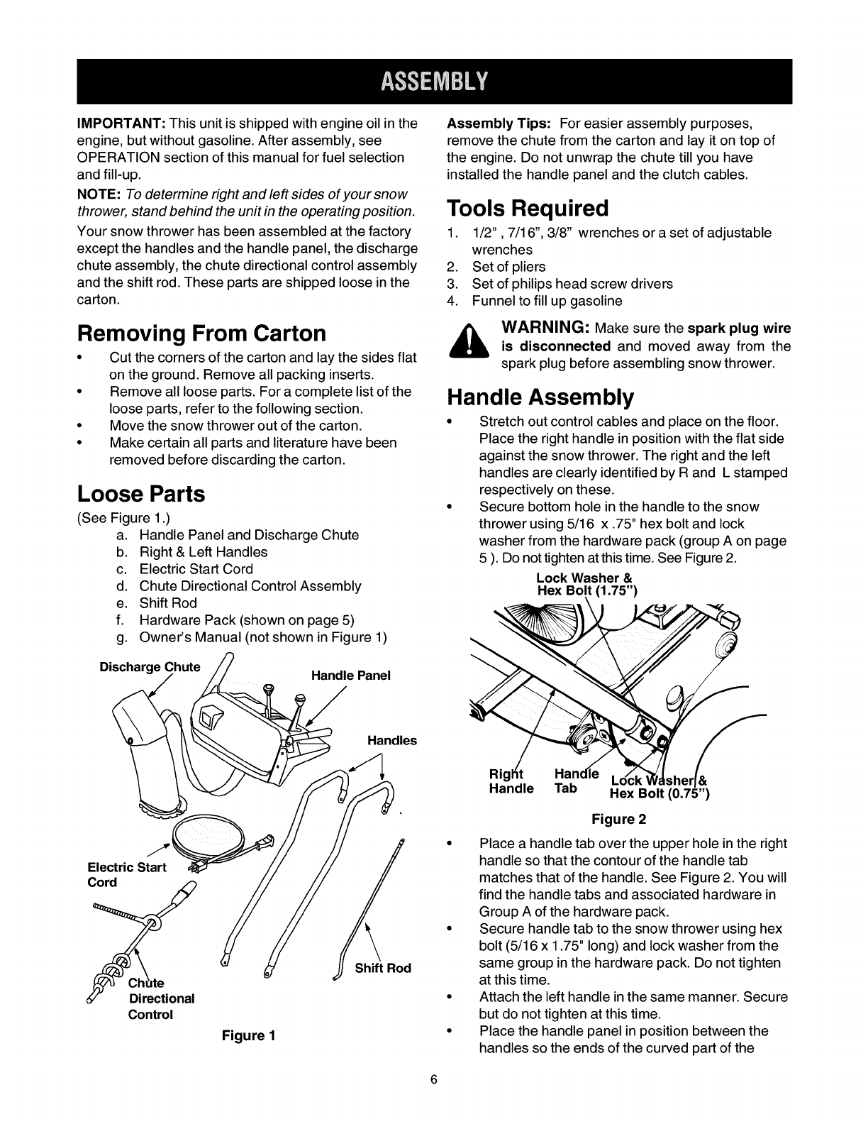
Loose Parts
(See Figure 1.)
a. Handle Panel and Discharge Chute
b. Right & Left Handles
c. Electric Start Cord
d. Chute Directional Control Assembly
e. Shift Rod
f. Hardware Pack (shown on page 5)
g. Owner's Manual (not shown in Figure 1)
Discharge Chute Handle Panel
Assembly Tips: For easier assembly purposes,
remove the chute from the carton and lay it on top of
the engine. Do not unwrap the chute till you have
installed the handle panel and the clutch cables.
Tools Required
1. 1/2", 7/16", 3/8" wrenches or a set of adjustable
wrenches
2. Set of pliers
3. Set of philips head screw drivers
4. Funnel to fill up gasoline
WARNING: Make sure the spark plug wire
is disconnected and moved away from the
spark plug before assembling snow thrower.
Handle Assembly
• Stretch out control cables and place on the floor.
Place the right handle in position with the flat side
against the snow thrower. The right and the left
handles are clearly identified by R and L stamped
respectively on these.
• Secure bottom hole in the handle to the snow
thrower using 5/16 x .75" hex bolt and lock
washer from the hardware pack (group A on page
5 ). Do not tighten at this time. See Figure 2.
Lock Washer &
Hex Bolt (1.75")
Electric Start
Cord
Directional
Control
Figure 1
Shift Rod
Rig=
Handle Tab .f
Hex Bolt (0.75")
Figure 2
Place a handle tab over the upper hole in the right
handle so that the contour of the handle tab
matches that of the handle. See Figure 2. You will
find the handle tabs and associated hardware in
Group A of the hardware pack.
Secure handle tab to the snow thrower using hex
bolt (5/16 x 1.75" long) and lock washer from the
same group in the hardware pack. Do not tighten
at this time.
Attach the left handle in the same manner. Secure
but do not tighten at this time.
Place the handle panel in position between the
handles so the ends of the curved part of the
handlesgothroughtheslotsinthehandlepanel.
Whileplacingthehandlepanel,makesureto _\_\TChut e
route chute and chute cable between the handles
underneath the panel keeping the cable on top of \\\ Hex Hex
the engine. __Flange
Align the holes in the handle with the holes on two Nut
sides of the handle panel. See Figure 3.
Right Handle Panel
"___==_ _ _\/ ._ Chute
Hex Bolt _ / Flange
_,t_))_ _ Keeper
Figure 4
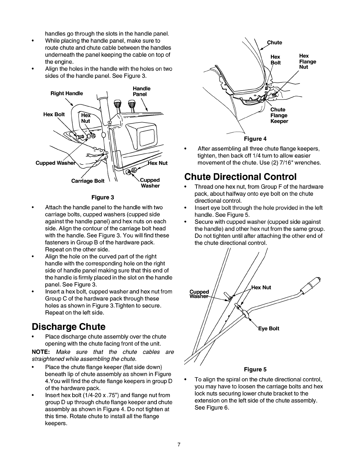
"_ " __u • After assembling all three chute flange keepers,
, tighten, then back off 1/4 turn to allow easier
Cupped t movement of the chute. Use (2) 7/16" wrenches.
Carriage Bolt ,Cupped Chute Directional Control
Washer •Thread one hex nut, from Group F of the hardware
Figure 3
Attach the handle panel to the handle with two
carriage bolts, cupped washers (cupped side
against the handle panel) and hex nuts on each
side. Align the contour of the carriage bolt head
with the handle. See Figure 3. You will find these
fasteners in Group B of the hardware pack.
Repeat on the other side.
Align the hole on the curved part of the right
handle with the corresponding hole on the right
side of handle panel making sure that this end of
the handle is firmly placed in the slot on the handle
panel. See Figure 3.
Insert a hex bolt, cupped washer and hex nut from
Group C of the hardware pack through these
holes as shown in Figure 3.Tighten to secure.
Repeat on the left side.
pack, about halfway onto eye bolt on the chute
directional control.
Insert eye bolt through the hole provided in the left
handle. See Figure 5.
Secure with cupped washer (cupped side against
the handle) and other hex nut from the same group.
Do not tighten until after attaching the other end of
the chute directional control.
Cu Hex Nut
Discharge Chute
• Place discharge chute assembly over the chute
opening with the chute facing front of the unit.
NOTE: Make sure that the chute cables are
straightened while assembling the chute.
• Place the chute flange keeper (flat side down)
beneath lip of chute assembly as shown in Figure
4.You will find the chute flange keepers in group D
of the hardware pack.
• Insert hex bolt (1/4-20 x .75") and flange nut from
group D up through chute flange keeper and chute
assembly as shown in Figure 4. Do not tighten at
this time. Rotate chute to install all the flange
keepers.
Bolt
Figure 5
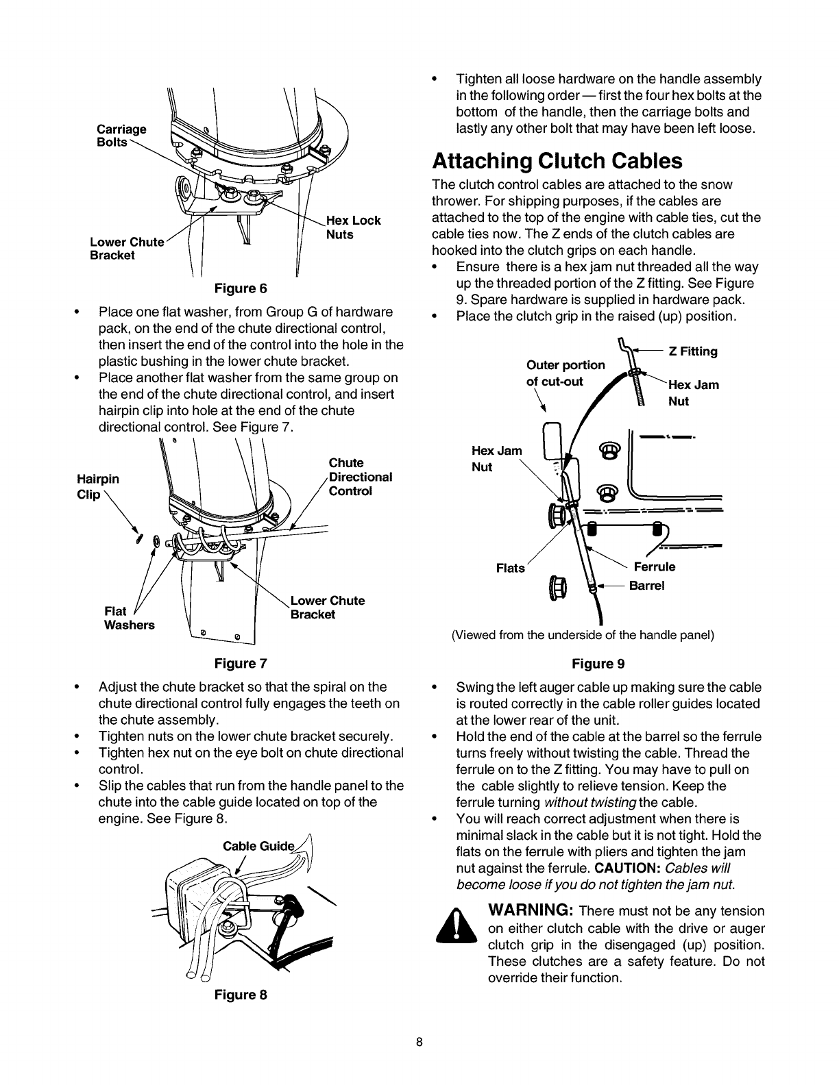
To align the spiral on the chute directional control,
you may have to loosen the carriage bolts and hex
lock nuts securing lower chute bracket to the
extension on the left side of the chute assembly.
See Figure 6.
Carriage
Tighten all loose hardware on the handle assembly
in the following order-- first the four hex bolts at the
bottom of the handle, then the carriage bolts and
lastly any other bolt that may have been left loose.
Lower
Bracket
Hex Lock
Nuts
Attaching Clutch Cables
The clutch control cables are attached to the snow
thrower. For shipping purposes, if the cables are
attached to the top of the engine with cable ties, cut the
cable ties now. The Z ends of the clutch cables are
hooked into the clutch grips on each handle.
Ensure there is a hex jam nut threaded all the way
up the threaded portion of the Z fitting. See Figure
9. Spare hardware is supplied in hardware pack.
Place one flat washer, from Group G of hardware Place the clutch grip in the raised (up) position.
Figure 6 i
• ler, fror 1(
pack, on the end of the chute directional control,
then i ls_ rt tt_eer=dof the con Lrolinto the hole in
I tl_ i Outer portion
p as "" b Jshng irl the lower c lute brack_.t, o_cut-out /
• Place an oth .=rfl_t washer fro n the sam_, group
the er=d(_fthe ch Jte direction al control, _Lndinse
hairpi _ c ip i_lto I_ole at the erd of the ch_Jte
direct on _lc _ntr(,I. See Figur _7. Chute NHeu;Jam, _-i
Hairpin _' / _/ _ /Directional
Clip_ _Control _ (_
F'°'s
er Chute
Flat _" \l I Bracket
Washers
then insert the end of the control into the hole in the
plastic bushing in the lower chute bracket.
Place another flat washer from the same group on
the end of the chute directional control, and insert
hairpin clip into hole at the end of the chute
directional control. See Figure 7.
ZFitting
Nut
Ferrule
Barrel
(Viewed from the underside of the handle panel)
Figure 7 Figure 9
• Adjust the chute bracket so that the spiral on the
chute directional control fully engages the teeth on
the chute assembly.
• Tighten nuts on the lower chute bracket securely.
• Tighten hex nut on the eye bolt on chute directional
control.
• Slip the cables that run from the handle panel to the
chute into the cable guide located on top of the
engine. See Figure 8.
Figure 8
• Swing the left auger cable up making sure the cable
is routed correctly in the cable roller guides located
at the lower rear of the unit.
• Hold the end of the cable at the barrel so the ferrule
turns freely without twisting the cable. Thread the
ferrule on to the Z fitting. You may have to pull on
the cable slightly to relieve tension. Keep the
ferrule turning without twisting the cable.
• You will reach correct adjustment when there is
minimal slack in the cable but it is not tight. Hold the
flats on the ferrule with pliers and tighten the jam
nut against the ferrule. CAUTION: Cables will
become loose if you do not tighten the jam nut.
WARNING: There must not be any tension
on either clutch cable with the drive or auger
clutch grip in the disengaged (up) position.
These clutches are a safety feature. Do not
override their function.
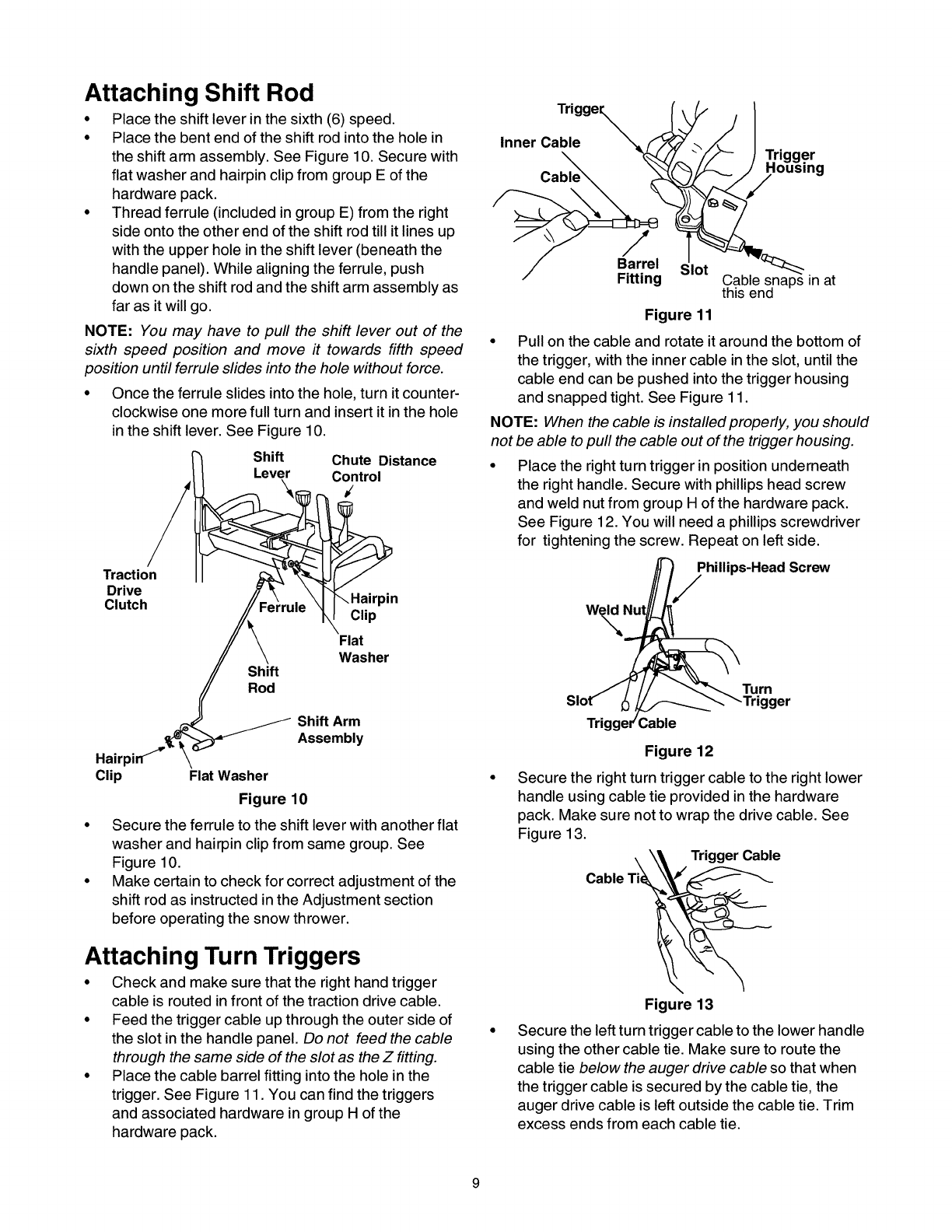
Attaching Shift Rod
• Place the shift lever in the sixth (6) speed.
• Place the bent end of the shift rod into the hole in
the shift arm assembly. See Figure 10. Secure with
flat washer and hairpin clip from group E of the
hardware pack.
• Thread ferrule (included in group E) from the right
side onto the other end of the shift rod till it lines up
with the upper hole in the shift lever (beneath the
handle panel). While aligning the ferrule, push
down on the shift rod and the shift arm assembly as
far as it will go.
NOTE: You may have to pull the shift lever out of the
sixth speed position and move it towards fifth speed
position until ferrule slides into the hole without force.
• Once the ferrule slides into the hole, turn it counter-
clockwise one more full turn and insert it in the hole
in the shift lever. See Figure 10.
Shift Chute Distance
Lever Control
Traction
Drive
Clutch
Shift
Rod
\Hairpin
Clip
Flat
Washer
Shift Arm
Assembly
Clip Flat Washer
Figure 10
Secure the ferrule to the shift lever with another flat
washer and hairpin clip from same group. See
Figu re 10.
Make certain to check for correct adjustment of the
shift rod as instructed in the Adjustment section
before operating the snow thrower.
Attaching Turn Triggers
• Check and make sure that the right hand trigger
cable is routed in front of the traction drive cable.
• Feed the trigger cable up through the outer side of
the slot in the handle panel. Do not feed the cable
through the same side of the slot as the Z fitting.
• Place the cable barrel fitting into the hole in the
trigger. See Figure 11. You can find the triggers
and associated hardware in group H of the
hardware pack.
Trigge%
Inner Cable Trigger
us,ng
/
Barrel Slot
Fitting
Figure 11
Cable snaps in at
this end
• Pull on the cable and rotate it around the bottom of
the trigger, with the inner cable in the slot, until the
cable end can be pushed into the trigger housing
and snapped tight. See Figure 11.
NOTE: When the cable is installed properly, you should
not be able to pull the cable out of the trigger housing.
• Place the right turn trigger in position underneath
the right handle. Secure with phillips head screw
and weld nut from group H of the hardware pack.
See Figure 12. You will need a phillips screwdriver
for tightening the screw. Repeat on left side.
ihillips-Head Screw
Slot_ _ _..__ TrTUgnger
Trigger'Cable
Figure 12
Secure the right turn trigger cable to the right lower
handle using cable tie provided in the hardware
pack. Make sure not to wrap the drive cable. See
Figure 13.
\ \_ Trigger Cable
Cable Ti_
Figure 13
Secure the left turn trigger cable to the lower handle
using the other cable tie. Make sure to route the
cable tie below the auger drive cable so that when
the trigger cable is secured by the cable tie, the
auger drive cable is left outside the cable tie. Trim
excess ends from each cable tie.
NOTE:The right side cable tie must be used to keep
cable from coming in contact with the moving shift arm
from the transmission.
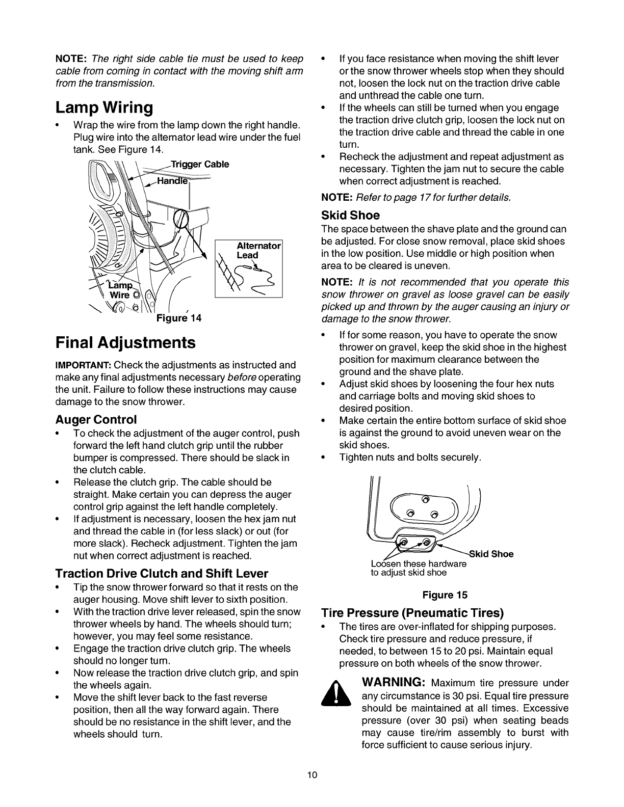
Lamp Wiring
• Wrap the wire from the lamp down the right handle.
Plug wire into the alternator lead wire under the fuel
tank. See Figure 14.
/Alternator
Figure 14
Final Adjustments
IMPORTANT:Check the adjustments as instructed and
make any final adjustments necessary before operating
the unit. Failure to follow these instructions may cause
damage to the snow thrower.
Auger Control
• To checkthe adjustment of the auger control, push
forward the left hand clutch grip until the rubber
bumper is compressed. There should be slack in
the clutch cable.
• Release the clutch grip. The cable should be
straight. Make certain you can depress the auger
control grip against the left handle completely.
• If adjustment is necessary, loosen the hex jam nut
and thread the cable in (for less slack) or out (for
more slack). Recheck adjustment. Tighten the jam
nut when correct adjustment is reached.
Traction Drive Clutch and Shift Lever
• Tip the snow thrower forward so that it rests on the
auger housing. Move shift lever to sixth position.
• With the traction drive lever released, spin the snow
thrower wheels by hand. The wheels should turn;
however, you may feel some resistance.
• Engage the traction drive clutch grip. The wheels
should no longer turn.
• Now release the traction drive clutch grip, and spin
the wheels again.
• Move the shift lever back to the fast reverse
position, then all the way forward again. There
should be no resistance in the shift lever, and the
wheels should turn.
• If you face resistance when moving the shift lever
or the snow thrower wheels stop when they should
not, loosen the lock nut on the traction drive cable
and unthread the cable one turn.
• If the wheels can still be turned when you engage
the traction drive clutch grip, loosen the lock nut on
the traction drive cable and thread the cable in one
turn.
• Recheck the adjustment and repeat adjustment as
necessary. Tighten the jam nut to secure the cable
when correct adjustment is reached.
NOTE: Refer to page 17 for further details.
Skid Shoe
The space between the shave plate and the ground can
be adjusted. For close snow removal, place skid shoes
in the low position. Use middle or high position when
area to be cleared is uneven.
NOTE: It is not recommended that you operate this
snow thrower on gravel as loose gravel can be easily
picked up and thrown by the auger causing an injury or
damage to the snow thrower.
• If for some reason, you have to operate the snow
thrower on gravel, keep the skid shoe in the highest
position for maximum clearance between the
ground and the shave plate.
• Adjust skid shoes by loosening the four hex nuts
and carriage bolts and moving skid shoes to
desired position.
• Make certain the entire bottom surface of skid shoe
is against the ground to avoid uneven wear on the
skid shoes.
• Tighten nuts and bolts securely.
_ ._.....Sk_i d Shoe
Loosen these hardware
to adjust skid shoe
Figure 15
Tire Pressure (Pneumatic Tires)
•The tires are over-inflated for shipping purposes.
Check tire pressure and reduce pressure, if
needed, to between 15 to 20 psi. Maintain equal
pressure on both wheels of the snow thrower.
WARNING: Maximum tire pressure under
any circumstance is 30 psi. Equal tire pressure
should be maintained at all times. Excessive
pressure (over 30 psi) when seating beads
may cause tire/rim assembly to burst with
force sufficient to cause serious injury.
10
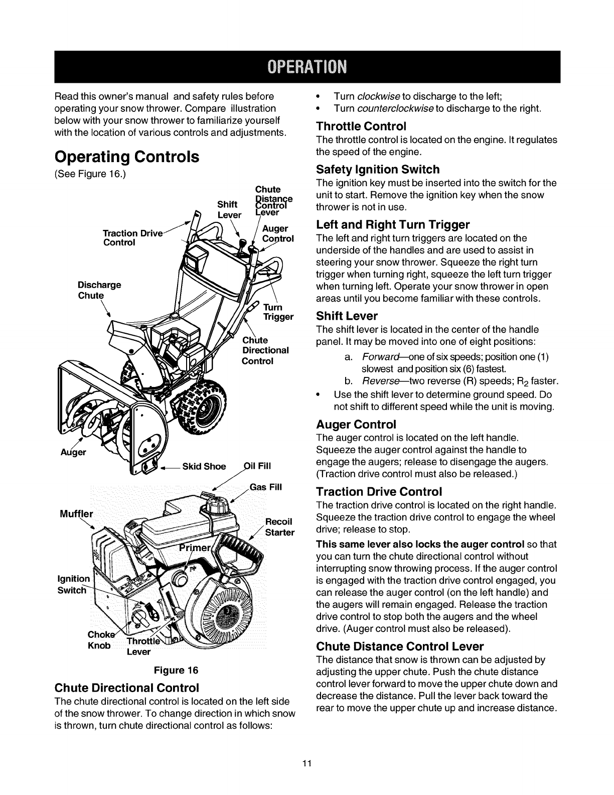
Read this owner's manual and safety rules before
operating your snow thrower. Compare illustration
below with your snow thrower to familiarize yourself
with the location of various controls and adjustments.
Operating Controls
(See Figure 16.)
Traction
Control
Shift
Lever
Chute
Auger
Discharge
Chute
Turn
Trigger
Directional
Control
Auger
Muffler
Ignition
Knob Throffiq
Lever
Figure 16
Chute Directional Control
The chute directional control is located on the left side
of the snow thrower. To change direction in which snow
is thrown, turn chute directional control as follows:
•Turn clockwise to discharge to the left;
• Turn counterclockwise to discharge to the right.
Throttle Control
The throttlecontrol is located on the engine. It regulates
the speed of the engine.
Safety Ignition Switch
The ignition key must be inserted into the switch for the
unit to start. Remove the ignition key when the snow
thrower is not in use.
Left and Right Turn Trigger
The left and right turn triggers are located on the
underside of the handles and are used to assist in
steering your snow thrower. Squeeze the right turn
trigger when turning right, squeeze the left turn trigger
when turning left. Operate your snow thrower in open
areas until you become familiar with these controls.
Shift Lever
The shift lever is located in the center of the handle
panel. It may be moved into one of eight positions:
a. Forward--one of six speeds; position one (1)
slowest and position six (6) fastest.
b. Reverse--two reverse (R) speeds; R2faster.
• Use the shift lever to determine ground speed. Do
not shift to different speed while the unit is moving.
Auger Control
The auger control is located on the left handle.
Squeeze the auger control against the handle to
engage the augers; release to disengage the augers.
(Traction drive control must also be released.)
Traction Drive Control
The traction drive control is located on the right handle.
Squeeze the traction drive control to engage the wheel
drive; release to stop.
This same lever also locks the auger control so that
you can turn the chute directional control without
interrupting snow throwing process. If the auger control
is engaged with the traction drive control engaged, you
can release the auger control (on the left handle) and
the augers will remain engaged. Release the traction
drive control to stop both the augers and the wheel
drive. (Auger control must also be released).
Chute Distance Control Lever
The distance that snow is thrown can be adjusted by
adjusting the upper chute. Push the chute distance
control lever forward to move the upper chute down and
decrease the distance. Pull the lever back toward the
rear to move the upper chute up and increase distance.
11
Before Starting Engine
Fill Gas
_, WARNING: Gasoline is flammable and
caution must be used when handling or
storing it.
Do not fill fuel tank while the snow thrower is
running, when it is hot or when it is in an
enclosed area.
Keep your snow thrower away from any open
flame or an electrical spark and do not smoke
while filling the fuel tank.
Never fill the fuel tank completely. Fill the tank
to within 1/4"-1/2" from the top to provide
space for expansion of fuel.
Always fill the fuel tank outdoors and use a
funnel or spout to prevent spilling.
Make sure to wipe off any spilled fuel before
starting the engine.
•Store gasoline in a clean, approved container and
keep the cap in place on the container.
• Make sure that the container from which you pour
the gasoline is clean and free from rust or other
foreign particles.
• Fill fuel tank with clean, fresh, unleaded grade
automotive gasoline.
• At the end of the job, empty the fuel tank if the snow
thrower is not going to be used for 30 days or
longer. See storage instructions on page 21.
CAUTION: Experience indicates that alcohol blended
fuels (called gasohol) or those using ethanol or
methanol can attract moisture which leads to
separation and formation of acids during storage.
Acidic gas can damage the fuel system of an engine
while in storage.
To avoid engine problems, the fuel system should be
emptied before storage for 30 days or longer. Drain the
gas tank, start the engine and let it run until the fuel lines
and carburetor are empty. Use fresh fuel next season.
See storage Instructions for additional information.
Never use engine or carburetor cleaner products in the
fuel tank or permanent damage may occur.
To Start Engine
WARNING: Be sure no one other than
the operator is standing near the snow
thrower while starting or operating. Do not
operate this snow thrower unless the
discharge chute assembly has been properly
installed and is secured.
A. Electric Starter
•For location of all the engine controls referred to in
this section, see Figure 16.
•Before starting, make sure that the engine has
sufficient oil. The snow thrower engine is equipped
with a 120 volt A.C. electric starter and recoil
starter. The electric starter is equipped with a three-
wire power cord and plug and is designed to
operate on 120 volt AC household current.Followall
instructionscarefully.
Cold Start
NOTE: If the unit shows any sign of motion (drive or
augers) with the clutch grips disengaged, shut the
engine off immediately. Readjust as instructed in the
"Final Adjustments" section on page 10.
_WARNING: The electric starter must be
properly grounded at all times to avoid the
possibility of electric shock to the operator.
• Determine whether your house wiring is a three-
wire grounded system. Ask a licensed electrician if
you are not certain.
WARNING: If your house wiring system is
not a three-wire grounded system, do not use
this electric starter under any conditions.
• If your house wiring system is grounded and a
three-hole receptacle is not available at the point
the snow thrower starter will normally be used, one
should be installed by a licensed electrician.
• When connecting the power cord, always connect
cord to starter on engine first, then plug the other
end into a three-hole grounded receptacle.
• When disconnecting the power cord, always
unplug the end from the three-hole, grounded
receptacle first.
• Attach spark plug wire to spark plug.
• Make sure that the auger drive and the traction
drive levers are in the RELEASED position.
• Move throttle control lever to FAST position.
• Remove the keys from the plastic bag. Push key
into the ignition slot. Make sure it snaps into place.
Do not turn key. Keep second key in a safe place.
• Rotate the choke knob to FULL choke position.
• Connect power cord to the switch box on engine.
• Plug the other end of the power cord into a three-
hole, grounded 120 volt A.C. receptacle.
_, ARNING: Do not use the primer whilestarting the engine with an electric starter.
Push down on the starter button until the engine
starts. Do not crank for more than 10 seconds at a
time. This electric starter is thermally protected. If
overheated, it will stop automatically and can be
12
restarted only when it has cooled to a safe
temperature (a wait of about 5 to 10 minutes).
• When the engine starts, release the starter button
and slowly rotate the choke to OFF position. If the
engine falters, rotate the choke to FULL and then
gradually to OFF.
• Disconnect the power cord from the receptacle first
and then from the switch box on the engine.
• Allow the engine to warm up for a few minutes
because the engine will not develop full power until
it reaches operating temperature.
• Operate the engine at full throttle (FAST) when
throwing snow.
Warm Start
• If restarting a warm engine, rotate choke to OFF
instead of FULL and press the starter button.
B. Recoil Starter
Make sure that the engine has sufficient oil and the
auger drive and the traction drive levers are released.
• Move throttle control to FAST position.
• Push key into the ignition slot so that it snaps into
place. Do not turn key. Remove plastic bag and
keep the second key in a safe place.
• Rotate choke control to FULL choke position.
• Push the primer button while covering the vent hole.
Remove your finger from the primer between primes.
Do not prime if temperature is above 50° F; prime
two times between 50oF and 15° F; and prime four
times below 15° F.
• Pull the starter handle rapidly. Do not allow the
handle to snap back, but allow it to rewind slowly
while keeping a firm hold on the starter handle.
• As the engine warms up and begins to operate
evenly, rotate the choke knob slowly to OFF
position. If the engine falters, return to FULL choke,
then slowly move to OFF choke position.
• Allow the engine to warm up for a few minutes
because the engine will not develop full power until
it reaches operating temperature.
• Operate the engine at full throttle (FAST) when
throwing snow.
Warm Start
• If restarting a warm engine after a temporary shut
down, rotate choke to OFF instead of FULL and do
not prime. Press the starter button.
Frozen Recoil Starter
If the starter is frozen and will not turn the engine,
proceed as follows:
•Pull as much rope out of the starter as possible.
•Release the starter handle and let it snap back
against the starter.
•If the engine stillfails to start, repeat the first two
steps. If continued attempts do not free starter,
follow the electric starter procedures to start.
•Avoid possible freezing of recoil starter and the
engine controls.
Operating Snow Thrower
To Engage Drive
•With the engine running near top speed, move shift
lever to one of six FORWARD positions or two
REVERSE positions. Select aspeed appropriate
for the snow conditions that exist. Use slower
speeds untilyou are familiar with the operation of
the snow thrower.
• Squeeze the traction drive clutch grip against the
righthandle and the snow thrower will move.
Release it and the drive motion will stop.
To Engage Augers
To engage the augers and start snow throwing,
squeeze the left hand auger clutch grip against the
left handle. Release to stop augers.
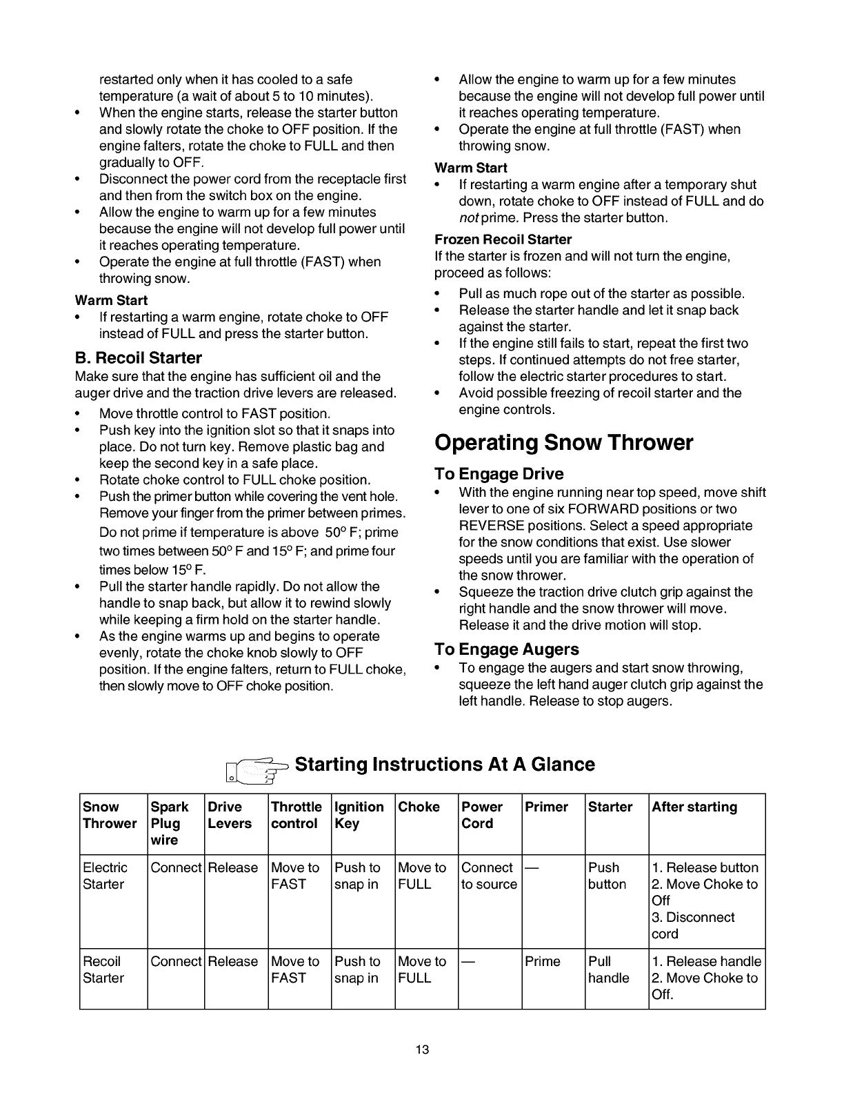
Snow
Thrower
Electric
Starter
Recoil
Starter
Spark
Plug
wire
Connect
Connect
Starting Instructions At A Glance
Drive
Levers
Release
Release
Throttle
control
Move to
FAST
Move to
FAST
Ignition
Key
Push to
snap in
Push to
snap in
Choke
Move to
FULL
Move to
FULL
Power
Cord
Connect
to source
Primer
Prime
Starter
Push
button
Pull
handle
After starting
1. Release button
2. Move Choke to
Off
3. Disconnect
cord
1. Release handle
2. Move Choke to
Off.
13
•While the auger control is engaged, squeeze the
traction drive control to move, release to stop. Do
not shift speeds while the drive is engaged.
NOTE: This same lever also locks the auger control so
you can turn the chute directional control without
interrupting the snow throwing process. •
• Release the auger control; the interlock mechanism
should keep the auger control engaged until the •
traction drive control is released.
• Release the traction drive control to stop both the
augers and the wheel drive.
WARNING: To stop the auger, both levers
must be released.
To Throw Snow
CAUTION: Check the area to be cleared for foreign
objects. Remove, if any.
• Start the engine following Starting instructions.
• Rotate the discharge chute to the desired direction,
away from bystanders and/or buildings. Move the
chute distance control forward or backward to
adjust the distance the snow is to be thrown.
• Select the speed according to snow condition.
CAUTION: Never move the shift lever without first
releasing the drive clutch.
• Engage the auger control and traction drive control
levers following instructions above.
• The interlock feature will allow you to remove your
left hand from the auger control lever.
• When clearing the first pass through the snow,
control the traction speed of the snow thrower
according to the depth and condition of snow.
• To turn the unit left, squeeze left trigger; to turn
right, squeeze right trigger.
• On each succeeding pass, readjust the chute
deflector to the desired position and slightly overlap
the previously cleared path.
• After the area is cleared, stop the snow thrower
following instructions given below.
Operating Tips
NOTE: Allow the engine to warm up for a few minutes
as the engine will not develop full power until it reaches
operating temperature.
WARNING: The temperature of muffler and
the surrounding areas may exceed 150° F.
Avoid these areas.
For most efficient snow removal, remove snow
immediately after it falls.
Discharge snow downwind whenever possible.
Slightly overlap each previous swath.
Set the skid shoes 1/4" below the scraper bar for
normal usage. The skid shoes may be adjusted
upward for hard-packed snow.
NOTE: It is not recommended that you operate this
snow thrower on gravel as loose gravel can be easily
picked up and thrown by the auger causing personal
injury and/or damage to the snow thrower.
• If for some reason, you have to operate the snow
thrower on gravel, keep the skid shoe in the highest
position for maximum clearance between the
ground and the shave plate.
• Clean the snow thrower thoroughly after each use.
Before Stopping
• Run engine for a few minutes to help dry off any
moisture on engine.
•To avoid possible freeze-up of the starter, follow
these steps:
Recoil Starter
a. With the engine running, pullthe starter rope
with a rapid, continuous full arm stroke three
or four times.
Electric Starter
a. Connect power cord to switch box, then to
120 Volt AC receptacle.
b. While the engine is running, push the starter
button and spin the starter for several
seconds.
c. Disconnect power cord from the receptacle
first, then from the snow thrower.
NOTE: The unusual sound from pulling the starter rope
or from spinning the starter will not harm the engine.
To Stop The Snow Thrower
• To stop the wheel, release the traction drive lever
on the snow thrower.
• To stop throwing snow, release auger drive lever.
• To stop engine, push throttle control lever to OFF
and pull out the key. Do not turn key.
14
General Recommendations
Always observe safety rules when performing any
maintenance.
The warranty on this snow thrower does not cover
items that have been subjected to operator abuse
or negligence. To receive full value from the
warranty, operator must maintain the snow
thrower as instructed in this manual.
Some adjustments will have to be made
periodically to maintain your unit properly.
All adjustments in the Service and Adjustments
section of this manual should be checked at least
once each season.
Follow the maintenance schedule given below.
Periodically check all fasteners and make sure
these are tight.
_, ARNING: Always stop the engine and
disconnect the spark plug wire before
performing any maintenance or adjustments.
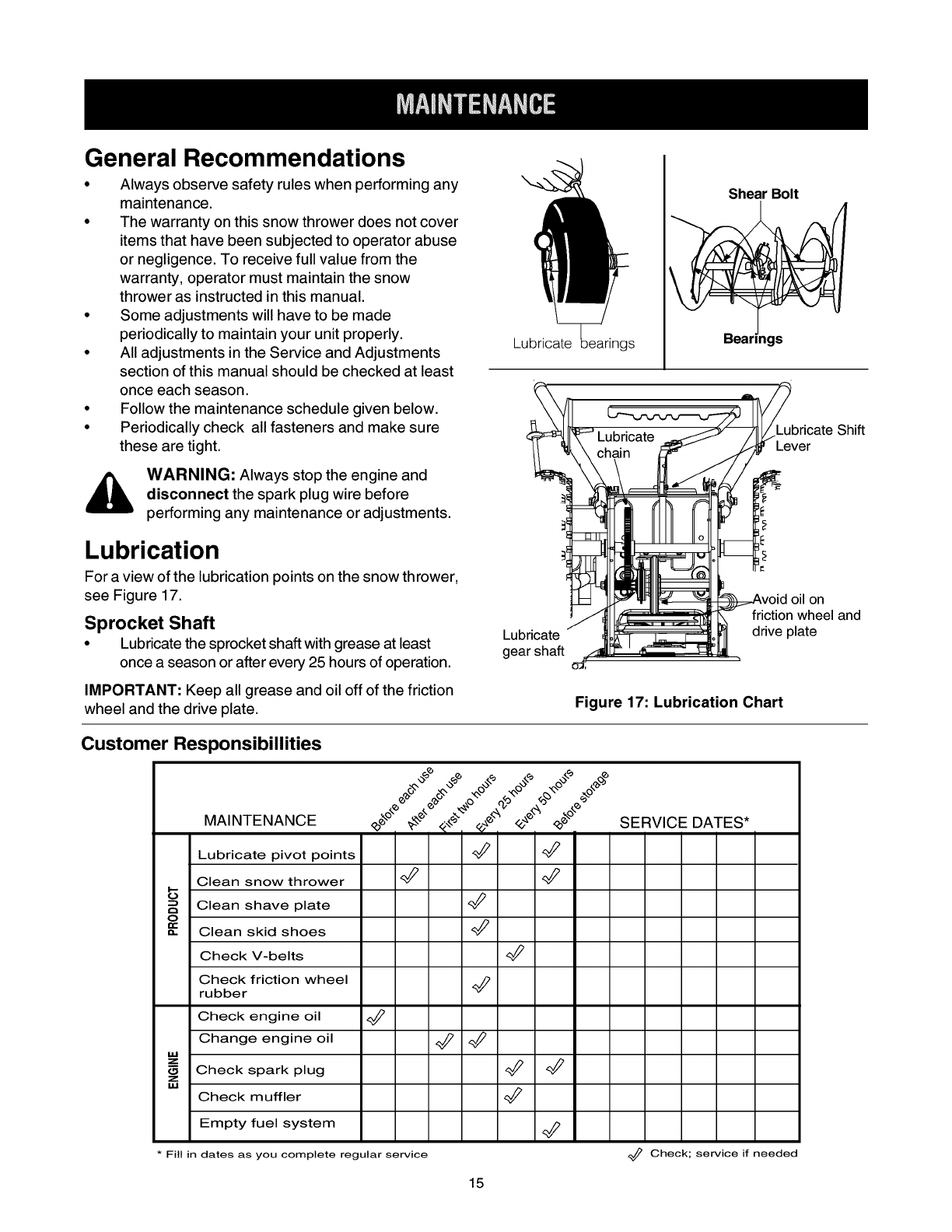
Lubrication
For a view of the lubrication points on the snow thrower,
see Figure 17.
Sprocket Shaft
• Lubricate the sprocket shaft with grease at least
once a season or after every 25 hours of operation.
IMPORTANT: Keep all grease and oil off of the friction
wheel and the drive plate.
Shear Bolt
Lubricate gs
bricate Shift
_JkX Lhai-n..... _ _ _t_Lever
__ 11 v I
i_ v(tiid°i/h°eneland
Lubricate , drive plate
gear shaft
Figure 17: Lubrication Chart
Customer Responsibillities
,¢
MAINTENANCE ¢_ _" _',":,__WSERVICE DATES*
Lubricate pivot points _
Clean snow thrower _
Clean shave plate
OClean skid shoes
Check V-belts <_
Check friction wheel
rubber
Check engine oil 4_
Change engine oil _
zCheck spark plug _
z
M.I
Check muffler
Empty fuel system
Fill in dates as you complete regular service _ Check; service if needed
15
Shifting Mechanism
• Lubricate the shifting mechanism and pivot points
on the shift rod with engine oil at least once a
season or after every 25 hours of operation.
Traction Drive Control
• Lubricate cams on the ends of the control rods,
which interlock the traction drive and auger
controls, at least once a season or every 25 hours
of operation with grease. The cams can be
accessed beneath the handle panel.
Gear Case
• The gear case is lubricated with grease at the
factory and does not require checking. If
disassembled for any reason, lubricate with two
ounces of Shell Alvania grease.
Bearings
• Once a season lubricate the auger bearings and
the bearings on the side of the frame with light oil.
See lube chart below
Engine Maintenance
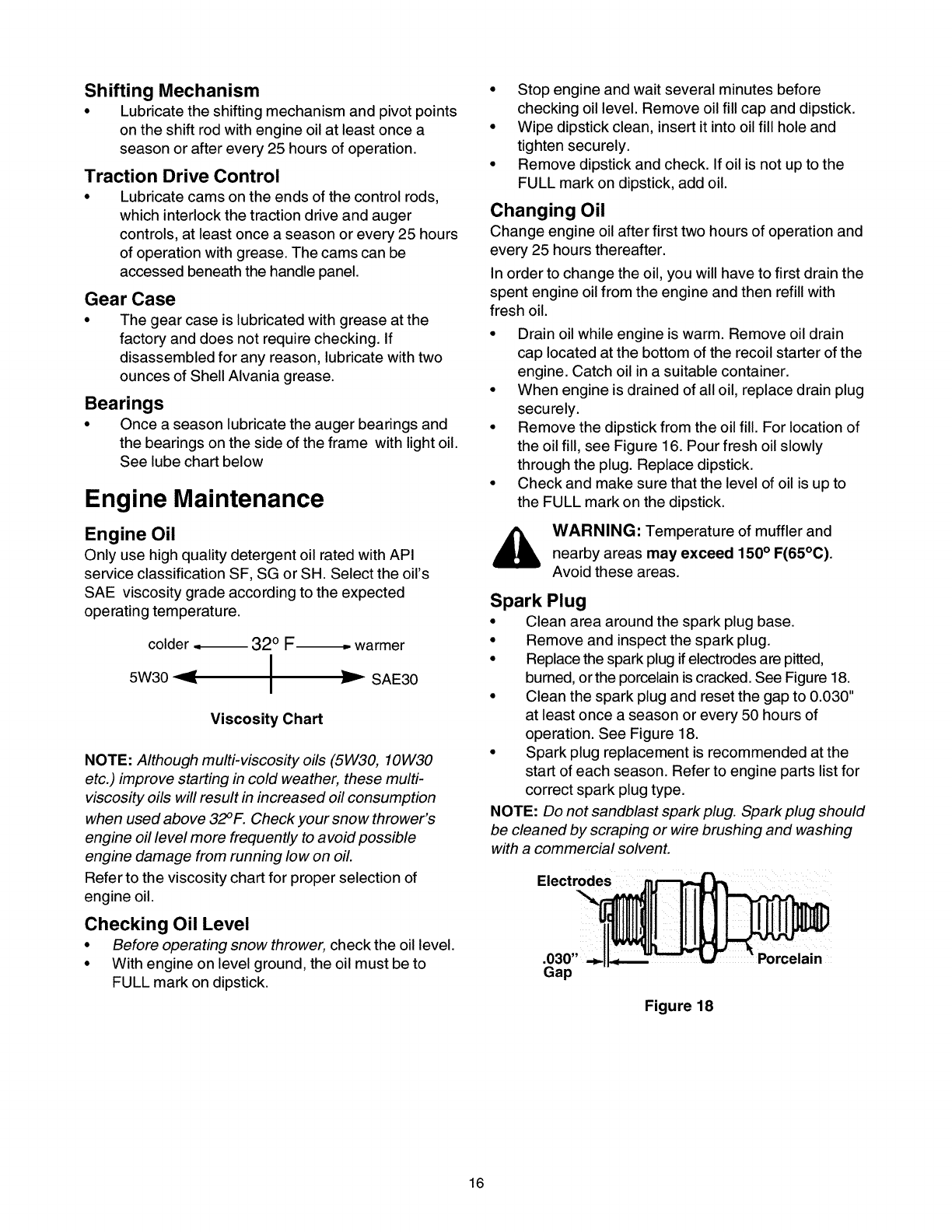
Engine Oil
Only use highquality detergent oil rated with API
service classification SF, SG or SH. Select the oil's
SAE viscosity grade according to the expected
operating temperature.
colder .._ 32 ° F-_,. warmer
5W30 _ I _.=
I SAE30
Viscosity Chart
NOTE: Although multi-viscosity oils (5W30, 10W30
etc.) improve starting in cold weather, these multi-
viscosity oils will result in increased oil consumption
when used above 32°F. Check your snow thrower's
engine oil level more frequently to avoid possible
engine damage from running low on oil.
Refer to the viscosity chart for proper selection of
engine oil.
Checking Oil Level
•Before operating snow thrower, check the oil level.
•With engine on level ground, the oil must be to
FULL mark on dipstick.
• Stop engine and wait several minutes before
checking oil level. Remove oil fill cap and dipstick.
• Wipe dipstick clean, insert it into oil fill hole and
tighten securely.
• Remove dipstick and check. If oil is not up to the
FULL mark on dipstick, add oil.
Changing Oil
Change engine oil after first two hours of operation and
every 25 hours thereafter.
In order to change the oil, you will have to first drain the
spent engine oil from the engine and then refill with
fresh oil.
• Drain oil while engine is warm. Remove oil drain
cap located at the bottom of the recoil starter of the
engine. Catch oil in a suitable container.
• When engine is drained of all oil, replace drain plug
securely.
• Remove the dipstick from the oil fill. For location of
the oil fill, see Figure 16. Pour fresh oil slowly
through the plug. Replace dipstick.
• Check and make sure that the level of oil is up to
the FULL mark on the dipstick.
_, WARNING: Temperature of muffler and
nearby areas may exceed 150° F(65°0).
Avoid these areas.
Spark Plug
• Clean area around the spark plug base.
•Remove and inspect the spark plug.
•Replace the spark plugif electrodesare pitted,
burned, or the porcelainis cracked. See Figure 18.
• Clean the spark plug and reset the gap to 0.030"
at least once a season or every 50 hours of
operation. See Figure 18.
• Spark plug replacement is recommended at the
start of each season. Refer to engine parts listfor
correct spark plug type.
NOTE: Do not sandblast spark plug. Spark plug should
be cleaned by scraping or wire brushing and washing
with a commercial solvent.
Electrodes
]
i
Gap
Figure 18
16
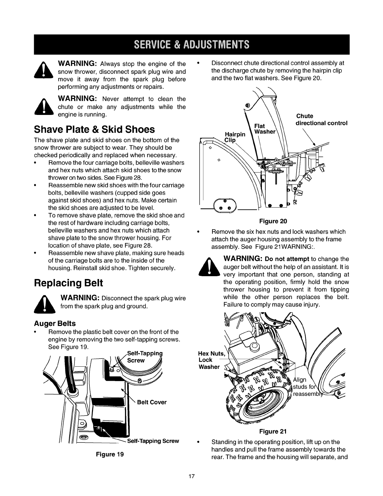
WARNING: Always stop the engine of the • Disconnect chute directional control assembly atsnow thrower, disconnect spark plug wire and the discharge chute by removing the hairpin clip
move it away from the spark plug before and thetwoflatwashers. See Figure20.
WARNING: _® Chute
F_at _ \\ directi\
Hairpin \'_ ...... \ \\ \
performing any adjustments or repairs.
Never attempt to clean the
chute or make any adjustments while the
engine is running.
directional control
Shave Plate & Skid Shoes
The shave plate and skid shoes on the bottom of the
snow thrower are subject to wear. They should be
checked periodically and replaced when necessary.
Remove the four carriage bolts, belleville washers
and hex nuts which attach skid shoes to the snow
throwerontwo sides. See Figure28.
Reassemble new skid shoes with the four carriage
bolts, belleville washers (cupped side goes
against skid shoes) and hex nuts. Make certain
the skid shoes are adjusted to be level.
•To remove shave plate, remove the skid shoe and
the rest of hardware including carriage bolts,
belleville washers and hex nuts which attach
shave plate to the snow thrower housing. For
location of shave plate, see Figure 28.
Reassemble new shave plate, making sure heads
of the carriage bolts are to the inside of the
housing. Reinstall skid shoe. Tighten securely.
Replacing Belt
WARNING: Disconnect the spark plug wire
from the spark plug and ground.
Figure 20
Remove the six hex nuts and lock washers which
attach the auger housing assembly to the frame
assembly. See Figure 21WARNING:.
,_ WARNING: Do not attempt to change the
auger belt without the help of an assistant. It is
very important that one person, standing at
the operating position, firmly hold the snow
thrower housing to prevent it from tipping
while the other person replaces the belt.
Failure to comply may cause injury.
Auger Belts
•Remove the plastic belt cover on the front of the
engine by removing the two self-tapping screws.
See Figure 19. Hex Nuts
Lock
Washer
Belt Cover
Self-Tapping Screw
Figure 19
Figure 21
Standing in the operating position, lift up on the
handles and pull the frame assembly towards the
rear. The frame and the housing will separate, and
17
the rear auger belt will come off the pulley.
Maintain control of the frame assembly while
pulling it.
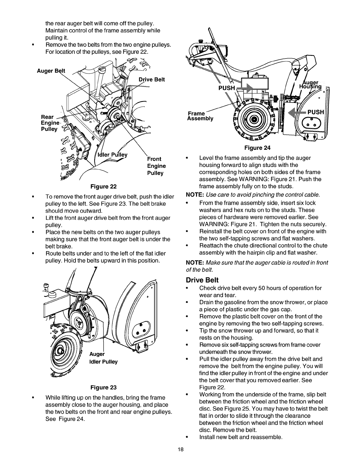
Remove the two belts from the two engine pulleys.
For location of the pulleys, see Figure 22.
Auger Be_
ERe;rn_
Pulley _
Pulley
Figure 22
To remove the front auger drive belt, push the idler
pulley to the left. See Figure 23. The belt brake
should move outward.
Lift the front auger drive belt from the front auger
pulley.
Place the new belts on the two auger pulleys
making sure that the front auger belt is under the
belt brake.
Route belts under and to the left of the flat idler
pulley. Hold the belts upward in this position.
Auger
Idler Pulley
Figure 23
While lifting up on the handles, bring the frame
assembly close to the auger housing, and place
the two belts on the front and rear engine pulleys.
See Figure 24.
PUSH
Frame
Assembly
Figure 24
• Level the frame assembly and tip the auger
housing forward to align studs with the
corresponding holes on both sides of the frame
assembly. See WARNING: Figure 21. Push the
frame assembly fully on to the studs.
NOTE: Use care to avoid pinching the control cable.
• From the frame assembly side, insert six lock
washers and hex nuts on to the studs. These
pieces of hardware were removed earlier. See
WARNING: Figure 21. Tighten the nuts securely.
• Reinstall the belt cover on front of the engine with
the two self-tapping screws and flat washers.
• Reattach the chute directional control to the chute
assembly with the hairpin clip and flat washer.
NOTE: Make sure that the auger cable is routed in front
of the belt.
Drive Belt
• Check drive belt every 50 hours of operation for
wear and tear.
•Drain the gasoline from the snow thrower, or place
a piece of plastic under the gas cap.
•Remove the plastic belt cover on the front of the
engine by removing the two self-tapping screws.
•Tip the snow thrower up and forward, so that it
rests on the housing.
•Remove six self-tapping screws from frame cover
underneaththe snow thrower.
•Pull the idler pulley away from the drive belt and
remove the belt from the engine pulley. You will
find the idlerpulley infront of the engine and under
the belt cover that you removed earlier. See
Figure 22.
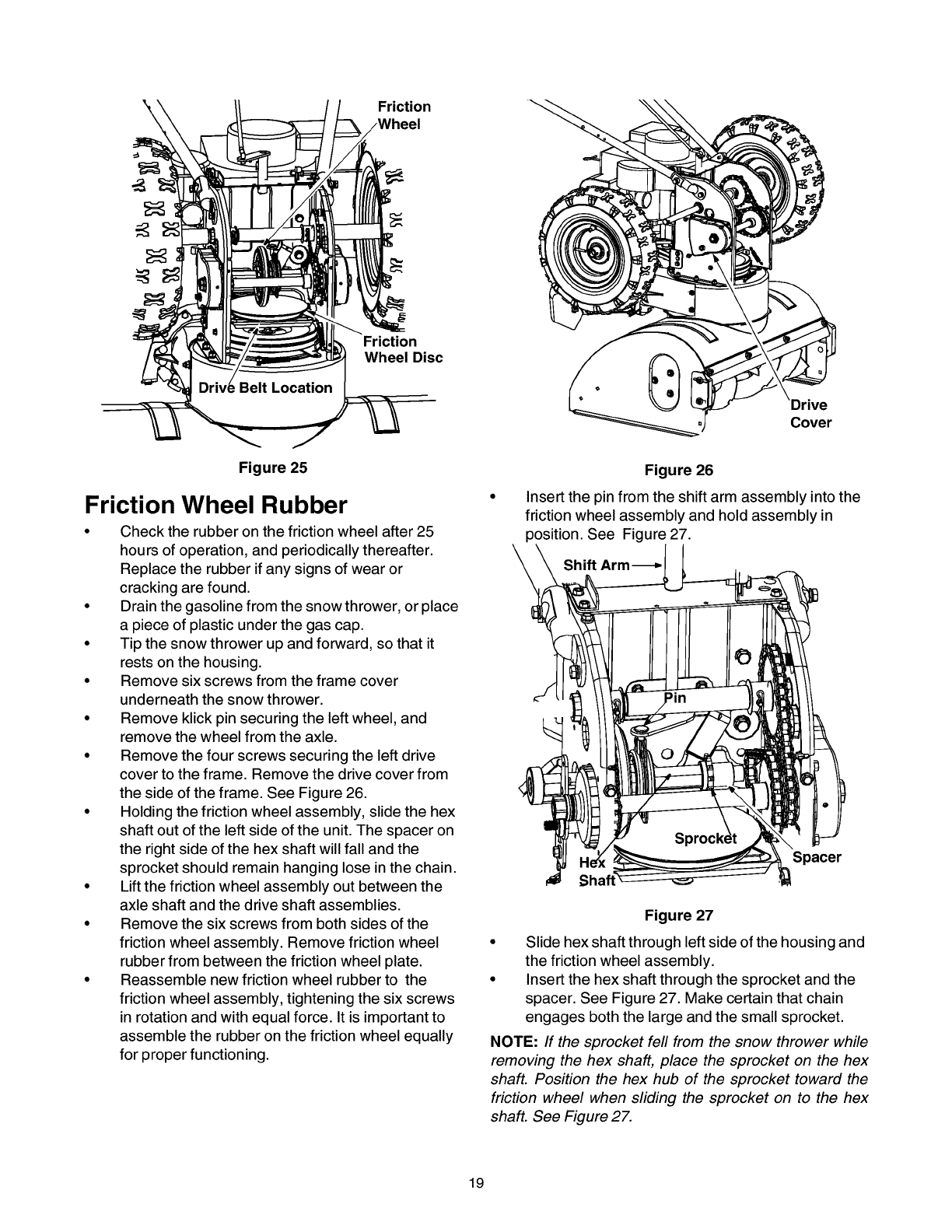
•Working from the underside of the frame, slip belt
between the friction wheel and the friction wheel
disc. See Figure 25. You may have to twistthe belt
flat in order to slide itthrough the clearance
between the friction wheel and the friction wheel
disc. Remove the belt.
•Install new belt and reassemble.
18
Friction
Friction
Wheel Disc
Cover
Figure 25
Friction Wheel Rubber
•Check the rubber on the friction wheel after 25
hours of operation, and periodically thereafter.
Replace the rubber if any signs of wear or
cracking are found.
• Drain the gasoline from the snow thrower, or place
a piece of plastic under the gas cap.
• Tip the snow thrower up and forward, so that it
rests on the housing.
• Remove six screws from the frame cover
underneath the snow thrower.
• Remove klick pin securing the left wheel, and
remove the wheel from the axle.
• Remove the four screws securing the left drive
cover to the frame. Remove the drive cover from
the side of the frame. See Figure 26.
• Holding the friction wheel assembly, slide the hex
shaft out of the left side of the unit. The spacer on
the right side of the hex shaft will fall and the
sprocket should remain hanging lose in the chain.
• Lift the friction wheel assembly out between the
axle shaft and the drive shaft assemblies.
• Remove the six screws from both sides of the
friction wheel assembly. Remove friction wheel
rubber from between the friction wheel plate.
• Reassemble new friction wheel rubber to the
friction wheel assembly, tightening the six screws
in rotation and with equal force. It is important to
assemble the rubber on the friction wheel equally
for proper functioning.
Figure 26
Insert the pin from the shift arm assembly into the
friction wheel assembly and hold assembly in
position. See Figure 27.
Shift Arm-_
Spacer
Figure 27
• Slide hex shaft through left side of the housing and
the friction wheel assembly.
• Insert the hex shaft through the sprocket and the
spacer. See Figure 27. Make certain that chain
engages both the large and the small sprocket.
NOTE: If the sprocket fell from the snow thrower while
removing the hex shaft, place the sprocket on the hex
shaft. Position the hex hub of the sprocket toward the
friction wheel when sliding the sprocket on to the hex
shaft. See Figure 27.
19
• Align the hex shaft with the right hand bearing and
carefully guide the left hand bearing into the left
side of the housing.
• Reassemble the drive cover with the four screws
that were earlier removed.
Note: If you placed plastic under the gas cap, be
certain to remove it.
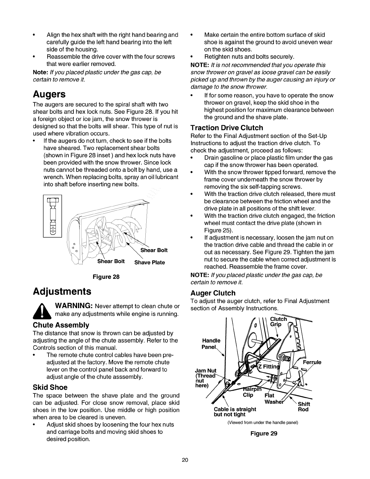
Augers
The augers are secured to the spiral shaft with two
shear bolts and hex lock nuts. See Figure 28. If you hit
a foreign object or ice jam, the snow thrower is
designed so that the bolts will shear. This type of nut is
used where vibration occurs.
• If the augers do not turn, check to see if the bolts
have sheared. Two replacement shear bolts
(shown in Figure 28 inset ) and hex lock nuts have
been provided with the snow thrower. Since lock
nuts cannot be threaded onto a bolt by hand, use a
wrench. When replacing bolts, spray an oil lubricant
into shaft before inserting new bolts.
Shear Bolt
Bolt Shave Plate
Figure 28
Adjustments
_ARNING: Never attempt to clean chute or
make any adjustments while engine is running.
Chute Assembly
The distance that snow is thrown can be adjusted by
adjusting the angle of the chute assembly. Refer to the
Controls section of this manual.
•The remote chute control cables have been pre-
adjusted at the factory. Move the remote chute
lever on the control panel back and forward to
adjust angle of the chute asssembly.
Skid Shoe
The space between the shave plate and the ground
can be adjusted. For close snow removal, place skid
shoes in the low position. Use middle or high position
when area to be cleared is uneven.
• Adjust skid shoes by loosening the four hex nuts
and carriage bolts and moving skid shoes to
desired position.
• Make certain the entire bottom surface of skid
shoe is against the ground to avoid uneven wear
on the skid shoes.
• Retighten nuts and bolts securely.
NOTE: It is not recommended that you operate this
snow thrower on gravel as loose gravel can be easily
picked up and thrown by the auger causing an injury or
damage to the snow thrower.
• If for some reason, you have to operate the snow
thrower on gravel, keep the skid shoe in the
highest position for maximum clearance between
the ground and the shave plate.
Traction Drive Clutch
Refer to the Final Adjustment section of the Set-Up
Instructions to adjust the traction drive clutch. To
check the adjustment, proceed as follows:
• Drain gasoline or place plastic film under the gas
cap if the snow thrower has been operated.
• With the snow thrower tipped forward, remove the
frame cover underneath the snow thrower by
removing the six self-tapping screws.
• With the traction drive clutch released, there must
be clearance between the friction wheel and the
drive plate in all positions of the shift lever.
• With the traction drive clutch engaged, the friction
wheel must contact the drive plate (shown in
Figure 25).
• If adjustment is necessary, loosen the jam nut on
the traction drive cable and thread the cable in or
out as necessary. See Figure 29. Tighten the jam
nut to secure the cable when correct adjustment is
reached. Reassemble the frame cover.
NOTE: If you placed plastic under the gas cap, be
certain to remove ft.
Auger Clutch
To adjust the auger clutch, refer to Final Adjustment
section of Assembly Instructions.
Handle
Panel_,_
Jam Nut
(Thread'_
nut
here)
Clip
Cable is straight
but not tight
Shift
Rod
(Viewed from under the handle panel)
Figure 29
Jle
20
Shift Rod
To adjust the shift rod, proceed as follows.
• Remove the hairpin clip and flat washer from the
shift handle under the handle panel.
•Place shift lever in sixth (6) positionor the fastest
forward speed.
• Push shift arm assembly down as far as it will go.
• Rotate the ferrule up or down on the shift rod as
necessary until the ferrule lines up with the upper
hole in the shift lever. See Figure 29.
Insert ferrule from the left side of the snowthrower
into the upper hole in shift lever.
Reinstall the hairpin clip and the washer.
_, AUTION: Check for correct adjustment
before operating the snow thrower.
If the snow thrower will not be used for 30 days or
longer, or at the end of the snow season when the last
possibility of snow is gone, the equipment needs to be
stored properly. Follow storage instructions below to
ensure top performance from the snow thrower for
many more years.
Preparing Engine
WARNING: Never store snow thrower with
fuel in tank indoors or in poorly ventilated
areas, where fuel fumes may reach an open
flame, spark or pilot light as on a furnace,
water heater, clothes dryer or gas appliance.
It is important to prevent gum deposits from
forming in essential fuel system parts of the
engine such as the carburetor, fuel filter, fuel
hose or tank during storage.
Also experience indicates that alcohol
blended fuels (called gasohol or using ethanol
or methanol) can attract moisture which leads
to separation and formation of acids during
storage. Acidic gas can damage the fuel
system of an engine while in storage.
To avoid engine problems, the fuel system
should be emptied before storage for 30 days
or longer. Follow these instructions to prepare
your snow thrower for storage:
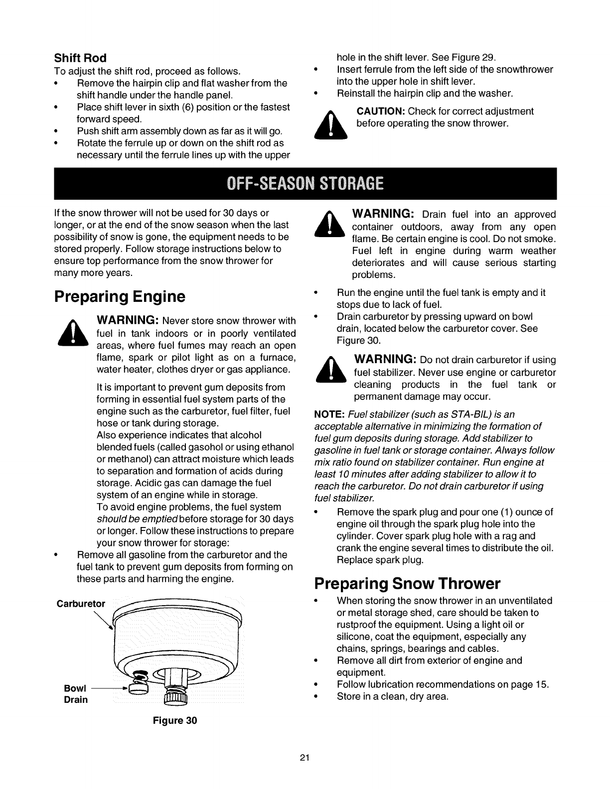
Remove all gasoline from the carburetor and the
fuel tank to prevent gum deposits from forming on
these parts and harming the engine.
Drain
Figure 30
_WARNING: Drain fuel into an approvedcontainer outdoors, away from any open
flame. Be certain engine is cool. Do not smoke.
Fuel left in engine during warm weather
deteriorates and will cause serious starting
problems.
Run the engine until the fuel tank is empty and it
stops due to lack of fuel.
Drain carburetor by pressing upward on bowl
drain, located below the carburetor cover. See
Figure 30.
,_ WARNING: Do not drain carburetor if usingfuel stabilizer. Never use engine or carburetor
cleaning products in the fuel tank or
permanent damage may occur.
NOTE: Fuel stabilizer (such as STA-BIL) is an
acceptable alternative in minimizing the formation of
fuel gum deposits during storage. Add stabilizer to
gasoline in fuel tank or storage container. Always follow
mix ratio found on stabilizer container. Run engine at
least 10 minutes after adding stabilizer to allow it to
reach the carburetor. Do not drain carburetor if using
fuel stabilizer.
• Remove the spark plug and pour one (1) ounce of
engine oil through the spark plug hole into the
cylinder. Cover spark plug hole with a rag and
crank the engine several times to distribute the oil.
Replace spark plug.
Preparing Snow Thrower
• When storing the snow thrower in an unventilated
or metal storage shed, care should be taken to
rustproof the equipment. Using a light oil or
silicone, coat the equipment, especially any
chains, springs, bearings and cables.
• Remove all dirt from exterior of engine and
equipment.
• Follow lubrication recommendations on page 15.
• Store in a clean, dry area.
21
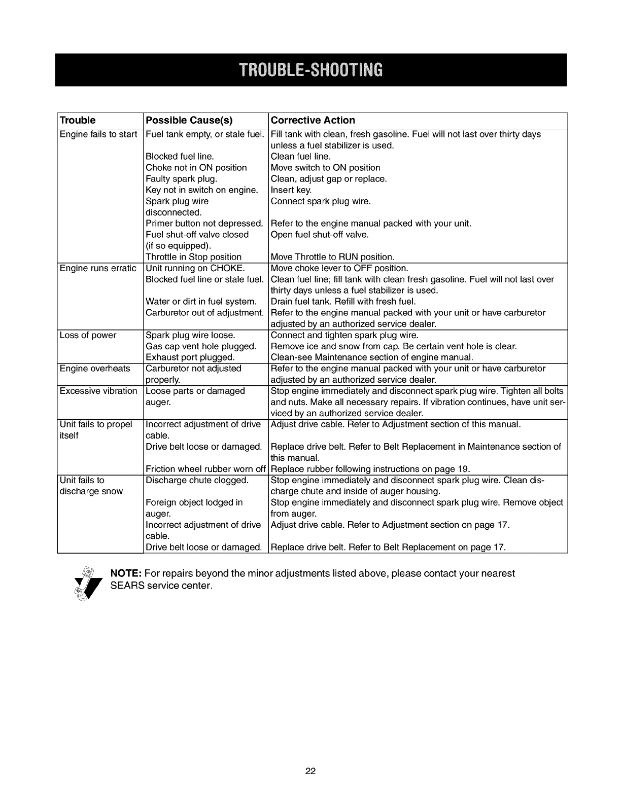
Trouble Possible Cause(s)
Enginefails to start Fueltank empty,or stale fuel.
Engine runs erratic
Blocked fuel line.
Choke not in ON position
Faulty spark plug.
Key not in switch on engine.
Spark plug wire
disconnected.
Primer button not depressed.
Fuel shut-off valve closed
(if so equipped).
Throttle in Stop position
Unit running on CHOKE.
Blocked fuel line or stale fuel.
Water or dirt in fuel system.
Carburetor out of adjustment.
Loss of power Spark plug wire loose.
Gas cap vent hole plugged.
Exhaust port plugged.
Engine overheats Carburetor not adjusted
properly.
Excessive vibration Loose parts or damaged
auger.
Unit fails to propel
itself
Unit fails to
discharge snow
Incorrect adjustment of drive
cable.
Drive belt loose or damaged.
Friction wheel rubber worn off
Discharge chute clogged.
Foreign object lodged in
auger.
Incorrect adjustment of drive
cable.
Drive belt loose or damaged.
Corrective Action
Fill tank with clean, fresh gasoline. Fuel will not last over thirty days
unless a fuel stabilizer is used.
Clean fuel line.
Move switch to ON position
Clean, adjust gap or replace.
Insert key.
Connect spark plug wire.
Refer to the engine manual packed with your unit.
Open fuel shut-off valve.
Move Throttle to RUN position.
Move choke lever to OFF position.
Clean fuel line; fill tank with clean fresh gasoline. Fuel will not last over
thirty days unless a fuel stabilizer is used.
Drain fuel tank. Refill with fresh fuel.
Refer to the engine manual packed with your unit or have carburetor
adjusted by an authorized service dealer.
Connect and tighten spark plug wire.
Remove ice and snow from cap. Be certain vent hole is clear.
Clean-see Maintenance section of engine manual.
Refer to the engine manual packed with your unit or have carburetor
adjusted by an authorized service dealer.
Stop engine immediately and disconnect spark plug wire. Tighten all bolts
and nuts. Make all necessary repairs. If vibration continues, have unit ser-
viced by an authorized service dealer.
Adjust drive cable. Refer to Adjustment section of this manual.
Replace drive belt. Refer to Belt Replacement in Maintenance section of
this manual.
Replace rubber following instructions on page 19.
Stop engine immediately and disconnect spark plug wire. Clean dis-
charge chute and inside of auger housing.
Stop engine immediately and disconnect spark plug wire. Remove object
from auger.
Adjust drive cable. Refer to Adjustment section on page 17.
Replace drive belt. Refer to Belt Replacement on page 17.
NOTE: For repairs beyond the minor adjustments listed above, please contact your nearest
SEARS service center.
22
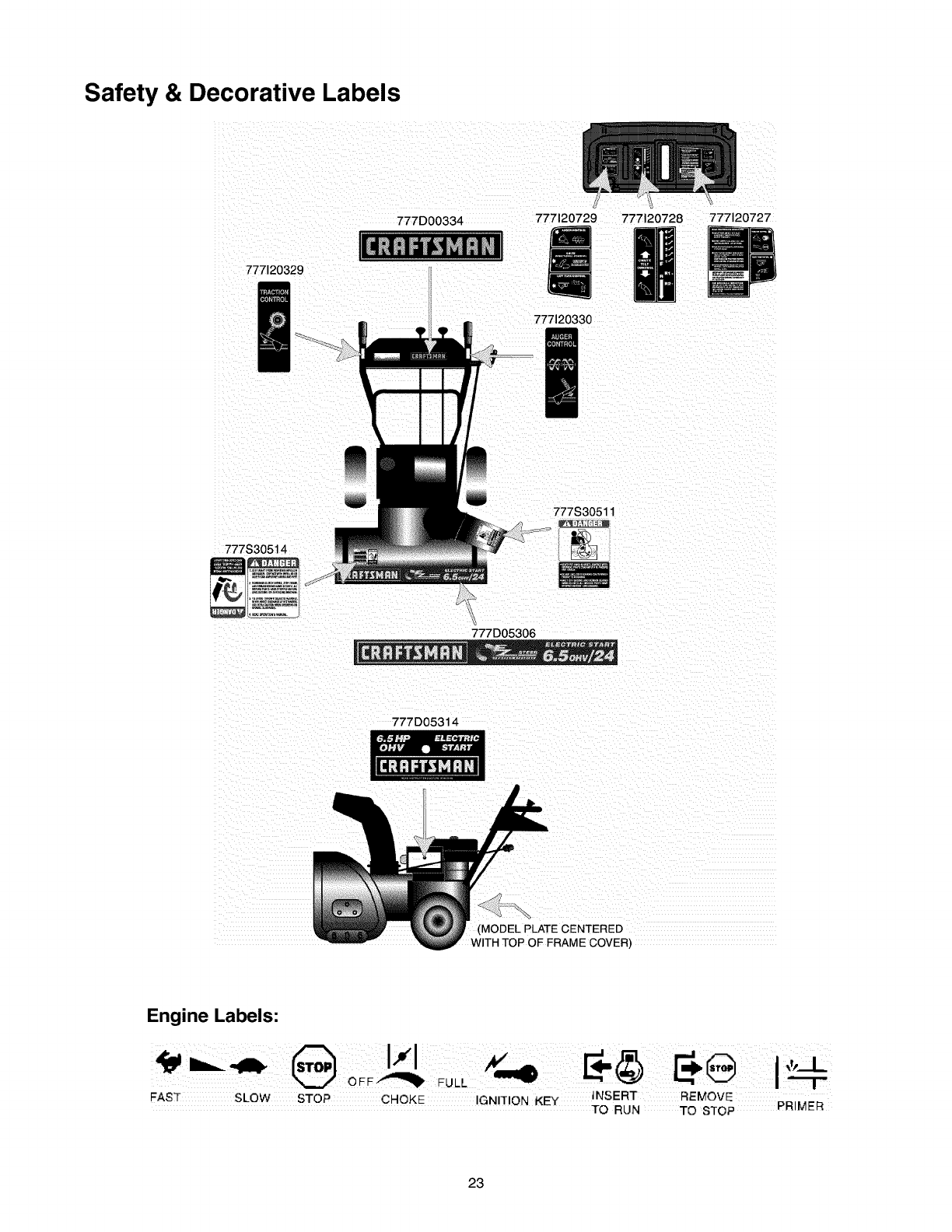
Safety & Decorative Labels
777120329
777D00334 777120729 777120728 777120727
777120330
777S30511
777S30514
777D05306
777D05314
(MODEL PLATE CENTERED
WITH TOP OF FRAME COVER)
Engine Labels:
FAST SLOW STOP CHOKE IGNITION KEY INSERT REMOVE
TO RUN TO STOP PRIMER
23
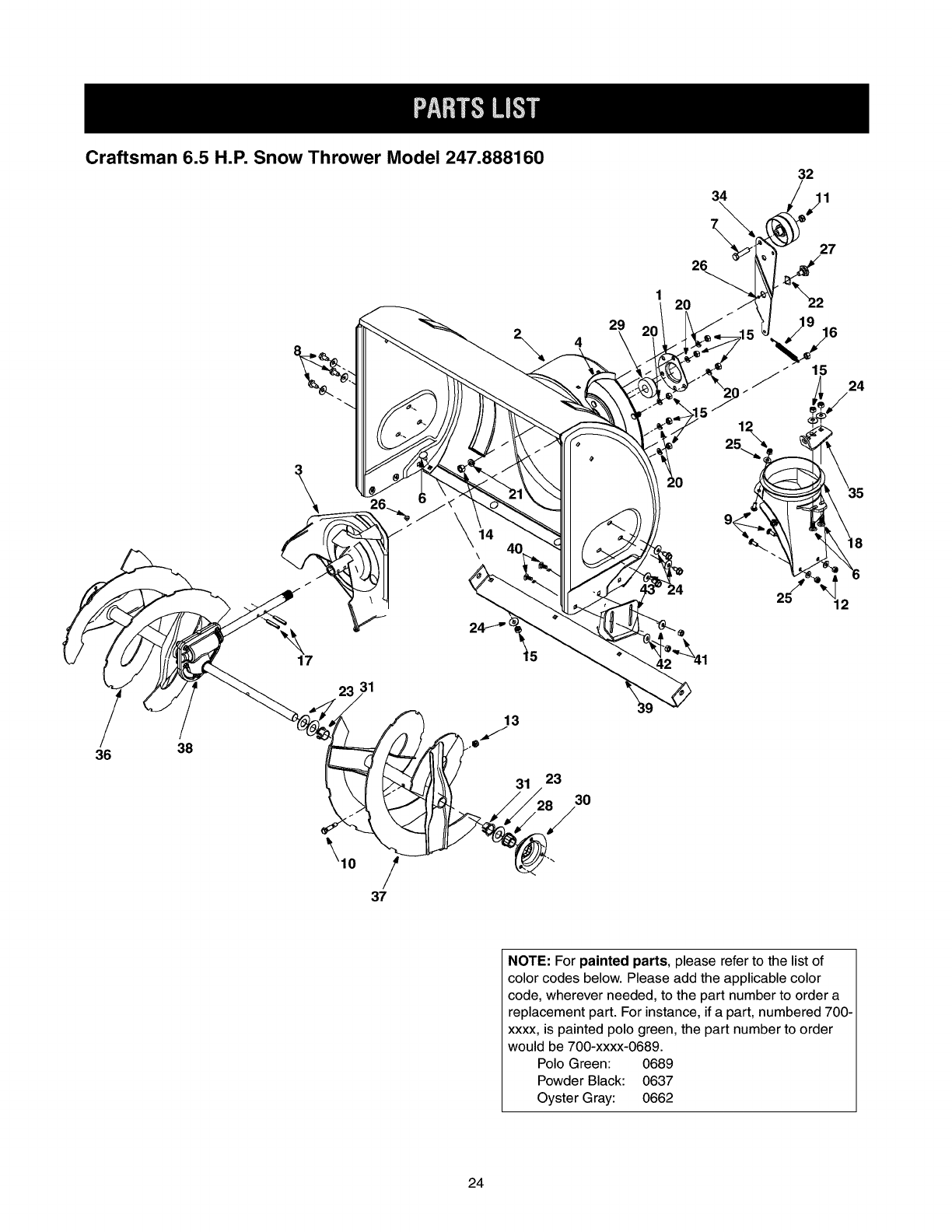
Craftsman 6.5 H.P. Snow Thrower Model 247.888160
36 38
\
17
23 31
31 23
30
29
34
\
26
120 /
32
I1
27
15
24
NOTE: For painted parts, please refer to the list of
color codes below. Please add the applicable color
code, wherever needed, to the part number to order a
replacement part. For instance, if a part, numbered 700-
xxxx, is painted polo green, the part number to order
would be 700-xxxx-0689.
Polo Green: 0689
Powder Black: 0637
Oyster Gray: 0662
24
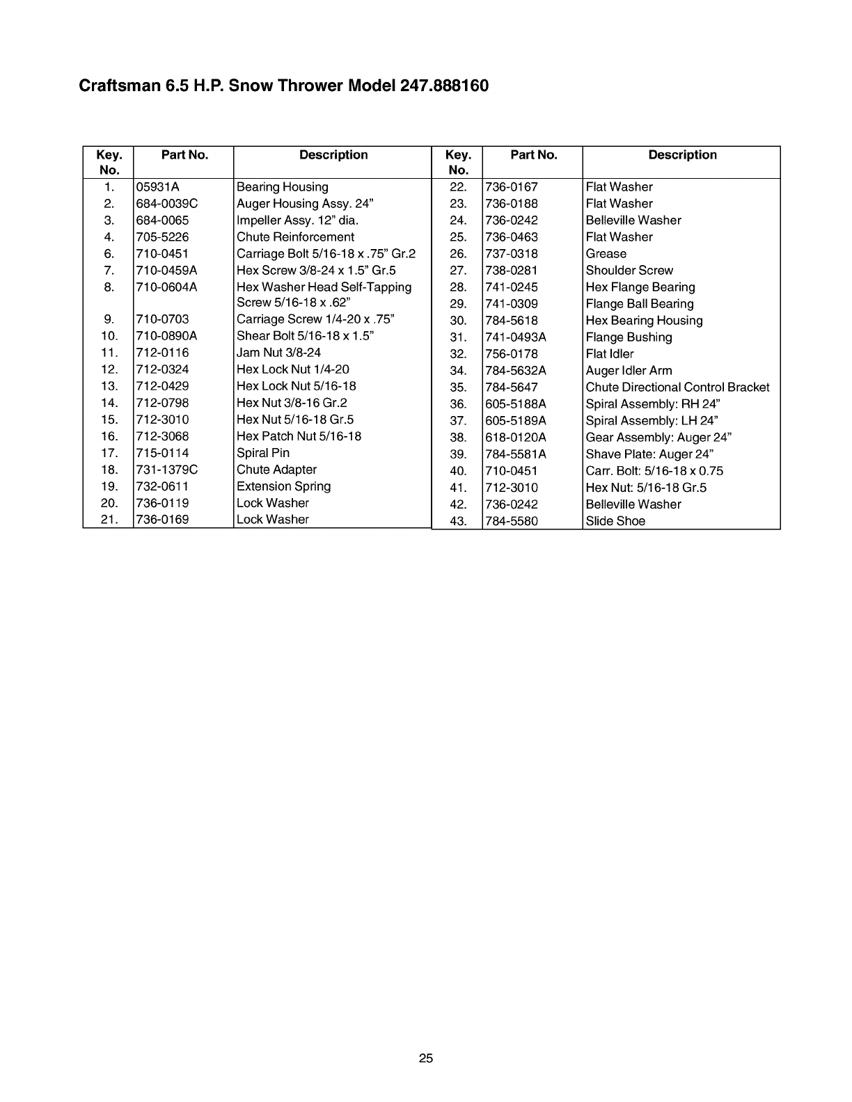
Craftsman 6.5 H.P. Snow Thrower Model 247.888160
Key. Part No.
No.
1. 05931A
2. 684-0039C
3. 684-0065
4. 705-5226
6. 710-0451
7. 710-0459A
8. 710-0604A
9. 710-0703
10. 710-0890A
11. 712-0116
12. 712-0324
13. 712-0429
14. 712-0798
15. 712-3010
16. 712-3068
17. 715-0114
18. 731-1379C
19. 732-0611
20. 736-0119
21. 736-0169
Description Key.
No.
Bearing Housing 22.
Auger Housing Assy. 24" 23.
Impeller Assy. 12" dia. 24.
Chute Reinforcement 25.
Carriage Bolt 5/16-18 x .75" Gr.2 26.
Hex Screw 3/8-24 x 1.5" Gr.5 27.
Hex Washer Head Self-Tapping 28.
Screw 5/16-18 x .62" 29.
Carriage Screw 1/4-20 x .75" 30.
Shear Bolt 5/16-18 x 1.5" 31.
Jam Nut 3/8-24 32.
Hex Lock Nut 1/4-20 34.
Hex Lock Nut 5/16-18 35.
Hex Nut 3/8-16 Gr.2 36.
Hex Nut 5/16-18 Gr.5 37.
Hex Patch Nut 5/16-18 38.
Spiral Pin 39.
Chute Adapter 40.
Extension Spring 41.
Lock Washer 42.
Lock Washer 43.
Part No.
736-0167
736-0188
736-0242
736-0463
737-0318
738-0281
741-0245
741-0309
784-5618
741-0493A
756-0178
784-5632A
784-5647
605-5188A
605-5189A
618-0120A
784-5581A
710-0451
712-3010
736-0242
784-5580
Description
Flat Washer
Flat Washer
Belleville Washer
Flat Washer
Grease
Shoulder Screw
Hex Flange Bearing
Flange Ball Bearing
Hex Bearing Housing
Flange Bushing
Flat Idler
Auger Idler Arm
Chute Directional Control Bracket
Spiral Assembly: RH 24"
Spiral Assembly: LH 24"
Gear Assembly: Auger 24"
Shave Plate: Auger 24"
Carr. Bolt: 5/16-18 x 0.75
Hex Nut: 5/16-18 Gr.5
Belleville Washer
Slide Shoe
25
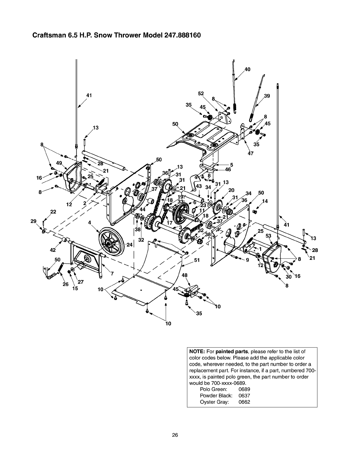
Craftsman 6.5 H.P. Snow Thrower Model 247.888160
41
3
42
5O
26 15 104
10
52
35
48
13
20
47
\41
NOTE: For painted parts, please refer to the list of
color codes below. Please add the applicable color
code, wherever needed, to the part number to order a
replacement part. For instance, if a part, numbered 700-
xxxx, is painted polo green, the part number to order
would be 700-xxxx-0689.
Polo Green: 0689
Powder Black: 0637
Oyster Gray: 0662
26
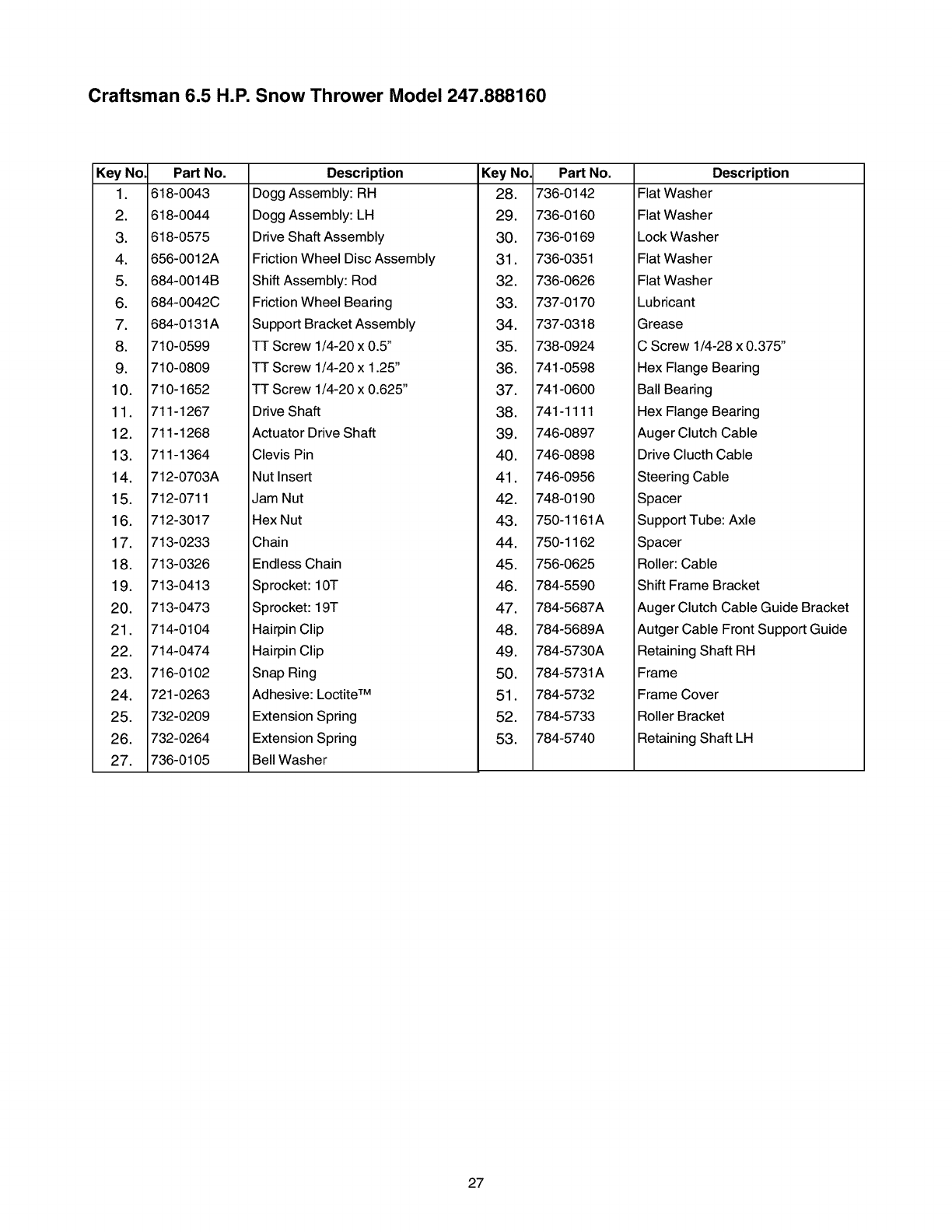
Craftsman 6.5 H.P. Snow Thrower Model 247.888160
Key No. Part No.
1. 618-0043
2. 618-O044
3. 618-0575
4. 656-0012A
5. 684-0014B
6. 684-0042C
7. 684-0131A
8. 710-0599
9. 710-0809
10. 710-1652
11. 711-1267
12. 711-1268
13. 711-1364
14. 712-0703A
15. 712-0711
16. 712-3017
17. 713-0233
18. 713-0326
19. 713-0413
20. 713-0473
21. 714-0104
22. 714-0474
23. 716-0102
24. 721-0263
25. 732-0209
26. 732-0264
27. 736-0105
Description
Dogg Assembly: RH
Dogg Assembly: LH
Drive Shaft Assembly
Friction Wheel Disc Assembly
Shift Assembly: Rod
Friction Wheel Bearing
Support Bracket Assembly
f-r Screw 1/4-20 x 0.5"
f-r Screw 1/4-20 x 1.25"
f-r Screw 1/4-20 x 0.625"
Key No.
28.
29.
30.
31.
32.
33.
34.
35.
36.
37.
Part No.
736-0142
736-0160
736-0169
736-0351
736-0626
737-0170
737-0318
738-0924
741-0598
741-0600
Description
Flat Washer
Flat Washer
Lock Washer
Flat Washer
Flat Washer
Lubricant
Grease
C Screw 1/4-28 x 0.375"
Hex Flange Bearing
Ball Bearing
Drive Shaft
Actuator Drive Shaft
Clevis Pin
Nut Insert
Jam Nut
Hex Nut
Chain
Endless Chain
Sprocket: 10T
Sprocket: 19T
Hairpin Clip
Hairpin Clip
Snap Ring
Adhesive: Loctite TM
Extension Spring
Extension Spring
Bell Washer
38.
39.
40.
41.
42.
43.
44.
45.
46.
47.
48.
49.
50.
51.
52.
53.
741-1111
746-0897
746-0898
746-0956
748-0190
750-1161A
750-1162
756-0625
784-5590
784-5687A
784-5689A
784-5730A
784-5731A
784-5732
784-5733
784-5740
Hex Flange Bearing
Auger Clutch Cable
Drive Clucth Cable
Steering Cable
Spacer
Support Tube: Axle
Spacer
Roller: Cable
Shift Frame Bracket
Auger Clutch Cable Guide Bracket
Autger Cable Front Support Guide
Retaining Shaft RH
Frame
Frame Cover
Roller Bracket
Retaining Shaft LH
27
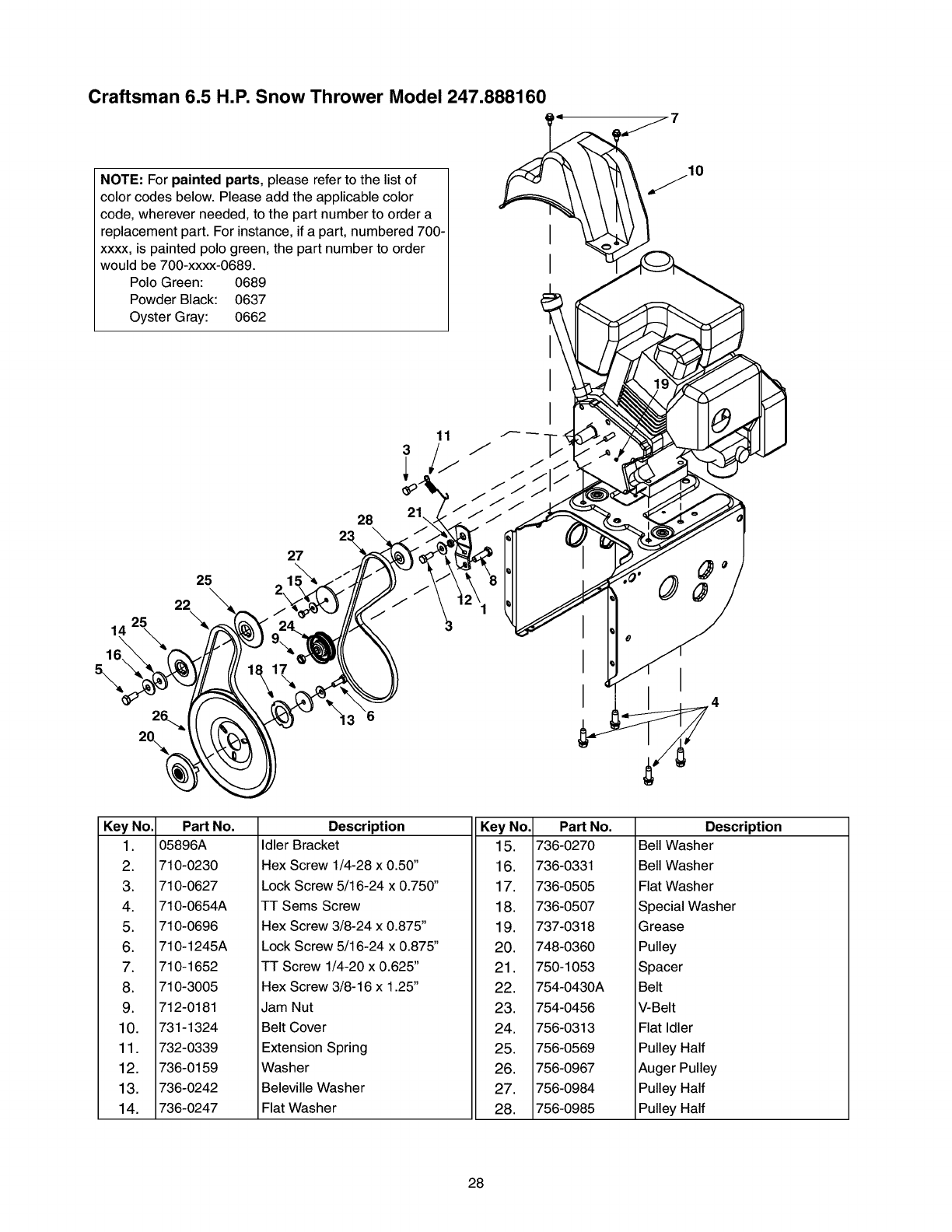
Craftsman 6.5 H.P. Snow Thrower Model 247.888160
NOTE: For painted parts, please refer to the list of
color codes below. Please add the applicable color
code, wherever needed, to the part number to order a
replacement part. For instance, if a part, numbered 700-
xxxx, is painted polo green, the part number to order
would be 700-xxxx-0689.
Polo Green: 0689
Powder Black: 0637
Oyster Gray: 0662
10
25
22
25 "_
14
16
\
27
2,
28
11
Key No.
1.
2.
3.
4.
5.
6.
7.
8.
9.
10.
11.
12.
13.
14.
Part No.
05896A
710-0230
710-0627
710-0654A
710-0696
710-1245A
710-1652
710-3005
712-0181
731-1324
732-0339
736-0159
736-0242
736-0247
Description
Idler Bracket
Hex Screw 1/4-28 x 0.50"
Lock Screw 5/16-24 x 0.750"
TT Sems Screw
Hex Screw 3/8-24 x 0.875"
Lock Screw 5/16-24 x 0.875"
TT Screw 1/4-20 x 0.625"
Hex Screw 3/8-16 x 1.25"
Key No.
15.
16.
17.
18.
19.
20.
21.
22.
23.
24.
25.
26.
27.
28.
Jam Nut
Belt Cover
Extension Spring
Washer
Beleville Washer
Flat Washer
Part No.
736-0270
736-0331
736-0505
736-0507
737-0318
748-0360
750-1053
754-0430A
754-0456
756-0313
756-0569
756-0967
756-0984
756-0985
Description
Bell Washer
Bell Washer
Flat Washer
Special Washer
Grease
Pulley
Spacer
Belt
V-Belt
Flat Idler
Pulley Half
Auger Pulley
Pulley Half
Pulley Half
28
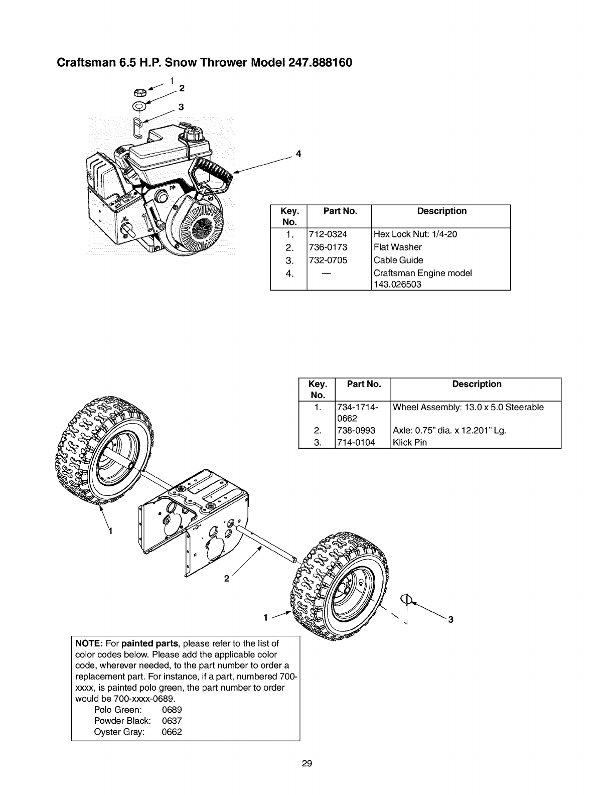
Craftsman 6.5 H.P. Snow Thrower Model 247.888160
4
Key.
No.
1.
2.
3.
4.
Part No. Description
712-0324
736-0173
732-0705
Hex Lock Nut: 1/4-20
Flat Washer
Cable Guide
Craftsman Engine model
143.026503
Key. Part No. Description
No.
1. 734-1714- Wheel Assembly: 13.0 x 5.0 Steerable
0662
2. 738-0993 Axle: 0.75" dia. x 12.201" Lg.
3. 714-0104 Klick Pin
NOTE: For painted parts, please refer to the list of
color codes below. Please add the applicable color
code, wherever needed, to the part number to order a
replacement part. For instance, if a part, numbered 700-
xxxx, is painted polo green, the part number to order
would be 700-xxxx-0689.
Polo Green: 0689
Powder Black: 0637
Oyster Gray: 0662
\ 3
-4
29
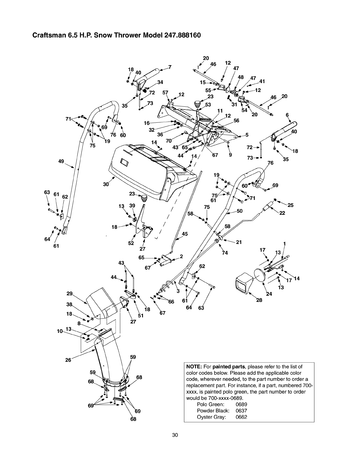
Craftsman 6.5 H.P. Snow Thrower Model 247.888160
63
\
9
75 14
61
29
27
45
61
2O
56
19
61
75
69
62
17
26 59
68
NOTE: For painted parts, please refer to the list of
color codes below. Please add the applicable color
code, wherever needed, to the part number to order a
replacement part. For instance, if a part, numbered 700-
xxxx, is painted polo green, the part number to order
would be 700-xxxx-0689.
Polo Green: 0689
Powder Black: 0637
Oyster Gray: 0662
30
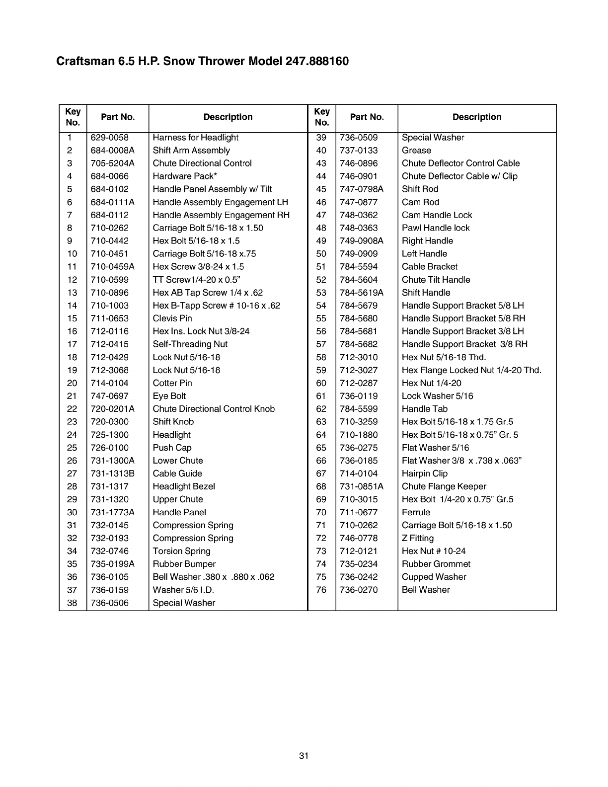
Craftsman 6.5 H.P. Snow Thrower Model 247.888160
Key Part No.
No.
1 629-0058
2684-0008A
3 705-5204A
4 684-0066
5 684-0102
6 684-0111A
7 684-0112
8 710-0262
9710-0442
10 710-0451
11 710-0459A
12 710-0599
13 710-0896
14 710-1003
15 711-0653
16 712-0116
17 712-0415
18 712-0429
19 712-3068
20 714-0104
21 747-0697
22 720-0201A
23 720-0300
24 725-1300
25 726-0100
26 731-1300A
27 731-1313B
28 731-1317
29 731-1320
30 731-1773A
31 732-0145
32 732-0193
34 732-0746
35 735-0199A
36 736-0105
37 736-0159
38 736-0506
Description Key
No.
Harness for Headlight 39
Shift Arm Assembly 40
Chute Directional Control 43
Hardware Pack* 44
Handle Panel Assembly w/Tilt 45
Handle Assembly Engagement LH 46
Handle Assembly Engagement RH 47
Carriage Bolt 5/16-18 x 1.50 48
Hex Bolt 5/16-18 x 1.5 49
Carriage Bolt 5/16-18 x.75 50
Hex Screw 3/8-24 x 1.5 51
TT Screw1/4-20 x 0.5" 52
Hex AB Tap Screw 1/4 x .62 53
Hex B-Tapp Screw # 10-16 x .62 54
Part No.
736-0509
737-0133
746-0896
746-0901
747-0798A
747-0877
748-0362
748-0363
749-0908A
749-0909
784-5594
784-5604
784-5619A
784-5679
Description
Special Washer
Grease
Chute Deflector Control Cable
Chute Deflector Cable w/Clip
Shift Rod
Cam Rod
Cam Handle Lock
Pawl Handle lock
Right Handle
Left Handle
Cable Bracket
Chute Tilt Handle
Shift Handle
Handle Support Bracket 5/8 LH
Clevis Pin 55
Hex Ins. Lock Nut 3/8-24 56
Self-Threading Nut 57
Lock Nut 5/16-18 58
Lock Nut 5/16-18 59
Cotter Pin 60
Eye Bolt 61
Chute Directional Control Knob 62
Shift Knob 63
Headlight 64
Push Cap 65
Lower Chute 66
Cable Guide 67
Headlight Bezel 68
Upper Chute 69
Handle Panel 70
Compression Spring 71
Compression Spring 72
Torsion Spring 73
Rubber Bumper 74
Bell Washer .380 x .880 x .062 75
Washer 5/6 I.D. 76
Special Washer
784-5680
784-5681
784-5682
712-3010
712-3027
712-0287
736-0119
784-5599
710-3259
710-1880
736-0275
736-0185
714-0104
731-0851A
710-3015
711-0677
710-0262
746-0778
712-0121
735-0234
736-0242
736-0270
Handle Support Bracket 5/8 RH
Handle Support Bracket 3/8 LH
Handle Support Bracket 3/8 RH
Hex Nut 5/16-18 Thd.
Hex Flange Locked Nut 1/4-20 Thd.
Hex Nut 1/4-20
Lock Washer 5/16
Handle Tab
Hex Bolt 5/16-18 x 1.75 Gr.5
Hex Bolt 5/16-18 x 0.75" Gr. 5
Flat Washer 5/16
Flat Washer 3/8 x .738 x .063"
Hairpin Clip
Chute Flange Keeper
Hex Bolt 1/4-20 x 0.75" Gr.5
Ferrule
Carriage Bolt 5/16-18 x 1.50
Z Fitting
Hex Nut # 10-24
Rubber Grommet
Cupped Washer
Bell Washer
31
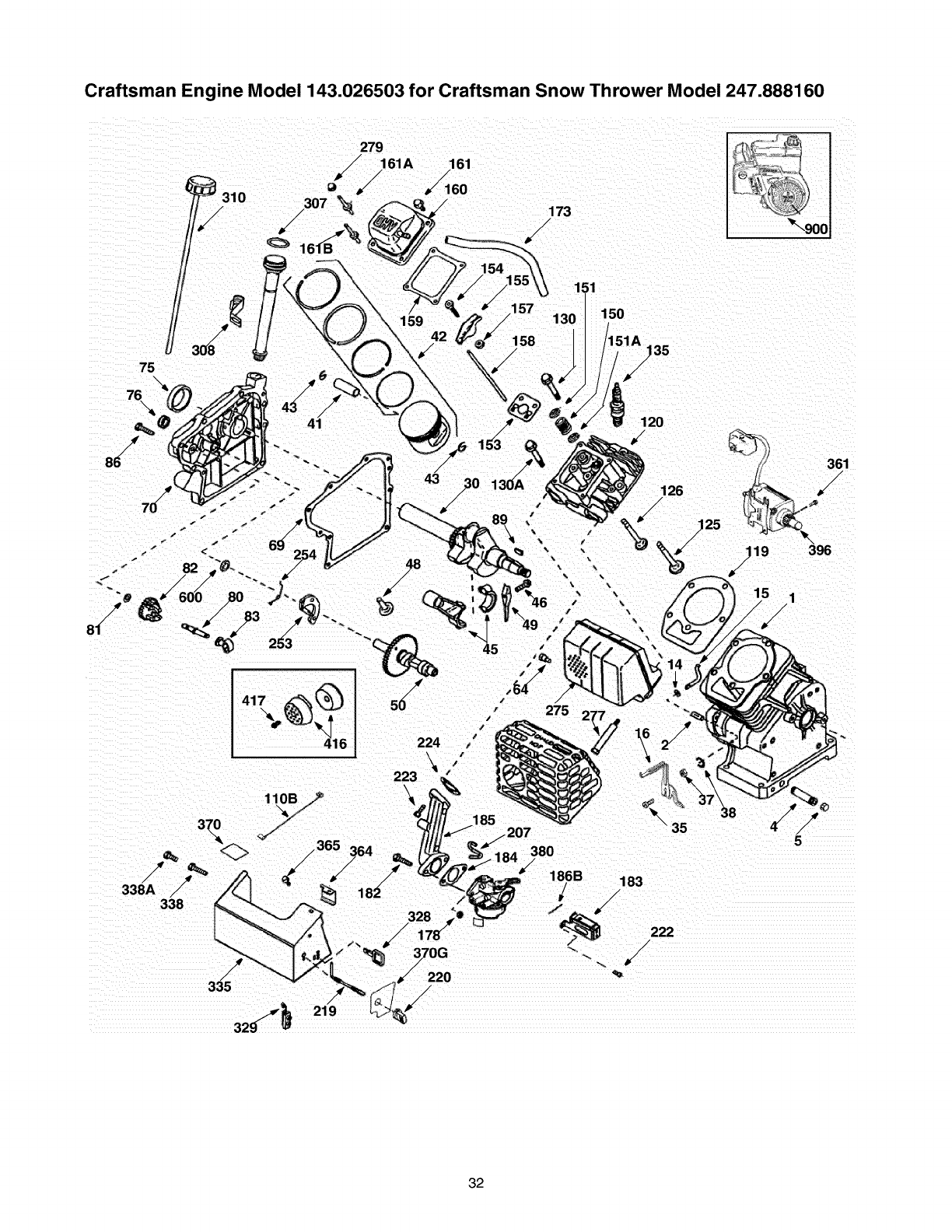
Craftsman Engine Model 143.026503 for Craftsman Snow Thrower Model 247.888160
279
/160
/173
/
/
75
159
/155 ;1
/
//157 130 150
158 A/!35
186B 183
/
/'_/ 222
/
/
32
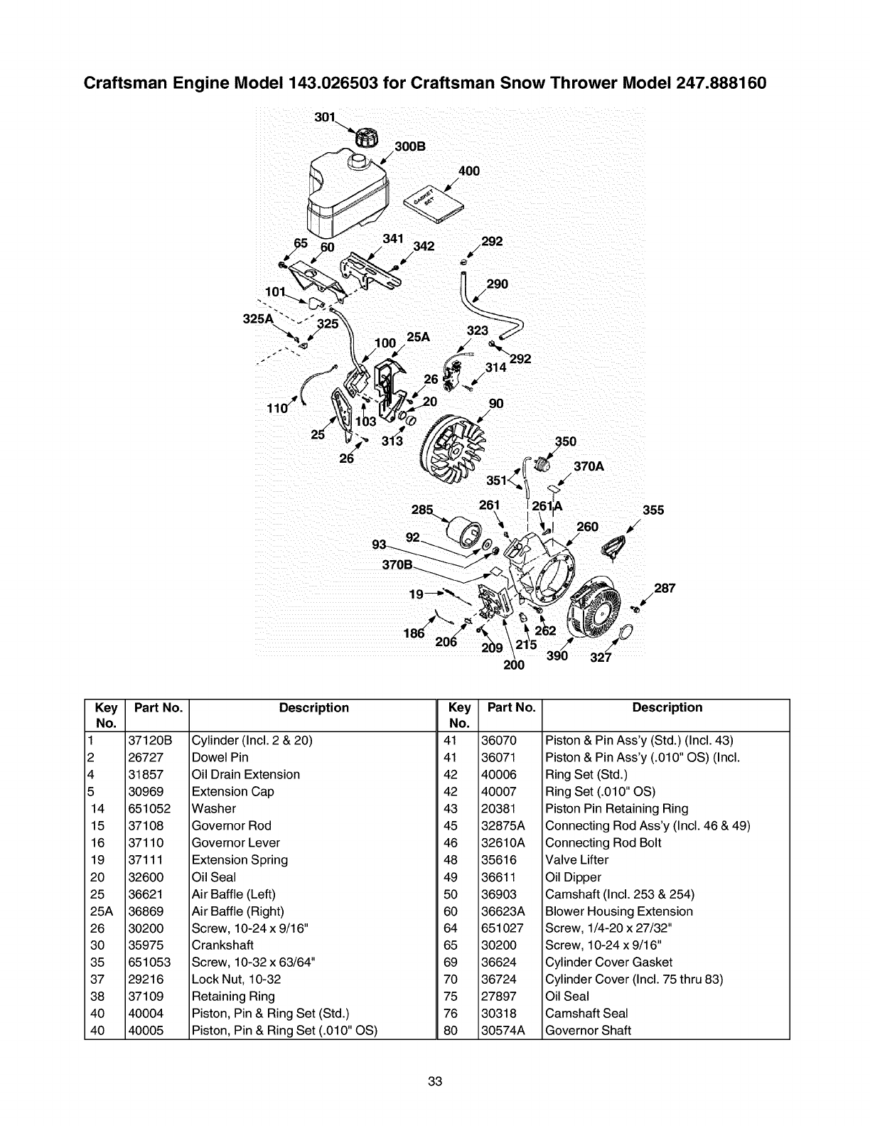
Craftsman Engine Model 143.026503 for Craftsman Snow Thrower Model 247.888160
/287
11
200
Key
No.
1
2
4
5
14
15
16
19
20
25
25A
26
30
35
37
38
40
40
Part No.
37120B
26727
31857
30969
651052
37108
37110
37111
32600
36621
36869
30200
35975
651053
29216
37109
40004
40005
Description Key Part No.
No.
Cylinder (Incl. 2 & 20) 41 36070
Dowel Pin 41 36071
Oil Drain Extension 42 40006
Extension Cap 42 40007
Washer 43 20381
Governor Rod 45 32875A
Governor Lever 46 32610A
Extension Spring 48 35616
Oil Seal 49 36611
Air Baffle (Left) 50 36903
Air Baffle (Right) 60 36623A
Screw, 10-24 x 9/16" 64 651027
Crankshaft 65 30200
Screw, 10-32 x 63/64" 69 36624
Lock Nut, 10-32 70 36724
Retaining Ring 75 27897
Piston, Pin & Ring Set (Std.) 76 30318
Piston, Pin & Ring Set (.010" OS) 80 30574A
Description
Piston & Pin Ass'y (Std.) (Incl. 43)
Piston & Pin Ass'y (.010" OS) (Incl.
Ring Set (Std.)
Ring Set (.010" OS)
Piston Pin Retaining Ring
Connecting Rod Ass'y (Incl. 46 & 49)
Connecting Rod Bolt
Valve Lifter
Oil Dipper
Camshaft (Incl. 253 & 254)
Blower Housing Extension
Screw, 1/4-20 x 27/32"
Screw, 10-24 x 9/16"
Cylinder Cover Gasket
Cylinder Cover (Incl. 75 thru 83)
Oil Seal
Camshaft Seal
Governor Shaft
33
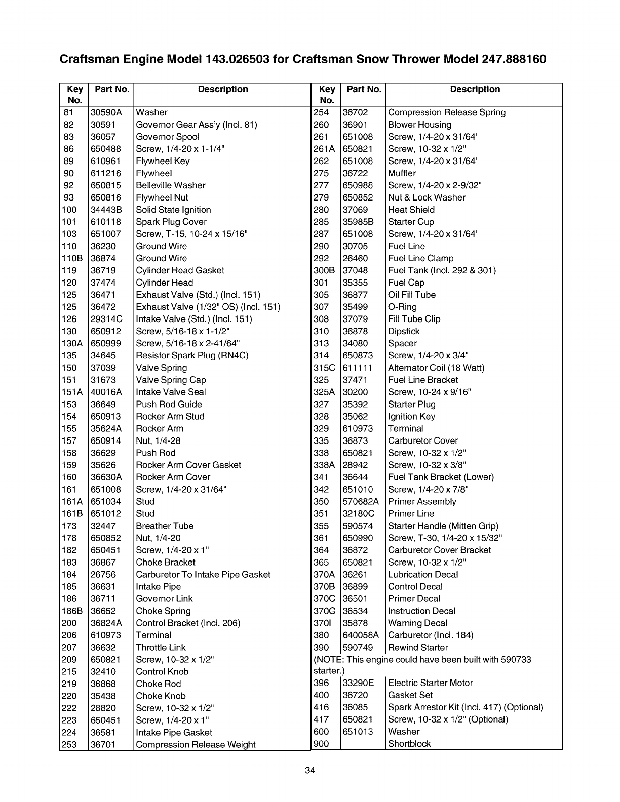
Craftsman Engine Model 143.026503 for Craftsman Snow Thrower Model 247.888160
Key Part No.
No.
81 30590A
82 30591
83 36057
86 650488
89 610961
90 611216
92 650815
93 650816
100 34443B
101 610118
103 651007
110 36230
110B 36874
119 36719
120 37474
125 36471
125 36472
126 29314C
130 650912
130A 650999
135 34645
150 37039
151 31673
151A 40016A
153 36649
154 650913
155 35624A
157 650914
158 36629
159 35626
160 36630A
161 651008
161A 651034
161B 651012
173 32447
178 650852
182 650451
183 36867
184 26756
185 36631
186 36711
186B 36652
200 36824A
206 610973
207 36632
209 650821
215 32410
219 36868
220 35438
222 28820
223 650451
224 36581
253 36701
Description
Washer
Governor Gear Ass'y (Incl. 81)
Governor Spool
Screw, 1/4-20 x 1-1/4"
Flywheel Key
Flywheel
Belleville Washer
Flywheel Nut
Solid State Ignition
Spark Plug Cover
Screw, T-15, 10-24 x 15/16"
Ground Wire
Ground Wire
Cylinder Head Gasket
Cylinder Head
Exhaust Valve (Std.) (Incl. 151)
Exhaust Valve (1/32" OS) (Incl. 151)
Intake Valve (Std.) (Incl. 151)
Screw, 5/16-18 x 1-1/2"
Screw, 5/16-18 x 2-41/64"
Resistor Spark Plug (RN4C)
Valve Spring
Valve Spring Cap
Intake Valve Seal
Push Rod Guide
Rocker Arm Stud
Rocker Arm
Nut, 1/4-28
Push Rod
Rocker Arm Cover Gasket
Rocker Arm Cover
Screw, 1/4-20 x 31/64"
Stud
Stud
Breather Tube
Nut, 1/4-20
Screw, 1/4-20 x 1"
Choke Bracket
Carburetor To Intake Pipe Gasket
Key
No.
254
260
261
261A
262
275
277
279
280
285
287
290
292
300B
301
305
307
308
310
313
314
315C
325
325A
327
328
329
335
338
338A
341
342
350
351
355
361
364
365
370A
Part No.
36702
36901
651008
650821
651008
36722
650988
650852
37069
35985B
651008
30705
26460
37048
35355
36877
35499
37079
36878
34080
650873
611111
37471
30200
35392
35062
610973
36873
650821
28942
36644
651010
570682A
32180C
590574
650990
36872
650821
36261
Description
Compression Release Spring
Blower Housing
Screw, 1/4-20 x 31/64"
Screw, 10-32 x 1/2"
Screw, 1/4-20 x 31/64"
Muffler
Screw, 1/4-20 x 2-9/32"
Nut & Lock Washer
Heat Shield
Starter Cup
Screw, 1/4-20 x 31/64"
Fuel Line
Fuel Line Clamp
Fuel Tank (Incl. 292 & 301)
Fuel Cap
Oil Fill Tube
O-Ring
Fill Tube Clip
Dipstick
Spacer
Screw, 1/4-20 x 3/4"
Alternator Coil (18 Watt)
Fuel Line Bracket
Screw, 10-24 x 9/16"
Starter Plug
Ignition Key
Terminal
Carburetor Cover
Screw, 10-32 x 1/2"
Screw, 10-32 x 3/8"
Fuel Tank Bracket (Lower)
Screw, 1/4-20 x 7/8"
Primer Assembly
Primer Line
Starter Handle (Mitten Grip)
Screw, T-30, 1/4-20 x 15/32"
Carburetor Cover Bracket
Screw, 10-32 x 1/2"
Lubrication Decal
Intake Pipe
Governor Link
Choke Spring
Control Bracket (Incl. 206)
Terminal
Throttle Link
Screw, 10-32 x 1/2"
Control Knob
Choke Rod
Choke Knob
Screw, 10-32 x 1/2"
Screw, 1/4-20 x 1"
Intake Pipe Gasket
Compression Release Weight
370B
370C
370G
3701
380
390
36899
36501
36534
35878
640058A
590749
Control Decal
Primer Decal
Instruction Decal
Warning Decal
Carburetor (Incl. 184)
Rewind Starter
(NOTE: This engine could have been built with 590733
starter.)
396 33290E
400 36720
416 36085
417 650821
600 651013
900
Electric Starter Motor
Gasket Set
Spark Arrestor Kit (Incl. 417) (Optional)
Screw, 10-32 x 1/2" (Optional)
Washer
Shortblock
34
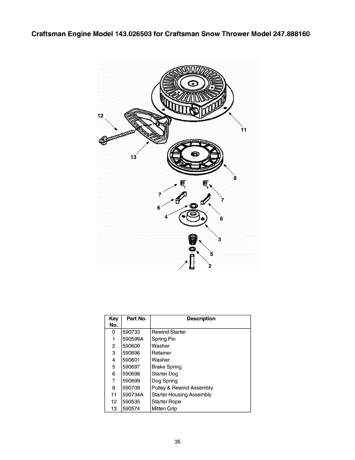
Craftsman Engine Model 143.026503 for Craftsman Snow Thrower Model 247.888160
12 \
/
/
/
./
13
\\
11
\\ \3
Key
No.
0 590733
1 590599A
2 590600
3 590696
4 590601
5 590697
6 590698
7 590699
8 590709
11 590734A
12 590535
13 590574
Part No. Description
Rewind Starter
Spring Pin
Washer
Retainer
Washer
Brake Spring
Starter Dog
Dog Spring
Pulley & Rewind Assembly
Starter Housing Assembly
Starter Rope
Mitten Grip
35
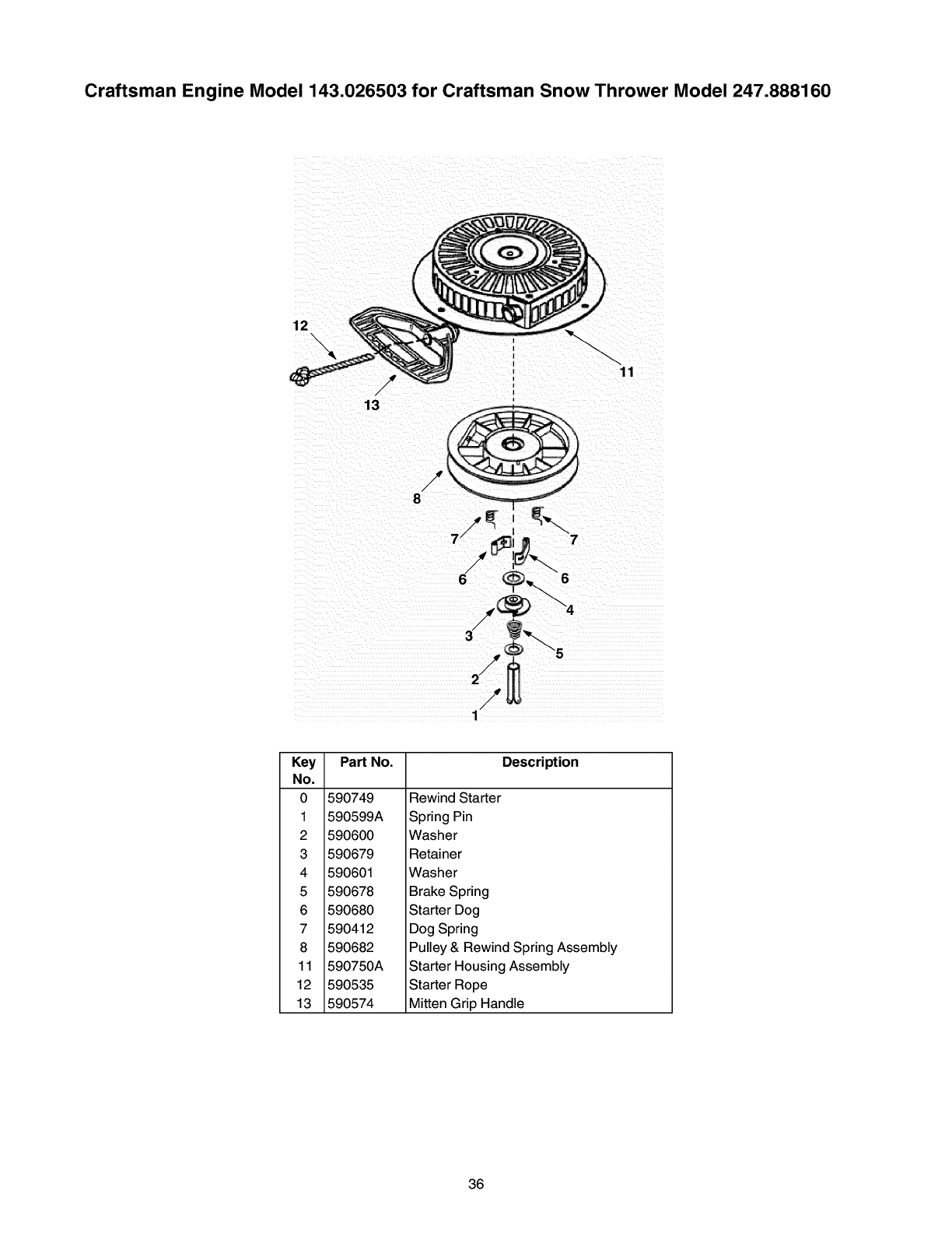
Craftsman Engine Model 143.026503 for Craftsman Snow Thrower Model 247.888160
12
,11
/J
13
/,
8
7
Key
No.
0
1
2
3
4
5
6
7
8
11
12
13
Part No. Description
590749
590599A
590600
590679
590601
590678
590680
590412
590682
590750A
590535
590574
Rewind Starter
Spring Pin
Washer
Retainer
Washer
Brake Spring
Starter Dog
Dog Spring
Pulley & Rewind Spring Assembly
Starter Housing Assembly
Starter Rope
Mitten Grip Handle
36
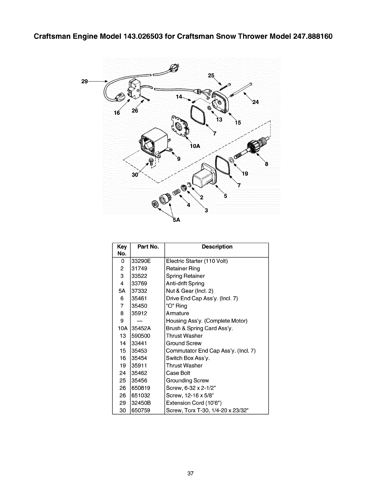
Craftsman Engine Model 143.026503 for Craftsman Snow Thrower Model 247.888160
Key
No.
0 33290E
2 31749
3 33522
4 33769
5A 37332
6 35461
7 35450
8 35912
9
10A 35452A
13 590500
14 33441
15 35453
16 35454
19 35911
24 35462
25 35456
26 650819
26 651032
29 32450B
30 650759
Part No. Description
Electric Starter (110 Volt)
Retainer Ring
Spring Retainer
Anti-drift Spring
Nut & Gear (Incl. 2)
Drive End Cap Ass'y. (Incl. 7)
"O" Ring
Armature
Housing Ass'y. (Complete Motor)
Brush & Spring Card Ass'y.
Thrust Washer
Ground Screw
Commutator End Cap Ass'y. (Incl. 7)
Switch Box Ass'y.
Thrust Washer
Case Bolt
Grounding Screw
Screw, 6-32 x 2-1/2"
Screw, 12-16 x 5/8"
Extension Cord (10'6")
Screw, Torx T-30, 1/4-20 x 23/32"
37
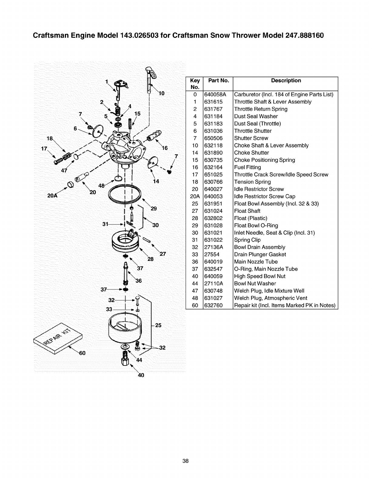
Craftsman Engine Model 143.026503 for Craftsman Snow Thrower Model 247.888160
7
-\
18,
17
0
1\
14
Key
No.
0 640058A
1 631615
2 631767
4 631184
5 631183
6 631036
7 650506
10 632118
14 631890
15 630735
16 632164
17 651025
18 630766
20 640027
20A 640053
25 631951
27 631024
28 632802
29 631028
30 631021
31 631022
32 27136A
33 27554
36 640019
37 632547
40 640059
44 27110A
47 630748
48 631027
60 632760
Part No. Description
Carburetor (Incl. 184 of Engine Parts List)
Throttle Shaft & Lever Assembly
Throttle Return Spring
Dust Seal Washer
Dust Seal (Throttle)
Throttle Shutter
Shutter Screw
Choke Shaft & Lever Assembly
Choke Shutter
Choke Positioning Spring
Fuel Fitting
Throttle Crack Screw/Idle Speed Screw
Tension Spring
Idle Restrictor Screw
Idle Restrictor Screw Cap
Float Bowl Assembly (Incl. 32 & 33)
Float Shaft
Float (Plastic)
Float Bowl O-Ring
Inlet Needle, Seat & Clip (Incl. 31)
Spring Clip
Bowl Drain Assembly
Drain Plunger Gasket
Main Nozzle Tube
O-Ring, Main Nozzle Tube
High Speed Bowl Nut
Bowl Nut Washer
Welch Plug, Idle Mixture Well
Welch Plug, Atmospheric Vent
Repair kit (Incl. Items Marked PK in Notes)
38
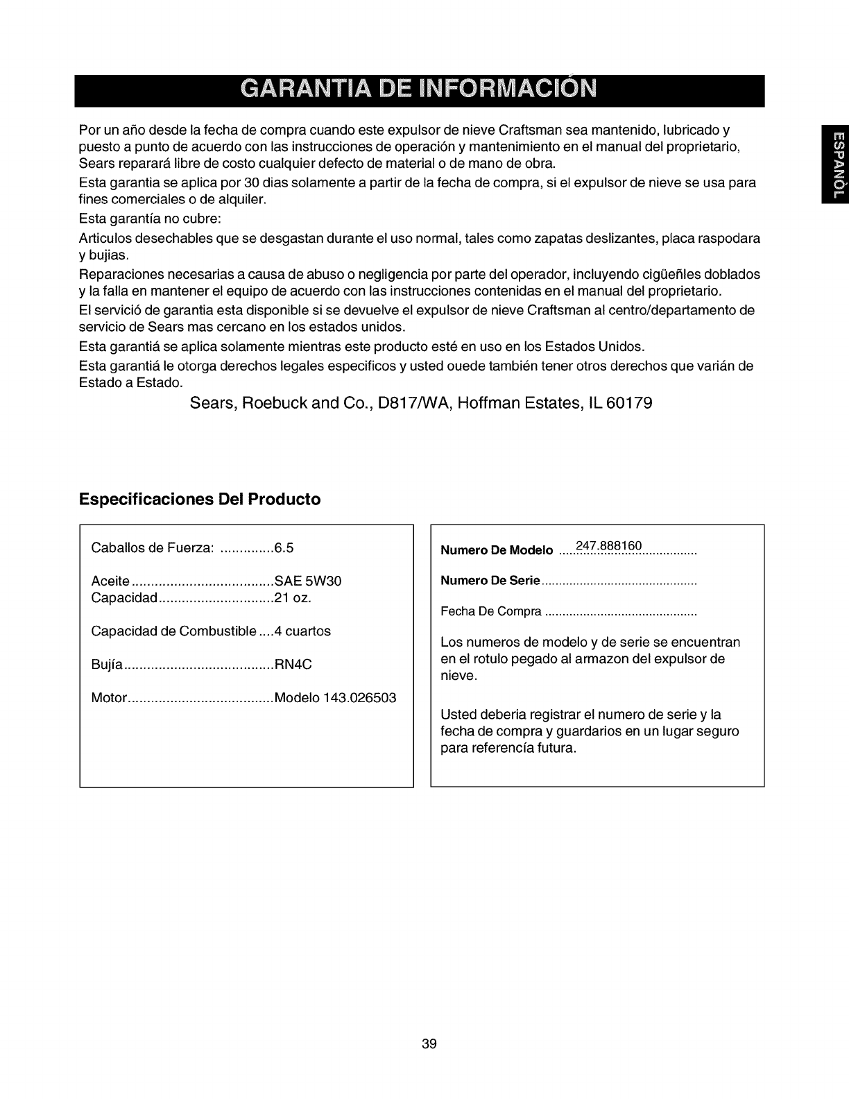
Por un afio desde la fecha de compra cuando este expulsor de nieve Craftsman sea mantenido, lubricado y
puesto a punto de acuerdo con las instrucciones de operaciSn y mantenimiento en el manual del proprietario,
Sears reparara libre de costo cualquier defecto de material o de mano de obra.
Esta garantia se aplica por 30 dias solamente a partir de la fecha de compra, si el expulsor de nieve se usa para
fines comerciales o de alquiler.
Esta garantfa no cubre:
Articulos desechables que se desgastan durante el uso normal, tales como zapatas deslizantes, placa raspodara
y bujias.
Reparaciones necesarias a causa de abuso o negligencia por parte del operador, incluyendo cig0efiles doblados
y la falla en mantener el equipo de acuerdo con las instrucciones contenidas en el manual del proprietario.
El servici5 de garantia esta disponible si se devuelve el expulsor de nieve Craftsman al centro/departamento de
servicio de Sears mas cercano en los estados unidos.
Esta garantia se aplica solamente mientras este producto este en uso en los Estados Unidos.
Esta garantia le otorga derechos legales especificos y usted ouede tambien tener otros derechos que varian de
Estado a Estado.
Sears, Roebuck and Co., D817/WA, Hoffman Estates, IL 60179
Especificaciones Del Producto
Caballos de Fuerza: .............. 6.5
Aceite ..................................... SAE 5W30
Capacidad .............................. 21 oz.
Capacidad de Combustible ....4cuartos
Bujfa ....................................... RN4C
Motor ...................................... Modelo 143.026503
Numero De Modelo .....247:8881.60................
Numero De Serie.............................................
FechaDe Compra ............................................
Los numeros de modelo y de serie se encuentran
en el rotulo pegado al armazon del expulsor de
nieve.
Usted deberia registrar el numero de serie y la
fecha de compra y guardarios en un lugar seguro
para referencfa futura.
39
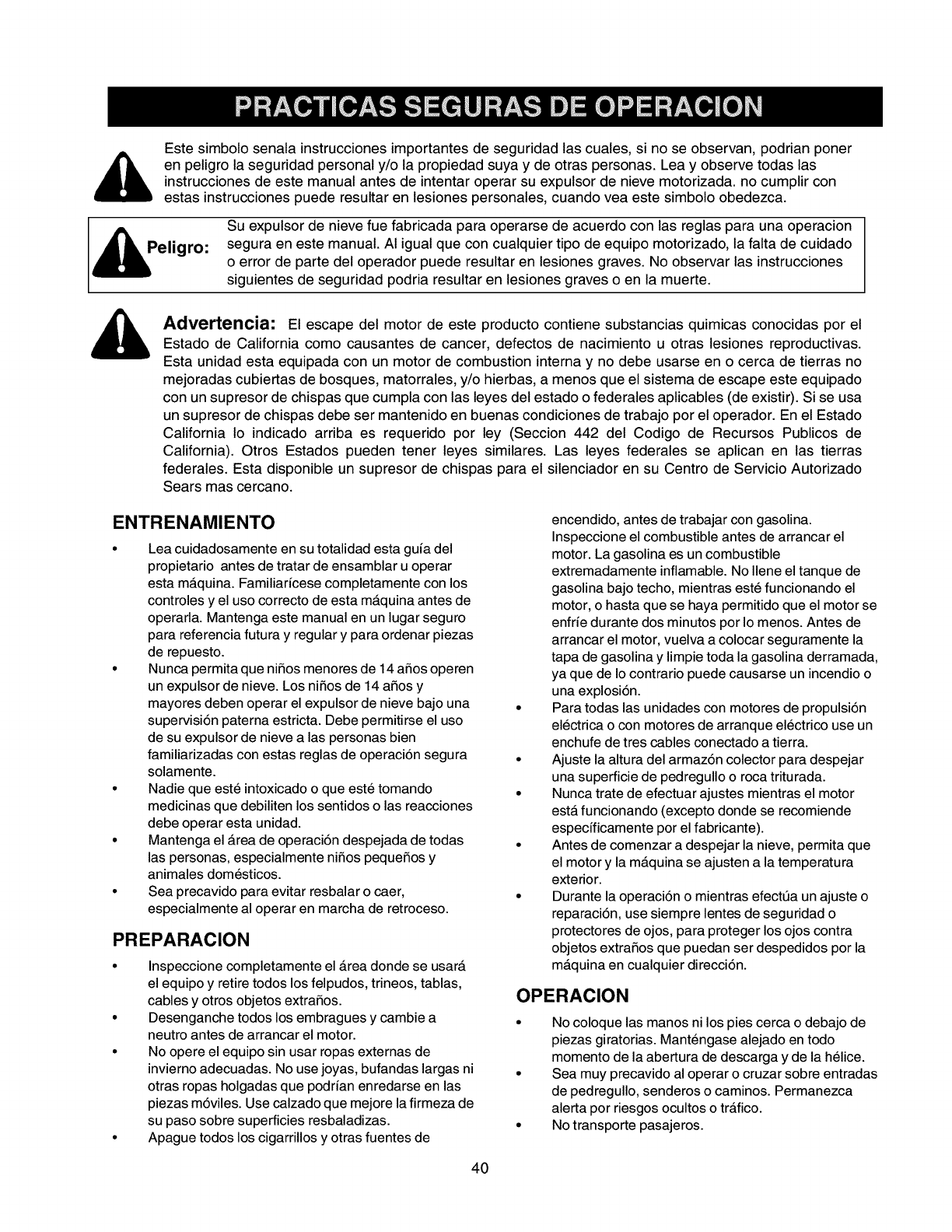
Este simbolo senala instrucciones importantes de seguridad las cuales, si no se observan, podrian poner
en peligro la seguridad personal y/o la propiedad suya y de otras personas. Lea y observe todas las
instrucciones de este manual antes de intentar operar su expulsor de nieve motorizada, no cumplir con
estas instrucciones puede resultar en lesiones personales, cuando vea este simbolo obedezca.
Peligro:
Su expulsor de nieve fue fabricada para operarse de acuerdo con las reglas para una operacion
segura en este manual. AI igual que con cualquier tipo de equipo motorizado, la falta de cuidado
o error de parte del operador puede resultar en lesiones graves. No observar las instrucciones
siguientes de seguridad podria resultar en lesiones graves o en la muerte.
Advertencia: El escape del motor de este producto contiene substancias quimicas conocidas por el
Estado de California como causantes de cancer, defectos de nacimiento u otras lesiones reproductivas.
Esta unidad esta equipada con un motor de combustion interna y no debe usarse en o cerca de tierras no
mejoradas cubiertas de bosques, matorrales, y/o hierbas, a menos que el sistema de escape este equipado
con un supresor de chispas que cumpla con las leyes del estado o federales aplicables (de existir). Si se usa
un supresor de chispas debe ser mantenido en buenas condiciones de trabajo por el operador. En el Estado
California Io indicado arriba es requerido por ley (Seccion 442 del Codigo de Recursos Publicos de
California). Otros Estados pueden tener leyes similares. Las leyes federales se aplican en las tierras
federales. Esta disponible un supresor de chispas para el silenciador en su Centro de Servicio Autorizado
Sears mas cercano.
ENTRENAMIENTO
Lea cuidadosamente en su totalidad esta guia del
propietario antes de tratar de ensamblar u operar
esta mAquina. Familiaricese completamente con los
controles y el uso correcto de esta mAquina antes de
operarla. Mantenga este manual en un lugar seguro
para referencia futura y regular y para ordenar piezas
de repuesto.
Nunca permita que niSos menores de 14 aSos operen
un expulsor de nieve. Los niSos de 14 aSos y
mayores deben operar el expulsor de nieve bajo una •
supervisi6n paterna estricta. Debe permitirse el uso
de su expulsor de nieve a las personas bien
familiarizadas con estas reglas de operaci6n segura •
solamente.
Nadie que este intoxicado o que este tomando •
medicinas que debiliten los sentidos o las reacciones
debe operar esta unidad.
Mantenga el Area de operaci6n despejada de todas •
las personas, especialmente niSos pequeSos y
animales domesticos.
Sea precavido para evitar resbalar o caer, •
especialmente al operar en marcha de retroceso.
PREPARACION
Inspeccione completamente el Area donde se usarA
el equipo y retire todos los felpudos, trineos, tablas,
cables y otros objetos extraSos.
Desenganche todos los embragues y cambie a •
neutro antes de arrancar el motor.
No opere el equipo sin usar ropas externas de
invierno adecuadas. No use joyas, bufandas largas ni •
otras ropas holgadas que podrian enredarse en las
piezas m6viles. Use calzado que mejore la firmeza de
su paso sobre superficies resbaladizas. •
Apague todos los cigarrillos y otras fuentes de
encendido, antes de trabajar con gasolina.
Inspeccione el combustible antes de arrancar el
motor. La gasolina es un combustible
extremadamente inflamable. No Ilene el tanque de
gasolina bajo techo, mientras este funcionando el
motor, o hasta que se haya permitido que el motor se
enfrie durante dos minutos por Io menos. Antes de
arrancar el motor, vuelva a colocar seguramente la
tapa de gasolina y limpie toda la gasolina derramada,
ya que de Io contrario puede causarse un incendio o
una explosi6n.
Para todas las unidades con motores de propulsi6n
electrica o con motores de arranque electrico use un
enchufe de tres cables conectado a tierra.
Ajuste la altura del armaz6n colector para despejar
una superficie de pedregullo o roca triturada.
Nunca trate de efectuar ajustes mientras el motor
estA funcionando (excepto donde se recomiende
especfficamente por el fabricante).
Antes de comenzar a despejar la nieve, permita que
el motor y la mAquina se ajusten a la temperatura
exterior.
Durante la operaci6n o mientras efectt_a un ajuste o
reparaci6n, use siempre lentes de seguridad o
protectores de ojos, para proteger los ojos contra
objetos extraSos que puedan ser despedidos por la
mAquina en cualquier direcci6n.
OPERACION
No coloque las manos ni los pies cerca o debajo de
piezas giratorias. Mantengase alejado en todo
momento de la abertura de descarga y de la helice.
Sea muy precavido al operar o cruzar sobre entradas
de pedregullo, senderos o caminos. Permanezca
alerta por riesgos ocultos o trAfico.
No transporte pasajeros.
40
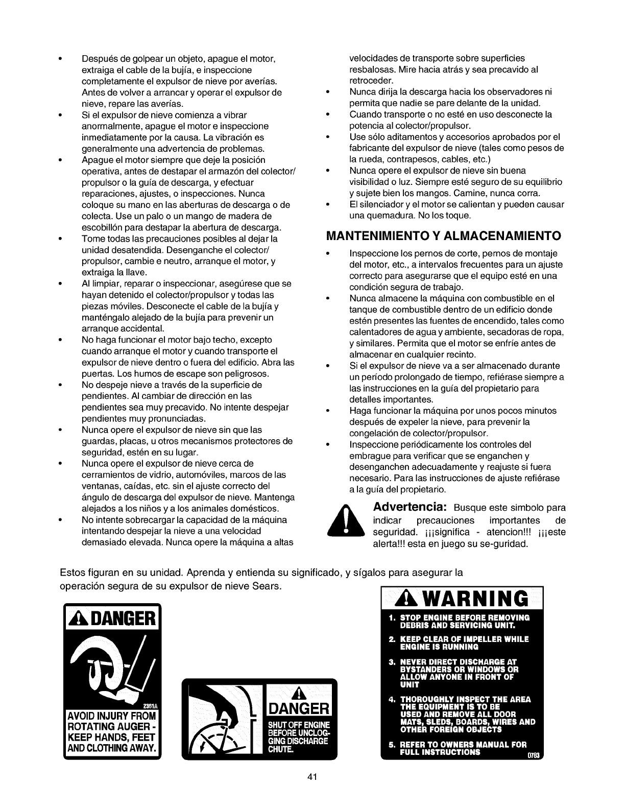
Despues de golpear un objeto, apague el motor,
extraiga el cable de la bujfa, e inspeccione
completamente el expulsor de nieve por averfas.
Antes de volver a arrancar y operar el expulsor de
nieve, repare las averfas.
Si el expulsor de nieve comienza a vibrar
anormalmente, apague el motor e inspeccione
inmediatamente por la causa. La vibraci6n es
generalmente una advertencia de problemas.
Apague el motor siempre que deje la posici6n
operativa, antes de destapar el armaz6n del colector/
propulsor o la gufa de descarga, y efectuar
reparaciones, ajustes, o inspecciones. Nunca
coloque su mano en las aberturas de descarga o de
colecta. Use un palo o un mango de madera de
escobill6n para destapar la abertura de descarga.
Tome todas las precauciones posibles al dejar la
unidad desatendida. Desenganche el colector/
propulsor, cambie e neutro, arranque el motor, y
extraiga la Ilave.
AI limpiar, reparar o inspeccionar, asegt_rese que se
hayan detenido el colector/propulsor y todas las
piezas m6viles. Desconecte el cable de la bujfa y
mantengalo alejado de la bujfa para prevenir un
arranque accidental.
No haga funcionar el motor bajo techo, excepto
cuando arranque el motor y cuando transporte el
expulsor de nieve dentro o fuera del edificio. Abra las
puertas. Los humos de escape son peligrosos.
No despeje nieve a traves de la superficie de
pendientes. AI cambiar de direcci6n en las
pendientes sea muy precavido. No intente despejar
pendientes muy pronunciadas.
Nunca opere el expulsor de nieve sin que las
guardas, placas, u otros mecanismos protectores de
seguridad, esten en su lugar.
Nunca opere el expulsor de nieve cerca de
cerramientos de vidrio, autom6viles, marcos de las
ventanas, cafdas, etc. sin el ajuste correcto del
Angulo de descarga del expulsor de nieve. Mantenga
alejados a los niSos y a los animales domesticos.
No intente sobrecargar la capacidad de la mAquina
intentando despejar la nieve a una velocidad
demasiado elevada. Nunca opere la mAquina a altas
velocidades de transporte sobre superficies
resbalosas. Mire hacia atrAs y sea precavido al
retroceder.
Nunca dirija la descarga hacia los observadores ni
permita que nadie se pare delante de la unidad.
Cuando transporte o no este en uso desconecte la
potencia al colector/propulsor.
Use s61oaditamentos y accesorios aprobados por el
fabricante del expulsor de nieve (tales como pesos de
la rueda, contrapesos, cables, etc.)
Nunca opere el expulsor de nieve sin buena
visibilidad o luz. Siempre este seguro de su equilibrio
y sujete bien los mangos. Camine, nunca corra.
El silenciador y el motor se calientan y pueden causar
una quemadura. No los toque.
MANTENIMIENTO Y ALMACENAMIENTO
• Inspeccione los pernos de corte, pernos de montaje
del motor, etc., a intervalos frecuentes para un ajuste
correcto para asegurarse que el equipo este en una
condici6n segura de trabajo.
• Nunca almacene la m_quina con combustible en el
tanque de combustible dentro de un edificio donde
esten presentes las fuentes de encendido, tales como
calentadores de agua y ambiente, secadoras de ropa,
y similares. Permita que el motor se enfrfe antes de
almacenar en cualquier recinto.
• Si el expulsor de nieve va a ser almacenado durante
un perfodo prolongado de tiempo, refierase siempre a
las instrucciones en la gufa del propietario para
detalles importantes.
• Haga funcionar la m_quina por unos pocos minutos
despues de expeler la nieve, para prevenir la
congelaci6n de colector/propulsor.
• Inspeccione peri6dicamente los controles del
embrague para verificar que se enganchen y
desenganchen adecuadamente y reajuste si fuera
necesario. Para las instrucciones de ajuste refierase
a la gufa del propietario.
_, dvertencia: Busque este simbolo para
indicar precauciones importantes de
seguridad, iiisignifica- atencion!!! iiieste
alerta!!! esta en juego su se-guridad.
Estos figuran en su unidad. Aprenda y entienda su significado, y sfgalos para asegurar la
operaci6n segura de su expulsor de nieve Sears.
, DANGER
AVOIDINJURYFROM
ROTATINGAUGER -
KEEP HANDS, FEET
ANDCLOTHINGAWAY.
DANGER
AWARNING
41
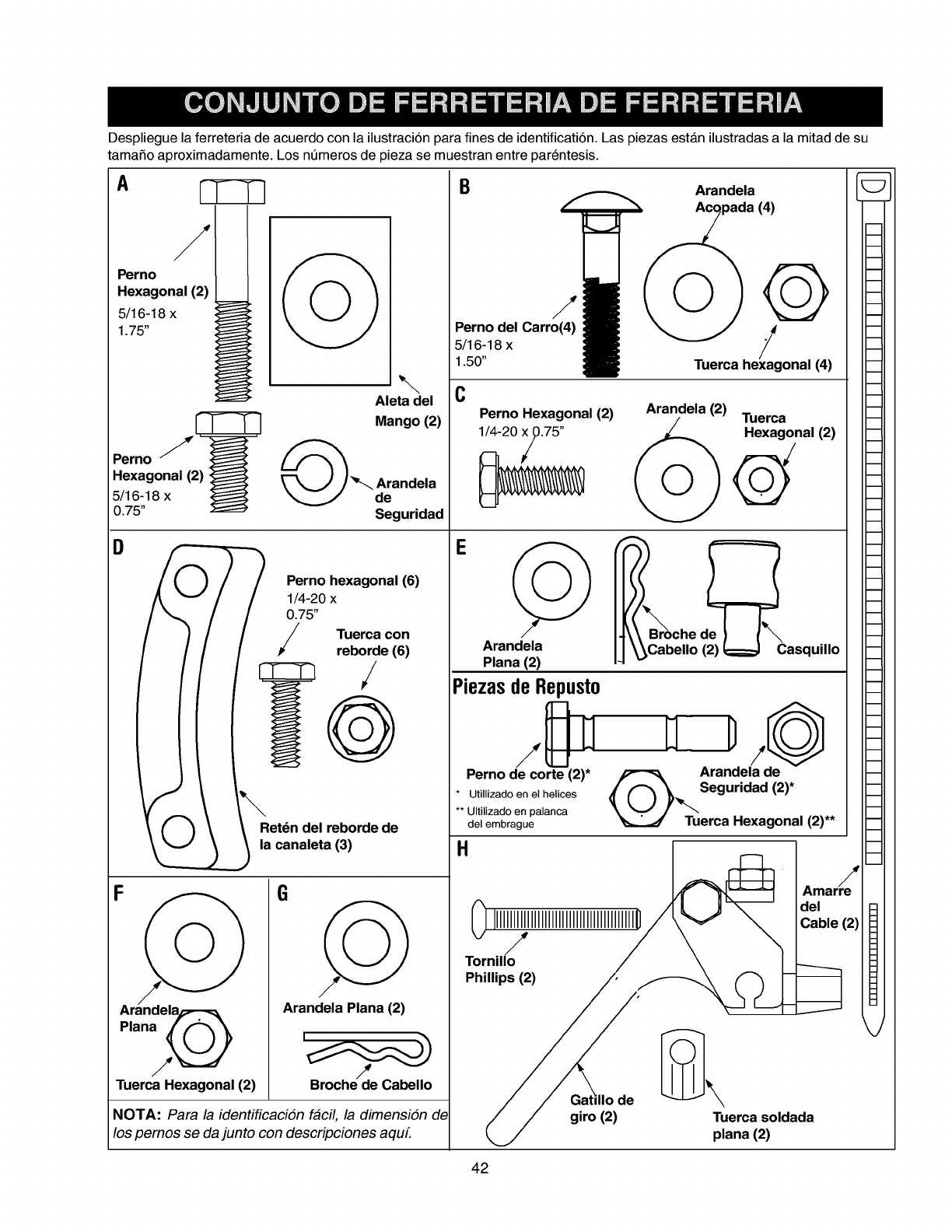
Desplieguelaferreteriadeacuerdoconlailustraci6nparafinesdeidentificati6n.LaspiezasestAnilustradasalamitaddesu
tamaSoaproximadamente.Losnt_merosdepiezasemuestranentreparentesis.
Ar-Tqq
Perno /I
Hexagonal (2), I
1
Pemo
Hexagonal (2) I_
O
Aleta del
Mango (2)
@ _.. Arandela
B
_? 0.75"P;rni°114-20xhexag/na@lTuercarebordeC°n(6)(6)
I _lR:td n del reborde de
canaleta (3)
Perno del Carro(4)
5/16-18 x
1.50"
Arandela Plana (2)
C
Seguridad
E
Tuerca Hexagonal (2) Broche de Cabello
NOTA: Para la identificaciSn facil, la dimensiSn de
los pemos se da junto con descripciones aquL
Arandela
uerca exagona ( )
Perno Hexagonal (2) Arandela (2) Tuerca
1/4-20 _0.75"L _)-_- _ Hexago@ial (2)
Arandela
Plana (2)
PiezasdeRepusto
che de _ !_
abello (2) i_l Casquillo
m
Perno de corte (2)* _Arandela de
* Utillizadoenelhelices { 0 }_,.x. Seguridad (2)*
** Ultiizadoen palanca
delembrague _Tuerca Hexagonal (2)**
m
m
m
m
m
m
m
m
m
m
m
m
m
m
m
m
m
m
m
m
m
m
m
m
m
m
m
m
m
m
m
m
m
m
m
m
m
m
m
H
Amar! --
0 IIIIIIIIIIIIIIIIIIIIIIIIIIIIIIIIIIIIIIII1" /_V_ '-_ l:lle (2)
Tornil! /_
.h,,,,.s=
/ / giro (2) Tuerca soldada
plana (2)
42
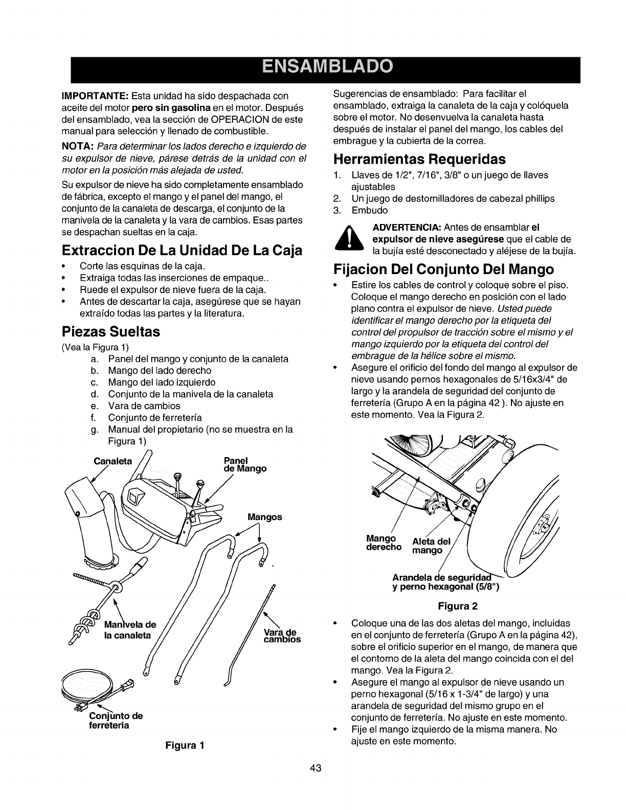
IMPORTANTE: Esta unidad ha sido despachada con
aceite del motor pero sin gasolina en el motor. Despues
del ensamblado, vea la secci6n de OPERACION de este
manual para selecci6n y Ilenado de combustible.
NOTA: Para determinar los lados derecho e izquierdo de
su expulsor de nieve, parese detras de la unidad con el
motor en la posiciSn mas alejada de usted.
Su expulsor de nieve ha sido completamente ensamblado
de fabrica, excepto el mango y el panel del mango, el
conjunto de la canaleta de descarga, el conjunto de la
manivela de la canaleta y la vara de cambios. Esas partes
se despachan sueltas en la caja.
Extraction De La Unidad De La Caja
• Corte las esquinas de la caja.
• Extraiga todas las inserciones de empaque..
• Ruede el expulsor de nieve fuera de la caja.
• Antes de descartar la caja, asegt_rese que se hayan
extrafdo todas las partes y la literatura.
Piezas Sueltas
(Vea la Figura 1)
a. Panel del mango y conjunto de la canaleta
b. Mango del lado derecho
c. Mango delladoizquierdo
d. Conjunto de la manivela de la canaleta
e. Varade cambios
f. Conjuntode ferreterfa
g. Manual del propietario (no se muestra en la
Figura 1)
Canale__.lelango
t__ Mangos
Sugerencias de ensamblado: Para facilitar el
ensamblado, extraiga la canaleta de la caja y col6quela
sobre el motor. No desenvuelva la canaleta hasta
despues de instalar el panel del mango, los cables del
embrague y la cubierta de la correa.
Herramientas Requeridas
1. Llaves de 1/2", 7/16", 3/8" o un juego de Ilaves
ajustables
2. Un juego de destornilladores de cabezal phillips
3. Embudo
,_ ADVERTENCIA: Antes de ensamblar el
expulsor de nieve asegdrese que el cable de
la bujfa este desconectado y alejese de la bujfa.
Fijacion Del Conjunto Del Mango
• Estire los cables de control y coloque sobre el piso.
Coloque el mango derecho en posici6n con el lado
piano contra el expulsor de nieve. Ustedpuede
identificar el mango derecho por la etiqueta del
control del propulsor de tracciSn sobre el mismo y el
mango izquierdo por la etiqueta del control del
embrague de la helice sobre el mismo.
• Asegure el orificio del fondo del mango al expulsor de
nieve usando pernos hexagonales de 5/16x3/4" de
largo y la arandela de seguridad del conjunto de
ferreterfa (Grupo A en la p_.gina 42 ). No ajuste en
este momento. Vea la Figura 2.
Mango Aleta del
derecho mango
Arandela de seg
y perno hexagonal (5/8")
de
la canaleta Vara. de
camDios
_e
ferreteria
Figura 1
Figura 2
• Coloque una de las dos aletas del mango, incluidas
en el conjunto de ferreterfa (Grupo A en la p_.gina 42),
sobre el orificio superior en el mango, de manera que
el contorno de la aleta del mango coincida con el del
mango. Vea la Figura 2.
• Asegure el mango al expulsor de nieve usando un
perno hexagonal (5/16 x 1-3/4" de largo) y una
arandela de seguridad del mismo grupo en el
conjunto de ferreterfa. No ajuste en este momento.
• Fije el mango izquierdo de la misma manera. No
ajuste en este momento.
43
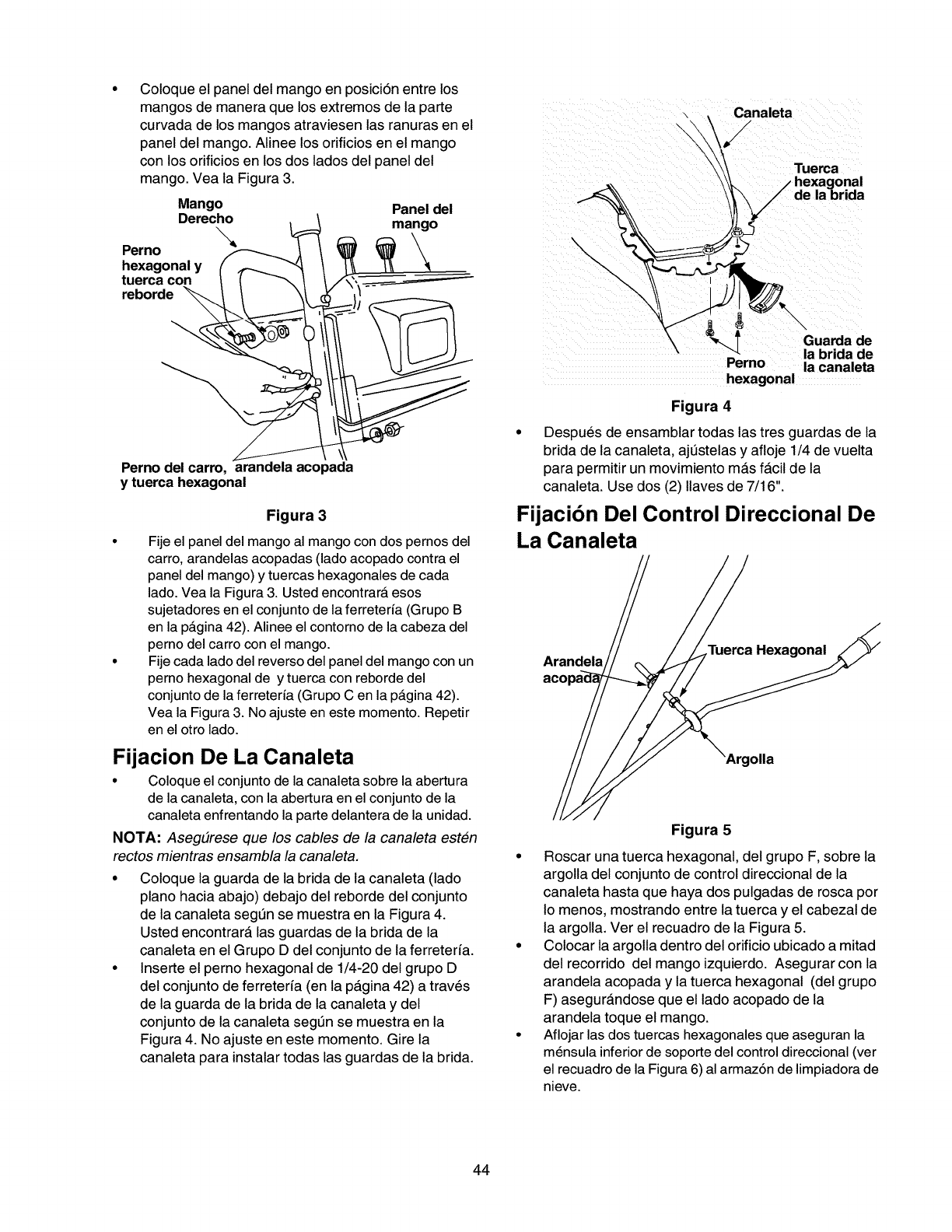
Coloqueelpaneldelmangoenposici6nentrelos
mangosdemaneraquelosextremosdelaparte
curvadadelosmangosatraviesenlasranurasenel
paneldelmango.Alineelosorificiosenelmango
conlosorificiosenlosdosladosdelpaneldel
mango.VealaFigura3.
Mango
Derecho
\
Perno
hexagonal y
tuerca con
reborde
Panel del
mango \\
Canaleta
/
"l'uel_a
hexagonal
de la brida
/
Perno del carro, arandela acopada
y tuerca hexagonal
Figura 3
Fije el panel del mango al mango con dos pernos del
carro, arandelas acopadas (lado acopado contra el
panel del mango) y tuercas hexagonales de cada
lado. Vea la Figura 3. Usted encontrarA esos
sujetadores en el conjunto de la ferreterfa (Grupo B
en la pAgina 42). Alinee el contorno de la cabeza del
perno del carro con el mango.
Fije cada lado del reverso del panel del mango con un
perno hexagonal de y tuerca con reborde del
conjunto de la ferreterfa (Grupo C en la pAgina 42).
Vea la Figura 3. No ajuste en este momento. Repetir
en el otro lado.
Fijacion De La Canaleta
• Coloque el conjunto de la canaleta sobre la abertura
de la canaleta, con la abertura en el conjunto de la
canaleta enfrentando la parte delantera de la unidad.
NOTA: AsegtJrese que los cables de la canaleta esten
rectos mientras ensambla la canaleta.
• Coloque la guarda de la brida de la canaleta (lado
piano hacia abajo) debajo del reborde del conjunto
de la canaleta segt_n se muestra en la Figura 4.
Usted encontrara, las guardas de la brida de la
canaleta en el Grupo D del conjunto de la ferreteria.
• Inserte el perno hexagonal de 1/4-20 del grupo D
del conjunto de ferreterfa (en la p_.gina 42) a traves
de la guarda de la brida de la canaleta y del
conjunto de la canaleta segt_n se muestra en la
Figura 4. No ajuste en este momento. Gire la
canaleta para instalar todas las guardas de la brida.
IGuarda de
la brida de
Pemo la canaleta
hexagonal
Figura 4
• Despues de ensamblar todas las tres guardas de la
brida de la canaleta, ajt_stelas y afloje 1/4 de vuelta
para permitir un movimiento ma.s f_.cil de la
canaleta. Use dos (2) Ilaves de 7/16".
Fijaci6n Del Control Direccional De
La Canaleta
Arandela
aco
Hexagonal
Figura 5
• Roscar una tuerca hexagonal, del grupo F, sobre la
argolla del conjunto de control direccional de la
canaleta hasta que haya dos pulgadas de rosca por
Io menos, mostrando entre la tuerca y el cabezal de
la argolla. Ver el recuadro de la Figura 5.
• Colocar la argolla dentro del orificio ubicado a mitad
del recorrido del mango izquierdo. Asegurar con la
arandela acopada y la tuerca hexagonal (del grupo
F) asegura.ndose que el lado acopado de la
arandela toque el mango.
• Aflojar las dos tuercas hexagonales que aseguran la
mensula inferior de soporte del control direccional (ver
el recuadro de la Figura 6) al armaz6n de limpiadora de
nieve.
44
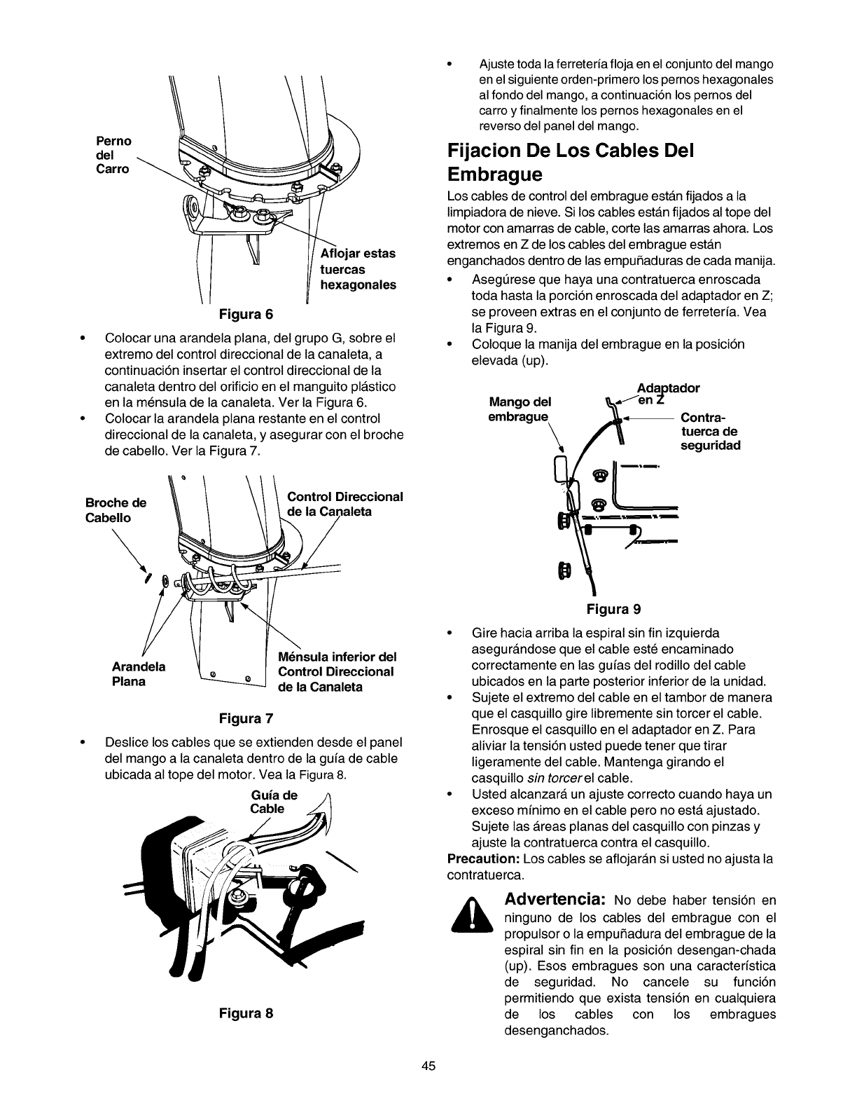
Ajuste toda la ferreteria floja en el conjunto del mango
en el siguiente orden-primero los pernos hexagonales
al fondo del mango, a continuaci6n los pernos del
carro y finalmente los pernos hexagonales en el
reverso del panel del mango.
Perno Fijacion De Los Cables Del
del
Carro _Embrague
Los cables de control del embrague estAn fijados a la
limpiadora de nieve. Si los cables estAn fijados al tope del
motor con amarras de cable, corte las amarras ahora. Los
/ I _ I/ Aflojar estas extremos en Z de los cables eel embrague estAn
enganchados dentro de las empuSaduras de cada manija.
/\ll I/]/tuercaShexagonales •Asegt_rese que haya una contratuerca enroscada
\l I toda hasta la porci6n enroscada eel adaptador en Z;
Figura 6 se proveen extras en el conjunto de ferreteria. Vea
la Figura 9.
Coloque la manija del embrague en la posici6n
elevada (up).
Mango del
embrague \
Adaptador
_en Z
_._ Contra-
_" _ tuerca de
f u seguridad
• Colocar una arandela plana, del grupo G, sobre el
extremo del control direccional de la canaleta, a
continuaci6n insertar el control direccional de la
canaleta dentro del orificio en el manguito plAstico
en la mensula de la canaleta. Ver la Figura 6.
• Colocar la arandela plana restante en el control
direccional de la canaleta, y asegurar con el broche
de cabello. Ver la Figura 7.
_' / _/ /C°ntr°lDirecci°nal_naleta ! _:_
Figura 9
Broche de
Cabello
\
Gire hacia arriba la espiral sin fin izquierda
M_nsula inferior del asegurandose que el cable este encaminado
Arandela Control Direccional correctamente en las guias del rodillo del cable
Plana de la Canaleta ubicados en la parte posterior inferior de la unidad.
Figura 7
Deslice los cables que se extienden desde el panel
del mango a la canaleta dentro de la guia de cable
ubicada al tope del motor. Vea la Figura 8.
Guia de
Cable
• Sujete el extremo del cable en el tambor de manera
que el casquillo gire libremente sin torcer el cable.
Enrosque el casquillo en el adaptador en Z. Para
aliviar la tensi6n usted puede tener que tirar
ligeramente del cable. Mantenga girando el
casquillo sin torcer el cable.
• Usted alcanzara un ajuste correcto cuando haya un
exceso minimo en el cable pero no estA ajustado.
Sujete las Areas planas del casquillo con pinzas y
ajuste la contratuerca contra el casquillo.
Precaution: Los cables se aflojaran si usted no ajusta la
contratuerca.
Figura 8
Advertencia: No debe haber tensi6n en
ninguno de los cables del embrague con el
propulsor o la empuSadura del embrague de la
espiral sin fin en la posici6n desengan-chada
(up). Esos embragues son una caractedstica
de seguridad. No cancele su funci6n
permitiendo que exista tensi6n en cualquiera
de los cables con los embragues
desenganchados.
45
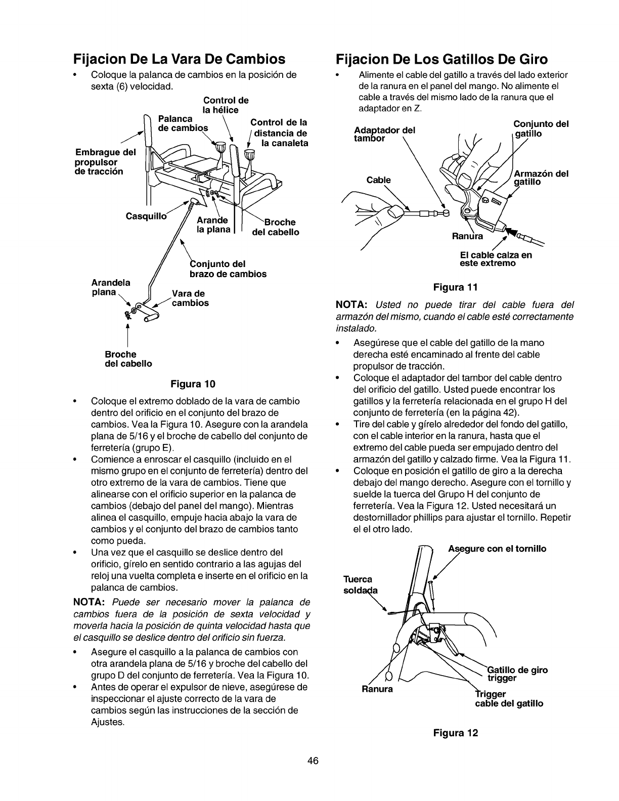
Fijacion De La Vara De Cambios
• Coloque la palanca de cambios en la posici6n de
sexta (6) velocidad.
Control de
la h_lice
Palanca \
de cambios \Control de la
\/distancia de
F_' I t_ lacanaleta
Embrague del
propulsor
de traccibn
casq he
del cabello
I _onjunto del
/_ brazo de cambios
Arandela f(
plane. II Vara de
Jcambios
T
Broche
del cabello
Figura 10
• Coloque el extremo doblado de la vara de cambio
dentro del orificio en el conjunto del brazo de
cambios. Vea la Figure 10. Asegure con la arandela
plane de 5/16 y el broche de cabello del conjunto de
ferreterfa (grupo E).
• Comience a enroscar el casquillo (incluido en el
mismo grupo en el conjunto de ferreteria) dentro del
otro extremo de la vara de cambios. Tiene que
alinearse con el orificio superior en la palanca de
cambios (debajo del panel del mango). Mientras
alinea el casquillo, empuje hacia abajo la vara de
cambios y el conjunto del brazo de cambios tanto
como pueda.
• Una vez que el casquillo se deslice dentro del
orificio, gffelo en sentido contrario alas agujas del
reloj una vuelta complete e inserte en el orificio en la
palanca de cambios.
NOTA: Puede ser necesario mover la palanca de
cambios fuera de la posiciSn de sexta velocidad y
moverla hacia la posiciSn de quinta velocidad haste que
el casquillo se deslice dentro del orificio sin fuerza.
• Asegure el casquillo ala palanca de cambios con
otra arandela plane de 5/16 y broche del cabello del
grupo D del conjunto de ferreterfa. Vea la Figure 10.
• Antes de operar el expulsor de nieve, asegt_rese de
inspeccionar el ajuste correcto de la vara de
cambios segt_n las instrucciones de la secci6n de
Ajustes.
Fijacion De Los Gatillos De Giro
• Alimente el cable del gatillo a traves del lado exterior
de la ranura en el panel del mango. No alimente el
cable a traves del mismo lado de la ranura que el
adaptador en Z.
Conjunto del
tAda_tad°r _(__/_,_il,o
Cable _! _ gA_ti_la_dndel
El cable calza en
este extremo
Figura 11
NOTA: Usted no puede tirar del cable fuera del
armazSn del mismo, cuando el cable este correctamente
instalado.
• Asegt_rese que el cable del gatillo de la mano
derecha este encaminado al frente del cable
propulsor de tracci6n.
• Coloque el adaptador del tambor del cable dentro
del orificio del gatillo. Usted puede encontrar los
gatillos y la ferreterfa relacionada en el grupo H del
conjunto de ferreterfa (en la p_.gina 42).
• Tire del cable y gffelo alrededor del fondo del gatillo,
con el cable interior en la ranura, haste que el
extremo del cable pueda ser empujado dentro del
armaz6n del gatillo y calzado firme. Vea la Figure 11.
• Coloque en posici6n el gatillo de giro ala derecha
debajo del mango derecho. Asegure con el tornillo y
suelde la tuerca del Grupo H del conjunto de
ferreterfa. Vea la Figure 12. Usted necesitara, un
destornillador phillips pare ajustar el tornillo. Repetir
el el otro lado.
muerca
soldad_
egure con
el tornillo
Ranura
de giro
trigger
cable del gatillo
Figura 12
46
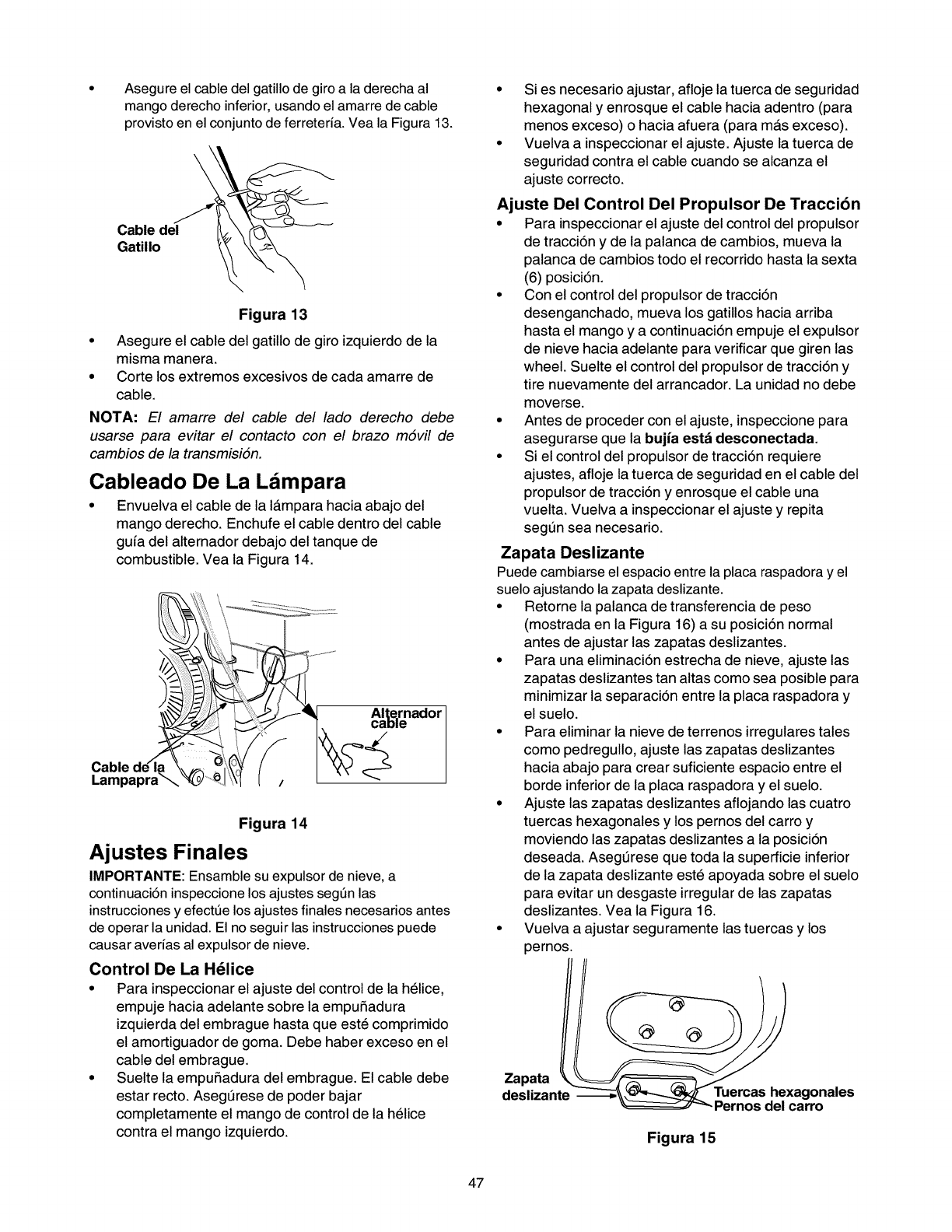
Asegure el cable del gatillo de giro a la derecha al
mango derecho inferior, usando el amarre de cable
provisto en el conjunto de ferreteria. Vea la Figura 13.
\
Cable del
Gatillo
Figura 13
• Asegure el cable del gatillo de giro izquierdo de la
misma manera.
• Corte los extremos excesivos de cada amarre de
cable.
NOTA: El amarre del cable del lado derecho debe
usarse para evitar el contacto con el brazo mSvil de
cambios de la transmisiSn.
Cableado De La Ldmpara
• Envuelva el cable de la I_.mpara hacia abajo del
mango derecho. Enchufe el cable dentro del cable
guia del alternador debajo del tanque de
combustible. Vea la Figura 14.
Alternador
cable
Lampapr_
Figura 14
Ajustes Finales
IMPORTANTE: Ensamble su expulsor de nieve, a
continuaci6n inspeccione los ajustes segt_n las
instrucciones y efectt_e los ajustes finales necesarios antes
de operar la unidad. El no seguir las instrucciones puede
causar averias al expulsor de nieve.
Control De La H_lice
• Para inspeccionar el ajuste del control de la helice,
empuje hacia adelante sobre la empufiadura
izquierda del embrague hasta que este comprimido
el amortiguador de goma. Debe haber exceso en el
cable del embrague.
• Suelte la empufiadura del embrague. El cable debe
estar recto. Asegt_rese de poder bajar
completamente el mango de control de la helice
contra el mango izquierdo.
• Si es necesario ajustar, afloje la tuerca de seguridad
hexagonal y enrosque el cable hacia adentro (para
menos exceso) o hacia afuera (para ma.s exceso).
• Vuelva a inspeccionar el ajuste. Ajuste la tuerca de
seguridad contra el cable cuando se alcanza el
ajuste correcto.
Ajuste Del Control Del Propulsor De Traccibn
• Para inspeccionar el ajuste del control del propulsor
de tracci6n y de la palanca de cambios, mueva la
palanca de cambios todo el recorrido hasta la sexta
(6) posici6n.
• Con el control del propulsor de tracci6n
desenganchado, mueva los gatillos hacia arriba
hasta el mango y a continuaci6n empuje el expulsor
de nieve hacia adelante para verificar que giren las
wheel. Suelte el control del propulsor de tracci6n y
tire nuevamente del arrancador. La unidad no debe
moverse.
• Antes de proceder con el ajuste, inspeccione para
asegurarse que la bujia estd desconectada.
• Si el control del propulsor de tracci6n requiere
ajustes, afloje la tuerca de seguridad en el cable del
propulsor de tracci6n y enrosque el cable una
vuelta. Vuelva a inspeccionar el ajuste y repita
segt_n sea necesario.
Zapata Deslizante
Puede cambiarse el espacio entre la placa raspadora y el
suelo ajustando la zapata deslizante.
• Retorne la palanca de transferencia de peso
(mostrada en la Figura 16) a su posici6n normal
antes de ajustar las zapatas deslizantes.
• Para una eliminaci6n estrecha de nieve, ajuste las
zapatas deslizantes tan altas como sea posible para
minimizar la separaci6n entre la placa raspadora y
el suelo.
• Para eliminar la nieve de terrenos irregulares tales
como pedregullo, ajuste las zapatas deslizantes
hacia abajo para crear suficiente espacio entre el
borde inferior de la placa raspadora y el suelo.
• Ajuste las zapatas deslizantes aflojando las cuatro
tuercas hexagonales y los pernos del carro y
moviendo las zapatas deslizantes a la posici6n
deseada. Asegt_rese que toda la superficie inferior
de la zapata deslizante este apoyada sobre el suelo
para evitar un desgaste irregular de las zapatas
deslizantes. Vea la Figura 16.
• Vuelva a ajustar seguramente las tuercas y los
pernos.
Zapata
deslizante
_carro
__cl/s_/hexagenales
Figura 15
47

Presi6n De Las Ruedas (Ruedas Neumdticas)
Para fines de transporte las ruedas estAn infladas en exceso.
• Inspeccionar la presi6n de la rueda, mantener la presi6n
entre 15 y 20 psi. Para la presi6n recomendada de la
rueda referirse a las paredes de la rueda.
NOTA: Si la presi6n de la rueda no es igual en ambos
neumaticos, la unidad puede desviarse hacia un lado u otro..
ADVERTENCIA: La presi6n maxima del
neumAtico bajo cualquier circunstancia es 30 psi.
Debe mantenerse en todo momento una presi6n
igual. Una presi6n excesiva (mayor de 30 psi) al
pasar sobre objetos duros puede causar que el
conjunto del neumAtico/aro explote con fuerza
suficiente para causar lesiones graves.
IMPORTANTE: Despues de ensamblar, cargar gasolina al
motor, e inspeccionar el nivel de aceite segt_n indicado en el
manual separado del motor incluido con la unidad.
48
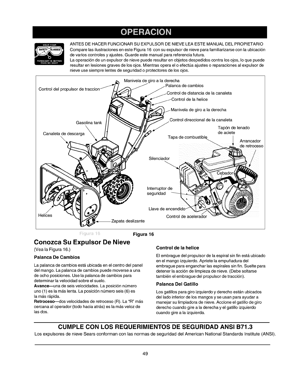
ANTESDEHACERFUNCIONARSUEXPULSORDENIEVELEAESTEMANUALDELPROPIETARIO
ComparelasilustracionesenesteFigura16consuexpulsordenieveparafamiliarizarseconlaubicaci6n
devarioscontrolesyajustes.Guardeestemanualparareferenciafutura.
Laoperaci6ndeunexpulsordenievepuederesultarenobjetosdespedidoscontralosojos,Ioquepuede
resultarenlesionesgravesdelosojos.Mientrasoperaeloefect0aajustesoreparacionesalexpulsorde
nieveusesiemprelentesdeseguridadoprotectoresdelosojos.
Controldel
Maniveladegiroaladerecha
decambios
distanciadelacanaleta
delahelice
Gasolinatank
x
Canaletadedescarga
\\
de giro a la derecha
Control direccional de la canaleta
Tap6n de lenado
de aciete
ices
.,_ Zapata deslizante
Silenciador
Isn;;rurridl:tadr d_
Llave de
Control de acelerador
Conozca Su Expulsor De Nieve
(Vea la Figura 16.)
Palanca De Cambios
Figura 16
La palanca de cambios estA ubicada en el centro del panel
del mango. La palanca de cambios puede moverse a una
de ocho posiciones. Use la palanca de cambios para
determinar la velocidad sobre el suelo.
Avance--una de seis velocidades. La posici6n n0mero
uno (1) es lamAs lenta. La posici6n n0mero seis (6) es
la mAs rApida.
Retroceso--dos velocidades de retroceso (R). La "R" mAs
cercana al operador (todo hacia atrAs) es lamAs veloz de
las dos.
Control de la helice
El embrague del propulsor de la espiral sin fin estA ubicado
en el mango izquierdo. Apriete la empuSadura del
embrague para enganchar las espirales sin fin. Suelte para
detener la acci6n de limpieza de nieve. (Debe soltarse
tambien el embrague del propulsor de tracci6n).
Palanca Del Gatillo
Los gatillos para giro izquierdo y derecho estAn ubicados
del lado inferior de los mangos y se usan para ayudar a
manejar su limpiadora de nieve. Accione el gatillo de giro
derecho cuando gire a la derecha y el gatillo izquierdo
cuando gire a la izquierda.
CUMPLE CON LOS REQUERIMIENTOS DE SEGURIDAD ANSI B71.3
Los expulsores de nieve Sears conforman con las normas de seguridad del American National Standards Institute (ANSI).
49
Propulsor De Traccion/Seguro Del Embrague De
La Espiral Sin Fin
El embrague del propulsor de tracci6n estA ubicado en el
mango derecho. Accione el embrague del propulsor de
tracci6n para enganchar la rueda motriz. Suelte para parar.
Esta misma palanca tambien fija el embrague de la espiral
sin fin de manera que se puede girar la manija
de la canaleta sin interrumpir el proceso de limpieza de
nieve. Si se engancha el embrague del propulsor de la
espiral sin fin con el embrague del propulsor de traccci6n
enganchado, el operador puede soltar el embrague del
propulsor de la espiral sin fin (en el mango izquierdo)y
las espirales sin fin permanecerAn enganchadas. Suelte el
embrague del propulsor de tracci6n para detener las
espirales sin fin y la rueda motriz (debe soltarse tambien el
embrague del propulsor de la espiral sin fin).
Control Direccional De La Canaleta
La Control Direccional de la Canaleta estA ubicada del lado
izquierdo de la limpiadora de nieve.
Para cambiar la direcci6n en la cual se limpia la nieve, gire
la Control Direccional de la Canaleta como sigue:
• Gire la manija en el sentido de las agujas del reloj
para descargar a la izquierda.
• Gire en sentido contrario alas agujas del reloj para
descargar a la derecha.
Control De Inclinacion De La Canaleta
La distancia a la que se despide la nieve puede ajustarse
ajustando el Angulo del conjunto de la canaleta. Mueva el
control de inclinaci6n hacia adelante para disminuir la
distancia, hacia atrAs para aumentarla.
Control Del Acelerador
El control del acelerador estA ubicado en el motor. Regula
la velocidad del motor. AI soplar la nieve, siempre haga
funcionar el motor con el acelerador en la posici6n rapid&
Interruptor De Encendido De Seguridad
El interruptor de la Ilave de encendido debe insertarse
completamente en el interruptor antes que arranque la
unidad. No intente girar la Ilave.
Valvula De Corte De Combustible
La vMvula de corte de combustible, ubicada debajo del
tanque de combustible controla el flujo de combustible del
tanque. Aseg6rese que no este en la posici6n "off" antes de
arrancar el motor.
Detencion Del Expulsor De Nieve
• Para detener la expulsi6n de nieve, desenganche la
palanca del propulsor de la helice.
• Para apagar el motor, empuje la palanca de control
del acelerador a OFF y extraiga la Ilave de
encendido. No gire la Ilave.
Llenado De Gasolina Y Aceite
Preste servicio al motor con gasolina y aceite seg6n las
instrucciones del manual del motor, empacado
separadamente con su limpiadora de nieve. Lea
cuidadosamente las instrucciones.
ADVERTENCIA: Nunca Ilene el tanque bajo
techo, con el motor funcionando o mientras el
motor estA caliente. No fume al Ilenar el tanque
de combustible.
Arrancador Eldctrico
Advertencia: El arrancador electrico esta
equipado con un cord6n de potencia de tres
conductores y un enchufe y esta disefiado
para operar con una corriente casera de 120
voltios de CA. Debe conectarse
apropiadamente a tierra en todo momento
para evitar la posibilidad de un choque
electrico que puede ser dafiino para el
operador.Observe cuidadosamente todas las
instrucciones. Determine que el cableado de
su casa es un sistema conectado a tierra de
tres conductores. Si no esta seguro pregunte
a un electricista licenciado. No use este
arrancador electrico bajo ninguna condici6n si
el sistema de cableado de su casa no es un
sistema de tres conductores conectado a
tierra. Si el sistema de cableado electrico de
su casa esta conectado a tierra pero no esta
disponible un receptaculo de tres orificios en
el punto donde se usara normalmente el
arrancador, debe instalarse uno por un
electricista licenciado.
AI conectar el cord6n de potencia, conecte siempre
primero el cord6n al arrancador del motor, a
continuaci6n enchufe el otro extremo a un
receptAculo de tres orificios conectado a tierra.
AI desconectar el cord6n de potencia, desenchufe
siempre primero el extremo del receptAculo de tres
orificios conectado a tierra.
Arranque Del Motor
_, Advertencia: Apague el motor
inmediatamente si la unidad muestra sefiales
de movimiento (rueda motriz o espirales sin
fin) con las empufiaduras del embrague
desenganchadas. Reajuste segt_n las
instrucciones en la secci6n de "Ajuste final" de
las instrucciones de Preparaci6n.
• Fije el cable de la bujia a la bujia. Asegt_rese que el
bucle de metal al extremo del cable de la bujia
(dentro de la bota) este bien fijo a la punta de metal
de la bujia.
• Asegt_rese que la valvula de corte de combustible
este en la posici6n abierta (vertical).
• Asegt_rese que las palancas del embrague del
propulsor esten en la posici6n desenganchada
(suelta).
• Mueva el control del acelerador a la posici6n FAST
(RAPIDA).
• Inserte la Ilave de encendido en la ranura.
• Asegt_rese que calce en su lugar. No gire la Ilave.
50
• Enelcasodearranque el_ctrico solamente siga
los tres pr6ximos pasos.
• Gire la perilla del regulador a la posici6n OFF.
• Oprima el bot6n del cebador mientras cubre el orificio
de ventilaci6n. Saque el dedo del cebador entre
cebados. No cebe para arrancar un motor caliente.
Si la temperatura es mayor de 15 grados F cebe dos
o tres veces y cuatro veces si es menor de 15 grados
F.
• Conecte el cord6n de potencia a la caja del
interruptor en el motor. Enchufe el otro extremo
del cord6n de potencia a un receptAculo de tres
orificios, conectado a tierra, de 120 voltios de CA.
• Oprima el bot6n del arrancador para intentar
arrancar el motor. Cuando el motor arranque,
suelte el bot6n del arrancador y mueva el regulador
lentamente a FULL (PLENO), y a continuaci6n
gradualmente a la posici6n OFF. Si el motor vacila,
mueva el regulador inmediatamente a la posici6n
FULL y a continuaci6n mueva gradualmente a la
posici6n OFF.
Para el arranque de retroceso solamente siga los tres
pr6ximos pasos:
• Gire la perilla del regulador a la posici6n FULL.
Coloque el regulador en la posici6n OFF en lugar de
la posici6n FULL, si el motor todavfa estA caliente.
• Oprima el bot6n del cebador dos o tres veces.
Oprima el bot6n del cebador una vez solamente, si
el motor estA caliente.
• Sujete el mango del arrancador y tire lentamente de
la soga hasta que comience a ejercer mas
resistencia. Permita que la soga se enrolle
lentamente. Tire rApidamente del mango del
arrancador. No permita que el mango retroceda
bruscamente. Permita que se enrolle lentamente
mientras sujeta firmemente el mango del
arrancador. Repita hasta que el motor arranque. A
medida que el motor se calienta y comienza a
funcionar suavemente, gire lentamente la perilla del
regulador a la posici6n OFF. Si el motor vacila,
regrese a regulador en FULL y a continuaci6n
mueva lentamente a la posici6n OFF.
Como Apagar El Motor
• Haga funcionar el motor por unos pocos minutos
antes de apagar para ayudar a secar la humedad
del motor.
• Proceda como sigue para evitar una posible
congelacibn del arrancador.
Arrancador el_ctrico: Conecte el cord6n de
potencia a la caja del interruptor del motor, a
continuaci6n a un receptAculo de 120 voltios de CA.
Con el motor funcionando, oprima el bot6n del
arrancador y gire el arrancador por varios
segundos. El sonido raro emitido al girar el
arrancador no da_arA el motor o el arrancador.
Desconecte primero el cord6n de potencia del
receptAculo y a continuaci6n de la caja del
interruptor.
Arrancador aretroceso: Con el motor
funcionando, tire de la soga del arrancador con una
pasada rApida y continua con todo el brazo, tres o
cuatro veces. El tirar de la soga del arrancador
producirA un sonido intenso de golpeteo, que no es
da_ino para el motor o el arrancador.
• Para apagar el motor, empuje todo hacia abajo
la palanca del acelerador o saque la Ilave de
encendido. No gire la Ilave. Desconecte el cable
de la bujia de la misma para evitar un arranque
accidental mientras el equipo estA desatendido.
NOTA: No pierda la Ilave de encendido. Mantengala en
un lugar seguro. El motor no arrancara sin la Ilave de
encendido.
Limpie toda la nieve y humedad de la cubierta del
carburador en el Area de las palancas de control.
Tambien, avance y retroceda varias veces las
palancas de control. Deje la palanca de control del
acelerador en la posici6n STOP u OFF. Deje el
control del regulador en la posici6n FULL.
Para Enganchar El Propulsor
Enganche De La Propulsion
• Con el motor funcionando cerca de la velocidad
maxima, mueva la palanca de cambios a una de las
posiciones de forward (avance) o alas dos de
reverse (retroceso). Seleccione una velocidad
apropiada para las condiciones de nieve existentes.
Use las velocidades mas lentas hasta que este
familiarizado con la operaci6n de la limpiadora de
nieve.
• Oprima la empu_adura del embrague de la espiral
sin fin izquierda contra el mango, para engancharla.
• Mientras la empu_adura del embrague de la espiral
sin fin esta enganchada, oprima la empu_adura del
embrague del propulsor derecho.
• Suelte la empu_adura del embrague de la espiral
sin fin izquierda, solamente. El mecanismo de
interbloqueo debe mantener el embrague izquierdo
enganchado hasta que se suelte el embrague
derecho.
NOTA: NUNCA mueva la palanca de cambios sin soltar
primero el embrague del propulsor.
Manejo De La Limpiadora De Nieve
Las palancas de los gatillos estan ubicadas en la
parte inferior de los mangos y se usan para manejar
su limpiadora de nieve.
NOTA: El embrague del propulsor debe estar
enganchado al usar los gatillos para manejar la
limpiadora de nieve.
• Para girar a la derecha, oprima la palanca del gatillo
derecho y guia la limpiadora de nieve
hacia la derecha.
• Para girar a la izquierda, oprima la palanca del
gatillo izquierdo y guie la limpiadora de nieve hacia
la izquierda.
51
• Oprima ambos gatillos para transportar la unidad
cuando el motor no esta.funcionando.
NOTA: Esos controles deben usarse mientras opera su
limpiadora de nieve en areas abiertas, hasta
familiarizarse con su operaciSn.
Enganche De Las Espirales Sin Fin
• Oprima la empuSadura del embrague de la espiral
sin fin contra el mango izquierdo, para enganchar
las espirales sin fin y comenzar la acci6n de
despedir la nieve. Suelte para detener las espirales
sin fin (debe soltarse tambien la empuSadura del
embrague del propulsor de tracci6n).
• Puede fijarse tambien el embrague del propulsor de
la espiral sin fin de manera que usted pueda girar la
Control Direccional de la Canaleta sin interrumpir el
proceso de despedir nieve. Refierase a "Propulsi6n
de Tracci6n/Fijaci6n del Embrague de la Espiral Sin
Fin" en la secci6n de Control.
Presion De La Ruedas
• Las ruedas esta.n sobreinfladas para fines de
transporte. Reduzca la presi6n de las ruedas a
10-15 p.s.i para la operaci6n de la limpiadora de
nieve. Use ruedas neuma.ticas solamente en su
unidad limpiadora de nieve.
• Deben usarse cadenas para ruedas (equipo
opcional) siempre que se requiera una tracci6n
adicional.
Consejos De Operacion
NOTA: Dado que el motor no desarrollara su potencia
plena hasta que alcance la temperatura de operaciSn,
permita que el motor se caliente por unos pocos
minutos.
Advertencia: La temperatura del
silenciador y de las Areas circundantes puede
exceder 150°F. Evite esas Areas.
• Limpie la nieve inmediatamente despues de caer,
para una limpieza mas eficiente de la misma.
• Despida la nieve en la direcci6n del viento siempre
que sea posible. Superponga ligeramente cada
pasada. La distancia a la que puede despedirse la
nieve puede ajustarse alterando el a.ngulo del
conjunto de la canaleta. Cuanto ma.s agudo sea el
angulo mas corta sera la distancia a la que se
despide la nieve.
• Gradt_e las zapatas deslizantes a 1/4" por debajo de
la barra raspadora para un uso normal. Las zapatas
deslizantes pueden ajustarse hacia arriba para la
nieve endurecida. AI usar sobre pedregullo o roca
triturada, ajuste hacia abajo.
• Asegt_rese de seguir las precauciones listadas
abajo "Apagado del Motor" para prevenir una
posible congelaci6n.
• Despues de cada uso limpie bien la limpiadora
de nieve.
Advertencia: Nunca intente limpiar la
canaleta ni efectuara ajustes mientras esta.
funcionando el motor.
_Instrucciones Abreviadas de Arranque
Expulsor de Cable Llave de Regulador Cord6n de Cebador Arrancador Despues de
Nieve de la encendido _otencia arrancar
bujia
Conecte SuelteArrancador
Electrico
Presione
para
calzar
Palancas Control del
propulsoras acelerador
Mueva a
FAST
Mueva a
FAST
Mueva a
FULL
Conecte a
la fuente
Cebado
Presione el
bot6n
1. Suelte el bot6n
2. Mueva el
regulador a Off
3. Desconecte el
cord6n
Arrancador Conecte Suelte Presione Mueva a -- Cebe Tire del 1. Suelte el mango
de para FULL mango 2. Mueva el
Retroceso calzar regulador a Off
52
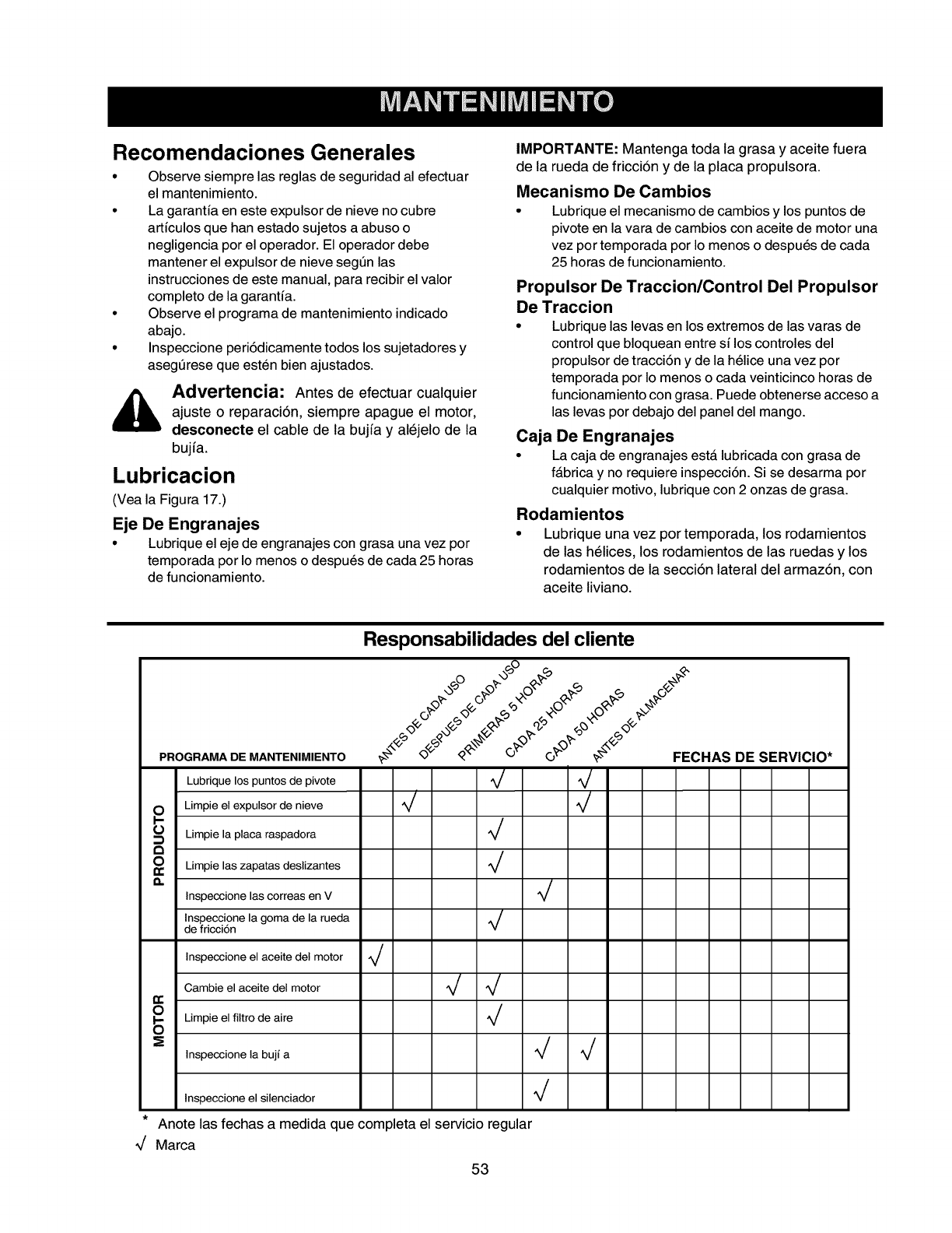
Recomendaciones Generales
•Observe siempre las reglas de seguridad al efectuar
el mantenimiento.
• La garantfa en este expulsor de nieve no cubre
artfculos que han estado sujetos a abuso o
negligencia por el operador. El operador debe
mantener el expulsor de nieve seg6n las
instrucciones de este manual, para recibir el valor
completo de la garantfa.
• Observe el programa de mantenimiento indicado
abajo.
•Inspeccione peri6dicamente todos los sujetadores y
aseg6rese que esten bien ajustados.
_, dvertencia: Antes de efectuar cualquier
ajuste o reparaci6n, siempre apague el motor,
desconecte el cable de la bujfa y alejelo de la
bujfa.
Lubricacion
(Vea la Figura 17.)
Eje De Engranajes
• Lubrique el eje de engranajes con grasa una vez por
temporada por Io menos o despues de cada 25 horas
de funcionamiento.
IMPORTANTE: Mantenga toda la grasa y aceite fuera
de la rueda de fricci6n y de la placa propulsora.
Mecanismo De Cambios
• Lubrique el mecanismo de cambios y los puntos de
pivote en la vara de cambios con aceite de motor una
vez por temporada por Io menos o despues de cada
25 horas de funcionamiento.
Propulsor De Traccion/Control Del Propulsor
De Traccion
• Lubrique las levas en los extremos de las varas de
control que bloquean entre sf los controles del
propulsor de tracci6n y de la helice una vez por
temporada por Io menos o cada veinticinco horas de
funcionamiento con grasa. Puede obtenerse acceso a
las levas por debajo del panel del mango.
Caja De Engranajes
• La caja de engranajes est_ lubricada con grasa de
fAbrica y no requiere inspecci6n. Si se desarma por
cualquier motivo, lubrique con 2 onzas de grasa.
Rodamientos
•Lubrique una vez por temporada, los rodamientos
de las helices, los rodamientos de las ruedas y los
rodamientos de la secci6n lateral del armaz6n, con
aceite liviano.
d
Responsabilidades del cliente
PROGRAMA DE MANTENIMIENTO
Lubrique los puntos de pivote
£Limpie el expulsor de nieve d d
Limpie la placa raspadora d
O_ Limpie las zapatas deslizantes d
a. /
Inspeccione las correas en V _/
Inspeccione la goma de la rueda ^//
de fricci6n v
Inspeccione el aceite del motor d
Cambie el aceite del motor d d
O
S Limpie el filtro de aire d
_ Inspeccione la bujf a d d
Inspeccione el silenciador V
Anote las fechas a medida que completa el serv_cio regular
Marca
53
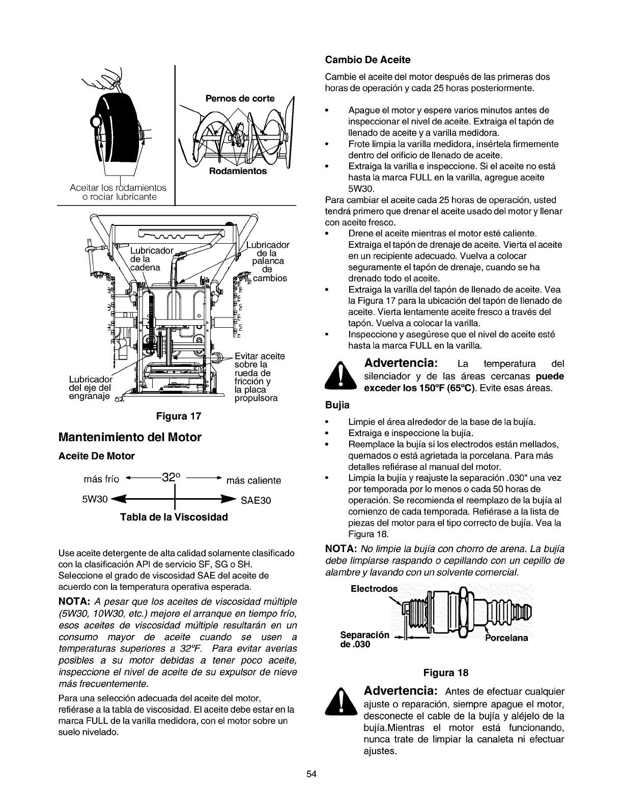
Pernos de corte
Rodamientos
Aceitar los r_)damientos
o rociar lubricante ! a ad°r
_C_ __:d°_._ _ cadmebios
i
_
!i:_jaCe:daje°j__, _ -_ pr_!ra
Figura 17
Mantenimiento del Motor
Aceite De Motor
mAs frio -,_32 ° --_" mas caliente
5W30 -'_ I
I SAE30
Tabla de la Viseosidad
Use aceite detergente de alta calidad solamente clasificado
con la clasificaci6n API de servicio SF, SG o SH.
Seleccione el grado de viscosidad SAE del aceite de
acuerdo con la temperatura operativa esperada.
NOTA: A pesar que los aceites de viscosidad mtJltiple
(5W30, 10W30, etc.) mejore el arranque en tiempo frfo,
esos aceites de viscosidad m#ltiple resultaran en un
consumo mayor de aceite cuando se usen a
temperaturas superiores a 32°F. Para evitar averfas
posibles a su motor debidas a tener poco ace#e,
inspeccione el nivel de aceite de su expulsor de nieve
mas frecuentemente.
Para una selecci6n adecuada del aceite del motor,
refierase a la tabla de viscosidad. El aceite debe estar en la
marca FULL de la varilla medidora, con el motor sobre un
suelo nivelado.
Cambio De Aceite
Cambie el aceite del motor despues de las primeras dos
horas de operaci6n y cada 25 horas posteriormente.
• Apague el motor y espere varios minutos antes de
inspeccionar el nivel de aceite. Extraiga el tap6n de
Ilenado de aceite y a varilla medidora.
• Frote limpia la varilla medidora, insertela firmemente
dentro del orificio de Ilenado de aceite.
• Extraiga la varilla e inspeccione. Si el aceite no estA
hasta la marca FULL en la varilla, agregue aceite
5W30.
Para cambiar el aceite cada 25 horas de operaci6n, usted
tendrA primero que drenar el aceite usado del motor y Ilenar
con aceite fresco.
• Drene el aceite mientras el motor este caliente.
Extraiga el tap6n de drenaje de aceite. Vierta el aceite
en un recipiente adecuado. Vuelva a colocar
seguramente el tap6n de drenaje, cuando se ha
drenado todo el aceite.
• Extraiga la varilla del tap6n de Ilenado de aceite. Yea
la Figura 17 para la ubicaci6n del tap6n de Ilenado de
aceite. Vierta lentamente aceite fresco a traves del
tap6n. Vuelva a colocar la varilla.
• Inspeccione y asegt_rese que el nivel de aceite este
hasta la marca FULL en la varilla.
,_ Advertencia: La temperatura del
silenciador y de las Areas cercanas puede
exceder los 150°F (65°C). Evite esas Areas.
Bujia
• Limpie el Area alrededor de la base de la bujia.
• Extraiga e inspeccione la bujia.
• Reemplace la bujia si los electrodos estAn mellados,
quemados o estA agrietada la porcelana. Para mAs
detalles refierase al manual del motor.
• Limpia la bujia y reajuste la separaci6n .030" una vez
por temporada por Io menos o cada 50 horas de
operaci6n. Se recomienda el reemplazo de la bujia al
comienzo de cada temporada. Refierase a la lista de
piezas del motor para el tipo correcto de bujia. Vea la
Figura 18.
NOTA: No limpie la bujfa con chorro de arena. La bujfa
debe limpiarse raspando o cepillando con un cepillo de
alambre y lavando con un solvente comercial.
Electrodos
i::iill
Separaci6n Porcelana
de .030
Figura 18
Advertencia: Antes de efectuar cualquier
ajuste o reparaci6n, siempre apague el motor,
desconecte el cable de la bujia y al6jelo de la
bujia.Mientras el motor esta funcionando,
nunca trate de limpiar la canaleta ni efectuar
ajustes.
54
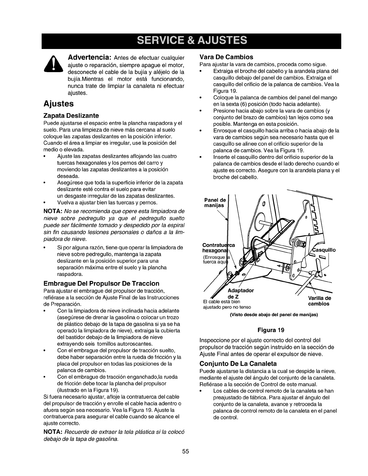
_, Advertencia: Antes de efectuar cualquier
ajuste o reparaci6n, siempre apague el motor,
desconecte el cable de la bujia y al_jelo de la
bujia.Mientras el motor esta funcionando,
nunca trate de limpiar la canaleta ni efectuar
ajustes.
Ajustes
Zapata Deslizante
Puede ajustarse el espacio entre la plancha raspadora yel
suelo. Para una limpieza de nieve mAs cercana al suelo
coloque las zapatas deslizantes en la posici6n inferior.
Cuando el Area a limpiar es irregular, use la posici6n del
medio oelevada.
• Ajuste las zapatas deslizantes aflojando las cuatro
tuercas hexagonales y los pernos del carro y
moviendo las zapatas deslizantes a la posici6n
deseada.
• Asegt_rese que toda la superficie inferior de la zapata
deslizante este contra el suelo para evitar
un desgaste i rrregular de las zapatas deslizantes.
• Vuelva a ajustar bien las tuercas y pernos.
NOTA: No se recomienda que opere esta limpiadora de
nieve sobre pedregullo ya que el pedregullo suelto
puede ser facilmente tomado y despedido por la espiral
sin fin causando lesiones personales o da#os a la lim-
piadora de nieve.
• Si por alguna raz6n, tiene que operar la limpiadora de
nieve sobre pedregullo, mantenga la zapata
deslizante en la posici6n superior para una
separaci6n maxima entre el suelo y la plancha
raspadora.
Embrague Del Propulsor De Traccion
Para ajustar el embrague del propulsor de tracci6n,
refierase a la secci6n de Ajuste Final de las Instrucciones
de Preparaci6n.
• Con la limpiadora de nieve inclinada hacia adelante
(asegt_rese de drenar la gasolina o colocar un trozo
de plAstico debajo de la tapa de gasolina si ya se ha
operado la limpiadora de nieve), extraiga la cubierta
del bastidor debajo de la limpiadora de nieve
extrayendo seis tornillos autoroscantes.
• Con el embrague del propulsor de tracci6n suelto,
debe haber separaci6n entre la rueda de fricci6n y la
placa del propulsor en todas las posiciones de la
palanca de cambios.
• Con el embrague de tracci6n enganchado,la rueda
de fricci6n debe tocar la plancha del propulsor
(ilustrado en la Figura 19).
Si fuera necesario ajustar, afloje la contratuerca del cable
del propulsor de tracci6n y enrolle el cable hacia adentro o
afuera segt_n sea necesario. Vea la Figura 19. Ajuste la
contratuerca para asegurar el cable cuando se alcance el
ajuste correcto.
NOTA: Recuerde de extraer la tela plastica si la coloc5
debajo de la tapa de gasolina.
Vara De Cambios
Para ajustar la vara de cambios, proceda como sigue.
• Extraiga el broche del cabello y la arandela plana del
casquillo debajo del panel de cambios. Extraiga el
casquillo del orificio de la palanca de cambios. Vea la
Figura 19.
• Coloque la palanca de cambios del panel del mango
en la sexta (6) posici6n (todo hacia adelante).
• Presione hacia abajo sobre la vara de cambios (y
conjunto del brazo de cambios) tan lejos como sea
posible. Mantenga en esta posici6n.
• Enrosque el casquillo hacia arriba o hacia abajo de la
vara de cambios segQn sea necesario hasta que el
casquillo se alinee con el orificio superior de la
palanca de cambios. Vea la Figura 19.
• Inserte el casquillo dentro del orificio superior de la
palanca de cambios desde el lado derecho cuando el
ajuste es correcto. Asegure con la arandela plana y el
broche del cabello.
Panel de
manijas
(Enrosque
tuerca aqu
uillo
Adaptador
de ZVarilla de
Elcable esta bien cambios
ajustado pero no tenso
(Visto desde abajo del panel de manijas)
Figura 19
Inspeccione por el ajuste correcto del control del
propulsor de tracci6n segQn instruido en la secci6n de
Ajuste Final antes de operar el expulsor de nieve.
Conjunto De La Canaleta
Puede ajustarse la distancia a la cual se despide la nieve,
mediante el ajuste del Angulo del conjunto de la canaleta.
Refierase a la secci6n de Control de este manual.
• Los cables de control remoto de la canaleta se han
preajustado de fabric& Para ajustar el Angulo del
conjunto de la canaleta, avance y retroceda la
palanca de control remoto de la canaleta en el panel
de control.
55
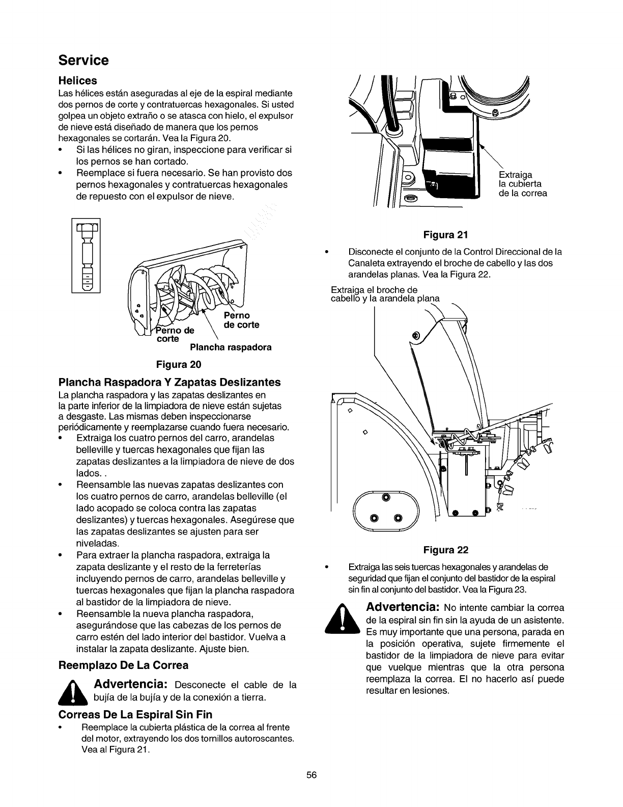
Service
Helices
Las helices est_n aseguradas al eje de la espiral mediante
dos pernos de corte y contratuercas hexagonales. Si usted
golpea un objeto extraSo o se atasca con hielo, el expulsor
de nieve estA diseSado de manera que los pernos
hexagonales se cortarAn. Vea la Figura 20.
• Si las helices no giran, inspeccione para verificar si
los pernos se han cortado.
• Reemplace si fuera necesario. Se han provisto dos
pernos hexagonales y contratuercas hexagonales
de repuesto con el expulsor de nieve.
EE33
w
m
Perno
de corte
rno de
corte Plancha raspadora
Figura 20
Plancha Raspadora Y Zapatas Deslizantes
La plancha raspadora y las zapatas deslizantes en
la parte inferior de la limpiadora de nieve estan sujetas
adesgaste. Las mismas deben inspeccionarse
peri6dicamente y reemplazarse cuando fuera necesario.
•Extraiga los cuatro pemos del carro, arandelas
belleville y tuercas hexagonales que fijan las
zapatas deslizantes ala limpiadora de nieve de dos
lados..
• Reensamble las nuevas zapatas deslizantes con
los cuatro pernos de carro, arandelas belleville (el
lado acopado se coloca contra las zapatas
deslizantes) y tuercas hexagonales. Asegt_rese que
las zapatas deslizantes se ajusten para ser
niveladas.
• Para extraer la plancha raspadora, extraiga la
zapata deslizante y el resto de la ferretedas
incluyendo pernos de carro, arandelas belleville y
tuercas hexagonales que fijan la plancha raspadora
al bastidor de la limpiadora de nieve.
• Reensamble la nueva plancha raspadora,
asegura.ndose que las cabezas de los pernos de
carro esten del lado interior del bastidor. Vuelva a
instalar la zapata deslizante. Ajuste bien.
Reemplazo De La Correa
_dvertencia: Desconecte el cable de la
bujia de la bujia y de la conexi6n a tierra.
Correas De La Espiral Sin Fin
• Reemplace la cubierta pl_stica de la correa al frente
del motor, extrayendo los dos tornillos autoroscantes.
Vea al Figura 21.
Extraiga
la cubierta
de la correa
Figura 21
Disconecte el conjunto de la Control Direccional de la
Canaleta extrayendo el broche de cabello y las dos
arandelas planas. Vea la Figura 22.
Extraiga el broche de
cabello y la arandela plana
®
Figura 22
• Extraiga las seis tuercas hexagonales y arandelas de
seguridad que fijan el conjunto del bastidor de la espiral
sin fin al conjunto del bastidor. Vea la Figura 23.
_ dvertencia: No intente cambiar la correa
de la espiral sin fin sin la ayuda de un asistente.
Es muy importante que una persona, parada en
la posici6n operativa, sujete firmemente el
bastidor de la limpiadora de nieve para evitar
que vuelque mientras que la otra persona
reemplaza la correa. El no hacerlo asf puede
resultar en lesiones.
56
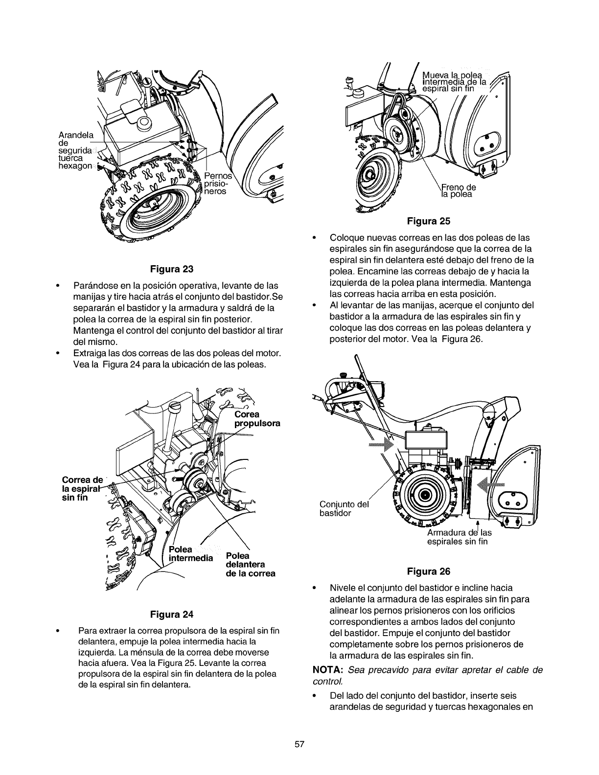
\
Arandela
de
segurida
tuerca
hexa¢
\Freno de
la polea
Figura 23
• Parandose en la posici6n operativa, levante de las
manijas y tire hacia atra.s el conjunto del bastidor.Se
separaran el bastidor y la armadura y saldra de la
polea la correa de la espiral sin fin posterior.
Mantenga el control del conjunto del bastidor al tirar
del mismo.
• Extraiga las dos correas de las dos poleas del motor.
Vea la Figura 24 para la ubicaci6n de las poleas.
Figura 25
• Coloque nuevas correas en las dos poleas de las
espirales sin fin asegura.ndose que la correa de la
espiral sin fin delantera este debajo del freno de la
polea. Encamine las correas debajo de y hacia la
izquierda de la polea plana intermedia. Mantenga
las correas hacia arriba en esta posici6n.
• AI levantar de las manijas, acerque el conjunto del
bastidor a la armadura de las espirales sin fin y
coloque las dos correas en las poleas delantera y
posterior del motor. Vea la Figura 26.
alsora
sinfin '_ % __
_ _ intermedia ;O_enatera
,_ _de la correa
Figura 24
Para extraer la correa propulsora de la espiral sin fin
delantera, empuje la polea intermedia hacia la
izquierda. La mensula de la correa debe moverse
hacia afuera. Vea la Figura 25. Levante la correa
propulsora de la espiral sin fin delantera de la polea
de la espiral sin fin delantera.
Conjunto del
bastidor
Armadura dJ las
espirales sin fin
Figura 26
• Nivele el conjunto del bastidor e incline hacia
adelante la armadura de las espirales sin fin para
alinear los pernos prisioneros con los orificios
correspondientes a ambos lados del conjunto
del bastidor. Empuje el conjunto del bastidor
completamente sobre los pernos prisioneros de
la armadura de las espirales sin fin.
NOTA: Sea precavido para evitar apretar el cable de
control
• Del lado del conjunto del bastidor, inserte seis
arandelas de seguridad y tuercas hexagonales en
57
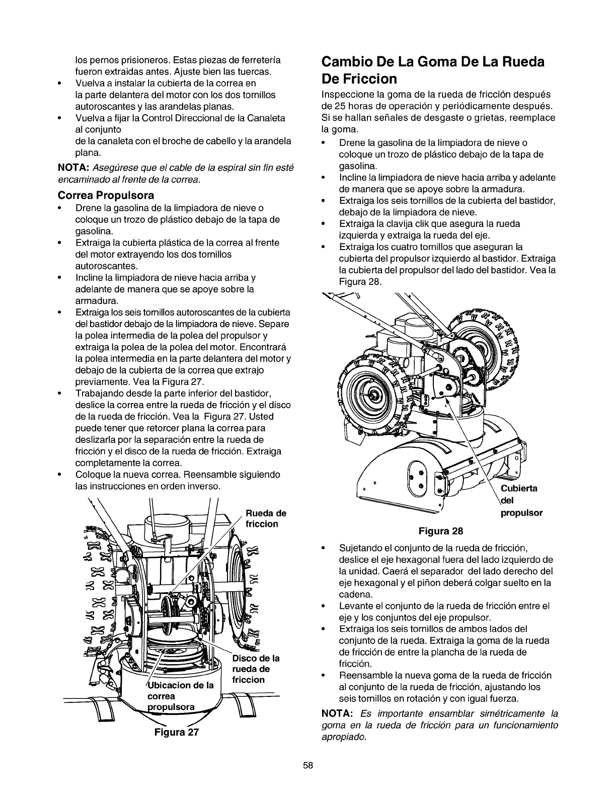
lospernosprisioneros.Estaspiezasdeferreterfa
fueronextraidasantes.Ajustebienlastuercas.
• Vuelvaainstalarlacubiertadelacorreaen
lapartedelanteradelmotorconlosdostornillos
autoroscantesy lasarandelasplanas.
• VuelvaafijarlaControlDireccionaldelaCanaleta
alconjunto
delacanaletaconelbrochedecabelloylaarandela
plana.
NOTA:Aseg#rese que el cable de la espiral sin fin este
encaminado al frente de la correa.
Correa Propulsora
•Drene la gasolina de la limpiadora de nieve o
coloque un trozo de pl_.stico debajo de la tapa de
gasolina.
• Extraiga la cubierta pl_.stica de la correa al frente
del motor extrayendo los dos tornillos
autoroscantes.
• Incline la limpiadora de nieve hacia arriba y
adelante de manera que se apoye sobre la
armadura.
• Extraiga los seis tomillos autoroscantes de la cubierta
del bastidor debajo de la limpiadora de nieve. Separe
la polea intermedia de la polea del propulsor y
extraiga la polea de la polea del motor. Encontrara.
la polea intermedia en la parte delantera del motor y
debajo de la cubierta de la correa que extrajo
previamente. Vea la Figura 27.
• Trabajando desde la parte inferior del bastidor,
deslice la correa entre la rueda de fricci6n y el disco
de la rueda de fricci6n. Vea la Figura 27. Usted
puede tener que retorcer plana la correa para
deslizarla por la separaci6n entre la rueda de
fricci6n y el disco de la rueda de fricci6n. Extraiga
completamente la correa.
• Coloque la nueva correa. Reensamble siguiendo
las instrucciones en orden inverso.
Rueda de
friccion
Disco de la
rueda de
friccion
Figura 27
Cambio De La Goma De La Rueda
De Friccion
Inspeccione la goma de la rueda de fricci6n despues
de 25 horas de operaci6n y peri6dicamente despues.
Si se hallan seSales de desgaste o grietas, reemplace
la goma.
• Drene la gasolina de la limpiadora de nieve o
coloque un trozo de pl_.stico debajo de la tapa de
gasolina.
• Incline la limpiadora de nieve hacia arriba y adelante
de manera que se apoye sobre la armadura.
• Extraiga los seis tornillos de la cubierta del bastidor,
debajo de la limpiadora de nieve.
• Extraiga la clavija clik que asegura la rueda
izquierda y extraiga la rueda del eje.
• Extraiga los cuatro tornillos que aseguran la
cubierta del propulsor izquierdo al bastidor. Extraiga
la cubierta del propulsor del lado del bastidor. Vea la
Figura 28.
Cubierta
propulsor
Figura 28
• Sujetando el conjunto de la rueda de fricci6n,
deslice el eje hexagonal fuera del lado izquierdo de
la unidad. Caera. el separador del lado derecho del
eje hexagonal y el piSon debera, colgar suelto en la
cadena.
• Levante el conjunto de la rueda de fricci6n entre el
eje y los conjuntos del eje propulsor.
• Extraiga los seis tornillos de ambos lados del
conjunto de la rueda. Extraiga la goma de la rueda
de fricci6n de entre la plancha de la rueda de
fricci6n.
• Reensamble la nueva goma de la rueda de fricci6n
al conjunto de la rueda de fricci6n, ajustando los
seis tornillos en rotaci6n y con igual fuerza.
NOTA: Es importante ensamblar simetricamente la
goma en la rueda de fricciSn para un funcionamiento
apropiado.
58
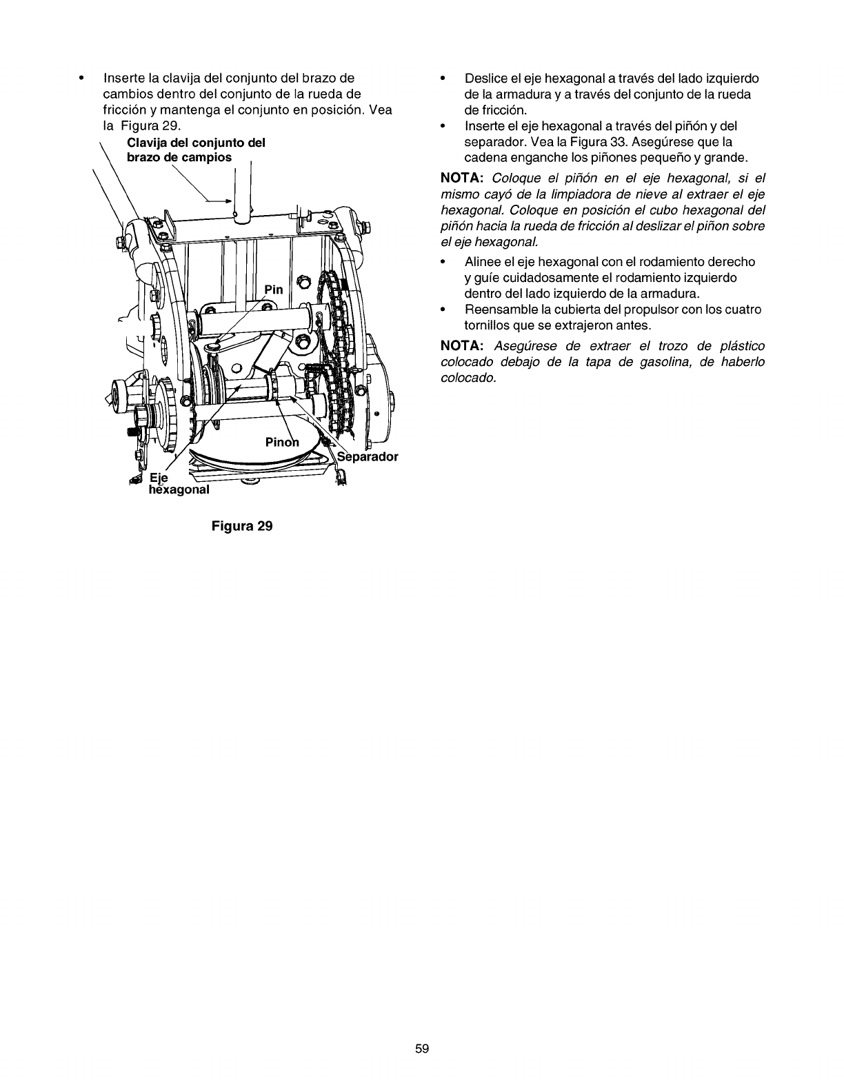
Insertelaclavijadelconjuntodelbrazode
cambiosdentrodelconjuntodelaruedade
fricci6ny mantengaelconjuntoenposici6n.Vea
la Figura29.
Clavijadelconjuntodel
brazodecampios
\
• Deslice el eje hexagonal a traves del lado izquierdo
de la armadura y a traves del conjunto de la rueda
de fricci6n.
• Inserte el eje hexagonal a traves del pi56n y del
separador. Vea la Figura 33. Asegt_rese que la
cadena enganche los piSones pequeSo y grande.
NOTA: Coloque el pi#6n en el eje hexagonal, si el
mismo cay5 de la limpiadora de nieve al extraer el eje
hexagonal Coloque en posiciSn el cubo hexagonal del
pi_6n hacia la rueda de fricciSn al deslizar el pi_on sobre
el eje hexagonal
• Alinee el eje hexagonal con el rodamiento derecho
y gufe cuidadosamente el rodamiento izquierdo
dentro del lado izquierdo de la armadura.
• Reensamble la cubierta del propulsor con los cuatro
tornillos que se extrajeron antes.
NOTA: Aseg#rese de extraer el trozo de plastico
colocado debajo de la tapa de gasolina, de haberlo
colocado.
onal
Figura 29
59
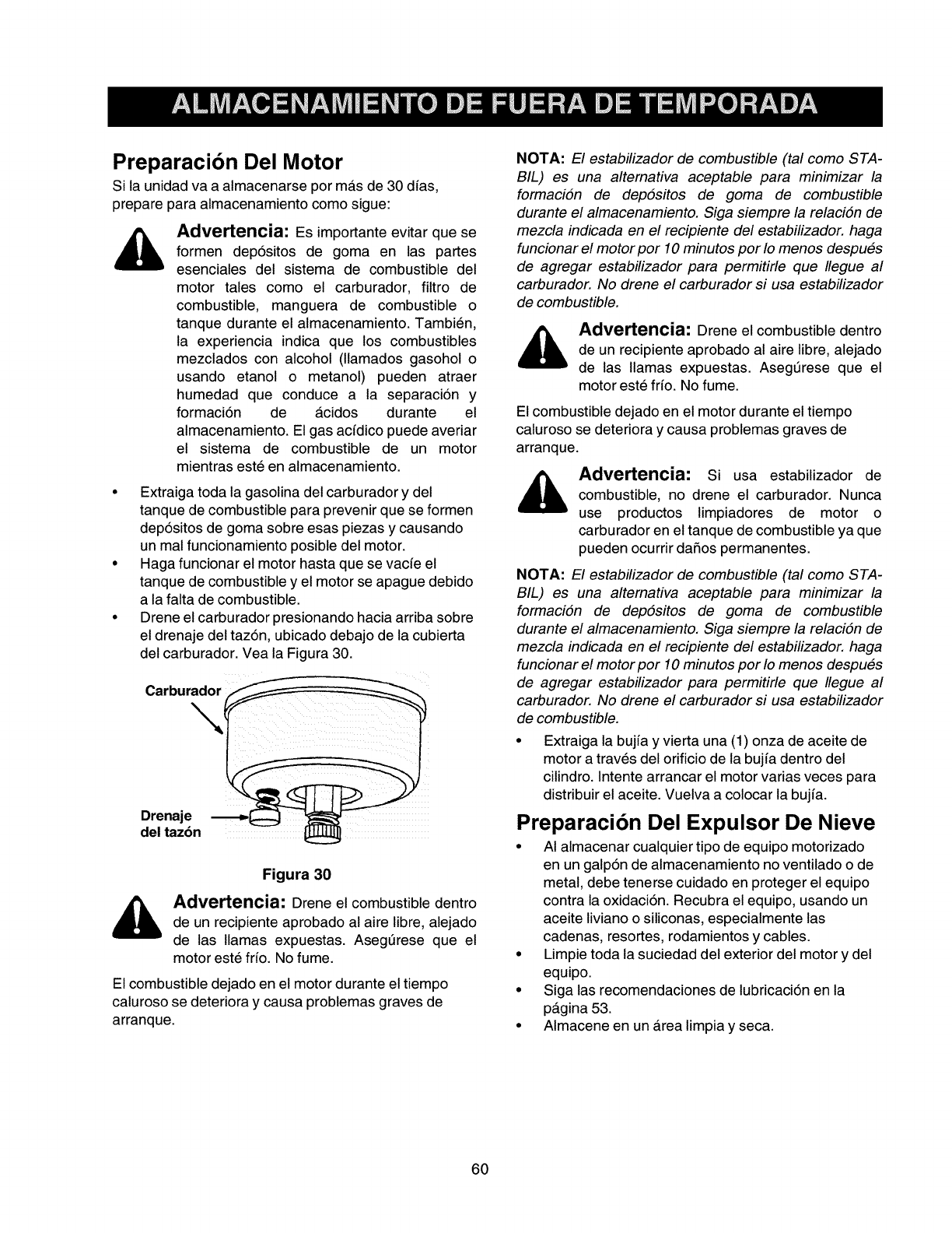
Preparacibn Del Motor
Si la unidad va a almacenarse por mas de 30 dias,
prepare para almacenamiento como sigue:
,_ Advertencia: Es importante evitar que se
formen dep6sitos de goma en las partes
esenciales del sistema de combustible del
motor tales como el carburador, filtro de
combustible, manguera de combustible o
tanque durante el almacenamiento. Tambien,
la experiencia indica que los combustibles
mezclados con alcohol (llamados gasohol o
usando etanol o metanol) pueden atraer
humedad que conduce a la separaci6n y
formaci6n de a.cidos durante el
almacenamiento. El gas acidico puede averiar
el sistema de combustible de un motor
mientras este en almacenamiento.
• Extraiga toda la gasolina del carburador y del
tanque de combustible para prevenir que se formen
dep6sitos de goma sobre esas piezas y causando
un mal funcionamiento posible del motor.
• Haga funcionar el motor hasta que se vacie el
tanque de combustible y el motor se apague debido
a la falta de combustible.
• Drene el carburador presionando hacia arriba sobre
el drenaje del taz6n, ubicado debajo de la cubierta
del carburador. Vea la Figura 30.
Carburador
Drenaje
del tazbn
Figura 30
Advertencia: Drene el combustible dentro
de un recipiente aprobado al aire libre, alejado
de las llamas expuestas. Asegt_rese que el
motor este fHo. No fume.
El combustible dejado en el motor durante el tiempo
caluroso se deteriora y causa problemas graves de
arranque.
NOTA: El estabilizador de combustible (tal como STA-
BIL) es una altemativa aceptable para minimizar la
formaciSn de depSsitos de goma de combustible
durante el almacenamiento. Siga siempre la relaciSn de
mezcla indicada en el recipiente del estabilizador, haga
funcionar el motor por 10 minutos por Io menos despues
de agregar estabilizador para permitirle que Ilegue al
carburador. No drene el carburador si usa estabilizador
de combustible.
Advertencia: Drene el combustible dentro
de un recipiente aprobado al aire libre, alejado
de las llamas expuestas. Asegt_rese que el
motor este fHo. No fume.
El combustible dejado en el motor durante el tiempo
caluroso se deteriora y causa problemas graves de
arranque.
Advertencia: si usa estabilizador de
combustible, no drene el carburador. Nunca
use productos limpiadores de motor o
carburador en el tanque de combustible ya que
pueden ocurrir dafios permanentes.
NOTA: El estabilizador de combustible (tal como STA-
BIL) es una altemativa aceptable para minimizar la
formaciSn de depSsitos de goma de combustible
durante el almacenamiento. Siga siempre la relaciSn de
mezcla indicada en el recipiente del estabilizador, haga
funcionar el motor por 10 minutos por Io menos despues
de agregar estabilizador para permitirle que Ilegue al
carburador. No drene el carburador si usa estabilizador
de combustible.
• Extraiga la bujia y vierta una (1) onza de aceite de
motor a traves del orificio de la bujia dentro del
cilindro. Intente arrancar el motor varias veces para
distribuir el aceite. Vuelva a colocar la bujia.
Preparacibn Del Expulsor De Nieve
• AI almacenar cualquier tipo de equipo motorizado
en un galp6n de almacenamiento no ventilado o de
metal, debe tenerse cuidado en proteger el equipo
contra la oxidaci6n. Recubra el equipo, usando un
aceite liviano o siliconas, especialmente las
cadenas, resortes, rodamientos y cables.
• Limpie toda la suciedad del exterior del motor y del
equipo.
• Siga las recomendaciones de lubricaci6n en la
pagina 53.
• Almacene en un area limpia y seca.
60
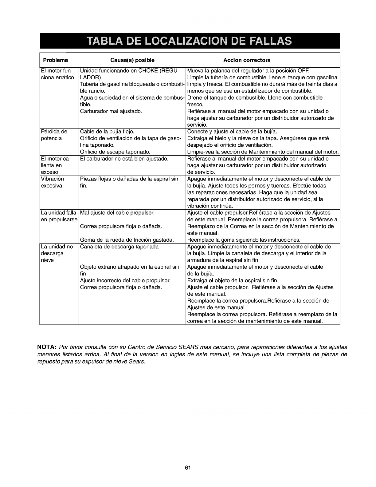
Problema
El motor fun-
ciona errAtico
Perdida de
potencia
Causa(s) posible Accion correctora
Unidad funcionando en CHOKE (REGU-
LADOR)
Tuberia de gasolina bloqueada o combusti-
ble rancio.
Agua o suciedad en el sistema de combus-
tible.
Carburador mal ajustado.
El motor ca-
lienta en
exceso
Vibraci6n Piezas flojas o daSadas de la espiral sin
excesiva fin.
La unidad falla
en propulsarse
La unidad no
descarga
nieve
Cable de la bujia flojo.
Orificio de ventilaci6n de la tapa de gaso-
lina taponado.
Orificio de escape taponado.
El carburador no estA bien ajustado.
Mal ajuste del cable propulsor.
Correa propulsora floja o daSada.
Goma de la rueda de fricci6n gastada.
Canaleta de descarga taponada
Objeto extraSo atrapado en la espiral sin
fin
Ajuste incorrecto del cable propulsor.
Correa propulsora floja o daSada.
Mueva la palanca del regulador a la posici6n OFE
Limpie la tuberia de combustible, Ilene el tanque con gasolina
limpia y fresca. El combustible no durarA mAs de treinta dias a
menos que se use un estabilizador de combustible.
Drene el tanque de combustible. Llene con combustible
fresco.
Refierase al manual del motor empacado con su unidad o
haga ajustar su carburador por un distribuidor autorizado de
servicio.
Conecte y ajuste el cable de la bujia.
Extraiga el hielo y la nieve de la tapa. Asegt_rese que este
despejado el orificio de ventilaci6n.
Limpie-vea la secci6n de Mantenimiento del manual del motor.
Refierase al manual del motor empacado con su unidad o
haga ajustar su carburador por un distribuidor autorizado
de servicio.
Apague inmediatamente el motor y desconecte el cable de
la bujia. Ajuste todos los pernos y tuercas. Efectt_e todas
las reparaciones necesarias. Haga que la unidad sea
reparada por un distribuidor autorizado de servicio, si la
vibraci6n contint_a.
Ajuste el cable propulsor.Refierase a la secci6n de Ajustes
de este manual. Reemplace la correa propulsora. Refierase a
Reemplazo de la Correa en la secci6n de Mantenimiento de
este manual.
Reemplace la goma siguiendo las instrucciones.
Apague inmediatamente el motor y desconecte el cable de
la bujia. Limpie la canaleta de descarga y el interior de la
armadura de la espiral sin fin.
Apague inmediatamente el motor y desconecte el cable
de la bujia.
Extraiga el objeto de la espiral sin fin.
Ajuste el cable propulsor. Refierase a la secci6n de Ajustes
de este manual.
Reemplace la correa propulsora.Refierase a la secci6n de
Ajustes de este manual.
Reemplace la correa propulsora. Refierase a reemplazo de la
correa en la secci6n de mantenimiento de este manual.
NOTA: Por favor consulte con su Centro de Servicio SEARS mas cercano, para reparaciones diferentes a los ajustes
menores listados arriba. AI final de la version en ingles de este manual, se incluye una lista completa de piezas de
repuesto para su expulsor de nieve Sears.
61

I
I
I
62

63

In U.S.A. or Canada
for in-home major brand repair service:
Call 24 hours a day, 7 days a week
1-800-4-MY-HOME sM(1-800-469-4663)
Para pedir servicio de reparaci6n adomicillio -- 1-800-676-5811
Au Canada pour tout le service ou les pi_ces -- 1-800-469-4663
For the repair or replacement parts you need:
Call 6 a.m. -- 11 p.m. CST, 7 days a week
PartsDirect SM
1-800-366-PART (1-800-366-7278)
Para ordenar piezas con entrega adomicillio -- 1-800-659-7084
For the location of a Sears Service Center in your area:
Call 24 hours a day, 7 days a week
1-800-488-1222
To purchase or inquire about a Sears Maintenance Agreement:
Call 7 a.m. -- 5 p.m. CST, Monday -- Saturday
1-800-827-6655
8EARS
HomeCentral
