Craftsman 247888530 User Manual SNOW THROWER Manuals And Guides L0308227
CRAFTSMAN Snowthrower, Gas Manual L0308227 CRAFTSMAN Snowthrower, Gas Owner's Manual, CRAFTSMAN Snowthrower, Gas installation guides
User Manual: Craftsman 247888530 247888530 CRAFTSMAN SNOW THROWER - Manuals and Guides View the owners manual for your CRAFTSMAN SNOW THROWER #247888530. Home:Lawn & Garden Parts:Craftsman Parts:Craftsman SNOW THROWER Manual
Open the PDF directly: View PDF ![]() .
.
Page Count: 64
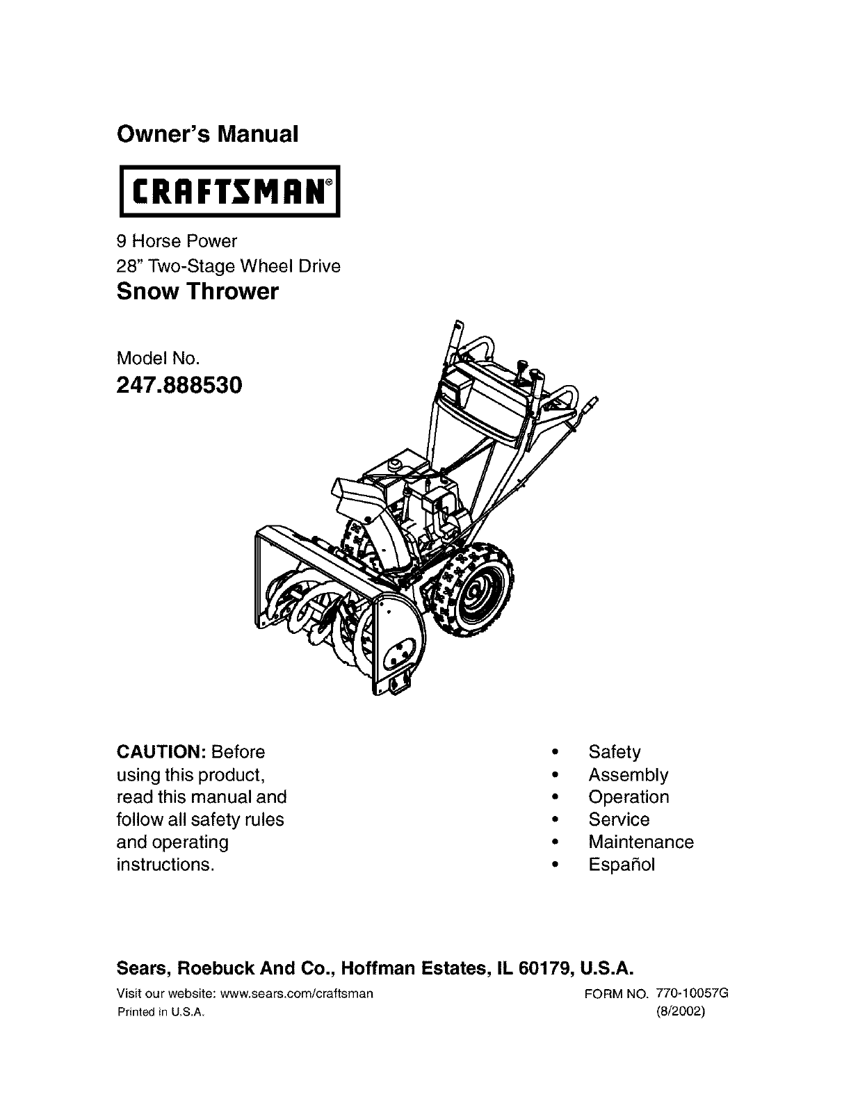
Owner's Manual
9 Horse Power
28" Two-Stage Wheel Drive
Snow Thrower
Model No.
247.888530
CAUTION: Before
using this product,
read this manual and
follow all safety rules
and operating
instructions.
•Safety
• Assembly
• Operation
• Service
• Maintenance
• EspaSol
Sears, Roebuck And Co., Hoffman Estates, IL 60179, U.S.A.
Visit our website: www.sears.com/craftsman FORM NO. 770-10057G
Prhted JnU.S.A. (8/2002)
Content Page
Warranty Information ......................................... 2
Safe Operation Practices ................................... 3
Assembly ........................................................... 6
Operation ........................................................... 12
Maintenance ...................................................... 17
Content Page
Service & Adjustment ......................................... 20
Off-Season Storage ........................................... 25
Trouble-Shooting ............................................... 26
Parts List ............................................................ 28
Espanbl .............................................................. 40
Two -Year Warranty on Craftsman Snow Thrower
For two years from the date of purchase, when this Craftsman Snow Thrower is maintained, lubricated and tuned
up according to the instructions in the owner's manual, Sears will repair, free of charge, any defect in material
and workmanship.
If this Craftsman snow thrower is used for commercial or rental purposes, this warranty applies for only 30 days
from the date of purchase.
This warranty does not cover:
Expendable items which become worn during normal use, such as skid shoes, shave plate and spark
plugs.
Repairs necessary because of operator abuse or negligence, including bent crankshafts and the failure to
maintain the equipment according to the instructions contained in the owner's manual.
WARRANTY SERVICE IS AVAILABLE BY RETURNING THE CRAFTSMAN SNOW THROWER TO THE NEAREST
SEARS SERVICE CENTER!DEPARTMENT IN THE UNITED STATES.
This warranty applies only while this product is in use in the United States.
This warranty gives you specific legal rights and you may also have other rights which may vary from state to state.
SEARS, ROEBUCK AND CO., D/817WA, HOFFMAN ESTATES, IL60179
Horsepower: ......................... 9
Engine Oil ............................. SAE 5W30 oil
Fuel Capacity: ....................... 1 gallon
Spark Plug: ........................... RJ-19LM
Engine: .................................. 143.039001
Model Number 247.888530
Serial Number ...........................................................
Date of Purchase ......................................................
Record both serial number and date of purchase and
keep in a safe place for future reference.
WARNING: This symbol points out important safety instructions which, if not followed, could endanger
the personal safety and/or property of yourself and others. Read and follow all instructions in this manual
before attempting to operate this machine. Failure to comply with these instructions may result in personal
injury. When you see this symbol--heed its warning.
WARNING: Engine Exhaust, some of its constituents, and certain vehicle components contain
or emit chemicals known to State of California to cause cancer and birth defects or other
reproductive harm.
DANGER: This machine was built to be operated according to the rules for safe operation in this manual. As with
any type of power equipment, carelessness or error on the pert of the operator can result in serious injury. This
machine is capable of amputating hands end feet and throwing objects. Failure to observe the following safety
instructions could result in serious injury or death.
Training
1. Read, understand, and follow all instructions on the
machine and in the manual(s) before attempting to
assemble and operate. Keep this manual in a safe place
for future and regular reference and for ordering
replacement parts.
2. Be familiar with all controls and their operation. Know
how to stop the machine and disengage controls.
3. Never allow children under 14 years old to operate this
machine. Children 14 years old and over should read and
understand the operation instructions and safety rules in
this manual and should be trained and supervised by a
parent.
4. Never allow adults to operate this machine without
proper instruction.
5. Thrown objects can cause serious personal injury. Plan
your snow-throwing pattern to avoid discharge of material
toward roads, bystanders and the like.
6. Keep bystanders, helpers, pets and children at least 75
feet from the machine while it is in operation. Stop
machine if anyone enters the area.
7. Exercise caution to avoid slipping or falling, especially
when operating in reverse.
Preparation
1. Thoroughly inspect the area where the equipment is to
be used. Remove all doormats, newspapers, sleds,
boards, wires and other foreign objects, which could be
tripped over or thrown by the auger/impeller.
2. Always wear safety glasses or eye shields during
operation and while performing an adjustment or repair to
protect your eyes. Thrown objects which ricochet can
cause serious injury to the eyes.
3. Do not operate without wearing adequate winter outer
garments. Do not wear jewelry, long scarves or other
loose clothing, which could become entangled in moving
parts. Wear footwear which will improve footing on
slippery surfaces.
4. Use a grounded three-wire extension cord and
receptacle for all units with electric start engines.
5. Adjust collector housing height to clear gravel or crushed
rock surfaces.
6. Disengage all clutch levers before starting the engine.
7. Never attempt to make any adjustments while engine is
8,
9.
running, except where specifically recommended in the
operator's manual.
Let engine and machine adjust to outdoor temperature
before starting to clear snow.
To avoid personal injury or property damage use extreme
care in handling gasoline. Gasoline is extremely
flammable and the vapors are explosive. Serious
personal injury can occur when gasoline is spilled on
yourself or your clothes, which can ignite. Wash your skin
and change clothes immediately.
a. Use only an approved gasoline container.
b. Extinguish all cigarettes, cigars, pipes and other
sources of ignition.
c. Never fuel machine indoors.
d. Never remove gas cap or add fuel while the
engine is hot or running.
e. Allow engine to cool at least two minutes before
refueling.
f. Never over fill fuel tank. Fill tank to no more than
Y2inch below bottom of filler neck to provide space
for fuel expansion.
g. Replace gasoline cap and tighten securely.
h. If gasoline is spilled, wipe it off the engine and
equipment. Move machine to another area. Wait 5
minutes before starting the engine.
L Never store the machine or fuel container inside
where there is an open flame, spark or pilot light
(e.g. furnace, water heater, space heater, clothes
dryer etc.).
j. Allow unit to cool for 5 minutes before storing.
Operation
1 DOnot put hands or feet near rotating parts, in the auger/
impeller housing or discharge chute. Contact with the
rotating parts can amputate hands and feet.
2. The auger/impeller clutch lever is a safety device. Never
bypass its operation. Doing so makes the machine
unsafe and may cause personal injury.
3. The clutch levers must operate easily in both directions
and automatically return to the disengaged position when
released.
4. Never operate with a missing or damaged discharge
chute. Keep all safety devices in place and working.
5. Never run an engine indoorsor in a poorly ventilated
area.Engineexhaustcontainscarbonmonoxide,an
odorlessanddeadlygas.
6. Donotoperatemachinewhileundertheinfluenceof
alcoholordrugs.
7. Mufflerandenginebecomehotandcancauseaburn.Do
nottouch.
8. Exerciseextremecautionwhenoperatingonorcrossing
gravelsurfaces.Stayalertforhiddenhazardsortraffic.
9. Exercisecautionwhenchangingdirectionandwhile
operatingonslopes.
10.Planyoursnow-throwingpatterntoavoiddischarge
towardswindows,walls,carsetc.Thus,avoiding
possiblepropertydamageorpersonalinjurycausedbya
ricochet.
11.Neverdirectdischargeatchildren,bystandersandpets
orallowanyoneinfrontofthemachine.
12.Donotoverloadmachinecapacitybyattemptingtoclear
snowattoofastofarate.
13.Neveroperatethismachinewithoutgoodvisibilityor
light.Alwaysbesureofyourfootingandkeepafirmhold
onthehandles.Walk,neverrun.
14.Disengagepowertotheauger/impellerwhen
transportingornotinuse.
15.Neveroperatemachineathightransportspeedson
slipperysurfaces.Lookdownandbehindandusecare
wheninreverse.
16.Ifthemachineshouldstarttovibrateabnormally,stopthe
engine,disconnectthesparkplugwireandgroundit
againsttheengine. Inspect thoroughly for damage.
Repair any damage before starting and operating.
17. Disengage all clutch levers and stop engine before you
leave the operating position (behind the handles). Wait
until the augedimpeller comes to a complete stop before
unclogging the discharge chute, making any
adjustments, or inspections.
18. Never put your hand in the discharge or collector
openings. Always use the clean-out tool provided to
unclog the discharge opening. Do not unclog discharge
chute while engine is running. Before unclogging, shut off
engine and remain behind handles until all moving parts
have stopped completely.
19. Use only attachments and accessories approved bythe
manufacturer (e.g. wheel weights, tire chains, cabs etc.).
20. If situations occur which are not covered in this manual,
use care and good judgment. Contact Sears service
center for assistance.
Maintenance & Storage
1 Never tamper with safety devices. Check their proper
operation regularly. Refer to the maintenance and
adjustment sections of this manual.
2. Before cleaning, repairing, or inspecting machine
disengage all clutch levers and stop engine. Wait until the
auger/impeller come to a complete stop. Disconnect the
spark plug wire and ground against the engine to prevent
unintended starting.
3. Check bolts and screws for proper tightness at frequent
intervals to keep the machine in safe working condition.
Also, visually inspect machine for any damage.
4. Do not change the engine governor setting or over-speed
the engine. The governor controls the maximum safe
operating speed of the engine.
5. Snow thrower shave plates and skid shoes are subject to
wear and damage. For your safety protection, frequently
check all components and replace with original
equipment manufacturer's (OEM) parts only. "Use of
parts which do not meet the original equipment
specifications may lead to improper performance and
compromise safety!"
6. Check clutch controls periodically to verify they engage
and disengage properly and adjust, if necessary. Refer to
the adjustment section in this operator's manual for
instructions.
7. Maintain/replace safety/instruction labels, as necessary.
8. Observe proper disposal laws and regulations for gas,
oil, etc. to protect the environment.
9. Prior to storing, run machine a few minutes to clear snow
from machine and prevent freeze up of auger/impeller.
10. Never store the machine or fuel container inside where
there is an open flame, spark or pilot light such as a water
heater, furnace, clothes dryer etc.
11. Always refer to the operator's manual for proper
instructions on off-season storage.
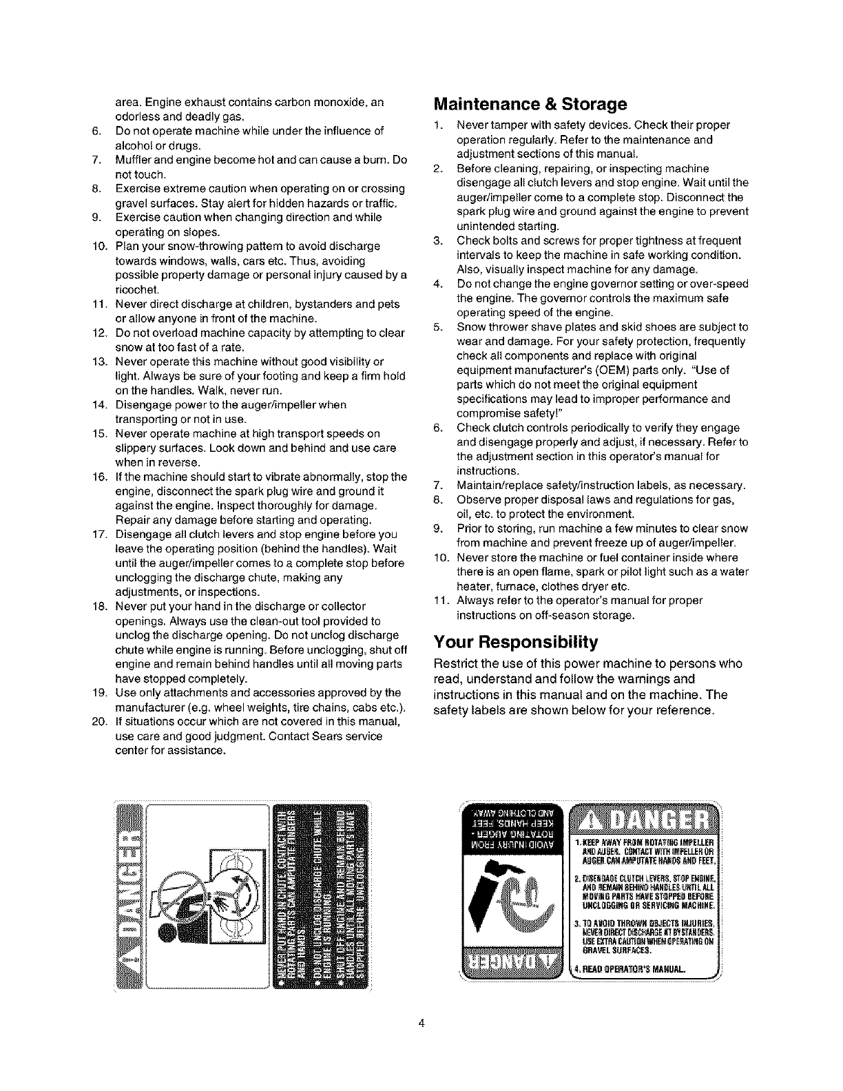
Your Responsibility
Restrict the use of this power machine to persons who
read, understand and follow the warnings and
instructions in this manual and on the machine. The
safety labels are shown below for your reference.
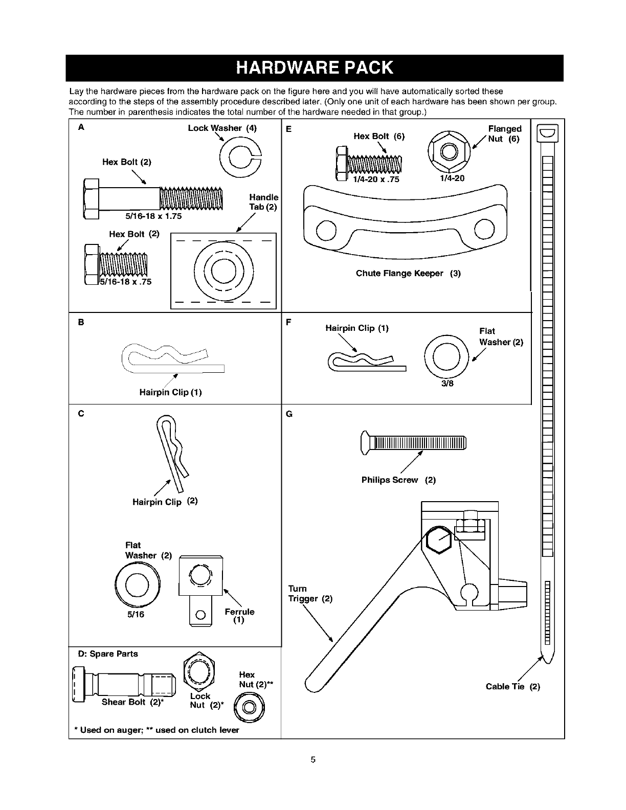
Laythehardwarepiecesfromthehardwarepackonthefigurehereandyouwillhaveautomaticallysortedthese
accordingtothestepsoftheassemblyproceduredescribedlater. (Only one unit of each hardware has been shown per group.
The number in parenthesis indicates the total number of the hardware needed in that group.)
A
B
Hex Bolt (2)
_,,,.
__ 5/16-18 x 1.75
Hex Bolt (2)
5116-18 X .75
Lock Washer (4)
,©
Handle
Tab (2)
/
C
/
HairpinClip (1)
Hairpin Clip (2)
Flat
Washer (2) c
5/16 C) Ferrule
(t)
D: Spare Parts
Hex
Nut (2)**
Lock
'--- Shear Bolt (2)* Nut (2)* _'_--_'_
* Used on auger; ** used on clutch lever
Hex Bolt_ (6) /_ /NutFlanged(6)
-1/4-20 x .75 114-20
I
Chute Flange Keeper (3)
Hairpin Clip (1) Flat
"_ __asher(2)
3/8
m
G-
_/ Cable Tie (2)
/
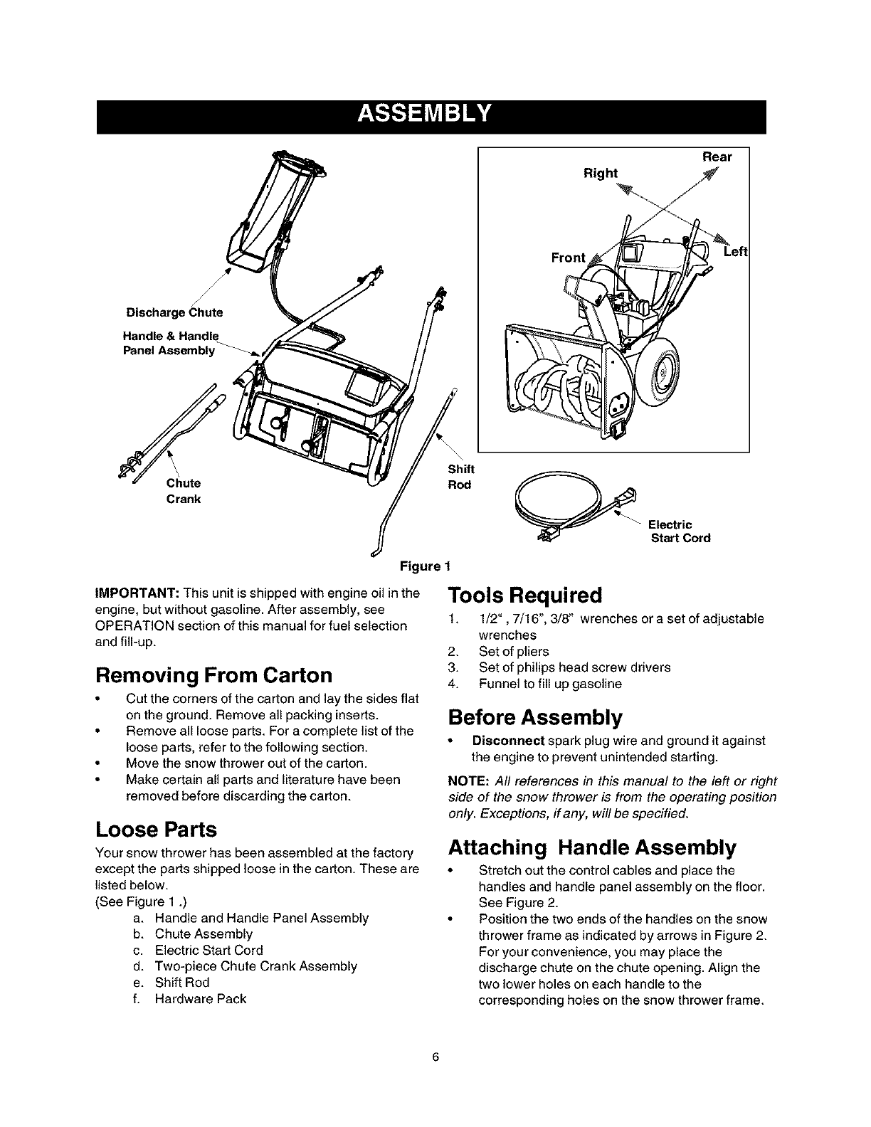
Discharge Chute
Handle & Handle
Panel Assembly _,
Right
Front
Rear
\
Chute
Crank
Figure 1
IMPORTANT: This unit is shipped with engine oil in the
engine, but without gasoline. After assembly, see
OPERATION section of this manual for fuel selection
and fill-up.
Removing From Carton
•Cut the corners of the carton and lay the sides flat
on the ground. Remove all packing inserts.
• Remove all loose parts. For a complete list of the
loose parts, refer to the following section.
• Move the snow thrower out of the carton.
• Make certain all parts and literature have been
removed before discarding the carton.
Loose Parts
Your snow thrower has been assembled at the factory
except the parts shipped loose in the carton. These are
listed below.
(See Figure 1 .)
a. Handle and Handle Panel Assembly
b. Chute Assembly
c. Electric Start Cord
d. Two-piece Chute Crank Assembly
e. Shift Rod
f. Hardware Pack
Shift
Rod
Electric
Start Cord
Tools Required
1. 1/2", 7/16", 3/8" wrenches or a set of adjustable
wrenches
2. Set of pliers
3. Set of philips head screw drivers
4. Funnel to fill up gasoline
Before Assembly
•Disconnect spark plug wire and ground it against
the engine to prevent unintended starting.
NOTE: All references in this manual to the left or right
side of the snow thrower is from the operating position
only. Exceptions, if any, will be specified.
Attaching Handle Assembly
• Stretch out the control cables and place the
handles and handle panel assembly on the floor.
See Figure 2.
• Position the two ends of the handles on the snow
thrower frame as indicated by arrows in Figure 2.
For your convenience, you may place the
discharge chute on the chute opening. Align the
two lower holes on each handle to the
corresponding holes on the snow thrower frame.
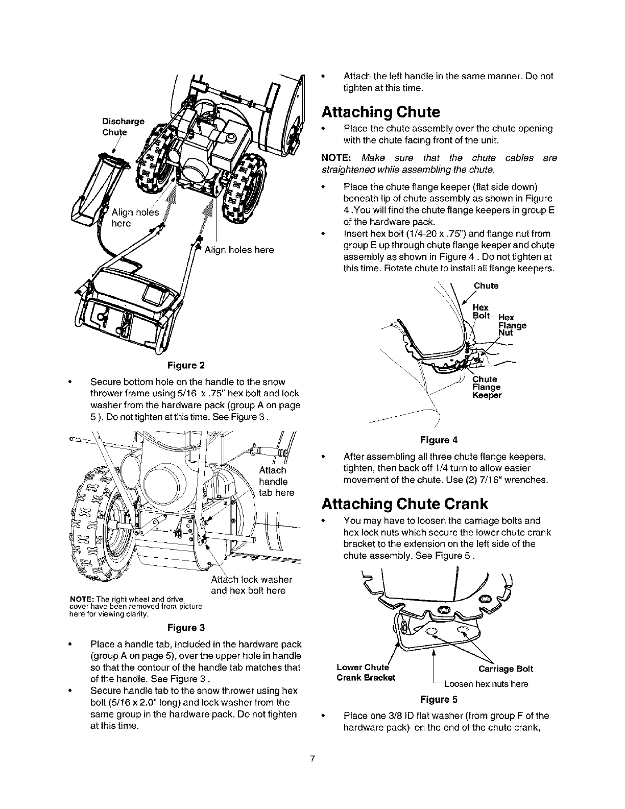
Discharge
n holes here
Figure 2
Secure bottom hole on the handle to the snow
thrower frame using 5/16 x .75" hex bolt and lock
washer from the hardware pack (group A on page
5 ). Do not tighten at this time. See Figure 3.
Attach
handle
tab here
Atta_ch lock washer
and hex bolt here
NOTE: The right wheel and drive
cover have been removed from picture
here for viewing clarity,
Figure 3
•Place a handle tab, included in the hardware pack
(group A on page 5), over the upper hole in handle
so that the contour of the handle tab matches that
of the handle. See Figure 3.
• Secure handle tab to the snow thrower using hex
bolt (5/16 x 2.0" long) and lock washer from the
same group in the hardware pack. Do not tighten
at this time.
• Attach the left handle in the same manner. Do not
tighten at this time.
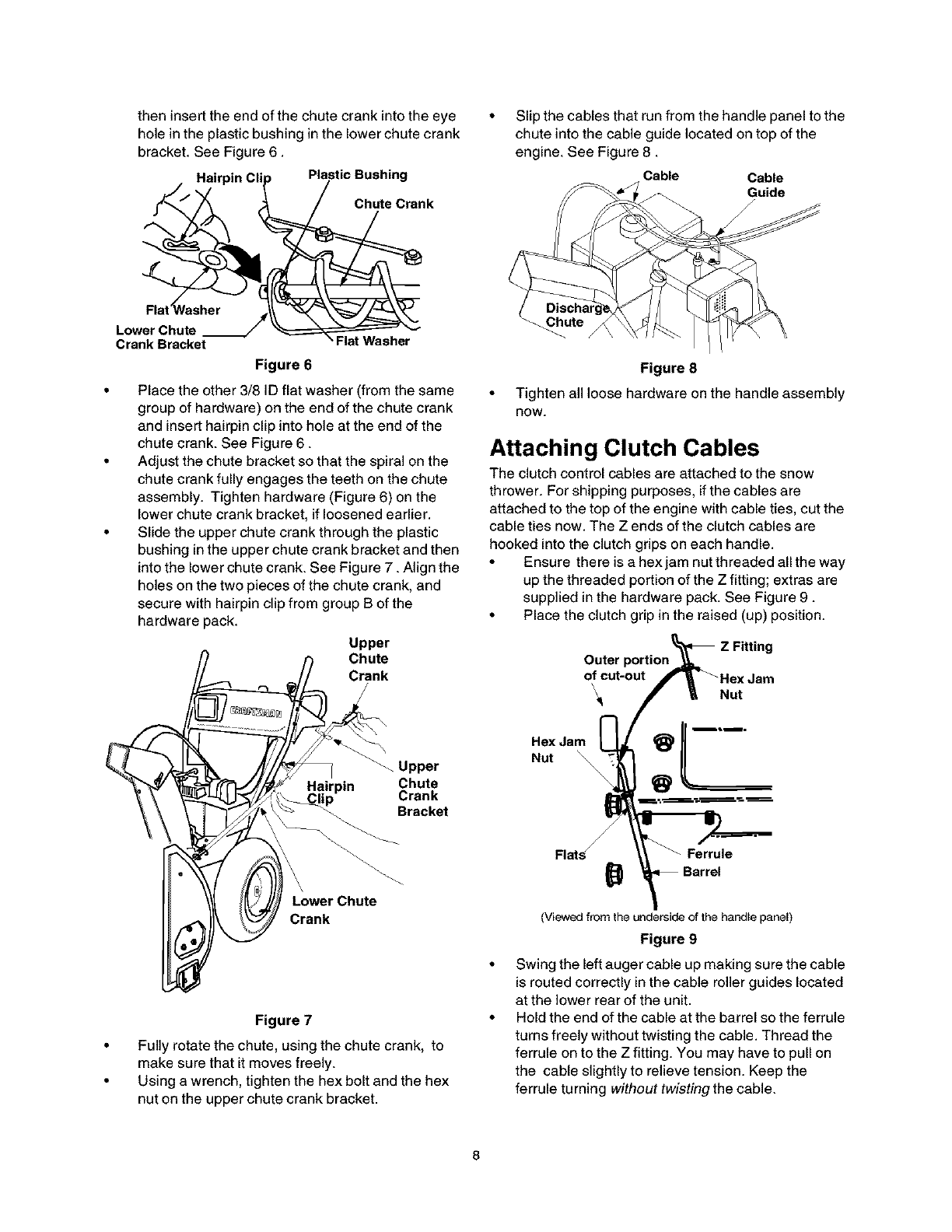
Attaching Chute
• Place the chute assembly over the chute opening
with the chute facing front of the unit.
NOTE: Make sure that the chute cables are
straightened while assembling the chute.
• Place the chute flange keeper (flat side down)
beneath lip of chute assembly as shown in Figure
4 .You will find the chute flange keepers in group E
of the hardware pack.
• Insert hex bolt (1/4-20 x .75") and flange nut from
group E up through chute flange keeper and chute
assembly as shown in Figure 4. Do not tighten at
this time. Rotate chute to install all flange keepers.
Chute
/
Hex
Bolt Hex
Range
\Chute
Flange
\Keeper
\
Figure 4
After assembling all three chute flange keepers,
tighten, then back off 1/4 turn to allow easier
movement of the chute. Use (2) 7/16" wrenches.
Attaching Chute Crank
• You may have to loosen the carriage bolts and
hex lock nuts which secure the lower chute crank
bracket to the extension on the left side of the
chute assembly. See Figure 5.
Lwr h _
Figure 5
• Place one 3/8 ID flat washer (from group F of the
hardware pack) on the end of the chute crank,
theninserttheendofthechutecrankintotheeye
holeintheplasticbushinginthelowerchutecrank
bracket.SeeFigure6.
Hairpin CI Plastic Bushing
Chute Crank
Slip the cables that run from the handle panel to the
chute into the cable guide located on top of the
engine. See Figure 8.
Cable Cable
Guide
Lower Chute
Crank Bracket Flat Washer
Figure 6
•Place the other 3/8 ID flat washer (from the same
group of hardware) on the end of the chute crank
and insert hairpin clip into hole at the end of the
chute crank. See Figure 6.
• Adjust the chute bracket so that the spiral on the
chute crank fully engages the teeth on the chute
assembly. Tighten hardware (Figure 6) on the
lower chute crank bracket, if loosened earlier.
• Slide the upper chute crank through the plastic
bushing in the upper chute crank bracket and then
into the lower chute crank. See Figure 7. Align the
holes on the two pieces of the chute crank, and
secure with hairpin clip from group B of the
hardware pack.
Upper
Chute
Crank
Upper
Chute
Crank
Bracket
Crank
Figure 7
Fully rotate the chute, using the chute crank, to
make sure that it moves freely.
Using a wrench, tighten the hex bolt and the hex
nut on the upper chute crank bracket.
Figure 8
• Tighten all loose hardware on the handle assembly
nOW.
Attaching Clutch Cables
The clutch control cables are attached to the snow
thrower. For shipping purposes, if the cables are
attached to the top of the engine with cable ties, cut the
cable ties now. The Z ends of the clutch cables are
hooked into the clutch grips on each handle.
• Ensure there is a hex jam nut threaded all the way
up the threaded portion of the Z fitting; extras are
supplied in the hardware pack. See Figure 9.
• Place the clutch grip in the raised (up) position.
Outer
of cut-out
\
Hex Jam
Nut
Nut
:L
Ferrule
(Viewedfrom the undersideof thehandlepanel)
Figure 9
Swing the left auger cable up making sure the cable
is routed correctly in the cable roller guides located
at the lower rear of the unit.
Hold the end of the cable at the barrel so the ferrule
turns freely without twisting the cable. Thread the
ferrule on to the Z fitting. You may have to pull on
the cable slightly to relieve tension. Keep the
ferrule turning without twisting the cable.
• Youwillreachcorrectadjustmentwhenthereis
minimalslackinthecablebutitisnottight.Holdthe
flatsontheferrulewithpliersandtightenthejam
nutagainsttheferrule.
CAUTION:Cableswillbecomelooseifyoudonot
tightenthejamnut.
WARNING: There must not be any tension
on either clutch cable with the drive or auger
clutch grip in the disengaged (up) position.
These clutches are a safety feature. Do not
override their function.
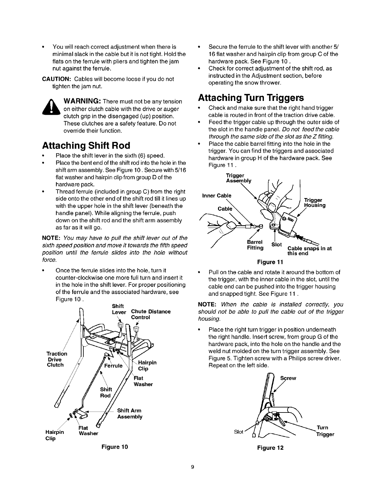
Attaching Shift Rod
• Place the shift lever in the sixth (6) speed.
• Place the bent end of the shift rod into the hole in the
shift arm assembly. See Figure 10. Secure with 5/16
flat washer and hairpin clip from group D of the
hardware pack.
• Thread ferrule (included in group C) from the right
side onto the other end of the shift rod till it lines up
with the upper hole in the shift lever (beneath the
handle panel). While aligning the ferrule, push
down on the shift rod and the shift arm assembly
as far as it will go.
NOTE: You may have to pull the shift lever out of the
sixth speed position and move it towards the fifth speed
position until the ferrule slides into the hole without
force.
Once the ferrule slides into the hole, turn it
counter-clockwise one more full turn and insert it
in the hole in the shift lever. For proper positioning
of the ferrule and the associated hardware, see
Figure 10. Shift
Lever Chute Distance
Control
Traction
Drive
Clutch Clip
Washer
Hairpin
Clip
Fin
Washer
Shift Arm
Assembly
Figure 10
• Secure the ferrule to the shift lever with another 5/
16 flat washer and hairpin clip from group C of the
hardware pack. See Figure 10.
• Check for correct adjustment of the shift rod, as
instructed in the Adjustment section, before
operating the snow thrower.
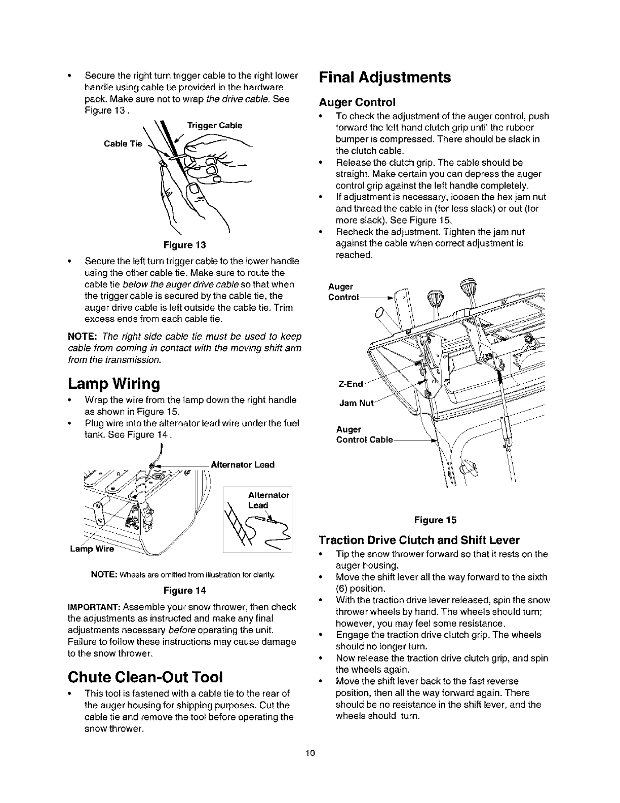
Attaching Turn Triggers
• Check and make sure that the right hand trigger
cable is routed in front of the traction drive cable.
• Feed the trigger cable up through the outer side of
the slot in the handle panel. Do not feed the cable
through the same side of the slot as the Z fitting.
• Place the cable barrel fitting into the hole in the
trigger. You can find the triggers and associated
hardware in group H of the hardware pack. See
Figu re 11.
Trigger
Inner Cabl[_sem_
/
Barrel Slot
Fitting Cable snaps in at
this end
Figure 11
• Pull on the cable and rotate it around the bottom of
the trigger, with the inner cable in the slot, until the
cable end can be pushed into the trigger housing
and snapped tight. See Figure 11 .
NOTE: When the cable is installed correctly, you
should not be able to pull the cable out of the trigger
housing.
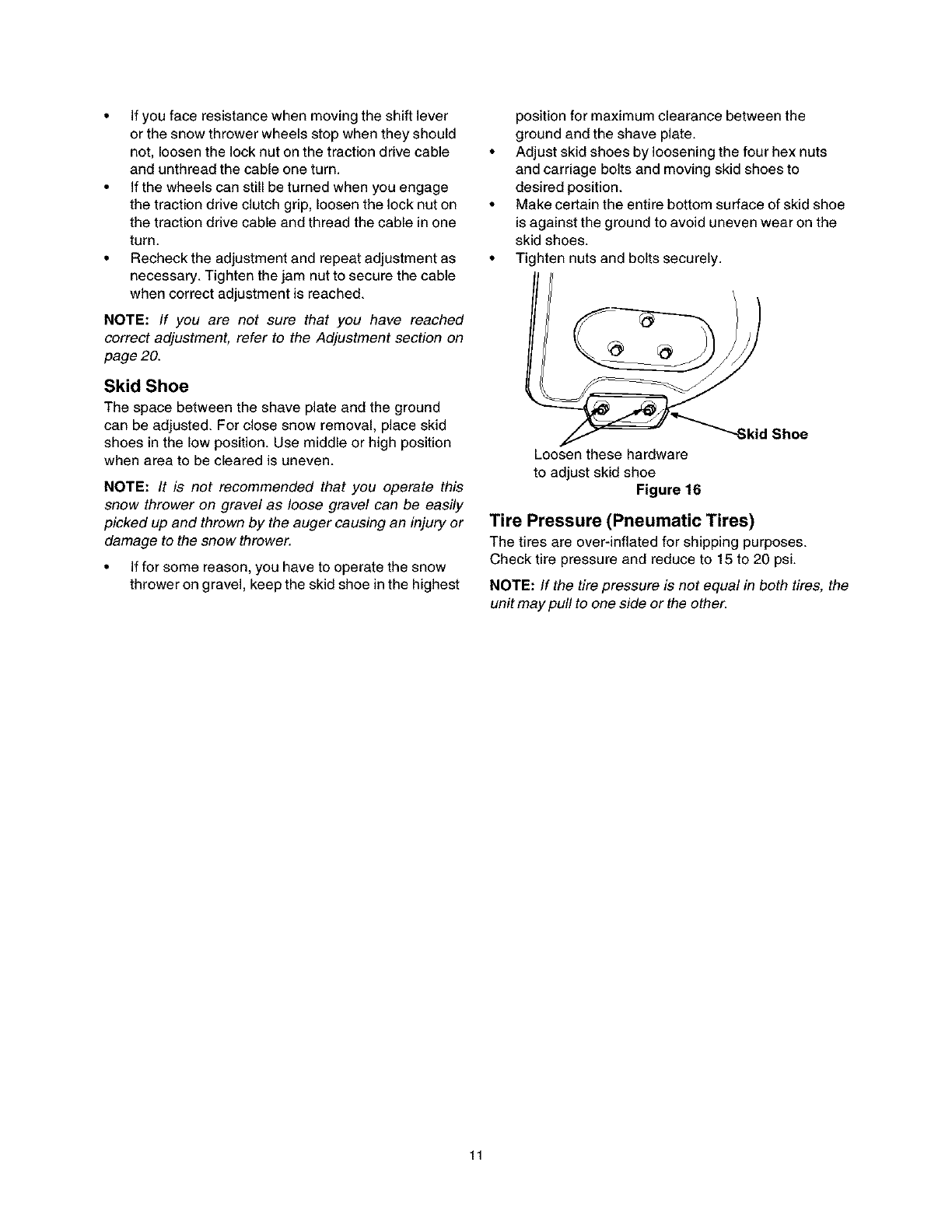
Place the right turn trigger in position underneath
the right handle. Insert screw, from group G of the
hardware pack, into the hole on the handle and the
weld nut molded on the turn trigger assembly. See
Figure 5. Tighten screw with a Philips screw driver.
Repeat on the left side.
/I I"_ _ Turn
Slot" _ ,_.,....._......_ _Trigger
Figure 12
Secure the right turn trigger cable to the right lower
handle using cable tie provided in the hardware
pack. Make sure not to wrap the drive cable. See
Figure 13.
Tie\_Trigger Cable
Cable
Figure 13
Secure the left turn trigger cable to the Iower handle
using the other cable tie. Make sure to route the
cable tie below the auger drive cable so that when
the trigger cable is secured by the cable tie, the
auger drive cable is left outside the cable tie. Trim
excess ends from each cable tie.
NOTE: The right side cable tie must be used to keep
cable from coming in contact with the moving shift arm
from the transmission.
Lamp Wiring
•Wrap the wire from the lamp down the right handle
as shown in Figure 15.
• Plug wire into the alternator lead wire under the fuel
tank. See Figure 14.
Final Adjustments
Auger Control
•To check the adjustment of the auger control, push
forward the left hand clutch grip until the rubber
bumper is compressed. There should be slack in
the clutch cable.
•Release the clutch grip. The cable should be
straight. Make certain you can depress the auger
control grip against the left handle completely.
• If adjustment is necessary, loosen the hex jam nut
and thread the cable in (for less slack) or out (for
more slack). See Figure 15.
•Recheck the adjustment. Tighten the jam nut
against the cable when correct adjustment is
reached.
Auger
Control_
Z-End j
Jam Nut j
Auger
Alternator Lead
NOTE: Wheetsare omittedfrom illustrationforclarity.
Figure 14
IMPORTANT: Assemble your snow thrower, then check
the adjustments as instructed and make any final
adjustments necessary before operating the unit.
Failure to follow these instructions may cause damage
to the snow thrower.
Chute Clean-Out Tool
• This tool is fastened with a cable tie to the rear of
the auger housing for shipping purposes. Cut the
cable tie and remove the tool before operating the
snow thrower.
Figure 15
Traction Drive Clutch and Shift Lever
•Tip the snow thrower forward so that it rests on the
auger housing.
• Move the shift lever all the way forward to the sixth
(6) position.
• With the traction drive lever released, spin the snow
thrower wheels by hand. The wheels should turn;
however, you may feel some resistance.
• Engage the traction drive clutch grip. The wheels
should no longer turn.
• Now release the traction drive clutch grip, and spin
the wheels again.
• Move the shift lever back to the fast reverse
position, then all the way forward again. There
should be no resistance in the shift lever, and the
wheels should turn.
10
• Ifyoufaceresistancewhenmovingtheshiftlever
orthesnowthrowerwheelsstopwhentheyshould
not,loosenthelocknutonthetractiondrivecable
andunthreadthecableoneturn.
• Ifthewheelscanstillbeturnedwhenyouengage
thetractiondriveclutchgrip,loosenthelocknuton
thetractiondrivecableandthreadthecableinone
turn.
• Rechecktheadjustmentandrepeatadjustmentas
necessary.Tightenthejamnuttosecurethecable
whencorrectadjustmentisreached.
NOTE:If you are not sure that you have reached
correct adjustment, refer to the Adjustment section on
page 20.
Skid Shoe
The space between the shave plate end the ground
can be adjusted. For close snow removal, place skid
shoes in the low position. Use middle or high position
when area to be cleared is uneven.
NOTE: It is not recommended that you operate this
snow thrower on gravel as loose gravel can be easily
picked up and thrown by the auger causing an injury or
damage to the snow thrower.
• If for some reason, you have to operate the snow
thrower on gravel, keep the skid shoe in the highest
position for maximum clearance between the
ground and the shave plate.
• Adjust skid shoes by loosening the four hex nuts
and carriage bolts and moving skid shoes to
desired position.
• Make certain the entire bottom surface of skid shoe
is against the ground to avoid uneven wear on the
skid shoes.
• Tighten nuts and bolts securely.
_Skid Shoe
Loosen these hardware
to adjust skid shoe
Figure 16
Tire Pressure (Pneumatic Tires)
The tires ere over-inflated for shipping purposes.
Check tire pressure and reduce to 15 to 20 psi.
NOTE: If the tire pressure is not equal in both tires, the
unit may pull to one side or the other.
11
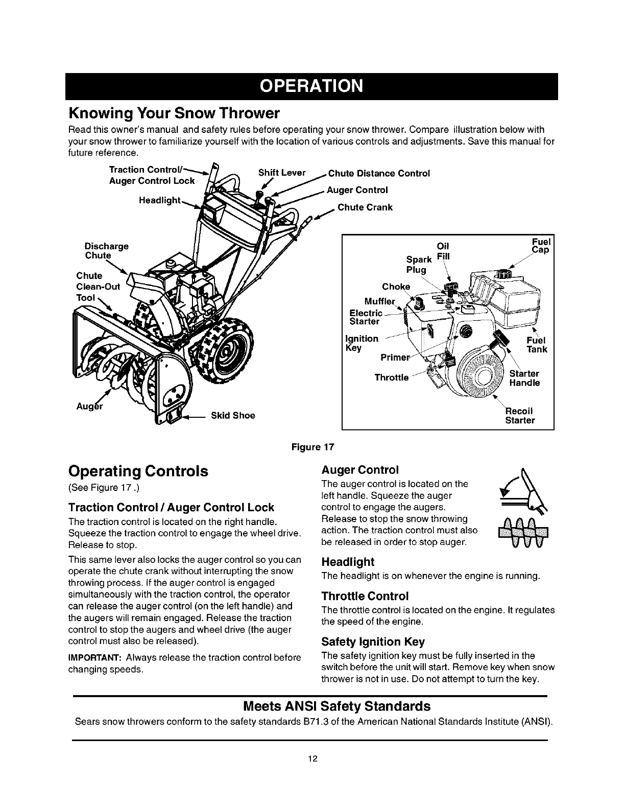
Knowing Your Snow Thrower
Read this owner's manual and safety rules before operating your snow thrower. Compare illustration below with
your snow thrower to familiarize yourself with the location of various controls and adjustments. Save this manual for
future reference.
Traction Shift Lever
Auger Control Lock jr/ erContml
Chute Crank
Discharge
Chute
Chute "_
Clean-Out
Aug6r Skid Shoe
Oil
Spark Fill
Plug
Choke
Electric
Starter _
Ignition J
Key Primer j
Throttle J
Fuel
Fuel
_Tank
Starter
Handle
Recoil
Starter
Figure 17
Operating Controls
(See Figure 17 .)
Traction Control /Auger Control Lock
The traction control is located on the right handle.
Squeeze the traction control to engage the wheel drive.
Release to stop.
This same lever also locks the auger control so you can
operate the chute crank without interrupting the snow
throwing process. If the auger control is engaged
simultaneously with the traction control, the operator
can release the auger control (on the left handle) and
the augers will remain engaged. Release the traction
control to stop the augers and wheel drive (the auger
control must also be released).
IMPORTANT: Always release the traction control before
changing speeds.
Auger Control
The auger control is located on the
left handle. Squeeze the auger
control to engage the augers.
Release to stop the snow throwing
action. The traction control must also
be released in order to stop auger.
Headlight
The headlight is on whenever the engine is running.
Throttle Control
The throttlecontrolis located on the engine. It regulates
the speed ofthe engine.
Safety Ignition Key
The safety ignition key must be fully inserted in the
switch before the unit will start. Remove key when snow
thrower is not in use. Do not attempt to turn the key.
Meets ANSI Safety Standards
Sears snow throwers conform to the safety standards B71.3 of the American National Standards Institute (ANSI).
12
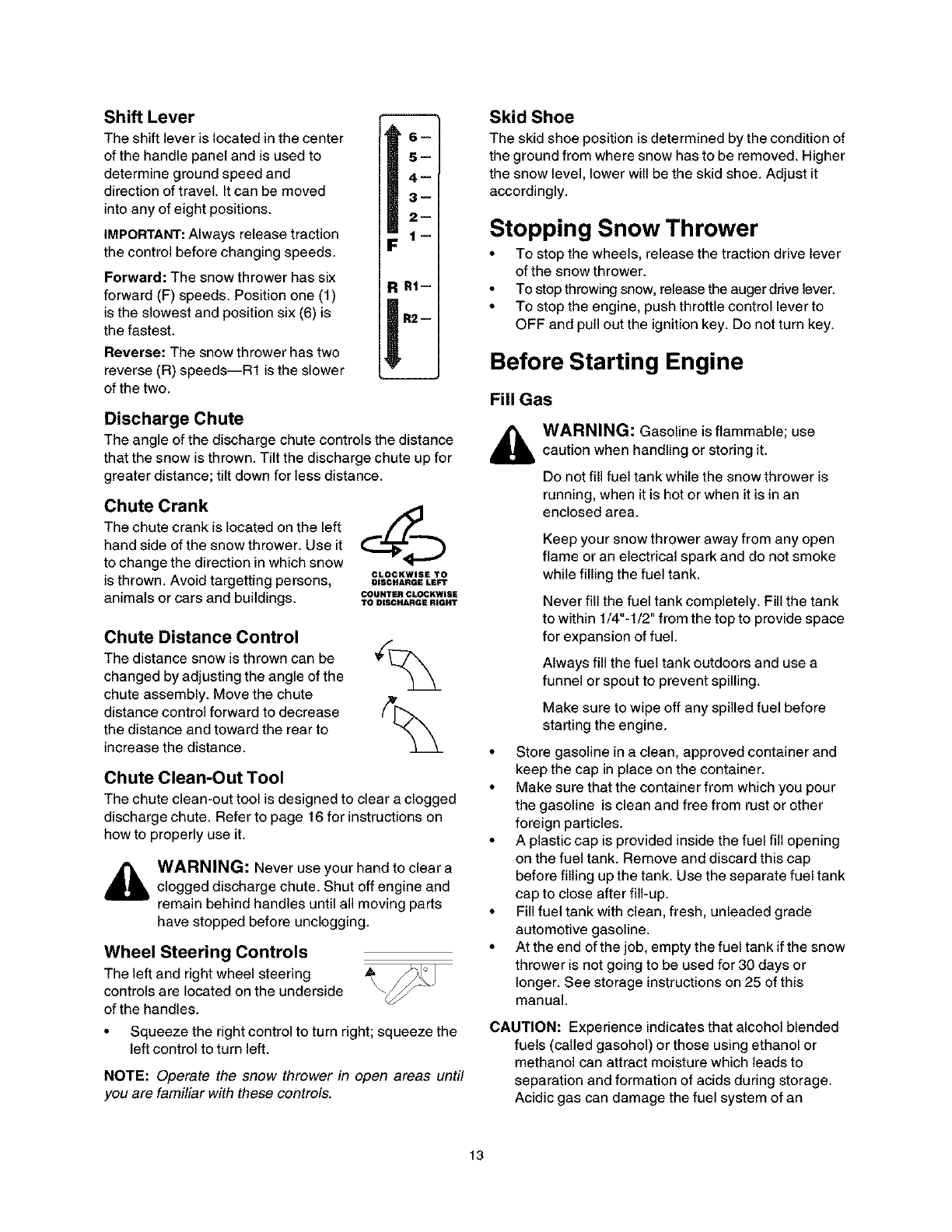
Shift Lever
The shift lever is located in the center
of the handle panel and is used to
determine ground speed and
direction of travel. It can be moved
into any of eight positions.
IMPORTANT: Always release traction
the control before changing speeds.
Forward: The snow thrower has six
forward (F) speeds. Position one (1)
is the slowest and position six (6) is
the fastest.
Reverse: The snow thrower has two
reverse (R) speeds--R1 is the slower
of the two.
6m
5--
4--
3--
2--
1--
R1--
R2--
Discharge Chute
The angle of the discharge chute controls the distance
that the snow is thrown. Tilt the discharge chute up for
greater distance; tilt down for less distance.
Chute Crank
The chute crank is located on the left
hand side of the snow thrower. Use it
to change the direction in which snow
is thrown. Avoid targetting persons,
animals or cars and buildings.
CLOCKWISE TO
DISCHARGE LEFT
COUNTIER CLOCKWISE
TO DISCHARGE RIGHT
Chute Distance Control
The distance snow is thrown can be
changed by adjusting the angle of the
chute assembly. Move the chute
distance control forward to decrease
the distance and toward the rear to
increase the distance.
Chute Clean-Out Tool
The chute clean-out tool is designed to clear a clogged
discharge chute. Refer to page 16 for instructions on
how to properly use it.
WARNING: Never use your hand to clear a
clogged discharge chute. Shut off engine and
remain behind handles until all moving parts
have stopped before unclogging.
Wheel Steering Controls
The left and right wheel steering
controls are located on the underside
of the handles.
• Squeeze the right control to turn right; squeeze the
left control to turn left.
NOTE: Operate the snow thrower in open areas until
you are familiar with these controls.
Skid Shoe
The skid shoe position is determined by the condition of
the ground from where snow has to be removed. Higher
the snow level, lower will be the skid shoe. Adjust it
accordingly.
Stopping Snow Thrower
• To stop the wheels, release the traction drive lever
of the snow thrower.
• To stop throwing snow, release the auger drive lever.
• To stop the engine, push throttle control lever to
OFF and pull out the ignition key. Do not turn key.
Before Starting Engine
Fill Gas
WARNING: Gasoline is flammable; use
caution when handling or storing it.
Do not fill fuel tank while the snow thrower is
running, when it is hot or when it is in an
enclosed area.
Keep your snow thrower away from any open
flame or an electrical spark and do not smoke
while filling the fuel tank.
Never fill the fuel tank completely. Fill the tank
to within 1/4"-1/2" from the top to provide space
for expansion of fuel.
Always fill the fuel tank outdoors and use a
funnel or spout to prevent spilling.
Make sure to wipe off any spilled fuel before
starting the engine.
• Store gasoline in a clean, approved container and
keep the cap in place on the container.
• Make sure that the container from which you pour
the gasoline is clean and free from rust or other
foreign particles.
• A plastic cap is provided inside the fuel fill opening
on the fuel tank. Remove and discard this cap
before filling up the tank. Use the separate fuel tank
cap to close after fill-up.
• Fill fuel tank with clean, fresh, unleaded grade
automotive gasoline.
• At the end of the job, empty the fuel tank if the snow
thrower is not going to be used for 30 days or
longer. See storage instructions on 25 of this
manual.
CAUTION: Experience indicates that alcohol blended
fuels (called gasohol) or those using ethanol or
methanol can attract moisture which leads to
separation and formation of acids during storage.
Acidic gas can damage the fuel system of an
13
enginewhileinstorage.Toavoidengineproblems,
thefuelsystemshouldbeemptiedbeforestoragefor
30daysorlonger.Drainthegastank,starttheengine
andletitrununtilthefuellinesandcarburetorare
empty.Usefreshfuelnextseason.Seestorage
Instructionsforadditionalinformation.Neveruse
engineorcarburetorcleanerproductsinthefuel
tankorpermanentdamagemayoccur.
Fill Oil
The engine was shipped with oil in the engine. Check
the levell of oil before each operation and make sure
there is adequate oil in the engine. Refer to instructions
on page 18 for correct procedure.
To Start Engine
WARNING: Be sure no one other than the
operator is standing near the snow thrower
while starting or operating. Do not operate this
snow thrower unless the discharge chute
assembly has been properly installed and is
secured.
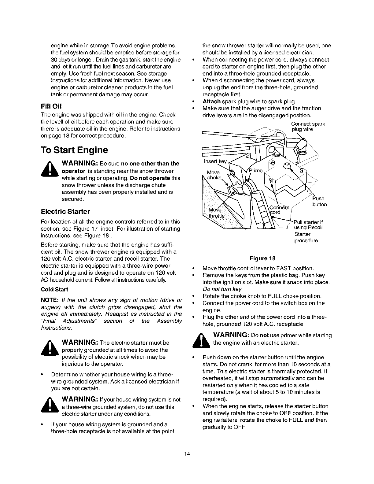
Electric Starter
For location of all the engine controls referred to in this
section, see Figure 17 inset. For illustration of starting
instructions, see Figure 18.
Before starting, make sure that the engine has suffi-
cient oil. The snow thrower engine is equipped with a
120 volt A.C. electric starter and recoil starter. The
electric starter is equipped with a three-wire power
cord and plug and is designed to operate on 120 volt
AC household current. Follow all instructions carefully.
Cold Start
NOTE: If the unit shows any sign of motion (drive or
augers) with the clutch grips disengaged, shut the
engine off immediately. Readjust as instructed in the
"Final Adjustments" section of the Assembly
Instructions.
WARNING: The electric starter must be
properly grounded at all times to avoid the
possibility of electric shock which may be
injurious to the operator.
• Determine whether your house wiring is a three-
wire grounded system. Ask a licensed electrician if
you are not certain.
_ARNING: If your house wiring system is not
a three-wire grounded system, do not use this
electric starter under any conditions.
•If your house wiring system is grounded and a
three-hole receptacle is not available at the point
the snow thrower starter will normally be used, one
should be installed by a licensed electrician.
• When connecting the power cord, always connect
cord to starter on engine first, then plug the other
end into a three-hole grounded receptacle.
• When disconnecting the power cord, always
unplug the end from the three-hole, grounded
receptacle first.
•Attach spark plug wire to spark plug.
• Make sure that the auger drive and the traction
drive levers are in the disengaged position.
Connect spark
plug wire
Move
Push
bu_on
Pull starter if
using Recoil
Starter
procedure
Figure 18
• Move throttle control lever to FAST position.
• Remove the keys from the plastic bag. Push key
into the ignition slot. Make sure it snaps into place.
Do not turn key.
• Rotate the choke knob to FULL choke position.
• Connect the power cord to the switch box on the
engine.
• Plug the other end of the power cord into a three-
hole, grounded 120 volt A.C. receptacle.
,_ WARNING: Do not use primer while starting
the engine with an electric starter.
• Push down on the starter button until the engine
starts. Do not crank for more than 10 seconds at a
time. This electric starter is thermally protected. If
overheated, it will stop automatically and can be
restarted only when it has cooled to a safe
temperature (a wait of about 5 to 10 minutes is
required).
• When the engine starts, release the starter button
and slowly rotate the choke to OFF position. If the
engine falters, rotate the choke to FULL and then
gradually to OFF.
14
Disconnectthepowercordfromthereceptaclefirst
andthenfromtheswitchboxontheengine.
Allowtheenginetowarmupforafewminutes
becausetheenginewillnotdevelopfullpoweruntil
it reachesoperatingtemperature.Operatethe
engineatfullthrottle(FAST)whenthrowingsnow.
Warm Start
• If restarting a warm engine, rotate choke to OFF
instead of FULL and press the starter button.
Recoil Starter
Make sure that the engine has sufficient oil and the
auger drive and the traction drive levers are released.
• Move throttle control to FAST position.
• Push key into the ignition slot so that it snaps into
place. Do not turn key.
• Rotate choke control to FULL choke position.
• Push the primer button while covering the vent hole.
Remove your finger from the primer between primes.
Do not prime if temperature is above 50 ° F; prime
two times between 50° F and 15° F; and prime four
times below 15' F.
• Pull the starter handle rapidly. Do not allow the
handle to snap back, but allow it to rewind slowly
while keeping a firm hold on the starter handle.
• As the engine warms up and begins to operate
evenly, rotate the choke knob slowly to OFF
position. If the engine falters, return to FULL choke,
then slowly move to OFF choke position.
• Allow the engine to warm up for a few minutes
because the engine will not develop full power until
it reaches operating temperature.
• Operate the engine at full throttle (FAST) when
throwing snow.
Warm Start
• If restarting a warm engine after a temporary shut
down, rotate choke to OFF instead of FULL and do
not prime. Press the starter button.
Frozen Recoil Starter
If the starter is frozen and will not turn the engine, pro-
ceed as follows:
• Pull as much rope out of the starter as possible.
• Release the starter handle and let it snap back
against the starter.
• If the engine still fails to start, repeat the first two
steps. If continued attempts do not free starter,
follow the electric starter procedures to start.
• Avoid possible freezing of recoil starter and the
engine controls.
To Engage Drive
• With the engine running near top speed, move shift
lever to one of six FORWARD positions or two
REVERSE positions. Select a speed appropriate
for the snow conditions that exist. Use slower
speeds until you are familiar with the operation of
the snow thrower.
Squeeze the traction drive clutch grip against the
right handle and the snow thrower will move.
Release it and the drive motion will stop.
To Engage Augers
• To engage the augers and start snow throwing,
squeeze the left hand auger clutch grip against the
left handle. Release to stop augers.
• While the auger control is engaged, squeeze the
traction drive control to move, release to stop. Do
not shift speeds while the drive is engaged.
NOTE: This same lever also locks the auger control so
you can turn the chute crank without interrupting the
snow throwing process.
• Release the auger control; the interlock mechanism
should keep the auger control engaged until the
traction drive control is released.
• Release the traction drive control to stop both the
augers and the wheel drive.
,_ WARNING: To stop the auger, both levers
must be released
To Throw Snow
CAUTION: Check the area to be cleared for foreign
objects. Remove, ifany.
• Start the engine following starting instructions.
• Rotate the discharge chute to the desired direction,
away from bystanders and/or buildings. Move the
chute distance control forward or backward to
adjust the distance the snow is to be thrown.
• Select the speed according to snow condition.
CAUTION: Never movethe shift lever without first
releasing the drive clutch.
• Engage the auger control and traction drive control
levers following instructions above.
• The interlock feature will allow you to remove your
left hand from the auger control lever.
• When clearing the first pass through the snow,
control the traction speed of the snow thrower
according to the depth and condition of snow.
• To turn the unit left, squeeze left trigger; to turn
right, squeeze right trigger.
• On each succeeding pass, readjust the chute
deflector to the desired position and slightly overlap
the previously cleared path.
• After the area is cleared, stop the snow thrower
following instructions given below.
15
Operating Tips
NOTE: Allow the engine to warm up for a few minutes
as the engine will not develop full power until it reaches
operating temperature.
_Chute Clean-Out Tool
/Clip
,_ WARNING: The temperature of muffler and
surrounding areas may exceed 150 ° F. Avoid
these areas.
• For most efficient snow removal, remove snow
immediately after it falls.
• Discharge snow downwind whenever possible.
Slightly overlap each previous swath.
• Set the skid shoes 1/4" below the scraper bar for
normal usage. The skid shoes may be adjusted
upward for hard-packed snow.
NOTE: It is not recommended that you operate this
snow thrower on gravel as loose gravel can be easily
picked up and thrown by the auger causing an injury or
damage to the snow thrower.
• If for some reason, you have to operate the snow
thrower on gravel, keep the skid shoe in the highest
position for maximum clearance between the
ground and the shave plate.
• Clean the snow thrower thoroughly after each use.
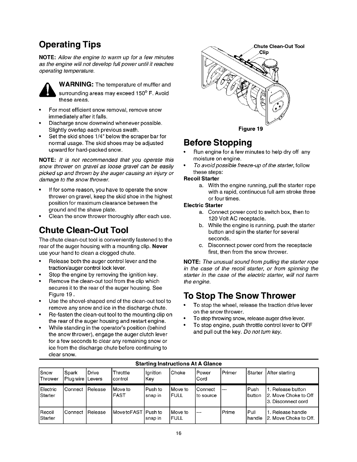
Chute Clean-Out Tool
The chute clean-out tool is conveniently fastened to the
rear of the auger housing with a mounting clip. Never
use your hand to clean a clogged chute.
• Release both the auger control lever and the
traction/auger control lock lever.
• Stop the engine by removing the ignition key.
• Remove the clean-out tool from the clip which
secures it to the rear of the auger housing. See
Figure 19.
• Use the shovel-shaped end of the clean-out tool to
remove any snow and ice in the discharge chute.
• Re-fasten the clean-out tool to the mounting clip on
the rear of the auger housing and restart engine.
• While standing in the operator's position (behind
the snow thrower), engage the auger clutch lever
for a few seconds to clear any remaining snow or
ice from the discharge chute before continuing to
clear snow.
Figure 19
Before Stopping
• Run engine for a few minutes to help dry off any
moisture on engine.
•To avoidpossible freeze-up of the starter, follow
these steps:
Recoil Starter
a. With the engine running, pull the starter rope
with a rapid, continuous full arm stroke three
or four times.
Electric Starter
a. Connect power cord to switch box, then to
120 Volt AC receptacle.
b. While the engine is running, push the starter
button and spin the starter for several
seconds.
c. Disconnect power cord from the receptacle
first, then from the snow thrower.
NOTE: The unusual sound from pulling the starter rope
in the case of the recoil starter, or from spinning the
starter in the case of the electric starter, will not harm
the engine.
To Stop The Snow Thrower
• To stop the wheel, release the traction drive lever
on the snow thrower.
• To stop throwing snow, release auger drive lever.
• To stop engine, push throttle control lever to OFF
and pull out the key. Do nottum key.
Snow Spark Drive
Thrower Plugwire Levers
Electric Connect Release
Starter
Recoil Connect Release
Starter
Thro_le
control
Move to
FAST
Move toFAST
Starting Instructions At A Glance
ignition
Key
Push to
snap in
Push to
snap in
Shake Power Primer
Cord
Move to Connect --
FULL [o source
Move to -- Prime
FULL
Starter
Push
button
Pull
handle
After starting
1. Release button
2. Move Choke to Off
3. Disconnect cord
1. Release handle
2. Move Choke to Off.
16
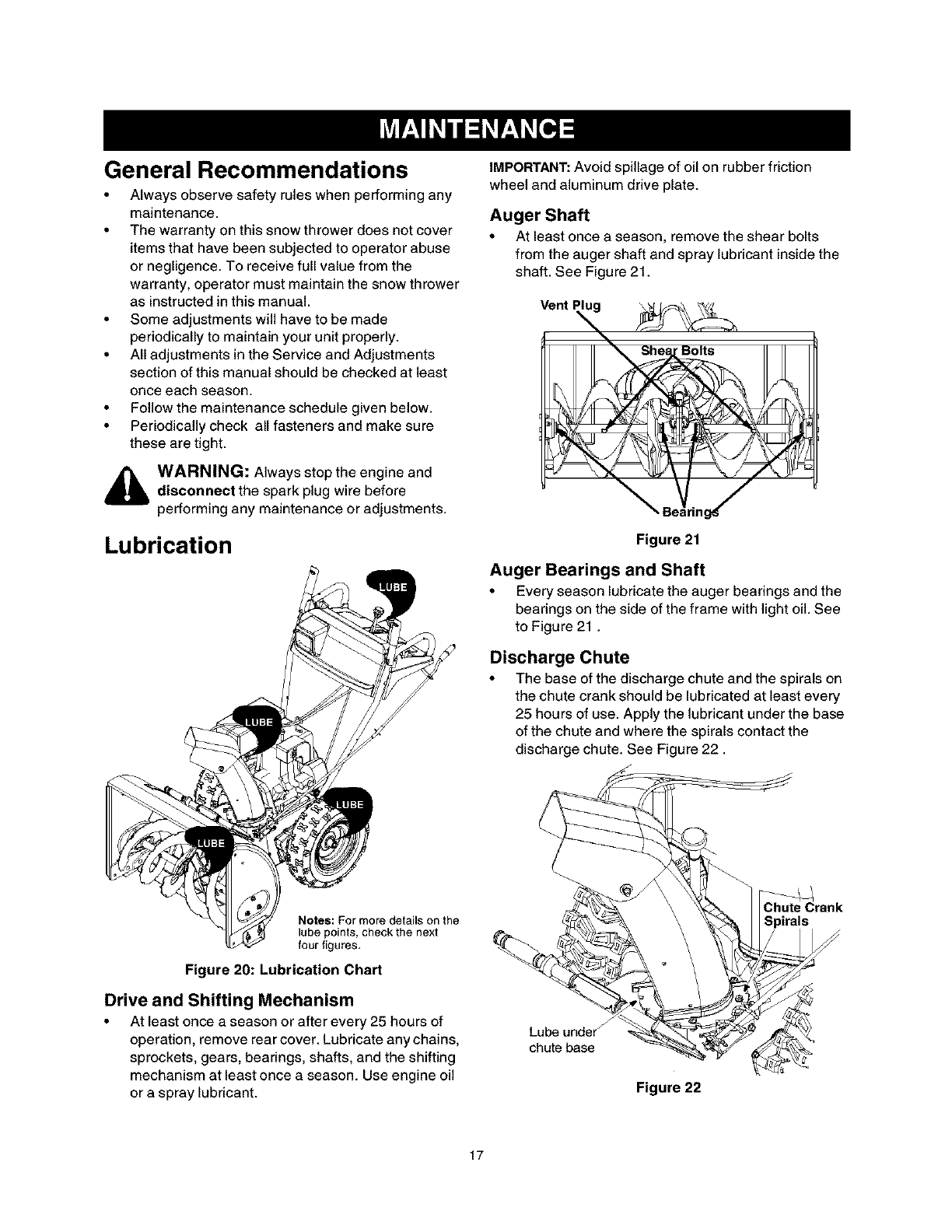
General Recommendations
• Always observe safety rules when performing any
maintenance.
• The warranty on this snow thrower does not cover
items that have been subjected to operator abuse
or negligence. To receive full value from the
warranty, operator must maintain the snow thrower
as instructed in this manual.
• Some adjustments will have to be made
periodically to maintain your unit properly.
• All adjustments in the Service and Adjustments
section of this manual should be checked at least
once each season.
• Follow the maintenance schedule given below.
• Periodically check all fasteners and make sure
these are tight.
,_ WARNING: Always stop the engine and
disconnect the spark plug wire before
performing any maintenance or adjustments.
Lubrication
IMPORTANT: Avoid spillage of oil on rubber friction
wheel and aluminum drive plate.
Auger Shaft
• At least once a season, remove the shear bolts
from the auger shaft and spray lubricant inside the
shaft. See Figure 21.
Vent Plu
Bolts
Figure 21
Auger Bearings and Shaft
•Every season lubricate the auger bearings and the
bearings on the side of the frame with light oil. See
to Figure 21.
Discharge Chute
•The base of the discharge chute and the spirals on
the chute crank should be lubricated at least every
25 hours of use. Apply the lubricant under the base
of the chute and where the spirals contact the
discharge chute. See Figure 22.
Notes: For more details on the
lube points,check the next
four figures,
Figure 20: Lubrication Chart
Drive and Shifting Mechanism
• At least once a season or after every 25 hours of
operation, remove rear cover. Lubricate any chains,
sprockets, gears, bearings, shafts, and the shifting
mechanism at least once a season. Use engine oil
or a spray lubricant.
Lube under f
chute base
Figure 22
Chute Crank
Spirals
17
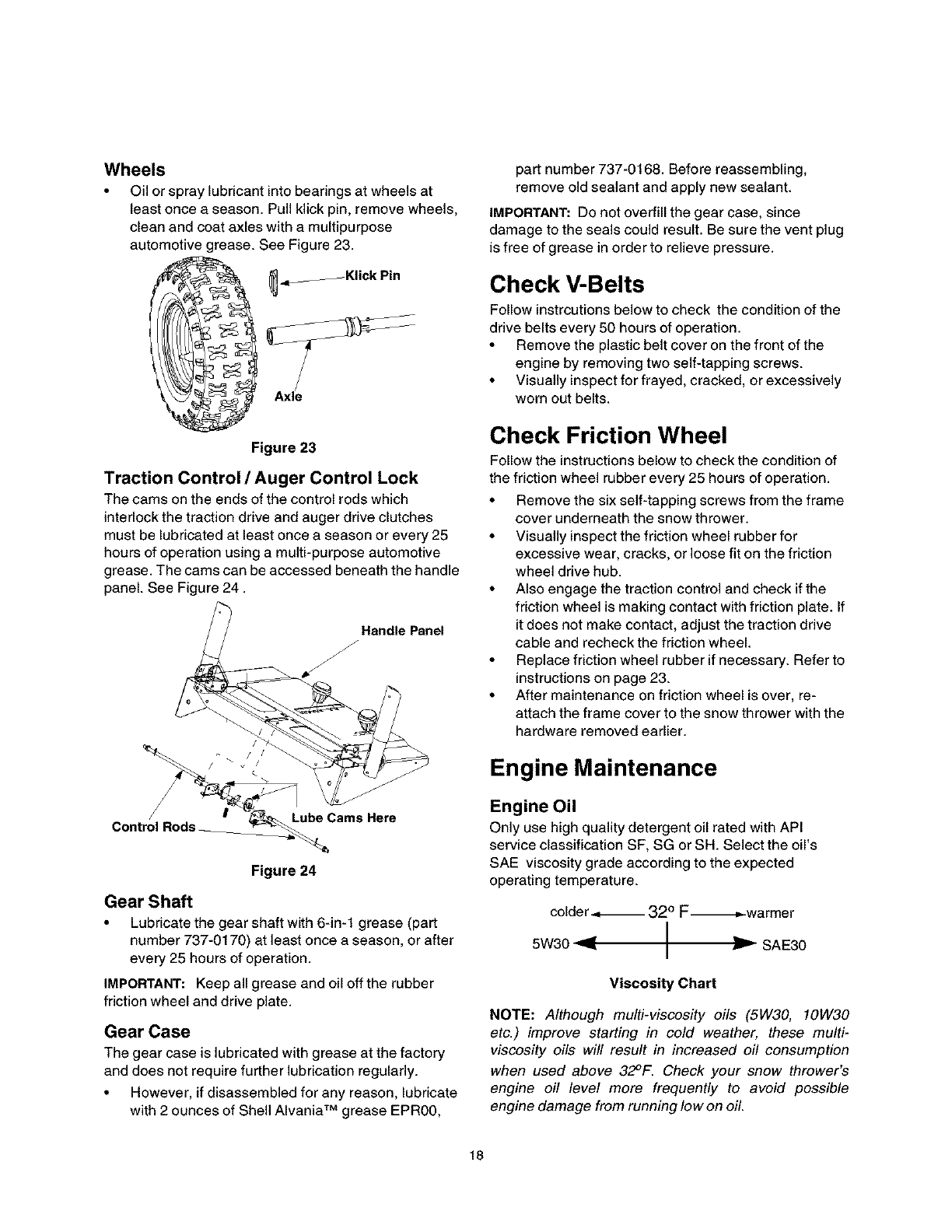
Wheels
•Oil or spray lubricant into bearings at wheels at
least once a season. Pull klick pin, remove wheels,
clean and coat axles with a multipurpose
automotive grease. See Figure 23.
_.,____Klick Pin
Figure 23
Traction Control /Auger Control Lock
The cams on the ends of the control rods which
interlock the traction drive and auger drive clutches
must be lubricated at least once a season or every 25
hours of operation using a multi-purpose automotive
grease. The cams can be accessed beneath the handle
panel. See Figure 24.
anel
Control Rods _ube Cams Here
Figure 24
Gear Shaft
• Lubricate the gear shaft with 6-in-1 grease (part
number 737-0170) at least once a season, or after
every 25 hours of operation.
IMPORTANT: Keep all grease and oil off the rubber
friction wheel and drive plate.
Gear Case
The gear case is lubricated with grease at the factory
and does not require further lubrication regularly.
• However, if disassembled for any reason, lubricate
with 2 ounces of Shell AIvania TM grease EPR00,
part number 737-0168. Before reassembling,
remove old sealant and apply new sealant.
IMPORTANT: Do not overfill the gear case, since
damage to the seals could result. Be sure the vent plug
is free of grease in order to relieve pressure.
Check V-Belts
Follow instrcutions below to check the condition of the
drive belts every 50 hours of operation.
• Remove the plastic belt cover on the front of the
engine by removing two self-tapping screws.
• Visually inspect for frayed, cracked, or excessively
worn out belts.
Check Friction Wheel
Follow the instructions below to check the condition of
the friction wheel rubber every 25 hours of operation.
• Remove the six self-tapping screws from the frame
cover underneath the snow thrower.
• Visually inspect the friction wheel rubber for
excessive wear, cracks, or loose fit on the friction
wheel drive hub.
• Also engage the traction control and check if the
friction wheel is making contact with friction plate. If
it does not make contact, adjust the traction drive
cable and recheck the friction wheel.
• Replace friction wheel rubber ifnecessary. Refer to
instructions on page 23.
• After maintenance on friction wheel is over, re-
attach the frame cover to the snow thrower with the
hardware removed earlier.
Engine Maintenance
Engine Oil
Only use high quality detergent oil rated with API
service classification SF, SG or SH. Select the oil's
SAE viscosity grade according to the expected
operating temperature.
colder .,_,_ 320 F-_-warmer
5W30 _ I
Ir- SAE30
Viscosity Chart
NOTE: Although multi-viscosity oils (5W30, 10W30
etc.) improve starting in cold weather, these multi-
viscosity oils will result in increased oil consumption
when used above 32°F. Check your snow thrower's
engine oil level more frequently to avoid possible
engine damage from running low on oil.
18
Refertotheviscositychartforproperselectionof
engineoil.
CheckingOilLevel
CAUTION:Beforeoperatingthesnowthrower,check
theengineoillevel.
• Withengineonlevelground,theoilmustbeto
FULLmarkondipstick.
• Stopengineandwaitseveralminutesbefore
checkingoillevel.Removeoilfillcapanddipstick.
• Wipedipstickclean,insertitintooilfillholeand
tightensecurely.
• Removedipstickandcheck.Ifoilisnotuptothe
FULLmarkondipstick,addoil
ChangingOil
Changeengineoilafterfirsttwohoursofoperationand
every25hoursthereafter.
Inordertochangetheoil,youwillhavetofirstdrainthe
spentengineoilfromtheengineandthenrefillwith
freshoil
• Drainoilwhileengineiswarm.Removeoildrain
caplocatedatthebottomoftherecoilstarterofthe
engine.CatchoilinasuRablecontainer.
• Whenengineisdrainedofalloil,replacedrainplug
securely.
• Removethedipstickfromtheoilfie Forlocationof
theoilfill,seeFigure17.Pourfreshoilslowly
throughtheplug.Replacedipstick.
,_ WARNING: Temperature of muffler and
nearby areas may exceed 150 ° F(65°0).
Avoid these areas.
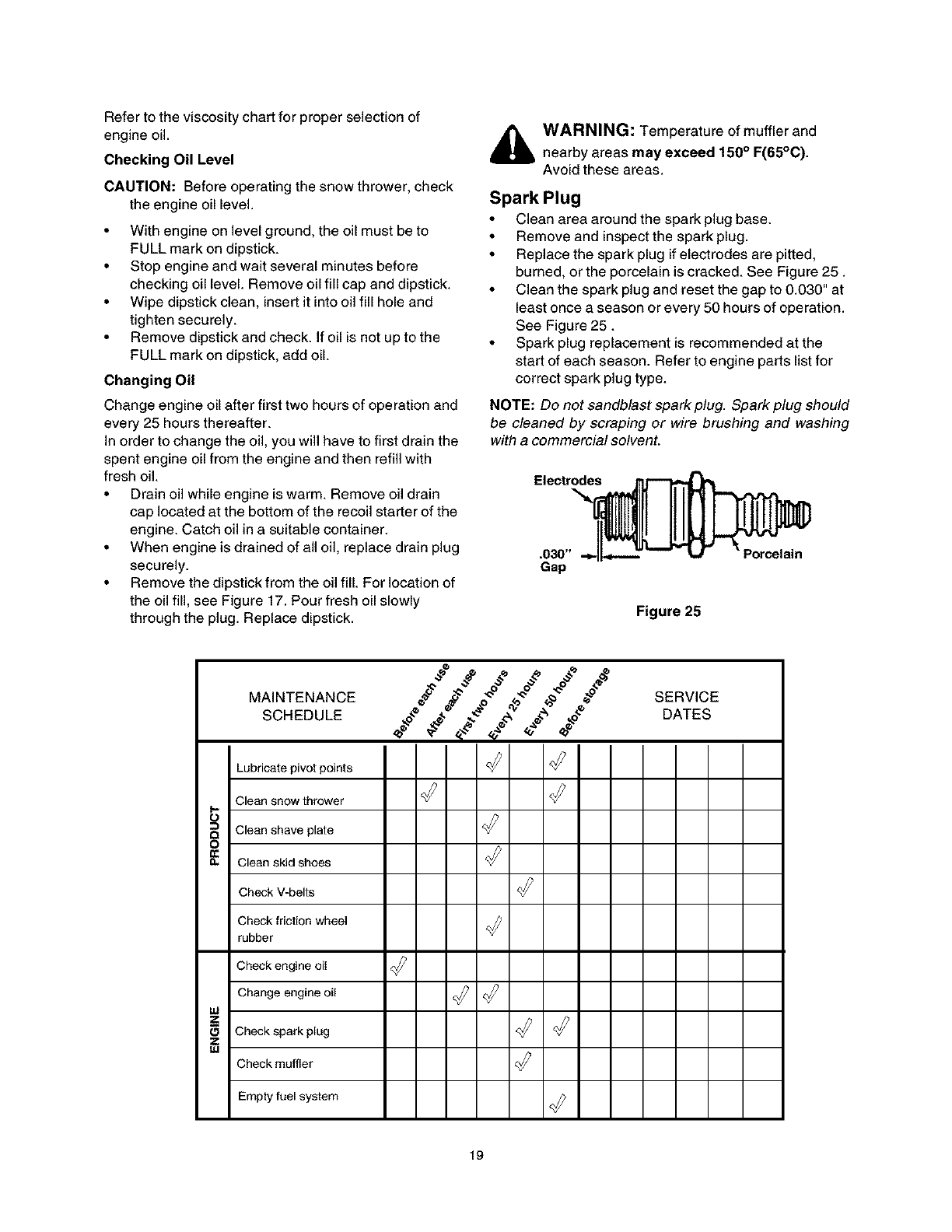
Spark Plug
• Clean area around the spark plug base.
•Remove and inspect the spark plug.
•Replace the spark plug if electrodes are pitted,
burned, or the porcelain is cracked. See Figure 25.
• Clean the spark plug and reset the gap to 0.030" at
least once a season or every 50 hours of operation.
See Figure 25.
•Spark plug replacement is recommended at the
start of each season. Refer to engine parts list for
correct spark plug type.
NOTE: Do not sandblast spark plug. Spark plug should
be cleaned by scraping or wire brushing and washing
with a commercial solvent.
Electr_
Gap
Figure 25
MAINTENANCE
SCHEDULE
Lubricatepivotpoints
Cleansnow thrower
S
_ Clean shave plate
o
I_ Clean skid shoes
Check V-belts
Check friction wheel
rubber
Check engine oil
Change engine oil
uJ
ZCheck spark plug
Z
uJ Check muffler
Empty foel system
SERVICE
DATES
19
WARNING: Always stop the engine,
disconnect spark plug wire and move it away
from the spark plug before performing any
adjustments or repairs.
Adjustments
Chute Assembly
The distance that snow is thrown can be adjusted by
adjusting the angle of the chute assembly. Refer to the
Controls section of this manual.
• The remote chute control cables have been pre-
adjusted at the factory. Move the remote chute
lever on the control panel back and forward to
adjust angle of the chute asssembly.
,_ WARNING: Never attempt to clean chute ormake any adjustments while engine is running.
Skid Shoe
The space between the shave plate and the ground
can be adjusted. For close snow removal, place skid
shoes in the low position. Use middle or high position
when area to be cleared is uneven.
• Adjust skid shoes by loosening the four hex nuts
and carriage bolts and moving skid shoes to
desired position.
• Make certain the entire bottom surface of skid shoe
is against the ground to avoid uneven wear on the
skid shoes.
• Retighten nuts and bolts securely.
NOTE: It is not recommended that you operate this
snow thrower on gravel as loose gravel can be easily
picked up and thrown by the auger causing an injury or
damage to the snow thrower.
• If for some reason, you have to operate the snow
thrower on gravel, keep the skid shoe in the highest
position for maximum clearance between the
ground and the shave plate.
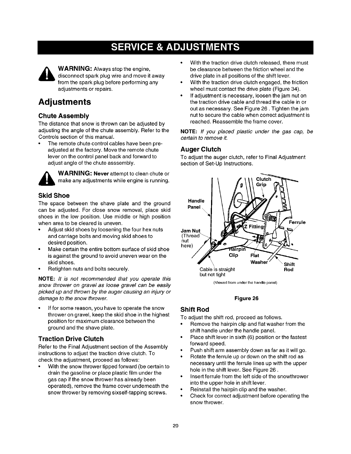
Traction Drive Clutch
Refer to the Final Adjustment section of the Assembly
instructions to adjust the traction drive clutch. To
check the adjustment, proceed as follows:
• With the snow thrower tipped forward (be certain to
drain the gasoline or place plastic film under the
gas cap if the snow thrower has already been
operated), remove the frame cover underneath the
snow thrower by removing sixself-tapping screws.
• With the traction drive clutch released, there must
be clearance between the friction wheel and the
drive plate in all positions of the shift lever.
• With the traction drive clutch engaged, the friction
wheel must contact the drive plate (Figure 34).
• If adjustment is necessary, loosen the jam nut on
the traction drive cable and thread the cable in or
out as necessary. See Figure 26. Tighten the jam
nut to secure the cable when correct adjustment is
reached. Reassemble the frame cover.
NOTE: If you placed plastic under the gas cap, be
certain to remove it.
Auger Clutch
To adjust the auger clutch, refer to Final Adjustment
section of Set-Up Instructions.
Handle
Panel
Jam Nut
nut
here)
Clip
\
Cable is straight
but not tight
(Viewed from under _he h_ndle panel)
\Shift
Rod
Figure 26
Shift ROd
To adjust the shift rod, proceed as follows.
• Remove the hairpin clip and flat washer from the
shift handle under the handle panel.
• Place shift lever in sixth (6) position or the fastest
forward speed.
• Push shift arm assembly down as far as it will go.
• Rotate the ferrule up or down on the shift rod as
necessary until the ferrule lines up with the upper
hole in the shift lever. See Figure 26.
• Insert ferrule from the left side of the snowthrower
into the upper hole in shift lever.
• Reinstall the hairpin clip and the washer.
• Check for correct adjustment before operating the
snow thrower.
2O
Carburetor
WARNING: If any adjustments are made to
the engine while the engine is running (e.g.
carburetor), keep clear of all moving parts. Be
careful of heated surfaces and mufflers.
Minor carburetor adjustments may be required to
compensate for differences in fuel temperature, altitude
and load.
Service
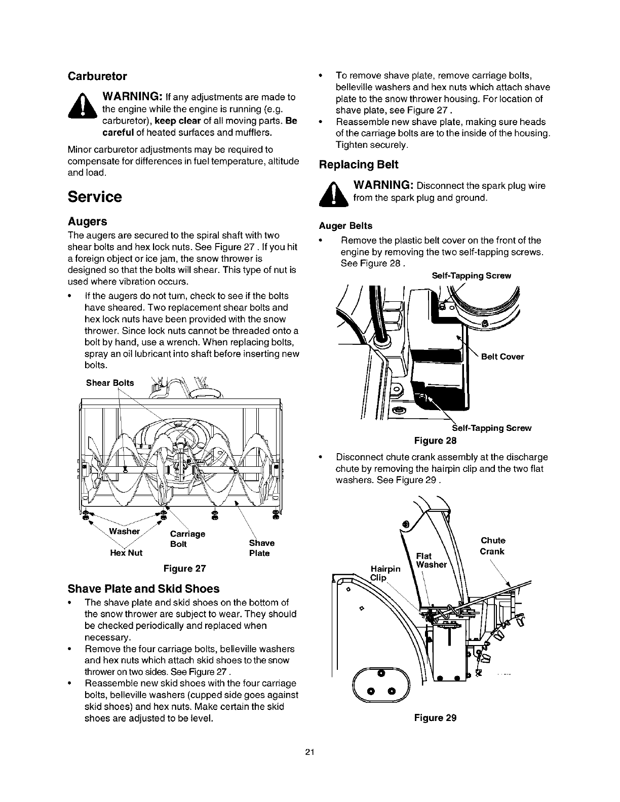
Augers
The augers are secured to the spiral shaft with two
shear bolts and hex lock nuts. See Figure 27. If you hit
a foreign object or ice jam, the snow thrower is
designed so that the bolts will shear. This type of nut is
used where vibration occurs.
• If the augers do not turn, check to see if the bolts
have sheared. Two replacement shear bolts and
hex lock nuts have been provided with the snow
thrower. Since lock nuts cannot be threaded onto a
bolt by hand, use a wrench. When replacing bolts,
spray an oil lubricant into shaft before inserting new
bolts.
• To remove shave plate, remove carriage bolts,
belleville washers and hex nuts which attach shave
plate to the snow thrower housing. For location of
shave plate, see Figure 27.
• Reassemble new shave plate, making sure heads
of the carriage bolts are to the inside of the housing.
Tighten securely.
Replacing Belt
,_ WARNING: Disconnect the spark plug wirefrom the spark plugand ground.
Auger Belts
• Remove the plastic belt cover on the front of the
engine by removing the two self-tapping screws.
See Figure 28.
Self-Tapping Screw
Hex Nut
Carriage
Bolt Shave
Plate
Figure 27
Shave Plate and Skid Shoes
• The shave plate and skid shoes on the bottom of
the snow thrower are subject to wear. They should
be checked periodically and replaced when
necessary.
• Remove the four carriage bolts, belleville washers
and hex nuts which attach skid shoes tothe snow
thrower on two sides. See Figure 27.
• Reassemble new skid shoes with the four carriage
bolts, belleville washers (cupped side goes against
skid shoes) and hex nuts. Make certain the skid
shoes are adjusted to be level.
Self-Tapping Screw
Figure 28
Disconnect chute crank assembly at the discharge
chute by removing the hairpin clip and the two flat
washers. See Figure 29.
Chute
Crank
Hairpin
Figure 29
21
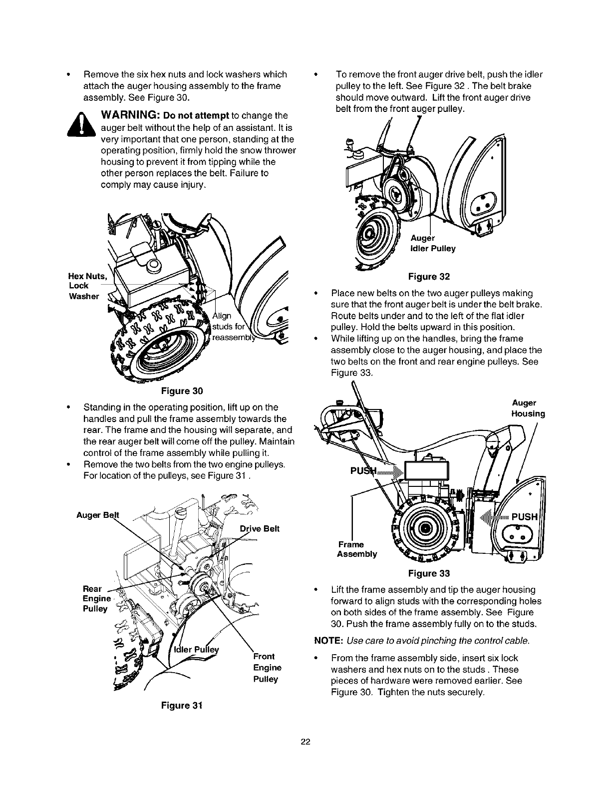
• Removethesixhexnutsendlockwasherswhich
attachtheaugerhousingassemblytotheframe
assembly.SeeFigure30.
WARNING: Do not attempt to change the
auger belt without the help of an assistant. It is
very important that one person, standing at the
operating position, firmly hold the snow thrower
housing to prevent it from tipping while the
other person replaces the belt. Failure to
comply may cause injury.
To remove the front auger drive belt, push the idler
pulley to the left. See Figure 32. The belt brake
should move outward. Lift the front auger drive
belt from the front auger pulley.
Idler Pulley
Hex Nuts,
Lock
Washer
Figure 30
• Standing in the operating position, lift up on the
handles end pull the frame assembly towards the
rear. The frame and the housing will separate, end
the rear auger belt will come off the pulley. Maintain
control of the frame assembly while pulling it.
• Remove the two belts from the two engine pulleys.
For location of the pulleys, see Figure 31.
\
Rear
Engine
Pulley
Belt
Front
Engine
Pulley
Figure 31
Figure 32
Place new belts on the two auger pulleys making
sure that the front auger belt is under the belt brake.
Route belts under and to the left of the flat idler
pulley. Hold the belts upward in this position.
While lifting up on the handles, bring the frame
assembly close to the auger housing, and place the
two belts on the front and rear engine pulleys. See
Figure 33.
Auger
Housing
Pt
Frame
Assembly
Figure 33
• Lift the frame assembly and tip the auger housing
forward to align studs with the corresponding holes
on both sides of the frame assembly. See Figure
30. Push the frame assembly fully on to the studs.
NOTE: Use care to avoid pinching the control cable.
From the frame assembly side, insert six lock
washers and hex nuts on to the studs. These
pieces of hardware were removed earlier. See
Figure 30. Tighten the nuts securely.
22
• Reinstallthebeltcoveronfrontoftheenginewith
thetwoself-tappingscrewsandflatwashers.
• Reattachthechutecranktothechuteassembly
withthehairpinclipandflatwasher.
NOTE:Make sure that the auger cable is routed in front
of the belt.
Drive Belt
• Check drive belt every 50 hours of operation for
wear and tear.
• Drain the gasoline from the snow thrower, or place
a piece of plastic under the gas cap.
• Remove the plastic belt cover on the front of the
engine by removing the two self-tapping screws.
• Tip the snow thrower up and forward, so that it
rests on the housing.
• Remove six self-tapping screws from frame cover
underneath the snow thrower.
• Pull the idler pulley away from the drive belt and
remove the belt from the engine pulley. You will
find the idler pulley in front of the engine and under
the belt cover that you removed earlier. See
Figure 31.
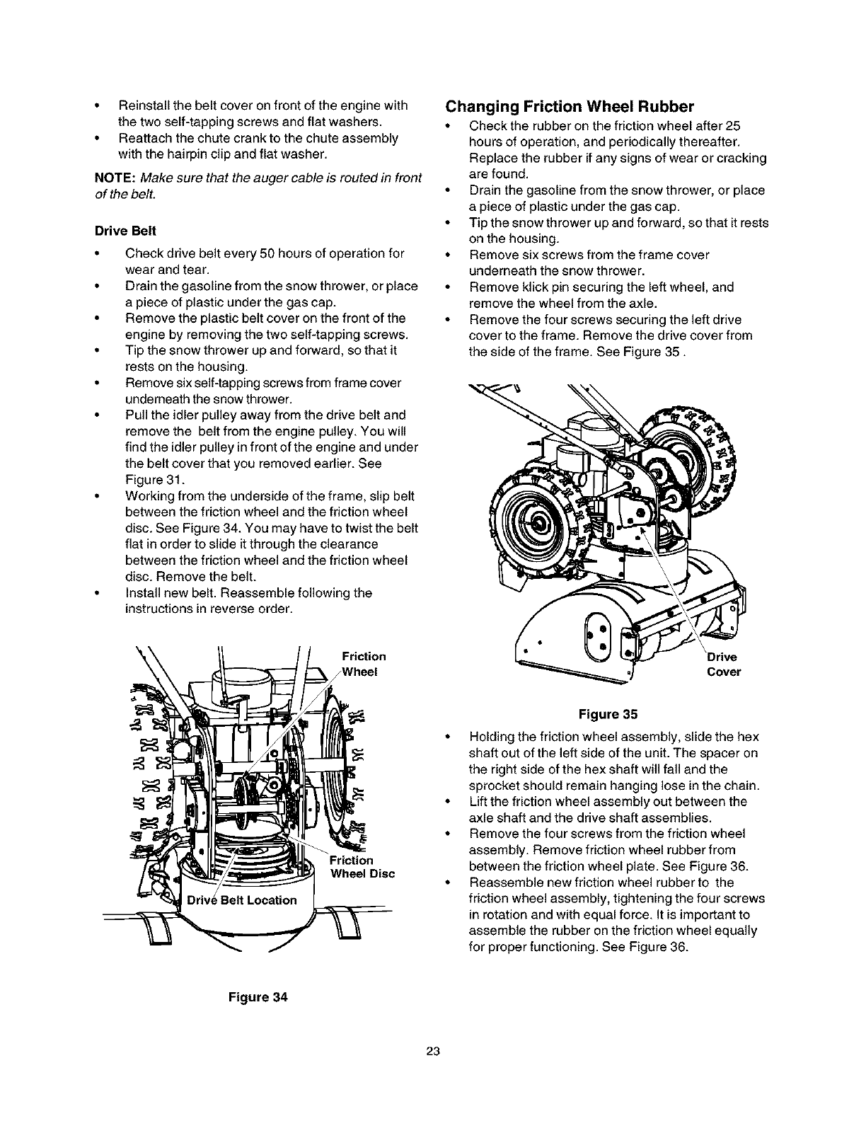
• Working from the underside of the frame, slip belt
between the friction wheel and the friction wheel
disc. See Figure 34. You may have to twist the belt
flat in order to slide it through the clearance
between the friction wheel and the friction wheel
disc. Remove the belt.
• Install new belt. Reassemble following the
instructions in reverse order.
Friction
JWheel
Friction
Wheel Disc
Changing Friction Wheel Rubber
• Check the rubber on the friction wheel after 25
hours of operation, and periodically thereafter.
Replace the rubber if any signs of wear or cracking
are found.
• Drain the gasoline from the snow thrower, or place
a piece of plastic under the gas cap.
• Tip the snow th rower up and forward, so that it rests
on the housing.
• Remove six screws from the frame cover
underneath the snow thrower.
• Remove klick pin securing the left wheel, and
remove the wheel from the axle.
• Remove the four screws securing the left drive
cover to the frame. Remove the drive cover from
the side of the frame. See Figure 35.
\Drive
Cover
Figure 35
• Holding the friction wheel assembly, slide the hex
shaft out of the left side of the unit. The spacer on
the right side of the hex shaft will fall and the
sprocket should remain hanging lose in the chain.
• Lift the friction wheel assembly out between the
axle shaft and the drive shaft assemblies.
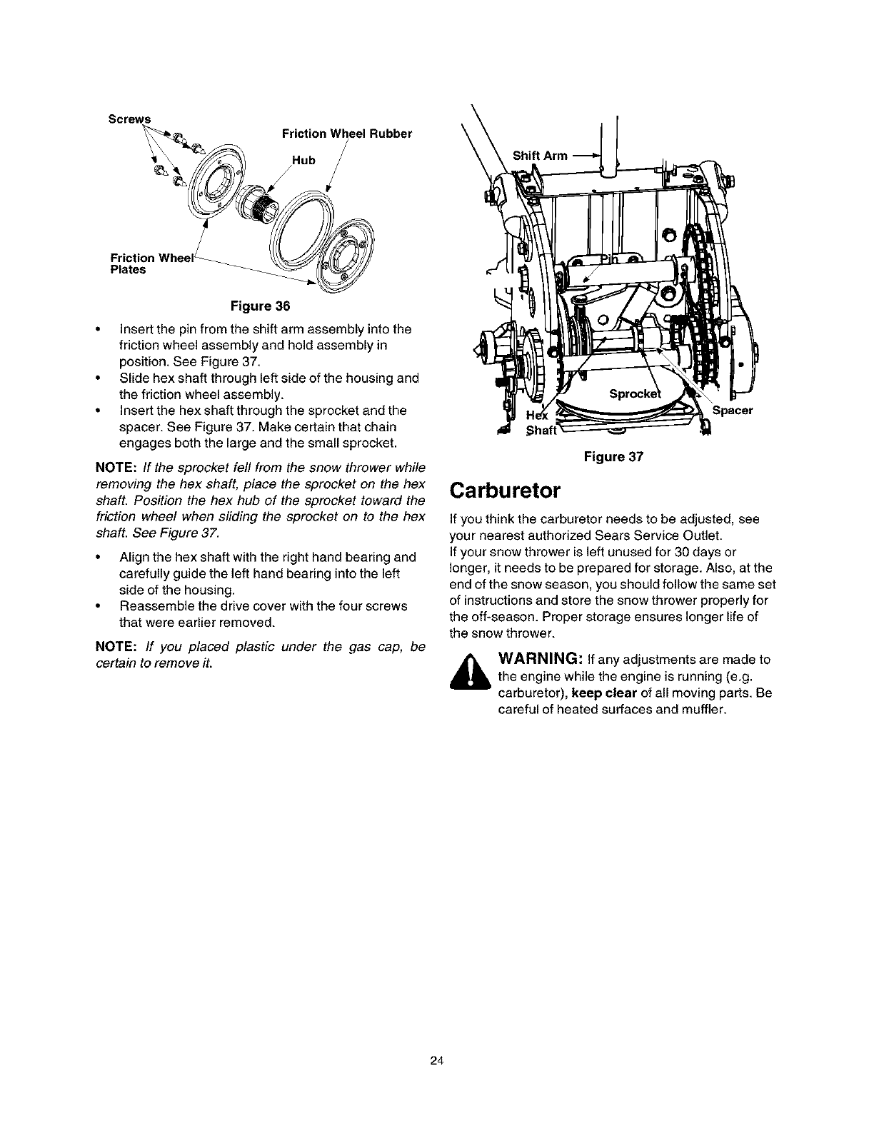
• Remove the four screws from the friction wheel
assembly. Remove friction wheel rubber from
between the friction wheel plate. See Figure 36.
• Reassemble new friction wheel rubber to the
friction wheel assembly, tightening the four screws
in rotation and with equal force. It is important to
assemble the rubber on the friction wheel equally
for proper functioning. See Figure 36.
Figure 34
23
Screws
Friction Wheel_
Plates
Figure 36
• Insert the pin from the shift arm assembly into the
friction wheel assembly and hold assembly in
position. See Figure 37.
• Slide hex shaft through left side of the housing and
the friction wheel assembly.
• Insert the hex shaft through the sprocket and the
spacer. See Figure 37. Make certain that chain
engages both the large and the small sprocket.
NOTE: If the sprocket fell from the snow thrower while
removing the hex shaft, place the sprocket on the hex
shaft. Position the hex hub of the sprocket toward the
friction wheel when sliding the sprocket on to the hex
shaft. See Figure 37.
• Align the hex shaft with the right hand bearing and
carefully guide the left hand bearing into the left
side of the housing.
• Reassemble the drive cover with the four screws
that were earlier removed.
NOTE: If you placed plastic under the gas cap, be
certain to remove it.
Shift Arm
Spacer
Figure 37
Carburetor
If you think the carburetor needs to be adjusted, see
your nearest authorized Sears Service Outlet.
If your snow thrower is left unused for 30 days or
longer, it needs to be prepared for storage. Also, at the
end of the snow season, you should follow the same set
of instructions and store the snow thrower properly for
the off-season. Proper storage ensures longer life of
the snow thrower.
WARNING: If any adjustments are made to
the engine while the engine is running (e.g.
carburetor), keep clear of all moving parts. Be
careful of heated surfaces and muffler.
24
Ifthesnowthrowerwillnotbeusedfor30daysor
longer,orattheendofthesnowseasonwhenthelast
possibilityofsnowisgone,theequipmentneedstobe
storedproperly.Followstorageinstructionsbelowto
ensuretopperformancefromthesnowthrowerfor
manymoreyears.
Preparing the Engine
WARNING: Never store snow thrower with
fuel in tank indoors or in poorly ventilated
areas, where fuel fumes may reach an open
flame, spark or pilot light as on a furnace, water
heater, clothes dryer or gas appliance.
NOTE: It is important to prevent gum deposits from
forming in essential fuel system parts of the engine
such as the carburetor, fuel filter, fuel hose or tank
during storage. Also experience indicates that alcohol
blended fuels (called gasohol or using ethanol or
methanol) can attract moisture which leads to
separation and formation of acids during storage.
Acidic gas can damage the fuel system of an engine
while in storage.
• To avoid engine problems, the fuel system should
be emptied before storage for 30 days or longer.
Follow these instructions to prepare your snow
thrower for storage:
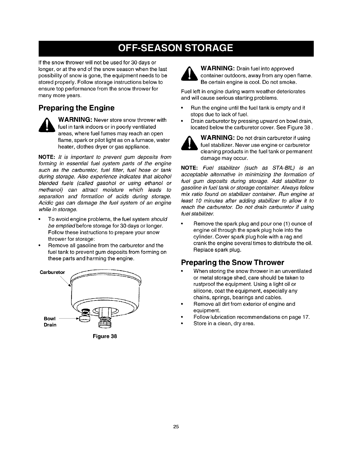
• Remove all gasoline from the carburetor and the
fuel tank to prevent gum deposits from forming on
these parts and harming the engine.
Carburet__j
Bowl
Drain
Figure 38
,_ WARNING: Drain fuel into approved
container outdoors, away from any open flame.
Be certain engine is cool. Do not smoke.
Fuel left in engine during warm weather deteriorates
and will cause serious starting problems.
• Run the engine until the fuel tank is empty and it
stops due to lack of fuel.
• Drain carburetor by pressing upward on bowl drain,
located below the carburetor cover. See Figure 38.
,_ WARNING: Do not drain carburetor if using
fuel stabilizer. Never use engine or carburetor
cleaning products in the fuel tank or permanent
damage may occur.
NOTE: Fuel stabilizer (such as STA-BIL) is an
acceptable alternative in minimizing the formation of
fuel gum deposits during storage. Add stabilizer to
gasoline in fuel tank or storage container. Always follow
mix ratio found on stabilizer container. Run engine at
least 10 minutes after adding stabilizer to allow it to
reach the carburetor. Do not drain carburetor if using
fuel stabilizer.
Remove the spark plug and pour one (1) ounce of
engine oil through the spark plug hole into the
cylinder. Cover spark plug hole with a rag and
crank the engine several times to distribute the oil.
Replace spark plug.
Preparing the Snow Thrower
• When storing the snow thrower in an unventilated
or metal storage shed, care should be taken to
rustproof the equipment. Using a light oil or
silicone, coat the equipment, especially any
chains, springs, bearings and cables.
• Remove all dirt from exterior of engine and
equipment.
• Follow lubrication recommendations on page 17.
• Store in a clean, dry area.
25
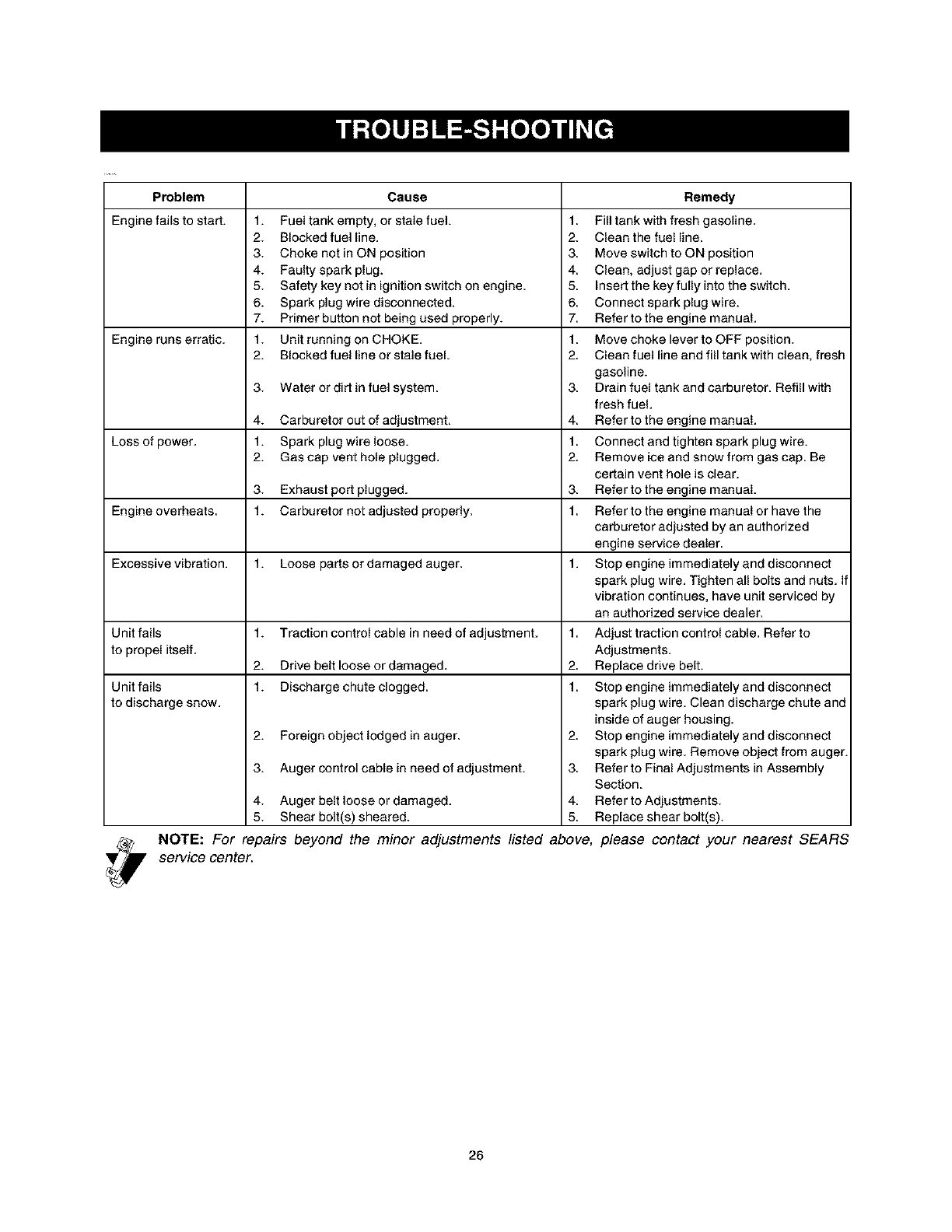
Problem Cause
Engine fails to start. 1. Fuel tank empty, or stale fuel. 1.
2. Blocked fuel line. 2.
3. Choke not in ON position 3.
4. Faulty spark plug. 4
5. Safety key not in ignition switch on engine 5.
6. Spark plug wire disconnected. 6
7. Primer button nat being used properly. 7
Engine runs erratic. 1. Unit running on CHOKE. 1
2. Blocked fuel line or stale fuel. 2.
3. Water or dirt in fuel system 3.
4. Carburetor out of adjustment. 4
Loss of power 1. Spark plug wire loose. 1
2. Gas cap vent hole plugged. 2.
3. Exhaust part plugged. 3.
Engine overheats. 1. Carburetor not adjusted properly. 1.
Excessive vibration. 1. Loose parts or damaged auger. 1.
Unit fails 1. Traction control cable in need of adjustment. 1.
to propel itself.
2. Drive belt loose or damaged. 2.
Unit fails 1. Discharge chute clogged. 1.
to discharge snow.
2. Foreign object lodged in auger.
3. Auger control cable in need of adjustment.
2.
3.
NOTE: For repairs beyond the minor adjustments listed above,
service center.
Remedy
Fill tank with fresh gasoline
Clean the fuel line
Move switch to ON position
Clean, adjust gap or replace.
Insert the key fully into the switch.
Connect spark plug wire.
Refer to the engine manual.
Move choke lever to OFF position.
Clean fuel line and fill tank with clean, fresh
gasoline.
Drain fuel tank and carburetor. Refill with
fresh fuel.
Refer to the engine manual.
Connect and tighten spark plug wire.
Remove ice and snow from gas cap. Be
certain vent hole is clear.
Refer to the engine manual.
Refer to the engine manual or have the
carburetor adjusted by an authorized
engine service dealer.
Stop engine immediately and disconnect
spark plug wire. Tighten all bolts and nuts. If
vibration continues, have unit serviced by
an authorized service dealer.
Adjust traction control cable. Refer to
Adjustments.
Replace drive belt.
Stop engine immediately and disconnect
spark plug wire. Clean discharge chute and
inside of auger housing.
Stop engine immediately and disconnect
spark plug wire. Remove object from auger.
Refer to Final Adjustments in Assembly
Section.
4. Auger belt loose or damaged. 4 Refer to Adjustments.
5. Shear bolt(s) sheared. 5. Replace shear bolt(s).
please contact your nearest SEARS
26
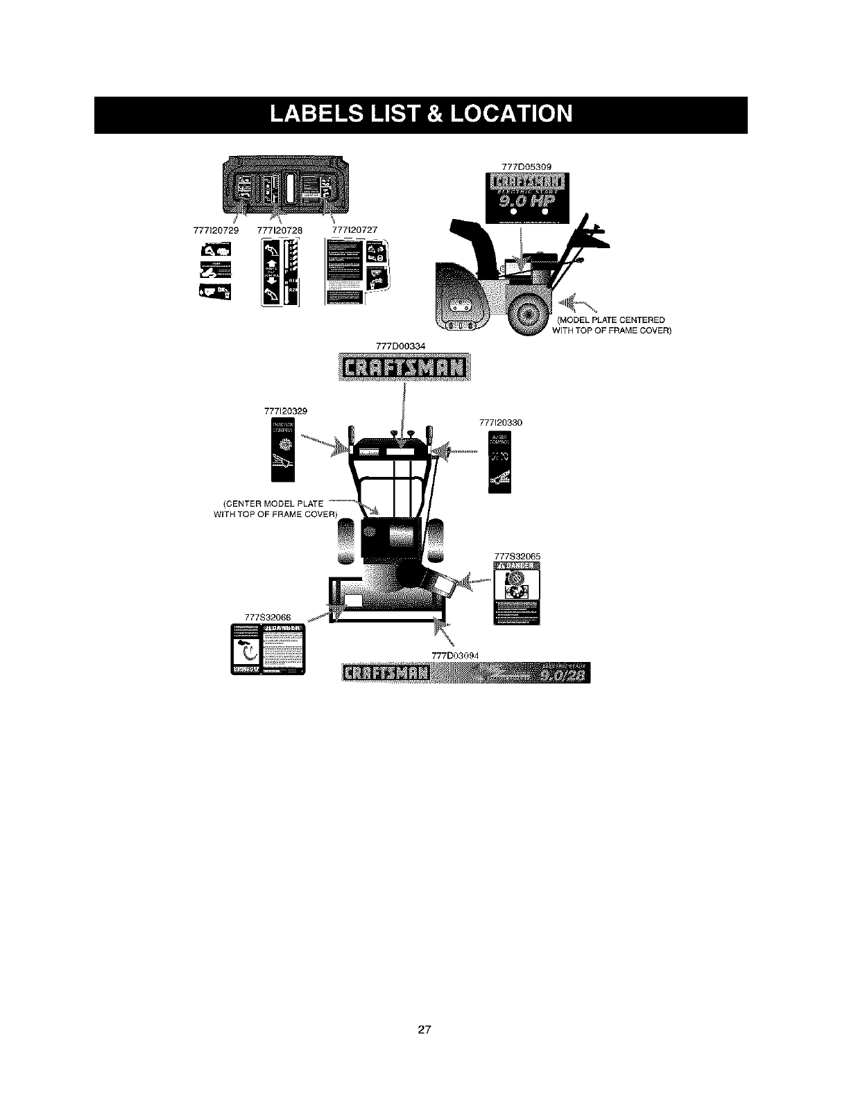
777D05309
777_20729 777120728 777120727
777D00334
(MODELPLATECENTERED
WITH TOP OF FRAME COVER)
777120329
777120330
(CENTER MODEL PLATE
777S32065
777S32066
777D03094
27
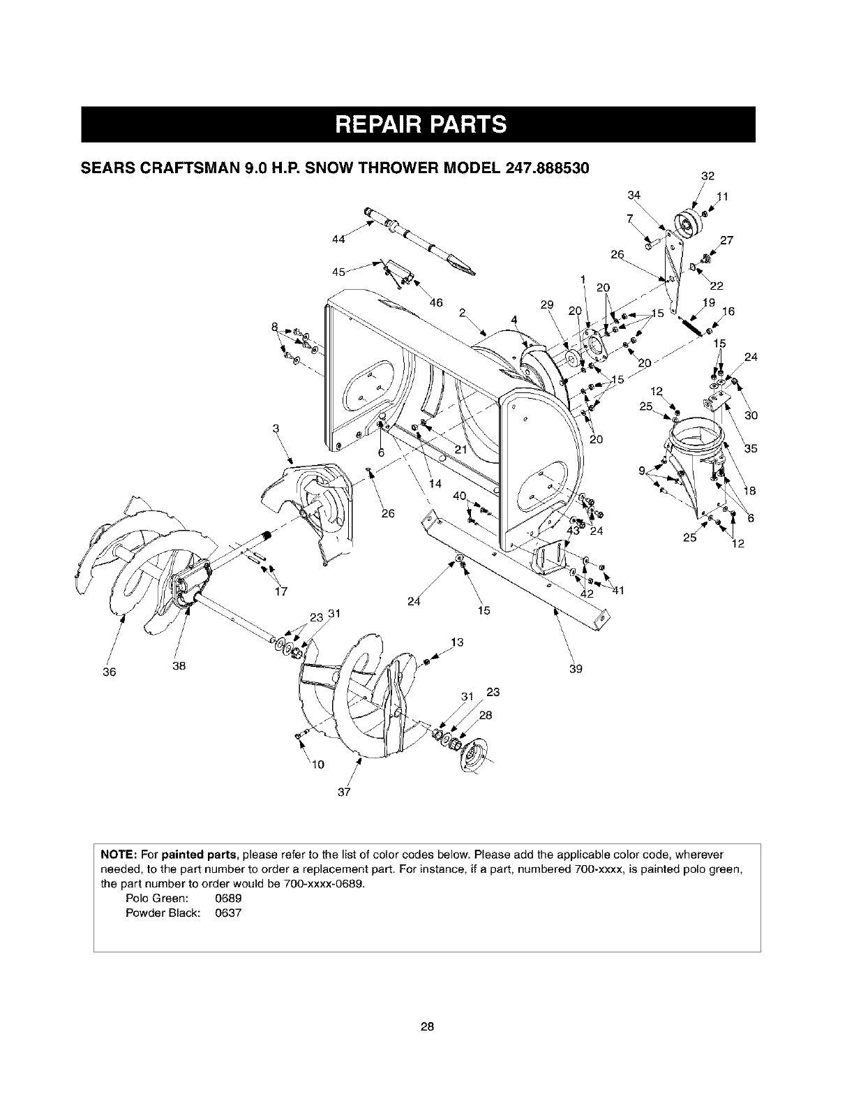
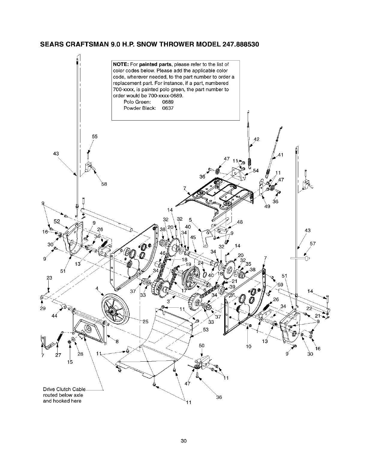
SEARS CRAFTSMAN 9.0 H.P. SNOW THROWER MODEL 247.888530
44
29
4
3
\
2O
17 24_ \
31 15
13 \
/38 _ \
36 " 39
\1o
/
37
31/23
28
f
NOTE: For painted parts, please refer to the list of color codes below. Please add the applicable color code, wherever
needed, to the part number to order a replacement part. For instance, if a part, numbered 700-xxxx, is painted polo green,
the part number to order would be 700-xxxx-0689.
Polo Green: 0689
Powder Black: 0637
28
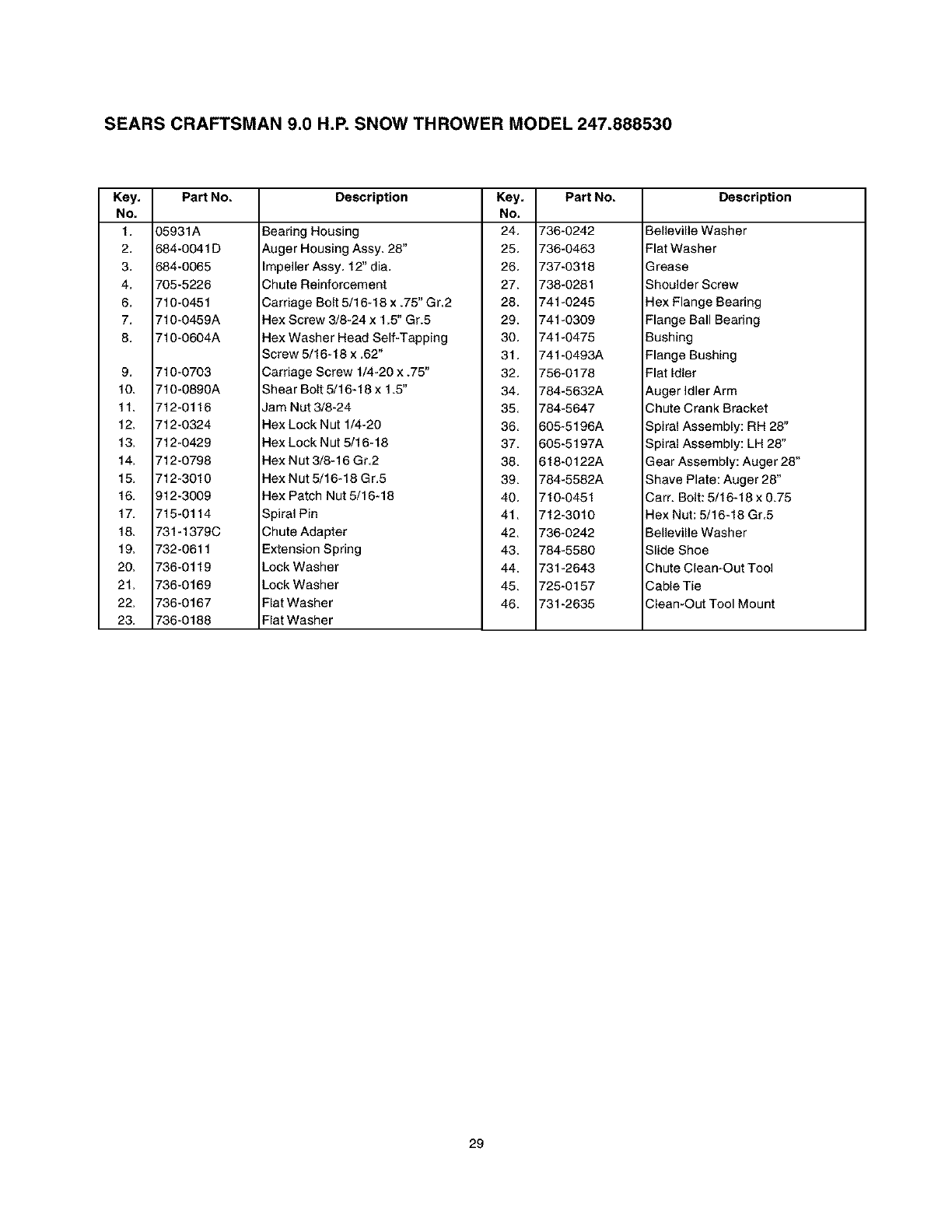
SEARS CRAFTSMAN 9.0 H.P. SNOW THROWER MODEL 247.888530
Key, Part No.
No,
1. 35931A
2. 584-0041 D
3. 584-0065
4. 705-5226
6. 710-0451
7. 710-0459A
8. 710-0604A
9. 710-0703
10. 710-0890A
11. 712-0116
12. 712-0324
13. 712-0429
14. 712-O798
15. 712-3010
16. )12-3009
17. 715-0114
18. 731-1379C
19. 732-0611
20. 736-0119
21. 736-0169
22. 736-0167
23. 736-O188
Description Key, Part No.
No,
Bearing Housing 24, 736-0242
Auger Housing Assy. 28" 25, 736-0463
impeller Assy, 12" dia. 26, 737-0318
Chute Reinforcement 27. 738-0281
Carriage Bolt 5/16-18 x .75" Gr,2 28. 741-0245
Hex Screw 3/8-24 x 1.5" Gr.5 29. 741-0309
Hex Washer Head Self-Tapping 30, 741-0475
Screw 5/16-18 x .62" 31, 741-0493A
Carriage Screw 1/4-20 x .75" 32, 756-0178
Shear Bolt 5/16-18 x 1.5' 34, 784-5632A
Jam Nut 3/8-24 35, 784-5647
Hex Lock Nut 1/4-20 36, 605-5196A
Hex Lock Nut 5/16-18 37, 605-5197A
Hex Nut 3/8-16 Gr,2 38, 618-0122A
Hex Nut 5/16-18 Gr.5 39. 784-5582A
Hex Patch Nut 5/16-18 40, 710-0451
Spiral Pin 41, 712-3010
Chute Adapter 42, 736-0242
Extension Spring 43, 784-5580
Lock Washer 44, 731-2643
Lock Washer 45, 725-0157
Flat Washer 46, 731-2635
Flat Washer
Description
Betleville Washer
Flat Washer
Grease
Shoulder Screw
Hex Flange Bearing
Flange Ball Bearing
Bushing
Flange Bushing
Flat Idler
Auger Idler Arm
Chute Crank Bracket
Spiral Assembly: RH 28"
Spiral Assembly: LH 28"
Gear Assembly: Auger 28"
Shave Plate: Auger 28"
Cam Bolt: 5/16-18 x 0.75
Hex Nut: 5/16-18 Gr,5
Belleville Washer
Slide Shoe
Chute Clean-Out Tool
Cable Tie
Clean-Out Tool Mount
29
SEARS CRAFTSMAN 9.0 H.P. SNOW THROWER MODEL 247.888530
43
\\\\\\\\
6(
23
44
27
15
Drive Clutch Cable
routed below axle
and hooked here
55
58
9
\\\
NOTE: For painted parts, please refer to the list of
color codes below. Please add the applicable color
code, wherever needed, to the part number to order a
replacement part. For instance, if a part, numbered
700-xxxx, is painted polo green, the part number to
order would be 700-xxxx-0689.
Polo Green: 0689
Powder Black: 0637
47
14
I
32 .748
32 14
J
3/
I
36
42
lO
41
11
\ 36
49
7
13
43
57
,//
14
3O
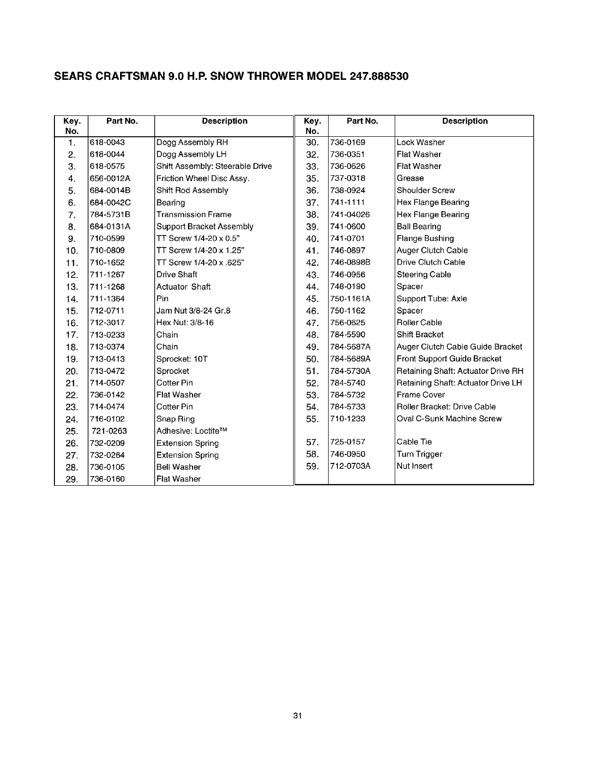
SEARS CRAFTSMAN 9.0 H.P. SNOW THROWER MODEL 247.888530
Key, Part No.
No,
1. 618-0043
2. 618-0044
3. 618-0575
4. 656-0012A
5. 684-0014B
6. 684-0042C
7. 784-5731B
8. 684-0131A
9. 710-0599
10. 710-0809
11. 710-1652
12. 711-1267
13. 711-1268
14. 711-1364
15. 712-0711
16. 712-3017
17. 713-0233
18. 713-0374
19. 713-0413
20. 713-0472
21. 714-0507
22. 736-0142
23. 714-0474
24. 716-0102
25. 721-0263
26. 732-O2O9
27. 732-O264
28. 736-0105
29. 736-0160
Description
Degg Assembly RH
Degg Assembly LH
Shift Assembly: Steerable Drive
Friction Wheel Disc Assy,
Shift Rod Assembly
Bearing
Transmission Frame
Support Bracket Assembly
TT Screw 1/4-20 x 0.5"
TT Screw 1/4-20 x 1,25"
TT Screw 1/4-20 x .625"
Key, Part No.
No.
30. 736-0169
32. 736-0351
33. 736-0626
35. 737-0318
36. 738-0924
37. 741-1111
38. 741-04026
39. 741-0600
40. 741-0701
41. 746-0897
42. 746-0898B
Description
Lock Washer
Flat Washer
Flat Washer
Grease
Shoulder Screw
Hex Flange Bearing
Hex Flange Bearing
Ball Bearing
Flange Bushing
Auger Clutch Cable
Drive Clutch Cable
Drive Shaft
Actuator Shaft
Pin
Jam Nut 3/8-24 Gr8
Hex Nut: 3/8-16
Chain
Chain
Sprocket: 10T
Sprocket
Cotter Pin
Flat Washer
Cotter Pin
Snap Ring
Adhesive: Lectite TM
Extension Spring
Extension Spring
Bell Washer
Flat Washer
43. 746-0956
44. 748-0190
45. 750-1161A
46. 750-1162
47. 756-0625
48. 784-559O
49. 784-5687A
50. 784-5689A
51. 784-5730A
52. 784-5740
53. 784-5732
54. 784-5733
55. 710-1233
57. 725-0157
58. 746-0950
59. 712-0703A
Steering Cable
Spacer
Support Tube: Axle
Spacer
Roller Cable
Shift Bracket
Auger Clutch Cable Guide Bracket
Front Support Guide Bracket
Retaining Shaft: Actuator Drive RH
Retaining Shaft: Actuator Drive LH
Frame Cover
Roller Bracket: Drive Cable
Oval C-Sunk Machine Screw
Cable Tie
Turn Trigger
Nut Insert
31
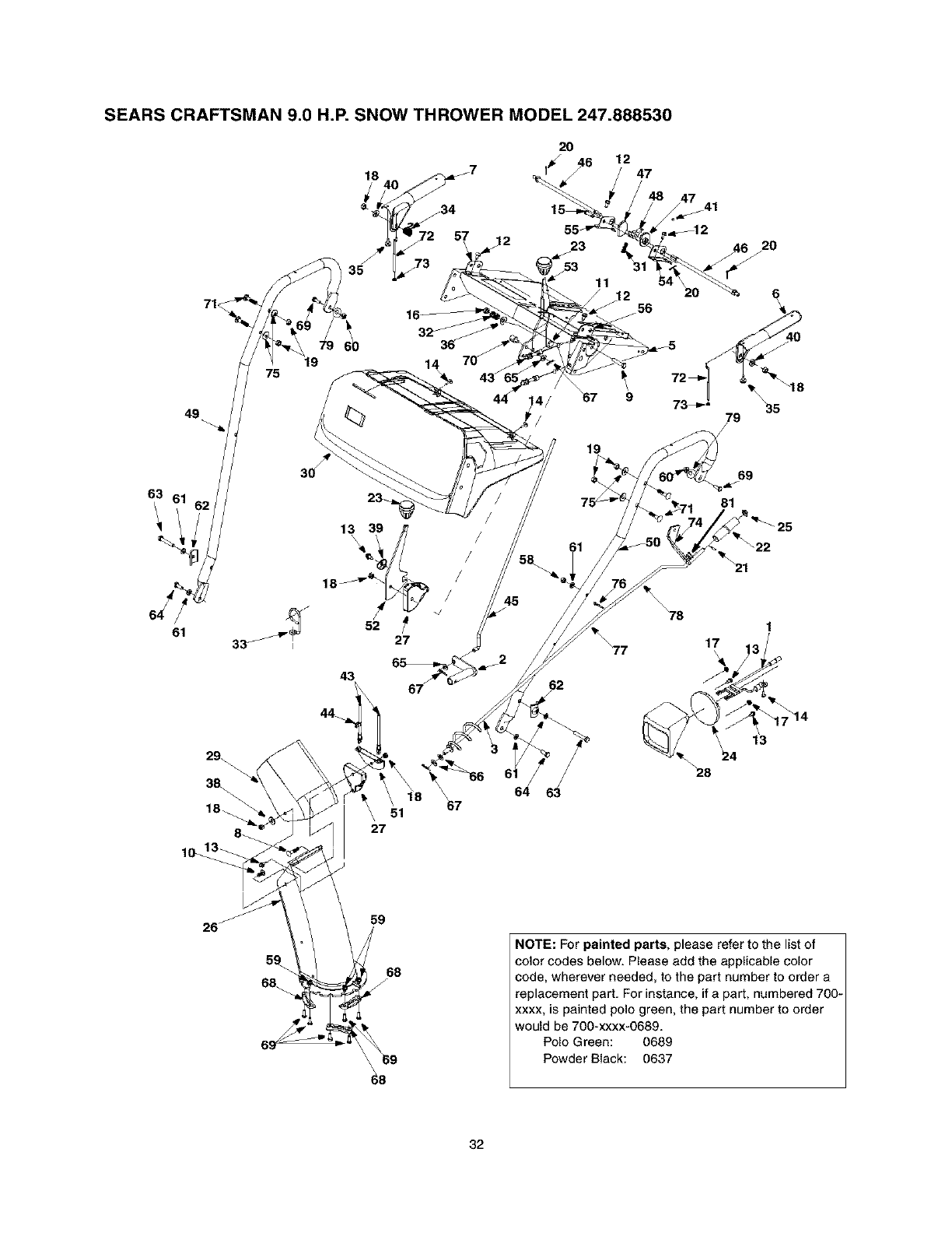
SEARS CRAFTSMAN 9.0 H.P. SNOW THROWER MODEL 247.888530
63
49
61
75
_67
51
27
2O
4/ 67 9
19
69
81
21
62
78 1
28
59
68
f
NOTE: For painted parts, please refer to the list of
color codes below. Please add the applicable color
code, wherever needed, to the part number to order a
replacement part. For instance, if a part, numbered 700-
xxxx, is painted polo green, the part number to order
would be 700-xxxx-0689.
Polo Green: 0689
Powder Black: 0637
32
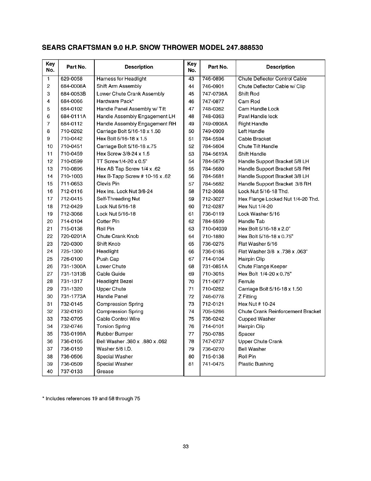
SEARS CRAFTSMAN 9.0 H.P. SNOW THROWER MODEL 247.888530
Key Part No.
No.
1 629-0058
2 684-0008A
3 684-0053B
4 684-0066
5 684-0102
6 684-0111A
7 684-0112
8 710-0262
9 710-0442
10 710-0451
11 710-0459
12 710-0599
13 710-0896
14 710-1003
15 711-0653
16 712-0116
17 712-0415
18 712-0429
19 712-3068
20 714-0104
21 715-0138
22 720-0201A
23 720-0300
24 725-1300
25 726-0100
26 731-1300A
27 731-1313B
28 731-1317
29 731-1320
30 731-1773A
31 732-0145
32 732-0193
33 732-0705
34 732-0746
35 735-0199A
36 736-0105
37 736-0159
38 736-0506
39 736-0509
40 737-0133
Description
Harness for Headlight
Shift Arm Assembly
Lower Chute Crank Assembly
Hardware Pack*
Handle Pane{ Assembly w/Tilt
Handle Assembly Engagement LH
Handle Assembly Engagement RH
Carriage Bolt 5/16-18 x 1.50
Hex Bolt 5/16-18 x 1.5
Carriage Bolt 5/16-18 x.75
Hex Screw 3/8-24 x 1.5
TT Screw1/4-20 x 0.5"
Hex AB Tap Screw 1/4 x .62
Hex B-Tapp Screw # 10-16 x .62
Clevis Pin
Hex Ins. Lock Nut 3/8-24
Key PaN No.
No.
43 746-0896
44 746-0901
45 747-0798A
46 747-0877
47 748-0362
48 748-0363
49 749-0908A
50 749-0909
51 784-5594
52 784-5604
53 784-5619A
54 784-5679
55 784-5680
56 784-5681
57 784-5682
58 712-3068
Description
Chute Deflector Control Cable
Chute Deflector Cable w/Clip
Shift Rod
Cam Rod
Cam Handle Lock
Pawl Handle {ock
Right Handle
Left Handle
Cable Bracket
Chute Tilt Handle
Shift Handle
Handle Support Bracket 5/8 LH
Handle Support Bracket 5/8 RH
Handle Support Bracket 3/8 LH
Handle Support Bracket 3/8 RH
Lock Nut 5/16-18 Thd.
Self-Threading Nut
Lock Nut 5/16-18
Lock Nut 5/16-18
Cotter Pin
Roll Pin
Chute Crank Knob
Shift Knob
Headlight
Push Cap
Lower Chute
Cable Guide
Headlight Bezel
Upper Chute
Handle Panel
Compression Spring
Compression Spring
Cable Control Wire
Torsion Spring
Rubber Bumper
Bell Washer 380 x.880 x.062
Washer 5/6 I.D.
Special Washer
Special Washer
Grease
59 712-3027
60 712-0287
61 736-0119
62 784-5599
63 710-04039
64 710-1880
65 736-0275
66 736-0185
67 714-0104
68 731-0851A
69 710-3015
70 711-0677
71 710-0262
72 746-0778
73 712-0121
74 705-5266
75 736-0242
76 714-0101
77 750-0785
78 747-0737
79 736-0270
80 715-0138
81 741-0475
Hex Flange Locked Nut 1/4-20 Thd.
Hex Nut 1/4-20
Lock Washer 5/16
Handle Tab
Hex Bolt 5/16-18 x 2.0"
Hex Bolt 5/16-18 x 0,75"
Flat Washer 5/16
Flat Washer 3/8 x .738 x .063"
Hairpin Clip
Chute Flange Keeper
Hex Bolt 1/4-20 x 075"
Ferrule
Carriage Bolt 5/16-18 x 150
Z Fitting
Hex Nut # 10-24
Chute Crank Reinforcement Bracket
Cupped Washer
Hairpin Clip
Spacer
Upper Chute Crank
Bell Washer
Roll Pin
Plastic Bushing
* Includes references 19 and 58 through 75
33
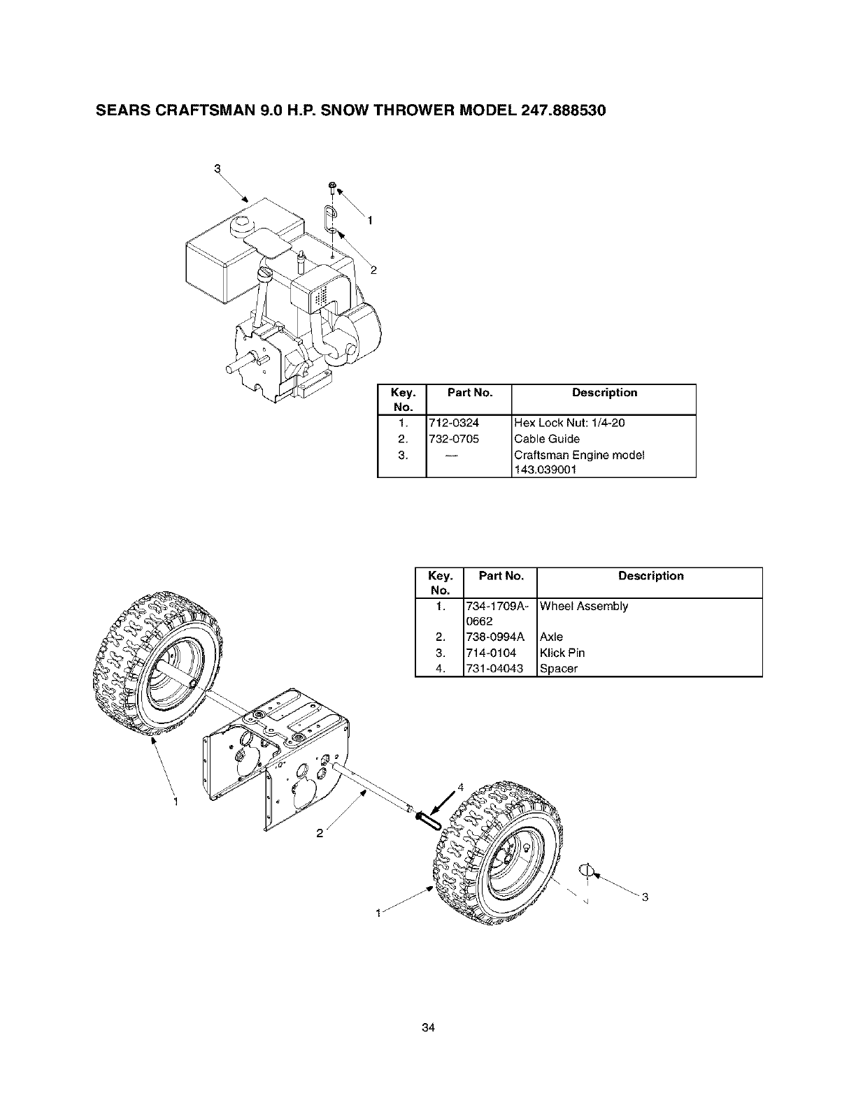
SEARS CRAFTSMAN 9.0 H.P. SNOW THROWER MODEL 247.888530
3
\\\\
Key. Part No. Description
No.
1. 712-0324 Hex Lock Nut: 1/4-20
2. 732-0705 Cable Guide
3. -- Craftsman Engine model
143.039001
Key, Part NO. Description
NO,
1. 734-1709A- Wheel Assembly
3662
2. 738-0994A Axle
3. 714-0104 Klick Pin
4. 731-04043 Spacer
\\\\,1
34
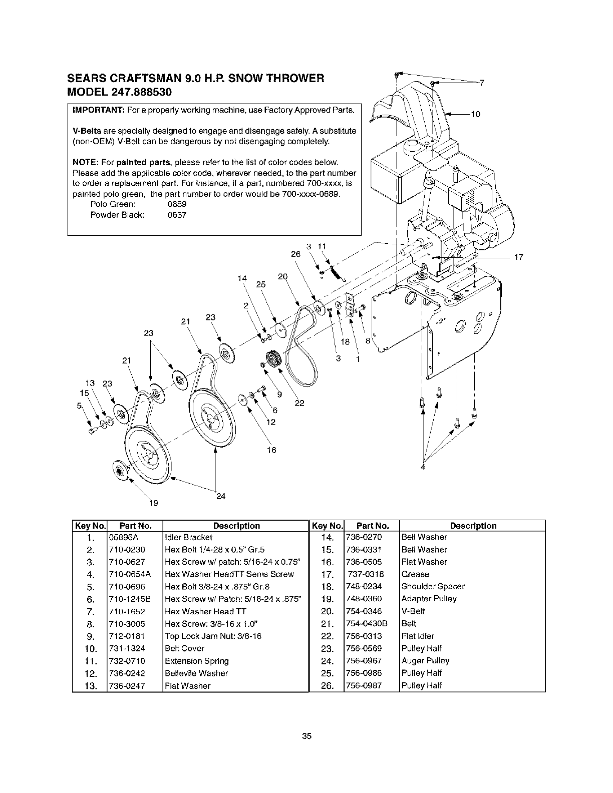
SEARS CRAFTSMAN 9.0 H.P. SNOW THROWER
MODEL 247.888530
IMPORTANT: For a properly working machine, use Factory Approved Parts.
V-Belts are specially designed to engage and disengage safely. A substitute
(non-OEM) V-Belt can be dangerous by not disengaging completely.
NOTE: For painted parts, please refer to the list of color codes below.
Please add the applicable color code, wherever needed, to the part number
to order a replacement part. For instance, if a part, numbered 700-xxxx, is
painted polo green, the part number to order would be 700-xxxx-0689.
Pole Green: 0689
Powder Black: 0637
13
15\
\
5\\
23
21
\\
21 23
\
14
\\\
2
26
\\
20
25
\\
3 11
22
16
Key NO
1.
2.
3.
4.
5.
6.
7.
8.
9.
10.
11,
12.
13.
\_19 24
Part No.
D5896A
710-0230
710-0627
710-0654A
710-0696
710-1245B
710-1652
710-3005
712-0181
731-1324
732-0710
736-0242
736-0247
Description
Idler Bracket
Hex Bolt 1/4-28 x 0.5" Gr.5
Hex Screw w/patch: 5/16-24 x 0.75"
Hex Washer HeadTT Sems Screw
Hex Bolt 3/8-24 x .875" Gr.8
Hex Screw w/Patch: 5/16-24 x .875"
Hex Washer Head TT
Hex Screw: 3/8-16 x 1.0"
Top Lock Jam Nut: 3/8-16
Belt Cover
Extension Spring
Bellevile Washer
Flat Washer
Key No.
14.
15.
16.
17.
18.
19.
20.
21.
22.
23.
24.
25.
26.
Part No,
736-0270
736-0331
736-0505
737-0318
748-0234
748-0360
754-0346
754-0430B
756-0313
756-0569
756-0967
756-0986
756-0987
Description
Bell Washer
Bell Washer
Flat Washer
Grease
Shoulder Spacer
Adapter Pulley
V-Belt
Belt
Fiat Idler
Pulley Half
Auger Pulley
Pulley Half
Pulley Half
35
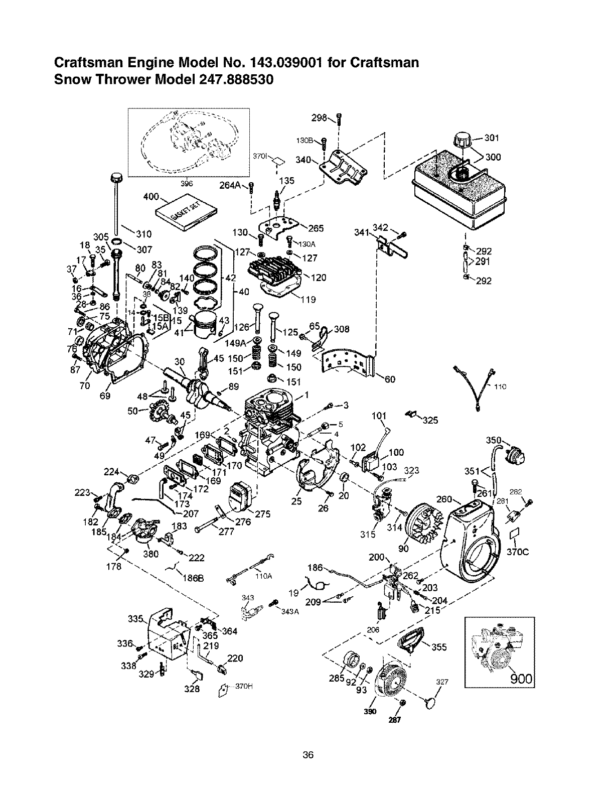
Craftsman Engine Model No. 143.039001 for Craftsman
Snow Thrower Model 247.888530
18
\
87
70
305
83
119
69
30
308
"60
101
I
25 26
37OH
03 323
/
315
>300
282
q
370C
'_" )00
36
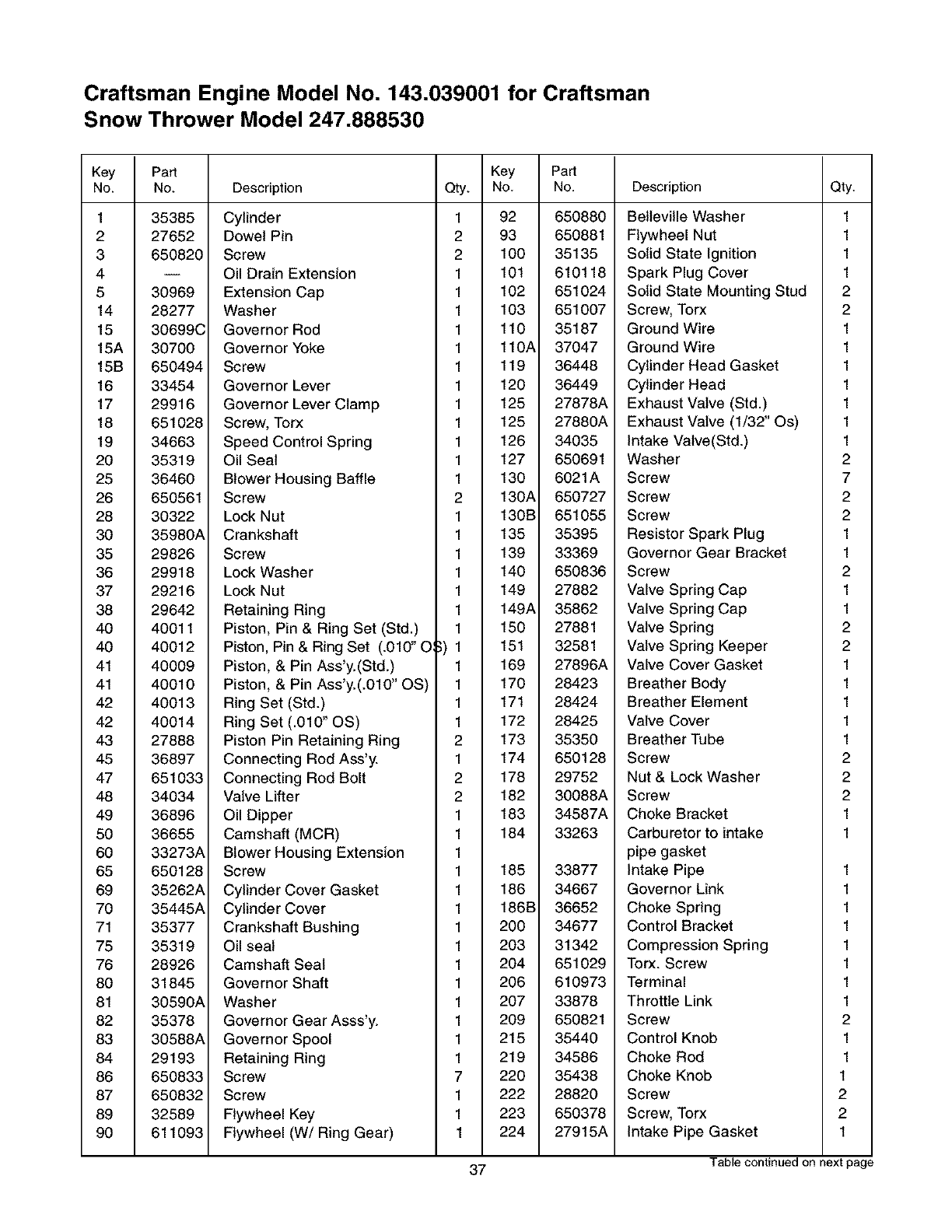
Craftsman Engine Model No. 143.039001 for Craftsman
Snow Thrower Model 247.888530
Key
No.
1
2
3
4
5
14
15
15A
15B
16
17
18
19
20
25
26
28
30
35
36
37
38
4O
4O
41
41
42
42
43
45
47
48
49
50
60
65
69
70
71
75
76
80
81
82
83
84
86
87
89
9O
Par_
No.
35385
27652
650820
30969
28277
30699C
30700
650494
33454
29916
651028
34663
35319
36460
650561
30322
35980A
29826
29918
29216
29642
40011
40012
40009
40010
40013
40014
27888
36897
651033
34034
36896
36655
33273A
650128
35262A
35445A
35377
35319
28926
31845
30590A
35378
30588A
29193
650833
650832
32589
611093
Key Pa_
Description Qty. No. No.
Cylinder 1 92 650880
Dowel Pin 2 93 650881
Screw 2 100 35135
Oil Drain Extension 1 101 610118
Extension Cap 1 102 651024
Washer 1 103 651007
Governor Rod 1 110 35187
Governor Yoke 1 110A 37047
Screw 1 119 36448
Governor Lever 1 120 36449
Governor Lever Clamp 1 125 27878A
Screw, Torx 1 125 27880A
Speed Control Spring 1 126 34035
Oil Seal 1 127 650691
Blower Housing Baffle 1 130 6021A
Screw 2 130A 650727
Lock Nut 1 130B 651055
Crankshaft 1 135 35395
Screw 1 139 33369
Lock Washer 1 140 650836
Lock Nut 1 149 27882
Retaining Ring 1 149A 35862
Piston, Pin & Ring Set (Std.) 1 150 27881
Piston, Pin & Ring Set (.010" O__) 1 151 32581
Piston, & Pin Ass'y.(Std.) 1 169 27896A
Piston, & Pin Ass'y.(.010" OS) 1 170 28423
Ring Set (Std.) 1 171 28424
Ring Set (.010" OS) 1 172 28425
Piston Pin Retaining Ring 2 173 35350
Connecting Rod Ass'y. 1 174 650128
Connecting Rod Bolt 2 178 29752
Valve Lifter 2 182 30088A
Oil Dipper 1 183 34587A
Camshaft (MCR) 1 184 33263
Blower Housing Extension 1
Screw 1 185 33877
Cylinder Cover Gasket 1 186 34667
Cylinder Cover 1 186B 36652
Crankshaft Bushing 1 200 34677
Oil seal 1 203 31342
Camshaft Seal 1 204 651029
Governor Shaft 1 206 610973
Washer 1 207 33878
Governor Gear Asss'y. 1 209 650821
Governor Spool 1 215 35440
Retaining Ring 1 219 34586
Screw 7 220 35438
Screw 1 222 28820
Flywheel Key 1 223 650378
Flywheel (W/Ring Gear) 1 224 27915A
Description
Belteville Washer
Flywheel Nut
Solid State Ignition
Spark Plug Cover
Solid State Mounting Stud
Screw, Torx
Ground Wire
Ground Wire
Cylinder Head Gasket
Cylinder Head
Exhaust Valve (Std.)
Exhaust Valve (1/32" Os)
Intake Valve(Std.)
Washer
Screw
Screw
Screw
Resistor Spark Plug
Governor Gear Bracket
Screw
Valve Spring Cap
Valve Spring Cap
Valve Spring
Valve Spring Keeper
Valve Cover Gasket
Breather Body
Breather Element
Valve Cover
Breather Tube
Screw
Nut & Lock Washer
Screw
Choke Bracket
Carburetor to intake
pipe gasket
Intake Pipe
Governor Link
Choke Spring
Control Bracket
Compression Spring
Torx. Screw
Terminal
Throttle Link
Screw
Control Knob
Choke Rod
Choke Knob
Screw
Screw, Torx
Intake Pipe Gasket
Qty.
1
1
1
1
2
2
1
1
1
1
1
1
1
2
7
2
2
1
1
2
1
1
2
2
1
1
1
1
1
2
2
2
1
1
1
1
1
1
1
1
1
2
1
1
1
2
2
1
37 Table continued on next page
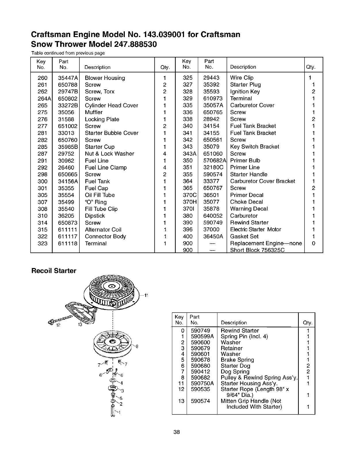
Craftsman Engine Model No. 143.039001 for Craftsman
Snow Thrower Model 247.888530
Table continued from previous page
Key
No.
260
261
262
264A
265
275
276
277
281
282
285
287
291
292
298
300
301
305
307
308
310
314
315
322
323
Part
No.
35447A
650788
29747B
650802
33272B
35056
31588
651002
33013
650760
35985B
29752
30962
26460
650665
34156A
35355
35554
35499
35540
36205
650873
611111
611117
611118
Key
Description Qty. No.
Blower Housing 1 325
Screw 2 327
Screw, Torx 2 328
Screw 1 329
Cylinder Head Cover 1 335
Muffler 1 336
Locking Plate 1 338
Screw 2 340
Starter Bubble Cover 1 341
Screw 1 342
Starter Cup 1 343
Nut & Lock Washer 4 343A
Fuel Line 1 350
Fuel Line Clamp 4 351
Screw 2 355
Fuel Tank 1 364
Fuel Cap 1 365
Oil Fill Tube 1 370C
"O" Ring 1 370H
Fill Tube Clip 1 3701
Dipstick 1 380
Screw 1 390
Alternator Coil 1 396
Connector Body 1 400
Terminal 1 900
9OO
Par_
No.
29443
35392
35593
610973
35057A
650765
28942
34154
34155
650561
35079
651060
570682_
32180C
590574
33377
650767
36501
35077
35878
640052
590749
37000
36450A
Description
Wire Clip
Starter Plug
Ignition Key
Terminal
Carburetor Cover
Screw
Screw
Fuel Tank Bracket
Fuel Tank Bracket
Screw
Key Switch Bracket
Screw
Primer Bulb
Primer Line
Starter Handle
Carburetor Cover Bracket
Screw
Primer Decal
Choke Decal
Warning Decal
Carburetor
Rewind Starter
Electric Starter Motor
Gasket Set
Replacement Engine--none
Short Block 756325C
Qty.
1
1
2
1
1
1
2
1
1
1
1
1
1
1
1
1
2
1
1
1
1
1
1
1
0
Recoil Starter
13
Part
No.
590749
590599A
590600
590679
590601
590678
590680
590412
590682
590750A
590535
590574
Description Qty.
Rewind Starter 1
Spring Pin (Incl. 4) 1
Washer 1
Retainer 1
Washer 1
Brake Spring 1
Starter Dog 2
Dog Spring 2
Pulley & Rewind Spring Ass'y 1
Starter Housing Ass'y. 1
Starter Rope (Length 98" x
9/64" Dia.) 1
Mitten Grip Handle (Not
Included With Starter) 1
38
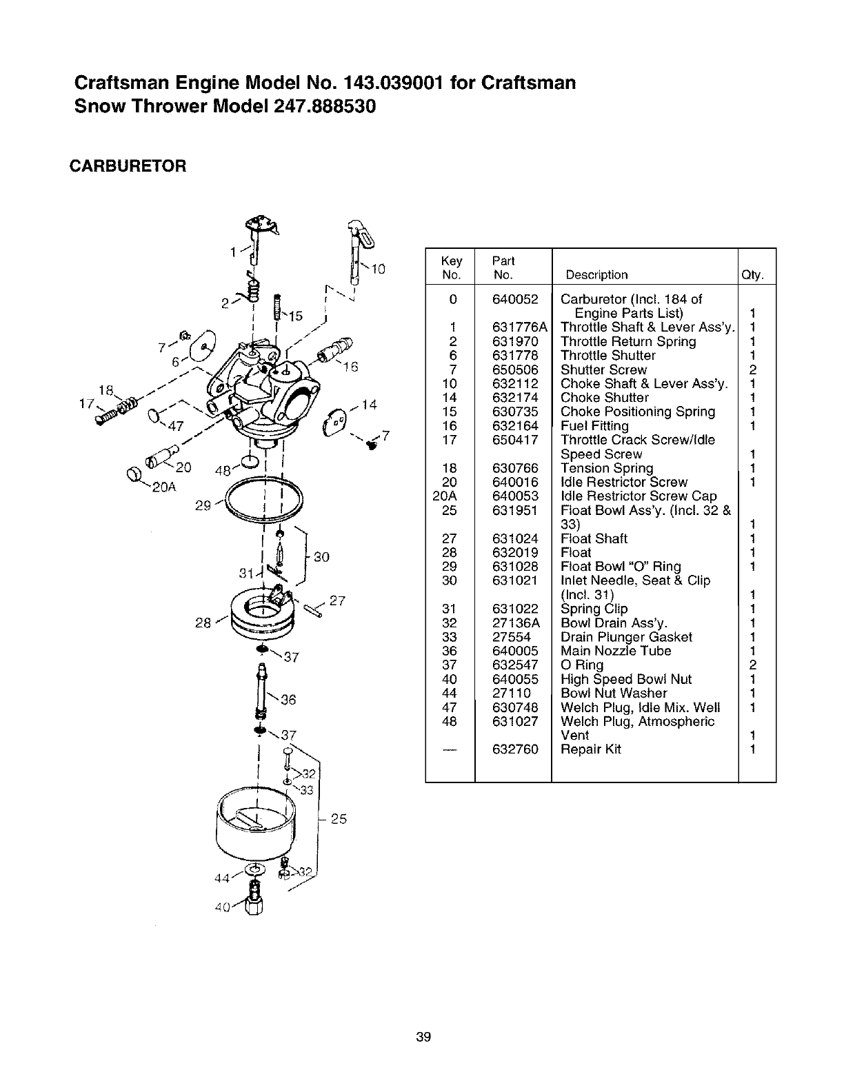
Craftsman Engine Model No. 143.039001 for Craftsman
Snow Thrower Model 247.888530
CARBURETOR
_10
I -4
I
J
I.-
18,.. _*" fLOf_f_ J_/.,_,_
_2o 48-.© I
_"_ 20A 29/_
3J,
28
'_',s7
I
,}
40/t_
Key Put
No. No. Description Q_.
0 640052
1 631776A
2 631970
6 631778
7 650506
10 632112
14 632174
15 630735
16 632164
17 650417
18 630766
20 640016
20A 640053
25 631951
27 631024
28 632019
29 631028
30 631021
31 631022
32 27136A
33 27554
36 640005
37 632547
40 640055
44 27110
47 630748
48 631027
632760
Carburetor (Incl. 184 of
Engine Parts List)
Throttle Shaft & Lever Ass'y.
Throttle Return Spring
Throttle Shutter
Shutter Screw
Choke Shaft & Lever Ass'y.
Choke Shutter
Choke Positioning Spring
Fuel Fitting
Throttle Crack Screw/Idle
Speed Screw
Tension Spring
Idle Restrictor Screw
Idle Restrictor Screw Cap
Float Bowl Ass'y. (Incl. 32 &
33)
Float Shaft
Float
Float Bowl "O" Ring
Inlet Needle, Seat & Clip
(Incl. 31)
Spring Clip
Bowl Drain Ass'y.
Drain Plunger Gasket
Main Nozzle Tube
O Ring
High Speed Bowl Nut
Bowl Nut Washer
Welch Plug, Idle Mix. Welt
Welch Plug, Atmospheric
Vent
Repair Kit
1
1
1
1
2
1
1
1
1
1
1
1
1
1
1
1
1
1
1
1
1
2
1
1
1
39
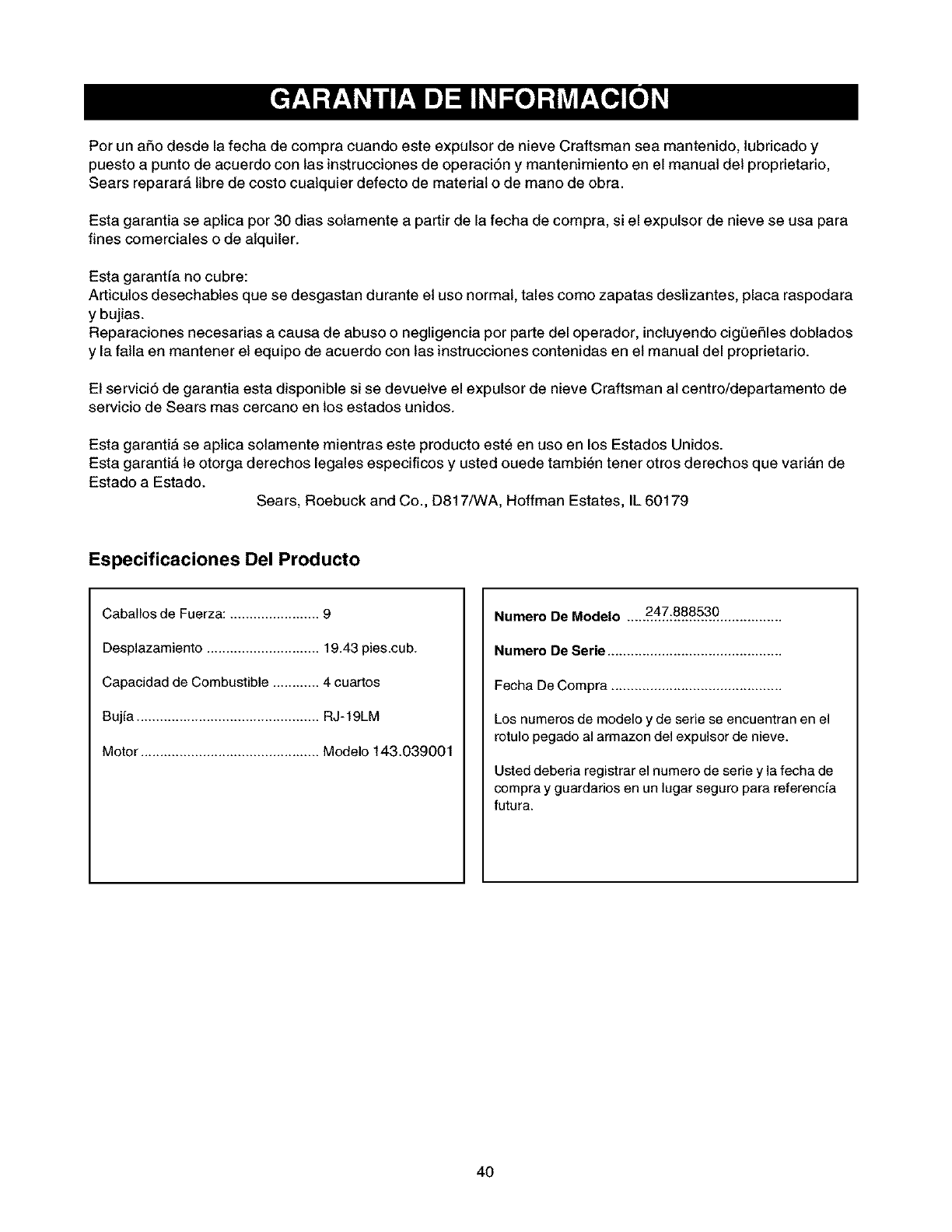
PorunalsodesdelafechadecompracuandoesteexpulsordenieveCraftsmanseamantenido,lubricadoy
puestoapuntodeacuerdoconlasinstruccionesdeoperaciSny mantenimientoenelmanualdelproprietario,
Searsreparar_,libredecostocualquierdefectodematerialodemanodeobra.
Estagarantiaseaplicapor30diassotamenteapartirdelafechadecompra,sielexpulsordenieveseusapara
finescomercialesodealquiler.
Estagarantfanocubre:
Articulosdesechablesquesedesgastanduranteelusonormal,talescomozapatasdeslizantes,placaraspodara
y bujias.
Reparacionesnecesariasacausadeabusoonegligenciaporpartedeloperador,incluyendocigL)eSlesdoblados
y lafallaenmantenerelequipodeacuerdoconlasinstruccionescontenidasenelmanualdelproprietario.
Elservici5degarantiaestadisponiblesisedevuetveelexpulsordenieveCraftsmanalcentro/departamentode
serviciodeSearsmascercanoenlosestadosunidos.
Estagarantiaseaplicasolamentemientrasesteproductoest6enusoenlosEstadosUnidos.
Estagaranti_,leotorgaderechoslegalesespecificosy ustedouedetambi6ntenerotrosderechosquevariande
EstadoaEstado. Sears,RoebuckandCo.,D817/WA,HoffmanEstates,IL60179
Especificaciones Del Producto
Caballos de Fuerza: ....................... 9
Desplazamiento ............................. 19.43 pies.cub.
Capacidad de Combustible ............ 4 cuartos
Bujfa ............................................... RJ-19LM
Motor .............................................. Modelo 143.039001
Numero De Modelo ....247:.888530 ................
Numero De Serie .............................................
Fecha De Compra ............................................
Los numeros de modelo y de serie se encuentran en el
rotulo pegado al armazon del expulsor de nieve.
Usted deberia registrar el numero de serie y la fecha de
compra y guardarios en un lugar seguro para referencfa
futura.
4O
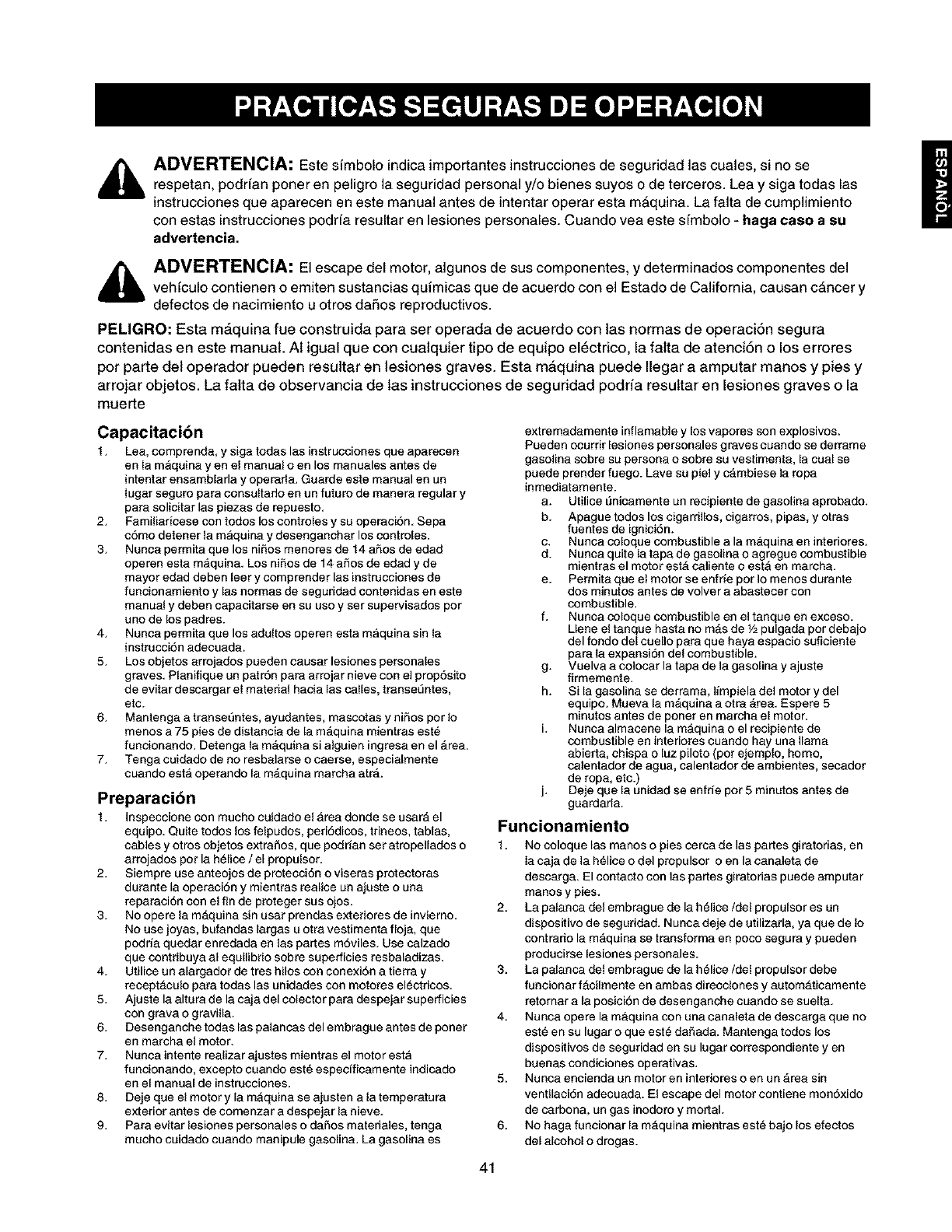
ADVERTENCIA: Este simbolo indica importantes instrucciones de seguridad las cuales, si no se
respetan, podffan poner en peligro la seguridad personal y/o bienes suyos o de terceros. Lea y siga todas las
instrucciones que aparecen en este manual antes de intentar operar esta mAquina. La falta de cumplimiento
con estas instrucciones podffa resultar en lesiones personales. Cuando vea este sfmbolo - haga caso asu
advertencia.
_1_ ADVERTENCIA: El escape del motor, algunos de sus componentes, y determinados componentes delvehfculo contienen o emiten sustancias quimicas qua de acuerdo con el Estado de California, causan cancer y
defectos de nacimiento u otros daffos reproductivos.
PEMGRO: Esta m_.quina fue construida para ser operada de acuerdo con las normas de operaci6n segura
contenidas en este manual. AI igual que con cualquier tipo de equipo eldctrico, la falta de atencidn o los errores
por parte del operador pueden resultar en lesiones graves. Esta maquina puede Ilegar a amputar manos y pies y
arrejar objetos. La falta de observancia de las instrucciones de seguridad podr/a resultar en lesiones graves o la
muerte
Capacitaci6n
1. Lea, comprenda, ysiga todas las instrucciones que aparecen
en la m_quina yen el manual o en los manuales antes de
intentar ensamblarla y operarla. Guarde este manual en un
lugar segure para consultado en un futuro de manere regular y
pare solicitar las piezas de repuesto.
2. Familiar[cese con todos los contreles y su operecidn. Sepa
cdmo detener la mAquina y desenganchar los controles.
3. Nunca permita que los niffos menores de 14 afros de edad
operen esta maquin& Los niffes de 14 afros de edad y de
mayor edad deben leer y comprender las instrucciones de
funcionamiento y las normas de seguridad contenidas en este
manual y deben capacitarse en su uso y ser supervisados por
uno de los padres.
4. Nunca permita que los adultos operen esta maquina sin la
instruccidn adecuada.
5. Los objetos arrojados pueden causer lesiones personales
graves. Planifique un pat r6n pare arrojar nieve con el prop6sito
de evitar descargar el material hacia las calles, transet]ntes,
etc.
6. Mantenga a transedntes, ayudantes, mascotas y niffos por Io
menos a 75 pies de distancia de la mAquina mientres este
funcionando. Detenga la mAquina si alguien ingresa en el Area.
7. Tenga cuidado de no resbalarse ocaerse, especialmente
cuando esta operando la mAquina marcha atrA.
Preparaci6n
1. Inspecciene con mucho cuidado el Area donda se usar& el
equipo. Quite todes los felpudos, peri6dicos, trineos, tablas,
cables yotros objetes extraffos, que podrian sat atropeUados o
arrojados por 18helice /el propu[sor.
2. Siempre use anteojos de protecci6n o viseres protectores
durante la operacion y mientres realice un ajuste o una
reparecidn con el fin de proteger sus ojos.
3. No opere la mAquina sin user prendas exteriores de invierno.
No use joyas, bufandas largas u otre vestimenta floja, qua
podda quedar enredada en las partes m6viles. Use calzado
que contribuya al equilibrio sobre superficies resbaladizas.
4. Utilice un alargador de tres hilos con conexidn a tierra y
receptaculo pare todas las unidades con motores electricos.
5. Ajuste 18alture de 18caja del colector pare despejar superficies
con grave o g revilla.
6. Desenganche todas las palancas del embregue antes de poner
en marcha el motor.
7. Nunca intente realizer ajustes mientras el motor esta
funcionando, excepto cuando este especificamente indicado
en el manual de instrucciones.
8. Deje que el motor y la mAquina se ajusten ala temperature
exterior antes de comenzar a despejar la nieve.
9. Pare evitar lesiones personales o daffos materiales, tenga
mucho cuidado cuando manipule gasoline. La gasoline es
extremadamente inflamable y los vapores son explosivos.
Pueden ocurrir lesiones personales graves cuando se derreme
gasoline sobre su persona o sobre su vestimenta, la cual se
puede prender fuego. Lave su piel y c&mbiese la rope
inmediatamente.
a. Utilice L_nicamente un recipiente de gasolina aprobado.
b. Apague todos los cigarrillos, cigarros, pipas, y otres
fuentes de ignicidn.
c. Nunca coloque combustible ala maquina en interiores.
d. Nunca quite la tape de gasoline o agregue combustible
mientres el motor estA caliente o est& en marcha.
e. Permita que el motor se entrie por Io menos durente
dos minutos antes de volver a abastecer con
combustible.
f. Nunca coloque combustible en el tanque en exceso.
Uene el tanque hasta no mAs de V2pulgada por debajo
del fendo del cuello pare que haya espacio suficiente
pare la expansi6n del combustible.
g. Vuelva a colocar la tape de la gasoline y ajuste
firmemente.
h. Si la gasolina se derrama, limpiela del motor y del
equipo. Mueva la m&quina a otre Area. Espere 5
minutos antes de poner en marcha el motor.
L Nunca almacene la mAquina o el recipiente de
combustible en interiores cuando hay una llama
abierta, chispa o luz piloto (por ejemplo, home,
calentador de agua, calentador de ambientes, secador
de rope, etc.)
j. Deje qua la unidad se enfrie pot 5 minutos antes de
guardarla.
Funcionamiento
1. No coloque las manes o pies cerca de las partes giretorias, en
la caja de la h_lice e del propulsor e en la canaleta de
descarga. El contacto con las partes giratorias puede amputar
manos y pies.
2. La palanca del embregue de 18helice/del propulsor es un
dispositivo de seguridad. Nunca deje de utilizarta, ya que de Io
cont rario 18mAquina se transforma en poco segure y pueden
producirse lesiones personales.
3. La palanca del embregue de la helice/del propulsor debe
funcionar fAcilmente en ambas direcciones y automaticamente
retomar ala posicidn de desenganche cuando se suelta.
4. Nunca opere 18mAquina con una canaleta de descarga que no
este en su lugar o que este dahada. Mantenga todos los
dispositives de seguridad en su lugar correspondiente yen
buenas condiciones operetivas.
5. Nunca encienda un motor en interiores o en un Area sin
ventilacidn adecuada. El escape del motor contiene monoxido
de carbona, un gas inodoro y mortal.
6. No haga funcionar la maquina mientras este bajo los efectos
del alcohol o drogas.
41
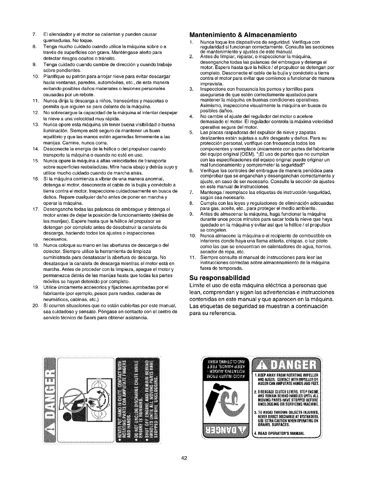
7. El silenciador y el motor se calientan y pueden causar
quemaduras. No toque.
8. Tenga mucho cuidado cuando utilice la m&quina sobre o a
traves de super[icies con grava. Mantengase ale[to para
detectar riesgos ocultos o trAnsito.
9. Tenga cuidado cuando cambie de direcci6n y cuando trabaje
sobre pendientes.
10. Planifique su patron para arrojar nieve para evitar descargar
hacia ventanas, paredes, autom6viles, etc., de esta manera
evitando posibles daSos materiales o lesiones personales
causadas pot un rebote.
11. Nunca dirija la descarga a niSos, transeQntes y mascotas o
permita que alguien se pare delante de la m&quina.
12. No sobrecargue la capacidad de la m&quina al intentar despejar
la nieve a una velocidad muy r&pida.
13. Nunca opere esta m&quina sin tenet buena visibilidad o buena
iluminaci6n. Siempre este seguro de mantener un buen
equilibrio y que las manos est_n agarradas firmemente a las
manijas. Camine, nunoa corra.
14. Desconecte la energfa de la h61ice o del propulsor cuando
transpo[te la m&quina o cuando no est6 en uso.
15. Nunca opere la mAquina a altas velocidades de transporte
sobre superficies resbaladizas. Mire hacia abajo y detr&s suyo y
utilice mucho cuidado cuando de marcha atrAs.
16. Si la maquina comienza a vibrar de una manera anormal,
detenga el motor, desconecte el cable de la bujfa y conectelo a
tierra contra el motor. Inspeccione cuidadosamente en busca de
daSos. Repare cualquier da5o antes de poner en marcha y
operar la maquina.
17. Desenganche todas las palancas de embrague y detenga el
motor antes de dejar la posici6n de funcionamiento (detr&s de
las manijas). Espere hasta que la h6lice/el propulsor se
detengan pot complete antes de desobst ruir la canaleta de
descarga, haciendo todos los ajustes o inspecciones
neoesarios.
18. Nunca coloque su mano en las aberturas de descarga o del
colector. Siempre utilice la herramienta de limpieza
suministrada para desatascar la abe[tufa de descarga. No
desatasque la canaleta de descarga mientras el motor esta en
marcha. Antes de proceder con la limpieza, apague el motor y
permanezca detr_s de las manijas hasta que todas las partes
moviles se hayan detenido por completo.
19. Utilice t]nicamente accesorias y fijaciones aprobadas pot el
fabricante (por ejemplo, pesos para ruedas, cadenas de
neum&ticos, cabinas, etc.)
20. Si ocurren situaciones que no estan cubie[tas por este manual,
sea cuidadoso y sensato. P6ngase en contacto con el cent ro de
servicio tecnico de Sears para obtener asistencia.
Mantenimiento & Almacenamiento
1. Nunca toque los dispositivos de seguridad. Verifique con
regularidad si funcionan correctamente. Consulte las secciones
de mantenimiento y ajustes de este manual.
2. Antes de limpiar, reparar, O inspeccionar la mAquina,
desenganche todas las palancas del embrague y detenga el
motor. Espere hasta que la h61ice /el propulsor se detengan por
completo. Desconecte el cable de la bujfa y conectelo a tierra
contra el motor para evitar que comience a funcionar de manera
imprevista.
3. Inspeccione con trecuencia los pernos y tornillos para
asegurarse de que est_n correctamente ajustados para
mantener la m_quina en buenas condiciones operativas.
Asimismo, inspeccione visualmente la maquina en busca de
posibles dartos.
4. No cambie el ajuste del regulador del motor o acelere
demasiado el motor. El regulador controla la m_.xima velocidad
operativa segura del motor.
5. Las placas raspadoras del expulsor de nieve y zapatas
deslizantes estAn sujetas a sufrir desgaste y daSos. Para su
protecci6n personal, veritique con frecuencia todos los
componentes y reemplace _nicamente con pa[tes gel fabricante
del equipo original (OEM). "iEI uso de partes que no cumplan
con las especificaciones del equipo original puede originar un
real funcionamiento y comprometer la seguridad!"
6. Verifique los controles del embrague de manera peri6dica para
comprobar que se enganchan y desenganchan correctamente y
ajuste, en case de set necesario. Consulte la secci6n de ajustes
en este manual de instrucciones.
7. Mantenga /reemplace las etiquetas de instrucci6n/seguridad,
segL_nsea necesario.
8. Cumpla con las [eyes y regulaciones de eliminaci6n adecuadas
para gas, aceite, etc., para proteger el medio ambiente.
9. Antes de almacenar la mAquina, haga funcionar la m_quina
durante unos pocos minutos para sacar toda la nieve que haya
quedade en la maquina y evitar asi que la helice / el propulsor
se congelen.
10. Nunca almacene la maquina o el recipiente de combustible en
interiores donde haya una llama abierta, chispas, o [uz piloto
como las que se encuentran en calentadores de agua, hornos,
secador de ropa, etc.
11. Siempre consulte el manual de instrucciones para leer las
instrucciones correctas sobre almacenamiento de la m&quina
tuera de temporada.
Su responsabilidad
Limite el uso de esta m_quina el_ctrica a personas que
lean, comprendan y sigan las advertencias e instrucciones
contenidas en este manual y que aparecen en la m_quina.
Las etiquetas de seguridad se muestran a continuaci6n
para su referencia.
t.KE_ tLW_,YFH_81__OTAI[_ I_ELL[_
AtlOAUGER.C8HT_TWITHIMP£LLERQ_
A_J_R_ _P_T/tI_ HAII_ .l_riFEEr_
A_D 8E_AIHBEHINDHAH_LE8L_rnLALL
M_VIN_ PANTSHAYEST_PPEPB_ORE
UNCLOGGINGDRSERIIICI_ M,_CHINE.
42
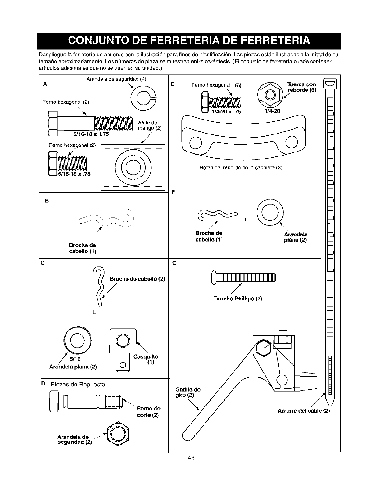
Desplieguelaferreteriadeacuerdoconlailustraci6nparafinesdeidentificaci6n.Laspiezasest_nilustradasalamitaddesu
tamaSoaproximadamente.Losnt3merosdepiezasemuestranentrepar_ntesis.(Elcenjuntodeferreteriapuedecentener
articulosadicionalesquenoseusanensuunidad.)
C
A
Perno hexagonal(2)
_-.,,
Arandela de segurJdad (4)
,©
m
__ 5/16-18 x 1.75
Perno hexagonal (2)
_._ 3/16-18 x.75
Ateta del
mango (2)
,/
B
D
Broche de
cabello (1)
_/_oche de cabello (2)
i
Casquillo
Arandela plana (2) (_ (1)
Piezas de Repuesto
i
"_ Pemo deI
corte (2)
Arandela de /_
seguridad (2)
E Perno._hexagona._(6) /,_\ rT_o¢Srd_l_) [_
Ret_n del reborde de la canaleta (3) _1
F
Gt
0IlllllllI_IllllllllllllllllllllllIOII
Tomillo Phillips(2) _I
_i_toi,l_)de /_ _ _ _
Arnarre del cable (2)
43
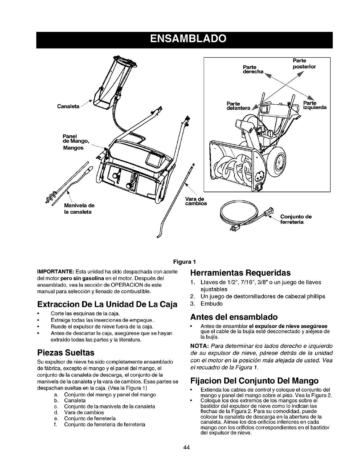
Panel
de Mango,
Mangos
Parte
derecha _.
Parte
delantera
Parte
posterior
Parte
izquierda
\
Manivela de
la canaleta
Vara de
cambios
Conjunto de
ferreteria
Figura 1
IMPORTANTE: Esta unidad ha sido despachada con aceite
del motor paro sin gasolina en el motor. Despu6s del
ensamblado, yea la secci6n de OPERACION de este
manual para selecci6n y Ilenado de combustible.
Extraccion De La Unidad De La Caja
Cotte las esquinas de la caja.
Extraiga todas las inserciones de empaque..
Ruede el expulsor de nieve fuera de la caja.
Antes de descattar la caja, asegt3rese que se hayan
extraido todas las pattes y la Iiteratura.
Piezas Sueltas
Su expulsor de nieve ha sido completamente ensamblado
de f&brica, excepto el mango y el panel del mango, el
conjunto de la canaleta de descarga, el conjunto de la
manivela de la canaleta y la vara de cambios. Esas pattes se
despachan sueltas en la caja. (Vea la Figura 1)
a. Conjunto del mango y panel del mango
b. Canaleta
c. Conjunto de la manivela de la canaleta
d. Varadecambios
e. Conjunto deferreter_a
f. Conjunto deferreteriadeferreteria
Herramientas Requeridas
1. Llaves de 1/2", 7/16", 3/8" o un juego de Ilaves
ajustables
2. Un juego de destornilladores de cabezal phillips
3. Embudo
Antes del ensamblado
Antes de ensamblar el expulsor de nieve ase_ldrese
que el cable de la bujfa est_ desconectado yal6jese de
la bujfa.
NOTA: Para determinar los lados derecho e izquierdo
de su expulsor de nieve, p_rese detr_s de la unidad
con el motor en la posici6n mas alejada de usted. Vea
el recuadro de la Figura 1.
Fijacion Del Conjunto Del Mango
Extienda los cables de control y coloque el conjunto del
mango y panel del mango sobre el piso. Vea la Figura 2.
Coloque los dos extremos de los mangos sobre el
bastidor del expulsor de nieve como Io indican las
flechas de la Figura 2. Para su comodidad, puede
colocar la canaleta de descarga en la abertura de la
canaleta. Alinee los dos orificios inferiores en cada
mango con los orificios correspondientes en el bastidor
del expulsor de nieve.
44
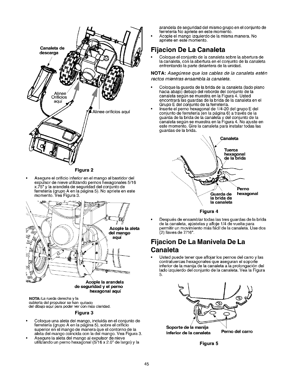
Canaleta de
Alinee orificios aquf
arandela de seguridad del mismo grupo en el conjunto de
ferreterfa No apriete en este momento.
Acople el mango izquierdo de la misma manera. No
apriete en este momento.
Fijacion De La Canaleta
Coloque el conjunto de la canaleta sobre la abedura de
la canaleta, con la abettura en el conjunto de la canaleta
enfrentando la parte delantera de la unidad.
NOTA: Aseg#rese que los cables de la canaleta est#n
rectos mientras ensambla la canaleta.
Coloque la guarda de la brida de la canaleta (lado piano
hacia abajo) debajo del reborde del conjunto de la
canaleta segQn se muestra en la Figura 4. Usted
encontrarA las guardas de la brida de la canaleta en el
Grupo E del conjunto de la ferreterfa.
lnserte el perno hexagonal de 1/4-20 del grupo E del
conjunto de ferreteria (en la pAgina 6) a trav6s de la
guarda de la brida de la canaleta y del conjunto de la
canaleta segQn se muestra en la Figura 4. No ajuste en
este momento. Gire la canaleta para instalar todas las
guardas de la brida.
Figura 2
Asegure el orificio inferior en el mango al bastidor del
expulsor de nieve utilizando pemos hexagonales 5/16
x.75" y la arandela de seguridad del conjunto de
ferreteria (grupo A en la pAgina 5). No apriete en este
momento. Vea Figura 3.
Acople la aleta
del mango
aqui
Aco_le la arandela
de seguridad y el pemo
hexagonal aqui
NOTA:La rueda derecha y la
cubierta del propulsor se han quitado
del dibujo aqui para poder ver con m_s claridad.
Figura 3
Coloque una aleta del mango, incluida en el conjunto de
ferreterfa (grupo A en la pAgina 5), sobre el orificio
superior en el mango de manera que el oontorno de la
aleta del mango coincida con la del mango. Vea Figura 3.
Asegure la aleta del mango al expulsor de nieve
utilizando un perno hexagonal (5/16 x 2.0 de largo) y la
\ la canaleta
\
Figura 4
Despu6s de ensamblar todas las tres guardas de la brida
de la canaleta, ajt3stelas y afloje 1/4 de vuelta para
permitir un movimiento mAs fAcil de la canaleta. Use dos
(2) Ilaves de 7/16".
Fijacion De La Manivela De La
Canaleta
Usted puede tener que aflojar los pernos del carro y las
contratuercas hexagonales que aseguran el sopoite
inferior de la manija de la canaleta a la prolongaci6n del
lado izquierdo del conjunto de la canaleta. Vea la Figura
5.
/
inferior de la canaleta Perno del carro
Figura 5
45
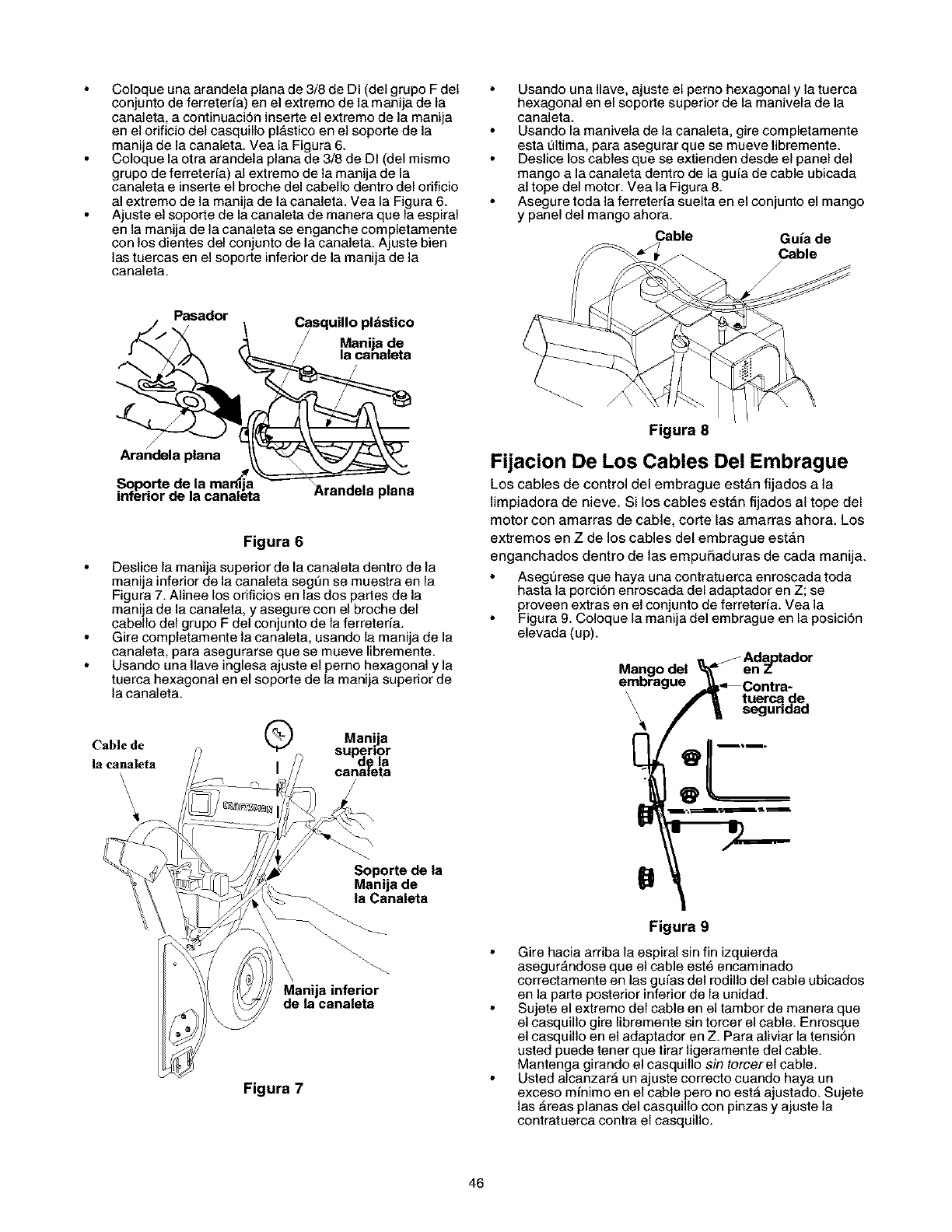
Coloqueunaarandelaplanade3/8deDI(delgrupoFdel
conjuntodeferreteria)enelextremodelamanijadela
canaleta,acontinuaciSninsetteelextremodelamanija
enelorificiodelcasquillopl_sticoenelsopor_edela
manijadelacanaleta.VealaFigura6.
Coloquelaotraarandelaplanade3/8deDI(delmismo
grupodeferreteria)alextremodelamanijadela
canaletaeinserteelbrochedelcabellodentrodelorificio
alextremodelamanijadelacanaleta.VealaFigura6.
Ajusteelsopor_edelacanaletademaneraquelaespiral
enlamanijadelacanaletaseenganchecompletamente
conlosdientesdelconjuntodelacanaleta.Ajustebien
lastuercasenelsoporteinferiordelamanijadela
canaleta.
UsandounaIlave,ajusteelpernohexagonalylatuerca
hexagonalenelsoportesuperiordelamaniveladela
canaleta.
Usandolamaniveladelacanaleta,girecompletamente
esta01tima, para asegurar que se mueve libremente.
Deslice los cables que se extienden desde el panel del
mango a la canaleta dentro de la gufa de cable ubicada
al tope del motor. Vea la Figura 8.
Asegure toda la ferreteria suelta en el con junto el mango
y panel del mango ahora.
Cable Guia de
Cable
Pasador
/
Arandela plana
Casquillo pl_stico
Manija de
la canaleta
Arandela plana
Figura 6
Deslice la manija superior de la canaleta dentro de la
manija inferior de la canaleta seg0n se muestra en la
Figura 7. Alinee los orificios en las dos partes de la
manija de la canaleta, y asegure con el broche del
cabello del grupo F del conjunto de la ferreteria.
Gire completamente la canaleta, usando la manija de la
canaleta, para asegurarse que se mueve libremente.
Usando una Ilave inglesa ajuste el perno hexagonal y la
tuerca hexagonal en el soporte de la manija superior de
la canaleta.
Cable de
la canaleta
'\\\
QManija
superior
de la
I canamta
Soporte de la
Manija de
la Canaleta
Manija inferior
de la canaleta
Figura 7
Figura 8
Fijacion De Los Cables Del Embrague
Los cables de control del embrague est_n fijados a la
limpiadora de nieve. Si los cables est_n fijados al tope del
motor con amarras de cable, corte las amarras ahora. Los
extremos en Z de los cables del embrague estfin
enganchados dentro de las empufiaduras de cada manija.
Aseg0rese que haya una contratuerca enroscada toda
hasta la porciSn enroscada del adaptador en Z; se
proveen extras en el conjunto de ferreteria. Vea la
Figura 9. Coloque la manija del embrague en la posici6n
elevada (up).
,_ _F Adagtador
Mango del _= en Z
embrague -_-_Contra-
\ _tuerca de
_/_seguridad
Figura 9
Gire hacia arriba la espiral sin fin izquierda
asegurAndose que el cable est_ encaminado
correctamente en las guias del rodillo del cable ubicados
en la parte posterior inferior de la unidad.
Sujete el extremo del cable en el tambor de manera que
el casquillo gire libremente sin torcer el cable. Enrosque
el casquillo en el adaptador en Z. Para aliviar la tensi6n
usted puede tenet que tirar ligeramente del cable.
Mantenga girando el casquillo sin torcerel cable.
Usted alcanzarA un ajuste correcto cuando haya un
exceso minimo en el cable pero no est_ ajustado. Sujete
las _reas planas del casquillo con pinzas y ajuste la
contratueroa oontra el casquillo.
46
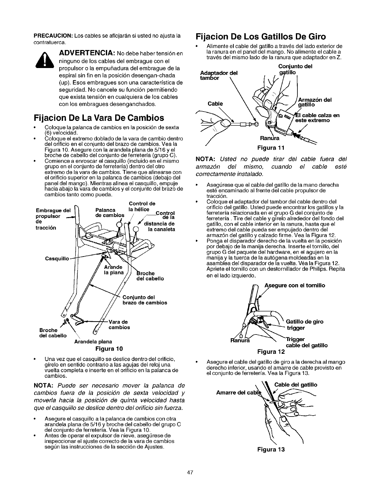
PRECAUCION: Los cables se aflojar_n si usted no ajusta la
contratuerca.
ADVERTENCIA: NO debe haber tensi6n en
ninguno de los cables del embrague con el
propulsor o la empufiadura del embrague de la
espiral sin fin en la posici6n desengan-chada
(up). Esos embragues sen una caracterfstica de
seguridad. No cancele su funci6n permitiendo
que exista tensi6n en cualquiera de los cables
con los embragues desenganchados.
Fijacion De La Vara De Cambios
Coloque la palanca de cambios en la posici6n de sexta
(6) velocidad.
Coloque el extremo doblado de la vara de cambio dentro
del orificio en el conjunto del brazo de cambios. Vea la
Figura 10. Asegure con la arandela plana de 5/16 y el
broche de cabello del conjunto de ferreterfa (grupo C).
Comience a enroscar el casquillo (incluido en el mismo
grupo en el conjunto de ferreteria) dentro del otro
extremo de la vara de cambios. Tiene que alinearse con
el orificio superior en la palanca de cambios (debajo del
panel del mange). Mientras alinea el casquillo, empuje
hacia abajo la vara de cambios y el conjunto del brazo de
cambios tanto como pueda.
Control de
la h61ice
Embrague del Palanca _ontrol
propulsor de cambios _de la
de _/rtdistancia de
tracci6n la canaleta
del cabello
unto del
brazo de cambios
Broche
del cabello
-Vara de
cambios
\
Arandela plana
Figura 10
Una vez que el casquillo se deslice dentro del orificio,
girelo en sentido contrario alas agujas del reloj una
vuelta completa e inserte en el orificio en la palanca de
cambios.
NOTA: Puede ser necesario mover la palanca de
cambios fuera de la posiciSn de sexta velocidad y
moverla hacia la posiciSn de quinta velocidad hasta
que el casquillo se deslice dentro del orificio sin fuerza.
Asegure el casquillo a la palanca de cambios con otra
arandela plana de 5/16 y broche del cabello del grupo C
del conjunto de ferreteria. Vea la Figura 10.
Antes de operar el expulsor de nieve, asegL_rese de
inspeccionar el ajuste correcto de la vara de cambios
segL_nlas instrucciones de la secci6n de Ajustes.
Fijacion De Los Gatillos De Giro
Alimente el cable del gatillo a traves del lado exterior de
la ranura en el panel del mango. No alimente el cable a
traves del mismo lado de la ranura que adaptador en Z.
Conjunto del
tAadma_t°ad°r_,_ _/_li I01
Cable \ _-_( l,/_/-_-j g_atillo
:&_.zeFo-,eoo
"/_ Ran_ra'a'a'a'a'a'a'a'a'_r:_
Figura 11
NOTA: Usted no puede tirar del cable fuera del
armaz6n del mismo, cuando el cable este
correctamente instalado.
Asegt3rese que el cable del gatillo de la mano derecha
est_ encaminado al frente del cable propulsor de
tracci6n.
Coloque el adaptador del tambor del cable dentro del
orificio del gatillo. Usted puede encontrar los gatillos y la
ferreteria relacionada en el grupo G del conjunto de
ferreteria. Tire del cable y girelo alrededor del fondo del
gatillo, con el cable interior en la ranura, hasta que el
extremo del cable pueda ser empujado dentro del
armaz6n del gatillo y calzado firme. Vea la Figura 12.
Ponga el disparador derecho de la vuelta en la posici6n
por debajo de la manija derecha, lnserte el tornillo, del
grupo G del paquete del hardware, en el agujero en la
manija y la tuerca de la aut6gena moldeadas en la
asamblea del disparador de la vuelta. Vea la Figura 12.
Apriete el tornillo con un destornillador de Philips. Repita
en el lade izquierdo.
e con el tomillo
Gatillo de giro
trigger
Trigger
cable del gatillo
Figura 12
Asegure el cable del gatillo de giro a la derecha al mango
derecho inferior, usando el amarre de cable provisto en
el conjunto de ferreteria. Vea la Figura 13.
Amarre del cabl_
Cable del gatillo
Figura 13
47
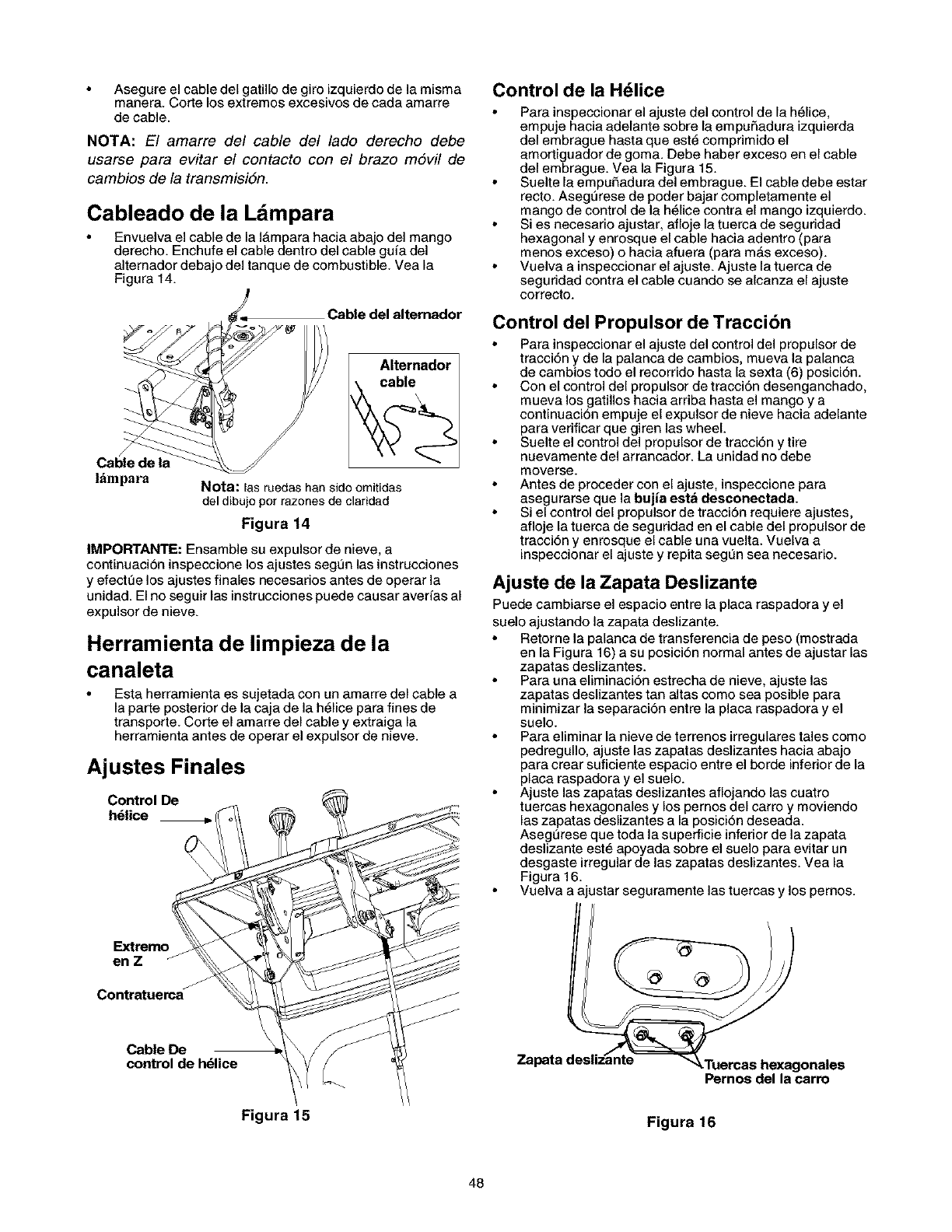
Asegure el cable del gatillo de giro izquierdode la misma
manera. CorSelos extremes excesivos de cada amarre
de cable.
NOTA: El amarre del cable del lado derecho debe
usarse para evitar el contacto con el brazo m6vil de
cambios de la transmisiSn.
Cableado de la Ldmpara
Envuelva el cable de la I_mpara hacia abajo del mango
derecho. Enchufe el cable dentro del cable guia del
alternador debajo del tanque de combustible. Vea la
Figura 14.
Cable del alternador
Cable de la
l_mpara
Alternador
Nota: las ruedas han sido omitidas
del dibujo por razones de claridad
Figura 14
IMPORTAWrE: Ensamble su expulsor de nieve, a
continuaciSn inspeccione los ajustes segt3n las instrucciones
y efectt3e los ajustes finales necesarios antes de operar la
unidad. El no seguir las instrucciones puede causar averias al
expulsor de nieve.
Herramienta de limpieza de la
canaleta
Esta herramienta es sujetada con un amarre del cable a
la parte posterior de la caja de la h_lice para fines de
transporte. Corte el amarre del cable y extraiga la
herramienta antes de operar el expulsor de nieve.
Ajustes Finales
Control De
h_lice
Control de la H_lice
Para inspeccionar el ajuste del control de la helice,
empuje hacia adelante sobre la empufiadura izquierda
del embrague hasta que est_ comprimido el
amortiguador de goma. Debe haber exceso en el cable
del embrague. Vea la Figura 15.
Suelte la empufiadura del embrague. El cable debe estar
recto. Asegt3rese de poder bajar completamente el
mango de control de la helice contra el mango izquierdo.
Si es necesario ajustar, afloje la tuerca de seguridad
hexagonal y enrosque el cable hacia adentro (para
menos exceso) o hacia afuera (para m_s exceso).
Vuelva a inspeccionar el ajuste. Ajuste la tuerca de
seguridad contra el cable cuando se alcanza el ajuste
correcto.
Control del Propulsor de Traccibn
Para inspeccionar el ajuste del control del propulsor de
tracciSn y de la palanca de cambios, mueva la palanca
de cambios todo el recorrido hasta la sexta (6) posiciSn.
Con el control del propulsor de tracciSn desenganchado,
mueva los gatillos hacia arriba hasta el mango y a
continuaciSn empuje el expulsor de nieve hacia adelante
para verificar que giren las wheel.
Suelte el control del propulsor de tracciSn y tire
nuevamente del arrancador. La unidad no debe
moverse.
Antes de proceder con el ajuste, inspeccione para
asegurarse que la bujia esta desconectada.
Si el control del propulsor de tracciSn requiere ajustes,
afloje la tuerca de seguridad en el cable del propulsor de
tracciSn y enrosque el cable una vuelta. Vuelva a
inspeccionar el ajuste y repita segL_nsea necesario.
Ajuste de la Zapata Deslizante
Puede cambiarse el espacio entre la plata raspadora y el
suelo ajustando la zapata deslizante.
Retorne la palanca de transferencia de peso (mostrada
en la Figura 16) a su posiciSn normal antes de ajustar las
zapatas deslizantes.
Para una eliminaciSn estrecha de nieve, ajuste las
zapatas deslizantes tan altas como sea posible para
minimizar la separaciSn entre la placa raspadora y el
suelo.
Para eliminar la nieve de terrenos irregulares tales come
pedregullo, ajuste las zapatas deslizantes hacia abajo
para crear suficiente espacio entre el berde inferior de la
placa raspadora y el suele.
Ajuste las zapatas deslizantes aflojando las cuatro
tueroas hexagenales y los pernos del carro y moviendo
las zapatas deslizantes a la posici6n deseada.
Asegurese que toda la superficie inferior de la zapata
deslizante est6 apoyada sebre el suelo para evitar un
desgaste irregular de las zapatas deslizantes. Vea la
Figura 16.
Vuelva a ajustar seguramente las tuercas y los pernos.
Extrerno
en Z J
Contratuerca F
Cable De
control de h_lice
Figura 15
Zapata desliz_nte _
Pernos del la carro
Figura 16
48
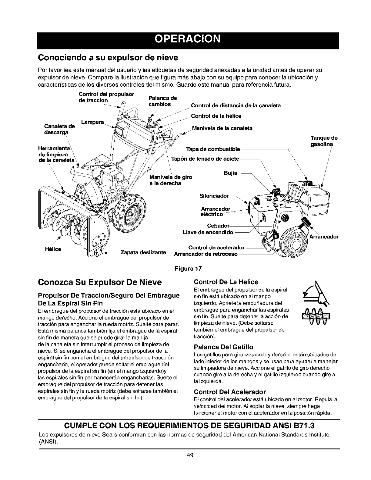
Conociendo a su expulsor de nieve
Por favor lea este manual del usuario y las etiquetas de seguridad anexadas a la unidad antes de operar su
expulsor de nieve. Compare la ilustraci6n que figura mas abajo con su equipo para conocer la ubicaci6n y
caracterfsticas de los diversos controles del mismo. Guarde este manual para referencia futura.
Control del propulsor
de traccion Palanca de
cambios Control de distancia de la canaleta
Control de la h_lice
Lampara_
Cana|eta de Manivela de la canaleta
descarg_ Tanque de
\gasolina
Herramienta\ Tapa de combustible \
de limpieza \
de la canalet Tap6n de lenado de aciete_ \\\
\ \ \
\ \ \
\\ Bujia \ \\
\Manivela de giro
\a la derecha
H_lice Zapata deslizante
Silenciador _
Arrancador
el_ctrico
Cebador
Llave de encendido
Arrancador de retroceso
Figura 17
Conozca Su Expulsor De Nieve
Propulsor De Traccion/Seguro Del Embrague
De La Espiral Sin Fin
El embrague del propulsor de tracci6n est_ ubicado en el
mango derecho. Accione el embrague del propulsor de
tracci6n para enganchar la rueda motdz. Suelte para parar.
Esta misma palanca tambien fija el embrague de la espiral
sin fin de manera que se puede girar la manija
de la canaleta sin interrumpir el proceso de limpieza de
nieve. Si se engancha el embrague del propulsor de la
espiral sin fin con el embrague del propulsor de traccci6n
enganchado, el operador puede soltar el embrague del
propulsor de la espiral sin fin (en el mango izquierdo)y
las espirales sin fin permanecerAn enganchadas. Suelte el
embrague del propulsor de tracci6n para detener las
espirales sin fin y la rueda motriz (debe soltarse tambien el
embrague del propulsor de la espiral sin fin).
Control De La Helice
El embrague del propulsor de la espiral
sin fin est_ ubicado en el mango
izquierdo. Apriete la empu£_adura del
embrague para enganchar las espirales
sin fin. Suelte para detener la acci6n de
limpieza de nieve. (Debe soltarse
tambien el embrague del propulsor de
tracci6n).
Palanca Del Gatillo
Los gatillos para giro izquierdo y dereeho est_n ubicados del
lado inferior de los mangos y se usan para ayudar a manejar
su limpiadora de nieve. Accione el gatillo de giro dereeho
cuando gire a la derecha y el gatillo izquierdo cuando gire a
la izquierda.
Control Del Acelerador
Elcontroldel acelerador est_ubicadoan el motor.Regulala
velocidad del motor. AI soplar la nieve, siempre haga
funcionar el motor con el acelerador en la posici6n r_pida.
CUMPLE CON LOS REQUERIMIENTOS DE SEGURIDAD ANSI B71.3
Los expulsores de nieve Sears conforman con las normas de seguridad del American National Standards Institute
(ANSI).
49
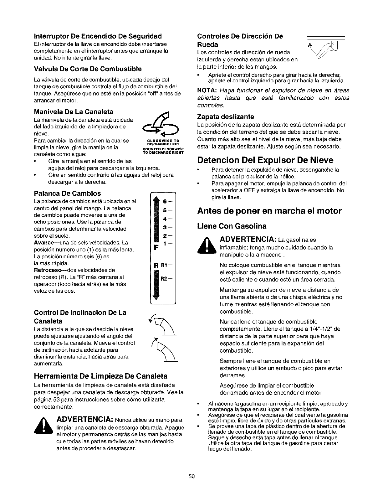
Interruptor De Encendido De Seguridad
El interrupter de la Ilave de encendido debe insertarse
completamente en el interrupter antes que arranque la
unidad. No intente girar la Ilave.
Valvula De Corte De Combustible
La v_lvula de corte de combustible, ubicada debajo del
tanque de combustible controla el fluje de combustible del
tanque. Asegt3rese que no est_ en la posici6n "off" antes de
arrancar el motor.
Manivela De La Canaleta
La manivela de la canaleta est'. ubicada
del lade izquierdo de la limpiadora de
nieve.
Para cambiar la direcci6n en la cual se
limpia la nieve, gire la manija de la
canaleta come sigue:
Gire la manija en el sentide de las
agujas del reloj para descargar a la izquierda.
Gire en sentido centrarie alas agujas del reloj para
descargar a la derecha.
Palanca De Cambios
La palanca de cambios est_ ubicada en el
centre del panel del mango. La palanca
de oambios puede moverse a una de
echo posiciones. Use la palanca de
cambios para determinar la velocidad
sebre el suelo.
Avance--una de seis velocidades. La
posici6n nL_mero uno (1) es la m_s lenta.
La posici6n ntTmero seis (6) es
la m_s r_pida.
Retreceso--dos velocidades de
retroceso (R). La "R" m_s cercana al
operador (tede hacia atr_s) es la m_s
veloz de las dos.
CLOCKWISE TO
DISCHARGE LEFT
COUNTER CLOCKWISE
TO DISCHARGE RIGHT
5--
4--
3--
2--
1--
Control De Inclinacion De La
Canaleta
La distancia a la que se despide la nieve
puedeajustarse ajustande el _ngule del
cenjuntode la canaleta.Muevael control
de inclinaci6n hacia adelante para
disminuir la distancia, hacia atr_s para
aumentarla.
RI--
R2=
Herramienta De Limpieza De Canaleta
La herramienta de limpieza de canaleta est_ disefiada
para despejar una canaleta de descarga obturada. Vea la
p#,gina 53 para instrucciones sobre c6mo utilizada
correctamente.
ADVERTENCIA: Nunca utilice su mane para
limpiar una canaleta de descarga obturada. Apague
el motor y permanezca detrAs de las manijas hasta
que todas las pattes m6viles se hayan detenide
antes de preceder a desatascar.
Controles De Direccibn De
Rueda
Los controles de direcci6n de rueda
izquierda y derecha est_n ubicados en
la parte inferior de los mangos.
Apriete el control derecho para girar hacia la derecha;
apriete el control izquierdo para girar hacia la izquierda.
NOTA: Haga funcionar el expulsor de nieve en areas
abiertas hasta que est# familiarizado con estos
controles.
Zapata deslizante
La posici6n de la zapata deslizante est_ determinada per
la condici6n del terreno del que se debe sacar la nieve.
Cuanto m&s alto sea el nivel de la nieve, m_s baja debe
estar la zapata deslizante. Ajuste segQn sea necesario.
Detencion Del Expulsor De Nieve
Para detener la expulsi6n de nieve, desenganche la
palanca del prepulsor de la helice.
Para apagar el motor, empuje la palanca de control del
acelerader a OFF y extraiga la Ilave de encendido. No
gire la Ilave.
Antes de poner en marcha el motor
Llene Con Gasolina
ADVERTENCIA: La gasolina es
inflamable; tenga mucho cuidado cuando la
manipule o la almacene.
No coloque combustible en el tanque mientras
el expulsor de nieve est_ funcionando, cuando
est_ caliente o cuando est_ un area cerrada.
Mantenga su expulsor de nieve a distancia de
una llama abierta o de una chispa el_ctrica y no
fume mientras est_ Ilenando el tanque con
combustible.
Nunca Ilene el tanque de combustible
completamente. Uene el tanque a 1/4"-1/2" de
distancia de la parte superior para que haya
espacio suficiente para la expansi6n del
combustible.
Siempre Ilene el tanque de combustible en
exteriores y utilice un embudo o pico para evitar
derrames.
Asegt3rese de limpiar el combustible
derramado antes de encender el motor.
Almacene la gasolina en un recipiente limpio, aprobado y
mantenga la tapa en su lugar en el recipiente.
Asegt3rese de que el recipiente del cual vierte la gasolina
este limpio, libre de 6xide y de otras partfculas extrafias.
Se provee una tapa de plAstico dentro de la abertura de
Ilenado de combustible en el tanque de combustible.
Saque y deseche esta tapa antes de Ilenar el tanque.
Utilice la otra tapa del tanque de gaselina para cerrar
luege del Ilenado.
50
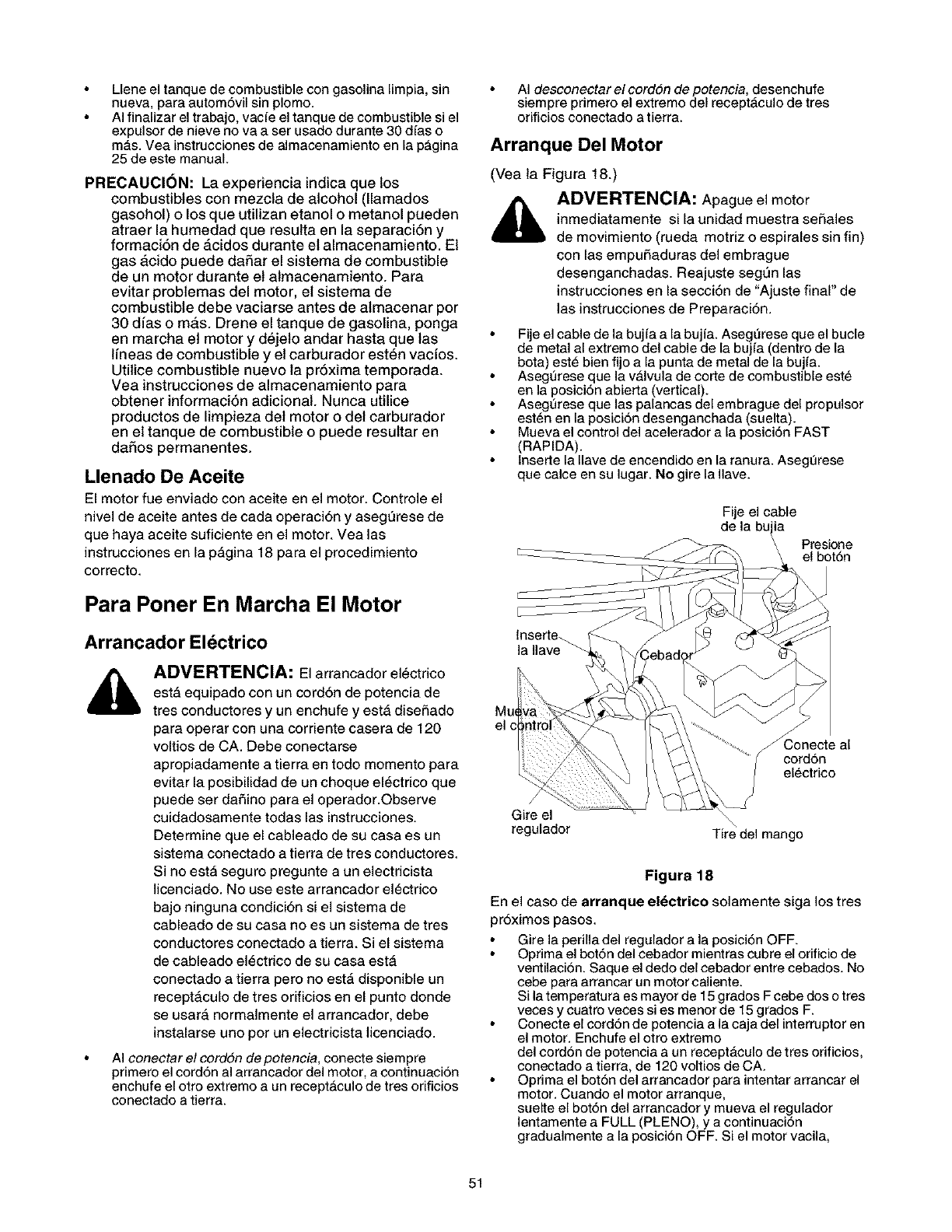
Lleneeltanquedecombustiblecongasolinalimpia,sin
nueva,paraautom6vilsinplome.
AIfinalizareltrabajo,vacfeeltanquedecombustiblesiel
expalserdenievenovaasetusadedurante30dfase
mAs.VeainstruccionesdealmacenamientoenlapAgina
25deestemanual.
PRECAUCl6N: La experiencia indica que los
combustibles con mezcla de alcohol (llamados
gasohol) o los que utilizan etanol o metanol pueden
atraer la humedad que resulta en la separaci6n y
formaci6n de _.cidos durante el almacenamiento. El
gas acido puede daSar el sistema de combustible
de un motor durante et almacenamiento. Para
evitar problemas del motor, et sistema de
combustible debe vaciarse antes de almacenar por
30 dfas o mas. Drene el tanque de gasolina, ponga
en marcha et motor y dejeto andar hasta que las
lfneas de combustible y el carburador esten vacfos.
Utilice combustible nuevo la pr6xima temporada.
Vea instrucciones de almacenamiento para
obtener informaci6n adicionaL Nunca utilice
productos de limpieza del motor o del carburador
en et tanque de combustible o puede resultar en
daSos permanentes.
Llenado De Aceite
El motor fue enviado con aceite en el motor. Controle el
nivel de aceite antes de cada operaci6n y asegt3rese de
que haya aceite suficiente en el motor. Vea las
instrucciones en la p_gina 18 para el procedimiento
correcto.
Para Poner En Marcha El Motor
Arrancador Eldctrico
_, ADVERTENCIA: El arrancador el_ctrico
est_ equipado con un cordSn de potencia de
tres conductores y un enchufe y est_ diseRado
para operar con una corriente casera de 120
voltios de CA. Debe conectarse
apropiadamente a tierra en todo momento para
evitar la posibilidad de un choque el_ctrico que
puede ser daSino para el operador.Observe
cuidadosamente todas las instrucciones.
Determine que el cableado de su casa es un
sistema conectado a tierra de tres conductores.
Si no est_ seguro pregunte a un electricista
licenciado. No use este arrancador el_ctrico
bajo ninguna condici6n si el sistema de
cableado de su casa no es un sistema de tres
conductores conectado a tierra. Si el sistema
de cableado el_ctrico de su casa est_
conectado a tierra pero no est& disponible un
recept_culo de tres orificios en el punto donde
se usar_ normalmente el arrancador, debe
instalarse uno por un electricista licenciado.
AI conectar el cordSn de potencia, conecte siempre
primero el cerd6n al arrancader del motor, a centinuaci6n
enchufe el otro extreme a un recept_culo de tres orificios
conectado a tierra.
AI desconectar el cordsn de potencia, desenchufe
siempre primere el extremo del recept_culo de tres
orificies cenectado a tierra.
Arranque Del Motor
(Vea la Figura 18.)
ADVERTENCIA: Apague el motor
inmediatamente si la unidad muestra se_ales
de movimiento (rueda motriz o espirales sin fin)
con las empuRaduras del embrague
desenganchadas. Reajuste segt3n las
instrucciones en la secci6n de "Ajuste final" de
las instrucciones de Preparaci6n.
Fije el cable de la bujfa a la bujfa. AsegL_rese que el bucle
de metal al extremo del cable de la bujfa (dentre de la
bota) est_ bien fijo a la punta de metal de la bujfa.
Asegt3rese que la v_lvula de corte de combustible este
en la posici6n abier_a (vertical).
Asegt3rese que las palancas del embrague del propulser
est_n en la posici6n desenganchada (suelta).
Mueva el control del acelerador a la posici6n FAST
(RAPIDA).
lnserte la Ilave de encendido en la ranura. AsegtTrese
que calce en su lugar. No gire la Ilave.
Fije el cable
de la bujia
Presione
el bot6n
lnserte-_
la Ilave
el c .J
_Conecte al
cord6n
electrico
Gire el
regulador \
Tire del mango
Figura 18
En el caso de arranque el_ctrico solamente siga los tres
pr6ximos pasos.
Gire la perilla del regulador a la posici6n OFF.
Oprima el bot6n del cebador mientras cubre el orificio de
ventilaci6n. Saque el dedo del cebador entre cebados. No
cebe para arrancar un motor caliente.
Si la temperatura es mayor de 15 grados F cebe dos o tres
veces y cuatro veces si es menor de 15 grados F.
Conecte el cord6n de potencia a la caja del interrupter en
el motor. Enchufe el otro extremo
del cord6n de potencia a un recept&culo de tres orificios,
conectado a tierra, de 120 voltios de CA.
Optima el bot6n del arrancador para intentar arrancar el
motor. Cuando el motor arranque,
suelte el bot6n del arrancador y mueva el regulador
lentamente a FULL (PLENO), y a continuaci6n
gradualmente a la posici6n OFF. Si el motor vacila,
51
muevaelreguladorinmediatamentealaposiciSnFULLy
acontinuaciSnmuevagradualmentealaposiciSnOFF.
Paraelarranque de tettoceao solamente siga los tres
prSxirnos pasos:
Gire la perilla del regulador a la posiciSn FULL. Coloque
el regulador en la posiciSn OFF en lugar de la posiciSn
FULL, si el motor todavfa est_ caliente.
Optima el botSn del cebador dos o tres veces. Optima el
botSn del cebador una vez solamente, si el motor estA
caliente.
Sujete el mango del arrancador y tire lentamente de la
soga hasta que comience a ejercer m_s resistencia.
Permita que la soga se enrolle lentamente. Tire
rApidamente del mango del arrancador. No permita que
el mango retroceda bruscamente. Permita que se enrolle
lentamente mientras sujeta firmemente el mango del
arrancador. Repita hasta que el motor arranque. A
medida que el motor se calienta y comienza a funcionar
suavemente, gire lentamente la perilla del regulador a la
posiciSn OFF. Si el motor vacila, regrese a regulador en
FULL y a continuaciSn mueva lentamente a la posiciSn
OFF.
Como Apagar El Motor
Haga funcionar el motor por unos pocos minutos antes
de apagar para ayudar a secar la humedad del motor.
Proceda como sigue para avitar una posibla
congelaci6n del arrancador.
Arrancador eldctrico: Conecte el cord6n de potencia a
la caja del interruptor del motor, a continuaci6n a un
recept_culo de 120 voltios de CA. Con el motor
funcionando, oprima el botSn del arrancador y gire el
arrancador pot varios segundos. El sonido raro emitido al
girar el arrancador no daSar_ el motor o el arrancador.
Desconecte primero el cordSn de potencia del
recept_culo y a continuaciSn de la caja del interruptor.
Arrancador a retroceso: Con el motor funcionando,
tire de la soga del arrancador con una pasada r_pida y
continua con todo el brazo, tres o cuatro veces. El tirar de
la soga del arrancador producir_ un sonido intenso de
golpeteo, que no es daSino para el motor o el arrancador.
Para apagar el motor, empuje todo hacia abajo
la palanca del acelerador o saque la Ilave de encendido.
No gire la Ilave. Desconecte el cable
de la bujia de la misma para evitar un arranque
accidental mientras el equipo est_ desatendido.
NOTA: No pierda la Ilave de encendido. Mantengala en
un lugar seguro. El motor no arrancara sin la Ilave de
encendido.
Limpie toda la nieve y humedad de la cubierta del
carburador en el _rea de las palancas de control.
Tambien, avance y retroceda varias veces las palancas
de control. Deje la palanca de control del acelerador en la
posici6n STOP u OFF. Deje el control del regulador en la
posici6n FULL.
Enganche De La Propulsion
Con el motor funcionando cerca de la velocidad m_xima,
mueva la palanca de cambios a una de las posiciones de
forward (avance) o alas dos de reverse (retroceso).
Seleccione una velocidad apropiada para las
condiciones de nieve existentes. Use las velocidades
m&s lentas hasta que est_ familiarizado con la operaci6n
de la limpiadora de nieve.
Optima la empuSadura del embrague de la espiral sin fin
izquierda contra el mango, para engancharla.
Mientras la empuSadura del embrague de la espiral sin
fin est_ enganchada, optima la empuSadura del
embrague del propulsor derecho.
Suelte la empuf_adura del embrague de la espiral sin
fin izquierda, solamente. El mecanismo de interbloqueo
debe mantener el embrague izquierdo enganchado
hasta que se suelte el embrague derecho.
NOTA: NUNCA mueva la palanca de cambios sin
soltar primero el embrague del propulsor.
Manejo De La Limpiadora De Nieve
Las palancas de los gatillos est_n ubicadas en la
parte inferior de los mangos y se usan para manejar
su limpiadora de nieve.
NOTA: El embrague del propulsor debe estar
enganchado al usar los gatillos para manejar la
limpiadora de nieve.
Para girar a la derecha, optima la palanca del gatillo
derecho y gufa la limpiadora de nieve
hacia la derecha.
Para girar a la izquierda, oprima la palanca del gatillo
izquierdo y gufe la limpiadora de nieve hacia la izquierda.
Optima ambos gatillos para transporlar la unidad cuando
el motor no est_ funcionando.
NOTA: Esos controles deben usarae mientras opera
su limpiadora de nieve en areas abiertas, hasta
familiarizarse con su operaci6n.
Instrucciones Abreviadas de Arranque
Expulsorde Cable Palancas Controldel Llavede Regulador Cord6nde Cebador Arrancador Despuesde
Nieve dela propulsoras acelerador encendidc )otencia arrancar
bujfa
Arrancador Conecte Suelte Muevaa Presione Muevaa Conectea -- Presioneel 1. Suelteelbot6n
El_ctrico FAST )ara FULL la fuente bot6n 2. Mueva el
calzar Cebado regulador a Off
3. Desconecte el
cord6n
Arrancador Conecte Suelte Muevaa Presione Muevaa -- Cebe Tiredel 1. Suelte el mango
de FAST )ara FULL mango 2. Mueva el
Retroceso calzar regulador a Off
52
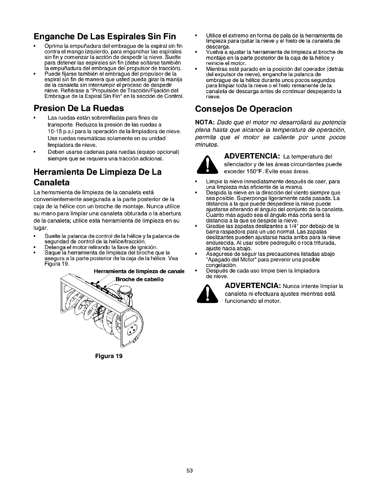
Enganche De Las Espirales Sin Fin
Optima la empu_adura del embrague de la espiral sin fin
contra el mango izquierdo, para enganchar las espirales
sin fin y comenzar la acci6n de despedir la nieve. Suelte
para detener las espirales sin fin (debe soltarse tambi6n
la empuSadura del embrague del propulsor de tracci6n).
Puede fijarse tambi_n el embrague del propulsor de la
espiral sin fin de manera que usted pueda girar la manija
de la canaleta sin interrumpir el proceso de despedir
nieve. Refierase a "Propulsi6n de Tracci6n/Fijaci6n del
Embrague de la Espiral Sin Fin" en la secci6n de Control.
Presion De La Ruedas
Las ruedas est_n sobreinfladas para fines de
transporte. Reduzca la presi6n de las ruedas a
10-15 p.s.i para la operaci6n de la limpiadora de nieve.
Use ruedas neum_ticas solamente en su unidad
limpiadora de nieve.
Deben usarse cadenas para ruedas (equipo opcional)
siempre que se requiera una tracci6n adicional.
Herramienta De Limpieza De La
Canaleta
La herramienta de limpieza de la canaleta est_
convenientemente asegurada a la parte posterior de la
caja de la h61ice con un broche de montaje. Nunca utilice
su mano para limpiar una canaleta obturada o la abertura
de la canaleta; utilice esta herramienta de limpieza en su
lugar.
Suelte la palanca de control de la h_lice y la palanca de
seguridad de control de la h_lice/tracci6n.
Detenga el motor retirando la Ilave de ignici6n.
Saque la herramienta de Iimpieza del broche que la
asegura a la patte posterior de la caja de la helice. Vea
Figura 19.
Herramienta de limpieza de canale
Broche de cabello
Utilice el extremo en forma de pala de la herramienta de
limpieza para quitar la nieve y el hielo de la canaleta de
descarga.
Vuelva a ajustar la herramienta de limpieza al broche de
montaje en la parte posterior de la caja de la helice y
reinicie el motor.
Mientras est_ parado en la posici6n del operador (detr_s
del expulsor de nieve), enganche la palanca de
embrague de la h_lice durante unos pocos segundos
para limpiar toda la nieve o el hielo remanente de la
canaleta de descarga antes de continuar despejando la
nieve.
Consejos De Operacion
NOTA: Dado que el motor no desarrollara su potencia
plena hasta que alcance la temperatura de operaci6n,
permita que el motor se caliente por unos pocos
minutos.
_, ADVERTENCIA: La temperaturadel
silenciador y de las _reas circundantes puede
exceder 150°F. Evite esas #,reas.
Limpie la nieve inmediatamente despu6s de caer, para
una limpieza m_s eficiente de la misma.
Despida la nieve en la direcci6n del viento siempre que
sea posible. Superponga ligeramente cada pasada. La
distancia a la que puede despedirse la nieve puede
ajustarse alterando el _ngulo del con junto de la canaleta.
Cuanto m_s agudo sea el Angulo m_s corta serA la
distancia a la que se despide la nieve.
Gradt3e las zapatas deslizantes a 1/4" por debajo de la
barra raspadora para un uso normal. Las zapatas
deslizantes pueden ajustarse hacia arriba para la nieve
endurecida. AI usar sobre pedregullo o roca triturada,
ajuste hacia abajo.
Asegt3rese de seguir las precauciones listadas abajo
"Apagado del Motor" para prevenir una posible
congelaci6n.
Despu6s de cada uso Iimpie bien la Iimpiadora
de nieve.
,_ ADVERTENCIA: Nunca intentelimpiar la
canaleta ni efectuara ajustes mientras est_
funcionando el motor.
Figura 19
53
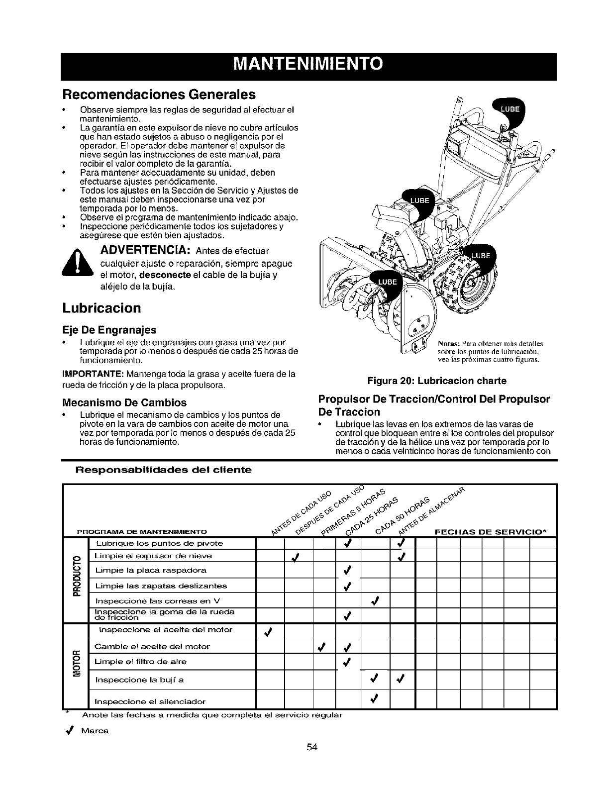
Recomendaciones Generales
Observe siempre las reglas de seguridad al efectuar el
mantenimiento.
La garanfia en este expulsor de nieve no cubre art{culos
que han estado sujetos a abuso o negligencia pot el
operador. El operador debe mantener el expulsor de
nieve segL_nlas instrucciones de este manual para
recibir el valor completo de la garant{a.
Para mantener adecuadamente su unidad, deben
efectuarse ajustes peri6dicamente.
Todos los ajustes en la Secci6n de Servicio y Ajustes de
este manual deben inspeccionarse una vez por
temporada pot Io menos.
Observe el programa de mantenimiento indicado abajo.
Inspeccione peri6dicamente todos los sujetadores y
asegurese que est6n bien ajustados.
,_ ADVERTENCIA: Antes de efectuar
cualquier ajuste o reparaciSn, siempre apague
el motor, desconecte el cable de la bujia y
al6jelo de la bujfa.
Lubricacion
Eje De Engranajes
Lubrique el eje de engranajes con grasa una vez por
temporada por Io menos o despu6s de cada 25 horas de
funcionamiento.
IMPORTANTE: Mantenga toda la grasa y aceite fuera de la
rueda de fricci6n y de la placa propulsora.
Mecanismo De Cambios
Lubrique el mecanismo de oambios ylos puntos de
pivote en la vara de cambios con aceite de motor una
vez por temporada por Io menos o despues de cada 25
horas de funcionamiento.
Notas: Para obtener mils detalles
sobre los puntos de lubricacidn,
yea las prdximas cuatro figuras.
Figura 20: Lubricacion charte
Propulsor De Traccion/Control Del Propulsor
De Traccion
Lubrique las levas en los extremos de las varas de
control que bloquean entre si los controles del propulsor
de tracci6n y de la h61ice una vez por temporada por Io
menos o cada veinticinco horas de funcionamiento con
Responsabilidades del cliente
PROGRAMA DE MANTEN|MIENTO
Lubrique los puntos de pivote
0 Umpie el expulsor de nieve
Limpie la plata raspadora
O_ himpie las zapatas deslizantes
Inspeccione las correas en V
delnSr_i_idnCci°ne la goma de la rueda
Inspeccione el aceite del motor
Gamble el aceite del motor
OO Umpie el filtro de aire
Inspeccione la bujl a
,/
,t ,t
,t
,t
,t
,t
,/
,t 4
Inspeccione el silenciador
Anote las fechas a medida que completa el servicio regular
,/
Marca
54
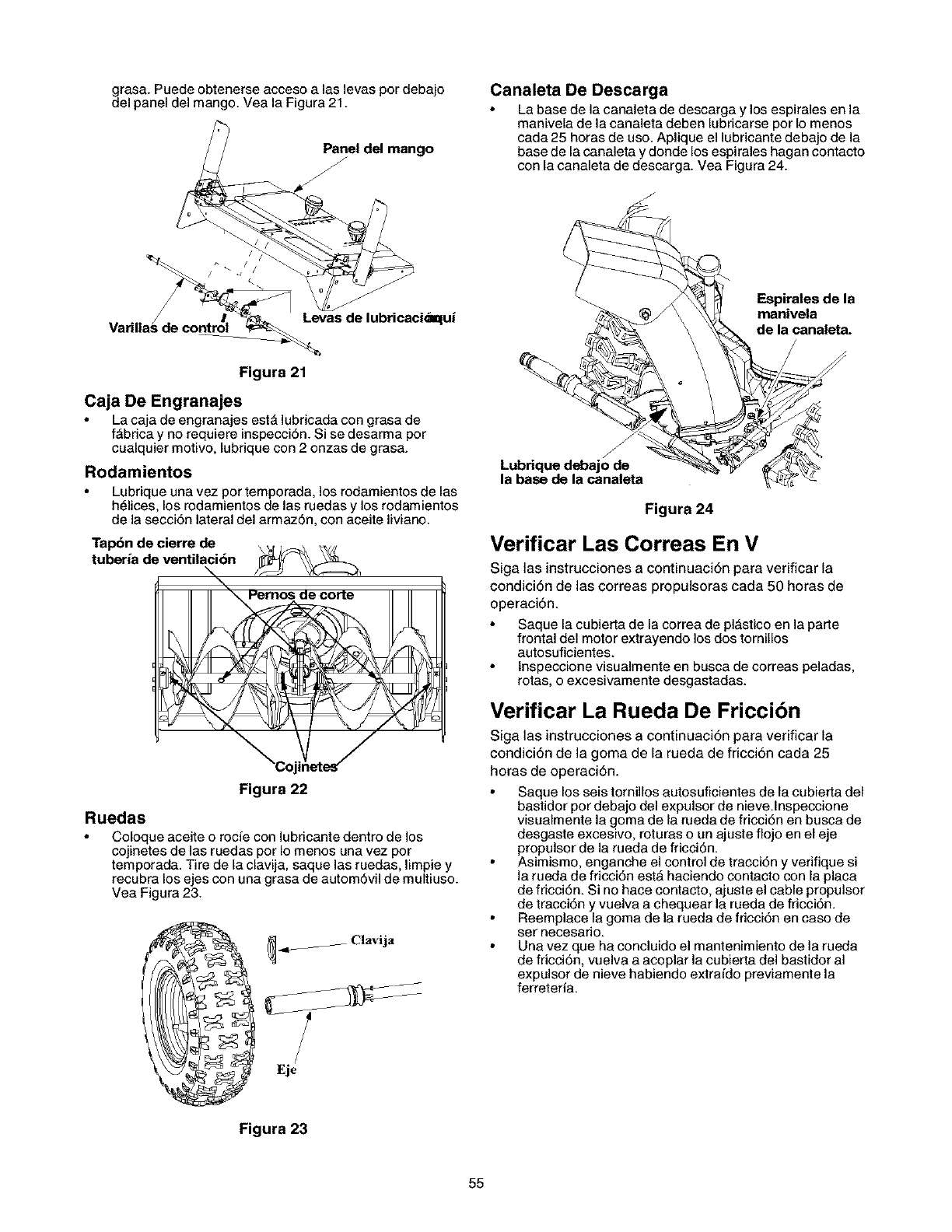
dgrasa. Puede obtenerse acceso alas levas por debajo
el panel del mango. Yea la Figura 21.
ango
Varilla/de_ contro/i _ I ev s de ub "caci_alUi
Figura 21
Caja De Engranajes
La caja de engranajes est& lubricada con grasa de
f_brica y no requiere inspecciSn. Si se desarma pot
cualquier motivo, lubrique con 2onzas de grasa.
Rodamientos
Lubrique una vez por temporada, los rodamientos de las
h_lices, los rodamientos de las ruedas y los rodamientos
de la secci6n lateral del armaz6n, con aceite liviano.
Tapbn de cierre de
tuberia de ventilaci6n
Figura 22
Ruedas
Coloque aceite o rocie con lubricante dentro de los
cojinetes de las ruedas pot Io menos una vez pot
temporada. Tire de la clavija, saque las ruedas, limpie y
recubra los ejes con una grasa de automSvil de multiuso.
Vea Figura 23.
_ -d_ Clavija
Eie
Canaleta De Descarga
La base de la canaleta de descarga y los espirales en la
manivela de la canaleta deben lubricarse pot Io menos
cada 25 horas de uso. Aplique el lubricante debajo de la
base de la canaleta y donde los espirales hagan contacto
con la canaleta de descarga. Vea Figura 24.
Espirales de la
manivela
de la canaleta.
Lubrique debajo de
la base de la canaleta
Figura 24
Verificar Las Correas En V
Siga las instrucciones a continuaci6n para verificar la
condici6n de las correas propulsoras cada 50 horas de
operaci6n.
Saque la cubietta de la correa de pl_stico en la patte
frontal del motor extrayendo los dos tornillos
autosuficientes.
lnspeccione visualmente en busca de correas peladas,
rotas, o excesivamente desgastadas.
Verificar La Rueda De Fricci6n
Siga las instrucciones a continuaci6n para verificar la
condici6n de la goma de la rueda de fricci6n cada 25
horas de operaci6n.
Saque los seis tornillos autosuficientes de la cubietta del
bastidor por debajo del expulsor de nieve.lnspeccione
visualmente la goma de la rueda de fricci6n en busca de
desgaste excesivo, roturas o un ajuste flojo en el eje
propulsor de la rueda de fricci6n.
Asimismo, enganche el control de tracci6n y verifique si
la rueda de fricci6n est_ haciendo contacto con la placa
de fricci6n. Si no hace contacto, ajuste el cable propulsor
de tracci6n y vuelva a chequear la rueda de fricci6n.
Reemplace la goma de la rueda de fricci6n en caso de
set necesario.
Una vez que ha concluido el mantenimiento de la rueda
de fricci6n, vuelva a acoplar la cubierta del bastidor al
expulsor de nieve habiendo extrafdo previamente la
ferreteria.
Figura 23
55
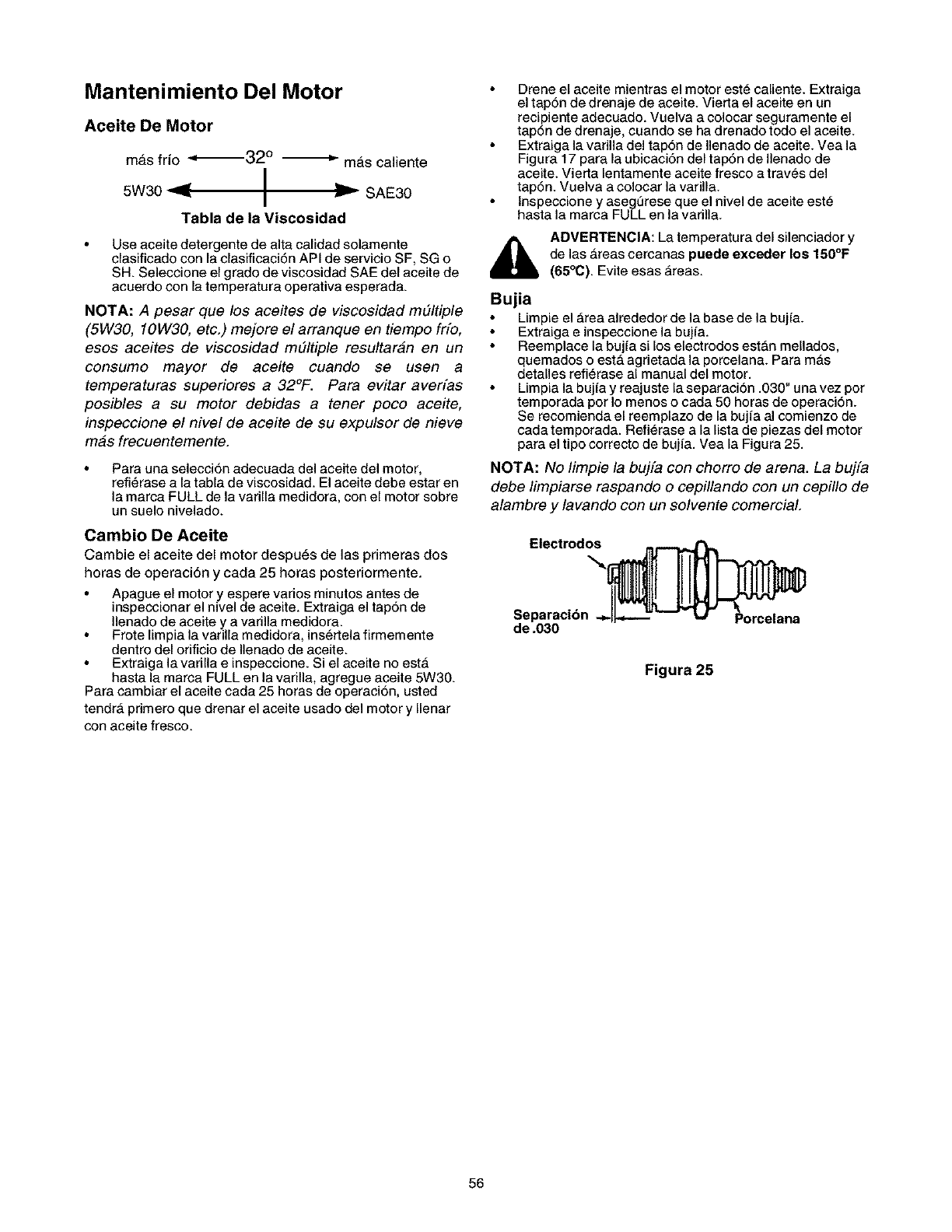
Mantenimiento Del Motor
Aceite De Motor
mAs frio _32 ° --*'- mAs caliente
I
5w30 _ I _- SAE30
I
Tabla de la Viscosidad
Use aceitedetergente de alta calidad solamente
clasificado con la clasificaci6n API de servicio SF, SG o
SH. Seleccione el gradode viscosidad SAEdel aceite de
acuerdo con la temperatura operativa esperada.
NOTA: A pesar que los aceites de viscosidad mtJltiple
(5W30, 10W30, etc.) mejore el arranque en tiempo frfo,
esos aceites de viscosidad m#ltiple resultaran en un
consumo mayor de aceite cuando se usen a
temperatures superiores a 32°F. Para evitar averfas
posibles a su motor debidas a tener poco ace#e,
inspeccione el nivel de aceite de su expulsor de nieve
mas frecuentemente.
Para una selecci6n adecuada del aceite del motor,
refi_rase a la tabla de viscosidad. El aceite debe estar en
la marca FULL de la varilla medidora, con el motor sobre
un suelo nivelado.
Cambio De Aceite
Cambie el aceite del motor despuAs de las primeras dos
horas de operaciAn y cada 25 horas posteriormente.
Apague el motor y espere varios minutos antes de
inspeccionar el nivel de aceite. Extraiga el tap6n de
Ilenado de aceite y a varilla medidora.
Frote limpia la varilla medidora, ins_dela firmemente
dentro del orificio de Ilenado de aceite.
• Extraiga la varilla e inspeccione. Si el aceite no est_
hasta la marca FULL en la varilla, agregue aceite 5W30.
Para cambiar el aceite cada 25 horas de operaci6n, usted
tendrA primero que drenar el aceite usado del motor y Ilenar
con aceite fresco.
Drene el aceite mientras el motor est_ caliente. Extraiga
el tap6n de drenaje de aceite. Vietta el aceite en un
recipiente adecuado. Vuelva a colocar seguramente el
tap6n de drenaje, cuando se ha drenado todo el aceite.
Extraiga la varilla del tap6n de Ilenado de aceite. Vea la
Figura 17 para la ubicaci6n del tap6n de Ilenado de
aceite. Vietta lentamente aceite fresco a traves del
tap6n. Vuelva a colocar la varilla.
lnspeccione y asegt3rese que el nivel de aceite est_
hasta la mama FULL en la varilla.
i_ ADVERTENCIA: La temperatura del silenciador y
de las _reas cercanas puede exceder los 150°F
(65°C). Evite esas _reas.
Bujia
Limpie el Area alrededor de la base de la bujfa.
Extraiga e inspeccione la bujfa.
Reemplace la bujfa si los electrodos estAn mellados,
quemados o estA agrietada la porcelana. Para mAs
detalles refi_rase al manual del motor.
Limpia la bujfa y reajuste la separaci6n .030" una vez por
temporada por Io menos o cada 50 horas de operaci6n.
Se recomienda el reemplazo de la bujia al comienzo de
cada temporada. Refi_rase a la lista de piezas del motor
para el tipo correcto de bujia. Vea la Figura 25.
NOTA: No limpie la bujfa con chorro de arena. La bujfa
debe limpiarse raspando o cepillando con un cepillo de
alambre y lavando con un solvente comercial.
de .030
Figura 25
56
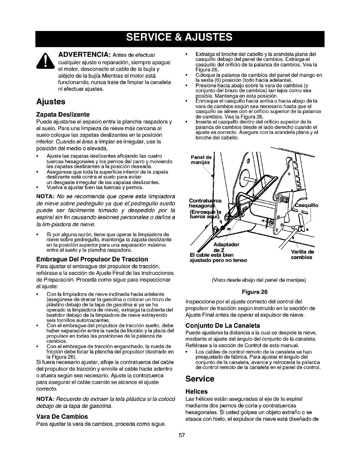
ADVERTENCIA: Antes de efectuar
cualquier ajuste o reparaci6n, siempre apague
el motor, desconecte el cable de la bujfa y
al_jelo de la bujfa.Mientras el motor est&
funcionando, nunca trate de limpiar la canaleta
ni efectuar ajustes.
Ajustes
Zapata Deslizante
Puede ajustarse el espacio entre la plancha raspadora y
el suelo. Para una limpieza de nieve m&s cercana al
suelo coloque las zapatas deslizantes en la posici6n
inferior. Cuando el Area a limpiar es irregular, use la
posici6n del medio o elevada.
Ajuste las zapatas deslizantes aflojando las cuatro
tuercas hexagonales y los pemos del carro y moviando
las zapatas deslizantes a la posici6n deseada.
Asegt_reseque toda la superficie inferior de la zapata
deslizante est6 contra el suelo para evitar
un desgaste irrregularde las zapatas deslizantes.
Vuelva a ajustar bien las tuercas y pemos.
NOTA: No se recomienda que opere esta limpiadora
de nieve sobre pedregullo ya que el pedregullo suelto
puede ser facilmente tomado y despedido por la
espiral sin fin causando lesiones personales o daSos a
/a lim-piadora de nieve.
Si pot alguna raz6n, tiene que operar la limpiadora de
nieve sobre pedregullo, mantenga la zapata deslizante
en la posici6n superior para una separaci6n m_xima
entre el suelo y la plancha raspadora.
Embrague Del Propulsor De Traccion
Para ajustar el embrague del propulsor de tracci6n,
refi_rase a la secci6n de Ajuste Final de las Instrucciones
de Preparaci6n. Proceda como sigue para inspeccionar
el ajuste:
Con la Iimpiadora de nieve inclinada hacia adelante
(asegt3rese de dranar la gasolina o colocar un trozo de
plAstico debajo de la tapa de gasolina si ya se ha
operado la limpiadora de nieve), extraiga la cubierta del
bastidor debajo de la limpiadora de nieve extrayendo
seis tornillos autoroscantes.
Con el embrague del propulsor de tracci6n suelto, debe
haber separaci6n entre la rueda de fricci6n y la placa del
propulsor en todas las posiciones de la palanca de
cambios.
Con el embrague de tracci6n enganchado, la rueda de
fricci6n debe tocar la plancha del propulsor (ilustrado en
la Figura 26).
Si fuera necesario ajustar, afloje la contratuerca del cable
del propulsor de tracci6n y enrolle el cable hacia adentro
o afuera segQn sea necesario. Ajuste la contratuerca
para asegurar el cable cuando se alcance el ajuste
correcto.
NOTA: Recuerde de extraer la tela pl#stica si la coloc5
debajo de la tapa de gasolina.
Vara De Cambios
Para ajustar la vara de cambios, proceda como sigue.
Extraiga el broche del cabello y la arandela plana del
casquillo debajo del panel de cambios. Extraiga el
casquillo del orificio de la palanca de cambios. Vea la
Figura 26.
Coloque la palanca de cambios del panel del mango en
la sexta (6) posici6n (todo hacia adelante).
Presione hacia abajo sobre la vara de cambios (y
conjunto del brazo de cambios) tan lejos como sea
posible. Mantenga en esta posici6n.
Enrosque el casquillo hacia arriba o hacia abajo de la
vara de cambios segt3n sea necesario hasta que el
casquillo se alinee con el orificio superior de la palanca
de cambios. Vea la Figura 26.
Inserte el casquillo dentro del orificio superior de la
palanca de cambios desde el lado derecho cuando el
ajuste es correcto. Asegure con la arandela plana y el
broche del cabello.
Panel de
manijas
deZ
uillo
ajustado pero no tenso
Varilla de
cambios
(Visto desde abajo del panel de manijas)
Figura 26
Inspeccione pot el ajuste correcto del control del
propulsor de tracci6n segt)n instruidoen la secci6n de
Ajuste Final antes de operar el expulsor de nieve.
Conjunto De La Canaleta
Puede ajustarse la distancia a la cual se despide la nieve,
mediante el ajuste del _.ngulo del conjunto de la canaleta.
Refi_rase a la secci6n de Control de este manual.
Los cables de control remoto de la canaleta se han
preajustado de fb,brica. Para ajustar el _ngulo del
conjunto de la canaleta, avarice y retroceda la palanca
de control remoto de la canaleta en el panel de control.
Service
Helices
Las h_lices est_maseguradas al eje de la espiral
mediante dos pernos de corte y contratuercas
hexagonales. Si usted golpea un objeto extrafio o se
atasca con hielo, el expulsor de nieve est,. disefiado de
57
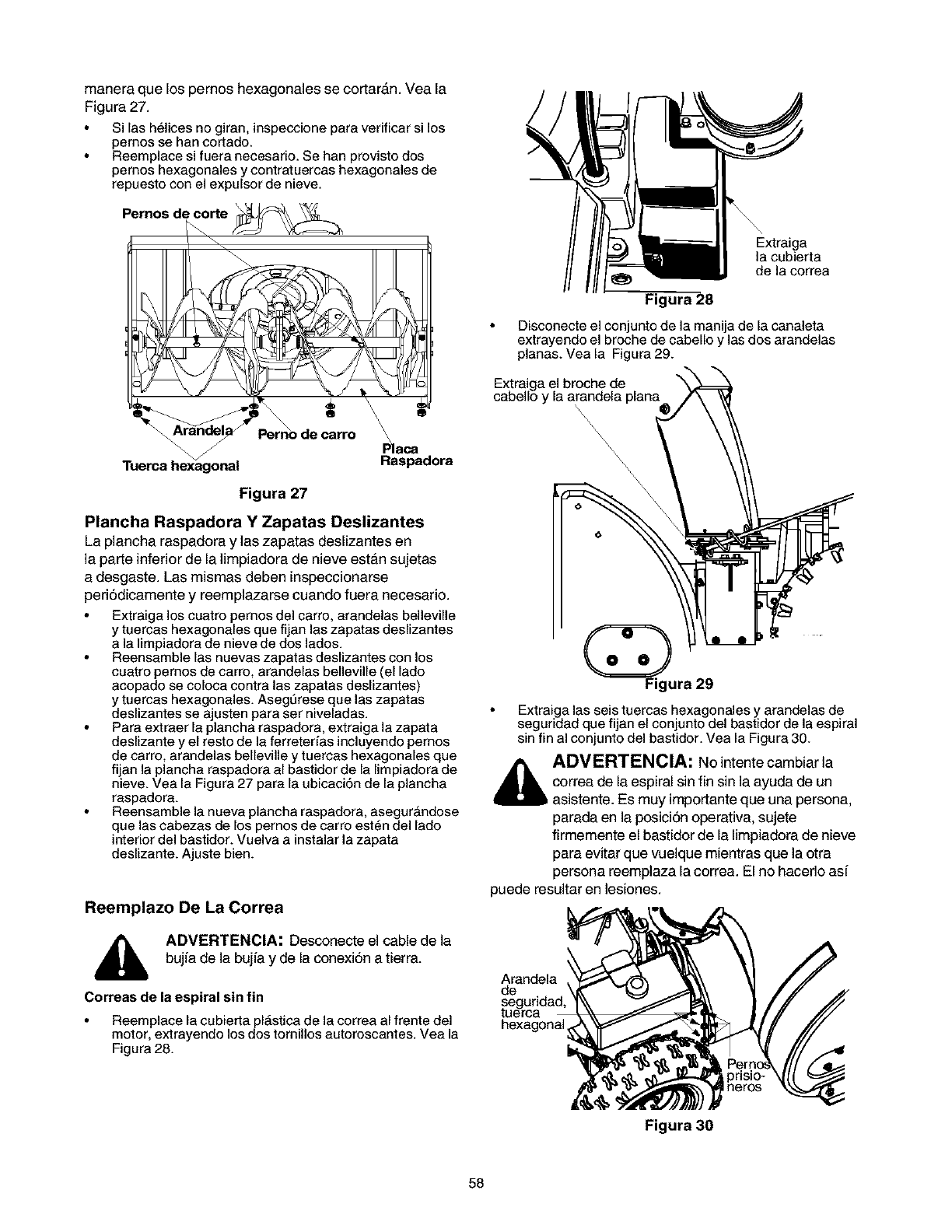
manera que los pernos hexagonales se cortar_m. Vea la
Figura 27.
Si las helices no giran, inspeccione para verificar si los
pernos se han cortado.
Reemplace si fuera necesario. Se han provisto dos
pernos hexagonales y contratuercas hexagonales de
repuesto con el expulsor de nieve.
Pernos de_orte _
Pemo de carro Raca
Raspadora
Figura 27
Plancha Raspadora Y Zapatas Deslizantes
La plancha raspadora y las zapatas deslizantes en
la parte inferior de la limpiadora de nieve estAn sujetas
a desgaste. Las mismas deben inspeccionarse
periSdicamente y reemplazarse cuando fuera necesario.
Extraiga los cuatro pemos del carro, arandelas belleville
y tuercas hexagonales que fijan las zapatas deslizantes
a la limpiadora de nieve de dos lados.
Reensamble las nuevas zapatas deslizantes con los
cuatro pernos de carro, arandelas belleville (el lado
acopado se coloca contra las zapatas deslizantes)
y tuercas hexagonales. Asegt3rese que las zapatas
deslizantes se ajusten para ser niveladas.
Para extraer la plancha raspadora, extraiga la zapata
deslizante y el resto de la ferreterfas incluyendo pernos
de carro, arandelas belleville y tuercas hexagonales que
fijan la plancha raspadora al bastidor de la limpiadora de
nieve. Vea la Figura 27 para la ubicaci6n de la plancha
raspadora.
Reensamble la nueva plancha raspadora, asegur_ndose
que las cabezas de los pernos de carro est_n del lado
interior del bastidor. Vuelva a instalar la zapata
deslizante. Ajuste bien.
Reemplazo De La Correa
ADVERTENCIA: Desconecte el cable de la
bujia de la bujia y de la conexiSn a tierra.
Correas de la espiral sin fin
Reemplace la cubier_a pl_stica de la correa al frente del
motor, extrayendo los dos tornillos autoroscantes. Vea la
Figura 28.
Extraiga
la cubierta
de la correa
Figura 28
Disconecte el conjunto de la manija de la canaleta
extrayendo el broche de cabello y las dos arandelas
planas. Vea la Figura 29.
Extraiga el broche de
cabello y la arandela plana@ /_ _'_
Figura 29
Extraigalas seis tuercas hexagonalesy arandelas de
seguridad quefijan el conjunto del bastidor de la espiral
sin fin al conjunto del bastidor. Vea la Figura 30.
_ADVERTENCIA: No intente cambiar la
correa de la espiral sin fin sin la ayuda de un
asistente. Es muy importante que una persona,
parada en la posiciSn operativa, sujete
firmemente el bastidor de la limpiadora de nieve
para evitar que vuelque mientras que la otra
persona reemplaza la correa. El no hacerlo asi
puede resultar en lesiones.
Arandela
de
hexagonal
58
Figura 30
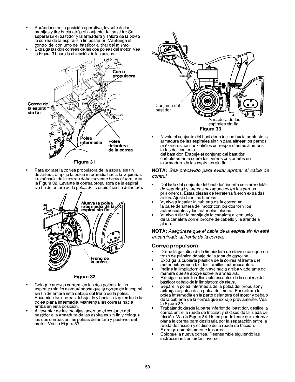
Par_ndose en la posici6n operativa, levante de las
manijas y tire hacia atr_s el conjunto del bastidor.Se
separar&n el bastidor y la armadura y saldr_ de la polea
la correa de la espiral sin fin posterior. Mantenga el
control del con junto del bastidor al tirar del mismo.
Extraiga las dos correas de las dos poleas del motor. Vea
la Figura 31 para la ubicaci6n de las poleas.
':_ (,n/t°eeaa_edia ;e°lenatera
_de la correa
Figura 31
Para extraer la correa propulsora de la espiral sin fin
delantera, empuje la polea intermedia hacia la izquierda.
La m_nsula de la correa debe moverse hacia afuera. Vea
la Figura 32. Levante la correa propulsora de la espiral
sin fin delantera de la polea de la espiral sin fin delantera.
_Freno de
la polea
Figura 32
Coloque nuevas correas en las dos poleas de las
espirales sin fin asegur_ndose que la correa de la espiral
sin fin delantera est_ debajo del freno de la polea.
Encamine las correas debajo de y hacia la izquierda de la
polea plana intermedia. Mantenga las correas hacia
arnba en esta posici6n.
AI levantar de las manijas, acerque el conjunto del
bastidor a la armadura de las espirales sin fin y coloque
las dos correas en las poleas delantera y posterior del
motor. Vea la Figura 33.
Conjunto del
bastidor
Armadurad_las
espirales sin fin
Figura 33
Nivele el conjunto del bastidor e incline hacia adelante la
armadura de las espirales sin fin para alinear los pernos
prisioneros con los orificios correspondientes a ambos
lados del conjunto
del bastidor. Empuje el conjunto del bastidor
completamente sobre los pernos prisioneros de
la armadura de las espirales sin fin.
NOTA: Sea precavido para evitar apretar el cable de
control.
Del lado del conjunto del bastidor, insette seis arandelas
de seguridad y tuercas hexagonales en los pernos
prisioneros. Estas piezas de ferreterfa fueron extraidas
antes. Ajuste bien las tuercas.
Vuelva a instalar la cubieda de la correa en
la par_edelantera del motor con los dos tornillos
autoroscantes y las arandelas planas.
Vuelva a fijar la manija de la canaleta al conjunto
de la canaleta con el broche de cabello y la arandela
plana.
NOTA: AsegEtrese que el cable de la espiral sin fin este
encaminado al frente de la correa.
Correa propulsora
Drene la gasolina de la limpiadora de nieve o coloque un
trozo de plAstico debajo de la tapa de gasolina.
Extraiga la cubier_a pl_stica de la correa al frente del
motor extrayendo los dos tornillos autoroscantes.
Incline la limpiadora de nieve hacia arnba y adelante de
manera que se apoye sobre la armadura.
Extraiga los seis tornillos autoroscantes de la cubier_a del
bastidor debajo de la limpiadora de nieve.
Separe la polea intermedia de la polea del propulsor y
extraiga la polea de la polea del motor. Encontrar_ la
polea intermedia en la parte delantera del motor y debajo
de la cubierta de la correa que extrajo previamente. Vea
la Figura 32.
Trabajando desde la par_e inferior del bastidor, deslice la
correa entre la rueda de fricci6n y el disco de la rueda de
fricci6n. Vea la Figura 34. Usted puede tenet que retorcer
plana la correa para deslizarla por la separaci6n entre la
rueda de fncci6n y el disco de la rueda de fricci6n.
Extraiga completamente la correa.
Coloque la nueva correa. Reensamble siguiendo las
instrucciones en orden inverso.
59
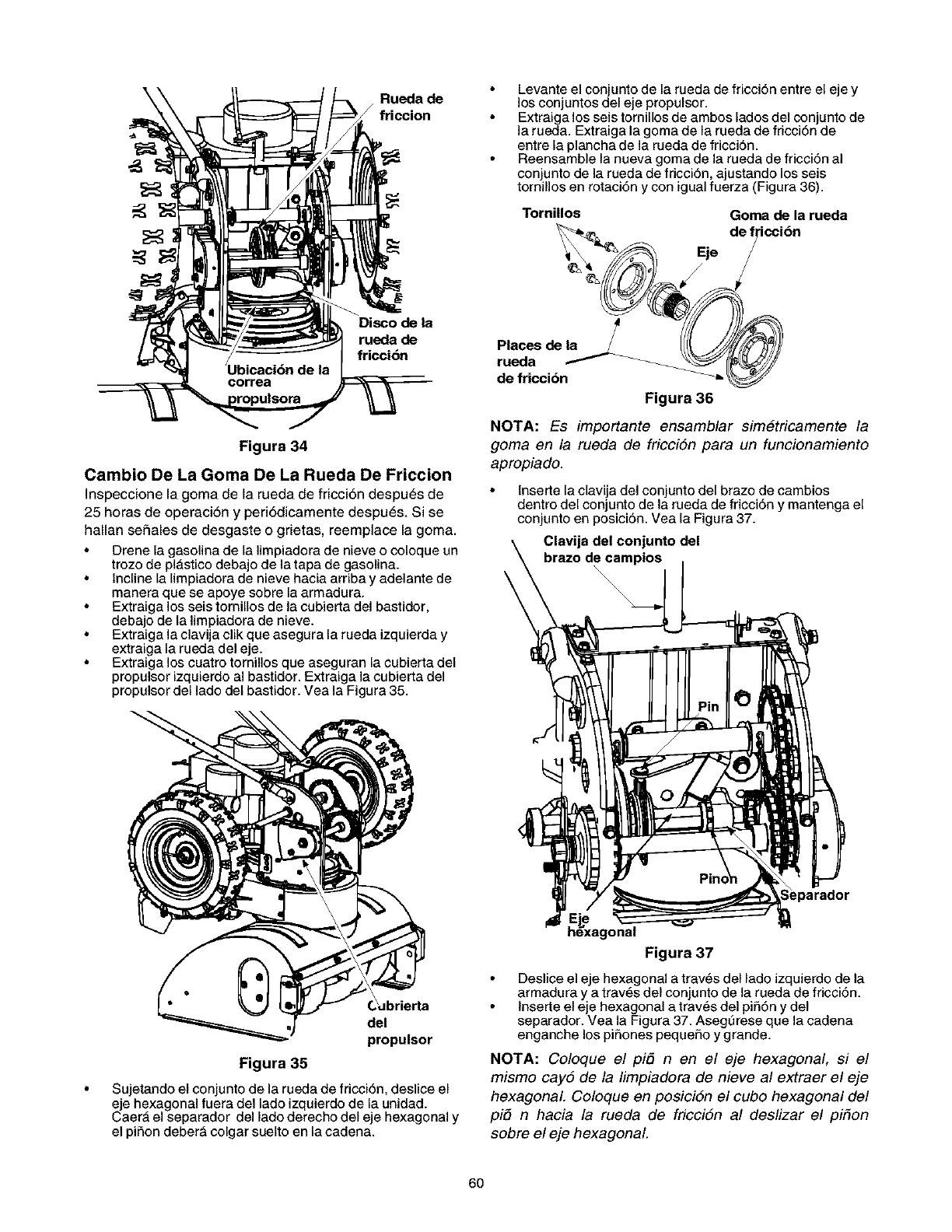
\Rueda de
/friccion
Disco de la
rueda de
fricci_n
Figura 34
Cambio De La Goma De La Rueda De Friccion
Inspeccione la goma de la rueda de fricci6n despu_s de
25 horas de operaci6n y peri6dicamente despu_s. Si se
hallan seSales de desgaste o grietas, reemplace la goma.
Drene la gasolina de la limpiadora de nieve o coloque un
trozo de plAstico debajo de la tapa de gasolina.
Incline la limpiadora de nieve hacia arriba y adelante de
manera que se apoye sobre la armadura.
Extraiga los seis tornillos de la cubierta del bastidor,
debajo de la limpiadora de nieve.
Extraiga la clavija clik que asegura la rueda izquierda y
extraiga la rueda del eje.
Extraiga los cuatro tornillos que aseguran la cubierta del
propulsor izquierdo al bastidor. Extraiga la cubierta del
propulsor del lado del bastidor. Vea la Figura 35.
Levante el conjunto de la rueda de fricci6n entre el eje y
los conjuntos del eje propulsor.
Extraiga los seis tornillos de ambos lados del con junto de
la rueda. Extraiga la goma de la rueda de fricci6n de
entre la plancha de la rueda de fricci6n.
Reensamble la nueva goma de la rueda de fricci6n al
conjunto de la rueda de fricci6n, ajustando los seis
tornillos en rotaci6n y con igual fuerza (Figura 36).
Tomillos Goma de la rueda
de I icci6n
Eje
de fricci6n
Figura 36
NOTA: Es importante ensamblar simetricamente la
goma en la rueda de fricci6n para un funcionamiento
apropiado.
lnse,le la clavija del conjunto del brazo de cambios
dentro del conjunto de la rueda de fricci6n y mantenga el
conjunto en posici6n. Vea la Figura 37.
Clavija del conjunto del
brazo de campios
\
del
propulsor
Figura 35
Sujetando el conjunto de la rueda de fricci6n, deslice el
eje hexagonal fuera del lado izquierdo de la unidad.
Caer_ el separador del lado derecho del eje hexagonal y
el piSon deber_ colgar suelto en la cadena.
_nal
Figura 37
Deslice el eje hexagonal a trav6s del lado izquierdo de la
armadura y a traves del conjunto de la rueda de fricci6n.
lnserte el eje hexagonal a traves del pi56n y del
separador. Vea la Figura 37. Asegt3rese que la ca(lena
enganche los piSones pequeSo y grande.
NOTA: Coloque el pi6 nen el eje hexagonal, si el
mismo cay6 de la limpiadora de nieve al extraer el eje
hexagonal Coloque en posici6n el cubo hexagonal del
pi5 n hacia la rueda de fricci6n al deslizar el piton
sobre el eje hexagonal
60
Alineeelejehexagonalconelrodamientoderecho
ygufecuidadosamenteelrodamientoizquierdodentro
delladoizquierdedelaarmadura.
Reensamblelacubiettadelpropulserconloscuatro
tornillosqueseextrajeronantes.
NOTA: AsegtJrese de extraer el trozo de pl#stico
colocado debajo de la tapa de gasolina, de haberlo
colocado.
Carburador
Si usted considera que el carburador necesita ser
ajustado, consulte con su Servicio T_cnico autorizado de
Sears m_s cercano.
Si su expulsor de nieve no se usa durante 30 dias o m_s,
debe ser preparado para su almacenamiento. Asimismo,
al finalizar la temporada de nieve, debe seguir las mismas
instrucciones y almacenar el expulsor de nieve
correctamente para la estaci6n sin nieve. El
almacenamiento adecuado garantiza una vida m_s
prolongada de nieve.
ADVERTENCIA: En caso de que se hagan
ajustes al motor mientras est_ funcionando (por
ejemplo carburador), mant_ngase a distancia de
todas las partes m6viles. Tenga cuidado con las
superficies recalentadas y con el silenciador.
61
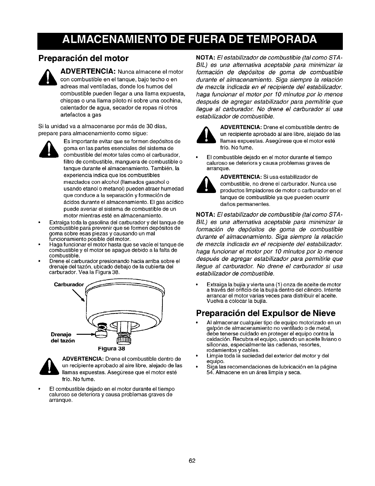
Preparaci6n del motor
ADVERTENCIA: Nunca almacene el motor
con combustible en el tanque, bajo techo o en
adreas mal ventiladas, donde los humos del
combustible pueden Ilegar a una llama expuesta,
chispas o una llama piloto ni sobre una cochina,
calentador de agua, secador de ropas ni otros
artefactos a gas
Si la unidad va a almacenarse por m&s de 30 dias,
prepare para almacenamiento como sigue:
Es importante evitar que se formen dep6sitos de
goma en las parses esenciales del sistema de
combustible del motor tales como el carburador,
filtro de combustible, manguera de combustible o
tanque durante el almacenamiento. Tambien, la
experiencia indica que los combustibles
mezclados con alcohol (llamados gasohol o
usando etanol o metanol) pueden atraer humedad
que conduce a la separaci6n y formaci6n de
Acidos durante el almacenamiento. El gas acfdico
puede averiar el sistema de combustible de un
motor mientras est_ en almacenamiento.
Extraiga toda la gasolina del carburador y del tanque de
combustible para prevenir que se formen dep6sitos de
goma sobre esas piezas y causando un real
funcionamiento posible del motor.
Haga funcionar el motor hasta que se vacfe el tanque de
combustible y el motor se apague debido a la falta de
combustible.
Drene el carburador presionando hacia arriba sobre el
drenaje del taz6n, ubicado debajo de la cubierta del
carburador. Vea la Figura 38.
Carburador
N
Drenaje
del taz6n
I-igura 38
_b ADVERTENCIA: Drene el combustible dentro de
un recipiente aprobado al aire libre, alejado de las
llamas expuestas. Asegt_rese que el motor est_
frfo. No fume.
El combustible dejado en el motor durante el tiempo
caluroso se deteriora y causa problemas graves de
arranque.
NOTA: El estabilizador de combustible (tal como STA-
BIL) es una alternafiva aceptable para minimizar la
formacidn de depdsitos de goma de combustible
durante el almacenamiento. Siga siempre la relacidn
de mezcla indicada en el recipiente del estabilizador.
haga funcionar el motor por 10 minutos por Io menos
despues de agregar estabilizador para permitirle que
Ilegue al carburador. No drene el carburador si usa
estabilizador de combustible.
ADVERTENCIA: Drene el combustible dentro de
un recipiente aprobado al aire libre, alejado de las
llamas expuestas. AsegL_rese que el motor est6
fr[o. No fume.
El combustible dejado en el motor durante el tiempo
oaluroso se deteriora y oausa problemas graves de
arranque.
ADVERTENCIA: Si usa estabilizador de
combustible, no drene el carburador. Nunca use
productos limpiadores de motor o carburador en el
tanque de combustible ya que pueden ocurrir
daSos permanentes.
NOTA: El estabilizador de combustible (tal como STA-
BIL) es una alternafiva aceptable para minimizar la
formaciSn de dep6sitos de goma de combustible
durante el almacenamiento. Siga siempre la relaciSn
de mezcla indicada en el recipiente del estabilizador.
haga funcionar el motor por 10 minutos por Io menos
despues de agregar estabilizador para permitirle que
Ilegue al carburador. No drene el carburador si usa
estabilizador de combustible.
Extraiga la bujfa y vier_a una (1) onza de aceite de motor
a trav_s del orificio de la bujia dentro del cilindro. Intente
arrancar el motor varias veces para distribuir el aceite.
Vuelva a colocar la bujfa.
Preparaci6n del Expulsor de Nieve
AI almacenar cualquier tipo de equipo motorizado en un
galp6n de almacenamiento no ventilado o de metal,
debe tenerse cuidado en proteger el equipo contra la
oxidaci6n. Recubra el equipo, usando un aceite liviano o
siliconas, especialmente las cadenas, resortes,
rodamientos y cables.
Limpie toda la suciedad del exterior del motor y del
equlpo.
Siga las recomendaciones de lubricaci6n en la pAgina
54. Almacene en un _rea limpia y seca.
62
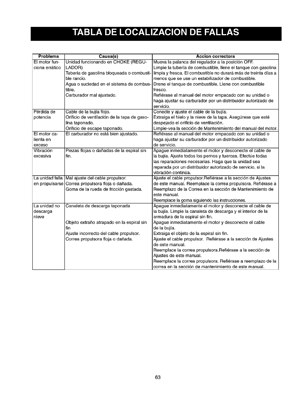
Problema
El motor fun-
ciona err_tico
Causa(s)
Unidad funcionando en CHOKE (REGU-
LADOR)
Tuberia de gasolina bloqueada o combusti-
ble rancio.
Agua o suciedad en el sistema de combus-
tible.
Carburador mal ajustado.
Perdida de Cable de la bujfa flojo.
)otencia Orificio de ventilaci6n de la tapa de gaso-
lina taponado.
Orificio de escape taponado.
El motor ca- El carburador no estA bien ajustado.
lienta en
exceso
Vibraci6n Piezas flojas o daSadas de la espiral sin
excesiva fin.
La unidad falla Mal ajuste del cable propulsor.
en propulsarse Correa propulsora floja o daSada.
Goma de la rueda de fricci6n gastada.
La unidad no Canaleta de descarga taponada
descarga
nieve
Objeto extraSo atrapado en la espiral sin
fin
Ajuste incorrecto del cable propulsor.
Correa propulsora floja o daSada.
Accion correctora
Mueva la palanca del regulador a la posici6n OFF.
Limpie la tuberfa de combustible, Ilene el tanque con gasolina
limpia y fresca. El combustible no durar_, m_.s de treinta dfas a
menos que se use un estabilizador de combustible.
Drene el tanque de combustible. Llene con combustible
fresco.
Refi_rase al manual del motor empacado con su unidad o
haga ajustar su carburador pot un distribuidor autorizado de
servicio.
Conecte y ajuste el cable de la bujfa.
Extraiga el hielo y la nieve de la tapa. Asegurese que est_
despejado el orificio de ventilaci6n.
Limpie-vea la secci6n de Mantenimiento del manual del motor.
Refi_rase al manual del motor empacado con su unidad o
haga ajustar su carburador pot un distribuidor autorizado
de servicio.
Apague inmediatamente el motor y desconecte el cable de
la bujfa. Ajuste todos los pernos ytuercas. Efectue todas
las reparaciones necesarias. Haga que la unidad sea
reparada por un distribuidor autorizado de servicio, si la
vibraci6n continua.
Ajuste el cable propulsor.Refierase a la secci6n de Ajustes
de este manual. Reemplace la correa propulsora. Refi_rase a
Reemplazo de la Correa en la secci6n de Mantenimiento de
sste manual.
Reemplace la goma siguiendo las instrucciones.
Apague inmediatamente el motor ydesconecte el cable de
la bujfa. Limpie la canaleta de descarga y el interior de la
armadura de la espiral sin fin.
Apague inmediatamente el motor y desconecte el cable
de la bujfa.
Extraiga el objeto de la espiral sin fin.
Ajuste el cable propulsor. Refierase a la secci6n de Ajustes
de este manual.
Reemplace la correa propulsora.Refi_rase a la secci6n de
Ajustes de este manual.
Reemplace la correa propulsora. Refi_rase a reemplazo de la
correa en la secci6n de mantenimiento de este manual.
63

Get it fixed, at your home or ours!
Your Home
For repair-in your home-of all major brand appliances,
lawn and garden equipment, or heating and cooling systems,
no matter who made it, no matter who sold it!
For the replacement parts, accessories and
owner's manuals that you need to do-it-yourself.
For Sears professional installation of home appliances
and items like garage door openers and water heaters.
1-800-4-MY-HOME ®(1-800-469-4663)
Call anytime, day or night (U.S.A. and Canada)
www.sears.com www.sears.ca
Our Home
For repair of carry-in items like vacuums, lawn equipment,
and electronics, call or go on-line for the location of your nearest
Sears Parts & Repair Center.
1-800-488-1222
Call anytime, day or night (U.S.A. only)
www.sears.com
To purchase a protection agreement on a product serviced by Sears:
1-800-827-6655 (U.S.A.) 1-800-361-6665 (Canada
Para pedir servic=o de reparacion
a domicdio, y para ordenar piezas:
1-888-SU-HOGAR sM
(1-888-784-6427)
Au Canada pour service en fran(_a=s:
1-800-LE-FOYER Mc
(1-800-533-6937)
www.sears ca
TF _F
A,Registered Trademark /"_Trademark / "'_Serv=ce Mark of Sears Roebuck and Co
Trl Fabrlca /-TI
A, Marca Reg_strada /Marca de = Marca de Servlclo de Sears, Roebuck and Co
rT 10
•c Marque de commerce /_ Marque deposee de Sears Roebuck and Co _, Sears, Roebuck and Co
