Craftsman 247888550 User Manual SNOW THROWER Manuals And Guides L9910191
CRAFTSMAN Snowthrower, Gas Manual L9910191 CRAFTSMAN Snowthrower, Gas Owner's Manual, CRAFTSMAN Snowthrower, Gas installation guides
User Manual: Craftsman 247888550 247888550 CRAFTSMAN SNOW THROWER - Manuals and Guides View the owners manual for your CRAFTSMAN SNOW THROWER #247888550. Home:Lawn & Garden Parts:Craftsman Parts:Craftsman SNOW THROWER Manual
Open the PDF directly: View PDF ![]() .
.
Page Count: 41
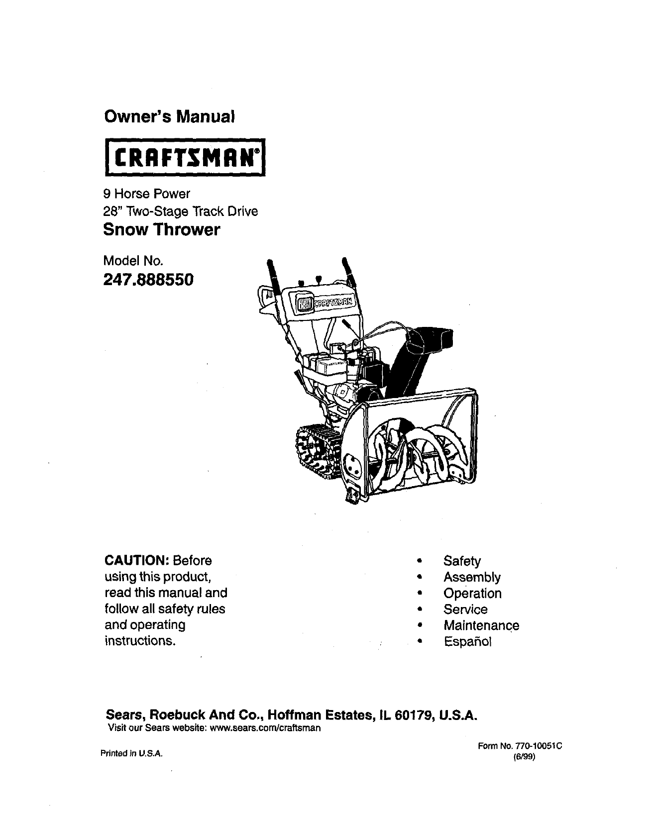
Owner's Manual
9 Horse Power
28" Two-Stage Track Drive
Snow Thrower
Model No.
247.888550
CAUTION: Before
using this product,
read this manual and
follow all safety rules
and operating
instructions.
• Safety
• Assembly
• Operation
•Service
•Maintenance
•Espafiol
Sears, Roebuck And Co., Hoffman Estates, IL 60179, U.S.A.
Visit our Sears website: www.sears.condcraftsman
FormNo.770-10051C
PdntedJnU.S.A. (6/99)
Content Page
Warranty Information......................................... 2
Safe Operation Practices................................... 3
Hardware Pack .................................................. 5
Assembly ........................................................... 6
Operation ............... ............................................ 12
Maintenance ...................................................... 17
Content Page
Service & Adjustment......................................... 20
Off*Season Storage ........................................... 24
Trouble-Shooting............................................... 25
Parts List............................................................ 26
Espanbl.............................................................. 40
Two -Year Warranty on Craftsman Snow Thrower
For two years from the date of purchase, when this Craftsman Snow Thrower is maintained,lubricatedand tuned
up accordingto the instructionsinthe owner's manual, Sears will repair, free of charge, any defect in material
and workmanship.
If this Craftsman snow throweris used for commercial or rental purposes, thiswarranty applies for only 30 days
from the date of purchase.
This warranty does not cover:
Expendable items which become worn duringnormal use, suchas skidshoes, shave plate and spark
plugs.
Repairs nec•ssary because of operator abuse or negligence, includingbent crankshaftsand the failure to
maintainthe equipment accordingto the instructionscontained in the owner's manual.
WARRANTY SERVICE IS AVAILABLEBY RETURNING THE CRAFTSMAN SNOWTHROWER TO THE NEAREST
SEARS SERVICE CENTER/DEPARTMENT IN THE UNITED STATES.
This warranty applies only while this product Is In use in the United States.
Thiswarrantygivesyouspecificlegal rightsandyou mayalsohaveotherdghts whichmayvary from stateto state.
SEARS, ROEBUCK AND CO., D/817WA, HOFFMAN ESTATES,IL60179
Horsepower: 9
EngineOil SAE 5W30 oil
Fuel Capacity: 1 gallon
Spark Plug: RJ-19LM
Engine: 143.999005
Model Number 247.888550
Serial Number ...........................................................
Date of Purchase ......................................................
Record both serial number and date of purchase and
keep in a safe place for future reference.
This symbol points out important safety instructions which, ifnotfollowed, could endanger the
personal safetyand/or propertyof yourselfand others. Read and followall instructions in this manual
before attemptingto operate your snow thrower. Failure to complywiththese instructionsmay resultin
personal injury.When yousee thissymbol--heed its warning.
,_ Your snow thrower was builtto be operated accordingto the rulesfor safe operation inthis manual. As
DANGER" withany type of power equipment carelessness or erroron the partof the operator canresultin serious
in ury. fyou v o ate anyofthese rules, you may cause serious njuryto yourselfor others.
Thisunitisequippedwithan internalcombustionengineandshouldnotbe usedonornearany unimproved
forest-covered, brush-coveredorgrass-coveredland unlessthe engine'sexhaustsystemis equippedwitha
sparkarrestermeetingapplicablelocalorstate laws(ifany). If a sparkarresteris used,it shouldbe
maintainedineffectiveworkingorderby theoperator.
In the StateofCaliforniathe aboveisrequiredby law (Section4442 ofthe CaliforniaPublicResources
Code).Otherstatesmayhave similarlaws.Federallawsapplyonfederal lands.A sparkarresterfor the
mufflerisavailablethroughyournearestSearsAuthorizedServiceCenter(See the REPAIR PARTS section
ofthismanual.)
TRAINING
Read thisowner's guide carefullyin itsentiretybefore
attemptingto assemble oroperate this machine. Be
completelyfamiliar withthe controlsand the proper
use of this machine before operating it. Keep this
manual ina safe place for future and regular
reference and for orderingreplacement parts.
Never allowchildrenunder 14 years oldto operate a
snowthrower. Children 14 years oldand over should
only operate asnow thrower underclose parental
supervision.Onlypersonswell acquainted with these
rulesof safe operationshould be allowed to use your
snow thrower.
No one should operate thisunit whileintoxicated or
whiletaking medicationthat impairsthe senses or
reactions.
Keep the area of operationclear of all persons,
especially small childrenand pets.
Exercise caution to avoidslippingor falling,especially
when operating inreverse.
PREPARATION
Thoroughlyinspectthe area where the equipment is
to be used and remove all door mats, sleds, boards,
wires and other foreign objects.
Do not operate equipment withoutwearing adequate
outergarments for winter.Do not wear jewelry, long
scarfs or other looseclothingwhich could become
entangled inmoving parts.Wear footwear which will
improvefootingon slipperysurfaces.
Before workingwithgasoline,extinguishalt cigarettes
and othersources of ignition.Check the fuel before
startingthe engine. Gasoline is an extremely
flammable fuel. Do not fillthe gasoline tank indoors,
while the engine is running,or untilengine has been
allowed to cool at least two minutes. Replace
gasoline cap securely and wipe off any spilled
gasoline before startingthe engine as itmay cause a
fire or explosion.
Use a grounded three wire plug-in for all unitswith
electricdrive motors or electricstarting motors.
Adjustcollector housingheightto clear gravel or
crushed rocksurface.
Never attemptto make any adjustmentswhile engine
is running(except where specificallyrecommended
by manufacturer).
Letengine and machine adjust to outdoor
temperature before startingto clear snow.
Always wear safety glasses oreye shields during
operationor whileperformingan adjustment or repair,
to protecteyes from foreign objectsthat may be
thrown from the machine in any direction.
OPERATION
Do not put hands orfeet near or under rotatingparts.
Keep clear of discharge opening and auger at all
times.
Exercise extreme caution when operatingon or
crossinggravel drives, walks,or roads. Stay alert for
hidden hazards or traffic.
Do not carry passengers.
After strikinga foreign object, stopthe engine, remove
wire from the spark plugand thoroughlyinspectthe
snow thrower for any damage. Repair the damage
before restartingand operating the snow thrower.
Ifthe snow thrower startsto vibrate abnormally,stop
the engineand check immediatelyfor the cause.
Vibration is generallya warning of trouble.
Stopthe engine whenever you leave the operating
position,before uncloggingthe collector/impeller
housingor dischargeguide and before making any
repairs,adjustments,or inspections.Never place your
hand in the dischargeor collectoropenings.Use a
stickor wooden broomhandle to unclogthe
discharge opening.
Take allpossible precautionswhen leaving the unit
unattended. Disengage the collector/impeller,stop
the engine and remove the key.
When cleaning, repairing,or inspecting,make certain
collector/impellerand allmoving parts have stopped.
Disconnectspark plugwire and keep away from plug
to prevent accidentalstarting.
• Do not runthe engine indoors,except when startingit
and/or transportingthe snowthrower in orout of
building.Open doors before startingtheengine inthat
case. Exhaust fumes are dangerous.
Do not clear snow across theface of slopes. Exercise
extreme caution when changingdirectionon slopes.
Do not attempt to clear steep slopes.
Never operate the snow thrower withoutguards,
plates or othersafety protectiondevices in place,
• Never operate the snow thrower near glass
enclosure, automobiles,window wells, dropoff, etc.,
withoutproper adjustmentsof snow thrower
dischargeangle. Keep childrenand pets away.
Do notoverload machine capacity by attemptingto
clear snow at too fast a rate. Never operate the
machine at hightransportspeeds onslippery
surfaces. Lookbehindand use care when backing.
Never direct discharge at bystanders or allowanyone
in front of unitwhilethrowingsnow.
•Disengagepower to collector/impellerofthe srx)w
throwerwhentransportingitorwhen the unitis notin use.
Use only attachments and accessories(such as
wheel weights,counter weights, cabs, etc.) approved
by the snow thrower manufacturer.
Never operatethe snow throwerwithoutgood visibility
or light.Always be sure of yourfooting and keep a firm
holdon the handles. Walk, never run.
Mufflerand engine become hotand can cause severe
bum injury.Do not touchthe mufflerorthe engine
whilestarting oroperatingthe snowthrower.
MAINTENANCE AND STORAGE
Check shear bolts, enginemountingbolts,etc., at
frequent intervalsfor propertightness,thusensuring
that the equipment is insafe workingcondition.
Never store the machine withfuel in the fuel tank
insidea buildingwhere ignitionscumes are present,
such as hot water heaters, space heaters, clothes
dryersand the like. Allowengineto cool beforestoring
in anyenclosure.
Always refer to owner's guide instructionsfor
importantdetails ifthesnow thrower isto be storedfor
an extended period.
Run machine a few minutes afterthrowingsnow to
preventfreeze-up of the collector/impeller.
Check clutch controlsperiodicallyto verifythat these
engage and disengage properlyand readjust if
necessary. Refer to Service and Adjustmentssection
page of this owner'sguide.
YOUR RESPONSIBILITY
Restrictthe use of this powermachine to personswho
read, understand and follow the warnings and
instructionsinthis manualand on the machine.
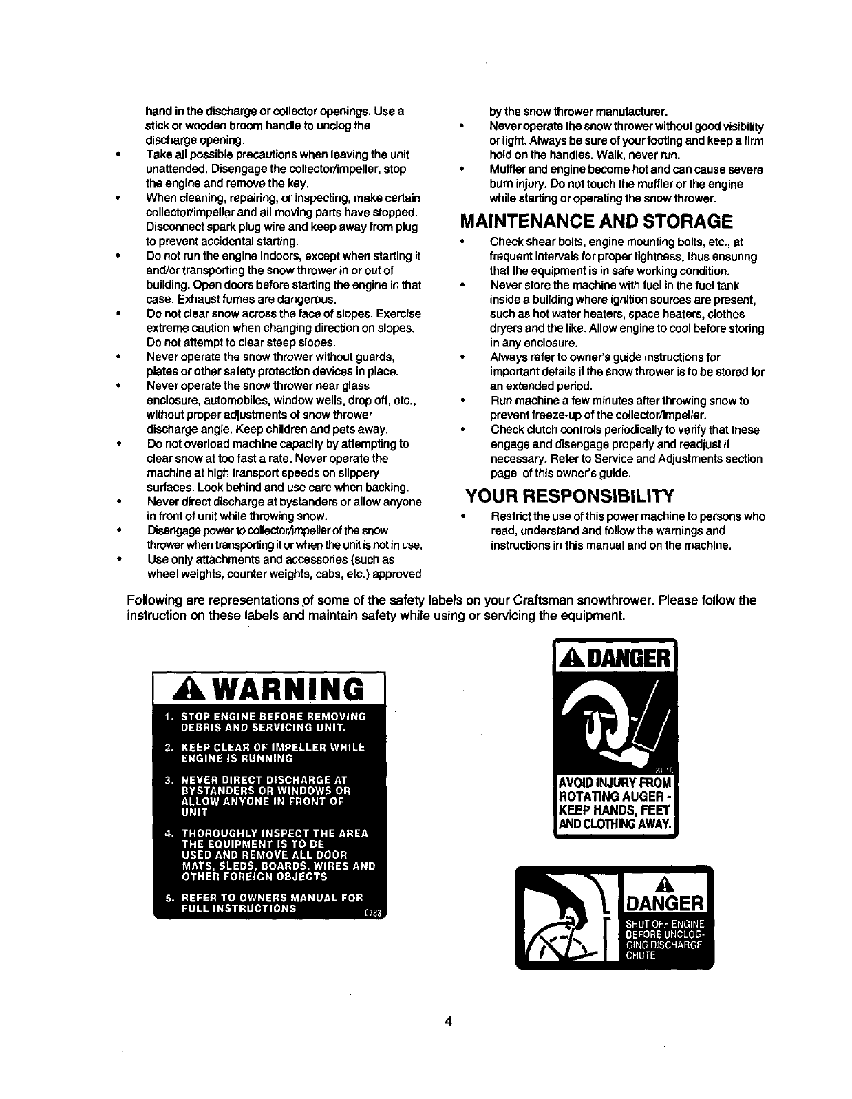
Following are representationsof some of the safety labels on your Craftsman snowthrower.Please follow the
instructionon these labels and maintain safety while usingor servicingthe equipment.
I ,A WARNING ADANGER
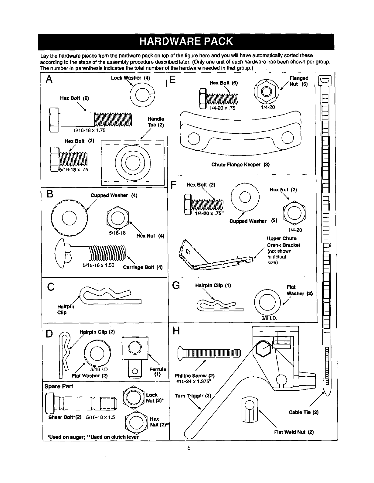
Lay the hardware pieces from the hardware pack on top of the figure here and you will have automatically soded these
aCCordingto the steps of the assembly procedure described later. (Only one unit of each hardware has been shown per group.
The number in parenthesis indicates the total number of the hardware needed in that group.)
q
m
h
A
B
Lock Washer (4)
Hex Bolt (2) /_
5/16-18 x 1.75
Hex Bolt (2)
,/t
NN
5/16-18 x.75
Handle
Tab (2)
/
Cupped Washer (4)
Hex Nut (4)
_5/16-18 x 1,50 Carriage Bolt
_\ (4)
(_ Helrp_ ]
D
Clip
-_fi_ilrpln Clip (2)
I Ferrule
Flat Washer (2) _ ! (1)
3pare Part
"ShearBolt*(2) 5/16-18 x 1.5
Lock
Nut (2)*
Hex
Hot (2)*
*Used on auger; **Used on clutch lever
_/Flanged _;
E_ Hex Bolt (6) Nut (6)
-'N "--"
1/4-20 x .75 1/4-20
Chute Flange Keeper (3)
F
:-_"exBolt(2) _) Hex_, (2)
1/4-20 X .75" Cup_ped Washer (2) G
1/4-20
Upper Chute
'_/ Crank Bracket
(notshown
inactual
size)
G
m
i
m
m
b
b
m
Hairpin Clip (1) Flat
©7
3/8 I.D.
H
HIIIIIIIIIIIIIIII_,@_ -
,1024x,375"/F "__
TurnTr_r_//// _" Cable Tie (2)_
//
_,/ Rat Weld Nut (2)
Chute Handte
Panel
Handles
Rear
, Left
Chute
Crank
Shift
Rod
Electric
Start Cord
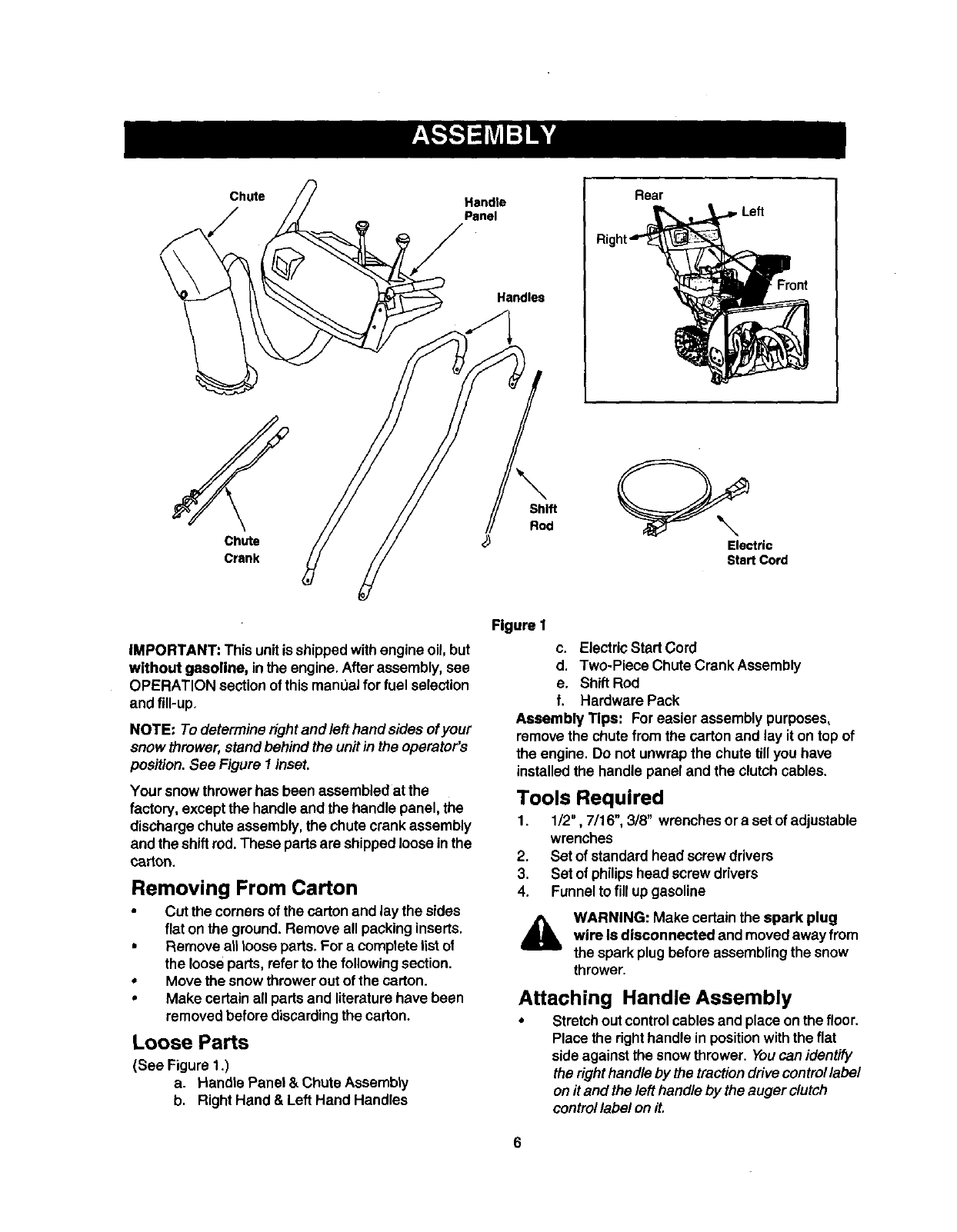
iMPORTANT: This unitis shippedwithengine oil, but
without gasoline, in the engine. Afterassembly, see
OPERATION section of thismanLJalfor fuel selection
and fill-up.
NOTE: To determineright and left hand sides ofyour
snow thrower, standbehind the unitin the operator's
position. See Figure I inset,
Your snowthrowerhas been assembled at the
factory, except the handle and the handle panel, the
discharge chute assembly,the chute crank assembly
and the shiftrod.These partsare shipped loose inthe
carton.
Removing From Carton
• Cut the comersof the carton and lay the sides
fiat on the ground. Remove all packinginserts.
• Remove all loose parts, For a complete listof
the looseparts, referto the following section.
• Move the snow throweroutof the carton.
• Make certain all partsand literaturehave been
removedbefore discardingthe carton.
Loose Parts
(See Figure 1.)
a. Handle Panel & Chute Assembly
b. Right Hand & Left Hand Handles
Figure I
c. Electric Start Cord
d. Two-Piece Chute Crank Assembly
e. Shift Rod
f. Hardware Pack
Assembly Tips: For easier assembly purposes,
remove the chute from the carton and lay it on top of
the engine. Do not unwrapthe chute tillyou have
installedthe handle panel and the clutchcables.
Tools Required
1. 1/2", 7/16", 3/8" wrenchesor a set of adjustable
wrenches
2. Set of standardhead screw drivers
3. Set of philipshead screw drivers
4. Funnel to fill up gasoline
WARNING: Make certainthe spark plug
wire Is disconnected and movedaway from
the spark plugbefore assemblingthe snow
thrower.
Attaching Handle Assembly
•Stretchout controlcables and place on the floor.
Place the righthandle in positionwiththe flat
side against the snow thrower. Youcan identify
the right handleby the traction drive control label
on it and the left handle by the auger clutch
control label on it.
6
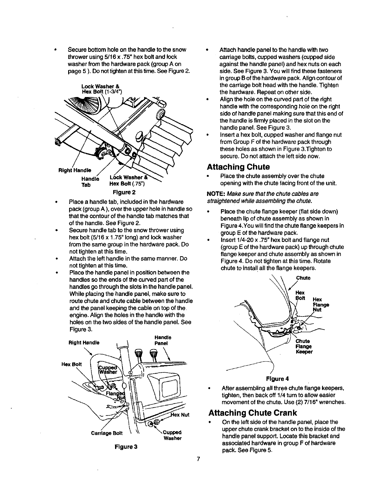
Securebottomholeonthehandletothesnow
throwerusing5/16x .75"hexboltandlock
washerfrom the hardware pack (groupA on
page 5 ). Donottightenatthistime.See Figure2.
Lock Washer &
He]( Bolt (1-3/4")
Right Handle
Handle
Tab Hex Bolt (.75")
Figure 2
•Place a handle tab, includedinthe hardware
pack (groupA ), overthe upperhole in handle so
that the contourof the handle tab matches that
of the handle. See Figure 2.
•Secure handletab to the snow throwerusing
hex bolt (5/16 x 1.75" long)and lockwasher
from the same group inthe hardware pack. Do
nottightenat thistime.
•Attachthe left handle inthe same manner. Do
nottightenat this time.
•Place the handle panel in positionbetween the
handles so the ends of the curvedpart of the
handlesgo throughthe slotsinthe handlepanel.
While placing the handle panel, make sure to
routechute andchute cable between the handle
and the panel keepingthe cable on top of the
engine. Align the holes inthe handlewiththe
holes onthe two sides of the handlepanel. See
Figure 3.
RightHandle 1
..xoo,t
/
Carriage Bolt
Handle
Panel
Washer
Figure 3
7
•Attachhandle panel to the handle withtwo
carriagebolts,cupped washers (cuppedside
againstthe handle panel) and hex nutson each
side. See Figure 3. You willfind these fasteners
ingroupB ofthe hardware pack.Aligncontourof
the carriage bolt head withthe handle. Tighten
the hardware. Repeat on other side.
• Align the hole on the curved partof the right
handle withthe correspondinghole on the right
side of handlepanel making sure that thisend of
the handle isfirmly placed inthe sloton the
handlepanel. See Figure 3.
•Inserta hex bolt, cuppedwasher and flange nut
from Group F of the hardware pack through
these holes as shown in Figure 3.Tighten to
secure, Do notattach the left side now.
Attaching Chute
•Place the chute assemblyover the chute
openingwiththe chutefacing front of the unit.
NOTE: Make sure that the chute cables are
straightened while assembling the chute.
Place the chuteflange keeper (flat side down)
beneath lip of chute assembly as shown in
Figure 4.You will find the chute flange keepers in
group E of the hardware pack.
Insert 1/4-20 x .75" hex bolt and flange nut
(group Eof the hardware pack) up through chute
flange keeper and chute assembly as shown in
Figure 4. Do not tighten at this time. Rotate
chute to instal! all the flange keepers.
Figure 4
Afterassembling allthree chuteflange keepers,
tighten, then back off 1/4 turn to allow easier
movementof the chute. Use (2) 7/16" wrenches.
Attaching Chute Crank
•On the left side of the handle panel, placethe
upperchute crankbracket onto the insideof the
handle panel support.Locate thisbracketand
associatedhardware ingroup F of hardware
pack. See Figure 5.
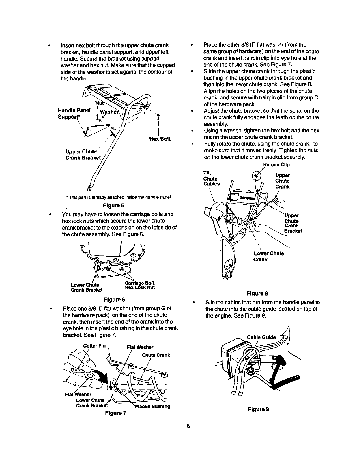
Inserthexboltthroughthe upper chutecrank
bracket, handle panel support,and upper left
handle. Secure the bracketusingcupped
washer and hex nut. Make surethat the cupped
side of the washer is set against the contourof
the handle.
Handle Panel l
Support*
\ "<
Hex Bolt
Crank Bracket
Place the other 3/8 ID flat washer (fromthe
same groupof hardware)on the end of the chute
crank and inserthairpinclip intoeye hole at the
end of the chutecrank. See Figure 7.
Slide the upperchute crank throughthe plastic
bushinginthe upperchute crank bracketand
then intothe lower chutecrank. See Figure 8.
Align the holeson the two piecesof the chute
crank, and securewith hairpinclip from groupC
of the hardwarepack.
Adjustthe chutebracketso that the spiralon the
chutecrankfully engages the teeth onthe chute
assembly.
Using a wrench, tightenthe hex boltand the hex
nut onthe upperchutecrank bracket.
Fullyrotatethe chute, usingthe chute crank, to
make surethat it moves freely. Tighten the nuts
on the lower chutecrank bracketsecurely.
* This part is already attached inside the handle panel
Figure 5
You may have to loosenthe carriage boltsand
hex locknutswhich securethe lower chute
crank bracketto the extensionon the left side of
the chute assembly. See Figure 6.
Lrrlage Bolt,
CrankBracket Itex LockNut
Figure 6
Place one 3/8 ID flat washer (fromgroup G of
the hardware pack) on the end of the chute
crank, then insertthe end of the crank intothe
eye hole inthe plasticbushinginthe chute crank
bracket. See Figure 7.
Cotter Pin Flat Washer
Chute Crank
Tilt Upper
Chute Chute
Cables Crank
\
Upper
Chute
Crank
Bracket
LowerChute
Crank
Flgure 8
Slip the cables that runfrom the handle panel to
the chute intothe cable guidelocated on topof
the engine. See Figure 9.
Cable Guide
Flat Rasher
Lower Chute /
Crank Bracl_t
Figure 7 Figure 9
8
Tightenallloose hardware on the handle
assemblyin the followingorder-- firstthe hex
boltsat the bottomof the handle, then the
carriagebolts and lastlythe hex boltson the rear
of the handle panel.
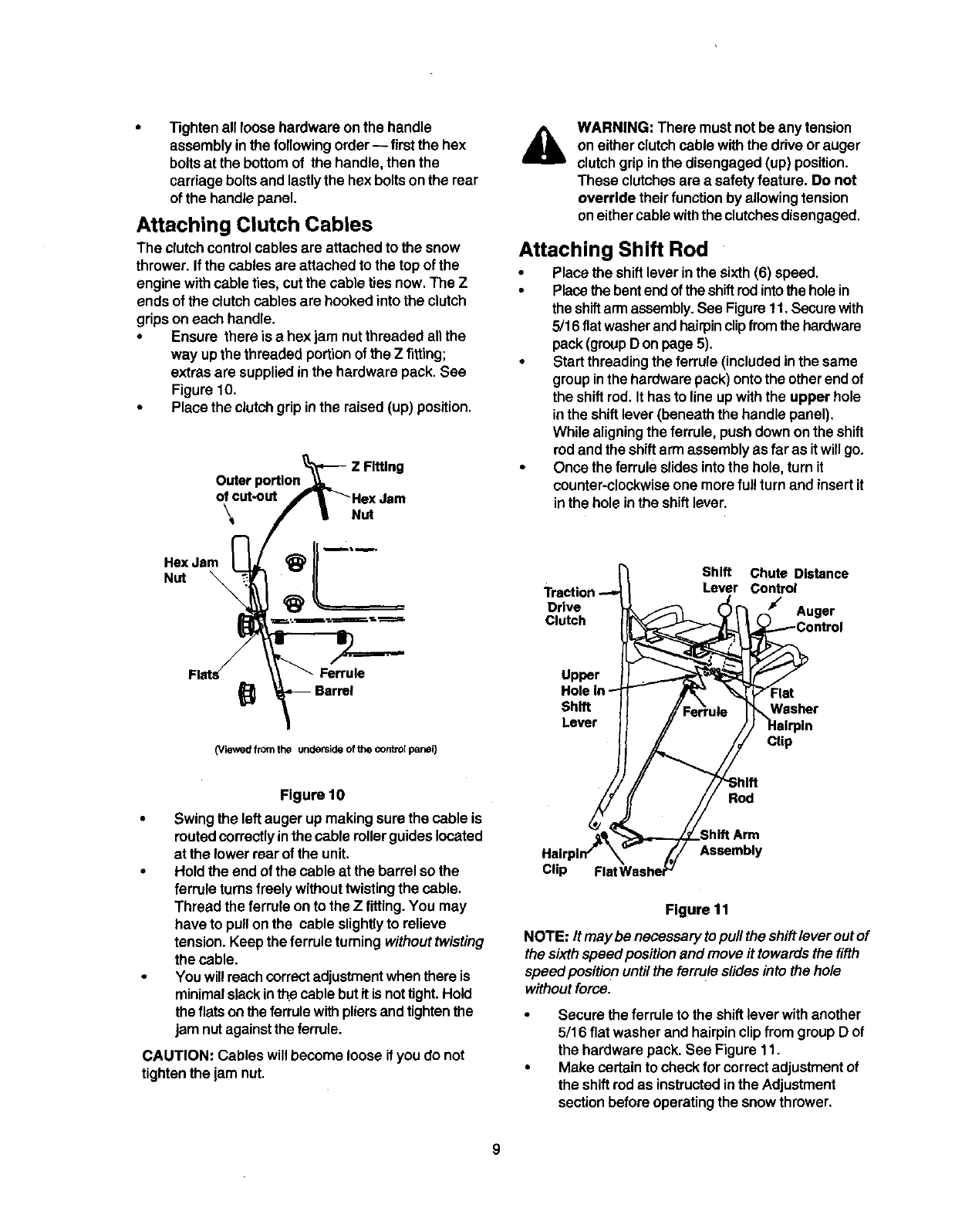
Attaching Clutch Cables
The clutchcontrolcables are attachedto the snow
thrower. If the cables ere attachedto the top of the
engine withcable ties, cut the cable ties now. The Z
ends of the clutchcables are hooked intothe clutch
gripson each handle.
•Ensure there is a hex jam nutthreaded allthe
way upthe threaded portion ofthe Z fitting;
extras are supplied in the hardware pack. See
Figure 10.
• Place the clutch grip in the raised (up) position.
Z Fitting
Outer
of cut-out
\Nut
Hex Jam
Nut
AWARNING: There must notbe any tension
on either clutchcable withthe driveor auger
clutchgripinthe disengaged (up) position.
These clutchesare asafety feature. Do not
override their function by allowingtension
on eithercablewiththe clutchesdisengaged.
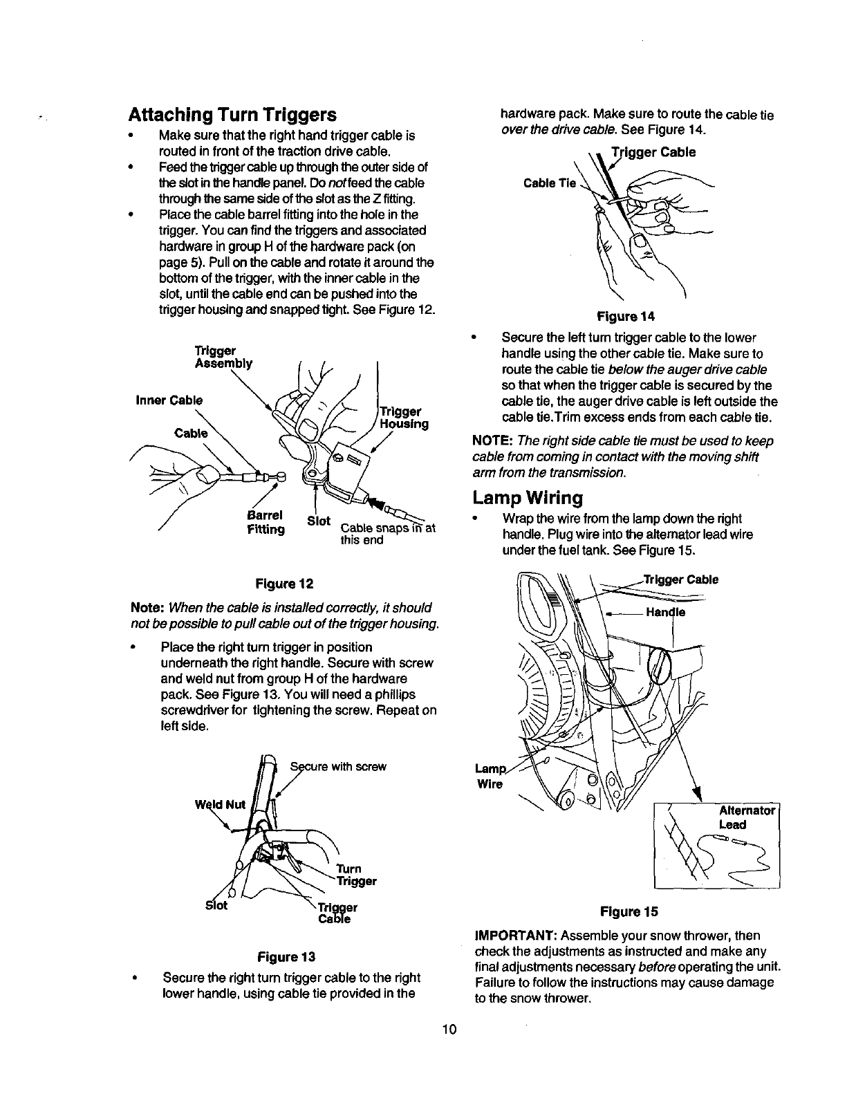
Attaching Shift Rod
•Place the shiftlever inthe sixth(6) speed.
•Place the bentendof the shiftrodintothe holein
the shiftarmassembly.See Figuret 1. Securewith
5/16 flatwasherandhairpinclipfromthe hardware
pack(groupD on page 5).
•Start threadingthe ferrule(includedinthe same
groupinthe hardware pack) ontothe otherendof
the shiftrod. It has to line up withthe upper hole
inthe shiftlever(beneath the handle panel).
While aligningthe ferrule, push down on the shift
rod and the shiftarm assemblyas far as it willgo.
•Once the ferrule slides intothe hole, turn it
counter-clockwiseone more ful!turn and insert it
inthe hole inthe shiftlever.
Shift Chute Distance
Lever Control
Drive Auger
Clutch
Ferrule
Barrel
(Viewed from the underside of the controlpanel)
Upper
Shift
Lever
Clip
Figure 10
•Swing the left auger upmaking surethe cable is
routed correctlyin the cable rollerguideslocated
at the lower rear of the unit.
•Hold the end of the cable at the barrel so the
ferrule turnsfreely withouttwistingthe cable.
Thread the ferrule on to the Z fitting.You may
have to pullon the cable slightlyto relieve
tension. Keepthe ferrule turningwithout twisting
the cable.
• You willreachcorrectadjustmentwhenthere is
minimalslack inthe cable butit isnottight.Hold
the flats on the ferrule withpliersandtightenthe
jam nutagainstthe ferrule.
CAUTION: Cables willbecome loose if youdo not
tighten the jam nut.
Rod
Clip
Assembly
Figure 11
NOTE: It may be necessary topull the shiftlever outof
the sixthspeed positionand move it towardsthe fifth
speedpositio n untilthe ferruleslides into the hole
withoutforce.
Secure the ferrule to the shift leverwithanother
5/16 flat washer and hairpin clipfrom group Dof
the hardware pack. See Figure 11.
Make certain to check for correctadjustmentof
the shiftrodas instructedinthe Adjustment
sectionbefore operatingthe snow thrower.
9
Attaching Turn Triggers
Make surethat the righthand triggercable is
routedinfront of the tractiondrive cable.
•Feedthetriggercableupthroughthe outersideof
the slotinthe handlepanel.Donotfeedthe cable
throughthe samesideofthe slotastheZ fitting.
•Place the cablebarrelfitting intothe holeinthe
trigger.You can findthe triggersandassociated
hardwareingroupH of the hardwarepack (on
page5). Pullonthe cable and rotateit aroundthe
bottomof thetrigger,withthe innercable inthe
slot,untilthecable endcan be pushedintothe
triggerhousingand snappedtight.See Figure 12.
Trigger
Assembly
Inner Cable
Y
Barrel Slot
Fitting thisend
Figure 12
Note: When the cable is installed correctly, it should
not be possibleto pullcable out of the trigger housing.
Place the rightturn trigger inposition
underneaththe righthandle. Secure withscrew
and weld nutfrom group H of the hardware
pack. See Figure 13. You will need a phillips
screwdriverfor tighteningthe screw. Repeat on
left side.
Turn
S_ot ,Trigger
Cable
Figure 13
•Secure the rightturn triggercable to the right
lower handle, usingcable tie providedinthe
hardware pack. Make sure to routethe cable tie
over the drive cable. See Figure 14.
Figure 14
Secure the leftturn triggercable to the lower
handle usingthe othercable tie. Make sureto
route the cable tie below the auger drive cable
so that when the trigger cable is secured by the
cable tie, the auger drive cable is left outside the
cable tie.Trim excess ends from each cable tie.
NOTE: The right sidecable tie must be used to keep
cable from comingin contact withthe moving shift
arm fromthe transmission.
Lamp Wiring
•Wrap the wirefrom the lampdownthe right
handle. Plugwireintothe aitemator leadwire
underthefuel tank. See Figure15.
I _ Hsn le
Figure 15
IMPORTANT: Assemble your snowthrower, then
check the adjustmentsas instructedand make any
final adjustmentsnecessarybefore operatingthe unit.
Failureto follow the instructionsmaycause damage
to the snowthrower.
10
Final Adjustments
Adjusting Auger Control
• To check the adjustment of the auger control,
push forward the left hand clutchgrip untilthe
rubberbumper is compressed, There should be
slack inthe clutchcable.
•Release the clutchgrip.The cable should be
straight. Make certain you can depress the
auger controlgripagainst the left handle
completely.
•If adjustmentis necessary, loosen the hex jam
nutand thread the cable in(for less slack) or out
(for more slack),
• Recheck the adjustment. Tighten the jam nut
against the cablewhen correctadjustmentis
reached.
Adjusting Traction Drive Control
To check the adjustmentof the tractiondrive
controland shiftlever, move the weight transfer
leverto the transportposition(shownin Figure
18 on page 13) and the shiftlever allthe way
forward to sixth(6) position.
•With the tractiondrive control released, pullthe
triggersupto the handleand then pushthe snow
throwerforward to checkthat the tracks turn.
•Squeeze tractiondrivecontrolagainstthe handle
and pullthe starter.The tracksshouldturn.
• Now release the tractiondrive controland pull
the starteragain. The unitshould not move.
•Before proceedingwith adjustment, make sure
that the spark plug is disconnected.
•If the tractiondrive controlneeds adjustment,
loosen the jam nut on the tractiondrive cable
and thread the cable one turn. Recheck
adjustmentand repeat as necessary.
•Tighten the jam nutto secure the cable when
correctadjustment is reached.
NOTE: Cables are outof adjustmentif augers
continueto turn whenauger clutchis released and/or
machine continuesto run when drive clutchis
released. For more details,refer to the Service and
Adjustment section.
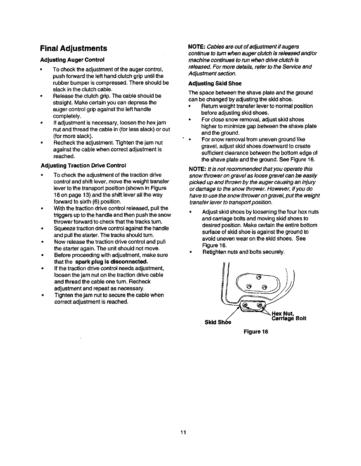
Adjusting Skid Shoe
The space between the shave plate and the ground
can be changed by adjustingthe skidshoe.
•Returnweight transferlever to normalposition
before adjustingskidshoes.
•For closesnow removal,adjust skidshoes
higher to minimizegap between the shave plate
and the ground.
•For snow removalfrom uneven groundlike
gravel, adjustskidshoes downwardto create
sufficientclearance between the bottomedge of
the shave plate andthe ground. See Figure 16.
NOTE: It is not recommended that you operate this
snow throweron gravel as loose gravel can be easily
picked up and thrownby the auger causingan injury
or damage to the snowthrower. However, if you do
have to use the snow throwerongravel,put the weight
transfer lever to transport position.
•Adjustskidshoesby loosening the four hex nuts
and carriage bolts and moving skidshoes to
desired position. Make certain the entire bottom
surface of skidshoe is against the ground to
avoid uneven wear on the skid shoes. See
Figure 16.
•Retighten nuts and bolts securely.
Skid Shoe_ _HeXNa_t" Bolt
Figure 16
11
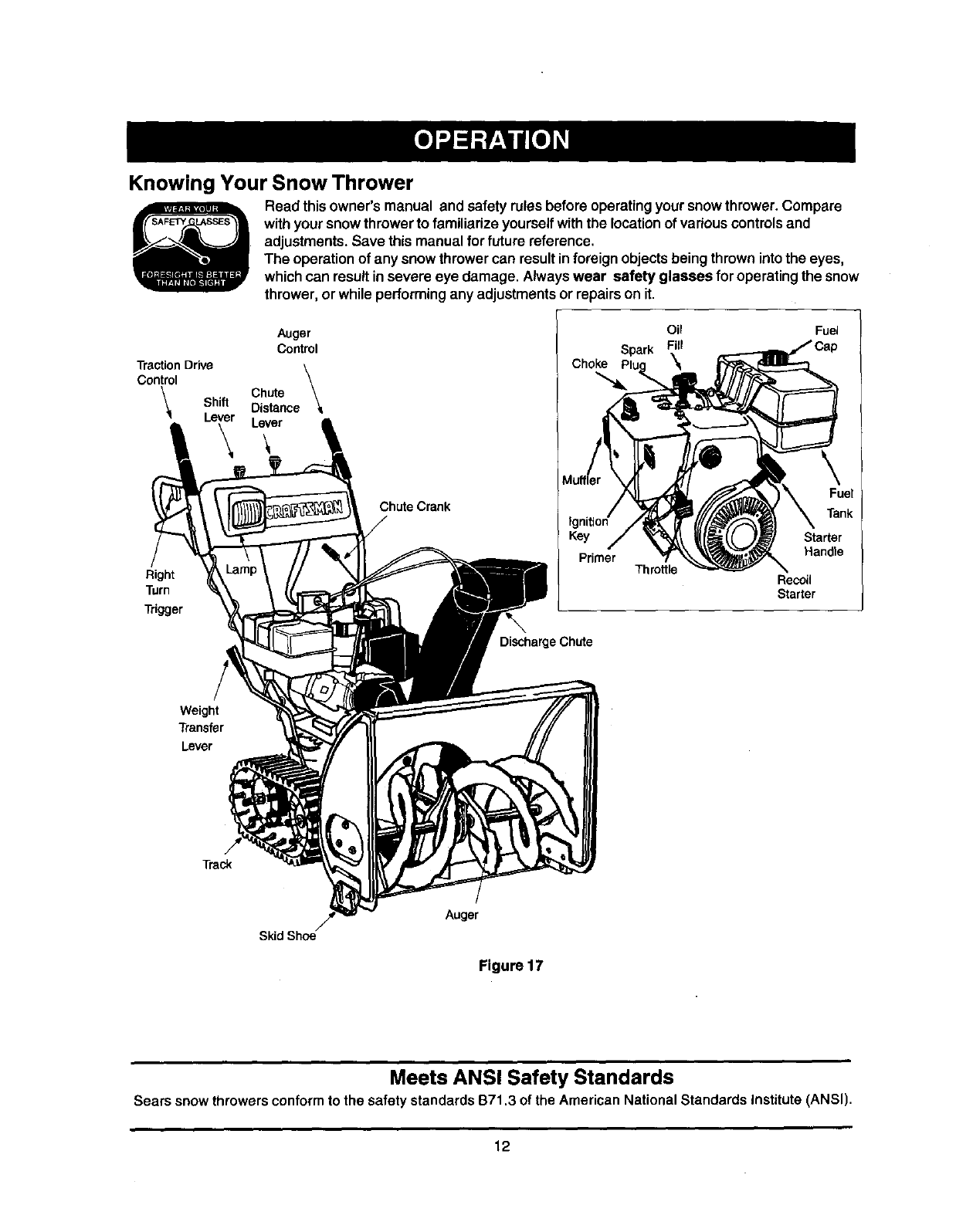
Knowing Your Snow Thrower
Read thisowner's manual and safety rules before operatingyour snowthrower. Compare
withyour snowthrowerto familiarize yourselfwiththe location of variouscontrols and
adjustments.Save this manual for future reference.
The operationof any snow throwercan resultin foreign objectsbeing thrownintothe eyes,
which can resultinsevere eye damage. Alwayswear safety glasses for operating the snow
thrower, or while performingany adjustmentsor repairson it.
Auger
Control
Traction Drive
Control
Chute
Shift Distance
Lever Lever
Choke
Oil
Spark Fill
\
Fuel
Right
Turn
Trigger
Chute Crank
DischargeChute
Throttle
Fuel
Tank
Starter
Handle
Recoil
Starter
Weight
Transfer
Lever
Track
Skid Shoe
Auger
Figure 17
Meets ANSI Safety Standards
Sears snowthrowersconformto the safety standardsB71,3 of the AmericanNational StandardsInstitute(ANSI),
12
Operating Controls
(See Figure 17.)
Chute Crank
The chute crankis located on the left sideof the snow
thrower. To change the direction in which snow is
thrown, turn chute crank as follows:
turn clockwise to discharge to the left;
turn counterclockwiseto discharge to the right.
Chute Distance Control
The distance that snow is thrown can be adjusted by
adjusting the angle of the chute assembly. Push the
chute distance control lever forward to move the
upper chute down and decrease the distance. Pull the
lever back toward the rear to move the upper chute
up and increase the distance.
Left And Right Turn Trigger
The left and rightturntriggers are located onthe
undersideof the handles and are used to assist in
steeringyour snow thrower. Squeeze the rightturn
trigger whenturningright,squeeze the leftturntrigger
when turningleft. Operate your snowthrower inopen
areas untilyou become familiar withthese controls.
Shift Lever
The shift lever is located inthe center of the handle
panel. It may be moved into one of eight positions:
a. Forward--oneofsixspoeds;po,v_onone(1)
is the slowest and position six (6) is the
fastest.
b. Reverse--two reverse (R) speeds; R2is
faster.
Use the shift lever to determine ground speed. Do not
shiftto different speed while the unit is moving.
Auger Control
The auger controlis located on the left handle.
Squeeze the auger controlagainst the handle to
engage the augers; release to disengage the augers.
(Tractiondrive controlmust also be released.)
Traction Drive Control
The tractiondrive controlis located onthe right
handle. Squeeze the tractiondrive controlto engage
the track drive; release to stop.
This same lever also locks the auger control so
that you can turn the chutecrank withoutinterrupting
the snowthrowingprocess.If the auger controlis
engaged withthe tractiondrive controlengaged, you
can release the auger control (onthe left handle) and
the augers will remainengaged. Release the traction
drivecontrolto stopboth the augers andthe track
drive. (Auger controlmust alsobe released).
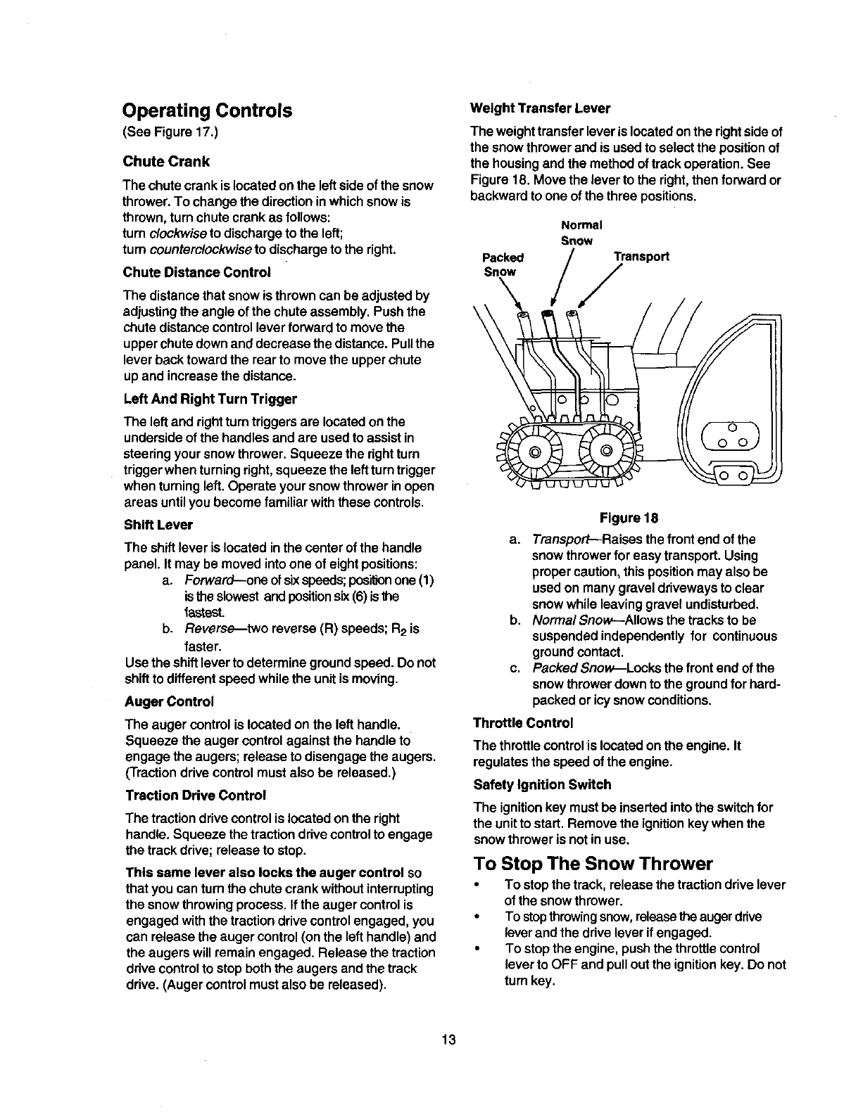
Weight Transfer Lever
The weighttransfer lever is locatedonthe rightside of
the snow throwerand is used to select the positionof
the housingand the method oftrack operation. See
Figure 18. Move the lever to the right,then forward or
backward to one of the three positions.
Packed
Snow
\
Normal
Snow
Transport
,/
Figure 18
a. Transport--Raises the front end of the
snowthrowerfor easytransport. Using
propercaution, thispositionmay also be
used on many gravel drivewaysto clear
snowwhile leaving gravel undisturbed.
b. Normal Snow--Allows the tracks to be
suspended independently for continuous
groundcontact.
c. Packed Snow.--Locksthe front end of the
snowthrowerdown to the groundforhard-
packed or icysnow conditions.
Throttle Control
The throttlecontrolis located onthe engine. It
regulatesthe speed of the engine.
Safety Ignition Switch
The ignitionkey must be insertedintothe switchfor
the unitto start. Remove the ignitionkey when the
snow thrower is not in use.
To Stop The Snow Thrower
•To stopthe track, release the tractiondrive lever
of the snowthrower.
•To stopthrowingsnow,releasethe augerdrive
leverand the drive leverif engaged.
•To stopthe engine, pushthe throttlecontrol
leverto OFF and pulloutthe ignitionkey. Do not
turn key.
13
Before Starting Engine
Fill Gas
&WARNING: Gasolineisflammableand cau-
tionmustbe usedwhenhandling orstoringit.
Do notfillfuel tank whilethe snowthroweris
running,when it is hotor when it is in an
enclosedarea.
Keep your snowthrower away from any
open flame or an electricalspark and do not
smoke while filling the fuel tank.
Never fill the fuel tank completely. Fill the
tank to within1/4"-1/2" from the topto
provide space for expansion of fuel.
Always fill the fuel tank outdoorsand use a
funnel or spoutto prevent spilling.
Make sure to wipeoff any spilledfuel before
startingthe engine.
•Store gasoline in a clean, approved container
and keep the cap in place on the container.
• Make sure that the container from which you
pour the gasoline is clean and free from rust or
other foreign particles.
• Fill fuel tank with clean, fresh, unleaded grade
automotivegasoline.
• At the end of the job, empty the fuel tank ifthe
snow thrower is not going to be used for 30 days
or longer. See storage instructions on page 24
of this manual.
CAUTION: Experience indicatesthat alcohol
blended fuels (called gasohol) or those usingetha-
nol or methanol can attract moisturewhich leads to
separation and formationof acids duringstorage.
Acidicgas can damage the fuel system of an engine
while in storage.
To avoidengineproblems,the fuel systemshouldbe
emptiedbeforestoragefor 30 days orlonger. Drain the
gas tank,start the engineand let it run untilthe fuel
linesand carburetor are empty.Use fresh fuel nextsea-
son. See storageInstructionsfor additionalinformation.
Never use engine or carburetor cleaner products in
the fuel tank or permanent damage may occur.
To Start Engine
&WARNING: Be sure no one other than
the operator is standingnear the snow
throwerwhile startingoroperating. Do not
operate thissnowthrowerunless the
dischargechuteassembly has been
properlyinstalledand issecured.
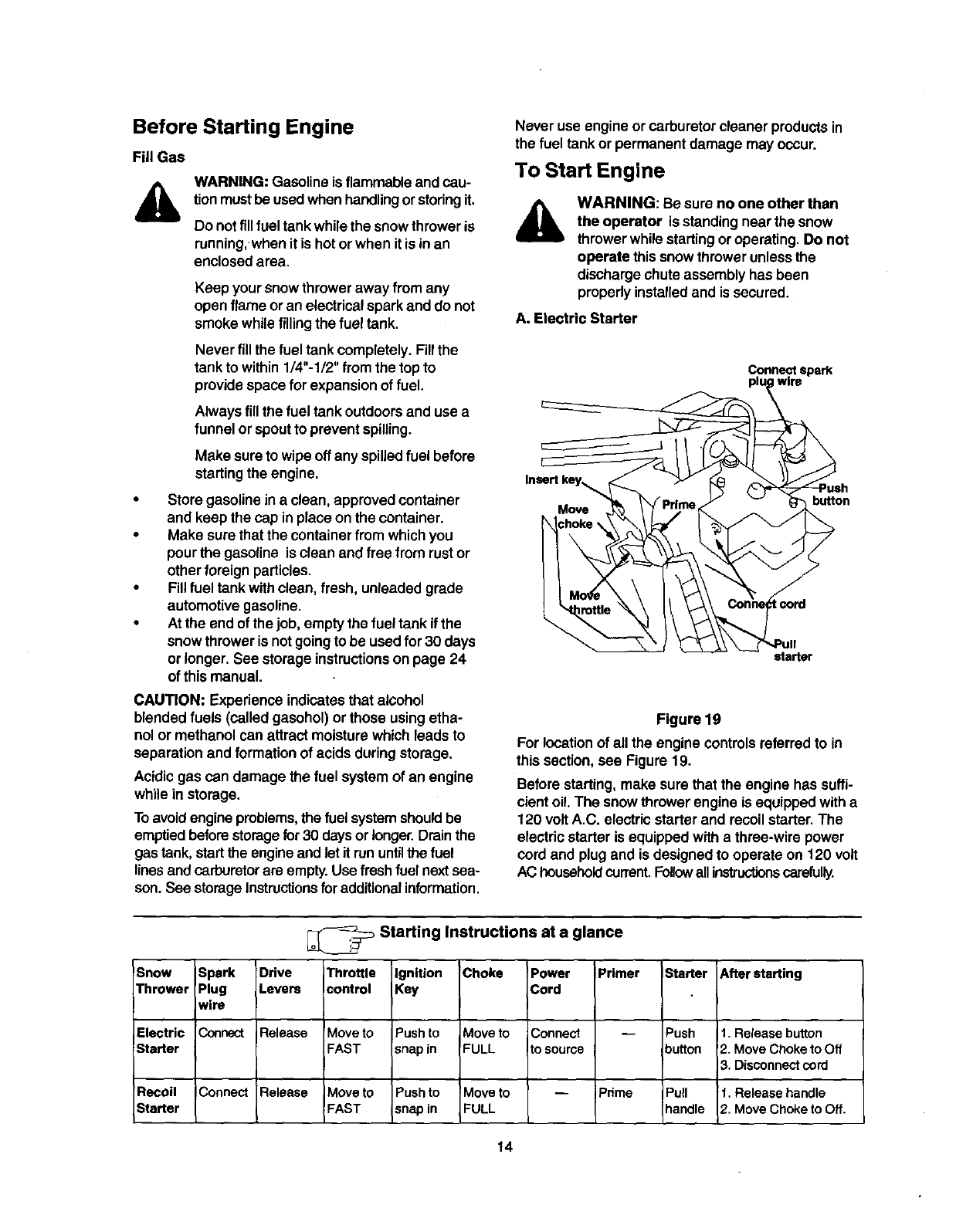
A. Electric Starter
Connect spark
wire
Insertkey_
Move button
starter
Figure 19
For locationof allthe engine controlsreferredto in
this section,see Figure 19.
Before starting, make sure that the engine has suffi-
cient oil.The snow thrower engine is equippedwith a
120 voltA.C. electric starterand recoilstarter. The
electricstarter is equippedwith a three-wire power
cord and plugand is designed to operate on 120 volt
AC householdcurrent,Foll_vallinstructionscarefully.
!Snow Spark Drive
Thrower Plug Levers
wire
Electric Connect Release
Starter
Recoil IConnect Release
Starter
_Starting Instructions at a glance
Throttle
control
Move to
FAST
Moveto
FAST
Ignition
Key
Push to
snap in
Push to
snap in
Choke
Move to
FULL
Move to
FULL
Power
Cord
Connect
to source
Primer
Pnme
Starter After starting
Push t. Release button
button 2. Move Choke to Off
3. Disconnectcord
IPull t. Release handle
handle 2. Move Choke to Off.
14
ColdStart
NOTE:ff the unit shows any sign of motion (drive or
augers) with the clutch grips disengaged, shutthe
engineoff immediately. Readjustas instructedin the
"FinalAdjustments"section onpage 11.
WARNING: The electric starter must be properly
grounded at all times to avoid possibility of electric
shockwhich may injurethe operator.
•Determinewhether your house wiring is a three-
wire groundedsystem. Ask a licensed
electricianif you are notcertain.
,_ WARNING: Ifyour housewiringsystemis
not a three-wiregrounded system,do notuse
thiselectricstarterunderany conditions.
• If your house wiringsystem is grounded and a
thrae-hole receptacle is notavailableat the point
the snow thrower starter will normallybe used,
one should be installed by a licensed electrician.
•When connecting the power cord, always
connect cord to starter on engine first, then the
other end into a three-hole grounded receptacle.
• When disconnecting the power cord, always
unplug the end from the three-hole, grounded
receptacle first.
•Attach spark plugwire to spark plug.
•Make sure that the auger drive and the traction
drive levers are inthe disengaged RELEASED
position.
•Move throttlecontrolleverto FAST position.
•Removethe keysfrom the plasticbag. Push key
intothe ignitionslot. Make sure itsnaps into
place. Do not tum key. Save the second key.
•Rotatethe choke knobto FULL choke position.
• Connect power cord to switchbox on engine.
•Plugthe other end of the power cord into a
three-hole, grounded 120 voltA.C. receptacle.
WARNING: Do not use primerwhile
startingthe enginewith an electricstarter,
Push down onthe starterbutton untilthe engine
starts.Do notcrank formorethan 10 secondsat
a time. This electric starteris thermally
protected. If overheated, itwill stop
automaticallyand can be restarted only when it
has cooled to asafe temperature (a wait of
about 5 to 10 minutes is required).
When the engine starts,release the starter
button and slowlyrotate the choke to OFF
position. If the enginefalters, rotate the choke to
FULL and then gradually to OFF.
Disconnect the power cord from the receptacle
first and then from the switch box on the engine.
Allow the engine to warm up for a few minutes
because the engine will not develop full power
until it reaches operating temperature.
Operate the engine at full throttle(FAST) when
throwing snow.
Warm Start
If restarting awarm engine after a shutdown,
rotatechoketo OFF insteadof FULL and press
the starter button.
B. Recoil Starter
Make sure that the engine has sufficientoil and the
auger drive and the traction drive levers are released.
• Move throttle control to FAST position.
• Push key into the ignitionslot so that it snaps
into place. Do not turn key. Remove plastic bag
and keep the second key in a safe place.
• Rotate choke control to FULL choke position.
• Push the primer button while covering the vent
hole.Removeyourfingerfromthe primerbetween
primes.Do not prime if temperature is above
50° F; primetwo timesbe{ween50° F and 15oF;
andprimefourtimesbelow15° F.
•Pull the starterhandle rapidly.Do not allowthe
handleto snap back, butallow itto rewindslowly
while keepinga firmholdon the starterhandle.
• As the engine warms up and beginsto operate
evenly, rotatethe choke knobslowlyto OFF
position.If the engine falters, returnto FULL
choke, then slowlymove to OFF chokeposition.
• Allow the engine to warm upfor a few minutes
becausethe engine will notdevelop full power
untilit reaches operatingtemperature.
•Operate the eng!ne at fullthrottle(FAST) when
throwingsnow.
Warm Start
•If restartinga warm engine after a temporary
shutdown, rotatechoke to OFF insteadof FULL
and do notprime. Press the starterbutton.
Frozen Recoil Starter
If the starter is frozen and will not turn the engine,
proceed as follows:
• Pull as much rope out of the starter as possible.
• Release the starter handle and let it snap back
against the starter.
• If the engine still fails to start, repeat the first two
steps. If continued attempts do not free starter,
follow the electric starter procedures to start.
• Avoid possible freezing of recoil starter and the
engine controls.
Operating Snow Thrower
To Engage Drive
With the engine running near top speed, move
shift lever to one of six FORWARD positions or
two REVERSE positions.Select a speed
appropriatefor the snowconditionsthat exist.
15
Use slowerspeeds untilyou are familiar withthe
operationof the snowthrower.
Squeeze the tractiondriveclutchgrip againstthe
righthandle and the snowthrowerwill move.
Release it and the drive motionwill stop.
To Engage Augers
To engage augers and start snowthrowing,
squeeze the left hand auger clutchgrip against
the lefthandle. Release to stop augers.
While the auger control is engaged, squeeze the
tractiondrive controlto move, releaseto stop. Do
not shiftspeeds whilethe drive is engaged.
NOTE: This same lever also locksthe auger control so
you can turn the chute crank without interrupting the
snow throwing process.
•Release the auger control;the interlock
mechanismshould keep the auger control
engaged untilthe tractiondrive controlis
released.
•Release the tractiondrivecontrolto stopboth the
augers and the track drive.
,_ WARNING: To stopthe auger, both levers
must be released.
To Throw Snow
CAUTION: Check the area to be cleared for foreign
objects. Remove, if any.
•Move weight transfer leverto the right, then
backward or forward to the desired position.
•Start the enginefollowing StartingInstructions.
Rotate the discharge chuteto the desired
direction,away from bystandersand/or buildings.
Move the chute distance controlforward or
backward to adjustthe distance the snowis to be
thrown.
•Select the speed accordingto the snow
condition.
CAUTION: Never move the shiftlever withoutfirst
releasing the drive clutch.
Engage the auger controland tractiondrive
controllevers following the preceding
instructions.
The interlock feature will allow youto remove
your left hand from the auger controllever.
When clearingthe first pass throughthe snow,
controlthe tractionspeed of the snowthrower
accordingto the depth and conditionof snow.
To turn the unitleft, squeeze left trigger;to turn
right,squeeze righttrigger.
On each succeeding pass, readjustthe chute
deflectorto the desired positionand slightly
overlapthe previouslycleared path.
•Afterthe area is cleared, stopthe snowthrower
following instructionsgiven below.
Operating Tips
NOTE: AIIowthe engineto warm up fora few minutes
as the engine willnot developfullpower untilff
reaches operatingtemperature.
Warning: The temperature of muffler and
surroundingareas mayexceed 150°F. Avoid
these areas.
•For most efficientsnow removal, removesnow
immediatelyafter it falls.
• Discharge snowdownwindwhenever possible.
Slightlyoverlapeach previousswath,
•Setthe skidshoes1/4"belewthe scraperbarfor
normalusage.The skidshoesmaybe adjusted
upwardfor hard-packedsnow.Adjustskidshoes
downwardwhen usingon gravel orcrushedrock.
• Clean the snowthrower thoroughly aftereach use.
Before Stopping
•Run enginefor a few minutesto help dry offany
moistureon engine.
To avoidpossible freeze.up of the starter, follow
these steps:
Recoil Starter
a. With the engine running,pullthe starterrope
witha rapid, continuousfullarm strokethree
or fourtimes.
Electric Starter
a. Connect power cord to switchbox, thento
120 Volt AC receptacle.
b. While the engineis running,push the starter
buttonand spinthe starterforseveral
seconds.
c. Disconnectpower cord from the receptacle
first,then fromthe snowthrower.
NOTE: The unusual sound from pulling the starter
rope in the case of the recoilstarter, orfromspinning
the starterin the case of the electricstarter, willnot
harm the engine.
To Stop The Snow Thrower
•To stopthe track, release the tractiondrive lever
on the snow thrower.
•Tostopthrowing snow,releaseaugerdrivelever
and drivelever, if engaged.
•To stopthe engine, push throttlecontrolleverto
OFF and pulloutthe ignitionkey. Do not turnkey.
16
General Recommendations
Always observe safety rules when performing
any maintenance.
The warranty on thissnow throwerdoes not
cover itemsthat have been subjectedto
operator abuse ornegligence. To receive full
value from the warranty, operator must maintain
the snow throweras instructedinthis manual.
Some adjustmentswill have to be made
periodicallyto maintainyour unit properly.
• All adjustments inthe Service and Adjustments
section of this manual should be checked at
least once each season.
• Follow the maintenanceschedule given below.
Periodically check all fasteners and make sure
these are tight.
&WARNING: Alwaysstop the engine and
disconnect the sparkplug wirebefore
performingany maintenanceor
adjustments.
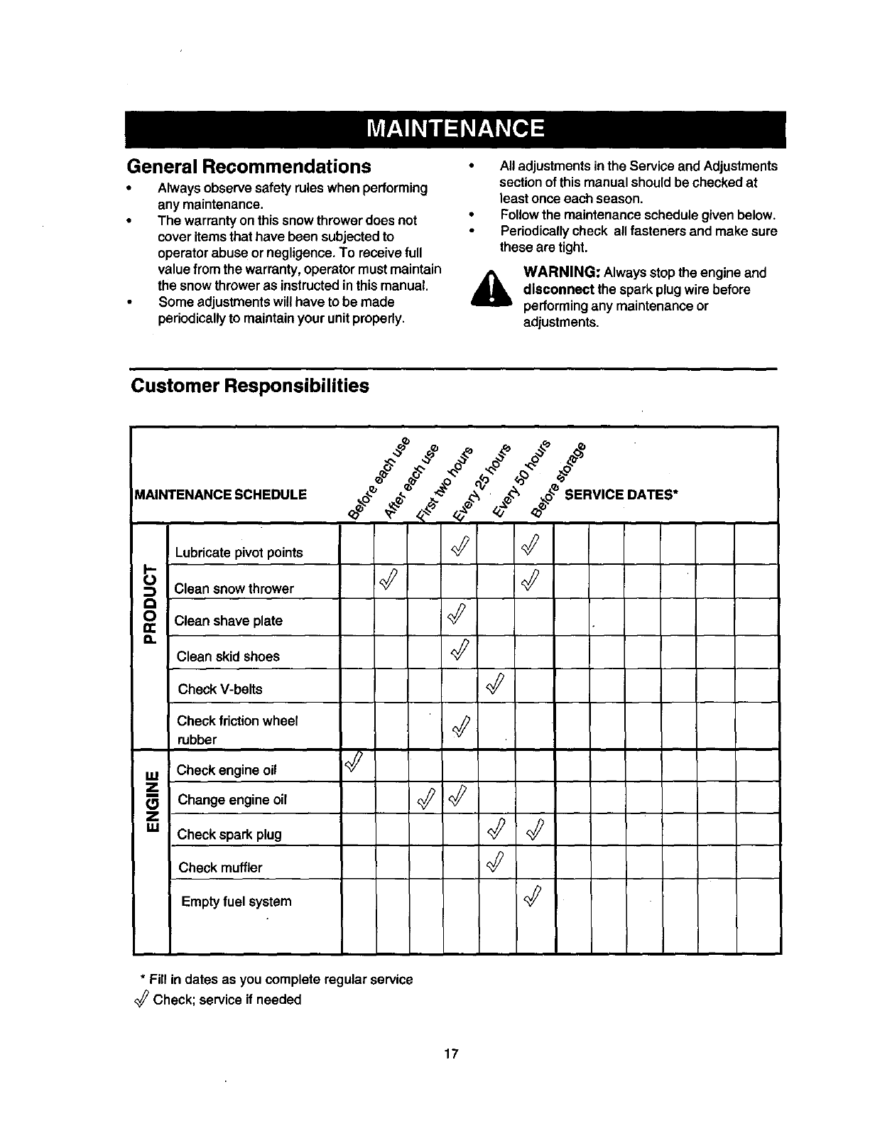
Customer Responsibilities
MAINTENANCE SCHEDULE ._oJ _ _ _ •___o_SERVICE DATES*
Lubricate pivot points <_
Clean snowthrower
0 Clean shave plate
a. Clean skid shoes '_
Check V-belts
Check friction wheel
rubber
Check engine oil '_
_Z Change engine oil _:_ <_
I
Z
g.l Check spark plug '_
Check muffler
Emptyfuel system '_
* Fill in dates as you complete regular service
Check; service if needed
17
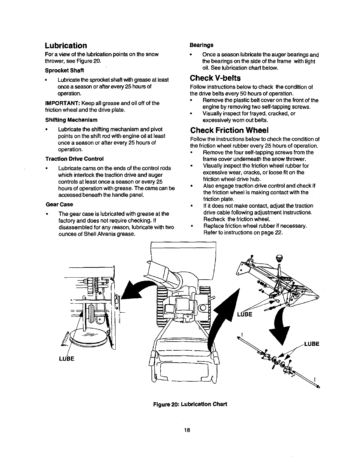
Lubrication
For a view of the lubricationpointson the snow
thrower, see Figure 20.
Sprocket Shaft
• Lubricatethe sprocketshaft withgreaseat least
oncea seasonorafter every25 hoursof
operation.
IMPORTANT: Keepall grease and oiloff of the
friction wheel andthe drive plate.
Shifting Mechanism
•Lubricatethe shiftingmechanism and pivot
pointsonthe shiftrodwith engine oilat least
once a season or after every 25 hoursof
operation,
Traction Drive Control
• Lubricate cams onthe ends of the controlrods
which interlockthe tractiondrive and auger
controlsat least onceaseason or every 25
hoursof operationwithgrease. The camscan be
accessedbeneaththe handlepanel,
Gear Case
The gear case is lubricatedwithgrease at the
factory and does notrequire checking. If
disassembledfor any reason, lubricatewithtwo
ounces of Shell Alvania grease.
Bearings
Once a season lubricatethe auger bearingsand
the bearingson the sideof the frame withlight
oil.See lubricationchart below.
Check V-belts
Follow instructionsbelow to check the conditionof
the drive beltsevery 50 hoursof operation.
•Remove the plasticbelt coveron the front of the
engine by removingtwo self-tappingscrews.
•Visuallyinspectfor frayed, cracked, or
excessivelywornout belts.
Check Friction Wheel
Follow the instructionsbelow to check the conditionof
the friction wheel rubber every 25 hours of operation.
• Remove the four self-tapping screws from the
frame cover underneath the snow thrower.
• Visually inspect the friction wheel rubber for
excessive wear, cracks, or loose fit on the
friction wheel drive hub.
• Also engage traction drive control and check if
the friction wheel is making contact with the
friction plate.
• If it does not make contact, adjust the traction
drive cable following adjustment instructions.
Recheck the friction wheel
•Replace friction wheel rubber if necessary.
Refer to instructionson page 22.
LUBE
Figure 20: Lubrication Chart
18
Engine Maintenance
Engine Oil
Only use high quality detergent oil rated withAPI
serviceclassification SF, SG or SH. Select the oil's
SAE viscositygrade according to the expected
operating temperature.
colder.,_---32 °warmer
|
5W30 '9[ I _'-_ SAE30
I
Viscosity Chart
NOTE: Although multi-viscosity oils (5W30, 10W30
etc.) improve startingin cold weather, these multi-
viscosityoils willresult inincreased oil consumption
when used above 32°F. Checkyour snow thrower's
engine oillevel more frequentlyto avoidpossible
engine damage fromrunninglow on oil.
Refer to the viscosity chart forproper selectionof
engine oil.
Checking Oil Level
IMPORTANT: Before operatingthe snow thrower,
check the oil level
•With engine on level ground, the oil must be to
FULL mark on dipstick.
• Stop engine and wait several minutes before
checking oil level. Remove oil fill cap and
dipstick.
• Wipe dipstick clean, insert it into oil fill hole and
tighten securely.
• Remove dipstick and check. Ifoil is not up to the
FULL mark on dipstick, add 5W30 oil.
Changing Oil
Change engine oilafter the firsttwo hoursof
operationand every 25 hours thereafter.
Inorder to do that you willhave to first drain the spent
engineoil from the engine and then refillwithfresh oil.
•Drainoil while engine is warm. Remove oil drain
cap located at the bottomof the recoilstarterof
the engine. Catch oil ina suitablecontainer.
•When engine is drainedof all oil, replace drain
plugsecurely.
Remove the dipstick from the oil till tube. For
locationof the oil fill tube, see Figure 17 inset.
Pour fresh oil slowlythroughthe tube. Replace
dipstick.
•Check and make sure that the oil levelis up to
the FULL mark on the dipstick.
WARNING: Temperature of muffler and
nearby areas may exceed 150° F (65°C).
Avoid these areas.
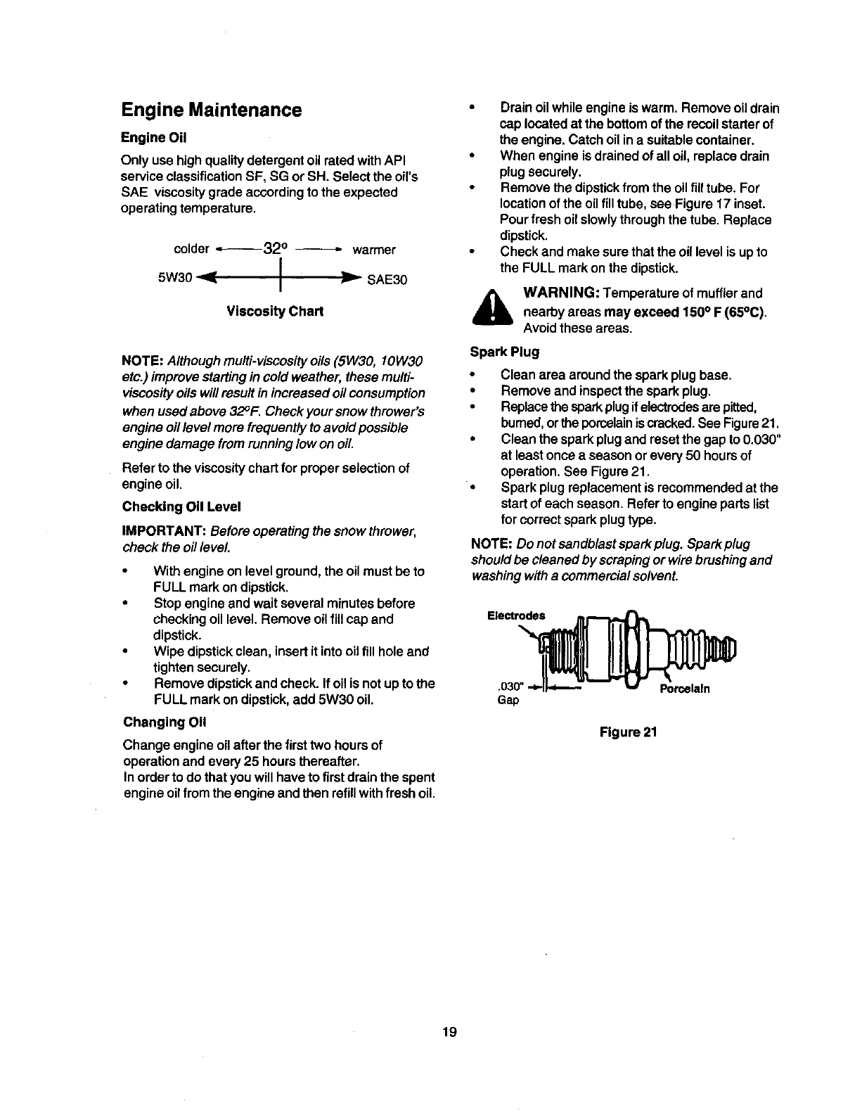
Spark Plug
• Clean area aroundthe sparkplug base.
•Remove and inspect the sparkplug.
• Replace the spark plug if electrodes are pitted,
burned, orthe porcelain is cracked. See Figure21.
• Clean the spark plug and reset the gap to 0.030"
at least once a season or every 50 hours of
operation. See Figure 21.
• Spark plug replacement is recommended at the
start of each season. Refer to engine parts list
for correct spark plug type.
NOTE: Do not sandblastspark plug. Spark plug
shouldbe cleaned by scrapingor wire brushing and
washing with a commercialsolvent.
Figure 21
19
AWARNING: Always stop the engine, dis-
connect sparkplug wireand move it away
fromthe spark plug before performingany
adjustmentsor repairs,
Never attempt to clean the chute or make
any adjustmentswhile the engine is running.
Adjustments
Traction Drive Control
Refer to the Final Adjustmentsection of the Set-Up
Instructionsto adjust the traction drive control.If you
are not sure of proper adjustment, check as follows.
•Drain the gasolineor place plasticfilm underthe
gas cap if the snow throwerhas already been
operated.
•Tip the snowthrowerforward and remove the
four self-tappingscrewsthat holdthe frame
cover underneaththe snowthrower.
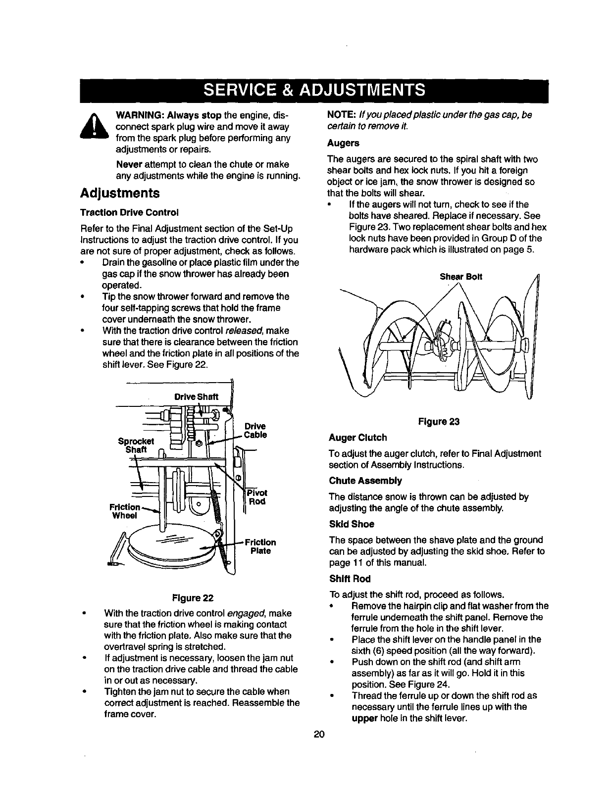
With the tractiondrive controlreleased, make
sure that there is clearance between the friction
wheel and the friction plate in all positionsof the
shiftlever. See Figure22.
"_l_ I I Drive
Sproc.e,
• IILIIIi._,i-II
,r,ct,on--...lli-tlLltL°Jill I
°,' Lon
Figure 22
With the tractiondrive controlengaged, make
surethat the frictionwheel is makingcontact
withthe friction plate, Also make sure that the
overtravelspringis stretched.
If adjustmentis necessary, loosen the jam nut
on the tractiondrivecable and thread the cable
in or outas necessary.
Tighten the jam nutto securethe cable when
correct adjustmentis reached. Reassemble the
frame cover.
NOTE: ff you placed plastic underthe gas cap, be
certain to remove it,
Augers
The augers are secured to the spiral shaft withtwo
shear boltsand hex lock nuts. If you hit a foreign
object or ice jam, the snowthrower is designed so
that the boltswill shear.
•If the augers will notturn, check to see ifthe
boltshave sheared. Replace ifnecessary. See
Figure23. Two replacementshear boltsand hex
locknuts have been providedinGroup D of the
hardwarepack which is illustratedon page 5.
\
ShearBolt
20
Figure 23
Auger Clutch
To adjustthe auger clutch,refer to Final Adjustment
sectionof Assembly Instructions,
Chute Assembly
The distance snow is throwncan be adjusted by
adjustingthe angle of the chute assembly,
Skid Shoe
The space between the shave plate and the ground
can be adjusted by adjustingthe skid shoe. Refer to
page 11 of thismanual.
Shift Rod
Toadjust the shiftrod, proceed as follows.
•Remove the hairpin clipand flat washerfrom the
ferrule underneaththe shiftpanel. Remove the
ferrule from the hole inthe shiftlever.
•Place the shiftlever onthe handle panel inthe
sixth(6) speed position(all the way forward).
•Pushdown onthe shiftrod (and shift arm
assembly)as far as it will go. Holdit in this
position.See Figure 24.
•Thread the ferrule up or downthe shiftrod as
necessary untilthe ferrule lines up withthe
upper hole inthe shiftlever.
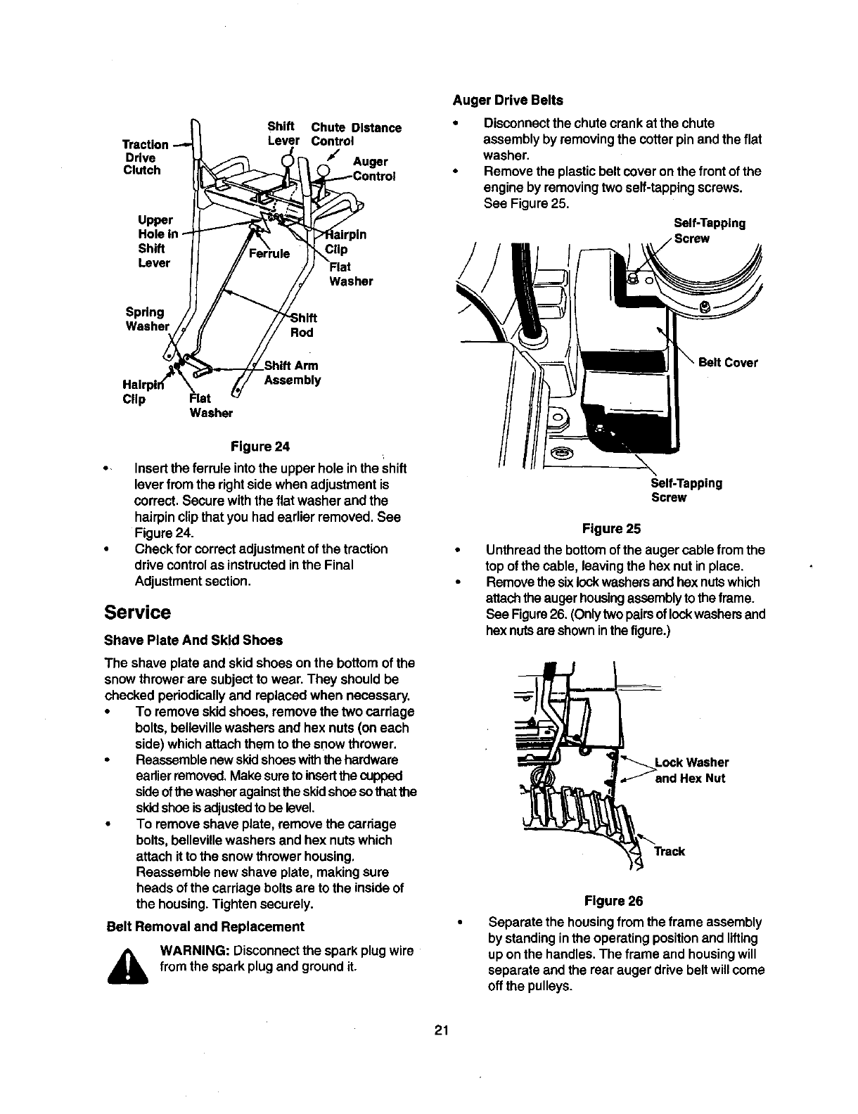
Shift Chute Distance
Lever Control
Drive Auger
Clutch
Upper
Shift
Lever
Spring
Washer Rod
Clip
Flat
Washer
Clip Flat
Washer
Assembly
Figure 24
• Insertthe ferrule intothe upper hole in the Shift
lever fromthe rightsidewhen adjustmentis
correct.Secure with the fiat washer and the
hairpinclip that you had earlier removed. See
Figure24.
• Check for correctadjustmentof the traction
drive controlas instructedinthe Final
Adjustment section.
Service
Shave Plate And Skid Shoes
The shave plate and skidshoes on the bottom of the
snow throwerare subject to wear. They should be
checked periodicallyand replaced when necessary.
•To remove skidshoes, remove the two carriage
bolts,beUevillewashers and hex nuts(on each
side) whichattach them to the snowthrower.
•Reassemblenewskidshoeswiththe hardware
earlierremoved,Make sureto insertthecupped
sideofthe washeragainstthe skidshoesothatthe
skidshoe isadjusted to be level,
•To remove shave plate, removethe carriage
bolts, bellevillewashers and hex nutswhich
attach it to the snow throwerhousing,
Reassemble new shave plate, making sure
heads of the carriagebolts are to the insideof
the housing.Tighten securely.
Belt Removal and Replacement
WARNING: Disconnect the spark plugwire
from the spark plugand groundit.
Auger Drive Belts
•Disconnectthe chute crank at the chute
assembly by removing the cotterpin andthe flat
washer.
•Remove the plasticbeltcover onthe frontof the
engine by removingtwoself-tappingscrews.
See Figure 25,
Self-Tapping
Cover
\Self-Tapping
Screw
Figure 25
Unthread the bottom of the auger cable fromthe
top ofthe cable, leavingthe hex nut inplace.
Removethe sixlockwashersandhex nutswhich
attachthe augerhousing assemblyto the frame.
See Figure26. (Onlytwopairsof lockwashersand
hex nutsare showninthefigure.)
Lock Washer
and Hex Nut
Figure 26
Separate the housingfrom the frame assembly
by standinginthe operatingpositionand lifting
up onthe handles. The frame and housingwill
separate and the rearauger drive beltwillcome
off the pulleys.
21
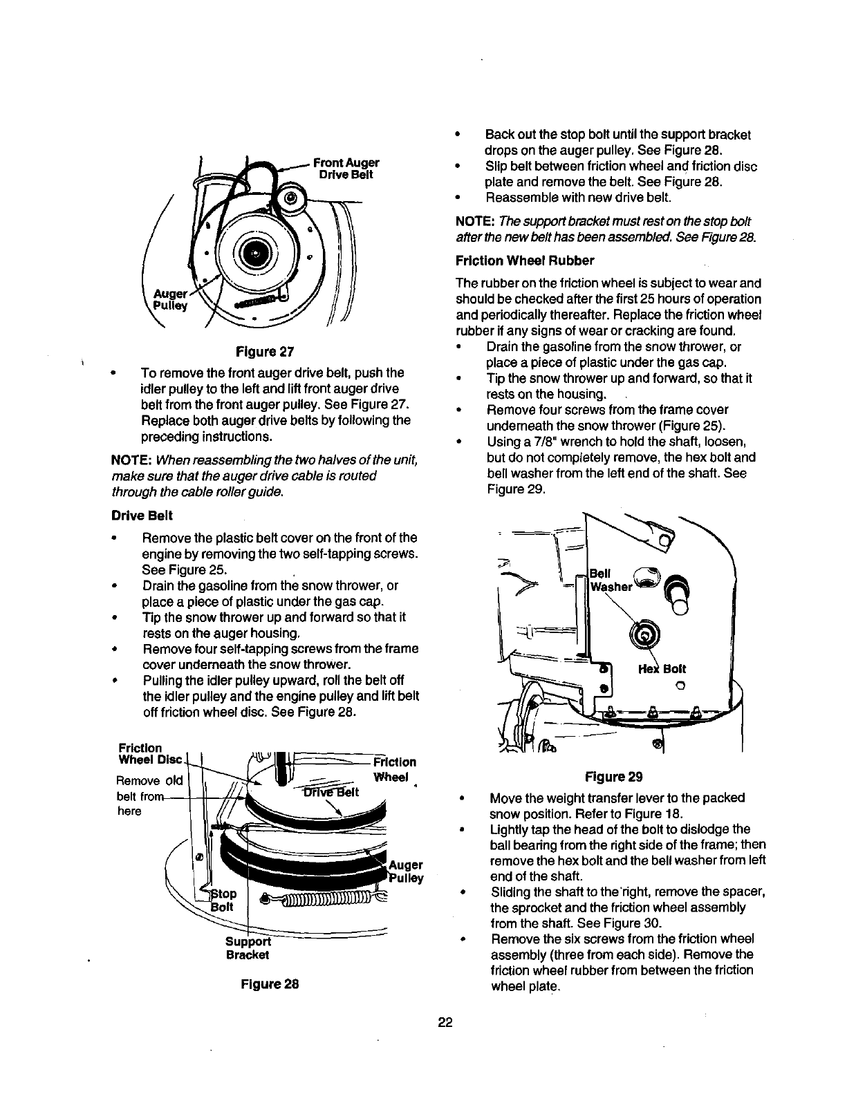
Drive Belt
Figure 27
To remove the front auger drive belt, push the
idler pulleyto the leftand liftfront auger drive
belt from the front auger pulley. See Figure27.
Replace both auger drive belts by following the
precedinginstructions.
NOTE: When reassembling the two halvesof the unit,
make sure that the auger drive cable is routed
throughthe cable roller guide.
Drive Belt
•Remove the plasticbelt coveron the front of the
engine by removingthe two self-tappingscrews.
See Figure 25.
•Drain the gasoline from the snowthrower, or
place a piece of plasticunderthe gas cap.
•Tip the snowthrower upand forward so that it
rests onthe auger housing,
•Remove four self-tappingscrewsfrom the frame
cover underneaththe snow thrower.
•Pullingthe idlerpulleyupward, rollthe beltoff
the idlerpulleyandthe engine pulleyand liftbelt
off fdction wheel disc. See Figure 28.
Friction
Wheel Disc
Remove
belt
here
Friction
Wheel
Support
Bracket
Figure 28
•Back outthe stopbolt untilthe supportbracket
dropson the auger pulley, See Figure 28.
•Slip belt betweenfriction wheel and friction disc
plate and removethe belt. See Figure 28.
•Reassemble withnew drive belt.
NOTE: Thesupportbracket must rest onthestopbolt
after thenew belthas been assembled. See Figure 28.
Friction Wheel Rubber
The rubberonthe friction wheel is subjectto wear and
shouldbe checkedafter the first 25 hoursof operation
and periodicallythereafter. Replace the friction wheel
rubber ifany signsof wear or crackingare found.
•Drainthe gasolinefrom the snow thrower,or
place a pieceof plasticunderthe gas cap.
•Tip the snowthrowerupand forward, so that it
restson the housing.
•Remove four screws from the frame cover
underneaththe snow thrower(Figure 25).
•Usinga 7/8" wrench to holdthe shaft, loosen,
butdo not completelyremove, the hex bolt and
bell washer from the leftend of the shaft. See
Figure 29.
Figure 29
•Move the weight transfer leverto the packed
snow position.Refer to Figure 18.
•Lightlytap the head of the boltto dislodgethe
ball bearing from the rightside of the frame; then
remove the hex boltand the bellwasher from left
end of the shaft.
•Slidingthe shaft to theTight,remove the spacer,
the sprocketand the friction wheel assembly
from the shaft.See Figure30.
•Remove the six screwsfrom the friction wheel
assembly (three from each side). Remove the
friction wheel rubber from between the friction
wheel plate.
22
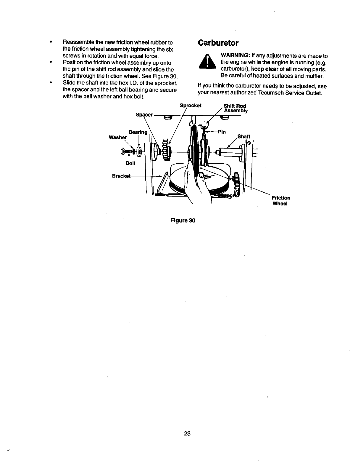
• Reassemblethenewfrictionwheelrubberto
thefrictionwheelassemblytighteningthesix
screwsinrotationandwithequalforce.
•Positionthe frictionwheel assembly uponto
the pin of the shiftrod assemblyand slide the
shaft throughthe friction wheel. See Figure 30.
•Slide the shaft intothe hex I.D. of the sprocket,
the spacer and the leftball bearing and secure
withthe bell washer and hex bolt.
Carburetor
AWARNING: If any adjustmentsare made to
the engine whilethe engine is running(e.g.
carburetor), keep clear of all movingparts.
Be careful of heated surfacesand muffler.
If youthinkthe carburetorneeds to be adjusted, see
your nearest authorizedTecumseh Service Outlet.
Shift Rod
ly
Washer
\
Friction
Wheel
Figure 30
23
If your snow thrower is leftunusedfor 30 days or
longer,it needsto be prepared for storage. Also, at
the end of the snow season, you should follow the
same set of instructionsend store the snow thrower
properly for the off-season. Proper storage ensures
longer life of the snow thrower.
Preparing Engine
AWARNING: Never store snow thrower with
fuel intank indoors or in poorlyventilated
areas, where fuelfumes may reach an open
flame, spark or pilotlightas on a furnace,
water heater, clothesdryer or gas
appliance.
It is important to prevent gum depositsfrom
forming inessential fuel systempartsof the
engine suchas the carburetor, fuel filter,
fuel hose ortank duringstorage.
Also experience indicatesthat alcohol
blended fuels (called gasohol or using
ethanol or methanol)can attract moisture
which leads to separation and formation of
acids duringstorage.Acidic gas can
damage the fuel system of an engine while
instorage.
To avoid engine problems,the fuel system should be
emptied before storagefor 30 days or longer.Follow
these instructionsto prepareyour snowthrowerfor
storage:
•Remove allgasolinefromthe carburetor and the
fueltank to prevent gum depositsfrom forming
on these partsand causingpossible malfunction
of the engine.
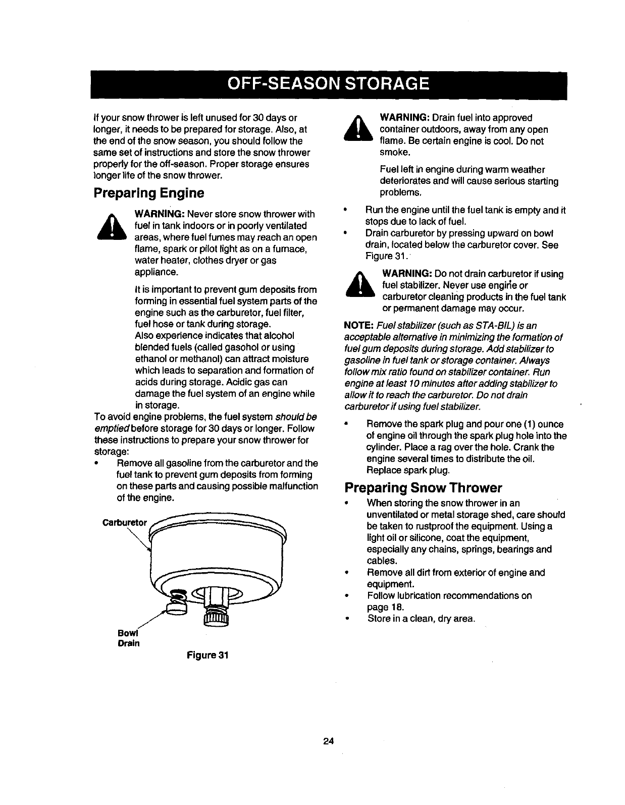
Carburetor
\
Bowl
Drain
Figure 31
&WARNING: Drain fuel into approved
containeroutdoors,away from any open
flame. Be certainengine is cool. Do not
smoke.
Fuel leftin engine duringwarm weather
deteriorates and will cause seriousstarting
problems,
Run the engine untilthe fuel tank is empty and it
stopsdue to lack of fuel.
Drain carburetor by pressing upwardon bowl
drain, located below the carburetorcover. See
Figure 31.
&WARNING: Do not drain carburetor if using
fuel stabilizer.Never use engirle or
carburetorcleaning productsin the fuel tank
or permanent damage may occur.
NOTE: Fuel stabilizer(suchas STA-BIL) is an
acceptable alternativeinminimizing the formationof
fuelgum depositsduring storage.Add stabilizerto
gasoline in fuel tank or storage container.Always
followmix ratio foundonstabilizer container.Run
engine at least 10minutesafter addingstabilizerto
allow it to reach the carburetor.Do not drain
carburetorff usingfuelstabilizer.
Remove the spark plug and pour one (1) ounce
of engineoil through the spark plughole intothe
cylinder. Place a rag over the hole. Crank the
engine several times to distribute the oil.
Replace spark plug.
Preparing Snow Thrower
•When storingthe snowthrower inan
unventilatedor metal storage shed, care should
be taken to rustproofthe equipment. Usinga
lightoilor silicone,coat the equipment,
especiallyany chains, springs,bearings and
cables.
•Remove alldirt from exteriorof engine and
equipment.
Followlubricationrecommendationson
page 18.
Store ina clean, dry area.
24
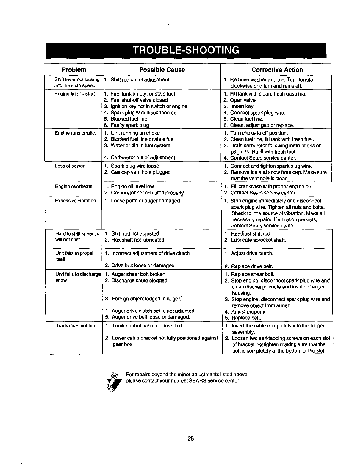
Problem
Shiftlevernotlocking
intothesixthspeed
Enginefailstostart
Engine runs erratic.
Lossof power
Engineoverheats
Excessivevibration
Hardto shiftspeed,or
willnotshift
Unitfails to propel 1.
itself 2.
Unitfails to discharge 1.
snow 2.
3,
4.
5.
Trackdoes notturn 1.
2,
Possible Cause
1, Shiftrodoutofadjustment
1. Fuel tank empty, or stale fuel
2. Fuel shut-oftvalve closed
3. Ignitionkey not inswitchor engine
4. Spark plugwire disconnected
5. Blockedfuel line
6. Faulty spark plug
1. Unit running onchoke
2. Blockedfuel lineorstale fuel
3. Water or dirt infuel system.
4. Carburetor out of adjustment
1. Spark plugwireloose
2. Gas cap vent hole plugged
1. Engine oil level low.
2. Carburetor notadjusted properly
1. Loose parts or auger damaged
Corrective Action
1. Remove washer and pin. Turn ferrule
clockwiseone turn and reinstall,
1. Filltank with clean, fresh gasoline.
2. Open valve.
3. Insertkey.
4. Connect spark plugwire.
5. Clean fuel line.
6. Clean, adjustgap orreplace.
1. Turn choketo offposition.
2. Clean fuel line,fill tank withfresh fuel.
3. Drain carburetorfollowing instructionson
page 24, Refill withfresh fuel.
4. Contact Sears service center.
1. Connect and tighten spark plug wire.
2. Remove ice and snow fromcap, Make sure
that the vent hole is clear,
1. Fill crankcase withproper engine oil
2. ContactSears service center.
1. Stopengine immediatelyand disconnect
spark plugwire. Tightenall nutsand bolts.
Check for the sourceofvibration. Make all
neceseePl repairs.If vibrationpersists,
contact Sears service center.
1. Shiftred not adjusted 1. Readjustshift red.
2. Hex sha_lnot lubricated 2. Lubricatesprocket shaft.
Incorrectadjustment of drive clutch 1. Adjust driveclutch.
Ddve belt loose ordamaged 2. Replace drivebelt.
Auger shear bolt broken 1. Replace shear bolt.
Discharge chute clogged 2. Stopengine, disconnectspark plugwire and
Foreignobject lodgedin auger.'
Auger drive clutchcable not adjusted.
Auger drive beltloose ordamaged.
Track controlcable not inserted.
Lowercable bracket not fullypositionedagainst
gear box.
clean discharge chute and insideof auger
housing.
3. Stopengine, disconnectspark plug wire and
remove object from auger.
4. Adjustpropady.
5. Replace belt.
1. Insertthe cable completelyintothe trigger
assembly.
2. Loosentwo self-tappingscrews oneach slot
of bracket. Retighten makingsure that the
bolt is completely at the bottom of the slot.
For repairs bey°nd the min°r adjustmentslistedabove'
please contact your nearest SEARS service center.
25
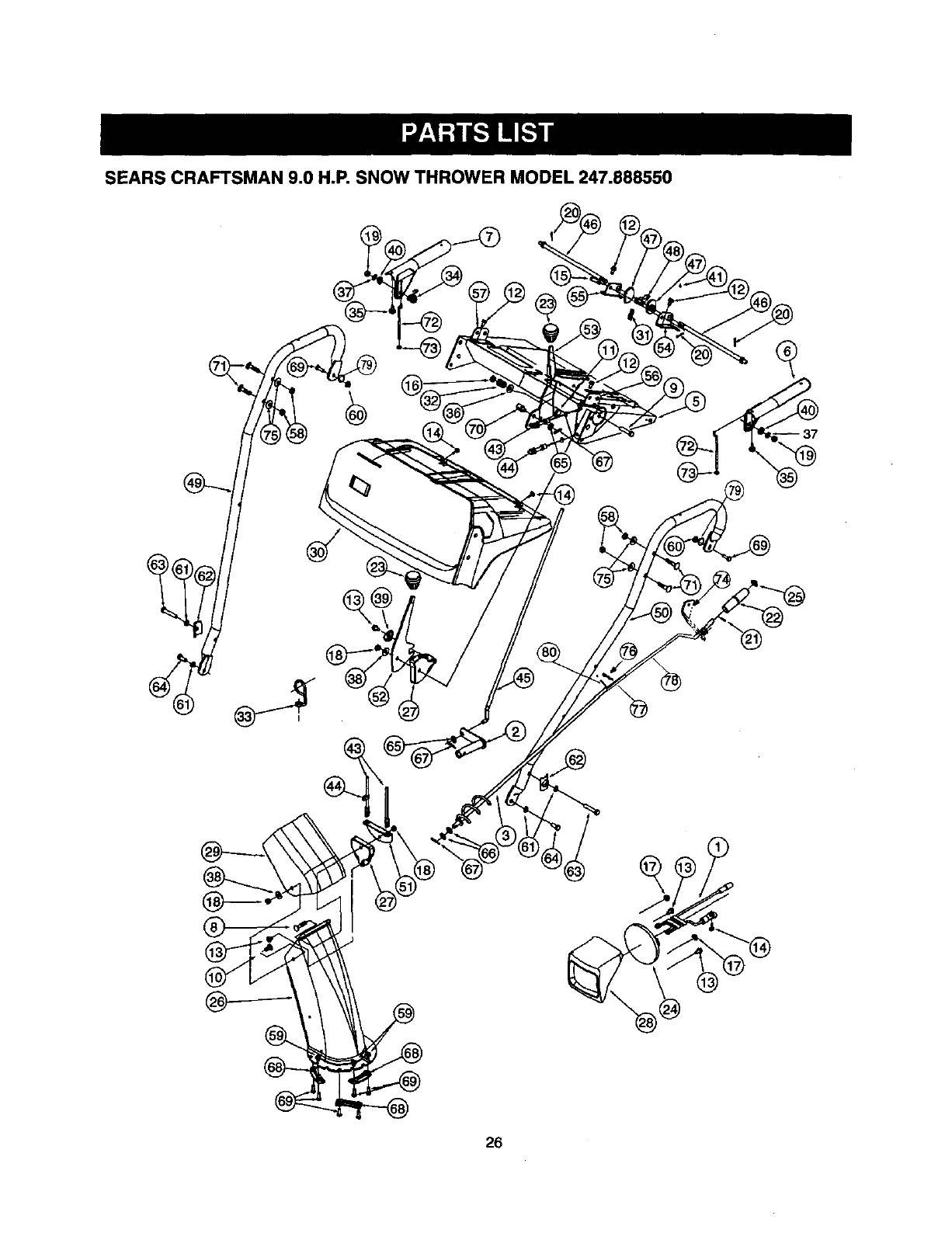
SEARS CRAFTSMAN 9.0 H.P. SNOW THROWER MODEL 247.888550
26
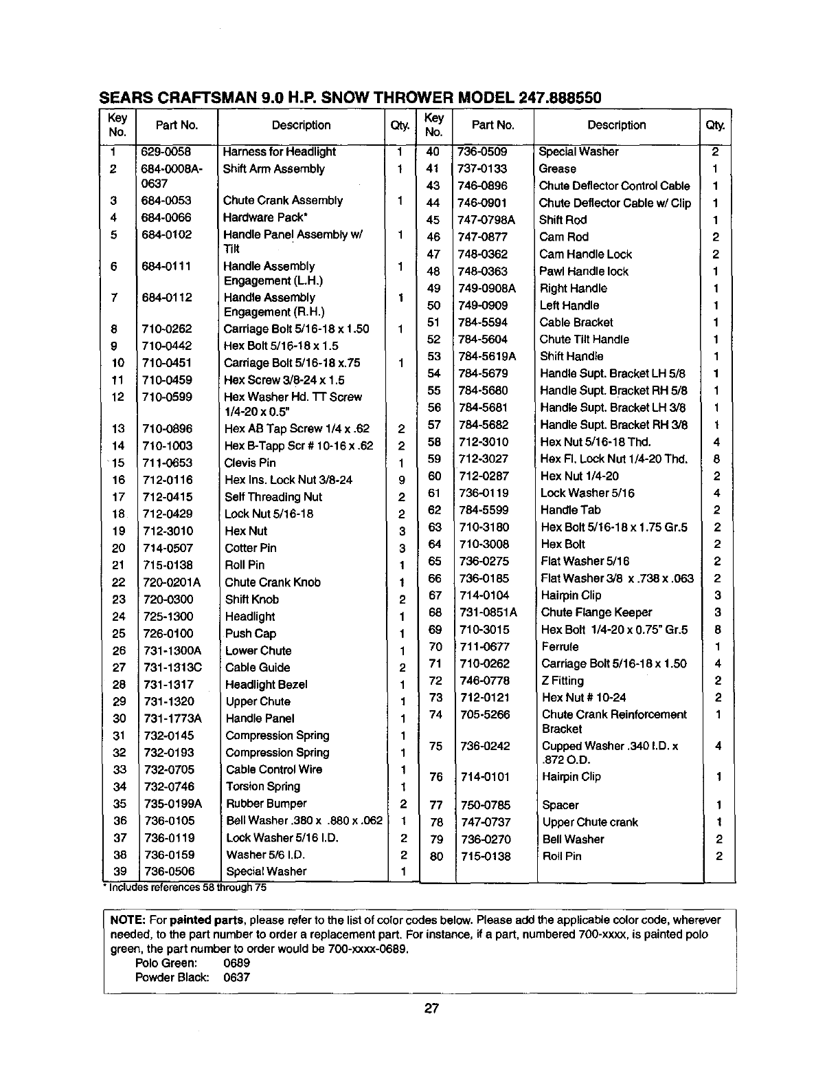
SEARS CRAFTSMAN 9.0 H.P. SNOW THROWER MODEL 247.888550
Key
No.
1
2
3
4
6
8
9
10
11
12
13
14
15
16
17
18
19
20
21
22
23
24
25
26
27
28
29
30
31
32
33
34
35
36
37
38
39
Part No.
629-0058
684-0008A-
0637
684-0053
684-0066
684-0102
684-0111
684-0112
710-0262
710-0442
710-0451
710-0459
710-0599
710-0896
710-1003
711-0653
712-0116
712-0415
712-0429
712-3010
714-0507
715-0138
720-0201A
Description
Harness for Headlight
ShiftArm Assembly
Chute Crank Assembly
Hardware Pack*
Handle Panel Assembly w/
Tilt
Handle Assembly
Engagement (L.H.)
Handle Assembly
Engagement (R.H.)
Carriage Bolt5/16-18 x 1.50
Hex Bolt5/16-18 x 1.5
Carriage Bolt 5/16-18 x.75
Hex Screw 3/8-24 x 1.5
Hex Washer Hd. 3-1"Screw
1/4-20 x 0.5"
Hex AB Tap Screw 1/4 x .62
Hex B-Tapp Scr # 10-16 x .62
Clevis Pin
Hex Ins.Look Nut 3/8-24
Self Threading Nut
Lack Nut 5/16-18
Hex Nut
Cotter Pin
Roll Pin
Chute Crank Knob
Qty,
1
1
1
1
1
1
1
1
2
2
1
9
2
2
3
3
1
1
KeY Part No.
No,
40 736-0509
41 737-0133
43 746-0896
44 746-0901
45 747-0798A
46 747-0877
47 748-0362
48 748-0363
49 749-0908A
50 749-0909
51 784-5594
52 784-5604
53 784-5619A
54 784-5679
55 784-5680
56 784-5681
57 784-5682
58 712-3010
59 '12-3027
60 _12-0287
61 736-0119
62 784-5599
63 710-3180
64 710-3008
65 736-0275
66 736-0185
720-0300 ShiftKnob
725-1300 Headlight
726-0100 Push Cap
731-1300A Lower Chute
731-1313C Cable Guide
731-1317 Headlight Bezel
731-1320 Upper Chute
731-1773A Handle Panel
2 67 714-0104
168 731-0851A
1 69 710-3015
170 711-0677
2 71 710-0262
1 72 746-0778
1 73 712-0121
1 74 705-5266
732-0145
732-0193
732-0705
732-0746
735-0199A
736-0105
736-0119
736-0159
736-0506
CompressionSpring
CompressionSpring
Cable Control Wire
TorsionSpring
RubberBumper
BellWasher .380 x .880 x .062
LockWasher 5/16 I.D.
Washer 5/6 I.D.
SpecialWasher
175
1
176
1
2 77
t 78
2 79
2 80
736-0242
714-0101
750-0785
747-0737
736-0270
7t5-0138
Description
SpecialWasher
Grease
Chute DeflectorControlCable
Chute Deflector Cable w/Clip
Shift Rod
Cam Rod
Cam Handle Lock
Pawl Handle lock
Right Handle
Left Handle
Cable Bracket
Chute Tilt Handle
ShiftHandle
Handle Supt. Bracket LH 5/8
Handle Supt. B_'acketRH 5/8
Handle Supt. Bracket LH 3/8
Handle Supt. Bracket RH 3/8
Hex Nut 5/16-18 Thd.
Hex FI. Lock Nut 1/4-20 Thd.
Hex Nut 1/4-20
LockWasher 5/16
Handle Tab
Hex Bolt 5/16-18 x 1.75 Gr.5
Hex Bolt
Flat Washer 5/16
Flat Washer 3/6 x ,738 x .063
Hairpin Clip
Chute Flange Keeper
Hex Bolt 1/4-20 x 0.75" Gr.5
Ferrule
Cardage Bolt 5/16-18 x 1.50
Z Fitting
Hex Nut # 10-24
Chute Crank Reinforcement
Bracket
CuppedWasher .340 I.D. x
.872 O.D.
HairpinClip
Spacer
Upper Chute crank
Bell Washer
; Roll Pin
•Includes references 58 through 75
Qty.
2
1
1
1
1
2
2
1
1
1
1
1
1
1
1
1
1
4
8
2
4
2
2
2
2
2
3
3
8
1
4
2
2
1
4
1
1
2
2
NOTE: Forpainted parts, please refer to the listof color codes below. Please add the applicable color code, wherever
needed, to the part number to order a replacement part. For instance, ifa part, numbered 700-xxxx, is painted polo
green, the part number to order would be 700-xxxx-0689.
PoloGreen: 0689
PowderBlack: 0637
27
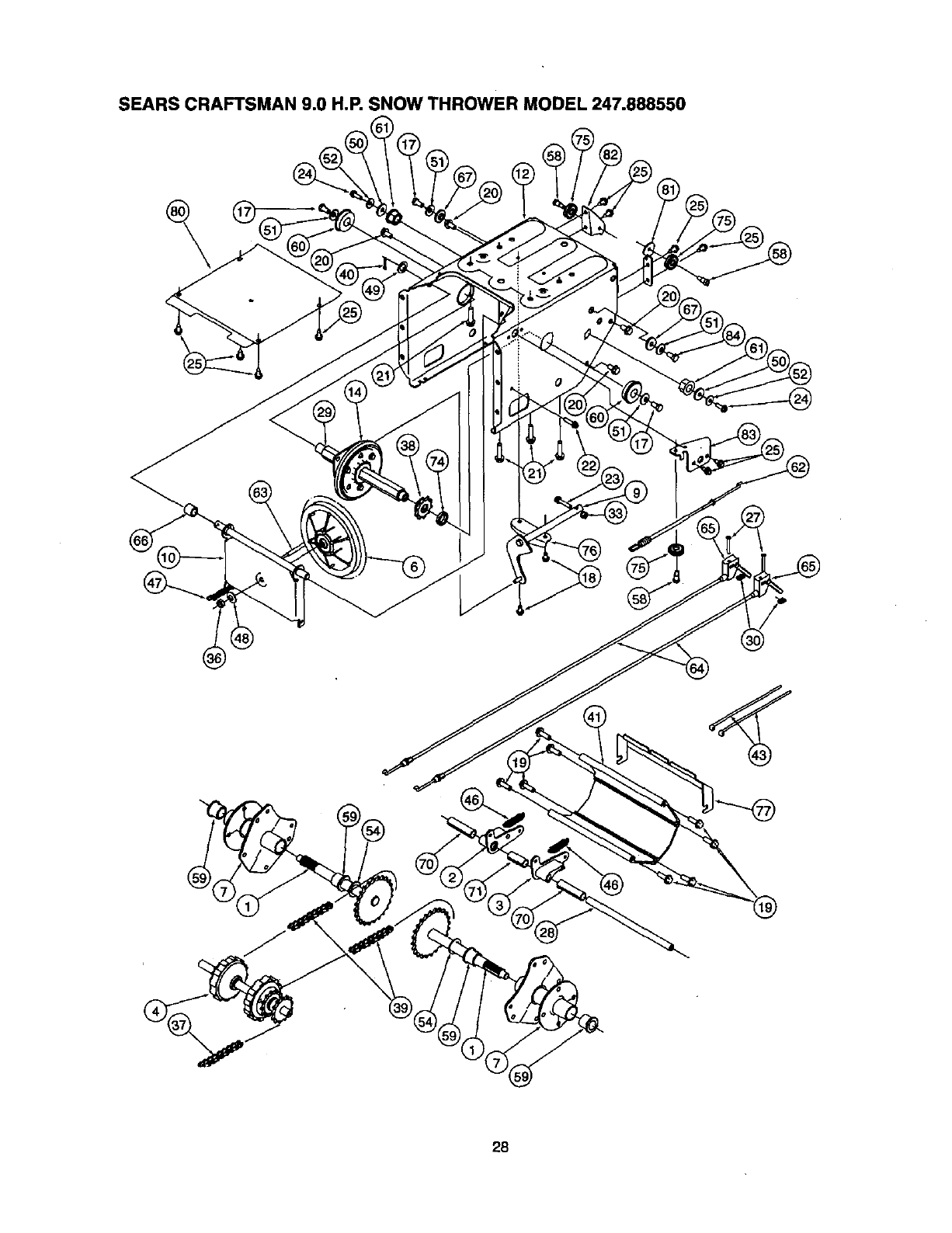
SEARS CRAFTSMAN 9.0 H.P. SNOW THROWER MODEL 247.888550
28
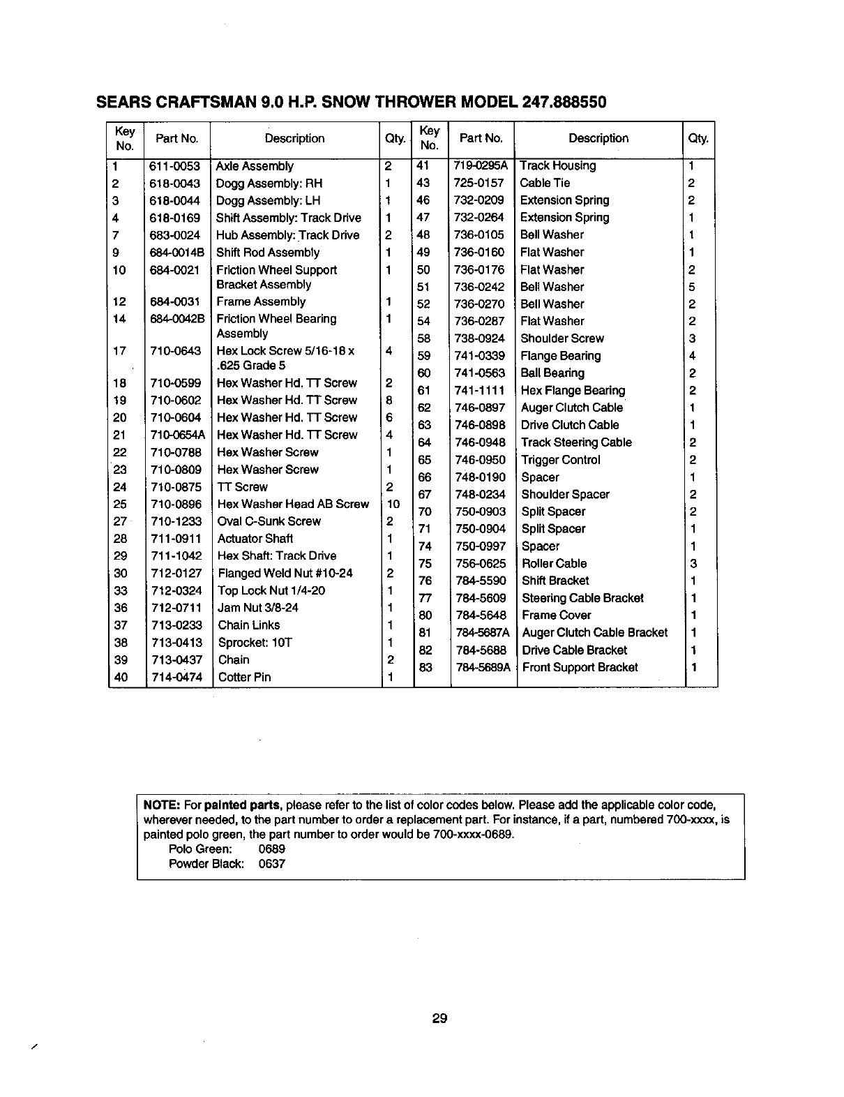
SEARS CRAFTSMAN 9.0 H.P. SNOW THROWER MODEL 247.888550
Key Part No.
No.
611-0053
2 618-0043
3 618-0044
4 618-0169
7 683-0024
9 684-0014B
10 684-0021
12
14
17
18
19
20
21
22
23
24
25
27
28
29
i30
33
36
37
38
39
40
684-0031
r_4-0042B
710-0643
710-0599
710-0602
710-0604
710-0654A
710-0788
710-0809
710-0875
710-0898
710-1233
711-0911
711-1042
712-0127
712-0324
7!2-0711
713-0233
713-0413
713-0437
714-0474
Description Key Part No.
No.
41 719-0295A
43 725-0157
46 732-0209
47 732-0264
48 736-0105
49 736-0160
50 738-0176
51 736-0242
52 736-0270
54 736-0287
58 738-0924
59 741-0339
60 741-0563
61 741-1111
62 746-0897
63 746-0898
64 746-0948
65 746-0950
66 748-0190
67 748-0234
70 750-0903
71 750-0904
74 750-0997
75 756-0625
76 784-5590
77 784-5609
80 784-5648
81 784-5687A
82 784-5688
83 784-5689A
Axle Assembly
Dogg Assembly:RH
Dogg Assembly:LH
Qty.
2
ShiftAssembly: Track Dnve
Hub Assembly: Track Drive 2
Shift Rod Assembly
FrictionWheel Support
Bracket Assembly
Frame Assembly
FrictionWheel Bearing
Assembly
Hex Lock Screw 5/16-18 x 4
.625 Grade 5
Hax Washer Hd. "17"Screw 2
Hex Washer Hd. TT Screw 8
Hex Washer Hd, TT Screw 6
Hex Washer Hd. TT Screw 4
Hex Washer Screw 1
Hex Washer Screw 1
TT Screw 2
Hex Washer Head AB Screw 10
Oval C-Sunk Screw 2
Actuator Shaft 1
Hex Shaft: Track Ddve 1
Flanged Weld Nut #10-24 2
Top Lock Nut 1/4-20 i1
Jam Nut 3/8-24 1
Chain Links 1
Sprocket: 10T 1
Chain 2
Cotter Pin 1
Description Qty.
Track Housing 1
Cable Tie 2
Extension Spring 2
Extension Spring 1
Bell Washer t
Flat Washer I1
Flat Washer 2
Bell Washer 5
Bell Washer 2
Flat Washer 2
Shoulder Screw 3
Flange Bearing 4
Ball Beadng 2
Hex Flange Bearing 2
Auger ClutchCable 1
Drive ClutchCable 1
Track Steering Cable 2
Trigger Control 2
Spacer 1
Shoulder Spacer 2
Split Spacer 2
SplitSpacer 1
Spacer 1
Roller Cable 3
ShiftBracket 1
SteeringCable Bracket 1
Frame Cover 1
AugerClutch Cable Bracket 1
Drive Cable Bracket 1
Front Support Bracket 1
NOTE: Forpainted parts, please refer to the list of color codes below.Please add the applicable color code,
wherever needed, to the part number to order areplacement part. For instance, ifa part, numbered700-xxxx, is
painted polo green, the part number to order would be 700-xxxx-0689.
Polo Green: 0689
Powder Black: 0637
f
29
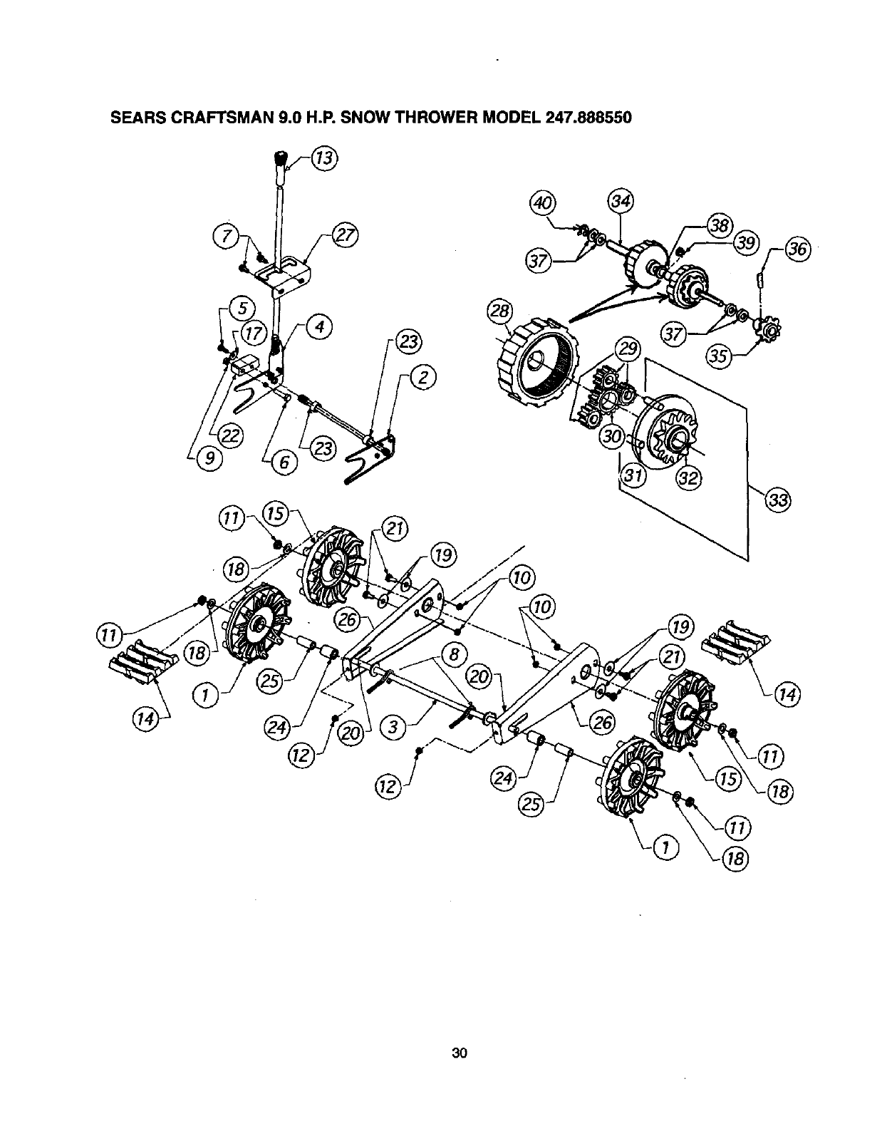
SEARS CRAFTSMAN 9.0 H.P. SNOW THROWER MODEL 247.888550
®
®
30
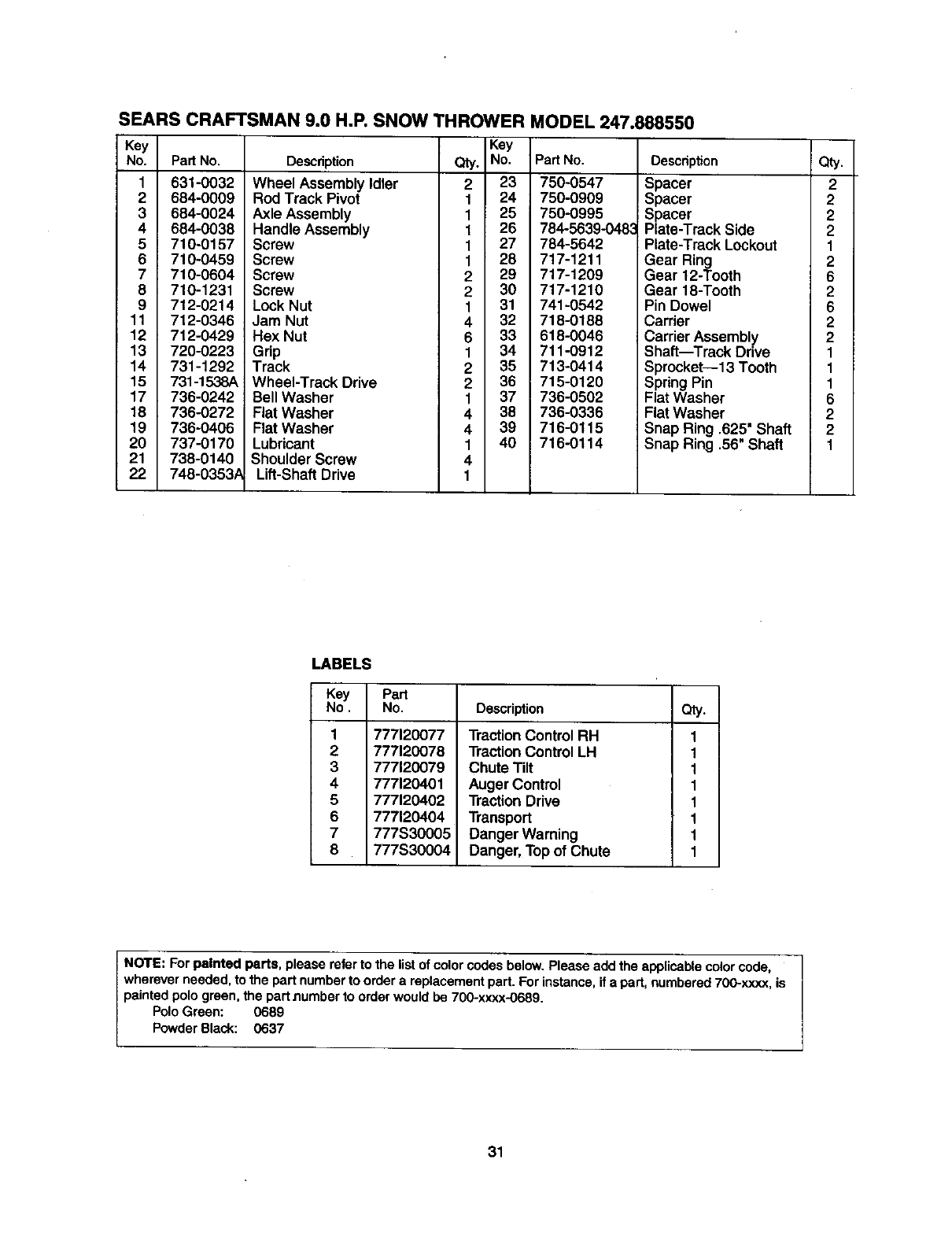
SEARS CRAFTSMAN 9.0 H.P. SNOW THROWER MODEL 247.888550
Key
No. PartNo.
1 631-0032
2 684-0009
3 684-0024
4 684-0038
5 710-0157
6 710-0459
7710-0604
8 710-1231
9 712-0214
11 712-0346
12 712-0429
13 720-0223
14 731-1292
15 731-1538A
17 736-0242
18 736-0272
19 736-0406
20 737-0170
21 738-0140
22 748-0353,_
Key
Description Qty. No.
Wheel Assembly Idler 2 23
Rod Track Pivot 1 24
Axle Assembly 1 25
Handle Assembly 1 26
Screw 1 27
Screw 1 28
Screw 2 29
Screw 2 30
Lock Nut 1 31
Jam Nut 4 32
Hex Nut 6 33
Grip 1 34
Track 2 35
Wheel-Track Drive 2 36
Bell Washer 1 37
Flat Washer 4 38
Flat Washer 4 39
Lubricant 1 40
Shoulder Screw 4
Lift-Shaft Drive 1
Pad No.
750-0547
750-0909
750-0995
784-5639-048_
784-5642
717-1211
717-1209
717-1210
741-0542
718-0188
618-0046
711-0912
713-0414
715-0120
738-0502
736-0336
716-0115
716-0114
Description Qty.
Spacer 2
Spacer 2
Spacer 2
Plate-Track Side 2
Plate-Track Lockout 1
Gear Ring 2
Gear 12-Tooth 6
Gear 18-Tooth 2
Pin Dowel 6
Carrier 2
Carrier Assembly 2
Shaft--Track Drive 1
Sprocket--13 Tooth 1
Spring Pin 1
Flat Washer 6
Flat Washer 2
Snap Ring .625' Shaft 2
Snap Ring .56" Shaft 1
LABELS
Key Part
No. No. Description Qty.
1
2
3
4
5
6
7
8
777120077
777120078
777120079
777120401
777120402
777120404
777S30005
777S30004
TractionControl RH
TractionControl LH
Chute Tilt
Auger Control
Traction Drive
Transport
Danger Warning
Danger, Top of Chute
1
1
1
1
1
1
1
1
NOTE: For painted parts, please refer to the list of color codes below. Please add the applicable color code,
wherever needed, to the part number to order a replacement part. For instance,if apart, numbered 700-x.xxx,is
painted polo green, the partnumber to order would be 700-xxxx-0689.
PoloGreen: 0689
PowderBlack: 0637
31
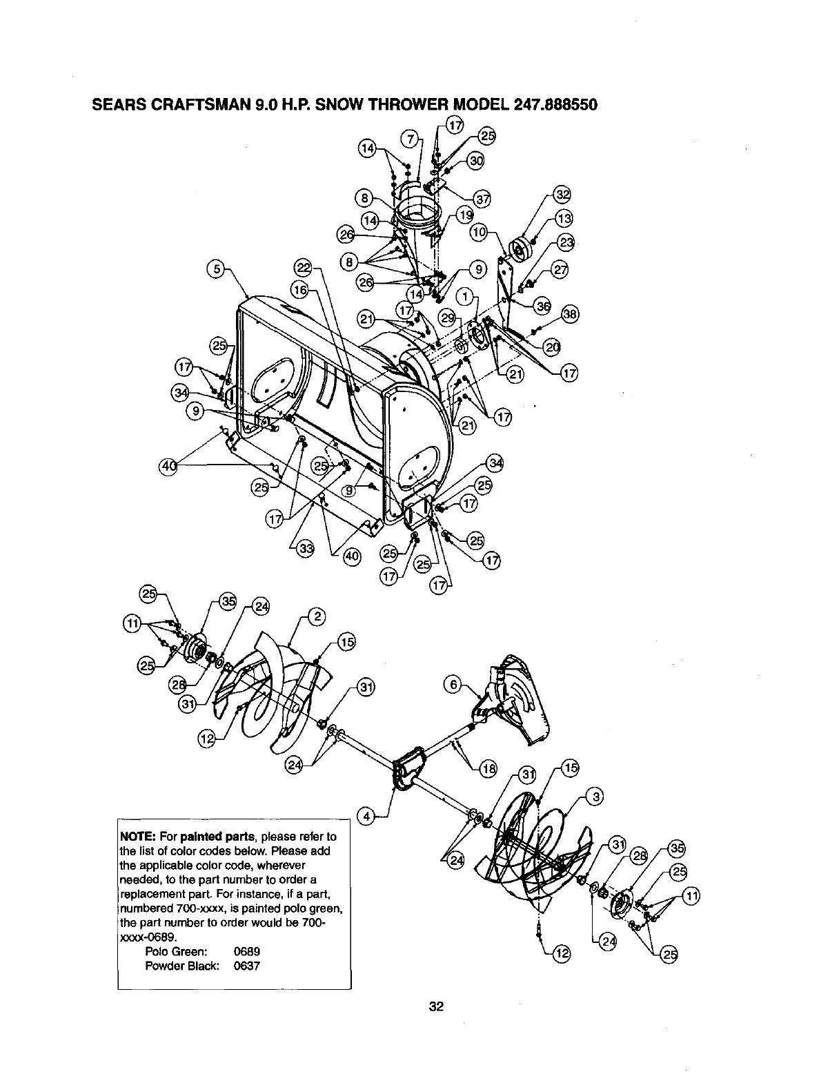
SEARS CRAFTSMAN 9.0 H.P. SNOW THROWER MODEL 247.888550
NOTE: For painted parts, please referto
the list of color codes below. Please add
the applicablecolor code, wherever
needed, to the part number to order a
replacement part. For instance, ifa part,
numbered 700-xxxx, is painted polo green,
the part number toorder would be 700-
xxxx-068g.
Polo Green: 0689
Powder Black: 0637
32
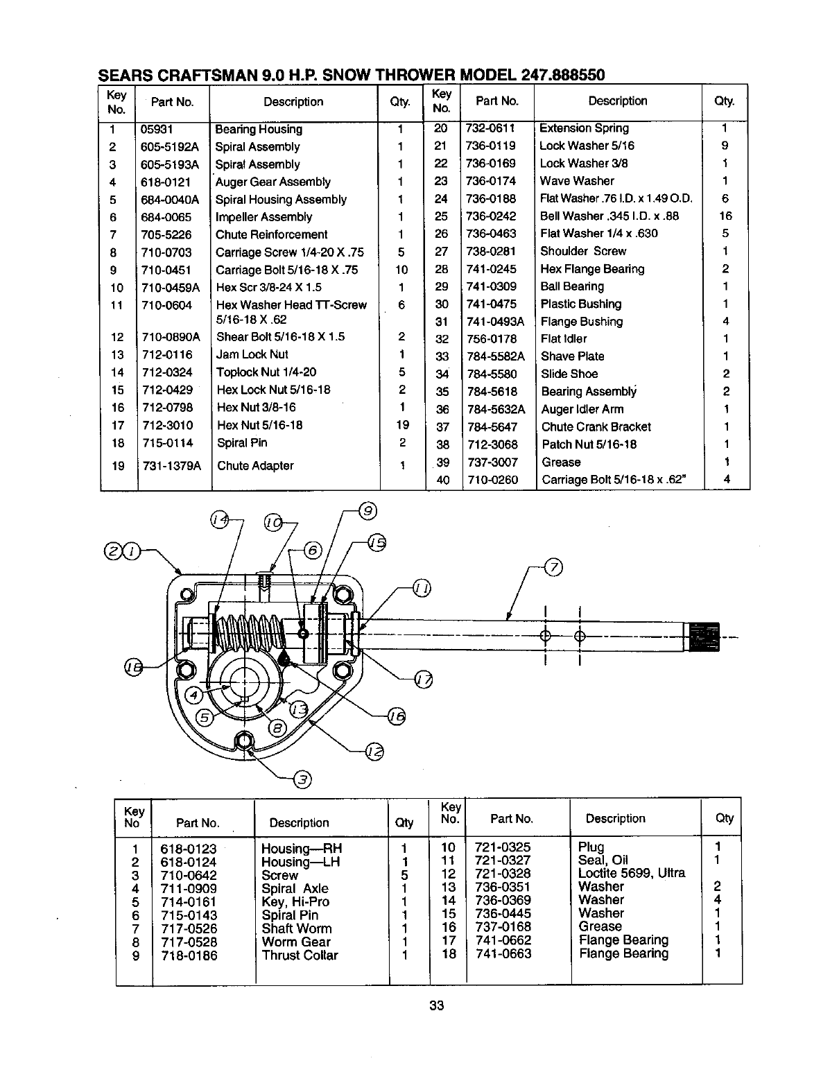
SEARS CRAFTSMAN 9.0 H.R SNOW THROWER MODEL 247.888550
Key Pad No.
No.
1 05931
2 605-5192A
3 605-5193A
4 618-0121
5684-0040A
6 684-0065
7 705-5226
8 710-0703
9 710-0451
10 710-0459A
It 710-0604
12
13
14
15
16
17
18
19
710-0890A
712-0116
712-0324
712-0429
712-0798
712-3010
715-0114
731-1379A
Key Part No.
Description Qty. No.
Bearing Housing 1 20 732-0611
SpiralAssembly 1 21 736-0119
SpiralAssembly 1 22 736-0169
Auger Gear Assembly 1 23 736-0174
Spiral HousingAssembly t 24 736-0188
Impeller Assembly 1 25 736-0242
Chute Reinforcement 1 26 736-0463
Carriage Screw I/4-20 X ,75 5 27 738-0281
Carriage Bolt 5/16-18 X .75 10 28 741-0245
Hex Scr 3/8-24 X 1,5 1 29 741-0309
Hex Washer Head 1-r-Screw 6 30 741-0475
5/16-18 X .62 31 741-0493A
Shear Bolt5/16-18 X 1.5 2 32 756-0178
Jam Lock Nut 1 33 784-5582A
Toptock Nut 1/4-20 5 34 784-5580
Hex Lock Nut 5116-18 2 35 784-5618
Hex Nut 3/8-16 1 36 784-5632A
Hex Nut 5/16-18 19 37 784-5647
Spiral Pin 2 38 712-3068
Chute Adapter 139 737-3007
40 710-0260
Description Qty.
ExtensionSpdng 1
LockWasher 5/16 9
LookWasher 3/8 1
Wave Washer 1
FlatWasher.76 I.D. x 1,49O.D. 6
Bell Washer .345 I.D. x .88 16
Flat Washer 1/4 x .630 5
Shoulder Screw f
Hex Flange Beadeg 2
Ball Bearing 1
: Plastic Bushing 1
Flange Bushing 4
Flat Idler 1
Shave Plate 1
Slide Shoe 2
BearingAssembl,/ 2
Auger IdlerArm 1
Chute Crank Bracket 1
Patch Nut 5/16-18 1
Grease 1
Carriage Bolt 5/16-18 x .62" 4
Ii
I I
Key
NO
1
2
3
4
5
6
7
8
9
Part No.
618-0123
618-0124
710-0642
711-0909
714-0161
715-0143
717-0526
717-0528
718-0186
Descdpfion
Housing---RH
Housing--LH
Screw
Spiral Axle
Key, Hi-Pro
Spiral Pin
Shaft Worm
IWorm Gear
Thrust Collar
aty
1
1
5
1
1
1
1
1
1
Key
No.
10
11
12
13
14
15
16
17
18
Part No,
721-0325
721-0327
721-0328
736-0351
736-0369
736-0445
737-0168
741-0662
741-0663
Descdption
Plug
Seal, Oil
Lo_ite 5699, Ultra
Washer
Washer
Washer
Grease
Flange Bearing
Flange Beadng
c_y
2
4
1
1
1
1
33
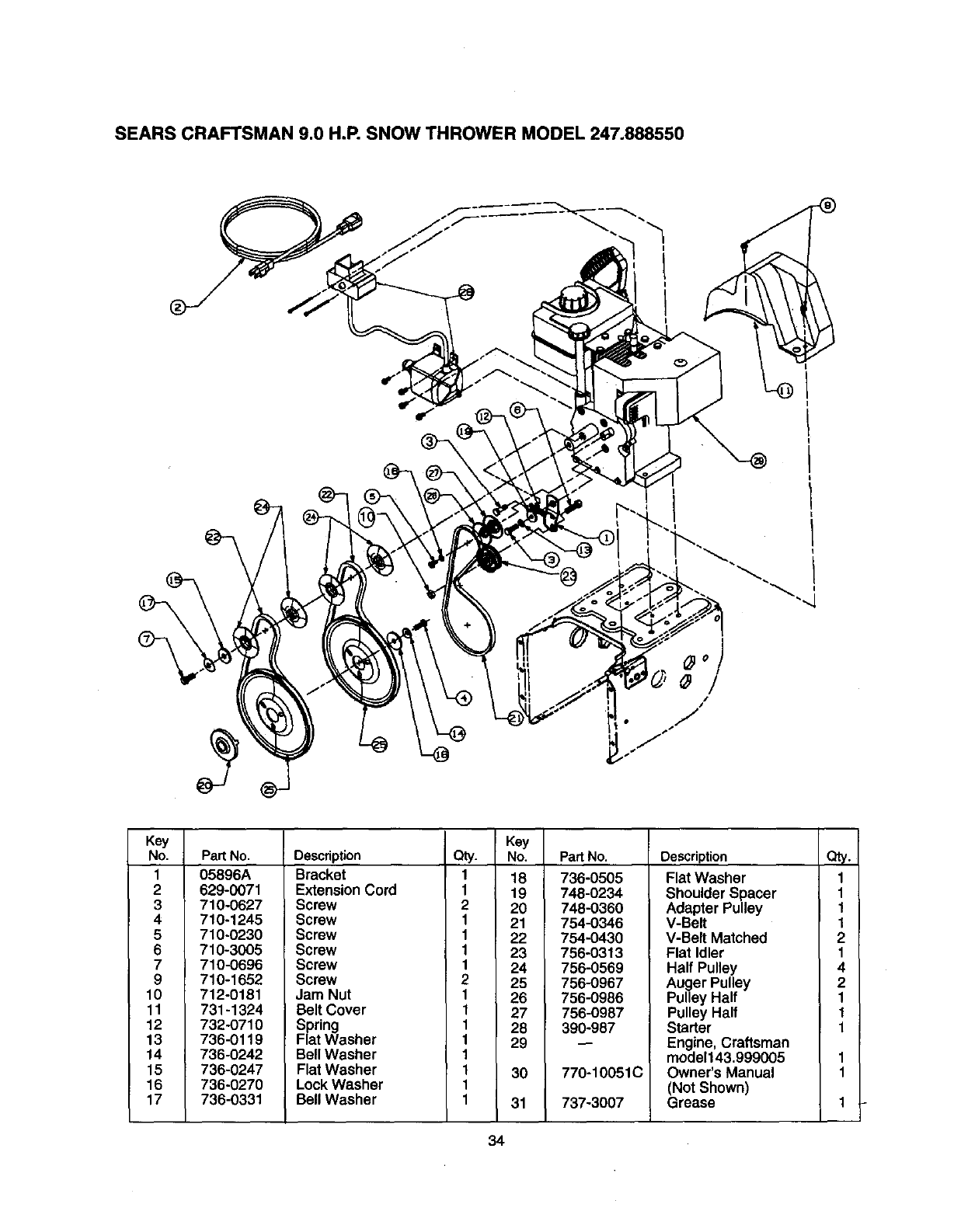
SEARS CRAFTSMAN 9.0 H.P. SNOW THROWER MODEL 247.888550
Key
No.
1
2
3
4
5
6
7
9
10
11
12
13
14
15
16
17
Pad No.
05896A
629-0071
710-0627
710-1245
710-0230
710-3005
710-0696
710-1652
712-0181
731-1324
732-0710
736-0119
736-0242
736-0247
736-0270
736-0331
Description
Bracket
ExtensionCord
Screw
Screw
Screw
Screw
Screw
Screw
Jam Nut
Belt Cover
Spring
Flat Washer
Bell Washer
Flat Washer
Lock Washer
Bell Washer
Key
Qty. No.
118
1 19
2 20
1 21
1 22
123
1 24
225
126
1 27
1 28
1 29
1
1 30
1
1 31
Pad No.
736-0505
748-0234
748-0360
754-0346
754-0430
756-0313
756-0569
756-0967
756-0986
756-0987
390-987
770-10051C
737-3007
Description
Flat Washer
Shoulder Spacer
Adapter Pulley
V-Belt
V-Belt Matched
Flat Idler
Half Pulley
Auger Pulley
Pulley Half
Pulley Half
Starter
Engine, Craftsman
model143,999005
Owner's Manual
(Not Shown)
Grease
Qt_,
1
1
1
1
2
1
4
2
1
1
1
34
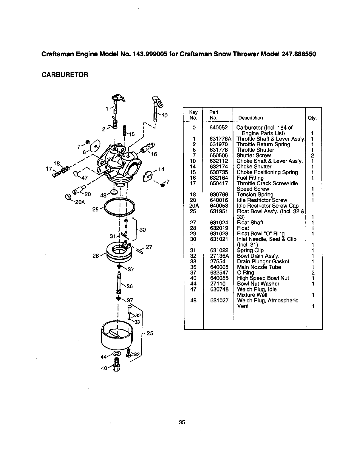
Craftsman Engine Model No. 143.999005 for Craftsman Snow Thrower Model 247.888550
CARBURETOR
20A
I
_P_37
"25
Key Part
No. No. Description Qty.
0 640052
1 631776A
2631970
6 631778
7650506
10 632112
14 632174
15 630735
16 632164
17 650417
18 630766
20 640016
20A 640053
25 631951
27 631024
28 632019
29 631028
30 631021
31
32
33
36
37
40
44
47
48
631022
27136A
27554
640005
632547
640055
27110
630748
631027
Carburetor (Incl. 184 of
Engine Parts List)
Throttle Shaft & Lever Ass'y
Throttle Return Spring
Throttle Shutter
Shutter Screw
Choke Shaft & Lever Ass'y.
Choke Shutter
Choke Positioning Spring
Fuel Fitting
Throttle Crack Screw/Idle
Speed Screw
Tension Spring
Idle Restrictor Screw
Idle RestrictorScrew Cap
Float Bowl Ass'y. (Incl. 32 &
33)
Float Shaft
Float
Float Bowl "O" Ring
Inlet Needle, Seat & Clip
(Incl. 31)
Spring Clip
Bowl Drain Ass'y.
Drain Plunger Gasket
Main Nozzle Tube
O Ring
High Speed Bowl Nut
Bowl Nut Washer
Welch Plug, Idle
Mixture Well
Welch Plug, Atmospheric
Vent
1
1
1
1
2
1
1
1
1
I
I
I
1
1
1
1
1
1
1
1
1
2
1
1
35
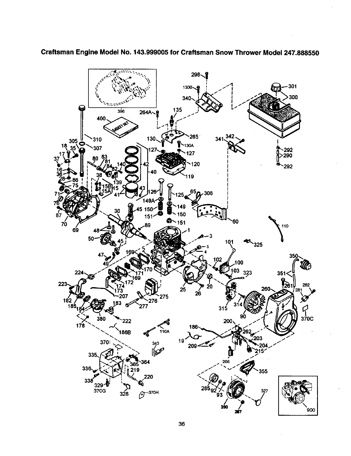
Craftsman Engine Model No. 143.999005 for Craftsman Snow Thrower Model 247.888550
305
18
87
70 69
224.
182
185.
!_120
,308
101
173 25 26
"275
315
200x
36
'q_325
323
9O
f
f
327
>300
282
370C
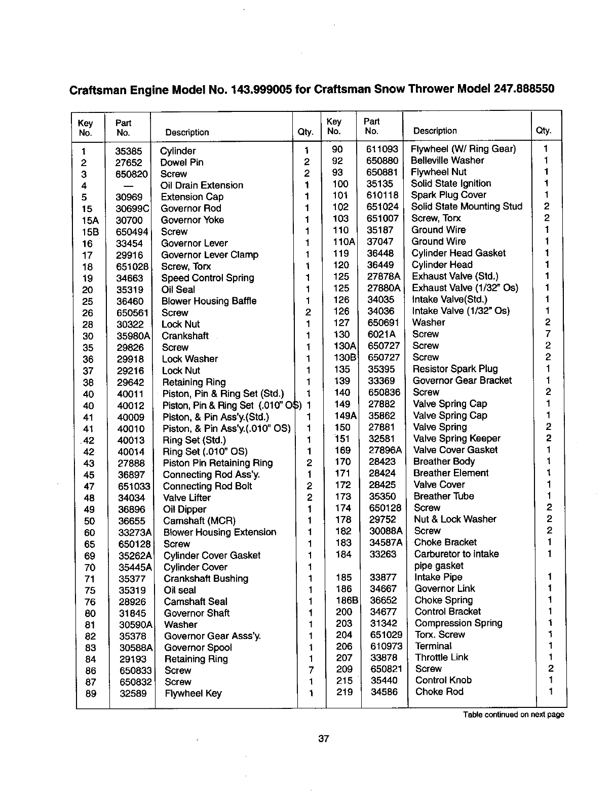
Craftsman Engine Model No. 143.999005 for Craftsman Snow Thrower Model 247.888550
Key
No.
1
2
3
4
5
15
15A
15B
16
17
18
19
20
25
26
28
30
35
36
37
38
40
40
41
41
42
42
43
45
47
48
49
50
60
65
69
70
71
75
76
80
81
82
83
84
86
87
89
Part
No.
35385
27652
650820
30969
30699C
30700
650494
33454
29916
651028
34663
35319
36460
650561
30322
35980A
29826
29918
29216
29642
40011
40012
40009
40010
40013
40014
27888
36897
651033
34034
36896
36655
33273A
650128
35262A
35445A
35377
35319
28926
31845
30590A
35378
30588A
29193
650833
650832_
32589
Description Qty.
Cylinder 1
Dowel Pin 2
Screw 2
Oil Drain Extension 1
Extension Cap 1
Governor Rod 1
Governor Yoke 1
Screw 1
Governor Lever 1
Governor Lever Clamp 1
Screw,Torx 1
Speed Control Spring 1
Oil Seal 1
Blower HousingBaffle 1
Screw 2
Lock Nut 1
Crankshaft 1
Screw 1
Lock Washer 1
Lock Nut 1
Retaining Ring 1
Piston, Pin & Ring Set (Std.) 1
Piston, Pin & RingSet (.010" O ;) 1
Piston, & Pin Ass'y.(Std.) 1
Piston, & Pin Ass'y.(.010" OS) 1
Ring Set (Std.) 1
Ring Set (.010" OS) 1
Piston Pin Retaining Ring 2
Connecting Rod Ass'y. 1
Connecting Rod Bolt 2
Valve Lifter 2
Oil Dipper 1
Camshaft (MCR) 1
BlowerHousing Extension 1
Screw 1
Cylinder Cover Gasket 1
Cylinder Cover 1
Crankshaft Bushing 1
Oil seal 1
Camshaft Seal 1
Governor Shaft 1
Washer 1
Governor Gear Asss'y. 1
Governor Spool 1
Retaining Ring 1
Screw 7
Screw 1
Flywheel Key 1
Key Part
No. No.
90 611093
92 650880
93 650881
100 35135
101 610118
102 651024
103 651007
110 35187
110A 37047
119 36448
120 36449
125 27878A
125 27880A
126 34035
126 34036
127 650691
130 6021A
130A 650727
130B 650727
135 35395
139 33369
140 650836
149 27882
149A 35862
150 27881
151 32581
169 27896A
170 28423
171 28424
172 28425
173 35350
174 6501281
178 29752
182 30088A
183 34587A
184 33263
185 33877
186 34667
186B 36652
200 34677
203 31342
204 651029
206 610973
207 33878
209 650821
215 35440
219 34586
Description Qty.
Flywheel (W/Ring Gear) 1
BellevilleWasher 1
Flywheel Nut 1
Solid State Ignition 1
Spark Plug Cover 1
Solid State Mounting Stud 2
Screw,Torx 2
Ground Wire 1
Ground Wire 1
Cylinder Head Gasket 1
Cylinder Head 1
Exhaust Valve (Std.) 1
Exhaust Valve (1/32" Os) 1
Intake Valve(Std.) 1
Intake Valve (1/32" Os) 1
Washer 2
Screw 7
Screw 2
Screw 2
Resistor Spark Plug 1
Governor Gear Bracket 1
Screw 2
Valve Spring Cap 1
Valve Spring Cap 1
Valve Spring 2
Valve Spring Keeper 2
Valve Cover Gasket 1
Breather Body 1
Breather Element 1
Valve Cover 1
Breather Tube 1
Screw 2
Nut & Lock Washer 2
Screw 2
Choke Bracket 1
Carburetor to intake 1
pipe gasket
Intake Pipe 1
Governor Link 1
Choke Spring 1
Control Bracket 1
Compression Spring 1
Torx. Screw 1
Terminal 1
Throttle Link 1
Screw 2
ControlKnob 1
Choke Rod 1
Table continued on next page
37
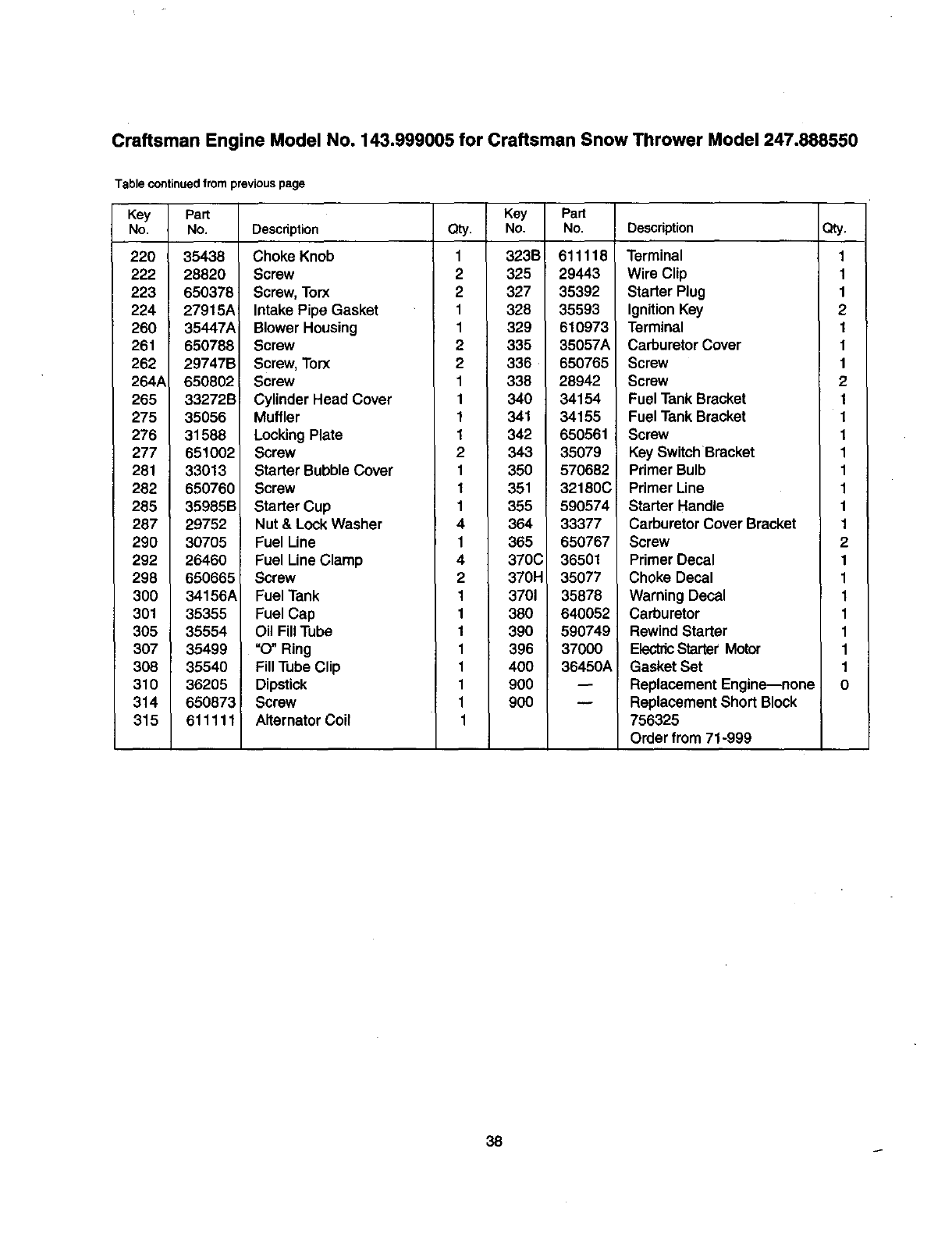
Craftsman Engine Model No. 143.999005 for Craftsman Snow Thrower Model 247.888550
Table continued from previous page
Key Part
No. No.
220 35438
222 28820
223 650378
224 27915A_
260 35447A
261 650788
262 29747B
264A 650802
265 33272B
275 35056
276 31588
277 651002
281 33013
282 650760
285 35985B
287 29752
290 30705
292 26460
298 650665
3OO 34156A
301 35355
305 35554
307 35499
308 35540
310 36205
314 650873
315 611111
Key
Description Qty. No.
Choke Knob 1 323B
Screw 2 325
Screw, Torx 2 327
Intake Pipe Gasket 1 328
BlowerHousing 1 329
Screw 2 335
Screw,Torx 2 336
Screw 1 338
CylinderHead Cover 1 340
Muffler 1 341
LockingPlate 1 342
Screw 2 343
Starter BubbleCover 1 350
Screw 1 351
Starter Cup 1 355
Nut & LockWasher 4 364
Fuel Line 1 365
Fuel Line Clamp 4 370C
Screw 2 370H
Fuel Tank 1 3701
Fuel Cap 1 360
Oil Fill Tube 1 390
=O" Ring 1 396
FillTube Clip 1 400
Dipstick 1 900
Screw 1900
Alternator Coil 1
Part
No.
611118
29443
35392
35593
610973
35057A
650765
28942
34154
34155
650561
35079
570682
32180C
590574
33377
650767
36501
35077
35878
640052
590749
37000
36450A
Description
Terminal
Wire Clip
Starter Plug
Ignition Key
Terminal
Carburetor Cover
Screw
Screw
Fuel Tank Bracket
Fuel Tank Bracket
Screw
Key Switch Bracket
Primer Bulb
Primer Line
Starter Handle
Carburetor Cover Bracket
Screw
Primer Decal
Choke Decal
Warning Decal
Carburetor
Rewind Starter
ElectricStarter Motor
Gasket Set
Replacement Engine--none
Replacement Short Block
756325
Order from 71-999
Qty,
1
1
1
2
1
1
1
2
1
1
1
1
1
1
1
1
2
1
1
1
1
1
1
1
0
38
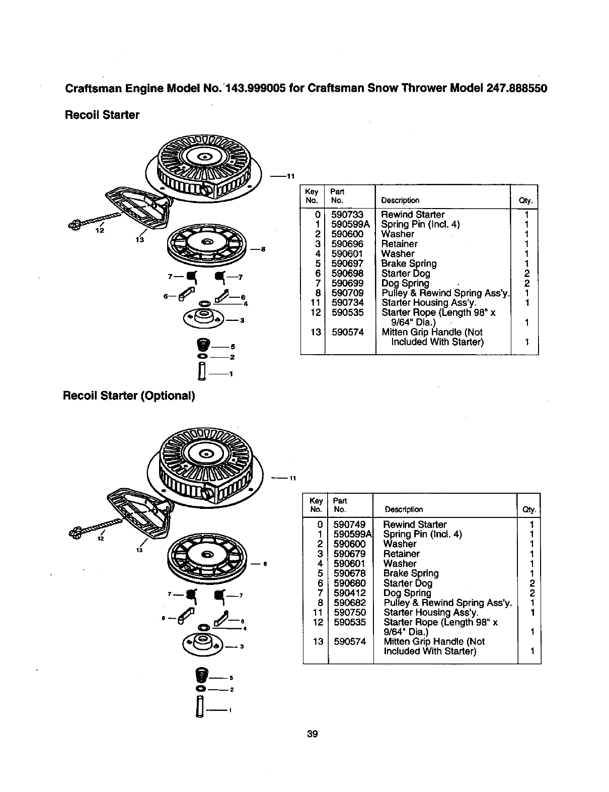
Craftsman Engine Model No. '143.999005 for Craftsman Snow Thrower Model 247.888550
Recoil Starter
12
13
_mS
Recoil Starter (Optional)
mll
Key Pa_
No. No.
0 590733
1 590599A
2 590600
3 590696
4 590601
5 590697
6 590698
7 590699
8 590709
11 590734
12 590535
13 590574
Description
Rewind Starter
Spring Pin (Incl. 4)
Washer
Retainer
Washer
Brake Spring
Starter Dog
Dog Spring
Pulley & Rewind SpringAss'y
Starter HousingAss'y.
Starter Rope (Length 98" x
9/64" Dia.)
Mitten Grip Handle (Not
IncludedWith Starter)
a_.
1
1
1
1
1
1
2
2
1
1
12
°,#-,
B--5
--11
Key , Part
No. No. Description
0
1
2
3
4
5
6
7
8
11
12 _
13
590749
590599A
590600
590679
590601
590678
590680
590412
590682
590750
590535
590574
Qty.
Rewind Starter 1
Spring Pin (Incl. 4) 1
Washer 1
Retainer 1
Washer 1
Brake Spring 1
Starter Dog 2
Dog Spring 2
Pulley & Rewind Spring Ass'y. 1
Starter Housing Ass'y. 1
Starter Rope (Length 98" x
9/64" Dia,) 1
Mitten Grip Handle (Not
IncludedWith Starter) 1
39

Comments Date
62
In U.S.A. or Canada
for in-home major brand repair service:
Call 24 hours a day, 7 days a week
1-800-4-MY-HOME sM(1-800-469-4663)
Para pedir servicio de reparaci6n a domiciliio m1-800-676-5811
Au Canada pour tout le service ou les pi_ces -- 1-800-469-4663
For the repair or replacement parts you need:
Call 6 a.m. -- 11 p.m. CST, 7 days aweek
PartsDirect sM
1-800-366-PART (1-800-366-7278)
Para ordenar piezas con entrega a domicillio m1-800-659-7084
For the location of a Sears Service Center in your area:
Call 24 hours a day, 7 days aweek
1-800-488-1222
To purchase or inquire about a Sears Maintenance Agreement:
Call 7 a.m. -- 5p.m. CST, Monday -- Saturday
1-800-827-6855
p,-
SEARS
HomeCentral""
