Craftsman 247889980 User Manual WIDE CUT MOWER Manuals And Guides L1001283
CRAFTSMAN Walk Behind Lawnmower, Gas Manual L1001283 CRAFTSMAN Walk Behind Lawnmower, Gas Owner's Manual, CRAFTSMAN Walk Behind Lawnmower, Gas installation guides
User Manual: Craftsman 247889980 247889980 CRAFTSMAN WIDE CUT MOWER - Manuals and Guides View the owners manual for your CRAFTSMAN WIDE CUT MOWER #247889980. Home:Lawn & Garden Parts:Craftsman Parts:Craftsman WIDE CUT MOWER Manual
Open the PDF directly: View PDF ![]() .
.
Page Count: 76

perator's
PROFESSIONAL
33-inch Wide Cut Mower
Model No. 247.889980
For answers to your questions about this product,
call 1-800-4MY=HOME.
CAUTION: Before using this
product, read this manual and
follow all safety rules and operating
instructions.
, SAFETY
ASSEMBLY
OPERATION
MAINTENANCE
PARTS LIST
ESPANOL R 48
Sears, Roebuck and Co., Hoffman Estates, IL 60179, U.S.A.
Visit our website: www.sears.com/craftsman FormNo.769-04684A
(December21,2009)

Warranty Statement .......................................................... 2
Safety Instructions ............................................................ 3
Slope Guide ....................................................................... 5
Safety Labels .................................................................... 6
Assembly ........................................................................... 8
Know your Lawn Mower .................................................. 11
Operation ........................................................................ 14
Service and Maintenance .............................................. 16
Off-Season Storage ........................................................ 26
Accessories and Attachments ........................................ 26
Troubleshooting .............................................................. 27
Parts List ......................................................................... 28
Espa_ol ............................................................................ 48
Service Numbers ............................................. Back Cover
CRAFTSMAN PROFESSIONAL FULL WARRANTY
Whenoperatedand maintainedaccordingto allsuppliedinstructions,if this CraftsmanProfessionalproductfailsdueto a defectin materialor
workmanshipwithintwoyearsfromthedateor purchase,call 1-800-4-MY-HOME®to arrangefor free repair(orreplacementif repairproves
impossible).
Thiswarrantyappliesfor onlyone yearfromthe dateof purchaseif this productis everusedfor commercialor rentalpurposes.
ThiswarrantycoversONLYdefectsin materialandworkmanship.Searswill NOTpayfor:
• Expendableitemsthatbecomewornduringnormaluse,includingbutnot limitedto blades,sparkplugs,aircleaners,belts,andoil filters.
Standardmaintenanceservicing,oilchanges,or tune-ups.
Tire replacementor repaircausedby puncturesfromoutsideobjects,suchas nails,thorns,stumps,or glass.
Tireor wheelreplacementor repairresultingfromnormalwear,accident,orimproperoperationor maintenance.
Repairsnecessarybecauseof operatorabuse,includingbutnot limitedto damagecausedby impactingobjectsthat bendthe frameor
crankshaft,orover-speedingtheengine.
Repairsnecessarybecauseof operatornegligence,includingbut not limitedto,electricalandmechanicaldamagecausedby improper
storage,failureto usethe propergradeandamountof engineoil, failureto keepthe deckclearof flammabledebris,orfailureto maintainthe
equipmentaccordingto the instructionscontainedinthe operator'smanual.
Engine(fuelsystem)cleaningor repairscausedbyfuel determinedto becontaminatedoroxidized(stale).In general,fuel shouldbeused
within30 daysof itspurchasedate.
Normaldeteriorationandwearof the exteriorfinishes,or productlabelreplacement.
Thiswarrantyappliesonly whilethisproductis withinthe UnitedStates.
Thiswarrantygivesyou specificlegalrights,andyou mayalso haveotherrightswhichvaryfromstateto state.
Sears, Roebuck and Co., Noffman Estates, IL 60179
GrossHP: 12.5
EngineOil: SAE30
Fuel: UnleadedGasoline
SparkPlug: Champion®RC12YC
Engine: Briggs& StrattonPowerBuiltTM
Model Number
Serial Number
Dateof Purchase
Recordthe modelnumber,serialnumber,
anddateof purchaseabove.
© SearsBrands,LLC 2

__IL his symbolpointsout importantsafetyinstructions
which,ifnot followed,couldendangerthe personal
safetyand/or propertyof yourselfandothers.Read
andfollowall instructionsinthismanualbefore
attemptingto operatethismachine.Failureto complywiththese
instructionsmayresultinpersonalinjury.Whenyou seethissymbol,
HEEDITSWARNING!
Your Responsibility: Restrictthe useof this powermachineto
personswhoread,understand,andfollowthe warningsand instruc-
tionsinthis manualandonthe machine.
Thismachinewasbuiltto beoperatedaccordingto the rulesfor
safeoperationinthis manual.As withanytypeof powerequipment,
carelessnessorerroronthe partof the operatorcan resultin serious
injury.Thismachineis capableof amputatinghandsandfeetand
throwingobjects.Failureto observethefollowingsafetyinstructions
could resultin seriousinjury ordeath.
__ate of Californiato I
causecancerandbirthdefectsor otherreproductiveharm.
CHILDREN
Tragicaccidentscanoccur ifoperatorisnotalert to presenceof children.Chil-
drenareoftenattractedto mowerandmowingactivity.Theydo notunderstand
thedangers.Neverassumethat childrenwillremainwhereyoulastsawthem.
,, Keepchildrenoutof the mowingareaand underwatchfulcare of a
responsibleadult otherthanthe operator.
,, Be alert andturnmoweroff if a child entersthe area.
,, Beforeandwhile movingbackwards,look behindanddownfor small
children.
,, Useextremecare whenapproachingblindcorners,doorways,shrubs,
trees,orotherobjectsthat mayobscureyourvisionof a childwho may
run intothemower.
,, Keepchildrenawayfrom hotor runningengines.Theycan sufferburns
froma hot muffler.
,, Neverallow childrenunder 14yearsold to operatea power mower.
Children14years oldand overshouldreadand understandoperation
instructionsand safetyrulesin this manualand shouldbetrainedand
supervisedbya parent.
GENERAL OPERATION
,, Readthis operator'smanualcarefullyin itsentirety beforeattempting
to assemblethis machine.Read,understand,andfollow all instructions
onthe machineand inthe manual(s)beforeoperation.Be completely
familiarwiththe controlsand the properuse ofthis machinebefore
operatingit. Keepthis manualin a safeplaceforfuture andregular
referenceand for orderingreplacementparts.
,, Thismachineisa precisionpieceof powerequipment,not a plaything.
Therefore,exerciseextremecautionat all times.Yourunithas been
designedto performonejob: to mowgrass.Do notuseitfor anyother
purpose.
,, Neverallow childrenunder 14yearsold to operatethis machine.
Children14years oldand overshouldreadand understandthe instruc-
tionsinthis manualand shouldbetrainedandsupervisedby a parent.
Onlyresponsibleindividualswho arefamiliarwiththese rulesof safe
operationshouldbe allowedto usethis machine.
,, Thoroughlyinspectthe areawherethe equipmentis to beused.Remove
allstones,sticks,wire,bones,toysand otherforeignobjectswhichcould
betrippedoveror pickedupand thrownbythe blade.Thrownobjects
cancauseseriouspersonalinjury.Planyourmowingpatternto avoid
dischargeof materialtowardroads,sidewalks,bystandersandthe like.
Also,avoiddischargingmaterialagainsta wallorobstructionwhich may
causedischargedmaterialto ricochetbacktowardthe operator.
,, To helpavoid bladecontactor a thrownobject injury,stay in operator
zone behindhandlesand keepchildren,bystanders,helpers,and petsat
least75feet frommowerwhile itis inoperation.Stopmachineifanyone
entersarea.
,, Alwayswearsafetyglassesor safetygogglesduringoperationand while
performingan adjustmentor repairto protectyoureyes.Thrownobjects
which ricochetcan causeserious injuryto theeyes.
,, Wearsturdy,rough-soledwork shoesandclose-fittingslacksandshirts.
Shirts and pantsthat coverthe armsand legsandsteel-toedshoes
are recommended.Neveroperatethis machinein barefeet, sandals,
slipperyor light weight(e.g.canvas) shoes.
,, Donot puthandsor feetnearrotatingpartsor undercutting deck.
Contactwith bladecanamputatehandsandfeet.
,, A missingor damageddischargecover can causebladecontactor
thrownobjectinjuries.
,, Manyinjuriesoccur as a resultof the mowerbeingpulledoverthefoot
duringa fall causedby slippingor tripping.Do notholdon to the mowerif
youare falling;releasethe handleimmediately.
,, Neverpull the mowerbacktowardyouwhileyou arewalking.If youmust
backthe mowerawayfroma wall or obstructionfirst look downand
behindto avoidtrippingandthenfollow thesesteps:
a. Step backfrom mowerto fully extendyourarms.
b.Besureyouare wellbalancedwithsure footing.
c. Pull backslowly,nomorethan halfwaytowardsyou.
d. Repeatthese stepsas needed.
,, Donotoperatethe mowerwhile underthe influenceof alcoholordrugs.
,, Donotengagethe self-propelledmechanismon unitsso equippedwhile
startingengine.
,, The blade controlhandleis a safety device.Neverattemptto bypassits
operation.Doingso makesthe safetydeviceinoperativeand mayresult
inpersonalinjurythroughcontactwiththe rotatingblade.The blade
controlhandlemustoperateeasily inboth directionsand automatically
returnto the disengagedpositionwhen released.
,, Neveroperatethe mowerin wet grass.Alwaysbesureof yourfooting. A
slip andfall cancauseseriouspersonalinjury.If you feelyouare losing
yourfooting, releasethe bladecontrolhandleimmediatelyandthe blade
will stoprotatingwithinthreeseconds.
,, Mowonly in daylightor good artificiallight. Walk,neverrun.
,, Stopthe bladewhencrossing graveldrives,walksorroads.
3

• If theequipmentshould startto vibrateabnormally,stoptheengineand
checkimmediatelyfor the cause.Vibrationis generallya warningof
trouble.
• Shutthe engineoff andwait untilthe bladecomesto a completestop
beforeremovingthe grass catcheror uncloggingthe chute.
The cuttingblade continuesto rotatefor a fewseconds afterthe engine
isshut off.Neverplaceany partof the bodyinthe bladearea untilyou
aresure the bladehasstoppedrotating.
• Neveroperatemowerwithoutpropertrailshield,dischargecover,grass
catcher,bladecontrolhandle,orothersafety protectivedevicesin place
andworking.Neveroperatemowerwithdamagedsafetydevices.Failure
to do so can resultin personalinjury.
• Mufflerandenginebecomehotand can causea burn.Do nottouch.
• Only usepartsand accessoriesmadefor this machineby manufacturer.
Failureto doso can result in personalinjury. Forrecommendedacces-
sories,call 1-800-659-5917.
• If situationsoccurwhich are notcoveredinthis manual,use careand
goodjudgment.ContactyourSearsServiceCenterfor assistance.
SLOPE OPERATION
Slopesare a majorfactorrelatedto slipandfall accidentswhichcanresultin
severeinjury.Operationon slopesrequiresextracaution.Ifyoufeeluneasyon
a slope,do notmow it.Foryoursafety,usethe slopeguideincludedas partof
thismanualto measureslopesbeforeoperatingthis unitona slopedor hilly
area.If theslopeis greaterthan 15degrees,do notmowit.
Do:
• Mowacrossthefaceof slopes; neverupanddown. Exerciseextreme
cautionwhenchangingdirectionon slopes.
• Watchfor holes,ruts,rocks, hiddenobjects,or bumpswhich cancause
youto slipor trip.Tall grasscan hideobstacles.
• Alwaysbe sureof your footing.A slip andfall can causeseriouspersonal
injury.If you feelyouare losingyour balance,releasethe bladecontrol
handleimmediately,andthe bladewill stoprotatingwithin3 seconds.
Do Not:
• Do notmowneardrop-offs,ditchesorembankments,whereyoucould
lose yourfootingor balance.
• Do notmow slopesgreaterthan 15degreesasshownonthe
slopegauge.
• Do notmowonwetgrass. Unstablefootingcouldcauseslipping.
SERVICE
Safe Handling Of Gasoline:
•Toavoidpersonalinjuryor propertydamageuseextreme care in
handlinggasoline.Gasolineis extremelyflammableandthevaporsare
explosive.Seriouspersonalinjurycanoccurwhengasolineis spilledon
yourselfor yourclotheswhichcan ignite.
• Washyourskin andchangeclothesimmediately.
• Useonly an approvedgasolinecontainer.
• Neverfill containersinsidea vehicle oron a truckor trailerbedwith a
plastic liner.Alwaysplacecontainersonthe groundawayfromyour
vehiclebeforefilling.
• Removegas-poweredequipmentfromthetruck ortrailerand refueliton
theground.If this isnot possible,then refuelsuchequipmentona trailer
witha portablecontainer,ratherthan froma gasolinedispensernozzle.
• Keepthe nozzlein contactwiththe rimofthefuel tank or container
openingat alltimesuntil fueling is complete.Donot usea nozzle
lock-opendevice.
• Extinguishallcigarettes,cigars, pipesand othersources
of ignition.
• Neverfuel machineindoorsbecauseflammablevaporswillaccumulate
inthe area.
• Neverremovegascapor addfuelwhile engineis hotor running.
Allowengineto cool at least two minutesbeforerefueling.
• Neveroverfill fuel tank.Fill tanktono morethan V2inch belowbottom
of filler neckto provideforfuel expansion.
• Replacegasolinecapandtightensecurely.
• If gasolineis spilled,wipe it offthe engineand equipment.Moveunit
to anotherarea.Wait 5 minutesbeforestarting engine.
• Neverstorethe machineorfuelcontainer nearan openflame,spark
or pilot light ason a waterheater,spaceheater,furnace,clothesdryer,
or othergasappliances.
• To reducefire hazard,keepmowerfree of grass, leaves,or other
debrisbuild-up.Cleanup oilor fuelspillageandremoveanyfuel
soakeddebris.
• Allowa mowerto cool at least5 minutesbeforestoring.
General Service:
• Neverrun an engineindoorsorin a poorlyventilatedarea.Engine
exhaustcontainscarbon monoxide,anodorlessand deadlygas.
• Beforecleaning,repairing,or inspecting,makecertainthe bladeand
all movingparts havestopped.Disconnectthe sparkplugwire and
ground againsttheengineto preventunintendedstarting.
• Checkthe bladeand engine mountingboltsat frequentintervalsfor
propertightness.Also, visuallyinspectbladefor damage(e.g.,bent,
cracked,worn)Replacebladewith theoriginalequipmentmanufac-
ture's(O.E.M.)bladeonly,listedin this manual.Use of partswhichdo
notmeetthe originalequipmentspecificationsmaylead to improper
performanceandcompromisesafety!
• Mowerbladesare sharpand can cut.Wrapthe bladeor weargloves,
and useextra cautionwhenservicingthem.
• Keepallnuts, bolts,andscrewstightto besurethe equipmentis in
safeworkingcondition.
• Nevertamperwith safetydevices.Checktheir proper
operationregularly.
• Afterstrikinga foreignobject, stoptheengine,disconnectthe spark
plugwire and groundagainstthe engine.Thoroughlyinspectthe
mowerfor anydamage.Repairthe damagebeforestartingand
operatingthe mower.
• Neverattemptto makea wheelor cutting heightadjustmentwhilethe
engineisrunning.
• Grasscatchercomponents,dischargecover,andtrailshieldare
subjectto wear anddamagewhichcould exposemovingparts or
allowobjectsto bethrown.Forsafetyprotection,frequentlycheck
componentsand replaceimmediatelywithoriginalequipment
manufacturer's(O.E.M.)parts only,listedin this manual.Use ofparts
which donotmeettheoriginal equipmentspecificationsmayleadto
improperperformanceand compromisesafety!
• Donotchangetheenginegovernorsetting oroverspeedthe engine.
The governorcontrolsthe maximumsafeoperatingspeed of the
engine.
• Maintainor replacesafetylabels,as necessary.
• Observeproperdisposallawsand regulations.Improperdisposalof
fluids and materialscan harmtheenvironment.
4

Usethispageas a guideto determineslopeswhereyoumaynot operatesafely.Donot operate the lawnmoweron suchslopes.
!
l
I
I
!
!
!
Thissymbolpointsoutimportantsafetyinstructionswhich,ifnot followed,could endangerthe personalsafetyand/or propertyof yourselfand
others.Readandfollowallinstructionsinthis manualbeforeattemptingto operatethis machine.Failureto complywiththeseinstructionsmay
resultinpersonalinjury.Whenyou seethissymbol,HEEDITSWARNING!

WARNING
This symbol pointsout importantsafety instructions
which, if not followed, could endanger the personal
safetyand/or property of yourself and others.Read and
follow all instructionsin this manual before attempting
to operatethis machine. Failureto comply with these
instructions may result in personal injury.When you see
thissymbol HEED ITS WARNING!
Your Responsibility
Restrictthe use of this power machineto persons who
read, understand,and followthe warnings and instruc-
tions in this manualand on the machine.
6

Thispageleftintentionallyblank.
7

IMPORTANT:Thisunitis shippedwithoilin the engine.After
assembly,see page12for fuelandoil details.
IMPORTANT:Referenceto rightor leftside of the moweris observed
fromthe operatingposition.
Disconnectthe sparkplugwire andgroundit againstthe engineto
preventunintendedstarting.
LOOSE PARTS IN CARTON
Thefollowingitemsare packagedina bag:
Operator'sManual,Oildrainhose,Waterhosecoupler,EngineManual
TOOLS NEEDED FOR ASSEMBLY
A setof adjustablewrenchesandtiregauge
MOWER SET-UP
Shipping Brace Removal
Makesurethe lawnmower'sengineis off. Removetheignitionkey
beforeremovingthe shippingbrace.
1. Locatethe shippingbrace,if present,foundon the rightside of
thecuttingdeck. SeeFigure1.
.
Figure1
Whileholdingthe dischargechutewithyour lefthand,removethe
shippingbracewithyourright handby graspingit betweenyour
thumbandindexfingerandrotatingit clockwise.
Attaching the Battery Cables
NOTE: The positivebatteryterminalis markedPos.(+).The negative
batteryterminalis markedNeg.(-).
The positivecable (heavyredwire)is securedto the positivebattery
terminal(+)witha hex boltandhex nutat thefactory.
The negativecable(heavyblackwire) maybe securedto the negative
batteryterminalat the factory.If it hasn'tbeenattached,proceedas
follows:
.
f
Removethe carriagebolt andhexnut fromthe positivecable
(heavyredwire).
Removethe redplasticcover,if present,fromthe positivebattery
terminalandattachthe positivecableto the positivebattery
terminal(+)withthe bolt andhexnut.See Figure2.
Figure2
3. Removethe carriagebolt andhexnut fromthe negativecable
(heavyblackwirel
4. Removethe blackplasticcover,if present,fromthe negativebat-
tery terminalandattachthe negativecableto the negativebattery
terminal(-) withthe boltand hexnut.SeeFigure2.
5. Makecertainthe hold-downrodis in positionoverthe battery,
securingit inplaceandmakecertainthatthe redrubberbootcov-
ers the positivebatteryterminalto helpprotectit fromcorrosion.
NOTE: Ifthe batteryis putinto serviceafterthe dateshown
on top/sidedbattery,chargethe batteryas instructedinthe
Maintenancesectionof thismanualpriorto operatingthe mower.
Theshippingbraceis usedfor packagingpurposesonly.Remove
anddiscardthe shippingbracebeforeoperatingyourlawnmower.
Themowingdeckis capableof throwingobjects.Failureto operate
I the mowerwithoutthedischargecoverin the properoperatingposi-
ltion could resultin seriouspersonalinjuryand/or propertydamage.
8

Unfolding the Handle
1. Removethestar knobsandcarriagescrewsfromthelower
handle.SeeFigure3.
.
Figure3
Pivotthe upperhandleintooperatingposition.Becarefulnotto
crimpcables.SeeFigure4.
Figure4
3. Reinstallthe carriagescrewsandknobsremovedearlier.
4. Tightenthe upperandlowerstarknobsandcarriagescrewsto
securethe upperhandleto the lowerhandle,See Figure4.
5. Thehandleheightcan beadjustedto anyof three positions.
For instructions,referto HandleHeightin the Maintenanceand
Adjustmentssectionof this manual.
Attaching the Shift Lever
1. Removethe screwandthe locknutthatsecuresthe shift leverto
the shift leverplate.SeeFigure5.
f
Figure5
2. Removethe remainingscrewandnut fromthe lowershiftlever
plate.SeeFigure5.
3. Positionthe uppershift leverintoa verticalpositionaligningthe
holesinthe leverwith the holesinthe shift plate.SeeFigure6.
f
..t'
Figure6
Securethe leverto the plateusingthe two screwsandtwo nuts
removedearlier.SeeFigure6.
9

Checking Tire Pressure
Maximumtire pressureunderany circumstancesis30 psi.Equaltire
pressureshouldbemaintainedat alltimes.
The reartiresonyour unitmaybeover-inflatedfor shippingpurposes.
Reducethe tire pressurebeforeoperatingthe mower.Recommended
operatingtire pressureis approximately20 p.s.i.Checkthe sidewallof
tirefor maximump.s.i.
Gas and Oil
Thefuel tankhasa capacityof twogallons.Removethe fuelcap by
turningit counterclockwise.Useonly clean,fresh(nomorethan30
daysold), unleadedgasoline.Fillthe tankno higherthanfour inches
belowthetop of the filler neckto allow spaceforfuel expansion.
Useextremecarewhenhandlinggasoline.Gasolineis extremely
flammableandthe vaporsareexplosive.Neverfuel the machine
indoorsor whilethe engineis hot or running.Extinguishcigarettes,
cigars,pipes andother sourcesof ignition.
NOTE:Yourlawnmoweris shippedwithoil inthe engine.However,
you MUSTchecktheoil levelbeforeoperating.Referto the Service
andMaintenanceSectionfor CheckOil instructions.
Alwayschecktheengineoil levelbeforeeachuse.Addoilas neces-
sary.Failureto do so mayresultinseriousdamageto yourengine.
10

Deck Height
Lever ===='_
Fuel Tank Ca
ignition Switch
Systems indicator Monitor
Drive Control
Gear Shift Lever
Figure7
f
oil
Dipstick
Air
-- Cleaner
Handle
_,, J
Figure8
ENGINE CONTROLS
Referto Figure8for locationsof the enginecontrols.
Oil Drain Valve
Usetheoil drainvalveto drainoilfromthe engine.Referto the
Maintenancesectionfor instructions.
Air Cleaner Handle
Theair cleanerhandleis usedto gainaccessto the aircleaner.The air
cleanercartridgecan be removedandcleanedor replaced.Referto
the Maintenancesectionfor details.
Spark Plug
Referto the Maintenancesectionfor instructionsonsparkplug
replacement.
Oil Cap/Dipstick
Referto the Maintenancesectionfor instructionsoncheckingthe oil.
MOWER CONTROLS
Referto Figure7 for locationsof the mowercontrols.
Throttle/Choke Control
NOTE:Whenoperatingthe mowerwiththe
cuttingdeckengaged,becertainthatthe
throttle/chokecontrolis in the fast position.
THEthrottle/chokecontrolis usedto adjust
enginespeeds,to activatethe enginechoke
andto stopthe engine.Alwaysrunengine
withthe throttle/chokecontrolleverinthe
fast positionfor bestmowerperformance.
CHOKE:Usewhenstartinga cold engine.
FAST:Useduringmoweroperation.
SLOW:Usewhenidlingengine.
STOP:Stopsthe engine.
REFERto StartingThe Engineinthe
Operationsectionof thismanualfor detailed
startinginstructions.
Choke==_
Fast
Slow ==_
Stop
11

Deck Height Lever
Usethisleverto adjustthe mowingdeck'scuttingheight.To use,move
the leverto the left, then placetheleverin the notchbestsuitedfor
yourapplication.
ignition Switch
Neverleavea runningmachineunattended.Alwaysdisengage
blades,stopengineandremovekeyto preventunintendedstarting.
Drive Control
The drivecontrolis usedto engageand
disengagedriveto the wheels.Toengage
this control,squeezethe drivecontrol
againstthe handlebargrip.To stopthe drive,
releasethedrive control.
f
@
The four-position switch is used to start and stop the engine on
electric-start models, To start the engine, insert the key into the
switch and turn clockwise to the START (;_
ignition position,
Release key into the RUN _ position<,:_once the engine has started,
Move the key into the RUN/LIGHT _)_ position to run the mower
to'STOP
with the headlight on, Turn the key 0 to stop the engine,
See Figure 9,
Run/Light
Stop 1
Position _ Run
Figure9
Nevermovethe keyintothe Startpositionwhile the engineis running;
doingso maycausedamageto the engine'sstarter.
Alwaysreleasethedrivecontrolbeforechangingspeeds.Failureto
do so mayresultin seriousdamageto yourtransmission.
Blade Control
Locatedonthe right-handhandle,the blade
controlis usedto engagethe mowingdeck.
Tooperate,pressand holdthe leveragainst
the handlebargrip.To stopthe blades,
releasethe bladecontrol.
,ik
@
Neverattemptto start theenginewiththe bladecontrolengaged.
Alwaysreleasethe bladecontrolwhenstartingthe engine.Failureto
do somayresultinprematurewearto yourengine'selectricstarter.
12

GEAR SHIFT LEVER
Usethisleverto selectanyof four forwardgroundspeeds,neutral,or
reverse.
Forward
Fourforwardspeedsareavailable.Positionone (1)is the slowestand
positionfour(4) is thefastest.
Reverse
Toselectreverse,putthe leverin the Reverse(R) position.
SYSTEMS INDICATOR MONITOR/HOUR METER
jf
BATTERY
42.0
/// HOURS 1/10 \\\
jJ
j j/
Figure10
Lookbehindthe mowerbeforeandduringreverseoperation.Stopthe
mowerbladesbeforeoperatingin reverse.
Neutral
Placethe leverinneutral(N) beforestartingthe mowerandwhenthe
moweris not inuse.In addition,the mowercan be manuallypushed
orpulledby placingthe gearshiftleverinto N (neutral)positionand
pressingthe drivecontrolagainstthe handlebargrip.
Alwaysreleasethe drivecontrolbeforechangingspeeds.Failureto
doso mayresultin seriousdamageto yourtransmission.
LCD
Whenthe ignitionkeyis rotatedout of the STOPpositionbut not
intothe STARTposition,the systemsindicatormonitordisplaysthe
battery'soutput,involts,onits LCDfor approximatelyfiveseconds,
afterwhichit displaysan hourglassandthe hoursof moweroperation.
Oncethe engineis started,the monitorcontinuallydisplaysan hour
glassandthe hoursof moweroperationon its LCD.SeeFigure10.
NOTE:Hoursof moweroperationarerecordedanytimethe ignition
keyis rotatedout of the STOP_i _position,regardlessof whetherthe
engineis started.
The IndicatorMonitorwill also remindthe operatorof maintenance
intervalsfor changingthe engineoil. The LCDwill alternatelyflashthe
recordedhours,"CHG"and"OIL' forfive minutes,afterevery50 hours
of recordedoperationelapse.The maintenanceintervallastsfor two
hours(from50-52, 100-102,150-152,etc.).The LeD willalso flash
as describedabovefor fiveminuteseverytimethe mower'sengine
hasbeenstartedduringthismaintenanceinterval.Beforethe interval
expires,changetheengineoilas instructedinthe Maintenancesection
of this Operator'sManual.
Battery
Itis normalfor the Batterylightto illuminatewhilethe engineis
crankingduringstart-up,but if it illuminatesduringoperation,whilethe
engineis running,the batteryis in needof a chargeor the engine's
chargingsystemis not generatingsufficientamperage.Chargethe
batteryas instructedin the Servicesectionof thismanualor havethe
chargingsystemcheckedby Searsor anotherqualifiedservicedealer.
13

STARTING THE ENGINE
Referto the Serviceand Maintenancesectionof thismanualfor
GasolineandOilfill-up instructions.
1. Disengageallcontrolsonthe mower.
2. Movethe gearshiftleverinto the neutral(N) position.
3. Insertthe keyintothe ignitionswitch.
4. If startinga cold engine,placethe throttle/chokecontrolallthe
wayforward,intothe CHOKE1'_,1position.If restartinga warm
engine,placethe throttle/chokecontrolintothe Fast'_ position.
5. Turnthe ignitionkeyclockwiseto the START___position.After
theenginestarts,releasethe key.Itwill returnto the RUN(_q)
position.
6. Movethe keyto the RUN/LIGHT_-:i'_i:positionto operatethe
mowerusingthe headlight.
Totravelin REVERSE,
a. Checkthatthe areabehindis clear.
b. Placethe gearshift leverinReverse(R).
c. Slowlysqueezethe DriveControlagainstthelefthandlegrip
andthemowerwill move.Releaseitanddrivemotionwillstop.
DoNOTattemptto changethe directionof travel whenthe moweris
in motion.Alwaysreleasethedrivecontrolandbringthe mowerto a
completestopbeforerepositioningthegearshift leverfromaforward
gearinto Reverse.Failuretodo so mayresultin seriousdamageto
rourtransmission.
Donot leavethe operator'spositionwithoutfirst releasingthe Blade
Control.Ifleavingthe mowerunattended,also turnthe engineoffand
removethe ignitionkey.
Do NOTholdthe keyinthe STARTpositionfor longerthan five
secondsat a time.Doingso maycausedamageto yourengine's
electricstarter.
7. Movethe throttle/chokecontrolintothe FAST_ position.
NOTE: Neverleavethe throttle/chokecontrolinthe CHOKEI_,1
positionwhileoperatingthemower.Doingso will resultin a "rich"fuel
mixtureandcausetheengineto runpoorly.
Stopping the Engine
e beforerestartinc
ENGAGING THE BLADES
Tohelpavoidbladecontactora thrownobjectinjury,keepbystand-
lets, helpers,childrenandpetsat least75feetfromthe machinewhile
lit is inoperation.Stopmachineif anyoneentersthe area.
1. Movethethrottle/chokecontrolto the FAST_ position.
2. Slowlysqueezethe BladeControlagainstthe righthandlegrip
andthe bladeswill engage.Releaseit andthe bladeswill stop.
OPERATING ON SLOPES
Referto the SLOPEGUIDEon page5 to helpdetermineslopeswhere
you mayoperatethemowersafely.
1. Ifthe bladesareengaged,releasethe BladeControl.
2. Movethe throttle/chokecontrolintothe STOPI_ position.
3. Turnthe ignitionkeycounterclockwiseto the STOP0 position.
4. Removethe keyfromthe ignitionswitchto preventunintended
starting.
ENGAGING THE DRIVE
Avoidsuddenstarts,excessivespeedandsuddenstops.
Startthe engineas instructedearlierin this sectionandmovethe
throttle/chokecontrolintothe FAST'_ position.
TotravelFORWARD:
a. Placethegearshift leverinanyof the fourforwardground
speeds.Selecta speedappropriatefor the conditionsanda
paceyou'recomfortablewith.
b. Slowlysqueezethe DriveControlagainstthe lefthandlegrip
andthe mowerwillmove.Releaseitanddrivemotionwillstop.
Donot mowon inclineswitha slopeinexcessof 15degrees(a rise
of approximately2-1/2feetevery 10feet).The mowercouldoverturn
andcauseseriousinjury.
•Mowacrossthefaceof slopes;neverupanddown.
•Exerciseextremecautionwhenchangingdirectionon slopes.
•Watchfor holes,ruts, rocks,hiddenobjects,or bumpswhichcan
causeyou to slip ortrip.Tallgrasscan hideobstacles.
•Alwaysbesureof yourfooting.A slipandfall can causeserious
personalinjury.Ifyou feelyou arelosingyourbalance,release
the bladecontrolhandleimmediatelyandthe bladewillstop
rotatingwithinthree (3) seconds.
•Donot mowneardrop-offs,ditchesor embankments,you could
lose yourfootingor balance.
•Donot mowslopesgreaterthan 15degreesas shownon the
slopegauge.
•Donot mowon wetgrass.Unstablefootingcouldcauseslipping.
14

USING THE DECK HEIGHT LEVER
Toraiseor lowerthecuttingdeck, movethe deck heightleverto the
left,then placeit inthe notchbestsuitedforyour application.
MOWING
Thefollowinginformationwill behelpfulwhenoperatingyour mower.
Planyour mowingpatternto avoiddischargeof materialstoward
roads,sidewalks,bystanders.Also,avoiddischargingmaterial
againstawall orobstructionwhichmaycausedischargedmaterialto
ricochetbacktowardtheoperator.
• Do not mowat fastgroundspeeds,especiallyif a mulchkitor
grasscollectoris installed.
• Do notcut thegrasstoo short.Shortgrassis proneto weed
growthandyellowsquicklyin dry weather.
• Alwaysoperatethe mowerwiththethrottle/chokecontrolinthe
FAST_ positionwhile mowing.
• For bestresultsit is recommendedthatthe firsttwolaps becut
withthe dischargethrowntowardsthe center.Afterthe first two
laps,reversethe directiontothrowthe dischargeto the outside
for the balanceof cutting.Thiswill givea betterappearanceto the
lawn.
Do NOTattemptto mowheavybrushandweedsor extremelytall
grass.Yourmoweris designedto mowlawns,NOTclear brush.
Keepthe bladessharpandreplacethe bladeswhenworn.
Afterstrikinga foreignobject,stopthe engine,disconnectthe spark
plugwireandgroundagainsttheengine.Thoroughlyinspectthe
mowerfor any damage.AlwaysInspectthe bladetimingbelt as
instructedin the Maintenancesectionof thismanual.Repairthe
damagebeforestartingandoperatingthe mower.
MULCHING
TheCraftsmanProWideCutmoweris equippedwitha mulchkit(sup-
pliedwiththe mower),whichusesspecialbladesto recirculategrass
clippingsrepeatedlybeneaththe cuttingdeck.The ultra-fineclippings
arethenforcedbackinto the lawnwheretheyact asa naturalfertilizer.
Observethe followingpointsfor the bestresultswhenmulching.
• Neverattemptto mulchif the lawnis damp.Wetgrasstends
to stickto the undersideof thecuttingdeckpreventingproper
mulchingof the clippings.
Do NOTattemptto mulchmorethan1/3the totalheightof the
grass.Doingsowill causetheclippingsto clumpupbeneaththe
deckandnot bemulchedeffectively.
• Maintaina slowgroundspeedto allowthe grassclippingsmore
timeto effectivelybe mulched.
• Alwayskeepthe throttlecontrolleverinthe FAST,_ position
whilemowing.Failingto keepthe engineat full throttleplaces
strainon the mower'sengineanddoes notallowthe bladesto
properlymulchthe grassclippings.
INSTALLING/REMOVING MULCH BAFFLE
Beforeinstallingor removingthe mulchbaffle,disengageblades,sto
the engineand removekeyto preventunintendedstarting.
Stoptheengineandwaitfor all partsto stopmoving.
Installing the Mulch Baffle
1. Insertthe right-sidetab (A)of the baffleinto the bracketonthe
deck. SeeFigure11.
2. Insertthe mulchbaffleinto thedischargeopening(B). See
Figure11.
3. Onceit's positionedin thedeckopening,pushthe baffletowards
the rearof the mower(C) to secureit inplace.
SeeFigure11.
Figure11
Removing the Mulch Baffle
Slidethe baffleto the right(towardthe frontof the mower)to disen-
gagethe slotfromthe mowerdeckandthen prythe left-sideof the
baffleoutward.
15

MAINTENANCE
Beforeperformingany maintenanceor repairs,disengageblades,
stopengineand removekeyto preventunintendedstarting.
GENERAL RECOMMENDATIONS
• Alwaysobservesafetyruleswhenperformingany typeof
maintenanceon the mower.
Thewarrantyon thislawnmowerdoesnot coveritemsthathave
beensubjectedto operatorabuseor negligence.To receivefull
valuefromwarranty,operatormustmaintainthe lawnmoweras
instructedinthismanual.
•Changingof engine-governedspeedwill voidenginewarranty.
•Alladjustmentsshouldbecheckedat leastonceeach season.
•Periodicallycheckall fastenersand makesuretheyare tight.
ENGINE MAINTENANCE
Checking the Engine Oil
Checkoil levelbeforeeachuse.Stopengineandwaitseveralminutes
beforecheckingoil level.Withengineon levelground,
theoil mustbe to FULLmarkondipstick.
1. Removethe OilCap/Dipstickand wipewitha
cleancloth.
2. ReplaceandtightenOilCap/Dipstick.Remove
OilCap/Dipstickandcheckoil level.Level
shouldbeat FULLmark.
3. If needed,addoil slowlyinto the engineoilfill. Recheckoil level.
Do notoverfill.
4. ReinsertOil Cap/Dipstickandtighten.
Do notoverfill.Overfillingwithoil maymakethe enginehardto start,
ornot to start.If overthe FULLmarkon the dipstick,drainoil levelto
FULLmarkondipstick.
Changing the Engine Oil
Ifthe enginehasbeenrecentlyrun,the engine,mufflerandsur-
roundingmetalsurfaceswill be hotandcan causeburnsto the skin.
Exercisecautionto avoidburns.
Theoil intheengineshouldbechangedafterthefirst twohoursof
operationand every25 hoursof operation.
1. Runthe enginefor a fewminutesto allowthe oilin the crankcase
to warmup. Warmoilwill flowmorefreelyandcarryawaymoreof
theenginesedimentwhichmayhavesettledat thebottomof the
crankcase.Usecareto avoidburnsfromhotoil.
.
.
Togainaccessto theoil drainvalveonthe engine,pivotthe right
handlebracetube forward.
a. Removethe upperstarknob andcarriagescrewonthe right
side of the handle,Figure12.
b. Pivotthe bracetube towardsthefrontof the mowerto allow
roomto connectthe oildrainhoseto the oil drainvalve,
Figure12.
Figure12
Popoff the protectivecapon theendof theoil drainvalveto
exposethe drainport.SeeFigure13.
fOil Fill Cap/Dipstick
\\
Figure13
4. Removethe oilfill cap/dipstickfromtheoil fill tube,Figure13.
5. Pushtheoildrainhose(packedwiththismanual)ontotheoildrain
port.Routetheoppositeenddthehoseintoanappropriateoilcollec-
tioncontainerwithat leasta 2.5quartcapacity,tocollecttheusedoil.
6. Releasethe valveby pressingthe twotabs inwardwhilepulling
the valveout.The oilwill beginto drainout of the engine.
16

7. Aftertheoil hasfinisheddraining,pressthetwo tabsinwardand
pushthe oildrainvalvebackin to lockthe valveclosed.Remove
the hose,andre-capthe endof the oildrainvalveto keepdebris
fromenteringthedrainport.
8. Refillthe enginewithnew motoroiluntil theoil levelonthe
dipstickreadsFULL.Replacethe oil fill cap/dipstick.
9. Pivotthe right handlebracetube backintoposition.Alignthe
middleholeinthe bracetubewiththe holein the handle.Secure
withthe starknobandcarriagescrewremovedearlier.
Onlyuse highqualitydetergentoil ratedwith APIserviceclassification
SF orSG. Selectthe oil'sSAEviscositygradeaccordingto your
expectedoperatingtemperature,Figure14.Althoughmulti-viscosity
oils (5W30,10W30etc.) improvestartingincold weather,thesemulti-
viscosityoilswill resultinincreasedoil consumptionwhenusedabove
32°RCheckyourengineoil levelmorefrequentlyto avoidpossible
enginedamagefromrunninglowon oil.
Oi!ViscositY Gila!! _j
Figure14
Checking the Spark Plug
Cleansparkplugand resettheelectrodegapto 0.030"at leastoncea
season;replaceevery100hoursof operation.
1. Cleanareaaroundthe sparkplugbase.Do notsandblastspark
plug.Sparkplugshouldbecleanedby scrapingorwire brushing
andwashingwitha commercialsolvent
2. Removeandinspectthe sparkplug.Checkgap to makesureit is
setat .030".See Figure15.
Replacethesparkplugif electrodesarepitted,burned,or the
porcelainis cracked.Usea Champion®RC12YCsparkplug.
.
fElectrode Porcelain "_
1 ;
_.030 inch(.76 rnm)gap
Figure15
Servicing the Air Cleaner
Iffilters,or coversare notinstalledcorrectlyseriousinjury ordeath
could resultfrombackfire.Do not attemptto startthe enginewith
themremoved.
Donot usepressurizedairor solventstoclean theair cleaner
cartridge.
Cleanor replacethe aircleanerevery25 hoursof operation.
1. Pullup onaircleanerhandle,Figure10,andpull backtowardsthe
engine.
.
f
Removethe aircleanercover,Figure16.
Air CleanerCover Air Cleaner Cartridge
\
AirCleanerHandle
-.. J
Figure16
3. Carefullyremoveair cleanercartridgeand pre-cleaner(if
equipped)fromthe blowerhousing.
4. Cleanthe baseof the aircleanercartridgecarefullyto prevent
debrisfromenteringthe engine.
5. Placethe pre-cleaner,if equipped,andcartridgebackintothe
blowerhousing.The cartridgemustbeplacedsecurelyinto
position.
6. Aligntabsoncoverwithslotsin blowerhousingand replacethe
cover.
17

BATTERY
Batteryposts,terminals,andrelatedaccessoriescontainleadand
leadcompounds,chemicalsknownto the Stateof Californiato cause
cancerandreproductiveharm.Washhandsafterhandling.
1. Positionthe moweron a level,clearspoton yourlawn,near
enoughfor yourgardenhoseto reach.
Makecertainthe mower'sdischargechuteis directedAWAYfrom
your house,garage,parkedcars,etc.
The batteryis sealedandis maintenance-free.Acid levelscannotbe
checkedandfluidcan not beadded.
• Alwayskeepthe batterycablesandterminalscleanandfreeof
corrosivebuild-up.
• Aftercleaningthe batteryandterminals,applya lightcoatof
petroleumjelly or greaseto bothterminals.
If removingthe batteryforcleaning,disconnecttheNEGATIVE(Black)
wirefromit'sterminalfirst,followedbythe POSITIVE(Red)wire.When
re-installingthe battery,alwaysconnectthe POSITIVE(Red)wireits
terminalfirst,followedby the NEGATIVE(Black)wire.Becertainthat
thewiresareconnectedto thecorrectterminals;reversingthemcould
resultinseriousdamageto yourengine'salternatingsystem.
TIRE PRESSURE
Maximumtire pressureunderany circumstancesis 30 psi.Equaltire
pressureshouldbemaintainedat alltimes.
.Threadthe hosecoupler(packagedwithyourmower'sOperator's
Manual)ontothe endof yourgardenhose.
Attachthe hosecouplerto thewaterporton the decksurface.
See Figure17.
Periodicallycheckthe pressureon bothyour mower'sreartires.
Uneventire pressurewill causethe cuttingdeckto mowunevenly
andmayresultin mowerto veeringto eitherthe leftor rightduring
operation.Recommendedoperatingtire pressureis approximately20
p.s.i.Checkthe sidewallof tire for maximump.s.i.
CLEANING THE MOWER
Anyfuel oroil spilledonthe machineshouldbewipedoff promptly.Do
NOTallowdebristo accumulatearoundthe coolingfinsof the engine,
thetransmission'scoolingfan or onany otherpartof the machine,
especiallythe beltsandpulleys.
Smart Jet
Yourmower'sdeck isequippedwitha waterport onits surfaceas part
of itsdeckwashsystem.
Usethe SmartJetto rinsegrassclippingsfromthedeck'sunderside
andpreventthe buildupof corrosivechemicals.Completethe following
stepsAFTEREACHMOWING:
Beforeusingthe deckwashsystem,alwaysdisengagethe Blade
Control,stopengineandremovekeyto preventunintendedstarting.
Figure17
4. Turnthe wateron.
5. Startthe engineandplacethe throttleleverinthe FAST,_
position.
6. Whilein the operator'spositionbehindthemower,movethe
BladeControlintothe ON position.
7. Remainin theoperator'spositionwiththe cuttingdeckengaged
for a minimumof twominutes,allowingthe undersideof the
cuttingdeckto thoroughlyrinse.
8. Movethe BladeControlintothe OFFposition.
9. Turnthe ignitionkeyto the STOP(_ positionto turn themower's
engineoff.
10. Turnthe wateroffanddetachthe hosecouplerfromthewater
port on yourdeck'ssurface.
Aftercleaningyourdeckwiththe SmartJet system,startthe mower's
engine,returnto the operator'spositionandengagethe blades.Keep
the cuttingdeckrunningfora minimumof two minutes,allowingthe
undersideof the cuttingdeckto thoroughlydry.
LUBRICATION
Beforelubricating,repairing,orinspecting,alwaysdisengagePTO,
setparkingbrake,stopengineandremovekeyto preventunintended
starting.
18

Pivot Points &Linkage
Lubricateall the pivotpointson thedrive systemandlift linkageat
leastoncea seasonwith lightoil.
Rear Wheels
The rearwheelsshouldbe removedfromthe axlesoncea season.
Lubricatethe axlesandrim hubswellwithanall-purposegrease
beforereinstallingthem.
Front Wheels
Eachof the frontwheelaxlesandcastersis equippedwitha grease
fitting.SeeFigure18.Lubricatewitha No.2 multi-purposegrease
appliedwitha greasegunafterevery50 hoursof moweroperation.
BLADE TIMING BELT
The cuttingdeckspindlesaredrivenby a timing(cogged)belt,
assuringthatthe deckbladesarealwaysperpendicularto eachother.
At leastoncea season,or afterstrikingany foreignobject,checkthe
timingbeltas follows:
1. Removethe beltcoverby removingthe threescrewsandwashers
whichsecureit to the frame.SeeFigure20.
Donot operatemowerwithoutthe belt coverinstalled.Failureto fol-
low thisinstructioncould resultin personalinjuryor propertydamage.
Figure18
Deck Spindles
Greasefittingscanbe foundon eachdeckspindle.SeeFigure19.
Lubricatewith251HEPgreaseoran equivalentNo.2 multi-purpose
lithiumgrease.Usinga greasegun, applytwostrokes(minimum)or
sufficientgreaseto the spindleshaft.
Figure20
The top of eachspindlepulleyis markedwithanarrow.See
Figure21.Thearrowsshouldbe perpendicular(at a 90° angle)to
eachother.
\
Figure21
Figure19
19

3. Ifthe arrowson the surfaceof each spindlepulleyarenot
perpendicular(ata 90°angle)to eachother,seeyour Searsor
otherqualifiedservicedealerto havethe timingbelt reset.
Do notoperatethe machinewithoutthe deck'stimingbelt properly
set. Failureto followthisinstructioncould resultin personalinjuryor
propertydamage.
ADJUSTMENTS
CUTTING DECK REMOVAL
Beforeperformingany maintenanceor repairs,disengageblades,
stopengineandremovekeyto preventunintendedstarting.
To removethe cuttingdeck,proceedas follows:
1. Removethe beltcoverby removingthethree screwsandwashers
whichsecureit to the frame.SeeFigure23.
Shutthe engineoffand removethe ignitionkeybeforemaking
adjustments.
Handle Height
The upperhandleis securedto twosupportbarsthatcanbe adjusted
to raiseor lowerthe handleheight.Adjustif necessaryas follows:
1. Removethe upperstarknobandcarriagescrewon the rightside
of the handleandthe Idt side of the handle.
SeeFigure22.
Figure22
2. Pivotthe handleforwardor rearwardto alignoneof the three
holesoneach supportbarwiththe holesonthe handle.
3. Reinstallthe upperstarknobandcarriagescrewon the rightside
of the handleandthe Idt side of the handlewhena comfortable
heightis achieved.
Donot operatemowerwithoutthe belt coverinstalled.Failureto fol-
low thisinstructioncould resultin personalinjuryorpropertydamage.
J
Figure23
2. Placethe deckheightleverinits highestposition.
3. Positionwoodblocksatvariousplacesunderthedeck'sedge.
Thesewilltemporarilysupportthedeckin theprocessof removingit.
4. Usethe deckheightleverto lowerthe deck, sothat it restsonthe
wood blocks.
2O

5. Removethescrewandflangenut whichsecuresthe belt keeper
rodto the left sideof the mower'sframe.SeeFigure24.
13. Pullthe click pinoutand unhookthe drivespringcablefromthe
idlerarm assembly.SeeFigure26.
j'
/
/
.................................
\\\\\
.
.
Figure24
Removethebelt keeperrodandremovethe deckbeltfrom
aroundthe mower'senginepulley.
Lookingat the cuttingdeckfromthe left side,locateandcarefully
removethe hairpinclipsthatsecurethe decksupportson the rear
left sideandfrontleftside of thedeck. SeeFigure25.
Lift Arm
Figure26
14. Gentlyslidethecuttingdeckto theright,outfrombeneaththe mower.
To installthe cuttingdeck, followthe abovestepsinthe oppositeorder
and mannerof removal.
Figure25
8. Repeatthe previousstepon the mower'srightside.
9. Carefullyremovethe frontdeck supportsfromthe decklift arms,
Figure25.
10. Carefullyunhookthe mower'sliftassemblyfromthe reardeck
supports.
11. Usethedeck heightleverto raisethe lift assemblyto its highest
position.
12. Removethewoodenblocksfromunderthedeckandgentlyslide
the cuttingdecktowardthe rearof the machine.
21

CUTTING BLADES
Shutthe engineoffand removeignitionkeybeforeremovingthe
cuttingblade(s)for sharpeningor replacement.Protectyour hands
usingheavygloveswhengraspingthe blade.
Periodicallyinspectthe bladeand/or spindlefor cracksor damage,
especiallyafter you've strucka foreignobject.Do not operatethe
machineuntil damagedcomponentsare replaced.
Toremovetheblades,proceedas follows.
1. Removethe deckfrombeneaththe mower,(referto CuttingDeck
Removalearlierinthis section)thengentlyflip thedeckoverto
exposeitsunderside.
2. Placea blockof wood betweenthe centerdeckhousingbaffle
andthe cuttingbladeto act asa stabilizer.SeeFigure27.
J
Figure27
Removethe hexflangenutthatsecuresthe bladeto the spindle
assembly.SeeFigure27.
.
.To properlysharpenthecutting blades,removeequalamounts
of metalfrombothendsof the bladesalongthe cuttingedges,
parallelto the trailingedge,at a 250.to 300angle.Alwaysgrind
eachcuttingbladeedgeequallyto maintainproperbladebalance.
See Figure28.
Ifthe cuttingedgeof thebladehas previouslybeensharpened,or if
any metalseparationis present,replacethe bladeswithnewones.
A poorlybalancedbladewill causeexcessivevibration,maydamage
to the mowerand/or resultin personalinjury.
Figure28
5. Testthe blade'sbalanceusinga bladebalancer.Grindmetalfrom
the heavyend untilthe bladebalancesevenly.
NOTE: Whenreplacingtheblade,be sureto installthe bladewiththe
side of the blademarked"Bottom"(orwitha partnumberstampedin
it) facingthe groundwhenthe moweris inthe operatingposition.
Usea torquewrenchtotightenthe bladespindlehexflangenut to
between70Ibs-ftand90 Ibs-ft.
The cuttingbladesmust be installedperpendicularto eachother.If
the bladescannotbeinstalledperpendicularto eachother,the blade
timingbeltmust bereset.SeeyourSearsorotherqualifiedservice
dealerto havethe decktimingbeltreset.
22

TRAIL SHIELD Jump Starting
Neveroperatethe mowerwithoutthe trail shieldin placeandworking.
Failureto do socan resultinpersonalinjury.
Toreplacethe trail shield,proceedas follows:
1. Removethescrewwhichsecuresthe trailshieldto the right side
of the mower.See Figure 29.
f . _ ...............
\\
\
2.
Figure29
Bowthe trail shieldinwardoneach sideto releaseit fromthe
mowerframe.
3. Installthe replacementtrail shieldby followingthe stepsabovein
the oppositeorderandmannerof removal.
BATTERY
Batteryposts,terminals,andrelatedaccessoriescontainleadand
leadcompounds,chemicalsknownto the Stateof Californiato cause
cancerandreproductiveharm.Washhandsafterhandling.
If removingthe battery,disconnectthe NEGATIVE(Black)wire
from it's terminalfirst,followedby the POSITIVE(Red) wire.When
re-installingthe battery,alwaysconnectthe POSITIVE(Red)wire its
terminalfirst,followedbythe NEGATIVE(Black)wire.
Neverjump starta damagedor frozenbattery.Becertainthe vehicles
do nottouch,andignitionsareoff. Do notallowcableclampsto
touch.
1. Connectpositive(+) cableto positivepost(+)of your mower's
dischargedbattery.
2. Connectthe otherendof the cableto the(positive+) postof the
jumperbattery.
3. Connectthe secondcable (negative-) to the otherpostof the
jumperbattery.
4. Makethefinal connectionon the engineblockof the mower,away
fromthe battery.Attachto an unpaintedpart to assurea good
connection.
Ifthejumperbatteryis installedona vehicle(i.e.car,truck),do NOT
start the vehicle'senginewhenjump startingyourmower.
5. Startthe mower(as instructedin the Operationsectionof this
manual).
6. Removethejumpercablesin reverseorderof connection.
Charging
giveoff an explosivegas whilecharging.Chargethe batteryI
Batteries
in a wellventilatedareaandkeepawayfroman openflameorpilot I
lightas on a waterheater,spaceheater,furnace,clothesdryeror I
othergas appliances. J
chargingyourmower'sbattery,useonlya chargerdesignedforI
When
12Vlead-acidbatteries.Readyourbatterycharger'sOwner'sManualI
priorto chargingyour mowers battery.Alwaysfollowits instructions I
andheeditswarnings.
Ifyour mowerhas not beenput into usefor anextendedperiodof time,
chargethe batteryas follows:
SETyourbatterychargerto delivera maxof 10amperes.
IFyourbatterychargeris automatic,chargethe batteryuntilthe
chargerindicatesthatchargingis complete.If thechargeris not
automatic,chargefor at leasteighthours.
23

CHANGING THE DECK ENGAGEMENT BELT
Shutthe engineoffand removeignitionkeybeforeremovingthe
cuttingblade(s)for sharpeningor replacement.Protectyour hands
usingheavygloveswhengraspingbladesandpulleys.
TheV-beltsfoundonyourmowerarespeciallydesignedto engageand
disengagesafely.A substitute(non-OEM)V-beltcanbedangerousby
notdisengagingcompletely.Fora properworkingmachine,useidenti- I
_ca repacementbetsas sted nparts stofthsoperatorsmanua, j
All beltsonyour mowerare subjectto wearand shouldbe replacedif
anysignsof weararepresent. To changeor replacethe deckengage-
mentbelton yourmower,proceedas follows:
1. Removethe cuttingdeckfromthe moweras instructedearlierin
thissection.
Avoidpinchinginjuries.Neverplaceyourfingerson the idlerspringor
betweenthe beltand a pulleywhile removingthe belt
2. Removethe beltcoveras instructedearlierinthis section.Refer
to Figure20on page19.
3. Removethe beltkeeperas instructedearlierinthis section.Refer
to Figure21onpage19.
4. Loosen,butnot remove,the nutandbolt whichsecureseach
deckidlerpulley.See Figure30.
CHANGING THE DECK TIMING BELT
Severalcomponentsmustbe removedand specialtoolsusedin
orderto changethe mowerdeck'stimingbelt.SeeyourSearsor
otherqualifiedservicedealerto havethe decktimingbelt replaced.
CHANGING THE TRANSMISSION DRIVE BELT
Severalcomponentsmustbe removedand specialtoolsusedinorder
to changethe mower'stransmissiondrive belt.Seeyour Searsor other
qualifiedservicedealerto havethe transmissiondrivebelt replaced.
FUSE
Beforeservicing,repairing,or inspecting,alwaysdisengageblades,
stopengineandremovekeyto preventunintendedstarting.
A 20Amp fuseis installedinyour mower'swiringharnessto protect
the mower'selectricalsystemfromdamagecausedby excessive
amperage.
Ifthe electricalsystemdoes notfunction,oryour mower'senginewill
not crank,firstcheckto becertainthat thefusehas notblown.Itis
locatednearthe battery.
Alwaysuse a replacementfusewiththe sameamperagecapacityas
the blownfuse.
Figure30
5. Removethe beltfromaroundall pulleys.
6. Routethe newbelt as illustratedinFigure30.
7. Retightenthe nutsandboltswhichsecureeachidlerpulley.
8. Reattachthe belt keeperandbelt cover.
24

MAINTENANCE SCHEDULE
Each Use
1st2 hours
25 hours
50 hours
Annuallyor 100hours
BeforeStorage
1. Mowerblades
2. Looseor missinghardware
3. Belts
4, Engineoillevel
5. Controls
6. Mulchplug(if fitted)
1. Engineoil
1. Engineoil
2. Aircleaner
3. Mowerblades
4. Controllinkagesandpivots
1. FrontWheelBearings
1. Sparkplug
2. RearWheels
1. Fuelsystem
= =
1. As required
2. Tightenor replace
3. Check
4. Check
5. Checkfor properoperation
6. Checkfor properpluginstallation
1. Change
1. Change
2. Cleanor replace
3. Sharpenandbalance
4. Lubewithlightoil
1. Grease
1. Clean,replace,re-gap
2. Grease
1. Runengineuntilit stopsfromlackof
fuel oradda gasolineadditiveto the
gas inthe tank.
25

Neverstorelawnmowerwithfuel intankindoorsor inpoorly
ventilatedareaswherefuel fumesmayreachan openflame,spark,
or pilot lightas ona furnace,waterheater,clothesdryer,or gas
appliance.
PREPARING THE ENGINE
Forenginesstoredover30days:
1. Topreventgum fromforminginfuel systemoron carburetor
parts,runengineuntilit stopsfromlackof fuel oradda gasoline
additiveto thegas in thetank. If youuse agas additive,runthe
enginefor severalminutesto circulatethe additivethroughthe
carburetor--afterwhichthe engineandfuel canbe storedupto
sixmonths.
2. Whileengineis stillwarm,changethe oil.
3. Removesparkplugandpourapproximately1oz.(30 rnl)of clean
engineoil intothe cylinder.Pullthe recoilstarterseveraltimesto
distributetheoil, and reinstallthe spark plug.
4. Cleanengineof surfacedebris.
PREPARING THE LAWN MOWER
•Whenstoringthe mowerinan unventilatedor metalstorageshed,
careshouldbetakento rustproofthe non-paintedsurfaces.Using
a lightoil or silicone,coatthe equipment,especiallyany springs,
bearings,andcables.
• Removealldirt fromexteriorof engineandequipment.
• Followlubricationrecommendations.
• Storeequipmentina clean,dry area.Do notstoreinan area
whereequipmentis presentthat mayuse a pilotlightor has a
componentthatcan createa spark.
Thefollowingattachmentsandaccessoriesareavailablefor the lawnmower.Contacta SearsServiceCenter1-800-4-MY-HOME®for more
information.
PARTNO. DESCRIPTION
33731 BaggerGrassCollector
26

Beforeperforminganytypedmaintenance/service,disengageall
controlsandstoptheengine.Waituntilallmovingpartshavecometo
a completestop.Disconnectsparkplugwireandgroundit againstthe
engineto preventunintendedstarting.Alwayswearsafetyglassesduring
operationorwhileperforminganyadjustmentsorrepairs.
Thissectionaddresses minor serviceissues.Tolocate the nearestSearsServiceCenteror to scheduleservice,simplycontactSears
at 1-800-4-MY-HOIVlE®.
Enginefailsto start
Enginerunserratically
1. Chokenotactivated
2. Throttb/chokecontrolnot in correctposition
3. Sparkplugwire disconnected
4. Faultysparkplug
5. Fueltank emptyorstalefuel
6. Blockedfuel line
1. Unitrunningwithchokeapplied
2. Sparkplugwire loose
3. Stalefuel
4. Wateror dirt in fuel system
5. Dirtyair cleaner
1. Engineoil levellow
2. Air flowrestricted
Engineoverheats
Enginehesitatesat high RPMs 1. Sparkpluggap settoo close 1.
Engineidlespoorly 1. Fouledsparkplug 1.
2. Dirtyair cleaner 2.
Excessivevibration 1. Cuttingbladeslooseor unbalanced 1.
2. Damaged,dull,or bentcuttingblade 2.
3. Loosehardware 3.
Unitfailsto propelitself 1. Drivebelt looseordamaged 1.
Poormowingperformance 1. Dullblade(s) 1.
2. Broken,loose,or wornbelt(s) 2.
3. Blade(s)out of balance 3.
1. Placethrottle/chokecontrolleverinto chokeposition.
2. Placethrottle/chokeleverintofast position.
3. Connectwiresto sparkplug.
4. Clean,adjustgap,or replace.
5. Filltankwithclean,freshgasoline.
6. Havefuel linecleanedby a Searsservicedealer.
1. Movethrottle/chokeleverout of chokeposition.
2. Connectandtightensparkplugwire.
3. Filltankwithfreshgasoline.
4. Drainfuel. Refillwithfreshfuel.
5. Replaceair cleanercartridge.
1. Fillenginewith properamountandtype of oil.
2. Cleangrassclippingsanddebrisfromaroundthe
engine'scoolingfinsandblowerhousing.
Removesparkplugandadjustgap.
Replacesparkplugandadjustgap.
Replaceair cleanercartridge.
Tightenbladeandspindle.Balanceblade.
Replaceblade.
Tightenall nutsandbolts.
Replacedrive belt.
Sharpenor replaceblade(s).
Replacebelt(s).
Balanceor replaceblade(s).
NEED MORE HELP?
Y¢,£,lql _kK1 the aI/,swer aild ir_or(:} Oll managemyhemeocem - £e_'free!
o Hnd this and aLLyour other product manuals online.
o Get answers from our team of home experts.
o 6et a personalized maintenance plan for your home.
oFindinformation and tools to help with home projects.

33-inch Wide Cut Mower B Model No. 247.889980
54
46
17
/
55
\
43 46
68 21
74 11
58
6O
\
6O
66
\59
7O
44
35
\27
36
45
51
45
24
41
37
42
39
25
28

33=inch Wide Cut Mower B Model No. 247.889980
687-02427 LeverAssembly:LH
2 687-02426 LeverAssembly:RH
3 710-0572 iScrew,Carriage:5/16-18x 2.25
4 710-0599 iScrew,1/4-20x 0.500
5 710-0606 iScrew,Cap:1/4-20x 1.50
6 712-04063 iaut, FlangeLock:5/16-18
7 912-0442 iNut,LockCap:1/4-20
8 720-0274
9 720-04072A
10 736-0270
11 938-0140
12 938-1226
13 946-04609
14 946-04606
15 946-04610
Grip,1.0IDx 5.0 Lg
StarKnob5/16-18
iWasher,Bell: .265x.75x.062
iScrew,Shoulder,.435x.178-5/16
Screw,Shoulder,.375x 1.355:1/4-20
iCable,ClutchWheel
iCable,Brake,Transmission:RH
iCable,ClutchDeck
16 946-04604 iCable,Throttle/Choke:38 x 1.1
17 946-04608 iCable,Brake,Transmission:LH
18 749-04330-0637LowerHandle
19 749-04331-0637UpperHandle:LH
20 749-04332-0637UpperHandle:RH
21 749-04333-06371BraceTube
22 787-01548-4028HandlePanel
23 787-01490A-0637CableMountBracket:RH
787-01491A-06371CableMountBracket:LH
24 687-02255B-4028FrameAssembly
25 687-02263-0637CasterWheelBracketAssembly
26 687-02419-0637DeckLiftAssembly:RR
27 687-02265-0637DeckLiftAssembly:Front
28 710-0627 iScrew,HHCap:5/16-24x .750
29 925-1649 iLampSocket
30 710-04312 iScrew,HHCap:5/16-18x .50
31 712-04065 iNut, FlangeLock:3/8-16
32 914-0145 Click Pin:.092x 1.64
33 720-0311 HandleGrip 1/2
34 931-05684 BeltCover33 WideCutMower
35 731-05791 iSnapSpacer:.63IDx .75LG
36 732-04418A iDeck HeightLever
37 736-0242 iWasher,Bell:.340x.872x.060
38 736-0343 iWasher,Flat:.330x 1.25x .120
39 936-0351 Washer,Flat:.760IDx 1.50OD
40 937-3000 LubeFitting:3/16:LNC#70
29
738-04216A Bolt,Shoulder:.625x 2.515x 3/8-16
42 741-0660A FlangeBearing:.760x.941x 1.0
43 787-01496-4028HeightAdjustmentBracket
44 787-01510-0637Link PivotBracket
45 787-01521-0637LeverPivotBracket
46 710-0604A Screw,TT: 5/16-18x .625
47 738-04282 Screw,Shoulder:.32 x 1.8x 1/4-20
48 951-10541 FuelTank,2 Gal.
49 951-10514 FuelCap
50 787-01507-4028FuelTankMountingBracket
51 734-04243 Wheel,8 x 1.75
* 941-0706 FlangeBearing,Wheel
52 710-1315 Screw,TT: 3/8-16x 1.25
53 710-0136 Screw,HHCap:1/4-20x 1.75
54 712-3006 Nut,Hex: 1/4-20
55 631-04339P HandlePanel
56 931-06935 TankCover
57 725-0157 CableTie
58 710-0642 Screw,TT: 1/4-20x .75
59 710-04666 Screw,1/4-20x .75
60 712-0271 Nut,Seres:1/4-20
61 712-04064 Nut,FlangeLock: 1/4-20
62 936-0463 Washer,Fiat:.25 x.63x.0515
63 925-04022B HourIndicatorMeter
64 925-1741 KeySwitch
65 725-04439 Solenoid,12V
66 925-1707D Battery
67 731-05319 Lens
68 751B221535 CasingClamp
69 747-04657 BatteryHold Down
70 751-10349 FuelHose
71 726-0205 HoseClamp
72 951-10517A Oil Drain
73 751-3141-14 OilDrainHose
74 710-1237 Screw,10-32X .625
75 925-1745A Key,Ignition,Black
76 710-0896 Screw,1/4-20x 1.75
77 925-04213 Lamp
78 777X41805 LabelReflector
* 725-04478 StarterWire
* 925-04911 Wiring Harness
* Notpictured

33=inch Wide Cut Mower B Model No. 247.889980
11_
11
°\
18
i 17
÷J
49
26
1461
42
73
51

33-inch Wide Cut Mower B Model No. 247.889980
17840-0637
2 918-04639
3 710-0176
4 710-0376
5 710-04377
6 710-0513
7 710-0520
8 710-0347
9 710-3008
10 710-3015
11 911-1000
12 712-04063
13 712-04064
14 712-04065
15 712-0700
16 914-0145
17 718-04407
18 720-0142
19 731-05766
20 732-04409
21 732-04443A
22 736-0105
23 736-0322
24 736-0270
25 736-04256
26 738-04166
27 747-04635A
28 747-04673
29 747-04678A
30 954-04145A
31 756-04129B
32 756-04258
33 756-04260
34 756-04280
35 787-01469B-0637
36 787-01470A-0637
37 787-01473-0637
38 787-01523A
39 918-04438B
D= I O
TransaxleBracketMount
Transmission4-Speed
iScrew,HHCap:5/16-18x 2.75"
iScrew,HHCap:5/16-18x 1.00"
Screw,HHCap:7/16-20x 2.75"
iScrew,HHCap: 1/4-28x .625"
iScrew,HHCap:3/8-16x 1.50"
iScrew,HHCap:3/8-16x 1.75"
Screw,HHCap:5/16-18x .75"
iScrew,HHCap: 1/4-20x .75"
iBelt Keeper
iNut, FlangeLock:5/16-18
iNut, FlangeLock: 1/4-20
iNut, FlangeLock:3/8-16
iNut, Flange:9/16-18
iHairpinClip:092"x 1.64"Long
iPulleyHub
iGrip
iTrailingShield
iExtensionSpring
ExtensionSpring
iWasher,Spring:.401"x.870"x.063"
iWasher,Flat:450"x 1.250"x .164"
iWasher,Bell
iWasher,Flat:.39"x .87"x .06"
Spacer,Shoulder:.50"x.1475"
iBelt KeeperRod
iLoopLinkCoupling
TransMountRod
iBelt,VType
iIdlerPulley:4.25"Dia.
FlatSheave7.75"
iEnginePulley3.20"x 4.35"Dia.
iIdlerPulley3.50"Dia.
iShiftRod,Lower
iShiftRod,Upper
iBelt Keeper
WheelDriveidlerBracket
iDriveSpindleAssembly
918-04439B
i41 631-04252
i42 987-02420
i43 i687-02476-0691
i44 i710-0451
i45 710-0514
i46 710-0560
i47 710-04484
i48 710-3184A
i49 931-04244
i50 i712-0417A
i51 912-0641
i52 912-3017
i53 732-04406
i54 732-04452
i55 736-0225
i56 938-0347
i57 738-04162A
i58 942-04154A
i59 754-04136
i60 954-04139
i61 756-04129B
i62 756-04280
i63 756-0616
i64 78_01440-0637
i65 921-04041
i66 737-04003D
i67 634-04285-0911
i68 736-0242
i69 710-0627
i70 710-1315
i71 710-04187
i72 711-04027
i73 787-01017A-0637
i74 732-04012
i75 726-04009
i76
977S30145
D= O O
SpacerSpindleAssembly
MulchPlug
IdlerArmAssembly
DeckAssembly33-inch
Bolt,Carriage:5/16-18x .75"
Screw,HHCap:3/8-16x 1.00"
Screw,Carriage:3/8-16x 1.75"
Screw,LD:5/16-18x .750"
Screw,HHCap:3/8-16x 2.00"
ChuteDeflectorAssy(includesref.72-76)
Nut,Flange:5/8-18
Nut,Hex
Nut,Hex3/8-16
ExtensionSpring:TimingBelt Tension
ExtensionSpring:Deck Brake
Washer,Lock
Spacer,Shoulder:.625"x.169"
Spacer,Shoulder:.884"x.190"
Blade:17.9"
Belt,Timing
Belt,V Type
IdlerPulley4.25"
IdlerPulley3.50"
IdlerPulleyV-Type5.0"
IdlerTimingBracket
WaterNozzleAdapter
WaterNozzle
Wheel 16x 4 x 8
Washer,Bell: .340"x.872"x.060"
Screw,HHCap:5/16-24x .75"
Screw,TT: 3/8-16x 1.25"
Screw,HL:1/4-15x .50"
DeflectorPin
DeflectorHingeBracket
DeflectorTorsionSpring
PushCap
ChuteDeflector,33"SD Deck
LabelChuteDeflector(notshown)
31

33=inch Wide Cut Mower m Model No. 247.887330
27
21 29
20,,_/22 I
I
71B
o/
\1
83
18 49
/
157
47
/
31A 13
/
15
29B
13 31A
3O
56
69
50
30
57 58
48
51
59
52
64 64 65
34 /
63 87
63 29
/35
3/
37 41
40
157
d
MODELandSERIAL
NUMBERSHERE
32

33-inch Wide Cut Mower B Model No. 247.887330
D = O O
TC-772147 TransaxleCover
2 TC-780086A NeedleBearing(1/,,long)
3 TC-770128A TransaxleCase
4 TC-776395 Countershaft
5 TC-776409 OutputShaft
6 T0-778364 SpurGear(38T-PM/SER)
6A T0-778369 SpurGear(15T-PM/SER)
7 T0-778330 SpurGear(11T-PM/SER)
8 TC-792180A ShiftKeySet (Qty.2)
9 TC-784352 ShiftCollar
10 TC-784378 ShiftRod& ForkAssembly
11 TC-778334 BevelGear(30T-PM)
12 TC-778309 InputBevelPinion(13T-PM)
13 TC-778368 BevelGear 13T(Incl. ref.13& 14)
14 TC-778368 BevelGear 13T(Incl. ref.13& 14)
15 T0-778370 RingGear(43T)
17 TC-786188 DrivePin
18 TC-786102 Spacer(1.130"x .695")
20 TC-792077A Ball(StainlessSteel5/16" dia.)
21 TC-792211 Screw,3/8-16x 3/8"
22 TC-792079 Spring
25 TC-792073A Screw,1/4-20x 1-1/4"
25A TC-792177 Screw,1/4-20x 1-3/8"
26 TC-792125 RetainingRing-packageof 2
27 TC-792035 RetainingRing
28 TC-788040 RetainingRing
29 TC-780072 Washer.627"ID .031"
29A TC-780160 ThrustWasher(.563"IDx .031")
29B TC-780051 ThrustWasher(.762"IDX .031")
30 T0-780108 ShiftWasher(Cupped)
31 TC-780001 Washer.750"ID .56"
31A TC-780195 Washer.750"ID .062
32 TC-788083 OilSeal5/8"
32A TC-792001 ORing(.823"OD)
34 TC-780194 Bushing(.563")
35 TC-780193 FlangedBushing(.625"ID)
35A TC-780197 FlangedBushing(.751"ID)
TC-790075 BrakeDisk
37 TC-790007 BrakePadPlate
38 TC-799021A BrakePad(pkg.of 2)
39 TC-786026 DowelPin.3125"x.750"
40 736-3078 Washer.312"ID.059"
41 TC-790104 BrakeLever
42 TC-792177 Screw1/4-20x 1-3/8"
43 912-0237 LockNut5/16-24
44 TC-790025 BrakePadHolder
46 TC-786086 Bracket
47 T0-775146 Axle (10.719"long)(Incl.26)
48 T0-775147 Axle (15.312"long)(Incl.26)
49 TC-778338 SpurGear(27T-PM/IC)
50 TC-778342 SpurGear(22T-PM/IC)
51 TC-778313 SpurGear(19T-PM/IC)
52 TC-778350 SpurGear(16T-PM/IC)
56 TC-778337 SpurGear(13T-PM/SER)
57 TC-778341 SpurGear(18T-PM/SER)
58 TC-778351 SpurGear(21T-PM/SER)
59 TC-778349 SpurGear(24T-PM/SER)
63 TC-786071 CountershaftSpacer1-1/8"x 3/8"
64 TC-786072 BrakeShaftSpacer1-3/8"x 3/8"
65 TC-780189 Washer.563"ID .062
66 TC-776472 inputShaft
67 TC-776396 BrakeShaft
69 TC-792170 RetainingRing(.75"x .042")
70 TC-786187 Spacer(.890")
71B TC-788092 O-Ring
76 TC-780090 FiatWasher(1.128"IDx .058")
77 TC-788078A RetainingRing(1.125"x .050")
79 TC-792144 Spring
82 TC-778333 Bevel(30T)& SpurGear
83 TC-778338 SpurGear(27T-PM/IC)
85 TC-792154 Oil FillPlug
87 TC-788089A Oil Seal9/16"ID
157 TC-788088A Oil Seal3/4" ID
33

Briggs and Stratton 219707=0712=B1
850
1022
238 ®
1022
1o29
1034
83o_ 870_ 51'_
13U _ 45 654
lO2_._ J
54%
51
1095 VALVE GASKET SET
868 _,
51A
1O22
883 _ "¢_
'_,
34

Briggs and Stratton 219707=0712=B1
95 6
987 ¢-<f_
51
lO8_!
lOS
104
9p 1091
_::::'_cct,.(_
127_)
!
'%= J
1127
24O
1266A ¢_ :::::::::: _)
1266
I 1036 EMISSIONS LABEL I
51
51A
95
121 CARBURETOR OVERHAUL KIT
104 _ 617 10 987<_
lOS
127 L'¢_}
217 _)
633 bf:_
J.._Jo
1266A
643
967
1397@
773 ®
445
35

Briggs and Stratton 219707=0712=B1
202 _ Z_/
_" 232
209 216 _J'_f 521 _:_ 1054 _'_
188
222 5O7
52O
359
373
@
415 - _'_,_
823
_ 613A _)
- _'-:-_
1005
23
1044
36

Briggs and Stratton 219707=0712=B1
334 _
356 f_ __ _
635 s ,_/J
801 _,_ _
1051 °
@
783 _
513
544
803
311
579
802
1119
37

Briggs and Stratton 219707=0712=B1
11
306
85O
718_
/
J
307/!1_
43
25[ 27 _>
358 ENGINE GASKET SET
12 _ \_
2o@ 524 0
_i_XX__ 177 0
51 .....!_i_l 617 _
691 _
51A 868 @
1O22
883
1266A ,f=:-_
616
523 I ,_,
---_ _
177 q_>
524 0
404
614 ,[_
56_
38

Briggs and Stratton 219707=0712=B1
699045 CylinderAssembly
2 399265 Kit-Bushing/Seal(MagnetoSide)
3 391086s Seal-Oil(MagnetoSide)
4 697106 Sump-Engine
5 792964 Head-Cylinder
7 273280s Gasket-CylinderHead
9 697109 Gasket-Breather
(BreatherGasketandLiquidSealantare
interchangeable,Reference850)
10 697157 Screw(BreatherAssembly)
11 794683 Tube-Breather
12 697110 Gasket-Crankcase
13 690360 Screw(CylinderHead)
15 690946 Plug-OilDrain
16 796146 Crankshaft
20 795387 Seal-Oil(PTOSide)
22 692125 Screw(CrankcaseCover/Sump)
23 698281 Flywheel
24 222698s Key-Flywheel
25 796155 PistonAssembly(Standard)
794891 PistonAssembly(.020"Oversize)
26 792306 RingSet (Standard)
792643 LRingSet(.020" Oversize)
27 698469 Lock-PistonPin
28 697099 Pin-Piston
29 791633 Rod-Connecting
32 791118 Screw(ConnectingRod)
33 791934 Valve-Exhaust
34 791935 Valve-Intake
35 691279 Spring-Valve(Intake)
36 691279 Spring-Valve(Exhaust)
37 697352 Guard-Flywheel
40 690964 Retainer-Valve
42 499586 Keeper-Valve
43 691968 Slinger-Governor/Oil
45 690564 iTappet-Valve
46 793880 Camshaft
48 697740 ShortBlock
50 697361 Manifold-Intake
51 692137 Gasket-intake
794312 Gasket-intake
53 690227 Stud(Carburetor)
54 691148 Screw(IntakeManifold)
78 691003 Screw(FlywheelGuard)
81 691178 Lock-MufflerScrew
94 793610 Kit-IdleMixture
95 690718 Screw(ThrottleValve)
98 695408 Kit-IdleSpeed
104 694918 Pin-FloatHinge
105 696136 Valve-FloatNeedle
108 698773 Valve-Choke
117 796079 Jet-Main(Standard)
118 796332 Jet-Main(HighAltitude)
121 698787 Kit-CarburetorOverhaul
125 794653 Carburetor
127 690727 Plug-Welch
130 698774 Valve-Throttle
131 698776 Kit-ThrottleShaft
133 694914 Float-Carburetor
135 698780 Tube-FuelTransfer
137 698781 Gasket-FloatBowl
141 698778 Kit-ChokeShaft
146 691639 Key-Timing
177 691031 Seal-ORing(Dipstick)
187 791805 Line-Fuel(Formed)
187A 791744 Line-Fuel(Formed)
188 691693 Screw(ControlBracket)
192 691986 Adjuster-RockerArm
202 691841 Link-MechanicalGovernor
209 792813 Spring-Governor(Brown)
216 691840 Link-Governor
217 695409 Spring-ChokeReturn
222 694042 Bracket-Control
227 691374 Lever-GovernorControl
232 691842 Spring-GovernorLink
238 691843 Cap-Valve
240 394358s Filter-Fuel
265 691024 Clamp-Casing
267 794904 Screw(CasingClamp)
300 796000 Muffler
39

Briggs and Stratton 219707=0712=B1
|= o o
BS-796414 Housing-Blower(Red)
BS-697102 Screw(BIowerHousing)(Long)
BS-793376 Screw(BIowerHousing)(Short)
305
305A
306 BS-697359 Shield-Cylinder
307 BS-691003 Screw(CylinderShield)
309 BS-693551 Motor-Starter
310 BS-690323 Bolt(StarterMotor)
311 BS-497608 BrushSet
324 BS-796308 Screen/CupAssembly
333 BS-795315 Armature-Magneto
334 BS-691061 Screw(MagnetoArmature)
337 BS-491055s Plug-Spark
356 BS-398808 Wire-Stop
358 BS-697151 GasketSet-Engine
359 BS-691077 Washer(GroundTerminal)
373 BS-691612 Nut(GroundTerminal)
404 BS-691691 Washer(GovernorCrank)
415 BS-794129 Plug(RotatingScreen)
431 BS-697122 Elbow-intake
445 BS-698413 Filter-AirCleanerCartridge
474 BS-696459 Alternator
505 BS-691251 Nut(GovernorControlLever)
507 BS-691972 insulator
510 BS-693699 Drive-Starter
513 BS-692024 Clutch-Drive
520 BS-691084 Terminal-Ground
521 BS-690581 Shield-Cable
523 BS-699908 Dipstick
524 BS-691032 Seal-DipstickTube
525 BS-697184 Tube-Dipstick
544 BS-692034 Armature-Starter
552 BS-697144 Bushing-GovernorCrank
562 BS-691119 Bolt(GovernorControlLever)
579 BS-691029 Nut(StarterCable)
584 BS-794682 Cover-BreatherPassage
601 BS-791850 Hose-Clamp
613 BS-691416 Screw(Muffler)(Long)
613A BS-691678 Screw(Muffler)(Short)
614 BS-691620 Pin-Cotter(GovernorCrank)
616 BS-692012 Crank-Governor
BS-692138 SeaI-ORing(IntakeManifold)
621 BS-692310 Switch-Stop
633 BS-699813 Seal-Choke/ThrottleShaft(ChokeShaft)
634 BS-698779 Spring/SealAssembly
635 BS-691909 Boot-SparkPlug
643 BS-697155 Retainer-AirFilter
654 BS-690958 Nut(Carburetor)
691 BS-692407 Seal-GovernorShaft
697 BS-690372 Screw(DriveCap)
718 BS-690959 Pin-Locating
729 BS-691224 Clip-Wire
741 BS-697128 Gear-Timing
773 BS-796448 Retainer
783 BS-693713 Gear-Pinion
797 BS-693167 Nut(Brush Retainer)
801 BS-691283 Cap-Drive
802 BS-691286 Cap-End
803 Housing-Starter
(NotServicedSeparately,OrderStarter
Motor693551,Reference309)
823 BS-698941 Screw(MufflerAdapter)
830 BS-691095 Stud-RockerArm
847 BS-790442 Dipstick/TubeAssembly
850 BS-100106 Sealant-Liquid
(interchangeablewith RockerCover
Gasketand BreatherGasket)
851 BS-692424 Terminal-SparkPlug
864 BS-796002 Adapter-Muffler
868 BS-690968 Seal-Valve
883 BS-692236 Gasket-Exhaust
914 BS-691108 Screw(RockerCover)
967 BS-697292 Filter-PreCleaner
968 BS-697420 Cover-AirCleaner(Black)
BS-697422 Cover-AirCleaner(Red)
975 BS-698783 Bowl-Float
987 BS-698777 Seal-ThrottleShaft
1005 BS-796082 Fan-Flywheel
1022 BS-272475s Gasket-RockerCover
(RockerCoverGasketand LiquidSealant
areinterchangeable,see Reference850)
4O

Briggs and Stratton 219707=0712=B1
|= = e e
BS-794659 Cover-Rocker
1026 BS-794573 Rod-Push(Exhaust)
BS-697394_Rod-Push(Intake)
1029 BS-691751 Arm-Rocker
1034 BS-690822 Guide-PushRod
1036 Label-Emissions(Availablefroma Briggs&
StrattonAuthorizedDealer)
1040 BS-698368 Plate-Trim
1044 BS-698139 Screw(Flywheel)
1051 BS-691265 Ring-Retaining
1054 BS-280275 Tie-Cable
1059 BS-698516 Kit-Screw/Washer(Alternator)
1090 BS-691293 Retainer-Brush
1091 BS-691333 Cap-Limiter
1095 BS-795807 GasketSet-Valve
1119 BS-691183 Screw(Alternator)
1127 BS-695407 Screw(FloatBowl)
1263 BS-697124 Reed-Breather
1264 BS-697104 Screw(BreatherReed)
1266 BS-691917 Seal-ORing(IntakeElbow)(Red)
1266A BS-697123 Seal-ORing(intakeElbow)(Large)
1267 BS-697419 Latch-BIowerHousing(Black)
BS-697424 Latch-BIowerHousing(Red)
1329 BS-2197070026G1ReplacementEngine
41

777S30145 777D09788 777122793
777122808 777D13372
777S30117
777122759
777122760
777D13373
777122815
777122814
777122809 777X43688
;;1. Insert Mulch Plug's front tab into slot on outside of deck.
::2. Pivot Mulch Plug inboard into discharge opening,
3. Slide rearward until slot bottoms out against edge of discharge opening.
4. Lower Discharge Chute to lock Mulch Plug in place.
42

Congratulationson makinga smartpurchase.YournewCraftsman@
productis designedandmanufacturedfor yearsof dependableopera-
tion.But likeall products,it mayrequirerepairfromtimeto time.That's
whenhavinga RepairProtectionAgreementcansaveyoumoneyand
aggravation.
Here'swhatthe RepairProtectionAgreement*includes:
* Expert service byour 10,000professionalrepairspecialists
oUnlimitedserviceand no chargefor partsand laboron all
coveredrepairs
o Product replacementupto $1500if yourcoveredproductcan't be
fixed
•Discountof 10%from regularprice of serviceand relatedinstalled
partsnotcoveredby theagreement;also,10%off regularpriceof
preventivemaintenancecheck
• Fast help by phone- we call it RapidResolution- phonesupport
froma Searsrepresentative.Thinkof usas a "talkingowner's
manual."
Onceyou purchasethe Agreement,a simplephonecall is all thatit
takesfor youto scheduleservice.Youcan call anytimedayor night,or
schedulea serviceappointmentonline.
The RepairProtectionAgreementis a risk-freepurchase.If youcancel
for any reasonduringthe productwarrantyperiod,wewill provideafull
refund.Or,a proratedrefundanytimeafterthe productwarrantyperiod
expires.Purchaseyour RepairProtectionAgreementtoday!
Somelimitationsand exclusionsapply. For pricesand additional
informationin the U.S.A.call 1-800-827-6655.
*Coverage inCanadavaries on some items.Forfull details call
Sears Canadaat 1-800-361-6665.
Sears Installation Service
ForSearsprofessionalinstallationof homeappliances,garagedoor
openers,waterheaters,andothermajorhomeitems,in the U.S.A.or
Canadacall 1-800-4-MY-HOME®.
43

FEDERAL and/or CALIFORNIA EMISSION CONTROL WARRANTY STATEMENT
YOUR WARRANTY RIGHTS AND OBLIGATIONS
MTDConsumerGroupInc,the UnitedStatesEnvironmentalProtectionAgency (EPA),and, forthose productscertifiedfor sale in the stateof California,the
CaliforniaAir ResourcesBoard(CARB)are pleasedto explainthe emission(evaporativeand/or exhaust)controlsystem(ECS) warrantyonyouroutdoor2006
andlater smalloff-roadspark-ignitedengine andequipment(outdoorequipmentengine)In California,new outdoorequipmentenginesmustbe designed,built and
equippedto meetthe State'sstringentanti-smogstandards(inotherstates, 1997andlater modelyear equipmentmustbedesigned,built, and equippedto meet
theU.S. EPAsmalloff-road, sparkignitionengineregulations.MTDConsumerGroupInc mustwarrantthe ECSonyour outdoorequipmentenginefor the periodof
timelisted belowprovidedtherehas been noabuse,neglector impropermaintenanceof outdoorequipmentengine.
YourECSmayincludeparts suchas thecarburetor,fuel-injectionsystem,the ignitionsystem,catalyticconverter,fueltanks,fuel lines,fuelcaps,valves,canisters,
filters,vaporhoses,clamps,connectors,andotherassociatedemission-relatedcomponents.
Wherea warrantableconditionexists, MTDConsumerGroupIncwill repairyouroutdoorequipmentengine at nocost to you includingdiagnosis,parts and labor.
MAN UFACTURER'S WARRANTY COVERAGE:
Thisemissioncontrolsystemis warrantedfor two years.If anyemission-relatedpart onyour outdoorequipmentengineis defective,the part will berepairedor
replacedby MTDCONSUMERGROUPINC.
OWNER'S WARRANTY RESPONSIBILITIES:
Asthe outdoorequipmentengineowner,you are responsiblefor performanceof the requiredmaintenancelisted inyour owner'smanual.MTDConsumerGroup
Inc recommendsthat you retainallreceiptscoveringmaintenanceon youroutdoorequipmentengine,butMTDConsumerGroupInc cannotdeny warrantysolely
forthe lackof receipts.
Asthe outdoorequipmentengineowner,you shouldhoweverbe awarethat MTDConsumerGroupInc maydenyyouwarrantycoverageifyour outdoorequipment
engineor a part hasfaileddue toabuse,neglect,or impropermaintenanceor unapprovedmodifications.
Youare responsiblefor presentingyouroutdoorequipmentengineto MTDConsumerGroupInc'sdistributioncenterorservicecenteras soon asthe problem
exists.Thewarrantyrepairsshouldbecompletedin a reasonableamountof time, notto exceed30 days.If youhavea questionregardingyour warrantycoverage,
you shouldcontactthe MTDConsumerGroupIncService Departmentat 1-800-800-7310orvia emailat http://support.mtdproducts.com
GENERAL EMISSIONS WARRANTY COVERAGE:
MTDConsumerGroupIncwarrantsto the ultimatepurchaserand eachsubsequentpurchaserthat theoutdoorequipmentengineis: Designed,built and equipped
so asto conformwithall applicableregulations;and freefromdefects in materialsand workmanshipthatcausethe failureof a warrantedpart to be identicalin all
materialrespectsto that part as describedin MTDConsumerGroup Inc'sapplicationfor certification.
The warrantyperiodbeginsonthedate theoutdoorequipmentengineisdeliveredto anultimatepurchaserorfirst placedinto service.Thewarrantyperiodis two
years.
Subjectto certainconditionsand exclusionsasstatedbelow,the warrantyon emission-relatedpartsis asfollows:
1. Anywarrantedpart that is notscheduledfor replacementas requiredmaintenancein thewritten instructionssupplied,is warrantedforthe warrantyperiod
statedabove. Ifthe partfails duringthe periodof warrantycoverage,thepart will be repairedor replacedbyMTDConsumerGroupInc accordingto subsection
(4)below.Anysuchpart repairedor replacedunderwarrantywillbewarrantedfor the remainderof the period.
2. Anywarrantedpart that isscheduledonlyfor regularinspectionin the writteninstructionssupplied is warrantedforthe warrantyperiodstatedabove.Anysuch
partrepairedor replacedunderwarrantywill bewarrantedforthe remainingwarrantyperiod.
3. Anywarrantedpart that isscheduledfor replacementas requiredmaintenancein thewritten instructionssuppliediswarrantedfor the periodof timebeforethe
firstscheduledreplacementdatefor that part.If the partfails beforethefirst scheduledreplacement,the partwill berepairedor replacedby MTDConsumer
GroupInc accordingto subsection(4) below.Any suchpart repairedor replacedunderwarrantywill be warrantedfor the remainderof the periodprior to the
firstscheduledreplacementpointfor the part.
4. Repairor replacementof any warrantedpart underthe warrantyprovisionshereinmustbeperformedat a warrantystationat no chargeto the owner.
5. Notwithstandingthe provisionsherein,warrantyservicesor repairswill be providedat allof our distributioncentersthatare franchisedto servicethe subject
enginesor equipment.
6. Theoutdoorequipmentengineownerwill notbe chargedfor diagnosticlaborthat isdirectlyassociatedwithdiagnosisof a defective,emission-relatedwar-
rantedpart, providedthat suchdiagnosticworkis performedat a warrantystation.
7. MTDConsumerGroupInc is liablefor damagesto otherengine or equipmentcomponentsproximatelycausedby a failure underwarrantyof any warranted
part.
8. Throughoutthe off-roadengineand equipmentwarrantyperiodstatedabove, MTDConsumerGroupInc will maintaina supply of warrantedparts sufficientto
meetthe expecteddemandfor such parts.
9. Anyreplacementpart maybe usedinthe performanceof anywarrantymaintenanceor repairsand mustbeprovidedwithoutchargeto the owner.Suchusewill
notreducethe warrantyobligationsof MTDConsumerGroupInc.
10.Add-onor modifiedpartsthat are notexemptedbythe AirResourcesBoardmaynot beused.The useof any non-exemptedadd-on or modifiedpartsby the
ultimatepurchaserwill be groundsfor disallowinga warrantyclaims. MTDConsumerGroup Incwill notbe liableto warrantfailuresof warrantedparts caused
bythe useof a non-exemptedadd-onor modifiedpart.

WARRANTED PARTS:
The repairor replacementof any warrantedpart otherwiseeligiblefor warrantycoveragemaybe excludedfromsuchwarrantycoverageif MTDConsumerGroup
Inc demonstratesthatthe outdoorequipmentengine hasbeenabused,neglected,orimproperlymaintained,and thatsuchabuse,neglect,or impropermainte-
nancewasthe direct causeof the needfor repairor replacementof the part.Thatnotwithstanding,anyadjustmentof a componentthat hasa factoryinstalled,
and properlyoperating,adjustmentlimitingdeviceisstill eligiblefor warrantycoverage.Further,the coverageunderthis warrantyextendsonlyto partsthat were
presentonthe off-roadengineand equipmentpurchased.
Thefollowing emissionwarrantypartsare covered(if applicable):
(1)FuelMeteringSystem
• Cold start enrichmentsystem(softchoke)
• Carburetorand internalparts (or fuel injectionsystem)
• Fuelpump
• Fueltank
(2)Air InductionSystem
• Aircleaner
• Intakemanifold
(3) IgnitionSystem
• Sparkplug(s)
• Magnetoignitionsystem
(4) ExhaustSystem
• Catalyticconverter
• SAI(Reed valve)
(5) MiscellaneousItemsUsedin AboveSystem
• Vacuum,temperature,position,timesensitivevalvesand switches
• Connectorsandassemblies
(6) EvaporativeControl
• Fuelhose
• Fuelhoseclamps
• Tetheredfuel cap
• Carboncanister
• Vapor lines
GDOC-100223

Look For Relevant Emissions Durability Period and
Air index information On Your Engine Emissions Label
Engines that are certified to meet the California Air Resources Board (CARB) Tier 2 Emission Standards must
display information regarding the Emissions Durability Period and the Air Index. Sears, Roebuck and Co., U.S.A.
makes this information available to the consumer on our emission labels.
The Emissions Durability Period describes the number of hours of actual running time for which the engine is
certified to be emissions compliant, assuming proper maintenance in accordance with the Operating & Mainte-
nance Instructions. The following categories are used:
Moderate: Engine is certified to be emission compliant for 125 hours of actual engine running time.
Intermediate: Engine is certified to be emission compliant for 250 hours of actual engine running time.
Extended: Engine is certified to be emission compliant for 500 hours of actual engine running time.
For example, a typical walk-behind lawn mower is used 20 to 25 hours per year. Therefore, the Emissions
Durability Period of an engine with an intermediate rating would equate to 10 to 12 years.
The Air Index is a calculated number describing the relative level of emissions for a specific engine family. The
lower the Air Index, the cleaner the engine. This information is displayed in graphical form on the emissions label.
After July 1,2000, Look For Emissions Compliance Period
On Engine Emissions Compliance Label
After July 1, 2000 certain Sears, Roebuck and Co., U.S.A. engines will be certified to meet the United States
Environmental Protection Agency (USEPA) Phase 2 emission standards. For Phase 2 certified engines, the Emis-
sions Compliance Period referred to on the Emissions Compliance label indicates the number of operating hours
for which the engine has been shown to meet Federal emission requirements.
For engines less than 225 cc displacement, Category C = 125 hours, B = 250 hours and A = 500 hours.
For engines of 225 cc or more, Category C = 250 hours, B = 500 hours and A = 1000 hours.
This is ageneric representation of the emission label typically found on a certified engine.
FAMILYYBSXS.3192VA 274812
GDOC-100182Rev.A
46

47

Declaraci6n de garant[a .................................................. 48
Instrucciones sobre seguridad ....................................... 49
Gu[a para pendientes ...................................................... 51
Etiquetas de seguridad ................................................... 52
Montaje ........................................................................... 53
Conozca su cortadora de cesped .................................. 56
Funcionamiento ............................................................... 59
Servicio y Mantenimiento ............................................... 61
Almacenamiento fuera de temporada ............................ 70
Aditamentos y Accesorios .............................................. 70
Soluci6n de problemas ................................................... 71
NOmero de servicio ............................... Cubierta posterior
GARANTiA COMPLETA Y PROFESIONAL DE CRAFTSMAN
Encondicionesnormalesdefuncionamientoy mantenimientoconformea las instruccionessuministradas,si esteproductoCraftsman
Profesionalfalladebidoa defectosen los materialesoen la manodeobradentrodelosdos aSosde lafechadecompra,comuniquesecon
1-800-4-MY-HOME®paraorganizarsu reparaci6nsincargo(o reemplazosi resultaraimposiNerepararlo).
Lagaranfias61oset&v&lidaduranteunaSoa partirde lafechadecomprasi esteproductose usaen cualquiermomentoparafinescomerciales
ode alquiler.
EstagarantiacubreONICAMENTElosdefectosenlos materialesyen la manodeobra. SearsNOpagar&por:
• Elementosquese desgastanporel usonormal,incluyendoentreotrosperono limitadoalas cuchillas,bujias,filtrosdeaire,correas,y
filtrosdeaceite.
• Serviciosde mantenimientoest&ndar,cambiode aceiteo reajustes.
Cambiode Ilantaso reparacionesocasionadosporpinchadurasconobjetosdel exteriorcomoclavos,espinas,toconeso vidrios,etc.
• Reemplazoo reparaci6nde neum&ticoso ruedascomoresultadodel desgastenormal,unaccidente,o funcionamientoo mantenimiento
incorrectos.
• Reparacionesrequeridascomoresultadodel abusodeloperador,incluyendoperonolimitadoa daSoocasionadopor objetosque impactan
la m&quinay quetuercenel bastidoro cig(JeSal,o debidoa queel motorfue aceleradoenexceso.
• Reparacionesnecesariasdebidoa negligenciadeloperador,incluyendoentre otros,daSosmec&nicoy el_ctricoocasionadoporunalmace-
namientonoapropiado,noutilizarel aceitede gradoy/o cantidadnoapropiada,nomantenerel &reade cubiertasin residuosinflamables,o
pornodar mantenimientoal equipodeacuerdocon las instruccionescontenidasenel manualdelpropietario.
Limpiezao reparacionesal motor(sistemadecombustible)provocadasporuncombustiblecontaminadouoxidado(viejo).Engeneral,el
combustibledebeutilizarseen unperiodono mayorde 30dias a partirde suadquisici6n.
• Eldeterioroy desgastenormalde losacabadosexteriores,o reemplazode laetiquetadelproducto.
Estagaranfiaseaplica solamentemientrasel productose encuentredentrodelos EstadosUnidos.
Estagaranfialeotorgaderechoslegalesespedficos,peroustedpodriagozarde otrosderechosen raz6nde su lugarde residencia.
Sears, Roebuck and Co., Hoffman Estates, IL 60179
Caballosde fuerza:12.5
Aceitedel motor: SAE30
Combustible: Gasolinasin plomo
Bujia: Champion®RC12YC
Motor: Briggs& StrattonPowerBuiltTM
NSmerode modelo
NSmerode serie
Fechade compra
RegistreelnQmerode modelo,nQmerode seriey fechade compra
m&sarriba.
© SearsBrands,LLC 4.8

Lapresenciadeestesimboloindicaquesetratade
instruccionesimportantesdeseguridadquesedeben
respetarparaevitarponerenpeligrosuseguridad
personaly/omaterialyladeotraspersonas.Leaysiga
todaslasinstruccionesdeestemanualantesdeponer
enfuncionamientoestam&quina.Sinorespetaestasinstruccionespodria
provocarlesionespersonales.Cuandoveaestesimbolo,ipresteatenci6na
laadvertencia!
Su responsabilidad:Restrinjael usode estarn_.quinarnotorizada
a las personasquelean,cornprendany respetenlas advertenciase
instruccionesqueaparecenen estemanualy en la rn&quina.
Estam&quinafueconstruidaparaseroperadade acuerdocon las reglas
deseguridadcontenidaseneste manual.AI igual queconcualquiertipo
de equipomotorizado,un descuidoo error por partedel operadorpuede
producirlesionesgraves.Estam&quinaes capazde amputarmanosy pies
y dearrojarobjetoscon granfuerza. Denorespetarlas instruccionesde
seguridadsiguientesse puedenproducirlesionesgraveso la muerte.
Elescapedel motorde este producto,algunosde suscomponentesy
algunoscomponentesdelvehiculocontieneno liberansustanciasquimicas
que elestadode Californiaconsideraque puedenproducirc_ncer,defectos
de nacimientou otros problemasreproductivos.
N QOS
Puedenocurriraccidentestr&gicossieloperadornoest_atentoa lapresencia
denifios.PorIogenerala losnifioslesatraenlascortadorasy laactividadde
cortarelcesped.No entiendenlosriesgosnilospeligros.Nuncaasumaquelos
nifiospermanecer&nenelmismolugardondelosvioporQltimavez.
• Mantengaa losnifiosfueradel&readetrabajoy bajoestrictavigilanciade
unadultoresponsableadem_sdeloperador.
• Estealertayapaguelapodadorasiunnifioingresaal_rea.
• Antesde moversehaciaarrasy mientrasIoestehaciendo,mirehacia
atr_sycuidequenohayanifios.
• Tengaextremaprecauci6ncuandose aproximea esquinasciegas,
entradasdepuertas,_rbolesu otrosobjetosque puedanobstaculizarlela
vistade unnifio quepudiesecorrer haciala cortadora.
• Mantengaa los nifiosalejadosde losmotoresenmarchao calientes.
Puedensufrirquemadurasconunsilenciadorcaliente.
• Nuncapermitaque nifiosmenoresde 14afiosoperenestam&quina.Los
nifiosmayoresde 14afios debenleery entenderlas instruccionesde
operaci6ny reglasde seguridadcontenidasenestemanual,ydebenset
entrenadosy supervisadospor suspadres.
FUNCIONAiVlIENTO GENERAL
• Leacuidadosamentetodas lasinstruccionescontenidasen estemanual
antesdeintentarmontarlam&quina.Lea,comprenday respetetodaslas
instruccionesquefiguranenla m&quinayen el o losmanualesantesde
hacerlafuncionar.Antesde operaresteequipo,familiaricesetotalmente
con loscontrolesy el usocorrectodel mismo.Guardeeste manualen un
lugarseguroparaconsultasfuturasy peri6dicas,asi comoparasolicitar
repuestos.
• Estam&quinaes unequipodeprecisi6n,nounjuguete.PorIotanto,tenga
muchocuidadoen todo momento.Estaunidadfue disefiadapararealizar
unatarea:cortarelcesped.Nola utiliceparaningL_notrofin.
• Nopermitanuncaque losnifios menoresde 14afiosutilicenesta
m_quina.Losnifiosmayoresde14afiosdebenleeryentenderlas
instruccionesdeoperaci6ncontenidasenestemanual,y debenset
entrenadosy supervisadospor suspadres.$61ose debepermitirusar
estam_quinaa individuosresponsablesyfamiliarizadoscon susreglas
deseguridad.
• Reviseminuciosamenteel &teadondese utilizar&el equipo.Retiretodas
laspiedras,palos,Ilantas,huesos,juguetesyotrosobjetosextrafiosque
podrianhacertropezary caero set recogidosyarrojadospor laacci6n
delascuchillas.Losobjetosarrojadospor lam_quinapuedenproducir
lesionesgraves.Planifiqueel patr6nde cortedelcespedque hade seguir
paraevitarla descargadematerialhacialoscaminos,lasveredas,los
observadores,etc.Eviteadem&sdescargarmaterialcontralasparedes
yobstruccionesquepodrianprovocarqueel materialdescargadorebote
contrael operador.
• Paraayudara evitarel contactocon lacuchillao unalesi6npot unobjeto
arrojado,mantengaseen lazonadel operadordetr_sde lasmanijasy
mantengaa los nifios,observadores,ayudantesy mascotasapartadosal
49
menos25metrosde lacortadoramientrasest_enoperaci6n.Detengala
m&quinasi alguienentraenlazona.
• Paraprotegerselosojos,utilicesiempregafaso lentesde seguridad
mientrasoperala m&quinao mientraslaajustao repara.Losobjetos
arrojadosquerebotanpuedenproducirlesionesocularesgraves.
• Utilicezapatosdetrabajoresistentes,desuelafuerte,y pantalonesy
camisasajustados.Se recomiendavestircamisay pantal6nparacubrir
brazosy piernasy usarzapatoscon punterade acero.Nuncaopereesta
m_quinadescalzo,consandalias,zapatosresbalososo livianos(pot ej.
de Iona).
• Nopongalasmanoso los piescercadelaspiezasrotatoriasnidebajo
de laplataformadecorte.Elcontactoconlascuchillaspuedeproducirla
amputaci6nde manosy pies.
• Unacubiertadedescargafaltanteo dafiadapuedeprovocarel contacto
conla cuchillao lesionespotobjetosarrojados.
• Muchaslesionesocurrencomoresultadodepasarla cortadorasobre
lospiesduranteunacaidaprovocadaal patinarseo tropezarse.No
se sostengadelacortadorasi seest_cayendo,sueltela manija
inmediatamente.
• Nuncatire lacortadorahaciaustedmientrascamina.Si deberetroceder
conla podadoraparaevitarunaparedu obst&culo,mireprimeroabajoy
atr_s paraevitartropezarsey luegosiga estos pasos:
a. Retrocedade la podadorahastaestirarcompletamentesus brazos.
b.AsegOresequeest&bienequilibradoy bienparado.
c.Tirelentamentehaciaarras,no m_sall_dela mitaddela distanciaentre
ustedy lacortadora.
d. RepitaestospasossegL_nsea necesario.
• Noopereestacortadorabajolosefectosdelalcoholo lasdrogas.
• Noengancheel mecanismoautopropulsadoen lasunidadesequipadas
mientrasarrancael motor.
• Lamanijadecontrolde la cuchillaes un dispositivode seguridad.
Nuncaintenteevitarsufuncionamiento.De hacerlonofuncionarianlos
dispositivosde seguridady podrianproducirselesionespersonalespor
el contactoconlascuchillasrotatorias.La manijadecontroldelacuchilla
debefuncionarbienen ambasdireccionesy regresarautom_ticamentea
laposici6ndesconectadacuandose lasuelta.
• Nuncaoperela cortadorasobrecespedhOmedo.Siempreestesegurode
su equilibrio.Sitropiezay cae puedelesionarsegravemente.Sisiente
que pierdeelequilibrio,suelteinmediatamentela manijade controldela
cuchillayla cuchilladejar&derotarentres segundos.
• Corteel cespedsolamenteconluzdedia o con unabuenaluzartificial.
Camine,nuncacorra.
• Detengala cuchillacuandocrucesendas,senderoso caminosdegrava.
• Si la m_quinacomenzaraavibrardemaneraanormal,detengael motor
y busqueinmediatamentelacausa.La vibraci6npotIo generales una
advertenciade algOnproblema.
• Apagueelmotoryesperehastaque lacuchillasedetenga
completamenteantesderetirarel colectorde cespedo dedesbloquearel
canal.La cuchillacontinOarotandopot unoscuantossegundosdespues

queelmotorsehaapagado.Nuncacoloqueningunapartedelcuerpoen
el_readelacuchillahastaqueesteseguroquelacuchillahadejadode
girar.
• Nuncaoperelacortadorasinotienecolocadosyfuncionandoelescudo
posteriorapropiado,lacubiertadedescarga,elcolectordecesped,
lamanijadecontroldelacuchillayotrosdispositivosdeseguridady
protecci6n.Nuncaoperelacortadorasilosdispositivosdeseguridad
est_nda_ados.SinoIohace,puedenproducirselesionespersonales.
• Elsilenciadoryelmotorsecalientanypuedencausarquemaduras.No
lostoque.
• Utilicesolamentepiezasyaccesoriosoriginalesdef_brica.SinoIohace,
puedenproducirselesionespersonales.
• Sisepresentansituacionesquenoest_nprevistasenestemanual,sea
cuidadosoyuseelsentidocomQn.Contacteconsucentrodeservicio
Searsparaobtenerayuda.
FUNCIONAIVlIENTO EN PENDIENTES
Laspendientessonunfactorimportanteenlosaccidentesocasionadospor
derrapesy caidasy puedenproducirlesionesgraves.La operaci6nenpendientes
requieremuchaprecauci6n.Si nose sienteseguroen unapendiente,no realice
elcorte.Parasuseguridad,useel indicadordependientesquese incluyecomo
partede estemanualparamedirla pendienteantesdeoperarla unidadenuna
zonainclinada.Si lapendientesuperalos 15grados,no realiceel corte.
HagaIo siguiente:
• Corteelcespeddela pendienteensentidotransversal,nuncahaciaarriba
yabajo.Tengasumocuidadoalcambiarde direcci6nenunapendiente.
• Esteatentoa losagujeros,surcos,rocas,objetosocultoso bultosque
puedanprovocarque seresbaleo se tropiece.Elcespedaltopuede
ocultarobst&culos.
• Siempreestesegurodequeest&bienafirmado.Sitropiezay cae
puedelesionarsegravemente.Sisientequepierdeel equilibrio,suelte
inmediatamentela manijadecontrolde la cuchillay lacuchilladejar_de
rotaren3 segundos.
NohagaIosiguiente:
• Nocorte elcespedcercadehundimientos,zanjaso terraplenes,podria
perderelequilibrio.
• Nocorte elcespedenpendientesmayoresde 15gradoscomose muestra
enel indicadorde pendiente.
• Nocorte elcespedhQmedo.Si no est_firmementeparado,puede
resbalarse.
SERVIClO
Manejo seguro de la gasolina:
•Paraevitarlesionespersonaleso da_os materialesseasumamente
cuidadosoal manipularlagasolina.Lagasolinaes sumamenteinflamable
ysusvaporespuedencausarexplosiones.Si sederramagasolinaencima
o sobrela ropase puedelesionargravementeya quese puedeincendiar.
• Lavesela piely c_mbiesede ropadeinmediato.
• Utilices61olosrecipientesparagasolinaautorizados.
• NuncaIlenelosrecipientesenel interiordeunvehiculoo cami6no caja
deremolqueconrecubrimientospl&sticos.Antesde Ilenarlos,coloque
siemprelosrecipientesen el suelo ylejosdel vehiculo.
• Retireel equipoa gasolinadel cami6no remolquey Ileneloen elsuelo.Si
estonoes posible,Ileneelequipoen unremolqueconcontenedorport_til,
envezde desdeunaboquilladispensadorade gasolina.
• Mantengalaboquilla encontactoconelhordedel dep6sitode
combustibleo con laaberturadel recipienteen todo momento,hasta
terminarde cargar.Noutiliceundispositivoparaabrir/cerrarla boquilla.
• Apaguetodosloscigarrillos,cigarros,pipasyotrasfuentesde
combusti6n.
• Nuncacarguecombustibleenla m&quinaen interioresporquelosvapores
inflamablespodrianacumularseenel _rea.
• Nuncasaquelatapa de lagasolinaniagreguecombustiblemientrasel
motorest&calienteo en marcha. Permitaqueel motorse enfriepot Io
menosdosminutosantesdevolvera cargarcombustible.
• NuncaIleneenexcesoel dep6sitodecombustible.Lleneel tanquea no
m&sdeY2pulgadapor debajode la basedel cuellodeltap6n decarga,
parapermitirla expansi6ndel combustible.
• Vuelvaa colocarlatapa de la gasolinayajL]stelabien.
• Limpiela gasolinaquese puedahaberderramadosobreel motoro el
equipo.Trasladela m_quinaaotra zona.Espere5 minutosantesde
encenderel motor.
• Nuncaalmacenela m_quinao el recipientede combustibleenun
espaciocerradodondehayafuego,chispaso aparatoscon pilotocomo
porejemplo,calentadoresdeagua,calefactores,hornos,secadoresde
ropau otrosaparatosa gas.
• Parareducirel riesgode incendiomantengalam_quinalimpia
de pasto,hojasy deacumulaci6nde otros escombros.Limpie
losderramesde aceiteo combustibley saquetodos losresiduos
embebidosdecombustible.
• Permitaque lam_quinase enfriepot Iomenos5 minutosantesde
almacenarla.
Servicio general:
• Nuncaenciendael motoren espacioscerradoso enunazonaconpoca
ventilaci6n.El escapedel motorcontienemon6xidode carbono,ungas
inodoroyletal.
• Antesdelimpiar,repararo inspeccionarla m&quina,compruebe
que lacuchillaytodaslas partesquese muevense hallandetenido.
Desconecteel cablede labujiayp6ngalohaciendomasacontrael
motorparaevitarquese enciendaaccidentalmente.
• Reviselospernosde montajede lacuchillay del motora intervalos
frecuentesparaverificarqueestenbienapretados.Inspeccione
adem&svisualmentela cuchillaen buscadedaSos(abolladuras,
desgaste,roturas,etc).Reemplacela cuchillaQnicamenteconequipo
originaldelfabricante(OEM)listadoenestemanual,i EIuso depiezas
que no cumplencon lasespecificacionesdel equipooriginalpodria
tenetcomoresultadounrendimientoincorrectoy adem_sponeren
riesgola seguridadk
• Lascuchillasde lascortadorassonmuyafiladasy podriancortarlo.
Envuelvala cuchillao utiliceguantesyextremelasprecauciones
cuandoefectQemantenimiento.
• Mantengatodoslospernos,tuercasy tornillosbienajustadospara
asegurarsede quela m_quinaseencuentraencondicionessegurasde
operaci6n.
• Nuncaintentealterarlosdispositivosde seguridad.Controle
peri6dicamentequefuncionencorrectamente.
• DespuesdegolpearalgQnobjetoextraSo,detengael motor,
desconecteelcabledela bujiay col6quelohaciendomasacontrael
motor.Inspeccioneminuciosamentela m_quinaparadeterminarsiest_
daSada.RepareeldaSoantesdeencenderlayoperarla.
• Nuncaintenteajustarunaruedao laalturadecortemientrasel motor
est&enmarcha.
• Loscomponentesdel colectorde cesped,la cubiertade descargay el
escudoposterior,est&nsujetosa desgastey daSosquepodriandejar
expuestaslaspiezasm6vileso permitirquese arrojenobjetos.Para
protegersu seguridad,verifiquefrecuentementetodosloscomponentes
y reempl_celosinmediatamentes61ocon piezasdelosfabricantes
del equipooriginal,listadosen estemanual,iEIuso depiezasque
nocumplenconlasespecificacionesdel equipooriginalpodriatener
comoresultadounrendimientoincorrectoyadem_sponerenriesgola
seguridadk
• Nocambielaconfiguraci6ndelreguladordel motorniexcedala
velocidaddel mismo.Elreguladorcontrolalavelocidadm_ximasegura
de funcionamientodel motor.
• Mantengao reemplacelasetiquetasde seguridad,segQnsea
necesario.
• Respetelasleyesy normasaplicablesparadisponeradecuadamente
de losdesechos.Ladisposici6ninapropiadade liquidoso materiales
puededaSarel medioambiente.
5O

¢d
03
03
o
o
"0
03
0
0
0
03
03
03
03
03
._o
o
E
03
03
c_- E
,_ ._
2x
,g" _
-o
o
No podeen inclinacionesmayoresa 15grados(elevaci6naproximadade2 1/2piesporcada 10pies). Unapodadoraen
movimientopodriavoltearsey causarlesionesseveras.Sien unapendienteoperaunapodadoraubicadodetr_sdela misma,es
extremadamentedificilmantenerel equilibrioy podriaresbalarsey sufrirlesionesgraves.
o
-'o
_, ==8
¢d
03
Z
0
03
03
03

ADVERTENCIA
Estesfmboloindicainstruccionesde seguridadimportantesquede
noseguirse,se podriaponerenpeligrolaseguridadpersonaly/o
la propiedadsuyay deterceros.Leay sigatodaslas instrucciones
enestemanualantesdeiniciarla operaci6ndeestam_.quina.En
casodeno seguirestasinstruccionespodriaprovocarlesiones
personales.Cuandoveaeste simbolo
SIGALAADVERTENCIA
Su responsabilidad:S61opermitaqueusenestam_.quinael_ctrica
las personasquelean,comprendany respetenlas advertenciasy
las instruccionesqueaparecenen estemanualyen la m_.quina.
52
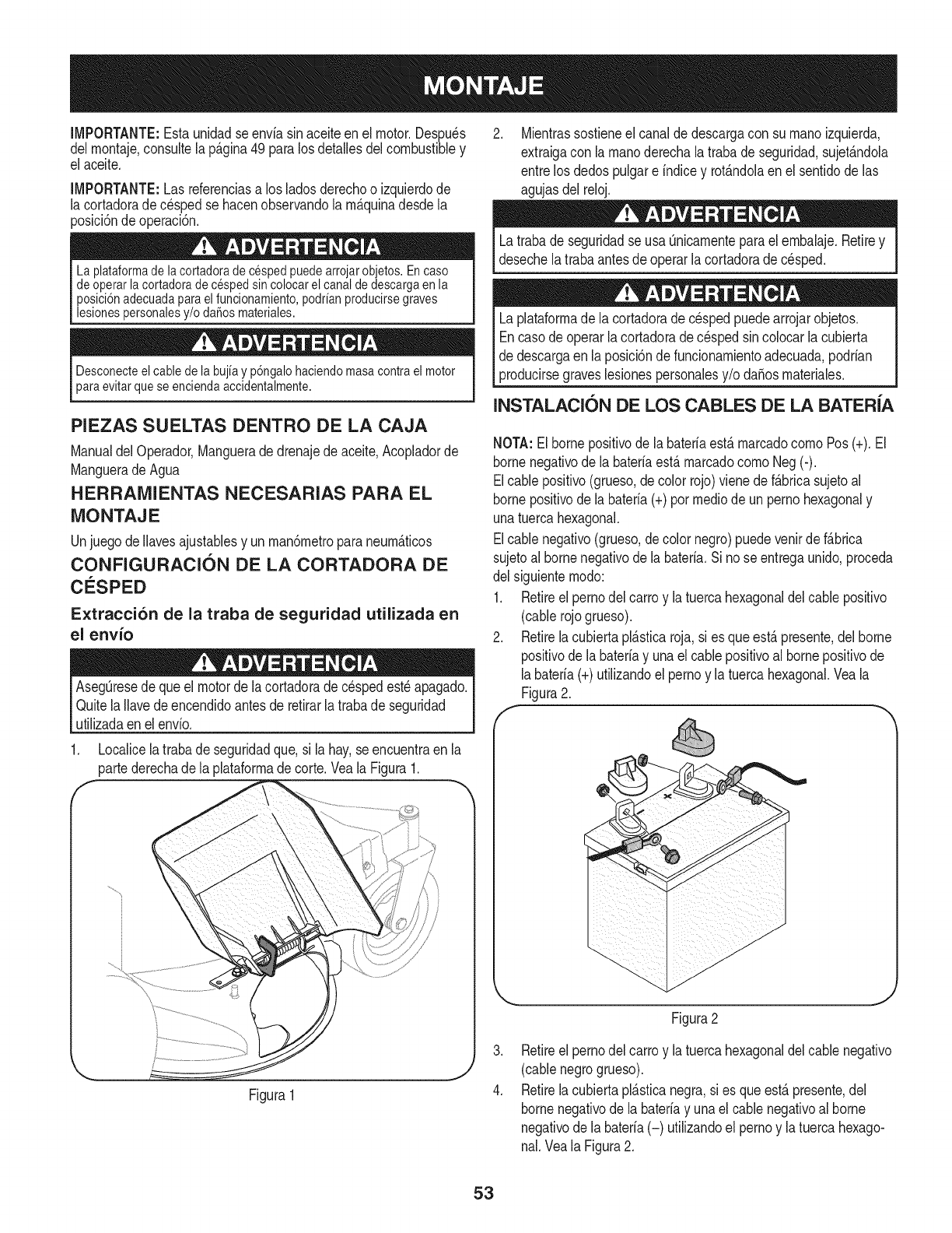
IMPORTANTE:Estaunidadse enviasin aceiteenel motor.Despu_s
delrnontaje,consultela p_.gina49 paralos detallesdelcombustibley
el aceite.
IMPORTANTE:Las referenciasa losladosderechoo izquierdode
la cortadoradec_spedse hacenobservandola rn_.quinadesdela
posicidndeoperacidn.
La plataformade lacortadorade cespedpuedearrojarobjetos.En caso
deoperarla cortadorade cesped sincolocarel canaldedescargaen la
posici6nadecuadaparaelfuncionamiento,podrianproducirsegraves
lesionespersonalesy/o daSosmateriales.
Desconecteel cablede la bujia y p6ngalohaciendomasacontrael motor
paraevitarquese enciendaaccidentalmente.
PIEZAS SUELTAS DENTRO DE LA CAJA
Manualdel Operador,Manguerade drenajede aceite,Acopladorde
Manguerade Agua
HERRAMIENTAS NECESARIAS PARA EL
MONTAJE
Unjuegode Ilavesajustablesy unrnan6rnetroparaneurn_.ticos
CONFIGURACION DE LA CORTADORA DE
C_:SPED
Extracci6n de la traba de seguridad utilizada en
el envio
AsegQresede queel motorde lacortadoradec_spedest_apagado.
QuitelaIlavede encendidoantesde retirarla trabade seguridad
utilizadaen elenvio.
1. Localicelatrabade seguridadque, si la hay,se encuentraen la
partederechade la plataforrnadecorte.Veala Figura1.
f
Figura1
Mientrassostieneel canalde descargacon su rnanoizquierda,
extraigacon la rnanoderechalatrabade seguridad,sujet_.ndola
entrelos dedospulgare indicey rot&ndolaenel sentidode las
agujasdel reloj.
Latrabade seguridadse usa Qnicarnenteparael ernbalaje.Retirey
desechelatraba antesdeoperarlacortadoradecesped.
Laplataforrnadela cortadoradecespedpuedearrojarobjetos.
Encasode operarlacortadoradec_spedsincolocarlacubierta
de descargaen laposici6ndefuncionarnientoadecuada,podrian
producirsegraveslesionespersonalesy/o daSosrnateriales.
INSTALACION DE LOS CABLES DE LA BATER{A
NOTA:Elbornepositivode labateriaest&rnarcadocornoPos(+).El
bornenegativode la bateriaest,.rnarcadocornoNeg (-).
Elcablepositivo(grueso,decolor rojo)vienedef&bricasujetoal
bornepositivode labateria(+) pormedicde unpernohexagonaly
unatuercahexagonal.
Elcablenegativo(grueso,decolor negro)puedevenirde f&brica
sujetoalbornenegativode labateria.Si nose entregaunido,proceda
del siguienternodo:
1. Retireelpernodel carroy latuercahexagonaldelcablepositivo
(cablerojogrueso).
2. Retirelacubiertapl_.sticaroja,si es queest,. presente,delborne
positivodela baterfay unael cablepositivoal bornepositivode
labateria(+)utilizandoel pernoy la tuercahexagonal.Veala
Figura2.
,
4.
Figura2
Retireelpernodel carroy latuercahexagonaldelcablenegativo
(cablenegrogrueso).
Retirelacubiertapl_.sticanegra,si es queest,.presente,del
bornenegativode la bateriay unael cablenegativoalborne
negativodela bateria(-) utilizandoel pernoy la tuercahexago-
nal.Veala Figura2.
53

.AsegQresedequela varilladesujeci6nest,.colocadasobrela
bateria,rnanteni_ndolaen su lugary asegQresede queel borne
positivode labateriaest_cubiertoconel capuch6nde gornarojo
paraprotegerlode lacorrosi6n.
NOTA:Si la bateriase poneenfuncionarnientodespu_sde lafecha
indicadaen la partesuperioro alcostadode la rnisrna,c_.rguela
siguiendolas instruccionesde la secci6nMantenirnientode este
manualantesde hacerfuncionarla cortadora.
Despliegue de la manija
1. Extraigalas perillasenestrellay los tornillosdel carrode la
rnanijainferior.Veala Figura3.
Figure3
Girelarnanijasuperiora la posici6nde funcionarniento.Tenga
cuidadode noprensarlos cables.VealaFigura4.
Figure4
3. Vuelvaa instalarlos tornillosdel carroy las perillasextraidos
anteriorrnente.
4. Ajustelas perillasen estrellasuperiorese inferioresy los tornillos
delcarro paraasegurarla rnanijasuperiora la inferior.Veala
Figura4.
5. Despu_sde arrnarlarnanija,paraextraercon seguridadla
unidaddel p_.let,saqueprirnerolostornillosquefijan lacortadora
al caj6n.
Colocaci6n de la palanca de cambios
1. Extraigael tornilloy la tuercade seguridadquesujetanla palanca
de carnbiosa la placadela palancade carnbios.Veala Figura5.
2. Extraigael tornilloy la tuercarestantesde la placade la palanca
de carnbiosinferior.Veala Figura5.
F
3. Coloquelapalancade carnbiossuperioren posici6nvertical
alineandolosorificiosde lapalancacon los dela placade
carnbios.VealaFigura6.
.
Figure6
Asegurelapalancaa la placausandolosdos tornillosy las dos
tuercasextraidosanteriorrnente.Veael recuadrode la Figura6.
54

Control de la presi6n de los neumaticos
Lapresi6nm_.xirnadelos neurn_.ticosencualquiercircunstanciaes
de 30 psi.Sedebernantenerunapresi6nuniforrneparatodoslos
neurn&ticosen todornornento.
Es posibleque losneurn_.ticostraseroshayansidoexcesivarnente
infladosparadespacharel producto.Reduzcalapresi6nde los
neurn_.ticosantesdehacerfuncionarlacortadora.Lapresi6nde
neurn_.ticosrecornendadaparael funcionarnientoes de aproxirnada-
rnente20 p.s.i.
Consulteenlos lateralesde los neurn_.ticosla presi6nrn_.xirnaenp.s.i.
Gasolina y aceite
Eltanquedecombustibletienecapacidadparados galones.Quitela
tapade combustiblegir_.ndolaensentidocontrarioalde las agujas
del reloj.UtiNceQnicarnentegasolinaNrnpia,nueva(no rn_.sde 30dfas
deuso) y sin plorno.Lleneel tanquea norn_.sdecuatropulgadas
pordebajodel hordesuperiordelcuellode Ilenadoparaperrnitirla
expansi6ndelcombustible.
Tengarnuchocuidadoal trabajarcon gasolina.Lagasolinaes
surnarnenteinflarnabley susvaporespuedencausarexplosiones.
Nuncaagreguecombustiblea la rn_.quinaeninterioresni rnientrasel
motorest,.calienteo en funcionarniento.ApaguecigarriNos,cigarros,
pipasy otrasfuentesdecornbusti6n.
NOTA:Sucortadoradecespedsedespachaconaceiteen el motor.
Sinembargo,ustedDEBEcontrolarel nivelde aceiteantesdehacerlo
funcionar.Refi_rasea laSecci6ndelServicioy el Mantenirnientopara
instruccionesde Petr61eode Cheque.
Controlesiernpreel niveldeaceitedel motorantesde cadauso.
AgregueaceitesegQnsea necesario.De nohacerlose pueden
producirda_osgravesal motor.
55

fThrottle/Choke
Control
Blade Control
Deck Height
Lever
Fuel Tank
ignition Switch
Systems indicator Monitor
Drive Control
Gear Shift Lever
J
Figure7
CONTROLES DEL MOTOR
Consultela Figura8 paraverla ubicaci6nde los controlesdelmotor.
!_TaP6nde aceite/
varillade rnedici6n del
del nivelde aceite ivlanlja
V_.lvulade Bujiade
drenajede Silenciadory encendido
aceite protectordel
silenciador
J
Figura8
Valvula de drenaje de aceite
Uselav_.lvulade drenajedeaceiteparadrenarel aceitedel motor.
Consultela secci6nde Mantenirnientoparaobtenerinstrucciones.
Manija del filtro de aire
La rnanijadeldepuradorde airese usaparaaccederaldepurador
deaire. Elcartuchopurificadorde airese puedeextraerparalirnpiar
o reernplazar.Consultela secci6nde Mantenirnientoparaobtener
detalles.
Bujia de encendido
Consultela secci6nde Mantenirnientoparaobtenerinstrucciones
sobreel reernplazode bujias.
Tap6n de aceite/varilla de medici6n del nivel de
aceite
Consultela secci6nde Mantenirnientoparaobtenerinstrucciones
sobrec6rnoverificarel aceite.
CONTROLES DEL CORTADORA
Consultela Figura7 paraver la ubicaci6nde loscontrolesdel motor.
PALANCA DE CONTROL DEL REGULADOR/
CEBADOR
NOTE: Cuandooperela cortadorade
cespedcon la plataforrnadecortecolocada,
aseg[3resede quelapalancadecontrol
del regulador/cebadorest_ siernpreen la
posici6nr_.pido.
Estapalancase usapararegularlavelocidad
del motor,paraaplicarel cebadordel motor,
y paradetenerel motor.Hagafuncionarel
motorsiernprea alta velocidadparaobtener
rnejoresresultadosde corte.
Cebador: Utiliceloparaarrancarunmotor
frio
R_pido: Utiliceloduranteel funcionarniento
de lacortadora.
Lento: Utilicelodurantela rnarchalenta.
Parar: Detieneelmotor.
!
Lento
Parar ==_
56

PALANCA DE ALTURA DE LA PLATAFORIVlA
Useestapalancaparaajustarlaalturade corte.Parautilizarla,mueva
la palancahaciala izquierda,luegocobquela en la muescaque mejor
se adaptea la aplicacbndeseada.
TAPON DE COMBUSTIBLE
Retireel tap6ndecombustibleparaagregarcombustibleal tanquede
combustible.
CONTROL DE LAS
CUCHILLAS
Seusa elcontrolde las cuchillaspara
engancharla plataformade lacortadora.Para
engancharestecontrol,presioney retenga
la palancacontrala empu_aduradela barra
decontrol.Paradetenerlascuchillas,suelte
el controldelas cuchillas.Desenganche
siempreelcontrolde las cuchillasantesde
arrancarel motor.Asi se aseguradeque
las cuchillasnocomenzar_.na girarcuando
arrancael motor.
,%
Sueltesiempreel controldelas cuchillasantesde arrancarel motor.
De Iocontrariopuedeocasionardesgasteprematuroalarranque
el_ctricodel motor.
Nuncaintentedetenerel motorcon elcontrolde las cuchillas
enganchado.
CONTROL DE LA
TRANSMISI6N
Elcontrolde latransmisi6nse usapara
engranary desengranarlatransmisi6nde
las ruedas.Paraengancharestecontrol,
aprieteel controldela transmisi6ncontra
laempu_aduradela barrade control.Para
detenerlatransmisi6n,suelteel controlde la
transmisi6n.
IMPORTANTE:Sueltesiempreel control
de latransmisi6nantesde cambiarlas
velocidades.
f
Sueltesiempreel controlde latransmisi6nantesde cambiarde
velocidad.DeIo contrariopuedeocasionargravesdaSosa la
transmisi6n.
PALANCA DE CAiVlBIO DE VELOCIDADES
Useestapalancaparaseleccionarunadecuatrovelocidadesde
marchadirect& neutralo marchaatr_.s.
IVlarcha directa
Haycuatrovelocidadesde marchadirect& Laposici6nuno(1)es la
m_.slent& y la posici6ncuatro(4)es lam_.sr_.pida.
Marcha atras
Paraseleccionarmarchaatr_.s,pongala palancaen la posici6nde
reversa(R).
Miredetr_.sdela cortadoraantesy duranteel funcionamiento
marchaatr_.s.Detengalas cuchillasde lacortadoraantesde operar
marchaatr_.s.
Neutral
Coloquelapalancaenneutro(N) antesde comenzarel cortac_sped,
y cuandoel cortacespednoest,.enel uso.Adem_.s,elcortac_sped
puedesera manoempujadoo tiradocolocandola palancade palanca
de cambiosenel N posici6n(neutra)y presionandoelcontrolde
paseocontrael apret6nde manillar.
Sueltesiempreelcontrolde latransmisi6nantesde cambiarde
velocidad.De IocontrariopuedeocasionargravesdaSosa la
transmisi6n.
57

INTERRUPTOR DE ENCENDIDO
Nuncadejelarn&quinaenfuncionarnientosin vigilancia.Siernpre
desenganchelascuchillas,apagueel motory retirela Ilave,paraevitar
elencendidoaccidentaldelmotor.
Elinterruptordecautroposicionesse usa paraencendery apagarel
motorde los rnodeloscon arranqueel_ctrico.Paraencenderel motor,
insertela Ilaveenel interruptorde encendidoy girelaenel sentidode
las agujasdel relojhaciala posici6nENCENDIDO.Sueltela Ilaveen
la posici6nFUNCIONAMIENTOunavezquehayaarrancadoel motor.
Muevala Ilaveen la posici6nCORRE/LIGEROacorrerel cortaces-
pedesconel faro.Paradetenerel motor,girela Ilavea PARAR.Veala
Figura9.
CORRE/LIGERO
PARA DIDO
.,J
Figura9
Nuncarnuevala Ilavea laposici6nStart(encendido)rnientras
elmotorest&funcionando;si Io hace,puedeocasionardaSosal
arrancadordel motor.
MONITOR INDICADOR DE SISTEMAS/MEDI-
DOR HORARIO
...... -J
f7
BATTERY
©©
42.0]
HOURS I/I0 \\\
j/J"
.....J
LCD (pantalla de cristal liquido)
CuandolaIlavede encendidose rotafuerade laposici6nSTOP
(parar)perono se colocaen laposici6nSTART(encendido),el
monitorindicadorde sisternasrnuestralasalidade labateria,en
voltios,en su pantallaLCDduranteaproxirnadarnentecincosegundos,
y despu_srnuestraunrelojdearenay las horasdefuncionarnientode
la cortadora.Unavezqueel motorha arrancado,el monitorrnuestra
continuarnenteun relojdearenay las horasdefuncionarnientode la
cortadoraenla pantalla.
NOTA: Lashorasde funcionarnientode lacortadorase registran
cada vezque laIlavede encendidose rotafueradela posici6nSTOP
(detener),independienternentedequese hayaarrancadoelmotor.
Elmonitorindicadortarnbi_nle recuerdaal operadorlos intervalos
de rnantenirnientoparacarnbiarelaceitedelmotor.Lapantallade
cristalliquidoparpadeaalternativarnentelas horasregistradas,"CHG"
(carnbiar)y "OIL"(aceite)durantecincorninutos,despu_sde cada50
horasde operaci6nregistrada.El intervalode rnantenirnientodurados
horas(entre50-52, 100-102,150-152,etc.)La pantallaLCDtarnbi_n
parpadeaseg0nse describern&sarriba,durantecincorninutos,cada
vezqueel motorde lacortadorase enciendeduranteel intervalode
rnantenirniento.Antesde quefinaliceel intervalo,carnbieel nivelde
aceitedelmotorseg0nse indicaen lasecci6nMantenirnientodeeste
ManualdelOperador.
Bateria
Esnormalquela luzde la bateriase ilurninecuandoel motoresta
girandoduranteel arranque,perosi se ilurninadurantela operaci6n,
cuandoel motorest&funcionando,labaterianecesitacargao el
sisternadecargadel motornoestagenerandoarnperajesuficiente.
Controlela bateriacornose indicaenla secci6nServiciode este
manualo hagaqueel sisternadecargasea verificadopor sudis-
tribuidorSearsuotro distribuidor.
58

ENCENDIDO DEL MOTOR
Consultela secci6nConfiguraci6ny Montajede estemanualpara
obtenerinstruccionessobreel Ilenadode aceitey gasolina.
1. Sueltetodoslos controlesdela cortadora.
2. Muevalapalancadecarnbiosa la posici6nneutral(N).
3. InsertelaNaveen elinterruptorde encendido.
4. Siel motorest,.fifo, rnuevael controldelregulador/cebador
completarnentehaciadelante,a la posici6nCHOKE(cebador).Si
est,.volviendoa arrancarunmotorcaliente,rnuevael controldel
regulador/cebadora laposici6nFAST(velocidadr_.pida,represen-
tadaporunaliebre).
5. Girela Navede encendidoen el sentidodelas agujasdel reloj
hastala posici6nSTART(encendido).Unavezquearranqueel
motor,sueltela Nave.Volver_.a laposici6nRUN(funcionarniento).
No rnantengalaNaveen laposici6nSTART(encendido)durante
rn_.sde cincosegundosporvez.Si Io hace,puedeocasionarda_os
al arrancadoreBctricodel motor.
6. MuevalaNavea la posici6nCORRE/LIGEROa operarel
cortac_spedesque utiNzael faro.
7. Muevaelcontroldelregulador/cebadora laposici6nFast
(velocidadr_.pida,representadaporunaliebre).
NOTA:Nuncadejeel controldel regulador/cebadoren la posici6n
CHOKE(cebador)rnientrasoperalacortadora.Si Io hace,se
generate,unarnezcla"rica"decombustibles,Io cual har_.queel motor
pierdapotencia.
DETENCION DEL MOTOR
Sigolpeaunobjetoextra_o,detengael motory saquela Navede
encendido.Inspeccionerninuciosarnentela rn_.quinaparaver si est,.
daSada.Repareel daSoantesdevolvera arrancarel motory operar
la rn_.quina.
1. Silascuchillasest_.nenganchadas,suelteelcontroldelascuchillas.
2. Muevaelcontroldelregulador/cebadora laposici6nSTOP(parar)
3. Girela Navede encendidoen sentidocontrarioalas agujasdel
reloja laposici6nSTOP(parar).
4. Retirela Navedelinterruptordeencendidoparaevitarqueel
motorse enciendaaccidentalrnente.
ENGANCHE DE LA TRANSMISI6N
EvitearrancarsQbitarnente,desarrollarexcesivavelocidady
detenersede repente.
EnciendaelmotorsegQnlas instruccionesanterioresy rnuevael
controldel regulador/cebadora la posici6nFAST(velocidadr_.pida,
representadaporunaNebre).
ParaconducirhaciaADELANTE:
a. Coloquelapalancadecarnbiosen cualquierade lascuatro
velocidadesde avance.Seleccioneunavelocidadadecuada
alas condicionesy conla cual se sientac6rnodo.
b. Oprirnaelcontroldelatransrnisi6n.
c. Oprirnalentarnenteelcontroldela transrnisi6ncontrala
rnanijadela ernpuSaduray la cortadorasernover_..Su_ltelo
y se detendr_,el rnovirnientode la transrnisi6n.
ParaconducirhaciaATRAS:
a. Verifiquequeel _.readetr_.ssuyoest,.despejada.
b. Coloquelapalancadecarnbiosen rnarchaatr_.s(R).
c. Optimalentarnenteelcontroldela transrnisi6ncontrala
rnanijadela ernpuSaduray la cortadorasernover_..Su_ltelo
y se detendr_,el rnovirnientode la transrnisi6n.
Nointentecarnbiarladirecci6ndedesplazarnientornientrasla
cortadoraest,.enrnovirniento.Siernpredebesoltarelcontrolde
la transrnisi6ny detenerla cortadoratotalrnenteantesde moverla
palancade carnbiosde unaposici6nde avancea Marchaatr_.s.De
Io contrariopuedeocasionargravesdaSosa latransrnisi6n.
Nodejela posici6ndel operadorsin antessoltarel controldelas
cuchillas.Sidejala cortadorasinvigancia, debeapagarel motory
retirarla Navedeencendido.
ENGANCHE DE LAS CUCHILLAS
Paratratardeevitarel contactocon las cuchillaso unalesi6npot
algQnobjetoque seaarrojado,rnantengaa losobservadores,a los
ayudantes,niSosy rnascotasalejadosal rnenos25metrosde la
rn_quinarnientrasest,.enfuncionarniento.Detengala rn_.quinasi
alguiense acerca.
5. Muevael controldel regulador/cebadora la posici6nFAST
(velocidadr_.pida,representadapot unaliebre).
6. Oprirnalentarnenteelcontroldelas cuchiNascontralaernpuSa-
durade larnanijaderechay lacortadorase rnover_..Su_ltelay
lascuchillassedetendr_.n.
FUNCIONAMIENTO EN PENDIENTE
Consultela secci6nINDICADORDE PENDIENTEdela p_.gina7 para
deterrninarenqu_pendientespuedeoperarlacortadoracon seguridad.
Nocorteen pendientescon unainclinaci6ndern_.sde 15grados
(elevaci6naproxirnadade 2 1/2 pies porcada 10pies).Lacortadora
podrfavoltearsey causarlesionesgraves.
• Muevala podadoraa travesde las carasde la pendiente,nunca
haciaarribay abajo.Tengacuidadocuandocarnbiededirecci6n
cuandooperela rn_.quinaenpendientes.
• Est_atentoa los agujeros,rafces,rocas,objetosocultoso
abultarnientosquepuedanprovocarque sederrapeo se tropiece.
Elc_spedalto puedeocultarobst_.culos.
59

• Siernpreest_segurode su equilibrio.Si tropiezay cae puede
lesionarsegravernente.Sisienteque pierdeelequilibrio,suelte
inrnediatarnentela rnanijade controldela cuchillay lacuchilla
dejar_,degiraren tres(3) segundos.
• Nocorteel cespedcercade pozos,hundirnientos,bancos,podrfa
perderel equilibrio.
• No podependientesrnayoresde 15gradoscornoIo indicael
rnedidorde pendientes.
• No podeel c_spedhOrnedo.Sinoest,.firrnernenteparado,puede
resbalarse.
USO DE LA PALANCA DE ALTURA DE LA
PLATAFORMA
Parasubiro bajarla plataforrnadecorte,rnuevala palancade altura
de laplataforrnahacia laizquierday col6quelaen larnuescaque
rnejorse adaptea la aplicaci6ndeseada.
CORTE DE ClaSPED
La siguienteinforrnaci6nle resultar_._til paraoperarlacortadora.
Planifiqueel patr6nde corte,paraevitarquela descargade
rnaterialesse realicehacialoscarninos,las veredas,losobserva-
dores,etc. Eviteadern_.sdescargarmaterialcontrauna paredu
obstrucci6nque podrfahacerqueel materialdescargadorebote
contrael operador.
• Nocortea alta velocidad,especialrnentesi se hainstaladoun kit
paraabonoo uncolectorde cesped.
• Nocorteel c_speddernasiadocorto. Elc_spedcortoalientael
crecirnientode rnalezasy se poneamarillor_.pidarnentecuando
escaseala Iluvia.
• Siernprehagafuncionarla cortadoracon elcontroldelregulador/
cebadoren laposici6nFAST(r_.pida,representadaporuna
Nebre)rnientrascortael c_sped.
• Paraobtenerlos rnejoresresultados,se recorniendareaNzarlos
dosprirneroscortesdecespedarrojandoladescargahaciael
centro.Despu_sde lasdos prirnerasvueltas,carnbieladirecci6n
paraarrojarla descargahaciaafuera,paraequilibrarel corte.Esto
otorgar_,unrnejoraspectoalcesped.
• NO intentecortarrnalezasfrondosaso cespedextremadarnente
alto.Lacortadoraruedisefiadaparacortarelcesped,NO para
podarrnalezas.
• Mantengalas cuchillasafiladasy reernpl_.celascuandose
desgasten.
Despu_sdegolpearalgQnobjetoextrafio,detengael motor,
desconecteel cablede labujfay conecteloa tierracon elmotor.
Inspeccioneminuciosarnentela rn_.quinaparadeterrninarsiest,.
dafiada.Controlesiernprelacorreadesincronizaci6ndelacuchilla
cornoseindicaenlasecci6nMantenirnientodeestemanual.Repare
eldafioantesdeencenderlay hacerfuncionarlacortadora.
ABONO
Lascortadorasde cespedanchasSearsvienenequipadascon unkit
paraabonoqueincorporacuchillasespeciales,quevienende serieen
su cortadora,pararecircularlos recortesdec_spedrepetidasveces
pordebajode laplataforrnade corte. Losrecortesrnuyfinosluegoson
despedidoshaciaatr_.sparaquesedepositenenel c_spedy actQen
cornofertiNzantenatural.Observelos siguientespuntosparaobtener
los rnejoresresultadosal realizarel abono.
• NuncaintentereaNzarelabonosi el c_spedest,.hOrnedo.El
c_spedhQrnedotiendea adherirseal ladoinferiorde laplata-
forrnade cortee irnpideel procesoadecuadodelos recortesde
cespedcornoabono.
• NOintenterealizarel abonoa rn_.sde 1/3de la alturatotaldel
c_sped.De Iocontrariolos recortesdec_spedsearnontonar_.n
forrnandoterronesdebajode la plataforrnay no seprocesar_.n
eficazrnentecornoabono.
• Mantengaunavelocidadabsolutalentaparaperrnitirquelosrecortes
dec_spedseproceseneficazrnentecornoabono.
• Siernprernantengala palancade controldel reguladorenla
posici6nFAST(velocidadr_.pida,representadapot unaliebre)
rnientrasrnientrascortael c_sped.Si el motornose rnantiene
con el reguladora plenose sorneteal motorde la cortadoraa un
esfuerzoqueno perrniteque lascuchiNasprocesenadecuada-
rnentelos recortesdec_spedquese usar_.ndeabono.
INSTALACION /EXTRACCION DE LA TOLVA
DE ABONO
Antesde instalaro extraerlaclavijadeabono,desenganchelas
cuchiNas,apagueel motory retirela Nave,paraevitarquealguien
enciendaaccidentalrnenteel motor.
Detengael motory esperaquetodaslas piezasdejendernoverse.
Instalaci6n de la tolva de abono
1. Insertela leng_Jetaderecha(A)de laclavijaen el soportede la
plataforrna.Veala Figura11.
2. Insertela clavijadeabonoenla aberturade descarga(B).
3. Unavezcolocadaen laaberturade la plataforrna,ernpujela
clavijahaciala parteposteriorde lacortadora(C) parafijarlaen
su lugar.
f -,,,
Figura11
Extracci6n de la tolva de abono
Deslicelaclavijahacialaderecha(haciala partedelanterade lacorta-
dora)paradesengancharla ranurade la plataforrnadela cortadoray
luegofuerceel ladoizquierdode la clavijahaciafuera.
6O

Detengasiempreel motor,desconectela bujiay haga masacontrael motor
antes derealizarcualquiertareade mantenimientoen la cortadora.
RECOMENDACIONES GENERALES
•Respetesiernprelas reglasde seguridadcuandorealice
cualquiertareade rnantenirnientoen la cortadora.
• Lagaranfiadeestacortadoranocubreelernentosque ban
estadosujetosal rnalusoo la negligenciadeloperador.Para
recibirel reernbolsototalde lagaranfia,el operadordeber&dar
rnantenirnientoa la podadoracornose indicaen estemanual.
• Elcarnbiode lavelocidadcontroladadelmotorinvalidar&la
garanfiadel motor.
• Todoslosajustesdebenser verificadosporIo rnenosunavezen
cadaestaci6n.
• Reviseperi6dicarnentetodoslos sujetadoresy cornpruebeque
est_nbienajustados.
MANTENIMIENTO DEL MOTOR
Control del aceite del motor
Controleel nivelde aceiteantesdel funcionarniento.Detengael motor
y esperevariosrninutosantesde verificarel niveldeaceite.Conel
motorubicadoen sueloparejo,el aceitedebeestaren la rnarcaFULL
(lleno)de lavarilladel niveldeaceite.
1. Saquela varilla/tap6ndelaceitey lirnpieloscon unatelalirnpia.
2. Vuelvaa colocary ajustelavarilla/tap6n
deaceite.Retirela varilla/tap6nde aceitey (-_-v-_--,_
controleelnivelde aceite.Elniveldeberiaestar
enla rnarcaFULL(lleno)
3. Sies necesario,agregueaceitelentarnenteen
el recipientedeIlenadode aceitedelmotor.
Vuelvaa controlarel nivelde aceite.NoIo Ilene
enexceso.
4. Vuelvaa colocary ajustelavarilla/tap6ndeaceite.
No IoIleneenexceso.ElIlenadoexcesivode aceitepuedehacer
que el motornoarranqueo Io hagacondificultad.Sise superala
rnarcaFULL(lleno)dela varilladernedici6n,dreneaceitepara
reducirel nivelhastaque quedeen larnarcaFULL.
Cambio de aceite del motor
Si el motorse hapuestoenfuncionarnientorecienternente,elmotor,
silenciadory las superficiesrnet&licascircundantesestar&ncalientes
y puedencausarquernadurasa lapiel. Tengaprecauci6nparaevitar
quernaduras.
5. Pongael motoren rnarchaduranteunosrninutosparaperrnitir
queel aceitedel c&rterdel motorse caliente.Elaceitecaliente
circular&rn&slibrernentey transportar&rn&sdelsedirnentodel
motorquepuedehabersedepositadoen larondodelc&rter.
Tengacuidadoy evitequernarseconel aceitecaliente.
6. Extraigala perillaen estrellasuperiory el tornillodelcarrodel
ladoderechode la rnanija.Veala Figura12.
Figura12
7. Gireel tubode soportehaciaelfrenteparatener lugarpara
conectarlarnangueradedrenajedeaceitea lav&lvulade
drenaje.Veala Figura12.
8. Abrael tap6nprotectoren el extrernode lav&lvulade drenajede
aceiteparadejarexpuestoelorificiodedrenaje.Yeala Figura13.
Oil Fill Cap/Dipstick
/
\
\\
Figura13
61

9. Retireel tap6ndeIlenadode aceite/lavarillade niveldeaceite
deltubode Ilenado.
10. Insertelarnangueradedrenajedeaceite(ernbaladacon este
manual)dentrodelorificiode drenajedeaceite.Coloqueel
extrernoopuestodela rnangueraen un recipientede recolecci6n
deaceiteadecuadocon capacidadparaporIo rnenos2,5cuartos
degal6n(2,4 litros)pararecogerel aceiteusado.
11. Aprietelas lengiJetasde lav_.lvulade drenajede aceite,hego tire
haciaafueraparacornenzara drenarelaceite.VealaFigura13.
12. Cuandoterrninededrenarel aceite,ernpujeel extrernode lav_.l-
vulade drenajedeaceitehaciaadentro,hastaquelas leng(Jetas
calcenen su hgar. Vuelvaa taparel extrernode lav_.lvulade
drenajeparaevitarqueentrenresiduosenel orificiode drenaje.
13. Vuelvaa Ilenarel motorcon aceitenuevo.Consulteel Manual
delpropietarioBriggs&Strattonparaver inforrnaci6nsobreel
vohrneny pesodelaceitede motor.
Usesolarnenteunaceitedetergentede alta calidadcuyaclasificaci6n
de servicioAPI seaSF o SG.Seleccioneel gradodeviscosidad
SAEdel aceiteseg0nla ternperaturade operaci6nesperada.Veala
Figura14.Aunquelos aceitesde viscosidadrndtiple (5W30,10W30,
etc.)rnejoranel encendidocuandoel clirnaest,.frio,los rnisrnos
incrernentanelconsurnode aceitecuandoseusan a rn_.sde 32°E
Cornpruebeel nivelde aceitecon mayorfrecuenciaparaevitardaSos
debidoa queel motortrabajecon un niveldeaceitebajo.
fColder < 32°F :_- Warmer
5W30 SAE 30
Oil Viscosity Chart
Figura 14
Control de la bujia de encendido
1
Lirnpielabujiay ajustela separaci6ndelelectrodoa 0.030"al rnenos
unavezporestaci6n,reernplacecada 100horasde funcionarniento.
1. Lirnpieel _.reaalrededorde la basedela bujia.No lijela bujia.Se
debelirnpiarlas bujiasrnedianteraspadoo talladocon cepillode
alarnbrey lavadoconun solventecomercial.
2. Saquee inspeccionela bujia.Verifiquelaseparaci6npara
asegurarsede queest,.fijadaen0.030".Veala Figura15.
3. Carnbielabujiasi loselectrodosest_.npicados,quernadoso la
porcelanaest,. rota.
f
Bectrodo Porcelana
l
Separaci6nde 0.030pulg(0.76rnrn)
IVlantenimiento del filtro de aire.
Si se instalanincorrectamentelos filtroso las cubiertas,se pueden
producirlesionesgraveso la rnuertede las explosionesdel
carburador.Nointentearrancarel motorcuandonoest_.npuestos.
Nouse airepresurizadoni solventesparalirnpiarel cartuchodel
filtrode aire.
Lirnpieo reernplaceelfiltrode airecada25 horasde funcionarniento.
1. Tire la rnanijadelfiltrode aireparaarriba,Figura16,y tire para
atr_.shaciael motor.
.
fRetirelacubiertadelfiltrode aire,Figura16.
Cubiertadelfiltro_de __ K/_
Cartuchodelfiltrode
aire \ aire
Manijadelfiltrode
aire
o
J
Figura16
3. Extraigacon cuidadoel cartuchodel fiitrodeairey el pre-filtro(si
est,.instalado)delalojarnientodel soplador.
4. Lirnpiela basedelcartuchodel filtrodeairecon cuidadopara
evitarquelas irnpurezaspenetrenenel motor.
5. Coloqueel pre-filtro,si est,.instalado,y el cartuchonuevarnente
en elalojamientodelsoplador.Elcartuchose debecolocar
firrnernenteensu posici6n.
6. Alinelas lengQetasde lacubiertacon las ranurasdelalojarniento
del sopladory vuelvaa colocarla cubierta.
BATERiA
Losbornesde labateriay losaccesoriosafinescontienenplornoy
cornpuestosdeplorno,sustanciasquirnicasquesegOnIoestablecido
porel EstadodeCaliforniacausanc_.ncery daSosenel sisterna
reproductivo.L_.veselasrnanosdespu_sde estarencontactocon
estoscornponentes.
Labateriaest,. selladay no necesitarnantenirniento.Losnivelesde
_.cidonose puedencontrolary nose puedeagregarIfquido.
•Siernprernantengalirnpiosy libresdeacurnulaci6nde elernentos
corrosivosloscablesy los bornesde la bateria.
Despu_sde lirnpiarlabateriay los bornes,apliqueunacapa
delgadade vaselinao grasaa arnbosbornes.
Figura15 62

Siextraelabateriaparalirnpiarla,desconecteprirneroel cable
NEGATIVO(negro)de su borney acontinuaci6nel cable POSITIVO
(rojo).Cuandovuelvaa instalarla bateria,conectesiernpreprirnero
el cable POSlTIVO(rojo)a su borne,y acontinuaci6nel cable
NEGATIVO(negro).AsegQresedequelos cablesest_nconectados
a losterrninalescorrectos,ya quesi los inviertepuedecausardaSos
gravesal sisternaalternadordel motor.
PRESION DE LOS NEUMATICOS
La presi6nmaximade los neurn_.ticosen cualquiercircunstanciaes
de 30 psi.Sedebernantenerunapresidnuniforrneparatodoslos
neurn_.ticosen todornornento.
Verifiqueperiodicarnentela presi6nde arnbosneurn_.ticostraseros
dela cortadora.Si lapresi6ndelos neurn_.ticosnoes uniforrne,la
plataforrnacortar_,el c_spedenforrnadesparejay se puededesviar
a izquierdao derechadurantelaoperaci6n.Recommendedoperating
tire pressureis approximately20p.s.i.Checkthe sidewallof tire for
maximump.s.i..
LIIVIPIEZA DE LA CORTADORA
Si sederrarnacombustibleo aceitesobrela rn&quina,debelirnpiarse
deinrnediato.NOperrnitaquese acurnulendesechosalrededorde las
aletasde refrigeracidndel motor,el ventiladorde refrigeracidnde la
transrnisi6nnien ningunaotrapartede la rn_.quina,especialrnentelas
correasy poleas.
Smart Jet
Laplataforrnade la cortadoratiene unpuertodeaguasobrela superfi-
cie cornoparte desu sisternadelavado.
Utiliceel SmartJet paradesalojarlos recortesde cespeddela parte
inferiorde la plataforrnae irnpedirla acurnulacidnde sustancias
qdrnicascorrosivas.Realicelos siguientespasosDESPUE_SDE
CADACORTEDECE_SPED:
Antesde usarel sisternade lavadode laplataforrna,debedesen-
gancharel controldela cuchilla,apagarel motory sacarla llave
paraevitarelencendidoaccidentaldelmotor.
1. Coloquela cortadoraen unazonaniveladay despejadadel
cesped,suficienternentecercaparaquela rnangueradeljardin
alcance.
AsegQresede queelcanal dedescargadela cortadoraest,.
orientadoALEJADOde lacasa,el garaje,losvehiculosestaciona-
dos,etc.
2. Enrosqueel acopledela rnanguera(ernbaladoconel Manual
deloperadordela cortadora)en elextrernode la rnanguerade
jardn.
3. Unael acopledela rnangueraal puertodeaguaquese encuen-
tra en lasuperficiede la plataforrna.Veala Figura17.
Figura17
4. Abrael surninistrodeagua.
5. Enciendael motory coloquela palancadel reguladoren la
posici6nRAPIDO(fast,representadaporunaliebre).
6. Desdelaposici6ndeloperadordetr_.sde lacortadora,coloqueel
controlde las cuchillasen laposici6nON (encendido).
7. Perrnanezcaenla posici6ndeloperadorcon la plataforrnade
corteenganchadadurantedos rninutoscornorninirno,perrni-
tiendoquela parteinferiorde la plataforrnadecorte se lavea
rondo.
8. Muevael controlde lascuchillasa la posici6nOFF(apagado).
9. Girela Ilavedeencendidoa la posici6nSTOP(detener)para
apagarel motorde lacortadora.
10. Desconecteel aguay retireel acopladorde la rnangueradel
puertode aguaquese encuentraen la superficiede la plata-
forrna.
Despu_sde lirnpiarlaplataforrnacon el sisternaSmartJetTM, regrese
a la posici6ndeloperadory enganchelascuchillas.Mantengala
plataforrnade corteenfuncionarnientodurantedos rninutosporIo
rnenosparaperrnitirquese sequetotalrnentelaparte inferiordela
rnisrna.
LUBRICACI(SN
Antesde lubricar,repararo inspeccionar,desconectela potenciade
arranque(PTO),coloqueel frenode rnano,apagueel motory retire
la llave,paraevitarel encendidoaccidentaldel motor.
Puntos de pivote y varillaje
Lubriquetodoslos puntosde pivotedelsisternadetransrnisi6ny
el varillajede elevaci6nconaceiteligeroporIo rnenosunavezpor
ternporada.
Ruedas traseras
Lasruedastraserasse debensacarde los ejesunavezportempo-
rada.Lubriquebienlos ejesy las Ilantascongrasarnultiusoantesde
volvera instalarlos.
63

Ruedas delanteras
CadaunodeJosejesy rueditasdela ruedadeJanteravieneequipado
con unaccesoriodeengrase.Yeala Figura18.Lubriquecon grasa
multiusoNo.2 aplicadacon unapistoladeengrasarcada50 horasde
funcionamientode lacortadora.
Figure18
Husillos de plataforma
Losaccesoriosde engrasese puedenencontraren cadahusillode la
plataforma.Veala Figura19.Lubriquecongrasa251HEPo conuna
grasade litiomultiusoNo.2 equivalente.Conunapistolade engrasar,
hagados aplicaciones(minimo)o suficientegrasaal ejede husillo.
1. Parasacarla cubiertade lacorreasaquelos trestornillosy
arandelasquela sujetanalbastidor.Veala Figura20.
Nohagafuncionarla unidadsin tenerlacubiertade la correa
instalada.Si nose observanestas instruccionesse puedenproducir
lesionespersonalesodaSosmateriales.
f
i
,
J
Figura20
Lapartesuperiorde cadapoleade husilloest,.marcadacon una
flecha.Veala Figura21.Las flechasdebenestarperpendiculares
(a un_.ngulode 90°)entre sL
Figure19
CORREA DE SINCRONIZACION DE LA
CUCHILLA
Los husillosde la plataformadecortese muevenpor mediode una
correa(dentada)de sincronizaci6n,garantizandoquelas cuchillasde
la plataformasiempreest_.nperpendicularesentresi. PorIo menos
unavezpot temporada,o despu_sde golpearcontraun objeto
extraSo,verifiquelacorreadesincronizaci6nde lasiguientemanera:
Figura21
3. Si las flechasen la superficiede cada poleadehusillonoest_.n
perpendiculares(aun _.ngulode900grados)entresi, consultea
su distribuidorSearsu ottodistribuidorparavolvera colocarla
correade sincronizaci6nde la plataforma.
Nohagafuncionarla m_.quinasi lacorreade sincronizaci6nnoest,.
correctarnentecolocada.Si no seobservanestasinstruccionesse
puedenproducirlesionespersonaleso daSosmateriales.
64

AJUSTES EXTRACCI6N DE LA PLATAFORiVlA DE
Apagueel motory retirela Navede encendidoantesde realizar
ajustes.
Altura de la manija
La rnanijasuperiorest,.sujetaa dos barrasde apoyoque se pueden
ajustarparasubiro bajarla alturadela rnanija.De ser necesario,
reaNceunajustede lasiguienternanera:
1. Extraigala perillaenestrellasuperiory eltornillodelcarroque
est_.ndel ladoderechoy del ladoizquierdode larnanija. Veala
Figura22.
f
2.
.
Figura22
Girela rnanijahaciaadelanteo haciaatr_.sparaalinearunode
los tresorificiosde cadabarrade apoyocon los orificiosde la
rnanija.
Vuelvaa colocarla perillaenestreNasuperiory eltornillodel
carroal ladoderechoy al ladoizquierdode la rnanijacuando
Iogreunaalturac6rnoda.
CORTE
Antesde realizarcualquierrnantenirnientoo reparaci6n,desconecte
las cuchillas,apagueel motory retirela Naveparaevitarel encen-
didoaccidentaldelmotor.
Paraextraerla plataforrnadecorte,procedade la siguienternanera:
1. Parasacarlacubiertade lacorreasaquelos trestorniNosy
arandelasquela sujetanal bastidor.Veala Figura23.
Nohagafuncionarla unidadsintenet lacubiertade la correa
instalada.Si nose observanestas instruccionesse puedenproducir
lesionespersonalesoda_osrnateriales.
J
Figure23
2. Coloquelapalancadealturade laplataforrnaen la posici6nde
cortern_.salta.
3. Coloquetacos dernaderaen varioslugaresdebajodel hordede
laplataforrna.Soportar_.nternporalrnentela plataforrnarnientras
ladesrnonta.
4. Usela palancade alturadela plataforrnaparabajarlaplataforrna
y hacerladescansarsobrelostacosde rnadera.
65

.Extraigael tornilloy latuercade bridaquesujetala varilladel
guardacorreaal ladoizquierdodelbastidordela cortadora.Vea
la Figura24.
Figure24
6. Extraigala varilladelguardacorreay extraigala correade
la plataforrnaqueest,.alrededorde lapolleadel motorde la
cortadora.
7. Mirela plataforrnadecortedesdeel ladoizquierdoy saquecon
cuidadolos pasadoreshorquillaque sujetanlos soportesde la
plataforrnaa los lateralesposteriory anteriorizquierdosde la
plataforrna.Veala Figura25.
Lift Arm
13. Desengancheelcable resortede latransrnisi6ndelrnontajedel
brazosecundariolibre.Veala Figura26.
Figure26
14. Deslicelentarnentela plataforrnahaciala derecha,sac_.ndolade
debajode lacortadora.
Parainstalarla plataforrnadecorte,siga los pasosanterioresenorden
inversoparavolvera acoplarla plataforrnay lacubiertade lacorrea.
CUCHILLAS DE CORTE
• A
Apagueel motory extraigala Ilavedecontactoantesde retirarlas
cuchillasde corteparaafilarlaso reernplazarlas.Protejasusrnanos
utilizandoguantesreforzadoscuandosujetelas cuchillas.
Inspeccioneperi6dicarnentela cuchillay/oel husilloenbuscade
rajaduraso da_os,especialrnentedespu_sdegolpearunobjeto
extra_o.Nooperelarn_.quinahastadespu_sde haberreernplazado
los cornponentesda_ados.
Pararetirarlascuchillas,hagaIosiguiente.
1. Saquelaplataforrnade debajode lacortadora,(consultela
Extracci6nde la plataforrnadeesta secci6n);luegovolteecon
delicadezala plataforrnaparadejaral descubiertosu parte
inferior.
J
Figure25
8. Repitalos pasosanterioresdel ladoderechodela cortadora.
9. Retirecon cuidadolos soportesdelanterosde laplataforrnade
los brazosdeelevaci6nde la plataforrna,Figura25.
10. Concuidadodesengancheel rnontajedeelevaci6ndela
cortadorade los soportesposterioresde laplataforrna.
11. Usela palancadealturade la plataforrnaparalevantarel rnontaje
a su posici6nrn_.salta.
12. Retirelos tacosde rnaderadedebajode la plataforrnay deslice
suavernentelaplataforrnade cortehaciael rondodela rn_.quina.
66

,
f
Coloqueuntacode rnaderaentreel deflectordelalojarniento
centralde laplataforrnay lacuchillade corte,paraqueactQe
cornoestabilizador.Veala Figura27.
3.
4.
J
Figure27
Extraigalatuercadebridahexagonalqueaseguralacuchillaal
rnontajedel husillo.Veala Figura27.
Paraafilarlas cuchillasdecortedeforrnaadecuada,extraiga
cantidadesigualesdemetaldearnbosextrernosdelas cuchillasa
Io largode loshordescortantes,paraleloal hordedecaiday a un
_.ngulode250a 30°.Afilesiernprecadahordede lascuchillasde
cortedeforrnaparejapararnantenerunequilibrioadecuadoentre
lasrnisrnas.VealaFigura28.
Siel hordede cortedela cuchillaha sidoafiladopreviarnenteo si
existeuna separaci6nde metal,reernplacelascuchillaspor otras
nuevas.
Unacuchillarnalequilibradacausar_,excesode vibraci6ny puede
ocasionardaSosa lacortadoray/o lesionespersonales.
J
Figure28
5. Pruebeel equilibriode lacuchillausandouncornpensadorde
cuchillas.Afileel metaldel ladopesadohastaquequedebien
equilibrada.
NOTA:Cuandoreernplacelacuchilla,aseg[3resede instalarlaconel
ladornarcado"Bottom"(inferior)(o conel ladoqueposeeunnQrnero
de piezaestarnpado)rnirandoal pisocuandolacortadoradecesped
est_.en ' " de "
UtiliceunaIlavedetorsi6nparaajustarlatuercade bridahexagonal
del husillode lacuchillaentre 70pies-librasy 90 pies-libras.
LascucHlas decorte deben instalarseperpendicularesentresi.
Si nose puedeinstalarlascuchillasperpendicularesentresi, se
debevolvera calibrarla correadesincronizaci6n.Consultea su
distribuidorSearsu ottodistribuidorparavolvera calibrarla correa
de sincronizaci6nde la plataforrna.
ESCUDO POSTERIOR
Nuncaoperelacortadorasi el escudoposteriornoest,.colocadoy
funcionando.De Iocontrariopodrianproducirselesionespersonales.
Paracarnbiarel escudoposteriorprocedade lasiguienternanera:
1. Extraigael tornilloque fijael escudoal ladoderechode la
cortadora.Veala Figura29.
\
\\\\\\\\\\
,
3.
Figure29
Combeel escudohaciaadentroa cada ladoparasoltarlodel
bastidorde lacortadora.
Coloqueel nuevoescudoposteriorsiguiendolos pasosanteriores
en ordeninverso.
67

BATERiA
Losbornesdela bateriay los accesoriosalinescontienenplornoy
cornpuestosde plorno,sustanciasquirnicasqueseg0nIoestablecido
porelEstadode Californiacausancancery daSosenelsisterna
reproductivo.Laveselas rnanosdespu_sdeestarencontactocon
estoscornponentes.
Siporalgunaraz6nextraela bateria,desconecteprirneroelcable
NEGATIVO(negro)desu borney acontinuaci6nelcablePOSITIVO
(rojo).Cuandovuelvaa instalarlabateria,conectesiernpreprirneroel
cablePOSlTIVO(rojo)a su borne,y a continuaci6nelcableNEGA-
_TVO(negro).
Arranque con pinzas para bateria
NuncaarranqueconpinzasunabateriadaSadao congelada.Aseg0rese
I dequelosvehiculosnosetoqueny losrnotoresest&napagados.No
[ perrnitaquelas pinzasdeloscablessetoquen.
Ajusteel cargadorde bateriaparaqueproduzcaun rn&xirnode 10
arnperios.
Si su cargadorde bateriaes autorn&tico,carguelabateriahastaqueel
cargadorindiqueque seha cornpletadolacarga.Siel cargadorno es
autorn&tico,cargueporochohorascornornfnirno.
CAIVIBIO DE LA CORREA DE ENGANCHE DE
LA CUBIERTA
Apagueel motory extraigala Ilavedecontactoantesde retirarlas
cuchillasde corteparaafilarlaso reernplazarlas.Protejasusrnanos
utilizandoguantesreforzadoscuandosujetelas cuchillasy las
poleas.
LascorreasenV de lacortadoraest&ndiseSadasespecialrnente
paraquese engraneny desengranensin riesgos.Elusode una
correaenV sustituta(queno seadelfabricantedelequipooriginal)
puederesultarpeligrososi larnisrnanose desengranacornpleta-
rnente.Paraquela rnaquinafuncionecorrectarnente,usecorreas
aprobadasporelfabricante.
1. Conecteel cablepositivo(+) al bornepositivo(+) dela bateria
descargadade su cortadora.
2. Conecteel ottoextrernodelcable al bornepositivo(+) de la
bateriacargada.
3. Conecteel segundocablenegativo(-)al otro bornede labateria
cargada.
4. Hagalaconexi6nfinal sobreel bloquedel motordela cortadora,
lejosde labateria.Acoplea unapartesin pinturaparaasegurarse
deque hayaunabuenaconexi6n.
Sila bateriacargadaest,.instaladaen unvehiculo(esdecir,
autorn6vil,carni6n)NOpongaen rnarchael motordel vehiculo
cuandoarranquelacortadoracon las pinzas.
5. Arranquela cortadora(segQnlas instruccionesdela secci6n
Funcionarnientodeestemanual).
6. Retireloscablesdearranqueenordeninversoa laconexi6n.
Carga de la bateria
AIcargarse,las bateriasernitenungas quepuedecausarexplo-
siones.Carguelabateriaenun&reabienventiladay rnant_ngala
alejadade unallamaexpuestao piloto,cornolosde los calentadores
deagua,calefactoresdearnbiente,hornos,secadoresde ropay
otrosaparatosagas.
Cuandocarguelabaterfadela cortadora,utiliceOnicarnenteun
cargadordiseSadoparabateriasde plorno-&cidode 12V.Leael
Manualdel Operadordelcargadorde labateriaantesde cargarla
I bateriade lacortadora.Siernpresigalas instruccionesy tengaen
cuentalasadvertencias.
Si sucortadorano se hausadoduranteunperiodode tiernpo
prolongado,carguela bateriade la siguienternanera:
Todaslas correasdela cortadoraest&nsujetasa desgaste,y se
las debecarnbiarsi presentansignosde desgaste.Paracarnbiaro
reernplazarla correade la plataforrnadesu cortadora,procedade la
siguienternanera:
1. Extraigalaplataforrnade cortede la cortadoracornose ha
indicadoantesenestasecci6n.
Evitelas lesionesporcornpresi6n.AIextraerla correa,nocoloque
nuncalos dedosenel resorteinterrnedioo entrelacorreay una
polea.
2. Retirelacubiertade lacorreacornose haindicadoantesenesta
secci6n.Consultela Figura20.
3. Retireel guardacorreacornose ha indicadoantesen esta
secci6n.Consultela Figura21.
4. Afloje,perono saque,latuercay el pernoquefijancada polea
Iocadela plataforrna.Veala Figura30.
68 Figure30

5. Retirelacorreadealrededordetodaslaspoleas.
6. ColoquelacorreanuevacornosernuestraenlaFigura30.
7. VuelvaaajustarlastuercasypernosquefijancadapoleaIoca.
8. Vuelvaacolocarelguardacorreaylacubiertadelacorrea.
CANIBIO DE LA CORREA DE SINCRONI-
ZACION DE LA PLATAFORMA
Paracarnbiarla correade sincronizaci6nde lacortadora,se deben
retirarvarioscornponentesy se requierenherrarnientasespeciales.
Consultea sudistribuidorSearsu otrodistribuidorparareernplazarla
correadesincronizaci6nde laplataforrna.
Cambio de la correa de transmisi6n
Paracarnbiarla correade transrnisi6nde la cortadora,se debenretirar
varioscornponentesy se requierenherrarnientasespeciales.Solicitea
su distribuidorSearsuotro distribuidorquerealiceel reernplazode la
correadetransrnisi6n.
FUSIBLE
Antesde realizartareasde rnantenirniento,reparaci6no inspecci6n,
siernpredebedesengancharlascuchillas,apagarel motory retirar
la Ilaveparaevitarel encendidoaccidentaldel motor.
Enelrnazodecablesde la cortadorase encuentraunfusiblede20
arnperios,queprotegeel sisternael_ctricode lacortadoradelos
daSoscausadospot excesode arnperaje.
Siel sisternael_ctriconofunciona,o el motorde lacortadorano
arranca,verifiqueprirneroqueel fusiblenose hayaquernado.Se
encuentracercade labateria.
Reernplacesiernpreporunfusibleconel rnisrnoarnperajeque el
fusiblequernado.
Cadauso
l ras2 horas
25 horas
50 horas
Anualrnenteo cada 100
horas
Antesde alrnacenar
PROGRAMA DE MANTENIlVlIENTO
1. Cuchillasdelacortadora
2. Piezassueltasofaltantes
3. Correas
4. Nivelde aceitedel motor
5. Controles
6. Clavijadeabono(si est,.
instalada)
1. Aceitedelmotor
1. Aceitedelmotor
2. Filtrode aire
3. Cuchillasdelacortadora
4. Varillajesy pivotesdecontrol
1. Rodarnientosdelasruedas
delanteras
1. Bujiadeencendido
2. Ruedastraseras
1. Sisternadecombustible
1. SegQnnecesidad
2. Ajustaro reernplazar
3. Verificar
4. Verificar
5. Verificarel funcionarnientocorrecto
6. Verificarlacorrectainstalaci6nde
la clavija
1. Carnbiar
1. Carnbiar
2. Lirnpiaroreernplazar
3. Afilarybalancear
4. Lubricarconaceiteligero
1. Engrasar
.
2.
1.
Lirnpiar,reernplazar,regular
Engrasar
Hacerfuncionarel motorhastaque
se detengapor faltade combustible
o agregaraditivoparagasolinaa la
que seencuentraen eltanque.
69

Nuncaalmacenela cortadoradecespedcon combustibleenel tanqueen
unespaciocerradoo en _reascon pocaventilaci6n,dondelosgasesdel
combustiblepuedanalcanzarel fuego,chispaso unaluz pilotocomola que
tienenalgunoshornos,calentadoresde agua,secadoresde ropao algQn
otrodispositivoa gas.
PREPARACI6N DEL MOTOR
Pararnotoresalrnacenadosdurantern&sde30 dfas:
1. Paraevitarquese forrnegornaenel sisternadecombustibleo en
las piezasdelcarburador,hagafuncionarel motorhastaquese
detengaporfaltadecombustibleo agregueaditivoparagasolina
alcombustibledeltanque.Si utilizaunaditivoparagasolina,
hagafuncionarel motordurantevariosrninutosparaqueel
aditivocirculeporel carburador--despu_sde estoel motory el
combustiblese puedenalrnacenarduranteun rn_.xirnode seis
rneses.
2. Carnbieel aceiternientrasel motorest,.todavfacaNente.
3. Extraigala bujfade encendidoy viertaenel cilindro
aproxirnadarnente1onza(30 rnl)de aceiteparamotorlirnpio.
Tirevariasvecesdel arrancadorde retrocesoparadistribuirel
aceitey reinstalela bujfa.
PREPARACI6N DE LA CORTADORA DE
CO'SPED
• Cuandoalrnacenela cortadorade c_spedenun galp6nrnet_.lico,
tengaespecialcuidadode realizarleun tratarnientoantioxidante
alas superficiesnopintadas.Cubraelequipoconunacapade
aceitelivianoo siNcona,especialrnentelos resortes,los cojinetes
y los cables.
• Elirninetodoel polvodelexteriordel motory del equipo.
• Sigalas recornendaci6ndelubricaci6n.
• Alrnaceneelequipoenun lugarlirnpioy seco.No Ioalrnacene
enun lugardondese encuentrenequiposqueusanpilotode
encendidoocon cornponentesquepuedengenerarchispas.
4. Lirnpieel motorde desechossuperficiales.
Puedeobtenerlos siguientesaditarnentosy accesoriosparasu cortadorade c_sped.P6ngaseencontactocon u Centrode servicioSearsenel
tel_fono1-800-4-MY-HOME®pararn_.sinforrnacidn.
No.de PIEZA DESCRIPCI6N
33731 Colectorde c_spedcon
sisternadeernbolsado
7O

Antesderealizarcualquiertipodemantenimientooservicio,desenganchetodos
loscontrolesydetengael motor.Esperea quesedetengancompletamente
todaslaspiezasm6viles.Desconecteelcabledelabujiay p6ngalohaciendo
masacontrael motorparaevitarqueseenciendaaccidentalmente.Utilice
siempreanteojosdeseguridaddurantelaoperaci6no mientrasrealizaajusteso
reparaciones.
Esta secci6nanaliza problemasrnenoresde servicio.Paraubicar el Centrode ServicioSears rn_scercanooparaprogramarun
servicio,sirnplementecornumcuese conSears al tel_fono 1-800-4-MY-HOME®.
El motornoarranca
El motorfuncionade manera
err&tica
1. Coloquela palancadecontroldel regulador/cebador
enla posici6ncebador.
2. Coloquela palancadecontroldel regulador/cebador
enla posici6nr_pido.
3. Conectelos cablesa la bujfa.
4. Limpie.ajustelaseparaci6n,o cambielabujfa.
5. Lleneel tanquecon gasolinalimpiay fresca.
El motorrecalienta
1. No se haactivadoel cebador
2. Elcontroldel regulador/cebadornoest,.en
la posici6ncorrecta.
3. Sehadesconectadoel cablede la bujia
4. Labujfano funcionacorrectamente
5. Eltanquedecombustibleest&vado oel
combustiblees viejo
6. Lalineadel combustibleest,.bloqueada
1. Launidadest,.funcionandoconel cebador
activado.
2. Elcablede la bujiaest&flojo
3. EIcombustibleesviejo
4. Aguao suciedaden el sistemade
combustible
5. Elfiltrode aireest&sucio
1. Elnivelde aceitedel motorest&bajo
2. Flujodeairerestringido
El motorvacilaa altas 1.
revoluciones
El motorfuncionarealen
marchalenta
Demasiadavibraci6n
.
1.
2.
1.
2.
3.
Laseparaci6nde loselectrodosde labujia
es muypoca.
Labujiade encendidoest,.sucia
Elfiltrode aireest_ sucio
Lascuchillasdecorteest_.nfiojaso
desbalanceadas
Lacuchillade corteest,.da_ada,desafilada
odoblada.
Herrajesfiojos
6. Pidaa un distribuidorde servicioSearsque lelimpie
lalineade combustible.
1. Muevalapalancadelregulador/cebadorpara
sacarlodela posici6ncebador.
2. Conectey ajusteel cablede la bujia.
3. Lleneel tanquecon gasolinalimpia.
4. Dreneel combustibleCarguecombustiblenuevoen
eldep6sito.
5. Reemplaceelcartuchodelfiltrodeaire.
1. Lleneel motorcon lacantidady tipo deaceite
adecuado.
2. Limpielos recortesdepastoy suciedadacumulados
alrededorde lasaletasde refrigeraci6ndel motory
delalojamientodel soplador.
Extraigala bujiay regulela separaci6n.
1. Extraigala bujiay regulela separaci6n.
2. Reemplaceelcartuchodelfiltrodeaire.
1. Aprietela cuchillay el husillo.Balanceelacuchilla.
2. Reemplacelacuchilla.
3. Ajustetodoslospernosy las tuercas.
1. Reemplacelacorreadetransmisi6n.La unidadnose autoimpulsa 1. Lacorreadetransmisi6nest,.flojao
da_ada
Bajorendimientode corte 1. Cuchillasdesafiladas 1. Afileo cambielas cuchillas.
2. Correasrotas,flojaso gastadas 2. Cambielascorreas.
3. Cuchillasdesbalanceadas 3. Afileocambielascuchillas.
71

Felicitacionespor haberrealizadounaadquisici6ninteligente.El
productoCraftsman@queha adquiridoest_dise_adoy fabricado
parabrindarrnuchosa_osde funcionarnientoconfiable.Perocorno
todoslos productosa vecespuederequerirde reparaciones.Esen
esernornentocuandoel disponerde unAcuerdode protecci6npara
reparacionesle puedeahorrardineroy problernas.
A continuaci6nsedetallanlos puntosincluidosenel Acuerdo:
•Servicio experto prestadopornuestros10,000especialistasen
reparacionesprofesionales
•Servicio ilirnitadosincargoparalaspiezasy la rnanodeobraen
todaslas reparacionescubiertas
•Reernplazodel productohasta1500d61aressi no es posible
repararel productocubierto
• Descuentode 10%del precionormaldel servicioy delas piezas
relacionadascon el rnisrnoqueno est_ncubiertasporel acuerdo;
adern&s,10%del precionormalde laverificaci6nde rnanten-
irnientopreventivo
• Ayudar_pidapottel_fono- IoIlarnarnosResoluci6nR_pida- el
apoyotelef6nicode unCharnuscaal representante.Pienseen
nosotroscornoel manual"de undue_ohablador."
Unavezadquiridoel Acuerdo,puedeprograrnarel serviciocon
tan s61orealizarunaIlarnadatelef6nica.PuedeIlarnarencualquier
mornentodeldia o dela nocheo prograrnarun servicioen linea.
ElAcuerdode Protecci6nde Reparaci6nesunacornprasin riesgo.
Siustedanulaporalgunaraz6nduranteel periodode garantiade
producto,proporcionarernosun reernbolsoIleno.O,un reernbolso
prorrateadoencualquiermornentodespu_sdelperiodode garantia
de productoexpira,iAdquieraboysu acuerdode protecci6npara
reparaciones!
Seaplican deterrninadaslimitaciones y exclusiones.Paraobtener
inforrnaci6nadicional y preciosen los Estados UnidosIlarne al
1-800-827-6655.
El*Coverage en Canad_variaen algunosarticulos. Paradetalles
Ilenosla IlarnadaCharnuscaCanad_en 1-800-361-6665.
Servicio de instalaci6nde Sears
Sideseasolicitarla instalaci6nprofesionalde Searsde aparatos
dorn_sticos,dispositivosparaabrirportones,calentadoresde agua
y otrosarficulosdorn_sticosirnportantes,en los EstadosUnidoso
Canad_Ilarneal 1-800-4-MY-HOME®.
72

DECLARACION FEDERAL y/o DE CALIFORNIA SOBRE GARANTJAS EN EL CONTROL DE EIVIISIONES
SUS DERECHOS Y OBLIGACIONES EN CUANTO A LA GARANTJA
MTDConsumerGroupInc,laAgenciadeProtecci6nMedioambientaldelos EstadosUnidos(EPA),y paraaquellosproductoscertificadosparasu ventaen el es-
tadode California,el Departamentode los Recursosdel Aire deCalifornia(CARB)secomplacenen explicarla garanfiaque cubreal sistemade control(ECS)de
emisiones(evaporativasy/o de escape)de su equipoy motor(motordeequiposdeexteriores)deencendidopot chispaparatodo terreno,peque_o,deexteriores
del a_o2006 y a_osposterioresEn California,losnuevosmotoresde equiposdeexterioresdebenestar dise_ados,construidosy equipadosparacumplircon las
estrictasnormasantipoluci6ndel Estado(en otrosestados,losequiposdela_o 1997y modelosposterioresdebenserestardise_ados,construidosy equipados
paracumplircon las regulacionesde motoresde encendidopor chispaparatodoterrenopeque_osde laAgenciade Protecci6nMedioambientaldelos Estados
Unidos,(EPA).MTDConsumerGroupInc. debegarantizarel sistemadecontrolde emisiones(ECS) desu motordeequiposde exteriorespot el periodode
tiempoindicadom_sabajo,siempreycuando noexistausoincorrecto,negligenciao mantenimientoinadecuadodedicho motor.
SuECSpuedeincluirpiezastalescomo el carburador,el sistemade inyecci6nde combustible,el sistemadeencendido,el convertidorcatalitico,losdep6sitos
decombustible,laslineasdecombustible,lostaponesde combustible,lasv_lvulas,contenedores,filtros, manguerasdevapor,abrazaderas,conectoresyotros
componentesafinesrelacionadosconlasemisiones.
Dondeexistaunacondici6ncubiertapor la garantia,MTDConsumerGroupInc.reparar_su motorde equiposde exterioressincostoalgunoincluyendoel
diagn6stico,las piezasy la manode obra.
COBERTURA DE LA GARANTJA DEL FABRICANTE:
Estesistemadecontroldeemisionesse garantizaporel t@minode dos aSos.Si algunapiezarelacionadacon lasemisionesdesu motorde equiposde
exterioreses defectuosa,MTDCONSUMERGROUPINC.reparar_o sustituir_dichapieza.
RESPONSABILIDADES DEL PROPIETARIO SEGUN LA GARANTJA:
Ensu car_cterdepropietariodel motordeequiposdeexteriores,usted es responsabledel mantenimientorequeridoquese especificaenel manualdel propieta-
rio.MTDConsumerGroupInc le recomiendaque conservetodos losrecibos quecubrenel mantenimientode su motor,no obstanteIo cual MTDConsumerGroup
Inc nopodr_denegarel cumplimientode lagarantiaQnicamentepor lafaltade los recibos.
Comopropietariodel motordeequiposde exteriores,usteddebe saberqueMTDConsumerGroupInc.puededenegarlacoberturade lagarantiasisu motoro
unapiezadel mismofallandebidoa uso incorrecto,negligencia,mantenimientoindebidoo a modificacionesnoaprobadas.
Ustedes responsablede presentarsu motoral centrode distribuci6no serviciotecnico deMTDConsumerGroupInc.tan prontocomo aparezcael problema.Las
reparacionescubiertaspor la garantiase debenIlevara caboen un lapsorazonableque no excedade30 dias.Sitiene algunapreguntarespectode lacobertura
dela garantia,p6ngaseen contactoconel Departamentodel ServicioT@nicode MTDConsumerGroupInc.al telefono1-800-800-7310o pot correoelectr6nico
enhttp://support.mtdproducts.com
COBERTURA DE LA GARANTJA DE EMISIONES GENERALES:
MTDConsumerGroupIncgarantizaal compradorfinaly a cadacompradorsubsiguienteque el motordeequiposde exteriores:est_ dise_ado,construidoy
equipadode mododecumplircontodas las regulacionesaplicablesy quese encuentralibrede defectosde materialesyde fabricaci6nque pudierencausarla
falla deuna piezagarantizadaidentica,entodos losaspectosmaterialesa la piezadescriptaenla solicitudde certificaci6ndeMTDConsumerGroupInc.
El periododegarantiacomienzaenla fechade entregadel motoral compradorfinalo en lafecha enque la m_quinase poneen funcionamientopot primeravez.
El periodode garantiaes de dosaSos.
Sujetoa ciertas condicionesyexclusionesquese indicana continuaci6n,lagarantiadelas piezasrelacionadascon lasemisioneses la siguiente:
1. Cualquierpiezagarantizadaque noesteprogramadaparaser reemplazadacomo partedel mantenimientorequeridoen lasinstruccionesescritassuminis-
tradasse garantizaporel periodo de garantiaarriba mencionado.Sila piezafalla duranteel periododecoberturade lagarantia,la mismaser_reparada
o reemplazadaporMTDConsumerGroupInc.deacuerdocon el parrafo(4)a continuaci6n.Cualquierpiezareparadao reemplazadasegQnlagaranfiase
garantizar_potel resto del periodode garantia.
2. Cualquierpiezagarantizadaqueeste programadasolamenteparainspecci6nregularenlas instruccionesescritassuministradassegarantizapotel periodo
degarantiaarribamencionado.Cualquierpiezareparadao reemplazadasegQnla garantiase garantizar_pot el restodel periodo.
3. Cualquierpiezagarantizadaqueeste programadaparareemplazosegQnel mantenimientorequeridode conformidadcon lasinstruccionesescritassuminis-
tradas,se garantizaporel periodode tiempoanteriora laprimerafecha de reemplazoprogramadaparaesa pieza.Si la piezafalla antes del primerreemplazo
programado,la mismaser_ reparadao reemplazadapot MTDConsumerGroupInc.deacuerdo conel parrafo(4)a continuaci6n.Cualquierpiezareparadao
reemplazadabajogarantia se garantizar_potel restodel periodoanterioral primerreemplazoprogramaticpuntualparaesapieza.
4. Lareparaci6no el reemplazodecualquierpiezagarantizadadeconformidadcon lasdisposicionesde lagarantiaqueaquise estipulase deben realizarenun
centrodegarantiasin costoalgunoparael propietario.
5. Noobstantelas disposicionesque aquise estipulan,losservicioso reparacionesbajo garantiase suministrar_nen todos nuestroscentrosdedistribuci6nbajo
franquiciademantenimientoparalos motoreso equiposencuesti6n.
6. El propietariodel motorde equiposdeexterioresno deber_pagarel trabajodediagn6sticodirectamenteasociadocon unapiezagarantizadadefectuosaen
relaci6nconlas emisiones,siempreycuandodichotrabajode diagn6sticose realiceen un centrocubiertopot lagarantia.
7. MTDConsumerGroupInces responsablepotda6os causadosa otros componentesde motoreso equiposderivadosde lafalla bajo garantiadecualquier
piezagarantizada.

8. Durantelatotalidaddelperiododegarantiadelmotoryequipoparatodoterrenoarribamencionado,MTDConsumerGroupIncmantendr_unsuministro
depiezasbajogarantiasuficienteparasatisfacerlademandaesperadadetalespiezas.
9. Cualquierpiezadereemplazosepodr_usarparaelcumplimientodelmantenimientoolasreparacionesbajogarantiaysesuministrar_nsincargopara
elpropietario.Dichousonoreducir_lasobligacionesdegarantiadeMTDConsumerGroupInc.
10.Nosepodr_nusarpiezasadicionalesnimodificadasquenoestenexentasdeacuerdoconelDepartamentodelosRecursosdelAire(AirResourcesBoard).
Elusodecualquierpiezaadicionalomodificadanoexentaporelcompradorfinalser_causaldeinvalidezdelosreclamosbajogaranfia.MTDConsumer
GroupIncnotendr_responsabilidadpotlagarantiadefallasdepiezasgarantizadasquefuerencausadaspotelusodeunapiezaadicionalnoexenta
omodificada.
PIEZAS GARANTIZADAS:
Lareparaci6no el reemplazode cualquierpiezagarantizadaquede otto modopudieseestar cubiertapot lagarantia podr_set excluidadetal coberturade
garantiasi MTDConsumerGroupIncdemuestraqueel motores objetode usoincorrecto,negligenciao mantenimientoinadecuado,y que tal usoincorrecto,
negligenciao mantenimientoinadecuadofue causadirectade la necesidadde reparaci6no reemplazode dichapieza.NoobstanteIo antedicho,cualquierajuste
de uncomponenteconun dispositivodelimitaci6nde ajusteinstaladoen f_bricay quefuncioneadecuadamente,podr_set cubiertopot la garantia.Adem_s,
la coberturabajoestagarantiase extiendesolo a piezasqueestuvieronpresentesenel motory equipotodo terrenoadquiridos.
Est_ncubiertaslas siguientespiezascongaranfiaparaemisiones(decorresponder):
(1)Sistemademedici6nde combustible
• Sistemade mejoraparainicioenfrio (cebadosuave)
• Carburadory piezasinternas(osistemade inyecci6npotcombustible)
• Bombade combustible
• Dep6sitodecombustible
(2)Sistemade inducci6ndeaire
• Purificadordeaire
• Colectordeadmisi6n
(3) Sistemadeencendido
• Bujia(s) deencendido
• Sistemade encendidopot magneto
(4)Sistemade encendido
• Convertidorcatalitico
• SAl(v_lvula Reed)
(5)Componentesvariosutilizadosen el sistemaanterior
• Wlvulas e interruptoresde vacio,temperatura,posici6nsensiblesal tiempo
• Conectoresy montajes
(6) Controlevaporativo
• Manguerade combustible
• Abrazaderasde la mangueradecombustible
• Tap6ndel combustibleatado pot correa
• Cajadecarbono
• Lineas de vapor
GDOC-100223

Busque el periodo de duraci6n de emisiones importantes yla informaci6n de clasificaci6n de aire en
la etiqueta de emisiones de su motor
Los motores cuyo cumpiimiento con los estAndares de emisi6n Tier 2 de la Comisi6n de Recursos Ambientales de California (CARB)
est6 certificado deben exhibir la informaci6n relacionada con el perJodo de duraci6n de las emisiones y la clasificaci6n de aire. Sears,
Roebuck and Co., de los Estados Unidos ponen esta informaci6n a disposici6n deJconsumidor en nuestras etiquetas de emisiones.
El Periodo de Duraci6n de las Emisiones describe el nQmero de horas de tiempo real de funcionamiento para el cual se certifica que
el motor cumple con las reglas de emisi6n, descontando el mantenimiento adecuado deJmismo segQn las instrucciones de oper-
aci6n y mantenimiento. Se utilizan las siguientes categorias:
Moderado:Se certifica que el motor cumpie con las reglas de emisi6n durante 125 horas de tiempo real de funcionamiento deJmotor.
Inmediato:Se certifica que el motor cumple con las reglas de emisi6n durante 250 horas de tiempo real de funcionamiento deJ motor.
Extendido:Se certifica que el motor cumple con las reglas de emisi6n durante 500 horas de tiempo real de funcionamiento deJmotor.
Por ejemplo, una cortadora de c6sped tJpica que se empuja desde atrAs se usa entre 20 y 25 horas por afio. Por Io tanto, el Periodo
de Duraci6n de Emisiones de un motor con una clasificaci6n intermedia seria equivalente a entre 10 y 12 afios.
Laclasificaci6n de aJre es un nQmero calculado para describir eJnivel reiativo de emisiones para un grupo de motores en particular.
Cuanto menor sea Jaclasificaci6n de aire, mayor es JaJimpieza deJ motor. La informaci6n se presenta de forma gr&fica en Jaetiqueta
de emisiones.
Despu_s del 1 de julio de 2000, busque el periodo de cumplimiento de las reglas de
emisiones en la etiqueta de cumplimiento de las reglas de emisiones del motor
Despu_s deJ 1 de julio de 2000 se certificar_, que determinados motores Sears, Roebuck and Co., de los Estados Unidos
cumpien con los estAndares de emisiones de la fase 2 de la Agencia de Protecci6n Ambiental de los Estados Unidos (USE-
PA). Para los motores certificados para la etapa 2, el periodo de cumpiimiento con las reglas de emisiones al cual se hace
referencia en la etiqueta de cumpiimiento con las reglas de emisiones indica el nQmero de horas de funcionamiento para el
cuaJ se ha demostrado que el motor cumpie con los requerimientos federales de emisi6n.
Para los motores con desplazamiento inferior a 225 cc, Categoria C = 125 horas, B = 250 horas y A = 500 horas.
Para los motores con desplazamiento de 225 cc o mAs, Categoria C = 250 horas, B = 500 horas y A = 1000 horas.
El despiazamiento de los motores de la serie modelo 150112 es 249 cc.
La presente es una representaci6n gen_rica de la etiqueta de emisi6n que se encuentra generaimente en un
motor certificado.
FAMILYYBSXS.3192VA 274812
GDOC-100182Rev.A
75

Your Home
For troubleshooting, product manuals and home solutions advice:
÷anag÷
www.managemyhome.com
For repair - in your home - of all major brand appliances,
lawn and garden equipment, or heating and cooling systems,
no matter who made it, no matter who sold it!
For the replacement parts, accessories and
owner's manuals that you need to do-it-yourself.
For Sears professional installation of home appliances
and items like garage door openers and water heaters.
1-800-4-MY-HOME ®(1-800-469-4663)
Call anytime, day or night (U.S.A. and Canada)
www.sears.com www.sears.ca
Our Home
For repair of carry-in items like vacuums, lawn equipment,
and electronics, call anytime for the location of your nearest
Sears Parts & Repair Service Center
1-800-488-1222 (U.S.A.) 1-800-469-4663 (Canada)
www.sears.com www.sears.ca
To purchase a protection agreement on a product serviced by Sears:
1-800-827-6655 (U.S.A.) 1-800-361-6665 (Canada)
Para pedir servicio de reparaci6n Au Canada pour service en fran£ais:
a domicilio, y para ordenar piezas: 1-800-LE-FOYER Mc
1-888-SU-HOGAR ® (1-800-533-6937)
(1-888-784-6427) www.sears.ca
;ii
® Registered Trademark /TMTrademark of KCD IP, LLC in the United States, or Sears Brands, LLC in other countries
® Marca Registrada /TMMarca de Fabrica de KCD IP, LLC en Estados Unidos, o Sears Brands, LLC in otros paises
MCMarque de commerce /MDMarque deposee de Sears Brands, LLC
