Craftsman 257796041 User Manual ADJUSTABLE HANDLE WEED AND GRASS TRIMMER Manuals Guides L0707268
CRAFTSMAN Line Trimmers/Weedwackers, Electric Manual L0707268 CRAFTSMAN Line Trimmers/Weedwackers, Electric Owner's Manual, CRAFTSMAN Line Trimmers/Weedwackers, Electric installation guides
User Manual: Craftsman 257796041 257796041 CRAFTSMAN CRAFTSMAN ADJUSTABLE HANDLE WEED AND GRASS TRIMMER - Manuals and Guides View the owners manual for your CRAFTSMAN CRAFTSMAN ADJUSTABLE HANDLE WEED AND GRASS TRIMMER #257796041. Home:Lawn & Garden Parts:Craftsman Parts:257796041 Craftsman Grass trimmer (weed wacker) Manual
Open the PDF directly: View PDF ![]() .
.
Page Count: 8

__AVRF_
ER'S
MANUAL
MODELNO.
257.796041
•CAUTION:
Read RULES for
Safe OPERATION
and INSTRUCTIONS
Carefully
,.!
ADJUSTABLE HANDLE
WEED AND GRASS TRIMMER
nOUBLE INSULATED
•Assembly. • '
• Operating
• Repair Parts
PROTECTED UNDER ONEOR MORE OF THE FOLLQW]NG /"11|_
U.S. PATENTS:4, 189, 833; 4, 269, 372; 4, 49{), 910. ". __
Sold by SEARS, ROEBUCK AND CO., Chicago, EL. 60684 U.S.A.
FORM 88-601-00 Rev. B 0687

IMPORTANT: RULES FOR SAFE OPERATION
SAFETY RULES FOR POWER TOOLS 17. The _[tomatic linecutteris extremelysharpand careshou_
CAUTION
2.
3.
4.
5.
7.
8.
9-
10.
11.
12-
13.
14.
15.
Keep hands, feet and face clear of rotating line. Do not
operate without guard in place.
Always use Safety Goggles. Wear at all times when
trimming.
Dress properly. Always wear shoes. Do not operate
Tool while barefoot or when wearing sandals, canvas
or open toed shoes. Use of rubber gloves and safety
footwear is recommended when working outdoors.
Wear long pants to protect your legs.
Keep Children away. Keep spectators at a safe
distance.
"WARNING: To reduce electric shock hazard use only
v_th ah eSdensioncord suit_ble:_r outdoor us_ A two_
W_.r_;_:0rd°witltouf_aground c0nnection may be used
st_'thetoo! isdouble insulated. CC_I should be 16
g_ge_ =hea.vterto reduce 0veYt_eatingand loss of
power.Extension cord should not exceed 100feeL U.L
listed extensiorl cords are available from your nearest
Sears s_or_ •
•To prevent dlsc0ncection of powe r supply cord from
the extension cord during operation, see instructions
with Figure 4.
Avoid Dangerous Environment -- Do not use unit in
damp or w_ areas, or inthe vicinity of flammable fumes,
Don't force this tool. It will work better and safer at the
rate for which it was designed_ if motor slows down
too much, pull away and allow unit to obtain full speed.
Do not use toot for any job excp.40tthat for which it is
intended.
Do not immerse tool in water or ope_te in rain.
Don't overreach -- Keep proper footing and balance st
all times.
Don't al_Use cOrd _never cart7 appliance by cord or
yank cord from receptacl_ Keepcord away from heat,
oll and. sharp edges. Replabe =damaged cord
immediately.
Never carry plugged in appliance with ringer Onswitch.
OL_connecttoolfrom the power suppl_whennot inuse and
when making at_y repairs or inspections.
Maintain Tdmmer with care and follow instructions for
replacing or rewinding spool. "
Store idle Tdmmer indoors. When not in use, Tdmmer
should be stored indoors in dry place out of (each ot
shffdran.
be exercised when handling or operating the Trimmer to
avoid contact with the cutter.
tS. Keep air ve_dS clear of debris.
DOUBLE INSULATION
Double Insulation is a concept in safety, replacing the star_
dard grounded supply system, in electric power tools. The
construction of a double insulated tool affords comparable
protection to a properly grounded tool without the necessity
for using agrounded conductor. The double insulation
system eliminates the need for the usual three wire
grounded power cord and grounded supply system.
Wherever there is electric current in the tool there are two
comp!ete sets of insulation to protect the user. All exposed
metal:pads are isolated from the internal metal motor
components with protecting insulation. The lead wires,
swit¢ii, etc. with their functional insulation have the added
protection of non-conductlve sleeving or housings to
complete the double insulation system.
SERVICING OF A TOOL WITH DOUBLE INSULATION
REQUIRES EXTREME CARE AND KNOWLEDGE OF THE
SYSTEM AND SHOULD-BE PERFORMED ONLY BY A
QUALIFIED SERVICE TECHNICIAN. FOR SERVICE WE
SUGGEST YOU RETURN THE TOOL TO YOUR NEAREST
AUTHORIZED DEALER FOR REPAIR WHICH WILL BE
DONE WITH ORIGINAL FACTORY REPLACEMENT PARTS.
BOX CONTENTS
Thisboxshouldcontact:
I 257.796041 _and.Grass Trlmmer
1 ea. _,2-15 RearGu_d &BladeAssy.
I LoosePartsKit ¢ori_ining:
1 ea. 683405 AssistI.ta_l_e
Iea. 683305 Handle Khob
I e_L6832-05PivotYoke
"I ea. 218_Bolt
2ea. 7191-05H_JndleInsert
Iea+ 454526Washer
2 each.1745-2Screws
2ea.2359-1Stop Nuts
2 e_. 1847-_S_rews
1 e_ 6772-_3 Front.Gu;_=
tea. 1_-601-00 Owner's'Mantr_t

ASSEMBLY INSTRUCTIONS
Remove TRIM MERfrom carton and examine it thoroughly to
make sure it is not damaged.
Remove and disc_u'd protective plastic clips inserted in
handle tubes before assembly of 1drainer.
TOOLS NEEDED FOR ASSEMBLY
Medium Phillips screwdriver
-Adjustable wrench or pliers
ATTACHING THE ASSIST HANDLE AND TUBES
YOUR WEEDWACKER COMES EQUIPPED WITH A
PIVOTING ASSIST HANDLE. THIS FEATURE ALLOWS YOU
ADDITIONAL FLEXIBILITY AND COMFORT FOR THE
ANGLE OR CUTTING POSITION YOU MIGHT REQUIRE.
1. The wire andcablethat is exposedbetweenthetubesections
will pass throughthe alot in the bottomof the yoke.
2.-Slide the ]_o_eonto theupper tube (F'lg. t)..
3. Locatethe assisthandle on the yoke (Fig. 1)and replaceall
parts as shown in F_gum1_
4, Slideoutertubealeeve uplowertubea,'_doveruppertubeuntil
the assembly,ho_esare aligned. BE CAREFUL NOT TO
PINCH, CUT OR TWIST CABLE AND HARNESS DURING
ASSEMBLY.
5. InSertscrewsinto the holesand attach Iocknuts(Fig.2). Actu-
ate leverto ensurefree movement of cable before tightening
,screws (see.inst_ctionsunder =ADJUSTABLE HANDLE_--
: PAGE 4).
6. Adjustpositionof handleto conformtOheightand arm length
of user. Handle may be adjusted forward or backward as
desired, Assisthandle may be rotatedor moved up ordown
by looseningthe knob,
ATTACHING TIlE GUARD
TURN TRIMMER UPSIDE DOWN. SLIDE REAR GUARD
SECTION AND FRONT GUARD SECTION INTO GROOVES
ON TRIMMER HOUSING (FIG. 3).
INSERT 2 SCREWS SUPPLIED AND TIGHTEN FIRMLY.
DO NOT OPERATE TRIMMER WqTHOUT GUARD IN PLACE.
CAUTION: THE CUTTING BLADE MOUNTED IN THE ",
GUARD ASSEMBLY IS EXTREMELY SHARP AND CARE
SHOULD BE EXERCISED WHEN HANDLING OR
OPERATING TRIMMER TO AVOID CONTACT WITH
CUTTER.
HANGER
.OLrTF_ "I3JBE_
FIG.1
FIG. 2
_toe
FIG. 3
OPERATING INSTRUCTIONS
BEFORE OPERATING
Before using your WEEDWACKER, read and under.and the Safety
Rules for Power TooLs.
•Always wear SAFETY GOGGLES.
• Cut to your LEFT _id_.
•Keep people away from you.
• Inspect the areas you are going to trim for wires, co_d and any
string-like matter to prevent them from getting tangled in the
cuttm 9head_
APPL{ANCE EXTENSION
CORD CORD
/
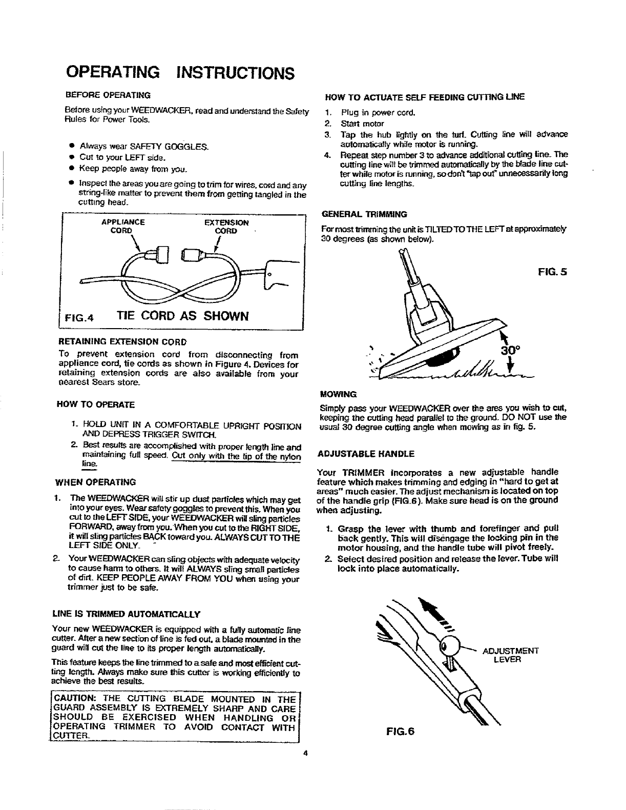
FIG.4 TIE CORD AS SHOWN
RETAINING EXTENSION CORD
To prevent extension cord from disconnecting from
appliance cord, tie cords as shown in Figure 4. Devices for
retaining extension cords are also available from your
oearest Sears store.
HOW TO OPERATE
1. HOLD UNIT IN A COMFORTABLE UPRIGHT POSITION
AND DEPRESSTRIGGER SWITCH.
2. Best resultsare accomplished with properlengthlineand
maintainingfull speed. Cut only with the tip of the nylon
line.
WHEN OPERATING
1. The WEEDWACF,F_Rwig stir up dust particleswhich mayget
into your eyes.Wear safety"goggles to preventthis.Whenyou
cut to theLEFT SIDE, yourWEEJDWACKERwillslingparticles
FORWARD, awayfrom you:When youcutto the RIGHTSIDE,
it wllislingparticlesBACKtoward you. ALWAYSCUT TO THE
LEFT SIDE ONLY_
2. Your WEE])WACKER can Sting objectsw_l adequatevelocity
to cause harm to others. It w_llALWAYS sling smallpa_cfes
of dirt. KEEP PEOPLE AWAY FROM YOU when using your
trimmer just to be safe.
LINE IS TRIMMED AUTOMATICALLY
Your new WEEDWACKER is equipped with a fully automaticline
cutter. Aftera new sectionof line is fed out, a blade mountedinthe
guard willcut the line to itsproper length automatic_dly.
Thisfeature keepsthe Ifnetrimmed to asafe and most effidentcut-
t_g length. Alwaysmake sure this cutter is workingefficientlyto
achieve the be_ result.€.
ICAUTION: THE CUTTING BLADE MOUNTED IN THE_
JGUARD ASSEMBLY IS EXTREMELY SHARP AND CARE |
ISHOULD BE EXERCISED WHEN HANDLING OR I
IOPERATING TRIMMER TO AVOID CONTACT WITH |
.[CUTTER. j
HOW TO ACTUATE SELF FEEDING CUT'RNG UNE
1. Plug in power ccrd.
2. Start motor
3. Tap the hub lightly on the tud. Cuttfng line will advance
automalicalty while motor iS running.
4. Repeat step number 3 to advance additional cuttL-"_3line_ The
cutting line w_l be trimmed automatically by the b_de line cut-
ter-while motor is running, so d0n't _p out_u_y tong
cul_ng line lenglbS.
GENERAL TRIMMING
Formost trimmingthe unitis"13LTEDTOTHE LEFTat appmxSmate_
30 degrees (as shown belew).
FIG. 5
MOWING
Simplypass your WEEDWAOKER over the ares you wish to cut,
keepingthe cuing head parallelto the ground.DO NOT use the
usual 30 degree cutting angle when mowing as in fig. 5.
ADJUSTABLE HANDLE
Your TRIMMER incorporates anew adjustable handle
feature which makes tdmming and edging in "hard to get at
areas" much easier. The adjust mechanism is located on top
of the handle grip {FIG.6). Make sure head is on the ground
when adjusting.
1. Grasp the lever with thumb and forefinger and pull
back gently. This will d_sengagethe locking pin in the
motor housing, and the handle tube will pivot freely.
2. Select desired position and release the lever. Tube will
lock into place automatically.
ADJUSTMENT
LEVER
FIG.6
OPERATING INSTRUCTIONS (cont'd)
POWER MISER
Your WEEDWACKER comes equipped with apower miser
switch located on the front of the handle. This feature
increases the power of your WEEDWACKER and is intended
for use when additional power is needed.
TO REPAIR BROKEN CUTTING UNE
1. Stop the motor an unplugpower cord.
2. Visible cutting line canbe retrieved withneecltenosed pliers.
3. Hub shouldbe depressedand releasedwhitekeepingtension
on the cutting line. One inchof cuttingline sl_ouldfeed each
th,ne the hub isdepressed.
4. If cutting line cannot be retrieved, follow instructionsunder
SPOOL REPLACEMENT.
SPOOL REPLACEMENT
1. Stop motor and unplugPoWercord.
Restrainrearplate,pushin|oc_button(locatedonhub),andtwist
hubcounter-clockwiseuntillockingtabsdisengage.Removehub.
3. Removespool from assemblyand removespring fromspool.
4. Rewindspeol inacco_dancewiththefnstructionsincludedheroin
(fig.8)orreplace spool as appropriate.
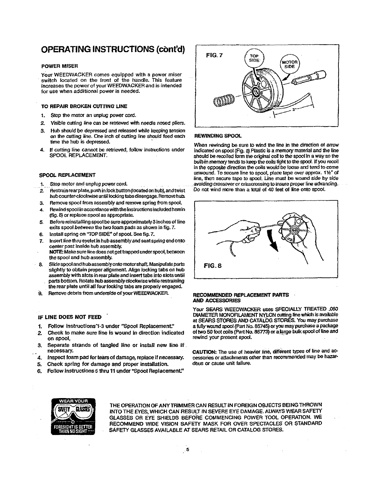
5. BeforereinstaUingspoolbesure appreximatsly3 inchesof line
exits spoolbetweenthe twofoam pads as shown in fig.7.
6. Installspring on 'q'OPSIDE_'of spool Seefig-7.
7. Insertlinethru eyeletin hub assemblyand seatspringendonto
centerpost inside hubassembly.
NOTE:Makesum line doescot getL,appedunderspool,between
the spooland hub assembly.
•8. S!_despoolandhubassemb_yontomotorshaft Manipulateperts
slightly to obtain properalignment.Align lockingtabs on hub
assemb_ with slots in rearplate and insert tabsinto slotsuntil
partsbottorrLRotatehubassemblyctoGkwisewhilerestraJning
the rear plate until all fourlockingtabs are properlyengaged.
9, Removedebrisfrom undersideofyourWEF_DWAGKEFL
IF LINE DOES NOT FEEl)
1. Follow instructions'l-3 under "Spool Replacement?'
2. Check to make sum line is wound in direction indicated
on Spool,
3, Separate strands of tangled line or install new line if.
necessary.
•"4. Inspect foam pad for tears of damage, replace ff necessary.
5. Check spring for damage agd proper installation.
6. Follow instructions 5 thru 11under "Spool Replacement."
FIG. 7
REWINDING SPOOL
When rewinding be sure to wind the line in the direction of arrow
indicated on spool (F_g. 8}.Plastic is amemory material and the line
should be recoiled form the original co_ to the spoOlin a way so the
bu_t-in memory tends to keep the coils t_ghtto the spool tf you recoil
in the opposite direction the coils would be Ioose and tend to come
unwound. To secure ]Jneto spoo!o place tape over approx. 11/=*of
line, then secure tape to spool. Line must be we[rod side by _de
............ avowingcrossoverorcr_._'ossing to insureproperlineadvancing.
DO not wind more than aIota| of 40 feetof line ontospool.
FIG. 8
RECOMMENDED REPLACEMENT PARTS •
AND ACCESSORIES
Your SEARS WEEDWACKER uses sPECIALLY TREATED .080
DIAMETERMONORLAMENT NYLON cutting_whichis available
at SEARS STORES ANB CATAt_0GS_S. You may purchase
afullywoundspool(Part No. 85745)oryoumaypurchaseapeckage
of two50 footcoils(Part No. 85773) ora_rge bulkspoolof lineand
rewindyour present sped.
CAUTION: The use of heavierline, diff';renttypesof line and ao-
cessoriesorattachmentsother than recommendedmay be hazar-
dous or cause unit failur_
THE OPERATION OF ANY TRIMMER CAN RESULTtN FOREIGN OBJECTS BEING THROWN
INTO THE EYES, WHICH CAN RESULT IN SEVERE EYE DAMAGE. ALWAYSWEAR SAFETY
GLASSES OR E_E SHIELDS BEFORE COMMENCING POWER TOOL OPERATION. WE
RECOMMEND WIDE VISION SAFETY MASK FOR OVER SPECTACLES OR STANDARD
SAFETY GLASSES AVAILABLE AT SEARS RETAILOR CATALOG STORES.
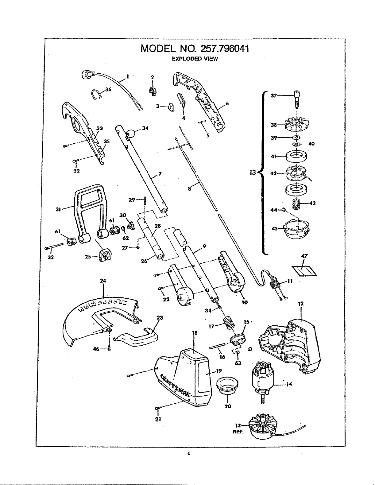
MODEL NO. 257.796041
EXPLODED Vt_W '
6I 62 r"
32 25 26"
24
22
23
12
MOTOR
REF.
NO.
1.
2.
3.
4.
5.
6,
7.
8,
9.
tO.
11.
12.
13.
14.
15.
16.
17.
l&
19_
20.
21.
22.
23,
24=
25.
26.
27.
29.
30.
31.
32.
33.
34,
35.
36.
37.
38.
39.
40,
41.
42.
43.
44.
45.
46.
47.
"-4&
50.
'51.
52.
53.
55.
57.
59.
m
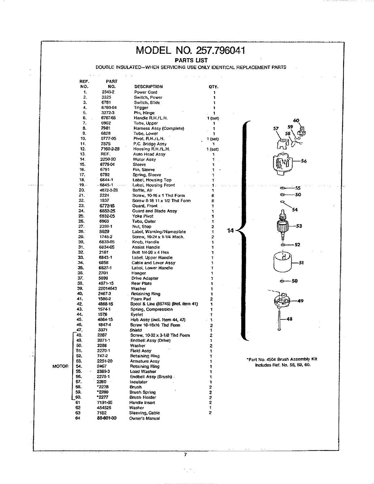
MODEL NO. 257.796041
PARTS LIST
DOUBLE INSULATED--WHEN SERVICING USE ONLY IDENTICAL REPLACEMENT PARTS
PART
NO.
2345-2
3326
6781
6780*04
3272-3
6767.65
6962
7B81
6828
6777-05
7875
716_2-28
REF_
2250-20
6779-04
6791
6799
6844-1
6845ol ......
4872-3-28
2224
1937
677245
6852-25
683205
6963
2359-!
8029
17452
6833-05
6834,05
2!81
6843-1
6858
6827.1
2701
5899
4871-15
22014643
2467-3
1586-2
4868-15
1574-1
157.6
4864.15
18474
337_
2287
207t_1
2288
2270-1
747-2
2251-20
2467
2389-3
:_")75-1
*2278
*_-_o
*2277
7191=0_
454526
7182
88-601_0
DESCRIPTION QTY.
Power Co_d 1
Switch, Power 1
Switch. Slide 1
Trigger 1
Pin, Hinge 1
Handle P_H./L.H. 1 (set)
Tube, Upper t
Harness ASSy (comPJete) 1
Tube, Lower 1
Pivot, R.bLI LH. 1 (Set)
P.C. Bridge Assy 1
Housing _H./LH. I (set)
Auto Head Assy 1
Motor ASsy 1
Sleeve 1
Pin, Sleeve 1 •
S_ring, Sleeve I
_?,be_. Housing Top 1
Label Housing Front .... 1.
Baffle, Air 1
SCrew, 10.16 x I Thd Form 6
Screw 8-18 1t x 112 "Phd Form 8
Guard, Front .1
Guard _nd Blade A_'y 1
Yoke Pivot 1
Tube, Outer 1
Nut, Stop 2
Label Warning ,Nameplate 1
Screw, 10.24 x1-114 Math. 2
Knob, HandTe 1
Assist Handle 1
Bolt II4.20 x 4 Hex 1
L_bel,Upper Handle 1
Cabin and Lever Assy 1
Lab_], Lower H_dle 1
Hanger 1
Drive Adapter 1
Rear Plate 1
Was hat" 1
Retaining Ring 1
Foam Pad 2
Spool &Line (85745) {Incl. item 4IJ 1
Spring, Compression 1
Eyelet 1
Hub Assy (incl. Item 44, 47) 1.
SCrew 10-16xV_ Tbd Fon'n 2
Sh_d 1
Screw. 10-32 x 3-118 Thd Form 2
Endbell Assy (Drive) 1
Washer 2
Field Assy 1
Retairdng Ring 1
Armature Ass)' 1
Ret_nin g Ring 1
Load Washer 1
Endb_l Assy (Brush). 1
InSulator 1
8rush 2
8rUsh Spring 2
Brueh Holder 2
Handle Insert 2
Washer 1
Sleevir,_j, Cable 2
Owner's MamJal
14-<
r6O
57 $9 _'_
@,°
"54
_----- s2
_-----so
"" _49
"Part No. 4504 Brush AssemblyK_t
IncludesReL No. 58, 59, 60.
, . k

OWNER
MANUAL
MODEL NO.
257.796041
Sears
SERVICE
is at
YOUR SERWCE.
How to Order Repair Pa_ r
The Model Number_qll be foundon a p_ateattached to yourWeadwacker
handletube. Alwaysmention/he ModelNumber"when requesting_rvJce
or repair parts for your Craftsman Wesdwacker.
All partsl_ted hereinmay be orderedfrom any SEARS, ROEBUCKAND
CO. retail or catalog store.
WHEN ORDERING REPAIR PARTS,ALWAYS GIVE THE FOLLOWING
INFORMATION.
1. PARTNUMBER
2. PART DESCRIPTION
3_MODEL NUMBER .L. 257.796041
4. NAME OF ITEM _ WEEDAND GRASS TRIMMER
USE ONLY SEARS REPLACEMENT PARTS.
If the parts you need are not stocked locally, your order will be elec-
Ironically transmitted to aSeam Repair Parts Distribution Center for
expedited handling.
"Your Sears merchandise has added value when you consider that Sears has
service units staffed with Sears trained technicans.. ,professional techni-
cians specifically trained on Sears products, having the parts, tools and equip
merit to insure that we meet our pledge to you...we service what we sell;'
FORM 88-601_O
Sold by SEARS, ROEBUCK AND CO., Chicago, IL 60684 U.S.A.
P0687 Printed _n U.S./L
