Craftsman 257857240 User Manual ELECTRIC EDGER Manuals And Guides L0707008
CRAFTSMAN Edger Manual L0707008 CRAFTSMAN Edger Owner's Manual, CRAFTSMAN Edger installation guides
User Manual: Craftsman 257857240 257857240 CRAFTSMAN ELECTRIC EDGER - Manuals and Guides View the owners manual for your CRAFTSMAN ELECTRIC EDGER #257857240. Home:Lawn & Garden Parts:Craftsman Parts:Craftsman ELECTRIC EDGER Manual
Open the PDF directly: View PDF ![]() .
.
Page Count: 8
MODEL NO.
257.857240
CAUTION:
Read RULES for
.Safe OPERATION .
and INSTRUCTIONS
Carefully
ii ill •], • ,........................,,,,,,,,,,, ,,
£RnFTrSMI:IN
ELECTRIC
EDGER
r•r"
DOUBLE INSULATED
•Assembly
•Operating
•Repair Parts
....... i i i,ii,...................................................
Sold by SEARS, ROEBUCK AND CO., Chicago, IL 60684 U.S.A.
ii ii1,111 i w, J viii llll i illl, ii L i ,,i................................... ,..... _ _, ,
FORM 88-4O5-0O Rev. B 0684 . •
FULL ONE-YEAR WARRANTY ON CRAFTSMAN- ELECTRIC EDGER _:_
c=_ If this Craftsumn Electric Edger fails to perform properly due to a defect in inatefial or workmanship within one year
_<
_x from the date of purchase, Sears will repair it free of charge.
If this Craftsman Electric Edger is used for commerdal and rental purposes, this warranty covexag_ applie s for only
90 days from the ,date of purchase, This warranty applies only while this product is in use in the United States.
WARRANTY SERVICE IS AVAILABLE BY CONWACTING THE NEAREST SEARS STORE OR SERVICE
_:_ CENTER THROUGHOUT THE LrNIT!3DSTATES.
<:_ This warranty gives you specific legal fights and you may also have other rights which vary from state to state.
=._ARS, ROEBUCK AND CO., DEPT. 698/731A, Sears Tower, Chicago, IL 60684
IMPORTANT: rules for safe operation
DOUBLE INSULATION
Double Insulationisa conceptinsafety,replacingthestandard
grounded supplysystem in electricpower tcols.Theconstrue-
tion of a double insttlated tool affords comparable pret_etion to a
properly grounded tool without the necessity for usiug a ground-
ed conductor.The double insulationsystem eliminatesthe need
fortheusualthree-wiregroundedpower cordand groundsupply
systenLWherever there iselee_c currentinthe toolthereare
two complete se_s of insulation to protect the user. All exposed
metal parts are isolated from the internal metal motor eom_
ponents with proteetfng instthtion: The lead wires, switch, etc_
with their functional insulation liave the added prote_ion of non-
conductivesleevingor housingtocompletethedoubleinsulation.
system.
SERVICING OF A TOOL WITH-DOUBLE INSULATION lqF__
QUIRES EXTREME CARE AND. KNOWLEDGE OF.THE
SYSTEM AND SHOULD BE PERFORMED ONLY BY A
QUALIFIED SERVICE TECHNICIAN. FOR SERVICE WE
SUGGEST YOU RETURN THE TOOL TO YOUR NEAREST
SEARS STORE FOR REPAIR WHICH WILL BE DONE WITH
ORIGINAL FACTORY REPLACEMENT PARTS.
SAFETY RULES FOR POWER TOOLS
CAUTION
!. Keep hands,feet,and facedear ofrotatingblade.
2. Use SafetyGoggles.Wear ata_ timeswhen usingtoo!`
3. Dress properly.Always wear shoes.Do not operatetool
while barefootor when wearing sandals,canvas or open-
toed shoes.Use of rubber glovesand safetyfootwearis
recommended when working outdoors.Wear longpantsto
protectyour legs.
4. Keep childrenaway. Keep spectatorsat a safedistance.
5. WARNING: To preventelectricshockhazarduseonlywith
an extension cord suitable for outdoor use. A two-wire e_rd
withoutaground connectionmay be used sincethetoolis
double insulated. Cord should be !8 gauge or heavier to pre-
vent overheating and loss of power, U.L. listed extension
cords are available at your nearest Sears store.
6. Toprevent disconnection of power supply cord from the ez-
tension cord during operation see hstructions v_h Fig. 4.
7. _Avoid Dangerous Environment-- Do not use unit in damp or
8. Don't force this too!. It wi!l work begter and safer at the rate
R was designed.Ifmotor slows down too much,pullaway
and allowunitto bbta_nfullspee&
9. Do not use toolfor any job exceptthat _orwhich itis
intended.
10. Do not immerse tool in water or operate in rai_
1i. Don't overreach--Keep proper footing and balance at all
ti_es.
t2. Don't abuse cord--Never e_rr_tool by Cord o_ yank cord
from receptacle.Keep cordaway from heat,oiiand sharp
edges.Replacedamaged cordimmediately.
13. Nevercarry pluggedintoo!with fingeron switch,
14= Disconnecttoolfrom thepower.supplywhen notinuse and
when making any repairsor inspections.
I5. Maintain tool withcare. Keep air ventsclearof debris. Keep
guards in place arm in working orderand follow instructions
forreplacingblade.
16. _tore indoorsin a high,dry,lock-upplaceoutofreathof
children.
Page2
BOX CONTENTS
This box should contain:
1 257.857240 Electric Edger
1 Loose Parts Kit containin_
2Ea. 3933-1 Screw
2 Ea. 3935 Locknut
1 Ea. 88-4054)0Owner'sManual
TOOLS NEEDED FOR ASSEMBLY
1 Phillips Screwdriver
111/32 Box or Crescent Wrench
Remove Edger from carton and examine it
thoroughly to make sure it is not damaged.
NOTE: Your Edger comes packaged wfth protective clips inserted in the .handle tubes. These plastic clips
must be discarded before assembly of the unit,
= === ,_ll,,lll i i i i =l =
ASSEMBLY INSTRUCTIONS
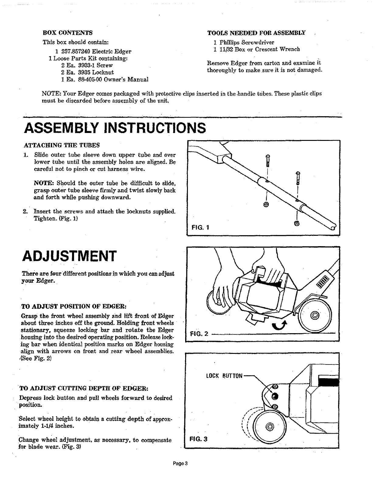
ATTACHING THE TUBES
1. Slide outer tube sleeve down upper tube and over
lower tube until the assembly holes are aligned. Be
careful not to pinch or cut harness wire.
NOTE: Should the outer tube be difficult to slide,
grasp outer tube sleeve firmly and twist slowly back
and forth while pushing downward.
2. Insertthe screws and attachthe locknutssupplied.
Tighten. (Fig. I)
@
ADJUSTMENT
There arefourdifferentpositionsinwhich you canadjust
your Edger.
.TO ADJUST POSITION OF EDGER:
Grasp the frontwheel assemblyand llftfrontof Edger
about threeinchesoffthe ground.Holding frontwheels
stationary,squeeze lockingbar and rotate the Edger
housing intothe desiredoperatingposition.Release10ck-
ing bar when identicalpositionmarks on Edger housing
alignwith arrows on frontand rear wheel assemblies.
,(See Fig. 2)
TO ADJUST CUTTING DEPTH OF EDGER:
:Depress lock button and pul! wheels forward to desired
position.
Selectwheel heighttoobtaina cuttingdepth of approx-
imately1-1/4inches.
iChange wheel adjustment, as necessary, to compensate
for blade wear. (Fig. 3}
Page3
OPERATING INSTRUCTIONS
....u,,,, , i;i i,L. ill iilllllll
BEFORE OPERATING:
Read and understand the safety rules for power tools.
•Always wear safety goggles.
Keep people at a safe distance.
Inspect area for wires,, glass, and other foreign objects.
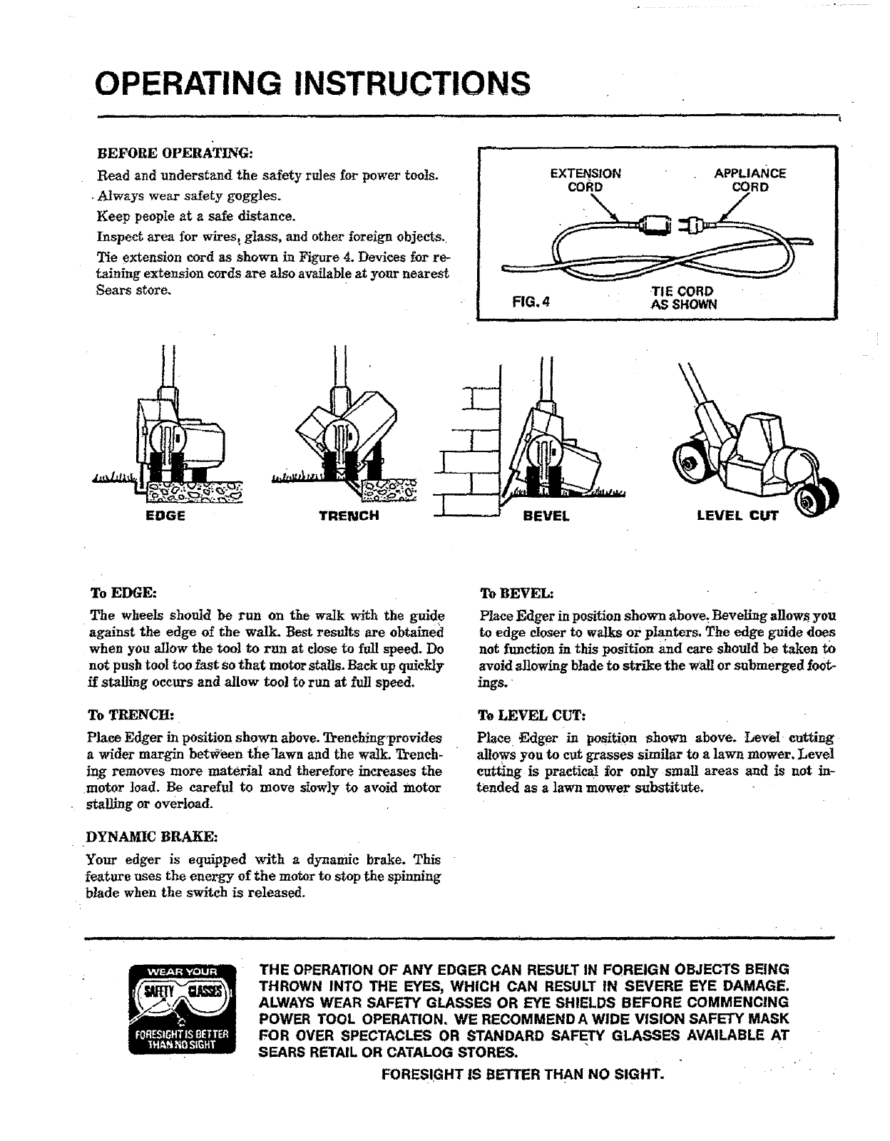
Tie extension cord as shown in Figure 4. Devices for re-
tainlng extension cords are also available at your nearest
Sears store.
EXTENSION
CORD
.................. ,i i ....
APPLIANCE
CORD
TIE CORD
FIG. 4 AS SHOWN
iiiiii i Hi ...... ,,,,,_,.,Ju,, i
EDGE TRENCH BEVEL LEVEL CUT
To EDGE:
The wheels should be run on the walk with the guide
against the edge of the walk. Best results are obtained
when you allow the tool to run at close to full speed. Do
not push tool too fast so that motor stalls. Back up quickly
if stalling occurs and allow tool to run at full speed.
To TRENCH:
Place Edger in position shown above. Trenching,provldes
awider margin betv_een the]awa and the watl_ Trench-
ing removes more material and therefore increases the
motor load. Be careful to move slowly to avoid motor
stalling or overload.
DYNAMIC BRAKE:
Your edger is equipped with adynamic brake. This
feature uses the energy of the motor to stop the spinning
blade when the switch is released.
To BEVEL:
Place Edger in position shown above. Beveling allows you
to edge closer to walks or planters. The edge guide dees
not function in this position and care should be taken to
avoid allowing blade to strike the Wall or submerged foot-
ings.
To LEVEL CUT:
Place _dger in position shown above. Level cutting
allows you to cut grasses similar to a lawn mower. Level
cutting is practical for only small areas and is not in-
tended as a lawn mower substitute.
THE OPERATION OF ANY EDGER CAN RESULT IN FOREIGN OBJECTS BEING
THROWN INTO THE EYES, WHICH CAN RESULT IN SEVERE EYE DAMAGE.
ALWAYS WEAR SAFETY GLASSES OR EYE SHIELDS BEFORE COMMENCING
POWER TOOL OPERATION. WE RECOMMENDA WIDE VISION SAFETY MASK
FOR OVER SPECTACLES OR STANDARD SAFETY GLASSES AVAILABLE AT
SEARS RETAIL OR CATALOG STORES.
FORESIGHT IS BETTER THAN NO SIGHT.
i i , Ill, II IIII IIIII I IIIIIIII I I
KEEP BLADE AREA CLEAN
Mud and grass around blade area must be cleaned away
regularly.
Make sure Edger is unplugged. Depress latch on side
guard to open. Glean out accumulated debris.
CAUTION: Do not operate tool with side guard
detached or open.
RECOMMENDED BLADE REPLACEMENT.
To maintain operating efficiency rcpla_ blade before wear
decreases length to six inches.
The blade supplied is specifically designed for this Edger.
Use of improper blades may behazardous.
Areplacement blade (Stock No. 85767) or a package of
three (Stock No. 85762) may be purchased from your
nearest Sears store or catalog outlet.
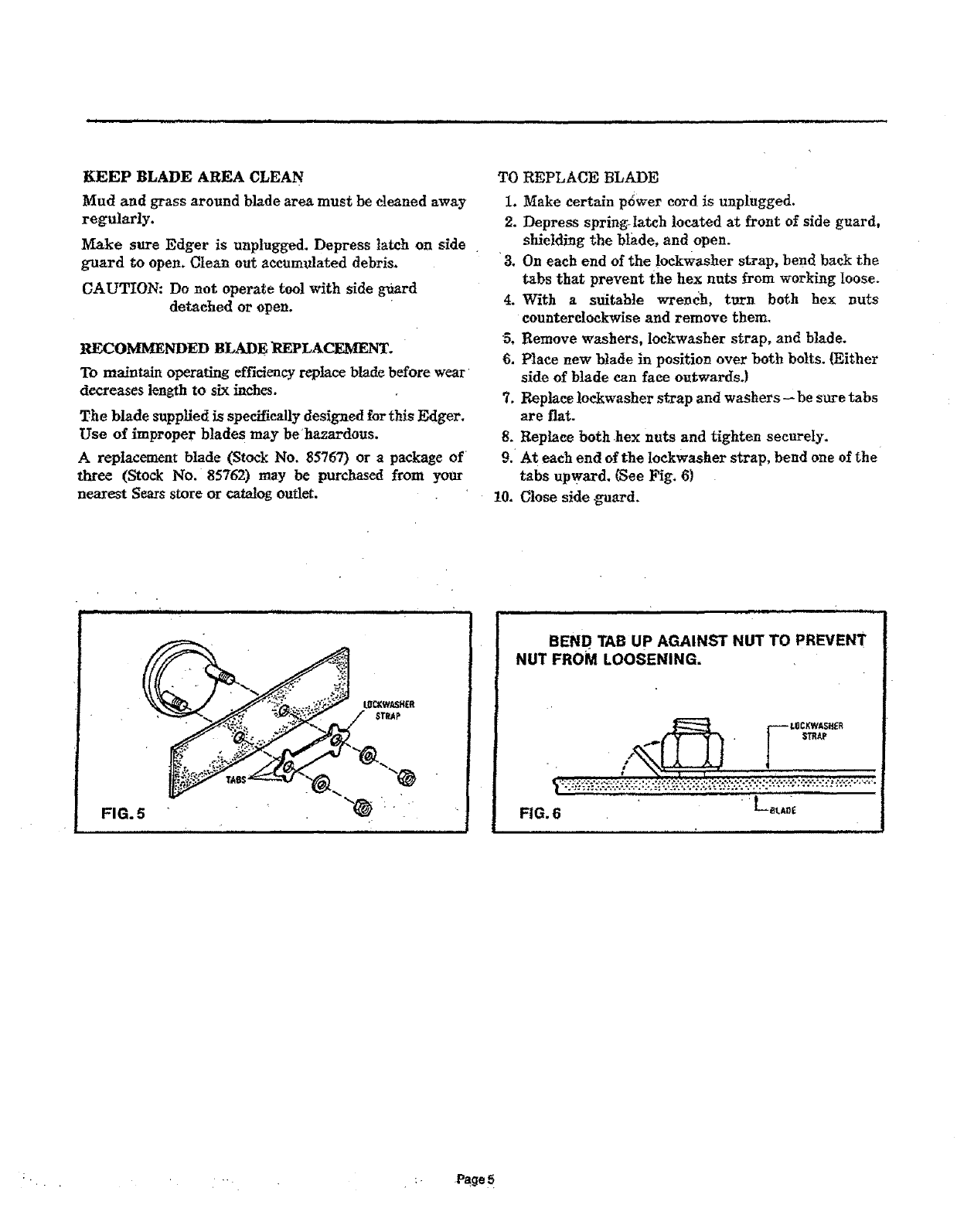
TO REPLACE BLADE
1. Make certain p6wer cord is unplugged.
2. Depress spring-latch located at front of side guard,
shielding the btade, and open.
•3. On each end of the loekwasher strap, bend back the
tabs that prevent the hex nuts _rom working loose.
4. With a suitable wrench, turn both hex nuts
counterclockwise and remove them.
5. Remove washers, lockwasher strap, and blade.
6. Place new blade in position over beth belts. (Either
side of blade can face outwards.}
7. Replace lockwasber strap and washers-- be sure tabs
are flat.
8. Replace both hex nuts and tighten securely.
9. At each end of the Ioekwasher strap, bend one of the
tabs upward. (See Fig. 6)
10. Close side guard.
iii iii
FIG. 5 ""_ :"
iii iiii i iii ii_ii iiiiiii iii i
BEND TAB UP AGAINST NUT TO PREVENT
NUT FROM LOOSENING.
•{-- i
FIG, 6
.... "" :" Page5
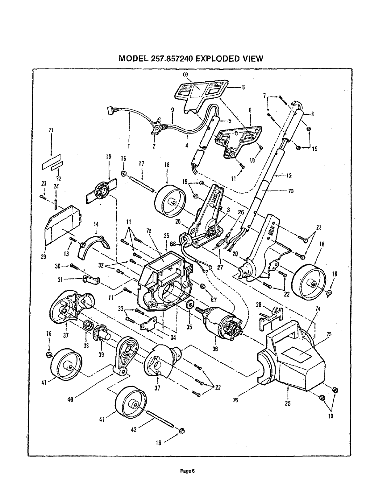
MODEL 257.857240 EXPLODED VIEW
69
71
!
16
l
11 20
25
/
11
37
39
\
22
25
74
75
t9
Pa.qe6
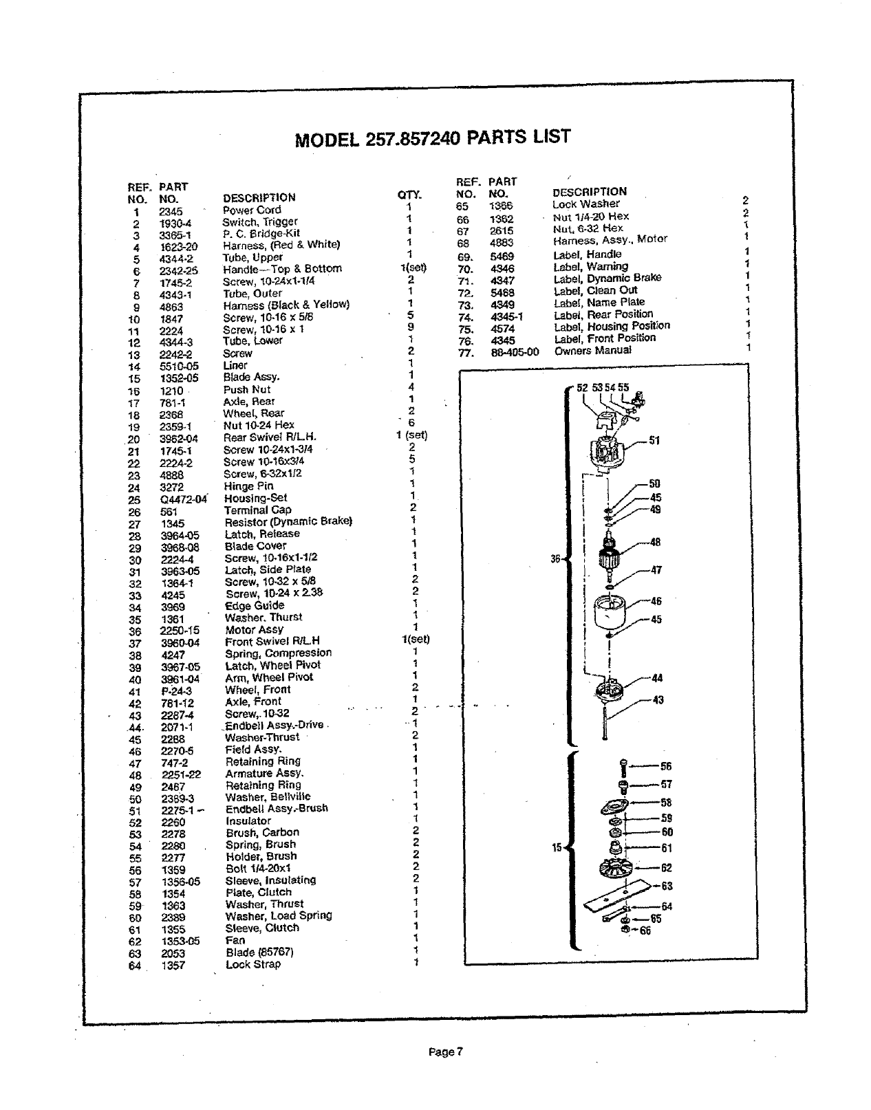
MODEL 257.857240 PARTS LIST
REF. PART
NO. NO.
1 2345
21930-4
3 3365-!
4 !623-20
5 4344-2
6 2342.25
7 1745-2
8 4343-1
9 4863
t0 1847
11 2224
12 4344-3
13 ?.242-2
14 5510-05
15 1352-05
15 1210
17 781-I
18 2368
19 2359-_;
20 3962-04
21 1745-1
22 2224-2
23 4888
24 3272
25 Q4472-04
26 561
27 1345
28 3964-05
29 3968-08
30 2224-4
31 3963-05
32 1364-1
33 4245
34 3969
35 1361
36 :2250-15
37 3980-04
38 4247
39 3967-05
40 3,_614_4
41 P.24-3
42 781-I2
43 2287-4
44. 2071-1
45 2288
46 2270-5
47 747-2
48 2251-22
49 2467
50 236'9-3
51 2275-1 -
52 2260
53 2278
54 2280
55 2277
56 1359
57 1356-05
58 1354
59 1363
60 2389
61 1355
62 1353-05
63 2053
64 1357
DESCRIPTION
Power Cord
Switch, Trigger
P. C. Bridge.Kit
Harness, (Red & White)
Tube, Upper
Handle--Top & Bottom
Screw, 10.24x1-114
Tube, Outer
Harness (Black & Yellow)
Screw, 10-16 _5f6
Screw, 10-16 x 1
Tube. Lower
Screw
Liner
Blade Assy.
Push Nut
A×le, Rear
Wheels Rear
Nut 10-24 Hex
Rear Swivel R/LH.
Screw 10-24xl-314
Screw 10-16×3/4
Screw, _-32x If2
Hinge Pin
Housing-Set
Terminal Gap
Resistor (Dynamic Brake)
Latch, Release
B_ade Cover
Screw, 10`16x1.1/2
Latch, Side Plate
Screw, 10-32 x 5/8
Screw, 10-24 x 2_38
Edge Guide
Washer. Thurst
Motor Assy
Front Swivel R/LH
Spring, Compression
Latch, Wheel Pivot
Arm, Wheel Pivot
Wheel, Front
Axle, Front
Screw,. 10-32
_F-.ndbellAssy..-Drive.
WaSher.Thrust ,
Field Assy.
Retaining Rin_l
Armature Assy.
Retaining Ring
Washer, Bellville
Endbetl Assy._Br_sh
Insulator
Brush, Carbon
Spring, Brush
Holder, Brush
Bolt t!4-20xl
Sleeve, Insulating
Plate, Clutch
Washer, Thrust
Washer, Load Spring
Sleeve, Clutch
Fan
Blade (85767)
Lock Strap
QTY.
1
I
I
I
I
1(se_)
2
I
1
5
9
I
2
1
I
4
I,
2
6
I (sat)
2
5
1
1
1
2
1
1
1
1
1
2
2
1
1
1
1(set)
1
1
1
2
I
2
1
1
1
1
1
1
1
2
2
2
2
2
1
1
1
1
1
t
1
R_F. PART
NO. NO.
65 1366
6_ _362
67 2615
68 4883
69. 5469
70. 4346
71. 4347
72. 5468
73, 4349
74, 4345-1
75. 4574
76. 4345
77. 88-405-00
DESCRIPTION
Lock Washer
, Nut 1;4-20 He×
Nut, 6-32 Hex
Harness, Assy., Motor
Label, Handle
Lebet, Warning
Label, Dynamic Brake
L_bel, Clean OUt
Label, Name Plate
L_bel, Rear Position
Label, Housing Position
Label, Front Position
Owners Manua3
1_56
_-----60
,,u ...............
2
2
1
1
1
1
1
1
1
1
1
"F
1
............... _._ .|1 ir Iii i I ii ,,11 ,i,l,llnl -- -- _
Page7
•11
[Sears
OWNER'S
MANUAL
MODEL NO.
257.857240
Sears
SERVICE
is at
YOUR
SERVICE.
=,1
ii|
IIIIIIIIIIIIINH
=
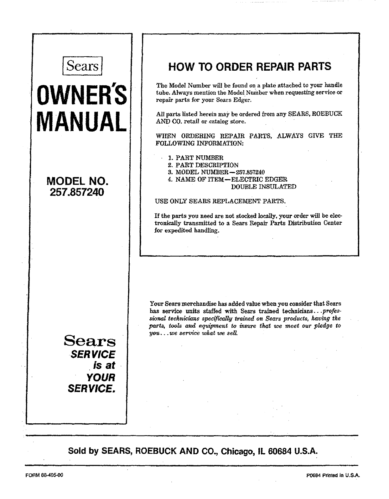
HOW TO ORDER REPAIR PARTS
The Model Number wil! be found on a plate attached to yotw handle
tube. Always mention the Model Number when requesting service or
repair parts for your Sears Edger.
All parts listed herein may be ordered from any SEARS, ROEBUCK
AND CO. retail or catalog store.
WHEN ORDERING REPAIR PARTS, ALWAYS GIVE THE
FOLLOWING 1Y_FORMATION:
!. PART NUMBER
2. PART DESCRIPTION
3. MODEL NUMBF_257.857240
4. NAME OF ITEM--ELECTRIC EDGER
DOUBLE INSULATED
USE ONLY SEARS REPLACEMENT PARTS.
If the parts you need are not stocked locally, your order wilt be elec-
tronically transmitted to a Sears Repair Parts Distribution Center
for expedited handling.
Your Sears merchandise has added value when you consider that Sears
has service units staffed with Sears trained technicians...profes-
sional technicians spec_wally trained on Sears products, having the
parts, tools and equiFmeut to insure that we meet our pledge to
you.., we service what we sell
L i=l,, ,t, =t :: _/ .................
Sold by SEARS, ROEBUCK AND CO., Chicago, IL 60684 U.S.A.
== i, i ..............................................................................
FORM 88*405-00 P0684 Printed in U,S.A.
