Craftsman 315101120 User Manual ELECTRONIC DRILL Manuals And Guides L0204028
CRAFTSMAN Drill Reversing Manual L0204028 CRAFTSMAN Drill Reversing Owner's Manual, CRAFTSMAN Drill Reversing installation guides
User Manual: Craftsman 315101120 315101120 CRAFTSMAN ELECTRONIC DRILL - Manuals and Guides View the owners manual for your CRAFTSMAN ELECTRONIC DRILL #315101120. Home:Tool Parts:Craftsman Parts:Craftsman ELECTRONIC DRILL Manual
Open the PDF directly: View PDF ![]() .
.
Page Count: 14
Operator's Manual
112in. ELECTRONIC DRILL
Variable Speed/Reversible
Double Insulated
Model No.
315.101120
Save this manual for
future reference
_IL CAUTION: Read and
follow all Safety Rules and
Operating Instructions before
first use of this product.
•Safety
•Features
•Operation
•Maintenance
•Parts List
Customer Help Line: 1-800-932-3188
Sears, Roebuck and Co., 3333 Beverly Rd., Hoffman Estates, IL 60179 USA
Visit the Craftsman web page: www.Sears.com/craftsman
972000-949
1-02
• Table of Contents ...................................................................................................................................................... 2
• Safety Rules ........................................................................................................................................................... 2-3
• Symbols .................................................................................................................................................................... 4
• Features .................................................................................................................................................................... 5
• Operation ............................................................................................................................................................... 6-9
• Maintenance ........................................................................................................................................................... 10
• Accessories ............................................................................................................................................................. 11
• Exploded View and Repair Parts List ................................................................................................................ 12-13
• Parts Ordering /Service ......................................................................................................................................... 14
,_ WARNING: Read and understand all instruc-
tions. Failure to follow all instructions listed below,
may result in electric shock, fire and/or serious
personal injury.
READ ALL INSTRUCTIONS
• Know your power tool. Read operator's manual
carefully. Learn its applications and limitations as
well as the specific potential hazards related to this
tool.
• Guard against electrical shock by preventing body
contact with grounded surfaces. For example: Pipes,
radiators, ranges, refrigerator enclosures.
• Keep guards in place and in working order.
• Double insulated tools are equipped with a
polarized plug (one blade is wider than the
other). This plug will fit in a polarized outlet only
one way. If the plug does not fit fully in the outlet,
reverse the plug. If it still does not fit, contact a
qualified electrician to install apolarized outlet.
Do not change the plug in any way. Double
insulation [] eliminates the need for the three-wire
grounded power cord and grounded power supply
system.
•Keep work area clean. Cluttered areas and
benches invite accidents.
• Avoid dangerous environment. Don't use power
tool in damp or wet locations or expose to rain. Keep
work area well lit.
Keep children and visitors away. All visitors should
wear safety glasses and be kept a safe distance
from work area. Do not let visitors contact tool or
extension cord.
•Store idle tools. When not in use tools should be
stored in a dry and high or locked-up place - out of
the reach of children.
•Don't force the tool. Don't force small tool or
attachment to do the job of a heavy duty tool. Don't
use tool for purpose not intended - for example - A
circular saw should never be used for cutting tree
limbs or logs.
•Dress properly. Do not wear loose clothing or
jewelry. Contain long hair. Keep your hair,
clothing, and gloves away from moving parts.
Loose clothes, jewelry, or long hair can be caught in
moving parts.
•Always wear safety glasses. Everyday eyeglasses
have only impact-resistant lenses; they are NOT
safety glasses.
• Protect your lungs. Wear a face or dust mask if
the operation is dusty. Following this rule will
reduce the risk of serious personal injury.
• Protect your hearing. Wear hearing protection
during extended periods of operation. Following
this rule will reduce the risk of serious personal
injury.
•Don't abuse cord. Never carry tool by cord or yank
it to disconnect from receptacle. Keep cord from
heat, oil and sharp edges.
• Secure work. Use clamps or another practical way
to secure and support the workpiece to a stable
platform. Holding the work by hand or against your
body is unstable and may lead to loss of control.
2
•Don't overreach. Keep proper footing and balance
at all times. Do not use on a ladder or unstable
support.
•Maintain tools with care. Keep tools sharp and
clean at all times for best and safest performance.
Follow instructions for lubricating and changing
accessories.
Disconnect tools. When not in use, before servic-
ing, or when changing attachments, blades, bits,
cutters, etc., all tools should be disconnected from
power supply.
Remove adjusting keys and wrenches. Form
habit of checking to see that keys and adjusting
wrenches are removed from tool before turning it on.
Avoid accidental starting. Don't carry plugged-in
tools with finger on switch. Be sure switch is off
when plugging in.
Make sure your extension cord is in good
condition. When using an extension cord, be
sure to use one heavy enough to carry the
current your product will draw. A wire gage size
(A.W.G.) of at least 16 is recommended for an
extension cord 100 feet or less in length. A cord
exceeding 100 feet is not recommended. If in
doubt, use the next heavier gage. The smaller
the gage number, the heavier the cord. An
undersized cord will cause a drop in line voltage
resulting in loss of power and overheating.
Outdoor use extension cords. When tool is used
outdoors, use only extension cords suitable for use
outdoors. Outdoor approved cords are marked with
the suffix W-A, for example -SJTW-A or SJOW-A.
Keep bits clean and sharp. Sharp bits minimize
stalling kickback.
Keep hands away from drilling area. Keep hands
away from bits. Do not reach underneath work while
bit is rotating. Do not attempt to remove material
while bit is rotating.
Never use in an explosive atmosphere. Normal
sparking of the motor could ignite fumes.
Inspect tool cords periodically and, if damaged,
have repaired at your nearest authorized ser-
vice center. Constantly stay aware of cord
location. Following this rule will reduce the risk of
electric shock or fire.
Inspect extension cords periodically and replace
if damaged.
Keep handles dry, clean, and free from oil and
grease. Always use a clean cloth when cleaning.
Never use brake fluids, gasoline, petroleum-based
products or any strong solvents to clean your tool.
Stay alert. Watch what you are doing and use
common sense. Do not operate tool when you are
tired. Do not rush.
Check damaged parts. Before further use of the
tool, a guard or other part that is damaged should be
carefully checked to determine that it will operate
properly and perform its intended function. Check for
alignment of moving parts, binding of moving parts,
breakage of parts, mounting, and any other condi-
tions that may affect its operation. A guard or other
part that is damaged should be properly repaired or
replaced by an authorized service center. Following
this rule will reduce the risk of electric shock, fire, or
serious injury.
Do not use tool if switch does not turn it on and
off. Have defective switches replaced by an autho-
rized service center.
•Drilling into electrical wiring in walls can cause
drill bit and chuck to become electrically live.
Do not touch the chuck or metal housing when
drilling into a wall; grasp only the insulated
handle(s) provided on the tool.
•Inspect for and remove all nails from lumber
before drilling. Following this rule will reduce the
risk of serious personal injury.
•Drugs, alcohol, medication. Do not operate tool
while under the influence of drugs, alcohol, or
any medication. Following this rule will reduce the
risk of electric shock, fire, or serious personal injury.
•Save these instructions. Refer to them frequently
and use them to instruct others who may use this
tool. If you loan someone this tool, loan them these
instructions also.
WARNING: Some dust created by power
sanding, sawing, grinding, drilling, and other
construction activities contains chemicals known
to cause cancer, birth defects or other reproduc-
tive harm. Some examples of these chemicals are:
•lead from lead-based paints,
•crystalline silica from bricks and cement and
other masonry products, and
• arsenic and chromium from chemically-treated
lumber.
Your risk from these exposures varies, depending
on how often you do this type of work. To reduce
your exposure to these chemicals: work in awell
ventilated area, and work with approved safety
equipment, such as those dust masks that are
specially designed to filter out microscopic par-
ticles.
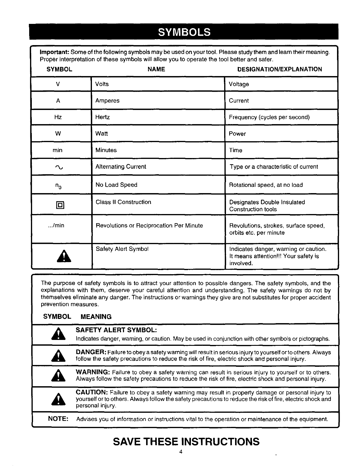
Important: Some of the following symbols may be used on your tool. Please study them and learn their meaning.
Proper interpretation of these symbols will allow you to operate the tool better and safer.
SYMBOL NAME DESIGNATION/EXPLANATION
V Volts Voltage
A Amperes Current
Hz Hertz Frequency (cycles per second)
W Watt Power
min Minutes Time
"v Alternating Current Type or a characteristic of current
no No Load Speed Rotational speed, at no load
[] Class II Construction Designates Double Insulated
Construction tools
.../min Revolutions or Reciprocation Per Minute Revolutions, strokes, surface speed,
orbits etc. per minute
Safety Alert Symbol Indicates danger, warning or caution.
,i_ It means attention!!! Your safety is
involved.
The purpose of safety symbols is to attract your attention to possible dangers. The safety symbols, and the
explanations with them, deserve your careful attention and understanding. The safety warnings do not by
themselves eliminate any danger. The instructions or warnings they give are not substitutes for proper accident
prevention measures.
SYMBOL MEANING
_k, SAFETY ALERTSYMBOL:
_ndicatesdanger_waming__rcauti_n.Maybeusedinc_njuncti_nwith_thersymb__s_rpict_graphs_
,_ DANGER: Failure to obey a safety warning will result in serious injury to yourself or to others. Always
follow the safety precautions to reduce the risk of fire, electric shock and personal injury.
WARNING: Failure to obey a safety warning can result in serious injury to yourself or to others.
Always follow the safety precautions to reduce the risk of fire, electric shock and personal injury.
CAUTION: Failure to obey a safety warning may result in property damage or personal injury to
others, follow the to reduce the risk of electric shock and
yourself or to Always safety precautions fire,
personal injury.
NOTE: Advises you of information or instructions vital to the operation or maintenance of the equipment.
SAVE THESE INSTRUCTIONS
4
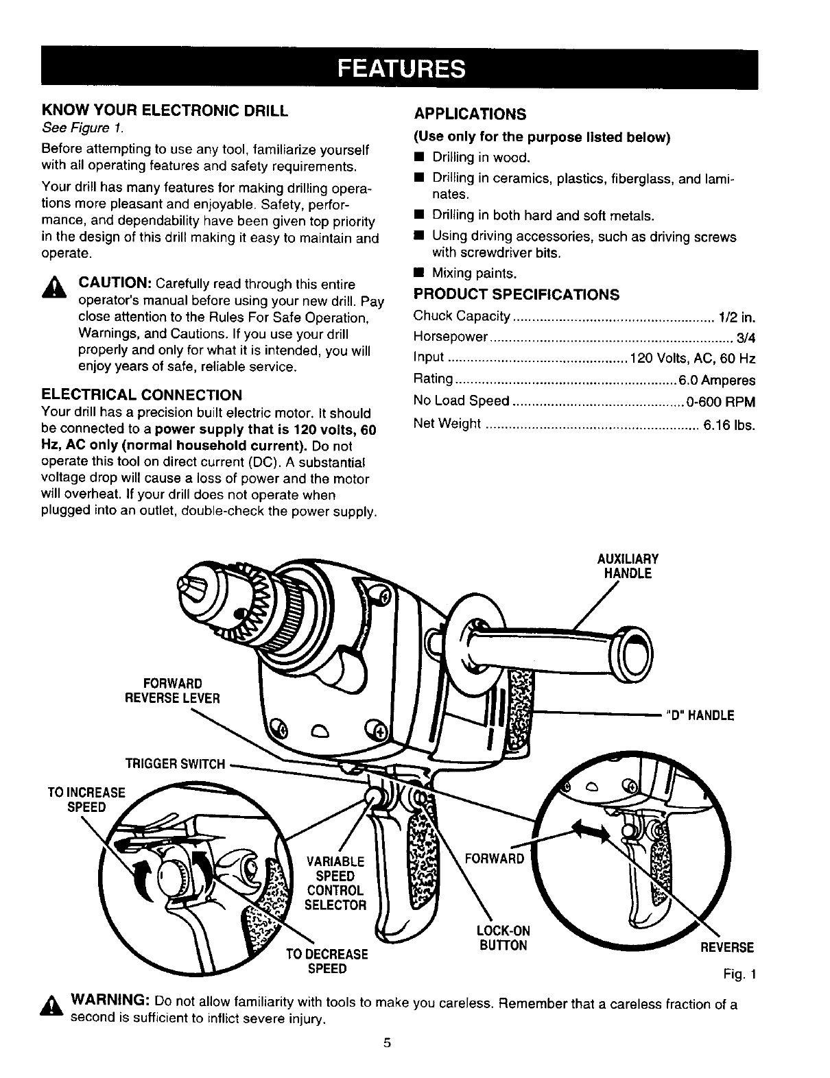
KNOWYOURELECTRONICDRILL
See Figure 1.
Before attempting to use any tool, familiarize yourself
with all operating features and safety requirements.
Your drill has many features for making drilling opera-
tions more pleasant and enjoyable. Safety, perfor-
mance, and dependability have been given top priority
in the design of this drill making it easy to maintain and
operate.
ACAUTION: Carefully read through this entire
operator's manual before using your new drill. Pay
close attention to the Rules For Safe Operation,
Warnings, and Cautions. If you use your drill
properly and only for what it is intended, you will
enjoy years of safe, reliable service.
ELECTRICAL CONNECTION
Your drill has a precision built electric motor. It should
be connected to a power supply that is 120 volts, 60
Hz, AC only (normal household current). Do not
operate this tool on direct current (DC). A substantial
voltage drop will cause aloss of power and the motor
will overheat. If your drill does not operate when
plugged into an outlet, double-check the power supply.
APPLICATIONS
(Use only for the purpose listed below)
• Drilling in wood.
• Drilling in ceramics, plastics, fiberglass, and lami-
nates.
• Drilling in both hard and soft metals.
• Using driving accessories, such as driving screws
with screwdriver bits.
• Mixing paints.
PRODUCT SPECIFICATIONS
Chuck Capacity ..................................................... 1/2 in.
Horsepower ................................................................ 3/4
Input ............................................... 120 Volts, AC, 60 Hz
Rating .......................................................... 6.0 Amperes
No Load Speed ............................................. 0-600 RPM
Net Weight ........................................................ 6.16 Ibs.
AUXILIARY
HANDLE
FORWARD
REVERSELEVER
TRIGGERSWITCH
TOINCREASE
SPEED
D"HANDLE
LOCK-ON
BUII'ON REVERSE
TO DECREASE
SPEED Fig. 1
_k WARNING: Do not allow familiarity with tools to make careless. Remember that careless fraction of
you aa
second is sufficient to inflict severe injury.
_i WARNING: Always wear safety goggles or safety
glasses with side shields when operating your drill.
Failure to do so could result in dust, shavings,
loose particles or foreign objects being thrown into
your eyes, causing possible serious injury.
_lb WARNING: If any parts are missing, do not
operate this tool until the missing parts are
replaced. Failure to do so could result in possible
serious personal injury.
SWITCH
To turn your drill ON, depress the switch trigger.
Release switch trigger to turn your drill OFF.
LOCK-ON BUTTON
Your drill is equipped with a lock-on feature, which is
convenient when continuous drilling for extended
periods of time is required. To lock-on, depress the
switch trigger, push in and hold the lock-on button
located on the side of the handle, then release switch
trigger. Release lock-on button and your drill will
continue running.
To release the lock, depress the switch trigger and
release.
If you have the lock-on feature engaged during use and
your drill becomes disconnected from power supply,
disengage the lock-on feature immediately.
_k WARNING: Your drill should never be connected
to power supply when you are assembling parts,
making adjustments, installing or removing drill
bits, cleaning, or when not in use. Disconnecting
your drill will prevent accidental starting that could
cause serious personal injury.
REVERSIBLE
See Figure 2.
Your electric drill has the feature of being reversible.
The directior) of chuck rotation is controlled by a lever
located above the switch trigger. With your drill held in
normal operating position, the direction of rotation lever
should be positioned to the left of the switch for drilling.
The drill direction is reversed when the lever is to the
right of the switch.
_l t "
FORWA_
"_ REVERSE
Fig. 2
The design of the switch will not permit changing the
direction of rotation while the drill is running. Release
the switch trigger and allow the drill to stop before
changing its direction.
Note: Your drill will net run unless the switch lever is
pushed fully to the left or right.
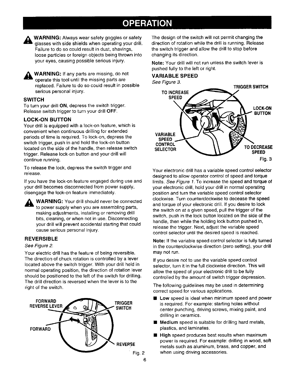
VARIABLE SPEED
See Figure 3.
TO INCREASE
SPEED
\
TRIGGERSWITCH
LOCK-ON
BUTTON
VARIABLE
SPEED
CONTROL
SELECTOR TO DECREASE
SPEED
Fig. 3
Your electronic drill has a variable speed control selector
designed to allow operator control of speed and torque
limits. See Figure 1. To increase the speed and torque of
your electronic drill, hold your drill in normal operating
position and turn the variable speed control selector
clockwise. Turn counterclockwise to decease the speed
and torque of your electronic drill. If you desire to lock
the switch on at a given speed, pull the trigger of the
switch, push in the lock button located on the side of the
handle, then while the holding lock button pushed in,
release the trigger. Next, adjust the variable speed
control selector until the desired speed is reached.
Note: If the variable speed control selector is fully turned
in the counterclockwise direction (zero setting), your drill
may not run.
If you desire not to use the variable speed control
selector, turn it in the full clockwise direction. This will
allow the speed of your electronic drill to be fully
controlled by the amount of switch trigger depression.
The following guidelines may be used in determining
correct speed for various applications.
• Low speed is ideal when minimum speed and power
is required. For example: starting holes without
center punching, driving screws, mixing paint, and
drilling in ceramics.
•Medium speed is suitable for drilling hard metals,
plastics, and laminates.
•High speed produces best results when maximum
power is required. For example: drilling in wood, soft
metals such as aluminum, brass, and copper, and
when using driving accessories.
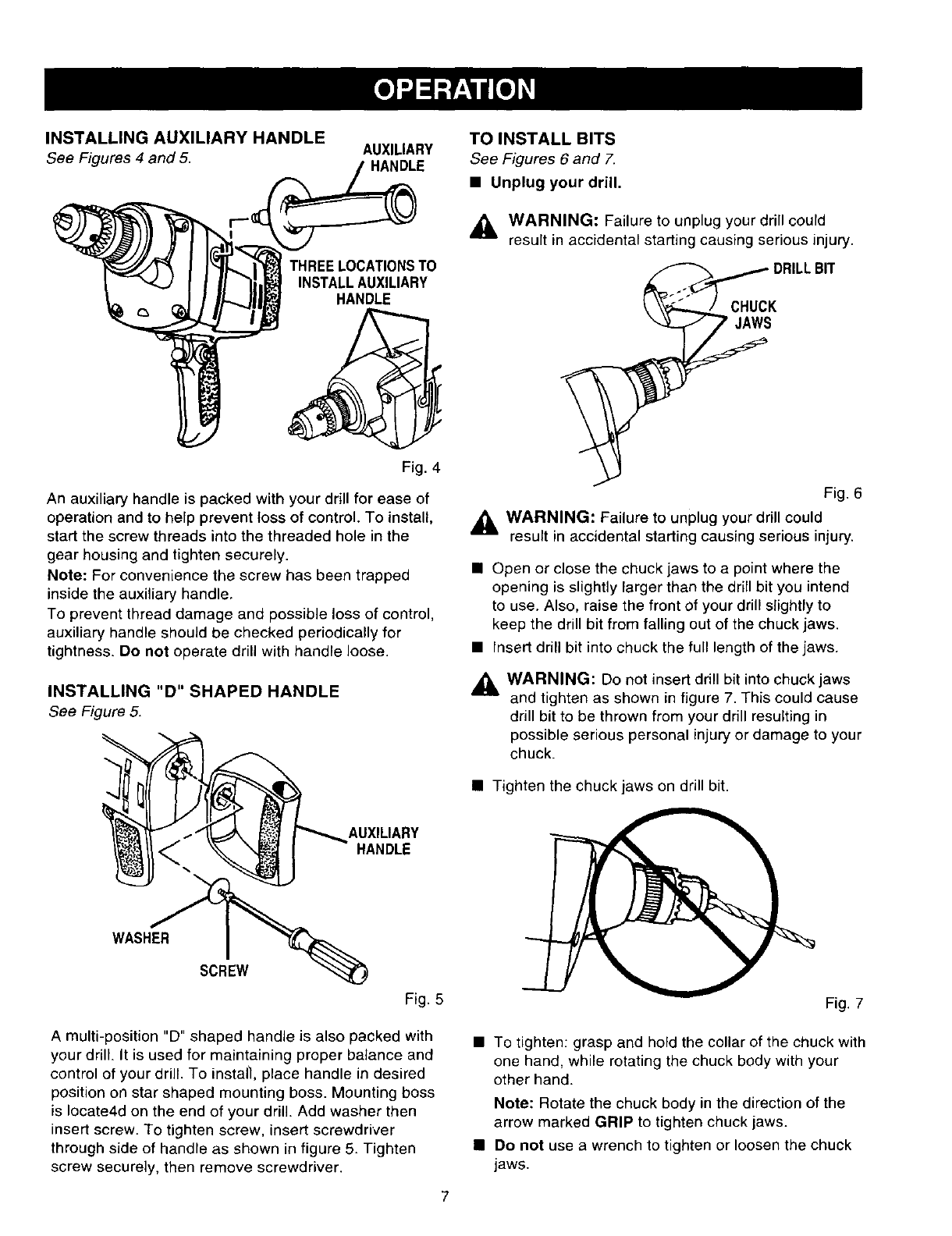
INSTALLING AUXILIARY HANDLE
See Figures 4 and 5. AUXILIARY
HANDLE
TO INSTALL BITS
See Figures 6 and 7.
•Unplug your drill.
THREE LOCATIONSTO
INSTALLAUXILIARY
HANDLE
Fig. 4
An auxiliary handle is packed with your drill for ease of
operation and to help prevent toss of control. To install,
start the screw threads into the threaded hole in the
gear housing and tighten securely.
Note: For convenience the screw has been trapped
inside the auxiliary handle.
To prevent thread damage and possible loss of control,
auxiliary handle should be checked periodically for
tightness. Do not operate drill with handle loose.
INSTALLING "D" SHAPED HANDLE
See Figure 5.
AUXILIARY
HANDLE
WASHER
SCREW
Fig. 5
WARNING: Failure to unplug your drill could
result in accidental starting causing serious injury.
I_CHuc:RILL BIT
Fig. 6
,_ WARNING: Failure to unplug your drill could
resurt in accidental starting causing serious injury.
• Open or close the chuck jaws to a point where the
opening is slightly Farger than the drill bit you intend
to use. Also, raise the front of your drill slightly to
keep the drill bit from falling out of the chuck jaws.
• Insert drill bit into chuck the full length of the jaws.
_k WARNING: Do not insert drill bit into chuck jaws
and tighten as shown in figure 7. This could cause
drill bit to be thrown from your drill resulting in
possible serious personal injury or damage to your
chuck.
• Tighten the chuck jaws on drill bit.
Fig. 7
A multi-position "D" shaped handle is also packed with
your drill. It is used for maintaining proper balance and
control of your drill. To install, place handle in desired
position on star shaped mounting boss. Mounting boss
is Iocate4d on the end of your drill. Add washer then
insert screw. To tighten screw, insert screwdriver
through side of handle as shown in figure 5. Tighten
screw securely, then remove screwdriver.
•To tighten: grasp and hold the collar of the chuck with
one hand, while rotating the chuck body with your
other hand.
Note: Rotate the chuck body in the direction of the
arrow marked GRIP to tighten chuck jaws.
• Do not use a wrench to tighten or loosen the chuck
jaws.
TO REMOVE BITS
•Unplug your drill.
_WARNING: Failure to unplug your drill could
result in accidental starting causing serious injury.
• Remove drill bit from chuck key.
• Remove chuck key.
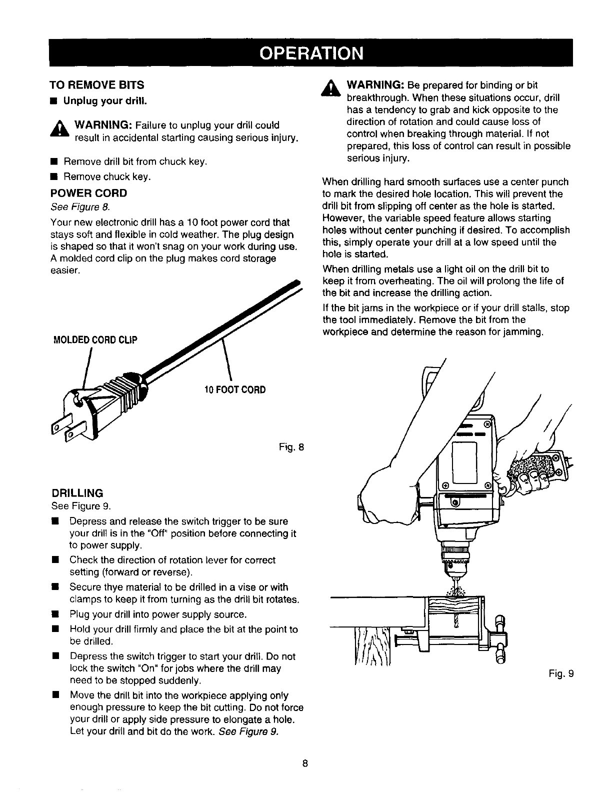
POWER CORD
See Figure 8.
Your new electronic drill has a 10 foot power cord that
stays soft and flexible in cold weather. The plug design
is shaped so that it won't snag on your work during use.
A molded cord clip on the plug makes cord storage
easier.
MOLDEDCORDCLiP
10 FOOTCORD
Fig. 8
DRILLING
See Figure 9.
• Depress and release the switch trigger to be sure
your drill is in the "Off" position before connecting it
to power supply.
• Check the direction of rotation lever for correct
setting (forward or reverse).
• Secure thye material to be drilled in a vise or with
clamps to keep it from turning as the drill bit rotates.
• Plug your drill into power supply source.
• Hold your drill firmly and place the bit at the point to
be drilled.
• Depress the switch trigger to start your drill. Do not
lock the switch "On" for jobs where the drill may
need to be stopped suddenly.
• Move the drill bit into the workpiece applying only
enough pressure to keep the bit cutting. Do not force
your drill or apply side pressure to elongate a hole.
Let your drill and bit do the work. See Figure 9.
_ll WARNING: Be prepared for binding or bit
breakthrough. When these situations occur, drill
has a tendency to grab and kick opposite to the
direction of rotation and could cause loss of
control when breaking through material. If not
prepared, this loss of control can result in possible
serious injury.
When drilling hard smooth surfaces use a center punch
to mark the desired hole location. This will prevent the
drill bit from slipping off center as the hole is started.
However, the variable speed feature allows starting
holes without center punching if desired. To accomplish
this, simply operate your drill at a low speed until the
hole is started.
When drilling metals use a light oil on the drill bit to
keep it from overheating. The oil will prolong the life of
the bit and increase the drilling action.
If the bit jams in the workpiece or if your drill stalls, stop
the tool immediately. Remove the bit from the
workpiece and determine the reason for jamming.
/
Fig. 9
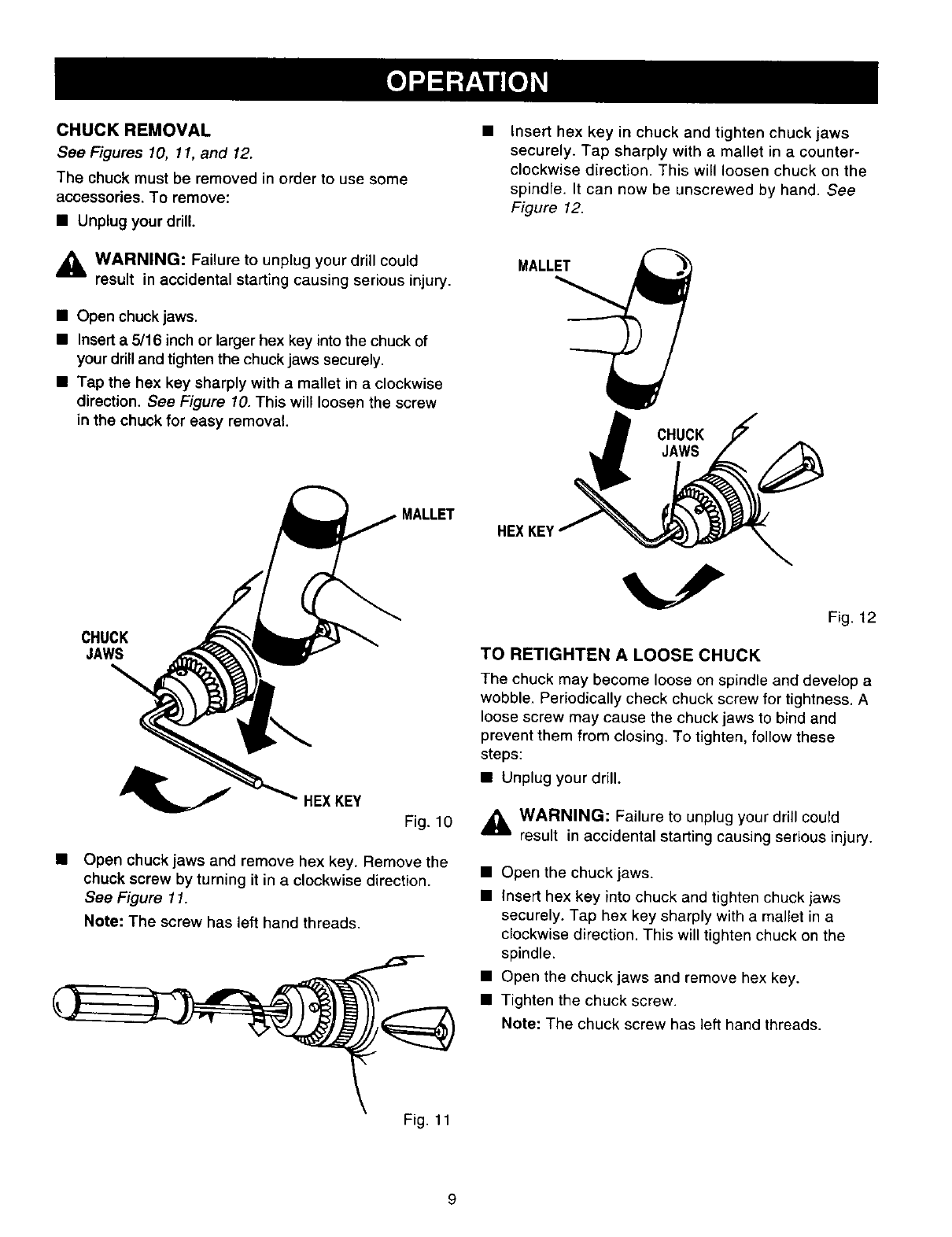
CHUCK REMOVAL
See Figures 10, 11, and 12.
The chuck must be removed in order to use some
accessories. To remove:
•Unplug your drill.
,_ WARNING: Failure to unplug your drill could
result in accidental starting causing serious injury.
• Open chuck jaws.
• Insert a5/16 inch or larger hex key into the chuck of
your drill and tighten the chuck jaws securely.
• Tap the hex key sharply with a mallet in a clockwise
direction. See Figure 10. This will loosen the screw
in the chuck for easy removal.
Insert hex key in chuck and tighten chuck jaws
securely. Tap sharply with a mallet in a counter-
clockwise direction. This will loosen chuck on the
spindle. It can now be unscrewed by hand. See
Figure 12.
MALLET
CHUCK
JAWS
CHUCK
JAWS
HEXKEY
Fig. 10
Open chuck jaws and remove hex key. Remove the
chuck screw by turning it in a clockwise direction.
See Figure 11.
Note: The screw has left hand threads.
F_g. 12
TO RETIGHTEN A LOOSE CHUCK
The chuck may become loose on spindle and develop a
wobble. Periodically check chuck screw for tightness. A
loose screw may cause the chuck jaws to bind and
prevent them from closing. To tighten, follow these
steps:
• Unplug your drill.
,_ WARNING: Failure to unplug your drill could
result in accidental starting causing serious injury.
• Open the chuck jaws.
• Insert hex key into chuck and tighten chuck jaws
securely. Tap hex key sharply with a mallet in a
clockwise direction. This will tighten chuck on the
spindle.
• Open the chuck jaws and remove hex key.
• Tighten the chuck screw.
Note: The chuck screw has left hand threads.
Fig. 11
9
GENERAL
Only the parts shown on parts list, page 13, are
intended to be repaired or replaced by the customer. All
other parts represent an important part of the double
insulation system and should be serviced only at a
Sears Service Center.
Avoid using solvents when cleaning plastic parts. Most
plastics are susceptible to damage from various types
of commercial solvents and may be damaged by their
use. Use clean cloths to remove dirt, carbon dust, etc.
,_ WARNING: Do not at any time let brake fluids,
gasoline, petroleum-based products, penetrating
oils, etc. come in contact with plastic parts. They
contain chemicals that can damage, weaken or
destroy plastic.
It has been found that electric tools are subject to
accelerated wear and possible premature failure when
they are used on fiberglass boats, sports cars,
wallboard, spackling compounds, or plaster. The chips
and grindings from these materials are highly abrasive
to electric tool parts, such as bearings, brushes,
commutators, etc. Consequently, it is not recommended
that this tool be used for extended work on any
fiberglass material, wallboard, spackling compounds, or
plaster. During any use on these materials, it is
extremely important that the tool is cleaned frequently
by blowing with an air jet.
LUBRICATION
All of the bearings in this tool are lubricated with a
sufficient amount of high-grade lubricant for the life of
the unit under normal operating conditions. Therefore,
no further lubrication is required.
DOUBLE INSULATION
Double insulation is a concept in safety in electric power
tools, which eliminates the need for the usual three-wire
grounded power cord. All exposed metal parts are
isolated from the internal metal motor components with
protecting insulation. Double insulated tools do not need
to be grounded.
IMPORTANT
Servicing of a tool with double insulation requires
extreme care and knowledge of the system and should
be performed only by a qualified service technician. For
service, we suggest you return the tool to your nearest
Sears store for repair. Always use original factory
replacement parts when servicing.
EXTENSION CORDS
The use of any extension cord will cause some loss of
power. To keep the loss to a minimum and to prevent
tool overheating, use an extension cord that is heavy
enough to carry the current the tool will draw.
A wire gage size (A.W.G.) of at least 16 is
recommended for an extension cord 100 feet or less in
length. When working outdoors, use an extension cord
that is suitable for outdoor use. The cord's jacket will be
marked WA.
,_ CAUTION: Keep extension cords away from the
drilling area and position the cord so that it will not
get caught on lumber, tools, etc., during drilling
operation.
,_ WARNING" Check extension cords before each
use. If damaged replace immediately. Never use
tool with a damaged cord since touching the
damaged area could cause electrical shock
resulting in serious injury.
Extension cords suitable for use with your drill are
available at your nearest Sears Retail Store.
10
Thefollowingrecommendedaccessoriesarecurrentlyavailableat SearsRetailStores.
• HighSpeedBits(Forwoodormetal)
• MasonryBits
• WoodBoringBits
• HoleSaws
• DrillStand
• DowelingJig
,_ WARNING: The use of attachments or accessories not listed might be hazardous.
1/2 in. Max.
3/4 in. Max.
1-1/4 in. Max.
2-1/2 in. Max.
WARRANTY
FULL ONE YEAR WARRANTY ON CRAFTSMAN 1/2 in. ELECTRIC DRILL
tf this CRRF¥$MnNDrill fails due to a defect in material or workmanship within one year from the date of purchase,
Sears will repair it, free of charge.
WARRANTY SERVICE IS AVAILABLE BY SIMPLY RETURNING THE TOOL TO THE NEAREST SEARS STORE
IN THE UNITED STATES.
This warranty gives you specific legal rights, and you may also have other rights which vary from state to state.
Sears, Roebuck and Co., Dept. 817WA, Hoffman Estates, IL 60179
,_, WARNING:
The operation of any drill can result in foreign objects being thrown into your eyes, which can
result in severe eye damage. Before beginning power tool operation, always wear safety
goggles or safety glasses with side shields and a full face shield when needed. We recommend
Wide Vision Safety Mask for use over eyeglasses or standard safety glasses with side shields,
available at Sears Retail Stores. Always wear eye protection which is marked to comply with
ANSI Z87.1.
11
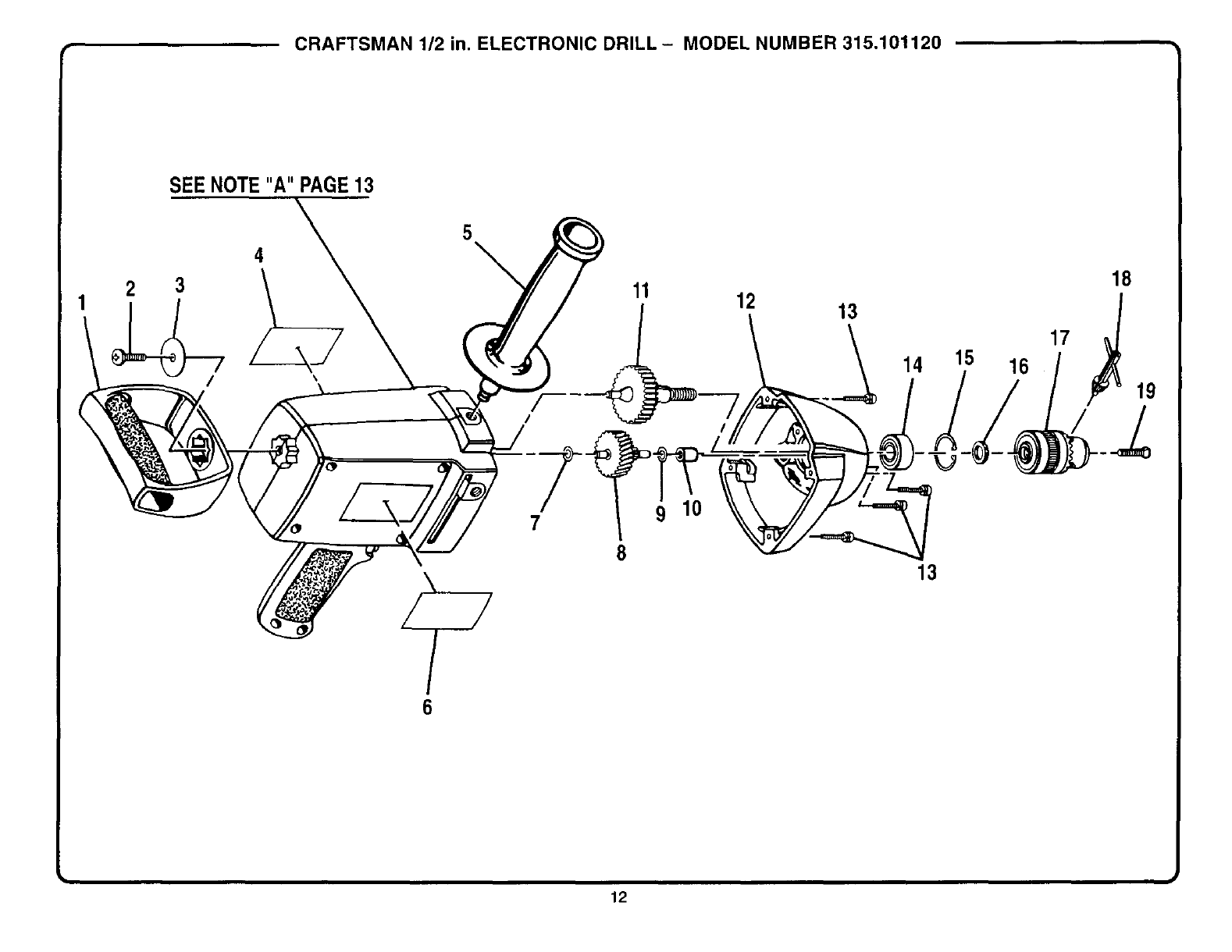
CRAFTSMAN 112 in. ELECTRONIC DRILL- MODEL NUMBER 315.101120
SEE NOTE"A" PAGE13
/
4
\
5\11 12 13
14 15 16
17
18
6
7
8
9
13
12
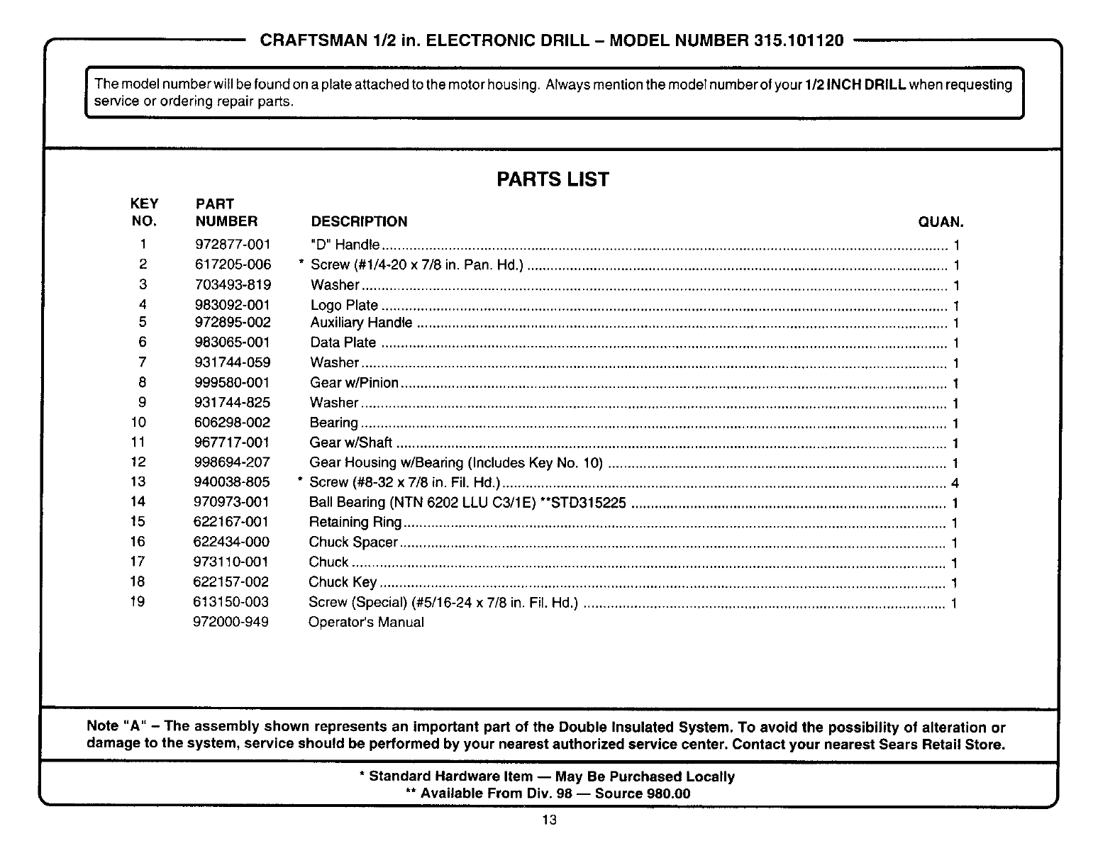
CRAFTSMAN 1/2 in. ELECTRONIC DRILL - MODEL NUMBER 315.101120
I Themodelnumberwillbefoundonaplateattachedtothemotorhousing. AIwaysmentionthemodelnumberofyourl/21NCHDRILLwhenrequesting I
service or ordering repair parts.
KEY PART
NO. NUMBER
1 972877-001
2 617205-006
3 703493-819
4 983092-001
5 972895-002
6 983065-001
7931744-059
8 999580-001
9 931744-825
10 606298-002
11 967717-001
12 998694-207
13 940038-805
14 970973-001
15 622167-001
16 622434-000
17 973110-001
18 622157-002
19 613150-003
972000-949
PARTS LIST
DESCRIPTION QUAN.
"D" Handle ................................................................................................................................................ 1
* Screw (#1/4-20 x 7/8 in. Pan. Hd.) ........................................................................................................... 1
Washer ..................................................................................................................................................... 1
Logo Plate ................................................................................................................................................ 1
Auxiliary Handle ....................................................................................................................................... 1
Data Plate ................................................................................................................................................ 1
Washer ..................................................................................................................................................... 1
Gear w/Pinion ........................................................................................................................................... t
Washer ..................................................................................................................................................... 1
Bearing ..................................................................................................................................................... 1
Gear w/Shaft ............................................................................................................................................ 1
Gear Housing w/Bearing (Includes Key No. 10) ...................................................................................... 1
* Screw (#8-32 x 7/8 in. Fil. Hd.) ................................................................................................................. 4
Ball Bearing (NTN 6202 LLU C3/1E) **STD315225 ................................................................................ 1
Retaining Ring .......................................................................................................................................... 1
Chuck Spacer ........................................................................................................................................... 1
Chuck ....................................................................................................................................................... 1
Chuck Key ................................................................................................................................................ 1
Screw (Special) (#5/16-24 x 7/8 in. Fil. Hd.) ............................................................................................ 1
Operator's Manual
Note "A" - The assembly shown represents an important part of the Double Insulated System. To avoid the possibility of alteration or
damage to the system, service should be performed by your nearest authorized service center. Contact your nearest Sears Retail Store.
* Standard Hardware Item -- May Be Purchased Locally
** Available From Div. 98 -- Source 980.00
I J
13

Get it fixed, at your home or ours!
For repair of major brand appliances in your own home...
no matter who made it, no matter who sold it!
1-800-4-MY-HOME sMAnytime, day or n,ght
(1-800-469-4663)
www.sears.com
To bring in products such as vacuums, lawn equipment and electronics
for repair, call for the location of your nearest Sears Parts & Repair Cente=
1-800-488-1222 Anyt,me, day or night
www.sears.com
For the replacement parts, accessories and owner's manuals
that you need to do-it-yourself, call Sears PartsDirect sM!
1-800-366-PART 6 a.m - 11 p m. CST,
(1-800-366-7278) 7 days a week
www.sears.com/partsdirect
To purchase or inquire about a Sears Service Agreement:
1-800-827-6655
7 a.m. - 5 p.m. CST, Mon. - Sat.
Para pedlr serVlClO de reparacl6n a domlclltO,
y para ordenar plezas con entrega a domlclho:
1-888-SU-HOGAR s_
(1-888-784-6427)
Au Canada pour service en fran£als
1-877-LE-FOYER s.
(1-877-533-6937)
® Registered Trademark t ru Trademark of Sears Roebuck and Co
_ Sears Roebuck and CO _,,Marca Reglstrada tTMMarca de Fabnca de Sears Roebuck and Co
