Craftsman 315101250 User Manual Drill Reversing Manuals And Guides L0090081
CRAFTSMAN Drill Reversing Manual L0090081 CRAFTSMAN Drill Reversing Owner's Manual, CRAFTSMAN Drill Reversing installation guides
User Manual: Craftsman 315101250 315101250 CRAFTSMAN Drill Reversing - Manuals and Guides View the owners manual for your CRAFTSMAN Drill Reversing #315101250. Home:Tool Parts:Craftsman Parts:Craftsman Drill Reversing Manual
Open the PDF directly: View PDF ![]() .
.
Page Count: 16
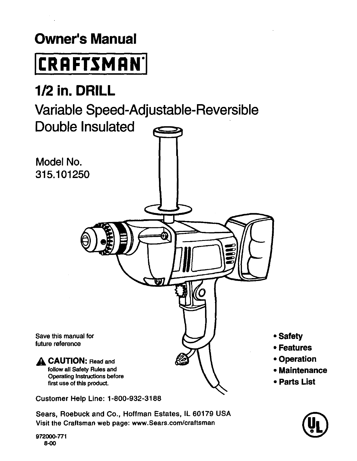
Owner's Manual
1/2 in. DRILL
Variable Speed-Adjustable-Reversible
Double Insulated
Model No.
315.101250
Save this manual for
future reference
CAUTION: Read and
follow all Safety Rules and
Operating Instructions before
first use of this product.
Customer Help Line: 1-800-932-3188
Sears, Roebuck and Co., Hoffman Estates, IL 60179 USA
Visit the Craftsman web page: www.Sears.com/craftsman
972000-771
8-00
•Safety
•Features
•Operation
•Maintenance
•Parts List
®
•Table Of Contents ........................................................................................................................... _.............. 2
•Warranty .......................................................................................................................................................... 2
•Introduction ..................................................................................................................................................... 2
•Rules For Safe Operation ........................................................................................................................... 3-5
•Product Specifications .................................................................................................................................... 6
•Unpacking ..................................................................................................................................................... .. 6
•Accessories .................................................................................................................................................... 6
•Features ......................................................................................................................................................... 7
•Operation ................................................................................................................................................... 8-12
•Maintenance ................................................................................................................................................. 13
•Exploded View and Repair Parts List...................................................................................................... 14-15
•Parts Ordering / Service ............................................................................................................................... 16
FULL ONE YEAR WARRANTY ON CRAFTSMAN DRILL
If this rRAF'rSMnN Drill fails to give complete satisfaction within one year from the date of purchase, RETURN
IT TO THE NEAREST SEARS STORE OR SEARS SERVICE CENTER IN THE UNITED STATES, and Sears
will repair it, free of charge.
If this CRIIFTSNRN Drill is used for commercial or rental purposes, this warranty applies for only 90 days from
the date of purchase.
This warranty gives you specific legal rights, and you may also have other rights which vary from state to state.
Sears, Roebuck and Co., Dept. 817WA, Hoffman Estates, IL60179
Your drill has many features for making your ddlling
operations more pleasant and enjoyable. Safety,
performance and dependability have been given top
priority in the design of this drill making it easy to
maintain and operate.
_k CAUTION: Carefully read through this entire
owner's manual before using your new drill. Pay
close attentaon to the Rul_s For Safe Operat'on,
Warnings and Cautions. If you use your drill
properly and only for what it is intended, yo0 will
enjoy years of safe, reliable service.
2
Thepurposeof safetysymbolsIsto attractyourattentionto possibledangers.Thesafetysymbols,and
the explanationswiththem,deserveyourcarefulettenUonendunderstanding.Thesafetywarningsdo
not bythemselveseliminateanydanger.Theinstructionsor warningstheygivearenotsubstitutesfor
properaccidentpreventionmeasures.
SYMBOL MEANING
ASAFETY ALERT SYMBOL:
Indicates danger, waming, or caution. May be used in conjunction with other symbols or picto-
graphs.
ADANGER: Failure to obey asafety waming will result in serious injury to yourself or to others.
Always follow the safety precautions to reduce the risk of fire, electric shock and personal injury.
AWARNING: Failure to obey a safety warning can result in serious injury to yourself or to others.
Always follow the safety precautions to reduce the risk of fire, electric shock and personal injury.
A
NOTE:
CAUTION: Failure to obey a safety warning may result in property damage or personal injury to
yourself or to others. Always follow the safety precautions to reduce the risk of fire, electric shock
and personal injury.
Advises you of information or instructions vital to the operation or maintenance of the equipment.
DOUBLE INSULATION
Double insulation is a concept in safety, in electric
power tools which eliminates the need for the usual
throe-wire grounded power cord. All exposed metal
parts are isolated from intemal metal motor
components with protecting insulation. Double
insulated tools do not need to be grounded.
_k WARNING: Do not attempt to operate this tool
until you have read thoroughly and understand
completely all instructions, safety rules, etc.
contained in this manual. Failure to comply can
result in accidents involving fire, electd¢ shock,
or sadous personal injury. Save owner's manual
and review frequently for continuing safe
operation, and instructing others who may use
this tool.
READ ALL INSTRUCTIONS
KNOW YOUR POWE R TOOL. Read owner's
manual carefully. Lsam its applications and
limitations as well as the specific potential
hazards related to this tool.
GUARD AGAINST ELECTRICAL SHOCK by
preventing body contact with grounded surfaces.
For example; pipes, radiators, ranges, refrigera-
tor enclosures.
•KEEP GUARDS IN PLACE and in working
order.
IMPORTANT
Servicing of a tool with double insulation requires
extreme care and knowledge of the system and
should be performed only by a qualified service
technician. For service we suggest you return the tool
to your nearest Sears Store or Sears Servive Center
for repair. Always use original factory replacement
parts when servicing.
•KEEP WORK AREA CLEAN. Cluttered areas
and benches invite accidents.
AVOID DANGEROUS ENVIRONMENT. Don't
use power tools in damp or wet locations or
expose to rain. Keep work area well lit.
KEEP CHILDREN AND VISITORS AWAY. All
,it
visitors should wear safety glasses end be kept a
safe distance from work area. Do not let visitors
contact tool or extension cord.
M
n
STORE IDLE TOOLS. When not in use, tools
should be stored in s dry and high or locked-up
place -out of the reach of children,
DON'T FORCE TOOL. It will do the job better
and safer at the rate for which it was designed.
USE RIGHT TOOL. Don't force small tool or
attachment to do the job of a heavy duty tool.
Donl use tool for purpose not intended - for
example - A circular saw should never be used
for cutting tree limbs or logs.
3
RULESFORSAFEOPERATION(Continued)
WEARPROPERAPPAREL.Donotwearloose
clothingorjewelrythatcangetcaughtintool's
movingpartsandcausepersonalinjury.Rubber
glovesandnonskidfootwear are recommended
when working outdoors. Wear protective hair
covering to contain long hair and keep it from
being drawn into nearby air vents.
ALWAYS WEAR SAFETY GLASSES. Everyday
eyeglasses have only impact-resistant lenses;
they are NOT safety glasses.
PROTECT YOUR LUNGS. Wear a face or dust
mask if the operation is dusty.
PROTECT YOUR HEARING. Wear hearing
protection during extended periods of operation.
DON'T ABUSE CORD. Never carry tool by cord
or yank it to disconnect from receptacle. Keep
cord from heat, oil, and sharp edges.
•SECURE WORK. Use clamps or a vise to hold
work. It's safer than using your hand and it frees
both hands to operate tool.
•DON'T OVERRL_ACH. Keep proper footing and
balance at all times. Do not use on a ladder or
unstable support. Secure tools when working at
elevated positions.
II
MAINTAIN TOOLS WITH CARE. Keep tools
sharp and clean for best and safest performance,
Follow instructions for lubricating and changing
accessories.
DISCONNECT TOOLS. When not in use, before
servicing, or when changing attachments,
blades, bits, cutters, etc,, all tools should be
disconnected from power supply.
REMOVE ADJUSTING KEYS AND
WRENCHES. Form habit of checking to see that
keys and adjusting wrenches are removed from
tool before turning it on.
AVOID ACCIDENTAL STARTING. Don't carry
plugged-in tool with finger on switch. Be sure
switch is off when plugging in,
• AKE SURE YOUR EXTENSION CORD IS IN
GOOD CONDITION. When using an extension
cord, be sure to use one heavy enough to carry
the current your product will draw. An undersized
cord will cause a drop in line voltage resulting in
loss of power and overheating. A wire gage size
(A.W.G.) of at least 16 is recommended for an
extension cord 100 feet or less in length. A cord
exceeding 100 feet is not recommended. If in
doubt, use the next heavier gage. The smaller
the gage number, the heavier the cord.
OUTDOOR USE EXTENSION CORDS. When
tool is used outdoors, use only extension cords
suitable for use outdoors. Outdoor approved
cords are marked with the suffix W-A, for ex-
ample -SJTW-A or SJOW-A.
KEEP BITS CLEAN AND SHARP. Sharp bits
minimize stalling and kickback.
KEEP HANDS AWAY FROM DRILLING AREA.
Keep hands away from bits. Do not reach
underneath work while bit is rotating. Do not
attempt to remove material while bit is rotating.
NEVER USE IN AN EXPLOSIVE ATMO-
SPHERE. Normal sparking of the motor could
ignite fumes.
INSPECT TOOL CORDS PERIODICALLY and if
damaged, have repaired by an authorized
service facility. Stay constantly aware of cord
location.
INSPECT EXTENSION CORDS PERIODI J
CALLY and replace if damaged.
KEEP HANDLES DRY, CLEAN, AND FREE
FRO• OIL AND GREASE. Always use a clean
cloth when cleaning. Never use brake fluids,
gasoline, petroleum-based products, or any
strong solvents to clean your tool.
STAY ALERT AND EXERCISE CONTROL.
Watch what you are doing and use common
sense. Do not operate tool when you are tired.
Do not rush.
4
RULESFORSAFEOPERATION(Continued)
CHECKDAMAGEDPARTS.Beforefurtheruse III
ofthetool,a guardorotherpartthatisdamaged
shouldbecarefullycheckedto determinethatit
willoperateproperlyandperformits intended
function.Checkforalignmentof movingparts,
bindingof movingparts,breakageofparts,
mountingandany other conditions that may •
affect its operation. A guard or other part that is
damaged should be properly repaired or re-
placed by an authodzed service center.
DO NOT USE TOOL IF SWITCH DOES NOT
TURN IT ON AND OFF. Have defective switches
replaced by an authodzed service center,
DRILLING INTO ELECTRICAL WIRING IN
WALLS CAN CAUSE DRILL BIT AND CHUCK
TO BECOME ELECTRICALLY LIVE. Do not
touch the chuck or metal housing when ddlling •
into a wall; grasp only the insulated handle(s)
provided on the tool.
INSPECT FOR and remove all nails from lumber
before drilling.
DRUGS, ALCOHOL, MEDICATION. Do not
operate this tool while under the influence of
drugs, alcohol, or any medication.
POLARIZED PLUGS. To reduce the risk of
electric shock, this tool has apolarized plug (one
blade is wider than the other). This plug will fit in
a polarized outlet only one way. If the plug does
not fit fully in the outlet, reverse the plug. If it still
does not fit, contact a qualified electrician to
install the proper outlet. Do not change the plug
in any way.
WHEN SERVICING USE ONLY IDENTICAL
CRAFTSMAN REPLACEMENT PARTS.
SAVE THESE INSTRUCTIONS. Refer to them
frequently and use them to instruct others who
may use this tool. If you loan someone this tool,
loan them these instructions also.
_k WARNING: Some dust created by power sanding, sawing, grinding, drilling, and other construction
activities contains chemicals known to cause cancer, birth defects or other reproductive harm. Some
examples of these chemicals are:
•lead from lead-based paints,
•crystalline silica from bricks and cement and other masonry products, and
•arsenic and chromium from chemically-treated lumber.
Your risk from these exposures varies, depending on how often you do this type of work. To reduce
your exposure to these chemicals: work in a well ventilated area, and work with approved safety
equipment, such as those dust masks that are specially designed to filter out microscopic particles.
_1_ Look for this symbol to point out important safety precautions. It means'attention!H Your
safety is involved.
WARNING:
The operation of any drill can result in foreign objects being thrown into your eyes, which
can result in severe eye damage. Before beginning power tool operation, always wear
safety goggles or safety glasses with side shields and a full face shield when needed. We
recommend Wide Vision Safety Mask for use over eyeglasses or standard safety glasses
with side shields, available at Sears Retail Stores.
SAVE THESE INSTRUCTIONS
5
Chuck Capacity 1/16 in. to 1/2 in.
Horsepower 3/8
Input 3.5 Amperes
Rating 120 volts, 60 Hz, AC
No Load Speed 0 -600 RPM
Switch Variable Speed-Adjustable-Reversible
Your drill has been shipped completely assembled
except for the auxiliary handle and "D" handle. Inspect
it carefully to make sure no breakage or damage has
occurred during shipping. If any parts are damaged or
missing, contact your nearest Sears Retail Store to
obtain replacement parts before attempting to Operate
ddU.The auxiliary handle, 'D" handle, washer, screw,
and this owner's manual are included in the box.
_i, WARNING: If any parts are missing, do not
operate this tool until the missing parts are
replaced. Failure to do so could result in possible
serious personal injury.
The following recomn_ended accessories are currently available at Sears Retail Stores.
•High Speed Bits (For wood or metal) 1/2 in. Max.
•Masonry Bits 3/4 in. Max.
•Wood Bodng Bits 1-1/2 in. Max.
HI Hole Saws 2-1/2 in. Max.
•Chuck Item No. 9 2980
_1= WARNING: The use of attachments or accessories not listed might be hazardous.
KNOW YOUR ELECTRIC DRILL
See Figure 1.
Before attempting to use any tool, familiarize yourself
with all operating features and safety requirements.
ELECTRICAL CONNECTION
Your drill has aprecision built electric motor. It should
be connected to a power supply that is 120 volts,
60 Hz, AC only (normal household current). Do not
operate this tool on direct current (DC). A substantial
voltage drop will cause a loss of power and the motor
will overheat. If your drill does not operate when
plugged into an outlet, double-check the power
supply.
AUXILIARY HANDLE
An auxiliary handle has been packed with your drill for
ease of operation and to help prevent loss of control.
"D" HANDLE
A 'D' handle is also packed with your drill for
maintaining proper balance and control,
APPLICATIONS
(Use only for the purpose listed below)
• Drilling in wood.
•Drilling in ceramics, plastics, fiberglass, and
laminates.
•Drilling in both hard and soft metals.
•Using driving accessories, such as driving screws
with screwdriver bits.
• Mixing paints.
AUXILIARY
HANDLE
CHUCK
HANDLE
VARIABLESPEED
CONTROLSELECTOR LOCK-ON
BUTTON
FORWARD-REVERSE
SWITCHTRIGGER LEVER
TO CHUCKKEY
STORE
TO
REMOVE REVERSE
Fig. 1
_k WARNING: Do not allow familiarity with tools to make you careless. Remember that a careless fraction of
a second is sufficient to inflict severe injury.
7
WARNING:Yourdrillshouldneverbe
connectedto powersupplywhenyouare
assemblingparts,makingadjustments,installing
orremovingdrillbits,cleaning,orwhennotin
use.Disconnectingyourdrillwillprevent
accidental starting that could cause serious
personal injury.
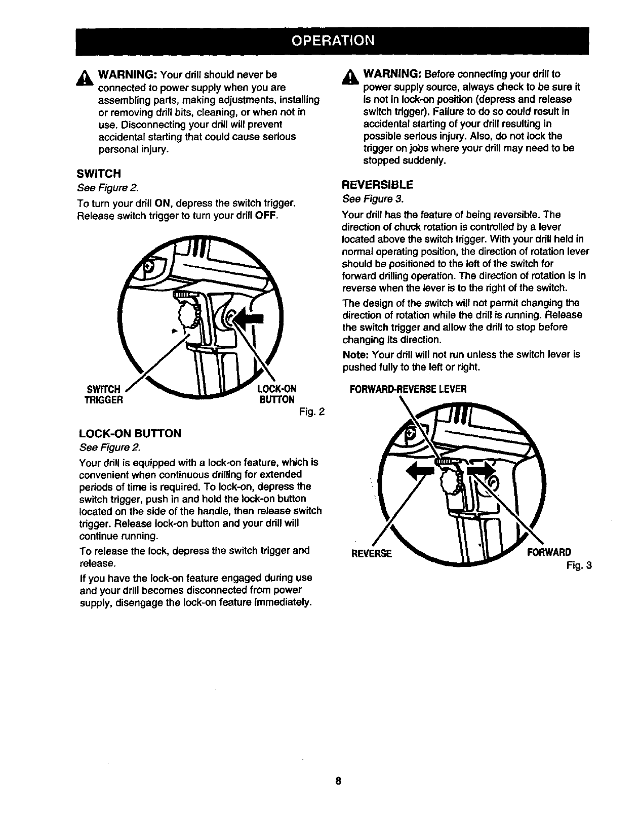
SWITCH
See Figure 2.
To turn your drill ON, depress the switch trigger.
Release switch trigger to turn your drill OFF.
SWITCH LOCK-ON
TRIGGER BuI"rON
Fig. 2
LOCK-ON BUTTON
See Figure 2.
Your drill is equipped with a lock-on feature, which is
convenient when continuous drilling for extended
periods of time is required. To lock-on, depress the
switch trigger, push in and hold the lock-on button
located on the side of the handle, then release switch
trigger. Release lock-on button and your drill will
continue running.
To release the lock, depress the switch trigger and
release.
If you have the lock-on feature engaged during use
and your drill becomes disconnected from power
supply, disengage the lock-on feature immediately.
_IL WARNING: Before connecting your drill to
power supply source, always check to be sure it
is not in lock-on position (depress and release
switch trigger). Failure to do so could result in
accidental starting of your drill resulting in
possible serious injury. Also, do not lock the
trigger on jobs where your drill may need to be
stopped suddenly.
REVERSIBLE
See Figure 3.
Your drill has the feature of being reversible. The
direction of chuck rotation is controlled by a lever
located above the switch trigger. With your drill held in
normal operating position, the direction of rotation lever
should be positioned to the left of the switch for
forward drillingoperation. The direction of rotation is in
reverse when the lever is to the right of the switch.
The design of the switch will not permit changing the
direction of rotation while the drill is running. Release
the switch trigger and allow the drill to stop before
changing its direction.
Note: Your drill will not run unless the switch lever is
pushed fully to the left or right.
FORWARD-REVERSELEVER
REVERSE FORWARD
Fig. 3
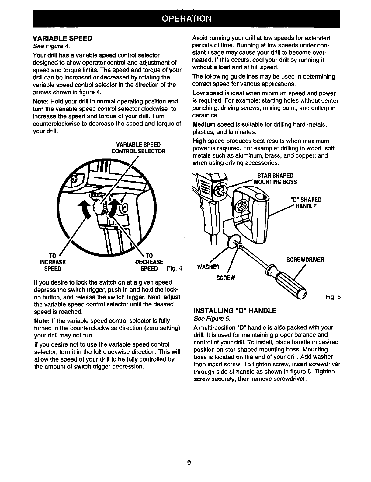
VARIABLE SPEED
See Figure 4.
Your drill has a vadable speed control selector
designed to allow operator control and adjustment of
speed and torque limits. The speed and torque of your
ddll can be increased or decreased by rotating the
variable speed control selector in the direction of the
arrows shown in figure 4.
Note: Hold your drill in normal operating position and
tum the vadable speed control selector clockwise to
increase the speed and torque of your ddll. Tum
counterclockwise to decrease the speed and torque of
your ddll.
VARIABLESPEED
CONTROLSELECTOR
TO
INCREASE DECREASE
SPEED SPEED Fig. 4
If you desire to lock the switch on at a given speed,
depress the switch trigger, push in and hold the lock-
on button, and release the switch tdgger. Next, adjust
the variable speed control selector until the desired
speed is roached.
Note: If the vadable speed control selector is fully
turned in the 'countemlockwise direction (zero setting)
your drill may not run.
If you desire not to use the variable speed control
selector, turn it in the full clockwise direction. This will
allow the speed of your drill to be fully controlled by
the amount of switch trigger depression.
Avoid running your ddll at low speeds for extended
pedods of time. Running at low speeds under con-
stant usage may cause your ddll to become over-
heated. If this occurs, cool your ddll by running it
without a load and at full speed.
The following guidelines may be used in determining
correct speed for various applications:
Low speed is ideal when minimum speed and power
is required. For example: starting holes without center
punching, ddving screws, mixing paint, and drilling in
ceramics.
Medium speed is-suitable for drilling hard metals,
plastics, and laminates.
High speed produces best results when maximum
power is required. For example: drilling in wood; soft
metals such as aluminum, brass, and copper; and
when using driving accessories.
STARSHAPED
WASHER
SCREW
SCREWDRIVER
Fig. 5
INSTALLING "D" HANDLE
See Figure 5.
A multi-position "D" handle is al#o packed with your
drill. It is used for maintaining proper balance and
control of your drill. To install, place handle in desired
position on star-shaped mounting boss. Mounting
boss is located on the end of your drill. Add washer
then insert screw. To tighten screw, insert screwdriver
through side of handle as shown in figure 5. Tighten
screw securely, then remove screwddver.
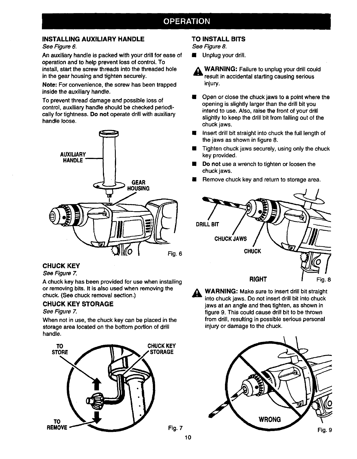
INSTALLING AUXILIARY HANDLE
See Figure 6.
An auxiliary handle is packed with your drill for ease of
operation and to help prevent loss of control. To
install, start the screw threads into the threaded hole
in the gear housing and tighten securely.
Note: For convenience, the screw has been trapped
inside the auxiliary handle.
To prevent thread damage and possible loss of
control, auxiliary handle should be checked periodi-
cally for tightness. Do not operate drill with auxiliary
handle loose.
AUXILIARY
GEAR
TO INSTALL BITS
See Figure 8.
•Unplug your drill.
A WARNING: Failure to unplug your drill could
result in accidental starting causing serious
injury.
Open or close the chuck jaws to a point where the
opening is slightly larger than the drill bit you
intend to use. Also, raise the front of your drill
slightly to keep the drill bit from falling out of the
chuck jaws.
•insert drill bit straight into chuck the full length of
the jaws as shown in figure 8.
•Tighten chuck jaws securely, using only the chuck
key provided.
•Do not use a wrench to tighten or loosen the
chuck jaws.
•Remove chuck key and return to storage area.
Fig. 6
CHUCK KEY
See Figure 7.
A chuck kay has been provided for use when installing
or removing bits. It is also used when removing the
chuck. (See chuck removal section.)
CHUCK KEY STORAGE
See Figure 7.
When not in use, the chuck key can be placed in the
storage area located on the bottom portion of drill
handle.
TO CHUCKKEY
STORE
\
DRILLBIT
CHUCKJAWS
CHUCK
RIGHT Fig. 8
,_k WARNING: Make sure to insert drill bit straight
into chuck jaws. Do not insert drill bit into chuck
jaws at an angle and theq tighten, as shown in
figure 9. This could cause drill bit to be thrown
from drill, resulting in possible serious personal
injury or damage to the chuck.
TO
REMOVE Fig. 7 Fig. 9
10
REMOVINGBITS
•Unplug your ddll.
_k WARNING: Failure to unplug your drill could
result in accidental starting causing serious
injury.
•Loosen the chuck jaws using only the chuck key
provided.
•Do not use a wrench to tighten or loosen the
chuck jaws.
•Remove drill bit from chuck jaws.
•Remove chuck key and return to storage area.
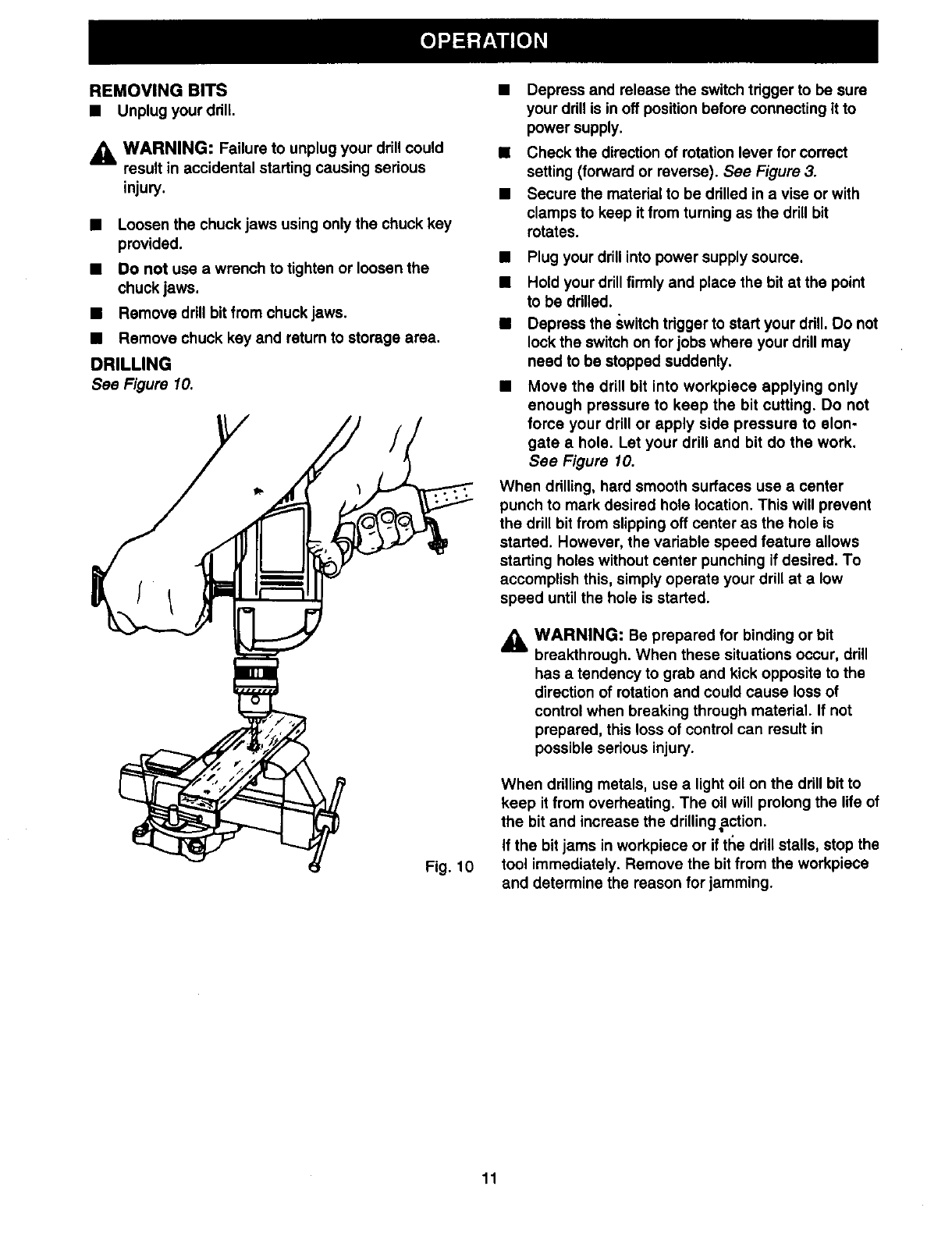
DRILLING
See Figure 10.
Fig. 10
•Depress and release the switch trigger to be sure
your drill is in off position before connecting it to
power supply.
•Check the direction of rotation lever for correct
setting (forward or reverse). See Figure 3.
•Secure the material to be drilled in a vise or with
clamps to keep it from turning as the drill bit
rotates.
Plug your drill into power supply source.
Hold your drill firmly and place the bit at the point
to be drilled.
Depress the switch trigger to start your drill, Do not
lock the switch on for jobs where your drill may
need to be stopped suddenly.
Move the drill bit into workpiece applying only
enough pressure to keep the bit cutting. Do not
force your drill or apply side pressure to elon-
gate a hole. Let your drill and bit do the work.
See Figure 10.
When drilling, hard smooth surfaces use acenter
punch to mark desired hole location. This will prevent
the drill bit from slipping off center as the hole is
started. However, the variable speed feature allows
starting holes without center punching if desired. To
accomplish this, simply operate your drill at a low
speed until the hole is started.
,_ WARNING: Be prepared for binding or bit
breakthrough. When these situations occur, drill
has a tendency to grab and kick opposite to the
direction of rotation and could cause loss of
control when breaking through material. If not
prepared, this loss of control can result in
possible serious injury.
When drilling metals, use a light oil on the drill bit to
keep it from overheating. The oil will prolong the life of
the bit and increase the drillingaction.
If the bit jams in workpiece or if ttle drill stalls, stop the
tool immediately. Remove the bit from the workpiece
and determine the reason for jamming.
11
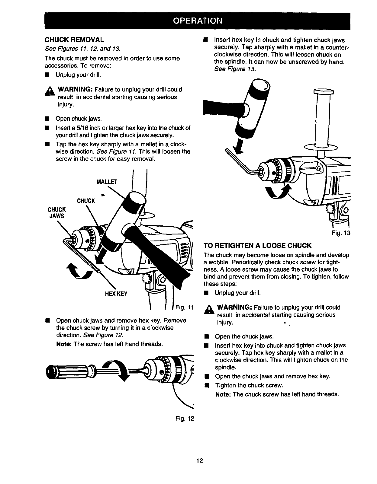
CHUCK REMOVAL
See Figures 11, 12, and 13.
The chuck must be removed in order to use some
accessodes, To remove:
•Unplug your drill,
_IL WARNING: Failure to unplug your ddll could
result in accidental starting causing serious
injury.
•Open chuck jaws.
•Insert a 5/16 inch or larger hex key into the chuck of
your drill and tighten the chuck jaws securely.
•Tap the hex key sharply with a mallet in a clock-
wise direction. See Figure 11. This will loosen the
screw in the chuck for easy removal.
Insert hex key in chuck and tighten chuck jaws
securely. Tap sharply with a mallet in a counter-
clockwise direction. This will loosen chuck on
the spindle. It can now be unscrewed by hand.
See Figure 13.
MALLET
CHUCK
CHUCK
JAWS
HEX KEY
Fig, 11
Open chuck jaws and remove hex key. Remove
the chuck screw by turning it in a clockwise
direction. See Figure 12.
Note: The screw has left hand threads.
Fig. 12
Fig. 13
TO RETIGHTEN A LOOSE CHUCK
The chuck may become loose on spindle and develop
a wobble. Pedodically check chuck screw for tight-
ness. A loose screw may cause the chuck jaws to
bind and prevent them from closing. To tighten, follow
these steps:
•Unplug your drill.
_k WARNING: Failure to unplug your drill could
result in accidental starting causing serious
injury, • .
•Open the chuck jaws.
•Insert hex key into chuck and tighten chuck jaws
securely. Tap hex key sharply with e mallet in a
clockwise direction. This will tighten chuck on the
spindle.
•Open the chuck jaws and remove hex key.
•Tighten the chuck screw.
Note: The chuck screw has left hand threads.
12
_i, WARNING: When servicing, use only identical
Craftsman replacement parts. Use of any other
part may create a hazard or cause product
damage.
GENERAL
Only the parts shown on parts list, page 15, are
intended to be repaired or replaced by the customer.
All other parts represent an important part of the
double insulation system and should be serviced only
at a Sears Service Center.
Avoid using solvents when cleaning plastic parts.
Most plastics are susceptible to damage from various
types of commercial solvents and may be damaged
by their use. Use clean cloths to remove dirt, carbon
dust, etc.
_i, WARNING: Do not at any time let brake fluids,
gasoline, petroleum-based products, penetrating
oils, etc. come in contact with plastic parts. They
contain chemicals that can damage, weaken or
destroy plastic. *"
It has been found that electric tools are subject to
accelerated wear and possible premature failure when
they are used on fiberglass boats, sports cars,
wallboard, spackling compounds, or plaster. The
chips and grindings from these materials are highly
abrasive to electdc tool parts such as bearings,
brushes, commutators, etc. Consequently, it is not
recommended that this tool be used for extended
work on any fiberglass material, wallboard, spackling
compounds, or plaster. During any use on these
matedals it is extremely important that the tool is
cleaned frequently by blowing with an air jet.
_1= WARNING: Always wear safety goggles or
safety glasses with side shields during power tool
operation or when blowing dust. If operation is
dusty,,also wear adust mask.
LUBRICATION
All of the beadngs in this tool are lubricated with a
sufficient amount of high grade lubricant for the life of
the unit under normal operating conditions. Therefore,
no further lubrication is required.
EXTENSION CORDS
The use of any extension cord will cause some loss of
power. To keep the loss to aminimum and to prevent
tool overheating, use an extension cord that is heavy
enough to carry the current the tool will draw.
Awire gage size .(A.W.G.) of at least 16 is
recommended for an extension cord 100 feet or less
in length. When working outdoors, use an extension
cord that is suitable for outdoor use. The cord'sjacket
will be marked WA.
ACAUTION: Keep extension cords away from the
drilling area and position the cord so that it will
not get caught on lumber, tools, etc., during
drilling operation.
WARNING: Check extension cords before each
use. If damaged, replace immediately. Never use
tool with adamaged cord since touching the
damaged area could cause electrical shock
resulting in serious injury.
Extension cords suitable for use with your drill are
available at your nearest Sears Retail Store.
13
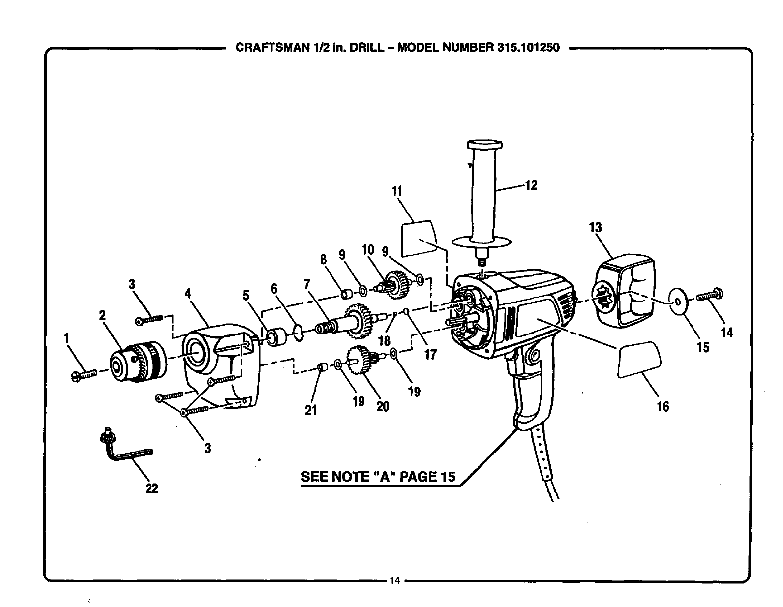
CRAFTSMAN 1/2 In. DRILL - MODEL NUMBER 315.101250
1
11
8 9
3 4 5 6 7
I18
I
!
22
3
SEE NOTE "A" PAGE 15
13
15
16
14
14
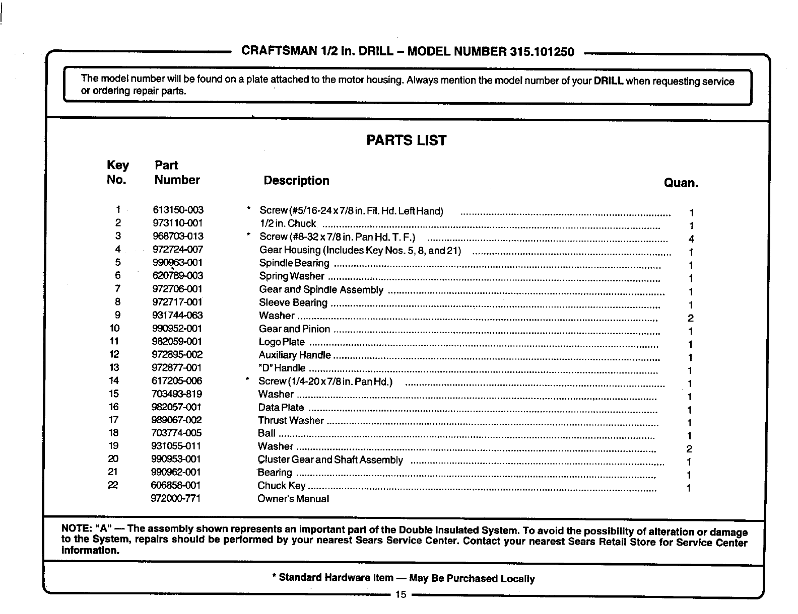
ICRAFTSMAN 1/2 in. DRILL - MODEL NUMBER 315.101250
The model number will be found on a plate attached to the motor housing. Always mention the model number of your DRILL when requesting service I
or ordering repair parts. I
PARTS LIST
Key Part
No. Number Description Quan.
1613150-003
2 973110-001
3 968703-013
4972724007
5 990O_o3-001
6 620789-003
7 972706-001
8 972717-001
9 931744-063
10 990952-001
11 982059-001
12 972895-002
13 972877-001
14 617205-006
15 703493-819
16 982057-001
17 989067-002
18 703774-005
19 931055-011
20 990953-001
21 990962-001
22 606858-001
972000-771
Screw (#5/16-24x 7/8 in. Fil. Hd. Left Hand) ........................................................................... 1
1/2 in. Chuck ......................................................................................................................... 1
Screw (#8-32 x 7/8 in. Pan Hd. T.F.) ...................................................................................... 4
Gear Housing (Includes Key Nos. 5, 8, and 21) ....................................................................... 1
Spindle Bearing ..................................................................................................................... 1
SpringWasher ....................................................................................................................... 1
Gear and Spindle Assembly ................................................................................................... 1
Sleeve Bearing ...................................................................................................................... 1
Washer ................................................................................................................................. 2
Gear and Pinion .....................................................................................................................
Logo Plate .............................................................................................................................
Auxiliary Handle .....................................................................................................................
"D" Handle .............................................................................................................................
Screw (1/4-20 x 7/8 in. Pan Hd.) .............................................................................................
Washer .................................................................................................................................
Data Plate .............................................................................................................................
Thrust Washer .......................................................................................................................
Ball .......................................................................................................................................
Washer ................................................................................................................................. 2
Cluster Gear and Shaft Assembly ........................................................................................... 1
Bearing ................................................................................................................................. 1
Chuck Key ............................................................................................................................. 1
Owner's Manual
NOTE: "A" -- The assembly shown represents an important part of the Double Insulated System. To avoid the possibility of alteration or damage
to the System, repairs should be performed by your nearest Sears Service Center. Contact your nearest Sears Retail Store for Service Center
information.
* Standard Hardware Item -- May Be Purchased Locally
i15
For repair of major brand appliances in your own home...
no matter who made it, no matter who sold ifl
1-800-4-MY-HOME sMAnytime, day or night
(1-800-469-4663)
www.sears.com
To bring in products such as vacuums, lawn equipment and electronics
for repair, call for the location of your nearest Sears Parts &Repair Center
1-800-488-1222 Anytime, day or night
www.sears.com
For the replacement parts, accessories and owner's manuals
that you need to do-it-yourself, call Sears PartsDirect sM!
1-800-366-PART 6 a.m. - 11 p.m. CST,
(1-800-366-7278) 7days a week
www.sears.com/partsdirect
To purchase or inquire about a Sears Service Agreement:
1-800-827-6655
7 a.rn. - 5 p.m. CST, Mon. - Sat.
Para pedir servicio de reparacibn a domicilio,
ypara ordenar piezas con entrega a domicilio:
1-888-SU-HOGAR s.
(1-888-784-6427)
Au Canada pourserviceen franc.,ais:
1-877-LE-FOYER s"
(1-877-533-6937)
@RegisteredTradernark/TM TrademarkofSears, Rodouckand Co.
O Sears,Roebuckand Co. ®Mama Reglstrada/TM Mama de Ft_rk:a de Sears,RoebuckandCO.
