Craftsman 315105050 User Manual 1/2 ELECTRONIC DRILL Manuals And Guides L0012019
CRAFTSMAN Drill Reversing Manual L0012019 CRAFTSMAN Drill Reversing Owner's Manual, CRAFTSMAN Drill Reversing installation guides
User Manual: Craftsman 315105050 315105050 CRAFTSMAN 1/2 ELECTRONIC DRILL - Manuals and Guides View the owners manual for your CRAFTSMAN 1/2 ELECTRONIC DRILL #315105050. Home:Tool Parts:Craftsman Parts:Craftsman 1/2 ELECTRONIC DRILL Manual
Open the PDF directly: View PDF ![]() .
.
Page Count: 12
SEARS
OWNERS
MANUAL
MODEL NO.
315.105050
CAUTION:
Read Rules for
Safe Operation
and Instructions
Carefully
SAVE THIS
MANUALFOR
FUTURE REFERENCE
612547-549
1%00
CRAFTSMAN
1/2 INCH
ELECTRONIC DRILL
DOUBLE INSULATED
VARIABLE SPEED
ADJUSTABLE- REVERSIBLE
Introduction
Operation
Maintenance
Repair Parts
Desl ned exclusively for and sold only by
SEARS, ROEBUCK AND CO., Hoffman Estates, IL 60179
®
FULL ONE YEAR WARRANTY ON CRAFTSMAN ELECTRONIC dRILL
If this Craftsman Electronic Drill fails to give complete satisfaction within one year from the date of
purchase, RETURN IT TO THE NEAREST SEARS STORE THROUGHOUT THE UNITED STATES and
Sears will repair if, free of charge.
If this electronic drill is used for commercial or rental purposes this warranty applies for only 90 days
from the date of purchase.
This warranty gives you specific legal rights, and you may also have other rights which vary from
state fo state.
SEARS, ROEBUCK AND CO.
DEPT. 817 WA
HOFFMAN ESTATES, IL 60179
INTRODUCTION
DOUBLE INSULATION Is a concept Ill safety, in elec- IMPORTANT -- Servicing of atool with double in-
tric power tools, which eliminates the need for the sulation requires extreme care and knowledge of the
usual three wire grounded power cord and grounded system and should be performed only by a qualified
supply system. Wherever there is electric current in service technician. For service we suggest you
the tOOl there are two complete sets of insulattan to return the tool to your nearest Sears Store for repair.
protect the user. All exposed metal parts are isolated Always use original factory replacement parts when
from the Internal metal motor components with prc- servicing.
tactlng insulation,
RULES FOR SAFE OPERATION
READ ALL iNSTRUCTIONS
1. KNOW YOUR POWER TOOL. Read owner's
manual carefully. Learn its applications and
limitations as well as the specific potential hazards
related to this tool.
2. GUARD AGAINST ELECTRICAL SHOCK by
preventing body contact with grounded surfaces,
For example; Pipes, radiators, ranges, refrigerator
enclosures.
3. KEEP GUARDS IN PLACE and in working order.
4. KEEP WORK AREA CLEAN.Cluttered ames and
benches invite accidents.
5. AVOID DANG EROUE ENVlRONM ENT.Don't use
power tool in damp or wet locations or expose to
rain. Keep work area well tit.
6. KEEP CHILDREN AND VISITORS AWAY. All
visitors should wear safely glasses and be kept a
safe distance from work area. Do not let visitors
contact tool or extension cord.
7. STORE IDLE TOOLS. When not in use tools
should be stored in e dry and high or locked-up
place - out of the reach of children.
8. DON'T FORCE TOOL. It will do the job bettar and
safer at the rate for which it was designed,
9. USE RIGHT TOOL. Don't force small tool or
attachment fo do the job of a heavy duty tool. Don't
use tool for purpose not intended - for example -A
circular saw should never be used for cutting tree
limbs or logs.
10. WEAR PROPER APPAREL. Do not wear loose
clothing or jewelry that can get caught in fool's
moving parts and cause personal injury. Rubber
gloves and non-skid footwear are recommended
when working outdoors. Wear protective hair
covering to contain long hair and keep if from being
drawn into nearby air vents.
11. ALWAYS WEAR SAFETY GLASSES. Everyday
eyeglasses have only impact-resistant lenses; they
are ROT safety glasses,
Page 2
RULES FOR SAFE OPERATION (Continued)
12. PROTECT YOUR LUNGS. Wear a face mask or
dust mask if operation is dusty.
13, PROTECT YOUR HEARING, Wear bearing
protection during extended periods of operation.
14. DON'T ABUSE CORD. Never carry tool by cord
or yank it to disconnect from receptacle. Keep
cord from beat, oil and sharp edges.
t5. SECURE WORK. Use clamps or a vise to hold
work. Both hands are needed to operate the tool.
16. DON'T OVERREACH. Keep proper footing and
balance at all times. Do not use on a ladder or
unstable support.
17. MAINTAIN TOOLS WITH CARE. Keep tools sharp
at all times, and clean for best and safest
performance. Follow instructions for lubricating
and changing accessories.
18 DISCONNECT TOOLS. When not in use, before
servicing, or when changing attachments, blades,
bits, cutters, etc., all tools should be disconnected
from power supply.
19 REMOVE ADJUSTING KEYS AND
WRENCHES. Form habit of checking to see that
keys and adjusting wrenches are removed from
tool before turning it on.
20 AVOID ACCIDENTAL STARTING. Don't carry
plugged-in tools with finger on switch. Be sure
switch is off when plugging in.
21. MAKE SURE YOUR EXTENSION CORD IS IN
GOOD CONDITION. When using an extension
cord, be sure to use one heavy enough to carry the
current your product will draw. An undersized cord
will cause a drop in line voltage resulting inloss of
power and overheating. A wire gage size (A,W.G.)
of at least 16 is recommended for an extension
cord 100 feet or less in length. A cord exceeding
1go feet is not recommended. If in doubt, use the
next heavier gage. The smaller the gage number,
the heavier the cord.
22. OUTDOOR USE EXTENSION CORDS. When
tool is used outdoors, use only extension cords
suitable for use outdoors, Outdoor approved cords
are marked with the suffix W-A, for example -
SJTW-A or SJOW-A.
23. KEEP BITS CLEAN AND SHARP. Sharp bits
minimize stalling and kickback,
24. KEEP HANDS AWAY FROM DRILLING AREA.
Keep hands away from bits. Oo not reach
underneath work while bd is rotating. Do not
attempt to remove material while bit is rotating.
25. NEVER USE IN AN EXPLOSIVE ATMOSPHERE.
Normal sparking of the motor could ignite fumes.
26. INSPECT TOOL CORDS PERIODICALLYand if
damaged, have repaired at your nearest Sears
Repair Center, Stay constantly aware of cord
location.
27, INSPECT EXTENSION CORDS PERIODICALLY
and replace if damaged.
28, KEEP HANDLES DRY, CLEAN, AND FREE
FROM OIL AND GREASE. Always use a clean
cloth when cleaning. Never use brake fluids,
gasoline, pat roleum-based products or any strong
solvents to clean your tool.
29. STAY ALERT.Watch wbet you are doing and use
common sense, Do not operate tool when you are
tired, 0o not rush,
30. CHECK DAMAGED PARTS. Before further use
of the tool, aguard or other pad that is damaged
should be carefully checked to determine that it
will operate properly and perform its intended
function, Check for alignment of moving pads,
binding of moving parts, breakage of parts,
mounting, and any other conditions that may
affect its operation. A guard or other pad that is
damaged should be probedy repaired or replaced
by an authorized service center unless indicated
elsewhere in this instruction manual.
31. DO NOT USE TOOL IF SWITCH DOES NOT
TURN IT ON AND OFF. Have defective switches
replaced by an authorized service center.
32, DRILLING INTO ELECTRICAL WIRING IN
WALLS CAN CAUSE DRILL BIT AND CHUCK
TO BECOME ELECTRICALLY LIVE. Do not
touch the chuck or metal housing when drilling
into a wall; grasp only the insulated handle(s)
provided on the tool.
33. Inspect for and remove elf nails from lumber
before drilling,
34. DRUGS, ALCOHOL, MEDICATION.' Do not
operate tool while under the influence of drugs,
alcohol, or any medication.
35. When servicing use only identical Craftsman
replacement parts.
36. POLARIZED PLUGS,To reduce tbe dsk of electric
shock, this tool has a polarized plug (one blade is
wider than the other), This plug will fit ina polarized
outlet only one way. If the plug does not fit fully in
the outlet, reverse the plug. If it still does not fit,
contact a qualified electrician to install the proper
outlet, Do not change the plug in any way.
37. SAVE THESE INSTRUCTIONS. Review them
frequently and use them to instruct others who
may use this tool. If you loan someone this tool,
loan them these instructions also.
Page 3
_e5
The operation ofany drill can relu;t In foreign ob_UI being lhrown Into your eyes, which 1
can result in severe lye damage. Before beginning power tool operation, always wear
safety goggles or safety glasses with aide |hlelds and afull face shield when needed.
We recommend Wide Vision SafeLy MHK for use over eyeglaasel or standard safety
glasses with side shields, avaiJable st SelN Retail Stores.
Page 4
OPERATION
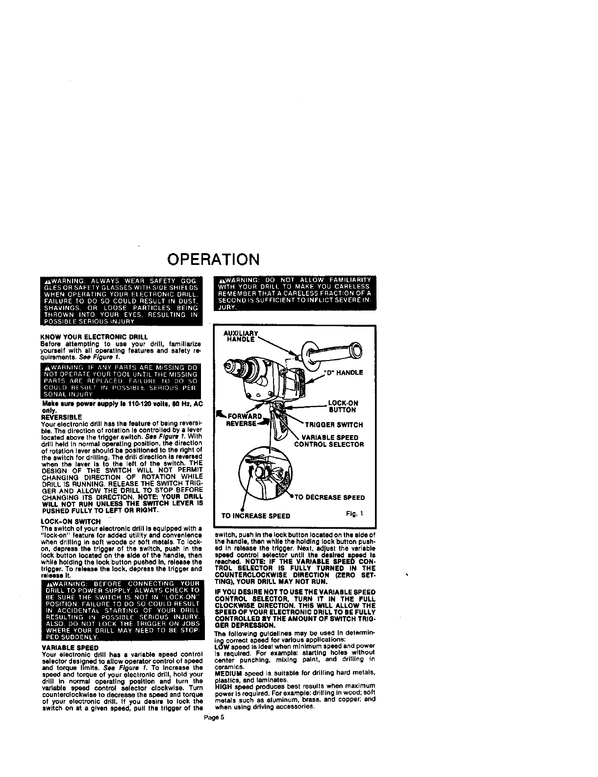
KNOW YOUR ELECTRONIC DRILL
Before attempting to use your drill, familiarize
yourseif with all operating features and safety re-
quirements. See Figure 1,
Make sum power supply Is 110.120 volts, _0 Hz, AC
on!y,
REVERSIBLE
YOUr electronic drill has the feature of being reversi-
ble, The direction of rotation Is controlled by s lever
located above the trigger switch. See Figure I. W_th
dr he d n normal operating position the direction
of rotation lever should be positioned to the right of
the switch for qriglng. The drill d_rectlon is reversed
when the _ever is to the left of the switch. THE
DESIGN OF THE SWITCH WILL NOT PERMIT
CHANGING DIRECTION OF ROTATION WHILE
DRILL IS RUNNING, RELEASE THE SWITCH TRiG-
GER AND ALLOW THE DRILL TO STOP SEFORE
CHANGING ITS DIRECTION. NOTE: YOUR DRILL
WILL NOT RUN UNLESS THE SWITCH LEVER IS
PUSHED FULLY TO LEFT OR RIGHT.
LOCK-ON SWITCH
The switch of your electronic drill is equipped with a
"lock.on" feature for added utility and convenience
when drilling in soft woods or soft metals. TO lock-
on, depress the trigger of the switch, push In the
lock button located on the side of the handle, then
while holding the lock button pushed In, release the
trigger, To release the lock, depress the trigger and
raleaae it.
VARIABLE SPEED
Your alectronic ddll has avadable speed control
selector designed to allow operator control of speed
and torque limits. See Figure 1. To increase the
speed and torque of your electronic drill, hold your
drill in normal operating position and turn the
variable speed control selector clockwise. Turn
counterclockwise to decrease the speed and torque
of your electronic drill. If you desire to lock the
switch on at a given speed, pull the trigger of the
AUXILIARY
HANDLE
'D"HANOLE
LOCK.ON
BUTTON
SWITCH
CONTROLSELECTOR
TO DECREASE SPEED
TO INCREASE SPEED Fig. 1
switch, push in the lock button located on the side of
the handle, then while the holding lock button push-
ed in release the trigger. Next, adjust the variable
speed control selector until the desired s,peed Is
reached. NOTE: IF THE VARIABLE SPEED CON.
TROL SELECTOR IS FULLY TURNED IN THE
COUNTERCLOCKWISE DIRECTION (ZERO SET.
TING), YOUR DRILL MAY NOT RUN.
IF YOU DESIRE NOT TO USE TH E VARIABLE SPEED
CONTROL SELECTOR, TURN IT IN THE FULL
CLOCKWISE DIRECTION. THIS WILL ALLOW THE
SPEED OF YOUR ELECTRONIC DRILL TO BE FULLY
CONTROLLED BY THE AMOUNT OF SWITCH TRIG.
GER DEPRESSION.
The following guidelines may be used In determln-
in_gcorrect speed for various applications:
L(_W speed is ideal when minimum speed and power
is required. For example: starting holes without
center punching, mixing paint, and drilti_g in
ceramics.
MEDIUM speed is suitable for drilling hard metals,
plastics, and laminates,
HIGH speed produces best results when maximum
bower is requLred. For example: drilling in wood; soft
metals such as aluminum, brass, and copper, and
when using ddvlng accessories.
Page 5
OPERATION (Cont.)
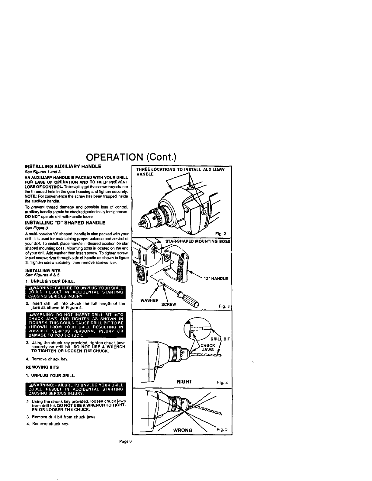
INSTALLING AUXILIARY HANDLE
See FIQuresl and _
AN AUXILIARY HANDLE IS PACKED WITH YOUR DRILL
FOR EASE OF OPERA'nON AND TO HELP PREVENT
LOSS OF CONTROL. To install, start the screw threads into
the threaded hole in the gear housing and tighten securely.
NOTE: For convenience the screw has been trapped inside
the auxilian/handle.
To prevent thread damage and possible loss of control,
auxiliaP/handle shouldbe checked periodicallyfor tightness,
DO NOT operate drillwith handle loose,
INSTALLING "D" SHAPED HANDLE
See Figure 3.
A multi-position"D" shaped handle is aJsopacked with your
ddll. It is used for maintaining proper balance and control of
your drill,To install, place handle in desired positionon star
shaped mounting boss, Mounting bess is located on the end
ofyour ddll.Add washer then insert screw. TO tighten screw,
insertscrewdriver through side of handle as shown infigure
3, Tighten screw securely, then remove screwdriver.
INSTALLING BITS
See Figures 4 &5.
1. UNPLUG YOUR DRILL.
2, Insert dritl bit into chuck the full length of the
Jaws as shown in Figure 4,
3. Using the chuck key provided, tighten chuck Jaws
securely on drill bit. DO NOT USE A WRENCH
TO TIGHTEN OR LOOSEN THE CHUCK,
4, Remove chuck key.
REMOVING BITS
1. UNPLUG YOUR DRILL.
2. Using the chuck key provided, loosen chuck jaws
from drill bit. DO NOT USE A WRENCH TO TIGHT,
EN OR LOOSEN THE CHUCK,
3. Remove drill bit from chuck jaws.
4, Remove chuck key.
THREE LOCATIONS TO INSTALL AUXILIARY
HANDLE
Fig, 2
STAR.SHAPED MOUNTING BOSS
DRILL BIT
Page 6
OPERATION (Cont.)
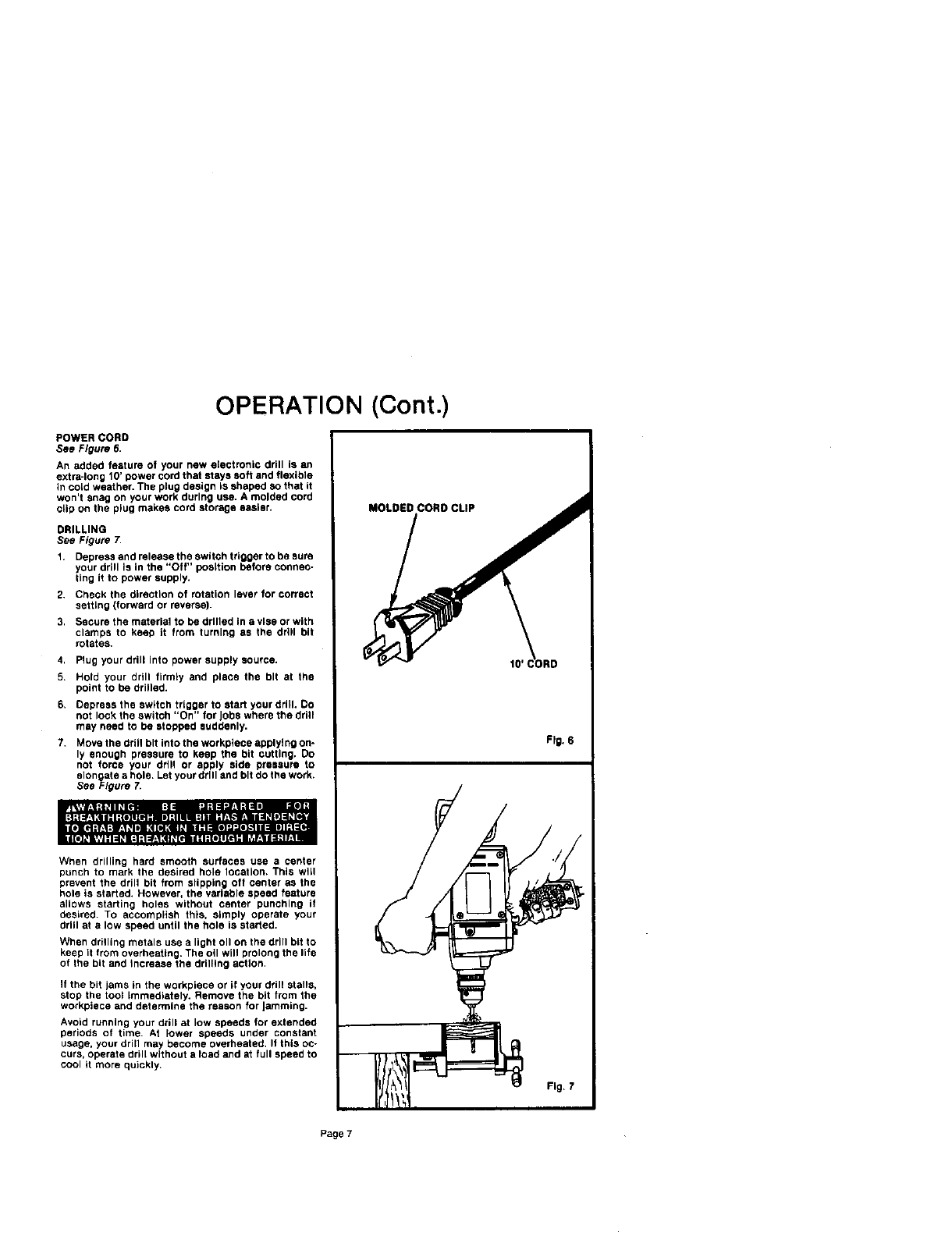
POWER CORD
See Figure 6.
An added feature of your new e_ectronic drill is an
extra-long 10' power cord that stays soft and flexible
in cord weather, The plug design is shaped 8o that it
won't snag on your work during use. A molded cord
clip on the plug makes cord storage easier.
DRILLING
See Figure 7,
1. Depress and release the switch trigger to be sure
your drill is in the "Off" position before connec-
ting it to power supply.
2. Check the direction of rotation lever for correct
setting (forward or reverse).
3, Secure the material to be drilled in a vise or with
clamps to keep tt from turning as the drill bit
rotates,
4. Plug your drill into power supply source.
5. Hold your drill firmly and place the bit at the
point to be drilled.
6. Depress the switch trigger to start your drill. DO
not lock the switch "On" for Jobs where the drill
may need to be stopped suddenly.
7. Move the ddll bit into the workplece applying on-
ly enough pressure to keep the bit cutting. Do
not force your drill or apply side pressure to
slon ate ahole. Let your drill and bit do the work.
See _=lgure 7.
When drilling hard smooth surfaces use a center
punch to mark the desired hole location. This will
prevent the drill bit from slipping oft center as the
hole is started, However, the variable speed feature
allows starting holes without center punching it
desired. TO accomplish this, simply operate your
drill at a low speed until the hole is started.
When drilling metals use a light oll on the drill bit to
keep it from overheating. The oil will prolong the life
of the bit and tncrease the drilling action,
If the bit jams in the workplace or if your drill stalls,
stop the tool Immediately. Remove the bit from the
workpiece and determine the reason for Jamming.
Avoid running your drill at low speeds for extended
periods of time. At lower speeds under constant
usage, your drill may become overheated, It this oc-
curs, operate drill without a load and at full speed to
cool it more quickly.
Fig. 6
Page 7
OPERATION (Cont.)
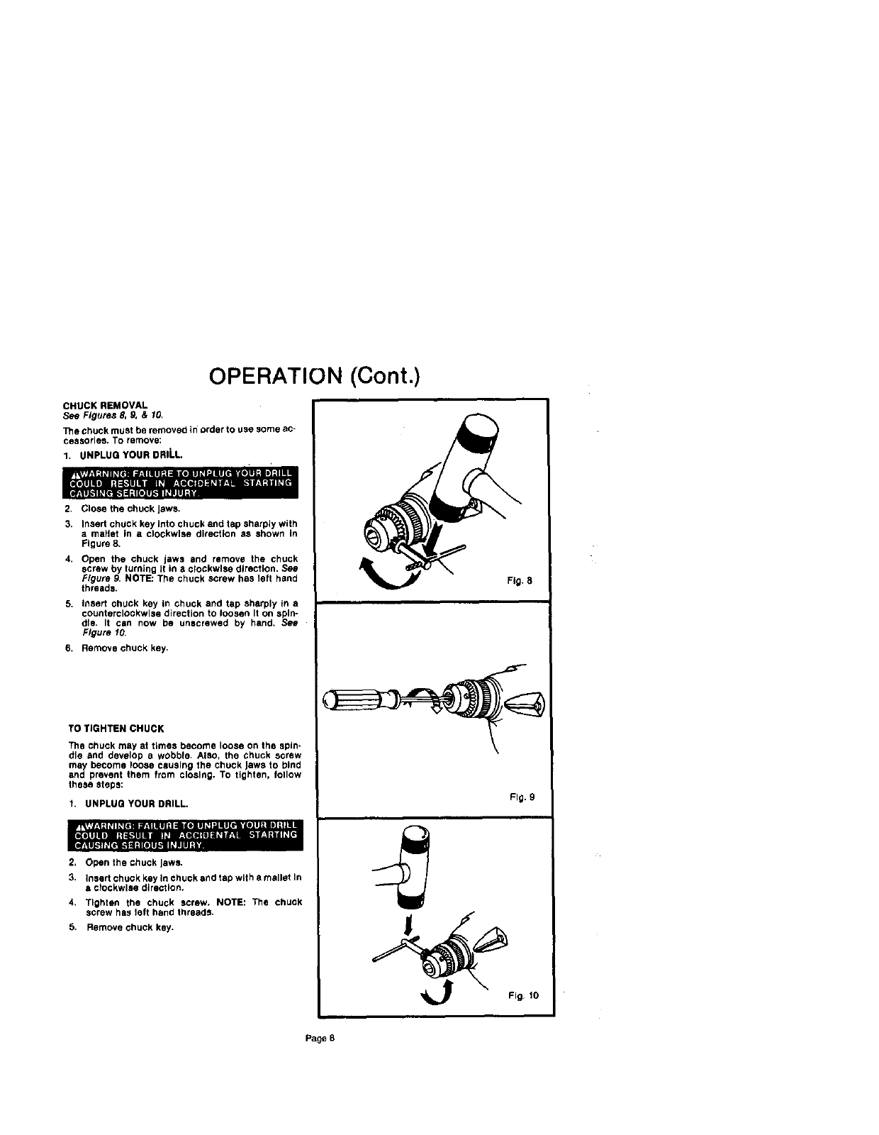
CHUCK REMOVAL
8se Figures 8, 9. &10.
The chuck must he removed in order to use some ac-
cessories, TO remove:
1. UNPLUG YOUR DRILL.
2. Close the chuck Jaws.
3. Insert chuck key Into chuck end tap sharply with
•matlet in aclockwise direction as shown Ln
Figure 8.
4, Open the chuck jaws and remove the chuck
screw by turning It in a c_ockwlse direction. See
Figure g. NOTE: The chuck screw has left hand
threads,
5. insert chuck key in chuck and tap sharply in a
counterclockwise direction to loosen It on spin-
dle. It can now be unscrewed by hand, See
Figure 10.
6. Remove chuck key.
TO TIGHTEN CHUCK
The chuck may at times become loose on the spin-
dle and develop awobble. Also, the chuck screw
may become loose causing the chuck Jaws to bind
and prevent them from closing. To tighten, follow
these steps:
1, UNPLUG YOUR DRILL.
2, Open the chuck Jews.
3. insert chuck key in chuck end tap with amallet In
aclockwise direction.
4, Tighten the chuck screw. NOTE: The chuck
screw has left hand threads.
5, Remove chuck key.
Fig. 8
Fig, 9
Fig, 10
Page 8
MAINTENANCE
pII+Vl.IIIU+II+IIII'_III:I_,IklWII, IIIII+IIP 111"13111+11+ IIII|L_Illl
• _,i h"11 "J I
r!11 -- --_;,._.,...l = --- o ::_: .., =,,
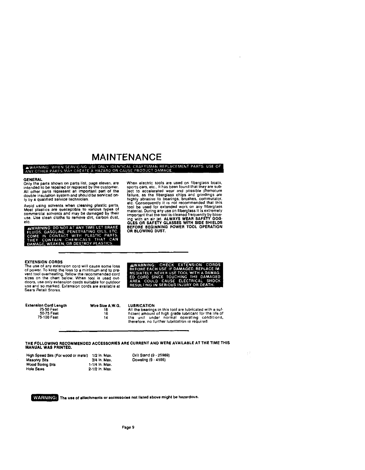
GENERAL
Only the parts shown on parts list, page eleven, are
intended to be repaired or replaced by the customer.
All other parts represent an important part of the
double insulation system and should be serviced on-
ly by a qualified service technician,
Avoid using solvents when cleaning plastic parts.
Most plastics are susceptible to various types of
commercial solvents and may be damaged by their
use, Use clean cloths to remove dirt, carbon dust,
etc.
...1=,,
When electric tools are used on fiberglass boats,
sports cars, etc, it has been found that they are sub-
ject to accelerated wear and possible premature
failure, as the fiberglass chips and grindings are
highly abrasive to bearings, brushes, commutator,
etc. Consequently it is not recommended that this
tool be used for extended work on any fiberglass
material. Curing any use on fiberglass it is extremely
im_ortant that the tool is cleaned frequently by blow-
ing with an air et. ALWAYS WEAR SAFETY GOG.
GLES OR SAFETY GLASSES W TH SDE BH ELDS
BEFORE BEGINNING POWER TOOL OPERATION
OR BLOWING DUST,
EXTENSION CORDS
The use of any extension cord will cause some loss
of power. To keep the loss to a minimum and to pre-
vent tool overheating, follow the recommended cord
sizes on the chart below, When tool is used out-
doors, use only extension cords suitable for outdoor
use and so marked. Extension cords are available at
Sears Retail Stores.
Extension Cord Length Wire Size A.W.G+
25-50 Feet 18
50.75 Feet 16
75.190 Feet 14
LUBRICATION
AH the bearings in this tool are lubricated with a suf-
ficient amount of high grade lubricant for the life of
the unit under normal oper_ating conditions,
therefore, no further lubrication iS required
THE FOLLOWING RECOMMENDED ACCESSORIES ARE CURRENT AND WERE AVAILABLE AT THE TIME THIS
MANUAL WAS PRINTED.
HighSpeed Bits(For wood or metal) 1/2 In. Max.
Masonry Bits 3/4 In. Max.
Wood BoringBits 1-1/4 In. Max.
Hole Raws 2-1/2 In, Max,
Drill Stand (9 -25989)
Doweling (9- 4186)
_The use of attachments or accessories not listed above might be hazardous.
Page 9
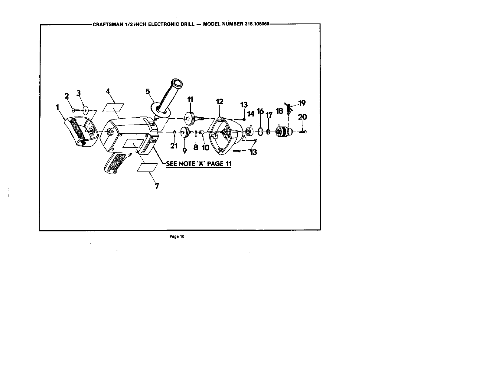
CRAFTSMAN 1/2 INCH ELECTRONIC DRILL -- MODEL NUMBER 315.105050.
2 3 411 12 13
20
8 10
Page 10
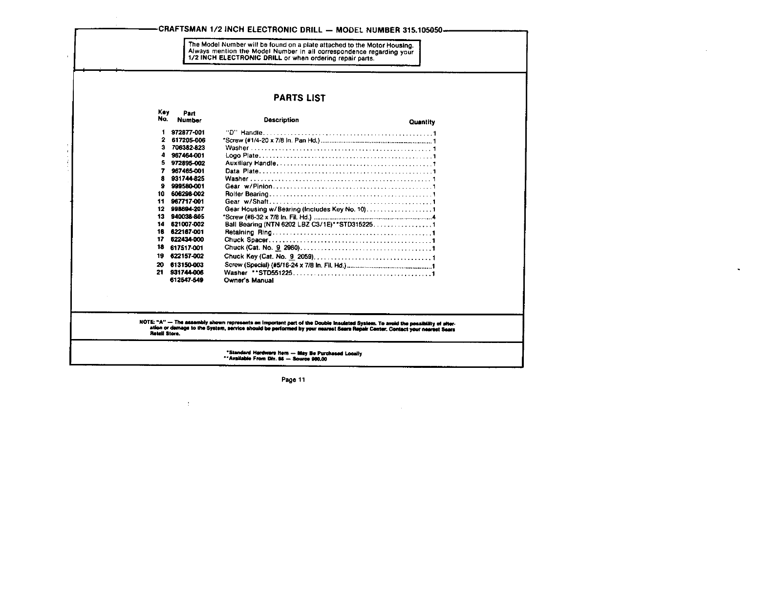
CRAFTSMAN 1/2 INCH ELECTRONIC DRILL -- MODEL NUMBER 315.105050
Key Part
No. Number
1 972877-001
2 617205-006
3 706382-823
4 967464_01
5 972_
7 g67465-001
8 931744-825
9 999580.001
10 606298-002
11 967717.001
12 998694-207
13 940038.005
14 621007-002
16 622187-001
17 622434-000
18 617517-001
19 622157-002
20 613150-003
21 931744.0_6
612547-549
PARTS LIST
Description Quantity
"D" Handle ................................................. 1
"Screw (#1/4-20 x 7/8 In. Pan Hd,) ............................................................... 1
Washer .................................................... 1
Logo Plate .................................................. 1
Auxiliary Handle ............................................. 1
Data Plate .................................................. 1
Washer .................................................... 1
Gear w/Pinion .............................................. 1
Roller Bearing ............................................... 1
Gear w/Shaft ............................................... 1
Gear Housing w/Bearing (Includes Key NO. 10) ................... 1
*Screw (#8-32 x 7_ In. Fil. Hd.) ................................................................... 4
Bali Bearing (NTN 6202 LBZ C3/1E)" *STD315225 ................. 1
Retaining Ring .............................................. 1
Chuck Spacer ............................................... 1
Chuck (Cat, No. 9 2980) ...................................... 1
Chuck Key (Cat. No. 9 2059) .................................. 1
Screw (Special) (#5/16-24 x 7/8 In. Fil. Hd.) ................................................ 1
Washer * "STITo51225 ........................................ 1
Owner's Manual
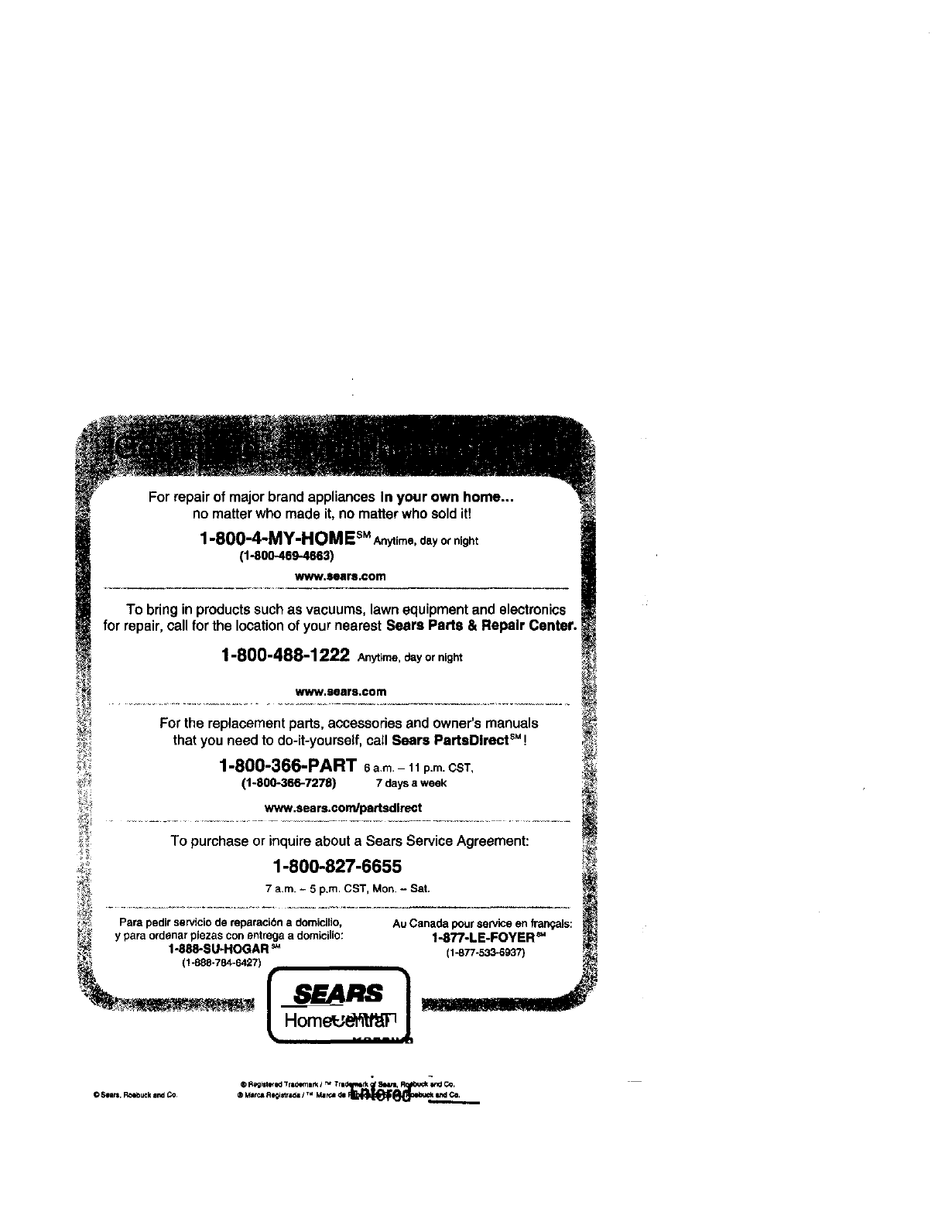
For
no matter who made it, no matter who sold itl
repairof majorbrand appliancesIn your own home...
i
1-80O-4-iY-HOa EsM
Anytime,day Ornight I
(1-800-469-4663) i
www.$ears,oom j
To bringin productssuchas vacuums,lawnequipmentandelectronics
for repair,callfor the locationof yournearestSeers Parts & Repair Canter._
1-800-488-1222 Anytime, dayor night
www.Bears.com _
For the replacement parts, accessories and owner's manuals
that you need to do-it-yourself, call Sears PartsDIrectSM! _i
1-800-366-PART 6am- 11p.m.CST,
_; (1-800-366-7278) 7 daysaweek
:_ TO purchase or inquire about a Sears Service Agreement:
1-800-827-6655
7 a,m. - 5 p.m. CST, Mon.- Sat.
Para pedirserviciode reparacibna domicJlio, Au Canada pour serviceen fran_als:
ypara ordenar plezascon entrega a domicilio: 1.877.LE.FOYER ='
1-888-SU-HOGAR _1-877-533-6937 _
- -7f 1.-.-.J
® P,egll_e't<J Tra_:_mtm=_/_?_ea4_m, I1_ CO,
