Craftsman 315108350 User Manual CIRCULAR SAW Manuals And Guides L0090013
CRAFTSMAN Saw Circular Manual L0090013 CRAFTSMAN Saw Circular Owner's Manual, CRAFTSMAN Saw Circular installation guides
User Manual: Craftsman 315108350 315108350 CRAFTSMAN CIRCULAR SAW - Manuals and Guides View the owners manual for your CRAFTSMAN CIRCULAR SAW #315108350. Home:Tool Parts:Craftsman Parts:Craftsman CIRCULAR SAW Manual
Open the PDF directly: View PDF ![]() .
.
Page Count: 20

_._/,_,_)_ Owner's Manual El
CRAI:T$MAN °
7-1/4 in. CIRCULAR SAW
Double Insulated B
Model No.
315.108356
Save this manual for
future reference
,_, CAUTION: Read and follow
all Safety Rules and Operat-
ing Instructions before first
use of this product.
Sears, Roebuck and Co., Hoffman Estates, IL 60179 USA
972000-323
7-00
• Table Of Contents .......................................................................................................................................... 2
• Warranty ......................................................................................................................................................... 2
• Introduction ..................................................................................................................................................... 2
• Rules For Safe Operation ............................................................................................................................ 3-5
• Product Specifications .................................................................................................................................... 6
• Unpacking ....................................................................................................................................................... 6
• Accessories .................................................................................................................................................... 6
• Features ........................................................................................... i.............................................................. 7
• Adjustments .................................................................................................................................................... 8
• Operation ................................................................................................................................................... 9-15
• Maintenance ................................................................................................................................................. 17
• Exploded View and Repair Parts List ...................................................................................................... 18-19
• Parts Ordering_/Service ............................................................................................................................... 20
FULL ONE YEAR WARRANTY ON CRAFTSMAN CIRCULAR SAW
If this I::RflI:TSMIIN Circular Saw fails to give complete satisfaction within one year from the date of purchase,
RETURN IT TO THE NEAREST SEARS STORE IN THE UNITED STATES, and Sears will repair it, free of
charge.
If this rRI|I:TSMRN Circular Saw is used for commercial or rental purposes, this warranty applies for only 90
days from the date of purchase.
This warranty gives you specific legal rights, and you may also have other rights which vary from state to state.
Seers, Roebuck and Co., Dept. 817WA, Hoffman Estates, IL 60179
Your circular saw has many features for making
cutting operations more pleasant and enjoyable.
Safety, performance and dependability have been
given top priority in the design of this saw making it
easy to maintain and operate.
_, CAUTION: Carefully read through this entire
owner's manual before using your new circular
saw. Pay close attention to the Rules For Safe
Operation, Warnings and Cautions. If you use
your circular saw properly and only for what it is
intended, you will enjoy years of safe, reliable
service.
Page 2

The purpose of safety symbols is to attract your attention to possible dangers. The safety symbols, and
the explanations with them, deserve your careful attention and understanding. The safety warnings do
not by themselves eliminate any danger. The instructions or warnings they give are not subsUtutes for
proper accident prevention measures.
SYMBOL MEANING
ASAFETY ALERTSYMBOL:
Indicatescautionorwarning. Maybeusedinconjunctionwithothersymbolsorpi_ographs.
ADANGER: Failure to obey a safety warning will result in serious injury to yourself or to others.
Always follow the safety precautions to reduce the risk of fire, electric shock and personal injury.
AWARNING: Failure to obey a safety warning can result in serious injury to yourself or to others.
Always follow the safety precautions to reduce the risk of fire, electric shock and personal injury.
ACAUTION: Failure to obey asafety warning may result in property damage or personal injury to
yourself or to others. Always follow the safety precautions to reduce the risk of fire, electric shock
and personal injury.
NOTE: Advises yo_ of information or instructions vital to the operation or maintenance of the equipment.
H
DOUBLE INSULATION
Double insulation is a concept in safety, in electric
power tools which eliminates the need for the usual
throe-wiro grounded power cord. All exposed metal
parts are isolated from internal metal motor
components with protecting insulation. Double
insulated tools do not need to be grounded.
IMPORTANT
Servicing of atool with double insulation requires
extreme care and knowledge of the system and
should be performed only by aqualified service
technician. For service we suggest you return the tool
to your nearest Sears Store for repair. Always use
original factory replacement parts when servicing.
_L WARNING: Do not attempt to operate this tool
until you have read thoroughly and understand
completely all instructions, safety rules, etc.
contained in this manual. Failure to comply
can result in accidents involving fire, electric
shock, or serious personal injury. Save owner's
manual and review frequently for continuing
safe operation, and instructing others who may
use this tool.
READ ALL INSTRUCTIONS
KNOW YOUR POWER TOOL. Read owner's
manual carefully. Learn its applications and
limitations as well as the specific potential
hazards related to this tool.
GUARD AGAINST ELECTRICAL SHOCK BY
PREVENTING BODY CONTACT WITH
GROUNDED SURFACES. For example; pipes,
radiators, ranges, refrigerator enclosures.
_, WARNING: If saw is dropped, lower blade
guard or bumper may be bent, restricting full
return.
KEEP GUARDS IN PLACE AND IN WORKING
ORDER. Never wedge or tie lower blade guard
open. Check operation of lower blade guard
before each use. Do not use if lower blade guard
does not close briskly over saw blade.
Page 3
If lower blade guard or bumper become bent or
damaged, replace them before rouse.
KEEP WORK AREA CLEAN. Cluttered areas
and benches invite accidents'.
AVOID DANGEROUS ENVIRONMENT. Don't
use power tools in damp or wet locations or
expose to rain. Keep work area well lit.
KEEP CHILDREN AND VISITORS AWAY. All
visitors should wear safety glasses and be kept a
safe distance from work area, Do not let visitors
contact tool or extension cord.
STORE IDLE TOOLS. When not in use, tools
should be stored in a dry and high or locked-up
place - out of the reach of children.
DON'T FORCE TOOL. It will do the job better
and safer at the rate for which it was designed.
RULES FOR SAFE OPERATION (Continued)
USE RIGHT TOOL. Don't force small tool or
attachment to do the job of aheavy duty tool.
Don't use tool for purpose not intended - for
example - A circular saw should never be used
for cutting tree limbs or logs.
WEAR PROPER APPAREL. Do not wear loose
clothing or jewelry that can get caught in tool's
moving parts and cause personal injury. Rubber
gloves and nonskid footwear are recommended
when working outdoors. Wear protective hair
covering to contain long hair and keep it from
being drawn into nearby air vents.
ALWAYS WEAR SAFETY GLASSES. Everyday
eyeglasses have only impact-resistant lenses;
they are not safety glasses.
PROTECT YOUR LUNGS. Wear a face or dust
mask if the cutting operation is dusty.
PROTECT YOUR HEARING. Wear hearing
protection during extended periods of operation.
DON'T ABU_"E CORD. Never carry tool by cord
or yank it to disconnect from receptacle. Keep
cord from heat, oil, and sharp edges.
SECURE WORK. Use clamps or a vise to hold
work. It's safer than using your hand and it frees
both hands to operate tool.
DON'T OVERREACH. Keep proper footing and
balance at all times. Do not use on aladder or
unstable support. Secure tools when working at
elevated positions.
MAINTAIN TOOLS WITH CARE. Keep tools
sharp and clean for best and safest performance.
Follow instructions for lubricating and changing
accessories.
DISCONNECT TOOLS. When not in use, before
servicing, or when changing attachments,
blades, bits, cutters, etc., all tools should be
disconnected from power supply.
REMOVE ADJUSTING KEYS AND
WRENCHES. Form habit of checking to see that
keys and adjusting wrenches are removed from
tool before turning it on.
AVOID ACCIDENTAL STARTING. Don't carry
plugged-in tool with finger on switch. Be sure
switch is off when plugging in.
MAKE SURE YOUR EXTENSION CORD IS IN
GOOD CONDITION. When using an extension
cord, be sure to use one heavy enough to carry
the current your product will draw. An undersized
cord will cause a drop in line voltage resulting in
loss of power and overheating. A wire gage size
(A.W.G.) of at least 12 is recommended for an
extension cord 50 feet or less in length. A cord
exceeding 100 feet is not recommended. If in
doubt, use the next heavier gage. The smaller
the gage number, the heavier the cord.
OUTDOOR USE EXTENSION CORDS. When
tool is used outdoors, use only extension cords
suitable for use outdoors. Outdoor approved
cords are marked with the suffix W-A, for ex-
ample -SJTW-A or SJOW-A.
•KEEP BLADES CLEAN AND SHARP. Sharp
blades minimize stalling and kickback.
KEEP HANDS AWAY FROM CUTTING AREA.
Keep hands away from blades. Do not reach
underneath work while blade is rotating. Do not
attempt to remove cut material when blade is
moving.
,_ WARNING: Blades coast after turn off.
•NEVER USE IN AN EXPLOSIVE ATMO-
SPHERE. Normal sparking of the motor could
ignite fumes.
INSPECT TOOL CORDS PERIODICALLY and if
damaged, have repaired by authorized service
facility. Stay constantly aware of cord location
and keep it well away from the rotating blade.
•INSPECT EXTENSION CORDS PERIODI-
CALLY and replace if damaged.
KEEP HANDLES DRY, CLEAN, AND FREE
FROM OIL AND GREASE. Always use a clean
cloth when cleaning. Never use brake fluids,
gasoline, petroleum-based products, or any
strong solvents to clean your tool.
STAY ALERT AND EXERCISE CONTROL.
Watch what you are do.ingand use common
sense. Do not operate tool when you are tired.
Do not rush.
CHECK DAMAGED PARTS. Before further use
of the tool, a guard or other part that is damaged
should be carefully checked to determine that it
will operate properly and perform its intended
function. Check for alignment of moving parts,
binding of moving parts, breakage of pads,
mounting and any other conditions that may
affect its operation. A guard or other part that is
damaged should be properly repaired or re-
placed by an authorized service center.
DO NOT USE TOOL IF SWITCH DOES NOT
TURN IT ON AND OFF. Have defective switches
replaced by an authorized service center.
Page 4
RULES FOR SAFE OPERATION (Continued)
USE RIP FENCE. Always use a fence or
straight edge guide when ripping.
SUPPORT LARGE PANELS, To minimize the
risk of blade pinching and kickback, always
support large panels as shown in figure 9, page
10. When cutting operation requires the resting
of the caw on the workpiece, the saw should be
rested on the larger portion and the smaller piece
cut off.
•LOWER BLADE GUARD.
_, WARNING: If lower blade guard must be raised
to make a cut, always raise it with the retracting
handle to avoid serious injury. See Figure 21,
Page 15.
GUARD AGAINST KICKBACK. Kickback occurs
when the saw stalls rapidly and is driven back
towards the operator. Release switch immedi-
ately if blade binds or saw stalls. Don't remove
saw from work during a cut while the blade is
moving. See Pages 9 and 10.
fP
BEFORE MAKING A CUT, BE SURE THE
DEPTH AND BEVEL ADJUSTMENTS ARE
TIGHT.
USE ONLY CORRECT BLADES. Do not use
blades with incorrect size holes. Never use blade
washers or bolts that are defective or incorrect.
The maximum blade capacity of your saw is
7-1/4 inches.
AVOID CuI-rlNG NAILS. Inspect for and
remove all nails from lumber before cutting.
NEVER touch the blade or other moving parts
during use.
NEVER start a tool when its rotating component
is in contact with the workpiece.
A
NEVER lay a tool down before its moving parts
have come to a complete stop.
DO NOT operate this tool while under the
influence of drugs, alcohol, or any medication.
POLARIZED PLUGS. To reduce the riskof
electric shock, this tool has a polarized plug (one
blade is wider than the other). This plug will fit in
a polarized outlet only one way. If the plug does
not fit fully in the outlet, reverse the plug. If it still
does not fit, contact a qualified electrician to
install the proper outlet. Do not change the plug
in any way.
WHEN SERVICING USE ONLY IDENTICAL
CRAFTSMAN REPLACEMENT PARTS.
SAVE THESE INSTRUCTIONS. Refer to them
frequently and use them to instruct others who
may use this tool. If you loan someone this tool,
loan them these instructions also.
WARNING: Some dust created by power
sanding, sawing, grinding, drilling, and other
construction activities contains chemicals known
to cause cancer, birth defects or other reproduc-
tive harm. Some examples of these chemicals
are:
• meadfrom lead-based paints,
•crystalline silica from bricks and cement
and other masonry products, and
•arsenic and chromium from chemically-
treated lumber.
Your risk from these exposures varies,
depending on how often you do this type of
work. To reduce your exposure to these
chemicals: work in a well ventilated area, and
work with approved safety equipment, such as
those dust masks that are specially designed to
filter out microscopic particles.
,_ Look for this symbol to point out important safety precautions. It means attentionU! Your
safety is involved.
_k WARNING:
The operation of any circular saw can result in foreign objects being thrown Into your
eyes, which can result in severe eye damage. Before beginning power tool operation,
always wear safety goggles or safety glasses with side shields and a full face shield
when needed. We recommend Wide Vision Safety Mask for use over eyeglasses or
standard safety glasses with side shields, available at Sears Retail Stores.
SAVE THESE INSTRUCTIONS
Page 5
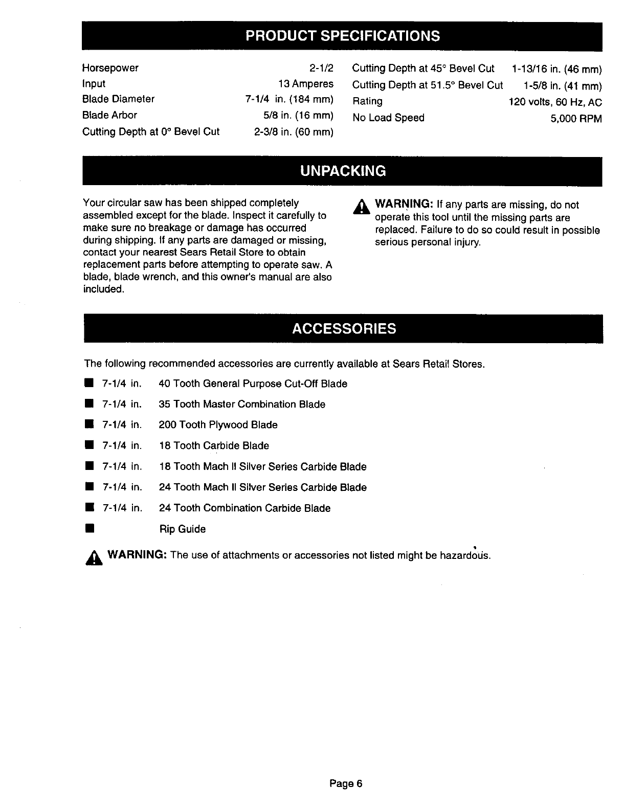
Horsepower
Input
Blade Diameter
Blade Arbor
Cutting Depth at 0° Bevel Cut
2-1/2
13 Amperes
7-1/4 in. (184 mm)
5/8 in. (16 ram)
2-3/8 in. (60 ram)
Cutting Depth at 45 ° Bevel Cut
Cutting Depth at 51.5 °Bevel Cut
Rating
No Load Speed
1-13/16 in. (46 mm)
1-5/8 in. (41 mm)
120 volts, 60 Hz, AC
5,000 RPM
Your circular saw has been shipped completely
assembled except for the blade. Inspect it carefully to
make sure no breakage or damage has occurred
during shipping. If any parts are damaged or missing,
contact your nearest Sears Retail Store to obtain
replacement parts before attempting to operate saw. A
blade, blade wrench, and this owner's manual are also
included.
_i, WARNING: If any parts are missing, do not
operate this tool until the missing parts are
replaced. Failure to do so could result in possible
serious personal injury.
The following recommended accessories are currently available at Sears Retail Stores.
• 7-1/4 in. 40 Tooth General Purpose Cut-Off Blade
• 7-1/4 in. 35 Tooth Master Combination Blade
• 7-1/4 in. 200 Tooth Plywood Blade
• 7-1/4 in. 18 Tooth Carbide Blade
• 7-1/4 in. 18 Tooth Mach II Silver Series Carbide Blade
• 7-1/4 in. 24 Tooth Mach II Silver Series Carbide Blade
• 7-1/4 in. 24 Tooth Combination Carbide Blade
• Rip Guide
WARNING: The use of attachments or accessories not listed might be hazardods.
Page 6
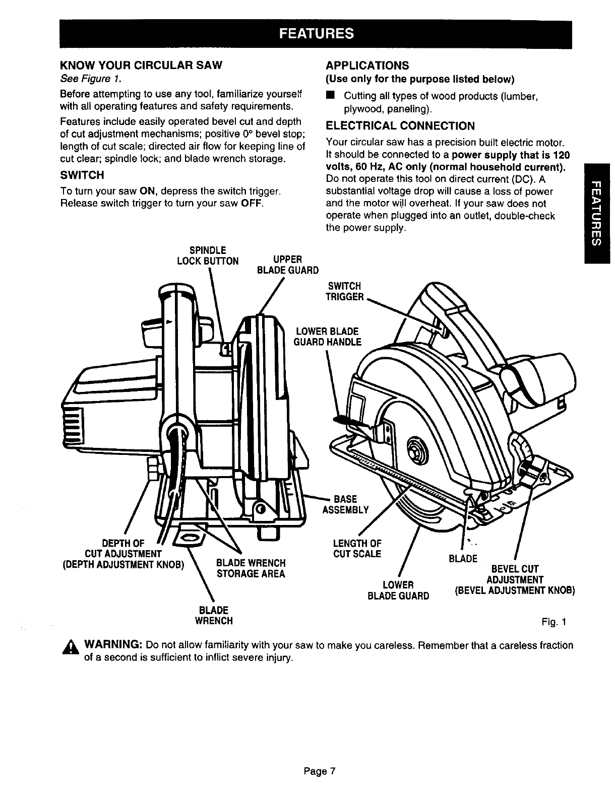
KNOWYOURCIRCULARSAW
See Figure 1.
Before attempting to use any tool, familiarize yourself
with all operating features and safety requirements.
Features include easily operated bevel cut and depth
of cut adjustment mechanisms; positive 0° bevel stop;
length of cut scale; directed air flow for keeping line of
cut clear; spindle lock; and blade wrench storage.
SWITCH
To turn your saw ON, depress the switch trigger.
Release switch trigger to turn your saw OFF.
SPINDLE
LOCKBuI"rON UPPER
BLADEGUARD
APPLICATIONS
(Use only for the purpose listed below)
• Cutting all types of wood products (lumber,
plywood, paneling).
ELECTRICAL CONNECTION
Your circular saw has a precision built electric motor.
It should be connected to a power supply that is 120
volts, 60 Hz, AC only (normal household current).
Do not operate this tool on direct current (DC). A
substantial voltage drop will cause a loss of power
and the motor wUIoverheat, If your saw does not
operate when plugged into an outlet, double-check
the power supply.
SWITCH
LOWERBLADE
GUARDHANDLE
BASE
ASSEMBLY
DEPTHOF
CUTADJUSTMENT
(DEPTHADJUSTMENTKNOB) BLADEWRENCH
STORAGEAREA
LENGTHOF
CUT SCALE BLADE BEVELCUT
LOWER ADJUSTMENT
BLADEGUARD (BEVELADJUSTMENTKNOB)
BLADE
WRENCH Fig. 1
,_ WARNING: Do not allow familiarity with your saw to make you careless. Remember that a careless fraction
of a second is sufficient to inflict severe injury.
Page 7
_1, WARNING: Your saw should never be
connected to power supply when you are
assembling parts, making adjustments,
assembling or removing blades, cleaning, or
when not in use. Disconnecting your saw will
prevent accidental starting that could cause
serious personal injury.
WARNING: A 7-1/4 in. blade is the maximum
blade capacity of your saw. Never use ablade
that is too thick to allow outer blade washer to
engage with the flat on the spindle. Larger blades
wilt come in contact with the blade guards, while
thicker blades will prevent blade screw from
securing blade on spindle. Either of these
situations could result in a serious accident.
TO ASSEMBLE OR REMOVE BLADE
•Unplug your saw.
_, WARNING: Failure to unplug your saw could
result in accidental starting causing possible
serious personal injury.
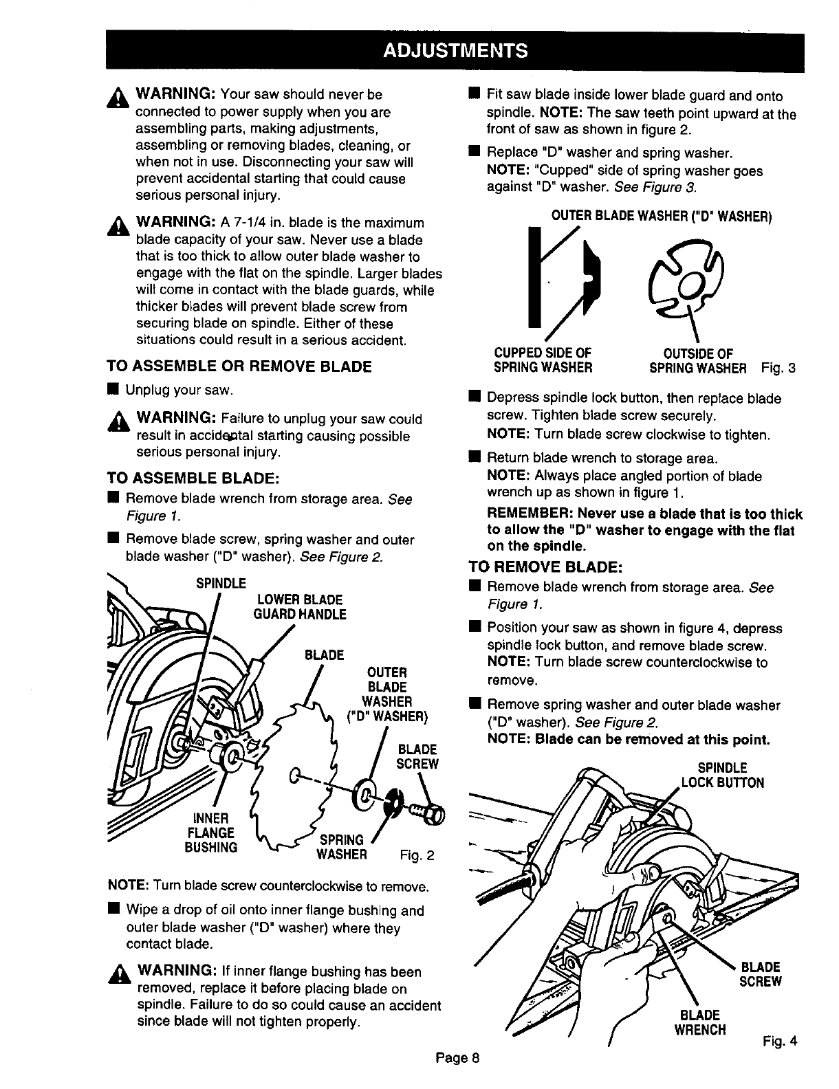
TO ASSEMBLE BLADE:
•Remove blade wrench from storage area. See
Figure 1.
• Remove blade screw, spring washer and outer
blade washer ("D" washer). See Figure 2.
SPINDLE LOWERBLADE
GUARDHANDLE
BLADE
OUTER
BLADE
WASHER
("D"WASHER)
BLADE
SCREW
• Fit saw blade inside lower blade guard and onto
spindle. NOTE: The saw teeth point upward at the
front of saw as shown in figure 2.
•Replace "D" washer and spring washer.
NOTE: "Cupped" side of spring washer goes
against "D" washer. See Figure 3.
OUTERBLADEWASHER("D" WASHER)
CUPPEDSIDEOF OUTSIDEOF
SPRINGWASHER SPRINGWASHER Fig. 3
• Depress spindle lock button, then replace blade
screw. Tighten blade screw securely.
NOTE: Turn blade screw clockwise to tighten.
•Return blade wrench to storage area.
NOTE: Always place angled portion of blade
wrench up as shown in figure 1.
REMEMBER: Never use a blade that is too thick
to allow the "D" washer to engage with the flat
on the spindle.
TO REMOVE BLADE:
•Remove blade wrench from storage area. See
Figure 1.
• Position your saw as shown in figure 4, depress
spindle lock button, and remove blade screw.
NOTE: Turn blade screw counterclockwise to
remove.
•Remove spring washer and outer blade washer
("D" washer). See Figure 2.
NOTE: Blade can be removed at this point.
SPINDLE
LOCKBUTrON
INNER
FLANGE
BUSHING WASHER Fig. 2
NOTE: Turn blade screw countemlockwise to remove.
•Wipe a drop of oil onto inner flange bushing and
outer blade washer ("D" washer) where they
contact blade.
_k, WARNING: If inner flange bushing has been
removed, replace it before placing blade on
spindle. Failure to do so could cause an accident
since blade will not tighten properly.
Page 8
BLADE
WRENCH
BLADE
SCREW
Fig. 4
SAW BLADES
The best of saw blades will not cut efficiently if they
are not kept clean, sharp, and properly set. Using a
dull blade will place a heavy load on your saw and
increase the danger of kickback. Keep extra blades
on hand, so that sharp blades are always available.
Gum and wood pitch hardened on blades will slow
your saw down. Use gum and pitch remover, hot
water, or kerosene to remove these accumulations.
Do not use gasoline.
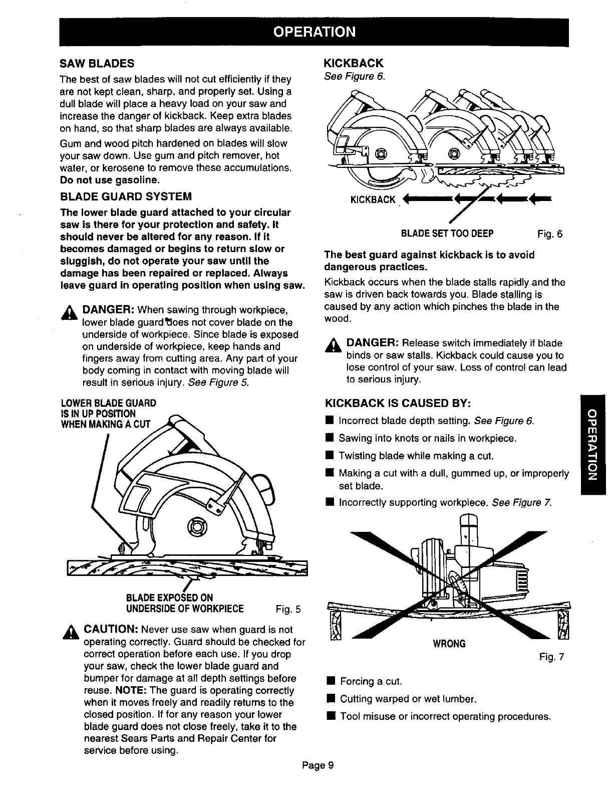
BLADE GUARD SYSTEM
The lower blade guard attached to your circular
saw is there for your protection and safety. It
should never be altered for any reason. If it
becomes damaged or begins to return slow or
sluggish, do not operate your saw until the
damage has been repaired or replaced. Always
leave guard in operating position when using saw.
_IL DANGER: When sawing through workpiece,
lower blade guard_oes not cover blade on the
underside of workpiece. Since blade is exposed
on underside of workpiece, keep hands and
fingers away from cutting area. Any part of your
body coming in contact with moving blade will
result in serious injury. See Figure 5.
LOWERBLADEGUARD
IS IN UP POSITION
WHENMAKINGA CUT
KICKBACK
See Figure 6.
KICKBACK '_mlm_KF'_E_
BLADESET TOODEEP Fig. 6
The best guard against kickback is to avoid
dangerous practices.
Kickback occurs when the blade stalls rapidly and the
saw is driven back towards you. Blade stalling is
caused by any action which pinches the blade in the
wood.
DANGER: Release switch immediately if blade
binds or saw stalls. Kickback could cause you to
lose control of your saw. Loss of control can lead
to serious injury.
KICKBACK IS CAUSED BY:
• Incorrect blade depth setting. See Figure 6.
• Sawing into knots or nails in workpiece.
•Twisting blade while making a cut.
• Making a cut with a dull, gummed up, or improperly
set blade.
•Incorrectly supporting workpiece. See Figure 7.
BLADEEXPOSEDON
UNDERSIDEOF WORKPIECE Fig. 5
,_ CAUTION: Never use saw when guard is not
operating correctly. Guard should be checked for
correct operation before each use. If you drop
your saw, check the lower blade guard and
bumper for damage at all depth settings before
reuse. NOTE: The guard is operating correctly
when it moves freely and readily returns to the
closed position. If for any reason your lower
blade guard does not close freely, take it to the
nearest Sears Parts and Repair Center for
service before using.
WRONG
Fig. 7
• Forcing a cut.
•Cutting warped or wet lumber.
• Tool misuse or incorrect operating procedures.
Page 9
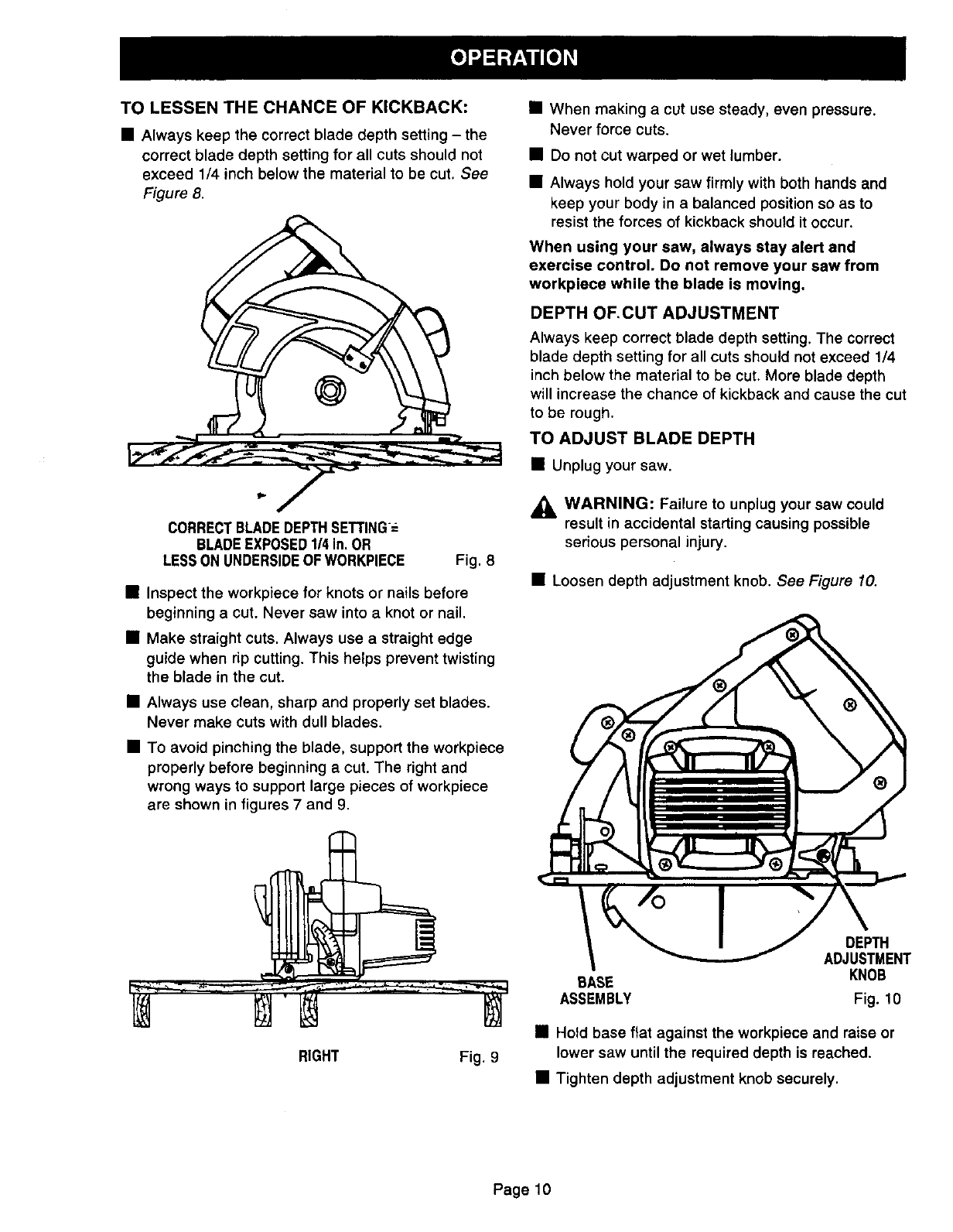
TO LESSEN THE CHANCE OF KICKBACK:
• Always keep the correct blade depth setting - the
correct blade depth setting for all cuts should not
exceed 1/4 inch below the material to be cut. See
Figure 8.
CORRECTBLADEDEPTHSETTING-
BLADEEXPOSED1/4 in, OR
LESSON UNDERSIDEOF WORKPIECE Fig. 8
•Inspect the workpiece for knots or nails before
beginning a cut. Never saw into a knot or nail.
•Make straight cuts. Always use a straight edge
guide when rip cutting. This helps prevent twisting
the blade in the cut.
•Always use clean, sharp and properly set blades.
Never make cuts with dull blades.
•To avoid pinching the blade, support the workpiece
properly before beginning a cut. The right and
wrong ways to support large pieces of workpiece
are shown in figures 7 and 9.
• When making a cut use steady, even pressure.
Never force cuts.
• Do not cut warped or wet lumber.
• Always hold your saw firmly with both hands and
keep your body in a balanced position so as to
resist the forces of kickback should it occur.
When using your saw, always stay alert and
exercise control. Do not remove your saw from
workpiece while the blade is moving.
DEPTH OF, CUT ADJUSTMENT
Always keep correct blade depth setting. The correct
blade depth setting for all cuts should not exceed 1/4
inch below the material to be cut. More blade depth
will increase the chance of kickback and cause the cut
to be rough.
TO ADJUST BLADE DEPTH
• Unplug your saw.
_IL WARNING: Failure to unplug your saw could
result in accidental starting causing possible
serious personal injury,
• Loosen depth adjustment knob. See Figure 10.
RIGHT Fig. 9
DEPTH
ADJUSTMENT
BASE KNOB
ASSEMBLY Fig. 1O
• Hold base flat against the workpiece and raise or
lower saw until the required depth is reached.
• Tighten depth adjustment knob securely.
Page10
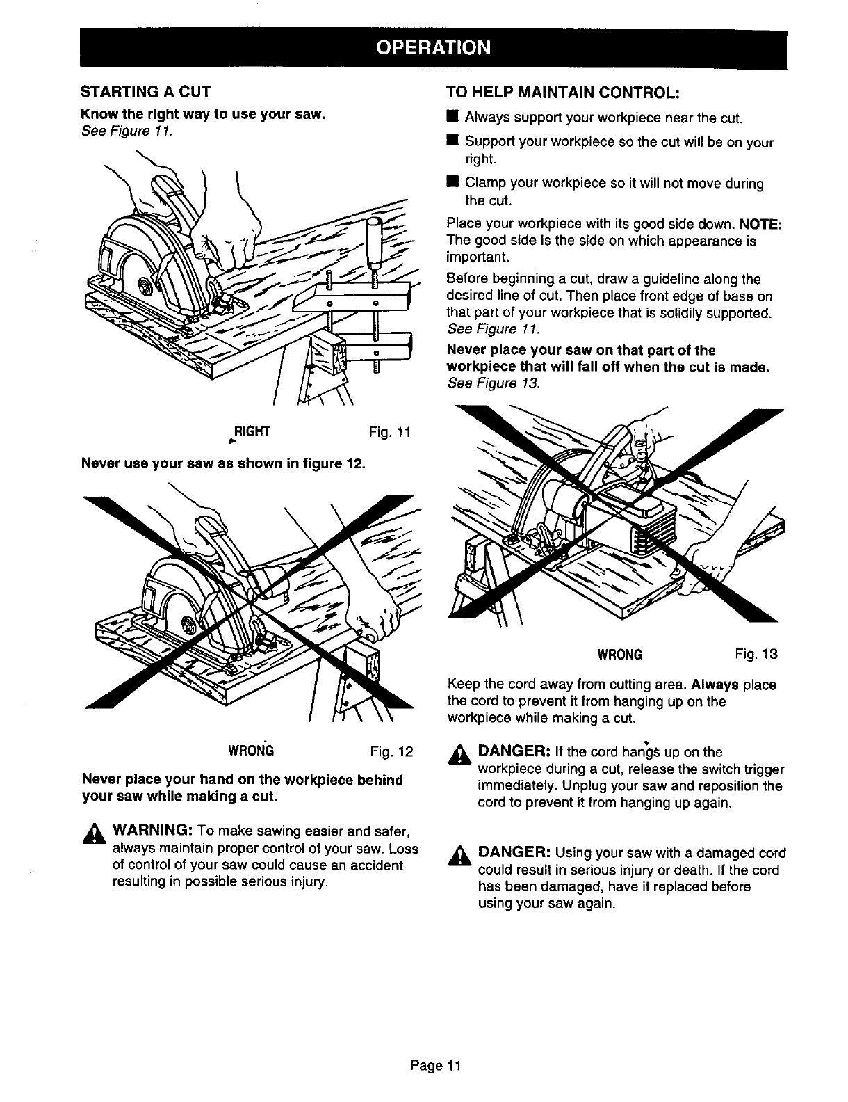
STARTING A CUT
Know the right way to use your saw.
See Figure 11.
TO HELP MAINTAIN CONTROL:
•Always support your workpiece near the cut.
•Support your workpiece so the cut will be on your
right.
•Clamp your workpiece so it will not move during
the cut.
Place your workpiece with its good side down. NOTE:
The good side is the side on which appearance is
important.
Before beginning a cut, draw a guideline along the
desired line of cut. Then place front edge of base on
that part of your workpiece that is solidily supported.
See Figure 11.
Never place your saw on that part of the
workpiece that will fall off when the cut is made.
See Figure 13.
RIGHT Fig. 11
Never use your saw as shown in figure 12.
WRONG Fig. 12
Never place your hand on the workpiece behind
your saw while making a cut.
,_, WARNING: To make sawing easier and safer,
always maintain proper control of your saw. Loss
of control of your saw could cause an accident
resulting in possible serious injury.
WRONG Fig. 13
Keep the cord away from cutting area. Always place
the cord to prevent it from hanging up on the
workpiece while making acut.
ADANGER: If the cord hangs up on the
workpiece during a cut, release the switch trigger
immediately. Unplug your saw and reposition the
cord to prevent it from hanging up again.
ADANGER: Using your saw with a damaged cord
could result in serious injury or death. If the cord
has been damaged, have it replaced before
using your saw again.
Page 11
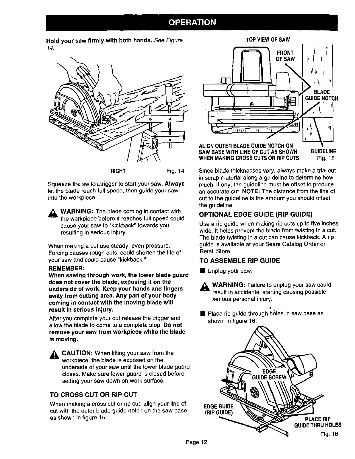
Holdyoursawfirmly withbothhands.See Figure
14.
TOPVIEWOF SAW
FRONT[7
OF SAW i_ i
BLADE
GUIDENOTCH
ALIGNOUTERBLADEGUIDENOTCHON
SAWBASEWITHLINEOF CUTAS SHOWN GUIDELINE
WHENMAKINGCROSSCUTS ORRIPCUTS Fig. 15
RIGHT Fig, 14
Squeeze the switct'_.trigger to start your saw. Always
let the blade reach full speed, then guide your saw
into the workpiece.
WARNING: The blade coming in contact with
the workpiece before it reaches full speed could
cause your saw to "kickback" towards you
resulting in serious injury.
When making a cut use steady, even pressure.
Forcing causes rough cuts, could shorten the life of
your saw and could cause "kickback."
REMEMBER:
When sawing through work, the lower blade guard
does not cover the blade, exposing it on the
underside of work. Keep your hands and fingers
away from cutting area. Any part of your body
coming in contact with the moving blade will
result In serious injury.
After you complete your cut release the trigger and
allow the blade to come to a complete stop. Do not
remove your saw from workpiece while the blade
is moving.
Since blade thicknesses vary, always make a trial cut
in scrap material along a guideline to determine how
much, if any, the guideline must be offset to produce
an accurate cut. NOTE: The distance from the line of
cut to the guideline is the amount you should offset
the guideline.
OPTIONAL EDGE GUIDE (RIP GUIDE)
Use a rip guide when making rip cuts up to five inches
wide. It helps prevent the blade from twisting in acut.
The blade twisting in a cut can cause kickback. Arip
guide is available at your Sears Catalog Order or
Retail Store.
TO ASSEMBLE RIP GUIDE
• Unplug your saw,
_, WARNING: Failure to unplug your saw could
result in accidental starting causing possible
serious personal injury.
• 4
•Place rip guide through holes in saw base as
shown in figure 16.
_, CAUTION: When lifting your saw from the
workpiece, the blade is exposed on the
underside of your saw until the lower blade guard
closes. Make sure lower guard is closed before
setting your saw down on work surface.
TO CROSS CUT OR RIP CUT
When making a cross cut or rip cut, align your line of
cut with the outer blade guide notch on the saw base
as shown in figure 15.
EDGEGUIDE
(RIPGUIDE) PLACERIP
GUIDETHRUHOLES
Fig. 16
Page 12
•Adjust rip guide to the length needed for the cut.
• Tighten edge guide screw securely.
When using a rip guide, position the face of the rip
guide firmly against the edge of workpiece. This
makes for a true cut without pinching the blade. The
guiding edge of workpiece must be straight for your
cut to be straight. Use caution to prevent the blade
from binding in the cut.
TO BEVEL CUT
The angle of cut of your saw may be adjusted to any
desired setting between zero and 51.5 °. NOTE: When
making cuts at 51.5 °blade should be set at full depth
of cut, with edge guide screw removed.
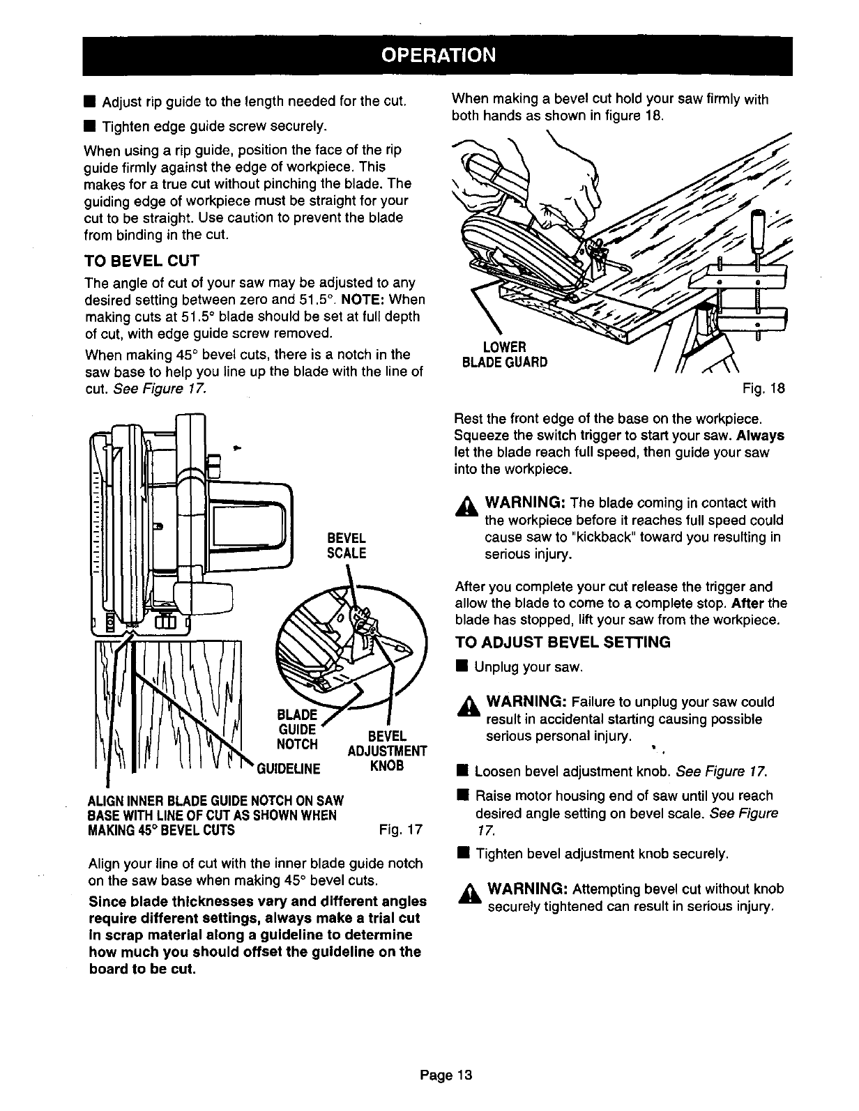
When making 45 ° bevel cuts, there is a notch in the
saw base to help you line up the blade with the line of
cut. See Figure 17.
:BEVEL
SCALE
GUIDE
..... BEVEL
NUm_M ADJUSTMENT
_GUIDELINE KNOB
ALIGNINNERBLADEGUIDENOTCHON SAW
BASEWITHLINEOF CUT AS SHOWNWHEN
MAKING45° BEVELCUTS Fig. 17
Align your line of cut with the inner blade guide notch
on the saw base when making 45 °bevel cuts.
Since blade thicknesses vary and different angles
require different settings, always make a trial cut
in scrap material along a guideline to determine
how much you should offset the guideline on the
board to be cut.
When making a bevel cut hold your saw firmly with
both hands as shown in figure 18.
\
LOWER
BLADEGUARD
Fig. 18
Rest the front edge of the base on the workpiece.
Squeeze the switch trigger to start your saw. Always
let the blade reach full speed, then guide your saw
into the workpiece.
,_ WARNING: The blade coming in contact with
the workpiece before it reaches full speed could
cause saw to "kickback" toward you resulting in
serious injury.
After you complete your cut release the trigger and
allow the blade to come to a complete stop. After the
blade has stopped, lift your saw from the workpiece.
TO ADJUST BEVEL SETTING
• Unplug your saw.
_IL WARNING: Failure to unplug your saw could
result in accidental starting causing possible
serious personal injury.
• Loosen bevel adjustment knob. See Figure 17.
•Raise motor housing end of saw until you reach
desired angle setting on bevel scale. See Figure
17.
• Tighten bevel adjustment knob securely.
,_ WARNING: Attempting bevel cut without knob
securely tightened can result in serious injury.
Page13
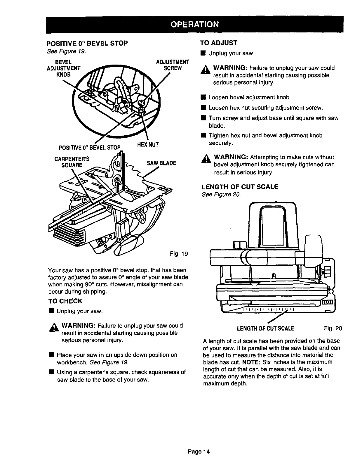
POSITIVE 0° BEVEL STOP
See Figure 19.
BEVEL
ADJUSTMENT
KNOB
POSITIVE0°BEVELSTOP
CARPENTER'S
SQUARE
ADJUSTMENT
SCREW
HEXNUT
SAWBLADE
TO ADJUST
•Unplugyoursaw.
,_ WARNING: Failure to unplug your saw could
result in accidental starting causing possible
serious personal injury.
•Loosen bevel adjustment knob.
•Loosen hex nut securing adjustment screw.
•Turn screw and adjust base untilsquare with saw
blade.
•Tighten hex nut and bevel adjustment knob
securely.
,_ WARNING: Attempting to make cuts without
bevel adjustment knob securely tightened can
result in serious injury.
LENGTH OF CUT SCALE
See Figure 20.
Fig. 19
Your saw has a positive O°bevel stop, that has been
factory adjusted to assure 0° angle of your saw blade
when making 90 °cuts. However, misalignment can
occur during shipping.
TO CHECK
• Unplug your saw.
_IL WARNING: Failure to unplug your saw could
result in accidental starting causing possible
serious personal injury.
• Place your saw in an upside down position on
workbench. See Figure 19.
• Using a carpenter's square, check squareness of
saw blade to the base of your saw.
LENGTHOF CUTSCALE Fig. 20
A length of cut scale has been provided on the base
of your saw. It is parallel with the sew blade and can
be used to measure the distance into material the
blade has cut. NOTE: Six inches is the maximum
length of cut that can be measured. Also, it is
accurate only when the depth of cut is set at fun
maximum depth.
Page 14
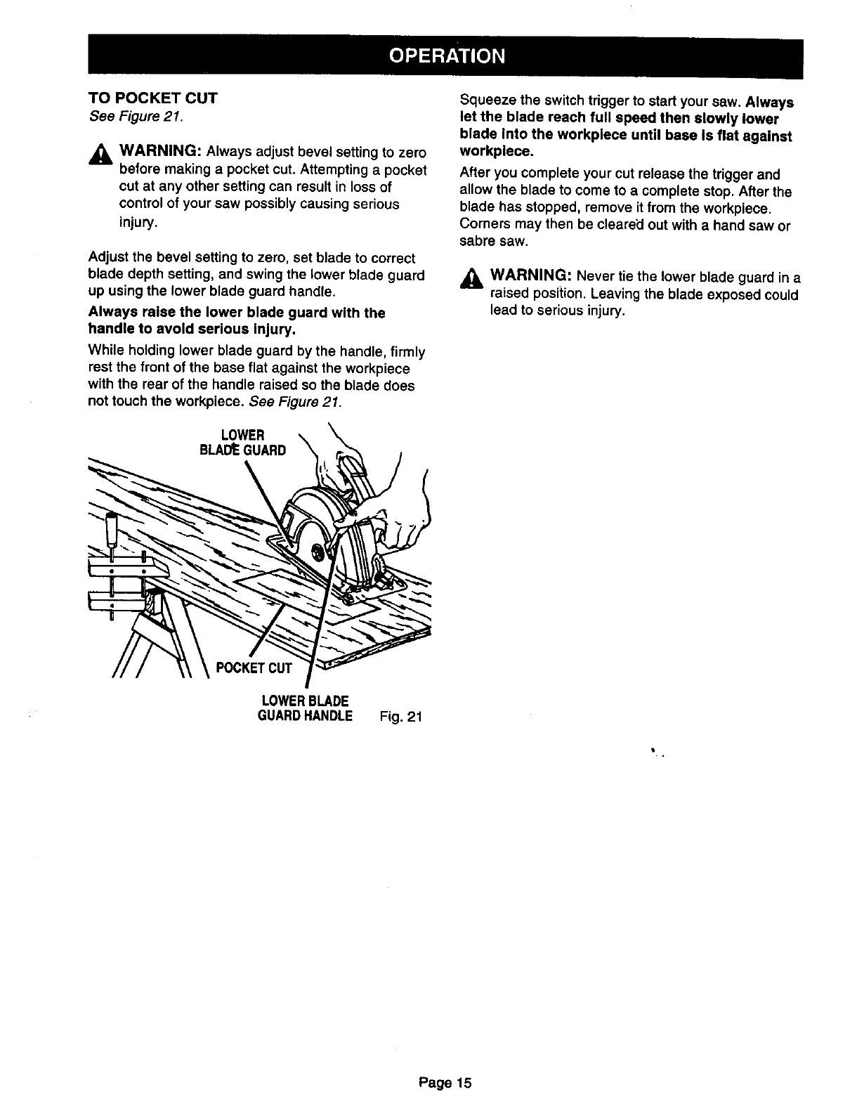
TO POCKET CUT
See Figure 21.
,_ WARNING: Always adjust bevel setting to zero
before making a pocket cut. Attempting apocket
cut at any other setting can result in loss of
control of your saw possibly causing serious
injury.
Adjust the bevel setting to zero, set blade to correct
blade depth setting, and swing the lower blade guard
up using the lower blade guard handle.
Always raise the lower blade guard with the
handle to avoid serious Injury.
While holding lower blade guard by the handle, firmly
rest the front of the base flat against the workpiece
with the rear of the handle raised so the blade does
not touch the workpiece. See Figure 21.
LOWER
BLADtEGUARD
Squeeze the switch trigger to start your saw. Always
let the blade reach full speed then slowly lower
blade Into the workplece until base Is flat against
workplece.
After you complete your cut release the trigger and
allow the blade to come to a complete stop. After the
blade has stopped, remove it from the workpiece.
Comers may then be cleared out with a hand saw or
sabre saw.
,_ WARNING: Never tie the lower blade guard in a
raised position. Leaving the blade exposed could
lead to serious injury.
POCKETCUT
LOWERBLADE
GUARDHANDLE Fig. 21
Page15

Page16
,_ WARNING: When servicing, use only identical
Craftsman replacement parts. Use of any other
part may create a hazard or cause product
damage.
GENERAL
Only the parts shown on parts list, page nineteen, are
intended to be repaired or replaced by the customer.
All other parts represent an important part of the
double insulation system and should be serviced only
by a qualified Sears service technician.
Avoid using solvents when cleaning plastic parts.
Most plastics are susceptible to damage from various
types of commercial solvents and may be damaged
by their use. Use clean cloths to remove dirt, carbon
dust, etc.
,_ WARNING: Do not at any time let brake fluids,
gasoline, petroleum-based products, penetrating
oils, etc. come in contact with plastic parts. They
contain chemicals,that can damage, weaken or
destroy plastic.
It has been found that electric tools are subject to
accelerated wear and possible premature failure when
they are used on fiberglass boats, sports cars,
wallboard, spackling compounds, or plaster. The
chips and grindings from these materials are highly
abrasive to electric tool parts such as bearings,
brushes, commutators, etc. Consequently, it is not
recommended that this tool be used for extended
work on any fiberglass material, wallboard, spackling
compounds, or plaster. During any use on these
materials it is extremely important that the tool is
cleaned frequently by blowing with an air jet.
_I, WARNING: Always wear safety goggles or
safety glasses with side shields during power tool
operation or when blowing dust. If operation is
dusty, also wear a dust mask.
LUBRICATION
All of the bearings in this tool are lubricated with a
sufficient amount of high grade lubricant for the life of
the unit under normal operating conditions. Therefore,
no further lubrication is required.
EXTENSION CORDS
The use of any extension cord will cause some loss of
power. To keep the loss to a minimum and to prevent
tool overheating, use an extension cord that is heavy
enough to carry the current the tool will draw.
A wire gage size (A.W.G.) of at least 12 is
recommended for an extension cord 50 feet or less in
length. When working outdoors, use an extension
cord that is suitable for outdoor use. The cord's jacket
will be marked WA.
,_ CAUTION: Keep extension cords away from the
cutting area and position the cord so that it will
not get caught on lumber, tools, etc., during
cutting operation.
_. WARNING: Check extension cords before each
use. If damaged replace immediately. Never use
tool with a damaged cord since touching the
damaged area could cause electrical shock
resulting in serious injury.
Extension cords suitable for use with your circular saw
are available at your nearest Sears Retail Store.
Page 17
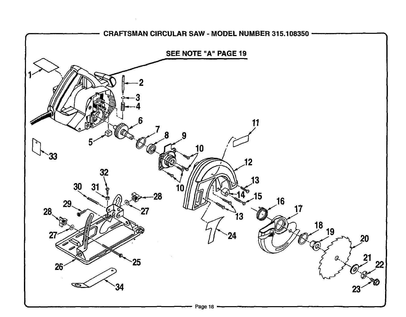
• CRAFTSMAN CIRCULAR SAW -MODEL NUMBER 315.108350 .....
SEE NOTE "A" PAGE 19
26
30
32
31 10
10
11
12
16 17
18 19 2o
_.. 21 22
Page18 ,,
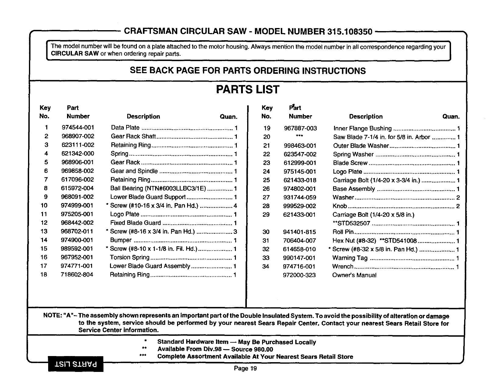
CRAFTSMAN CIRCULAR SAW -MODEL NUMBER 315.108350
I he model number will be found on a plate attached to the motor housing. Always mention the model number in all correspondence regarding your |
CIRCULAR SAW or when ordering repair parts. I
SEE BACK PAGE FOR PARTS ORDERING INSTRUCTIONS
PARTS LIST
Key Part
No. Number
1974544-001
2 968907-002
3 623111-002
4 621342-000
5 968906-001
6 969858-002
7 617096-002
8 615972-004
9 968091-002
10 974999-001
11 975205-001
12 968442-002
13 968702-011
14 974900-001
15 989592-001
16 967952-001
17 974771-001
18 718602-804
Description Quan.
Data Plate ...................................................... 1
Gear Rack Shaft ............................................. 1
Retaining Ring ................................................ 1
Spring ............................................................. 1
Gear Rack ...................................................... 1
Gear and Spindle ........................................... 1
Retaining Ring ................................................ 1
Ball Bearing (NTN#6003LLBC3/1 E) ............... 1
Lower Blade Guard Support ........................... 1
* Screw (#10-16 x 3/4 in. Pan Hd.) ................... 4
Logo Plate ...................................................... 1
Fixed Blade Guard ......................................... 1
* Screw (#8-16 x 3/4 in. Pan Hd.) ..................... 3
Bumper .......................................................... 1
* Screw (#8-10 x 1-1/8 in. Fil. Hd.) .................... 1
Torsion Spring ................................................ 1
Lower Blade Guard Assembly ........................ 1
Retaining Ring ................................................ 1
Key Ptart
No. Number Description
19 967887-003
20 ***
21 998463-001
22 623547-002
23 612999-001
24 975145-001
25 621433-018
26 974802-001
27 931744-059
28 999529-002
29 621433-001
30 941401-815
31 706404-007
32 614658-010
33 990147-001
34 974716-001
972000-323
Quan.
Inner Flange Bushing ..................................... 1
Saw Blade 7-1/4 in. for 5/8 in. Arbor .............. 1
Outer Blade Washer ....................................... 1
Spring Washer ............................................... 1
Blade Screw ................................................... 1
Logo Plate ...................................................... 1
Carriage Bolt (1/4-20 x 3-3/4 in.) .................... 1
Base Assembly .............................................. 1
Washer ........................................................... 2
Knob ............................................................... 2
Carriage Bolt (1/4-20 x 5/8 in.)
**STD532507 ................................................. 1
Roll Pin ........................................................... 1
Hex Nut (#8-32) **STD541008 ...................... 1
* Screw (#8:32 x 5/8 in. Pan Hd.) ..................... 1
Warning Tag .................................................. 1
Wrench ........................................................... 1
Ownecs Manual
NOTE: "A"- The assembly shown represents an important part of the Double Insulated System. To avoid the possibility of alteration or damage
to the system, service should be performed by your nearest Sears Repair Center. Contact your nearest Sears Retail Store for
Service Center information.
* Standard Hardware item -- May Be Purchased Locally
** Available From Div.98 -- Source 980.00
*** Complete Assortment Available At Your Nearest Sears Retail Store
lk-']lll L--'_q_d_.m Page 19

For repair of major brand appliances in your own home...
no matter who made it, no matter who sold it!
1-800-4-MY-HOME sMAnytime, day or night
(1-800-469-4663)
www.sears.com
To bring in products such as vacuums, lawn equipment and electronics
for repair, call for the location of your nearest Sears Parts & Repair Center.
1-800-488-1222 Anytime, day or night
www.sears.com
For the replacement parts, accessories and owner's manuals
that you need to do-it-yourself, call Sears PartsDirect sM!
1-800-366-PART 6a.m.- 11 p.m. CST,
(1-800-366-7278) 7 days a week
www.sears.com/partsdirect
To purchase or inquire about a Sears Service Agreement:
1-800-827-6655
7 a.m. - 5 p,m. CST, Mon. - Sat.
Para pedir servicio de reparaci6n a domicilio,
y para ordenar piezas con entrega a domicilio:
1-888-SU-HOGAR SM
(1-888-784-6427)
Au Canada pour service en fran_:ais:
1-877-LE-FOYERS"
(1-877-533-6937)
®Registered Trademark /TM Trademark of Sears, Roebuck and Co.
TM
®Sears, Roebuck and Co. ®MarCa Registrada /Marca de F_brlCa de Sears, Roebuck and Co.
