Craftsman 31511870 User Manual CIRCULAR SAW Manuals And Guides L0408209
CRAFTSMAN Saw Circular Manual L0408209 CRAFTSMAN Saw Circular Owner's Manual, CRAFTSMAN Saw Circular installation guides
User Manual: Craftsman 31511870 31511870 CRAFTSMAN CIRCULAR SAW - Manuals and Guides View the owners manual for your CRAFTSMAN CIRCULAR SAW #31511870. Home:Tool Parts:Craftsman Parts:Craftsman CIRCULAR SAW Manual
Open the PDF directly: View PDF ![]() .
.
Page Count: 7
Sears •owners manual
MOOEL NO.
315.11870
CAUTION:
Read Rules for
Safe Operation
and Instructions
Carefully
•Introduction
• Operation
•Repair Parts
THIS SAFETY SEAL OF THE POWER TOOL INSTITUTE ASSURES YOU:
J_ 1, That the nyanufm;h/rer's power tools, 'lnch_d|ns the p_rticular fool assodeled with
the Seal, ere pro_foced in accordance with applicable Standards for Safety of Under.
writers" Laboratories and AmHcan Netionol Standards (ANSI),
2. Thtt _:_lIpillln©o with ipplir, ibte ,foty stindai_ki Is ,Isii, i,i'id by Independint In-
speotlon and testing cr,nducte4 by Underwriters jLaboratories (UL).
3. That every nlotor_ed tool ki inipicted under power.
4. Thit every tool his with It adequate Instructions end 8 Use of surety rules for the
protection of the usiir.
$. Thee the tool mnufi_urer Is I member _i the Power Tool In/Htotu lind Is a,
spontir of the Institutes Conimnar Sifaty llon Progrim.
COP_IGHT, 1969. BY I:_OW'_R TOOL INST!'!_"!_, ]]_C. ALL RIGHTS RF_ERVED
GUARANTEE
CRAFTSMAN PORTABLE ELECTRIC TOOLS ARE UNCONDITIONALLY GUARANTEED FOR
ONE YEAR TO GIVE COMPLETE SATISFACTION OR RETURN FOR FREE REPLACEMENT.
THIS GUARANTEE SERVICE IS AVAILABLE BY SIMPLY RETURNING THE TOOL TO ANY
SEARS STORE.
SEARS, ROEBUCK AND CO. end SIMPSONS-SEARS LTD.
introduction
DOUBLE INSULATION
Double insulation is a concept in safety, replacing the
standard grounded supply system, in electric power
tools. The construction of adouble insulated tool of-
fers protection equal to,a properly grounded tool with-
our the necessity for us,ng a gruunded conductor, The
double insulation system ehmmntes the need for the
usual three wire 9rounded power cord and grounded
supply system.
Wherever there is electric current in the tool there
ore two complete sets of insulation to protect the user.
All exposed metal parts are isolated from the internal
metal motor components with prOtecting insulation.
The lead wires, switch, etc. with their functional in÷
sulution have the added protection of non-conductlve
sleeving or housings to complete the double insulation
system.
SERVICING OF ATOOL WITH DOUBLE INSULA-
TION REQUIRES EXTREME CARE AND KNOWL-
EDGE OF THE SYSTEM AND SHOULD BE PER-
FORMED ONLY BY AQUALIFIED SERVICE TECH-
NICIAN. FOR SERVICE WE SUGGEST YOU RE-
TURN THE TOOL TO YOUR NEAREST SEARS
STORE FOR REPAIR WHICH WILL BE DONE
WITH ORIGINAL FACTORY REPLACEMENT
PARTS.
Features include e rip guide for making fast,
smooth, consistent rip cuts without penciled lines;
push button arbor lock for fast, easy blade change-
over; easy _ew saw blade port with directed air flow
for keeping line of cut clear; uses 7, 7-_, or 7-t/z
inch blades; kick-proof clutch which allows blade to
slip on spindle should binding or jamming occur
a|ong with exclusive riving knife assure maximum
user saf_ry.
When servicing use only identi¢(=l reploeemeot
I_sts,
RULES FOR SAFE OPERATION
I. KNOW YOUR POWER TOOL -- Read owner's manual carefully. Learn its applications and limit-
ations as well as the speclf'ic pOtential hazards peculiar to this tool.
2. GROUND ALL TOOLS -- UNLESS DOUBLE-INSULATED. if tool'is equipped with three-prong
plug, it should be plugged into a three-hole electrical receptacle. If adapter is used to accommo-
date two.prong receptacle, the adapter wire must be attached to o known ground. " (Usually the
screw securing the receptacle cover plate.) Never remove third prong.
3. KEEP GUARDS IN PLACE and in working order.
4. KEEP WORK AREA CLEAN. Cluttered areas and benches invite accidents.
SAVOID DANGEROUS ENVIRONMENT. Don't use pOwer tool in damp or wet locations. And keep
work area well lit.
6. KEEP CHILDREN AWAY. All visitors should be kept safe distance from work area.
7. STORE IDLE TOOLS. When not in use, tools should be stored in dry, high or locked-up place---
out of reach of children.
8. DON'T FORCE TOOL. It will do the iob better and safer at the rate for which it wn¢ designed.
9. USE RIGHT TOOL. Don't force small tool. or attachment to do the job of oheavy duty! tool.
10. WEAR PROPER APPAREL. Noloose clothing or jewelry to get caught in moving parts. Rubber
gloves and footwear Ore recommended when working outdoors.
I I. USE SAFETY GLASSES with most tools. Alto foc'e or dust mask if cuffing operation is dusty.
|2. DON'T ABUSE CORD. Never carry tool by cord or yank it to disconnect from receptacle. Keep
cord from heat. oil and sharp edges.
13. SECURE WORK. Use clamps or avise to hold work. it's safer than using your hand and it frees
both bonds to Ol_Zrate tool.
14. DON'T OVERREACH. Keep proper footing and balance at all times.
15. MAINTAIN TOOLS WITH CARE. Keep tools sharp at off times, ar_ clean for best and safest
performance. Follow instructions for lubricating and changing accessories.
16. DISCONNECT TOOLS. When not in use, before servicing; when changing attochmenls, blades,
bits, cutters, etc.
17, REMO_'E ADJUSTING KEYS AND WRENCHES. Form habit of _:hecking to see that keys and ad-
justing wrenches Ore removed from tool before turning it on.
18 AVOID ACCIDENTAL STARTING. Don't carry plugged-in tool with finger on switch.
eOp,RIGk'r. IH_). B_lf POWER TOOL. INSTITUTE, INC, ALL RI_.NT_; REgeRV[D
Po,ae 2
1. DO read thoroughly INTRODUCTION and OP-
ERATING INSTRUCTIONS before using your
CIRCULAR SAW.
2. DO be sure the voltage of the power supply
agrees with the data plate marking on the unit.
3. DO use correct size extension cord as recom-
mended_
4. DO be sure switch is in "OFF" position before
connecting tool to power supply,
5. DO be sure sow blade is properly mounted with
teeth pointing upward at front of sow.
6- DO tighten locking nuts oher making adjust-
ments.
7- DO let saw blade come to full speed before be-
ginning cut.
8, DO releaseswitch immediately if blade binds or
jams in work.
9. DO disconnect power cord when cleaning or do_
ing maintenance on tool,
10. DO replace both brushes when either is worn to
about 1/_ inch in length.
1 1. DO keep blades sharp..
12. DO disconnect •from power source and store in
aclean dry place.
CAUTION
1. DON'T use your CIRCULAR SAW before read-
ing thoroughly, INTRODUCTION and OPERAT-
ING INSTRUCTIONS.
2. DON'T begin operation unless lower blade guard
operates freely.
3. DON'T use o dull blade or damaged blade.
4. DON'T begin operation until sow blade clamp
screw is securely tightened.
S, DON'T cut materials that ore not suitably sup-
ported.
6. DON'T tie back lower blade guard•
7. DON'T force tool, allow Circular Saw to per-
form as Jt waS designed,
8. DON'T leave Circular Saw unattended before
disconnecting from power source.
9. DON'T allow the card near saw blade when op-
erating,
10. DON'T allow children to operate Circulor Sow,
]]. DON't carry unit by power cord.
12. DON'T plug or cover air vents to keep dust from
flying. Vents must be kept open to keep motor
cool.
The operation of any power tool con result in for-
eign object= being thrown into the eyes, which con
result in severe eye damage. Always wear safety
glosses or eye shields before commencing power
tool operation. We recommend Wide Vision Safety
Mask for use over spectacles, or standard safety
glasses . . . available at Sears retail or catalog
1totes.
KEEP HAND.S AWAY FROM CUTTING ARIL_
DO NOT REACH UNDERNEATH WORK
PIECE FOR ANY REASON WHILE SAW
BLADE IS ROTATING.
IF SAW SHOULD' BE USED IN OVERHEAD
OR VERTICAL POSITION, IT IS NORMAL
THAT BLADE GUARD NOT COMPLETELY
RETRACT, THEREFORE ALWAYS CHECK
GUARD BEFORE MAKING NEXT CUT.
AVOID USE OF ALL SOLVENTS WHEN
CLEANING PLASTIC PARTS, USE CLEAN
CLOTHS AND WIPE PARTS AS MUCH AS
POSSIBLE TO REMOVE DIRT, CARBON
DUST, ETC. MOS_" PLASTICS ARE SUSCEPT-
IBLE TO VARIOUS TYPES OF COMMERCIAL
SOLVENTS AND MAY BE DAMAGED BY
THE USE OF THESE SOLVENTS.
THIS PRODUCT, or any electrical product, re-
quires extreme care when service repairs ore
mode. A dangerous electrical hazard con be
created by tempering lr_th the electrical or in-
sulating systems or in the replacement or subxtl-
tut/on of repQir par_. Repairs should be made
only by a qualified technician. If service is re-
quired we suggest you return the tool to your
nearest Sears store far approved service with
original factory r_plocement I_rts.
WHEN ELECTRIC TOOLS ARE USED ON FIBER-
GLASS berets, sports cars, etc. it has been found
that they are subject to accelerated wear and possi-
ble premature failure, as the fiberglass chips and
gi4ndings ore highly abrasive to bearings, brushes,
commutator, etc. Consequently it is not recom-
mended that this tool be used tar continuous pro-
duction work on any fiberglass material. During
any use on fiberglass it is extremely important that
the tool is €leaned frequently by blowing wlth on
oir jet.
EXTENSION CORDS-_The use of any Extension
cord will cause some loss of power. To keep this to
a minimum and to prevent overheating and motor
burn-out, use the table below to determine the MIN-
IMUM wire size (A.W.G.) Extension Cord.
•Extonxion Co_d Leqltl, Wire Size A.W.G.
25- 50 Feet 14
50- 75 Feet 12
7S-100 Feet 10
Extension cords suitable far use with your Circular
SaW are available at your neare_ Sear= Catalog
Order or Retail Store
Another time saving convenience is a €ord-lock
offered by Sears which prevents separation of cord.
Cord-lock is available et your nearest Sears Retail
Store or Catalog Order House.
Page 3'
operating
\
Fig. Fig. 2 Fig. 3
PREPARING FOR OPERATION
When making accurate cuts take into consideration wrench to acti_ute kick-proof clutch. Operating with
not only the width of tee blade but also its kerf. Most blade Screw securely tightened is recommended only
blades have teeth that ere set alternately to the right for the users which prefer to operate without benefit
and left. This means the kerr or cut made ,s wider of kick-proof clutch.
than the blade itself. The best of saw blades will not cut efficiently if they
If a board is marked to precise length from the right,
for example, the bose ..edge(guide) must ride the left
aide of the hue. Splitting the hne or guiding to its
right may cause the work piece to be shorter by the
width of the kerf.
Always be ©er_in guards ere working properly before
connecting un=t to power supply. "if guards do not work
freely, clean thoroughly of all sawdust, etc. Should
improper operating condition still exist the torsion
spring in |owes blade guard may need replacing. ISee
Torsion Spring Replacement instructions, page 6). The
design of your saw allows unit to be positioned on the
end of the motor housing, for one}' guard inspection,
blade change-over, and riving knife assembly,
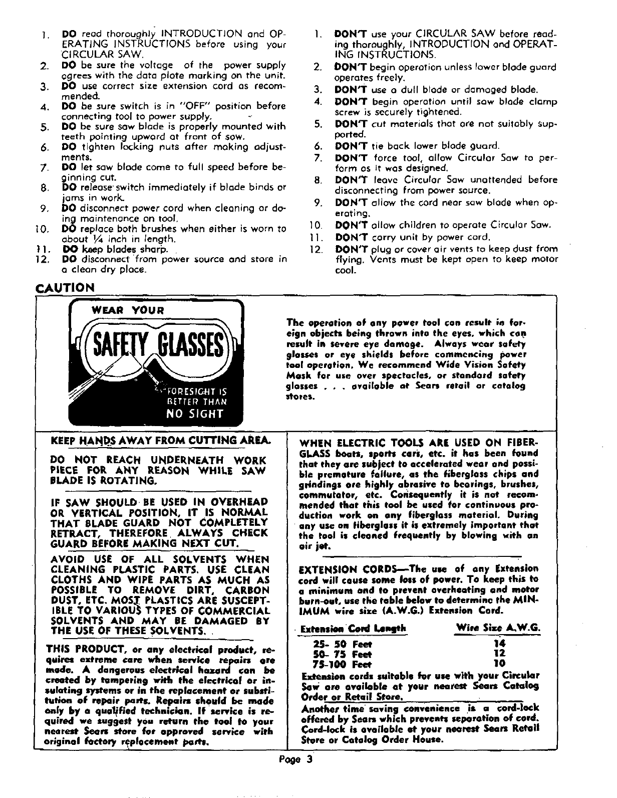
BLADE CHANGE-OVER: IMPORTANTmBE SURE
POWER CORD IS DISCONNECTED FROM POWER
SUPPLY. (See Fig. I) Position unit on end of motor
housing and depress lock pin fully. Using wrench,
Key No. 46, (See I_rts list, page 9) turn blade Screwy,
Key No. $4, €lockw=se while depressing lock pm until
pin moves into lock position. While holdang leek pin,
turn blade screw counterclockwise to loosen. Release
lock and remove blade Screw, spring washer, Key No.
56, and blade washer, Key No. 5,5, from spindle shaft.
Wipe adrop of all onto flange bushing and blade
washer (D) where contact is made with saw blade.
are not kept ,clean and sharp. Using adull blade
will do nothing more than place e heavy load on your
sew. Keep extra blades On band, so that sharp blades
are always available. Gum end wood pitch hardened
on blade will slow it down. Use hot water or kere_ne
to remove these accumulations. DO NOT USE GASO-
LINE,
TO ASSEMBLE RIVING KNIFE: IMPORTANT---BE
SURE POWER CORD IS DISCONNECTED FROM
POWER SUPPLY. (See Fig. 2) The Riving Knife keeps
wood apart to guard against blade binding or jam-
ruing. The effectiveness of the riving knife depends
upon the amount of effort used in assembling and
arriving at a proper setting. The saw blade should be
in place before assembling riving knife as this is the
determining factor for proper setting. Position
holes in knife (A) over ho|es in upper blade
guurd (B) and insert screws (C) through holes in riv-
ing knife and into threaded boles in upper blade
guard. _urn at least 1/16 inch clearance between
tip of blade tooth and inside edge uttip of knife and
tghten screws securely.
TO OPERATE
To start a cut, rest front edge of besa on supported
portion of wnrk, line up guide (line where bose and
outlxmrd besa meet or edge of base when outboard
Position saw blade (A) ins/de blade guard (C) with bose is removed) with line of cut, hold handles Firmly
teeth pointing upward at front of saw..Place the un- end squeeze tagger switch. Allaw saw blade to reach
dercut side of blade washer (D) and spring washer (E) full speed, then guide sew into work with.steady, even
over shaft, insert blade screw IF), engage lock pin pressure. DO_NOT FORCE. When cut is Completed
and tighten blade screw until spring washer is flatten- release switchand allow blade to stop before lifting
ed. Loosen blade screw 1/6 turn or one hex with sow From work.
Page 4
..IAFTSMAN CIRCULAR SAW--MODEL NUMBER 315.11870
Fig. 4Fig. 5
\
Fig, 6
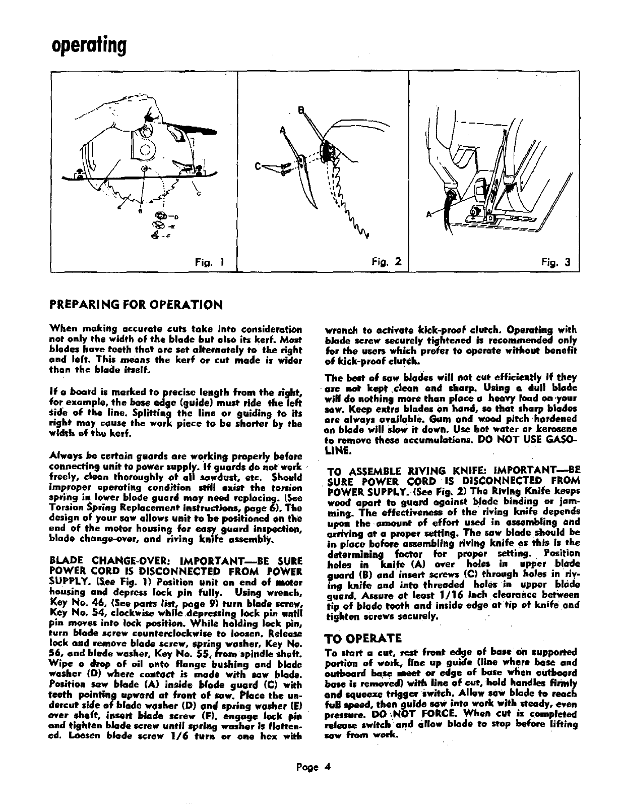
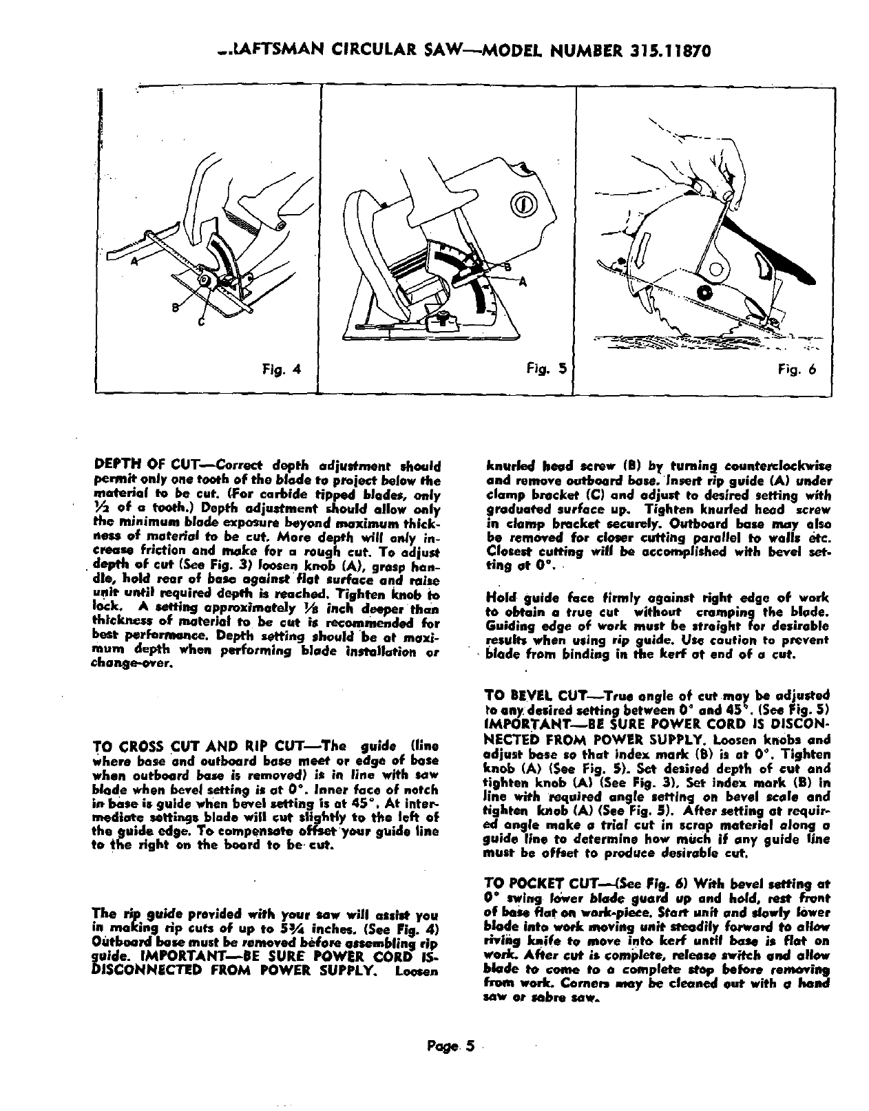
DEPTH OF CUT--freer depth adjustment should
permit only one tooth of the blade to proie_ below the
material to be cut. (For carbide tipped blades, only
of.a tooth.) Depth adjustment should allow only
the minimum blade exposure beyond maximum thick-
ness of material to be cut, More depth will an/y in-
crease friction and make for a rough cut. To adjust
depth of cut (See Fig. 3) loosen knob (A), grasp han-
dle, bold rear of base against flat surface and raise
un_ until required depth is reached, Tighten knob h)
lock, Asetting approximately Ya inch d_pper than
thickn_se of material to be cat is recommended for
best perfarn_nce. Depth setting should 'be at max/-
mum depth when performing blade installation or
change-over.
T° CROSS CUT AND RiP CUT--The guide (llne
where bose and outboard base meet or edge of base
when outboard bcue is removed) is in line with sew
blade when .b_.velsetting is at 0°. Inner face of notch
in base is guide when bevel setting is at 45 ° . At inter_
mediate settings blade will cut slightly to the left of
the guide edge. To compensate offeatyonr guide line
to the right on the board to be cut.
The rip guide provided with your sew will assist you
in making rip cuts of up to 5_ inches. (See Pig. 4)
Outboard bose must be removed I_fose assembling rip
gmae. I/VtPORTANT_EE SURE POWER CORD IS-
DISCONNECTED FROM POWER SUPPLY. Lo_en
knurled head screw IB) by turning conntemlockwise
and remove outboard base. Insert rip guide (A) under
clamp bracket (C) and adjust to desired setting with
graduated surface up. Tighten knurled head screw
in clamp bracket securely. Outboard base may also
be removed for closer cutting parallel to walls etc.
Closest cutting will be accomplished with bevel set-
_ng at 0 °.
H01d• guide face firmly against right edge of wnrk
to obtain a true cut without cramping the blade.
Guiding edge of work must he streight for desirable
results when using rip guide. Us_ caution to prevent
• • blade from binding in the kerf at end of a cut.
TO BEVEL CUT,-**-_..Trueangle of cat may be adjusted
to anydesired setting between 0°and 45 °. (See Fig. 5)
IMPORTAHT_EE SURE POWER CORD IS DISCON-
NEC'TED FROM POWER SUPPLY. Loosen knobs and
adjust base so that index mark (B) is at O°, Tighten
knob (A) (See Fig. S). Set desired depth of cut and
tighten knob U_) (See Fig. 3), Set index mark (B) in
line with _requirod angle setting on bevel scale and
tighten knob (A) (See Fig. 5), After setting at requir-
ed angle make atria.I cut in scrap material along a
guide line to determine how much if any guide line
must be offset to produce desirable cut.
TO POCKET CUT---(See Fig. 6) With bevel setting at
0 swing k_war blade guard up and hold, rest frQnt
of base fiat on work-piece. Sta_ unit end slowly lower
blade into work moving unit steadily forward to allmr
rh, ing knife to move into kerr until base is fiat on
york. After cut is complete, release switch and allow
blade to come to a complete step bob)re removing
from work. CoreenD my be cleaned out with e hand
sew or sebre sew.
Page5
O
£
Fig. 7
Fig. 8
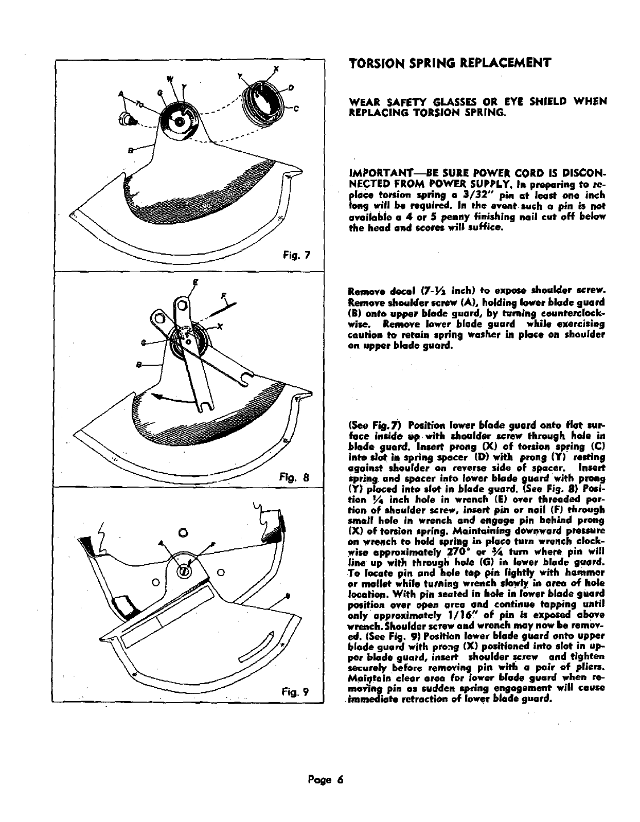
TORSION SPRING REPLACEMENT
WEAR SAFETY GLASSES OR EYE SHIELD WHEN
REPLACING TORSION SPRING.
IMPORTANT--BE SURE POWER CORD IS DISCON-
NECTED FROM POWER SUPPLY, In pml_rlng to re-
place torsion spring e 3/32" pin at least one inch
long will be required. In the event such a Pin is not
available o 4 or 5 penny finishing nail cut off below
the head and scores will suffice.
Remove decal 17-_ inch) to expose shoulder screw.
Remove shoulder screw (A), holding lower blade guard
(B) onto upper blade guard, by turning eon"terclo.¢,k-
wise. Remove lower blade guard while exercising
caution to retain sprin 9 washer in place on shoulder
on upper blade guard.
(See Fig.7) Position lower blade guard onto flat cur-
face inside up with shoulder screw through hole in
blade guard. Insert prong (X) of torsion spring !C)
into, dot in spnng spacer (D) with prong (Y)" resting
against sh0ulder on reverse side of spacer, Insert
_'prlng. and spacer into Ic_wer blade guard with prong
(,!") placed into slot in blade guard, (See Fig. 8) Pos:-
treu !_ inch hole in wrench (E) over threaded par-
tion of shoulder s_rew, insert pin or noil (F) through
smell hole in wrench and engage pin behind prong
IX) of torsion spring. Maintaining downward pressure
on wrench to hold spring m place turn wrench clock-
wise approximately 270 ° or ,a_ turn where pin will
line up with through hole (G! :n. lower b.lnde guard.
To locate pin and hole top pin hghtly with hammer
or n_.lint while turning wrench slowly m area of hole
location With pin seated :n hole in lower blade guard
position over open area and continue tapping until
on|y appreximatnly i/16" of pm is exposed above
wrench.Shoulder screw and wrench may now be remov-
ed. (See Fig. 9) Position lower blade g,ua.rd onto upper
blade guard with pre._g (X) positioned ,.to clot in up-
per blade guard, ,nsert shoulder screw and tighten
securely before removing pin wjtl: aPair of phers.
_iqtain clear area for la.wer blade guard when re-
_;ing pm as sudden spnng engagement will cause
immediate retraction of lower blade guard.
Page 6
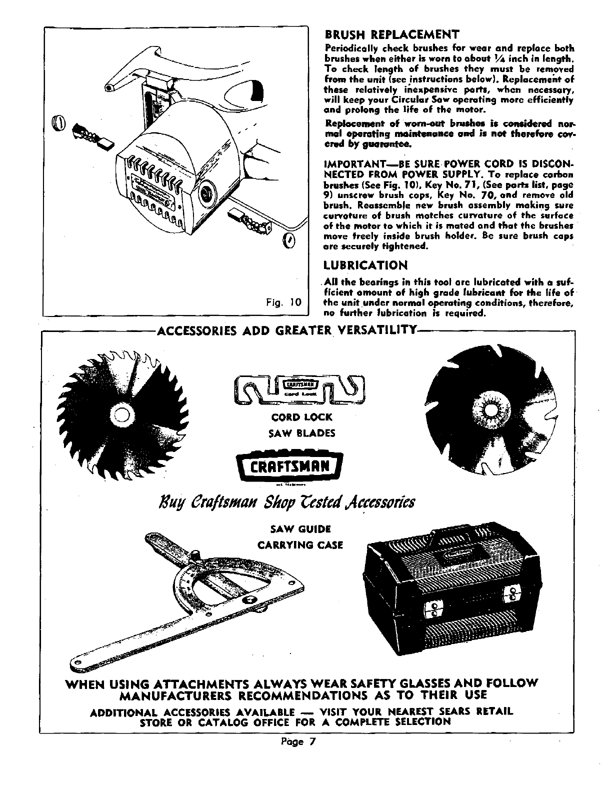
Fig. 10
BRUSH REPLACEMENT
Periodically check brushes for wear and repluce both
brushes when either is worn to about v/_ inch in length.
To check length of brushes they must be removed
from the unit (see instructions below). Replacemei:t of
these relatively inexpensive ports, when necessary,
will keep your Circular Sow operating more efficiently
and prolong the life of the motor.
Replacement of worn-out brushes is considered nor-
real operating mc_ntenanee and is not therefore €o_-
emd by gwrentee.
IMPORTANT--BE SURE POWER CORD IS DISCON-
NECTED FROM POWER SUPPLY. Ta replace carbon
brushes (See Fig. 101, Key No. 71, (See pan list, poge
9) unscrew brush cops, Key No. 70, and remove old
brush. Reassemble new brush assembly making sure
curvature of brush matches curvature of the surface
of the motor to which it is mated and that the brushes
move freely inside brush holder. Be sure brush caps
ore securely tightened.
LUBRICATION
All the bearings in this teal ore lubricated with n suf-
ficient amount of high grade lubricant for the llfe of
the unitunder normal operating conditions, therefore,
no further lubrication is required.
ACCESSORIES ADD GREATER VERSATILITY
CORD LOCK
SAW BLADES
.L ,4*U--,
3HyCru/ts m 814op stcd c:essorics
SAW GUIDE
G CASE
WHEN USING ATTACHMENTS ALWAYS WEAR SAFETY GLASSES AND FOLLOW
MANUFACTURERS RECOMMENDATIONS AS TO THEIR USE
ADDITIONAL ACCESSORIES AVAILABLE -- VISIT YOUR NEAREST SEARS RETAIL
STORE OR CATALOG OFFICE FOR A COMPLETE SELECTION
Pdge 7
