Craftsman 315172320 User Manual AUTO SCROLL SAW Manuals And Guides 99040498
CRAFTSMAN Saw Scroll Manual 99040498 CRAFTSMAN Saw Scroll Owner's Manual, CRAFTSMAN Saw Scroll installation guides
User Manual: Craftsman 315172320 315172320 CRAFTSMAN AUTO-SCROLL SAW - Manuals and Guides View the owners manual for your CRAFTSMAN AUTO-SCROLL SAW #315172320. Home:Tool Parts:Craftsman Parts:Craftsman AUTO-SCROLL SAW Manual
Open the PDF directly: View PDF ![]() .
.
Page Count: 18

Owner's Manual
II:RRFTSMRN'I
AUTO-SCROLL SAW
Variable Speed - Adjustable
Double Insulated
Model No.
315.172320
Save this manual for
future reference
CAUTION: Read and follow
all Safety Rules and Operating
Instructionsbefore first use of
this product.
Customer Help Line: 1-800-932-3188
Sears, Roebuck and Co., Hoffman Estates, IL 60179 USA
Visit the Craftsman web page: www.sears.com/craftsman
972000-480
1-99
•Safety
•Features
•Assembly
•Operation
•Maintenance
•Parts List
NRTL

TABLEOFCONTENTS
• Table Of Contents .......................................................................................................................................... 2
" 2
•General Safety Rules .................... I............................................................................................................. -3
m _Specifie-Sefety-.Rutes/Symbols .,:.......L_........................................................................................................ 4
n ...........................................................................................................S-6
•Assembly................. ,_,.;._;= ................... ;._.=J.................................................................................................. 7
•','813
Operation......._................... :_:...;?_;,.;;_;.,...;................................................................................................. -
•,_JDJI_D_JB_......... i......"------_..................................................................................................... 14
m-Accassed ...... .:.-.....!_...;._._:....!.................................................................................................... 15
•ExplodedView And Repair Parts List..................................................................................................... 16-17
•Parts Ordering /Service ............................................................................................................................... 18
WARNING: Read end understand all Instructions.
Failure to followall instructionslisted below may
result in electric shock,fire, and/or seriouspersonal
injury.
SAVE THESE INSTRUCTIONS
Wo_ A_a
•Keep your work area clean and well lit. Clut-
tered benchesand dark areas inviteaccidents.
•Do not operate power tools in explosive
atmospheres, such as in the presence of
flammable liquids, gases, or dust. Powertools
create sparkswhichmay ignitethe dustor fumes.
•Keep bystanders, children, and visitors away
while operating a power tool. Distractionscan
cause youto lose control.
Electrical Safety
•Double insulated tools are equipped with a
polarized plug (one blade is wider than the
other). This plug will fit In a polarized outlet
only one way. If the plug does not fit fully in the
outlet, reverse the plug. If it still does not fit,
contact equalified eleutriclan to install a
polarized outlet. Do not change the plug In any
way. Double insulation[] eliminatesthe need for
the three-wire groundedpower cord and grounded
power supplysystem.
•Avoid body contact with grounded surfaces,
such as pipes, radiators, ranges, end refrigera-
tors. There is an increased riskof electricshockif
your body is grounded.
•Don't expose power tools to rain or wet condi-
tions. Water entering a power toolwill increase
the riskof electric shock.
• Do not abuse the cord. Never use the cord to
carry the tools or pull the plug from an outlet.
Keep cord away from heat, oil, sharp edges, or
moving parts. Replace damaged cords immedi-
ately. Damaged cords increase the riskof electdc
shock.
•When operating a power tool outside, use an
outdoor extension cord marked "W-A" or "W."
These cordsare rated foroutdooruse and reduce
the riskof electricshock.
Personal Safety
•Stay alert, watch what you are doing, end use
common sense when operating a power tool.
Do not use tool while tired or under the Influ-
ence of drugs, alcohol, or medication. A mo-
ment of inattentionwhile operatingpowertools
may resultin seriouspersonalinjury.
•Dress properly. Do not wear loose clothing or
jewelry. Contain long hair. Keep your hair,
clothing, and gloves away from moving parts.
Loose clothes,jewelry,or longhair can be caught
in movingpads.
•Avoid accidental starting. Be sure switch is off
before plugging In. Carryingtoolswithyour
fingeron the switchor pluggingintoolsthat have
the switchon invitesaccidents.
•Remove adjusting keys or wrenches before
turning the tool on. A wrenchor a key that is left
attached to a rotatingpartof the tool may resultin
personalinjury.
•Do not overreach. Keep proper footing and
balance at all times. Properfootingand balance
enables bettercontrolof the toolin unexpected
situations.
Use safety equipment. Always wear eye protec-
tion. Dust mask, nonskidsafetyshoes, hard hat,
or hearing protectionmustbe used forappropriate
conditions.

ToolUse and Care
•Use clamps or another practical way to secure
and support the workplece to a stable plat-
form. Holdingthe work by hand or againstyour
body is unstableand may leadto lossof control.
•Do not force tool. Use the correct tool for your
application. The correcttoolwill dothe job better
and safer at the rate for which it is designed.
•Do not use tool If switch does not turn R on or
off. Any tool that cannot be controlledwiththe
switchis dangerousand mustbe repaired.
•Disconnect the plug from the power source
before making any adjustments, changing
accessories, or atodng the tool. Such preven-
tive safety measures reducethe riskof startingthe
tool accidentally.
•Store Idle tools out of the reach of children and
other untrained persona. Toolsare dangerousin
the hands of untrainedusers.
•Maintain tools with care. Keepcuttingtools
sharp and cieen. Propedymaintainedtoolswith
sharp cuttingedges are less likelyto bindand are
easier to control.
•Check for mlcellgnment or binding of moving
parts, breakage of parts, end any other condi-
tion that may affect the tool's operation. If
damaged, have the toolserviced before using.
Many accidentsare caused by poorlymaintained
tools.
•Use only accessories that are recommended
by the manufacturer for your model. Accesso-
riesthat may be suitablefor one tool may become
hazardouswhen used on anothertool.
Service
•Tool service must be performed only by quail-
fled repair personnel. Serviceor maintenance
performedby unqualifiedpersonnelcould resultin
ariskof injury,
•When servicing atool, use only identical
replacement parts. Follow Inatructlons in the
Malntenanca section of this manual. Use of
unauthorizedpartsor failureto followMaintenance
Instructionsmay create a riskof electdcshockor
injury.

HoldtoolbyInsulatedgrippingsurfaceswhenperforminganoperationwherethecuttingtoolmay
contacthiddenwiringorItscord.Contactwitha"live" wire will make exposed metal partsof the tool "live" and
shockthe operator.
Additional Rules for Safe Operation
•Know your power tool. Read operator's manual
carefully. Learn Its applications and limitations,
as well as the specific potential hazards related
to this tool. Followingthisrulewillreducethe riskof
electricshock, fire, or seriousinjury.
•Always wear safety glasses. Everyday eye-
glasses have only Impact-resistant lenses; they
are NOT safety glasses. Following this rule will
reduce the riskof seriouspersonal injury.
•Protect your lungs. Wear s face or dust mask If
the operation Is dusty. Following this rule will
reduce the risk of seriouspersonal injury.
•Protect your hearing. Wear hearing protection
during extended periods of operation. Following
this rule will reduce the risk of serious personal
injury.
•Inspect tool cords periodically and, if dam-
aged, have repaired at your nearest Factory
Service Center or other Authorized Service
Organization. Constantly stay aware of cord
location. Followingthis rule will reduce the riskof
electric shockor fire.
•Check damaged parts. Before further use of
the tool, a guard or other part that is damaged
should be carefully checked to determine that It
will operate properly and perform its Intended
function.Check for alignment of moving parts,
binding of moving parts, breakage of parts,
mounting, and any other conditions that may
affect its operation. A guard or other part that is
damaged should be properly repaired or
replaced by an authorized service center.
Followingthis rule will reduce the riskof electric
shock,fire, or seriousinjury.
•Don't abuse cord. Never carry the tool by the
cord or yank It to disconnect It from the
receptacle. Keep cord away from heat, oil, and
sharp edges. Followingthisrule will reduce the
riskof electricshockor fire.
•Make sure your extension cord Is In good
condition. When using an extension cord, be
sure to use one heavy enough to carry the
current your product will draw. A wire gage
size (A.W.G.) of at least 16 Is recommended
for an extension cord 100 feet or less In
length. A cord exceeding 100 feet is not
recommended. If In doubt, use the next
heavier gage. The smaller the gage number,
the heavier the cord. An undersizedcord will
cause a drop in line voltage resultingin lossof
power and overheating.
•Inspect for end remove all nails from lumber
before cutting. Followingthis rule will reduce the
riskof seriouspersonal injury.
•Drugs, alcohol, medication. Do not operate tool
while under the Influence of drugs, alcohol, or
any medication. Followingthisrule will reducethe
riskofelectricshock,fire, orseriouspersonalinjury.
•Save these Instructions. Refer to them frequently
and use them to Instruct others who may use
this tool. If you loan someone this tool, loan
them these instructions also.
4
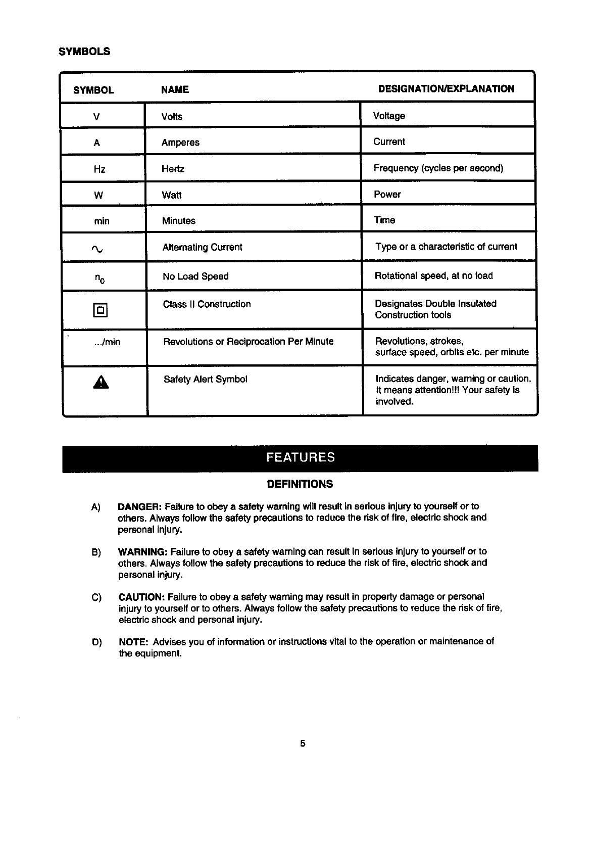
SYMBOLS
SYMBOL NAME DESIGNATION/EXPLANATION
V Volts Voltage
A Amperes Current
Hz Hertz Frequency (cycles per second)
W Watt Power
II
rain Minutes Time
,%, AlternatingCurrent Type or a characteristicof current
no No Load Speed Rotationalspeed, at no load
]Class II Construction Designates Double Insulated
Construction tools
_./min Revolutionsor ReciprocationPer Minute Revolutions,strokes,
surface speed, orbitsetc. per minute
_i, Safety Alert Symbol Indicatesdanger, warningor caution.
It means attention!!!Your safetyis
involved.
DEFINITIONS
A)
B)
C)
D)
DANGER: Failure to obey a safetywaming will resultin seriousinjuryto yourselfor to
others.Always follow the safety precautionsto reduce the riskof fire, electdc shockand
personalinjury.
WARNING: Failure to obey a safety warning can result in serious injuryto yourselfor to
others.Alwaysfollow the safety precautionsto reduce the riskof fire, electricshockand
personal injury.
CAUTION: Failure to obey a safetywarning may resultin property damage or personal
injuryto yourselforto others.Always follow the safety precautionsto reduce the riskof fire,
electric shockand personal injury.
NOTE: Advisesyou of informationor instructionsvitalto the operationor maintenanceof
the equipment,
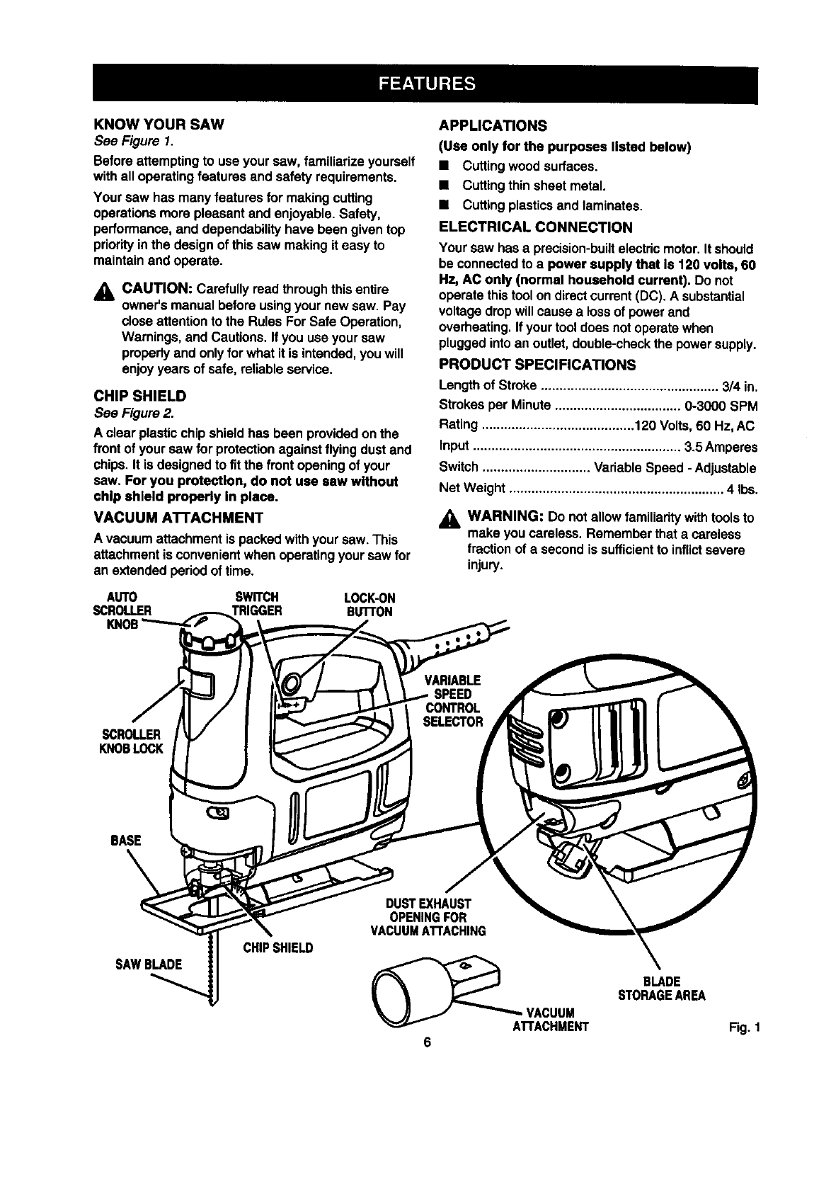
KNOWYOURSAW
See Figure 1.
Before attempting to use your saw, familiarize yourself
with all operatingfeatures and safety requirements.
Your saw has many features for making cutting
operationsmore pleasant and enjoyable.Safety,
performance,and dependabilityhave been given top
priorityinthe designof thissaw making it easy to
maintainand operate.
_1= CAUTION: Carefully read throughthisentire
owner'smanual before usingyour new saw. Pay
closeattentionto the Rules For Safe Operation,
Warnings, and Cautions.If you use your saw
properlyand only for what it is intended,youwill
enjoy years of safe, reliable service.
CHIP SHIELD
See Figure 2.
A clear plasticchip shield has been providedon the
front of your saw for protectionagainst flyingdust and
chips.It is designed to fit the front openingof your
saw. For you protection, do not use saw without
chip shield properly in place.
VACUUM AI-rACHMENT
A vacuum attachmentis packed withyour saw. This
attachmentis convenientwhen operatingyoursaw for
an extended period of time.
APPLICATIONS
(Use only for the purposes listed below)
•Cutting wood surfaces.
•Cutting thin sheet metal.
•Cuttingplasticsand laminates.
ELECTRICAL CONNECTION
Your saw has a precision-builtelectricmotor.It should
be connectedto a power supply that Is 120 volts, 60
Hz, AC only (normal household current). Do not
operate thistool on directcurrent(DC). A substantial
voltage dropwill cause a lossof powerand
overheating.If your tool does notoperate when
pluggedintoan outlet,double-checkthe powersupply.
PRODUCT SPECIFICATIONS
Lengthof Stroke ................................................ 3/4 in.
Strokes per Minute .................................. 0-3000 SPM
Rating ......................................... 120 Volts,60 Hz, AC
Input........................................................ 3.5 Amperes
Switch ............................. Variable Speed -Adjustable
Net Weight .......................................................... 4 Ibs.
,_ WARNING: Do notallow familiaritywithtools to
make you careless. Remember that a careless
fractionof a second is sufficientto inflictsevere
injury.
_ROLLER
K_BLOCK
BASE
SAWBLADE CHIPSHIELD
DUST EXHAUST
OPENINGFOR
VACUUMATrACHING
(__AI.I .ACUUM
ACHMENT
6
BLADE
STORAGEAREA
Fig. 1
Yoursawhasbeenshippedcompletelyassembled
exceptfortheblade,inspectitcarefullytomakesure
nobreakageordamagehasoccurredduringshipping.
Ifanypartsaredamagedormissing,contactyour
nearestSearsretailstoretoobtainreplacementparts
beforeattempting to operate saw. A blade, vacuum
attachment, and thisowner'smanual are also
included.
,_ WARNING: If any parts are missing,do not
operate this tool untilthe missingparts are
replaced. Failure to do so could resultin possible
seriouspersonal injury.
TWO BLADE SLOTS
Your saw has been designedwith two blade slots. For
general cutting,making straightcuts, angle cutting,
plungecutting, or splinter-freecutting,or when using
a flush cuttingblade, installblade inthe front slot. For
scrollcutting, installblade in the back slot.
_i, WARNING: To avoid possibleserious injury,
always wear safetygoggles or safety glasses
with side shields.Keep hands and fingersfrom
betweenthe motorhousingand blade clampand
do notreach underneathwork while blade is
cutting.
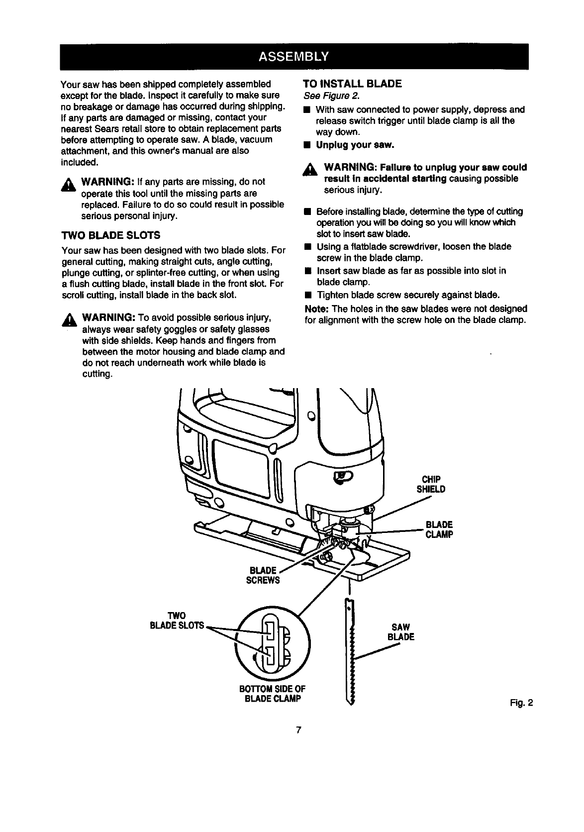
TO INSTALL BLADE
See Figure2.
•With saw connectedto power supply, depress and
release switchtrigger untilblade clamp is all the
way down.
•Unplug your saw.
_, WARNING: Failure to unplug your saw could
result In eccldental atertlng causing possible
seriousinjury.
•Beforeinstalling blade,determinethetype of cutting
operation youwillbe doingsoyou willknowwhich
slotto insertsaw blade.
•Using a flatbladescrewdriver,loosenthe blade
screw in the blade clamp.
•Insert saw blade as far as possibleinto slot in
blade clamp.
•Tighten blade screw securely against blade.
Note: The holes inthe saw blades were notdesigned
for alignmentwith the screw hole on the blade clamp.
_) CHIP
SHIELD
BLADE
CLAMP
SCREWS
TWO
BLADESLOTS
BOTrOMSIDEOF
BLADECLAMP
SAW
BLADE
Fig. 2
7
_1= WARNING: Do notattempt to operate thistool
untilyou have read thoroughlyand understand
completelyall instructions,safety rules, etc.,
contained in this manual. Failure to complycan
resultin accidents involvingfire, electricshock,
or seriouspersonal injury.Save owner's manual,
and review frequently for continuingsafe opera-
tion and for instructingothers who may use this
tool.
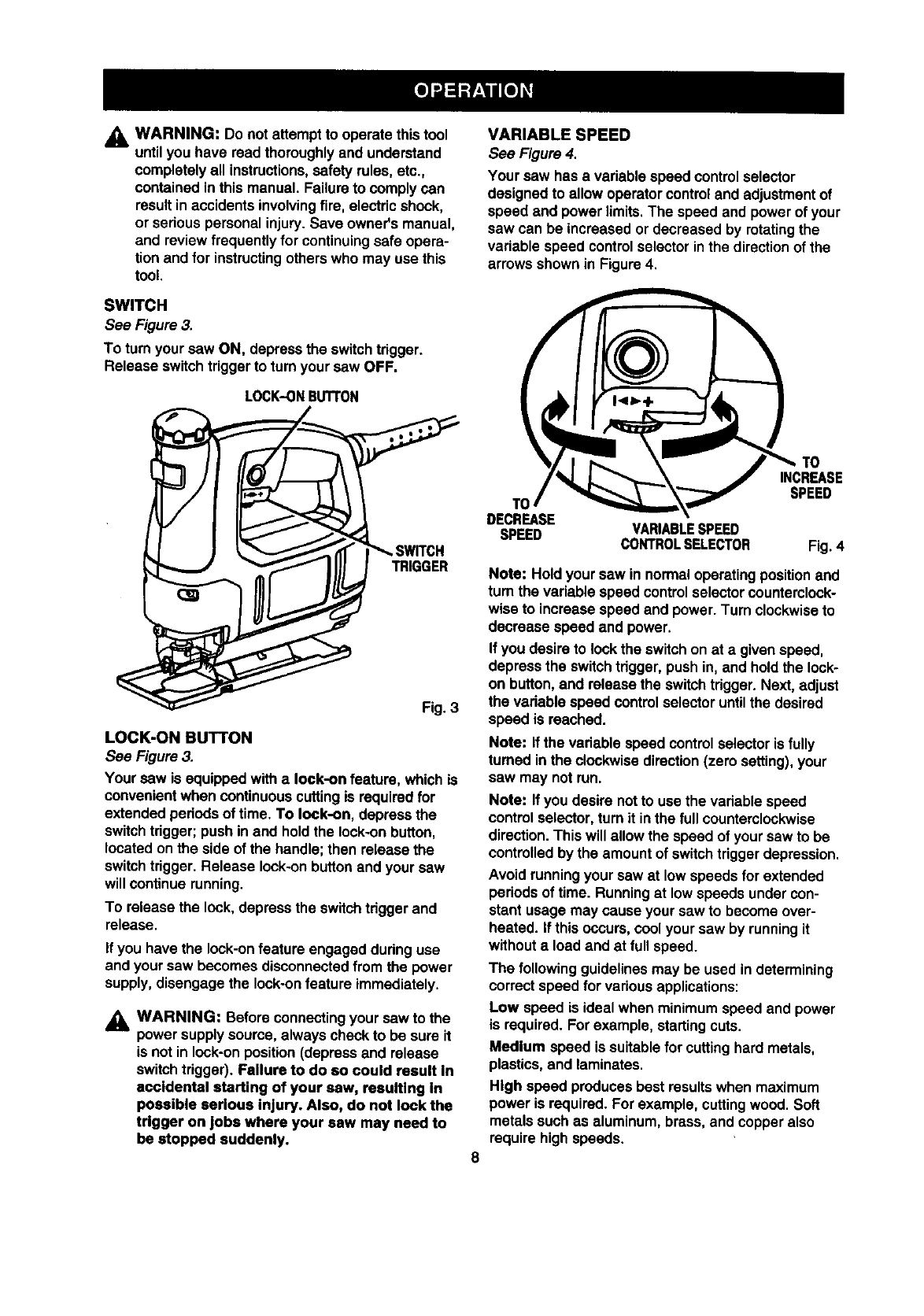
VARIABLE SPEED
See Figure 4.
Your saw has a variable speed controlselector
designed to allow operator controland adjustmentof
speed and power limits.The speed and power of your
saw can be increasedor decreased by rotatingthe
variable speed controlselector inthe directionof the
arrows shown in Figure 4,
SWITCH
See Figure 3.
To turn your saw ON, depress the switchtrigger.
Release switchtriggerto turnyour saw OFF.
LOCK-ONBUTTON
LOCK-ON BUTTON
See Figure 3.
Your saw is equippedwitha lock-on feature, which is
convenientwhen continuous cuttingis requiredfor
extended periodsof time. To lock-on, depress the
switchtrigger;push in and holdthe lock-onbutton,
located on the side of the handle; then release the
switchtrigger.Release lock-onbuttonand your saw
will continue running.
To release the lock, depress the switchtdggerand
release.
If you have the lock-on feature engaged duringuse
and your saw becomes disconnected from the power
supply, disengage the lock-onfeature immediately.
WARNING: Before connectingyour saw to the
power supplysource,always check to be sure it
is not in lock-onposition (depress and release
switchtrigger). Failure to do so could result In
accidental starting of your saw, resulting In
possible serious injury. Also, do not lock the
trigger on jobs where your saw may need to
be stopped suddenly.
T(
DECREASE
SPEED
TO
INCREASE
SPEED
VARIABLESPEED
CONTROLSELECTOR Fig.4
Note: Holdyour saw in normaloperatingpositionand
turn the variable speed controlselector counterclock-
wise to increase speed and power. Turn clockwiseto
decrease speed and power.
If you desire to lookthe switchon at a given speed,
depress the switchtrigger,push in, and holdthe look-
on button,and release the switchtrigger.Next, adjust
the vadable speed controlselector untilthe desired
speed is reached.
Note: If the variable speed controlselector is fully
turned inthe clockwisedirection(zero setting),your
saw may notrun.
Note: If you desire notto use the variable speed
control selector,turn it in the fullcounterclockwise
direction.This will allow the speed of your saw to be
controlledby the amountof switchtrigger depression.
Avoid runningyour saw at lowspeeds for extended
periodsof time. Runningat lowspeeds undercon-
stant usage may cause your saw to become over-
heated, if this occurs,cool your saw by runningit
withouta load and at full speed.
The followingguidelinesmay be used in determining
correct speed for variousapplications:
Low speed is ideal when minimumspeed and power
is required. For example, startingcuts.
Medium speed is suitableforcuttinghard metals,
plastics,and laminates.
High speed producesbest resultswhen maximum
power is required. For example, cuttingwood. Soft
metals such as aluminum, brass, and copperalso
require highspeeds.
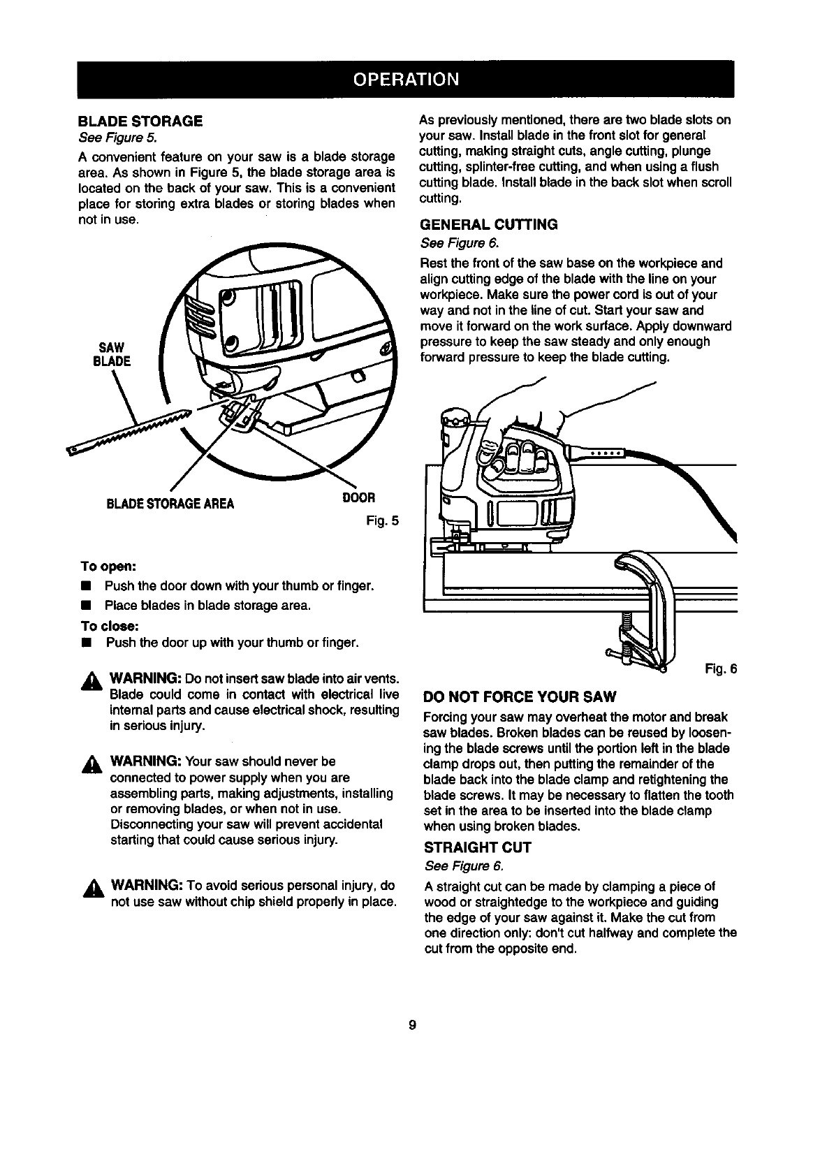
BLADESTORAGE
See Figure 5.
A convenient feature on your saw is a blade storage
area. As shown in Figure 5, the blade storage area is
located on the back of your saw. This is a convenient
place for storing extra blades or storing blades when
not in use.
SAW
BLADE
As previouslymentioned,there are two blade slotson
your saw. Installblade in the front slotfor general
cutting,making straightcuts, angle cutting,plunge
cutting,splinter-freecutting, and when usinga flush
cuttingblade. Installblade inthe back slotwhen scroll
cutting.
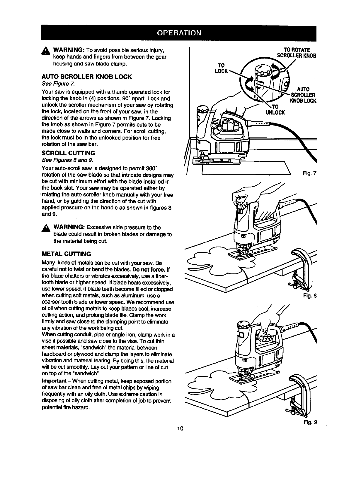
GENERAL CUTTING
See Figure 6.
Rest the front of the saw base on the workpieceand
align cuttingedge of the blade withthe line on your
workpiece. Make sure the power cord is out of your
way and notin the line of cut. Start your saw and
move it forwardon the worksurface. Apply downward
pressureto keep the saw steady and only enough
forward pressureto keep the blade cutting.
BLADESTORAGEAREA DOOR
Fig. 5
To open:
•Pushthe door down withyour thumb or finger.
•Place blades inblade storage area.
To close:
•Push the door up withyour thumbor finger.
AWARNING: Do not insertsawblade intoair vents.
Blade could come in contact with electrical live
internal partsand cause electricalshock, resulting
in serious injury.
WARNING: Your saw should never be
connectedto power supplywhen you are
assembling parts, making adjustments,installing
or removing blades, or when not in use.
Disconnectingyour saw will prevent accidental
startingthat could cause seriousinjury.
,_ WARNING: To avoid seriouspersonal injury,do
not use saw withoutchip shieldproperlyin place.
Fig. 6
DO NOT FORCE YOUR SAW
Forcingyour saw may overheat the motorand break
saw blades. Brokenblades can be reused by loosen-
ing the blade screws untilthe portionleft in the blade
clamp dropsout, then puttingthe remainder of the
blade back intothe blade clampand retighteningthe
blade screws. It may be necessaryto flattenthe tooth
set in the area to be insertedintothe blade clamp
when usingbrokenblades.
STRAIGHT CUT
See Figure 6.
A straightcut can be made by clampinga piece of
wood or straightedgeto the workpieceand guiding
the edge of your saw against it. Make the cut from
one directiononly:don't cut halfway and completethe
cut from the opposite end.
9
_, WARNING: To avoid possibleseriousinjury,
keep handsand fingersfrom betweenthe gear
housingand saw blade clamp.
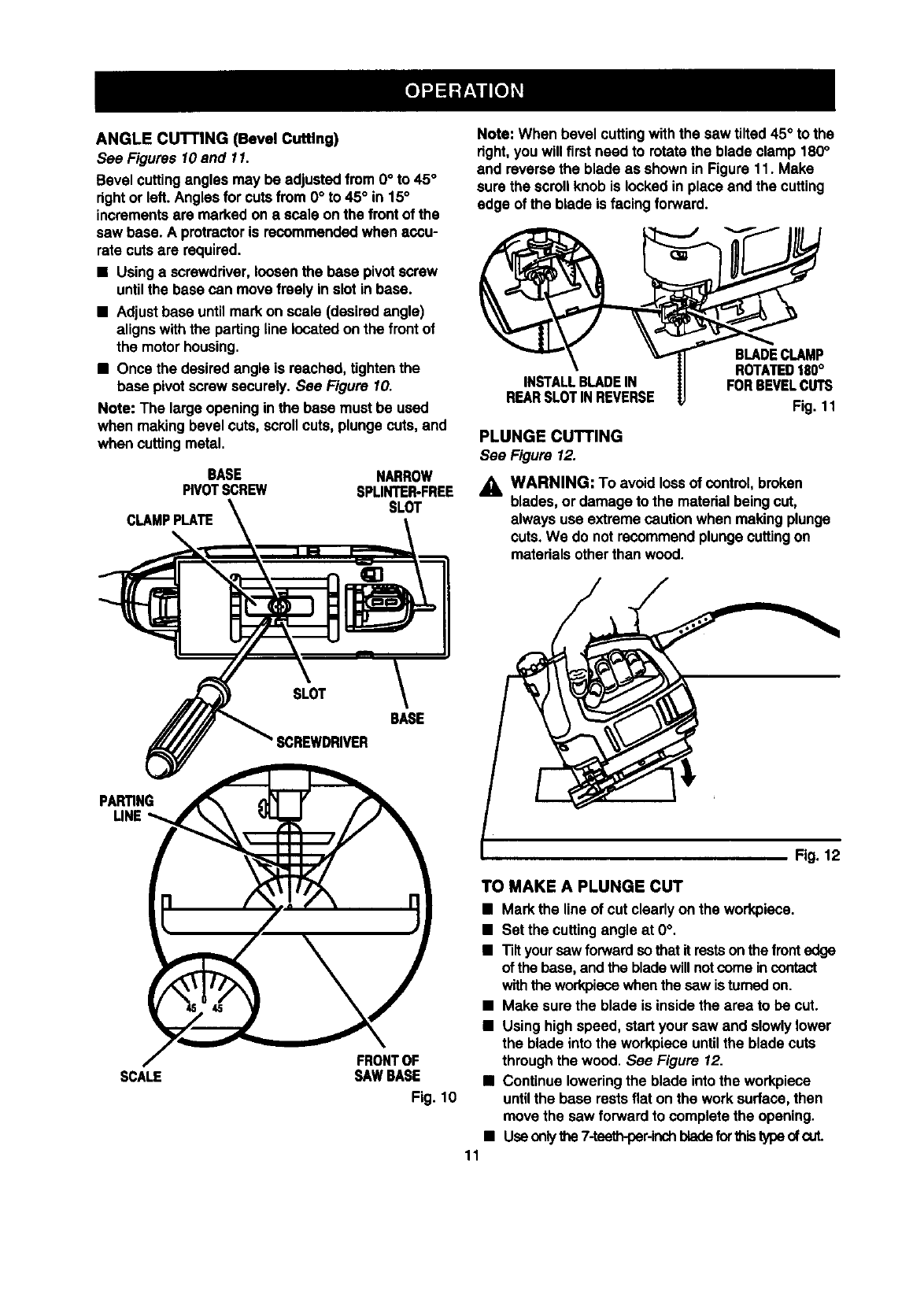
AUTO SCROLLER KNOB LOCK
See Figure 7.
Your saw is equippedwith a thumboperated lockfor
lockingthe knob in (4) positions,90" apart. Lockand
unlockthe scroller mechanismof your saw by rotating
the lock, located on the frontof your saw, inthe
directionof the arrows as shown in Figure 7. Locking
the knob as shown in Figure7 permits cuts to be
made closeto walls and corners. For scrollcutting,
the lockmust be in the unlocked positionfor free
rotationof the saw bar.
SCROLL CUTTING
See Figures8 and 9.
Your auto-scrollsaw is designed to permit 360"
rotationof the saw blade so that intricatedesigns may
be cut with minimumeffortwith the blade installedin
the back slot. Your saw may be operated either by
•rotatingthe auto scrollerknob manuallywith your free
hand, or by guidingthe directionof the cut with
applied pressureon the handle as shown in figures8
and 9.
WARNING: Excessiveside pressureto the
blade couldresultin brokenblades or damage to
the materialbeing cut.
METAL CU'I-rlNG
Many kinds of metalscan be cut withyour saw. Be
carefulnotto twistorbend the blades.Do not force. If
the bladechattersorvibratesexcessively,use a finer-
toothblade or higherspeed, if blade heats excessively,
usa lowerspeed. If bladeteeth becomefilledorclogged
whencuttingsoftmetals,suchas aluminum,usa a
coarser-toothbladeor lowerspeed.We recommenduse
of oilwhen cuttingmetalsto keep bladescool, increase
cuttingaction,and prolongblade life•Clamp the work
firmlyand saw closetothe clampingpointto eliminate
any vibrationof the workbeingcut.
When cuttingconduit,pipe orangle iron,clampworkina
visa ifpossibleand sawcloseto the _sa. To cutthin
sheet matedals,"sandwich" the matedalbetween
hardboardor plywoodand clampthe layersto eliminate
vibrationand matedaltearing.By doingthis,the material
willbe cutsmoothly.Layoutyour patternor lineof cut
ontop of the "sandwich".
Important - When cuttingmetal, keep exposedportion
of saw barclean andfree of metal chipsbywiping
frequentlywithan oilycloth.Use extremecautionin
disposingof oilyclothafter completionof jobto prevent
potential firehazard.
TO
TOROTATE
SCROLLERKNOB
AUTO
KNOBLOCK
UNLOCK
Fig.7
Fig.8
Fig. 9
10
ANGLECUTTING(BevelCutting)
See Figures lO and 11.
Bevel cuttingangles may be adjustedfrom0° to 45°
rightor left.Anglesfor cuts from 0° to 45° in 15°
incrementsare markedon a scale on the frontof the
saw base. A protractoris recommended when accu-
rate cuts are required.
•Usinga screwdriver,loosenthe base pivotscrew
untilthe base can move freely in slot in base.
•Adjustbase untilmark on scale (desiredangle)
alignswiththe parting line located on the front of
the motor housing.
•Once the desiredangle is reached, tightenthe
base pivotscrew securely. See Figure 10.
Note: The large openinginthe base must be used
when making bevel cuts,scrollcuts,plunge cuts, and
when cuttingmetal.
BASE NARROW
PIVOT,SCREW SPLINTER-FREE
SLOT
CLAMPPLATE
Note: When bevel cuttingwiththe saw tilted 45° to the
right,you will firstneed to rotate the blade clamp 180°
and reverse the blade as shown in Figure 11. Make
sure the scrollknob is locked in place and the cutting
edge of the blade is facing forward.
INSTALLBLADEIN
REARSLOTINREVERSE
BLADECLAMP
ROTA_DI80 °
_RB_ELCUTS
Fig. 11
PLUNGE CUTTING
See Figure 12.
_k WARNING: To avoid lossof control, broken
blades, or damage to the matedal beingcut,
always use extreme caution when making plunge
cuts. We do not recommendplungecuttingon
materialsother than wood.
PARTING
LINE
BASE
FRONTOF
SCALE SAWBASE
Fig. 10
Fig. 12
TO MAKE A PLUNGE CUT
•Markthe line of cut clearly on the workpiece.
•Set the cuttingangle at 0°.
•Tilt yoursawforwardsothat it restsonthe frontedge
of the base,and the bladewill notcome incontact
withthe workpiecewhenthe saw isturnedon.
•Make sure the blade is insidethe area to be cut.
•Using highspeed, start your saw and slowlylower
the blade intothe workpiece untilthe blade cuts
throughthe wood. See Figure 12.
•Continue loweringthe blade into the workpiece
untilthe base restsflat on the worksurface, then
move the saw forwardto complete the opening.
•Useonlythe7-teet3-_-per-inchbladeforthis typeofcut.
11
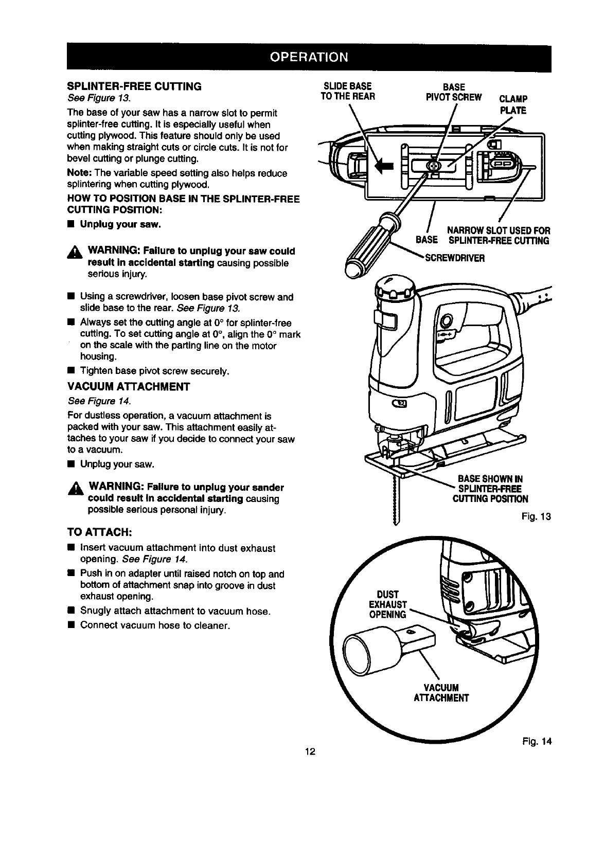
SPLINTER-FREECU'I-rlNG
See Figure 13.
The base of your saw has a narrowslotto permit
splinter-freecutting. It is especially usefulwhen
cuttingplywood.This feature shouldonly be used
when making straightcuts or circle cuts. It is notfor
bevel cuttingor plunge cutting.
Note: The variable speed setting also helps reduce
splinteringwhen cuttingplywood.
ROW TO POSITION BASE IN THE SPLINTER-FREE
CUTTING POSITION:
• Unplug your saw.
WARNING: Failure to unplug your saw could
result in accidental starting causing possible
seriousinjury.
•Usinga screwdriver,loosenbase pivot screw and
slide base to the rear. See Figure 13.
•Always set the cuttingangle at O° for splinter-free
cutting.To set cuttingangle at O°, alignthe O° mark
on the scale withthe partingline onthe motor
housing.
•Tighten base pivot screw securely.
VACUUM ATTACHMENT
See Figure 14.
For dustlessoperation, a vacuumattachment is
packed withyour saw. This attachment easilyat-
taches to your saw if you decide to connectyour saw
to avacuum.
•Unplugyour saw.
,_ WARNING: Failure to unplug your sander
could result In accidental starting causing
possibleserious personal injury,
TO ATTACH:
•Insert vacuum attachment into dust exhaust
opening. See Figure 14.
•Push inon adapter untilraised notchon top and
bottomof attachmentsnap into groovein dust
exhaustopening.
•Snugly attach attachment to vacuum hose.
•Connect vacuum hose to cleaner.
SLIDEBASE
TO THEREAR BASE
PIVOTSCREW CLAMP
PLATE
NARROWSLOTUSEDFOR
BASE SPUNTER-FREECUTTING
"SCREWDRIVER
CUTTINGPOSmON
Fig. 13
Fig. 14
12
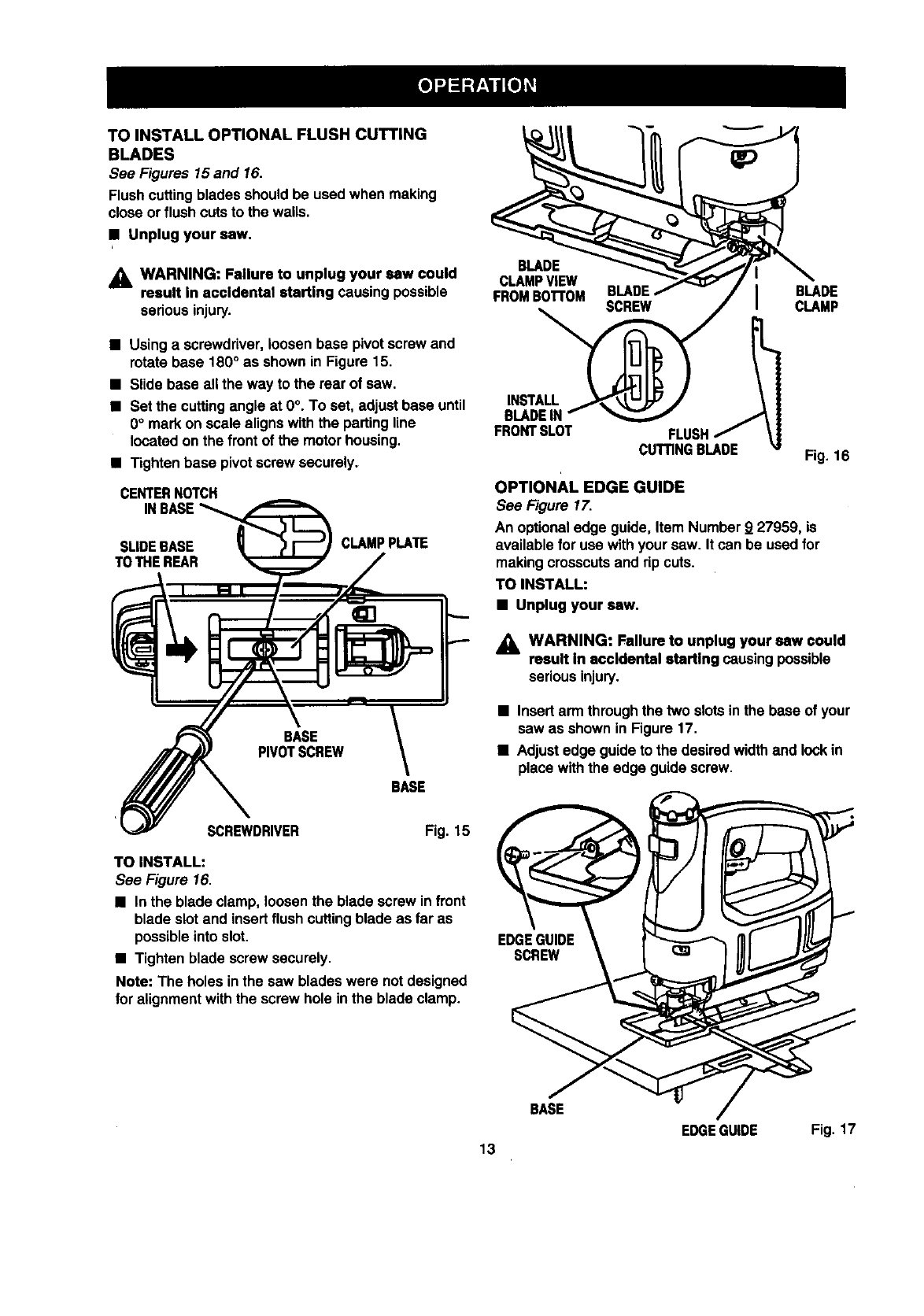
TOINSTALLOPTIONALFLUSHCUTTING
BLADES
See Figures 15 and 16.
Flushcuttingblades should be used when making
close or flush cutsto the wails,
•Unplug your saw.
_i, WARNING: Failure to unplug your saw could
result in accidental starting causing possible
serious injury.
•Usinga screwdriver,loosen base pivotscrew and
rotate base 180° as shown in Figure 15.
•Slide base all the way to the rear of saw.
•Set the cuttingangle at 0°. To set, adjust base until
0° mark on scale alignswith the partingline
located on the front of the motor housing.
• Tighten base pivotscrew securely.
CENTERNOTCH
INBASE
SLIDEBASE CLAMPPLATE
TOTHEREAR
EASE
PIVOTSCREW
BASE
SCREWDRIVER Fig. 15
TO INSTALL:
See Figure 16.
•Inthe blade clamp, loosenthe blade screw infront
blade slotand insertflush cuttingblade as far as
possible into slot.
•Tighten blade screw securely.
Note: The holes in the saw blades were notdesigned
for alignmentwiththe screw hole in the blade clamp.
BLADE
CLAMPViEW
FROMBo'rr0M
INSTALL
BLADEIN
FRONTSLOT
BLADE I BLADE
CLAMP
Fig. 16
OPTIONAL EDGE GUIDE
See Figure 17.
An optionaledge guide, Item Number 9 27959, is
availablefor use withyour saw. It can be usedfor
making crosscutsand rip cuts.
TO INSTALL:
•Unplug your saw.
_1, WARNING: Failure to unplug your saw could
result in accidental starting causingpossible
seriousinjury.
•Insertarm throughthe two slotsin the base of your
saw as shown in Figure 17.
•Adjustedge guideto the desiredwidthand lockin
place withthe edge guidescrew.
==Jj
EDGEGUIDE
SCREW
BASE
EDGE GUIDE Fig. 17
13
GENERAL
All parts represent an importantpart of the double
insulationsystem and shouldbe servicedonly by a
qualified Sears servicetechnician.
Avoidusingsolvents when cleaning plasticparts.
Most plasticsare susceptibleto damage fromvarious
types of commercialsolventsand may be damaged
by their use. Use clean clothsto remove dirt,carbon
dust, etc.
_i, WARNING: Do notat any time let brake fluids,
gasoline,petroleum-basedproducts,penetrating
oils,etc. come in contactwith plasticparts. They
containchemicalsthat can damage, weaken or
destroy plastic.
It has been found that electric toolsare subjectto
accelerated wear and possiblepremature failure when
they are used on fiberglass boats, sportscars,
wallboard, spacklingcompounds,or plaster.The
chipsand gdndingsfrom these materialsare highly
abrasive to electdctool parts, suchas bearings,
brushes, commutators, etc. Consequently,it is not
recommended that this tool be used for extended
workon any fiberglass material,wallboard, spackling
compounds,or plaster.Duringany use on these
materials, it is extremelyimportantthat the tool is
cleaned frequently by blowingwith an airjet.
LUBRICATION
All of the bearings inthis tool are lubdceted witha
sufficientamount of high-grade lubdcentfor the llfe of
the unit under normaloperatingconditions.Theratora,
no furtherlubricationis required.
WARNING: Alwayswear safetygoggles or
safety glasseswithside shieldsduringpower tool
operationorwhen blowingdust. If operationis
dusty, alsowear a dustmask.
DOUBLE INSULATION
Double insulationis a conceptin safety in electric
power tools,which eliminatesthe need forthe usual
three-wire groundedpower cord.All exposed metal
parts are isolatedfromthe internalmetal motor
components withprotectinginsulation.Double
insulatedtools do not need to be grounded.
IMPORTANT
Servicingof a toolwith double insulationrequires
extreme care and knowledgeof the systemand
should be performedonly by a qualifiedservice
technician.For service, we suggestyou returnthe tool
to your nearest Sears storefor repair. Alwaysuse
odginalfactory replacementpartswhen servicing.
EXTENSION CORDS
The use of any extensioncordwill cause some lossof
power. To keep the lossto a minimumand to prevent
tool overheating, use an extensioncordthat is heavy
enough to carrythe currentthe tool will draw.
A wire gage size (A.W.G.) of at least 16 is
recommendedforan extensioncord 100 feet or less
in length. When workingoutdoors,use an extension
cord that is suitablefor outdooruse. The cord'sjacket
will be markedWA.
_, CAUTION: Keep extensioncordsaway fromthe
cuttingarea and position the cord so that it will
notget caught on lumber,tools,etc., during
cuttingoperation.
_, WARNING: Check extensioncordsbefore each
use. If damaged replaceimmediately.Never use
tool witha damaged cord sincetouchingthe
damaged area couldcause electricalshock
resultingin seriousinjury.
Extensioncords suitablefor use withyour saw are
available at your nearestSears Retail Store.
14
ThefollowingrecommendedaccessoriesarecurrentlyavailableatSearsretailstores.
• Bi-MetalBlades •Metal Cuffing Blades
•Blade AssortmentSets •Wood CuttingBlades
•Fine ScrollingBlades •Edge Guide
•General Purpose Blades
WARNING: The use of attachmentsor accessoriesnot listedmight be hazardous.
WARNING:
The operationof any saw can resultin foreignobjectsbeingthrowninto your eyes, which can
resultinsevere eye damage. Before beginning power tooloperation, always wear safety
gogglesor safety glasseswithside shieldsand a fullface shieldwhen needed. We recom-
mendWide VisionSafety Mask for use over eyeglassesor standard safetyglasseswith side
shields,availableat Seers retailstores.
WARRANTY
FULL ONE YEAR WARRANTY ON CRAFTSMAN SABRE SAW
if this rlIRF'rSHRN Sabre Saw failsto give complete satisfactionwithinone year from the date of purchase,
RETURN IT TO THE NEAREST SEARS STORE IN THE UNITED STATES, and Sears will repair it, free of
charge.
If this CRRF'rSHRN Sabre Saw is used for commercialor rental purposes,this warrantyapplies for only90 days
fromthe date of purchase.
This warranty givesyou specificlegal rights,and you may also have other dghts whichvary from state to state,
Sears, Roebuck and Co.; Dept. 817WA; Hoffmen Estates, IL 60179
SAVETHESEINSTRUCTIONS
15
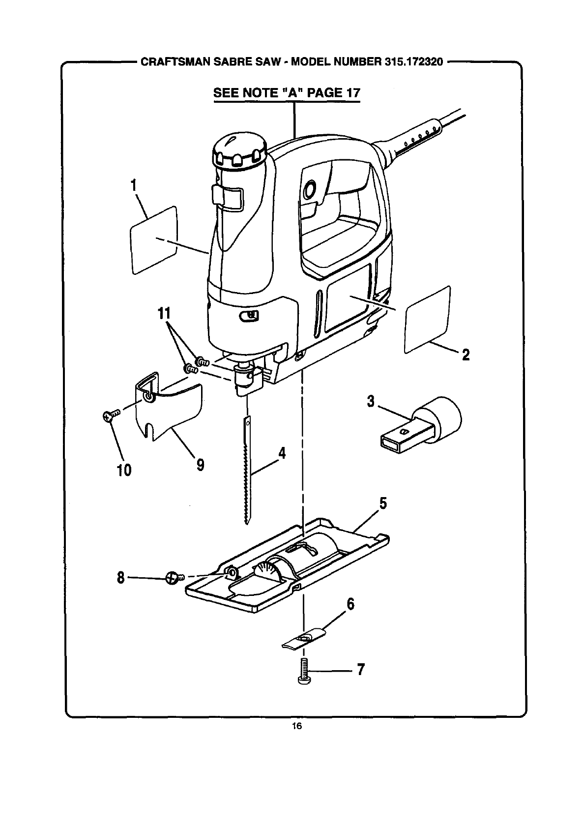
CRAFTSMANSABRESAW -MODEL NUMBER 315.172320
SEE NOTE "A" PAGE 17
11 Og
2
16
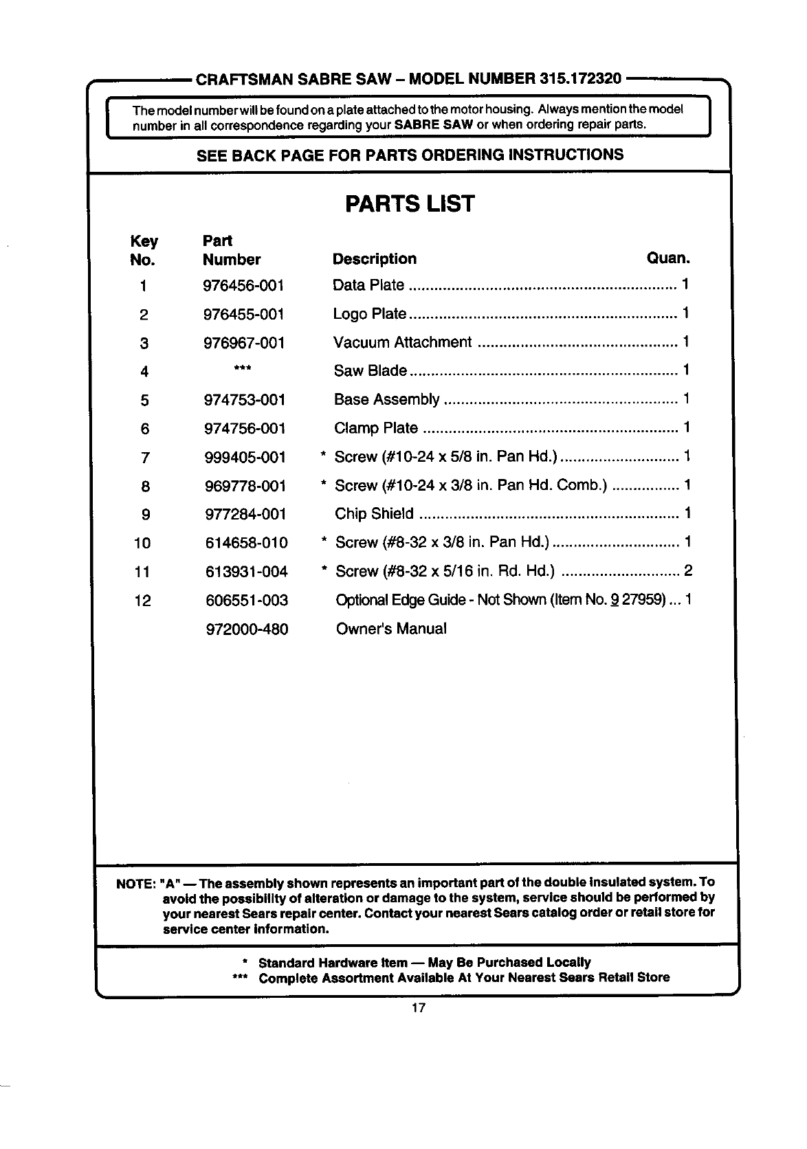
tCRAFTSMAN SABRE SAW - MODEL NUMBER 315.172320
The modelnumberwiUbefoundona plateattachedto themotorhousing.Alwaysmentionthe model
number in all correspondenceregarding your SABRE SAW or when orderingrepair parts.
SEE BACK PAGE FOR PARTS ORDERING INSTRUCTIONS
Key Pa_
No. Number
1 976456-001
2 976455-001
3 976967-001
_
5 974753-001
6 974756-001
7 999405-001
8 969778-001
9 977284-001
10 614658-010
11 613931-004
12 606551-003
972000-480
,t
PARTS LIST
Description Quan.
Data Plate ............................................................... 1
Logo Plate ............................................................... 1
Vacuum Attachment ............................................... 1
Saw Blade ............................................................... 1
Base Assembly ....................................................... 1
Clamp Plate ............................................................ 1
Screw (#10-24 x 5/8 in. Pan Hd.) ............................ 1
Screw (#10-24 x 3/8 in, Pan Hd, Comb.) ................ 1
Chip Shield ............................................................. 1
Screw (#8-32 x 3/6 in, Pan Hd.) .............................. 1
Screw (#8-32 x 5/16 in, Rd. Hd,) ............................ 2
Optional Edge Guide - Not Shown (Item No. _927959).,. 1
Owner's Manual
I
NOTE: "A" -- The assembly shown represents an important pert of the double Insulated system. To
avoid the possibility of alteration or damage to the system, service should be performed by
your nearest Sears repair center. Contact your nearest Sears catalog order or retail store for
service center information.
* Standard Hardware Item -- May Be Purchased Locally
*** Complete Assortment Available At Your Nearest Sears Retail Store
17

For in-home major brand repair service:
Call 24 hours a day, 7 days a week
1-800-4-MY-HOME s" (1-800-469-4663)
Para pedir servicio de reparaci6n a domicilio - 1-800-676-5811
In Canada for all your service and parts needs call - 1-800-665-4455
Au Canada pour tout le service ou les pi6ces
For the repair or replacement parts you need:
Call 8 am - 11 pm CST, 7 days a week
PartsDirect=M
1-800-366-PART (1-800-366-7278)
Para ordenar piezas con entrega a domicilio - 1-800-659-7084
For the location of a Sears Parts and Repair Center in your area:
Call 24 hours a day, 7 days a week
1-800-488-1222
For information on purchasing a Sears Maintenance Agreement
or to inquire about an existing Agreement:
Call 9 am - 5 pm, Monday - Saturday
1-800-827-6655
I
The Service Side of Sears
