Craftsman 315212110 User Manual 10 COMPOUND MITER SAW Manuals And Guides L1001368
CRAFTSMAN Miter Saw Manual L1001368 CRAFTSMAN Miter Saw Owner's Manual, CRAFTSMAN Miter Saw installation guides
User Manual: Craftsman 315212110 315212110 CRAFTSMAN 10 COMPOUND MITER SAW - Manuals and Guides View the owners manual for your CRAFTSMAN 10 COMPOUND MITER SAW #315212110. Home:Tool Parts:Craftsman Parts:Craftsman 10 COMPOUND MITER SAW Manual
Open the PDF directly: View PDF ![]() .
.
Page Count: 8
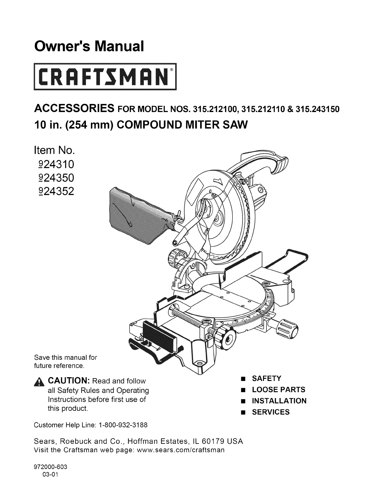
Owner's Manual
T ®
ACCESSORIES FOR MODEL NOS. 315.212100, 315.212110 & 315.243150
10 in. (254 mm) COMPOUND MITER SAW
Item No.
_924310
_924350
924352
Save this manual for
future reference.
_, CAUTION: Read and follow
all Safety Rules and Operating
Instructions before first use of
this product.
Customer Help Line: 1-800-932-3188
Sears, Roebuck and Co., Hoffman Estates, IL 60179 USA
Visit the Craftsman web page: www.sears.com/craftsman
972000-603
03-01
• SAFETY
•LOOSE PARTS
•INSTALLATION
• SERVICES
READ ALL INSTRUCTIONS
READ THESE INSTRUCTIONS AND THE
INSTRUCTIONS FOR THE 315.212100,
315.212110, and 315.243150 COMPOUND
MITER SAW THOROUGHLY before using
accessories.
KNOW YOUR POWER TOOL. Read the owner's
manual for the Compound Miter Saw carefully.
Learn the saw's applications and limitations as well
as the specific potential hazards related to this
tool.
KEEP THE WORK AREA CLEAN. Cluttered work
areas and work benches invite accidents. DO NOT
leave tools or pieces of wood on the saw while it is
in operation.
,&
•ALWAYS WEAR SAFETY GLASSES. Everyday
eyeglasses have only impact-resistant lenses; they
are NOT safety glasses.
•ALWAYS DISCONNECT SAW FROM POWER
SUPPLY BEFORE MAKING ADJUSTMENTS OR
ADDING ACCESSORIES. Make sure the switch is
off when reconnecting to power supply.
• SAVE THESE INSTRUCTIONS. Refer to them
frequently and use to instruct other users. If you
loan someone this tool, loan them these instruc-
tions also.
Look for this symbol to point out important safety precautions. It
means attention!!! Your safety is involved.
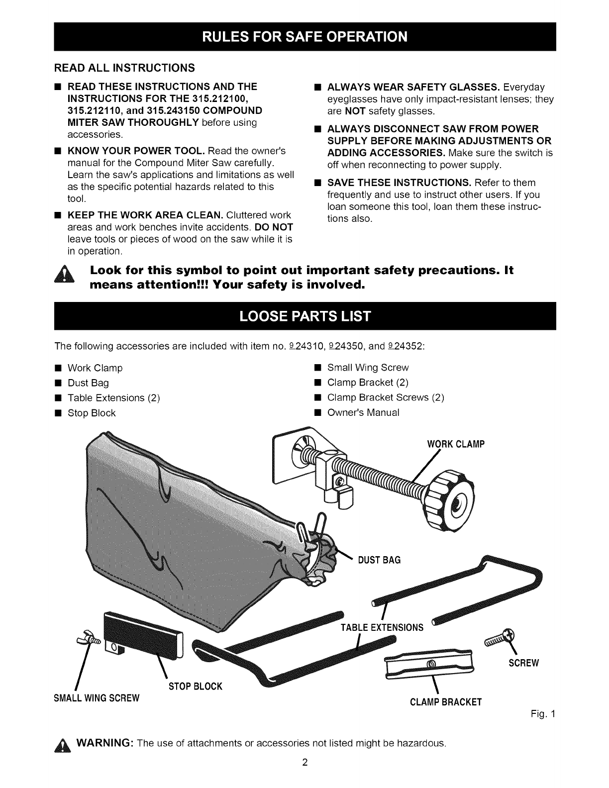
The following accessories are included with item no. 924310, 924350, and 924352:
• Work Clamp
• Dust Bag
• Table Extensions (2)
• Stop Block
• Small Wing Screw
• Clamp Bracket (2)
• Clamp Bracket Screws (2)
• Owner's Manual
WORKCLAMP
DUSTBAG
/"
SMALLWINGSCREW
STOPBLOCK
TABLE EXTENSIONS
CLAMPBRACKET
SCREW
Fig. 1
_, WARNING: The use of attachments or accessories not listed might be hazardous.
2
,_ WARNING:Topreventaccidentalstartingthat
couldcausepossibleseriouspersonalinjury,
assembleallpartstoyoursawcompletelybefore
connectingit to powersupply.Sawshouldnever
beconnectedtopowersupplywhenyouare
assemblingparts,makingadjustments,installing
orremovingbladesoraccessories,orwhennot
inuse.
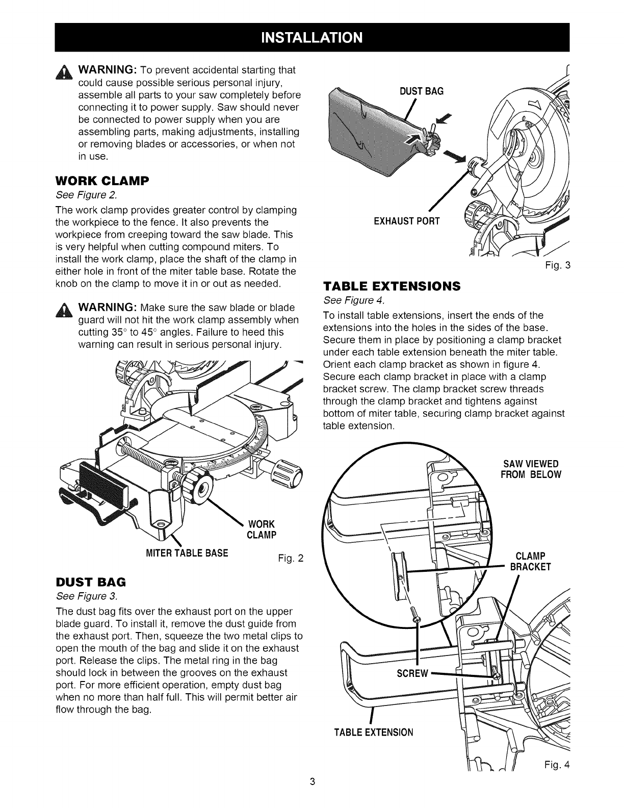
WORK CLAMP
See Figure 2.
The work clamp provides greater control by clamping
the workpiece to the fence. It also prevents the
workpiece from creeping toward the saw blade. This
is very helpful when cutting compound miters. To
install the work clamp, place the shaft of the clamp in
either hole in front of the miter table base. Rotate the
knob on the clamp to move it in or out as needed.
,_ WARNING: Make sure the saw blade or blade
guard will not hit the work clamp assembly when
cutting 35° to 45 ° angles. Failure to heed this
warning can result in serious personal injury.
MITERTABLE BASE
WORK
CLAMP
Fig. 2
DUST BAG
See Figure 3.
The dust bag fits over the exhaust port on the upper
blade guard. To install it, remove the dust guide from
the exhaust port. Then, squeeze the two metal clips to
open the mouth of the bag and slide it on the exhaust
port. Release the clips. The metal ring in the bag
should lock in between the grooves on the exhaust
port. For more efficient operation, empty dust bag
when no more than half full. This will permit better air
flow through the bag.
DUSTBAG
EXHAUSTPORT
Fig. 3
TABLE EXTENSIONS
See Figure 4.
To install table extensions, insert the ends of the
extensions into the holes in the sides of the base.
Secure them in place by positioning a clamp bracket
under each table extension beneath the miter table.
Orient each clamp bracket as shown in figure 4.
Secure each clamp bracket in place with a clamp
bracket screw. The clamp bracket screw threads
through the clamp bracket and tightens against
bottom of miter table, securing clamp bracket against
table extension.
SAW VIEWED
FROM BELOW
CLAMP
BRACKET
TABLE EXTENSION
Fig. 4
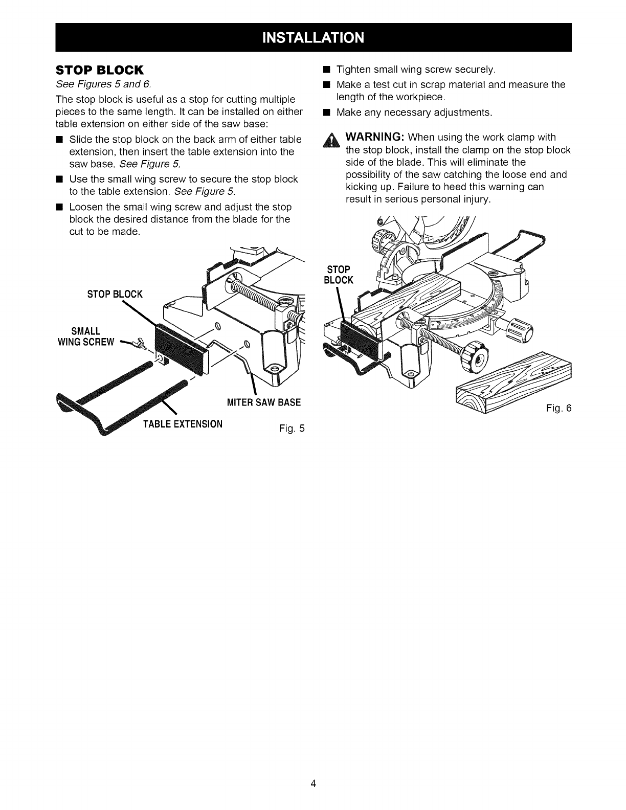
STOP BLOCK
See Figures 5 and 6.
The stop block is useful as a stop for cutting multiple
pieces to the same length. It can be installed on either
table extension on either side of the saw base:
• Slide the stop block on the back arm of either table
extension, then insert the table extension into the
saw base. See Figure 5.
• Use the small wing screw to secure the stop block
to the table extension. See Figure 5.
• Loosen the small wing screw and adjust the stop
block the desired distance from the blade for the
cut to be made.
STOPBLOCK
SMALL
WINGSCREW
MITERSAWBASE
TABLE EXTENSION Fig. 5
• Tighten small wing screw securely.
• Make a test cut in scrap material and measure the
length of the workpiece.
• Make any necessary adjustments.
WARNING: When using the work clamp with
the stop block, install the clamp on the stop block
side of the blade. This will eliminate the
possibility of the saw catching the loose end and
kicking up. Failure to heed this warning can
result in serious personal injury.
STOP
BLOCK
Fig. 6
Manual del usuario
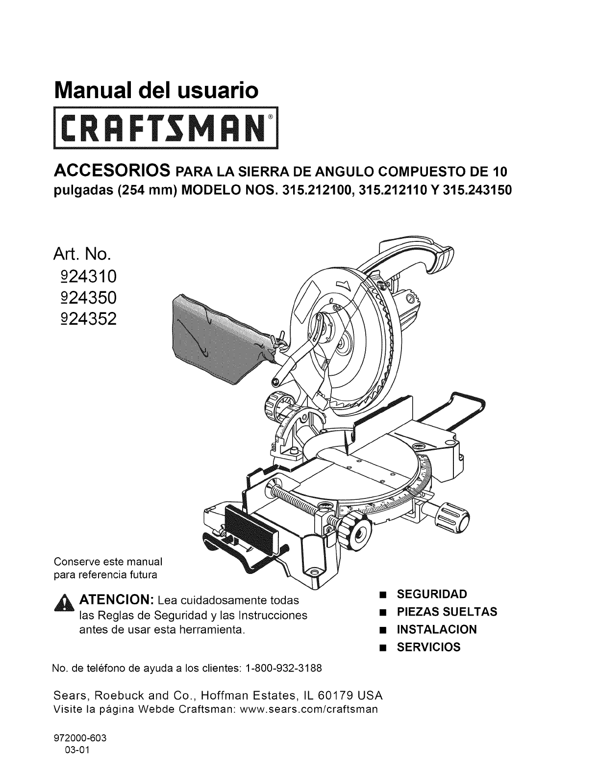
ACCESORIOS PARA LA SIERRA DE ANGULO COMPUESTO DE 10
pulgadas (254 mm) MODELO NOS. 315.212100, 315.212110 Y 315.243150
Art. No.
924310
924350
_924352
Conserve este manual
para referencia futura
ATENCION" Lea cuidadosamente todas
las Reglas de Seguridad y las Instrucciones
antes de usar esta herramienta.
No. de telefono de ayuda a los clientes: 1-800-932-3188
Sears, Roebuck and Co., Hoffman Estates, IL 60179 USA
Visite la pagina Webde Craftsman www.sears.com/craftsman
972000-603
03-01
• SEGURIDAD
•PIEZAS SUELTAS
•INSTALACION
• SERVICIOS
LEA TODAS LAS INSTRUCCIONES
•LEA ATENTAMENTE ESTAS INSTRUCCIONES
Y LAS INSTRUCCIONES
DE LA SIERRA DE ANGULO COMPUESTO
315.212100, 315.212110 y 315.243150 antes de
utili7ar los accesorios.
• FAMILIARICESE CON SU HERRAMIENTA. Lea
cuidadosamente el manual del usuario de la sierra
de angulo compuesto. Aprenda cuales son las
aplicaciones y limitaciones de la sierra, as{ como
los peligros espec{ficos relacionados con esta
herramienta.
•MANTENGA LIMPIA LA ZONA DE TRABAJO.
Las areas y bancos de trabajo congestionados son
una invitaci6n a tener accidentes. NO DEJE las
herramientas o piezas de madera en la sierra
mientras la misma est6 funcionando.
•UTILICE SIEMPRE GAFAS DE SEGURIDAD. Los
anteojos normales solamente tienen lentes
protectores contra el choque; NO SON gafas de
seguridad.
•DESCONECTE SIEMPRE LA SIERRA DE LA
CORRIENTE ANTES DE HACER AJUSTES O
AGREGAR ACCESORIOS. Verifique que el
interruptor est6 apagado antes de reconectar la
sierra a la corriente.
GUARDE ESTAS INSTRUCCIONES. ConsL_ltelas
con frecuencia y utilicelas para instruir a otros
usuarios. Si le presta la maquina a alguien,
pr6stele tambi6n estas instrucciones.
Busque este simbolo, que indica precauciones importantes
de seguridad. ;Significa atenci6n! Esta en juego su seguridad.
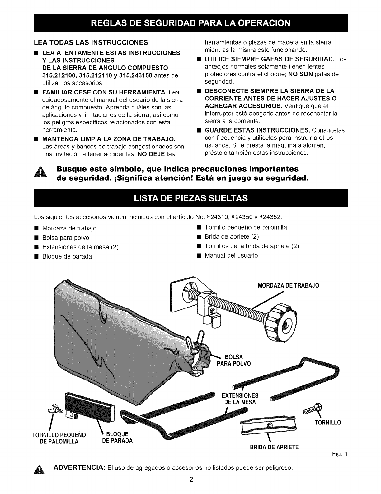
Los siguientes accesorios vienen incluidos con el articulo No. 924310, 924350 y 924352:
• Mordaza de trabajo • Tornillo peque_o de palomilla
• Bolsa para polvo • Brida de apriete (2)
• Extensiones de la mesa (2) • Tornillos de la brida de apriete (2)
• Bloque de parada • Manual del usuario
MORDAZADETRABAJO
BOLSA
PARAPOLVO
/
TORNILLOPEQUEItO
DE PALOMILLA BLOQUE
DE PARADA
EXTENSIONES
DELA MESA
BRIDADEAPRIETE
ADVERTENClA: El uso de agregados o accesorios no listados puede ser peligroso.
2
TORNILLO
Fig. 1
AADVERTENClA: Para evitar el peligro de que
la sierra arranque accidentalmente y cause
posibles lesiones graves, monte completamente
todas las piezas en la sierra antes de conectarla
a la corriente. La sierra jamas debe estar
conectada a la corriente mientras se est6n
montando piezas, haciendo ajustes, instalando o
sacando hojas o accesorios, o cuando no est6
en uso.
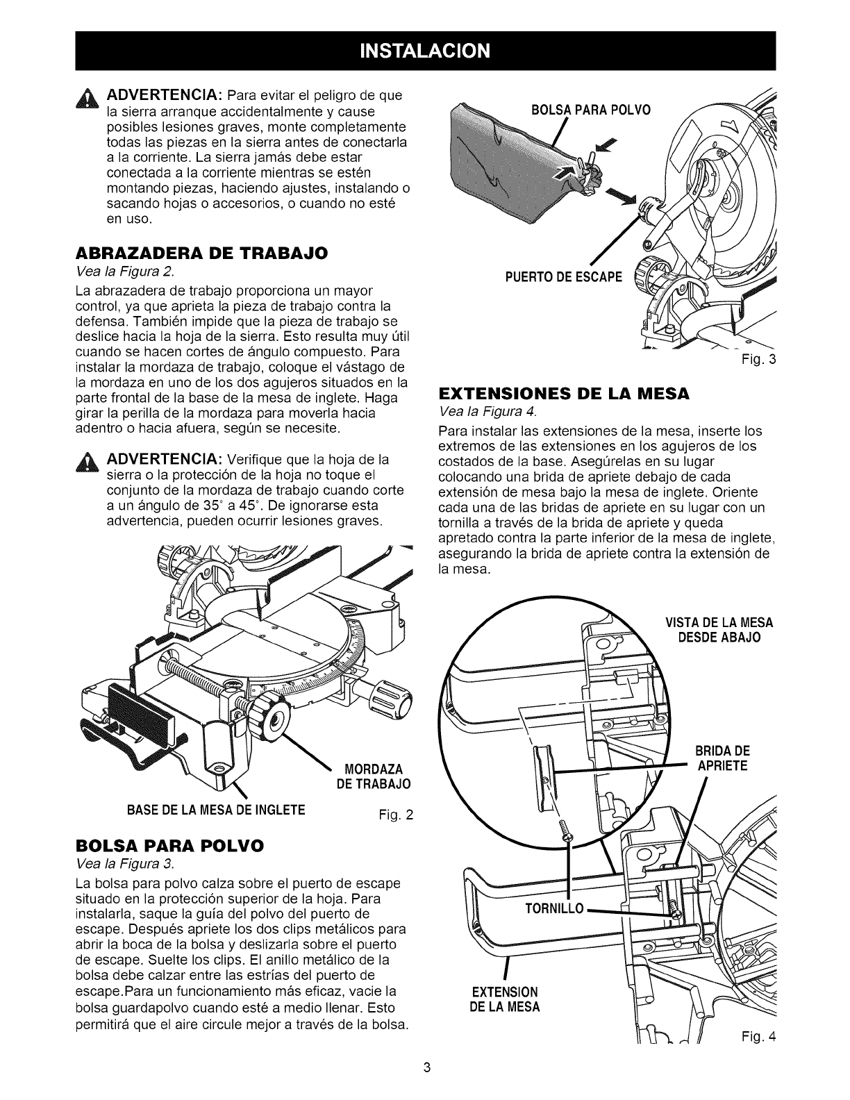
ABRAZADERA DE TRABAJO
Vea la Figura 2.
La abrazadera de trabajo proporciona un mayor
control, ya que aprieta la pieza de trabajo contra la
defensa. Tambien impide que la pieza de trabajo se
deslice hacia la hoja de la sierra. Esto resulta muy Qtil
cuando se hacen cortes de angulo compuesto. Para
instalar la mordaza de trabajo, coloque el vastago de
la mordaza en uno de los dos agujeros situados en la
parte frontal de la base de la mesa de inglete. Haga
girar la perilla de la mordaza para moverla hacia
adentro o hacia afuera, segQn se necesite.
AADVERTENClA: Verifique que la hoja de la
sierra o la protecci6n de la hoja no toque el
conjunto de la mordaza de trabajo cuando corte
a un angulo de 35 ° a 45 °. De ignorarse esta
advertencia, pueden ocurrir lesiones graves.
BASEDE LA MESADE INGLETE
MORDAZA
DETRABAJO
Fig. 2
BOLSA PARA POLVO
Vea la Figura 3.
La bolsa para polvo calza sobre el puerto de escape
situado en la protecci6n superior de la hoja. Para
instalarla, saque la guia del polvo del puerto de
escape. Despues apriete los dos clips metalicos para
abrir la boca de la bolsa y deslizarla sobre el puerto
de escape. Suelte los clips. El anillo metalico de la
bolsa debe calzar entre las estrias del puerto de
escape.Para un funcionamiento mas eficaz, vacie la
bolsa guardapolvo cuando est6 a medio Ilenar. Esto
permitira que el aire circule mejor a trav6s de la bolsa.
Fig. 3
EXTENSIONES DE LA MESA
Vea la Figura 4.
Para instalar las extensiones de la mesa, inserte los
extremos de las extensiones en los agujeros de los
costados de la base. AsegQrelas en su lugar
colocando una brida de apriete debajo de cada
extensi6n de mesa bajo la mesa de inglete. Oriente
cada una de las bridas de apriete en su lugar con un
tornilla a trav6s de la brida de apriete y queda
apretado contra la parte inferior de la mesa de inglete,
asegurando la brida de apriete contra la extensi6n de
la mesa.
EXTENSION
DELA MESA
Fig. 4
3
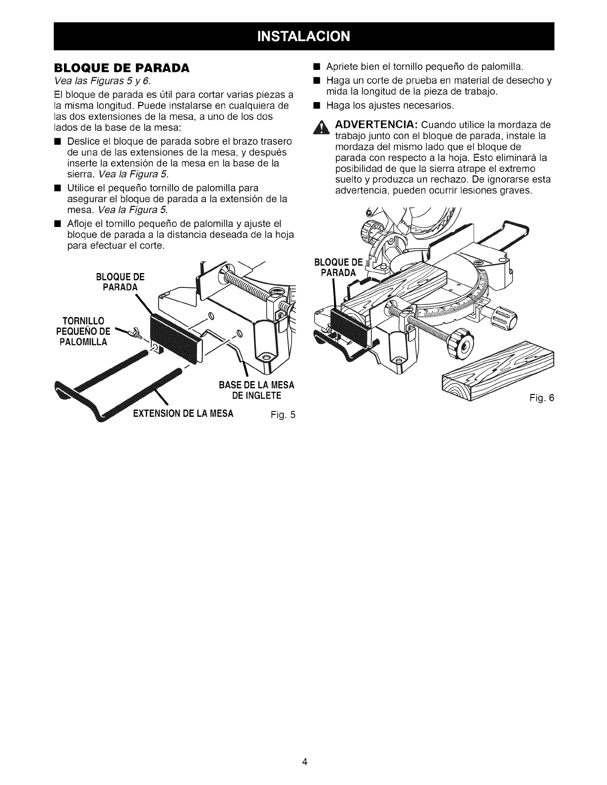
BLOQUE DE PARADA
Vea las Figuras 5 y 6.
El bloque de parada es Otil para cortar varias piezas a
la misma Iongitud. Puede instalarse en cualquiera de
las dos extensiones de la mesa, a uno de los dos
lados de la base de la mesa:
• Deslice el bloque de parada sobre el brazo trasero
de una de las extensiones de la mesa, y despues
inserte la extensi6n de la mesa en la base de la
sierra. Vea la Figura 5.
• Utilice el pequeSo tornillo de palomilla para
asegurar el bloque de parada a la extensi6n de la
mesa. Vea la Figura 5.
• Afloje el tornillo pequeSo de palomilla y ajuste el
bloque de parada a la distancia deseada de la hoja
para efectuar el corte.
BLOQUEDE
PARADA
TORNILLO
PEQUEItODE
PALOMILLA
BASEDELA MESA
DEINGLETE
EXTENSIONDE LAMESA Fig. 5
• Apriete bien el tornillo peque_o de palomilla.
• Haga un corte de prueba en material de desecho y
mida la Iongitud de la pieza de trabajo.
• Haga los ajustes necesarios.
_, ADVERTENCIA: Cuando utilice la mordaza de
trabajo junto con el bloque de parada, instale la
mordaza del mismo lado que el bloque de
parada con respecto a la hoja. Esto eliminara la
posibilidad de que la sierra atrape el extremo
suelto y produzca un rechazo. De ignorarse esta
advertencia, pueden ocurrir lesiones graves.
BLOQUEDE
PARADA
Fig. 6
4
