Craftsman 315212330 User Manual 10 INCH COMPOUND MITER SAW Manuals And Guides L0601002
CRAFTSMAN Miter Saw Manual L0601002 CRAFTSMAN Miter Saw Owner's Manual, CRAFTSMAN Miter Saw installation guides
User Manual: Craftsman 315212330 315212330 CRAFTSMAN 10 INCH COMPOUND MITER SAW - Manuals and Guides View the owners manual for your CRAFTSMAN 10 INCH COMPOUND MITER SAW #315212330. Home:Tool Parts:Craftsman Parts:Craftsman 10 INCH COMPOUND MITER SAW Manual
Open the PDF directly: View PDF ![]() .
.
Page Count: 44

'S MANUAL
I0 in. COMPOUND MITER SAW
DOUBLE INSULATED
Model No.
31 5.212330
_ WARMNG: To reduce the risk of injury,
the user must read and understand the
operator's manual before using this product.
Customer HeUp Line: 1=800=932=3188
Sears, Roebuck and Co., 3333 Bevedy Rd., Hoffman Estates, IL 60179 USA
Visit the Craftsman web page: www.sears.com/craftsman
983000-697
5=05
Save this manual for future reference
[] Warranty ............................................................................................................................................................................ 2
[] introduction ....................................................................................................................................................................... 2
[] General Safety Rules ..................................................................................................................................................... 3-4
[] Specific Safety Rules ..................................................................................................................................................... 4-5
[] Symbols ......................................................................................................................................................................... 6-7
[] Eiectr(cal ............................................................................................................................................................................ 8
[] Glossary of Terms .............................................................................................................................................................. 9
[] Features ..................................................................................................................................................................... 10-12
[] Tools Needed ................................................................................................................................................................. 13
[] Loose Parts .................................................................................................................................................................... 14
[] Assembly ................................................................................................................................................................... 15-24
[] Operat(on ................................................................................................................................................................... 24-31
[] Adjustments .............................................................................................................................................................. 32-33
[] Ma(ntenance .............................................................................................................................................................. 33-34
[] Exploded V(ew ........................................................................................................................................................... 36-43
[] Parts Order(ng/Serv(ce ...................................................................................................................................... Back Page
ONE YEAR FULL WARRANTY ON CRAFTSMAN TOOL
if this Craftsman tool fails due to a defect in material or workmanship within one year from the date of purchase,
CONTACT THE NEAREST SEARS PARTS & REPA(R CENTER at 1-800-4-MY-HOME ® and Sears w((I repa(r (t, free of
charge. This warranty app(ies on(y while this product is (n the United States.
if this too! is used for commercia( or rental purposes, this warranty w((I apply for on(y ninety days from the date of
purchase.
This warranty gives you specific legal rights, and you may also have other rights which vary from state to state.
Sears, Roebuck and Co., Dept. 817WA, Noffrnan Estates, (L 60179
This too( has many features for making its use more p(easant and enjoyab(e. Safety, performance, and dependab((ity
have been given top priority in the design of this product making it easy to maintain and operate.

_ WARMNG:Readandunderstandall instruc=
tions. Failure to follow a(! instruct(ons listed below
may result in electric shock, fire, and/or serious
personal injury.
READ ALL (NSTRUCT(ONS
[] KNOW YOUR POWER TOOL. Read the operator's
manua( carefu((y. Learn the app(ications and limitations
as we(( as the specific potential hazards related to this
tool.
[] GUARD AGA(NST ELECTR)OAL SHOOK BY PRE-
VENT(NG BODY CONTACT W(TH GROUNDED
SURFACES. For example, pipes, radiators, ranges,
refrigerator enc(osures.
[] KEEP GUARDS (N PLACE and (n good working order.
[] REMOVE ADJUST(NG KEYS AND WRENCHES.
Form the habit of checking to see that keys and ad-
justing wrenches are removed from too( before turning
(t on.
[] KEEP WORK AREA CLEAN. Cluttered areas and
benches inv(te accidents. DO NOT (eave tools or
p(eces of wood on the saw while it is in operation.
[] DO NOT USE (N DANGEROUS ENV(RONMENTS.
Do not use power tools in damp or wet locations or
expose to rain. Keep the work area well (it.
[] KEEP CHILDREN AND VIS)TORS AWAY. Al! visitors
should wear safety glasses and be kept a safe
distance from work area. Do not let visitors contact tool
or extension cord whi(e operating.
[] MAKE WORKSHOP CHILDPROOF w(th padlocks and
master switches, or by removing starter keys.
[] DON'T FORCE TOOL. (t w((( do the job better and
safer at the feed rate for which it was designed.
[] USE RIGHT TOOL. Do not force the too( or attachment
to do a job for which it was not designed.
[] USE THE PROPER EXTENS(ON CORD. Make sure
your extension cord is in good condition. Use on(y a
cord heavy enough to carry the current your product
w((( draw. An undersized cord w((I cause a drop in (ine
vo(tage resu(ting in (oss of power and overheating. A
w(re gauge s(ze (A.W.G.) of at least 14 (s recommended
for an extens(on cord 25 feet or (ess (n (ength. (f in
doubt, use the next heavier gauge. The sma((er the
gauge number, the heav(er the cord.
[] DRESS PROPERLY. Do not wear (oose c(othing,
gloves, neckties, or jewelry,. They can get caught
and draw you into mov(ng parts. Rubber g(oves and
nonskid footwear are recommended when working
outdoors. A(so wear protective hair cover(ng to contain
(ong ha(r.
[] ALWAYS WEAR SAFETY GLASSES W(TH S(DE
SH(ELDS. Everyday eyeg(asses have only impact-
res(stant lenses, they are NOT safety g(asses.
[] SECURE WORK. Use clamps or a vise to hold work
when practical. (t's safer than using your hand and
frees both hands to operate too(.
[] DON'T OVERREACH. Keep proper footing and
balance at all t(mes.
[] MAINTAIN TOOLS WITH CARE. Keep too(s sharp
and c(ean for better and safer performance. Follow
instructions for lubricating and changing accessories.
[] DISCONNECT TOOLS. When not (n use, before
servicing, or when changing attachments, blades, bits,
cutters, etc., al( too(s shou(d be disconnected.
[] AVOID ACC(DENTAL START(NG. Be sure switch (s off
when p(ugging in any tool.
[] USE RECOMMENDED ACCESSORIES. The use of
improper accessories may risk injury.
[] NEVER STAND ON TOOL. Serious injury could occur
if the tool is tipped or if the cutting too( is un(ntention-
a((y contacted.
[] CHECK DAMAGED PARTS. Before further use of
the tool, a guard or other part that is damaged should
be carefu((y checked to determine that it wU(operate
properly and perform its intended function. Check for
alignment of moving parts, b(nding of moving parts,
breakage of parts, mounting and any other conditions
that may affect (ts operation. A guard or other part that
ls damaged must be properly repaired or replaced by
an authorized service center to avoid risk of personal
injury.
[] USE THE R(GHT D(REOT)ON OF FEED. Feed work
into a blade or cutter against the direction of rotation of
Made or cutter only.
[] NEVER LEAVE TOOL RUNN(NG UNATTENDED.
TURN THE POWER OFF. Don't leave too( until it
comes to a complete stop.
[] PROTECT YOUR LUNGS. Wear a face or dust mask if
the cutting operation is dusty,.
[] PROTECT YOUR HEAR(NG. Wear hearing protect(on
during extended periods of operation.
[] DO NOT ABUSE CORD. Never yank cord to discon-
nect from receptacle. Keep cord from heat, oi!, and
sharp edges.
[] USE OUTDOOR EXTENSION CORDS. When tool is
used outdoors, use only extension cords with ap-
proved ground connection that are intended for use
outdoors and so marked.
[] KEEP BLADES CLEAN, SHARP, AND W)TH
SUFF)O(ENT SET. Sharp b(ades min(m(ze sta)((ng
and kickback.
[] BLADE COASTS AFTER BE)NG TURNED OFF.
[] NEVER USE (N AN EXPLOS(VE ATMOSPHERE.
Norma( spark(ng of the motor could (gn(te fumes.

[] INSPECTTOOLCORDSPERIODICALLY.Hfdamaged,
haverepairedbya qualifiedservicetechnicianat
anauthorizedservicefacility.Theconductorwith
insulationhavinganoutersurfacethatisgreenwith
orwithoutyellowstripesistheequipment-ground-
ingconductor.Hfrepairor replacementof theelectric
cordorplugisnecessary,donotconnecttheequip-
ment-groundingconductorto aliveterminal.Repair
orreplaceadamagedorworncordimmediately.Stay
constantlyawareofcordlocationandkeepit wellaway
fromtherotatingblade.
[] INSPECTEXTENSIONCORDSPERIODICALLYand
replaceif damaged.
[] POLARIZEDPLUGS.Toreducetheriskofelectric
shock,thistoolhasapolarizedplug(onebladeis
widerthantheother).Thisplugwilifit ina polarized
outletonlyoneway.Iftheplugdoesnotfitfullyinthe
outlet,reversetheplug.Ifit stilldoesnotfit,contacta
qualifiedelectricianto installtheproperoutlet.Donot
changethepluginanyway.
[] KEEPTOOLDRY,CLEAN,ANDFREEFROMOIL
ANDGREASE.Alwaysusea cleanclothwhenclean-
ing.Neverusebrakefluids,gasoline,petroleum-based
products,oranysolventsto cleantool.
[] STAYALERTANDEXERCISECONTROL.Watch
whatyouaredoingandusecommonsense.Donot
operatetoolwhenyouaretired.Donotrush.
[] DONOTUSETOOLIFSWITCHDOESNOTTURNIT
ONANDOFF.Havedefectiveswitchesreplacedbyan
authorizedservicecenter.
[] USEONLYCORRECTBLADES.Donotuseblades
withincorrectsizeholes.Neverusebladewashersor
bladeboltsthataredefectiveorincorrect.Themaxi-
mumbladecapacityofthesawis10in.
[] BEFOREMAKINGA CUT,BESUREALLADJUST-
MENTSARESECURE.
[] BESUREBLADEPATHiS FREEOFNAILS.Inspect
forandremoveallnailsfromlumberbeforecutting.
[] NEVERTOUCHBLADEorothermovingpartsduring
use.
[] NEVER STARTA TOOLWHEN ANY ROTATING COM-
PONENT IS IN CONTACT WITH THE WORKPII=CE.
[] DO NOT OPERATE A TOOL WHILE UNDER THE
INFLUENCE OF DRUGS, ALCOHOL, OR ANY
MEDICATION.
[] WHEN SERVICING use only identical replacement
parts. Use of any other parts may create a hazard or
cause product damage.
[] USE ONLY RECOMMENDED ACCESSORIES listed
in this manual or addendums. Use of accessories
that are not listed may cause the risk of personal
injury. Instructions for safe use of accessories are
included with the accessory.
[] DOUBLE CHECK ALL SETUPS. Make sure blade is
tight and not making contact with saw or workpiece
before connecting to power supply.
[] FIRMLY CLAMP OR BOLT the tool to a workbench or
table at approximately hip height.
[] KEEP HANDS AWAY FROM CUTTING AREA. Do not
reach underneath work or in blade cutting path with
your hands and fingers for any reason. Always turn the
power off.
[] ALWAYS SUPPORT LONG WORKPJECES while cut-
ting to minimize risk of blade pinching and kickback.
Saw may slip, walk, or slide while cutting long or heavy
boards.
[] ALWAYS USE A CLAMP to secure the workpiece
when possible.
[] BE SURE THE BLADE CLEARS THE WORKPIECE.
Never start the saw with the blade touching the
workpiece. Allow motor to come up to full speed
before starting cut.
[] MAKE SURE THE MITER TABLE AND SAW ARM
(BEVEL FUNCTION) ARE LOCKED IN POSITION
BEFORE OPERATING YOUR SAW. Lock the miter
table by securely tightening the miter lock tevers. Lock
the saw arm (bevel function) by securely tightening the
bevel lock knob.
[] NEVER USE A LENGTH STOP ON THE FREE SCRAP
END OF A CLAMPED WORKPIECE. NEVER hold
onto or bind the free scrap end of the workpiece in any
operation. If a work clamp and length stop are used
together, they must both be installed on the same side
of the saw table to prevent the saw from catching the
loose end and kicking up.
[] NEVER cut more than one piece at a time. DO NOT
STACK more than one workpiece on the saw table at a
time.
[] NEVER PERFORM ANY OPERATION FREEHAND.
Always place the workpiece to be cut on the miter
table and position it firmly against the fence as a back-
stop. Always use the fence.
[] NEVERhandholdaworkpiecethatistoosmallto be
clamped.Keephandsclearof thecuttingarea.
[] NEVERreachbehind,under,orwithinthreeinches
of thebladeanditscuttingpathwithyourhandsand
fingersforanyreason.
[] NEVERreachto pickupaworkpiece,apieceof scrap,
oranythingelsethatisinornearthecuttingpathofthe
blade.
[] AVOIDAWKWARDOPERATIONSANDHAND
POSITIONSwhereasuddenslipcouldcauseyour
handto moveintotheblade.ALWAYSmakesureyou
havegoodbalance.NEVERoperatethemitersaw
onthefloororina crouchedposition.
[] NEVERstandorhaveanypartof yourbodyinlinewith
thepathofthesawblade.
[] ALWAYSreleasethepowerswitchandallowthe
sawbladeto stoprotatingbeforeraisingit outofthe
workpiece.
[] DONOTTURNTHEMOTORSWITCHONANDOFF
RAPIDLY.Thiscouldcausethesawbladeto loosen
andcouldcreateahazard.Shouldthiseveroccur,
standclearandallowthesawbladeto cometo a
completestop.Disconnectthesawfromthepower
supplyandsecurelyretightenthebladebolt.
[] JFANYPARTOFTHISMITERSAWISMISSINGor
shouldbreak,bend,orfailinanyway,orshouldany
electricalcomponentfailto performproperly,shutoff
thepowerswitch,removethemitersawplugfromthe
powersource,andhavedamaged,missing,orfailed
partsreplacedbeforeresumingoperation.
[] ALWAYSSTAYALERT!Donotallowfamiliarity(gained
fromfrequentuseofthesaw)to causeacarelessmis-
take.ALWAYSREMEMBERthatacarelessfractionof
asecondissufficientto inflictsevereinjury.
[] MAKESURETHEWORKAREAHASAMPLEUGH%
INGto seetheworkandthatnoobstructionswillinter-
ferewithsafeoperationBEFOREperforminganywork
usingthesaw.
[] ALWAYSTURNOFFTHESAWbeforedisconnecting
itto avoidaccidentalstartingwhenreconnectingto
powersupply.NEVERleavethesawunattendedwhile
connectedto a powersource.
[] THISTOOLshouldhavethefollowingmarkings:
a) Weareyeprotection.
b) Keephandsoutof pathofsawblade.
c) Donotoperatesawwithoutguardsinplace.
d) Donotperformanyoperationfreehand.
e) Neverreacharoundsawblade.
f) Turnofftoolandwaitfor sawbladeto stopbefore
movingworkpieceorchangingsettings.
g) Disconnectpower(orunplugtoolasapplicable)
beforechangingbladeorservicing.
h) Noloadspeed.
[] ALWAYScarrythetoo!onlybythecarryinghandle.
[] AVOIDdirecteyeexposurewhenusingthelaserguide.
[] SAVETHESEINSTRUCTIONS.Referto them
frequentlyanduseto instructotherusers.Ifyouloan
someonethistool,loanthemtheseinstructionsalso.
_ WARNING:Somedustcreatedbypowersanding,sawing,grinding,drilling,andotherconstructionactivities
containschemicalsknownto causecancer,birthdefectsorotherreproductiveharm.Someexamplesof these
chemicalsare:
leadfromlead-basedpaints,
crystallinesilicafrombricksandcementandothermasonryproducts,and
arsenicandchromiumfromchemically-treatedlumber.
Yourriskfromtheseexposuresvaries,dependingonhowoftenyoudothistypeofwork.Toreduceyourexposure
to thesechemicals:workinawellventilatedarea,andworkwithapprovedsafetyequipment,suchasthosedust
masksthatarespeciallydesignedto filteroutmicroscopicparticles.

Someofthefollowingsymbolsmaybeusedonthistool.Pleasestudythemandlearntheirmeaning.Proper
interpretationofthesesymbolswillallowyouto operatethetoolbetterandsafer.
SYMBOL NAME DESJGNATION/EXPLANATION
V Volts Voltage
A Amperes Current
Hz Hertz Frequency (cycles per second)
W Watt Power
min Minutes Time
'%, Alternating Current Type of current
m Direct Current Type or a characteristic of current
no No Load Speed Rotational speed, at no goad
Class H Construction Doubbqnsulated construction
.../rain Per Minute Revolutions, strokes, surface speed, orbits etc., per minute
Wet Conditions Alert Do not expose to rain or use in damp locations.
Read The Operator's Manual To reduce the risk of injury, user must read and understandoperator's manual before using this product.
Eye Protection Always wear safety goggles or safety glasses with side
shields and a full face shield when operating this product.
Safety Alert Precautions that involve your safety.
Failure to keep your hands away from the blade win result in
No Hands Symbol serious personal injury.
Failure to keep your hands away from the blade wil! result in
No Hands Symbol serious personal injury.
Failure to keep your hands away from the blade win result in
No Hands Symbol serious personal injury.
No Hands Symbol Failure to keep your hands away from the blade will result in
serious personal injury.
®Hot Surface To reduce the risk of injury or damage, avoid contact with
any hot surface.
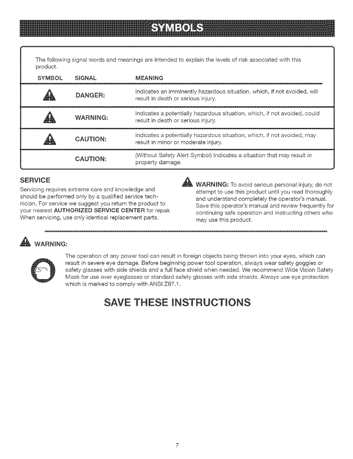
Thefollowingsignalwordsandmeaningsareintendedto explainthelevelsofriskassociatedwiththis
product.
SYMBOL S+GNAL MEAN+NG
DANGER: hdicates an imminently hazardous situation, which, if not avoided, wil!
result in death or serious injury.
hdicates a potentially hazardous situation, which, if not avoided, could
WARNING: result in death or serious injury.
hdicates a potentially hazardous situation, which, if not avoided, may
CAUTION: result in minor or moderate injury.
CAUTION: (Without Safety Alert Symbol) Indicates a situation that may result in
property damage.
SERVICE
Servicing requires extreme care and knowledge and
should be performed only by a qualified service tech-
nician. For service we suggest you return the product to
your nearest AUTHORIZED SERVICE CENTER for repair.
When servicing, use only identical replacement parts.
_J_l_ WARNING: To avoid serious personal injury, do not
attempt to use this product until you read thoroughly
and understand completely the operator's manual.
Save this operator's manual and review frequently for
continuing safe operation and instructing others who
may use this product.
_ WARNING:
The operation of any power tool can result in foreign objects being thrown into your eyes, which can
result in severe eye damage. Before beginning power tool operation, always wear safety goggles or
safety glasses with side shields and a ful! face shield when needed. We recommend Wide Vision Safety
Mask for use over eyeglasses or standard safety glasses with side shields. Always use eye protection
which is marked to comply with ANSHZ87.1.
SAVE THESE INSTRUCTIONS
DOUBLE {NSULATION
Double insulation is a concept in safety in electric power
tools, which eliminates the need for the usual three-wire
grounded power cord. All exposed metal parts are
isolated from the internal metal motor components with
protecting insulation. Double insulated tools do not need
to be grounded.
,_ WARNING: The double insulated system is
intended to protect the user from shock resulting
from a break in the tool's internal insulation. Observe
all normal safety precautions to avoid electrical
shock.
NOTE: Servicing of a tool with double insulation requires
extreme care and knowledge of the system and should
be performed only by a qualified service technician. For
service, we suggest you return the tool to your nearest
authorized service center for repair. Always use original
factory replacement parts when servicing.
ELECTRICAL CONNECTION
This tool has a precision-built electric motor. It should be
connected to a power supply that is 120 volts, 60 Hz,
AC only (normal household current). Do not operate
this tool on direct current (DC). A substantial voltage drop
wil! cause a loss of power and the motor will overheat. If
your tool does not operate when plugged into an outlet,
double-check the power supply.
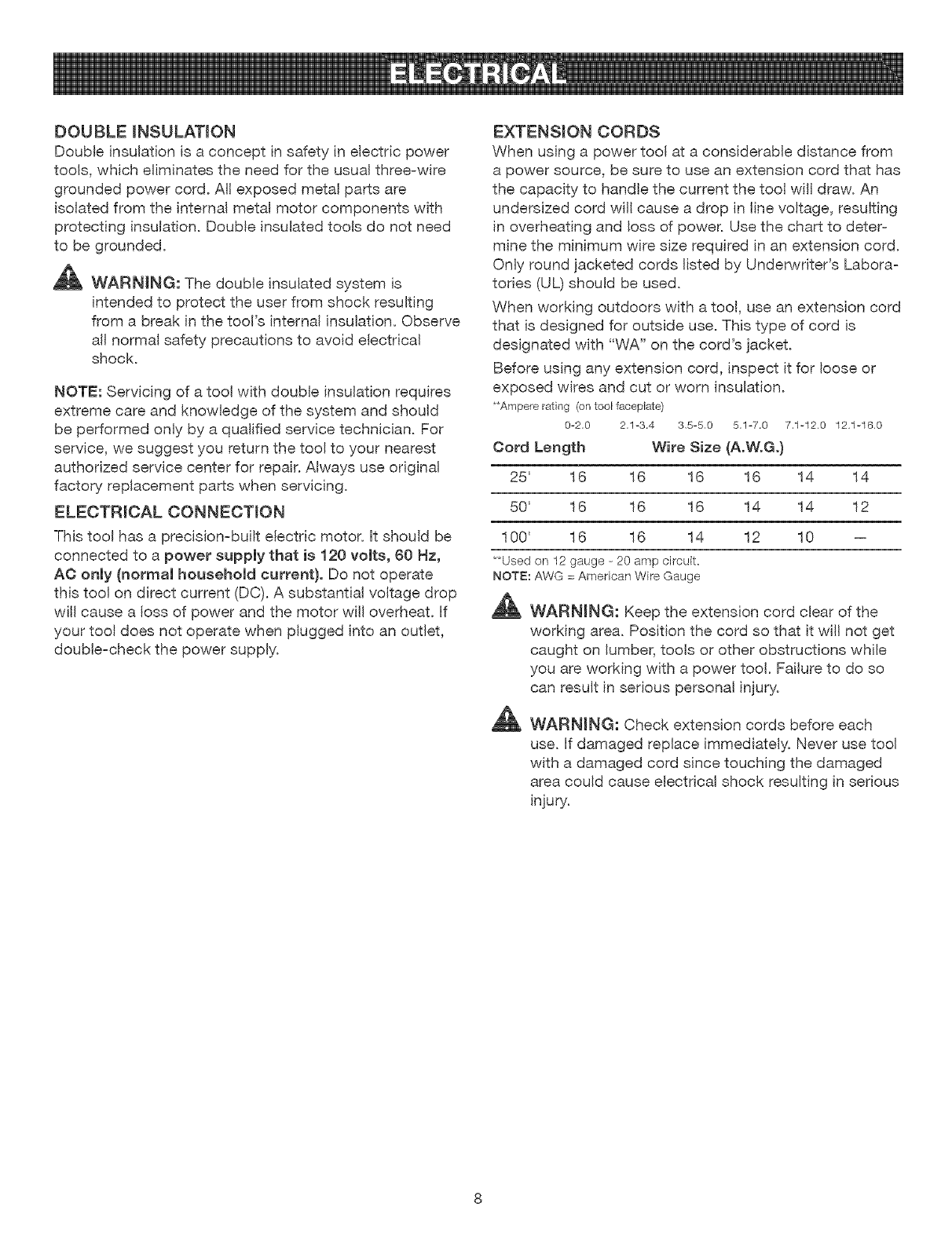
EXTENSION CORDS
When using a power tool at a considerable distance from
a power source, be sure to use an extension cord that has
the capacity to handle the current the tool will draw. An
undersized cord will cause a drop in line voltage, resulting
in overheating and loss of power. Use the chart to deter-
mine the minimum wire size required in an extension cord.
Only round jacketed cords listed by Underwriter's Labora-
tories (UL) should be used.
When working outdoors with a too!, use an extension cord
that is designed for outside use. This type of cord is
designated with "WA" on the cord's jacket.
Before using any extension cord, inspect it for loose or
exposed wires and cut or worn insulation.
**Ampere rating (on tool faceplate)
0-2,0 2,1-3,4 3,5-5,0 5,1-7,0 7,1-12.0 12.1-16.0
Cord Length Wire Size (A.W.G.)
25' 16 16 16 16 14 14
50' 16 16 16 14 14 12
100' 16 16 14 12 10 --
**Used on 12 gauge - 20 amp circuit.
NOTE: AWG = American Wire Gauge
_ WARNING: Keep the extension cord clear of the
working area. Position the cord so that it will not get
caught on lumber, tools or other obstructions while
you are working with a power tool. Failure to do so
can result in serious personal injury.
_ WARNING: Check extension cords before each
use. If damaged replace immediately. Never use tool
with a damaged cord since touching the damaged
area could cause electrical shock resulting in serious
injury.
Anti-KickbackPawls(radialarmandtablesaws)
A devicewhich,whenproperlyinstalledandmaintained,
isdesignedto stoptheworkpiecefrombeingkickedback
towardthefrontof thesawduringarippingoperation.
Arbor
Theshaftonwhicha bladeorcuttingtoolis mounted.
Bevel Cut
A cutting operation made with the blade at any angle
other than 90° to the table surface.
Chamfer
A cut removing a wedge from a block so the end (or part
of the end) is angled rather than at 90°.
Compound Cat
A cross cut made with both a miter and a bevel angle.
Crosscut
A cutting or shaping operation made across the grain or
the width of the workpiece.
Cutter Head (planers and jointers)
A rotating piece of adjustable blades. The cutter head
removes material from the workpiece.
Dado Cut
A non=through cut which produces a square=sided notch
or trough in the workpiece (requires a special blade).
Featherboard
A device used to help control the workpiece by guiding it
securely against the table or fence during any ripping
operation.
FPIVl or SPM
Feet per minute (or strokes per minute), used in reference
to blade movement.
Freehand
Performing a cut without the workpiece being guided by a
fence, miter gauge, or other aids.
Gum
A sticky, sap=based residue from wood products.
Heel
Alignment of the blade to the fence.
Kerr
The material removed by the blade in a through cut or the
slot produced by the blade in a non-through or partial cut.
Kickback
A hazard that can occur when the blade binds or stalls,
throwing the workpiece back toward operator.
Leading End
The end of the workpiece pushed into the tool first.
IViiter Cut
A cutting operation made with the workpiece at any angle
to the blade other than 90 ° .
Non-Through Cuts
Any cutting operation where the blade does not extend
completely through the thickness of the workpiece.
Push Blocks and Push Sticks
Devices used to feed the workpiece through the saw
blade during cutting operations. A push stick (not a push
block) should be used for narrow ripping operations.
These aids help keep the operator's hands well away from
the blade.
Pilot Hole (drill presses)
A small hole drilled in a workpiece that serves as a guide
for drilling large holes accurately.
Resaw
A cutting operation to reduce the thickness of the work=
piece to make thinner pieces.
Resin
A sticky, sap=based substance that has hardened.
Revolutions Per IViinute (RPIVi)
The number of turns completed by a spinning object in
one minute.
Ripping or Rip Cut
A cutting operation along the length of the workpiece.
Riving Knife (table saws)
Also known as a spreader or splitter. A metal piece, slight-
ly thinner than the saw blade, which helps keep the kerf
open and also helps to prevent kickback.
Saw Blade Path
The area over, under, behind, or in front of the blade. As
it applies to the workpiece, that area which wil! be or has
been cut by the blade.
Set
The distance that the tip of the saw blade tooth is bent (or
set) outward from the face of the blade.
Snipe (planers}
Depression made at either end of a workpiece by cutter
blades when the workpiece is not properly supported.
Throw-Back
The throwing back of a workpiece usually caused by the
workpiece being dropped into the blade or being placed
inadvertently in contact with the blade.
Through Sawing
Any cutting operation where the blade extends completely
through the thickness of the workpiece.
Workpiece or tViaterial
The item on which the operation is being done.
Worktable
Surface where the workpiece rests while performing a
cutting, drilling, planing, or sanding operation.
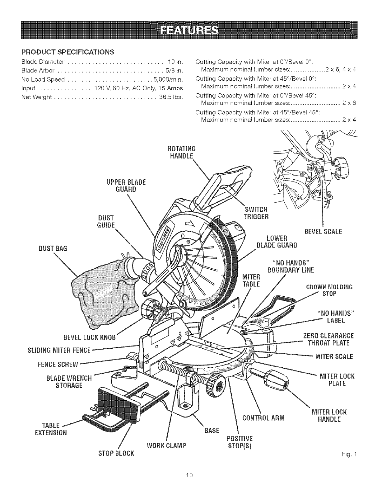
PRODUCTSPECIFICATIONS
BladeDiameter............................ 10in.
BladeArbor............................... 5,,/8in.
NoLoadSpeed......................... 5,000/rain.
input ................ 120M60Hz,AC©nly, 15 Amps
Net Weight .............................. 36.5 Ibs.
Cutting Capacity with Miter at O°/Bevel 0°:
Maximum nominal lumber sizes: .................... 2 x 6, 4 x 4
Cutting Capacity with Miter at 45°/Bevel 0°:
Maximum nominal lumber sizes: ............................. 2 x 4
Cutting Capacity with Miter at O°/Bevel 45°:
Maximum nominal lumber sizes: ............................. 2 x 6
Cutting Capacity with Miter at 45°/Bevel 45°:
Maximum nominal lumber sizes: ............................. 2 x 4
DUST BAG
UPPER BLADE
GUARD
DUST
OUmDE
SWRTCH
TRIGGER
LOWER
BLADE GUARD
BEVELSCALE
MITER
TABLE
BEVELLOCKKNOB
SUD_NGMITERFENCE
FENCESCREW
BLADEWRENCH
STORAGE
ZERO CLEARANCE
THROAT PLATE
MRTERSCALE
MITERLOCK
PLATE
TABLE
EXTENS_0N
/
STOPBLOCK
/
WORKCLAMP
BASE
CONTROLARM
POSmTIVE
STOP(S)
MITERLOCK
HANDLE
Fig. 1
10
KNOWYOURCOMPOUNDMITERSAW
See Figure 1.
Before attempting to use tMs product, familiarize yourself
with all operating features and safety rules.
15 AMP MOTOR
Your saw has a powerful 15 amp motor with sufficient
power to handle tough cutting jobs. It is made with all ball
bearings, and has externally accessible brushes for ease
of servicing.
10 in. BLADE
A 10 in. carbide-tipped saw blade is included with your
compound miter saw. It will cut materials up to 4 in. thick
or 6 in. wide, depending upon the angle at which the cut
is being made.
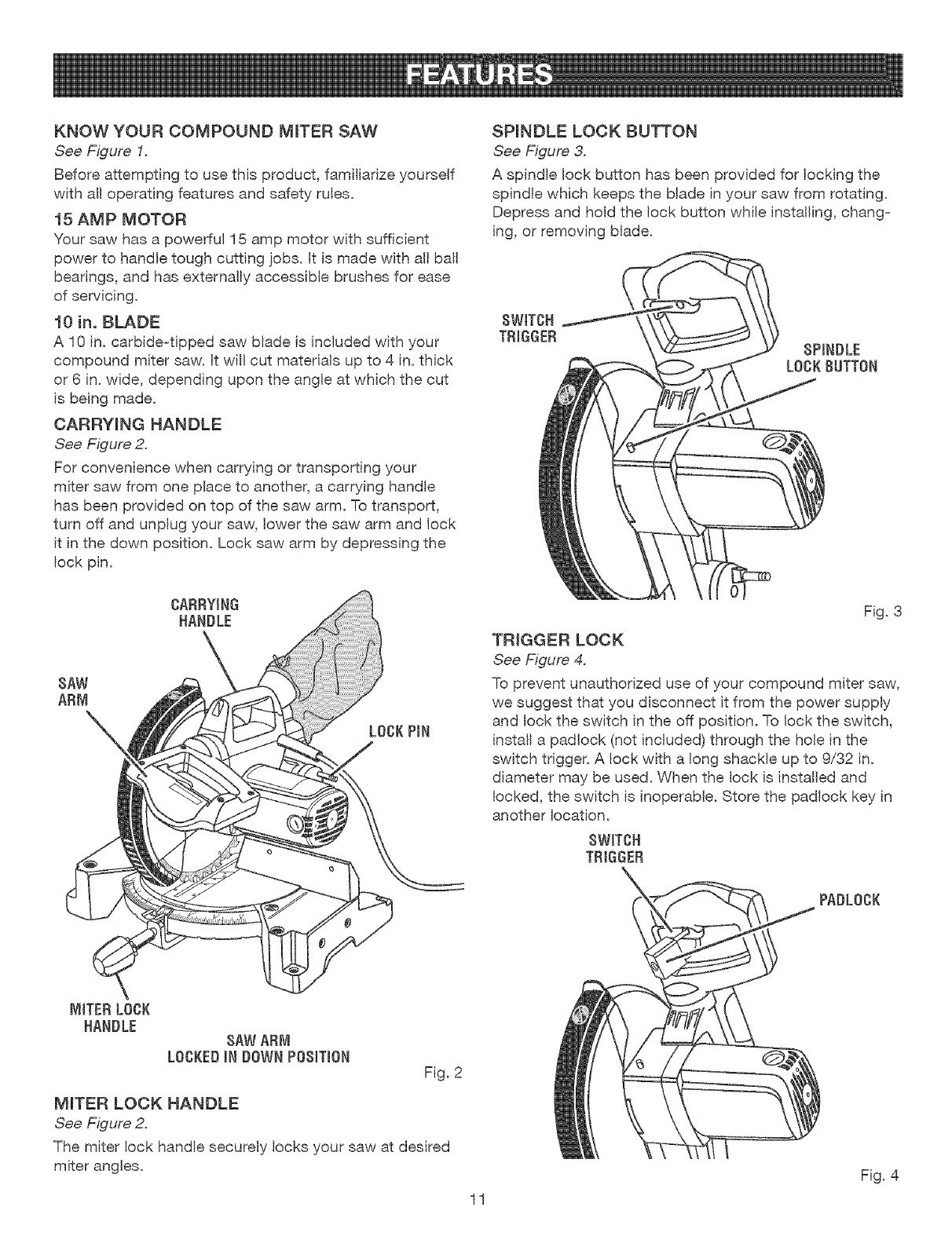
CARRYING HANDLE
See Figure 2.
For convenience when carrying or transporting your
miter saw from one place to another, a carrying handle
has been provided on top of the saw arm. To transport,
turn off and unplug your saw, lower the saw arm and lock
it in the down position. Lock saw arm by depressing the
lock pin.
CARRYING
HANDLE
SAW
ARM
LOCKPiN
SPINDLE LOCK BUTTON
See Figure 3.
A spindle lock button has been provided for locking the
spindle which keeps the blade in your saw from rotating.
Depress and hold the lock button while installing, chang-
ing, or removing blade.
SWITCH
TRIGGER SPINDLE
LOCKBUTTON
Fig. 3
TRIGGER LOCK
See Figure 4.
To prevent unauthorized use of your compound miter saw,
we suggest that you disconnect it from the power supply
and lock the switch in the off position. To lock the switch,
install a pad!ock (not included) through the hole in the
switch trigger. A lock with a !ong shackle up to 9/32 in.
diameter may be used. When the lock is installed and
locked, the switch is inoperable. Store the pad!ock key in
another location.
SWITCH
TRIGGER
PADLOCK
SAWARM
LOCKEDIN DOWNPOSITION Fig. 2
MITER LOCK HANDLE
See Figure 2.
The miter lock handle securely locks your saw at desired
miter angles.
11
Fig. 4
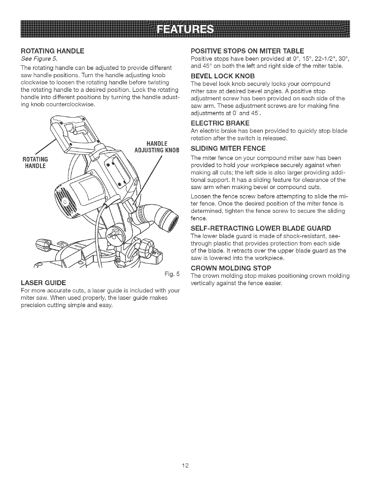
ROTATING HANDLE
See Figure 5.
The rotating handle can be adjusted to provide different
saw handle positions. Turn the handle adjusting knob
clockwise to loosen the rotating handle before twisting
the rotating handle to a desired position. Lock the rotating
handle into different positions by turning the handle adust-
ing knob counterclockwise.
Fig. 5
LASER GUIDE
For more accurate cuts, a laser guide is included with your
miter saw. When used properly, the laser guide makes
precision cutting simple and easy.
POSITIVE STOPS ON MITER TABLE
Positive stops have been provided at 0°, !5 °, 22-1/2 °, 30°,
and 45 ° on both the Idt and dght side of the miter table.
BEVEL LOCK KNOB
The bevel lock knob securely locks your compound
miter saw at desired bevel angles. A positive stop
adjustment screw has been provided on each side of the
saw arm. These adjustment screws are for making fine
adjustments at 0 and 45:.
ELECTRIC BRAKE
An electric brake has been provided to quickty stop blade
rotation after the switch is released.
SLiDiNG MITER FENCE
The miter fence on your compound miter saw has been
provided to hold your workpiece securely against when
making alt cuts; the left side is also larger providing addi-
tional support. It has a sliding feature for clearance of the
saw arm when making bevel or compound cuts.
Loosen the fence screw before attempting to slide the mi-
ter fence. Once the desired position of the miter fence is
determined, tighten the fence screw to secure the sliding
fence.
SELF-RETRACTING LOWER BLADE GUARD
The lower blade guard is made of shock-resistant, see-
through plastic that provides protection from each side
of the blade. It retracts over the upper blade guard as the
saw is lowered into the workpiece.
CROWN MOLDING STOP
The crown molding stop makes positioning crown molding
vertically against the fence easier.
12
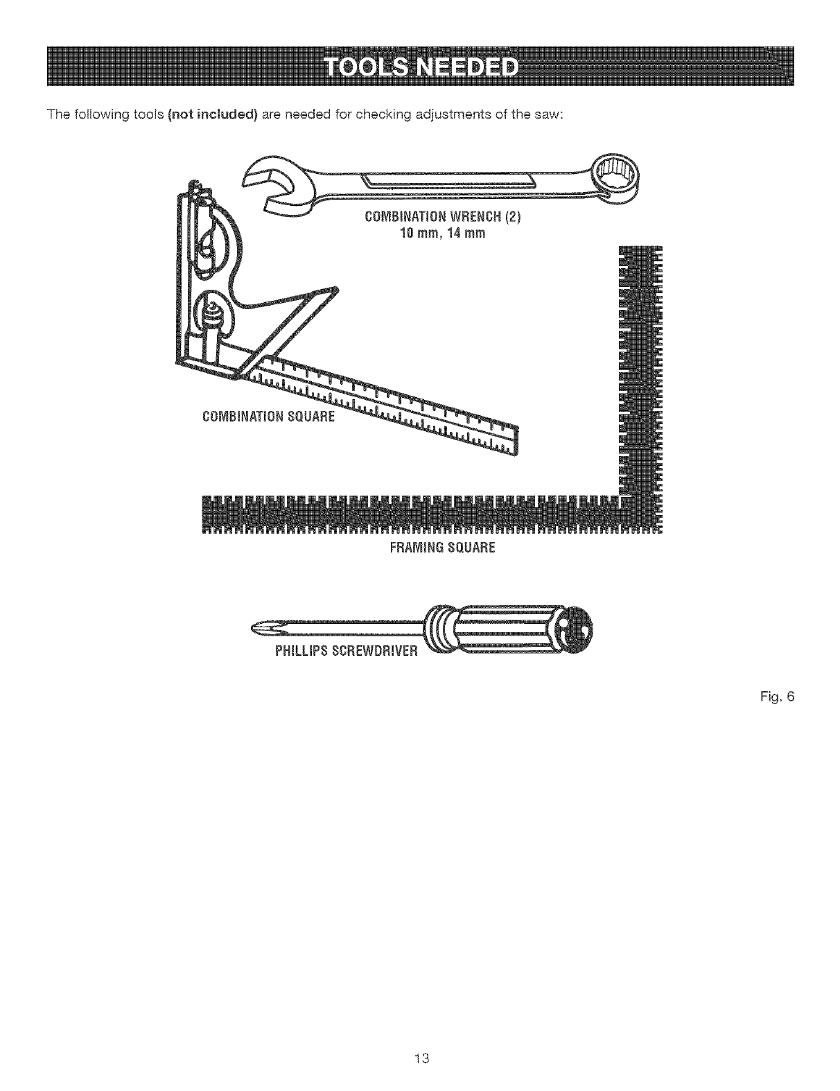
Thefollowingtools(notincluded} are needed for checking adjustments of the saw:
FRAMINGSQUARE
PHiLLiPSSCREWDRIVER
Fig. 6
13
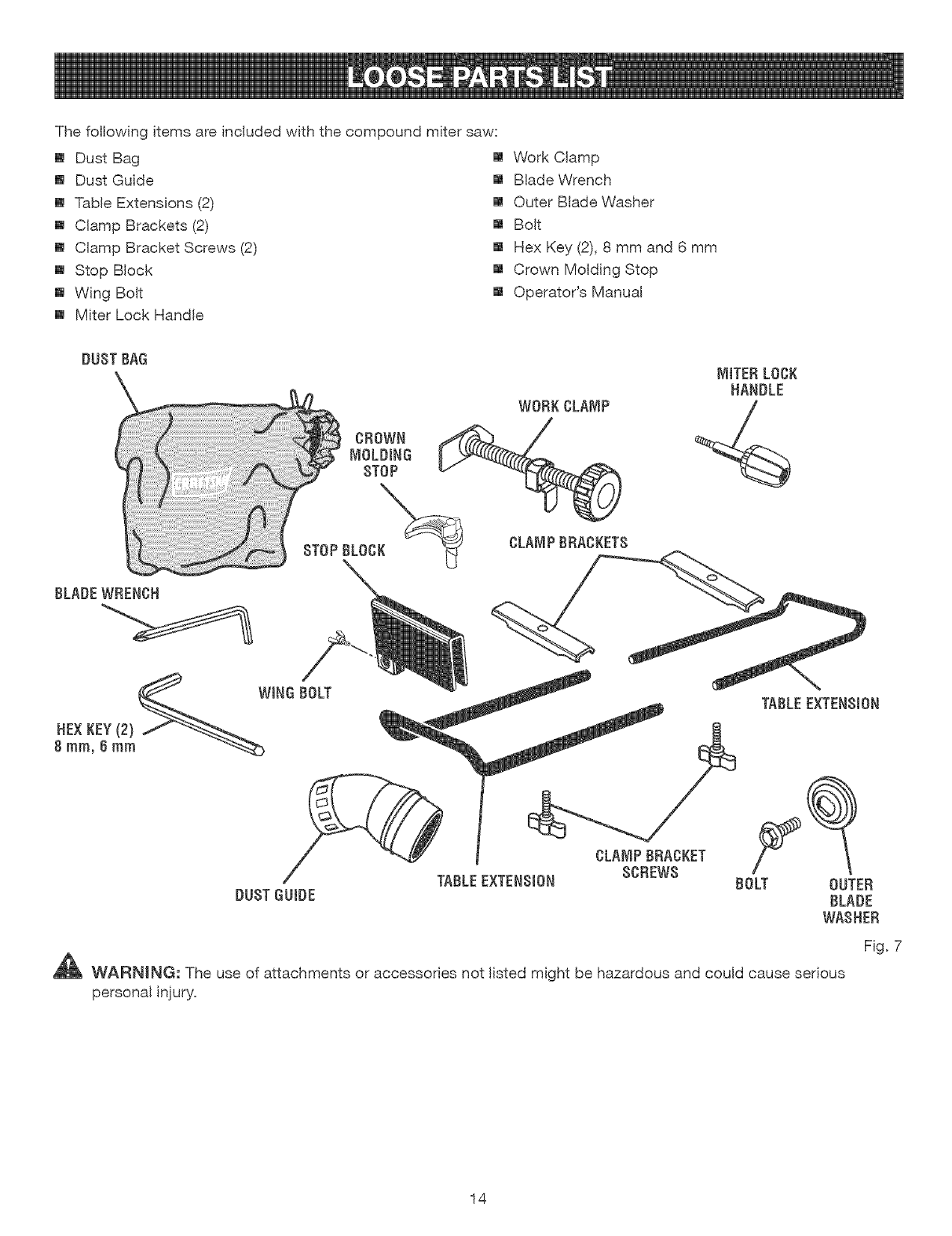
Thefollowingitemsareincludedwiththecompoundmitersaw:
[] DustBag
[] DustGuide
[] TableExtensions(2)
[] ClampBrackets(2)
[] ClampBracketScrews(2)
[] StopBlock
[] WingBolt
[] MiterLockHandle
[] WorkClamp
[] BladeWrench
[] OuterBladeWasher
[] Bolt
[] HexKey(2),8 mmand6 mm
[] CrownMoldingStop
[] Operator'sManual
DUST BAG
\
BLADEWRENCH
SCREWS
TABLEEXTENSION BOLT
DUSTGUIDE
TABLE EXTENB(ON
CLANiPBRACKET
OUTER
BLADE
WASHER
F(g. 7
_1_ WARN(NG: The use of attachments or accessories not listed might be hazardous and could cause serious
personal injury.
14
UNPACKING
Thisproductrequiresassembly.
[] Carefullylift sawfromthecartonbythecarryinghandle
andthesawbase,andplaceit onatevelworksurface.
NOTE:Thissawisheavy.Toavoidbackinjury,liftwith
yourlegs,notyourback,andgethelpwhenneeded.
[] Thissawhasbeenshippedwiththesawarmsecured
inthedownposition.Toreleasethesawarm,push
downonthetopof thesawarm,cutthetie+wrap,and
pulloutonthelockpin.
[] Liftthesawarmbythehandle.Handpressureshould
remainonthesawarmto preventsuddenriseupon
releaseofthetiewrap.
[] hspectthetoolcarefullyto makesurenobreakageor
damageoccurredduringshipping.
[] Donotdiscardthepackingmaterialuntilyouhave
carefullyinspectedandsatisfactorilyoperatedthetool.
[] Thesawisfactorysetforaccuratecutting.After
assemblingit,checkforaccuracy.Hfshippinghas
influencedthesettings,refertospecificprocedures
explainedinthismanual.
[] Hfanypartsaredamagedormissing,pleasecall
1+800+932+3188forassistance.
_ WARNING:Ifanypartsaremissing,donotoperate
thistooluntilthemissingpartsarereplaced.Failure
to dosocouldresultinpossibleseriouspersonal
injury.
WARNING:Donotattemptto modifythistool
orcreateaccessoriesnotrecommendedfor use
withthistool.Anysuchalterationormodificationis
misuseandcouldresultinahazardouscondition
leadingto possibleseriouspersonalinjury.
WARNING:Donotconnectto powersupplyuntil
assemblyiscomplete.Failureto complycouldresult
inaccidentalstartingandpossibleseriouspersonal
injury.
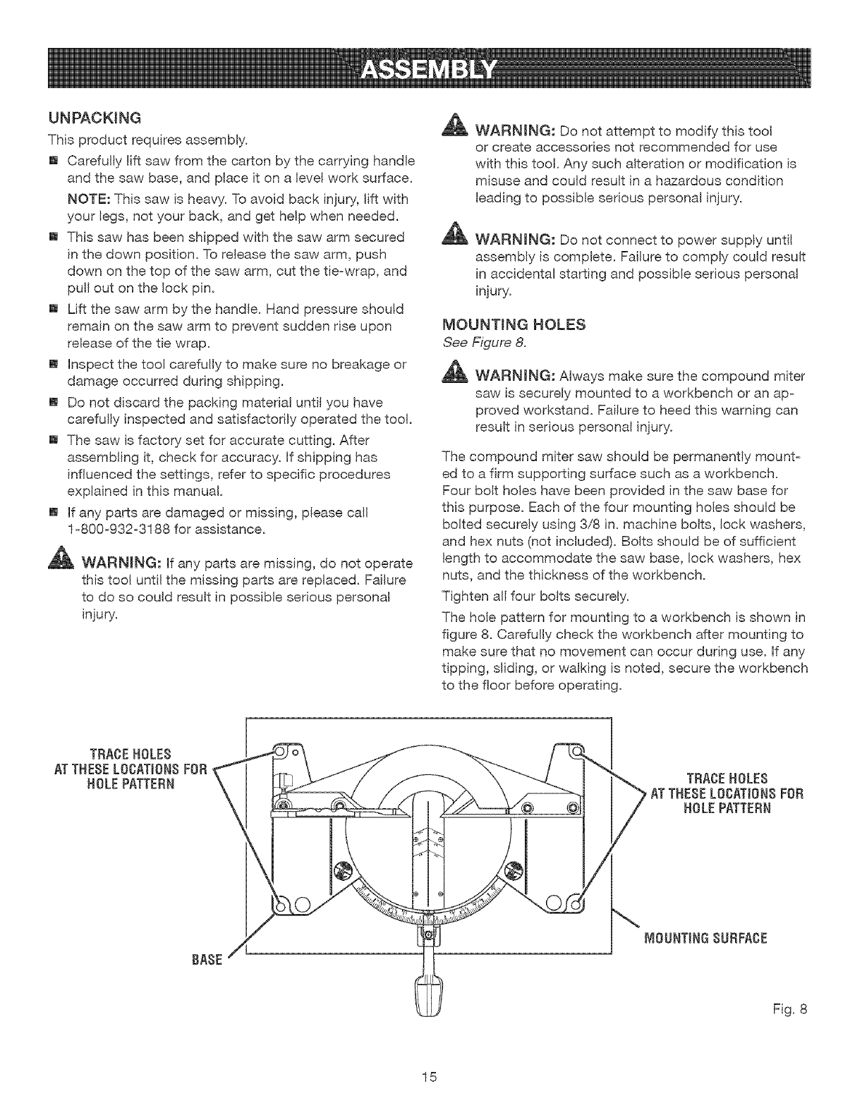
MOUNTINGHOLES
See Figure 8.
_ WARNING: Always make sure the compound miter
saw is securely mounted to a workbench or an ap-
proved workstand. Failure to heed this warning can
result in serious personal injury.
The compound miter saw should be permanently mount-
ed to a firm supporting surface such as a workbench.
Four bolt holes have been provided in the saw base for
this purpose. Each of the four mounting holes should be
bolted securely using 3/8 in. machine bolts, lock washers,
and hex nuts (not included). Bolts should be of sufficient
length to accommodate the saw base, lock washers, hex
nuts, and the thickness of the workbench.
Tighten all four bolts securely.
The hole pattern for mounting to a workbench is shown in
figure 8. Carefully check the workbench after mounting to
make sure that no movement can occur during use. If any
tipping, sliding, or walking is noted, secure the workbench
to the floor before operating.
TRACEHOLES
ATTHESELOCATIONSFOR
HOLEPATTERN TRACEHOLES
ATTHESELOCATIONSFOR
HOLEPATTERN
BASE
[VIOUNTINGSURFACE
Fig. 8
15
Asmentionedpreviously,thesawhasbeenfactory
assembledandadjusted.Themiterlockhandle,dust
guide,andbladearetheonlypartsthathaveto be
installed.
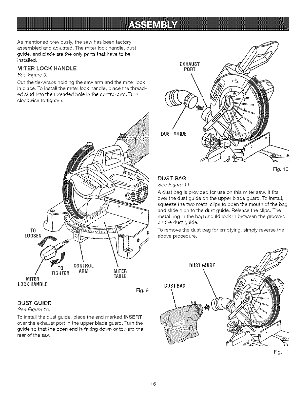
MITERLOCK HANDLE
See Figure 9.
Cut the tie-wraps holding the saw arm and the miter lock
in place. To install the miter lock handle, place the thread-
ed stud into the threaded hole in the control arm. Turn
clockwise to tighten.
EXHAUST
PORT
DUST GUIDE
TO
LOOSEN
MITER
LOCK HANDLE
MITER
TABLE
Fig. 9
DUST GUIDE
See Figure 10.
To install the dust guide, place the end marked INSERT
over the exhaust port in the upper blade guard. Turn the
guide so that the open end is facing down or toward the
rear of the saw.
Fig. 10
DUST BAG
See Figure 11.
A dust bag is provided for use on this miter saw. It fits
over the dust guide on the upper blade guard. To install,
squeeze the two metal clips to open the mouth of the bag
and slide it on to the dust guide. Release the clips. The
metal ring in the bag should lock in between the grooves
on the dust guide.
To remove the dust bag for emptying, simply reverse the
above procedure.
DUSTGUIDE
DUST BAG
Fig. 11
16
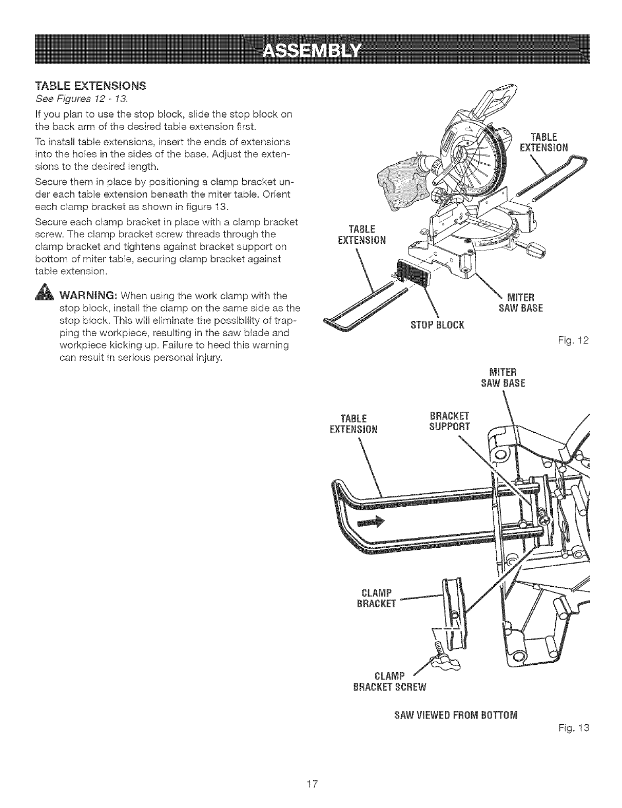
TABLEEXTENSIONS
See Figures 12- 13.
Hfyou p}an to use the stop block, slide the stop block on
the back arm of the desired tame extension first.
To install table extensions, insert the ends of extensions
into the holes in the sides of the base. Adjust the exten-
sions to the desired length.
Secure them in place by positioning a clamp bracket un-
der each table extension beneath the miter table. Orient
each clamp bracket as shown in figure 13.
Secure each clamp bracket in place with a clamp bracket
screw. The clamp bracket screw threads through the
clamp bracket and tightens against bracket support on
bottom of miter table, securing clamp bracket against
table extension.
_ WAF{NING, When using the work clamp with the
stop block, install the clamp on the same side as the
stop block. This wilt eliminate the possibility of trap-
ping the workpiece, resulting in the saw blade and
workpiece kicking up. Failure to heed this warning
can result in serious personal injury.
TABLE
EXTENSION
TABLE
EXTENSION
MtTER
SAWBASE
Fig. 12
MITER
8AWBASE
TABLE
EXTENSION
BRACKET
SUPPORT
CLAMP
BRACKET
SAWVIEWEDFROMBOTTOM
Fig. 13
17
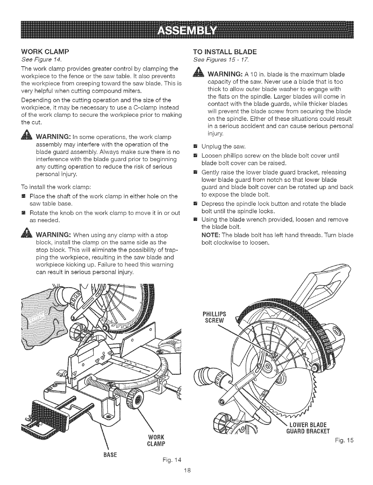
WORKCLAMP
See Figure 14.
The work clamp provides greater control by clamping the
workpiece to the fence or the saw table, ff also prevents
the workpiece from creeping toward the saw blade. This is
very helpful when cutting compound miters.
Depending on the cutting operation and the size of the
workpiece, it may be necessary to use a C-clamp instead
of the work clamp to secure the workpiece prior to making
the cut.
_ WARNING: Hnsome operations, the work clamp
assembly may interfere with the operation of the
blade guard assembly. Always make sure there is no
interference with the blade guard prior to beginning
any cutting operation to reduce the risk of serious
personal injury.
To install the work clamp:
[] Place the shaft of the work clamp in either hole on the
saw table base.
[] Rotate the knob on the work clamp to move it in or out
as needed.
_b, WARNING: When using any clamp with a stop
block, install the clamp on the same side as the
stop block. This wil! eliminate the possibility of trap-
ping the workpiece, resulting in the saw blade and
workpiece kicking up. Failure to heed this warning
can result in serious personal injury.
BASE
WORK
CLAMP
Fig. 14
TO mNSTALL BLADE
See Figures 15- 1Z
,_k WARNING: A 10 in. blade is the maximum blade
capacity of the saw. Never use a blade that is too
thick to allow outer blade washer to engage with
the fiats on the spindle. Larger blades will come in
contact with the blade guards, while thicker blades
wil! prevent the blade screw from securing the blade
on the spindle. Either of these situations could result
in a serious accident and can cause serious personal
injury.
[] Unplug the saw.
[] Loosen phillips screw on the blade bolt cover unti!
blade bolt cover can be raised.
[] Gently raise the lower blade guard bracket, releasing
lower blade guard from notch so that lower blade
guard and blade bolt cover can be rotated up and back
to expose the blade bolt.
[] Depress the spindle lock button and rotate the blade
bolt until the spindle locks.
[] Using the blade wrench provided, loosen and remove
the blade bolt.
NOTE: The blade bolt has left hand threads. Turn blade
bolt clockwise to loosen.
LOWERBLADE
GUARD BRAGKET
Fig. 15
18
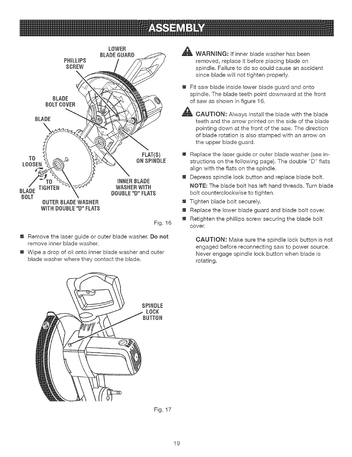
PH&LIPS
SOREW
LOWER
BLADEGUARD
BLADE
BOLTOOVER
BLADE
TO
LOOSEN
FLAT(S)
ON SPINDLE
TIGHTEN
BLADE
BOLT OUTER BLADE WASHER
WITH DOUBLE "D"FLATS
Fig. 16
[] Remove the laser guide or outer blade washer. Do not
remove inner blade washer.
[] Wipe a drop of oil onto inner blade washer and outer
blade washer where they contact the blade.
'_1I_ WARNING: Hfinner blade washer has been
removed, replace it before placing blade on
spindle. Failure to do so could cause an accident
since blade wil! not tighten properly.
[] Fit saw blade inside lower blade guard and onto
spindle. The blade teeth point downward at the front
of saw as shown in figure 16.
,_ CAUTION: Always install the blade with the blade
teeth and the arrow printed on the side of the blade
pointing down at the front of the saw. The direction
of blade rotation is also stamped with an arrow on
the upper blade guard.
[] Replace the laser guide or outer blade washer (see in-
structions on the following page). The double "D" flats
align with the flats on the spindle.
[] Depress spindle lock button and replace blade bolt.
NOTE: The blade bolt has left hand threads. Turn blade
bolt counterclockwise to tighten.
[] Tighten blade bolt securely.
[] Replace the lower blade guard and blade bolt cover.
[] Retighten the phillips screw securing the blade bolt
cover.
CAUTION: Make sure the spindle lock button is not
engaged before reconnecting saw to power source.
Never engage spindle lock button when blade is
rotating.
SPINDLE
LOOK
Fig. 17
19
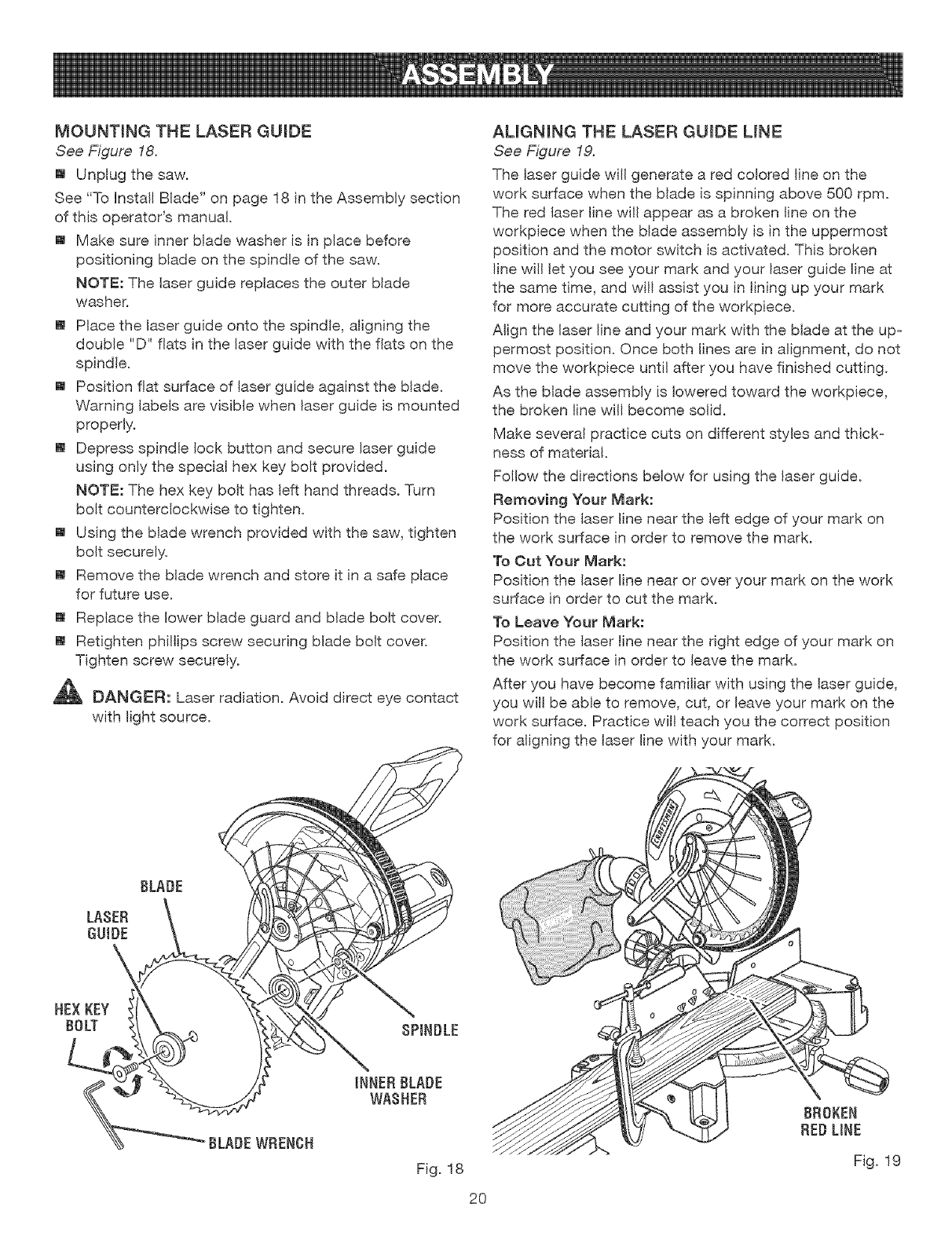
MOUNTINGTHELASER GUIDE
See Figure 18.
[] Unplug the saw.
See "To hsta!l Blade" on page 18 in the Assembly section
of this operator's manual.
[] Make sure inner blade washer is in place before
positioning blade on the spindle of the saw.
NOTE: The laser guide replaces the outer blade
washer.
[] Place the laser guide onto the spindle, aligning the
double "D" fiats in the laser guide with the flats on the
spindle.
[] Position flat surface of laser guide against the blade.
Warning labels are visible when laser guide is mounted
properly.
[] Depress spindle lock button and secure laser guide
using only the special hex key bolt provided.
NOTE: The hex key bolt has left hand threads. Turn
bolt counterclockwise to tighten.
[] Using the blade wrench provided with the saw, tighten
bolt securely.
[] Remove the blade wrench and store it in a safe place
for future use.
[] Replace the lower blade guard and blade bolt cover.
[] Retighten phillips screw securing blade bolt cover.
Tighten screw securely.
_, DANGER: Laser radiation. Avoid direct eye contact
with light source.
ALIGNING THE LASER GUIDE LINE
See Figure 19.
The laser guide wil! generate a red colored line on the
work surface when the blade is spinning above 500 rpm.
The red laser line will appear as a broken line on the
workpiece when the blade assembly is in the uppermost
position and the motor switch is activated. This broken
line will let you see your mark and your laser guide line at
the same time, and wil! assist you in lining up your mark
for more accurate cutting of the workpiece.
Align the laser line and your mark with the blade at the up-
permost position. Once both lines are in alignment, do not
move the workpiece until after you have finished cutting.
As the blade assembly is lowered toward the workpiece,
the broken line will become solid.
Make several practice cuts on different styles and thick-
hess of material.
Follow the directions below for using the laser guide.
Removing Your Mark:
Position the laser line near the left edge of your mark on
the work surface in order to remove the mark.
To Out Your Mark:
Position the laser line near or over your mark on the work
surface in order to cut the mark.
To Leave Your Mark:
Position the laser line near the right edge of your mark on
the work surface in order to leave the mark.
After you have become familiar with using the laser guide,
you will be able to remove, cut, or leave your mark on the
work surface. Practice will teach you the correct position
for aligning the laser line with your mark.
BLADE
LASER
GUIDE
NEX KEY
BOLT SPINDLE
INNERBLADE
WASHER
Fig. 18
2O
BROKEN
REDLINE
Fig. 19
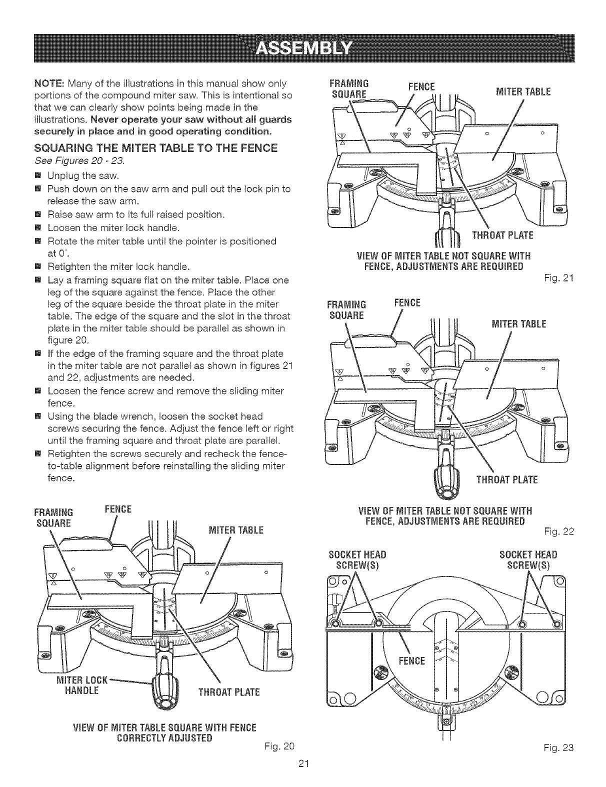
NOTE:Manyoftheillustrationsinthismanua!showonty
portionsofthecompoundmitersaw.Thisisintentionalso
thatwecanclearlyshowpointsbeingmadeinthe
illustrations.Neveroperateyoursawwithoutall guards
securelyin place and in good operating condition.
SQUARING THE MITER TABLE TO THE FENCE
See Figures 20 -23.
[] Unplug the saw.
[] Push down on the saw arm and pull out the lock pin to
release the saw arm.
[] Raise saw arm to its full raised position.
[] Loosen the miter lock handle.
[] Rotate the miter table until the pointer is positioned
at 0.
[] Retighten the miter lock handle.
[] Lay a framing square flat on the miter table. Place one
leg of the square against the fence. Place the other
leg of the square beside the throat plate in the miter
table. The edge of the square and the slot in the throat
plate in the miter table should be parallel as shown in
figure 20.
[] If the edge of the framing square and the throat plate
in the miter table are not parallel as shown in figures 21
and 22, adjustments are needed.
[] Loosen the fence screw and remove the sliding miter
fence.
[] Using the blade wrench, loosen the socket head
screws securing the fence. Adjust the fence left or right
untiI the framing square and throat plate are paralie!.
[] Retighten the screws securely and recheck the fence-
to-table alignment before reinstalling the sliding miter
fence.
FRAMING
SQUARE FENCE
THROATPLATE
VtEW OFMITERTABLENOTSQUAREWITH
FENCE,ADJUSTMENTSAREREQUtRED
Fig. 21
FRAMING
SQUARE
FENCE
MITERTABLE
THROATPLATE
FENCE
MITERTABLE
VtEWOF tVitTERTABLENOTSQUAREWiTH
FENCE,ADJUSTMENTSARE REQUtRED Fig. 22
SOCKETHEAD SOCKETHEAD
SCREW(S) SCREW(S)
MITER
NANDLE THROATPLATE
VIEWOF MITERTABLESQUAREWITH FENCE
CORRECTLYADJUSTED Fig. 20
21
Fig. 23
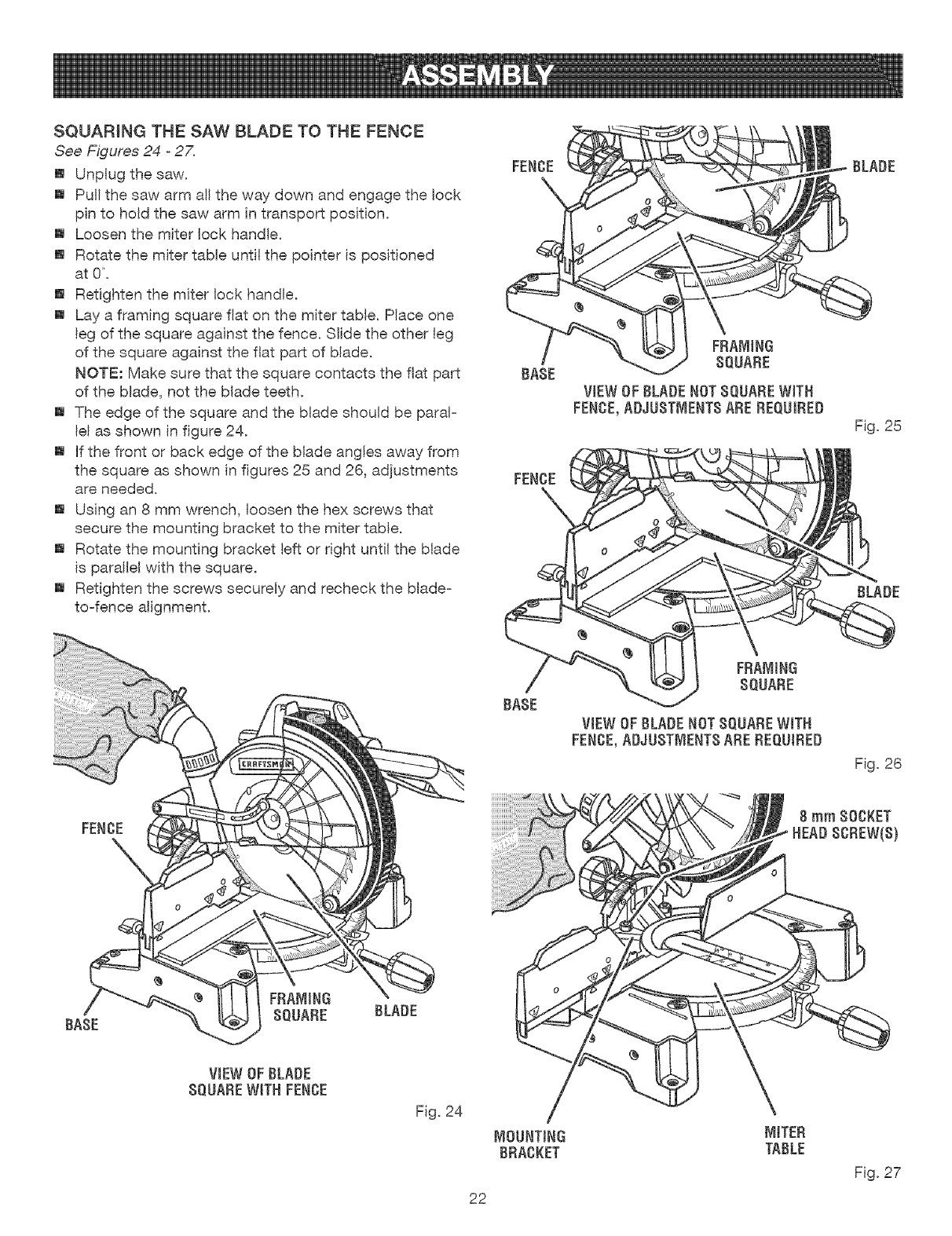
SQUARINGTHESAWBLADETOTHE FENCE
See Figures 24 -27.
[] Unp(ug the saw.
[] Pul( the saw arm all the way down and engage the lock
p(n to hold the saw arm (n transport pos(tion.
[] Loosen the miter (ock handle.
[] Rotate the miter tame unt(( the po(nter is pos(tioned
at O.
[] Retighten the miter (ock handle.
[] Lay a framing square flat on the miter table. P(ace one
(eg of the square against the fence. S(ide the other (eg
of the square against the flat part of b(ade.
NOTE: Make sure that the square contacts the flat part
of the blade, not the blade teeth.
[] The edge of the square and the blade shou(d be paraF
(el as shown in figure 24.
[] (f the front or back edge of the blade angles away from
the square as shown in figures 25 and 26, adjustments
are needed.
[] Using an 8 mm wrench, loosen the hex screws that
secure the mounting bracket to the miter table.
[] Rotate the mounting bracket (eft or right unti! the Made
is paraHe( with the square.
[] Retighten the screws securely and recheck the blade-
to-fence a(ignment.
FENCE
BLADE
FENCE
BASE
BASE
FRAM(NG
SQUARE
V(EWOFBLADENOTSQUAREW(TH
FENCE,ADJUSTMENTSARE REQUIRED
VIEWOF CLADENOTSQUAREW(TH
FENCE,ADJUSTMENTSAREREQUIRED
BLADE
Fig. 25
BLADE
Fig. 26
8 mm SOCKET
, HEADSCREW(S)
V(EWOF BLADE
SQUAREW(TN FENCE
F(g. 24
22
[V](TER
TABLE
F(g. 27
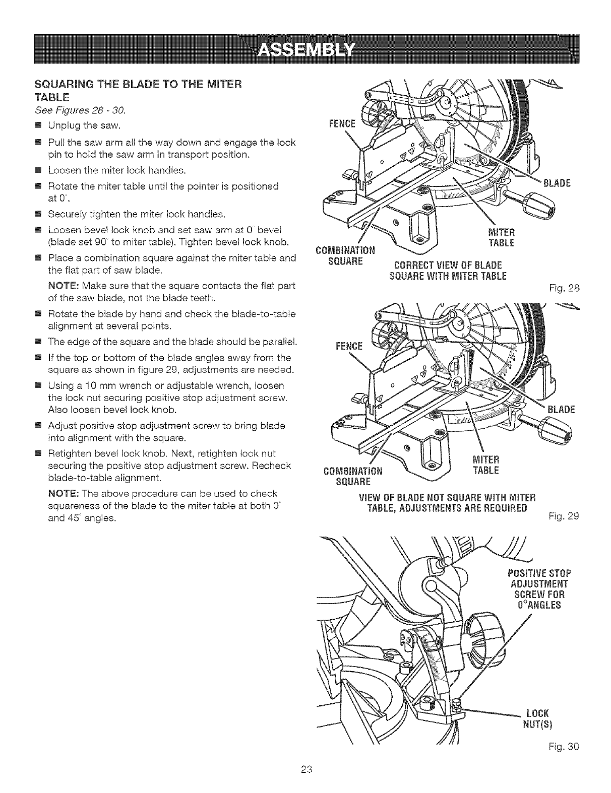
SQUARINGTHE BLADETO THEMITER
TABLE
See Figures 28 -30.
[] Unplug the saw.
[] Pul! the saw arm al! the way down and engage the lock
pin to hold the saw arm in transport position.
[] Loosen the miter lock handles.
[] Rotate the miter table until the pointer is positioned
at 0.
[] Securely tighten the miter lock handles.
[] Loosen bevel lock knob and set saw arm at 0 bevel
(blade set 90 to miter table). Tighten bevel !ock knob.
[] Place a combination square against the miter table and
the flat part of saw blade.
NOTE: Make sure that the square contacts the flat part
of the saw blade, not the blade teeth.
[] Rotate the blade by hand and check the blade-to-table
alignment at several points.
[] The edge of the square and the blade should be parallel.
[] If the top or bottom of the blade angles away from the
square as shown in figure 29, adjustments are needed.
[] Using a !0 mm wrench or adjustable wrench, loosen
the lock nut securing positive stop adjustment screw.
Also loosen bevel lock knob.
[] Adjust positive stop adjustment screw to bring blade
into alignment with the square.
[] Retighten bevel lock knob. Next, retighten lock nut
securing the positive stop adjustment screw. Recheck
blade-to-table alignment.
NOTE: The above procedure can be used to check
squareness of the blade to the miter table at both 0
and 45 angles.
FENCE
MITER
TABLE
[VIITER
CO_,_BINATION TABLE
SQUARE
VIEW OF BLADE NOT SQUARE WITH MITER
TABLE,ADJUSTMENTS ARE REQUIRED
BLADE
Fig. 29
POSITIVESTOP
ADJUSTMENT
SCREW FOR
O°ANGLEB
LOCK
NUT(S)
Fig. 30
23
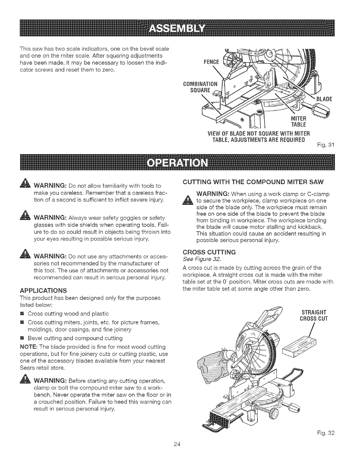
Thissawhastwoscaleindicators, one on the bevel scale
and one on the miter scale. After squaring adjustments
have been made, it may be necessary to loosen the indi=
cater screws and reset them to zero.
_ WARNING: Do not allow familiarity with tools to
make you careless. Remember that a careless frac=
tion of a second is sufficient to inflict severe injury.
_ WARNING: Always wear safety goggles or safety
glasses with side shields when operating tools. Fai!=
ure to do so could result in objects being thrown into
your eyes resulting in possible serious injury.
_ WARNING: Do not use any attachments or acces=
sories not recommended by the manufacturer of
this tool. The use of attachments or accessories not
recommended can result in serious personal injury.
APPUCATIONS
This product has been designed only for the purposes
listed below:
[] Cross cutting wood and plastic
[] Cross cutting miters, joints, etc. for picture frames,
moldings, door casings, and fine joinery
[] Bevel cutting and compound cutting
NOTE: The blade provided is fine for most wood cutting
operations, but for fine joinery cuts or cutting plastic, use
one of the accessory blades available from your nearest
Sears retail store.
_ WARNING: Before starting any cutting operation,
clamp or bolt the compound miter saw to a work=
bench. Never operate the miter saw on the floor or in
a crouched position. Failure to heed this warning can
result in serious personal injury.
CUTTING WiTH THE COMPOUND MITER SAW
WARNING: When using a work clamp or C=clamp
_to secure the workpiece, clamp workpiece on one
side of the blade only. The workpiece must remain
free on one side of the blade to prevent the blade
from binding in workpiece. The workpiece binding
the blade wil! cause motor stalling and kickback.
This situation could cause an accident resulting in
possible serious personal injury.
CROSS CUTTING
See Figure 32.
A cross cut is made by cutting across the grain of the
workpiece. A straight cross cut is made with the miter
table set at the 0 position. Miter cross cuts are made with
the miter table set at some angle other than zero.
STRAIGHT
CROSSCUT
24
Fig. 32
TO MITER CUT
[] Pull out the lock pin and lift saw arm to its full height.
[] Loosen the miter lock handles.
[] Rotate the saw table until the pointer aligns with the
desired angle on the miter scale.
[] Reighten the miter lock handles securely.
_I_ WARNING: To avoid serious personal injury, always
tighten the miter lock handle securely before making
a cut. Failure to do so could result in movement of
the control arm or miter table while making a cut.
[] Place the workpiece flat on the miter table with one edge
securely against the fence. If the board is warped, place
the convex side against the fence. If the concave edge
of a board is placed against the fence, the board could
collapse on the blade at the end of the cut, jamming the
blade.
[] When cutting long pieces of lumber or molding, support
the opposite end of the stock with a roller stand or with
a work surface leve! with the saw table. See Figure 37.
[] Align cutting line on the workpiece with the edge of
blade.
[] Grasp the stock firmly with one hand and secure
it against the fence or use the optional work clamp or a
C-clamp to secure the workpiece.
_1_ WARNING: To avoid serious personal injury, keep
hands outside the no hands zone; at least 3 in. from
blade. Never perform any cutting operation freehand
(without holding workpiece against the fence). The
blade could grab the workpiece if it slips or twists.
[] Before turning on the saw, perform a dry run of the cutting
operation just to make sure that no problems wil! occur
when the cut is made.
[] Grasp the saw handle firmly then squeeze the switch
trigger. Allow several seconds for the blade to reach
maximum speed.
[] Slowly lower the blade into and through the workpiece.
[] Release the switch trigger and allow the blade to stop
rotating before raising the blade out of workpiece. Wait
until the electric brake stops blade from turning before
removing the workpiece from the miter table.
TO BEVEL CUT
See Figures 33 -34.
A bevel cut is made by cutting across the grain of the
workpiece with the blade angled to the workpiece. A
straight bevel cut is made with the miter table set at the
zero degree position and the blade set at an angle
between 0 and 45.
[] Pull out the lock pin and lift saw arm to its full height.
[] Loosen the miter lock handles.
[] Rotate the saw table unti! the pointer aligns with zero
on the miter scale.
[] Retighten the miter lock handles securely.
_I_ WARNING: To avoid serious personal injury, always
tighten the miter lock handle securely before making
a cut. Failure to do so could result in movement of
the control arm or miter table while making a cut.
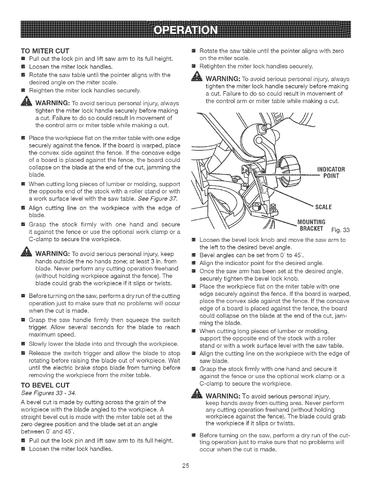
SCALE
MOUNTING
BRACKET Fig. 33
[] Loosen the bevel lock knob and move the saw arm to
the left to the desired bevel angle.
[] Bevel angles can be set from 0 to 45.
[] Align the indicator point for the desired angle.
[] Once the saw arm has been set at the desired angle,
securely tighten the bevel lock knob.
[] Place the workpiece flat on the miter table with one
edge securely against the fence. If the board is warped,
place the convex side against the fence. If the concave
edge of a board is placed against the fence, the board
could collapse on the blade at the end of the cut, jam-
ming the blade.
[] When cutting long pieces of lumber or molding,
support the opposite end of the stock with a roller
stand or with a work surface level with the saw table.
[] Align the cutting line on the workpiece with the edge of
saw blade.
[] Grasp the stock firmly with one hand and secure it
against the fence or use the optional work clamp or a
C-clamp to secure the workpiece.
,_ WARMNG: To avoid serious personal injury,
keep hands away from cutting area. Never perform
any cutting operation freehand (without holding
workpiece against the fence). The blade could grab
the workpiece if it slips or twists.
[] Before turning on the saw, perform a dry run of the cut-
ting operation just to make sure that no problems wil!
occur when the cut is made.
25

[] Graspthesawhandlefirmlythensqueezetheswitch
trigger.Altowseveralsecondsforthebladeto reach
maximumspeed.
[] Slowlylowerthebladeintoandthroughtheworkpiece.
[] Releasetheswitchtriggerandallowthesawbladeto
stoprotatingbeforeraisingthebladeoutofworkpiece.
Waituntiltheelectricbrakestopsbladefromturning
beforeremovingtheworkpiecefrommitertable.
BEVEL CUT
TO COMPOUND MITER CUT
A compound miter cut is a cut made using a miter angle
and a bevel angle at the same time. This type of cut is
used to make picture frames, cut molding, make boxes
with sloping sides, and for certain roof framing cuts.
To make this type of cut the control arm on the miter table
must be rotated to the correct angle and the saw arm
must be tilted to the correct beve! angle. Care should
always be taken when making compound miter setups
due to the interaction of the two angle settings.
Adjustments of miter and bevel settings are interde-
pendent with one another. Each time you adjust the miter
setting you change the effect of the bevel setting. Also,
each time you adjust the bevel setting you change the
effect of the miter setting.
It may take several settings to obtain the desired cut. The
first angle setting should be checked after setting the
second angle, since adjusting the second angle affects
the first.
Once the two correct settings for a particular cut have
been obtained, always make a test cut in scrap material
before making a finish cut in good material.
TO MAKE A COMPOUND CUT
[] Pull out the lock pin and lift saw arm to its full height.
[] Loosen the miter lock handles.
[] Rotate the saw table until the pointer aligns with the
desired angle on the miter scale.
[] Retighten the miter lock handles securely.
,_ WARNING: To avoid serious personal injury, always
tighten the miter lock handle securely before making
a cut. Failure to do so could result in movement of
the control arm or miter table while making a cut.
[] Loosen the bevel lock knob and move the saw arm to
the left to the desired bevel angle.
[] Bevel angles can be set from 0° to 45°.
[] Once the saw arm has been set at the desired angle,
securely tighten the bevel lock knob.
[] Recheck miter angle setting. Make a test cut in scrap
material.
[] Place the workpiece flat on the miter table with one
edge securely against the fence. If the board is warped,
place the convex side against the fence. If the concave
edge of a board is placed against the fence, the board
could collapse on the blade at the end of the cut, jam-
ming the blade.
[] When cutting long pieces of lumber or molding, sup-
port the opposite end of the stock with a roller stand or
with a work surface level with the saw table.
[] Align the cutting line on the workpiece with the edge of
saw blade.
[] Grasp the stock firmly with one hand and secure it
against the fence or use the optional work clamp or a
C-clamp to secure the workpiece when possible.
NOTE: When making a 45° left miter and a bevel angle
greater than 30°, you must use a C-clamp to secure the
workpiece or move clamp to the right side of the base.
_ WARNING: To avoid serious personal injury, always
keep hands away from cutting area. Never perform
any cutting operation freehand (without holding
workpiece against the fence). The blade could grab
the workpiece if it slips or twists.
[] Before turning on the saw, perform a dry run of the cut-
ting operation just to make sure that no problems wil!
occur when the cut is made.
26
[] Grasp the saw handle firmly then squeeze the switch
trigger. Allow several seconds for the blade to reach
maximum speed.
[] Slowly lower the blade into and through the workpiece.
[] Release the switch trigger and allow the blade to stop
rotating before raising the blade out of workpiece. Wait
until the electdc brake stops blade from turning before
removing the workpiece from miter table.
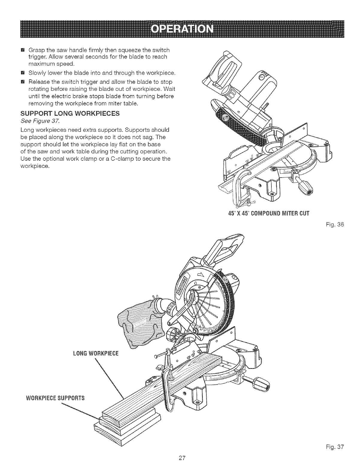
SUPPORT LONG WORKPIECES
See Figure 37,
Long workpieces need extra supports. Supports should
be placed along the workpiece so it does not sag. The
support should let the workpiece lay flat on the base
of the saw and work table during the cutting operation.
Use the optional work clamp or a C-clamp to secure the
workpiece.
45°X 45° COMPOUNDMITER CUT
Fig. 36
27
Fig. 37

CUTTINGCOMPOUNDMITERS
Toaidinmakingthecorrectsettings,thecompoundanglesettingchartbelowhasbeenprovided.Sincecompoundcuts
arethemostdifficultto accuratelymake,trialcutsshouldbemadeinscrapmaterial.Muchthoughtandplanningshould
bemadepriorto makingyourrequiredcut.
NUMBEROFSIDES--
PITCH
orswDE 4 ! 5 L 6 ! 7 8 ! 9 m 10
M- 45.00 °M- 36.00 ° M- 30.00 °M- 25.7! ° M_ 22.50 °M- 20.00 ° M- !8.00 °
0oB- 0.00 ° B- 0.00 °B- 0.00 ° B- 0.00 °B- 0.00 °B- 0.00 °B- 0.00 °
M- 44,89 ° M- 35.90 ° M- 29.91 ° M- 25.63 ° M- 22.42 ° M- 19.93 °M- 17.94 °
5° B- 3.53 °B- 2.94 ° B- 2.50 ° B- 2.!7 ° B- 1.91° B- 1.71° B- 1.54°
M- 44.56 ° M- 35.58 ° M_ 29.62 ° M- 25.37 ° M_ 22.19 °M- 19.72 ° M- 17.74 °
10° B- 7.05 °B- 5.86 ° B- 4.98 °B- 4.32 ° B- 3.8! °B- 3.40 °B- 3.08 °
M_ 44.0! ° M- 35.06 ° M_ 29.!5 ° M- 24.95 ° M_ 2! .81° M_ !9.37 ° M- !7.42 °
15° B-10.55 °B- 8.75 ° B- 7.44 ° B- 6.45 °B- 5.68 °B- 5.08 ° B- 4.59 °
M-43.22 ° M-34.32 ° M-28.48 ° M-24.35 °M-21.27 ° M- 18.88 °M- 16.98 °
20 ° B-14.00 °B-11.60 °B- 9.85 °B- 8.53 °B- 7.52 ° B- 6.72 ° B- 6.07 °
M- 42.!9 °M_ 33.36 ° M- 27.62 ° M_ 23.56 ° M_ 20.58 ° M- !8.26 °M- !6.41 °
25°B- 17.39 °B- 14.38 °B- 12.20 °B- 10.57 ° B- 9.31 ° B- 8.31 ° B- 7.50 °
30° M_ 40.89 ° M_ 32.18 ° M- 26.57 ° M_ 22.64 °M_ 19.73 °M_ !7.50 ° M- !5.72 °
B- 20.70 °B- 17.09 ° B- 14.48 °B- 12.53 °B- 11.03 ° B- 9.85 °B- 8.89 °
M- 39.32 ° M_ 30.76 ° M- 25.3! ° M_ 21.53 °M_ 18.74 ° M- 16.60 °M_ 14.90 °
35 ° B- 23.93 ° B- 19.70 °B- 16.67 ° B- 14.41 ° B- 12.68 ° B- 11.31 ° B- 10.21 °
M- 37.45 ° M- 29.10 ° M- 23.86 ° M- 20.25 °M- 17.60 ° M- 15.58 °M- 13.98 °
40 ° B- 27.03 °B- 22.20 °B- 18.75 ° B- 16.19 ° B- 14.24 ° B- 12.70 °B- 1!.46 °
M- 35.26 ° M- 27.!9 ° M- 22.2! ° M- 18.80 ° M- 16.32 ° M- 14.43 °M- 12.94 °
45° B- 30.00 ° B- 24.56 ° B- 20.70 ° B- 17.87 ° B- 15.70 °B- 14.00 ° B- 12.62 °
M_32.73 ° M_25.03 °M-20.36 ° M_17.20 ° M_14.91 ° M_13.17 ° M_11.80 °
50 ° B- 32.80 °B- 26.76 ° B- 22.52 ° B- !9.4! °B- 17.05 ° B- 15.19 ° B- 13.69 °
M_ 29.84 °M_ 22.62 ° M- 18.32 ° M- !5.44 °M_ 13.36 ° M- 11.79 °M_ 10.56 °
55°B- 35.40 °B- 28.78 ° B- 24.18 ° B- 20.82 ° B- 18.27 ° B- 16.27 ° B- 14.66 °
M-26.57 ° M-!9.96 ° M-16.10 ° M-13.54 ° M-11.70 ° M-10.31 ° M- 9.23 °
60° B- 37.76 ° B- 30.60 ° B- 25.66 ° B- 22.07 ° B- 19.35 ° B- 17.23 ° B- 15.52 °
M-22.91 ° M-!7.07 ° M-13.7! ° M-11.50 ° M- 9.93 ° M- 8.74 ° M- 7.82 °
65° B- 39.86 ° B- 32.19 °B- 26.95 °B- 23.16 ° B- 20.29 ° B- 18.06 ° B-16.26 °
M_18.88 ° M_13.95 ° M-11.!7 ° M- 9.35 ° M- 8.06 ° M- 7.10 ° M- 6.34 °
70° B- 41.64 ° B- 33.53 ° B- 28.02 ° B- 24.06 ° B- 21.08 ° B- 18.75 ° B- 16.88 °
75° M-14.51 ° M-10.65 ° M- 8.50 ° M- 7.10 ° M- 6.12 ° M- 5.38 ° M- 4.81 °
B- 43.08 ° B- 34.59 ° B- 28.88 ° B- 24.78 ° B- 21.69 ° B- 19.29 ° B- 17.37°
M- 9.85 ° M- 7.19 ° M_ 5.73 ° M- 4.78 ° M- 4.11 ° M- 3.62 ° M- 3.23 °
80° B- 44.14 ° B- 35.37 ° B- 29.50 ° B- 25.30 ° B- 22.14 ° B- 19.68 ° B- 17.72 °
M- 4.98 ° M- 3.62 ° M_ 2.88 ° M- 2.40 ° M-2.07 ° M-1.82 ° M_ 1.62 °
85° B- 44.78 ° B- 35.84 ° B- 29.87 ° B- 25.61 ° B- 22.41 ° B- 19.92 ° B- 17.93°
M- 0.00 ° M- 0.00 ° M- 0.00 ° M- 0.00 ° M- 0.00 ° M- 0.00 ° M- 0.00 °
90 ° B- 45.00 ° B- 36.00 ° B- 30.00 ° B- 25.71 ° B- 22.50 ° B- 20.00 ° B- 18.00 °
Each B (Bevel) and M (Miter) Setting is Given to the Closest 0.005 °.
COMPOUND-ANGLE SETTINGS FOR POPULAR STRUCTURES
28
CUTTINGCROWNMOLDING
Thecompoundmitersawdoesanexcellentjobof cut=
tingcrownmolding.Hngeneral,compoundmitersawsdo
abetterjobofcuttingcrownmoldingthananyothertool
made.
Hnordertofit properly,crownmoldingmustbecompound
miteredwithextremeaccuracy.
Thetwocontactsurfacesonapieceofcrownmolding
thatfit flatagainsttheceilingandthewallofaroomareat
anglesthat,whenaddedtogether,equalexactly90. Most
crownmoldinghasatop rearangle(thesectionthatfits
flatagainsttheceiling)of 52 andabottomrearangle(the
sectionthatfitsflatagainstthewall)of 38.
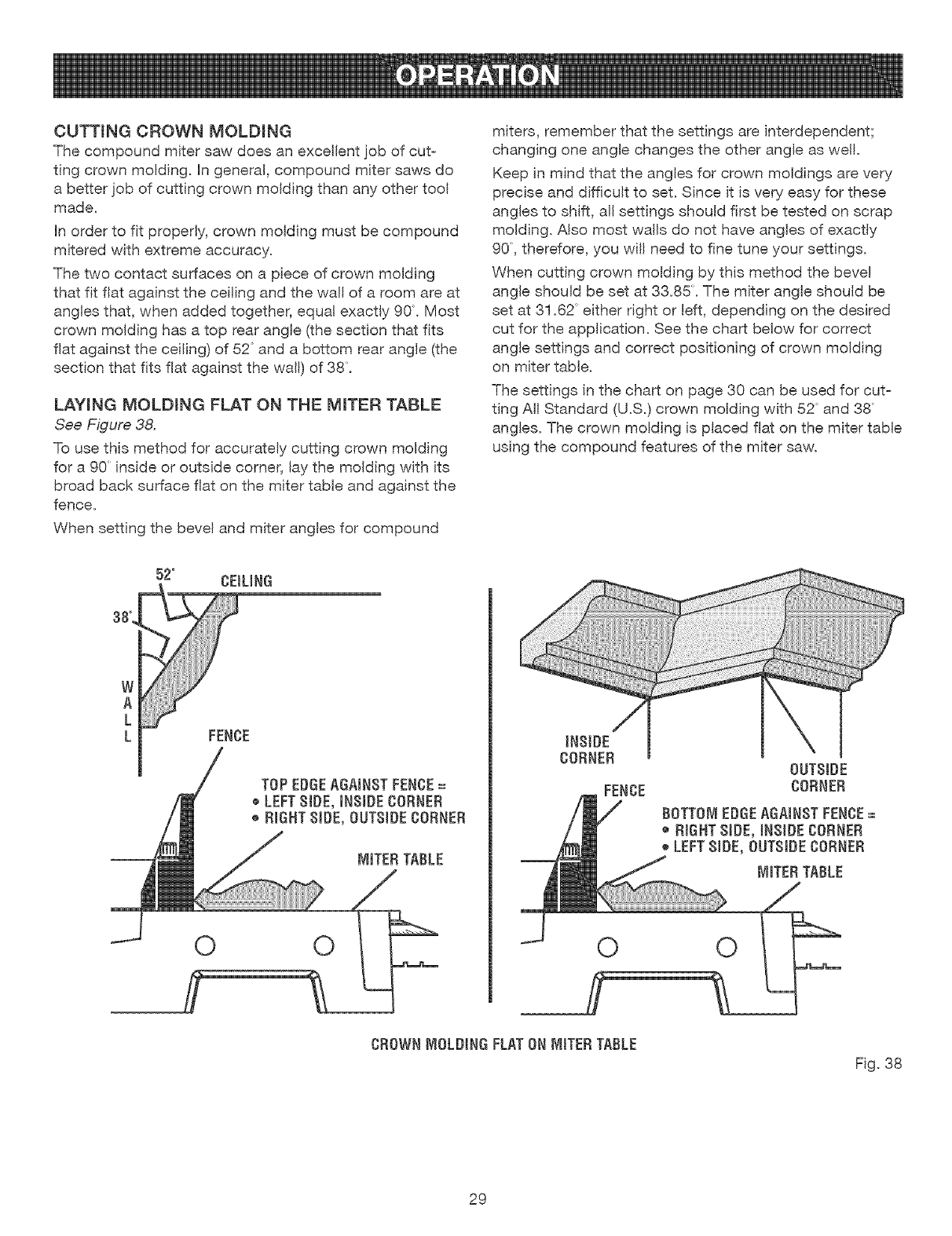
LAYINGMOLDINGFLATONTHE MITERTABLE
See Figure 38.
To use this method for accurately cutting crown molding
for a 90 inside or outside corner, lay the molding with its
broad back surface flat on the miter table and against the
fence.
When setting the bevel and miter angles for compound
miters, remember that the settings are interdependent;
changing one angle changes the other angle as well.
Keep in mind that the angles for crown moldings are very
precise and difficult to set. Since it is very easy for these
angles to shift, all settings should first be tested on scrap
molding. Also most walls do not have angles of exactly
90, therefore, you wil! need to fine tune your settings.
When cutting crown molding by this method the bevel
angle should be set at 33.85:. The miter angle should be
set at 31.62 either right or left, depending on the desired
cut for the application. See the chart below for correct
angle settings and correct positioning of crown molding
on miter table.
The settings in the chart on page 30 can be used for cut=
ting A!! Standard (U.S.) crown molding with 52 and 38
angles. The crown molding is placed flat on the miter table
using the compound features of the miter saw.
52° CEILING
A ....
k
LFENCE
TOP EDGEAGAINSTFENCE=
e LEFTSIDE, iNSIDECORNER
®RIGHT81DE,OUTSIDECORNER
0 0
CROWNWIOLDINGFLATONMITERTABLE
Fig. 38
29
BeveJ
Angle Type of Cut
Setting
Left side, inside corner
1. Top edge of molding against fence
33.85 2. Miter table set right 31.62:
3. Save left end of cut
Right side, inside corner
1. Bottom edge of molding against fence
33.85 2. Miter table set left 31.62
3. Save left end of cut
Left sWde,outside corner
1. Bottom edge of molding against fence
33.85 2. Miter table set left 31.62
3. Save right end of cut
Right side, outside corner
1. Top edge of molding against fence
33.85 2. Miter table set right 31.62
3. Save right end of cut
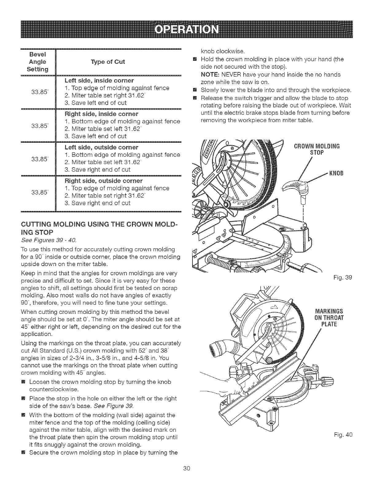
CUTTING MOLDING USING THE CROWN MOLD-
iNG STOP
See Figures 39 -40.
To use this method for accurately cutting crown molding
for a 90 inside or outside corner, place the crown molding
upside down on the miter table.
Keep in mind that the angles for crown moldings are very
precise and difficult to set. Since it is very easy for these
angles to shift, all settings should first be tested on scrap
molding. Also most wails do not have angles of exactly
90, therefore, you will need to fine tune your settings.
When cutting crown molding by this method the bevel
angle should be set at 0. The miter angle should be set at
45 either right or Idt, depending on the desired cut for the
application.
Using the markings on the throat plate, you can accurately
cut All Standard (U.S.) crown molding with 52 and 38
angles in sizes of 2-3/4 in., 3-5/8 in., and 4-5/8 in. You
cannot use the markings on the throat plate when cutting
crown molding with 45 angles.
[] Loosen the crown molding stop by turning the knob
counterclockwise.
[] Place the stop in the hole on either the left or the right
side of the saw's base. See Figure 39.
[] With the bottom of the molding (wall side) against the
miter fence and the top of the molding (ceiling side)
against the miter table, align with the desired mark on
the throat plate then spin the crown molding stop unti!
it fits snuggly against the crown molding.
[] Secure the crown molding stop in place by turning the
knob clockwise.
[] Hold the crown molding in place with your hand (the
side not secured with the stop).
NOTE: NEVER have your hand inside the no hands
zone while the saw is on.
[] S!owly lower the blade into and through the workpiece.
[] Release the switch trigger and allow the blade to stop
rotating before raising the blade out of workpiece. Wait
until the electric brake stops blade from turning before
removing the workpiece from miter table.
Fig. 39
Fig. 40
3O
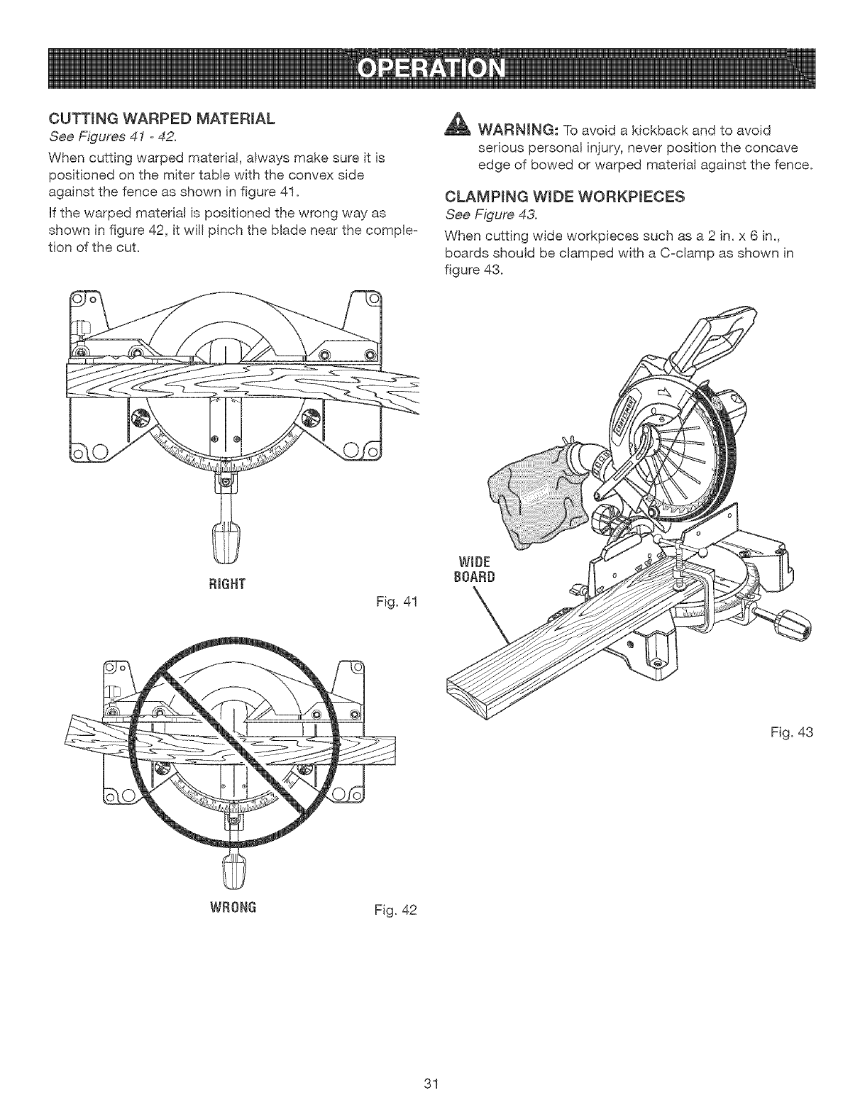
CUTTINGWARPEDMATERIAL
See Figures 41 -42.
When cutting warped material, always make sure it is
positioned on the miter table with the convex side
against the fence as shown in figure 41.
Hfthe warped material is positioned the wrong way as
shown in figure 42, it wil! pinch the blade near the comple-
tion of the cut.
_ WARNING: To avoid a kickback and to avoid
serious personal injury, never position the concave
edge of bowed or warped material against the fence.
CLAMPING WIDE WORKPIECES
See Figure 43.
When cutting wide workpieces such as a 2 in. x 6 in.,
boards should be clamped with a C-clamp as shown in
figure 43.
RIGHT
Fig. 41
Fig. 43
WRONG Fig. 42
31
_ WARNING:Beforeperforminganyadjustment,
makesurethetoolisunpluggedfromthepower
supplyandtheswitchisin the OFF position. Failure
to heed this warning could result in serious personal
injury.
The compound miter saw has been adjusted at the fac=
tory for making very accurate cuts. However, some of the
components might have moved out of alignment during
shipping. Also, over a period of time, readjustment will
probably become necessary due to wear. After unpacking
the saw, check the following adjustments before you
begin using the saw. Make any readjustments that are
necessary and periodically check the parts alignment
to make sure that the saw is cutting accurately.
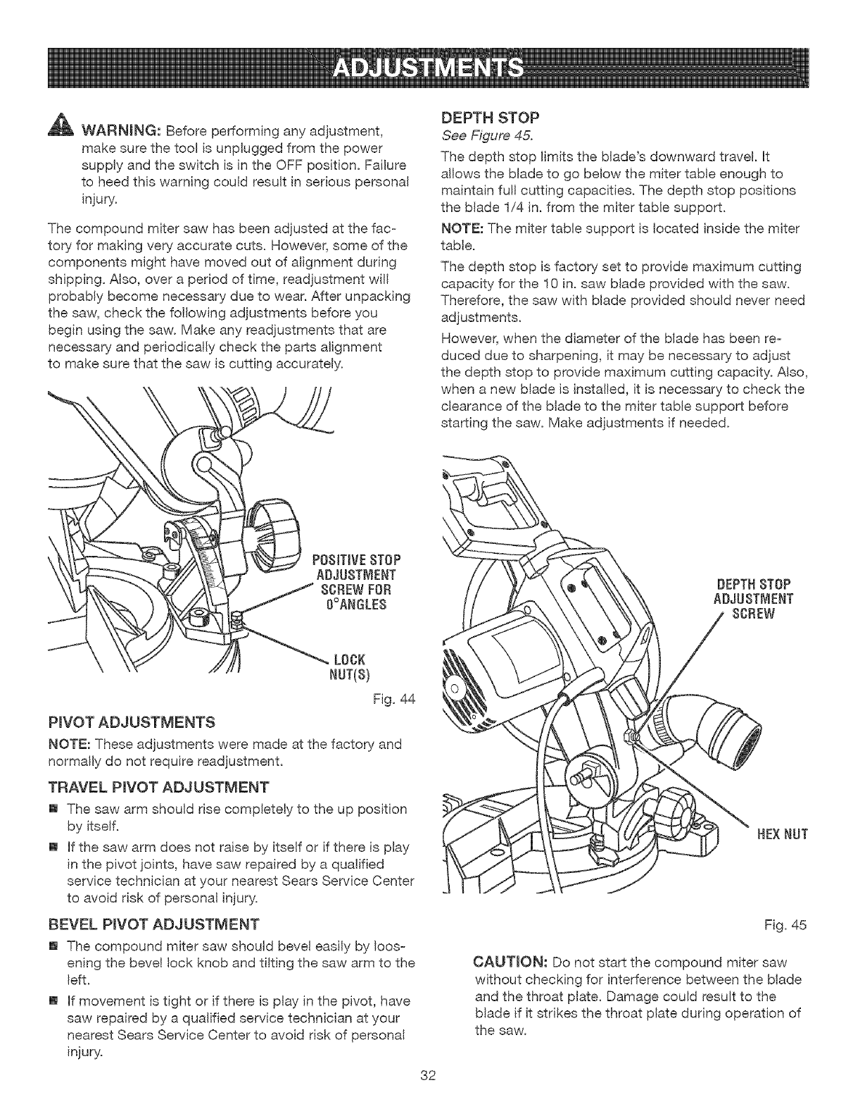
DEPTH STOP
See Figure 45.
The depth stop limits the blade's downward travel. Ht
allows the blade to go below the miter table enough to
maintain full cutting capacities. The depth stop positions
the blade 1/4 in. from the miter table support.
NOTE: The miter table support is located inside the miter
table.
The depth stop is factory set to provide maximum cutting
capacity for the 10 in. saw blade provided with the saw.
Therefore, the saw with blade provided should never need
adjustments.
However, when the diameter of the blade has been re=
duced due to sharpening, it may be necessary to adjust
the depth stop to provide maximum cutting capacity. Also,
when a new blade is installed, it is necessary to check the
clearance of the blade to the miter table support before
starting the saw. Make adjustments if needed.
POSITIVE8TOP
ADJUSTMENT
8CBEWFOB
O°ANGLE$
LOCK
NUT(8)
Fig. 44
PIVOT ADJUSTMENTS
NOTE: These adjustments were made at the factory and
normally do not require readjustment.
TRAVEL PIVOT ADJUSTMENT
[] The saw arm should rise completely to the up position
by itself.
[] If the saw arm does not raise by itself or if there is play
in the pivot joints, have saw repaired by a qualified
service technician at your nearest Sears Service Center
to avoid risk of personal injury.
BEVEL PIVOT ADJUSTMENT
[] The compound miter saw should bevel easily by loos-
ening the bevel lock knob and tilting the saw arm to the
left.
[] If movement is tight or if there is play in the pivot, have
saw repaired by a qualified service technician at your
nearest Sears Service Center to avoid risk of personal
injury.
32
HEXNUT
Fig. 45
CAUTION: Do not start the compound miter saw
without checking for interference between the blade
and the throat plate. Damage could result to the
blade if it strikes the throat plate during operation of
the saw.
DEPTHSTOPADJUSTMENTS
See Figure 45.
[] Unplug the saw.
[] To adjust the depth stop use a 10 mm wrench or
adjustable wrench and loosen the hex nut at the rear
of the miter saw arm.
[] Use a 5 mm hex key wrench to adjust the depth stop
adjustment screw. The saw blade is lowered by turning
the screw counterclockwise and raised by turning the
screw clockwise.
[] Lower the blade into the miter table. Check blade
clearance and maximum cutting distance (distance
from fence where blade enters) to front of miter table
slot.
[] Readjust if necessary.
[] Tighten the hex nut with a !0 mm wrench or adjustable
wrench.
[] To prevent the depth stop adjustment screw from
turning while tightening the hex nut, carefully hold it
with the hex key wrench while tightening the hex nut.
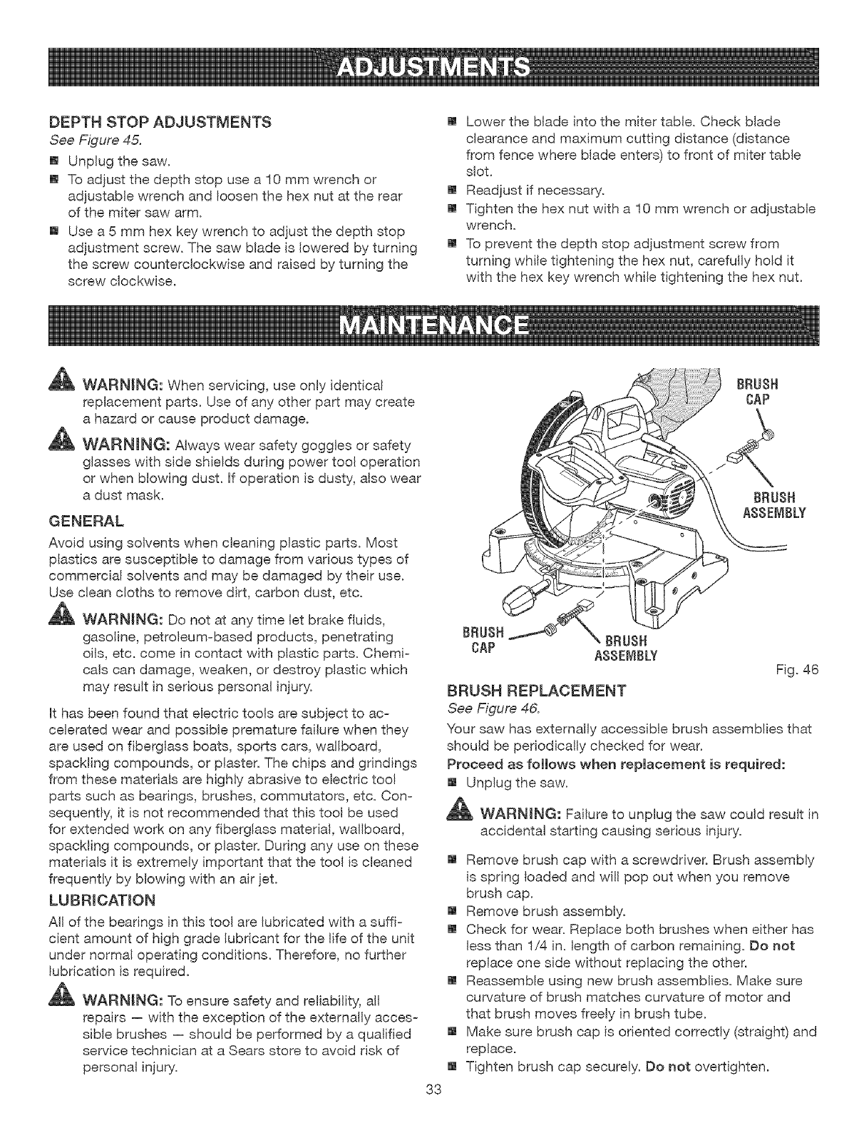
_ WARNING: When servicing, use only identical
replacement parts. Use of any other part may create
a hazard or cause product damage.
_ WARNmNG: Always wear safety goggles or safety
glasses with side shields during power tool operation
or when blowing dust. Hfoperation is dusty, also wear
a dust mask.
GENERAL
Avoid using solvents when cleaning plastic parts. Most
plastics are susceptible to damage from various types of
commercial solvents and may be damaged by their use.
Use clean cloths to remove dirt, carbon dust, etc.
_ WARNING: Do not at any time let brake fluids,
gasoline, petroleum-based products, penetrating
oils, etc. come in contact with plastic parts. Chemi-
cals can damage, weaken, or destroy plastic which
may result in serious personal injury.
It has been found that electric tools are subject to ac-
celerated wear and possible premature failure when they
are used on fiberglass boats, sports cars, wallboard,
spackling compounds, or plaster. The chips and grindings
from these materials are highly abrasive to electric tool
parts such as bearings, brushes, commutators, etc. Con-
sequently, it is not recommended that this tool be used
for extended work on any fiberglass material, wallboard,
spackling compounds, or plaster. During any use on these
materials it is extremely important that the tool is cleaned
frequently by blowing with an air jet.
LUBRICATION
All of the bearings in this tool are lubricated with a suffi-
cient amount of high grade lubricant for the life of the unit
under normal operating conditions. Therefore, no further
lubrication is required.
_ WARNING: To ensure safety and reliability, all
repairs -- with the exception of the externally acces-
sible brushes -- should be performed by a qualified
service technician at a Sears store to avoid risk of
personal injury.
Fig. 46
BRUSH REPLACEMENT
See Figure 46.
Your saw has externally accessible brush assemblies that
should be periodically checked for wear.
Proceed as follows when replacement is required:
[] Unplug the saw.
,_ WARMNG: Failure to unplug the saw could result in
accidental starting causing serious injury.
[] Remove brush cap with a screwdriver. Brush assembly
is spring loaded and wil! pop out when you remove
brush cap.
[] Remove brush assembly.
[] Check for wear. Replace both brushes when either has
less than 1/4 in. length of carbon remaining. Do not
replace one side without replacing the other.
[] Reassemble using new brush assemblies. Make sure
curvature of brush matches curvature of motor and
that brush moves freely in brush tube.
[] Make sure brush cap is oriented correctly (straight) and
replace.
[] Tighten brush cap securely. Do not overtighten.
33
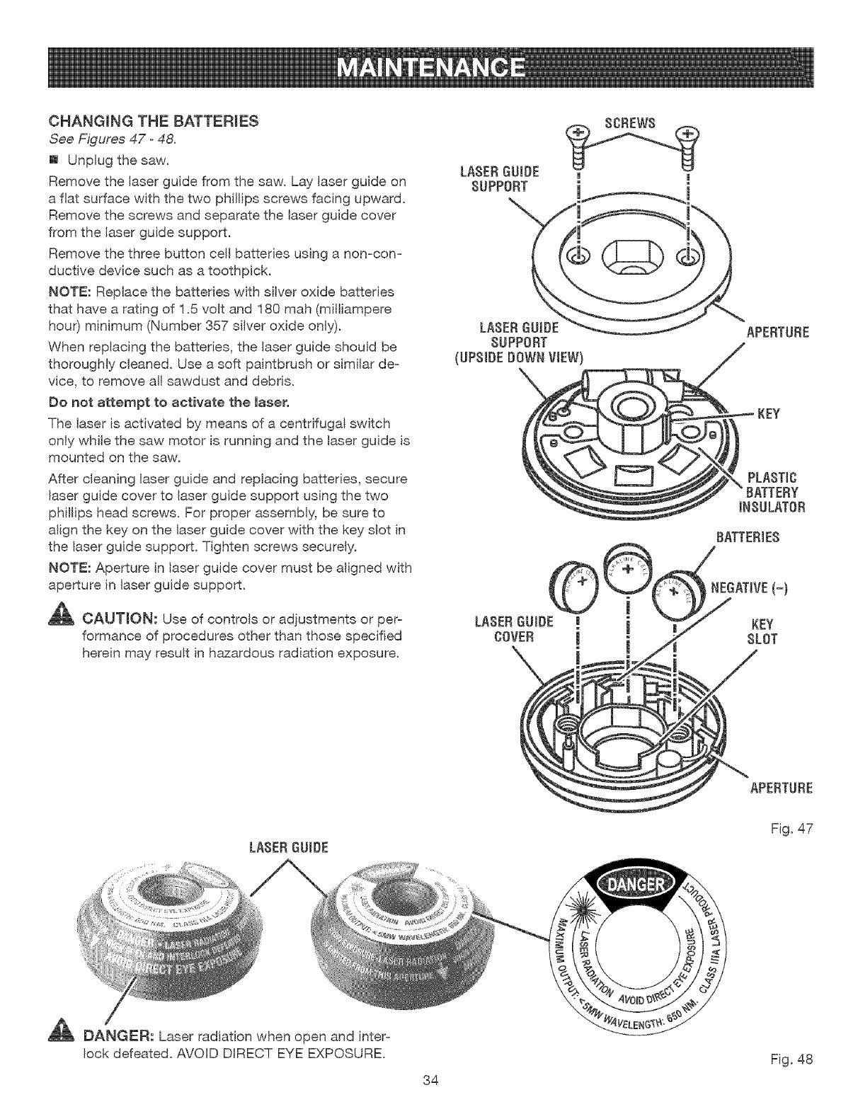
CHANGINGTHEBATTERIES
See Figures 47 -48.
[] Unplug the saw.
Remove the laser guide from the saw. Lay laser guide on
a flat surface with the two phillips screws facing upward.
Remove the screws and separate the laser guide cover
from the laser guide support.
Remove the three button cell batteries using a non-con-
ductive device such as a toothpick.
NOTE: Replace the batteries with silver oxide batteries
that have a rating of 1.5 volt and 180 mah (milliampere
hour) minimum (Number 357 silver oxide only).
When replacing the batteries, the laser guide should be
thoroughly cleaned. Use a soft paintbrush or similar de=
vice, to remove all sawdust and debris.
Do not attempt to activate the laser.
The laser is activated by means of a centrifugal switch
only while the saw motor is running and the laser guide is
mounted on the saw.
After cleaning laser guide and replacing batteries, secure
laser guide cover to laser guide support using the two
phillips head screws. For proper assembly, be sure to
align the key on the laser guide cover with the key slot in
the laser guide support. Tighten screws securely.
NOTE: Aperture in laser guide cover must be aligned with
aperture in laser guide support.
_[_ CAU'TION: Use of controls or adjustments or per-
formance of procedures other than those specified
herein may result in hazardous radiation exposure.
LASER GUIDE
SUPPORT
LASER GUIDE
SUPPORT
(UPSIDEDOWN VIEW)
LASERGUIDE i
COVER !
1 |
1l
APERTURE
_ PLASTIC
BATTERIES
NEGATIVE(-)
KEY
SLOT
APERTURE
LASER GUIDE
Fig. 47
_ DANGER: Laser radiation when open and inter-
lock defeated. AVOID DIRECT EYE EXPOSURE.
34
Fig. 48

35
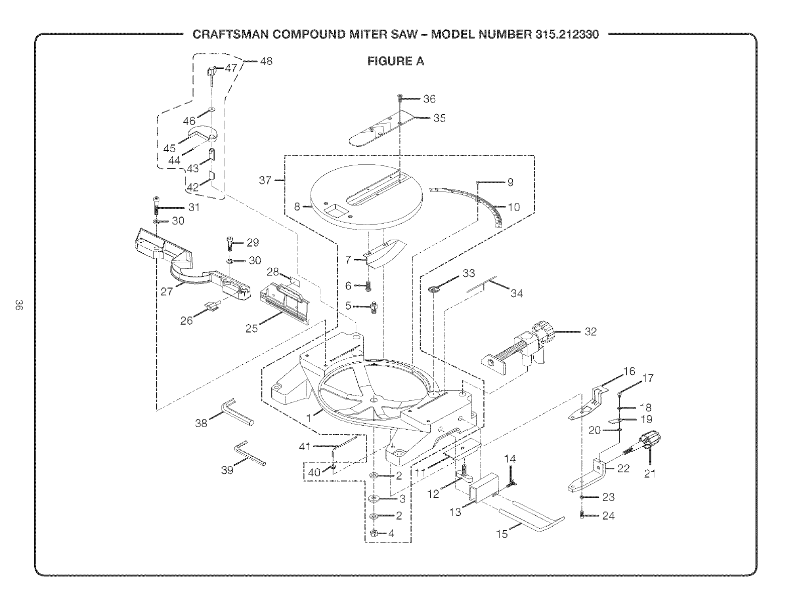
_,__' CRAFTSMAN COMPOUND MINTER SAW - MODEL NUMBER 315.212330
' i
k _
38
39
41 ......... !i
FmGURE A
36
35
32
13
15
14
21

_CRAFTSMAN COMPOUND MINTER SAW = MOOEL NUMBER 315.212330
The model number wil! be found on a plate attached to the motor housing. Always mention the model number in al! correspom 1
dence regarding your Compound Miter Saw or when ordering repair parts. J
PARTS LiST -FIGURE A
Key Part
No. Humber Description Qty.
1 513101100
2 A35031025153
3 A36131020100
4 A31703010008
5 518106300
6 A19003040093
7 511104000
8 512106000
9 A49010020056
10 511111000
11 558511100
12 555516000
13 558507200
14 558512100
15 558510200
16 518105400
17 A10003040107
18 A35030410018
19 578105102
20 A35030511158
21 511107000
22 518104200
23 A36030612157
24 A07003060257
25 511112000
Base .................................................. 1
Flat Washer (M 10) **STD851010 ........... 2
* Spring Washer (M10) **STD852010 ......... 1
Self=Locking Nut (M10) .......................... 1
Table Spindle ......................................... 1
*Screw (M4 X 9 mm Pan Hd) .................. 2
Table Hold Down ................................... 1
Table .................................................. 1
Rivet ................................................. 3
Miter Scale ............................................. 1
Clamp Bracket ....................................... 2
Wing Bolt ............................................... 2
Stop Block ............................................. 1
Wing Bolt ............................................... 1
U-type Table Extension ......................... 2
Lock Plate .............................................. 1
*Screw (M4X 10 mm Pan Bd) ................ 1
* Flat Washer (M4) **STD851004 ............. 1
Miter Hndicater ....................................... 1
Flat Washer (M5) **STD851005 ............. 1
Miter Knob ............................................. 1
Control Arm ........................................... 1
* Spring Washer (M6) **STD852006 ......... 2
*Screw (M6 X 25 ram) ............................. 2
Slide Fence ............................................ 1
Key Part
No. Humber Description Qty.
26 511103100
27 511114000
28 511113000
29 A07003080253
30 A36030814204
31 A07103080457
32 518A08130
33 588072000
34 588071004
35 511116000
36 A16003040083
37 $51100500
38 A07910810000
39 A07910610000
40 503118000
41 511115000
42 511520000
43 511519000
44 A18003040080
45 511521000
46 A35010823020
47 511522000
48 511V07010
Fence Knob ........................................... 1
Fence ..................................................... 1
Slide Fence Label .................................. 1
*Screw (M8 X 25 mm) ............................. 2
* Spring Washer (M8) **STD852008 ........ 4
*Screw (M8 X 45 mm) ............................. 2
Miter Olamp Assembly" .......................... 1
Warning Label, No-hands ...................... 2
Label, Alarm Line ................................... 2
Table Insert ............................................ 1
*Screw (M4 X 8 mm) ............................... 4
Base And Table Assembly
(Inc. Key Nes. 1 Thru 10 and 40) ........... 1
Hex Key (8 mm) ..................................... 1
Hex Key (6 mm) ..................................... 1
Key Storage ........................................... 1
Hex Key (5 mm X !!5 mm) .................... 1
Adjustable Lower Tube .......................... 1
Adjustable Upper Tube .......................... 1
*Set Screw (M4 x 8 ram) ......................... 1
Crown Molding Clamp ........................... 1
Flat Washer (MS x 23 x 2t) ..................... 1
Crown Molding Knob ............................. 1
Crown Molding Stop Assembly
(Hncludes Key Nos. 42-47) ..................... 1
*Standard Hardware Item -May Be Purchased Locally
** Available from Div 98 = Source 980.0
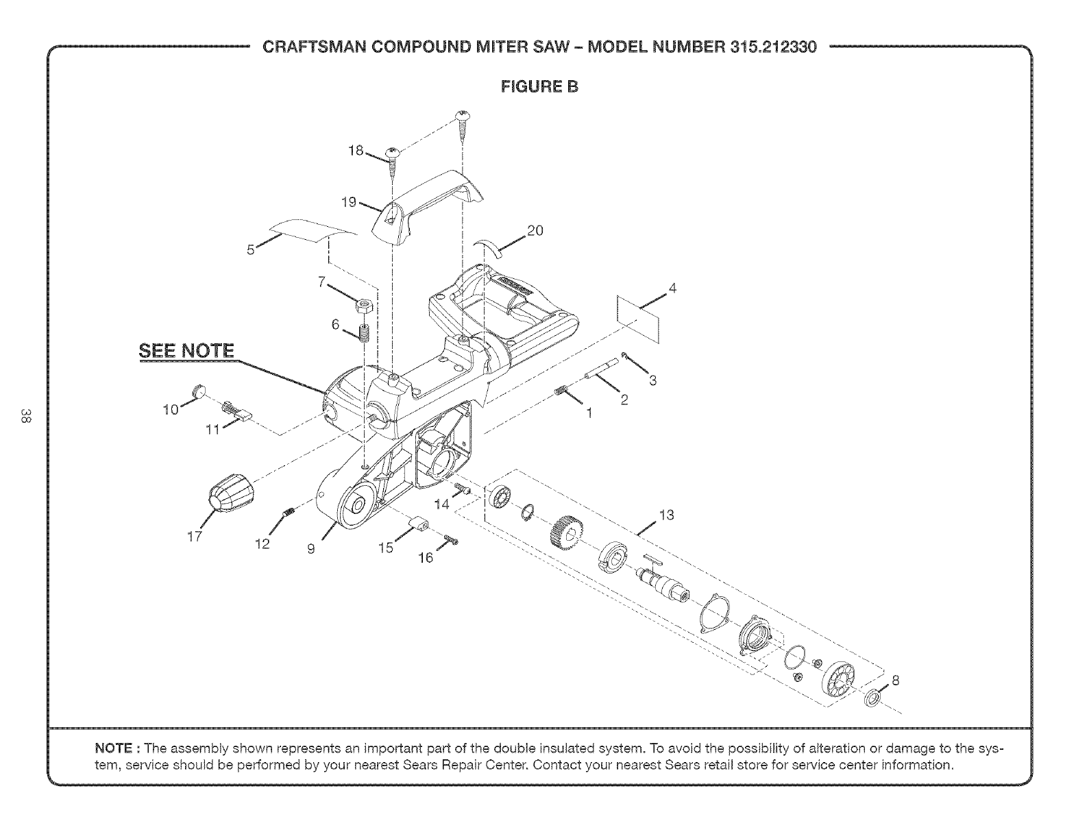
_,__' CRAFTSMAN COMPOUND MINTER SAW- MODEL NUMBER 315.212330 __
FmGURE B
SEE NOTE
1C
17 12 9 15
2O
14
16
NOTE : The assembty shown represents an important part of the double insulated system. To avoid the possibility of alteration or damage to the sys-
tem, service should be performed by your nearest Sears Repair Center. Contact your nearest Sears retail store for service center information.

CRAFTSMAN COMPOUND MITER SAW - MODEL NUMBER 315.212330
I The model number will be found attached to the motor mention the model number inall
on a plate housing. Always correspondence m
regarding your Compound Miter Saw or when ordering repair parts. J
PARTS UST -NGURE B
Key PaA
No. Humber
1 588027005
2 588026106
3 A47000040006
4 511356000
5 511353000
6 A18003100206
7 A30003010007
8 511414000
9 $51102000
10 588005105
11 588006100
12 A18003050086
13 $51!00700
14 A510001040120
15 588021203
16 A10003040207
17 511340000
18 A70003060250
19 511311000
20 511352000
Description Qty.
Compression Spring ......................................................................... 1
Arbor Lock Pin.................................................................................. 1
E-ring (E4)......................................................................................... 1
Data Plate ......................................................................................... 1
Warning Label ................................................................................... 1
* Depth Adjusting Bolt (M10 X 20 ram) ............................................... 1
Hex Nut (M10) **STD841010 ............................................................ 1
Spacer .............................................................................................. !
Complete Motor Assembly ............................................................... 1
Brush Cap ......................................................................................... 2
Brush Assembly ................................................................................ 2
* Screw (M5 X 8 mm) .......................................................................... 1
Arbor Assembly ................................................................................ 1
* Screw (M4 X 12 ram) ........................................................................ 3
Rubber Stopper ................................................................................ 1
* Screw (M4 X 20 mm) ........................................................................ 1
Twist Handle Knob ............................................................................ 1
* Screw (M6 X 25 mm Pan Hd.) .......................................................... 2
Carry Handle ..................................................................................... 1
Label, Twist Handle Warning ............................................................ 1
* Standard Hardware Item - May Be Purchased Locally
** Available from Div 98 -Source 980.0
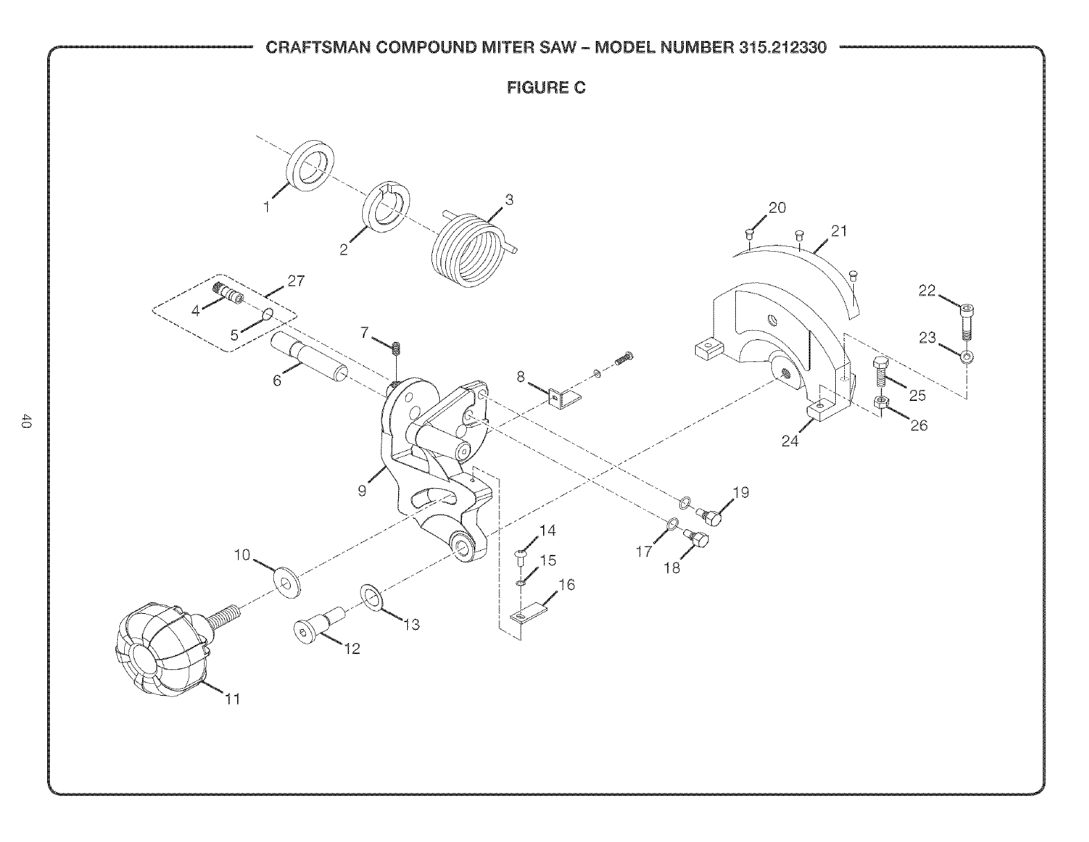
_,__' CRAFTSMAN COMPOUND MINTER SAW- MODEL NUMBER 315.212330 __
10
11
FmGURE C
3
24
21
26

CRAFTSMAN COMPOUND MINTER SAW = MODEL NUMBER 315.212330
The modeJ number wiHbe found On a plate atiaChed i0 the motor housing. Always mention the mode, number in all correspondence regarding your
ompound Miter Saw or when ordering repair parts.
Key Pa_
No. Number
1 511348000
2 511349000
3 511350000
4 511206000
5 A63000000062
6 511205000
7 A18003040080
8 558207007
9 511204000
10 A35031025135
11 511202000
12 589010200
13 589011308
14 A10003040107
15 A350304100!8
16 558208003
17 A36031015158
18 511208000
19 588058200
20 A49010020056
21 511209000
22 A01003100256
23 A36031018255
24 578205106
25 578206000
26 A30003006003
27 $5!100900
28 $51101000
983000697
PARTS LmST -FmGURE C
Description Qty.
Rear Spring Spacer ................................................................................... 1
Front Spring Spacer .................................................................................. 1
Torsion Spring ............................................................................................ 1
Arm Stop Pin ............................................................................................. 1
O-Ring (P=6)............................................................................................... 1
Arm Shaft ................................................................................................... 1
Screw (M4 x 8 ram) .................................................................................... 1
Bevel hdicator (right) ................................................................................. 1
Pivot Bracket ............................................................................................. 1
Flat Washer (M! 0) **STD85! 0! 0 ............................................................... 1
Bevel Knob ................................................................................................ 1
Pivot Shaft ................................................................................................. 1
Spring Washer ........................................................................................... 1
Screw (M4 x 10 ram) Pan Hd ..................................................................... 2
Washer (M4) **STD851004 ........................................................................ 4
Bevel hdicator (left) ................................................................................... 1
Washer (M10) **STD8520! 0 ...................................................................... 2
Spring Fixed Bolt ....................................................................................... 1
Stop Bolt .................................................................................................... 1
Rivet ........................................................................................................... 6
Bevel Scale ................................................................................................ 1
Screw (M!0 x 25 mm) **STD83!025 ......................................................... 2
Washer (M! 0) **STD8520! 0 ...................................................................... 2
Pivot Support ............................................................................................. 1
Hex Bolt (M6 x 16 mm) .............................................................................. 2
Hex Nut (M6) .............................................................................................. 2
Saw Arm-Lock Pin Assembly (hcl. Key Nos 4 & 5)................................... 1
Pivot/Pivot Support Assembly (hcl. Key Nos 9, 12, 13, 20, 21 & 24) ............1
Operator's Manual
*Standard Hardware Item -May Be Purchased Locally
** Available from Div 98 = Source 980.0
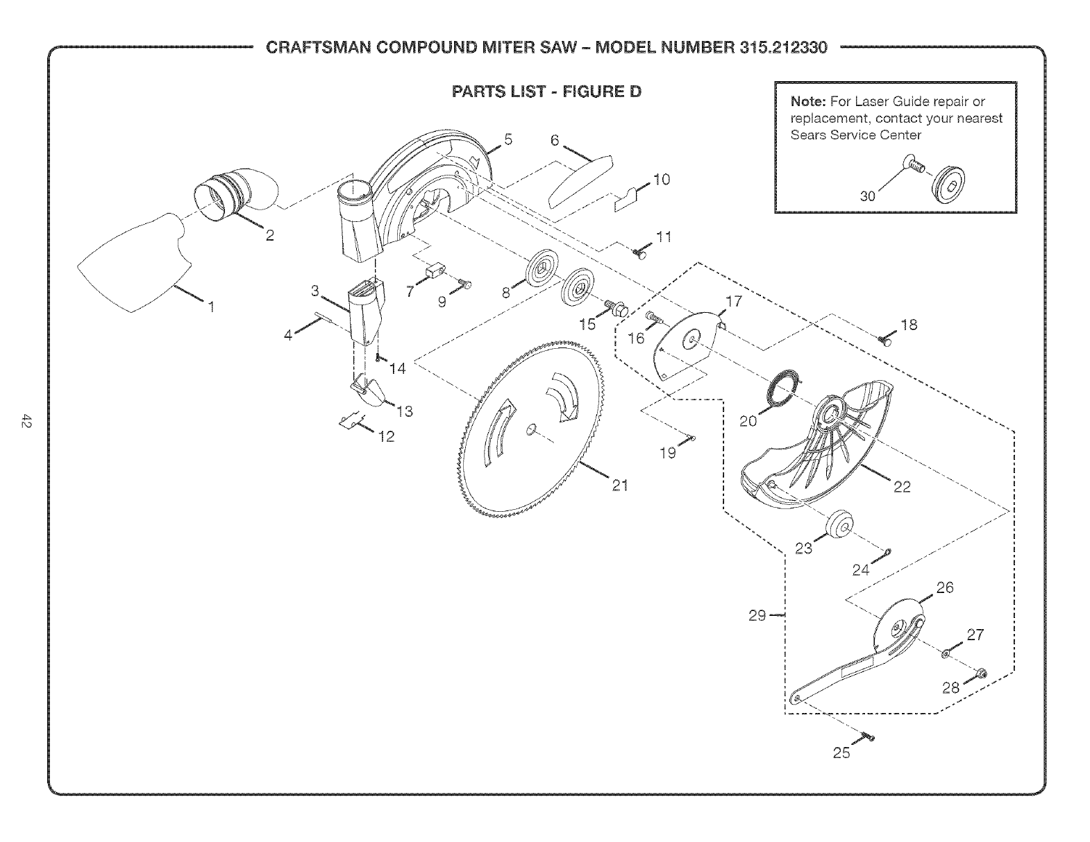
,-_' CRAFTSMAN COMPOUND MINTER SAW- MODEL NUMBER 315.212330 __
4
PARTS LmST-FIGURE D
5 6
J
-ZI 10
Note: For Laser Guide repair or
replacement, contact your nearest
Sears Service Center
3O
21
i <:.. _
i..Z
25

__' CRAFTSMAN COMPOUND MINTER SAW- MODEL NUMBER 315.212330 __
The model number will be found on a plate attached to the motor housing. Always mention the model number in all correspondence regarding your 1
Compound Miter Saw or when ordering repair parts. J
Key PaA
No. Number
1 511517000
2 511518000
3 511412000
4 511413000
5 511416000
6 510401007
7 589032207
8 588035105
9 A10003040152
10 555412000
11 A10003050206
12 511410000
13 511411000
14 Al1003050083
!5 588037107
16 581410003
17 581408100
18 A19001040091
19 578406003
20 589021300
21 510502007
22 511402100
23 566407000
24 538417000
25 589015108
26 511U04020
27 A35010616105
28 A31703006004
29 $5!100600
30 511505000
PARTS LmST - FmGURE D
Description Qty.
Dust Bag ........................................................................................... 1
Elbow ................................................................................................ 1
Dust Chute Adapter .......................................................................... 1
Dust Chute Pin ................................................................................. 1
Upper Safety Guard .......................................................................... 1
Logo Label ........................................................................................ 1
Bumper ............................................................................................. 1
Flange .............................................................................................. 2
Screw (M4 x 15 mm) ......................................................................... 1
Warning Label, Upper Guard ............................................................ 1
Screw (M5 x 20 ram) ......................................................................... 4
Dust Chute Spring ............................................................................ 1
Dust Chute ........................................................................................ 1
Screw (M5 x 8 mm) ........................................................................... 1
Blade Bolt ......................................................................................... !
Bolt ................................................................................................... 1
Blade Bolt Cover .............................................................................. 1
Screw (M4 x 9 mm) ........................................................................... 1
Screw ................................................................................................ 1
Retaining Spring ............................................................................... 1
Blade ................................................................................................ 1
Lower Guard ..................................................................................... 1
Roller ................................................................................................ 1
Retaining Nut .................................................................................... 1
Screw, Shoulder ............................................................................... 1
Retaing Spring Holder Assembly ..................................................... 1
Washer (M6) **STD851006 ............................................................... 1
Nut, Self=Locking (M6) ...................................................................... 1
Lower Blade Grd. Assembly
(hcl. Key Nos 16, 17, 20, 22, 23, 24, 26, 27 & 28) ......................................1
Laser Bolt ......................................................................................... 1
* Standard Hardware Item -May Be Purchased Locally
_, ** Avaiiabme from Div 98 -Source 980.0 ,_

iii!ii!ii!ii!ii!ii!ii!ii!ii!ii!ii!ii!ii!ii!ii!ii!ii!i ,
SM
® Registered Trademark /TMTrademark /Service Mark of Sears, Roebuck and Co.
TM SM
® Marca Registrada /Mama de F_brica /Marca de Servicio de Sears, Roebuck and Co.
MC MD
Marque de commerce /Marque d6pos6e de Sears, Roebuck and Co. ® Sears, Roebuck and Co.
