Craftsman 315212740 User Manual MITER SAW Manuals And Guides L0411411
CRAFTSMAN Miter Saw Manual L0411411 CRAFTSMAN Miter Saw Owner's Manual, CRAFTSMAN Miter Saw installation guides
User Manual: Craftsman 315212740 315212740 CRAFTSMAN MITER SAW - Manuals and Guides View the owners manual for your CRAFTSMAN MITER SAW #315212740. Home:Tool Parts:Craftsman Parts:Craftsman MITER SAW Manual
Open the PDF directly: View PDF ![]() .
.
Page Count: 46

OPERATOR'S MANUAL
iPROFIESS IONAL I
10 in. COMPOUND MITER SAW
DOUBLE INSULATED
Model No.
315.212740
AWARNING: To reducethe riskof injury,
the user mustread and understandthe
operator'smanual beforeusingthis product.
Customer Help Une: 1-.800-932-3188
Sears, Roebuck and Co., 3333 Beverly Rd., Hoffman Estates, [L 60179 USA
Visit the Craftsman web page: www.eears.com/crsftsman
983000-551 Save this manual for future reference
9-04
Warranty............................................................................................................................................................................ 2
•Introduction ....................................................................................................................................................................... 2
•General Safety Rules..................................................................................................................................................... 3-4
•Specific Safety Rules..................................................................................................................................................... 4-5
•Symbols......................................................................................................................................................................... 6-7
•Electrical............................................................................................................................................................................ 8
•GLossaryof Terms.............................................................................................................................................................. 9
•Fea_ras ..................................................................................................................................................................... 10-12
•ToolsNeeded ................................................................................................................................................................. 12
•Loose Parts .................................................................................................................................................................... 13
•Assembly................................................................................................................................................................... 14-23
•Operation................................................................................................................................................................... 23-31
•Adjustments................................................................................................................................................................... 32
•Maintenance.............................................................................................................................................................. 33-35
•Exploded_ew ........................................................................................................................................................... 37-45
•PartsOrderingJServlca...................................................................................................................................... Back Page
ONE YEAR FULL WARRANTY ON CRAFTSMAN TOOL
If thisCraftsman tool failsdue to a defect in materialor workmanshipwithinoneyaar fTomthe date of purchase,
CONTACT THE NEAREST SEARS PARTS &REPAIR CENTER at 1-800-4-SV-M_:HOMEOand Searswill repairIt, free of
charge. This warranty applies onlywhile thisproduct Is inthe Unltod States,
_fthis tool is used for commercLalor rentalpurposes,thiswarranty will apply for only ninetydays fi'onlthe date of
purchase.
This warranty givesyou specificlegal dghts,and youmay also have other dghts which varyfrom state to state.
Sears, Roebuck and Co., Dept. 817WA, Hoffman Estates, IL 60179
This tool has manyfeaturesfor making Its use mornpleasant and enjoyable.Safety, pedormancs,and dependability
have beengiven top priorityin the designof this product makingit easy to maintain and operate.
_k WARNING." Read and understand all inet_uo-
t/one. Failure to follow all instruotfons listedbelow,
may resultIn etectdc shock,tlre and/or serious
personal injury.
READ ALL INSTRUCTIONS
•KNOW YOUR POWER TOOL. Read the operator's
manual carefully.Learn the saw's applications and
{(mltations as we{{as the specific potent_{ hazards
related to this toot.
•GUARD AGAINST ELECTRICAL SHOCK BY PRE-
VENTING BODY CONTACT WITH GROUNDED
SURFACES. For example, pipes,radiators,ranges,
refrigeratorenclosures.
•KEEP GUARDS IN PLACE and Ingood workingorder.
•REMOVE ADJUSTING KEYS AND WRENCHES.
Form habit of checldngto see that keys and adjusting
wrenches are removed fromtool beforeturningit on.
•KEEP WORK AREA CLEAN. Cluttered areas and
benches invite accidents. DO NOT leaveto_,s or
placesof wood on the saw while it Is In operation.
•DO NOT USE IN DANGEROUS ENVIRONMENTS.
Do r_t use Dowertools in damp or wet Iocatk_neor
expose to rain. Keepthe work areawell tit.
•KEEP CHILDREN AND VISITORS AWAY. A/I visitors
shou;dwear safety glassesand be kept a safe
distance fromwork araa. Do not let visitors contact too_
or extens'=oncord while operating.
•MAKE WORKSHOP CHILDPROOF with padlocksand
masterswitches, or by removingstarer keys.
• DON'T FORCE TOOL. it will do the job betterand
safer at the feed rate forwhich it was designed.
• USE RIGHT TOOL. Don't forcethe tool or attachment
to do aiob it was not designedfor. Don't use it for a
purpose notintended.
•USE THE PROPER EXTENSION CORD. Make sure
your extensioncord is in'goodcondition. Use only a
cord heavy enough1o carrythe currentyourproduct
will draw. An undersizedcord will cause •drop in_ine
voltage resultingin lossof power and overhcating.A
wire gauge size (A.W.G.)of at least 14 Is recommended
foran extensioncord 25 feet or less in length, if in
doubt, use the next heavier gauge.The smallerthe
gauge number,the heavierthe cord,
•DRESS PROPERLY, Do not wear looseclothing,
gloves,nec_as, or)ewelry.They can get caught
and draw you Into moving parts. Rubbergloves and
nonskidfooWvearare reaommendedwhen working
outdoors.Alsowear protectivehair coveting Io contain
longhair.
• ALWAYSWEARSAFETYGLASSESW|TH SIDE
SHIELDS. Everyday eyeglasseshave only Impact-
res'lstantlenses, they are NOT setetyg;asees.
•3ECURE WORK. Use clampsor a vise to holdwork
when pract!cal,It's s_far than usingyourhand and
freesboth handsto operate tool.
•DON'T OVERREACH. Keep proper footingand
balance at all times.
•MNNT/UN TOOLS WITH CARE. Keep tools sharp
and cleanfor betterand safer performance.Follow
instructionsfor Lubricatingand changingaccessories.
•DISCONNECT TOOLS. When not in use, before
servicing, orwhen changingattachments, blades,bits,
cutters, etc., elltoo{sshould be disosnnected.
•AVOID ACCIDENTAL STAR'nNG. Be sure switchis off
when plugginginany tool.
•USE RECOMMENDED ACCESSORIES. The use of
improperaccessoriesmay dsk injury.
•NEVER STAND ON TOOL. Seriousinjurycould occur
if the tool is tippedor if the cuttingtoot is unintention-
ally centacte_,
•CHECK DAMAGED PARTS. Batonsfurtheruse of
the loci, aguardor othar _rt that is damaged should
be carefullycheckedto determine that it will operate
properlyand performits intended function.Check for
alignment of moving pads, b_ndingof movingpads,
_a of parts, moun_ng and any other condllk_ts
that may affectits operation. A guard orother pert that
is damaged mu_t be properlyrepairedor repla_d by
an authorizedservicecenterto avoiddsk of personaJ
injury.
•USE THE RIGHT DIRECTION OF FEED. Feedwork
Into ablade or cutter against the directionof rotation of
blade or cutter only.
•NEVER LEAVE TOOL RUNNING UNATTENDED.
TURN THE POWER OFF, Don't leave tool untilit
comas to a complete stop.
•PROTECT YOUR LUNGS. Wear aface or dust maskif
the cuffingoperationIs dusty,
• PROTECT YOUR HEARING, Wear hearingprotection
during extended periodsof opera,on.
•DO HOT ABU.RECORD. Neveryank cord to discon-
nect from receptacle.Keep cord from heat, o11,end
sharpedges.
•USE OUTDOOR EXTENSION CORDS. When tool Is
used outdoors,usa onlyextensioncordswith ap-
proved groundconnectionthat are intended for use
outdoorsand so mmked,
• KEEP BLADES CLEAN, SHARP, AND WITH SUF-
RCIENT SET. Sharp blades minimizestallingand
kickback.
•BLADE COASTS AFTER BEING TURNED OFF.
•NEVER USE IN AN EXPLOSIVE ATMOSPHERE.
Normalsparkingof the motor couldignite fumes.
3

•INdPECT TOOL CORDS PERIODICALLY. if damaged,
have repairedby 8qua_Lfiedservicetechnician at
an authorizedservice facility.The conductorwith
Insulationhevlngan outer surfacethat Is green with
or wYchoutyellow s_pee is the equipmenL-ground-
in9 conductor,ff repairor replacementof the electric
cord or plug is necessaPz,do not oonnect Theequip-
men'_-ground'mgconductor to a liveterm'inst.Repair
or replace a damaged or worn cordImmediately.Stay
constantlyaware of cord {(>cationand keep ttwelt sway
from the rotatingblade.
•INSPECT EXTENSION CORDS PERIODICALLY and
reOlace tfdamaged.
•POLARIZED PLUGS. To reduce the dsk of e[ectdc
shock, thistool has a po{adzedplug (oneblade is
wider than the other).This plugwill f_ ina polarized
outlet only oneway. It the plug does not fit fullyin _e
out_et,reversethe plug, If it stiltdoes notfit, contact a
qusL'zfiedetect_clanto Install the proper Duller.Do not
change the plug in any way.
•KEEP TOOL DRY, CLEAN, AND FREE FROM OIL
AND GREASE, A_waysuse ac_sanclothwhen c_san-
ing. Never usebrake fluids,gasoline,petroleum-based
products, or any so(ventsto c{eantoo(.
•STAYALERT AND EXERCISE CONTROL. Watch
what you are doing and use common sense,Do not
operate too(when you aretired. Do not rush.
•DO NOT USE TOOL IF SWITCH DOES NOT TURN IT
ON AND OFR Have defective switchesreplaced by an
authorized servicecenter.
•USE ONLY CORRECT BLADES, Do not use blades
with incorrectsize holes.Never use blade washersor
blade bottsthat ate detectiveorincorrect. The maxi-
mum blade capacity of your saw is 10 in. (254 mm).
•BEFORE MAKING A CUT, BE SURE ALL ADJUST-
MENTS ARE SECURE.
• BE SURE BLADE PATH IS FREE OF NAILS. Inspec_
forand removeall nailsfrom lumberbefore cuffing.
• NJ_fERTOUCH BLADE or othermoving partsdudng
use.
•NEVER STARTA TOOL WHEN ANY ROTATING COM-
PONENT IS IN CONTACT WITH THE WORKPIECE.
•DO NOT OPERATE A TOOL WHILE UNDER THE
INFLUENCE OF DRUGS, ALCOHOL, OR ANY
MEDIOATION.
•WHEN SERVICING use only identicel replacement
palls. Use of any other parts may create a hazard or
csuee productdema_je,
•USE ONLY RECOMMENDED ACCESSORIES ltsled
in this menus( or addendums, Use of accessories
that ere not [(sled may cause the risk of personal
Inlury,instructions for safe use of accessories are
inc(uded with the accessory,
•DOUBLE CHECK ALL SETUPS. Make sure blade is
tight and not making contact with saw or workpiece
before connecting to power supply.
•FIRMLY CLAMP OR BOLT your miter saw to a work-
bench or table at approx'_nately h_pheight.
• KEEP HANDS AWAY FROM CUTTING AREA. Do not
reachunderneathwork or inblade cuttingpath with
your hands and fingersfor any reason.Alwaysturn the
power off,
• ALWAYS SUPPORT LONG WORKPIECES while cut-
ring to minimize riskof blade pinchingand kickback.
Saw may Hip, walk ors_de while cuffinglong orheavy
boards.
• ALWAYS USE A CLAMP to secure the workplece
when possible.
•BE SURE THE BLADE CLEAR_ THE WORKPIECE.
Never startthe sew with the blade touchingthe
workplece. Allow motor to come up to fult speed
before start(n9cut.
•MAKE SURE THE MITER TABLE AND SAW ARM
{BEVEL FUNCTION) ARE LOCKED IN POSITION
BEFORE OPERATING YOUR SAW. Lockthe miter
table by securelytightening the miter _ockk_vere.Lock
the saw arm (bevel_nction) by securelytighteningthe
bevellock knot_,
NEVER USE A LENGTH 8TOP ON THE FREE SCRAP
END OF A CLAMPED WORKPIECE. NEVER hold
onto or bindthe free scrap end of the workpiesein any
operation.If awork clampand length stopare used
toget*ner,they must bot_ be installedon the same Side
of the saw table to preventthe saw Jmmcatchingthe
loose end and klcldngup,
NEVER out more thsn one piece at a time. DO NOT
b'rACK more than one workpiece onthe saw table at a
time.
NEVER PERFORM ANY OPERATION FREEHAND.
Always place the workpieco to be cu_ on the miter
table and posl_on It firmly against the fence as a bach-
stop, Abbeys use the fence.
4
•NEVER hand hold a wo.rl_lece that is too smallto be
clamped. Keep hands clear of the cuttingarea.
•NEVER reachbehind, under,orwithin threeinches
of the blade and Its cuttingpath with your hands and
fingersfor any reason.
•NEVER reachto pick up a workplace, apiece of scrap,
or anythingelse that is in or nea_'thecuttingpath ofthe
blade.
•AVOID AWKWARD OPERATIONS AND HAND
PORTIONS where a suddenslip could cause your
hand to move intothe blade. ALWAYSmake sure you
have good balance. NEVER operate your mitersaw
onthe f_oor or in acrouchedposition.
•NEVER stand or have any part of your body in linewith
the path of the saw blade.
•ALWAYS releasethe power switchand allowthe
caw blade to stop rotatingbefore raisingit out of the
workplace.
•DO NOT TURN THE MOTOR SWITCH ON AND OFF
RAPIDLY.This couldcause the saw blade to loosen
and could create a hazard. Shouldthis ever occur,
standdear and allow the saw blade tocome to a
complete stop. Disconnect your saw flora the power
supplyand sacursiy ret_ghtenthe blade bolt.
•IF ANY PART OF THIS MITER SAW IS MISSING or
shou[dbreak, bend, or fail in anyway, or shouldany
dsctdcaJcomponent fsilto performproperly,shutoff
the power switch, removethe miter saw plug from the
power source and have damaged, missing, or failed
partsreplacedbefore resumingoperation.
•ALWAYSSTAYALERTI Do not allow farnliled_(gained
ftom frequentuse of your saw)to cause a careless
mistake.ALWAYS REMEMBER that a careless fraction
of a second is sl._ c_mt to Snil_-'tsm/ereIniu_j.
•MAKE SURE THE WORK AREA HAS AMPLE LIGHT-
ING to see the work and that no obstructionswill inter-
fere with safe operationBEFORE performingany work
u_ng your saw.
•ALWAYSTURN OFF THE SAW beforedisconnecting
It to avoid accidental startingwhen reconnectingto
power supply.NEVER leavethe saw unattendedwhi_e
connectedto a power source.
•THIS TOOL shouldhave the following markings:
a) Weareye protection,
To) Keep hands out of path of saw blade
c) Do not operate saw without guardsin place.
d) Do not performany operationfreehand,
s) Never reach aroundsaw blade.
f) Turnoff tool and walt forsaw blade to stop before
movingworkp(eceor changingsettings,
g) Disconnect power (orunplugtoo(as applicable)
before changingblade or servicing.
h) No iced speed,
•ALWAYS carry the too[ onlyby the carryinghandle,
•AVOID direct eye exposurewhen usingthe laserguide.
• SAVE THESE INSTRUCTIONS. Referto them
fi'eduent_yand use to instructother users.If you Loan
someone thistool, foan them these Instructions alsO.
,_ WARNING: Some dust created by power sanding, sawing, grinding,drilling,end other construction activities
contains chemlcels known to cause cancer, birthdefects orother reproductiveharm. Some examples of these
chemic,areare:
•(sad from lead-based paints,
•crystallinesilicafrom bricksand cement and othermasonry products,and
•arsenic and chromiumfrom chemically-treatedlumber.
Your riskfrom these exposure(;redes, depending on how oftenyou do thistype of work. Toreduce your exposure
to these chemicals:work in awell ventilated area,and work with approved cafety equipment, suchas thosedust
masksthat are speciallydesigned to filter out microscopicpa_cies.
5

Someofthe followingsymbolsmay be used onthis too]. Please studythem and learntheir meaning. Proper
Interpretstfonof these symbolswill allow youto operate the tool better and safer.
SYMBOL NAME DESIGNATIONIEXPLANATI ON
v
A
Hz
W
min
,_,
no
[]
.../min
®
O
&
®
®
@
®
Vc_te
Ampuls
Hertz
Watt
Minutes
Alternating Current
DirectCurrent
No t-oadSpeed
Classli Construction
Per MinUte
Wet ConditionsAlert
Read The Operetor'sManual
Eye Protection
SafetyAlan
hLot-_nds Symbol
No Hands Symbol
m
No Hands Symbol
No Hands Symbol
Hot Surface
Voltage
C_rre_t
Frequency(cycles per second)
Power
Time
Type o'tcurrent
Type ora characteristicof current
Rotationalspeed, at no load
Doubie-insuisteqconstruction
Revolutions,strokes,surface speed, orbits etc., per minute
Do not expose to rain or use indamp locations.
To reduce the dsk of injury,usermust readand understand
operator'smanuat before usingthis product.
Always wear safety gogglesor safety g_asseswith side
shieldsand a full face shieldwhen operatingthis product.
Preeau_ionsthat involve your safety.
Faltureto keep your handsaway fromthe blade will result In
sedous personal Injury.
Failureto keep your handsaway fromthe bladewill resultin
serious personal injury.
Failureto keep your handsaway fromthe bladewill resultin
seriouspersona{injury.
Failureto keep your hands away from the blade will resultin
seriouspersonal Injury.
TOreduce the risk ot injuryor damage, avoid contactwith
any hot surface.
6
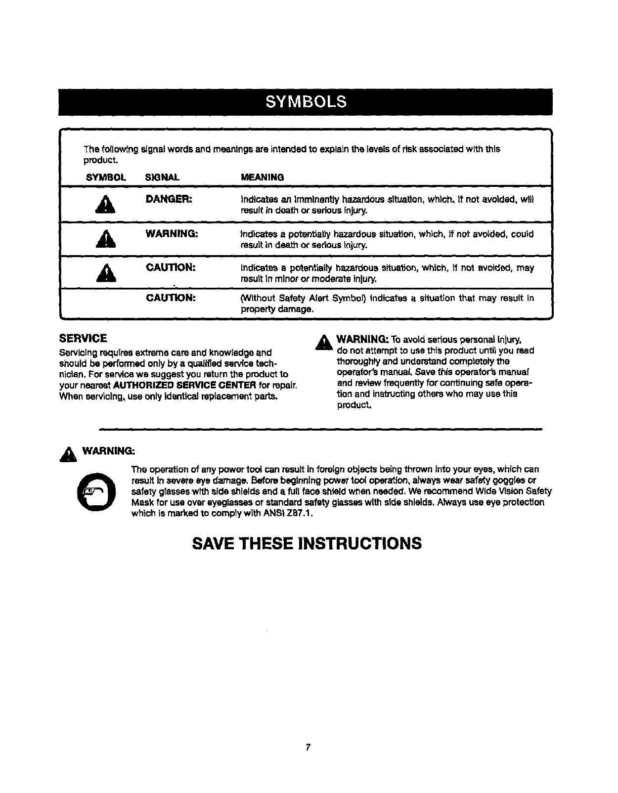
The fo(Iow[ngsignalwords and meaningsare intended to explainthe levelsof riskassociatedwith this
product.
SYMBOL SIGNAL MEANING
A DANGER: Indicates an Immlnenttyhazardoussituation,which, If not avoided, wtl)
resultin death or seriousinjury.
AWARNING: |ndicates a potentially hazardous situation, which, if not avoided, could
result in death or serious injury.
,_ CAUTION:
CAUTION:
Indicate_ apolentially hazardouseftuslJon,which, if nol avoided, may
resultIn minoror moderate Inlury.
(Without Safety Alert Symbol) Indicates a situation that may result in
property damage.
SERVICE
Servicing requires extreme care and knowledgeand
should be performedonly by a qualifiedservicetech-
nician. For servicewe suggestyou returnthe productto
your nearestAUTHORIZED 8ERVIGE GENTER for repair.
When servicing,usa only Identicalreplacementparts.
A WARNING: Toavoid seriouspersonalInjury,
do notattempt to use this productuntilyou read
thoroughlyand understandcomplete)ythe
operator'smanual Save this opemfer'smanual
end reviewfrequently forcontinuingsafeopera-
tion and instructingotherswho may use this
product.
,&WARNING:
The operationof any powertoo( can resultin foreignobjects beingthrown intoyour eyes,which can
OresultIn severe eye damage. Beforebeginningpowertool opera_lon,alwayswear safety gogglesor
safely glasseswffh side shieldsand afull face shieldwhen needed.We reGommendWide VisionSafety
Mask for use overeyeglassesorstandard safetyglasseswith side shields.Alwaysuse eye protection
whioh is marked to cemply with ANSi Z87.1.
SAVE THESE INSTRUCTIONS
DOUBLE INSULATION
DoubtsinsulationIs a concept In safety in electric power
tools,which eliminatesthe need forthe usualthree-wire
groundedpower cord.All exposed metal parts are
Isolated from the internalmetal motor componentswith
protectinginsulation.Double insulatedtools do not need
to be grounded.
A WARNING: "thedouble insotated is
system
Intendedto protect the userfrom shockresulting
fTomabreak inthe tool's internalinsulation, Observe
a(!normalsafety precautionsto avoidafec_caf
shock.
NOTE: Servicingof a tool with double Insulationrequires
extreme care and knowiedgeof the systemand should
be performed onlyby a qua.fled service tenhnlclan.For
service,we suggestyou returnthe tool to your nearest
authorized servicecenterfor repair.Alwaysuse original
factoryreplacementpafcswhen servicing.
ELECTRICAL CONNECTION
This tool has;a precision-buntelectric motor.It shouldbe
connected to epower supply that It 120 voltS, 60 Hz,
AC only {normal houSehold current). Do not operate
thistool on direct current(DC). A substantialvoltage drop
wlrrcause a Jossof power and the motorwill overheat, rf
yourtoot does not operate when plugged intoan outlet,
double-checkthe Dowersupply.
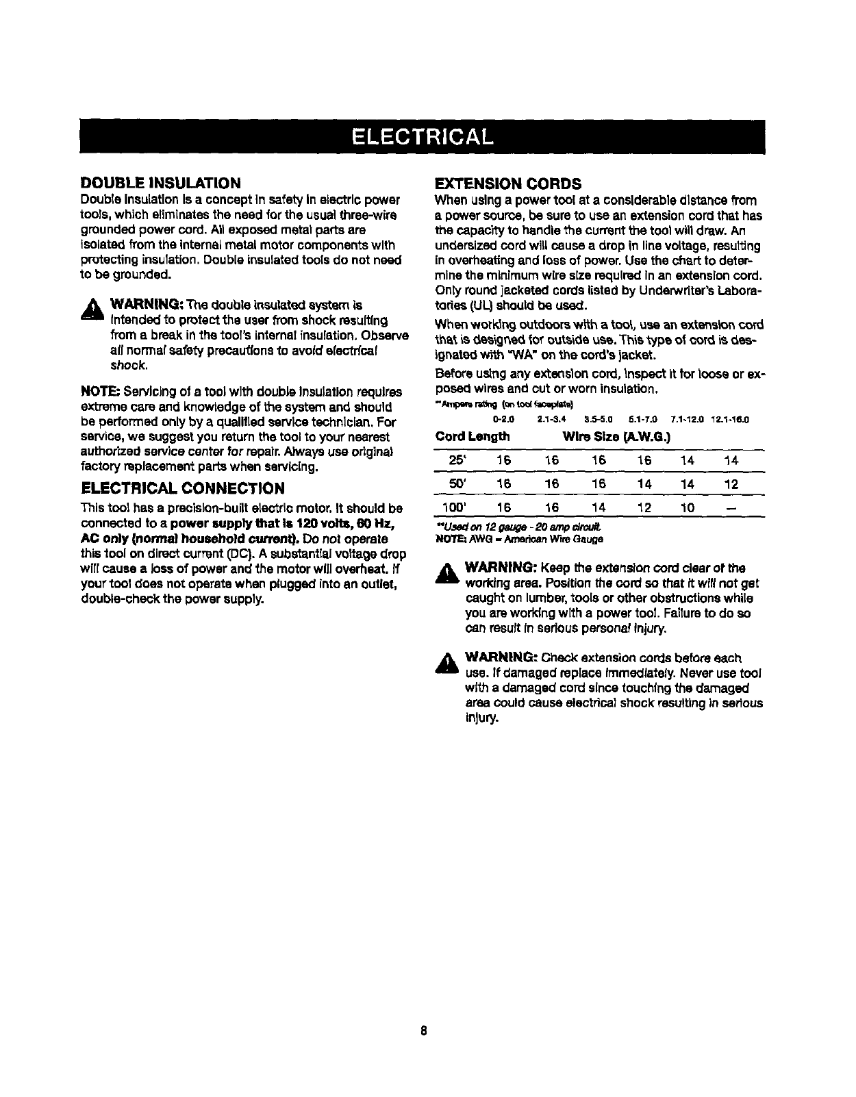
EXTENSION CORDS
When usinga powertool at a considerablecllstancafrom
spowersource, be sureto use an extensioncord that has
the capac'rtyto handlethe currentthe tool wiltdrew. An
undersizedcord will cause a drop in linevoltage,resulting
in overheatingand lossof power.Use the chart to deter-
minethe minimum wire size requiredIn an extensioncord.
Only roundjacketed cords listedby Underwritsr'sLabora-
tories (U_ sl_utd be used.
When workln 9 outdoorswith e Icon,use an ext_sk_n cord
_thB.tis _e_'_gne_tot ouL_'_deusa. _'hietype ot cord is _ee-
ignated w_th=WA"on the cord's )acket.
Before usingany sxte_don cord,_nspect it forloose or ex-
posedwires and cut orworn insulation.
0-2.0 2*1-3.4 3.0-5.0 5.1-7.0 7.1-12.0 12.1-16.0
Cord Length WInDSize (A.W.G.)
25' 16 16 16 16 14 14
50' 16 16 16 14 14 12
100' 18 16 14 12 10 --
"Used on_ga_,_e-20 amp_t:_
NO1rF_.:AWO- Arnedr,_mW'_ Gauge
AWARNING: Keep the extensioncord clearor the
workingarea. Positionthe cord so that it willnot get
caught on lumber,tools or other obstructionswhile
you are workingwith a power tool Failureto do so
can resultIn ssdous persona!injury.
A WARNING: Check exten._on cords before each
use. If damaged replace immediately.Never use tool
with a damaged cord sincetouchingthe _amaged
area could cause elec_cal shock resultingin serious
Injury.
8
Anti-KickbackPawls(radialarmandtablesaws)
Adevisewhich,whenpropertyinstatedandmaintained,
Is designedto stopthe workplace from beingkicked back
toward the front of the saw duringarippingoperation.
Arbor
The shaft on which a blade or cuttingtool is mounted.
Bevel Cut
A cut,rig operationmade wit'nthe blade at any angle
other than 90* to the table surface.
Chamler
A cut removingawedge from a black so the end (orpart
of the end) is angledrather than at 90..
Compound Cut
A cross cut made with both a miter end a bevelangle.
Crosscut
A cut_ng orshaping opera, on made acrossthe grainor
the width of the workplene.
Cutter Head (planers andjothters)
Arots_ng plece of adjustableblades. "Thecutterheed
removesmaterial from the workpiace.
Dado Cut
A non-throughcut which produces a squara-s_dednotch
or troughIn the workplece(requiresa speclalblade).
Featherboard
A deviceused to help controlthe wod_ptaceby gu)dlngit
sacuretyagainst the table o?fence during any dpplng
operation.
FPM or SPM
Feet per rnlnute(orstrokesper minute), used inreference
to blade movement.
Freehand
Performinga out withoutthe workplace beingguided by a
fence, miter gauge, or other aids.
Gum
A s_ck'7,sap-based residuefromwood products.
Heel
Altgnmentof the blade to the fence.
Karl
The material removed by the blade ina through cut or the
slot producedby the blade In a non-throughor partialcut.
Kickback
A hazardthat can occurwhen the blade b_ndsor stalls,
throwingthe workplace back toward operator.
Leading End
The end of the workplace pushed intothe tool first.
Miter Cut
A cuttingspars'donmade w_n the workpiece at any angle
to the blade otherthen 90°.
Non-Through Guts
Any cuing operationwhere the blade does not extend
completelythroughthe thicknessof the workpiace.
Push Blooke and Push Stloks
Devtcesused to feed the workplacethroughthe saw
blade duringcutting operations.A push stick (nota push
block)should be usedfor narrow dppingoperations.
These aids h_,p keep the operator's hands w_l away from
the blede.
Pilot Hole (drill presses)
A small heradrilledIn a workp_ce that sawes as a guide
for dr_(lfnglarge holesaccurately.
Resaw
A cuing op_atton to reducethe thickness of the work-
piece to make thinner pieces.
Resin
A sticky,se.p-t:_sed substancethat has hardened.
Revolutions Per Minute (RPM)
The numberof _rns completedby a spinningobjac_in
one minute.
Ripping or Rip Cut
A cuing operation alongthe leng'ih olthe workplace.
Rkdng Knife [table saws)
Also known as espreaderor splitter.A metal piece, slight-
ty thinner than the saw b_ade,which h_ps keep the _erf
open and alsohelps to prevent kickback.
Saw Blade Path
The area over,under,behind,or in frontof the blade.As
it appliesto the workpiece, that area which will be orhas
been cut by the blade.
Set
The distancethat the tip of the saw blade tooth is bent (or
set)outwardfromthe face of theblade.
Snipe (planers]
De0rsssionmade at either end of a workpiece by cutler
bladeswhen the workpiace is not properlysupported.
Throw-Back
The throwing back of aworkplace usuallycaused by the
workpiecebeing dropped intothe blade orbeing placed
InadvertentlyIncontact with the blade.
Through Sawing
Anycut'_ng opera, on where the blade extends completely
throughthe thickness of the workplace,
Workplace or Material
The item on which the operationis beingdone.
WoltCmble
Sur_ce wh_rethe workplace restswhi(eperfom_inga
cutting,drilting,planing,orsandingoperation.
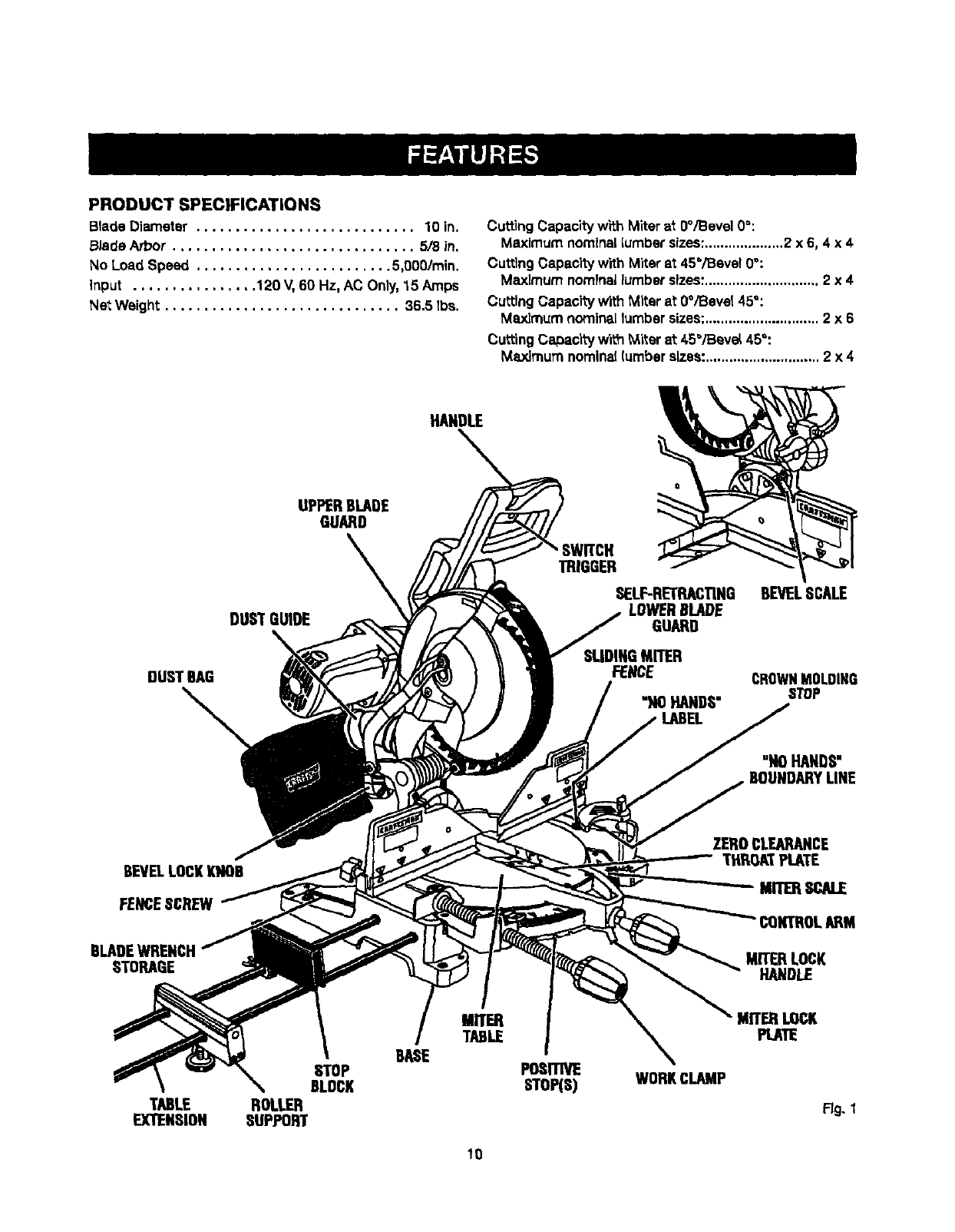
PRODUCT SPECIFICATIONS
Blade Diameter ............................ 10 in.
B_de Arbor ............................... 5/8 in.
No Load Speed ......................... 5,000/min.
Input ................ 120 V, 60 Hz, AC Only.15 Amps
Net Weight .............................. 36.5 tbs.
Cutting Capacitywtth Miterat0°/Bevel 0_:
Maximum nominal[umbersizes:....................2 x 6, 4 x 4
Cuttlng Capacity with Miter at 45°/Beve!0°:
Maximum nominallumbersizes:............................. 2x4
Cutting Capacity WithMiter at 0°iBeval 45°:
Maximum nominal lumbersizes:............................. 2x6
Cutting Capac'l_ with _i_er at 45"/Beve_45_:
Maximum nominal[umberalzes: ............................. 2x4
HANDLE
UPPERBLADE
GUARD
DUST GUIDE
DUST BAG
• SWITCH
TRIGGER
SELF-RETRACTING
LOWERBLADE
GUARD
SLIDINGMITER
FENCE
"NO HANDS"
BEVELSCALE
CROWNMOLDING
STOP
"NOHANDS"
BOUNDARYLINE
BEVELLOCKKNOB
FENCESCREW
ZEROCLEARANCE
THROATPLATE
Mm_ SCALE
BLADEWRENCH
STORAGE MITERLOCK
HANDLE
STOP
BLOCK
TABLE ROLLER
EXTENSION SUPPORT
MITER
TABLE
BASE POSITIVE
STO_S) WORKCLAMP
MITERLOCK
PLATE
Fig. I
10
KNOW YOUR COMPOUND MITER SAW
See Figure 1.
Before attempting to use this product,familiarizeyourself
w_ ail operatingfeatures and safetyrules.
15 AMP MOTOR
Your sew has a powerful15 amp belt-drivenmotor with
sufficientpower to handle tough cuttinglobs. It Is made
w;th airball bsedngs,and has externallyaecesaibre brush-
es for ease of servicing.
10 in, BLADE
A 10 in. carbide-Upped saw blade is includedwith your
compound miter sew. It will cut materialsup to 4 in. thick
or 6 In. wide, depending uponthe angle at which the cut
is being made.
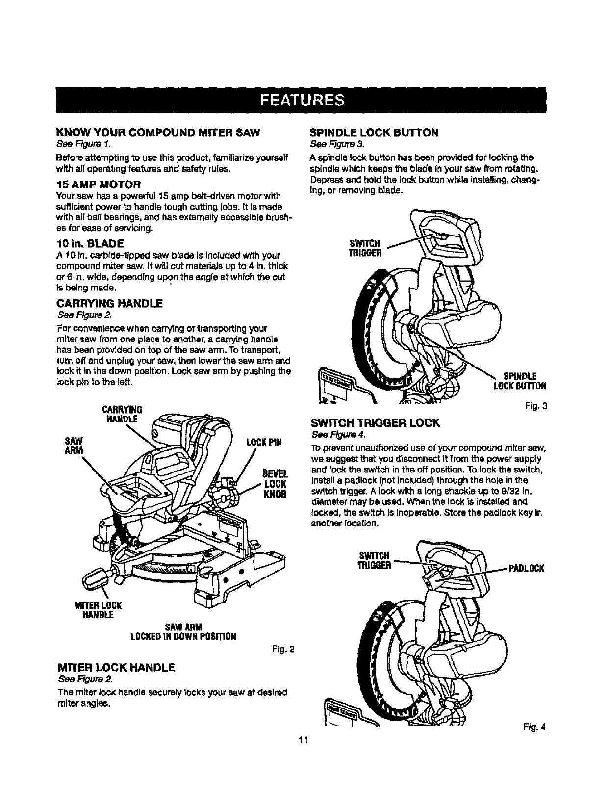
CARRYING HANDLE
See Figure 2.
For conveniencewhen carr_ng ortransportingyour
miter saw from one place to another,acarryinghandte
has been provldedon top of the saw arm.To transport,
turn off and unplugyour sew, then lower the sew arm and
lock it in the down position.Locksaw arm by pushingthe
lock pin to the left.
CARRYING
HANDL£
SAW LOCKPiN
ARM
DEVEL
KNOB
SPINDLE LOCK Bu'rroN
See Figure3.
A spindlelock buttonhas been providedfor lockingthe
spindlewhich keeps the blade In your saw fromrotating.
Depressand holdthe lockbuttonwhile instaging,chang-
ing,or removingblade.
SWITCH
mlGGER
SPINDLE
LOCKBUTi'ON
Fig. 3
SWITCH TRIGGER LOCK
See Figure 4.
Topreventunauthorizeduse of your compoundmiter saw,
we suggestthat you disconnectIt from the power supply
and lock the switch inthe off position.Totookthe switch,
installa padlock (notincluded)throughthe hole inthe
switchtrigger,A lock with a tong shackteup to 9/32 In.
diameter may be used. When the lock is insta(iedand
locked, the switchIs Inoperable.Store the padlockkey In
another location.
MITERLOCK
HANOLE
SAWARM
LOCKEDIN GOWNPOSITION
Fig. 2
MITER LOCK HANDLE
See Rgure 2.
The miterlock handle securelyrocksyour saw at desired
miterangles.
Fig.4
11
LASERTRACTM LASER GUIDE
For more accurate cuts, a LasarTmcTM laser guide Is
includedwithyour miter saw. When used properly,the
laser guidemakes accurate, precisioncutting simpleand
easy.
Posn'IVE STOPS ON MITER TABLE
Positivestops have been providedat 0°, 15°, 22-1/2 °,
31.62 °, and 45°onboth the left and rightside of the miter
table.
BEVEL LOCK KNOB
The bevellock knob securelylocksyour compoundmiter
saw at desired bevelangles.A positivestop adiustment
screw has been providedon each srdeof the saw arm.
These adjustment screwsare for making fineadjustments
at O"and 45".
ELECTRIC BRAKE
An electdo brake has been providedto quioklystop blade
rotation after the switchis reteaead.
CROWN MOLDING STOP
The crown moldingstop makes positioningcrownmolding
verticallyagainstthe fence easier.
SLIDING MITER FENCE
Hold the workpiesa securely against the mRer fence when
making all cuts. The stiding feature atlows both fences (left
and right) to be moved when making bevel or compound
CLIts,
Slide the miterfences by tooseningthe fence screws.
Once the dealredposition of the miterfence Is deter-
mined, retightsnthe fence screws to securethe sliding
fence.
SELF-RETRACTING LOWER BLADE GUARD
The lower blade guardis made of shook-resistant,see-
throughplasticthat providesprotectionfl'omeach side
of the blade.It retractsover the upper blade guard as the
saw isloweredintotheworkplsce,
ROLLER SUPPORT
WI_ the miler supportInstalled, the workplacewill glide
smoothlyand levellyoverthe table extensions.
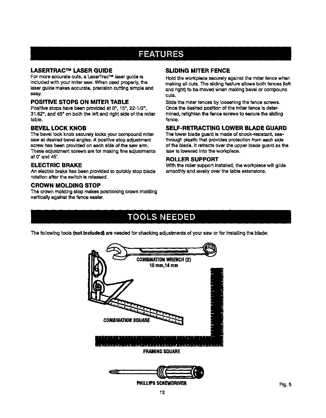
The followingtools (not Included} are needed for checking adlus_ents of your saw or forInstalling the blade:
COMBINATIONWRENCH(2)
10 ram,14me
COMSINA7"/ONS01/ARE
FRAMINGSQUARE
PHILLIPSSCREWDRIVER Fig.5
12
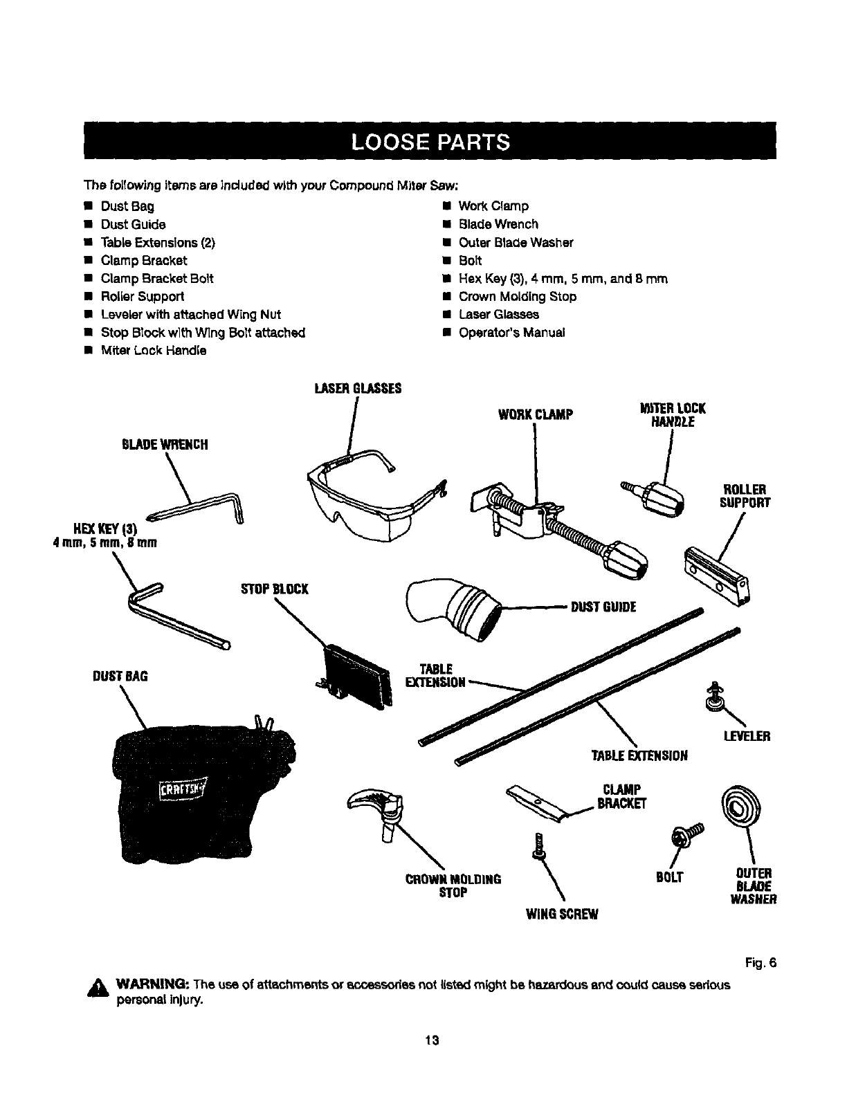
The follow'_ngi_:emsare Lncludedw|th your CompoundMiter Saw;
•Dust Bag
• DustGuide
•Table Extensions(2)
•Clamp Breaker
•CLampBracket Bolt
•RoLLerSupport
•LeveLerwith attached Wing Nut
•Stop Block wlthWing Bolt attached
•Miter Lock Handle
• WorkClamp
•Blade Wrench
• Outer BladeWasher
•Bolt
•Hex Key (3), 4 mm, 5 mm, and 8 mm
•Crown Molding Stop
•LaserGlasses
•Operator's Manual
BLADEWRENCH
LASERGLASSES
WORKCLAMP I_11ERLOCK
ROLLER
SUPPORT
HE)CKEYiS)
°°,T,,o =oy .
TABLEEXTENSION
4 ram,Sram,8 mm
_BRACKET
CROWNMOLDING _BOLT OUTER
STOP \8LAOE
WASHER
WINGSCREW
Fig. 6
_i WARNING- The use of ettechmentsor scsessodesnot listedmight be hazardousend c_uk_oause sedous
personalInjury.
13
UNPACKING
This product requires assembly.
•Carefullyliftsaw fTomthe carton by the carrying handle
and the saw base, and place it on a lard work surface.
NOTE: Th_ssaw is heeW.'To avoid back I_lury, _.w_th
your legs, notyour back, and get help when needed.
•Thissaw has been shipped with the saw arm secured
in the down position.To releasethe saw arm, push
down on the top of the saw arm, cutthe tie-wrap, and
puttout or the look pin,
• Uft the saw arm by the handle. Hand pressureshould
remain on the saw arm to prevent suddenrise upon
mtesae ol _hetie wrap.
•Inspect the tool carefullyto make sure no breakage or
damage occurreddudng shipping.
•Do not discardthe packing material un_JJyou have
carsfultyinspected and set'=sfectofi_yoperated the tool.
•The saw is factory set for accuratecutting. After
assarnbllngit, check for accuracy, if shippinghas
influencedthe settings,referto specific procedures
explained inthis manual."
•If any parts are damaged or missing, please call
1-800-932-3188 for assistance.
WARNING: (fany parts are m[sslng, do not operate
this tool untllthe missingpartsare replaced. Faflbre
to do so couldresult in possible sedouspersonal
injury.
_lb WARNING: Do notattempt to modify thistool
orcreate accessories notrecommendedfor use
with thistool. Anysuch alterationor modificationIs
misuse and could resultin a hazardouscondition
feeding to possibleseriouspersonal injury.
WARNING: Do not connect to powersupply until
assembly is complete. Failureto complycouJdresult
_naccJdantalstartingand poss]b_asarfous personal
iniu_
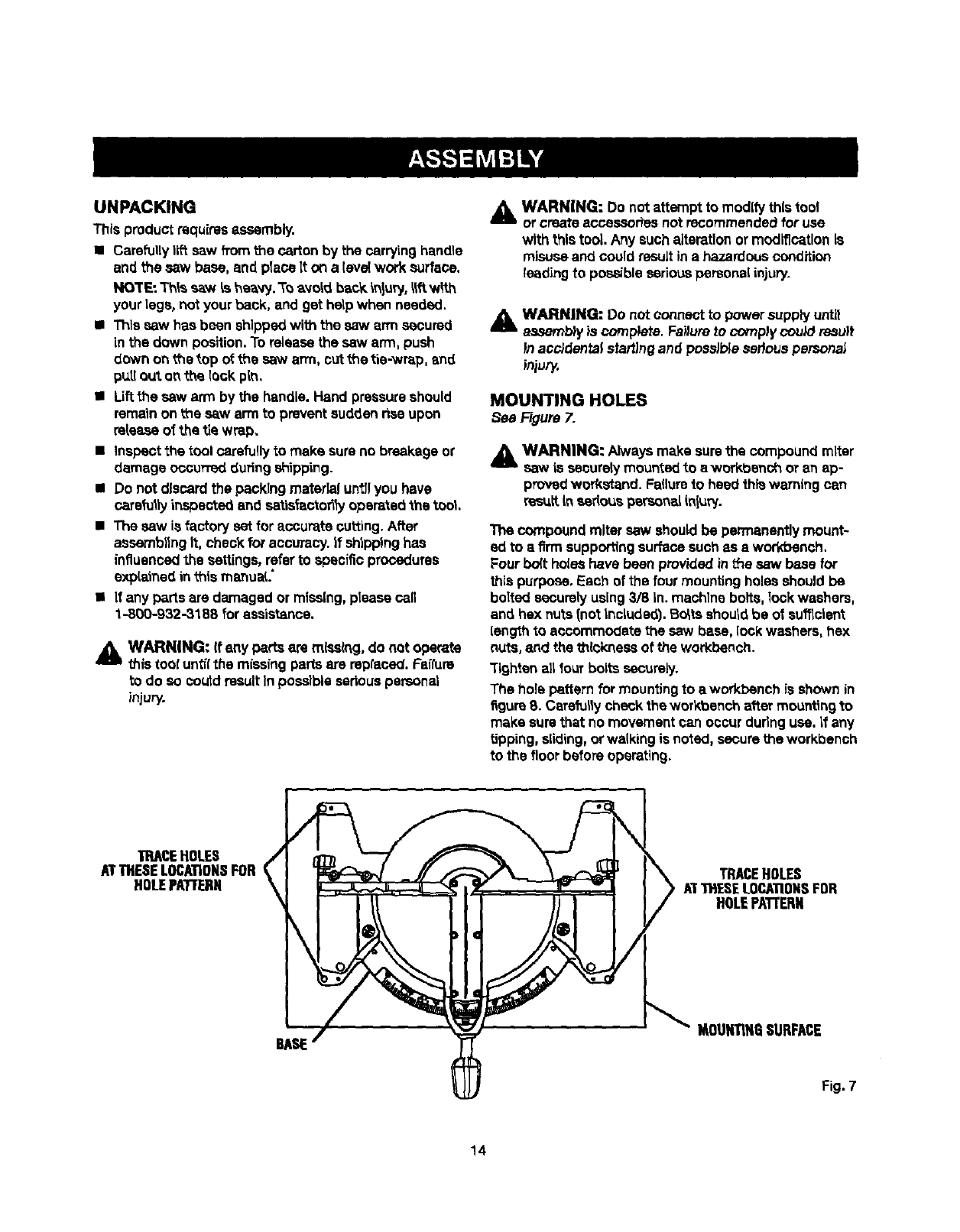
MOUNTING HOLES
See Figure 7.
_WARNING: Alwaysmake surethe compoundmltsr
saw is securelymounted to e workbench or an ap-
provedworkstand. Failureto heed thiswarning can
recuitinsadousperso_L inluw.
The compoundmiter saw shouldbe permanentlymount-
ed to afirm supportingsurfacesuchas a workbench.
Four bolt holes have been providedinthe saw base fOr
this puq_ose.Each of the four mounting holes should be
bolted securelyusing3/8 In. machine bolts,lockwashers,
an_ hex nuts(not included). Bo_tsshouldbe of su_clent
lengthto accommodate the saw base, [ockwashers, hex
nuts, and the thicknessof the workbench.
Tightec airfour bolts securely.
The hole pattern for mountingto a workbench is shownin
figure8. Carefullycheck the workbench attar mounting to
make surethat no movementcan occur duringuse. If any
Upping,sliding,orwalking is noted, securethe workbench
to the floorbefore operating.
TRACEHOLES
ATTHESELOCATIONSFOR
HOLEPATIF1ERN
BASE
TRACEHOLES
A"T"tHESELOCATIONSFOR
HOLEPA'TrERN
IAOUNTIH_iSURFACE
Fig. 7
14
Asmantfonedpreviously,thesawhasbeenfactory
assembledand adiusted.
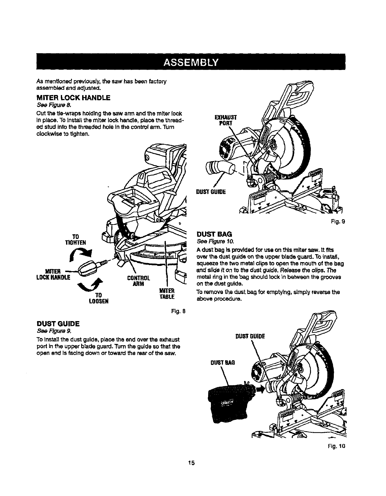
MITER LOCK HANDLE
See Figure 8,
Cut the tie-wraps holdingthe saw arm and the miter lock
in place, Toinstallthe miter lock handle, place the thread-
ed stud into the threaded hole inthe controlarm, Turn
clockwiseto tighten,
EXHAUST
PORT
\
TO
TIGHTEN
TO
LOOSEN
CONmOL
ARM MnZX
TABLE
Fig. 8
DUST GUIDE
See Figure 9,
To Installthe dust guide, piecethe end overthe exhaust
port in the upper blade guard. Turnthe guideso that the
open end Is facing down or toward the rearof the saw.
Fig.9
DUST BAG
See FJgure10.
A dust bag ht providedfor use on this mitersaw. tt fits
over the dustguideon the up_r bladeg_l. To _nst_ll,
squeezethetwo metalclipstoopen themouthofthebag
and slideIton tothedustguide.Releasethecllps.The
metalrthginthe"gagshouldlockinbetweenthegrooves
on the dustguide.
To removethe dustbag for emptying, simplyreversethe
above procedure.
DUSTSUIDE
DUSTBAg
\
Fig. 10
15
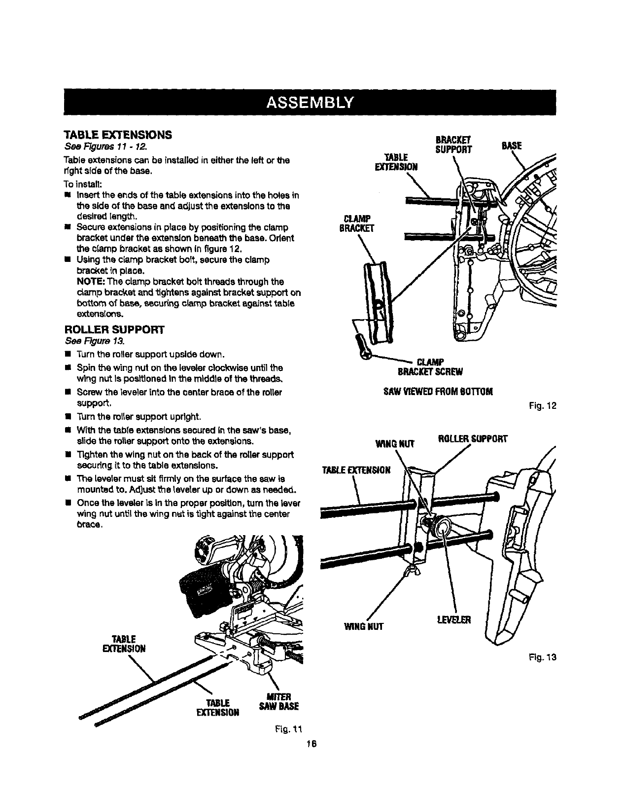
TABLE EXTENSIONS
See Figures 11 - 12,
Table extensionscan be instaflad ineither the left orthe
rfghtsfdeof the base.
To install:
i Insertthe ends of the table extensionsinto the holesin
the side of the bass and adjust the extensionsto the
desiredlength.
• Secure extensionsinplace by positioningthe clamp
bracketunder the extensionbeneath the base. Orient
the clamp bracket as shown in figure12.
•Usingthe clamp bracket bolt, securethe clamp
bracketin place.
NOTE: The clamp bracket bolt threadsthroughthe
c_ampbrac_,et and tightens againstbracket supporton
bottom of base, securingc_p bracket ag_nst _ble
extensions.
ROLLER SUPPORT
See Figure 13.
•Turnthe rottersupport upsidedown.
•Spin the wing nut onthe levelerclockwiseuntilthe
wing nut Is positionedIn the middle of the threads,
• Screw the leveler into the center brace of the roller
support.
•Turnthe rollersupport upright.
• W_ththe table extensionssecured inthe saw's base.
slide the roller support onto the extensions.
•Tightenthe wing nut on the back of the rollersupport
secudngit to the table extensions.
•The levelermust sit firmlyon the surfacethe saw is
mountedto. Adjustthe leveler up or down as needed.
•Once the leveleris in the proper position,turn the lever
wing nutuntilthe wing nut is t_ghtagainstthe center
brace.
CLAMP
BRACKET
CLAMP
BRACKETSCREW
SAW_'1E'WEOFROM6Ol"rOM
WINQNUT
BRACKET
SUPPORT BASE
TABLEEXTENSION
ROLLERSUPPORT
Fig. 12
TABLE
EXTENSION
WING NUT
Fig.13
m
TABLE SAWBASE
EXTENSION
Fig. 11
_6
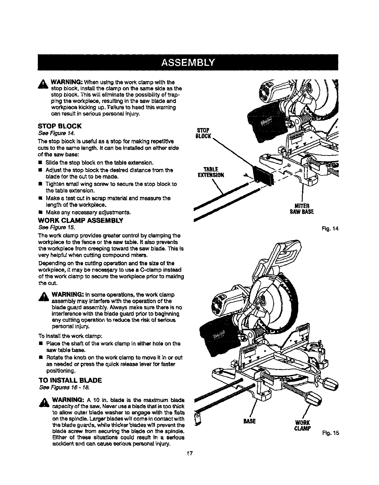
_lb WARNING: When usingthe work clampwith the
stop block,installthe clamp on the same side as the
stop block.This will elimlnatsthe possibilityof _rap-
ping the workpisce, resultinginthe saw b]adeand
work,oiecekickingup. Failureto heed thiswarning
can result inseriouspersona]injury,
STOP BLOCK
See Figure 14.
The stop block is usefulas a stop for making repstlt_ve
cuts to the same length. It can be installedon either side
of the saw base:
• Slide the stop block onthe table extension,
• Adjustthe stop block the desired distancefromthe
blade for the outto be made.
•Tighten Smallwing screw to sacum the stop blockto
the table extension.
•Make a test cut in scrapmatariaI and measure the
length of the workplace,
•Make any necessaryadjus_ents.
WORK CLAMP ASSEMBLY
See Figure 15.
The work clamp provides greater controlby clampingthe
workpisce to the fence or the saw table. It also prevents
the workpisce from creeping toward the saw blade. Thisis
very helpfuiwhen cuttingcompoundmiters.
Depending on the cuttingoperationand the sizeof the
workpieee, it may be neces,_ry to use aC-clamp instead
of the work clamp to securethe workpiscepdorto making
the cut.
AWARNING: insome operations, the work clamp
assemblymay interferewlth the operationof the
blade guard assembly. Alwaysmake surethere is no
interferencewith the blade guardpriorto beginning
shy cutt_r_9 operationto reduce the riskof serious
personalInjury,
To installthewod_clamp:
•Piecetheshaftofthework clampineitherholeonths
saw table base.
•Rotate the knob on the work clampto move it in or out
as needed orpress the Rulckreleaselaverforfaster
position'mg,
TO INSTALL BLADE
See Figures 16.18.
WARNING: A10 in. blade Ls the rr_dmum blade
capacity of the saw. Never use ablade that is too thick
to allow outer blade washer to engage with the flats
on the spindle. Larger blades will come in contact with
the blade guards, wh'_e thicker blades w'lll prevent the
blade screw from securing the blade on the spindle.
Either of these situattons could result In aserious
accidentand can cauee seriouspersonal_njury.
STQP
BLOCK
TABLE
EXTENSION
t7
BASE
MITER
SAWBASE
Fig. 14
WORK
cLAMP Fig. 15
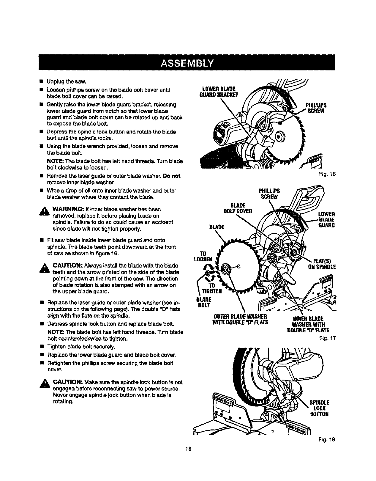
•Unplugthesew,
• Loosenphillipsscrew onthe blade bolt coveruntil
b_de bolt cover can be raised.
•Gently raisethe lower blade guard bracket, releasing
tower blade guard_rom notch so that lower blade
guardand blade boRcover can be rotated up and back
toexposethe blade bolt.
•Depress the spindlelock button and rotate the blade
boil untO{the spindle (coke.
•Usingthe blade wrench provided, loosenand remove
the blade bdit,
NOTE: The b(edebolt has left hand threads.Turnblade
bolt clockwiseto loosen.
•Removethe laserguide or outer blade washer, no not
remove_nnerblade washer.
•Wipe adrop of oll onto Inner blade washer and outer
b(adewasher where they contactthe b(ede.
WARNING: if inner b_de washer has been
removed, mplaca it beforeplacing blade on
spindle, Failureto do so could cause an accident
since blade will not tightenproperty.
•Fit saw blade insidelower blade guard and onto
spindle.The blade teeth point downward at the fTont
O1"saw as shown infigure 16.
_l CALITIONt A_wayslnat_l[ the I_adewith the blade
teeth and the arrow printedon the side of the blade
pointingdown at the front of the saw. The direction
of blade rotationIs also stampedwith an arrow on
the upper blade guard.
•Replace the [aserguide orouter blade washer (see in-
structionson thefdiiowingpage). "thedoub_e=D"fiats
alignwith the fiats on the spindle.
•Depress spindle lockbutton and replace blade bolt.
NOTE: The blade bolt has left hand threads.Turnblade
boil count_mlockwlseto lighten.
•lighten blade bolt securely.
•Replace the lower blade guard and blade boil cover.
•Refightanthe phillipsscrew eecudng the blade bolt
cover.
_1 CAUTION: Make sure the spindlek>ckbutton is not
engaged before reconnectingsaw to power source,
Never engage spindle]ock buttonwhen blade is
rotating,
LOWERBLADE
GUARD8P,ACI(ET
PHILLIPS
SCIUEW
TO
LOOSEN
TO
TIGHTEN
BLADE
BOLT
Fig, 16
LOWER
GUARD
INNERBLADE
WASHERWITH
O_U6LE'ir FlATS
Fig. 17
SPINDLE
LOCI[
DUll'ON
Fig. 18
tS
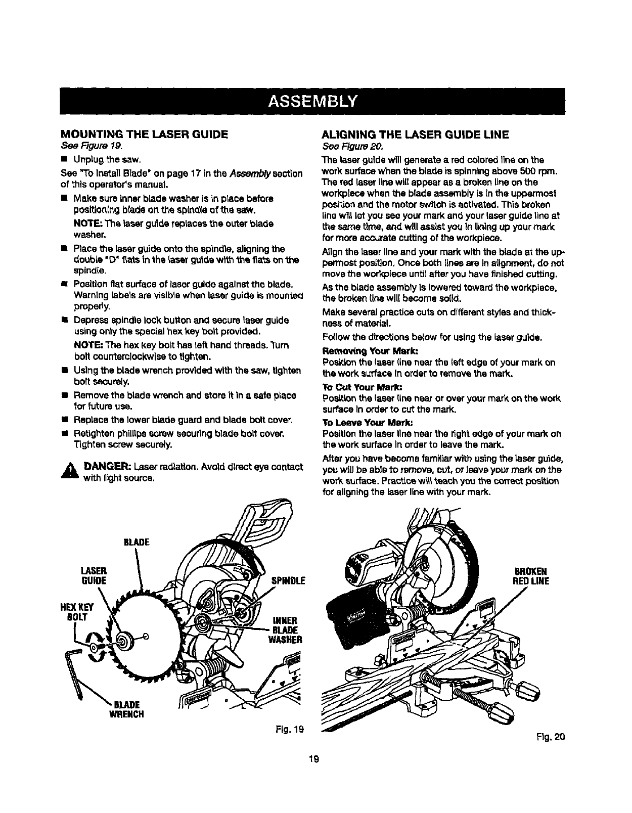
MOUNTING THE LASER GUIDE
See Figure 19.
• Unplug file saw.
See "To InstallBlade"onpage 17 inthe Asaernb/ysestion
of this operator's manual.
• Make sureinnerblade washer is in place before
pos_onlng b{adeon the sp_d(e o_the saw.
NOTE; The laser guidereplaces the outer blade
washer.
•Place the laser guide ontothe spindle, aligningthe
double "0' gets Inthe tasar guidew_ the fta_sonthe
spind{e.
•Positionfiat surfaceof laser guideagainst the blade.
Warning labels are visiblewhen laser guide is mounted
pmpedy.
•Depress spindlelock buttonand secure laserguide
usingonlythe special hex key bolt provided.
NOTE: The hex key bolt has left hand threads.Turn
bolt counterclockwiseto tighten.
•Usingthe blade wrench providedwith the saw, tighten
bolt securely,
•Removethe blade wrench and store it In a safe place
for future usa.
•Replace the lower blade guardend blade boltcover.
•Rstlghten phillipsscrew sscudng blade bolt cover,
Tightenscrew secursiy.
A DANGER: Laser radiation,Avoiddirecteye contact
with lightsource.
ALIGNING THE LASER GUIDE LINE
See Figure20.
The laser guidewill generate a redceiored 1]neonthe
work surfacewhen the blade is spinningabove 500 rpm,
The red laserlinewill appear as a brokenlineon the
workplacewhen the blade assembly is In the uppermost
positionand the motor switchis activated, This broken
linewfll let you see your mark and yourlaser guide line at
the same time, and will assist you In liningup your mad(
for more accurate cuffingof the workplace.
AJignthe laserline and your mad( with the blade at the up*
permost position.Once both lines are tn a(Ignment,do not
move the workplace untilafter you have finishedcuffing.
As the blade asaembly is loweredtoward the workplace,
the broken(Inswll( becomesolid,
Make several practice outs on differentstylesand thick-
ness of material.
Fo{iowthe directionsbelow forusingthe laserguide.
Remo_l Your Mark:
Positionthe (seerfinenear the left edge of your mark on
the work surfaceInorder to removethe mad(.
To Cut Your Mark:
Positionthe lasarline near or overyour mark on the work
surface Inorderto cut the mark.
To Lsave Yore Mark:
Positionthe laserline near the tightedge of your mark on
the work surfacein orderto leave the mark.
Afteryou have become familiarwith usingthe laser gLdde,
you wlJJbe ableto remove, cut, orleave your mark onthe
wor_ surface. Practicewtllt_oh _o_ _heco,act posi_on
for aligningthe laserlinewith your mark.
BLADE
LASER
GUIDE
BOLT
WRENCH
SPINDLE
INNER
WASHER
Fig. 19
BROKEN
REDLINE
Fig. 20
19
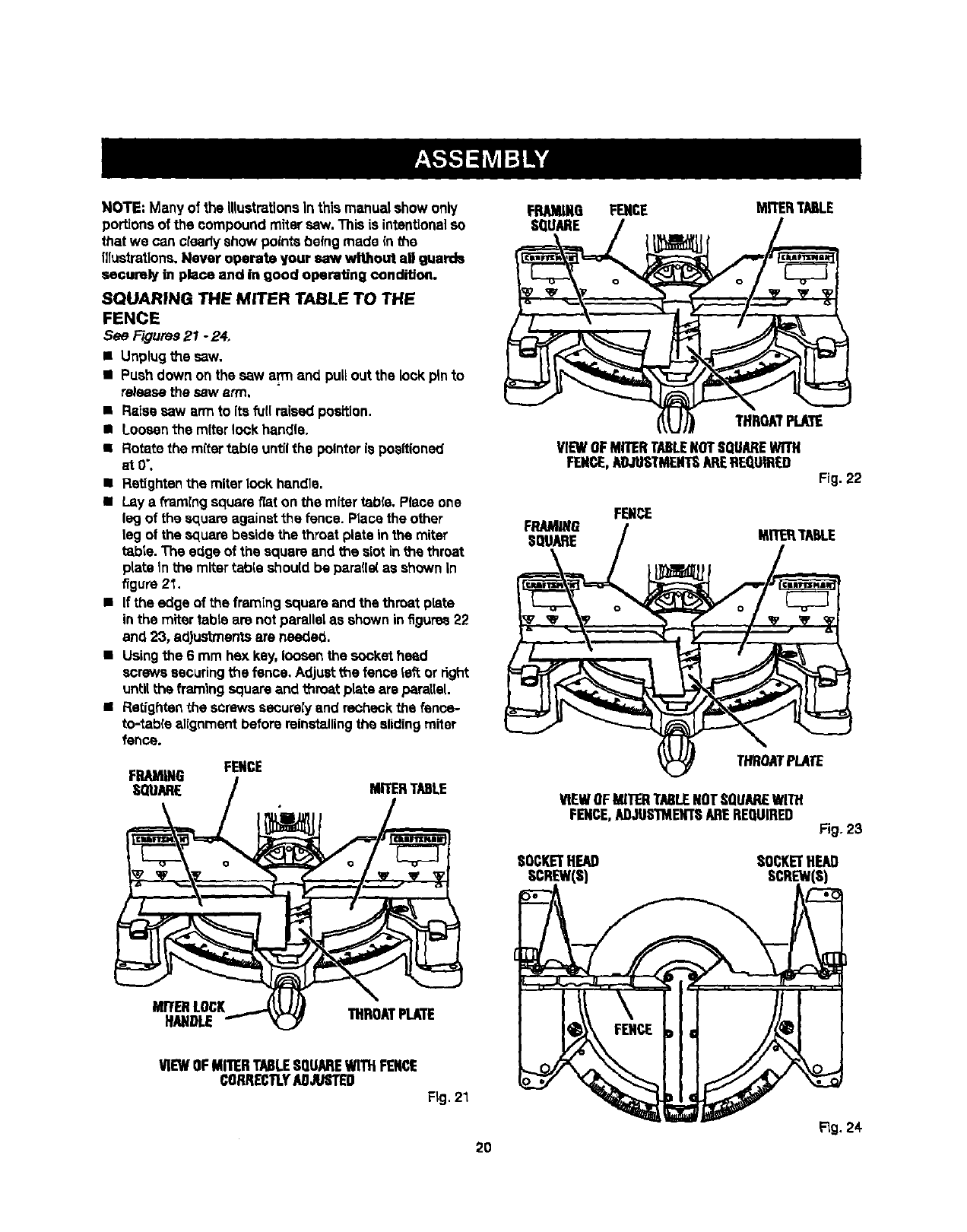
NOTE:Manyofthe Illustrationsin thismanual show only
portionsof the compoundmiter saw. This is intentionalso
that we can ctsadyshow pointsbeingmade in the
Illustrations,Never operate your saw wlUtourlaD guards
securely in place and in good operating condition.
SQUARING THE MITER TABLE TO THE
FENCE
See Figures21 -24.
• Unplugthe saw.
•Push down on the saw arm anti pulloutthe lock pin'co
releasethe saw arm,
•R_sa saw arm to its full raised position.
• Loosenthe miter lock handle,
•Rotate the re{tar tab(e untilthe pointer is posftioned
atO'.
•Rat(ghtanthe miter look handle.
• Lay a fi-am[ngsquare fiat on the miter table. Piece one
leg of the squareagainst the fence. Place the other
leg ot the squarebeside the throat plate in the miter
tabte.The edge of the square and the stot inthe throat
plate In the miter table shou(dbe parafle(as shown in
figure 21,
•If the edge of the framingsquare and the throat plate
inthe miter tabte are notparallel as shown in figures22
and 23, adjustmentsare needed.
•Usingthe 6 mm hex key, loosenthe socket head
screwssecuringthe fence, Adjustthe fence te_ or right
unlitthe framing squareand throat plate are parallel.
•Retfghtenthe screws securely and recheckthe fence-
to-tabre alignment before reinstallingthe slidingmiter
fence.
FENCE
FQuRAMIARNEG/MITERTABLE
M.RERL,02K...---'_ J_ THROATPLATE
HANDLE _'- _ '"""'_""=
FRAMING FENCE MITERTABLE
SQUARE
THROATPLATE
VIEWOFMITERTABLENOTSQUAREWITH
FENCE,ADJUSTMENTSAREREQUIRED Fig.22
FENCE
/MI ,..E
VIEWOFMITERTABLENOTSQUAREWITH
FENCE,ADJUS'iMEXTSAREREQUIRED Fig. 23
SOCKETHEAD SOCKETHEAl)
SCREW(S) SCREW(S)
VIEWOFMITERTABLESQUAREWITHFENCE
CORRECTLYAN&/STED
Fig. 21
Flg.24
20
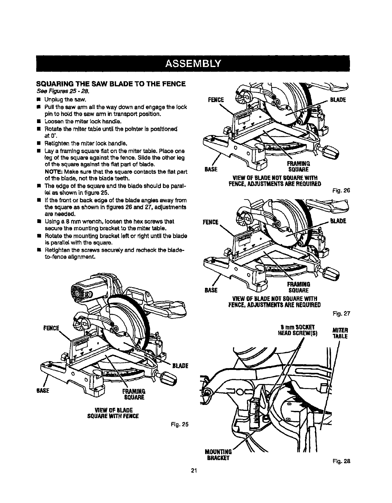
SQUARINGTHE SAWBLADETO THEFENCE
See Figures25 -28.
•Unplugthe saw.
•Pullthe saw arm all the way down and engagethe lock
pin to ho_dthe saw arm in transport position.
•Loosenthe miter took handle.
•Rotatethe miter table untilthe pointeris positioned
at0".
•Retightenthe miter(ock handle.
•Lay a framingsquare flat on the miter table. P(aceone
leg of the squareagainst the fence. Slide the other leg
ol the square against the fiat part of blade.
NOTE: Make surethat the square contactsthe fiat part
of _s blade, not the b_adeteeth.
•The edge of the square end the blade shouldbe paral-
lelas shownin figure25.
• If the frontor back edge of the blade angles away from
the square as shown infigures26 and 27, adjustments
are needed.
•Usinga8mm wrench, loosenthe hex screwsthat
securethe mountingbracket to the miter table.
• Rotatethe mountingbracketleft or rightuntilthe blade
is parallelwi_ the square.
•Retightenthe screws secure(yand recheckthe blade-
to-fence alignment.
FENCE
FENCE
BASE
FENCE
BASE
FRAMINQ
SQUARE
VIEWOFBLAOENOTSQUAREWITH
FENCE,AD-aQSTMENT__'_EREQUIRED
FRAMING
SQUARE
V)EWOFELARENOTSQUAREWITH
FENCE,ADJUSTMENTSAREREQUIRED
9mrn$QCKL_'
HEADSCREW(S)
Fig,26
Fig. 27
MITER
TABLE
VIEWOFBLARE
SQUAREWiTHFENCE
Rg. 25
MOUNTING'
BRACKET Fig.28
21
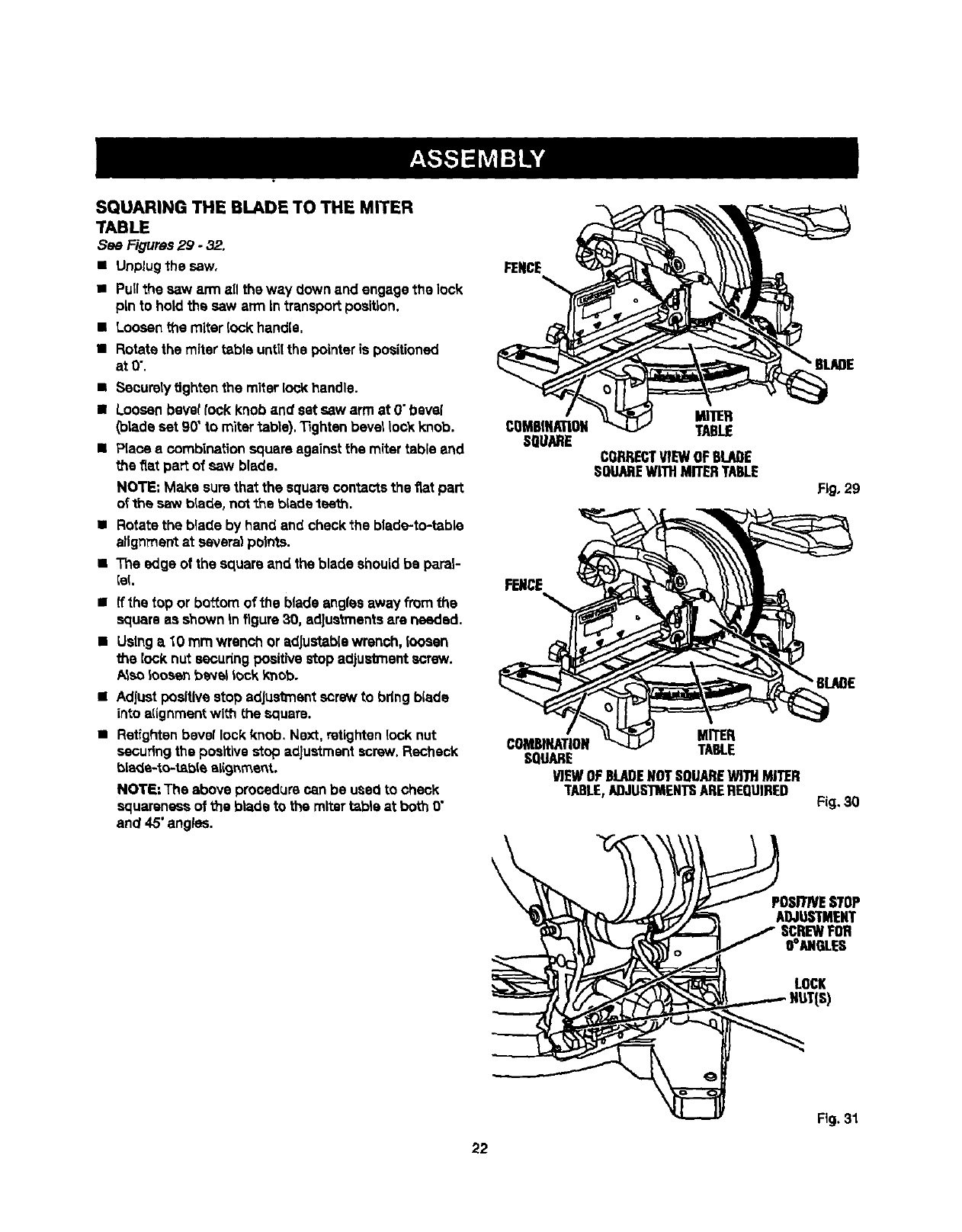
SQUARINGTHE BLADETOTHE MITER
TABLE
See Figures29 - 32.
• Unplugthe saw,
• Pullthe saw arm all the way down and engage the lock
pin to holdthe saw arm In transport position.
•Loosenthe miter lock handle.
•Rotatethe miter table untilthe pointeris positioned
atO'.
•Securelytightenthe miter lockhandle.
II Loosenbevellock knob and set saw arm at 0"bevel
(blade set 90"to mitertable). 33ghtenbevellock knob.
•Place a combinationsquare againstthe mitertable and
the fiat part of saw blade.
NOTE: Make surethat the square contacts the fiat part
o_the saw blade, notthe blade 1seth,
•Rotate the blade by hand and check the blade-to-table
alignmentat several points.
•The edge of the square and the blade shouldbe paral-
lel.
•ffthe top or bosom of the blade anglesaway from the
square as shown In figure30, adjustmentsare needed.
•Usinga 10 mm wrench or adjustable wrench, loosen
the lock nut secudngpositivestop adjustmentscrew.
/_so _oosenbeve_lock knob.
•Adjustpositivestop adjustmentscrew to bdng blade
into a(ignmentwiff_(he square.
•Ratlghtenbevel lockknob, Next, retightenlocknut
securingthe positivestop adjustment screw. Recheck
bla_a-to-t_bie elignmertt.
NOTE:The above procedure can be used to check
squareness of the blade to the mitertable at both 0"
and 45"angles.
FENCE
COMG[NATION
SQUARE
FENCE
COMB_ATION
SQUARE
\
MITER
TABLE
CORRECTVIEWOFBLADE
SOUABEWITHMITERTA6lE
MITER
TABLE
VIEWOFBLABENOTSQUAREWITHMITER
TABLE,ABJUSIMENTSAREREQUIRED
•BLADE
Rg, 29
Fig,30
POSI"FNESTOP
ADJUSTMENT
rFOR
O°ANGLES
LOCK
22
Fig.31
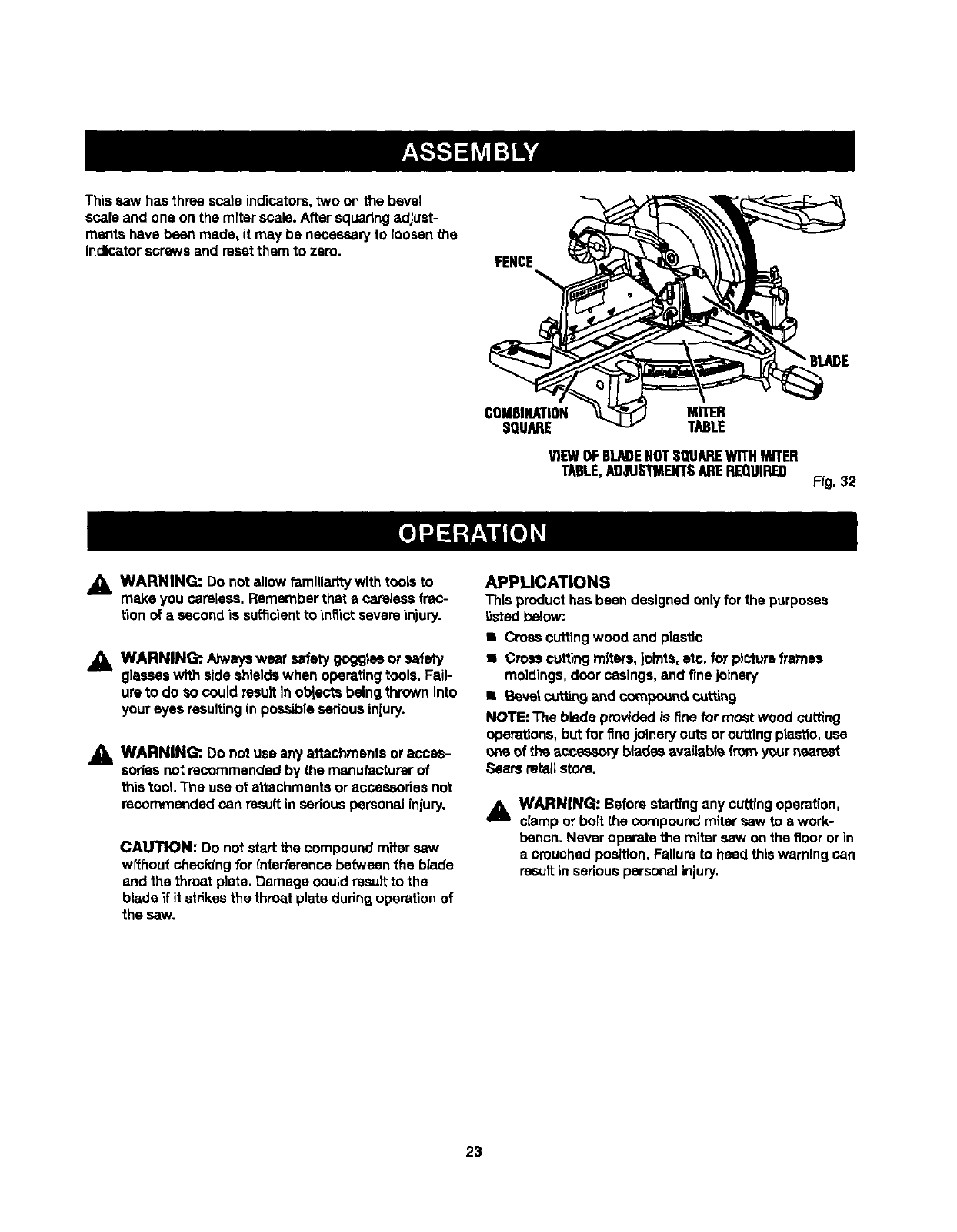
Thissawhasthree scale indicators,two on the bevel
scale and one on the miterscale. Aftersquadngadjust-
ments have been made, it may be necessaryto loosen the
Indicator screws and reset them to zero. FENCE
•BLADE
COMBINATION
SQUARE MnER
TABLE
VIEWOFBLADENOTSQUAREWITHMITER
TAm.E,ADJUSTMENTSAREREQUIRED Fig. 32
_1= WARNING: Do notallow famlllarltywlth tools to
make you careless. Remember that e carelessfrec-
tion of a second is sufScient to inflict severe in)ury.
,_ WARNING: Ahvayswear safetygoggle or safety
glasseswith side shieldswhen operatingtools. Fail-
ure to do so could resultIn oblects beingthrownInto
your eyes resultingin possibleseriousinjury.
_, WARNING: Do not usa any attachmentsor acces-
sories not recommended by the manufacturer of
this tool The use of attachmentsor accessoriesnot
recommendedcan result inseriouspersonalinjury.
CAUTION: Do not start the compoundmiter saw
wfthout checkingfor interferencebetweentile bIade
and the throat plate. Damage could resultto the
blade if it strikesthe throat plate dudng operationof
the saw.
APPLICATIONS
This product has been designed onlyfor the purposes
_sted _,ow;
• Crosscuttingwood and plastic
• Crosscuttb_gmiters, joints,etc. for pictureframes
moldings,door casings,and finejoinery
•Beret c_ttin9 and compound cu_n 9
NOTE. The blade providedis finefor most wood cutting
operations,but for finejoinerycuts or cuttingplastic, use
oneof the acoesso_ blades availabk_fromyour nearest
Sears retail store.
AWARNfNG: Beforestartingany cuttingoperation,
clampor bolt the compoundmiter saw to awork-
bench. Neveroperate the miter saw on the floor orin
a crouchedposition.Fallursto heed thiswarning can
resultin seriouspersonalinjury.
23
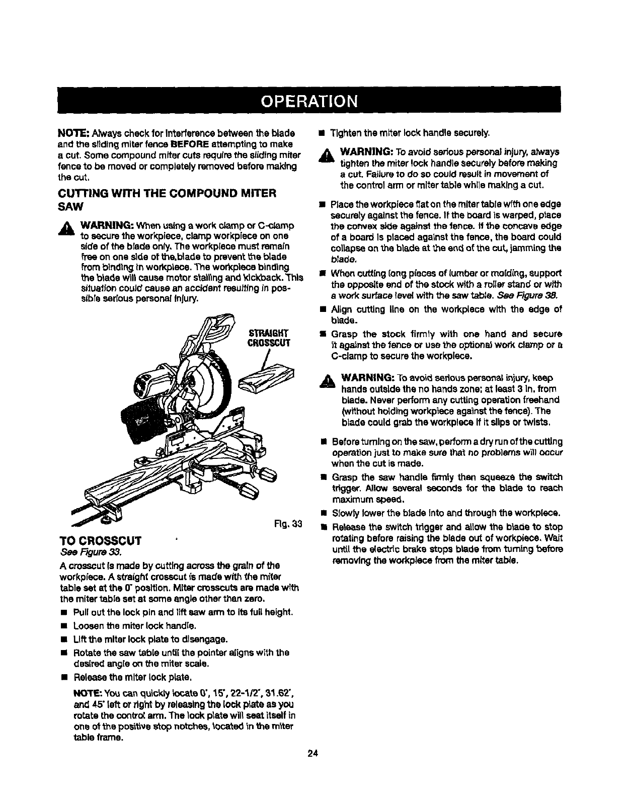
NOTE:Always check for Interferencebetween the blade
and the sliding miter fence BEFORE attempting to make
a cut. Some compound mitercuts requirethe slidingmiter
fence to be movedor completelyremoved before making
the cut.
CUTTING WITH THE COMPOUND MITER
SAW
,_ WARNING: When usingawork c_mp or C-c_mp
to securethe workpiece, clamp workpieca on one
sideof the blade only.The workpiese must remain
free onone ride of the.blade to prevent the blade
frombinding inworkplace. The workpleca binding
the b_adewgtcause motor stallingand klckback.'Thls
siluafioncould cause an accident resumingin pos-
slbresedous personalinjury.
STRAtGHT
CROSSCUT
TO CROSSCUT
See Rgure 33.
A crosscut(smade by cuffingacrossthe grainof the
workpieca. A straightcrosscutis made with the miter
table set at the 0"position.MRercrosscutsare made wlth
the mitertable setat some angle otherthan zero.
• Pullout the lockpin and liftsaw arm to its full height.
•Loosenthe miter lockhandle.
• Uft the miterlock plateto disengage.
•Rotatethe saw table until the pointer alignswiththe
desiredangle onthe miter scale.
•Rsioasethe miterlock plate.
NOTE: Youcan qu'_cklyk_cats_', 15°,22-1/2", 31.62",
and 45"leftorright by releasingthe lock plate as you
rotate the contr_ arm. The lock plata wil_seat itselfin
one of l_e pes_ve stop notches,located in the m_ter
table frame.
• Tighten the miter lock handle securely.
_k WARNING: Toavoid seriouspersonal injury, ahvays
tightenthe miter lock handlesecurely beforemaking
a cut. Failureto do so could resultinmovementof
the controlarm or mitertable while makinga cut.
•Place theworkplacefiat on the mitertable withoneedge
securely against the fence, if the boardiswarped, place
the convex side against the fence, ff1he concave edge
of a board Is placed against the fence, the board could
collapseon the blade at the end of the cut,jammingthe
b!ade.
•When cutt'mg(ong piecesof lumberor mo(ding, support
the oppositeend of the stock wRha rollerstand orwith
a worksurface level with the saw table. See Figure38.
Align cutting line on the workplace with the edge of
blade.
Grasp the stock firmly wilh one hand and secure
it against the fence or use the optional work clamp or a
C-clamp to secure the workplece.
_1_ WARNING: Toavoid seriouspersenalinjury, keep
hands outsidethe no hands zone; at least 3 In. from
blade. Never perform any cuttingoperationfreehand
(withoutholdingworkpiece againstthe fence). The
blade couldgrab the workplace If It slips ortwists.
•Beforeturningonthe saw,perform a dryrunofthe cutting
operationjust to make surethat no problemswill occur
whenthe cut is made.
•Grasp thesaw handle firmly then squeeze theswitch
trigger. Allow several seconds for the bladeto reach
maximum speed.
ISIowh/lowerthebladeintoand throughtheworkplece.
•Rsieese the swRch trigger and allowthe blade to stop
rotatingbefore raisingthe blade out of workpiece, Wait
untilthe doct_c brake stops blade from toming before
removingthe workplace from the rarer tab_e.
24
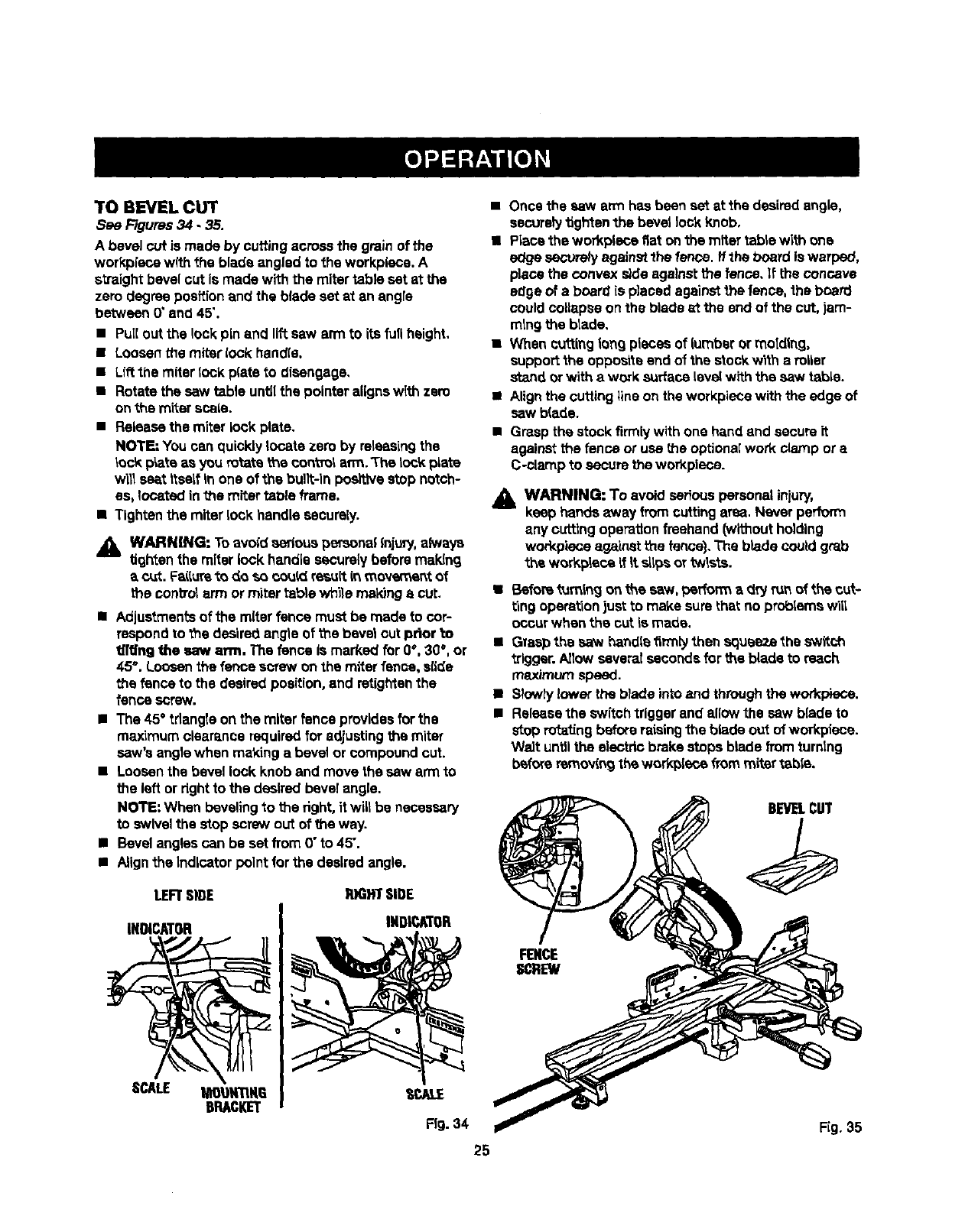
TO BEVELCUT
See Figures 34.35.
A bevel cut is made by cuffingacross the grainof the
workp{ecewith the blade angled to the work,piece. A
straight bevelcut is made withthe mitertable eat at the
zero degree positionand the blade set at an angre
between 0"and 45".
• PU[[outthe lock pin and liftsew arm to its fullheight.
•Loosenthe miter lock handle.
•L{f_the miter lock plate to disengage,
•Rotate the sew table until the pointer aligns wlth zero
on the miter scale.
•Release the miter lock plate.
NOTE: You can quickly locate zero by releasing the
lock p_ata as you rotate the Control arm.'The lock plate
will east tteaLfin one of the built-In positive stop notch-
es, located in the miter table frame.
•Tighten the miter lock handle securely.
_lb WARNING: Toavbld serious persona|{nit,a7,always
tightenthe miter lockhandle securely before mak{ng
acut. Faitureto do so could resultin movement of
the conbol arm or miter babtewh'dema_ng e cut.
•Adjustmentsof the miter fence mustbe made to cor-
respondto the desiredangle of the bevel cut prior 'm
tfting the saw arm. The fence is markedfor 0%30°, or
45% Loosenthe fence screw on the miterfence, slide
the fence to the desiredposition,and retightanthe
fence screw.
•The 45" triangle onthe miter fence providesfor the
maximum clears.acerequiredfor adjustingthe miter
saw's anglewhen making a bevel or compoundcut.
•Loosenthe bevellock knob and move the saw arm to
the left or rightto the desired bevelangle.
NOTE"When bevelingto the right,it wilt be necessary
to swivel the stop screw out of the way.
•Bevelanglescan be set from 0"to 45".
•Alignthe Indicatorpoint for the desiredangle.
LEFTSn)E R)GHTSIDE
INDICATOR
SCALE _U_R6
B_CKET
INDICATOR
25
• Once the saw arm has been set atthe desiredangle,
securelytightenthe bevet lock knob,
•Piece the workp_ecefiat on the miter table with one
es_gesecurelyagainstthe fence, if the board iswarpe_,
place the convex sideagainst the fence, _fthe concave
edge of a board is p)aced againstthe fence, the board
couldcollapseon the blade st the end of the cut. jam-
mlng the btade.
•When cutting_ongpieces of lumberor mbldlng,
supportthe oppositeend of the stock with aroller
stand orwith a work surfaceteve_with the saw table.
•Alignthe cuffingline on the workpiecewith the edge of
sew blade.
•Grasp the stock firmlywith one handand secureit
against the fence or use me optionalwork clampor a
C-clamp to securethe workplace.
_. WARNING: To avoid serious personalinjury,
keep hands awayfrom cuttingarea. Never perform
any cuttingoperationfreehand Without holding
workpieceagainst the fence),The b_adecould grab
'_heworkplace Lf_tsl_psor twists.
• Before turn_ngon the sew, performa dry run of +,hecut-
ring operat'Lonjust to make sure thatnoproblems will
occur when the cut is made.
•Graspthe saw handle firmlythen squeezethe switch
'_rlgger.Allowseveralsecondsfor the blade to reach
maximum speed.
• Slowlylower the blade intoand throughthe workpiece.
•Releasethe switch triggerand allow the saw blade to
stop ro_ling before raisingthe blade out of workpiene.
Wait untilthe electric brakestops blade fromturnlng
befere removingthe wor!_[soe from miter ruble.
BEVELCUT
FENCE
SCREW
FIg. 35
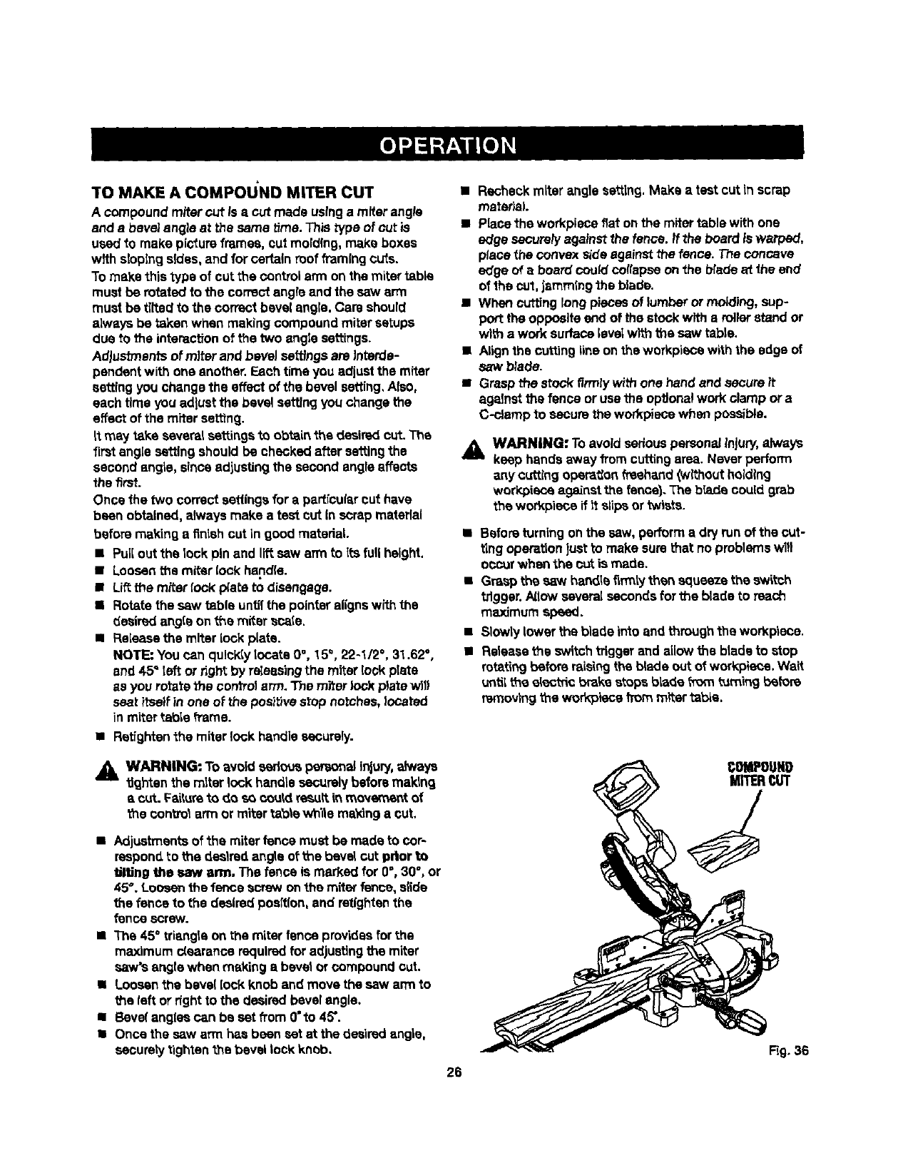
TO MAKE A COMPOU'ND MITER CUT
Acompoundrafter cut Is acut made usingamiter angle
and abevel angle at the same _me. This type of cut is
usedto make pictureframes, cut molding, make boxes
wfth slopingsides, and for certain roofframingcuts.
To make this type of cut the contreiarm on the mitertable
must be rotated to the correct angle and the saw arm
must be tilted to the correct bevel angle.Care should
always be taken when making compoundmiter setups
due to the interactionof the two angle settings.
Ad)ustmentsof miter and bevelsattfngs are interde-
pendentwith one another. F.schtime you adjustthe miter
eetting you change the effect of the bevel setting, Also,
each time you adjustthe bevel setting youchange the
effect of the miter sethng.
tt may take severalsettings to obtainthe desiredcut. The
firstangle sa_lng should be checkedafter settingthe
second angle, sinceadjustingthe second angleaffects
the first.
Once the two correct settingsfor apartfcularout have
been obtained, always make a test cut In scrap material
before making afinish cut in good matedai.
•Pullout the lock pin and liftsaw arm to its full height.
• Loosenthe miter [ock hend(e.
•Liftthe miterlock p_ateto disengage.
• Rotate the saw fable unt_ the pointeralignswith the
desiredangle on the miter scale.
• Release the miter lockplate.
NOTE: Youcan quloldylocate0°, 15°, 22-1/2 °, 31.62°,
and 45" left or fight by ra_sasingthe miter lock plate
as you rotatethe controlarm. The miterlock plate will
seat itselfin one of the positivestop notches,located
in mitertable frame.
•Retightan the miter lock handle securely.
•Recheck miter angle setting. Make a test cut In scrap
matedaL
•Place the workpiece fiat on the miter table with one
edge sacureh/against the fence, ff the board is warped,
place the convex side against the fence. The concave
edge of aboard could collapse on the _ade at the end
of the cut, jamming the blade.
•When cutting long pieces of lumber or molding, sup-
port the opposite end of the stock with aroller stand or
with a work surface lava/with the saw table.
•Align the cutting line on the workpiece with the edge of
saw blade.
•Grasp the stock firmly with one hand and secure it
against the fence or use the optiona! work clamp or a
C-clamp to secure the workpiese when possible.
_1= WARNING: Toavoid seriouspersona/Injury,always
keep hands away from cuttingarea. Neverperform
any cutting operation freehand (without holding
workpisce against the fence). The b_aLdacould grab
the workpiece ff _tslips or twists.
•Before turningon the saw, performa dry run of the cut-
ting operationlustto make surethat noproblemswl!l
occurwhen the cut is made.
• Grasp the saw handletirmiy then squeeze the switch
tdgger.A_lowseveral secondsfor the blade to reach
maximum speed.
•Slowly lower the blade into andthroughthe workpiase.
•Releasethe switchtrigger and allowthe bladeto stop
rotatingbefore raisingthe blade out of werkpiece. Wait
untilthe e_ecthcbrakestops blade from turningb_fore
removingthe workplacet"rommlter ta_a,
_. WARNING: To avoid sedous_al injury, always
tightenthe miter lock handlesecurelybefore making
acut. F_ture to do so couldrasuitin movement of
'{hecontrolarm or mitertable wh'_tsma_ng a cut.
•Adjustmentsof the miterfence must be made to cor-
respond to the daslredangle of the bevel cut prior to
tJlUngthe saw arm. The fence is marked for 0°, 30°, or
45°, Loo_ the fence screw on the mit_ fence, s_de
the fence to the desired poeftlon,and ret|ghtanthe
fence screw.
•The 45° triangle on the miterfence providesfor the
maximum c{sarancerequired for adjustingthe miter
saw's angle when making a bevel or compound cut.
•Loosenthe bevel lock knob and move the saw arm to
the left or right to the desiredbevel angle.
•Bevelengias can be set from 0"to 45".
•Once the saw arm has been sat at the desiredangle,
sacurety tightenthe bevel lock knob.
26
Fig. 36
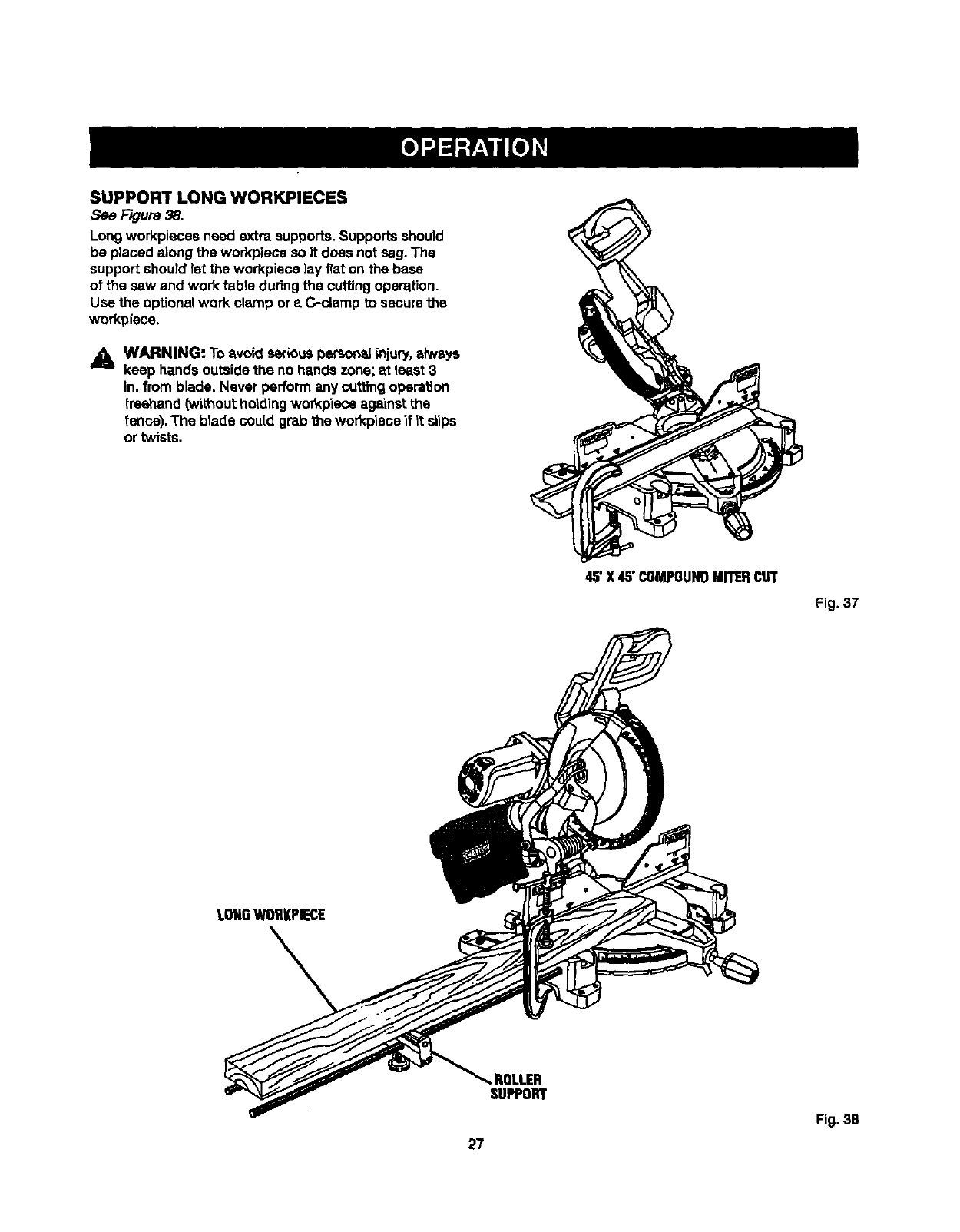
SUPPORT LONG WORKPIECES
See Figure38.
Longworkpieces need extra supports.Supportsshould
be placed along the workp)ece so it does not sag.The
support should let the workpisoe lay fiat onthe base
of the saw and work table dudng the cuffingoperation.
Use the optional work clamp or s C-clamp to securethe
workpisoe.
L_, WARNING'. Toavoid seriouspersonalinjury,alwsys
keep hands outsidethe no handszone; at least 3
in. from blade. Never performany cuffingoperation
freehand(wikhouLholding workp'Leoeagainst the
fence). The blade cupid grab the wor_pleoe i1It slips
ortwists.
45"X 45"COMPOUNDMITERCOT
Fig. 37
LONGWOR|(PIECE
ROLLER
SUPPORT
Fig. 38
27
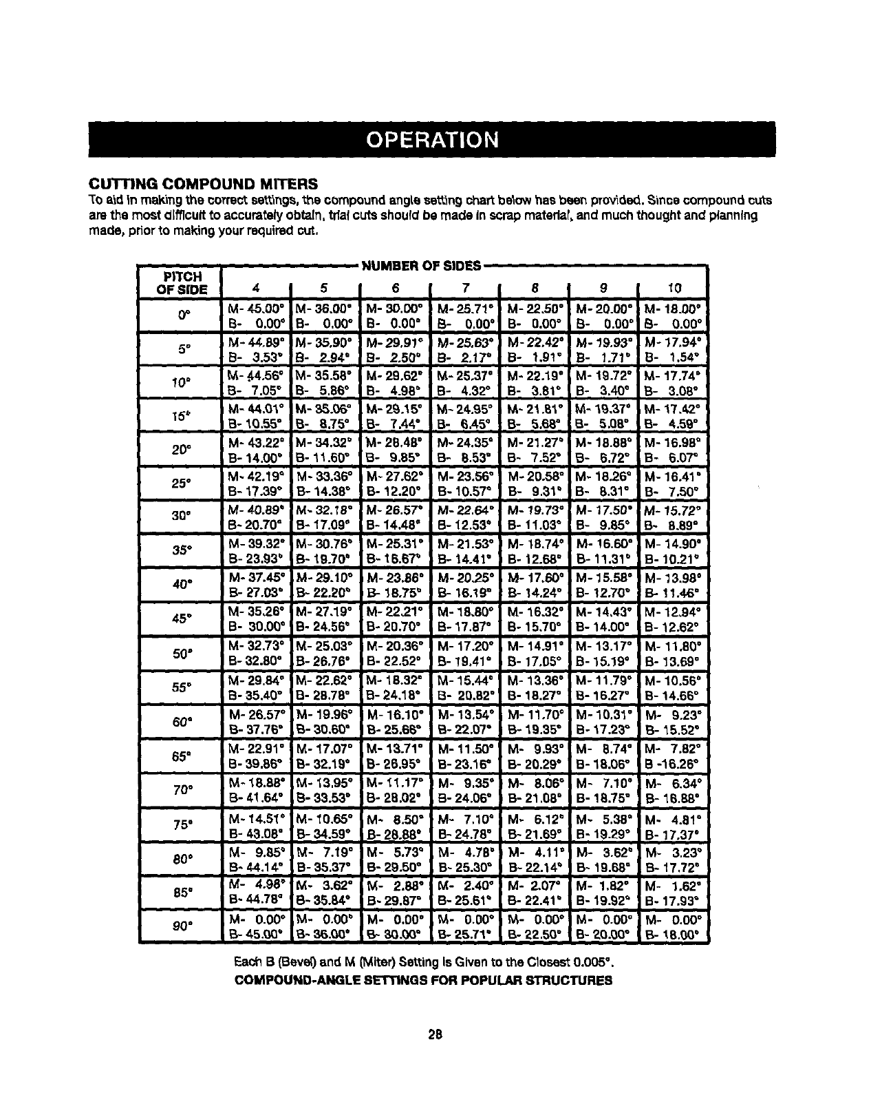
CUTTINGCOMPOUNDMITERS
"toa%d|nmaking the coTrectsettings,_e compound angle se_n9 chaTtbelow has been provided.,_nce compound cuts
are the most difficult to accurately obtain, trialcuts should be made in scrapmatedar,and muchthought and planning
made, priorto makingyour requiredcut.
PITCH
o =oE 4I5I6I7IsI9Ito
O" M-45"00° M-36"00° M'3D'O0° M'25"71° M-22"50° M'20"O0° M'18"00°
B- 0.00° B- 0,00" B- 0,00" B- 0,00°B- 0.00" B- 0.00°B- 0.00 °
5oM-4_..89 °M-35.90 °M-29.91 ° IM-25.63 ° M-22.42 ° M-19.93 ° M-17.94 °
B- 3.53" B- 2.94°B- 2.50 ° B- 2.17° B- 1.91" B- 1.71" B- 1.54"
10o M.-.44.56° M-35.58 ° M-29.62 ° M-25.37 °M-22.19" M-19.72 ° M-17.74 °
B- 7,05 =8- 5,86°8- 4.98°B- 4.32° B- 3.81° B- 3.40°8- 3,08°
15" M-44"0_'° M-35"06° k_-29"15°iM-24'g50 _'2_'_° M'I°_'37° M'17"42°
8-1Q.55 ° 8- 8.75°8- 7,44°iB- 6.45°B- 5.68°B- 5,08° B- 4.59°
20" M'43'22= M'34'32° M'28'48° M'24'35° M'21'27° M'18"88° M'16"98°
B-14,00 °B-11.60" B- 9.85" 8- 8.53" B- 7.52" B- 5.72" B- 6.0"r
M-42.19 °M-33.36 ° M-27.62 °M-23.56 °M-20.58 °M-18.26 QM-16.41 °
25°B-17.39" B-14.38 ° B-12.20" I B-10,57 °B- 9,31°B- 8.31° B- 7.50°
30° M-40.89 _M-32._8 °M-28.57 _M-22,64 ° M-!9.73 °M-17.50 ° M-15.72 °
B-20.70" B-17.09 ° B-14.48 ° B-12.53 ° B- 11.03°B- 9.85°B- 8.89°
35°M-39.32 °M-30.76 bM-25.31 °M-21.53 °M-18.74 ° M-!6.60 °M-14,90 °
8-23.93 b8-'t9.70 °B"tB.6"P 8-14.41 ° B-12.68 °8-11.31 °8-10.21 °
40°M'37.45 °M-29.10 °M-23.86 °M-20,25 °M-17.60 °M-15.58 ° M-13,98 °
B-27.03" B-22.20 =B- 18,75' B- 16.19=B- 14.24° B- !2.70 =t3- 11.46°
M-35,26 °M-27,19 °M-22,,?.1=M-18,80 °M-16.32 ° M-14,43°1 M-12,94 °
45 °B- 30.00°B-24.56 _B-20.70 °B-17.87 °B-15,70 ° 8-14.00 °B-12.62 °
M-32.73 °M-25,03 ° M-20.36 ° M-17.20 °M-14.91 °M-13.17°mM-11.80°
50° B-32.80 °B-26,76 ° B-22.52 °B- 19.41° B- 17.05°B-15,19 °B- 13.69°
M-29,84 ° M-22.62 ° M-18.32 °M-15.44 °M-13,36 ° M-11.79°! M-10.56 °
55 ° 8-35,40" B- 28.78°8-24,18 °El- 20.82° B- 18,27°8- 16.27° 8- 14.66°
M-26.57 °M-19.96 °M-16.10 °M-13.54 ° M-11.70 °M-10.31 °' M- 9.23 °
60° B-37,76 °B-30.60 ° 8-25.65 °B-22.07 °B-19.35 ° 8-_7.23 ° B- 15,52°
M-22.91 °M-17.07 °M-13-71 °M-11,50 ° M- 9.93°M- 8.74°M- 7.82 °
65° 8-39.86 ° 8-32.19 ° 8- 26.95° 8-23.16" 8-20.29 °8-18.06" 8-16.25 °
70" M-18.68 °M-13,95 °M-11.17 °M- 9,35°i M- 8.06°M- 7.10°' M- 6,34 °
8-41.64 °B-33.53 ° 8-28.02 °B-24.06 ° B-21.08 °B-18.75" B-16.88 °
i
75°M'14.51 °M-10.65 °M" 8.50°M- 7,10=M- 6.12°M- 5.38°' M- 4.81°
B" 43.08°8-34.59 ° B-28.88 ° B-24.78 °B-21.69 °B" 19.29" B- 17.37°
80°M- 9.85°,M- 7.19°M" 5.73°M- 4.78°1 M- 4.11°M- 3.52°' M- 3,23=
8.44.1,€ °B-35.37 oB-29.50 °8.25.30 °I B. 22.14_B. 19.68=B. 17.72o
M- 4.98 °M- 3.62 °M- 2.88° M- 2.40° M-2,07 °M-1.82 ° M- 1.62"
85° B'44.78 °B-35.84 °B-29.87 =B-25.61 =B- 22.41 °B- 19.92= B- 17.93=
M- 0.00° IM" 0.00 °M- 0.00° M- 0.00° I M- 0.00° M- 0.00° M- 0.00 °
90° _- 45._ _ B- 36.00 °15-30.00= _" 25.71°I_ 22,50 °IB-20.00°B- 18,00°
Each B (Bevet)and M(Miter) Setting is Givento the Closest 0.005°.
COMPOUND-ANGLE SETTINGS FOR POPULAR STRUCTURES
28
CUTrlNG CROWN MOLDING
"['hecompoundmiter sew does an excellentjob of cut-
ting crown molding. In general, compound mRersaws do
abetter jo_ of cuttingcrown moldingthen any othertool
made.
In orderto fit properly,crown molding must be compound
miteredwith extreme accuracy.
The two contaet surfacesor_a piece of crown motdtng
that fit fiat againstthe cettlngand the wall of a room are at
anglesthat, when added together,squatexactly gO'. Most
crown molding has a top rest angle (the seetfonthat fits
fiat against the ceiling)of 52"and a bottom rear angle (the
sectionthat fits fiat against the wall} of 36".
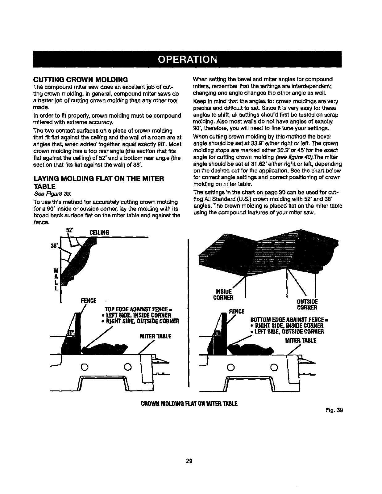
LAYING MOLDING FLAT ON THE MITER
TABLE
See Figure 39.
"Touse this method for accuratelycutting CTownmolding
for a 90"insideor outsidecorner, laythe moldingwith its
broad back surfacefiat onthe m_tertable end against the
fence.
52" CEILING
When setting the bevel and miter angles for compound
miters, remember that the se_ings areinterdependent;
changing one angle changes the other angle as well.
Keep in mind that the angles for crown moldings ere very
preeise end diff_cuitto set. Since it is veryeasy for these
angles to shift, all settings shoutd first be tested on scrap
molding. AJso most walls do not have angles of exactly
90", therefore, you will need to fine tune your seffings.
When cuffing crown molding by this method the bevel
angle should be set at 33,9" either right or left. The crown
molding stops are marked either 33.9" or 45" for the exact
angle for cutting crown molding (see figure 40).The miter
angle should be set at 31.62" either right or left, depending
on the desired cut for the application. See the chart be|ow
for correct angle settings and correct positioning of crown
molding on miter table.
The seffings in the chart on page 30 can be used for cut-
ttng AJ]Standard (U.S.) crown molding with 52" and 38"
angles. The crown molding is placed/]at on the miter tsble
using the compound features of your miter sew.
w
A
L
L
FENCE
TOPEDGEAGMHSTFENCE-
• LEFTSIDE,INSIDECONNER
•RIGHTSIDE,OUTSIOECORMER
00
MITERI"NSLE
INSIDE
CORNER
FENCE
OUTSIDE
CORtiER
BOTTOMEDGEAGAINSTFENCE-
•RIGHTSIDE,iNSIDECORNER
•LEFTSIDE,OUTSIDECORNER
MITERTABLE
CROWNMOLDINGFLATONMtTER'TAlSLE
Fig. 39
29
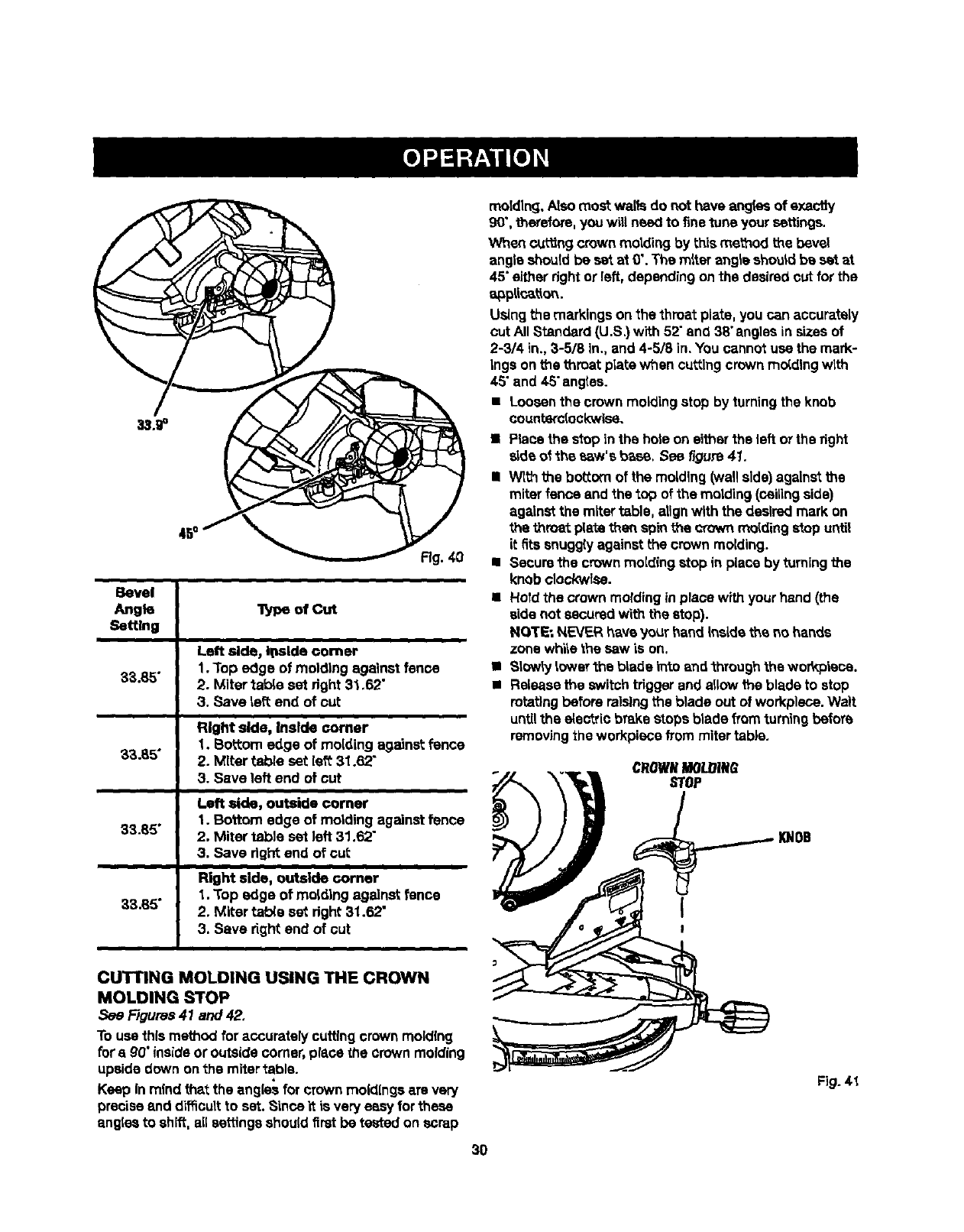
Fig.
Bevel
Angle lype of Cut
Setting
Left side, Ioside comer
1. Top edge of molding against fence
33.85" 2. Miter lathe set right 3_.62"
3. Save taft end of cut
Right side, Inside comer
1. Bottom edge of molding against fence
37,.35" 2. Miter table set left 31.62"
3. Save left end of cut
Left side, outside comer
1. Bottom edge of molding against fence
33.85" 2. Miter table set left 31.62"
3. Save dght end of cut
Right side, outside corner
1. Top edge of molding against fence
33.85" 2. Miter tab(e set dgh_ 31.62"
3. Save fight end of cut
molding.Alsomost walls do not have angles of exactty
90",therefore,youw,I need to finetune your settings.
When cuing crown mo_inc3 by this me_od the bevel
angle shouldbe set at 0". The m_tarangle should be s_tat
45"either dght or left,depending onthe desiredcut for the
a_plic_on.
Usingthe markingson the throat plate, you can accurately
cut All Standard (U.S.) with 52"and 38"anglesinsizesof
2-314 in., 3-5/8 In.,and 4-5/8 in. YOUcannot use the mark-
Ings on the throat plate when cuttingcrown molding with
45"and 4.5"angles.
•Loosenthe crown molding stop by turningthe knob
counterclockwise.
n P_ce the stopin the hole on eitherthe left orthe fight
sideof the saw's b_,se.See/iguro 41.
•Wlth the bottom of the molding(wallside)against the
miterfence and the top of the molding(ceilingside)
againstthe mRertable, aUgnwith the desiredmark: on
the throat plate themspk_the _own residingstop until
it fits snugglyagainst the crown molding.
•Securethe crown molding stop in place by turningthe
knob clockwise.
•Hold the crown molding in place with your hand (the
side not securedwith the stop).
NOTE: NEVF_Rhaveyour hand _nsidethe no hands
zone whi_ethe sew is on.
• Slowly tower the blade mrs andthrough the wor_oisce.
•Releasethe switchrigger and allow the blade to stop
rotatingbefore relsing the blade outof workplace. Wait
untilthe electric brakestops blade fTomturningbefore
removingthe workpisce frommiter table.
CROWNMOinlRO
STOP
CUTTING MOLDING USING THE CROWN
MOLDING STOP
See Figures41 and 42.
Touse this method for accurately cuffingcrown molding
fora g0"insideor OutSidecomer, place the crown molding
upsidedown onthe mitertable.
Keep Inmind that the angles for crown moldingsare very
precise and difficultto set, Since "¢_is very eseyfor these
angles to shift, allseffinga should firstbe tested on scrap
Fig. 4.t
3O
MARKINGSON
THROATPLATE
Fig.42
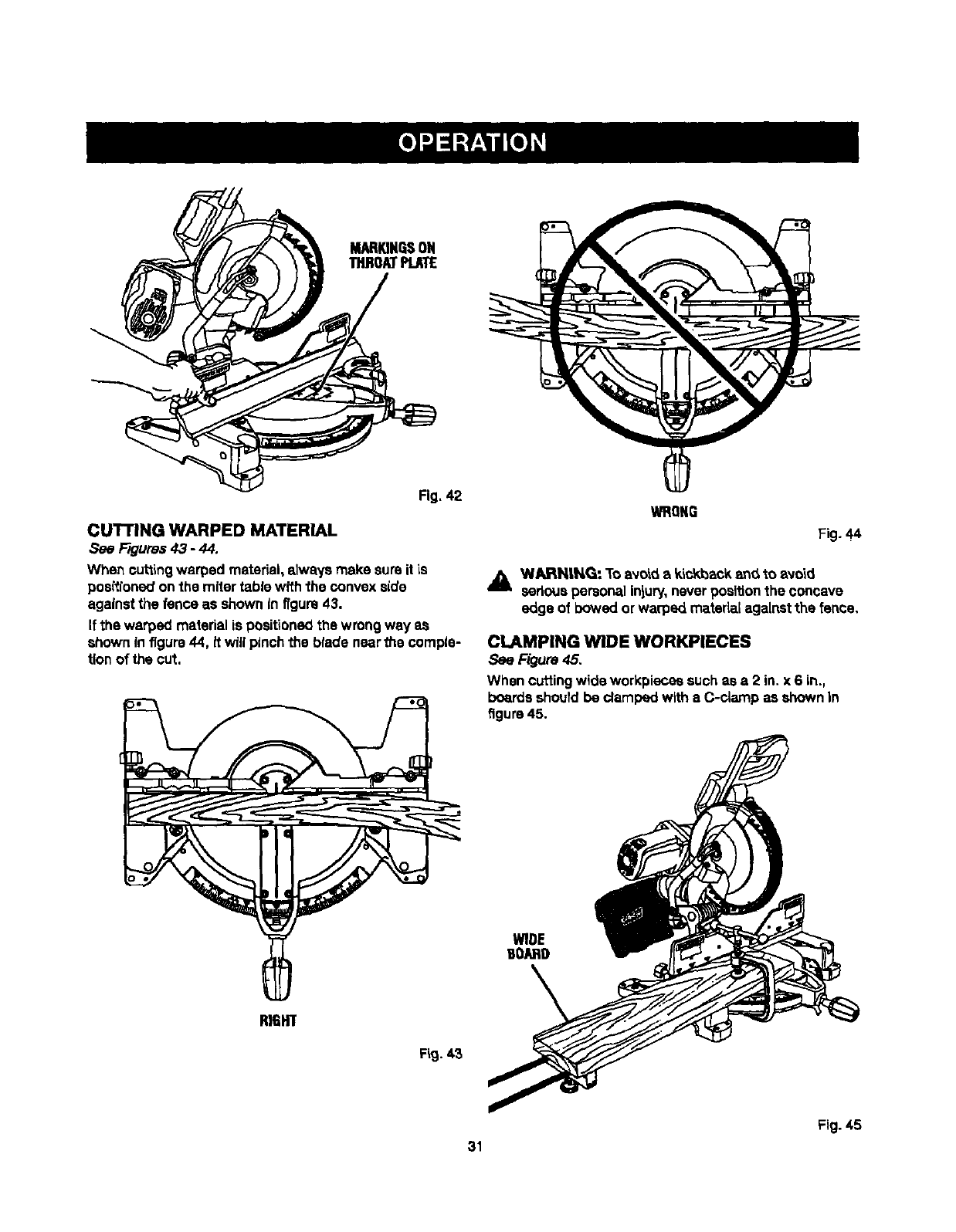
CUTTINGWARPEDMATERIAL
Rgums 43 -44.
When cuttingwarped material,elways make sureit is
positioneo'on the miter tablewith the convex side
against the fence as shown in figure43.
If the warped material is positionedthe wrong way as
shown in figure44, it will pinchthe blade nearthe comple-
tion of the cut.
WRONG
Fig. 44
_lk WAJRHtN,G: To avo_ akickback_ to avoid
asdous personalinjury,never positionthe concave
edge of bowed or warped material against the fence.
CLAMPING WIDE WORKPIECES
See Figure45.
When cuttingwide workpiecassuch as a 2 in. x 6 in.,
boardsshould be damped with a C-clamp as shown In
figure45.
WIDE
UOARD
RIGHT
Fig. 43
Fig. 45
31
,_ WARNING: Before performing any adjustment,
make surethe tool Is unpluggedfromthe power
supplyand the switch is in the OFF ( O ) position.
Failureto heed thiswarning could result in serious
personal Iniury.
The compound miter saw has been adjusted at the fac-
tory for makingvery accurate cuts. However,soma of the
components might have moved outof alignmentduring
shipping.PJSO,over a period of time, rsadlustmentwill
probably become necessarydue to wear. Afterunpacking
the saw, check the foflowing adjus_xnentsbefore you
begin usingsaw. Make any readjustmentsthat are
necessaryand periodicallycheck the partsalignment
to make surethat the saw is cuttingaccurately.
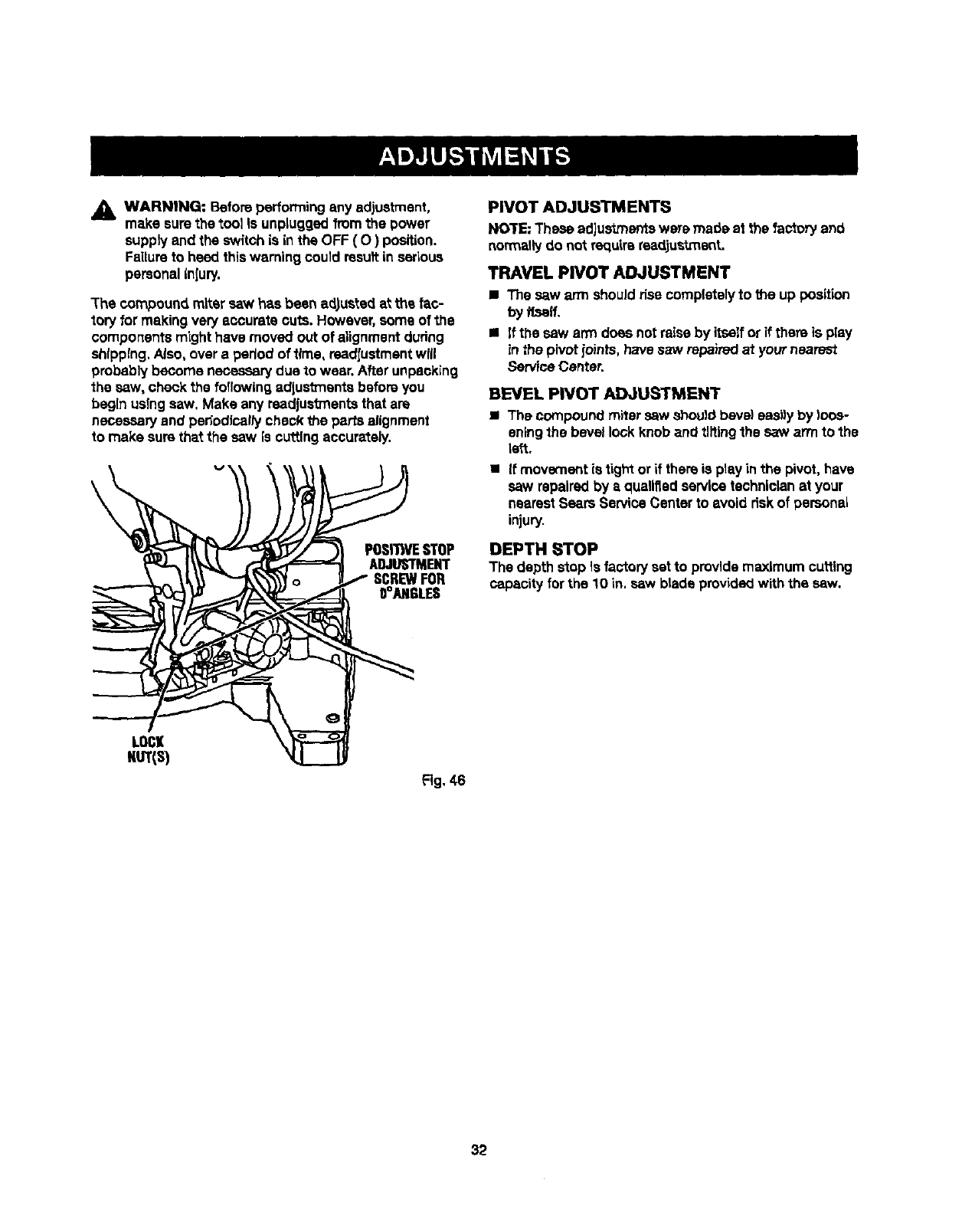
v__P0SI_VE STOP
AOJUS NENT
oI,y FOR
LOC
NUT(S)
Fig. 46
PIVOT ADJUSTMENTS
NOTE: These adjustmentswere made at the factory and
norm=ly do not requirereadjustment.
TRAVEL PIVOT ADJUSTMENT
• The saw arm shouldfisa completelyto the up position
by flsalf,
•If the saw arm does notraise by itself or if there is play
in the pivot ioints, have saw repaired at yournearest
ServiceCenter.
BEVEL PIVOT ADJUSTMENT
•The compound mitersaw Shouldbevel eeai)yby loos-
eningthe bevel lockknob and tiffingthe saw arm to the
left.
• If movement is tight orif thereis play in the pivot,have
saw repairedby aqualifiedservicetschnlclan at your
nearestSears Service Center to avoid riskof personal
injury.
DEPTH STOP
The depth stop is factorysetto providemaximumcuffing
capacity forthe 10 in. saw blade providedwith the saw.
32
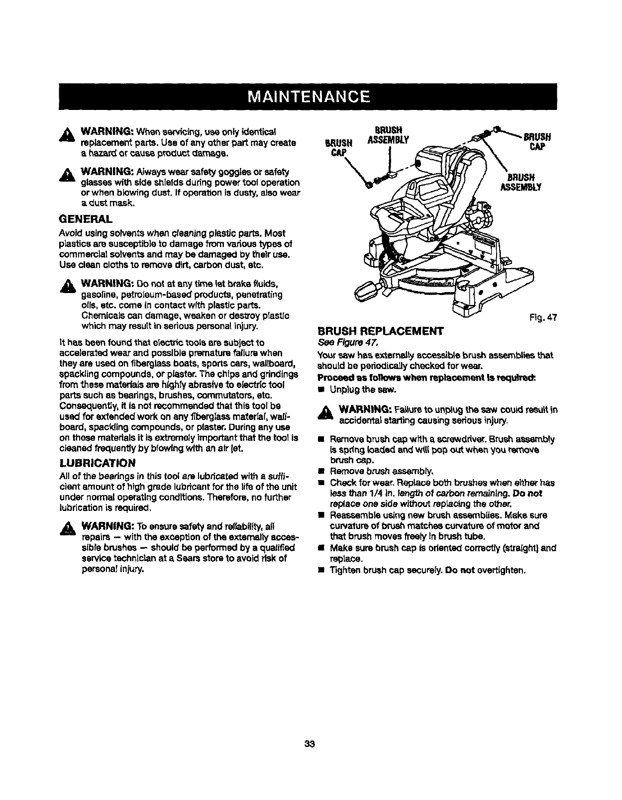
j_ WARNING: When ssr_blng, use only _dentlcal
replacementparts. Use of any other part maycreate
ah,_._rdor c_use product da_ge.
_IL WARNING: Always wear safety goggissor safety
glasseswith sideshieldsduringpower tool operation
orwhen blowingduet. If operationis dus_, also wear
a dust mask.
GENERAL
Avoidusingsolventswhen qleaning pisstlc parts. Most
plastlcaare susceptibleto damage fromvadous types of
commercialsolventsand may be damaged by their use.
Use clean clothe to remove dirt,carbondust, etc.
_1_ WARNING: Do not at any t_',e let brake fluids,
gasoline,petroleum-b,'tsedproducts,penetrating
oils, etc. come in contact with plastic parts.
Chemicals Pan damage, weaken or destroy pisst[c
which may rsoutt in serious personal in)ury.
tt has been foundthat electric tools are subject to
eccaismtsd wear and possibleprematurefailure when
they are used on fiberglassboats, sports cars,waltboard,
spacklingcompounds, or plaster.The chips and grindings
fromthese materialsare high,/abrasive to electdctool
partssuch as beadngs, brushes, commutators, etc.
Consequently,it is not recommended that 1histool be
usedfor extended work on any fiberglassmatsr_al,wall-
board, spacklingcompounds, or piaster.Duringany use
on these materials it is extremelyimportant that the tool is
cleaned frequentlyby blowingwith an air let.
LUBRICATION
All of the bearingsin thistool are lubricatedwith a suffi-
cientamount of highgrade lubdcant for the lifeof the unit
under normaloperatingconditions.Therefore,no further
lubricationis required.
_k WARNING: To ensuresafetyand re_ablll_, al_
repairs -- with the exceptionof the externallyances-
sibfebrushes- should be performed by a qualified
servicetechnicianat aSears storeto avoid dsk of
personatinjury.
Fig.47
BRUSH REPLACEMENT
see Figure47.
Yoursaw has externally eccessible brush assemblies that
shoutd be pedodicallychecked forwear.
Proceed as follows when replacement Is _qulred:
• Unplugthe saw.
,_ WARNING: Fs_ureto un_j the saw could resultin
eccidental startingcausingserious injury.
• R_oIa bnJ_'t _ap wit_. ascrewdriver.Brushassembly
Is spdng _oadedandWIUpop o_ when you remove
brushcap.
•Remove brushassembly,
•Check forwear. Reptacaboth brusheswhen either has
less than 1/4 In. length of carbonremaining. Do not
replace one sidewithout repisctngthe other.
•Reassembleusingnew brushsssembIiss. Make sure
curvatureof brushmatchsa curvatureof motor and
th= brush moves freelytn brushtube.
•Make surebrushcap is odantadcorrectly(straight)and
re_iace.
•Tighten brushcap securely. Do not overtighten.
33
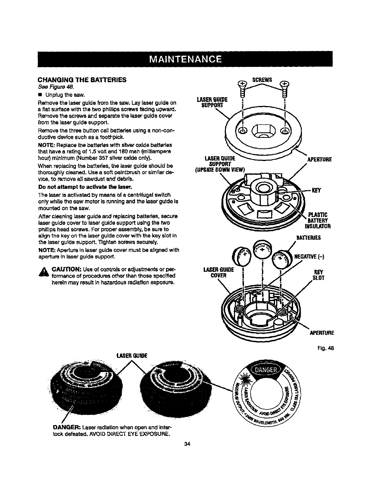
CHANGING THE BATTERIES
See Figure 48.
•Unp(ug the saw.
Removethe laear guidefrom the saw. Lay laserguide on
a fiat surfacewith the two phillipsscrews facing upward.
Removethe screws and separatethe laserguidecover
fromthe laser guide support.
Removethe three buttonceil batteries usinga non-con-
ductJvede_ce suchas a toothpick.
NOTE: RepLacethe batteries wRhsilveroxide batteries
that have a retingof 1.5 voltand 180 mah (mitfiampem
hour)minimum(Number357 sliveroxide only).
When replacingthe batteries,the laserguide shouldbe
thoroughly cleaned. Use a soft paintbrushor similarde-
vice, to removeall sawdust and debds,
Do not attempt to activate the laser.
The |seer is activated by means of e centrifugal switch
ontywhile the saw motor is runningand the laser guide is
mountedon the saw.
After cleaning laserguide and replacingbatteries,secure
laserguide coverto laser guidesupport usingthe two
philtipshead screws,For properassembly,be sum to
alignthe key onthe laserguidecoverwith the key s]ot in
the laserguide support.Tighten screws securely,
NOTE: Aperture inlaser guidecovermust be aligned with
aperture(n laser guidesupport.
_IL CAUTION: Use of canve(s or adjustmenfa or per-
formance of proceduresother thanthose specified
_erelnmay resultIn hazardousradiationexposure.
LASERGUIDE ! I
SUPPORT
__
LASERgUIDE APERTURE
SUPPORT
(UPS_E DOWNVIEW)
PLASTIC
BATIERY
UISULATOR
REG_VE(-)
LASERGUIGE !j
COVER SLUT
U_ER gUIDE Fig,48
DANGER: Laser radiation when open and inter-
lock defeated. AVOID DIRECT EYE EXPOSURE.
34
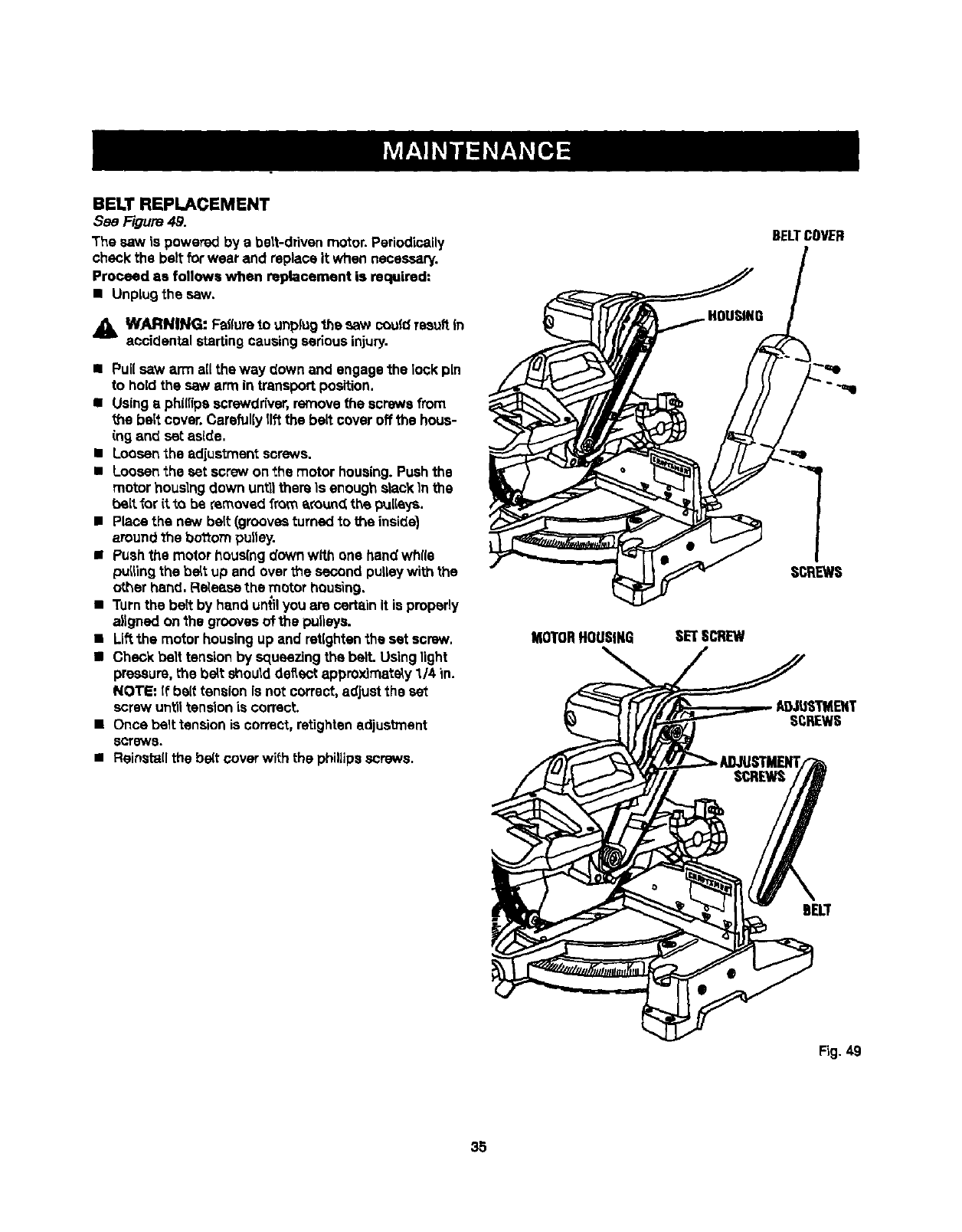
BELTREPLACEMENT
See Figure 49.
The saw is powered by a belt-drivenmotor. Periodically
check the beltfor wear and replace it when necessary.
Proceed as follows when replacement is required:
• Unplug the saw.
WARNING: Failureto unplug",hesaw couldrseuftin
accidental startingcausingseriousinjury.
•Pull saw arm all the way down and engage the lock pin
to holdthe saw arm in transportposition.
• Usingaphi(iipascrewdriver,removethe screws from
the belt cover.Carefullylift the belt cover off the hous-
ing and set aside,
•Loosenthe adjustment screws.
•Loosenthe set screw on the motor housing.Pushthe
motor houslngdown untllthere Is enough slack In the
belt for it to be removed from a_o_ndthe pulleys.
•Place the new belt (groovesturned to the inside}
around the bottom pulley.
•Pushthe motor hous(ng down with one handwhlfa
pu_lingthe be_tup and overthe second pulleywith the
other hand, Fle_sesethe motor housing.
•Turnthe be_tby hand un{il you are certain It is pmpedy
aligned on the groovesof the pulleys.
•Liftthe motor housingup and retlghtenthe set screw,
•Check belt tensionby squeezingthe belt. Usinglight
pressure,the bdt shoulddeflectapproximately1/4 in.
NOTE: if belt tension is not correct,a_justthe set
screw untiltension is correct.
•Onse belt tension is correct, retightsnadjustment
scrow8.
•Reinstall the be(t cover wi_h the phillips screws.
MOTORHOUSING SETSCREW
BELTCOVER
i
SCREWS
S_REWS
BELT
Fig.49
35

38
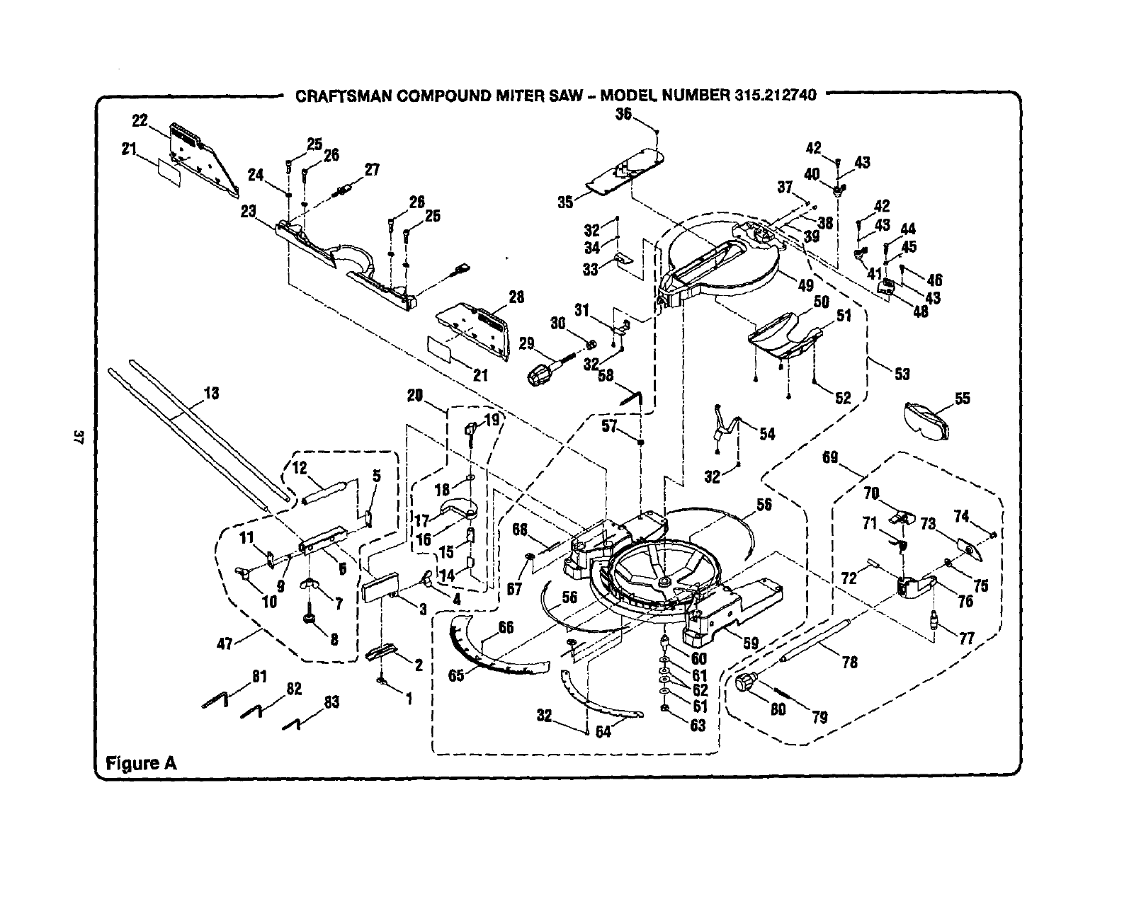
r,_
,,,,,,/
••HI ' CRAFTSMAN COMPOUND MITER SAW - MODEL NUMBER 315.212740
44
I
II
II
ii
L
I
\
Figure A
I

,- , CRAFTSMAN COMPOUND MITER SAW - MODEL NUMBER 315.212740
The modelnumberwillbe found ona plate attached to the motor housing.Alwaysmentionthe mode(numberinall correspondenceregardingyour |
MITER SAW or whenordedngrepair parts. !
KEY PART
NO. NUMBER
1555516000
2 558511100
3 558,507200
4 5585121O0
5545506O0O
6 5455070O0
7A33055056000
8 54550900O
9 A10003040050
10 545511000
11 5455050O0
12 545508000
13 545512000
14 5655O6OO0
15 5655O50OO
16 At 8003040080
17 5655040O0
18 A35010823020
19 565007000
20 565A07020
21 545117000
PARTS LIST FOR FIGURE A
KEY PART
DESCRIPTION QTY.
"Wing Nut (MS x 30 ram)................................... 1
Clamp Bracket ................................................. 1
Stop Block ....................................................... 1
* Wing Screw (1/4-20 x 12 mm)......................... 1
RollerSupportFrontBrace.............................. 1
RollerSupport Base ........................................ 1
* Wing Nut (5/16 In.)**STD541631 .................... 1
LevelingScrew (5/16 In.) ................................. 1
* Screw (M4 x 5 mm Pan Hd,)............................4
* W(ngScrew (MS x 20 miTt).............................. 1
RollerSupport End Brace................................ 1
Roller............................................................... 1
Tab(eExtension............................................... 2
LowerTube,Adjustable................................... 1
UpperTube.Adjustable................................... 1
"Set Screw (M4 x 8 mm) ................................... 1
CrOwnMoldingClamp..................................... 1
FiatWasher(MS x 23 x 2t)............................... 1
CrownMoldingKnob....................................... 1
CrownMoldingStop Assembly
(IncludesKey Nos. 14-19) ............................... 1
SlidingMiter Fence label ................................. 2
NO. NUMBER
2_ 5451150O0
23 545113000
24 A36030814204
25 A0710308045T
26 A07003080208
27 565123000
28 545114000
2g 545112000
30 545116000
31 545110000
32 A10003050105
33 545111000
34 A35010510010
35 545108000
36 A16003050080
37 565119000
38 565120000
39 A59000006000
40 565121000
41 565122000
42 565118000
DESCRIPTION QTY,
SlidingMiler Fence(left)...................................1
Fence............................................................... I
* LockWasher(MS)**STD852008..................... 4
*Bolt (MS x 45 mm Soc. Hd.) ............................2
•Bolt (MS x 20 mm Soc. Hd,) ............................2
FenceScrew.................................................... 2
SlidingMiterFence(right)................................ 1
Miter LockHandle........................................... 1
Clamp Nut .......................................................1
Fixed Plata....................................................... 1
*Screw OVl5x 10 mm Pan Hd.).......................... 6
Miter Indicator................................................. 1
FlatWasher(MS x 10 xl t)................................ 1
Throat Plate..................................................... 1
* Screw _v15x 8 mm Fist Hd,)............................6
Set Screw........................................................ 2
LockSpring ..................................................... 2
Bail...................................................................2
Bevel Stop(right)............................................. 1
BevelStop (left)............................................... I
"Screw (M6 x 6 mm).......................................... 2
* Standard Hardware Item - May Be Purchased Locally
** Available From Olv.9_ -- Source 980.00
*** Available At Your Nearest Sears Catalog Order or Retail Store
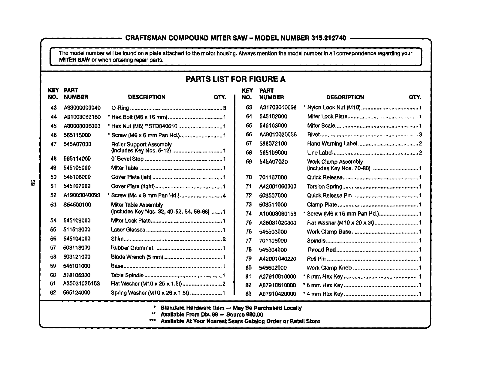
CRAFTSMAN COMPOUND MITER SAW - MODEL NUMBER 315.212740
i
Themodel numberwillbe foundona plateattaclled to the motor housing,Alwaysmentionthe modelnumberIn all correspondenceregardingyour |MITER SAW or whenorderingrepairparts. J
¢o
(o
KEY PART
NO. NUMBER
43 A63000000040
44 A01003060160
45 A30003006003
46 565115000
47 545A07030
48 565114000
49 545105000
50 545106000
51 545107000
52 A19003040093
53 $54500100
54 545109000
55 511513000
56 545104000
57 503118000
58 503121000
59 545101000
60 518106300
61 A35031025153
62 565124000
PARTS LIST FOR FIGURE A
DESCRIPTION QTY.
O-Ring .............................................................3
"Hex Bolt (M6 x 16 ram).................................... 1
* Hex Nut (M6) *'STD840610 ............................. 1
* Screw (M6 x 6 mm Pan Hd,)............................ 1
RotlerSupportAssembly
(includes Key Nos. 5-12} ................................. 1
0' BevelStop................................................... 1
Miter Table ...................................................... 1
Cover Plate (left).............................................. 1
Cover Plate(right)............................................ 1
•Screw (M4x9 mm Pan Hd,)............................ 4
MiterTableAssembly
(IncludesKeyNos, 32, 49-52, 54, 56-68) ....... 1
Miter LockPlate............................................... 1
I_ser Glasses.................................................. 1
Shim................................................................. 2
Rubber Grommet ........................................... 1
BladeWrench(5 mm)...................................... 1
Base................................................................. 1
TableSpindle................................................... 1
FlatWasher(M10 x 25 x 1.St)..........................2
SpdngWasher(M10 x 25 x 1.5t) ..................... 1
KEY PART
NO. NUMBER
63 A31703010098
64 545102000
65 545103000
66 A49010020056
67 568072100
69 565109000
69 545A07020
70 701107000
71 A42001060300
72 503507000
73 503511000
74 A10003060158
75 A35031020300
76 545503000
77 701106000
79 545504000
79 A42001040220
80 545502000
61 A07910810000
62 A07910610000
63 A07910420000
DESGRIPTION Q'rY,
* NylonLockNut (M10)...................................... 1
Miter Lock Plate............................................... 1
Miter Sca(o....................................................... 1
Rivet................................................................. 3
Hand WarningLabel........................................ 2
LineLabel ........................................................ 2
Work Clamp Assembly
(includesKey Nee. 70-80) ..............................1
Quick Release.................................................. 1
TorsionSpring.................................................. 1
Quick ReleasePin ........................................... 1
Clamp Plate..................................................... 1
* Screw (M6 x 15 mm Pan Hd.).......................... 1
FiatWasher(M 10 x 20 x 3t)............................. 1
WorkClamp Base............................................ 1
Spindle............................................................. 1
Thread Rod...................................................... 1
RollPin ............................................................ 1
WorkClamp Knob........................................... 1
* 5 mm Hex Key................................................. I
"6 mm Hex Key ................................................. 1
* 4 mm Hex Key ................................................. 1
* Standard Hardware item -- May Be PurChaSed Locally
** Available From DIv,98 -- Source 980.00
**" Avaiteble At Your Nearest Sears Catalog Order or Retail Store
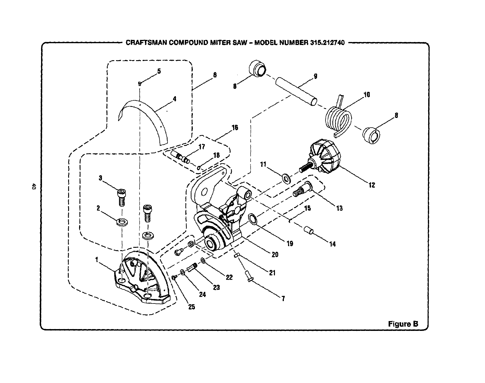
C3
CRAFTSMAN COMPOUND MITER SAW - MODEL NUMBER 315.2t2740
19 _14
"20
23
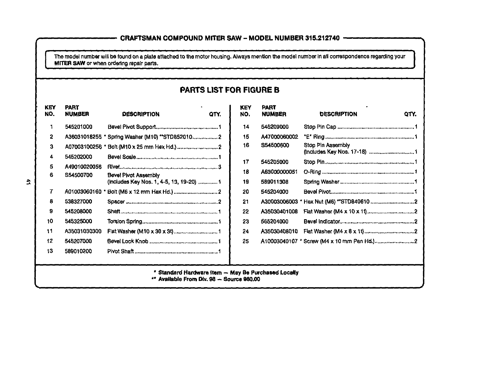
CRAFTSMAN COMPOUND MITER SAW - MODEL NUMBER 315.212740
The model numberwill be found ona plateattached to the motorhousing.Alwaysmentionthe model numberinallcorrespondenceregardingyour I
MITER SAW orwhen orderingrepairparts. J
PARTS LIST FOR FIGURE B
J_
.,x
KEY PART
NO. NUMBER DESCRIPTION QTY.
1545201000 BevelPivotSupport......................................... 1
2 A35O31018255 "SpringWasher (M10)**STD852010................. 2
3A07003100256 "Bolt (M10 x 25 mm He:<Hd.) ........................... 2
4 545202000 BevelScale...................................................... 1
5 A49010025O56 Rivet................................................................. 3
6 $54500700 BevelPivotAssembly
(IncludesKey Nos. 1,4-5, 13, 19-20) ............. 1
A01003060160 * Bo(t(M6 x 12 mm Hex Hd.) ............................. 2
T
8 538327000
9 545208000
10 545325OO0
11 A35031030300
12 545207000
13 589010200
Spacer............................................................. 2
Shaft................................................................ 1
TorsionSpring.................................................. 1
FlatWasher (M10 x 30 x 3t)............................. 1
Beve(Lock Knob............................................. 1
PivotShaft ....................................................... 1
KEY PART
NO, NUMBER OESCRIPTION
14 545299QOQ
15 A47000060002
16 854500600
QTY.
17
18
19
20
21
22
23
24
25
545205000
A63000000051
589011308
545204000
Stop PinCap ................................................... 1
'E' Ring........................................................... 1
Stop PinAssembly
(includesKey Nos. 17-18) .............................. t
Stop Pin........................................................... 1
O-Ring............................................................. 1
SpringWasher................................................. 1
BevelPivot....................................................... 1
A,30003006003* Hex Nut(M6) *'STD840610 .............................2
A35030401008 FlatWasher(M4x 10xlt) ............................... 2
565204000 BevelIndlca'cor................................................. 2
A35030408010 FlalWasher (M4 x 8 x lt) .................................2
A10003040107 *Screw (M4 x 10 mm Pan Hd,)..........................2
" Standard Hardware Item -- May Be Purchased Locally
** Available From DIv.g8 - 8ourca 980.00
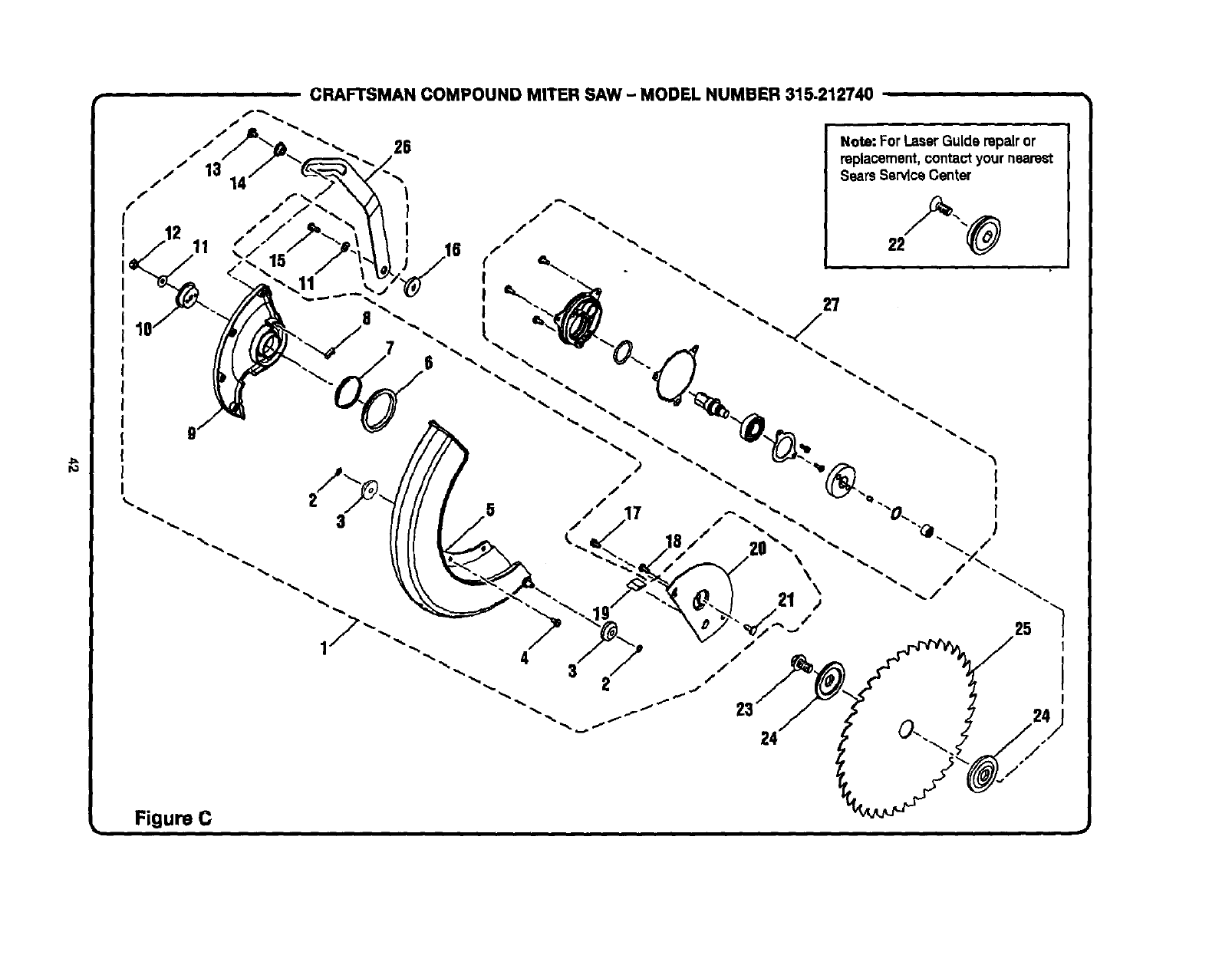
CRAFTSMAN COMPOUND MITER SAW - MODEL NUMBER 315.212740
""'"- 26 Note: For LaserGuide repairor
replacement,contactyour nearest
Sears Se_ce Center
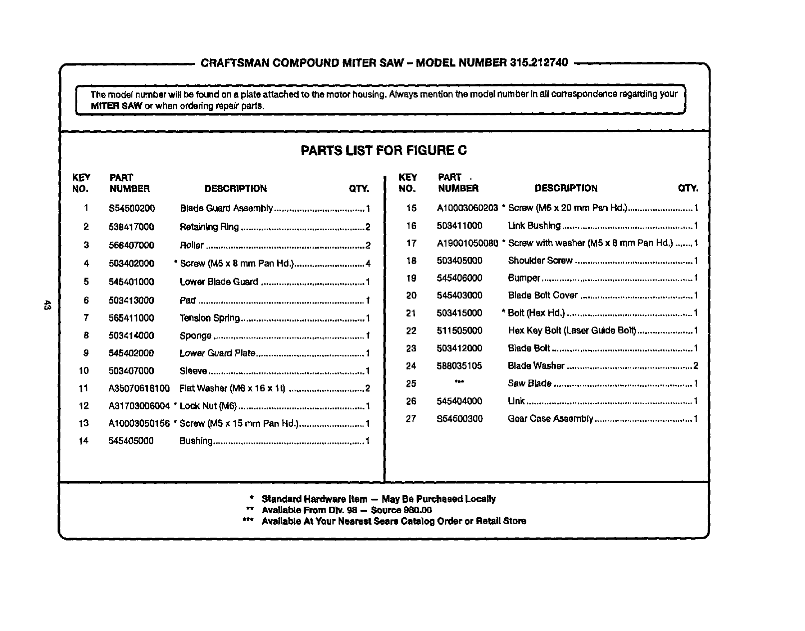
iii
[
CRAFTSMAN COMPOUND MITER SAW - MODEL NUMBER 315.212740
i
The modelnumberwi[Ibe foundon a plateattachedto the motorhousing.Alwaysmentionthe model numberinall correspondenceregardingyour |
MITER SAW orwhen orderingrepairparts. /
PARTS UST FOR FIGURE C
KEY PART
NO. NUMBER
1 $54500200
2 538417000
3 566407000
4 503402000
5 545401000
6 5034130O0
7 565411000
8 503414000
9 545402000
10 503407000
11 A3507061610g
12
13
14
DESCRIPTION QTY.
Blade GuardAssembly.................................... 1
RetainingRing................................................. 2
Rol)er............................................................... 2
* Screw (MSx 8 mm Pan Hd.)............................4
lower BladeGuard ......................................... 1
Pad .................................................................. I
TensionSpring................................................. 1
Sponge............................................................ I
LowerGuard Plate........................................... 1
Sleeve.............................................................. 1
FLatWasher (M6 x 16 x lt) .............................. 2
A31703006004 "Lock Nut(M6) .................................................. 1
A10003050156 "Screw (MS x 15 mm Pan Hd.).......................... 1
545405000 Bushing............................................................ 1
KEY
NO.
15
16
17
18
19
20
21
22
23
24
25
26
27
PART .
NUMBER DESCRIPTION QTY.
A10003060203 * Screw (M6 x 20 mm Pan Hd.).......................... 1
503411000 LinkBushing.................................................... 1
A1900105008Q * Screwwithwasher (M5 x 8 mmPan Hd.) ....... 1
503405000
545406000
545403000
503415000
511505000
503412000
5880351O5
545404000
$54500300
ShoulderScrew ............................................... 1
Bumper ............................................................ 1
BladeBolt Cover ............................................. 1
* Bolt(Hex Hd.) .................................................. 1
Hex Key Bolt(LaserGuideBolt)...................... 1
BladeBolt........................................................ 1
BladeWasher ..................................................2
Saw Blade ....................................................... 1
Unk.................................................................. 1
Gear Case Assembly....................................... 1
* Standard Hardware Item - May Be Purchased Locally
"* Available From DIv. 98 -- Source 980.00
*** Available At Your Nearest Soars Catalog Order or Retail Store
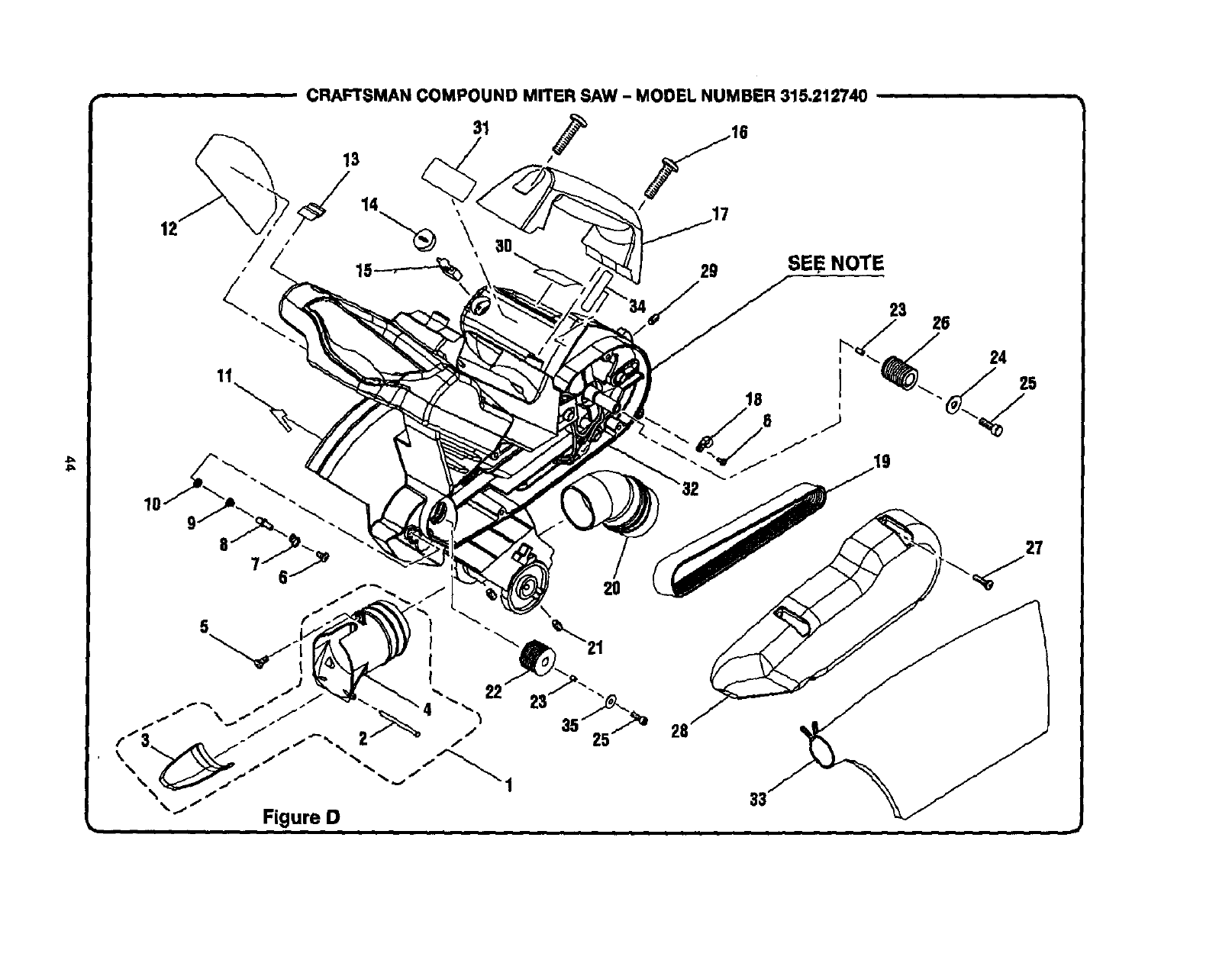
CRAFTSMAN COMPOUND MITER SAW -MODEL NUMBER 315.212740
31
13
/
/15 \
11
IO 9. 8
29 SEE NOTE

CRAFTSMAN COMPOUND MITER SAW - MODEL NUMBER 315.212740
|
I"r'_e nl°de_ numbe_ will _[_ _°und on a Plata a_ta_h_ t° the m°_°r h°ueJng" _waYa m°n_J°n the re°de( number in aI_ c°n'esP°_dant_e r_r_Ing y°urIM]TE w SAW or when ordering r_p_" _)_r_e,
O1
KEY
NO.
1
2
3
4
5
6
7
8
g
10
11
12
13
14
15
16
17
18
PARTS LIST FOR FIGURE D
PART KEY PART
NUMBER DESCRIPTION QTY. NO. NUMBER
545A05020
54532400
545323000
545322000
DustChute Assembly......................_,.............. 1
Stud................................................................. 1
DustChute....................................................... 1
DustHood ....................................................... 1
A10003050127 *Screw (M5 x 12 mm Pen Hd.).......................... 1
A10003050105 * ScreW(M5 x 10 mm Pen Hd.)..........................2
545305000 LockPinPlate.................................................. 1
545302000 ArborLock Pin................................................. 1
545303000 CompressionSpdng........................................ 1
545304000 Felt................................................................... 1
545330000 WarningLabel.................................................. 1
545329000 Logo Plate ....................................................... 1
E07010000450 Sleeve.............................................................. 1
588005100 BrushCap........................................................2
588006100 BrushAssembly............................................... 2
A70003060250 * ScreW(M6 x 25 mm Pan Hd.)..........................2
545328000 CarryingHandle............................................... 1
E07000846157 CordClamp ..................................................... 1
19 545320000
20 545501000
21 A18003060106 *
22 545312OO0
23 A45204040080
24 A35010513156
25 A07013050126 "
26 545319O00
27 A10003050180 *
28 54532100O
29 A18003080250 *
30 57831O0O8
31 545327000
32 545A04000
33 565501000
34 545331000
35 A35010519150
983000551
i
* Standaltl Hardware Item -- May Be Purr,based Locally
** AvaUableFrom Div. 98 -- Source gS0.O0
OESCRIPTION QTY.
Belt(PJS08-6V)............_................................... 1
DustGuide....................................................... 1
Set Screw (MS x 10 ram)................................. 2
Arbor Pulley..................................................... 1
ParallelKey (4 x 4 x 3 ram).............................. 1
FlatWasher(M5 x13x1.51}............................ 1
Bolt(MS x 12 mm Soc. Hd,) ............................ 1
MotorPulley .................................................... 1
Screw(M5 x 18 rnmPan Hd,}.......................... 1
BeltCover........................................................ 1
SetScrew (M8 x 25 ram) ................................. 1
WarningLabel.................................................. 1
Dat_ Plate........................................................ 1
MotorAssembly.............................................. 1
Oust Bag.......................................................... 1
BeltAdjustment WarningLabel ....................... 1
FlatWasher(MS x 19 x 1.St)............................ 1
OpetatQr'SManual(NotShown)
NOTE: The assembly shown representSan Important part of the Double Insulated System. To avoid t_e possibility of alteration or damage
to the system, service should be performed by your nearest E_earsRepair Center. Contact your nearest I_eersCatalog Order or Retail
Store for Service Center Information.

Your Home
For repair-in your home-of all major brand appliances,
lawn and garden equipment, or heating and cooling systems,
no matter who made it, no matter who sold itl
For the replacement parts, accessories and
owner's manuals that you need to do-it-yourself.
For Sears professional installation of home appliances
and items like garage door openers and water heaters.
1-800-4-MY-HOME ®(1-800.469-4663)
Call anytime, day or night (U.S.A. and Canada)
www.sears.com www.sears.ca
Our Home
For repair of carry-in items like vacuums, lawn equipment,
and electronics, cell or go on-line for the location of your nearest
Sears Parts & Repair Center.
1-800-488-1222
Call anytime, day or night (U.S,A. only)
www.sears,com
To purchase a protectionagreement (U.S.A.)
or maintenance agreement (Canada) on a productserviced by Sears:
1-800-827-6655 (U.S.A.) 1-800-361-6665 (Canada)
Para pedir servicio de reparacibn
a domicilio, y para ordenar piezas:
1-888-SU-HOGAR _
(1-888-784-6427)
Au Canada pour service en fran_ais:
1-B00-LE-FOYER _c
(1-800-533-6937)
v_vw.sears.ca
G£ 6
®RegisteredTrademarkITMTradem_k I=M_wiee Mad( ofSeara. R_ebu(#.and Co.
®M a_a Re_strada ITMMarcade F_bdcl IaMMar(a de _gr/i_o de_ears, Roebuck_ CO.
McM=rquede oomrne_e I_M_I_UQd_om_e de Sears, RoebuckandCo. O Se=_. RoebuckandCo.
