Craftsman 315218050 User Manual TABLE SAW Manuals And Guides L0521320
CRAFTSMAN Saw Table Manual L0521320 CRAFTSMAN Saw Table Owner's Manual, CRAFTSMAN Saw Table installation guides
Vizio Speaker System SB4020M-A0 L0521320
User Manual: Craftsman 315218050 315218050 CRAFTSMAN TABLE SAW - Manuals and Guides View the owners manual for your CRAFTSMAN TABLE SAW #315218050. Home:Tool Parts:Craftsman Parts:Craftsman TABLE SAW Manual
Open the PDF directly: View PDF ![]() .
.
Page Count: 48
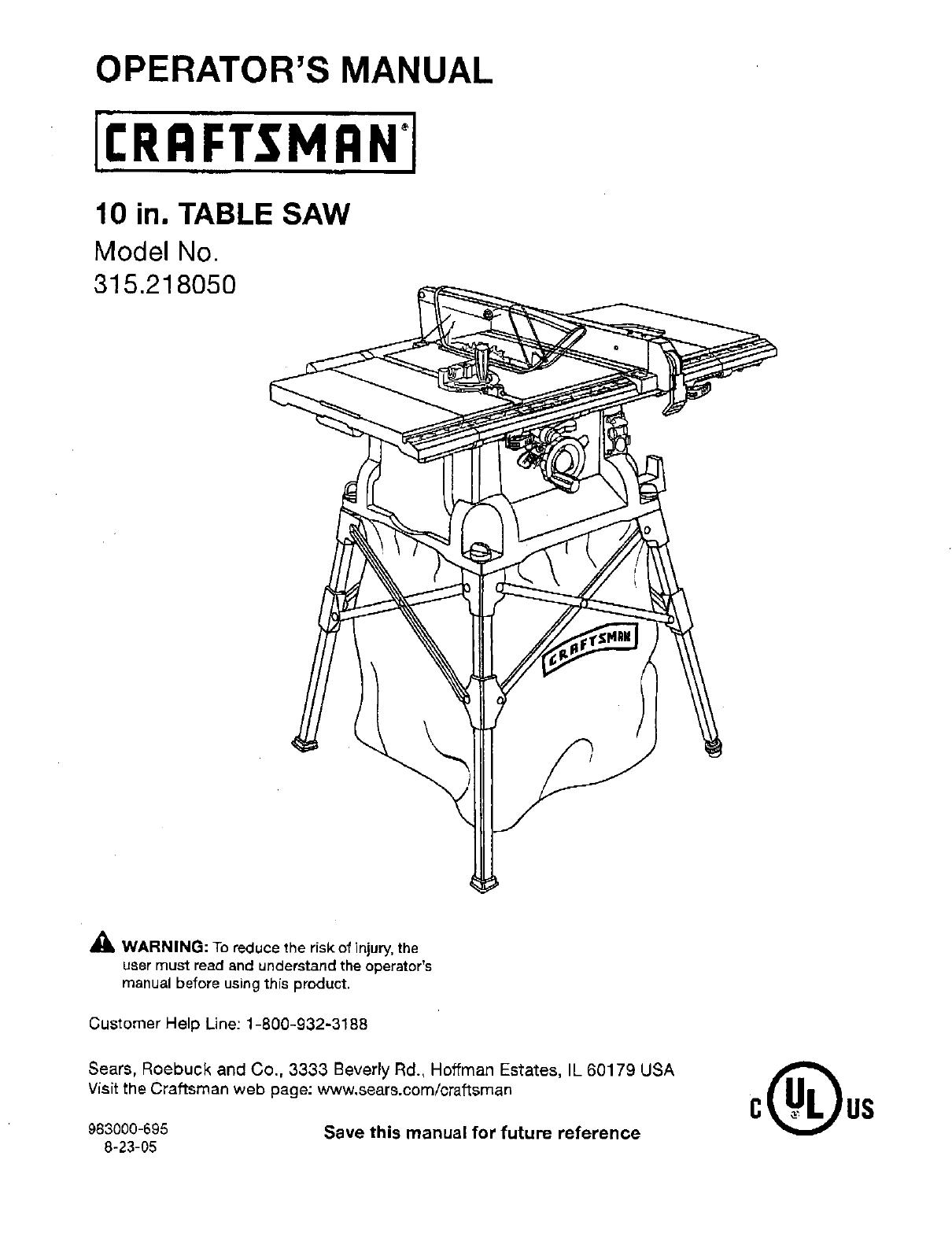
OPERATOR'S MANUAL
10 in. TABLE SAW
Model No.
315.21 8050
_lJ WARNING: To reduce the risk of injury, the
user must reed end understand the operator's
manual before using this product.
Customer Help Line: 1-800-932-3188
Sears, Roebuck and Co., 3333 Beverly Rd., Hoffman Estates, IL 60179 USA
Visit the Craftsman web page: www,sears.com/craftsman
983000-695
8-23-05 Save this manual for future reference

• Warranty ............................................................................................................................................................................ 2
• Introduction ............................................................................................................................................ :.......................... 2
• General Safety Rules..................................................................................................................................................... 3-4
• Specific Safety Rules..................................................................................................................................................... 4-5
• Symbols ......................................................................................................................................................................... 6-7
•Electrical......................................................................................................... .'.................................................................. 8
•Glossary of Terms............................................................................................................................... _.............................. 9
"Features..................................................................................................................................................................... 10-13
•ToolsNeeded ................................................................................................................................................................. 13
•Loose Parts .................................................................................................................................................................... 14
• "Assembly ................................................................................................................................................................... 15-19
• Operation ...................................................... :............................................................................................................ 19-32
II Adjustments.............................................................................................................................................................. 33-35
• Maintenance ................................................................................................................................................................... 36
•Troubleshooting......................................................................................................................................................... 37-38
• Exploded View........................................................................................................................................................... 39-47
• Parts Ordering/Service ...................................................................................................................................... Back Page
ONE YEAR FULL WARRANTY ON CRAFTSMAN TOOL
If this Craftsman tool fails due to adefect in material orworkmanshipwithin one year from the date of purchase. Call
1-800-4-MY-HOME ® to arrange for free repair.If thistool is usedfor commercial or rentaJpurposes,this warranty will
apply for only ninety days from the date of purchase This warranty applies only while this product is in the United States.
This warranty givesyou specific legal rights, and you may also have other rightswhich vary from state to state,
Sears, Roebuck and Co., Dept. 817WA, Hoffman Estates, IL 60179
This tool has many features for' making its use more pleasant and enjoyable, Safety, performance, and dependability
have been given top priority in the design of this product making it easy to maintain and operate.
2
_k WARNING: Read and understand all instruc-
tions. Failureto follow all instructions listed below,
may result inelectric shock, fire and/or serious
personal injury.
READ ALL INSTRUCTIONS
•KNOW YOUR POWER TOOL Read the operator's
manual carefuny. Learn the saw's applications and
limitations as well as the specific potential hazards
related to this tool.
•GUARD AGAINST ELECTRICAL SHOCK BY PRE-
VENTING BODY CONTACT WITH GROUNDED
SURFACES. For example, pipes, radiators, ranges,
refrigerator enclosures.
•KEEP GUARDS IN PLACE and in good working order.
•REMOVE ADJUSTING KEYS AND WRENCHES.
Form habit of checking to see that keys and adjusting
wrenches are removed from tool before turning it on.
•KEEP WORK AREA CLEAN, Cluttered areas and
benches inviteaccidents. DO NOT leave tools or
pieces of wood on the saw while {t is in operation.
•DO NOT USE IN DANGEROUS ENVIRONMENTS.
Do not use power tools in damp orwet locations or
expose to rain. Keep the work area well lit.
• KEEP CHILDREN AND VISITORS AWAY, All visitors
shouldwear safety glasses and be kept a safe
distance from work area. Do not let visitors contact
tool or extension cord while operating.
•MAKE WORKSHOP CHILDPROOFwith padlocks and
master switches, or by removing starter keys.
•DON'T FORCE TOOL It will do the job better and
safer at the feed rate for which it was designed.
•USE RIGHTTOOL. Don=tforce the tool or attachment
to do ajob it was not designed for. Don't use it for s
purpose not intended.
•USE THE PROPER EXTENSION CORD. Make sure
your extension cord is in good condition. Use only a
cord heavy enough to carry the currentyour product
will draw. An undersized cord will cause a drop in line
voltage resulting in loss of power and overheating. A
wire gauge size (A.W.G.) of at least 14 is recommended
for an extension cord 25 feet or less in length. If in
doubt, use the next heavier gauge. The smaller the
gauge number,the heavier the cord.
•DRESS PROPERLY. Do net wear loose clothing,
gloves, neckties, or jewelry. They can get caught
and draw you into moving parts. Rubber gloves and
nor_skidfootwear are recommended when working
outdoors.Also wear protective hair covering to contain
long hair.
•ALWAYSWEAR SAFETY GLASSES WITH SIDE
SHIELDS. Everydayeyeglasses have only impact-
resistantlenses,they are NOT safety glasses.
•SECURE WORK. Use clamps or a vise to hold work
when practical. It's saferthan using your hand and
frees both hands to operate tool,
•DON'T OVERREACH. Keep proper footing and
balance at all times.
• MAINTAIN TOOLS WITH CARE. Keep tools sharp
and clean for better and safer performance. Follow
instructions for lubricating and changing accessories.
•DISCONNECT TOOLS, When not in use, before
servicing, or when changingattachments, blades, bits,
cutters, etc., all tools should be disconnected,
• AVOID ACCIDENTAL STARTING. Be sure switch is off
when plugging in any tool,
•USE RECOMMENDED ACCESSORIES. Consult the
operator's manual for recommended accessories. The
use of improper accessories may dsk injury.
•NEVER STAND ON TOOL. Serious injury could occur
if the tool is tipped or if the cutting tool is unintention-
ally contacted.
l= CHECK DAMAGED PARTS, Before further use of
the tool, a guard or other part that is damaged should
be carefully checked to determinethat it will operate
properly and perform its intended function. Check for
alignment of moving parts, binding of moving parts,
breakage of parts, mounting and any other conditions
that may affect its operation. A guard or other part that
is damaged must be properly repaired or replaced by
an authorized service center to avoid risk of personal
injury.
•USE THE RIGHT DIRECTION OF FEED. Feed work
into a blade or cutter againstthe direction of rotation of
blade or cutter only.
•NEVER LEAVE TOOL RUNNING UNA'n-ENDED.
TURN THE POWER OFF, Don't leave tool until it
comes to acomplete stop.
•PROTECT YOUR LUNGS. Wear a face or dust mask if
the cutting operation is dusty.
•PROTECT YOUR HEARING, Wear bearing protection
during extended periods of operation,
•DO NOT ABUSE CORD. Never yank cord to discon-
nect from receptacle. Keep cord from heat, oil, and
sharp edges.
•USE OUTDOOR EXTENSION CORDS. When tool
is used outdoors, use only extensioncords with
approved ground connectionthat are intended for use
outdoors and so marked,
•ALWAYS KEEP THE BLADE GUARD AND RIVING
KNIFE/SPREADER/SPLITFER IN PLACE and in
working order.
•KEEP BLADES CLEAN, SHARP, AND WITH
SUFFICIENT SET. Sharp blades minimize stalling
and kickback.
•KEEP HANDS AWAY FROM CUTTING AREA. Keep
hands away from blades. Do not reach underneath

work or around or over the blade while blade is
rotating, Do not attempt to remove cut material when
blade is moving.
• BLADE COASTS AFTER BEING TURNED OFF.
• NEVER USE IN AN EXPLOSIVE ATMOSPHERE.
Normal sparking of the motor could ignite fumes.
• INSPECT TOOL CORDS PERIODICALLY. If damaged,
have repaired by a qualified servicetechnician at
an authorized service facility. The conductor with
insulation havTngan outer surface that is green with
or without yellow stripes is the equipment-ground-
ing conductor. If repairor replacement of the electric
cord or plug is necessary,do not connect the equip-
ment-grounding conductor to a liveterminal. Repair
or replace a damaged or worn cord immediately. Stay
constantly aware of cord location and keep it we]l away
from the rotating blade.
•INSPECT EXTENSION CORDS PERIODICALLY and
replace if damaged.
•GROUND ALL TOOLS. If tool is equipped with three-
prong plug, it should be plugged into a three-hole
electrical receptacle.
•CHECK WITH AQUALIFIED ELECTRICIAN or service
personnel if the grounding instructionsare not com-
pletely understood or if indoubt as to whether the tool
iS propedy grounded.
•USE ONLY CORRECT ELECTRICAL DEVICES: 3-wire
extension cords that have 3-prong grounding plugs and
3-pole receptacles that accept the tool's plug.
•DO NOT MODIFY the plug provided. If it will not r_the
outlet, have the proper outlet installed by a qualified
electrician.
•KEEP TOOL DRY, CLEAN, AND FREE FROM OIL
AND GREASE. Always use a clean cloth when clean-
ing, Never use brake fluids, gasoline, petroleum-based
products, or any solventsto clean tool.
•STAYALERT AND EXERCISE CONTROL. Watch
what you are doing and use common sense. Do not
operate tool when you are tired. Do not rush.
•DO NOT USE TOOL IF SWITCH DOES NOT TURN IT
ON AND OFF. Have defective switches replaced by an
authorized service center.
•USE ONLY CORRECT BLADES. Do not use blades
with incorrect size holes. Never use blade washers or
blade bolts that are defective or incorrect.The maxi-
mum blade capacity of your saw is 10 in. (254 ram).
•BEFORE MAKING A CUT, BE SURE ALL ADJUST-
MENTS ARE SECURE.
•BE SURE BLADE PATH IS FREE OF NAILS. Inspect
for and remove 8,11nails from lumber before cutting,
• NEVER TOUCH BLADE or other moving parts during
use.
•NEVER START A TOOL WHEN ANY ROTATING COM-
PONENT IS IN CONTACT WITH "rile WORKPIECE.
•DO NOT OPERATE A TOOL WHILE UNDER THE
INFLUENCE OF DRUGS, ALCOHOL, OR ANY
MEDICATION.
•WHEN SERVICING use only identical replacement
parts. Usa of any other parts may create a hazard or
cause product damage.
•USE ONLY RECOMMENDED ACCESSORIES listed
in this manual or addendums, Use of accessories
that are not listed may cause the risk of personal
injuw, Instructions for safe use of accessories are
included with the accessory.
•DOUBLE CHECK ALL SETUPS. Make sure blade is
tight and not making contact with saw or workplace
before connecting to power supply.
•GUARD AGAINST KICKBACK. Kickback occurs
when the blade stallsrapidly and workplace is driven
back towards the operator. It can pull your hand into
the blade resultingin sedous personal injury. Stay out
of blade path and turn switch Offimmediately if blade
binds or stalls.
•USE RIP FENCE. Always use a fence or straight edge
guide when ripping.
•SUPPORT LARGE PANELS. To minimize risk of blade
pinching and kickback, always support ]argo panels.
•REMOVE ALL FENCES AND AUXILIARY TABLES
before transporting saw. Failure to do so can result in
an accident causing possible serious personaL injury.
•ALWAYS USE BLADE GUARD, RIVING KNIFE/
SPREADER/SPLrrrER, AND ANTI-KICKBACK
PAWLS on all "through-sawing" operations. Through-
sawing operations are these in which the blade cuts
completelythrough the workplace as in ripping or
crosscutting. Keep the blade guard down, the anti-
kickback pawls down, and the rivingknife/spreader/
splitter properly aligned to the saw blade.
•ALWAYS SECURE WORK firmly against rip fence,
miter fence, or miter gauge.
• ALWAYS USE A PUSH STICK FOR RIPPING NAR-
ROW STOCK, A push stick is a device used to push
aworkpiece through the blade instead of using your
hands. Size and shape can vary but the push stick must
always be narrower than the workplace to prevent the
push stick from contacting the saw blade_When ripping
narrow stock, always use a push stick,so your hand does
not come close to the saw blade. Use a featherboardand
push blocks for non-through cuts.
•NEVER perform any operation "freehand" which
means using only your hands to support or guide the
workpiece. Always use either the rip fence or miter
gauge to position and guide the work.
•NEVER stand or have any part of your body in line
with the path of the saw blade.
•NEVER reach behind, over, or within three inches of
the blade or cutter with either hand for any reason.
• MOVE THE RIP FENCE out of the way when cross
cutting,
•NEVER use rip fence as cutoff gauge when cross
cutting.
• NEVER attempt to free a stalled saw blade without
first turning the saw OFF and disconnecting the saw
from the power source.
•PROVIDE ADEQUATE SUPPORT to the rear and
sides of the saw table for wide or longwork pieces.
Use a sturdy "outrigger" support if atable extension
more than 24 inches long is attached to the saw.
•AVOID KICKBACKS (work thrown back toward you)
by:
a) Keeping blade sharp.
b) Keeping rJpfence parallel to the saw blade.
c) Keeping riving knife/spreader/splitter=anti-kickback
pawls, and blade guard in place and operating,
d) Not releasing the work before it is pushed all the
way past the saw blade using a push stick,
e) Not ripping work that is twisted or warped or does
not have a straight edge to guide alongthe fence.
• AVOID AWKWARD OPERATIONS AND HAND
POSITIONS where a suddenslip could cause your
hand to move into the cutting tool,
•USE ONLY RECOMMENDED ACCESSORIES listed
in this manual or addendums. Use of accessories that
are not listed may cause the risk of personal injury.
Instructionsfor safe use of accessories are included
with the accessory.
•MAKE SURE THE WORK AREA HAS AMPLE LIGHT-
ING to see the work and that no obstructions will
interferewith safe operation BEFORE performing any
work using the table saw.
• ALWAYS TURN OFF SAW before disconnecting it, to
avold accidental starf{ng when reconnecting to power
supply.
•ALWAYS DISCONNECT SAW FROM POWER SUP-
PLY BEFORE MAKING ADJUSTMENTS OR ADDING
ACCESSORIES. Make sure the switch is off when
reconnecting to power supply.
•ALWAYS FEED WORKPIECE AGAINST THE ROTA-
TION OF THE CUTTER.
• DO NOT USE AWKWARD HAND POSITIONS.
•KEEP FINGERS AWAY from the revolvingcutter, and
use fixtures when necessary.
•ALWAYS USE THE DUST COVER for overhead
guarding.
•DO NOT REMOVE JAMMED CUTOFF PIECES until
cutter or blade has atopped and tool has been
disconnected from power source.
II HOLD THE WORKPIECE FIRMLY AGAINST THE
TABLE.
•THIS TOOL should have the foJlowing markings:
a) Wear eye protection.
b) Use saw blade guard and dying knife/spreader/
splitterfor every operation for which it can be
used, including all throughsawing.
c) Keep hands out of the line of saw blade.
d) Use a push stickwhen required.
e) Pay particular attentionto instruCtionson reducing
risk of kickback.
t) Do not perform any operationfreehand.
g) Never reach around or over the saw blade.
•SAVE THESE INSTRUCTIONS. Refer to them
frequently and use to instructother users. If you loan
someone this tool, loanthem these instructionsalso.
_, WARNING" Some dust created by power sanding, sawing, grinding, drilling, and other construction activities
containschemicals known to cause cancer, birth defects or other reproductive harm. Some examples of these
chemicals are:
• lead from lead-based paints,
•crystalline silica from bricks and cement and other masonry products, and
• arsenic and chremium from chemically-treated lumber.
Your risk from these exposures varies, depending on how often you do this type of work. To reduce your exposure
to these chemicals: work in a well ventilated area. and work with approved safety equipment, such as those dust
masks that are specially designed to filter out microscopic particles.

Some of the following symbols may be used on this tool. Please study them and learn their meaning. Proper
interpretation of these symbols will allow you to operate the tool better and safer.
SYMBOL NAME DESIGNATION/EXPLANATION
V
A
Hz
W
rain
no
[]
.,./rain
@
O
A
@
®
Volts
Amperes
Hertz
Watt
Minutes
Alternating Current
Direct Current
No Load Speed
Class II Construction
Per Minute
Wet Conditions Alert
Read The Operator's Manual
Eye Protection
Safety Alert
NO Hands Symbol
Pinch Warning
Hot Surface
Vo{tage
Current
Frequency (cycles per second)
Power
Time
Type of current
Type or a characteristic of current
.=i i
Rotational speed, at no load
Double-insulated construction
Revolutions,strokes, surface speed, orbitsetc., per minute
Do not expose to rain or use in damp locations.
=l i
To reduce the risk 'of injury,user must read and understand
operator's manual before using this product.
Always wear safety goggles or safety glasses with side
shieldsand a full face shieldwhen operatingthis product.
i. m=l
Precautions that involveyour safety,
iira= i
Failureto keep your hands away from the blade will result in
seriouspersonal injury.
Alwayswatch for movement paying extra attention to
potential areas where pinching could occur.
To reduce the risk of injuryor damage, avoid contact with
any hot surface.
ii
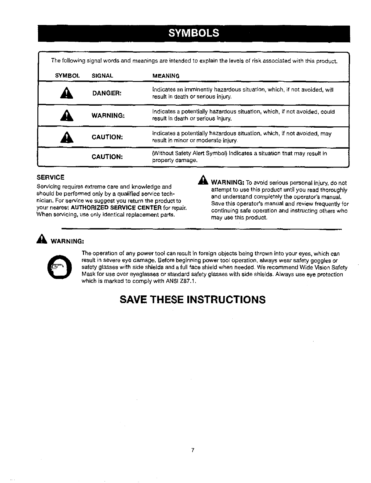
The following signal words and meanings are intended to explain the levelsof risk associated with this product.
SYMBOL SIGNAL
DANGER:
WARNING:
MEANING
iim
Indicates an imminently hazardous situation, which, if not avoided, will
result indeath or serious injury.
Indicatesa potentiallyhazardous situation, which, if not avoided, could
result in death or serious injury.
ACAUTION:
CAUTION:
Indicates a potentially hazardous situation, which, ff not avoided, may
result in minor or moderate injury.
ilil
(Without Safety Alert Symbol) Indicates a situation that may result in
property damage,
ill
SERVICE
Sen/icing requires extreme care and knowledge and
should be performed on{y by a qualified service tech-
nician. For service we suggest you return the product to
your nearest AUTHORIZED SERVICE CENTER for repair.
When servicing, use only identical replacement parts.
_k WARNING: To avoid serious personal injury, do not
attempt to use this product until you read thoroughly
and understand completely the operator's manual.
Save this operator's manual and review frequently for
continuing safe operation and instructing others who
may use this product.
_k WARNING:
OThe operation of any power tool can result in foreign objects being thrown into your eyes, which can
resultin severe eye damage. Before beginning power tool operation, always wear safety goggles or
safety glasses with side shields and a full face shield when needed. We recommend Wide Vision Safety
Mask for use over eyeglasses or standard safety glasses with side shields. Always use eye protection
which is marked to comply with ANSI Z87.1,
SAVE THESE INSTRUCTIONS
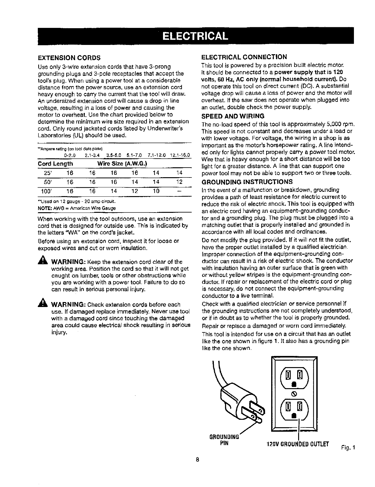
EXTENSION CORDS
Use only 3-wire extension cords that have 3-prong
grounding plugs and 3-pole receptacles that accept the
tool's plug. When using a power tool at a considerable
distance from the power source, use an extension cord
heavy enough to ¢arrythe current that the tool will draw.
An undersized extension cord will cause a drop in line
voltage, resulting in a loss of power and causing the
motor to overheat. Use the chart provided below to
determine the minimum wire size required in an extension
cord. Only round jacketed cords listed by Underwriter's
Laboratories (UL) should be used.
"Ampere rating (or_tool da_ plate)
0-2.0 2,1-3.4 3.6-&0 5.1-7.0 7.1-12.0 12.1-16,0
Cord Length Wire Size (A.W.G.)
25' 16 16 16 16 14 14
50' 16 16 16 14 14 12
100' 16 16 14 12 10 -
"*U5ed on 12 gauge - 20 amp circuit.
NOTE: AWG = American Wire Gauge
When working with the tool outdoors, use an extension
cord that is designed for outside use. This is indicated by
the letters "WA" on the cord's jacket.
Before using an extensioncord, inspect it for loose or
exposed wires and cut or worn insulation.
AWARNING: Keep the extensioncord clear of the
working ares. Position the cord so that it will not get
caught on lumber, tools or other obstructions while
you are working with apower tool. Failure to do so
can result in seriouspersonal injury.
_WARNING: Check extension cords before each
use. If damaged replace immediately. Never use tool
with a damaged cord since touching the damaged
area could cause electricalshook resulting in serious
injury.
ELECTRICAL CONNECTION
This tool is powered by aprecision bu(It electricmotor.
It should be connected to apower supply that is 120
volts, 60 Hz, AC only (normal household current). Do
notoperate thistool on direct current (DC). Asubstantial
voltage drop will cause a loss of power and the motor will
overheat. If the saw does not operate when plugged into
an outlet, double check the power supply.
SPEED AND WIRING
The no-load speed of this tool is approximately 5,000 rpm.
Thisspeed is not constant and decreases under aload or
with lower voltage. For voltage, the wiring in a shop is as
importantas the motor's horsepower rating. A line intend-
ed only for lightscannot properly carry apower tool motor.
Wirethat is heavy enough for a short distance will be too
light for a greater distance. Alinethat can support one
power tool may not be able to support two orthree tools.
GROUNDING INSTRUCTIONS
In the event of a malfunction or breakdown, grounding
provides a path of least resistance for electric current to
reduce the risk of electric shock. This tool is equipped with
an electric cord having an equipment-grounding conduc-
tor and a grounding plug. The plug must be plugged into a
matching outlet that is properly installed and groundedin
accordance with all local codes and ordinances.
Do notmodify the plug provided, If it will not fitthe outlet.
have the proper outlet installed by a qualified electrician.
Improper connection of the equipment-grounding con-
ductor can result in a risk of electric shock. The conductor
with insulation having an outer surface that is green with
or without yellow stripes is the equipment-grounding con-
ductor. If repair or replacement of the electric cord or plug
is necessary, do not connect the equipment-grounding
conductor to alive terminal.
Check with a qualified electrician or service personnel if
the grounding instructions are not completely understood,
or if in doubt as to whether the tool is properly grounded.
Repair or replace adamaged orworn cord immediately.
This tool is intended for use o(1a circuitthat has an outlet
like the one shown in figure 1. it also has agrounding pin
like the one shown.
_GROUNDING L_m__
PIN 120V GROUNDEDOUTLET _'ig. 1
8

Anti-Kickback Pawls (radial arm and table saws)
Adevice which, when property installedand maintained,
is designed to stop the workpiece from being kicked back
toward the front of the saw duringaripping operation.
Arbor
The shaft on which abtade or cutting tool is mounted.
Bevel Cut
A cutting operation made withthe blade at any angle
other than 90_to the table surface.
Chamfer
A cut removing awedge from a block so the end (or part
of the end) is angled rather than at 90°,
Compound Cut
A cross cut made with both amiter and abevel ang[s.
Cross Cut
A cutting or shaping operation made across the grain or
the width of the workpiece.
Cutter Head (planers and jointers)
Arotatingpiece of adjustable blades. The cutter head
removes material from the workplace.
Dsdo Cut
Anon-through cut which produces asquare-sided notch
or trough inthe workplace (recluires aspecial blade).
Featherboard
A device used to help control the workpiece by guidingit
securely against the table or fence during any ripping
operation.
FPM or SPM
Feet per minute (or strokes per minute), used in reference
to blade movement,
Freehand
Performing a cut without the workplace being guided by a
fence, miter gauge, or other aids.
Gum
A sticky,sap-based residue from wood products.
Heel
Alignment of the blade to the fence.
Kerr
The material removed by the blade in a through cut orthe
slot produced by the blade in a non-through or part{al cut.
Kickback
Ahazard that can occur when the blade binds or stalls,
throwingthe workplace back toward operator_
Leading End
The end of the workpieoe pushed into the tool first.
Miter Cut
A cutting operation made with the workpiece sit any angle
to the blade other than 90%
Non-Through Cuts
Any cutting operation where the blade does not extend
completely through the thickness of the workpieee.
Pilot Hole (drill presses)
Asmall hole drilled in a workpiece that serves as a guide
for drillinglarge holes accurately,
Push Blocks and Push Sticks
Devices used to faod the workplace through the saw
blade during cutting operations. A push stick (not a push
block) should be used for narrow ripping operations,
These aids help keep the operator's hands well away from
the blade.
Resaw
A cutting operation to reduce the thickness of the work-
piece to make thinner pieces,
Resin
Asticky,sap-based substance that has hardened.
Revolutions Per Minute (RPM)
The number of turns completed by aspinning object in
one minute.
Ripping or Rip Cut
Acutting operation alor_gthe lengthof the workpiece.
Riving Knife/Spreader/Splitter (table saws)
Ametal piece= slightly thinner than the blade, which helps
keep the kerr open and also helps to prevent kickback.
Saw Blade Path
The area over, under, behind, or in front of the blade. As
it applies to the workpiece, that area which will be or has
been cut by the blade.
Set
The distance that the tip of the saw blade tooth is bent (or
set) outward from the face of the blade.
Snipe (planers)
Depression made at either end of a workpiece by cutter
blades when the workplace is not properlysupported.
Through Sawing
Any cutting operation where the blade extends completely
throughthe thickness of the workplace.
Throw-Baok
The thmwlng back of a workplace usuallycaused by the
workpiece being dropped into the blade or being placed
inadvertentlyin contact with the blade.
Workpieee or Material
The item on which the operation is being done,
Worktable
Surface where the warkpieee rests while performing a
cutting, drilling, planing, or sanding operation,
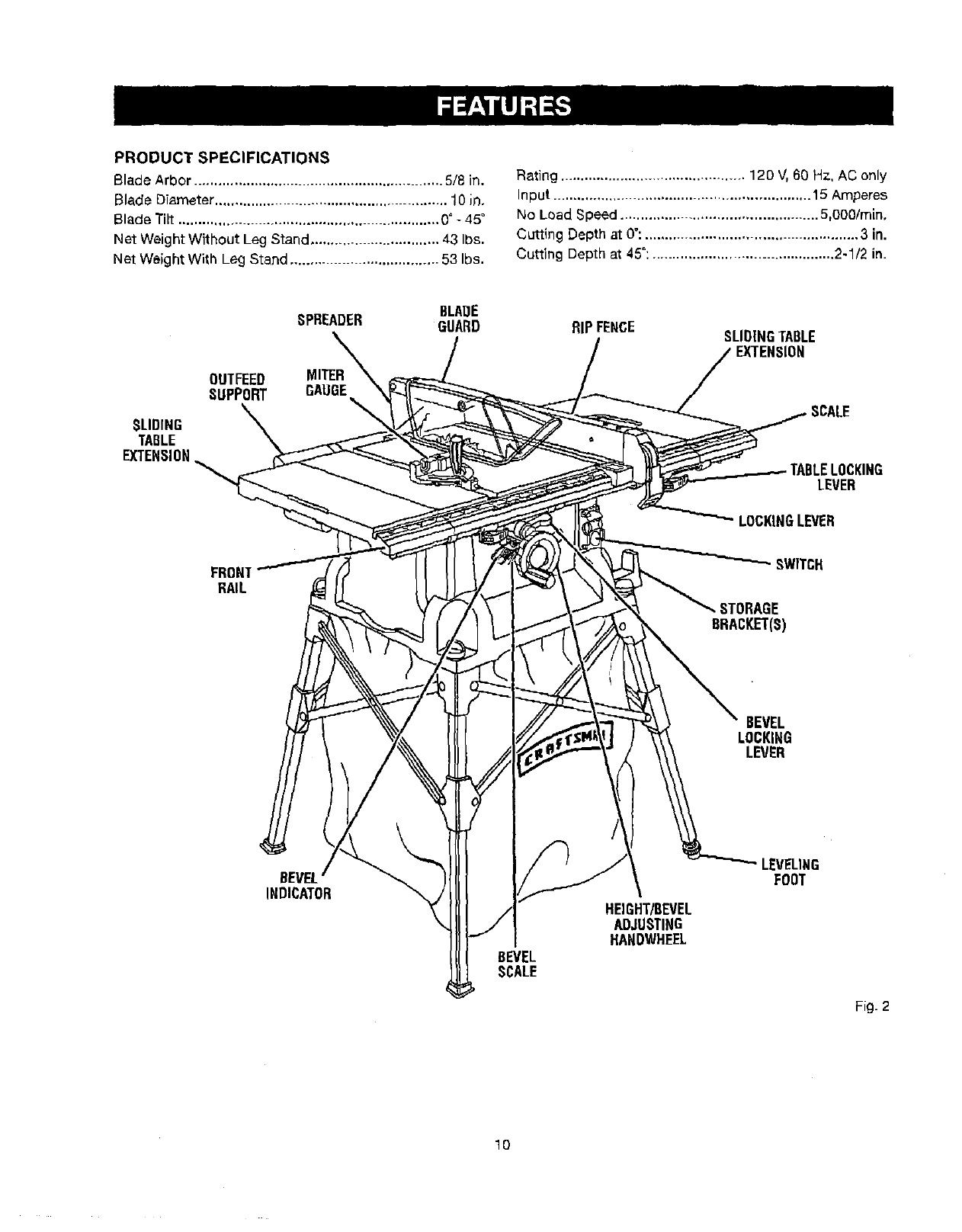
PRODUCT SPECIFICATIONS
Blade Arbor .............................................................. 5/8 in.
Blade Diameter .......................................................... 10 in.
Blade Tilt ................................................................. O° -45°
Net WeightWithout Leg Stand ................................ 43 Ibs.
Net Weight Wlth Leg Stand ..................................... 53 Ibs.
Rating .............................................. 120 V,60 Hz, AC only
Input ................................................................ 15 Amperes
No Load Speed ................................................. 5,000/min,
Cutting Depth at 0": ..................................................... 3 in.
Cutting Depth at 45": ............................................. 2-1/2 in.
BLAOE
SPREADER GUARD RIPFENCE SLIDINGTABLE
SLIDING
TABLE
EXTENSION
OUTFEED MITER
SUPPORT GAUGE
ICKING
LEVER
LOCKINGLEVER
FRON]
RAIL
BEVEL
INDICATOR
BEVEL
SCALE
SWITCH
,STORAGE
BRACKET(S)
BEVEL
LOCKING
LEVER
HEIGHT/BEVEL
ADJUSTING
HANDWHEEL
LEVELING
FOOT
Fig. 2
10
KNOW YOUR TABLE SAW
See Figure 2.
Before attemptlng to use this product, familiarize yourself
with all operating features and safety rules.
ANTI-KICKBACK PAWLS -Kickback is a hazard inwhich
the workpiece is thrown back toward the operator.The
teeth on the anti-kickback pawls point away from the
workpiece, if the workpiece sbou[d be pulled back toward
the operator, the teeth dig into the wood to help prevent
or reduce the possibility of kickback.
BEVEL SCALE -The easy-to-read scale on the front of
the cabinet shows the exact blade angle.
BLADE - This saw is provided with a36-tooth, 10 in.
carbide blade. The blade is raised and lowered with,
the height/bevel adjusting handwheeL Bevel angles are
locked with the bevel locking lever.
,_ WARNING: Do not use blades rated less than the
speed of this tool. Failure to heed this warning could
result in persona] iniury,
BLADE GUARD - Always keep the blade guard down
over the saw blade for through-sawing cuts.
BEVEL LOCKING LEVER - This lever, placed just under
the saw table surfaceon the front of the cabinet, locksthe
angle setting of the blade.
HEIGI-rF/BEVEL ADJUSTING HANDWHEEL -Located
on the front of the cabinet, use this handwheel to lower
and raise the blade for height adjustments or blade re-
placement. This handwhesl also makes the adjustment for
bevel angles easy.
MITER GAUGE - The miter gauge aligns the wood for
a cross cut. The easy-to-read indicator shows the exact
angle for a miter cut, with positive stops at 90 ° and 45 _.
MITER GAUGE GROOVBS - The miter gauge rides in the
grooves on the saw table.
MOTOR -The powerful industion motor, with capacitor
start and V-belt drive, is housed in asturdy steel base.
OUTFEED SUPPORT - This table extension at the back
of the tool gives the operator additional support when cut-
ting longworkpieces.
RIP FENCE - A sturdy metal fence guides the workpiees
and is secured with the locking handle. Grooves run along
the top and sides of the rip fence for use with optional
clamps and accessories,
SCALE - Located on the front rail, the easy-to-read scale
provides precise measurements for rip cuts,
SLIDING TABLE EXTENSIONS -Located on each side
of the saw table, these table extension gives the operator
additional support when cutting wide workpieoes.
SPREADER - Ametal piece of the hie,de guard assembly,
slightly thinner than the saw blade, which helps keep the
kerr open and prevent kickback.
SWITCH ASSEMBLY - This saw has an easy access
power switch located below the front rail. To lock the
switch in the OFF position, remove the switch key from
the switch. Place the key in a location that is inaccessible
to children and others not qualified to use the tool.
11
OPERATING COMPONENTS
The upper portion of the blade projects up through the
table and is surrounded by an insert called the throat
plate. The height of the blade is set with a handwheel on
the front of the cabinet. To accommodate wide panels,
the saw table has rails on each side. Detailed instructions
are provided in the Operation section of this manual for
the basic cuts: cross cuts. miter cuts, bevel cuts. and
compound cuts.
The rip fence is used to position work for lengthwise cuts.
Ascale on the front rail shows the distance between the
rip fence and the blade,
it is very important to usa the blade guard assemblyfor all
through-sawing operations. The blade guard assembly
includes: riving knife/spreader/splitter, anti-kickback
pawls, and plastic blade guard.
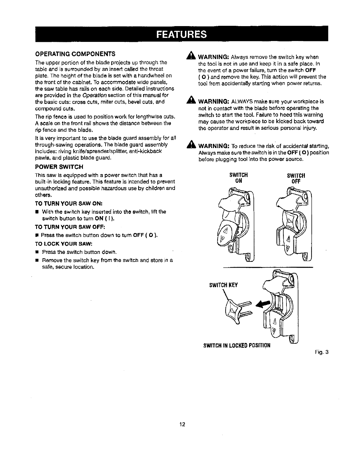
POWER SWITCH
This saw is equipped with apower switchthat has a
built-in locking feature. This feature is intended to prevent
unauthorized and possible hazardous use by childrenand
others,
TO TURN YOUR SAW ON:
•With the switch key insertedinto the switch, lift the
switch button to turn ON ( I ).
TO TURN YOUR SAW OFF:
•Press the switch button down to t_rn OFF ( O ).
TO LOCK YOUR SAW:
•Press the switch button down.
• Remove the switch key from the swftch and store in a
safe, secure location.
_k WARNING: Always remove the switch key when
the tool is not in use and keep it in a safe place. In
the event of apower failure, turn the switch OFF
( O ) and remove the key, This action will prevent the
too] from accidentally starting when power returns.
_, WARNING: ALWAYSmake sure your workplace is
not in contact with the blade before operatingthe
switch to start the tool. Failureto heed this warning
may cause the workpiece to be kicked back toward
the operator and result in seriouspersonal injury.
_lb WARNING: To reduce the riskof accidental starting,
Always makeaurethe switch is inthe OFF (O) position
before plugging tool into the power source.
SWITCH SWITCH
ON OFF
SWITCH,KEY ,,__
SWITCHIN LOCKEDPOSITION
Fig. 3
12
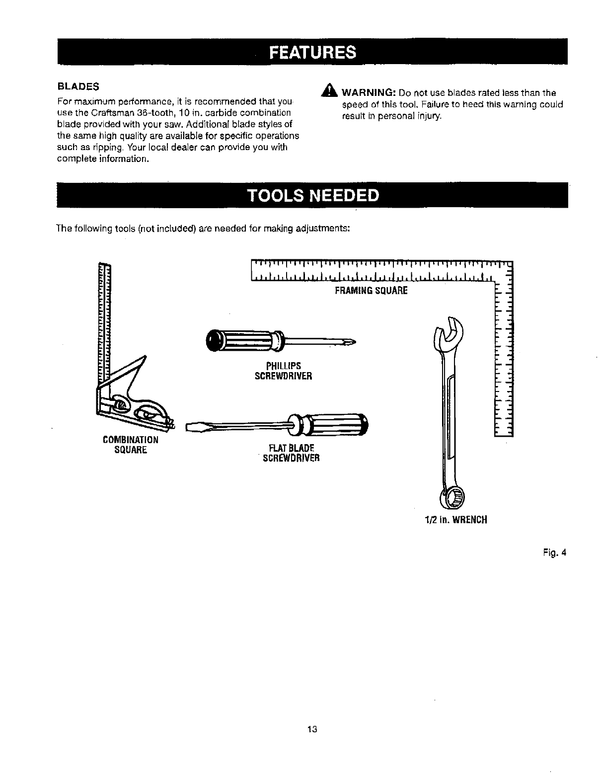
BLADES
For maximum performance, it is recommended that you
use the Craftsman 36-tooth, 10 in. carbide ¢ombination
blade provided with your saw. Additional blade styles of
the same high quality are available for specific operations
such as ripping. Your local dealer can provide yeu with
complete information.
_lk WARNING: Do not use blades rated less than the
speed of this tool. Failure to heed this warning could
result in personal injury.
The following tools (not included) are needed for making adjustments:
COMBINATION
SQUARE
1/2 in. WRENCH
Fig. 4
13
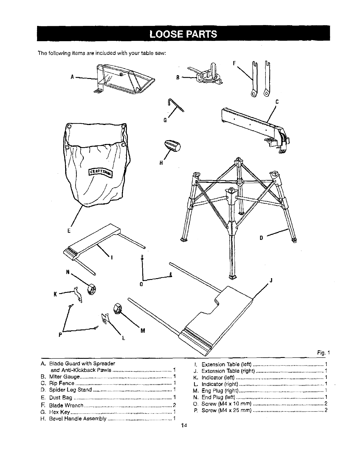
The following items are included with your table saw:
It
E
PM
L
Fig. 1
A. Blade Guard with Spreader
and Anti-Kickback Pawls ....................................... 1
B. Miter Gauge ............................................................. 1
C. Rip Fence ................................................................ 1
D. Spider Leg Stand .................................................... 1
E. Dust Bag ................................................................. 1
F. Blade Wrench .......................................................... 2
G. Hex Key ................................................................... 1
H. Bevel Handle Assembly .......................................... 1
I. Extension Table (left) ............................................... 1
J. Extension Table (right) ............................................. 1
K. Indicator (left) .......................................................... 1
L, Indicator (right) ........................................................ 1
M, Eng Plug (right) ........................................................ 1
N, End Plug (left) .......................................................... 1
O. Screw (M4 x 10 ram) ............................................... 2
Ft Screw (M4 x 25 mm) ............................................... 2
14
UNPACKING
This product requires assembly.
= Carefully lift saw from the carton and place saw on the
aide with the wheels.
NOTE: This tool is heavy. To avoid back injury,keep
your knees bent and liftwith your legs. not your back,
and get help when needed.
• Inspect the tool carefully to make sure no breakage or
damage occurred during shipping_
•Do not discard the packing material until you have
carefully inspected and satisfactorily operated the tool.
• The saw is factory set for accurate cutting. After
assembling it,cheek for accuracy. If shipping has
influenced the settings, refer to specific procedures
explained in this manual.
• If any pans are damaged or missing, please call
1-800-932-3188 for assistance.
_L WARNING" If any parts are missing, do not operate
this tool until the missing pans are replaced. Failure
to do so could result in possible serious personal
injury.
_, WARNING: DOnot attempt to modify this tool
or create accessories not recommended for use
with this tool. Any such alteration or modification is
misuse and could result in a hazardous condition
leading to possible serious personal injury,
_, WARNING: Do not connect to power suppry until
assembly iScompTete. Failure to comply could result
Jnaccidental starting and possible sedous personal
injury.
_IL WARNING: De not liftthe saw without help. Hold
it close to your body. Keep your knees bent and
lift with your legs, net your back. Ignoring these
precautions can result in back injury.
WARNING: Never stand directly in line with the
blade or allow hands to come closer than 3 in. to the
brads. Do not reachever or across the blade. Failure
to heed this warning can result in serious personal
injury.
_k WARNING: To avoid serious personal injury, always
make sure the table saw is securely mounted to
aworkbench or an approved leg stand. NEVER
operate the saw en the floor.
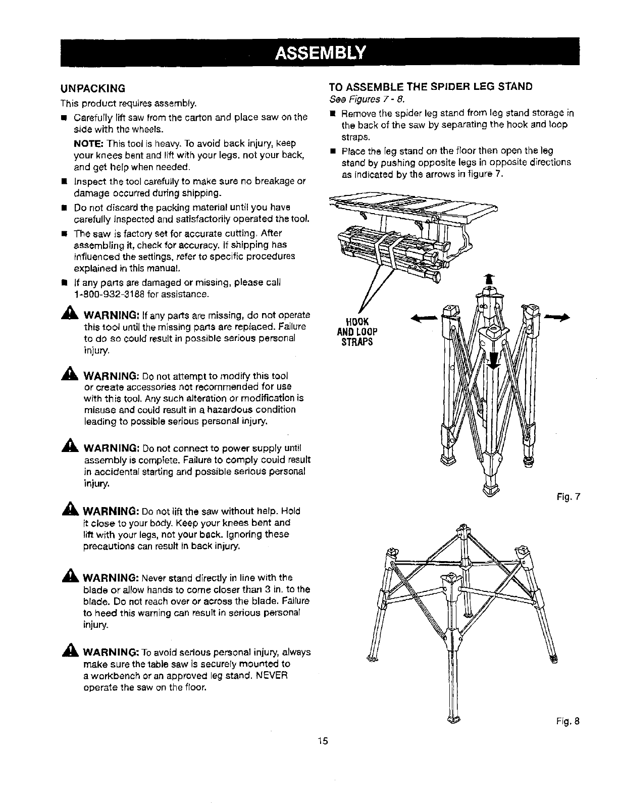
TO ASSEMBLE THE SPIDER LEG STAND
See Figures 7- 8.
• Remove the spider leg stand from leg stand storage in
the back of the saw by separating the hook and loop
straps.
•Place the leg stand on the floor then open the leg
stand by pushing opposite legs in opposite directions
as indicated by the arrows in figure 7.
I
HOOK
ANDLOOP
STRAPS
Fig, 7
Fig. 8
15
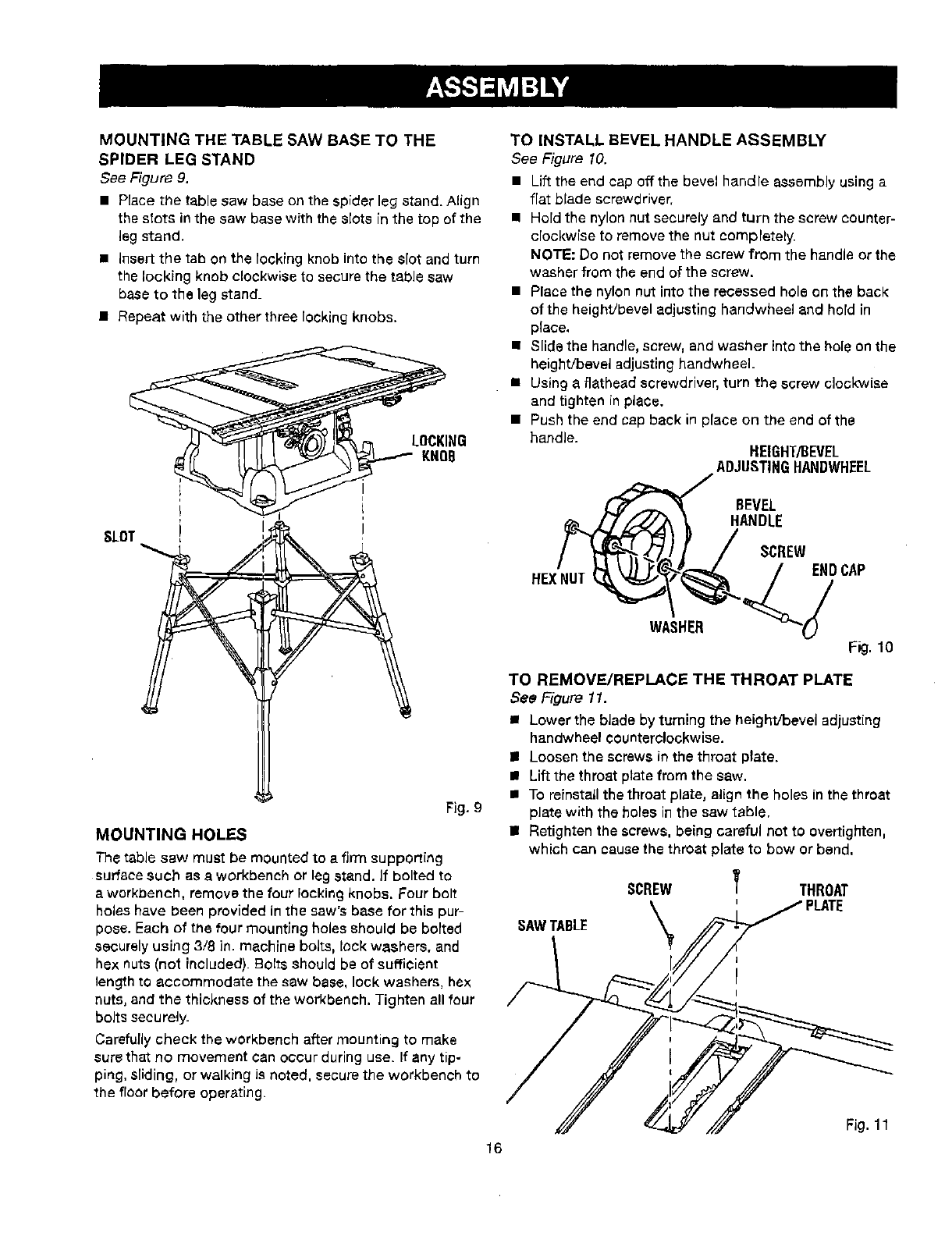
MOUNTING THE TABLE SAW BASE TO THE
SPIDER LEG STAND
See Figure 9.
• Place the tablesaw base on the spider leg stand. Align
the stota in the saw base with the slots in the top of the
leg stand.
• InserLthe tab on the locking knob into the slot and turn
the locking knob clockwise to secure the table saw
base to the leg stand_
• Repeat with the other three locking knobs.
SLOT
I
I
LOCKING
KNOB
Fig. 9
MOUNTING HOLES
The table saw must be mounted to a firm supporting
surface such as a workbench or leg stand. If bolted to
a workbench, remove the four locking knobs. Four bolt
holes have been provided in the saw's base for this pur-
pose. Each of the four mounting holes should be bolted
securely using 3/8 in. machine bolts, lock washers, and
hex nuts (not included). Bolts should be of sufficient
length to accommodate the saw base, lock washers, hax
nuts, and the thickness of the workbench, Tighten all four
bolts securely.
Carefully check the workbench after mounting to make
sure that no movement can occur during use. If any tip-
ping, sliding, or walking J9 noted, secure the workbench to
the floor before operating.
TO INSTALL BEVEL HANDLE ASSEMBLY
See Figure 10.
• Lift the end cap off the bevel handle assembly using a
flat blade screwdriver.
• Hold the nylon nut securely and turn the screw counter-
clockwise to remove the nut completely.
NOTE: Do not remove the screw from the handle or the
washer from the end of the screw.
• Place the nylon nut into the recessed hole on the back
of the height/bevel adjustinghandwheel and hold in
place,
• Slide the handle, screw, and washer intothe hole on the
height!bevel adjusting handwheel.
• Using a flathead screwdriver,turn the screw clockwise
and tighten in place.
•Pushthe end cop back in place on the end of the
handle. HEIGHT/BEVEL
ADJUSTINGHANDWHEEL
BEVEL
HANDLE
HEXNUT
WASHER
SCREW
._;DCAP
F_.10
TO REMOVE/REPLACE THE THROAT PLATE
See Figure 11.
•Lower the bJade by turning the height/bevel adjusting
handwheel counterclockwise.
II Loosen the screws in the throat ptate.
II Liftthe throat plate from the saw.
•To roinstaUthe throat plato, alignthe holes in the throat
plate with the holes inthe saw table,
= Retighten the screws, being careful not to overtighten,
which can cause the throat plate to bow or bend.
SCREW THROAT
SAWTABLE
Fig. 11
16
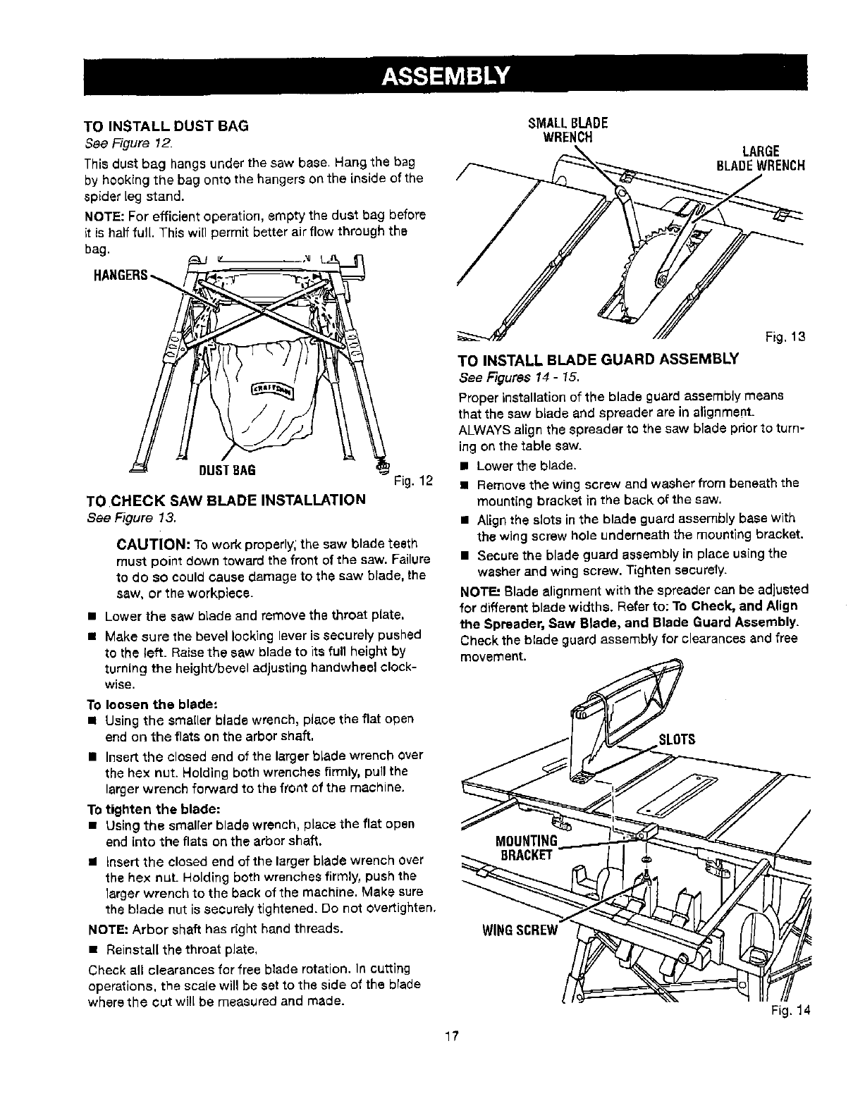
TO INSTALL DUST BAG
See Figure 12.
This dust bag hangs under the saw base. Hang the bag
by hook(ng the bag onto the hangers on the inside of the
spider leg stand.
NOTE: For efficient operation, empty the dust bag before
(t is half full This will permit better air flow through the
bag.
DUSTBAG
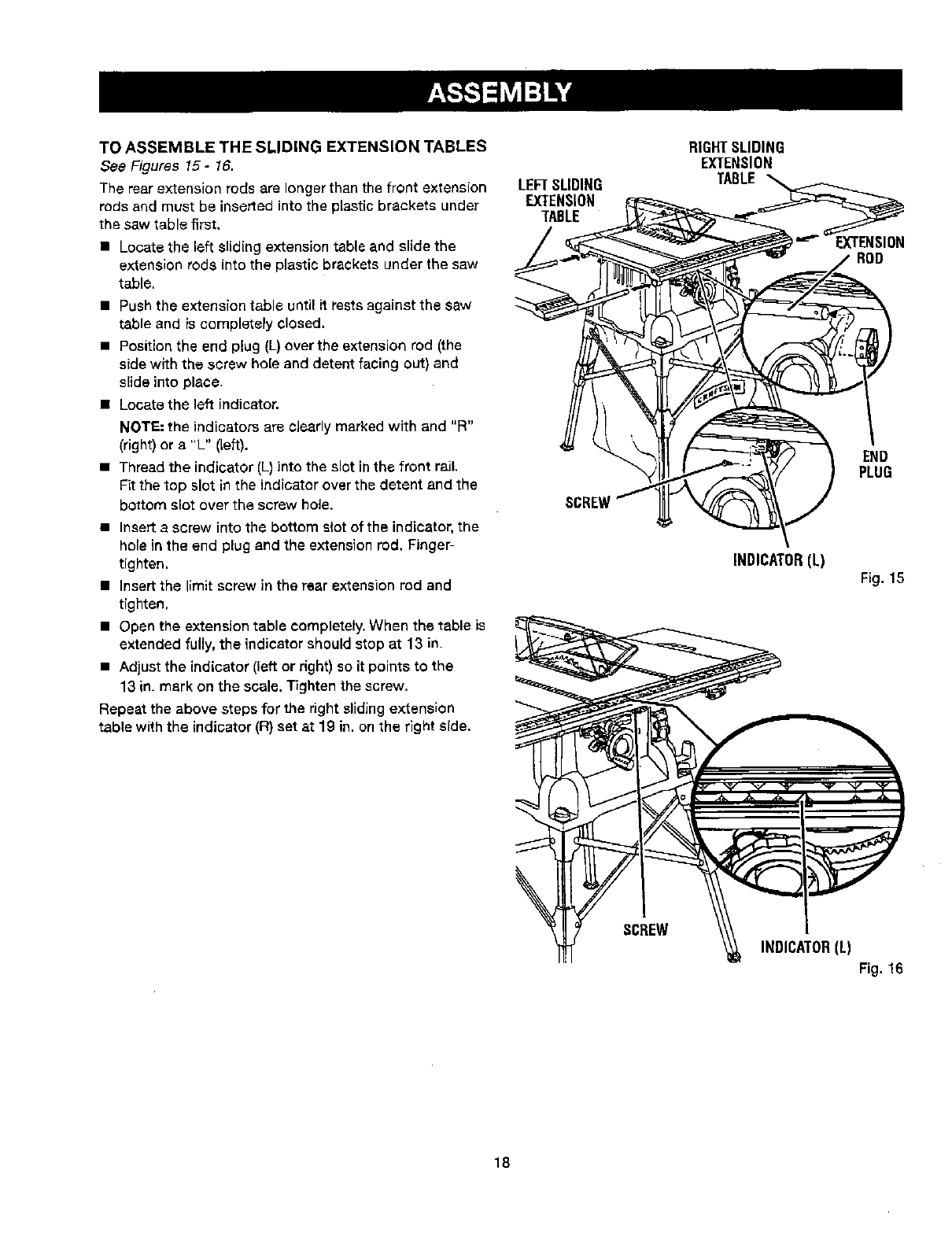
TO CHECK SAW BLADE INSTALLATION
See Figure 13.
Fig. 12
CAUTION." To work properly,' the saw blade teeth
must point down toward the front of the saw. Failure
to do so could cause damage to the saw blade, the
saw, or the workpiese.
• Lower the saw blade and remove the throat plate.
• Make sure the bevel locking lever is securely pushed
to the left. Raisethe saw blade to its full height by
turning the height/bevel adjusting handwheel oIock-
wise.
To loosen the blade:
•Using the smaller blade wrench, place the flat open
end on the flats on the arbor shaft.
• Insert the closed end of the larger blade wrench over
the hex nut. Holding both wrenches firmly, pull the
larger wrench forward to the front of the machine.
To tighten the blade:
•Using the smaller blade wrench, place the flat open
end into the flats on the arborshaft.
•Insert the closed end of the larger blade wrench over
the hex nut. Holding both wrenches firmly, push the
larger wrench to the back of the machine. Make sure
the blade nut is securely tightened. Do not overtighten,
NOTE: Arbor shaft has right hand threads.
•Reinstall the throat plate,
Check all clearances for free blade rotation. In cutting
operations, the scale will be set to the side of the blade
where the out will be measured and made.
SMALLBLADE
WRENCH LARGE
BLADEWRENCH
Fig, 13
TO INSTALL BLADE GUARD ASSEMBLY
See Figures 14 -15.
Proper installation of the blade guard assembly means
that the saw blade and spreader are in alignment-
ALWAYS align the spreader to the saw blade pdor to turn-
ing on the table saw.
• Lower the blade,
• Remove the wing screw and washer from beneath the
mount(ng bracket in the back of the saw.
• Align the slots in the blade guard assembly base with
the wing screw ho]e underneath the mounting bracket.
• Secure the blade guard assembly in place ue(ng the
washer and wing screw. Tighten securely.
NOTE: Blade alignment with the spreader can be adjusted
for different blade widths. Refer to; To Check, and Align
the Spreader, Saw Blade, and Blade Guard Assembly.
Check the blade guard assembly for clearances and free
movement.
SLOTS
MOUNTING
WINGSCREW
17
Fig, 14
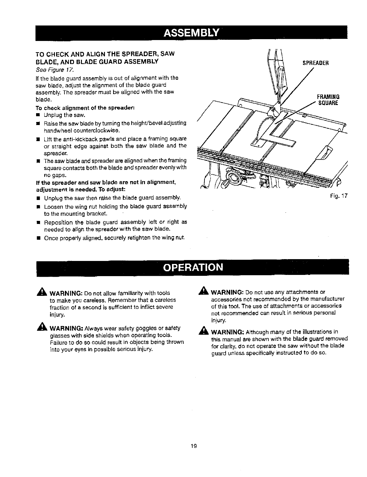
TO ASSEMBLE THE SLIDING EXTENSION TABLES
See Figures 15- 16.
The rear extension rods are longer than the front extension
rods and must be inserted into the plastic brackets under
the saw table first.
• Locate the left sliding extension tabl- and slide the
extension rode into the plastic brackets under the saw
table,
• Push the extension table until it rests against the saw
table and is completely closed.
• Position the end plug (L)over the extension rod (the
side with the screw hole and detent facing out) and
slide into place,
• Locate the left indicator.
NOTE: the indicators are cJearly marked with and "R"
(right) or a "L" (left).
• Thread the indicator (L) into the slot in the front rail.
Fit the top slot in the indicator over the detent and the
bottom slot over the screw hole.
• Insert a screw into the bottom slotof the indicator, the
hole in the end plug and the extension rod, Finger-
tighten.
• Insert the limit screw in the rear extension red and
tighten,
•Open the extensiontable completely. When the table is
extended fully, the indicator should stop at 13 in.
• Adjust the indicator(left or right)so it points to the
13 in_mark on the scale. Tighten the screw.
Repeat the above steps for the right sliding extension
table withthe indicator (R) set at 19 in. onthe right side.
LEFTSLIDING
EXTENSION
TABLE
RIGHTSLIDING
EXTENSION
TABLE_
ROD
END
PLUG
INDICATOR(L) Fig. 15
SCREW
INDICATOR(L)
Fig, 16
18
TO CHECK AND ALIGN THE SPREADER, SAW
BLADE, AND BLADE GUARD ASSEMBLY
See Figure 17.
If the blade guard assembly is out of alignment with the
saw blade, adjust the alignment of the blade guard
assembly. The spreader must be aLignedwith the saw
blade.
To check alignment of the spreader:
•Unplug the saw.
/ Raise the saw blade by turning the height!bevel adjusting
handwheel counterclockwise.
• Lift the anti-kickback pawls and place a framing square
or straight edge against both the saw blade and the
spreader,
• Thesawbladeandspreaderareallgnedwhentheframing
square contaCtS beth the blade and spreader evenly with
no gaps.
If the spreader and saw blade are not in alignment,
adjustment is needed. To adjust:
• Unplug the saw then raisethe blade guard assembly.
m Loosen the wing nut holding the blade guard assembly
to the mounting bracket.
• Reposition the blade guard assembly left or right as
needed to align the spreader with the saw blade.
• Once properly aligned, securely retighten the wing nut.
SPREADER
FRAMING
SQUARE
Fig. 17
_IL WARNING: De not allow familiarity with tools
to make you careless. Remember that a careless
fraction of asecond is sufficient to inflict severe
injury.
_IL WARNING: Always wear safety goggles or safety
glasses with side shieldswhen operating tools.
FaiLureto do so could result in objects being thrown
into your eyes in possibleserious injury.
_IL WARNING: Do not use any attachments or
accessories not recommended by the manufacturer
of this tool. The use of attachments or accessories
not recommended can resurt in serious personal
injury.
_1, WARNING; Although many of the illustrations in
this manual are shown with the blade guard removed
for clarity, do not operate the saw without the blade
guard unless specifically instructed to do so.
19
APPLICATIONS
You may use this tool for the purposes listed below:
• Straight line cutting operations such as cross cutting,
ripping, mitering, beveling, and compound cutting
• Dado or molding cuts with optional accessories
II Cabinet making and woodworking
NOTE=This table saw is designed to cut wood and wood
composition products only.
BASIC OPERATION OF THE TABLE SAW
The 3-prong plug must be plugged into a matching outlet
that is properly installed and grounded according to all
local codes and ordinances, Improper connection of the
equipment can result in electric shock. Do not modify
the plug if it will not fit the outlet. Have the correct outlet
installed by a qualified electrician. Refer to the Electrical
section inthis manual.
CAUSES OF KICKBACK
Kickback can occur when the blade stalls or binds, kick-
ing the workpiece back toward you with great force and
speed. Ifyour hands are near the saw blade, they may
be jerked loose from the workplace and may contact the
blade. Kiokback can cause serious injury. Use precautions
to avoid the risks.
Kickback can be caused by any action that pinches the
blade in the wood such as;
• Making a cut with incorrect blade depth
• SaWing into knots or nails in the workplace
•Twistingthe wood while making a cut
• Failing to support work
• Forcing a cut
•Cutting warped orwet lumber
• Using the wrong blade for the type of cut
• Not following correct operating procedures
• Misusing the saw
• Failing to use the anti-kickback pawls
• Cutting wlth a dull, gummed-up, or improperly set
blade
AVOIDING KICKBACK
• Always use the correct blade depth setting.The top of
the blade teeth should clear the workpiece by 1/8 in. to
1/4 in.
• Inspect the work for knots or nails before beginning a
cut. Knock out any loose knots with a hammer. Never
saw into a loose knot or nail.
•Always use the rip fence when rip cutting and the miter
gauge when cross cutting. This helps prevent twisting
the wood in the cut.
PUSHSTICKS
PUSHBLOCKS Fig. 18
• Always use clean, sharp, and properly-set blades.
Never make cuts with dull blades.
• To avoid pinching the blade, support the work properly
before beginning a cut.
• When making a cut, use steady, even pressure. Never
force cuts.
•DO not cut wet orwarped lumber.
• Always hold your werkpieee firmly with both hands or
with push st[cks. Keep your body [na balanced posi-
tion to be ready to resist kickback should it occur.
Never stand directly in line with the blade,
• Use the right type of blade for the cut being made,
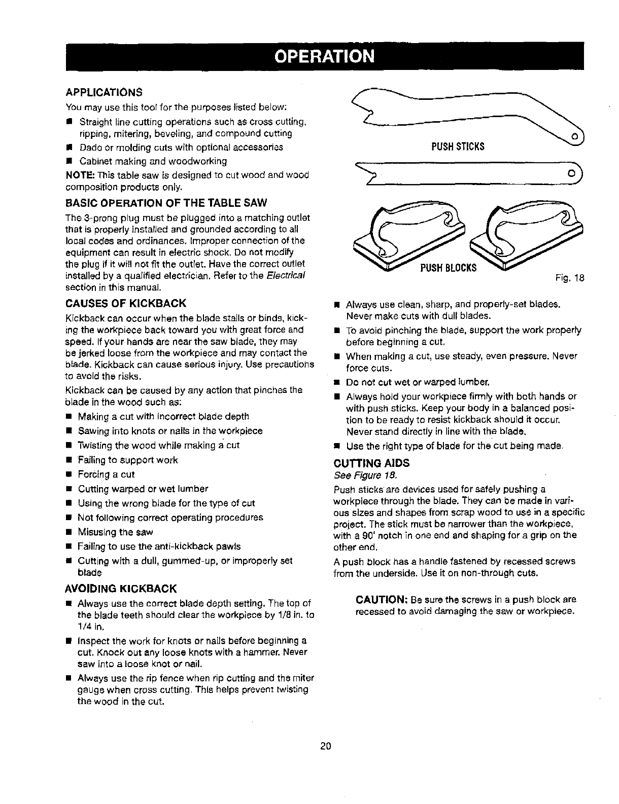
CUTI"ING AIDS
See Figure 18,
Push sticks •are devices used for safely pushing a
workplace through the blade. They can be made in vari-
ous sizes and shapes from scrap wood to use in a specific
project. The stick must be narrower than the workpiece,
with a 90° notch in one end and shaping for a grip on the
other end.
A push block has a handle fastened by recessed screws
from the underside. Use it on non-through cuts.
CAUTION; Be surethe screws in a push block are
recessed to avoid damaging the saw or workplace.
20
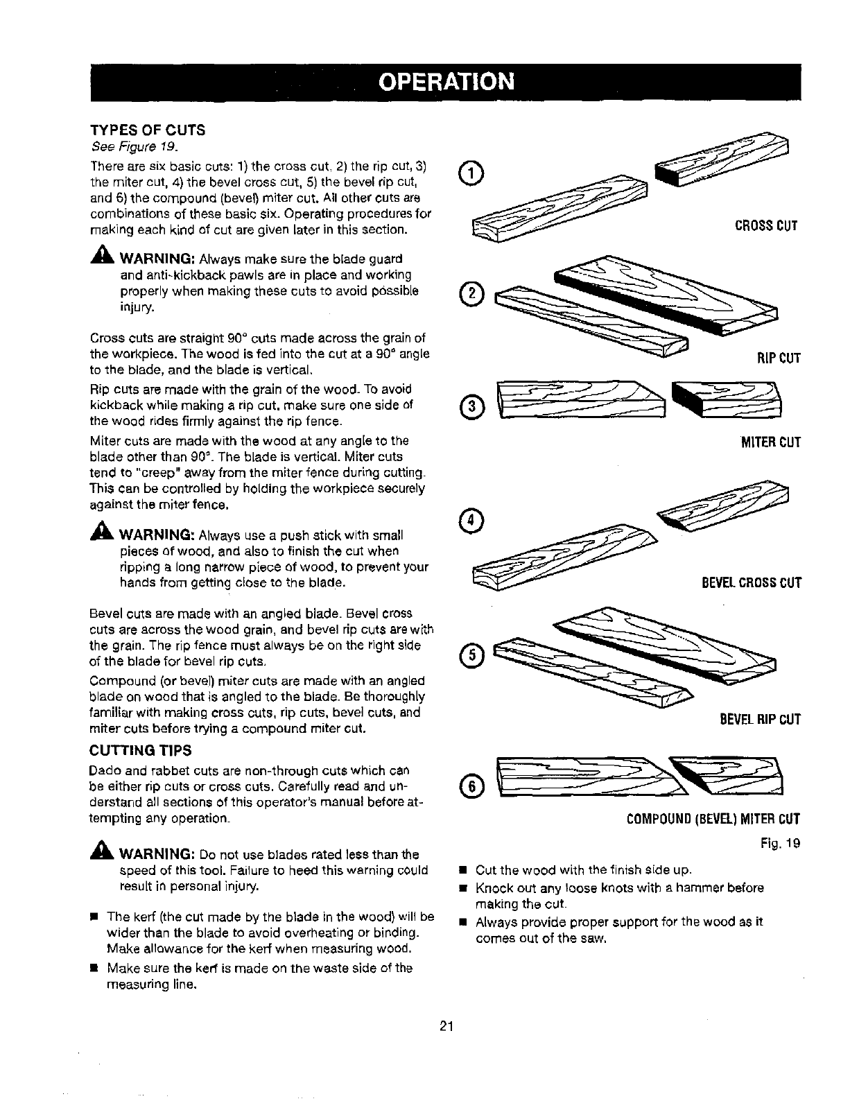
TYPES OF CUTS
See Figure 19.
There are six basic outs: 1) the cross cut, 2) the rip cut, 3)
the miter cut, 4) the bevel cross cut, 5) the bevel rip cut,
and 6) the compound (bevel) miter cut. All other cuts are
combinations of these basic six. Operating procedures for
making each kind of cut are given Laterin this section.
_k, WARNING" Always make sure the blade guard
and anti-kickback pawls are in place and working
properly when making these cuts to avoid possible
injury.
Cross cuts are straight g0° cuts made across the grain of
the workpieee. The wood is fed into the cut at a 90" angle
to the blade, and the blade is vertical.
Rip cuts are made with the grain of the wood_ To avoid
kickback while making a rip cut, make sure one side of
the wood rides firmly against the rip fence.
Miter cuts are made with the wood at any angle to the
blade other than 90%The blade is vertical. Miter cuts
tend to "creep" away from the miter fence during cutting.
This can be controtled by holding the workpiece securely
against the miter fence.
A
AML WARNING: Always use a push stick with small
pieces of wood, and also to finish the cut when
ripping a long narrow piece ef wood, to prevent your
hands from getting close to the blade.
Bevel cuts are made with an angled blade. Bevel cross
cuts are across the wood grain, and bevel rip cuts arewlth
the grain. The rip fence must always be on the rightside
of the blade for bevel rip cuts,
Compound (or bevel) miter cuts are made with an angled
blade on wood that is angled to the blade. Be thoroughly
familiar with making cross cuts, rip cuts, bevel cuts, and
miter cuts before trying a compound miter cut.
CUTTING TIPS
Bade and rabbet cuts are non-through cuts which can
be either rip cuts or cross cuts. Carefully read and un-
derstand all sections of this operator's manual before at-
tempting any operation.
_, WARNING: Do not use blades rated less than the
speed of this tool. Failure to heed this warning could
result in personal injury.
• The kerr (the cut made by the blade inthe wood) will be
wider than the blade to avoid overheating or binding.
Make allowance for the kerr when measuring wood.
• Make sure the kerr is made on the waste side of the
measuring line.
CROSSCUT
RIPCUT
MITERCUT
o
BEVELCROSSCUT
BEVELRIPCUT
COMPOUND(BEVEL)MITERCUT
Fig. 19
• Cut the wood with the finish side up.
•Knock out any loose knots with e hammer before
making the cut.
• Always provide proper support for the wood as it
comes out of the saw,
21
FEATHERBOARD
Afsatherboard is a device used to help control the
workpiece by guiding it securely against the table or
fence. Featherboards are especially usefut when ripping
small workpiecee and for completing non-through cuts_
The end is angled with anumber of short kerfs to give a
friction hold on the workpiece and locked inplace on the
table with a C-clamp. Test that it can resist kickback.
_, WARNING: Place the featherboard against the
uncut portion of the workpiece to avoid kickback that
could Cause serioUSpersonal iniury.
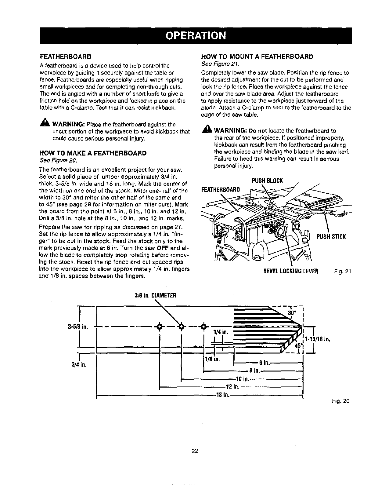
HOW TO MAKE A FEATHERBOARD
See Figure 20.
The featherboard is an excellent project for your saw.
Select a solid piece of lumber approximately 3/4 in.
thick, 3-5/8 in. wide and 18 in. long. Mark the center of
the width on one end of the stock. Miter one-half of the
width to 30° and miter the other half of the same end
to 45" (see page 28 for information on miter cuts). Mark
the board from the point at 6 in., 8 in., 10 in. and 12 in,
Drill a3/8 in. hole atthe 8 in., 10 in., and 12 in. marks.
Prepare the saw for ripping as discussed on page 27.
Set the rip fence tO allow approximately a1/4 in. "fin-
ger" to be cut in the stock. Feed the stock only to the
mark previously made at 6in. Turn the saw OFF and al-
low the blade to completely stop rotating before remov-
ing the stock. Reset the rip fence and cut spaced rips
into the workpiece to allow approxfmately 1/4 in. fingers
and 1/8 in. Spaces between the fingers.
HOW TO MOUNT A FEATHERBOARD
See Figure 21.
Completely lower the saw blade. Position the rip fence to
the desired adjustment for the cut to be performed and
lock the rip fence, Place the workpiece against the fence
and over the saw blade area, Adjust the featherboard
to apply resistance to the workpiece just forward of the
blade. Attach aC-clamp to securethe featherboard to the
edge of the saw table.
_k WARNING: DO not locate the featherboard to
the rear of the workplace. If positioned improperly,
kickback can resultfrom the featherboard pinching
the workpiece and bindingthe blade in the saw kerf.
Failureto heed this warning can result in serious
persona]injury.
FEATHERBOARD
PUSHBLOCK
PUSHSTICK
BEVELLOCKINGLEVER Fig. 21
3.5/8 in,
,ll
'1
3/4 in.
3/8 in. DIAMETER
I loin, ,....
12 in.
18 in. Fig_20
22
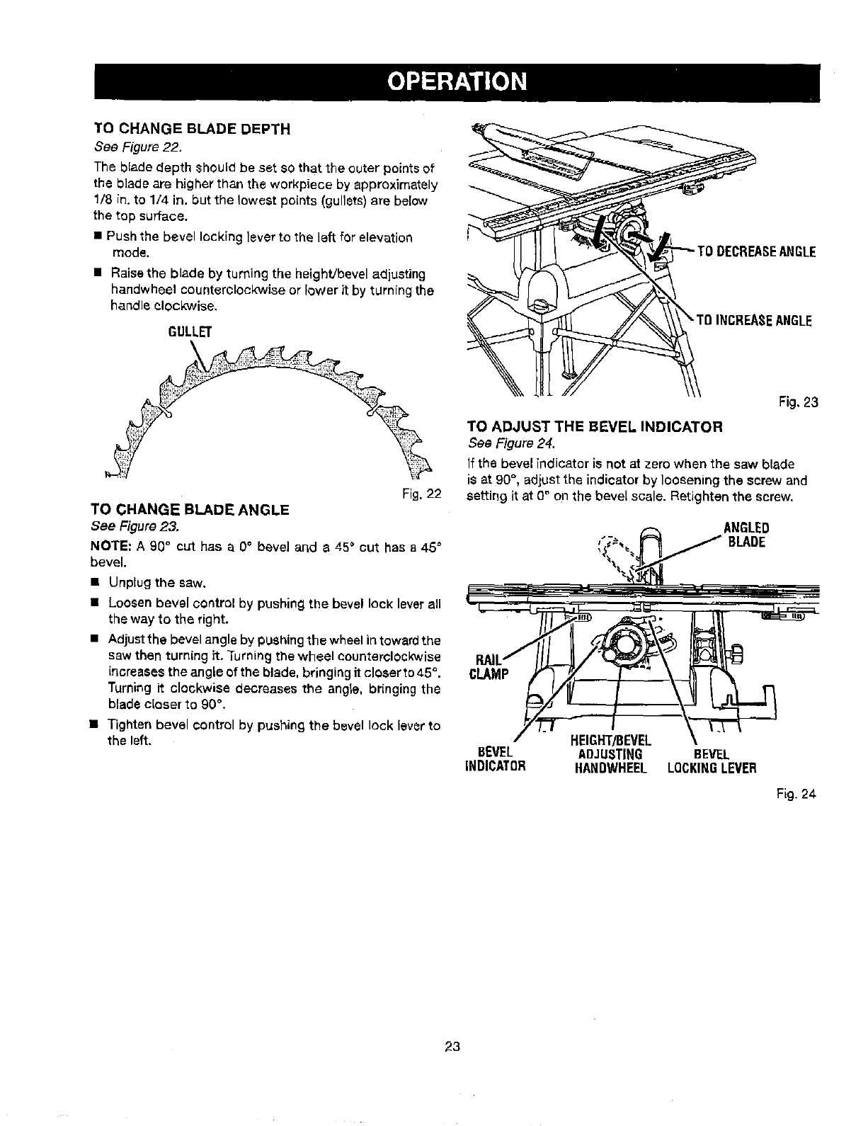
TO CHANGE BLADE DEPTH
See Figure 22.
The blade depth ehould be set SOthat the outer points of
the blade are higher than the workpiece by approximately
1/8 in. to 1/4 in. but the lowest points (gullets) are below
the top surface.
• Push the bevel locking lever to the left for elevation
mode.
• Raisethe blade by turning the height/bevel adjusting
handwheel counterclockwise or lower it by turning the
handle clockwise,
GULLET
Fig. 22
TO CHANGE BLADE ANGLE
See Figure23.
NOTE: A 90 ° cut has a 0° bevel and a 45° cut has a 45°
bevel.
•Unplug the saw,
Loosen bevel control by pushing the bevel leek leverall
the way to the right.
Adjustthe bevel angle by pushing the wheel intowardthe
saw then turning it. Turningthe wheel counterclockwise
{ncreasesthe angle of the blade, bringingit closer to45°.
Turning it clockwise decreases the angle, br{nging the
blade closer to 90%
lighten bevel control by pushing the bevel lock lever to
the left.
EANGLE
Fig, 23
TO ADJUST THE BEVEL INDICATOR
See Figure 24.
If the bevel indicator is not at zero when the saw blade
is at 90°, adjust the indicator by loosening the screw and
setting it at 0_ on the bevel scale. Retighten the screw.
ANGLED
BLADE
CLAMP
HEIGHT/BEVEL
BEVEL ADJUSTING BEVEL
INDICATOR HANDWHEEL LOCKINGLEVER
Fig. 24
23
,_k WARNING: To reduce the risk of injury, always
make sure the rip fence is parallel to the blade before
beginning any operation.
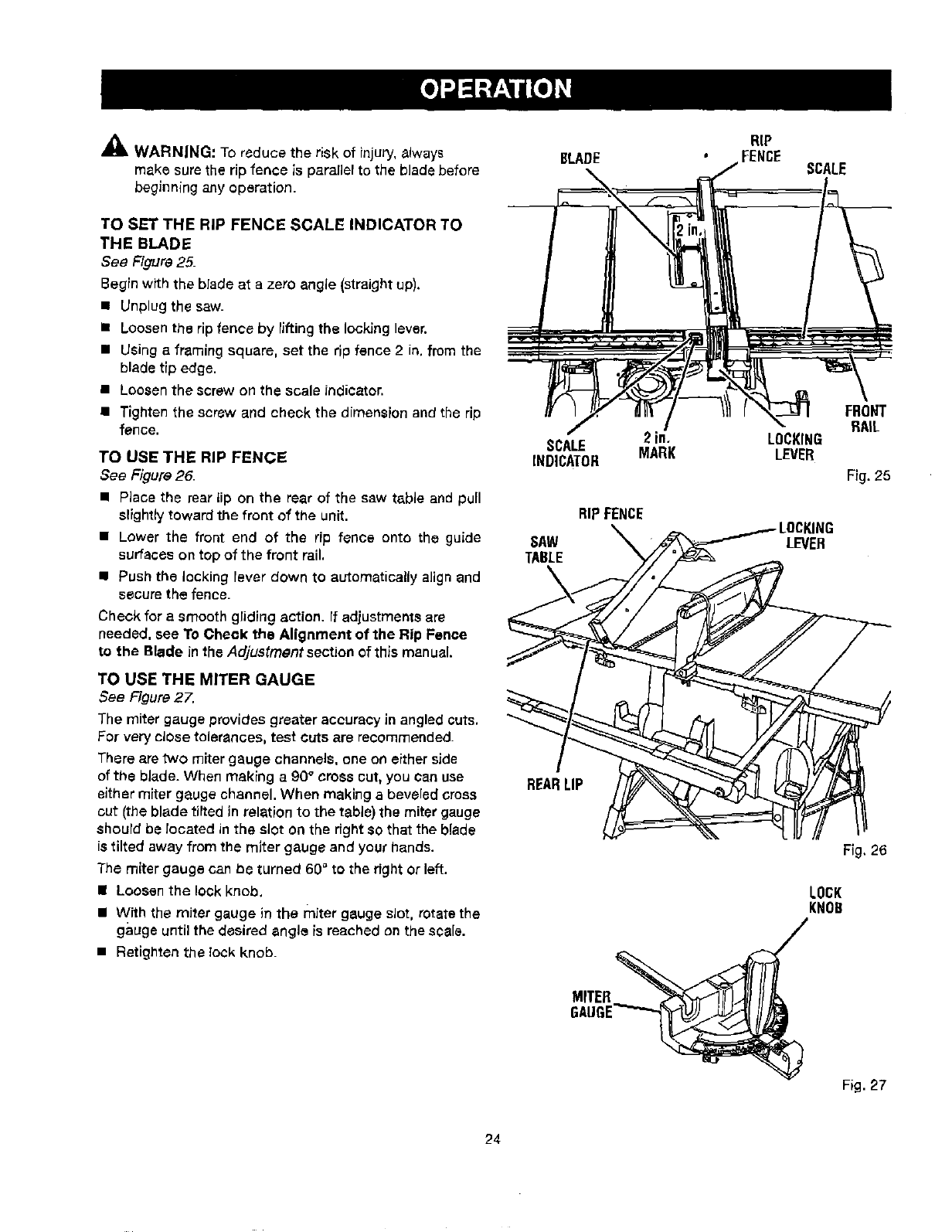
TO SET THE RIP FENCE SCALE INDICATOR TO
THE BLADE
See Figure 25.
Begin withthe blade at a zero angle (straight up),
m Unplug the saw.
• Loosen the rip fence by lifting the locking lever.
• Using a framing square, set the rip fence 2 in. from the
blade tip edge.
• Loosen the screw on the scale indicator.
• Tighten the screw end check the dimension and the rip
fence.
TO USE THE RIP FENCE
See Figure 26.
• Place the rear tip on the rear of the saw table and pull
slightly toward the front of the unit.
• Lower the front end of the rip fence onto the guide
surfaces on top of the front rail.
• Push the locking lever down to automatically align and
secure the fence.
Check for a smooth gliding action. If adjustments are
needed, see TOCheck the Alignment of the Rip Fence
to the Blade in the Adjustment section of this manual.
TO USE THE MITER GAUGE
See Figure 27.
The miter gauge provides greater accuracy in angled cuts,
For very close tolerances, test cuts are recommended.
There are two miter gauge channels, one on either side
of the blade. When making a90° cross cut, you can use
either miter gauge channel. When making a beveled cross
cut (the blade tilted in relation to the table) the miter gauge
should be located in the slot on the dght SOthat the blade
is tilted away from the miter gauge and your hands.
The miter gauge can be turned 60" to the right or left.
• Loosen the lock knob,
• With the miter gauge in the miter gauge slot. rotate the
gauge until the desired angle is reached on the scale.
•Retighten the lock knob.
RIP
BLADE
2irl.
SCALE MARK
INDICATOR
RIPFENCE
SAW
TABLE
REARLIP
MITER_
GAUGE_
SCALE
FRONT
RAIL
LOCKING
LEVER
Fig. 25
LEVER
FTg,26
LOCK
KNOB
/
)
Fig. 27
24
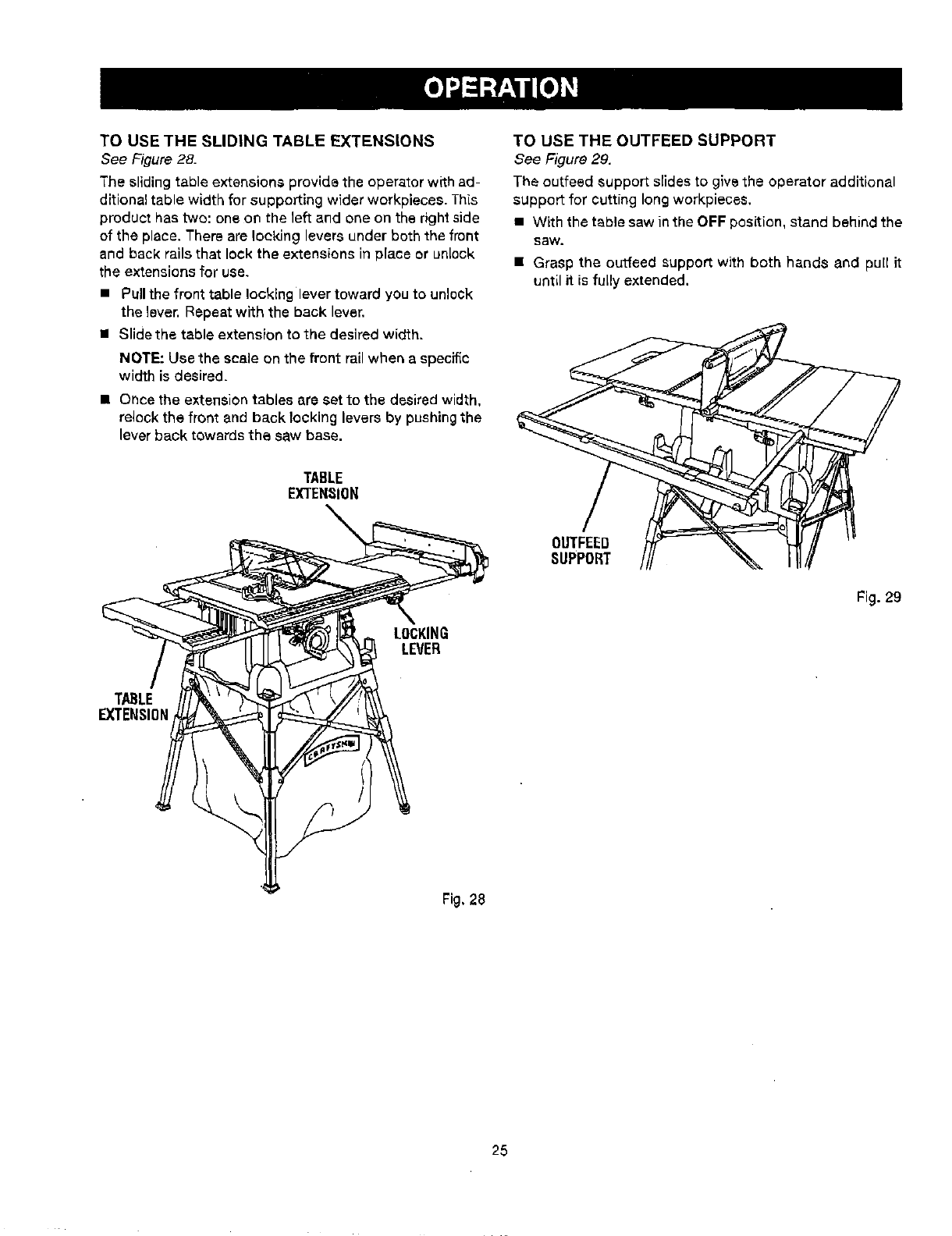
TO USE THE SLIDING TABLE EXTENSIONS
See Figure 28.
The sliding table extensions provide the operator with ad-
ditional table width for supporting wider workpieces. This
product has two: one on the left and one on the right side
of the place. There are locking levers under both the front
and back rails that lock the extensions in place or unlock
the extensions for use.
•Pullthe front table locking lever toward you to unlock
the lever. Repeat with the back lever.
=l Slide the table extension to the desired width.
NOTE: Use the scale on the front rail when a specific
width is desired.
• Once the extension tables are set to the desired width.
relock the front and back locking levers by pushing the
lever back towards the saw base.
TABLE
EXTENSION
LOCKING
LEVER
TO USE THE OUTFEED SUPPORT
See Figure 29.
The outfeed Support slides to give the operator additional
support for cutting long workpieces.
• With the table saw in the OFF position, stand behind the
saw.
• Grasp the outfesd support with both hands and pull it
until it is fully extended.
OUTFEEO
SUPPORT
Fig. 29
TABLE
EXTENSION
Fig, 28
25
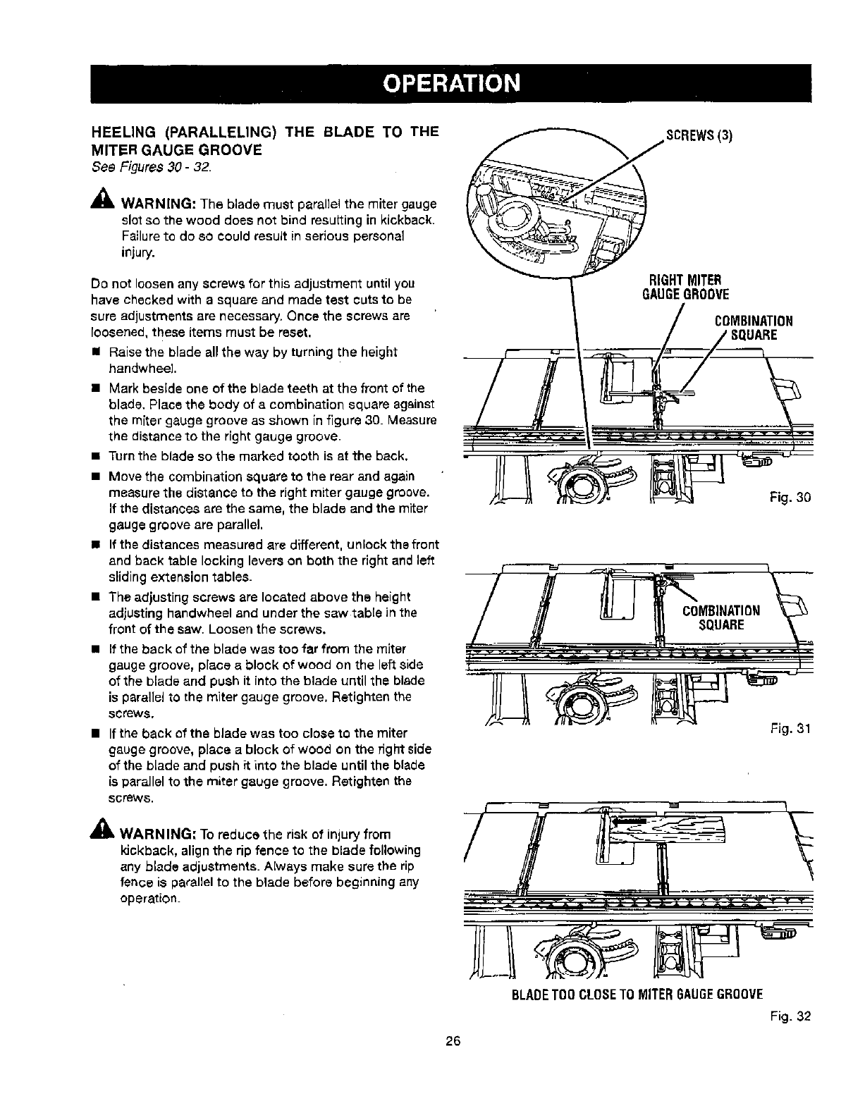
HEELING (PARALLELING) THE BLADE TO THE
MITER GAUGE GROOVE
See Figures 30 -32.
,_ WARNING: The blade must parallel the miter gauge
slot so the wood does not bind resulting in kickback.
Failure to do so could result in serious personal
injury.
Do not loosen any screws for this adjustment until you
have checked with a square and made test cuts to be
sure adjustments are necessary. Once the screws are
loosened, these items must be reset.
• Raise the blade all the way by turning the height
handwhee].
• Mark beside one of the blade teeth at the front of the
blade. Place the body of a combination square against
the miter gauge groove as shown in figure 30. Measure
the distance to the fight gauge groove.
•Turn the blade so the marked tooth is at the back.
• Move the combination square to the rear and again
measure the distance to the fight miter gauge groove.
If the distances are the same, the blade and the miter
gauge groove are parallel,
• If the distances measured are different, unlock the front
and back table locking levers on both the right and left
sliding extension tables.
• The adjusting screws are located above the height
adjusting handwheel and under the saw table in the
front of the saw. Loosen the screws.
• If the back of the blade was too far from the miter
gauge groove, place a block of wood on the left side
of the blade and push it into the blade until the blade
is parallel to the miter gauge groove. Retighten the
screws,
• If the back of the blade was too close to the miter
gauge groove, place a block of wood on the fight side
of the blade and push ft into the blade until the blade
is parallel to the miter gauge groove. Ratighten the
screws,
_k WARNING: To reduce the risk of injury from
kickback, align the rip fence to the blade following
any blade adjustments. Always make sure the rip
fence is parallel to the blade before beginning any
operation.
RIGHTMITER
GAUGEGROOVE
COMBINATION
BQUARE
Fig. 30
Fig. 31
BLADETOO CLOSE TO MITER GAUGEGROOVE
Fig. 32
26
MAKING CUTS
The blade provided with the saw is a high-quality combi-
nation blade suitable for ripping and crosscut operations.
_WARNING; Do not use blades rated less than the
speed of thistool. Failure to heed this warning could
result in personal injury,
Use the miter gauge when making cross, miter, bevel,
end compound miter cuts. To secure the angle, lock the
miter gauge in place by twisting the lock knob clockwise.
Always tighten the lock knob securely in place before use.
NOTE: It is recommended that you place the piece to be
saved on the left side ef the blade and that you make e
test cut on scrap wood first.
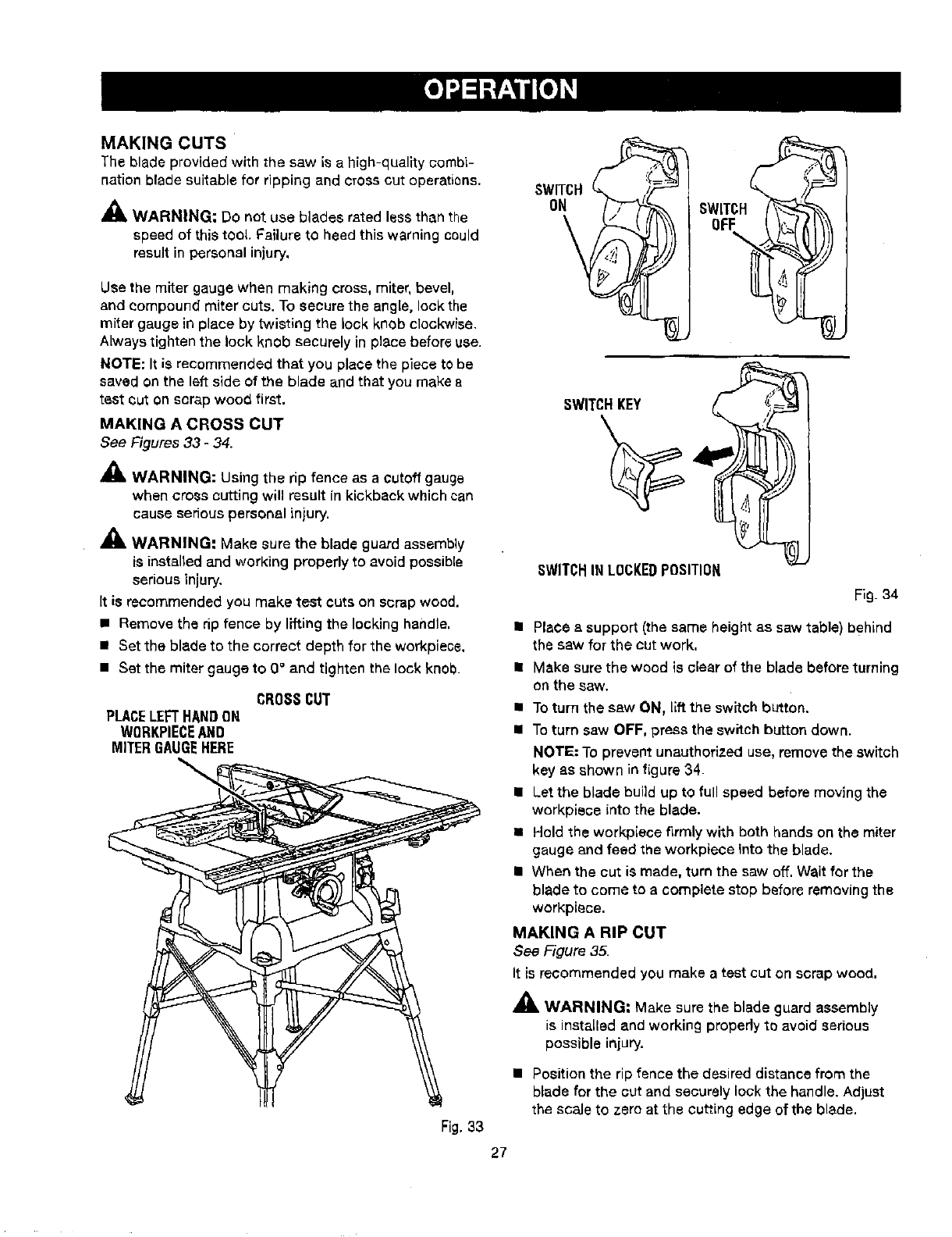
MAKING A CROSS CUT
See Figures 33 -34.
_1, WARNING: Using the rip fence as a cutoff gauge
when cross cutting will result in kickback which can
cause seriouspersonal injury.
_, WARNING: Make sure the blade guard assembly
is installed and working propedy to avoid possible
serious injury,
It is recommended you make test cuts on scrap wood.
= Remove the rip fence by lifting the locking handle,
• Set the blade to the correct depth for the workpiecs,
• Set the miter gauge to O°and tighten the lock knob.
CROSSCUT
PLACELEFTHANDON
WORKPIECEANO
MITERGAUGEHERE
Fig.33
SWITCH
OFF
%
SWITCH,KEY ,,_I__
SWITCHINLOCKEDPOSITION
Fig. 34
• Place a support (the same height as saw table) behLnd
the saw for the cut work,
• Make sure the wood is clear of the blade before turning
on the saw.
• To turn the saw ON, Liftthe switch button.
• To turn saw OFF, press the switch button down.
NOTE."To prevent unauthorized use, remove the switch
key as shown in figure 34.
• Let the blade build up to full speed before moving the
workpiece into the blade.
• Hold the workpiece firmly whh both hands on the miter
gauge and feed the workpiece into the blade.
• When the cut is made, turn the saw off. Wait for the
blade to come to a complete stop before removing the
workpiece.
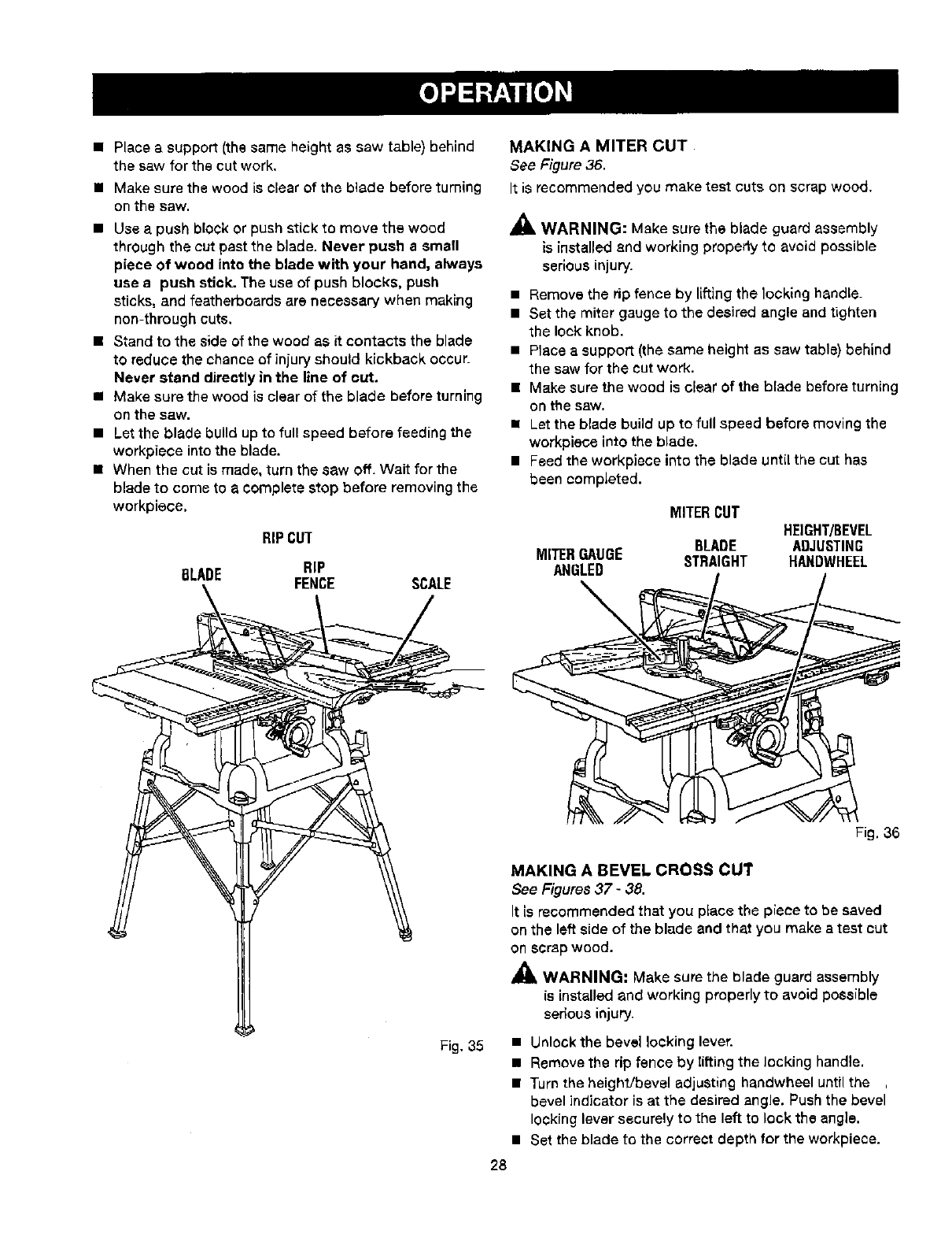
MAKING A RIP CUT
See Figure 35.
It is recommended you make atest cut on scrap wood,
•_ WARNING: Make sure the blade guard assembly
is installed and working propedy to avoid serious
possible injury,
• Position the rip fence the desired distance from the
blade for the cut and securely lock the handle. Adjust
the scale to zero at the cutting edge of the blade.
27
• Place a support (the same height as saw table) behind
the saw for the cut work.
• Make sure the wood is clear of the blade before turning
on the saw.
• Use a push block or push stick to move the wood
through the cut past the blade. Never push a small
piece of wood into the blade with your hand, always
use a push stick. The use of push blocks, push
sticks, and featherbeards are necessary when making
non-through cuts.
• Stand to the side of the wood as it contacts the blade
to reduce the chanceof injury should kickback occur.
Never stand directly in the line of cut.
•Make sure the wood is clear of the blade before turning
on the saw.
•Let the blade build up to full speed before feeding the
workpiece into the blade.
• When the cut is made, turn the saw off. Wait for the
blade to come to acomplete stop before removing the
workplace.
RIPCUT
BLADE RIP
FENCE SCALE
MAKING A MITER CUT
See Figure36.
It is recommended you make test cuts on scrap wood.
A
All, WARNING: Make sure the blade guard assembly
is installed and working property to avoid possible
serious injury.
•Remove the rip fence by lifting the locking handle.
• Set the miter gauge to the desired angle and tighten
the lock knob.
• Place a support (the same height as saw table) behind
the saw for the cut work.
• Make sure the wood is clear of the blade before turning
on the saw.
• Let the blade build up to full speed before moving the
workplace into the blade.
• Feed the workpiece into the blade until the cut has
been completed.
MITERCUT
HEIGHT/BEVEL
BLADE ADJUSTING
MITERGAUGE STRAIGHT HANDWHEEL
ANGLED
Fig, 35
Fig. 36
MAKING A BEVEL CROSS CUT
See Figures37 -38.
It is recommended that you place the piece to be saved
on the left side of the blade and that you make atest cut
on scrapwood.
,_ WARNING: Make sure the blade guard assembly
is installed and working properly to avoid possible
serious injury.
• Unlockthe bevel locking lever.
• Remove the rip fence by lifting the locking handle.
• Turn the height/bevel adjusting handwheel until the
bevel indicator is at the desired angle. Push the bevel
locking lever securely to the left to lock the angle.
• Set the blade to the correct depth for the workpiece.
28
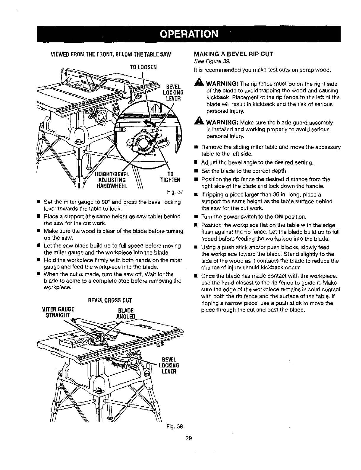
VIEWEDFROMTHEFRONT,BELOWTHETABLESAW
TO LOOSEN
_'_='_ _ _\,'_'- LOCKING
_---._.,.-----i_'-"_ Jo" _ LEVER
_//HEIGHT/BEVEL \\\ TO
_ _ ADJUSTING _TIGHTEN
\II7HANDWHEEL \\\ Fig. 37
• Set the miter gauge tO 90° and press the bevel locking
lever towards the table to lock.
• Place a support (the same height as saw table) behind
the saw for the cut work.
• Make sure the wood is clear of the blade before turning
on the saw.
• Let the saw blade build up to full speed before moving
the miter gauge and the workplace into the blade.
• Hold the workpiece firmly with both hands on the miter
gauge and feed the workpiece into the blade.
•When the cut is made, turn the saw off. Wait for the
blade to come to a complete stop before removing the
workpiece.
BEVELCROSSCUT
MITERGAUGE BLADE
STRAIGHT ANGLED
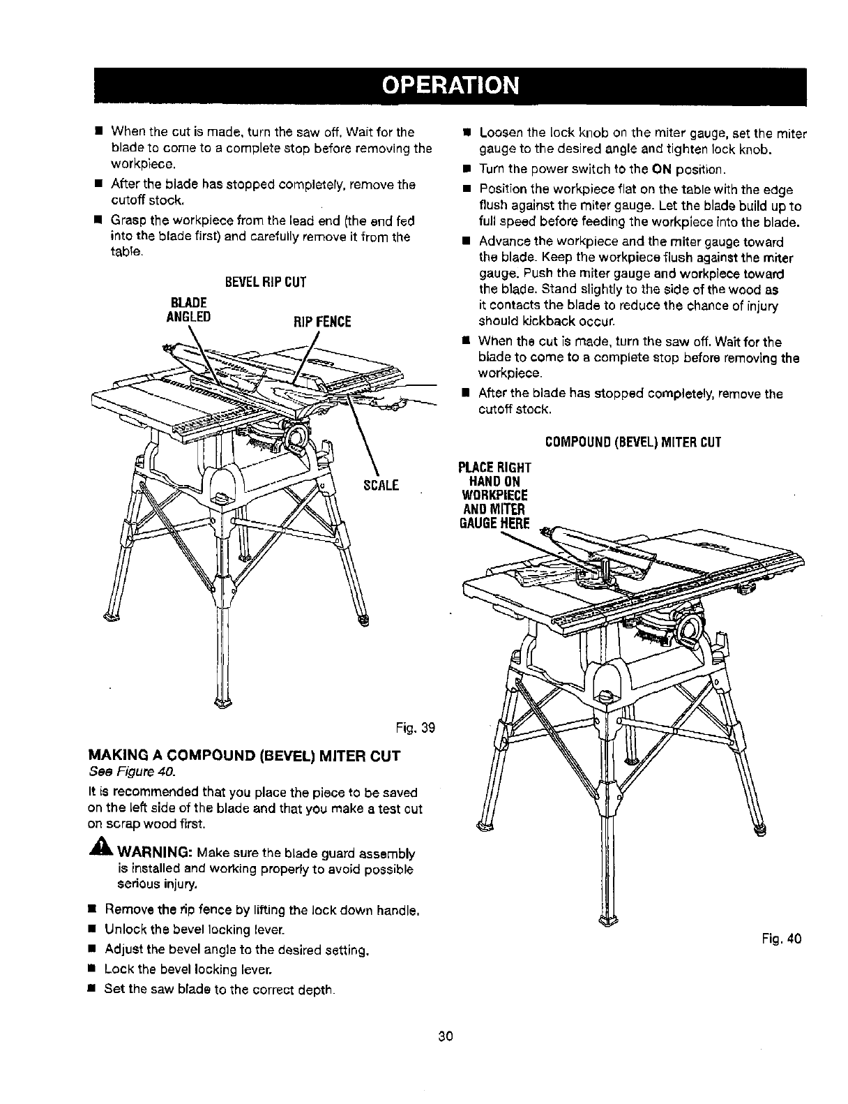
MAKING A BEVEL RIP CUT
See Figure 39.
It is recommended you make test cuts on scrap wood.
_, WARNING: The rip fence must be on the right side
of the blade to avoid trapping the wood and causing
kickback. Placement of the rip fence to the left of the
blade will result in kickback and the risk of serious
personal injury.
,_, WARNING; Make sure the blade guard assembly
is installed and working properly to avoid serious
personal injury.
• Remove the sliding miter table and move the accessory
table to the left side.
• Adjust the bevel angle to the desired setting.
• Set the blade to the correct depth,
• Position the rip fence the desired distance from the
right side of the blade and lock down the handle.
• If ripping a piece larger than 36 in. long, place a
support the same height as the table surface behind
the saw for the cut work.
• Turn the power switchto the ON positLon.
•Position the workpiece fiat on the table with the edge
flush against the rip fence. Let the blade build up to full
speed before feeding the workplace into the blade,
• Using a push stick and/or push blocks, slowly feed
the workpiece toward the blade. Stand slightlyto the
side of the wood as it contacts the blade to reduce the
chance of Lnjuryshould kickback occur.
• Once the blade has made contact with the workplace,
use the hand closest to the rip fence to guide it. Make
surethe edge of the werkpiece remains in solid contact
with both the rip fence and the surface of the table. If
ripping anarrow piece, use a push stickto move the
piece through the cut and past the blade.
BEVEL
LEVER
Fig. 38
29
•When the cut is made, turn the saw off, Wait for the
blade to come to a complete stop before removing the
workpiece.
• After the blade has stopped completely, remove the
cutoff stock.
• Grasp the workplace from the lead end (the end fed
into the blade first) and carefully remove it from the
table.
BEVELRIPCUT
BLADE
ANGLED RIPFENCE
SCALE
• Loosen the Lockknob on the miter gauge, set the miter
gauge to the desired angle and tighten lockknob.
• Turn the power switch to the ON position.
• Position the workplace flat on the table with the edge
flush against the miter gauge. Let the blade build up to
full speed before feeding the workplece into the blade.
• Advance the workpiece and the miter gauge toward
the blade. Keep the werkpiece flush against the miter
gauge. Push the miter gauge and workplace toward
the blade, Stand slightly to the side of the wood aS
it contacts the blade to reduce the chance of injury
should kickback occur.
• When the cut is made, turn the saw off. Wait for the
blade to come to e complete stop before removing the
workplace.
• After the blade has stopped completely, remove the
cutoff stock.
PLACERIGHT
HANDON
WDRKPIECE
ANDMITER
GAUGEHERE
COMPOUND(BEVEL)MITERCUT
Fig. 39
MAKING A COMPOUND (BEVEL) MITER CUT
See Figure 40.
It is recommended that you place the piece to be saved
on the Left side of the blade and that you make a teat cut
on scrap wood first.
_' WARNING: Make sure the blade guard assembly
is installed and working properly to avoid possible
serious injury,
• Remove the rip fence by lifting the lock down handle,
• Unlock the bevel locking lever.
• Adjust the bevel angle to the desired setting,
•Lock the bevel locking lever.
•Set the saw blade to the correct depth.
Fig. 40
30
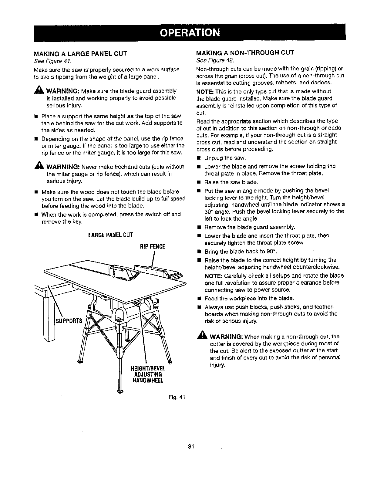
MAKING A LARGE PANEL CUT
See Figure 41.
Make surethe saw is properly secured to awork surface
to avoid tipping from the weight of a large panel.
_1= WARNING: Make sure the blade guard assembly
is installed and working properly to avoid poseible
serious injury,
• Place asupport the same height as the top of the saw
table behind the saw for the cut work. Add supportsto
the sides as needed.
• Depending onthe shape of the panel, use the rip fence
or miter gauge. If the panel is too large to use either the
rip fence or the miter gauge, it is too large for this saw.
,_ WARNING: Never make freehand cuts (cuts without
the miter gauge or rip fence), which can result in
seriousinjury.
• Make sure the wood does not touch the blade before
you turn on the saw, Let the blade build up to full speed
before feeding the wood into the blade.
• When the work is completed, press the switch off and
remove the key.
LARGEPANELCUT
RIPFENCE
HEIGHT/BEVEL
ADJUSTING
HANDWHEEL
MAKING A NON-THROUGH CUT
See Figure 42.
Non-through cuts can be made with the grain (ripping) or
across the grain (cross cut). The use.of a non-through cut
is essential to cutting grooves, rabbets, and dadoes.
NOTE: This is the only type cut that is made without
the blade guard installed.Make sure the blade guard
assembly is reinstalled upon completion of this type of
cut.
Read the appropriate section which describes the type
of cut in addition to this section on non-through or dade
cuts. For example= if your non-through cut is astraight
cross cut, read and understand the section on straight
cross cuts before proceeding.
• UnpJug the saw,
•Lower the blade and remove the screw holding the
throat plate in place. Remove the throat plate,
• Raise the saw blade.
• Put the saw in angle mode by pushing the bevel
locking lever to the right. Turn the height/bevel
adjusting hendwheel until the blade indicator shows a
30° angle. Push the bevel locking lever securely to the
left to lock the angFe.
• Removethe blade guard assembly.
• Lower the blade and insert the throatplate, then
securely tighten the throat plate screw,
• Bring the blade back to 90°.
•Raisethe blade to the correct height by turning the
height/bevel adjusting handwheel counterclockwise.
NOTE: Carefully check all setups and rotate the blade
one full revolution to assure proper clearance before
connecting saw to power source,
•Feed the workpiece into the blade.
• Always use push blocks, push sticks, and feather-
boards when making non-through cuts to avoid the
risk of serious injury.
,_ WARNING: When making a non-through cut, the
cutter is covered by the workplace duringmost of
the cut, Be alert to the exposed cutter at the start
and finish of every cut to avoid the riskof persona]
injury.
Fig. 41
31
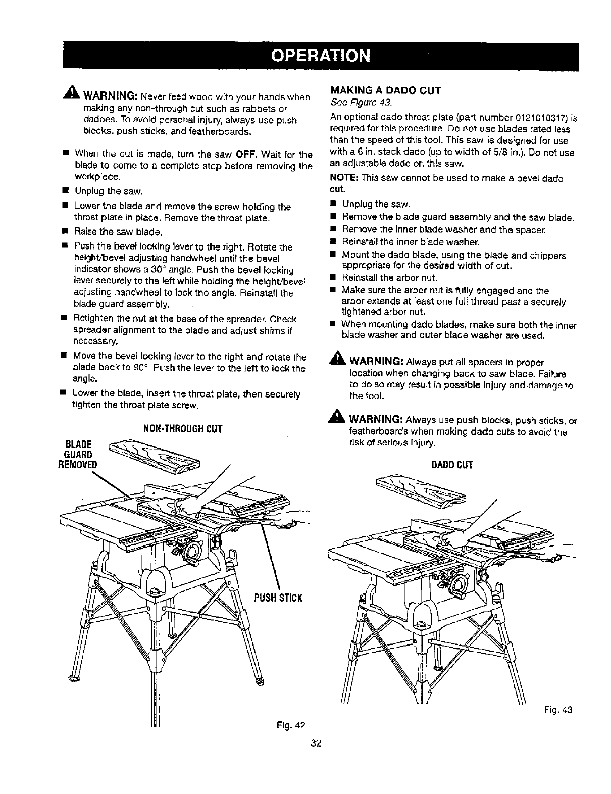
_& WARNING: Never feed wood with your hands _vhen
making any non-through cut such as rabbets or
dadoes. To avoid personal injury, always use push
blocks, push sticks, and featherboards.
• When the cut is made, turn the saw OFF, Wait for the
blade to come to a complete stop before removing the
workplace.
• Unplug the saw,
• Lower the blade and remove the screw holding the
throat plate in place. Remove the throat plate.
• Raisethe saw blade.
• Pushthe bevel locking lever to the right. Rotate the
height/bevel adjusting handwheel until the bevel
indicator shows a 30" angle. Push the bevel locking
lever securely to the left while holding the height/bevel
adjusting handwheel to lock the angle. Reinstall the
blade guard assembly,
• Retighten the nut st the base of the spreader. Check
spreader alignment to the blade and adjust shims if
necessary,
• Move the bevel locking lever to the right and rotate the
blade back to 90°. Push the lever to the left to look the
angle.
• Lower the blade, insert the throat plate, then securely
tighten the throat p_atescrew.
BLADE
GUARD
REMOVED
NON-THROUGHCUT
MAKING A DADO CUT
See Figure 43.
An optional dadc throat plate (part number 0121010317)is
required for this procedure. Do r_otuse blades rated less
than the speed of this tool. This saw is designed for use
with a 6 in. stack dado (up to width of 5/8 in,), Do not use
an adjustable dado on this saw,
NOTE: This saw cannot be used to make sbevel fade
OUt.
• Unplug the saw.
• Remove the blade guard assembly and the saw blade.
• Remove the inner blade washer and the spacer.
•Reinstall the inner blade washer.
• Mount the dado blade, using the blade and chippers
appropriate for the desired width of cut.
• Reinstall the arbor nut.
• Make sure the arbor nut is tully engaged and the
arbor extends at least one fuji thread past a securely
tightened arbor nut.
• When mounting dsdo blades, make sure both the inner
blade washer and outer blade washer are used.
.& WARNING: Always put all spacers in proper
location when changing back to saw blade. Failure
to de so may result in possible injury and damage to
the tool.
A
AI& WARNING: Always use push blocks, push sticks, or
featherboards when making dado cuts to avoid the
risk of serious injury.
DADBCUT
PUSHSTICK
Fig. 42
32
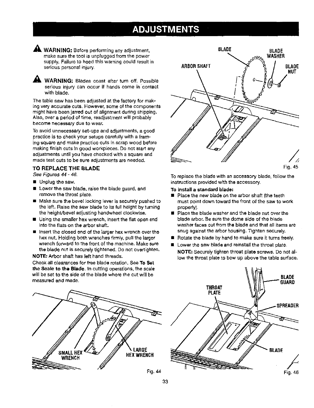
,_ WARNING: Before performing any adjustment,
make sure the tool is unplugged from the power
supply. Failure to heed this warnLng could result in
serious personal injury.
WARNING: Blades coast after turn off. Possible
serious injury can occur if hands come in contact
with blade.
The table saw has been adjusted at the factory for mak-
(ng very accurate cuts. However, some of the components
might have been jarred out of alignment during shipping.
Also, over a period of time, readjustment will probably
become necessary clueto wear.
To avoid unnecessary set-ups and adjustments, a good
practice is to check your setups carefully with a flam-
ing square and make practice cuts (nscrap wood before
making finish cuts (n good workp(eces. Do not start any
adjustments until you have checked with e square and
made test cuts to be sure adjustments are needed.
TO REPLACE THE BLADE
See Figures 44 -46.
• Unplug the saw.
•Lower the saw blade, raise the blade guard, and
remove the throat plate_
• Make sure the bevel locking lever is securely pushed to
the left. Raise the saw blade to (ts full height by turning
the height/bevel adjusting handwheel clockwise.
• Using the smaller hex wrench, insertthe flat open end
into the flats on the arbor shaft.
• Insert the closed end of the larger hex wrench overthe
hex nut. Holding both wrenches firmly, pull the larger
wrench foP,yard to the front of the machine. Make sure
the blade nut is securely tightened. Do not overt(ghten.
NOTE: Arbor shaft has left hand threads.
Check all clearances for free blade rotation. See To Set
the Scale to the Blade. In cutting operat(ons, the scale
will be set to the side of the blade where the cut will be
measured and made.
REXWRENCH
Fig. 44
33
BLADE BLADE
WASHER
ARBORSHAFT BLADE
NUT
Fig. 45
To replace the blade with an accessory blade, follow the
instructions provided with the accessory.
To install a standard blade:
•Place the new blade on the arbor shaft (the teeth
must point down toward the front of the saw to work
properly).
• Place the blade washer and the blade nut over the
blade arbor. Be sure the dome side of the blade
washer faces out from the blade and that all items are
snug against the arbor housing. Tighten securely.
m Rotate the blade by hand to make sure it turns freely.
• Lower the sew blade and reinstall the throat plate.
NOTE: Securely tighten throat plate screws. Do not al-
low the throat plate to bow up above the table surface.
THROAT
PLATE
BLADE
GUARD
'READER
BLADE /
Fig. 46
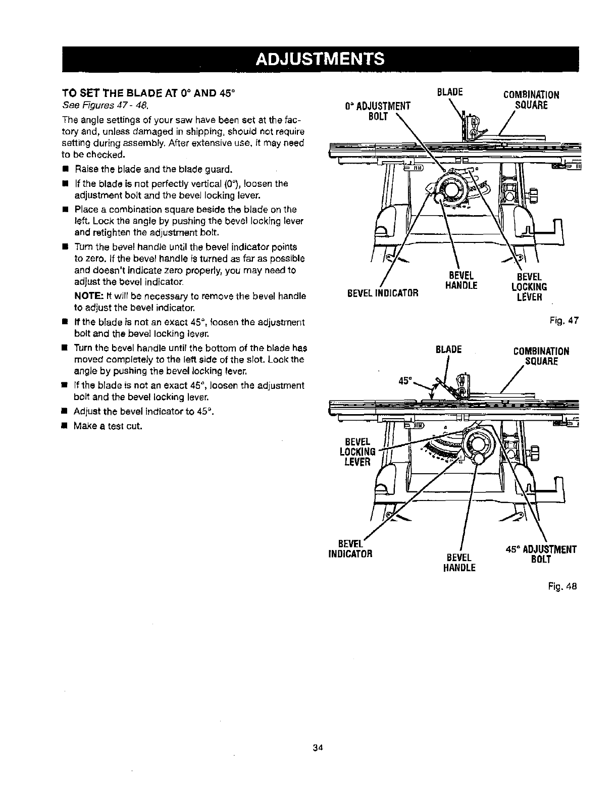
TO SET THE BLADE AT 0°AND 45 °
See Figures 47- 48.
The angle settings of your saw have been set at the fac-
tory and, unless damaged in shipping, should not require
setting during assembly. After extensive use, it may need
to be checked.
•Raise the blade and the blade guard.
• If the blade is not perfectly vertical (O_),loosen the
adjustmentbolt and the bevel locking lever.
•Place a combination square beside the blade on the
left. Lock the angle by pushing the bevel locking lever
and retighten the adjustment bolt.
• Turn the bevel handJe until the bever indicator points
to zero. If the bevel handle is turned as far as possible
and doesn't indicate zero properly, you may need to
adjust the bevel indicator.
NOTE: It wirr be necessary to remove the bevel handle
to adjust the bevel indicator.
• fftha blade is not an exact 45_, loosen the adjustment
bolt and the bevel locking laver.
• Turn the bevel handle until the bottom of the blade has
moved completely to the left side of the slot. Look the
angle by pushing the bevel locking laver.
•If the blade is net an exact 45°, loosenthe adjustment
bolt and the bevel locking lever.
• Adjust the bevel indicator to 45°.
• Make a test cut.
O° ADJUSTMENT
BOLT
BEVELIND]CATOR
BEVEL
LOCKING
LEVER
BLADE
BEVEL
HANDLE
BLADE
COMBINATION
SQUARE
BEVEL
LOCKING
LEVER
Fig, 47
COMBINATION
SQUARE
BEVEL
INDICATOR BEVEL
HANDLE
45°ADJUSTMENT
BOLT
Fig. 48
34
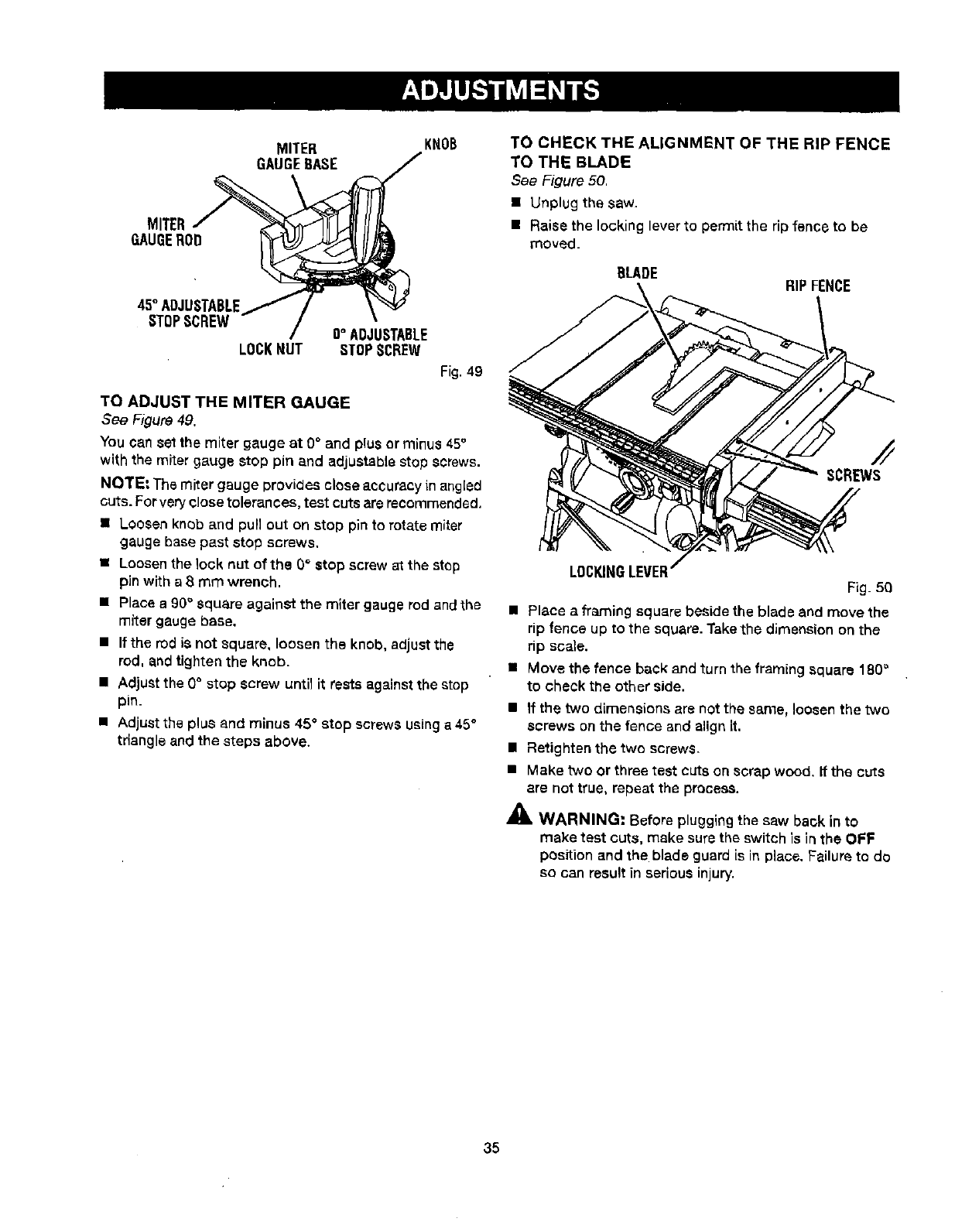
MITER
GAUGEBASE
MITER_ _
GAUGEROI
45°ADJUSTABLE/
STOPSCREW
LOCKNUT
KNOB
/
O°ADJUSTABLE
STOPSCREW
Fig.49
TO ADJUST THE MITER GAUGE
See Figure 49.
You can setthe miter gauge at 0° and plus or minus 45°
with the miter gauge stop pin and adjustable stop screws.
NOTE: The miter gauge provides close aecuracy in angled
cute.For very closetolerances, test cute are recommended.
• Loosen knob and pull out on stop pin to rotate miter
gauge base past stop screws,
• Loosen the lock nut of the G° stop screw at the step
pin with a 8 mm wrench.
•Place a 90° square againSt the miter gauge rod and the
miter gauge base,
• If the rod is not square, loosen the knob, adjustthe
rod. and tighten the knob.
• Adjust the 0° stop screw until it rests against the stop
pin.
• Adjust the plus and minus 45° stop screws using a45 °
triangle and the steps above.
TO CHECK THE ALIGNMENT OF THE RIP FENCE
TO THE BLADE
See Figure 50,
• Unplug the saw.
• Raise the locking lever to permit the rip fsnce to be
moved.
BLADE RIP FENCE
SCREWS
LOCKINGLEVER Fig. 50
•place a framing square beside the blade and move the
rip fence up to the square. Takethe dimension on the
rip scale.
• Move the fence back and turn the framing square 180_
to check the other side.
•If the two dimensions are not the same, loosen the two
screws on the fence and align it.
•Retighten the two screwS.
•Make two or three test cuts on scrap wood, If the cuts
ere not true, repeat the process.
_i, WARNING: Before pluggingthe saw back in to
make test cuts, make surethe switch is in the OFF
position and the blade guard is in place. Failure to do
so can result in seriousinjury.
35
A
AWARNING: When servicing, use only identical
replacement parts. Use of any other parts may create
ahazard or cause product damage.
WARNING: Always wear safety goggles or safety
glasses with side shields during power tool operation
or when blowing dust. If operation is dusty, also wear
adust mask.
GENERAL
Avoid usingsolvents when cleaning plastic parts, Most
plastics are susceptible to damage from vadous types of
commercial solvents and may be damaged by their use.
Use clean cloths to remove dirt, dust, oil, grease, etc.
_I, WARNING: Do not at any time let brake fluids,
gasoline, petroleum-based products, penetrating
oils, etc., come incontact with p[astic parts.
Chemicals can damage, weaken, or destroy plastic
which may result in seriouspersonal injury.
• Periodically check all clampS, nuts, bolts, screws, and
belts for tightness and condition. Make surethe throat
plate is in good condition and in position.
• Check the blade guard assembly.
• TOmaintain the table surfaces, fence, and rails,
periodically apply paste wax to them and buff to
provide smooth functioning. To prevent work from
slipping during cutting operation, Do not wax the
working face of the miter gauge.
• Protect the blade by cleaning out saw dustfrom
underneaththe table and inthe blade teeth. Use a
resin solvent on the blade teeth.
•Clean plastic parts only with a soft damp cloth. Do
not use any aerosol or petroleum solvents,
LUBRICATION
This saw has been lubricated at the rectory prior to ship-
ment.
36
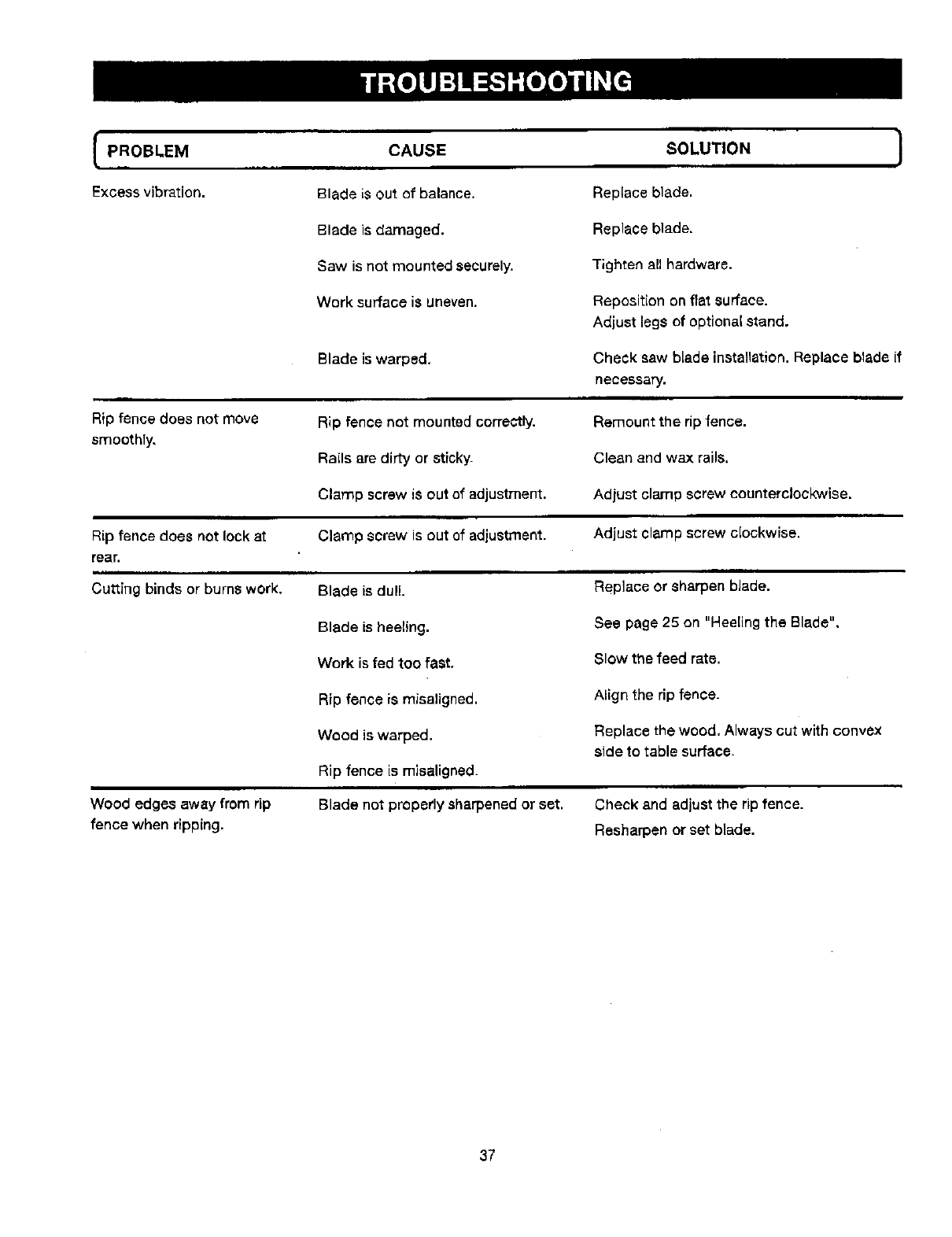
PROBLEM CAUSE SOLUTION }
inn
Excess vibration. Blade is out of balance. Replace blade.
Blade is damaged. Replace blade,
Saw is not mounted securely. Tighten all hardware.
Work surface is uneven. Reposition on flat surface.
Adjust legs of optional stand.
Cheek saw blade installation.Replace blade [f
necessary.
Rip fence does not move
smoothTy.
Rip fence does not lock at
rear.
ii
Cutting binds or burns work,
Wood edges away from rip
fence when ripping.
Blade is warped,
Rip fence not mounted correctly.
RaEIsare dirty or sticky.
Clamp screw is out of adjustment.
Clamp screw is out of adjustment.
Blade is dull.
Blade is heeling.
Work is fed too fast.
Rip fence is misaligned.
Wood is warped.
Rip fence is misaligned.
Blade not properly sharpened or set.
Remount the rip fence.
Clean and wax rails,
Adjust clamp screw counterclockwise.
Adjust clamp screw clockwise.
Replace or sharpen blade.
See page 25 on "Heeling the Blade".
Slow the feed rate.
Align the rip fence.
Replace the wood. Always cut with convex
side to table surface.
Check and adjust the rip fence.
Resharpen or set blade.
37
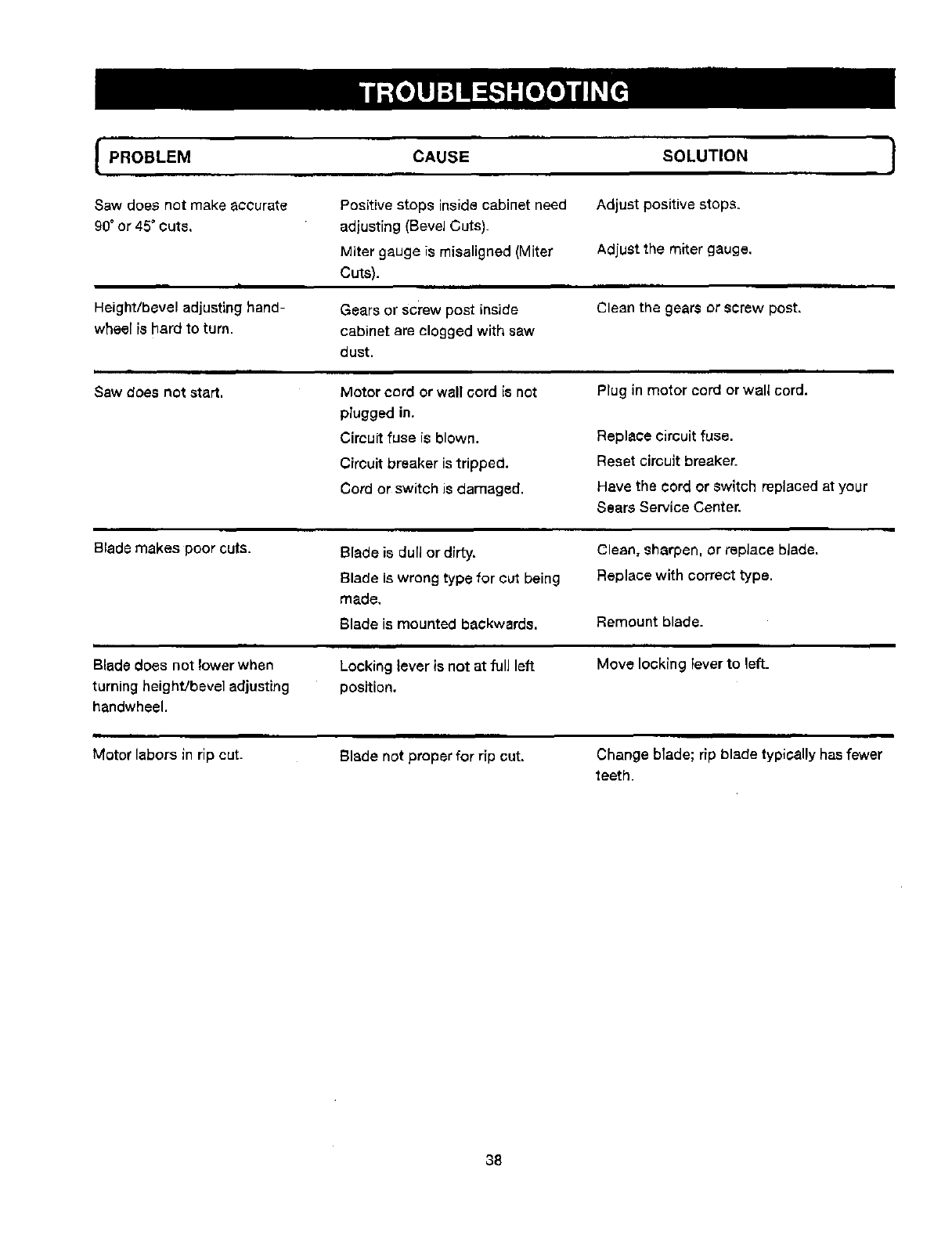
]
Saw does not make aCCurate
90" or 45" Outs.
I
Height/bevel adjusting hand-
wheel is hard to turn.
Sew does not start.
Positive stops insidecabinet need
adjusting (Bevel Cuts).
Miter gauge is rnisaligned (Miter
Cuts).
Gears or screw post inside
cabinet ere clogged with saw
dust.
Motor cord or wall cord is not
plugged in,
Circuitfuse is blown.
Circuit breaker is tripped.
Cord or switch is damaged.
Adjust positive stops.
Adjustthe miter gauge,
HHn •n
Clean the gears or screw post.
• •nn
Plug in motor cord or wall cord.
Replace circuit fuse.
Reset circuit breake[
Have the cord or switch replaced at your
Sears Service Center.
m
Blade makes poor cuts. Blade is dull or dirty.
Blade is wrong type for cut being
made,
Clean, sharpen, or replace blade,
Replace with correct type.
Blade is mounted backwards. Remount blade.
Blade does not lower when
turning height/bevel adjusting
handwheel.
Locking lever is not at full left
position.
Move locking Feverto left_
Motor labors in rip cut. Blade not proper for rip cut. Change blade; rip blade typically has fewer
teeth.
38
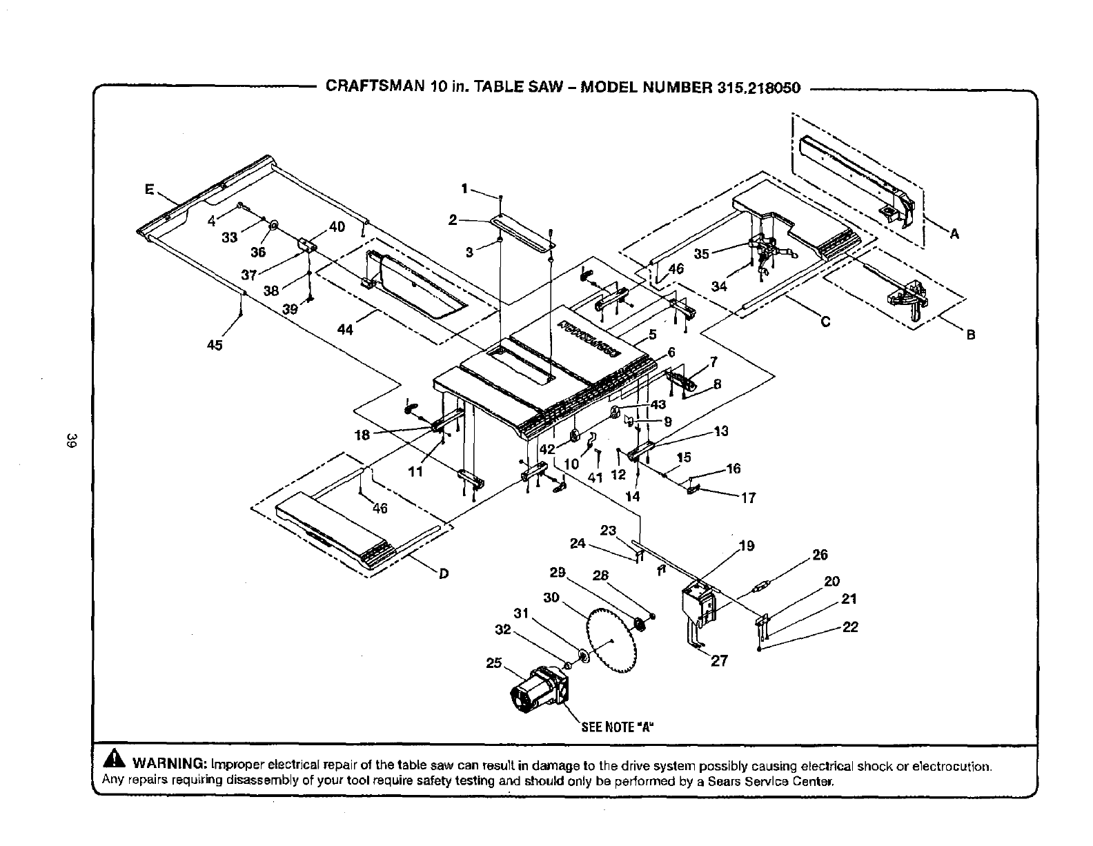
co
45
36
CRAFTSMAN 10 in. TABLE SAW - MODEL NUMBER 315.218050
34
C
I
B
D2O
SEE_OTE"A"
_IL WARNING: Lmproperelectrical repair of the table saw can resu]tin damage to the drive system possibly causing electrical shock or electrocution,
Any repairs requiring disassembly of your tool require safetytesting aad should only be performed by a Sears Service Center.
k

,
KEY PART
NO. NUMBER
CRAFTSMAN 10 in. TABLE SAW - MODEL NO. 315.218050 --
= ==
The model number wirl be found on the data plate attached 1othe cabinet. Arways mention the model ]
number in all correspondence J
1 410101OO5
2 0121010304-129
3 0121011301
4 410151713
5 0121010104-126
6 9121015330301
7 0131010221
8 410171722
90121010318-129
10 0121010319-129
11 410192001
12 411071003
13 0121010214
14 410171706
15 0121010903
16 414011033
17 0121010211
18 0121010215
19 A121014301
20 0121010314
21 410371002
22 0121010901
23 0121010313
24 410151016
25 A121010101
26 0121010902
27 41O341006
28 0131010912
29 0101010302
30 422010046
31 0121010502
32 0121010501
33 412012701
34 410171710
35 0121010216
36 412042702
37 41OO79021
38 412011701
39 0121010802
40 0121010105
41 410602002
42 0121010236
43 0121010237
44 A121011001
45 410192001
46 410602001
regarding your TABLE SAW or when ordering repair parts.
DESCRIPTION QTY,
imlm,
" Screw (MS x 15 ram) .......................................................................................... 2
Throat Plate ........................................................................................................ 1
Throat Plate Adjusting Pad................................................................................. 2
" Screw, Hex Hal. (1/4-20 x 46 ram) ...................................................................... 1
Main Table .......................................................................................................... 1
Scale Label ......................................................................................................... 1
Handle Bracket ................................................................................................... 1
" Screw (10-24 x 3/8 in.) ....................................................................................... 2
Right Scale Indicator .......................................................................................... 1
Left Scale Indicator ............................................................................................ 1
" Screw (M4 x 10 ram) .......................................................................................... 4
Nylon Nut (M5) ................................................................................................... 4
Short Bracket ..................................................................................................... 4
" Screw (10-24 x 1/2 in.) ....................................................................................... 8
Auxiliary Table Clamping Handle Screw ............................................................. 4
Spring Pin (MS x 18 ram).................................................................................... 4
Auxiliary Table Clamping Handle ........................................................................ 4
Ouffeed Rod Primary Bracket ............................................................................ 2
Motor Bracket Assembly .................................................................................... 1
Adjusting Plate ................................................................................................... 1
• Hex Screw With S Washer (M6 x 15 ram) .......................................................... 2
Eccentric Roller ................ "................................................................................. 1
Pivot Bracket Plate ............................................................................................. 2
Screw= Hex w/washer (M6 x12 ram).................................................................. 4
Motor Assembly .......................................................... i...................................... 1
Glider .................................................................................................................. 1
"Screw (M6 x 15 ram) .......................................................................................... 3
"Nut (5/8-18NF-2B) .............................................................................................. 1
Flange ................................................................................................................. 1
Blade .................................................................................................................. 1
Blade Washer ..................................................................................................... 1
Spacer ................................................................................................................ 1
* Washer (1/4 in. x 16 x1T)................................................................................... 1
*Tapping Screw (10-24 x 1 in,)............................................................................. 4
Miter Gauge BOx ................................................................................................ 1
* Washer (1/4 in.)................................................................................................... 1
Screw (M5 x 6 ram, Soc.) ................................................................................... 1
* Washer (1/4 x 16 x 13")........................................................................................ 1
Wing Screw (M6 x16 mm) ................................................................................. 1
Block .................................................................................................................. 1
"Screw (M4 ×25 ram) .......................................................................................... 2
End Plug, Extension Table Rod (left) .................................................................. 1
End Plug, Extension Table Rod (right) ................................................................ 1
Blade Guard Assembly ....................................................................................... 1
Screw w/Washer (1/4-20 x 1/2 in.) ..................................................................... 2
Screw, Pan Hd. (M4 × 10 ram)............................................................................ 2
*Standard Hardwere Item - May Be Purchased Locally
=
NOTE: =A" -The assembly shown represents an important part of the double insulatedsystem. To avoid the
possibility of alteration or damage to the system, service should be performed by your nearest Sears Repair Center,
Contact your nearest Sears Retail Store for Service Center information.
i
_WARNING: Improper repair of adouble insulated product can result in damages to the double insulation system
possibly causing eleetricar shock or electrocution. Any repairS requ r ng d sassemb y of your table saw requires safety
testing to be performed by your nearest Sears Repair Center, Contact your nearest Sears Retail Store for Service
Center information,
.1111
40
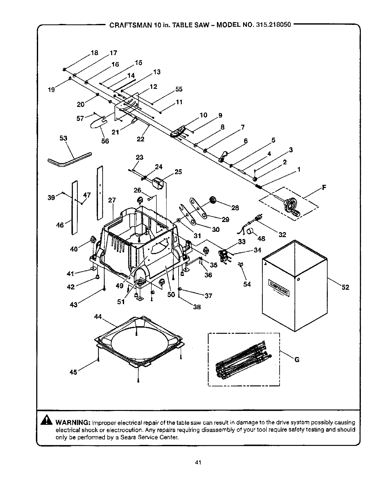
•CRAFTSMAN 10 in. TABLE SAW - MODEL NO. 315.218050
53 56
46" [J
21 22
23
24
31
8
4
2
42
43 51
36
-37
\54
G
,_L WARNING. Improperelectrical repair of the table saw can result in damage to the dnve system possibly causing
electrical shock or electrocution. Any repairs requiringdisassemblyof your 1ool require safetytesting and should
only be performed by a Sears Service Center.
41

KEY PART
NO. NUMBER
1 0121010919
2 0134010224
3 410138743
4 0121O10906
5 0134010316
6 0121010220
7 0134011301
8 41201113
9 410181001
10 0121010219
11 410499O07
12 0121010316
13 0121010315
14 412042002
15 410134005
16 412011113
17 0121010230
18 411071004
19 411011701
20 0101010908
21 O121010206
22 410211006
23 410451703
24 0131010210
25 0131010209
26 410031710
27 0121010202-130
28 0121010221
29 0131010318
30 0134010331
31 0134010238
32 0121010701
33 452070019
34 410601001
35 0101040203
36 410561002
37 0301030202
38 410451701
39 416090001
40 0121010229
41 0121011302
42 0101040201
43 410161012
44 0121010225
45 410601003
46 0121015002
47 412011109
48 0121010235
49 9121015330101
50 9121015330202
51 9121015335701
52 0121015001
53 0101140903
54 0121010232
55 410181001
56 0121010321
57 410251018
CRAFTSMAN 10 in. TABLE SAW -MODEL NO. 315.218050 ....
DESCRIPTION QTY.
Compression Spring.............................................................................................. 1
Cam ....................................................................................................................... 1
" Screw (8-32 x 1in.)................................................................................................ 1
Locking Screw (SS41) ........................................................................................... 1
Locking Shim (SUS310)......................................................................................... 1
Locking Lever........................................................................................................ 1
Rubber Pad (NRB70)............................................................................................. 1
"Washer (M26 x 10 x 2T)......................................................................................... 1
• Screw (M4 x 7mm)................................................................................................ 8
Gear Rack .............................................................................................................. 1
• Screw, Hex Hd. (M5 x8 ram)................................................................................. 2
Front Cabinet Support PEate.................................................................................. 1
Cam ....................................................................................................................... 2
" Washer (D4) ........................................................................................................... 2
*Screw, Pan Hd. (M4 x8 ram)................................................................................. 2
*Washer (M10 x23 x 2"[')......................................................................................... 1
Locking Ring .......................................................................................................... 1
" Nut (MIO) ............................................................................................................... 1
"C" Ring (56).......................................................................................................... 1
Special Nut (3/8-16 x 4)......................................................................................... 2
Bevel indicator ....................................................................................................... 1
"Screw (M4 x 10 ram).............................................................................................. 1
Screw (8-16 x 3/4 in.) ............................................................................................ 2
Clamping Pad, Power Cord ................................................................................... 1
Switch Box ............................................................................................................ 1
* Carriage Bolt (5/16-18 x 1/2 in.) ............................................................................ 1
Cabinet .................................................................................................................. 1
Knob ...................................................................................................................... 1
Blade Wrench ........................................................................................................ 1
Blade Wrench ........................................................................................................ 1
Knob Ring .............................................................................................................. 1
power Cord ........................................................................................................... 1
Switch With Key .................................... •............................................................... 1
• Screw (M4 x 20 mm).............................................................................................. 4
Power Cord Pad .................................................................................................... 1
* Screw (M4 x 16 ram).............................................................................................. 2
Power Cord Clamp ................................................................................................ 2
"Self Tapping Screw (8-16 x 1/2 in.)........................................................................ 2
Pin (4.8 x 1/2 in.).................................................................................................... 4
Knob ...................................................................................................................... 4
Locking Pad .......................................................................................................... 4
Cabinet Pad ........................................................................................................... 4
" Screw, Hex. Hd. (M6 x 20 mm).............................................................................. 4
Duet Bag Adaptor .................................................................................................. 1
-Screw (M4 x 10 mm).............................................................................................. 4
Velero Tape ............................................................................................................ 2
* Washer (5.2 x 24 x 2"1-)........................................................................................... 2
Power Cord Bushing ............................................................................................. 1
Name Plate ............................................................................................................ 1
Warning Label ........................................................................................................ 1
Knob Label, Leg .................................................................................................... 4
Dust Bag ................................................................................................................ 1
• Hex Wrench (M5 x 75 mm) .................................................................................... 1
Switch Key ............................................................................................................. 1
• Screw (M4 x 7 mm)................................................................................................ 4
Front Guard ........................................................................................................... 1
* Bolt (M5 x 10 ram) ................................................................................................. 1
"Standard Hardware Item - May Be Purchased Locally
42
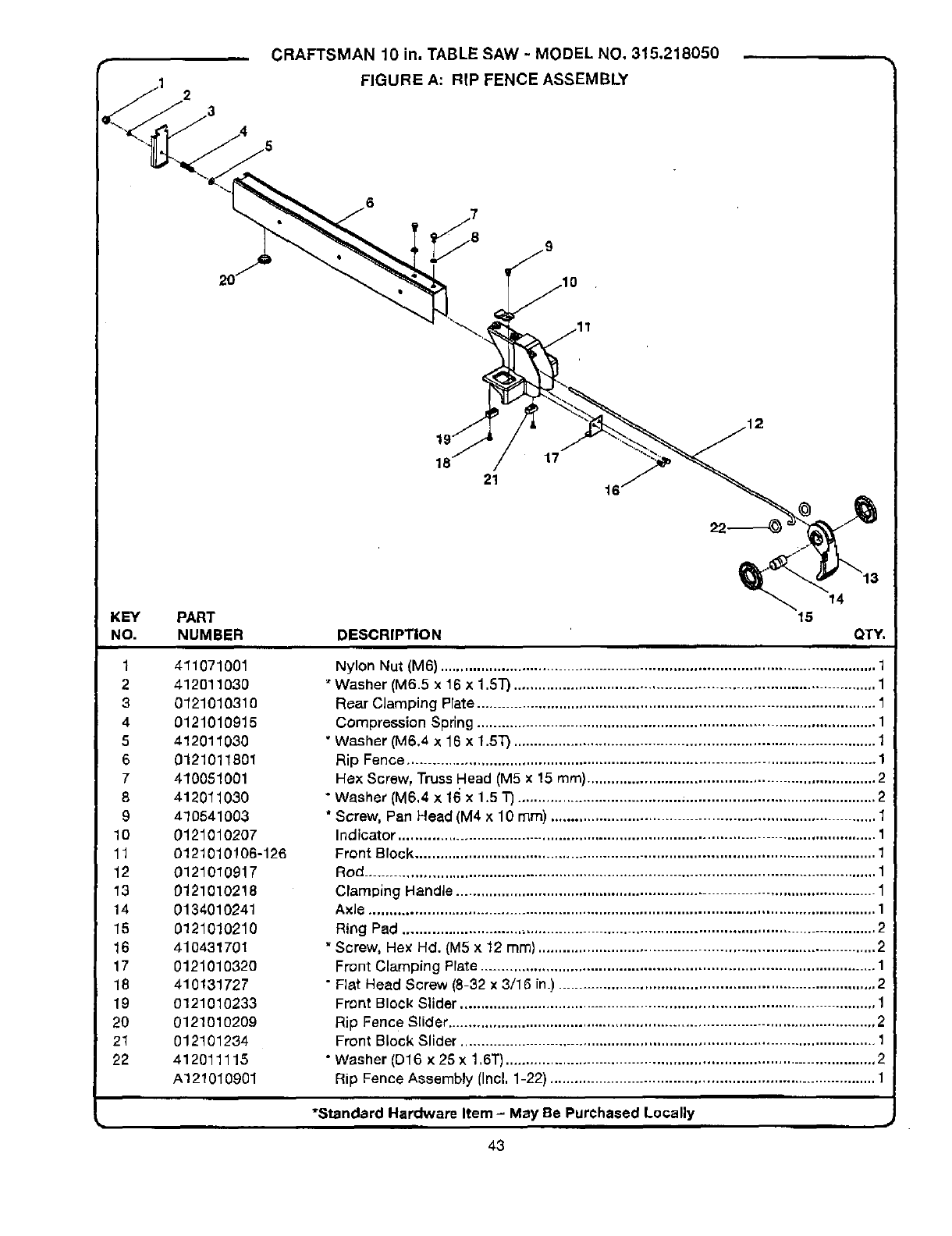
2
CRAFTSMAN 10 in. TABLE SAW - MODEL NO, 315,218050 .
FIGURE A: RIP FENCE ASSEMBLY
6
21
17
16
KEY
NO.
1
2
3
4
5
6
7
8
9
lO
11
12
13
14
15
16
17
18
19
20
21
22
PART
NUMBER DESCRIPTION
14
15 QTY.
411071001
412011030
012101031O
0121010915
412011030
0121011801
410051001
412011030
410541003
0121010207
0121010106-126
0121010917
0121010218
0134010241
0121010210
410431701
012101032O
410131727
0121010233
0121010209
012101234
412011115
A121010901
Nylon Nut (M6) .......................................................................................................... 1
* Washer (M6.5 x 16 x 1.5"1")........................................................................................ 1
Roar Clamping Plato ................................................................................................. 1
Compression Spring ................................................................................................. 1
"Washer (M6,4 x16 x 1.ST) ........................................................................................ 1
Rip Fence .................................................................................................................. 1
Hex Screw, Truss Head (M5 x 15 ram}...................................................................... 2
"Washer (M6.4 x 16 x 1,5 1")....................................................................................... 2
*Screw, Pan Head (M4 x 10 ram) ............................................................................... 1
Indicator .................................................................................................................... 1
Front Block ................................................................................................................ 1
Rod ............................................................................................................................ 1
Clamping Handle ...................................................................................................... 1
Axle ........................................................................................................................... 1
Ring Pad ................................................................................................................... 2
*Screw, Hex Hd, (M5 x 12 mm) .................................................................................. 2
Front Clamping Plate ................................................................................................ 1
" Flat Head Screw (8-32 x 3/16 in.) ............................................................................. 2
Front Block Slider ..................................................................................................... 1
Rip Fence Slider ........................................................................................................ 2
Front Block Slider ..................................................................................................... 1
•Washer (D16 × 25 x 1,6T).......................................................................................... 2
Rip Fence Assembly Ilncl. 1-22) ............................................................................... 1
"Standard Hardware Item -May Be Purchased Locally
43
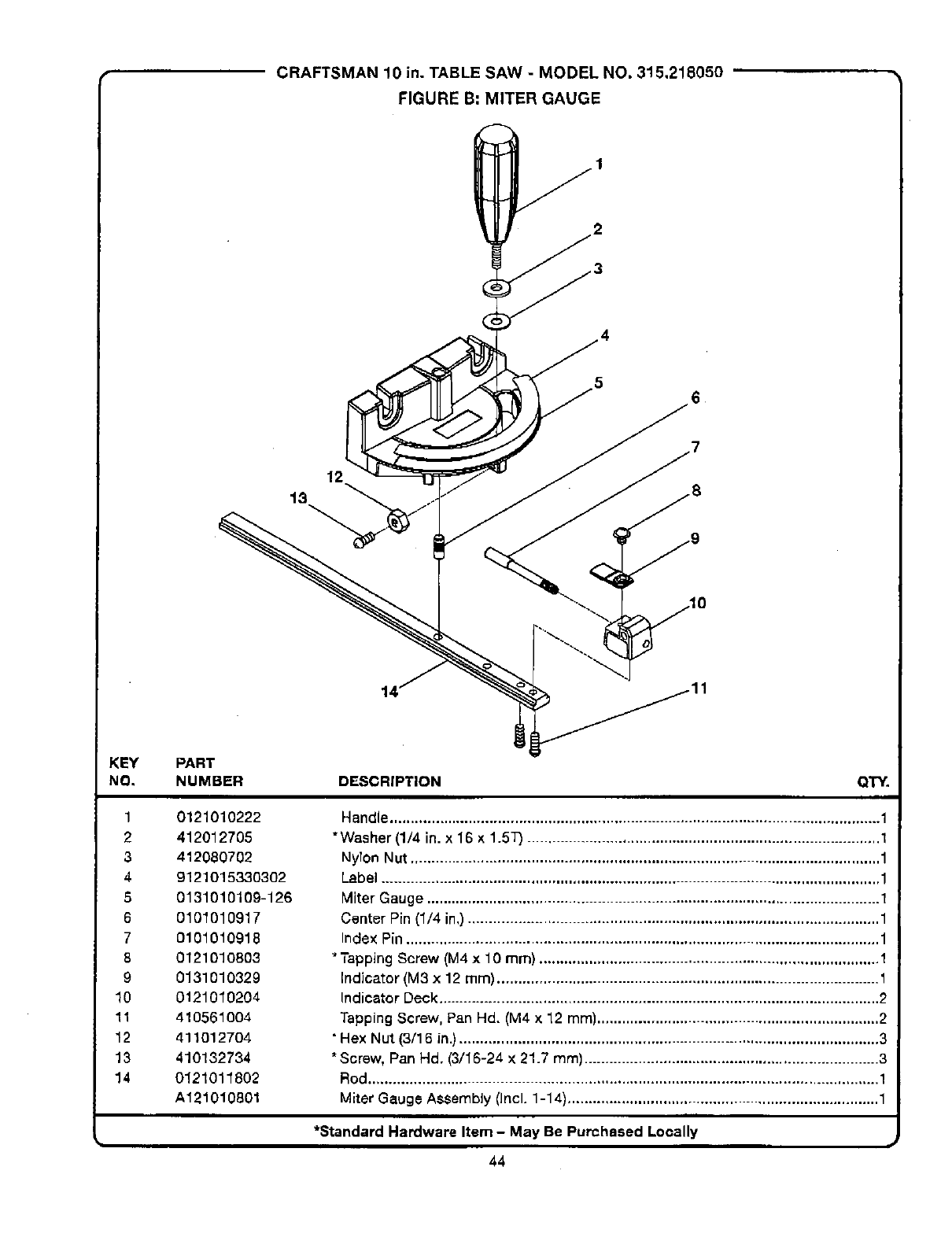
CRAFTSMAN 10 in. TABLE SAW - MODEL NO. 315,218050 '"
FIGURE B" MITER GAUGE
1
2
3
13
12
14
KEY
NO.
1
2
3
4
G
6
7
8
9
10
11
12
13
14
PART
NUMBER
0121010222
412012705
412080702
9121015330302
0131010109-126
0101010917
0101010918
0121010803
0131O10329
0121010204
410561004
411012704
410132734
0121011802
A121010801
DESCRIPTION QTY.
Handle...................................................................................................................... 1
*Washer (1/4 in. x 16 x 1.5_ ..................................................................................... 1
NyTonNut ................................................................................................................. 1
Label ........................................................................................................................ 1
Miter Gauge ............................................................................................................. 1
Center Pin (1/4 in,) ................................................................................................... 1
Index Pin .................................................................................................................. 1
* Tapping Screw (M4 x 10 ram) .................................................................................. 1
Indicator (M3 x 12 ram) ............................................................................................ 1
Indicator Deck .......................................................................................................... 2
Tapping Screw, Pan Hd. (M4 x 12 mm).................................................................... 2
• Hex Nut (3/16 in.) ..................................................................................................... 3
*Screw, Pan Hd. (3/16-24 X 21.7 mm) ....................................................................... 3
Rod........................................................................................................................... 1
Miter Gauge Assembly (Incl. 1-14)........................................................................... 1
k, *Standard Hardware Item -May Be Purchased Locally =*
44
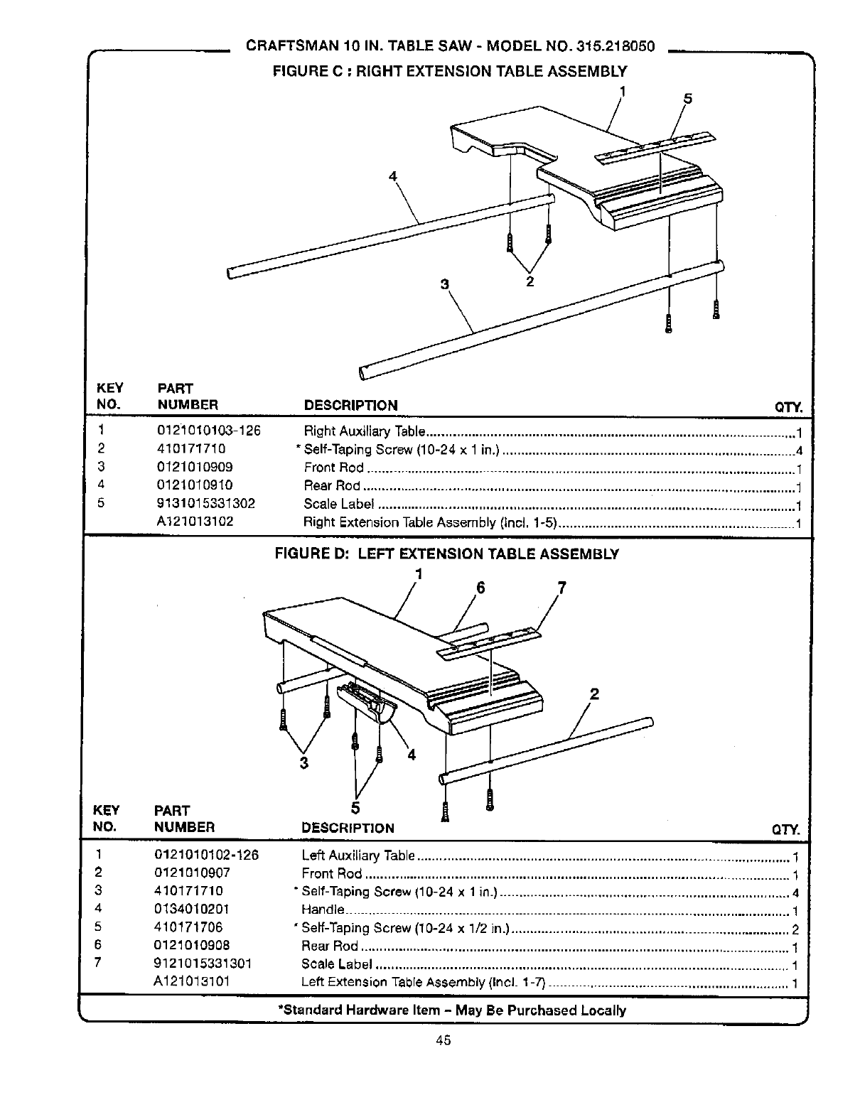
CRAFTSMAN 10 IN. TABLE SAW - MODEL NO. 315.218050 __
FIGURE C : RIGHT EXTENSION TABLE ASSEMBLY
1 5
4
3 2
KEY PART
NO. NUMBER
1 0121010103-126
2 410171710
30121010909
4 0121010910
5 9131015331302
A121013102
KEY PART
NO. NUMBER
1
2
3
4
5
6
7
0121010102-126
0121010907
410171710
013401O2O1
410171706
0121010908
9121015331301
A121013101
DESCRIPTION QTY.
Right Auxiliary Table.................................................................................................. 1
"Self-Taplng Screw (10-24 x 1 in.) .............................................................................. 4
Front Rod .................................................................................................................. 1
Rear Rod ................................................................................................................... 1
Scale Label ............................................................................................................... 1
Right Extension Table Assembly (Incl. 1-5)............................................................... 1
FIGURE D: LEFT EXTENSION TABLE ASSEMBLY
16 7
5
DESCRIPTION QTY.
= i=
Left Auxiliary Table................................................................................................... 1
Front Rod ................................................................................................................. 1
* Self-Taping Screw (10-24 x 1 in.) ............................................................................. 4
Handle ...................................................................................................................... 1
•Serf-Taping Screw (10-24 x 1/2 in.) .......................................................................... 2
Rear Rod .................................................................................................................. 1
Scale Label .............................................................................................................. 1
Left Extension Table Assembly (Incl. 1-7) ................................................................ 1
*Standard Hardware Item -May Be Purchased Locally
45
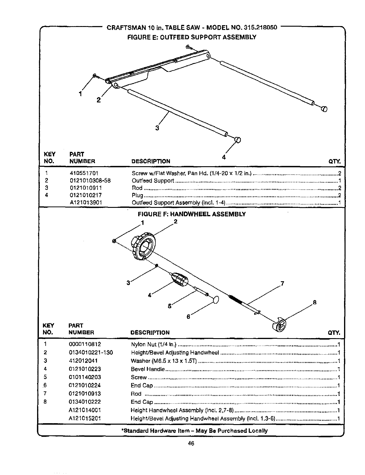
LCRAFTSMAN 10 in. TABLE SAW -MODEL NO. 315.218050 '
FIGURE E: OUTFEED SUPPORT ASSEMBLY
12
3
KEY PART
NO. NUMBER
1 410551701
20121010308-58
3 0121o10911
40121010217
A121013901
=m
4
DESCRIPTION QTY.
Screw w/Flat Washer. Pan Hd. (1/4-20 x1/2 in.) ...................................................... 2
Outfeed Support ....................................................................................................... 1
Rod ........................................................................................................................... 2
PLug........................................................................................................................... 2
Outfeed Support Assembly (Incl. 1-4).........................................................................., 1
FIGURE F; HANOWHEEL ASSEMBLY
2
KEY PART
NO. NUMBER
10000110812
2 0134010221-130
3412012041
4 O121010223
5 0101140203
.6 0121010224
7 0121010913
8 0134010222
A121014001
A121015201
5' 8
DESCRIPTION QTY.
m
Nylon Nut (1/4 in.) ..................................................................................................... 1
Height/Bevel AdjustingHandwheel .......................................................................... 1
Washer (M6.5 x 13 x 1,5"1")........................................................................................ 1
Bevel Handle............................................................................................................. 1
Screw ........................................................................................................................ 1
End Cap .................................................................................................................... 1
Rod .......................................................................................................................... 1
End Cap .................................................................................................................... 1
Height Handwheel Assembly (Incl. 2,7-8) ................................................................. 1
Height/Bevel AdjustingNandwheel Assembly (Incl.1,3-6) ....................................... 1
i i
=Standard Hardware Item - May Be Purchased Locally
46
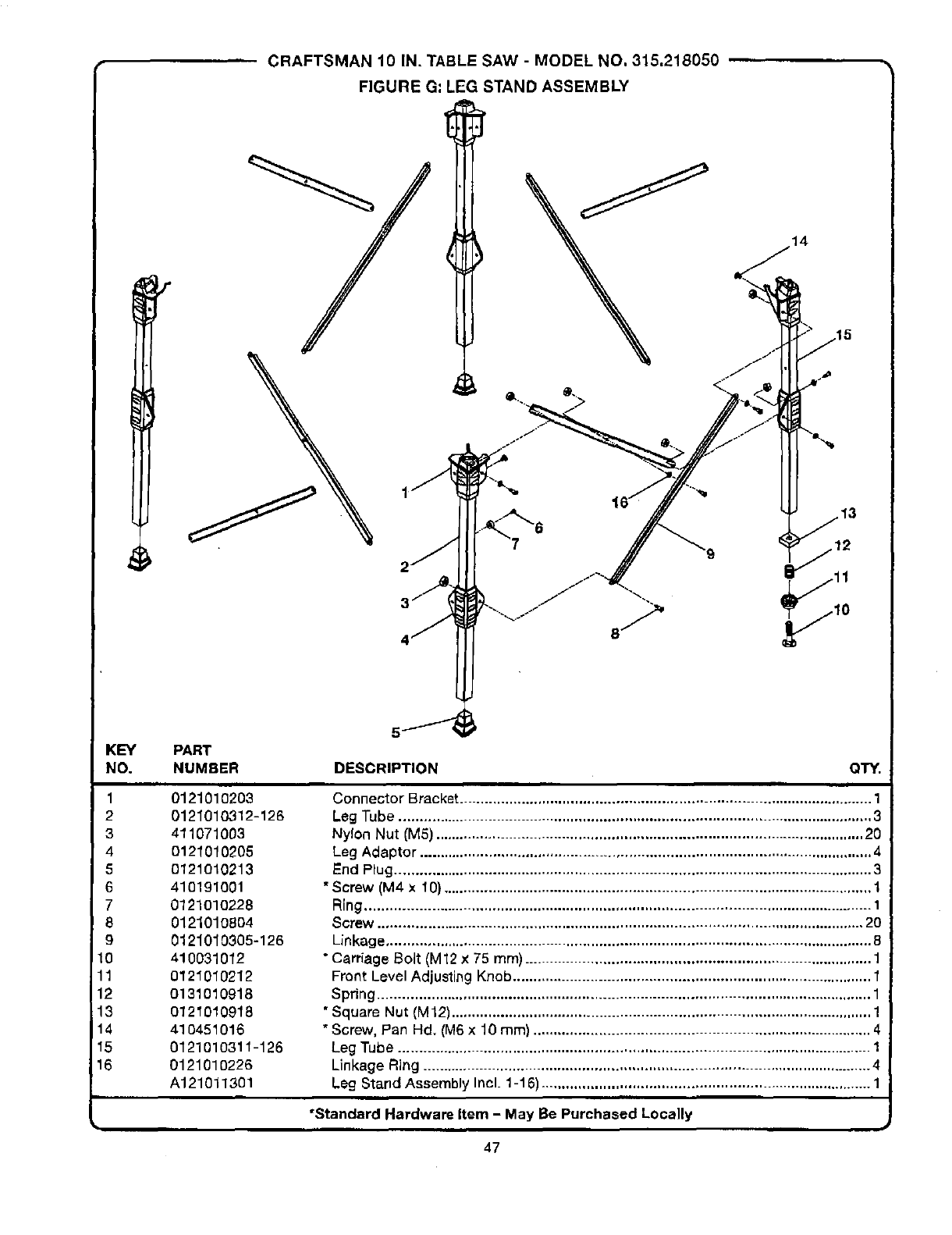
'" CRAFTSMAN10IN.TABLESAW- MODELNO.315,218050
FIGUREG=LEGSTANDASSEMBLY
14
KEY
NO.
1
2
3
4
5
6
7
8
9
10
11
12
13
14
15
16
PART
NUMBER
0121010203
0121010312-126
411071003
0121010205
O121O10213
410191001
0121010228
0121010804
0121010805-126
410031012
O121010212
0131010918
O121010918
410451016
0121010311-126
0121010226
A121011301
DESCRIPTION QTY.
Connector Bracket .................................................................................................... 1
Leg Tube ................................................................................................................... 3
Nylon Nut (M5) ........................................................................................................ 20
Leg Adaptor .............................................................................................................. 4
End Plug .................................................................................................................... 3
*Screw (M4 x 10) ........................................................................................................ 1
Ring ........................................................................................................................... 1
Screw ...................................................................................................................... 20
Linkage ...................................................................................................................... 8
"Carriage Bolt (M12 x75 ram) .................................................................................... 1
Front Level Adjusting Knob ....................................................................................... 1
Spring ........................................................................................................................ 1
*Square Nut (M12) ...................................................................................................... 1
*Screw, Pan Hd. (M6 x 10 ram) .................................................................................. 4
Leg Tube ................................................................................................................... 1
Linkage Ring ............................................................................................................. 4
Leg Stand Assembly Incl. 1-16) ................................................................................ 1
•Standard Hardware Item -May Be Purchased Locally
47

Your Home
,;:::,_,: For repair-in your home-of all major brand appliances, :;__:
ii::::_::::__ lawn and garden equipment, or heating and cooling systems, .................
_. no matter who made it, no matter who sold it! ,:_;_::
For the replacement parts, accessories and :.:i:::::_
owner's manuals that you need to do-it-yourself.
_,;, For Sears professional installation of home appliances
,,.................. and items like ara e door openers and water heaters. ,_,......
,,',_,_ 1-800-4-MY-HOME ®11-800-4694663) _,_?_
_:::.:._ Call anytime, day or night (U.S.A. and Canada) ......................
www.sears.¢om www,sears.ca
......... Our Home ....
For repair of carry in items like vacuums lawn equipment
and electronics, call or go on-line for the location of your nearest
!i_............... Seers Parts & Repair Center ::_,_"
..... .:_=
.... 1 800488 1222._., m m .,,,
.::_::.,: Call anytime, day or night (U.S.A. only)
www.sears.¢om
_':_,_ To purchase a protection agreement (U.S.A.)
_,,,,., or maintenance agreement (Canada) on a product serviced by Sears:
,,.....................,1-800-827-6655 (u.s.A.) 1-800 -361-6665 (Canada)
_i_;__ii_i_
Para pedirserviciode reparacibn
a domicilio,y para ordenar piezas:
1-888-SU-HOGAR =
(1-888-784-6427)
Au Canada pour service en fran_ais:
I"800-LE-FOYER _
(1-800-533-6937)
r,_'*
i¸ !:!:_
www.sears .ca
® Registered Traderr=_ I_Trademark /==Service Mark ofSeas, RoebuCkane Co.
® Mama Regtsnda ImMaria de F_ica /s. M_rce de Sew_io de Se_s. Roebuckand Co.
MC MD
M_rque de commerce /M_tque d_pO_ee de Sean_, Roebuc_ and Co. _Sders, Roebuck and Co.
