Craftsman 315218060 User Manual TABLE SAW Manuals And Guides L0710064
CRAFTSMAN Saw Table Manual L0710064 CRAFTSMAN Saw Table Owner's Manual, CRAFTSMAN Saw Table installation guides
User Manual: Craftsman 315218060 315218060 CRAFTSMAN TABLE SAW - Manuals and Guides View the owners manual for your CRAFTSMAN TABLE SAW #315218060. Home:Tool Parts:Craftsman Parts:Craftsman TABLE SAW Manual
Open the PDF directly: View PDF ![]() .
.
Page Count: 48
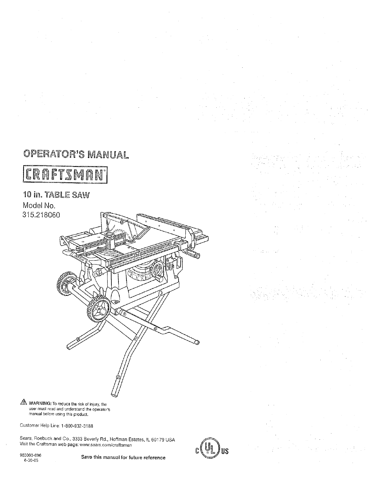
_ WARNING: To reduce the risk of injury, the
user must read and 'Jnderstand the operator's
manual before using this product.
Customer Help Line: 1-800-932-3188
Sears, Roebuck and Co., 3333 Beverly Rd., Hoffman Estates, IL 60179 USA
Visit the Craftsman web page: w_,.sears.com/craftsman
983000-696
6-30-05 Save this manual for future reference
[] Waoanty ........................................................................................................................................................................ 2
Introduchon ..................................................................................................................................................................... 2
I_ General Sa(ety Rules ...............................................................................................................................................
Specific Safety Rules ................................................................................................................................................... 4-5
Symbols ....................................................................................................................................................................... 6-7
D _lectrical .............
u Glossar_ of Terr_s .......................................................................................................................................................... 9
E] Features ........................................................................................................................................................... 10-13
[] Tools Needed ................................................................................................................................................................. 13
"_ LOOSe Pads ................ ........................................................................................................................................... 14
a Assembl_. ..................................................................................................................................................... t5-19
_3 Operation ................................................................................................................................................................. 19-34
a Adjustments .......................................................................................................................................................... 35-37
[3 Maintenance ............................................................................................................................................................ 38
Troublesheot..ng ....................................................................................................................................................... 39-40
Fx ploded View ...................................................................................................................................................... 43-50
_a Parts Ordedncj/Service .................................................................................................................................... Back Page
ONE YEAR FULL WARRANTY ON CRAFTSMAN TOOL
If this Craftsman tool fails due _o a detect in material or workmanship within one year from the dale of purchase. Call
1-800-4-MY-HOME ® to arrange for free repai_ If this tool is used for commercial or rental purposes, this warranty will
apply for only ninety days from the date of purchase This warranty applies onty while t_qis product is in the United States.
This warranty gives you spec tic lega r ghts, and you may also have other rights which vary t_om state to stale.
Sears, Roebuck and Ce., Dept. 817WA, Hoffman Estates, IL 60179
This loci has many features for making its use more pleasant and enjoyable. Safety, performance, and dependability
l_ave been given top priority in the design of this product makiFg it easy to maintain and operate.
A WARNING:Read and understand all ]nstruc-
gone. Failure to follow all instructions listed below,
may result in electric shock, fire and/or serious
persona_ injury.
READ ALL INSTRUCTIONS
13 KNOW YOUR POWER TOOL. Read the operator's
manuc_l c_llefu[iy. Lealn the saw's applications and
limitations as well as the specific potential hazards
related to this tool.
[_ GUARD AGAINST ELECTRICAL SI-IOCK BY PRE-
VENTING BODY CONTACT WITH GROUNDED
SURFACES. For exampte, pipes, radiators, ranges,
refrigerator enclosures.
g KEEP GUARDS IN PLACE and in good working order:
_] REMOVE ADJUSTING KEYS AND WRENCHES,
Form habit of checking to see thai k.eys and adjusting
wrenches are removed from tool before turning it on.
B KEEP WORK AREA CLEAN. Cluttered areas and
benches invge accidents. DO NOT leave tools or
pieces of wood on the saw while it is in operation,
[1 DO NOT USE IN DANGEROUS ENVIRONMENTS.
Do not use power tools in damp or we{ locations or
expose to rain. Keep the work area well lit.
B KEEP CHILDREN AND VISITORS AWAY. All visitors
should wear safety glasses end be kept a safe
distance from work area, Do not let visitors contact
tool or extension cord while operating.
a MAKE WORKSHOP ONILDPROOF with padlocks and
master switches, or by removing starter keys.
B DON'T FORCE TOOL. It will do the job better and
safer at the feed rate for which it was designed.
8 USE RIGHT TOOL. Don't force the tool or attachment
to do a iob il was not designed for. Don't use it for a
purpose not intended.
8USE THE PROPER EXTENSION CORD. Make sure
your extension cord Js in good condition. Use only a
cord heavy enough to carry the current your product
wilt draw. An undersized cord will cause a diop ir_ line
voltage resulting in loss of power and overheating. A
wire gauge size (A.W.G) of at least 14 is recommended
for an extension cord 25 feet or less in length, If in
doubt, use the r_ext heavier gauge The smaller the
gauge number, the heavier the oord.
pa DRESS PROPERLY. Do act wear IoosecIothing,
gloves, neckties, or jewelry. They can _et caughl
and draw you into moving parLs Rubber gloves and
nonskid footwear are recommended when working
outdoors. Aieo wear protective hair covering to contain
}cog hair.
B ALWAYS WEAR SAFETY GLASSES WITH SIDE
SHIELDS, Everyday eyeglasses have only impact-
resistant lenses, they are NOT safety glasses,
i_ SECURE WORK. Use clamps or a visa to hold wed{
when practical. It's safer than using your hand and
frees both hands to operate tool
a DON_T OVERREACH. Keep proper fooling and
balance at all times.
8MAINTAIN TOOLSWITH CARE. Keep tools sharp
and clean for better and safer performance. Follow
instructions fo_ lubFicating and changing accessories
_] DISCONNECT TOOLS. When not in use, before
servicing, or when changing attachments, blades, bits.
cutters, etc., all toots should be disconnected.
F3 AVOID ACCIDENTAL STARTING. Be sure switch is off
when plugging in any tool.
g USE RECOMMENDED ACCESSORIES. Consult the
operators manual Ior recommended accessories. The
use of improper accessories may risk iniury.
D NEVER STAND ON TOOL. Serious injury could occur
it the tool is tipped or if the cutting tool is uninlention-
ally contacted•
13 CHECK DAMAGED PARTS. Before further use of
the tool, a guard or other pad that is damaged should
be carefulry checked to determ, ine that it will operate
properly and penlorm its intended function. Check for
alignment of moving paris, binding of moving parts,
breakage of pans, n7ounting and any other conditions
thai may affect its operation. A guard or other part thai
is damaged must be properly repaired or replaced by
an authorized set&,ice center to avoid risk of personal
injury.
B USE THE RIGHT DIRECTION OF FEED, Feed work
into a blade or cutter against the direction of rotation of
blade or cutter only,
B NEVER LEAVE TOOL RUNNING UNATTENDED.
TURN THE POWER OFF. Don't leave tool until it
comes to a complele slop.
PROTECT YOUR LUNGS. Wear a face or dust mask if
the cutting operation is dusty.
u PROTECT YOUR HEARING. Wear hearing protection
ddring extended periods of operation.
B DO NOT ABUSE CORD. Never yank cord to discon-
nect from receptacle. Keep cord from heat, oil. and
sharp edges,
[] USEOUTDOOR EXTENSION CORDS. When tool
is used outdoors, use only extension cords wilh
approved ground cormection that a_e intended for use
outdoors and so marked.
ALWAYS KEEP THE BLADE GUARD AND RIVING
KNIFE/SPREADER/SPLITTER IN PLACE and in
working order,
B KEEP BLADES CLEAN, SHARP, AND WITH
SUFFICIENT SET. Sharp btades minimize stalting
and kickback.
[_ KEEP HANDS AWAY FROM CUTTING AREA. Keep
hands away from blades Do not reach underpeath
3
- ..; . . ." . . . ..
• • :- • "• • .; "i .
work or around or over the blade while blade is
rotating. Do not attempt to remove cut material when
blade is moving,
[] BLADE COASTS AFTER BEING TURNED OFF.
e NEVER USE IN AN EXPLOSIVE ATMOSPHERE•
Normal sparking of the motor could ignite fumes.
B INSPECT TOOL CORDS PERIODICALLY• If damaged,
have repaired by a qualified service lechnician at
an authorized service (acillty. The conductor with
insulation having an outer surface that is green w_th
or without yellow stripes is the equbrnent-ground-
ing conductor. If repair or replacement of the electric
cord or plug is necessa!% do not connect the equip-
ment-grounding conductor to a live terminal Repair
er replace a damaged or worn cord immediately. Stay
constanUyaware of cordlocationend keep itweiraway
fromtherotatingblade.
INSPECT EXTENSION CORPS PERIODICALLY and
replaceifdamaged,
E]GROUND ALL TOOLS. Iftoolisequipped withthree-
prong plug,itshouldbe pluggedintoa three-hob
e}ectrlcalreceptacle.
B CHECK WITH A QUALIFIED ELECTRtCIAN or service
personnel if the grounding instructions are not com-
pletely understood or if in doubt as to whether the toe]
is properly grounded.
[] USE ONLY CORRECT ELECTRICAL DEVICES: 3-wire
extension cords that have 3-proeg grounding plugs and
3-pole receptacles that accept the tool's plug.
a DO NOT MODIFY the plug provided. II it wiU not tit the
outlet, have the proper outlet installed by a qualified
electrician•
_1 KEEP TOOL DRY, CLEAN, AND FREE FROM OIL
AND GREASE. Always use a clean cloth when clean-
ing. Never use brake fluids, gasoline, petroleum-based
products, or any solvents to clean tool,
STAY ALERT AND EXERCISE CONTROL, Watch
what you are doing and use common sense. Do not
operate tool when you are tired. Do not rush.
DO NOT USE TOOL IF SWITCH DOES NOT TURN IT
ON AND OFF. Have defeegve switches replaced by an
authorized service center.
la USE ONLY CORRECT BLADES. Do not use blades
with incorrect size holes. Never use blade washers or
blade bolts that are defective or incorrect. The maxi-
mum blade capacity of your saw is 10 in. (254 ram).
_9 BEFORE MAKING A CUT, BE SURE ALL ADJUST-
MENTS ARE SECURE.
Z] BE SURE BLADE PATH IS FREE OF NAILS. Inspect
[or and remove all nails from turnber before cutting.
B NEVER TOUCH BLADE or other moving parts during
use,
t_ NEVER START A TOOL WHEN ANY ROTATING COM-
PONENT IS IN CONTACT WITH THE WORKPIECE.
_' DO NOT OPERATE A TOOL WHILE UNDER THE
INFLUENCE OF DRUGS, ALCOHOL, OR ANY
MEDICATION.
I_1WHEN SERVICING use only identical replacement
parts. Use of any other pads may create a hazard or
cause product damage.
li_ USE ONLY RECOMMENDED ACCESSORIES listed
in this manual or addendums. Use of accessories
that are net listed may cause the risk of personal
injury, instructions for safe use of accessories are
included with the accessory.
B DOUBLE CHECK ALL SETUPS, Make sure blade is
tight and not making contact with saw or workpiece
before connecting to power supply• •:-. •.
GUARD AGAtNST KICNBACK. Kickback occurs
when the blade stalls rapidly and workplace is driven
back towards the operator• It can pull your hand into
the blade resulting in echoes personal injury. Stay out
of blade path and turn switch off immediately if blade
binds or stalls.
a USE RIP FENCE. Always use a fence or straight edge
guide when rippir, g,
SUPPORT LARGE PANELS. To minimize risk of blade
pinching and Idckbaek, atways support large panels.
el REMOVE ALL FENCES AND AUXILIARY TABLES
belore trenspaJting saw. Failure to do so can "esult in
an accident causing possibie serious personal injun/.
ra ALWAYS USE BLADE GUARD, RIVING KNIFE/
SPREADER/SPLITTER, AND ANTI-KICKBACK
PAWLS on all "through-sawing' operations. Through-
sawing operations are those inwhich the blade cuts
completely Ihrough the workpiece as in ripping or
cross cutting. Keep lhe blade guard down, the anti-
kickbaak pawls down, and the riving knifeispreeded
splitter properly aligned to the saw blade.
ALWAYS SECURE WORK firmly against rip fence,
miter fence, or miter gauge.
ALWAYS USE APUSH STICK FOR RIPPING NAR-
ROW STOCK. A push stick is a dev=ce used to push
a werkpiece through the blade instead of using your
hands Size and shape can vary but the push stick must
always De narrower than tbe wofi_piece to prevent the
push stick from contacting the saw blade. When ripping
narrew stock, always use a push stick, so your hand does
not come close to the saw blade. Use afeatherbeard and
push blocks for oemthrough cuts
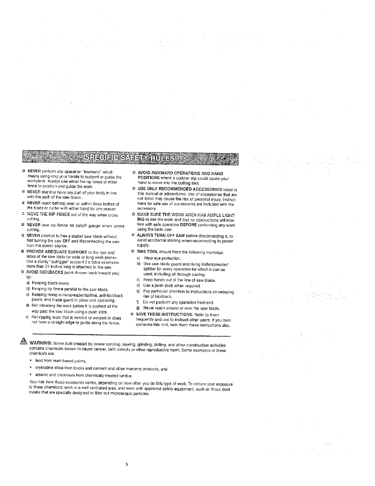
f_ NEVER perform any operation "|reehand" which
means using only your hands to support or guide the
workpiece, Always use either the rip tence or miler
fence to posRion and guide the work.
m NEVER ste,_d or t'_ve any part of your body in line
with the path of fhe saw blade.
NEVER reach behind, over, or within three inches of
the brads or cutter with either hand for any reason,
_, MOVE THE RIP FENCE out of the way when cross
cutting•
B NEVER use tip fence as cutoff gauge when c_'oss
cutting.
13 NEVER attempt to free a statted saw blade without
first turning the saw OFF and disconnecting the saw
from tr_e power source.
8 PROVIDE ADEQUATE SUPPORT to the rear and
sides of the saw table for wide or long work pieces•
Use a sturdy "oufriggar" suppoll it a table extension
more than 24 inches long is attached to the saw.
AVOID K_OKBACKS (work throwr_ back toward 'you}
by:
a_ Keeping b_ade sharp.
b) Keeping rip fence parallel to the saw blade•
c} Keeping dvir',9 _,£itelspreader/splittar, anti-kickback
pawls, and blade guard in place and operating•
d) Not r=Jeasi_g the work before it (s pushed all the
way past the saw blade using a push stick•
e) Not ripping work. that is b.eisted or warped or does
not have a straight edge to guide along the fence.
AVOID AWl{WARD OF'ERATIONS AND HAND
POSITIONS where a sudder_ slip could cause your
hand to m,_ve into the cutting tool
USE ONLY RECOMMENDED ACCESSORIES [isled in
this marius[ or adder_dums. Use of accessories that are
not listed may cause Ihe risk of personal injury. Instruc-
tions for safe use of accessories are included with the
accessory.
c_ I'.",AKESURE THE WORN AREA HAS AMPLE LIGHT-
ING to see the work and that no obstructions will inter-
fore with safe operation BEFORE performing any work
using the table saw.
n ALWAYS TURN OFF SAW before disconnecting it, to
a'Joid accidental staffing when reconnecting to power
supply•
THIS TOOL should have the following markings:
a) Wear eye protection.
b) Useeawbladeguardandrivingl_nffe/spreaded
splitter for every operation for whicll it can be
used, including all through sawing.
c] Keep hands out of the line of saw blade.
d) Use a push stick when required.
e) Pay particular altention to instructions on reducing
risk of kickbacK.
0 DOnot perform any operation freehand.
g) Nevei" leach around or over the saw blade.
e SAVETRESE INSTRUCTIONS, Refer to them
frequently and use toinstruct other users. Ifyou loan
someone this tool, loan them these instructions also.
_ WARNIN6: Some dust created by power sanding, sawing, gr nd rig, dri ing, and other conslruct[on activities
contains ctlemicals known to cause cancer, birth defects or other reproductive harm. Some examples of these
chemicals are:
•lead from lead-based paints.
a crystalline shies from blicks and cement and ether masonry Products, and
• arsenic and chromium from chemically4reated _urnber.
Your risk from these exoesures varies, depending on how often you do this type of weds. To reduce your exposure
to these chemicals: work in a well ventilated area, and work with approved safety equipment, such as those dust
masks that are specially designed to filter out microscopic particle.
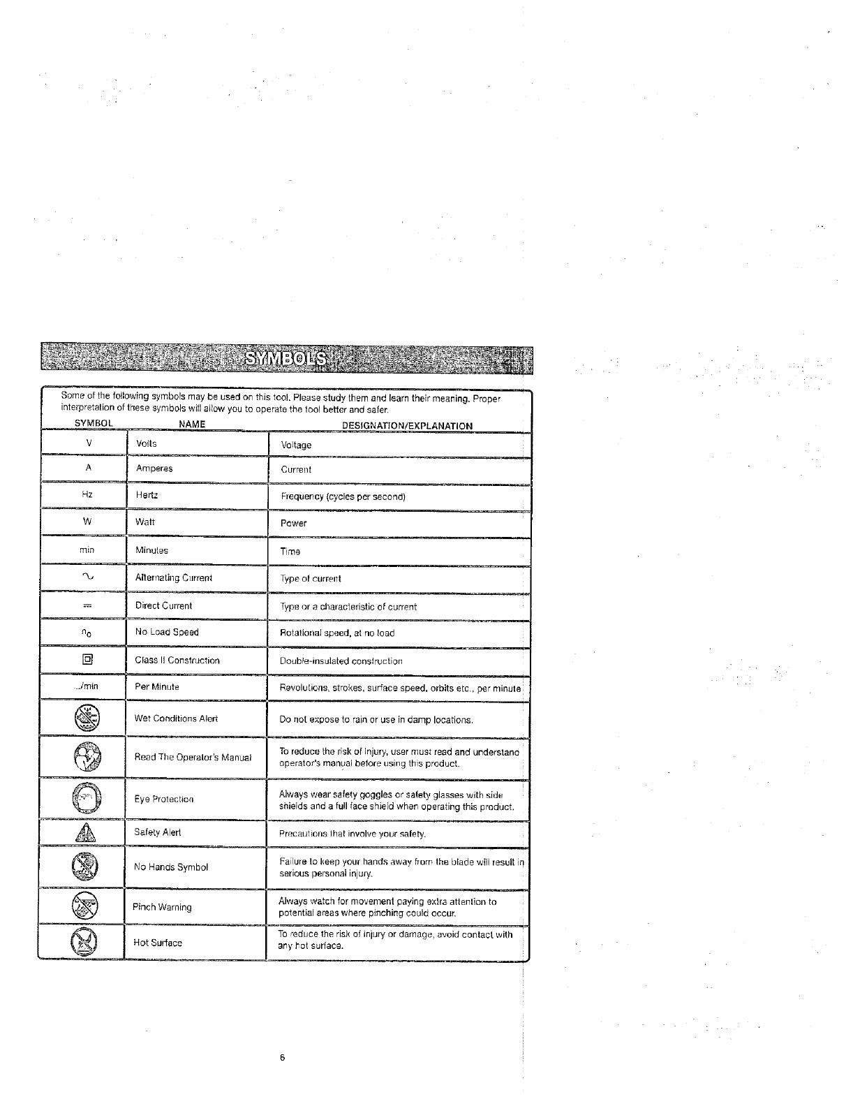
SomeofthefollowingsymbolsmaybeusedonthistoolPleasestudythemandlearntheirmeantng,Proper •
interpretationofthesesymbolswillallowyoutooperatethetoolbetterandsafer,
SYMBOL NAME DESIGNATION/EXPLANATION
V Vogs VoJtage
A
Hz
W
rain
n o
[]
../rain
@
@
©
A
@
@
@
Amperes
Hertz
Watt
Minules
Alternating Current
Direct Current
No Load Speed
Class II Construction
Per Minute
Wet Conditions Alert
Read The Operator's Manual
Eye Protection
Safety Alert
No Hands Symbol
Pinch Warning
Hot Surface
Current
Frequency (cycles per second)
Power
Time
Type of current
Type or e characteristic of current
Rotational speed, at no load
Doublednsulated construction
Revolutions, strokes, surface speed, orb tse c, per nnute
Do not expose to rain or use in damp locations.
To reduce the risk of injury, user must read and understand
operator's man_:_albefore using this product.
Always wear safety goggles or safety glasses with side
shields and a full face shield when operating this product,
Precaulions Ihat involve your safety.
Failure to keep your hands away flora Ihe blade wilJ result io
serious personal injury.
Always watch for movement paying extra attenlion to
potential a_as where pinching could occur.
To "educe the risk of injury or damage, avoid contact with
any hot surface.
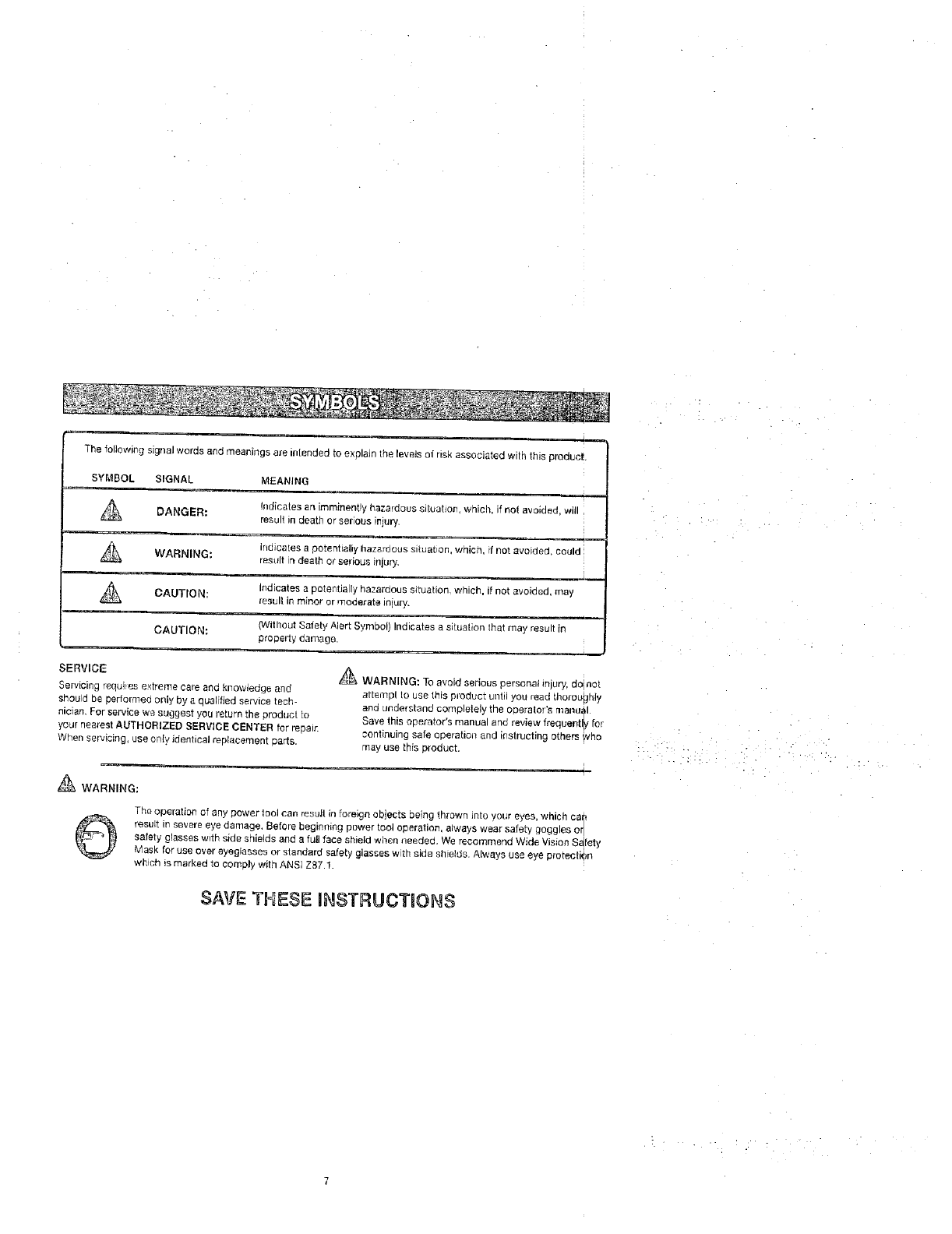
The following signal words and meanings are intended to explain the levels of nsk associated with this eroduct
SYMBOL SIGNAL MEANING
Indicates an imrninent!y hazardous siluatlon, which, if not avoided, will
DANGER: result in death or $er cos iiljury,
indicates a potenhaliy hazardous situat on, which, f not avoided, could
_esult in death or selbus illjur'j•
WARNING:
Indicates a potentia ly hazardous situation, which, it Rot avoided may
Aresult in minor or moderate iniury.
CAUTION:
CAU'[ION: (Without Safely Alert Symbol) Indicates a situation that {"nay result in
propelly damage.
SERVICE
Servicing requites e×trome cote and knowledge and
should be performed only by a qualified service tech
nician, For service we suggest you return the product lo
your nearest AUTHORIZED SERV}CE CENTER for repair.
When servicing, use only identical replacement parts.
_-_\ WARNING: To avoid serious personal mlUrY,do not
attempl to use this p_odoct until you read thoroughly
and understand completely the opera[ol s ruanu_l
Save this operator's manual and review frequentl[v for
continuing safe operation and instructing o[ners WhO
may use this product,
_WARNING:
©The operatia_ of any power tool can result in foreign objects being thrown into your eyes, wmcn car'
result in severe eye damage, Belore beginning power tool operation, always wear satet'y goggles or
safety glasses with side shields and a full face shield when needed• We recommend Wide Vision S_fety
Mask for use over eyeglasses or standard safety glasses w th side shields Always use eye orotectien
whtch is marked to comply with ANSI Z87.1.
SAVE THESE INSTRUCTIONS
EXTENSION CORDS
Use only 3-wire extension cords that have 3-prong
grounding plugs and 3-pole receptacles that accept the
tool's plug. When using a power tooi at aconsiderable
distance from the power source, use an extension cord
heavy enough lo carry the current that the tool will draw.
Art undersized extension cord will cause a drop in line
voltage, resulting in a loss of power and causing the
motor to overheat. Lisa the chart provided below to
determine the minimum wire size required in an extension
cord, Only round jacketed cords listed by Underwdter's
Laboratories (UL) should be used.
"Ampere _atng ton tC_l dale _late t
012,0 2.r-3,4 3.5-5.0 51-70 7,1-12.0 12.1-16.0
Cord Length Wire Size (A.W.G.)
25' !6 16 16 16 14 14
50' 16 16 t5 14 14 12
100' 16 16 14 12 10 -
"*Used on 12 gauge - 20 amp circuit.
NO]E: AWG = Am_ic_r_ Wire G_ge
When working with the tool outdoors, uee an extension
cord that is designed for outside use. This is indicated by
Ihe letters "WA 'ron the cord's jacket.
Before using an extensron cord, inspect it for loose or
exposed wires and cut or worn insulation,
_, WARNING: Keep the extension cord clear of the
working area. Position the cord so that itwill not get
caught on lumber, tools or other obstructions while
you are working with a power tool. Failure le do so
can result in serious personal injury.
[1,
[JL_ WARNING: Check extension cords before each
use. g damaged replace immediately, Never use tool
with a dereaged cord since touching the damaged
area could cause electrical shock resulting in serious
injury,
ELECTRICAL CONNECTION
This tool is powered by a precision buitl electric motor.
It should be connected to apower supply that Is 120
volts, 60 Hz, AC only [normal household current}. Do I
not operate this tool on direct current (DC). A substantial
voltage drop will cause a loss of power and the motor w!ll
overheat. ]f the saw does not operate when plugged intq
an outlet, double check the power supply.
SPEED AND WIRING
The no-load speed of this tool is approy, imateltt _,,800 rp_n.
This speed is not constant and decreases under s load (_r
with lower voltage. For voltage, the wiring in ashop is a_
important as the motor's horsepower rating A line intend-
ed on_yfor lights cannot properly cart,/a power tool motor.
Wire that is heavy enough for a short distance will be toq
light for a greater distance. A line that can support one |
power tool may not be able to supped two or three tool.
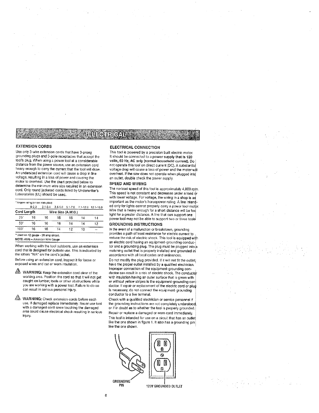
GROUNDING INSTRUCTIONS
In the event of a malfunction or breakdown, grounding
provldes a path of leasl resistance for electric current to
reduce the risk of electric shock. This tool is equipped Wilh
an electdc cord having an equipment-grounding conduc- I
tcr and a grounding plug. The plug must be plugged into _a
matching outlet that is properly instarled and grounded in/
accordance with all local codes and ordinances.
Do net modify the plug provided. {fit will not fit the outlet I
have the proper outlet installed by a qualified electrician.
Improper connection of the equipment-grounding con-
duotor can result in a risk of electric shock. The ¢onduclctr
with insulation having an outer surface that is green wil,h
or without yellow stripes is the equipment-grounding con_
ducton If repair or replacement of the etecfric cord or plu_
is necessary, do not connect the equipment grounding "
conductor to alive terminal. I
Check with aqualilied electrician or service personnel if i
the grounding instructions are not completely understood,
or it in doubt a_ to whether the tool is plo[_edy grounded.[
Repairorreplaoeadamagedorworncordimmediately. i
This tool is intended for use on a circuit that has an outlet i
like the one shown in figure 1. It also has a grounding pin i
like the one shown,
®
(gg
120V GR(]g_BEBOUTLEI
Anti-Kickback Pawls (radial arm and table saws)
A device which, when properly installed and maintained
is designed to stop the workplace from being kicked back
toward the front of the saw during a ripping operation.
Arbor
The shaft on which a blade or cutting tool is mounted.
Bevel Gut
A cLltting operation re,ado with the blade at any angle
ether than 90_ to the tab{e sudace.
Chamfer
A cut removing a wedge from a block so the end (or part
of the end) is angled rather than at 90".
Compound Cut
A cross cut made with both a miter and a bevel angb.
Cross Cut
A cutting or shaping operalio=_ made across the grain or
the width of the workpiece.
Cutter Heed Iplaners and jointers}
A rotating piece of adjustable btades. The cutter head
removes material from the wod{piece.
Dado Cut
A non-through cut which produces asqua_e-sided notch
or trough in the workpiece (requires a special blade}
Featherboard
A device tJsed to help control the workpiece by guiding it
securely against the table or fence during any ripping
operation.
FPM or SPM
Feet per minute (or strokes per minute}, used inreference
to blade movement.
Freehand
Performing a cat without the workplace being guided by a
fence, miter gauge, or other aids.
Gum
A sticky, sap-based residue from wood products.
Heal
Alignment of the blade lo the fence.
Kerr
]'he matedal removed by the blade in a through cut or the
slot produced by the blade in a non-through or partial cut.
Kickback
A hazard that can occur when the blade binds or stalls,
throwingthe workpiece back toward operator.
Leading End
the end ol the wod_piece pushed into the tool first.
Miter Cut
A curling operation made with the workpiece at any angle
to the blade other lhan 90°.
Non-Through Cuts
Any cutting operalien where the blade does not extol d
completely through the thickness of the workpiece.
Pilot Role (drill presses)
A smatl hole drilled ina workpiece that serves as a gt {de
for dfilhng large holes accurately.
Push 8locks and Push Slicks
Devices used to feed the workpiece through the saw
blade during cutting operations. A push stick (not ap xsh
block} should be used for narrow ripping operations. _/rom
These aids help keep the operator's hands well away
the blade.
Resaw
A cutting operat_n to [educe the thickness of the wor
piece to make thinner p_eces.
Resin
A sticky, sap-based substance that has hardened.
Revelations Per Minute (RPM)
The number of turns completed by a spinning object i
one Minute.
Ripping or Rip Cut
A cutting operation along the length of the workplace.
Riving Knife/SpreaderlSpl_tter (table saws)
A metal piece, sJightlv thinner than the blade, _.¢hiohh,
keep the kerr open and also helps to prevent kickbacl
Sew Blade Path
The area over, under, behind, or }nfront ot the blade. ,_
it applies to the workplace, that area which will be or h
been cut by the blade.
Set
The distance that the tip ef the saw blade tooth is ben1
set) outward from the face of the blade.
Snipe (planers) [
Depression made at either end of aworkpiece by cutter
blades when the workpieee is not properly supportedq
Through Sawing |
Any cutting operation where the blade extends completely
through the thickness of the wo[kpiece.
Throw-Back
The throwing back of a workpiece usually caused by tl
workpiece being dropped into the blade or being plact
inadvertently in contact with the blade.
t,Vorl{plece or Material
The item on which the operation is being done
Worktable
Surface where the workpiece rests while performing a
curling, drilling, pianing, or sanding operation.
• 'i ...... i _ :. :: L ..
,?..
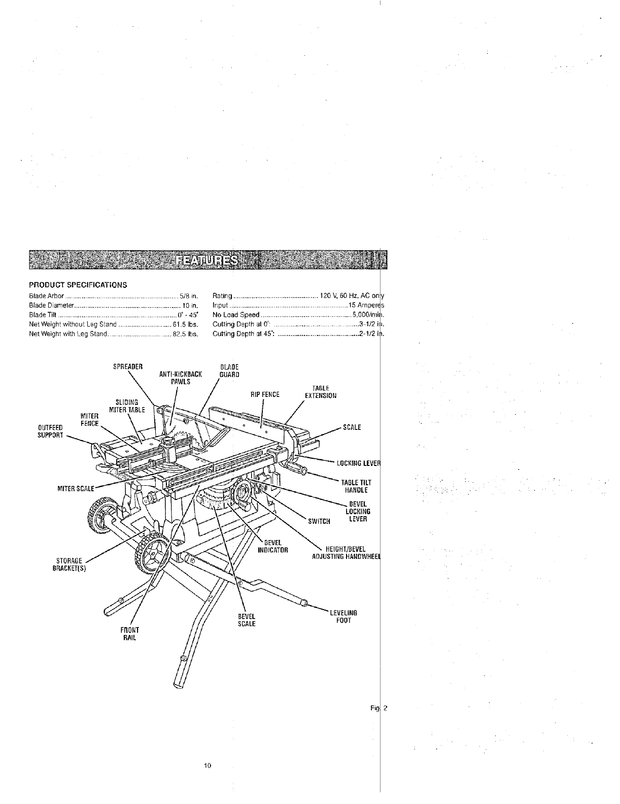
PRODUCT SPECIFICATIONS
Blade Arbor .............................................................. 5/8 in. Rating .............................................. 120 V, 50 Hz, AC
Blade Diameter .......................................................... 10 in. Input ................................................................ 15 Amper_
Blade Tilt ................................................................. O° * 45°No Load Speed ................................................. 5,000imi
Net Weight without Leg Stand ............................. 61,5 Ibs. Cutting Depth at 0°: .................................... 3 1/'2 i
Net Weight with Leg Stand ................................... 82.5 Ibs. Cutting Depth at 45": ............................................ 2-1/2 i
OUTFEED
SUPPORT
SPREADER
SLIDING
MITERTABLE
MITER
FENCE
BLAOE
ANTI-KICKBACK GUARD
PAWLS
TABLE
RIP FENCE EXTENSION
LOCKINGLEVEF
TABLETILT
HANDLE
_BEVEL
LOCKING
LEVER
STORAGE
BRACKET(S}
HEIGHT]BEVEL
ADJUSTINGHANDWHEEI
FRONT
RAIL
BEVEL
SCALE FOOT
F_g
IO
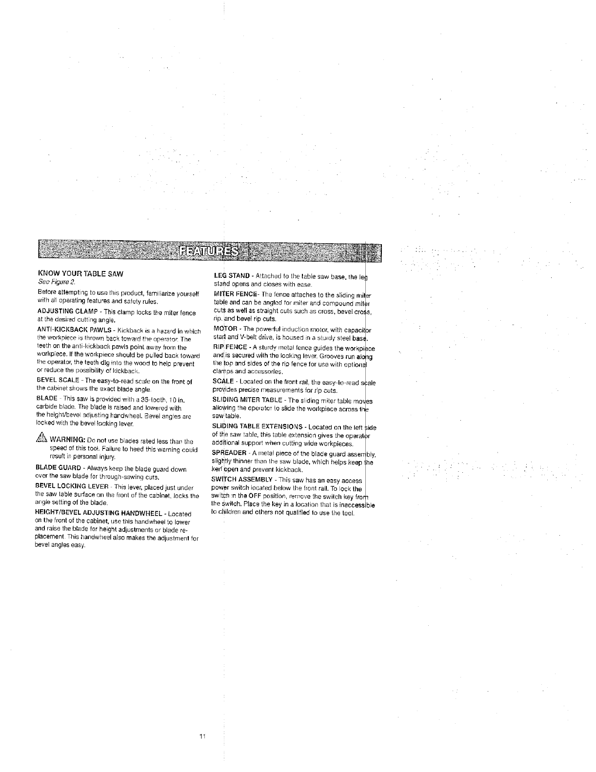
KNOW YOUR TABLE SAW
See Figure 2.
Before attemptin G to use fins aroduct, faml iarize yourself
with at operating features ana safety rules.
ADJUSTING CLAMP - This cramp locks the miter fence
at tne aes_rsd curt ng angle.
ANTI-I(IGKBAOI( PAWLS - Kickback _s a heza,d in wttich
the workplace _s thrown back toward the opera;or: The,
teeth on the eng-k_ckb_c_, paw_s po_r_t away f[om the
workpiece. If the workplace should be Ouilec Back towage
the operator, the teeth dig rote the wood to held arl_vent
or reduce the uo£s_Olll|y of kickback.
BEVEL SCALE - The easy4o-read scale on the froPt Ol
the cabinet shows the exact blade angle
BLADE This saw is providsc with a 36-1ooB" I 0 In.
carbrde blade. The b_aoe Js rased end lowered with
the heighVbeve adlusting hardwheel. _evel ang'es ale
locked with the be_,el _ock_ng _evsr
_,-_ WARNING: Do not use bla0es rated less rna_ the
speed of this too}. Failure to heed this warning COUId
result i# personal injury.
BLADE GUARD - Always keep the blade guard daws
over the saw blade for through-sawing curs.
BEVEL LOCKING LEVER This ever, sicced just unaer
the saw table surface on the front of the cabinet oaks the
angle setting of the blade
HEIGHT/BEVEL ADJUSTING HANBWN_:EL -Locates
on the front of the cabinet, use this handwheel to lower
and raise the blade for height adjustments or blade re-
placement This t_a_dwhee! a_ao makes the ad,Jstmeet far
bevel angles easy.
LEG STAND * Attached to the table saw base, the le
stand ooens ano ClOSeS WIUq ease.
MITER FENCE- The fence attaches to the sliding rrli
table and can be angled for miter and comsound mg
cut_. as w_II as s_fa_gnt cuts such as cross bevel ere
rip. and bevel ric cuts.
MOTOR - The oeweriul _neuc_on meter, with capaci
starl and V-belt drive Is hodsed _na sturdy steel bas
RiP FENCE - A _turdy metal lence guides the wdrkp
and is secured with the locking lever• Grooves rull ale
the to_ and sides of the -3 fence for use with optiona
clar_Ds and accessories.
SCALE -Losaled on lhe frort rail. the easy-lo-read s_
provides Dreclse measurements tar rio cute.
SLIDING MtlTER TABLE - The siding miter table mo_
allowing rne coclater to s}ide the worhBlece across lh
sew table.
SLIDING TASLE EXTENSIONS - Located on the left
of the saw table this table extension gwes the costal
additional support when cutting wide workpieoes.
SPREA[}ER - A metal piece of the blade guara assen
slightly '_" nner than the saw blade, which heIps }<eeD
kerr open and prevent kickback.
SWlTC_ ASSEMBLY - This saw has an easy access
cower switch located below the bent rail. To ock the
switch _n the OFF aositior remove the switch key fi'o
the switch. Place the key in a location that is inaeees_
to children and others not 3ualifiec to use the tool.
}r
or
ce
_g
ale
,de
)r
bly.
he
n
ibis
11
OPERATING COMPONENTS
The upper podioo of the blade pro}ects up through the
tabie and is staTounded by an insert called the throat
plate. The height of the blade is set with a handwheel on
the front of the cabinet. To accommodate wide panels,
the saw table has rails on each aide, Detailed instructions
are provided in the Operation section of this manual for
the basis cuts: cross cuts, miter cuts, bevel cuts, and
compound cuts.
The sliding miter table assembly is used for sloes cutting
operations. The miter fence is easily adjusted to cut wood
at an angle by loosening the adiustJn§ clamp, setting the
fence to the miter scale, and retightening the clamp. The
sliding miter table, which rests on a base mounted on the
rails, can be repositioned along the rails for wide work. it
can be reversed so the projecting base is in the back and
can be moved from the left side to the right side as need-
ed, With the miter fence removed, the miter table offers
additional support for other operations such as ripping.
The rip fence is used to position work for lengthwise cuts.
A scale on the front rail shows the distance between the
rip fence and the blade.
It is very important to use the blade guard assembly for all
Ihrough-sawi#g operations. The blade guard assembly
includes: riving kniteispreader/splitter, anti-kickback
pawls, and plastic blade guard.
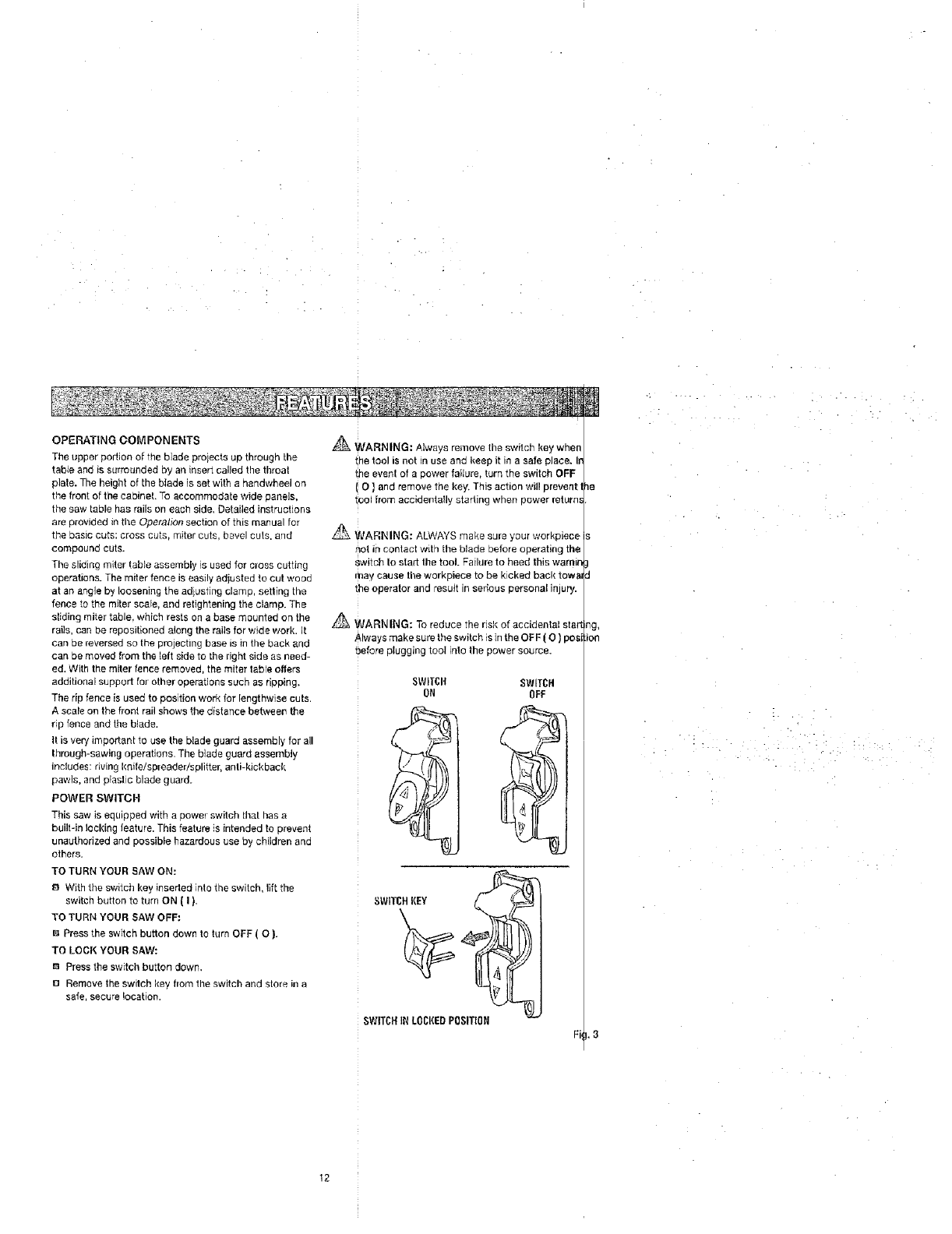
POWER SWITCH
This saw is equipped with a power switch thai has a
built-in locking feature. This feature is intended to prevent
unauthorized and possible hazardous use by children and
others.
TO TURN YOUR SAW ON:
8 With the switch key inserted into the switch, lift the
switch button to turn ON [ I ).
TO TURN YOUR SAW OFF:
I_ Press the switch button down to turn OFF ( O ).
TO LOOK YOUR SAW:
m Press the switch button down.
I_1Remove the switch key from the switch and store in a
safe, secure location.
_ WARNING: Atways remove the switch key when
_he tool is not in use and keep it in a safe place. Ir
the event of a power faiture, turn the switch OFF
O ] and remove the key. This action will prevent I
tool from accidentally starling when power return_
WARNING: ALWAYS make sure your workpiece
not in contact with the blade before operating the
switch to stad the tool. Failure to heed this warnin
may cause tile workpiece to be kicked back towa_
the operator and result in serious personal injury.
WARNING: To reduce the risk of accidental star1
Always make sure the switch is in the OF F ( O )pest
before plugging tool into the power source.
SWITCI'I SWITCH
ON OFF
i -•- • •
i •
BLADES
For maximum performance, it is recommended that you
use the Craftsman 36-tooth, 10 in. carbide combination
blade provided with your saw, Additiona_ blade styles of
the same high quality are available for specific operat one
such as ripping, Your local dealer can provide you with
complete information,
_ WARNING: Do no_ use blades raled less than
speed of this tool. Failure to heed this warning (
result in personal injury.
ould
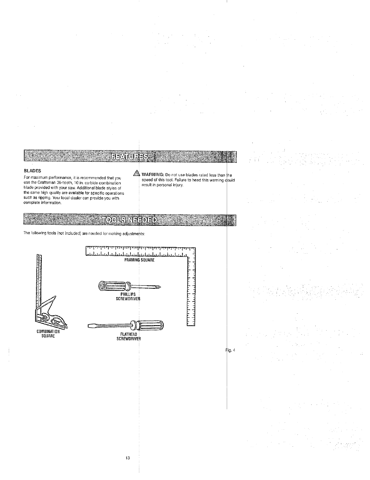
The following tools {not included) are needed for making adjustmenta:
COMBINATION
SQLIARE
,L_L,J._.#._,, I,,, I, _, !, q, I, bJ.LI, !, _
FRAMINGSQUARE "_
;i
PHILLIPS T"1
SCREWDRNEH : :
FLATHEAD
SCREWDRIVER
ig. 4
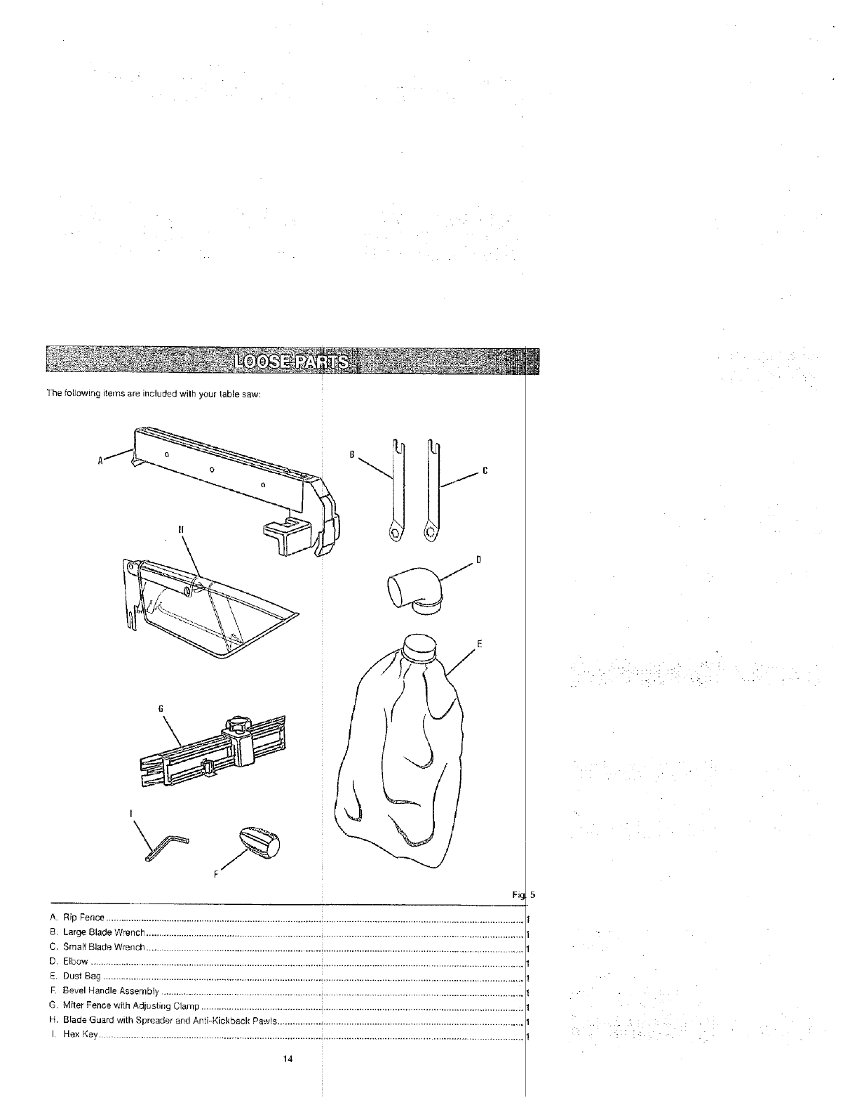
The following items are included wilh your table saw:
6
A. Rip Fence ...................................................................................................................................................................
B. Large Blade Wrench ...................................................................................................................................................
C. Smalt Blade Wrench ................................................................................................................................................
D, Elbow ......................................................................................... _............................................................................
E. Dust Bag ................................................................................................................................................................
E Bevel HandleAssembly ..........................................................................................................................................
G. Miter Fence wi[h Adjusting Clamp ........................................................................................................................... i
H. Blade Guard with Spreader and Anti-Kickback Pawls ...............................................................................................
I Hex Key .............................................................................................................................................................
14
UNPACKING
This product requires assembly.
IJ Carefully lift saw from the carton and place it on alevel
work sudace.
NOTE: This too! is heavy. To avoid back injury, keep
your knees bent and lift with your legs, nat your back,
and get help when reeded.
19 Inspect the took carefully to make sure no breakage or
damage occurred during shipping.
E1 Do not discard the pacldng material until you have
carefully iospected and satbfaetobty operated the tool.
The saw is factory set for accurate cutting. After
assembling it, check for accuracy. If shipping has
influenced the settings, refer' to specific procedures
explained in this manual
El if any parts are damaged or missing, please can
1-800-932-3188 for assistance.
_ WARNING: If any parts are missing, do not operate
this tool until the missing parts are replaced. Failure
to do so could result in possible seric)us personal
injury.
_ WARNING: Do not attempt to modify this tool
or create accessories not recommended for use
with this tool Any such alteration or modification is
misuse and could resull in a hazardous condition
leading to possible serious personal injury.
_ WARNING: Do not connect to power supply until
assembly is complete. Failure to comply could result
in accidental starting and possible serious personal
injury.
,_,_"_ WARNING: Do not lift the saw without help. Hold
it close to your body. Keep your knees bent and
lift with your legs, not your back. Ignoring these
precautions can ,esult in back injury.
_ WARNING: Never stand directly in line with the
blade or allow hands 10 come closer than 3 in. to the
blade. Do not reach over or across the blade Failure
to heed this warning can result in serious personal
illlLiry.
AWARNING: To avoid serious personal injury, always
make sure the table saw is securely mounted to
a workbench or an approved leg stand NEVER
operate the saw on the floor.
MOUNTING HOLES
This toot comes mounled to a leg stand. ]f you chose
remove the leg stand, the table saw must be mounted
firm _upporfing surface such as a worl_bench or leg sin _d,
Four bolt holes have been provided in the saw's basel
this porpose. Each of the four mounting holes should b
boll_ securely using 3/8 in. machine botts, lock wash_
and Nex nuts (not included). Bolls should be of sufficiei t
length to accommodate the saw base, lock washers, I_ _x
nuts, and the thickness of the workbench. Tighten all < ur
bolts securely.
Carefully check the workbench after mounting to make
sure that r_omovement can occur du[ng use. If any tip
ping, sliding, or we kirlg is noted, secure the workberi to
the fleer before operating.
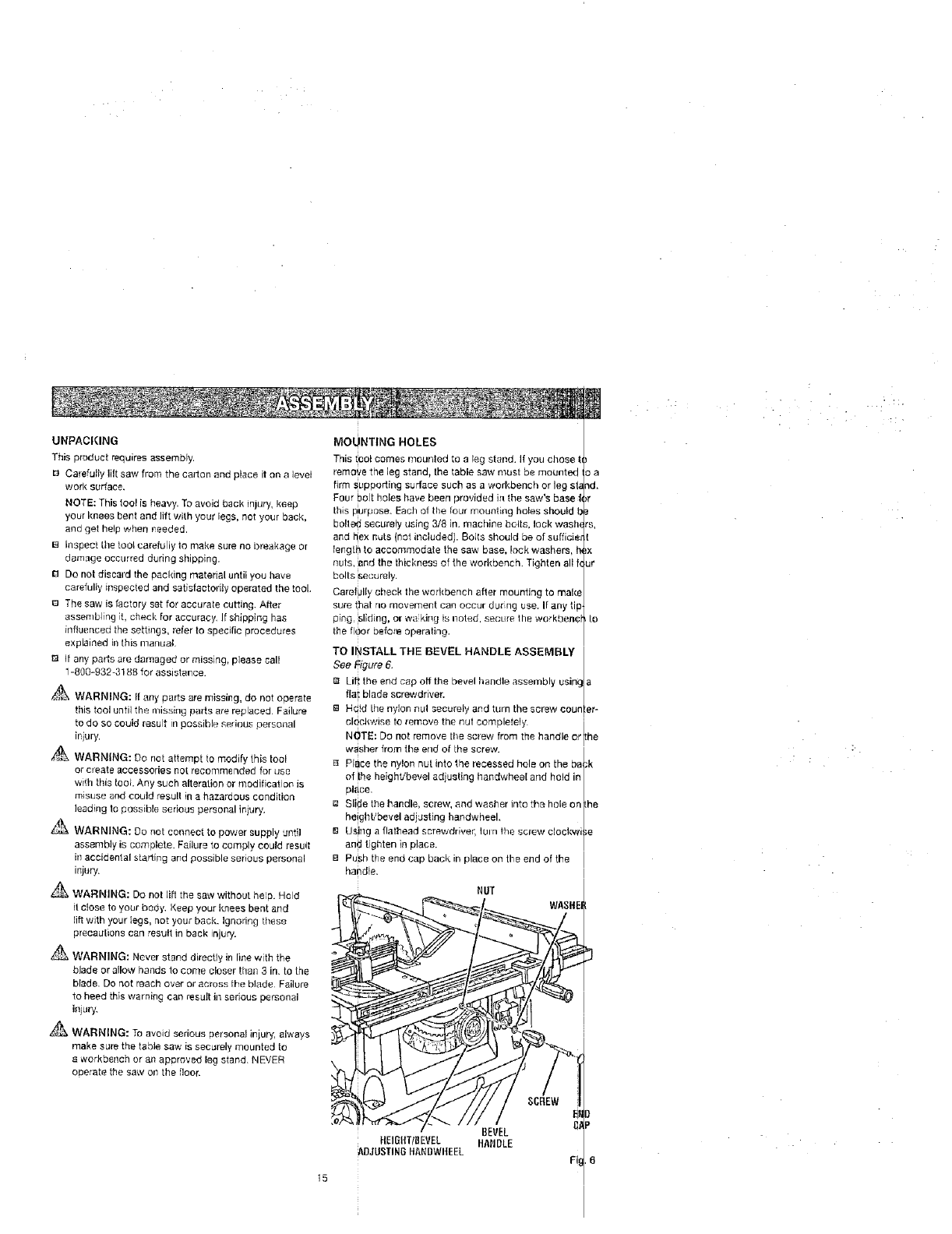
TO INSTALLTHE BEVEL HANDLE ASSEMBL I
See Figure 6. I
r_ Lift the end cap off the bevel handle assembly using Ia
flu i blade screwdriver. /
Ea Hdld [he nylon nut securely and turn the screw couoler-
clockwise to remove the nut completely I
NOTE: Do not remove tile screw from the handle o:rlthe
washer from the end of [he screw. i
/
Place the nylon nut into the recessed hole on the ba_,k
of ihe heightibevel adjusting handwheel arid hold in/
pl_ce, l
[] Slide the handle> screw, and washer into the hole on I[he
height/bevel ad _eting handwheeh /
B Using a flatlqead screwdriver, iul n the screw clockwise
and tighten in place. /
[] Push the end cap back in place on the end of the
handle.
NUT
BEVEL
ftEIGItTIBEVEL HANDLE
ADJUSTINGftANBWHEEL
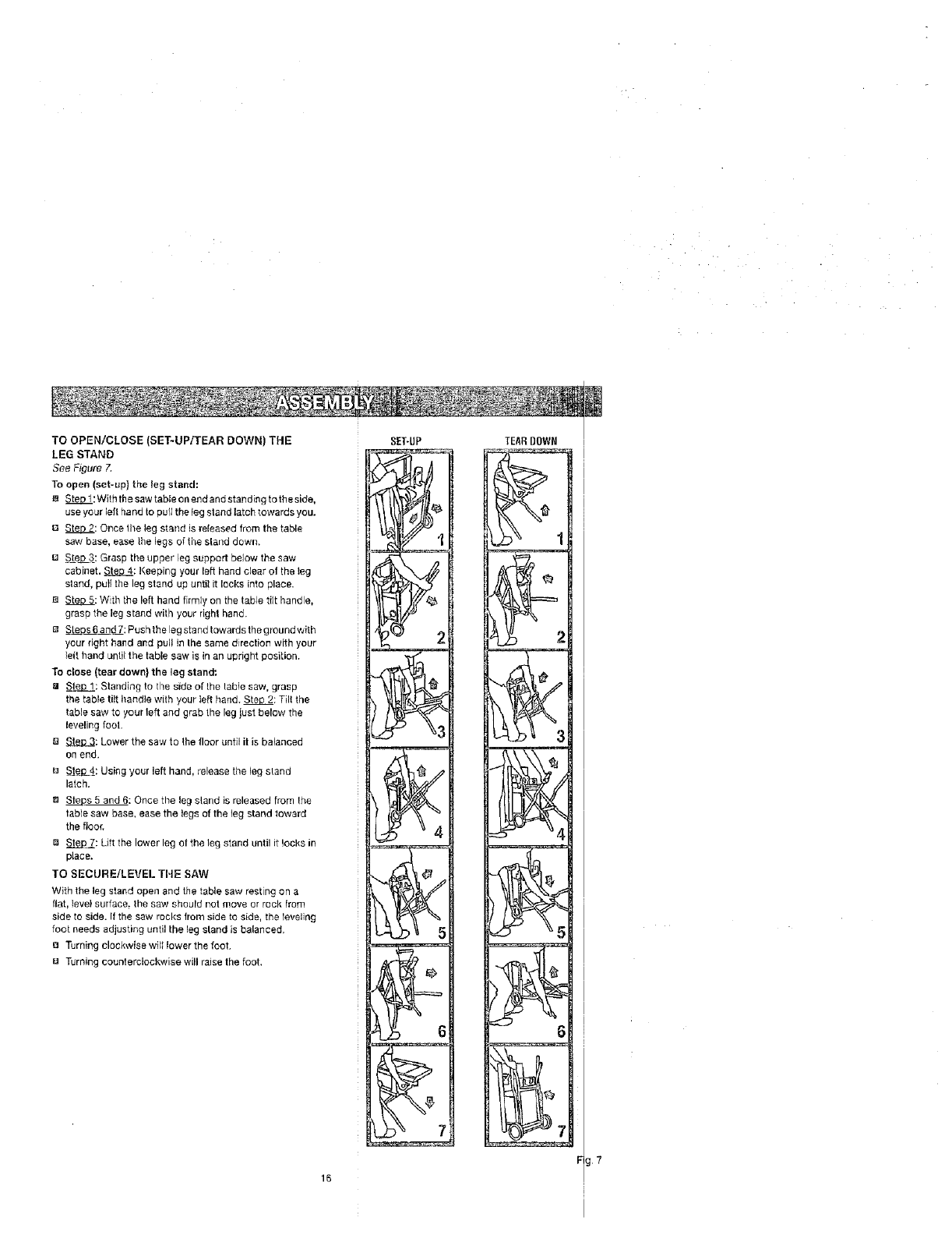
TOOPEN/CLOSE(SET-UP/TEAR DOWN) THE
LEG STAND
See Figure 7.
To open (set-up} tt_e leg stand:
m Step l:Withthe saw table on endand standing to theside,
use your left hand to pull the _egstand latch towards you.
13 Sten 2: Once the leg stand is released from the table
saw base, ease the legs of tl_e sland down.
S±e__.3_:Grasp the upper legsupport below the saw
cabinet. Ste_: Keeping your left hand clear of the leg
stand, pull the leg stand up until it locks into place.
Steo 5: Wth the left hand firmly on the table tilt handle,
grasp the leg stand with your right hand.
B _s 6and 7: Push the leg stand towardsthe groundwith
your right hand and pu]! in Ihe same direction with your
leit hand until the table saw is in an upright position.
To close (tear down) the leg stand:.
81 Ste_: Standing to the side ot the table saw, grasp
the table tilt tlandle with your left hand. Ste_ 2: Tilt the
table saw to your left and grab the leg just below the
leveling foot.
E] _.e.l;L_:Lower the saw to the floor until it is balanced
on end.
Sto,0 4_:Using your left hand, release the leg stand
latch.
m _s 5 and 6: Once the leg sland is released from the
fable saw base, ease the legs of the leg stand toward
the floor.
i_ St__p7: Lift the lower leg of the leg stand until it locks in
place.
TO SECURE/LEVEl-THE SAW
With the leg stand open and the table saw resting on a
flat, level surface= the saw should not move or rock from
side to side. It the saw rocks from side to side, the leveling
foot needs adjusting until the leg stand is balanced.
e Turning clockwise will lower the foot.
8 Turning counterclockwise will raise the foot.
16
_ 7
TEAR DOWN
7
I
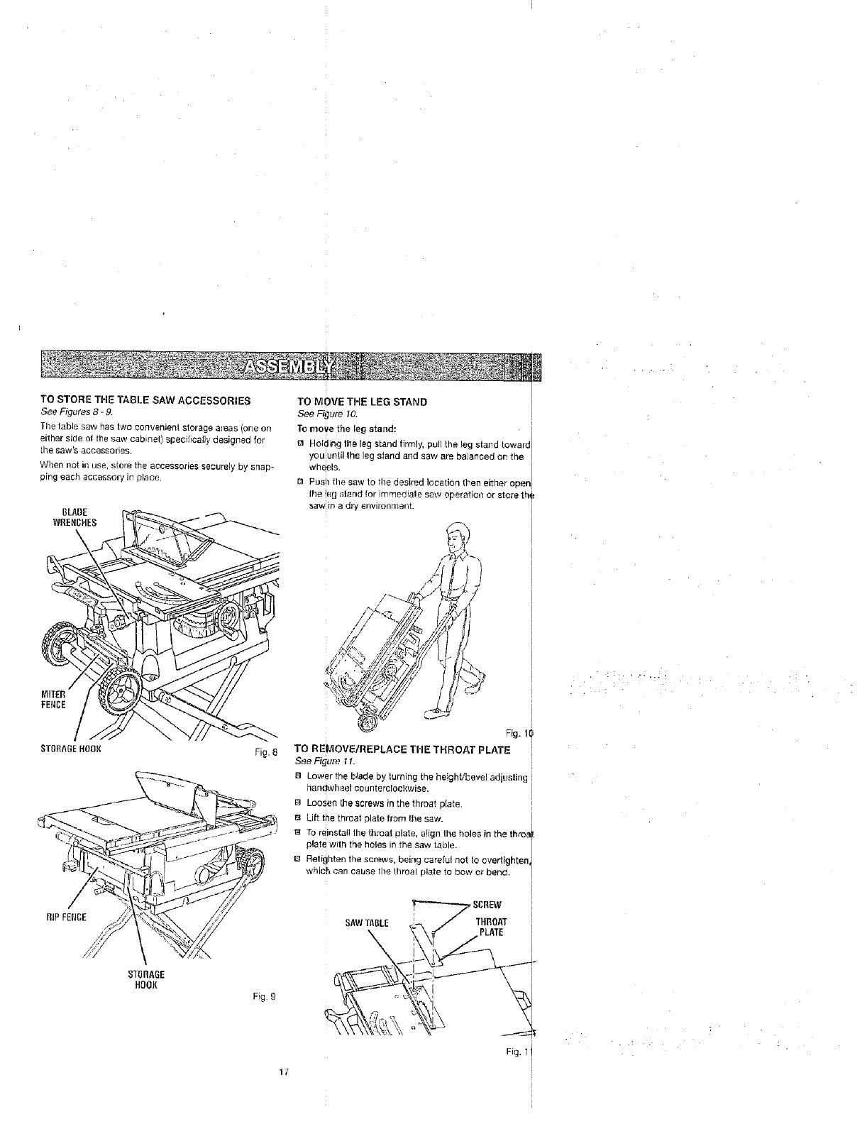
TO STORE THE TABLE SAW ACCESSORIES
SeeFigures3- g.
The table saw has two convenient storage areas (one on
either side ot the saw cabinet) specifically desigt_ed [er
the saw's accessories.
When net in see, store the accessories securely by snap-
ping each accessory in place
ST{IBhGEHOOK Fig. 8
STORAGE
HOOK
Fig£
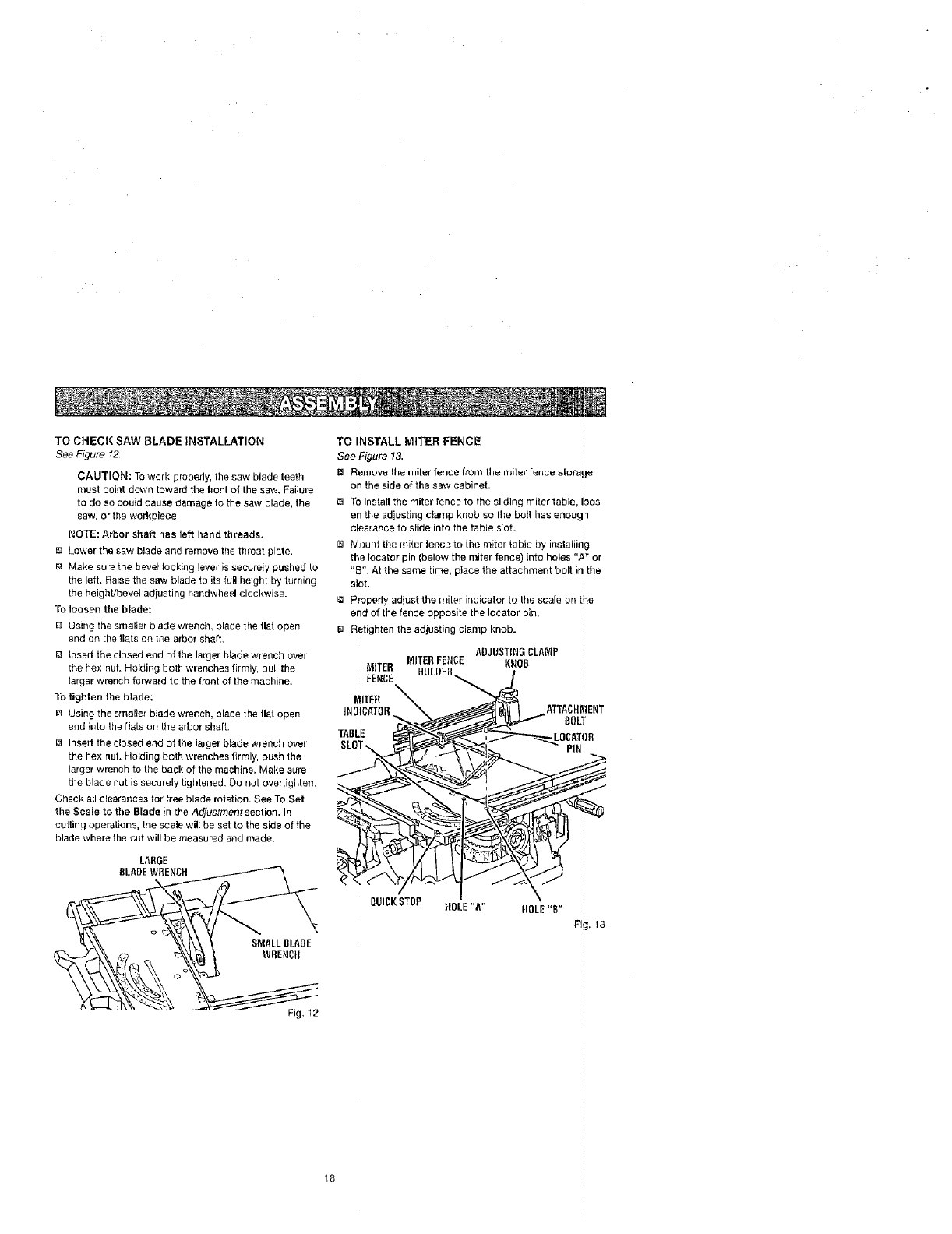
TO MOVE THE LEG STAND
See Figure 10.
To move the leg stand: I
Holdin 9 _#ie _e_ S[_d _r_, pU_ the _egstand t_waldl
you until the leg stand and saw are balanced en the
wheels.
B Pus!_the saw to the desired location then either open
the !eg sland for immediate saw operation or store th_
saw in a dry environment.
TO REMOVE/REPLACE THE THROAT PLATE
See Figure, 1I.
8 Lower the blade by turning the height/bevel adiuslin £
handwheel counterclockwise.
B LooSen the screws in the throat plate•
Lift the threat plate from the saw.
• 1 TO [einst&U the throat plate, alige the holes in the throa
plate with the holes in the saw table.
o I
El Relightcn the screws, being careful not to evertighten,
which can cause the throat plate te bow or bend.
SAWTABLE
•:i:; ¸ ....:_•i .
Fig. 1 i
17
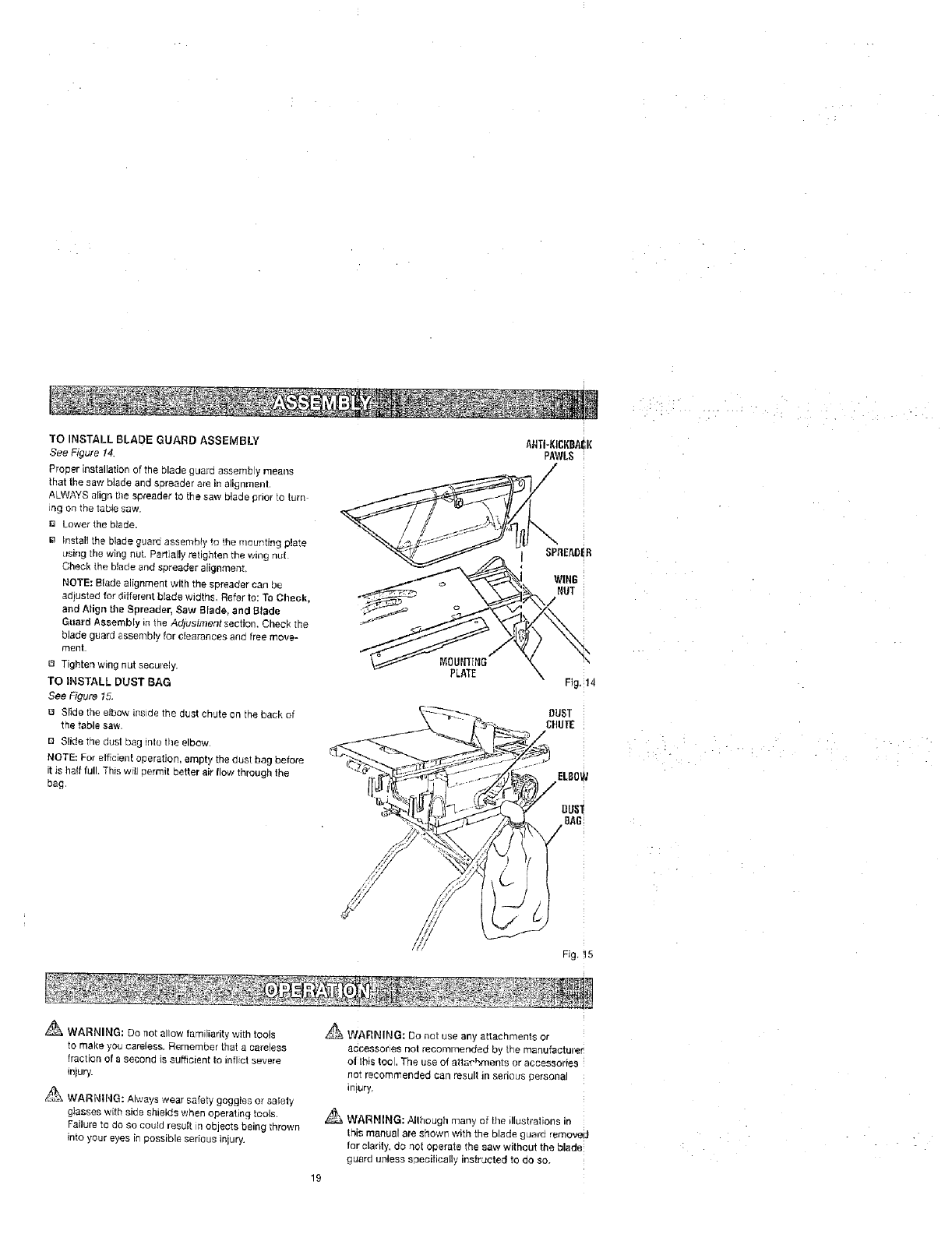
TO CHECK SAW BLADE INSTALLATION
See Figure !2
CAUTION: To work properly, the saw blade teeth
must point down toward tile front o{ the saw. Failure
to do so could cause damage to the saw blade, the
saw, or the wcrkpiece.
NOTE: Arbor shaft has left hand threads.
Ia Lawer the saw blade and remove the throat plate.
M_ke sure the beret locking lever is securely pushed to
the left. Raise the saw blade to its full height by turning
the height!bevel adjusting handwheel clockwise.
To loosen the blade:
BUsing the smalter blade wrench, place the flat open
end on the flats on the arbor shaft.
F_ insert the closed end of the larger bJade wrench over
the heY. nut. Holding both wrenches firmly, puff the
larger wrench forward to the front of the machine.
To tighten the blade:
_4 Using the smaller blade wrench, place the flat open
end ir_to the flats on the arbor shaft.
Insert the closed end af the larger blade wrench over
Lhe hex nut. Holding both wrenches firmly, push the
larger wrench to the back of the machine. Make sure
Lhe blade nut is securely tightened. Do not overtighten.
Check all clearances for free blade rotation. See To Set
the Scale to the Blade [n the AdjustmentsecUon, In
cutting operations, lhe scale will be set ta the side of the
blade where the cut wil! be measured and made.
LARGE
gLADE WRENCH
tSMALLBLADE
WRENCH
Fig. 12
i
TO INSTALL MITER FENCE
See Figure 13.
Remove the miter fence from the miter fence storafje
oh the side af the saw cabinet.
{a TOinstallthe miter lence to the eliding miter table, I)oos-
en the adjusting clamp knob so the bolt has enoug!l
clearance to slide into the table slot.
Mouot the miter fence to ihe miter tabte by instaliia_g
the locater pie (below the miter fence) into holes "A" or
, i
"B". At the same hme, place the attachment bolt h'l!the
!
slot.
Properly adiust the miter indicator to the scale an the
end af the fence apposite the Iocator pin,
_q Retighten the adjusting clamp knob.
MITERFENCE
HOLDER
MITER
iNDICATOR
TABEE
ATTACHMENT
BOLl
•LOCATIIR
PIN J
OUICI(STOP HOLE"A" flDLE "B"
FirJ.t3
18
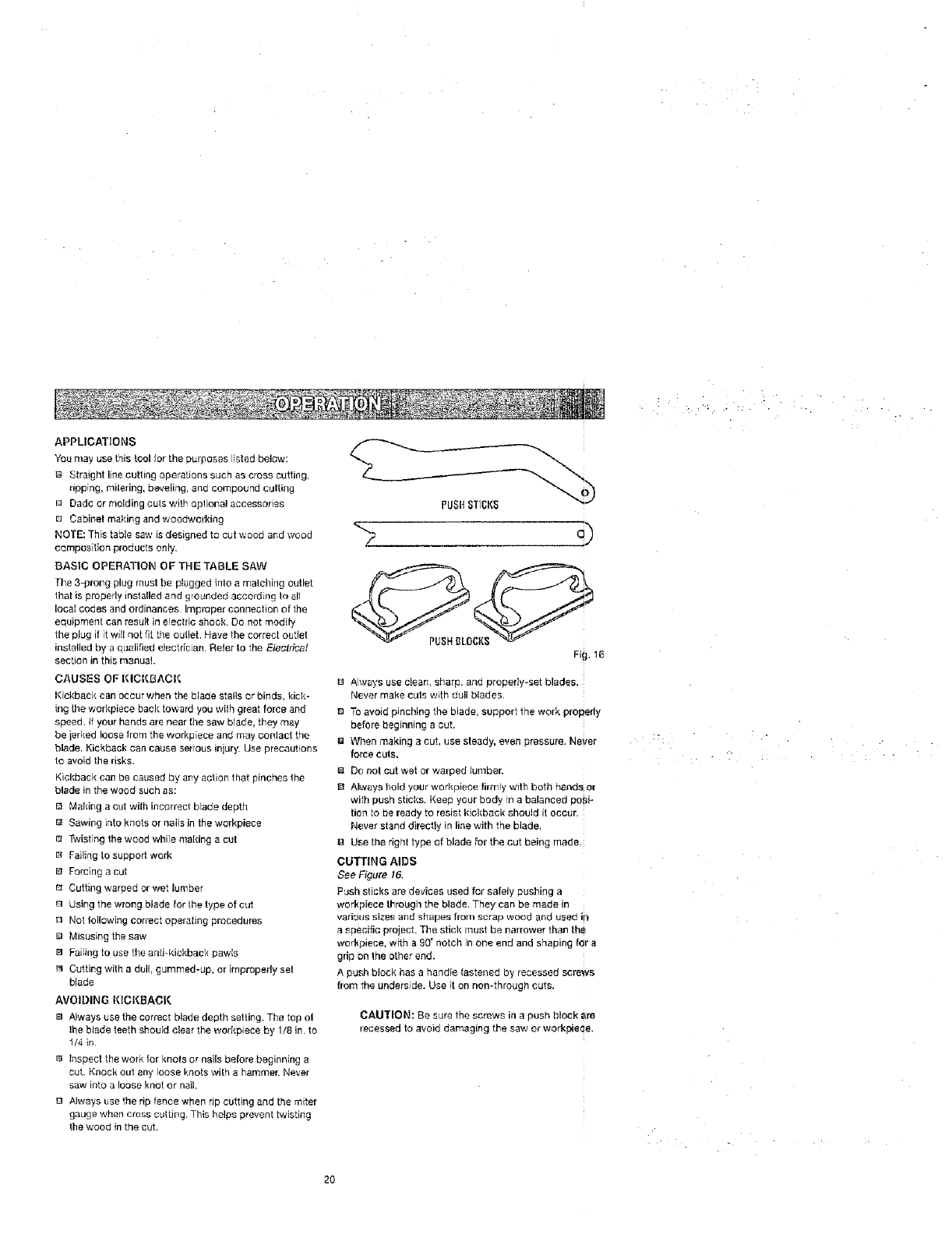
TO INSTALL BLADE GUARD ASSEMBLY
See Figure 14.
Prober installation of the blade guard assembly means
that the saw blade and spreader are in aligrlmenl.
ALWAYS align the spreader to the saw blade prior to turn
ing on the table saw.
Lower the blade.
la Install the blade guard assembly to !he mounting plate
using the wing nut. Partially retighten the wing nul
Check the blade and spreader alignment.
NOTE: Blade alignment with the spreader can be
adjusted for different blade widths, Refer to: To Cheek,
and Align the Spreader, Saw Blade, and Blade
Guard Assembly in the Adjustment section. Check the
blade guard assembly for clearances and free move-
ment.
El Tighten wing nut seculely.
TO INSTALL DUST BAG
See Figure 15.
13 Slide the elbow inside the dust chute on the back of
the table saw.
BSlide the dust bag into the elbow.
NOTE: For efficient operation, empty the dust bag before
it is half full. This wfll permit better air flow through the
bag.
MOUN'IING
PLATE
/Z/
AIITI-KICKBAI_K
PAWLS
i
SPRE!'_ER
WING :
Fig. !4
DUST
{;}IUTE
Fig. il5
_ WARNING: Do not allow familiarity with tools
to make you careless. Remember that a careless
traction of a second is sufficient to inflict severe
injury.
_ WARNING: Always wear safety gaggles or safely
glasses with side shields when operating tools,
Failure to do so could result in objects being thrown
into your eyes in possible serious injury,
_J_ WARNING: Do not use any attachments or
accessories not recommended by the manufacturer
o| this tool, The use of altat'_',ments or accessories
not recommended can resull in serious personal
injury,
_ WARNING: Allhough many of the illustrations in
this manual are shown with the blade gLJard removed
tot cladty, do r_ot operate the saw without the blade
guard unless soecilically instructed to do so,
19
APPLICATIONS
Youmayusethistoolforthepurposeslistedbelow:
Straightlinecuttingoperationssuchascrosscutting,
ripping,mitering,beveling,andcompoundculting
_ Dadcormoldingoutswithoptionalaccessories
[] Cabinetmakingandwoodworldng
NOTE:Thistablesawisdesignedtocutwoodandwood
compositionproductsonly.
BASICOPERATIONOFTHETABLESAW
The 3-prong plug must be plugged irrto a malching outlet
that is properly installed and grounded according 1o ell
Iocat codas and ordinances Improper connection of the
equipment can result in electric shock. Do not modify
the pbg if it will not fit the outlet. Have the correct outlet
installed by a qualified electdcian. Reler to the EtecPica!
section in this manuel
CAUSES OF KICKBACK
Kickback can occur when the blade stalls or binds, kick-
ing the workpiece back toward you with great force and
speed, tf your hands are near the saw blade, they may
be jelked loose from the workp[ece and may contact the
blade. Kickback can cause serious injury. Use precautions
to avoid the risks.
Kickback can be caused by any action that pinches the
blade in the wood such as:
B Making a cut with incorrect blade depth
e Sawing into knots or nails in the wcrkpiece
Twisting the wood whi]e making a cut
[a Failing to support work
B Forcing a cut
r_ Cutting warped or wet lumber
Using the wrong blade for the type of cut
_ Not Ioilowing correct operating procedures
B Misusing the saw
B Failing to use the antbkickbauk pawls
r_ Cutting with a dull, gummed-up, or improperly sel
blade
AVOIDING KICKBACK
la Always usethe correct blade depth setting. The top oi
lhe blade teeth should clear the workpiece by 1/8 in. to
1/4 in.
r_ Inspect the work for knots or nails before beginning a
cut. Knock out any loose knots wilh a hammer. Never
saw into a loose knot or nail.
B Always use the rip fence when rip cutting and the miter
gauge when cress cutting. This helps prevent twisting
the wood in the cut,
,,,=
<z
Fli_. 16
B Always use clean, sharp, and propeify-set blades.
Never make cuts with dull blades.
B To avoid pinching the blade, support the work properly
before beginning a cut.
_a When making a cut, use steady, even pressure. Never
force cuts.
B Do not cut wet or walped lumber.
Always hold your werkpiece firmly with both hands or
with push sticks. Keep your body in a balanced po_}i-
tien to be ready to resist kickback should it occur,
Never stand directly in line with the blade,
g Use the right type of blade for the cut being made,
curJlNG AIDS
See Figure 16.
Push sticks are devices used for safely pushing a
workpiece through the blade. They can be made in
various sizes and shapes from scrap wood and used in
a specific project. The stick must be narrower than tha_
workpiece, with a 90°notch in one end and shaping for a
grip on the other end.
A push block has a handle lastened by recessed screws
from the underside. Use it on non-through cuts.
CAUTION: Be sure the screws in a push block are
recessed to avoid damaging the saw or workpie_e.
2O
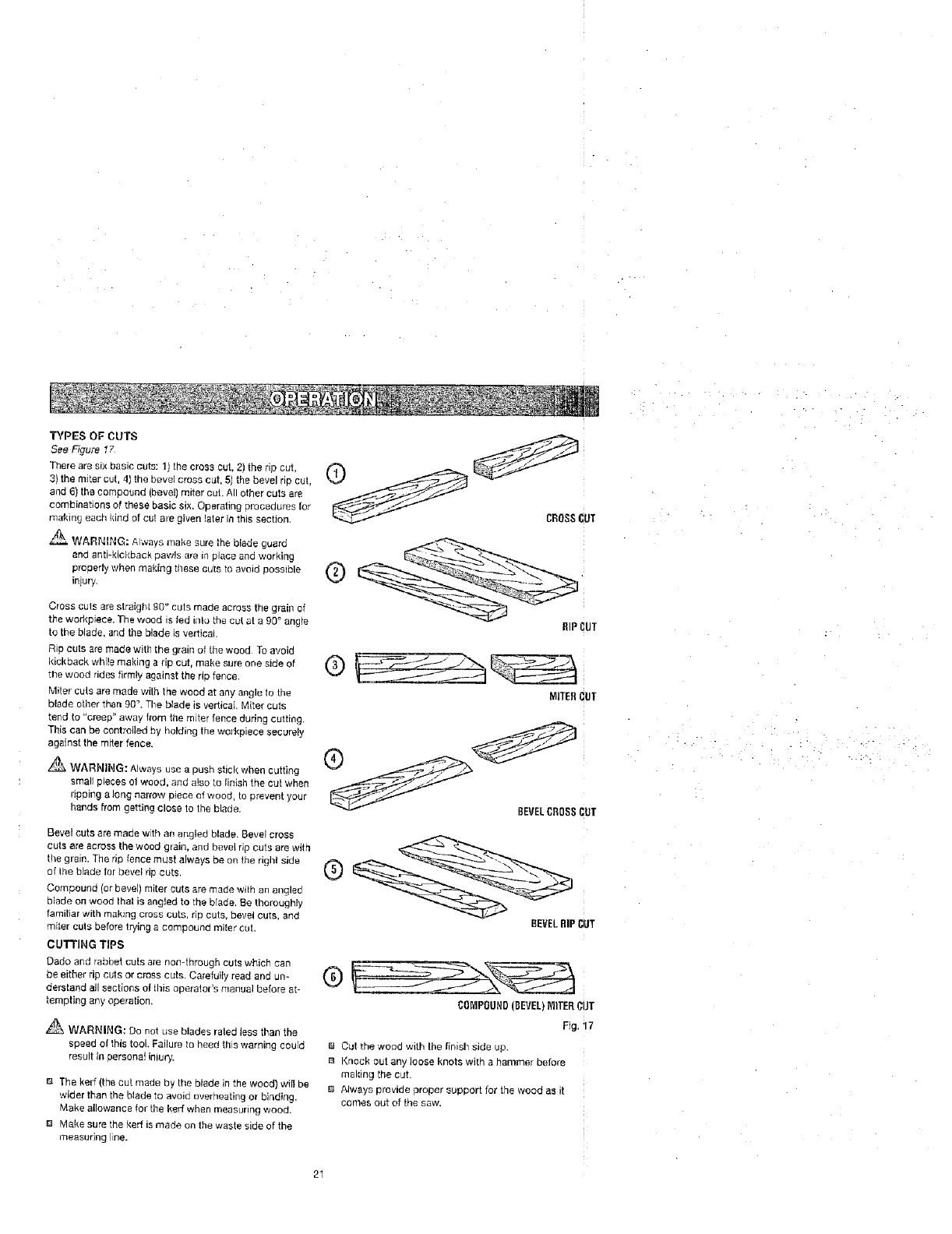
T'_'PES OF CUTS
See FTgure17
There are six basic cuts: 1) the cross cut, 2) the rip cut,
3) the miter cut, 4) the bevel cross cut, 5) the bevel rip cut,
and 6) the compound (bevel) miter cut. All other cuts are
combinations of these basic six. Operating procedures for
making eacb kind of cut are given later in this section.
WARNING: A]ways make sure the blade guard
end anti-kickback pawls ere in place and working
ptopert'y when making these outs to avt_id possible
injury•
Cross cuts are straight 90 ° cuts made across the grain of
the workpiece. The wood is fed inla the cut at a g0° angle
to the blade, and the blade is vertical.
Rip cuts are made witll the grain of the wood Toavoid
kickback while maldng a rip cut, make sure one side of
the wood ddee firmly against the ripfence.
Miter cuts are made with the wood at any angle to the
blade other than 90",The blade is vertical Miter cuts
tend to "creep" away from the miter fence during cutting.
This can be controlled by holding the workpiece securely
againstthe miter fence.
_ WARNING: Always use a push stick when cutting
sma_;p;eces ot wood, and also to lin{shthe cut when
dpping a long narrow piece of wood, to prevent your
hands from getting close to the blade.
Bevel cuts are made with an angled blade. Bevel cross
cuts are across the wood grain, and bevel rip cuts are with
the grain. The rip fence must always be on the right side
of the blade for bevel rip outs,
Compound (or bevel) miter cuts are made with an angled
btade on wood that is angled to the brads, Be thoroughly
familiar with making cross cuts, rip cuts, bevel cuts, and
miter cuts before trying a compound miter cut.
CUTTING TIPS
Dado and rabbet cuts are non-through cuts which can
be either rip cuts or cross cuts Carefully read and un-
derstand all sections of tllis operator's manual before at-
tempting any operation.
_WARNING: Do not use blades rated Jessthan the
speed of this tool. Failure to heed this warning could
result in persona] injury.
The kerr (the cut made by the blade Jn the wood) will be
wider than the blade to avoid averheating or binding.
Make allowance for the kerr when measuring wood.
m Make sure the kerr is made on the waste side of the
measuring line.
@
RiP CUT
MITER_]UT
BEVELCROSSCUT
BEVELRIP CUT
®
CO_/IPOUND(BEVEL)_IER CUT
Fig. 17
a Cut the wood with Ihe finish side up.
[] Knock out any loose knots with a hammer before
making the cut.
B Alweys provide proper support for the wood as it
comes out ot the s_'w.
FEATHERBOARD
A featherboard is adevice used to belp control the
workpiece by guiding it securely against the table or
fence. Featherbeards are especially useful when ripping
smalr workpieces and for completing non-through cuts.
The end is angled with a number of short kerfs to give a
frict on hold on the wcrkpiace and locked in place on the
taoie with a C-clamp Test to ensure it can resist kickback.
WARNING: Place the featherboard against the
uncut poiSion of the workpJece to avoid kickback that
could cause serious personal injury.
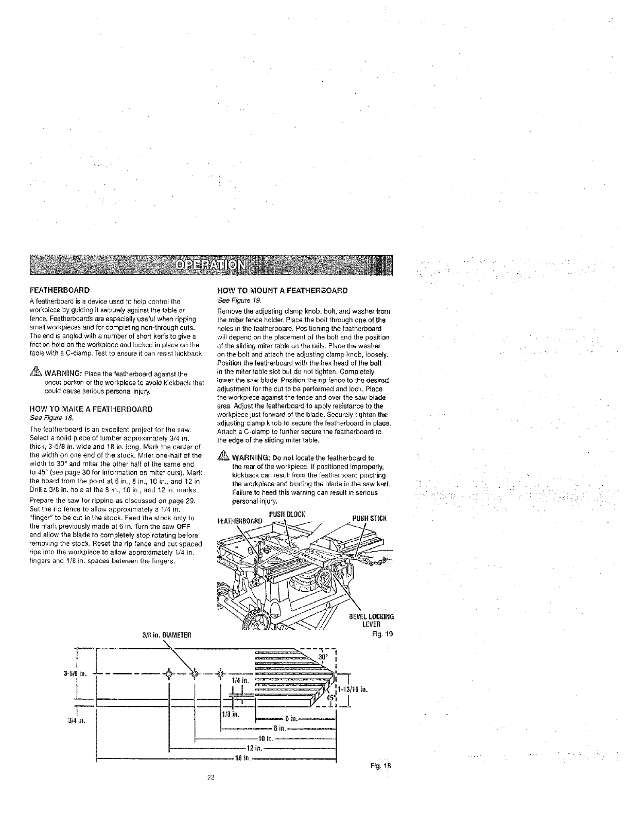
HOW TO MAKE A FEATHERBOARD
See Figare 18.
The teatherboard is an excellent project for the saw.
Select a solid piece of lumber approximately 3/4 in.
thick, 3-5/8 in. wide and 18 in. long. Mark the center of
the width on one end of the stock• Miter one-half of the
width to 30* and miter the other half of the same end
to 45 ° (see page 30 for information on miter cuts). Mark
the board from the poinl at 6 in., 8 in., 10 ill., and 12 in.
Drill a 3/8 in, hole at the 8 in., 10 in, end 12 in. marks.
Prepare the saw for ripping as discussed on page 29.
Set the rip fence to allow approximately a 1/4 in.
"finger" to be cut in the stock. Feed the stock only to
the mark previously made at 6 in. Turn the saw OFF
and allow the blade to completely stop rotating before
removing the stock. Reset the rip fence and cut spaced
rips into the workpiece to allow approximately I/4 in.
fingers and 1/8 in. spaces between the fingers.
HOW TO MOUNT AFEATHERBOARD
See Figure 19
Remove the adjusting clamp knob, bolt, and washer fronq
the miter fence holder. Place the bolt through one of the
holes it'l the featherboard. Positioning the featherboard
will depend on the placement of lhe bolt and the Dositiolr_
ef the sliding miter table on the rails, Place the washer
on the bolt and attach the adjusting clamp knob. ioosei?,
Position the featherboard with the hex head of the bolt
in the miter table slot bat do not tighten. Completely
lower the saw blade• Position the np fence to tha desired
adjustment for the cut to be pedormed and lock. Piece
the workplace against the fence and over the saw bade
area. Adjust the featherboard to apply resistance to the
workpiece just forward of the blade. Securely ngnten fine
adjusting clamp knob to secure the teatherboard in zglac,e.
Attach a C-clamp to further secure the featherboard te
the edge of the sliding miter table.
WARNING: Do not locate the featherboara to
Ihe rear of the workplace. If oositioned improperly.
kickback can resull [rom the featlerboard pulching
the workpiece and binding the blade in _ne saw ker_
Failure to heed this warning can result in serious
parser, el injury.
PUSII gkOCl(
FEATHERBOARO PUSH8T161{
[
3-5/8 is.
1
3/4 in.
22
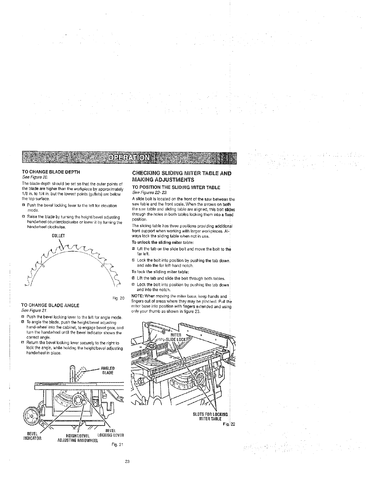
TO CHANGE BLADE DEPT_
See Figure 20.
The blade depth should be set so that the outer points cff
tile blade are higher than the workpiece by approximately
1/8 in. to 1/4 in. but the lowest pmnts {gullets) are below
the top surface.
BPush the bevel Iockin$ lever to tqe left for elevahon
triode.
{3 Raise the blade by turning the height/bevel adiusting
handwheel counterclockwise or lower it by turning [ne
handwheel clockwise
GULLET
F,g 20
TO CHANGE BLADE ANGLE
See Figu_e21.
Push the bevel locking lever to the left for angle mode.
BTo angle the blade, pus/_ the helght,'bevel adjusting
hand-wheer into the cabinet, to engage bevel gear. and
turn the handwheel until the bevel indicator shows the
correct angle.
_] Return the bevel locking lever secure}y to the right to
lock the angle, while holding the heighVbevet adjusting
handwheel in place,
BLADE
BEVEL
INDICATOR
BEVEl
NEIGHTiBEVEL LOCKINGLEVEII
A£JL]STIN6ltAl4DWliEEL Fig. 21
CHECKING SLIDING MITER TABLE AND
tVIA_(ING ADJUSTMENTS
TO POSITION THE SLIDING MITER TABLE
See Figures 22- 23
A slide bolt is located on the front of the sew between the
saw tab e and the front sos e. When the arrows on botlh
_he sin, table and stlding table are a_lgreo, rnls bolt s|ides
throu )r the holes in both tables leck_ng mem into a fi×eG
oosition.
The sltdlng table has three positions providing eddJtional
front suooort when working with larger workpieces. At-
ways lock the sliding table when not in use.
To unlock1be sliding miteT table:
a Ld{ the tab on the slide bolt and move the bog to the
tar left
B LOCKthe be t into position by pushing the tab oown
and into I!_e far left hand notcn
To rock the sliding miter table:
Lift the tab and elide the bolt through L_otntables
DLOCkthe bolt into position by pushing the tab down
and rite the notch.
NOTE: When moving t!le miler Dash. _eel. hands and
Bngers out of areas where thev may oe _[nched. Pull the
m_[er base into sosition with fingers extended and ti$1ng
only your thumL as shown in figure 23
[
I
SLOTSFOB LOOKING;
IVIITERTABLE
Fi_lli!22
.... ! :
:: • : ;: ... : •
23
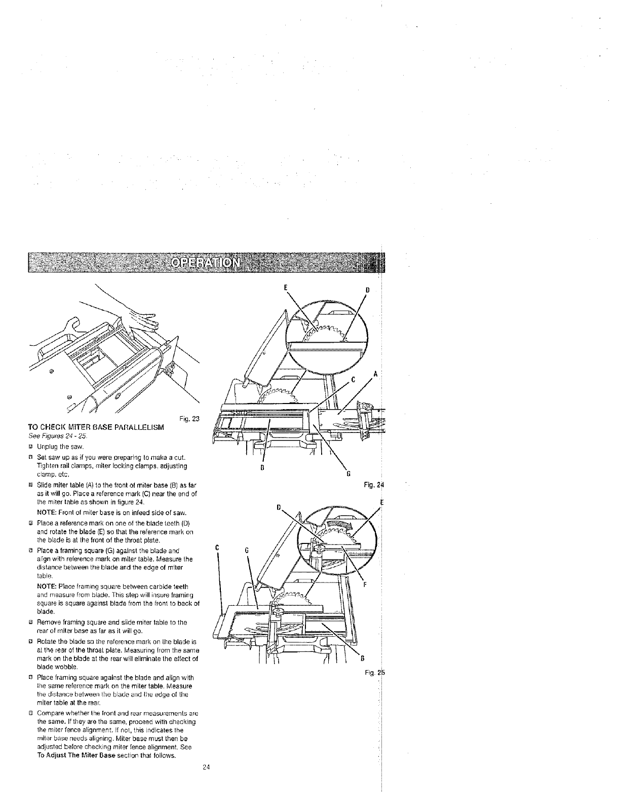
Fig. 23
TO CI-IEOK MITER BASE PARALLELISM
See Figures 24 -25.
_a Unplug the saw.
B Set saw up as if you were preparing to make a cut.
Tighten rail ciamps, miter locking clamps, adjusting
clamp, etc,
Slide miter table (A) to the front of miter base (B) as far
as it will go. Place a reference mark (C) near the and of
the miter table as shov,,n in figure 24,
NOTE: Front of miter base is on infeed side of saw.
e Place a reference mark on ane of the blade teeth (D)
and rotate the blade (E) so that the reference mark oll
the blade is at the front of the throat plate.
a Place a framing square (G) against the blade and
align with reference mark on meter table, Measure the
distance betweet_ the blade and the edge of miler
table
NOTE: P]ace framing square between carbide teeth
and measure from blade. This step will inslJre framing
square is square against blade from the flent to back of
blade.
El Remove framing square and slide miter table to the
rear of miter base as far as it will go.
la Rotate the blade so the reference mark on tbe blade is
at the rear of the throat plate. Measuring from the same
mark en the blade at the rear will eliminate the effect of
btade wobble,
a Place framing square against the blade and align with
Ihe same reference mark on the miter table. Measure
_he d&_ance befween [he blade _tnd lhe edge of the
miter table at the rea_:
[3 Compare whether the Ironl and rear measurements are
the same. if they are the same, proceed with checking
the miler fence alignment. If not, this indicates the
miter base needs aligning. Miter base must then be
adjusted before checking miter fence alignment, See
To Adjust The Miter Base section that follows.
24
Fig,241
IE
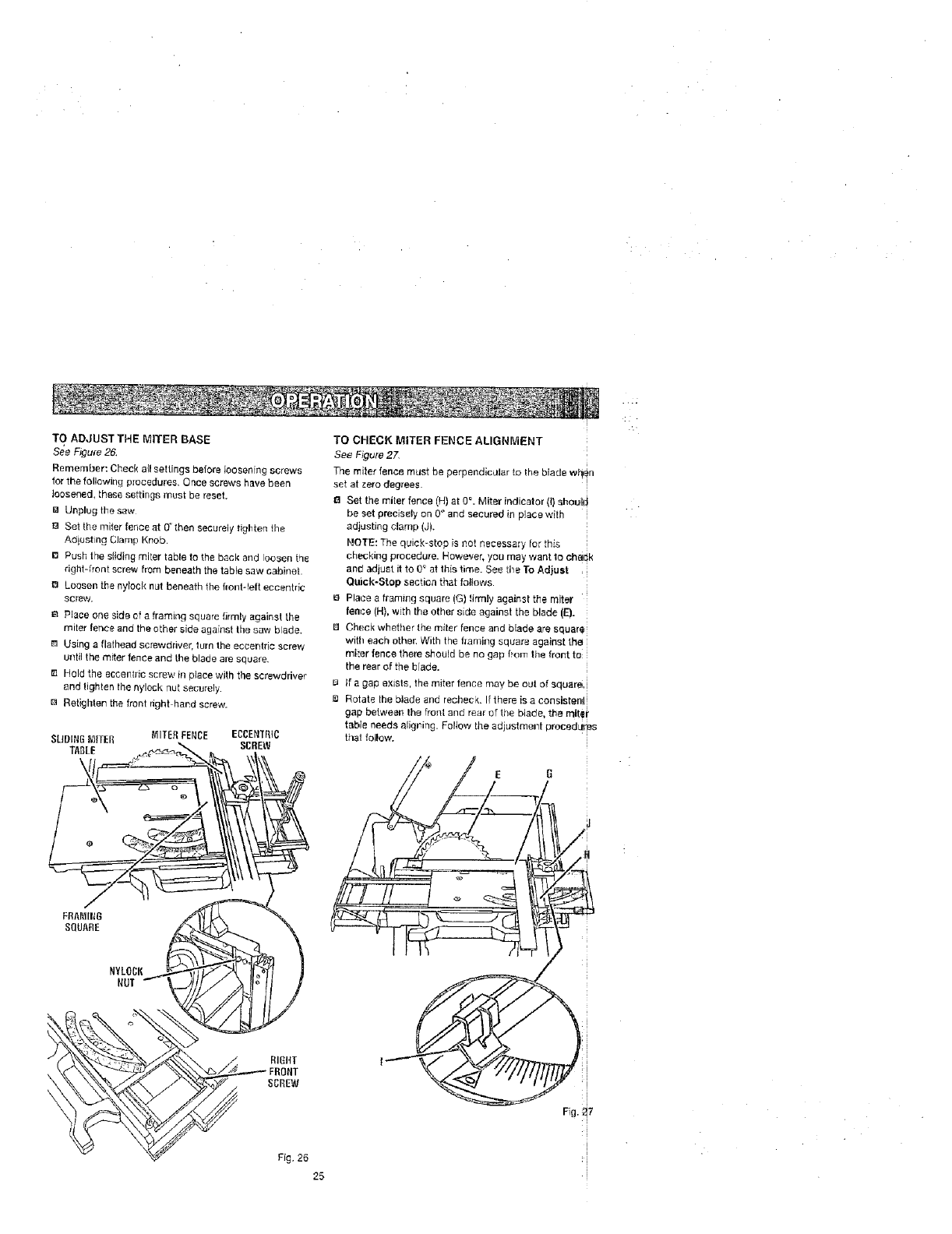
TOADJUSTTHEMITERBASE
See Figure 26.
Remember: Check a{I settings before loosening screws
for the following p:ocedures, Once screws have been
loosened, these settings must be reset.
_1 Unplug tits saw
O Sel the miter fence at O' then securely tighten the
Aaiusting Clarn_ Knob,
[] Push the stiding miter table te the back and loosen the
right-front screw from beneath the table saw cabinet.
LoOsen the ny_ock Nut beneath the f_m_t-le|t eocent_k;
screw.
8 Place one side of a framing square firmly against the
miter fer_ce and the ether side against the saw blade.
m Using s flalhead scnewdriver, turn the eccentric screw
ulltil the miter fence and the blade are square
Hold the eccentric screw in place wilh the screwdriver
and tighten the nylock nut securely
m Retighten the front right hand screw.
SLIDINGnITER MITERFENCE ECCENTR{C
SCREW
TABLE
TO CHECK MITER FENCE ALIGNMENT
See Figure 27,
The miter fence must be perpendic_llar to the blade w_!in
set at zero degrees.
O Set the miter fence (H) at 0 °. Miter indicator (I) shoulid
be set precisely on 0° and secured in place with
adjusting clamp (J).
NOTE'. The quick*stop is not necessary for this
checking procedure. However, you may want to cbedk
and adjust it to 0 _ at this time. See the To Adjust ,
Quick-Stop sectisn that follows.
e Place a framing square (G) !Jrmly against the miter
fence (H), with the other side against the blade (E).
[] Check whether the miter fence and blade are square
with each other. With the trarning square against the
relier fence there should be no gap from the front to
the rear of the brads.
B g a gap exists, the miter fence may be out of square, i
Rotate the blade and rechec £ If there is a consistelll j
gap between the froI_t and rear of the blade, the miter
table needs aligning. Follow the adjustment prooedurbs
that follow.
RIGHT
FRONT
SCREW
25
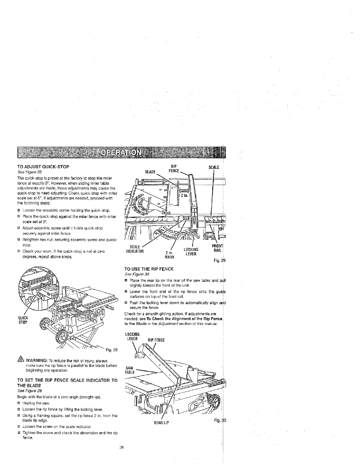
TO ADJUST QUICK-STOP
See Figure 28
The quick-stop is preset at the factory to stop the miter
fence at exactly 0°, However, when sliding miter table
adluslments are made, these adjustments may cause the
quick-stop to need adjusting. Ci_eck quick{ stop with miter
scale set at 0_,If adjustments are needed, proceed with
lhe folIowing steps:
B Loosen the eccentric screw holding the quick stop.
B Place the quick-stop against the miter fence with miter
scale set at 0°.
B Adjust eccentric screw unli] it holds quick-stop
securely againsl miter fer_ce.
g Retighten he× nut, securing eccentric screw and quick-
stop.
B Check your work. If the quick-stop is not at zero
degrees, repeat above steps.
QUICK
STOP
Fig. 28
_ WARNING: To reduce the risk of injury, always
make sure the rip fence is parallel to the blade before
beginning any operation.
TO SET THE RIP FENCE SCALE INDICATOR TO
THE BLADE
See Figure 29.
Begin with the blade at a zero angle (straight up).
n Unplug the saw.
Loosen the rip fence by lifting the locking lever.
Using a framing square, set the rip fence 2 in. from the
blade tip edge.
Loosen the screw on lhe scale indicator.
Tighten the sclew and check the dimension arid the rip
fence.
RIP
BLADE FENCE
SCALE/ /LOCKING
INBICAI'0fl 2in. LEVER
MARl(
SCALE
FBONTi
RAIL
I
Fig. _9
TO USE THE RiP FENCE
See Figure 30.
BPtaee the rear lip on [he rear of the sew table and p!ill
slightly toward the front of the unit. i
i
B Lower the front end ot the rip fence onto the gul_ e
surfaces on top of the front rail.
BPush the Iocldnglever down to automatically align alid
secure the fence.
Check for a smooth gliding action. If adjustments are ,
needed, see To Check tire Alignment of the Rip Fence
to the Blade in the Adjustment section of this manual :
LOCI[IBG
LEVER RIP FENCE
REARLIP Fig,l:}O
26
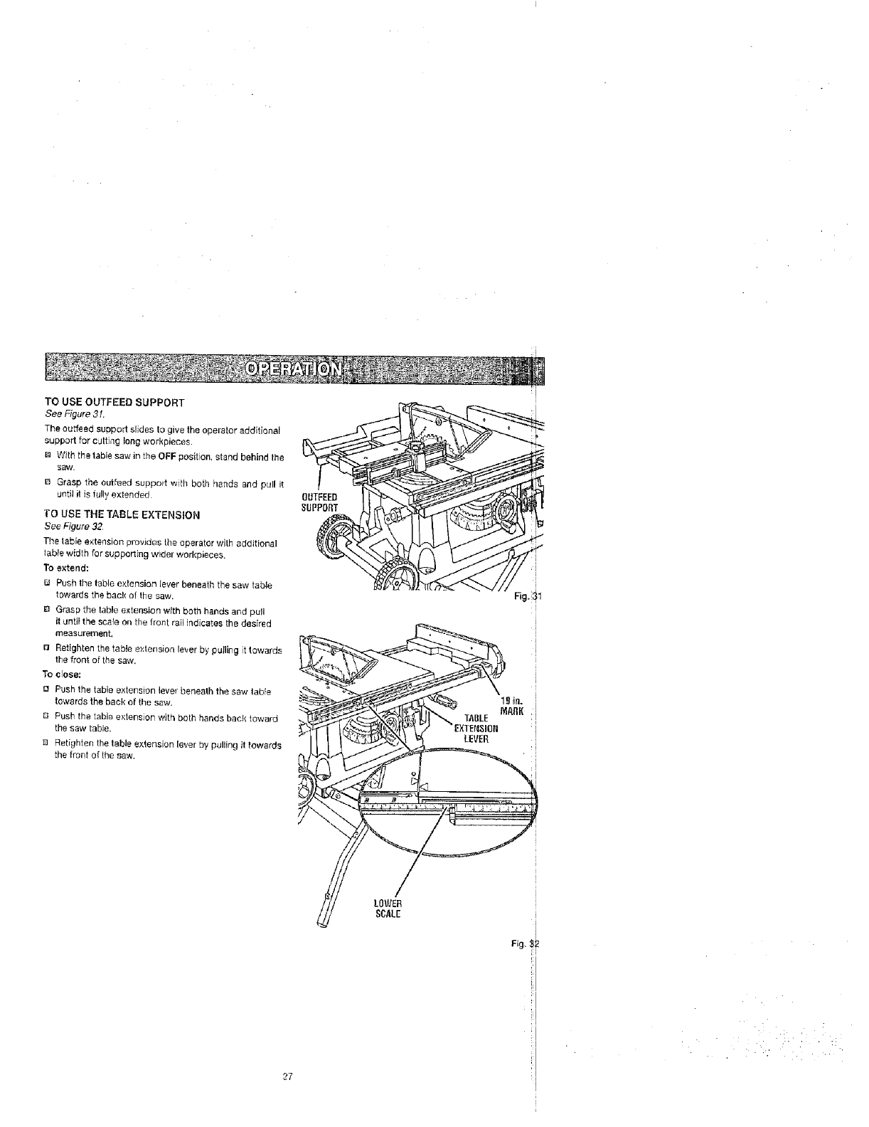
TO USE OUTFEED SUPPORT
See Figure 31.
The ouLffeedsuopod slides to give the operator additional
support for cutting long workpieces.
m With the table saw in the OFF position, stand behind the
saw.
13 Grasp the outfeed suppod with both hands and pull it
ur_t_lit is _ulb]extended
TO USE THE TABLE EXTENSION
See Figure 32
Tile table extension provides the operator with additional
table width for supporting wider workpieces.
To e_;ter_d:
FJ Push the table extension lever beneath the saw table
rewards the back o_ the saw.
B Grasp the table extension with both hands al3dpull
it until the scale on the lront rail indicates the desired
measurement.
o Retighten the tab!e extension lever by pulling it towards
the front of the saw.
To close:
Push the table extension lever beneath the saw table
towards the back of the saw,
Q Push the table e/derision with both hands beck toward
the saw table.
Retighten the _able extension le,_e_by pu_lle9 it towards
the front of the saw+
LOWER
SCALE
Fig. ;!1
LEVER
27 ]
I
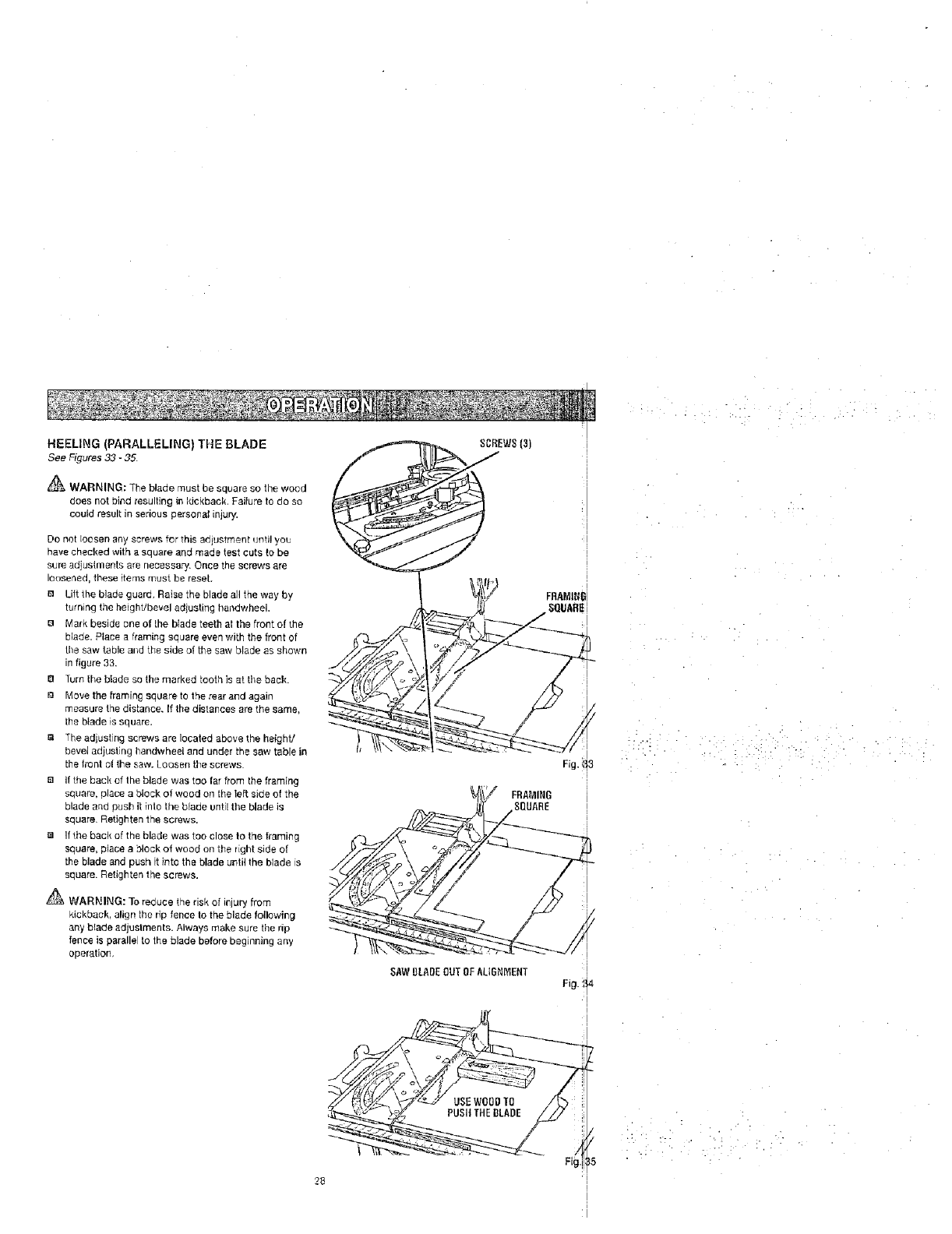
HEELING (PARALLELING) THE BLADE
See Figures33 -35.
_'_ WARNING: The blade must be square so the wood
does not bind resulting in kickback, Failure to do so
could result in serious personal injury.
Do not loosen any screws for 1his adjustment uf_ti!yot_
have checked with a square and made test cuts to be
sure adjustments are necessary. Once the screws are
loosened, these items must be reset
B Lift the blade guard. Raise the blade all the way by
turning the height/bevel adjusting handwheek
B Mark beside one of the btade teeth at the front of the
blade. Place a framing square even with the front of
the saw table and the side of the saw blade as shown
in figure 33.
B Turn the blade so the marked tooth is at the bacl<.
Move the framing square to the rear and again
measure the distance. If the distances ere the same,
the blade is square.
m The adjusting screws are located above the heighV
bevel adjusting handwheel end under the sa',v table in
the front of the saw. Lousen the screws•
B If the back of the blade was too far from the framing
square, place a block of wood on the left side of the
blade and bush it inlo the blade until the blade is
square. Retighten the screws.
If the back of the blade was too close to the framing
square, place a block of wood on the right side of
the blade and push [tinto the blade until the blade is
square. Retighten the screws.
_V[tARNING: To re_ducethe risk of injury from
kickback, align the rip fence to the blade following
any blade adjustments. Always make sure the rip
fence is parallel to the blade before beginning any
operation,
SAWBLADEOUTDEALtQNMENT
FRAMItJ6
SQUARE
Fig.!t4
28
PUSHTHEDLADE
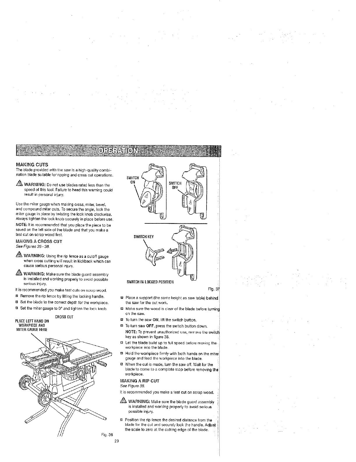
MAKING CUTS
The blade provided with lhe saw is a high-quaiity combi-
nation blade suitable for ripping and cross cut operations.
_ WARNING: Do not use blades rated tess than the
speed of this tool. Failure to heed this warning could
result in personal il,iury.
Use the miter gauge when making cross, miter, bevel
and compound miter outs. To secure the angle, lock the
miter gauge in place by twisting the leak knob clockwise.
Always tighten the tack knob securely in place before use.
NOTE: It is recommended that you place the piece to be
ea,_edon the _eftaide o{ the blade and that you make e
test cut on scrap wood first.
MAKING A CROSS CUT
See Figures 36 -3&
WARNING: Using the rip fence as a cutoff gauge
when cross cuging will result in kickback which can
cause serious personal injury.
WARNING; Make sure the blade guard assembly
is installed and working properly to avoid possible
serious injury,
It is recommended you make teat cuts on scrap woad.
lu Remove the np fence by lifting the Ioekirg handle.
Set Ihe blade to the correct depth for the workpiece.
m Set the miter gauge to 0° and tighten the bck knob
CROS_ CUT
PLACELEFT}lANDON
W_BI|{P{ECEANB
MITEI_GAUGEHERE
SWITCH,KEY
SWITCHIN LOCREDPOSITION
Flg. 3i
UPlace a support (the same height as saw table) behind
the saw for the cut work.
13 Make sure the wood is clear of the blade before turnini
cn the saw. I
B To turn the saw ON, lift the switch button. !
To turn saw OFF, press the switch button dovvn.
NOTE: To prevent unauthorized usa, remove the switch
key as shown in figure 38. I
8 Let the blade build up to full speed be ore moving the
warkpiece into the blade.
I
0 Hold the workpiece firmly with both hands on the mitai I
gauge arld feed tl7eworkplace into the blade,
BWhen the outis made, turn the saw off Wait for the :
blade to come to a complete slop before removing the
workpieee.
MAI{ING ARiP CUT
See Figure 38.
It is recommer_ded you make a test cut on scrap wood,
WARNING; 'vlake sure the blade guard assembly
is installed and working properly to avoid seriou_
possible injury.
E_ Position the rip fence the desired distance from the
blade for the cut and securely lock the handle. Adios i
the scale to zero at the cutting edge at the blade.
Fig. 36
2g
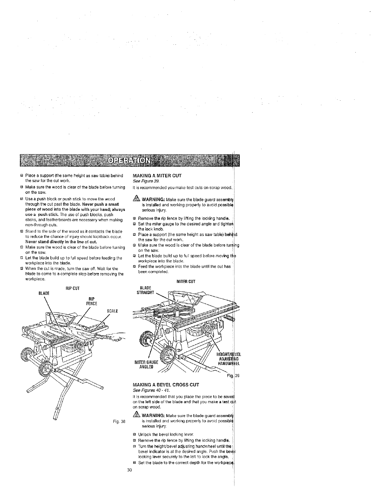
Placeasupport(thesameheightassawtable)behind
thesawforthecutwork,
MakesurethewoodIscIearofthebladebeforeturning
onthesaw.
Useapushblockorpushsticktomovethewood
throughthecutpasttheblade.Neverpushasmall
pieceofweedintothebladewithyourhand;always
useapushstick.Theuseofpushblocks,push
sticks,andfeatherboardsarenecessarywhenmaking
non-throughcuts.
BStarldtothesideofIhewoodasitcontactstheblade
toreducethechanceofinjuryshouldkickbackoccur.
Neverstanddirectlyinthelineofcut.
Makesurethewoodisclearofthebladebeforefuming
onthesaw.
[3Letthebladebuildup to fult speed before feeding the
workplace into the blade.
When the cut is made, turn the saw off. Wait for the
blade to come to a complete stop before removing the
workplace.
RiP CUT
BLADE
RIP
FENCE
MAKING A MITER CUT
See Figure 39. I
It is recommended you make test cuts on scrap wood. =
WARNING; Make sure the blade guard assembly _
is installed and woddng properly to avoid poasible
serious injury.
Remove the rip fence by lifting the locking handle.
ia Set the miter gauge to the desired angle arid tigt'rle_
the lock knob.
B Place a support (the same height as saw table}, behi
the saw for the cut work.
Q Make sure the wood is clear of the blade before tLurl
on the saw.
la Let the Made build up to full speed before moving fl
workpieee into tile blade.
13 Feed the workplace into the blade until the cut has
been completed.
MILERCUT
8LADE
STRAIGHT_
d
_g
Fig. 38
Ig
MITERGAUGE IEL
ANGLED
_g,3g
MAKING A BEVEL CROSS CUT
See Figures 40- 41.
It is recommended that you place the piece to be save,
on the left side of the blade and that you make a test c
on scrap wood.
_ WARNING: Make sure the blade guard asserqbl,
is installed and werldng properly to avoid peesibl_
serious injury.
F3 Unlock the bevel locking lever.
El Remove the rip fence by lifting the locking handle
B Turn the height/bevel adjusting handwheel unti_ the
be_,'el indicalor is at the desired angie. Push the be_
looking Fever securely to the left to lock the an#le_
Set the blade to the correct depth for the workpie_
30
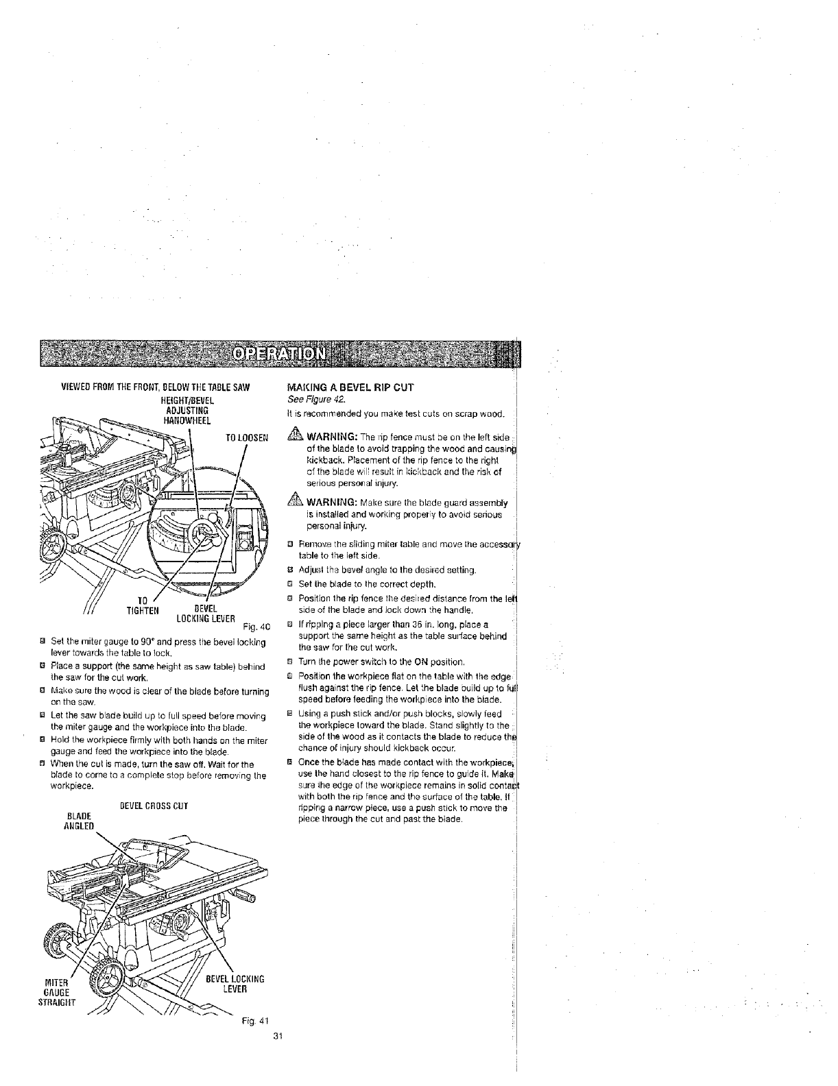
VIEWEDFROr_THE FRONT,BELOWTHETABLESAW
HEIGHTIBEVEL
ADJUSTING
HANOWHEEL
TOLOOSEN
10
TIGtiTEN BEVEL
LOCKINGLEVER Fig. 40
_] Set the miter gauge to 90 ° and press the bevel locking
lever towards the table to lock,
B Place a support (the same height as saw table) behind
the saw for tire cut work.
Make sure the wood is clear of the blade before turning
on the saw.
Let the saw blade build up to full speed before moving
the miter gauge and the workpiece into the blade.
El Hold the workpiece firmly with both hands on the miter
gauge and feed the workpiece into the blade
When the cut is made, turn the saw off, Wait for the
blade to come to a complete stop before removing lhe
workpiece.
DEVELCROSS CUT
BLADE
ANGLED
BEVELLOCKING
LEVER
MAKING A BEVEL RiP CUT i
See Figure 42. I
It is recommended you make test cuts oil scrap wood. I
I
WARNING: The np fence must oe on the let. side I
of the blade to avoid trapping the wood and c_usinil
kickback. PIacement of the rip fence to the righl I
of the blade will result in kickback and the risk of
seedus personal inlury.
_ WARNING: Make sure the blade guard assembly
is installed and working proper y to avoid serious
personal injury.
,pN Remove ,he sliding miter table and move the accessoi
table to the left side.
Adjust the bevel angle to the desired setting.
D Set the blade to Ihe correct depth,
Position the rip fence the desired distance from the lei'
side of the blade and lock down the handle,
Ifripping a piece larger than 36 in. long, place a
support the same height as the table sutfface behind i
the sew for lhe cut work.
r_ Turn lhe power switch to the ON position,
Position the workpiece flat on the table with tt]e edge
flush against the rip fence. Let the blade ouild up to full
speed before feeding the workpiece into the blade.
Using a push stick and!or push blocks, slowly feed
the workpiece toward the blade. Stand slightly t_ the
side of the wood as it contacts the blade to reduce th
chance of injury should kickback occur.
Once the blade has made contact with the workpieee_ I
use the hand closest to the rip fence to guide it. Mak_
sJre ihe edge of the workpiece remains in solid conta_;
with boh he rp once and the surface of he tab e. t
ripping a narrcw piece, use a push stick to move the
piece through the cut and past the biade.
Fig 41
31
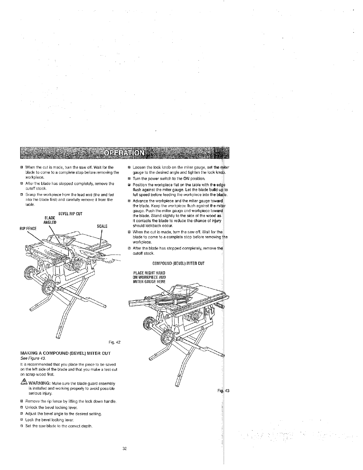
When the cut is made, turn the saw off. Wait Ior the
blade to come to a complete stop be[ore _emoving tire
workplace.
After the blade has stopped completely, remove the
cutoff stGck.
0 Grasp Ihe workplace from the lead end (the end fed
!/1o lhe blade first) and carefully remove it from the
table.
BEVELRIP CUT
BLADE
ANGLED
RiP FENCE
la Loosen tile lock knob on the miler gauge, sel the
gauge to the desired angle and tighten the lock km_
m Turn the power switch to the ON position.
B Position the workplace flat on the table with the ed
flush against the miter gauge. Let the blade build u
full speed before feeding Ihe workpiece into the bh
BAdvance the workpieee a_d the miter gauge tower
the b!ade. Keep the workpiece flush against the mit
gauge. Push the miter gauge and wod_piece towar_
the blade. Stand slightly to the side of the wood as
it contacts the blade to reduce the chance of injury
should kickback occur.
o When the cut is made, turn the saw off. Wait for the
blade 1o come to a complete stop before removing
workplace.
o After the blade has stopped completely, remove th<
cutoff stock.
CO[VIPOUt,tD(BEVEL)PI'IITERCUT
PLACERIGHTHAND
ONWIIRKPIECEAilg
MITERG/_UGEHERE
tar
Fig. 42
MAKING ACOMPOUND (BEVEL} MITER OUT
SeeFigure43.
It is recommended that you place the piece to be saved
on the left side of the blade and that you make ates[ cut
on scrap wood first.
_ WARNING: Make sure the blade guard assembly
is installed and working properly to avoid possible
serious injury.
8 Remove the rip fence by I]fting the lock down handle.
El Unlock the bevel Iocl{ing lever.
Adjust the bevel angle to the desired setting.
E_ LocI_ the bevel locking leven
o Set the saw blade to the correct deplh.
32
: " : ;- '7"
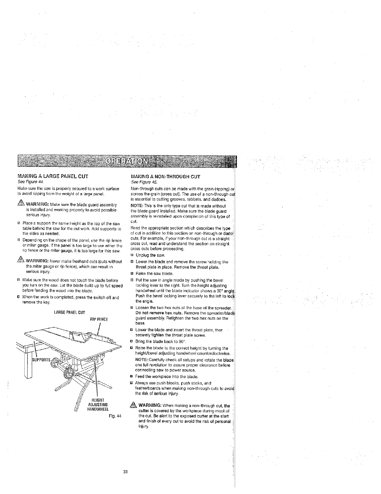
MAKING A LARGE PANEL CUT
See Figure 44.
Make sure the saw is p_opetly secured ta a work surface
to avoid lipping from the weight of a large panel.
WARNING: Make sure the blade guard assembly
is installed and working propedy to avoid possible
serious injury.
[] Place a support the same height as the lop of the saw
table behind the saw for the cut work Add supports to
the sides as needed.
B Depending on the shape of the panel, use the dp fence
or miter gauge. If the ;)ansi is too large to use either the
rip fence or the miter gauge, it is too {arge for this saw,
_"_ WARNING: Never make freehand cuts (cuts without
the miter gauge or rip fence), which can result in
serious injury.
B Make sure the wood does not touch the blade before
you turn on tile saw. Let the blade build up to full speed
before feeding the wood into the blade.
a When the work is completed, press the switch oft and
remove the key.
LARGEPANELCUT
RIP FENCE
HEIGHT
ADJUS11NG
HANBWHEEL
Fig. 44
33
MAKING ANON-THROUGH CUT
See Figure 45,
Non-through cuts can be made with the grain (ripping) _1
across the grain (cross cut}, The use of a non-through cU
is essential to cutling grooves, rabbets, and dadoes.
NOTE: This is the only type cut that is made without
the blade guard installed, Make sure the blade guard
assenqbly is reinstalled upoo completion of this type of
cuL
Read the appropriate section which describes the type
of cut in addilioo to this section on non-through or dado
cuts. For example, if your non-through cut is a straight
cross cut, read and understand the sectior_ on straight
cross cuts before proceeding.
a Unplug the saw,
El Lower the blade and remove the screw he{ding the
throat p_ate in place. Remove the throat plate.
ra Raise the saw blade.
B Put the saw in angle mode by pushing the bevel
Tooklng lever to the right. Turn the height adjusting
handwheel until the blade indicator shows a 30 _anglf
Push the bevel locking lever securely to the left I0 lee
the angle.
u Loosen the two hex nuts at the base o| the spreader.
Do not remove hex nuts. Remove the spreadedblad
guard assembly. Retighten the two hex sots on lhe
base•
B Lower the blade and insert the throat plate, thor- •
securely tighten the throat plate screw.
e Bring the blade backto 90 _.
g Raise the blade to the correct height by turning the
height,q0eve{adjusting handwheel counterclockwise,
NOTE: Carefully check oil setups and rotate the blade
one lull revolution to assure proper clearance before
connecting saw to power source.
[] Feed the workpiece into the blade.
Always use push blocks, push sticks, and
featherboards when making non-through cuts to avok
the dak of serious injury.
_WARNING: When making a non=through cut, the
cutter is covered by the workpiece during most o|
the cut. Be alert to the exposed cutter at the start
and finish of every cut to avoid the risk of persona!
injery_
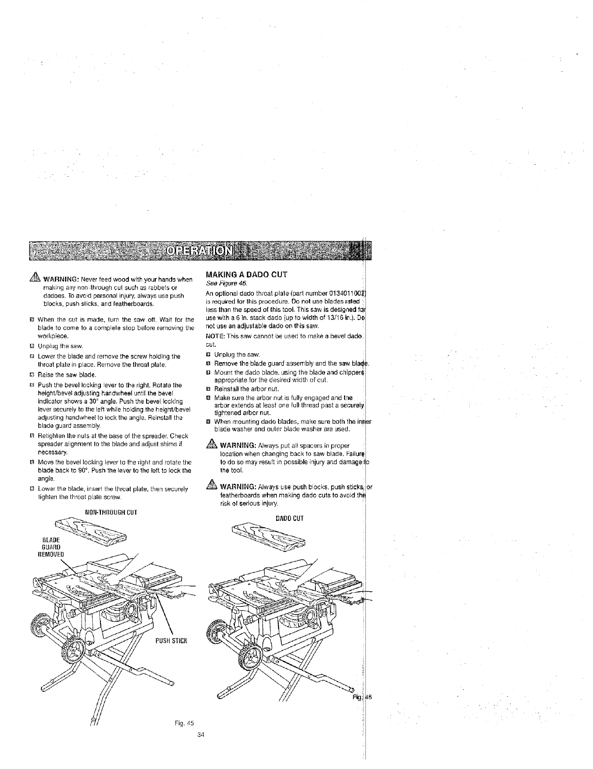
,& WARNING: Never feed wood with your hands when
making any nan through cut such as rabbets or
dadoes. To avoid personal iniury, always use push
blocks, push slicks, and featherboards.
When the cut is made. turn the saw off. Wait for the
blade to come to a complele stop before removing tile
workaiece.
13 Unplug the saw.
Lower the blade and remove the screw holding the
Ihroat prate in place. Remove the throat plate,
I_ Raise the saw blade.
D Push the bevel lacking lever to the right. Rotate the
height/bevel adjusting handwheel until the bevel
indicator shows a 30 ° angle. Push the bevel locking
lever securely to the [eft while holding the height/bevel
adjusting handwhee[ to lock the angle. Reinstall the
blade guard assembly.
n Retighten the nuts at the base of the spreader. Check
spreader alignment lo the blade and adjust shims if
necessary.
B Move the bevel locking lever to the right and rotate the
blade back to gOt . Push the lever to the left to lock the
angle.
D Lower the blade, insan: the throat plate, then securely
tighten the throat pJate screw
MAKING A DADO CUT
See _Tgute 46. I
As optional dado throat plate (part number 0134011_!
is requi_ed for tills procedure. Do not use blades Jalee
less than the speed of this tool, This saw is designed fa_
use with a 6 in. stack dado (up to width of 13/16 i_q.). D_
not use an adjustable dado on this saw, :i
NOTE: This saw cannot be used to make abevel dade I
cut. Ii
I
°Unplug the saw.
B Remove the blade guard assembly and the saw bl_ ,
I:1 Mount the dado blade, LISing the blade and chipper@|
appropriate for the desired width of cut. [
e Reinstall the arbor nut. |
B Make sure the arbor nut is fully engaged and the 1
arbor extends at least one full thread past a securely
tightened arbor nut. |
B When mounting dado blades, make sure both the ina#r
blade washer and outer blade washer are used, |
A i
WARNING: Always put alI spacers in proper I
blade, Feilur_
location when changing back to saw and damageit_
to do so may result in possible injury
the tool. |
WARNING: Always use push blocks, push sticks or
featherbeards when making dado cuts to avoid th
dsk of serious injury.
DADO CUT
PUSHS]ICK
Fig. 45
34
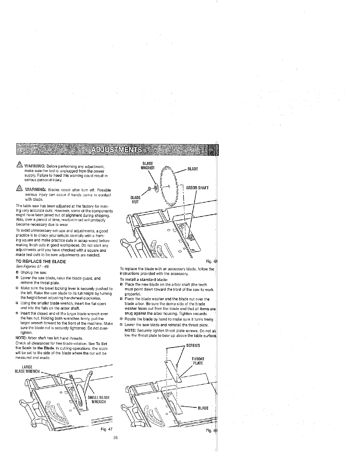
_ WARNING: Before performing any adjustment,
make sure the fool is unplugged from the power
supply. Faiture to heed this warning could result in
serious personal injury.
_ WARNING: Blades coast after turn off. Possible
serious injury can occur if hands come m conlac!
with blade.
The fable saw has been adjusted at the factory for mak-
Irg very accurate cuts. However, some ol the componenfs
might have been jarred out of alignment during shipping.
Also, over a period of time, readjustmen[ will probably
become necessary due to wear.
To avoid unnecessary set-ups arid adiL,[stments, a good
practice is to check your setups carefully with a tram-
ing square and make practice cuts in scrap wood before
making linish cuts in good worl_pieces. Do not start any
adjusfments until you have checked with a square and
made test cuts to be sure adjustments are needed.
TO REPLACE THE BLADE
See Figures 47 -49.
DUnplug the saw.
13 Lower the saw blade, raise the blade guard, and
remove the throat plafe.
Make sure the bevel locking lever issecurely pushed fo
the left. Raise the saw blade to its full height by turning
the height/bevel adjusting handwheel clockwise.
I_ Using the Smaller blade wrench, insert the fiat open
end into the flats an the arbor shaft.
B Insert the closed end of the larger blade wrench over
the hex nut. Holding both wrenches firmly, pull the
larger wrench forward to the frort of the machine. Make
sure the blade nut is securely tightened. Do not over-
tighten.
NOTE= Arbor shaft has left hand threads.
Check al! clearances for free blade rotation. See To Set
the ScaIe to the Blade. 1,1cutting operations, the scale
will be sef to the side of the blade where the cut will be
measured and made.
LARGE _-,------
BLADEW[iENCH.__....___ i_J
_U_ Fig4/7
ABBOR SHAFT ;1
To replace the blade with an accessory blade, follow the
instructions provided with the accessory.
To install a standard blade:
e Place tile new blade on the arbor shaft (the leefh
must point down toward fl'_etfont of the say,' to,_o,4_
properly).
13 Place the blade washer and the blade nut over the
blade arbor. Be sure the dome side of the blade
washer faces out from the biade end that all items are
snug against the arbor housing, Tighten securely.
e Rotate tire blade by hand to make sure it turns freety.
8 Lower the saw blade and reinsta{I the throat plate,
NOTE: Securely tighten throat plate screws, Do nor eli
low Ihe lhroal plate to bow up above the table surfacal.
TItFIOA"I"
PLATE
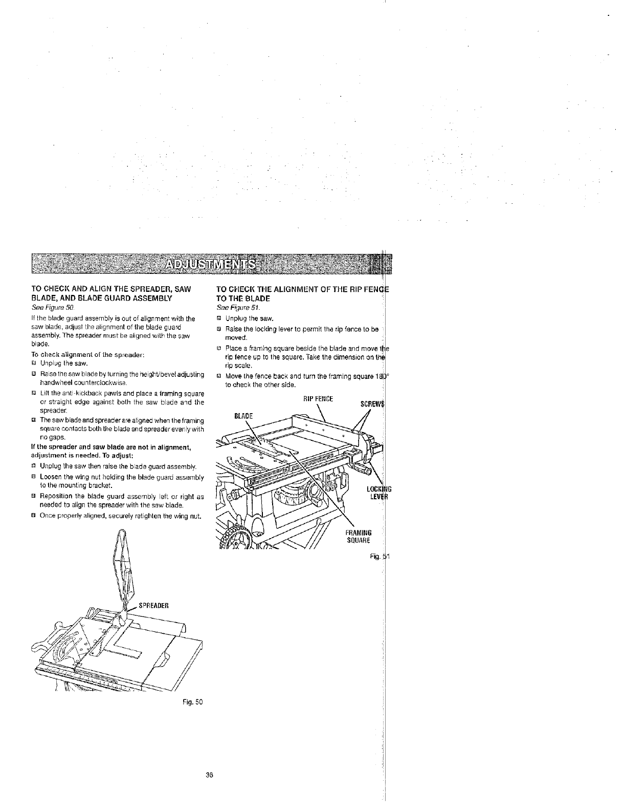
TO CHECK AND ALIGN THE SPREADER, SAW
BLADE, AND BLADE GUARD ASSEMBLY
See Figure 50
If the blade guard assembly is out of alignment with the
saw blade, adjust the alignment of the blade g[Jard
assembly. The spreader must be aligned with the saw
blade.
To check allgnmm_t of the spreader:
e UnpJug Ihe saw.
[] Raiset_esawbladebyturningtheheight/beve[adjusting
handwheel counterclockwise.
D Lift the anti-kickback pawls and place a lraming sauare
or straight edge against both the saw blade and the
spreader.
_] Thesaw blade and spreader are aligned when the framing
square contacts both the blade and spreader evenly with
no gaps.
If the spreader and saw blade are not in alignment,
adjustment is needed. To adjust:
_1 Unplug the saw then raise the blade guard assembly.
e Loosen the wing nut holding the blade guard assembly
to the mounting bracket.
e Repesition the blade guard assembly left or right as
needed to align the spreader with the saw blade.
El Once properly aligned, securely retighten the wing nut.
TO CHECK THE ALIGNMENT OF THE RIP FEN_
TO THE BLADE
See F_?ure 51.
Unplug the saw.
e Raise the locking lever to permit the rip fence to be
moved.
Pface a ,_amiag square beside the blade and move t
rip fence up to the square Take the d mens on on th,
rip scale.
Move the fence back and turn the framing square 18
to check the other side.
RIP FENCE SCREW_
BLAOE
Fig. 50
3B
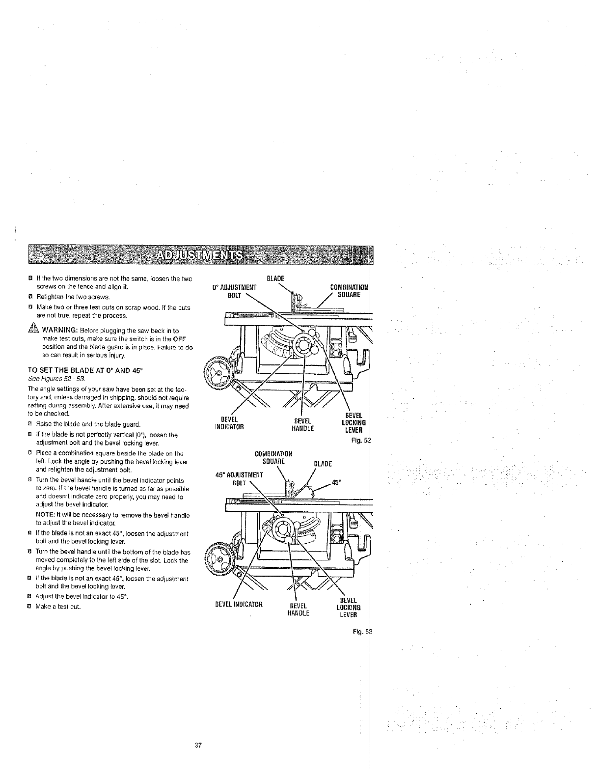
B If the two dimensions are not the same, loosen the two
screws on the fence and align it.
B Retighten the two screws.
8 Make two or three test cuts on scrap wood. If the cuts
are trot true, repeat the process.
_ WARNING: Before plugging the saw back [n to
make Lest cuts, make sure the switch is in the OFF
position and the blade guard is in place, Failure te do
so can result in serious injury.
TO SET THE BLADE AT 0 °AND 45 °
See Figures 52 5&
The angle settings of your saw have been set at the fac-
tory and, unless damaged in shipping, should not require
setting during assen_Ny. After extensive use, it may need
to be checked.
Raise the blade and the blade guard.
e If the blade is not perfectly vertical (0'), Ioesen the
adjustment bolt and the bevel locking ]ever,
e Place a combination square beside Ihe blade on fbe
left. Loci( the angle by pushing the bevel locking lever
and retighten the adjustment bolt.
8 Turn the beret handle until the be_rel indicator points
to zero. If the bevel handle is turned as far as possible
and doesn't indicate zero properly, you may need to
adjust fhe bevel indicator.
NOTE: It will be necessary to remove the bevel handle
to adjust the bevel indicator,
a If the blade is not an exact 45 °, loosen the adjustment
boll and the bevel looking lever.
8 Turn the bevel handle unt[r the bottom of file blade has
moved completely to tee left side of the slot. Look the
angle by pushing the bevel locking lever.
B If the blade is not an exact 45 °, loosen the adjustment
bolt and the bevel locking lever.
8 Adjust tie bevel indicator to 45 °.
B Make a test cut.
BLADE
BEVELINDICATOR
_ WARNING: When servicing, use only identical
replacement parts. Use of any other parts may create
a hazard or cause product damage.
_ WARNING: Always wear safety goggles or safety
glasses with side shields during power tool operation
or when blowing dust. If operation is gusty, also wear
a dust mask,
GENERAL
Avoid using solvents when cleaning plastic parts. Most
olaslics are susceptible Io damage from various types of
commercial solvents and may be damaged by their use.
Use clean cloths to remove dirt, dust, oil, grease, etc.
_ WARNING: Do not at any time let brake fluids.
gasoline, petroleum-based products, peFetrating
oils, etc., come in contact with plastic parts.
Chemicals can damage, weaken, or destroy plastic
which may result in serious personal injury.
38
L_ Periodically check all clam
bolts for tightness and condition.
plate is in good condition and in position.
Check the blade guard assornbly.
[] To maintain the table sudaces, fence, and rails,
periodically apply paste wax to them and buff to
provide smooth functioning. To prevent work from
slipping during cutting operation, Do not wax the
working face of the miter fence.
B Protect the blade by cleaning out saw dust from
underneath the table and in the blade teeth. Use a
resin solvent on the blade teeth.
I_ Clean ptastic parts only with a soft damp cloth.
not use any aerosol or petroleum solvents.
LUBRICATION
This saw has been lubricated at the factory prior to ship
rnent. Following exlended use, you should illspec/and
lubricale the following areas to assure smooth operatic!
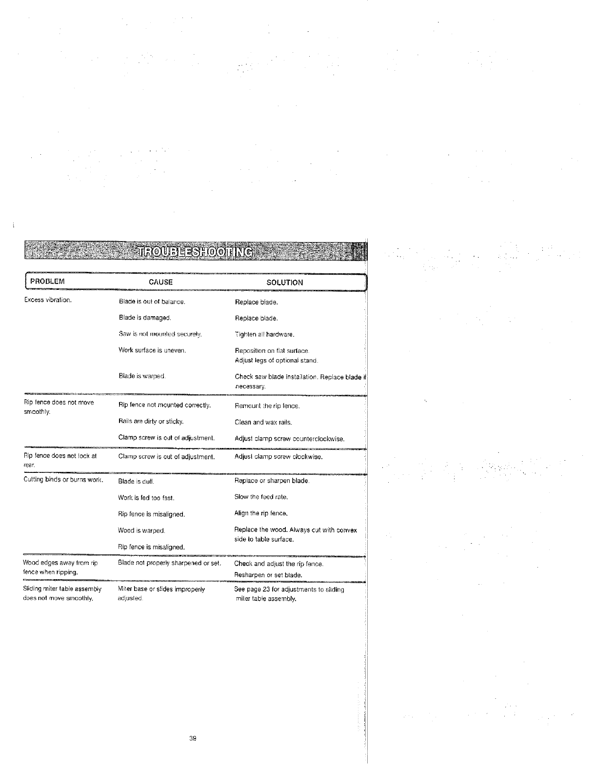
PROBLEM CAUSE SOLUTION
Excess vibration. Blade is out el balarce. Replace blade.
Blade is damaged. Replace blade.
Saw is not mour_led securely. Tighten all hardware.
Work surface is uneven.
Blade is warped
Rip fence does not move Rip fence not mounted correctly.
smoothly.
Rails are dirty, or sticky.
Clamp screw is out of adjustment.
Rip fence does not lock at Clamp screw is out of adjustment.
rear.
Cutting binds or burns weft{. Blade is dull•
Work [s ted too fast.
Rip fence [s rnisaligned.
Wood is warped•
Rip fence is misaligned.
Reposition on fiat SlJdace
Adjusl legs of optional stand
Check saw bJadeinsta latices. Replace blade i
necessary,
Remou_L the rip fence.
Clean and wax rails.
Adjust clamp screw counterclockwise.
Adjust clamp screw clockwise.
Replace or sharpen blade
Slow the feed rate.
Align the rip fence,
Replace the wood. Always out with convex
side Io table surface.
Wood edges away frGm rip Blade not properly sharpened or set. Check and adjust the rip fence.
fence when ripping. Resharpen or set blade.
Sliding miter table assembly ',,4iler base or slides improperly See page 23 for adiustments to sliding
does not move smoothly, adjusled miler table assembly.
39
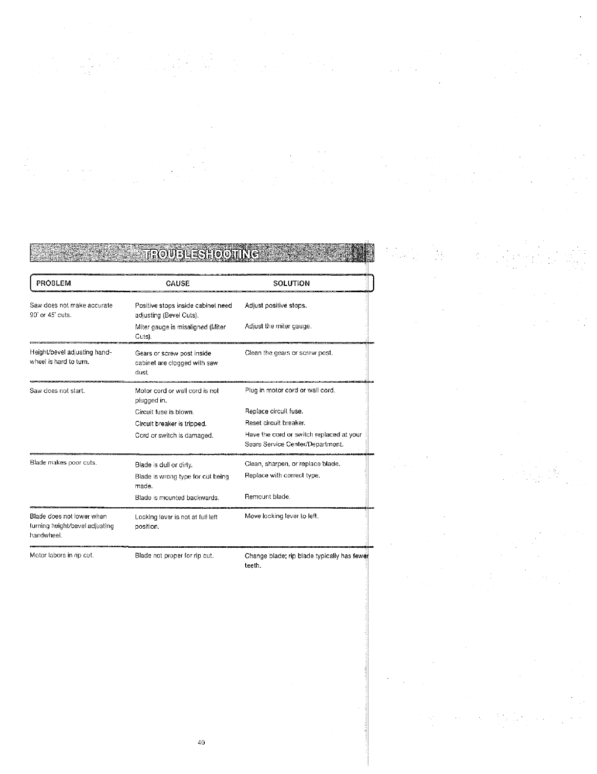
I PROBLEM CAUSE SOLUTION
Sawdoesnotmakeaccurate PositivestopsinsidecabinetneedAdjustpositivestops.
gO'or45'cuts. adjusting(BevelCuts).
Mitergaugeismisaligned(Miter Adjustthemitergauge•
Cuts).
Heighbtbeveladjustinghand- Gearsorscrewpostinside Cleanthegearsorscrewpost.
wheelishardtoturn. cabinetarecloggedwithsaw
dust
SawdoesnotslarL Pluginmotorcordorwallcord.
Blade makes poor cuts
Blade does not lower when
turning height/bevel adjusting
bmTdwheeL
Motor labors in rip cut.
Molor cord or wall cord is not
pklgged in.
Circuit iuse is blown•
Circuit breaker is tripped.
Cord or switch is damaged.
Blade is dutl or didy.
Blade is wrong type for eul being
made.
Blade is mounted backwards.
Locking lever is not at full left
position.
Replace circui[ fuse.
Reset circuit breaker:
Have the cord or switch replaced at your
Sears Sewice CenledDepadment.
J
Clean, sharpen, or replace blade.
Replace with correct type.
Remount blade.
Move locking lever to left.
Blade not proper for rip cut. Change blade; rip blade typically has few_
teeth.
4O
• • • • . . :
•.• .
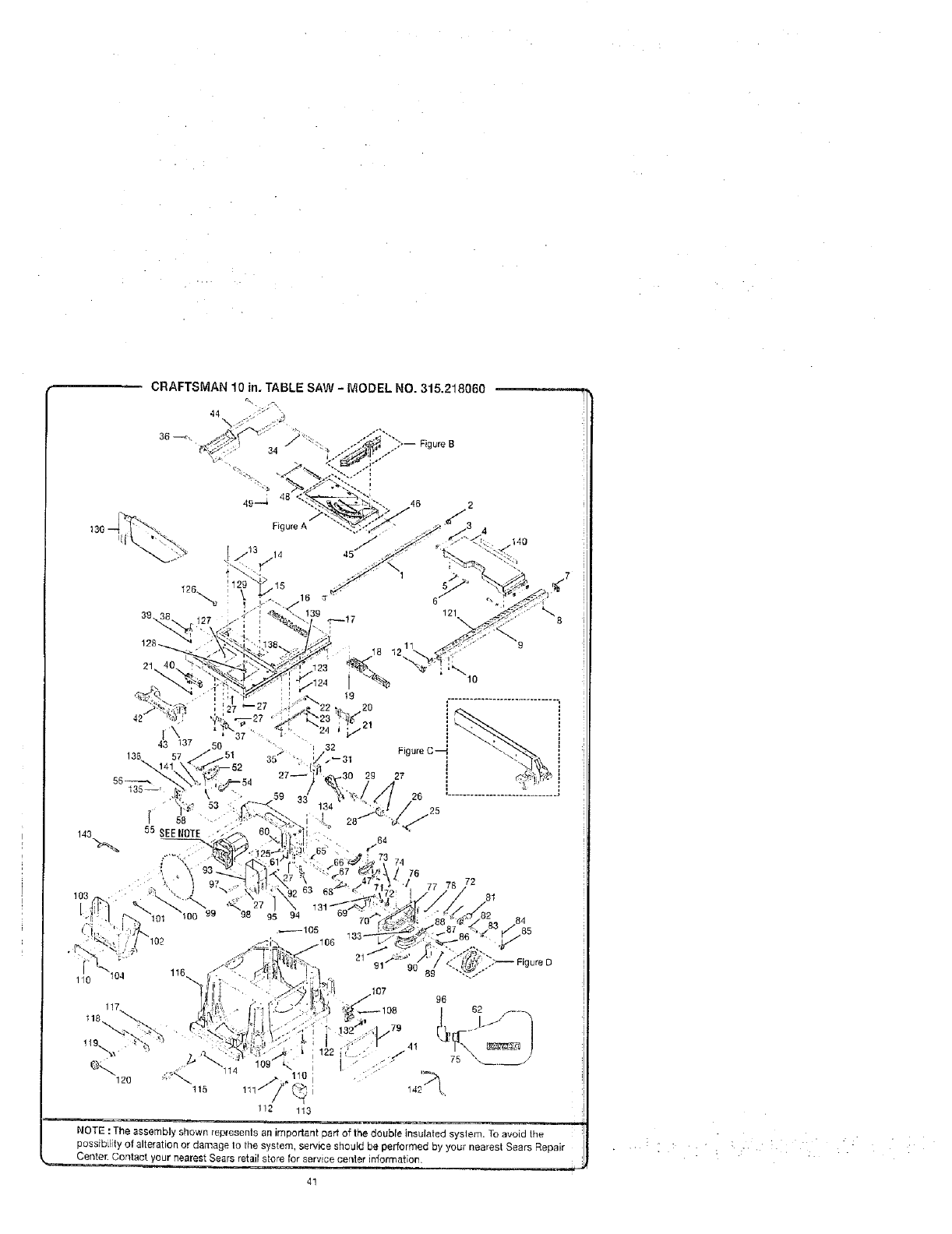
CRAFTSMAN 10 in. TABLE SAW - MODEL NO. 315,218060
_ -'/, . /",:- Figure B
: 48
49--4
Figure A
21
143
94
._105
74
76 72
81
110 104
115
112 113
NOTE :The assembly shown represents an important part of the double insulated syslem. To avoid the
possibility of alteration or damage to the system, service sheuld be performed by your nearest Sears Repair
Center. Contact your nearest Sears retail stere for service cerder information.
4!
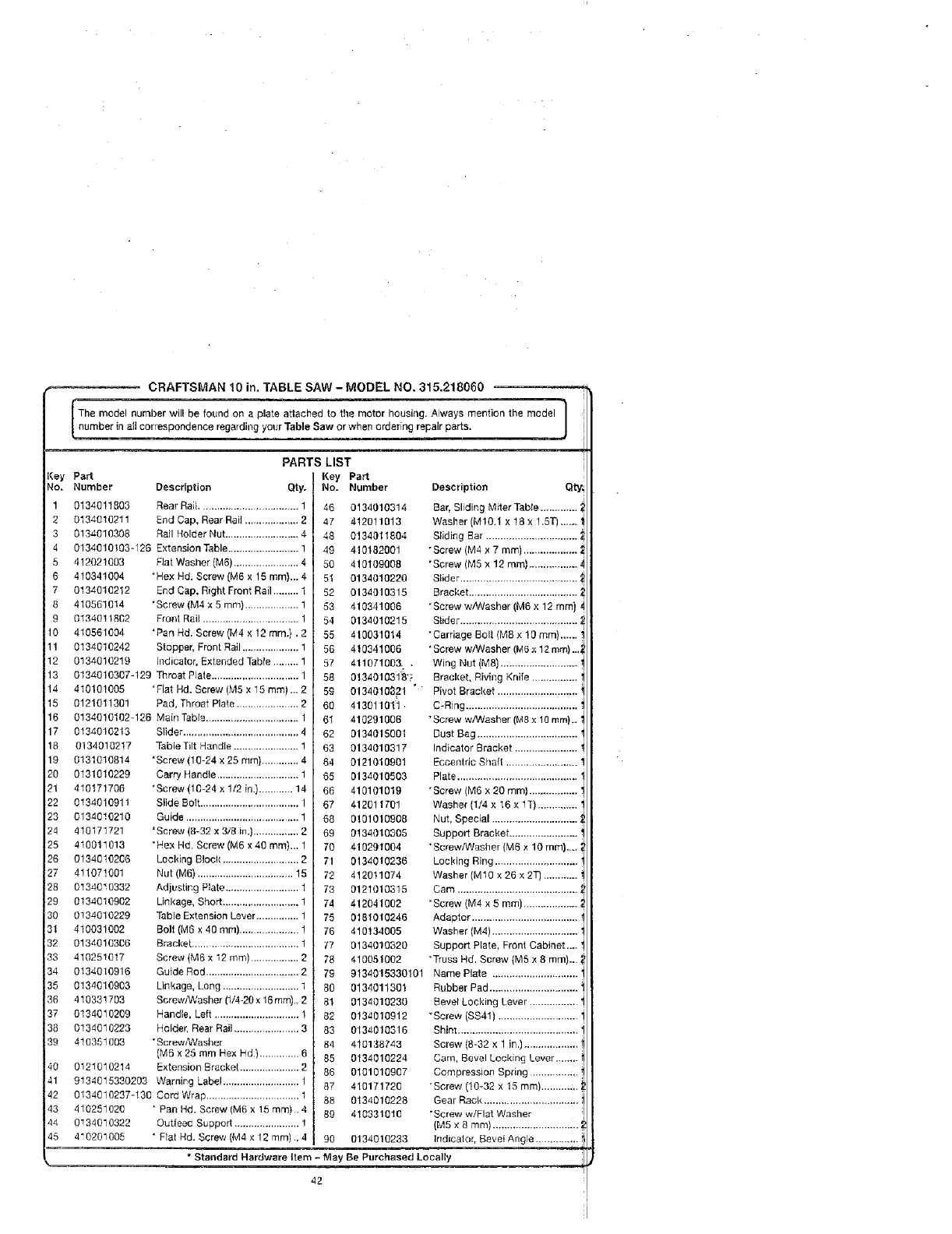
CRAFTSMAN 10 in. TABLE SAW -MODEL NO. 315.218060 l
The model number will be found on a plate attached to the motor housing. Always mention the model
number n a correspondence regatdin 9 your Table Saw or when order ng repa r paris. /
/
(ey PaN
No. Number
1 0134011803
2 0134010211
3 0134010308
4 0134010!03-126
5 412021003
6 410341004
7 0134010212
8 410561014
90134011802
10 410561094
11 0134010242
12 0134810219
13
14
t5
16
17 0134010213
16 0134010217
19 0131010814
20 0131010229
21 410171706
22 0134010911
23 0134010210
24 410171721
25 410011013
26 0134010206
27 411071001
28 0134010332
29 0134010902
30 0134010229
31 410031002
32 0134010306
33 410251017
34 0134010916
35 0134010903
36 410331793
37 0134010209
38 0134010223
39 410351003
40
41
42
43
44
45
PARTS LIST
Description Qty.
Hear Rai;................................... 1
End Cap, Rear Rail ................... 2
Rail Holder Nut.......................... 4
Extension Table ......................... 1
Flat Washer (M6) ....................... 4
+Hex Hd. Screw (M6 x 15 mm),.. 4
End Cap, Right Front Rail ......... 1
"Screw (M4 x 5 ram) ................... 1
Front Rail .................................. 1
*Pan Hd. Screw (M4 x 12 ram.), 2
Stopper. Front Rail.................... 1
Indicator, Extended Table ......... 1
0134010307-129 Throat Plate ............................... 1
410101005 *Flat Hd. Screw (k,15x 15 rnm)... 2 :
0121011301 Pad, Throat Plate ..................... 2
0134010102q26 Main Table ................................. 1
Key PaN
No. Number
46 0134010314
47 412011013
48 0134011804
49 410182001
50 419109008
51 0134010220
52 0134010315
53 410341006
54 0134010215
55 410031014
56 4103,11006
57 41107100& ,
56 013401031_'?
59
60
61
Slider ......................................... 4
Table Tilt Handle ....................... !
'Screw (10-24 x 25 ram) ............. 4
Carry Handle ............................. 1
*Screw (10-24 x 1/2 in.)............ 14
Slide Bo_t................................... 1
Guide ........................................ 1
'Screw (8-32 x 3/8 in.) ................ 2
*He;{ Hd. Screw (M6 x 40 ram),,. 1
Loel4ng Block ........................... 2
Nut (M6) .................................. 15
Adjusting P!ate .......................... 1
Linkage, Short........................... 1
Table Extension Lever ............... 1
Bolt (M6 x 40 ram)..................... 1
Bracket ................................... 1
Screw (Me x 12 ram) ................. 2
Description Qty
Bar, Sliding Miter Table ............. ;
Washer (M10.t x 18 x 1.5T} ...... '
Sliding Bal. ...............................
"Screw (M4 x 7 mm) ...................
'Screw (MS x 12 ram) ..................
Slider ........................................
Bracket ......................................
"Screw w/Washer (M6 x 12 ram),
Slider ......................................... ;
"Carriage Bolt (M8 x 10 mm)...,. "
'Screw w/Washer (Me,_12 mm) ..J
Wing Nut (Me) ........................... "
Bracket, Riving Knife ................ '
0134010821 ° Pivot Bracket ............................ "
41301101:1, C-Ring ....................................... '
410291006 "Screw wANasher (Mex 10ram).. "
62 0134015001
63 0134010317
64 0121010901
65 0134010503
66 410101019
67 412011701
68 0101010908
69 3134010805
70 410291004
71 01340t0236
72 412011074
73 3121010815
74 412041002
75 0181010246
76 410134005
77 0134010320
78 410051002
Guide Rod ................................. 2
Linkage, Long ........................... 1
Screw/Washer (1/4-20 x 16 ram}.. 2
Handle, Left .............................. 1
Holder. Rear Rail ....................... 3
•Screw/Washer
(M6 x 25 mm Hex Hd) .............. 6
Extension Bracket ..................... 2
Dust Bag ...................................
Indicator Bracket ...................... "
Eccentric Shaft .....................
Plate ..........................................
"Screw (Me x 20 ram) ................. '
Washer (1/4 x 16 x 1T) .............. '
Nut, Special .............................
Support Bracket ........................ '
•Screw/Washer (M6 x 10 ram).... ;
Locking Ring .............................
Washer (MIO x 26 x 2T) ............ '
_am ..........................................
"Screw (M4 x 5 ram) ...................
Adaptor .....................................
Washer (M4)..............................
Support Plate, Front Cabinet._. '
"Truss Hd. Screw (M5 x 8 mm}.. ;
0121010214
9134015330203 Warning Label ........................... I
0134010237-I30 Cord Wrap ................................. 1
410251020 * Pan Hd. Screw (M6 x 15 mm) . 4
0134010322 Outfeac Support ....................... 1
410201005 ' Flat Hd. Screw (M4 x 12 ram) .. 4 90 0134010233
• Standard Hardware Item - May Be Purchased
79 9134015330101 Name Plate ..............................
80 0134011301 Rubber Pad ...............................
81 0134010230 Bevel Locldng Lever .................
82 0134010912 *Screw (SS41) ............................
83 0134010316 Shim ..........................................
84 410138743 Screw (8-32 x 1 in.) ...................
85 0134010224 Cam, Bevel Locking Lever.....;,.
86 0101010907 Compression Spring .............. ;,.
97 410171720 "Screw (10-32 x 15 ram).......... 4,.;
88 0134010228 Gear Rack .............................. ;,.
89 410331010 *Screw w/Flat Washer
(M5 x 8 mm) ..............................
Indicator, Bevel Angle ..............
Locally
42
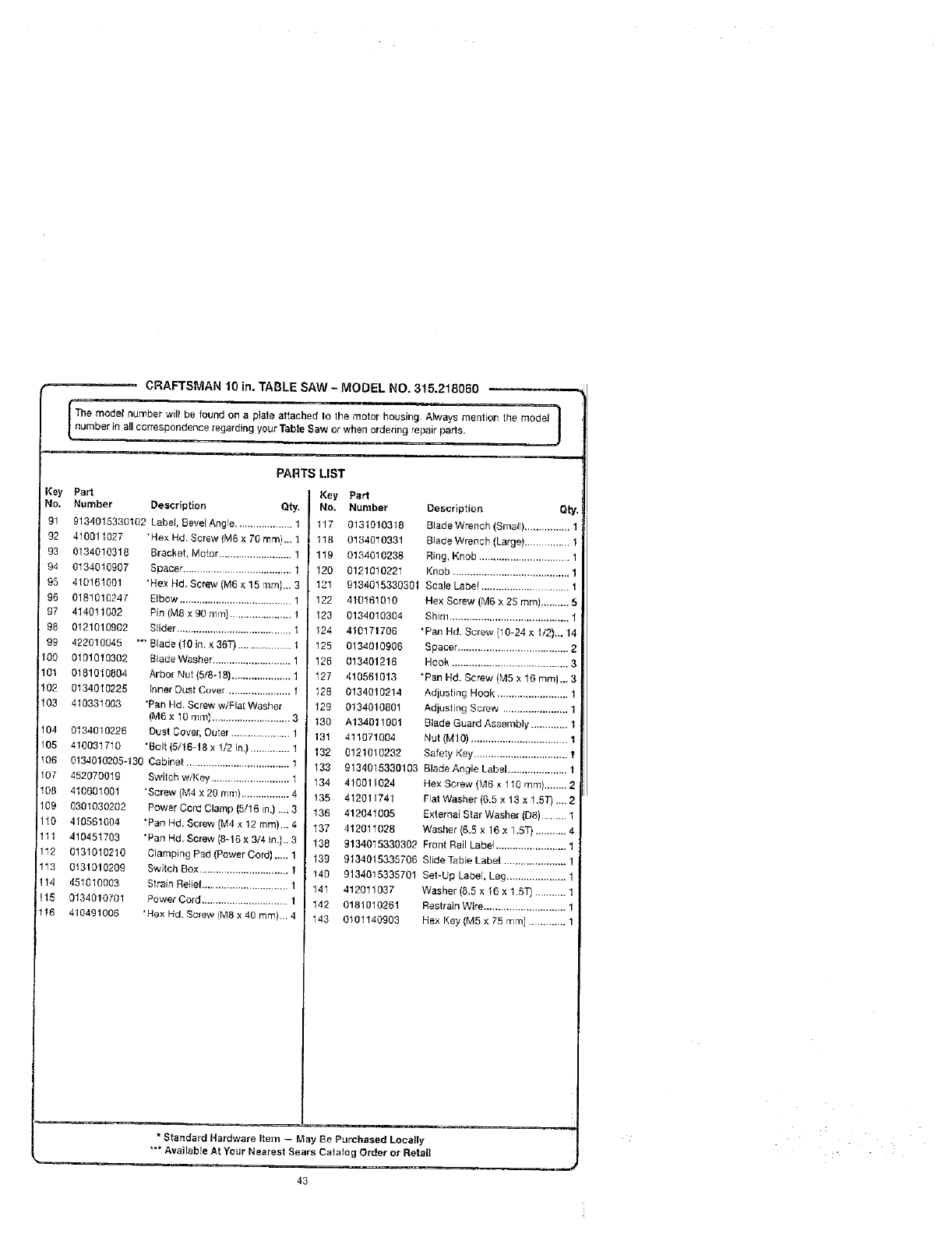
CRAFTSMAN10 in. TABLE SAW - MODEL NO, 315.218060
The model number will be found on eplate attached to the motor housing Always mentioiq the model 1number in all correspondence regarding your Tab eSaw or when ordering repair parts. J
Key
No.
91
92
93
94
95
96
97
98
99
100
101
! 02
103
PARTS LIST
Part Key Part
Number Descriptlon Qty. No. Number
9134015330102 Label, BeveiAng'e .................... 1 117 0131010318
410011027 *Hex Hd. Screw {M6 x 70 ram}.,, 1 118 0134010331
0134010318 Bracket, Motor .......................... I 1!9 0134010238
0134010907 Spacer ...................................... 1 120 0121010221
410161001
0181010247
414011002
0121Q16902
422010045
0101010302
0181010804
0134010225
4103310Q3
Description ely.
Blade Wrench (Small) ................
Blade Wrench (Large)................
Ring, Knob ................................
Knob ......................................... 1
104 0134010226
105 410031710
106 0134010205-130
107 452070019
108 410501001
109 0301030202
110 410561884
111 410451703
112 0131010210
113 0131010209
114 451010083
115 0134010701
116 410491006
"Hex Hd. Screw (M6 × 15 'rim}... 3
Elbow ........................................ 1
Pin (Me x 90 tlq_'fl) ..................... 1
Slider ......................................... 1
"_ Blade (10 in. × 36"0 ................... 1
Blade Washer ............................ 1
Arbor Nut (5/8-18) ..................... 1
Inner Dust Cover ....................... 1
*Pan Hd. Screw w/FleEWasher
(M6 x 10 ram) ............................ 3
Dust Cover, Outer ..................... 1
*Bait (5/18-18 x 1/2 in.) .............. 1
Cabinet ..................................... !
Switch w/Key ............................ 1
'Screw (M4 x 20 ram)................. 4
Power Cord Clamp (5!16 in.) ..., 3
"Pan Hd. Screw (M4 x 12 ram)... 4
"Pan Hd. Screw [8-16 x 314 in.).. 3
CJamping Pad (Power Cord)._,. 1
Switch Box ................................ 1
Strain Reliel ............................... 1
Power Cord ............................... 1
_Hex Hd. Screw (M8 x 40 ram)... 4
12! 9134015330301 Scale Label .............................. 1
122 410161010 Hex Screw (M6 x 25 ram).......... 5
123 0134010304 Shim .......................................... 1
124 410171706 "Pan Hd. Screw/10-24 x112)... 14
125 0134010906 Spacer ....................................... 2
126 013401218 Hook ......................................... 3
127 410561013 *Pan He. Screw (MS x 16 mini..- 3
128 0134010214 Adjusting Hook .........................
129 0134010601 Adjusting Screw ....................... 1
130 A134011001 Blade Guard Assembly .............
131 411071004 Nut (M1O) .................................. 1
132 0121010232 Safety Key ................................. I
133 9134015330103 Blade Angle Label ..................... 1
134 410011024 He× Screw (Me x 1t0 mm) ........ 2
135 412011741 Flat Washer (6.5 x 13 x 1.5T) ... 2
136 412041005 External Star Washer (D8) ......... 1
137 412011028 Washer (6.5 x 16 x 1.5"0 ........... 4
138 9134015330302 Front Rail Label ......................... 1
139 9134015335706 SlideTableLabel ....................... 1
140 9134015335701 Set-Up Label. Leg ..................... 1
141 412011037 Washer (6.5 x 16 x 1.5T) ...........
142 0181010261 Restrain Wire.............................
143 0101140903 Hex Key (M5 × 75 r'nm) .............
*Standard Hardware Item - May Be Purchased Locally
*'* Available At Your Nearest Sears Catalog Order or Retail
43
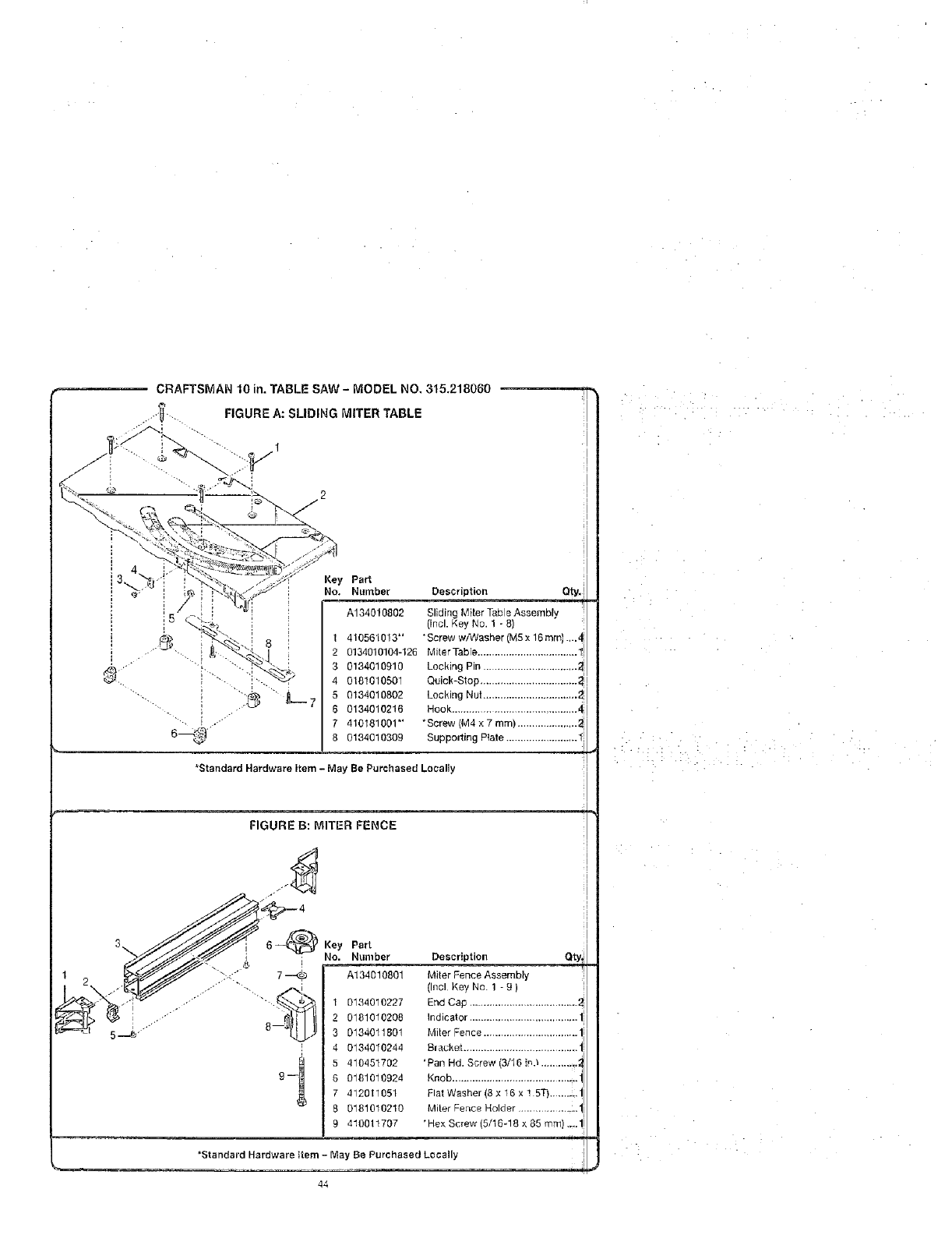
CRAFTSMAN 10 in. TABLE SAW -MODEL NO, 315.218060
_', FIGURE A: SLIDING MITER TABLE
l
8
Key Part
No. Number Description Qty.
A134010802 Sliding Miter Table Assembly
(incl. Key No. 1 - 8)
I 410561013" "Screw w/Washer (MSx 16 mini .,..4
2 0134010104-126 MiterTabie ................................... 1
3 0134010910 Locking Pin .................................
4 0181010501 Quick-Stop ..................................
5 0134010802 Locking Nut .................................
60134010216 Hook ...........................................
7 410181001*' "Screw (M4 × 7 ram) .....................
8 0134010309 Supporting Plate .........................
"Standard Hardware Item - May Be Purchased Locally
FIGURE B: MITER FENCE
F
Key Part
No. Number
A134010801
1 0134010227
2 0181010208
30134011801
4 0134010244
5 410451702
6 0181010924
7 412011051
8 0181010210
9 410011707
Description _t
Miter Fence Assembly i
(Incl Key No. 1 - 9 )
End Cap ......................................
Indicator ...................................... 1
Miter Fence .................................
Bracl_et .....................................
'Pan Hd. Screw (3/16 i,,_.l............._
Knob ............................................
Flat Washer (8 x 16 x ! 5T).......;. 1
Miter Fence Holder ......................
*He× Screw (5/16-18 x 85 ram)....1
=
'Standard Hardware Item - May Be Purchased Locally
44
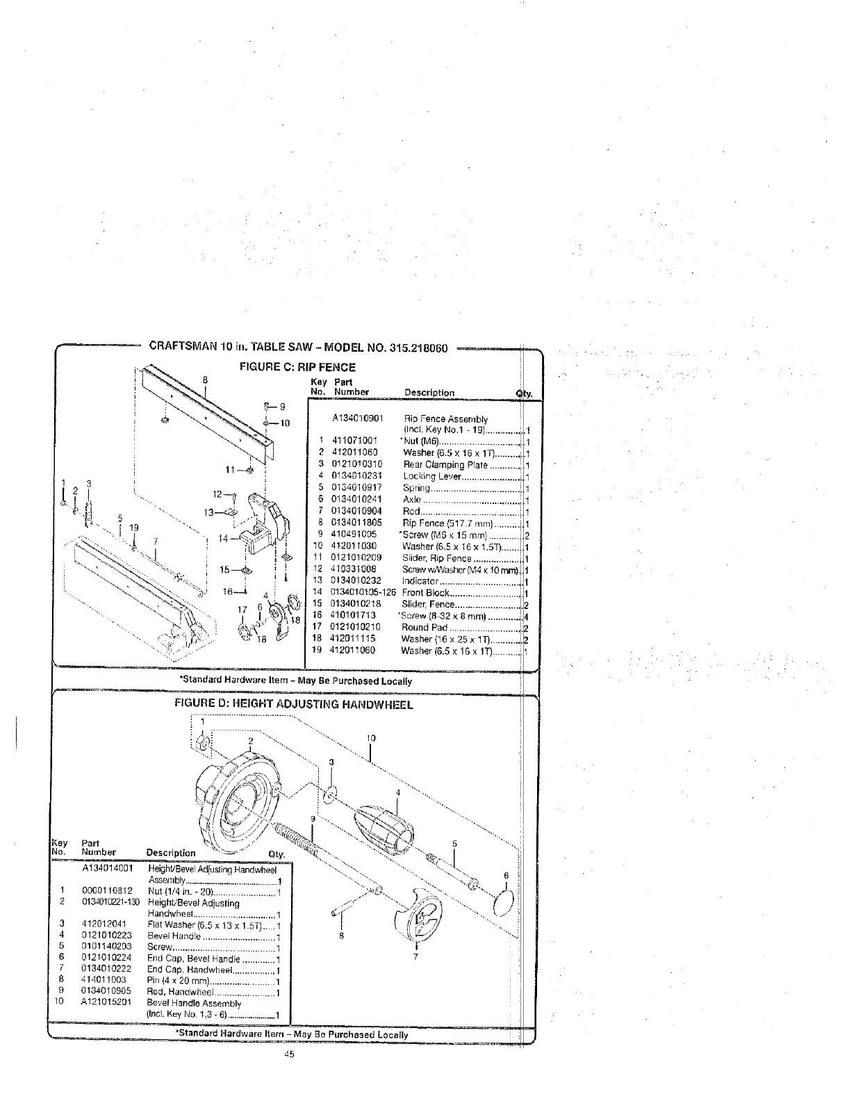
3
4
5
6
8
9
10
Part
Number Description
A134014001
00001 !0812
0134010221-130
412012041
0121010223
0101140203
0121010224
0134010222
414011003
0134010905
A121015201
Qty.
Height/Bevel Adjusting Handwheel
Assembly .................................................1
Nut (1/4 in. - 20) ......................... 1
BeightLBevel Adjusting
Handwheel ................................. 1
Flat Washer (6+5 x 13 x 1.57)....1
Bevel Handle ............................. 1
Screw ......................................... 1
End Cap, Bevel Handle ............. 1
End Cap. Handwheel ................. 1
Pin (4 x 20 ram) .......................... 1
Rod, Handwheel ........................ 1
Bevel Handle Assembl_
(IneL Key No. 1,3 - 6) ....................... 1
*Standard Hardware Item -May Be Parohaaed Locally
=¢*=_
45
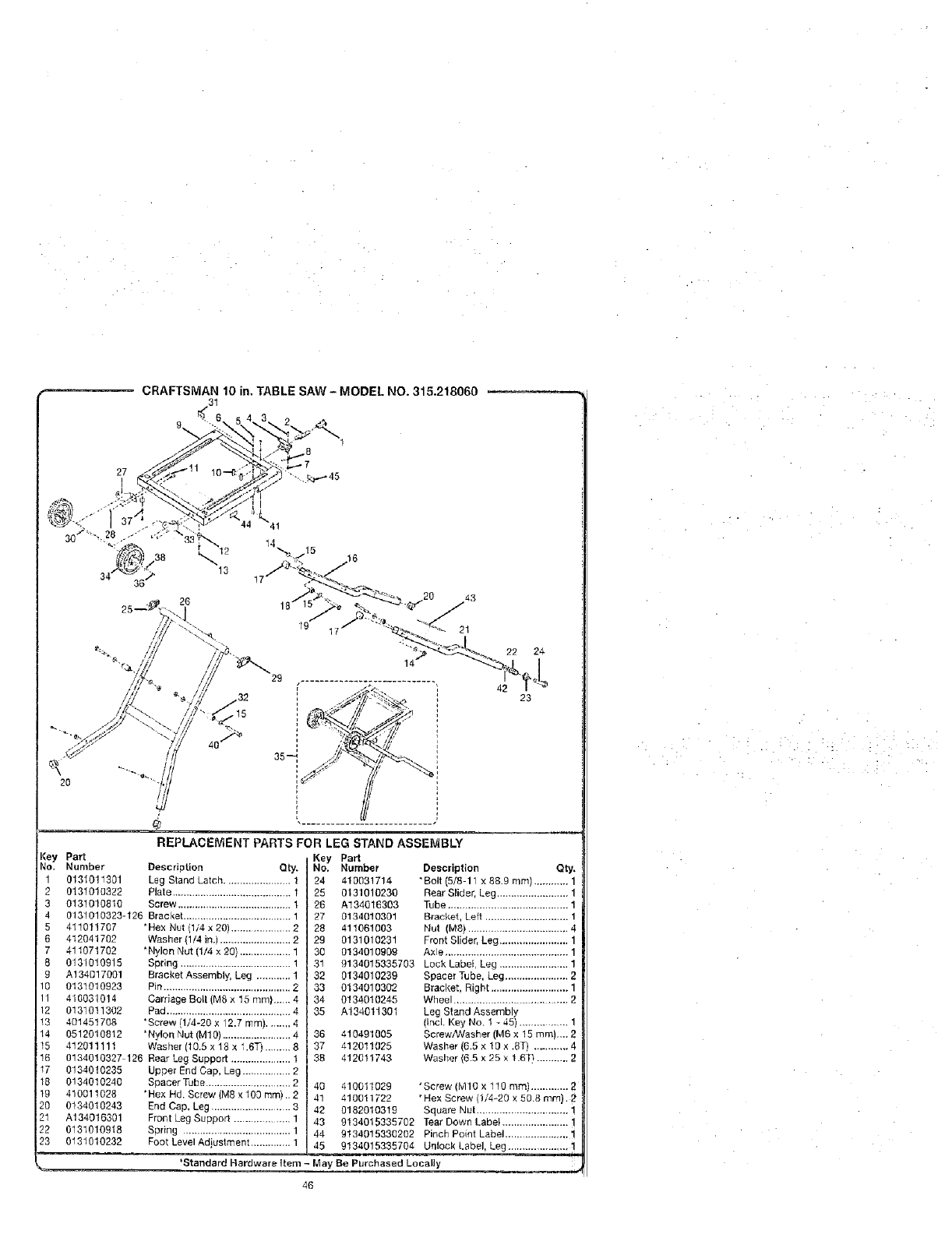
CRAFTSMAN10 in. TABLE SAW - MODEL NO. 315.218060
3t
d
27
20
¼13
3s-4,'
22
42
24
23
Key Pa_
No. Number
1 0131011301
2 O131O10322
3 0131010810
4 0131010323-126
5 411011707
6 412041702
7 411071702
8 0131010915
9 A134017001
10 0131010923
11 410031014
12 0131011302
13 401451708
14 0512010812
15 412011111
REPLACEMENT PARTS FOR LEG STAND ASSEMBLY
Description Qty.
Leg Stand Latch ....................... 1
Plale .......................................... 1
Screw ........................................ 1
Bracket ...................................... 1
*Hex Nut (1/4 x 20) ..................... 2
Washer (1/4 in.) ......................... 2
*Nylon Nut (1/4 x 20) .................. 1
Spring ....................................... 1
Bracket Assembly, Leg ............ 1
Pin ............................................. 2
Carriage Bolt (M8 x 15 ram)..... 4
Pad ............................................ 4
•Screw !!14-20 x 12.7 ram) ........ 4
'Nylon Nut (M10) ........................ 4
Washer (10.5 x 18 ×1.6T) ......... 8
Key Pa_
No. Number
24 410031714
25 0131010236
20 A134016303
27 0134010301
28 411061003
29 0131010231
30 013401O909
31 9134015335703
32 0134010239
33 0134010302
34 0134010245
35 A134011301
36 410491005
37 412011025
Description Qty,
"Boil (5/8-11 x 88.9 ram) ........... 1
Rear Slider, Leg ......................... 1
Tube .......................................... 1
Bracket, Left ............................. 1
Nut (M8) ................................... 4
Front Slider, Leg ........................ 1
Axle ........................................... 1
Lock Label, Leg ........................ 1
Spacer Tube, Leg ...................... 2
Bracket, Right ........................... 1
Wheel ............................. 2
Leg Stand Assembly
(IncL Key No. I - 45) ............... 1
Screw/Washer (M6 x 15 ram).._ 2
Washer (6,5 x 10 x .8T) ........... 4
15 0134010327 126
I7 0134010235
18 0134010240
19 410011028
20 0134010243
21 A134016301
22 0131010918
23 0131010232
I
Rear Leg Support ..................... 1
Upper End Cap, Leg ................. 2
Spacer Tube .............................. 2 40
"Hex Hd. Screw (M8 x 100 ram) ..2 41
End Cap, Leg ............................ 3 42
Front Leg Support ................... 1 43
Spring ...................................... 1 44
Foot Level Adjuslment .............. 1 45
*Standard Hardware Item -May Be Purchased Locally
46
38 412011743 Washer (6.5 x 25 x 1.6T_ ........... 2
41001t029 'Screw (MIO x 110 ram) .............
410011722 "Hex Screw (1/4-20 x 50.8 ram). 2
0182010319 Square Nut ................................ !
9134015335702 Tear Down Label ....................... !
9134015330202 Pinch Point Label ...................... 1
9134015335704 Unlock Label, Leg ..................... 1
: . -,:.

I
!,
,il
m
_w m

Get it fixed, at your home or ou 's!
Your Home
For repair-in your home of all major brand appliances,
lawn and garden equipment, or heating and cooling systems,
no matter who made it, no matter who sold it!
For the replacement pads, accessories and
owner's manuals that you need to doqt-yourself.
For Sears professional installation of home appliances
and items Tikegarage door openers and water heaters.
I°800-44VlY-HOi_tiE ® (!-800-469-4663)
Carl anytime, day or night(U,S.A, and Canada)
www.sears.com www.sears.ca
Our Home
For repair of carry-in items like vacuums, lawn equipment,
and electronics, call or go on-line for the location of your nearest
Sears Parts & Repair Center.
1-800-488-1222
Call anytime, day or nighl (U.S.A. only)
www.sears.com
To purchase a protection agreement (U.S.A.)
or mainlenance agreement (Canada) on a product serviced by Sears:
1o800o827-6655 (U.S.A.) t-800-361-6665 (Canada)
Para pedir servicio de reparaci6n Au Canada pour service en ffanqais:
a domicilio, y para ordenar piezas: I=800-LE-FOYER _c
1-888oSU-HOGAR"_" (1-800-533-6937)
(1888-784-6427) www.sears.ca
#Z RegFst_red Tfademalk [TM Trademark /s_ Service Mar_; o! Seals, Reel}tick arid Ct}
_b Mate3 Re!]L_tr ad a /Tr, M_lca Ic F_b ca J'_¸_Marca _e Selvic o de S_ars, Ro_ u_, an_ Co
rz¢r._atql_e d_ _:t_mmerce fu_ t,_arqu_ depo_ee de Se_rs R_t_ck and CO © S_ats. _r_bJJc£ an_ _ i
