Craftsman 315220380 User Manual 10 IN. STATIONARY RADIAL ARM SAW Manuals And Guides L9050174
CRAFTSMAN Saw Radial Manual L9050174 CRAFTSMAN Saw Radial Owner's Manual, CRAFTSMAN Saw Radial installation guides
User Manual: Craftsman 315220380 315220380 CRAFTSMAN 10 IN. STATIONARY RADIAL ARM SAW - Manuals and Guides View the owners manual for your CRAFTSMAN 10 IN. STATIONARY RADIAL ARM SAW #315220380. Home:Tool Parts:Craftsman Parts:Craftsman 10 IN. STATIONARY RADIAL ARM SAW Manual
Open the PDF directly: View PDF ![]() .
.
Page Count: 82
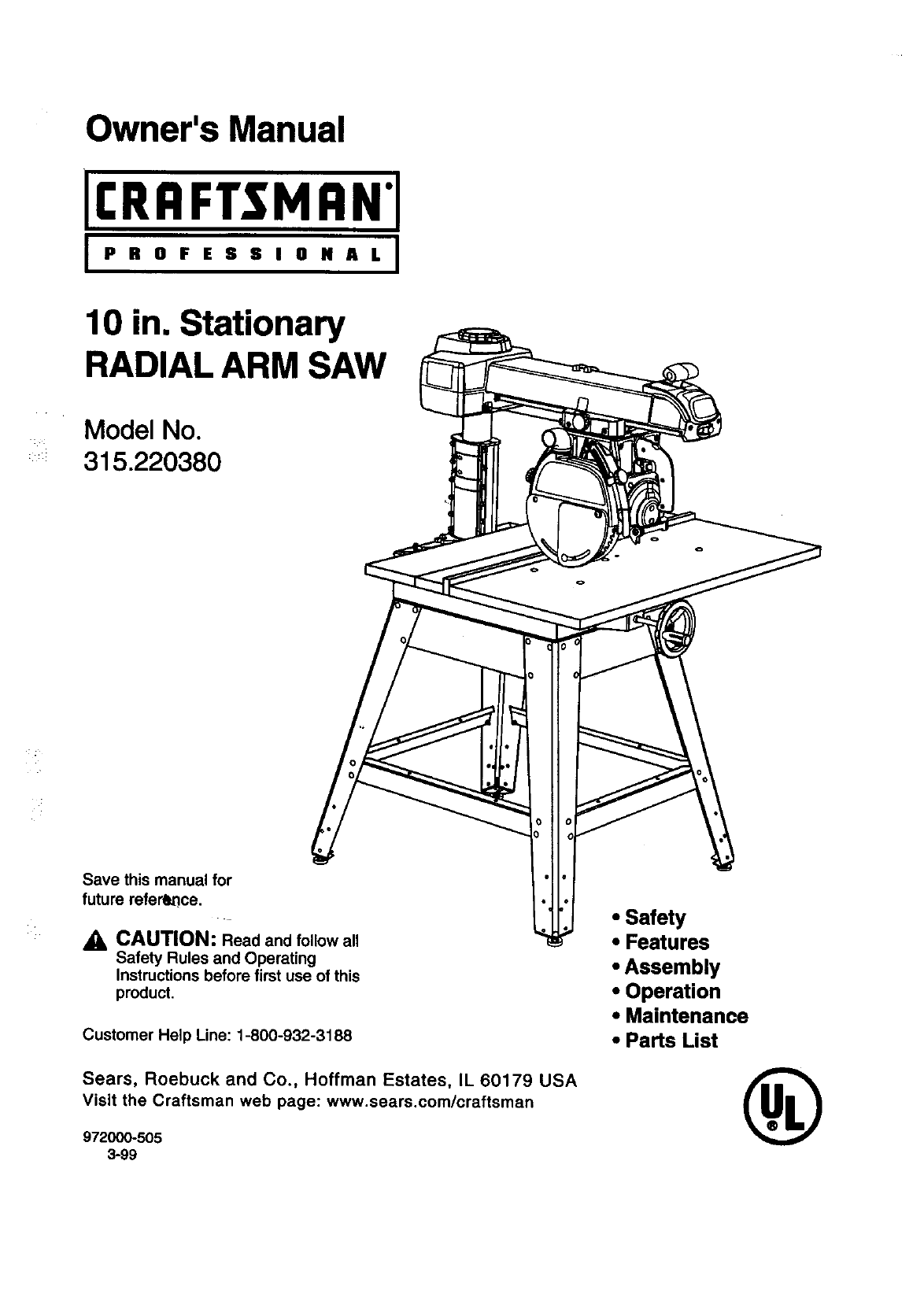
Owner's Manual
[I:RRFTSMRN'[
i PROFESSIONAL I
10 in. Stationary
RADIAL ARM SAW
Model No.
315.220380
Save this manual for
future reference.
CAUTION: Read and follow all
Safety Rules and Operating
Instructions before first use of this
product.
Customer Help Line: 1-800-932-3188
Sears, Roebuck and Co., Hoffman Estates, IL 60179 LISA
visit the Craftsman web page: www.sears.com/craftsman
972000-505
3-99
• Safety
•Features
•Assembly
•Operation
•Maintenance
•Parts List ®
FULL ONE YEAR WARRANTY ON CRAFTSMAN RADIAL ARM SAW
If this CItRFTSMRN'Radial Arm Saw fails,dueto a defect inmaterial or workmanshipwithinone year fromthe
date of purchase, Sears will repair it,free of charge.
Contact a Sears Service Center for repair.'
If thisproduct is used for commercial'orrentalpurposes,this warrantyappliesonlyfor 90 daysfrom thedate of
purchase.
This warranty givesyou specificlegal rights,and you may also have other rightswhichvary from state to state.
Sears, Roebuck and Co., Dept. 817WA, Hoffman Estates, IL 60179
Your saw has many features for making cuttingoperations more pleasantand enjoyable.Safety, performance
and dependabilityhave been given top priorityin the design of thissaw making it easy to maintainand operate.
_l, CAUTION: Carefully read throughthisentire owner's manual before usingyour new saw. Pay close
attentionto the Rules For Safe Operation, and all Safety Alert Symbols,includingDanger, Warning and
Caution. If you use your saw properlyand only for what it is intended,you will enjoy years of safe, reliable
service.
_k Look for this symbol to point out important safety precautions. It means attentionf!! Your safety is
involved.
,_ WARNING:
The operationof any power tool can result inforeign objectsbeing throwninto your eyes,
whichcan resultin severe eye damage. Before beginningpower tool operation,always wear
safety gogglesor safety glasses withside shieldsand a full face shield when needed. We
recommendWide Vision Safety Mask for use over eyeglassesor standardsafety glasses
withside shields, available at Sears Retail Stores.
•Warranty and Introduction ............................................................................................................................... 2
•Table of Contents.......................................................................................................................................... 2-3
•Rules For Safe Operation............................................................................................................................. 4-7
•Electrical........................................................................................................................................................ 8-9
•ProductSpecificationsand Glossary........................................................................................................ 10-t 1
•Unpackingand Accessories.......................................................................................................................... 11
•Loose Parts List........................................................................................................................................ 12-14
•Tools Needed ................................................................................................................................................. 15
•Labels........................................................................................................................................................ 16-17
•Features .................................................................................................................................................... 18-21
•Assembly................................................................................................................................................... 22-36
AssemblingLeg Stand ................................................................................................................................... 22
Mounting Saw to Leg Stand........................................................................................................................... 23
I:RRFTSNRN"RADIALSAW315.220380 2
AttachingElevating Handwheel ..................................................................................................................... 23
Installingthe Yoke Assembly......................................................................................................................... 24
Removing the Blade....................................................................................................................................... 25
AttachingTable Supports .............................................................................................................................. 25
Setting the Arm Lock Knob............................................................................................................................ 26
Setting the Yoke Clamp ................................................................................................................................. 26
Setting the Bevel LockLever......................................................................................................................... 27
Tighteningthe Armand Column.................................................................................................................... 28
Adjustingthe Column Tube ...................................................................................................................... 28-29
Adjustingthe Carriage Bearings.................................................................................................................... 30
Levelingthe Table Supports.......................................................................................................................... 31
Installingthe FrontTable ............................................................................................................................... 32
Levelingthe FrontTable ................................................................................................................................ 33
InstallingRear Table, SpacerTable, Fence, and Clamps........................................................................ 33-34
Installing Blade and Blade Guard .................................................................................................................. 34
:AligningRiving Knifeto Blade........................................................................................................................ 35
InstallingRip Scale Indicators........................................................................................................................ 36
•Adjustments ................................................................ :;,............................................................................ 36-42
Aligningthe Armfor Cross Cuts .................................................................................................................... 37
Aligningthe Blade to Table at 0" Bevel ......................................................................................................... 38
Squadng Blade to Fence ............................................................................................................................... 39
Paralleling Blade to Table .............................................................................................................................. 40
Aligningthe Rip Scale Indicators ................................................................................................................... 41
InstallingControlCut Device ......................................................................................................................... 42
•Operation .................................................................................................................................................. 43-53
Basic Operation of the Radial Arm Saw ........................................................................................................ 43
Types of Cuts ................................................................................................................................................. 43
Switchand Switch Key................................................................................................................................... 44
Causes of K_ckback....................................................................................................................................... 44
.AvoidingKickback.......................................................................................................................................... 44
CuttingAids .................................................................................................................................................... 45
Making aCross Cut ....................................................................................................................................... 46
Making a Miter Cut......................................................................................................................................... 47
Makinga Bevel Cut........................................................................................................................................ 48
Making a Compound Cross Cut..................................................................................................................... 49
Rip Cut Hazards and Precautions................................................................................................................. 50
Setting Up a Rip Cut ................................................................................................................................. 50-51
Making a Rip Cut ........................................................................................................................................... 51
Making Other Cuts ......................................................................................................................................... 52
Cutting LongWorkpieces............................................................................................................................... 52
Non-ThroughCuts ......................................................................................................................................... 53
•Maintenance .................................................................................................................................................. 54
•Troubleshooting........................................................................................................................................ 55-59
•ExplodedView and Repair Parts Ust ....................................................................................................... 60-81
•Parts Ordering/Service .................................................................................................................... back page
3 CRIIFTSHAN"RADIALSAW315.220380
The purpose of safety symbols is to attract your attention to possible dangers. The safety symbols, and
the explanations with them, deserve your careful attention and understanding. The safety warnings do
not by themselves eliminate any danger. The Instructions or warnings they give ere not substitutes for
proper accident prevention measures.
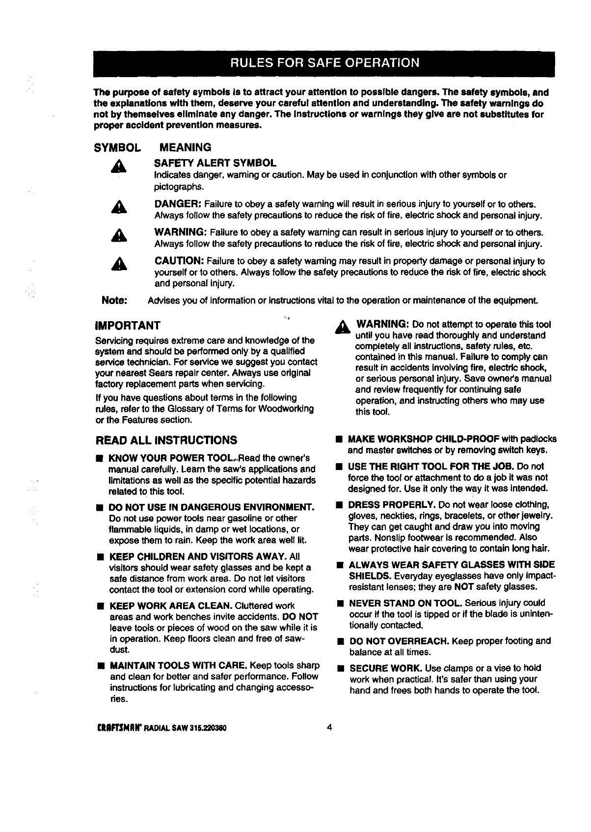
SYMBOL
A
A
&
Note:
MEANING
SAFETY ALERT SYMBOL
Indicatesdanger, warningor caution.May be used in conjunctionwithothersymbolsor
pictographs.
DANGER: Failure to obey a safetywarningwill resultin seriousinjuryto yourselforto others.
Alwaysfollow the safety precautionsto reduce the riskof fire, electricshockand personalinjury.
WARNING: Failureto obeya safety warningcan resultin serious injuryto yourselforto others.
Alwaysfollow the safety precautionsto reduce the riskof fire, electricshockand personalinjury.
CAUTION: Failure to obeya safety warning may resultin propertydamage or personalinjuryto
yourselfor to others. Alwaysfollow the safety precautionsto reducethe riskoffire, electdcshock
and personalinjury.
Advisesyou of informationor instructionsvitalto the operationor maintenanceof the equipment.
IMPORTANT
Servicing requiresextreme care and knowledge of the
systemand shouldbe performedonly by a qualified
service technician.For servicewe suggestyoucontact
your nearestSears repaircenter. Alwaysuse odginal
factory replacementpartswhen servicing.
If you have questionsabout terms inthe following
rules, referto the Glossary of Terms for Woodworking
or the Features section.
_l, WARNING: Do not attemptto operate thistool
untilyou have readthoroughlyand understand
completelyall instructions,safety rules,etc.
contained in thismanual. Failure to comply can
resultin accidentsinvolvingfire, electdcshock,
or sedous personal injury.Save owner'smanual
and review frequently for continuing safe
operation,and instructingothers who may use
thistool.
READ ALL INSTRUCTIONS
KNOW YOUR POWER TOOL.Read the owner's
manual carefully. Learn the saw's applicationsand
limitationsas well as the specificpotential hazards
related to thistool.
•DO NOT USE IN DANGEROUS ENVIRONMENT.
Do not use power tools near gasoline or other
flammable liquids,in damp or wet locations,or
expose them to rain. Keep the work area well lit.
•KEEP CHILDREN AND VISITORS AWAY. All
visitorsshouldwear safety glasses and be kept a
safe distance from workarea. Do notlet visitors
contact the tool or extensioncord while operating.
•KEEP WORK AREA CLEAN. Cluttered work
areas and work benches inviteaccidents. DO NOT
leave tools or pieces of wood on the sew while it is
in operation. Keep floorsclean and free of saw-
dust.
•MAINTAIN TOOLS WITH CARE. Keep tools sharp
and clean for better and safer performance. Follow
instructionsfor lubricatingand changingaccesso-
des.
•MAKE WORKSHOP CHILD-PROOF with padlocks
and master switchesor by removingswitchkeys.
• USE THE RIGHT TOOL FOR THE JOB. Do not
force the tool or attachmentto do ajob it was not
designedfor. Use it onlythe way it was intended.
DRESS PROPERLY, Do notwear loose clothing,
gloves, neckties, rings,bracelets, or otherjewelry.
They can get caught and draw you into moving
pads. Nonslipfootwear is recommended.Also
wear protectivehair covedngto containlonghair.
ALWAYS WEAR SAFETY GLASSES WITH SIDE
SHIELDS. Everyday eyeglasseshave only impact-
resistantlenses;they are NOT safety glasses.
•NEVER STAND ON TOOL. Sedous injurycould
occur if the tool is tipped or if the blade is uninten-
tionallycontacted.
•DO NOT OVERREACH. Keep proper footingand
balance at all times.
•SECURE WORK. Use clamps or a vise to hold
workwhen practical. It's safer than usingyour
hand and frees both hands to operate the tool.
I]IIIFTSHIIN"RADIAL SAW 315.220380 4
n USE THE PROPER EXTENSION CORD. Make
sureyour extensioncord is in good condition,Use
onlyacord heavy enough to carrythe currentyour
productwill draw. An undersizedcord will cause a
dropin linevoltage resultingin loss of power and
overheating.A wiregage size (A.W.G.) of at least
14 is recommendedfor an extensioncord 25 feet
or less in length. If in doubt,use the next heavier
gage. The smaller the gage number, the heavier
the cord.
MAVOID ACCIDENTAL STARTING. Be sure switch
is off when pluggingin the tool.
•REMOVE WRENCHES AND ADJUSTING KEYS.
Get in the habit of checking- before turningon the
tool - that hex keys and adjustingwrenchesare
removed from tool.
DISCONNECT ALL TOOLS. When not in use,
before servicing,orwhen changingattachments,
blades, bits,cutters, etc., all tools should be
disconnectedfrom the power supply.
•DO NOT FORCE THE TOOL. It will do the job
better and more safely at the rate for which it was
designed.
•BEFORE MOUNTING, DISCONNECTING OR
REMOUNTING THE MOTOR; unplugthe saw and
removethe switchkey.
_IL WARNING: When servicing,use only identical
Craftsman replacementparts. Use of any other
partsmay create a hazard or damage product.
•CHECK DAMAGED PARTS. Before usingthe tool
again, check any damaged parts, includingguards,
for proper operationand performance.Check •
alignmentof movingparts, bindingof movingparts,,
breakage of parts, saw stability,mounting,and any
other conditions that may affect itsoperation. A
damaged part must be propedy repaired or re- •
placed by a qualifiedservicetechnicianat aSears
repaircenter to avoid riskof personalinjury.
USE ONLY CORRECT BLADES. Use the right
blade stylefor the material and the type of cut.
Use only blades markedfor at least 5,000 rpmand
10 in. or smaller,with e 5/8 in.arbor hole.
•KEEP GUARDS IN PLACE and Ingood working
order. This includesthe blade guard,the dving
knife, and the anti-kickback pawls.
•CHECK DIRECTION OF FEED. When dpping,
feed work into a blade or cutteragainst the direc-
tion of rotation of the blade or cutter.
•NEVER LEAVE TOOL RUNNING UNAI"rENDED.
TURN THE POWER OFF. Do not leave the tool
untilit comes to a complete stop.
•USE RECOMMENDED ACCESSORIES. Using
improperaccessories may riskinjury.Consultthe
Accessoriessection for recommendedaccesso-
des.
MUSE ONLY SEARS REPLACEMENT PARTS. All
repairs, whether electricalor mechanical,should
be made by a qualifiedservicetechnicianat a
Sears repaircenter.
NEVER USE THIS TOOL IN AN EXPLOSIVE
ATMOSPHERE. Normal sparkingof the motor
could ignitefumes.
MAKE SURE THE WORK AREA HAS AMPLE
LIGHTING to see the workand that no obstruc-
tionswill interferewithsafe operation BEFORE
performingany work usingthis tool.
DO NOT USE TOOL IF SWITCH DOES NOT
TURN IT ON AND OFF. Have defective switches
replaced by a qualified servicetechnicianat a
Sears repaircenter.
•GUARD AGAINST ELECTRICAL SHOCK by
preventingbodycontactwith groundedsurfaces
suchas pipes,radiators,ranges, refrigerator
enclosures.
MGROUND ALL TOOLS. See Electricalpage.
•WEAR A DUST MASK to keep frominhalingfine
particles.Use wood dustcollectionsystems
whenever possible.
mPROTECT YOUR HEARING. Wear headng
protectionduringextended periodsof operation.
•DO NOT OPERATE THIS TOOL WHILE UNDER
THE INFLUENCE OF DRUGS, ALCOHOL, OR
ANY MEDICATION.
STAY ALERT AND EXERCISE CONTROL. Watch
what youare doingand use common sense. Do
not operate tool when you are fired. Do not
rush.
AVOID AWKWARD OPERATIONS AND HAND
POSITIONS where a sudden slipcould cause your
hand to move intothe blade. ALWAYS make sure
you have good balance.
5CRRFTSNRrRADfALSAW315._80
•GUARD AGAINST KICKBACK, Kickbackcan
occur when the blade stalls, drivingthe work piece
back toward the operator. It can cause your hand
to contact the blade, resultingin seriouspersonal
injury.Stay outof the blade pathand turnswitch
off immediatelyit blade binds or stalls.
•DO NOT USE A PERSON AS A SUBSTITUTE
FOR A TABLE if additional supportis needed. Use
a supportthe same heightas the table.
•USE A SUPPORT FOR THE SIDES AND BACK
OF THE SAW TABLE when sawingwide or long
workpiecesto minimize the riskof blade pinching
and kickback. Use a sturdy"outrigger" supportto
prevent tippingif a table extensionmore than24
inches longis attached to the saw.
• CUT ONLY WOOD, PLASTIC OR WOOD-LIKE
MATERIALS. Do notcut metal•
•BEFORE MAKING A CUT, be sure all adjustments
are secure.
I NEVER cut more than one piece at a tnme.DO
NOT STACK more than one workpieceon the saw
table at a time.
lDO NOT REMOVE THE SAW'S BLADE GUARD.
Never operate the saw withthe blade guard
removed. Make sure all guardsare operating
properlybefore each use.
•NEVER PERFORM ANY OPERATION FREE-
HAND. Always place the workpieceto becut on
the saw table and positionit firmlyagainst the
fence as a backstop.
• USE THE RIP FENCE. Always use a fence or
straightedge guide when ripping.
•BE SURE THE BLADE PATH IS FREE OF
NAILS. Inspect for and remove all nailsfrom
lumberbefore cutting.
•BE SURE THE BLADE CLEARS THE WORK-
PIECE. Never start the saw withthe blade touching
the stock.
• KEEP HANDS AWAY FROM CUTTING AREA.
Do not reach underneathwork or in blade cutting
path with your hands and fingers for any reason.
Always turn the power off when cut is complete.
•USE A PUSHBLOCK OR PUSHSTICK in rip mode
for workpiecesso smallthat your fingersgo under
the blade guard. NEVER TOUCH BLADE or other
movingpartsduring use, for any reason.
l
ALLOW THE MOTOR TO COME UP TO FULL
SPEED before startinga cut to avoid blade binding
or stalling.
ALWAYS PUSH THE WORKPIECE when ripping;
never pullit toward the saw.
DO NOT FEED THE MATERIAL TOO QUICKLY.
Do notforce the workpieceagainst the blade.
ALWAYS TURN OFF SAW before disconnecting
it, to avoid accidentalstartingwhen reconnecting
to the power supply. NEVER leave the saw
unattendedwhile connectedto a power source.
•BEFORE CHANGING THE SETUP, REMOVING
COVERS, GUARDS, OR BLADE; unplugthe saw
and removethe switchkey.
•KEEP TOOL DRY, CLEAN, AND FREE FROM
OIL AND GREASE. Always use a clean cloth
when cleaning. Never use brake fluids,gasoline,
petroleum-basedproducts,or any solventsto
clean tool.
•KEEP BLADES CLEAN, SHARP AND WITH
SUFFICIENT SET. Sharp blades minimizestalling
and kickback•Keep blades free of rust,grease,
and pitch.
_i, WARNING: Blade coasts after beingturned off.
USE ONLY OUTDOOR EXTENSION CORDS.
Use only extensioncordswiththe marking"Ac-
ceptable for use withoutdoorappliances; store
indoorswhile notin use," Use extensioncords with
an electricalratingnot less than the saw's rating.
Alwaysdisconnectthe extensioncord fromthe
outlet before disconnectingthe productfromthe
extensioncord.
INSPECT TOOL CORDS AND EXTENSION
CORDS PERIODICALLY and, if damaged, have
repaired by a qualifiedservicetechnicianat a
Sears repaircenter. Stay constantly aware of cord
locationand keep it wellaway fromthe moving
blade.
DO NOT ABUSE CORD. Never yank the cord to
disconnectit from receptacle.Keep the cord from
heat, oil, and sharp edges.
SAVE THESE INSTRUCTIONS. Refer to them
frequently and use to instruct other users. If you
loan someone this tool, loan them these instruc-
tionsalso.
SAVE THESEINSTRUCTIONS
IHF{'INAr RADIALSAW315.220380 6
M SECURE THE SAW. Firmlyboltthe saw to the leg
stand to keep the saw fromtipping,walking, or
sliding.
BDO NOT SET UP WORK WITH THE BLADE
SPINNING. Keep the saw power off untilyou are
ready to use it.
M RIP ONLY WORKPIECES LONGER THAN THE
BLADE'S DIAMETER. Never rip a pieceof wood
that is shorterthan the diameter of the blade.
m NEVER LOWER AN UNLOCKED REVOLVING
CUI-rlNG TOOL. Alwayslock the carriage lock
knob before loweringthe blade.
M SHUT OFF THE POWER TO FREE A JAMMED
GUARD. Press the switchoff before puttingyour
hands near the blade. Wait forthe blade to stop,
then free the guard.
BLOCK THE SAW BEFORE MOVING IT. Secure
the radial arm with the arm lockknob. Secure the
carriage withthe carriage lockknob.
BPOSITION THE WORKPIECE WITH THE FIN-
ISHED SIDE DOWN. If the anti-kickbackpawls
catchthe woodto stop kickback,they couldmar
the top surface or cause splintering.
M POSITION THE WORKPIECE SO NO ONE MUST
STAND IN LINE WITH THE BLADE. If kickbackor
climb occurs, a helper, operator, or observerin the
sawblade path couldbe seriouslyinjured.
M POSITION THE CUT SO THE WASTE PART
FALLS OFF. Never use a lengthstopon the free
end of the workpiece. Never apply forceto the free
end or holdit while the sawblade is rotating.
WARNING: In a rip cut, holdingthe cut-offedge
behindthe blade can cause the cut edges to
pinch, riskingkickback.It couldcause the blade
to climb over the front edge of the wood and
contactyour hand.
nBEFORE STARTING EACH CUT, check that no
play exists in the carriage. Be sure the arm, yoke
and bevel locksand clamps are tight.Verify the
blade, aUhandles, blade washers, and blade nuts
are secure.
M BEFORE MAKING A CUT, test the upperand
lower blade guardsfor free movement up and
down. Positionthe nose of the guard to just clear
the workpiece.
M AVOID KICKBACK AND POSSIBLE INJURY by
preventingheeling,grabbing,and pinching.
•BEFORE CUTTING, positionand tightenthe blade
guard and anti-kickbackpawls.Test the pawls to
make sure they would stop kickbackif it started.
Keep the pointssharp.
MKEEP THE SAW BLADE PATH CLEAR. Position
the saw to allow enough room on all sides so
neitherthe operator nor a visitorstands in line with
the sawblade.
M AVOID HEELING by adjustingthe saw blade so it
exactly parallelsthe fence duringrippingopera-
tions.
MAVOID GRABBING in rip mode by keepingthe
saw blade correctly adjusted and by feeding the
work fromthe infeed side (opposite the anti-
kickbackpawls).
BAVOID PINCHING by usinga rivingknife and
sharp saw blade. Keep the work positionedfirmly
against the fence.
BUSE IN-RIP WHENEVER POSSIBLE by position-
ingthe work so the blade is between (inside)the
columnand the motor.
m NEVER ADJUST GUARD, PAWLS, OR BLADE
WITHOUT DISCONNECTING THE POWER.
Alwaysturn off the switchand unplugthe cord
before freeing a jammed blade, tighteninga loose
blade, or repositioningthe guardor pawls.
,_ CAUTION: Do notturn the motor switchon and
off rapidly.This can loosenthe sawblade.
nNEVER CUT MORE THAN ONE PIECE OF
WOOD AT A TIME. The feed will be uneven and
couldcause the blade to pick up one or more
piecesand cause seriousinjury.
BTURN OFF SAW IF A STRANGE NOISE OR
HEAVY VIBRATION OCCURS. Immediatelyturn
off the saw, locatethe source, and correct the
problem before usingthe saw further.
UPOSITION THE CUT SO THE BLADE WILL NOT
EXTEND BEYOND THE EDGE OF THE TABLE.
iKEEP THE GUARDS IN PLACE AND THE WORK
SURFACE CLEAR DURING A CUT. Small objects
or wood sliverscan ricochetfrom the blade intothe
fence and back toward the operator. If the blade
loosensslivers, removethem witha stick, notyour
hand.
• IN A RIP CUT, DO NOT LET GO OF THE WORK-
PIECE UNTIL THE CUT IS COMPLETE. When the
workpiece is fed into the blade, pushthe workpiece
all the way past the blade.
7CRAFTSHQN'RADIALSAW315.220380
EXTENSION CORDS
Use only 3-wire extensioncordsthat have 3-prong
groundingplugsand 3-pole receptacles that accept
the tool'splug.When usinga powertoolat a consider-
able distance from the power source, use an exten-
sion cord heavy enough to carrythe current that the
tool will drew. An undersizedextensioncord will
cause a drop in line voltage, resultingin a lossof
power and causingthe motor to overheat. Use the
chart providedbelow to determinethe minimumwire
size requiredin an extensioncord. Only roundjack-
eted cords listed by Underwriter'sLaboratories(UL)
should be used.
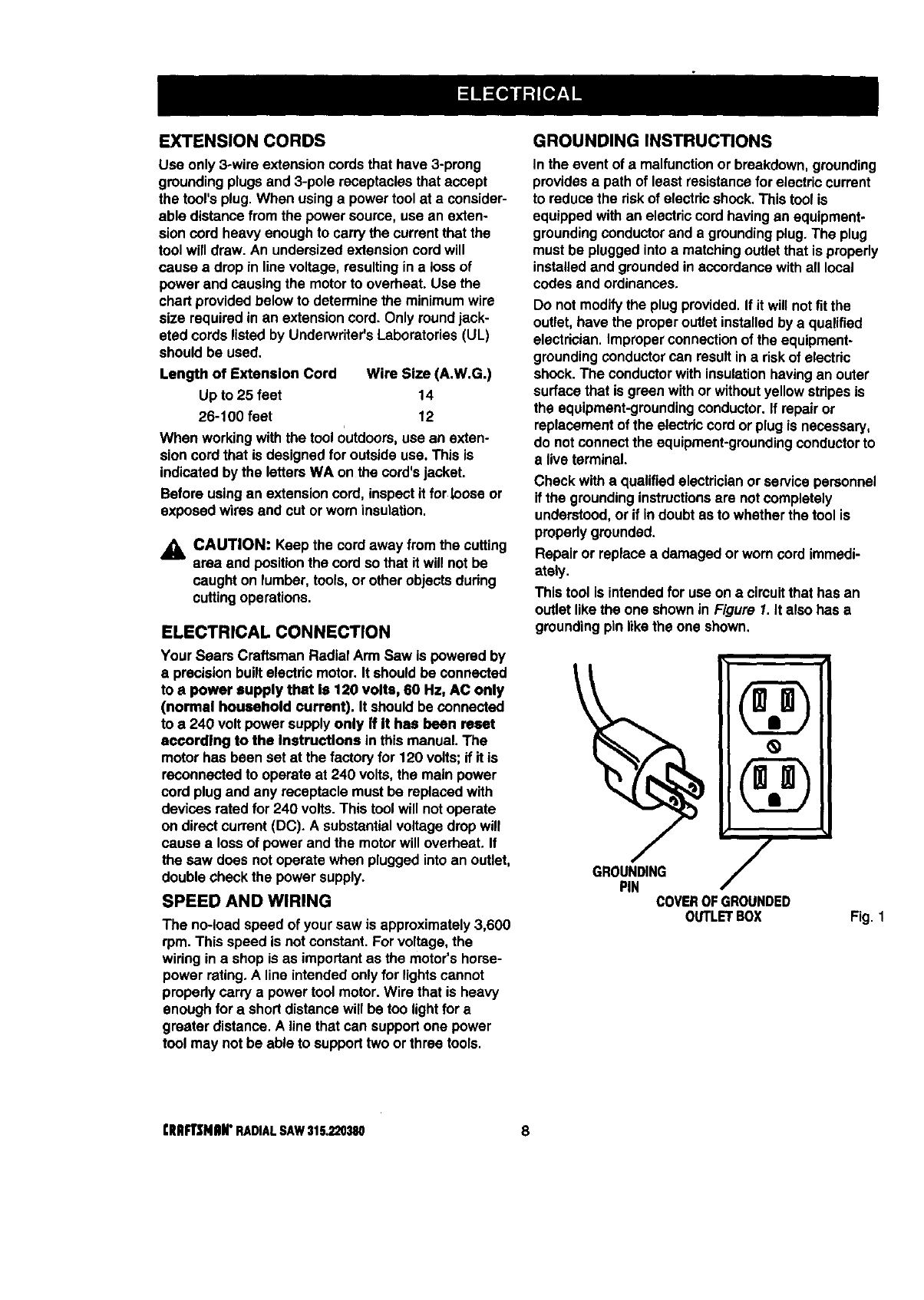
Length of Extension Cord Wire Size (A.W.G.)
Up to 25 feet 14
26-100 feet 12
When workingwith the tool outdoors,use an exten-
sion cord that is designed foroutside use. This is
indicated by the lettersWA on the cord'sjacket.
Before usingan extensioncord, inspectit for Looseor
exposed wires and cut or worn insulation.
_1_ CAUTION: Keep the cord away from the cutting
area and positionthe cord so that it will not be
caught on lumber, tools,or other objectsdudng
cuttingoperations.
ELECTRICAL CONNECTION
Your Sears Craftsman Radial Arm Saw is powered by
a precisionbuiltelectric motor.It shouldbe connected
to a power supply that Is 120 volts, 60 Hz, AC only
(normal household current). It should be connected
to a 240 volt power supplyonly If It has been reset
according to the Instructions in this manual.The
motor has been set at the factory for 120 volts;if it is
reconnectedto operate at 240 volts,the main power
cord plugand any receptacle must be replacedwith
devices rated for 240 volts. This tool will notoperate
on direct current(DC). A substantialvoltage dropwill
cause a lossof power and the motorwill overheat. If
the saw does not operate when plugged intoan outlet,
double check the power supply.
SPEED AND WIRING
The no-load speed of your saw is approximately3,600
rpm. This speed is not constant.For voltage, the
wiring in a shop is as importantas the motor's horse-
power rating. A line intendedonly for lightscannot
propedy carry a power tool motor.Wire that is heavy
enough for a shortdistance will be too lightfor a
greater distance. A line that can supportone power
tool may not be able to supporttwo or three tools.
GROUNDINGINSTRUC_ONS
In the event of a malfunctionor breakdown,grounding
providesa path of least resistancefor electriccurrent
to reduce the riskof electricshock.This tool is
equippedwithan electriccord havingan equipment-
groundingconductorand a groundingplug. The plug
must be pluggedintoa matchingoutlet that is propedy
installedand groundedin accordancewithall local
codes and ordinances.
Do not modifythe plugprovided. If it willnot fit the
outlet,have the properoutlet installedby a qualified
electrician.Improperconnectionof the equipment-
groundingconductorcan result ina riskof electric
shock. The conductorwith insulationhavingan outer
surfacethat is green withor withoutyellow stripesis
the equipment-groundingconductor.If repairor
replacementof the electriccordor plugis necessary,
do notconnectthe equipment-groundingconductorto
a liveterminal.
Check with a qualifiedelectricianor servicepersonnel
if the groundinginstructionsare notcompletely
understood,or if indoubt asto whether the tool is
properlygrounded.
Repair or replace a damaged or worn cord immedi-
ately.
This tool is intendedfor use on a circuitthat has an
outlet likethe one shownin Figure I. It also has a
groundingpin likethe one shown. 1
PIN COVEROFGROUNDED
OUTLETBOX Fig. 1
CRAFTSMAN"RADIAL SAW 315,220380 8
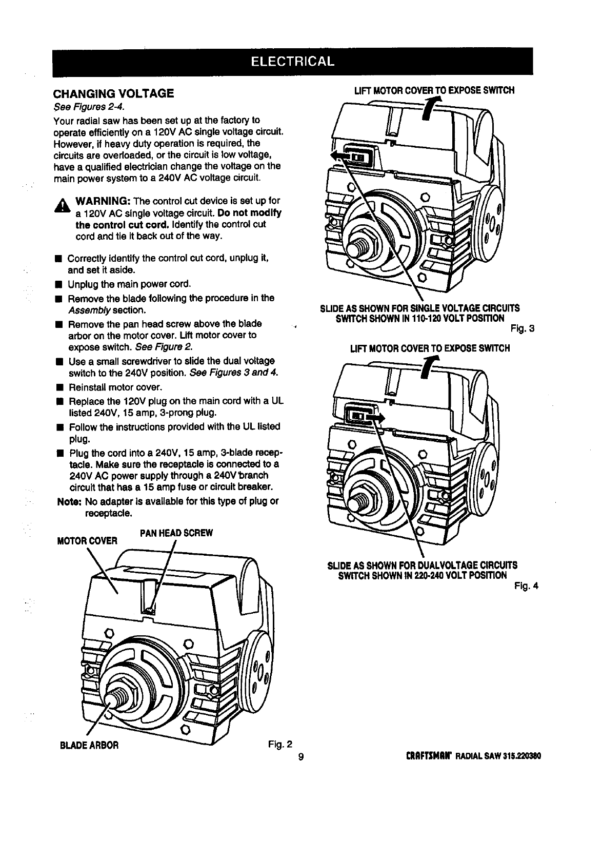
CHANGING VOLTAGE
See Figures 2-4.
Your radial saw has been set up at the factoryto
operate efficientlyon a 120V AC singlevoltagecircuit.
However, if heavy duty operationis required,the
circuitsare overloaded, or the circuitis lowvoltage,
have a qualifiedelectdcianchange the voltage onthe
main power systemto a 240V AC voltage circuit.
_l, WARNING: The controlcut device is set up for
a 120V AC singlevoltage circuit.Do not modify
the control cut cord. Identifythe controlcut
cord and tie it back out of the way.
•Correctly identifythe controlcut cord, unplugit,
and set it aside.
•Unplugthe main power cord.
•Remove the blade following the procedureinthe
Assemblysection.
•Remove the pan head screw above the blade
arbor on the motorcover. Liftmotor coverto
expose switch.See Figure 2.
•Use a small screwdriverto slidethe dual voltage
switchto the 240V position. See Figures3 and 4.
•Reinstall motorcover.
•Replace the 120V plugon the main cordwith a UL
listed 240V, 15 amp, 3-prong plug.
•Follow the instructionsprovidedwiththe UL listed
plug.
•Plugthe cord into a 240V, 15 amp, 3-blade recep-
tacle. Make sure the receptacle is connected to a
240V AC power supplythrougha 240V'bmnch
circuitthat has a 15 amp fuse orcircuitbreaker.
Note: No adapter is available for thistype of plugor
receptacle.
PANHEADSCREW
M_ORC_ER
LIFTMOTORCOVERTOEXPOSESWITCH
SUDEASSHOWNFORSINGLEVOLTAGECIRCUITS
SWITCHSHOWNIN110-120VOLTPosmoN Fig. 3
LIFTMOTORCOVERTOEXPOSESWITCH
SLIDEASSHOWNFORDUN.VOLTAGECIRCUITS
SWITCHSHOWNIN220-240VOLTPOSmONFig. 4
0
BLADEARBOR Fig. 2 9 CnFT|NIIN"RADIALSAW315.220380
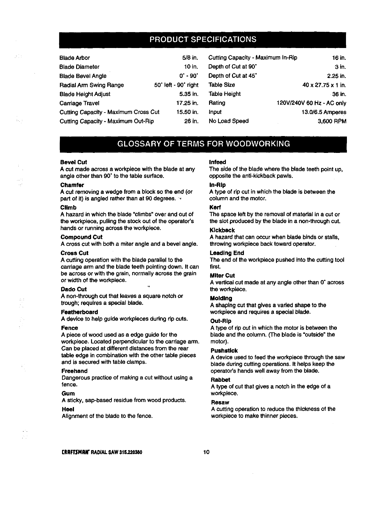
Blade Arbor 5/8 in.
Blade Diameter 10 in.
Blade Bevel Angle 0" - 90"
Radial Arm Swing Range 50" left - 90" right
Blade Height Adjust 5.35 in.
Carriage Travel 17.25 in.
Cutting Capacity - MaximumCross Cut 15.50 in.
Cutting Capacity - Maximum Out-Rip 26 in.
Cutting Capacity - Maximum In-Rip
Depth of Cut at 90"
Depth of Cut at 45"
Table Size
Table Height
Rating
Input
No Load Speed
16 in.
3 in.
2.25 in.
40 x 27.75 x 1 in.
36 in.
120V/240V 60 Hz -AC only
13.0/6.5 Amperes
3,600 RPM
Bevel Cut
A cut made acrossa workpiecewiththe blade at any
angle other than 90° to the table surface.
Chamfer
A cut removinga wedge froma blockso the end (or
partof it) is angled ratherthan at 90 degrees.,
Climb
A hazard in which the blade =climbs" overand out of
the workpiece, pullingthe stockout of the operator's
hands or runningacross the workpiece.
Compound Cut
A crosscut withboth a miterangle and a bevel angle.
Cross Cut
A cuttingoperation withthe blade parallel to the
carriage arm and the blade teeth pointingdown. It can
be across or withthe grain, normallyacross the grain
or width of the workpiece.
Dado Cut
A non-throughcut that leaves a square notchor
trough; requires a specialblade.
Featherboard
A deviceto help guideworkpiecesduringrip cuts.
Fence
Apiece of wood usedas a edge guidefor the
workplace. Located perpendicularto the carriage arm.
Can be placed at differentdistancesfrom the rear
table edge in combinationwith the other table pieces
and is secured withtable clamps.
Freehand
Dangerouspractice of makinga out withoutusinga
fence.
Gum
Asticky, sap-based residuefromwood products.
Heel
Alignmentof the blade to the fence.
Infeed
The side of the blade where the blade teeth pointup,
oppositethe anti-kickbackpawls.
In-Rip
Atype of ripcut in whichthe blade is between the
columnand the motor.
Kerr
The space left by the removal of material in acut or
the slotproducedby the blade ina non-throughcut.
Kickback
A hazard that can occurwhen blade bindsor stalls,
throwingworkpieceback towardoperator.
Leading End
The end of the workpiecepushedintothe cuttingtool
first.
Miter Cut
A verticalcut made at any angle other than 0" across
the workpiece.
Molding
A shaping cutthat gives a vaded shapeto the
workpieceand requiresa specialblade.
Out-Rip
A type of ripcut inwhich the motoris betweenthe
blade and the column. (The blade is "outside"the
motor).
Pushatlck
A device usedto feed the workpiecethroughthe saw
blade duringcuttingoperations.It helps keep the
operator'shands well away fromthe blade.
Rabbet
Atype of cut that gives a notchin the edge of a
workpiece.
Resaw
A cuttingoperationto reducethe thicknessof the
workplaceto make thinner pieces.
(IIRR'$NRIr RADIALSAW315.220380 10
Resin
A sticky,sap-based substance.
Rip Cut "
In a radial saw, acut made withthe blade parallel to
the fence and perpendicularto the arm. Can be
acrossor with the grain. The teeth pointup at the
pointof contactwith the wood,
Sawblade Path
The area directlyin line withthe blade -- over, under,
behind, or in frontof it. Also,the workpiecearea which
will be or has been cut by the blade.
Set
The distance that the tip of the saw blade tooth is off
sat from the face of the blade.
Throw-Back
Saw throwingback a workpiecesimilarto kickback.
Through Sawing
AnyCutting operationwhere the blade extends
completelythroughthe workpieca.
Trailing End
The workpieceend last cut by the blade ina ripcut.
Workplace
The item on which the cuttingoperationis beingdone.
The surfacesof aworkpieceare commonly referredto
as faces, ends, and edges.
Worktable
The surfaceon which the workpieca restswhile
performingacuttingoperation.
,& WARNING: To prevent accidentalstartingthat
could cause possibleseriouspersonalinjury,
assemble all partsto your saw before connecting
it to power supply.The saw shouldnever be
connected to the power supplywhen you are
assembling parts, making adjustments,installing
or removingblades, or when notin use.
_, WARNING: If any partsare missing,do not
operate thistool untilthe missingpartsare
replaced. Failure to do so couldresultin possible
seriouspersonal injury.
•Carefully remove all partsfrom the carton and
place the saw on a levelworksurface. Separate
and check againstthe listof loose parts.
•Do not discardthe packingmaterials untilyou have
carefullyinspectedthe saw, identifiedall parts,and
satisfactorilyoperated your new saw.
Note: If any partsare damaged or missing,do not
attempt to plug inthe power cord and turn the
switchon untilthe damaged or missingparts
are obtained and are installedcorrectly.
The followingrecommendedaccessoriesare currentlyavailableat Sears Retail Stores.
•Steel and carbide tippedcircularsaw blades •Adjustabletaper jig
•Hold down clamps •Sawdustcollectorshroud
•Saw baskets
WARNING: The use of attachments or accessories notlisted mightbe hazardous.
11 CRIIFTSNRN"RADIALSAW315.220380
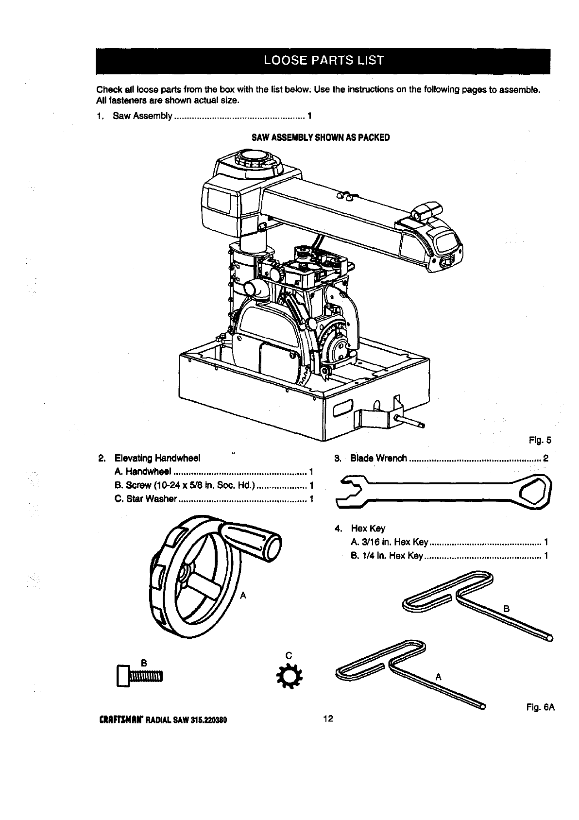
Checkall loose parts fromthe box withthe listbelow. Use the instructionson the followingpages to assemble.
Allfasteners are shown actual size.
f. Saw Assembly.................................................... 1
SAWASSEMBLYSHOWNASPACKED
21 ElevatingHandwheel
A. Handwheel ................................................... ;. 1
B. Screw (10-24 x 5/8 In. Soc. Hd.) .................... 1
C. Star Washer ................................................... 1
c
(IUImMlUr RADIALSAWS15._,0_180
Fig. 5
3; Blade Wrench..........;.......................................... 2
4. Hex Key
A. 3/16 In. Hex Key............................................. 1
B. 1/4 in. Hex Key ............................................... 1
Fig.6A
12
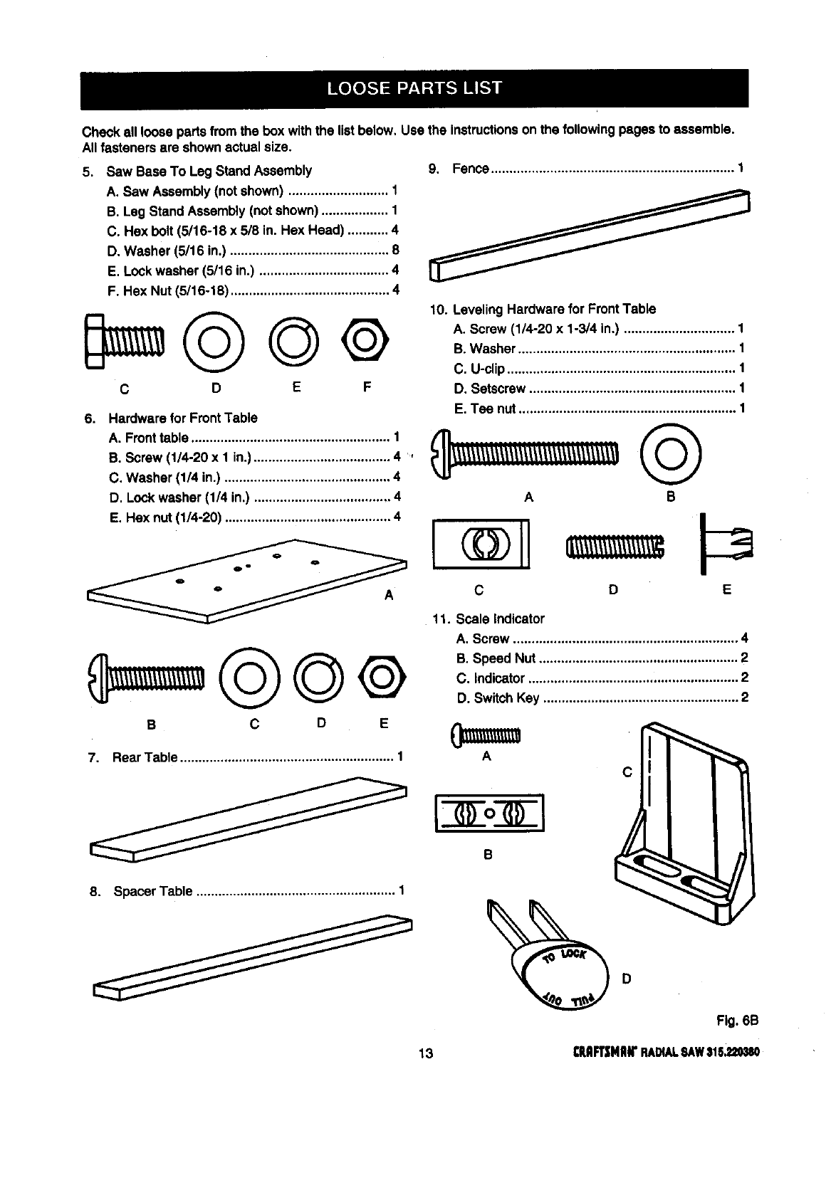
Checkall loose partsfromthe box withthe listbelow. Use the Instructions on the followingpages to assemble.
All fasteners are shown actual size.
5. Saw Base To Leg Stand Assembly
A. Saw Assembly(not shown) ........................... 1
B. Leg Stand Assembly (notshown) .................. 1
C. Hex bolt (5/16-18 x 5/8 in. Hex Head) ........... 4
D. Washer (5/16 in.) ........................................... 8
E. Lockwasher (5/16 in.) ................................... 4
F. Hex Nut (5/16-18) ........................................... 4
C D E F
9. Fence.................................................................. 1
10. Leveling Hardware for FrontTable
A. Screw (1/4-20 x 1-3/4 in.) .............................. 1
B. Washer ........................................................... 1
C. U-clip.............................................................. 1
D. Setscrew ........................................................ 1
6. Hardware for FrontTable
A. Fronttable ...................................................... 1
B. Screw (1/4-20 x 1 in.)..................................... 4,
C. Washer (1/4 in.) ............................................. 4
D. Lockwasher (1/4 in.) ..................................... 4
11. Scale Indicator
E. Tee nut........................................................... 1
AB
D E
A. Screw ............................................................. 4
B. Speed Nut ...................................................... 2
C. Indicator......................................................... 2
D. SwitchKey ..................................................... 2
7, RearT:ble .....................:.................:................:.I
8. Spacer Table ...................................................... 1
Fig. 6B
13 CHFi2HIIN"RADIALSAWIlS.220UO
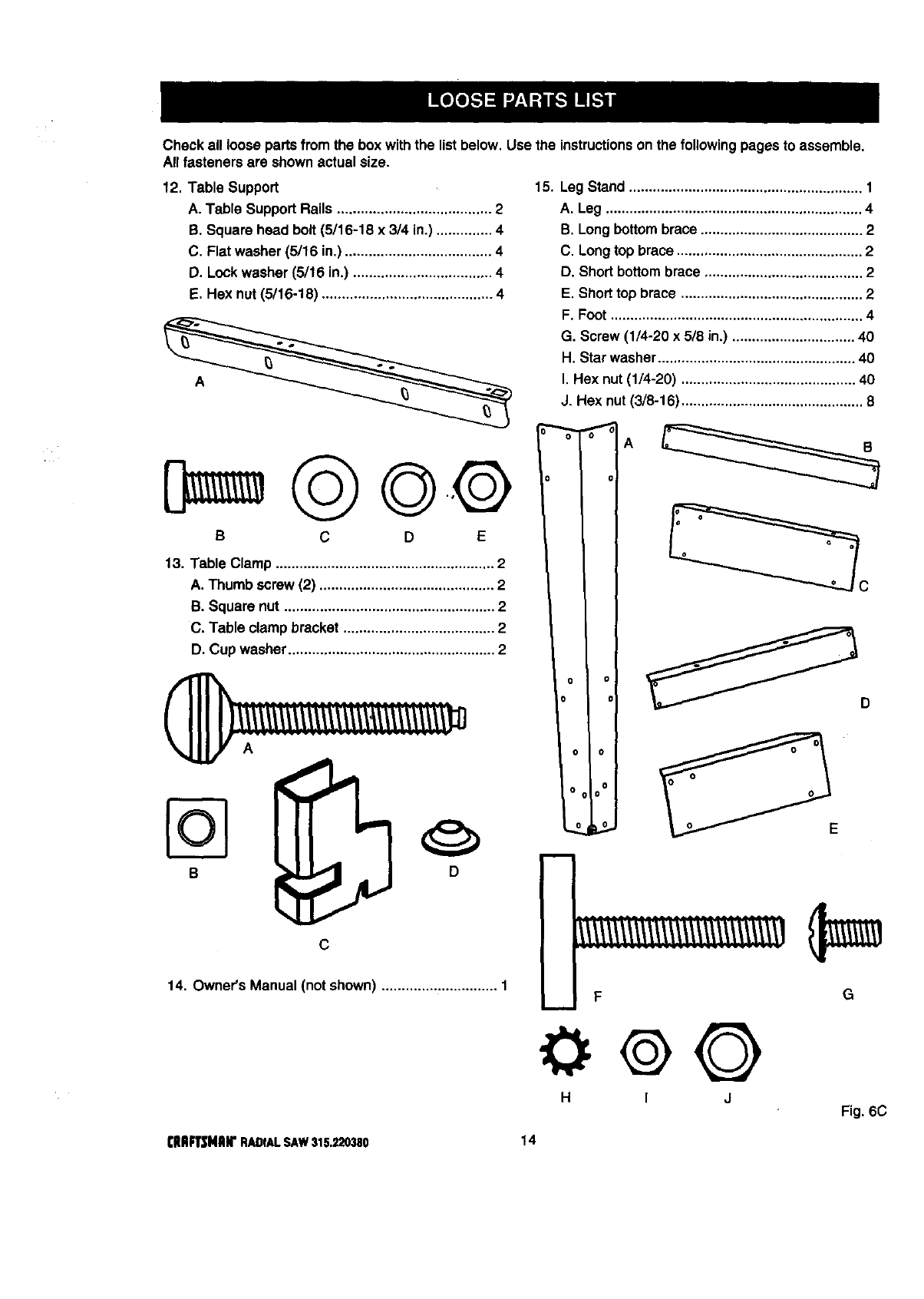
Check all loose partsfrom the boxwith the listbelow. Use the instructionson the followingpages to assemble.
All fasteners are shownactual size.
12. Table Support
A. Table SupportRails ....................................... 2
B. Square head bolt (5/16-18 x 314in.) .............. 4
C. Flatwasher (5/16 in,) ..................................... 4
D. Lockwasher (5/18 in.) ................................... 4
E. Hex nut(5/16-18) ........................................... 4
©©.®
BCD E
13. Table Clamp ....................................................... 2
A. Thumb screw (2) ............................................ 2
B. Square nut ..................................................... 2
C. Table clampbracket ...................................... 2
D. Cup washer.................................................... 2
B
c
14. Owner's Manual (notshown) ............................. 1
15. Leg Stand ........................................................... 1
A. Leg ................................................................. 4
B. Long bottom brace ......................................... 2
C. Long top brace ............................................... 2
D. Short bottom brace ........................................ 2
E, Short top brace .............................................. 2
F. Foot ................................................................ 4
G. Screw (1/4-20 x 5/8 in.) ............................... 40
H. Star washer .................................................. 40
I. Hex nut (1/4-20) ............................................ 40
J, Hex nut (3/8-16) .............................................. 8
o ol
ol
o o I
O( O0 J
G
H I JFig. 6C
[IIIIFI_NIIli" RADIALSAW315.220380 14
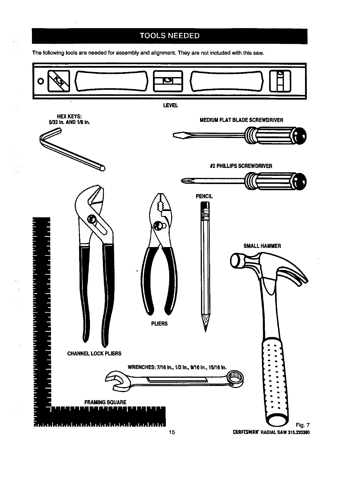
Thefollowingtoolsareneededforassemblyandalignment.Theyarenotincludedwiththissaw.
HEXKEYS:
S/32In.AND1/8in.
LEVEL
MEDIUM FLAT BLADESCREWDRIVER
#2PHILUPSSCREWDRIVER
PENCIL
SMALL HAMMER
C8
FRAMINGSQUARE
Fig. 7
15 ClUlFt'$MAI1"RADIALSAW315.220380
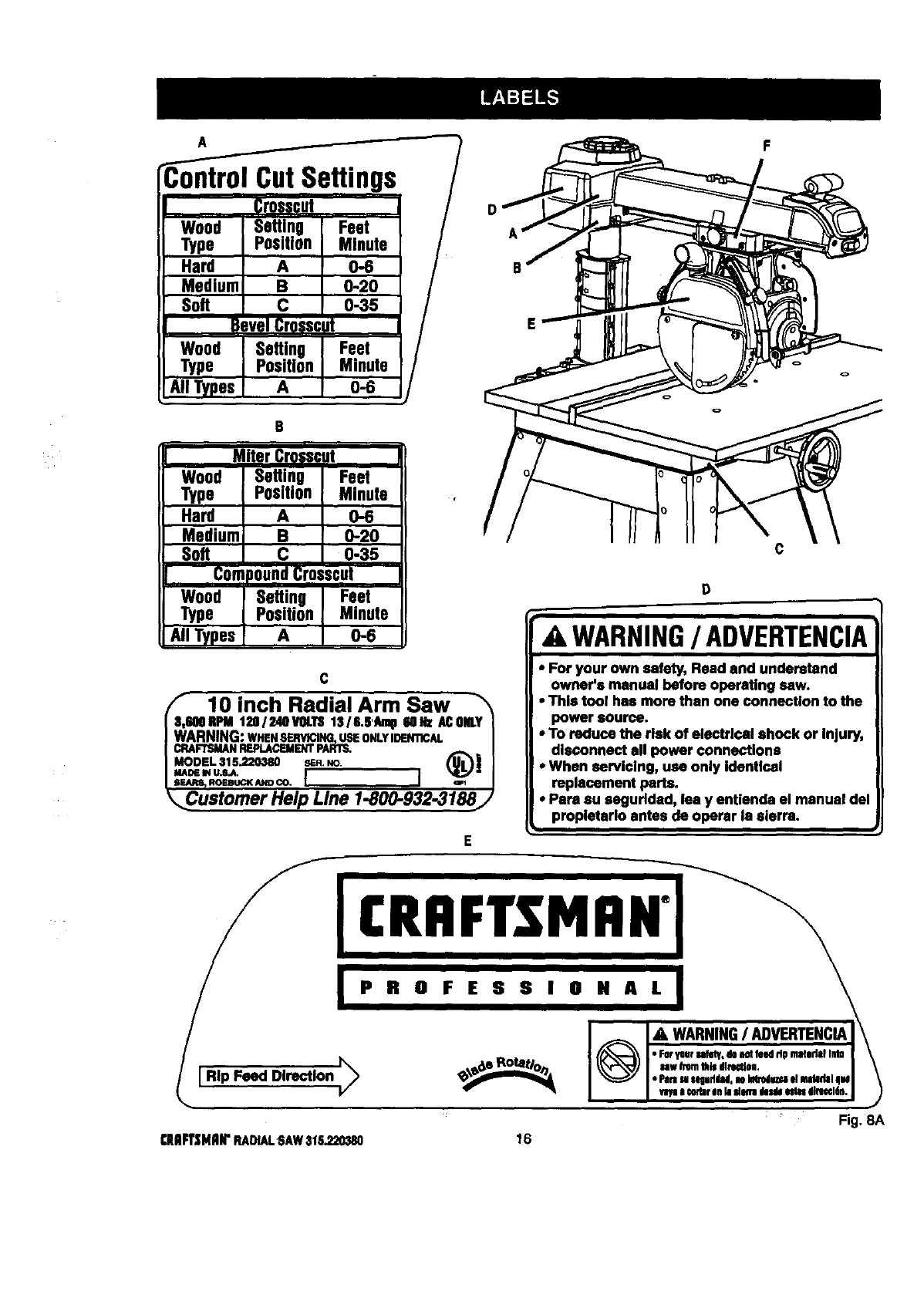
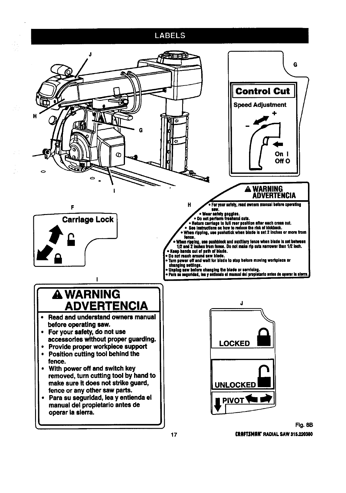
-ontrol CutSettings
Crospcut
Wood Seftlng Feet
Type Position Minute
Hard A 0-6
Medium B 0-20
Soft C 0-35
B ,vel Cr0sscJt
Wood Setting Feet
Type Position Minute
All Types A 0-6
e
Wood ISetting Feet
Type [ Position Minute ,
Hard IA 0-6
Mediuml e0-20
Soft I c 0-35
CompoundCr0=scot
Wood i Setting Feet
Type IPosition Minute
S.IITypes A 0-6
D
F
C
10 inch Radial Arm Saw _'_
600RPM120/2410VOLTS1316.6'Aml16oez ACONLY[
RNING:WHENSERVICING,USEONLYIIDEN'I1CAL |
FTSMANREPLACEMENTPARTS, /
ROEBUCKANDCO, I ] wl J
sterner Help Line 1-800-932-3188/
c
WARNING/ADVERTENCIA
• For your own safety, Read and understand
owner's manual before operating saw.
•This tool has more than one connection to the
power source.
• To reduce the risk of electrical shock or Injury,
disconnect all power connections
•When sarvlclng, usa only Identical
replacement parts.
•Para au segurldad, lea y entlenda el manual del
propletarlo antes de operar la sierra.
Fig. 8A
(HFT_;NRIrRADIALSAW316,220_10 16
H
F
r- :rr'.e'ock1
AWARNING
ADVERTENCIA
• Read and understand owners manual
before operating sew.
•For your safety, do not use
accessories without proper guarding.
•Provide proper workplece support
•Position cutting tool behind the
fence.
•With power off and switch key
removed, turn cutting tool by hand to
make sure it does not strike guard,
fence or any other sew parts.
•Pare su segurlded, lea y entlenda el
manual del propletario antes de
operar is sierra.
Control Cu_t
On I
Ofre
i
'_&WARNING
i_._,. ADVERTENClA
H._ F_pw sahd,/,read0Nm maualbeta.op_'_q
J" "War_hqOlu.
f• Donotpedormfreehandeots.
J• Returncankigatofull rearpsaltisaalter eachcrossrut,
/• SeeInotn_lonsoll hawtoreducethe riskM M_.
i"men dpplng,use pus_ rosa blade_sot2 InchesormoreDin
J _nu.
/•WhimdbPlng,m p_l_ andauxiliary lamawhsabladeIssotbotlsa
flf2 end2 inchesfromtom:o.Ohnotrake dp aidsnarrewerthan1/2 ioch,
r • Ksaphandsoutofpathof btoda,
, OnnotIHch nroungsawblade.
Turnpower offandwalt to_ bladeto stopbeforemovingworkplaceor
changingsattlnp.
DUnglngsawbeforechangingthe bladeorsarviving,
, Paresasngultdad,len yeotlendael msauotdviproplviadoantesde090mrhislofla
Fig. 8B
17 ClUiFl'|HlilrRADIALSAW316,320380
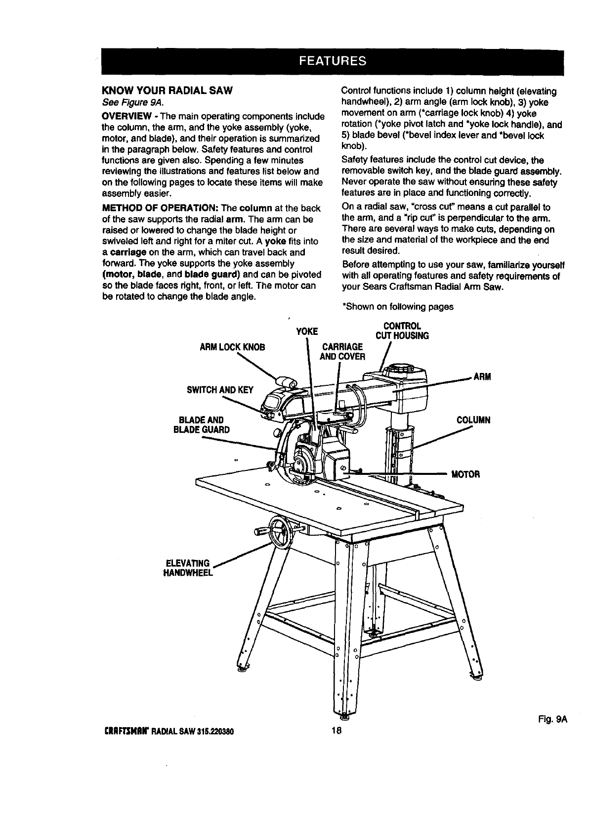
KNOWYOURRADIALSAW
See Figure 9A.
OVERVIEW -The mainoperatingcomponentsinclude
the column, the arm, and the yoke assembly (yoke,
motor,and blade), and their operationis summarized
in the paragraph below. Safetyfeatures and control
functionsare given also. Spendinga few minutes
reviewingthe illustrationsand features list below and
on the followingpages to locate these items will make
assemblyeasier.
METHOD OF OPERATION: The column at the back
of the saw supportsthe radialarm. The arm can be
raised or loweredto change the blade heightor
swiveled left and rightfor a mitercut. A yoke fits into
a Carriage on the arm, which can travel back and
forward. The yoke supportsthe yoke assembly
(motor, blade, and blade guard) and can be pivoted
so the blade faces right,front,or left. The motorcan
be rotatedto change the blade angle.
Controlfunctions include 1) column height(elevating
handwheel), 2) arm angle (arm lockknob),3) yoke
movementon arm (*carriage lockknob) 4) yoke
rotation(*yoke pivot latchand *yoke lockhandle), and
5) blade bevel (*bevel index lever and *bevel lock
knob).
Safety features includethe controlcut device, the
removableswitchkey, and the blade guard assembly.
Never operate the saw withoutensudngthese safety
features are in place and functioning correctly.
On aradialsaw, =crosscut" means a cut parallel to
the arm, and a "ripcut' is perpendicularto the arm.
There are several ways to make cuts, dependingon
the size and material of the workpieceand the end
resultdesired.
Beforeattemptingto use your saw, familiarize yoursaff
withall operatingfeatures and safety requirementsof
your Sears Craftsman Radial Arm Saw.
*Shownon following pages
ARMLOCKKNOB
YOKE
CARRIAGE
ANDCOVER
CONTROL
CUTHOUSING
SWITCHANDKEY
BLADEAND
BLADEGUARD COLUMN
MOTOR
ELEVA_NG
HANDWHEEL
Fig. 9A
[IIIIF'Ir$MRWRADIALSAW31S.220380 18
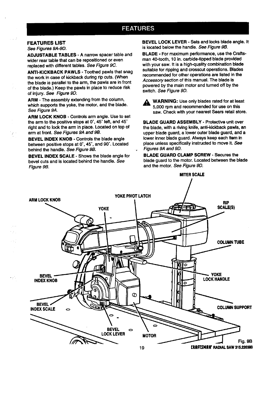
FEATURESLIST
See Figures 9A-9D.
ADJUSTABLE TABLES -A narrowspacer table and
wider rear table that can be repositionedor even
replacedwith differenttables. See Figure 9C.
ANTI-KICKBACK PAWLS - Toothed pawlsthat snag
the workin case of kickbackduring ripcuts. (When
the blade is parallel to the arm, the pawls are in front
of the blade.) Keep the pawlsin placeto reduce risk
of injury.See Figure 9D.
ARM - The assemblyextendingfrom the column,
whichsupportsthe yoke, the motor,and the blade.
See Figure 9A.
ARM LOCK KNOB - Controlsarm angle. Use to set
the arm to the positivestopsat 0", 45" left,and 45"
rightand to lock the arm inplace. Located on top of
arm at front. See Figures 9A and gB.
BEVEL INDEX KNOB - Controlsthe blade angle
between positivestopsat 0", 45", and 90". Located
behind the handle. See Figure gB.
BEVEL INDEX SCALE -Showsthe blade angle for
bevel cuts and is located behind the handle. See
Figure 9B.
BEVEL LOCK LEVER - Sets and locksblade angle. It
is located below the handle. See Figure 9B.
BLADE -For maximumperformance,use the Crafts-
man 40-tooth, 10 in. carbide-tipped blade provided
withyour saw. It is a high-qualitycombination blade
suitablefor rippingand crosscutoperations. Blades
recommendedfor other operationsare listed inthe
Accessorysectionof thismanual. The blade is
powered by the main motor and turnedoff by the
switch. See Figure 9D.
_, WARNING: Use only blades ratedfor at least
5,000 rpm and recommendedfor use on this
saw. Check withyour nearest Sears retailstore.
BLADE GUARD ASSEMBLY -Protective unitover
the blade, witharivingknife, anti-kickbackpawls, an
upper blade guard, alowerouter blade guard, and a
lower innerblade guard. Alwayskeep each item in
place unlessspecificallyinstructedto move it. See
Figures 9A and 9D.
BLADE GUARD CLAMP SCREW -Secures the
blade guardto the motor.Located between the blade
and the motor. See Figure 9D.
MITERSCALE
ARMLOCKKNOB YOKEPIVOTLATCH
YOKE
RIP
SCALE(S)
COLUMNTUBE
BEVEL
INDEXKNOB
YOKE
LOCKHANDLE
BEVEL
INDEXSCALE
ER MOTOR
19
COLUMNSUPPORT

CARRIAGE- Shdesalongtrackunderarmand
supportsyoke. Containedin two carriage covers, one
on each side of the arm. See Figure 9C.
CARRIAGE LOCK KNOB -Controlswhether the
carriage is locked or can travel Located on the left
side of the arm on the carnage cover. See Figure 9C.
COLUMN -Updght housingat the back of the saw,
consistingof a columnsupportand a column tube.
The columntube can be raised or loweredwith the
elevating handwheel at the frontof the saw See
Figures 9A and 9B.
CONTROL CUT DEVICE -Limitscarriagespeed to
prevent climb, usinga cable from the cardage to the
column. Has a separate motoron left side, which is
activated by the switchtriggerin the handle. The
cable returns the carriage to the columnwhen the
motoris notactivated. Speed is adjustedwitha
thumbwheel on the handle. It runs on a separate
120V AC singlevoltage circuit See Figure 9C.
_i, WARNING: When connecting onlyone of'the
cords,squeeze the switchtdggerinthe handle. If
the mare motorcord alone is connected, the
switchtrigger inthe handlewill notoperate the
controlcut device. The carriage cannot be
advanced withoutpower to the controlcut device.
DUAL VOLTAGE -If needed, your main power
source may be rewired by a qualifiedelectdcianto
providea240V AC circuit. See the Electricalsection.
DUST GUIDE -Directssawdust, created from the cut
being made, inthe directionyou set. Located at the
rear of the upperblade guard. See Figure 9D.
ELEVATING HANDWHEEL -The handwheel below
the worktable(in front)that changes the heightof the
arm and the blade. See Figure 9C.
FENCE -Removable guide forwork, which extends
across w_dthof table, See Figure 9C.
FRONT TABLE -Fixed portionof the worktablethat
supportsthe work. See Figure 9C.
HANDLE -Used to pull the yoke assembly. Mounted
on the yoke to the rightof the blade. See Figure 9C.
HOLD DOWN -A metal guardto control workpiece
climbdudng ripcuts. When blade parallelsarm, hold
down is overthe back of the blade. See Figure 9D.
HOLD DOWN KNOB -Controlsplacement of the hold
down and locksit m place. See Figure 9D.
MITER SCALE - Shows the miterangle settingof the
arm. See Figure 9B.
TRACK CARRIAGE CARRIAGE
LOCKKNOB ANDCOVER
CONTROL
CUTMOTOR
CONTROL
CUTCABLE
REAR
TABLE
SPACER
TABLE
SWITCH
ANDKEY
CONTROLCUT
THUMBWHEEL
FRONTTABLE
FENCE ELEVATING
HANDWHEEL
Fig. gC
qtlIIRSNRWRADIALSAW315.2L_B0 20
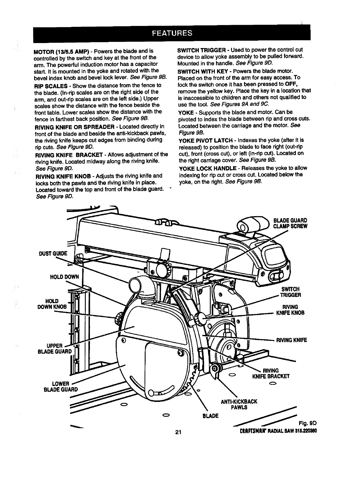
MOTOR(13/6.5AMP)- Powersthebladeandis
controlledbytheswitchand key at the frontof the
arm. The powerful inductionmotorhas a capacitor
start. It is mountedinthe yoke and rotatedwith the
bevel index knob and bevel locklever. See Figure 9B.
RIP SCALES - Show the distancefrom the fence to
the blade. (In-dp scales are on the rightside of the
arm, and out-ripscales are on the left side.) Upper
scales show the distance withthe fence beside the
fronttable. Lower scales showthe distancewith the
fence in farthest back position. See Figure 9B.
RIVING KNIFE OR SPREADER - Located directlyin
front of the blade and beside the anti-kickbackpawls,
the rivingknife keeps cut edges from bindingduring
rip cuts, See Figure 9D.
RIVING KNIFE BRACKET - Allowsadjustmentof the
dving knife. Located midway along the rivingknife.
See Figure 9D.
RIVING KNIFE KNOB - Adjuststhe rivingknifeand
locksbeth the pawls and the rivingknife in place.
Located toward the top and front of the blade guard. '
See Figure 9D.
SWITCH TRIGGER -Used to power the controlcut
deviceto allow yoke assemblyto be pulledforward.
Mounted in the handle. See Figure 9D.
SWITCH WITH KEY -Powersthe blade motor.
Placed onthe front of the arm for easy access. To
lockthe switchonce it has been pressed to OFF,
removethe yellow key. Place the key in a locationthat
is inaccessibleto childrenand others notqualifiedto
use the tool. See Figures 9A and 9C.
YOKE -Supportsthe blade and motor.Can be
pivotedto index the blade between rip and crosscuts.
Located between the carriage and the motor. See
Figure 9B.
YOKE PIVOT LATCH -indexes the yoke (after it is
released) to positionthe blade to face right(out-rip
cut), front (crosscut), or left (in-rip cut). Located on
the rightcardage cover. See Figure 9B.
YOKE LOCK HANDLE -Releases the yoke to allow
indexingfor ripcut orcross cut. Located belowthe
yoke, on the right. See Figure 9B.
DUSTGUIDE
HOLD DOWN
HOLD
DOWNKNOB
SWITCH
RIVING
UPPER
BLADEGUARD :
RIVINGKNIFE
LOWER
BLADEGUARD
21
BLADE
RIVING
oKNIFEBRACKET
ANTI-KICKBACK
__ Fig. 9D
rlUIFTSNIIWRADIALSAWStl;_mSO
Assembly is best done in the area where the saw will
be used. When you removethe saw and hardware
fromthe packingmatedals, carefullycheck the items
withthe Loose Parts list. If you are unsureabout the
descriptionof any part, refer to their illustrations.For
your convenience,all fasteners have been drawn
actual size. If any pads are missing,delay assembling
untilyou have obtained the missingpart(s).
Your radial arm saw is capable of a wide varietyof
operations,and thus requiresa numberof initialsetup
adjustments.However, once the saw is set up, you
can check yoursaw in about ten minutesand correct
any misalignmentwiththe proceduresin the Adjust-
ment section.
CAUTION: Perform all the proceduresin both
the Assemblyand Adjustmentssectionsbefore
usingthe saw. Run a check on your saw
frequently,referringto the Adjustmentssection.
Failure to performthe adjustmentsin the initial
set up or on a frequentbasiscan result inpoor
performanceor machine damage.
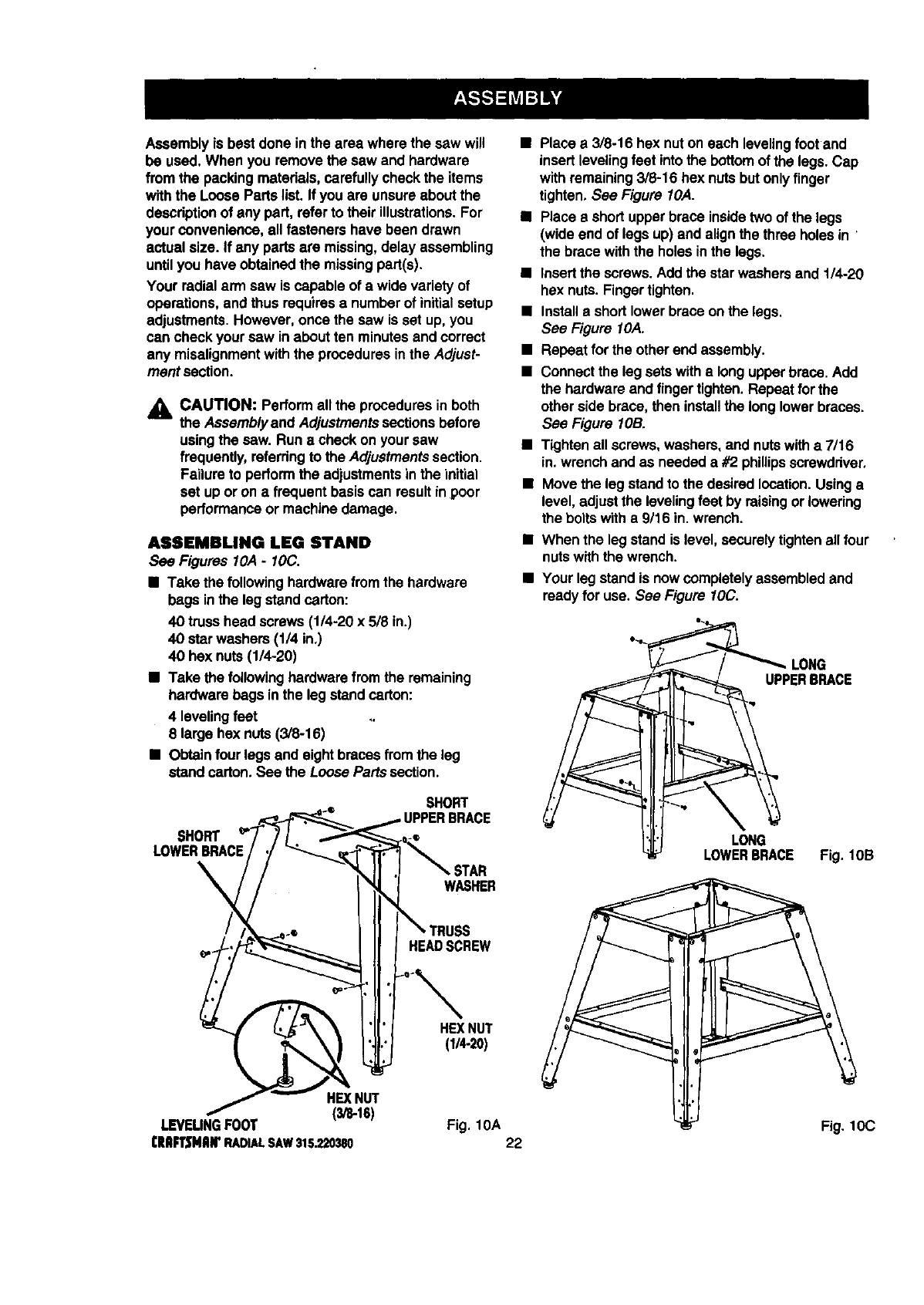
ASSEMBLING LEG STAND
See Figures 10,4-IOC.
•Take the followinghardwarefromthe hardware
bags inthe leg standcarton:
40 trusshead screws(1/4-20 x 5/8 in.)
40 star washers(1/4 in.)
40 hex nuts(1/4-20)
•Take the followinghardwarefrom the remaining
hardwarebags in the legstand carton:
4 levelingfeet
8 large hex nuts(3/8-16)
•Obtain four legsand eightbraces fromthe leg
stand carton. See the Loose Parts section.
•Place a 3/8-16 hex nuton each levelingfootand
insert levelingfeet intothe bottom of the legs. Cap
with remaining3/8-16 hex nutsbutonly finger
tighten. See Figure 10,4.
•Place a short upperbrace insidetwoof the legs
(wideend of legs up)and alignthe three holes in
the brace withthe holes inthe legs.
•Insertthe screws.Add the star washersand 1/4-20
hex nuts. Fingertighten.
•Installa shortlower brace on the legs.
See Figure I OA.
•Repeat forthe otherend assembly.
•Connectthe leg setswith a longupperbrace. Add
the hardwareand finger tighten.Repeat for the
other side brace, then installthe longlowerbraces.
See Figure lOB.
•Tighten all screws,washers, and nutswitha 7/16
in. wrench and as needed a #2 phillipsscrewdriver.
•Move the leg standto the desiredlocation.Usinga
level, adjustthe levelingfeet by raisingorlowering
the bolts witha 9/16 in. wrench.
•When the leg stand is level, securelytighten all four
nutswiththe wrench.
•Your legstand is now completelyassembled and
readyfor use. See Figure 10C.
LONG
UPPERBRACE
SHORT
SHORT
LOWERBRACE
;TAR
WASHER
HEADSCREW
HEXNUT
(1_-20)
HEXNUT
(3/8-16)
I.EVEUNGFOOT Fig. 10A
I:RIIR3MIIWRADIALSAW315.220380 22
LONG
LOWERBRACE Fig. lOB
Fig. 10C
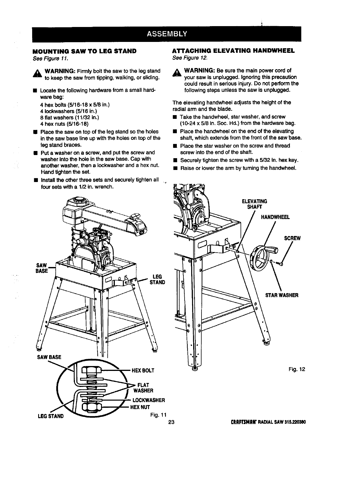
MOUNTING SAW TO LEG STAND
See Figure 11.
,_ WARNING: Firmlybolt the saw to the leg stand
to keep the saw from tipping,walking,or sliding.
•Locatethe followinghardwarefroma smallhard-
ware bag:
4 hex boils (5/16-18 x 5/8 in.)
4 Iockwashers(5/16 in.)
8 flat washers (11/32 in.)
4 hex nuts(5/16-18)
• Place the saw on top of the legstand so the holes
in the saw base line up withthe holeson top of the
leg standbraces.
•Put awasher on a screw,and put the screw and
washer intothe hole in the saw base. Cap with
another washer, then a Iockwasherand a hex nut.
Hand tightenthe set.
•Installthe otherthree setsand securelytightenall ,
four sets witha 1/2 in. wrench.
An'ACHING ELEVATING HANDWHEEL
See Figure 12.
_1= WARNING: Be surethe main power cord of
your saw is unplugged.Ignodngthisprecaution
could resultin seriousinjury.Do not performthe
followingsteps unlessthe saw is unplugged.
The elevating handwheeladjuststhe heightof the
radialarm and the blade.
•Take the handwheel,star washer, and screw
(10-24 x 5/8 in. Soc. Hd.) from the hardwarebag.
•Place the bandwheel on the end of the elevating
shaft,which extendsfromthe front of the saw base.
•Place the star washer on the screw and thread
screw intothe end of the shaft.
•Securely tightenthe screwwitha 5/32 in. hex key.
•Raiseor lowerthe arm by turningthe handwheel.
ELEVATING
SHAFT
HANDWHEEL
SCREW
SAW
BASE LEG
_TANO
STARWASHER
SAWBASE
Fig. 12
FLAT
LEGSTAND
HEX NUT
Fig. 11
23 CRRFTJ[MIIWRADIALSAW315,220380
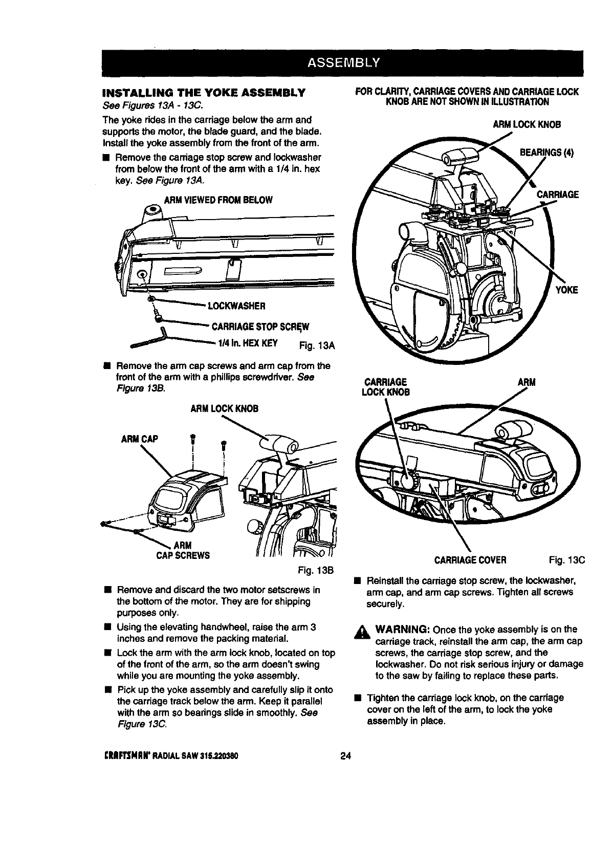
INSTALLING THE YOKE ASSEMBLY
See Figures 13A -13C.
The yoke rides in the carriage below the arm and
supportsthe motor,the blade guard, and the blade.
Installthe yoke assembly fromthe front of the arm.
• Removethe carriage stop screwand Iockwasher
from belowthe frontof the arm witha 1/4 in. hex
key. See Figure 13A.
ARMVIEWEDFROMBELOW
FORCLARITY,CARRIAGECOVERSANDCARRIAGELOCK
KNOBARENOTSHOWNINILLUSTRATION
ARMLOCKKNOB
BEARINGS(4)
CARRIAGE
_CARRIAGE STOPSCREW
1/4In.HEXKEY Fig. 13A
•Removethe arm cap screws and arm cap fromthe
frontof the arm with a phillipsscrewdriver, See
Figure 13B.
ARMCAP
ARM
CAPSCREWS
ARMLOCKKNOB
Fig. 13B
•Remove and discardthe two motorsetscrewsin
the bottomof the motor.They are for shipping
purposesonly.
•Usingthe elevatinghandwheel,raisethe arm 3
inches and removethe packingmaterial.
•Lockthe arm withthe arm lockknob,located on top
of the front of the arm, so the arm doesn't swing
while youare mountingthe yoke assembly.
•Pick upthe yoke assemblyand carefullyslipit onto
the carriage track below the arm. Keep it parallel
withthe arm so bearingsslide in smoothly,See
Figure 13C.
YOKE
CARRIAGE ARM
LOCKKNOB
CARRIAGECOVER Fig. 13C
•Reinstallthe cardage stopscrew,the Iockwasher,
arm cap, and arm cap screws,Tighten all screws
securely.
_IL WARNING: Once the yoke assemblyis onthe
carriage track, reinstallthe arm cap, the arm cap
screws, the carriagestop screw,and the
Iockwasher.Do not riskserious injuryor damage
to the saw by failing to replace these parts.
•Tighten the carriage lockknob,on the carriage
cover on the left of the arm, to lockthe yoke
assembly in place.
[Rlllrl3MIIIr RADIALSAW316_20380 24
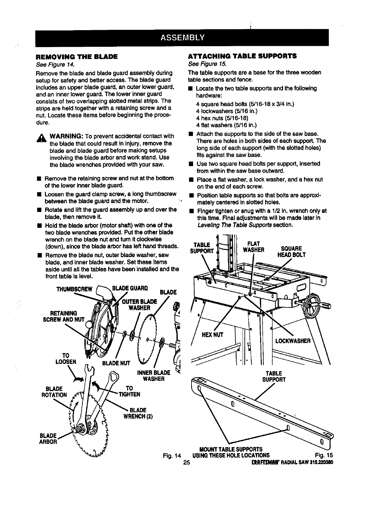
REMOVING THE BLADE
See Figure 14.
Remove the blade and blade guard assemblyduring
setupfor safety and betteraccess. The blade guard
includesan upper blade guard, an outer lower guard,
and an inner lowerguard. The lower innerguard
consistsof two overlappingslotted metal strips.The
stripsare held togetherwith a retainingscrew and a
nut. Locatethese items before beginningthe proce-
dure.
_i, WARNING: To prevent accidentalcontactwith
the blade that couldresult in injury,remove the
blade and blade guard before makingsetups
involvingthe blade arbor and workstand. Use
the blade wrenches providedwithyour saw.
•Remove the retainingscrew and nut at the bottom
of the lower innerblade guard.
•Loosenthe guardclamp screw,a longthumbscrew
between the blade guard andthe motor.
•Rotateand liftthe guardassembly up and overthe
blade, then remove it.
•Holdthe blade arbor (motorshaft) withone of the
two blade wrenches provided.Put the otherblade
wrench onthe blade nutand turn it clockwise
(down), sincethe blade arborhas left hand threads.
•Remove the blade nut, outer blade washer, saw
blade, and inner blade washer. Set these Items
aside untilall the tables have bean installedand the
fronttable is level.
THUMBSCREW BLADE
RETAINING
SCREWANDNUT
TO
LOOSEN
\
BLADE
ROTATION
BLADENUT
TO
INNERBLADE
WASHER
BLADE
WRENCH(2)
BLADE
ARBOR _'_
ATTACHING TABLE SUPPORTS
See Figure 15.
The table supportsare a base for the three wooden
table sectionsand fence.
•Locatethe two table supportsand the following
hardware:
4 square head bolts(5/16-18 x 3/4 in.)
4 Iockwashers(5/16 in.)
4 hex nuts (5/16-18)
4flat washers(5/16 in.)
•Attachthe supportsto the side of the saw base.
There are holes in bothsidesof each support.The
longsideof each support(withthe slottedholes)
fits against the saw base.
BUse two square head boltsper support,inserted
from withinthe saw base outward.
•Place a fiat washer, a lockwasher, and a hex nut
on the end of each screw.
•Positiontable supportsso that boltsare approxi-
matelycentered in slottedholes.
•Fingertightenorsnug witha 1/2 in. wrench onlyat
thistime. Finaladjustmentswill be made later in
Leveling The Table Supportssection.
TABLE FLAT
SUPPORT WASHER SQUARE
HEAl)BOLT
TABLE
SUPPORT
MOUNTTABLESUPPORTS
Fig, 14 USINGTHESEHOLELOCATIONS Fig. 1B
25 rltRFTSNRB"RADIALSAW315.220_I0
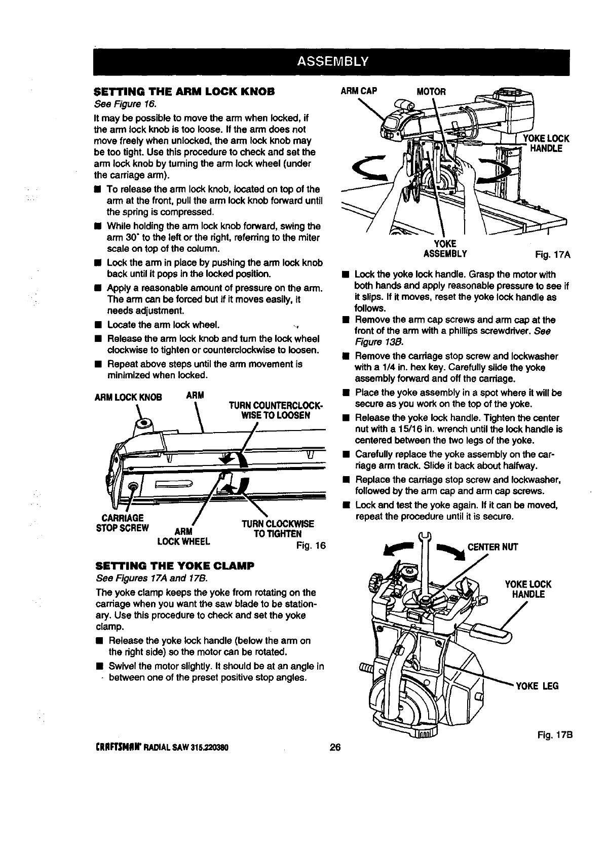
SET'rING THE ARM LOCK KNOB
See Figure 16.
It may be possibleto move the arm when locked,if
the arm lockknob is too loose•If the arm does not
move freely when unlocked,the arm lock knob may
be too tight. Use thisprocedureto check and set the
arm lock knob by turningthe arm lock wheel (under
the carriage arm).
•To releasethe arm lockknob,located on topof the
arm at the front,pullthe arm lockknob forwarduntil
the spring is compressed.
•While holdingthe arm lockknob forward,swing the
arm 30" to the left orthe right,referring to the miter
scale on top of the column.
•Lockthe arm in placeby pushingthe arm lockknob
back untilit popsin the lockedposition.
•Applya reasonableamount of pressureonthe arm.
The arm can be forced butif it moves easily, it
needs adjustment.
•Locatethe arm lockwheel. _,
•Release the arm lockknoband turn the lockwheel
clockwiseto tightenor countemiockwise to loosen.
•Repeat above steps untilthe arm movementis
minimizedwhen locked.
ARMLOCKKNOB ARM TURNCOUNTERCLOCK-
WISETO LOOSEN
CARRIAGE TURNCLOCKWISE
STOPSCREW ARM TOTIGHTEN
LOCKWHEEL Fig. 16
SET'rING THE YOKE CLAMP
See Figures 17.4and 17B.
The yoke clamp keeps the yoke from rotatingon the
carriage when you want the saw blade to be station-
ary. Use thisprocedureto check and set the yoke
clamp.
•Release the yoke lock handle(below the arm on
the dghtside) so the motorcan be rotated.
•Swivelthe motorslightly•Itshould be at an angle in
•between one of the presetpositivestopangles.
ARMCAP MOTOR
YOKELOCK
HANDLE
YOKE
ASSEMBLY Fig. 17A
•Lockthe yoke lockhandle. Graspthe motorwith
both hands and apply reasonablepressureto see if
it slips.If it moves, reset the yoke lock handleas
follows.
•Remove the arm cap screwsand arm cap at the
front of the arm with a phillipsscrewdriver.See
Figure 13B.
•Remove the cardage stopscrew and Iockwasher
with a 1/4 in. hex key. Carefullyslidethe yoke
assemblyforwardand offthe carriage.
•Place the yoke assemblyin a spotwhere itwill be
secure as you workon the top of the yoke.
•Release the yoke lockhandle. Tightenthe center
nutwith a15/16 in. wrench untilthe lockhandleis
centered between the two legsof the yoke.
•Carefully replace the yoke assemblyon the car-
riage arm track.Slide it back about halfway.
•Replace the cardage stopscrew and Iockwasher,
followed by the arm cap and arm cap screws.
•Lockand test the yoke again. If it can be movsd,
repeatthe procedureuntil it is secure.
_CENTERNUT
YOKELOCK
HANDLE
LEG
Fig. 17B
[lUlFT|NIIIr RADIALSAW315.220380 26
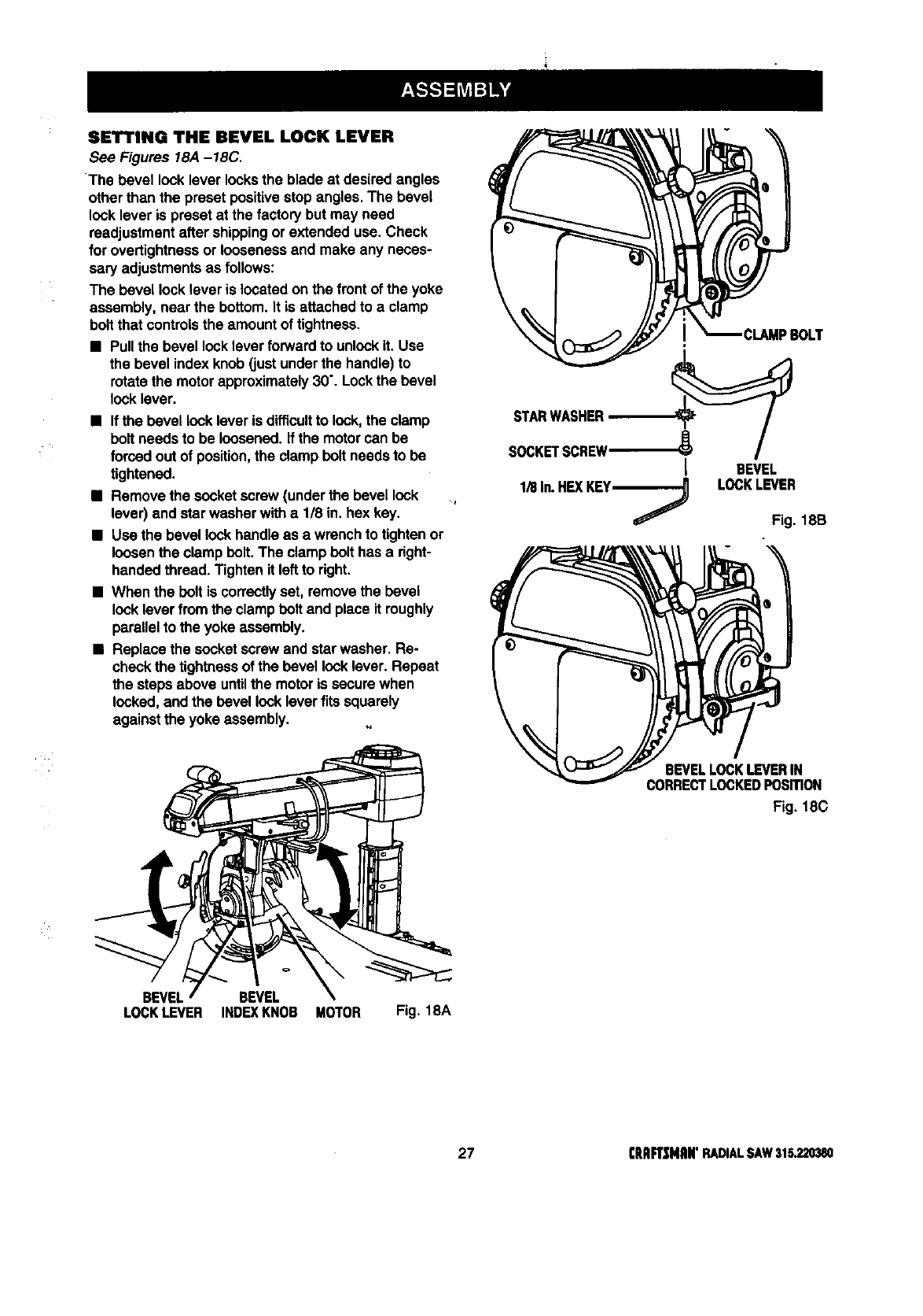
SETTING THE REVEL LOCK LEVER
See Figures 18A-18C,
The bevel lock lever locksthe blade at desired angles
other than the preset positivestop angles.The bevel
lock lever is preset at the factorybut may need
readjustmentafter shippingor extended use. Check
for overtightnessor loosenessand make any neces-
sary adjustmentsas follows:
The bevel locklever is locatedon the frontof the yoke
assembly, near the bottom.It is attachedto a clamp
boltthat controlsthe amount of tightness.
•Pullthe bevel locklever forwardto unlockit. Use
the bevel index knob (justunderthe handle)to
rotatethe motorapproximately30".Lockthe bevel
locklever.
•If the bevel locklever is difficultto lock,the clamp
boll needsto be loosened,if the motorcan be
forced outof position,the clamp boltneeds to be
tightened.
•Remove the socket screw (underthe bevellock
lever) and star washer witha 1/8 in. hex key.
•Use the bevel lockhandle as a wrenchto tightenor
loosenthe clamp bolt.The clamp belt has a right-
handedthread. Tighten it leftto right.
•When the boltis correctlyset, removethe bevel
locklever fromthe clampboil and place it roughly
parallel to the yoke assembly.
•Replace the socket screw and star washer, Re-
check the tightnessof the bevellocklever. Repeat
the steps above untilthe motoris secure when
locked,and the bevel locklever fitssquarely
againstthe yoke assembly.
STARWASHER
SOCKETSCREW'_'_ I
1/8 In. HEXKEym----_ BEVEL
LOCKLEVER
Fig. 18B
BEVEL BEVEL
LOCKLEVER INDEXKNOB MOTOR Fig. 18A
BEVELLOCKLEVERIN
CORRECTLOCKEDPOSITION
Fig, 18C
27 (RIIFT_[NAN"RADIALSAW315,220380
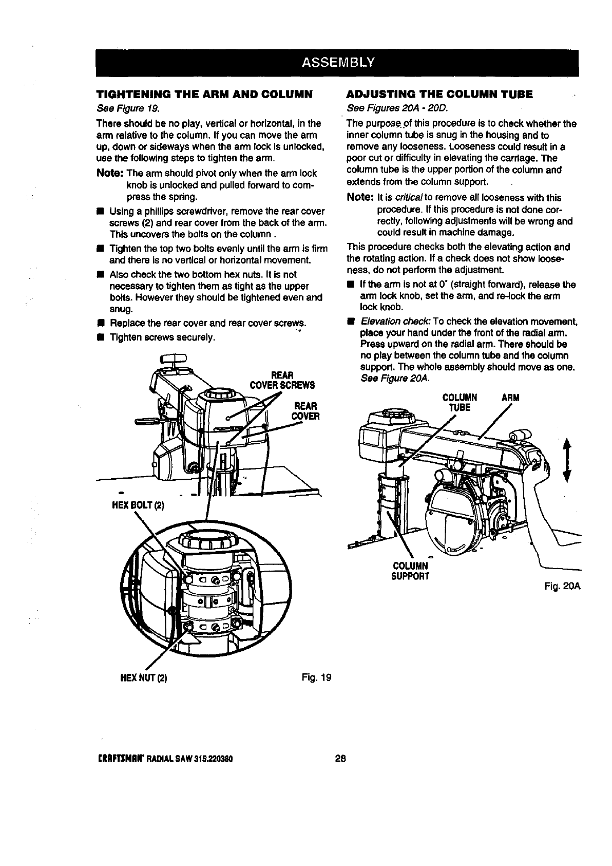
TIGHTENING THE ARM AND COLUMN
See Figure 19.
There should be no play, vertical or horizontal,in the
arm relativeto the column. If youcan movethe arm
up, down or sidewayswhen the arm lockis unlocked,
use the followingsteps to tightenthe arm,
Note: The arm shouldpivot onlywhen the arm lock
knob is unlockedand pulled forwardto com-
pressthe spdng.
• Usinga phillipsscrewdriver,removethe rear cover
screws (2) and rear coverfrom the backof the arm.
This uncoversthe boltson the column.
•Tighten the top two bolts evenly untilthe arm is firm
and there is no vertical or horizontalmovement.
•Also check the two bottomhex nuts. It is not
necessaryto tightenthem as tight as the upper
bolts.Howeverthey shouldbe tightenedeven and
snug.
•Replace the rear cover and rear coverscrews.
•Tighten screws securely.
REAR
COVERSCREWS
REAR
COVER
HEXBOLT(2)
ADJUSTING THE COLUMN TUBE
See Figures 20A - 20D.
The purpos¢.pfthis procedureis to check whether the
inner column tube is snug in the housingand to
remove any looseness. Loosenesscould resultin a
poorcut or difficultyin elevatingthe carriage. The
columntube is the upperportionof the columnand
extendsfrom the columnsupport,
Note: It is crftica/to removeall loosenesswiththis
procedure. If thisprocedureis notdone cor-
rectly,followingadjustmentswill be wrongand
couldresultin machine damage.
This procedurechecks both the elevatingaction and
the rotatingaction. If a check does not show loose-
ness, do not performthe adjustment.
• If the arm is notat O"(straightfonNard), release the
arm lock knob,set the arm, and re-lockthe arm
lockknob.
•Elevationcheck:To check the elevationmovement,
placeyour hand underthe frontof the radialarm.
Press upwardon the radialarm.There should be
no play betweenthe column tubeand the column
support.The whole assembly shouldmove as one.
See Figure 20A.
COLUMN ARM
TUBE
COLUMN
SUPPORT Fig. 20A
HE](NUT(2) Fig. 19
(lUlF1]MIIW RADIALSAW316.220380 28
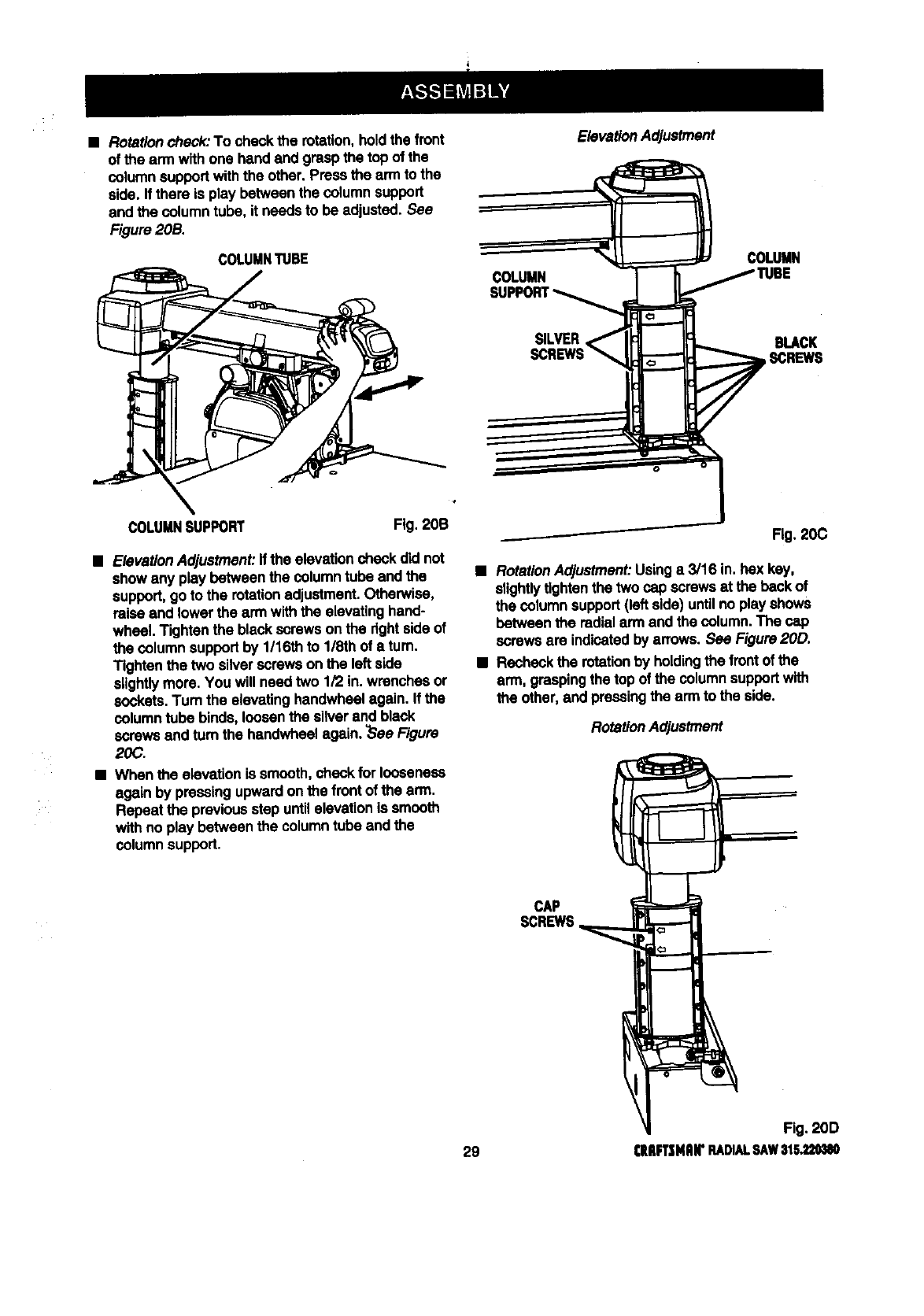
•Rotationcheck:To check the rotation, holdthe front
of the ann withone hand and grasp the top of the
columnsupportwiththe other.Press the arm to the
side. If there is play between the column support
and the columntube, it needs to be adjusted. See
Figure 20B.
COLUMNTUBE
ElevationAdjustment
COLUMN
COLUMN
SILVER BLACK
SCREWS
COLUMNSUPPORT Fig, 20B
•ElevationAdjustment:If the elevationcheck did not
showany play between the columntube and the
support,goto the rotationadjustment.Otherwise,
raiseand lowerthe ann withthe elevatinghand-
wheel. Tighten the blackscrews on the rightsideof
the columnsupportby 1/16th to 1/8th of aturn.
Tightenthe two silver screws on the left side
slightlymore. You will needtwo 1/2 in.wrenches or
sockets.Turn the elevatinghandwhselagain. If the
columntube binds, loosenthe silverand black
screws and tum the handwheelagain. ?SeeFigure
20C.
•When the elevationis smooth,check for looseness
again by pressingupwardon the front of the arm.
Repeat the previousstep untilelevationis smooth
withno play between the columntube and the
columnsupport.
Fig. 20C
•RotationAdjustment:Usinga 3/16 in. bax key,
slightlytightenthe two cap screwsat the back of
the columnsupport(left side) untilno playshows
between the radialarm and the column. The cap
screws are indicatedby arrows.See Figure20D.
•Recheckthe rotationby holdingthe frontof the
arm, graspingthe top of the columnsupportwith
the other,and pressingthe ann to the side.
RotationAdjustment
CAP
SCREWS
Fig. 2OD
29 CIIIIFTSNAI('RADIALRAW$1S.,_
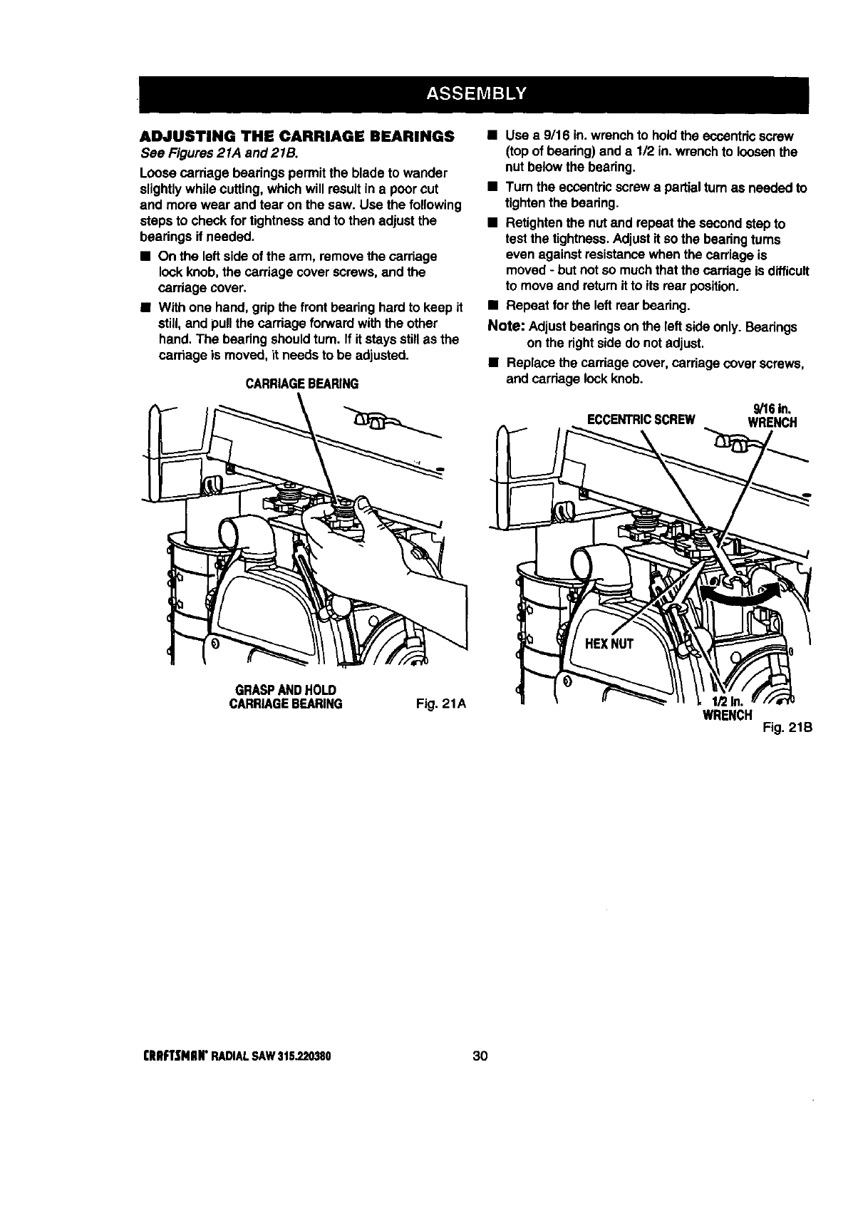
ADJUSTING THE CARRIAGE BEARINGS
See Figures21A and 215.
Loose carriage bearings permitthe blade to wander
slightlywhile cutting,which will resultin a poorcut
and more wear and tear on the saw. Use the following
steps to check fortightnessand to then adjust the
beadngs if needed.
•On the leftside of the arm, removethe carriage
lockknob,the carriage coverscrews,and the
carriage cover.
•With one hand,grip the front bearinghard to keep it
still,and pullthe carriage forwardwiththe other
hand. The beadng shouldturn. If it staysstillas the
carriage is moved, it needsto be adjusted.
CARRIAGEBEARING
•Use a 9/16 in. wrenchto holdthe eccentricscrew
(top of beadng) and a 1/2 in. wrench to loosenthe
nut belowthe bearing.
•Turn the eccentricscrew a partialturn as needed to
tightenthe bearing.
•Retighten the nut and repeatthe second stepto
testthe tightness.Adjustif so the bearingturns
even against resistancewhenthe carriage is
moved-butnot so muchthat the carriage is difficult
to move and retum it to its rear position.
•Repeat for the left rearbearing.
Note: Adjustbearingson the leftside only. Bearings
on the rightsidedo notadjust.
•Replace the carriage cover, carriage coverscrews,
and carriagelockknob.
9/16In.
ECCENTRICSCREW WRENCH
GRASPANDHOLD
CARRIAGEBEARING Fig. 21A WRENCH Fig. 21B
I;RIIFTSNIIN"RADIALSAW315.220380 30
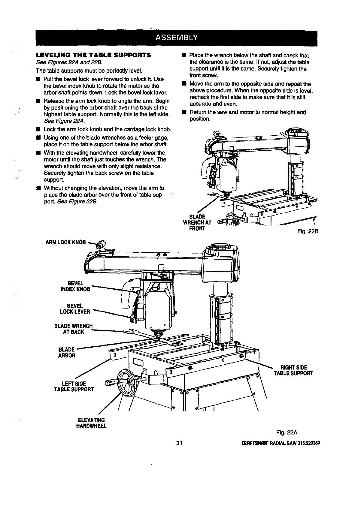
LEVELING THE TABLE SUPPORTS
See Figures 22,4 and 22B.
The table supports must be perfectlylevel.
•Pull the bevel locklever forwardto unlockit. Use
the bevel index knobto rotatethe motorso the
arborshaft pointsdown. Lockthe bevel lock lever.
•Release the arm lockknob to angle the arm. Begin
by positioningthe arborshaft over the back of the
highesttable support.Normallythis is the left side.
See Figure 22,4.
•Lockthe arm lockknob and the cardage lockknob.
•Usingone of the blade wrenchesas a feeler gage,
place it on the table supportbelow the arbor shaft.
•With the elevating handwheel,carefullylower the
motor untilthe shaftjust touchesthe wrench.The
wrenchshould move withonly slightresistance.
Securelytightenthe back screw on the table
support.
iWithoutchangingthe elevation, move the arm to
place the blade arbor over the frontof table sup- '
port. See Figure 22B.
Place the wrench belowthe shaft and checkthat
the clearance is the same. If not, adjustthe table
supportuntilit is the same, Securelytightenthe
frontscrew,
•Movethe arm to the oppositeside and repeat the
above procedure.When the oppositeside is level,
recheckthe firstsideto make surethat it is still
accurate and even.
•Returnthe saw and motorto normalheightand
position.
BLADE
WRENCHAT
FRONT Fig. 22B
BEVEL
INDEXKNOB
BEVEL
LOCKLEVER
BLADEWRENCH
AT BACK
BLADE
ARBOR
LEFTSIDE
TABLESUPPORT
RIGHTSIDE
TABLESUPPORT
ELEVATING
HANDWHEEL
Fig. 22A
31 [IIRFTSHRII"RADIALSAW315.220380
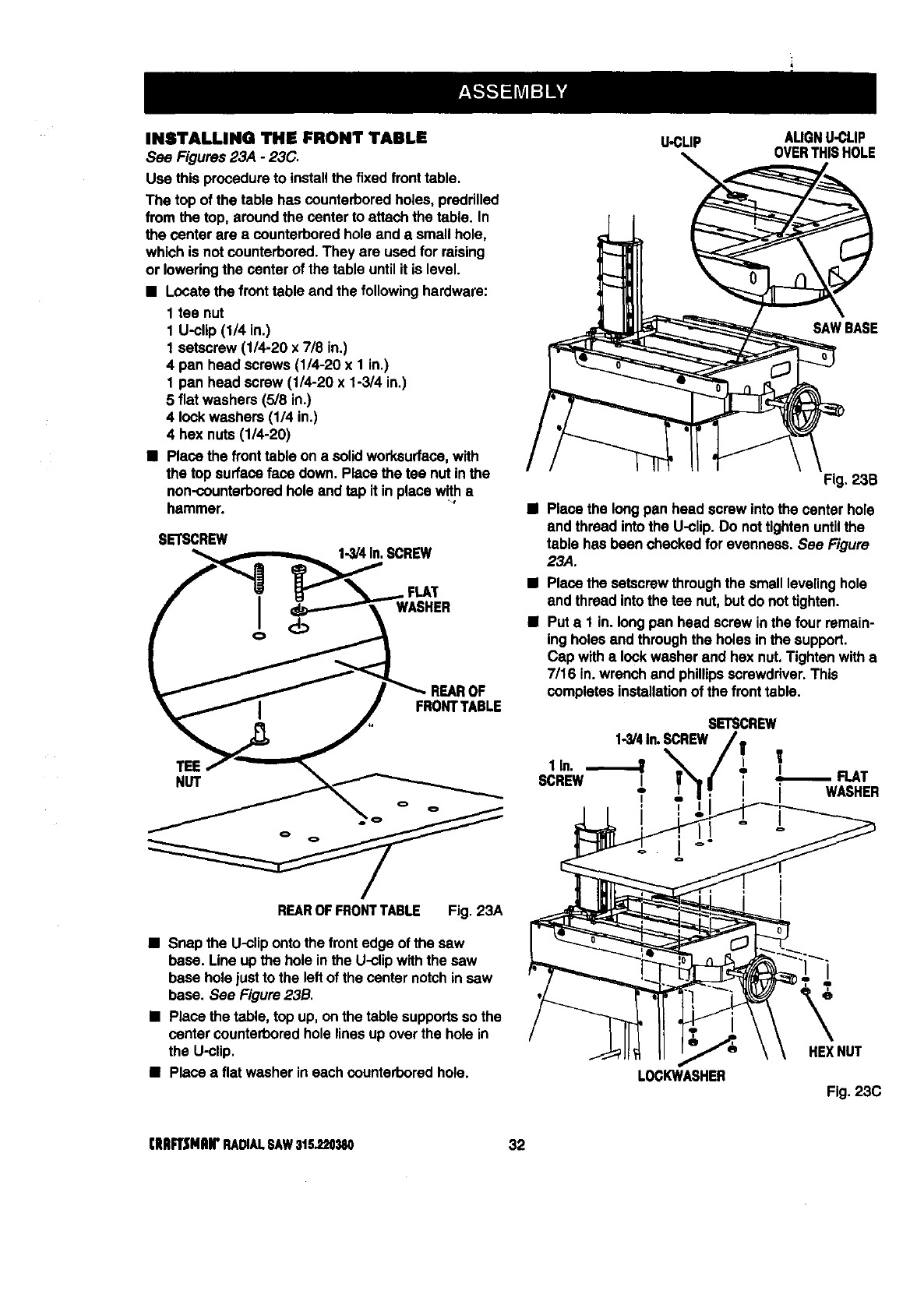
INSTALLING THE FRONT TABLE
See Figures 23,4 -23C.
Use thisprocedureto installthe fixed fronttable.
The top of the table has counterboredholes, preddlled
from the top, around the center to attach the table. In
the center are acounterboredhole and a smallhole,
which is not counterbored.They are used for raising
or loweringthe center of the table until it is level.
•Locate the fronttable and the followinghardware:
1 tee nut
1 U-clip (1/4 in.)
1 setscrew (1/4-20 x 7/8 in.)
4 pan head screws (1/4-20 x 1 in.)
1 pan head screw (1/4-20 x 1-3/4 in.)
5 fiat washers (5/8 in.)
4 lockwashers (1/4 in.)
4 hex nuts(1/4-20)
•Place the fronttable on a solidworksurfoce,with
the top surface face down. Place the tee nutin the
non-counterboredhole andtap it inplace with•
hammer.
SETSCREW 1.3/4In.SCREW
FLAT
WASHER
TEE
NUT
REAROFFRONTTABLE Fig. 23A
•Snap the U-cliponto the front edge of the saw
base. Line up the hole inthe U-clipwiththe saw
base hole justto the leftof the center notchin saw
base. See Figure 23B.
•Place the table, top up, onthe table supportsso the
center counterboredhole linesup over the hole in
the U-clip.
•Place a flat washer in each counterboredhole.
U-CLIP AUGNU-CLIP
OVERTHISHOLE
Fig, 23B
BPlace the longpan head screw intothe center hole
and thread into the U-clip. Do nottightenuntilthe
table has been chockedfor evenness. See Figure
23,4.
•Place the setscrewthroughthe small levelinghole
end thread intothe tee nut, butdo nottighten.
•Put a1 in. long pan head screw in the four remain-
ing holes end throughthe holes in the support.
Cap with• lockwasher end hex nut, Tighten witha
7/16 in. wrench and phillipsscrewdriver.This
completesinstallationof the front table.
SETSCREW
1-3/4In.SCREW l
SCREwlln"_1 ; ,I°_ FLAT
I I WASHER
LOCKWASHER
HEXNUT
Fig.23C
[ERFTSMRWRADIALSAW315.220380 32
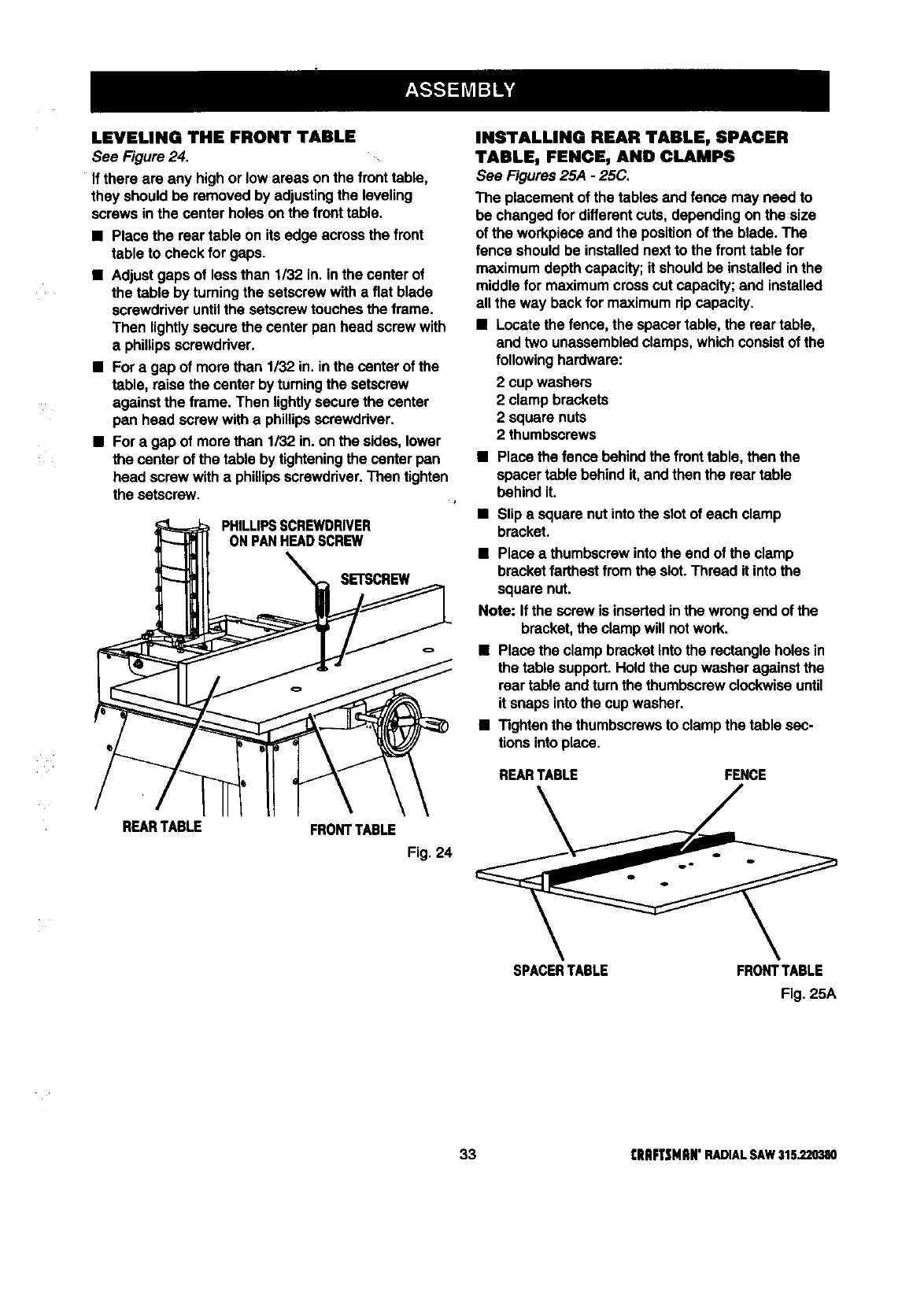
LEVELING THE FRONTTABLE
See Figure24.
If there are any high or lowareas onthe front table,
they should be removed by adjustingthe leveling
screws in the center holes on the front table.
•Place the rear table on its edge acrossthe front
table to check for gaps.
•Adjust gaps of less than 1/32 in. in the center of
the table by tuming the setscrewwith a fiat blade
screwdriveruntilthe setscrewtouches the frame.
Then lightlysecure the center pan head screw with
a phillipsscrewdriver.
•For a gap of more than 1/32 in. in the centerof the
table, raisethe center by turningthe setscrew
against the frame. Then lightlysecurethe center
pan head screw witha phillipsscrewdriver.
•For a gap of more than 1/32 in. on the sides, lower
the center of the table by tighteningthe center pan
head screw with a phillipsscrewdriver.Then tighten
the setscrew.
INSTALLING REAR TABLE, SPACER
TABLE, FENCE, AND CLAMPS
See Figures25A -25C.
The placement of the tablesand fence may need to
be changed for differentcuts,depending on the size
of the workpieceand the positionof the blade.The
fence shouldbe installednext to the front table for
maximumdepth capacity;it shouldbe installed inthe
middle for maximumcrosscut capacity;and installed
all the way back for maximumrip capacity.
•Locatethe fence, the spacertable, the rear table,
and two unassembledclamps,which consistof the
following hardware:
2 cup washers
2 clamp brackets
2 square nuts
2 thumbscrews
•Place the fence behindthe fronttable, then the
spacertable behindit, and thenthe reartable
behind it.
•Slip a square nutintothe slotof each clamp
PHILLIPSSCREWDRIVER bracket.
ONPANREADSCREW
_ll _% SETSCREW • Place a thumbscrewintothe end of the clamp
bracketfarthestfromthe slot.Thread it into the
enut
Note: If the screw is insertedinthe wrongend of the
bracket,the clampwill not work.
•Place the clampbracketintothe rectangleholes in
___ REARTABLE FENCEthe table support.Held the cupwasher against the
reartable and turn the thumbscrewclockwiseuntil
it snaps intothe cup washer,
•Tighten the thumbscrewsto clampthe table sec-
tions into place.
REARTABLE FRONTTABLE Fig 24
SPACERTABLE FRONTTABLE
Fig. 25A
33 [RRFTSNRWRADIALSAW315.220380
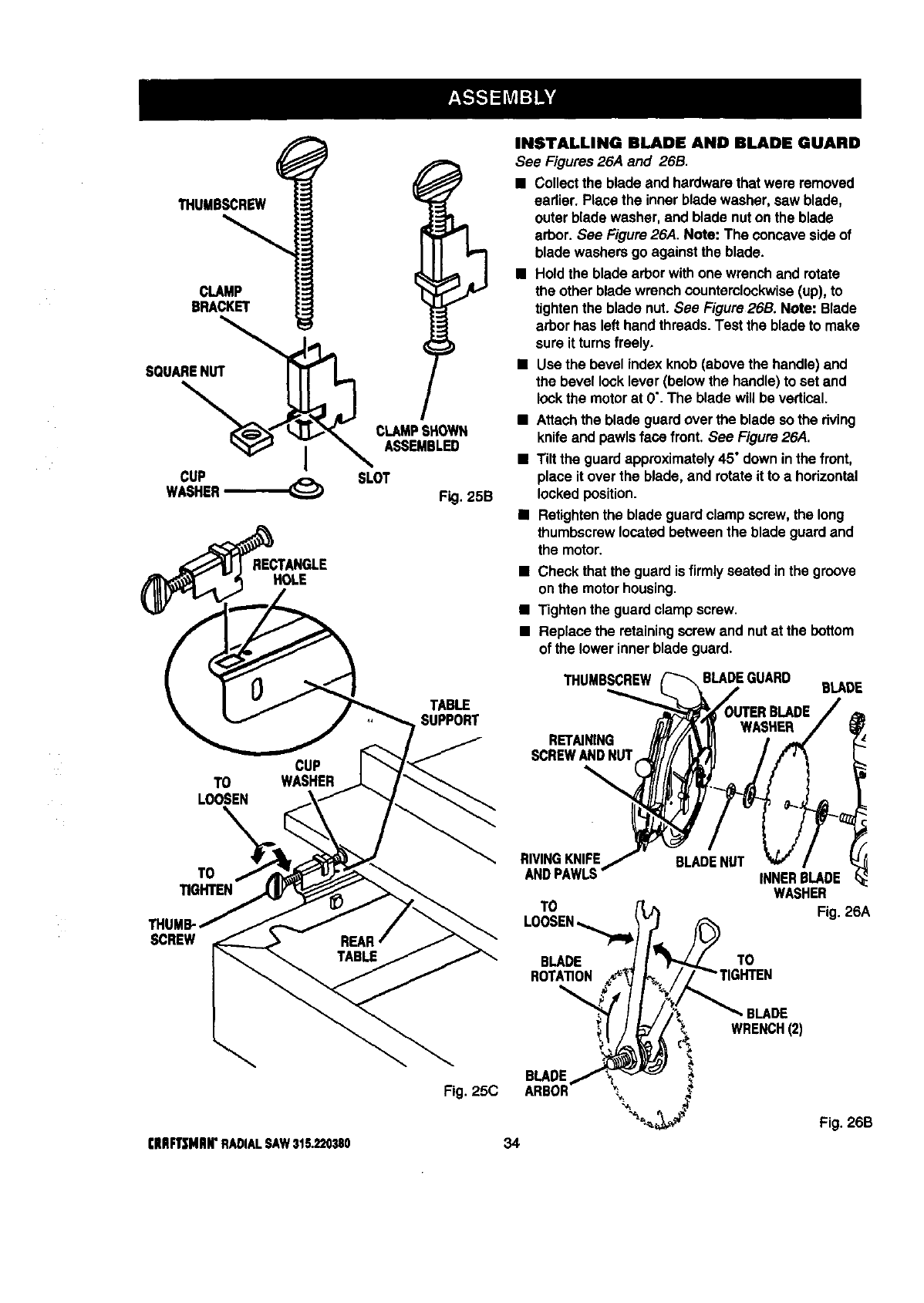
THUMBSCREW
CLAMP
BRACKET
SQUARENUT
I
CUP
WASHER
RECTANGLE
HOLE
CUP
TO WASHER
LOOSEN
TO
TIGHTEN
SCREW
(IIRFT|MIIW RADIAL SAW 315.220380
CLAMPSHOWN
ASSEMBLED
SLOT F .25B
TABLE
SUPPORT
Fig. 25C
INSTALLING BLADE AND BLADE GUARD
See Figures26,4 and 26B.
•Collectthe blade and hardwarethat were removed
eadier. Place the inner bladewasher, saw blade,
outer blade washer, and blade nuton the blade
arbor. See Figure26A. Note: The concavesideof
blade washersgo againstthe blade.
•Holdthe blade arborwithone wrenchand rotate
the other blade wrenchcounterclockwise(up), to
tightenthe blade nut. See Figure26B. Note: Blade
arborhas left hand threads.Test the blade to make
sure it turnsfreely,
•Use the bevel index knob(abovethe handle)and
the bevel locklever(below the handle)to set and
lockthe motorat 0".The blade will be vertical.
•Attachthe blade guardover the blade sothe riving
knifeand pawlsface front. See Figure26A.
•Tilt the guard approximately45° down inthe front,
place it over the blade, and rotateit to a horizontal
locked position.
•Retightanthe blade guardclamp screw,the long
thumbscrewlocatedbetweenthe blade guardand
the motor.
•Check that the guardis firmly seated in the groove
onthe motorhousing.
•Tighten the guard clampscrew.
•Replace the retainingscrew and nut at the bottom
of the lower innerblade guard.
THUMBSCREW BLADE
RET_NING
SCREWANDNUT
RIVINGKNIFE
ANDPAWLS
TO
BLADENUT INNERBLADE
WASHER
Fig. 26A
BLADE
ROTATION
TO
34
BLADE
BLADE
WRENCH(2)
Fig. 26B
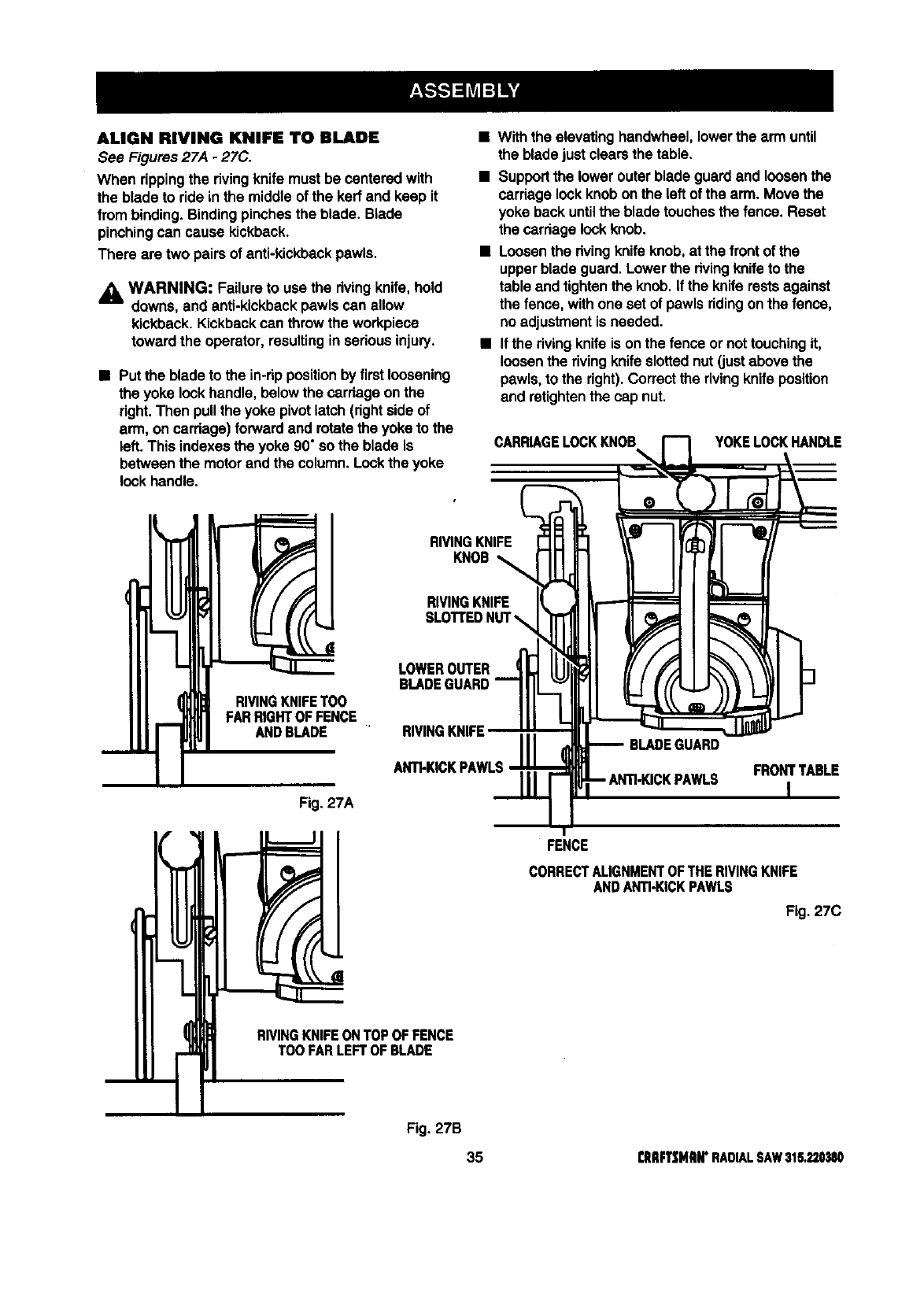
ALIGN RIVING KNIFE TO BLADE
See Figures 27A -27C.
When rippingthe rivingknife must be cantered with
the blade to ride in the middleof the kerf and keep it
from binding.Bindingpinchesthe blade. Blade
pinchingcan cause kickback.
There are two pairs of anti-kickbackpawls.
_l WARNING: Failure to use the rivingknife, hold
downs, and anti-kickbackpawls can allow
kickback. Kickbackcan throw the workpiece
toward the operator, resultinginseriousinjury.
• Put the bladeto the in-rippositionby firstloosening
the yoke lockhandle, below the carriageonthe
right. Then pullthe yoke pivot latch (rightside of
arm, on carriage) forwardand rotatethe yoke to the
left. This indexesthe yoke 90°so the blade is
betweenthe motor andthe column. Lockthe yoke
lockhandle.
•With the elevatinghandwheel,lowerthe arm until
the blade justclearsthe table.
•Supportthe lower outer blade guardand loosenthe
carriagelockknobon the left of the arm. Move the
yoke back untilthe blade touchesthe fence. Reset
the carriage lookknob.
•Loosenthe rivingknifeknob, at the frontof the
upperblade guard. Lowerthe rivingknifeto the
table and tightenthe knob. if the kniferestsagainst
the fence,with one set of pawls ridingonthe fence,
noadjustmentis needed.
•If the rivingknifeis on the fence ornot touchingit,
loosenthe rivingknifeslottednut (justabove the
pawls,to the right).Correctthe rivingknife position
and retightenthe cap nut.
CARRIAGELOCKKNOB
%YOKELOCKHANDLE
m
( RIVINGKNIFETOO
FARRIGHTOFFENCE
ANDBLADE
Fig. 27A
RIVINGKNIFE
KNOB
RIVINGKNIFE
LOWEROUTER
BLADEGUARD
RIVINGKNIFE
ANTI-KICKPAWLS
BLADEGUARD
FRONTTABLE
I
FENCE
CORRECTALIGNMENTOFTHERIVINGKNIFE
ANDANTI-KICKPAWLS
Fig. 27C
RIVINGKNIFEONTOPOFFENCE
TOOFARLEFTOFBLADE
Fig. 27B
35 rlIIIFTSMRWRADIALSAW315,220380
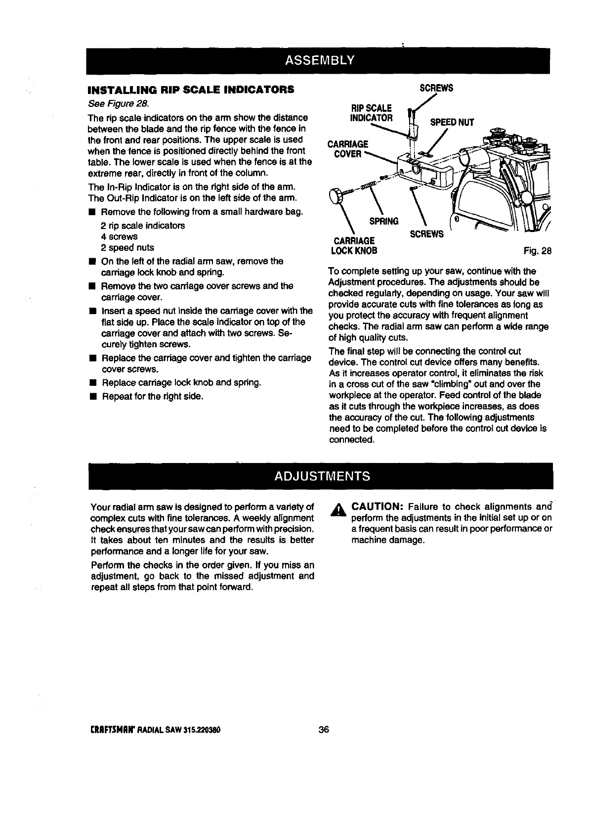
INSTALLING RIP SCALEINDICATORS
See Figure 28.
The ripscale indicatorson the arm showthe distance
between the blade and the ripfence with the fence in
the front and rear positions.The upperscale is used
when the fence is positioneddirectlybehindthe front
table. The lower scale is used when the fence is at the
extreme rear, directly infront of the column.
The In-Rip Indicatoris on the dght side of the arm.
The Out-Rip Indicatoris on the left sideof the arm.
• Remove the followingfroma smallhardware bag.
2 ripscale indicators
4 screws
2 speed nuts
•On the left of the radialarm saw, removethe
carriage lockknob and spdng.
•Remove the two carriage cover screws andthe
carriagecover.
•Insert a speed nut insidethe carriage cover withthe
fiat sideup. Place the scale indicatoron topof the
cardage coverand attach with two screws. Se-
curely tightenscrews.
•Replace the cardage cover and tightenthe carriage
coverscrews.
•Replace carriage lockknob and spring.
• Repeat for the right side.
RIPSCALE
INDICATOR
CARRIAGE
SCREWS
SPEEDNUT
_'_SPRING
CARRIAGE
LOCKKNOB
SCREWS
Fig.28
To complete settingup your saw, continue withthe
Adjustmentprocedures. The adjustmentsshouldbe
checked regulady,dependingon usage. Your saw will
provideaccurate cuts withfine tolerancesas long as
you protectthe accuracywithfrequentalignment
checks.The radialarm saw can performa wide range
of highqualitycuts.
The final step will be connecting the controlcut
device. The controlcut device offersmany benefits.
As it increasesoperator control, it eliminatesthe risk
ina crosscut of the saw "climbing" Outand overthe
workpieceat the operator.Feed controlof the blade
as it cutsthroughthe workpieceincreases,as does
the accuracy of the cut.The followingadjustments
need to be completedbefore the controlcut device is
connected.
Your radialarm saw is designedto performa varietyof
complex cuts withfine tolerances. A weekly alignment
check ensuresthatyoursawcan performwithprecision.
It takes about ten minutes and the results is better
performanceand a longer lifefor your saw.
Perform the checks in the order given. If you miss an
adjustment, go back to the missed adjustment and
repeat all steps from that pointforward.
_k CAUTION: Failure to check alignments and_
performthe adjustmentsin the initialset up or on
a frequentbasiscan resultinpoorperformanceor
machinedamage.
CRIIFTSHAM'RADIALSAW315.220380 36
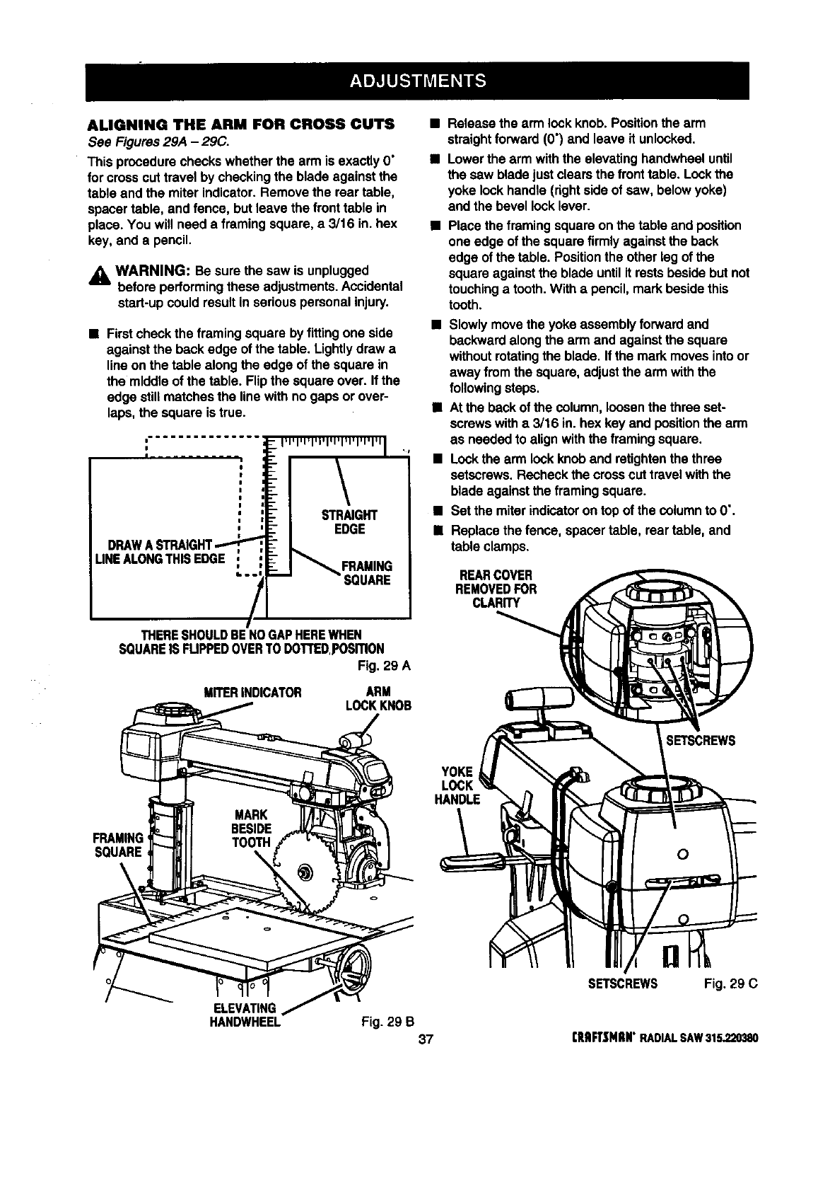
ALIGNING THE ARM FOR CROSS CUTS
See Figures 29A -29C.
This procedurechecks whether the arm is exactly O"
for crosscut travel by checkingthe blade against the
table and the miter indicator.Remove the rear table,
spacertable, and fence, but leave the front table in
place. You will need a framingsquare, a 3/16 in. hex
key, and a pencil.
_lb WARNING: Be sure the saw is unplugged
before performingthese adjustments.Accidental
start-up could resultin seriouspersonalinjury.
•First check the framingsquare by fittingone side
against the back edge of the table. Lightlydrew a
line on the table alongthe edge of the square in
the middle of the table. Flipthe square over. If the
edge stillmatches the line with no gaps or over-
laps, the square is true.
DRAWA STRAIGHT..."-
UNEALONGTHISEDGE FRAMING
SQUARE
THERESHOULDBENOGAPHEREWHEN
SQUAREIS FUPPEDOVERTO DOTTED,posmoN
Fig. 29 A
MITERINDICATOR ARM
LOCKKNOB
Release the arm lock knob.Positionthe arm
straightforward (O') and leave it unlocked.
Lowerthe arm withthe elevatinghandwheel until
the saw bladejust clearsthe front table. Lockthe
yoke lockhandle (rightside of saw, belowyoke)
and the bevel locklever.
•Place the framingsquare on the table and position
one edge of the square firmly againstthe back
edge of the table. Positionthe other leg of the
square against the blade untilit rests beside butnot
touchinga tooth.With apencil, mark besidethis
tooth.
•Slowly move the yoke assemblyforward and
backwardalongthe arm and againstthe square
withoutrotatingthe blade. If the mark moves intoor
away fromthe square,adjust the arm withthe
followingsteps.
•At the back of the column, loosenthe three set-
screwswith a 3/16 in. hex keyand positionthe arm
as needed to alignwiththe framingsquare.
•Lockthe arm lockknob and retightenthe three
setscrews. Recheckthe crossouttravelwith the
blade againstthe framingsquare.
•Set the miterindicatoron topof the columnto 0".
•Replace the fence, spacertable, rear table, and
table clamps.
REARCOVER
REMOVEDFOR
CLARITY
YOKE
HANDLE
SETSCREWS
FRAMING
SQUARE
ELEVATING
HANDWHEEL Fig. 29 B 37
SETSCREWS Fig. 29 C
rRIIFTtNIIN" RADIALSAW315,220380
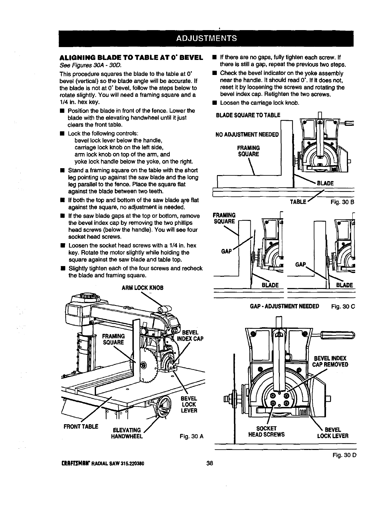
ALIGNING BLADE TO TABLE AT O" BEVEL
See Figures 30A -30D.
This proceduresquares the blade to the table at O"
bevel (vertical) so the blade angle willbe accurate. If
the blade is not at D"bevel, followthe steps below to
rotate slightly.You willneed a framing square and a
1/4 in. hex key.
•Positionthe blade infront of the fence. Lowerthe
blade withthe elevatinghandwheeluntil it just
clearsthe fronttable.
•Lockthe followingcontrols:
bevel locklever belowthe handle,
carriagelockknob on the leftside,
arm lock knob ontop of the arm, and
yoke lockhandle below the yoke, on the dght.
•Stand a framing square on the table with the short
leg pointingup againstthe saw blade and the long
leg parallelto the fence. Place the squareflat
against the blade between two teeth.
•If both the topand bottomof the saw blade a_reflat
againstthe square, no adjustment is needed.
•If the saw blade gaps at the top or bottom,remove
the bevel indexcap by removingthe two phillips
head screws (below the handle). You willsee four
sockethead screws.
•Loosenthe socket head screwswith a 1/4 in. hex
key. Rotate the motorslightlywhile holdingthe
square againstthe saw blade and table top.
• Slightlytighteneach of the four screws and recheck
the blade and framing square.
ARMLOCKKNOB
• If there are no gaps, fullytighteneach screw, If
there is stilla gap, repeatthe previoustwo steps.
•Checkthe bevel indicatoron the yoke assembly
near the handle. It should readO'. If itdoes not,
reset it by looseningthe screws and rotatingthe
bevel indexcap. Retightenthe two screws.
•Loosenthe cardage lockknob.
BLADESQUARETOTABLE
NO ADJUSTMENTNEEDED
FRAMING
SQUARE
FRAMING
SQUARE
BLADE
TABLEjFig. 30 B
GAP
BLADE
FRONTTABLE
INDEX CAP
BEVEL
LOCK
LEVER
ELEVATING
HANDWHEEL Fig. 30 A
GAP-ADJUSTMENTNEEDED Fig. 30 C
SOCKET
HEADSCREWS
BEVELINDEX
CAPREMOVED
f
_. BEVEL
LOCKLEVER
Fig. 30 D
CRAFTSMIIH"RADIALSAW315.220380 38
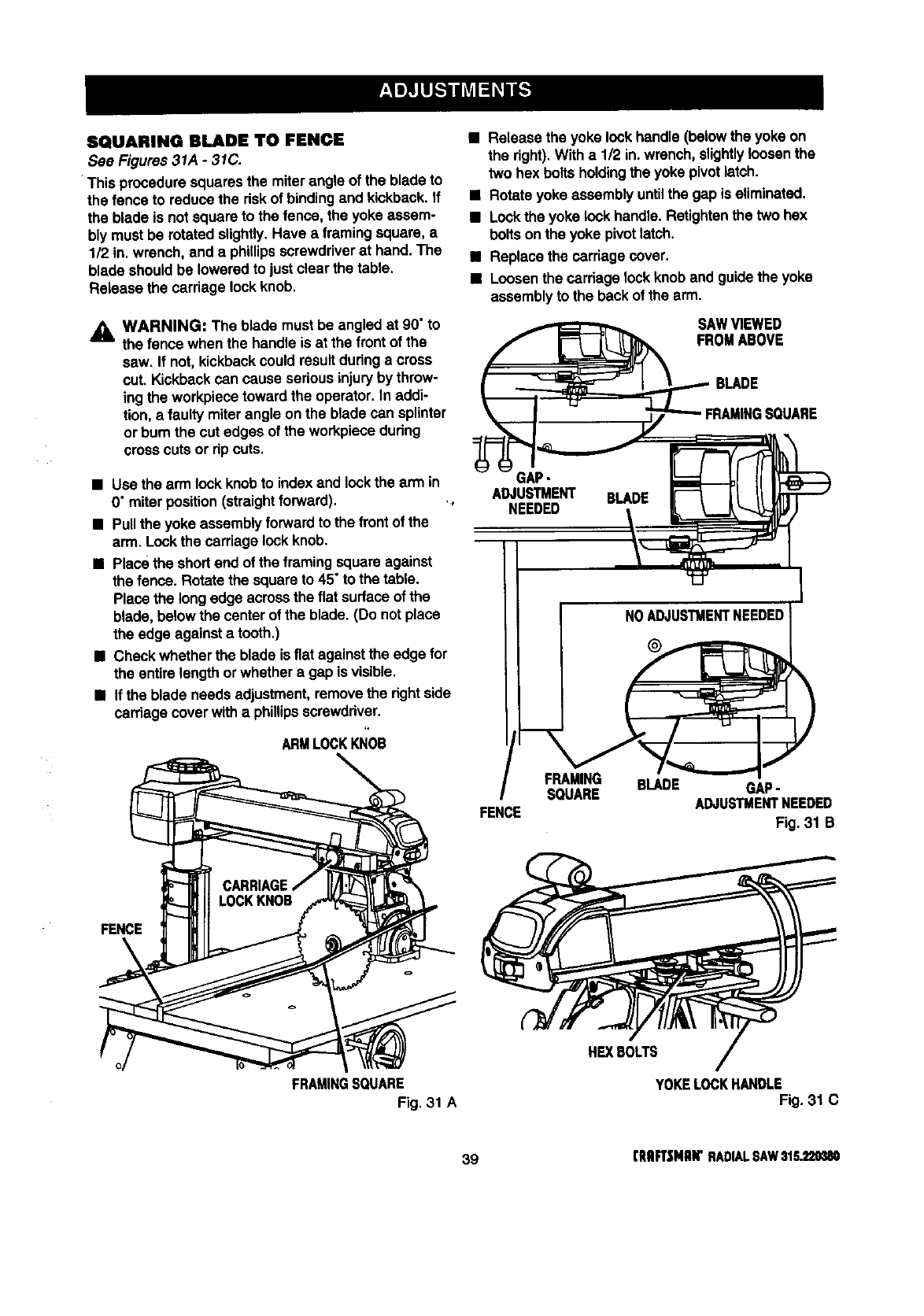
SQUARINGBLADETO FENCE
See Figures 31A -31C.
This proceduresquares the miter angle of the blade to
the fence to reducethe dsk of bindingand kickback. If
the blade is not square to the fence, the yoke assem-
blymust be rotated slightly.Have aframing square,a
1/2 in. wrench, and a phillipsscrewdriverat hand.The
blade shouldbe loweredto justclear the table.
Release the carriage lockknob.
_k WARNING: The blade must be angled at 90" to
the fence when the handle is at the frontof the
saw. If not, kickbackcould resultduringa cross
cut. Kickbackcan cause seriousinjuryby throw-
ing the workpiecetoward the operator. In addi-
tion, afaulty miterangle on the blade can splinter
or bum the cut edges of the workpiecedudng
cross cutsor dp cuts.
•Use the arm lock knobto index and lockthe arm in
0" miterposition(straightforward). .,
•Pullthe yoke assemblyforward to the front of the
arm. Lockthe carriage lockknob.
•Place the shortend of the framing square against
the fence. Rotate the square to 45° to the table.
Place the longedge acrossthe flat surfaceof the
blade, belowthe center of the blade. (Do notplace
the edge against a tooth.)
•Check whetherthe blade isflat against the edge for
the entire lengthor whether a gap is visible.
•If the blade needs adjustment,removethe rightside
carriage coverwitha phillipsscrewddver.
ARMLOCKKNOB
FENCE
FRAMINGSQUARE
Fig. 31 A
•Release the yoke lock handle(below the yoke on
the fight).With a 1/2 in. wrench,slightlyloosenthe
two hex bolts holdingthe yoke pivotlatch.
•Rotateyoke assembly untilthe gap is eliminated.
•Lockthe yoke lockhandle. Retightenthe two hex
boltson the yoke pivotlatch.
•Replace the carriagecover.
•Loosenthe carriagelockknob and guidethe yoke
assemblyto the back of the arm.
SAWVIEWED
FROMABOVE
BLADE
GAP-
ADJUSTMENT BLADE
NEEDED
INOADJUSTMENTNEEDEDI
FRAMING BLADE GAP-
SQUARE ADJUSTMENTNEEDED
FENCE Fig. 31 B
HEXBOLTS
YOKELOCKHANDLE
Fig. 31 C
39 (RRFT|MRW RADIALSAW$1S_20380
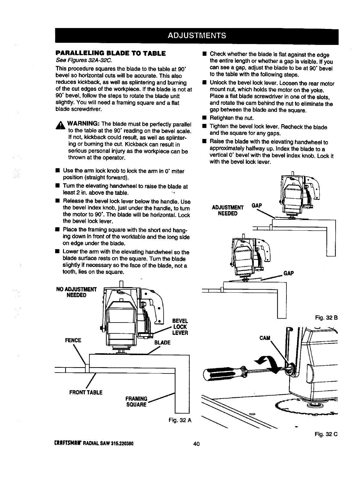
PARALLELING BLADE TO TABLE
See Figures 32A-32C.
This proceduresquares the blade to the table at 90"
bevel so hodzontatcuts will be accurate. This also
reduces kickback,as well as splintedngand burning
of the cut edges of the workpiece. If the blade is not at
90' bevel,followthe steps to rotatethe blade unit
slightly.You will need a framingsquare and a flat
blade screwdriver.
,_ WARN|NG: The blade must be pedactly parallel
to the table at the 90" reading on the bevel scale.
If not, kickbackcould result,as well as splinter-
ingor burningthe cut. Kickbackcan result in
seriouspersonalinjuryas the workpiecacan be
thrownat the operator.
• Check whetherthe blade is flat againstthe edge
the entire length or whethera gap is visible. If you
can see a gap, adjustthe blade to be at 90" bevel
to the table withthe followingsteps.
•Unlockthe bevellock lever. Loosenthe rear motor
mountnut,which holdsthe motoron the yoke.
Place a fiat blade screwdriverin one of the slots,
and rotatethe cam behind the nutto eliminatethe
gap betweenthe blade and the square.
•Retightenthe nut.
•Tighten the bevel rockfever. Recheckthe blade
and the square for any gaps.
•Raise the bladewith the elevatinghandwheelto
approximatelyhalfwayup. Index the blade to a
vertical0" bevel withthe bevel index knob. Lockit
withthe bevel locklever.
•Use the arm lock knobto lockthe arm in O"miter
position(straightforward).
•Turn the elevatinghandwheelto raisethe blade at
least 2 in. above the table. ',
Release the bevel locklever belowthe handle. Use
the bevel indexknob,just underthe handle, to turn
the motor to 90".The blade willbe hodzontal.Lock
the bevel locklever.
•Place the framingsquare with the shortend hang-
ing down infront of the worktableand the longside
on edge underthe blade.
•Lower the arm withthe elevatinghandwheelso the
blade surface restson the square.Turn the blade
slightlyif necessaryso the face of the blade, not a
tooth, tieson the square.
NOADJUSTMENT
NEEDED
FENCE BLADE
BEVEL
LOCK
FRONTTABLE FRAMING
SQUARE
Fig. 32 A
ADJUSTMENT GAP
NEEDED
Fig.32 B
o
Fig. 32 C
CRIIFTSNIIIr RADIALSAW315,220380 40
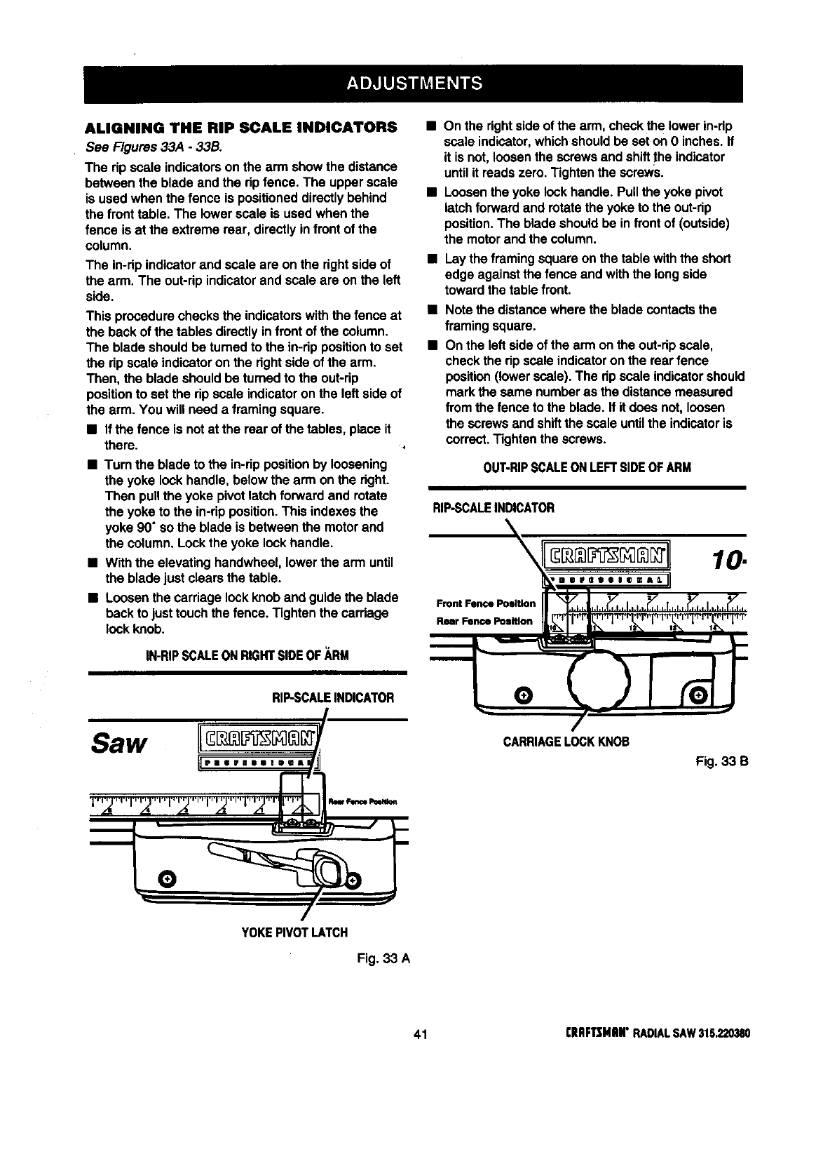
ALIGNING THE RIP SCAL• INDICATORS
See Figures 33A - 33B.
The rip scale indicatorson the arm showthe distance
between the blade and the rip fence. The upperscale
is used when the fence is positioneddirectlybehind
the front table. The lower scale is used when the
fence is at the extreme roar, directlyinfront of the
column.
The in-rip indicatorand scale are on the rightside of
the arm. The out-rip indicatorand scale are on the left
side.
This procedurechecksthe indicatorswith the fence at
the back of the tables directlyin front of the column.
The blade shouldbe turnedto the in-dp positionto set
the rip scale indicatoron the dght side of the arm.
Then, the blade should be turnedto the out-dp
positionto set the rip scale indicatoron the left side of
the arm. You will need a framingsquare.
•If the fence is notat the rear of the tables, place it
there.
•Turn the blade to the in-rip positionby loosening
the yoke lock handle, below the arm on the right.
Then pullthe yoke pivotlatchforward and rotate
the yoke to the in-ripposition.This indexes the
yoke 90" so the blade is between the motor and
the column. Lockthe yoke lock handle.
•With the elevating handwheel, lowerthe arm until
the blade just clears the table.
•Loosenthe carriage lock knoband guidethe blade
beck to justtouchthe fence. Tightenthe carriage
lock knob.
IN-RIPSCALEONRIGHTSlOEOF_,RM
RIP-SCALEINDICATOR
Saw II
11,,, °,,,,,,,,
•.,d! A ,_ .d! .__
• On the rightside of the arm, check the lower in-dp
scale indicator,whichshould be seton O inches.If
it is not, loosenthe screws and shiftthe indicator
untilit reads zero. Tightenthe screws.
•Loosenthe yoke lockhandle. Pull the yoke pivot
latchforward and rotatethe yoke to the out-rip
position.The blade shouldbe in front of (outside)
the motorand the column.
•Lay the framingsquare on the table withthe short
edge against the fence and withthe long side
toward the table front.
Note the distancewhere the blade contactsthe
framingsquare.
On the left side of the arm on the out-dpscale,
check the rip scale indicatoron the rearfence
position(lowerscale). The rip scale indicatorshould
mark the same numberas the distancemeasured
from the fence to the blade. If it does not, loosen
the screws and shiftthe scale untilthe indicatoris
correct.Tighten the screws.
OUT-RIPSCALEONLEFTSIDEOFARM
RIP.SCALEINDICATOR
Front Fence Position
Rear Fence Position
10.
,,,..,°=.,11
CARRIAGELOCK KNOB
Fig. 33 B
YOKEPIVOTLATCH
Fig. 33 A
41 [IIliFTtMitN" RADIALSAW315.220380
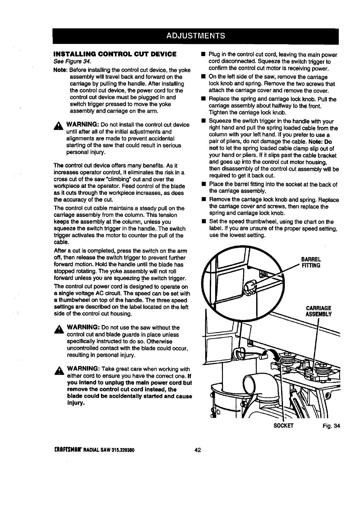
INSTALLING CONTROL CUT DEVICE
See Figure 34.
Note: Before installingthe controlcut device, the yoke
assemblywill travel beck and forwardon the
carriage by pullingthe handle. Afterinstalling
the control cut device, the power cordfor the
control cut device must be pluggedinand
switchtrigger pressed to move the yoke
assemblyand carriage on the arm.
,_= WARNING: Do notinstallthe controlcut device
untilafter all of the initialadjustmentsand
alignments are made to prevent accidental
startingof the saw that couldresult in serious
personal injury.
The controlcut deviceoffers many benefits.As it
increases operatorcontrol, it eliminatesthe riskin a
crosscut of the saw "climbing"out and over the
workpieceat the operator. Feed controlof the blade
as it cutsthroughthe workpieceincreases,as does
the accuracyof the cut.
The controlcut cable maintainsa steady pullon the
cardage assemblyfromthe column.This tension
keeps the assemblyat the column, unlessyou
squeeze the switchtriggerin the handle. The switch
tdgger activatesthe motorto counter the pullof the
cable.
After a cut is completed, pressthe switchon the arm
off, then release the switchtdggerto preventfurther
forward motion. Hold the handle untilthe blade has
stopped rotating.The yoke assemblywill notroll
forward unlessyou are squeezing_e switchtrigger.
The controlcut powercord is designedto operate on
a singlevoltage AC circuit.The speed can be set with
a thumbwheel ontop of the handle. The three speed
settingsare describedon the label locatedon the left
side of the control cut housing.
WARNING: Do notuse the saw withoutthe
control cut and blade guardsin place unless
specificallyinstructedto do so. Otherwise
uncontrolledcontactwith the blade couldoccur,
resultingin personal injury.
,_ WARNING: Take great care when workingwith
either cord to ensure you have the correct one. If
you Intend to unplug the main power cord but
remove the control cut cord Instead, the
blade could be accidentally started and cause
Injury.
•Plug in the control cut cord,leavingthe mainpower
cord disconnected.Squeeze the switchtdggerto
confirmthe control cut motoris receivingpower.
•On the left sideof the saw, removethe carriage
lockknoband spring.Remove the two screwsthat
attach the carriage coverand removethe cover.
•Replace the spdngand carriage lockknob.Pullthe
cardage assemblyabout halfwayt0 the front.
Tighten the carriage lockknob.
•Squeeze the switchtrigger inthe handlewithyour
dght hand and pullthe springloadedcable from the
columnwithyour left hand. If you preferto use a
pair of pliers,do not damage the cable. Note: Do
not to let the spdngloadedcable clampslipout of
yourhand or pliers.If it slipspast the cable bracket
and goes up intothe control cut motorhousing,
then disassemblyof the controlcut assemblywillbe
requiredto get it beck out.
•Place the barrelfittingintothe socketat the back of
the carriageassembly.
•Remove the carriage lockknoband spring.Replace
the cardage cover and screws,then replacethe
springand carriagelockknob.
•Set the speed thumhwheel,usingthe charton the
label. If youare unsureof the properspeed setting,
use the lowestsetting.
BARREL
FIITING
CARRIAGE
ASSEMBLY
SOCKET Fig. 34
CIIAFrSHlUFRADIALSAW315.220380 42
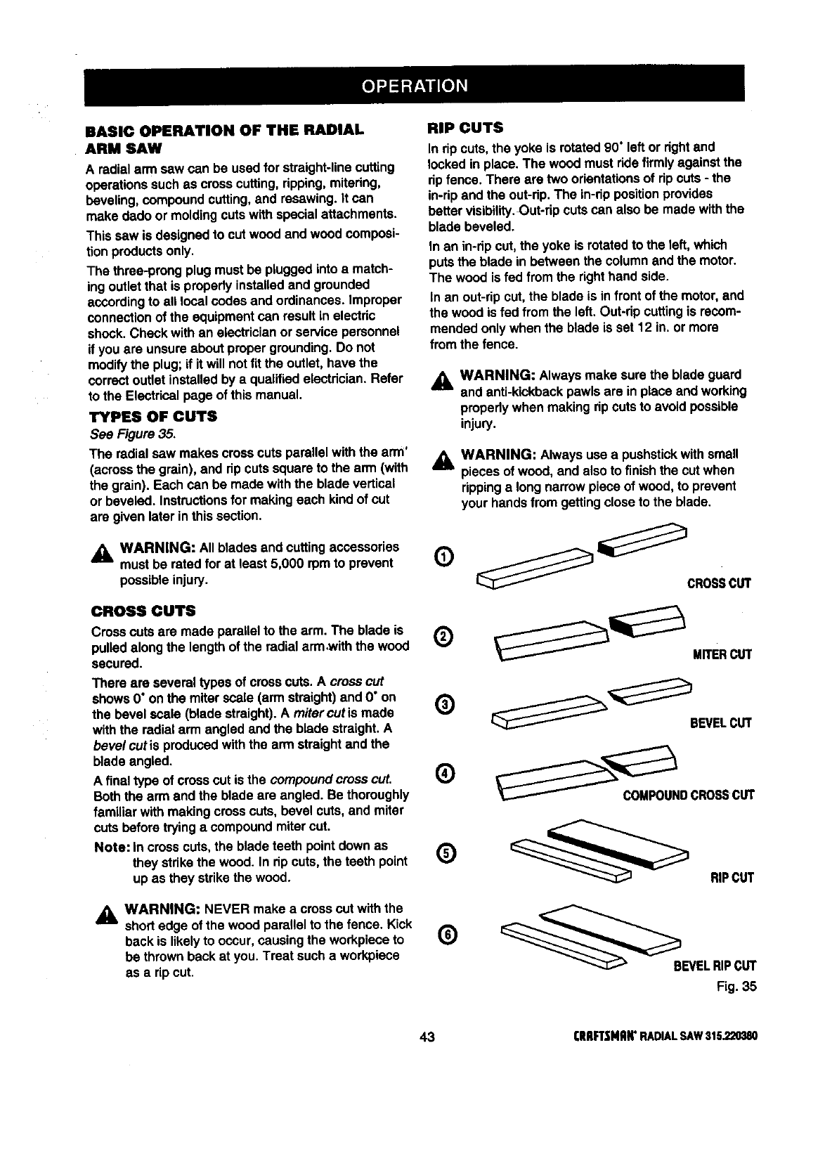
BASIC OPERATION OF THE RADIAL
ARM SAW
A radialarm saw can be usedfor straight-linecutting
operationssuch as cross cutting,ripping,mitering,
beveling,compound cutting,and resawing. It can
make dado or moldingcuts with special attachments.
This sew is designed to cut wood and wood composi-
tion productsonly.
The three-prong plug must be pluggedinto a match-
ing outletthat is properlyinstalledand grounded
accordingto all local codes and ordinances. Improper
connectionof the equipmentcan result in electric
shook.Check with an electricianor service personnel
ifyou are unsureabout propergrounding.Do not
modifythe plug;if it will notfit the outlet,have the
correctoutlet installedby a qualified electrician.Refer
to the Electricalpage of this manual.
TYPES OF CUTS
See Figure 35.
The radial sew makes crosscuts parallel with the arm'
(acrossthe grain), and rip cuts square to the arm (with
the grain). Each can be made withthe blade vertical
or beveled. Instructionsfor makingeach kind of cut
are given later inthis section.
AWARNING: All blades and cuttingaccessories
am, must be ratedfor at least 5,000 rpmto prevent
possible injury.
CROSSCUTS
Cross cuts are made parallel to the arm. The blade is
pulledalong the length of the radialarm ,withthe wood
secured.
There are severaltypes of cross cuts.A crosscut
shows 0"on the miterscale (arm straight)and 0" on
the bevel scale (blade straight).A mitercut is made
with the radial arm angled and the blade straight.A
bevel cut is producedwiththe arm straightand the
blade angled.
Afinal type of crosscut is the compound crosscut.
Both the arm and the blade are angled. Be thoroughly
familiar with making cress cuts, bevel cuts, and miter
cuts before tryinga compoundmitercut.
Note: incross cuts,the blade teeth pointdown as
they strikethe wood. In rip cuts, the teeth point
up as they strikethe wood.
_WARNING: NEVER make a cross cut withthe
short edge of the wood parallel to the fence. Kick
back is likelyto occur,causing the workpieceto
be thrownback at you. Treat such a workpiece
as a rip cut.
RIP CUTS
In dpcuts, the yoke is rotated 90" left or rightand
locked in place. The wood must ride firmlyagainst the
rip fence. There are two orientationsof ripcuts - the
in-rip and the out-rip.The in-rip positionprovides
better visibility.Out-rip cutscan also be made withthe
blade beveled.
In an in-ripcut, the yoke is rotatedto the left,which
putsthe blade in between the columnand the motor.
The wood is fed from the righthand side.
In an out-ripcut, the blade is in front of the motor,and
the wood is fed from the left.Out-rip cuttingis recom-
mended only when the blade is set 12 in. or more
fromthe fence.
_1= WARNING: Alwaysmake surethe blade guard
and anti-kickbackpawlsare in place and working
propedy when making ripcuts to avoid possible
injury.
WARNING: Always use a pushstickwith small
pieces of wood, and alsoto finishthe cut when
rippinga long narrowpiece of wood, to prevent
your hands from gettingcloseto the blade.
0 _ _CROSS cu'r
®MITERcur
(_) _'_BEVEL CUT
COMPOUNDCROSSCUT
O __ RIPCUT
O ___BEVEL RIPCUT
Fig. 35
43 I:IIRFTSMflN"RADIALSAW315,220380
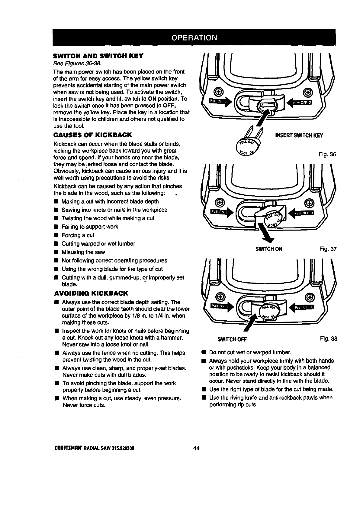
SWITCH AND SWITCH KEY
See Figures 36-38.
The main power switchhas been placed on the front
of the arm for easy access. The yellowswitchkey
prevents accidental startingof the main power switch
when saw is not beingused. To activate the switch,
insertthe switchkey and liftswitchto ON position.To
lookthe switchonce it has been pressed to OFF,
remove the yellow key. Place the key in a locationthat
is inaccessibleto childrenend othersnot qualifiedto
use the tool.
CAUSES OF KICKBACK
Kickbackcan occur when the blade stallsor binds,
kickingthe workpiece back toward youwithgreat
force and speed. If your hands are near the blade,
they may be jerked loose and contactthe blade.
Obviously,kickbackcan cause seriousinjuryand it is
well worth using precautionsto avoid the risks.
Kickbackcan be caused by any actionthat pinches
the blade in the wood, such as the following:
•Making a cut with incorrectblade depth
•Sawing into knotsor nails inthe workpiece
•Twistingthe woodwhile makinga cut
•Failingto supportwork
•Forcinga cut
•Cuttingwarped or wet lumber
•Misusingthe saw
•Not following correctoperatingprocedures
•Usingthe wrongblade for the type of cut
•Cuttingwithadull, gummed-up,or improperlyset
blade.
AVOIDING KICKBACK
•Always use the correctblade depth setting.The
outer point of the blade teeth shouldclear the lower
surface of the workpieceby 1/8 in. to 114in. when
making these cuts,
•Inspectthe workfor knotsor nails before beginning
a cut. Knock outany loose knotswitha hammer.
Never saw intoaloose knotor nail.
•Always use the fence when ripcutting.This helps
prevent twistingthe wood inthe cut.
•Alwaysuse clean, sharp,and properly-setblades.
Never make cuts withdullblades.
•To avoid pinchingthe blade, supportthe work
properlybefore beginninga cut.
•When makinga cut, use steady,even pressure.
Never force cuts.
INSERTSWITCHKEY
Fig. 36
SWITCHON Fig. 37
SWITCHOFF Fig. 38
•Do not cutwet or warped lumber.
•Always holdyourworkpiecefirmlywithboth hands
or with pushsticks.Keep your body ina balanced
positionto be readyto resistkickbackshould it
occur.Never standdirectlyinline withthe blade,
•Use the right type of blade forthe cut being made.
•Use the rivingknifeand anti-kickbackpawlswhen
performingripcuts.
_EAFTSNlUI"RADIALSAW$15,220380 44
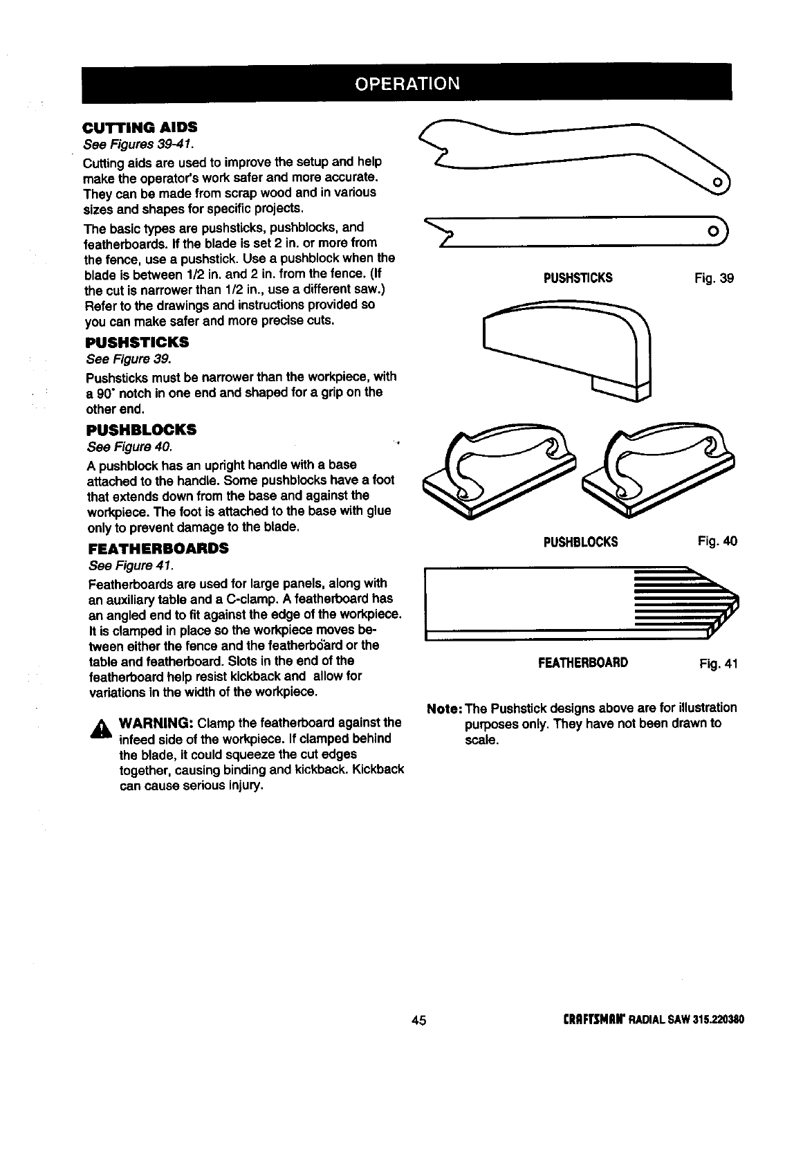
CUTTING AIDS
See Figures 39-41.
Cuttingaids are usedto improvethe setup and help
make the operator'sworksafer end more accurate.
They can be made fromscrap wood and invarious
sizes and shapes forspecific projects,
The basic types are pushsticks,pushblocks,and
featherboards. If the blade is set 2 in. or morefrom
the fence, use a pushstick.Use a pushblockwhen the
blade is between 1/2 in. and 2 in. from the fence. (If
the cut is narrower than 1/2 in., use adifferentsaw.)
Refer to the drawings and instructionsprovidedso
you san make safer and more precise cuts.
PUSHSTICKS
See Figure 39.
Pushsticksmust be narrowerthan the workpiece, with
a 90" notch in one end and shaped for a gripon the
other end.
PUSHSTICKS Fig. 39
posLoo s
See Figure 40.
A pushblockhas an uprighthandle with a base
attachedto the handle. Some pushblockshave a foot
that extends down fromthe base and againstthe
workpiece.The foot is attached to the base with glue
only to prevent damage to the blade.
FEATHERBOARDS
See Figure 41.
Featherboardsare used for large panels, along with
an auxiliary table and a C-clamp. A featharboardhas
an angled end to fit against the edge of the workplace.
It is clamped in place so the workpiecemoves be-
tween either the fence and the featherb6hrdor the
table and featherboard. Slotsin the end of the
faatharboardhelp resist kickbackand allow for
variations inthe width of the workplace.
_1= WARNING: Clamp the featherboardagainst the
infeed side of the workpiece. If clamped behind
the blade, it couldsqueeze the cut edges
together, causing bindingand kickback.Kickback
can cause seriousinjury.
IPUSHBLOCKS Fig. 40
FEATHERBOARD Fig. 41
Note: The Pushstickdesignsabove are for illustration
purposesonly.They have notbeen drawnto
scale.
45 rRAFTSMIIN'RADIALSAW315.220380
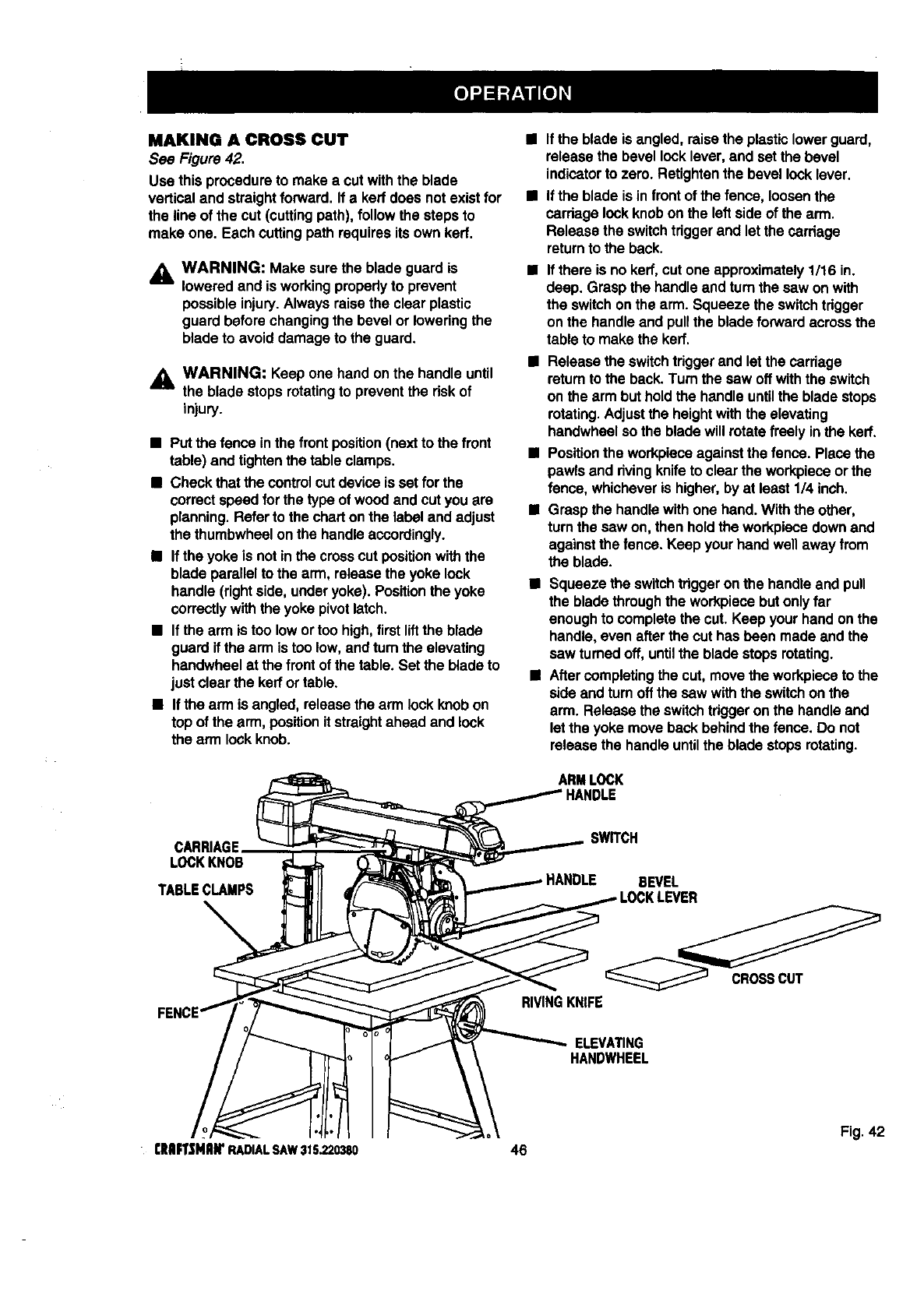
MAKING A CROSS CUT
See Figure 42.
Use this procedureto make a cut withthe blade
vertical and straightforward. If a ken`does notexist for
the line of the cut (cutting path), follow the steps to
make one. Each cuttingpath requiresits own ken`.
_, WARNING: Make sure the blade guard is
loweredand is workingproperlyto prevent
possibleinjury.Alwaysraisethe clear plastic
guard before changingthe bevel or loweringthe
blade to avoid damage to the guard.
,_ WARNING: Keep one hand on the handle until
Hthe blade stops rotatingto preventthe riskof
injury.
•Put the fence in the front position(next to the front
table) and tightenthe tableclamps.
•Check that the controlcut deviceis set for the
correctspeed forthe type of woodand cut you are
planning.Referto the charton the label and adjust
the thumbwheelon the handleaccordingly.
•If the yoke is not inthe crosscut positionwiththe
blade parallelto the arm, release the yoke lock
handle (rightside, under yoke). Positionthe yoke
correctlywiththe yoke pivotlatch.
•If the arm is too lowortoo high,first liftthe blade
guard if the arm is too low,and turn the elevating
handwheel at the front of the table. Set the bladeto
just clear the ken`or table.
•If the arm is angled, releasethe arm lock knobon
top of the arm, position it straightahead and lock
the arm lockknob.
• If the blade is angled, raisethe plasticlower guard,
release the bevel locklever, and set the bevel
indicatorto zero. Retightenthe bevel locklever.
•If the blade is in front of the fence, loosenthe
cardage lockknobon the leftside of the arm.
Release the switchtrigger and let the carriage
returnto the back.
•If there is no ken',cut one approximately1/16 in.
deep. Grasp the handleand turn the saw on with
the switchonthe arm. Squeeze the switchtrigger
onthe handle and pullthe blade forward acrossthe
tableto make the kerr.
•Release the switchtdggerand let the carriage
returnto the back.Turn the saw offwiththe switch
on the arm but holdthe handle untilthe blade stops
rotating.Adjustthe heightwiththe elevating
handwheelso the blade will rotatefreely in the ken'.
•Positionthe workpieceagainstthe fence. Place the
pawls and rivingknifeto clearthe workpieceor the
fence, whicheveris higher,by at least 114inch.
•Graspthe handlewithone hand. With the other,
turn the saw on, then holdthe workpiecedownand
againstthe fence. Keep your hand wellaway from
the blade.
•Squeeze the switchtriggeron the handle and pull
the blade throughthe workpiecebutonly far
enoughto completethe cut.Keep your hand on the
handle, even after the cut has been made and the
saw turnedoff, untilthe blade stops rotating.
II Aftercompleting the cut, move the workpiecoto the
side and turnoff the saw withthe switchon the
arm. Release the switchtriggeron the handleand
let the yoke move back behindthe fence. Do not
releasethe handle untilthe blade stopsrotating.
ARMLOCK
CARRIAGE
LOCKKNOB
SWITCH
BEVEL
CROSSCUT
RIVINGKNIFE
ELEVMING
HANDWHEEL
Fig. 42
13tlIFTSHAWRADIALSAW315.220380 46
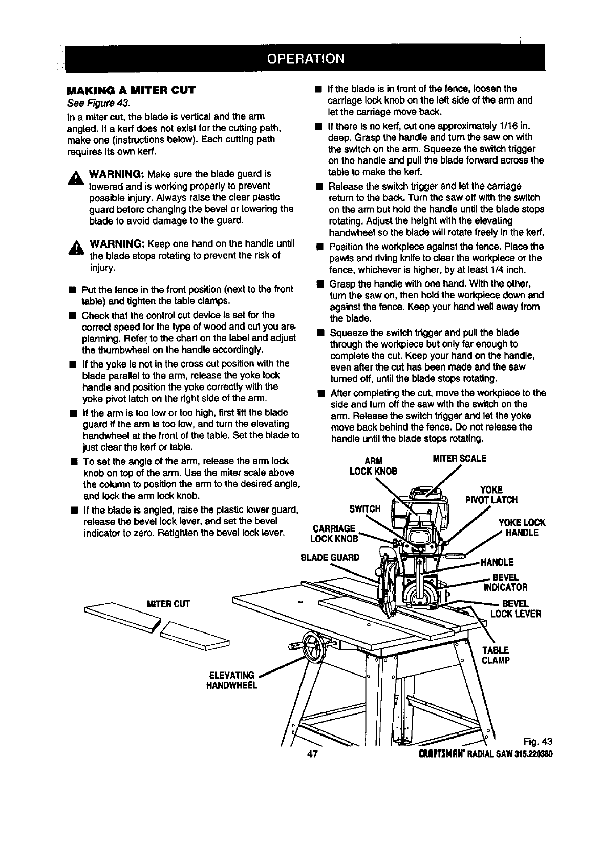
MAKING A MITER CUT
See Figure 43.
In a miter cut, the blade is verticaland the arm
angled. If a ked does not exist forthe cuttingpath,
make one (instructionsbelow). Each cuttingpath
requires its own kerf.
WARNING: Make sure the blade guard is
lowered and is working properlyto prevent
possibleinjury.Always raisethe clear plastic
guard before changingthe bevel or loweringthe
blade to avoid damage to the guard.
_1= WARNING: Keep one hand on the handle until
the blade stops rotatingto preventthe riskof
injury.
• Put the fence in the front position(nextto the front
table) and tightenthe tableclamps.
•Check that the controlcut device is sat for the
correct speed for the type of woodand cut you ars
planning.Refer to the charton the label and adjust
the thumbwheel on the handle accordingly.
•Ifthe yoke is not inthe crosscut positionwith the
blade parallelto the arm, releasethe yoke lock
handle and position the yoke correctlywiththe
yoke pivot latchon the right sideof the arm.
•If the arm is too lowor too high,first liftthe blade
guardif the arm is too low, andturn the elevating
handwheel at the front of the table. Set the blade to
just clearthe kerrortable.
•To set the angle of the arm, release the arm lock
knob on top of the arm. Use the mite_scale above
the column to position the arm to the desiredangle,
and lockthe arm lockknob.
•If the blade is infrontof the fence, loosenthe
carriagelockknob onthe left side of the arm and
let the carriagemove back.
•If there is no kerf,cut one approximately 1/16 in.
deep. Grasp the handleand turnthe saw on with
the switchon the arm. Squeeze the switchtrigger
on the handleand pullthe blade forward across the
table to make the kerf.
•Release the switchtriggerand let the carriage
returnto the back.Turn the saw off withthe switch
on the arm but holdthe handle untilthe blade stops
rotating.Adjustthe heightwiththe elevating
handwheel so the blade will rotatefreely inthe kerr.
•Positionthe workpieceagainstthe fence. Place the
pawls and rivingknifeto clear the workplaceor the
fence, whicheveris higher, by at least 1/4 inch.
•Graspthe handlewith one hand.With the other,
turnthe saw on, then holdthe workpiecedown and
againstthe fence. Keep your hand wellaway from
the blade.
•Squeeze the switchtriggerand pullthe blade
through the workpiecebut onlyfar enoughto
completethe cut. Keep your hand on the handle,
even after the cut has been made and the saw
turned off, untilthe blade stopsrotating.
•After completingthe cut,move the workpieceto the
side and turnoff the saw with the switchon the
arm. Releasethe switchtriggerand let the yoke
move back behindthe fence. Do notrelease the
handleuntilthe blade stopsrotating.
ARM MITERSCALE
LOCKKNOB
•If the blade is angled, raisethe plasticlower guard, SWITCH
releasethe bevellock lever, and set the bevel
indicatorto zero. Retightenthe bevellocklever. CARRIAGE
YOKE
PIVOTLATCH
YOKELOCK
BLADEGUARD
MITERCUT
INDICATOR
LOCKLEVER
ELEVATING
HANDWHEEL
TABLE
CLAMP
Fig. 43
47 CRAFTSMAN"RADIALSAW315.220380
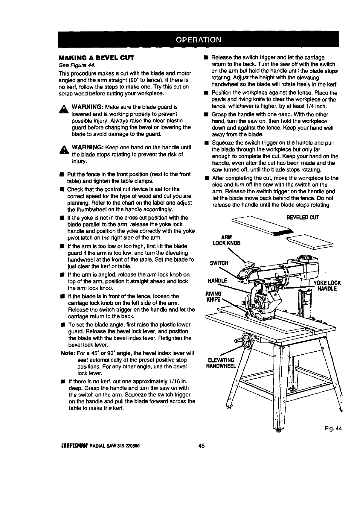
MAKING A BEVELCUT
See Figure 44.
This proceduremakes a cut withthe blade and motor
angled and the arm straight(90" to fence). If there is
no kerf, followthe steps to make one. Try this cut on
scrapwood before cuttingyour workpiece.
_i, WARNING: Make sure the blade guard is
lowered and is workingproperlyto prevent
possibleinjury.Always raisethe clear plastic
guard before changingthe bevel or loweringthe
blade to avoid damage to the guard.
,_ WARNING: Keep one hand on the handle until
the blade stopsrotatingto preventthe risk of
injury.
• Put the fence in the front position(next to the front
table) and tightenthe table clamps.
•Check that the controlcut deviceis set for the
correctspeed for the type of woodand cut you are
planning.Referto the chart onthe label and adjust
the thumbwheelon the handleaccordingly.
•If the yoke is notin the crosscut positionwiththe
blade parallelto the arm, release the yoke lock
handleand positionthe yoke correctly withthe yoke
pivotlatchonthe rightside of the arm.
•If the arm is too lowor toohigh, firstliftthe blade
guardif the arm is too low, and tum the elevating
handwheelat the front of the table. Set the blade to
justclearthe kerrortable.
•If the arm is angled, release the arm lock knobon
topof the arm, positionit straightahead and lock
the arm lockknob.
•If the blade is in frontof the fence, loosenthe
carriage lockknobon the left sideof the arm.
Release the switchtdggeronthe handleand let the
carriage returnto the back.
•To set the blade angle,first raise the plasticlower
guard. Release the bevel locklever, and position
the blade withthe bevelindex lever. Refighten the
bevel locklever.
Note: For a 45" or 90" angle, the bevel index lever will
seat automaticallyat the presetpositivestop
positions.For any otherangle, usethe bevel
lock lever.
• If there is no kerr, cut one approximately1/16 in.
deep. Graspthe handleand turnthe saw on with
the switchonthe arm. Squeeze the switchtrigger
onthe handleand pullthe blade forward acrossthe
tableto make the kert.
•Release the switchtriggerand let the carriage
returnto the back,Turn the saw off withthe switch
on the arm but holdthe handleuntilthe blade stops
rotating.Adjustthe heightwiththe elevating
handwheel so the blade will rotatefreely in the kerr.
•Positionthe workpieceagainst the fence. Place the
pawls and rivingknifeto clear the workpieceorthe
fence, whicheveris higher,by at least 114inch,
•Grasp the handlewith one hand, Withthe other
hand,turn the saw on, then holdthe workpiece
down and againstthe fence. Keep your hand well
away from the blade.
•Squeeze the switchtriggeron the handleand pull
the bladethroughthe workplacebutonly far
enough to completethe cut. Keep yourhand onthe
handle, even after the cut has been made and the
saw turnedoff, untilthe blade stops rotating.
•Aftercompletingthe cut,move the workpieceto the
side and turn off the saw withthe switchon the
arm. Release the switchtrigger onthe handleand
let the blade move back behind the fence. Do not
release the handle untilthe blade stopsrotating.
VELEDCUT
SWITCH
HANDLE
RIVING
YOKELOCK
HANDLE
ELEVATING
HANDWHEEL
Fig. 44
(IIRFrSNRIr RADIALSAW315.220380 48
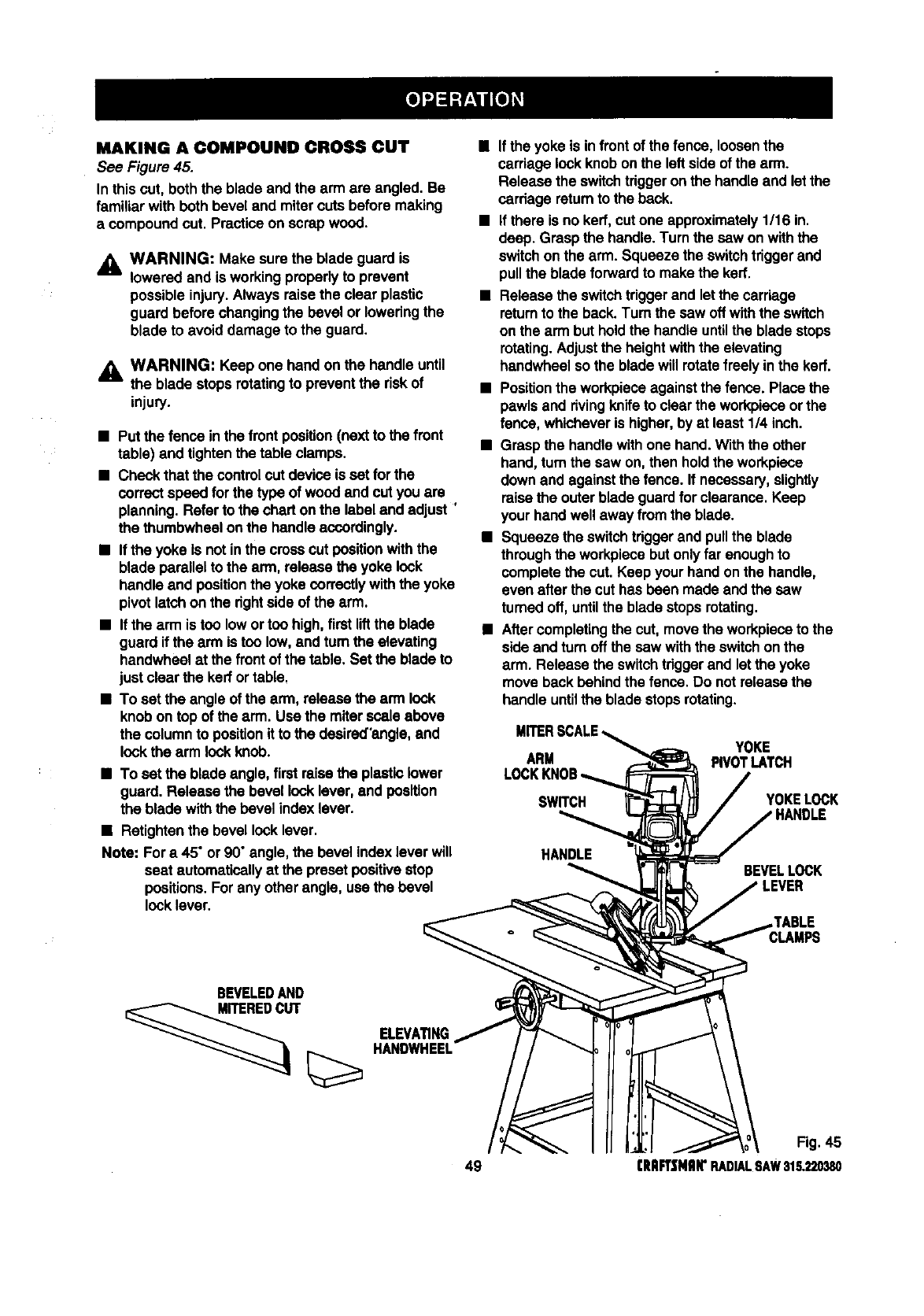
MAKING A COMPOUND CROSS CUI"
See Figure 45.
In thiscut, boththe blade and the arm are angled. Be
familiarwith both bevel and mitercuts before making
a compoundcut. Practiceon scrapwood.
_1= WARNING: Make sure the blade guard is
lowered and is workingproperlyto prevent
possible injury.Always raise the clear plastic
guard before changingthe bevel or loweringthe
blade to avoid damage to the guard.
_k WARNING: Keep one hand on the handleuntil
the blade stops rotatingto prevent the riskof
injury.
• Put the fence in the front position(nextto the front
table) and tightenthe tableclamps.
•Check that the controlcut device is set for the
correct speed for the type of woodand cut youare
planning.Refer to the charton the label and adjust '
the thumbwheelonthe handle accordingly.
•If the yoke Is notinthe crosscut positionwiththe
blade parallelto the arm, releasethe yoke lock
handle and positionthe yoke correctlywiththe yoke
pivot latchon the dghtside of the arm.
•If the arm is too lowortoo high, first liftthe blade
guard if the arm is too low,and turn the elevating
handwheal at the front of the table, Set the blade to
just clearthe kerf ortable.
•To set the angle of the arm, release the arm look
knob on top of the arm. Usa the miterscale above
the columnto positionit to the desired'angle,and
look the arm look knob.
•To set the blade angle,firstraise the plasticlower
guard. Release the bevel locklever, and position
the blade withthe bevel index lever.
•Retightenthe bevel looklever.
Note: For a 45" or 90" angle, the bevel index lever will
seat automatically at the presetpositivestop
positions. For any otherangle, usa the bevel
locklever.
• If the yoke is infront of the fence, loosen the
carriage lookknobon the left side of the arm.
Release the switchtriggeronthe handleand let the
cardage retumto the back.
•If there is no kerr, cut one approximately1/16 in.
deep. Graspthe handle. Turnthe saw onwiththe
switchon the arm. Squeeze the switchtriggerand
pullthe blade forwardto makethe kerr.
•Release the switchtriggerand let the carriage
returnto the back.Turn the saw Offwiththe switch
on the arm but holdthe handle untilthe blade stops
rotating.Adjustthe heightwiththe elevating
handwheel so the blade will rotatefreely inthe kerf.
•Positionthe workpieceagainstthe fence. Place the
pawlsand rivingknife to clear the workpieceor the
fence, whicheveris higher,by at least 114inch.
•Graspthe handle withone hand.With the other
hand,turn the saw on, then holdthe workpiece
down and againstthe fence. If necessary, slightly
raisethe outer blade guard for clearance.Keep
your hand well away from the blade.
•Squeeze the switchtriggerand pullthe blade
throughthe workpiecebut onlyfar enough to
completethe cut. Keep your hand onthe handle,
even after the cut has been made and the saw
turned off, untilthe blade stopsrotating.
•After completingthe cut,move the workpieceto the
sideand turn off the sew withthe switchon the
arm. Release the switchtdggerand letthe yoke
move back behind the fence. Do notreleasethe
handle untilthe blade stopsrotating.
ARM
SWITCH
YOKE
PIVOTLATCH
YOKELOCK
HANDLE BEVELLOCK
BEVELEDAND
ELEVA_NG
HANDWHEEL
Fig. 45
49 (RRFT|NRIrRADIALSAW315.220380
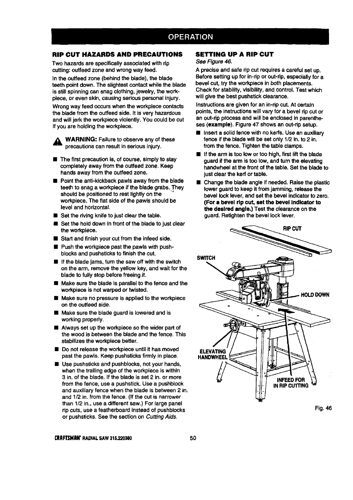
RIP CUT HAZARDS AND PRECAUTIONS
Two hazards are specificallyassociated withrip
cutting:ouffeed zone and wrongway feed.
In the outfeed zone (behind the blade), the blade
teeth pointdown. The slightestcontactwhile the blade
is still spinningcan snag clothing,jewelry, the work-
piece, or even skin, causing seriouspersonal injury.
Wrong way feed occurswhen the workpiececontacts
the blade from the outfeed side. It is very hazardous
and willjerk the workpieceviolently.You could be cut
if you are holdingthe workpiece.
_, WARNING: Failureto observe any of these
precautionscan result inserious injury.
• The firstprecautionis, of course, simplyto stay
completelyaway from the ouffeed zone. Keep
hands away from the outfeed zone.
•Point the anti-kickbackpawlsaway from the blade
teeth to snag aworkpieceif the blade grabs..They
shouldbe positionedto rest lightlyon the
workpiece.The flat side of the pawlsshouldbe
level and horizontal.
•Set the rivingknifeto just clear the table.
•Set the holddown infront of the blade to just clear
the workpiece.
•Start and finish your cut from the infeed side.
•Push the workpiecepast the pawls with push-
blocksand pushsticksto finishthe cut.
•If the bladejams, turn the saw off withthe switch
on the arm, remove the yellowkey, and wait for the
blade to fully stop before freeingJt.
•Make sure the blade is parallel to the fence and the
workpieceis notwarped or twisted.
•Make sure no pressureis applied to the workpiece
on the outfeed side.
•Make sure the blade guard is lowered and is
workingproperly.
•Always set up the workpieceso the wider part of
the wood is between the blade and the fence. This
stabilizesthe workpiecabetter.
•Do not release the workpieceuntil it has moved
past the pawls. Keep pushsticksfirmly in place.
•Use pushsticksand pushblocks,notyour hands,
when the trailingedge of the workpieceis within
3 in. of the blade. If the blade is set 2 in. or more
from the fence, use a pushstick.Use apushblock
and auxiliaryfence when the blade is between2 in.
and 1/2 in. from the fence. (If the cut is narrower
than 1/2 in., use adifferentsaw.) For large panel
rip cuts, use a featherboard instead of pushblocks
or pushsticks.See the sectionon CuttingAids.
SETTING UP A RIP CUT
See Figure 46.
A precise and safe rip cut requiresa careful set up.
Before setting upfor in-rip or out-rip,especiallyfor a
bevel cut,try the workpieceinboth placements.
Check for stability,visibility,and control.Test which
will give the best pushstickclearance.
Instructionsare given for an in-rip cut.At certain
points, the instructionswill vary for a bevel rip cut or
an out-ripprocessand will be enclosedin parenthe-
ses (example). Figure 47 showsan out-ripsetup.
•Inserta solidfence withno kerfs.Use an auxiliary
fence if the blade will be set only 1/2 in. to 2 in.
from the fence. Tighten the table clamps.
•If the arm is too lowor toohigh, firstliftthe blade
guardif the arm istoo low,and turn the elevating
handwheelat the front of the table. Set the blade to
just clear the kerf or table.
•Change the blade angle if needed. Raisethe plastic
lower guardto keep itfrom jamming, releasethe
bevel locklever, and setthe bevel indicatorto zero.
(For a bevel rip cut, set the bevel Indicator to
the desired angle.) Test the clearance onthe
guard. ReUghtenthe bevel locklever.
SWRCH
IOWN
HANDWHEEL
INFEEOFOR
INRIPCUTrlNG
Fig.46
I;RllFTSHItN'RADIALSAW315.220380 50
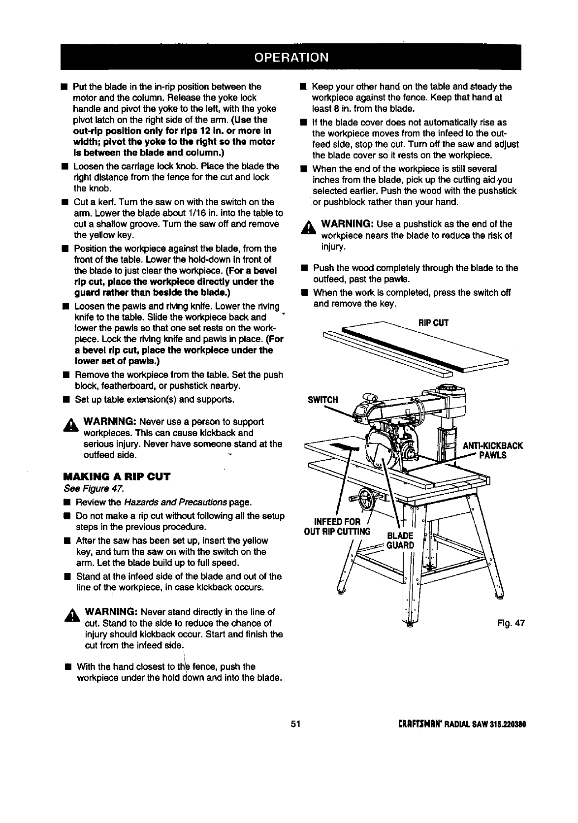
•Put the blade inthe in-rippositionbetweenthe
motorand the column.Release the yoke look
handle and pivotthe yoke to the left,withthe yoke
pivot latch onthe rightsideof the arm. (Use the
out-rip position only for rlpa 12 in. or more in
width; pivot the yoke to the right so the motor
is between the blade and column.)
•Loosenthe cardage lookknob. Place the blade the
dghtdistancefrom the fence for the cut and lock
the knob.
•Cut a kerf.Turn the saw onwiththe switchonthe
arm. Lower the blade about 1/16 in. intothe tableto
cut a shallowgroove. Turnthe sew off and remove
the yellow key.
•Positionthe workpieceagainstthe blade,from the
frontof the table. Lowerthe hold-downinfrontof
the blade to just clearthe workpiece.(For abevel
rip cut, place the workplece directly under the
guard rather than beside the blade.)
•Loosenthe pawlsand rivingknife.Lower the dving,
knifeto the table. Slide the workpieceback and
lower the pawlsso that one set rests onthe work-
piece. Lockthe rivingknifeand pawlsin place. (For
abevel rip cut, place the workplece under the
lower set of pawls.)
•Remove the workpiecefromthe table. Set the push
block,featherboard, or pushsticknearby.
•Set uptable extension(s)and supports.
_i, WARNING: Never use a personto support
workpieces. This can cause kickbackand
sedous injury.Never have someone stand at the
outfeed side.
MAKING ARIP CUT
See Figure 47.
•Reviewthe Hazards and Precautionspage.
•Do not make adp cut withoutfollowingallthe setup
steps inthe previousprocedure.
•Afterthe saw has been set up, insertthe yellow
key, and turnthe saw on withthe switchon the
arm. Let the blade buildup to full speed.
• Stand at the infsed sideof the blade and out of the
lineof the workpiece, incase kickbackoccurs.
_i WARNING: Never stand directlyin the line of
cut. Stand to the side to reduce the chance of
injuryshould kickbackoccur. Start and finishthe
cut from the infeed side=
/
•With the hand closestto th_ fence, push the
workpieceunderthe holddown and intothe blade.
•Keep your otherhand on the table andsteady the
workpieceagainst the fence. Keep that hand at
least 8 in. fromthe blade.
•if the blade cover does notautomaticallydsa as
the workpiecemovesfrom the infeed to the out-
feed side, stopthe cut.Turn off the saw and adjust
the blade cover so it rests on the workpiece.
•When the end of the workpieceis stillseveral
inches from the blade, pick upthe cuttingaid .you
selected earlier. Pushthe wood withthe pushstick
,or pushblockratherthan your hand.
_k WARNING: Use a pushstickas the end of the
workpiecenears the blade to reducethe riskof
injury.
•Push the wood completelythroughthe blade to the
ouffeed,past the pawls.
•When the work is completed,pressthe switchoff
and removethe key.
SWITCH
ANTkKICKBACK
PAWLS
INFEEDFOR
OUTRIPCUTrlNG BLADE
Fig. 47
51 CRRFI"$NRN'RADIALSAW315.220380
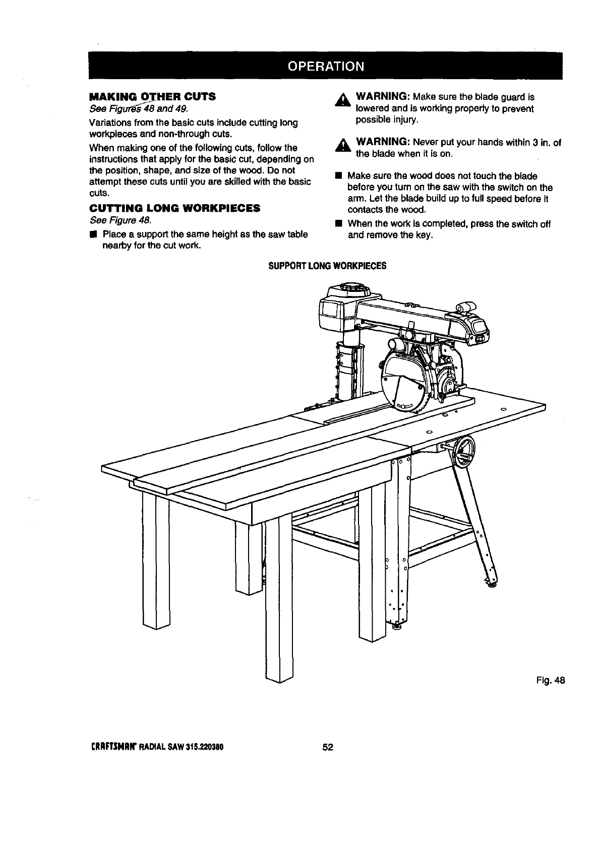
MAKINGO_HER OUTS
See Figu_s 48 and 49,
Variationsfrom the basic cuts includecuttinglong
workpiecesand non-throughcuts.
When making one of the following cuts, followthe
instructionsthat apply for the basiccut, dependingon
the position,shape, and size of the wood. Do not
attempt these cuts untilyou are skilledwiththe basic
cuts.
CUTTING LONG WORKPIECES
See Figure 48.
•Place a supportthe same heightas the saw table
nearby for the cut work.
,_ WARNING: Make sure the blade guardis
loweredand is workingproperlyto prevent
possibleinjury.
,_ WARNING: Never putyour hands within3 in. of
the blade when it is on.
•Make surethe wood does nottouchthe blade
before youturn on the saw withthe switchonthe
arm. Let the blade buildupto full speed before it
contactsthe wood.
•When the work is completed,pressthe switchoff
and remove the key.
SUPPORTLONGWORKPIECES
Fig. 48
rltmFT_iNRIrRADIALSAW31S._'0380 52
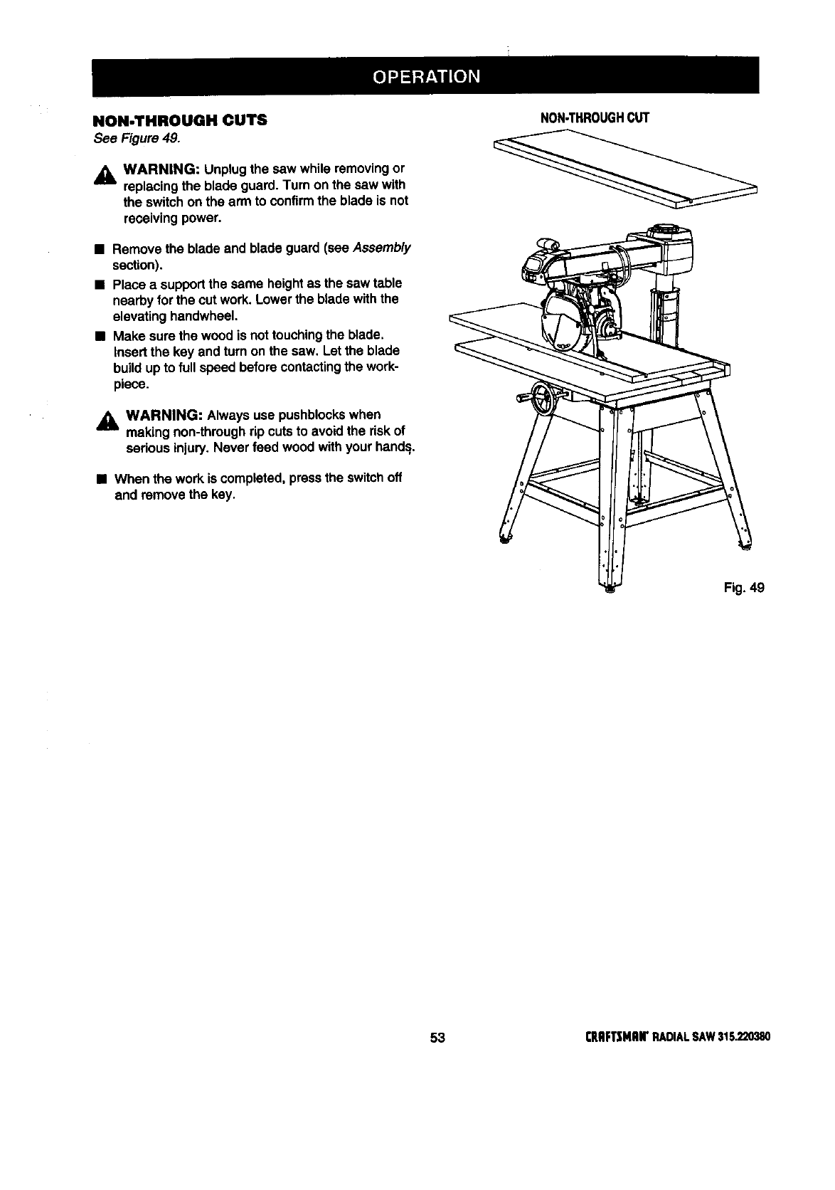
NON-THROUGH CUTS
See Figure 49.
,_L WARNING: Unplugthe saw while removingor
replacingthe blade guard. Turn on the saw with
the switchon the arm to confirmthe blade is not
receivingpower.
NON-THROUGHCUT
•section).Rem°vethe blade and blade guard (see Assembly ___
•Place asupportthe same heightas the saw table
nearby forthe cut work. Lower the blade withthe
elevatinghandwheel.
•Make sure the wood is not touchingthe blade.
Insert the key and turn on the saw. Let the blade
build upto fullspeed before contactingthe work-
piece.
WARNING: Always use pushblockswhen
--'-- making non-throughrip cuts to avoid the riskof
seriousinjury.Never feed wood withyour hand=i, k
•When the workis completed, pressthe switchoff \
and removethe key,
Fig. 49
53 rRIIFTSMRWRADIALSAW316.220380
CiENERAL MAINTENANCE
_i, WARNING: When servicing,use only identical
Craftsman replacementparts. Use of any other
part may create e hazard or cause product
damage.
_k WARNING: To prevent accidentalstartingthat
could cause possible sedous personal injury,turn
offthe saw withthe switchon the arm, remove
the switch key, and unplugthe saw before
workingon the radial saw.
•Remove sawdustfrom the workarea, including
inside the blade cover, frequently.
•Remove sawdustfrom and clean the blade guards
frequently.
•Clean plastic partswith a softdamp cloth. Do not
use any strongsolvents.
_b, WARNING: Do notat any time let brake fluids,
gasoline, petroleum-basedproducts,penetrating
oils, etc. contactplasticparts. They contain
chemicals that can damage, weaken or destroy
plastic.
•Check teeth of anti-kickbackpawls;sharpen with
file if needed.
•Regularlycheck all nuts,bolts, screws,and cables
for tightnessand condition.
MOTOI_IELEGTIIIlCAL
•Frequentlyvacuumor blow outany sawdustfrom
the workareas.
_k WARNING: If the power cords are wom, cut, or
damaged inany way, have them replaced
immediatelyby a qualifiedservice technicianat a
Sears store or repaircenter. Failure to do so
could resultin sedous personalinjury.
_IL WARNING; To avoid fire or electrocution,
reassembleelectric partsonly with identical
Craftsman replacement pads. Reassemble
exactlyas originallyassembled.
CRIIFTSNnN'RADIALSAW315220380 54
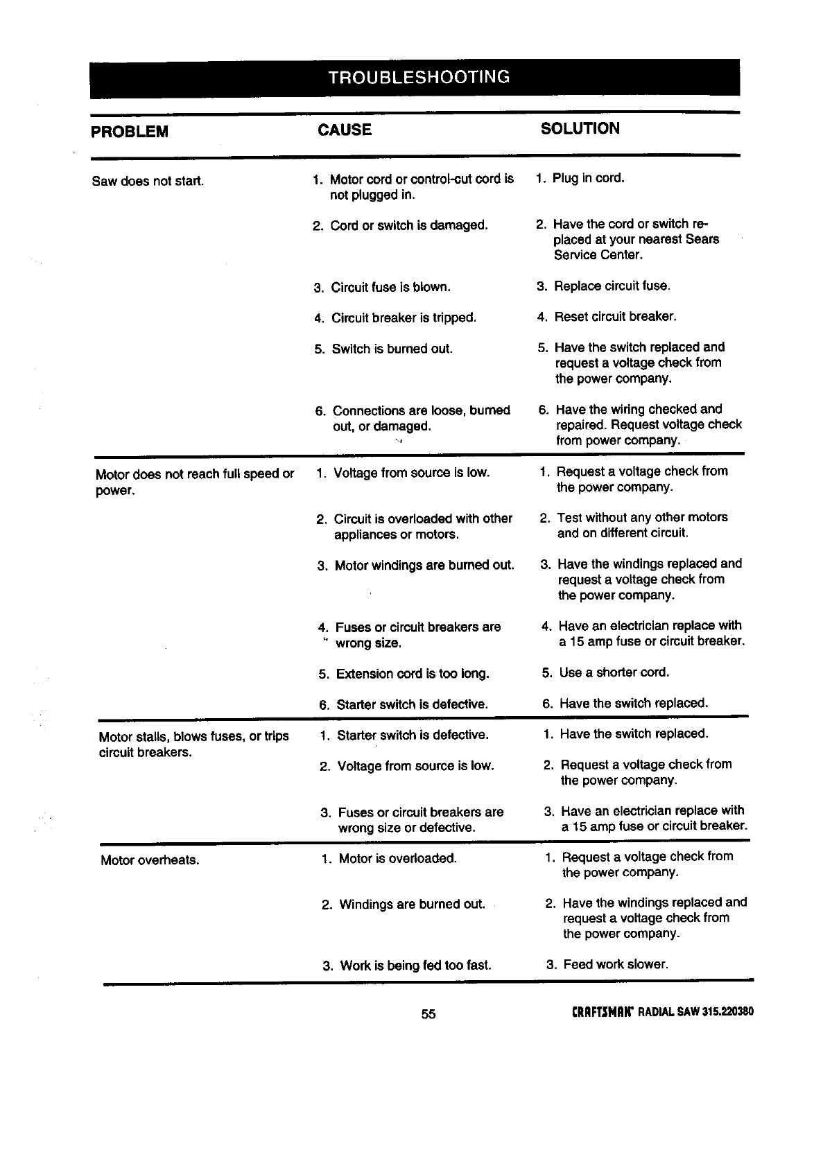
PROBLEM CAUSE SOLUTION
Saw does not start. I. Motorcord or control-cutcord is I. Plug incord.
not pluggedin.
2. Cord or switchis damaged. 2. Have the cord orswitch re-
placed at your nearest Sears
Service Center.
3. Circuitfuse is blown. 3. Replace circuitfuse.
4, Circuit breaker is tripped. 4. Reset circuitbreaker.
5. Switch is burned out. 5. Have the switchreplacedand
requesta voltagecheck from
the power company.
6. Connectionsare loose, burned
out, or damaged.
Lf
6, Have the wiring checkedand
repaired. Request voltagecheck
frompower company.
Motordoes not reachfull speed or
power.
1. Voltage fromsource is low.
2. Circuitis overloadedwithother
appliancesor motors.
1_ Requesta voltage check from
the power company.
2. Test withoutany other motors
and on differentcircuit.
3. Motor windingsare burned out. 3. Have the windingsreplaced and
requesta voltage check from
the power company.
4, Fuses or circuitbreakers are
wrongsize,
4. Have an electricianreplace with
a 15 amp fuse or circuitbreaker.
5. Extensioncord is too long. 5. Use a shortercord.
6. Starterswitchis defective. 6. Have the switchreplaced.
Motor stalls, blowsfuses, ortrips
circuitbreakers.
1. Starter switchis defective.
2, Voltage from source is low.
1. Have the switchreplaced.
2. Requestavoltage check from
the power company.
3. Fuses or circuitbreakers are
wrongsize or defective.
3. Have an electricianreplace with
a 15 amp fuse or circuitbreaker.
Motoroverheats. 1. Motor is ovedoaded. 1. Requesta voltage check from
the power company.
2. Windings are burned out. 2. Have the windingsreplacedand
requesta voltage check from
the power company.
3. Work is being fed toofast. 3. Feed workslower.
55 CRAFTSNAW RADIAL SAW 315.220380
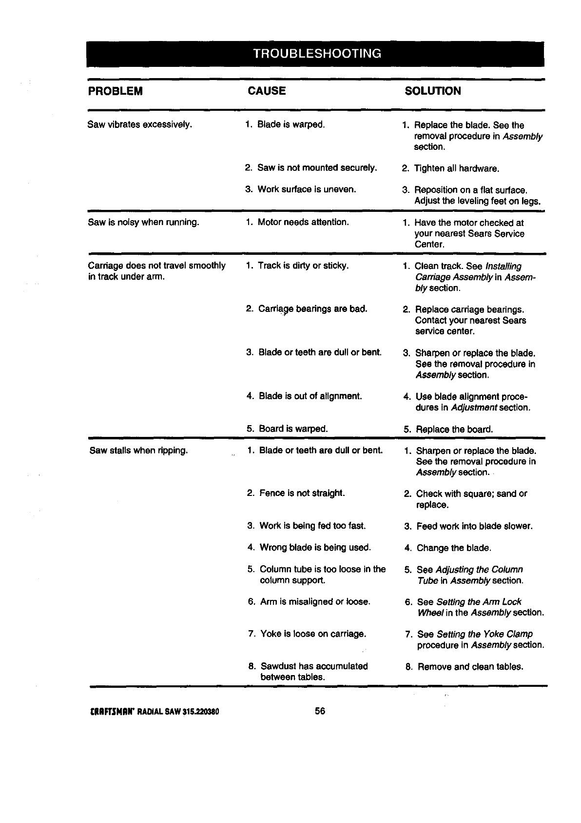
PROBLEM CAUSE SOLUTION
Saw vibmtas excessively. I. Blade is warped. 1, Replace the blade. See the
removalprocedurein Assembly
section,
2. Saw is not mountedsecurely, 2, Tighten all hardware.
3. Work surface is uneven. 3. Reposition on a flat surface.
Adjust the leveling feet on legs.
Saw is noisy when running. 1. Motor needs attention. 1. Have the motor checkedat
your nearest Sears Service
Center.
Carriage does nottravel smoothly
in track underarm. 1. Track is dirtyor sticky. 1. Clean track. See Installing
Carriage Assemblyin Assem-
bly section.
2. Carriage beadngs are bad. 2. Replace cerdage bearings.
Contact your nearestSears
servicecenter.
3. Blade or teeth are dull or bent. 3. Sharpen or replace the blade.
See the removal procedurein
Assemblysection.
4. Blade is out of alignment. 4. Use blade alignmentproce-
dures in Adjustmentsection.
5. Boardis warped. 5. Replace the board,
Saw stallswhen dpping. 1. Blade or teeth are dull orbent. 1. Sharpen or replace the blade.
See the removalprocedurein
Assembly section.
2. Fence is not straight. 2. Check withsquare; sand or
replace.
3. Work is being fed too fast. 3. Feed workinto blade slower.
4. Wrong blade is being used. 4. Change the blade.
5. Column tube is too loose inthe
columnsupport. 5. See Adjustingthe Column
Tube in Assembly section.
6. Arm is misalignedor loose. 6. See Setting the Arm Look
Wheel inthe Assembly section.
7. Yoke is loose on carriage. 7, See Setting the Yoke Clamp
procedurein Assemblysection,
8. Sawdust has accumulated
between tables. 8. Remove and clean tables.
I:HFt'$NIUr RADIALSAW315.220380 56
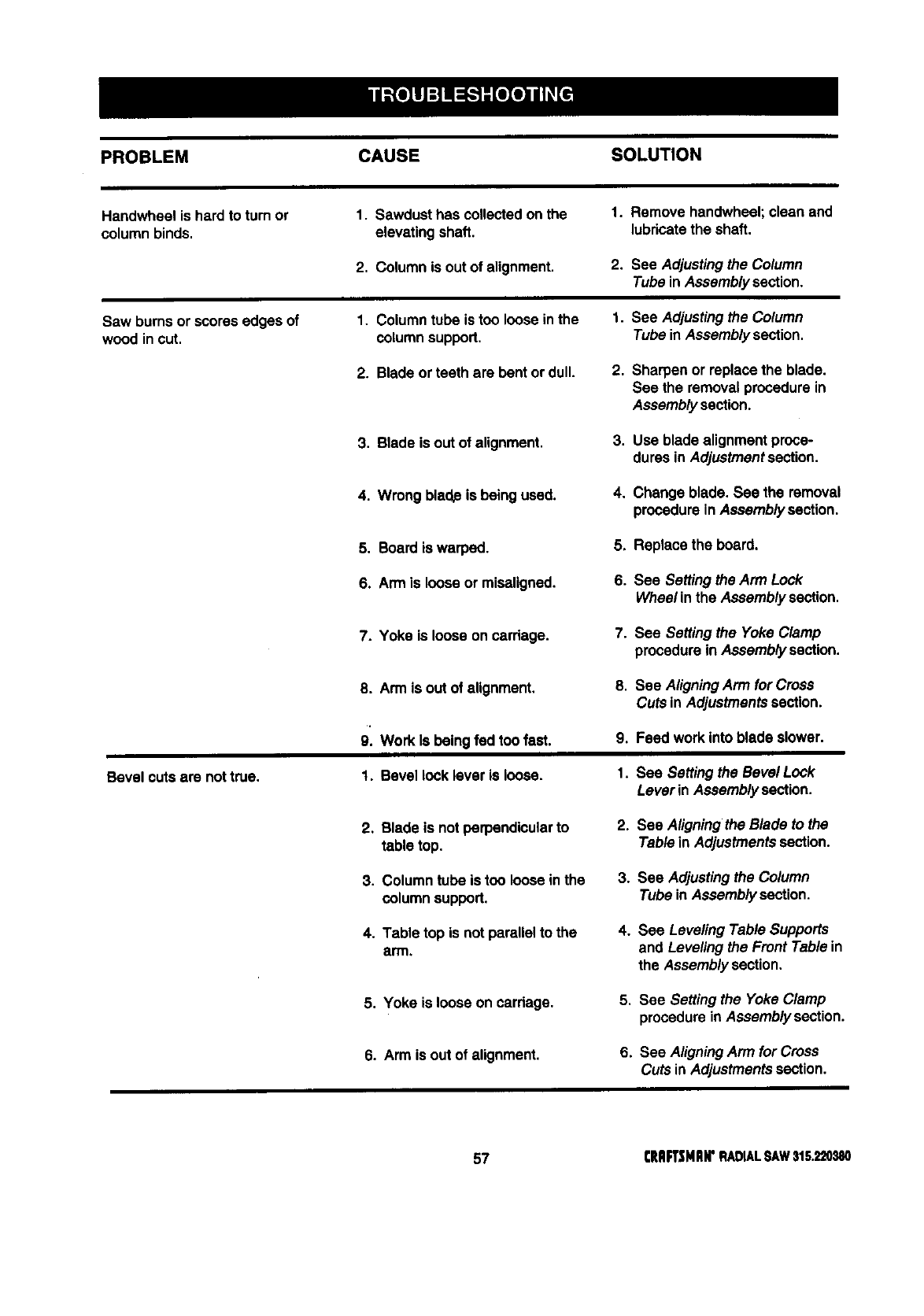
PROBLEM CAUSE SOLUTION
Handwheel is hard to turn or I. Sawdust has collectedon the I. Remove handwheel;clean end
columnbinds, elevating shaft, lubricatethe shaft.
2, Columnis outof alignment. 2. See Adjustingthe Column
Tube in Assemblysection.
Saw burnsor scores edges of 1. Columntube is too loose inthe 1. See Adjustingthe Column
wood in cut. columnsupport, Tube in Assemblysection,
2. Blade orteeth are bentor dull. 2. Sharpen or replacethe blade.
See the removal procedurein
Assemblysection.
3. Blade is out of alignment. 3. Use blade alignment proce-
dures in Adjustmentsection.
4. Wrong blade is being used. 4. Change blade. See the removal
procedurein Assemblysection.
5, Board is warped. 5. Replace the board.
6. Arm is loose or miseligned. 6. See Settingthe Arm Lock
Wheel in the Assembly section.
7. Yoke is loose on carriage. 7. See Setting the Yoke Clamp
procedurein Assemblysection.
Bevel cuts are nottrue.
8. Arm is out of alignment, 8.
9. Work Is being fed toofast. 9.
1. Bevel lock lever is loose, 1.
See AligningArm for Cross
Cuts in Adjustmentssection.
Feed workinto blade slower.
See Setting the Bevel Lock
Leverin Assembly section.
2. Blade is notperpendicularto
table top.
3. Columntube is too loose inthe
columnsupport.
4. Table top is not paraUelto the
arm.
2. See Aligningthe Blade to the
Table in Adjustmentssection.
3. See Adjustingthe Column
Tube in Assemblysection.
4. See Leveling Table Supports
and Leveling the Front Table in
the Assembly section,
5, Yoke is loose on carriage, 5, See Setting the Yoke Clamp
procedurein Assemblysection.
6. Arm is out of alignment. 6. See AligningArm for Cross
Cuts inAdjustmentssection.
57 CRAFTSHIIN'RADIALSAW315.220380
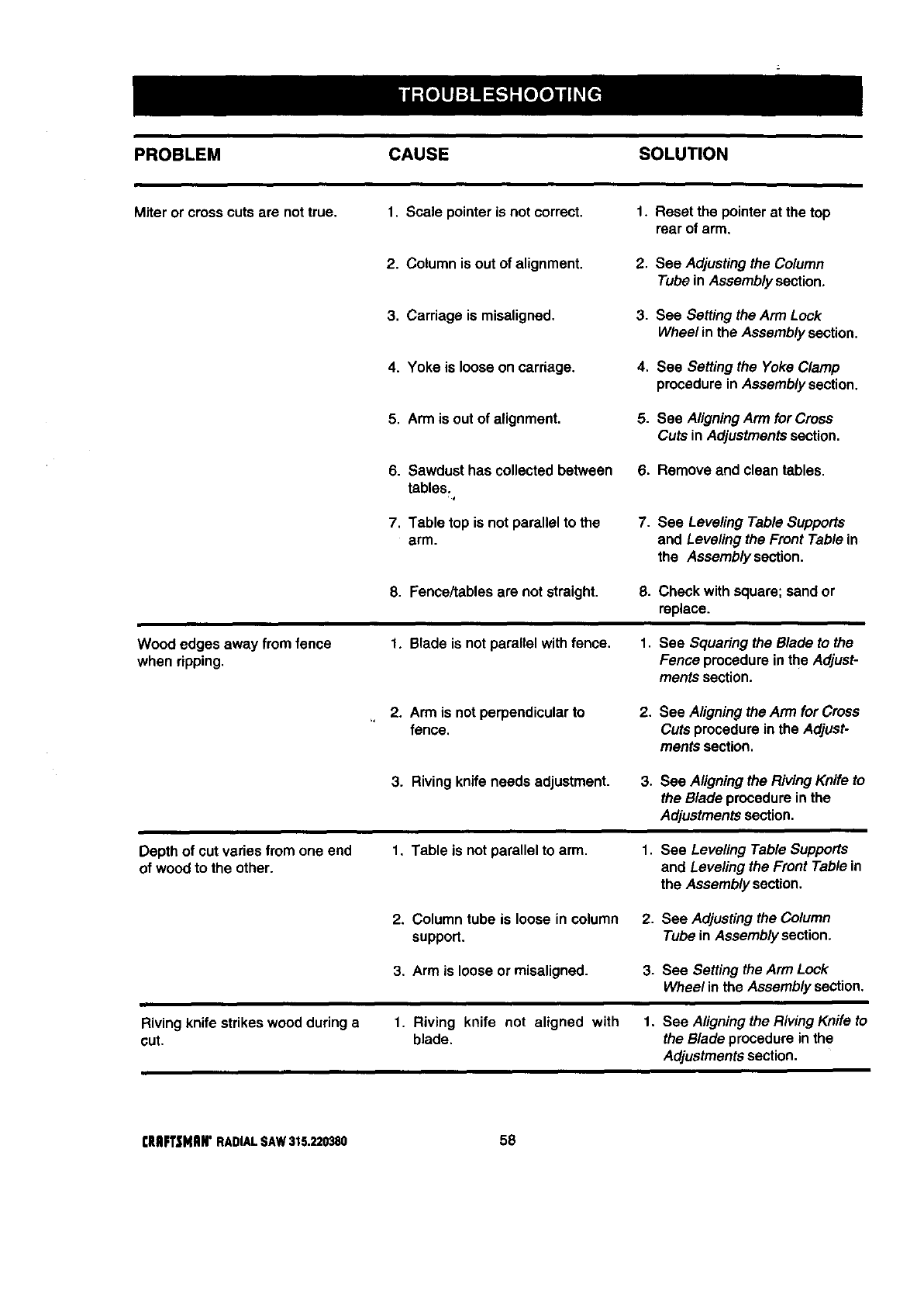
PROBLEM CAUSE SOLUTION
Miter or crosscuts are nottrue, 1. Scale pointeris notcorrect. 1. Reset the pointerat the top
rear of arm.
2. Column is out of alignment. 2. See Adjustingthe Column
Tube in Assemblysection.
3. Carriage is misaligned. 3. See Setting the Arm Lock
Wheel in the Assembly section.
4. Yoke is loose on carriage. 4. See Setting the Yoke Clamp
procedurein Assemblysection.
5. Armis outof alignment. 5. See AligningArm for Cross
Cuts inAdjustmentssection.
6. Sawdust has collected between
tables.
,t
7. Table top is notparallel to the
arm.
6. Remove and clean tables.
7. See Leveling Table Supports
and Leveling the Front Table in
the Assemblysection.
8. Fence/tables are not straight. 8. Check with square; sandor
replace.
Wood edges away from fence
when ripping.
1. Blade is not para!lel withfence. 1. See Squaring the Blade to the
Fence procedurein the Adjust-
ments section.
2. Arm is notperpendicularto
fence. 2. See Aligningthe Arm for Cross
Cutsprocedurein the Adjust-
ments section.
3. Riving knife needs adjustment. 3. See Aligning the RivingKnife to
the Blade procedureinthe
Adjustmentssection,
Depth of cut varies from one end
of wood to the other. 1. Table is not parallel to arm. 1. See Leveling Table Supports
and Leveling the Front Table in
the Assembly section.
2. Column tube is loose in column 2. See Adjustingthe Column
support. Tube inAssembly section.
3. Arm is loose or misaligned. 3. See Setting the Arm Lock
Wheel in the Assembly section.
Riving knife strikeswood during a
cut. 1. Riving knife not aligned with 1. See Aligningthe Riving Knife to
blade, the Blade procedure in the
Adjustments section.
rlIRFTSNRIr RADIALSAW315.220380 58
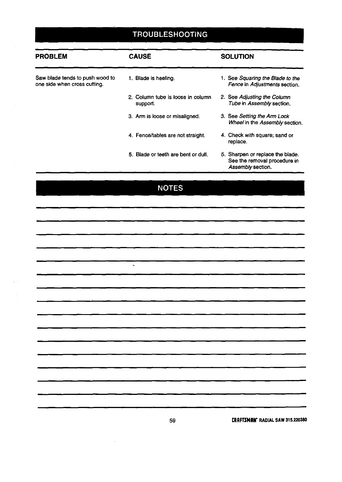
PROBLEM CAUSE SOLUTION
i
Saw blade tends to push wood to 1. Blade is heeling. 1, See Squaringthe Blade to the
one side when crosscutting, Fence inAdjustmentssection,
2. Column tube is loose in column 2, See Adjustingthe Column
support. Tube in Assembly section.
3, Arm is loose or misaligned, 3. See Setting the Arm Lock
Wheel inthe Assemblysection,
4, Fence/tables are not straight, 4. Check with square; sand or
replace.
5. Blade or teeth are bent or dull. 5, Sharpen or replace the blade.
See the removal procedurein
Assembly section.
59
illm
CRnFTSNnN"RADMLSAW315.220380
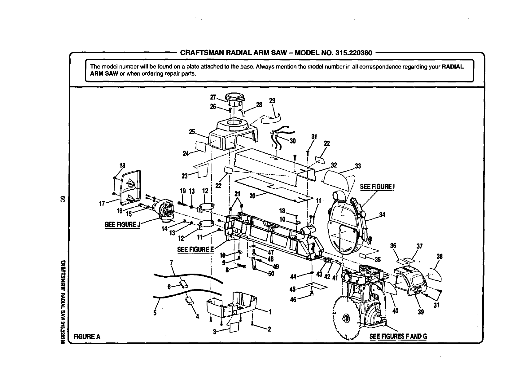
CRAFTSMAN RADIAL ARM SAW - MODEL NO, 315.220380
I The model numberwillbe foundon a plate attachedto the base. Always mentionthe model numberin allcorrespondenceregardingyour RADIAL |
=
ARM SAW or whenordering repair parts. J
29
31 22
0
!
18
19 13 22
12 SEERGUREI
SEER
36 37
38
4O 39
SEEFIGURESFANDG
31
RGUREA
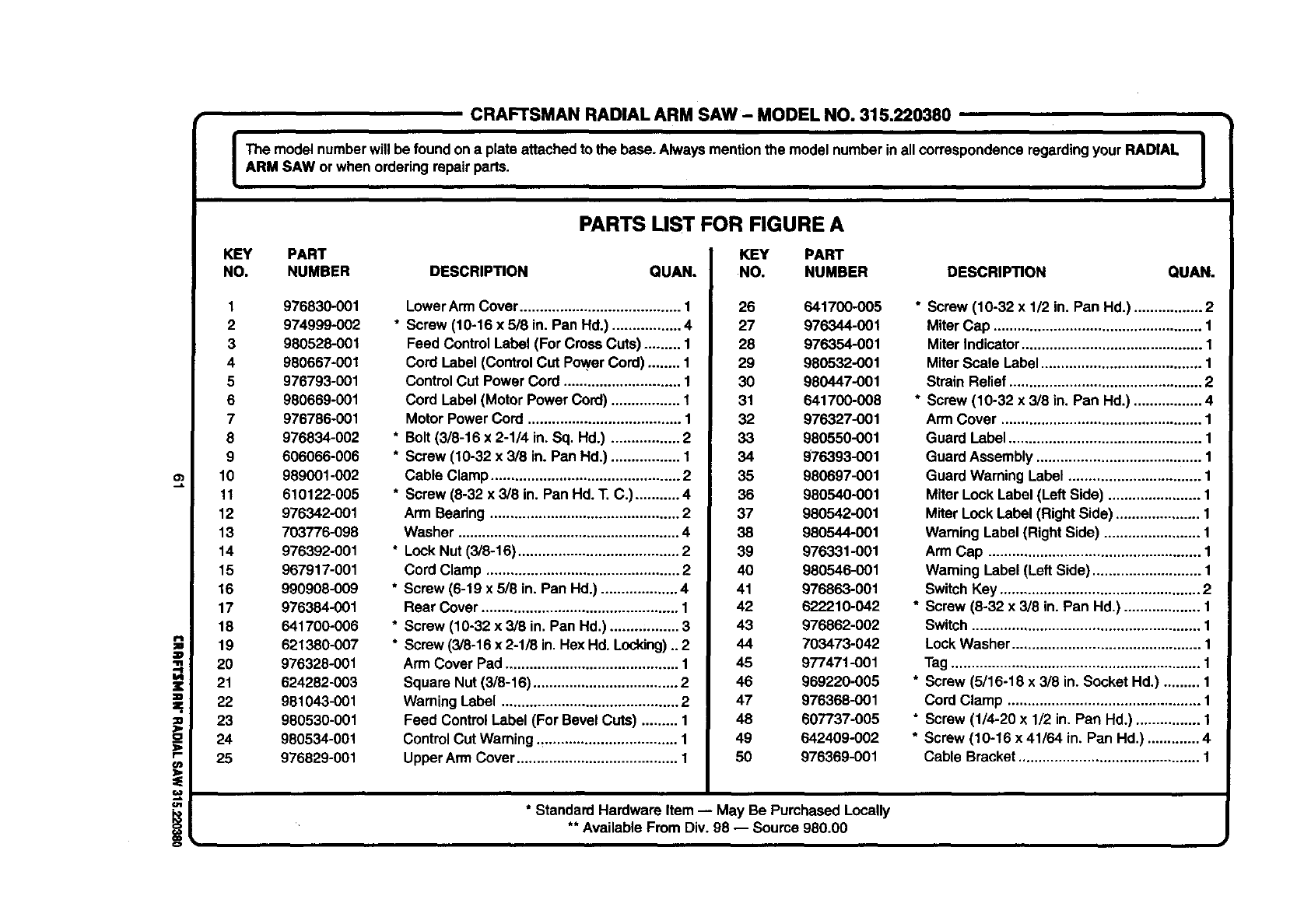
=_.
11r
r-
o_
€4R
i
CRAFTSMAN RADIAL ARM SAW - MODEL NO. 315.220380
Ibe model numberwill be foundon a plateattachedto the base. Always mention the model numberinall correspondenceregardingyour RADIAL I
ARM SAW or whenordering repairparts. J
f
KEY PART
NO. NUMBER
1 976830-001
2 974999-002
3 980528-001
4 980667-001
5 976793-001
6 980669-001
7 976786-001
8 976834-002
9 606066-006
10 989001-002
11 610122-005
12 976342-001
13 703776-098
14 976392-001
15 967917-001
16 990908-009
17 976384-001
18 641700-006
19 621380-007
20 976328-001
21 624282-003
22 981043-001
23 980530-001
24 980534-001
25 976829-001
PARTS LIST FOR FIGURE A
KEY PART
DESCRIPTION QUAN. NO. NUMBER
LowerArmCover ........................................ 1 26 641700.005
* Screw (10-16 x 618in. Pan Hd.) ................. 4 27 976344-001
Feed ControlLabel (For Cross Cuts) ......... 1 28 976354-001
Cord Label (ControlCut PowerCord) ........ 1 29 980532-001
ControlCut Power Cord ............................. 1 30 980447-001
Cord Label (Motor Power Cord) ................. I 31 641700-008
MotorPower Cord ...................................... 1 32 976327-001
* Bolt (3/8-16 x 2-114in. Sq. Hd.) ................. 2 33 980550-001
* Screw (10-32 x 3/8 in. Pan Hd.) ................. 1 34 976393-001
Cable Clamp............................................... 2 35 980697-001
* Screw (8-32 x 3/8 in. Pan Hd. T. C.) ........... 4 36 980540-001
Arm Beadng ............................................... 2 37 980542-001
Washer ....................................................... 4 38 980544-001
* LockNut (3/8-16) ........................................ 2 39 976331-001
Cord Clamp ................................................ 2 40 980546-001
* Screw (6-19 x 518in. Pan Hd.) ................... 4 41 976863-001
Rear Cover ................................................. 1 42 622210-042
* Screw (10-32 x 3/8 in. Pan Hd.) ........;........ 3 43 976862-002
* Screw (3/8-16 x 2-1/8 in. Hex Hd. Locldng)..2 44 703473-042
Arm Cover Pad ........................................... 1 45 977471-001
Square Nut(3/8-16) .................................... 2 46 969220-005
WarningLabel ............................................ 2 47 976368-001
Feed ControlLabel (For BevelCuts) ......... 1 48 60T/37-005
ControlCut Warning.,................................. 1 49 642409-002
UpperArm Cover........................................ 1 50 976369-001
DESCRIPTION QUAN.
* Screw (10-32 x 1/2 in. Pan Hd.) ................. 2
Miter Cap .................................................... 1
Miter Indicator............................................. 1
Miter Scale Label........................................ 1
Strain Relief ................................................ 2
* Screw (10-32 x 3/8 in. Pan Hd.) ................. 4
ArmCover .................................................. 1
Guard Label ................................................ 1
GuardAssembly ......................................... 1
Guard WarningLabel ................................. 1
Miter Lock Label (Left Side) ....................... 1
Miter LockLabel (RightSide) ..................... 1
Warning Label (Right Side) ........................ 1
Arm Cap ..................................................... 1
Warning Label (Left Side) ........................... 1
SwitchKey .................................................. 2
* Screw (8-32 x 3/8 in. Pan Hd.) ................... 1
Switch......................................................... 1
LockWasher ............................................... 1
Tag.............................................................. 1
* Screw (5/16-18 x 3/8 in. Socket Hd.) ......... 1
Cord Clamp ................................................ 1
* Screw (1/4-20 x 1/2 in. Pan Hd.) ................ 1
* Screw (10-16 x 41/64 in. Pan Hd.) ............. 4
Cable Bracket............................................. 1
* StandardHardware Item -- May Be PurchasedLocally
** Available From Div. 98 -- Source 980.00
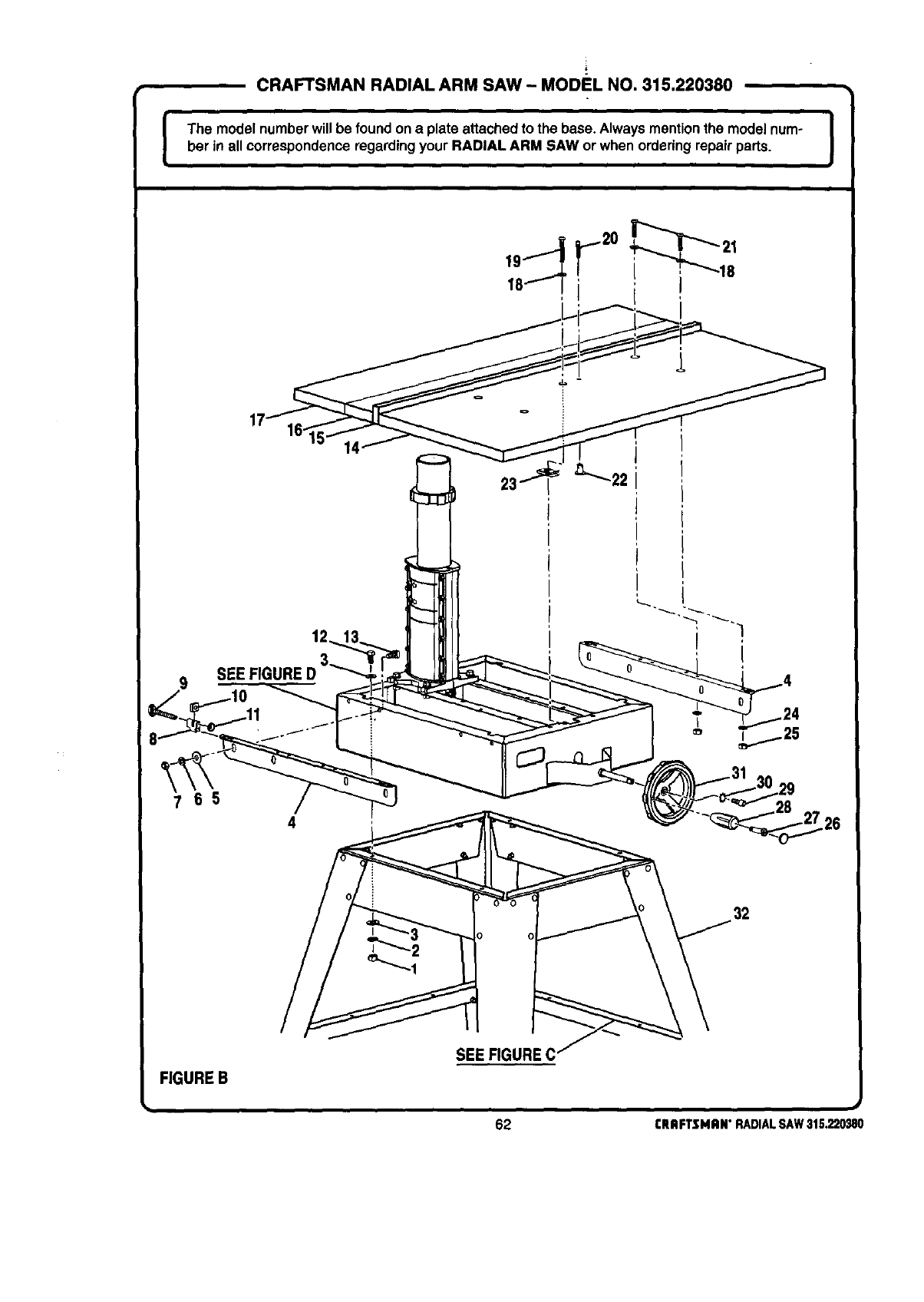
[CRAFTSMAN RADIAL ARM SAW- MODEL NO. 315.220380
I
The model numberwillbe foundon a plate attachedto the base. Alwaysmentionthe modelnum- |
her in all correspondenceregardingyour RADIAL ARM SAW or when ordering repairparts. I
9SEE FIGL
32
FIGUREB
SEE FIGURE C
62 I:RAFTSMRN"RADIALSAW31S.220_80
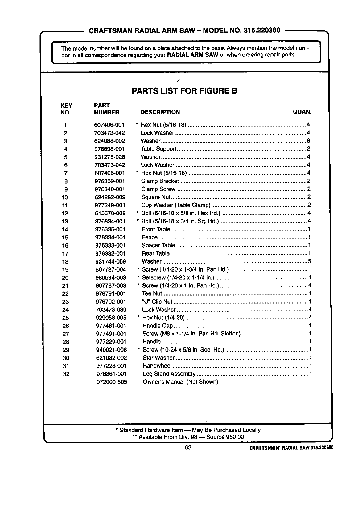
CRAFTSMAN RADIAL ARM SAW -MODEL NO. 315.220380
I The model numberwill be foundon a plate attachedto the base,Always mentionthe model num- I
ber in all correspondenceregardingyour RADIAL ARM SAW orwhen orderingrepair parts. I
PARTS LIST FOR FIGURE B
KEY PART
NO. NUMBER DESCRIPTION QUAN.
1 607406-001
2 703473-042
3 624088-002
4 976698-001
5 931275-028
6 703473-042
7 607406-001
8 976339-001
9 976340-001
10 624282-002
11 977249-001
12 615570-008
13 976834-001
14 976335-001
15 976334-001
16 976333-001
17 976332-001
18 931744-059
19 607737-004
20 989594-003
21 607737-003
22 976791-001
23 976792-001
24 703473-089
25 929058-005
26 977481-001
27 977491-001
28 977229-001
29 940021-008
30 621032-002
31 977228-001
32 976361-001
972000-505
* Hex Nut (5/16-18) .......................................................................... 4
Lock Washer .................................................................................. 4
Washer ........................................................................................... 8
Table Support ................................................................................. 2
Washer ........................................................................................... 4
Lock Washer .................................................................................. 4
* Hex Nut (5/16-18) .......................................................................... 4
Clamp Bracket ............................................................................... 2
Clamp Screw ................................................................................. 2
Square Nut..,' ................................................................................ 2
Cup Washer (Table Clamp) ............................................................ 2
* Bolt (5/16-18 x 5/8 in. Hex Hd.) ..................................................... 4
* Bolt (5/16-18 x 3/4 in. Sq, Hd.) ...................................................... 4
Front Table ..................................................................................... 1
Fence ............................................................................................. 1
Spacer Table .................................................................................. 1
Rear Table ..................................................................................... 1
Washer ........................................................................................... 5
* Screw (1/4-20 x 1-3/4 in. Pan Hd.) ................................................ 1
*Setscrew (1/4-20 x 1-1/4 in.) .......................................................... 1
*Screw (1/4-20 x 1 in. Pan Hd.) ....................................................... 4
Tee Nut .......................................................................................... 1
"U" Clip Nut .................................................................................... 1
Lock Washer .................................................................................. 4
* Hex Nut (1/4-20) ............................................................................ 4
Handle Cap .................................................................................... 1
Screw (M8 x 1-1/4 in. Pan Hd. Slotted) ......................................... 1
Handle ........................................................................................... 1
* Screw (10-24 x 5/8 in. Soc. Hd.) .................................................... 1
Star Washer ................................................................................... 1
Handwheel ..................................................................................... 1
Leg Stand Assembly ...................................................................... 1
Owner's Manual (Not Shown)
*Standard Hardware Item -- May Be PurchasedLocally
** Available From Div, 98 -- Source 980,00
63 CRRFTSMRH"RADIALSAW315.220380
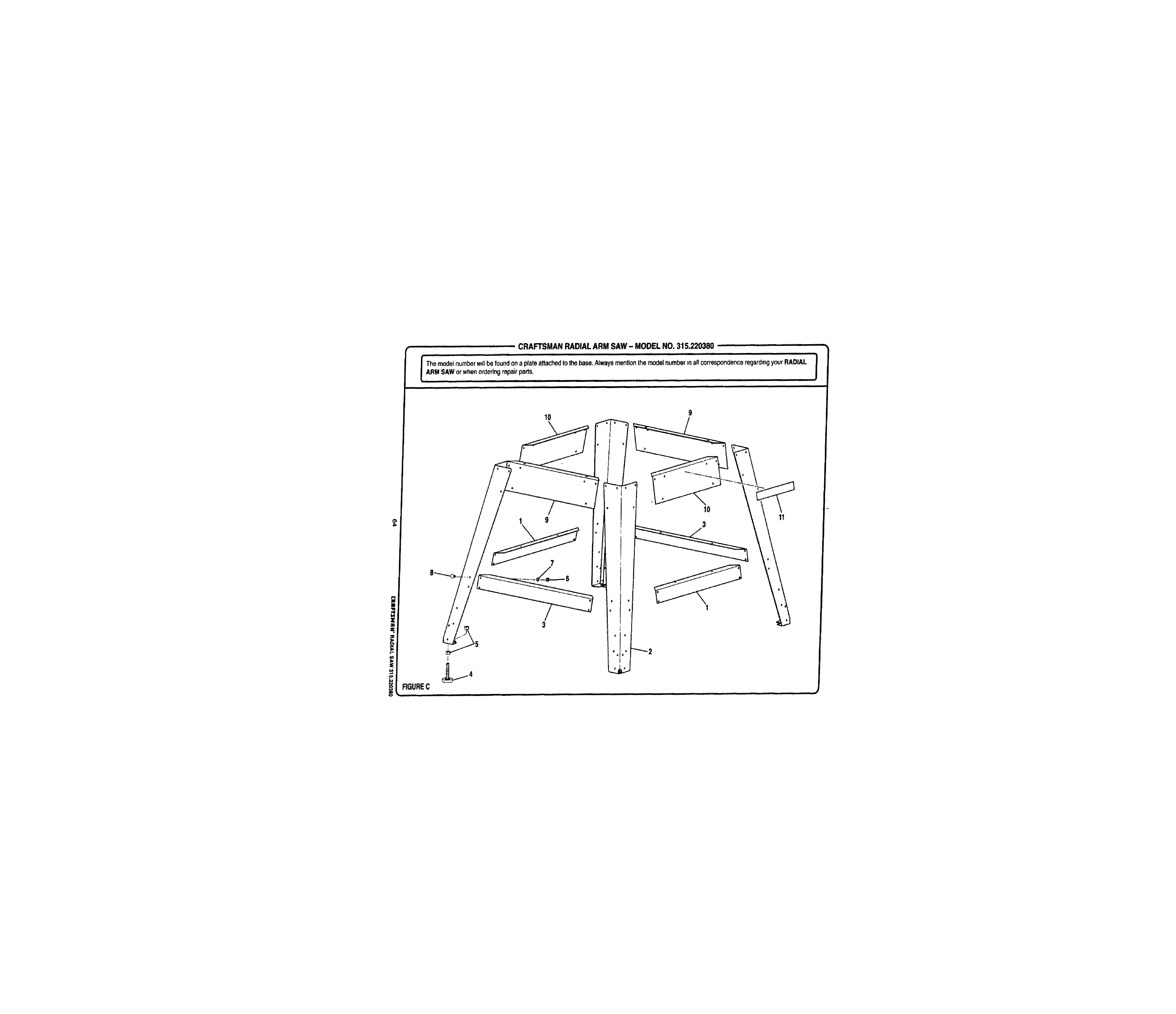
CRAFTSMAN RADIAL ARM SAW - MODEL NO. 315.220380 ...........
iqH i i iqHt rrr[[t r rl Illll I I Illl I[I
iT he modelnumberwillbe foundona plateattac/'_:l to_e base.Alwaysmentionthe modelnumber_naF_correspondenceregardingyourRADIAL
I ARM SAW°r when°rderin9repair parts , ........ J
• i rrrrlnl Iqqr ]_l I II IJI I I I I H I
................ nnn iI II I Illl IIIm Ir IIImll
10 9
1 9
3
iqqqqml qi
10
3
I
rr iiiiir Iqqr
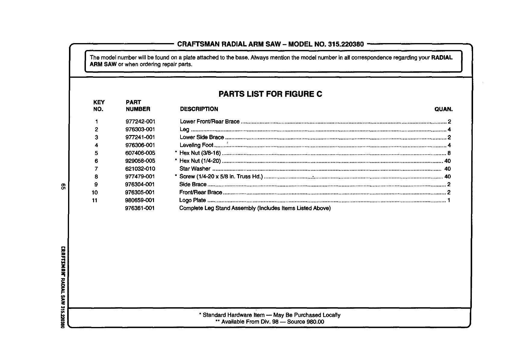
CRAFTSMAN RADIAL ARM SAW- MODEL NO. 315.220380
IThe model numberwillbe foundon a plateattached to the base. Always mentionthe model numberin all correspondenceregardingyour RADIAL |
|
ARM SAW or when orderingrepair parts. I
o1
ol
PARTS LIST FOR FIGURE C
KEY PART
NO. NUMBER DESCRIPTION QUAN.
1 977242-001
2 976303-001
3 977241-001
4 976306-001
5 607406-005
6 929058-005
7 621032-010
8 977479-001
9 976304-001
10 976305-001
11 980659-001
976361-001
LowerFront/Rear Brace.................................................................................................................................... 2
Leg ........................... ............................ ,................... .................... ................... ..,............................................... 4
Lower Side Brace .............................................................................................................................................. 2
LevelingFoot........:............................................................................................................................................. 4
Hex Nut (3/8-16) ................................................................................................................................................ 8
Hex Nut (1/4-20) .............................................................................................................................................. 40
Star Washer ................................................................................................................................................... 40
Screw (114-20x 518in.Truss Hd.) ............................... :................................................................................... 40
Side Brace......................................................................................................................................................... 2
Front/RearBrace............................................................................................................................................... 2
LogoPlate ......................................................................................................................................................... 1
CompleteLeg Stand Assembly (IncludesItems ListedAbove)
*Standard Hardware Item -- May Be PurchasedLocally
** Available From Div. 98 -- Source 980.00
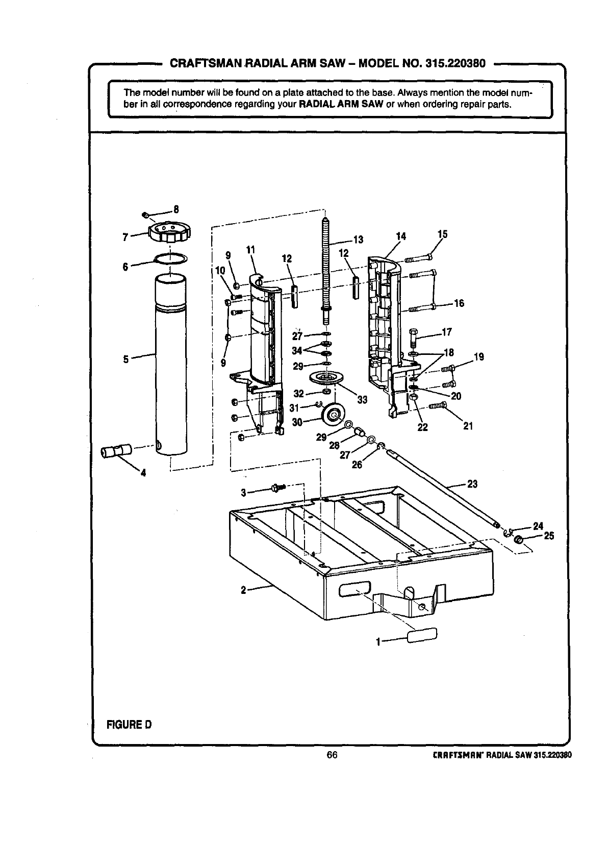
CRAFTSMAN RADIAL ARM SAW- MODEL NO. 315.220380
I•
inu--w0efouo on , o--0o on ooo0onI
ber in all correspondence regardingyour RADIAL ARM SAW or when orderingrepair pads.
11 12
14 15
22 21
RGURE D
_.,
66 CRRFTSMRN"RADIALSAW315.220380
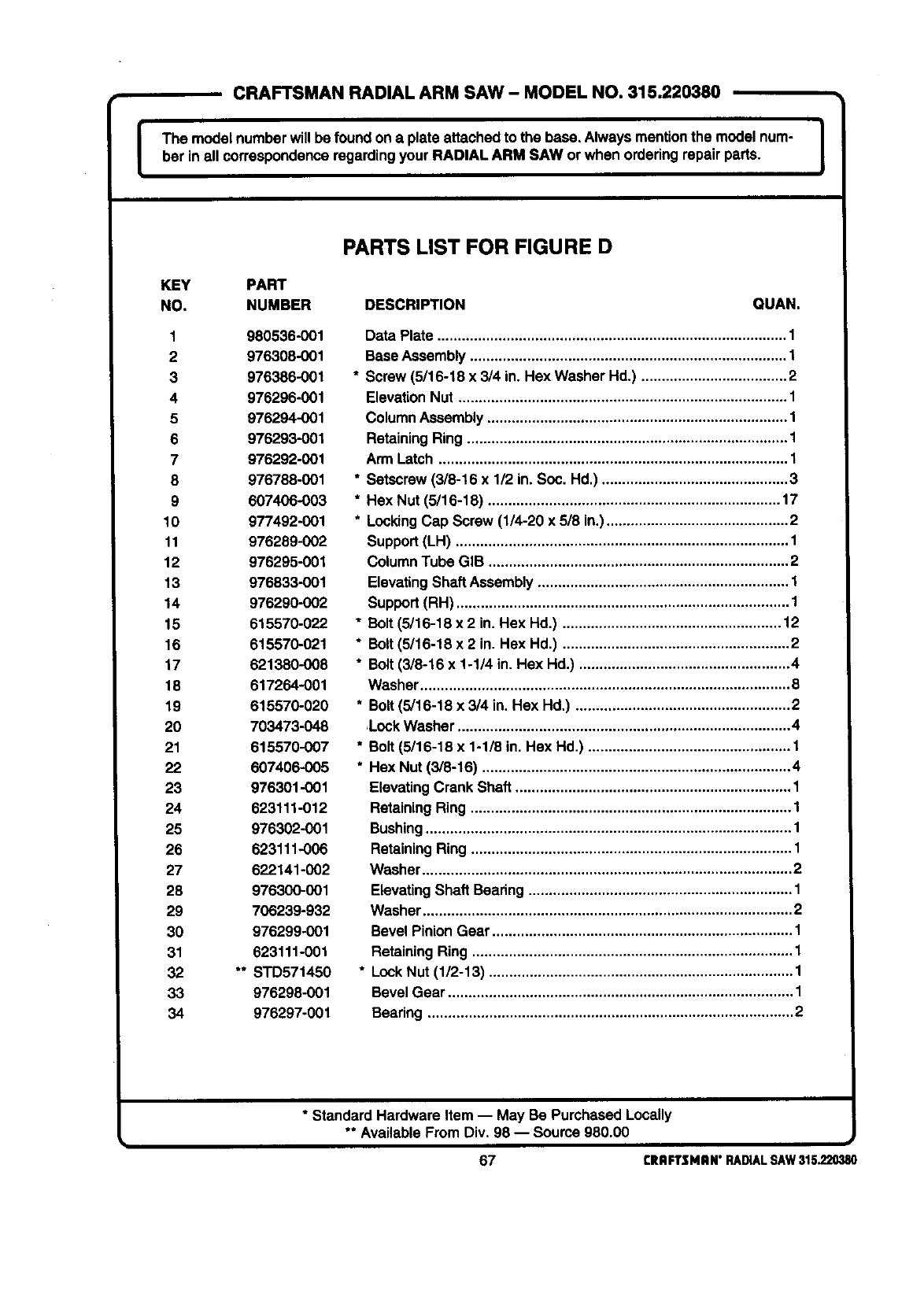
ICRAFTSMAN RADIAL ARM SAW- MODEL NO, 315,220380
I
The model numberwill be foundon a plateattached to the base, Alwaysmentionthe model num-
her in all correspondenceregardingyour RADIAL ARM SAW or when ordering repairparts. I
PARTS LIST FOR FIGURE D
KEY PART
NO. NUMBER DESCRIPTION QUAN.
1980536-001
2 976308-001
3 976386-001
4976296-001
5 976294-001
6 976293-001
7 976292-001
8 976788-001
9 607406-003
10 977492-001
11 976289-002
12 976295-001
13 976833-001
14 976290-002
15 615570-022
16 615570-021
17 621380-008
18 617264-001
19 615570-020
20 703473-048
21 615570-007
22 607406-005
23 976301-001
24 623111-012
25 976302-001
26 623111-006
27 622141-002
28 976300-001
29 706239-932
30 976299-001
31 623111-001
32 " STD571450
33 976298-001
34 976297-001
Data Plate ...................................................................................... 1
Base Assembly .............................................................................. 1
*Screw (5/16-18 x 3/4 in. Hex Washer Hd.) .................................... 2
ElevationNut ................................................................................. 1
Column Assembly .......................................................................... 1
Retaining Ring ............................................................................... 1
Arm Latch ...................................................................................... 1
*Setscrew (3/8-16 x 1/2 in. Soc. Hd,) .............................................. 3
* Hex Nut (5/16-18) ........................................................................ 17
* Locking Cap Screw (1/4-20 x 5/8 in.) ............................................. 2
Support(LH) .................................................................................. 1
Column Tube GIB .......................................................................... 2
ElevatingShaft Assembly .............................................................. 1
Support(RH) .................................................................................. 1
* Bolt (5/16-18 x 2 in. Hex Hd.) ...................................................... 12
*Bolt(3/16-18 x 2in. Hex Hd.) ........................................................ 2
*Bolt (3/8-16 x 1-1/4 in. Hex Hd.) .................................................... 4
Washer ........................................................................................... 8
* Bolt (5/16-18 x 3/4 in. Hex Hd,) ..................................................... 2
,Lock Washer .................................................................................. 4
* Bolt (5/16-18 x 1-1/8 in. Hex Hd.) .................................................. 1
* Hex Nut (3/8-16) ............................................................................ 4
Elevating Crank Shaft .................................................................... 1
Retaining Ring ............................................................................... 1
Bushing .......................................................................................... 1
Retaining Ring ............................................................................... 1
Washer ........................................................................................... 2
ElevatingShaft Bearing ................................................................. 1
Washer ........................................................................................... 2
Bevel Pinion Gear .......................................................................... 1
Retaining Ring ............................................................................... 1
* Lock Nut (1/2-13) ........................................................................... 1
Bevel Gear ..................................................................................... 1
Bearing .......................................................................................... 2
* Standard Hardware Item -- May Be Purchased Locally
** Available From Div. 98 -- Source 980.00
67 CRAFTSMAN"RADIALSAW315.220380
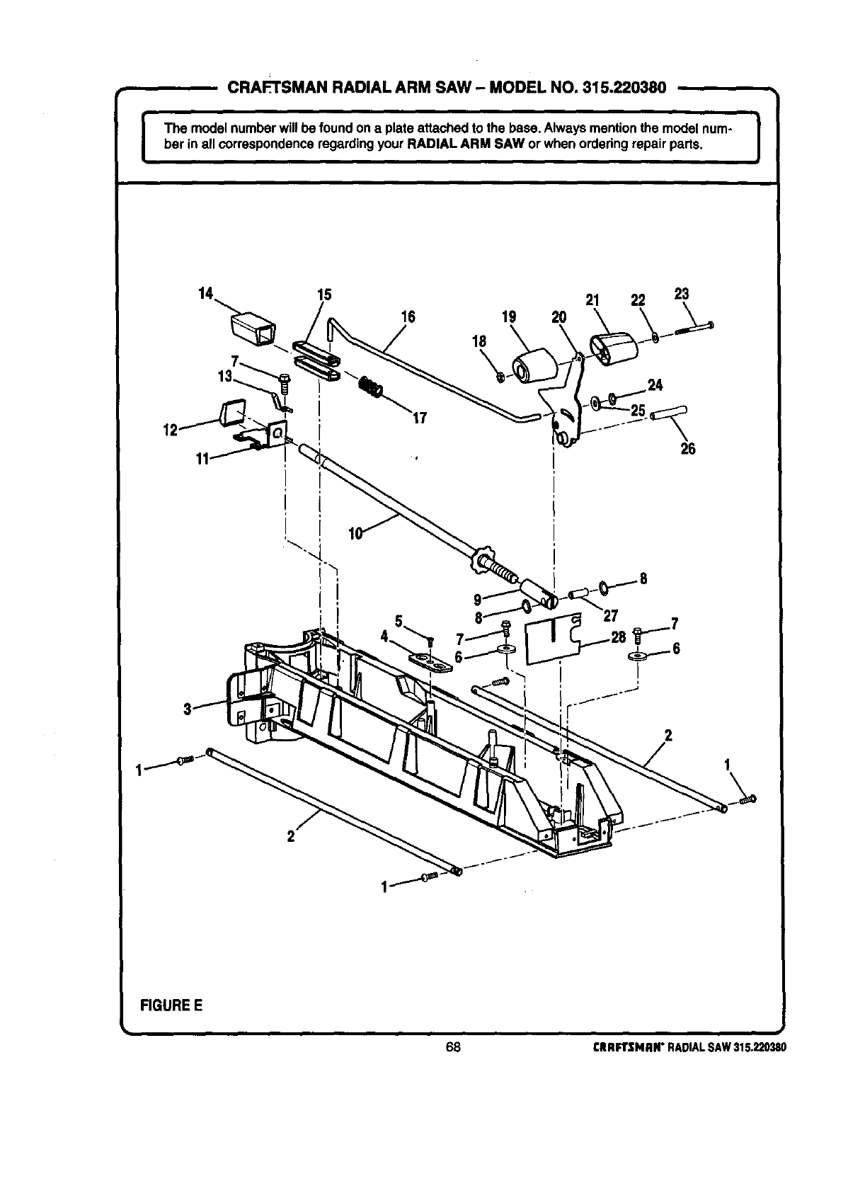
CRAFTSMAN RADIAL ARM SAW -MODEL NO. 315.220380
IThe model numberwill be foundon a plateattached to the base. Alwaysmentionthe model num-
bar in all correspondenceregardingyour RADIAL ARM SAW or whenordering repair parts. I
12'
15 21 22 23
16 19 20
18
\
26
FIGURE E
;i
68 £RAFTSMAN" RADIAL SAW 315,220380
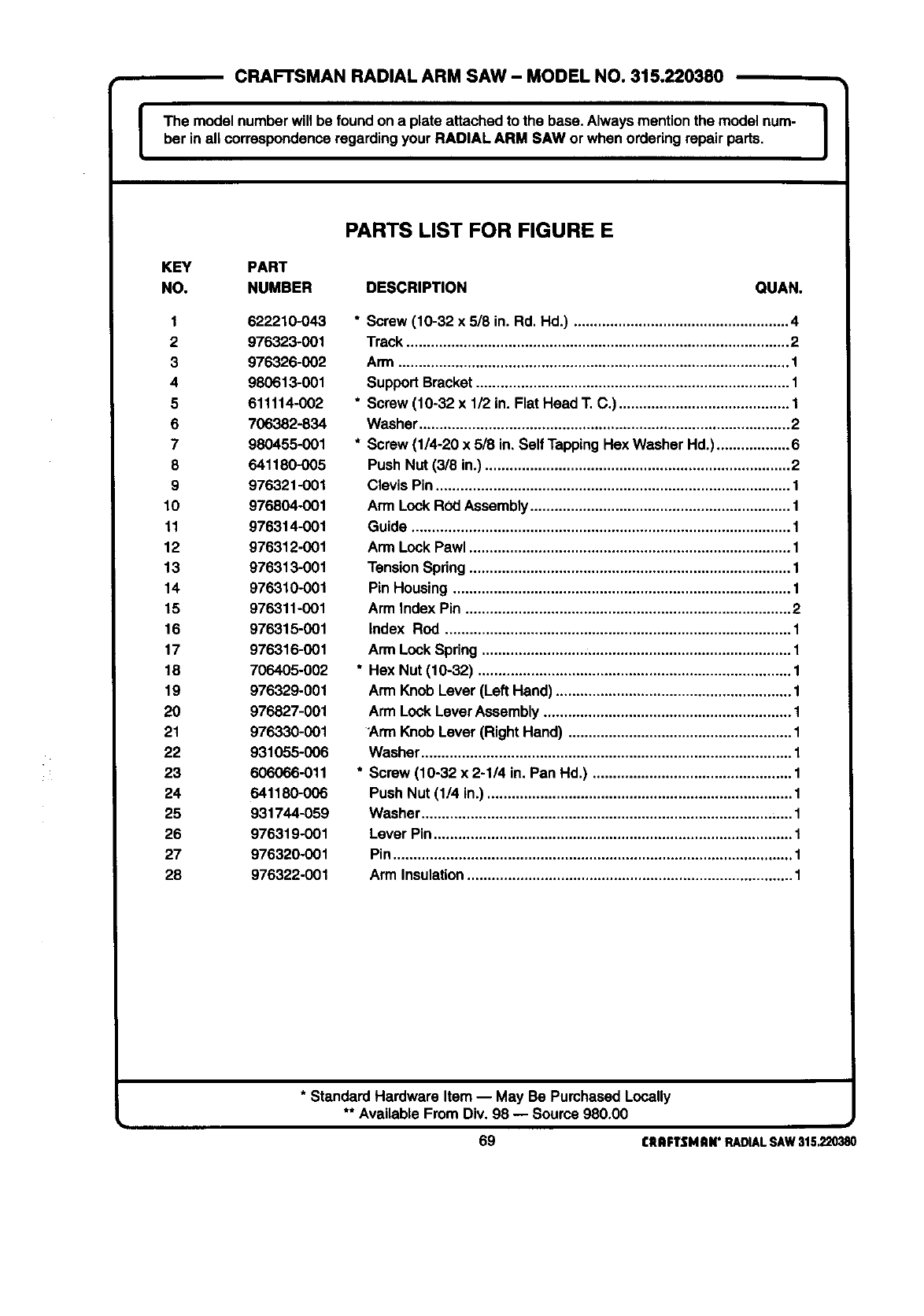
ICRAFTSMAN RADIAL ARM SAW- MODEL NO. 315.220380
The model numberwill be found on a plate attached to the base.Always mentionthe model num-
ber in all correspondenceregardingyour RADIAL ARM SAW orwhen orderingrepair parts. I
PARTS LIST FOR FIGURE E
KEY PART
NO. NUMBER DESCRIPTION QUAN.
1 622210-043
2 976323-001
3 976325-002
4 980613-001
5 611114-002
6 706382-834
7 980455-001
8 641180-005
9 976321-001
10 976804-001
11 976314-001
12 976312-001
13 976313-001
14 976310-001
15 976311-001
16 976315-001
17 976316-001
18 706405-002
19 976329-001
20 976827-001
21 976330-001
22 931055-006
23 606066-011
24 641180-006
25 931744-059
26 976319-001
27 976320-001
28 976322-001
*Screw (10-32 x 518in. Rd Hd.) ..................................................... 4
Track .............................................................................................. 2
Arm ........ ,......................................... .....** ................................. ***.,. 1
SupportBracket............................................................................. 1
* Screw (10-32 x 112in Flat Head T C) .......................................... 1
Washer........................................................................................... 2
* Screw (1/4-20 x 5/8 in Self TappingHex Washer Hd) .................. 6
PushNut (3/8 in) ........................................................................... 2
Clevis Pin....................................................................................... 1
Arm Lock ROdAssembly................................................................ 1
Guide ............................................................................................. 1
Arm Lock Pawl ............................................................................... 1
TensionSpring ............................................................................... 1
Pin Housing ................................................................................... 1
Arm Index Pin ................................................................................ 2
Index ROd..................................................................................... 1
Arm LockSpring ............................................................................ 1
* Hex Nut (10-32) ............................................................................. 1
Arm Knob Lever(Left Hand) .......................................................... 1
Arm LockLever Assembly............................................................. 1
Arm Knob Lever(Right Hand) ....................................................... 1
Washer........................................................................................... 1
* Screw (10-32 x 2-1/4 in Pan Hd) ................................................. 1
PushNut (1/4 in) ........................................................................... 1
Washer ...................................................................................... .1
Lever Pin........................................................................................ 1
Pin.................................................................................................. 1
Arm Insulation................................................................................ 1
* Standard Hardware Item -- May Be PurchassdLocally
** Available From Div 98 -- Source 980.00
69 CRRFTSHRN"RADIALSAW315.220380
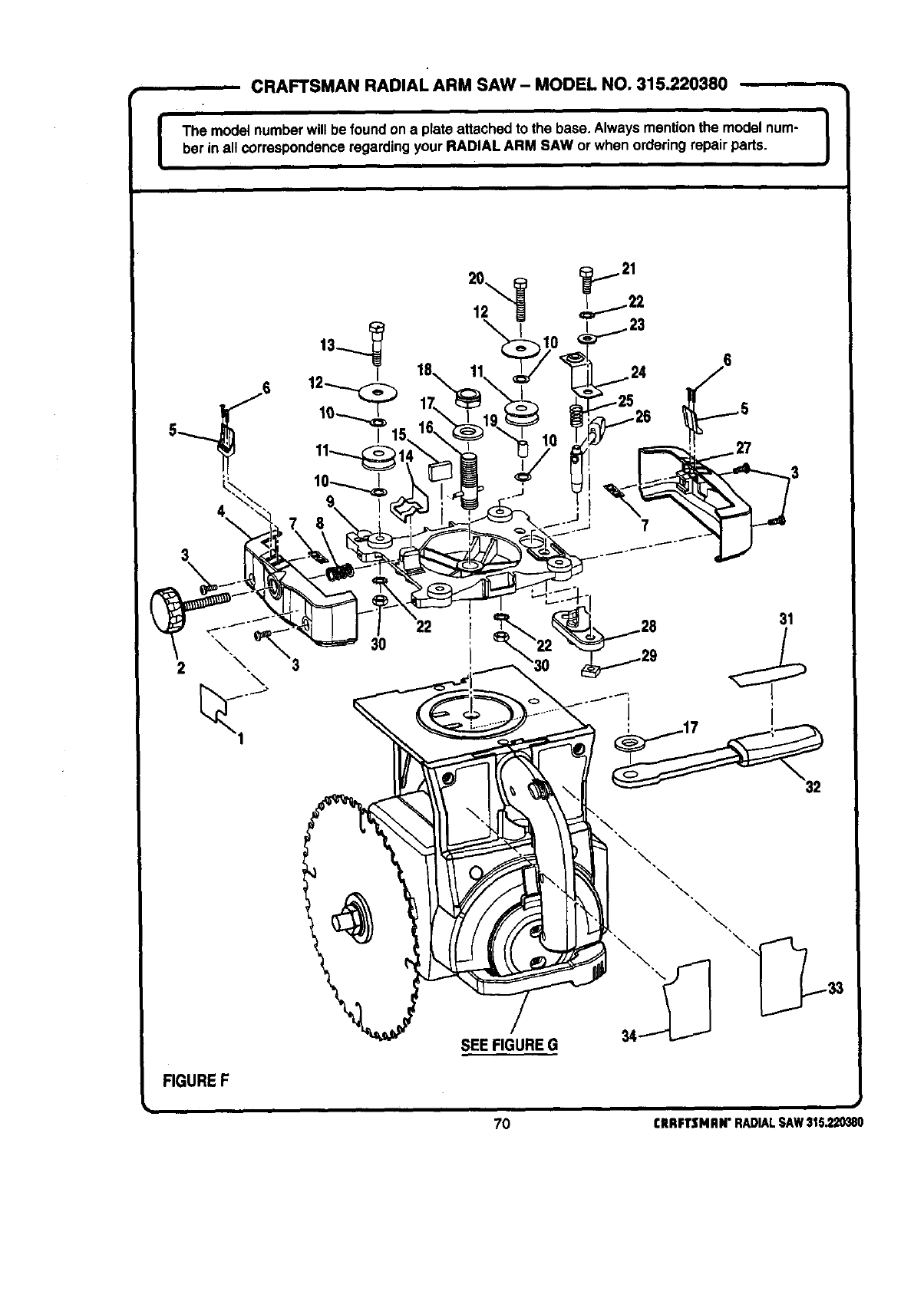
I, CRAFTSMAN RADIAL ARM SAW- MODEL NO. 315.220380
The model numberwill be found ona plata attachedto the base. Alwaysmentionthe model num- I
bet in all correspondenceregardingyour RADIAL ARM SAW or when orderingrepair pads. J
4\
_ _ 21
20
I
30
3
22 31
FIGUREF
/
SEE FIGURE G
70 CRRFTSNRN"RADIALSAW315.220380
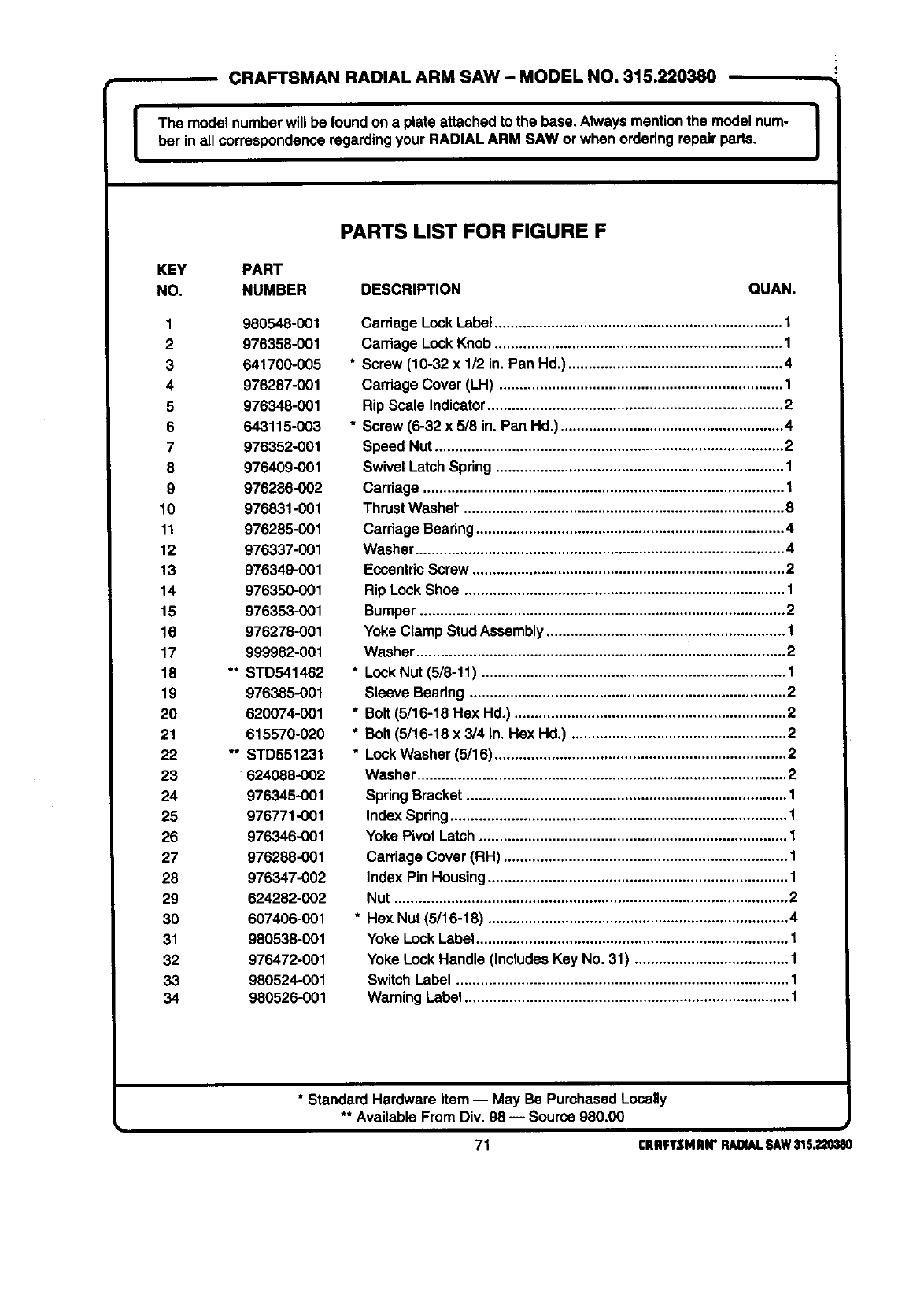
ICRAFTSMAN RADIAL ARM SAW - MODEL NO, 315.220380
The model numberwill be found on a plate attachedto the base. Always mentionthe model nurn- J
ber in allcorrespondenceregardingyour RAOIAL ARM SAW or when ordedng repairparts. I
PARTS LIST FOR FIGURE F
KEY PART
NO. NUMBER DESCRIPTION QUAN.
1 980548-001
2 976358-001
3 641700-005
4 976287-001
5 976348-001
6 643115-003
7 976352-001
8 976409-001
9 976286-002
10 976831-001
11 976285-001
12 976337-001
13 976349-001
14 976350-001
15 976353-001
16 976278-001
17 999982-001
18 ** STD541462
19 976385-001
20 620074-001
21 615570-020
22 ** STD551231
23 624088-002
24 976345-001
25 976771-001
26 976346-001
27 976288-001
28 976347-002
29 624282-002
30 607406-001
31 980538-001
32 976472-001
33 980524-001
34 980526-001
Carriage LockLabe! ....................................................................... 1
Cardage Lock Knob ....................................................................... 1
*Screw (10-32 x 1/2 in. Pan Hd.) ..................................................... 4
Cardage Cover (LH) ...................................................................... 1
Rip Scale Indicator ......................................................................... 2
* Screw (6-32 x 5/8 in. Pan Hd.) ....................................................... 4
Speed Nut ...................................................................................... 2
Swivel Latch Spdng ....................................................................... 1
Carriage ......................................................................................... 1
Thrust Washer" ............................................................................... 8
Cardage Bearing ............................................................................ 4
Washer ........................................................................................... 4
Eccentdc Screw ............................................................................. 2
Rip Lock Shoe ............................................................................... 1
Bumper .......................................................................................... 2
Yoke Clamp Stud Assembly ........................................................... 1
Washer ........................................................................................... 2
* Lock Nut (5/8-11) ........................................................................... 1
Sleeve Beadng .............................................................................. 2
* Bolt (5/16-18 Hex Hd.) ................................................................... 2
* Bolt (5/16-18 x 3/4 in. Hex Hd.) ..................................................... 2
* Lock Washer (5/16) ........................................................................ 2
Washer ........................................................................................... 2
Spring Bracket ............................................................................... 1
Index Spdng................................................................................... 1
Yoke Pivot Latch ............................................................................ 1
Carriage Cover (RH) ...................................................................... 1
Index Pin Housing .......................................................................... 1
Nut ................................................................................................. 2
* Hex Nut (5/16-18) .......................................................................... 4
Yoke Lock Label............................................................................. 1
Yoke Lock Handle (Includes Key No. 31) ...................................... 1
SwitchLabel .................................................................................. 1
Warning Label ................................................................................ 1
*Standard Hardware Item -- May Be PurchasedLocally
** Available From Div. 98 -- Source 980.00 i
71 CRflFTSMRN"RADIALSAW31S.220_180

[CRAFTSMAN RADIAL ARM SAW - MODEL NO. 315.220380
The model numberwill be foundon aplate attachedto the base.Always mentionthe model num-
ber in all correspondenceregardin9 your RADIAL ARM SAW or when ordering repairparts. I
SEE FIGURE F
15-
10
18
SEE FIGURE H
i,
i,
I21
22
25
37 28_
40
26
FIGUREG
72 rRRFTSMRN"RADIALSAW315.220380
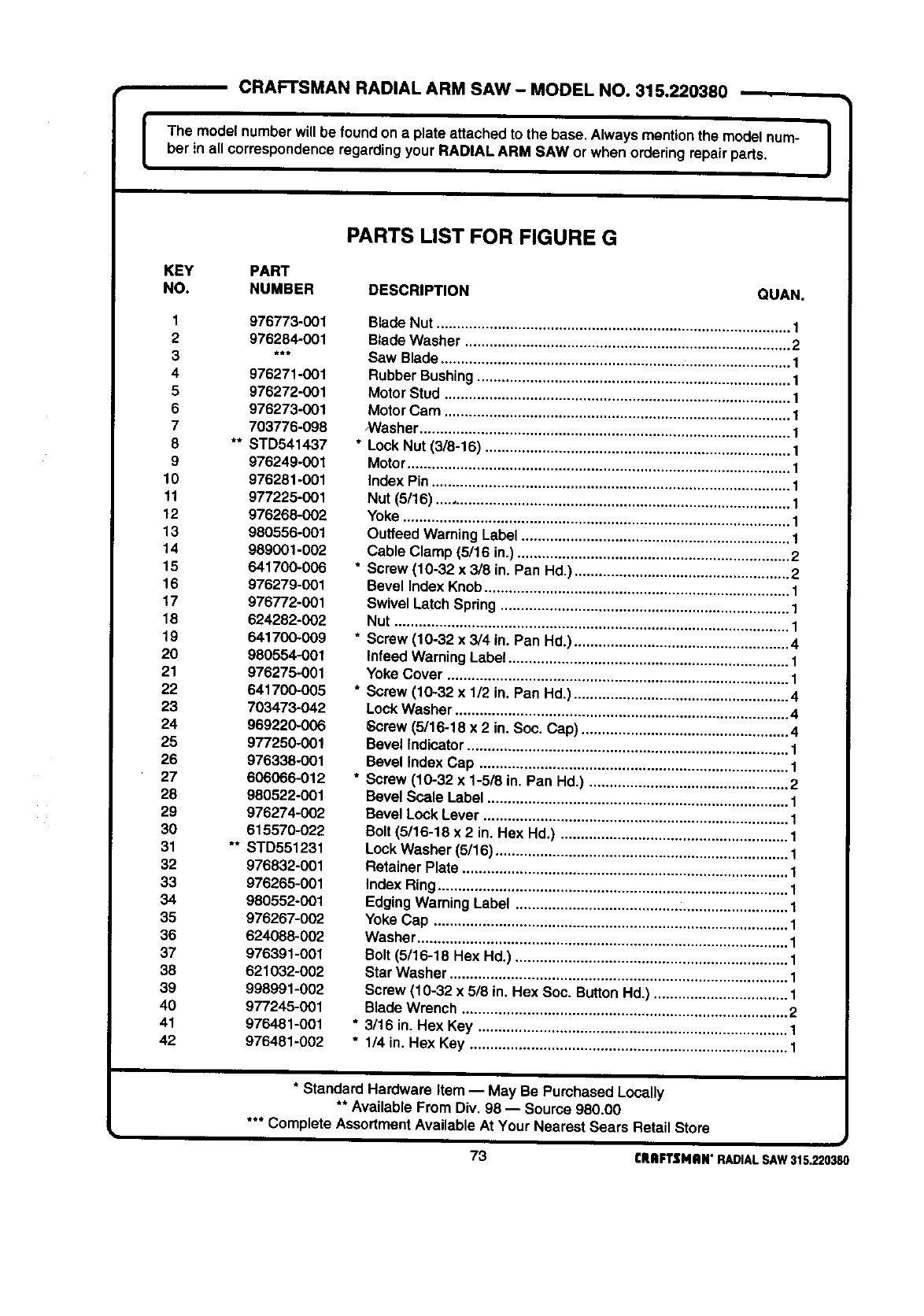
ICRAFTSMAN RADIAL ARM SAW - MODEL NO. 315.220380
The model numberwillbe foundon a plate attachedto the base.Always mentionthe model num-
ber in all correspondenceregardingyour RADIAL ARM SAW or when orderingrepair parts. ]
PARTS LIST FOR FIGURE G
KEY PART
NO. NUMBER DESCRIPTION QUAN,
1976773-001
2 976284-001
3 ***
4 976271-001
5 976272-001
6 976273-001
7 703776-098
8 ** STD541437
9 976249-001
10 976281-001
11 977225-001
12 976268-002
13 980556-001
14 989001-002
15 641700-006
16 976279-001
17 976772-001
18 624282-002
19 641700-009
20 980554-001
21 976275-001
22 641700-005
23 703473-042
24 969220-006
25 97/250-001
26 976338-001
27 606066-012
28 980522-001
29 976274-002
30 615570-022
31 ** STD551231
32 976832-001
33 976265-001
34 980552-001
35 976267-002
36 624088-002
37 976391-001
38 621032-002
39 998991-002
46 977245-001
41 976481-001
42 976481-002
Blade Nut ....................................................................................... 1
Blade Washer ................................................................................ 2
Saw Blade ...................................................................................... 1
Rubber Bushing............................................................................. 1
MotorStud ..................................................................................... 1
MotorCam ..................................................................................... 1
NVasher........................................................................................... 1
* Lock Nut (3/8-16) ........................................................................... 1
Motor.............................................................................................. 1
index Pin........................................................................................ 1
Nut (5/16) ....................................................................................... 1
Yoke ............................................................................................... 1
Outfeed Warning Label .................................................................. 1
Cable Clamp (5/16 in.) ................................................................... 2
* Screw (10-32 x 3/8 in. Pan Hd.) ..................................................... 2
Bevel index Knob........................................................................... 1
Swivel Latch Spring ....................................................................... 1
Nut ................................................................................................. 1
*Screw (10-32 x3/4 in. Pan Hd.) ..................................................... 4
Infeed Warning Labe! ..................................................................... 1
Yoke Cover .................................................................................... 1
*Screw (10-32 x 1/2 in, Pan Hd.) ..................................................... 4
LockWasher .................................................................................. 4
Screw (5/16-18 x 2 in. Soc. Cap) ................................................... 4
Bevel Indicator ............................................................................... 1
Bevel Index Cap ............................................................................ 1
*Screw (10-32 x 1-5/8 in. Pan Hd,) ................................................. 2
Bevel Scale Label .......................................................................... 1
Bevel Lock Lever ........................................................................... 1
Bolt (5/16-18 x 2 in. Hex Hd.) ........................................................ 1
Lock Washer (5/16) ........................................................................ 1
Retainer Plate ................................................................................ 1
Index Ring ...................................................................................... 1
Edging Warning Label ................................................................... 1
Yoke Cap ....................................................................................... 1
Washer ........................................................................................... 1
Bolt (5/16-18 Hex Hd.) ................................................................... 1
Star Washer ................................................................................... 1
Screw (10-32 x 5/8 in. Hex Soc. Button Hd.) ................................. 1
Blade Wrench ................................................................................ 2
* 3/16 in. Hex Key ............................................................................ 1
* 1/4 in. Hex Key .............................................................................. 1
*Standard Hardware Item -- May Be PurchasedLocally
** Available From Div, 98 -- Source 980.00
*** Complete AssortmentAvailable At Your Nearest Sears Retail Store
J
73 rRIIFTSNilN"RADIALSAW315.220380
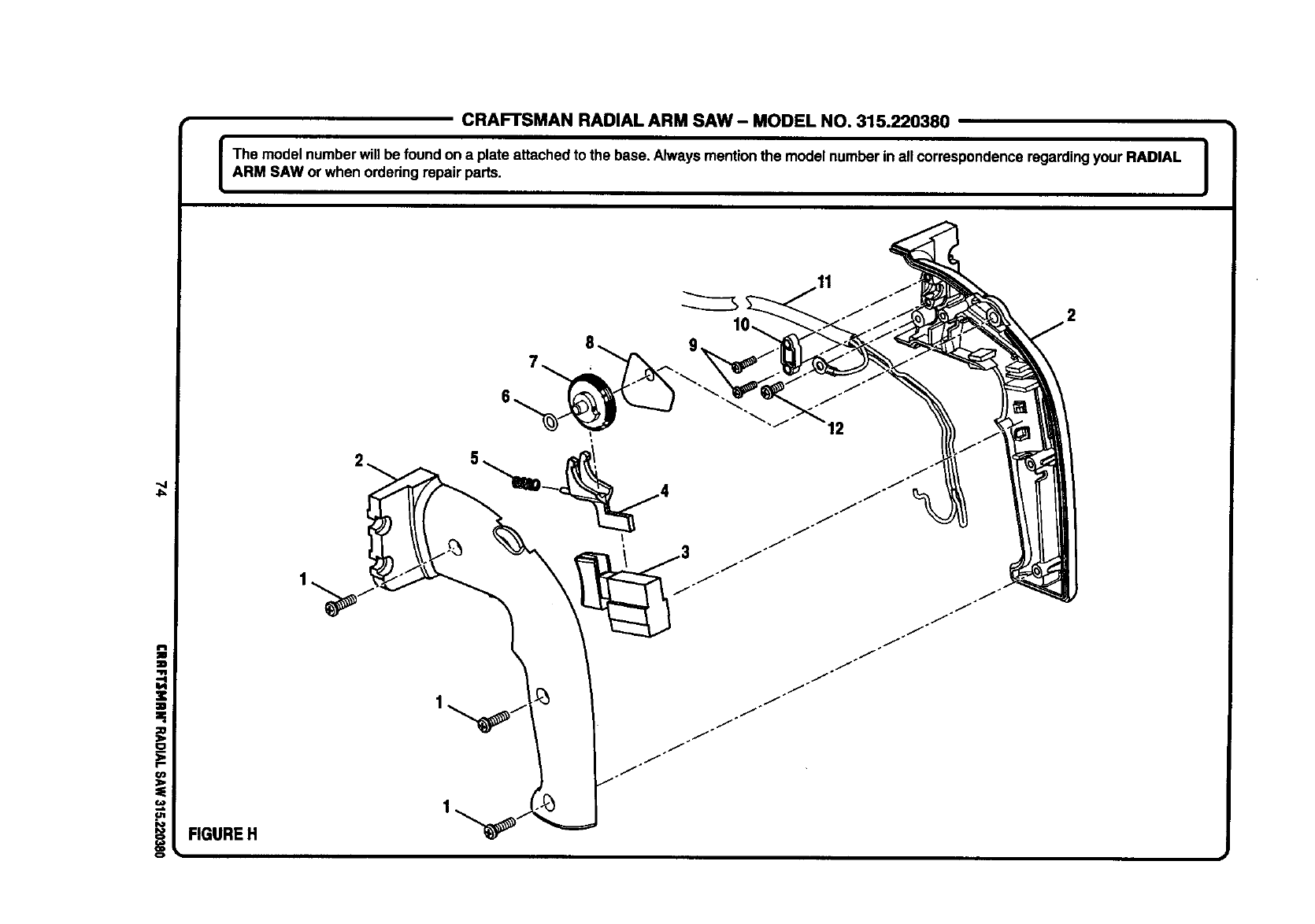
CRAFTSMAN RADIAL ARM SAW- MODEL NO. 315.220380
I The model numberwill be foundon a plateattached to the base. Alwaysmentionthe model numberin all correspondenceregardingyour RADIAL |
|
ARM SAW or when orderingrepair parts. I
4=
iFIGURE H
12
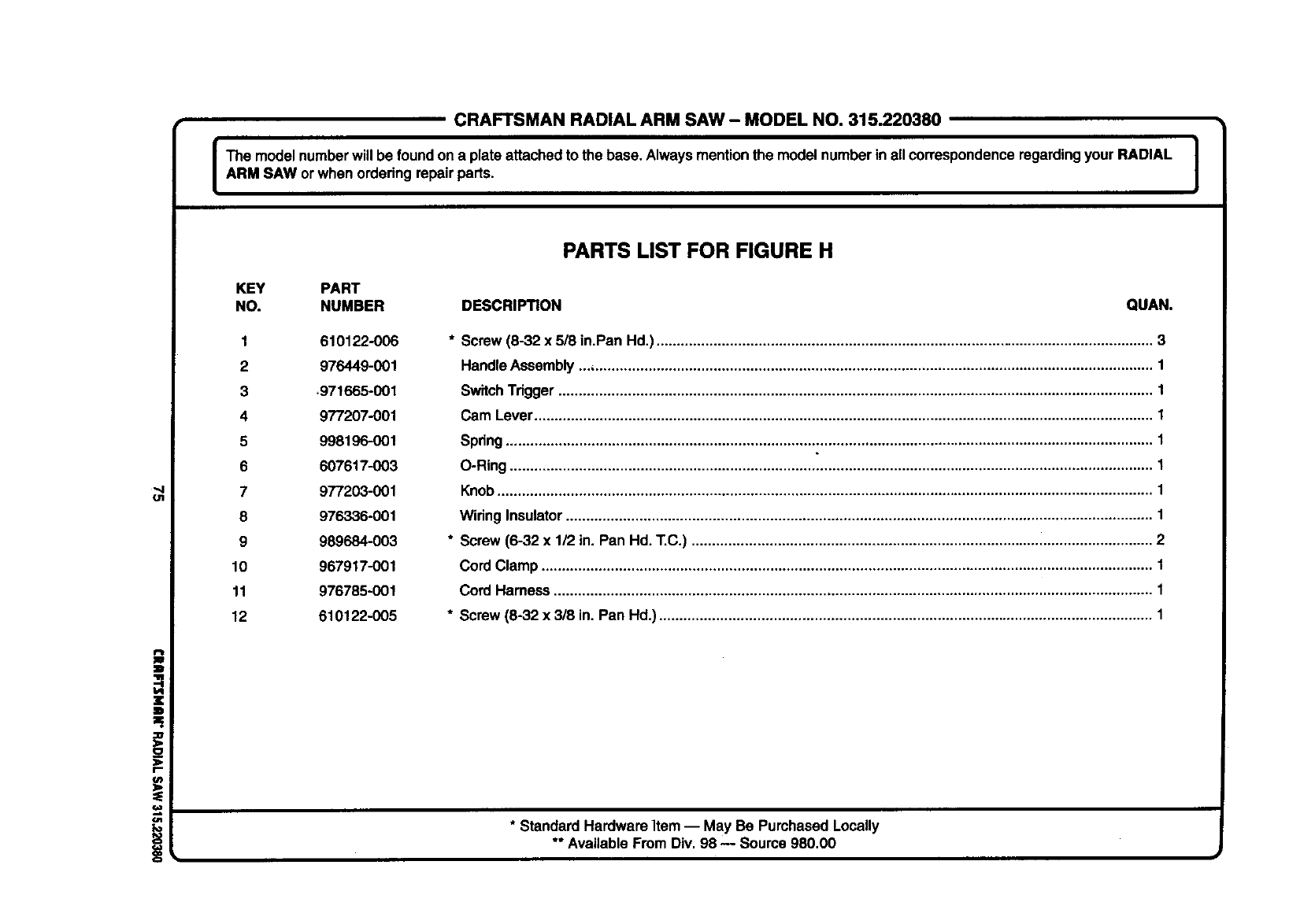
CRAFTSMANRADIALARMSAW- MODELNO.315.220380
The model numberwill be foundon a plate attachedto the base. Alwaysmentionthe model numberin all correspondenceregardingyour RADIAL |
ARM SAW orwhen ordering repairparts. I
PARTS LIST FOR FIGURE H
KEY PART
NO. NUMBER DESCRIPTION QUAN.
1 610122-006
2 976449-001
3_971665-001
4 977207-001
5 998196-001
6 607617-003
7 977203-001
8 976336-001
9 989684-003
10 967917-001
11 976785-001
12 610122-005
* Screw (6-32 x 5/8 in.Pan Hd.).......................................................................................................................... 3
HandleAssembly... ......................................................................................................................................... 1
SwitchTrigger.................................................................................................................................................. 1
Cam Lever........................................................................................................................................................ 1
Spring............................................................................................................................................................... 1
O-Ring .............................................................................................................................................................. 1
Knob................................................................................................................................................................. 1
Wiring Insulator................................................................................................................................................ 1
* Screw (6-32 x 1/2 in. Pan Hd. T.C.) ................................................................................................................. 2
Cord Clamp ...................................................................................................................................................... 1
Cord Harness ................................................................................................................................................... 1
* Screw (8-32 x 3/8 in. Pan Hd.) ......................................................................................................................... 1
* Standard HardwareItem -- May Be Purchased Locally
** Available From Div. 98 -- Source 980.00
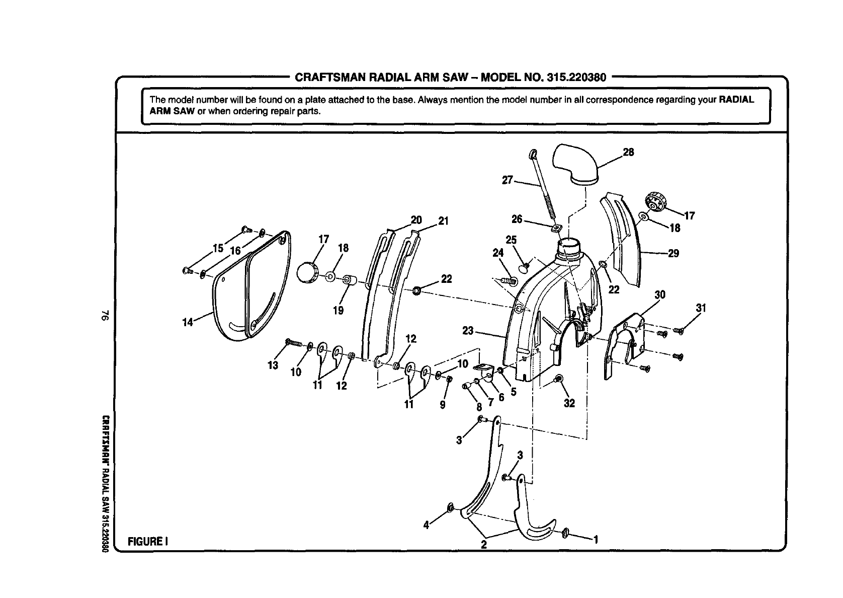
CRAFTSMAN RADIAL ARM SAW- MODEL NO. 315.220380
The model numberwill be foundon a plate attachedto the base, Alwaysmentionthe model number inall correspondenceregardingyour RADIAL |
i
ARM SAW or whenordering repairparts. J
_4
O_
z
zl
=,
:O
o
€O
t,n
FIGUREI
13 10
17 25
18
11
3O
31
19 ._
11 9 8
3
32
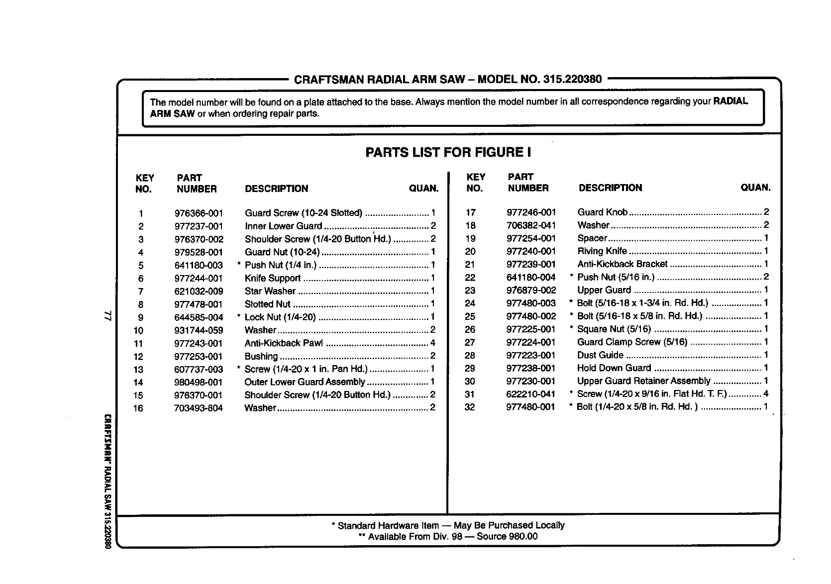
CRAFTSMANRADIALARM SAW- MODELNO.315.220380
The model numberwill be foundona plate attachedto the base. Alwaysmentionthe modelnumber inall correspondenceregardingyour RADIAL I
I
ARM SAW or when orderingrepairparts. J
PARTS LIST FOR FIGURE I
i
z
D
=,
;Ib
r-
=
!
KEY PART
NO. NUMBER DESCRIPTION QUAN.
1976366-001
2 977237-001
3 976370-002
4 979528-001
5 641180-003
6 977244-001
7 621032-009
8 977478-001
9 644585-004
10 931744-069
11 977243-001
12 977253-001
13 607737-003
14 980498-001
15 976370-001
16 7O3493-804
Guard Screw (10-24 Slotted) ......................... 1
inner LowerGuard ......................................... 2
ShoulderScrew (1/4-20 ButtonHd.) .............. 2
Guard Nut (10-24) ..........................:............... 1
* Push Nut (1/4 in.) ........................................... 1
Knife Support................................................. 1
Star Washer ................................................... 1
SlottedNut ..................................................... 1
* LockNut (1/4-20) ........................................... 1
Washer ........................................................... 2
Anti-KickbackPawl ........................................ 4
Bushing.......................................................... 2
* Screw (1/4-20 x 1 in. Pan Hd.) ....................... 1
Outer Lower GuardAssembly........................ 1
ShoulderScrew (1/4-20 Button Hd.) .............. 2
Washer ........................................................... 2
KEY PART
NO. NUMBER DESCRIPTION QUAN.
17 977246-001
18 706382-041
19 977254-001
20 977240-001
21 977239-001
22 641180-004
23 9/6879-002
24 977480-003
25 977480-002
26 977225-001
27 977224-001
28 977223-001
29 977238-001
30 977230-001
31 622210-041
32 977480-001
* Standard Hardware Item-- May Be PurchasedLocally
** Available From Div. 98 -- Soume 980.00
Guard Knob.................................................... 2
Washer ........................................................... 2
Spacer............................................................ 1
RivingKnife.................................................... 1
Anti-KickbackBracket.................................... 1
* Push Nut (5/16 in.) ......................................... 2
Upper Guard .................................................. 1
* Bolt (5/16-18 x 1-3/4 in. Rd. Hd.) .................... 1
* Bolt (5/16-18 x 5/8 in. Rd. Hd.) ...................... 1
* Square Nut (6/16) .......................................... 1
Guard Clamp Screw (5/16) ............................ 1
DustGuide ..................................................... 1
HoldDown Guard .......................................... 1
Upper Guard RetainerAssembly ................... 1
* Screw(1/4-20 x 9/16 in. Flat Hd. T. F.)............. 4
* Bolt(1/4-20 x 5/8 in. Rd. Hd.) ........................ 1
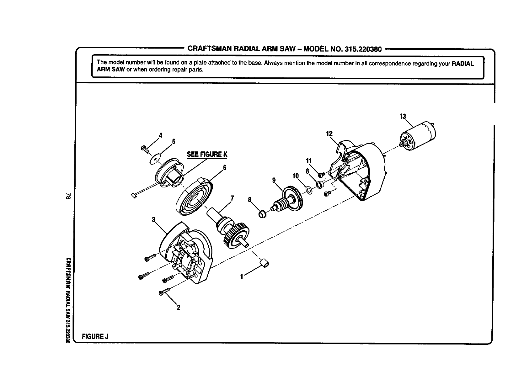
CRAFTSMAN RADIAL ARM SAW - MODEL NO. 315.220380
I The model numberwillbe foundon a plateattachedto the base.Always mentionthe model numberin allcorrespondenceregardingyour RADIAL |
ARM SAW or when orderingrepair parts. I
Co
RGUREJ
SEERGUREK
7
10
9X
11
12
13
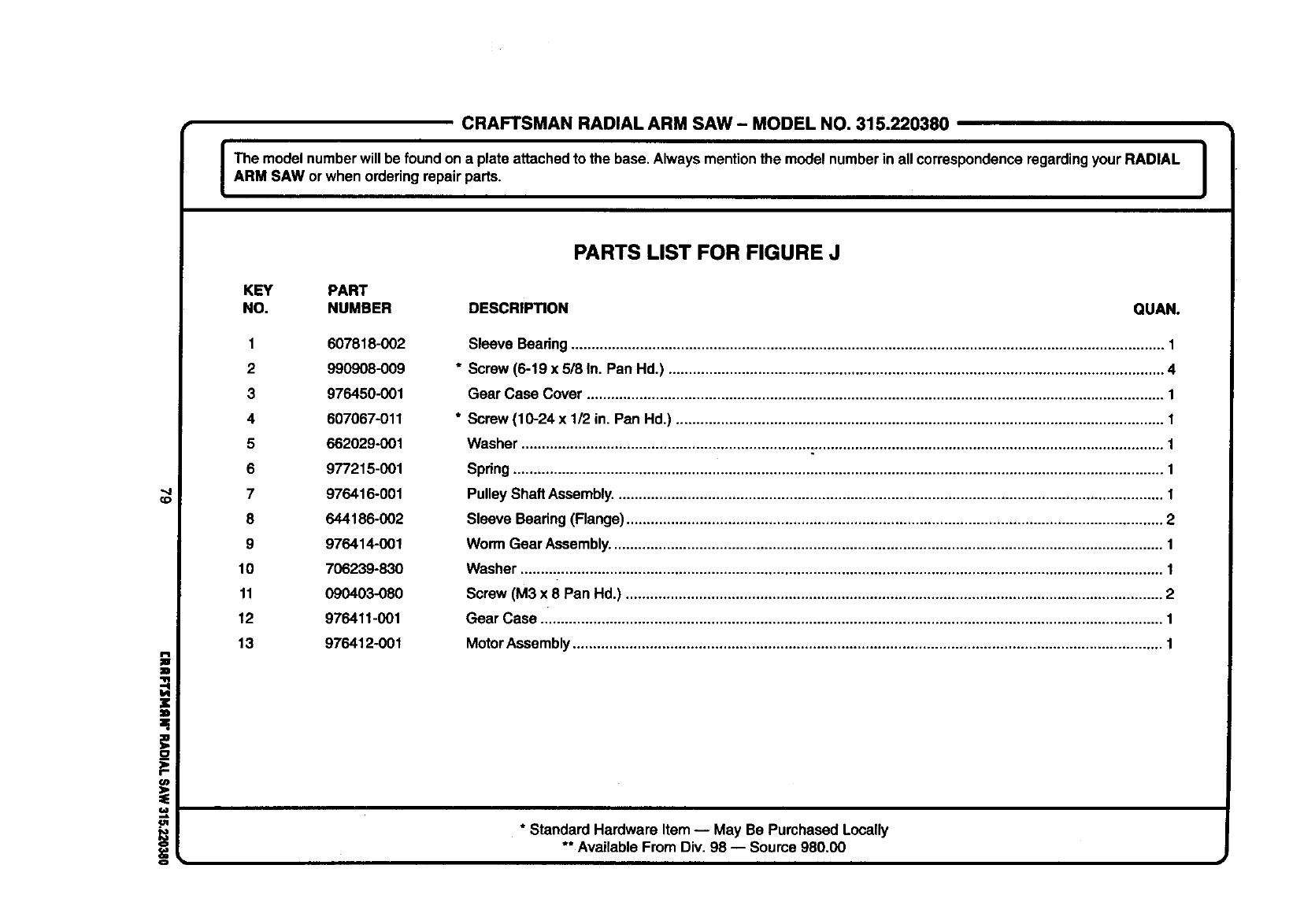
CRAFTSMANRADIALARMSAW- MODELNO.315.220380
I The model numberwill be foundon a plateattached to the base.Always mentionthe model numberin all correspondenceregardingyour RADIAL |
i
ARM SAW orwhen orderingrepair parts. I
CD
(/)
=.
==,
PARTS LIST FOR FIGURE J
KEY PART
NO. NUMBER DESCRIPTION QUAN.
1 607818-002
2 990908-009
3 976450-001
4 607067-011
5 662029-001
6 977215-001
7 976416-001
8 644186-002
9 976414-001
10 706239-830
11 090403-080
12 976411-001
13 976412-001
Sleeve Beadng.................................................................................................................................................. 1
* Screw (6-19 x 5/8 In. Pan Hd.) .......................................................................................................................... 4
Gear Case Cover .............................................................................................................................................. 1
* Screw (10-24 x 1/2 in. Pan Hd.) ........................................................................................................................ 1
Washer .............................................................................................................................................................. 1
Spring................................................................................................................................................................ 1
PulleyShaft Assembly....................................................................................................................................... 1
Sleeve Bearing (Flange).................................................................................................................................... 2
Worm Gear Assembly........................................................................................................................................ 1
Washer .............................................................................................................................................................. t
Screw (M3 x 8 Pan Hd.) .................................................................................................................................... 2
Gear Case ......................................................................................................................................................... 1
MotorAssembly................................................................................................................................................. 1
* Standard Hardware Item -- May Be Purchased Locally
** Available From Div. 98 -- Soume 980.00
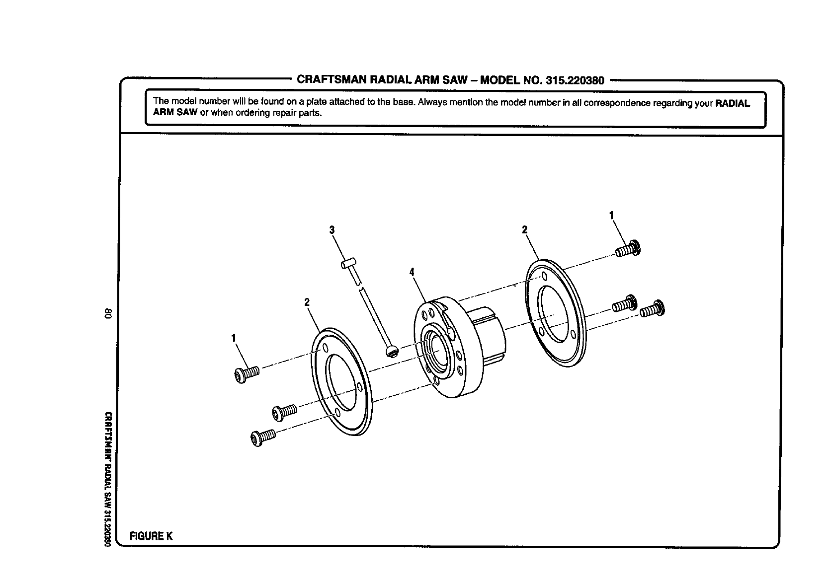
CRAFTSMAN RADIAL ARM SAW - MODEL NO. 315.220380
I The model numberwillbe foundona plate attachedto the base. Alwaysmentionthe model numberinall correspondenceregardingyour RADIAL I
ARM SAW or when orderingrepairparts. I
o=
.=
==
_O
_2
I"
o1
iRGUREK
1
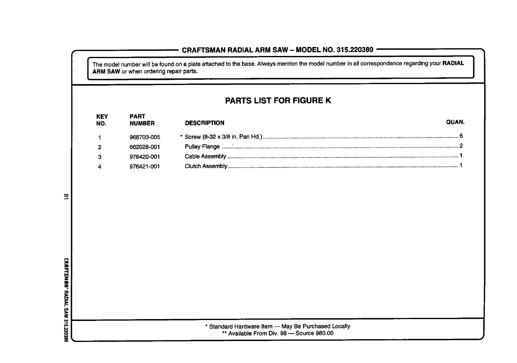
CRAFTSMANRADIALARM SAW- MODELNO.315.220380
The model number will be foundon a plate attachedto the base. Alwaysmentionthe model numberinall correspondenceregarding your RADIAL
ARM SAW or when ordering repairparts.
PARTS LIST FOR FIGURE K
KEY PART
NO. NUMBER DESCRIPTION QUAN.
1
2
3
4
968703-005
662028-001
976420-001
976421-001
* Screw (8-32 x 3/8 in. Pan Hd.) .......................................................................................................................... 6
PulleyFlange ......."............................................................................................................................................. 2
Cable Assembly ................................................................................................................................................ 1
ClutchAssembly................................................................................................................................................ 1
=_,
i* Standard Hardware Item -- May Be PurchasedLocally
** Available From Div. 98 -- Source 980.00

For in-home major brand repair service:
Call 24 hours a day, 7days a week
1-800-4-MY-HOME s" (1-800-469-4663)
Para pedir servicio de reparacibn a domicilio - 1-800-676-5811
In Canada for all your service and parts needs call - 1-800-665-4455
Au Canada pour tout le service ou les pi_ces
For the repair or replacement parts you need:
Call 6 am - 11 pm CST, 7 days a week
PartsDirect sM
1-800-366-PART (1-800-366-7278)
Para ordenar piezas con entrega a domicilio - 1-800-659-7084
For the location of a Sears Parts and Repair Center in your area:
Call 24 hours a day, 7 days a week
1-800-488-1222
For information on purchasing a Sears Maintenance Agreement
or to inquire about an existing Agreement:
Call 9 am - 5 pm, Monday - Saturday
1-800-827-6655
HomeCentrals"
The Service Side of Sears
